Embed Size (px)
Citation preview

Page 1 of 5
CHAPTER-1
ELECTRIC CHARGES AND FIELDS (Prepared by AYYAPPAN C, HSST, GMRHSS KASARAGOD)
Electric Charge
· Electric charge is the physical
property of matter that causes it to
experience a force when placed in
an electromagnetic field.
· The two types of charges are positive and
negative (Named by Benjamin Franklin)
· Like charges repels and unlike charges
attracts.
· When amber rubbed with wool or silk cloth attracts light objects – discovered by
Thales.
· Electroscope – device for charge
detection
· It is a scalar quantity .
· SI unit of electric charge- coulomb (C)
· Charge of a proton is positive
(1.602192 × 10⁻¹⁹
C)
· Charge of an electron is negative
(-1.602192 × 10⁻¹⁹
C)
· Matter with equal number of electrons
and protons are electrically neutral.
· Matter with excess number of electrons –
negatively charged
· Matter with excess protons – positively
charged.
Coulomb’s law
· The force of attraction or repulsion
between two stationary electric charges is
directly proportional to the product of the
charges and inversely proportional to the
square of the distance between them.
· Force between two stationary charges is
1 2
2
0
1
4 r
q qF
rpe e=
· Where 0e -permittivity of free space, re -
relative permittivity.
· Relative permittivity is given by ,0
r
ee
e=
· e - Permittivity of the medium. · Also e 0 = 8.854x10
-12 C
2N
-1m
-2
· Thus
9
0
19 10
4pe= ´
Definition of coulomb
· When q1 = q2 = 1 C, r = 1 m , F = 9 × 109 N
· 1 C is the charge that when placed at a
distance of 1 m from another charge of
the same magnitude in vacuum
experiences an electrical force of
repulsion of magnitude 9 × 10⁹ N.
Coulomb’s law in vector form
· Force on q1 due to q2 is,
· Force on q2 due to q1 is,
· Thus F12= -F21, Coulomb’s law agrees with
Newton’s third law.
Electric field
· Region around a charge where its effect
can be felt.
· Intensity of electric field at a point is the
force per unit charge.
FE
q
F qE
=
=
· Unit of electric field is N/C or V/m.
· It is a vector quantity.
Electric field due to a point charge
2
0
1
4
qE
rpe=
Electric field due to a system of charges
· Total electric field at a point due to a
system of charges is the vector sum of the
field due to individual charges.

Page 2 of 5
Electric field lines
· Pictorial representation of electric field.
· Electric field line is a curve drawn in such
a way that the tangent to it at each point
is in the direction of the net field at that
point.
Properties of field lines
· Start from positive charge, end at
negative charge. Do not form closed
loops.
· Field lines are continuous in a charge free
region.
· Two field lines never intersect.( Reason:
two directions for electric field is not
possible at a point)
· Field lines are parallel in uniform electric
field.
· Tangent at any point gives direction of
electric field.
· Number of field lines gives intensity of
electric field.
positive charge negative charge
Positive and negative charge (dipole)
Two positive charges
Electric Dipole
· Two equal and opposite charges
separated by a small distance.
· Total charge and force on a dipole is zero.
Dipole moment
· Product of charge and dipole length.
2p q a= ´
q- charge, 2a- dipole length
· Direction is from negative to positive
charge.
· SI unit- coulomb metre ( C m)
Electric field due to a dipole
Axial point
· The field at the point P due to positive
charge is
· The field due to negative charge is
· Thus the total electric field at P is
( ) ( )( ) ( )
2 2
2 2
04
r a r aqE p
r a r ape
® Ùé ù+ - -= ê ú
+ ´ -ê úë û
· Simplifying
( )22 2
0
4
4
q arE p
r ape
® Ùé ùê ú=ê ú-ë û
· For r >> a, we get 3
0
1 4
4
qaE p
rpe
® Ùé ù= ê úë û
· Using p= q x2a

Page 3 of 5
3
0
1 2
4
pE p
rpe
® Ùé ù= ê úë û
Equatorial point
· The magnitudes of the electric fields due
to the two charges +q and –q are equal
and given by
· The components normal to the dipole axis
cancel away.
· The components along the dipole axis add
up.
· Thus total electric field is
· Substituting
( )1
2 2 2
cosa
r a
q =+
and
simplifying we get
( )3
2 2 20
2
4
q aE p
r ape
® Ù- ´=
+
· For r >> a, we get 3
0
2
4
q aE p
rpe
® Ù- ´=
· Using p= q x2a
3
04
pE p
rpe
® Ù-=
Relation connecting axial field and equatorial
field of dipole
· We have axial field
3
0
1 2
4
pE p
rpe
® Ùé ù= ê úë û
· Equatorial field
3
04
pE p
rpe
® Ù-=
· Thus
Physical significance of electric dipole
Non Polar molecules
· The molecules in which positive centre of
charge and negative centre of charge lie
at the same place.
· Dipole moment is zero for a non polar
molecule in the absence of an external
field.
· They develop a dipole moment when an
electric field is applied.
· Eg:CO2, CH4, etc.
Polar molecules
· The molecules in which the centres of
negative charges and of positive charges
do not coincide.
· Eg: water
Electric flux
· Number of field lines passing normal
through a surface.
cosEAf q=
· Or
· Unit – Nm2/ C
· It is a scalar quantity
Charge density
Linear charge density (λ)
· It is the charge per unit length.
Q
ll =
· SI unit is C/m. Surface charge density (σ)
· It is the charge per unit area.
Q
As =

Page 4 of 5
· SI unit is C/m2.
Volume charge density (ρ)
· It is the charge per unit volume.
Q
Vr =
· SI unit is C/m3.
Gauss’s Theorem
· Total electric flux over a closed surface is
0
qf
e=
· Where q - total charge enclosed
· The closed surface – Gaussian surface.
Proof
• The flux through area element ΔS is
• The total flux through the sphere is
• Where the total surface area S = 4πr
2.
• Thus
Features of Gauss’s law
• Gauss’s law is true for any closed surface
irrespective of the size and shape.
• The charge includes sum of all charges
enclosed by the surface.
• Gauss’s law is useful to calculate electric
field when the system has some
symmetry.
• Gauss’s law is based on the inverse square
dependence on distance contained in the
Coulomb’s law.
Applications of Gauss’s law
Electric field due to a straight charged wire
· Total flux through the Gaussian surface is
2E rlf p= ´
· Total charge enclosed is
q ll= ´ , λ- charge per unit length
· Using Gauss’s law
0
2l
E rll
pe
´ =
· Thus 02
Er
lpe
=
· In vector form 02
E nr
lpe
® Ù
=
· Where nÙ
- radial unit vector
Electric field due to a plane sheet of charge
· Total flux enclosed by the Gaussian
surface is (2 )E Af = ´ , A- area of cross
section.
· Total charge enclosed is q As= ,
σ – surface charge density.

Page 5 of 5
· Using Gauss’s law
0
(2 )A
E Ase
´ =
· Thus 02
Ese
=
· In vector form 02
E nse
® Ù
=
· Electric field due to a charged spherical shell
Points outside the shell
· Total flux enclosed by the Gaussian
surface is 2(4 )E rf p= ´ , r- radius of
Gaussian surface.
· Total charge enclosed is 2(4 )q Rs p= ´ , R –radius of shell
· Using Gauss’s law 2
2
0
4(4 )
RE r
s pp
e´
´ =
· Thus 2
2
0
RE
r
se
=
· Or 2
0
1
4
qE
rpe=
· In vector form 2
0
1
4
qE r
rpe
® Ù
=
Points on the shell
· On the surface r=R, therefore 0
Ese
=
Points inside the shell
· Total charge enclosed =0
24 0E rp´ =
· Thus E= 0 inside the shell.
· Vanishing of electric field (E=0) inside a
charged conductor is called electrostatic
shielding
****

Page 1 of 3
Chapter Two
ELECTROSTATIC POTENTIAL AND CAPACITANCE
(Prepared by AYYAPPAN C, HSST, GMRHSS KASARAGOD)
ELECTROSTATIC POTENTIAL
· The electrostatic potential (V ) at any point
is the work done in bringing a unit positive
charge from infinity to that point.
WV
q= , W – work done, q – charge.
· Also W qV=
· It is a scalar quantity.
· Unit is J/C or volt (V)
POTENTIAL DUE TO A POINT CHARGE
· The force acting on a unit positive charge
(+1 C) at A , is
2 2
0 0
1 1 1
4 4
q qF
x xpe pe´
= =
· Thus the work done to move a unit positive
charge from A to B through a displacement
dx is
2
0
1
4
qdW dx
xpe= -
· The negative sign shows that the work is
done against electrostatic force.
· Thus the total work done to bring unit
charge from infinity to the point P is
2
0
1
4
r r qW dW dx
xpe¥ ¥
é ù= ò = ò -ê ú
ë û
2
0
1
4
rqW dx
xpe ¥
é ù= - ò ê úë û
· Integrating
0 0
1 1
4 4
q qW
r rpe peé ù= - =ê ú¥ë û
· Therefore electrostatic potential is given by
0
1
4
qV
rpe=
Variation of potential V with r
Capacitor
· It is a charge storing device.
· A capacitor is a system of two conductors
separated by an insulator.
• A capacitor with large capacitance can hold
large amount of charge Q at a relatively
small V.
Capacitance
· The potential difference is proportional to
the charge , Q.
· Thus Q
CV
=
· The constant C is called the capacitance of
the capacitor. C is independent of Q or V.
· The capacitance C depends only on the
geometrical configuration (shape, size,
separation) of the system of two
conductors
· SI unit of capacitance is farad.
· Other units are, 1 μF = 10–6
F, 1 nF = 10–9
F,
1 pF = 10–12
F, etc.
Symbol of capacitor
Fixed capacitance Variable capacitance

Page 2 of 3
Dielectric strength
• The maximum electric field that a dielectric
medium can withstand without break-down
is called its dielectric strength.
• The dielectric strength of air is about
3 × 10⁶
Vm–1
.
THE PARALLEL PLATE CAPACITOR
• A parallel plate capacitor consists of two
large plane parallel conducting plates
separated by a small distance
Capacitance of parallel plate capacitor
• Let A be the area of each plate and d the
separation between them.
• The two plates have charges Q and –Q.
• Plate 1 has surface charge density σ = Q/A
and plate 2 has a surface charge density –σ.
· At the region I and II, E=0
· At the inner region
· The direction of electric field is from the
positive to the negative plate.
· For a uniform electric field the potential
difference is
• The capacitance C of the parallel plate
capacitor is then
· Thus 0ACd
e=
Combination of capacitors
Capacitors in series
· In series charge is same and potential is
different on each capacitors.
· The total potential drop V across the
combination is
1 2V V V= +
· Considering the combination as an effective
capacitor with charge Q and potential
difference V, we get
1 2
Q Q Q
C C C= +
· Therefore effective capacitance is
1 2
1 1 1
C C C= +
· For n capacitors in series
1 2
1 1 1 1.......
nC C C C= + + +
Capacitors in parallel
· In parallel the charge is different, potential
is same on each capacitor.
· The charge on the equivalent capacitor is
1 2Q Q Q= +
· Thus 1 2CV CV CV= +
· Therefore 1 2C C C= +
· In general , for n capacitors
1 2 .............. nC C C C= + + +

Page 3 of 3
Energy stored in a capacitor
· Energy stored in a capacitor is the electric
potential energy.
· Charges are transferred from conductor 2
to conductor 1 bit by bit, so that at the end,
conductor 1 gets charge Q.
· Work done to move a charge dq from
conductor 2 to conductor 1, is
argdW Potential Ch e= ´
· That is q
dW dqC
= ´
· Since potential at conductor 1 is , q/C.
· Thus the total work done to attain a charge
Q on conductor 1, is
0 0
Q Qq
W dW dqC
= = ´ò ò
· On integration we get,
2
0
21
22
Q
QW
C C
q= =
é ùê úë û
· This work is stored in the form of potential
energy of the system.
· Thus energy stored in the capacitor is 2
2
QU
C=
· Also 1
2U QV= or
21
2U CV=
Alternate method
· We have the Q – V graph of a capacitor,
· Energy = area under the graph
· Thus , 1
2U Q V= ´ ´
· Also 21
2U CV=
Energy Density of a capacitor
· Energy density is the energy stored per unit
volume.
· We have 2
2
QU
C=
· But Q As= and 0ACd
e=
· Thus we get ( )2
02
A dU
A
se
æ ö= ç ÷
è ø
· Using
0
Ese
= , we get
2
0
1
2U E Ade= ´
· Thus energy per unit volume is given by
2
0
1
2
UE
Ade=
· That is the energy density of the capacitor is
2
0
1
2u Ee=
*****

Page 1 of 4
CHAPTER -3
CURRENT ELECTRICITY (Prepared By Ayyappan C, HSST Physics, GMRHSS,,
Kasaragod, Mob: 9961985448)
Ohm’s law
· At constant temperature the current
flowing through a conductor is directly
proportional to potential difference
between the ends of the conductor. · Thus V IR= ,
V- potential difference, I – current,
R- resistance
Resistance
· Ability of conductor to oppose electric
current.
V
RI
=
· SI unit – ohm (Ω)
Factors affecting resistance of a conductor
· Nature of material
· Proportional to length of the conductor
· Inversely proportional to area of cross
section.
· Proportional to temperature
Relation connecting resistance and resistivity
lR
A
r=
Where ρ- resistivity, A – area, l- length
Resistivity (specific resistance)
· Resistivity of the material of a conductor
is defined as the resistance of the
conductor having unit length and unit
area of cross section.
RA
lr =
· Unit – ohm meter (Ωm)
· Resistivity of conductor depends on
nature of material and Temperature Conductance (G)
· Reciprocal of resistance
1
GR
=
· Unit- Ω-1
, or mho or siemens (S)
Conductivity (σ)
· Reciprocal of resistivity
1
sr
=
· Unit- Ω
-1m
-1, or mho m
-1, or S m
-1
Ohmic conductor
· A conductor which obeys ohm’s law.
· Eg:- metals
V-I graph of an ohmic conductor
Non ohmic conductors
· Conductor which does not obey ohm’s
law.
· Eg :- diode, transistors, electrolytes etc.
V-I graph of a non- ohmic conductor (Diode)
Circuit diagram for the experimental study of
ohm’s law
Vector form of ohm’s law
· We have V El=
· From ohm’s law, I l
V IRA
r= =
· Thus I l
ElA
r=
· That is I
E JA
rr= =
· Therefore E Jr® ®
= or J Es® ®
=
Resistors
· The resistor is a passive electrical
component to create resistance in the
flow of electric current. Symbol
Constant resisstance Variable resistance
Combination of resistors
Resistors in Series

Page 2 of 4
· In series connection same current pass
through all resistors.
· The potential drop is different for each
resistor.
· The applied potential is given by
1 2 3V V V V= + +
· Where V1, V2 and V3 are the potential drop
across resistors R1, R2 and R3 respectively.
· If all the resistors are replaced with a
single effective resistance RS , we get
SV IR=
· Thus 1 2 3SIR IR IR IR= + +
· Therefore the effective resistance is
1 2 3SR R R R= + +
· For n resistors
1 2 3 ..........S nR R R R R= + + +
· Thus effective resistance increases in
series combination.
Resistors in parallel
· In parallel connection current is different
through each resistors.
· The potential drop is same for all
resistors.
· The total current
1 2 3I I I I= + +
· If all resistors are replaced with an
effective resistor of resistance RP, we get
P
VI
R=
· Thus
1 2 3P
V V V V
R R R R= + +
· Therefore the effective resistance in
parallel combination is
1 2 3
1 1 1 1
PR R R R= + +
· For n resistors in parallel
1 2 3
1 1 1 1 1....
nPR R R R R= + + + +
· For two resistors
1 2
1 2
P
R RR
R R=
+
· Thus effective resistance decreases in
parallel combination.
Internal resistance of a cell (r)
· Resistance offered by the electrolytes and
electrodes of a cell.
Factors affecting internal resistance
· Nature of electrolytes
· Directly proportional to the distance
between electrodes
· Directly proportional to the concentration
of electrolytes.
· Inversely proportional to the area of the
electrodes.
· Inversely proportional to the temperature
of electrolyte.
Relation connecting emf and internal resistance
· Effective resistance = R+r
· Thus the current is IR r
e=
+
· Where e –emf, R- external resistance,
r- internal resistance.
· That is ( )I R r IR Ire e+ = Þ + =
· From ohm’s law, V=IR, therefore
V
rI
e -=
· The potential is given by
V Ire= -
Joule’s law of heating
· The heat energy dissipated in a current
flowing conductor is given by 2H I Rt=
· I- current, R –resistance, t –time
Electric power
· It is the energy dissipated per unit time.
· Power , 2H
P I Rt
= =
· Also
2VP VI
R= =
· SI unit is watt (W)
· 1 kilo watt (1kW) = 1000W

Page 3 of 4
· 1mega watt (MW) = 106W
· Another unit horse power (hp)
· 1 hp = 746 W
Electrical energy
· Electrical energy = electrical power X time
· SI unit – joule (J)
· Commercial unit – kilowatt hour (kWh)
· 1kWh = 3.6 x 10⁶ J.
Efficiency
· The efficiency of an electrical device is
Kirchhoff’s rule
First rule (junction rule or current rule)
· Algebraic sum of the current meeting at
junction is zero.
· Thus , Current entering a junction =
current leaving the junction
1 2 3 4 5 0I I I I I+ + - - =
Sign convention
· Current entering the junction – positive
· Current leaving the junction - negative
Second rule (loop rule or voltage rule)
· Algebraic sum of the products of the
current and resistance in a closed circuit is
equal to the net emf in it.
· This rule is a statement of law of
conservation of energy.
Sign convention
· Current in the direction of loop – positive
· Current opposite to loop - negative
Illustration
Loop ABCFA
1 1 2 2 1 2I R I R E E- = -
Loop CDEFC
( )2 2 1 2 3 2I R I I R E+ + =
Wheatstone’ s bridge
Wheatstone’ s principle
· If galvanometer current is zero, P R
Q S=
Derivation of balancing condition
· Applying voltage rule to the loop ABDA
1 2 0gI P I G I R+ - =
· For the loop BCDB
( ) ( )1 2 0g g gI I Q I I S I G- - + - =
· When the bridge is balanced Ig=0.
· Thus 1 2 0I P I R- = and 1 2 0I Q I S- =
· Or , 1 2I P I R= and 1 2I Q I S=
· Thus P R
Q S=
· This is the balancing condition of a
Wheatstone bridge.
Meter bridge (slide wire bridge)
· Works on Wheatstone’s principle.
· Used to find resistance of a wire.
Circuit diagram
· Where k – key, X – unknown resistance,
R- known resistance, HR- high resistance,
G – Galvanometer, J – Jockey
Equation to find unknown resistance
· From wheatstone’s principle

Page 4 of 4
P R
Q S=
· Here P – unknown resistance , Q- known
resistance, R- resistance of the wire of
length l , S - resistance of wire of length
(100-l).
· The length l for which galvanometer
shows zero deflection – balancing length.
· Thus
(100 )
X lr
R l r=
-
· Where r – resistance per unit length of the
meterbridge wire.
· Therefore the unknown resistance is given
by
(100 )
RlX
l=
-
· The resistivity of the resistance wire can
be calculated using the formula
2r X
l
pr =
Where r – radius of the wire, l –length of
the wire.
Potentiometer
· A device used to measure an unknown
emf or potential difference accurately.
Principle
· When a steady current (I) flows through a
wire of uniform area of cross section, the
potential difference between any two
points of the wire is directly proportional
to the length of the wire between the two
points.
· From ohm’s law , V IR=
· That is . I l
VA
r=
· Therefore , V la or V kl=
· Thus , where k – constant.
– potential gradient.
Uses of potentiometer
· To compare the emf of two cells
· To find the internal resistance of a cell
Comparison of emfs
Circuit diagram
· We have, 1 1E lµ and 2 2E lµ
· Thus 1 1
2 2
E l
E l=
· l1- balancing length with cell E1
· l2- balancing length with cell E2
· To get the balancing length E1>E2
To find internal resistance
Circuit diagram
· when the key K1 is open
1le µ
· when the key K1 is closed
2V lµ
· Thus 1
2
l
V l
e=
· But we have
( )
V IR
I R re
=
= +.
r – internal resistance
· Therefore ( ) ( )I R r R r
V IR R
e + += =
· Thus 1
2
( )R r l
R l
+=
· The internal resistance is given by
( )1 2
2
R l lr
l
-=
· Where l1- balancing length, key K1open,
l2- balancing length, key K1 closed.
Why potentiometer is preferred over voltmeter
for measuring emf of a cell?
· In potentiometer null method is used, so
no energy loss in measurement.
******

Page 1 of 4
CHAPTER 4
MOVING CHARGES AND MAGNETISM (Prepared by AYYAPPAN C, HSST, GMRHSS KASARAGOD)
Magnetic Lorentz force
· Force on charge moving in a magnetic
field.
sinF qvB q= , q –charge, v- velocity,
B – magnetic field, θ- angle between v and B.
· Or ( )F q v B= ´
Special Cases:
· If the charge is at rest, i.e. v = 0, then
F = 0.
· Thus, a stationary charge in a magnetic
field does not experience any force.
· If θ = 0° or 180° i.e. if the charge moves
parallel or anti-parallel to the direction of
the magnetic field, then F = 0.
· If θ = 90° i.e. if the charge moves
perpendicular to the magnetic field, then
the force is maximum.
maxF qvB=
Right Hand Thumb Rule
· The direction of magnetic Lorentz force
can be found using right hand rule.
Work done by magnetic Lorentz force
· The magnetic Lorentz force is given by
( )F q v B= ´
· Thus F, is perpendicular to v and hence
perpendicular to the displacement.
· Therefore the work done
cos90 0W Fd= =
· Thus work done by the magnetic force on
a moving charge is zero.
· The change in kinetic energy of a charged
particle, when it is moving through a
magnetic field is zero.
· The magnetic field can change the
direction of velocity of a charged particle,
but not its magnitude.
Lorentz force
· Force on charge moving in combined
electric and magnetic field.
· [ ]( ) ( )F qE q v B q E v B= + ´ = + ´
Units of magnetic field (magnetic induction or
magnetic flux density)
· SI unit is tesla (T)
· Other unit is gauss(G)
· 1 gauss =10-4
tesla
· The earth’s magnetic field is about
3.6x10⁻⁵
T
Definition of Tesla
· The magnetic induction (B) in a region is
said to be one tesla if the force acting on a
unit charge (1C) moving perpendicular to
the magnetic field (B) with a speed of
1m/s is one Newton. Force on a current carrying wire in a magnetic
field
· The total number of charge carriers in the
conductor = n Al
· Where, n-number of charges per unit
volume, A-area of cross section, l-length
of the conductor.
· If e is the charge of each carrier , the total
charge is Q enAl=
· The magnetic force is ( )F Q v B= ´
· Where v – drift velocity
· Thus ( ) ( )F enAl v B nAve l B= ´ = ´
· Thus
sinF IlB q=
· Since I nAve=
· When θ=0 , F=0
· When θ=900, F = IlB
Fleming’s left hand rule
· A rule to find the direction of the force n a
current carrying wire.
· Fore finger – direction of magnetic field
· Middle finger –direction of current
· Thumb – direction of force.

Page 2 of 4
Biot-Savart Law
· The magnetic field at a point due to the
small element of a current carrying
conductor is
· directly proportional to the current
flowing through the conductor (I)
· The length of the element dl
· Sine of the angle between r and dl
· And inversely proportional to the square
of the distance of the point from dl.
· Thus the magnetic field due to a current
element is
· μ0-permeability of free space, I – current,
r- distance
· or 0
34
Idl rdB
r
mp
´=
Idl rl rl r
· where , 70 10 /
4Tm A
mp
-=
· The direction of magnetic field is given by
right hand rule.
Comparison between Coulomb’s law and Biot-
Savart’s law
Coulomb’s law Biot – Savart’s law
1 2
2
0
1
4 r
q qF
rpe e=
Electric field is due to
scalar source
Magnetic field is due to
vector source
Electric field is present
everywhere
Along the direction of
current magnetic field
is zero
Applications of Biot-Savart Law
Magnetic Field on the Axis of a Circular Current
Loop
· The magnetic field at P due to the current
element dl , at A is 0
0 0
2 2
sin90
4 4
Idl IdldB
r r
m mp p
= =
· The component dB sinθ is cancelled by
the diametrically opposite component.
· Thus magnetic field at P ,due to the
current element is the x- component of
dB.
· Therefore cosxdB dB q=
0
2cos
4x
IdldB
r
mq
p=
· But we have ( )1
2 2 2r x R= + and
( )1
2 2 2
cosR
x R
q =+
· Therefore
0
12 22 2 24 ( ) ( )
x
Idl RdB
x R x R
mp
=+ +
0
32 2 24 ( )
x
IRdldB
x R
mp
=+
· The summation of the current elements dl
over the loop gives , the circumference
2πR.
· Thus the total magnetic field at P due to
the circular coil is 2
0 0
3 32 2 2 22 2
(2 )
4 ( ) 2( )
IR R IRB
x R x R
m p mp
= =+ +
· Therefore
2
0
3
2 2 22( )
IRB
x R
m=
+
· At the centre of the loop x=0, thus,
00
2
IB
R
m=

Page 3 of 4
· The direction of the magnetic field due to
a circular coil is given by right-hand
thumb rule.
· Curl the palm of your right hand around
the circular wire with the fingers pointing
in the direction of current. Then the right
hand thumb gives the direction of
magnetic field.
Magnetic field lines due to a circular current
loop
Relation Connecting Velocity of Light ,
Permittivity and Permeability
· We have 7
0 00 0 9 16
4 10 1
1 4 9 10 9 10
pe me m
p
-æ ö= = =ç ÷ ´ ´è ø
· Thus
( )0 0 2 28
1 1
3 10 ce m = =
´
· Where c – speed of light in vacuum.
· Therefore the speed of light is given by
0 0
1c
e m=
· In general , 1
vem
=
Ampere's Circuital Law
· The closed line integral of magnetic field is
equal to µ0 times the total current.
· The closed loop is called Amperian Loop.
Applications Of Ampere’s Circuital Law
1. Magnetic field due to a straight wire
· Over the Amperian loop B and dl are
along the same direction.
· Thus . cos0l l l
B dl Bdl B dl= =ò ò òB dlò ò ò. cos0. cB dl Bdl B dl Bdl B d. cos0. c. c B dB d. cos0. c. c. c
· That is . (2 )l
B dl B rp=ò . (2 )B dl B r. (2 ). (2 )2 )2 )2 )2 ). (. (ò
· From ampere’s circuital law ,02B r Ip m´ =
· Thus 0
2
IB
r
mp
=
2. Magnetic field due to a solenoid
Solenoid
· A solenoid is an insulated copper wire
closely wound in the form of a helix
· When current flows through the
solenoid, it behaves as a bar magnet.
· For a long solenoid, the field outside is
nearly zero.
· A solenoid is usually used to obtain a
uniform magnetic field.
· If the current at one end of the
solenoid is in the anticlockwise
direction it will be the North Pole and
if the current is in the clockwise
direction it will be the South Pole.
Expression for magnetic field inside a solenoid

Page 4 of 4
· Consider an amperian loop abcda
· The magnetic field is zero along cd,bc and
da.
· The total number of turns of the solenoid
is N nh= , where n – number of turns
per unit length, h –length of the amperian
loop.
· Therefore the total current enclosed by
the loop is eI nhI= ,
· where, I –current in the solenoid
· Using Ampere’s circuital law
eIBhdlBò == 0. m
0Bh nhIm=
· Therefore , the magnetic field inside the
solenoid is
0B nIm=
• The direction of the field is given by Right
Hand Rule.
The magnetic field due to a solenoid can be
increased by
i) Increasing the no. of turns per unit
length (n)
ii) Increasing the current (I)
iii) Inserting a soft iron core into the
solenoid.
Magnetic Field lines of a Solenoid
3. Magnetic Field due to a Toroid
Toroid
· Toroid is a hollow circular ring on which a
large number of turns of a wire are closely
wound.
· The magnetic field in the open space
inside ( point P) and exterior to the
Toroid ( point Q ) is zero.
· The field B is constant inside the Toroid.
Magnetic Field due to a Toroid
For points interior (P)
· Length of the loop 1 , L1 = 2π r1
· The current enclosed by the loop = 0.
· Therefore
· Magnetic field at any point in the interior
of a toroid is zero.
For points inside ( S )
· Length of the loop , L2 = 2π r2
· The total current enclosed =N I, where N
is the total number of turns and I the
current.
· Applying Ampere’s Circuital Law and
taking r2 = r
B(2πr) = µ0 NI
0
2
NIB
r
mp
=
· Or
0B nIm=
· Where 2
Nn
rp=
For points Exterior(Q)
· Each turn of the Toroid passes twice
through the area enclosed by the
Amperian Loop 3.
· For each turn current coming out of the
plane of the paper is cancelled by the
current going into the plane of paper.
· Therefore I = 0, B = 0.
*********

Page 1 of 3
CHAPTER 5
MAGNETISM AND
MATTER
( Prepared By Ayyappan C, HSST Physics, GMRHSS
Kasaragod)
Gauss’s Law in magnetism
· The law states that “the net magnetic flux
through any closed surface is zero”
Earth’s Magnetism
· Earth has an immense magnetic field
surrounding it and is of the order of 10-5
T.
· The location of the north magnetic pole is
at latitude of 79.740 N and a longitude of
71.80 W, a place somewhere in north
Canada.
· The magnetic South Pole is at 79.740 S,
108.220 E in the Antarctica.
Source of Earth’s Magnetism – Dynamo Effect
· Earth’s magnetism is due to the electric
currents produced by the convective
motion of metallic fluids (consisting
mostly of metallic iron and nickel) in the
outer core of earth. This is known as
Dynamo Effect.
Magnetic Meridian
· A vertical plane passing through the
magnetic axis of a freely suspended
magnet is called the magnetic meridian.
Geographic Meridian
· The vertical plane passing through a place
and the geographic north and south poles
is called the geographic meridian at that
place.
Elements of earth’s magnetism
The three elements of earth’s magnetic field are
· Angle of declination (D)
· Angle of Dip or inclination (I)
· Horizontal component of earth’s
magnetic field (BH)
Magnetic Declination
· The angle between the geographic
meridian and magnetic meridian is called
the angle of declination.
· The magnetic declination is different at
different places on the surface of earth.
· The declination is greater at higher
latitudes and smaller near the equator.

Page 2 of 3
· The declination in India is small, it being
0041ʹ E at Delhi and 0
0 58ʹ W at Mumbai.
Dip or Inclination
· Dip is the angle that the total magnetic
field BE of the earth makes with the
surface of the earth.
· The angle of dip is maximum (90 degree)
at the magnetic poles and minimum (0
degree) at the magnetic equator.
· At other places its value lies between 0
degree and 90 degree.
· In most of the northern
hemisphere, the north pole of the
dip needle tilts downwards.
· In most of the southern
hemisphere, the south pole of the
dip needle tilts downwards
Horizontal Component of earth’s magnetic field
· The total magnetic field at P can
be resolved into a horizontal
component BH and a vertical
component BV.
Relation Connecting Horizontal component and
vertical component
· We have BH = B cos I and BV = B sin
I
· Thus tan I = BV/ BH
· Also
Some Important Terms
Magnetistion or Intensity of Magnetisation (M)
· Magnetisation M of a sample is the
net magnetic moment per unit
volume, when the sample is subjected
to magnetizing field.
· M is a vector with dimensions L
-1A and
is measured in a units of A m-1
.
Magnetic Intensity or Magnetising Field (H)
· When a magnetic material is placed in a
magnetic field, magnetism is induced in
the material. It is known as induced
magnetism.
· The field which induces magnetism in a
material is called magnetizing field and
the strength of that field is called
magnetic intensity (H).
· Its SI unit is ampere/ metre
· The magnetizing field is given by
where, B – net magnetic field, M – Magnetistion,
μ0-permeability of free space
Relation connecting B , M and H
· The total magnetic field B is written as ,
B = μ0 (H + M)
Relation connecting M and H

Page 3 of 3
· The dependence of M on H is given by
M= χH, Where χ – Magnetic susceptibility
Magnetic susceptibility
· Magnetic susceptibility is a measure of
how a magnetic material responds to an
external field.
· It is small and positive for paramagnetic
materials
· It is small and negative for diamagnetic
materials
Relation connecting B , μ and H
· We have B = μ0 (H + M)
· Substituting M= χH , we get
B = μ0 (H + χH) = μ0H(1+χ) ,
· Thus
· where μ r = 1 + χ, is a dimensionless
quantity called the relative magnetic
permeability of the substance.
· The magnetic permeability of the
substance is μ and it has the same
dimensions and units as μ 0
μ μ = μ 0 μ r = μ 0 (1+χ)
Magnetic permeability (μ)
· It is the ratio of magnetic field to the
magnetizing field
· Its unit is tesla meter/ampere (TmA
-1)
Relative permeability of medium
· Relative permeability of medium is the
ratio of permeability of a medium (μ) to
the permeability of air or vacuum (μ0)
· Also μ r = (1+χ)
Magnetic Flux (φ)
· It is the number of magnetic field lines
passing normally through a surface.
· The SI unit is weber( Wb)
******

Page 1 of 3
CHAPTER 6
ELECTROMAGNETIC INDUCTION (Prepared by AYYAPPAN C, HSST, GMRHSS KASARAGOD)
Faraday’s Law of Electromagnetic Induction
· The magnitude of the induced emf in a
circuit is equal to the time rate of change
of magnetic flux through the circuit.
· Mathematically
· If there are N turns
· The negative sign indicates the direction
of emf.
Ways to increase the induced emf
· By increasing the number of turns, N.
· By changing magnetic flux.
· The magnetic flux can be varied by
· Changing magnetic field, B
· Changing area, A.
· Changing the angle, θ.
· Rotating the coil in a magnetic
field.
· Shrinking or stretching the coil
in a magnetic field.
Motional Electromotive Force
· The emf induced by the motion of a
conductor in a magnetic field is called
motional emf.
Expression of motional emf
· The magnetic flux ΦB enclosed by the
loop PQRS is
ΦB = Blx , where B – magnetic field
· Since x is changing with time, the rate of
change of flux Φ B will induce an emf
given by
· The induced emf Blv is called motional
emf.
Eddy Currents
· Eddy currents are the surface currents
produced when bulk pieces of conductors
are subjected to changing magnetic field.
· Eddy currents flow in closed loops within
conductors, in planes perpendicular to the
magnetic field.
· This effect was discovered by physicist
Foucault, and hence this current is also
known as Foucault current.
· The direction of eddy currents is given by
Lenz’s law.
Demonstration of eddy currents
Experiment 1
· When a copper plate is allowed to swing
like a simple pendulum between the pole
pieces of a strong magnet, it is found that
the motion is damped and the plate
comes to rest in the magnetic field.
Reason :
· As the plates moves the magnetic flux
associated with it changes and eddy
currents are induced on its surface.
· Directions of eddy currents are opposite
when the plate swings into the region
between the poles and when it swings out
of the region.

Page 2 of 3
· Hence the plate comes to rest.
Experiment II
· If rectangular slots are made in the copper
plate the area available to the flow of
eddy currents is less.
· The pendulum plate with holes or slots
reduces electromagnetic damping and the
plate swings more freely.
Experiment III
· When a metallic disc is placed on one end
of a solenoid connected to an ac source
and with a soft iron core in it, the disc is
thrown up into air.
Reason
· The disc is subjected to a changing
magnetic field and eddy currents are
formed on it.
· The direction of the induced currents is as
per Lenz’s law and hence the disc is
thrown up into air.
Disadvantages of eddy currents
· The eddy currents dissipate energy in the
form of heat.
· Eddy currents are minimized by using
laminations.
· Eddy currents are undesirable, in most of
the electrical devices like transformer,
induction coil, choke coil etc. Eddy
currents produce heating in these devices,
which is wastage of energy.
Applications of Eddy currents
· Magnetic braking in trains
· Electromagnetic damping in
galvanometers.
· Induction furnace
· Electric power meters
· Metal detectors
· Induction cookers
· Speedometer
· Induction motors
AC Generator
· An ac generator converts mechanical
energy into electrical energy.
· Nicola Tesla is credited with the
development of an ac generator.
· Modern day generators produce electric
power as high as 500 MW.
· The frequency of rotation is 50 Hz in India.
In certain countries such as USA, it is 60
Hz.
Principle/Theory
· A.C. generator works on the principle of
electro-magnetic induction.
· The rotation of the coil causes the magnetic
flux through it to change, so an emf is induced
in the coil.
· When the coil is rotated with a constant
angular speed ω, the angle θ between the
magnetic field vector B and the area vector A
of the coil at any instant t is θ = ωt
· The flux at any time t is
Φ B = BA cos θ = BA cos ωt
· From Faraday’s law, the induced emf for
the rotating coil of N turns is then,
· Thus, the instantaneous value of the emf
is
ε = NBAω sin ωt
· where NBAω is the maximum value of the
emf, which occurs when sin ωt = ±1.
· If we denote NBAω as ε0, then

Page 3 of 3
ε = ε0 sin ωt
· The direction of the current changes
periodically and therefore the current is
called alternating current (ac).
· Since ω = 2πν
ε = ε 0 sin 2π ν t
· Where ν is the frequency of revolution of
the generator’s coil.
Construction
· An AC Generator consists of a coil
mounted on a rotor shaft.
· The axis of rotation of the coil is
perpendicular to the direction of the
magnetic field.
· The coil (called armature) is mechanically
rotated in the uniform magnetic field by
some external means.
· The ends of the coil are connected to an
external circuit by means of slip rings and
brushes.
Working
· When the armature coil is mechanically
rotated in a uniform magnetic field, the
magnetic flux through the coil changes
and hence an emf is induced in the coil.
ε = ε0 sin ωt · The ends of the coil are connected to
external circuit by means of slip rings and
brushes.
· In most generators, the coils are held
stationary and it is the electromagnets
which are rotated.
Hydro-electric generators.
· The mechanical energy required for
rotation of the armature is provided by
water falling from a height.
Thermal generators
· Water is heated to produce steam using
coal or other sources.
· The steam at high pressure produces the
rotation of the armature.
Nuclear power generators
· Nuclear fuel is used to heat water to
produce steam.
*******

Page 1 of 6
CHAPTER 7
ALTERNATING CURRENT
(Prepared By Ayyappan C, HSST, GMRHSS Kasaragod)
AC Voltage and AC Current
· A voltage that varies like a sine function
with time is called alternating voltage (ac
voltage).
· The electric current whose magnitude
changes with time and direction reverses
· v- instantaneous value of voltage , vm- peak value of voltage, ω - Angular
frequency.
RMS Value (effective current)
· r.m.s. value of a.c. is the d.c. equivalent
which produces the same amount of heat
energy in same time as that of an a.c. · It is denoted by Irms or I. · Relation between r.m.s. value and peak
value is
periodically is called the alternating
current (ac current). Irms = im
√2
Advantages of AC: · The r.m.s voltage is given by
· Easily stepped up or stepped down using
transformer
· Can be regulated using choke coil without
loss of energy
Phasors
Vrms = vm
√2
· Easily converted in to dc using rectifier (Pn - diode)
· Can be transmitted over distant places
· Production of ac is more economical
Disadvantages of ac
· Cannot used for electroplating - Polarity
of ac changes
· ac is more dangerous
· It can't store for longer time
Representation of ac
· An ac voltage can be represented as
· A phasor is a vector which rotates about the origin with angular speed ω.
· The vertical components of phasors V and
I represent the sinusoidally varying
quantities v and i.
· The magnitudes of phasors V and I represent the peak values vm and im
· The diagram representing alternating
voltage and current (phasors) as the
rotating vectors along with the phase
angle between them is called phasor
diagram.
AC Voltage applied to a Resistor
Page 2 of 6
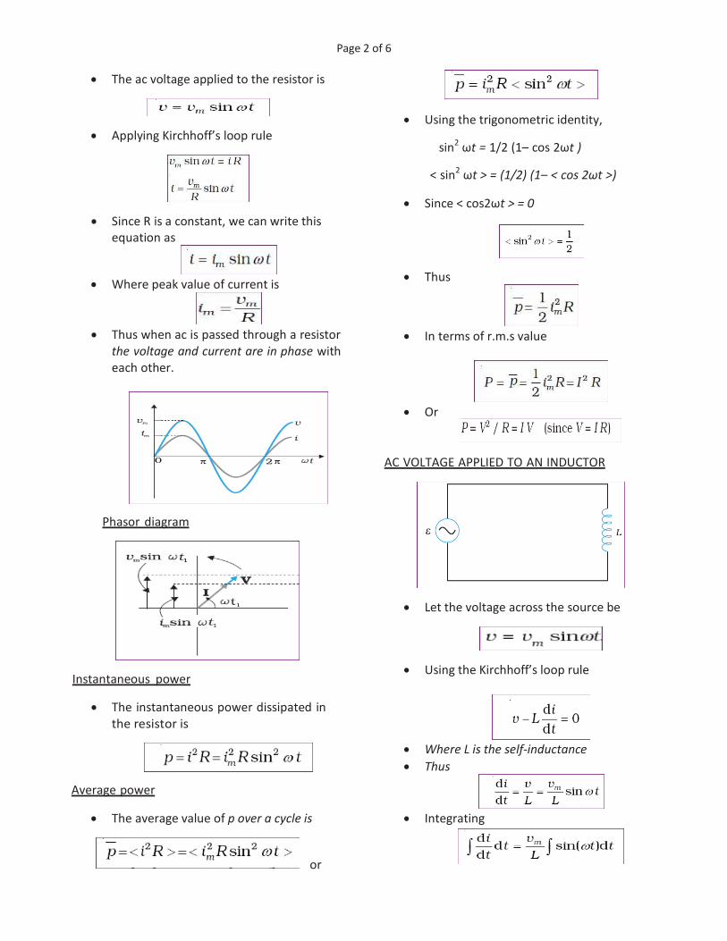
· The ac voltage applied to the resistor is
· Applying Kirchhoff’s loop rule
· Since R is a constant, we can write this
equation as
· Where peak value of current is
· Thus when ac is passed through a resistor
the voltage and current are in phase with
each other.
Phasor diagram
Instantaneous power
· The instantaneous power dissipated in
the resistor is
Average power
· The average value of p over a cycle is
or
· Using the trigonometric identity,
sin2 ωt = 1/2 (1– cos 2ωt )
< sin2 ωt > = (1/2) (1– < cos 2ωt >)
· Since < cos2ωt > = 0
· Thus
· In terms of r.m.s value
· Or
AC VOLTAGE APPLIED TO AN INDUCTOR
· Let the voltage across the source be
· Using the Kirchhoff’s loop rule
· Where L is the self-inductance · Thus
· Integrating

Page 3 of 6
· Since the current is oscillating , the
constant of integration is zero. · Using
· Where
· Or
· Where XL- inductive reactance
Inductive reactance (XL)
· The resistance offered by the inductor to
an ac through it is called inductive
reactance. · It is given by
· The dimension of inductive reactance is
the same as that of resistance and its SI
unit is ohm (Ω).
· The inductive reactance is directly
proportional to the inductance and to the
frequency of the current.
Phasor Diagram
· We have the source voltage
· The current
· Thus a comparison of equations for the
source voltage and the current in an
inductor shows that the current lags the
voltage by π/2 or one-quarter (1/4) cycle.
Instantaneous power
· The instantaneous power supplied to the
inductor is
Average power
· The average power over a complete cycle
in an inductor is
· since the average of sin (2ωt) over a
complete cycle is zero.
· Thus, the average power supplied to an
inductor over one complete cycle is zero.

Page 4 of 6
AC VOLTAGE APPLIED TO A CAPACITOR
· A capacitor in a dc circuit will limit or
oppose the current as it charges. · When the capacitor is connected to an ac
source, it limits or regulates the current,
but does not completely prevent the flow
of charge. · Let the applied voltage be
· The instantaneous voltage v across the
capacitor is
· Where q is the charge on the capacitor.
· Using the Kirchhoff’s loop rule
· Therefore
· Using the relation
· Where
· Or
· Where XC – capacitive reactance
Capacitive Reactance
· It is the resistance offered by the
capacitor to an ac current through it. · The dimension of capacitive reactance is
the same as that of resistance and its SI
unit is ohm (Ω).
Phasor Diagram
· The applied voltage is
· The current is
· Thus the current leads voltage by π/2.
Instantaneous power
· The instantaneous power supplied to the
capacitor is
Average power
· The average power is given by

Page 5 of 6
· Thus the average power over a cycle
when an ac passed through a
capacitor is zero. TRANSFORMER
· It is a device used to change alternating
voltage.
· It works using the principle of mutual
induction.
· Works only in ac
Construction
· A transformer consists of two sets of coils,
insulated from each other.
· They are wound on a soft-iron core, either
one on top of the other.
· One of the coils called the primary coil has
Np turns.
· The other coil is called the secondary coil; it
has Ns turns.
· The primary coil is the input coil and the
secondary coil is the output coil of the
transformer.
Theory / Transformer Equation
· Let φ be the flux in each turn in the core at
time t due to current in the primary when a
voltage v p is applied to it.
· The induced emf or voltage ε s in the
secondary with N s turns is
· The alternating flux φ also induces an emf,
called back emf in the primary.
· Assuming
and
· Therefore
· Thus
· For an ideal transformer input power and out put
power are equal, therefore
· Thus
· This is the transformer equation.
Types of Transformers
Step-up transformer
· We have
· Thus, if the secondary coil has a greater number
of turns than the primary (NS > NP), the
voltage is stepped up (VS > VP). This type of
arrangement is called a step-up transformer.
· In step up transformer, there is less current in
the secondary than in the primary ( IS < IP )
Step-down transformer
· In a step-down transformer the secondary coil
has less turns than the primary (NS< NP).
· Here VS < VP and IS > IP. That is, the voltage is
stepped down, or reduced, and the current is
increased.

Page 6 of 6
Working
· When an alternating voltage is applied to
the primary, the resulting current produces
an alternating magnetic flux which links the
secondary and induces an emf in it.
· The value of the emf depends on the
number of turns in the secondary.
Efficiency of a transformer
· The efficiency of a transformer is given by
Energy loss in transformers
Copper Loss
· As the current flows through the primary
and secondary copper wires, electric energy
is wasted in the form of heat.
· This is minimised by using thick wire.
Eddy current Loss (Iron Loss)
· The eddy currents produced in the soft iron
core of the transformer produce heating.
· Thus electric energy is wasted in the form
of heat.
· The effect is reduced by having a laminated
core.
Magnetic flux leakage
· The entire magnetic flux produced by the
primary coil may not be available to the
secondary coil.
· Thus some energy is wasted.
· It can be reduced by winding the primary
and secondary coils one over the other.
Hysteresis Loss
· Since the soft iron core is subjected to
continuous cycles of magnetization, the
core gets heated due to hysteresis.
· Minimised by using a magnetic material which
has a low hysteresis loss.
Uses of a transformer
· The large scale transmission and distribution of
electrical energy over long distances is done with
the use of transformers.
· The voltage output of the generator is stepped-
up .It is then transmitted over long distances to
an area sub-station near the consumers. There
the voltage is stepped down.
· It is further stepped down at distributing sub-
stations and utility poles before a power supply
of 240 V reaches our homes.
******


Page 1 of 4
CHAPTER 8
ELECTROMAGNETIC WAVES
( Prepared By Ayyappan C, HSST Physics, GMRHSS
, Kasaragod, Mob: 9961985448 )
INTRODUCTION
• Electromagnetic waves are one of the
predictions of Maxwell’s equations.
• Electromagnetic waves are time varying
electric and magnetic fields that
propagate in space.
• Hertz experimentally confirmed the
existence of electromagnetic waves with
the help of spark gap oscillator.
• J C Bose produced electromagnetic
waves of smaller wavelength (5mm-
25mm).
• Marconi discovered that electromagnetic
wave can radiate up to several kilometers.
DISPLACEMENT CURRENT
· From Maxwell’s correction to Ampere’s
circuital law , the total current i is the sum
of the conduction current denoted by ic,
and the displacement current denoted by
id.
· The current due to changing electric field
(or electric displacement) is called
displacement current or Maxwell’s
displacement current.
· The current carried by conductors due to
flow of charges is called conduction
current.
· Thus the generalized Ampere’s circuital
law (Ampere-Maxwell law ) is given by
Nature of electromagnetic waves
· An electric charge oscillating with a
frequency produces em waves of the
same frequency.
• The electric and magnetic fields in an
electromagnetic wave are perpendicular
to each other, and to the direction of
propagation.
· The electric and magnetic fields are
represented by
• Here k is related to the wave length λ of
the wave by the equation,
• The speed of propagation of the wave is
(ω/k ).
• The magnitude of the electric and the
magnetic fields in an electromagnetic
wave are related as
· Pressure exerted by em wave is called
radiation pressure
Properties of EM waves
• They are self-sustaining oscillations of
electric and magnetic fields in free space,
or vacuum.
• Shows transverse wave nature.
• No material medium is needed for its
propagation.
• EM waves are not deflected in electric
field and magnetic field.
• The velocity of em waves in any media is
given by
· EM waves are polarised.

Page 2 of 4
· Electromagnetic waves carry energy and
momentum like other waves.
· If the total energy transferred to a surface
in time t is U, the magnitude of the total
momentum delivered to this surface (for
complete absorption) is,
ELECTROMAGNETIC SPECTRUM
· An arrangement of electromagnetic
radiations according to their wavelength
or frequency.
· Some of the waves in the increasing order
of frequency (decreasing order of
wavelength) are :
Radio waves, microwaves, infra-
red, visible light, ultra violet, x-rays,
Gamma rays
Radio waves
• Radio waves are produced by the
accelerated motion of charges in
conducting wires.
• They are used in radio and television
communication systems.
• They are generally in the frequency range
from 500 kHz to about 1000 MHz.
• The AM (amplitude modulated) band is
from 530 kHz to 1710 kHz.
• Higher frequencies up to 54 MHz are used
for short wave bands. TV waves range
from 54 MHz to 890 MHz.
• The FM (frequency modulated) radio
band extends from 88 MHz to 108 MHz.
• Cellular phones use radio waves to
transmit voice communication in the
ultrahigh frequency (UHF) band.
Microwaves
• Microwaves are produced by special
vacuum tubes such as klystrons,
magnetrons and Gunn diodes.
• Microwaves are used for the radar
systems used in aircraft navigation. Radar
also provides the basis for the speed guns
used to time fast balls, tennis serves, and
automobiles.
• Used in Microwave ovens.
• In such ovens, the frequency of the
microwaves is selected to match the
resonant frequency of water molecules so
that energy from the waves is transferred
efficiently to the kinetic energy of the
molecules. This raises the temperature of
any food containing water.
• Also used in satellite communication.
Infrared waves
• Infrared waves are produced by hot
bodies and molecules.
• Infrared waves are referred to as heat
waves. This is because water molecules
present in most materials readily absorb
infrared waves (many other molecules, for
example, CO2, NH3, also absorb infrared
waves). After absorption, their thermal
motion increases, that is, they heat up
and heat their surroundings.

Page 3 of 4
• Infrared radiation plays an role in
maintaining the earth’s warmth or
average temperature through the
greenhouse effect.
• Incoming visible light is absorbed by the
earth’s surface and reradiated as infrared
radiations. This radiation is trapped by
greenhouse gases such as carbon dioxide
and water vapour.
• Infrared detectors are used in Earth
satellites, both for military purposes and
to observe growth of crops.
• Electronic devices (for example
semiconductor light emitting diodes) also
emit infrared and are widely used in the
remote switches of household electronic
systems such as TV sets, video recorders
and hi-fi systems.
• Used in secret signaling and burglar
alarms.
• Used in the treatment of dislocations,
paralysis etc.
• Used to take the photographs of distant
objects.
• Used in physiotherapy
• Used for determination of molecular
structure.
Visible rays
• It is the part of the spectrum that is
detected by the human eye.
• It runs from about a wavelength range of
about 700 – 400 nm.
• Visible light emitted or reflected from
objects around us provides us information
about the world. Our eyes are sensitive to
this range of wavelengths.
• Different animals are sensitive to different
range of wavelengths. For example,
snakes can detect infrared waves, and the
‘visible’ range of many insects extends
well into the ultraviolet.
Ultraviolet rays
• Ultraviolet (UV) radiation is produced by
special lamps and very hot bodies
• The sun is an important source of
ultraviolet light. But most of it is absorbed
in the ozone layer in the atmosphere at an
altitude of about 40 – 50 km.
• UV light in large quantities has harmful
effects on humans. Exposure to UV
radiation induces the production of more
melanin, causing tanning of the skin.
• UV radiation is absorbed by ordinary
glass. Hence, one cannot get tanned or
sunburn through glass windows.
• Welders wear special glass goggles or face
masks with glass windows to protect their
eyes from large amount of UV produced
by welding arcs.
• Due to its shorter wavelengths, UV
radiations can be focused into very
narrow beams for high precision
applications such as LASIK (Laser assisted
in situ keratomileusis) eye surgery.
• UV lamps are used to kill germs in water
purifiers.
• Ozone layer in the atmosphere plays a
protective role.
• Used in the manufacture of fluorescent
tubes
• Used in the determination of age of
written documents
• Used in the detection of finger prints.
• Helps to produce vitamin D in our skin.
X-rays
• Beyond the UV region of the
electromagnetic spectrum lies the X-ray
region.
• W Roentgen discovered x-rays
• One common way to generate X-rays is to
bombard a metal target by high energy
electrons.
• X-rays are used as a diagnostic tool in
medicine and as a treatment for certain
forms of cancer.
• Because X-rays damage or destroy living
tissues and organisms, care must be taken
to avoid unnecessary or over exposure.

Page 4 of 4
• Used to study structure of atoms
molecules and crystals
• Used to detect cracks and holes inside a
sheet of metal.
• Used to detect hidden materials.
Gamma rays
• They lie in the upper frequency range of
the electromagnetic spectrum.
• This high frequency radiation is produced
in nuclear reactions and also emitted by
radioactive nuclei.
• They are used in medicine to destroy
cancer cells.
• Used to study structure of nuclei of atom.
• Used to sterilize surgical Instruments,
• Used to detect cracks in underground
metal pipes etc
Production and detection of em waves
*********

Page 1 of 9
CHAPTER 9
RAY OPTICS AND OPTICAL INSTRUMENTS
(Prepared By Ayyappan C, HSST Physics, GMRHSS , Kasaragod, Mob: 9961985448)
REFLECTION OF LIGHT
• When light is incident on a surface, it
partially reflected back, partly absorbed
by the surface and remaining is
transmitted through the surface.
• Mirrors are used to reflect light efficiently.
Ray of Light
• The path along which a light wave travels
is called ray of light.
Beam of Light
• A bundle of ray of light is called beam of
light.
Angle of incidence
• The angle between the incident ray and
the normal is the angle of incidence.
Angle of reflection
• The angle between the reflected ray and
the normal is the angle of reflection
Spherical Mirrors
• The portion of a reflecting surface, which
forms a part of a sphere, is called a
spherical mirror.
• Concave mirror – reflecting surface
towards the centre of the sphere
• Convex mirror – reflecting surface away
from the centre of the sphere.
Some definitions
Centre of curvature (C)
• The centre of the sphere of which the
mirror forms a part.
Radius of curvature (R)
• The radius of the sphere of which the
mirror forms a part.
Pole
• The geometric centre of a spherical mirror
is called its pole.
Principal Axis
• The line joining the pole and centre of
curvature.
Aperture
• The diameter of the mirror.
Principal Focus
• The point at which, a narrow beam of light
incident on the mirror parallel to its
principal axis , after reflection from the
mirror , meets or appears to come from.
Focal length
• The distance between pole and principal
focus.
Spherical aberration
• The inability of a spherical mirror of large
aperture to focus the marginal rays and
central rays at a single point is called
spherical aberration
Cartesian Sign Convention
• According to this convention, all distances
are measured from the pole of the mirror
or the optical centre of the lens.
• The distances measured in the same
direction as the incident light are taken as
positive and those measured in the
direction opposite to the direction of
incident light are taken as negative .
• The heights measured upwards with
respect to x-axis and normal to the
principal axis (x-axis) of the mirror/ lens
are taken as positive).
• The heights measured downwards are
taken as negative.

Page 2 of 9
Reflection of light by spherical mirrors
Concave mirror
Covex Mirror
Relation between focal length and radius of
curvature of a spherical mirror
• Consider a ray parallel to the principal axis
striking the mirror at M.
• Thus from the diagram
• For small θ, tan θ ≈ θ, tan 2θ ≈ 2θ.
• For small θ, the point D is very close to the
point P.
• Therefore, FD = f and CD = R.
Some conventions to draw a ray diagram
• The ray from the point which is parallel to
the principal axis. The reflected ray goes
through the focus of the mirror.
• The ray passing through the centre of
curvature of a concave mirror or
appearing to pass through it for a convex
mirror. The reflected ray simply retraces
the path.
• The ray passing through (or directed
towards) the focus of the concave mirror
or appearing to pass through (or directed
towards) the focus of a convex mirror. The
reflected ray is parallel to the principal
axis.
• The ray incident at any angle at the pole.
The reflected ray follows laws of
reflection.
The mirror equation
• The relation connecting the object
distance (u), image distance (v) and the
focal length ( f) is the mirror equation.
Derivation
• In the diagram the two right-angled
triangles AʹBʹF and MPF are similar.

Page 3 of 9
• Therefore,
• Since APB = AʹPBʹ, the right angled
triangles AʹBʹP and ABP are also similar.
• Therefore,
• Comparing Equations :
• Using sign conventions
• We get
• Therefore the mirror equation is given by
• The same equation can be derived for a
convex mirror too.
Linear Magnification
• Linear magnification (m) is the ratio of the
height of the image (hʹ) to the height of
the object (h).
• In triangles AʹBʹP and ABP, we have,
• With the sign convention, this becomes
• Therefore the linear magnification is given
by
vm
u= -
• The expression for magnification is same
for concave and convex mirror.
Significance of magnification ‘m’
• When ‘m’ is positive, the image is erect
(virtual)
• When ‘m’ is negative, the image is
inverted (real)
• For enlarged image, m>1
• For diminished image, m<1
Uses of spherical mirrors
Concave mirrors
• Used as reflectors of table lamps to direct
light in a given area.
• Concave mirrors of large aperture are
used in reflecting type astronomical
telescopes.
• Shaving mirrors are made slightly concave
to get erect enlarged image of the face.
Convex mirrors
• They are used in automobiles as rear view
mirrors because of the two reasons:
• A convex mirror always produces an erect
image.
• The image is diminished in size, so that it
gives a wide field of view.
Nature of the image formed by a Concave mirror

Page 4 of 9
Nature of the image formed by a Convex mirror
• A convex mirror always forms a virtual
and diminished image irrespective of the
position of the object
REFRACTION OF LIGHT
• The phenomenon of change in path of
light as it goes from one medium to
another is called refraction.
Laws of Refraction
• The incident ray, the refracted ray and the
normal to the interface at the point of
incidence, all lie in the same plane.
Snell’s law:-
• The ratio of the sine of the angle of
incidence to the sine of angle of refraction
is constant.
• Now
• Where n21 is a constant, called the
refractive index of the second medium
with respect to the first medium.
221
1
nn
n=
• Where n1- absolute refractive index of the
first medium and n2 – absolute refractive
index of the second medium.
Refractive index
• The refractive index of a medium depends
on
• Nature of the pair of medium
• Wavelength of light
• Refractive index is independent of the
angle of incidence.
• A medium having larger value of
refractive index is called optically denser
medium.
• A medium having smaller value of
refractive index is called optically rarer
medium.
• Also
• Where 112
2
nn
n=
• If n32 is the refractive index of medium 3
with respect to medium 2 then
n32 = n31 × n 12 • Where n31 is the refractive index of
medium 3 with respect to medium 1.
Absolute refractive index
• The ratio of velocity of light in vacuum to
the velocity of light in a medium is called
absolute refractive index.
cn
v=
• Where C - velocity of light in vacuum,
v- velocity of light in the medium.
• When light enters from a rarer medium
to denser medium, the refracted ray
bends towards the normal.
• When light enters from a denser medium
to rarer medium, the refracted ray bends
away from the normal.

Page 5 of 9
Refraction through a glass slab - Lateral shift
• For a rectangular slab, refraction takes
place at two interfaces (air-glass and
glass-air).
• When a light ray enters a glass slab it
undergoes lateral displacement/ shift with
respect to the incident ray.
• The perpendicular distance between the
incident ray and the emergent ray, when
the light is incident obliquely on a parallel
sided refracting slab is called lateral shift.
Applications of refraction
Apparent depth
• If an object in a denser medium is viewed
from a rarer medium the image appears
to be raised towards the surface.
• The bottom of a tank filled with water
appears to be raised due to refraction.
• For viewing near the normal direction
Apparent position of sun
• The sun is visible a little before the actual
sunrise and until a little after the actual
sunset due to refraction of light through
the atmosphere.
• Time difference between actual sunset
and apparent sunset is about 2 minutes.
• As we go up, the density of air in the
atmosphere continuously decreases, and
thus the light coming from the sun
undergoes refraction.
• Thus we see the sun at an apparent
position raised above the horizon.
• This is the reason for early sunrise and
delayed sunset.
Twinkling of stars
• The light rays coming from the sun
undergo refraction and hence the star is
viewed at the apparent position.
• As the density of air in the atmosphere
continuously changes, the apparent
position also changes continuously.
• Thus the star appears to be twinkling.
REFRACTION AT SPHERICAL SURFACES
Expression for refraction at a convex surface
• For small angles , tan θ ≈ θ, thus

Page 6 of 9
• From triangle OMP ,
• From triangle PCM,
• From triangle PMI,
• From triangle OMC,
Exterior angle = sum of interior angles
• Thus
• From triangle IMC
• By Snell’s law
• If I and r are small,
• Substituting for I and r,
• Or
• Thus
• Therefore
• By Cartesian sign convention
PO = -u , PI = v , PC =R
• Thus equation(3) becomes
• This is the equation of refraction at
convex surface.
Refraction by a lens - Lens maker’s formula
· The image formation has two steps:
· The first refracting surface forms the
image I1 of the object O.
· The image formed by the first refracting
surface acts as the virtual object for the
second refracting surface and the final
image is formed at I.
· We have the curved surface formula
For refraction at the surface ABC
· Light ray travels from n1 to n2 and O is the
object and I1 is the image.
· And
· Here R1 is the radius of curvature of ABC.

Page 7 of 9
· Thus
For refraction at the surface ADC
· Light ray travels from n2 to n1.
· Here I1 is the object and I is the image and
· Here R2 is the radius of curvature of ADC
· Adding equation 1 and 2, we get
· Dividing by n1
· If the object is at infinity, the image is
formed at the principal focus.
· Thus if u=∞, v=f, equation 4 becomes
· Thus the lens maker’s formula is given by
Thin lens formula
· We have from eqn 4,
· And the lens maker’s formula
· If the first medium is air n1 = 1 and ,let
n2=n, then
· Thus
· Therefore
· This equation is the thin lens formula.
· The formula is valid for both convex as
well as concave lenses and for both real
and virtual images.
Linear magnification of a lens
• Magnification (m) produced by a lens is
defined, as the ratio of the size of the
image to that of the object.
· The value of m is negative for real images
and positive for virtual images.
Power of a lens
· Power of a lens is the reciprocal of focal
length expressed in metre.
· Power of a lens is a measure of the
convergence or divergence, which a lens
introduces in the light falling on it.
• The SI unit for power of a lens is dioptre
(D).

Page 8 of 9
• Power of a lens is positive for a
converging lens and negative for a
diverging lens.
Combination of thin lenses in contact
· For the first lens, object is at O and image
is at I1.
· Thus
· For the second lens object is I1 and image
is at I.
· Therefore
· Adding Equations
· If the two lens-system is regarded as
equivalent to a single lens of focal length
f, we have
· Therefore
· If several thin lenses of focal length f1, f2,
f3,... are in contact, the effective focal
length of their combination is given by
· Thus the power is given by
• The total magnification
REFRACTION THROUGH A PRISM
Angle of deviation, (d)
• The angle between the emergent ray RS
and the direction of the incident ray PQ is
called the angle of deviation, δ.
Angle of minimum deviation (D)
• The angle of deviation for which the
refracted ray inside the prism becomes
parallel to its base is called angle of
minimum deviation.
Prism Formula ( Eqn. for refractive index)
• In the quadrilateral AQNR, two of the
angles (at the vertices Q and R) are right
angles.
• Therefore, the sum of the other angles of
the quadrilateral is 1800.
• From the triangle QNR
• Comparing these two equations

Page 9 of 9
• We know ,exterior angle = sum of interior
angles, thus
d = (i - r1) + (e - r2) • That is
d = (i + e - A) • Thus, the angle of deviation depends on
the angle of incidence.
• At the minimum deviation, d=D, i=e,
r1=r2, therefore
• Thus using Snell’s law, the refractive index
of the prism is given by
21
( )sin
2
sin2
A D
nA
+
=
Prism formula for a small angled prism
• For a small angled prism
21
( )
2
2
A D
nA
+
=
• Therefore
21( 1)D n A= -
i-d curve
• It is the plot between the angle of
deviation and angle of incidence.
DISPERSION BY A PRISM
• The phenomenon of splitting of light into
its component colours is known as
dispersion.
• The pattern of colour components of light
is called the spectrum of light.
• Thick lenses could be assumed as made of
many prisms, therefore, thick lenses show
chromatic aberration due to dispersion of
light.
• When white light is passed through a
prism, it splits into its seven component
colors (VIBGYOR).
• If we place a second prism in an inverted
position, close to the first prism, the
second prism recombines the colors and
we get white light.
Cause of dispersion
• Dispersion takes place because the
refractive index of medium for different
wavelengths (colors) is different.
Dispersive medium
• The medium in which the different
colours of light travel with different
velocities is called a dispersive medium.
• Eg :- Glass
Non-Dispersive medium
• The medium in which all colours travel
with the same speed is called non-
dispersive medium.
Eg:- vacuum
Chromatic abberation
• The inability of a lens to focus all
wavelength to a single point is called
chromatic aberration.
*****

Page 1 of 4
Chapter Ten
WAVE OPTICS
(Prepared by AYYAPPAN C, HSST, GMRHSS KASARAGOD)
Wavefront
· A wavefront is locus of all points in a
medium which are at the same phase of
vibration.
· The speed with which the wavefront
moves outwards from the source is called
the speed of the wave.
· The energy of the wave travels in a
direction perpendicular to the wavefront.
Types of wavefront
· Spherical wavefront – wavefront from a
point source
· Cylindrical wavefront- wavefront from a
linear source.
· Plane wavefront : - wavefront at large
distances from a point source.
Huygen’s Principle
· According to Huygens principle, each
point of the wavefront is the source of a
secondary disturbance and the wavelets
(secondary wavelets) emanating from
these points spread out in all directions
with the speed of the wave.
· By drawing a common tangent to all these
spheres, we obtain the new position of the
wavefront at a later time.
• Huygens argued that the amplitude of the
secondary wavelets is maximum in the
forward direction and zero in the
backward direction
Refraction of a plane wave
• Let τ be the time taken by the wavefront
to travel the distance BC.
• Thus
• From the triangle ABC we get
• Also from triangle AEC
• Thus
• If c represents the speed of light in
vacuum, then,
• Therefore
• This is the Snell’s law of refraction.
• If λ1 and λ 2 denote the wavelengths of
light in medium 1 and medium 2,
respectively, then

Page 2 of 4
• That is
• This implies that when a wave gets
refracted into a denser medium, the
wavelength and the speed of
propagation decrease but the frequency
ν (=v/λ) remains the same.
Refraction at a rarer medium
• The angle of refraction will be greater
than angle of incidence.
• Thus, if i = ic then sin r = 1 and r = 90°.
• Therefore
• The angle ic is known as the critical angle
and for all angles of incidence greater
than the critical angle the wave will
undergo total internal reflection.
Reflection of a plane wave by a plane surface
• If v represents the speed of the wave in
the medium and if τ represents the time
taken by the wavefront to advance from
the point B to C then
• Also
• The triangles EAC and BAC are congruent
• Therefore the angles i and r would be
equal. This is the law of reflection.
A plane wave passing through a thin prism.
A plane wave incident on a thin convex lens
A plane wave is incident on a concave mirror
The Doppler effect
• The apparent change in frequency of light
seen by an observer ,whenever there is a
relative motion between source and
observer is called Doppler Effect.
• When the source is moving towards the
observer with a velocity v, then the
apparent frequency of light
' (1 )v
cn n= +
· Where ν- actual frequency, v – velocity
· Therefore the fractional change in
frequency
v
c
nnD
=
• If the source is moving away from the
observer, the apparent frequency
' (1 )v
cn n= -
• Hence the fractional change in frequency
is

Page 3 of 4
v
c
nnD
= -
Red shift
· When the source moves away from the
observer, there is an apparent decrease in
the frequency of light. This is called red
shift.
Blue shift
· When the source moves towards the
observer, there is an apparent increase in
the frequency of observed light. This is
called blue shift.
POLARISATION
• When ordinary light passes through
certain crystals like tourmaline crystal, the
vibrations of electric field vector are
restricted. This phenomenon is called
polarization.
• Polarization shows that light is a
transverse wave.
• Sound waves cannot polarize.
Unpolarised light
• The ordinary light which contains the
vibrations of electric field vector in every
plane perpendicular to the direction of
propagation is called unpolarised light.
Representation of unpolarised light
Plane polarized light
• The polarized light in which the electric
field vibrations of light are confined to a
single plane are called plane polarised
light.
Representation of plane polarised light
Plane of vibration
• It is the plane in which the vibrations of
the polarized light take place.
Plane of polarization
• It is the plane perpendicular to the plane
of vibration of the plane polarized light.
Polarizer
• The crystal which produces polarized light
is called a polarizer.
Analyzer
• The crystal which is used to check
whether the light is polarized or not is
called analyzer or detector.
An experiment to study polarization of light
• When unpolarized light passes through
polarizer the light coming out of it is plane
polarized.
• If the polarizer and analyser are parallel
the intensity of light coming through the
analyser will be maximum.
• If the analyser is rotated through 900
the
intensity of light coming out of it becomes
zero.
Polaroids
• Polaroid is an artificially made polarising
material that produce intense beam of
polarised light by selective absorption.
• Polaroids are in sunglasses,
windowpanes, photographic cameras, 3D
movie cameras etc.
Malus’ law
• Malus’s law states that when a beam of
plane polarised light is incident on the
analyser, then the intensity of the
emergent light is directly proportional to
square of the cosine of the angle between
the polariser and analyser.

Page 4 of 4
• Where θ is the angle between the axes of
polarizer and analyzer.
Methods of polarization
• Polarization by scattering
• Polarisation by reflection
Polarization by scattering
• When sunlight is incident on the gas
molecules in the atmosphere, it gets
scattered.
• The scattered light seen in a direction
perpendicular to the direction of
incidence is found to be plane polarised.
This phenomenon is called polarisation by
scattering.
• When this polarised light is viewed
through a polaroid which is rotated, then
the intensity changes with rotation.
• The scattering of light by molecules was
intensively investigated by C.V. Raman
and his collaborators .Raman was
awarded the Nobel Prize for Physics in for
this work.
Polarisation by reflection
• When ordinary light falls on a surface
separating two transparent media, a part
of the light is reflected and the other part
is transmitted (refracted).
• When reflected wave is perpendicular to
the refracted wave, the reflected wave is
a totally polarised wave.
Brewster’s angle (polarizing angle)
• The angle of incidence at which the
reflected ray is totally polarized is called
Brewster’s angle and is denoted by iB.
Brewster’s law
• Brewster’s law states that the tangent of
the Brewster’s angle is equal to the
refractive index of the medium.
tan Bi m=
Proof
• From Snell’s law
Distinguishing a polarized light and
unpolarized light
• When we observe unpolarised light
(ordinary light) through a Nicol prism
(tourmaline crystal), the intensity of the
light coming out of the prism does not
change if the crystal is rotated.
• But when we observe polarized light
through a Nicol prism, the intensity of the
light coming out of the prism changes if
the crystal is rotated.
********

Page 1 of 2
Chapter Eleven
DUAL NATURE OF RADIATION AND MATTER
(Prepared by AYYAPPAN C, HSST, GMRHSS KASARAGOD)
PHOTOELECTRIC EFFECT
• The phenomenon of ejection of electrons
when light of suitable frequency falls on
it is called photoelectric effect.
• Photoelectric emission was discovered in
by Heinrich Hertz.
• In photoelectric effect the light energy is
converted to electrical energy.
• The photo (light)-generated electrons are
called photoelectrons and the current is
called photo current.
• Substances that respond to light are called
photo sensitive substances.
• Metals like zinc, cadmium, magnesium
etc respond only to ultra violet light.
• Alkali metals such as lithium, sodium,
potassium, cesium and rubidium are
sensitive to visible light.
Hallwachs’ and Lenard’s observations
• Wilhelm Hallwachs and Philipp Lenard
studied photo electric effect in detail
using an evacuated glass tube with two
zinc plates as electrodes.
Experimental set up
Observations
• When ultraviolet radiations were allowed
to fall on the emitter plate current flows
in the circuit.
• When collector plate is illuminated no
current flows.
• When the frequency of incident radiation
is less than a certain minimum value no
photo electrons emission is possible. This
minimum frequency is called threshold
frequency.
• Threshold frequency depends on the
nature of the metal.
Laws of Photoelectric emission
• The photoelectric current is directly
proportional to the intensity of incident
light and independent of the frequency.
• Kinetic energy of emitted photo
electrons depends on the frequency and
does not depend on intensity of
radiation.
• For each metal there is a threshold
frequency, below which no
photoelectron emission is possible.
• The photoelectric emission is an
instantaneous process.
EINSTEIN’S EXPLANATION OF PHOTO ELECTRIC
EFFECT
• Einstein explained photoelectric effect
based on quantum theory.
• According to quantum theory, light
contain photons having energy hν.
• When a photon of energy hν is incident on
a metal surface, electrons are emitted.
• A part of the photon energy is used as the
work function and the remaining part of
the photon energy appears as the kinetic
energy of photoelectrons.
Einstein’s photoelectric equation
• Photon Energy = Work function +
maximum K.E. of photoelectron.
• That is
0 maxh Kn f= +
• Thus
• But the work function is given by 0 0hf n= ,
where 0n is the threshold frequency.
• Therefore
max 0( )K h n n= -
• This equation is the Einstein’s photo
electric equation.

Page 2 of 2
Frequency - stopping potential graph ( for
different metals )
• We have, the photo electric equation,
• Also in terms of stopping potential
• Thus 0 0eV hn f= -
• That is 0
0
hV
e e
fn= -
• It predicts that the V0 versus ν curve is a
straight line with slope = (h/e),
independent of the nature of the material.
• Thus Planck’s constant =slope X charge of
electron.
• The y-intercept is 0
e
f- , therefore the
work function = - (y intercept) X charge of
electron.
Photoelectric cell
• Photoelectric cell is a device used to
convert light energy into electric energy
using the principle of photoelectric effect.
PARTICLE NATURE OF LIGHT:
THE PHOTON
• In interaction of radiation with matter,
radiation behaves as if it is made up of
particles called photons.
Properties of Photons
• Each photon has energy E (=hν) and
momentum p (= h ν/c), and speed c, the
speed of light.
• All photons of light of a particular
frequency ν, or wavelength λ, have the
same energy E (=hν = hc/λ) and
momentum p (= hν/c = h/λ), independent
of intensity of light.
• By increasing the intensity of light of given
wavelength, there is only an increase in
the number of photons per second
crossing a given area, with each photon
having the same energy.
• The photon energy is independent of
intensity of radiation.
• Photons are electrically neutral and are
not deflected by electric and magnetic
fields.
• In a photon-particle collision (such as
photon-electron collision), the total
energy and total momentum are
conserved.
• However, the number of photons may not
be conserved in a collision. The photon
may be absorbed or a new photon may be
created.
Dual nature of radiation
• Radiation has wave nature as well as
particle nature. This is called the dual
nature of radiation.
*****

Page 1 of 3
Chapter Twelve
ATOMS (Prepared by AYYAPPAN C, HSST, GMRHSS KASARAGOD)
Limitations of Rutherford Model
• Rutherford’s model fails to account for
the stability of the atom.
• The energy of an accelerating electron
should continuously decrease and the
electron would spiral inward and
eventually fall into the nucleus.
• Rutherford’s model does not explain the
line spectra of atoms.
BOHR MODEL OF THE HYDROGEN ATOM
• Bohr combined classical and early
quantum concepts and gave his theory in
the form of three postulates:
Postulate I
• Electrons in an atom can revolve in
certain stable orbits without radiating
energy.
• According to this postulate, each atom
has certain definite stable states in which
it can exist, and each possible state has
definite total energy.
• These are called the stationary states of
the atom
Postulate II
• The electron revolves around the
nucleus only in those orbits for which
the angular momentum is some
integral multiple of h/2π where h is
the Planck’s constant (= 6.6 × 10⁻³⁴
J
s).
• Thus the angular momentum (L) of the
orbiting electron is quantised.
• That is L = nh/2π , where n= 1,2,3
….., is the principal quantum number.
Postulate III
• An electron might make a transition from
one of its specified non-radiating orbits
to another of lower energy.
• A photon is emitted having energy equal
to the energy difference between the
initial and final states.
• The frequency of the emitted photon is
then given by
Radii of Bohr’s Stationary orbits:
• The centripetal force for the revolution of
electrons round the nucleus is provided by
the electrostatic force of attraction
between the nucleus and the electron.
• Thus
• Therefore
• From Bohr’s II postulate the angular
momentum L= mvr, is given by
• Thus
• Therefore
• That is
• The radius is given by
• In general
• Thus
• The radii of the stationary orbits are in the
ratio, 12:2
2:3
2:….. or 1: 4: 9: …..

Page 2 of 3
• The stationary orbits are not equally
spaced.
Bohr Radius
• The radius of the lowest orbit (n=1) is
called Bohr radius.
• The Bohr radius is given by
• Substituting the values we get
• Thus the radius of n
th orbit becomes:
2
0nr a n=
Velocity of electrons in an orbit
• We have
• But
• Therefore
• That is
• In general
Total energy of an orbiting electron
Kinetic energy
• For an orbiting electron , we have
• Or
• Thus the kinetic energy is given by
22
0
1
2 8
eK mv
rpe= =
Potential energy
• The electrostatic potential energy of an
orbital electron is given by 2
04
eU
rpe= -
Total energy
• Total energy is given by 2 2
0 08 4
e eE K U
r rpe pe= + = -
• That is
• But , we have
• Thus
• In general
• Substituting the values we get
Energy level diagram of hydrogen atom

Page 3 of 3
Excitation energy
• Excitation energy is the energy required
to excite an electron from its ground
state to an excited state.
• First excitation energy of hydrogen atom
required to excite the electron from n = 1
to n = 2 orbit of hydrogen atom. That is
(-3.4) –( -13.6) = 10.2 eV.
Excitation potential
• Excitation potential of an excited state is
the potential difference through which
electron in an atom has to be accelerated
so as to excite it from its ground state to
the given excited state.
• The first excitation potential of H atom is
10.2V.
Ionization energy
• Ionisation energy is the energy required to
take an electron completely out of the
atom.
• The ionization energy of hydrogen atom is
13.6 eV.
DE BROGLIE’S EXPLANATION OF BOHR’S
SECOND POSTULATE OF QUANTISATION
• Louis de Broglie argued that the electron
in its circular orbit, as proposed by Bohr,
must be seen as a particle wave.
• In analogy to waves travelling on a string,
particle waves too can lead to standing
waves under resonant conditions.
• In a string, standing waves are formed
when the total distance travelled by a
wave down the string and back is one
wavelength, two wavelengths, or any
integral number of wavelengths.
• For an electron moving in nth circular
orbit of radius rn, the total distance is the
circumference of the orbit, 2πrn.
• But we have λ = h/p,
• This is the quantum condition proposed
by Bohr for the angular momentum of the
electron
Limitations of Bohr Model
• Bohr’s theory is applicable only to single
electron atoms.
• This theory gives no idea about relative
intensities of spectral lines.
• Could not explain the fine structure of
hydrogen spectrum.
****

Page 1 of 5
Chapter Thirteen
NUCLEI (Prepared by AYYAPPAN C, HSST, GMRHSS KASARAGOD)
RADIOACTIVITY
• H. Becquerel discovered radioactivity in
1896.
• Radioactivity is a nuclear phenomenon in
which an unstable nucleus undergoes a
decay.This is referred to as radioactive
decay.
• Three types of radioactive decay occur in
nature :
• α-decay in which a helium nucleus (He) is
emitted;
• β-decay in which electrons or positrons
(particles with the same mass as
electrons, but with a charge exactly
opposite to that of electron) are emitted;
• γ-decay in which high energy (hundreds of
keV or more) photons are emitted.
Law of radioactive decay
• This law states that the number of nuclei
undergoing the decay per unit time is
proportional to the total number of
nuclei in the sample.
• If a sample contains N undecayed nuclei
and let dN nuclei disintegrate in dt
second, thus the rate of disintegration
dN
Ndta -
• The negative sign shows that the number
of nuclei decreases with time.
• Thus
• Where λ is called the radioactive decay
constant or disintegration constant.
• Now, integrating both sides of the above
equation, we get
• Here N0 is the number of radioactive
nuclei in the sample at some arbitrary
time t0 and N is the number of radioactive
nuclei at any subsequent time t.
• Setting t0 = 0
• Thus N = No e- λt
Decay Rate
• It gives the number of nuclei decaying per
unit time
• Here R0 is the radioactive decay rate at
time t = 0, and R is the rate at any
subsequent time t.
• Thus
• The total decay rate R of a sample of one
or more radionuclide’s is called the
activity of that sample.
• The SI unit for activity is becquerel,
named after the discoverer of
radioactivity.
• 1 becquerel = 1Bq = 1 decay per second
• An older unit, the curie, is still in common
use.
Half life period (T1/2)
• It is the time in which the number of
undecayed nuclei falls into half of its
original number.
• Thus it is the time at which both N and R
have been reduced to one-half their initial
values.

Page 2 of 5
Mean life (τ)
· It is the average life of all the nuclei in a
radioactive sample.
· Mean life = total life time of all nuclei /
total number of nuclei present initially
1t
l=
· The number of nuclei which decay in the
time interval t to t + Δt is
• Each of them has lived for time t. Thus the
total life of all these nuclei would be
• Therefore mean life is given by
Alpha decay
• When a nucleus undergoes alpha-decay, it
transforms to a different nucleus by
emitting an alpha-particle (a helium
nucleus)
• The difference between the initial mass
energy and the final mass energy of the
decay products is called the Q value of the
process or the disintegration energy.
• This energy is shared by the daughter
nucleus and the alpha particle,in the form
of kinetic energy
• Alpha-decay obeys the radioactive law
• Alpha particles are positively charged
particles
• Can be deflected by electric and magnetic
fields.
• Can affect photographic plates.
Beta decay
• A nucleus that decays spontaneously by
emitting an electron or a positron is said
to undergo beta decay.
• In beta-minus decay, a neutron
transforms into a proton within the
nucleus according to
· Where ν is the antineutrino
• In beta minus (β −) decay, an electron is
emitted by the nucleus.
• Eg:
• When β –
particles are emitted, the atomic
number increases by one.
• In beta-plus decay, a proton transforms
into neutron (inside the nucleus)
• Where ν is the neutrino
• In beta plus (β+ ) decay, a positron is
emitted by the nucleus,
• Eg:
• When β+ particles are emitted the atomic
number decreases by one.
Neutrinos and Antineutrinos
• The particles which are emitted from the
nucleus along with the electron or
positron during the decay process.

Page 3 of 5
• Neutrinos interact only very weakly with
matter; they can even penetrate the earth
without being absorbed.
Gamma decay
• There are energy levels in a nucleus, just
like there are energy levels in atoms.
• When a nucleus is in an excited state, it
can make a transition to a lower energy
state by the emission of electromagnetic
radiation.
• As the energy differences between levels
in a nucleus are of the order of MeV, the
photons emitted by the nuclei have MeV
energies and are called gamma rays.
• Most radionuclides after an alpha decay
or a beta decay leave the daughter
nucleus in an excited state.
• The daughter nucleus reaches the ground
state by a single transition or sometimes
by successive transitions by emitting one
or more gamma rays.
NUCLEAR ENERGY
• In conventional energy sources like coal or
petroleum, energy is released through
chemical reactions.
• One kilogram of coal on burning gives 107
J of energy, whereas 1 kg of uranium,
which undergoes fission, will generate on
fission 1014
J of energy.
Nuclear Fission
• Enrico Fermi found that when neutrons
bombard various elements, new
radioactive elements are produced.
• Eg:
• The fragment nuclei produced in fission
are highly neutron-rich and unstable.
• They are radioactive and emit beta
particles in succession until each reaches
a stable end product.
• The energy released (the Q value ) in the
fission reaction of nuclei like uranium is
of the order of 200 MeV per fissioning
nucleus.
• The disintegration energy in fission events
first appears as the kinetic energy of the
fragments and neutrons.
• Eventually it is transferred to the
surrounding matter appearing as heat.
• The source of energy in nuclear reactors,
which produce electricity, is nuclear
fission.
• The enormous energy released in an
atom bomb comes from uncontrolled
nuclear fission.
Nuclear reactor
• Neutrons liberated in fission of a uranium
nucleus were so energetic that they would
escape instead of triggering another
fission reaction.

Page 4 of 5
• Slow neutrons have a much higher
intrinsic probability of inducing fission in U
(235) than fast neutrons.
• The average energy of a neutron
produced in fission of U (235) is 2 MeV.
• In reactors, light nuclei called moderators
are provided along with the fissionable
nuclei for slowing down fast neutrons.
• The moderators commonly used are
water, heavy water (D2O) and graphite.
• The Apsara reactor at the Bhabha Atomic
Research Centre (BARC), Mumbai, uses
water as moderator.
• The other Indian reactors, which are used
for power production, use heavy water as
moderator.
Multiplication factor
• It is the ratio of number of fission
produced by a given generation of
neutrons to the number of fission of the
preceding generation.
• It is the measure of the growth rate of the
neutrons in the reactor.
• For K = 1, the operation of the reactor is
said to be critical, which is what we wish it
to be for steady power operation.
• If K becomes greater than one, the
reaction rate and the reactor power
increases exponentially.
• Unless the factor K is brought down very
close to unity, the reactor will become
supercritical and can even explode.
• The explosion of the Chernobyl reactor in
Ukraine in 1986 is a sad reminder that
accidents in a nuclear reactor can be
catastrophic.
• The reaction rate is controlled through
control-rods made out of neutron-
absorbing material such as cadmium.
• In addition to control rods, reactors are
provided with safety rods which, when
required, can be inserted into the reactor
and K can be reduced rapidly to less than
unity.
• The abundant U(238) isotope, which does
not fission, on capturing a neutron leads
to the formation of plutonium.
• Plutonium is highly radioactive and can
also undergo fission under bombardment
by slow neutrons
Pressurized-water reactor
• In such a reactor, water is used both as
the moderator and as the heat transfer
medium
• In the primary-loop, water is circulated
through the reactor vessel and transfers
energy at high temperature and pressure
(at about 600 K and 150 atm) to the steam
generator, which is part of the secondary-
loop.
• In the steam generator, evaporation
provides high-pressure steam to operate
the turbine that drives the electric
generator.
• The low-pressure steam from the turbine
is cooled and condensed to water and
forced back into the steam generator.
• A kilogram of U(235) on complete fission
generates about 3 × 10⁴ MW.
• in nuclear reactions highly radioactive
elements are continuously produced.
• Therefore, an unavoidable feature of
reactor operation is the accumulation of
radioactive waste, including both fission
products and heavy transuranic elements
such as plutonium and americium.
Nuclear fusion

Page 5 of 5
• Energy can be released if two light nuclei
combine to form a single larger nucleus, a
process called nuclear fusion.
• The fusion reaction in the sun is a multi-
step process in which hydrogen is burned
into helium, hydrogen being the ‘fuel’ and
helium the ‘ashes’.
• The proton-proton (p, p) cycle by which
this occurs is represented by the
following sets of reactions:.
• The combined reaction is
• In sun it has been going on for about 5 ×
109 y, and calculations show that there is
enough hydrogen to keep the sun going
for about the same time into the future.
• In about 5 billion years, however, the
sun’s core, which by that time will be
largely helium, will begin to cool and the
sun will start to collapse under its own
gravity.
• This will raise the core temperature and
cause the outer envelope to expand,
turning the sun into what is called a red
giant.
• If the core temperature increases to 108
K
again, energy can be produced through
fusion once more – this time by burning
helium to make carbon.
Controlled thermonuclear fusion
• The first thermonuclear reaction on earth
occurred at Eniwetok Atoll on November
1, 1952, when USA exploded a fusion
device, generating energy equivalent to
10 million tons of TNT (one ton of TNT on
explosion releases 2.6 × 10’22 MeV of
energy).
• A sustained and controllable source of
fusion power is considerably more difficult
to achieve.
*****

Page 1 of 3
Chapter 14
SEMICONDUCTOR ELECTRONICS
(Prepared By: Ayyappan C, HSST Physics, GMRHSS, Kasaragod)
p-n JUNCTION
· A junction formed when a p-type
semiconductor and n-type conductor are
brought together is called a p-n junction.
SEMICONDUCTOR DIODE (p-n junction Diode)
• A semiconductor diode is a p-n junction
with metallic contacts provided at the
ends for the application of an external
voltage.
• It is a two terminal device.
Symbol
· The barrier voltage of a Ge diode is 0.2V
and that of a Si diode is 0.7V.
p-n junction diode under forward bias
• In forward biasing the p-side is connected
to the positive terminal of the battery and
n-side to the negative terminal.
• In forward bias, the junction offers a very
low resistance to the flow of current
p-n junction diode under reverse bias
• In reverse biasing n-side is connected to
positive of the battery and p-side to
negative of the battery.
• In reverse biasing Junction resistance is
very high for current flow
APPLICATION OF JUNCTION DIODE - RECTIFIER
• The process of conversion of ac current to
dc current is called rectification.
• Device used for rectification is called
rectifier.
Half wave Rectifier:
• It uses only one diode.
• The diode becomes forward biased only in
the positive half cycle of ac.
• Efficiency is only 40.6%.
Full wave rectifier
• A simple full wave rectifier consists of two
diodes.
• A centre tapped transformer is used in the
circuit.
• During the positive half cycle first diode
conducts current and second diode during
negative half cycle.
Filters
• The circuits used to filter out the ac
ripples from the rectifier output are called
filters. • The capacitor input filters use large
capacitors.
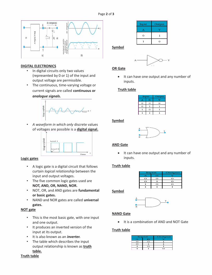
Page 2 of 3
DIGITAL ELECTRONICS
• In digital circuits only two values
(represented by 0 or 1) of the input and
output voltage are permissible. • The continuous, time-varying voltage or
current signals are called continuous or
analogue signals.
• A waveform in which only discrete values
of voltages are possible is a digital signal.
Logic gates
• A logic gate is a digital circuit that follows
curtain logical relationship between the
input and output voltages.
• The five common logic gates used are
NOT, AND, OR, NAND, NOR.
• NOT, OR, and AND gates are fundamental
or basic gates.
• NAND and NOR gates are called universal
gates.
NOT gate
• This is the most basic gate, with one input
and one output.
• It produces an inverted version of the
input at its output.
• It is also known as an inverter.
• The table which describes the input
output relationship is known as truth
table.
Truth table
Symbol
OR Gate
· It can have one output and any number of
inputs.
Truth table
Symbol
AND Gate
· It can have one output and any number of
inputs.
Truth table
Symbol
NAND Gate
· It is a combination of AND and NOT Gate
Truth table

Page 3 of 3
Symbol
NOR Gate
· It is a combination of OR gate and NOT
gate.
Truth table
Symbol
INTEGRATED CIRCUITS ( IC )
• An entire circuit fabricated (consisting of
many passive components like R and C
and active devices like diode and
transistor) on a small single block (or chip)
of a semiconductor is called integrated
circuit.
• Depending on nature of input signals, IC’s
can be grouped in two categories: linear
or analogue IC’s and digital IC’s
• Depending upon the level of integration
(i.e., the number of circuit components or
logic gates), the IC’s are termed as
• Small Scale Integration, SSI (logic gates <
10)
• Medium Scale Integration, MSI (logic
gates < 100)
• Large Scale Integration, LSI (logic gates <
1000)
• Very Large Scale Integration, VLSI (logic
gates > 1000).
• The most widely used IC technology is the
Monolithic Integrated Circuit.
*****