Embed Size (px)
Citation preview

Center for Precision Forming(www.cpforming.org
Taylan Altan, Director
(e-mail: [email protected])
A short Review
March 2014
1

INTRODUCTION
• The Ohio State University (OSU) has established the Industry/University Cooperative Research Center (I/UCRC) on Precision Forming (CPF) focusing on research needs of metal forming industry
• Funding is provided by National Science Foundation (NSF) and member companies.
• CPF (www.cpforming.org) benefits from research conducted at the Engineering Research Center for Net Shape Manufacturing (ERC/NSM – www.ercnsm.org)
2

OBJECTIVES
• Improve existing metal forming processes/products and develop new innovative processes, tooling and equipment
• Conduct projects in close collaboration with industry and transfer the results to the member companies
• Train and educate engineers in the fundamentals and practice of metal forming science and technology
3

CPF is supported by NSF and member companies,
interested in metal forming
4

CURRENT PROJECTS
Project CPF-1.1 – Warm Forming of Al AlloysProject CPF-1.4 – Forming of AHSS in a Servo Press – Die Design Project CPF-2.1 – Material Properties and Formability Project CPF-2.2 – Forming Al in a Servo Press Project CPF 3.3 – Friction/Lubrication/Wear Project CPF-5.1 – Bending and Springback in Forming of AHSS and Copper Alloys Project CPF-5.2 – Blanking / PiercingProject CPF-5.2 A – Hole Flanging and Edge Cracking Project CPF-5.5 - Hot Stamping Project CPF 5.6 Practical Method for Predicting Fracture Using FE Simulation
5

AZ31B-OAA5754-O
T(°C) LDRRT -
275 2.6275 3.2
T(°C) LDRRT 2.1
250 2.5300 2.9
Velocity : 2.5-50mm/sec
Cup diameter: 40 mm
Insulation plate
Die ring
Heaters
Blank holder
Water inlet
Cushion pins
Punch
Sheet
CPF-1.1 - Warm Forming of Al, Mg, Ti & SSin an Aida Servo Drive Press
6

7
CPF-1.4 - Forming of AHSS in a Servopress
Forming of AHSS in Servo Press
980 MPa(145 ksi)
590 MPa(85 ksi)
440 MPa(65 ksi)
270 MPa(40 ksi)
Can we use servo drive properties to improve formability and reduce springback in forming AHSS?

Die
Top die set8
CPF-1.4 - Forming of AHSS
Punch
Blank holder
Bottom die set
Materials of interest:DP 600DP 980And others
Forming of AHSS in Servo Press
Die design (manufactured by Shiloh) for testing AHSS.

9
CPF-1.4 - Forming of AHSS in a Servopress
Forming of AHSS in Servo Press
1) Straight Bending2) Shrink Flanging3) Stretch Flanging4) U-Bending5) Curved U-Bending6) Deep Drawing

CPF/Shiloh die set (for 300 ton servo-press)
CPF-1.4 – Forming of AHSS in a Servopress
10
R1
R2
R3 R4
R5R6
DIE
Parameter Notation Value
Concave side radius R1 601.6 mm
Convex side radius R2 598.4 mm
Cavity corner radii
R3 51.6 mm
R4 56.6 mm
R5 61.6 mm
R6 66.6 mm

11
CPF-1.4 – Forming of AHSS in a Servopress
Example: Shrink and Stretch Flanging
DIE
BLANK

12
CPF-1.4 - Forming of AHSS in a Servopress
Deep drawn sampleDP 600, t0 = 0.83 mmDraw depth = 50 mm
Forming of AHSS in Servo Press
Thinning (%)
Min = -12.8Max = 9.0
-9.7-12.8
9.05.82.7-0.4-3.5-6.6
Max. Thinning ~ 9%

CPF-2.1 Material Characterization
Downward motion
clamps the sheet
Before Forming After Forming
Stationary Punch
Pressure Transducer
Viscous Medium
Test Sample
Laser Sensor
Continued downward
motion forms the bulged
sheet
Viscous Pressure Bulge (VPB) Test
13

14
CPF-2.1 Material Characterization – Flow Stress
Viscous Pressure Bulge (VPB) Test
0 0.1 0.2 0.3 0.4 0.50
200
400
600
800
1000
True Strain
True Stress (MPa) True Stress (ksi)
29
58
87
116
145
VP Bulge Test
Tensile Test
Uniform Strain from Tensile Test = 0.16
Tensile data with Power Law (σ=Kεn)
Useful strain from Bulge Test = 0.49
Material, DP600, 1 mm

Before bursting After bursting
Test sample
CPF-2.1 - Material Characterization – VPB Test
15

CPF-2.1 - Material Characterization – VPB Test
16

CPF-2.1 - Determination of Sheet Formability Using VPB Test
Highest formability G , Most consistent F
Lower formability and inconsistent H
Graph shows dome height comparison for SS 304 sheet material from eight different batches/coils [10 samples per batch].
0
0.2
0.4
0.6
0.8
1
1.2
1.4
1.6
A B C D E F G H
Coil/Heat/Supplier
Do
me
he
igh
t b
efo
re b
urs
t (i
n)40
30
20
10
1.6
1.2
0.8
0.4
Maximum bulge height before fracture(mm) (in)
Batch / Coil / Heat / Supplier ID
17

CPF-2.1 - Materials Tested with VPB Test at CPF(data available to CPF members)
Aluminum and Magnesium AlloysAA 6111
AA 5754-OX626 -T4P
AZ31BAZ31B-O
SteelsSt 14 DP 780-CR
St 1403 DP 780-HYAISI 1018 Bare DP 980 Y-type X
AKDQ Bare DP 780 T-Si type1050 GA DP 780 T- AI Type
DR 120 GA DP 780 Y-type UDDS GA DP 780 Y-type V
BH 210 DQS-270F GA-Phosphate coatedHSS DQS-270D GA-Phosphate coated
DP500 DP 780DP 590 TRIP 780DP 600 DP 980
Stainless SteelsSS 201SS 301SS 304SS 409
SS 410 (AMS 5504)SS 444
LDX 2101
18

19
CPF-2.1 - Material Characterization – Dome Test
Dome Test (Frictionless) When the blank is well lubricated, it fails at the center of the dome.
Necking / fracture moves with increased friction.

CPF-2.1 - Formability
Ref: Shi and Chen 2007
Stretch Bending
DP780Underbody structural part
DP980 B-pillar inner
Challenge:This type of fracture cannot be predicted using conventional Forming Limit Curve (FLC).
20
21
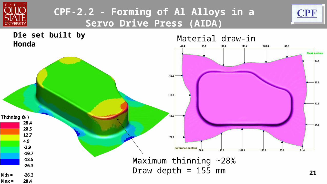
CPF-2.2 - Forming of Al Alloys in a Servo Drive Press (AIDA)
Thinning (%)
Min = -26.3Max = 28.4
-18.5-26.3
28.420.512.74.9-2.9-10.7
Maximum thinning ~28%Draw depth = 155 mm
Material draw-inDie set built by Honda

22
CPF-3.3 - Friction/Lubrication – Cup Draw Test
Evaluation of Lubricants
Performance evaluation criteria (cups drawn to same depth):i.Higher the Blank Holder Force (BHF)
that can be applied without fracture in the drawn cup, better the lubrication condition
ii.Smaller the flange perimeter, better the lubrication condition (lower coefficient of friction)

CPF-3.3 - Friction – Cup Draw Test
Shorter Perimeter
Higher BHF before fracture
Cup Draw Test
Lubrication performance:
23

CPF-3.3 - Friction / Tribology
Ref: Kim et al 2009
Temperatures in Cup Draw Test – DP 600
Contact area with die
Challenges: 1) Higher contact pressure and higher temperature are detrimental for lubricants, 2) Temperature and pressure additives are needed
24

25
CPF-3.3 - Friction / Lubrication
Evaluation of Lubricants for Forming Al 5182-0 (1.5 mm)

Punch(Stationary)
Die Insert
Dp = 152.4 mm
r = 5 mmt0 = 0.77 mm
r = 20 mm
Punch(Stationary)Die Insert
Press Motion
Ironingt ≈ 0.70 mm
Dp = 152.4 mm
r = 5 mm
t0 = 0.77 mm
r = 20 mm
Press Motion
26
CPF-3.3 - Forming of AHSS / Die Wear
Die Wear in Forming of AHSS
Currently with DP590In future, Stainless Steel

27
CPF-5.1 – Bending and springback in Forming AHSS and Copper Alloys
Schematic of 3 point bending tooling at OSU

28
CPF-5.2 - Blanking/Piercing of AHSS
Blanking / PiercingSchematic of piercing
vp = punch velocity fb = blank holder forcedp = punch diameter dd = die diameterrp = punch corner radius rd = die corner radiusdb = blank holder diameter t = sheet thicknessPunch-die clearance (% of sheet thickness) = (dd-dp)/2t*100
Fracture zone (Zf)
Burr zone (Zb)
Roll over zone (Zr)
Shear zone (Zr)
Blanked edge(obtained from FE simulations)

29
CPF-5.2 - Blanking/Piercing of AHSS
Reduction of strains at blanked surface
Single shear Conical with flat tip
HumpedConical with spherical tip
0.600000000000
001
1 1.5 2 2.5 3 3.5 3.60
0.5
1
1.5
2
2.5
3
Flat
Humped
Conical
Distance from the top surface of the sheet (mm)
Eff
ecti
ve s
trai
n

30
CPF-5.2A – Hole Flanging/Edge Cracking
Hole Expansion Test
Schematic of hole expansion test
vp=punch velocity fb=blankholder forceθ=punch angle (conical) dd=diameter of the diedb=diameter of blankholder rd=die radiusdh=diameter of pierced hole in the blankdp=punch diameter (hemispherical)
Punch
θdp
dd
rd
db
vp
fbBlank Holder
DIE dh
Before and After Hole Expansion(conical punch)

31
CPF-5.5 - Hot Stamping
Ref: Grote 2009, Gutermuth 2011.
Less force and springback
Mn-B alloyed steel (As delivered)Ferrite-Pearlite
At ~950°C (1750ºF)
Austenite
3-5 min.s in Furnace
Quenched Martensite
Quenched in the die >27°C/s (~49°F/s)
Eas
ier
to F
orm
22MnB5
32
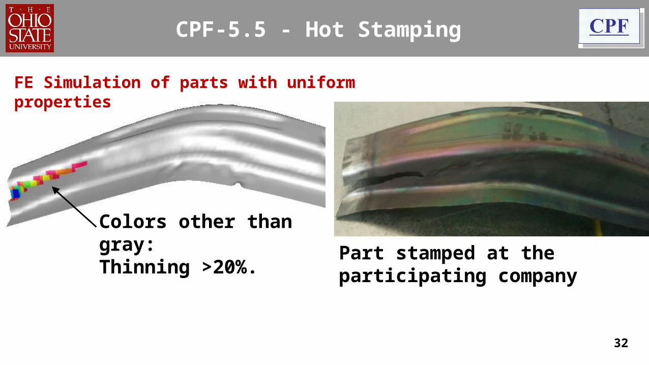
CPF-5.5 - Hot Stamping
Colors other than gray:Thinning >20%. Part stamped at the participating
company
FE Simulation of parts with uniform properties

33
CPF-5.5 - Hot Stamping
Nodal temperature - Membrane
5425
23020017114211283
FE Simulation of cooling channel analysis
1.3 mm roof rail die,After 10 stampings.

34
CPF-5.5 - Hot Stamping
FE Simulation of cooling channel analysis
After 10 stampings.

35
CPF-5.5 - Hot Stamping
Hardened zone:485 – 515 HV1500 – 1590 MPa(~220 – 230 ksi)
Soft zone:310 – 330 HV920 – 1020 MPa(~135 – 150 ksi)
Literature:[George 2011] , 400°C dies = 790-840 MPa [Feuser 2011], 450°C dies = ~850 MPa
FE Simulation of parts with tailored properties

0 0.02 0.04 0.06 0.08 0.1 0.12 0.140
200
400
600
800
1000
1200
1400
Strain (mm/mm)
Str
ess
(MP
a)
CPF–5.6 - New Project: Prediction of Fracture
Prediction of fracture/necking from strain or thickness variations (tensile data from Jim Dykeman-Honda HRA)
0 50 100 150 2000
0.1
0.2
0.3
0.4
0.5
0.6
Maj
or S
trai
n (m
m/m
m)
Time (s) 36

Questions / Comments?
For more information , please contact:
Dr. Taylan Altan ([email protected]), Ph-614-292-5063
Center for Precision Forming –CPF (www.cpforming.org)
339 Baker Systems,1971 Neil Ave,
Columbus, OH-43210
Non-proprietary information can be found at web sites:
www.cpforming.org
www.ercnsm.org
37