Embed Size (px)
Citation preview

CATIA MACHINING SEMINAROriginally created by Edwin Anderson
Updated by Cam Stefanic (Spring 2011)

GENERAL MACHINING TERMINOLOGY NC - Numerically controlled G Code - Coding language our CNC machines
read PO - Part Operation MO - Machine Operation
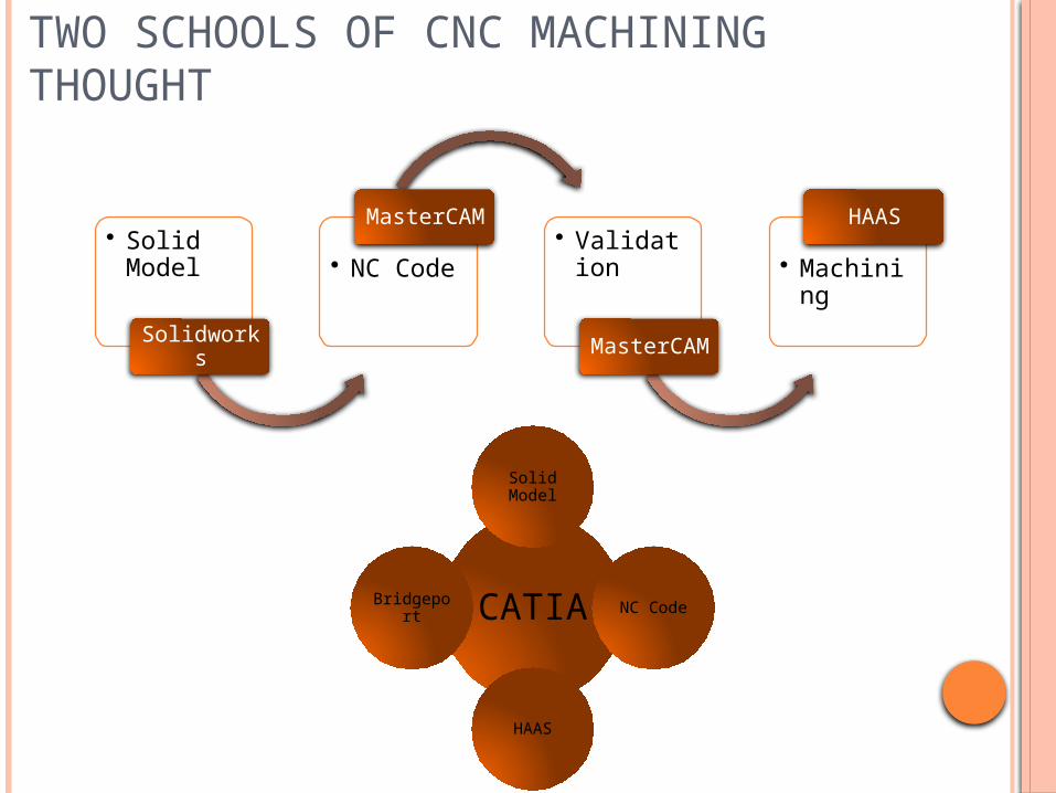
TWO SCHOOLS OF CNC MACHINING THOUGHT
• Solid Model
Solidworks
• NC Code
MasterCAM• Validation
MasterCAM
• Machining
HAAS
CATIA
Solid Model
NC Code
HAAS
Bridgeport
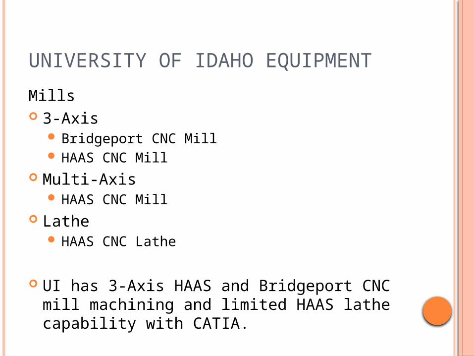
UNIVERSITY OF IDAHO EQUIPMENT
Mills 3-Axis
Bridgeport CNC Mill HAAS CNC Mill
Multi-Axis HAAS CNC Mill
Lathe HAAS CNC Lathe
UI has 3-Axis HAAS and Bridgeport CNC mill machining and limited HAAS lathe capability with CATIA.

MACHINE PROCESS OVERVIEW
CATIA Product Definition Create a Machine Plan Creating a Process Document inside CATIA
Part Operation Set-up Tool Selection Machine Operation/Simulation
Verification Post Processing Export to CNC mill

INSIDE CATIA
CATIA Product Part
Finished product in proper orientation
Stock If necessary
Fixture If necessary

GUIDELINES FOR CREATING A MACHINE PLAN
Name, Date, Part, Material, Group, Project, Tolerances, etc.
Stock Size Sequence Description Tool List Picture of Setup Other Information

CREATING A PROCESS DOCUMENT
Select Product intended for machining Enter Advanced Machining workbench
Start>Machining>Advanced Machining
PPR Process List
Machine Operation Product List
Part Stock Fixture
Resource List Tools

Define Machine
3-axis mill Part
The finished part Stock
The starting material Fixture
Any clamps or other surfaces not waiting to be machined
PART OPERATION| SETUP

MACHINE OPERATION DETAILS Operation Name Comment Tabs
Machine Strategy Geometry Tool Feeds and Speeds Macros
Stoplights Colors
Red – Needs defined Yellow – Could be defined, but not necessary Green – Defined
Selectable Objects and Text Blue text is editable

MACHINE OPERATION| GEOMETRY COLORS
Geometry Colors Red- Not defined and required. Orange- Not defined, but not
required. Green- Defined. Brown-Definition element has been
changed or deleted. Purple- Tool path needs to be
recalculated. Blue- Editable parameters.
All surfaces are defined by clicking in the window and then selecting the
surface in the geometry

QUESTIONS?