Embed Size (px)
Citation preview

Catastrophes in wavefront-codingspatial-domain design
Shane BarwickRocky Mound Engineering, 116 White Pine Court, Macon, Georgia 31216, USA
Received 23 September 2010; revised 6 November 2010; accepted 8 November 2010;posted 8 November 2010 (Doc. ID 135579); published 14 December 2010
Spatial-domain design for wavefront-coding systems frequently simplifies the defining oscillatory inte-gral of the point spread function (PSF) by means of the stationary phase approximation (SPA). Althoughthe SPA applies over much of the support of the PSF, it tends to break down at or near the regions ofhighest intensity. A branch of mathematics known as catastrophe theory is shown to provide tools thatcan ferret out important design information precisely at the points where the SPA is unphysical. © 2010Optical Society of AmericaOCIS codes: 110.1758, 110.0110, 070.0070.
1. Introduction
Wavefront coding (WC) is an approach to imaging sys-tems in which the pupil phase is manipulated in con-junction with digital postprocessing so as to achieve agiven design goal. Research in this area was spurredin particular by the desire to increase the depth offield of imaging systems beyond what is possible withconventional imaging. Seminal research by Dowskiand Cathey that built upon earlier findings byCastañeda et al. proved that this goal was achievable[1,2]. The last decade has seen researchers tackling adesign trade-off that is inherent in the use of WC forthis application. Increasing the depth of field, or de-creasing sensitivity to defocus, tends to lower themagnitude of the optical transfer function (OTF),knownas themodulation transfer function (MTF), be-low the noise level at high spatial frequencies.
So as to predict the relative merit of systems inhandling this trade-off, design methodologies havebeen developed that concisely represent how thesystem performs with varying defocus. So-calledphase-space transformations, such as the ambiguityfunction, theWignerdistribution, andRadon–Wignerdistribution, have proved effective at displaying thedefocus dependence of both the OTF and its Fourier
transform, the PSF [3,4]. However, these transforma-tions are most suited for separable phase masksthat can be designed in one dimension. Hence, two-dimensional (2-D) design of phase masks hasfrequently fallen back on numerical optimization ofdesign metrics [5–11]. Unfortunately, numericalmethods run into problems with rapidly increasingcomputational costs and with design spaces clutteredwith local minima as the number of design para-meters rises.
The subject of this paper is a suite of tools thatwill be shown to be useful at localizing the areasin the design space that are likely to yield superiorperformance. These tools operate in the context ofspatial-domain design through the PSF. Althoughspatial-frequency design methods have been morepopular, researchers have studied how the PSF be-haves in WC through numerical methods and analy-tical derivation [12–14]. Most of these techniquesmake use of the convenient result that the PSF canbe approximated over much of its support throughthe stationary phase approximation (SPA) of the de-fining oscillatory integral from Fourier optics [15].The SPA has a significant flaw. It only applies whenstationary points have nondegenerate Hessians.This condition is, in fact, frequently violated forWC phase masks. The solution to this problem inWCspatial-domain design has generally been to ignoreit. Fortunately, a branch of mathematics known as
0003-6935/10/366893-10$15.00/0© 2010 Optical Society of America
20 December 2010 / Vol. 49, No. 36 / APPLIED OPTICS 6893
catastrophe theory (CT) that was pioneered by Thomwill allow us to deduce important design informationwhere the SPA breaks down [16]. Although CT haslong been employed in scattering and diffraction the-ory [17,18], it has not, to my knowledge, been appliedto WC design.
In Section 2, a necessarily brief review of the mostimportant mathematical concepts will be presented.Interested readers unfamiliar with CT are encour-aged to seek out source material in the references,especially [19]. In Section 3, the methodology willbe applied to the analysis of general cubic masksfor decreasing sensitivity to defocus. The results willthen be generalized to higher order masks and, inSection 4, to other Seidel aberrations. Finally,Section 5 presents implications from CT on maskoptimization.
2. Review of Mathematical Concepts
A. Oscillatory Integrals
Fourier optics predicts that the three-dimensionalPSF h of a diffraction-limited imaging system of focallength f with a phase mask ϕ at the pupil is given byan oscillatory integral of the form [20]
hðs; t; zÞ ¼����ZZΣ
expðikFðx; y; s; t; zÞÞdxdy����2; ð1Þ
where Fðx; s; zÞ ¼ ϕðx; yÞ − zðx2 þ y2Þ − sx − ty, x ¼ðx; yÞ are the pupil coordinates, z is the defocusstrength u=2f ðf þ uÞ, u is the distance from the focalplane along the optic axis, s ¼ ðs; tÞ are the trans-verse coordinates in image space scaled by f, k isthe wavenumber 2π=λ, and Σ defines the finite pupilsize that will be assumed to be a circle of unit radiusunless stated otherwise. Because of the small valueof optical wavelengths, the complex exponential inEq. (1) oscillates rapidly and contributes little tothe total integral except at critical points (CPs) xc ∈Σ such that F is stationary, or∇xFðxc; s; zÞ ¼ 0, where∇x is the gradient with respect to x. In the limit thatλ → 0, the SPA predicts that h ≈ jPcαcjdetð∇2
xFðxc; s; zÞÞj−1=2j2, where αc are complex constants, detdenotes determinant, and ∇2 is the Hessian [15].
A problem is immediately evident for the SPAwhen the Hessian is degenerate at xc due to it beingless than full rank, or detð∇2FÞ ¼ 0. An infinite in-tensity is predicted at ðs; zÞ, which is related to thebreakdown of ray optics. Although the exact integraleliminates this unphysical result, the points in imagespace associated with such degenerate CPs in the pu-pil tend to form the envelope of caustics, brightcurves of high intensity to which light rays are tan-gent [19]. In fact, the PSF of WC masks tend to be ofhighest intensity at caustics [4]. It is unusual engi-neering practice to ignore large values in approxima-tions, but that has frequently been the case inspatial-domain analysis of WC designs. The applica-tion of results from a range of mathematical disci-
plines that has been collected under the umbrellaof CT will show that, not only should degeneraciesnot be ignored, they provide important informationconcerning both the defocus sensitivity and theMTF of WC designs.
B. Essential Results from Catastrophe Theory
In order to make the relevance of the following con-cepts to WC more easily understandable, a simpleone-dimensional (1-D) cubic phase mask ϕðxÞ ¼wx3 will be used as an example to illustrate themeth-odology. The total modulation w is a design para-meter. Like ϕ above, WC masks usually have nopolynomial terms, or Taylor expansions for nonpoly-nomial masks, of order lower than 3. Degeneraciesoccur when the quadratic Taylor terms (i.e., secondderivative) disappear at CPs. Hence, degeneraciesare unavoidable inWC. In fact, by design, the on-axispoint in the focal plane, or ðs; zÞ ¼ ð0; 0; 0Þ, that yieldsthe popular metric of the Strehl ratio is determinedby a degenerate CP. Another important aspect of F inEq. (1) is that it can be looked upon as a family offunctions in which the state of ϕðx; yÞ is being per-turbed by an amount dependent on control variablesðs; zÞ. CT tells us how these perturbations will influ-ence the nature of the CPs and, thus, the propertiesof the PSF.
The singularity set S will be defined as all ðx; s; zÞsuch that∇xF ¼ 0 and detð∇2FÞ ¼ 0. It is a subset ofthe set of all CPs, which is known as the catastrophemanifold M. In our 1-D example, the elements of Sreduce to ðx; s; zÞ that satisfy
dFdx
¼ 3wx2 − 2zx − s ¼ 0;d2F
dx2¼ 6wx − 2z ¼ 0:
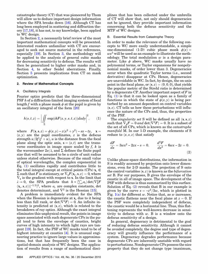
ð2ÞUnlike phase-space distributions, the information inS is readily accessed by projection onto lower dimen-sions, even for 2-D masks. The projection of S ontothe control variables ðs; zÞ is known as the bifurcationset B. For our purposes, B gives the envelope of thecaustic in all of image space. The development of thePSFwith defocus is thus summarized by this surface.Solution of Eq. (2) reveals that B in our example isgiven by the curve s ¼ −z2=3w, which is plotted inFig. 1(a) for different w. Notice that, as w increases,the caustic flattens near the focal plane at z ¼ 0. Ifthe PSF were completely independent of defocus,the caustic would be a horizontal line. Thus, this flat-tening represents the well-known decrease in sensi-tivity to defocus with w. B is a window onto thedefocus sensitivity of a design.
In general, degeneracy is detrimental to the goalof reducing defocus sensitivity. Although it cannotbe avoided completely, the degree and type of degen-eracy will greatly influence the performance of asystem. Degeneracy degrades performance becausedegenerate CPs are inherently unstable with regardto perturbations.NondegenerateCPspossess theniceproperty that they do not change type (maximum,
6894 APPLIED OPTICS / Vol. 49, No. 36 / 20 December 2010

minimum, or saddle) under perturbation [19]. Theimplicit function theorem of calculus guarantees thattheir position in the pupil will vary as a smooth func-tion with the control variables [21]. If the PSF is tochange slowly with z, this behavior is a necessity.However, a degenerate CP is prone to splitting intomultiple new CPs of varying types under infinitelysmall perturbations [19]. For instance, f ðxÞ ¼x3 þ px is plotted for varying p in Fig. 2. The degener-ate CP at the origin for p ¼ 0 splits into separatemaximum andminimum for p < 0, but disappears al-together for p > 0. The order of the degeneracy is de-termined by the lowest order nonzero term in theTaylor expansion at the CP. If the degeneracy is ofhigher order, the degeneracy can split into a greaternumber of CPs. For instance, the degeneracy at theorigin of x5 can split into fourCPs under perturbation,as opposed to two for the cubic. Rapid change in theCPs with the control variables will frequently leadto rapid change in the PSF because they determinethe integral. Furthermore, bright spots in the PSFas-sociated with degeneracies tend to shift in the PSFwith changing defocus, which increases defocus sen-sitivity. These issues get much more complicatedwhen analyzing 2-D masks, as opposed to 1-D masks,because the types of CPs increase and degeneracy canbe in only one or in two coordinate directions, depend-ing on whether the rank of the Hessian is 1 or 0,respectively.
Degenerate CPs can be more stable to certainforms of perturbations than others. Fortunately,CT provides tools to divide the Taylor expansionsnear a CP into a small number of topological classesbased on the type of degeneracy, and the behavior ofall functions of a given class near a CP will be similarin the presence of perturbations. It is beyond thescope of this paper for a detailed explanation, but
the behavior of any function f ðx; yÞ at a CP can becharacterized locally by its k jet, or jkf, which is sim-ply the Taylor expansion truncated to degree k. If,through a smooth, perhaps nonlinear, change of coor-dinates, jkf is locally equal to jkf þ g to within a con-stant, where g is any polynomial of order kþ 1, then fis said to be k-determinant at this point. The smallestk for which this is true is the determinancy of f , and,if k is infinite, f is indeterminate [19]. The determi-nancy of f is found by computing in what “vectordirections” a smooth coordinate change takes jkf .By direction, it is meant that the set of all polynomialfunctions is a vector space in which the monomialsðx; y; xy; etc:Þ serve as a basis. The set of all possibledirections is referred to in [19] as the tangent space off , and it is algebraically equal to all possible linearcombinations of terms of the form jkþ1ðQnjkþ1
ð∂f =∂xÞÞ or jkþ1ðQmjkþ1ð∂f =∂yÞÞ, where Qi¼m;n is anypolynomial. As will be demonstrated, degeneraciestend to be less sensitive to perturbations in the tan-gent space. Furthermore, it can be shown that afinite number of polynomial perturbations multi-plied by control variables can be added to f [likethe term sx in Eq. (1)] in order to form a structurallystable family of functions in the sense that no otherperturbations significantly affect f locally [19]. Theminimum number of necessary control variables tostabilize f is the co-dimension of f . We will see thatthe properties of WC phase masks vary a great dealdepending on the class of ϕ, its determinancy, its co-dimension, and the composition of its tangent space.
Thedesignbattle inWCismanaging the trade-off ofthe suppression of the MTFas defocus sensitivity de-creases. The degeneracies of F are central to thistrade-off. This point is demonstrated by projecting Monto constant z surfaces, which will be referred to asthe transfer set T because it relates xc in the pupil tothe points s they influence in an image plane. For ex-ample, by setting z ¼ 0 in the first equation of Eq. (2),T is given by the curve s ¼ 3wx2 for our example.Figure 1(b) plots s versus x for varying w with an as-sumed pupil of −1 < x < 1. Remember that, in Eq. (1),a CP must lie in the pupil to affect h in the SPA. Notethat increasing w has the effect of associating CPs inthe pupil with larger s. Consequently, as defocus sen-sitivity decreases with increasing w, the PSF is ex-pected to broaden, which tends to suppress the MTF.
Degeneracy in general tends to affect the PSF in alike manner. In Eq. (1) the implicit function theorempredicts that ∇sxcðsÞ for nondegenerate xc will de-pend on ð∇2
xFðxc; s; zÞÞ−1, which implies in 1-D thatds=dx ∝ d2F=dx2 in T [21]. In our example, as w in-creases,∇2
xFðx; z ¼ 0Þ ¼ 6wx gets further from singu-larity for x ≠ 0. Thus, s varies more rapidly with x inT. But, for degenerate CPs, ∇2
xF is singular, i.e., 0 for1-D masks. Note in Fig. 1(b) that ds=dx ¼ 0 only atthe degenerate critical point x ¼ 0. Consequently, de-generacy tends to flatten the graph of T. The result isthat fewer s far from the optic axis are associated
Fig. 1. (Color online) (a) B at z ¼ 0 for the 1-D cubic with w ¼ 5(black solid), 10 (blue dotted), and 15 (green dashed). (b) T for thesame parameters.
Fig. 2. Plots of x3 þ px for (a) p < 0, (b) p ¼ 0, and (c) p > 0.
20 December 2010 / Vol. 49, No. 36 / APPLIED OPTICS 6895
with CPs in the pupil. Ergo, degeneracy tends toshrink the PSF and raise contrast in the MTF.
3. General Cubic Phase Masks
Phase masks that are invariant in an x↔y exchangeoperation and odd under coordinate inversion, orϕðx; yÞ ¼ ϕðy; xÞ and ϕð−x;−yÞ ¼ −ϕðx; yÞ, have beenshown to possess PSFs and OTFs that have Taylorexpansions with respect to z with no even terms[6]. As a result, cubic phase masks for WC generallyhew to the following form:
ϕðx; yÞ ¼ wðx3 þ y3 þ rðx2yþ xy2ÞÞ; ð3Þwhere the design parameters are r and w. Cubicmasks are commonly used in WC applications andhave been studied heavily. CT can, nonetheless, re-veal new insights on the properties of these masks,as well as provide an analytic basis to explain resultsheretofore arrived at only numerically. These resultsthen generalize to higher order masks and aberra-tions that have been less studied.
In general, all homogeneous cubic polynomials inðx; yÞ can be reduced by a linear coordinate change toone of four nontrivial canonical types based on theirroot structure [19]. The roots are lines through theorigin in the x–y plane, and they number either (a)a single real line, (b) three distinct real lines, (c) threelines, two of which coincide, or (d) three coincidentlines. Owing to their form, an easy method to findthe root lines is to determine their intersection withthe line x ¼ 1, which reduces the problem to a cubicequation in y only. For ϕ in Eq. (3), y ¼ −x is a uni-versal root line. Thus, after substituting x ¼ 1 inEq. (3), synthetic division reveals that the otherintersections satisfy y2 þ ðr − 1Þyþ 1 ¼ 0, or
y ¼ −ðr − 1Þ �ffiffiffiffiffiffiffiffiffiffiffiffiffiffiffiffiffiffiffiffiffiffiffiffiðr − 1Þ2 − 4
p2
: ð4Þ
It is immediately apparent that r decides the type ofcubic in question. The form in Eq. (3) reduces to case(a) for −1 < r < 3, (b) for r < −1 or r > 3, (c) for r ¼ −1,and (d) for r ¼ 3. Types (a) and (b) are two of Thom’scanonical catastrophes, the hyperbolic and ellipticumbilics, respectively, that conveniently have a co-dimension of 3 and can be stabilized by a quadraticand two linear terms, i.e., the form of F in Eq. (1) [19].Most WC masks will be one of these two types or in aclosely related family of catastrophes. They will beanalyzed in detail shortly.
Types (c) and (d) are indeterminate with infiniteco-dimension and, hence, highly unstable to pertur-bation. It should then come as no surprise thatVettenburg et al. found, by exhaustive numericalanalysis, that r ¼ −1 and r ¼ 3 represent global mini-mums in performance for cubic masks under typicalimaging [7]. Presumably, these masks perform poorlybecause they possess troughs of zero modulationacross the pupil. For instance, for r ¼ 3, the maskϕ is simply ðxþ yÞ3. However, fifth and higher order
masks that are extremely flat throughout a largefraction of the pupil centered at the origin have beenshown to perform well [22]. There must be a chasm ofdifference between low and zero modulation. CT pro-vides a definitive explanation. For r ¼ 3, the bifurca-tion set B in the focal plane at z ¼ 0 is a line segmentoriented along s ¼ t. (See [19] for detailed exampleson how to calculate B.) Importantly, every criticalpoint in the pupil is degenerate and an infinite num-ber (a continuous line segment) are associated witheach ðs; tÞ ∈ B. B immediately rotates 90° to lie alongthe s ¼ −t line in the image plane for z > 0. The highdegeneracy obviously makes indeterminate formshighly volatile to defocus.
A. Hyperbolic Umbilics (−1 < r < 3)
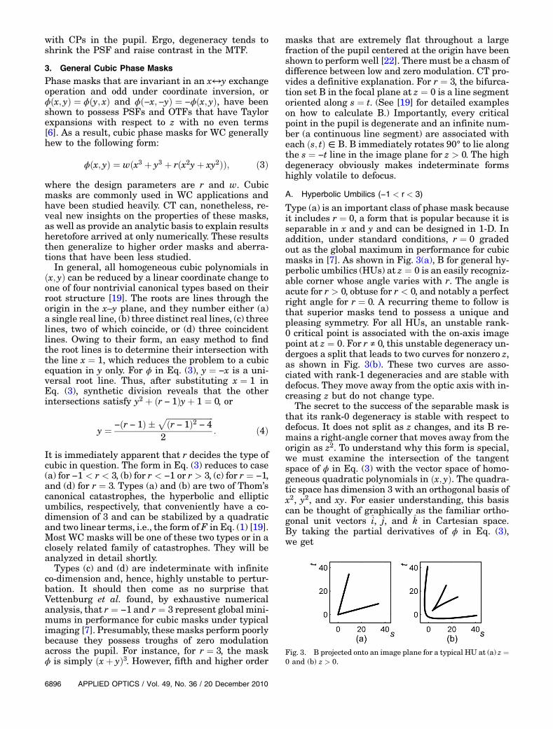
Type (a) is an important class of phase mask becauseit includes r ¼ 0, a form that is popular because it isseparable in x and y and can be designed in 1-D. Inaddition, under standard conditions, r ¼ 0 gradedout as the global maximum in performance for cubicmasks in [7]. As shown in Fig. 3(a), B for general hy-perbolic umbilics (HUs) at z ¼ 0 is an easily recogniz-able corner whose angle varies with r. The angle isacute for r > 0, obtuse for r < 0, and notably a perfectright angle for r ¼ 0. A recurring theme to follow isthat superior masks tend to possess a unique andpleasing symmetry. For all HUs, an unstable rank-0 critical point is associated with the on-axis imagepoint at z ¼ 0. For r ≠ 0, this unstable degeneracy un-dergoes a split that leads to two curves for nonzero z,as shown in Fig. 3(b). These two curves are asso-ciated with rank-1 degeneracies and are stable withdefocus. They move away from the optic axis with in-creasing z but do not change type.
The secret to the success of the separable mask isthat its rank-0 degeneracy is stable with respect todefocus. It does not split as z changes, and its B re-mains a right-angle corner that moves away from theorigin as z2. To understand why this form is special,we must examine the intersection of the tangentspace of ϕ in Eq. (3) with the vector space of homo-geneous quadratic polynomials in ðx; yÞ. The quadra-tic space has dimension 3 with an orthogonal basis ofx2, y2, and xy. For easier understanding, this basiscan be thought of graphically as the familiar ortho-gonal unit vectors i, j, and k in Cartesian space.By taking the partial derivatives of ϕ in Eq. (3),we get
Fig. 3. B projected onto an image plane for a typical HU at (a) z ¼0 and (b) z > 0.
6896 APPLIED OPTICS / Vol. 49, No. 36 / 20 December 2010
ϕx ¼∂ϕ∂x
¼ 3wx2 þwry2 þ 2wrxy;
ϕy ¼∂ϕ∂y
¼ wrx2 þ 3wy2 þ 2wrxy: ð5Þ
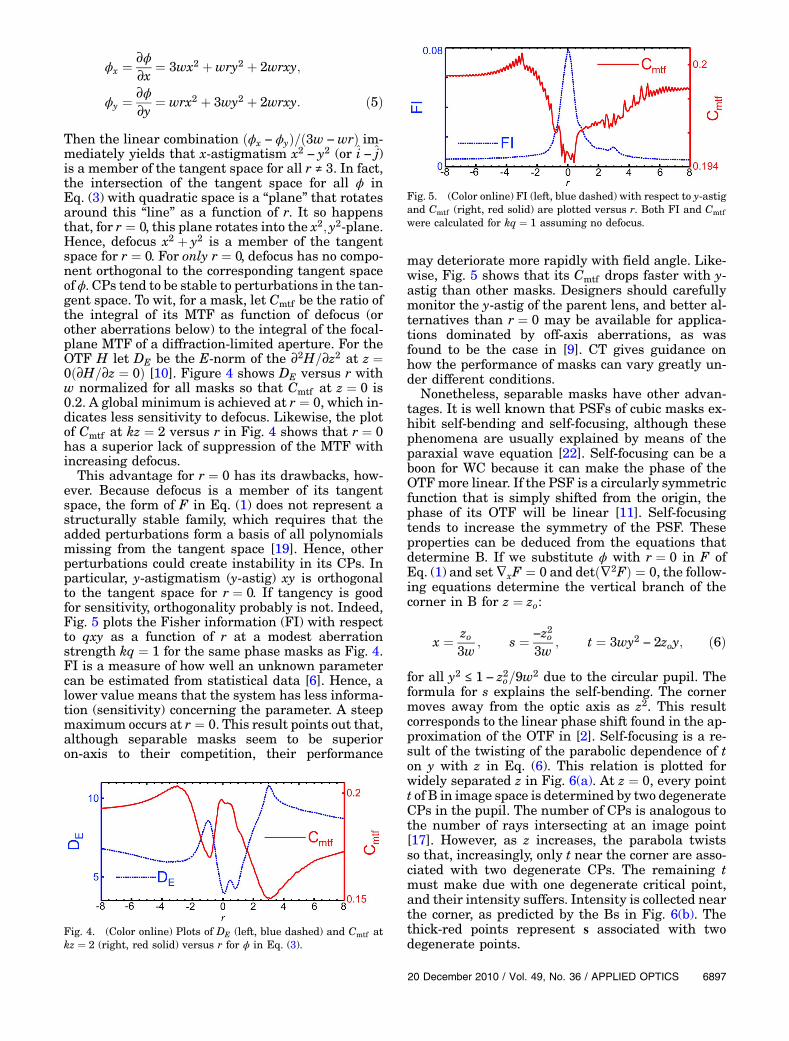
Then the linear combination ðϕx − ϕyÞ=ð3w −wrÞ im-mediately yields that x-astigmatism x2 − y2 (or i − j)is a member of the tangent space for all r ≠ 3. In fact,the intersection of the tangent space for all ϕ inEq. (3) with quadratic space is a “plane” that rotatesaround this “line” as a function of r. It so happensthat, for r ¼ 0, this plane rotates into the x2; y2-plane.Hence, defocus x2 þ y2 is a member of the tangentspace for r ¼ 0. For only r ¼ 0, defocus has no compo-nent orthogonal to the corresponding tangent spaceof ϕ. CPs tend to be stable to perturbations in the tan-gent space. To wit, for a mask, let Cmtf be the ratio ofthe integral of its MTF as function of defocus (orother aberrations below) to the integral of the focal-plane MTF of a diffraction-limited aperture. For theOTF H let DE be the E-norm of the ∂2H=∂z2 at z ¼0ð∂H=∂z ¼ 0Þ [10]. Figure 4 shows DE versus r withw normalized for all masks so that Cmtf at z ¼ 0 is0.2. A global minimum is achieved at r ¼ 0, which in-dicates less sensitivity to defocus. Likewise, the plotof Cmtf at kz ¼ 2 versus r in Fig. 4 shows that r ¼ 0has a superior lack of suppression of the MTF withincreasing defocus.
This advantage for r ¼ 0 has its drawbacks, how-ever. Because defocus is a member of its tangentspace, the form of F in Eq. (1) does not represent astructurally stable family, which requires that theadded perturbations form a basis of all polynomialsmissing from the tangent space [19]. Hence, otherperturbations could create instability in its CPs. Inparticular, y-astigmatism (y-astig) xy is orthogonalto the tangent space for r ¼ 0. If tangency is goodfor sensitivity, orthogonality probably is not. Indeed,Fig. 5 plots the Fisher information (FI) with respectto qxy as a function of r at a modest aberrationstrength kq ¼ 1 for the same phase masks as Fig. 4.FI is a measure of how well an unknown parametercan be estimated from statistical data [6]. Hence, alower value means that the system has less informa-tion (sensitivity) concerning the parameter. A steepmaximum occurs at r ¼ 0. This result points out that,although separable masks seem to be superioron-axis to their competition, their performance
may deteriorate more rapidly with field angle. Like-wise, Fig. 5 shows that its Cmtf drops faster with y-astig than other masks. Designers should carefullymonitor the y-astig of the parent lens, and better al-ternatives than r ¼ 0 may be available for applica-tions dominated by off-axis aberrations, as wasfound to be the case in [9]. CT gives guidance onhow the performance of masks can vary greatly un-der different conditions.
Nonetheless, separable masks have other advan-tages. It is well known that PSFs of cubic masks ex-hibit self-bending and self-focusing, although thesephenomena are usually explained by means of theparaxial wave equation [22]. Self-focusing can be aboon for WC because it can make the phase of theOTFmore linear. If the PSF is a circularly symmetricfunction that is simply shifted from the origin, thephase of its OTF will be linear [11]. Self-focusingtends to increase the symmetry of the PSF. Theseproperties can be deduced from the equations thatdetermine B. If we substitute ϕ with r ¼ 0 in F ofEq. (1) and set∇xF ¼ 0 and detð∇2FÞ ¼ 0, the follow-ing equations determine the vertical branch of thecorner in B for z ¼ zo:
x ¼ zo3w
; s ¼ −z2o3w
; t ¼ 3wy2 − 2zoy; ð6Þ
for all y2 ≤ 1 − z2o=9w2 due to the circular pupil. Theformula for s explains the self-bending. The cornermoves away from the optic axis as z2. This resultcorresponds to the linear phase shift found in the ap-proximation of the OTF in [2]. Self-focusing is a re-sult of the twisting of the parabolic dependence of ton y with z in Eq. (6). This relation is plotted forwidely separated z in Fig. 6(a). At z ¼ 0, every pointt of B in image space is determined by two degenerateCPs in the pupil. The number of CPs is analogous tothe number of rays intersecting at an image point[17]. However, as z increases, the parabola twistsso that, increasingly, only t near the corner are asso-ciated with two degenerate CPs. The remaining tmust make due with one degenerate critical point,and their intensity suffers. Intensity is collected nearthe corner, as predicted by the Bs in Fig. 6(b). Thethick-red points represent s associated with twodegenerate points.
Fig. 4. (Color online) Plots of DE (left, blue dashed) and Cmtf atkz ¼ 2 (right, red solid) versus r for ϕ in Eq. (3).
Fig. 5. (Color online) FI (left, blue dashed) with respect to y-astigand Cmtf (right, red solid) are plotted versus r. Both FI and Cmtfwere calculated for kq ¼ 1 assuming no defocus.
20 December 2010 / Vol. 49, No. 36 / APPLIED OPTICS 6897

B. Elliptic Umbilics (r < −1 or r > 3)
B at z ¼ 0 for elliptic umbilics (EUs) is the single on-axis image point because EUs have a single isolatedrank-0 degenerate point at the origin of the pupil. Forz ≠ 0, this point in the image plane immediatelysplits into three interconnecting so-called cusp linesthat form a deltoid, as shown in Fig. 7(a). A cusp is acanonical rank-1 catastrophe whose B at constant zis a semicubic parabola. The vertex of the parabola,or cusp point, is associated with an order-4 degener-acy, and the curves radiating away from the cusppoint are associated with order-3 degeneracies [19].We have already seen a single cusp as part of thesplit that occurs with defocus for the B of HU inFig. 3. For EUs, this triple-cusp deltoid is stable withfurther perturbation from defocus, and the cusppoints simply move away from the optic axis asdefocus increases.
Vettenburg et al. found a second local maximum inperformance at r ¼ −3 [7]. A curious result is that r ¼−3 is the value of r where the tangent plane of ϕ ro-tates into a position that is exactly orthogonal to thex2; y2-plane. Thus, defocus is orthogonal to the tan-gent plane in this case! It may seem counterintuitivethat a local maximum in performance occurs herebased on the previous discussion. However, it mustbe remembered that performance is determinednot only by defocus sensitivity, but also by concomi-tant MTF contrast. By no means is orthogonality anadvantage for sensitivity in this case. The plot of DEversus r in Fig. 4 shows that this mask is inferiorwith regard to sensitivity. There is actually a tinylocal maximum at r ¼ −3, but it certainly does notsuffer nearly as much as the r ¼ 0 case does withy-astig in Fig. 5.
The reasons are twofold. First, the properties of itsBmitigate the damage of orthogonality. B at z ¼ 0 forEUs is a point, not a caustic of two intersecting linesas in the HU case. Less degeneracy results in mutedvolatility. This rank-0 degeneracy splits immediatelywith nonzero z. However, the effects are felt only on-axis, and the caustic is washed out by the central blobdue to diffraction of the finite pupil for small defocus.The cusps are subsequently stable for increasing z.Second, the properties of EUs change more slowlywith r than those of the HUs. Figure 8 shows a plotof the “angle” that the normal to the tangent “plane”makes with the x2; y2-plane as a function of r. The to-tal rotation and rate of change are much greater forthe HUs. Because the properties of the masks changecontinuously, if orthogonality is a problem at r ¼ −3,the situation is not much better for its neighbors,which have tangent planes nearly orthogonal to de-focus. This slow rate of change may, nonetheless, al-low EU masks to have looser manufacturingtolerances than HU masks.
The above explains why r ¼ −3 is not terrible inperformance but does little to illuminate why it is lo-cally superior. To see this, we must examine the de-generacies in the singularity set S more closely. If wesubstitute ϕ with r ¼ −3 in F of Eq. (1) and setdetð∇2FÞ ¼ 0, the CPs in the pupil that are degener-ate are found to satisfy
x2 þ y2 ¼ z2
18w2 : ð7Þ
The degenerate CPs form a perfect circle centered atthe origin of the pupil with a radius that increaseswith z. As it turns out, the equivalent result for otherEUs is an ellipse whose center also shifts with z. InSection 2, it was explained that degeneracy in the pu-pil is beneficial to the MTF by flattening the transferset T. If the degeneracies are closer to the origin, theyflatten Tmore because they impact more of the T sur-face over the pupil. The r ¼ −3 mask minimizes thedistance that its degenerate points are from the ori-gin relative to other EUs. Furthermore, Eq. (7) pointsout a mechanism that can separate masks in theirability to trade-off competing goals. Increasingw alsomoves the degeneracies closer to the origin. This fac-tor helps mitigate that increasingw tends to increasethe gradient of s with respect to x at nondegenerate
Fig. 6. (Color online) (a) Position of singularities in the t–y planethat give rise to the vertical branch of B for r ¼ 0 in Eq. (3) areplotted for z ¼ 0 (black solid) and 20 (green dashed). (b) Thecorresponding Bs are shown at those values of z. Red thick sare associated with two degenerate CPs in the pupil.
Fig. 7. (a) B of a cubic EU for r ¼ −3 in Eq. (3) is shown for z > 0.(b) B for r1 ¼ 5 and r2 ¼ −10 in Eq. (8) is shown for z > 0.
Fig. 8. “Angle” that the normal of the tangent-space “plane”makes with the x2; y2-plane for masks described by Eq. (3) plottedversus r.
6898 APPLIED OPTICS / Vol. 49, No. 36 / 20 December 2010

CPs in T. The symmetry of Eq. (7) is further reflectedin its B, which is shown in Fig. 7(a). The cusp pointsform a perfect equilateral triangle with the pointsspaced 120° around the optic axis. These points moveaway from the optic axis at the same rate. For otherEUs, the spacing of the angles of the cusp points varywith r, and different cusp points move at differentrates. This symmetry also gives r ¼ −3 a virtuallylinear OTF phase for small defocus. Not surprisingly,the plot of Cmtf versus r in Fig. 4 shows that a globalmaximum occurs at r ¼ −3.
It should also be noted that xy is contained in thetangent plane for r ¼ −3. Therefore, as in the case ofthe separable mask with defocus, the rank-0 degen-eracy at the origin is stable with y-astig and does notsplit. As implied by Fig. 5, r ¼ −3 has overall mini-mum sensitivity to this perturbation. For this reason,it can have advantages for applications dominated byoff-axis aberrations, as found experimentally in [9].
C. Higher Order Masks
A design obstacle with higher order masks is that nu-merical computational costs increase as the numberof coefficients increases. The design space also tendsto be littered with local minima of the cost function sothat numerical global optimization is difficult with-out good starting points. Since symmetry seems to bethe key in performance for cubic masks, it begs thequestion of whether this property holds at higher or-ders. Can we analytically predict the form of maskslikely to have superior performance? The answerseems to be yes.
Let ϕ take the following form of a homogeneousfifth-order mask that satisfies all symmetry con-straints:
ϕðx; yÞ ¼ wðx5 þ y5 þ r1ðx4yþ xy4Þ þ r2ðx3y2 þ x2y3ÞÞ;ð8Þ
where r ¼ ðr1; r2Þ are design parameters and w is themodulation. Obviously, finding the equivalent separ-able mask rh ¼ ð0; 0Þ is trivial. Its B is a corner, likethose of cubic HUs, that is stable with defocus. Theequivalent of the optimum cubic EU is found easilyby requiring that the linear z terms disappear in thedegeneracy condition detð∇2FÞ ¼ 0. The mask thatsatisfies this constraint is re ¼ ð5;−10Þ. Its B atthe focal plane is the on-axis image point like the cu-bic EUs, and, as shown in Fig. 7(b), its B for nonzero zare five interconnecting cusps. The cusp points arearranged in a symmetric pentagon. Furthermore,as in the analogous cubic case, the degenerate CPsform a circle centered at the pupil origin that satisfy
x2 þ y2 ¼�
z2
200w2
�1=3
: ð9Þ
Figure 9(a) is a surface plot of the ratio of Cmtf to FIat kz ¼ 2 versus r1 and r2. Themodulationwwas nor-malized for all masks so that Cmtf at z ¼ 0 was 0.2. A
larger ratio represents a better trade-off in restor-ability to defocus sensitivity. A global maximum isat re, closely followed by a secondary maximum atrh. Like the cubic case, the general areas of maximaand minima of this surface in Fig. 9(b) are well char-acterized by the root-line structure of Eq. (8). Area 1in Fig. 9(b) that contains re and area 2 that containsrh have five and one distinct real roots, respectively.Area 3, which also has good performance, has threedistinct real roots. Area 4 is a transition boundary. Itcontains indeterminate forms and masks with multi-plicities of roots. The mask re is compared to the op-timum cubic masks in Fig. 10. The ratio of FI to Cmtfis plotted versus kz for masks with normalized mod-ulation. The mask re is significantly better by thismetric.
The cubic EU and HU are actually the foundingmembers of higher order conic families of cata-strophes [19]. CT analysis of higher order polynomialmasks is the topic of a future paper.
4. Spherical and Other Aberrations
The concepts and methodology detailed so far are ap-plicable to any aberration. The power of the conceptof tangency is illustrated by analytically deriving amask that should be superior for insensitivity tospherical aberration. The phase at the pupil due toSeidel spherical aberration is well known to be givenby qρ4, where ρ is the radius in pupil cylindrical co-ordinates and q is the aberration strength. Becausethis aberration is fourth order, it would seem naturalto search for a fifth-order mask that contains thisaberration in its tangent space. A quick calculation
Fig. 10. (Color online) Ratio of the defocus FI to Cmtf is plottedversus kz for the (black solid) fifth-order mask re, as well as thecubic masks with (green dashed) r ¼ 0 and (red dotted) r ¼ −3in Eq. (3).
Fig. 9. (a) Surface plot of the ratio of Cmtf to defocus FI at kz ¼ 2versus r1 and r2 is shown for normalized masks described by Eq.(8). (b) The corresponding gray-scale contour plot is shownwith thedata in (a) interpolated for easier viewing.
20 December 2010 / Vol. 49, No. 36 / APPLIED OPTICS 6899
reveals that the mask ϕsp of Eq. (8) with r1 ¼ −5=7and r2 ¼ 10=7 possesses this property.
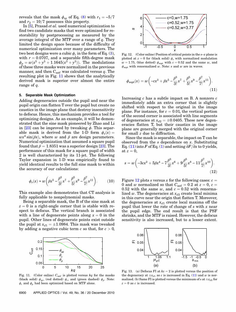
In [5], Prasad et al. used numerical optimization tofind two candidate masks that were optimized for re-storability by postprocessing as measured by theaverage integral of the MTF over a range of q. Theylimited the design space because of the difficulty ofnumerical optimization over many parameters. Thetwo best designs were a cubic ϕc in the form of Eq. (3),with r ¼ 0:0707, and a separable fifth-degree maskϕp ¼ wðx5 þ y5 þ 1:1645ðx3 þ y3ÞÞ. The modulationsof these three masks were normalized in the previousmanner, and then Cmtf was calculated versus q. Theresulting plot in Fig. 11 shows that the analyticallyderived mask is superior over almost the entirerange of q.
5. Separable Mask Optimization
Adding degeneracies outside the pupil and near thepupil origin can flatten T over the pupil but create nocaustics in the image plane that destroy insensitivityto defocus. Hence, this mechanism provides a tool foroptimizing designs. As an example, it will be demon-strated that the sine mask pioneered by Zhao and Liin [23] can be improved by tweaking ϕ. This separ-able mask is derived from the 1-D form ϕsðxÞ ¼wx4 sinðβxÞ, where w and β are design parameters.Numerical optimization that assumed a square pupilfound that β ¼ 1:8351was a superior design [23]. Theperformance of this mask for a square pupil of width2 is well characterized by its 11-jet. The followingTaylor expansion in 1-D was empirically found toyield identical results to the full sine mask to withinthe accuracy of our calculations:
ϕsðxÞ ≈ w
�βx5 − β3
3!x7 þ β5
5!x9 −
β77!
x11�: ð10Þ
This example also demonstrates that CT analysis isfully applicable to nonpolynomial masks.
Being a separable mask, the B of the sine mask atz ¼ 0 is a right-angle corner that is stable with re-spect to defocus. The vertical branch is associatedwith a line of degenerate points along x ¼ 0 in thepupil. Other lines of degenerate points exist outsidethe pupil at xd1 ¼ �1:0984. This mask was tweakedby adding a negative cubic term c so that, for c > 0,
ϕsoptðxÞ ¼ w
�−cx3 þ βx5 − β3
3!x7 þ β5
5!x9 −
β77!
x11�:
ð11ÞIncreasing c has a subtle impact on B. A nonzero cimmediately adds an extra corner that is slightlyshifted with respect to the original in the imageplane. For instance, for c ¼ 0:01, the vertical portionof the second corner is associated with line segmentsof degeneracies at xd2 ¼ �0:0405. These new degen-eracies flatten T, but their caustics in the imageplane are generally merged with the original cornerfor small z due to diffraction.
Since themask is separable, the impact on T can beobserved from the s dependence on x. SubstitutingEq. (11) into F of Eq. (1) and setting ∂F=∂x to 0 yields,at z ¼ 0,
s ¼ w
�−3cx2 þ 5βx4 − 7
β33!
x6 þ 9β55!
x8 − 11β77!
x10�:
ð12ÞFigure 12 plots s versus x for the following cases: c ¼0 and w normalized so that Cmtf ¼ 0:2 at z ¼ 0, c ¼0:52 with the same w, and c ¼ 0:52 with renorma-lized w. The degeneracies at xd2 create local minimain this curve near the origin that flatten T. Moreover,the degeneracies at xd1 create local maxima off thepupil that lower the rate of change of s with x nearthe pupil edge. The end result is that the PSFshrinks, and the MTF is raised. However, the defocussensitivity is also increased, but to a lesser extent.
Fig. 11. (Color online) Cmtf is plotted versus kq for the masks(black solid) ϕsp, (red dotted) ϕc, and (green dashed) ϕp. Note:ϕc and ϕp had been optimized based on MTF alone.
Fig. 12. (Color online) Position of critical points in the s–x plane isplotted at z ¼ 0 for (black solid) ϕs with normalized modulationw ¼ 1:75, (blue dotted) ϕsopt with c ¼ 0:52 and the same w, andϕsopt with renormalized w. Note: s and w are in waves.
Fig. 13. (a) Defocus FI at kz ¼ 2 is plotted versus the position ofthe degeneracy at �xd1 as c is increased in Eq. (11) and w is nor-malized. (b) Same FI is plotted versus the minimum of s at�xd2 forz ¼ 0 as c is increased.
6900 APPLIED OPTICS / Vol. 49, No. 36 / 20 December 2010

The reason is that, as long as the “wells” at the localmimina created by xd2 are shallow, their caustics inthe image plane are absorbed into the on-axis blob bydiffraction. Thus, after renormalization of w, there isa net gain in defocus insensitivity. Performance ac-cording to this metric improves as c increases, butonly to a point.
Figure 13(a) plots the FI of ϕsopt at kz ¼ 2 versusjxd1j as c is increased and w is normalized so thatCmtf ¼ 0:2 at z ¼ 0. Likewise, Fig. 13(b) plots thesame FI versus the value of s at �xd2 for z ¼ 0. TheFI initially decreases by more than 17% in an oscil-latory fashion as jxd1j moves closer to the pupil andthe wells at �xd2 remain shallow. FI then starts toincrease slowly as the wells at xd2 deepen and createa caustic at ever more negative s. Finally FI in-creases rapidly as jxd1j moves onto the pupil edgeat x ¼ 1. This rapid rise points out the potential de-struction of defocus sensitivity by degeneracy. Theminimum FI occurs at c ≈ 0:52 just before the caus-tics from �xd2 become distinct in the exact PSF atz ¼ 0. With this value of c substituted into Eq. (12),ϕsopt and ϕs were compared with the separable cubicand the EU cubic with r ¼ −3 in Eq. (3). Figure 14plots the ratio of FI to Cmtf versus kz. The modula-tions were normalized in the usual manner. The op-timized sine mask performs better than the otherthree by this metric for almost all defocus.
It should be noted that removing degeneracy or get-ting further from degeneracy can also improve perfor-mance under some circumstances. For instance,adding a separable fifth-order term to a separable cu-bic of the same sign adds nonewdegeneracies. By con-trast, T is narrowed because s increases more rapidlywith x. Thus, the PSF grows in size as the MTF falls,but defocus sensitivity decreases. Increasingmodula-tion w has the same effect except that, over a largerange of values of the fifth-order coefficient, renorma-lization to a lower w will leave a net gain in defocusinsensitivity. The caustic is flattened near the focalplane to a greater extent than the MTF is lowered.This effect can be inferred from the B of the swallow-tail catastrophe [19]. If the fifth-order term has theopposite sign of the cubic term, new degeneraciesare typically added only outside the pupil. The T flat-tens, but not by enough for a net gain in defocus insen-sitivity. The deterioration of sensitivity is slow until
the new degeneracy moves onto the pupil. Sensitivityincreases rapidly thereafter.
6. Conclusions
CT illuminates several interesting aspects of phasemasks that are frequently employed in WC. Cubicmasks can generally be classified as one of two cano-nical catastrophes, HU or EU. Separable HU maskshave been analytically shown to be optimum with re-gards todefocus sensitivity, butat theprice of instabil-ity to y-astig. By contrast, a symmetric EU masktrades slightly lower ideal performance for more ro-bustness to aberrations across the field of view andperhaps less strict manufacturing tolerances. Thegeneralization of these results allows us to analyti-cally predict the optimum masks among homoge-neous fifth-order polynomial phases. These shortcutsare equally relevant to other applications, such as in-sensitivity to spherical aberration. Finally, CT pre-dicts how masks based on constrained designspaces can be improved by simple tweaks.
References1. J. O. Casteñeda, L. R. B. Valdos, and E. Montes, “Ambiguity
function as a design tool for high focal depth,” Appl. Opt.27, 790–795 (1988).
2. E. Dowski and W. Cathey, “Extended depth of field throughwavefront coding,” Appl. Opt. 34, 1859–1866 (1995).
3. G. E. Johnson, P. Silveira, and E. Dowski, “Analysis tools forcomputational imaging systems,” Proc. SPIE 5817, 34–44 (2005).
4. Q. Yang, L. Liu, J. Sun, Y. Zhu, and W. Lu, “Analysis of opticalsystems with extended depth of field using the Wigner distri-bution function,” Appl. Opt. 45, 8586–8595 (2006).
5. S. Prasad, T. Torgersen, V. P. Pauca, R. Plemmons, and J. vander Gracht, “Pupil phase optimization for extended-focus,aberration-corrected imaging systems,” Proc. SPIE 5559,335–345 (2004).
6. S. Prasad, T. Torgersen, V. Pauca, R. Plemmons, and J. van derGracht, “Engineering the pupil phase to improve image qual-ity,” Proc. SPIE 5108, 1–12 (2003).
7. T. Vettenburg, N. Bustin, and A. Harvey, “Fidelity optimiza-tion for aberration tolerant hybrid imaging systems,” Opt.Express 18, 9220–9228 (2010).
8. T. Vettenburg, A. Wood, N. Bustin, and A. Harvey, “Optimalityof pupil-phase profiles for increasing the defocus tolerance ofhybrid digital-optical imaging systems,” Proc. SPIE 7429,742903 (2009).
9. G. Muyo, A. Singh, M. Andersson, D. Huckridge, A. Wood, andA. R. Harvey, “Infrared imaging with a wavefront-codedsinglet lens,” Opt. Express 17, 21118–21123 (2009).
10. S. Barwick, “Efficient metric for pupil-phase engineering,”Appl. Opt. 46, 7258–7261 (2007).
11. S. Barwick, “Increasing the information acquisition volumefor iris recognition,” Appl. Opt. 47, 4684–4691 (2008).
12. S. Barwick, “Joint fractional Fourier analysis of wavefront-coding systems,” Opt. Lett. 34, 154–156 (2009).
13. W. Zhang, Z. Ye, T. Zhao, Y. Chen, and F. Yu, “Point spreadfunction characteristics analysis of wavefront codingsystems,” Opt. Express 15, 1543–1552 (2007).
14. S. Sherif, W. Cathey, and E. Dowski, “Phase plate to extenddepth of field of incoherent hybrid imaging systems,” Appl.Opt. 43, 2709–2721 (2004).
15. M. Born and E. Wolf, Principles of Optics (Pergamom, 1985).
Fig. 14. (Color online) The ratio of the defocus FI toCmtf is plottedversus kz for (black solid) ϕsopt with c ¼ 0:52, (red-dashed) ϕs,and the cubic masks with (green dotted) r ¼ 0 and (bluedashed–dotted) r ¼ −3 in Eq. (3). A square pupil of width 2 wasassumed.
20 December 2010 / Vol. 49, No. 36 / APPLIED OPTICS 6901

16. R. Thom, Structural Stability and Morphogenesis(Benjamin, 1972).
17. J. Nye, “Evolution of the hyberbolic umbilic diffraction patternfrom Airy rings,” J. Opt. A Pure Appl. Opt. 8, 304–314 (2006).
18. F. Wright, G. Dangelmayer, and D. Lang, “Singular coordinatesections of the conic umbilic catastrophes,” J. Phys. A 15,3057–3071 (1982).
19. T. Poston and I. Stewart, Catastrophe Theory and ItsApplication (Pitman, 1978).
20. J. W. Goodman, Introduction to Fourier Optics (McGraw-Hill, 1968).
21. D. Bertsekas, Nonlinear Programming (Athena Scientific,1999).
22. G. Siviloglou and D. Christodoulides, “Accelerating finiteenergy Airy beams,” Opt. Lett. 32, 979–981 (2007).
23. H. Zhao and Y. Li, “Optimized sinusoidal phase mask toextend the depth of field of an incoherent imaging system,”Opt. Lett. 35, 267–269 (2010).
6902 APPLIED OPTICS / Vol. 49, No. 36 / 20 December 2010