Embed Size (px)
Citation preview

242
Caso
Lin
e M
FCasoLine MF
Concealed grid MF suspended ceiling system
CasoLine MF is a suspended ceilingsystem suitable for most internaldrylining applications. The grid isfully concealed and the ceiling lining is joint-treated or plastered topresent a seamless, monolithicappearance.
May 2008
www.gypsum.ie
7
CasoLine MF_120408:Layout 1 26/05/2008 15:37 Page 242

243
Caso
Lin
e M
F
Key facts
● Monolithic appearance
● Suspension from concrete or timber floors
● Acoustic hangers provide option of resilient
suspension
● Durable ceiling lining
● Ventilation ducts and other services can be
accommodated in plenum
● Access panels provide services access
● Easy to create bulkheads and change levels
May 2008
2
1
Gypframe MF7 Primary Support Channel
Gypframe MF5 Ceiling Section
Gypframe MF9 Connecting Clip
Gypframe MF6 Perimeter Channel
1
234
3
4
Technical support: T 01 629 8400 E [email protected]
7
CasoLine MF_120408:Layout 1 26/05/2008 15:37 Page 243

ComponentsGyproc and Glasroc board products
Gyproc WallBoard1, 2
Thickness 9.5, 12.5, 15mm
Width 900, 1200mm
Gyproc SoundBloc1
Thickness 12.5, 15mm
Width 1200mm
Gyproc FireLine1, 2
Thickness 12.5, 15mm
Width 1200mm
Glasroc MultiBoard
Thickness 6, 10, 12.5mm
Width 1200mm
Gypframe MF6 Perimeter Channel
Perimeter support for MF5s.
Prime dimensions 20 x 28 x 30mm
Ceiling products
Gypframe MF5 Ceiling Section
Main support section.
Prime dimensions 80 x 26mm
Gyp
Wal
l™ C
LASS
IC
244
Caso
Lin
e M
F
1 Moisture resistant boards are specifed in intermittent wet useareas e.g. shower areas, bathrooms and kitchens.
2 Also available in DUPLEX grades where vapour control is required.
May 2008
Gyptone board products
and
Rigitone board products
Gypframe metal products
www.gypsum.ie
7
Gypframe MF7 Primary Support
Channel
Primary support for MF5s.
Prime dimensions 15 x 45mm
CasoLine MF_120408:Layout 1 26/05/2008 15:37 Page 244

Gyp
Lyn
er™
UN
IVER
SAL
245
Caso
Lin
e M
F
Gypframe metal products Gypframe metal products
Gypframe MF8 Strap Hanger
Suspension of ceiling grid.
Prime dimension 25mm
Gypframe GAH1 Acoustic Hanger
Length 35mm
Gypframe GAH2 Acoustic Hanger
Length 70mm
Gypframe GA1 Steel Angle
Width 25 x 25mm
Gypframe MF9 Connecting Clip
Fixing MF5s to MF7.
Gypframe MF11 Nut and Bolt
Joining hanger to soffit cleat.
Dimensions 6 x 12mm bolt
Gypframe MF12 Soffit Cleat
Suspension point from structural soffit.
Prime dimensions 27 x 37 x 25mm
May 2008
Gyproc Profilex Access Panels
For access to the plenum for
maintenance purposes.
Gyproc Drywall Screws
For fixing boards to framing up to
0.79mm thick.
OR Fixing and finishing products
OR
Technical support: T 01 629 8400 E [email protected]
7Gyproc Wafer Head Jack-Point Screws
For metal-to-metal fixing 0.8mm thick
or greater.
Gyproc Wafer Head Drywall Screws
For metal-to-metal fixing up to 0.79mm thick.
CasoLine MF_120408:Layout 1 26/05/2008 15:37 Page 245
ComponentsFixing and finishing products Fixing and finishing products
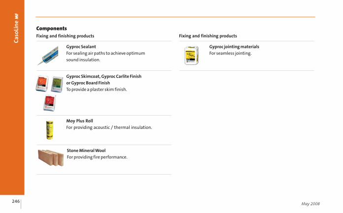
Moy Plus Roll
For providing acoustic / thermal insulation.
Gyp
Wal
l™ C
LASS
IC
246
Caso
Lin
e M
F
May 2008
Gyproc Sealant
For sealing air paths to achieve optimum
sound insulation.
Gyproc jointing materials
For seamless jointing.
Stone Mineral Wool
For providing fire performance.
Gyproc Skimcoat, Gyproc Carlite Finish
or Gyproc Board Finish
To provide a plaster skim finish.
CasoLine MF_120408:Layout 1 26/05/2008 15:38 Page 246

Gyp
Lyn
er™
UN
IVER
SAL
247
Caso
Lin
e M
F
Construction tips
● Estimated construction time 1.5m2 / man hour (single layer ceiling) or 1m2 / man hour (double layer ceiling)
ready for finishing
● Ascertain ceiling height required and set out accordingly
● Plan the ceiling layout. Fixing points for suspending the metal grid are required at 1200mm centres in each
direction. Suitable fixing devices should be employed when fixing to the structure.
● Make provision for an adequate flexible seal between ceiling and walls to counter shrinkage gaps
● Install services before fixing the framework
● Install a vapour control layer, if required, to reduce the risk of interstitial condensation
● Install cavity barriers where specified
● Steel angle provides a more robust suspension support than strap hangers. Gypframe GA1 Steel Angle is
thus the required suspension option when a plaster finish is specified
May 2008
Technical support: T 01 629 8400 E [email protected]
CasoLine MF_120408:Layout 1 26/05/2008 15:38 Page 247

Gyp
Wal
l™ C
LASS
IC
248
Caso
Lin
e M
F
May 2008
Construction tips (cont’d)
● The MF ceiling grid will accept a degree of loading. Suspension and MF7 centres may require closing down –
refer to the Gypsum Industries Product Manual for full details (www.gypsum.ie)
● Pre-determine the position of fixtures and fittings. Fixings must be made into the grid or to supplementary framing
● Gypframe acoustic hangers can be used to suspend the grid from timber joists to maximise the degree of
acoustic isolation. With concrete floors the high mass of the construction means that high levels of acoustic
performance can be achieved when the CasoLine MF ceiling is suspended by conventional means i.e. strap
hangers or angle section
● Consider installing a standard or fire-rated Gyproc Profilex Access Panel at access points (600 x 1200mm
maximum size)
● Air-tightness is essential for optimum sound insulation. Gaps at the perimeter of the ceiling, and other small
airpaths, can be sealed using Gyproc Sealant
● Consider sound absorption requirements. Gyptone and Rigitone boards provide sound absorption when used in
conjunction with an air space behind a ceiling
● Gyproc Control Joints may be required in the ceiling to relieve stresses induced by expansion and contraction
of the structure. It is recommended that they coincide with movement joints within the surrounding structure
www.gypsum.ie
7
CasoLine MF_120408:Layout 1 26/05/2008 15:38 Page 248

Gyp
Lyn
er™
UN
IVER
SAL
249
Caso
Lin
e M
F
Typical Installation for GyprocPlasterboard Ceilings
• Determine the required ceiling leveland mark the position of Gypframe MF6Perimeter Channel on the walls.
• Fix Gypframe MF6 at 600mm centres,using appropriate fixings (by others)around the full perimeter of the ceiling.
• Mark fixing points of Gypframe MF12Soffit Cleats to the structure at 1200mmcentres (to form a 1200 x 1200mm grid).Secure each cleat using suitable fixings(by others).
Construction tips (cont’d)
● The designer should give consideration to designing in a ‘pressure
relief’ to minimise the risk of ceiling ‘lift’ in rooms with no
permanent ventilation. This situation arises when a door is opened
in a virtually leak proof room causing the lightest element in the
room, normally the ceiling, to lift. Making efforts to improve
airtightness in buildings may increase the instances of ceiling lift.
Designing this out by incorporating permanent ventilation would
be desirable.
May 2008
1
Technical support: T 01 629 8400 E [email protected]
7
CasoLine MF_120408:Layout 1 26/05/2008 15:38 Page 249

2 4
Gyp
Wal
l™ C
LASS
IC
250
Caso
Lin
e M
F
May 2008
Standard Hangers - MF8 or GA1
• Pre-cut Gypframe MF8 Strap Hangersor Gypframe GA1 Steel Angle to theapproximate depth of suspensionrequired. Pre-punch or pre-drill tofacilitate fixing to soffit cleat.
• Locate each MF8 strap hanger or anglesection against a Gypframe MF12 SoffitCleat and fix using a Gypframe MF11Nut and Bolt.
3Suspension from timber joists usingGypframe Acoustic Hangers
35m
m
Acoustic Hangers - timber only
• Mark fixing points of Gypframe GAH2Acoustic Hangers to the timber joists at1200mm centres (to form a 1200mm x1200mm grid). Secure each hanger usingtwo Gyproc Drywall Timber Screws. Fix aGypframe MF12 Soffit Cleat to theGypframe Acoustic Hanger using an M6Bolt, washers and locking nut.
Gyproc Drywall Timber Screwsshould achieve a minimum of 25mmpenetration into the timber joist.
• Alternatively, Gypframe GA1 SteelAngle can be cut, bent and drilled tofacilitate direct fixing to the structure(maximum loads will be reduced by 25%if using this method).
If the above method is used, formost double layer ceilings the GypframeGA1 Steel Angles are fixed at max.1200mm centres, but the GypframeMF7s are closed down to 900mm max.centres.
www.gypsum.ie
7
CasoLine MF_120408:Layout 1 26/05/2008 15:38 Page 250
Gyp
Lyn
er™
UN
IVER
SAL
251
Caso
Lin
e M
F
May 2008
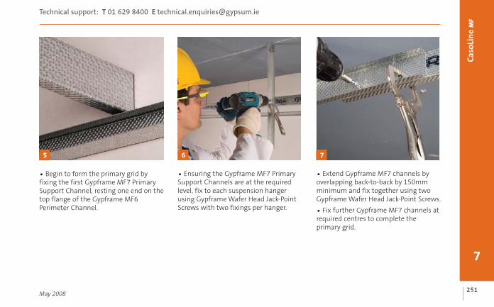
• Begin to form the primary grid byfixing the first Gypframe MF7 PrimarySupport Channel, resting one end on thetop flange of the Gypframe MF6Perimeter Channel.
5
Technical support: T 01 629 8400 E [email protected]
7
6
• Ensuring the Gypframe MF7 PrimarySupport Channels are at the requiredlevel, fix to each suspension hangerusing Gypframe Wafer Head Jack-PointScrews with two fixings per hanger.
• Extend Gypframe MF7 channels byoverlapping back-to-back by 150mmminimum and fix together using twoGypframe Wafer Head Jack-Point Screws.
• Fix further Gypframe MF7 channels atrequired centres to complete theprimary grid.
7
CasoLine MF_120408:Layout 1 26/05/2008 15:38 Page 251

Gyp
Wal
l™ C
LASS
IC
252
Caso
Lin
e M
F
May 2008
10
• Alternatively, screw-fix the GypframeMF5 to the Gypframe MF7 using twoGyproc Wafer Head Jack-Point Screws.
Where ceilings are pitched,screwing of MFS’s to MF7’s isrecommended.
• Form the secondary grid by installingGypframe MF5 Ceiling Section at rightangles to the underside of the primarygrid at 450mm (maximum) centres forGyproc plasterboard ceilings.
• Engage MFS’s into Gypframe MF6Perimeter Channel at the perimeter.
• Connect Gypframe MF5 toGypframe MF7 using Gypframe MF9Connecting Clips.
8
• Use a cut piece of Gypframe MF7(or similar) to facilitate engagementof the second leg of the Gypframe MF9Connecting Clip.
• Do not squeeze the Gypframe MF5Ceiling Section.
9
www.gypsum.ie
7
CasoLine MF_120408:Layout 1 26/05/2008 15:38 Page 252

Gyp
Lyn
er™
UN
IVER
SAL
253
Caso
Lin
e M
F
May 2008
• Extend Gypframe MF5 sections(overlapping by 150mm minimum)and crimp or screw-fix twice througheach flange.
• Ensure that joins do not occur at theintersection of Gypframe MF5 andGypframe MF7 sections, otherwiseengagement of the Gypframe MF9 clipwill be impaired.
11
Technical support: T 01 629 8400 E [email protected]
7
• Install further Gypframe MF5 CeilingSections at required centres to completethe grid.
12 13
Fixtures
• Install additional Gypframe MF5section, close down suspension centresor install supplimentary framing, asrequired, to support fixtures and fittings.
• Where apertures are cut in the ceilingto accomodate fixtures, additionalframing will be required to supportperimeters around the opening.
Additional suspension supportmay be required to independentlysupport heavier fixtures.
CasoLine MF_120408:Layout 1 26/05/2008 15:38 Page 253

15
Gyp
Wal
l™ C
LASS
IC
254
Caso
Lin
e M
F
May 2008
Fixing Gyproc boards
• Fix boards to Gypframe MF5 sectionswith long edges at right angles to theframing using Gyproc Drywall Screws.Lightly butt board ends inserting fixingsnot closer than 10mm from boundboard edges and 13mm from cut edges.Stagger end joints.
• Insert screws at 230mm maximumcentres in the field of boards and 150mmmaximum centres at board ends.
14
1200mm
450mm
1200mm
Installing access panels
• Fix a standard or fire-rated GyprocProfilex Access Panel, if specified
Services• Route all services including ducting,pipework, electrical cables and conduit,within the plenum.
Consideration must be given tomaintaining the integrity of the ceilingto meet fire resistance and soundinsulation requirements.
• For double layer linings stagger boardjoints in the second layer relative tothe first.
Consideration should be given toany uneveness of the perimeter walls. Thehigh and low spots could be establishedby use of a chalk line and the framing outand boarding procedure should beadjusted accordingly.
www.gypsum.ie
7
CasoLine MF_120408:Layout 1 26/05/2008 15:38 Page 254

Gyp
Lyn
er™
UN
IVER
SAL
Gyp
Lyn
er™
UN
IVER
SAL
255
Caso
Lin
e M
F
May 2008
7
Technical support: T 01 629 8400 E [email protected]
16 17
Gypframe MF8 Strap Hanger or Gypframe GA1 Steel Angle
Gypframe MF5 Ceiling Section
Gypframe MF7 Primary Support Channel
Ceiling boards
Junction details
12
Perimeter fixing Gypframe MF5 Ceiling SectionPerimeter arrangement - Gypframe MF7 Primary
Support Channel
6
2
4
5
34
Gypframe MF6 Perimeter Channel
Wall structure5
6
3
1
4
5
6
CasoLine MF_120408:Layout 1 26/05/2008 15:38 Page 255

1918
Gyp
Wal
l™ C
LASS
IC
256
Caso
Lin
e M
F
May 2008
Bulkhead Change of level
3
2
4
5
Gypframe MF8 Strap Hanger or Gypframe GA1 Steel Angle
Gypframe MF5 Ceiling Section
Gypframe MF7 Primary Support Channel
Ceiling boards
Gypframe MF6 Perimeter Channel
12
34
Gypframe MF12 Soffit Cleat
Gypframe MF11 Nut and Bolt
Gyproc Wafer Head Jack-Point Screw
Gypframe MF9 Connecting Clip
5
6
789
4
2
3
1
5
5
2
6
7
6
7
1
8
9
www.gypsum.ie
7
CasoLine MF_120408:Layout 1 26/05/2008 15:38 Page 256

Gyp
Lyn
er™
UN
IVER
SAL
257
Caso
Lin
e M
F
May 2008
Technical support: T 01 629 8400 E [email protected]
7
Typical Installation for a Gyptone CeilingSystem
• Install framework as per a typicalGyproc Plasterboard MF Ceiling Systemwith the exception that the MF5s areinstalled at 600mm centres to coincidewith the unperforated areas.
• In high humidity areas, install MF5s at400mm centres.
• To aid finishing of the boards, Gyptoneboards joints are generally in-line(i.e. not staggered)
20 21 22
Typical Installation for a Rigitone CeilingSystem• Determine the required ceiling leveland mark the position of GypframeMF6a Perimeter Channel on the walls.
• Fix MF6a at 600mm centres usingappropriate fixings.
For Rigitone boards: Fix MF6APerimeter Channels through 25 x 25mmtimber battens (see Figs 22 and 23),forming a 10mm shadow gap detailaround the perimeter of the ceiling.
• The Gypframe MF7 Primary SupportChannels are installed at 1000mmcentres. A fixing point should beprovided at 900mm centres along MF7.Gypframe MF5 Ceiling Sections are atnominal 330mm centres. The first MF5should be a maximum 150mm from theperimeter wall.
• The framework should be assembledand adjusted in such a way that theRigitone perforated boards are fixed toMF5 ceiling sections with long edges at
Section AA
See fig. 22
See fig. 23B
B
A A
1000mmmax
CasoLine MF_120408:Layout 1 26/05/2008 15:38 Page 257
Gyp
Wal
l™ C
LASS
IC
258
Caso
Lin
e M
F
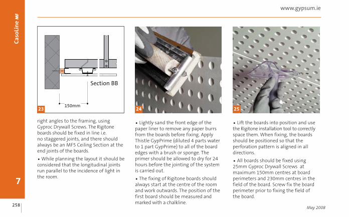
right angles to the framing, usingGyproc Drywall Screws. The Rigitoneboards should be fixed in line i.e.no staggered joints, and there shouldalways be an MF5 Ceiling Section at theend joints of the boards.
• While planning the layout it should beconsidered that the longitudinal jointsrun parallel to the incidence of light inthe room.
May 2008
• Lightly sand the front edge of thepaper liner to remove any paper burrsfrom the boards before fixing. ApplyThistle GypPrime (diluted 4 parts waterto 1 part GypPrime) to all of the boardedges with a brush or sponge. Theprimer should be allowed to dry for 24hours before the jointing of the systemis carried out.
• The fixing of Rigitone boards shouldalways start at the centre of the roomand work outwards. The position of thefirst board should be measured andmarked with a chalkline.
• Lift the boards into position and usethe Rigitone installation tool to correctlyspace them. When fixing, the boardsshould be positioned so that theperforation pattern is aligned in alldirections.
• All boards should be fixed using25mm Gyproc Drywall Screws atmaximum 150mm centres at boardperimeters and 230mm centres in thefield of the board. Screw fix the boardperimeter prior to fixing the field ofthe board.
7
www.gypsum.ie
2423 25
Section BB
150mm
CasoLine MF_120408:Layout 1 26/05/2008 15:38 Page 258

Gyp
Lyn
er™
UN
IVER
SAL
259
Caso
Lin
e M
F
No fixings should be made into MF6APerimeter Channels. Outermost fixings inline with MF5 ceiling section should be amaximum of 150mm from perimeter.Outermost fixings perpendicular toMF5 ceiling sections should be amaximum of 15mm from edge of MF6APerimeter Channel.
• Mix the Rigitone Vario 60 filler withclean water (approximately 3 partswater to 1 part filler) and fill a cartridgewith the mixture. Insert the bung andscrew the nozzle onto the end of thecartridge. Apply the filler to the jointsensuring the joint is completely full.Failure to fully fill the joint can causethe joint to crack.
Once the cartridge is empty the bungshould be removed for reuse using thetool supplied.
• The filler should be left to dry for aminimum of 50 minutes before strikingthe excess material away from the joint.
May 2008
7
Technical support: T 01 629 8400 E [email protected]
26 27
CasoLine MF_120408:Layout 1 26/05/2008 15:38 Page 259
Gyp
Wal
l™ C
LASS
IC
260
Caso
Lin
e M
F
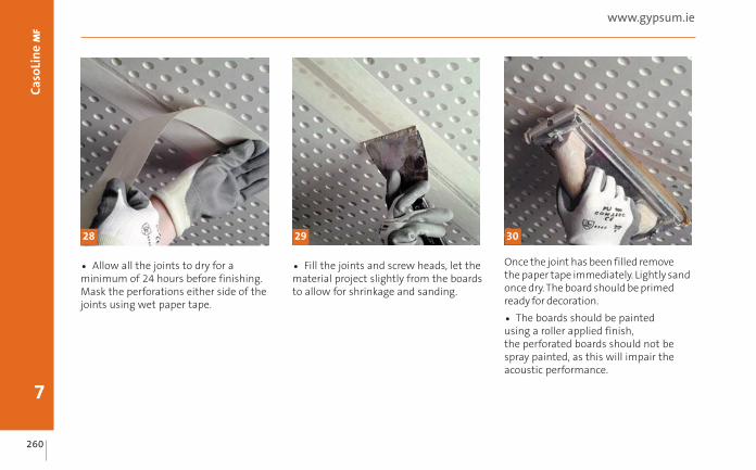
• Allow all the joints to dry for aminimum of 24 hours before finishing.Mask the perforations either side of thejoints using wet paper tape.
• Fill the joints and screw heads, let thematerial project slightly from the boardsto allow for shrinkage and sanding.
Once the joint has been filled removethe paper tape immediately. Lightly sandonce dry. The board should be primedready for decoration.
• The boards should be paintedusing a roller applied finish,the perforated boards should not bespray painted, as this will impair theacoustic performance.
7
www.gypsum.ie
28 29 30
CasoLine MF_120408:Layout 1 26/05/2008 15:38 Page 260

Gyp
Lyn
er™
UN
IVER
SAL
261
Caso
Lin
e M
F
7
Technical support: T 01 629 8400 E [email protected]
CasoLine MF_120408:Layout 1 26/05/2008 15:38 Page 261