Embed Size (px)
Citation preview

User’sManual
CAN BUS INTERFACE Module
IM 707081-01E1st Edition
IM 707081-01E 1
Disk No. WE21
1st Edition: May 2003 (YK)
All Rights Reserved, Copyright © 2003 Yokogawa Electric Corporation
Thank you for purchasing the WE7081 CAN BUS INTERFACE Module for the WE7000PC-Based Measurement Instruments.
This user’s manual contains useful information about the function, connection to themeasuring station, operations of the software on the PC, and troubleshooting of theWE7081. This manual assumes that you will be using the WE7000 Control Software
that is included with the measuring station.
The manual listed below contains general information about the WE7000 (primarilydescribes the operations of the measuring station, the optical interface module, theoptical interface card, and the WE7000 Control Software) and is included with the
measuring station.
Manual Title Manual No. Note
WE7000 User’s Manual IM 707001-01E User’s manual for the WE7000.
To ensure correct use, please read this manual thoroughly before beginning operation.After reading the manual, keep it in a convenient location for quick reference whenever a
question arises during operation.
Notes• The contents of this manual describe WE7000 Control Software Ver. 4.6.0.0 and
module software Ver. 2.01. The operating procedures and screen contentsdescribed in this manual may differ from those in other versions of the software.
• The contents of this manual are subject to change without prior notice as a result ofcontinuing improvements to the instrument’s performance and functions.
• Every effort has been made in the preparation of this manual to ensure the accuracyof its contents. However, should you have any questions or find any errors, pleasecontact your nearest YOKOGAWA dealer.
• Copying or reproducing all or any part of the contents of this manual without thepermission of Yokogawa Electric Corporation is strictly prohibited.
Trademarks• Microsoft, Windows, and Windows NT are either registered trademarks or trademarks
of Microsoft Corporation in the United States and/or other countries.• Adobe and Acrobat are trademarks of Adobe Systems incorporated.
• All other company and product names used in this manual are trademarks orregistered trademarks of their respective companies.
Revisions1st Edition: May 2003

IM 707081-01E2
Checking the Contents of the Package
Unpack the box and check the contents before operating the instrument. If some of thecontents are not correct or missing or if there is physical damage, contact the dealer
from which you purchased them.
Measurement ModuleCheck that the model name given on the name plate matches those on the order.MODEL
Model Suffix Code Description
WE7081 CAN BUS INTERFACE Module/HE English help message
NO. (Instrument Number)When contacting the dealer from which you purchased the instrument, please give them
the instrument number.
MODELMODELNO.NO.
Made in Japan
Standard AccessoriesThe standard accessories below are supplied with the instrument. Check that allcontents are present and that they are undamaged.User’s manual (this manual) 1 piece
IM 707081-01E

IM 707081-01E 3
How to Use This Manual
Structure of the ManualThis user’s manual consists of the following sections:
Chapter Title Description
1 Explanation of Functions Explains the system configuration, functions, and setupoperations.
2 Hardware Preparation Explains how to install the module into the measuringstation and how to connect the input.
3 Troubleshooting and Explains the procedures for troubleshooting and selfMaintenance testing.
4 Specifications Explains the specifications of the module.
Appendix Gives sample point tables.
Index Index of contents.
Conventions Used in This ManualUnitk: Denotes “1000.” Example: 100 kHz
K: Denotes “1024.” Example: 720 KB
Bolded CharactersBolded characters are mainly characters and numbers that appear on the display.
Safety MarkingsThe following markings are used in this manual.
Danger. Refer to corresponding location on the instrument. Thissymbol appears on dangerous locations on the instrument whichrequire special instructions for proper handling or use. The same
symbol appears in the corresponding place in the manual toidentify those instructions.
WARNING Calls attention to actions or conditions that could cause seriousinjury or death to the user, and precautions that can be taken to
prevent such occurrences
CAUTION Calls attentions to actions or conditions that could cause light
injury to the user or damage to the instrument or user’s data, andprecautions that can be taken to prevent such occurrences.
Note Calls attention to information that is important for proper operationof the instrument.

IM 707081-01E4

IM 707081-01E 5
Contents
Checking the Contents of the Package ................................................................................................ 2
How to Use This Manual ...................................................................................................................... 3
Chapter 1 Explanation of Functions1.1 System Configuration, Block Diagram, Frame Types and Format, and Operation Panel .... 1-1
1.2 Operation Modes and Common Settings ............................................................................. 1-5
1.3 Data Block Signal Acquisition/Frame Output Mode (Acquisition) ......................................... 1-9
1.4 Data Frame Acquisition Mode (Frame Acquisition) ............................................................ 1-25
1.5 Data Block Signal Output Mode (Output) ........................................................................... 1-30
1.6 Data Frame Output Mode (Frame Output) ......................................................................... 1-36
1.7 Displaying Waveforms, Saving Acquired Data Automatically, Converting Files, and Other
Functions ............................................................................................................................ 1-39
1.8 WCF⇔CSV converter and WVF⇒WCF Converter ............................................................ 1-40
1.9 Names and Functions of Sections ...................................................................................... 1-45
Chapter 2 Hardware Preparation2.1 Installing the Module into the Measuring Station .................................................................. 2-1
2.2 Connecting the Input/Output Signal Cable ........................................................................... 2-3
2.3 Terminator ............................................................................................................................. 2-4
Chapter 3 Troubleshooting and Maintenance3.1 Troubleshooting .................................................................................................................... 3-1
3.2 Self Test ................................................................................................................................ 3-2
3.3 Maintenance ......................................................................................................................... 3-3
Chapter 4 Specification4.1 Performance Specifications .................................................................................................. 4-1
4.2 Specifications Specific to Operation Modes ......................................................................... 4-2
4.3 Default Values (Factory Default Settings) ............................................................................. 4-5
4.4 General Specifications.......................................................................................................... 4-7
4.5 Dimensional Drawings .......................................................................................................... 4-8
AppendixAppendix 1 Sample Point Table ....................................................................................................App-1
Appendix 2 Data Structure of Files ...............................................................................................App-6
Appendix 3 Error Codes ...............................................................................................................App-7
Index
1
2
3
4
App
Index

1-1
Exp
lanatio
n o
f Fu
nctio
ns
IM 707081-01E
1
Chapter 1 Explanation of Functions
1.1 System Configuration, Block Diagram, FrameTypes and Format, and Operation Panel
System ConfigurationThe following is an example in which the WE7081 CAN BUS INTERFACE Module is
installed into the measuring station and the measuring station is connected to the PCwith the optical fiber cable.
Data monitor onthe CAN Bus
Data input Data output
Other measurementmodules that inputanalog signals suchas sensors
Optical fiber cable
Measuringstation
Opticalinterfacemodule
WE7081PC
Optical interface card
RL RLTerminalregister
Bus line
CANnode 1
CANnode 2
CANnode N

1-2 IM 707081-01E
Block Diagram
SJA1000 CANController
WE businterface
WE bus
Interrupt
Module controlprogram flash
memory
CPU
EPROM
DPRAM
SRAM
SDRAM
Flash ROM
Tran-sceiver
Photo-coupler
Input/outputconnector
TerminationSW
Termi-nator
CAN I/F block
Description of OperationThis modules is connected to a CAN Bus conforming to ISO-11898 as a single node. Itcan read the data frames that flow through the CAN Bus and output data frames andremote frames to the CAN Bus.
The module receives frames by reading the frames transmitted by other nodes throughthe input/output connector (D-Sub 9 pin). If the frame is a data frame, it is retrievedusing the CAN controller (SJA1000) by Philips that is isolated using a photocoupler in theCAN I/F block. The data frame is then written to the temporary buffer on the SRAM. As
necessary, the data in the temporary buffer is re-sampled using a clock of a constantperiod and stored in the data memory within the SDRAM.The module transmits frames by downloading the transmission data frame or remote
frame that is defined at the software level to the SDRAM via the DPRAM and passing theframe to the CAN controller (SJA1000). The module is capable of transmitting remoteframes while acquiring data.
The module is characterized by a local CPU that is dedicated to transmitting/receivingdata to/from the CAN bus via the DPRAM and controlling the system according to theWE7000 firmware. The CPU runs according to the firmware in the flash ROM and issues
CAN Bus input/output instructions to the controller. It also controls the functions to theleft of the DPRAM in the above figure such as communicating with the WE7000 mainCPU through the interface consisting of the DPRAM and interrupt signals.
1.1 System Configuration, Block Diagram, Frame Types and Format, and Operation Panel

1-3
Exp
lanatio
n o
f Fu
nctio
ns
IM 707081-01E
1Frame Types
The WE7081 handles the following three types of frames.Data FrameFrame used to transmit data on the CAN Bus. The figure below shows structure of the
data frame.
Start of
Frame
1
IdentifierField
11
RTR
1
ControlField
6
DataField
0-8 Byte
0-64
CRCSequence
15
CRCDel
1
ACKSlot
1
ACKDel
1
End of
Frame
7
ITM
3
BusIdle
InterframeSpace
InterframeSpace
r1 r2 d1d2 d0d3
DLC(Data Length Code)0 0reserviert
Data Frame
recessive
dominant
Remote FrameFrame used by the transmitter node to request data corresponding to the specifiedmessage ID to other nodes. On the WE7081, remote frames can be issued for each
message ID to request data.The remote frame format conforms to the data frame but there is no data field.
Start of
Frame
1
IdentifierField
11
RTR
1
ControlField
6
CRCSequence
15
CRCDel
1
ACKSlot
1
ACKDel
1
End of
Frame
7
ITM
3
BusIdle
InterframeSpace
InterframeSpace
Data Frame
recessive
dominant
Error FrameFrame generated when an error is detected on the CAN Bus. On the WE7081, the error
indicator on the front panel illuminates when an error frame is detected.
Error Flag
6
Superposition of Error Flags
0-6
ErrorDelimiter
8
Data Frame Error Framerecessive
dominant
Frame FormatThe WE7081 supports both the standard and extended formats.Standard Format
Start of
Frame
1
IdentifierField
11 Bit RTR
1 1 1 (0-8 Byte)
DataField
0-64 Bit
CRCSequence
15
CRCDel
1
ACKSlot
1
ACKDel
1
End of
Frame
7
Data Field
recessive
dominant
IDE(r1)
r0
ArbitrationField
Control Field
DLC
Data CRC ACK
4
Extended Format
Start of
Frame
1
IdentifierField
11 Bit
ExtendedIdentifier
Field
18 BitSRR
1
RTR
1 1 1 (0-8 Byte)
DataField
0-64 Bit
CRCSequence
15
CRCDel
1
ACKSlot
1
ACKDel
1
End of
Frame
7
Data Field
recessive
dominant
r1
1
IDE r0
Arbitration Field Control Field
DLC
Data CRC ACK
4
29 Bit
1.1 System Configuration, Block Diagram, Frame Types and Format, and Operation Panel

1-4 IM 707081-01E
Operation PanelThe WE7000 Control Software that is installed in the PC is used to control the WE7081CAN BUS INTERFACE Module. The WE7000 Control Software displays operationpanels similar to those shown in sections 1.3 to 1.6. This user’s manual does not explain
the operations of the operation panel or waveform monitor. For the operations of theseitems, see the on-line help that is provided with the WE7000 Control Software.
1.1 System Configuration, Block Diagram, Frame Types and Format, and Operation Panel
1-5
Exp
lanatio
n o
f Fu
nctio
ns
IM 707081-01E
11.2 Operation Modes and Common Settings
Operation ModesThe WE7081 has the following four operation modes for you to choose from.
Data Block Signal Acquisition/Frame Output Mode (Acquisition)Acquires a specified block (data block) of the data field defined as channel setting
information from the data frame flowing on the CAN Bus and resamples and converts thedata to time-series data. The CANdb database file from Vector Informatik can also beused to define the CAN data.
Like the digitizer module, this module can perform free-run measurement and triggermeasurement. The acquired data can be displayed on the waveform monitor on the PC,the instantaneous values can be displayed, and the data can be saved to files. In
addition, you can specify multiple data frames to be output periodically, when triggers aredetected, when remote frames are received, or at an arbitrary time. Furthermore, thedata frames can be output according to a predefined sequence.
Data Frame Acquisition Mode (Frame Acquisition)Receives data frames flowing on the CAN Bus and stores them along with the reception
time information indicating the time elapsed since the trigger was detected andacquisition was started. The resolution is 100 µs. You can limit the received framesusing an ID filter, specify the number of data frames to be acquired, and save the data
stored to the memory to a WCF binary file (.wcf) or ASCII data file in CSV format (.csv)on the PC.The saved data can be output on the CAN Bus using the frame output mode.
Data Block Signal Output Mode (Output)Combines data frames by the ID according to the conditions defined as channel setting
information and outputs the data periodically on the CAN Bus. The data block to beoutput can be swept in a ramp or triangular shape with time.
Data Frame Output Mode (Frame Output)Loads the frame data file in WCF or CSV format from the PC and transmits the dataframes on the CAN Bus. You can specify the repetition count for outputting the loaded
data frame. Trigger detection can be used to control the output timing.
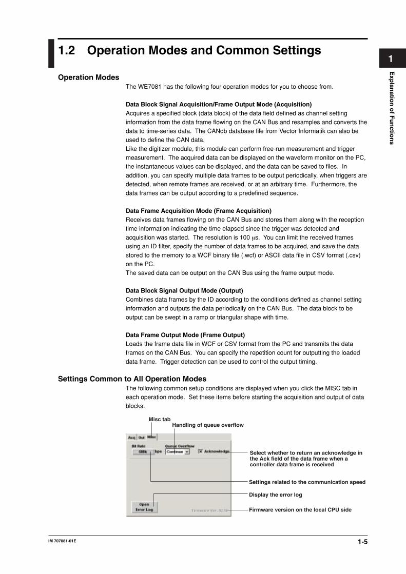
Settings Common to All Operation ModesThe following common setup conditions are displayed when you click the MISC tab ineach operation mode. Set these items before starting the acquisition and output of datablocks.
Select whether to return an acknowledge in the Ack field of the data frame when a controller data frame is received
Misc tabHandling of queue overflow
Firmware version on the local CPU side
Settings related to the communication speed
Display the error log
1-6 IM 707081-01E
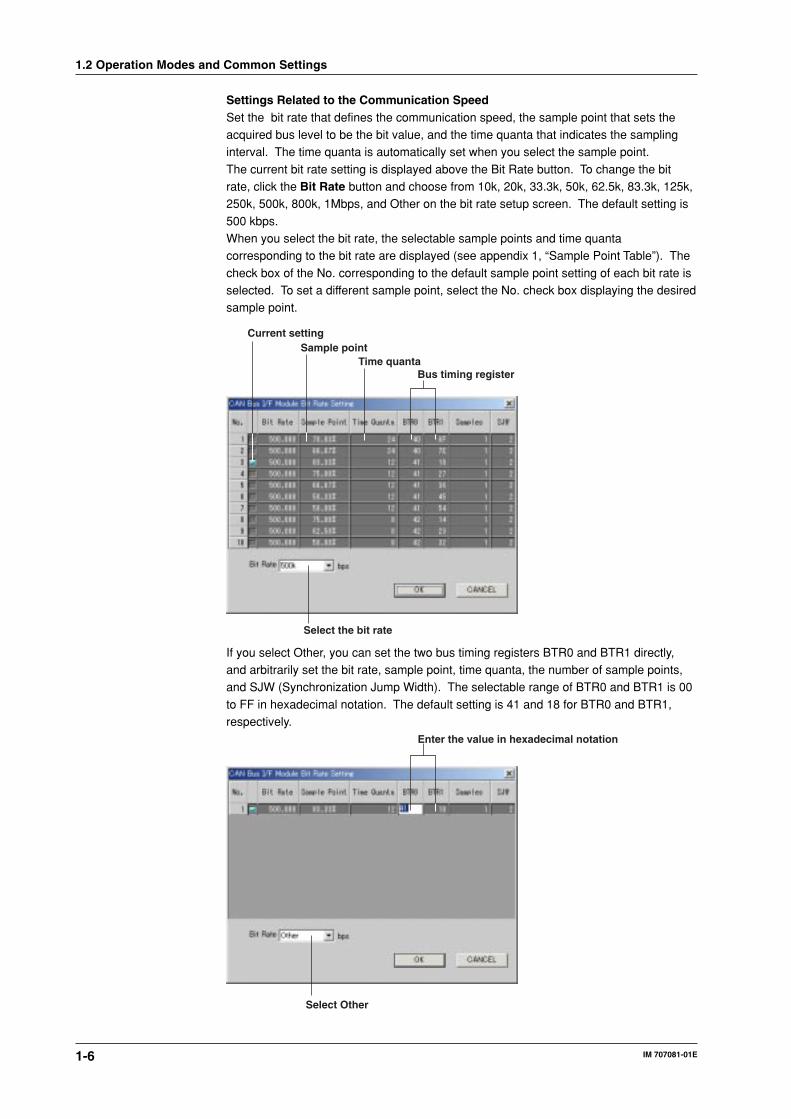
Settings Related to the Communication SpeedSet the bit rate that defines the communication speed, the sample point that sets theacquired bus level to be the bit value, and the time quanta that indicates the samplinginterval. The time quanta is automatically set when you select the sample point.
The current bit rate setting is displayed above the Bit Rate button. To change the bitrate, click the Bit Rate button and choose from 10k, 20k, 33.3k, 50k, 62.5k, 83.3k, 125k,250k, 500k, 800k, 1Mbps, and Other on the bit rate setup screen. The default setting is
500 kbps.When you select the bit rate, the selectable sample points and time quantacorresponding to the bit rate are displayed (see appendix 1, “Sample Point Table”). The
check box of the No. corresponding to the default sample point setting of each bit rate isselected. To set a different sample point, select the No. check box displaying the desiredsample point.
Current settingSample point
Time quantaBus timing register
Select the bit rate
If you select Other, you can set the two bus timing registers BTR0 and BTR1 directly,and arbitrarily set the bit rate, sample point, time quanta, the number of sample points,and SJW (Synchronization Jump Width). The selectable range of BTR0 and BTR1 is 00
to FF in hexadecimal notation. The default setting is 41 and 18 for BTR0 and BTR1,respectively.
Enter the value in hexadecimal notation
Select Other
1.2 Operation Modes and Common Settings

1-7
Exp
lanatio
n o
f Fu
nctio
ns
IM 707081-01E
1The definition of BTR0 and BTR1 conforms to the specifications of the Philips SJA1000
CAN Controller. The following description is based on the data sheet of the SJA1000CAN Controller.BTR0 (Bus Timing Register 0)BTR0 determines the BRP (Bit Rate Prescaler) and SJW (Synchronization Jump Width)using the following bit assignments.
BIT 7 BIT 6 BIT 5 BIT 4 BIT 3 BIT 2 BIT 1 BIT 0
SJW.1 SJW.0 BRP.5 BRP.4 BRP.3 BRP.2 BRP.1 BRP.0
• BRP(Baud Rate Prescaler)
The CAN system clock cycle tscl is variable. It determines the bit timing.The CAN system clock cycle tscl is derived from the following equation.tscl =2 * tCLK * (32 * BRP.5+16 * BRP.4+8 * BRP.3+4 * BRP.2+2 * BRP.1 * BRP.0+1)
where tCLK is the WE7081 internal clock cycle which is equal to 1/XTAL=1/24000000.• SJW (Synchronization Jump Width)
Re-synchronization of signals is carried out to correct the clock phase shifts of bus
controllers of other nodes connected to the same bus.When carrying out re-synchronization, the maximum clock cycles in a bit period isactually longer or shorter than the setting. To correct this difference, you set tSJW
(Synchronization Jump Width). The variable tSJW is derived from the followingequation.tSJW =tscl * (2 * SJW.1 +SJW.0 +1)
BTR1 (Bus Timing Register 1)BTR1 defines the two time segment lengths within a bit period, sample point, and thenumber of samples using the following bit assignments.
BIT 7 BIT 6 BIT 5 BIT 4 BIT 3 BIT 2 BIT 1 BIT 0
SAM TSEG2.2 TSEG2.1 TSEG2.0 TSEG1.3 TSEG1.2 TSEG1.1 TSEG1.0
• SAM (Sampling)
When SAM = 1, the bus is sampled three times. It is recommended for low/mediumspeed buses.When SAM = 0, the bus is sampled once. It is recommended for high speed buses.
• TSEG1 (Time Segment 1) and TSEG2 (Time Segment 2)TSEG1 and TSEG2 determine the number of clock samples per bit period and thesample point.
tSYNCSEG =1 * tscl[s]tTSEG1 =tscl * (8 * TSEG1.3 + 4 * TSEG1.2 + 2 * TSEG1.1 + TSEG1.0 + 1)[s]tTSEG2 =tscl * (4 * TSEG2.2 + 2 * TSEG2.1 + TSEG2.0 + 1)[s]
As a result, the bit rate is also determined as indicated by the following equation.Bit rate =1/(tSYNCSEG + tTSEG1 + tTSEG2)[bps]
Handling When the Queue Overflows (Queue Overflow)If you select Continue, acquisition or output continues even if the data acquisition oroutput queue buffer overflows. In this case, the operation continues, but data dropout
occurs in the acquisition or output.If you select Stop, acquisition or output stops when the data acquisition or output queuebuffer overflows.
1.2 Operation Modes and Common Settings

1-8 IM 707081-01E
AcknowledgeSelects whether the controller returns an acknowledge in the Ack field of the data framewhen data frames are received in data block signal acquisition/frame output mode anddata frame acquisition mode (Frame Acquisition). In general, acknowledge is returned
when used as a virtual node and not returned when used as a bus monitor. Ifacknowledge is not returned, remote frame output and frame output do not work. Thedefault setting is to return acknowledges.
This check box is used to select whether frames are retransmitted (check box selected)or not retransmitted (check box not selected) when an acknowledge is not received indata block signal output mode (Output) and data frame output mode (Frame Output).
The default setting is to retransmit the frame.
Displaying the Error LogLists the log of errors that the controller detected. If you click the Open Error Log button,a separate dialog box displaying the error log opens.The dialog box shows the newest 64 errors at the time the dialog box was opened. The
errors before those shown on the log do not remain. In addition, the log that is displayedis cleared when you close the dialog box. For details on the error codes, see appendix3, “Error Codes.”
Firmware Version (Ver.XX.XX) on the Local CPU SideDisplays the firmware version number on the local CPU side.
1.2 Operation Modes and Common Settings

1-9
Exp
lanatio
n o
f Fu
nctio
ns
IM 707081-01E
11.3 Data Block Signal Acquisition/Frame Output
Mode (Acquisition)Operation Panel
Start/Stop acquisition
Set the data sampling interval
Turn ON/OFF waveform monitor
Select the operation modeSetup window for the data field extraction conditions (see page 1-11)
Set the number of memory partitions
Set the record length
Set the number of acquisitions
Select the time base
Select the acquisition mode
Select the trigger sourceSet the pretrigger
Set the trigger hold off
Select the check box for repetitive acquisition
Selecting the (Operation Mode)Select Acquisition.
Start/Stop Data AcquisitionClick the Start button to start data acquisition according to the specified acquisition
mode. If you select the Repeat check box*, acquisition continues until you press theStart button again.
* The Repeat check box appears only when you set the acquisition mode to Triggered, and the
number of acquisitions to 1.
Acquisition ModeSelect either of the following.Trigger Mode (Triggered)Acquires data to the data memory according to the specified trigger conditions (see thenext page) and stops the operation when the specified record length of data is acquired.In this mode, the data memory can be partitioned and the data can be written to the
individual memory blocks each time a trigger occurs. If you set the number ofacquisitions (see the next page) to 1 and select the Repeat check box, the sameoperation is repeated until you click the Start button again. However, if the record length
is set to a value greater than 4,194,304/the number of channels/data size,measurements cannot be repeated.
Free Run Mode (Free Run)Acquisition of the data starts immediately upon starting the measurement. The operationstops when the measurement is stopped.
1-10 IM 707081-01E
Trigger Setting (only when the acquisition mode is set to Trigger)Trigger Source (Source)Select the trigger source signal from the following:Internal: Trigger is activated according to the trigger condition of each channel
specified on the channel setting panel.BUSTRG: Bus signal (BUSTRG1/BUSTRG2) of the WE bus
PretriggerThe data before the trigger point can be acquired to the data memory. Set how manypoints before the trigger point to begin the acquisition in the range, “0 to the specified
record length – 2.”
Trigger Hold OffIf the number of acquisitions is set to value greater than or equal to 2, you can specifythe trigger hold off period that is used to temporarily stop the detection of the next triggeronce a trigger occurs. Enter the number of samples for the hold off period in the Hold Off
box. The hold off period can be set in the range of “the record length to 8,388,608” (datapoints).
Data Acquisition ConditionMemory Partition (only in trigger mode)You can divide the data memory into multiple blocks and acquire the data to the memory
blocks in order every time the trigger occurs. You can divide the memory into 1, 2, 4, 8,16, 32, 64, 128, or 256 partitions.
Record Length (only in trigger mode)The number of data points acquired in the data memory is called the record length. Theselectable range is “100 to 8,388,608/(the number of acquisition channels × acquisitiondata size × the number of memory partitions)” points. The maximum selectable number
of points when data is repetitively acquired by selecting the Repeat check box is“4,194,304/(the number of memory partitions) × the number of acquisition channels)/acquisition data size)” points.
No. of Acquisitions (only in trigger mode)Set the number of times to carry out data acquisition. The selectable range is 1 to
2,147,483,647 times. However, repeat is possible only when the number of acquisitionsis 1. In addition, even if the number of acquisitions is “1”, but the record length is set to avalue greater than or equal to “4,194,304/the number of channels/data size,” repeat is
not possible.
Time BaseSelect whether to sample the input signal with the specified sampling interval based onthe module’s internal clock or to sample with the time base signal of the measuringstation.
Internal: Internal clockBUSCLK: Input signal (CMNCLK) according to the trigger source/time base source/
arming setting (see section 4.6, “Setting Trigger Source/Time Base Source/
Arming” in the WE7000 User’s Manual (IM707001-01E)).
1.3 Data Block Signal Acquisition/Frame Output Mode (Acquisition)
1-11
Exp
lanatio
n o
f Fu
nctio
ns
IM 707081-01E
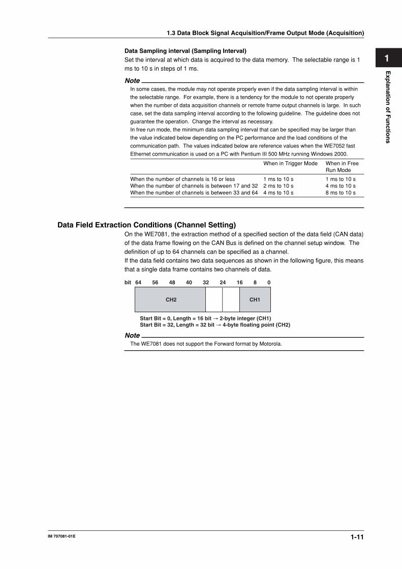
1Data Sampling interval (Sampling Interval)Set the interval at which data is acquired to the data memory. The selectable range is 1ms to 10 s in steps of 1 ms.
NoteIn some cases, the module may not operate properly even if the data sampling interval is within
the selectable range. For example, there is a tendency for the module to not operate properly
when the number of data acquisition channels or remote frame output channels is large. In such
case, set the data sampling interval according to the following guideline. The guideline does not
guarantee the operation. Change the interval as necessary.
In free run mode, the minimum data sampling interval that can be specified may be larger than
the value indicated below depending on the PC performance and the load conditions of the
communication path. The values indicated below are reference values when the WE7052 fast
Ethernet communication is used on a PC with Pentium III 500 MHz running Windows 2000.
When in Trigger Mode When in FreeRun Mode
When the number of channels is 16 or less 1 ms to 10 s 1 ms to 10 sWhen the number of channels is between 17 and 32 2 ms to 10 s 4 ms to 10 sWhen the number of channels is between 33 and 64 4 ms to 10 s 8 ms to 10 s
Data Field Extraction Conditions (Channel Setting)On the WE7081, the extraction method of a specified section of the data field (CAN data)of the data frame flowing on the CAN Bus is defined on the channel setup window. The
definition of up to 64 channels can be specified as a channel.If the data field contains two data sequences as shown in the following figure, this meansthat a single data frame contains two channels of data.
Start Bit = 0, Length = 16 bit → 2-byte integer (CH1)Start Bit = 32, Length = 32 bit → 4-byte floating point (CH2)
bit 64 56 48 40 32 24 16 8 0
CH2 CH1
NoteThe WE7081 does not support the Forward format by Motorola.
1.3 Data Block Signal Acquisition/Frame Output Mode (Acquisition)

1-12 IM 707081-01E
Click Channel Setting to define the data block to be extracted and set the internal
trigger, alarm, and other settings.
For extended format
Execute the copy operation
Set the ID of the data frame to be acquired
Select the channel
Set the alarm output
Set the internal trigger
Select the item to be copied
Set the data bit length
Set the start position for extracting data
Select the data typeSet the Endian
• When in free run mode• When in trigger mode
Set the trigger combination
Select the handling of invalid values
• Section common to trigger mode and free run mode
Set the scalingWhen carrying out scaling
Set the unit
Displays the size of the data to be extracted
Set the label
Select the scaling type
Use the database file
Set the remote frameSet the frame output value (see pages 1-19 to 1-22)
1.3 Data Block Signal Acquisition/Frame Output Mode (Acquisition)
1-13
Exp
lanatio
n o
f Fu
nctio
ns
IM 707081-01E
1Turn ON/OFF the Acquisition Channel (On)Select the check boxes for the channels you wish to acquire data.
Data Frame Format (Ext)Select the check box when setting the data frame to be acquired to the extended format.Otherwise, the data frame is set to the standard format.
Message ID (ID)Set the ID of the data frame to be acquired. For extended format, the selectable range is0 to 0×1FFFFFFF (29 bits). For standard format, the selectable range is 0 to 0×7FF (11
bits).
Data Extraction Position (SB)Set the data position of the data frame to start extracting using a bit number. Theselectable range is from 0 to 63.
Bit Length (LN)Set the bit length of data block to be extracted. The selectable range is from 1 to 64.
Data Type (Value Type)Select the type for handling the extracted CAN data from the following.Unsigned (Unsigned Integer) type
Signed(Signed Integer) typeFloat typeIf you select Float, the only selectable bit lengths are 32 and 64.
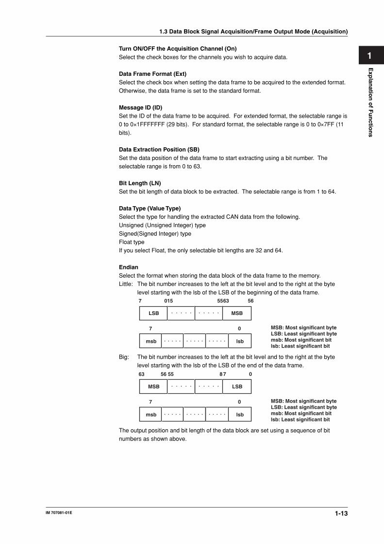
EndianSelect the format when storing the data block of the data frame to the memory.Little: The bit number increases to the left at the bit level and to the right at the byte
level starting with the lsb of the LSB of the beginning of the data frame.
LSB
7 015 5563 56
msb
7 0
lsb
MSB
MSB: Most significant byteLSB: Least significant bytemsb: Most significant bitlsb: Least significant bit
Big: The bit number increases to the left at the bit level and to the right at the bytelevel starting with the lsb of the LSB of the end of the data frame.
MSB
63 56 55 8 7 0
msb
7 0
lsb
LSB
MSB: Most significant byteLSB: Least significant bytemsb: Most significant bitlsb: Least significant bit
The output position and bit length of the data block are set using a sequence of bitnumbers as shown above.
1.3 Data Block Signal Acquisition/Frame Output Mode (Acquisition)
1-14 IM 707081-01E
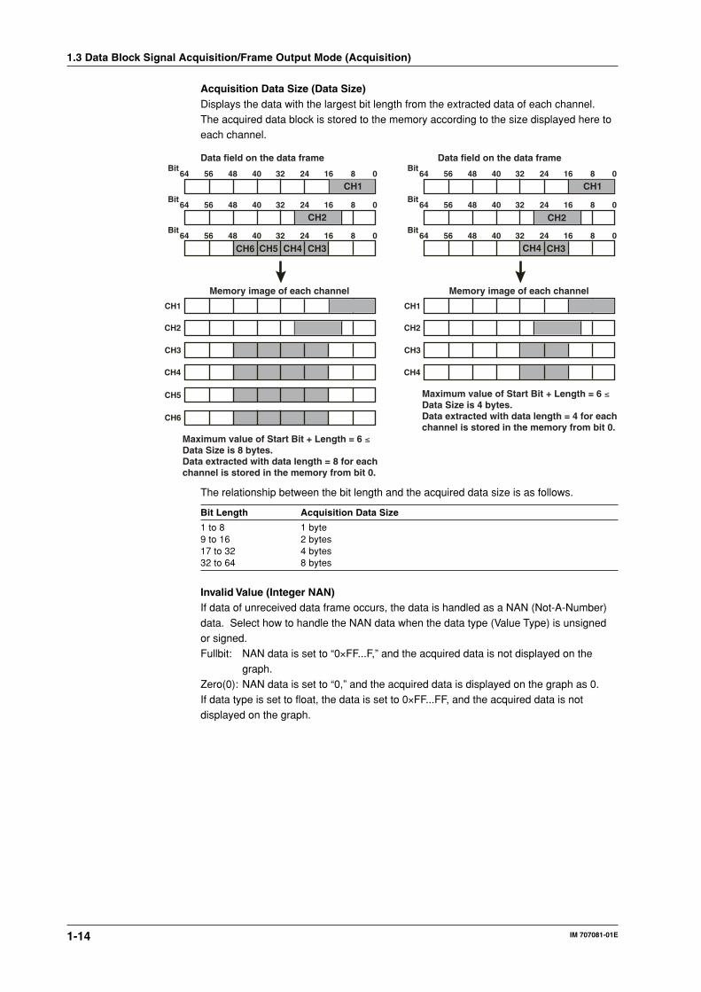
Acquisition Data Size (Data Size)Displays the data with the largest bit length from the extracted data of each channel.The acquired data block is stored to the memory according to the size displayed here toeach channel.
CH1
0816243240485664Bit
0816243240485664Bit
CH5CH6 CH4 CH30816243240485664
Bit
CH1
CH2
CH1
CH3
CH4
CH5
CH6
CH1
CH2
Data field on the data frame
Memory image of each channel
CH1
0816243240485664Bit
0816243240485664Bit
CH4 CH30816243240485664
Bit
CH1
CH2
CH1
CH3
CH4
CH1
CH2
Data field on the data frame
Memory image of each channel
Maximum value of Start Bit + Length = 6 ≤Data Size is 4 bytes.Data extracted with data length = 4 for eachchannel is stored in the memory from bit 0.
Maximum value of Start Bit + Length = 6 ≤Data Size is 8 bytes.Data extracted with data length = 8 for eachchannel is stored in the memory from bit 0.
The relationship between the bit length and the acquired data size is as follows.
Bit Length Acquisition Data Size
1 to 8 1 byte9 to 16 2 bytes17 to 32 4 bytes32 to 64 8 bytes
Invalid Value (Integer NAN)If data of unreceived data frame occurs, the data is handled as a NAN (Not-A-Number)
data. Select how to handle the NAN data when the data type (Value Type) is unsignedor signed.Fullbit: NAN data is set to “0×FF...F,” and the acquired data is not displayed on the
graph.Zero(0): NAN data is set to “0,” and the acquired data is displayed on the graph as 0.If data type is set to float, the data is set to 0×FF...FF, and the acquired data is not
displayed on the graph.
1.3 Data Block Signal Acquisition/Frame Output Mode (Acquisition)

1-15
Exp
lanatio
n o
f Fu
nctio
ns
IM 707081-01E
1Internal Trigger Setting (Trigger) (only when the acquisition mode is set toTriggered)When the acquisition mode is set to Triggered, the data trigger of each channel can beused as an internal trigger. The conditions for trigger detection are set for each channel.
The detected triggers can be output to the WE bus BUSTRG or notified as events to thePC.• Trigger Type
If the trigger source is set to Internal, you can select the trigger type for each channel.Rise: A trigger is activated when the readout signal changes from below the trigger
level to above the trigger level (edge trigger).
Fall: A trigger is activated when the readout signal changes from above the triggerlevel to below the trigger level (edge trigger).
Both: Both rising and falling (edge trigger)
High: A trigger is activated when the readout signal is greater than or equal to thespecified trigger level or when it enters that condition (state trigger).
Low: A trigger is activated when the readout signal is less than or equal to the
specified trigger level or when it enters that condition (state trigger).X: A trigger is activated when the data frame of the message ID of the acquisition
channel specified in advance is received. When this setting is used, you cannot
set the trigger level.Off: Trigger detection is not performed.
• Trigger LevelYou can set the trigger level when the trigger source is set to internal and the trigger
type is set to a value other than X or Off. The selectable range varies depending onthe data type (Value Type) selection.• When the data type is unsigned and scaling is not used
0 to 2N–1 (where N is the bit length (LN))• When the data type is signed and scaling is not used
–2N–1 to 2N–1–1 (where N is the bit length (LN))
• When the data type is float or when scaling is used–3,40282E38 to 3,40282E38
• Trig CombinationSelects the logic between channels.
OR trigger: A trigger is activated if any one of the trigger conditions specified forthe input signal of each channel is met.
AND trigger: A trigger is activated when all of the trigger conditions specified for the
input signal of each channel are met.
1.3 Data Block Signal Acquisition/Frame Output Mode (Acquisition)

1-16 IM 707081-01E
Alarm Setting (Alarm) (only when the acquisition mode is set to free run)When the acquisition mode is set to free run, the alarm activated status can be output tothe BUSTRG1/BUSTRG2 bus in the measuring station as a bus trigger signal.• Alarm Type
You can select the alarm type from the following:Off: Do not detect alarms.Rise: Output when the readout signal changes from a value less than the specified
upper limit to a value greater than the specified upper limit.
High levelReadoutsignal
Alarm
Fall: Output when the readout signal changes from a value exceeding the specifiedlower limit to a value less than the lower limit.
High: Output when the readout signal is greater than or equal to the specified upperlimit.
Low: Output when the readout signal is less than or equal to the specified lower limit.
Low levelReadoutsignal
Alarm
In: Output when the readout signal is within the specified upper and lower limits.Out: Output when the readout signal is less than the specified lower limit or greater
than the specified upper limit.
Readoutsignal Low level
Alarm
High level
• Alarm HighSet the threshold level when alarm type is set to Rise, High, In, or Out.• When the data type is unsigned and scaling is not used
0 to 2N–1 (where N is the bit length (LN))• When the data type is signed and scaling is not used
–2N–1 to 2N–1–1 (where N is the bit length (LN))
• When the data type is float or when scaling is used–3,40282E38 to 3,40282E38
NoteIf this value is set to a value smaller than Alarm Low, Alarm Low is set equal to the specified
Alarm High value.
1.3 Data Block Signal Acquisition/Frame Output Mode (Acquisition)

1-17
Exp
lanatio
n o
f Fu
nctio
ns
IM 707081-01E
1• Alarm Low
Set the threshold level when alarm type is set to Rise, High, In, or Out.• When the data type is unsigned and scaling is not used
0 to 2N–1 (where N is the bit length (LN))
• When the data type is signed and scaling is not used–2N–1 to 2N–1–1(where N is the bit length (LN))
• When the data type is float or when scaling is used
–3,40282E38 to 3,40282E38
NoteIf this value is set to a value larger than Alarm High, Alarm High is set equal to the specified Alarm
Low value.
LabelYou can assign labels to each channel. When the acquisition or output channel is ON,enter the label using up to 31 characters.
ScalingYou can linearly convert the measured values to arbitrary physical values.
On: Select the check box when carrying out linear scaling.Unit: Set the physical unit after linear scaling.
Scaling TypeSelect either of the following. A channel setup window corresponding to the selectedtype appears.
P1-P2: Set the measured values at any two points (VP1 and VP2) and theircorresponding physical values (SP1 and SP2). The values at these four pointsdefine the scale converting equation (Y = aX + b).
aX+b: Set the scaling coefficient (a) and offset value (b) to define the scale conversionequation (Y = aX + b)
The scaling setting of the channel setup window is synchronized to the WE7000 Control
Software. For details on setting the scale, “Convert Scale” in section 4.4, “Station ListWindow Operations” in the WE7000 User’s Manual (IM707001-01E).
Remote Frame Output ON/OFF and Output Interval (Rq)The remote frame of the message ID of the data acquisition channel can be output at aninteger multiple of the data sampling interval.
On: Select the check boxes for the channels you wish to output the remote frames. Youcannot select the check box on channels whose data acquisition is turned OFF.
Intvl: Set the output interval in the range of 1 to 9999.
NoteChannels whose message ID are the same are set to the same setting.
1.3 Data Block Signal Acquisition/Frame Output Mode (Acquisition)
1-18 IM 707081-01E
Using the Database File (Database)The target information from a database file containing data extraction definition can beset to the setup data of a specified channel. In addition, the extraction informationdefined in the channel setup of the WE7081 can be saved as a database.
The file formats that can be used are the following two types.dbc format: CANdb or CANdb++ signal definition data base by Vector Informatik. Can
be used as a channel setting definition of the WE7081. This is a read-only
file format.CSV format: The channel setting definition of the WE7081 can be saved as a database
to a text file in CSV format. The saved data can be edited using Excel or a
text editor.
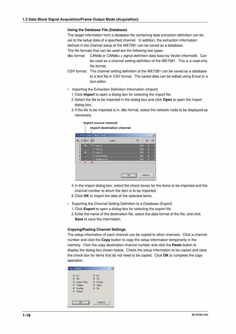
• Importing the Extraction Definition Information (Import)1.Click Import to open a dialog box for selecting the import file.2.Select the file to be imported in the dialog box and click Open to open the import
dialog box.3. If the file to be imported is in .dbc format, select the network node to be displayed as
necessary.
Import source channel
Import destination channel
4. In the import dialog box, select the check boxes for the items to be imported and thechannel number to which the item is to be imported.
5.Click OK to import the data of the selected items.
• Exporting the Channel Setting Definition to a Database (Export)
1.Click Export to open a dialog box for selecting the export file.2.Enter the name of the destination file, select the data format of the file, and click
Save to save the information.
Copying/Pasting Channel SettingsThe setup information of each channel can be copied to other channels. Click a channel
number and click the Copy button to copy the setup information temporarily in thememory. Click the copy destination channel number and click the Paste button todisplay the dialog box shown below. Check the setup information to be copied and clear
the check box for items that do not need to be copied. Click OK to complete the copyoperation.
1.3 Data Block Signal Acquisition/Frame Output Mode (Acquisition)
1-19
Exp
lanatio
n o
f Fu
nctio
ns
IM 707081-01E
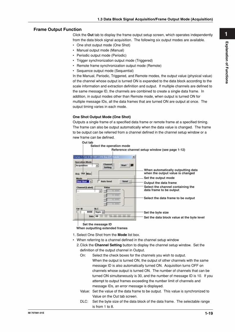
1Frame Output Function
Click the Out tab to display the frame output setup screen, which operates independentlyfrom the data block signal acquisition. The following six output modes are available.• One shot output mode (One Shot)
• Manual output mode (Manual)• Periodic output mode (Periodic)• Trigger synchronization output mode (Triggered)
• Remote frame synchronization output mode (Remote)• Sequence output mode (Sequential)In the Manual, Periodic, Triggered, and Remote modes, the output value (physical value)
of the channel whose output is turned ON is expanded to the data block according to thescale information and extraction definition and output. If multiple channels are defined tothe same message ID, the channels are combined to create a single data frame. In
addition, in output modes other than Remote mode, when output is turned ON formultiple message IDs, all the data frames that are turned ON are output at once. Theoutput timing varies in each mode.
One Shot Output Mode (One Shot)Outputs a single frame of a specified data frame or remote frame at a specified timing.
The frame can also be output automatically when the data value is changed. The frameto be output can be referred from a channel defined in the channel setup window or anew frame can be defined.
Select the operation modeReference channel setup window (see page 1-12)
Output the data frameSelect the channel containing the data frame to be output
Select the data frame to be output
Set the output mode
Set the data block value at the byte level
Set the message IDWhen outputting extended frames
Set the byte size
When automatically outputting data when the output value is changed
Out tab
1. Select One Shot from the Mode list box.• When referring to a channel defined in the channel setup window
2.Click the Channel Setting button to display the channel setup window. Set thedefinition of the output channel in Output.On: Select the check boxes for the channels you wish to output.
When the output is turned ON, the output of other channels with the samemessage ID is also automatically turned ON. Acquisition turns OFF onchannels whose output is turned ON. The number of channels that can be
turned ON simultaneously is 30, and the number of message ID is 10. If youattempt to output frames exceeding the number limit of channels andmessage IDs, an error message is displayed.
Value: Set the value of the data frame to be output. This value is synchronized toValue on the Out tab screen.
DLC: Set the byte size of the data block of the data frame. The selectable range
is from 1 to 8.
1.3 Data Block Signal Acquisition/Frame Output Mode (Acquisition)
1-20 IM 707081-01E
3.Click the OK button to close channel setup window.
4.Select the channels containing the data frame to be output from the Channel[Label] list box. The definition of the data frame to be output is displayed at thelower section of the panel. If a label is defined for the channel, the label is
displayed. If there are channels that have the same message ID defined as theselected channel, up to three of those channels are displayed automatically. If thereare more than three channels that have the same message ID defined, the three
smallest channels following the selected channel are displayed in ascending order.5.Set the output value in Value using a physical value.
• When defining a new frame
6.Set the following items.Ext: Select the check box when outputting an extended frame.ID: Set the message ID. When the data frame is in the standard format, the
selectable range is 0 to 0×7FF (11 bits). When the data frame is in theextended format, the selectable range is 0 to 0×1FFFFFFF (29 bits).
DLC: Select the byte size of the data block of the data frame in the range of 1 byte
to 8 bytes. If you select R0, a remote frame is output.Data: Set the value of the data block of the data frame in unit of bytes using
hexadecimal notation.
7. Click Send to output the data frame. To output the data frame automatically when theoutput value is changed, select the Auto Send check box.
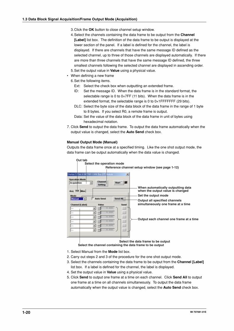
Manual Output Mode (Manual)Outputs the data frame once at a specified timing. Like the one shot output mode, thedata frame can be output automatically when the data value is changed.
Select the operation modeReference channel setup window (see page 1-12)
Output all specified channels simultaneously one frame at a time
Output each channel one frame at a time
Select the channel containing the data frame to be outputSelect the data frame to be output
Set the output mode
When automatically outputting data when the output value is changed
Out tab
1. Select Manual from the Mode list box.
2. Carry out steps 2 and 3 of the procedure for the one shot output mode.3. Select the channels containing the data frame to be output from the Channel [Label]
list box. If a label is defined for the channel, the label is displayed.
4. Set the output value in Value using a physical value.5. Click Send to output one frame at a time on each channel. Click Send All to output
one frame at a time on all channels simultaneously. To output the data frame
automatically when the output value is changed, select the Auto Send check box.
1.3 Data Block Signal Acquisition/Frame Output Mode (Acquisition)
1-21
Exp
lanatio
n o
f Fu
nctio
ns
IM 707081-01E
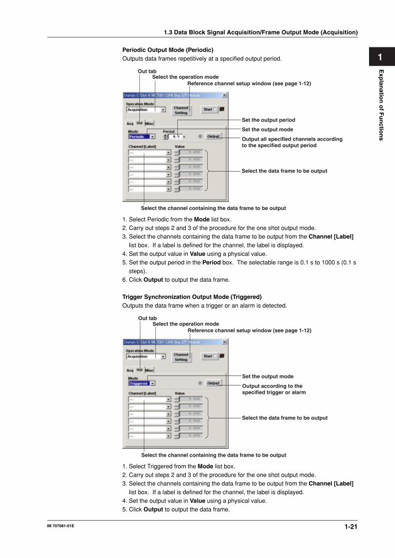
1Periodic Output Mode (Periodic)Outputs data frames repetitively at a specified output period.
Select the operation modeReference channel setup window (see page 1-12)
Output all specified channels according to the specified output period
Select the channel containing the data frame to be output
Select the data frame to be output
Set the output mode
Set the output period
Out tab
1. Select Periodic from the Mode list box.2. Carry out steps 2 and 3 of the procedure for the one shot output mode.3. Select the channels containing the data frame to be output from the Channel [Label]
list box. If a label is defined for the channel, the label is displayed.4. Set the output value in Value using a physical value.5. Set the output period in the Period box. The selectable range is 0.1 s to 1000 s (0.1 s
steps).6. Click Output to output the data frame.
Trigger Synchronization Output Mode (Triggered)Outputs the data frame when a trigger or an alarm is detected.
Select the operation modeReference channel setup window (see page 1-12)
Output according to the specified trigger or alarm
Select the channel containing the data frame to be output
Select the data frame to be output
Set the output mode
Out tab
1. Select Triggered from the Mode list box.2. Carry out steps 2 and 3 of the procedure for the one shot output mode.3. Select the channels containing the data frame to be output from the Channel [Label]
list box. If a label is defined for the channel, the label is displayed.4. Set the output value in Value using a physical value.5. Click Output to output the data frame.
1.3 Data Block Signal Acquisition/Frame Output Mode (Acquisition)
1-22 IM 707081-01E
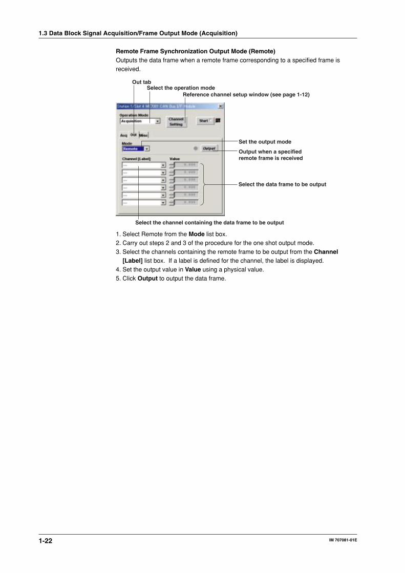
Remote Frame Synchronization Output Mode (Remote)Outputs the data frame when a remote frame corresponding to a specified frame isreceived.
Select the operation modeReference channel setup window (see page 1-12)
Output when a specified remote frame is received
Select the channel containing the data frame to be output
Select the data frame to be output
Set the output mode
Out tab
1. Select Remote from the Mode list box.2. Carry out steps 2 and 3 of the procedure for the one shot output mode.
3. Select the channels containing the remote frame to be output from the Channel[Label] list box. If a label is defined for the channel, the label is displayed.
4. Set the output value in Value using a physical value.
5. Click Output to output the data frame.
1.3 Data Block Signal Acquisition/Frame Output Mode (Acquisition)

1-23
Exp
lanatio
n o
f Fu
nctio
ns
IM 707081-01E
1Sequence Output Mode (Sequential)Outputs the frames according to a sequence table created in advance. You can specifythe number of times to repeat the sequence table.
Select the operation modeReference channel setup window (see page 1-12)
Output according to a specified sequence table
Sequence table setup window
Set the output mode
Setting the number of repetitions of the sequence table
Out tab
1. Select Sequential from the Mode list box.
2. Click Table Setting to show the sequence table. The data frame can be output oneline at a time according to the setting on this table. Up to 1024 lines can be specifiedon the sequence table.
One shot output per channel
When outputting
Interval until the next line is output
Set the data frame value at the byte levelData frame byte size
ID of the data frame to be outputWhen using extended format
When using triggeres
On: Select the check boxes for the line numbers you wish to output.
Trig: Select the check boxes for the line numbers you wish to output whentriggers are detected.
Ext: Select this check box to set the ID of the output data frame to extended
format. Otherwise, the data frame is set to the standard format.ID: Set the ID of the data frame to be output. For extended format, the
selectable range is 0 to 0×1FFFFFFF (29 bits). For standard format, the
selectable range is 0 to 0×7FF (11 bits).DLC: Select the byte size of the data block of the data frame in the range of 1 byte
to 8 bytes.
1.3 Data Block Signal Acquisition/Frame Output Mode (Acquisition)

1-24 IM 707081-01E
Data: Set the value of the data frame corresponding to the byte size specified by
DLC in unit of bytes using hexadecimal notation.Invl[s]: Set the time until the next line is output. The selectable range is 0.1 s to 100
s (0.1 s steps).
Send: Click to output one shot on the channel.3. Click OK.4. Set the number of times to output the sequence table in the No. of Repeat box. The
selectable range is from 0 to 2,147,483,647. If you set the value to 0, the output isrepeated infinitely.
5. Click Output to output the data frame.
1.3 Data Block Signal Acquisition/Frame Output Mode (Acquisition)

1-25
Exp
lanatio
n o
f Fu
nctio
ns
IM 707081-01E
11.4 Data Frame Acquisition Mode (Frame
Acquisition)Operation Panel
Start/Stop acquisition
Select the operation modeSave the acquired data frames
Select the trigger sourceFor extended format
Select the data type
Select the EndianSet the message ID
Generate a manual trigger
Set the number of frames to be acquired
Displays the number of frames that has been acquired
Set the trigger level
Set the bit length
Set the start position for extracting data
Select the trigger type
Selecting the (Operation ModeSelect Frame Acquisition.
Starting/Stopping AcquisitionClick the Start button to enter the trigger-wait state. When the trigger is activated,acquisition starts. When you click the Start button, you can no longer operate the setupitems on the operation panel and all the buttons other than the Start button. Data frame
acquisition continues until the specified number of times the data frames are acquired oruntil the Start button is clicked again.
Setting the Acquisition ConditionsSetting the Number of Acquired Frames (No. of Frames)Set the number of data frames to be acquired in the range of 0 or 1 to 2,147,483,647.
However, if you set the number of frames to 419430 or greater, only the newest 410430frames are retained. If you set the value to 0, the module acquires data frames from thetime the Start button is clicked until the acquisition is stopped. If you set a value other
than 0, the module acquires data frames until the specified number of frames is acquiredor from the time the Start button is clicked until the acquisition is stopped. The dataframes in the internal memory are acquired in order from the oldest to the newest data
frame. Data frames that overflow from the memory are cleared in order from the oldestdata frame. When the data acquisition is stopped, the data frames remaining in thememory can be saved collectively to a file.

1-26 IM 707081-01E
Setting the Filter for Retrieving Data (ID Filter)You can set a bit pattern of the data frame to be acquired and acquire only the dataframes that match the specified bit pattern using the Misc tab. This allows only therequired data frames to be stored. If the data frame to be acquires is in the standard
format, set the filter in the Standard box; if it is in the extended format, set the filter in theExtended box.If the bit pattern is set to Bin, set a binary pattern using an array of three characters, 0, 1,
and X.0: Pass the data through if the corresponding bit is 0.1: Pass the data through if the corresponding bit is 1.
X: Pass the data through regardless of whether the corresponding bit is 0 or 1 (Don’t care).If the bit pattern is set to Hex, the pattern is set 4 bits at a time using hexadecimalnotation. Thus, the pattern cannot be set in detail at the bit level. Set the pattern using a
character array of 0 to 9, A to F, and X. “X” denotes Don’t Care. All 4 bits of the bitpattern is set to “XXXX.”If you selected Bin and the 4 bits consist of a mixture of X, 0, and 1s, the value cannot be
displayed in the Hex setting if you change the setting to Hex. 4 bits that cannot bedisplayed on the viewer is indicated with a $ mark.
Misc tab
Select binary notation or hexadecimal notation
Bit pattern of the standard format
Bit pattern of the extended format
NoteOn the WE Control API sold separately, the bit pattern can be set only using binary values.
Setting the Trigger (Trigger)Trigger Source (Source)Select the signal for triggering. Select from the following:
Internal: Receives the data frames flowing on the CAN Bus, and activates a triggerwhen the data block of the data frame of a specified ID matches a specifiedcondition. Trigger is activated according to the trigger condition specified on
the operation panel.BUSTRG: Bus signal (BUSTRG1/BUSTRG2) of the WE bus
Trigger TypeIf the trigger source is set to Internal, you can select the trigger type for each channel.Rise: A trigger is activated when the readout signal changes from below the trigger
level to above the trigger level (edge trigger).Fall: A trigger is activated when the readout signal changes from above the trigger
level to below the trigger level (edge trigger).
Both: Both rising and falling (edge trigger)High: A trigger is activated when the readout signal is greater than or equal to the
specified trigger level or when it enters that condition (state trigger).
Low: A trigger is activated when the readout signal is less than or equal to the specifiedtrigger level or when it enters that condition (state trigger).
X: A trigger is activated when the data frame of the message ID of the acquisition
channel specified in advance is received. When this setting is used, you cannotset the trigger level.
Off: Trigger detection is not performed.
1.4 Data Frame Acquisition Mode (Frame Acquisition)

1-27
Exp
lanatio
n o
f Fu
nctio
ns
IM 707081-01E
1Trigger LevelYou can set the trigger level when the trigger source is set to internal and the trigger typeis set to a value other than X or Off. The selectable range varies depending on the datatype (Value Type) selection.
• When the data type is unsigned0 to 2N–1 (where N is the bit length (LN))
• When the data type is signed
–2N–1 to 2N–1–1 (where N is the bit length (LN))• When the data type is float
–3,40282E38 to 3,40282E38
Data Frame Format (Ext)Select the check box when setting the ID of the data frame for activating the trigger to
the extended format. Otherwise, the data frame is set to the standard format.
Message ID (ID)Select the data frame ID for activating the trigger. For extended format, the selectablerange is 0 to 0×1FFFFFFF (29 bits). For standard format, the selectable range is 0 to0×7FF (11 bits).
Data Extraction Position (SB)Set the data position of the data frame to start extracting using a bit number. The
selectable range is from 0 to 63.
Bit Length (LN)Set the bit length of data block to be extracted. The selectable range is from 1 to 64.
Data Type (Value Type)Select the type for handling the extracted CAN data from the following.
Unsigned (Unsigned Integer) typeSigned(Signed Integer) typeFloat type
If you select Float, the only selectable bit lengths are 32 and 64.
1.4 Data Frame Acquisition Mode (Frame Acquisition)

1-28 IM 707081-01E
EndianSelect the format when storing the data block of the data frame to the memory.Little: The bit number increases to the left at the bit level and to the right at the byte
level starting with the lsb of the LSB of the beginning of the data frame.
LSB
7 015 5563 56
msb
7 0
lsb
MSB
MSB: Most significant byteLSB: Least significant bytemsb: Most significant bitlsb: Least significant bit
Big: The bit number increases to the left at the bit level and to the right at the byte
level starting with the lsb of the LSB of the end of the data frame.
MSB
63 56 55 8 7 0
msb
7 0
lsb
LSB
MSB: Most significant byteLSB: Least significant bytemsb: Most significant bitlsb: Least significant bit
Start Bit and Length are set using bit numbers in the order shown above.
Manual TriggerClick the Manual Trigger button to activate a trigger independently from the specifiedtrigger source.
No. of Stored FramesIf you start acquisition by clicking the Start button, the number of frames that have beenacquired is indicated in the range of 0 to 4,294,967,295. The update period is
approximately 1 s. If the number of frames that have been acquired reaches4,294,967,295, the indication returns to 0.
1.4 Data Frame Acquisition Mode (Frame Acquisition)

1-29
Exp
lanatio
n o
f Fu
nctio
ns
IM 707081-01E
1Saving the Data
Click the Save Frame Data button to read the data from the data memory and save thedata in binary WCF (WE7000 CAN Binary Format) format (*.wcf) or CSV (*.csv) format.
File FormatThe file saved in WCF format can be converted into a file in CSV format using theconverter provided. In addition, a converter is provided for creating a file in WCF format
from the measurement data file saved in WVF format. For a description of eachconverter, see section 1.8, “WCF⇔CSV Converter and WVF⇒WCF Converter.”For details on the data formats of the data frame, WCF format, and CSV format, see
appendix 2, “Data Structure of Files.”
1.4 Data Frame Acquisition Mode (Frame Acquisition)

1-30 IM 707081-01E
1.5 Data Block Signal Output Mode (Output)
Operation Panel
Start/Stop output
Generate a manual trigger
Select the operation modeWindow used to create data frames
Set the number of times to output
Set the output mode
Set the output interval
Setting the Trigger Level
Set the bit length
Set the start position for extracting data
Select the trigger type
Select the trigger sourceFor extended format
Select the data type
Select the EndianSet the message ID
Selecting the (Operation Mode)Select Output.
Starting/Stopping OutputClick the Output button to start the output operation. When the output operation isstarted, the output indicator to the left of the Output button illuminates, and you can nolonger operate the setup items on the operation panel and all the buttons beside theOutput button. The output operation continues until the Output button is clicked again.The output operation includes the trigger-wait state. If the output mode (see below) isset to Trigger or One Shot, the data frame may actually not be output even if the outputindicator is illuminated. If the output mode is set to Cont and the output indicator isilluminated, the signal is output at constant intervals. However, the signal is not output ifthe module is not connected to the CAN Bus or in the Bus Off condition.
Setting Output ConditionsOutput ModeSelect from the following.Cont: Outputs the data frame continuously according to the specified definition and
the number of output samples.Trigger: Outputs the data frame when triggers are detected according to the specified
definition and the number of output samples.One Shot: Outputs the data frame once when a trigger is detected according to the
specified definition and the number of output samples.No. of Output Samples) (only when the output mode is set to Cont or Trigger)You can set the number of times the data frame of each channel is output in the range of0 to 2,147,483,647. If you set the value to 0, the data frame is output indefinitely.Output Interval) (only when the output mode is set to Cont or Trigger)The selectable range is 1 to 10 s (1-ms steps). The setting applies to all data framesspecified on the channel setup screen.
NoteIf the load on the CAN Bus is large or the number of output frames is large, the data frames maynot be output at the specified output interval.

1-31
Exp
lanatio
n o
f Fu
nctio
ns
IM 707081-01E
1Creating Data Frames (Channel Setting)
In the data block signal output mode, data frames are created by defining multiple datasequences on the data field and output on the frame. The output data frame definition isspecified as a channel. Up to 64 channels can be assigned.
Multiple channels can be included in a single data frame. As shown in the examplebelow, CH1 and CH2 are embedded in the same data frame.
Start Bit = 0, Length = 16 bits → 2-byte integer(CH1)Start Bit = 32, Length = 32 bits → 4-byte floating point (CH2)
bit 64 56 48 40 32 24 16 8 0
CH2 CH1
Click the Channel Setting button to set the data field, sweep pattern, and otherparameters.
For extended format
Execute copy
Set the ID of the data frame to be acquired
Select the channel
Set the sweep pattern
Select the item to be copied
Set the data bit lengthSet the start position for extracting data
Select the data typeSet the Endian
End output valueStep for changingthe sweep pattern
Start output value
1.5 Data Block Signal Output Mode (Output)
1-32 IM 707081-01E
Turning ON/OFF the Output Channel (On)Select the check boxes for the channels you wish to output the data frames.
Data Frame Format (Ext)Select the check box when setting the data frame to be output to the extended format.Otherwise, the data frame is set to the standard format.
Message ID (ID)Set the ID of the data frame to be acquired. For extended format, the selectable range is0 to 0×1FFFFFFF (29 bits). For standard format, the selectable range is 0 to 0×7FF (11
bits).
Data Output Position (SB)Set the data position of the data frame to start the output using a bit number. Theselectable range is from 0 to 63.
Bit Length (LN)Set the bit length of the output data block. The selectable range is from 1 to 64.
Data Type (Value Type)Select the output CAN data type from the following.Unsigned (Unsigned Integer) type
Signed(Signed Integer) typeFloat typeIf you select Float, the only selectable bit lengths are 32 and 64.
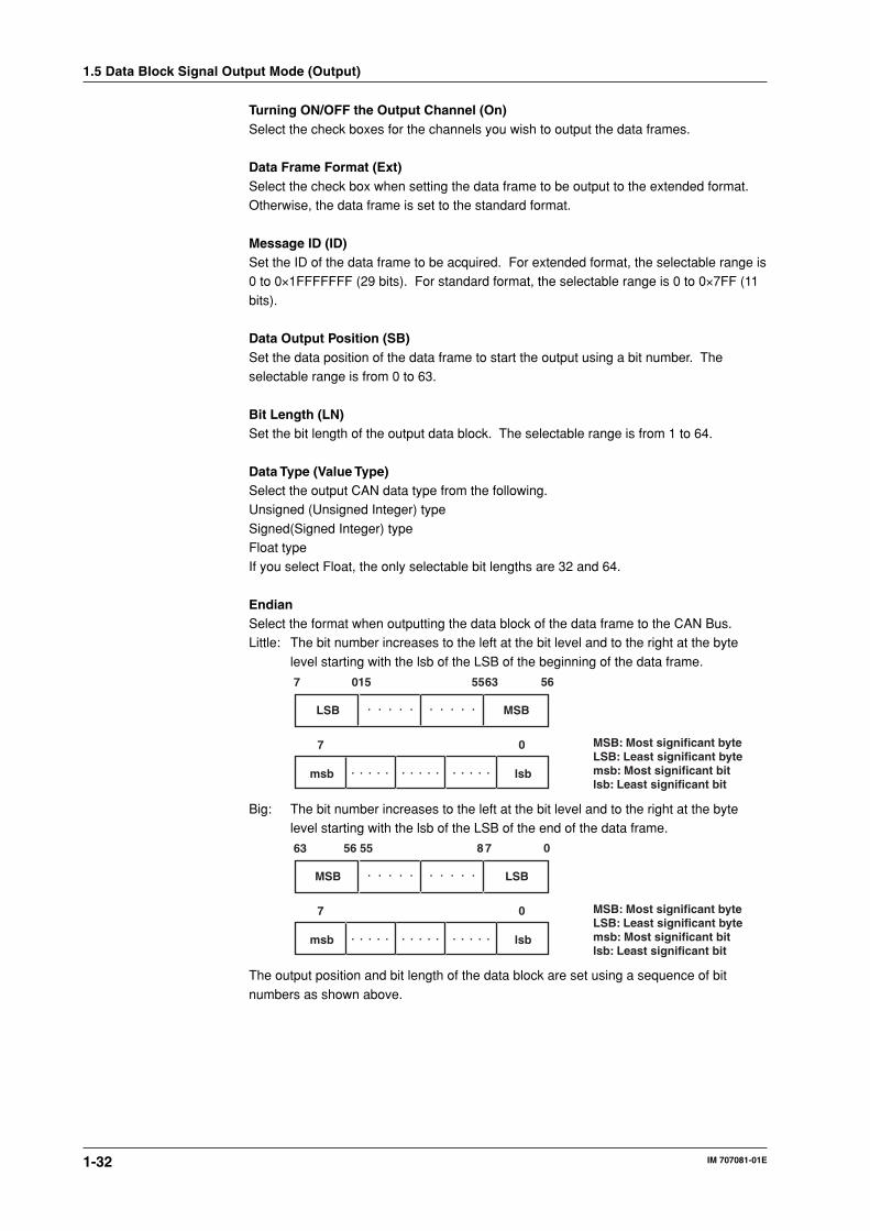
EndianSelect the format when outputting the data block of the data frame to the CAN Bus.Little: The bit number increases to the left at the bit level and to the right at the byte
level starting with the lsb of the LSB of the beginning of the data frame.
LSB
7 015 5563 56
msb
7 0
lsb
MSB
MSB: Most significant byteLSB: Least significant bytemsb: Most significant bitlsb: Least significant bit
Big: The bit number increases to the left at the bit level and to the right at the bytelevel starting with the lsb of the LSB of the end of the data frame.
MSB
63 56 55 8 7 0
msb
7 0
lsb
LSB
MSB: Most significant byteLSB: Least significant bytemsb: Most significant bitlsb: Least significant bit
The output position and bit length of the data block are set using a sequence of bit
numbers as shown above.
1.5 Data Block Signal Output Mode (Output)

1-33
Exp
lanatio
n o
f Fu
nctio
ns
IM 707081-01E
1Sweep PatternYou can change the output CAN data with time. You can select a sweep pattern for eachchannel.Ramp-Repeat: Repetitively outputs the slope specified by Data Start and Data
End.
Data Start
Data End
The number of specified samples
Ramp-single&Reset: Outputs the slope specified by Data Start and Data End once andoutputs the data specified by Data Start last.
Data Start
Data End
The number of specified samples
Ramp-Single&Hold: Outputs the slope specified by Data Start and Data End once andcontinues to output the data specified by Data End.
Data Start
Data End
The number of specified samples
Triangle-Repeat: Outputs the slope specified by Data Start and Data End. When theData End value is reached, the signal moves back toward DataStart. This operation is repeated.
Data Start
Data End
The number of specified samples
Off: Outputs the data specified by Data Start.
Data Start
The number of specified samples
Output Start Value (Data Start)Set the output start value using an integer or a floating-point number.
Output End Value (Data End)Set the output end value using an integer or a floating-point number.
StepSet the step for changing the sweep pattern using an integer or a floating-point number.
NoteIf the value derived by (Data End – Data Start)/Step is an indivisible number, the last step for
outputting Data End is smaller than the step for outputting earlier data.
1.5 Data Block Signal Output Mode (Output)
1-34 IM 707081-01E
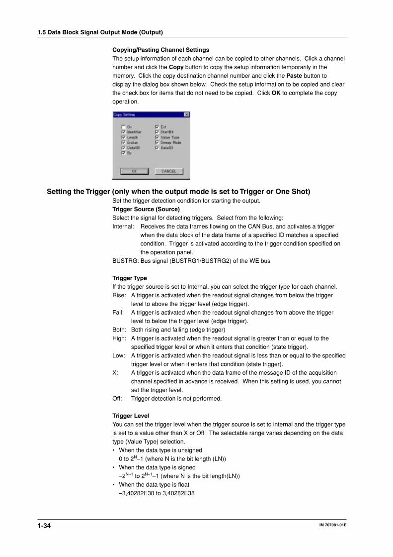
Copying/Pasting Channel SettingsThe setup information of each channel can be copied to other channels. Click a channelnumber and click the Copy button to copy the setup information temporarily in thememory. Click the copy destination channel number and click the Paste button to
display the dialog box shown below. Check the setup information to be copied and clearthe check box for items that do not need to be copied. Click OK to complete the copyoperation.
Setting the Trigger (only when the output mode is set to Trigger or One Shot)Set the trigger detection condition for starting the output.Trigger Source (Source)Select the signal for detecting triggers. Select from the following:
Internal: Receives the data frames flowing on the CAN Bus, and activates a triggerwhen the data block of the data frame of a specified ID matches a specifiedcondition. Trigger is activated according to the trigger condition specified on
the operation panel.BUSTRG: Bus signal (BUSTRG1/BUSTRG2) of the WE bus
Trigger TypeIf the trigger source is set to Internal, you can select the trigger type for each channel.Rise: A trigger is activated when the readout signal changes from below the trigger
level to above the trigger level (edge trigger).Fall: A trigger is activated when the readout signal changes from above the trigger
level to below the trigger level (edge trigger).
Both: Both rising and falling (edge trigger)High: A trigger is activated when the readout signal is greater than or equal to the
specified trigger level or when it enters that condition (state trigger).
Low: A trigger is activated when the readout signal is less than or equal to the specifiedtrigger level or when it enters that condition (state trigger).
X: A trigger is activated when the data frame of the message ID of the acquisition
channel specified in advance is received. When this setting is used, you cannotset the trigger level.
Off: Trigger detection is not performed.
Trigger LevelYou can set the trigger level when the trigger source is set to internal and the trigger type
is set to a value other than X or Off. The selectable range varies depending on the datatype (Value Type) selection.• When the data type is unsigned
0 to 2N–1 (where N is the bit length (LN))• When the data type is signed
–2N–1 to 2N–1–1 (where N is the bit length(LN))
• When the data type is float–3,40282E38 to 3,40282E38
1.5 Data Block Signal Output Mode (Output)

1-35
Exp
lanatio
n o
f Fu
nctio
ns
IM 707081-01E
1Data Frame Format (Ext)Select the check box when setting the data frame ID to the extended format. Otherwise,the data frame is set to the standard format.
Message ID (ID)Set the data frame ID. For extended format, the selectable range is 0 to 0×1FFFFFFF(29 bits). For standard format, the selectable range is 0 to 0×7FF (11 bits).
Data Extraction Position (SB)Set the data position of the data frame to start extracting using a bit number. The
selectable range is from 0 to 63.
Bit Length (LN)Set the bit length of the data block. The selectable range is from 1 to 64.
Data Type (Value Type)Select the CAN data type from the following.Unsigned (Unsigned Integer) typeSigned(Signed Integer) type
Float typeIf you select Float, the only selectable bit lengths are 32 and 64.
EndianSelect the format when storing the data block of the data frame to the memory.Little: The bit number increases to the left at the bit level and to the right at the byte level
starting with the lsb of the LSB of the beginning of the data frame.
LSB
7 015 5563 56
msb
7 0
lsb
MSB
MSB: Most significant byteLSB: Least significant bytemsb: Most significant bitlsb: Least significant bit
Big: The bit number increases to the left at the bit level and to the right at the byte levelstarting with the lsb of the LSB of the end of the data frame.
MSB
63 56 55 8 7 0
msb
7 0
lsb
LSB
MSB: Most significant byteLSB: Least significant bytemsb: Most significant bitlsb: Least significant bit
Start Bit and Length are set using bit numbers in the order shown above.
Manual TriggerClick the Manual Trigger button to activate a trigger independently from the specifiedtrigger source.
1.5 Data Block Signal Output Mode (Output)

1-36 IM 707081-01E
1.6 Data Frame Output Mode (Frame Output)
Operation Panel
Start/Stop output
Generate a manual trigger
Select the operation modeSelect the files to be loaded
Set the repeat output count
Set the output mode
Displays the number of frames that has been loaded
Setting the Trigger Level
Set the bit length
Set the start position for extracting data
Select the trigger type
Select the trigger sourceFor extended format
Select the data type
Select the EndianSet the message ID
Selecting the (Operation Mode)Select Frame Output.
Selecting the Data File to Be Loaded and Indication of the Number of Data FramesClick the Load Frame Data button and select the frame data file in WCF or CSV formatto be downloaded to the output memory. When the download is complete, the number ofdata frames that has been downloaded is indicated in No. of Stored Frames.
Starting/Stopping OutputClick the Output button to start the output operation. When the output operation isstarted, the output indicator to the left of the Output button illuminates, and you can no
longer operate the setup items on the operation panel and all the buttons beside theOutput button. The output operation continues until the Output button is clicked again.The output operation includes the trigger-wait state. If the output mode (see below) is
set to Trigger, the data frame may actually not be output even if the output indicator isilluminated. If the output mode (see below) is set to Cont, the data frame is output at alltimes when the output indicator is illuminated.

1-37
Exp
lanatio
n o
f Fu
nctio
ns
IM 707081-01E
1Setting Output Conditions
Output ModeSelect from the following.Cont: Continuously outputs the loaded data frame.
Trigger: Outputs the data frame the number of specified times each time a triggeroccurs.
Repeat Output Count (Repeat)Select the number of times to output the data frame in the range of 0 to 100. If you setthe number to 0, the output continues until the output is stopped. If you set the number
between 1 and 100, the data frame is output the specified number of times and theoutput stops.
Setting the Trigger (only when the output mode is set to Trigger)Set the trigger detection condition for starting the output.Trigger Source (Source)Select the signal for detecting triggers. Select from the following:Internal: Receives the data frames flowing on the CAN Bus, and activates a trigger
when the data block of the data frame of a specified ID matches a specified
condition. Trigger is activated according to the trigger condition specified onthe operation panel.
BUSTRG: Bus signal (BUSTRG1/BUSTRG2) of the WE bus
Trigger TypeIf the trigger source is set to Internal, you can select the trigger type for each channel.
Rise: A trigger is activated when the readout signal changes from below the triggerlevel to above the trigger level (edge trigger).
Fall: A trigger is activated when the readout signal changes from above the triggerlevel to below the trigger level (edge trigger).
Both: Both rising and falling (edge trigger)High: A trigger is activated when the readout signal is greater than or equal to the
specified trigger level or when it enters that condition (state trigger).
Low: A trigger is activated when the readout signal is less than or equal to the specifiedtrigger level or when it enters that condition (state trigger).
X: A trigger is activated when the data frame of the message ID of the acquisition
channel specified in advance is received. When this setting is used, you cannotset the trigger level.
Off: Trigger detection is not performed.
Trigger LevelYou can set the trigger level when the trigger source is set to internal and the trigger type
is set to a value other than X or Off. The selectable range varies depending on the datatype (Value Type) selection.• When the data type is unsigned
0 to 2N–1 (where N is the bit length (LN))• When the data type is signed
–2N–1 to 2N–1–1 (where N is the bit length (LN))
• When the data type is float–3,40282E38 to 3,640282E38
Data Frame Format (Ext)Select the check box when setting the data frame ID to the extended format. Otherwise,the data frame is set to the standard format.
1.6 Data Frame Output Mode (Frame Output)
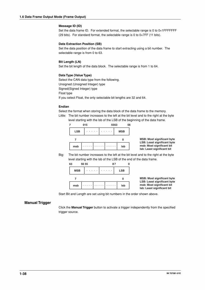
1-38 IM 707081-01E
Message ID (ID)Set the data frame ID. For extended format, the selectable range is 0 to 0×1FFFFFFF(29 bits). For standard format, the selectable range is 0 to 0×7FF (11 bits).
Data Extraction Position (SB)Set the data position of the data frame to start extracting using a bit number. Theselectable range is from 0 to 63.
Bit Length (LN)Set the bit length of the data block. The selectable range is from 1 to 64.
Data Type (Value Type)Select the CAN data type from the following.
Unsigned (Unsigned Integer) typeSigned(Signed Integer) typeFloat type
If you select Float, the only selectable bit lengths are 32 and 64.
EndianSelect the format when storing the data block of the data frame to the memory.Little: The bit number increases to the left at the bit level and to the right at the byte
level starting with the lsb of the LSB of the beginning of the data frame.
LSB
7 015 5563 56
msb
7 0
lsb
MSB
MSB: Most significant byteLSB: Least significant bytemsb: Most significant bitlsb: Least significant bit
Big: The bit number increases to the left at the bit level and to the right at the byte
level starting with the lsb of the LSB of the end of the data frame.
MSB
63 56 55 8 7 0
msb
7 0
lsb
LSB
MSB: Most significant byteLSB: Least significant bytemsb: Most significant bitlsb: Least significant bit
Start Bit and Length are set using bit numbers in the order shown above.
Manual TriggerClick the Manual Trigger button to activate a trigger independently from the specifiedtrigger source.
1.6 Data Frame Output Mode (Frame Output)

1-39
Exp
lanatio
n o
f Fu
nctio
ns
IM 707081-01E
11.7 Displaying Waveforms, Saving Acquired Data
Automatically, Converting Files, and OtherFunctions
The following functions are common to all measurement modules of the WE7000 ControlSoftware. For details on the functions, see the WE7000 User’s Manual (IM707001-01E).
Controlling the Timing of the Start of the Acquisition (Arming)You can control the timing of the start of measurement by using the arming signal set in
the trigger source/time base source/arming setting dialog box. When the arming signal(ARM) bus is connected to the measurement module in the trigger source/time basesource/arming setting dialog box, clicking Start on the operation panel causes the
module to enter the arming signal wait state. The acquisition starts when the armingsignal becomes True. For details on the settings on the trigger source/time base source/arming setting dialog box, see section 4.6, “Setting Trigger Source/Time Base Source/
Arming” in the WE7000 User’s Manual (IM707001-01E).
Displaying Waveforms (valid only when in data block signal acquisition mode)The WE7081 allows acquisition data to be monitored as waveforms. By default, thewaveforms are automatically displayed on the Waveform Monitor of the WE7000 ControlSoftware when acquisition is started on the WE7081 operation panel.
Saving Acquired Data Automatically (valid only when in data block signal acquisitionmode)
Besides saving the data displayed on the waveform monitor, you can also save theacquired data automatically. You can select whether to save the data to a single file or tomultiple files by specifying the number of data points per file.
Converting Acquisition Data FilesAcquisition data that is saved in data block signal acquisition mode can be converted to
ASCII data in CSV format (*.csv) or to a physical value in 32-bit floating point format(conforming to IEEE754-1985) (*.wvf).Data that has been saved in data frame acquisition mode is saved in WCF format
(WE7000 CAN Binary Format) or CSV format. The conversion software provided can beused to convert the saved data into CSV format or WCF format. For a description of theconversion software, see section 1.8, “WCF⇔CSV converter and WVF⇒WCF
Converter.”
Scaling the Acquisition Data (valid only when in data block signal acquisition mode)Set the acquired values at any two points (VP1 and VP2) and their correspondingphysical values (SP1 and SP2). The values at these four points define the scaleconverting equation (Y = ax + b). The acquired values are converted to physical values
according to this equation. The waveform can be displayed, or the acquired data can besaved.

1-40 IM 707081-01E
1.8 WCF⇔CSV converter and WVF⇒WCF ConverterThe WE7000 Control Software comes with the following file format conversion tools.WCF⇔CSV Converter: Converts a binary data file in WCF format (*.wcf) to an ASCII
data file in CSV format (*.csv) or vice versa.WVF⇒WCV Converter: Creates a binary data file in WCF format (*.wcf) from a
measurement data file in WVF format (*.wvf)
WCF⇔CSV ConverterThe data in WCF (WE7000 CAN Binary Format) binary format saved in the data frame
acquisition mode can be converted into CSV format so that Excel or other general-purpose text editors can be used to check or edit the frame data contents.
Installation DirectoryThe WCF⇔CSV Converter is installed as “Wcf_CsvConverter.exe” when the WE7000
Control Software is installed.
• Installation directory exampleC:\program files\we7000\Wcf_CsvConverter.exe
Procedure1. When you start the software, the following window below opens.
2. Click ..... to display the following dialog box. Select a file in WCF format or CSVformat here.
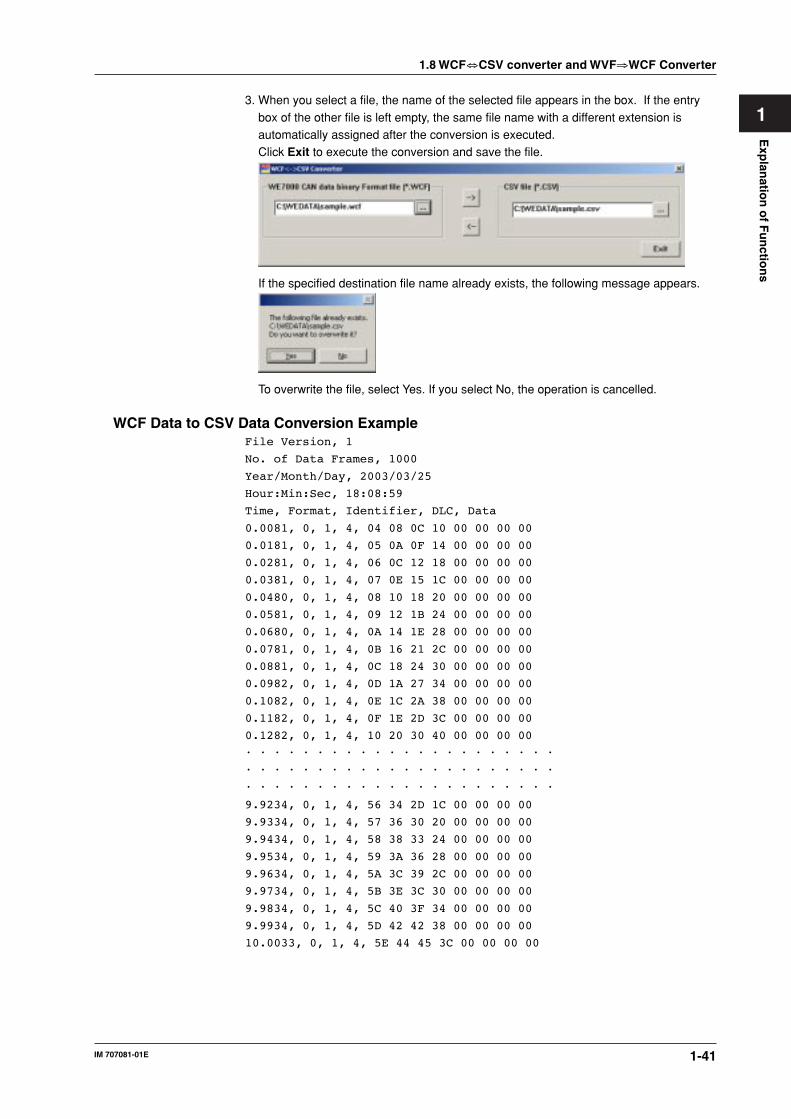
1-41
Exp
lanatio
n o
f Fu
nctio
ns
IM 707081-01E
13. When you select a file, the name of the selected file appears in the box. If the entry
box of the other file is left empty, the same file name with a different extension isautomatically assigned after the conversion is executed.Click Exit to execute the conversion and save the file.
If the specified destination file name already exists, the following message appears.
To overwrite the file, select Yes. If you select No, the operation is cancelled.
WCF Data to CSV Data Conversion ExampleFile Version, 1
No. of Data Frames, 1000
Year/Month/Day, 2003/03/25
Hour:Min:Sec, 18:08:59
Time, Format, Identifier, DLC, Data
0.0081, 0, 1, 4, 04 08 0C 10 00 00 00 00
0.0181, 0, 1, 4, 05 0A 0F 14 00 00 00 00
0.0281, 0, 1, 4, 06 0C 12 18 00 00 00 00
0.0381, 0, 1, 4, 07 0E 15 1C 00 00 00 00
0.0480, 0, 1, 4, 08 10 18 20 00 00 00 00
0.0581, 0, 1, 4, 09 12 1B 24 00 00 00 00
0.0680, 0, 1, 4, 0A 14 1E 28 00 00 00 00
0.0781, 0, 1, 4, 0B 16 21 2C 00 00 00 00
0.0881, 0, 1, 4, 0C 18 24 30 00 00 00 00
0.0982, 0, 1, 4, 0D 1A 27 34 00 00 00 00
0.1082, 0, 1, 4, 0E 1C 2A 38 00 00 00 00
0.1182, 0, 1, 4, 0F 1E 2D 3C 00 00 00 00
0.1282, 0, 1, 4, 10 20 30 40 00 00 00 00
• • • • • • • • • • • • • • • • • • • • • •
• • • • • • • • • • • • • • • • • • • • • •
• • • • • • • • • • • • • • • • • • • • • •
9.9234, 0, 1, 4, 56 34 2D 1C 00 00 00 00
9.9334, 0, 1, 4, 57 36 30 20 00 00 00 00
9.9434, 0, 1, 4, 58 38 33 24 00 00 00 00
9.9534, 0, 1, 4, 59 3A 36 28 00 00 00 00
9.9634, 0, 1, 4, 5A 3C 39 2C 00 00 00 00
9.9734, 0, 1, 4, 5B 3E 3C 30 00 00 00 00
9.9834, 0, 1, 4, 5C 40 3F 34 00 00 00 00
9.9934, 0, 1, 4, 5D 42 42 38 00 00 00 00
10.0033, 0, 1, 4, 5E 44 45 3C 00 00 00 00
1.8 WCF⇔CSV converter and WVF⇒WCF Converter

1-42 IM 707081-01E
WVF⇒WCF ConverterThe WVF⇒WCF Converter can create a file in WCF format in which the data block ofthe CAN data frame fluctuates in the same fashion as the waveform data measured onother measurement modules and waveform data created using the arbitrary waveform
editor. By outputting the WCF file that you created in data frame output mode, framedata in which the data block fluctuates in the same fashion as the data in a WVF file canbe transmitted on the CAN Bus.
Starting the ProgramStart the WE Control Software and choose Convert WVF to WCF from the Tools menu.
Procedure1. When you start the software, the following window below opens.
Displays the file name of the loaded data
Displays the record length of the loaded data
Displays the data sampling interval of the loaded data
Turn ON/OFF the conversi-on
Select the data type
Displays channel labels
Displays unit character strings
Displays the minimum value of the data
Displays the maximum value of the data
End the program
For extended format
Open the dialog box for selecting the conversion destination file
Open the dialog box for selecting the conversion source file
Set the ID
Set the position for extracting data
Set the bit length of the data to be extracted
Set the conversion interval
Set the scaling coefficientsTurn ON/OFF scaling
Select the Endian
1.8 WCF⇔CSV converter and WVF⇒WCF Converter

1-43
Exp
lanatio
n o
f Fu
nctio
ns
IM 707081-01E
1Loading Files1. Clicking the Load button displays the dialog box shown below.
2. Select a file with .wvf extension for the conversion source, and click Open. Thecontents of the loaded data are shown on the main window.
Selecting the Channels to Be Converted3. Select the On check box on the channels in which the data is to be converted into the
data frame of CAN data. Multiple channels can be selected.
Setting the Conversion Conditions4. Set the ID (message ID) of the data frame after the conversion and SB (start bit
position), LN (bit length), Value Type (data type), and Endian of the data expansiondestination. To scale the values, select the Scaling check box and set the conversioncoefficients (VP1, SP1, VP2, and SP2). The DLC after the conversion is automatically
assigned to 1, 2, 4, or 8.
Setting the Conversion Interval5. Set the interval (the number of samples) to create the frame data with respect to the
sampling interval of the loaded data (division factor with respect to the samplinginterval) in the range of 1 to 10000.
Converting and Saving6. Click Convert & Save to open the following dialog box. Select a destination file name
and click Save.
1.8 WCF⇔CSV converter and WVF⇒WCF Converter
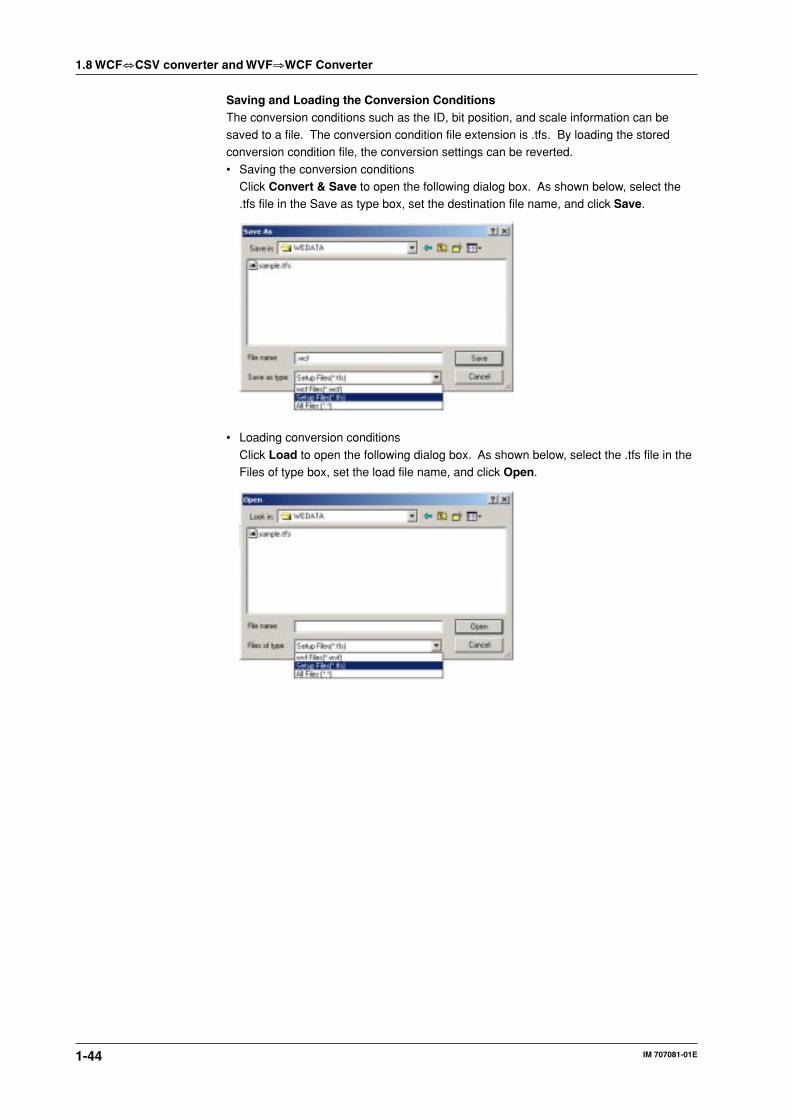
1-44 IM 707081-01E
Saving and Loading the Conversion ConditionsThe conversion conditions such as the ID, bit position, and scale information can besaved to a file. The conversion condition file extension is .tfs. By loading the storedconversion condition file, the conversion settings can be reverted.
• Saving the conversion conditionsClick Convert & Save to open the following dialog box. As shown below, select the.tfs file in the Save as type box, set the destination file name, and click Save.
• Loading conversion conditions
Click Load to open the following dialog box. As shown below, select the .tfs file in theFiles of type box, set the load file name, and click Open.
1.8 WCF⇔CSV converter and WVF⇒WCF Converter
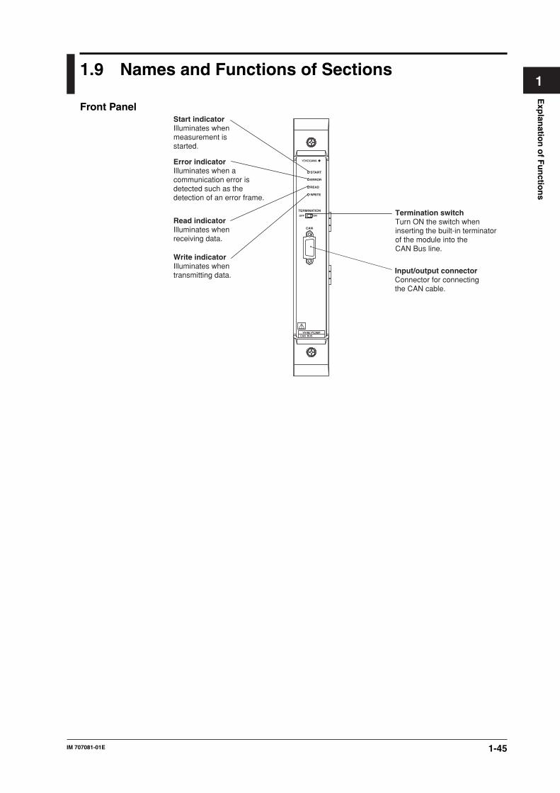
1-45
Exp
lanatio
n o
f Fu
nctio
ns
IM 707081-01E
11.9 Names and Functions of Sections
Front Panel
CAN BUS
START
ERROR
READ
WRITE
TERMINATION
OFF ON
CAN
Start indicatorIlluminates whenmeasurement isstarted.
Error indicatorIlluminates when acommunication error isdetected such as thedetection of an error frame.
Read indicatorIlluminates whenreceiving data.
Write indicatorIlluminates whentransmitting data.
Termination switchTurn ON the switch wheninserting the built-in terminatorof the module into theCAN Bus line.
Input/output connectorConnector for connectingthe CAN cable.
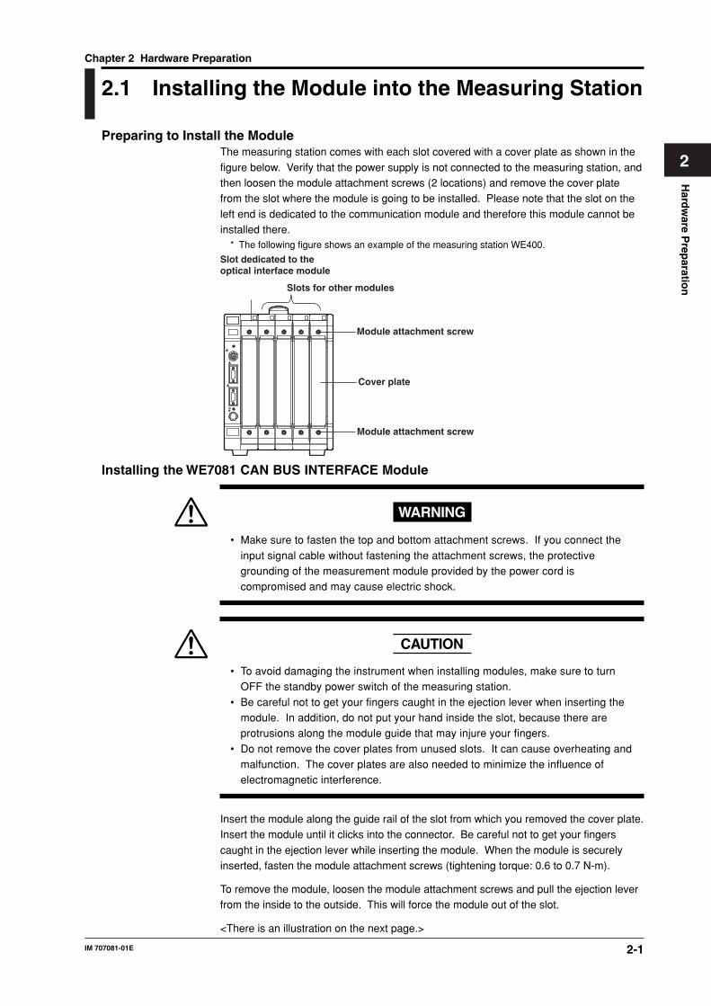
2-1IM 707081-01E
Hard
ware P
reparatio
n
2
Chapter 2 Hardware Preparation
2.1 Installing the Module into the Measuring Station
Preparing to Install the ModuleThe measuring station comes with each slot covered with a cover plate as shown in the
figure below. Verify that the power supply is not connected to the measuring station, andthen loosen the module attachment screws (2 locations) and remove the cover platefrom the slot where the module is going to be installed. Please note that the slot on the
left end is dedicated to the communication module and therefore this module cannot beinstalled there.
* The following figure shows an example of the measuring station WE400.
Slots for other modules
Slot dedicated to the optical interface module
Module attachment screw
Module attachment screw
Cover plate
Installing the WE7081 CAN BUS INTERFACE Module
WARNING
• Make sure to fasten the top and bottom attachment screws. If you connect the
input signal cable without fastening the attachment screws, the protectivegrounding of the measurement module provided by the power cord iscompromised and may cause electric shock.
CAUTION
• To avoid damaging the instrument when installing modules, make sure to turnOFF the standby power switch of the measuring station.
• Be careful not to get your fingers caught in the ejection lever when inserting themodule. In addition, do not put your hand inside the slot, because there areprotrusions along the module guide that may injure your fingers.
• Do not remove the cover plates from unused slots. It can cause overheating andmalfunction. The cover plates are also needed to minimize the influence ofelectromagnetic interference.
Insert the module along the guide rail of the slot from which you removed the cover plate.Insert the module until it clicks into the connector. Be careful not to get your fingers
caught in the ejection lever while inserting the module. When the module is securelyinserted, fasten the module attachment screws (tightening torque: 0.6 to 0.7 N-m).
To remove the module, loosen the module attachment screws and pull the ejection leverfrom the inside to the outside. This will force the module out of the slot.
<There is an illustration on the next page.>
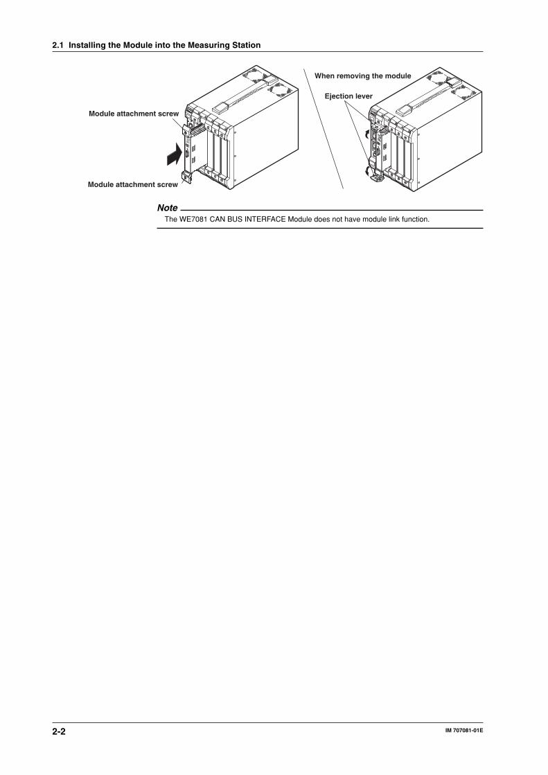
2-2 IM 707081-01E
When removing the module
Module attachment screw
Module attachment screw
Ejection lever
NoteThe WE7081 CAN BUS INTERFACE Module does not have module link function.
2.1 Installing the Module into the Measuring Station
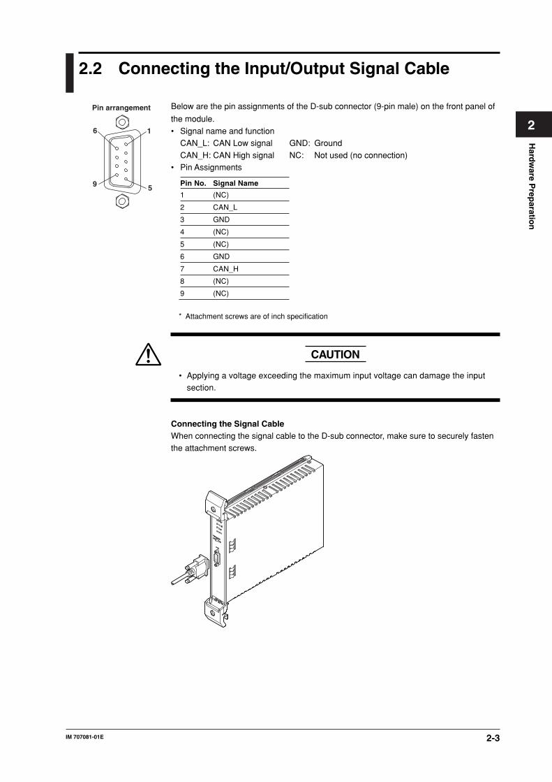
2-3IM 707081-01E
Hard
ware P
reparatio
n
2
2.2 Connecting the Input/Output Signal Cable
Pin arrangement
1
5
6
9
Below are the pin assignments of the D-sub connector (9-pin male) on the front panel of
the module.
• Signal name and functionCAN_L: CAN Low signal GND: Ground
CAN_H: CAN High signal NC: Not used (no connection)• Pin Assignments
Pin No. Signal Name
1 (NC)
2 CAN_L
3 GND
4 (NC)
5 (NC)
6 GND
7 CAN_H
8 (NC)
9 (NC)
* Attachment screws are of inch specification
CAUTION
• Applying a voltage exceeding the maximum input voltage can damage the inputsection.
Connecting the Signal CableWhen connecting the signal cable to the D-sub connector, make sure to securely fasten
the attachment screws.

2-4 IM 707081-01E
2.3 Terminator
You can insert a terminator (124 Ω) between CAN_H and CAN_L on the CAN Bus line byturning ON the terminator switch on the front panel as shown below.
CAN I/F section
CAN TRANSCEIVER
CAN_H
62 Ω
7
2
3
6
62 Ω
CAN_H
CAN_L CAN_L
GND
GND0.1 µF

3-1IM 707081-01E
Trou
blesh
oo
ting
and
Main
tenan
ce
3
Chapter 3 Troubleshooting and Maintenance
3.1 Troubleshooting
• If servicing is necessary, or if the instrument is not operating correctly after performingthe following corrective actions, contact your nearest YOKOGAWA dealer.
• To verify that the module is operating correctly, perform the self test as described onthe next page.
Description Probable Cause/Corrective Action Reference Page
Module does not operate. Check to see that the module is installed correctly into 2-1, *the station. Also, install the module into another slot,and check whether it will operate there. If it operatesin the other slot, the arming is not set properly or themeasuring station is likely to have malfunctioned.If the module is installed correctly and does not operate,the connector might be bad or the IC may havemalfunctioned. In either case, contact your nearestYOKOGAWA dealer.
Waveform data cannot be acquired. Check that the signal input lines are properly connected. 2-3
Measured values are not correct. Check whether the ambient temperature and humidity are 4-7within the allowed ranges.If you did not allow a warm-up time of 30 minutes, trymeasuring again after the warm-up time has passed.
Trigger does not activate Check whether the trigger setting is adequate for the input 1-10, 1-15, 1-26source in the operation panel. 1-34, 1-37If you are using the bus trigger signal, verify that thesettings are correct in the trigger source/time base source/arming setting dialog box of the WE7000 Control Software.
The waveform monitor does not appear. Check to see that the waveform monitor ON/OFF button, 1-9located to the right of the Start button of the operation,is not set to OFF.
* See the WE7000 User’s Manual (IM 707001-01E).

3-2 IM 707081-01E
3.2 Self Test
If you believe that the module is not operating correctly, perform the self test according tothe following steps:
Executing Self Test1. Select Self Test from the System menu of the WE7000 Control Software.
2. In the Self Test dialog box that appears, select the station name and enter the slotnumber corresponding to the module, and click Execute.“Executing...” is displayed in the Result display box.
The four LEDs on the front panel illuminate in order from the top, and all four LEDsilluminate at once at the end.
→
Verifying Test ResultsIf a value other than “0” is displayed in the Result display box of the Self Test dialog box
or the LEDs do not illuminate, the module is probably malfunctioning. In this case,contact your nearest YOKOGAWA dealer.

3-3IM 707081-01E
Trou
blesh
oo
ting
and
Main
tenan
ce
3
3.3 Maintenance
Maintenance of PartsThere are no parts in this module that require periodic replacement.

4-1IM 707081-01E
Sp
ecification
4
Chapter 4 Specification
4.1 Performance Specifications
Number of ports1
Connector TypeD-Sub 9-pin (male)
ControllerPhilips SJA1000 CAN chip
TransceiverBuilt in the module
Terminator124 Ω, switch the terminator On/Off using the dipswitch on the front panel
Data Memory8 MB FIFO buffer
Output Memory8 MB FIFO buffer
Supported ProtocolPhysical layer: ISO-11898 (High Speed Communication)CAN in Automation: CAN2.0B (Standard & extended message format)
Save Format of DataBinary file in WVF (YOKOGAWA measurement standard) formatBinary file in WCF (WE7000 CAN Binary Format) format
Can be saved in binary or ASCII in CSV formatBit Rate
10 k, 20 k, 33.3 k, 50 k, 62.5 k, 83.3 k, 100 k, 125 k, 250 k, 500 k, 800 k, 1 Mbps, and
OtherTime quanta and sample point are selectable
EndianLittle or Big selectable
Synchronized OperationPossible by sharing the trigger signal and clock signal
4-2 IM 707081-01E
4.2 Specifications Specific to Operation Modes
Data Block Signal AcquisitionNumber of Channels1 to 64Acquisition ModeTrigger and free run
Trigger Source (only in trigger mode)Internal trigger and bus trigger signal of the measuring stationPretrigger Amount (only in trigger mode)Set in the range from 0 to (the record length – 2)Trigger Hold Off (only in trigger mode)Record length to 8,388,608
Time BaseInternal clock and bus clock signal of the measuring stationData Sampling Interval1 ms to 10 s (1-ms steps)Remote Frame Output Interval1 to 9999 times (integer multiple of the data sampling interval)
Memory Partition (only in trigger mode)1, 2, 4, 8, 16, 32, 64, 128, and 256Record Length100 to (8,388,608/(the number of memory partitions) × the number of channels)/datasize) points.4,194,304/((the number of memory partitions) × the number of channels)/data size)
points (when repetitively acquiring data)(only in trigger mode)Number of Acquisitions (only in trigger mode)1 to 2,147,483,647Output ModeOne shot output, manual output, periodic output, trigger synchronization output, remote
frame synchronization output, and sequence outputAlarm Output (only in free run mode)Trigger output the result of high limit, low limit, within limits, rising, and falling to the
internal bus (BUSTRG1/BUSTRG2). Output a preset data frame.One Shot OutputOutput a preset data frame once using the Output button.
Manual OutputOutput the data frame selected on the channel setup panel once using the Send button.When Auto Send is enabled, data is output automatically when the data value is changed
Periodic OutputOutput the data frame selected on the channel setup panel at 0.1 to 100 s (0.1 s steps)intervals.
Trigger Synchronization OutputOutput the data frame selected on the channel setup panel each time a trigger isdetected.
Remote Frame Synchronization OutputOutput the data frame selected on the channel setup panel each time a remote frame isreceived.
Sequence OutputSequentially output the data frames of contents specified in advance on the sequencetable.
Up to 1024 frames can be specified on the sequence table.

4-3IM 707081-01E
Sp
ecification
4
Data Field Extraction SettingTurn ON/OFF each channel, select the remote frame, select the extended format, set thedata frame ID, set the extraction position, set the bit length, select the data type, selectthe Endian, set the internal trigger (only in trigger mode), set the internal alarm (only in
free run mode), set the scaling, and select the graph method of NAN data.Saving and Loading of Database FilesLoad the data frame ID, extraction position, bit length, data type, Endian, and scaling
settings of each channel from a CAN database (dbc format or CSV format) and save to aCAN database file (CSV format only).
Data Frame AcquisitionNumber of Acquired Frames0 to 4,294,967,295 (0 = infinite number of times), maximum number of frames that can
be saved = 419430Load Data Filter SettingBit pattern: Hexadecimal or binary
Hex: 0, 1, 2, ... E, F, and X (Don’t Care) for every 4 bitsBinary: 0, 1, or X (Don’t Care)Trigger SourceInternal trigger and bus trigger signal of the measuring stationTrigger TypeEdge trigger, state trigger, and data frame ID receive timing
Other Specifications Related to the TriggerSelect the extended format, set the data frame ID, set the extraction position, set the bitlength, select the data type, select the Endian, and execute manual trigger.
Data Block Signal OutputOutput ModeContinuous, trigger, and one shot
Output Interval1 to 10000 ms (1-ms steps)Frame Data Output Count0 to 2,147,483,647 (0 = infinite number of times)Trigger Source (only in trigger mode or one shot output mode)Internal trigger and bus trigger signal of the measuring station
Trigger Type (only in trigger mode or one shot output mode)Edge trigger, state trigger, and data frame ID receive timingOther Specifications Related to the Trigger (only in trigger mode or one shotoutput mode)Select the extended format, set the data frame ID, set the extraction position, set the bitlength, select the data type, select the Endian, and execute manual trigger.
Data Field Extraction SettingTurn ON/OFF each channel, select the extended format, set the data frame ID, set theextraction position, set the bit length, select the data type, select the Endian, select the
sweep pattern, set the output start/end value, and the step for changing the sweeppattern.
Data Frame OutputOutput ModeContinuous and trigger
Repeat Output Count0 to 100 (0 = infinite number of times)Trigger Source (only in trigger mode or one shot output mode)Internal trigger and bus trigger signal of the measuring station
4.2 Specifications Specific to Operation Modes

4-4 IM 707081-01E
Trigger Type (only in trigger mode or one shot output mode)Edge trigger, state trigger, and data frame ID receive timingOther Specifications Related to the Trigger (only in trigger mode or one shotoutput mode)Select the extended format, set the data frame ID, set the extraction position, set the bitlength, select the data type, select the Endian, and execute manual trigger.
4.2 Specifications Specific to Operation Modes

4-5IM 707081-01E
Sp
ecification
4
4.3 Default Values (Factory Default Settings)
Operation Mode: AcquisitionBit Rate: 500 kbps
Queue Overflow (handling): ContAcknowledge (ON/OFF): On
Data Block Signal Acquisition SettingsAcquisition Mode: TriggeredSource (trigger source): Internal
Pretrigger: 0Hold Off: 1000Time Base: Internal
Sampling Interval: 10 msMemory Partition: 1Record Length: 1000
No. of Acquisitions: 1Data Frame Output Settings
Out Mode: One Shot
One Shot OutputExt (ON for extended format): OFFIdentifier (ID): 0
DLC (data field length): 1DATA (output data): 0
Auto Send: Off
Period (output period): 1.0 sNo. of Repeat (sequence output): 1
Repeat (repetitive measurement): On
Channel Extraction SettingsOn (channel ON/OFF): OffExt (ON when the ID format is extended): Off
ID (ID of the data frame to be acquired): 0SB (data extraction start position): 0LN (bit length): 1
Value Type (data type): UnsignedEndian: BigType (trigger type): Rise on CH1, Off on others
Level (trigger level): 0Label: NoneScaling: Off
Unit: NoneRq (transmit or not transmit the remote frame): OffRq Interval (remote frame output interval): 1
Output On: OffOutput Value: 0Output DLC: 1
Scaling Type: ax+bInteger NAN (graph display method of NAN data): Full bitTrig Combination: OR

4-6 IM 707081-01E
Data Frame Acquisition SettingsNo. of Frames: 1000Identifier Filter (read data filter): All bits set to X, Hex displayTrigger Settings
Source (trigger source): InternalType (trigger type): OffLevel (trigger level): 0
Ext (ON for extended format): OffID (data frame ID): 0SB (data extraction start position): 0
LN (bit length): 1Value Type (data type): UnsignedEndian: Big
Data Block Signal OutputOutput Mode: Cont
Output Interval: 10 msNo. of Output Samples: 0Trigger Settings
Source (trigger source): InternalType (trigger type): OffLevel (trigger level): 0
Ext (ON for extended format): OffID (data frame ID): 0SB (data extraction start position): 0
LN (bit length): 1Value Type (data type): UnsignedEndian: Big
Channel Settings
On (channel ON/OFF): OffExt (ON when the ID format is extended): OffID (ID of the data frame to be output): 0
SB (data extraction start position): 0LN (bit length): 1Value Type (data type): Unsigned
Endian: BigSweep Pattern: OffData Start (output start value): 0
Data End (output end value): 0Step (step for changing the sweep pattern): 0
Frame Output SettingsOutput Mode: ContRepeat (repeat output count): 0
Trigger SettingsSource (trigger source): InternalType (trigger type): Off
Level (trigger level): 0Ext (ON for extended format): OffID (data frame ID): 0
SB (data extraction start position): 0LN (bit length): 1Value Type (data type): Unsigned
Endian: Big
4.3 Default Values (Factory Default Settings)
4-7IM 707081-01E
Sp
ecification
4
4.4 General Specifications
Safety StandardsComplies with CSA C22.2 No.1010.1 and EN61010-1, conforms to JIS C1010-1
• Overvoltage Category CAT I and II*1
• Pollution Degree 1 and 2*2
*1Overvoltage Categories define transient overvoltage levels, including impulse withstand voltage
levels.
Overvoltage Category I: Applies to equipment supplied with electricity from a circuit
containing an overvoltage control device.
Overvoltage Category II: Applies to equipment supplied with electricity from fixed installations
like a distribution board.
*2Pollution Degree: Applies to the degree of adhesion of a solid, liquid, or gas which
deteriorates withstand voltage or surface resistivity.
Pollution Degree 1: Applies to closed atmospheres (with no, or only dry, non-conductive
pollution).
Pollution Degree 2: Applies to normal indoor atmospheres (with only non-conductive
pollution).
EMC StandardEmissionComplying Standard: EN55011 Group 1 Class AThis product is a Class A (for industrial environment) product. Operation of this product in
a residential area may cause radio interference in which case the user is required tocorrect the interference.ImmunityComplying Standard: EN61326 Industrial EnvironmentMaximum Measuring Input Cable Length: 30 m
Basic Operating ConditionsAmbient temperature: 23±5 °C, ambient humidity: 50±10% RH,Supply voltage/frequency error: Within 1% of rating, and after the warm-up time haspassed
Warm-up TimeAt least 30 minutes
Operating ConditionsSame as those of the measuring station
Storage ConditionsTemperature: –20 °C to 60 °C
Humidity: 20% to 80%RHPower Consumption
5 VA (typical value* at 100 V/50 Hz)
WeightApprox. 0.7 kg
External DimensionsApprox. 33(W) × 243(H) × 232(D) mm (projections excluded)
Number of Used Slots1
Standard AccessoriesUser’s Manual (this manual) (1)
* The typical value is a representative or standard value. It is not a warranted value.
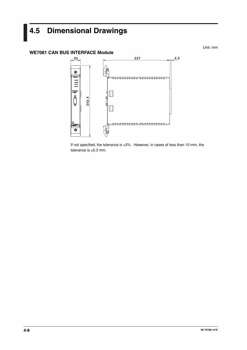
4-8 IM 707081-01E
4.5 Dimensional Drawings
Unit: mmWE7081 CAN BUS INTERFACE Module
33
24
2.4
227 4.5
If not specified, the tolerance is ±3%. However, in cases of less than 10 mm, thetolerance is ±0.3 mm.

App-1IM 707081-01E
Ap
pen
dix
App
Appendix
Appendix 1 Sample Point Table
The rows that are shaded in gray in the table are the default settings for each bit rate.
Bit Rate = 1 Mbps
No. Sample Point Value [%] Time Quanta BTR0 BTR1
1 83.33 12 40 182 75.00 12 40 273 66.67 12 40 364 58.33 12 40 455 50.00 12 40 54
Bit Rate = 800 kbps
No. Sample Point Value [%] Time Quanta BTR0 BTR1
1 86.67 15 40 1B2 80.00 15 40 2A3 73.33 15 40 394 66.67 15 40 485 60.00 15 40 576 53.33 15 40 66
Bit Rate = 500 kbps
No. Sample Point Value [%] Time Quanta BTR0 BTR1
1 70.83 24 40 6F2 66.67 24 40 7E3 83.33 12 41 184 75.00 12 41 275 66.67 12 41 366 58.33 12 41 457 50.00 12 41 548 75.00 8 42 149 62.50 8 42 2310 50.00 8 42 32
Bit Rate = 250 kbps
No. Sample Point Value [%] Time Quanta BTR0 BTR1
1 70.83 24 41 6F2 66.67 24 41 7E3 87.50 16 42 1C4 81.25 16 42 2B5 75.00 16 42 3A6 68.75 16 42 497 62.50 16 42 588 56.25 16 42 679 50.00 16 42 7610 83.33 12 43 1811 75.00 12 43 2712 66.67 12 43 3613 58.33 12 43 4514 50.00 12 43 5415 75.00 8 45 1416 62.50 8 45 2317 50.00 8 45 32
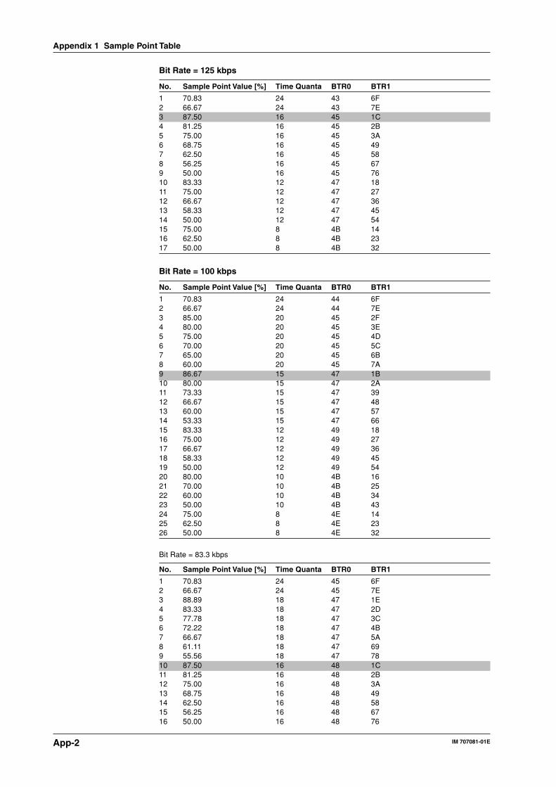
App-2 IM 707081-01E
Bit Rate = 125 kbps
No. Sample Point Value [%] Time Quanta BTR0 BTR1
1 70.83 24 43 6F2 66.67 24 43 7E3 87.50 16 45 1C4 81.25 16 45 2B5 75.00 16 45 3A6 68.75 16 45 497 62.50 16 45 588 56.25 16 45 679 50.00 16 45 7610 83.33 12 47 1811 75.00 12 47 2712 66.67 12 47 3613 58.33 12 47 4514 50.00 12 47 5415 75.00 8 4B 1416 62.50 8 4B 2317 50.00 8 4B 32
Bit Rate = 100 kbps
No. Sample Point Value [%] Time Quanta BTR0 BTR1
1 70.83 24 44 6F2 66.67 24 44 7E3 85.00 20 45 2F4 80.00 20 45 3E5 75.00 20 45 4D6 70.00 20 45 5C7 65.00 20 45 6B8 60.00 20 45 7A9 86.67 15 47 1B10 80.00 15 47 2A11 73.33 15 47 3912 66.67 15 47 4813 60.00 15 47 5714 53.33 15 47 6615 83.33 12 49 1816 75.00 12 49 2717 66.67 12 49 3618 58.33 12 49 4519 50.00 12 49 5420 80.00 10 4B 1621 70.00 10 4B 2522 60.00 10 4B 3423 50.00 10 4B 4324 75.00 8 4E 1425 62.50 8 4E 2326 50.00 8 4E 32
Bit Rate = 83.3 kbps
No. Sample Point Value [%] Time Quanta BTR0 BTR1
1 70.83 24 45 6F2 66.67 24 45 7E3 88.89 18 47 1E4 83.33 18 47 2D5 77.78 18 47 3C6 72.22 18 47 4B7 66.67 18 47 5A8 61.11 18 47 699 55.56 18 47 7810 87.50 16 48 1C11 81.25 16 48 2B12 75.00 16 48 3A13 68.75 16 48 4914 62.50 16 48 5815 56.25 16 48 6716 50.00 16 48 76
Appendix 1 Sample Point Table
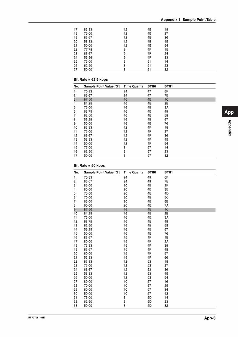
App-3IM 707081-01E
Ap
pen
dix
App
17 83.33 12 4B 1818 75.00 12 4B 2719 66.67 12 4B 3620 58.33 12 4B 4521 50.00 12 4B 5422 77.78 9 4F 1523 66.67 9 4F 2424 55.56 9 4F 3325 75.00 8 51 1426 62.50 8 51 2327 50.00 8 51 32
Bit Rate = 62.5 kbps
No. Sample Point Value [%] Time Quanta BTR0 BTR1
1 70.83 24 47 6F2 66.67 24 47 7E3 87.50 16 4B 1C4 81.25 16 4B 2B5 75.00 16 4B 3A6 68.75 16 4B 497 62.50 16 4B 588 56.25 16 4B 679 50.00 16 4B 7610 83.33 12 4F 1811 75.00 12 4F 2712 66.67 12 4F 3613 58.33 12 4F 4514 50.00 12 4F 5415 75.00 8 57 1416 62.50 8 57 2317 50.00 8 57 32
Bit Rate = 50 kbps
No. Sample Point Value [%] Time Quanta BTR0 BTR1
1 70.83 24 49 6F2 66.67 24 49 7E3 85.00 20 4B 2F4 80.00 20 4B 3E5 75.00 20 4B 4D6 70.00 20 4B 5C7 65.00 20 4B 6B8 60.00 20 4B 7A9 87.50 16 4E 1C10 81.25 16 4E 2B11 75.00 16 4E 3A12 68.75 16 4E 4913 62.50 16 4E 5814 56.25 16 4E 6715 50.00 16 4E 7616 86.67 15 4F 1B17 80.00 15 4F 2A18 73.33 15 4F 3919 66.67 15 4F 4820 60.00 15 4F 5721 53.33 15 4F 6622 83.33 12 53 1823 75.00 12 53 2724 66.67 12 53 3625 58.33 12 53 4526 50.00 12 53 5427 80.00 10 57 1628 70.00 10 57 2529 60.00 10 57 3430 50.00 10 57 4331 75.00 8 5D 1432 62.50 8 5D 2333 50.00 8 5D 32
Appendix 1 Sample Point Table

App-4 IM 707081-01E
Bit Rate = 33.3 kbps
No. Sample Point Value [%] Time Quanta BTR0 BTR1
1 70.83 24 4E 6F2 66.67 24 4E 7E3 85.00 20 51 2F4 80.00 20 51 3E5 75.00 20 51 4D6 70.00 20 51 5C7 65.00 20 51 6B8 60.00 20 51 7A9 88.89 18 53 1E10 83.33 18 53 2D11 77.78 18 53 3C12 72.22 18 53 4B13 66.67 18 53 5A14 61.11 18 53 6915 55.56 18 53 7816 86.67 15 57 1B17 80.00 15 57 2A18 73.33 15 57 3919 66.67 15 57 4820 60.00 15 57 5721 53.33 15 57 6622 83.33 12 5D 1823 75.00 12 5D 2724 66.67 12 5D 3625 58.33 12 5D 4526 50.00 12 5D 5427 80.00 10 63 1628 70.00 10 63 2529 60.00 10 63 3430 50.00 10 63 4331 77.78 9 67 1532 66.67 9 67 2433 55.56 9 67 3334 75.00 8 6C 1435 62.50 8 6C 2336 50.00 8 6C 32
Bit Rate = 20 kbps
No. Sample Point Value [%] Time Quanta BTR0 BTR1
1 68.00 25 57 7F2 70.83 24 58 6F3 66.67 24 58 7E4 85.00 20 5D 2F5 80.00 20 5D 3E6 75.00 20 5D 4D7 70.00 20 5D 5C8 65.00 20 5D 6B9 60.00 20 5D 7A10 86.67 15 67 1B11 80.00 15 67 2A12 73.33 15 67 3913 66.67 15 67 4814 60.00 15 67 5715 53.33 15 67 6616 83.33 12 71 1817 75.00 12 71 2718 66.67 12 71 3619 58.33 12 71 4520 50.00 12 71 5421 80.00 10 7B 1622 70.00 10 7B 2523 60.00 10 7B 3424 50.00 10 7B 43
Appendix 1 Sample Point Table

App-5IM 707081-01E
Ap
pen
dix
App
Bit Rate = 10 kbps
No. Sample Point Value [%] Time Quanta BTR0 BTR1
1 68.00 25 6F 7F2 70.83 24 71 6F3 66.67 24 71 7E4 85.00 20 7B 2F5 80.00 20 7B 3E6 75.00 20 7B 4D7 70.00 20 7B 5C8 65.00 20 7B 6B9 60.00 20 7B 7A
Appendix 1 Sample Point Table

App-6 IM 707081-01E
Appendix 2 Data Structure of Files
DATA Structure of WCF FilesThe WCF file is a binary file with a structure shown in the figure below. The Endian is
big. Therefore, when directly processing a WCF file on a PC with Intel or compatibleCPU, the byte order must be swapped.
A Header
Magic No.
File Version
Header Size
No. of Data Frames
Start Time
Reserved
Time Data
Ex ID
DLC
Data
Frame Data (1)
Frame Data (2)
Frame Data (3)
Frame Data (N)
WCF file
64 byte
20 byte
20 byte
20 byte
20 byte
32 bit
32 bit
Char[4]=“%WCF”
Char[44]
Unsigned Long=1
Unsigned Long=64
Unsigned Long=N
Unsigned Long (time_t)
Unsigned Long
Unsigned Long
Unsigned Long
Unsigned Char[8]
bit31=0: Standard format (11bit)1: Extended format (29bit)
DATA Structure of CSV FilesThe CSV file is a comma-separated text file with the syntax shown in the figure below.
Line
1
2
3
4
5
6
7
8
9
:
N
Description (d and x indicate decimal and
hexadecimal notations, respectively)
File Virsion, 1
No.of Data Frames, dddd
Year/Month/Day, dddd/dd/dd
Hour:Min:Sec, dd:dd:dd
Time, Format, ID, DLC, Data
ddd.dddd, d, d, xx xx xx xx xx xx xx xx
ddd.dddd, d, d, xx xx xx xx xx xx xx xx
ddd.dddd, d, d, xx xx xx xx xx xx xx xx
:
ddd.dddd, d, d, xx xx xx xx xx xx xx xx
Header section
Blank line
Data block title line
Data block
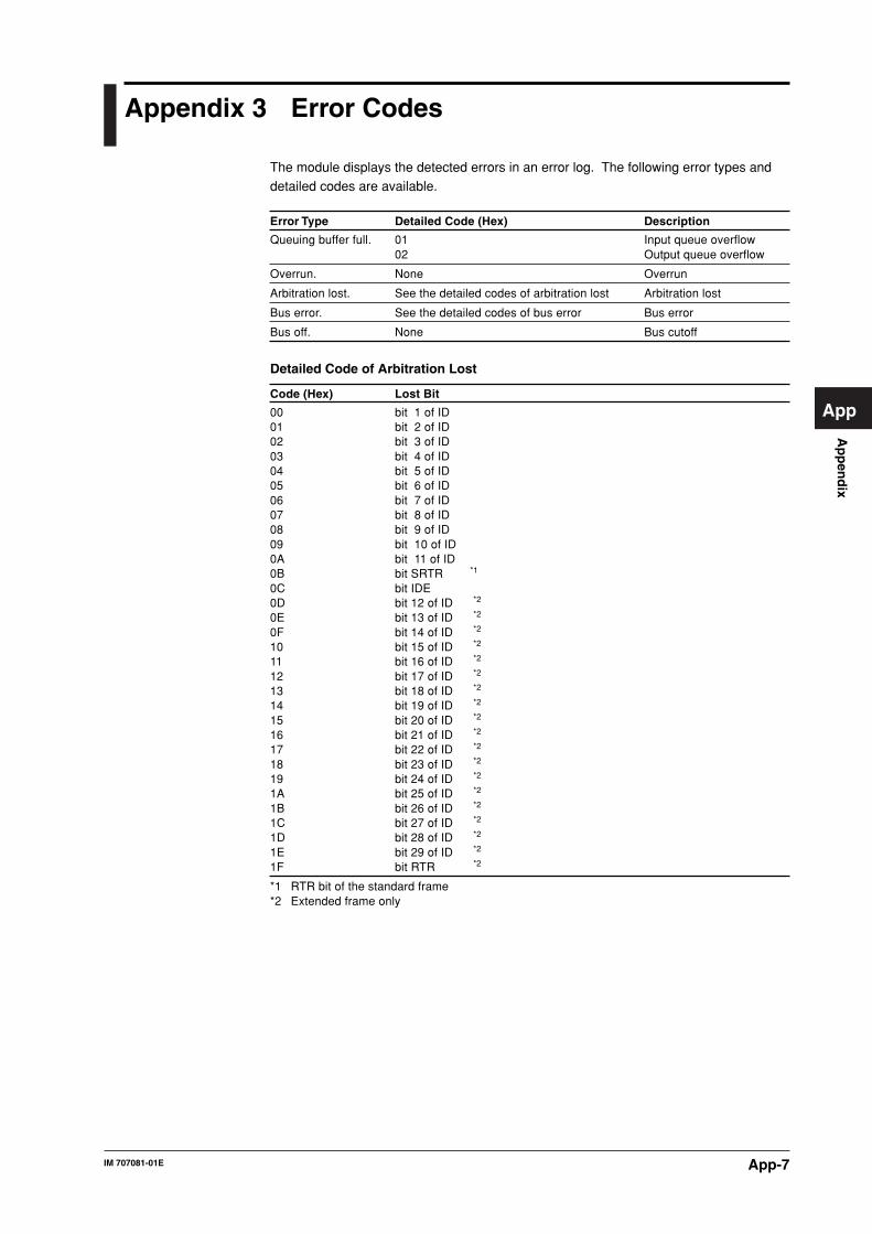
App-7IM 707081-01E
Ap
pen
dix
App
Appendix 3 Error Codes
The module displays the detected errors in an error log. The following error types anddetailed codes are available.
Error Type Detailed Code (Hex) Description
Queuing buffer full. 01 Input queue overflow02 Output queue overflow
Overrun. None Overrun
Arbitration lost. See the detailed codes of arbitration lost Arbitration lost
Bus error. See the detailed codes of bus error Bus error
Bus off. None Bus cutoff
Detailed Code of Arbitration Lost
Code (Hex) Lost Bit
00 bit 1 of ID01 bit 2 of ID02 bit 3 of ID03 bit 4 of ID04 bit 5 of ID05 bit 6 of ID06 bit 7 of ID07 bit 8 of ID08 bit 9 of ID09 bit 10 of ID0A bit 11 of ID0B bit SRTR *1
0C bit IDE0D bit 12 of ID *2
0E bit 13 of ID *2
0F bit 14 of ID *2
10 bit 15 of ID *2
11 bit 16 of ID *2
12 bit 17 of ID *2
13 bit 18 of ID *2
14 bit 19 of ID *2
15 bit 20 of ID *2
16 bit 21 of ID *2
17 bit 22 of ID *2
18 bit 23 of ID *2
19 bit 24 of ID *2
1A bit 25 of ID *2
1B bit 26 of ID *2
1C bit 27 of ID *2
1D bit 28 of ID *2
1E bit 29 of ID *2
1F bit RTR *2
*1 RTR bit of the standard frame*2 Extended frame only

App-8 IM 707081-01E
Detailed Codes of Bus Error
Bit Number Item Code (Bin): Description
0 to 4 Segment 00010 : ID.28 to ID.2100011 : start of frame00100 : bit SRTR00101 : bit IDE00110 : ID.20 to ID.1800111 : ID.17 to ID.1301000 : CRC sequence01001 : reserve bit 001010 : data field01011 : data length code01100 : bit RTR01101 : reserve bit 101110 : ID.4 to ID.001111 : ID.12 to ID.510001 : active error flag10010 : intermission10011 : tolerate dominant bit10110 : passive error flag10111 : error delimiter11000 : CRC delimiter11001 : acknowledge slot11010 : end of frame11011 : acknowledge delimiter11100 : overload flag
5 Direction 0 : Occurred during transmission1 : Occurred during reception
6 to 7 Error code 00 : bit error01 : form error10 : stuff error11 : other type of error
Appendix 3 Error Codes
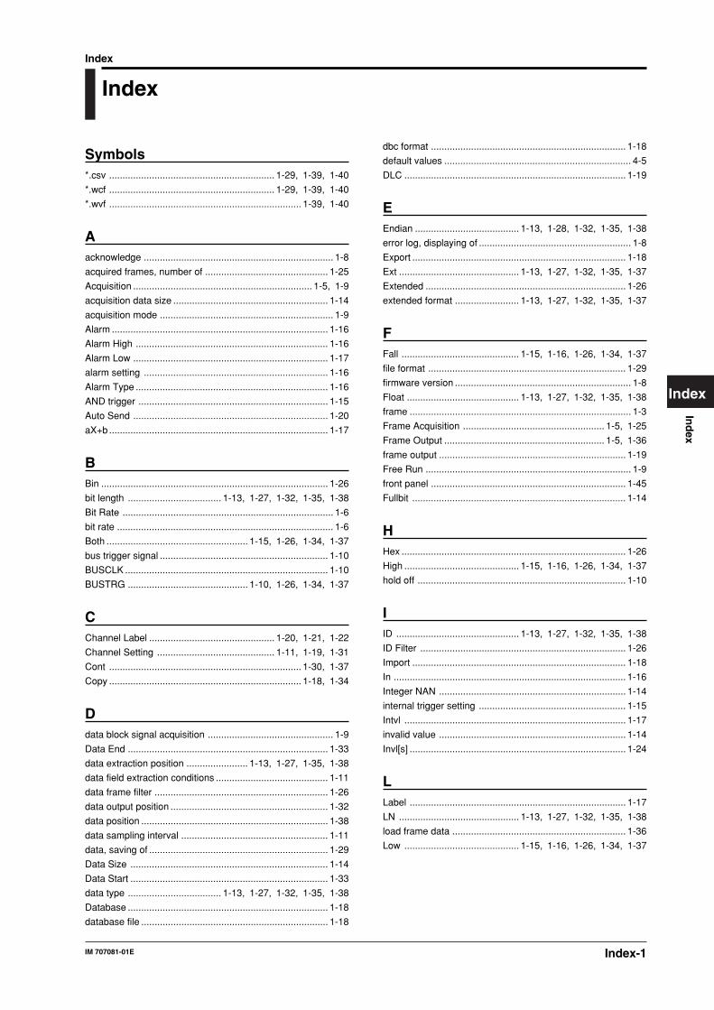
Index-1IM 707081-01E
Ind
ex
Index
Index
Index
dbc format ......................................................................... 1-18
default values ...................................................................... 4-5
DLC ................................................................................... 1-19
EEndian ....................................... 1-13, 1-28, 1-32, 1-35, 1-38
error log, displaying of ......................................................... 1-8
Export ................................................................................ 1-18
Ext ............................................. 1-13, 1-27, 1-32, 1-35, 1-37
Extended ........................................................................... 1-26
extended format ........................ 1-13, 1-27, 1-32, 1-35, 1-37
FFall ............................................ 1-15, 1-16, 1-26, 1-34, 1-37
file format .......................................................................... 1-29
firmware version .................................................................. 1-8
Float .......................................... 1-13, 1-27, 1-32, 1-35, 1-38
frame ................................................................................... 1-3
Frame Acquisition ..................................................... 1-5, 1-25
Frame Output ............................................................ 1-5, 1-36
frame output ...................................................................... 1-19
Free Run ............................................................................. 1-9
front panel ......................................................................... 1-45
Fullbit ................................................................................ 1-14
HHex .................................................................................... 1-26
High ........................................... 1-15, 1-16, 1-26, 1-34, 1-37
hold off .............................................................................. 1-10
IID .............................................. 1-13, 1-27, 1-32, 1-35, 1-38
ID Filter ............................................................................. 1-26
Import ................................................................................ 1-18
In ....................................................................................... 1-16
Integer NAN ...................................................................... 1-14
internal trigger setting ....................................................... 1-15
Intvl ................................................................................... 1-17
invalid value ...................................................................... 1-14
Invl[s] ................................................................................. 1-24
LLabel ................................................................................. 1-17
LN ............................................. 1-13, 1-27, 1-32, 1-35, 1-38
load frame data ................................................................. 1-36
Low ........................................... 1-15, 1-16, 1-26, 1-34, 1-37
Symbols*.csv .............................................................. 1-29, 1-39, 1-40
*.wcf .............................................................. 1-29, 1-39, 1-40
*.wvf ........................................................................ 1-39, 1-40
Aacknowledge ....................................................................... 1-8
acquired frames, number of .............................................. 1-25
Acquisition ................................................................... 1-5, 1-9
acquisition data size .......................................................... 1-14
acquisition mode ................................................................. 1-9
Alarm ................................................................................. 1-16
Alarm High ........................................................................ 1-16
Alarm Low ......................................................................... 1-17
alarm setting ..................................................................... 1-16
Alarm Type ........................................................................ 1-16
AND trigger ....................................................................... 1-15
Auto Send ......................................................................... 1-20
aX+b .................................................................................. 1-17
BBin ..................................................................................... 1-26
bit length ................................... 1-13, 1-27, 1-32, 1-35, 1-38
Bit Rate ............................................................................... 1-6
bit rate ................................................................................. 1-6
Both ..................................................... 1-15, 1-26, 1-34, 1-37
bus trigger signal ............................................................... 1-10
BUSCLK ............................................................................ 1-10
BUSTRG ............................................. 1-10, 1-26, 1-34, 1-37
CChannel Label ............................................... 1-20, 1-21, 1-22
Channel Setting ............................................ 1-11, 1-19, 1-31
Cont ........................................................................ 1-30, 1-37
Copy ........................................................................ 1-18, 1-34
Ddata block signal acquisition ............................................... 1-9
Data End ........................................................................... 1-33
data extraction position ....................... 1-13, 1-27, 1-35, 1-38
data field extraction conditions .......................................... 1-11
data frame filter ................................................................. 1-26
data output position ........................................................... 1-32
data position ...................................................................... 1-38
data sampling interval ....................................................... 1-11
data, saving of ................................................................... 1-29
Data Size .......................................................................... 1-14
Data Start .......................................................................... 1-33
data type ................................... 1-13, 1-27, 1-32, 1-35, 1-38
Database ........................................................................... 1-18
database file ...................................................................... 1-18
Index-2 IM 707081-01E
Index
MManual .............................................................................. 1-20
manual output ................................................................... 1-20
Manual Trigger .............................................. 1-28, 1-35, 1-38
manual trigger ............................................... 1-28, 1-35, 1-38
Memory Partition ............................................................... 1-10
Mode ......................................... 1-19, 1-20, 1-21, 1-22, 1-23
MODEL .................................................................................. 2
NNAN .................................................................................. 1-14
NO. ......................................................................................... 2
No. of acquisitions ............................................................. 1-10
No. of Frames ................................................................... 1-25
No. of Output Samples[data/CH] ...................................... 1-30
No. of Repeat .................................................................... 1-24
No. of Stored Frames ........................................................ 1-28
OOn ..................................................................................... 1-13
One Shot ................................................................. 1-19, 1-30
one shot output ................................................................. 1-19
operation, description of ...................................................... 1-2
operation mode ............................. 1-5, 1-9, 1-25, 1-30, 1-36
OR trigger ......................................................................... 1-15
Out .................................................................................... 1-16
Output ................................................... 1-5, 1-19, 1-30, 1-36
output end value ............................................................... 1-33
Output Interval .................................................................. 1-30
output mode ............................................................ 1-30, 1-37
output start value .............................................................. 1-33
PP1-P2 ................................................................................ 1-17
package, contents of .............................................................. 2
Paste ....................................................................... 1-18, 1-34
Performance Specifications ................................................ 4-1
Period ................................................................................ 1-21
Periodic ............................................................................. 1-21
periodic output mode ........................................................ 1-21
Pretrigger .......................................................................... 1-10
QQueue Overflow .................................................................. 1-7
RRamp-Repeat .................................................................... 1-33
Ramp-Single&Hold ........................................................... 1-33
Ramp-single&Reset .......................................................... 1-33
record length ..................................................................... 1-10
Remote ............................................................................. 1-22
remote frame output .......................................................... 1-17
remote frame synchronization output ................................ 1-22
Repeat ...................................................................... 1-9, 1-37
repeat output ..................................................................... 1-37
Rise ........................................... 1-15, 1-16, 1-26, 1-34, 1-37
Rq ..................................................................................... 1-17
Ssampling interval ............................................................... 1-11
Save Frame Data .............................................................. 1-29
SB ............................................. 1-13, 1-27, 1-32, 1-35, 1-38
Scaling .............................................................................. 1-17
Scaling Type ..................................................................... 1-17
self test ................................................................................ 3-2
Send ........................................................................ 1-20, 1-24
Send All ............................................................................. 1-20
sequence output ............................................................... 1-23
sequence table .................................................................. 1-23
Sequential ......................................................................... 1-23
Signed ....................................... 1-13, 1-27, 1-32, 1-35, 1-38
Source ................................................. 1-10, 1-26, 1-34, 1-37
Standard ........................................................................... 1-26
Start .......................................................................... 1-9, 1-25
Start Bit ............................................................................. 1-13
Step ................................................................................... 1-33
Sweep Pattern .................................................................. 1-33
TTable Setting ..................................................................... 1-23
terminator switch ................................................................. 2-4
Time Base ......................................................................... 1-10
Triangle-Repeat ................................................................ 1-33
Trig .................................................................................... 1-23
Trig Combination ............................................................... 1-15
Trigger ................................................. 1-15, 1-26, 1-30, 1-37
trigger hold off ................................................................... 1-10
trigger level ......................................... 1-15, 1-27, 1-34, 1-37
trigger source ...................................... 1-10, 1-26, 1-34, 1-37
trigger synchronization output ........................................... 1-21
Trigger Type .................................................. 1-26, 1-34, 1-37
trigger type ........................................................................ 1-15
Triggered ................................................................... 1-9, 1-21
Troubleshooting .................................................................. 3-1
UUnit .................................................................................... 1-17
Unsigned ................................... 1-13, 1-27, 1-32, 1-35, 1-38
Index-3IM 707081-01E
Ind
ex
Index
VValue ................................................... 1-19, 1-20, 1-21, 1-22
Value Type ................................ 1-13, 1-27, 1-32, 1-35, 1-38
WWCF!s!¤CSV converter .......................................... 1-29, 1-40
WE7000 CAN binary format .................................... 1-29, 1-40
WVF!s!fiWCF converter .......................................... 1-29, 1-42
XX .......................................................... 1-15, 1-26, 1-34, 1-37
ZZero(0) .............................................................................. 1-14
Index


![PROFIsafe bus interface, PROFIsafe [BU 2800]](https://img.dokumen.tips/doc/110x75/613ca1cbf046235e845cdfe2/profisafe-bus-interface-profisafe-bu-2800.jpg)


