Embed Size (px)
Citation preview
Agenda:
What exactly is CAN ?
Identifiers – what are these ?
What does the data look like ?
What the CAN wires look like.
Example CAN circuits.
Arbitration – who gets priority.
Errors and how to detect them !
Some valuable Tips and Hints….
Connect up a real CAN network !

Is not only for automotive applications !
Can be found everywhere.
Automation is one (CANopen, DeviceNet)
Is easy to implement…no mystery anymore
…unless you use some tricky protocols.
You can “roll your own” for simplicity.
Can gateway to USB, Ethernet, RS232 and other networks to form larger systems.
Some Facts about CAN:

Why Use CAN ?
Electrically robust with built-in error and arbitration features. These are automatic !
Differential pair reduces EMI in/out. Cheap wiring: twisted pair Many controllers, parts & software available. Really, really easy to add another node. Hard work is done by the CAN controller. Many chips have implemented CAN. Very easy to add and subtract nodes. Largest CAN network in world is believed to be
the Vancouver Olympic sign.

What exactly is CAN ?
CAN – Controller Area Network The Bosch CAN spec includes:
Some of the physical layer (wires).
Message frame description.
Attributes – Peer-to-Peer network.
Arbitration scheme - multiple messages.
Some error detection and handling.

The CAN spec does not include:
Any high level addressing modes.
Any message descriptions or groupings.
Diagnostics or messages streams.
Any acknowledgement a message reached its intended target.
Bus Speed: see ISO 11898-2, J2284.
The physical link – you can use anything.
People often include these items. Shouldn’t !

CAN Speeds
Is specified from ~10 Kbps to 1Mbps.
Can’t change speed dynamically…ever !
125, 250 & 500 Kbps common.
Longer cable runs means slower frequency.
1 Mbps a bit hard to manage in a real system.
Better controllers and transceivers make higher speeds easier.
New Bosch standard coming…
Has flexible data rate….

Somewhat compatible with CAN 2.0
> 1 Mbps
After arbitration, can:
Speed up the data fields
Add more data bytes
A few more tricks
Need to be faster and provide less overhead.
Search on web for CAN-FD (CiA)
CAN-FD

High Points of the CAN Bus
Uses a Differential twisted pair of wires. The highest priority message gets thru. Uses non-destructive arbitration. The priority of message is its identifier. 0 has the highest priority. Always. No Master or Slave – Peer to Peer. All nodes see all messages on network. …except their own…..

Construction of a CAN Network
Node 1 Node 3 Node 6 Node
5
Node 4 Node 2
a b
a,b = 120 Ω ½ watt termination resistors.
Drops use the same twisted pair of wires as the backbone.
drops
The main CAN backbone and drops are comprised
of a twisted pair of wires.

A real CAN circuit:
R12, R13 & C45 create “Split Termination” for extra noise immunity instead of one 120 ohm.
Can connect many nodes together. 100’s.
TIP: Use USB cable to power Keil boards.

Differential Twisted Pair
CAN transceiver converts your single-ended Tx signal to a differential pair output and sends to everyone else on your network.
ALSO – takes differential pair from everyone else and converts to the Rx signal for you.
Node sees in and out at same time….
On the 2 CAN wires: CAN_Hi and CAN_Lo
Interference coming in & out cancels out.
Twisted pair and receiver ccts does this.

Recessive and Dominant Bits
Recessive is 2.5 volts CAN Hi and Lo. Difference is 2.5 – 2.5 = 0 volts. Call this a “1”
Dominant is CAN_Hi 3.5v CAN_Lo 1.5v. Difference is 3.5 – 1.5 = 2.0 volts. Call this a “0”
The important
voltage is the
difference between
CAN Hi and Lo
and not to ground.

Recessive and Dominant Bits
Any node can pull Hi and Lo apart on the bus. No node can force Recessive. This is how arbitration works. A bus can sit idle for a hundred years and every
node will see the first message sent. Whether your processor sees it depends if you
configured the CAN controller correctly. If do nothing: nothing happens. The clocks in CAN need to be good ones.

18
Differential Twisted Pair
CAN transceiver converts single-ended Tx to a differential pair output.
ALSO – takes differential pair and converts back to Rx.
Node sees in and out at same time.
Interference in & out cancels out.
Twisted pair and receiver ccts does this.
19
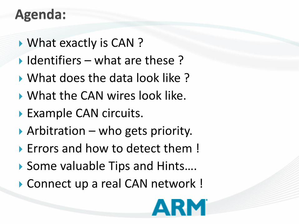
Differential Pair
Subtraction: Noise cancels out. a-b = 0 Good signals add: x-(-y) = x+y

Bit Stuffing
Nodes need an active clock to stay in sync.
Must come from the bus transitions.
If no change for 5 bit times – will add a bit.
CAN frame is actually lengthened by this.
CAN controllers add & remove stuffed bits.
Invisible to the programmer.
Only an oscilloscope will show this...and here is where a problem can surface !

25
Stuff Bit example:
1 2 3 4 5 6 7 8 9 10 11 12 13 14 15 16
1 3 4 5 6 8 9 10 11 13 14 15 16 2 7 12
Stuff Bits
Desired Data
Actual
Data Stream
Note the frame is made longer by the stuff bits.
Bit stuffing is active between Start of Frame and including CRC field –but not the CRC delimiter.
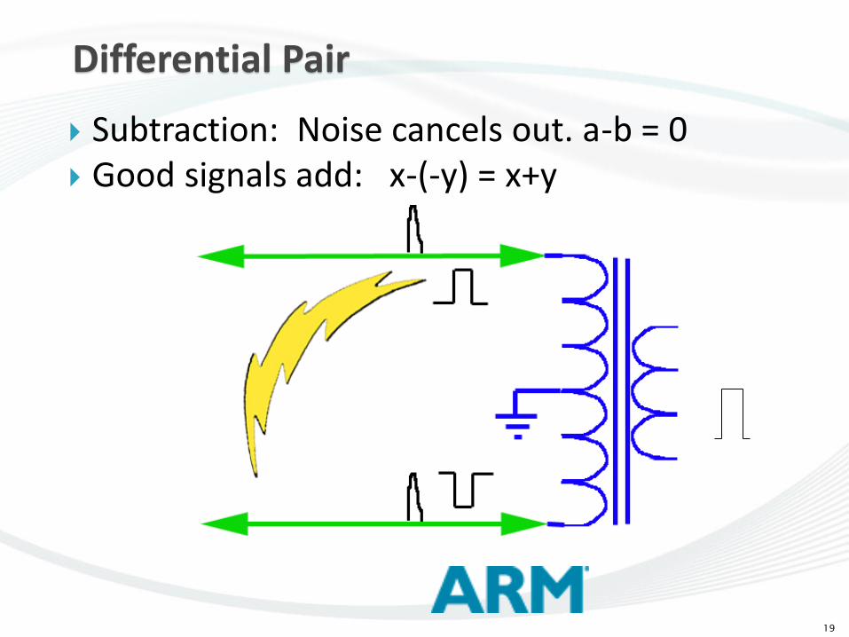
Rain sensor
output
CAN decode
Differential CAN
signal
SPI signals in
ECU

2nd Generation Truck J1939 CAN
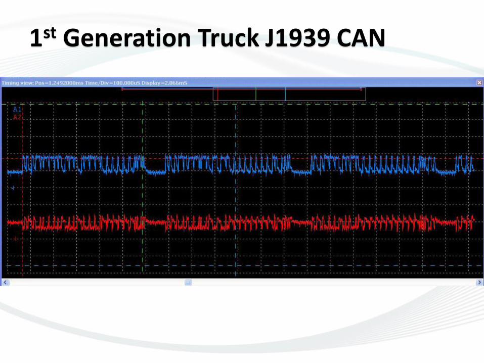
1st Generation Truck J1939 CAN

30
ISO 11898
ISO 11898 = CAN – go deeper now.
4 parts to this.
In addition to the Bosch specification.
Part 1: Data Link + part of Physical Layer.
Part 2: Hi Speed Physical Layer
Part 3: Fault Tolerant CAN
Part 4: Time Triggered CAN

Data Link: the frame.
CAN 2.0 A Standard 11 bit identifiers – 2,048 ID’s. 0 – 7FF CAN 2.0 B Extended
29 bit identifiers – 536 million ID’s. 0 – 1FFF FFFF
Both 11 and 29 bit can be used on the bus. Can change dynamically. CAN controllers can easily sort them out.

A little more…
0 to 8 bytes of data per CAN frame.
This can be changed dynamically.
Bus length to 40 meters @ 1 Mbps, 1 meter drops. Slower = longer.
Two 120 termination resistors needed at each end of the bus. (measure 60 ohms)
Frames start transmitting at the same time.
Bus Error if starts in middle if another frame.

Standard and Extended CAN Frames
SOF - Start of Frame
SRR - Substitute Remote Request
IDE - Identifier Extension
RTR - Remote Transmission Request
R0 - Reserved bit
Extended Frame: SRR=1, IDE=1
R1 - Reserved bit
DLC - Data Length Code
CRC - Cyclic Redundancy Check
DEL - Delimiter
ACK - Acknowledgement bit
SR
R
11-bit
Identifier
Data Field
18-bit
Identifier
Arbitration Field Control
Field CRC Field
ACK
Field
End of
Frame
IFS
Data Field Arbitration
Field
Control
Field CRC Field ACK
Field
End of
Frame
IFS
11-bit
Identifier 0-8 Bytes
0-8 Bytes
15-bit CRC
15-bit CRC
DE
L
DE
L
DE
L
DE
L
AC
K
AC
K
7
7 3
3 DLC
(4)
DLC
(4)
Designers need only fill in the RED lines !
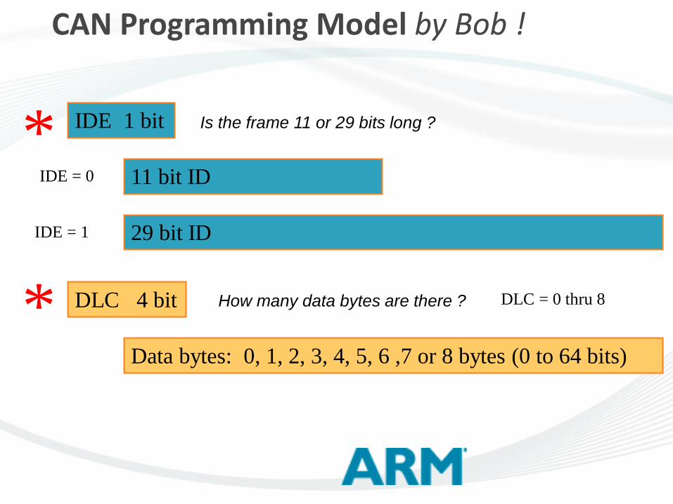
CAN Programming Model by Bob !
11 bit ID
29 bit ID
IDE 1 bit
DLC 4 bit
Data bytes: 0, 1, 2, 3, 4, 5, 6 ,7 or 8 bytes (0 to 64 bits)
*
*
IDE = 0
IDE = 1
DLC = 0 thru 8
Is the frame 11 or 29 bits long ?
How many data bytes are there ?

37
CAN Bit Timing
Each bit consists of a # of time quantum (tq).
Each tq is a fixed length.
TQs added and subtracted as clock syncs.
Tqs are set by designer in CAN controller chip. 1 bit
time 1 time quantum (tq)
sample point
transmit point
Sync-
segment
Propagation
Time Segment
Phase
Buffer
Segment 1
Phase
Buffer
Segment 2
38
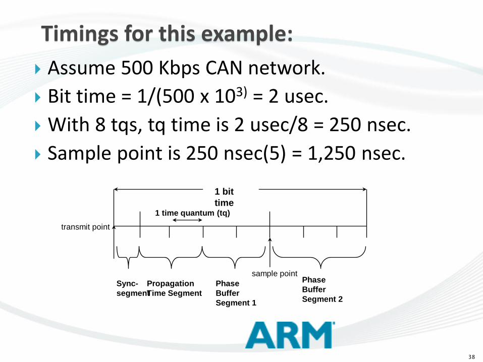
Timings for this example:
Assume 500 Kbps CAN network.
Bit time = 1/(500 x 103) = 2 usec.
With 8 tqs, tq time is 2 usec/8 = 250 nsec.
Sample point is 250 nsec(5) = 1,250 nsec.
1 bit
time 1 time quantum (tq)
sample point
transmit point
Sync-
segment
Propagation
Time Segment
Phase
Buffer
Segment 1
Phase
Buffer
Segment 2

Acknowledge: Newbie mistake # 1.
The ACK bit.
Sender sets this Recessive.
Someone has to assert this to dominant.(probably everybody will)
Else: sender re-transmits again forever.
So – need at least one other CAN node.
Is merely 2 µsec wide @ 500 Kbps.
3 7 A
CK
15-bit CRC 0-8 Bytes
DLC
(4)
RT
R 11-bit Identifier
Data Frame

A bug turned into a feature…..
If bus gets trashed after sender finishes…
But before others think is over…
Bus fault occurs and message retransmitted.
SO: don’t ever increment or toggle a value !
If you want a variable to be 64 – say it in full.
3 7 A
CK
15-bit CRC 0-8 Bytes
DLC
(4)
RT
R 11-bit Identifier
Data Frame
*&#&^%@@#

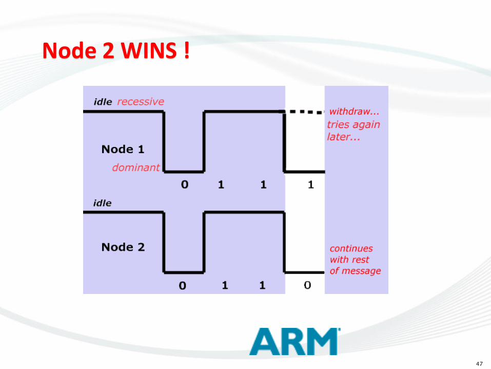
Priority Levels
Message with highest priority gets thru.
Lowest Identifier has priority.
000 beats 001, 123 beats 256. Always.
Arbitration evaluated in real-time.
Uses Recessive and Dominant bits.
A node can (and must!) see itself and others on the bus in real time.
Note: a node can’t see its own ID and data.
All this happens without your intervention !

48
Arbitration Notes:
Illegal to have same identifier at same time. Busoff – if too many errors. T&R Counters. Possible a node will never get priority. CAN is not deterministic. TTCAN is though. Note: if 11 and 29 bit same identifier at the
same time – 11 bit wins arbitration. i.e. 11010101010 &
11010101010101100101001101000

What can you put into the ID ?
Anything at all ! CAN does not specify. IDs will get on bus according to priority. Your System Designer will not agree ! Normally: addresses of modules or devices. Or tasks….Request or Response Acknowledge (don’t confuse with ACK) ID values are carefully selected for filtering. 11 bit ID: 7E0 29 bit ID: 0D43FF00

What can put into Data Bytes ?
Anything at all ! CAN does not specify.
Will not be prioritized by CAN controller.
Your System Designer will not agree !
Normally: Services, Modes, data (signals).
Data transfers etc.
Multi-byte data control bytes. i.e. # bytes sent
Number of data bytes can be changed.
7DF 02 01 00 -> 7E8 xx xx xx xx xx xx xx xx

000:000 0B2 00 48 00 48 00 00
004:510 2D2 00
008:240 O25 00 A2 00 00 00 00 00 CF
010:240 0B0 00 48 00 48 00 00
011:810 2C4 00 00 00 20 00 80 21 8F
012:260 0B2 00 48 00 48 00 00
014:360 223 00 00 00 00 00 00 00 2D
016:420 224 00 00 00 00 00 00 00 00
020:510 O25 00 A2 00 00 00 00 00 CF
021:030 2C1 08 05 83 28 06 EC 00 75
022:500 0B0 00 48 00 48 00 00
024:540 0B2 00 48 00 48 00 00
029:220 2D0 00 00 08 00 10 00 00 F2
032:770 O25 00 A2 00 00 00 00 00 CF
034:770 0B0 00 48 00 48 00 00
035:370 2C4 00 00 00 20 00 80 21 8F
036:260 2D2 00
036:840 0B2 00 48 00 48 00 00
Real CAN traffic on a 500 Kbps car.

CAN Summary
This gives a basic understanding of CAN.
From here you can go to: High level protocols connect to CAN J1939, CANopen, MilCAN, J2284, …
Now: a bit about errors and some handy hints…

53
CAN Faults
Regular dual-wire CAN redundancy:
One CAN open or shorted to ground.
Note: ground must be connected for open.
But not to each other or both to ground.
Ground can be open.
or a ground loop can exist.

54
BUT !
Not always true:
Some transceivers might not be in spec.
CAN LO short
No ground OK
CAN LO open ?
No ground OK

55
ISO 11898 Part 3
Fault Tolerant CAN – up to 125 kpbs
Built to withstand severe line failures: CAN_H or CAN_L open circuit different places.
CAN_H or CAN_L shorted to battery or ground
CAN_L shorted to CAN_H
CAN_H and CAN_L interrupted at the same location (is a
bad situation)
Loss of termination
Needs Vbatt and Gnd to detect these errors.

56
FT CAN Voltage Levels
Not the same as regular CAN. (0 – 2.5 v)
Same controller – different transceiver.
4 wires: CAN Hi, CAN Lo, Vbatt, Ground.
5V
3.6V
1.4V
5V 2.2V
CAN_L
CAN_H

Error Frames
Any node see something wrong on the bus. Makes bus dominant for along time. This trashes he network… All nodes knows this is an error frame. Sender stops transmitting. Increments its Transmit Error Counter by 8. If TEC < FF, resends message else bus off. Others increment their Receive Error Counters.

Error Counters
Two 8 bit counters in CAN controller. Counts the errors. Inc. & decrement. Up by 8, down by 1 Can read as an
indication of bus health. Busoff return: RESET
or 128 good messages :its what you decide. TEC REC
Reset
96
127
255
Note: 96 is considered a significant error level
Bus Off

59
>Error notes:
All nodes check for errors & report any.
Only a node can boot itself off the bus.
Controller handles errors automatically.
Errors will probably slow the bus down.
End off our discussion on bus errors !
TEC – my errors
REC – everybody else’s error.
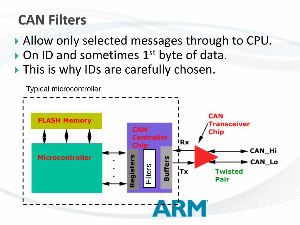
CAN Filters
Typical microcontroller
Filt
ers
Allow only selected messages through to CPU. On ID and sometimes 1st byte of data. This is why IDs are carefully chosen.

Tips & Hints
nodes: never send the same message same time. Get a bus error or both think successful.
Use same # data bytes all the time. Software is much simpler to debug and
maintain….but you don’t have to… Never change the bus speed ! Beware of short bursts of high bus traffic. Read TEC & REC to view state of your bus If use a protocol – implement all of it ! “Throw data on the floor” but take care of it.

more Tips & Hints
Don’t mix one protocol with another J1939 and CANopen will crash…maybe…
Use defaults – don’t do anything “elegant” You don’t want to be the first to find that bug !
Use timeouts – don’t hang until RESET. Don’t make timeouts too tight – sloppy is OK. Select IDs with care for easy filtering. Don’t fudge the bus. Fix it. Buy the best CAN analyzer you can afford.

And a few more….
Design in some “elbow room”. Reserve some IDs for expansion/bug fixes. Take care of “Reserved Bits”… oops… Remember protocols are designed by
committees. Investigate odd things you see. Watch out for the simple things….. How to force CAN errors ? Easy ! Just send a CAN frame with the wrong
frequency.
Choose speed, 11 or 29 bit, # data bytes.
Need to devise upper layer – format ID and data.
Structure of your CAN frame. What in ID and what in data bytes ?
Choose and allocate IDs:
choose IDs thinking of filtering – granularity of CAN filters not always 1 bit. (depends on you)
Allocated with regards to required priorities.
Scheme: ID = address, request/response, function (i.e. turn off), acknowledge.
OK – I have CAN working – what’s next ?

Data bytes: what is the content and format ?
What > 8 data bytes ? A protocol is needed.
Heartbeat ? Determine what nodes are on line.
Diagnostics ? Crash or fault recording ?
Report information to user ?
Limp-home ? Punitive limp home, shut down, recover. What to do about Bussoff ?
Hot plug ?
Monitor TEC and REC ? Self testing ?
NXP LPC11C14 CAN and CANOpen drivers.
OK – I have CAN working – what’s next ?

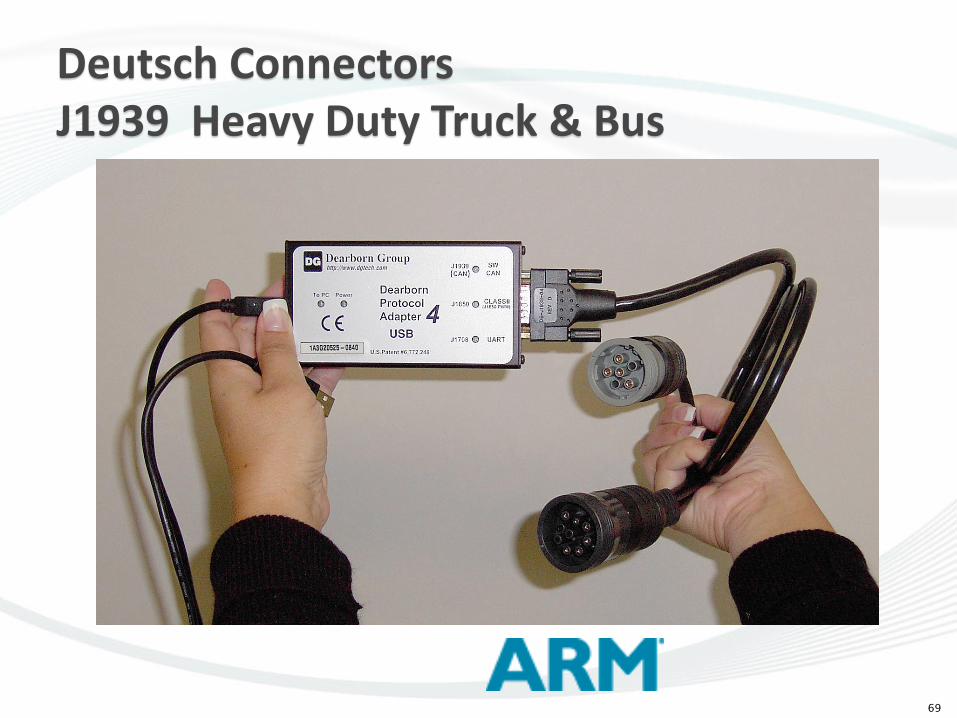
Network Tools – Bus Analyzers and CAN Oscilloscopes
Development of network and diagnostics
Sits on a bus and monitor.
Can send and receive messages on bus.
Save messages, trigger, filter, respond.

70
CAN Statistics
Periodic Auto bus rates about 6 – 7 %
GM periodic about 15 % @ 500 Kbps.
Simulation done to test networks.
Hardware-in-the-Loop also.
What priority a message has is important.
These are not determined randomly but with great thought and planning.

Time Triggered CAN
Fault Tolerant CAN
FlexNet
LIN
Other Useful Protocols:
The End…for now...
See www.keil.com/ for free Keil MDK
Can run CAN example in the simulator.
Plenty of examples – no hardware needed. …and look for my CAN Primer on www.keil.com
Buy a board with 2 CAN controllers….
Or use the Keil simulator.
Lots of examples.
ISO 11898-1,-2-3-4 defines CAN further.
Testing CAN Physical layers: www.dgtech.com/pdfs/techpapers/CIA_article.pdf