Embed Size (px)
Citation preview
8 6 4 . 2 3 4 . 4 8 0 0
m p h u s k y . c o m
Copyright 2013 MP Husky. All rights reserved.
CABLE BUSCABLE TRAY 1-TECHNICAL
2
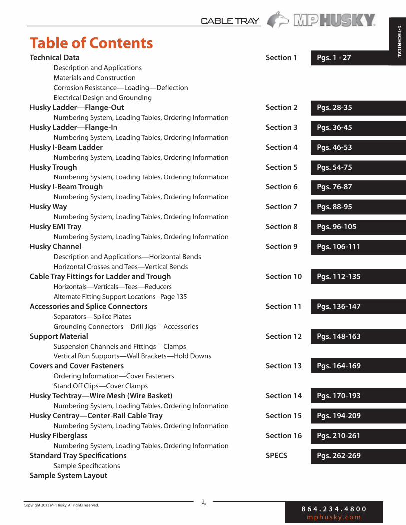
Table of ContentsTechnical Data Section 1 Pgs. 1 - 27
Description and Applications
Materials and Construction
Corrosion Resistance—Loading—Deflection
Electrical Design and Grounding
Husky Ladder—Flange-Out Section 2 Pgs. 28-35
Numbering System, Loading Tables, Ordering Information
Husky Ladder—Flange-In Section 3 Pgs. 36-45
Numbering System, Loading Tables, Ordering Information
Husky I-Beam Ladder Section 4 Pgs. 46-53
Numbering System, Loading Tables, Ordering Information
Husky Trough Section 5 Pgs. 54-75
Numbering System, Loading Tables, Ordering Information
Husky I-Beam Trough Section 6 Pgs. 76-87
Numbering System, Loading Tables, Ordering Information
Husky Way Section 7 Pgs. 88-95
Numbering System, Loading Tables, Ordering Information
Husky EMI Tray Section 8 Pgs. 96-105
Numbering System, Loading Tables, Ordering Information
Husky Channel Section 9 Pgs. 106-111
Description and Applications—Horizontal Bends
Horizontal Crosses and Tees—Vertical Bends
Cable Tray Fittings for Ladder and Trough Section 10 Pgs. 112-135
Horizontals—Verticals—Tees—Reducers
Alternate Fitting Support Locations - Page 135
Accessories and Splice Connectors Section 11 Pgs. 136-147
Separators—Splice Plates
Grounding Connectors—Drill Jigs—Accessories
Support Material Section 12 Pgs. 148-163
Suspension Channels and Fittings—Clamps
Vertical Run Supports—Wall Brackets—Hold Downs
Covers and Cover Fasteners Section 13 Pgs. 164-169
Ordering Information—Cover Fasteners
Stand Off Clips—Cover Clamps
Husky Techtray—Wire Mesh (Wire Basket) Section 14 Pgs. 170-193
Numbering System, Loading Tables, Ordering Information
Husky Centray—Center-Rail Cable Tray Section 15 Pgs. 194-209
Numbering System, Loading Tables, Ordering Information
Husky Fiberglass Section 16 Pgs. 210-261
Numbering System, Loading Tables, Ordering Information
Standard Tray Specifications SPECS Pgs. 262-269
Sample Specifications
Sample System Layout

8 6 4 . 2 3 4 . 4 8 0 0
m p h u s k y . c o m
Copyright 2013 MP Husky. All rights reserved.
CABLE TRAY
1-TECHNICAL
3
IntroductionDecade after decade, for nearly 60 years, MP Husky continues
to be the trusted and proven name in Cable Tray. With more
systems installed in more industries and environments than
any other manufacturer, you can rest assured MP Husky has
the experience and capability to meet your most demanding
requirements. As we begin another decade, MP Husky is
stronger than ever and positioned to lead the industry with
the latest innovations, eco-friendly products, and engineer-
ing and manufacturing technologies. Our focus continues to
remain on providing unmatched customer support, invest-
ing in our people, protecting the environment, and providing
the most technologically advanced and engineered systems.
MP Husky - Engineered to Support Powerful Reputations.
Description and Selection
Cable Tray systems provide rigid structural support for cables in a variety of commercial and industrial applications.
The basic styles of cable tray are: Ladder, Trough, Center Rail, Wire Basket and Channel. For a more comprehensive
description of the construction and utilization of these types of tray, turn to Sections 2, 3, 4, 5, 6, 7, 8,9, 14, 15 and
16 in this catalog.
Husky LadderLadder consists of two longitudinal side members connected by individual traverse members. It is intend-ed for use primarily for power cable or control cable support and excels in heavy loading and longer span applications. It is available in I-Beam, Flange-In and Flange-Out designs.
Husky TroughTrough has a corrugated solid or ventilated bottom, 4” rung spacing or flat bottom pan design which is contained within longitudinal side members. It is especially appropriate for control and instrumentation cables.
Husky ChannelChannel is a one piece support with either ventilated or solid bottom sections. These sections are used with power cables, multiple control, or signal circuit cables.
8 6 4 . 2 3 4 . 4 8 0 0
m p h u s k y . c o m
Copyright 2013 MP Husky. All rights reserved.
CABLE BUSCABLE TRAY 1-TECHNICAL
4
Description and Selection
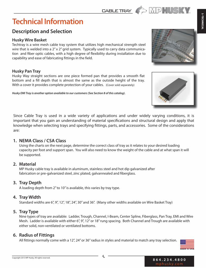
Husky Wire BasketTechtray is a wire mesh cable tray system that utilizes high mechanical strength steel wire that is welded into a 2” x 2” grid system. Typically used to carry data communica-tion and fiber optic cables, with a high degree of flexibility during installation due to capability and ease of fabricating fittings in the field.
Husky Pan TrayHusky Way straight sections are one piece formed pan that provides a smooth flat bottom and a fill depth that is almost the same as the outside height of the tray. With a cover it provides complete protection of your cables. (Cover sold separately)
Husky EMI Tray is another option available to our customers (See Section 8 of this catalog).
Since Cable Tray is used in a wide variety of applications and under widely varying conditions, it is important that you gain an understanding of material specifications and structural design and apply that knowledge when selecting trays and specifying fittings, parts, and accessories. Some of the considerations are:
1. NEMA Class / CSA Class Using the charts on the next page, determine the correct class of tray as it relates to your desired loading capacity per foot and support span. You will also need to know the weight of the cable and at what span it will be supported.
2. Material MP Husky cable tray is available in aluminum, stainless steel and hot dip galvanized after fabrication or pre-galvanized steel, zinc plated, galvannealed and fiberglass.
3. Tray Depth A loading depth from 2” to 10” is available, this varies by tray type.
4. Tray Width Standard widths are 6”, 9”, 12”, 18”, 24”, 30” and 36”. (Many other widths available on Wire Basket Tray)
5. Tray Type Nine types of tray are available: Ladder, Trough, Channel, I-Beam, Center Spline, Fiberglass, Pan Tray, EMI and Wire Mesh. Ladder is available with either 6”, 9”, 12” or 18” rung spacing. Both Channel and Trough are available with either solid, non-ventilated or ventilated bottoms.
6. Radius of Fittings All fittings normally come with a 12”, 24” or 36” radius in styles and material to match any tray selection.
Technical Information
8 6 4 . 2 3 4 . 4 8 0 0
m p h u s k y . c o m
Copyright 2013 MP Husky. All rights reserved.
CABLE TRAY
1-TECHNICAL
5
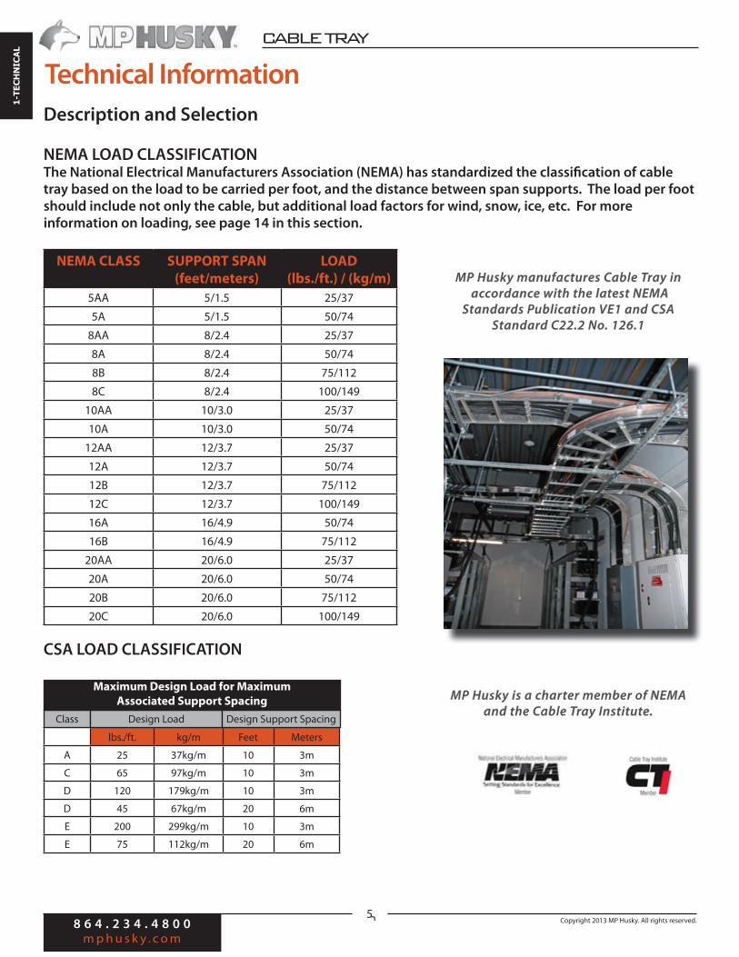
NEMA LOAD CLASSIFICATIONThe National Electrical Manufacturers Association (NEMA) has standardized the classification of cable tray based on the load to be carried per foot, and the distance between span supports. The load per foot should include not only the cable, but additional load factors for wind, snow, ice, etc. For more information on loading, see page 14 in this section.
NEMA CLASS SUPPORT SPAN
(feet/meters)
LOAD
(lbs./ft.) / (kg/m)
5AA 5/1.5 25/37
5A 5/1.5 50/74
8AA 8/2.4 25/37
8A 8/2.4 50/74
8B 8/2.4 75/112
8C 8/2.4 100/149
10AA 10/3.0 25/37
10A 10/3.0 50/74
12AA 12/3.7 25/37
12A 12/3.7 50/74
12B 12/3.7 75/112
12C 12/3.7 100/149
16A 16/4.9 50/74
16B 16/4.9 75/112
20AA 20/6.0 25/37
20A 20/6.0 50/74
20B 20/6.0 75/112
20C 20/6.0 100/149
CSA LOAD CLASSIFICATION
lbs./ft. kg/m Feet Meters
A 25 37kg/m 10 3m
C 65 97kg/m 10 3m
D 120 179kg/m 10 3m
D 45 67kg/m 20 6m
E 200 299kg/m 10 3m
E 75 112kg/m 20 6m
Technical Information
Description and Selection
Class Design Load Design Support Spacing
Maximum Design Load for Maximum
Associated Support Spacing
MP Husky manufactures Cable Tray in
accordance with the latest NEMA
Standards Publication VE1 and CSA
Standard C22.2 No. 126.1
MP Husky is a charter member of NEMA
and the Cable Tray Institute.

8 6 4 . 2 3 4 . 4 8 0 0
m p h u s k y . c o m
Copyright 2013 MP Husky. All rights reserved.
CABLE BUSCABLE TRAY 1-TECHNICAL
6
Our Quality PolicyAt MP Husky we are committed to producing only the highest quality products that meet or exceed our customers’ expectations and requirements. Our goal is to achieve 100% customer satisfaction by delivering the best products and services on time and defect free. We will achieve this individually and corporately through tested and proven processes and controls, in our Quality System, and with a constant focus and effort on continuous improvement.
Item Standards
MP Husky Quality Program • ANSI / ASQC Q9001-2000 (ISO 9001 Compliant)
• ASME NQA-1-2004
• ANSI N45.2
-Quality Assurance-Manufacturing Standards
ISO9001National Electric Code, National Electrical Manufacturers Association VE-1, Canadian Standards Association, American Welding Society, American Society for Testing and Materials
Certification CSA Certified
UL Classified for use and an equipment ground conductor
Load Test Standards NEMA VE-1/CSA Tray Standards
Cable Tray Standard NEMA VE-2
Grounding UL, CSA, NEC
Welding • AWS D1.1 (American Welding Society Structural Welding Code: Steel)
• AWS D1.3/D1.2: (American Welding Society Structural Welding Code:
Aluminum)
• AWS C1.1/ANSI American Welding Society Recommended Practices for
Resistance Welding
• ASME QW 100.1 American Society of Mechanical Engineers
• Welding Procedure Specifications (Procedure Qualifications Record)
• Certified Welding Inspector—QC1-96 (On Staff)
• 100% of MP Husky welders are AWS Certified.
Nuclear • Audited every three years since 1977 in conformance with 10 CFR50
Appendix B - Nuclear Standards (U.S. Nuclear Regulatory Commission)

8 6 4 . 2 3 4 . 4 8 0 0
m p h u s k y . c o m
Copyright 2013 MP Husky. All rights reserved.
CABLE TRAY
1-TECHNICAL
7
Nuclear Program
MP Husky is audited in conformance with 10 CFR50 Appendix B - Nuclear Standards by the U.S. Nuclear Regulatory Commission. Appendix B to Part 50--Quality Assurance Criteria for Nuclear Power Plants and Fuel Reprocessing Plants - This appendix establishes quality assurance requirements for the design, manufacture, construction, and operation of those structures, systems, and components. The pertinent requirements of this appendix apply to all activities affecting the safety related functions of those structures, systems, and components; these activities include designing, purchasing, fabricating, handling, shipping, storing, cleaning, erecting, installing, inspecting, testing, operating, maintaining, repairing, refueling, and modifying.
Duke EnergyDuquesne Light CompanyFlorida Power & LightCincinnati Gas & Electric CompanyGulf States UtilitiesPA Power & Light CompanyConsumer Power CompanyLong Island Lighting CompanyIllinois Power CompanyWA Public Power Supply SystemsCommission Fed De Electridad MexCarolina Power & Light CompanyTexas UtilitiesFlorida Power & Light CompanyIowa Electric & Power CompanyLouisiana Power & Light CompanyNorthern States Power CompanyTaiwan Power CompanyPublic Service Electric & GasPuerto Rico Water Res.Pacific Gas & Electric
SCANASouthern California EdisonSouthern Nuclear (Southern Company)Wisconsin Public ServiceDetroit EdisonBaltimore Gas & Electric CompanyNational Power CorporationPublic Service of New HampshireFlorida Power CorporationCleveland Electric IlluminatingBoston Edison CompanyGeorgia Power CompanyHouston Lighting & Power CompanyJersey Central Power & LightMississippi Power & Light CompanyOhio Edison CompanyPower Authority of State of New YorkPublic Service of Indiana, Inc.Public Service Company of OklahomaTennessee Valley Authority (TVA)
Nuclear Clients & Partners
• We have and continue to serve over thirty Nuclear plants around the world.
• MP Husky has been compliant for over 45 years.• We are the ONLY Cable Tray manufacturer to be 10CFR50
Appendix B compliant.• We are audited every three years by members of the
Nuclear Procurement Issues Committee using the Nuclear Procurement Issues Committee Audit Checklist (NUPIC Audit Checklist).
• The scope of the audit is to ensure that our Quality Assurance Program (QAP) is compliant with ANSI N45.2 and 10CFR50 Appendix B.

8 6 4 . 2 3 4 . 4 8 0 0
m p h u s k y . c o m
Copyright 2013 MP Husky. All rights reserved.
CABLE BUSCABLE TRAY 1-TECHNICAL
8
Materials & Construction
Cable tray systems are commonly fabricated from a corrosion-resistant metal or from a metal with a corrosion-resistant finish. The selection of the proper material is essentially an economic consideration.
Every cable tray installation places requirements on the mechanical properties of the material from which it is fabricated. These properties influence the spacing frequency of supporting members, and the ease of installation. The selection of the material may also be dependent upon electrical (conductivity), physical (appearance), or chemical (corrosion resistance) properties, according to the demands of the specific installation. Although there are numerous metals available which could satisfy the basic requirements, certain wrought aluminum alloys and low carbon steels meet these requirements most economically.
Wrought Aluminum AlloysPure aluminum is soft and ductile. However, most commercial uses require greater strength than pure aluminum af-fords. This strength is achieved by the addi-tion of other elements to produce alloys which singly, or in combina-tion, impart strength to the metal. These alloys have been classified into seven categories ac-cording to their chemi-
cal composition, and have been given numeri-cal designations for each series of alloys of 1000 through 7000 by the Aluminum Assoc. In addition to alloying the pure aluminum, further strengthen-ing is possible by heat treating.
Heat-Treatable Alloys—the initial strength of alloys in this group is enhanced by the addition of such alloying elements as copper, magnesium, zinc and silicon, and are designated as 2000, 6000, and 7000 series. Since these alloys singly, or in various combi-nations, show increasing solid solubility in aluminum with increasing temperature, it is possible to sub-ject them to thermal treatments which will impart pronounced strengthening.
APamretfattstths
Non-Heat-Treatable Alloys—the initial strength of alloys in this group depends upon the hardening effect of elements such as manganese, silicon, iron and magnesium, singly or in various combinations.
The non-heat treatable alloys are designated as 1000, 3000, 4000, and 5000 series. As these alloys are work-hardenable, further strengthening is made possible by various degrees of cold working, denoted by the “H” series of tempers. Alloys containing appreciable amounts of magnesium when supplied in strain-hardened tempers are usually given a final elevated temperature “stabilizing” to insure stability of properties.
In determining the proper aluminum alloy for structural applications, such as ventilated cable tray systems, the design engineer should recognize the advantages inherent in using alloys that are heat-treatable and of being able to fabricate the structure from materials possessing known minimum values of yield strength.
Cable tray products are most widely formed from the 6000 series alloys. Alloys in this group contain silicon and magnesium in approximate proportions to form magnesium silicide, thus making them capable of being heat-treated. Major alloys in this series are 6061 and 6063, which are among the most versatile of the heat-treatable alloys. Though not as strong as most 2000 or 7000 alloys, the magnesium-silicon (or magnesium silicide) alloys possess good formability and corrosion resistance.
Basic structural members of aluminum cable tray systems can be made from 6063-T6 aluminum extrusions, a material which economically meets the requirements of the majority of installations. The 6063-T6 alloy has adequate strength and good corrosion resistance. It is light weight, maintenance-free, and because of the non-magnetic properties of aluminum, keeps electrical losses to a minimum.
MP Husky manufactures Cable Tray in
accordance with the latest edition of
NEMA Standards Publication VE1
and CSA Standard C22.2 No. 126.1.

8 6 4 . 2 3 4 . 4 8 0 0
m p h u s k y . c o m
Copyright 2013 MP Husky. All rights reserved.
CABLE TRAY
1-TECHNICAL
9
Materials & Construction
SteelSteel cable trays are used principally in environments which are relatively free from corrosive attack. They are available with various types of corrosion-resistant finishes; usually hot-dip galvanized. The main advantages of using steel in cable tray fabrication are its high strength and low cost. Its disadvantages are increased structural weight, poor corrosion-resistance, and low electrical conductivity.
The idea that all steels are the same, except for chemical disposition is false. Carbon steels may be produced with chemical compositions (carbon, manganese, phosphorus, sulphur and silicon) within the specified limits of a given grade and still have characteristics that are widely dissimilar. Each grade and quality variation has a useful place, depending upon the end use and the methods of fabrication.
Basic components of steel cable trays are normally fabricated from either hot or cold rolled steel strips of commercial quality. Steels in this category are ASTM A-1011 CS Type B (formerly ASTM A-569) and ASTM A-1008 CS Type B (formerly A-366). Pre-galvanized steel conforms to ASTM A-653.
Stainless SteelToday, hundreds of different alloy combinations exist for the endless variety of applications which utilize stainless and heat resisting steels. The primary elements added to obtain the various properties required in the steels include chromium, nickel, manganese, silicon, molybdenum, and the stabilizing elements of titanium columbium and tantalum.
Stainless steel contains at least 10 percent chromium, along with other elements to develop specific properties. Depending on the quality of the elements present in a stainless alloy, it will have a metallurgical structure which will be characteristic of the basic stainless steel groups. Metallurgists refer to these groups as the martensitic, ferritic, austenitic and precipitation hardening stainless steels. All standard austenitic alloys are given numbers in the “200” and “300” series, while the martensitic and ferritic alloys are numbered in the “400” series.
If your job calls for stainless steel, please
contact the MP Husky factory for assistance in
determining the correct type for your
speci!c application.
MP Husky offers cable trays and accessories in both the 304 and 316 series. These austenitic alloys are remarkable in several respects. Unlike the other two classes, they contain nickel in quantities from 4 to 22 percent, while the percentage of carbon is kept relatively low. When chromium is increased for improved corrosion resistance, nickel must also be increased to retain the austenitic structure.
304 stainless steel has chromium and nickel in-creased and carbon lowered to reduce carbide pre-cipitation and increase corrosion resistance. Lower-ing the carbon content also makes welding easier.
316 stainless steel has molybdenum added to improve corrosion resistance and high temperature strength. The carbon content is also lowered to im-prove welding performance.

8 6 4 . 2 3 4 . 4 8 0 0
m p h u s k y . c o m
Copyright 2013 MP Husky. All rights reserved.
CABLE BUSCABLE TRAY 1-TECHNICAL
10
Materials & Construction
Typical Applications include:
Type 304 Type 316Beer Barrels Chemical Processing Equip
Chemical Equipment Chemical Storage and Transportation tanks
Coal Hopper Linings Food Processing Equip
Cryogenic Vessels and Components
Steam Cooking Kettles
Dairy Equipment
Evaporators Paper Pulp Digesters and Evaporators
Food Handling Equipment
Milking Machines Pharm. Processing Equipment
Nuclear Vessels and Comp Scrubbers and Environmental
Oil Well Filter Screens Soap and Photographic Handling Equipment
Pressure Vessels General apps in Textile Ind.
Sanitary Fittings and Valves
Shipping Drums
Steel Tubes
Textile Dyeing Equipment
Hypodermic Needles
Feedwater Tubing
GalvannealedGalvannealed or Galvanneal, is the result from the com-bined process of galvanizing and annealing the steel. The galvanization is made through the hot-dipping (hot-dip galvanizing) process and gives a very fine grayish matte finish. Galvanneal does not flake off its galvanized coating when formed, stamped, and bent. The very fine matte finish acts like a primer and paint easily adheres to the tray. It is very rust proof, only white to dark grey marks appear if it comes in contact with water. Galvan-neal sheets offers good paintability, weldability, corro-sion resistance, and formability. It is extensively used in the automotive, signage, electric equipment, and other industries requiring good paintability and long reliable service life.
FiberglassMP Husky’s Fiberglass Cable Tray systems are manu-factured from glass fiber-reinforced plastic shapes and provides the load capacity of steel, plus the inherent characteristics afforded by our Pultrusion Technology: non-conductive, non-magnetic and corrosion-resistant. Although light in weight, the strength to weight ratio surpasses that of equivalent steel products. MP Husky’s Fiberglass Cable Tray will not rust, nor does it ever require painting. It is available in both polyester and vinylester resin systems, manufactured to meet ASTM E-84, Class 1 Flame Rating and self-extinguishing requirements of ASTM D-635. MP Husky’s Fiberglass Cable Tray comes in gray or blue (polyester resin) and beige (vinylester resin) but is available in custom colors upon request.
For more than 30 years, MP Husky’s Fiberglass Cable Tray systems have been tested and proven in the harsh en-vironment of the offshore oil and gas industry. Our tray has stood up to the test of being exposed to the cor-rosive conditions inherent in petroleum products, plus the daily punishment of exposure to wind, weather and salt water.
Husky Fiberglass Cable Tray is the perfect choice for harsh environments.
Husky Way is available in the galvanneal "nish.
8 6 4 . 2 3 4 . 4 8 0 0
m p h u s k y . c o m
Copyright 2013 MP Husky. All rights reserved.
CABLE TRAY
1-TECHNICAL
11
Corrosion Resistance
The underlying causes of corrosion are the same for all metals, all stemming from electrochemical phenom-ena. But the ways in which corrosion manifests itself are characteristic of each particular metal. Steel corrodes in the atmosphere with the formation of rust, which de-velops very rapidly on unprotected surfaces. In a clean atmosphere, aluminum slowly develops a white or silver grey patina.
Aluminum surfaces weather by a characteristic of pitting, and corrosion rates are often assessed by measuring the depth of the pits. The rate of pitting falls off after the first year or two, moving gradually to a standstill.
The strong, heat-treatable alloys of aluminum, with copper as one of the chief alloy elements, or certain fully heat-treated alloys with magnesium and silicon as ma-jor alloying elements, may manifest another type of at-tack, inter-crystalline in nature, which may cause more pronounced loss of strength if allowed to continue. Such materials may require protection by painting, cladding, or metal spraying, depending on the environ-ment.
Several characteristic modes of corrosive attack may be distinguished as follows:
Simple Chemical Attack—the solution of a metal by an acid is an obvious example of simple chemical at-tack. Simple chemical attack occurs when sulfides are in contact with steel or copper. Ordinarily, aluminum is not subject to such attack. A classic example of such chemical attack is sludge retaining rainwater in the bottom of guttering. In this case, a corrosive solution is held in constant contact with the metal, and rapid attack may follow.
Electrochemical Corrosion—corrosion of a metal accelerated through contact with another metal in moist or wet conditions is known as bimetallic or electrolytic corrosion. This corrosion is due to the action of a simple voltaic cell. The presence of a conducting solution is es-sential to this phenomenon but the presence of dissimi-lar metals is not essential provided that a difference of potential exists.
In addition to the nature of the two metals, the extent of galvanic attack depends upon many other factors. Among these are:
• Nature of ions present in the electrolyte • Polarization effects• Effect of stable surface films on the metal• Relative areas of anode and cathode• The physical nature of the corrosion product• Temperature variations
Each of these factors can influence the total resistance of the circuit. The following table is a compilation of solution potentials of metals and alloys with respect to a calomel electrode. It provides an initial guide to the possible effects of bi-metallic contact.
Galvanic PotentialCorroded End (Anodic or Least Noble)• Magnesium• Magnesium Alloys• Zinc
Galvanized Steel or Galvanized Iron• Aluminum Alloy 5052-H• Aluminum Alloy 3004-S• Aluminum Alloy 3003-S
Aluminum Alloy 1100-S• Aluminum Alloy 6053-T• Alclad
Cadmium• Aluminum Alloy 2117-T
Aluminum Alloy 2017-TAluminum Alloy 2024-T
• Mild Steel Wrought IronCast IronNickel Cast Iron
• Lead-Tin SoldersLeadTinBrassCopperBronze
• Copper-Nickel AlloysMonelSilver SolderNickelIconelChromium Iron
• 18-8 Stainless SteelType 304 (passive)Type 316 (passive)Hastelloy CSilverGraphiteGold
Protected End (Cathodic or Most Noble)

8 6 4 . 2 3 4 . 4 8 0 0
m p h u s k y . c o m
Copyright 2013 MP Husky. All rights reserved.
CABLE BUSCABLE TRAY 1-TECHNICAL
12
Corrosion Resistance
The composition of the base metals has no measur-able effect on the life of zinc coatings. However, the composition of the base metals is the major factor in the years to perforation.
The corrosion rate of zinc varies more with the type of atmosphere (marine, industrial) than does that of steel or iron.
The chloride content of sea air apparently has an accelerating effect on the corrosion of zinc coating.
Rainfall removes about 75% of the corrosion products from zinc surfaces if the results of tests in rural, industrial and marine exposures are averaged together. The resid-ual corrosion products remaining on the surface become basic in character and exert a retarding influence on corrosion. In highly industrialized or polluted atmo-spheres, this basic film may not exist, a fact which helps explain the more rapid attack experienced in such atmospheres.
Indoor atmospheres correspond in a general way to that prevailing outside in a given locality. Variations in humidity and temperature are somewhat less ex-treme and there is no rainfall indoors to dissolve and remove soluble corrosion products. In general, it may be assumed that the protective life of zinc coatings indoors is at least five times greater than that of coatings of the same thickness exposed to the outdoor atmosphere in the same locality.
The indoor corrosion of zinc may be severe when moisture condensation is frequent and air circulation is restricted. This effect is particularly bad in humid, tropi-cal locations with nightly condensation.
These conclusions indicate zinc coatings will in any event have an acceptable service life expectancy regardless of how the end point of failure is defined. However, it should be noted that whenever maintenance, such as painting, is neglected, it is unreasonable to expect galvanized steel to last indefinitely.
Finishes
MetallicCable trays fabricated of steel can be protected from corrosion by coating with another metal using one of the following methods:
• Continuous Hot-Rolled GalvanizingASTM Designation A653 Specifications for Zinc Coated Galvanized) Iron or Steel Sheets, Coils, and Cut Lengths—This process applies a zinc coating to sheet steel prior to fabrication of the product (pre-galvanized cable tray) by passing the metal down-ward through a molten ammonium chloride flux bath, and then into the zinc and out again by means of rolls.
The MP Husky standard zinc coating designation is G90, which has an average zinc coating weight of 1.25 ounces per square foot of steel for an average coating on both surfaces of 1.06 mils.
• Hot Dipped Galvanizing After FabricationASTM Designation A123 Specification for Zinc Coating (Hot Dip) on Assembled Steel Products—This process is used to apply a zinc coating to an already fabricated product. The product is first cleaned in a caustic bath, then further cleaned by a pickling acid bath. The article is then thoroughly rinsed and dipped in a bath of molten zinc. The nature and thickness of the coating depend largely on the immersion rate, temperature of the bath, im-mersion period, and withdrawal rate. The resulting coating consists of an outer layer of relatively pure zinc, and lower layers of iron-zinc compounds.
Generally, hot dip coatings are highly non-uniform, except on very simple shapes and are usually thick-est at small recesses (unless these remain uncoated altogether). The advantage of this method is that the zinc applied is thicker than when applied by other processes. However, the protective characteristics of zinc coating under atmospheric conditions have been found to be equal, regardless of process: i.e. zinc coatings of the same weight have approximately the same service life.
• GalvannealedGalvannealed or Galvanneal, is the result from the combined process of galvanizing and annealing the steel. The galvanization is made through the hot-dipping (hot-dip galvanizing) process and gives a very fine grayish matte finish. Galvanneal does not flake off its galvanized coating when formed, stamped, and bent.

8 6 4 . 2 3 4 . 4 8 0 0
m p h u s k y . c o m
Copyright 2013 MP Husky. All rights reserved.
CABLE TRAY
1-TECHNICAL
13
The corrosive nature of sea water and of coastal envi-ronments is partly due to the low electrical resistance of salt solution. Similarly, the bad effects of industrial atmospheres on metals arise largely from the sulphur compounds, sulphurous and sulfuric acids, which are largely formed as a result of burning coal, and which dissolve in the moisture in the air or in the rain as it falls, or in films of condensed water on the metal.
To summarize, the extent and type of moisture is an important factor in determining the severity of galvanic attack. For indoor service, where wetting is infrequent, galvanic corrosion normally is no problem. Outdoors, attack may be relatively rapid in sea coast and industrial environments, where contamination, hence conduc-tivity, of rain and condensed moisture is high. Several general rules can be applied in selecting metal combi-nations for use in corrosive environments. These are:
Select metals as close together in the galvanic series as possible. For the anodic protection of steel, metals above steel in the series should be selected, or the steel should be galvanized or otherwise protective-coated. Avoid combinations having a smaller area of the more anodic metal than of the cathodic, to avoid excessive current density on the anodic areas. Insulate dissimilar metals wherever possible to minimize galvanic corrosion.
Aluminum AlloysThe corrosion-resistance of aluminum alloys is due to the presence on the surface of a very thin protective film of aluminum oxide which has strong self-healing properties when damaged. The oxide film be-gins to form immediately on the surface of the bare metal exposed to air and grows rapidly for several days, then slowly for a month, when it reaches a thickness of approximately 0.0000002”. Corrosion of aluminum can only occur when the oxide film is damaged or removed and conditions prevent its formation.
Substances which may come in contact with aluminum can be divided into three groups:
Those substances which attack the oxide film. These are most strong alkalis, mercurical compounds, and most strong acids.
Substances which cause localized breakdown of the oxide film (pitting) - and for which aluminum is suitable only under certain conditions, such as some natural fresh waters and aqueous solutions containing traces of mercury, copper, or other heavy metals.
Corrosion Resistance
Substances which do not attack the oxide film. The majority of substances fall in this group, including many industrial chemicals.
The majority of aluminum installations give perfectly satisfactory service, free from corrosion, and only in exceptional cases do problems occur. When problems do occur, they can be attributed to one or more of the following causes:
• Wrong choice of alloy• Exposure conditions• A bimetallic joint which causes galvanic corrosion• Crevices• Unwise location of the aluminum assembly, resulting
in deposition corrosion• Contact with aggressive chemicals
Among the heat-treatable alloys, the 6000 series has good resistance to industrial and marine atmospheres.
With the exception of certain corrosive chemicals, no corrosion at all will occur if water is not present. Thus, indoor installations that are not in actual contact with water or installations which are maintained in dry conditions, will not corrode.
Steel with Zinc CoatingsThe data from which comparative performance of different types of zinc coating can be inferred, are generally obtained from comprehensive exposure tests in various atmospheres, such as those conducted since 1926 by the American Society of Testing Materials. From the results of these tests, the following conclusions can be made:
The corrosion rate of zinc on galvanized sheets is practically linear in industrial or rural atmospheres, and in a marine atmosphere that is polluted with industrial contaminants. Thus, in these atmospheres, a sheet with double the weight of coating than that of another sheet can be expected to last twice as long before rusting of the base metal occurs.

8 6 4 . 2 3 4 . 4 8 0 0
m p h u s k y . c o m
Copyright 2013 MP Husky. All rights reserved.
CABLE BUSCABLE TRAY 1-TECHNICAL
14
Loading
This section presents guidelines for classification of design conditions with respect to weather factors, meth-ods of determination and application of various types of loadings encountered, maximum allowable work-ing stresses and other pertinent considerations. This information will assist the designer in evaluating ma-terials and product catalog information so that he can design a system which will achieve the desired strength and rigidity at the lowest possible installed cost.
Load ClassificationLoads on structures are usually divided into three types:
• Dead loads that do not change their magnitude or their position during the life of the structure.
• Live loads that change their magnitude, their position and/or their direction during the life of the structure.
• Dynamic loads that are caused by the motion of the live load, or the movement of the structure.
Because of their general nature, these load classifica-tions can be used for any structure. However, for the purpose of establishing a practical load classification for cable tray system design, it is necessary to create additional subdivisions and provide a guide for assumption of specific loads.
Thus, for cable tray system design, the three basic load types are also considered as follows:
Dead LoadsSince dead loads are the weight of the members that make up a tray or tray support, they have a known value. A summation of the weights of the individual members is all that is required to calculate the dead load.
Live LoadsIn cable tray design, dynamic loads are considered to be as follows:
• The design load is the weight of cables, cable tray accessories, and sometimes workers (which vary in both magnitude and position). Ca-ble only design loads can be determined by adding the component weights of the sys-tem. Any provision for workers will require an assumption of magnitude and position—for practi-cal purposes, an assigned weight acting at mid span of the tray.
• Parasitic loads such as ice, snow, wind, traction, and electromagnetic forces exist only because the tray exist. They are the most difficult to determine, and different assumptions can be made about their ef-fect on the overall loadings. The following informa-tion will provide a general guide.

8 6 4 . 2 3 4 . 4 8 0 0
m p h u s k y . c o m
Copyright 2013 MP Husky. All rights reserved.
CABLE TRAY
1-TECHNICAL
15
Three general degrees of loading due to weather conditions are recognized in the National Electrical Safe-ty Code, and are designated as heavy, medium and light loading.
Districts in the United States in which these loadings are normally applicable are indicated in Figure 1. Values used in determining conductor loadings under these conditions for ice, wind and temperature are given in the Table 1—Degrees of Loading Due to Weather. How-ever, modifications of these values are necessary when applied to cable tray systems, since the NESC is concerned primarily with the construction of overhead supply and communication lines. These modifications are:
Ice LoadingThe NESC loading of 1/2” thickness is applied to both cables and cable tray. In applying loadings to interlocked armored cables, and bare stranded conductors or sus-pension cables, the coating of ice is considered as a hol-low cylinder with an inside diameter equal to the outside diameter of the cable or strand. Ice is assumed to weigh 57 lbs. per cubic foot.
Snow LoadingThe NESC does not consider snow loading, and in gen-eral this also applies to cable tray systems. However, in the case of a solid cover on a tray, the minimum load of 5lbs. per square foot should be used for outdoor instal-lations where snow is a factor.
Wind LoadingThe NESC loadings are modified as follows, in order to provide adequate protection against the maximum wind velocities encountered with consideration of the shapes of the various structures (not considered by NESC).
Wind velocity—in the loading tables, wind means horizontal wind. Wind velocity should be considered to be true wind speed, corrected for instrumentation er-rors. Any variation of velocity with height is not consid-ered. All structures will be under 100 feet in height, and 100% of the ground velocity is assumed to be adequate.
Wind loads—the exteriors of all structures, with the exception of cylindrical structures, should be loaded with a wind pressure normal to the surface, having an intensity given by the formula:
Loading
Wp = C VpWp = wind pressure in pounds per square footC= coefficient depending upon the size, shape, and position of the structure in the wind and having values specified in Table 2, Shape FactorsVp = impact pressure = 0.00256V² where V= the design velocity. Values of Vp may be obtained from Table 3, Impact Pressures
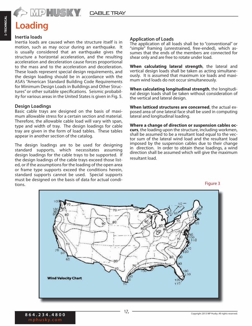
Wind direction and distribution—the allowance for wind pressure shall be made assuming the wind from any possible direction to be critical. Wind loads shall be considered uniformly distributed. Average annual tor-nado frequency, average wind velocities for different ar-eas of the U.S. are shown in Figs. 2 and 3.
Traction ForcesTraction forces are caused by the cables starting and stop-ping during the cable installation period and they vary in magnitude and direction. They are of such nature, there-fore, that no general assumptions can be made to provide for them. However, the safety factors selected for the basic design stresses should be conservative enough to provide for these forces when they do occur.
Condition Heavy Medium Light
Radial thickness of ice (ins.) 0.50 0.25 0.00
Horizontal wind pressure(lbs./sq.ft.)
4 4 9
Temperature (degrees F) 0 15 30
Isolated Structural Shapes 2.0
Trusses, Towers, Etc. 2.0
Wires, Cables, Etc. 1.2
Pipe Supports, Poles, Etc. 1.0
Loading District
Degrees of Loading Due to Weather National Electrical Safety Code Values
Structure Shape Factor “C”
Shape Factors
For trusses and towers the wind load is assumed to be acting on the projected area of the windward face only.
For structures with circular cross sections, the a"ected area is the area projected on a vertical plane.
Table 1
Table 2

8 6 4 . 2 3 4 . 4 8 0 0
m p h u s k y . c o m
Copyright 2013 MP Husky. All rights reserved.
CABLE BUSCABLE TRAY 1-TECHNICAL
16
Electromagnetic Forces
These forces, caused by short-circuit current during a ca-ble fault, vary in magnitude and position. It is impractical to make an assumption providing for them. Ordinarily, the safety factors selected for the basic design stresses will be adequate. However, in installations where these forc-es are of such magnitude that they become a factor in the design of the cable tray system, adequate provision must be made so that the design stresses are not exceeded.
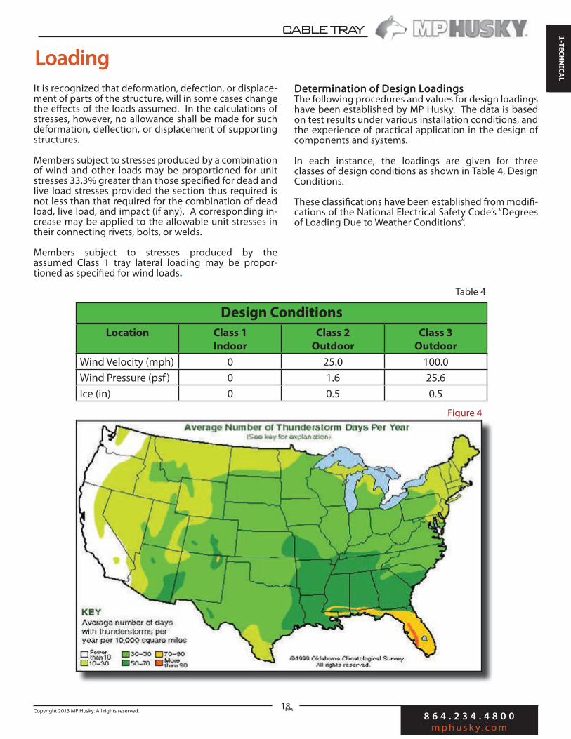
(The Average Annual Number of Days with Thunderstorms for various areas of the United States are shown in Figure 4).
Dynamic Loads
Impact loads which result because the live load is in motion, are loads in addition to the static weight of the live load. Such loads could be caused by cables being dropped onto it, or by workmen walking on it or climb-ing up or down a ladder leaning against it. These loads are provided for in the same manner as traction forces—the safety factors selected for the basic design stresses should be conservative enough to provide for these forces if they occur.
Loading
V (mph) Vp (psf) V (mph) Vp (psf)
15 0.58 85 18.5
20 1.02 90 20.7
25 1.60 95 23.1
30 2.30 100 25.6
35 3.13 105 28.2
40 4.09 110 30.9
45 5.18 115 33.8
50 6.39 120 36.8
55 7.73 125 40.0
60 9.21 130 43.3
65 10.80 135 46.6
70 12.50 140 50.1
75 14.40 145 53.8
80 16.40 150 57.6
These values are for an air density of 0.07651 lbs. per cu. ft. corresponding to a temperature of 60˚F and barometric
pressure of 14.7 lbs. per sq. in.
Table 3
Figure 2
8 6 4 . 2 3 4 . 4 8 0 0
m p h u s k y . c o m
Copyright 2013 MP Husky. All rights reserved.
CABLE TRAY
1-TECHNICAL
17
Inertia loadsInertia loads are caused when the structure itself is in motion, such as may occur during an earthquake. It is usually considered that an earthquake gives the structure a horizontal acceleration, and the resulting acceleration and deceleration cause forces proportional to the mass and to the acceleration and deceleration. These loads represent special design requirements, and the design loading should be in accordance with the ASA’s “American Standard Building Code Requirements for Minimum Design Loads in Buildings and Other Struc-tures” or other suitable specifications. Seismic probabil-ity for various areas in the United States is given in Fig. 5.
Design LoadingsBasic cable trays are designed on the basis of maxi-mum allowable stress for a certain section and material. Therefore, the allowable cable load will vary with span, type and width of tray. The design loadings for cable tray are given in the form of load tables. These tables appear in another section of the catalog.
The design loadings are to be used for designing standard supports, which necessitates assuming design loadings for the cable trays to be supported. If the design loadings of the cable trays exceed those list-ed, or if the assumptions for the loading of the open area or frame type supports exceed the conditions herein, standard supports cannot be used. Special supports must be designed on the basis of data for actual condi-tions.
Loading
Application of LoadsThe application of all loads shall be to “conventional” or “simple” framing (unrestrained, free-ended), which as-sumes that the ends of the members are connected for shear only and are free to rotate under load.
When calculating lateral strength, the lateral and vertical design loads shall be taken as acting simultane-ously. It is assumed that maximum ice loads and maxi-mum wind loads do not occur simultaneously.
When calculating longitudinal strength, the longitudi-nal design loads shall be taken without consideration of the vertical and lateral design.
When latticed structures are concerned, the actual ex-posed area of one lateral face shall be used in computing lateral and longitudinal loading.
Where a change of direction or suspension cables oc-curs, the loading upon the structure, including workmen, shall be assumed to be a resultant load equal to the vec-tor sum of the lateral wind load and the resultant load imposed by the suspension cables due to their change in direction. In order to obtain these loadings, a wind direction shall be assumed which will give the maximum resultant load.
Figure 3
8 6 4 . 2 3 4 . 4 8 0 0
m p h u s k y . c o m
Copyright 2013 MP Husky. All rights reserved.
CABLE BUSCABLE TRAY 1-TECHNICAL
18
It is recognized that deformation, defection, or displace-ment of parts of the structure, will in some cases change the effects of the loads assumed. In the calculations of stresses, however, no allowance shall be made for such deformation, deflection, or displacement of supporting structures.
Members subject to stresses produced by a combination of wind and other loads may be proportioned for unit stresses 33.3% greater than those specified for dead and live load stresses provided the section thus required is not less than that required for the combination of dead load, live load, and impact (if any). A corresponding in-crease may be applied to the allowable unit stresses in their connecting rivets, bolts, or welds.
Members subject to stresses produced by the assumed Class 1 tray lateral loading may be propor-tioned as specified for wind loads.
Loading
Determination of Design LoadingsThe following procedures and values for design loadings have been established by MP Husky. The data is based on test results under various installation conditions, and the experience of practical application in the design of components and systems.
In each instance, the loadings are given for three classes of design conditions as shown in Table 4, Design Conditions.
These classifications have been established from modifi-cations of the National Electrical Safety Code’s “Degrees of Loading Due to Weather Conditions”.
Location Class 1
Indoor
Class 2
Outdoor
Class 3
Outdoor
Wind Velocity (mph) 0 25.0 100.0
Wind Pressure (psf ) 0 1.6 25.6
Ice (in) 0 0.5 0.5
Design Conditions
Figure 4
Table 4

8 6 4 . 2 3 4 . 4 8 0 0
m p h u s k y . c o m
Copyright 2013 MP Husky. All rights reserved.
CABLE TRAY
1-TECHNICAL
19
Cable Tray Loading (tray in horizontal position)
Vertical Design Loading
CLASS 1The loading shall be a uniformly distributed load of 40 lbs. per foot, equivalent to the vertical load per foot of the cables, tray and accessories.
CLASS 2The loading shall be a uniformly distributed load of 52 lbs. per foot, equivalent to the vertical load per foot of ice-covered cables and tray. The weight of ice computed on the basis of 1/2 inch thickness and 57 lbs. per cubic foot density.
CLASS 3Same as for Class 2. Values established for the above (lbs. per linear foot)
Class 1: 40 Class 2: 52 Class 3: 52
Lateral Design Loading
CLASS 1The loading shall be a uniformly distributed load of 120 divided by span length (in feet) lbs. per foot, equivalent to a 50lb ladder leaning against the tray at an angle of 75° with horizontal plane and 200 lbs man at mid span. ( A position of the man on the ladder shall be assumed which will give the maximum resultant loading on the tray.
LoadingCLASS 2The loading shall be lateral, horizontal wind pressure of 1.6 lbs. per square foot upon the projected area of a 4 inch deep ice-covered tray multiplied by a shape factor of 2.0, or the design loading for Class 1 if it is greater.
CLASS 3The loading shall be a lateral, horizontal wind pressure of 25.6 lbs. per square foot upon the projected area of a 4 inch deep tray without ice-coating multiplied by a shape factor of 2.0. Values established for the above (in pounds per linear foot)
120Class 1: sp Class 2: 1.33 Class 3: 17
Longitudinal Design Loading
CLASS 1Same as Class 3.
CLASS 2Same as Class 3.
CLASS 3The loading shall be a lateral, horizontal wind acting against the tray at an angle of 45° to the longitudinal axis and on the projected area of a 4 in. deep tray (without ice-coating) with a pressure of 25.6 lbs. per square foot multiplied by the shape factor of 2.0. Longitudinal design Loading as above will insure adequate provision for trac-tion forces when they occur.Values established for the above (lbs. per linear foot)Class 1: 12 Class 2: 12 Class 3: 12
Figure 5
8 6 4 . 2 3 4 . 4 8 0 0
m p h u s k y . c o m
Copyright 2013 MP Husky. All rights reserved.
CABLE BUSCABLE TRAY 1-TECHNICAL
20
The concept of “Cables in Free Air” for power distribu-tion and control cables has been adopted primarily for economic reasons. Cable tray support systems should be designed, whenever possible, for minimum installed cost. In order to achieve this objective, the engineer must bear in mind that the general design rules estab-lished for aluminum and steel structures are not always compatible with design rules for a cable tray system. This is particularly applicable in the case of restrictions on deflection.
Since the most economical cable tray system uses heat treated aluminum alloys, or high strength steels with long spans, any limitation on deflection which will not permit the best utilization of material and design will increase the cost. By limiting the maximum fiber and shear stress used in the design the adequacy and safety of the structure is assured.
Why Limit Deflection?The primary reason to limit deflection in cable tray systems is appearance. Engineers and owners take pride in the appearance of their installations. So rigid restrictions on deflection of cable trays installed at eye level or in a prominent location are common. However, it is neither economical nor good engineering practice to restrict deflection of a cable tray system in less promi-nent areas.
Methods of Decreasing DeflectionThere are various ways to limit deflection of a cable tray. If the objective is minimal installed cost, they should be considered in this order:
• Decreasing stress by decreasing the bending moment. This can be accomplished by introduc-ing restraining moments at the end of a span in the form of a rigid support. The deflection in a continu-ous beam, with negative bending moments at the intermediate support points, is only a fraction of the deflection in a simple beam.
• Increasing depth of the tray. Deflection in any lo-cation can be reduced by increasing the depth of the load-carrying side members and/or by adding to their cross-sectional area. Adding to the depth gen-erally utilizes the material most economically.
• Increasing modulus of elasticity. Since the modu-lus of elasticity of steel is 29 x 106 psi, and that of aluminum alloys is only 10 x 106 psi, greater defor-mation of aluminum alloy trays is to be expected at any given stress level. Under its own weight, an aluminum beam will defect the same amount as an identical steel beam, since not only the weight, but also the modulus of elasticity is only one-third that of steel. However, under the same applied load (disregarding the beam’s own weight), aluminum will deflect almost three times as much as steel.
Loading• Therefore, consideration must be given to the choice
of material for any one location, for an isolated run or for an entire installation.
• Decreasing span length. For economic reasons, this method of reducing deflection should be a last resort, since it increases field labor considerably. However, it can be an effective means to improve the appearance of an installation when the number of spans to be reduced is small in comparison to the number in the entire installation.
Deflection Criteria Applied to Cable TrayDesign rules and specifications developed for steel should not be applied to aluminum alloys since this would not permit the most economical use of these ma-terials. Deflection criteria which apply only to steel, and should not be used when the most economical system is desired include:
• Span-deflection ratio - Example: Deflection is limited to 1/300 of the span by the National Electrical Manufacturers Association specifications for structures supporting air switches. While very important in that instance, as even slight deflec-tion could cause misalignment in the operating mechanism and result in binding and difficult switch operation, the application of this specification to a cable tray is uneconomical and not recommended.
• Depth to span ratio - Example: The American Institute of Steel Construction, in the specifications for buildings, specifies the depths of beams and girders in floors to be not less that 1/24 of the span, or not less than 1/20 of the span where shock or vibration may be encountered. This specifica-tion ensures a certain rigidity and levelness of the structure which is important in that in-stance, but cannot be justified for cable tray systems because of the higher cost involved.
• Deflection constant - Example: Deflection is limit-ed to a certain amount by an engineering company for a tray system. While such specifications might make a system using 8-foot spans look better, it pro-hibits the use of more economical designs with lon-ger spans which have a much greater deflection and still look acceptable. Such a specification increases the cost of the tray system unnecessarily, especially if the trays are to be installed well above eye level.
SummaryAs a guide, a span-deflection ratio of around 1/200 satisfies most owners. This ratio provides an allowable deflection of 0.6” in a 10-foot span, 0.72” in a 12-foot span, and 1.20” in a 20-foot span under the actual loads encountered. Data for calculating deflection is present-ed in Table 5, Constants for Beam De#ections.

8 6 4 . 2 3 4 . 4 8 0 0
m p h u s k y . c o m
Copyright 2013 MP Husky. All rights reserved.
CABLE TRAY
1-TECHNICAL
21
=C
5 Span
Deflection
2 Span 3 Span
Constants for Beam Deflection
4 Span
r
Free
Beam
Span 1
Span 2
Span 1
Span 3 Span 2
Span 1
Span 4
Span 2
Span 3
Span 1
Span 5
Span 2
Span 4 Span 3
Fixed
Beam r
0 0 0 0 0 0 0 0 0 0 0 12
1 2.94 1.490 1.800 -0.363 1.680 -0.155 1.71 0.251 0.337 0.190 11
2 5.79 2.780 3.360 -0.311 3.180 0.078 3.24 0.389 0.804 0.691 10
3 8.03 3.970 4.640 -0.078 4.400 0.544 4.37 1.710 1.810 1.23 9
4 9.75 4.450 5.500 -0.181 5.220 1.020 5.10 2.570 2.200 1.77 8
5 10.88 4.570 *5.910 -0.389 5.530 1.350 5.65 3.130 2.450 2.14 7
6 11.31 4.490 5.860 -0.449 5.470 1.620 5.56 4.150 2.720 2.25 6
7 10.88 3.980 5.360 -0.389 4.970 1.640 4.88 3.320 2.450 2.14 5
8 9.75 3.160 4.480 -0.181 4.110 1.360 4.19 3.200 2.200 1.77 4
9 8.03 2.080 3.270 -0.078 2.930 1.030 3.01 2.590 1.810 1.23 3
10 5.79 1.180 2.090 -0.311 1.830 0.640 1.89 1.850 0.804 0.691 2
11 2.94 0.285 0.804 -0.363 0.657 0.147 0.70 0.838 0.337 0.190 1
12 0 0 0 0 0 0 0 0 0 0 0
*Maximum Deflection for Continuous Beams up to and including 5 spans.
______
Example: A cable tray with specified load has a simple beam deflection of 1.92 inches at mid-span. Find the deflection for the fifth span of the 5-span installation. From the table above, the maximum constant in the free beam columns is 11.31. Note that this is the center of the span. For the 5-span installation, the maximum constant in the 5-span column is 5.65, which is not in the center, but 7/12 of the span length from the support between spans 4 and 5. The maximum deflection of this fifth span is given by:
A cable tray system must provide protection to life and property against faults caused by electrical disturbances, lightning, failures which are a part of the system, and the failure of equipment that is connected to the system. For this reason, all metal enclosures of the system, as well as non-current carrying or neutral conductors, should be tied together and reduced to a common earth potential.
This includes the structural steel of a building, all piping for water, gas, steam, and sewers, tanks, well casings, down spouts, gutters, siding and roofing. There are two distinct divisions to the grounding problem: System grounding and Equipment grounding.
Electrical Equipment & Grounding
Table 5
Wc14
EIwhere
= Deflection (inches)W
c = Carrier Load (lbs/ft)
1 = Span LengthE = Modulus of Elasticity (psi)I = Moment of Intertia of Carrier Stringer (in4)C = Values shown in table
=1.92 x 5.65 = 0.96 inches 11.31
8 6 4 . 2 3 4 . 4 8 0 0
m p h u s k y . c o m
Copyright 2013 MP Husky. All rights reserved.
CABLE BUSCABLE TRAY 1-TECHNICAL
22
The following explanation gives the reasons for grounding, and how to provide for it.
System GroundingThe purpose of system grounding is to drain off any excessively high voltages that may accidentally come on the tray system. If the system is properly grounded by means of a low-resistance conductor of sufficient capacity, the current will be carried off to earth immediately with a minimum danger of fire or shock. In a grounded system, an accidental grounding of one of the current carrying conductors will result in a short circuit, and cause a fuse or circuit breaker to open.
Equipment GroundingEquipment grounding means the connection to earth of all exposed, non-current carrying metallic parts of the components of the distribution system. The purpose of this ground is to prevent a voltage higher than earth potential on cable tray or equipment. Grounding thus reduces the danger of shock or fire in the event a live conductor comes in contact with these conductive parts.
Methods of GroundingEffective grounding must be permanent and continuous, and have ample capacity to safety conduct any current likely to be imposed on it. It should also have impedance sufficiently low to limit the potential above ground and to facilitate operation of over-current devices in the circuit. A continuous, underground metallic water supply system is acknowledged to be the best electrical ground. Other suitable methods of grounding include continuous metallic steam and gas piping systems, the grounded metal framing of the building,
or an artificial electrode such as a driven steel pipe, galvanized or otherwise protected from corrosion, or a buried metallic plate.
The tray system and equipment ground connections should be made to the same electrode at the service entrance, on the supply side of the equipment used for disconnecting the service. Equipment should be solidly tied in with the system ground. It is also important, that wherever multiple grounds are used, they be tied together in order to avoid any difference of potential between the various parts of the tray system.
Complete rules for grounding are contained in Article 250 of the National Electric Code.
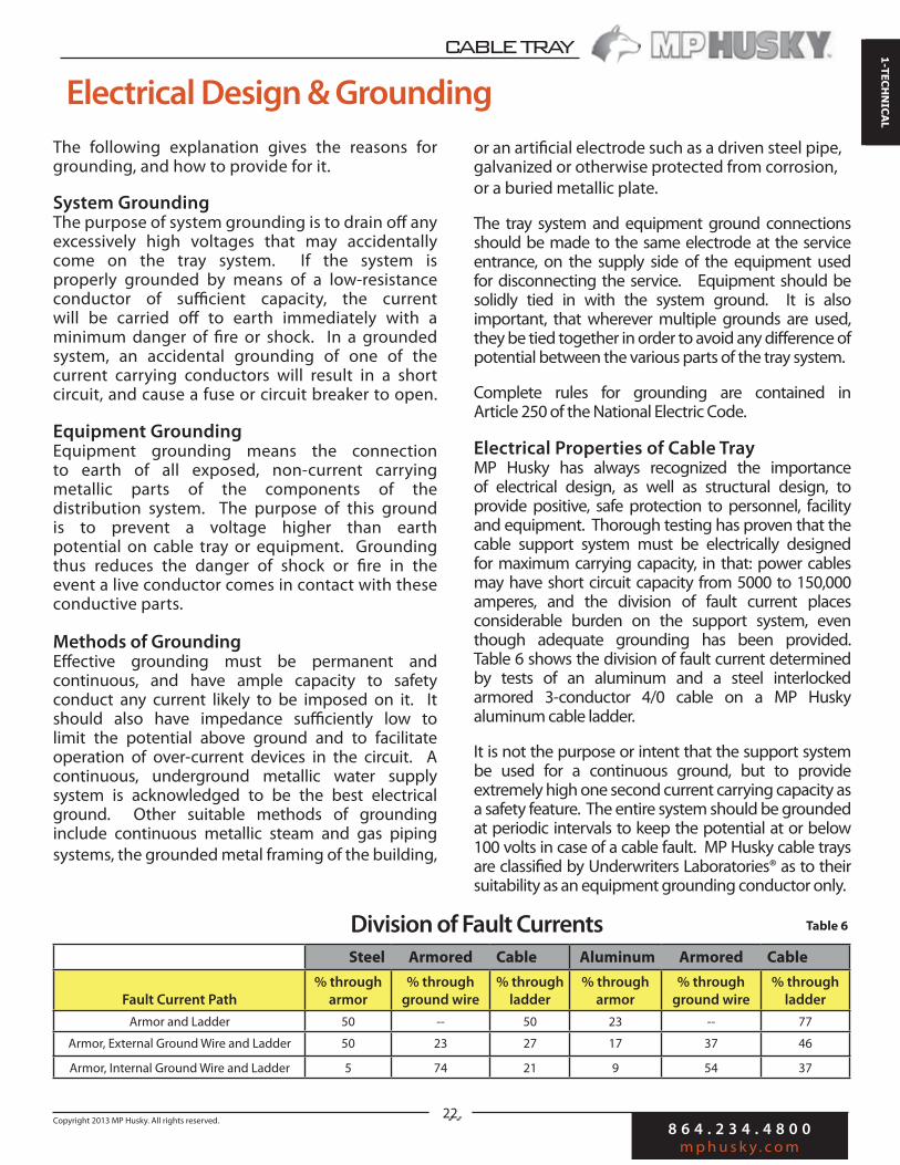
Electrical Properties of Cable TrayMP Husky has always recognized the importance of electrical design, as well as structural design, to provide positive, safe protection to personnel, facility and equipment. Thorough testing has proven that the cable support system must be electrically designed for maximum carrying capacity, in that: power cables may have short circuit capacity from 5000 to 150,000 amperes, and the division of fault current places considerable burden on the support system, even though adequate grounding has been provided. Table 6 shows the division of fault current determined by tests of an aluminum and a steel interlocked armored 3-conductor 4/0 cable on a MP Husky aluminum cable ladder.
It is not the purpose or intent that the support system be used for a continuous ground, but to provide extremely high one second current carrying capacity as a safety feature. The entire system should be grounded at periodic intervals to keep the potential at or below 100 volts in case of a cable fault. MP Husky cable trays are classified by Underwriters Laboratories® as to their suitability as an equipment grounding conductor only.
Division of Fault Currents Table 6
Steel Armored Cable Aluminum Armored Cable
Fault Current Path
% through
armor
% through
ground wire
% through
ladder
% through
armor
% through
ground wire
% through
ladder
Armor and Ladder 50 -- 50 23 -- 77
Armor, External Ground Wire and Ladder 50 23 27 17 37 46
Armor, Internal Ground Wire and Ladder 5 74 21 9 54 37
Electrical Design & Grounding

8 6 4 . 2 3 4 . 4 8 0 0
m p h u s k y . c o m
Copyright 2013 MP Husky. All rights reserved.
CABLE TRAY
1-TECHNICAL
23
Electrical Properties of Cable Trays
Note:
For electrical properties of pre-galvanized cable trays, refer to the electrical properties given above for hot dipped galvanized cable trays of the same style. Example: For electrical properties of PHA cable tray, refer to SHA in the above table.
UL GroundingTable 7
Electrical Design & Grounding
Product
Resistance
Across One
Foot of Rail
(Microhms/ft)
Resistance
Across Splice
(Microhms)
Resistance of
12ft. Length
with Splices
(Microhms)
Copper
Equivalent
(MCM)
SHASJ2SKCSY
SY1SYASYD
SM61SM14SMC
SMD4SX
SX1SXBSXCSXD
S( )HAS( )J2S( )KCS( )Y
S( )Y1S( )YAS( )YD
S( )M61S( )M14S( )MC
S( )MD4S( )X
S( )X1S( )XBS( )XCS( )XD
S( )B2S( )FCS( )C
S( )C1S( )CAS( )CDS( )P61S( )P14S( )PC
S( )PD4S( )E
S( )E1S( )EBS( )ECS( )ED
23423016314410318216311089
10812411688
1119893
57686959405875403139384443353532
146114481047923658
11501053700565687782740571701623590
8394
108160222129143128160110133203283155193215
AJAAJBAY
AY1AYA2AMCAX
AX1AXAAIXBAIXC
A( )JAA( )JBA( )Y
A( )Y1A( )YA2A( )MCA( )X
A( )X1A( )XAA( )IXBA( )IXC
A( )BAA( )BBA( )C
A( )C1A( )CA2A( )PCA( )E
A( )E1A( )EAA( )IEBA( )IECA( )I6
272719183123181426191715
1212111112887
1316116
17417412511920614611691
16913011396
712712
10241305819944
12681499981
128215391835
SG-4SG-6
12168
5033
776441
160203
AG-4AG-6
2624
229
178153
10241268

8 6 4 . 2 3 4 . 4 8 0 0
m p h u s k y . c o m
Copyright 2013 MP Husky. All rights reserved.
CABLE BUSCABLE TRAY 1-TECHNICAL
24
Sizing Trays for Multiple-Conductor Cables Section 392.2 lists the requirements for installing multiple-conductor cables in ladder, ventilated trough, solid-bottom, or ventilated channel type trays.
For ladder or ventilated trough trays, the diam-eter of all cables No. 4/0 and larger must be added together and the total must not exceed the width of the cable tray. Cables must be placed side by side. Table 392.9, Column 1 is used for cables less than 4/0. These cables do not have to be placed side by side. Ta-ble 392.9, Column 2 is used for a combination of cables rated larger than 4/0 and smaller than 4/0.
The total cross-sectional areas of the cables in trays with an inside depth of 6” or less, containing control and/or signal cables must not exceed 50% of the cross-sectional area of the tray.
For solid bottom trays, the diameter of all cables No. 4/0 and larger must not exceed 90% of the cable tray width. Table 392.9, Column 3 is used for cables smaller than 4/0. Table 392.9, Column 4 is used for a combina-tion of cables rated 4/0 or larger, or less than 4/0.
For trays with an inside depth of 6 inches or less, containing control and/or signal cables, the to-tal cross-sectional areas of the cables must not exceed 40% of the cross-sectional area of the tray.
For ventilated channel type trays, the total cross-sec-tional areas of all cables must not exceed 2.5 square inches for 3 inch wide trays or 3.8 square inches for 6 inch wide trays.
Sizing Trays for Single Conductor Cables For ladder or ventilated trough trays, the total diameter of all cables 1000MCM and larger must not exceed the width of the cable tray. Table 392.10, Column 1 is used for cables smaller than 1000MCM. Tables 392.10, Column 2 is used for a combination of cables rated 1000MCM and larger, and smaller than 1000MCM.
For ventilated channel type trays, the total diameter of all cables must not exceed the inside width of 4” or 6” wide trays.
SizingProblem:What size ladder-type cable tray is required for nine
multi-conductor smaller than 4/0 and four multi-con-
ductors larger than 4/0? The total diameter (in inches)
for the 4/0 and
larger cables is 12.6� and the total area for cables rated
less than 4/0 is 22 sq. in.
Note: Square inch area of cables obtained from manufacturer.Step 1: 392.9 (a) (3)
Sq. in. of cables smaller than 4/0 = 22 sq. in.Diameter of cables larger than 4/0 = 12.6 in.
Step 2: Table 392.922 sq. in. + (12.6 x 1.2) = 37.12 sq in.A 36” tray has 42 sq. in. area
Answer: The inside width of the cable tray must be equal to 36”.
Problem:What size tray is required for ten No. 250 MCM RHH RHW copper conductors and twelve No. 750 MCM RHH RHW copper conductors laid in a ladder-type tray?
Cable tray width must be selected from Table 392.9 and be based on the calculation in Column 2.
Cable tray must be selected from Table 392.10, Column 1 based on square inch area.
Step 1: 250 MCM = .554 sq. in. 750 MCM = 1.286 sq. in.Step 2: Table 392.10 (a) (2) Table 392.10, Column 1.554 x 10 = 5.54 sq. in. + 1.286 x 12 = 15.43 sq. in. = 20.97 sq. in.Step 3: Table 392.10, Column 1 18” wide tray = 19.5 sq. in. 24” wide tray = 26.0 sq. in.Answer: The inside width of the cable tray must be equal to 24”.

8 6 4 . 2 3 4 . 4 8 0 0
m p h u s k y . c o m
Copyright 2013 MP Husky. All rights reserved.
CABLE TRAY
1-TECHNICAL
25
Obtain a Deflection for a Load that is smaller than a Load Shown in a Load Deflection Table:
Formula: Divide the desired load by the load shown in the load deflection table and multiply the answer times the deflection shown for the known load in the load deflection table.Example: If the load table shows 200 pounds per foot on a 12 foot span with 1.5 inches of deflection and you want to know the deflection for a 150 pounds per foot on the 12 foot span you would divide the load desired (150) by the load known (200) and multiply the answer (0.75) times the known deflection (1.5”). The answer would be 1.125” deflection at 150 pounds per foot on a 12 foot span.
Convert a Concentrated Load to Pounds per Linear Foot:
Formula: Concentrated Load times 2 divided by the support span.Example: A 200 pound concentrated load on a 20 foot span would be a load of 20 additional pounds per linear foot. This load can be added to the uniform cable load for a total load and compared to a load shown in a load deflection table.
Convert a Load with a 1.5 Safety Factor to a Load with a 2.0 Safety Factor:
Formula: Multiply the load shown with a 1.5 safety factor by 0.75 to convert the load to a 2.0 safety factor.Example: A load of 100 pounds per foot with a 1.5 safety factor would be 75 pounds per foot with a 2.0 safety factor. The multiplier for a 2.5 safety factor would be 0.60.
Formulas & Conversions
W2
Formula: D2 = ��- x D1
W1
150
Calc: �� = 0.75 x 1.5� = 1.125�
200
Where
D2 = Calculated Deflection with s maller load
W2 = 150 lbs/ft Smaller Desired Load
W1 = 200 lbs/ft load in load table
D1 = 1.5� Deflection for 200 lb load in table
S = 12 Foot Span in Deflection Table
Where
Concentrated Load = 200 pounds
Span = 20 feet
We= Converted Load in pounds per linear foot
2 x 200
Calc: ��� = 20 lbs/ft
20
2 x (Concentrated Load)
Formula: We= ����������
S pan (Ft)
Formula: Wk x Multiplier
Calc: 100 x 0.75 = 75 lbs/ft
Where
Wk = 100 pounds per foot
Safety Factor = 1.5
Multiplier 0.75 for 2.0 safety factor, 0.60 for 2.5 S.F.

8 6 4 . 2 3 4 . 4 8 0 0
m p h u s k y . c o m
Copyright 2013 MP Husky. All rights reserved.
CABLE BUSCABLE TRAY 1-TECHNICAL
26
Calculate a Load for a Shorter Span that is not shown in a Load Deflection Table:
Formula: Take the load of a known span times the span length squared and divide by the span desired squared.
Example: The load table shows 100 pounds per foot on a 12 foot span with a deflection of 1.5 inches. To find the load for a 10 foot span that is not in the table you take the load known (100) pounds times the span (12) foot squared then divide the answer (14,400) by the span desired (10) foot squared. The result is 144 pounds per foot on a 10 foot span. Do not calculate longer spans with this formula.
Part 2 Calculate the deflection for the new load of 144 pounds per foot on a 10 foot span:
Formula: Divide the new desired load for the 10 foot span by the known load for the 12 foot span and multi-ply the answer times the deflection for the known load on the 12 foot span.
Example: Take the load on the known span (100) pounds and divide by the new desired load (144) pounds. Take the result (0.6944) times the known span deflection (1.5) inches to get 1.0416 inches. The 144 pound load on a 10 foot span would have a deflection of 1.0416 inches. Catalog Deflections are based on simple beam support spans.
Formulas & Conversions
1.0416�
W2
D1
Where
W2 = Calcu lated load for the 10� span
W1 = Tested 100 lb/ft load or load in load table
L1 = Tested 12� span or span in load table
L2 = Shorter 10 ft span not tested or in load table
100 x 122
Calc: ���-- = 144 lbs/ft on 10�
102
Formula: W2 =W1 x L12/L2
2
W1
Formula: D2 = ��- x
D1
Where
D2 = Calculated deflection for new load
W2 = 144 lbs/ft new 10� span desired load
W1 = 100 lbs/ft load in load table
D1 = 1.5� Deflection for 12 � span 100 lb/ft load in table
S = 12 Foot Span in Deflection Table
100
Calc: �� = 0.6944 x 1.5� = 1.125�
144
1.0416�
W2
D1

8 6 4 . 2 3 4 . 4 8 0 0
m p h u s k y . c o m
Copyright 2013 MP Husky. All rights reserved.
CABLE TRAY
1-TECHNICAL
27
Request for Quote
Email: ______________________________
10 in.
Husky Way EMI
(Standard)
(Circle One)
________
4� 6�