Embed Size (px)
Citation preview

NASA CONTRACTOR
REPORT
NASA CR-2500
00
!
k.,,I
,<¢
,1¢Z
_C _ S E F'I L E....: _ #_
COP_
FLIGHT CONTROL
PROPERTIES AND
Volume I
SYSTEMS
PROBLEMS
Duane T. McRuer and DonaldE. Johnston
Prepared by
SYSTEMS TECHNOLOGY, INC.
Hawthorne, Calif. 90250
/or Flight Research Center
NATIONAL AERONAUTICSAND SPACE ADMINISTRATION • WASHINGTON, O. C. • FEBRUARY 1975
!
https://ntrs.nasa.gov/search.jsp?R=19750009299 2018-09-06T04:56:01+00:00Z


1. Report No, 2. Government Accession No.NASA CR-2500
4, Title and Subtitle
FLIGHT CONTROL SYSTEMS PROPERTIES AND PROBLEMS
Volume I
7. Author(s)
Duane T. McRuer and Donald E. Johnston
9. Performing Organization Name and Address
Systems Technology, Inc.
Hawthorne, California 90250
12. Sponsoring Agency Name and Address
National Aeronautics and Space Administration
Washington, D.C. 20546
3. Recipient's Catalog No.
5. Report Date
February 1975
6. Performing Organization Code
H-859
8. Performing Organization Report No.
TR-1018-1
A
10. Work Unit No.
11. Contract or Grant No.
NAS 4-1881
13. Type of Report and Period Covered
Contractor Report - Final
14. Sponsoring Agency Code
15, Supplementary Notes
NASA Technical Monitor: Herman A. Rediess, NASA Flight Research Center
16. Abstract
This volume contains a delineation of fundamental and mechanization-
specific flight control characteristics and problems gleaned from many
sources and spanning a period of over two decades. It is not a complete
exposition of systems past and present; however, everything described
has actually occurred--often recurring with each new team of system or
aircraft designers. It is organized to present and discuss first some fun-
damental, generic problems of closed-loop flight control systems involv-
ing numerator characteristics (quadratic dipoles, non-mlnimum phase
roots, and intentionally introduced zeros). Next the principal elements
of the largely mechanical primary flight control system are reviewed
with particular emphasis on the influence of nonlinearities. The charac-
teristics and problems of augmentation (damping, stability, and feel)
system mechanizations are then dealt with. The particular idiosyncracies
of automatic control actuation and command augmentation schemes are
stressed, because they constitute the major interfaces with the primary
flight control system and an often highly variable vehicle response.
Specific emphasis is placed on high angle-of-attack and non-straight and
level flight influences. Finally, various approaches to turn-coordination
mechanization are covered.
17, Key Words (Suggested by Author(s)) 18. Distribution Statement
Aircraft control systems
Systems designUnclassified - Unlimited
Category: 08
19. Security Classif. (of this report) 20. Security Classif, (of this page) 21. No. of Pages 22, Price"
Unclassified Unclassified 171 $6.25 _
*For sale by the National Technical Information Service, Springfield, Virginia 22151

FOREWORD
The purpose of this program was to document and pass onpast experiences to current and future generations of flightcontrol system engineers, hopefully, to prevent costly redis-
covery of past mistakes and to stimulate trade studies betweenpossible competing mechanizational approaches.
This report is divided into two volumes. This volume con-tains the technical discussion while Volume II (NASA CR-2501)
is a compendium of stability augmentation system and autopilotblock diagrams and descriptive material for 48 different typesof aircraft. These provide a broad representation of the manymechanizational approaches which have been employed in the
past.
.°.
III


TABLE OF CONTENTS
I. INTRODUCTION ................ I
II. QUADRATIC DIPOLE PROBLEMS ............ 6
A. "a_/_d Effect" in Bank Angle Control ....... 9
B. "_r/md Effect" in Dutch Roll Damping Augmentation . . . 17
C. Hydraulic and Electrohydraulic Actuation Systems . . . 20
III. SYSTEMS _TOR PROBLEMS ............ 29
A. Non-Minimum Phase Zeros ........... 30
B. Intentionally Introduced Zeros ......... 46
IV. PROBLEMS ASSOCIATED WITH MECHANICAL FLIGHTCONTROL SYSTEM ELEMENTS ............. 93
A. Artificial Feel System Input/Output Characteristics . . 93
B. Actuation Dynamics ............. 68
C. Bobweight Effects ............. 71
V. AUGMENTATION AND STABILIZATION SYSTEM PROBLEMS . . . . . 80
A. Command Insertion/Actuation Subsystem Combinations . . 83
B. Electrical Command Preshaping or Filtering ..... 103
C. Feedback-Related Problems ........... I07
VI. TURN COORDINATION ............... 137
A. Directional Stiffening ............ 137
B. Control Crossfeeds to Rudder .......... 138
C. Roll Crossfeed to Rudder . .... ...... 143
REFERENCES .................. 190
BIBLIOGRAEIY .................. 151
INDEX .................... 159
V

LIST OF FIGURES
I. System Surveys for Quadratic Dipole .........
2. Root Plot of Bank Angle/Aileron Transfer
Function and Approximate Factors ..........
3. Closed-Loop Surveys for r --- 5r Yaw Damper Systems ....
4. Effect of Roll Damper on Yaw-Rate-to-Rudder Numerator ...............
5. A Fully-Powered Hydraulic Servo Surface Actuator .....
6. Block Diagram of Actuator, Load, and Support ......
7. Simplified Load Dynamics .............
8. Rigid Support Structure, Compliant Load Coupling,
Feedback Attached to xa .............
9. Root-Locus Sketch of Altitude Control System ......
10. System Survey of Pure Gain Pitch Attitude
Control System ................
11. Pure Gain Pitch Attitude Control System withStatic-to-Short-Period Gain Ratio Less Than I......
12. System Survey of Pitch Attitude Control System
with Integrator ...............
13. Matrix for Coupled Equations with _ _ 0 ........
14. Survey of Ne Approximations for s = 18.8 deg,5e= 6 deg ..................
15. Pitch Attitude Closure Survey; s o = 19 deg, _o = 6 deg. . .
16. Movement of 6 DOF N_e Zeros for O° < _ < 15° ......
17. Effect of M_ on 6 DOF Poles and Zeros(so = 20 deg 3 Po = I deg) ............
18. Survey for Migration of Roots with SAS Loop Closure ....
19. Comparison of Effective Vehicle Dynamics
SAS On and Off ................
20. Curve Fit of Equivalent Short Period
Aircraft Dynamics ...............
Page
7
IO
18
19
20
21
25
28
31
34
36
37
4o
41
44
45
47
49
51
52
vi H-859

21. Pilot-vehicle Control System ......
22. Control System Schematic ............
23. Detailed Characteristics of Typical
Artifical Feel System ............
24. Dynamic Characteristics, Feel System ........
25. Survey of Feel System Poles with
Change in Damping, Cs ............
26. Feel System Characteristics at Very Low Frequencies . . .
27. Waveforms in Artificial Feel System with Friction ....
28. Mechanical Hysteresis Due to Coulomb Friction
and Feel Spring ...........
29. Inverse Describing Function for Hysteresis,Friction and Preload, and Backlash .........
30. Stick-to-Tail Gearing Versus Tail Deflection ......
31. Block Diagram--Aircraft Control System withValve Friction ................
32. Negative Inverse Describing Function for a
Control System with Valve Friction; Kf = I ......
33. Block Diagram of Longitudinal Control System ......
aB a _ _34. Root Survey for NsZ = Nb _g _BN ........
35 t Bobweight Loop Closure ............
36. Effect of Increasing Control System Lags
on Bobweight Loop Closure ..........
37. Generic Block Diagram for Command Augmentation
Systems .................
38. Full Authority Series Actuation .........
39. Breakout Characteristics ............
40. Pseudo Force Mechanization ............
41. Control System Displacement Sensing .........
42. Limited Authority Series Actuation with
Automatic Trim ...............
55
56
58
6o
61
62
63
65
68
7o
72
73
75
77
79
81
85
87
91
93
95
vii
Pag____e
43. Full Authority Parallel and Surface Actuators
With Limited Authority Series Actuator and Trim .... 97
44. Forward Loop Integration with Large Authority
Series Servo ................ 100
45. Forward Loop Integration with Small AuthoritySeries Servo and Series Trim ........... 101
46. Typical CAS with Automatic Series Trim ........ 102
47. Rolling Velocity Command Augmentation System ...... 103
48. Attitude Rate Command, Attitude Hold System ...... 115
49. Simplified Roll Rate CAS-- Fixed-Wing Aircraft ..... 118
50. Simplified Roll Rate CAS-- Swing-Wing Aircraft ..... 118
51. Typical ay --_ 5r Bode Diagram ........... 124
52. Mid- and High-Frequency Portion of Bode Plot
for f(ay) -_ 5r Loop .............. 126
53. Roots of (NPs/N_) tan (16 + eT) = -I ........ 133
54. Yaw Rate Damper Effectiveness at _ = 16 deg ...... 135
55. Survey Sketch for Bank-Angle-to-Rudder ....... 145
56. Yaw Stability Augmentation System (SAS) ....... 146
57. Roll Stability Augmentation System (SAS) ....... 147
58. Survey Sketch of Bank-Angle-to-Aileron ....... 148
viii
LIST OF TABLES
I. Two Decades of u_p/_d Problems ...........
2. Effects of Idealized Adjustments of
f(ay) --- 5r Controller Parameters ..........
3. Summary of Configurations Utilized .........
ix

SECTION I
INTRODUCTION
From an overall systems viewpoint, the history of flight control system
development can be considered in terms of stimulus and response. The
stimuli have been flight control desires or troubles; these caused inter-
mediate responses in the form of system configurations to satisfy the
desires or to remedy the basic problems presumed to underlie the troubles;
followed by final responses which were the most efficient system configu-
rations which did indeed satisfy. In the course of such challenge-respouse
evolutions, there have been two fundamentally independent types of compe-
titions. The first is among imagined problem possibilities as the under-
lying causes for any observed troubles. This competition is decided
primarily by analysis; it euds when the actual problem is defined in terms
of pertiuent vehicle and/or control system parameters and factors. The
second competition is betweeu system configurations, each capable in
principle of satisfying the flight control desires or of correcting the
fundamental flight control problems. Although all of the system coufigu-
rations conceived may be possible, some are far more feasible and desirable
than others. When practical mechanization possibilities, equalization
requirements, sensor noise, sensitivity to system tolerances and controlled
element uncertaiuties, responses to unwanted inputs, gain compensation,
computational complexity, etc., are fully considered, many of the theore-
tically possible configurations are eliminated as practical possibilities.
Historically, system configuration competitions have involved both sophis-
ticated analyses and experimentation with actual equipment. In actuality,
of course, few systems have been formally competitive, oue with another.
Rather the competition has been akin to historical evolutiou.
Each past flight control system design has had its share of advantages,
limitations, and shortcomings. The advantages (real or potential) have
quite often been extolled in various technical publicatlons. Rarely,
however, do the limitations and shortcomings achieve the same public (or
even iutracompany) notice. Yet these aspects really define the limitations
on the state of the art, and there is much profit in learning from past

mistakes. Far too manyshortcomingsor mistakes are subtle, conceptual,recurring, and very costly. Table I presents an exampleof such recur-rence for one of the fUndamentalproblemsdiscussed in Section II. Thisproblem is knownto havebeenencounteredin the early 19_0's. Theprincipal causesand cures were identified andvalidated in the middle19_0's. Thesewere promulgatedon a widespreadbasis of technical reportsand Journal articles by the late 1950's. Yet it continues to pop-up.
Someshortcomingsresult in piling fix upon fix until an overlycomplexand unreliable design evolves. There is muchto be gained fromexposingpast flight control systemfaults, over-design, and key limita-tions which havebeenvery resistant to elimination. Particularly thosecharacteristics which are basic In concept or which havebeen showntohave considerable carryover from one aircraft to another are high prioritycandidates.
Thepurposeof this programwas the collection, unification, anddissemination of such information. This volumecontains a delineationof both fundamentalandmechanizationspecific problemsgleanedfromvarious sources. It is by no meansa completeexposition of systemspastand present; however,everything described has actually happened- oftenrecurring with eachnewteamof project or aircraft designers. Theproblemsare both subtle and (in hindsight) obvious. Manyare the conse-
quenceof compromises,resulting in somenon-ideal rather than criticallybad characteristics. Manywere encounteredand eliminated early insystemdevelopmentprograms. Since mistakes are seldomadvertised andmanyincidents are reported here as a result of verbal or inside infor-mation (e.g., items in Table I), we do not have identifiable referenceson everything reported. Therefore, in the interest of even handedtreat-ment, wehave adopteda general policy of source anonymity.
Thereport is divided into two volumes. VolumeI contains the technicaldiscussions while VolumeII is a compendiumof systemblock diagrams.VolumeI is organizedto present and discuss first somefundamental#genericproblemsof closed loop flight control systemsas generally as possible.
This is donein Sections II and III. Section II delves into the familyof flight control problemsinvolving unfavorable quadratic dipole (pole-
zero) effects. Theseinclude the _/_d effect on closed loop roll control

TABLEI
TWODECADESOFa_/0_dPROBLEMS
k_
YEAR VEHICLE
Early 190O's Snark Missile
Mid- 19_0' s Q-2 Drone
Late 19_0' s KC- 139A
Late 19_0' s F-IOIB
19_8
1961 T-33VSA
X- 1:9
R_RKS SOURCE
Long range cruise missile. Two axis autopilot. Roll control unstable Undocumented Contractor
when push-over into terminal dive. Required changes in trajectory. Design Study
_vo axis autopilot. Essentially continuous dutch roll oscillation of Consulting activities
significant a_,plitude with autopilot on.
Lateral-directional dutch roll oscillation in smooth air. Corrective
aileron actioa by pilot amplifies oscillation. Use of rudder axis of AFFTC TR-_13
autopilot stabilizes motion.
Lateral PIO at high dynamic pressure, subsonic conditions. Oscillation AFFTC TR-98-11
ceases when pilot releases stick. 1
Identification of principal causes and cures. WADC TR-98-82
In-flight simulation in variable stability T-33 validation offend effects. WADD TR-61-147
Divergent lateral PIO with roll and yaw d_mper off at higher angles of
attack due to negative dihedral effect of lower rudder.
Failure of yaw damper resulted in unstable roll damper and/or autopilot.
Triple redundant yaw dam@er to be retrofitted.
NASA TND-1059
Zarly 196o's B-_8
Late 1960's B-70 Divergent lateral PIO with wing tips down and yaw augmentor off at high NASA TM X-2933supersonic speeds. Aircraft could not be maneuvered in roll_rith SAS off.
Large variation in_a_ partially due to swing-wing. Alleviated by Consulting activites andLate 1960's F-111 triple redundant, fail-operational yaw damper, early contractor design
studies
Closed loop lateral instability (PIO) at low angle of _,ttack in preflare NASA _ND-64961970-71 H2-F2 maneuver. ARI aggravated.
Report of the A.S.D. Flight
Control System Review Board

and roll PIO tendencies, the _r/_d effect which has determined the success
or lack thereof of nearly all yaw damping mechanizations, and the quadratic
dipole effect involved in electrohydraulic actuation systems. In each
instance the causal factors are identified along with fundamental and
direct means of countering the problems.
The influence, and problems, associated with unfavorable transfer
function zeros, such as performance reversal in altitude control, are
discussed in the first part of Section III. These are also known as
"non-minimum phase" and/or "right half plane" zeros. Among the problems
involving such zeros are speed divergence, longitudinal flight path
divergence, and a newly identified lateral-longitudinal coupling which
results iu lateral "nose-slice" divergence. The second part of Section III
presents seme examples of problems encountered when zeros are intentionally
introduced to attract closed loop poles of the basic vehicle response modes
(e.g., longitudinal short period) to specified locations (frequency and
damping). It is shown that while the specified results may be accemplished
from an accounting standpoint, the equalization poles which inherently
accompany the introduced zeros can negate the intended system benefits.
Section IV contains a discussion of the principal elements of the
largely mechanical primary flight control system, from pilot stick input
to control surface output. The interrelationship of the feel system,
surface actuator, mechanical bobweight system, and series augmentation
actuator is described. Particular attention is given to the influence of
nonlinearities.
The characteristics and problems of various augmentation system
mechanizations are dealt with in Section V. This first expands upon
interfaces between the augmentation and primary flight control systems.
Particular emphasis is placed upon command augmentation system considera-
tions. These are generally high gain, large authority systems of inherently
greater complexity than conventional stability augmentation systems. They
can deliver more performance and, conversely, suffer greater problem
potential. Problems associated with motion feedback sensing are also
discussed with specific emphasis on the effects of high angle of attack
and non-straight and level flight.
4

Section VI contains a discussion of three approaches to turn coordination
mechanization. Same advantages and shortcomings of each are preseuted. A
mathmmaticalmodel of a theoretically ideal aileron-rudder interconnect (ARI)
is developed which indicates the influence of various augmentation feedbacks,
as well as airframe parameters, on the deslredARI characteristics.
As indicated previously, Volume II is a compeudium of SAS and autopilot
block diagrams and descriptive material for _8 different types of aircraft.
These provide a broad represeutatiou of the many mechaulzational approaches
which have been employed in the past three decades. Collectively they
also have exhibited many, if not all, of the problems discussed lu this
volume. A bibliography of source material is appended to Volume I.

SECTION II
QUADRATIC DIPOLZ PRO_
There are a remarkable number of flight control situations which are
dominated by the dynamic properties of a lightly-damped quadratic dipole
(quadratic pole-zero pair) in the crossover region of a feedback system.
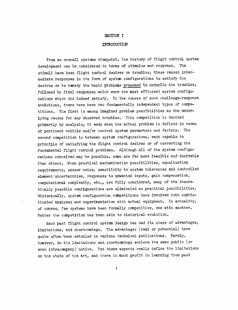
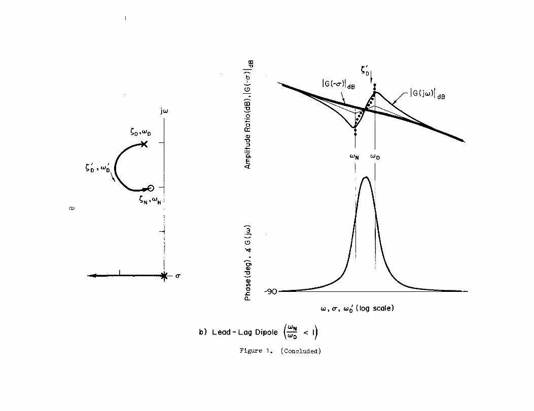
The essence of what can happen is indicated in Figs. la and lb. This
considers an open-loop system which can be approximated in the region of
crossover by:
i[s2 + 2_s + _] i[_N, _]G(s) --
s[s2 + 2_D%s + _] s[_D,%](1)
In the idealized situations illustrated the closed-loop quadratic mode
(_ ,a_) progresses as open-loop gain is increased from the open-loop pole
(_D ,_D) to the open-loop zero (_N ,e>N), in a counterclockwise direction
along a circular segment. Thus, when the pole is smaller than the zero, the
closed-loop roots depart toward the right-half plane and suffer a damping
decrease, whereas the reverse is true when the numerator, _N, is smaller
than the denominator, _D. The maximum diminution or increase in damping is
measured by the maximum phase deviation, due to the dipole, from the phase
angle contributed by the rest of the system. This is given by:
_(_, _O)max2 h_, ;'
+*tN_D a_D a_N
When _N/C)D is near I, this becomes approximately:
• )_(a_ a_)max = _tan-1 _N + _D ct_ 1' 2_N_D
(5)
6

.-,.1
joJ
D,(dD
r-o,_o N''_
nnlo
04,-
'no
4--.
Q.E
,ki= Or
3
Lo
I/}t_r-Q_
a) Lag- Lead Dipole
-9O
IG(j(_)IdB
G(-a')
t
/
OdB Lines forNeutral Stability
-180 U
oJ N
/
_, o', oJo (log scale)
Figure I. System Surveys for Quadratic Dipole
jcu
D, C_D
_N _'Q'JN
Or
00
..-...
bI
CDm
m"C3
,...,..
O°m
Orr
"IO:3
.t-...
E
:3
(.o
o;
OJ_£I..
IG(-0.)IdB --
Q'JN C°D
IA
-90
' (log scale)_d I 0"1 (JJD
_)Leo0-Lo_D,_o,e(_< ,)Figure I. (Concluded)

When_/_D _ I, the incremental phaseis a dip resulting in a decreasedphasemargin (whencrossover occurs in the dipole region) over that whichwouldbe present without the dipole. Conversely, _N/_D_ I implies a phaselead blip and an increased phasemargin. Thegreater the blip, the largerthe attainable closed-loop dampingratio, _.
All of the ramifications implicit in the idealized situations aboveareexhibited in practical control situations. WhenC_N/_D _ I the presenceofthe dipole is a distinct nuisance, often causing instability or marginallystable operation. Theseare exemplified belowby the "_J_d effect" encoun-tered in roll control using ailerons and the oil-compressibility structural-compliancecoupling associated with hydraulic surface actuators. Outheother side of the coin, the presenceof the dipole is advantageousin that
_N/_D( I situations permit the closed-loop dampingto be increased overthat available openloop. The classic case to be described below is the
"a_f/_d effect" associatedwith yaw-rate-to-rudder feedbackcontrols.Other examples#suchas lateral-acceleration-to-rudder feedback(_ay/_d)and longitudinal control systemscontaining dual bobweights(_B/_sp),will be described in later sections.
A. "_md EFFECT"IN BANKANGLECONTROL
A root plot of the aircraft= bank-angle/aileron transfer function is given
in Fig. 2. Here,'the quadratic dipole _$/_d ratio is greater than I. Inorder to accomplishgoodroll control, stabilization, and regulation, a bank-angle-to-aileron controller would contain equalization which wouldmakethetotal open-loopsystemtransfer function, less the dipole, appear like a K/sin the crossover region. To the extent that this is accomplished,the bankangle controller approachesthe a_N/_D > I situation idealized above. Accord-ingly, by analogy with Fig. I, the closed-loop dutch roll dampingwill beless for low andmoderategains than the openloop andwill then turn about
and approacha dampingratio _ and damping_ as the gain becomesverylarge. Thus, the dutch roll undampednatural frequency is increased and thedampingand dampingratio (at other than high gains) is decreasedby virtue
9
/if
/

Dufch Roll _d, Wd
JLTs
cr
Figure 2. Root Plot of Bank Angle/AileronTransfer Function and Approximate Factors
I0

of the bank angle controller. (When the feedback control equalization does
not approximate that needed to make good the K/s-llke property, the e_e d
effects are somewhat the same in general but differ significantly in detail.
See Chap. 8 of Ref. I.)
Marginal dutch roll damping problems arising from the e$/_ d effect can
cause longitudinal problems as well. For instance, to help maintain altitude
in turns bank angle is crossfed to the pitch axis to provide up-elevator bias,
i.e.:
ZhSe = _ (I -- cos _I (_)cos
With an unfavorable _ed, and with the relatively large I$/BI d character- _
istic of most high performance craft, the lateral dynamics of an aileron-only
controlled aircraft will exhibit an almost continuous large amplitude roll
oscillation when disturbed by turbulence or turning maneuvers. Thus, in both
level flight and in turns the dutch roll oscillation is coupled into pitch
excursions. At steep bank angles large load factor oscillations result [for
= _ = o, nz = (l-cos _)/cos _].
In general, if only aileron is available for feedback control purposes,
it is desirable that eke d approximately equal I so that the dutch roll poles
are nearly cancelled by the aileron bank angle numerator zeros. This has the
benefit of permitting excellent closed-loop bank angle control and regulation
with little excitation of the dutch roll mode by aileron inputs. The dutch
roll is then essentially decoupled from rolling motions; with exact cancella-
tion of the dipole pair, the mode is not "observable" in terms of the state
variable, _, nor "controllable" by the control variable, 5a.
As separation between the pair increases, the aileron excitation of the
dutch roll mode also increases. When _V_d > I, the closed-loop stability
is degraded; whereas when e$/ed < I, the ailerons are effective in _amping
the dutch roll. As described above, the degree of damping degradation ofI
improvement is determined primarily by the phase dip or blip, which in turn
depend predominantly on the separation of the dipole pair (_N/_D - I) and l
the effective dipole composite damping ratio, _$_D/(_ $ + _D ), as indlcate_
by Eq. 3. As shown in Fig. 2, the separation of the dipole pair is
i
11

largely determinedby the stability derivative, N_a,which accountsforthe aileron-induced yawing acceleration. The general level of damping,
_o_ and _d_d, on the other hand, is primarily dependent on N_, the yawing
acceleration due to yawing velocity stability derivative, while the pre-
dominant distinction between numerator and denominator damping is a more
complex function of yawing acceleration due to rolling velocity, _, and
the lateral-dlrectional sideslip coupling, L_/N_.
Because dutch roll is a nuisance mode in roll attitude control, it is
highly desirable that akp/ak[approximately equal I and/or that the dutch roll
is well damped at all flight conditions. For hlghperformance manned aircraft,
both conditions are desired, although the first may be sufficient for many
missile situations and for minimum complexity flight control systems. The
conventional means to correct non-ldeal _$/_d is to incorporate an aileron-
to-rudder interconnect which serves to reduce the effective adverse yawing
components, N_a and sometimes N_, and/or to rely on a yaw damper to provide
sufficient dutch roll damping so that no stability problem occurs.
I. Adjustment of akp/ed
The value of _d is most simply adjusted to an "optimum" value near I
by modifying the effective yawing moment due to aileron deflection, N_a, so
as to reduce the amount of dutch roll excitation due to aileron. This is
commonly accomplished using a mechanical aileron-to-rudder interconnect
(e.g., A-5, A-7, B-58, F-4, F-8, F-14, F-I02, F-I06, etc.). Because the
e$/ed problem exists throughout a range of flight conditions, it is common
to schedule the interconnect gain with elevator position (A-7, F-8) or dynamic
pressure (F-I02, F-I06).
When e$ _ed the dutch roll excitation via aileron is minimized except
for the pole-zero damping difference, _ - _ded • This difference can be
reduced substantially by either equalization in the interconnect or by roll-
rate-to-rudder feedback. This can simply be illustrated by noting that, with
L8r & O, the rudder required to offset aileron and rolling velocity induced
yawing terms is:
12
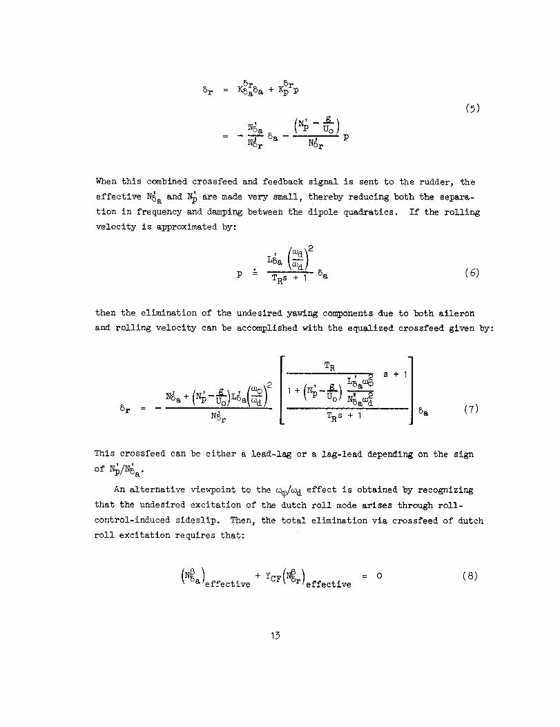
5r 8r8r = KSa5a + Kpp
= ----V--8a-- . ,N8r N5r
(7)
When this combined crossfeed and feedback signal is sent to the rudder, the
effective N_a and_ are made very small, thereby reducing both the separa-
tion in frequency and damping between the dipole quadratics. If the rolling
velocity is approximated by:
LSa \_d/
P "= TRS + I 5a (6)
then the elimination of the undesired yawing components due to both aileron
and rolling velocity can be accomplished with the equalized crossfeed given by:
_r
+ Uo/ _al_ /
N_r
TR, 2
LSaa_
Nsaoo_
s+1
TRS + I8a (7)
This crossfeed can be either a lead-lag or a lag-lead depending on the sign
of
An alternative viewpoint to the _/_d effect is obtained by recognizing
that the undesired excitation of the dutch roll mode arises through roll-
control-induced sideslip. Then, the total elimination via crossfeed of dutch
roll excitation requires that:
(N@) + YCF(_ ) = 0 (8)a effective r effective
13
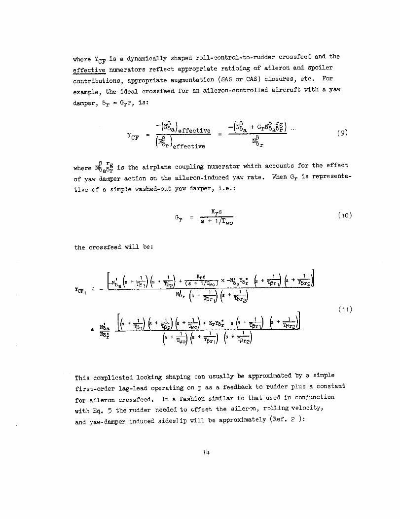
where YCF is a dynamically shaped roll-control-to-rudder crossfeed and the
effective numerators reflect appropriate ratioing of aileron and spoiler
contributions, appropriate augmentation (SAS or CAS) closures, etc. For
example, the ideal crossfeed for an aileron-controlled aircraft with a yaw
damper, 5r =Grr, is:
--(_a) effective --(_a+ Gr_sa_gr ) (9)YCF = =
(_r)effective _Sr
where _Sa_ g is the airplane coupling numerator which accounts for the effect
of yaw damper action on the aileron-induced yaw rate. When G r is representa-
tive of a simple washed-out yaw damper, i.e. :
Krs (10)G r =
s + I/Two
the crossfeed will be:
YCF I "w
I I Krs -N' Y * + ++ + + _(_s+ i/Two) X 5a 5r
N8 r s + +
Nsa
(11)
This complicated looking shaping can usually be approximated by a simple
first-order lag-lead operating on p as a feedback to rudder plus a constant
for aileron crossfeed. In a fashion similar to that used in conjunction
with Eq. _ the rudder needed to offset the aileron, rolling velocity,
and yaw-damper induced sideslip will be approximately (Ref. 2 ):
_r
TWO J
5a= --7- 5a -
N5r K 1Uo rNSr_g) s + Uo
N_r(S + I/Two)P
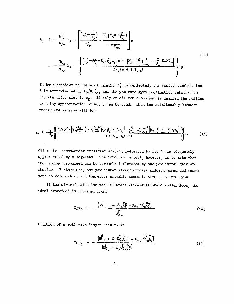
In this equation the natural damping N_ is neglected, the yawing acceleration
is approxlmatedby (g/Uo)p, and the yaw rate gyro inclination relative to
the stability axes is o_. If only an aileron crossfeed is desired the rolling
velocity approximation of Eq. 6 can be used. Then the relationship between
rudder and aileron will be:
• I TRNSa"+ [NSm_T-_o+ 11 a _ Uo r_SrC_ TwO 5a Uo T%_ U0
_ " "'_ .... _, (13)NSr (s + I/T_)(TRs ÷ 1)
Often the second-order crossfeed shaping indicated by Eq. 13 is adequately
approximated by a lag-lead. The important aspect, however, is to note that
the desired crossfeed can be strongly influenced by the yaw damper gain and
shaping. Furthermore, the yaw damper always opposes aileron-commanded maneu-
vers to some extent and therefore actually augments adverse aileron yaw.
If the aircraft also includes a lateral-acceleration-to rudder loop, the
ideal crossfeed is obtained from:
YCF 2(N_a + Gr N_a_ + Gay N_aS_ )
Addition of a roll rate damper results in
YCF 3
(NS_r+ GpN_BrPag)
(_)
15

Additional considerations can include such things as the contribution of
any lateral stlck-to-surface shaping (e.g., resulting from forward path
filtering in a roll rate CAS), etc.
In all of these cases, incorporation of the ideal YCF can make _$/_i_ I;
although the theoretical shaping can become quite complex. This corresponds
to the ideal decoupling case, and is seldom of practical importance. Instead,
as noted previously, the shaping is usually approximated. More often than not
this can be accomplished by a simple lag-lead or, sometimes, even a straight
gain.
2. Influence of the Yaw Damper on _d
The fundamental purpose of a yaw damper is to increase the dutch roll
damping without greatly detracting from the aircraft's ability to fly coor-
dinated turns. As indicated by the root plot of Fig. 2, the dutch roll
damping of the aircraft alone is predominantly dependent on Yv and N_. If
a stability derivative N6 were also explicitly carried in the aircraft equa-
tions of motion, it would add directly to these two. Thus, to augment the
dutch roll damping implies augmentation of one of these three derivatives in
the region of the dutch roll frequency. The most common techniques are to
use a washed-out signal from a rate gyro measuring yawing velocity or a lead-
equalize signal from a lateral accelerometer (properly located to deliver an
approximation to 6). The influence of these types of yaw damper on the damp-
ing terms in the dipole may be seen from the following approximate factors.
2( d d)aug -(Yv + Nraug
2_q:_ & --(Yv + N'raug
Y
' N_a ,+ N6aug) +-- Lr
L5a
(16)
The contribution of the yaw damper in augmenting N_ or N_ is such that the
pole-zero pair "track." Thus, an effective yaw damper will increase the
damping of both terms and reduce the significance of the dipole in affect-
ing the closed-loop roll axis dynamics. On the other hand, an ineffective
15

yaw damper or one that has failed will result in both terms moving toward
the j_ axis where _ > _d can have the serious consequences already noted.
This then leads to the second quadratic dipole problem, _r/a_.
B. "S>r/_d EFFECT" IN DUTCH ROLLDAMPING A_TION
The effectiveness of yaw rate feedback to rudder as a means to damp the
dutch roll often depends on the location of the quadratic zero of the yaw-
rate-to-rudder numerator, _r" Assuming the sensor measures stability axis
yawing velocity, r, the r/5 r numerator approximate factors most often
encountered in practice are*:
a_ " U-_ Lp ; 2_r_r -- V- Y5r Uo L
1_ Lp
Tr
Normally, a¥ is considerably less thane d. However, at low speeds, at high
angles of attack, or for conditions of low Lp and/or high L_, _r can approach
_d" In these cases, yaw-rate-to-rudder feedback is relatively ineffective in
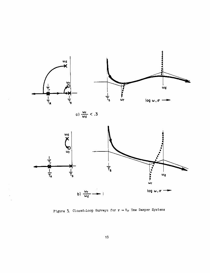
damping dutch roll. Sketches of system surveys are given in Fig. 3 (not
to scale). Clearly, the damping potential for yaw rate to rudder is much
greater when _r << _d. Furthermore, the full benefits of a washout circuit,
which reduces the low-frequency adverse yaw due to yawing velocity, with
I/Two & _r (the usual case) can be obtained when _r/_d_ 0.3, but as I/Two =
-,-ed the washout actually mitigates against an increase in the dutch roll
damping. The latter situation is commonly encouutered in landing approach
where angle of attack is large or in maneuvering flight where high angle of
attack and increased load factor combine.
To improve situations where _r is not sufficiently small, it can be
decreased by augmenting roll damping (Lp) via roll rate feedback to aileron.
*_VSr_is of third degree. All possible combinations of minimum and non-
minimum phase first- and second-degree terms have occurred in practice.
These particular approximate factors are, therefore, only one of several.
Others are provided in Refs. I and 3.
17
Wd
I Wr
T:
@
Ts wr logw, o"
(=Jr
a) --_- < .3
d
II
I
I".
Wd
-7. i::owr
Wr log o_,o"b) _'l
OJd
Figure 3. Closed-Loop Surveys for r_Sr Yaw Damper Systems
18

The consequences of this procedure are revealed by considering the r/8 r
numerator with the roll damper loop closed, i.e. :
r I _- r _rN8r p_Sa NSr + Kp aSr (_8)
The roots of the roll rate augmented numerator are obtained by treating
this equation as a feedback problem, i.e., from the expression:
= -I (19)
The ratio of coupling numerator to the N_Sr numerator is typically of the
form shown in Fig. 4. Since L'5a is usually quite large, the complex root
rapidly moves toward the origin with increasing roll damper gain, Kp.
This may be observed by comparing the relative motions of the closed-loop
roots _ and I/T_. Note that c_ moves toward the origin at a rate Just
slightly less than that of the root I/T_ moving to higher frequency. The
Figure 4. Effect of Roll Damper onYaw-Rate-to-Rudder Numerator
19
latter movement is almost identical to that of the roll rate damper augmented
roll subsidence mode (I/T_ & +KpLSa ) which is the usual reason for incor-
porating this feedback. Thus, the usual near cancellation of I/T r and I/T R
in the yaw-rate/rudder transfer function is enhanced along with the reduction
of o_r.
C. HYDRAULIC AND ELECTROHYDRAULIC
ACTUATION SYSTEMS
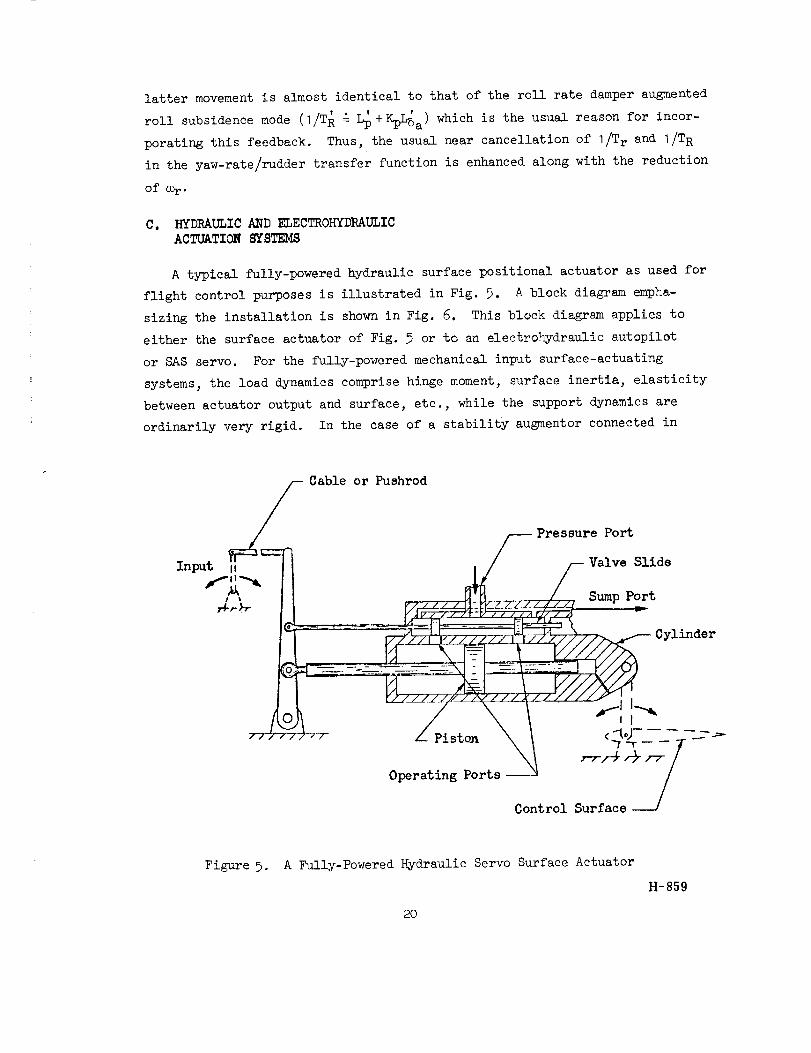
A typical fully-powered hydraulic surface positional actuator as used for
flight control purposes is illustrated in Fig. 5. A block diagram empha-
sizing the installation is shown in Fig. 6. This block diagram applies to
either the surface actuator of Fig. 5 or to an electrohydraulic autopilot
or SAS servo. For the fully-powered mechanical input surface-actuating
systems, the load dynamics comprise hinge moment, surface inertia, elasticity
between actuator output and surface, etc., while the support dynamics are
ordinarily very rigid. In the case of a stability augmentor connected in
Cable or Pushrod
Input II
Pressure Port
Valve Slide
Sump Port
Cylinder
Piston
Operating Ports--
Figure 5. A Fully-Powered Hydraulic Servo Surface Actuator
2O
H-859

Force Developed/,.
Across Actuotor L
x b
Actuator Base
Motion
X a
Actuator
Output Motion
Ba
Load
Dynamics
YL
Support j
Dynamics JYB I
,,, ,, J
//_//////////////////////////////////////////////////////////////,/A,
Figure 6. Block Diagram of Actuator, Load, and Support
21

series within the manual control system, the support dynamics consist primarily
of detents, friction, and preload, while the load dynamics may be dominated
by valve friction and artificial feel system forces.
The force, F, in Fig. 6 is developed across the piston of the actuator
by the metering activities of the valve. The viscous friction term, Ba,
represents a frictional force proportional to the velocity across the piston.
In most actuators, this is very small, although viscous dampers or extra
leakage flow can make it very large. From a performance standpoint, Ba is
kept as small as possible.
The equations governing the load dynamics for the general case are given by:
FYLBsBaslIXIYYBJXbThus, the transfer function relating the actuator @isplacement, Xa, and force
across the piston is:
x_A = I (21)
F YL+Ba s 1 +_B
Ideally, the purpose of the actuator is to move the load dynamics rather
than support structure, so xa is hopefully much larger than xb. Because
Xa/X b = -YB/YL, this is accomplished by making YB much greater than YL for
the varieties and kinds of piston forces developed. Making good this inequal-
ity for series SAS servos is sometimes difficult without compromising other
elements in the manual control system such as stick breakout forces or trim
systems. Nonetheless, it is only when this inequality approaches ideal
values that a series installation will operate effectively. Similarly, the
surface actuator should operate with very little backup structure deformation
(although some installations use so-called structural feedback to circumvent
stability problems). Consequently, for both types of actuators operating in
near-ideal circumstances, Eq. 21 will reduce to:
22
Xa I YL
F YL + Bas ' YB << I (22)
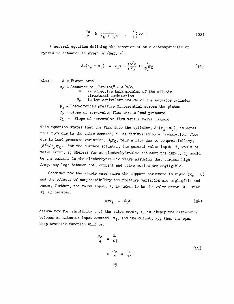
A general equation defining the behavior of an electrohydraulic or
hydraulic actuator is given by (Ref. 4):
As(xa--Xb) --Cii--/A2s+Cp)\ ko Pc (23)
where A = Piston area
ko = Actuator oil "spring" = AgN/VeN is effective bulk modulus of the oil-air-
structural combination
Ve is the equivalent volume of the actuator cylinder
PC = Load-induced pressure differential across the piston
CR = Slope of servovalve flow versus load pressure
Ci = Slope of servovalve flow versus valve command
This equation states that the flow into the cylinder, As(x a-xb) , is equal
to a flow due to the valve command, ij as diminished by a "regulation" flow
due to load pressure variation, Cppc, plus a flow due to compressibility,
(A2S/ko)PC. For the surface actuator, the general valve input, i, would be
valve error, ¢; whereas for an electrohydraullc actuator the input, i, could
be the current in the electrohydraulic valve assuming that various high-
frequency lags between coil current and valve motion are negligible.
Consider now the simple case where the support structure is rigid (xb = O)
and the effects of compressibility and pressure variation are negligible and
where, further, the valve input, i, is taken to be the valve error, ¢. Then
Eq. 23 becomes:
Asxa = Cie (24)
Assume now for simplicity that the valve error, c, is simply the difference
between an actuator input command, xi, and the output, xa; then the open-
loop transfer function will be:
xa Ci
°_c 1s Ts
(25)
23

This is the pure-integrator open-loop form of an idealizedhydraullc actuator.
The crossover frequency and closed-loop bandwidth, _c, is Ci/A , which is also
the inverse time constant of the closed-loop system.
In line with the principal thesis in this section of quadratic dipole
problems, it is the departure of the physical actuator dynamics from these
ideal characteristics which is of primary interest here. This will be worst
for the most difficult stability situation which will occur when the actuator
is holding little or no steady-state hinge moment. Accordingly, the flow due
to pressure variation, Cppc, can be ignored since Cpko/A2 << _c except near
actuator stall. The force developed across the piston will then be:
CikoAPc = F - As ¢ - k°(Xa --xb) (26)
From Eqs. 20 and 26 one can derive the open-loop transfer functien relating
the actuator output, Xa, and the valve error, g. This is:
x-_a = Ki/s (27)
¢ YL + (BaS + ko) 1 +
where Ki = Ciko/A
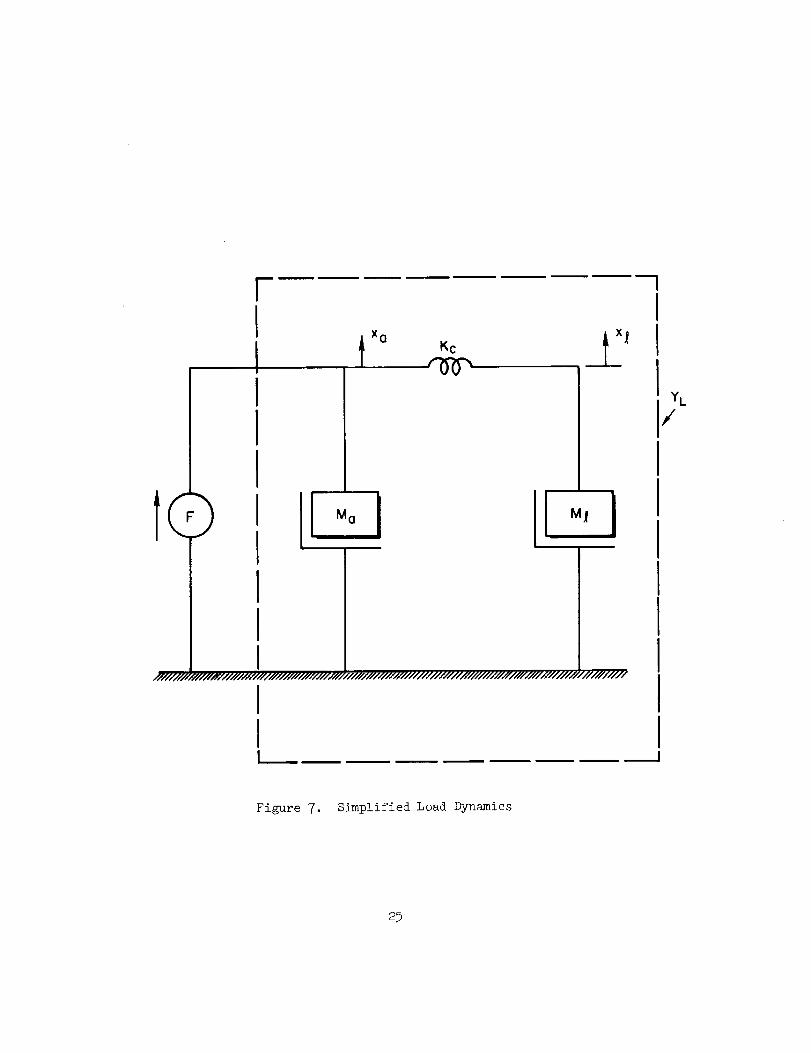
Consider now a completely rigid support structure and a set of simplified
load dynamics such as shown in Fig. 7. The coupling compliance, Kc, is the
only spring involved in this simplified situation. More generally, a spring
in parallel with the load mass, M_, would appear representing the hinge moment
gradient. This spring, however, will always be much less than typical coupling
compliance, so its effect on stability is relatively minor. The load admittance
is:
Mas 2 s2 + +
F Ma (28)YL - xa = -
Kcs2 +_
M_
24
U
I/////////
YL
i
Figure 7. Simplified Load Dynamics
25

Ordinarily, for a surface actuator the actuator mass will be much less than
the load mass, i.e., Ma_ _ << I. The lower-frequency characteristics of the
load admittance then become approximately:
YL
Kc s2&
Kcs2 +--
M
and the open-loop transfer function becomes:
K i s 2 +_X a
¢ sB a + s2 +- sM_
_ Ki
(K c + ko)S
+--
M_ +'_
I Ba (Kc/ko)s2 + _ '(1+Kc/ko) s + Kc iM_(I +Kc/k O)
(30)
00C +11l(s)22 IsI+00-U-+I
where
00c: Ki/ko : Ci/A
001 = 002 _/( 1 + Kc/ko)
002: ,/k-'_/M_,
Thus, the quadratic pair atop an ec/S characteristic again appears. The
numerator and denominator are very close together and essentially cancel
when the compressibility spring, ko, becomes infinite, thereby reducing to
the idealized case already discussed. The open- and closed-loop transfer
26

function characteristics are portrayed in conventional and Bode root locus
form in the system survey of Fig. 8. The available bandwidth is limited
to a value which will permit a finite gain margin. The gain margin in this
case is given approxlmatelyby the negative of the gain of the peak of the
Bode plot of G(j_) near the frequency _I"
In principle, since there is ordinarily some damping in the load, one
can never get an s2 + Kc/M _ numerator without some slight damping. Under such
conditions, it is theoretically possible to increase the bandwidth by increas-
ing the system gain to the extent that the denominator roots are driven back
into the stable left half plane toward the numerator zeros. This cannot
ordinarily be accomplished without exciting hlgher-frequency structural modes
or encountering limiting in the hydraulic actuator. Limiting, of course,
effectively decreases the gain and forces the roots back into the region of
instability.
The limitation of bandwidth due to the dipole emphasizes the need for
stiff actuator-to-surface compliance and effective oil spring. For many
systems these steps are sufficient. When they are not, the gain margin can
be increased by modifying the effective damping of the _I mode. This can be
accomplished in a large number of ways, the simplest being to permit more
leakage, and hence a larger Ba, at the cost of increased drain on the power
system. Relatively complicated hydraulic-mechanlcal equalization or, in the
case of electrohydraulic valves, electrical equalization can be used to alle-
viate the deleterious effects of the dipole. Closing the actuator loop using
w
a specially contrived structural llnk can also serve the same purpose.
i
"An exhaustive treatment of these and other appropriate techniques is
provided in Ref. 4.
27

I%B
Inw,o',wc "---'" Wc _| U_
-90
-180 \(ol
G = _xa .__
CifJJc =
ko
4J Kob=j2 =
,f'u==wz '1+ Kc/k °
Figur'e 8.
--,-- O'c Ig
(AJc
(b)
Rigid Support Structure, Compliant Load Coupling,
Feedback Attached to x a
28

SECTION III
SYSTEMS NUMERATOR PROBLEMS
A fundamental feature of feedback control systems is the property that
some system poles progress toward open-loop zeros as loop gains are
increased. Thus, any open-loop zeros which are present in a frequency
regime associated with high amplitude ratio of some feedback loop are close
approximations to a closed-loop mode. Ordinarily, this property is a highly
desirable attribute of feedback, for it simply indicates that a closed-loop
mode is essentially canceled by an open-loop zero-- thereby providing a
more direct correspondence between a specified system command input and
its associated output. This feature may not be so desirable, on the other
hand, if the zero being approached is in the right half plane; then an
unstable mode can be introduced ihto the closed-loop system. This unstable
mode will be hardly apparent in the motion being commanded because of the
near pole-zero cancellation in that particular closed-loop transfer function.
But the instability is there and inevitably will be a dominant feature in
some other degree of freedom where this nice near-cancellation is not
present. There are a number of interesting cases in flight control where
this phenomenon occurs. These will be exemplified in the first section
following. The most common non-minimum phase zero occurring in flight
control is probably the "performance reversal" associated with control of
altitude or rate of climb. Closely connected with the same root causes
is a less common, but nonetheless important, divergence associated with
a negative pitch attitude control zero. This is particularly insidious
when it does occur, because attitude control is an omnipresent require-
ment for almost any aircraft maneuver or steady-state situation. A third
example of the non-minimum phase zero is also associated with longitudinal
control although its effect is felt predominately in a lateral divergence.
This interesting condition occurs in some so-called "nose slice" departures
occurring in high-angle-of-attackflight.
Another circumstance in which zeros play a key role occurs when they
are intentionally introduced as desirably located "sinks" in the root
plane to be approached by root loci originating at undesirably located
29

open-loop airframe poles. This technique offers an often beneficial,
and always simple, design technique to place the poles in a desirable
location. But this may lead to very little benefit when the overall
system dynamics are viewed, because poles accompany the intentionally
introduced zeros as an offshoot of the mechanization. These additional
poles also influence the system dynamic characteristics and can negate
the intended improvement associated with the zeros. An example is given
in Subsection B.
A. N(_q-MINIMUM PHA,q_.. ZEROS
I. Altitude Control
Altitude and rate of climb are very important quantities which must
often be controlled accurately. This is accomplished by direct feedback
of the controlled variable since both altitude and rate of climb are both
very low-frequency path quantities. Any control exerted to affect them
is outer loop in nature; thus the essential features can be considered
with a simplified airframe description. An appropriate version is the
three degree-of-freedGmphugoid equations of motion of Ref. I. These are:
-Zu (s - Zw) -Uos = ZSe 5e
-Mu -_ o M8e]
(31)
With XSe neglected the altitude-to-elevator transfer function is given by:
__h = [(%J%)MS- zS][s+ (I/Tht)] (32)5e s[s2 + 2([e)pS+4]
where
2(_)p ---x_+Mu(%-_) ; _ -_ __g [zu_(%/Mw)%]M_ Uo
3o
and the zero, I/Thl is
I/ThI = -xu +( - g)(ZseMu - Ms Zu)
(Zse -(33)
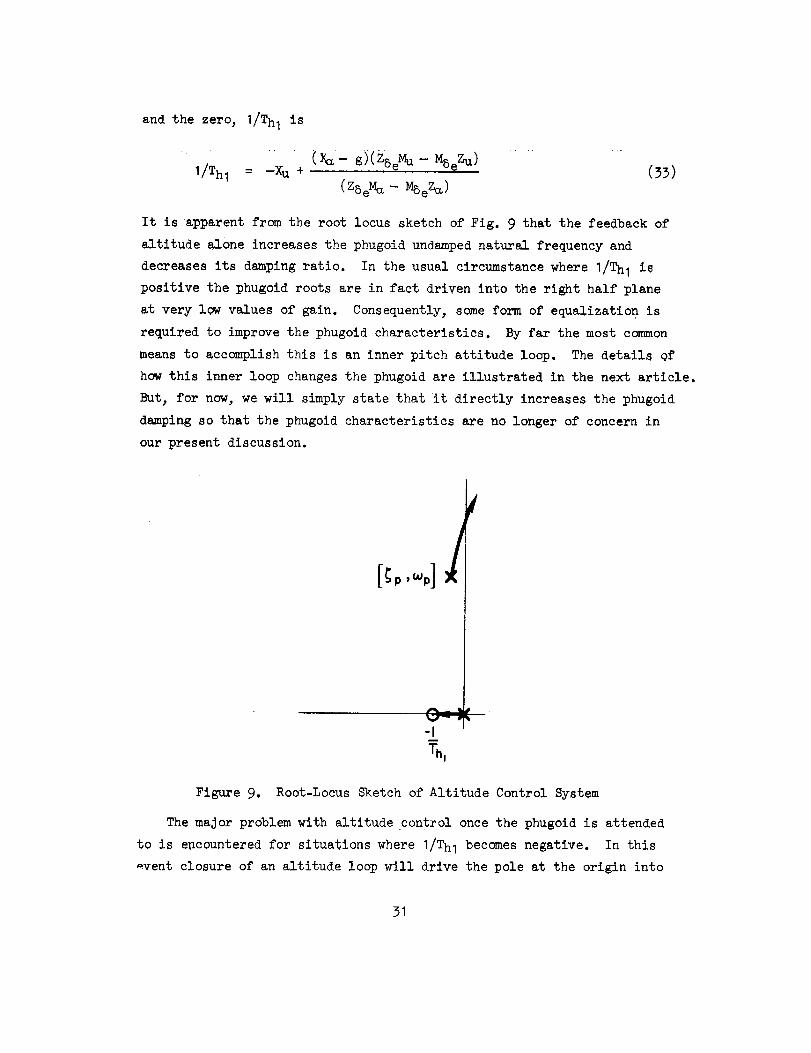
It is apparent from the root locus sketch of Fig. 9 that the feedback of
altitude alone increases the phugoid undamped natural frequency and
decreases its damping ratio. In the usual circumstance where I/Thl is
positive the phugoid roots are in fact driven into the right half plane
at very low values of gain. Consequently, some form of equalization is
required to improve the phugoid characteristics. By far the most common
means to accomplish this is an inner pitch attitude loop. The details of
how this inner loop changes the phugoid are illustrated in the next article.
But, for now, we will simply state that it directly increases the phugoid
damping so that the phugoid characteristics are no longer of concern in
our present discussion.
Figure 9. Root-Locus Sketch of Altitude Control System
The major problem with altitude control once the phugoid is attended
to is encountered for situations where I/Thl becomes negative. In this
_vent closure of an altitude loop will drive the pole at the origin into
31

the right half plane toward I/Thl. Theresult is a divergent instabilityat any value of closed-loop gain. For the typical values of altitudecontrol gain used conventionally, the pole at the origin is driven quite
close to I/Thl. Therefore, while the divergence is theoretically presentit is effectively canceledby the I/Thl zero in the closed-loop altitudetransfer function as far as any altitude commandinputs are concerned.Thusa divergence in altitude is the last thing seenin a typical negative
I/Thl situation. It is present but again only marginally indicated inthe pitch response, becausethe pitch attitude is tightly held to controlphugoid. The divergenceappearsfull blown in the speed,becausethistransfer function doesnot contain the -I/Thl zero. Eventually, of course,airspeed will slow to a point wherethe available lift is inadequate forcontrol of the flight path. In other words, the altitude (path) controlgain cannot be maintained so the divergencewill becomemoreapparent.In fact whencarried to its ultimate limit, the airplane will stall andall closed-loop control is lost.
Thekey to this situation is I/Thl. As shownin Ref. I, this canbeapproximatedby:
I _ 1d(_U ST)Th---{ (34)
It follows that I/Th I will reverse sign at that flight condition corres-
ponding to maximum excess thrust; or, if thrust variations with speed are
unimportant, at the minimum drag condition (dD/dU = 0). Or, in other
words, the zero will change sign whenever the airplane goes from the front
side to the back side of the thrust required versus speed curve. This is
a common situation on very low speed approaches, particularly on carrier
approaches. It is also encountered in steep climbs near the vehicle's
absolute ceiling, and at other situations where flight at near-minimum
drag is desirable. Since the condition coincides with one version for
maximum rate of climb, it also has implications for rate of climb systems
set up to give maximum climb rates.
32
To correct the performancereversal, the zero mustbe madepositive,thereby essentially providing for front side operation. Several possiblemeansof accomplishingthis are revealed from the literal expression for
I/Thl in Eq. 33. This showsthat modifying either X_ or X_ can eliminatethe divergence. This is conventionally accomplishedby throttle. Itshouldbe recalled that in any casea zero cannotbe modified withoutactuation of au additional control (other than the elevator, in this case).
Themaximumrate of climb difficulties associated with the performancereversal are most usually alleviated by the use of airspeed-like feedbacksto control either indicated airspeed or Machnumberto values which approxi-matethose for best climb. Feedbacksof these quantities do not sufferfrom performancereversal problems. Further, they usually do not requirecommandscheduling as a function of altitude to comequite close to bestclimb performance. Consequentlythis type of system,which sidesteps the
performancereversal, often offers a simple and adequatesolution.
2. Pitch Attitude Control Reversal
The control and regulation of the airplane's pitch attitude is perhapsthe most ubiquitous longitudinal control function. It is present inalmost all automatic flight control systemsand is furthermore the mostcommonfunction provided by the pilot in non-automatic circumstances.It is also a constituent of most morecomplexsystemssuch as the attitudecontrol andregulation systemdiscussedabove. Figure 10 showsa blockdiagramof a typical e -- 5e feedbackcontrol systemwith a pure gaincontroller. In this systemthe short period is assumedto be well enoughdamped,either inherently or via a pitch damper,to permit a pure gainclosure to be adequate. Thefigure also contains a "system survey" usingBodeand conventional root loci which showthe migration of the closed-
loop roots in their progression from the open-looppoles to the open-loopzeros and the high-gain asymptotes. Fromthe systemsurvey it canbeappreciated that the closed-loop phugoidroots are driven into close
proximity to the I/Tel and I/T82 zeros. The phugoid is in fact overdamped,andthe pitch attitude in this entire frequency range is very well controlled.This is evidencedby the closed-loop asymptotic amplitude Bodeplot con-structed for the example0 dBline. Its nearly flat properties in the
33

f
l,'
G(=)
"O
AO[' " '/TBJ[$ t liT'z] "_ i
E<[
_'P[
"'tp_
r-L
xe,%
i -1
I J-- "," :°-/"T i :'
I 0
! Ti! , e
= -9o/
._ (7" G.
-180
b) Roof Locus
0 dB line
A,ylG,,4_Z--
eI OJ=p
/- _ e(-o-)/
i
m
_, o', Jsl (log scale)
o) Bode G(Jm)o G(-o') Diagrams and Bode Roof Locus
Figure 10. System Survey of Pure Gain Pitch Attitude Control System
vicinity of the modified phugoid roots due to the essential cancellation
of the overdamped phugoid poles by the open-loop zeros, I/Tel and I/Te2 ,
indicate that the closed-loop mode will be suppressed almost completely
in the pitch attitude response to ec commands.
In the system as shown, the open-loop gain does not become infinite
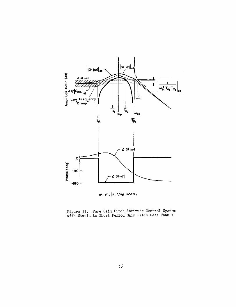
at zero frequency, and therefore the closed-loop frequency response has
an amplitude ratio slightly less than I at low frequencies. This is not
serious for the situation depicted in Fig. 10. However, at conditions
when I/Thl is near zero the static-to-short,period gain ratio, 1/_T81T82 ,
is small and the system may appear as shown in Fig. 11. When this occurs
the long-term response of the closed-loop system to commands is very poor.
As indicated graphically by the closed-loop asymptotes, there will be a
very low-frequency lead/lag and a dc gain less than unity. In the response
of 8 to a step 8c, these would correspond to a very long time constant mode
and to a steady-state position error.
For automatic pilot systems which are intended to follow comands, such
as systems with attitude-hold features, this sort of deficiency in low-
frequency gain can be made up using integral control. A pitch integrator
is added in parallel to the straight-through gain of the controller, leading
to the configuration shown in Fig. 12. The transfer function of the con-
troller is now Ks + K_/s and an integration and a lead, (Ks/s)(s +K_/Ke),
are cascaded with the open-loop function representing the dynamics of the
airplane. As shown in the amplitude ratio asymptotes for the compensated
system, the lead time constant is shown so that its breakpoint, KS/Ks, is
greater than the phugoid undamped natural frequency, thus making the low-
frequency amplitude ratio in the region of the phugold as large as feasible.
This effectively eliminates the droop and other characteristics shown in
Fig. 11. With the aid of the integral control we are thus returned to a
closed-loop situation similar to that shown in Fig. 10. In the sense of
our current emphasis, in both cases a closed-loop root is present near
I/T81.
Let us now define more precisely the aircraft characteristics which
the static-to-short period gain ratio, 1/_T81T %. This can begovern
expressed in terms of the approximate factors of Ref. I as:
35
Z
-"\""'. _ ' 2 .I I_ :e, To, dl
I Wsp
%Wp _Sp
m m
TO, Te2
4)"0
U)
¢...
CL
0
-90
-180
i
....___ 4 G(jm)
_, o" ,Isl (/og sco/e)
Figure 11. Pure Gain Pitch Attitude Control Systemwith Static-to-Short-Perlod Gain Ratio Less Than I
36

.-..1
e(s)
"°['"/_4[""*0.],I
"0
0°_
38 "
l-"E
:! _!!
'_i j,
_Sp o
- o" -90
b) Roof Locus
F _'--,I,. _ !rlo,,o,l,.\ i
:,,_.
I | _sp
K_ _L,,To Ke Tez
_ G(-o-)
_, o-, I s l (log sco/e)
o) Bode G(joJ), G(-o-) Diogroms ond Bode Roof Locus
Figure 12. System Survey of Pitch Attitude Control System with Integrator
I.
_TeIT82
[I - (ZwMq/M_)] [ZwXu- XwZu + (ZSe/MSe)(X_Mu- XuMw)].=
-(g/Uo)[Zu- (MuZw/ )]
(35)
For the simplified, but not unusual, conditions where 1 and
IZBeMwlZwMBe I << I and the Mu terms negligible, the static-to-short-period
gain ratio will become:
I =" I + _ (36)
_TeITe 2 g Zu
Thus, the magnitude of 1/_Te1Te 2 will be unity when I/Th I = 0 and less
than unity when I/Thl decreases to negative values. Consequently the
static-to-short-period gain of I occurs approximately at performance
reversal. Because near-minimum drag flight is often desirable from a
performance standpoint, flight conditions near the performance reversal
are not uncommon and, as described in the above discussion, good attitude
control is still possible under these conditions. There is, however, a
lurking specter analogous to the I/Thl performance reversal situation in
altitude control. This is the possibility that I/T81 will become negative
and thereby draw a closed-loop root into the right half plane. If Eq. 36
is solved for I/T82 it is approximately:
_j_1 _ _/_I___. (37)T81 ThI Uo ZuTS2
:__I +2Th I Uo T82
T82 is always positive in unstalled flight. Therefore, while I/T81 can
become negative if I/Th I is sufficiently large and negative, the change
in sign in the pitch characteristic will not occur until the airplane is
well on the back side. The performance regime for good pitch attitude
control with elevator is therefore wider than that for path control with
elevator alone, but a divergence can nonetheless appear when the backsidedness
38
exceedsthe safety margin given by 2(g/Uo)2T82. While a pitch attitude
divergence causedby a negative I/T81 is less likely than the associatedperformancereversal due to I/Thl , it is in manywaysmoreembarrassingbecauseof the ever-present nature of attitude control loops.
3. Coupled Lateral-Longitudinal (Non-MinimumPhase Zeros) Dynamic Effects
For high performance military aircraft at high angles of attack, it
is common for sideslip to exist either intentionally (e.g., rudder maneuver-
ing) or unintentionally (e.g., adverse aileron yaw, mistrim, etc.). The
longitudinal-lateral coupling resulting from unsymmetrical flight can
create non-minimum phase zeros in the pitch attitude numerator. These
can occur at angles of attack considerably below that for stall and at
relatively small sideslip angles. Conventional feedback of pitch attitude
or rate to elevator (either automatic or manual) then produces a coupled
longitudinal-lateral divergence known as nose slice.
As an example (Ref. 5), Fig. 13 presents a nine by nine matrix (three
body axis moments, three flight path displacements, and three Euler angle
transformation equations) for coupled, non-symmetric flight. The elements
of the matrix are obtained from the small perturbation expansion of the
complete nonlinear (inertial and aerodynamic) equations of motion in which
aerodynamic coefficients are a function of s and _. Only the most signifi-
cant off-diagonal terms are identified. Example numerical values are given
for a current operational aircraft at 19 deg m and 6 deg 8.
The major coupling associated with nose slice is provided by the terms
within the heavy borderlines. Two of these, L_ and N_, are aerodynamic
and two, _o cos s o _ Zp and 6o sin so _ Zr, are nonlinear kinematic terms.
The effect of the off-diagonal terms on pitch attitude transfer function
pole-zero locations is demonstrated in Fig. 14. Figure 14a shows a com-
pletely uncoupled six-degree-of-freedom case for reference. Here the two
lateral-directional modes (_d and _SR) have cancelling pole-zero dipoles
as would be expected. Figure 14d presents the pole-zero locations for
the completely coupled 6 DOF case which shows the poles to be little
affected by coupling, whereas a major shift occurs in zero locations.
The most significant movement is the real zero which moves into the right
half plane.
39

4=-O
(s-X u)
s + .0634]
_Zu i
Uo
[.00087]
i
-XwU o
[22.68]
(_-_'] -ii[s+ .323]%
......I.........
-._ S-Mq
[3.577] I[s+.386]' t
I -Y_
[-.0122]T
-L<_
[-3.09]
[I .486]
(s-Yv)
[s+ .1062]
!
-N_[. 1885]
,i,.
_o cos so #o sin co
[.o995 ]
ro( )
t%( )[.oo8_8]
[.0338]
-to( )
_io( )[-.oo_]
-Np
[-.o193]
-I
cos co
[.9469 ]
[-.3323]
(s-N#)[s + . 1276]
--tan 60
I [-.3396]
-g cos 8
sin _I g cos _o
I[-3.18T]I [32.o2_]
[-.I_66][-.o129]
I
t--r 0
s c°s2 eo
[.01_6]
I_'o cos 8os
![-.oi0_]i
--l
cos 80
i[-1.o56]
p
r
e- _o
e - 8o
l--ro sin O
[.oo371I
X5 e XSr
[-. 1o25 [. ®8
Z5 e
[-.o_7]
_e
[-2.92]
Y5 e Y6 r
[-.o,o37]I [.o2_]
L' L' i L'5e 5a i' 5r
[-._2] [._31].il [1._,]
T
N5 e
[._o9_]N5 a N5 r
[.031] [-.998]
b
5e
5&
F_ure 13. Matrix for Coupled Equations with B _ 0

_sp X
Wd_ _
I
Lat-Dir Pairs ,,_w-_ "'SR
®>[ /_ ,
1.0 I
- 2.0
1.0
_Up
J
I
a) 6 DOF Uncoupled
11.0
X
m
0
X_
- 2.0
.0
b) 6 DOF Coupled
but Zp=Zr=O
X
I 01.0
c) 6 DOF Coupled
but L a : Na = 0
2.0
1.0
X
0
X
1.0
- 2.0
1.0
X i
0
w
X
2.0
X
1.0
V
i.o ±
T_3d) 6 DOF Coupled e) 5 DOF Coupled
Figure 14. Survey of N_ Approximations
for _ = 18.8 deg_e# = 6 deg
4!
The influence of the individual pair of coupling terms is identified
in Figs. 14b and I_c. In Fig. 14b the Z equation off-diagonal terms are
set to zero; in Fig. 14c the L and N equation off-diagonal terms are
rmnoved. Both result in similar influences on the various zeros and
indicate these "effective" derivatives must occur in combined or multi-
plicative form in the transfer function numerator. This can be demonstrated
in a simplified model by deleting the X equation from the matrix of Fig. 13,
expanding the remaining five body equations in literal terms and obtaining
the polynomial coefficients. Approximations containing only the most
significant terms are presented in Eq. 38.
where
N85e : MSe[AS9 + Bs 4 + Cs3 + Ds2 + Es + F] (38)
A = I
B _ Zw + Lp + (Nr + Yv)
C _ Lp(Z w + Nr) - L6 sin a- LaZp
D _ -L_[(g/Uo) cos 8- (Zw + Nr) sin _] --N6(Zw+ Lp) cos
E _ l_(g/Uo) cos 8[(Zw+Nr)-- (ZSe/MSe)Mw] + Zp(L_Na-N_La)
F = -L_(g/Uo) cos 8 [NrZw]
It may be observed that the off-diagonal terms are multiplicative and
primarily influence the C and E coefficients.
As an aid in identification of the modes reflected by the poles and
zeros of Fig. I_c, the five degrees-of-freedom model is shown in Fig. 1_e.
Deletion of the X equation should eliminate the I/T81 zero and convert
the complex phugoid pole into a first-order pole at the origin. However,
Fig. 14e shows the same first order zeros as shown in Fig. 14d, i.e.,
the real axis Zeros for five degrees-of-freedom remain unchanged from the
six-degrees-of-freedom case. The complex zero previously identified as eSR
becomes, for five degrees,of-freedom, a first-order zero near the origin;
and the phugoid mode is transformed into a first-order pole at the origin.
Because the pole-zero configuration of Fig. 14e reflects coupled lateral-
longitudinal modes (compare with Fig. 14d), the real zero in the right
half plane will be identified as I/T83 since this is a uew coupled lateral-
longitudinal mode.
h2
A single-loop system-surveyfor elevator control of pitch attitudewith the six-degrees-of-freedom coupled airframe in non-symmetricalflight
is shownin Fig. 15. Thetransfer function is shownin the upper left.Theroot locus in the top right of the figure reflects root migrationsfor a pure gain closure. Note that the roots starting at _SRrapidly moveto the real axis and then split into two real roots; one of which moves
towards I/T%, the other movestowards I/Te3. Therapidity of the move-ment of these closed-loop poles towardsthe zeros is demonstratedby thesiggy-Bodeplot in the bottom half of Fig. 15. Theheavy solid and dashedlines of the Bodecorrespondto the path of the closed-loop roots alongthe real (_) axis in the root locus above. As the loop gain is increased,the complexpoles emanatingfrom _SRmeet the real axis at the apex of thesolid curve in the Bode-siggyplot. Further increase in gain movesoneclosed-loop root to a lower frequency or towards the origin while theother root movesto higher frequency and, at very high gain, asymptoticallyapproachesthe I/Te2 zero at 0.866 rad/sec. Theroot that goestoward theorigin passesinto the right half plane as shownin the root locus. Thisis represented in the Bode-siggyby the dashedline which reflects themirror imageof the closed-loop pole asymptotically approachingthe I/Te3zero at --0.3 rad. If an autopilot or pilot is to achieve effective con-
trol of pitch attitude, the loop must be closed so that the gain line liesbelow the low-frequency asymptoteof the Bodeplot. It is obvious thatthis then results in a closed-loop pole in the right half plane. If thegain "crossover" is achieved in the region of I-3 rad/sec, which coversthe range of usual "loose" to "tight" piloted pitch attitude control, itmaybe seenthat the closed-loop poles will lie very close to the open-loop zeros. For example,a unity dc gain provides a crossover between1.5 and 2.5 rad/sec and closed-loop roots at --0.28 and +0.66 rad/sec. Theresulting first-order divergence has a time constant of about 3.6 sec.
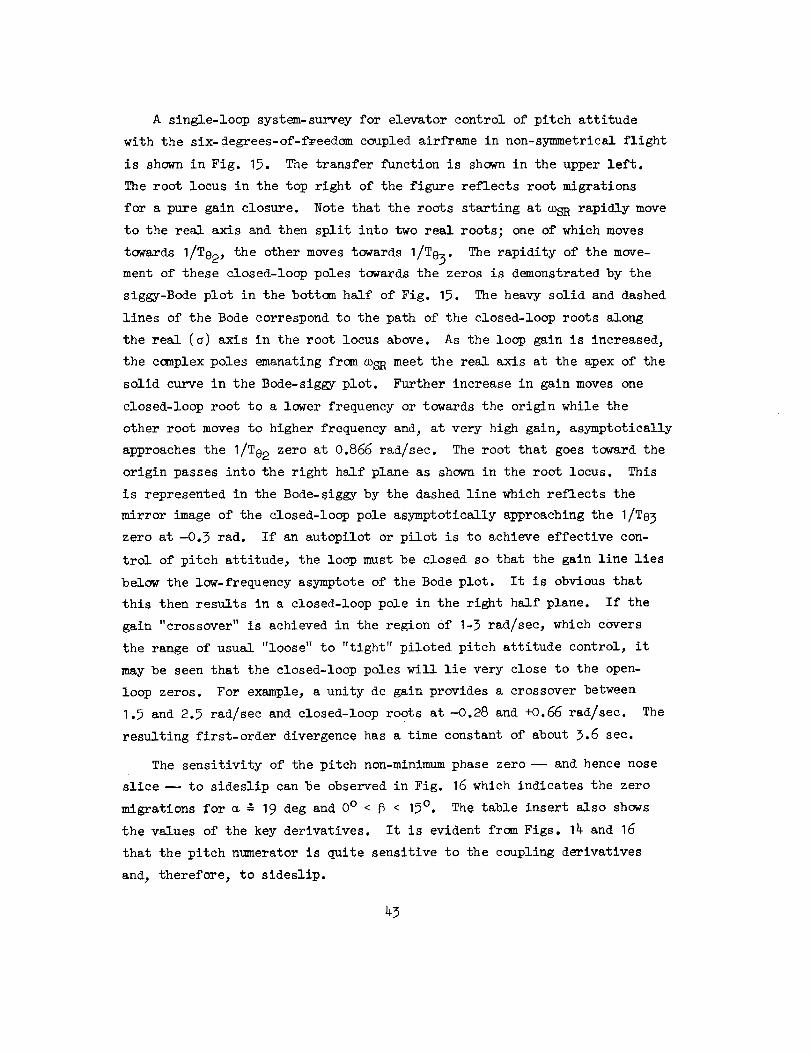
The sensitivity of the pitch non-minimumphasezero- and hencenoseslice -- to sideslip canbe observedin Fig. 16which indicates the zeromigrations for _ -" 19 deg and 0° < _ < 15°. The table insert also shows
the values of the key derivatives. It is evident from Figs. 14 and 16
that the pitch numerator is quite sensitive to the coupling derivatives
and, therefore, to sideslip.
43

I
"---K
¢/}
3
q
I
"10
3
cb
m
_.oJ
oJ oo_..LJ, ",
oo oo
re)
--- O_CO 04CO130 --.... r--.rO
i. r--.._..,
i rOco
I!
Q.
3
(/)
3
bI
e,l
qI
-Lo /3=o
jw
2.0
1.0
La Na
0 0 0
6 -3. I 1.5
15 -9.4 2.33
6 15
) Q 0 I
Zp
0
,I
.25
1.0
O"
Figure 16. Movement of 6 DOF N_e Zeros for 0 ° < _ < 15 °
_5
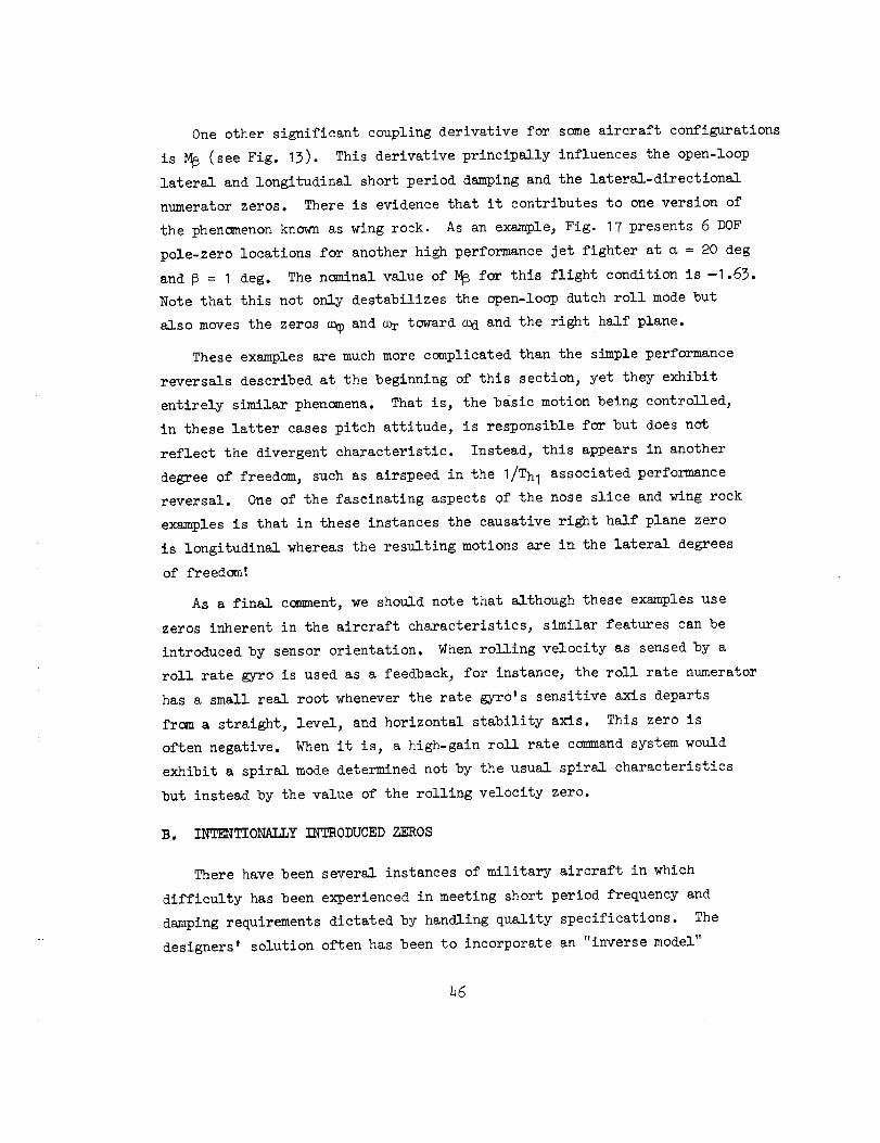
One other significant coupling derivative for some aircraft configurations
is M_ (see Fig. 13). This derivative principally influences the open-loop
lateral and longitudinal short period damping and the lateral-directional
numerator zeros. There is evidence that it contributes to one version of
the phenomenon known as wing rock. As an example, Fig. 17 presents 6 DOF
pole-zero locations for another high performance jet fighter at _ = 20 deg
and _ = I deg. The n_ninal value of M_ for this flight condition is -I .63.
Note that this not only destabilizes the open-loop dutch roll mode but
also moves the zeros a_ and _r toward O_d and the right half plane.
These examples are much more complicated than the simple performance
reversals described at the beginning of this section, yet they exhibit
entirely similar phenomena. That is, the basic motion being controlled,
in these latter cases pitch attitude, is responsible for but does not
reflect the divergent characteristic. Instead, this appears in another
degree of freedom, such as airspeed in the I/Th I associated performance
reversal. One of the fascinating aspects of the nose slice and wing rock
examples is that in these instances the causative right half plane zero
is longitudinal whereas the resulting motions are in the lateral degrees
of freedom'
As a final corsnent, we should note that although these examples use
zeros inherent in the aircraft characteristics, similar features can be
introduced by sensor orientation. When rolling velocity as sensed by a
roll rate gyro is used as a feedback, for instance, the roll rate numerator
has a small real root whenever the rate gyro's sensitive axis departs
fr_n a straight, level, and horizontal stability axis. This zero is
often negative. When it is, a high-gain roll rate command system would
exhibit a spiral mode determined not by the usual spiral characteristics
but instead by the value of the rolling velocity zero.
B. INTENTIONALLY INTRODUCED ZEROS
There have been several instances of military aircraft in which
difficulty has been experienced in meeting short period frequency and
damping requirements dictated by handling quality specifications. The
designers' solution often has been to incorporate an "inverse model"
46

M/3 = 0 M;3 = -1.63
C°sPX8
8e
CUd _)
WsPIJl
8o
COdX G
J%
r
_°dX
¢I
i _
m
(°sp X
0
X
X w d
_E)
COsp
X 0X Wd
IJ
_Osp
X oX Wd
_Wr
Figure 17. Effect of M_ on 6 DOF Poles and Zeros
(ao = 20 deg, 6o = I deg)
47

in the stability augmentorfeedbackand then to employhigh gain whichdrives the short period roots into or near the zeros of the inversemodel. The short period modethus is forced to meet the specification
requirement.
Unfortunately, whenmultiple zeros are introduced to modify onemodeit is usually necessaryto introduce accompanyingpoles, either to preventundesirable influence on modesat higher frequency than the zeros or as anoffshoot of the mechanization. Theadditional poles also influence system
dynamiccharacteristics and, from a total or equivalent systemstandpoint,can negatethe intended improvementin systemhandling qualities.
A specific exampleis presented here for illustration. Theaircrafthad a short period of considerably less than I rad/sec in someflight con-ditions and it wasdesired to increase it to greater than I rad/sec.Additional considerations, including provision of relatively constantshort period characteristics throughout the aircraft performanceenvelopeandthe use of a fixed gain pitch rate feedback, led to SASshaping of
the form
YSASKqs
(s + o.5)
WASHOUT
(s + 5) 2
(s + 1.89)(s+ 14)
_HORT PERIOD CONTROL
(39)
A survey plot for the system open and closed-loop characteristics is
presented in Fig. 18. The two zeros at 5 rad/sec introduced to attract
the short period perform as advertised. The Bode-root locus indicates
the migration of system closed loop roots as the pitch rate gain is varied.
The specific roots for a gain of Kq = 0.42 deg/deg/sec are indicated as
(_). The root migrations of major interest are those emanating from the
short period and the SAS pole I/Tsl. Notice that as _p moves to the
desired higher frequency (> I rad/sec) the SAS-introduced root rapidly
moves toward I/To2. The net result is a trade in system low frequency
lag between the two modes. Comparing the SAS off-on characteristics in
the short period region
48

_o
.422 (5)(5)(0) 20SAS = Actuator =
(14)(I.89)(.5) (20)
q 1.582(0) (.099)(.511}A/C = "_H = (.697,.775)(.048,.177)
Closed LoopRoots ore=
(.464) (.589)(15.8) (17,9)(-.011,.104)(.889,1.546)
8AS Act Phugoid ShortPer iod
,041 I i
•J t.026 r _1
-- _Op I
TO,
:1 _,.S25 J =, I,
_.S89__ _sp _2 OdB h'ne for
" ,970 " OO_/$RC
.866
_Jsp I I I
Tw°'T82 _$l _z Tsz TA
ID
0t-
90 -
0-
"90
I0.I
I I I1.0 _(rod/sec) I0.0 I00
Figure 18. Survey for Migration o,f Roots with SAS Loop Closure

B 1.58(0.51)_ASOFFm =
(0)[0.70 , 0.78]
e' I.58(0.51) (I .89)(_)SAS ON m =
8H (0)[0.89, 1.5_ ](0.59) (D_g)
The washout contribution essentially cancels but the SAS lag-lead contri-
bution is n_ very significant. The factor of three lag-lead separation
(0.6 to 1.9) introduces 30 deg of phase lag at a frequency midway between
the pole and zero.
The effect of this SAS on vehicle short period characteristics as seen
by the pilot is shown in Fig. 19. This Bode diagram indicates attitude
response for stick force input versus frequency. (The feel system contri-
butes an additional pole at 4 rad/sec and, because it contains a bobweight
loop, slightly alters the closed loop aircraft and SAS roots as may be
noted by camparing the SAS-on roots identified in Figs. 18 and 19.) The
important aspect of Fig. 19 is that there is little difference between
the SAS on and off short period handling characteristics even though the
SAS has Increased the short _erlod mode (per so) fram 0.78 to 1.55 rad/sec.
This may be further demonstrated by curve fitting the SAS-on Bode amplitude
and phase shown in Fig. 19 with a third-order short period model for the
effective airframe model. This is shown in Fig. 20. The equivalent air-
frame will appear to the pilot as a nearly critically damped short period
at 0.9 rad/sec.
Thus the effective contribution of the rather involved SAS feedback
shaping has been to increase short period damping from 0.6_ to 0.92 with
only a slight modification in frequency (frc_ 0.78 to 0.9 rad/sec). The
basic reason the desired improvement does not materialize may be traced
back to the migration of the root I/T_I in Fig. 18.
5O

k_
._ Feel FSystem
Aircraftj e
With
SAS |
SAS on
SAS off
1.76 (.511) (._(I.89)
(0) (.907, 1.404) ( .4/_1) (.712) (4.008)
1.76 (.511)
(0) (.638, .8) (4.013)
8
2O
0
-2O
-4O
_9O°
_18o°
I deg/Ib
_ .5 deg/Ib
.25 deg/Ib
I I0.1 1.0
(rad/sec)
II0.0
Figure 19. Comparison of Effective Vehicle Dynamics SAS On and Off

rn
-,.1
Q.E
I0
0
-I0
I
I'o
Actual
EquivalentIOtQItQQO •
1.76 (.511) (.5)(1.89)
(0)(.907, 1.404.) (.4-81)(.712) (4.008)
1.85 (.51")
(0)(.92, .9) (4..0)
,... -I00
Q)"0
_3¢,-
£L
-150
- 180 °
I I I.5 1.0 u) ( rad/sec) 2
Figure 20, Curve Fit of Equivalent Short Period Aircraft Dynamics
I5
SECTION IV
PROHLEMS ASSOCIATED WITH MECHANICAL FLIGHT
CONTROL SYSTEM ELEMENTS
Some situation-specific problems are not easily sorted into such
convenient bins as "quadratic dipoles". These can sometimes be con-
veniently classified into categories which emphasize their causes. In this
section, we shall be concerned with mechanical flight control elements.
These mainly involve the primary controls actuated by the pilot and certain
interfaces between the mechanical primary system and stability augmentation.
In a general framework, they are the mechanical elements of the components
enclosed within dashed lines on Fig. 21 except that very limited considera-
tion is given to the stability augmentation actuator. This and the force
feedforward are more integral with the augmentation system, per se, and
are elaborated on in the next section. To be more concrete, the major
mechanical elements to be described here are shown in the control system
schematic of Fig. 22. This layout is representative of a general longi-
tudinal control system containing bobweights as force stability augmentors
and series actuators as extensible links between the force feel package and
the surface actuator. It is also applicable to lateral, and even direc-
tional, control as an overall generalization; for while bobweights may not
be intentionally present in these systems, there is often some mass unbalance
which can amount to the same thing. Thus, by treating longitudinal control,
the other axes are covered by analogy.
In the following articles, dynamic models for each segment in the schematic
diagram of Fig. 22 are developed and discussed as to their past or potential
problem areas or points deserving of special attention by the designer.
A. ARTIFICIAL FEEL SYSTEM INPUT/0UTPJT CHARACTERISTICS
The stick input/output properties of the artificial feel system are derived
from the combination of spring, mass, damper, friction, etc., elements in the
control system. Figure 23 shows both linear and nonlinear models of these.
For the stick force/displacement characteristics considered here, the bob-
weights and other massive elements contribute to a net inertia, IT; the effects
of the bobweights as a force stability augmentor are the subject of a later
53

Human
Pilot
PilotForce
Output
.._ ForceFeed forward
t 1I
Manipulatorsand
Linkages
Displacement J Surface
Output ___-IActuat°rs
Motion I
StabilityAugmentorActuator
Control
Surface • ]Deflection
III
_ II
II
Vechicle I
Dynam_ cs !
MotionStability J
Augmentor _ --Sensor and JEqualizationl
Equivalent Vehicle, Stick - FixedI
tForce1StabilityAugmentors
Vehicle
Equivalent Vehicle,Stick-Free and Active Control
Motion
Figure 21. Pilot-vehicle Control System

(_ Stick Grip
Forward _ f
Damper Damper
Spring (Cs)CKs)
_. Series
<-_op.... .,.
Figure 22. Control System Schematic

Fs' 8sr __IT
c,l[I
LINEAR MODEL
KI. I , KLz_ Linkage Springiness
FL =_Linkage Friction
Fv _Valve Friction
NON-LINEAR MODEL
Figure 23. Detailed Characteristics of Typical
Artifical Feel System
article. The various springs provide for: feel forces as appropriate
functions of stick deflection; preload; stick centering; bobweight balance;
etc. The linkage compliance itself is small (stiffness very large) so the
constant KLI can be lumped with KB, and KL2 can be considered rigid in an
analysis which emphasizes low-frequency behavior.
In good design practice the nonlinearities, linkage, and valve friction
are minimized, and the control system characteristics approach those of the
linear model shown on the left in Fig. 23. In the discussions below this
linear system will be treated first, followed by a consideration of the more
important nonlinear aspects.
1. Linear I_namicl
The transfer function relating stick displacement to stick force can be
derived from equations based on Fig. 23. It is:
_sT R_ (_+ Ks/Cs)
- ( K_ _2 KB+Ks _Ks) (4o)FS IT S3+ _ss + I_ S + ITC---_
This can ordinarily be factored approximately in literal form as:
56
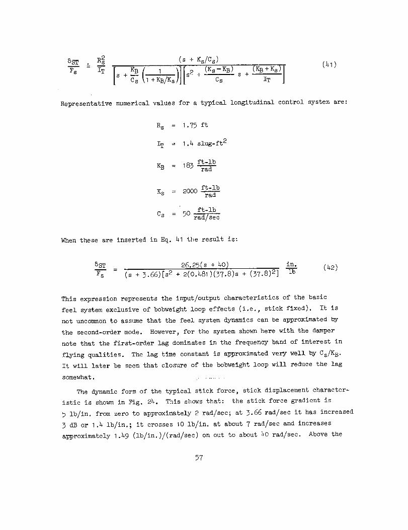
8sT R_ (s + _s/Cs)
;s "-IT [S+--Cs_B ( I)111+KB/Ks s2+_(Ks-K_)Css+ (KB+_s)lIT (41)
Representative numerical values for a typical longitudinal control system are:
Rs = I.75 ft
IT = 1.4 slug-ft 2
ft-lbKB : 183
ft-lbK s = 2000 ra-'---d--
ft-lb
Cs = 50_
When these are inserted in Eq. 41 the result is:
5s_x= 26.25(s+ 40) in. (42)Fs (s + 3.66)[s 2 + 2(0.481)(37.8)s + (37.8) 2 ] ib
This expression represents the input/output characteristics of the basic
feel system exclusive of bobweight loop effects (i.e., stick fixed). It is
not uncommon to assume that the feel system dynamics can be approximated by
the second-order mode. However_ for the system shown here with the damper
note that the first-order lag dominates in the frequency band of interest in
flying qualities. The lag time constant is approximated very well by Cs/K B.
It will later be seen that closure of the bobweight loop will reduce the lag
somewhat.
The dynamic form of the typical stick force, stick displacement character-
istic is shown in Fig. 24. This shows that: the stick force gradient is
5 lb/in, from zero to approximately 2 rad/sec; at 3.66 rad/sec it has increased
3 dB or 1.4 lb/in.; it crosses 10 lb/in, at about 7 rad/sec and increases
approximately 1.49 (lb/in.)/(rad/sec) on out to about 40 rad/sec. Above the
57

IO0
I0
m
IK_ dB
Cs (1+
OdB //ne
/
,_. KB+ KSIT
K s
CS
KB
CS( I+KB/K s)
I I I1.0 I0.0 I00
_u( rad/sec)
Figure 22. Dynamic Characteristics, Feel System
combined first- and second-order breaks near 20 rad/sec the gradient increases
as the square of angular rate. Thus, the feel system causes the pilot to use
more force for a given stick deflection (work harder) if he tries to close
loops above I to 2 rad/sec. At the same time s viewed in terms of a pilot
force input to the system, the feel system introduces a good deal of lag.
In fact, at low frequencies the feel system can be approximated by a constant
and pure delay, i.e., a linear phase shift with frequency:
J
5S-_T" ' _ < Cs (_3)Fs
_8
This delay can adversely affect either the autopilot or pilot/vehlcle system
stability and performance.
Possible means of improving the situation can be deduced from Fig. 2_.
Decreasing Cs will directly reduce the effective delay and increase the
first-order lag break frequency and damping of the second order. The plot
shows that decreasing Cs moves the flrst-order lag to higher frequencies,
but this is partially offset by the second-order becoming critically damped
and hence contributing more phase lag at the lower-frequency region of interest.
If Cs is reduced sufficiently, the feel system dynamics do become dominated by
the second-order mode in the frequency bandwidth of interest.
The feel system d.c. gain and both second-order terms in the transfer
fUnction shown in Fig. 25 are directly affected by changes in feel _pring
(KB). A stiff spring moves the second-order contribution to higher frequency
but also increases the stick force. The second orders can also be moved to
higher frequency by decreasing the control system inertia. This has the
additional benefit of not increasing steady-state stick force.
When the feel system is considered as a series link in the pilot/vehicle
or autopilot system, its lags would ideally be made as small as possible.
This implies that the damping, Cs, also be minimized. On the other hand,
some aircraft designs place great reliance on force stability au_nentation
with dual or single bobwelghts. These, together with the other elements in
the mechanical system, increase the system inertia and hence reduce the
undamped natural frequency of the second-order characteristic. Because the
value of the feel spring; KB, is fairly tightly constrained by flying quall-
ties requirements, the primary means for keeping the mechanical control system
from undue oscillation when actuated by pilot inputs is the damper. But, as
seen above, this has its inevitable consequence in increasing the low-frequency
lag. Thus, it is apparent that control systems having large inertia (heavy
bobweights) and low minimum feel spring gradients must be very carefully
designed for proper interface operation with the autopilot and pilot.
_9

Iy = m
Cs s(,2+ IT
"rT = 1.4 K s = 183
Rs = 1.75 K s = 2000
o_o
KB+Ks jw'_' : IT ,40
5O
,,,2=
3O
2O
IO0 _ _.229
Io -'-p_'o.316
I "156
2O
I I I I I2 5 I0 20 50
w ( rod/sec )
Figure 25. Survey of Feel System Poles with Change in Damping, C s
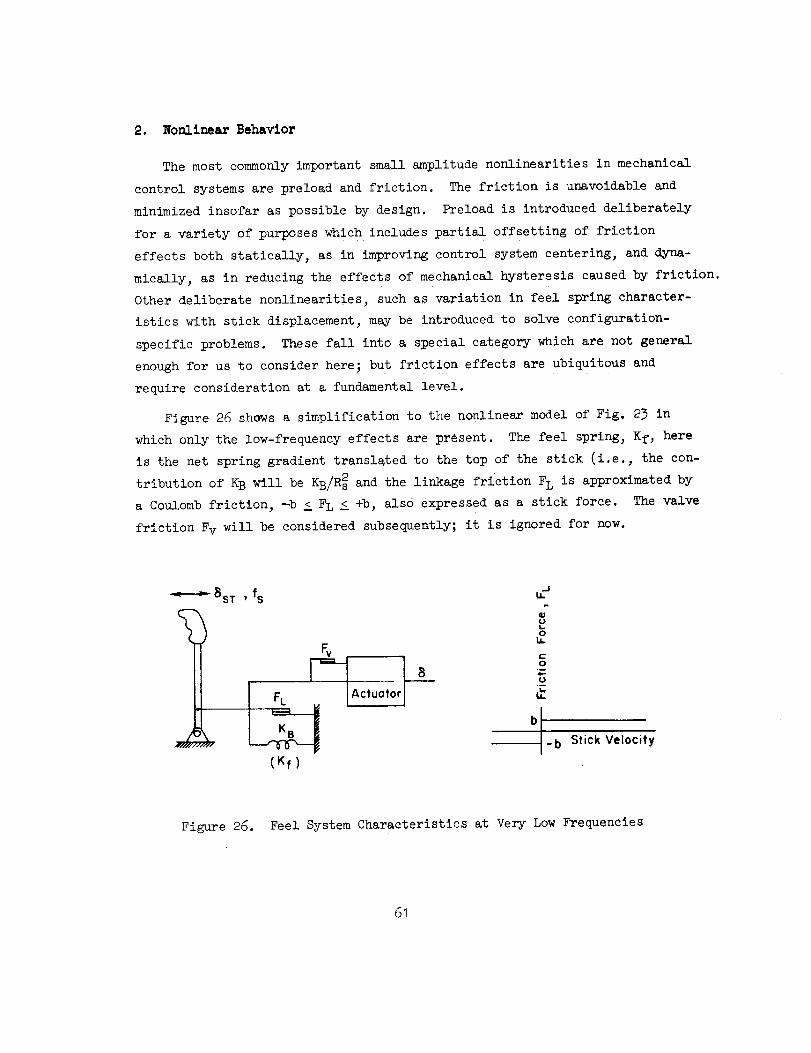
2. Nonlinear Behavior
The most commonly important small amplitude nonlinearities in mechanical
control systems are preload and friction. The friction is unavoidable and
minimized insofar as possible by design. Preload is introduced deliberately
for a variety of purposes which includes partial offsetting of friction
effects both statically, as in improving control system centering, and dyna-
mically, as in reducing the effects of mechanical hysteresis caused by friction.
Other deliberate nonlinearities, such as variation in feel spring character-
istics with stick displacement, may be introduced to solve configuration-
specific problems. These fall into a special category which are not general
enough for us to consider here; but friction effects are ubiquitous and
require consideration at a fundamental level.
Figure 26 shows a simplification to the nonlinear model of Fig. 23 in
which only the low-frequency effects are present. The feel spring, Kf, here
is the net spring gradient translated to the top of the stick (i.e., the con-
tribution of KB will be KB/Rs2 and the linkage friction FL is approximated by
a Coulomb friction, --b < FL <_+b, also expressed as a stick force. The valve
friction Fv will be considered subsequently; it is ignored for now.
BST ' fs u'_
IM
% u.
t "J FL Actuator
K_B b I-b Stick Velocity
(Kf)
Figure 26. Feel System Characteristics at Very Low Frequencies
61

If a sinusoidal stick force, fs = Fs sin et, is applied, typical waveformsof the forces andmotion will be as shownin Fig. 27. Thelinkage will not
begin to moveuntil fs > b, the Coulombfriction force. Thereafter, thedeflection of the feel spring will be (fs-b)/Kf. After fs reaches its maxi-mumvalue, Fs, and begins to decrease, the linkage will again stand still as
the friction force which always opposes motion builds up in the opposite
direction until the magnitude of the spring force, (KfSST)max, exceeds Fs + b.
With F s now decreasing further the linkage will move in the negative 5ST
direction until Fs reaches its maximum negative value, at which polntthe
linkage Will again stand still. In terms of a transfer characteristic between
the stick force, fs, and the linkage deflection, 5ST , this motion is accounted
for by the hysteresis loop shown in Fig. 28.
O
O
f$
I/-K-7 b
,I/,
Kf
I \ [ -" II=,,.=,,.o,J..!i / /,
_'_ '_:.-'_ sticking-I I
t
Figure 27. Waveforms in Artificial FeelSystem with Friction
62

_ST
0
Z4
T_2
Ii
StickForce
0 3T
StickDisplacement
Figure 28. Mechanical Hysteresis Due to CoulombFriction and Feel Spring
63

The sinusoidal describing function between 5ST and fs is well known
(e.g., Ref. 6). It can be expressed as:
8ST u 2 I
_s = tan-1
where
3_ _ sin--1 u + u_ - u22
; when u = 0 take sin-I u =
A graphical representation of this describing function is presented on the
gain-phase plane as a negative inverse in Fig. 29. It indicates that the
ordinary 0 dB, -180 deg phase _, which for non-minimum phase systems
must be avoided to assure stability, is now a rather significant se6ment of
the gain phase plane.
It may be desirable at this point to review the interpretation of the
negative inverse describing function on the galn-phase plane as it is used
to determine the possibility of a sustained oscillation. In a manner similar
to the basic stability condition which underlies the theory of constant coeffi-
cient linear systems, the fundamental condition for stationary oscillations in
a quasi-linear closed-loop system can be formulated as:
I + _ = 0 or _B = -I (47)
where _ and _ are the forward path and feedback path transfer or describing
functions, respectively. Now, if any part of either _ or 6 is the describing
function of a nonlinearity, N, and the remainder of the open-loop frequency
response function is the linear term, G(j_), the stability condition is:
NG(J_) = -I or G(j_) = -I/N (46)
64

FRICTION and EQUALPRELOAD
2b-- = .90qFs
Io =0.!
HYSTERESIS Fs
b
Kf=l
0.(
0.5
Phase Angle, Negative Inverse Describing Function, (deg)
-140 -12_0I I
0.2 0.3 04
I Load_'fc
I Backlash 1 Oriv'ng II b L = Mmb/( Mm-l" M L)
Figure 29 l_.'_verse Describi_]g Function for Hysteresis, Friction and Preload, an'.i Backlash

Equation _6 indicates that if G(J_) and -I_ are plotted together on the
gain-phase plane, intersections of the two curves will satisfy the equation.
Intersections, therefore, will show the conditions for neutral oscillatory in-
stability. In general, -I/N is an amplitude and frequency variant function,
whereas G(J_) varies only with frequency. The values of the amplitude and
frequency parameters at an intersection of the G(J_) and -I/N curves give
the amplitude and frequency of the oscillation or limit cycle. This inter-
section is the critical point analogous to the point -I + jO in the conventional
polar diagram analysis of linear control systems or, in the gain-phase _lane,
the point 0 dB and -180 deg phase angle. In this sense, the negative inverse
describing function can be viewed as creating a critical region as an expansion
of the critical point for linear systems. When a goodly region of the gain-
phase plane is covered thereby, it is not uncommon to have several intersections
of the linear locus with --I/N. Not all of these indicate stable limit cycles
but as a practical matter all are to be avoided. Describing function analysis
is an approximate procedure and can lead to inaccurate predictions when its
implicit assumptions do not parallel those actually present. Nonetheless, it
is an extraordinarily powerful and effective technique in practical engineering
and nowhere has been more bengficially and extensively used than in flight
control system design and analysis. For more details see Refs° 6, 7, and 8.
From this discussion it is apparent that the locus of the open-loop transfer
function of either an autopilot or pilot-plus-vehicle system should avoid inter-
section with this inverse describing function to be assured of stability. As a
practical matter_ close approach gives warning of degraded closed-loop character-
istics of a wandering-about, driftlike behavior. If gains required for control
and stabilization purposes are so high as to actually cause an intersection with
the inverse describing function, a limit cycle in the automatic system or a PIO
under manual control can occur.
To reduce the change of dynamic problems of this character, the control
system can be preloaded. This has the effect of shifting the hysteresis loop
with a consequent marked attenuation and phase reduction in the describing
function_ as ca_ be seen by comparing the hysteresis describing function with
that for friction with equal preload (Fig. 29). A much smaller proportion
of the gain-phase plane now constitutes a forbidden area, so the likelihood
66

of any closed-loop system oscillation from this cause becomes much less.
This comparison indicates that not only is the preload useful for the purpose
of returning the stick for a centered position but also beneficial in terms
of dynamic stability.
The artificial feel system can contain other deleterious nonlinearities
in unusual circumstances. For example, backlash can occasionally be present
if a system is improperly rigged or if backlash preloading forces are exceeded.
The backlash inverse describing function is much worse than that of hysteresis.
As seen in Fig. 29, it in fact is almost impossible to avoid by amy reasonable
open-loop system transfer function locus. When backlash plus friction are con-
sidered together this becomes less serious, although the limiting case is that
for hysteresis (see Ref. 6 for more details). While in this instance friction
is beneficial_ it should be emphasized that it also contributes to control
system phase lag which is detrimental to closed-loop pilot-vehicle performance.
Excessive control system friction can cause the pilot to operate as a posi-
tional rather than force controller and hence increase his phase lag. Thus
friction should be kept to a minimum.
The location of the principal friction contributors within the control
system can also have a strong influence on the consequences. When located
in the control system cables or push rods it can have the beneficial (limited)
influence noted above. However_ if located in the hydraulic actuator input
valve it can have very strong negative effects. This will be discussed in
the next subsection.
The final nonlinearity to be mentioned here is stick-to-surface gearing.
A common type of gearing is shown in Fig. 30. Here, the stick-to-surface
gain increases as the horizontal tail deflection moves more trailing edge up
(TEU). The gradient is nearly constant over the range of horizontal surface
deflections required to trim the aircraft throughout the flight envelope. This
gradient is selected to provide "good" control sensitivity for small stick
deflections about trim (i.e., to provide low sensitivity in this region).
However, for maneuvering requiring nearly full surface deflection, the gain
between stick and surface is rapidly increased to prevent excessive stick
deflection requirements.
67

.24 t
f--
.12 I
.08
__1 I i l I I I I
+4 0 -4 -8 -12 116 -20 -24 -28
(TED) Horizontal Tail Deflection, 8.(deg) (TEU)
Figure 30. Stick-to-Tail Gearing Versus Tail Deflection
B. ACTUATION DYNAMICS
Some of the more important linear dynamics of electrohydraulic and
hydraulic actuation systems have been described in Section II. Although this
emphasized actuator stability, the need for an adequate backup support struc-
ture was also mentioned. With stability augmentation installations in parti-
cular, the backup can be very tricky. Ideally, the series-installed actuator
will move the surface actuator input without feeding back in any way to the
stick. This requires the load as seen by the series servo looking toward
the surface to be much less than that looking toward the pilot. Detents,
system friction, preload, favorable mechanical advantages, and minimum series-
servo-to-surfacelactuator loads are elements in the compromises needed to
68
attain a satisfactory SASinstallation. It is also important that the SASlimiting velocity be tailored to be consistent with that of the surfaceactuators so that surface actuator valve bottoming does not lead to seriesservo kickback to the cockpit controls. This characteristic canbe almostinevitable whenthe surface actuators are holding substantial trim loads
near the actuator stall. Under these circumstances, the surface ratesattainable from the surface actuators are muchless than maximum,whereasthe stability augmentorlimiting velocity is unaffected by the hinge moments.Consequently, full rate is still available to the SASservo, while the surfaceactuator rate is muchreduced. Although these practical design matters arefairly obvious and generally recognized, they have typically beenindependentlydiscovered by newdesigners. At best, they tax design ingenuity to achieve asatisfactory compromise.
The series actuator backupproblem in somesystemsis so difficult as torequire alternative solutions. Oneconceptwhich has other favorable proper-ties is the use of a fully-powered hydraulic actuator inboard (on the pilot'sside) of the series connection. This serves to isolate the series and surfaceactuators and all downstreamfriction and other nonlinearities from the cock-
pit controls. Themajor disadvantageis the increased complexity. Otherapproachesare to feed forward, as in Fig. 21, a signal proportional todesired control action. This provides commandaugmentationas well as analternate pathwaywhich canbe used to offset someof series servo lostmotion due to a soft backup. This type of systemis inevitably highlycalibrated on an individual basis and is seldomsatisfactory except for
experimental installations. Perhapsthe ultimate solution to backupproblemsis to accomplishthe series summingelectrically, as iu a fly-by-wlre system.Then, of course, the SASactuators are full authority andmultiply redundant,leading to a different kind of flight control systemwith compromisesofits o_m. Again, the subject of commandaugmentationwill be elaborateduponin Section V.
An important feature of any mechanicalinput hydraulic servo installationis the effect of valve friction on other elementsof the system. This parti-cular friction is of a different category than that distributed along themechanicallinkages in that it is affected by the hydraulic systemfeedbacks.This is shownby the schematicdiagramof Fig. 31. To emphasizethe majoreffects introduced by this peculiar friction force, the feel systemis
69

StickForce
fs L ,_
sgn function
Feel
SpringHydraulic Servo
xi
Figure 31. Block Diagram- Aircraft Control Systemwith Valve Friction
represented only by the feel spring; and inertias, other frictional forces,
dampers, etc., are neglected.
On a simple physical basis, we would expect that the friction at the
outset of motion would act similarly to that normally in control linkages,
but its position within the hydraulic servo feedback tends to maintain a
valve error once this is established. Consequently, the servo will tend
to go further and continue moving for a longer time than it would if the
friction were not present. Qualitatively, then, the presence of the friction
would be expected to increase the gain and lag of the hydraulic actuator as
seen from outside this loop. Both of these features could be inimical to auto-
pilot or human pilot control activity, resulting in limit cycles or PIO's,
re spe ctlye ly.
The nonlinear properties of the actuation system cum valve friction which
relate to periodic behavior are conveuiently haudled with describing function
analyses. An appropriate describing function for this case has been derived
(Ref. 8) a'_._, is g_ven by;
7O

X o
fs
I
4Ff\ .+ _-_UlT3_ + I
(_7)
Notice that, as anticipated by the qualitative physics, the closed-loop sinu-
soidal describing function shows both gain and time constant are augmented
by the factor (I + 4Ff/_Fs).
The actuator plus vaive friction characteristics are shown in a gain
_ phase plo_ as a negative inverse describing function in Fig. 32. It is
important to recognize that the describing function is frequency-dependent.
This means that intersections with the negative inverse describing function
of the transfer function locus for the remaining elements in the loop must
match in amplitude, phase, au_d frequency if an oscillation is to be present.
It is apparent from Fig. 32 that the 0 dB, -180 deg criterion point for
stability of the linear system is enormously extended by the valve friction
effect. The nonlinearity represented by this type of describing function
is thus very inimical to stability, particularly if the actuator time con-
staut is fairly large or valve friction excessive. Indeed, the need to
eliminate these effects as contributors to a serious stability problem is
a major incentive in design efforts to minimize valve friction and actuator
time constant.
C. BOBWEIGHT EFFECTS
Many mechanical control systems have unavoidable or deliberately introduced
bobweight elements. The situation shown in Fig. 22 is fairly general in that
both fore and aft bobweights are present. For the illustrative longitudinal
case, these alter stick force characteristics as a function of normal and pitch-
ing accelerations. These two bobweight feedback loops are represented in the
Fig. 33 block diagram as a single path. The single equivalent loop is obtained
by solving the following expression for bobweight stick force:
F = BN(a z) = BN(azcg + _@)
= BNazcg + B_@
(48)
71
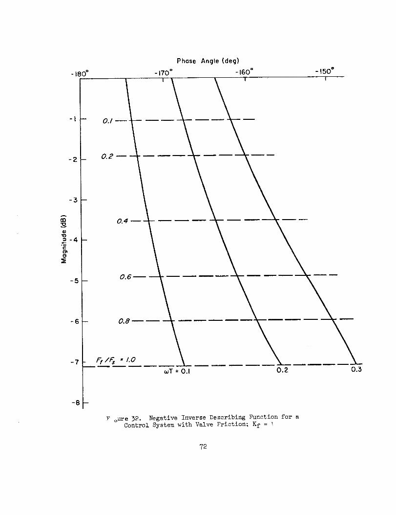
- 180°
-I
-'2
-3
l]3
4.}
:3- 4
"Eo2
-5
-6
-7
F oure 32. Negative Inverse Describing Function for aControl System with Valve Friction; Kf = I
72

I Bobweight I _
t.N
r
Feel I-_ GearingSystem
8H_,_ Surface
- T_ I Actuator,
I_HsAs
AirframeOz
azB is the normal acceleration at the effective bobweight moment arm
Figure 33. Block Diagram of Longitudinal Control System
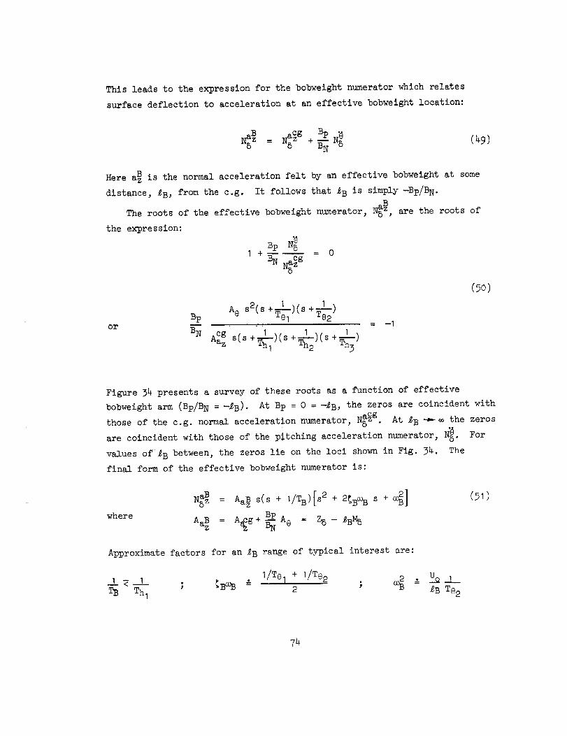
This leads to the expression for the bobweight numerator which relates
surface deflection to acceleration at an effective bobwelght location:
Bp .(49)
Here a_ is the normal acceleration felt by an effective bobweight at some
distance, _B, from the c.g. It follows that _B is simply -Bp/BN.
The roots of the effective bobweight numerator, _5_, are the roots of
the expression:
or
Bp
BN
Bp N_I + = 0
B__sCzg
% s2(s+_)(s +I-L-)Te2
A_gz s(s+ )(s+ )(s %3
= --I
(_o)
Figure 34 presents a survey of these roots as a function of effective
bobweight arm (Bp/B N = --_B)- At Bp = 0 =--_B, the zeros are coincident with
those of the c.g. normal acceleration numerator, N__g. At _B -_'_ the zeros
are coincident with those of the pitching acceleration numerator, N_. For
values of _B between, the zeros lie on the loci shown in Fig. 34. The
final form of the effective bobweight numerator is:
where
NSaBz = AaB z S(S + I/TB)[S2 + 2_BC_B S + _]
BpAaB = A_g+ _ A6 = Z5 - _BM5
(_1)
Approximate factors for an _B range of typical interest are:
../_1 _'1 ; _Ba,,B & 1/Tel + 1/Te2 • Uo.J--.TB Thl 2 ; o._ = _B Te 2
74

-.1L_
41
2O
6
i/Te, • t/Tez
7
8
I0
2O
15
Ae sz
A:_ ,/T.=VT..
A
I I I0,1 1.0 I0.0
-o', = (rod/sec)
OdB for
FigtLre 3_. Root Survey for N_aB = N_5_g -- _B_

Numeratorroot values for a fighter aircraft with an effective bobweight
armof 92 ft are identified in Fig. 34. It canbe seenthat I/TB = I/Thlover a considerable range of _. Over most of this range the short-periodequations offer a valid approximation to the principal bobweight effects.Theseare subsumedhere in the second-orderzeros which approachthe vehicle
short-perlod dynamicsin the numerical example.
Ignoring stick breakout force (or assumingthe stick is displaced from
trim), the bobweightcontribution to stick force dynamicsfor a representa-tive case canbe obtained from the loop closure of Fig. 39. Here, theairplane dynamicsare representedby the short period alone. Theshort-period poles and the complexbobweight zeros, while typical, havebeenarbitrarily selected for demonstrationpurposes. Theratio of bobweightzeros to short period, a_/_sp, shownhere as greater than one is usuallyclose to unity• It can, in general, be either greater or less than unity.This is yet another exampleof the quadratic dipole situation discussedat
length in Section II.
Twomajor contributions of the bobweight loop maybe noted. First, thelow-frequency root of the feel system(at 3.66 rad/sec) is movedto a higher
frequency (identified as I/_I). Thus, the bobweight loop tends to reducethe low-frequency lag contribution of the feel system. Secondly, the short-
period roots are driven toward the bobweightcomplexzeros. If weassume:
• (_ + _ + Zw)I = -zw ; _sp_p = - 2
Te 2
{]_L_ 2 = -- 2
it is readily seen that closure of this type of bobweight loop always results
in decreased stick-free short-period damping. Taken to the extreme, i.e.,
_sp driven into _B, the bobweight can cancel out that portion of the short-
period damping due to Mq and M_.
There are factors which can aggravate this situation. The first is
increasing separation between _B and rasp when _B/esp > I. In this case
the root locus betwen _sp and _B tends to blossom out toward the right half
76

Artificial Feel
Bobwt i'"26.2_(40) I ieoring_.l__. LL.J _F(,,_) _
-_. l_o_I -I(,,_,)(_._) I" {(3.665) (.481,57.76) I
--.1
_1 .. I_-4 I -3
T_I
I
_ Mq + M_ + Z w ISTICK2
/FIXED
I -20 -
-40_ -I
ws0
jOJ _ O"
IK)
OdB for
L
\
I
WFIWF
Figure 32. Bobwaight Loop Closure
plane and the closed-loop short-period damping is reduced more rapidly for
the same loop gain. A second is the introduction of lag in the region of
of the short period which also contributes to the blossoming. This can be
due to I/_FI (the open-loop feel system pole) or by introduction of low
frequency lags due to system nonlinearities (hysteresis). Either is dem-
onstrated by the loci of Fig. 36. Note particularly the blossoming that
results as the lag inverse time constant moves from 10 to 2._. If this
inverse lag is thought of as the artificial feel contribution, a potential
detrimental interaction between the feel and bobweight systems becomes
obvious.
If aB/esp < I, the locus between them rotates counterclockwise so that
the closed-loop short-period damping tends to increase. While this may be
beneficial at times, it must be noted that the effective short-perlod fre-
quency is decreased simultaneously and this could be quite undesirable at
times.
In sun_nary, closure of the bobweight loop will either increase the
effective airframe short-period frequency at the cost of reduced damping
or increase the short-period damping at a cost of reduced frequency. The
interaction between the feel system first-order lag and the bobweight loop
is such as to increase ]/TF'I (and hence decrease the low-frequency lag con-
tribution of the feel systems), but to decrease the closed-loop short-perlod
damping. Any nonlinearities iu this control loop will also tend to reduce
the closed-loop short-period damping. Finally, it should be noted that
friction and stiction in the bobweight system can cause the effective short-
period dynamics to "jump" from the stick-fixed to stick-free values.
78

K [s_+2(.25)(5)s,,S2]
(J/TLAG)[S2+ 2(.6)(4)S+42]
E)
I_ 1 I3 I 2 I
TLAG
-6
-5
-4
-3
-2
-I
O"
Figure 36. Effect of Increasing Control System Lags
on Bobweight Loop Closure
?9
SECTION V
AUGMENTATION AND STABILIZATION SYST_ PROBL]_S
The previous section emphasized the predominantly mechanical aspects
of the flight control system. These elements are always turned on in normal
operation, and usually constitute the irreducible complete chain from pilot
to surface. Accordingly, this collection of components is often called the
primary flight control system. They constitute the milieu for the remaining
flight control system elements which are predominantly automatic in nature
and primarily feedback in character. These additional flight controls may
provide damping, stability, or feel augmentation and other automatic control
activities such as autopilot and command augmentation. Because their signal
and equalization circuits are electronic, and thus highly flexible and versa-
tile, these augmentation and stabilization systems offer great appeal as
devices to modify and manipulate the controlled element characteristics and
to accomplish other functions otherwise impossible to perform. Thus, they
offer many promises. On the other hand, augmentation and stabilization
systems also possess great potential for problems because they are integra-
tive --and therebymust interface with the previously discussed mechanical
control system, extensive sensor complexes and the pilot, and must react
properly in conjunction with a highly variable response vehicle. Such inte-
gration is intrinsically synonymous with complexity. For example, Fig. 37
is a generic block diagram elaboration of Fig. 21 which shows the many inter-
facing elements possible in a Command Augmentation System (CAS) --as many as
six interactive loops. Depending on the specific aircraft installation these
elements may encompass parallel but non-identical pathways, multiple feedback
loops, series and parallel actuators, coupling with the aircraft control feel
and trim systems, etc. Figure 37 also shows the location and type of some of
the more troublesome nonlinearities -- friction, preload, threshold, limit,
etc. These many factors will be discussed in this section. Major considera-
tion will be given those augmentation and stabilization systems which provide
both electrical and mechanical control parallel pathways from stick to sur-
face. There are two reasons for this emphasis on command-type systems. First,
the mechanization is more complex than a direct-wire electrical backup path
8O

03
/
,' LOOP; NO. 3
rI
Free Play, I Free Play,
Friction _ion Friction
/ '_ --_--/Aotuator/---_
\
Prelood LO0_4Friction
J Spring t Parallel __
IDor"per I Tr_m I _-
E._OOP NO, 5Bias
Displacement .i.
Sensing
a C
Farce
_. Sensing Jv
Limiting Saturation
ies
Co___mptlone_._._e
Bernoulli Force Limlt
1I
I
I
I
IIII
Gust I
Forces Rate Limit Disturbances ISeries Servo .... " Position Limit [ I ....
AuthOrity rncnon, _ t . _lglaI Threshold _, I 2ody and
,LA_'G( y _ _ _ f--'L-- 1 J _'lexlbility
.-1 _-"LJ ....... L-J Su,_oce L-J s_r_ce I d ..... I I Motions''l T-I "_"_ l-]Actuatori--'] Load_ .... °_Fr-----I__, _----_ _---_ _---_ _,So u otic,
t-1 _;" h_ I F---q ! coup,o_1' eta. ',
i ('-OOpNO.2 ',
Bias, Threshold,L imif,Hysteresis
Adoptive
Gain ChangeLogic and /
Computer J
IIIII
_.J
..... Mechanical Path
-- Electrical Path
Figure 37. Generic Block Diagram for Command Augmentation Systems

(fly-by-wire system) and therefore has morepotential problemareas. Second,although fly-by-wlre control will becomemorecommonin the future, parallelmechanlcal-electrical CASdesigns are currently predominantand will be forsometime. However,it should be noted that total fly-by-wire mechanizations
generally will have "direct wire" stlck-to-surface-actuator backupmodesandthus will also be prone to problemsassociated with dissimilar parallel paths.
Thetypes of commandinsertion (input) and actuation (output) employedfor the augmentation scheme will be discussed as the first topic. These CAS-
mechanical control system interfaces are one of the central factors in command
augmentation mechanization. Thre____einput sensing and fou___ractuation concepts
are covered. These afford twelve potential system mechanizations. Rather than
discuss each of these in detail, we shall divide the presentation on the basis
of the four actuation schemes and make the command sensing a subset of these.
Command augmentation requires large effective actuation authority for the
concept to be viable. The two most common means of achieving this are with
full authorit_ series positional servos or with limited authority series servos
plus large authorit7 parallel actuators. Full authority series is discussed
first. The limited authority series mechanization is then presented with fur-
ther breakdown as to p_allel trim versus parallel boost actuation considera-
tions. The fourth concept encompasses forward loop integration within the
large authority series actuation means (otherwise known as velocity servos,
automatic series trim, neutral speed stability actuation, etc.).
The three fundamental types of input command sensing covered are those
Force directly at the pilot level input (stick force).
Displacement of the force feel element (pseudo stick
force).
c. Displacement of the pilot lever input (stick displace-
ment).
The attributes of these are discussed most fully in conjunction with the fUll
authority positional series actuation and are not carried into the other
*It should be noted that augmentation actuation functions may be provided
by separate servos as reflected in Fig. 22 or incorporated into the basic sur-face actuator package via a multi-input scheme. In general, the conceptual
problems are similar although the detail aspects may vary somewhat.
that sense:
a.
b.
82
actuation schemesexcept as specifically altered by the actuation concept.This discussion of the three commandsensing types within the frameworkof
the four actuation schemesis a major part of the section becauseof' themanyinherent problemsrequiring coverage.
Attention is next turned to preshaplng of the electrical commandpriorto differencing it with the feedbacksignal. Twoforms of shapingareconsidered: lag (or low bandpass)and nonlinear gain.
Thelast article in the section is devotedto feedbacksensor related
considerations including location and orientation problems (gravity vectorand aircraft responseaxis), influence of nonlinearities, and interactionof feedback, command,and actuation. Examplemechanizationsare also shown.This presentation is separatedinto separate discussions of each axis(longitudinal, lateral, and directional). Intentional coupling of lateral-directional motion, e.g., turn coordination, is not coveredhere but is thesubject of Section VI.
The last article also briefly touches on problemsrelated to the inter-action of high-gain feedbacksystemsand structural bending. Structural
feedbackand resonancehas afflicted almost every high-gain system. Although
structural modes are estimated as closely as possible, considerable cut and
try generally has been required on the first few flights to finalize struc-
tural filter characteristics -- sometimes resulting in different filter
characteristics for ground and flight operations.
A. CO_U_D IN_TION/AOTUATION_SYST_C0M_I2_ATION8
Because CAS are integrations of many flight control subsystems they share
the problems of their component elements. Nowhere is this connection more
pervasive than with the actuation --the final common pathway of all flight
control system action. We have already covered generally some features of
actuators in previous sections, particularly dynamic stability, interfaces
with load and backup structure, and some nonlinear aspects. Some of these
features will be reiterated here in a more specific context. This repetition
is inevitable as we proceed from general to specific considerations if coverage
is to be reasonably complete.
83
Thetwo basic types of actuation systeminstallations are referre_ toas series and parallel. Series actuation results in control surface motionwithout motion at the control stick, whereasa parallel servo actuator movessurface and stick alike. It is desirable and commonpractice to isolate
high-frequency signals from the control stick; hence, a SASused for dampingaugmentationis accomplishedby series-type actuation. Conversely, paralleloperation is conventionally used for autopilot control of path, speed,andposition and is often employedfor control stick steering as well. Parallelactuation provides a direct indication of operation andthus from a safetystandpoint provides the advantageof giving the pilot a meansfor monitoring
the system.
As introduced previously, an extremely important characteristic of CASisthe needfor high authority servo actuators to accommodatelarge commandinputsas well as SASoperation. To avoid position limiting, most CASsystemsprovideservo authority which approachesfull surface deflection. This complicates the
problemof aircraft safety in the event of a systemhardovermalfunction. Therehavebeen several approachesto hardoverprotection. Themost commontechniquefor series actuators is limitation of actuator authority to commandsurfacedeflections sufficiently small to prevent structural damagein the event offailure. This restricted authority series servo is then used in conjunctionwith an automatic trim systemwhich increases the low-frequency surface author-ity to full deflection. Another schemewhich is becomingpopular in actuationsystemfail safety is dual, triple, or quadredundancy. Yet another methodisto employparallel servoswhich provide the pilot direct indication of servo
output and canbe overridden by the pilot.
The special systemcomponentproblemsassociatedwith redundancy,failuremonitoring, etc., are highly mechanization-specific. Theyare peculiar toparticular designs rather than generalizable to systemsas a whole. Conse-quently, these will not be coveredhere. Wewill discuss, however, someofthe fundamentalsystemproblemswhich canbe and havebeenencounteredwhenthe large authority, redundant servos are functioning as intended.
84

1. Full Authority Series Actuation
Figure 38 shows a typical full authority series actuation system. As
noted in Sections II and IV, for this system to function properly the mechani-
cal impedance between the series actuator and the control stick must be much
greater than that between the series actuator and the surface actuator valve.
The backup impedance needed to act as a "ground" for the series actuator is
provided by the feel system force breakout and spring gradient. In the
absence of any free play between the series actuator and its ground, all
motion of the actuator is transmitted to the surface actuator valve. The
major forces with which the series actuator must contend are surface actuator
valve friction, centering, and Bernoulli forces. If these are high, the
backup forces needed may become excessive; then a separate power boost or
fully-powered actuator may be incorporated between the series actuator and
surface actuator.
If the surface actuator valve is "bottomed" (comes in contact with the
actuator case) by the summed mechanical and series servo inputs, the impe-
dance at the surface actuator valve becomes infinite and any subsequent series
_en$ol"
Zl F- --1,Follow i
I up ,
Bobwe,ght t,'_r_'_'f'_r I :
_--_/_ Full Authority
F'e_ISprl_._.s Actuator Series Actuator$ur face
Actuator
Figure 38. Full Authority Series Actuation
85

actuator deflection will be transmitted back to the stick. As noted previously,this "kickback" will occur whenthe actuator rates are incompatible, whensufficient surface actuator valve travel is not available to accommodatefullstick travel (mechanical link) plus full series actuator travel, etc. Thishas beenparticularly troublesomein aircraft which employthe samecontrolsurfaces for pitch and roll control (e.g., elevons or rolling tail), becausethe combinedinputs of partial roll and pitch stick candrive one surface toits limit while the other is still functional.
Most of the other characteristics of the full authority CASseriesactuation are related to the type andlocation of the pilot input sensorused for the electrical path. This will be discussednext, classified asStick Force, PseudoStick Force, or Stick Displacement, as appropriate forthe sensor.
a. Stick Force
Figure 38 indicates a stick force sensor which detects stress due to
forces (direct or reaction) applied at any point on the stick above the
sensor location. This type of sensor is attractive for systems in which
it is desired to provide essentially invariant stick force per g character-
istics. The interaction of this sensing technique with the other elements
of the control system has also created several potential problem areas as
follows.
I) Feel System. Feel system integrity is a prime concern if this type
sensing is to provide redundant stick-to-surface paths. If the mechanical
link between the stick and feel spring is broken, both control paths are lost
because there is no ground for the force sensor. Thus, to minimize the number
of vulnerable parts and connections, the feel spring should be located as near
to the stick as possible and the series servo as near to the power actuator
as possible. On the other hand, if the mechanical link between the feel system
and the series actuator is broken, both control paths are also lost because
there is no backup for the series actuator.
In this same vein, the feel system (or stick) spring gradients should be
selected to provide proper harmony between stick displacement, stick force, and
86

electrical output from the force sensor. A single gradient which achieves a
satisfactory balance between stick displacements for gross maneuvering (large
stick amplitude) and for precise control (small stick amplitude) conditions
is hard enough to obtain without the complications added by the force sensor.
The familiar effective stick force breakout characteristic associated
with the normal center stick is eliminated and/or replaced by entirely dif-
ferent characteristics which derive from friction forces within the stick/
feel-system mechanism. It is common to incorporate an electrical threshold
on the electrical force signal to match the ideal mechanical breakout (detent)
threshold. The actual breakout characteristic as sensed by the force trans-
ducer is composed of the following elements sketched in Fig. 39. The friction
Force
Detent
Preload
DisplQcement
Force
- Stiction
Coulomb
Friction
Velocity
Figure 39. Breakout Characteristics
components can (and do) vary widely with production tolerances and with field
usage (wear, corrosion, dirt, etc.); these v_riations are largely beyond the
control of the systems designer. The stiction component results in a signi-
ficant initial impulse or "dropback" characteristic at the series servo output
(and hence power actuator) which can drastically affect control precision in
the _mall stick deflection region (i,e. I formation flying, aerial refuelling,
etc.). If the electrical threshold is set sufficiently high to acco_odate
the stiction component, then problems arise because mechanical surface deflec-
tion occurs before the electrical response is commanded. Since the latter
actually commands a specific aircraft motion response dependent upon the CAS
feedback employed, this can result in effective control reversal in the small
stick deflection area.
87

Poor stick centering characteristics dueto friction and freeplaybetweenthe stick and feel springs (or within the detent) are improvedby
the preload, although they are relatively insignificant since the forcesensor is unaffected by stick neutral position. Freeplay by itself is atemporarylack of groundand no poweractuator commandis generated througheither the electrical or mechanicalpaths.
2) Trim System. It is very difficult for the pilot manually to trim
stick force to zero via the feel trim actuator with this type sensor. If
the pilot applies force to achieve a desired trim surface position and then
actuates the feel trim motor to neutralize stick force, the series actuator
retracts to neutral as stick force reduces and hence the surface deflection
reduces. A constant stick movement which creates a series actuator movement
equal and opposite to the trim motion is therefore required while trimming
off the force in order to replace the retracting servo displacement with
mechanical link displacement and hence retain constant surface position.
This generally results in imprecise trial and error trimming and is greatly
disliked by pilots. An alternative method is to introduce the trim command
both to the feel trim actuator and, summed with the force sensor output, to
the series servo such that the motion of one exactly cancels the motion of
the other. This method is sensitive to production tolerances, wear, etc.,
on the trim motor rate.
Another method is to accomplish trimming via the series servo alone;
however, this also introduces several problems. First, stick neutral is
always at the same position regardless of flight condition. This destroys
the relationship between stick position and surface position and hence
removes a cue of vital importance to the pilot in maneuvering, landing, etc.
Additionally# if the pilot attempts to trim off forces in, for example, a
high g windup turn, he can be moving the stick forward while increasing the
load factor. This is undesirable_ to say the least. Finally, in the event
the CAS cycles off for any reason (e.g., electrical power failure, redun-
dant voting, etc.), the series trim is instantly lost and can provide
dangerous, if not catastrophic, results. When used, this latter mechaniza-
tion has often required the CAS to be turned off for approach and landing.
88

3) Kickback. If stick kickback is encountered, the stick force against
the pilot's hand decreases and thus calls for decreased series servo deflec-
tion and a reduction in demand at the power actuator valve. The resulting
motion may immediately jerk the stick from the pilot's hand or may cause a
high-frequency "ratcheting" of the stick against his hand. This is most
often encountered while the aircraft is on the ground but could be catas-
trophic if encountered in flight.
4) Bobweight Effects. Control system bobweight effects can be inten-
tional to augment feel forces or unintentional due to mass imbalance in the
control system (which almost always occurs to some extent at some trim con-
ditions even if the control system is carefully mass-balanced). The inten-
tional bobweight alters feel forces by increasing the force/displacement
ratio as a function of load factor when the stick is out of the neutral
position. Any bobweight contribution is sensed by the force transducer and
transmitted to the augmentation system. The results depend upon the aircraft
response (acceleration or attitude rate) feedback employed but, in general,
the command will be for increased aircraft response via the series servo, will
result in stick force lightening, and may provide a tendency to overcontrol.
Inadvertent mass imbalance can be either harmful or beneficial. Except
for special situations such as catapult launch or massive control columns
in climb or dive, mass balance is not usually considered to be important.
However, a force-sensing CAS amplifies control system imbalance effects and
can become crucial. The problem is quite difficult to avoid because the
control system has distributed mass which is acted upon by a non-uniform
force field (i.e., rotational and translational accelerations) dependent
upon location of the masses within the aircraft and the initiating cause
(stick input, gust disturbance, catapult, etc.). Any imbalance forces which
reflect back to the pilot's hand will then be picked up by t,_ CAS command
sensor and cause immediate control surface deflection via the CAS.
As an example of the complexity of the problem, assume the control stick
has appreciable mass above the pivot point and the control system has been
mass balanced to zero stick force per g with the stick at the mid position
of its travel. However, in flight the force neutral (trim) stick position
can be forward (high speed) or aft (low speed) of the mid position and a
89
net moment arm may be present. The electrical signal obtained from the result-
ing action of the stick imbalance against the pilot's hand is stabilizing for
the stick trimmed aft and destabilizing for the stick tri_ued forward.
Bobweight effects of the pilot's arm also can be significant in creating
unwanted inputs. This is especially true under high acceleration or decelera-
tion situations such as catapult launch from aircraft carriers. The CAS of
some Navy aircraft are generally turned off during launch for this specific
reason. This same feature can cause severe bottoming of servos, surface
actuators, etc., during hard landings, carrier arrestments, etc.
5) Structur&_ Bendix. Structural bending can modify the mechanical
path length between the stick and power actuator. Like the series actuator,
the effects of the resulting system inputs depend upon the effective control
system impedances at the input locations. For a system with the feel package
near the stick, any relative motion between the control run and structure
should result in power actuator valve motion rather than stick motion. Thus,
there should be no output from the force sensor (against the pilot's hand as
ground). Conversely, if the feel package is located near the power actuator,
the impedance looking toward the stick can be low so that any differential
motion is reflected into stick deflection. In this case, a force signal can
be developed against the pilot's hand.
6) Tranad_cer Null. With this type of sensing, the transducer null (zero
force output) is independent of any other elements of the control system.
Therefore, once adjusted, it should require no further trimming.
7) 0n/Off Tranelents. The electrical path shown in Fig. 38 will provide
series servo transients upon system engagement only if stick force is applied
simultaneously. Disengagement transients can occur if either stick force or
series trim is being used at the time of disengagement.
8) Tranaducer Vulnerability. A stick force sensor located near the top
of the control stick is particularly vulnerable to damage and/or incorrect
installation. The sensor is subject to damage resulting from various mainten-
ance activities within the cockpit. A sensor which is integral with the stick
grip is also vulnerable to specific maintenance actions involving any of the
many switches mounted within the grip. Each removal and reinstallatlon, for
9O
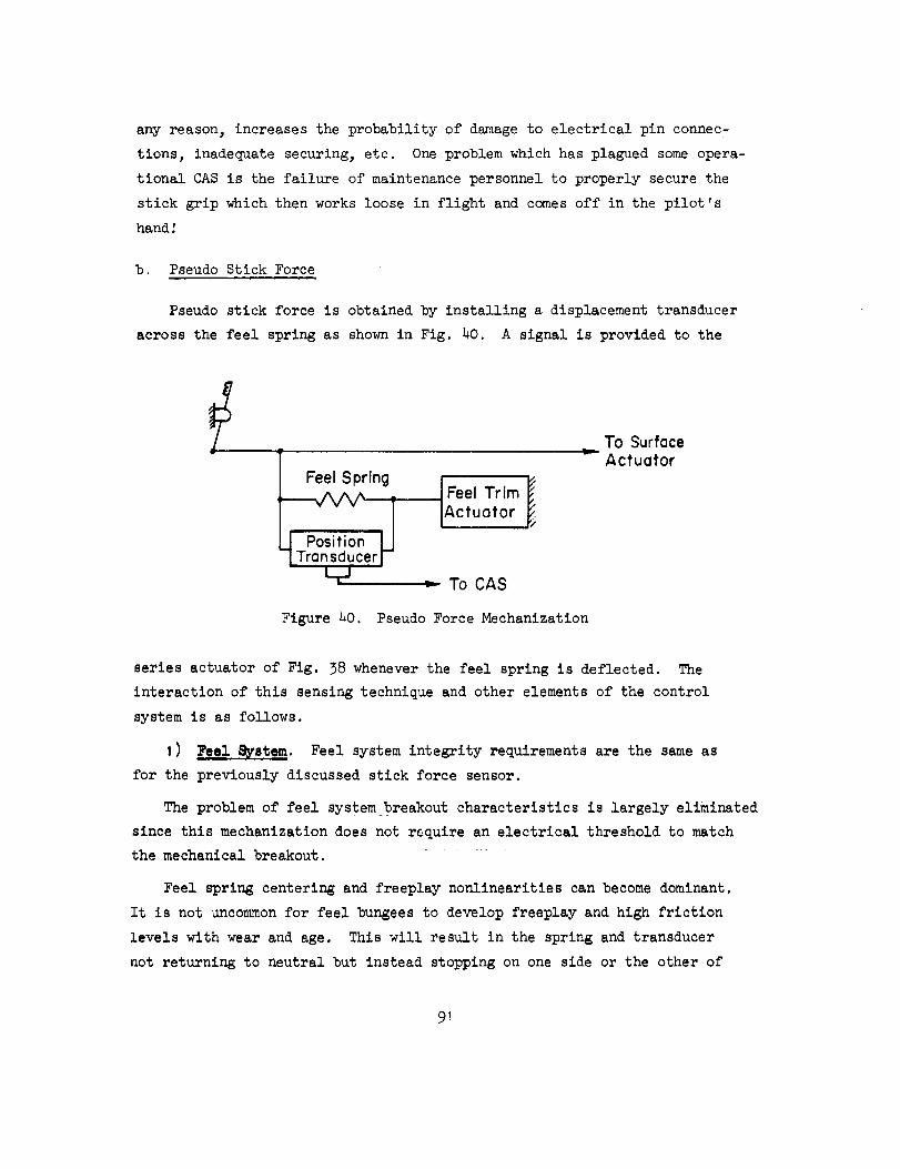
any reason, increases the probability of damageto electrical pin connec-tions, inadequatesecuring, etc. Oneproblemwhichhas plagued someopera-tional CASis the failure of maintenancepersonnel to properly secure thestick grip which then works loose in flight and comesoff in the pilot'shandl
b. Pseudo Stick Force
Pseudo stick force is obtained by installing a displacement transducer
across the feel spring as shown in Fig. 40. A signal is provided to the
Feel Spring
Position _
Transducer I--
LrJ
! Feel Trim
IActuatOr I
_-" To CAS
L
Figure 20. Pseudo Force Mechanization
To SurfaceActuator
series actuator of Fig. 38 whenever the feel spring is deflected. The
interaction of this sensing technique and other elements of the control
system is as follows.
I) _. Feel system integrity requirements are the same as
for the previously discussed stick force sensor.
The problem of feel system breakout characteristics is largely eliminated
since this mechanization does not require an electrical threshold to match
the mechanical breakout.
Feel spring centering and freeplay nonlinearities can become dominant.
It is not uncommon for feel bungeesto develop freeplay and high friction
levels with wear and age. This will result in the spring and transducer
not returning to neutral but instead stopping on one side or the other of
91

the freeplay. Thus, the transducer will have a bias (zero force at stick)output with magnitudedependentuponthe mechanicalsystemfreeplay andfriction level and with sign dependentuponthe direction of the last stick
input. Since the transducer commandsaircraft motion responsevia theseries servo, these nonlinearities in the feel systemcan result in impre-cise control in the small stick deflection region and in trimming.
2) Trlm System. Manual trim of stick force to zero via the feel trim
actuator is subject to the same problems previously discussed for the stick
force sensor.
3) Kickback. With this installation, kickback can cause the feel
spring deflection to increase (over that initially commanded by the pilot)
which, in turn, drives the series servo even harder. Thus, this system is
divergent and, once started, will tend to drive the stick/feel-system to
their stops unless alleviated by surface actuator movement sufficient to
"unground" the surface actuator valve. The effect of kickback can be
reversed if direction reversing links are judiciously employed in the
control system.
) Bobwei ht Effects. Intentional longitudinal bobweight activity is
designed to increase stick force by introducing a moment to return the stick
toward neutral. This has no effect on the pseudo-force transducer unless the
feel spring is actually deflected (toward neutral position). In the latter
case, the signal to the series actuator commands retraction which, in turn,
decreases the maneuver command. Thus, both the mechanical and CAS paths
increase stick force per g.
If the control stick or column has appreciable mass this system can also
be sensitive to trim stick position. However, it makes little difference
whether the stick is trimmed forward or aft of neutral since in either case
the bobweight effect of the stick mass and the pilot's arm inertia will be
in a direction to increase feel spring and transducer deflections.
) Structural Bendix. Structural bending effects should be nil since
this sensor is located across the highest impedance component.
6 ) Transducer Null. Transducer null depends upon installation adjustment
which generally will be non-zero. This null is further affected by feel system
centering characteristics noted previously.
92

7 ) On/Off Tr&nalents. These are the same as for the stick force sensor.
8 ) Trannducer Vulnerability. The sensor is generally located in an
area which has little maintenance "traffic" and is well protected from inad-
vertent damage.
c. Stick Displacement
Stick displacement can be sensed by transducers located in any number of
places within the control system. However, minimization of control system
nonlinear effects generally dictates locating the sensor such that it is pre-
loaded to eliminate as many nonlinearities as possible. One such location
is across the feel system as shown in Fig. 41. The interaction of this
sensing technique and other elements of the control system is as follows.
_ To Surfoce
Spring
VVV
Position
Transducer
Fee ITrim
Actuator
To CAS
r
Actuator
Figure 41. Control System Displacement Sensing
I) Feel System. Feel system integrity requirements for the installation
shown are the same as previously discussed. However, the sensor can be located
(e.g., directly from the stick to ground) such that mechanical integrity
between the stick and the feel system is not required and hence the mechanical
and electrical paths to the surface actuator are independent and, therefore,
redundant.
This system also does not require an electrical threshold to match the
mechanical breakout characteristics because there is no electrical output
until the breakout is exceeded.
93

Feel spring centering and freeplay nonlinearity effects are the sameaswith the pseudoforce sensing except that nowthose acting betweenthe springand ground throughthe trim actuator are also involved.
_) Trlm _atem. Manual trim of stick force to zero via the feel trim
actuator is considerably eased with this mechanization since the actuator
only relieves spring loading and does not change control linkage displacement
relative to ground. Thus, the pilot can hold the desired stick position and
trim forces to zero at this position. If the pilot operates the trim without
force applied to the stick, the trim actuator moves the entire control system
including the stick command sensor and hence commands series servo motion
(or CAS response) consistent with the direction of trim.
This mechanization is not compatible with introduction of separate,
large trim signals to the CAS, since the latter will change the neutral posi-
tion relationship between the stick (and stick transducer) and the surface.
Small separate trim inputs can be inserted directly to the series serv%
however, to offset stick position sensor bias, lack of centering, etc.
3) Kickback. The results of kickback are the same as with pseudo force
sensing, i.e., can be favorable or divergent depending upon the usage of
reversing links in the control system.
4) Bobwei_ht Effects. Bobweight effects are the same as for the
pseudo force sensor system.
_) BtructuralBendln_. Structural bending effects are nll if the sensor
is located across the high impedance feel package.
6) Tranmducer Null. Transducer null effects are the same as for the
pseudo force sensor installation.
7) On/Off Transienta. Engage or disengage transients are only obtained
if the system is turned on or off while holding stick deflection from force
neutral.
8) Transducer Vulnerability. Same as for pseudo force sensor.
94
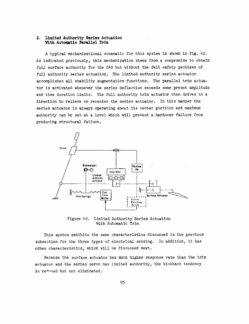
2. Limited Authority Series ActuationWith Automatic Parallel Trim
A typical mechanizational schematic for this system is shown in Fig. 42.
As indicated previously, this mechanization stems from a compromise to obtain
full surface authority for the CAS but without the fail safety problems of
full authority series actuation. The limited authority series actuator
accomplishes all stability augmentationfunctions. The parallel trim actua-
tor is activated whenever the series deflection exceeds some preset amplitude
and time duration limits. The full authority trim actuator then drives in a
direction to relieve or recenter the series actuator. In this manner the
series actuator is always operating about its center position and maximum
authority can be set at a level which will prevent a hardover failure from
producing structural failure.
ror_e U -- -
Figure 42. Limited Authority Series Actuation
With Automatic Trim
This system exhibits the same characteristics discussed in the previous
subsection for the three types of electrical sensing. In addition 3 it has
other characteristics, which will be discussed next.
Because the surface actuator has much higher response rate than the trim
actuator and the series servo has limited authority, the kickback tendency
is replaced but not eliminated.
95

Thecenter detecting switch unit musthave a significant threshold aboutseries actuator neutral to prevent undesirable chattering of the feel trim
actuator.
During large extendedmaneuversthe systemwill attempt automatically totrim feel forces to zero. If maneuverforces are held in one direction foran extendedperiod the stick force required will decreaseas the trim systemtakes over commandof the surface position. This results in stick forcelightening in maneuverswhich canbe objectionable to the pilot. In addition,to return the surface to its initial, pre-maneuver,position, an opposite
force must be applied to the stick until the trim actuator returns to its
previous position. Thus, the pilot cannot establish a trim point, maneuver
away from the trim point momentarily, and then just re].ax stick force to
return to the trim condition. Instead, he must constantly "drive" the trim
system via stick force. This:
• Increases pilot workload.
• Makes precise control difficult.
• Is especially objectionable at low q conditions where
large surface (and hence stick) deflections are required
for maneuvering.
• Makes stall and spin recovery more awkward.
The degree to which the above properties lead to control difficulties
depends on trim actuator rate. The higher the trim rate, the greater the
degradation in handling characteristics. Thus, a compromise in rate must
be made between sufficiently high to prevent series servo bottoming and
sufficiently low to prevent handling quality degradation.
The conflict between the pilot and the trim actuator can be reduced by
incorporating a switching logic which disables the automatic trim during
pilot-commanded maneuvers. However, this also removes the ability to trim
stick force to zero at the pilot's discretion unless manual trim (via stick
trim button) is also provided during such stick commands. This introduces
the trim problems noted in the previous section In addition, if the pilot
attempts to use manual trimwithout deflecting the stick, the automatic trim
will cancel the manual trim.
96

Finally, a small authority (easily saturated) series actuator with a
large authority parallel autotrim gives the same result as command augmen-
tation mechanized using parallel actuation alone.
_. Limited Authority Series andParallel Actuation
A typical schematic for this type of mechanization is shown in Fig. 43.
The limited authority series servo provides the high-frequency stability aug-
mentation functions (damping, disturbance suppression, etc. ). The parallel
actuator provides the necessary authority to accommodate path control modes
(i.e., autopilot control wheel steering, hold functions, etc.) and/or serves
as a power boost for pilot stick or column inputs.
j_ SAS
/ Com,¢s,cnd
..... i/' FA--fg_'d _ie, 7 , ,A--P'[f|er I ,
_/ _ -----F-_ - _77 !-- J_ __.IL]_-]
_. _ [ A]:_J]_ lie[ Ac _ or Series Actuator _______x j__
__J.__,x v .. Surface Actuetor
Figure 43. Full Authority Parallel and Surface Actuators With
Limited Authority Series Actuator and Trim
Since the parallel actuator provides a rigid link to ground until it is
overpowered, it acts as a very large mechanical preload or detent. Thus,
position sensing is ineffective and true force sensing at the stick or column
must be employed. The resulting force feel depends upon the ratio of feel
system spring gradient, the parallel actuator spring gradient, and the
electrical gain between the force sensor and the parallel actuator.
97
Although the parallel actuator is generally considered to have full
surface authority, in reality it may not. The actuator output power is
ordinarily limited so the pilot can overpower it in an emergency. In
moving the entire control system, the actuator works against the feel
springs, the power actuator valve forces, and other mechanical system
friction, inertia, etc. Therefore, when the sum of these forces equals
the parallel actuator overpower limit, it stalls and its surface authority
is thereby limited. The authority is thus set by the pilot overpower
limit. Another result of this limiting is that the actuator dynamics
change as it approaches stall if the force limit is accomplished within
the actuator itself instead of by virtue of an external clutch, bellville
spring, or similar force-transmission limiting device. This introduces
additional phase lag in the forward path for large pilot (or autopilot)
coumuanded maneuvers.
The above force limiting effect can be reduced by incorporating an auto-
matic crossfeed from the parallel actuator output to the trim actuator which
operates to relieve feel system forces. However, this requires a fast trim
rate to prevent the trim actuator from getting out of phase with the parallel
actuator in large maneuvers and hence actually increasin_ the load on the
parallel actuator. This is the same problem as Just discussed for pilot/
automatic trim opposition in large maneuvers. Another possibility is to use
the trim actuator as the parallel actuator and hence reduce system complexity.
In this instance, the stick force sensor signal is used to drive the trim
actuator. Unfortunately, the pilot cannot overpower the trim actuator, and
the actuator rates required then create a safety problem in the event of a
runaway trim actuator.
Additional control system interface considerations include:
a) Feel S_stem. This system mechanization can retain completecontrol function even if the links between the parallel
actuator and the feel system are broken. In this case, the
feel system remains ground for the force sensor while the
parallel actuator functions as ground for the series actua-
tor. Thus, the electrical and mechanical paths are separate
to some degree and hence redundant. Note, however, that if
the parallel actuator is located between the stick and thefeel system, no part of the mechanical system can be broken
and still retain any control over the surface power actuator.
98
Theforce sensorrequires somethreshold to prevent inad-vertent pilot inputs in turbulence or pilot movementwithinthe cockpit. However,in this instance, there is no needtomatchthe mechanicalsystemdetent, friction, and stictioncharacteristics since the parallel actuator acts as a powerboost to overcomethese nonlinearities. Similarly, feelsystemcentering characteristics are of little concern.
b) Trim System. The use of automatic trim has already beendiscussed above. Manual trim button control of the trim
actuator to relieve maneuver stick force results in the same
trim problems previously discussed in Subsection I.a.2 for
force sensing. Additionally, it is possible for the pilotto mistrim the system so the parallel actuator is working
against a steady load and hence will have a lower stall limit
in one direction. Thus, the use of manual trim is discouraged.
c) Kickback. This mechanization is not subject to kickback if
the surface actuator valve is bottomed because the resulting
load will merely stall the parallel actuator. However, depend-
ing upon the stall force, kickback can result in damage to thecontrol system or its support structure.
d)
e)
f)
g)
Bobwei_ht Effects. Any intentional or unintentional mass imbal-ance primarily adds to the loads seen by the parallel actuator.
The system is subject to the same stick or column/force-sensormass imbalance effects discussed in Subsection I.a.4 for stick
trimmed forward or aft of the neutral position.
Structural Bendins. Structural bending effects are nil.
Transducer Null. Transducer null effects are nil.
On/Off Transients. Disengage transients can be severe if thesystem is cycled off when the parallel actuator is holding trim
position against the feel springs. Elimination of this possi-
bility requires slaving the trim actuator to the parallel actua-
tor. As discussed previously, this can create other problems.
h) Transducer Vulnerability. Transducer vulnerability to damageis relatively high as discussed in Subsection I.a.8.
4. 8erlea Actuation With Forward Loop Integration
Two additional actuation concepts which have been used are series
CAS actuator with separate series trim motor and series CAS actuator with
washed-out positional feedback. These two techniques, while generally used
for different purposes, provide very similar dynamic characteristics, i.e.,
forward loop integration, as will be shown in the following.
99

a. Large Authority --Washout on Servo Actuator Feedback
This mechanization is used when the series actuator has large surface
authority. The block diagram of the servo loop is shown in Fig. 44.
Servo _ _ _-_Ampl[fierCommand _
Motor or Piston
---_ K/s
Washout
Figure 44. Forward Loop Integration With
Large Authority Series Servo
The closed-loop transfer function is:
Yc
K/s 1 (Twos + 1)
_wo Two s (_- + 1)I +'(Twos + 1)
where generally I/K << Two so the actuator acts as an integrator or rate
servo at frequencies less than I/Two and as a positional servo over the broad
bandwidth between I/Two and K. The integration prevents the necessity for
command/feedback error offset to maintain non-zero actuation trim. This
allows the actuator automatically to compensate for changing control surface
effectiveness or trim surface deflection requirements with change in flight
condition. However, it also changes the relationship between stick neutral
and surface neutral. This, in turn, provides an airframe of apparent neutral
speed stability, as will be noted later, because the pilot does not have to
retrim stick position as speed changes. In the same manner, it masks airframe
c.g. shift.
100

b. Limited Authority Series Actuator
With Separate Series Trim
This mechanization is generally used when the series servo has small
surface authority. The block diagram is of the form shown in Fig. 4_.
Servo
Command
SerfesPositional Servo
rim Motor
Surface
Actuator
Figure 45. Forward Loop Integration With Small AuthoritySeries Servo and Series Trim
The closed-loop transfer function is:
- I [I + sK-_-]= K _T/Ks.+ I)Yc Ts +I + I)
where, for this mechanization, T << I/K and, again, the combination acts
as an integrator or rate servo at low frequency and a positional servo at
intermediate (maneuvering and short-period) frequencies. The low-frequency
integration maintains the series servo operating about neutral at all times
and hence helps prevent servo position saturation. As was noted in the
previous discussion regarding use of the parallel trim servo for centering
the series actuator, a centering threshold is needed between the series
servo and the trim motor to prevent chattering or oscillation of the trim
motor.
A schematic of a typical control system incorporating a series trim
actuator to null the series SAS servo is shown in Fig. 46. The series
servo displacement is sensed by the follow-up transducer and transmitted
to the series trim actuator through a center threshold, as noted above. For
lOl
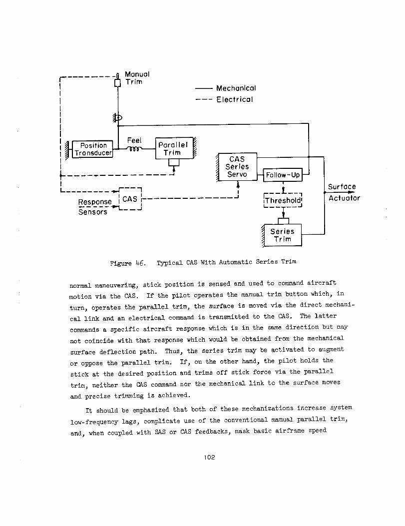
Manual
Trim
Position L__ ParallelTransducer / Trim
,,.,.,I
_ ._ .... 1I I
Response j CAS r- ......I
"In'=___ __ ..=I
Sensors
Mechanical
Electrical
CASSeriesServo
I
_-_ Follow- Up k
I
E--I'--7,Threshold _
I'-u--A---- /
_J Series
Figure 4g. Typical CAS With Automatic Series Trim
Surface
Actuator
normal maneuvering, stick position is sensed and used to command aircraft
motion via the CAS. If the pilot operates the manual trim button which, in
turn, operates the parallel trim, the surface is moved via the direct mechani-
cal link and an electrical command is transmitted to the CAS. The latter
commands a specific aircraft response which is in the same direction but may
not coincide with that response which would be obtained from the mechanical
surface deflection path. Thus, the series trim may be activated to augment
or oppose the parallel trim. If, on the other hand, the pilot holds the
stick at the desired position and trims off stick force via the parallel
trim, neither the CAS command nor the mechanical link to the surface moves
and precise trimming is achieved.
It should be emphasized that both of these mechanizations increase system
low-frequency lags, complicate use of the conventional manual parallel trim,
and_ when coupled with SAS or CAS feedbacks, mask basic airframe speed
102

stability cues, mask longitudinal c.g. shift, and create other problems
which depend upon the specific SAS or CAS feedbacks employed. These will
be discussed subsequently.
5. Additional Notes
There are many variations on the themes of these CAS and CSS actuation
systems. Reference 9 presents additional pertinent discussion of some of
these. There also have been numerous largely unsuccessful attempts to use
parallel actuation in past CAS and CSS designs, e.g., Ref. 10. Problems
contributing to the lack of success include high-frequency motion of the
stick, unnatural feel, etc. Parallel actuation has been so universally
unacceptable that these mechanizations do not warrant further discussion.
B. ELECTRICAL COMMAND PRESHAPING OR FILTERING
The essential property of a command augmentation system is the use of an
electrical command to the augmentation system so that the augmentor acts as
a booster on pilot actions. As shown in the typical system of Fig. 47, the
StickDeflection
8s
Mechanical Pathway
Electrical Pathway
Prefilter Equalization
--1°' Ii_ 1ActuationGA
Aileron Rolling
_ Deflection I . . I Velocity
Surface 80 I _irTrame / P
Actuator [ r-__*_-------_-Gs8aA
FeedbackGF
Figure 47 . Rolling Velocity Command Augmentation System
1o3

two pathwaysto the surface, one electrical and onemechanical, offer a gooddeal of flexibility in tailoring the system. As a practical matter, thesimplest approachwill seldomserve and all the flexibility available isneededto provide desirable features. For instance, a simple commandinputto the augmentorwhich is linear with respect to stick force or displacementover the entire stick deflection range will often be unsuitable. This typeof mechanizationtends to provide an aircraft which is overresponsive forsmall stick inputs and underresponsivefor large. Consequently, the historyof most commandaugmentationsysteminstallations has an early phasewithconsiderable diddling and fiddling.
To illustrate someof the factors involved, consider the rolling velocity
commandsystemof Fig. 47. The important transfer functions are given below.
Total Aileron:
_a (I + OiGA)Gs
5S I + GFGAGsG_a +aiaA1---- iTA !
Aileron due to CAS
5aA GA(Gi - GFGsG_Pa) ( Gi )= _ I
i+a AGsG a a
(52)
(53)
Rolling Velocity
o_ (I + OiaA)_- = (I +GiGA)G s a
5s I + GFGAGs_ a G_A
(54)
The righthand column shows the forms approached by the transfer functions
over the frequency range where the open-loop gain of the augmentation system
is very large. In choosing the form of the command feedforward Gi there are
a number of key design considerations. We will mention the three most
important.
104
"'t

The first consideration is that full aileron will be required for some
flight condition(s) to get the most out of the airplane. Since the augmenta-
tion should not degrade the aircraft's capability, it is thus essential that
for these flight conditions the aileron due to the augmentor should be equal
to or greater than zero or it will otherwise subtract from the total aileron
available. From Eq. 53 this is seen to require
or
5aA _ 0 , Gi _ GFGsG_ a
Gi G_ a for large 5sGFG s
A second design condition often imposed also relates to maximum aileron.
In this instance, the maximum stick deflection is to provide a given maximum
rolling velocity, Pmax" It follows from Eq. 54 that:
I + GiG A G i Pmax"= '- for maximum a s (55)
GFGA _ 5Smax
Finally, for good flying qualities about neutral there is an optimum
airplane gain, Kcopt. This optimum gain is a strong function of the manipu-
lator characteristics and is, in general, different for control wheels, center
sticks, and side sticks. The optimum effective controlled element gain is
essentially a compromise between too sluggish and too sensitive conditions.
Equation 54 implies that:
I + GiGA ± Gi & for small as (56)G_GA GF Kcopt
The first two conditions apply for large stick deflections, whereas the
third is most important for small. As noted at the beginning of this section,
conflict in desires is unavoidable unless, for example, Eqs. 55 and 56 are
compatible.
There have been two basic approaches to the solution of command sensi-
tivity dilemmas posed above. One is the introduction of low-pass filtering,
1o5

usually a first-order lag, for Gi and the other is nonlinear gain shaping
in the prefilter Gi and sometimes in the feedback GF. These are discussed
anecdotally below.
1. Lag Shaping
This type of mechanization generally uses linear or nearly linear command
sensor output with the electrical gain set to favor the full stick maneuver
requirements. This signal is then put through a first-order lag (model) to
reduce the gain of rapid (high bandwidth) stick motion and hence reduce con-
trol sensitivity in control situations where small rapid stick deflections
may be required. Unfortunately, to be effective this requires a relatively
low-frequency breakpoint which then introduces appreciable phase lag in the
forward loop (similar to that previously discussed for the manual feel system).
This phase lag then appears in all control loop dynamics and can appreciably
degrade flight path control under certain conditions. For example, the first-
order command filter in one high-performance aircraft has a lag time constant
of over one-half second in both the lateral and longitudinal channels. This
limits the tightness with which the attitude loops may be closed and hence
limits precision of flight path control. In this case the CAS actually
degrades carrier approach and landing performance of the aircraft. The extra
phase lag can also contribute to PIO tendency when attempting to control flight
path precisely at high dynamic pressure flight conditions. Such filtering or
lags, if used, should not contribute appreciable phase lag at the highest
short-period frequencies encountered in the flight envelope.
2. Nonlinear Gain S_ping
Another approach is to use nonlinear command gain shaping as a function
of stick input. As represented by the sketch below, this provides a low
command gradient around stick neutral and high gradient when near full stick
deflection. In some past development programs a factor of 3 gain variation
has been found desirable for fighter-type missions and control tasks. This
type of gain shaping approximates the "softening" effect small distributed
nonlinearities have on small stick deflection inputs with conventional mechani-
cal control paths. Thus, it improves low stick amplitude command harmony at
]o6
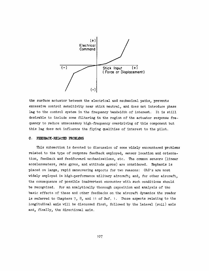
C+)Electrical
Command
Stick Input (+)
(Force or Displacement)
the surface actuator between the electrical and mechanical paths, prevents
excessive control sensitivity near stick neutral, and does not introduce phase
lag to the control system in the frequency bandwidth of interest. It is still
desirable to include some filtering in the region of the actuator response fre-
quency to reduce unnecessary high-frequency overdriving of this component but
this lag does not influence the flying qualities of interest to the pilot.
C. FEEDBACK-RELATED PROBLEMS
This subsection is devoted to discussion of some widely encountered problems
related to the type of response feedback employed, sensor location and orienta-
tion, feedback and feed_forward mechanizations_ etc. The common sensors (linear
accelerometers, rate gyros, and attitude gyros) are considered. Emphasis is
placed on large, rapid maneuvering aspects for two reasons: CAS's are most
widely employed in high-performance military aircraftj and_ for other aircraft,
the consequence of possible inadvertent encounter with such conditions should
be recognized. For an analytically thorough exposition and analysis of the
basic effects of these and other feedbacks on the aircraft dynamics the reader
is referred to Chapters V, 8, and 11 of Ref. I. Those aspects relating to the
longitudinal axis will be discussed first, followed by the lateral (roll) axis
and, finally, the directional axis.
107

1. I_Itu_In_l AxlJ
The different types of sensors and their location and orientation
influences will be discussed first. This will be followed by brief descrip-
tions of some specific mechanizational shortcomings not previously considered.
a. Linear Accelerometers
Normal acceleration feedback generally is used in a CAS to stiffen the
aircraft and/or to provide direct augmentation of stick force per g character-
istics. The accelerometer is rigidly mounted in the aircraft with its sensitive
axis perpendicular to an aircraft reference line or axis which is roughly hori-
zontal when the aircraft is in nominal cruise conditions. The accelerometer
sensitive element is biased to offset a I g gravity input and thus to sense
deviation from level I g flight. The static output of the sensor is
nz & I - cos 8o cos _o
where eo is the steady-statepitch angle of the accelerometer relative to the
gravity vector. Thus, a (I -- cos e cos _) feedback signal is obtained in
unaccelerated non-level flight and stick command (force or position) must be
maintained to prevent the feedback from producing surface deflection to return
the aircraft to a 1 g flight path. The sign of the feedback is selected to
provide aircraft nose-up surface deflection when the sensed normal accelera-
tion is less than I g and nose-down surface deflection when the sensed normal
acceleration is greater than I g. For unaccelerated, nose-down descent, the
feedback will tend to make the aircraft level off. However, for unaccelerated
climb the feedback will tend to further increase the climb attitude. This
effect can be particularly insidious if automatic trim actuation or other for-
ward loop integration is also present, for then a divergence in flight path
and speed can be created which can end, ultimately_ in aircraft stall. The
necessity for holding stick inputs in such steady flight situations can be
overcome by washing out the very-low-frequency sensor output or by incorpora-
ting an electrical trim command input. However, for aircraft in highly maneu-
vering flight it is impractical to keep introducing a trim signal to offset
the change in gravity component, and this must be accomplished via the stick
io8

command. Therefore, in constant g maneuvers this feedback causes consider-
ably more longitudinal stick activity by the pilot. This may be readily
appreciated by considering 360 deg rolls.
Another aspect of acceleration sensing concerns sensor location relative
to the aircraft c.g. The combined static and dynamic output of the biased
accelerometer in g units is (neglecting bending modes)
nz = I - cos e cos _ +azcg + (pr--_)x i + (qr +P)Yi + (q2 +p2)z i
where xi, Yi, zi are distances between the sensor and the aircraft c.g. measured
in the stability axis. Generally, the seusor can be located in or near
the aircraft x-z plane so the lateral offset term (Yi) is small. The major
problem arises with the xi and zi terms and, in particular, the -_x i and +p2zi
contributions. Recognizing that the accelerometer is an electrical bobweightj
we may refer back to the discussion of Section IV-C. The zeros of the feed-
back numerator are controlled by the bobweight arm, i.e., xi = _B. It may be
noted in Fig. 34 that if the accelerometer is located such that xi = _B = Zs/MB
then the high-frequency zeros (one of which is non-minimum phase) are effec-
tively moved out the a axis to infinity. This is the location at which elevator
deflection produces rotation without translation, i.e., the center of rotation
for which the elevator is a center of percussion. It may be noted from Fig. 35
that movement of the zeros (i.e., U_B) to very high frequency will greatly
attenuate the high-frequency amplitude asymptote and thus greatly reduce the
potential of instability of high-frequency, lowly damped modes (e.g., bending
or actuator). This location also minimizes the requirement for complex low-
frequency lead-lag shaping to maintain loop stability. For further discussion
the reader is again referred to Chapter 6 of Ref. I.
Since most aircraft roll about an axis near the stability x axis, when the
aircraft is at high angle of attack, an accelerometer mounted ahead of the
vehicle c.g. along the fuselage reference axis can be a considerable distance
above the vehicle roll axis (i.e., zi can be appreciable). This can result in
significant coupling of lateral motion into the longitudinal axis in highly
maneuverable aircraft:
Io9
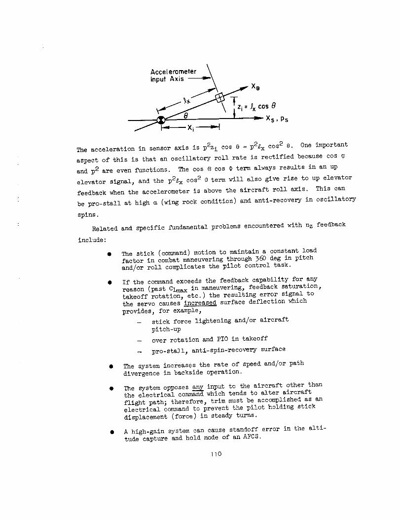
Accelerometer \
Input Axis _\
Tzi: 4 cos0_" j \
.\ Xs,Ps
The acceleration in sensor axis is p2z i cos e = p2_ x cos 2 e. One important
aspect of this is that an oscillatory roll rate is rectified because cos
and p2 are even functions. The cos _ cos ¢ term always results in an up
elevator signal, and the p2_ x cos 2 e term will also give rise to up elevator
feedback when the accelerometer is above the aircraft roll axis. This can
be pro-stall at high m (wing rock condition) and anti-recovery iu oscillatory
splus.
Related aud specific fundamental problems encountered with nz feedback
include:
• The stick (command) motion to maintain a constant loadfactor in combat maneuvering through 360 deg in pitch
and/or roll complicates the pilot control task.
• If the command exceeds the feedback capability for any
reason (past CLmax in maneuvering, feedback saturation,
takeoff rotation, etc.) the resulting error signal to
the servo causes Increased surface deflection which
provides, for example,
- stick force lightening and/or aircraft
pitch-up
- over rotation and PI0 in takeoff
- pro-stall, anti-spin-recovery surface
• The system increases the rate of speed and/or path
divergence in backside operation.
• The system opposes any input to the aircraft other thanthe electrical command which tends to alter aircraft
flight path; therefore, trim must be accomplished as anelectrical command to prevent the pilot holding stick
displacement (force) in steady turns.
• A high-gain system can cause standoff error in the alti-
tude capture and hold mode of an AFCS.
110
All of the aboveare magnified or intensified if the systemincorporatesintegration in the forward loop, e.g., actuation mechanizationsusing feed-back washoutor automatic trim. Several aircraft have beenlost becauseof
inadvertent aft c.g., normal acceleration feedback, and an auto trim feature.
Finally, the use of this feedbackgenerally requires somemeansof gainscheduling since the loop gain changesas the squareof dynamicpressure.
b. Rate G_ro
Aside from structural elastic mode considerations there are few problems
in locating and aligning pitch rate gyros. This feedback is generally employed
to augment short-perlod damping (i.e., augment Mq); however, with gain schedul-
ing of either the feedback or the stick con_nand, this type CAS has also been
employed to augment stick force characteristics since nz N Uoq. Either approach
has certain drawbacks. The basic aircraft stick force per g tends to lighten
at high dynamic pressure flight conditions. To augment stick force requires
either increasing the feedback gain and thereby decreasing the forward loop
gain or maintaining the feedback relatively constant and decreasing the command.
Scheduling an increase in feedback gain as a function of Uo rapidly leads to
instability problems because the total lo_._gain is then proportional to:
UoPSU_c
U°M6 = 2Iy Cm5
The high-gain pitch rate CAS can provide unusual landing characteristics.
For example, one aircraft gave the impression it did not want to land. Gener-
ally, an aircraft will tend to balloon at hhe completion of flare and, as it
enters the ground effect region, the nose will drop as airspeed decreases, and
the aircraft will settle to a landing. A high-gain pitch rate CAS, however,
prevents the pitch attitude from changing during the ballooning phase and sub-
sequent bleedoff of airspeed. The pilot therefore has to keep "pushing" the
nose down via stick commands to make the aircraft approach the ground as speed
bleeds off. This appears to the pilot as a negative Fs/u characteristic and
is particularly disconcerting. Pilots have overcome the tendency by trimming
the aircraft nose down before starting the flare and then keeping positive
111

force on the stick to counter the mistrim. This technique will work where
the trim is accomplished through the CAS series servo, but it is not possible
when automatic or separate manual trim is used.
In the analysis, synthesis, and simulation of augmentation systems the
effect of sensor and/or transducer saturation limiting is often neglected.
This can result in surprises in flight if both command and rate feedback do
not limit or saturate at the same value. Typical responses for either path
reaching saturation first are shown in the following sketch.
Pitch IRate
Feedback /tS atura es "/ ,.. Command Saturates
Unly //,,,/" _ Only
"_tion Occurs
Stick Position or Force
It is assumed here that the series servo is not saturated and the aircraft
is at a flight condition where the basic vehicle rotation capability is some°
what higher than that commanded via the electrical path. Command saturation
results in the system behaving as a pure rate damper system and suddenly
reduces maneuver performance at a time when the pilot is using large stick
inputs presumably to obtain maximum maneuvering capability. Feedback satura-
tion without simultaneous command saturation results in a sudden error command
to increase the maneuver. This can produce pitch-up, stick force per g lighten-
ing, loss of pitch rate damping, etc. These occurrences are encountered in
rapid maneuvering situations where they can be awkward at best and catastrophic
at worst. As noted previously, the use of forward loop integration (rate servo
or automatic trim) will further aggravate this situation because the input
error will continue to drive the actuators in a direction to maintain system
saturation.
112

c. Blended Normal Acceleration and Rate Gzro
Blended feedbacks are employed to provide nearly invariant handling
and transient responses throughout the aircraft flight envelope. The specific
responses are dependent upon the ratio of feedback gains. These are usually
selected such that the system is essentially pitch rate command at low dyna-
mic pressure and normal acceleration command at high dynamic pressure. The
idiosyncracies previously discussed for each feedback still apply (e.g.,
accelerometer location), although they are modified somewhat. The pitch rate
feedback opposes the undesirable characteristics of normal acceleration in
non-zero pitch, roll, or flight path angle and backside operation. The normal
acceleration feedback opposes the pitch-up effects of limiting in pitch rate
feedback_ However, limiting of normal acceleration feedbacks for any reason
(past CLmax, not yet airborne, etc.) can still result in stick force lighten-
ing and pitch-up tendencies because the total stick command then calls for more
pitch rate.
Stall warning is often greatly decreased with this type of CAS because the
combined feedbacks maintain "good" vehicle handling characteristics up to the
point of stall. One method of countering this problem is to decrease the elec-
trical command path gain as a function of angle of attack or dynamic pressure.
This effectively increases the stick force per g as the stall is approached.
Unfortunately, once the stall is achieved both feedbacks oppose the natural
tendency for the aircraft nose to drop. Thus, the pilot must command a nose-
down attitude by forcefully pushing on the stick. The decreased command path
gain then requires a 6reater stick displacement and/or force for stall recovery
which is quite objectionable to pilots. Yet another problem experienced with
this means of introducing stall warning is a pitch-up command upon failure or
disengagement of the warning system if CAS gains are returned to normal upon
such failure.
d. Attitude and Attitude Rate
Autopilot control wheel steering modes generally are attitude-hold type
with either pitch rate or attitude rate command. For control at large bank
angles it is important to note the differences between body axis rates (rate
gyro) and Euler axis rates (vertical gyro):
113
or
Bodyaxis rate q =
Euler axis rate _ =
cos q0+ _ cos e sin
q cos $- r sin
Thus, at large bank angles body axis and Euler axis rates are not equlv_leut
and, more important, cannot simultaneously be zero. Thus, a mixture of body
rate command and attitude hold functions which perform properly for wings-
level condition can be quite different in turns. Also, if attitude (Euler)
rate command is used, operation of the system must be restricted to within
limited roll attitudes. This is due to the decrease in Euler angle pitch
rate for a given elevator deflection as roll angle increases. Thus, the
feedback decreases, the CAS effective forward loop gain increases, and stick
force per g lightening is obtained.
Other problems assoclatedwlth such mechanizations may be readily visual-
ized with the aid of Fig. h8. This shows a blended rate commandj attitude
hold system which was actually developed and flown in a fighter aircraft. This
mechanization has several shortcomings. First, precise control of pitch atti-
tude is difficult when the stick force switch is set to a low threshold, because
the system "locks onto" a e reference whenever stick force is less than the
preset switching value. This is frequently referred to as "nibble." It is not
possible to arrive at the desired e with q = 0 and Fs > X lb. If pitch rate is
appreciable, a "pitch back" is experienced and control becomes a trial anderror
process. The @ error cannot be removed via the basic manual trim system because
the autotrlm function will oppose any non-electrlcal trim command. By increas-
ing the force switching threshold, a stick force less than the switching value
can be transmitted to the attitude synchronizer and thus serve as an attitude
rate to obtain vernier control of the reference attitude. However, caution
must be exercised in using such attitude rate commands because the attitude
being commanded is an Euler angle, not an integral of a body axis rate, and
this results in the previously mentioned stick force lightening with increasing
bank angle.
114

Dual - Bobweight/Spring / Sprashpot
[_--r-mr"l_
S-r ' _ '
Parallel ITrim
Actuator
ev___l[ FsFS
i
Trans.
>Xlb
<Xlb
SeriesTrim
T
"1III
I
t-J
I
E
i
)_. __._ Series_Servo .....
Figure 28. Attitude Rate Command, Attitude Hold System
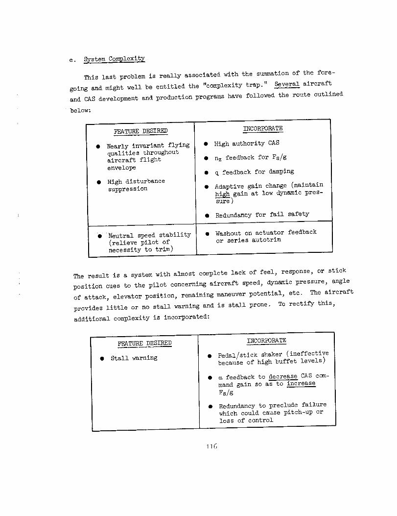
e. _stem Complexity
This last problem is really associated with the summation of the fore-
going and might well be entitled the "complexity trap." Several aircraft
and CAS development and production programs have followed the route outlined
below:
FEATURE DESIRED
Nearly invariant flying
qualities throughoutaircraft flight
envelope
High disturbance
suppression
• Neutral speed stability
(relieve pilot of
necessity to trim)
INCORPORATE
• High authority CAS
• n z feedback for Fs/g
• q feedback for damping
• Adaptive gain change (maintain
highgain at low dynamic pres-
sure )
• Redundancy for fail safety
• Washout on actuator feedback
or series autotrim
The result is a system with almost complete lack of feel, response, or stick
position cues to the pilot concerning aircraft speed, dynamic pressure, angle
of attack, elevator position, remaining maneuver potential, etc. The aircraft
provides little or no stall warning and is stall prone. To rectify this,
additional complexity is incorporated:
FEATURE DESIRED
• Stall warning
INCORPORATE
Pedal/stick shaker (ineffectivebecause of high buffet levels)
feedback to decrease CAS com-
mand gain so as to increase
Fs/g
Redundancy to preclude failure
which could cause pitch-up or
loss of control
]16

The latter, while providing stall warning, was shown previously to actually
increase the initial pilot effort to effect stall recovery, since he still
must actively push the aircraft nose down and the decreased command then
requires greater stick force on deflection to do so.
2. _teralAxis
Lateral CAS mechanizations are not as varied as are longitudinal. Roll
axis systems are invariably roll rate command and differ primarily in the
number and type of non-equal parallel paths between pilot input and surface
deflection (Figs. 49 and _0). The most prevalent feedback sensor is a rate
gyro although derived rate and roll attitude have been used successfully in
the autopilot Control Wheel Steering modes of transport-type aircraft
a. Rate Gyro
The major problem regarding sensor location is minimization of structural
mode effects. The gyro generally is rigidly mounted with its sensitive axis
aligned with the aircraft centerline axis. Since most aircraft are flown to
roll about an axis near the aircraft velocity vector (stability axis), the mis-
alignment between sensor input axis and vehicle roll axis is directly related
to vehicle angle of attack. The rate gyro output is:
Pg = Ps cos _- rs sin
Generally, rs sin _ << Ps cos _ so that pg _Ps cos _ and angle of attack
merely modulates the loop gain.
Since command augmentation systems are generally employed in high perfor-
mance fighter and attack aircraft where rapid roll is essential to rapid
maneuvering, there is a strong tendency to make the system high gain. Also,
since the yaw axis SAS is generally employed to maintain stable dutch roll
characteristics and correct airframe dynamic deficiencies (e.g., _/_d), it
is often possible for the roll rate CAS to be fixed gain even on aircraft with
Mach 2+ capability. Therefore# most of the problems encountered have been
associated with high gain, e.g.:
117

mm_mm_mmmu_ I
I Nonlinear Tim i
_s _ Gain J,
',_'--I._J--1T-_I -_ _-1 _' !'_'-I Serv° [-'LT.I" ....
Figure 49. Simplified Roll Rate CAS -- Fixed-Wing Aircraft
NonlinearGain
-II...........
_S im
r "1i Ratio I
.... "],change!- i"ll gll Illl IB Ill II I
Nonlinear Trim I
Figure _0. Simplified Roll Rate CAS -- Swing-Wing Aircraft
118

@ Gain shaping of command is crucial; oversensitivityto small stick deflection inputs leads to PI0 in
precise tracking tasks; undersensitivity at large
stick deflection leads to restricted performance.
Command or feedback limiting is more prevalent(than for longitudinal); at low q (landing) slow
aircraft response leads to large stick inputs and
command (or servo) limiting; at high q aircraft
response can be so rapid that feedback limiting isencountered.
System gain (command and feedback) must be drasti-
cally reduced on swept wing aircraft as stall is
approached to prevent introduction of large pro.-departure surface deflections.
The system prevents control of bank angle via rudder(S-turns in landing, rudder roll in air combat maneu-vering).
Returning of control stick to neutral (Pc = 0)following high roll rate maneuver results in abrupt
stopping of aircraft roll but inertia of pilot's
head and body gives head snap, inadvertent controlinput, etc.
• Rough ride qualities in turbulence and/or lateral PIO.
• Large lateral control deflections commanded by thesystem tend to emphasize "aileron yaw" characteristics.
Other problems which have been encountered include the use of automatic
parallel trim to augment series servo authority. For steady roll, aileron
displacement must be maintained and this requires a finite error between Pc
and p. If the error signal operates the autotrim then the previously noted
stick force lightening (if series trim), stick "wander" (if parallel trim),
and excessive stick motion to stop the maneuver are encountered. Also, rudder
maneuvering causes a roll rate error and hence the autotrim to operate.
Response models generally are first-order lags placed in the command path.
More complicated "inverse models" have been placed in the feedback of some
systems; however, these have not met with much success. The "inverse model"
is introduced as lead in the feedback. This requires accompanying lags and
results in the type of behavior discussed in Section III-B. In addition,
since lateral trim must be introduced as an electrical command in CAS's, the
119

dynamics of the "inverse model" feedback result in imprecise, trial and
error trin_ning.
The advent of swing wing aircraft introduced another set of potential
problems. These aircraft generally have differential moving tail surfaces
for roll control throughout the aircraft performance envelope. Therefore,
the roll rate CAS operates through these surfaces. The wings typically
contain spoilers which augment the rolling tail control power when the wings
are forward of some nominal sweep angle (e.g., 45-50 deg). Therefore, three
parallel but different roll command paths (as indicated in Fig. 50 ) can exist
over a significant segment of the aircraft flight envelope and at a range of
wing sweep angles. A number of countering factors imuediately come into play.
First, the wing spoilers are highly effective but usually highly non-
linear roll moment producers. They also produce favorable (proverse) yaw
moment. Second, except at high speeds, the differential tail generally is
not a highly effective roll moment producer and, further, the differential
deflection allowable is generally restricted to avoid interference with longi-
tudinal control requirements. Differential tail deflection does produce large
adverse yaw moments. If the control path through the spoilers and the direct
link (mechanical) to the differential tail provide greater roll rate than is
commanded via the CAS, then it is possible for the spoilers and differential
tail to provide opposing roll moments but with yaw moments summing. Such
complicated interactions can result in widely varying e_/_d characteristics
unless gains in all paths are carefully matched over the complete flight regime.
b. Roll Attitude and Attitude Rate
It was mentioned previously that derived rate, roll attitude command has
been successfully employed in transport-type aircraft. On these aircraft the
low frequency of the structural bending modes makes it difficult to separate
(filter) rigid and flexible body modes in the rate gyro signal while the con-
servative bank angles and rates employed in typical maneuvering allows use of
vertical gyro or platform outputs. Direct attitude command systems (attitude
proportional to control wheel deflection) also have been successful because of
the conservative maneuvering and the fact that the pilot can maintain control
wheel displacement without appreciable arm fatigue. While frequently proposed
120
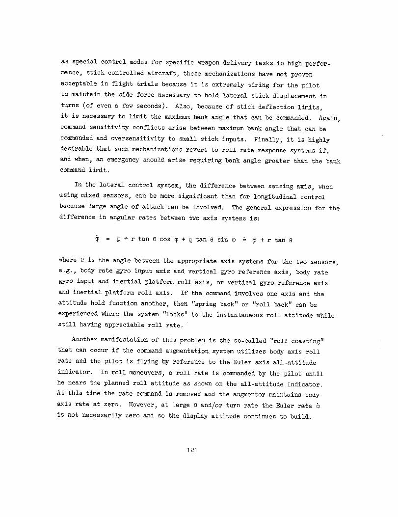
as special control modesfor specific weapondelivery tasks in high perfor-mance,stick controlled aircraft, these mechanizationshave not provenacceptable in flight trials becauseit is extremely tiring for the pilotto maintain the side force necessaryto hold lateral stick displacement in
turns (of evena few seconds). Also, becauseof stick deflection limits,it is necessaryto limit the maximumbank angle that canbe commanded.Again,commandsensitivity conflicts arise betweenmaximumbankangle that canbecommandedand oversensitivity to small stick inputs. Finally, it is highlydesirable that suchmechanizationsrevert to roll rate responsesystemsif,and when,an emergencyshouldarise requiring bank angle greater than the bankcommandlimit.
In the lateral control system, the difference betweensensing axis, whenusing mixed sensors, canbe moresignificant than for longitudinal controlbecauselarge angle of attack canbe involved. Thegeneral expression for thedifference in angular rates betweentwo axis systemsis:
= p + r tan 8 cos _ + q tan e sin _ & p + r tan e
wheree is the angle betweenthe appropriate axis systemsfor the two sensors,e.g., body rate gyro input axis and vertical gyro reference axis, body rategyro input and inertial platform roll axis, or vertical gyro reference axisand inertial platform roll axis. If the commandinvolves one axis and theattitude hold function another, then "spring back" or "roll back" canbeexperiencedwherethe system"locks" to the instantaneousroll attitude whilestill having appreciable roll rate.
Another manifestation of this problem is the so-called "roll coasting"that can occur if the commandaugmentationsystemutilizes body axis rollrate and the pilot is flying by reference to the Euler axis all-attitudeindicator. In roll maneuvers,a roll rate is commandedby the pilot untilhe nears the planned roll attitude as shownon the all-attitude indicator.At this time the rate commandis removedand the augmentormaintains bodyaxis rate at zero. However,at large e and/or turn rate the Euler rateis not necessarily zero and so the display attitude continues to build.
121

3. Directional Axis
Theconventional functions of this axis include dutch roll damping
augmentation,increasing directional stiffness, combattingyawdisturbances
(aileron yaw, engine out moments,gusts, etc.), and turn coordination. Whenthese are accomplishedsatisfactorily with a relatively small authority
systemthere is little needfor the yawaxis to be a CAS. If the perfor-manceof these functions requires a large, or full, authority yawSAS,then
pedal commandcapability is required to allow the pilot necessaryuncoor-dinated maneuvers(rudder S-turns in landing or rudder rolls in air combat
maneuvering,sideslip in crosswlnd landing or formation flying). Thesigni-ficant problems, however,do not involve the commandpath but rather thefeedbacksensing which then also encompassesfundamentalSASproblemsandturn coordination. The latter is the topic of the next chapter and will not
be discussed here. The principal sensing problems to be discussed here relate
to lateral accelerometer placement and gain scheduling, and angle of attack
influence on yaw rate gyro orientation and washout effectiveness.
a. Lateral Acceleration
Similar to the longitudinal case, the rigid-bodymotion sensed by an
accelerometer fixed in the aircraft is:
ayi = aycg + (pq + _)xi _ (p2 + r2)yi + (qr - p)z i
Analogous to the longitudinal case, it is desirable that the sensor be located
on the aircraft x axis at the center of rotation for which the control sur-
face deflection m in this case rudder -- is a center of percussion. This is
a distance Xa = -YSr/NSr, ahead of the aircraft c.g. for aft rudders. Assuming
for the moment all other motion quantities to be small, Ref. I shows:
aycg + Xa_ = Yvv + YSrSr + Xa_ & YO8
Thus, the accelerometer located at Xa closely approximates a sideslip sensor
and is effective in augmenting the directional stiffness derivative, N_.
122

Becauseboth center of rotation and vehicle c.g. can shift appreciablyI
with changes in Mach number and loading, a serious practical problem is
finding an accelerometer location which is adequate for all flight and
loading conditions. Figure _I indicates the effect of sensor location on
the high-frequency zeros of the ay/8 r numerator. For accelerometer loca-
tions at the center of rotation one zero goes to infinity and the other is
at a very high frequency. Therefore, the high-frequency asymptote is maxi-
mally attenuated and the likelihood of higher-frequency mode instability
(actuator or structure) is reduced. The possibility then exists for intro-
ducing lead-lag equalization in the vicinity of open-loop _d so the closed-
loop frequency can be increased without incurring instability.
For accelerometer locations forward or aft of the center of rotation,
the high-frequency zeros move toward _d and hence raise the high-frequency
asymptote with the attendant danger of actuator on structural resonance or
instability. The potential of lead equalization is also reduced because
this further increases the high-frequency asymptote. It should be noted
that for accelerometer aft of the center of rotation one high-frequency zero
is non-minimum phase and introduces another example of the right half plane
zero problem described in Section III. For accelerometer locations ahead of
the center of rotation, the complex zeros, 0_ay_ are in the left half plane
and provide some lead equalization for higher-frequency modes.
Another problem related to that of sensor location is the gain limitation
posed by the high-frequency modes. In the absence of any gain adjustment
mechanization, the loop gain will vary as:
r
P2_Cy6CnSr
Y_N_r _ ml z
Thus, gain compensation the inverse of this is required if this feedback is
to be stable and effective throughout the aircraft flight envelope. However,
more refined equalization adjustments (i.e., lead-lag) are desired. To develop
these, attention is directed to the exact expressions for the various asymp-
totes called out in Fig. 52 for an accelerometer plus lead-lag equalization
(I/T and a/T) and servo (_). The aircraft dutch roll in this example is
123
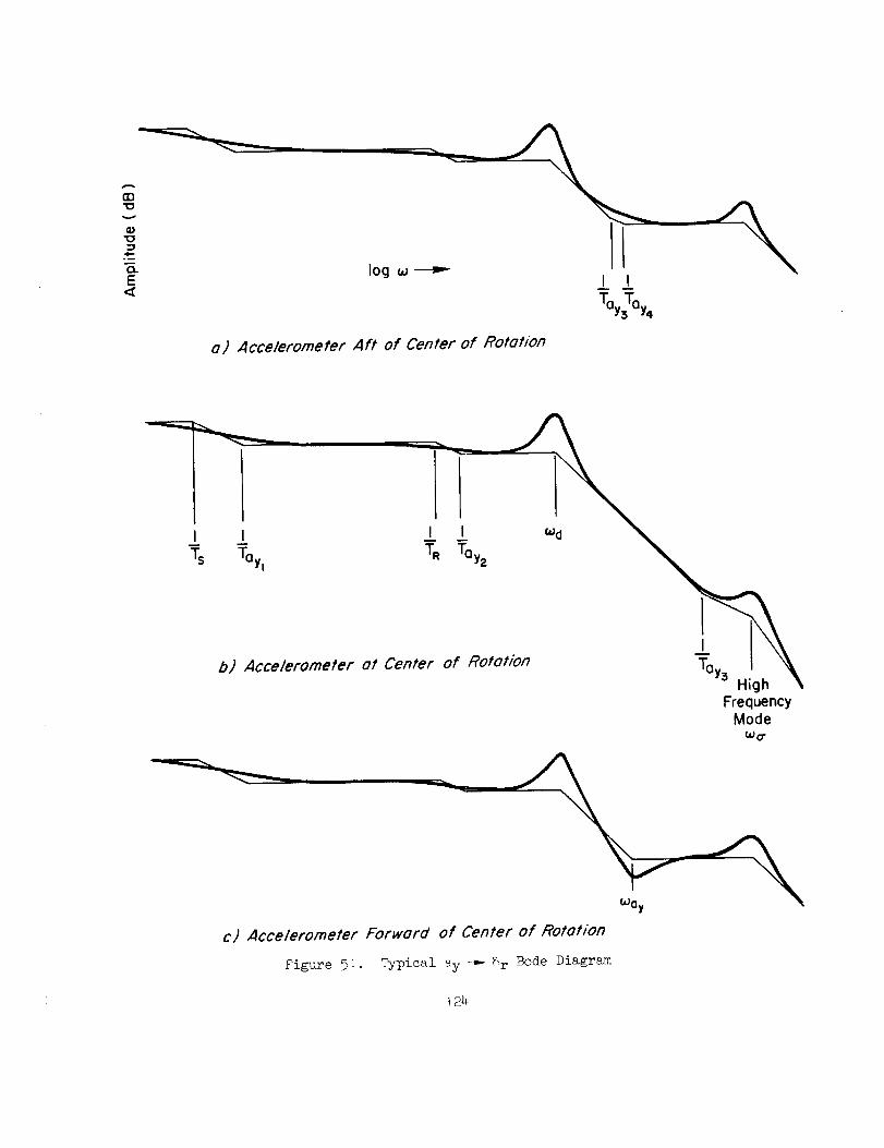
o) Acceleromefer Aft of Center of Rotation
FrequencyMode
w o-
c) Acce/erometer Forward of Center of Rotat/on
Figure 5:. Typical ay -_- _r Bode Diagram
124

generalized in that it can be either stable and underdamped (_d) or over-
damped (I/Tdl, I/Td2) even to the realm of instability (I/Td2 negative).
Similarly, the accelerometer location can be either ahead (_y) or behind
(I/Ty3, I/Ty4) the center of rotation. The asymptotes of major interest
are those for the flat regions preceding _ and_a, and the section of
-20 dB/decade slope lying between. The expressions for these three asymp-
totes are invariant with interchange of neighboring break frequencies,
except for the high-frequency flat region which requires _ to be greater
than all the other break frequencies (in particular, _a > _y). However, the
frequency regions over which the three asymptotes apply are not invariant
with such interchanges. These ranges are summarized below:
I) Low-frequency asymptote, AyE_/_.
High-frequency end limited by either _ or I/m,whichever is smaller.
2) Mid-frequency asymptote, AyK_2m/_.
Low-frequency end limited by larger of vfl_l or I/T.
High-frequency end limited by smaller of a/T or _.
3) High-frequency flat asymptote, AyKya.
For existence requires _a > COy. _a is always high-frequency limit.
Low-frequency end limited by larger of a/T or _7_I.
To insure adequate dutch roll damping and/or stiffening requires that the
gain crossover be made in an amplitude ratio region which has a reasonable
length of roughly -20 dB/decade slope. Another way of saying the same thing
is that a reasonable phase margin is required at crossover. Thus, the zero dB
line should cross the asymptotic plot (at _c) somewhere along the mid-frequency
asymptote. For this crossover region even to exist, _ and/or I/T must
be less than a/T or _; and for good closed-loop servo mode (_a) damping
to be possible this "less than" must be modified to "much less than."
The existence of the region can be assured by controlling the values of
I/T and a. Generally speaking, I/T less than _ is preferable since it
results in higher potential phase margin. For a reasonably large value of a,
125

l :_ _i.__ /
I " _ I_,l _ .--.'/I "-g °°
_!__ i_-,-_
o___ _
I _I'_7 J. oI_.
_l_UIN'o
: °PI(_E)E)I
t3
01
o
I
o
or-t
o
0
('!.0
orl
I
I
or-t
_6

however, it is sufficient to specify simply that I/T be near the dutch roll
roots.
From damping considerations, a fairly large value of a is needed; other-
wise the lead effect of I/T would be largely canceled. Also, for a nominal
case, Iv_T_d21< I/T and a/T < V_, a large value of a allows plenty of margin
in which to meet the stiffening requirement. By virtue of this desire for rela-
tively large values of a, it can be inferred that a reasonable location for a/T
is somewhere in the vicinity of o_y.
It appears therefore that the '_roper equalization" is quite closely tied
to the basic transfer function factors, _d aridly, which vary with flight
condition and c.g. location. In order then to maintain the virtues of this
system for all flight conditions, the location of the lead-lag pair, as well
as the gain, will very likely have to be automatically adjusted.
The above discussion shows that the significant vehicle parameters involved
in the final adjustment of gain and equalization are Ay, _, and _. Using the
definition of Xa _ -UoY_r/NSr, these quantities are given in terms of dimen-
sionless derivatives by:
A_x qSbZ_ x
Ay = -YSr Xa Iz Cnsr
xa(% YV_r_ qS
- -JIxZz
_OY_r kz2 CYst_x --_x-Xa o _+ _-_r ° _x÷V
127
The aerodynamic parameters involved in these expressions represent two very
different levels of predictability and "computational" difficulty. The values
of Cn_ and C_ entering into ed are very strong functions of angle of attack,
in addition to Mach number, and are not easily measured or extrapolated to
full-scale conditions. On the other hand, Cy_, CYSr , and Cn6r are measured
in body rather than stability axes for the specific calculation of my, and as
such are essentially completely independent of _. Also, for varying c.g. and
inertia, _x and k_ vary; and CYSr/Cnsr , which depends on the effective rudder
arm, is also a weak function of Mach number (due to shifts in the rudder center
of pressure). Finally, Cy_ is a moderately strong function of Mach number, but
is relatively easy to measure experimentally.
As an example of how complex the system compensation may be, assume that
the dimensionless aerodynamic derivatives are constant as is _x and k_ (e.g.,
over some restricted flight regime). The variation of the pertinent system
parameters with dynamic pressure and equalization is tben as follows:
PARAMETER CONTROLLED PARAMETER VARIED
I
AyKya = Constant Ky cc a-_
i__c = Ay _ _c cc -_-q
_oc I
a _ oc a
The effects of various possible equalization adjustments on these parameters
are summarized in Table 2. The last column of the table indicates the basic
mechanism of equalization adjustment. For example, the variation of Ky may
be accomplished by a servo-driven potentiometer; therefore, additional
suitably "shaped" potentiometers on the same servo shaft can be used to
vary the equalization time constants as the desired function of Ky.
128

_. , .,,
i)
a fixed
2) I-_I/_T
I3) a, T _
4)
_)
ASSUMED
EQUALIZATION
ADJUSTMENTS
TABLE 2.
a, • fixed
W
T fixed
a
- fixedT
VARIATIONS, WITH DYNAMIC PRESS'URE, OF
EFFECTS OF IDEALIZED ADJUSTMENTS OF f(ay) _ 5r CONTROLLER PARAMETERS
EQUALIZATION
Controller
Gain, Ky
I
q
1
q
Crossover
Frequency, ah
q
Vv
Constant
Low Frequency
Gain, ah/T _
Constant
Constant
W
Relative Lead Relative Lag
Location, _d _ Location, _yv/a
qvI,
Constant
Constant
Constant
Constant
Constant
Vv
I6) a fixed, T cc q
I
q
Constant ConstantI
q
VARIATION
WITH t_r
None
T
_ Kyl/3
Ky2/3
fixed
Kyl/3
• _ Ky
--_fixeda
T, _ _ Ky

Of the possibilities listed, Cases I and 5 can be eliminated immediately
because a variation of _c proportional to q is too drastic. Case 2 has the
most promise of working over the entire flight regime because of its lead
and lag location characteristics, although a variation of _c with _ is not
desirable. Case 3 has the desirable characteristic of _c & constant, but
also has the undesirable features that the low-frequency gain decreases with
an increase in _ and the dynamic range of Ky variations is very large.
Also, the lag, a/T, is likely to depart too drastically from _y. Case 4
does not suffer this last defect_ but Ky variations again are large and
crossover frequency is proportional to v_. Case 6 has desirable character-
istics on all counts, except lead and lag location variations which may be
too drastic.
The net conclusion to be drawn from Table 2 is that no one of the
"simple" equalization adjustments is likely to suffice over an entire
flight envelope. Also, the real variations in vehicle dynamic charac-
teristics not taken into account will substantially modify the "idealized"
conclusions stated above.
As a result of the foregoing, it is not uncommon for the lateral
acceleration loop gain to be fixed value and selected so that this feed-
back does not cause adverse effect throughout the aircraft flight envelope.
This generally results in an almost totally ineffective feedback in the
low speed, low dynamic pressure flight regimes.
Returning now to the more general aspects of motions sensed by a
lateral accelerometer, the actual sensor location is usually a compromise.
Geuerally it can be located such that Yi is small and the sensed accel-
eratlon reduces to
+ (pq + _)x i - _zi_Yi - aycg
For highly maneuvering aircraft all of these terms can be significant:
pqxi in rolling pullouts, _xi for rudder deflection, and-_zi for aileron
deflection. In the latter case it should be noted that the zi for aileron
input can be different for the initial and steady rolling motions. This
is because the initial roll axis is defined by the moment producing terms
130

!
LSa5a' and NSa5 a. At high angle of attack, assuming adverse aileron yaw
and stability axis derivatives, the relationship between the axis systems
of interest is as follows.
j X fuselage
Accelerometer .o,'"
= taft I -Ns,_ .... ..._ Xinstantane°us
'
X stability
Thus the instantaneous roll acceleration lever arm is defined by the
!
angle (m - _). If this is large (i.e., NSa = 0 or positive) then the
initial lateral acceleration sensed (by accelerometer or pilot) can be
very large in full aileron rolls. For example, initial lateral accelera-
tions exceeding one g have been obtained on some high performance fighters
with sudden application of full aileron deflection. The sign of the
sensed feedback to rudder is such that, for the example sketched above,
the resulting initial rudder deflection would uncoordinate the maneuver.
Another source of large lateral acceleration is sudden loss of engine
thrust in aircraft with engines mounted a considerable distance outboard
from the aircraft centerline. Again magnitudes greater than one g have
been experienced. The possibility of such large accelerations should be
taken into account and precautions taken to prevent amplitude or rate
saturation anywhere within the system causing phase lags which might lead
to system instability.
b. Rate Gyro
The yaw rate gyro is the most common of the directional axis sensors.
The fundamental problem of this sensor is orientation with respect to
aircraft stability axes. The yaw rate sensed by the rate gyro (rg) can_
differ considerably from the stability axis perturbation yaw rate (rs) of
the aircraft, i.e.,
131

rg = rs cos (_ + ST) + Ps sin (_ + ST)
where _ = angle between aircraft stabilityaxis and aircraft reference axis
eT = rate gyro tilt from aircraftreference axis
(a + eT) = sensor angle of attack =
At low sensor angle of attack rg _ rs; however, at large positive _ and/or
eTa significant roll rate component is obtained. It is commonly recognized
that this roll rate component destabilizes the dutch roll.; The reason for
destabilizatiou is that the angular velocity numerator qua dratic's undamped
natural frequency, _rg, increases as the sensor axis is inclined above
the stability axis (the usual case). Thus _rg/a_i approaches unity with
the consequent reduction in damping attainable as explained in Section II-B.
The shift in sensor zeros with gyro tilt may be observed from the survey
plot of Fig. 53 which derives from
zeros of N_rg = zeros of I + (NPS/N rs) tan (_ + 0T)
For a typical fighter aircraft at 5 63 0.8 m 3 and 203000 ft the trim
is 16 deg and
NPs
Nrs -0.43 (1.39)[-.285, 0.9]
At this condition _d = 3.64 rad/sec, therefore, from Fig. 53:
eT _rg _rg _d _d
-16 deg (stability axis) 0.9 -.28_ 3.64 0.2
-6 deg 2.25 0.2 3.64 0.2
-0 deg (FRL axis) 2.70 0.2 3.64 0.2
+4 deg 3.25 0.2 3.64 0.2
_Org/a_i I/Trg
0.247 1.39
0.619 0.23
0.742 o. 16
O.893 o. 11
132

L_L_
dr_
-2 -I
T_
eT = 4 °
8 T = 0 °
(FRL Axis)
8T = -16°
(StabilityAxis) 03r
1W
O"
Figure 53.
lOdB
l,d r
I I0.I 1.0
I
r,
"=--6 0
8 T = + 4 °
log (_ (rad/sec)
II0.0
Roots of (NPs/N rs) tan (16 + 9T) = -I

It is readily apparent that gyro inclination with respect to stability
axis has a strong effect on _rg/_d and hence the effectiveness of this
feedback in damping dutch roll.
Another aspect, not so well recognized, is the dramatic influence this
shift in_rg has on the effectiveness of the yaw rate feedback washout. The
washout time constant is selected to attenuate sensing and feedback of fre-
quencies below the dutch roll and, in particular, the yaw rate of steady
turns. Typically this is 0._ to I rad/sec. However, for the _ = 16 deg
example case the dramatic shift in_rg results in the closed-loop survey
plot of Fig. _h. The movement of_rg toward _d causes the low-frequency
amplitude to be increased and hence to counter the washout. The nominal
gain line passes below the amplitude ratio plot and indicates the yaw damper
will actively oppose aircraft motion in this bandwidth (i.e., any yaw). Such
opposition at high _ is recognized by many pilots who turn yaw dampers off
prior to engaging in air combat maneuvering.
The above shift in numerator zeros can be counteracted in several ways.
0ue is to tilt the yaw rate gyro so the sensitive axis is nearly coincident
with the vehicle stability axis. For a fixed gyro mounting, this involves
compromising system performance at both high and lc_m. Tilting the gyro
down tends to move _rg farther into the right half plane and can rapidly
lead to system instability. However, on one aircraft two rate gyros were
employed. One was aligned with the fuselage reference line (approximately)
for up and away flight, and the other was aligned with stability axis for
nominal approach and landing conditions. Sensing was switched from one
gyro to another as a function of flap position.
A third way'to combat their shift is the previously discussed
(Section II-B) augmentation of L O Ksince _ _ (g/Uo)(L6/LD)] with a roll
rate-to-aileron feedback capability of the yaw rate damper. However, this
method is limited to those flight conditions and configurations where use
of aileron is both effective and safe. On aircraft which require fading
out the roll SAS or CAS at high m, this method would be totally ineffective.
Yet another technlque is to crossfeed roll rate to rudder to cancel the
component sensed by the yaw rate gyro. However, to be truly effective this
134
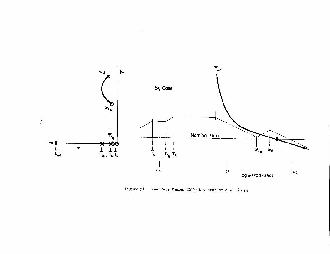
_d
_rg
%
j_
5g Case
J
T_ T_gTR
I0.1
ITwo
Nominal Gain
Wrg Wd
I I1.0 I0.0
log w (rad/sec)
Figure _. Yaw Rate Damper Effectiveness at _ = 16 deg

also requires multiplying the roll rate signal by a so that p_ - p sin a.
Despite problems associated with sensing _, this corrective term recently
has proven very effective and safe at m's approaching stall.
c. Blended Lateral Acceleration and
Yaw Rate
It is common for lateral acceleration and yaw-rate feedback to be
employed together, especially in supersonic aircraft. Yaw rate is employed
primarily to augment dutch roll damping and lateral acceleration to aug-
ment directional stability at supersonic conditions. As indicated previ-
ously the gain of the lateral acceleration loop varies as qc2, therefore
it often is optimized and fixed for the high speed condition. The
effectiveness rapidly decreases at lower dynamic pressures and provides
little benefit at low speed. 0u the other hand, maximum yaw-rate feed-
back gain is generally required at low dynamic pressure flight conditions
and, since loop gain again is directly proportional to dynamic pressure,
system gain can become too high at supersonic speeds. Therefore it has
been common to vary this gain as an inverse function of indicated airspeed,
true airspeed, Mach or some system parameter (i.e., M5) which is a function
of dynamic pressure. More recently, to reduce complexity and improve
reliability, there has been a tendency to employ a fixed, compromise gain
or, at most, a step change in gain for landing and take-off.
_36

SECTIONVI
TURNCOORDINATION
In general, coordinated flight implies minimum roll-yaw coupling which
can be quantified in many ways, some of which are:
• Zero sideslip angle (_ = O)
• Zero lateral acceleration at the c.g.
• Turn rate consistent with bank angle and speed(r = g_/U o)
• Zero lateral acceleration at the cockpit (ballin the middle)
The first three are equivalent when the side force due to aileron, YSa ,
and due to turn rate, Yr, are very small, which is usually the case. The
last is complicated by pilot location effects which are mainly associated
with ride qualities. Based on these considerations sideslip angle is the
appropriate indicator of turn coordination. If a good sideslip sensor
(or sensor complex) were available, this feedback would certainly be pre-
ferred as the most straightforward and simple. Unfortunately, such is not
the case. Sideslip seuslug is plagued by many problems not the least of
which are local flow anomalies and sensor vulnerability. In fact the most
significant problem in turn coordination is that of obtaining an approxi-
mation to direct sideslip sensing which is practical yet adequate through-
out the aircraft flight and maneuver envelope.
Three means of approximating sideslip are discussed here: directional
stiffening (ay augmentation of N_), control crossfeeds (lateral stick or
aileron to rudder), and roll feedbacks (p, _ to rudder). For the most
part, the theoretical aspects of directional stiffening have been discussed
in the preceding section and will be touched lightly here.
A. DIRECTIONAL STIFFENING
As noted previously, if an accelerometer is located at the center of
percussion for rudder inputs, the lateral acceleration sensed, exclusive
of other nonlinear kinematic effects, is:
137
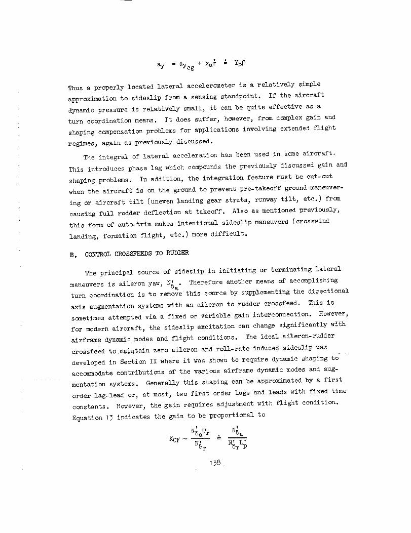
ay = aycg + xar _ Y6_
Thusa properly located lateral accelerometeris a relatively simple
approximation to sideslip from a sensing standpoint. If the aircraftdynamicpressure is relatively small, it canbe quite effective as aturn coordination means. It does suffer, however,from complexgain andshaping compensationproblemsfor applications involving extendedflight
regimes, again as previously discussed.
Theintegral of lateral acceleration has beenused in someaircraft.This introduces phaselag which compoundsthe previously discussed gain and
shapingproblems. In addition, the integration feature must be cut-outwhenthe aircraft is on the ground to prevent pre-takeoff groundmaneuver-iug or aircraft tilt (unevenlauding gear struts, runwaytilt, etc.) fromcausing full rudder deflection at takeoff. Also as mentionedpreviously,this form of auto-trim makesintentional sideslip maneuvers(crosswiud
landing, formation flight, etc.) moredifficult.
B. CONTROLCROSSFEEDSTORUDDER
Theprincipal source of sideslip in initiating or terminating lateralmaneuversis aileron yaw, N' Therefore another meansof accomplishing5a"turn coordination is to removethis sourceby supplementingthe directionalaxis au_nentation systemswith an aileron to rudder crossfeed. This issometimesattemptedvia a fixed or variable gain interconuection. However,for modernaircraft, the sideslip excitation can changesignificantly withairframe dynamicmodesandflight conditions. The ideal aileron-ruddercrossfeed to maintain zero aileron androll-rate induced sideslip wasdevelopedin Section II where it was shownto require dynamicshaping toaccommodatecontributions of the various airframe dynamicmodesand aug-mentatiou Systems. Generally this shaping canbe approximatedby a firstorder lag-lead or, at most, two first order lags and leads with fixed timeconstants. However,the gain requires adjustmentwith flight condition.
Equation 13 indicates the gain to be proportional toT
NSaT r N'5aq
KCFN-- =N' "N, L'5r "St P
138 •

The influence of flight condition is morereadily seenby expressing thegain in coefficient form andwith the ratio of yawcoefficients in aircraftbody rather than stability axis, viz.,
C !
= --C_8a B -C_gaBnSas Cn_a B cos m sin m sin
Cnsr B C_5rB " CnSrBC_srs = cos _ -- sin _ = cos
at high
Thus
pSUb2 C_p
KCF _ C_SaB
CnSrB
tan
The ideal crossfeed gain is thus proportional to angle of attack and inversely
proportional to aircraft velocity. The sign of crossfeed might also vary
with aircraft configurations (i.e., swing wing aircraft).
It should also be noted that the foregoing applies only to aileron
induced maneuvers for which turn coordination is desired. There are
situations where non-zero sideslip maneuvers are necessary (e.g., cross-
wind landings). For such cases, the addition of a washout on the cross-
feed will allow unopposed steady sideslip maneuvers.
As indicated in Section II, aileron to rudder crossfeeds have been
employed on many aircraft. None, however, have been formulated on the
basis of the foregoing total system approach and therefore have met with
varying degrees of success. Table 3 summarizes a few of the configurations
used.
139

TABLE 3. SUMMARY OF CONFIGURATIONS UTILIZED
O
ARI FORM
Fixed gain
AIRC_FT/_STEM
F-4
_CHANI_TI_
Electr_mechanic_, stick _dder
F- 14 Mechanical, stick-rudder
B-58 Electro-mechanical, aileron-rudder f(m, h)
Variable gain ......A-7 Electro-mechanical, aileron-rudder f(5 e trim)
K(s + _)Fixed gain and
compensation
Fixed compensation
variable gain
F- 4/TWeadD I
F-4/_WeaD II
F-89
F-4/SFCS
Variable gain and
compensation
Electronic r c =(s + .3)(s + 10)
5 a
Electronic rcK(_)(s+ 9)2
(s + .3)(s + 10)
Electronic 5r = _ 5a(s+I)
i i
Low speed rc = K1s Pc(s + .2)
Mid speed rc =K2s
(s + .2)(s + .5) PC
High speed r c = 0
Fixed gain crossfeeds generally are employed to overcome a specific
airframe deficiency and/or improve turn coordination in a limited portion
of the flight envelope-- usually lauding. These mechanizations are then
engaged upon lowering flaps or gear. Mechanical systems have often proven
quite troublesome because of the considerable uncertainty in prediction of
key stability derivatives and parameters before actual flight and the
inherent problems in changing a mechanical system after the aircraft starts
flying.
The variable gain crossfeeds for the B-_8 and A-7 are designed to reduce,
but not eliminate, aileron yaw. The B-58 nominally had strong proverse
aileron yaw. An adverse yaw mechanical 5a-5 r interconnect was used to
cancel the major portion of this yaw. A relatively small authority elec-
trical crossfeed with gain and sign a function of Mach and altitude was
then employed as a vernier adjustment to the mechanical interconnect. The
adverse yaw ARI interconnect, however, aggravated control in engine out
situations where it is necessary to hold aileron opposite to the engine out.
Therefore it was necessary to also include a high gain feedback of lateral
acceleration to rudder to overcome the rapid yaw that could develop under
engine out conditions. Unfortunately, the peculiarities of this aircraft
required the use of a rather large rudder authority coordination system.
The A-7 aircraft exhibits adverse aileron yaw at high angle of attack
and proverse at low angle of attack. Therefore the ARI crossfeed is
scheduled with trim elevator position to reduce the variation in aileron
yaw rather than actually provide turn coordination.
The meaD I ARI mechanization is very close to the form derivedln
Subsection A preceding although the specific compensation time constants
were derived through pilot selection in flight test. The low frequency
lag is slightly lower than the yaw damper washout [(I/Two ) = 0.5] while
the high frequency lag is probably somewhat higher than the augmented roll
subsidence (I/T_). This fixed gain system provided "good" turn coordination
over the speed ranges frcm low subsonic to low supersonic.
The T_eaD II ARI mechanizatlou again was selected on the basis of flight
trials but with emphasis on optimizing turn coordination in high angle of
attack maneuvers, alr-to-alr_ and air-to-ground tracking tasks. This flight
t41
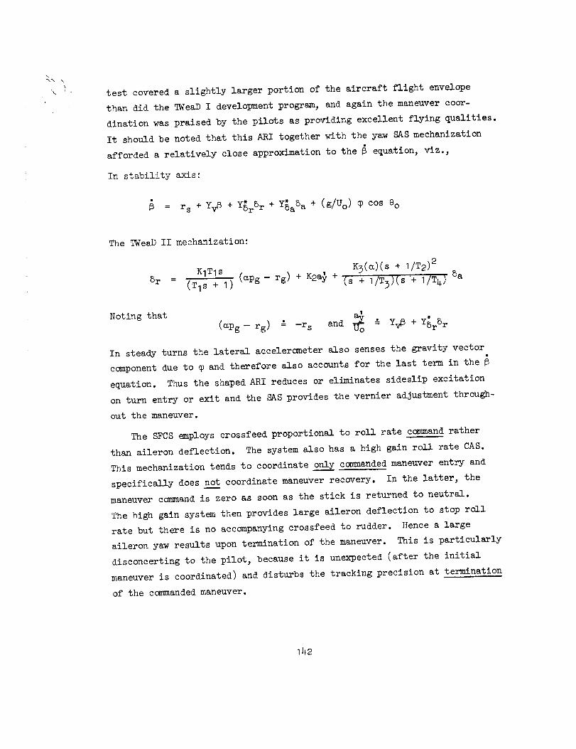
\
test covered a slightly larger portion of the aircraft flight envelope
than did the T_eaD I development program, and again the maneuver coor-
dination was praised by the pilots as providing excellent flying qualities.
It should be noted that this ARI together with the yaw SAS mechanization
afforded a relatively close approximation to the _ equation, Viz.,
In stability axis:
= rs + yv_ + Y_rSr + y_aSa + (g/Uo) $ cos eo
The TWeaD II mechanization:
5r
KITIS K3(e)(s + I/T2) 2
'(TIS + I) (mpg- rg) + K2a_ + _s + I/T3)(s '+'I/T4) 5a
Noting that _o Y5rSr(mpg-- rg) _ -rs and _ Y_6 + *
In steady turns the lateral accelercmeter also senses the gravity vector
component due to $ and therefore also accounts for the last term in the
equation. Thus the shaped ARI reduces or eliminates sideslip excitation
on turn entry or exit and the SAS provides the vernier adjustment through-
out the maneuver.
The SFCS employs crossfeed proportional to roll rate con_nand rather
than aileron deflection. The system also has a high gain roll rate CAS.
This mechanization tends to coordinate only commanded maneuver entry and
specifically does no__tcoordinate maneuver recovery. In the latter, the
maneuver ccmnand is zero as soon as the stick is returned to neutral.
The high gain system then provides large aileron deflection to stop roll
rate but there is no accompanying crossfeed to rudder. Hence a large
aileron yaw results upon termination of the maneuver. This is particularly
disconcerting to the pilot, because it is unexpected (after the initial
maneuver is coordinated) and disturbs the tracking precision at termination
of the commanded maneuver.
_42
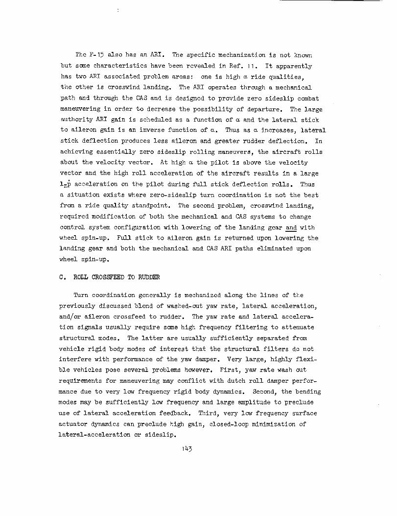
The F-15 also has an ARI. The specific mechanization is not known
but some characteristics have been revealed in Ref. 11. It apparently
has two ARI associated problem areas: one is high _ ride qualities,
the other is crosswind landing. The ARI operates through a mechanical
path and through the CAS and is designed to provide zero sideslip combat
maneuvering in order to decrease the possibility of departure. The large
authority ARI gain is scheduled as a function of a and the lateral stick
to aileron gain is an inverse function of _. Thus as a increases, lateral
stick deflection produces less aileron and greater rudder deflection. In
achieving essentially zero sideslip rolling maneuvers, the aircraft rolls
about the velocity vector. At high a the pilot is above the velocity
vector and the high roll acceleration of the aircraft results in a large
izp acceleration on the pilot during full stick deflection rolls. Thus
a situation exists where zero-sideslip turn coordination is not the best
from a ride quality standpoint. The second problem, crosswind landing,
required modification of both the mechanical and CAS systems to change
control system configuration with lowering of the landing gear and with
wheel spin-up. Full stick to aileron gain is returned upon lowering the
landing gear and both the mechanical and CAS ARI paths eliminated upon
wheel spin-up.
C. ROLL CROSSFEED TO RUDDER
Turn coordination generally is mechanized along the lines of the
previously discussed blend of washed-out yaw rate, lateral acceleration,
and/or aileron crossfeed to rudder. The yaw rate and lateral accelera-
tion signals usually require some high frequency filtering to attenuate
structural modes. The latter are usually sufficiently separated from
vehicle rigid body modes of interest that the structural filters do not
interfere with performance of the yaw damper. Very large, highly flexi-
ble vehicles pose several problems however. First, yaw rate wash out
requirements for maneuvering may conflict with dutch roll damper perfor-
mance due to very low frequency rigid body dynamics. Second, the bending
modes may be sufficiently low frequency and large amplitude to preclude
use of lateral acceleration feedback. Third, very low frequency surface
actuator dynamics can preclude high gain, closed-loop minimization of
lateral-acceleration or sideslip.
143

In such situations bank angle-to-rudder has been used as the basic
turn coordination loop. This feedback is appropriately gain compen-
sated with dynamic pressure and introduced to the damper loop as the
zero sideslip yaw rate command rc " (g/U) q0. Roll rate is also fed
to rudder to provide lead. A system survey sketch for these feedbacks
is presented in Fig. 55. Note that the spiral is greatly destabilized
since the system commands rudder to convert any bank angle that develops
(e.g., due to gust) into a coordinated turn. Also note these feedbacks
increase dutch roll damping. The resulting yaw axis turn coordination
and damper block diagram is shown in Fig. 56.
In order to restabilize the spiral mode, it is necessary to close
the bank angle-to-aileron loop at all times. The block diagram is
shown in Fig. 57 and a system survey plot of the resuJting lateral-
directional dynamics is shown in Fig. 58. It may be uoted from the
survey plot that a minimum gain is required to move the spiral back
into the left half plane and that any further gain increase rapidly
couples the spiral and roll subsidence into a quadratic "lateral phugoid"
which can be objectionable from a handling quality standpoint.
Finally, it should be noted that closure of the roll to aileron loop
modifies the yaw rate-to-rudder numerator quadratic (_r) in a beneficial
manner similar to that of p _ 8a. That is, the coupled numerator is
r + Kq_NSaSrN5 r
and the effective zeros follow the locus indicated in the following
typical survey sketch. As _r moves toward the real axis, separation
of _r/_d increases and the effectiveness of yaw rate feedback to rudder
in damping dutch roll is improved.
iW
t_

( K_p_) A¢_ (s+ I/T_, )( s + I/TC_z )YOL = Kp s+ (s+l/Ts)(S+l/TR)[S2+2_dWdS+Wd 2]
I I
_, P "-*" Br jw
--,6
i
--_ ×_1 I.L ± ±
.4
.2I
O"
OdB
± ITC'z 0.1
)__ -_ . Kp= .32
T
_I ±T_,'%
Icu( rad/sec ) 1.0
Figure 55. Survey Sketch for Bank Angle-to-Rudder

_ _._IScheduled _deg Gain, GI
[_ qcIb/ft z
I
deglsec--IGain.G21 I
I
1+O.05s
Rdeg/sec
Manual andAutopilot
Inputs
BeFr_di:rg + 20deg [ Actuotor
C-o_
0.34
GI
0.157
0.07
GAIN SCHEDULES
2.58
G2
0.78I
0.32
I I ! 040 I00 250
q¢
i
I I I,250
40 IO0 qc
Figure 56. Yaw Stability Augmentation System (SAS)

RollRoteGyro
CADC I
AHRU I
deg/sec T 1+O.05s I
A/P ON
qc
Ib/ft 2
deg 1+O.05s Gain, G
Bending Sac
Fi Iter +-.30deg
I(1+O.06s) z
Manual andAuto ,ilot
In )uts
Actuator
'1+0.25s I deg
Total
GAIN SCHEDULE
0.48
G
0.055
l
I I0 40 125
Dynamic Pressure, qc
Figure 97. Roll Stability Augmentation System (SAS)
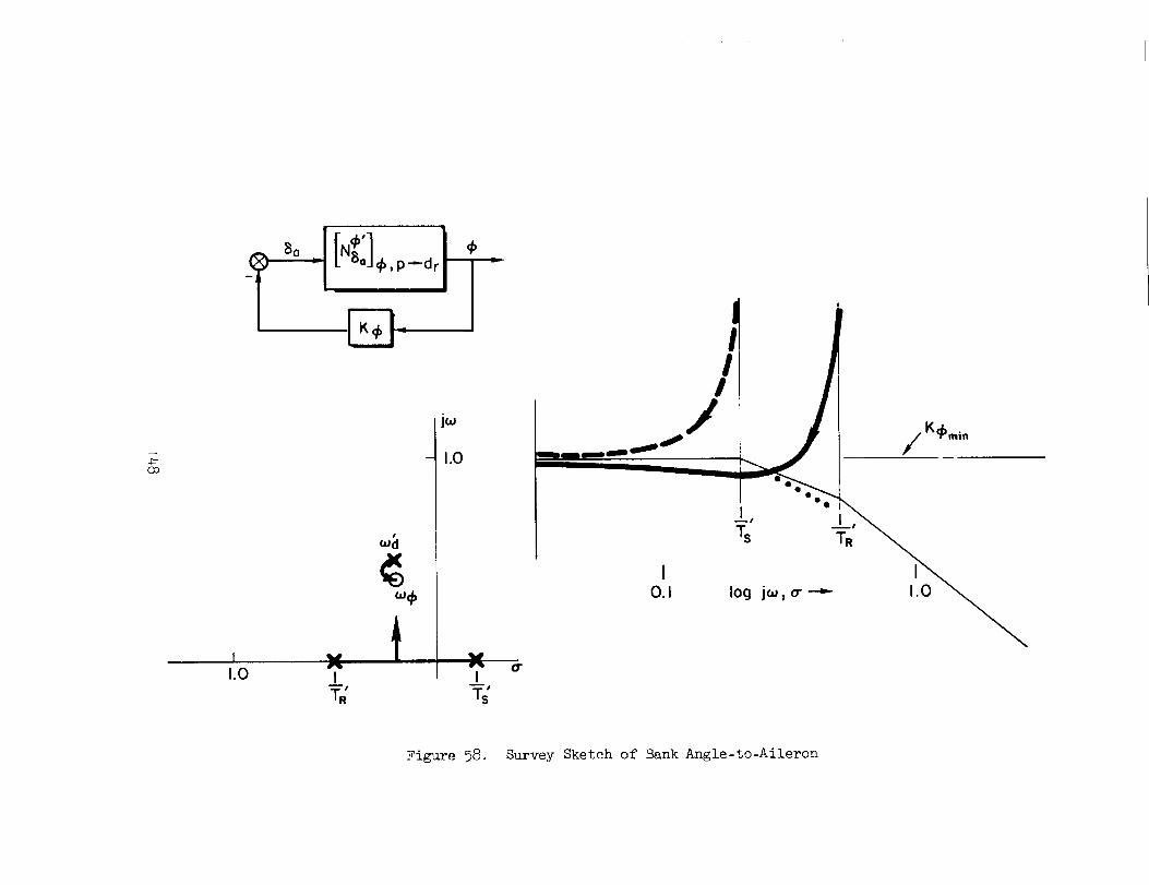
7-(30
1.0 I
$
w
IQ-
/K_min
0.1 log j_,o'_ I
Figure 58. Survey Sketch of Bank Angle-to-Aileron

While the foregoing mechanization accomplishes the intended functions
of dutch roll damping and turn coordination there are several associated
problems. First, the mechanization is comparatively complex with all roll
and roll rate gains scheduled with dynamic pressure. Second, stability
of the spiral and/or presence of a "lateral phugoid" depends upon cancel-
lation of effects and hence is sensitive to airframe parameter and system
gain changes. Third, if any one feedback is lost the remaining system
degrades the basic airframe flying characteristics and will necessitate
turning off all feedbacks in both axes. This then leads to the use of
massive redundancy to avoid the complete loss of any one signal.
I_9
REFERENCES
I. McRuer,Duane,Irving Ashkenas,and DunstanGraham,Aircraft Dynamicsand Automatic Control, Princeton Univ. Press., New Jersey, 1974.
2,
3,
.
Stapleford, R. L., D. T. McRuer, L. G. Hofmanu, and G. L. Teper,
A Practical Optimization Design Procedure for Stability Augmen-
tation__ AFFDL-TR-70-11, Oct. 1970.
Ashkenas, Irving L., and Duane T. McRuer, Approximate Airframe Transfer
Functions and Application to Single Sensor Control Systems, WADC
TR-58-82 , June 19_8.
Ashkenas, Irving L., Gordon E. Click, Dunstan Graham, James W. Hager,
et al, Aircraft Hydraulic Servomechanisms, Richard A. Peters andDunstan Graham, Ed., Systems Technolo-_-7-,Ihc., TR 129-2, Mar. 1969.
5. Johnston, Donald E., Irving L. Ashkenas, and Jeffrey R. Hogge, Inves-
tigation of Flying Qualities of Military Aircraft at High Angles
of Attack, AFFDL-TR-74-61, June 1974.
E. Graham, Dunstan, and Duane McRuer, Analysis of Nonlinear Control Systems,
Dover Publications, Inc., New York, 1971.
7.Gelb, Arthur, and Wallace E. Vander Velde, Multiple-Input Describing
Functions and Nonlinear System Design, McGraw-Hill Book Company,
1968.
8. Graham, Dunstan, and Lee Gregor Hofmann_ Investigations of Describing
Function TechniQue, AFFDL-TR-65-13% Feb. 1966.
9. Howell, G. D. 3 "Advances in Aircraft Control Systems with ParticularReference to Combat Aircraft," AGARD Conference Proceeding No. 62,
Preliminary Design Aspects of Military Aircraft, Sept. 1969.
10.
11.
Research and Development Automatic Flight Control System: Design,
Installation and Flight Evaluation in Model F8U-IP, Chance Vought
_ircraft Rept. E9R 12185, 30 June 1959.
Seventeenth Symposium Proceedings, 1973 Report to the Aerospace Prof-
fession, SETP, Tech. Review, Vo±. 11, No. 4, 26-29 Sept. 1973.
_5o

BIBLIOGRAPHY
Abrams, C. R., A New Concept in Automatic Fli_ht Control, Final Report,NADC AM 6904, 13 Feb. 1969.
Abzug, Malcolm J., High-Speed Stability and Control Problems as They AffectFlight Testing, AGARD Rept. 120, May 1957.
Allender, J. Reverdy, and Robert M. White, F-IO2A Phase IV Stability Test,AFFTC-TR-57-5, Apr. 19_7.
Archer, Donald D., and Charles L. Gandy, Jr., T-37A Phase IV Performance
and Stability and Control, AFFTC-TR-56-37, Feb. 1957.
Aston, P., _-2C Pitch Axis Control System An_, Lear Siegler, Inc.,Astronics Div., InterlOffice Correspondence SA69-239, 15 Oct. 1969.
Bielka, R. P., A. P. Kavalok, W. L. Johnson, and R. E. Reel, Aircraft Fli_h$
Control Systems Field Safety Exl0erience , Air Force Flight Dynamics Lab.TR-T2-33, May 1972.
Burrows, I. L., F-15 Progress Report: Part II, SETP 1973 Report to the
Aerospace Profession, 17th Symposium Proceedings, Sept. 1973.
Burtner, S. K., and Charles T. Garrington_ Automatic Control and Stabilization
System, Engineering Report, North AmericanAviation, Inc. Report NA59H-238,May 19, 1959.
Carleton, David L., and Cecil W. Powell, Limited Air-to-Air Tracking land
Qualitative Flying _ualities Evaluation of Selected Flight Control System
Configurations in the F-4C/E Aircraft, AFFTC-TD-T1-4, Aug. 1971.
Carleton, David L., Richard E. Lawyer, and Cecil W. Powell, Development andEvaluation of the mead II Flight Control Augmentation System, AFFTC-TD-72-1,Nov. 1972.
Ciscel, B. H., A Description of the Honeywell E-lO Flisht Control System,Minneapolis-Honeywell Regulator Co. Rept. R-ED 9048-2, 28 May 1954.
Crawford, Charles C., and Jones P. Seigler, KC-135A Stability and ControlTest, AFFTC-TR-58-13, May 1958.
Darrieus, Bernard, Concorde Fli6ht Control System, presented at the SAE A-18
Committee Meeting No. 20, Boston, Mass., Aug. 1967.
Dempster, John B., and Kenneth L. Roger, Flight Test Evaluation of an Advanced_Stability Augmentation System for the B-52 Aircraft, AIAA Paper No. 68-10_8,Oct. 1968.
Dempster, John B._ and Kenneth L. Roger_ Evaluation of B-52 Structural Responseto Random Turbulence with Various Stability Augmentation Systems, AIAAPaper No. 66-998, Nov° 1966.
151
Devlin, B. Terry, andRobert H. Parker, '_TheSP-77Automatic Flight ControlSystemfor the 737," Sperry Rand Engineering Review, Vol. 20, No. 3,
1967, pP. 26-33.
Eldridge, W. M., Lateral Control Au6mentation for Transport Aircraft, pre-sented at the Boeing Conference on Manned Vehicle Flying Qualities,
Seattle, Wash., Mar. 1962.
Ettinger, Robert C., Robert L. MaJoros, and Cecil W. Powell, Air Force Evaluation
of the Fly-By-Wire Portion of the Survivable Fli6ht Control System Advanced
Development Program, AFFTC-TR-73-32, Aug. 1973.
Falkner, V. L., Functional Configuration of Pre-Production No. B, AFCS,
Honeywell, Inc., SEN No. ll5.009OA, 6 Aug. 1970.
Finch, Thomas W., and Gene J. Matranga, Launch , Low-Speed, and LandingCharacteristics Determined from the First Fli6ht of the North American
X-l_ Research Airplane, NASA TMX-195, Sept. 1959-
Fling, G. K., XC-124A Control System, SAE Paper No. 670571, June 1967.
Gaertner, R. V., R. C. McLane, and V. Baxter, Flare Out Program for Air ForceType E-lO Automatic Pilot, Minneapolis-Honeywell Regulator Co. Aero Rept.
AD5501-TR1, 15 Aug. 1957.
Gerrity, Robert J., Test and Evaluation of a Versatile Drone Automatic Flight
Control System for the BQM-34A, Society of Flight Test Engineers ReportNo. 13, presented at the Symposium on Test and Evaluation of Automatic
Control Systems, Aug. 31, Sept. 1-2, 1971.
Guion, H. D., Regulus II Lot I AutopilotmSection IX, Chance Vought AircraftService Training Manual, Jan. 11, 1956.
Hanke, C. Rodney, and Donald R. Nordwall, S_mt41atioo_ of a Ju_o Jet TranswortAircraft. Vol. II: Modeling Data, Boeing Co. Rept. D6-30643, Vol. II,
Part l, Sept. 1970.
Hannegan, E. A., Evaluation and Flight Test of Self Adaptive Automatic FlightControl Syst_, Report No. l_ General Electric System, NATC ProJ. TED
No. PTR-RAAV-43021, FT2121-39, 7 Feb. 1961.
Harper, Robert P., Jr., In-Fl_ght Sin_j1ation of the Lateral-Directional Handling
_ualities of Entry Vehicles, WADD-TR-61-147, Feb. 1961.
Harris, Pat, Some Aspects of the 727 Flight Control System, presented at theSAE A-18 Committee Meeting No. 14, New York, July 1964.
Hart, John E., and Harold A. Valery, C-5A Flight Control Report (Aerospace Vehi-
cle). Flight Control Subsystem. Volume I, Lockheed-Georgia Company Report
No. LGIUS42-2-1, 17 Dec. 1966.
152

Hendrick, R. C., A. J. Bailey, L. D. Edinger, et al., Desi6n Criteria for
Hi6h Authority Closed Loop Primary Fli6ht Control Systems, AFFDL-TR-71-78,Aug. 1972.
Hilburger, E. A., Control Systems Desi6n Report for A_J-1 Attack Airplane,North American Aviation, Inc. Report NA 59H-98, lO Apr. 1959.
Hillman, W. J., and W. Titchnell, Avionic Fli_ht Control System (AFCS),
(Preliminary), Lockheed-California Co. Document No. TB3002, 29 Mar. 1968.
Hoey, Robert G., and Louis W. Schalk, Air Force Evaluation of the Automatic
Pitch Control for the F-IO4A, AFFTC TN 5?-ll, Feb. 1957.
Howell, G. C., Flight Experience of Rate Demand Control Using Electric Signal-
ling in the Avro 707C Aircraft, AGARD Report No. 536, May 1966.
Hurt, George J., Jr., and James B. Whitteu, Flight Investigation of an AutomaticPitchup Control, NASA TN D-If4, Aug. 1960.
Jamison, Gene S., C-_A Flisht Control System, SAE Paper No. 670574, presented
at the Aerospace Systems Conference, Los Angeles, Calif., June 27-30, 1967.
Jex, H. R., Summary of T-38A PIO Analyses, Systems Technology, Inc., TR-239-IJan. 1963.
Johnston, D. E., and R. K. Heffley, Preliminary. Assessment of the F-14ALonsitudinal Handlin5 Characteristics, Systems Technology, Inc., TR-193-1 ,Oct. 1970.
Johnston, D. E., O. Imai, and D. D. Miles, F-89D Sideslio Stability Au_nenter
Operation and Maintenance_ Airplanes N-2216 through N-4>_, NorthropAircraft, Inc., Rept. No. NAI-54-767, 15 Oct. 1953.
Johnston, D. E., and D. H. Weir, An Assessment of Operational and Cost Trade-off Factors for a T_ical High Performance AFCS, Systems Technology, Inc.TR-119-1, June 1962.
Kastner, T. M., and R. H. Soderquist, Evaluation of a General Electric Self
Adaptive Flight Control System in the F-4AAirplane, Final Report, NATCTech. Rept. FT2123-49R-64, 8 July 1964.
Kempel, Robert W., Analysis of a Coupled Roll-Splral-Mode I Pilot-Induced
Oscillation Experienced with the M2-F2 Liftin S Bod_, NASA TN D-6496,
Sept. 1971.
Kisslinger, Robert L., and George J. Vetsch, Survivable Flight Control System,Interim Report No. l, Studies, Analyses and Approach. Supplement for
Control Law Development Studies, AFFDL-TR-71-20, Suppl. 2, May 1971.
IaGue, T., F-IO6A Damper Systems, Convair Rept. DC-8B-135, Rev. A, Ii Mar. 1958.
153

Lindahl, J., W. McGuire, and M. Reed, Advanced Flight Vehicle Adaptive Flight
Control System. Part VII: Final Report on Study, Development_ and Testof the MH-96 System for the X-l>, WADD-TR-60-651 (VII), Dec. 1963.
Martin, C. E., Preliminary. Flight Control Subsystem Ensineering Report for
the F-111A_ Aircraft, General Dynamics, Fort Worth, Rept. FZM-12-874,
Oct. 1964, (Rev. 26 Jan. 1965).
McEntire, Kenneth G., and E. H. Underwood, Jr., Flight Test Evaluation of the
A-?D/E Emergency ("Back-Up") Flight Control System, Society of Flight
Test Engineers Report No. 14, Aug.-Sept. 1971.
Miller, H., and R. H. Wagner, Flight Control System for Jet Transports,
Sperry Gyroscope Co., no date.
Mueller, Leo J., Some Experiences in VTOL Automatic Flight Control, presen-ted at the SAE A'18 Committee Meeting No. 14, New York, July 196_.
Naumann, Erwin A., and Herman Schmier, "Design and Development of the Stability
Augmentation System for the Lockheed/Army XV-4A," Proc. of the 20th AnnualNational Forum of the American Helicopter Society, Washington, D. C.,
May 1964, pp. 140-151.
Newberry, C. F., B-52 Autopilot Modification, Boeing Company Technical Paper
D3-4525, prese--nted to SAE Committee A-18 Aerospace Vehicle Flight Control
Systems, 14 June 1962.
Quinlivan, R. P., Multimnde Flight Control Definition Study, AFFDL-TR-T2-55,
May 1972.
Rabenberg, B. E., and J. J. Gondek, XB-70 Flight Control System Summary Test
Re___22_, North American Aviation, Inc. Report NA-66-360, 30 Sept. 1966.
Rickard, Richard R., Stability and Control Evaluation of an F-4C Aircraftwith a High-Gain Adaptive Control Augmentation System, AFFTC-TR-71-1y,
June 1971.
Rickard, Richard R., and Jerauld R. Gentry_ Development Testing of a High-Gain
Adaptive Control A_gmentation System Inst_1 ]ed in an F-4C Aircraft,AFFTC-TD-70-4, Vols. I and II, Sept. 1970.
Rickard, Richard R., Richard H. Kogler, and Cecil W. Powell, Stability andControl Evaluation of an F-4C Aircraft with a High-Gain Adaptive Control
Augmentation System, AFFTC-SD-71-17, June 197 I.
Russell, Walter, R._ and William L. Alford_ Fl__ightInvestigation of a Centrally
Located Rigid Force Control Stick Used with Electronic Control Systems in
a Fighter Airplane, NASA TN-D-102, Sept. 1959.
Russell, Walter R., Sigurd A. Sjoberg_ and William L. Alford, A Fli.ght Investi-
gation of the _nallng Characteristics of a Fighter Airplane ControlledThrough a Rate Type of Automatic Control System, NACA RM L56F06, Sept. 1956.
154

Russell, Walter R., Sigurd A. Sjoberg, and WillimmL. Alford, Flight Investiga-
tions of Automatic Stabilization of smAirplane Having Static Longitudinal
Instability, NASA TN D-173, Dec. 1959.
Sanctuary, G. E., and A. M. Roberto, Low Speed "Adverse" Yaw Flight Simulator,
Evaluation, General Dynsmtics/Fort Worth Div., S/C TMNo. 52, 28 Oct. 1966.
Schuetz, A. J., R. L. Fortenbaugh, and W. E. Becker, An Aerodynamic Stabilitz
and Control Data Summary for Several Selected Military Aircraft_ Volume I:Conventional Aircraft, Naval Air Development Center Report AM-7106,
28 Sept. 1971.
Seacord, Charles L., The Honeywell AFCS (MH-I_) for the Swedish Viggen (AJ-37)Aircraft, Honeywell, Inc., Report T-230, circa 1969.
Seeman, William G., and Floyd H. Moody, Usin_ the Man to Test Unmanned Aircraft,Society of Flight Test Engineers Report No. 16, presented at the Symposium
on Test and Evaluation of Automatic Control Systems, Aug. 31, Sept. 1-2, 1971.
Seth, W. A., A-TD Estimated F_ying Qualities, LTV Vought Aercnautics Report
No. 2-53320/8R-8089, 15 Jan. 1998.
Sexton, H. A., Jr., Flight Testing the F-104 Automatic Flight Control System,AIAA Paper No. 64-328, July 1964.
Shah, N. M., G. Gevaer% and L. O. Lykken_ The Effect of Aircraft Environment
on Category III Autoland Performance and Safety, AIAA Paper No. 72-811, -AUg. 1972.
Shields, M. E., Estimated Flying qualities XC-142A V/STOL Assault Transport,
LTVVought Aeronautics Division Report No. 2-53310/4R 939, 22 May 1964.
Simmons, Carl D., and Donald M. Sorlle, F-IOIB Air Force Stability and ControlEvaluation, AFFTC-TR-58-11, May 1958.
Sjoberg, Sigurd A., Walter R. Russell_ and William L. Alford, A Fli_ht InvestiEa-
tion of the Handling Characteristics of a Fighter Airplane ControlledthrouEh an Attitude Type of Automatic Pilot, NACA RM L56A12, April 1956.
Sjoberg, Sigurd A., Walter R. Russell_ and William L. Alford_ Flight Investiga-
tion of a Normal-Acceleration Automatic Longitudinal Control System in aFighter Airplane, NASA Memo 10-26-58L, Dec. 1958.
Taylor, Lawrence W., Jr., Analysis of a Pilot-Airplane Lateral InstabilityExperienced with the X-15 Airplane, NASA TN D-1059, Nov. 1961.
Teper, Gary L., and Richard H. Klein, Analysis for the MQM-74A Drone Contro_
System, Systems Technology, Inc., TR-279-I, Feb. 1968.
Terrill, W. H., L. R. Springer, and J. G. Wong, Investigation of Pilot-Induced
Longitudinal Oscillation in the Douglas Model A4D-2 Airplane, DouglasAircraft Company, Inc., Rept. LB-25452, May 15, 1957.
155

Tomlin, K. H., C-_ Flight Control Report (Aerospace Vehicle) Stability and
Control, Lockheed-Georgia Company Report No. LGIUB42-1-1, 1 Oct. 1966.
Townsend, Marland W._ and William B. Rhodes, Flight Evaluation of the LearAdvanced Automatic Flight Control System (AFCS) Installed in an F-8D
Airplane, Final Report, NATC Tech. Rept. FT2121-63, 31 Dec. 1963.
Tremant, Robert A., _erational Ex?eriences and Characteristics of the X-l_
Flight Control System, NASA TN D-1402, Dec. 1962.
Wolowicz, C. H._ and R. B. Yancey, Summary of Stability and Control Character-
istics of the XB-?O Airplane, NASA TM X-2933, Oct. 1973.
Advanced Automatic Flight Control System for Attack/Fishter Aircraft, Lear
Siegler, Inc., Rept. ADR-565, 15 Feb. 1964.
Automatic Flight Control System, Control Stick Steering, Evaluation of Report
No. i_ Interim Report, NATC Proj. TED No. FI'_ AV-37009, ST312-190, 2 June
1959.
Automatic Flight Control Systeml Control Stick Steering_ Evaluation of, Report
No. 21 Final Report, NATC ProJ. TED No. PTR AV-37009, ST312-283, lO Aug. 1959.
B-_2 Autopilot Modification, Boeing Company Document D3-4360, 15 March 1962,
presented at the Boeing Conference on Manned Vehicle Flying Qualities,
Mar. I_-16, 19_2_ Seattle, Washington.
B-58 Flight Control System Air Force Review Board, General Dynsmlcs/Fort Worth
- FZE-4-049, 6 Nov. 1962.
Current Autopilot Block Diagrams, SAE A-18 Committee, Oct. 1959.
Experience with the X-l_ Adaptive Fli_ht Control System, NASA TN D-6208,
Mar. 1971.
F-I] ] Category I Flight Test Progress Report, Pre!_m_n_a_ry Stabilit_ and Control/
Flight Control Subsystem Fli_ht Test Results, General Dynamics/Fort Worth
Div., Rept. FZM-12988-13-2, 14 Feb. 1966. (Report Confidential, Title
Unclassified)
Flight Control Systems for F-IOOF Airplane, North American Aviation, Inc.,
Rept. NA56-731, 1956.
Flight Manual_ USAF Series F-IOOC, Air Force T.O. 1F-lOOC-1, 22 Dec. 1960.
Flight Manila!, USAF Series F-lOiA and F-101C, Air Force T.O. 1F-lOiA-1, 15 May
-- 1962.
FlIEht Manual_ USAF Series F-102 and TF-IO2A, Air Force T.O. 1F-lO2A-1, 4 Oct.
1962.
Flight Man_a] I USAF Series F-IO4A and F-IO4B, Air Force T.0. 1F-lO4A-1,
15 Dec. 1961.
156

Flight Manual_ USAF Series F-IO5B, Air Force T.O. IF-IO5B-I, 15 July 1962.
Fli6ht Manual, USAF Series C-I_OA Aircraft, Air Force T.O. IC-130-i,lO Jan. 1963.
Fligrht Manual, USAF Series C-133A and C-133B Aircraft, Air Force T.O. IC-133A-I,14 June 1962.
Flight Manual, USAF Series C-135A and B-
1 Mar. 1963., Air Force T.O. IC-135A-I,
Handbook Operation and Maintenance Instructions__MH-6? Automatic Flight
Control System , Publication No. 95-4256B, May 1964.
The Honeywell Flight Boundary Control System, Honeywell, Inc., Government andAeronautical Products Div., Brochure ADC 364, Jan. 1972.
Maintenance Instructions Manual_ Navy Models F-4B and RF-4B Aircraft_ Fli6htControl Group AN/ASA-_2 Series and Related Systems, NAVWEPS O1-245FDB-2-6.3,1 Dec. 1965.
Maintenance Manual, Flight Control Systems, USAF Series F-102A and TF-IO2A, AirForce T.O. 1F-lO2A-2-7, 5 Jan. 1962.
Maintenance Manual, Fligh t Control Systems_ USAF Series F-IO6A and F-IO6BAircraft, 20 Dec. 1962.
MH-96 Flight Control System for the X-l_ Aircraft. Vol. V: System Descrip-tion and Bench Test Procedure, Minneapolis-Honeywell Regulator Co. Aero
Report 2373-TMI (Vol. V), _Aug. 1962.
Organizational Maintenance Manual, Flight Control System@ , USAF Series T-_8A,Air Force T.O. 1T-38A-2-3, 1 Sept. 1962.
Preliminary Flight Control Subsystem Analysis for the F-IIIA/B Airplanes,General Dynamics/Fort Worth Div., Report FzM-12-278, 16 Aug. 1963.(Report Confidential, Title Unclassified)
Preliminary Flight Manual DSN-_Drone and Target Control System AN/SRW-4B,
Bureau of Naval Weapons NAVWEPS Ol-150DHB-1, 1 Jan. 1962.
Preliminary Report on Lateral Piloted Handling Quality Problems, Honeywell
Aeronautical Division, CEL No. DS 567, 12 Nov. 1963.
Presentation to ASD Division Advisory Group, General Dynamics/Fort Worth Div.,Report FZM-12-2357, June 1966.
ProDoss_l for a Product Irqprovement Program for the BQM-3_A Automatic FlightControl System (Versatile Drone Autopilot_, Lear Siegler, Inc., Astronics
Division, Report AD-975, 17 July lg70.
Report of the B-_8 Flight Control System Review Board, Sect. VII-A, Aerodynamic
Trade-Off Team Report, Aeronautical Systems Division, 5 Dec. 1962.
I}7

Research and Development, Automatic Fli_ht Control System: Design I Installa-
tion and Flight Evaluation in Model F8U-1P, Chance Vought Aircraft, Inc.,
Report E9R 12185, 30 June 1959.
Round Up Revlewl Division Advisory Group-ASD_ 21 and 22 June 1_68, Flight
- Control System/Stability and Control, General Dynamics/Fort Worth Di_.,
Report FZM-12-596_-2, 21 June 1968. (Report Confidential, Title Unclass-
ified).
S-_A Auto,tic Thrust Control System, (Unpublished notes).
S_m_]ator System Test Report for A2F-1 Airplane_ Part a, Grummau Aircraft
Engineering Corporation, Report No. AV-128R32.0, no date.
"TA-4F Accident Provides Some Costly Lessons," Approach, Vol. 15, No. 8, Feb.
1970, PP. 36-41.
Transfer Functions and Block Diagrams of the SP-3OAL Automatic Pilot and
Z-14 Flight Director as Applied to the Douglas Model DC-8-60 Series
of Aircraft, material transmitted to STI in Sperry Flight SystemsDivision letter of 29 Sept. 1969.
USAF Type A/A37G-3 Flight Control Subsystem of the Type Q-2C Drone, RyanAeronautical Co. Spec. 12459-2A, no dame.
158

INDEX
Acceleration
Lateral, 122
Normal, 108
Adverse yaw
Aileron, 12, 39, 119, 122, 141
Reduction, 13
Rolling velocity, 12
Yaw damper, 15, 17, 134
Aileron/rudder interconnect, 12, 137
Equalized crossfeed, 13, 137
Ideal crossfeed, 14
Gain variation, 137
Influence of SAS, 14
Autotrim, 95, 108, 111, 112
C.g. shift, 100
Opposition to manual inputs, 96,98, 102, 114, 137
Stick force lightening, 96
Trim rate effects, 96, 98
Backside [of thrust required curve],
32, 38, 110, 113
Bank angle control, 9
Body rate command, 120
Inertial platform sensing, 121Roll back, 121
Roll coasting, 121
Vertical gyro sensing, 121
Blended feedbacks, 113, 114, 135
Bobweight, 50, 53, 99, 109
Effective moment arm, 74, 109
Effective numerator, 74
Influence on CAS sensing, 89, 92,94
Influence on stick free dynamics,76
Pilot's arm, 90, 119
Stick force, 71
CAS command sensing, 86, 95, 97
Displacement, 93, 97
Force, 86, 97
Pseudo force, 91
CAS electrical command, 103
Gain shaping, 106, 113, 119
Mechanical nonlinearities, 87, 91,94
Phase lag, 106
Prefilter considerations, 105
Saturation (limiting), 112, 119
Threshold, 87, 93
Center of percussion, 109, 122, 136
Center of rotation, 109, 122
Command augmentation, 69
Blended normal acceleration and
pitch rate, 113
Comman_ saturation, 112, 119
Derived attitude rate, 114
Feedback saturation, 112, 119
Normal acceleration, 108, 111Pitch rate, 111
Roll attitude, 120
Roll rate, 117
Yaw rate, 122
Complexity, 80, 116, 148
Control reversal, 87Crossfeed
Aileron to rudder, 12, 137
Lateral stick to rudder, 140
Roll attitude to rudder, 142
Roll rate command to rudder, 141
Roll rate to rudder, 12, 134
Derived attitude rate, 114, 121
Dissimilar parallel paths, 82, 117,120
Divergence
Nose slice, 4, 29, 39
Path, 108
Speed, 4, 32, 108, 110
Dutch roll, 9, 11, 12, 124, 136, 143,149
Aileron excitation, 12
Reduction, 13, 122
Effective numerators, 14, 74
Equivalent system, 48, 52
Feel system, 50, 53, 86, 97, 98Breakout, 85
Linear dynamic models, 56
Damper influence, 58
Feel spring influence, 59, 86
Lags introduced, 58, 78System inertia, 59
Nonlinearities, 61
Flight path divergence, 4, 29, 108,110
Fly-by-wire, 82
Force sensing, 86, 99
Bobweight effects, 89
I_9

Force sensing (continued)Ground, 86Kickback, 89On/off transients, 90Structural bending, 90Transducer null, 90Transducer vulnerability, 90With parallel trim, 88
Forward loop integration, 99, 108,1113 112
Frontside [of thrust required curve],
33Hardover failure, 84, 95
High angle of attack, 109, 121# 131,
135Hydraulic actuator dynamics
Idealized, 24Load contributions, 20, 22, 24
No load, 24
Phase lag, 70, 98
Rate limiting, 27
Support contributions, 20, 22
Valve forces, 85
Inertial platform, 121
Integral control, 35Inverse model feedback, 119
Kickback, 69, 85, 89, 92 , 94 , 95, 99
Lateral acceleration
At pilot, 142Directional stiffening, 135
Feedback shaping, 123
Feedback to rudder, 15, 16, 122
Gain compensation, 123, 135
Integration, 137Structural mode attentuation, 123
Lateral-longitudinal coupling, 4, 11,
39, I09Limit cycle, 66, 70
Low-frequency droop, 35
Neutral speed stability, 100
Nonlinearities
Backlash, 67Describing function analysis, 64,
7oDetent, 87
Hydraulic valve friction, 69, 85
Hysteresis, 62Mechanical friction, 61, 78, 87
Preload, 87
Stiction, 87Non-minimum phase zeros, 4, 29
Altitude control, 30
Lateral acceleration, 123
Normal acceleration, 109
Pitch attitude control, 33, 39
Normal acceleration feedback
Feedback shaping, 109
Gain scheduling, 111
Gravity vector, 108
Sensor location, 109
Sensor orientation, 108
Washout, 108Nose slice divergence, 4, 29, 39
Parallel actuation, 84, 97, 103
Authority, 98
On/off transients, 99Overpower, 98
Performance reversal, 4
Corrections of I/Thl, 33
Pitch attitude, 39
Speed, path, 29
Phase lag
Hydraulic actuator, 70, 98
Pilot cues, 102, 109, 116
PIO, 3, 66, 7O, 106, 110, 119Pitch attitude control, 114
Attitude rate command, 114
Body rate command, 114
Pitch back, 114
Power boost actuator, 85, 97
Primary flight control system
Backlash, 67Detent, 87
Hydraulic valve friction, 69
Hysteresis, 62Mass imbalance influence, 89
Mechanical friction, 61, 78, 87
Preload, 61, 66, 87Stick to surface gearing, 67
Pseudo force sensing, 91
Bobweight interaction, 92
Feel system interaction, 91
Kickback, 92
On/off transients, 93Structural bending, 92
Transducer null, 92Transducer vulnerability, 93
Trim system interaction, 92
Quadratic dipole problems
Hydraulic actuator, 24
_B/_sp, 76OOr/_d, 4, 17, 132
Roll damper influence, 17
Yaw rate gyro tilt, 132
160

Quadratic dipole problems (continued)_m/_d, 3, 9, 120
'ARI influence, 13Yawdamperinfluence, 16
Rate gyros, 111Pitch rate, 111Roll rate, 117Yawrate, 131
Responsefeedback, 107Lateral acceleration, 122, 137Lateral acceleration and yawrate,
136Normalacceleration, 108Normalacceleration and pitch rate,
113Pitch attitude, 113Pitch rate, 111Roll attitude, 120, 143Roll rate, 117, 135Yawrate, 131
Right half plane zeros, 4, 29, 39,109, 123
Ruddermaneuvering, 119, 122Saturation (limiting)
Actuator position, 85Actuator rate, 69, 85, 98CAScommand,112, 119CASfeedback, 110, 112, 119
Sensor location effectsLateral accelerometer, 122Normal accelerometer, 109
Sensor orientation, 46, 108Bodyvs. Euler axis, 113, 121, 131Lateral acceleration, 131Normal acceleration, 108Roll rate gyro, 117Yawrate gyro, 131
Series actuation, 84Full authority, 84, 85Limited authority, 84, 95, 97Washed-outfeedback, 99, 100
Series servoBackup, 67, 85Ground, 85Kickback, 69, 85, 89, 92, 94, 95Support, 22
SideslipIntentional, 119, 122, 138Lateral-longitudinal coupling, 39Roll control induced, 13Sensing, 122, 136Turn coordination, 136
Speeddivergence, 4, 32, 108, 110Spin recovery, 110, 113Stall, 32, 39, 96, 108, 110, 113,
116, 119Stick displacement sensing, 93, 102
Bobweight interaction, 94Feel system interaction, 93Kickback, 940n/off transients, 94Structural bending, 94Transducer null, 94Transducervulnerability, 94Trim system interaction, 94
Stick force per g, 86, 92, 108, 111,113Augmentation, 108, 111Lightening, 89, 96, 110, 112, 114,
119Variation with gravity vector, 108
Stick nibble, 114Trim
AutomaticParallel, 95, 119Series, 99, 109
Electrical, 110Opposition of manualand automatic,
96Parallel, 88, 92, 94, 99Series, 88, 94
Turn coordination, 122, 136Valve forces
Bernoulli, 85Centering, 85Friction, 69, 85
Vertical gyro, 113, 121Washout
Aileron/rudder crossfeed, 138Normalacceleration, 108Servo feedback, 99, 111Yawrate damper, 17, 122, 134, 142
Yawrate gyroFeedbackto rudder, 14, 16, 122,
131Inclination effects, 131
ZerosIntentionally introduced, 4, 29Inverse model, 46, 119Non-minimumphase (right half
plane), 4, 29, 39, 109, 123
U.S. GOVERNMENt PRINTING OFFICE: 1975--6354)48" 59
161