Embed Size (px)
Citation preview

N A S A TECHNICAL NOTE - NASA 0, /
TN - D-5964
AN EQUATION FOR VORTEX MOTION INCLUDING EFFECTS OF BUOYANCY AND SOURCES WITH APPLICATIONS TO TORNADOES
by Robert C. Costen
Langley Research Center Hampton, Va. 23365
N A T I O N A L AERONAUTICS A N D SPACE A D M I N I S T R A T I O N W A S H I N G T O N , D. C. OCTOBER 1970 B 1 I 1
https://ntrs.nasa.gov/search.jsp?R=19700032427 2020-04-03T22:50:32+00:00Z
TECH LlBRARY KAFB, NM
1. Report No. 2. Government Accession No. 0132824 NASA TN D-5964
I 5. Re rt ate
& o k r 1970 4. Title and Subtitle
AN EQUATION FOR VORTEX MOTION INCLUDING EFFECTS OF BUOYANCY AND SOURCES WITH APPLICATIONS TO TORNADOES
6. Performing Organization Code
7. Author(s1 8. Performing Organization Report No. Robert C. Costen L-5738
10. Work Unit No. 9. Performing Organization Name and Address 129-02 -22 -0 1
1 1 . Contract or Grant No, NASA Langley Research Center Hampton, Va. 23365
13. Type of Report and Period Covered 2. Sponsoring Agency Name and Address Technical Note
National Aeronautics and Space Administration Washixgton, D.C. 20546
14. Sponsoring Agency Code I 5, Supplementary Notes
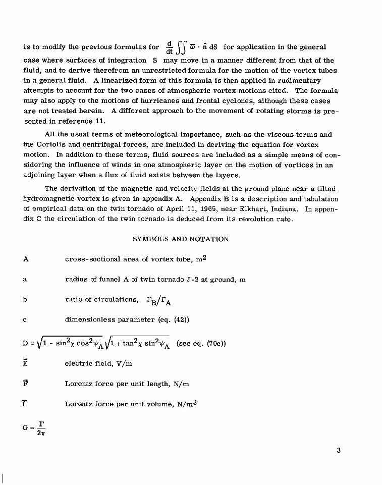
6. Abstract
A new equation is derived for the motion of vorticity in a general fluid, including the effects of viscosity, compressibility, nonhomogeneity, and nonconservative forces. equation holds, in particular, for vortices which may not move with the fluid. A linearized form of this equation is applied to tornado cyclones and to the twin tornado of April 11, 1965, near Elkhart, Indiana. It is shown that the displacement of tornado cyclones to the right of the mean tropospheric winds may be accounted for by the upward efflux of fluid from the cyclone into the jet stream. Also, the retarded revolution rate of the twin tornado may be due in part to an attractive "buoyancy" force acting on the partially rarefied cores of the pair.
The
7. Key Words (Suggested by Author(s)) 18. Distribution Statement Equation for vortex motion Hydro magnetic vortex Buoyant vortex Source - vortex Tornado Cyclone
Unclassified Unclassified 66 $3.00
Unclassified - Unlimited
20. Security Classif. (of this page) 21. No. of Pages 22. Rice' 9. Security Classif. (of this report)
~ ~~~
'For sale by the Clearinghouse for Federal Scientific and Technical Information Springfield, Virginia 72151


CONTENTS
Page SUMMARY . . . . . . . . . . . . . . . . . . . . . . . . . . . . . . . . . . . . . . . 1
INTRODUCTION . . . . . . . . . . . . . . . . . . . . . . . . . . . . . . . . . . . . 2
SYMBOLS AND NOTATION . . . . . . . . . . . . . . . . . . . . . . . . . . . . . . 3
DERIVATION OF GENERAL EQUATION FOR MOTION OF VORTICITY . . . . . . 8 Fluid Sources . . . . . . . . . . . . . . . . . . . . . . . . . . . . . . . . . . . . 8
Conservation-of -mass equation with fluid sources in integral form 8 Conservation-of-momentum equation with fluid sources in integral form . . . 8
. . . . . .
Conservation equations in differential form . . . . . . . . . . . . . . . . . . . 9 Vorticity Equation . . . . . . . . . . . . . . . . . . . . . . . . . . . . . . . . . . 10 Kinematics . . . . . . . . . . . . . . . . . . . . . . . . . . . . . . . . . . . . . 10 General Kinematic Form of the Vorticity-Flux Equation . . . . . . . . . . . . . 11 General Equation for Motion of Vorticity . . . . . . . . . . . . . . . . . . . . . . 11 Alternative Forms of the Vortex-Motion Equation for an Inviscid Fluid . . . . . 13 Linearization of Equation for Vortex Motion . . . . . . . . . . . . . . . . . . . . 15
Perturbation series . . . . . . . . . . . . . . . . . . . . . . . . . . . . . . . . 15 Physical interpretation of t e rms in linearized equation for vortex motion . . . 16 Linearized equation for the motion of isolated vortex tubes . . . . . . . . . . 16
APPLICATIONS OF LINEARIZED EQUATION FOR VORTEX MOTION TO TORNADOES AND TORNADO CYCLONES . . . . . . . . . . . . . . . . . . . . . 19 Rudimentary Approach To Be Used in the Following Applications . . . . . . . . 19 Effect of the Boundary Layer at the Ground on Tornado Motion . . . . . . . . . . 20
Description and analysis . . . . . . . . . . . . . . . . . . . . . . . . . . . . . 20 Order -of -magnitude check on boundary -layer effect . . . . . . . . . . . . . . 24
25 Effect of the Jet Stream on Motion of Tornado Cyclones . . . . . . . . . . . . . The jet stream as a sink fluid . . . . . . . . . . . . . . . . . . . . . . . . . . 25 Sample solutions for the motion of tornado cyclones . . . . . . . . . . . . . . 27
28 Occurrence of twin tornado 5-2 . . . . . . . . . . . . . . . . . . . . . . . . . 28 Tornado model . . . . . . . . . . . . . . . . . . . . . . . . . . . . . . . . . . 29 Absence of source force density despite possible convergent flow 30 Buoyancy t e rms . . . . . . . . . . . . . . . . . . . . . . . . . . . . . . . . . 31 Effect of tilt neglected . . . . . . . . . . . . . . . . . . . . . . . . . . . . . . 31 Adaptation of linearized equation for vortex motion to twin-vortex model Correlation of the twin-vortex model with data from the twin tornado
Effect of Core Buoyancy on Revolution Rate of a Twin Tornado . . . . . . . . .
. . . . . . .
. . . 31 36 . . . . .
iii

11 I I 1.111111111111.111111111111 II 1 1 1 1 1 ~ . - I ~ I - I -
Page
37 37
37
ground . . . . . . . . . . . . . . . . . . . . . . . . . . . . . . . . . . . . . 4 1
retarded revolution rate of twin tornado . . . . . . . . . . . . . . . . . . . 42
Influence of Axial Electric Current on Revolution Rate of Twin Vortices . . . . . Speculative hydromagnetic -vortex hypothesis . . . . . . . . . . . . . . . . . . Hydromagnetic -vortex model . . . . . . . . . . . . . . . . . . . . . . . . . . . 37 Equation for vortex motion with ax ia l electric current in a magnetic field . . . Solution for revolution ra te of inclined hydromagnetic vortex pair at the
Order of magnitude of axia l electric current which would account for
CONCLUDINGREMARKS . . . . . . . . . . . . . . . . . . . . . . . . . . . . . . . 43
APPENDIX A - DERIVATION OF MAGNETIC AND VELOCITY FIELDS AT THE GROUND PLANE NEAR A TILTED HYDROMAGNETIC VORTEX . . . . . . . . .
TWIN TORNADO OF APRIL 11, 1965. NEAR ELKHART. INDIANA . . . . . . . .
45
APPENDIX B . DESCRIPTION AND TABULATION OF EMPIRICAL DATA ON 53
APPENDIX C - CIRCULATION OF THE TWIN TORNADO AS DEDUCED FROM . EVIDENCE THAT THE FUNNELS MOVED MORE ITS REVOLUTION RATE
SLOWLY THAN THE FLUID . . . . . . . . . . . . . . . . . . . . . . . . . . . . 54 Circulation Estimate From Revolution Rate . . . . . . . . . . . . . . . . . . . . 54
54 Twin-vortex model . . . . . . . . . . . . . . . . . . . . . . . . . . . . . . . . 54
58
Velocity field at ground plane due to single inclined vortex . . . . . . . . . . .
Evidence That the Revolution Rate Was Retarded With Respect to the Fluid . . . REFERENCES . . . . . . . . . . . . . . . . . . . . . . . . . . . . . . . . . . . . . 60
TABLES . . . . . . . . . . . . . . . . . . . . . . . . . . . . . . . . . . . . . . . . 62
iv

AN EQUATION FOR VORTEX MOTION INCLUDING
EFFECTS OF BUOYANCY AND SOURCES
WITH APPLICATIONS TO TORNADOES
By Robert C. Costen Langley Research Center
SUMMARY
A new equation is derived fo r the motion of vorticity in a general fluid, including the effects of viscosity, compressibility, nonhomogeneity, and nonconservative forces. This equation results from a kinematical revision in the derivation of Kelvin's circulation theorem. It applies, in particular, to vortices which may not move with the fluid flow. The equation also admits fluid sources. The source te rm accounts for the influence of winds in one atmospheric layer on the motion of vortex tubes in an adjoining layer when a flux of fluid exists between the layers.
A linearized form of the equation is used to obtain possible explanations for (1) why tornado cyclones move to the right of the mean tropospheric winds, and (2) why the observed revolution rate of the funnels of a twin tornado about their common center w a s retarded with respect to the fluid flow. near Elkhart, Indiana.
This twin tornado occurred on April 11, 1965,
It is shown that the rightward motion of tornado cyclones may be attributed on the basis of order-of-magnitude calculations to the upward flux of air from the core of the cyclone into the jet stream. It is also shown that a slowdown in the revolution rate of a twin tornado would result from (1) an attractive buoyancy force acting on each partially rarefied core in the presence of the radial pressure gradient of the other vortex or (2) an attractive magnetostatic force between axial dc electric currents of like sense in both cores. was estimated to be 5 percent. The electric current required for comparable retardation is on the order of lo6 amperes, which appears to be much too large for atmospheric phenomena. According to the linearized theory, the maximum possible retardation for two buoyant vortices of like circulations and c ross sections is 22 percent. This figure applies to hollow vortices revolving about each other in near contact.
The retardation in revolution rate of the twin tornado due to buoyant attraction

INTRODUCTION
An accumulation of evidence exists that atmospheric vortices associated with severe s torms do not necessarily move with the local fluid flow. According to reference 1, pp. 71-72, and reference 2, pp. 319-321, a storm cell which is destined to become severe moves with the mean tropospheric winds during the initial stages of formation. As the storm matures it acquires cyclonic rotation (being thereafter termed a tornado cylcone, see ref. 3, pp. 3-4) and commences to move at an angle of about 25' to the right of the mean tropospheric winds in the northern hemisphere. This is an example of atmospheric vorticity which does not move with the fluid.
A second case of such deviate vortex motion is pointed up in this report. It con- cerns a twin tornado which occurred on April 11, 1965, near Elkhart, Indiana, and whose motion is documented in reference 4. Analysis of the data presented in this reference shows that the tornado pair apparently revolved about each other at a much slower rate than the fluid flow in which the tornadoes were immersed.
The explanation for these motions would seem to lie in a theory embracing the motion of vortex tubes, such as the circulation theorem of Kelvin (ref. 5, pp. 35-37).
JJ I? dS dt Kelvin obtained a formula for the time rate of change of vorticity flux
through an arbitrary surface S of finite area which moves with the fluid, where 3 = curl 7 is vorticity and 6 is the unit normal on S. (See ref. 5, pp. 35-37, and
9 T. $ which is the dt dt ref. 6, pp. 150-151, 162. By Stokes' theorem
time rate of change of circulation about the closed circuit line 1 which bounds surface S and moves with the fluid.) When the fluid is inviscid and subjected to conservative forces only, and when the density is either a constant o r a single-valued function of the pressure
2 JJ w' - 6 dS = 0, from which the con- dt
(autobarotropic fluid), this formula reduces to
clusion is reached that under these conditions, the vorticity moves with the fluid. The
A TJ 3 - 6 dS was also considered by Helmholtz, V. Bjerknes, and others dt
expression
(as mentioned in refs. 7 and 8). V. Bjerknes evaluated the expression for the case of an inviscid nonbarotropic fluid and considered the effect of the Coriolis force (as discussed
in ref. 9, pp. 233-261). The expression for 2 JJ 3 * fi dS in a viscous, compressible dt
fluid is given in reference 10, pp. 51-52.
But in all these treatments the surface of integration S (or bounding circuit loop 1) is taken to move with the fluid. What is desired is to have S. and 1 move with the vorticity, independent of the fluid, when these two motions are not the same. This distinction, being purely kinematical, is readily incorporated. The purpose of this report
2
is to modify the previous formulas for JJ G5 - dS for application in the general dt
case where surfaces of integration S may move in a manner different from that of the fluid, and to derive therefrom an unrestricted formula for the motion of the vortex tubes in a general fluid. A linearized form of this formula is then applied in rudimentary attempts to account for the two cases of atmospheric vortex motions cited. The formula may also apply to the motions of hurricanes and frontal cyclones, although these cases are not treated herein. A different approach to the movement of rotating s torms is pre- sented in reference 11.
All the usual t e rms of meteorological importance, such as the viscous t e rms and the Coriolis and centrifugal forces, are included in deriving the equation for vortex motion. In addition to these terms, fluid sources are included as a simple means of con- sidering the influence of winds in one atmospheric layer on the motion of vortices in an adjoining layer when a flux of fluid exists between the layers.
The derivation of the magnetic and velocity fields at the ground plane near a tilted hydromagnetic vortex is given in appendix A. Appendix B is a description and tabulation of empirical data on the twin tornado of April 11, 1965, near Elkhart, Indiana. In appen- dix C the circulation of the twin tornado is deduced from its revolution rate.
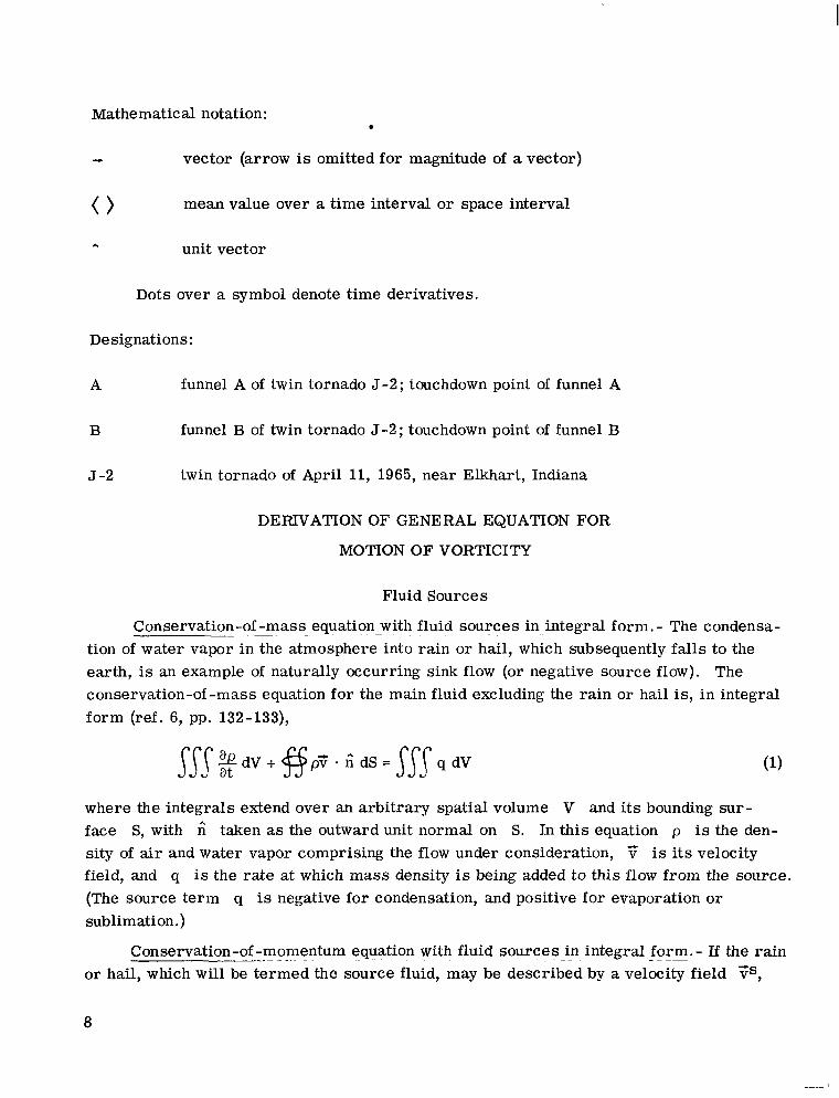
SYMBOLS AND NOTATION
A cross-sectional area of vortex tube, m2
a radius of funnel A of twin tornado 5-2 at ground, m
b ratio of circulations, rB/rA
C dimensionless parameter (eq. (42))
1 - sin 2 x c o s 2 q A d l + tan2>( sin2qA (see eq. (70c))
E electric field, V/m
F' Lorentz force per unit length, N/m
T Lorentz force per unit volume, N/m3
3

E magnetic field, A/m
T axial electric current (figs. 11 and 12), A
i effective axial electric current (eqs. (71b) and (71d)), A
-c
J electric current density, A/m2
L
1
M
A n
P
cc P
P
P' (P)
P"
a Q
Q*
Qe
q
length, m
circuit line of integration, m
excess mass present in a vortex tube per unit length, kg/m
unit normal
center point of revolution of twin tornado 5 -2 at the ground (figs. 11 and 19)
pressure tensor including viscous terms, N/m2
scalar pressure, N/m2
pressure field which is single-valued function of density (eq. (23)), N/m2
deviation of pressure from single-valued function of density, (eq. (23)), N/m2
total fluid source strength, kg/sec
mass of source fluid being added to a vortex tube per unit length per unit time (eq. (36)), kg/m-sec
fictitious source (sink) strength per unit length in a vortex tube having con- vergent flow and updraft, kg/m-sec (see section entitled "Tornado model")
electric charge, C
source density; mass per unit volume and per unit time being added to a flow from a fluid source, kg/m3-sec
4

radius from tornado touchdown point in ground plane, m R
R,
rA
rB
S
t
v'
E'
V
4
V
X,Y 7z
CY
P
r
Y
E
€0
e
center-to-center distance between touchdown spots of funnels A and B of twin tornado 5-2, m
distance of vortex A from center point of revolution P of twin vortices in ground plane (figs. 11 and 19), m
distance of vortex B from center point of revolution P of twin vortices in ground plane (figs. 11 and 19), m
surface area of integration, m2
time, sec
velocity of displacement of vorticity, m/sec
arbitrary abstract velocity field utilized to describe the motion of regions of integration S and V, m/sec
volume of integration, m3
fluid velocity field, m/sec
Cartesian coordinates, m
angle shown in figure 16, rad
dimensionless parameter (eq. (62c))
circulation of a fluid vortex, m2/sec
effective circulation of a fluid vortex (eqs. ("Ob) and (70e)), m2/sec
small dimensionless parameter
permittivity of vacuum, F/m
angle depicted in figures 13, 14, and 15, rad
5
I

K
A
P
P' (PI
P"
cp
X
rc/
rat io of axial electric current to circulation for a hydromagnetic vortex (eq. (83)), A-sec/mZ
dimensionless parameter (eq. (61))
direction cosines
permeability of vacuum, H/m
Cartesian coordinates used in figures 13 and 14
mass density, kg/m3
density field which is a Single-valued function of pressure (eq. (19)), kg/m3
deviation of density field f rom single-valued function of pressure (eq. (19)),
W m 3
electric-charge density, C/m3
vector shown in figure 16
gravitational potential (including centrifugal force in the rotating frame of the earth), J/kg
arbitrary scalar function, m2/sec2
azimuth angle in symmetrical coordinate system of figure 13, rad
tilt angle of vortex with respect to the vertical (figs. 4 and 8), rad
azimuth angle in ground plane of figures 15 to 18, rad
azimuth angles shown in figures 11 and 19, rad
retarded revolution rate of twin vortices with axial electric current I, rad/sec
angular velocity of rotation of the earth, rad/sec

- w ' fluid vorticity, cur l 3, sec-1
Superscripts:
A
B
bl boundary layer at ground
j s jet stream
0
S source fluid
1
funnel A of twin t0rnado.J-2 (fig. 4)
funnel B of twin tornado 5-2 (fig. 4)
unperturbed vector fields in perturbation expansion
first-order vector fields in perturbation expansion
Subscripts :
funnel A of twin tornado 5-2 (fig. 4)
funnel B of twin tornado 5-2 (fig. 4)
moving point
unperturbed scalar fields in perturbation expansion
components in spherical coordinate system R,cp,O (figs. 13 and 14)
components in cylindrical coordinate system (figs. 15 to 18)
Cartesian components of a vector
component in Cartesian coordinate system [,q, (figs. 13 and 14)
first-order scalar fields in perturbation expansion
field component perpendicular to the ground or to the lower jet-stream boundary
7
Mathematic a1 notation :
e vector (arrow is omitted for magnitude of a vector)
mean value over a time interval o r space interval 0 A unit vector
Dots over a symbol denote time derivatives.
Designations:
A funnel A of twin tornado 5-2; touchdown point of funnel A
B funnel B of twin tornado 5-2; touchdown point of funnel B
J -2 twin tornado of April 11, 1965, near Elkhart, Indiana
DElUVATION OF GENERAL EQUATION FOR
MOTION OF VORTICITY
Fluid Sources
Conservation-of -mass . equation . with fluid sources in integral form. - The condensa- tion of water vapor in the atmosphere into rain or hail, which subsequently falls to the earth, is an example of naturally occurring sink flow (or negative source flow). The conservation-of -mass equation for the main fluid excluding the rain or hail is, in integral form (ref. 6, pp. 132-133),
where the integrals extend over an arbitrary spatial volume V and its bounding sur - face S, with ; taken as the outward unit normal on S. In this equation p is the den- sity of air and water vapor comprising the flow under consideration, v is its velocity field, and q is the rate at which mass density is being added to this flow from the source. (The source te rm q is negative for condensation, and positive for evaporation o r sublimation. )
+
Conservation-of -momentum . equation with fluid sources - in integral form. - If the rain or hail, which will be termed the source fluid, may be described by a velocity field TS,
8
which is distinct from 7, then momentum is also transferred from the source fluid to the main flow at the rate of q? per unit volume. The conservation-of -momentum equation for the main flow becomes, in integral form (ref. 6, pp. 132-138, and ref. 9, pp. 233-236),
where
- P pressure tensor (including viscous terms), N/m2
cp gravitational potential (including centrifugal force in the rotating frame of the earth), J/kg
2p(? X 5) Coriolis force density, N/m3
5 angular velocity of the earth, rad/sec
f Lorentz force density, peE + poz X E, N/m3
In equation (2) the first integral represents the time rate of increase of momentum contained in spatial volume V, the second integral is the rate of efflux of momentum through the closed bounding surface tractions, and the third integral gives the rate at which momentum is being added to volume V by transfer from the source fluid, and by the action of the gravitational, Coriolis, and Lorentz forces.
S by convection and by the action of the surface
Conservation equations in differential form. - In differential form equation (1) is
+ div pi; = q (3 1 a t
and equation (2) is
p + 7% + ? div p? + p grad 3 - p(T x G) - d i v F = qys + p grad + 2pT x 6 + (4) a t a t 2
where v2 = ? - ? and G = curl 7 (vorticity). When combined and divided by p, as is customarily done, these two equations give

which for Cartesian coordinates may also be written
( & + T - g r a d ) T = - 1 d i v T - $ ? - T s ) + g r a d @ + 2 T X S + - f P P
Vorticity Equation
The vorticity equation is obtained by taking the cur l of equation (5a)
An integral form of this equation is given by
(7)
where the integrals are taken over an arbitrary spatial surface S of finite area, and 6 is the unit normal on S, as shown in figure 1.
/--------- Figure 1.- Arbitrary surface S with unit normal 2,
Kinematics
Since the integrals in equation (7) a r e taken with time t fixed, the surface of inte- gration S may be regarded as moving and deforming in an arbitrary continuous manner. Not being a material surface, S need not move with the velocity 7 of the fluid medium. Instead, imagine surface S to be moving and deforming in accordance with some arbi- t ra ry abstract velocity field v"(x,y,z,t), which will in general be different from the veloc- ity field 3 of the fluid. For such a moving surface of integration, the following kine- matical theorem of Helmholtz, as given in reference 7, pp. 130-132, applies:
10

where x(x,y,z,t) is an arbitrary vector field. In this equation the flux of through
.the moving and deforming surface S, given by 11 A - f; dS, is purely a function of time;
hence, it is appropriate to take the total time derivative of this quantity as indicated in the first te rm of equation (8).
General Kinematic Form of the Vorticity -Flux Equation
If the vector field in Helmholtz' theorem is taken to be the vorticity = curl ?;, equation (8) becomes
Eliminating the vorticity -f lux equation
i3w'/at between equations (7) and (9) yields the general kinematic form of
where the surface of integration S is convected with the abstract velocity field f?'(x,y,z,t). The abstract velocity field v" and the fluid velocity field 7 which appear in this equation may be regarded as superposed, v" of integration S, and ?; the motion of the fluid elements. These two fields of motion are (in concept) unrelated. Equation (10) reduces to the usual form of the vorticity-flux relation in the special case of setting v" = ?;.
governing the motion of the surface
General Equation for Motion of Vorticity
In relation (10) the abstract velocity v" with which the surface of integration S moves is continuous, but otherwise arbitrary. Now v" is constrained by the specifica- tion that S moves in such a manner that the flux of vorticity z through S is con- served; that is,
- fi dS = 0 dt
The field v" when constrained in this manner is designated by the symbol v', where 8 satisfies the equation
- ?;) X 3 - 1 d i v T + g(?; - ?is) - 27 X 6 - (1 1b) P P
11

Thus, v' may be regarded as describing the motion of the vortex lines which pass through S.
Equation (12) applies to any surface of integration S having any chosen orientation, and the integrand is assumed to be continuous. This is possible only if
- - f;) X 2j - 1 d i v T + :(T - 7s) - 27 x 6 - = 0
P P
or , equivalently,
I I I (3 - T) x 0' - 1 d i v 7 + 9(?; - FS) - 27 x 52 - f - - = grad @I I P P P
where @(x,y,z,t) is an arbitrary scalar field.
Equation (13) is the desired general formula fo r the speed of displacement v' of vorticity. Note that v' is not, in general, determined uniquely because of the arbitrary function @. Physically, this means that for general distributions of vorticity there are arbitrari ly many flux-preserving motions. In the simple case when w' = Constant, any area-preserving motion of S perpendicular to w' would also be flux conserving. But when a vortex tube is isolated, the displacement velocity 8 of the tube should be uniquely determined, except for displacements along the tube. absorb forces directed along w' which the term p ( 3 - 7) X w' cannot balance.)
Substituting equation (13) back into the momentum equation (5a) gives
(Also the te rm p grad @ may
I- " a t
or since in Cartesian coordinates
grad V 2 - = (7 grad)? + 7 x G 2
then
+?;. grad ) 7 = (- U -7 1 X G + grad(@ - @) (at (144
which shows that the Magnus force density p(f f - 7) X 0' acts directly to accelerate the fluid elements. Comparison with equation (5b) shows that in equation (14a), all the non- conservative forces, including the viscous force, a r e lumped together into one te rm and represented by the Magnus force density. The vorticity equation (6) becomes upon sub- stitution of equation (13)
12
I
- aTj - c u r l ( 8 x G) = o a t
or
(" + v' . grad)w' = (3 - grad)f? - 3 div v' .(14b)
which is analogous (with v' replacing 7) to relations first obtained by Helmholtz under restrictive conditions.
a t
(See ref. 7, pp. 129-130.)
The pressure tensor 7 has been retained for generality to illustrate that a dis- placement velocity v' may be assigned to vortex tubes even in the presence of viscous diffusion. For an inviscid fluid, equation (13) becomes
(15) (5 -3) x G + -grad 1 p + g(7 - 3s) - 2T x 6 - r = grad 4 P P P
where p is the scalar pressure.
Alternative Forms of the Vortex-Motion Equation
for an Inviscid Fluid
The alternative formulas derived in this section are included here for completeness although they will not be used in subsequent sections. Because 4 is arbitrary, any con- servative t e rms on the left-hand side of equation (15) (i.e., t e rms which have the form of a gradient of some scalar quantity) may be deleted from the left-hand side and absorbed in the arbitrary grad 4 term. Therefore, since
- 1 grad p = grad(;) - P grad(i) P
equation (15) for an inviscid fluid can be expressed as
(5-7) x G - p grad -TS) - E X S2 - f - - = grad 4 P
For an autobarotropic fluid, where pressure is a single-valued function of density (that is, p = p(p)), the term - grad p in equation (15) and p grad(:) in equation (17) may be
deleted by absorption into grad @. If, in addition, all nonconservative t e rms should be omitted, these equations become
1 P
(8 -7) x w ' = grad @ (18)
13

from which it may be inferred by taking 4 = 0 that the components of v' and 'i; per- pendicular to Z are equal, in agreement with Kelvin's theorem that vorticity moves with the fluid under these conditions.
The density may be written
P = P'(P) + P" (19)
where p' is a single-valued function of the pressure and p" is the deviation of p from p'(p). It follows that
5 l- - P T -5-7 PP' P
and equations (15) and (17) may be written, respectively,
+ $7 - TS) - 2T x f2 - f - - = grad 4 [A] P (.' - 7) x G + p grad
where the t e rms - g r a d p and pgrad- [p!bi have been absorbed in the grad 4
term. Alternatively, if the pressure is written in the form P' (PI
P = P ' b ) + P" (23)
where p' is a single-valued function of the density and p" is the deviation of p f rom p'(p), equations (15) and (17) become, respectively,
-c + (5 -7) x C + Lgrad p" + $7 -Ts) - 2 F X 52 - P - = grad 4 (24) P
(c-7) - 2 7 x z - - = g r a d @ f P
From equation (13), (15), or (17) a speed of displacement v" may be assigned to every element of vorticity in a fluid when the other relevant fields, such as pressure, density, and fluid velocity, a r e known. Evidently v' frequently differs from 3. These equations may prove to be useful in forecasting the movement of severe local s torms and
14
tropical storms. This is because they show explicitly how various atmospheric fields affect the movement of vorticity, and vorticity is a characteristic property of such storms. Conversely, they may aid in determining the structure of such atmospheric vortices from observations of their motion.
Linearization of Equation for Vortex Motion
Perturbation series.- Analysis of equation (15) for the motion of vortex lines in an inviscid fluid is simplified by linearization as follows:
4 v = To(x,y,Z,t) + Eiil(x,y,z,t)
z,t)
zj = Ed(X,y,z,t)
q = Eq1(X9Y7z7t)
- -1 f = E f (x,y,z,t)
where E is a small dimensionless parameter. Substituticn of set (26) in equation (15) gives for the unperturbed potential flow
- 1 P O - vpo - 270 x s2 = v@o
From equation (5a) (with viscous t e rms omitted),
V @ , = V @ , - - ( $) - - a70 a t
where
and v i = To - 3'. The first-order perturbation equation is Go is the potential for gravitational, centrifugal, and other conservative forces
15

I11111111
Substituting equation (27) in equation (29) gives
po(C - To) x GI+ q1(s;0 - F;s) + vpl - p1 - vpo - 2p0+ x 5 - T1 = p0vC#l1 PO
For the present purposes it is desirable to simplify equation (30) further by elimi- nating the perturbation pressure p1 and velocity 'i;l fields. The te rm Vpl/po may be absorbed into the VC#ll t e rm provided the unperturbed density po is taken to be a constant. Elimination of T1 requires that the Coriolis force be neglected. With these two restrictions equation (30) becomes
p0 (8 -70) x 3 1 -E ql(? - 7s) - p1 - vpo - T 1 = V$ll
P O
In many cases the arbitrary term in general it may be needed in order to balance forces directed parallel to the vortex lines, which the Magnus term po(v' - ?;o) x Z1 cannot balance.
t e rms of equation (31) all have the dimensions of force per unit volume. The first te rm p0(C - To) x z1 represents the Magnus force density on vortex filaments which do not move with the unperturbed flow velocity To. The second te rm q1(T0 - Ts) represents the force density required to accelerate the source fluid from the source velocity TS
to the flow velocity yo. The third term - Vpo represents a "buoyancy" force which
acts on density variations in the presence of the unperturbed pressure gradient. It cor re- sponds, for example, to the buoyant lift on a balloon. The fourth te rm T1 represents an extraneous, nonconservative force density, which in this study will be taken to be the magnetic force density T1 =T1 X go where T1 is a perturbation electric current den- sity, and Eo is the applied magnetic field.
V@l in equation (31) may be set equal to zero. But
Physical interpretation of - t e rms -- in linearized equation for vortex motion. - The
p1 PO
Equation (31) states that the vorticity moves in such a manner that the Magnus force, source-force, buoyant-force, and magnetic-force densities vanish (or a r e equal to the gradient of some scalar field). Only the Magnus term po(v' - Yo) x G1 contains the velocity of displacement v' of the vorticity. Incidentally, in the derivation of equa- tion (31) no attempt has been made to follow the motion of any quantity except the vorticity. That is, source strength is not necessarily conserved and density irregularit ies are not necessarily followed by the motion 5.
Linearized equation for the motion _ _ of isolated vortex tubes.- Up to this point the vorticity has been considered to be distributed generally throughout the flow. The case of an isolated vortex tube of circulation I' will now be considered as a prelude to the
16

treatment of atmospheric vortices. tube, it is convenient to integrate over the volume V of the tube included between two surfaces S' and S" which are everywhere normal to the vorticity in the tube, as shown in figure 2.
For application of equation (31) t o an isolated vortex
_ _ _ - - -
Figure 2.- Isolated vortex tube with cross-sectional surfaces S' and S" and included volume V shown.
Upon integration, equation (31) becomes
This volume integral may be written as an integral on a cross-sectional surface S and along a line 1 parallel to the vorticity:
Since assigned to
the integrand is assumed to be continuous throughout V, mean values may be the quantities (E - G o ) , (3" - ss), Vp,, and V@l on surface S so that
equation (33) is termwise identical with the following equation:
1
where the brackets ( ) denote mean values on the cross-sectional surface S. This
17

equation may also be written
where
F1 circulation of the vortex tube
mass of source fluid being added to the vortex tube per unit length Q1
excess mass present in the tube per unit length M 1
F1 Lorentz force on the tube per unit length
A cross-sectional a rea of the tube (taken perpendicular to $)
The remaining integration in equation (35) is over an arbitrary length Z of the vortex tube, and the integrand is assumed to be a continuous function of 1; hence, the integrand itself must vanish for all values of 1:
p 0 ( 8 -To) X y1 + (Yo -TS)Q1 - (vpO) M1 - F1 = (V@l)A PO
The arbitrary term (V@l)A has been retained for the purpose of balancing possible axial forces which cannot be balanced by the Magnus force po(8 - To) x ?. This first- order perturbation equation is applicable to an isolated weak vortex tube in an inviscid fluid without Coriolis forces. The unperturbed flow must be irrotational and f ree of sources, have constant density po, and must satisfy the equation
vp0 ( 2) a p - = v PO % - - a t (37)
where +o is the potential for gravitational, centrifugal, and other conservative forces.
In subsequent sections where equation (36) is applied, the subscript 1 (or super- script 1) will be dropped from the perturbation fields F1, Q1, MI, and F1. The sub- scipt o (or superscript 0) will be retained on the unperturbed fields, however. Any confusion which might arise from this practice can be resolved by referring back to equation (36).
18

APPLICATIONS OF LINEARIZED EQUATION FOR VORTEX MOTION
TO TORNADOES AND TORNADO CYCLONES
Rudimentary Approach To Be Used in the Following Applications
In the following sections equation (36) will be applied to tornadoes and tornado cyclones as if they were weak perturbations on an unperturbed potential flow. linear effects will clearly be missing in this rudimentary treatment. Moreover, only gross features of these storms, such as circulation, updraft, and core density, will be considered together with some effects of the boundary layer at the ground and of the jet stream near the tropopause.
This simplified version of a severe local storm which is producing a tornado may be described briefly as fo1lows:l A tornado cyclone, or parent storm, is regarded as a vertical vortex which significantly affects the flow in a region about 16 km (10 miles) in diameter. The tornado cyclone has a core that is several miles in diameter and a strong updraft within the core. The cyclone terminates near the tropopause and the updraft from i t s core is ejected into the jet stream and carr ied eastward. produced by this storm is pendent from the cloud base at an altitude on the order of 0.3 km (1000 f t ) and may extend to the ground. The circulation of the tornado is about 1 order of magnitude less than that of the tornado cyclone, and its core diameter is from 1 to 2 orders of magnitude less. fluid from the viscous boundary layer at the ground is drawn up into the tornado. This interaction with the boundary layer at the ground is considered capable of affecting the speed of displacement of the lower portion of the tornado - but not of the tornado cyclone. action with the jet stream above. and the jet stream acts as a sink, both these effects depend upon the source te rm (TO - TS)Q1 in equation (36), and these are the first cases which will be treated.
be rarefied so that its motion is influenced by the buoyancy term ( - ) M1 in equa-
tion (36). may be warmer than the surrounding air and therefore buoyant. If the vortices should be tilted from the vertical, one effect of their buoyancy would be the presence of upward lift, which could affect their motion. omitted in the case of the twin tornado because the algebra becomes cumbersome. It will also be omitted from the treatment of tornado cyclones because it appears that in this
All non-
A tornado
An updraft exists in the tornado core, and retarded
The motion of the tornado cyclone, however, may be influenced by its inter- Since the boundary layer at the ground acts as a source,
Because of the high speed of the circulating wind in a tornado, the tornado core may
vPO PO
Also, the updrafts in a tornado cyclone indicate that the core of the cyclone
This effect, although potentially important, will be
'For a more complete discussion of severe local storms, see reference 2.
19

case the te rm VpI in equation (30) cannot be absorbed into the term, as done throughout this report, nor can it be ignored. The case of buoyancy which will be treated with equation (36) is that of buoyant attraction between the rarefied cores of a twin tornado.
The applications of equation (36) are concluded with a hypothetical example which depends upon the Lorentz term. The case treated is that of two parallel vortices which are subject to magnetic attraction by virtue of dc axial electric currents of like sense in the vortex cores.
Effect of the Boundary Layer at the Ground on Tornado Motion
Description and analysis.- For this analysis the following simplified form of equa- tion (36) is used:
where only the Magnus te rm and source term have been retained, and where the sub- script 1 (or superscript 1) has been dropped from the perturbation fields I' and Q. Near the ground the flow undergoes a rapid transition from the free-stream flow to the retarded flow in the viscous boundary layer. Ordinarily, the boundary layer does not significantly affect the free-s t ream flow. But in the event of a tornado, the retarded fluid in the boundary layer is sucked up into the free stream as shown in figure 3(a). This constitutes a fluid source at the boundary of the free. stream, which is coincident with the tornado and can affect i t s motion.
The upward flux of fluid from the boundary layer into the tornado core occurs essentially as follows: The pressure p in the boundary layer is the same as in the free stream, although the flow is considerably retarded. Therefore the radial pressure gradient within the free-stream vortex also exists in the boundary layer below. The boundary-layer fluid moves radially inward under the influence of this pressure gradient and ultimately ascends into the low-pressure tornado core. Although the magnitude of this flux from the boundary layer to the free stream may not be accurately known, there is ample evidence of its existence (ref. 12, p. 675, and ref. 3, p. 7).
This upward flux of fluid from the boundary layer appears as a source to the free stream. The total magnitude of this source, in kg/sec, is
2 = P o q (39)
where A is the area of the tornado core at the free-stream boundary, and vl is the upward component of velocity at this boundary. The fluid source is located (concentrated)
20
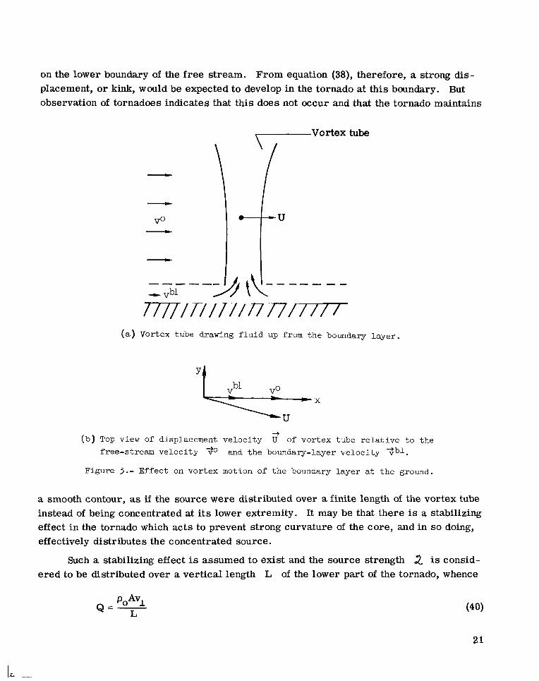
on the lower boundary of the free stream. From equation (38), therefore, a strong dis- placement, or kink, would be expected to develop in the tornado at this boundary. But observation of tornadoes indicates that this does not occur and that the tornado maintains
Vortex tube 7
----- bl -V
(a) Vortex tube drawing f l u i d up from the boundary l aye r .
+ ( b ) Top view of displacement ve loc i ty U of vortex tube r e l a t i v e t o the
free-stream ve loc i ty To and t h e boundary-layer ve loc i ty 9vb1. Figure 3 . - Effec t on vortex motion of t h e boundary l aye r at t h e ground.
a smooth contour, as if the source were distributed over a finite length of the vortex tube instead of being concentrated at its lower extremity. It may be that there is a stabilizing effect in the tornado which acts to prevent strong curvature of the core, and in so doing, effectively distributes the concentrated source.
Such a stabilizing effect is assumed to exist and the source strength 2 is consid- ered to be distributed over a vertical length L of the lower part of the tornado, whence
Q=- POA% L
21

and equation (38) becomes
where Tbl the brackets have been dropped by taking mean values over the vortex c ros s section to be approximated by values at the core center. If
is the unperturbed velocity in the boundary layer (source fluid), and where
with 0 < c < 1, then
(8 -70) x F + P ( l - c)-= Avl 0 L (43)
+ In Cartesian component form, with circulation in the x-direction, equation (43) becomes
taken along the z-axis and To taken
u y r + v0(i - c)-= Avl o L (444
(ux - v o ) r = o (44b)
whence
u = -v0(1 - c)- Avl Y r L
(45b)
It is clear from equations (45) that the effect of the boundary layer at the ground is to make the base of the funnel move to the right of the local wind To, as shown in fig- ure 3(b). In the case of the twin tornado referred to in the Introduction and in appendix B, this implies that the lower portions of the two funnels should tend to separate as they revolve about each other. According to figure 4, which w a s prepared by Fujita (ref. 4), they did apparently separate from a center-to-center distance of 118.9 m (390 f t ) to 147.1 m (482.6 f t ) in a period of 52 sec during which time the pair revolved about their common center through an angle of about 140°.
22

(a) Damage path and debr i s marks near t he Midway T r a i l e r Court ind ica ted S ix p i c t u r e s w e r e taken i n the d i r ec t ion of t he arrows. by l e t t e r M.
(b) Sequence depict ing the i n i t i a l occurrence of funnel A, the subsequent occurrence and growth of funnel B at the expense of funnel A, and the revolut ion of funnels A and B about t h e i r common center .
6 . . . . . . , e?.. I . . . _ _ . .&*. 3 . . . . .*. . . . . . . .3\.. . . . . . . ..+. . .. .
t % 2
%$+o4 “6-
(C) Photogrammetric sketches of t h e tornado p a i r .
Figure 4.- Twin tornado 5-2 path and configuration, as drawn by Fujita (ref. 4 ) from an aerial survey and from the six photographs taken by Paul Huffman.
23

I
Order-of -magnitude ~ ~- check on boundary-layer effect. - In order to check whether the observed rate of separation of the twin tornado could possibly have been due to boundary- layer interaction, an order-of-magnitude calculation for this effect may be made as fol- lows: For the tornado pair the ratio of radial speed of displacement -Uy to tangential speed of displacement Ux is on the order of -U U, =: 0.1. From equations (45), d
-U Avl y= (1 - c ) - = 0.1 UX rLl
o r
VI = rL x o . l A(l - C)
A value for A, the area of the core at the base of one of the funnels, may be obtained from figure 5
A = 6 x 1 0 3 2 m
where the scale length used in this estimate is the center-to-center distance as given in table I, location 4. The circulation r of each funnel, when approximately equal in strength at location 4, is estimated in appendix C as
Taking the mean velocity in the boundary layer equal to one-half the free-stream velocity gives, from equation (42),
c = 0.5
When these values for A, r, and c are substituted, equation (46a) becomes
L = 6
which is a relation between the updraft velocity vl in the core at the boundary layer and the length L at the base of each funnel, which is assumed to be affected by the boundary- layer interaction. Taking L = 60 m (196 ft) gives vl = 10 m/sec (22.4 mph) for the updraft velocity at the boundary layer, a value which appears to be of reasonable magni- tude. It is concluded that the increasing separation observed for the twin tornado may have been due to its interaction with the boundary layer at the ground.
24
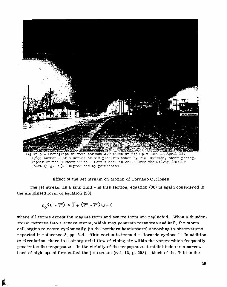
1965; number 4 of a s e r i e s of s i x p i c tu re s taken by Paul Huffman, s t a f f photog- rapher of t he Elkhart Truth. Left funnel i s shown over t h e Midway Tra i l e r Court ( f i g . 20). Reproduced by permission.
Effect of the Je t Stream on Motion of Tornado Cyclones
The jet stream as a sink fluid.- In this section, equation (36) is again considered in the simplified form of equation (38)
po(v' -To) X F + (To -Ts)Q= 0
where all t e rms except the Magnus term and source te rm a r e neglected. When a thunder- storm matures into a severe storm, which may generate tornadoes and hail, the storm cell begins to rotate cyclonically (in the northern hemisphere) according to observations reported in reference 3, pp. 3-4. This vortex is termed a "tornado cyclone." In addition to circulation, there is a strong axial flow of rising air within the vortex which frequently penetrates the tropopause. In the vicinity of the tropopause at midlatitudes is a narrow band of high-speed flow called the jet stream (ref. 13, p. 553). Much of the fluid in the
25

updraft of the storm is swept eastward by the jet s t ream as shown in figure 6, and forms the broad anvil canopy which is characteristic of these s torms (ref. 1, pp. 67-68, and ref. 2, pp. 185-195). For the tropospheric flow below, therefore, the jet s t ream consti- tutes a sink fluid. - -
vj s
V0
Figure 6.- Vortex tube e j ec t ing fluid i n t o the j e t stream.
The efflux of fluid from the tornado cyclone into the jet s t ream will affect the motion of the tornado cyclone in the troposphere below the jet s t ream. In particular, an attempt will be made to show on the basis of equation (38) that the storm will tend to move to the right of the mean winds in the troposphere in agreement with observations reported in reference 1, pp. 71-72, and reference 2, pp. 319-321.
The winds in the troposphere below the jet s t ream vary considerably in direction with altitude, as described in reference 2, pp. 319-336. Moreover, the actual location of the fluid sink is near the upper extremity of the storm, where the cyclone core intersects the lower boundary of the jet stream. Despite the wind variation and sink concentration, the s torms are observed to move, more or less, as a unit, although the core of the storm may be tilted from the vertical by as much as 20' (ref. 1, p. 69). Possibly the storm structure resists deformation of the core of the cyclone and in so doing effectively spreads out localized effects over its entire vertical extent. If this is the case, it would seem appropriate to distribute the sink strength uniformly over the vertical extent L of the storm and also to define a mean wind velocity 'iio for the troposphere below the jet s t ream. assumed to flare out horizontally upon penetrating the jet stream so that the tube as such is confined to the flow region below the jet stream.
This is the view which is adopted in this section. The vortex tube is also
The total strength of the sink is poAvI, which in t e rms of total source strength in kg/sec is
26
2= -P0AV1 (47)
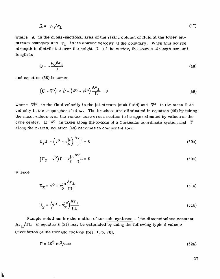
where A is the cross-sectional area of the rising column of fluid at the lower jet- s t ream boundary and vl is its upward velocity a t the boundary. When this source strength is distributed over the height L of the vortex, the source strength per unit length is
POAV, Q = -- L
and equation (38) becomes
where fijs is the fluid velocity in the jet stream (sink fluid) and 7 is the mean fluid velocity in the troposphere below. The brackets are eliminated in equation (49) by taking the mean values over the vortex-core c r o s s section to be approximated by values at the core center. If is taken along the x-axis of a Cartesian coordinate system and r along the z-axis, equation (49) becomes in component form
whence
u y r - ( v 0 - V I ,)% - - = o L
(ux - v o ) r - v i kAVl L- -
. Avl
Y r L u, = VO + VIS-
u = ( 0 v - v g)% Y rL
Sample solutions for ~~ the motion of tornado cyclones.- The dimensionless constant Avl/rZ in equations (51) may be estimated by using the following typical values:
Circulation of the tornado cyclone (ref. 1, p. 76),
27

Vertical extent of s torm (ref. 2, pp. 176-177),
L = 12.2 km (40 000 f t )
Upward velocity of fluid in the cyclone core (ref. 12, p. 675),
vI = 152 m/sec (500ft/sec)
Area of core, assumed circular with radius fi km (ref. 1, p. 74),
A = 6.28 x lo6 m2
The resultant value for the dimensionless constant is
Avl rL -= 0.78 (53)
In order to determine the storm displacement velocity 0, two other quantities must be specified in equations (51). These are the ratio vjs/vo of the wind magnitude in the jet s t ream vjs to that below vo, and the included angle between To and Yjs. (In the vector diagrams of figure 7, the vortex is viewed from above and F0 is always taken to
lie in the same direction.) In figure 7(a), the wind-speed ratio is vjs -
diagrams are sketched for various included angles between 'iio and Tjs in 15' incre-
ments.
of-displacement vector v' is usually found to l ie to the right of both ?io and ?;jS in agreement with observation. The general condition that v' lie to the right of To is that (Tjs - TO) - ?;o > 0.
and vector F- z
vjs - Similar diagrams are presented in figure 7(b) for Note that the speed- F- T'
Effect of Core Buoyancy on Revolution Rate of a Twin Tornado
Occurrence of twin tornado J -2 . - On April 11, 1965, a twin tornado (fig. 5) occurred near Elkhart, Indiana. erence 4, and an abbreviated account is given in appendix B of this paper. The funnels were parallel, about 122 m (400 f t ) apart (center-to-center distance), and were tilted at an angle of about 29' from the vertical. Their circulations were of like sense (cyclonic) and they revolved about each other while slightly increasing the distance of separation. The relative motion of this tornado pair is an interesting case to which equation (13) should apply. Rather than attempt this at present, the linearized form, equation (36), will be applied, despite its limitation to weak vortices in an inviscid fluid without Coriolis forces.
28
Full details of this tornado (designated 5-2) a r e presented in ref-

/
e u V j S
Figure 7.- Top views of displacement ve loc i ty
vo
v j s
vo (b) - = 2.
-)
U of tornado cyclone r e l a t i v e t o f r e e - stream ve loc i ty $0 and je t -s t ream ve loc i ty 3 s f o r d i f f e ren t or ien ta t ions of ?js.
Tornado model.- Figure 8 depicts a physical model for the twin tornado to which equation (36) may be applied. The vorticity is assumed to be largely contained in two tubes which are finite in c r o s s section, semi-infinite in length, and terminate at the ground. The tubes are parallel, but tilted with respect to the vertical, and do not neces- sarily have the same circulation strength. Updrafts a r e present within the cores as an outlet for the convergent flow in the boundary layer at the ground, which was mentioned in the section entitled "Effect of the Boundary Layer at the Ground on Tornado Motion."
29

I
Figure 8.- Model used for twin tornado: t i l t e d vortex tubes with updraft and influx.
One model for tornadoes (refs. 14 and 15) assumes that such a convergent flow exists not only within the boundary layer at the ground, but at every point along the ver - tical extent of the funnel in the free stream. This convergent flow is conceived as main- taining the concentration of vorticity in the funnels. Thus besides circulation r, each core has convergence Q", in kg/m-sec, which represents the rate at which convergent fluid is entering the core per unit length in the free s t ream. The asterisk notation is needed because within the core this convergent flow of fluid turns upward in a rising column which remains a part of a total f ree-s t ream flow field. If the converging fluid were actually withdrawn from the flow (as by entering a pipe), the asterisk notation would be unnecessary.
This circulation-convergence -updraft model will be adapted herein for tornadoes. Thus the cores in figure 8 are assigned individual circulations and rB and con- vergences QI and Qg. For a given location of the tubes the velocity field Tj outside the cores may be solved for, assuming that the external fluid is inviscid, incompressible, and irrotational, and that it does not penetrate the ground. The velocity field thus deter- mined should be a good approximation to the real flow except within the cores and within the boundary layer at the ground. The effect of the boundary layer at the ground, which is to make the cores move to the right of the local flow (and thus tend to separate) has already been discussed in the section entitled "Effect of the Boundary Layer at the Ground on Tornado Motion."
Absence of source force ~. density - despite possible convergent flow.- The motion of the co res may be determined from equation (36). The source te rm (To - Ys)Q in this equation would apply if QI and Q& were true sinks. However, they are fictitious in
30

that the converging fluid is not withdrawn from the free-stream flow, but is simply deflected upward. it penetrates through a surface of discontinuity into a different flow region. Any such penetration point is assumed to occur only at altitudes which are large compared with the separation distance of the two tornadoes, so that the relative motion of the two funnels near the ground is unaffected by it. Therefore, despite convergence in the tornado model,
the source term (7" - 7') Q in equation (36) is properly equated to zero for this study of the mutual interaction between the funnels.
Buoyancy terms.- Now if the Lorentz force density F' in equation (36) is also not
considered, the buoyancy term ___ M remains to influence the motion of the vortex
pair:
This rising column does not constitute a sink except at a point where
PO
The possibility exists that the cores of the tornado pair are partially rarefied. occur if the circulating winds approach the speed of sound near the cores, as illustrated in the compressible-vortex example presented in reference 10, pp. 158-159. excess mass M per unit length is negative, and each vortex is buoyant in the radial pressure gradient of the flow field of the other. upon the pair should be attractive and tend to slow down their revolution rate.
This will
Thus the
Consequently, the buoyancy force acting
Effect of tilt neglected.- Although the convergences Q i and QL do not appear explicitly in equation (54), they still influence the velocity fields and pressure gradients in this equation and thus complicate the solution. The problem of two buoyant vortices with influx is simplified if the pair a r e taken to be alined with the vertical and to be iden- tical in influx and circulation, as illustrated in figure 9 where Q i = QL = Q*. The equal influx and circulation strengths correspond to the state of the tornado pair at location 4 of figure 4. Neglecting the tilt angle appears to be warranted in the following order-of -magnitude calculation to determine whether buoyant attraction could cause signficant retardation in the revolution rate of twin vortices with influx. In appendix C it is estimated that the revolution rate of the twin tornado w a s retarded by at least 50 percent with respect to the fluid.
to calculate the motion ffA of vortex A, the unperturbed flow, represented by ? and po in equation (54), is taken t o be the flow field due to vortex B. Similarly, the motion of vortex B is determined by considering the unperturbed flow to be that due to
rA = rB = I? and
Adaptation of linearized equation for vortex motion to twin-vortex model.- In order
31
I... .

r Q*
J X
Figure 9.- Vertical vortex tubes having identical circulation ("."A) (%'".)* and influx with centers at
vortex A. For either vortex equations (54) and (37) apply:
po(v' - y o ) X - M (( V a0 -$)-S)=A(V@) (55)
where v: = y o . p. In the Cartesian coordinate system of figure 9 where the z-axis is vertical, the x- and y-components of equation (55) are, for vertical vortices,
where the brackets have been eliminated by taking the mean values over the vortex cores to be approximated by values at the core centers. The A (V@) t e rm was retained in equation (55) only for the purpose of balancing possible axial forces. For vertical vor- t ices this te rm need have only a z-component and therefore does not appear in equa- tions (56).
Suppose now that the vortex giving r i se to the unperturbed flow is located at the moving point xm(t),ym(t). The velocity components for the unperturbed flow are then given by
32

I
where
These velocity fields and their x-, y-, and t-derivatives, if evaluated on the line y - ym = 0, take the form
(59d
33

II I 11111111
av"v XmG
where dots denote time derivatives, and where K and G are taken to be constants.
Now take x-axis at equal
the two moving vortices of figure 9 to be momentarily located on the
distances %/2 from the origin, as viewed from above in figure 10.
(- +, 0) (+, 0)
Figure 10.- View of figure 9 from above when both vertical vortices are momentarily located on the x-axis at equal distances from the origin.
Substituting equations (58) into equations (56) for the motion gA of vortex A in the fields due to vortex B gives
where the identifications
the problem dictates that
x m = U E and y m = U y have been made. The symmetry of
U - -U . Hence, equations (59) become -B - -A
34
UxG A U A K
M e RE + J X 2TpoG A -.;)+-- K Y= 0
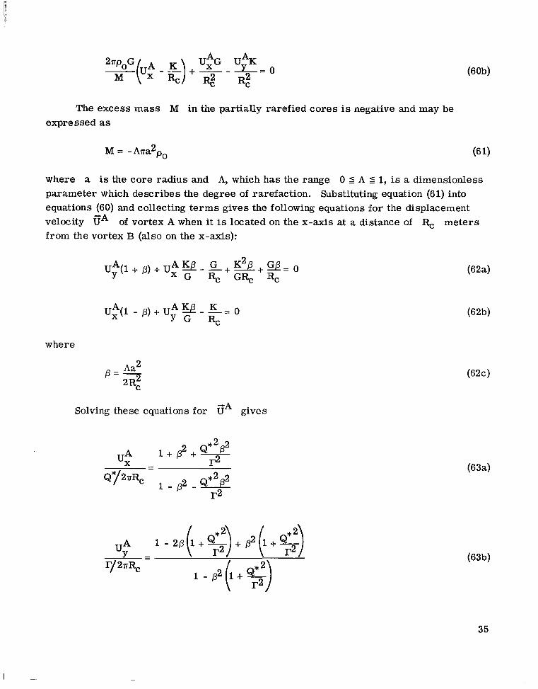
The excess mass M in the partially rarefied cores is negative and may be expressed as
where a is the core radius and A, which has the range 0 5 A 5 1, is a dimensionless parameter which describes the degree of rarefaction. Substituting equation (61) into equations (60) and collecting t e rms gives the following equations for the displacement velocity GA of vortex A when it is located on the x-axis at a distance of R, meters from the vortex B (also on the x-axis):
G Rc GRc Rc
U e ( 1 - p) + uy" y - -= K 0 RC
Solving these equations for cA gives
where
Aa2 P = 7 2RC
UA 1 -2B(l+$)+P2(1+$) Y= r/2aRC 1 - P 2 ( l + $ )
35
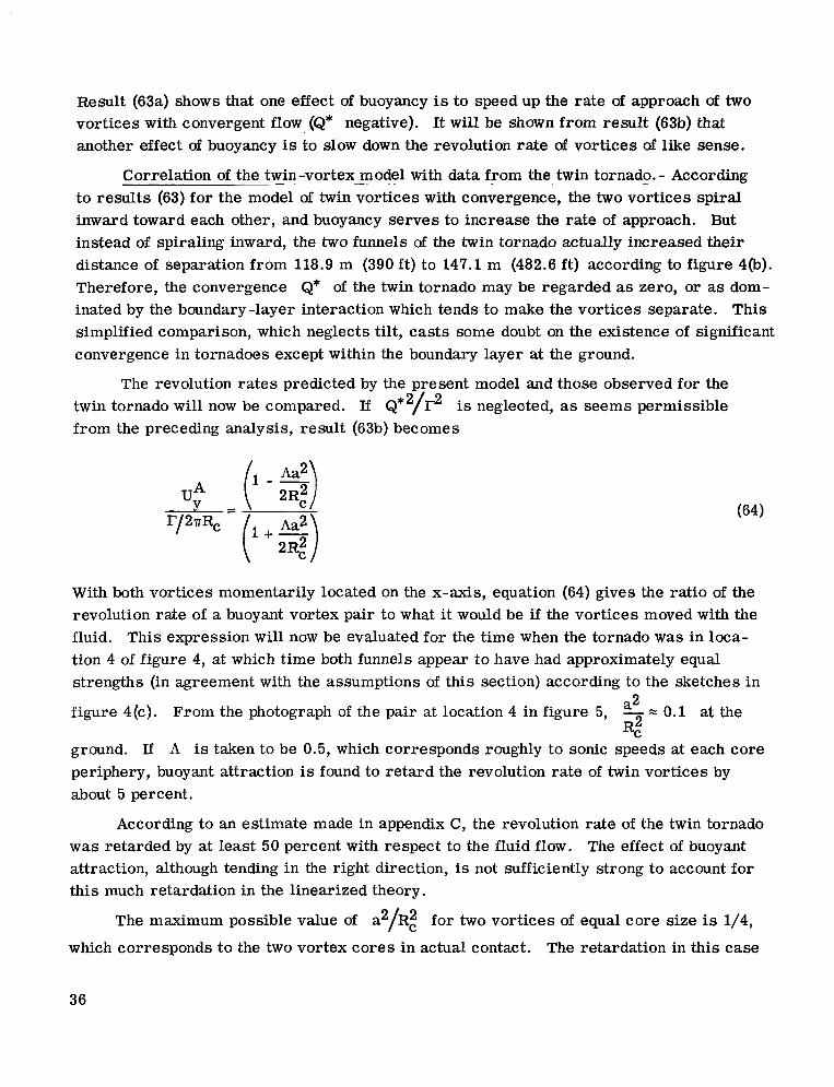
Result (63a) shows that one effect of buoyancy is to speed up the rate of approach of two vortices with convergent flow (Q* negative). It will be shown from result (63b) that another effect of buoyancy is to slow down the revolution rate of vortices of like sense.
Correlation of the twin-vortex - - model with data from the twin tornado. - - According to results (63) for the model of twin vortices with convergence, the two vortices spiral inward toward each other, and buoyancy serves to increase the rate of approach. But instead of spiraling inward, the two funnels of the twin tornado actually increased their distance of separation from 118.9 m (390 ft) to 147.1 m (482.6 ft) according to figure 4(b). Therefore, the convergence Q* of the twin tornado may be regarded as zero, or as dom- inated by the boundary-layer interaction which tends to make the vortices separate. This simplified comparison, which neglects tilt, cas t s some doubt on the existence of significant convergence in tornadoes except within the boundary layer at the ground.
The revolution rates predicted by the present model and those observed for the twin tornado will now be compared. If Q*2/$ is neglected, as seems permissible from the preceding analysis, result (63b) becomes
UA
r p R , Y - q)
( I + % )
With both vortices momentarily located on the x-axis, equation (64) gives the ratio of the revolution rate of a buoyant vortex pair to what it would be if the vortices moved with the fluid. This expression will now be evaluated for the time when the tornado w a s in loca- tion 4 of figure 4, at which time both funnels appear to have had approximately equal strengths (in agreement with the assumptions of this section) according to the sketches in
a2 figure 4(c). From the photograph of the pair at location 4 in figure 5, - = 0.1 at the
ground. If A is taken to be 0.5, which corresponds roughly to sonic speeds at each core periphery, buoyant attraction is found to re tard the revolution rate of twin vortices by about 5 percent.
Rc2
According to an estimate made in appendix C, the revolution rate of the twin tornado was retarded by at least 50 percent with respect to the fluid flow. The effect of buoyant attraction, although tending in the right direction, is not sufficiently strong to account for this much retardation in the linearized theory.
The maximum possible value of a2/Rz for two vortices of equal core size is 1/4,
which corresponds to the two vortex cores in actual contact. The retardation in this case
36

for A = 0.5 is then about 12 percent. Totally evacuated cores (A = 1) or cores filled with hydrogen gas (A = 1) would raise the maximum retardation to about 22 percent.
Influence of Axial Electric Current on Revolution
Rate of Twin Vortices
Speculative hydromagnetic -vortex hypothesis. - In this section equation (36) will be taken in the simplified form
The Lorentz force te rm F' in this equation is capable of exerting an attractive force on the funnels of the twin tornado which could retard their revolution rate to any degree, stop it altogether, or even reverse it. The possible existence of such electromagnetic forces in tornadoes is highly speculative, but it does provide an instructive application of equation (36). references 16 and 17.
For a bibliography of other electrical theories concerning tornadoes, see
It is well known from electrodynamics that two parallel w i r e s will exert an attrac- tive force on each other if (a) they are oppositely charged or (b) they a re conducting elec- t r ic currents of like sense. Since the two funnels of the twin tornado were in contact with the ground, it seems unlikely that opposite static electric charges on the two funnels could be maintained. But axial electric currents of like sense could conceivably have existed in the two funnels, and this is the case that will be treated in this section.
Fluid vortices with strong axial dc electric currents are termed hydromagnetic vortices. They have been discussed by Busemann (refs. 18 and 19) for the somewhat different case of a fluid with uniformly high electrical conductivity. In the analysis to follow high conductivity is assumed to persist only in the tornado cores .
Hydromagnetic -vortex model. - Each vortex tube of the twin-tornado model (fig. 8)
This sketch is a view of the ground plane in the proximity of the touchdown is characterized by coincidence of the fluid and electromagnetic states depicted in fig- ure 11. points A and B of the tornado funnels. The broken lines represent projections in the ground plane of the tilted axes of tornadoes A and B.
Equation for vortex motion with axial electric current - in a magnetic field.- The ~- -___I
Lorentz force per unit length on an electric current filament in the presence of a mag- netic field is given by
- + F = p o I XH
37

where T is the current in amperes, H' is the magnetic field in amperes/meter, and
po into equation (65) gives
is the magnetic permeability of vacuum in henries/meter. Substituting equation (66)
- where in this linearized equation, I is viewed as a perturbation current and Eo as the unperturbed magnetic field.
( a ) Velocity f i e l d s i n ground plane due t o t i l t e d vortex tubes
of c i r cu la t ion fl and I? . B
I
(b) Magnetic f i e l d s i n ground plane due t o t i l t e d current f i laments I* and 1'.
Figure 11.- Duplicate view from above of t he ground plane, showing touchdown poin ts of t i l t e d hydromagnetic vo r t i ce s A and B, with pro jec t ions of t h e vortex axes ind ica ted by broken l i n e s .
38

As in the section entitled "Adaptation of linearized equation for vortex motion to twin-vortex model," the unperturbed fields To and go at one vortex will be those due to the other vortex. For vortex A in figure 11, equation (67) becomes
where the brackets have been dropped as in equations (49) and (56). And for vortex B,
If the cylindrical coordinate system R, +, z, with z perpendicular to the ground (see appendix A), is applied to both hydromagnetic vortices in figure 11, the radial components of equations (68) become at the ground
po(U$ - .$)e + poH$It = 0
Formulas for v and H+ at the ground plane near a tilted hydromagnetic vortex * a r e derived in appendix A. are found by applying equation (A24) of appendix A
The fluid velocity fields vA and v6 at the ground plane IC/ +
where R, is the center-to-center distance in the ground plane and
yB = F ( I r B - sin x COS qA)
D = / V i - 1 - sin x cos +A 1 + tan x sin2QA
Also,

where
and
where
B The magnetic fields HA and HIC, are obtained from equation (A23): IC,
(7 I C )
Expressions (70) and (71) will be used as mean values for the velocity and magnetic fields over the vortex c ros s sections.
The vortex end points A and B a r e assumed to revolve about the point P (fig. 11) defined by the equations
r A + ' B = &
with displacement velocities
and
(7 3)
(74b) u@ B = rB&B(l)
where the revolution rate +*(I) = +B(I) is now a function of the axial electric currents in the vortex cores. Equation (72) may also be written, by use of equation (73),
(7 5) YB - YA + YB rA Rc --
40

Solution for revolution rate of inclined hydromagnetic vortex pair at the ground. - Substituting equations (70), (71), and (73) in equations (69) and noting that rz = r cos x and I, = I cos x for both touchdown points (see appendix A) gives at A
and at B
If equation (76a) is multiplied by the factor (1 + sin x cos @ by the factor (1 - sin x cos I ,~~)/D, equations (76) become upon substitution of equa- tions (70b), (70e), (71b), and (71d)
D and equation (76b) A)/
and
Equating the left-hand sides of equations (77a) and (77b) and collecting te rms gives
Relation (72) then shows that
which verifies that point P is the center point of revolution of points A and B in the ground plane, as assumed for equations (74).
If equation (77a) is multiplied by 2nRc and equation (75) is substituted, then

+ ” is the revolution rate $A of touchdown points A and B in the absence of 2 2rRC But
axid electric currents, and equation (80) may be written
p y y l - - = p i i o A B [ O A B
where denotes the revolution rate of points A and B with axial electric currents, and &A the revolution rate without electric currents. Substitution of definitions (70b), (7Oe), (71b), and (71d) also gives
r r [ I - - = P I I o A B o A B
Now take the axial electric current for each funnel to be proportional to its individ- ual circulation
Substitution of these relations in equation (82) results in the following equation for K ,
in A-sec/m2,
Order of magnitude ._ of axial electric ._ current which would account for retarded revolution rate of __ twin tornado.- In appendix C it is estimated that the revolution rate of the twin funnels was retarded by at least one-half with respect to the fluid flow and that the actual circulation of the pair r A + r B w a s probably greater than 104 m2/sec. Substituting the values
PO = 1.18 kg/m3
42

r-l, = 477 X lo-'' H/m
in equation (84) gives for air near sea level
K = 6.86 X lo2 amp-sec/ma (86)
and by equations (83) the total axial electric current which would be required to slow down the f ree revolution rate of the twin tornado to one-half that of the fluid flow is
I + IB = 6.86 X lo6 A A
It w a s estimated in the section entitled "Effect of Core Buoyancy on Revolution Rate of a Twin Tornado" that buoyant attraction could have reduced the revolution rate of the twin tornado by about 5 percent. To accomplish the same 5-percent reduction by mag- netic attraction would require a total axial electric current of 2.16 X lo6 amperes in the
funnels. This would make the total magnetic energy of a tornado I S $ d V com-
parable in magnitude with its kinetic energy rII 'f$f dV. Such electric currents a r e "
much larger than values previously proposed as possibly existent in tornadoes (refs. 20 to 24).
CONCLUDING REMARKS
The new equation for the motion of vorticity derived in this paper is found to have application to the motion of tornadoes and tornado cyclones. Quantitatively, the most successful of these applications of the equation in its linearized form appears to be the explanation given for the tendency of severe local s torms (tornado cyclones) to move to the right of the mean tropospheric wind by virtue of their interaction with the jet stream. Also successful was finding that the effect of the boundary layer at the ground on the twin tornado of April 11, 1965, near Elkhart, Indiana, w a s to make the two funnels separate, as they were observed to do. The increasing separation of the twin tornado also appears to constitute evidence against the possibility of convergent flow in the funnels of the twin tornado except within the boundary layer at the ground.
43

Less successful, quantitatively, were attempts at explaining why the funnels of the twin tornado apparently revolved about each other at a much slower rate than the fluid flow. The retardation in revolution rate was estimated to be about 50 percent with respect to the fluid. Two mechanisms were found which could retard the revolution rate: (1) buoyant attraction of each partially rarefied tornado core in the radial pressure gra- dient of the other core, and (2) magnetostatic attraction between axial dc electric currents of like sense in the cores . The retardation due to buoyant attraction was calculated to be about 5 percent for the twin tornado. In general buoyant attraction could retard the revo- lution rate of hollow-core or helium-core vortices of like sense by as much as 22 percent. Retardation by magnetostatic attraction requires electric currents in the tornado cores which are much larger than existing evidence would indicate.
A potentially important buoyancy effect was not included in this report, that is the upward lift on buoyant atmospheric vortices which are tilted with respect to the vertical. The most significant new result appears to be the equation for vortex motion, itself. Since it is f r ee of constraints on the fluid medium or on the flow or force fields, it should find applications in meteorology concerning the motions of various cyclones.
Langley Research Center, National Aeronautics and Space Administration,
Hampton, Va., July 24, 1970.
44
APPENDIX A
DERIVATION OF MAGNETIC AND VELOCITY FIELDS AT THE GROUND
PLANE NEAR A TILTED HYDROMAGNETIC VORTEX
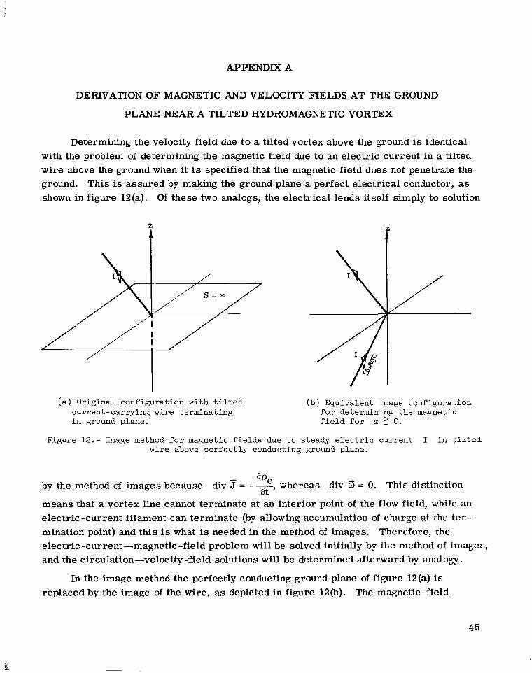
Determining the velocity field due t o a tilted vortex above the ground is identical with the problem of determining the magnetic field due to an electric current in a tilted wire above the ground when it is specified that the magnetic field does not penetrate the ground. This is assured by making the ground plane a perfect electrical conductor, as shown in figure 12(a). Of these two analogs, the electrical lends itself simply to solution
i I
(a) Original configuration with tilted current-carrying wire terminating in ground plane.
(b) Equivalent image configuration for determining the magnetic field for z I O .
Figure 12.- Image method for magnetic fields due to steady electric current I in tilted wire above perfectly conducting ground plane.
-c ape by the method of images because div J = --, whereas div 3 = 0. This distinction
means that a vortex line cannot terminate at an interior point of the flow field, while an electric-current filament can terminate (by allowing accumulation of charge at the ter- mination point) and this is what is needed in the method of images. electric -current -magnetic -field problem will be solved initially by the method of images, and the circulation-velocity -field solutions will be determined afterward by analogy.
a t
Therefore, the
In the image method the perfectly conducting ground plane of figure 12(a) is replaced by the image of the wire, as depicted in figure 12(b). The magnetic-field
45

APPENDIX A - Continued
solution for this sharply bent wire is then obtained by superposition of the magnetic-field solutions for the two straight semi-infinite wire sections. The first concern, therefore, is to determine the magnetic field about a straight semi-infinite wi re bearing a uniform current I, as illustrated in figure 13.
f
Qe
Figure 1.3.- Semi-infinite w i r e i n spher ica l coordinate system, showing uniform d i r e c t current I along the (-axis and charge accumulation Qe a t the o r ig in .
3
A suitable representation for the current density J. in the wire is given by 5
where 6 is the Dirac delta function and H([) is the Heaviside unit step function. The continuity equation for current and charge densities
requires a buildup of negative charge density represented by the expression
pe at the termination point of the wire, as
(This negative charge will be canceled out upon superposition by an equivalent positive charge at the end of the image wire.) Maxwell's equations in a medium with negligible electric and magnetic polarization are
46
APPENDIX A - Continued
curl Z = e o Z + 3 -c
div E ~ E = pe
h
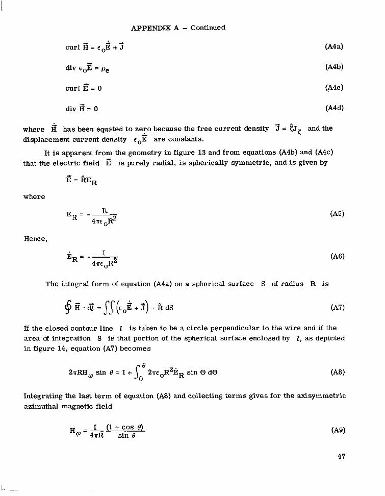
where H' has been equated to zero because the free current density 5 = CJC and the displacement current density E oE are constants.
It is apparent from the geometry in figure 13 and from equations (A4b) and (A4c) that the electric field E' is purely radial, is spherically symmetric, and is given by
E = 6~~
where
It 2 E R = -
47r~
Hence,
I 2 E R = -
47r~
The integral form of equation (A4a) on a spherical surface S of radius R is
If the closed contour line 1 is taken to be a circle perpendicular to the wire and if the area of integration S is that portion of the spherical surface enclosed by 1, as depicted in figure 14, equation (A7) becomes
Integrating the last t e rm of equation (A8) and collecting t e rms gives for the &symmetric azimuthal magnetic field
I (1 +COS e) H =- CP 47rR sin 8
47

APPENDIX A - Continued
E Figure 14.- Surface of in tegra t ion S for equation (A7)
and i t s bounding c i r c u i t l i n e 2 on the spher ica l surface R = Constant i n the coordinate system R,B,rp.
Now take the straight semi-infinite wire to lie in the xz-plane of a Cartesian coor- dinate system, inclined at an angle x t o the z-axis, as pictured in figure 15. The radius vector E will now be confined to the xy-plane. The amplitude of the magnetic field Hq (eq. (A9)) at all points in the xy-plane (or Rq-plane) will now be determined. All that is necessary is to evaluate cos 6 and sin 8 of equation (A9) in t e r m s of the angles x and @.
The formula for cos 8 from analytic geometry is
where the direction cosines XI,/+,vI of I and X R , k , v R of line E are given by
and
48

APPENDIX A - Continued
- a -It
X
Figure 15.- Configuration of f igu re 13 t i l t e d and embedded i n a Cartesian coordinate system x,y ,z . The current-carrying wire i s taken t o l i e i n the xz-plane and the radius vector R i n the xy-plane.
Thus,
c o s 8 = sin x c o s rC,
and
sin e = 4- 1 - sin x c o s \I/
and the magnitude of the magnetic field at points in the xy-plane is given by
H - I (l + sin xCos \I/) 2 2 CP 47rR
1 - sin ~ C O S \I/ (z = 0)
This magnetic field is oriented in the direction of 7 where 7 is normal to the plane formed by the vectors and R, as shown in figure 16.
49
APPENDIX A - Continued
c
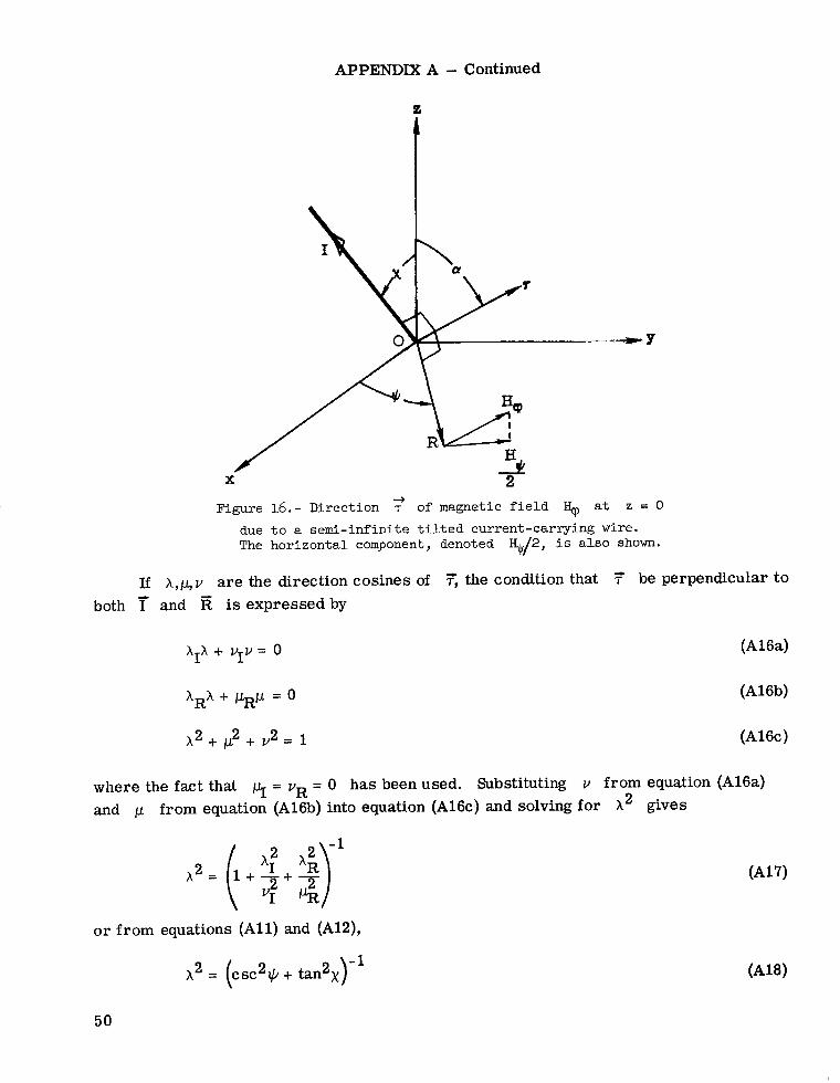
+ Figure 16.- Direction T of magnetic field % at z = 0
due to a semi-infinite tilted current-carrying wire. The horizontal component, denoted 5/2, is also shown.
If X , L V are the direction cosines of 5 the condition that 7 be perpendicular t o both T and is expressedby
(A16a) hIX + VI” = 0
XRA + pRp = 0 (A16b)
A2 + p2 + v2 = 1 (A16c)
where the fact that 4 = vR = 0 has been used. Substituting v from equation (A16a) and p from equation (A16b) into equation (A16cj and solving for A2 gives
-1
X2= ( 1 + - + $ Q o r from equations (All) and (A12),
A2 = (csc2*+ t a n q - l
50
APPENDIX A - Continued
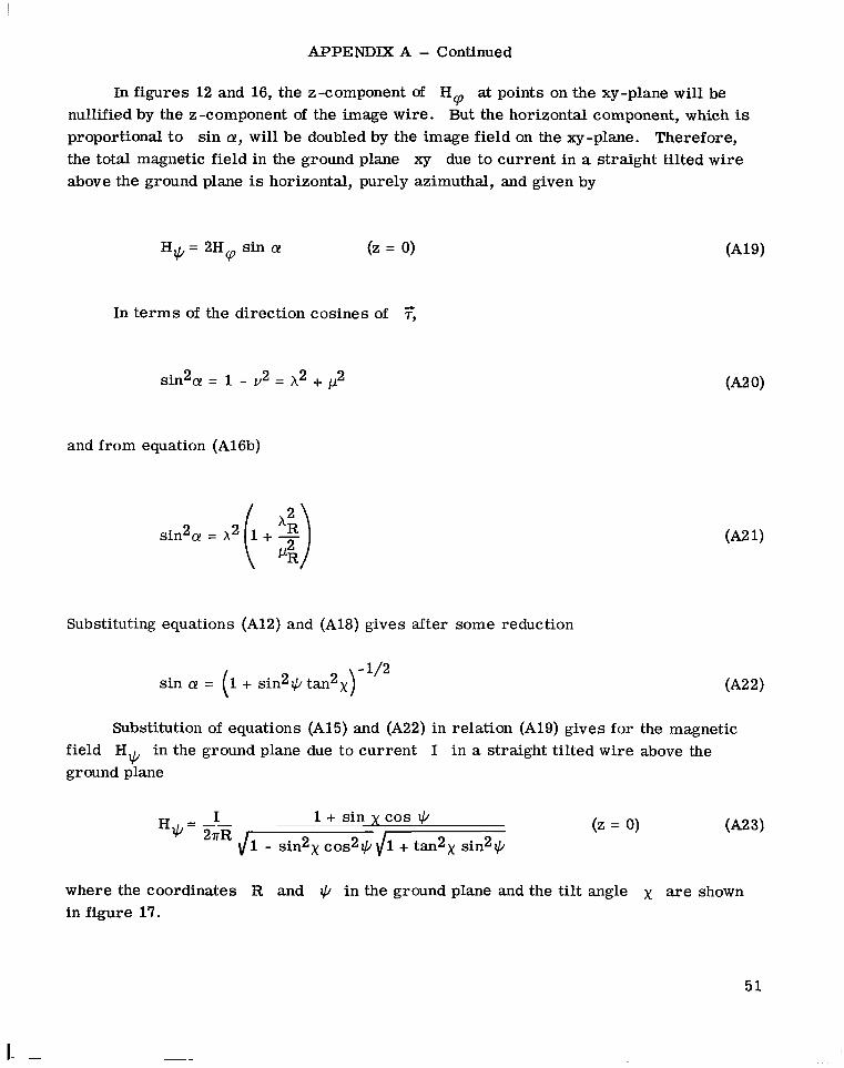
In figures 12 and 16, the z-component of €Iq at points on the xy-plane will be nullified by the z-component of the image wire. But the horizontal component, which is proportional to sin a, will be doubled by the image field on the xy-plane. Therefore, the total magnetic field in the ground plane xy due to current in a straight tilted wire above the ground plane is horizontal, purely azimuthal, and given by
H = 2H sin a (2 = 0) * c p
In t e rms of the direction cosines of ?,
and from equation (A16b)
Substituting equations (A12) and (A18) gives after some reduction
- 1/2 sin a! = (I + sin2q tanax)
Substitution of equations (A15) and (A22) in relation (A19) gives for the magnetic field H* in the ground plane due to current I in a straight tilted w i r e above the ground plane
where the coordinates R and * in the ground plane and the tilt angle x are shown in figure 17.
51
I. -

APPENDIX A - Concluded
e
Figure 17.- Coordinate system for equation (A23).
* Since 7 and H' in electrodynamics are analogous to r and 7 in fluid
dynamics,
(2 = 0) (A241 r 1 + sin x cos + - sin 2 x cos --q- + 1 + tan x sln
where v culation r above the ground plane. The vortex configuration for equation (A24) is shown in figure 18.
is the velocity field in the ground plane due to a straight tilted vortex of c i r - + e
1
Figure 18.- Coordinate system f o r equation (A24).
52

APPENDIX B
DESCRIPTION AND TABULATION OF EMPIlUCAL DATA
ON TWIN TORNADO OF APlUL 11, 1965,
NEAR ELKHART, INDIANA
An unusual tornado, identified 5-2 in reference 4, occurred on April 11, 1965, near
Six photo- Elkhart, Indiana. This tornado developed a second funnel, and the two funnels revolved about each other fo r about 1 minute, and then the original funnel disappeared. graphs of the tornado were taken during the period of duality by Paul Huffman of the Elkhart Truth. One of these photographs is reproduced in figure 5. On the basis of these photographs and aerial examination of the damage paths, Fujita determined that the circu- lation of both funnels during their brief period of individuality w a s cyclonic, and he pro- duced figure 4 (fig. 49 in ref. 4) which shows to scale the motion of the two vortices. The time intervals between the photographs w e r e determined from the translational speed of the storm, about 22.4 m/sec (50 mph).
From a fourfold enlargement of figure 4(b), the following parameters have been obtained for each of the locations 3 to 6: twin vortices; (2) the tilt angle x of the pair with respect to the vertical; and (3) the azimuth angle qA of the pair in the ground plane. These quantities are listed in table I. The aximuth angle +A is the angle at funnel A measured counterclockwise from the broken line labeled "tilt 29'" in figure 4(b) to the line AB connecting the cen- t e r s of the vortex pair. The diameters of the spots in figure 4(c) were taken to be indic- ative of their relative strengths and were used to calculate the tabulated values for the ratio I' I' . d A
(1) the center-to-center distance R, of the
For each of the three intervals between these four data points interpolation gives the mean separation (&), the mean tilt angle ( x), the mean azimuth angle (qA), the mean revolution rate ($A), and the mean circulation ratio ( rB/rA). These
quantities a r e listed in table II. Also included for use in appendix C are mean values
(D) where D
53

APPENDIX C
CIRCULATION OF THE TWIN TORNADO AS DEDUCED
FROM ITS REVOLUTION RATE - EVIDENCE THAT THE FUNNELS MOVED MORE SLOWLY THAN THE FLUID
Circulation Estimate From Revolution Rate
In this appendix the total circulation r A + rB of the twin tornado will first be estimated from its revolution rate with the assumption that the funnels move with the fluid. According to equation (36) this means that the buoyancy and source t e r m s are neglected as well as a possible Lorentz force F'. The effects of these t e rms have been determined, subject to certain simplifications, i L the sections entitled, "Effect of Core Buoyancy on Revolution Rate of a Twin Tornado,'' "Effect of the Boundary Layer at the Ground on Tornado Motion," and "Influence of Axial Electric Current on Revolution Rate of Twin Vortices." After the first estimate is obtained, the effects of the neglected t e rms on this estimate will be considered.
The velocity fields are determined in accordance with the twin-vortex model pre- sented in the section entitled, "Tornado model" and illustrated in figure 8. Effects of the tilt angle x and of the unequal circulations and rB of the two vortices are included. But the convergences Q; and Q& of this model are equated to zero in order to conform to the observation that the twin funnels did not approach each other, as explained in the section entitled, "Correlation of the twin-vortex model with data from the twin tornado."
Velocity field at ground plane due to single inclined vortex.- Consider a single vor- which terminated on the ground plane and is inclined to the vertical
___-___
tex of circulation by the angle x as in figure 18. The velocity field at the ground plane (RG-plane) for such a vortex in a perfect fluid is found in appendix A (eq. (A24)) to be purely azimuthal and given by the formula
(2 = 0)
Twin-vortex model.- Now, consider the configuration shown in figure 8 as viewed from above in figure 19. Here the two tilted, semi-infinite vortices terminate at spots A and B in the ground plane. The broken lines in this figure represent the projections of the vortex axes in the ground plane, as in figure 4(b). Take the two inclined vortices to be parallel to each other and to have cyclonic circulations r A and l?, in a perfect
54

APPENDIX C - Continued
I I I
Figure 19.- View of ground plane f r o m above (as i n f i g . 4(b)) showing the touchdown points of two vor t ices A and B, t h e i r ve loc i ty f i e l d s , and or ien ta t ion with respect t o project ions of t h e vortex axes.
The velocity field TB at point B is perpendicLAr to fluid which is otherwise at rest. the line AB, as shown in figure 19, and is given by
where
and
D = \/I - sin2X cos2+A\ l~ + tanax sin2qA
Similarly, the velocity field TA is given by
,A=- YB * 2nRc
where
1 - s i n xcos * YB = D( A) (C 5)
55

APPENDIX C - Continued
and the substitution qB = 'CIA f T has been made. The quantities y A and yB will be referred to as the "effective circulations" of vortices A and B.
Define point P on the line AB, as shown in figure 19 so that
Then the revolution rates of points A and B about P are given by
But by relation (C6a)
and point P is seen to be the center point of revolution of points A and B in the ground plane. (Since yA and yB a r e different functions of qA, the location of point P on line AB will also vary with the azimuth angle qA of the pair.) Combination of equa- tions (C6a) and (C6b) gives
Hence, the theoretical revolution rate in the ground plane of a tilted vortex pair of like sense in a perfect fluid is given by
yA + yB 2 2 aRc
+A =
The effective circulation yA + yB of the vortex pair is related to the circulation + rB by adding equations (C2) and (C5)
56

APPENDIX C - Continued
where D is given by equation (C3). Combining equations (C11) and (C12) gives
~ ~ T R ~ D $ ~ 2 = rA(1 + b) + rA(1 - b)sin X C O S $'A
where b rB A. Solving for rA: P
rA= ~
(1 + b) + (1 - b)sin x COS qA
and multiplying by (1 + b) gives
27TRCDSIA(1 2 + b) r + r B = -
(1 + b) + (1 - b)sin x COS +A A
For intervals 3-4, 4-5, and 5-6 mean values
tuting values from table I1 for (Rc), ( D ) , (qA), ( b ) , (x), and ($A) in
formula (C15). This gives the following estimate for (FA + r,) in m2/sec:
(rA + rB) can be determined by substi-
x lo3 (Interval 3-4)
x 103 (Interval 4-51 (rA + rB> = 4.91 x lo3 (Interval 5-6)
Averaging these values gives
(rA + rB) = 4.92 x 10³ (interval 3-6)
for the total circulation in m2/sec of the tornado pair, as computed from the revolution rate of their touchdown spots on the ground with the assumption that the funnels move with the fluid.
57

I '
APPENDIX C - Continued
Evidence That the Revolution Rate Was Retarded
With Respect to the Fluid
Examining the wind damage shown in figure 20 shows that the value (C17) for
( rA + rB) Trailer Court from the north. This trailer court was hit by the twin tornado. The two funnels moved from right to left across this photograph and were tilted toward the bottom edge of the photograph. Figure 5, which depicts the funnels at location 4, was taken while funnel B was over the trailer court.
is too small by at least a factor of 2. This photograph views the Midway
Figure 20.- Aer ia l photograph of severe damage t o t h e Midway T r a i l e r Court near E l k h a r t , Indiana. Devastatidn seen near center of p i c tu re was caused by the l e f t funnel of t he tornado shown i n f igure 5 , while the r i g h t funnel moved over the plowed f i e l d from r i g h t t o l e f t , cu t t ing across upper corner of the court . Apri l 13.
Damage occurred at 5:32 p.m. CST, Apr i l 11, 1965; p ic ture w a s taken Courtesy T. F u j i t a ( r e f . 4).
Note the damage near the lower edge of figure 20 left of center. One trailer has a side blown out, and next to it is one which was upturned (wheels up). The maximum pos- sible wind speed at this point due to the calculated value (C17) for determined by combining the two funnels into a single vortex on the nearest tornado path and tilting this vortex directly toward the upturned trailer. The center of the nearest
( r A + r,) can be
58
APPENDIX C - Concluded
path is a distance of 89.9 m (295 f t ) from the upturned trailer. (This distance estimate assumes that the trailers were typically 15.2 m (50 ft) long.) The nearest path is that of funnel B, which cut diagonally from upper right to center left across the trailer court and caused the devastation near the middle of the photograph.
The velocity field at the ground due to a single tilted vortex (fig. 18) is given by equation (A24). Substituting the values
r =
R = 89.9 m (295 f t )
x = 29'
r A + rB) = 4.92 x 10³ m2/sec (
@A= 0'
in equation (A24) gives
v@ = 14.8 m/sec (33.1 mph) (C 19)
as the maximum possible wind speed at the upturned trailer due to the circulation value ( r A + rB) = 4.92 x 10³ m2/sec calculated from the revolution rate of the pair, assumed to move with the fluid. This wind speed is clearly too low, and it is not augmented by the speed of the storm, about 22.4 m/sec (50 mph), because the site of the upturned t ra i ler was on the northern side of the tornado path, where the storm velocity opposes and tends to reduce the circulation velocity. In reference 3, Fujita reports an anemometer recording which shows winds of 67 m/sec (150 mph) at the edge of a damage path of a tornado generated an hour later by the same storm. The conclusion therefore is that the actual circulation of the twin tornado w a s much greater than the value (4.92 x 10³ m2/sec) calculated from its revolution rate by assuming that the vortices moved with the fluid. Apparently, the revolution rate was retarded with respect to the fluid by at least a factor of 1/2.
The possibility of local wind shear causing this retardation has been considered. A continuous source of wind shear is the tornado cyclone in which tornado J - 2 was embedded. This wind shear can be estimated from the paths of the family of tornadoes generated by the tornado cyclone, as presented in the maps of reference 4. The wind shear estimated in this way is found to be too low to affect the revolution rate of the twin tornado J - 2 significantly .
59

I I II l11111I I I 1111111 I I111 I l1.1111 I I, , 1 1 1 1 1 1 1 1 1 1 . - .I_., .,.. .- ...--
REFERENCES
1. Fujita, Tetsuya: Formation and Steering Mechanisms of Tornado Cyclones and Associated Hook Echoes. Mon. Weather Rev., vol. 93, no. 2, Feb. 1965, pp. 67-78.
2. Browning, Keith A.; and Fujita, T.: A Family Outbreak of Severe Local Storms - A Comprehensive Study of the Storms in Oklahoma on 26 May 1963, Part I. AFCRL-65-695(1), U.S. Air Force, Sept. 1965.
3. Fujita, Tetsuya: Estimated Wind Speeds of the Palm Sunday Tornadoes. SMRP Res. Pap. No. 53 (ESSA Grant No. E-86-67-(G)), Univ. of Chicago, Apr. 1967.
4 . Fujita, Tetsuya: Aerial Survey of the Palm Sunday Tornadoes of April 11, 1965. SMRP Res. Pap. No. 49 (Grant WBG-41(NSSL)), Univ. of Chicago, Jan. 1966.
5 . Lamb, Horace: Hydrodynamics. Sixth ed., Dover Publ., Inc., 1945.
6. Serrin, J.: Mathematical Principles of Classical Fluid Mechanics. Encycl. Phys., vol. VIII, pt. 1, Fluid Dynamics I, S. Flugge, ed., Springer-Verlag (Berlin), 1959, pp. 125-263.
7. Sommerfeld, Arnold: Mechanics of Deformable Bodies. Academic Press, Inc ., c.1950.
8 . Tsien, H. S.: The Equations of Gas Dynamics, Fundamentals of Gas Dynamics, Howard W. Emmons, ed., Princeton Univ. Press , 1958, pp. 3-63.
9 . Godske, C. L.; Bergeron, T.; Bjerknes, J.; and Bundgaard, R. C.: Dynamic Meteo- rology and Weather Forecasting. Amer. Meteorol. SOC. and Carnegie Inst. of Washington, 1957.
10. Howarth, L.: The Equations of Flow in Gases. Modern Developments in Fluid Dynamics - High Speed Flow, Vol. 1, L. Howarth, ed., Clarendon Press (Oxford), 1953, pp. 34-70.
11. Goldman, Joseph L.: The Role of the Kutta-Joukowski Force in Cloud Systems With Circulation. Tech. Note 48-NSSL-27, Weather Bur., U.S. Dep. Com., June 1966, pp. 21-34.
12. Brooks, Edward M.: Tornadoes and Related Phenomena. Compendium of Meteorology, Thomas F. Malone, ed., Amer. Meteorol. SOC., 1951, pp. 673-680.
13. Namias, Jerome; and Clapp, Philip F.: Observational Studies of General Circulation Patterns. Compendium of Meteorology, Thomas F. Malone, ed., Amer. Meteorol. SOC., 1951, pp. 551-567.
14. Abdullah, Abdul Jabbar: Some Aspects of the Dynamics of Tornadoes. Mon. Weather Rev., vol. 83, no. 4, Apr. 1955, pp. 83-94.
60

15. Lewis, William; and Perkins, Porter J.: Recorded Pressure Distribution in the Outer Portion of a Tornado Vortex. Mon. Weather Rev., vol. 81, no. 12, Dec. 1953, pp. 3'79-385.
16. Vonnegut, B.; and Weyer, James R.: Luminous Phenomena in Nocturnal Tornadoes. Science, vol. 153, no. 3741, Sept. 9, 1966, pp. 1213-1220.
17. ROSSOW, Vernon J.: On the Origin of Circulation for Tornado Formation. Twelfth Conference on Radar Meteorology, Amer. Meteorol. SOC., 1967, pp. 183-189.
18. Busemann, Adolf: Relations Between Aerodynamics and Magnetohydrodynamics. Proceedings of the NASA-University Conference on the Science and Technology of Space Exploration, Vol. 2, NASA SP-11, 1962, pp. 305-312.
19. Busemann, Adolf: On the K & m b Vortex Street in Magnetofluid-Dynamics. Aero- space Scientific Symposium of Distinguished Lecturers honoring Von K&rm&n on 80th Anniversary, Inst. Aerosp. Sci., c.1962, pp. 87-110.
20. Vonnegut, Bernard: Electrical Theory of Tornadoes. J. of Geophys. Res., vol. 65, no. 1, Jan. 1960, pp. 203-212.
21. Silberg, P. A.: Dehydration and Burning Produced by the Tornado. J. Atmos. Sci., vol. 23, no. 2, Mar. 1966, pp. 202-205.
22. Colgate, Stirling A.: Tornadoes: Mechanism and Control. Science, vol. 157, no. 3795, Sept. 22, 1967, pp. 1431-1434.
23. Brook, Marx: Electric Currents Accompanying Tornado Activity. Science, vol. 157, no. 3795, Sept. 22, 1967, pp. 1434-1436.
24. ROSSOW, Vernon J.: Observations of Waterspouts and Their Parent Clouds. NASA TN D-5854, 1970.
61

TABLE 1.- PARAMETERS FOR TWIN TORNADO 5-2
OBTAINED FROM FIGURE 4
._
Center -to-center separation in Tilt angle with ground plane,
f t m
respect to vertical, x t deg
Location Azimuth
angle , +A, deg
62
3 4 5 6
~-
Interval between locations
390 118.9 431.8 131.6 134.1 478.2 145.7 151.4
237.0 482.6 147.1 1 I i3 1 96.9-
- __._ ____
3 -4 (13 see)
4-5 (8 sec)
(31 sec) 5 -6
an le, Mean tilt Mean azimuth
angle 9 (x), deg (*A71 deg
-
rB/rA
0.6 1.00 1.35 2.75
_ _ _ -
__
rate (observed), Mean revolution
(*A)’ rad/sec
TABLE 11.- MEAN VALUES FOR PARAMETERS OF TABLE I AND
125.2
138.7
146.4
f t
410.9 __ -
455.0
480.4 __ ~.
I - - . - - ~
0.8 111:; 1 o:!l 1.17 29
29 194.2 2.05
30
- -__
1.1
.973
.891
-
NASA-Langley, 1970 - 13 L-5738
~

I I IIIIII 111l11lIIlIIIlIlII
NATIONAL AERONAUTICS AND SPACE ADMINISTRATION WASHINGTON, D. C. 20546
OFFICIAL BUSINESS FIRST CLASS MAIL
POSTAGE A N D FEES PAID NATIONAL AERONAUTICS A N D
SPACE ADMINISTRATION
OlU 001 37 51 313s 70272 00903 A I i i FORCE WEAPONS L A B O R A T C I R Y /WLOL/ K I R T L A i d D A F B p N E N MtXICO 87117
A T 1 E, LOU BOWMAN, CHLEFVTECH- L I l j K A R Y
POSTMASTER: If Undeliverable (Section 158 Postal Manual) Do Not Return
I
“The aeroizanticnl nnd space activities of the United Stntes shall be coizducted so as to contribute . . . t o the expnmion. of hzma?z knoiul- edge of phefzoiizena ia the attlliosphere a i d Jpace. T h e Admi?zistratioa shall provide for t he widest practicnble and nppropriate disseimhation of iizforiiintion concerning i ts activities and the resnlts thereof.”
-NATIONAL AERONAUTICS AND SPACE ACT OF 1958 . . - , - ~.
NASA SCIENTIFIC AND TECHNICAL PUBLICATIONS
TECHNICAL REPORTS: Scientific and technical idformation considered important, complete, and a Ipting contribution to existing knowled@.
TECHNICAL NOTES: Information less broad in scop , but nevertheless of importance as a contribjition to existing knowledge.
TECHNICAL MEMORANDUMS: Inforniation. receiving limited distribution becaust! of preliminary data, security classifica- tion, or phe r reasons.
I .
TECHNICAL TRANSLATIONS: Information published in a foreign language considered to merit NASA distribution in English.
SPECIAL PUBLICATIONS: Information derived from or of value to NASA activities. Publications include conference proceedings, monographs, data compilations, handbooks, sourcebooks, and special bibliographies.
TECHNOLOGY UTILIZATION PUBLICATIONS: Information on technology used by NASA that may be of particular
/
interest in commercial and other non-aerospace applications. Publications include Tech Briefs, Ttchnology Utilization Reports and Notes, and Technology Surveys.
CONTRACTOR REPORTS: Scientific and technical information generated under a NASA contract or grant and considered an important contribution to existing knowledge.
Details on the availability of these publications may be obtained from:
SCIENTIFIC AND TECHNICAL INFORMATION DIVISION
NATIONAL AERONAUTICS AND SPACE ADMINISTRATION Washington, D.C. 90546