Embed Size (px)
Citation preview
BUILDINGSTEEL PROFILES
03
INTRODUCTION
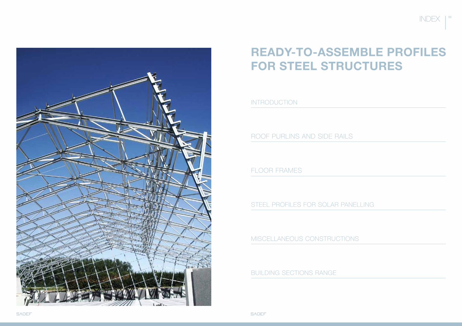
ROOF PURLINS AND SIDE RAILS
FLOOR FRAMES
STEEL PROFILES FOR SOLAR PANELLING
MISCELLANEOUS CONSTRUCTIONS
BUILDING SECTIONS RANGE
READY-TO-ASSEMBLE PROFILES FOR STEEL STRUCTURES
INDEX
INTRODUCTION
- WHAT HAS SADEF TO OFFER? p. 06
- WHO IS SADEF? p. 08
- WHY SADEF? p. 09
06
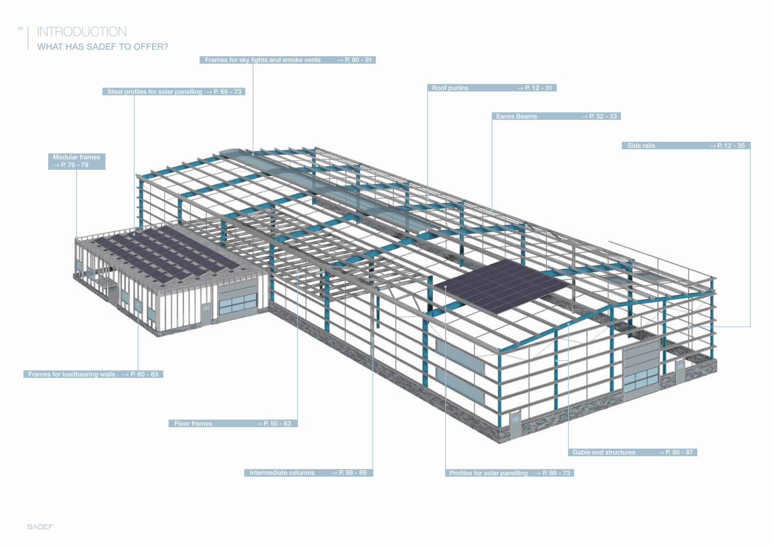
Roof purlins → P. 12 - 31
Eaves Beams → P. 32 - 33
Floor frames → P. 50 - 63
Profiles for solar panelling → P. 66 - 73
Steel profiles for solar panelling → P. 66 - 73
Modular frames → P. 76 - 79
Frames for loadbearing walls → P. 80 - 83
Gable end structures → P. 86 - 87
Intermediate columns → P. 88 - 89
Frames for sky lights and smoke vents → P. 90 - 91
Side rails → P. 12 - 35
WHAT HAS SADEF TO OFFER?
INTRODUCTION
08 09
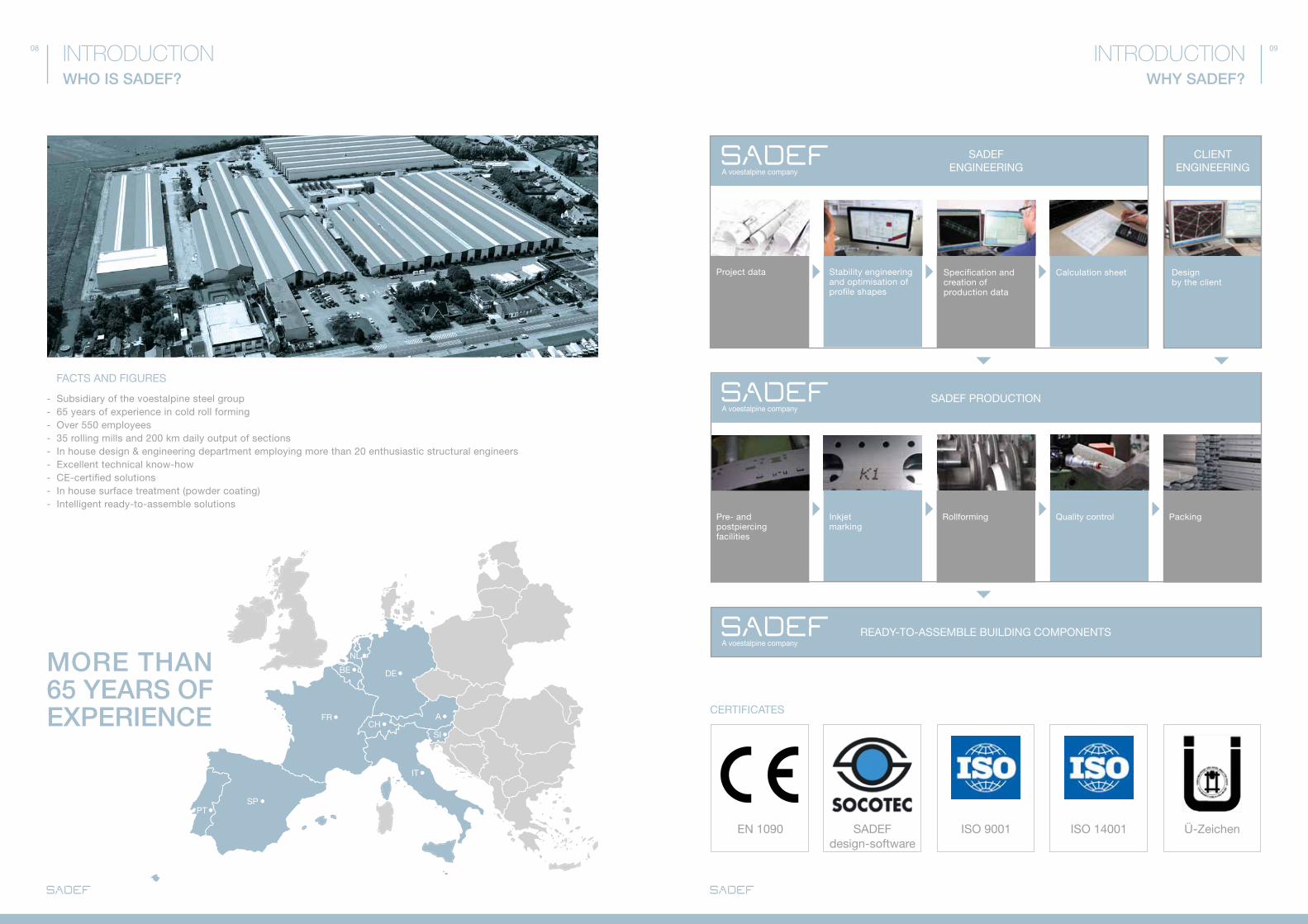
Ü-ZeichenISO 9001 ISO 14001EN 1090 SadEf design-software
WHY SADEF?WHO IS SADEF?
INTRODUCTIONINTRODUCTION
CERTIfICaTES
faCTS aNd fIGURES
- Subsidiary of the voestalpine steel group- 65 years of experience in cold roll forming- Over 550 employees - 35 rolling mills and 200 km daily output of sections- In house design & engineering department employing more than 20 enthusiastic structural engineers- Excellent technical know-how- CE-certified solutions- In house surface treatment (powder coating)- Intelligent ready-to-assemble solutions
fRCH
SI
PT
BE
NL
dE
IT
SP
MORE THAN 65 YEARS OF EXPERIENCE a
SadEf ENGINEERING
REadY-TO-aSSEMBLE BUILdING COMPONENTS
CLIENT ENGINEERING
Stability engineering and optimisation of profile shapes
Project data Calculation sheet design by the client
Specification and creation of production data
Pre- and postpiercing facilities
Inkjetmarking
Rollforming Quality control Packing
SadEf PROdUCTION
ZED p. 16 - 21
SIGMA p. 24 - 29
SE p. 32 - 33
CEE p. 34 - 35
ACCESSORIES p. 38 - 43
ONLINE OFFER CALCULATION p. 46 - 47
ROOF PURLINS AND SIDE RAILS

12
OVERVIEW
ROOF PURLINS AND SIDE RAILS
Cleats ZED → P. 20 - 21
SIGMA Sleeve → P. 28 - 29
Cleats SIGMA → P. 28 - 29
Anti-sag bars → P. 38 - 39
Eaves Brace → P. 32 - 33
Apex tie → P. 40 - 41 Profiles for roof purlins
ZEd
Z 375Z 350Z 300Z 250Z 200Z 180
P.16P.105
SIGMa -plus
S+450S+400S+350S+300S+250
P.24P.103
SIGMaS 200S 170S 140
P.24P.104
Eaves Beams
SESE 200SE 250SE 330
P.32P.104
Diagonal tie wires → P. 42 - 43
Profiles for side rails
ZEd
Z 375Z 350Z 300Z 250Z 200Z 180
P.16P.105
SIGMa-plus
S+450S+400S+350S+300S+250
P.24P.103
SIGMaS 200S 170S 140
P.24P.104
CEE-plus
C+200C+160C+150C 140
P.34P.101
16 17
ZED
ZED - BEAM
ROOF PURLINS AND SIDE RAILS
OVERLaP BEaM WITH Qa-SYSTEM
SINGLE SPaN BEaMS (aSSEMBLY BETWEEN SPaNS)
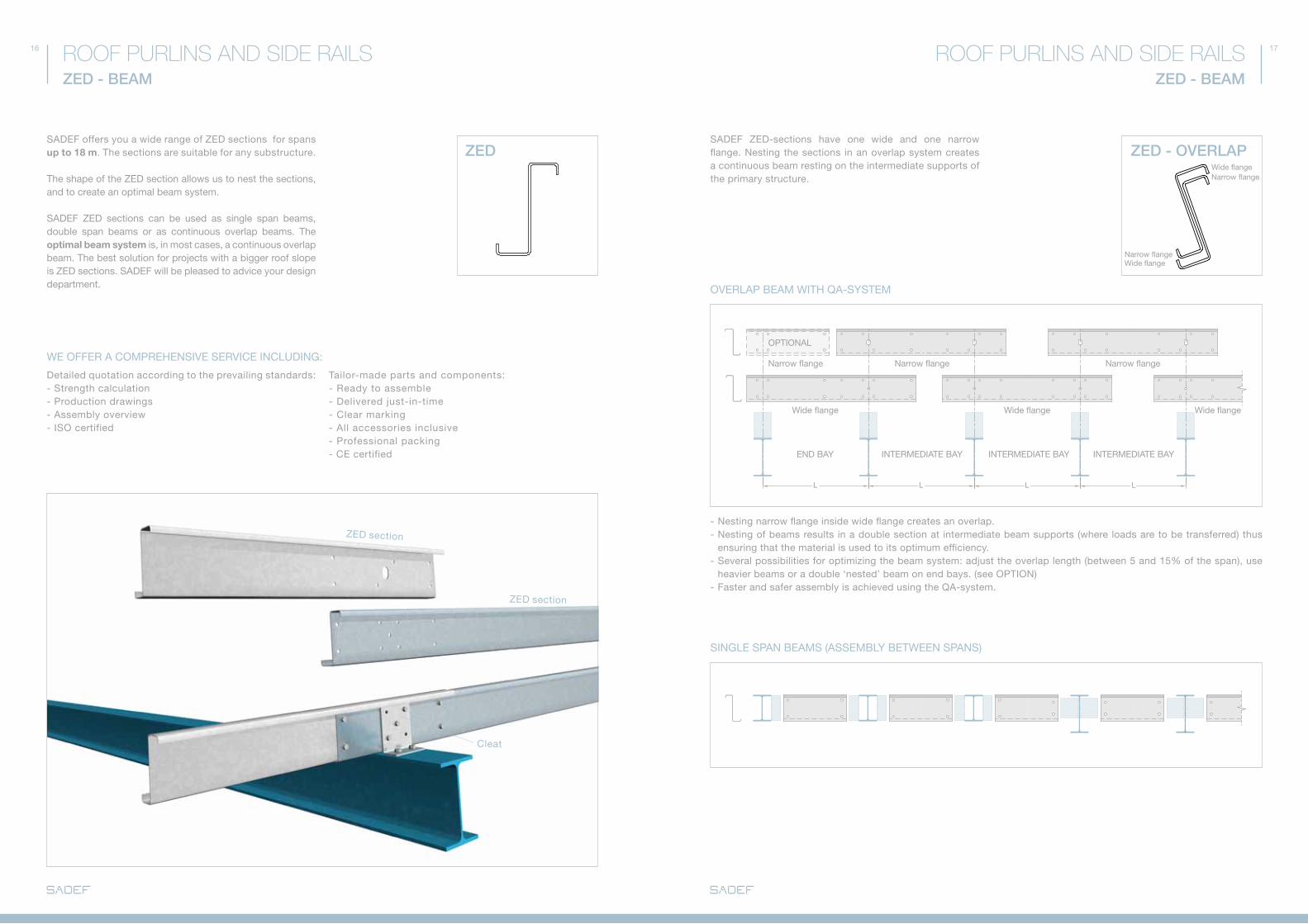
SadEf ZEd-sections have one wide and one narrow flange. Nesting the sections in an overlap system creates a continuous beam resting on the intermediate supports of the primary structure.
Wide flangeNarrow flange
ZED - OVERLAP
- Nesting narrow flange inside wide flange creates an overlap. - Nesting of beams results in a double section at intermediate beam supports (where loads are to be transferred) thus ensuring that the material is used to its optimum efficiency.- Several possibilities for optimizing the beam system: adjust the overlap length (between 5 and 15% of the span), use heavier beams or a double ‘nested’ beam on end bays. (see OPTION)- faster and safer assembly is achieved using the Qa-system.
Narrow flange Wide flange
ROOF PURLINS AND SIDE RAILSZED - BEAM
SadEf offers you a wide range of ZEd sections for spans up to 18 m. The sections are suitable for any substructure.
The shape of the ZEd section allows us to nest the sections, and to create an optimal beam system.
SadEf ZEd sections can be used as single span beams, double span beams or as continuous overlap beams. The optimal beam system is, in most cases, a continuous overlap beam. The best solution for projects with a bigger roof slope is ZEd sections. SadEf will be pleased to advice your design department.
WE OffER a COMPREHENSIVE SERVICE INCLUdING:
detailed quotation according to the prevailing standards:- Strength calculation - Production drawings- assembly overview - ISO certified
Tailor-made parts and components:- Ready to assemble- delivered just-in-time - Clear marking- all accessories inclusive- Professional packing - CE certified
ZEd section
ZEd section
Cleat
L L L L
Narrow flange Narrow flange Narrow flange
Wide flange
ENd BaY INTERMEdIaTE BaY INTERMEdIaTE BaY INTERMEdIaTE BaY
Wide flange Wide flange
OPTIONaL
18 19
AB
CD
E
1
2
3
ED 3
C2B
1A
44
AB
CD
E
1
2
3
4E 4D 3
C2B
1A
AB
CD
E
1
2
3
4
5
6
7
88
7
6
5
4
3
2
1
ED
CB
A
AB
CD
E
1
2
3
4E 4
D 3C
2B1A
AB
CD
E
1
2
3
4E 4D 3
C2B
1A
ROOF PURLINS AND SIDE RAILSZED OVERLAPPING BEAM WITH QA-SYSTEM
Qa-SYSTEM: SafE, faST aNd EaSY-TO-INSTaLL
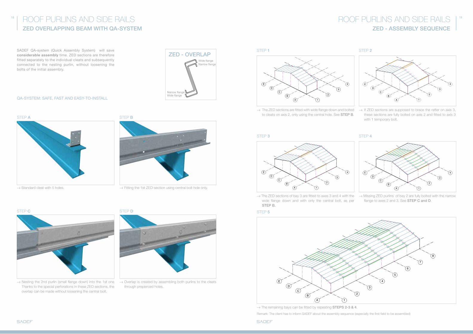
SadEf Qa-system (Quick assembly System) will save considerable assembly time. ZEd sections are therefore fitted separately to the individual cleats and subsequently connected to the nesting purlin, without loosening the bolts of the initial assembly.
STEp A
STEp C STEp D
STEp B
→ Standard cleat with 5 holes.
→ Nesting the 2nd purlin (small flange down) into the 1st one Thanks to the special perforations in these ZED sections, the overlap can be made without loosening the central bolt.
→ Fitting the 1st ZED-section using central bolt hole only.
→ Overlap is created by assembling both purlins to the cleats through prepierced holes.
ZED - ASSEMBLY SEQUENCE
ROOF PURLINS AND SIDE RAILS
STEp 1
STEp 3
STEp 5
STEp 2
STEp 4
→ The ZED sections are fitted with wide flange down and bolted to cleats on axis 2, only using the central hole. See STEP B.
→ The ZED sections of bay 3 are fitted to axes 3 and 4 with the wide flange down and with only the central bolt, as per STEP B.
→ The remaining bays can be fitted by repeating STEPS 2-3 & 4.
Remark: The client has to inform SADEF about the assembly sequence (especially the first field to be assembled)
→ If ZED sections are supposed to brace the rafter on axis 3, these sections are fully bolted on axis 2 and fitted to axis 3 with 1 temporary bolt.
→ Missing ZED purlins of bay 2 are fully bolted with the narrow flange to axes 2 and 3. See STEP C and D.
ZED - OVERLAPWide flangeNarrow flange
Narrow flange Wide flange

20 21
ZED ZED
E*160
40D
50 50100
=
=
B
C
AØ
Ø14-18
E*160
40D
50 50100
=
=
B
C
AØ
Ø14-18
10 mm
10 mm
ROOF PURLINS AND SIDE RAILSZED - CLEATS
CLEaTS
SadEf sections are fitted to the substructure by means of cleats.ZEd-purlins should be bolted to the cleats with their top flanges pointing to the roof ridge.
To avoid web crippling, a 10 mm clearance between main frame and SadEf beams is required. This is achieved by the offset hole position in beams and cleats.
Cleats are also necessary for transmitting the roof diaphragm forces to the substructure. SadEf-cleats are made from HSLa-steel grades and are hot-dip galvanized.
RafTER STaYS
Rafter stays can be fixed in the holes at the end of the overlap. Please inform SadEf if rafter stays are to be used. This element will then be taken into consideration for the strength calculations.
ZEd section
Rafter stay
+/- 10 mm clearance between Sadef ZEd sections and substructure
ROOf - CLEaTS SIdE RaIL - CLEaTS
Cleat
ZED - CLEATS
ROOF PURLINS AND SIDE RAILS
depending on the substructure geometry either standard (EZEd) or reinforced (EZEdXX) cleats can be used. Both types are suitable for the Qa-system.
ZEd - CLEaTS
TypeSection name
a(mm)
B(mm)
C(mm)
d(mm)
f(mm)
Ø(mm)
EZED375XX
Z 375x5
365 265 65 85
60,0
18
Z 375x4 58,0
Z 375x3 57,5
Z 375x2,5 57,0
Z 375x2 56,5
EZED350XX
Z 350x4
340 240 65 85
58,0
18
Z 350x3,5 58,0
Z 350x3 57,5
Z 350x2,5 57,0
Z 350x2 56,5
EZED300XX
Z 300x5
290 190 65 85
59,5
18
Z 300x4 58,0
Z 300x3,5 58,0
Z 300x3 58,0
Z 300x2,5 57,0
Z 300x2 56,5
Z 300x1,75 56,0
EZED250EZED250XX
Z 250x4
245 150 60 75
53,5
18
Z 250x3,5 53,0
Z 250x3 52,5
Z 250x2,5 52,0
Z 250x2 51,5
Z 250x1,75 51,5
Z 250x1,5 52,0
EZED200EZED200XX
Z 200x4
195 100 60 75
53,5
14
Z 200x3 53,0
Z 200x2,5 53,0
Z 200x2 52,0
Z 200x1,75 52,0
Z 200x1,5 52,0
EZED180EZED180XX
Z 180x2,5
176 81,5 60 75
52,0
14
Z 180x2 50,5
Z 180x1,75 50,0
Z 180x1,5 50,0
Z 180x1,25 50,0
Piercing pattern is symmetrical in the bottom of the cleats. for alternative piercing patterns: please contact SadEf.
E*: Hole distance variable from 50 to 100 mm with 70 mm (Ø 18 mm) as standard.
TYPE EZEdXX
TYPE EZEd
reinforced cleat
standard cleat
Narrow flange
Wide flangeSection properties: please turn to page 105

24 25
SIGMA
L L L L
ROOF PURLINS AND SIDE RAILSSIGMA BEAM
SadEf offers you an extensive range of SIGMa sections for spans up to 18 m.
The sections are suitable for virtually any substructure.SadEf SIGMa can be used as single span beams, double span beams or as a continuous beam.
Use continuous sleeve beams for optimum deflection and strength. SadEf will be pleased to advise your design department.
SIGMA BEAM
ROOF PURLINS AND SIDE RAILS
dOUBLE SPaN BEaM
SINGLE SPaN BEaMS (aSSEMBLY BETWEEN SPaNS)
double span beams are to be placed in a staggering pattern, ensuring an even distribution of the load to the primary structure.
SLEEVE BEaM
for wide spans (> 8 m), a continuous sleeve beam is usually the best solution. If necessary, the end bays can be fitted either with a thicker section or with a double beam (see OPTION). for standard SadEf sleeves, please turn to page 29.
details autoNotch (Notch): please turn to page 60
WE OffER a COMPREHENSIVE SERVICE INCLUdING:
detailed quotation according to the prevailing standards:- Strength calculation - Production drawings- assembly overview - ISO certified
Tailor-made parts and components: - Ready to assemble - delivered just-in-time - Clear marking - all accessories inclusive - Professional packing - CE certified
SIGMa section
SIGMa section
SLEEVE
Cleat
Sleeve Sleeve Sleeve Sleeve
OPTIONaL
without autoNotch with autoNotch
ENd BaY INTERMEdIaTE BaY INTERMEdIaTE BaY INTERMEdIaTE BaY
26 27
AB
CD
E
1
2
3
4
5
66
5
E 4D 3
C2B
1A
AB
CD
E
1
2
3
4
5
66
5
E 4D 3
C2B
1A
AB
CD
E
1
2
3
4
5
6
7
88
7
6
5
4
3
2
1
ED
CB
A
AB
CD
E
1
2
3
4
5
66
5
E 4D 3
C2B
1A
AB
CD
E
1
2
3
4
5
66
5
E 4D 3
C2B
1A
SIGMA
ROOF PURLINS AND SIDE RAILSSIGMA - SLEEVE BEAM
SafE, faST aNd EaSY SLEEVE aSSEMBLY
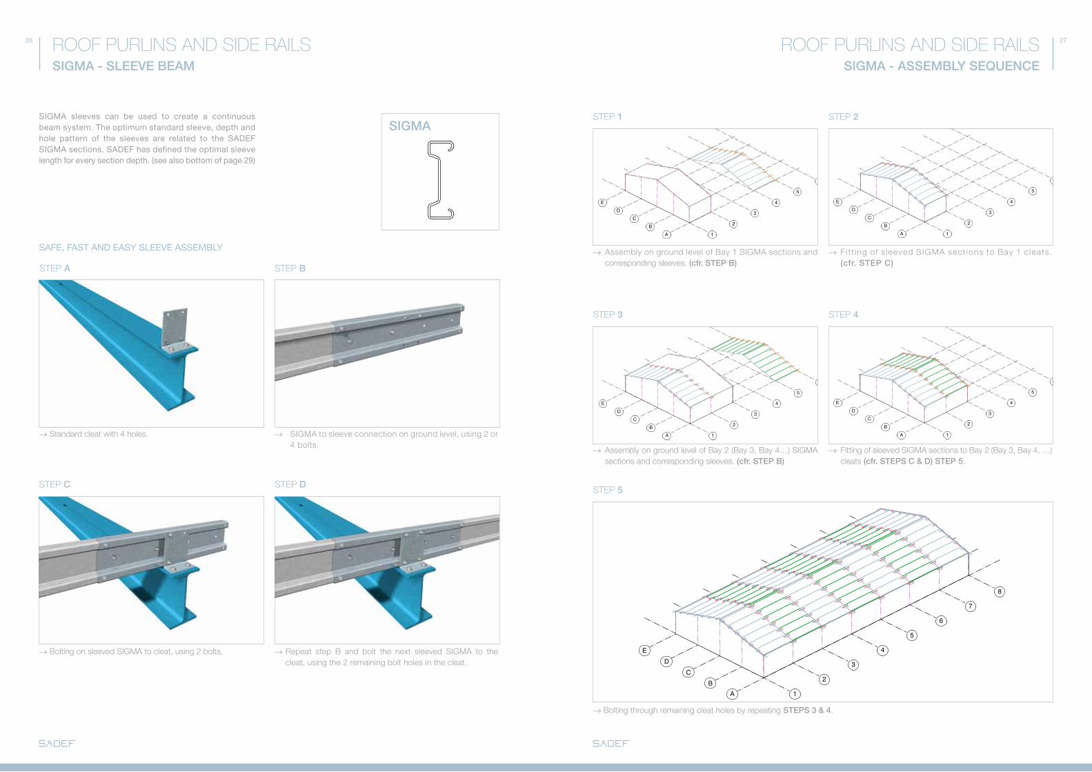
SIGMa sleeves can be used to create a continuous beam system. The optimum standard sleeve, depth and hole pattern of the sleeves are related to the SadEf SIGMa sections. SadEf has defined the optimal sleeve length for every section depth. (see also bottom of page 29)
STEp A
STEp C STEp D
STEp B
→ Standard cleat with 4 holes.
→ Bolting on sleeved SIGMA to cleat, using 2 bolts.
→ SIGMA to sleeve connection on ground level, using 2 or 4 bolts.
→ Repeat step B and bolt the next sleeved SIGMA to the cleat, using the 2 remaining bolt holes in the cleat.
SIGMA - ASSEMBLY SEQUENCE
ROOF PURLINS AND SIDE RAILS
STEp 1
STEp 3
STEp 5
STEp 2
STEp 4
→ Assembly on ground level of Bay 1 SIGMA sections and corresponding sleeves. (cfr. STEP B)
→ Assembly on ground level of Bay 2 (Bay 3, Bay 4…) SIGMA sections and corresponding sleeves. (cfr. STEP B)
→ Bolting through remaining cleat holes by repeating STEPS 3 & 4.
→ Fi t t ing of s leeved SIGMA sect ions to Bay 1 c leats. (cfr. STEP C)
→ Fitting of sleeved SIGMA sections to Bay 2 (Bay 3, Bay 4, …) cleats (cfr. STEPS C & D) STEP 5.
28 29
SIGMA SIGMA
=
=
B
= Ls Ls =
Ltot.
50 50 50 50
(1) (1)(1) (1)(2) (2)
E*160
40DØ14-18
100
BA
Ø
C
E*160
40D
100
BA
Ø
Ø14-18
C
10
10
B
F
=
=B
F
=
=
Ø
Ø
ØØ
Ø
Ø
ROOF PURLINS AND SIDE RAILSSIGMA - CLEATS & SLEEVES
SLEEVES
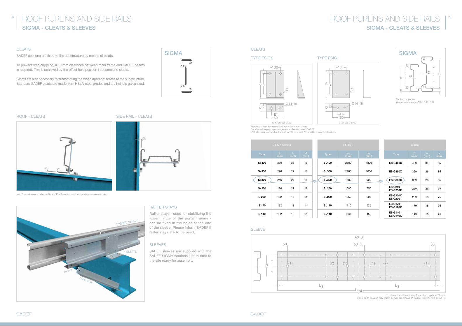
SadEf sections are fixed to the substructure by means of cleats.
To prevent web crippling, a 10 mm clearance between main frame and SadEf beams is required. This is achieved by the offset hole position in beams and cleats.
Cleats are also necessary for transmitting the roof diaphragm forces to the substructure. Standard SadEf cleats are made from HSLa-steel grades and are hot-dip galvanized.
SadEf sleeves are supplied with the SadEf SIGMa sections just-in-time to the site ready for assembly.
RafTER STaYS
Rafter stays - used for stabilizing the lower flange of the portal frames - can be fixed in the holes at the end of the sleeve. Please inform SadEf if rafter stays are to be used.
rafter stay
ROOf - CLEaTS
CLEaTS
SIdE RaIL - CLEaTS
sleeve
SIGMa section
CLEaTS
SIGMA - CLEATS & SLEEVES
ROOF PURLINS AND SIDE RAILS
SLEEVE
(1) Holes in web centre only for section depth > 200 mm.(2) Holes to be used only where sleeves are placed off centre. (sleeve+ and sleeve++)
Piercing pattern is symmetrical in the bottom of cleats. for alternative piercing arrangements, please contact SadEf.E*: Hole distance variable from 50 to 100 mm with 70 mm (Ø 18 mm) as standard.
SLEEVE
TypeLtot
(mm)LS
(mm)
SL400 2680 1300
SL350 2180 1050
SL300 1880 900
SL250 1580 750
SL200 1260 600
SL170 1110 525
SL140 960 450
Cleats
Typea
(mm)C
(mm)d
(mm)
ESIG400X 409 34 85
ESIG350X 359 26 85
ESIG300X 309 26 85
ESIG250ESIG250X
259 26 75
ESIG200X ESIG200
209 18 75
ESIG170ESIG170X
179 18 75
ESIG140ESIG140X
149 18 75
SIGMa section
TypeB
(mm)f
(mm)Ø
(mm)
S+400 330 35 18
S+350 296 27 18
S+300 246 27 18
S+250 196 27 18
S 200 162 19 14
S 170 132 19 14
S 140 102 19 14
TYPE ESIGX
CLEaTS
TYPE ESIG
reinforced cleat standard cleat
Section properties: please turn to pages 102 - 103 - 104
aXIS
+/- 10 mm clearance between Sadef SIGMa-sections and substructure is recommended.
30 31ROOF PURLINS AND SIDE RAILS ROOF PURLINS AND SIDE RAILS
32 33
SESE
W
V
B2
Ø2
ROOF PURLINS AND SIDE RAILSSE - EAVES BEAM
SE - EaVES BEaM
OUTSIdE GUTTER fIXEd ON WaLL CLaddING
OUTSIdE GUTTER fIXEd ON ROOf PROJECTION
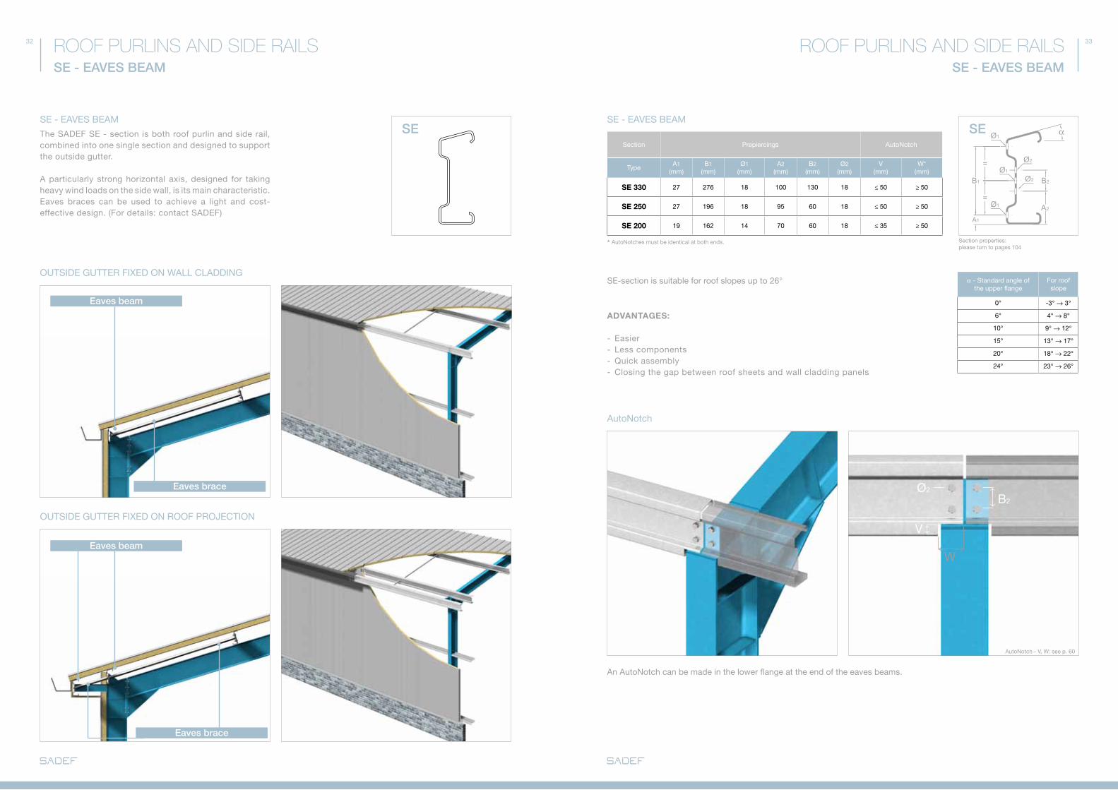
The SadEf SE - section is both roof purlin and side rail, combined into one single section and designed to support the outside gutter.
a particularly strong horizontal axis, designed for taking heavy wind loads on the side wall, is its main characteristic. Eaves braces can be used to achieve a light and cost-effective design. (for details: contact SadEf)
Eaves brace
Eaves brace
Eaves beam
Eaves beam
SE - EAVES BEAM
ROOF PURLINS AND SIDE RAILS
autoNotch
SE - EaVES BEaM
ADVANTAGES:
- Easier- Less components- Quick assembly- Closing the gap between roof sheets and wall cladding panels
SE-section is suitable for roof slopes up to 26°
an autoNotch can be made in the lower flange at the end of the eaves beams.
Section Prepiercings autoNotch
Typea1
(mm)B1
(mm)Ø1
(mm)a2
(mm)B2
(mm)Ø2
(mm)V
(mm)W*
(mm)
SE 330 27 276 18 100 130 18 ≤ 50 ≥ 50
SE 250 27 196 18 95 60 18 ≤ 50 ≥ 50
SE 200 19 162 14 70 60 18 ≤ 35 ≥ 50
α - Standard angle of the upper flange
for roof slope
0° -3° → 3°
6° 4° → 8°
10° 9° → 12°
15° 13° → 17°
20° 18° → 22°
24° 23° → 26°
* autoNotches must be identical at both ends. Section properties: please turn to pages 104
autoNotch - V, W: see p. 60
34 35
CEE-plus CEE-plus
A2
B2
A1
B1
Ø1
Ø2
Ø2
Ø1
Ø1
=
=
1
1
2
3
3
3
4
4
2
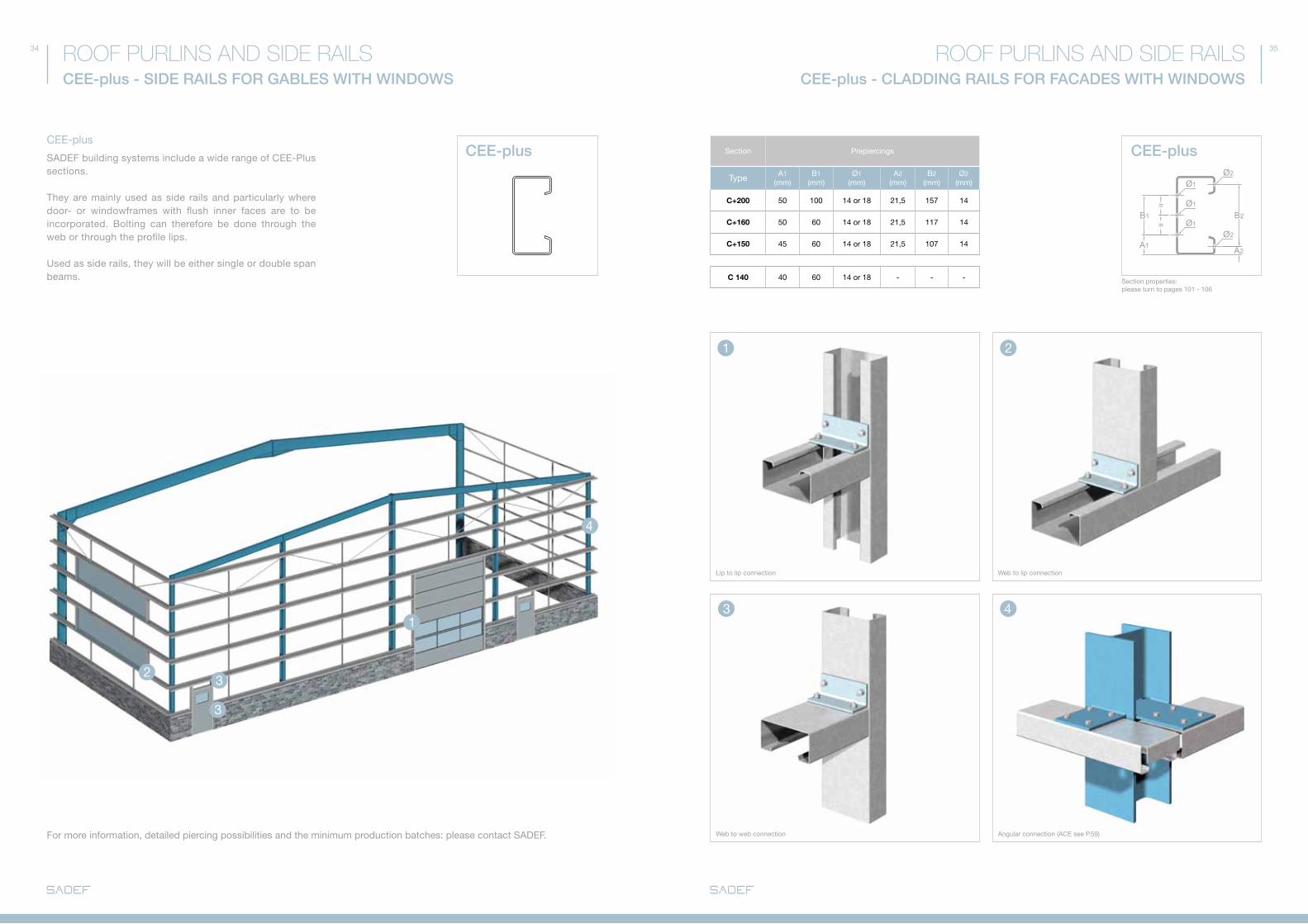
CEE-plus - CLADDING RAILS FOR FACADES WITH WINDOWS
ROOF PURLINS AND SIDE RAILSROOF PURLINS AND SIDE RAILSCEE-plus - SIDE RAILS FOR GABLES WITH WINDOWS
CEE-plus
SadEf building systems include a wide range of CEE-Plus sections.
They are mainly used as side rails and particularly where door- or windowframes with flush inner faces are to be incorporated. Bolting can therefore be done through the web or through the profile lips.
Used as side rails, they will be either single or double span beams.
for more information, detailed piercing possibilities and the minimum production batches: please contact SadEf.
Section Prepiercings
Type a1(mm)
B1(mm)
Ø1(mm)
a2(mm)
B2(mm)
Ø2(mm)
C+200 50 100 14 or 18 21,5 157 14
C+160 50 60 14 or 18 21,5 117 14
C+150 45 60 14 or 18 21,5 107 14
C 140 40 60 14 or 18 - - -
Lip to lip connection
Web to web connection angular connection (aCE see P.59)
Web to lip connection
Section properties: please turn to pages 101 - 106

38
SIGMa SIGMaSIGMa SIGMa
ZEd ZEdZEd ZEd
100
mm
Ø 18
Ø 18
M16
39
Ø30 / Ø50
aC
E
ROOF PURLINS AND SIDE RAILSACCESSORIES - ANTI-SAG BARS
SadEf - LOCk® - aNTI-SaG BaR BOLT-ON - aNTI-SaG BaR
Length = purlin distance - profile thickness* Length = purlin distance - profile thickness
* -6 mm = plate thickness of the diagonal tie wire (if used)
ACCESSORIES - ANTI-SAG BARS
ROOF PURLINS AND SIDE RAILS
for flat roofs (< 5% slope) and mezzanine floors the number of anti-sag bars can be reduced by assembling the purlins or joists as follow:
anti-sag bars will be applied for the alignment of purlins and side-rails, or in case the roof sheeting has no stabilising capacity.
In case of important forces in the anti-sag bars, the use of diagonal tie wires is recommended.
autoConnectEnd (aCE) - SaG BaR aPPLICaTION Of aNTI-SaG BaRS
aSSEMBLY aNTI-SaG BaRS
- Minimum length: 800 mm.- Strength needs to be controlled. for more information, detailed perforation possibilities and the minimum production quantity: contact SadEf.
Length = purlin distance - profile thickness
Ø30 / Ø50
SIGMa SIGMa
ZEd ZEd
100
mm
40 41
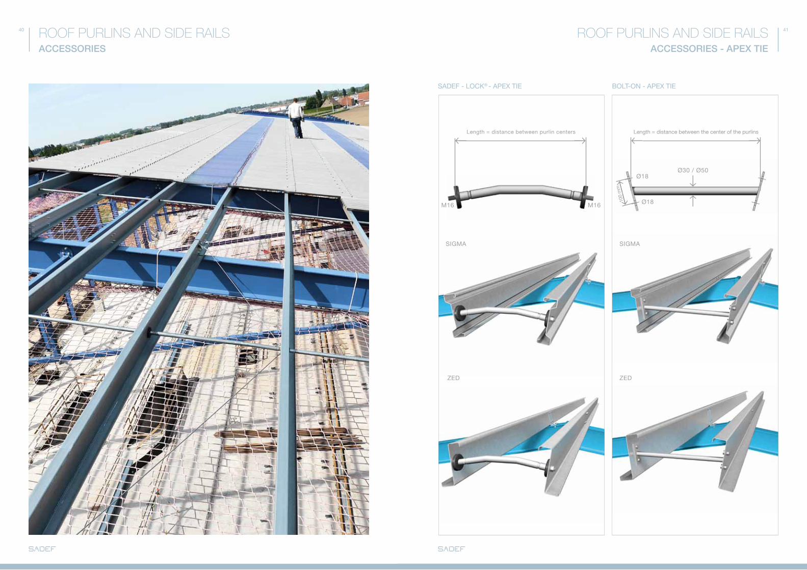
SadEf - LOCk® - aPEX TIE BOLT-ON - aPEX TIE
ROOF PURLINS AND SIDE RAILSACCESSORIES ACCESSORIES - APEX TIE
ROOF PURLINS AND SIDE RAILS
Length = distance between purlin centers
M16 M16
Ø18
Ø18
Length = distance between the center of the purlins

42 43ROOF PURLINS AND SIDE RAILSACCESSORIES - DIAGONAL TIE WIRES
SINGLE dIaGONaL TIE WIRE
dOUBLE dIaGONaL TIE WIRE
Tie wires are required for wide spans and/or for sheeting with no diaphragm action.
They prevent side rail deflection.
Please contact SadEf for prepiercing of additional holes for connection of diagonals to main structure.
Max. tensional force / diagonal tie wire: please contact SadEf.
*Where cleats are welded to the primary structure, ø 14 mm holes should be made in the beam upper flange (specially for Sigma 140 – 170 – 200). Contact SadEf for more information.
USE Of dIaGONaL TIE WIRES
→ 3 anti-sag bars per span at 1/4 , 1/2 and 3/4 span.
Positioning of tie wires in function of the number of anti-sag bars.
→ 2 anti-sag bars per span on 1/3 and 2/3 span.
→ 1 anti-sag bar at mid-span.
ACCESSORIES - ASSEMBLY
ROOF PURLINS AND SIDE RAILS
Roof purlin + bolt-on anti-sag bar + single diagonal tie wire.
Construction detail of the roof purlin + cleat + diagonal tie wire.
fitting of diagonal tie to rafter. Using the cleat hole will avoid time consuming drilling of extra holes.*
Construction roof purlin + SadEf-Lock® + double diagonal tie wire.
Construction detail of side rail + cleat + diagonal tie wire.
Construction detail of side rail + SadEf-Lock® + double diagonal tie wire.
aSSEMBLY Of aCCESSORIES
Ø14-18
Ø14-18
Ø14-18
Ø14-18 Ø14-18
Ø18
Ø18
46 47
ONLINE OFFER CALCULATION
ROOF PURLINS AND SIDE RAILSROOF PURLINS AND SIDE RAILSONLINE OFFER CALCULATION
Step 1: INpUT OF GEOMETRY
www.sadef.com
www.sadef.comwww.sadef.com
Step 2: INpUT OF LOADS
Step 3: OUTpUT - RESULT
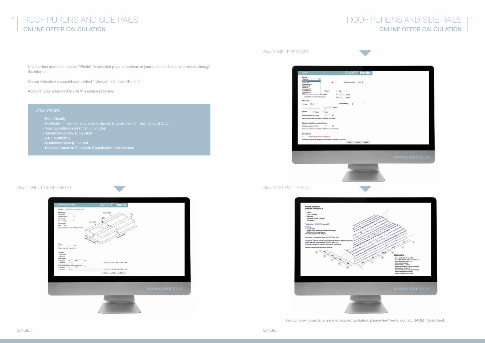
Use our fast quotation service “iPurlin” for detailed price quotations of your purlin and side rail projects through the internet.
On our website www.sadef.com, select “idesign” first, then “iPurlin”.
apply for your password to use this unique program.
adVaNTaGES:
- User friendly - available in multiple languages including English, french, German and dutch - Your quotation in less than 5 minutes - Variations quickly achievable - 24/7 availability - Quotations clearly laid-out - National annex to Eurocode if applicable implemented
for complex projects or a more detailed quotation, please feel free to contact SadEf Sales dept.
FLOOR FRAMES
ACM SYSTEM p. 56 - 57
ACE SYSTEM p. 58 - 59
MIXED SYSTEM p. 60 - 61
FLOOR COMpOSITION p. 62 - 63
50
OVERVIEW
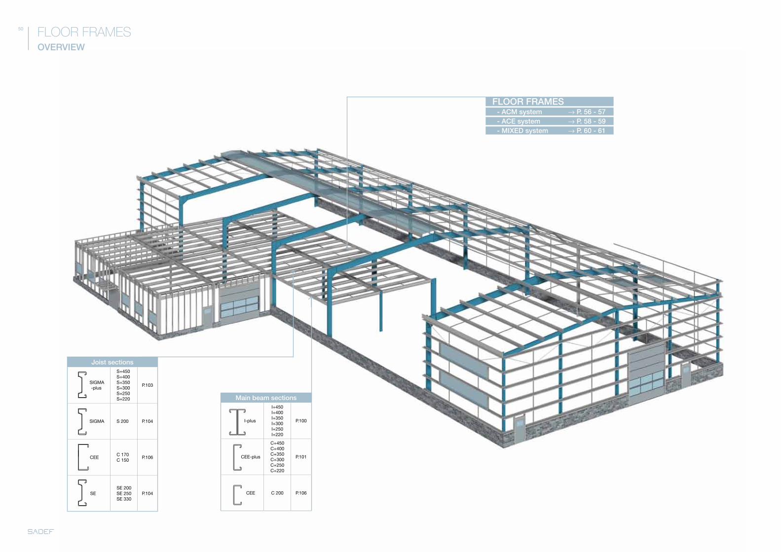
FLOOR FRAMES
- ACM system → P. 56 - 57FLOOR FRAMES
- ACE system → P. 58 - 59- MIXED system → P. 60 - 61
Joist sections
SIGMa -plus
S+450S+400S+350S+300S+250S+220
P.103
SIGMa S 200 P.104
CEEC 170C 150
P.106
SESE 200SE 250SE 330
P.104
Main beam sections
I-plus
I+450I+400I+350I+300I+250I+220
P.100
CEE-plus
C+450C+400C+350C+300C+250C+220
P.101
CEE C 200 P.106
54 55
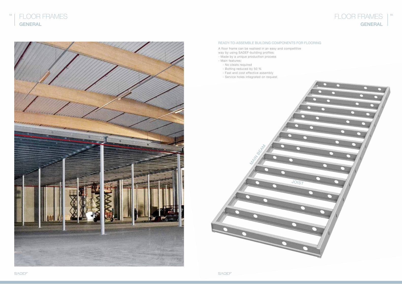
MaI
N B
EaM
JOIST
GENERAL
FLOOR FRAMESFLOOR FRAMESGENERAL
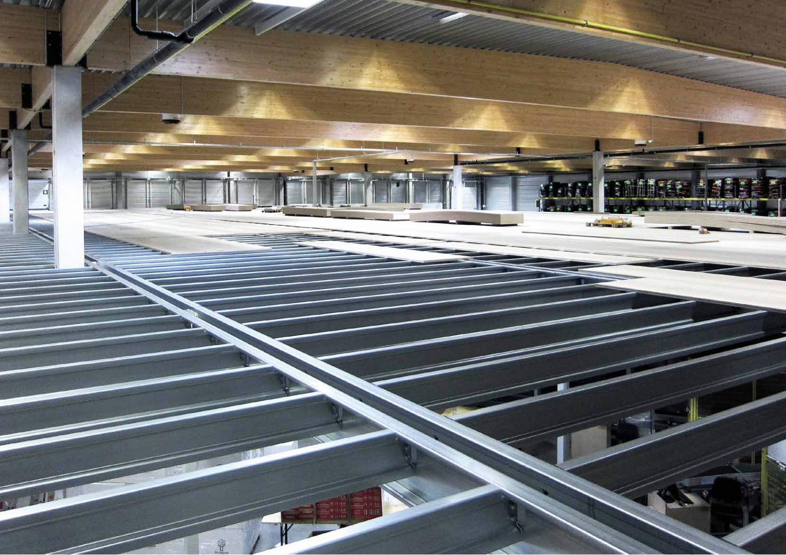
a floor frame can be realised in an easy and competitive way by using SadEf-building profiles:- Made by a unique production process- Main features: - No cleats required - Bolting reduced by 50 % - fast and cost effective assembly - Service holes integrated on request
REadY-TO-aSSEMBLE BUILdING COMPONENTS fOR fLOORING
56 57
ACM 200
ACM 150
ACM 100
FLOOR FRAMESACM SYSTEM
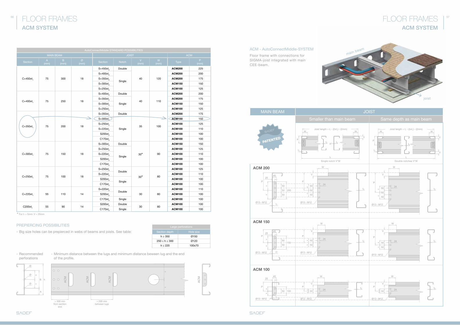
autoConnectMiddle STaNdaRd POSSIBILITIES
MaIN BEaM JOIST aCM
Sectiona
(mm)B
(mm)Ø
(mm)Section Notch
V(mm)
W(mm)
TypeP
(mm)
C+450xt1 75 300 18
S+450xt2 double
40 120
ACM200 225
S+400xt2
Single
ACM200 200
S+350xt2 ACM200 175
S+300xt2 ACM150 150
S+250xt2 ACM100 125
C+400xt1 75 250 18
S+400xt2 double
40 110
ACM200 200
S+350xt2
Single
ACM200 175
S+300xt2 ACM150 150
S+250xt2 ACM100 125
C+350xt1 75 200 18
S+350xt2 double
35 100
ACM200 175
S+300xt2
Single
ACM150 150
S+250xt2 ACM100 125
S+220xt2 ACM100 110
S200xt2 ACM100 100
C170xt2 ACM100 100
C+300xt1 75 150 18
S+300xt2 double
30* 90
ACM150 150
S+250xt2
Single
ACM100 125
S+220xt2 ACM100 110
S200xt2 ACM100 100
C170xt2 ACM100 100
C+250xt1 75 100 18
S+250xt2double
30* 80
ACM100 125
S+220xt2 ACM100 110
S200xt2Single
ACM100 100
C170xt2 ACM100 100
C+220xt1 55 110 14
S+220xt2double
30 80
ACM100 110
S200xt2 ACM100 100
C170xt2 Single ACM100 100
C200xt1 55 90 14S200xt2 double
30 80ACM100 100
C170xt2 Single ACM100 100
ACM SYSTEM
FLOOR FRAMES
aCM - autoConnectMiddle-SYSTEM
Large perforations
Section depth Hole size
h ≥ 350 Ø150
250 ≤ h ≤ 300 Ø120
h ≤ 220 100x70
floor frame with connections for SIGMa-joist integrated with main CEE-beam.
joist
PREPIERCING POSSIBILITIES
- Big size holes can be prepierced in webs of beams and joists. See table:
main beam
* for t1 = 5mm: V = 35mm
Single notch V*W
Joist length = L - (2xt1) - (2mm) Joist length = L - (2xt1) - (2mm)
double notches V*W
MaIN BEaM JOIST
Smaller than main beam Same depth as main beam
- Minimum distance between the lugs and minimum distance beween lug and the end of the profile.
- Recommended perforations
> 500 mmfrom section
end
> 200 mmbetween lugs
58 59FLOOR FRAMESACE SYSTEM
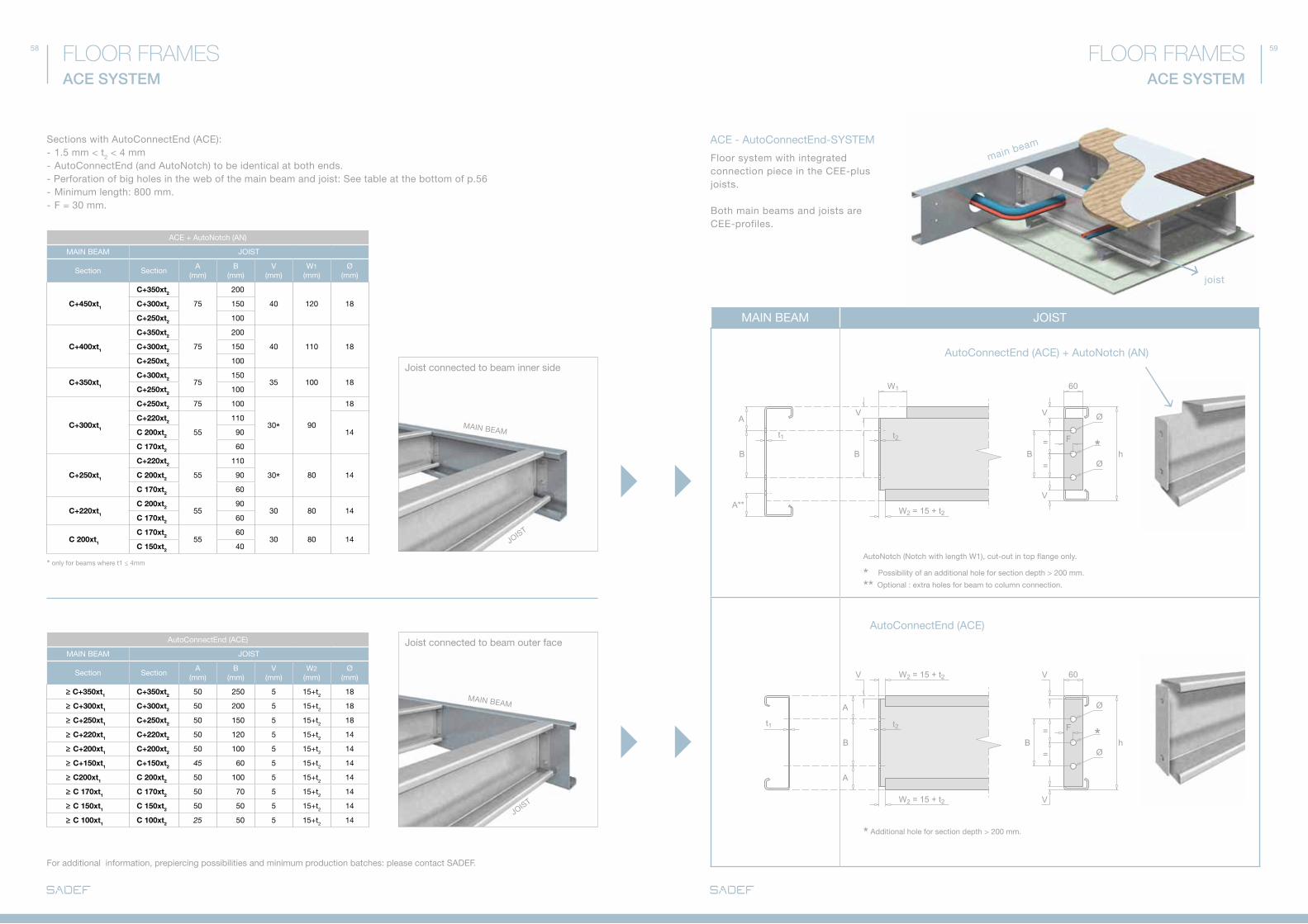
autoConnectEnd (aCE)
MaIN BEaM JOIST
Section Sectiona
(mm)B
(mm)V
(mm)W2
(mm)Ø
(mm)
≥ C+350xt1 C+350xt2 50 250 5 15+t2 18
≥ C+300xt1 C+300xt2 50 200 5 15+t2 18
≥ C+250xt1 C+250xt2 50 150 5 15+t2 18
≥ C+220xt1 C+220xt2 50 120 5 15+t2 14
≥ C+200xt1 C+200xt2 50 100 5 15+t2 14
≥ C+150xt1 C+150xt2 45 60 5 15+t2 14
≥ C200xt1 C 200xt2 50 100 5 15+t2 14
≥ C 170xt1 C 170xt2 50 70 5 15+t2 14
≥ C 150xt1 C 150xt2 50 50 5 15+t2 14
≥ C 100xt1 C 100xt2 25 50 5 15+t2 14JOIST
MaIN BEaM
aCE + autoNotch (aN)
MaIN BEaM JOIST
Section Sectiona
(mm)B
(mm)V
(mm)W1
(mm)Ø
(mm)
C+450xt1
C+350xt2
75
200
40 120 18C+300xt2 150
C+250xt2 100
C+400xt1
C+350xt2
75
200
40 110 18C+300xt2 150
C+250xt2 100
C+350xt1
C+300xt275
15035 100 18
C+250xt2 100
C+300xt1
C+250xt2 75 100
30* 90
18
C+220xt2
55
110
14C 200xt2 90
C 170xt2 60
C+250xt1
C+220xt2
55
110
30* 80 14C 200xt2 90
C 170xt2 60
C+220xt1
C 200xt255
9030 80 14
C 170xt2 60
C 200xt1
C 170xt255
6030 80 14
C 150xt2 40
Sections with autoConnectEnd (aCE):- 1.5 mm < t2 < 4 mm- autoConnectEnd (and autoNotch) to be identical at both ends.- Perforation of big holes in the web of the main beam and joist: See table at the bottom of p.56- Minimum length: 800 mm.- f = 30 mm.
JOIST
MaIN BEaM
* only for beams where t1 ≤ 4mm
ACE SYSTEM
FLOOR FRAMES
autoConnectEnd (aCE) + autoNotch (aN) Joist connected to beam inner side
Joist connected to beam outer face
floor system with integrated connection piece in the CEE-plus joists.
Both main beams and joists are CEE-profiles.
main beam
autoConnectEnd (aCE)
aCE - autoConnectEnd-SYSTEM
for additional information, prepiercing possibilities and minimum production batches: please contact SadEf.
autoNotch (Notch with length W1), cut-out in top flange only.
* Possibility of an additional hole for section depth > 200 mm.
** Optional : extra holes for beam to column connection.
* additional hole for section depth > 200 mm.
MaIN BEaM JOIST
joist

60 61
hh
h
h
MIXED SYSTEM
FLOOR FRAMESFLOOR FRAMESMIXED SYSTEM
MaIN BEaM JOIST
Section
S/S
E 2
00
I+/S
+2
20
I+/S
+25
0
I+/S
+30
0
I+/S
+35
0
I+/S
+40
0
I+/S
+45
0 autoNotch
V(mm)
W(mm)
HEA/HEB 200 - - - - - - 35 120
HEA/HEB 220 - - - - - 35 120
HEA/HEB 240 - - - - - 35 125
HEA/HEB 260 → 280 - - - - 35 145
HEA/HEB 300 - - - 35 145
HEA/HEB 320 → 340 - - - - - 50 145
HEA/HEB 360 - - - - 50 145
HEA/HEB 400 - - - 50 145
HEA/HEB 450 → 700 - - 50 145
HEA/HEB 800 → 1000 - - 50 145
IPE 200 - - - - - - 35 55
IPE 220 - - - - - 35 55
IPE 240 - - - - - 35 65
IPE 270 - - - - 35 65
IPE 300 → 330 - - - 35 80
IPE 360 - - 35 90
IPE 400 - 35 90
IPE 450 35 90
IPE 500 → 600 35 105
UPN 200 - - - - - - 25 85
UPN 220 → 240 - - - - - 25 85
UPN 260 - - - - 25 85
UPN 280 - - - - 30 100
UPN 300 → 320 - - - 30 100
UPN 350 → 360 - - 30 100
UPN 400 - 35 100
RECOMMENdEd PERfORaTION JOIST
Section height h
a1(mm)
B1(mm)
Ø1(mm)
a2(mm)
B2(mm)
Ø2(mm)
450 75 300 18 125 200 18
400 75 250 18 125 150 18
350 75 200 18 100 150 18
330 115 100 18
300 75 150 18 100 100 18
250 75 100 18 100 50 18
220 55 110 14 75 70 14
200 75 50 14
MIXEd-SYSTEM
CEE-plus / I-plus - joist with autoConnectEnd (aCE)
CEE-plus / I-plus - joist
SIGMa-Joist
floor framing consisting of hot rolled main beams and cold rolled side beams.
main beam
Main beam deeper than aCE-joist
Main beam deeper than joist
Main beam and joist have about the same depth
Main beam deeper than joist
Big size holes can be prepierced in webs of main beams and joists:
please turn to p. 56.
autoNotches to be identical on both profile ends.
* additional hole for section depth > 200 mm.
joist
Single notch V*W
Single notch V*W
OR
OR
Single notch V*W
double notches V*W
MaIN BEaM JOIST
Hot rolled Smaller than main beam Same depth as main beam
MaIN BEaM
MaIN BEaM
MaIN BEaM
MaIN BEaM
JOIST
JOIST
JOIST
JOIST
62 63
FLOOR COMPOSITION
FLOOR FRAMESFLOOR FRAMESFLOOR COMPOSITION
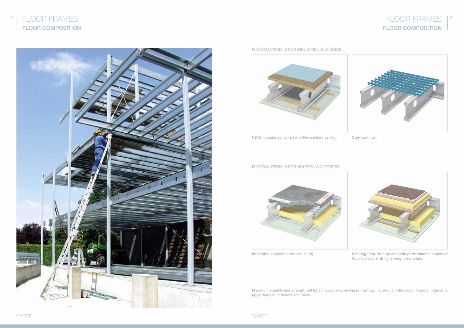
fLOOR MaTERIaLS fOR INdUSTRIaL BUILdINGS
fLOOR MaTERIaLS fOR HOUSES aNd OffICES
Hd-Chipboard combined with fire resistant ceiling.
Integrated concrete floor (see p. 78).
Maximum stability and strength will be achieved by screwing (or nailing…) at regular intervals of flooring material to upper flanges of beams and joists.
Steel gratings.
floating floor for high acoustic performance in case of floor built up with light weight materials.
- FLEXROOF™ p. 66 - 67
- FLEXpARK™ p. 68 - 69
- FLEXFIELD™ p. 70 - 71
- TAILOR-MADE ROOF TOp STRUCTURES p. 72
- TAILOR-MADE GROUND STRUCTURES p. 73
STEEL PROFILES FOR SOLAR PANELLING
66 67
α 5° - 15° α 15° - 30°
1 2 3 4 5
1 2
4
44
3
5
/
α 9° of 16°
α
FLEXROOF™
STEEL PROFILES FOR SOLAR PANELLINGSTEEL PROFILES FOR SOLAR PANELLINGFLEXROOF™
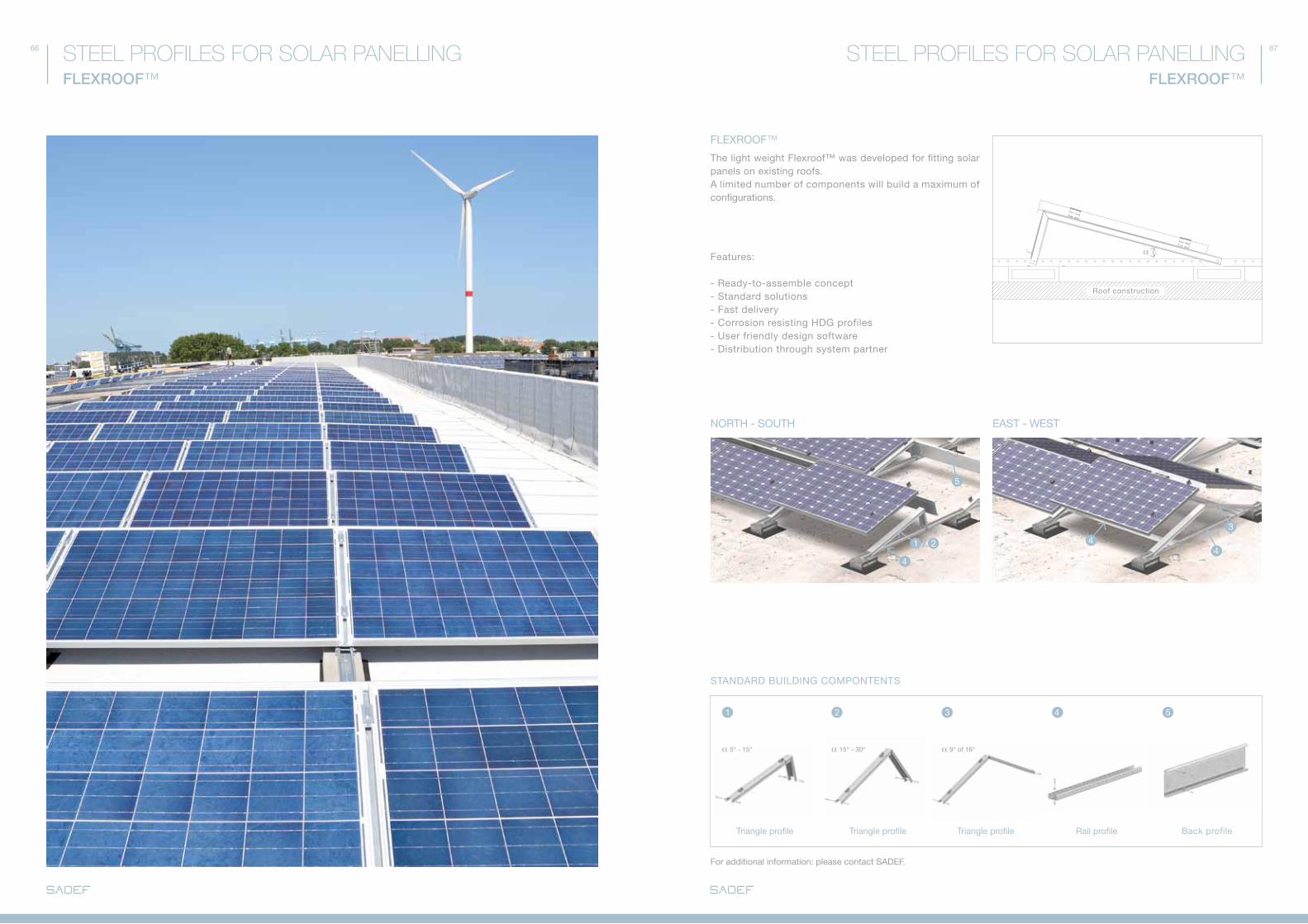
fLEXROOf™
The light weight flexroof™ was developed for fitting solar panels on existing roofs. a limited number of components will build a maximum of configurations.
features:
- Ready-to-assemble concept - Standard solutions- fast delivery - Corrosion resisting HdG profiles - User friendly design software- distribution through system partner
Triangle profile Triangle profile Triangle profile Rail profile Back profile
STaNdaRd BUILdING COMPONTENTS
NORTH - SOUTH EaST - WEST
Roof construction
for additional information: please contact SadEf.
68 69
cadcoaching.co.uk
2
3 4
2
55
66
1 1
1 2 3 4 5 6
FLEXPARk™
STEEL PROFILES FOR SOLAR PANELLINGSTEEL PROFILES FOR SOLAR PANELLINGFLEXPARk™
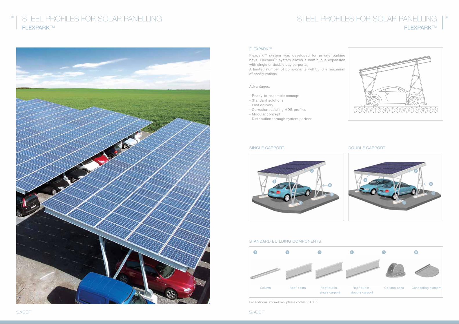
fLEXPaRk™
flexparkTM system was developed for private parking bays. flexparkTM system allows a continuous expansion with single or double bay carports. a limited number of components will build a maximum of configurations.
advantages:
- Ready-to-assemble concept - Standard solutions- fast delivery - Corrosion resisting HdG profiles - Modular concept- distribution through system partner
STaNdaRd BUILdING COMPONENTS
SINGLE CaRPORT dOUBLE CaRPORT
Column Roof purlin -
single carport
Roof beam Roof purlin -
double carport
Column base Connecting element
for additional information: please contact SadEf.
70 71
3
7
8
45
2
6
1
1 42 53 6 7 8
FLEXFIELD™
STEEL PROFILES FOR SOLAR PANELLINGSTEEL PROFILES FOR SOLAR PANELLINGFLEXFIELD™
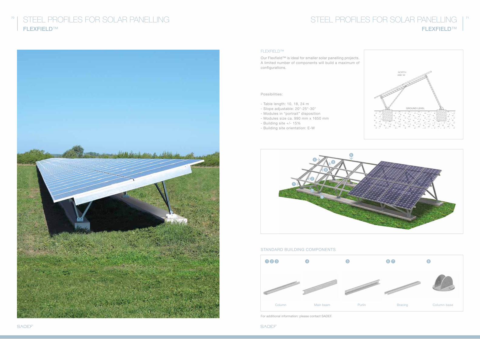
FLEXFIELD™
Our flexfield™ is ideal for smaller solar panelling projects. a limited number of components will build a maximum of configurations.
Possibilities: - Table length: 10, 18, 24 m- Slope adjustable: 20°-25°-30°- Modules in “portrait” disposition- Modules size ca. 990 mm x 1650 mm- Building site +/- 15%- Building site orientation: E-W
NORTH
STaNdaRd BUILdING COMPONENTS
Column Main beam Purlin Bracing Column base
GROUND LEVEL
for additional information: please contact SadEf.
72 73
Foto van staalskelet
TAILOR-MADE GROUND STRUCTURES
STEEL PROFILES FOR SOLAR PANELLINGSTEEL PROFILES FOR SOLAR PANELLINGTAILOR-MADE ROOF TOP STRUCTURES
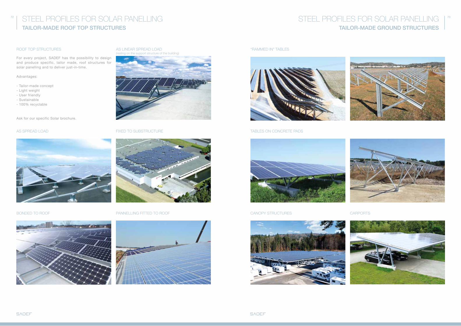
ROOF TOp STRUCTURES AS LINEAR SpREAD LOAD (resting on the support structure of the building)
“RAMMED IN” TABLES
AS SpREAD LOAD
BONDED TO ROOF
FIXED TO SUBSTRUCTURE TABLES ON CONCRETE pADS
pANNELLING FITTED TO ROOF CANOpY STRUCTURES CARpORTS
for every project, SadEf has the possibility to design and produce specific, tailor made, roof structures for solar panelling and to deliver just-in-time.
advantages:
- Tailor-made concept- Light weight- User friendly- Sustainable - 100% recyclable
ask for our specific Solar brochure.
COMPONENTS FOR:
- 3D MODULAR p. 76 - 77
- 2D MODULAR p. 78 - 79
- LOAD BEARING WALLS p. 80 - 83
- EXpORT-FRIENDLY TRUSSES p. 84 - 85
- GABLE END STRUCTURES p. 86 - 87
- INTERMEDIATE GABLE COLUMNS AND BRACING p. 88 - 89
- SMOKE VENTS AND SKY LIGHTS p. 90 - 91
TAILOR-MADE PROFILES P. 94 - 95
SURFACE TREATMENT P. 96 - 97
MISCELLANEOUS CONSTRUCTIONS
76 77
Nieuw beeld
3D MODULAR
MISCELLANEOUS CONSTRUCTIONSMISCELLANEOUS CONSTRUCTIONS3D MODULAR
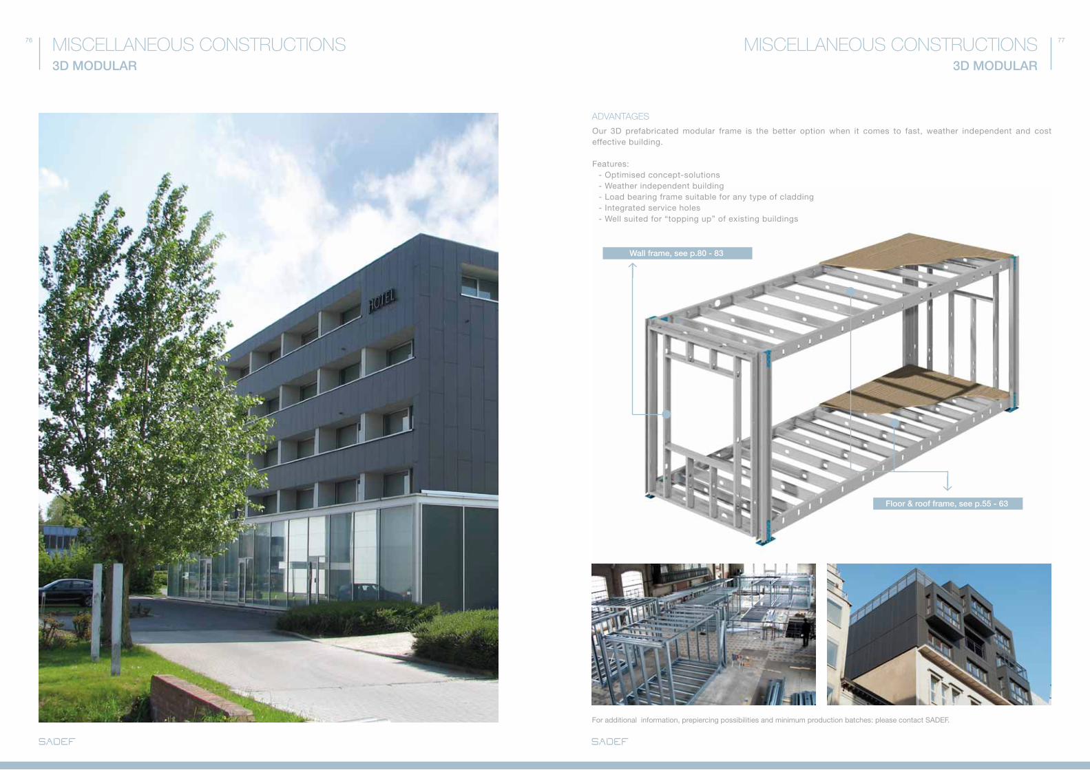
ADVANTAGES
Our 3d prefabricated modular frame is the better option when it comes to fast, weather independent and cost effective building.
features: - Optimised concept-solutions - Weather independent building - Load bearing frame suitable for any type of cladding - Integrated service holes - Well suited for “topping up” of existing buildings
Wall frame, see p.80 - 83
Floor & roof frame, see p.55 - 63
for additional information, prepiercing possibilities and minimum production batches: please contact SadEf.

78 79
2D MODULAR
MISCELLANEOUS CONSTRUCTIONSMISCELLANEOUS CONSTRUCTIONS2D MODULAR
2D ROOF ELEMENTS
2D WALL ELEMENTS
2D FLOOR ELEMENTS
Prefabricated modular 2d building elements are the better option when it comes to fast, weather independent and cost effective building.
features: - fast building on site - Independent of weather circumstances - High standard and yet low cost production - Consistent quality - Compact transport - No scrap on site
Wall frame, see p.80 - 83 Floor and roof frame, see p.55 - 63
Wall profiles
CEEC 150C 100C 80
P.106
UU 150U 100U 80
P.107
floor and roof profiles
CEE-plus
C+450C+400C+350C+300C+250
P.101
CEE C 170 P.106
SIGMa-plus
S+450S+400S+350S+300S+250
P.103
SIGMa S 200 P.104
for additional information, prepiercing possibilities and minimum production batches: please contact SadEf.
80 81
= =100
=
=50
=
=
25=
=
= =
25
30
CF
CW
CW
Cf
CW
Ø1Ø1 00
LOAD BEARING WALLS
MISCELLANEOUS CONSTRUCTIONSMISCELLANEOUS CONSTRUCTIONSLOAD BEARING WALLS
STUd PROfILE
TRaCk PROfILE
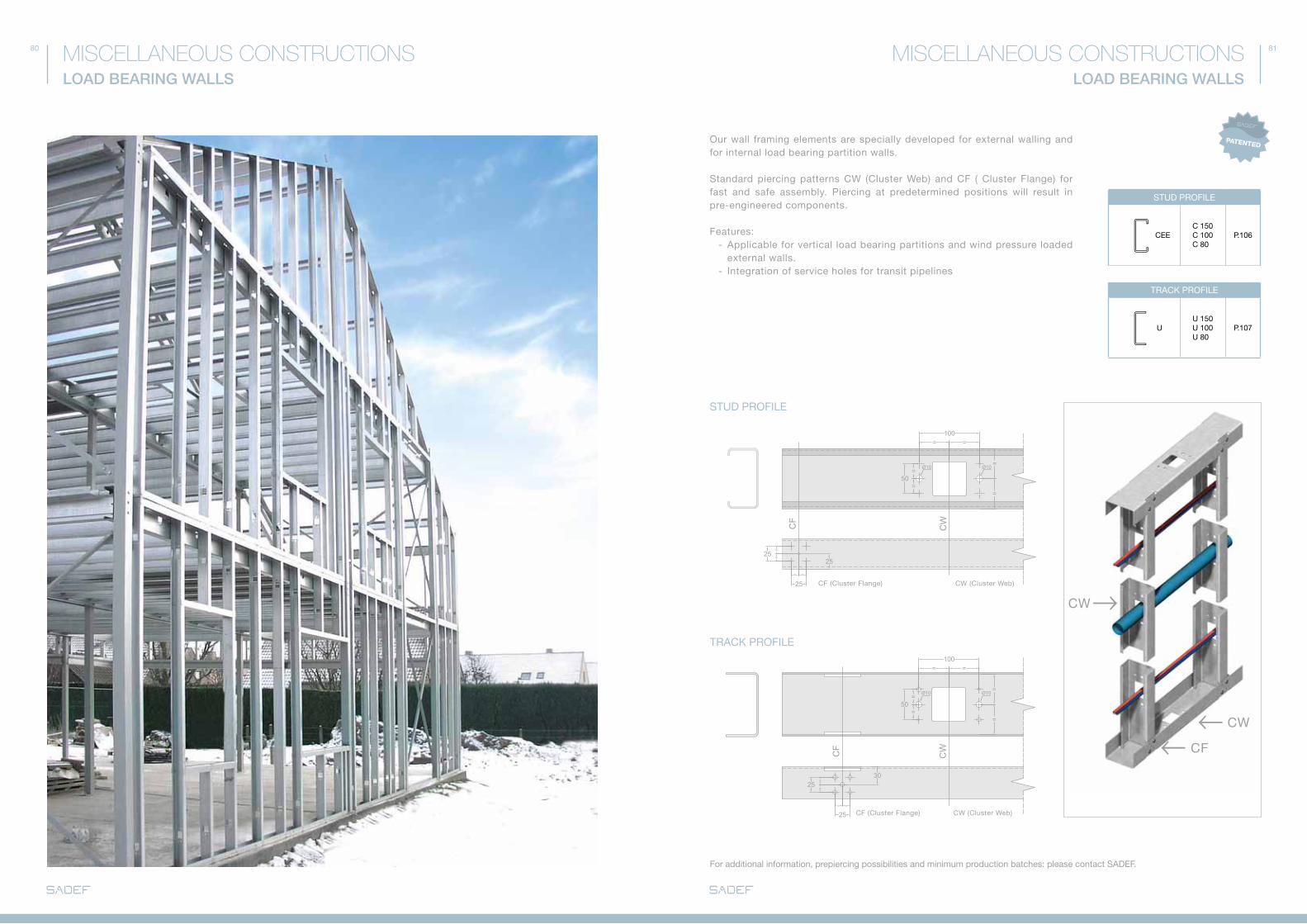
Our wall framing elements are specially developed for external walling and for internal load bearing partition walls.
Standard piercing patterns CW (Cluster Web) and Cf ( Cluster flange) for fast and safe assembly. Piercing at predetermined positions will result in pre-engineered components.
features: - applicable for vertical load bearing partitions and wind pressure loaded external walls. - Integration of service holes for transit pipelines
25=
=25
= =
25
= =100
=
=50
=
=
Ø1 Ø10 0
CF
CW
STUd PROfILE
CEEC 150C 100C 80
P.106
TRaCk PROfILE
UU 150U 100U 80
P.107
for additional information, prepiercing possibilities and minimum production batches: please contact SadEf.
Cf (Cluster flange) CW (Cluster Web)
Cf (Cluster flange) CW (Cluster Web)
82 83
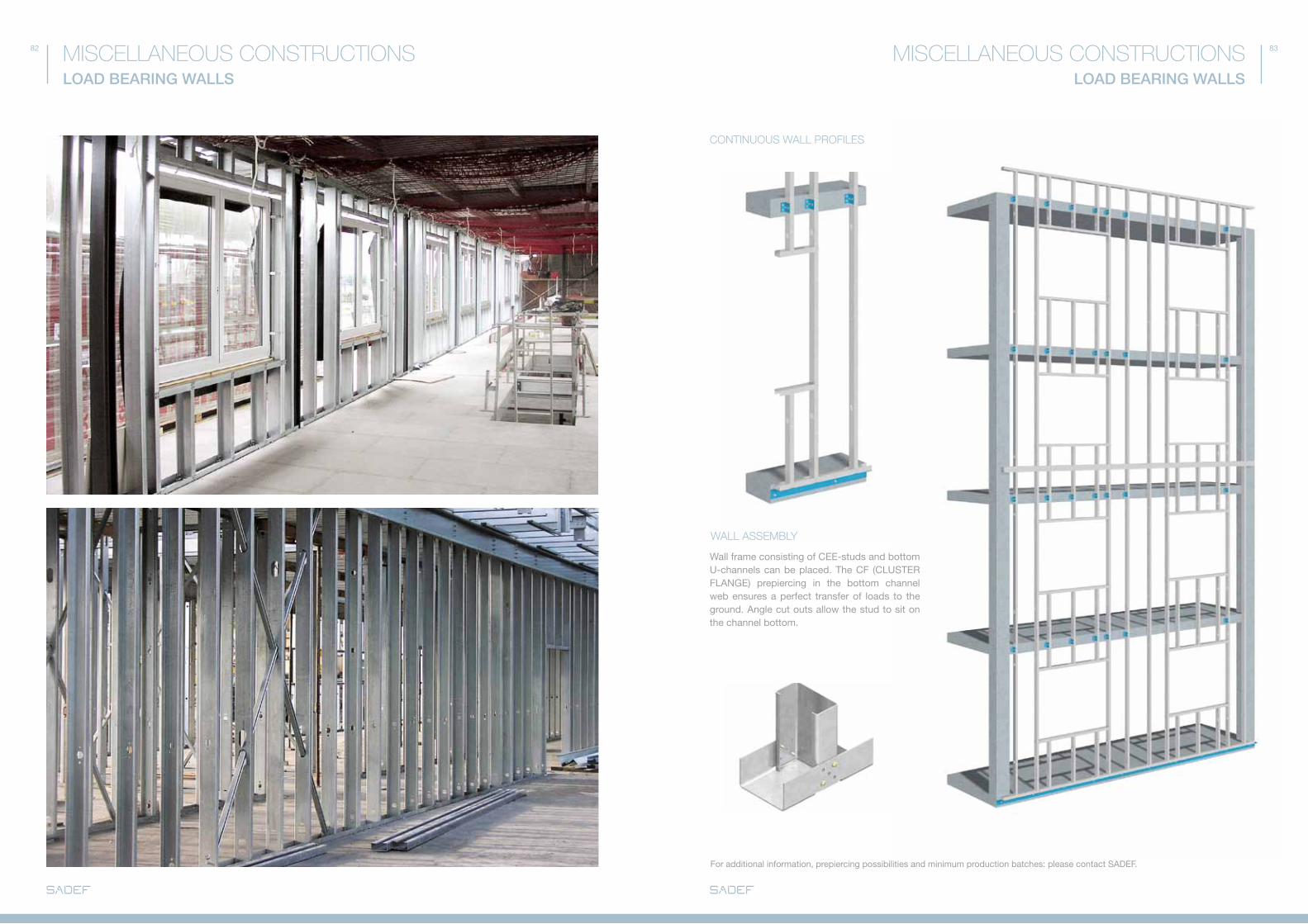
CONTINUOUS WALL pROFILES
for additional information, prepiercing possibilities and minimum production batches: please contact SadEf.
WALL ASSEMBLY
Wall frame consisting of CEE-studs and bottom U-channels can be placed. The Cf (CLUSTER fLaNGE) prepiercing in the bottom channel web ensures a perfect transfer of loads to the ground. angle cut outs allow the stud to sit on the channel bottom.
LOAD BEARING WALLS
MISCELLANEOUS CONSTRUCTIONSMISCELLANEOUS CONSTRUCTIONSLOAD BEARING WALLS
84 85
1
1
22
EXPORT-FRIENDLY TRUSSES
MISCELLANEOUS CONSTRUCTIONSMISCELLANEOUS CONSTRUCTIONSEXPORT-FRIENDLY TRUSSES
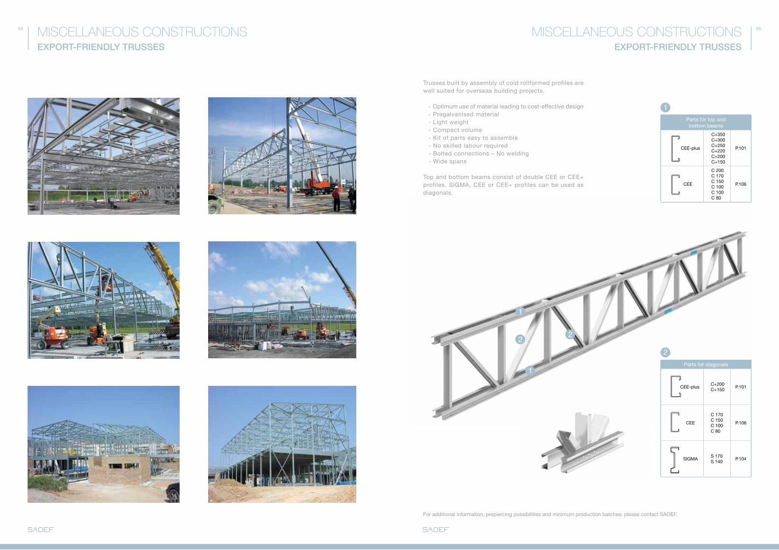
Trusses built by assembly of cold rollformed profiles are well suited for overseas building projects.
- Optimum use of material leading to cost-effective design - Pregalvanised material - Light weight - Compact volume - kit of parts easy to assemble - No skilled labour required - Bolted connections – No welding - Wide spans
Top and bottom beams consist of double CEE or CEE+ profiles. SIGMa, CEE or CEE+ profiles can be used as diagonals.
Parts for diagonals
CEE-plusC+200C+150
P.101
CEE
C 170C 150C 100C 80
P.106
SIGMaS 170S 140
P.104
Parts for top and bottom beams
CEE-plus
C+350C+300C+250C+220C+200C+150
P.101
CEE
C 200C 170C 150C 100C 100C 80
P.106
1
2
for additional information, prepiercing possibilities and minimum production batches: please contact SadEf.

86 87
1
12
&a B
a
f G H I J
B C d E
&a B
&E d&G C
f
& &H I J
GABLE END STRUCTURES
MISCELLANEOUS CONSTRUCTIONSMISCELLANEOUS CONSTRUCTIONSGABLE END STRUCTURES
Gable end structures are easy to assemble using cold rollformed sections. They are ideally suited for repetitive construction projects.
features:
- Easy assembly - Light weight components - Bolted connection – no welding required - Galvanised profiles - finish identical to cladding rails
Columns + Upper beam
CEE-plus
C+450C+400C+400C+350C+300C+250C+220C+200C+150
P.101
1
Side rails
ZEd
Z 375Z 350Z 300Z 250Z 200Z 180
P.105
SIGMa-plusS+350S+300S+250
P.103
SIGMaS 200S 170S 140
P.104
CEE-(plus)
C+200C+160C+150C 140
P.101
2
CLEaTEd CONNECTION
DIRECT CONNECTION INTEGRATED CONNECTION
for additional information, prepiercing possibilities and minimum production batches: please contact SadEf.
aCE (P.58-59) aCE (P.58-59) aCM (P.56-57)
88 89
22
1
11
1
1
INTERMEDIATE GABLE COLUMNS AND BRACING
MISCELLANEOUS CONSTRUCTIONSMISCELLANEOUS CONSTRUCTIONSINTERMEDIATE GABLE COLUMNS AND BRACING
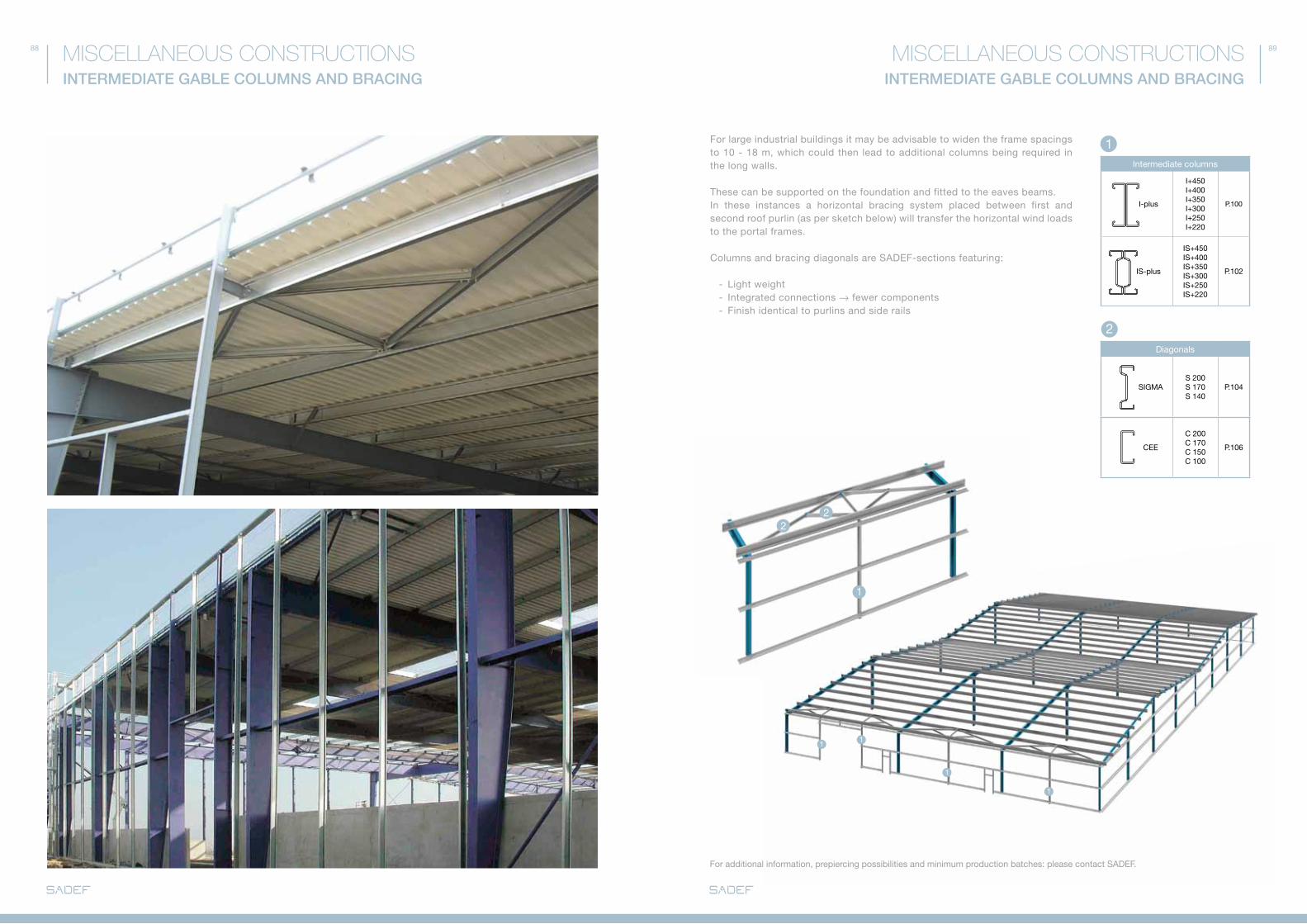
for large industrial buildings it may be advisable to widen the frame spacings to 10 - 18 m, which could then lead to additional columns being required in the long walls.
These can be supported on the foundation and fitted to the eaves beams.In these instances a horizontal bracing system placed between first and second roof purlin (as per sketch below) will transfer the horizontal wind loads to the portal frames.
Columns and bracing diagonals are SadEf-sections featuring:
- Light weight - Integrated connections → fewer components - finish identical to purlins and side rails
1
2
Intermediate columns
I-plus
I+450I+400I+350I+300I+250I+220
P.100
IS-plus
IS+450IS+400IS+350IS+300IS+250IS+220
P.102
diagonals
SIGMaS 200S 170S 140
P.104
CEE
C 200C 170C 150C 100
P.106
for additional information, prepiercing possibilities and minimum production batches: please contact SadEf.

90 91
A
SMOkE VENTS AND SkY LIGHTS
MISCELLANEOUS CONSTRUCTIONSMISCELLANEOUS CONSTRUCTIONSSMOkE VENTS AND SkY LIGHTS
Standard SadEf components will create easy to assemble and cost effective supporting structures for smoke vents and/or skylights.
- Specific requirements for sprinkler systems can be taken into account. - Very often these structures can be placed in a roof sheet corrugation.
Components for smoke vents and sky lights
CEE
C 200C 170C 150C 100
P.106
autoConnectEnd: see p.59
Detail A
SMOKE VENTS AND SKY LIGHTS
Components for sky lights
CEE-plus
C+450C+400C+350C+300C+250
P.101
SIGMa-plus
S+450S+400S+350S+300S+250
P.103
SESE 200SE 250SE 330
P.104
Skylights can be supported by SadEf profiles. Eaves beam sections fitted with their angled flange to the portal frame will create a flat base for supporting the skylight.
SKY LIGHTS
for additional information, prepiercing possibilities and minimum production batches: please contact SadEf.
94 95MISCELLANEOUS CONSTRUCTIONSTAILOR-MADE PROFILES
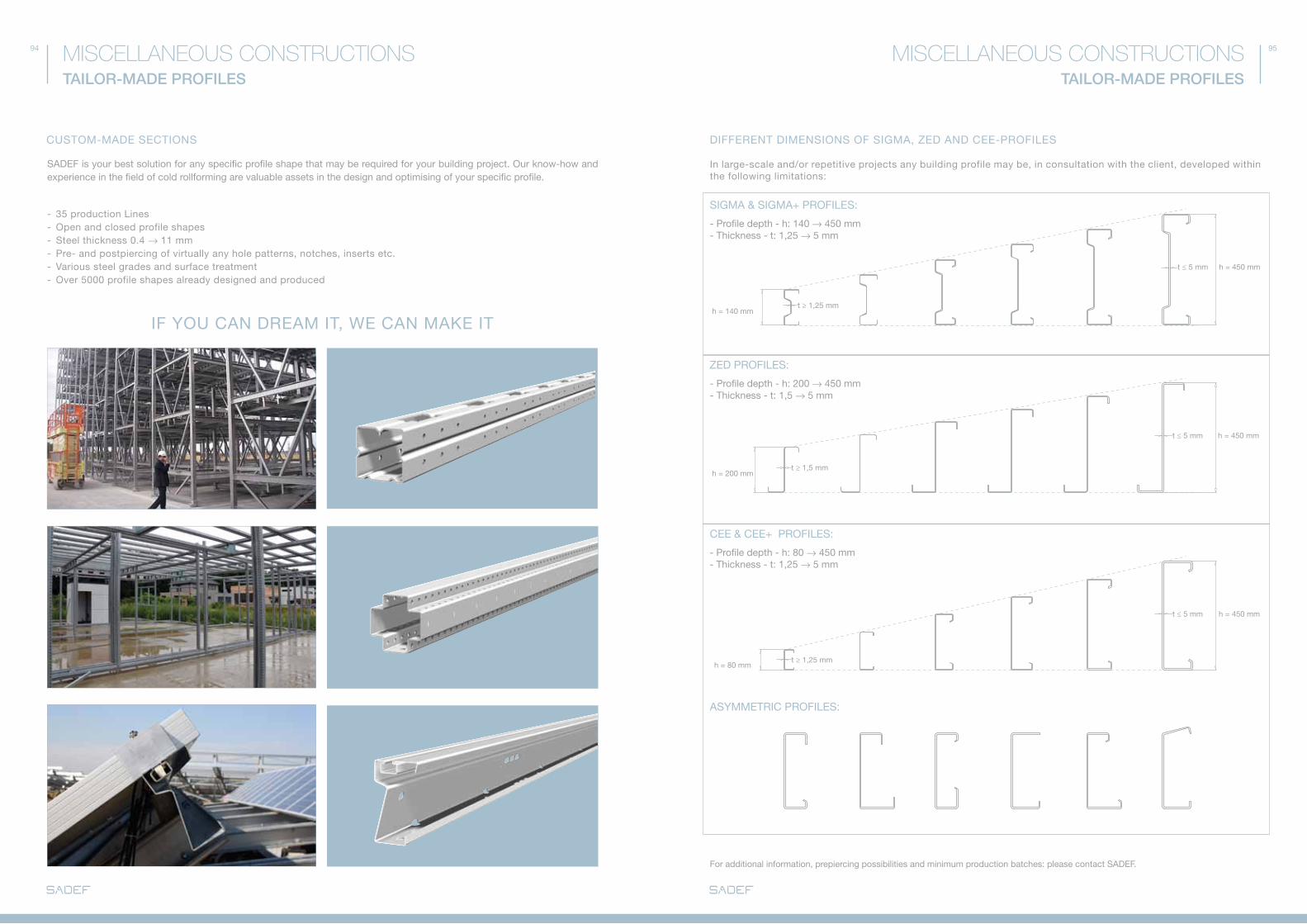
ZEd PROfILES:
CEE & CEE+ PROfILES:
SIGMa & SIGMa+ PROfILES:
In large-scale and/or repetitive projects any building profile may be, in consultation with the client, developed within the following limitations:
- Profile depth - h: 140 → 450 mm - Thickness - t: 1,25 → 5 mm
h = 140 mmt ≥ 1,25 mm
t ≥ 1,5 mm
t ≥ 1,25 mm
t ≤ 5 mm
t ≤ 5 mm
t ≤ 5 mm
h = 450 mm
h = 450 mm
h = 450 mm
h = 200 mm
h = 80 mm
- Profile depth - h: 200 → 450 mm - Thickness - t: 1,5 → 5 mm
aSYMMETRIC PROfILES:
- Profile depth - h: 80 → 450 mm - Thickness - t: 1,25 → 5 mm
TAILOR-MADE PROFILES
MISCELLANEOUS CONSTRUCTIONS
CUSTOM-MadE SECTIONS
If YOU CaN dREaM IT, WE CaN MakE IT
dIffERENT dIMENSIONS Of SIGMa, ZEd aNd CEE-PROfILES
SadEf is your best solution for any specific profile shape that may be required for your building project. Our know-how and experience in the field of cold rollforming are valuable assets in the design and optimising of your specific profile.
- 35 production Lines- Open and closed profile shapes- Steel thickness 0.4 → 11 mm- Pre- and postpiercing of virtually any hole patterns, notches, inserts etc. - Various steel grades and surface treatment - Over 5000 profile shapes already designed and produced
for additional information, prepiercing possibilities and minimum production batches: please contact SadEf.
96 97
1
1
2
2
3
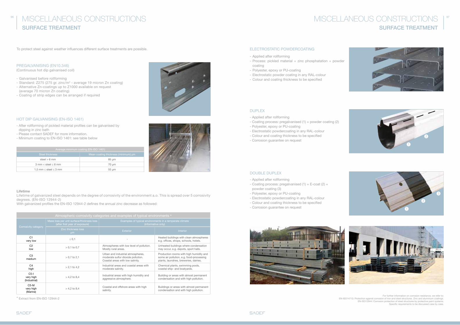
HOT dIP GaLVaNISING (EN-ISO 1461)
(Continuous hot dip galvanised coil)
- Galvanised before rollforming - Standard: Z275 (275 gr. zinc/m2 - average 19 micron Zn coating) - alternative Zn-coatings up to Z1000 available on request (average 70 micron Zn coating)- Coating of strip edges can be arranged if required
average minimum coating (EN-ISO 1461)
Steel thickness Mean coating thickness (minimum) µm
steel > 6 mm 85 μm
3 mm < steel ≤ 6 mm 70 μm
1,5 mm ≤ steel ≤ 3 mm 55 μm
atmospheric-corrosivity categories and examples of typical environments *
Corrosivity category
Mass loss per unit surface/thickness loss(after first year of exposure)
Examples of typical environments in a temperate climate(informative only)
Zinc thickness lossµm
Exterior Interior
C1very low
≤ 0,1 -Heated buildings with clean atmospherese.g. offices, shops, schools, hotels.
C2low
> 0,1 to 0,7atmospheres with low level of pollution.Mostly rural areas.
Unheated buildings where condensation may occur, e.g. depots, sport halls.
C3medium
> 0,7 to 2,1Urban and industrial atmospheres, moderate sulfur dioxide pollution. Coastal areas with low salinity.
Production rooms with high humidity andsome air pollution, e.g. food-processing plants, laundries, breweries, dairies.
C4high
> 2,1 to 4,2Industrial areas and coastal areas with moderate salinity.
Chemical plants, swimming pools, coastal ship- and boatyards.
C5-Ivery high (Industrial)
> 4,2 to 8,4Industrial areas with high humidity and aggressive atmosphere.
Building or areas with almost permanent condensation and with high pollution.
C5-Mvery high(Marine)
> 4,2 to 8,4Coastal and offshore areas with high salinity.
Buildings or areas with almost permanent condensation and with high pollution.
- after rollforming of pickled material profiles can be galvanised by dipping in zinc bath- Please contact SadEf for more information. - Minimum coating to EN-ISO 1461: see table below
LifetimeLifetime of galvanized steel depends on the degree of corrosivity of the environment a.o. This is spread over 5 corrosivity degrees. (EN-ISO 12944-2) With galvanized profiles the EN-ISO 12944-2 defines the annual zinc decrease as followed:
ELECTROSTaTIC POWdERCOaTING
dUPLEX
- applied after rollforming- Process: pickled material + zinc phosphatation + powder coating- Polyester, epoxy or PU-coating- Electrostatic powder coating in any RaL-colour- Colour and coating thickness to be specified
- applied after rollforming- Coating process: pregalvanised (1) + powder coating (2)- Polyester, epoxy or PU-coating- Electrostatic powdercoating in any RaL-colour- Colour and coating thickness to be specified- Corrosion guarantee on request
dOUBLE dUPLEX
- applied after rollforming- Coating process: pregalvanised (1) + E-coat (2) + powder coating (3)- Polyester, epoxy or PU-coating- Electrostatic powdercoating in any RaL-colour- Colour and coating thickness to be specified- Corrosion guarantee on request
for further information on corrosion resistance, we refer to: EN-ISO14713: Protection against corrosion of iron and steel structures. Zinc and aluminium coatings. EN-ISO12944: Corrosion protection of steel structures by protective paint systems.
Specific requirements to be discussed case by case.
SURFACE TREATMENT
MISCELLANEOUS CONSTRUCTIONSMISCELLANEOUS CONSTRUCTIONSSURFACE TREATMENT
To protect steel against weather influences different surface treatments are possible.
PREGaLVaNISING (EN10.346)
* Extract from EN-ISO 12944-2
BUILDING SECTIONS RANGE
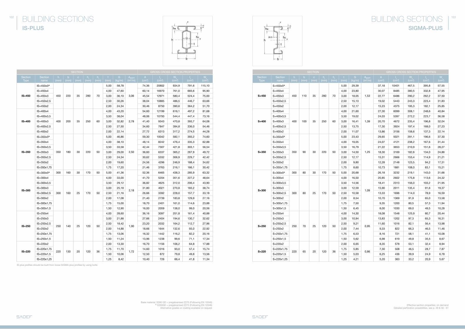
I-pLUS p. 100
CEE-pLUS p. 101
IS-pLUS p. 102
SIGMA-pLUS p. 103
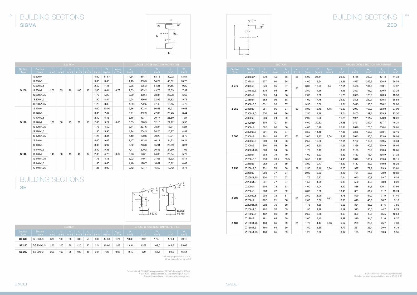
SIGMA p. 104
SE p. 104
ZED p. 105
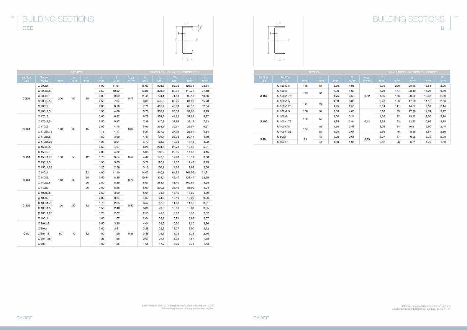
CEE p. 106
U p. 107
101100
b
2 x t
z
y
c+5-0
h h
t
z
y
c+5-0
b
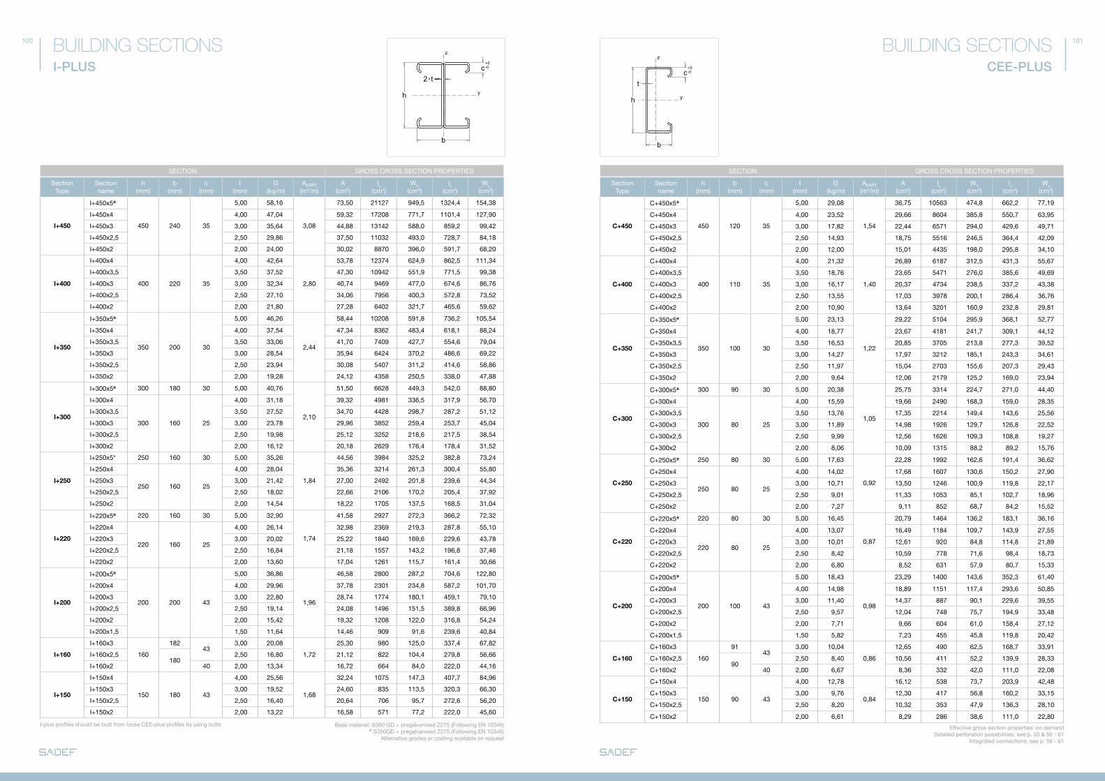
CEE-PLUS
BUILDING SECTIONSBUILDING SECTIONSI-PLUS
SECTION GROSS CROSS SECTION PROPERTIES
Section Type
Section name
h(mm)
b(mm)
c(mm)
t(mm)
G(kg/m)
apaint
(m2/m)a
(cm2)Iy
(cm4)WY
(cm3)Iz
(cm4)Wz
(cm3)
I+450
I+450x5
450 240 35
5,00 58,16
3,08
73,50 21127 949,5 1324,4 154,38
I+450x4 4,00 47,04 59,32 17208 771,7 1101,4 127,90
I+450x3 3,00 35,64 44,88 13142 588,0 859,2 99,42
I+450x2,5 2,50 29,86 37,50 11032 493,0 728,7 84,18
I+450x2 2,00 24,00 30,02 8870 396,0 591,7 68,20
I+400
I+400x4
400 220 35
4,00 42,64
2,80
53,78 12374 624,9 862,5 111,34
I+400x3,5 3,50 37,52 47,30 10942 551,9 771,5 99,38
I+400x3 3,00 32,34 40,74 9469 477,0 674,6 86,76
I+400x2,5 2,50 27,10 34,06 7956 400,3 572,8 73,52
I+400x2 2,00 21,80 27,28 6402 321,7 465,6 59,62
I+350
I+350x5
350 200 30
5,00 46,26
2,44
58,44 10208 591,8 736,2 105,54
I+350x4 4,00 37,54 47,34 8362 483,4 618,1 88,24
I+350x3,5 3,50 33,06 41,70 7409 427,7 554,6 79,04
I+350x3 3,00 28,54 35,94 6424 370,2 486,6 69,22
I+350x2,5 2,50 23,94 30,08 5407 311,2 414,6 58,86
I+350x2 2,00 19,28 24,12 4358 250,5 338,0 47,88
I+300
I+300x5 300 180 30 5,00 40,76
2,10
51,50 6628 449,3 542,0 88,80
I+300x4
300 160 25
4,00 31,18 39,32 4981 336,5 317,9 56,70
I+300x3,5 3,50 27,52 34,70 4428 298,7 287,2 51,12
I+300x3 3,00 23,78 29,96 3852 259,4 253,7 45,04
I+300x2,5 2,50 19,98 25,12 3252 218,6 217,5 38,54
I+300x2 2,00 16,12 20,18 2629 176,4 178,4 31,52
I+250
I+250x5* 250 160 30 5,00 35,26
1,84
44,56 3984 325,2 382,8 73,24
I+250x4
250 160 25
4,00 28,04 35,36 3214 261,3 300,4 55,80
I+250x3 3,00 21,42 27,00 2492 201,8 239,6 44,34
I+250x2,5 2,50 18,02 22,66 2106 170,2 205,4 37,92
I+250x2 2,00 14,54 18,22 1705 137,5 168,5 31,04
I+220
I+220x5 220 160 30 5,00 32,90
1,74
41,58 2927 272,3 366,2 72,32
I+220x4
220 160 25
4,00 26,14 32,98 2369 219,3 287,8 55,10
I+220x3 3,00 20,02 25,22 1840 169,6 229,6 43,78
I+220x2,5 2,50 16,84 21,18 1557 143,2 196,8 37,46
I+220x2 2,00 13,60 17,04 1261 115,7 161,4 30,66
I+200
I+200x5
200 200 43
5,00 36,86
1,96
46,58 2800 287,2 704,6 122,80
I+200x4 4,00 29,96 37,78 2301 234,8 587,2 101,70
I+200x3 3,00 22,80 28,74 1774 180,1 459,1 79,10
I+200x2,5 2,50 19,14 24,08 1496 151,5 389,8 66,96
I+200x2 2,00 15,42 19,32 1208 122,0 316,8 54,24
I+200x1,5 1,50 11,64 14,46 909 91,6 239,6 40,84
I+160
I+160x3
160
18243
3,00 20,08
1,72
25,30 980 125,0 337,4 67,82
I+160x2,5180
2,50 16,80 21,12 822 104,4 279,8 56,66
I+160x2 40 2,00 13,34 16,72 664 84,0 222,0 44,16
I+150
I+150x4
150 180 43
4,00 25,56
1,68
32,24 1075 147,3 407,7 84,96
I+150x3 3,00 19,52 24,60 835 113,5 320,3 66,30
I+150x2,5 2,50 16,40 20,64 706 95,7 272,6 56,20
I+150x2 2,00 13,22 16,58 571 77,2 222,0 45,60
SECTION GROSS CROSS SECTION PROPERTIES
Section Type
Section name
h(mm)
b(mm)
c(mm)
t(mm)
G(kg/m)
apaint
(m2/m)a
(cm2)Iy
(cm4)WY
(cm3)Iz
(cm4)Wz
(cm3)
C+450
C+450x5
450 120 35
5,00 29,08
1,54
36,75 10563 474,8 662,2 77,19
C+450x4 4,00 23,52 29,66 8604 385,8 550,7 63,95
C+450x3 3,00 17,82 22,44 6571 294,0 429,6 49,71
C+450x2,5 2,50 14,93 18,75 5516 246,5 364,4 42,09
C+450x2 2,00 12,00 15,01 4435 198,0 295,8 34,10
C+400
C+400x4
400 110 35
4,00 21,32
1,40
26,89 6187 312,5 431,3 55,67
C+400x3,5 3,50 18,76 23,65 5471 276,0 385,6 49,69
C+400x3 3,00 16,17 20,37 4734 238,5 337,2 43,38
C+400x2,5 2,50 13,55 17,03 3978 200,1 286,4 36,76
C+400x2 2,00 10,90 13,64 3201 160,9 232,8 29,81
C+350
C+350x5
350 100 30
5,00 23,13
1,22
29,22 5104 295,9 368,1 52,77
C+350x4 4,00 18,77 23,67 4181 241,7 309,1 44,12
C+350x3,5 3,50 16,53 20,85 3705 213,8 277,3 39,52
C+350x3 3,00 14,27 17,97 3212 185,1 243,3 34,61
C+350x2,5 2,50 11,97 15,04 2703 155,6 207,3 29,43
C+350x2 2,00 9,64 12,06 2179 125,2 169,0 23,94
C+300
C+300x5 300 90 30 5,00 20,38
1,05
25,75 3314 224,7 271,0 44,40
C+300x4
300 80 25
4,00 15,59 19,66 2490 168,3 159,0 28,35
C+300x3,5 3,50 13,76 17,35 2214 149,4 143,6 25,56
C+300x3 3,00 11,89 14,98 1926 129,7 126,8 22,52
C+300x2,5 2,50 9,99 12,56 1626 109,3 108,8 19,27
C+300x2 2,00 8,06 10,09 1315 88,2 89,2 15,76
C+250
C+250x5 250 80 30 5,00 17,63
0,92
22,28 1992 162,6 191,4 36,62
C+250x4
250 80 25
4,00 14,02 17,68 1607 130,6 150,2 27,90
C+250x3 3,00 10,71 13,50 1246 100,9 119,8 22,17
C+250x2,5 2,50 9,01 11,33 1053 85,1 102,7 18,96
C+250x2 2,00 7,27 9,11 852 68,7 84,2 15,52
C+220
C+220x5 220 80 30 5,00 16,45
0,87
20,79 1464 136,2 183,1 36,16
C+220x4
220 80 25
4,00 13,07 16,49 1184 109,7 143,9 27,55
C+220x3 3,00 10,01 12,61 920 84,8 114,8 21,89
C+220x2,5 2,50 8,42 10,59 778 71,6 98,4 18,73
C+220x2 2,00 6,80 8,52 631 57,9 80,7 15,33
C+200
C+200x5
200 100 43
5,00 18,43
0,98
23,29 1400 143,6 352,3 61,40
C+200x4 4,00 14,98 18,89 1151 117,4 293,6 50,85
C+200x3 3,00 11,40 14,37 887 90,1 229,6 39,55
C+200x2,5 2,50 9,57 12,04 748 75,7 194,9 33,48
C+200x2 2,00 7,71 9,66 604 61,0 158,4 27,12
C+200x1,5 1,50 5,82 7,23 455 45,8 119,8 20,42
C+160
C+160x3
160
9143
3,00 10,04
0,86
12,65 490 62,5 168,7 33,91
C+160x2,590
2,50 8,40 10,56 411 52,2 139,9 28,33
C+160x2 40 2,00 6,67 8,36 332 42,0 111,0 22,08
C+150
C+150x4
150 90 43
4,00 12,78
0,84
16,12 538 73,7 203,9 42,48
C+150x3 3,00 9,76 12,30 417 56,8 160,2 33,15
C+150x2,5 2,50 8,20 10,32 353 47,9 136,3 28,10
C+150x2 2,00 6,61 8,29 286 38,6 111,0 22,80Base material: S390 Gd + pregalvanised Z275 (following EN 10346)
S350Gd + pregalvanised Z275 (following EN 10346)alternative grades or coating available on request
I-plus profiles should be built from loose CEE-plus profiles by using bolts Effective gross section properties: on demand detailed perforation possibilities, see p. 35 & 56 - 61 Integrated connections, see p. 56 - 61
102 103
b
ht
hc26.5
he
z
y
c+5-0
b
ht
hc53
he
z
y
c+5-0 SIGMA-PLUS
BUILDING SECTIONS
SECTION GROSS CROSS SECTION PROPERTIES
Section Type
Section name
h(mm)
b(mm)
c(mm)
hc
(mm)h
e
(mm)t
(mm)G
(kg/m)apaint
(m2/m)a
(cm2)Iy
(cm4)WY
(cm3)Iz
(cm4)Wz
(cm3)
S+450
S+450x5
450 110 35 280 70
5,00 29,39
1,53
37,18 10401 467,5 395,8 57,55
S+450x4 4,00 23,80 30,07 8485 380,5 332,8 47,95
S+450x3 3,00 18,05 22,77 6486 290,2 262,2 37,50
S+450x2,5 2,50 15,13 19,02 5443 243,3 223,4 31,83
S+450x2 2,00 12,17 15,23 4375 195,3 182,1 25,85
S+400
S+400x4
400 100 35 250 60
4,00 21,60
1,39
27,30 6099 308,1 248,6 40,84
S+400x3,5 3,50 19,02 24,03 5397 272,2 223,7 36,58
S+400x3 3,00 16,41 20,70 4672 235,4 196,8 32,04
S+400x2,5 2,50 13,75 17,30 3924 197,4 168,0 27,23
S+400x2 2,00 11,07 13,86 3156 158,6 137,3 22,14
S+350
S+350x5
350 90 30 220 50
5,00 23,43
1,25
29,65 5021 291,1 196,6 37,30
S+350x4 4,00 19,05 24,07 4121 238,2 167,6 31,44
S+350x3,5 3,50 16,79 21,22 3653 210,9 151,6 28,27
S+350x3 3,00 14,50 18,30 3169 182,6 134,0 24,86
S+350x2,5 2,50 12,17 15,31 2666 153,4 114,9 21,21
S+350x2 2,00 9,80 12,28 2148 123,5 94,2 17,31
S+350x1,75 1,75 8,60 10,73 1881 108,0 83,1 15,21
S+300
S+300x5 300 80 30 170 50 5,00 20,68
1,09
26,18 3232 219,1 143,0 31,66
S+300x4
300 80 25 170 50
4,00 16,50 20,85 2602 175,8 113,6 24,32
S+300x3,5 3,50 14,56 18,41 2313 156,0 103,2 21,95
S+300x3 3,00 12,59 15,90 2011 135,4 91,6 19,37
S+300x2,5 2,50 10,58 13,33 1696 114,0 78,9 16,59
S+300x2 2,00 8,54 10,70 1369 91,9 65,0 13,58
S+300x1,75 1,75 7,50 9,35 1200 80,5 57,3 11,94
S+300x1,5 1,50 6,45 8,00 1030 69,0 49,5 10,28
S+250
S+250x4
250 70 25 120 50
4,00 14,30
0,95
18,08 1548 125,9 80,7 20,44
S+250x3 3,00 10,94 13,83 1202 97,3 65,3 16,31
S+250x2,5 2,50 9,21 11,60 1016 82,1 56,4 13,98
S+250x2 2,00 7,44 9,33 822 66,3 46,5 11,46
S+250x1,75 1,75 6,53 8,16 721 58,1 41,1 10,08
S+250x1,5 1,50 5,62 6,98 619 49,8 35,5 8,67
S+220
S+220x2
220 65 20 120 36
2,00 6,65
0,86
8,35 578 53,1 32,4 8,94
S+220x1,75 1,75 5,85 7,30 508 46,5 28,7 7,87
S+220x1,5 1,50 5,03 6,25 436 39,9 24,9 6,78
S+220x1,25 1,25 4,21 5,20 363 33,2 20,9 5,67
SECTION GROSS CROSS SECTION PROPERTIES
Section Type
Section name
h(mm)
b(mm)
c(mm)
hc
(mm)h
e
(mm)t
(mm)G
(kg/m)apaint
(m2/m)a
(cm2)Iy
(cm4)WY
(cm3)Iz
(cm4)Wz
(cm3)
IS+450
IS+450x5
450 220 35 280 70
5,00 58,78
3,06
74,36 20802 934,9 791,6 115,10
IS+450x4 4,00 47,60 60,14 16970 761,0 665,6 95,90
IS+450x3 3,00 36,10 45,54 12971 580,4 524,4 75,00
IS+450x2,5 2,50 30,26 38,04 10885 486,5 446,7 63,66
IS+450x2 2,00 24,34 30,46 8750 390,6 364,2 51,70
IS+400
IS+400x4
400 200 35 250 60
4,00 43,20
2,78
54,60 12199 616,1 497,2 81,68
IS+400x3,5 3,50 38,04 48,06 10793 544,4 447,4 73,16
IS+400x3 3,00 32,82 41,40 9343 470,8 393,7 64,08
IS+400x2,5 2,50 27,50 34,60 7847 394,8 336,0 54,46
IS+400x2 2,00 22,14 27,72 6313 317,2 274,5 44,28
IS+350
IS+350x5
350 180 30 220 50
5,00 46,86
2,50
59,30 10042 582,1 393,2 74,60
IS+350x4 4,00 38,10 48,14 8242 476,4 335,3 62,88
IS+350x3,5 3,50 33,58 42,44 7307 421,8 303,1 56,54
IS+350x3 3,00 29,00 36,60 6337 365,2 267,9 49,72
IS+350x2,5 2,50 24,34 30,62 5332 306,9 229,7 42,42
IS+350x2 2,00 19,60 24,56 4296 246,9 188,4 34,62
IS+350x1,75 1,75 17,20 21,46 3763 216,1 166,1 30,42
IS+300
IS+300x5 300 160 30 170 50 5,00 41,36
2,18
52,36 6465 438,3 285,9 63,32
IS+300x4
300 160 25 170 50
4,00 33,00 41,70 5204 351,6 227,2 48,64
IS+300x3,5 3,50 29,12 36,82 4625 312,0 206,4 43,90
IS+300x3 3,00 25,18 31,80 4021 270,8 183,2 38,74
IS+300x2,5 2,50 21,16 26,66 3392 228,0 157,7 33,18
IS+300x2 2,00 17,08 21,40 2739 183,8 129,9 27,16
IS+300x1,75 1,75 15,00 18,70 2401 161,0 114,6 23,88
IS+300x1,5 1,50 12,90 16,00 2059 138,0 99,0 20,56
IS+250
IS+250x4
250 140 25 120 50
4,00 28,60
1,90
36,16 3097 251,8 161,4 40,88
IS+250x3 3,00 21,88 27,66 2404 194,6 130,7 32,62
IS+250x2,5 2,50 18,42 23,20 2032 164,2 112,7 27,96
IS+250x2 2,00 14,88 18,66 1644 132,6 93,0 22,92
IS+250x1,75 1,75 13,06 16,32 1442 116,2 82,2 20,16
IS+250x1,5 1,50 11,24 13,96 1238 99,6 71,1 17,34
IS+220
IS+220x2
220 130 20 120 36
2,00 13,30
1,72
16,70 1156 106,2 64,8 17,88
IS+220x1,75 1,75 11,70 14,60 1016 93,0 57,4 15,74
IS+220x1,5 1,50 10,06 12,50 872 79,8 49,8 13,56
IS+220x1,25 1,25 8,42 10,40 726 66,4 41,8 11,34
BUILDING SECTIONSIS-PLUS
Base material: S390 Gd + pregalvanised Z275 (following EN 10346) S350Gd + pregalvanised Z275 (following EN 10346)
alternative grades or coating available on request Effective section properties: on demand detailed perforation possibilities, see p. 29 & 56 - 61
IS-plus profiles should be built from loose SIGMa-plus profiles by using bolts
h
b1
b2
t
z
y
c+5-0
104
b
ht
hc26.5
he
z
y
c+5-0
b
ht
hc26.5
he
z
y
c+5-0
b
ht
hc26.5
he
z
y
c+5-0
SE200SE250SE330
α
α
105
ZED
BUILDING SECTIONS
SECTION GROSS CROSS SECTION PROPERTIES
Section Type
Section name
h(mm)
b1
(mm)b2
(mm)c
(mm)t
(mm)G
(kg/m)apaint
(m2/m)a
(cm2)Iy
(cm4)WY
(cm3)Iz
(cm4)Wz
(cm3)
Z 375
Z 375x5 379 103 88 28 5,00 23,11
1,2
29,20 5766 300,7 421,8 44,33
Z 375x4 377 96 88
30
4,00 18,54 23,38 4597 243,2 330,5 36,53
Z 375x3 376 95 87 3,00 13,99 17,61 3478 184,0 253,1 27,97
Z 375x2,5 375 94 86 2,50 11,66 14,66 2897 153,0 209,5 23,29
Z 375x2 375 94 86 2,00 9,38 11,73 2325 123,0 170,9 18,90
Z 350
Z 350x4 352 96 88
30
4,00 17,75
1,15
22,39 3895 220,7 330,5 36,55
Z 350x3,5 351 95 87 3,50 15,56 19,61 3415 193,5 288,2 32,05
Z 350x3 351 95 87 3,00 13,40 16,87 2947 167,0 253,0 27,99
Z 350x2,5 350 94 86 2,50 11,18 14,04 2455 139,1 209,5 23,30
Z 350x2 350 94 86 2,00 8,98 11,24 1971 111,7 170,9 18,91
Z 300
Z 300x5 304 103 88
30
5,00 20,32
1,04
25,68 3421 222,4 437,7 46,21
Z 300x4 302 96 88 4,00 16,18 20,41 2698 178,3 330,4 36,61
Z 300x3,5 301 95 87 3,50 14,18 17,88 2365 156,3 288,1 32,10
Z 300x3 301 95 87 3,00 12,22 15,39 2043 135,0 253,0 28,03
Z 300x2,5 300 94 86 2,50 10,20 12,81 1702 112,5 209,5 23,34
Z 300x2 300 94 86 2,00 8,20 10,26 1366 90,3 170,9 18,94
Z 300x1,75 300 94 86 1,75 7,19 8,96 1193 78,9 150,6 16,65
Z 250
Z 250x4 253 79 70
22
4,00 12,93
0,84
16,39 1482 116,4 155,9 21,32
Z 250x3,5 253 78,5 69,5 3,50 11,46 14,45 1319 103,7 139,0 19,11
Z 250x3 252 78 69 3,00 9,77 12,33 1117 87,9 119,0 16,28
Z 250x2,5 251 78 68 2,50 8,16 10,25 927 72,9 99,9 13,61
Z 250x2 250 77 67 2,00 6,53 8,16 734 57,8 78,9 10,82
Z 250x1,75 250 77 67 1,75 5,73 7,14 645 50,7 69,7 9,53
Z 250x1,5 251 77 67 1,50 4,95 6,13 560 43,9 60,9 8,28
Z 200
Z 200x4 204 73 63
21
4,00 11,04
0,71
13,92 836 81,3 120,1 17,99
Z 200x3 203 72 62 3,00 8,30 10,48 631 61,4 91,7 13,74
Z 200x2,5 203 72 61 2,50 6,96 8,75 529 51,2 77,0 11,49
Z 200x2 202 71 60 2,00 5,56 6,96 419 40,6 60,7 9,13
Z 200x1,75 202 70 59 1,75 4,86 6,06 364 35,3 51,6 7,85
Z 200x1,5 202 70 59 1,50 4,18 5,19 313 30,3 44,7 6,78
Z 180
Z 180x2,5 182 66 60
21
2,50 6,38
0,66
8,02 392 42,8 65,5 10,54
Z 180x2 181 65 59 2,00 5,10 6,38 310 34,0 51,6 8,37
Z 180x1,75 180 65 59 1,75 4,47 5,57 269 29,6 45,7 7,39
Z 180x1,5 180 65 59 1,50 3,85 4,77 231 25,4 39,6 6,38
Z 180x1,25 180 65 59 1,25 3,22 3,97 193 21,2 33,3 5,35
SECTION GROSS CROSS SECTION PROPERTIES
Section Type
Section name
h(mm)
b(mm)
c(mm)
hc
(mm)h
e
(mm)t
(mm)G
(kg/m)apaint
(m2/m)a
(cm2)Iy
(cm4)WY
(cm3)Iz
(cm4)Wz
(cm3)
S 200
S 200x4
200 65 20 100 36
4,00 11,57
0,78
14,64 814,7 83,13 49,22 13,51
S 200x3 3,00 8,85 11,19 633,3 64,29 40,02 10,76
S 200x2,5 2,50 7,45 9,38 535,3 54,21 34,55 9,20
S 200x2 2,00 6,01 7,53 433,2 43,76 28,53 7,52
S 200x1,75 1,75 5,28 6,59 380,4 38,37 25,28 6,63
S 200x1,5 1,50 4,54 5,64 326,8 32,93 21,92 5,72
S 200x1,25 1,25 3,80 4,69 272,5 27,42 18,45 4,79
S 170
S 170x4
170 60 15 70 36
4,00 10,00
0,68
12,66 502,4 60,53 35,91 10,53
S 170x3 3,00 7,67 9,71 392,9 47,06 29,43 8,44
S 170x2,5 2,50 6,46 8,15 333,1 39,77 25,50 7,24
S 170x2 2,00 5,22 6,55 270,3 32,18 21,12 5,93
S 170x1,75 1,75 4,59 5,74 237,6 28,24 18,74 5,24
S 170x1,5 1,50 3,96 4,94 204,3 24,25 16,27 4,52
S 170x1,25 1,25 3,31 4,10 170,6 20,22 13,71 3,79
S 140
S 140x4
140 60 15 40 34
4,00 9,05
0,62
11,47 313,5 46,11 34,92 10,21
S 140x3 3,00 6,97 8,82 246,3 35,91 28,69 8,21
S 140x2,5 2,50 5,88 7,41 209,2 30,43 24,89 7,05
S 140x2 2,00 4,75 5,96 170,1 24,66 20,64 5,79
S 140x1,75 1,75 4,18 5,22 149,7 21,65 18,32 5,11
S 140x1,5 1,50 3,60 4,48 128,7 18,61 15,92 4,42
S 140x1,25 1,25 3,02 3,72 107,7 15,52 13,42 3,71
SECTION GROSS CROSS SECTION PROPERTIES
Section Type
Section name
h(mm)
b(mm)
c(mm)
hc
(mm)h
e
(mm)t
(mm)G
(kg/m)apaint
(m2/m)a
(cm2)Iy
(cm4)WY
(cm3)Iz
(cm4)Wz
(cm3)
SE 330 SE 330x3 330 100 30 200 50 3,0 14,50 1,24 18,30 2906 177,8 176,4 29,10
SE 250 SE 250x2,5 250 100 30 120 50 2,5 10,60 1,08 13,34 1262 102,0 148,6 25,03
SE 200 SE 200x2 200 100 25 100 36 2,0 7,27 0,93 9,10 579 58,5 94,0 15,54
BUILDING SECTIONS
BUILDING SECTIONS
SIGMA
SE
Section properties for α = 0° Other values for α, zie p. 33
Base material: S390 Gd +pregalvanised Z275 (following EN 10346) S350Gd + pregalvanised Z275 (following EN 10346)
alternative grades or coating available on request Effective section properties: on demand detailed perforation possibilities, see p. 21,29 & 33
h
b
c
t
z
y
+5-0
h
b
t
z
y
106 107
Base material: S390 Gd + pregalvanised Z275 (following EN 10346)alternative grades or coating available on request
Effective cross section properties: on demand detailed perforation possibilities, see pag. 35, 56-61, 81
SECTION GROSS CROSS SECTION PROPERTIES
Section Type
Section name
h(mm)
b(mm)
c(mm)
t(mm)
G(kg/m)
apaint
(m2/m)a
(cm2)Iy
(cm4)WY
(cm3)Iz
(cm4)Wz
(cm3)
C 200
C 200x4
200 80 25
4,00 11,91
0,79
15,03 908,6 92,72 125,33 23,64
C 200x3,5 3,50 10,52 13,26 808,6 82,31 112,72 21,18
C 200x3 3,00 9,09 11,45 704,1 71,48 99,16 18,56
C 200x2,5 2,50 7,64 9,60 595,0 60,25 84,90 15,78
C 200x2 2,00 6,16 7,71 481,4 48,63 69,16 12,84
C 200x1,5 1,50 4,66 5,78 363,2 36,59 52,65 9,73
C 170
C 170x3
170 60 15
3,00 6,97
0,62
8,79 374,3 44,82 37,22 8,87
C 170x2,5 2,50 5,87 7,39 317,9 37,96 32,16 7,63
C 170x2 2,00 4,75 5,95 258,5 30,77 26,57 6,27
C 170x1,75 1,75 4,17 5,21 227,3 27,02 23,54 5,54
C 170x1,5 1,50 3,60 4,47 195,7 23,23 20,41 4,79
C 170x1,25 1,25 3,01 3,72 163,5 19,38 17,18 4,02
C 150
C 150x2,5
150 50 12
2,50 4,97
0,52
6,26 204,5 27,73 17,80 5,01
C 150x2 2,00 4,02 5,05 166,9 22,55 14,83 4,15
C 150x1,75 1,75 3,54 4,42 147,0 19,83 13,19 3,68
C 150x1,5 1,50 3,05 3,79 126,7 17,07 11,48 3,19
C 150x1,25 1,25 2,56 3,16 106,1 14,26 9,69 2,68
C 140
C 140x4
140 90
32 4,00 11,10
0,72
14,00 440,1 64,72 163,06 31,21
C 140x3 28 3,00 8,29 10,44 338,4 49,40 121,44 22,55
C 140x2,5 26 2,50 6,89 8,67 284,7 41,40 100,51 18,38
C 140x2 26 2,00 5,56 6,97 230,8 33,45 81,99 14,94
C 100
C 100x2,5
100 50 12
2,50 3,99
0,42
5,04 78,8 16,16 15,60 4,79
C 100x2 2,00 3,24 4,07 64,6 13,19 13,00 3,96
C 100x1,75 1,75 2,85 3,57 57,0 11,61 11,50 3,51
C 100x1,5 1,50 2,46 3,06 49,3 10,01 10,07 3,05
C 100x1,25 1,25 2,07 2,55 41,3 8,37 8,50 2,52
C 100x1 1,00 1,67 2,04 33,2 6,71 6,88 2,07
C 80
C 80x2,5
80 40 12
2,50 3,20
0,35
4,04 39,5 10,20 8,20 3,26
C 80x2 2,00 2,61 3,28 32,6 8,37 6,90 2,72
C 80x1,5 1,50 1,99 2,48 25,1 6,38 5,38 2,10
C 80x1,25 1,25 1,68 2,07 21,1 5,35 4,57 1,78
C 80x1 1,00 1,35 1,65 17,0 4,30 3,71 1,43
SECTION GROSS CROSS SECTION PROPERTIES
Section Type
Section name
h(mm)
b(mm)
t(mm)
G(kg/m)
apaint (m2/m)
a(cm2)
Iy(cm4)
WY
(cm3)Iz
(cm4)Wz
(cm3)
U 150
U 150x2,5 156 54 2,50 4,98
0,52
6,25 220 28,65 16,58 3,96
U 150x2155 55
2,00 4,02 5,03 177 23,19 14,08 3,30
U 150x1.75 1,75 3,53 4,40 156 20,32 12,37 2,89
U 150x1.5154 56
1,50 3,05 3,78 133 17,50 11,16 2,56
U 150x1.25 1,25 2,55 3,14 111 14,57 9,31 2,14
U 100
U 100x2,5 106 54 2,50 4,00
0,42
5,02 89 17,20 14,74 3,77
U 100x2105 55
2,00 3,24 4,05 72 13,92 12,50 3,14
U 100x1,75 1,75 2,84 3,55 63 12,22 10,99 2,75
U 100x1,5104
56 1,50 2,46 3,05 54 10,51 9,90 2,44
U 100x1,25 57 1,25 2,07 2,56 46 8,88 8,67 2,10
U 80U 80x2
8545 2,00 2,61
0,353,27 37 9,05 6,72 2,08
U 80x1,5 44 1,50 1,95 2,42 28 6,71 4,79 1,50
U
BUILDING SECTIONSBUILDING SECTIONSCEE
www.sadef.com
Sad
ef -
sep
201
2BUILDINGSTEEL PROFILES
CUSTOM-MADESTEEL PROFILES
HEADQUARTER:
BELGIUMBruggesteenweg 60
8830 Hooglede-Gits, BelgiumT. +32 51/26 12 11f. +32 51/26 13 [email protected]
REPRESENTATIVE OFFICES:
THE NETHERLANDSW. Witsenplein 4
2596 Bk den Haag, The Netherlands
T. +31 70/324 28 02f. +32 51/26 16 13
FRANCE188 Grande Rue Charles de Gaulle
CS 3000194736 Nogent sur Marne cedex, france
T. +33 1/43 24 60 11f. +33 1/43 24 60 01
GERMANYfranz-Tilgner-Straße 1050354 Hürth, GermanyT. +49 22 33/20 11 48f. +49 22 33/20 28 [email protected]
SPAINC. Galileo, 303-305 4a
08028 Barcelona, SpainT. +34 93/394 44 60f. +34 93/439 89 [email protected]