Embed Size (px)
Citation preview
13th World Conference on Earthquake Engineering Vancouver, B.C., Canada
August 1-6, 2004 Paper No. 1406
BUILDING RISK MONITORING USING WIRELESS SENSOR NETWORK
Narito KURATA1, Billie F. SPENCER, Jr.2, Manuel RUIZ-SANDOVAL3
SUMMARY Buildings are subjected to natural hazards, such as earthquakes and winds, and man-made hazards, such as fires and crimes, during their long-term use. To mitigate these hazards, monitoring these risks by sensing certain types of physical values is necessary. Recently, a smart sensor based on the Berkeley Mote platform was introduced, and an application to the next generation of structural health monitoring and control was proposed [1, 2]. The Mote has on-board microprocessor and ready-made wireless communication capabilities. In this paper, the performance of the Mote is investigated through shaking table tests employing a two-story steel structure. The acceleration sensor is tested, and its performance for wireless measurement and specific risk monitoring applications, such as damage detection in the structure, is presented. The feasibility of risk monitoring for buildings is also discussed.
INTRODUCTION “Ubiquitous sensing/computing” is expected to be realized over the next ten years. The interest in sensing technology for various uses has been growing, and new kinds of sensors have been developed by micro electro mechanical systems (MEMS) technology. Environmental information, such as brightness, temperature, sound, vibration, and a picture of a certain place in a building, is evaluated by the network to which a huge number of microcomputer chips with sensors were connected [3, 4]. Fig. 1 shows the flow towards a ubiquitous sensing/computing/networked society. A structural health monitoring technology will play an important role in this stream.
A number of studies have been conducted on structural health monitoring for buildings and civil engineering structures in recent years [5, 6, 7, 8]. Some of these studies have focused on wireless sensing technology. Researchers at the Stanford University have developed a wireless sensing unit for real-time structural response measurements and conducted a series of validation tests [9, 10]. In Japan, the Mitsubishi Electric Corporation has developed energy-saving wireless sensor network as shown in Fig. 2 [11, 12]. The University of Tokyo [13] and the Oki Electric Industry [14] have devoted their effort to develop new wireless sensor networks as shown in Fig. 3.
1 Kajima Corporation, Tokyo, Japan. Email: [email protected] 2 University of Illinois at Urbana-Champaign, Urbana, USA. Email: [email protected] 3 University of Notre Dame, Notre Dame, USA. (On leave from Universidad Autonoma Metropolitana)
Email: [email protected]

Figure 1. Towards a ubiquitous computing/sensing/networked society. (a) Prototype of sensor node (b) Small Size (c) Wireless sensor board
Figure 2. Wireless sensor network developed by Mitsubishi Electric Corporation [11, 12]. (a) U3 developed by Univ. of Tokyo [13] (b) Sensor node developed by Oki Electric Industry [14]
Figure 3. Wireless sensor networks. Recently, a commercially available wireless sensor platform called the “Berkeley Mote” with an operating system was provided by researchers at the University of California, Berkeley [15, 16], and its application to the next generation of structural health monitoring and control was recently proposed [1, 2]. Because of its open hardware and software platform, the Berkeley Mote is a useful tool for research activities. In this paper, the feasibility of monitoring of various risks for buildings using the smart sensors is discussed, and the performance of the “MICA and MICA2 Mote” as a wireless acceleration sensor is tested.
Computer with sensors are getting
smaller, smarter and
cheaper
Small networks of computer/ sensor will
be increased
Large scale networks of computer/ sensor will
appear
Ubiquitous computing/
sensing/networked
society
Computer with sensors are getting
smaller, smarter and
cheaper
Small networks of computer/ sensor will
be increased
Large scale networks of computer/ sensor will
appear
Ubiquitous computing/
sensing/networked
society

BUILDING RISK MONITORING Risk monitoring and hazard mitigation Buildings are subjected to natural hazards such as severe earthquakes and strong winds, as well as man-made hazards such as fire, crime, and terrorism, during their long-term use. To mitigate these hazards, monitoring various risks in a building employing an intelligent sensor network is necessary. The sensor network could measure acceleration, displacement, strain, etc. The risk to buildings includes degraded structural performance, fatigue, damage, gas leaks, intrusions, fires, etc. According to the risk monitoring results, appropriate risk control measures (e.g., structural control, maintenance, evacuation guidance, warnings, alarms, fire fighting, rescue, security measures, etc.) can be applied (see Fig. 4).
Figure 4. Building risk monitoring and hazard mitigation. Role of sensor networks A wireless sensor network plays an important role in such strategies and can be connected to the internet so that this information can be used to monitoring future risks. Wireless sensors are easy to install, re-move, and replace at any location, and are expected to become increasingly smaller (i.e., “smart dust” [21]) by using MEMS technology. They will provide a ubiquitous, networked sensing environment in buildings. For example, the acceleration and strain at numerous locations on each beam and column, temperature and light in each room, images and sounds in desired regions can be obtained by the “smart dust” sensors, as illustrated in Fig. 5. Additionally, a single type of sensor such as a condenser microphone can be used for multiple purposes, for example, to detect earthquake, fires and intrusions [17]. Furthermore, a fiber optic network is not only utilized as infrastructure for information technology, but also as a “wired” sensor network. Table 1 shows various kinds of hazards, and possible applications/combination of sensors.
Risk Monitoring
Degraded structural performance/Fatigue/
Damage/Fires/Gas leaks/Intrusions/etc.
Hazard Mitigation
Natural hazard(Earthquake/Typhoon/etc.)
Man-made hazard(Fire/Crime/
Terrorism/etc.)
Sensor Network
Acceleration/Strain/Displacement/Light/Temperature/Image/Olfactory/Smoke/
Sound/etc.
Risk Control
Structural control/Maintenance/Warning/Evacuation guidance/Fire fighting/Rescue/Security measures/
etc.

Figure 5. Example of risk monitoring system.
Table 1. Sensor Applications. Hazard Application Sensor
observation acceleration experiment acceleration, strain structural control acceleration health monitoring acceleration, strain
damage detection acceleration, strain, displacement
fire detection temperature, smoke, acoustic, acceleration, olfactory
gas leak detection olfactory alarm, warning sounder Fire
evacuation control temperature, smoke, acoustic, light, olfactory
surveillance acceleration, acoustic, light, camera Crime
security alert sounder
WIRELESS SENSOR NETWORK MOTE Smart dust project This technology is based on the smart dust project supported by the Defense Advanced Research Projects Agency (DARPA [18]) under the Network Embedded Software Technology (NEST [19]) program in the Wireless Embedded Systems at the University of California, Berkeley (Berkeley WEBS [20]). The goal of this project is to explore the fundamental limits to the size of autonomous sensor platforms. Many new applications are expected to become possible when actual “smart dust” can be realized on a millimeter size scale [21]. MICA and MICA2 Mote The MICA and MICA2 Mote (see Photo. 1 and 2) have been developed by researchers at the University of California, Berkeley [22]. It is an open hardware and open software platform for smart sensing and consists of plug-in sensor boards, processor, transceiver, and attached AA battery pack as shown in Table 2.
Internet
Fiber optic network acceleration/strain/etc.
Main server/base station
Earthquake /Wind
Wireless sensor network acceleration/strain/ temperature/light/ image/sound/etc.

Photograph 1. MICA. Photograph 2. MICA2.
Table 2. Specifications. Processor/Radio MICA MICA2 Remarks
CPU ATmega103L ATmega128L CPU clock 4 MHz 7.4 MHz Program memory 128 KB 128 KB Data memory 512 KB 512 KB AD converter 10 bit 10 bit
5.5 mA 8 mA active mode Processor current draw
<1 µA <15 µA sleep mode
Radio frequency 916 MHz 315/433/868/
916 MHz
Data rate 50 KB/sec 38.4 K baud 12 mA 25 mA transmit 1.8 mA 8 mA receive Radio current draw <5 µA <1 µA sleep
Radio range 200 feet 1000 feet Power 2 AA batteries 2 AA batteries External power 3 Volts 2.7 – 3.3 Volts
TinyOS TinyOS is a distributed, open-source operating sys-tem which supports large scale, self-configuring sensor networks as shown in the Fig. 6 [23]. TinyOS includes radio messaging, message hopping from Mote to Mote, low power modes, sensor measurements and signal processing. nesC is used as the programming language for TinyOS.
Figure 6. Ad hoc and multi hop sensing.
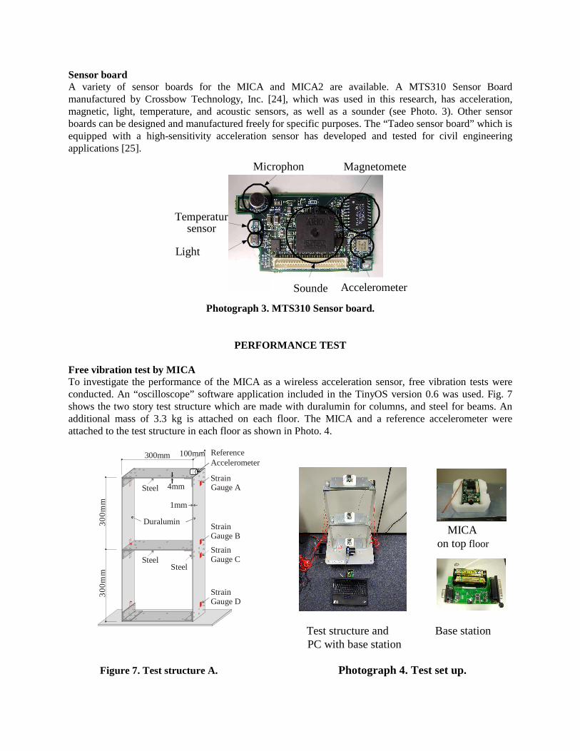
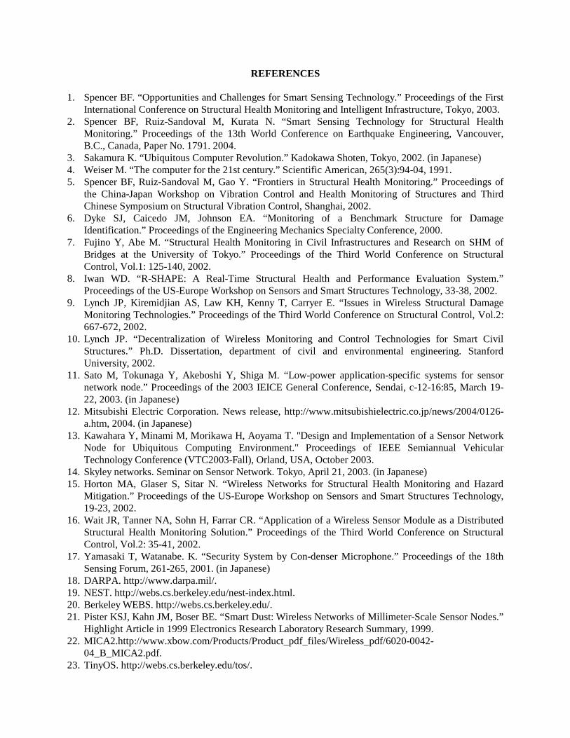
Sensor board A variety of sensor boards for the MICA and MICA2 are available. A MTS310 Sensor Board manufactured by Crossbow Technology, Inc. [24], which was used in this research, has acceleration, magnetic, light, temperature, and acoustic sensors, as well as a sounder (see Photo. 3). Other sensor boards can be designed and manufactured freely for specific purposes. The “Tadeo sensor board” which is equipped with a high-sensitivity acceleration sensor has developed and tested for civil engineering applications [25].
Photograph 3. MTS310 Sensor board.
PERFORMANCE TEST Free vibration test by MICA To investigate the performance of the MICA as a wireless acceleration sensor, free vibration tests were conducted. An “oscilloscope” software application included in the TinyOS version 0.6 was used. Fig. 7 shows the two story test structure which are made with duralumin for columns, and steel for beams. An additional mass of 3.3 kg is attached on each floor. The MICA and a reference accelerometer were attached to the test structure in each floor as shown in Photo. 4. MICA on top floor Test structure and Base station
PC with base station
Figure 7. Test structure A. Photograph 4. Test set up.
300mm
Duralumin
Steel 4mm
1mm
300
mm
300m
m
StrainGauge D
Steel
StrainGauge A
StrainGauge C
StrainGauge B
100mm
Steel
ReferenceAccelerometer
Microphon
Temperatursensor
Light
Sounde
Magnetomete
Accelerometer

Acc
eler
atio
n (c
m/s
ec2 )
Acc
eler
atio
n (c
m/s
ec2 )
(a) Top Acceleration by Reference
(b) Top Acceleration by
(sec)
(sec)
Free vibration tests of structure A were conducted. Fig. 8 shows measured accelerations at the top of test structure A using both the reference accelerometer and the MICA. Accelerations from the MICA were sent wirelessly to the base station, which was attached directory to the notebook PC (see Photo. 4). The sensitivity of the accelerometer on the MTS310 Sensor Board is not sufficient for accurate measurement of small amplitudes [25]. Additionally, some of data were lost during the test because of wireless communication problems such as packet collisions. The maximum rate of data loss was 30 percent.
Figure 8. Free vibration test results.
Shaking table test by MICA2 The application software, which was developed by the Open Systems Laboratory, the University of Illinois at Urbana-Champaign, was installed to the MICA2. It runs on the TinyOS version 1.0 and has a re-try function for sending the information to the base station from each MICA2. Shaking table tests were conducted to investigate the performance of the MICA2. Fig. 9 shows the two story test structure considered with elasto-plastic beams and columns. They are made with aluminum for columns and beams. The MICA2 and a reference accelerometer were attached to the top and base of the test structure as shown in Photo. 5.
Figure 9. Test structure B. Photograph 5. Test set up.
180
Aluminum(A1050P)
Steel
1.5mm
220
300m
m30
0mm
505
180
351.
550
1.5
1.5mm
8.5
208.
520
Aluminum(A1050P)
1.5mm
Weight(Steel)
300mm
6060
Base station
MICA2

0 5 10 15-500
0
500
0 5 10 15-500
0
500
0 5 10 15-500
0
500
0 5 10 15-500
0
500
(a) Top acceleration by reference
(b) Top acceleration by MICA2
(c) Base acceleration by reference
(d) Base acceleration by MICA2
Acc
eler
atio
n (c
m/s
ec2 )
Acc
eler
atio
n (c
m/s
ec2 )
Acc
eler
atio
n (c
m/s
ec2 )
Acc
eler
atio
n (c
m/s
ec2 )
The input excitation was the JMA-Kobe (NS) earthquake. Fig. 10 shows measured accelerations for test structure B using both the reference accelerometer and the MICA2 for the case of an input peak acceleration of 371 cm/sec2. Accelerations from the 3 units of the MICA2 were sent wirelessly to the base station attached directly to the notebook PC wirelessly (see Photo. 5). The communication reliability was greatly improved so that only 0.5 percent of data were lost during the test because of the re-try function used for the wireless communication. Accelerations measured by the MICA2 at the top and base of the test structure agree with results by reference accelerometer. The accuracy of the measurements using MICA2 was also recognized.
Figure 10. Shaking table test results.
Damage detection tests for structure B were carried out using the shaking table. The peak value of the input acceleration was 428 cm/sec2. Photo. 6 and Fig. 11 show the damage process for test structure B, and the measured top-floor acceleration and strain in the columns, respectively. The first story collapsed at stage 2 and 3 of the process, subsequently the second story collapsed at stage 4, as shown in Photo. 6. Comparing measured results between reference accelerometer and the MICA2, the MICA2 was able to measure the response of the structure with minimal data loss and detected its damage wirelessly.

Photograph 6. Damage process.
Figure 11. Damage detection test results.
CONCLUSIONS
The feasibility of risk monitoring for buildings using the smart sensors was discussed, and the performance of the MICA and MICA2 Mote as a wireless sensor was tested. The results showed the MICA2 has a promising future as an effective tool for risk monitoring in buildings. Further research on more effective modes of communication that facilitate no data loss is needed to achieve a wireless sensor network for building risk monitoring.
1 2 3 4
0 1 2 3 4 5 6 7-500
0
500
0 1 2 3 4 5 6 7-500
0
500
0 1 2 3 4 5 6 7-4
-2
0
2x 10
4
Acc
eler
atio
n (c
m/s
ec2 )
(b) Top Acceleration by reference
(c) Strain of Column
Stra
in(μ
) Gauge (2nd story)
Gauge (1st story)
Acc
eler
atio
n (c
m/s
ec2 )
(a) Top Acceleration by MICA2
(sec)
1 2 3
4
(sec)
(sec)
REFERENCES 1. Spencer BF. “Opportunities and Challenges for Smart Sensing Technology.” Proceedings of the First
International Conference on Structural Health Monitoring and Intelligent Infrastructure, Tokyo, 2003. 2. Spencer BF, Ruiz-Sandoval M, Kurata N. “Smart Sensing Technology for Structural Health
Monitoring.” Proceedings of the 13th World Conference on Earthquake Engineering, Vancouver, B.C., Canada, Paper No. 1791. 2004.
3. Sakamura K. “Ubiquitous Computer Revolution.” Kadokawa Shoten, Tokyo, 2002. (in Japanese) 4. Weiser M. “The computer for the 21st century.” Scientific American, 265(3):94-04, 1991. 5. Spencer BF, Ruiz-Sandoval M, Gao Y. “Frontiers in Structural Health Monitoring.” Proceedings of
the China-Japan Workshop on Vibration Control and Health Monitoring of Structures and Third Chinese Symposium on Structural Vibration Control, Shanghai, 2002.
6. Dyke SJ, Caicedo JM, Johnson EA. “Monitoring of a Benchmark Structure for Damage Identification.” Proceedings of the Engineering Mechanics Specialty Conference, 2000.
7. Fujino Y, Abe M. “Structural Health Monitoring in Civil Infrastructures and Research on SHM of Bridges at the University of Tokyo.” Proceedings of the Third World Conference on Structural Control, Vol.1: 125-140, 2002.
8. Iwan WD. “R-SHAPE: A Real-Time Structural Health and Performance Evaluation System.” Proceedings of the US-Europe Workshop on Sensors and Smart Structures Technology, 33-38, 2002.
9. Lynch JP, Kiremidjian AS, Law KH, Kenny T, Carryer E. “Issues in Wireless Structural Damage Monitoring Technologies.” Proceedings of the Third World Conference on Structural Control, Vol.2: 667-672, 2002.
10. Lynch JP. “Decentralization of Wireless Monitoring and Control Technologies for Smart Civil Structures.” Ph.D. Dissertation, department of civil and environmental engineering. Stanford University, 2002.
11. Sato M, Tokunaga Y, Akeboshi Y, Shiga M. “Low-power application-specific systems for sensor network node.” Proceedings of the 2003 IEICE General Conference, Sendai, c-12-16:85, March 19-22, 2003. (in Japanese)
12. Mitsubishi Electric Corporation. News release, http://www.mitsubishielectric.co.jp/news/2004/0126-a.htm, 2004. (in Japanese)
13. Kawahara Y, Minami M, Morikawa H, Aoyama T. "Design and Implementation of a Sensor Network Node for Ubiquitous Computing Environment." Proceedings of IEEE Semiannual Vehicular Technology Conference (VTC2003-Fall), Orland, USA, October 2003.
14. Skyley networks. Seminar on Sensor Network. Tokyo, April 21, 2003. (in Japanese) 15. Horton MA, Glaser S, Sitar N. “Wireless Networks for Structural Health Monitoring and Hazard
Mitigation.” Proceedings of the US-Europe Workshop on Sensors and Smart Structures Technology, 19-23, 2002.
16. Wait JR, Tanner NA, Sohn H, Farrar CR. “Application of a Wireless Sensor Module as a Distributed Structural Health Monitoring Solution.” Proceedings of the Third World Conference on Structural Control, Vol.2: 35-41, 2002.
17. Yamasaki T, Watanabe. K. “Security System by Con-denser Microphone.” Proceedings of the 18th Sensing Forum, 261-265, 2001. (in Japanese)
18. DARPA. http://www.darpa.mil/. 19. NEST. http://webs.cs.berkeley.edu/nest-index.html. 20. Berkeley WEBS. http://webs.cs.berkeley.edu/. 21. Pister KSJ, Kahn JM, Boser BE. “Smart Dust: Wireless Networks of Millimeter-Scale Sensor Nodes.”
Highlight Article in 1999 Electronics Research Laboratory Research Summary, 1999. 22. MICA2.http://www.xbow.com/Products/Product_pdf_files/Wireless_pdf/6020-0042-
04_B_MICA2.pdf. 23. TinyOS. http://webs.cs.berkeley.edu/tos/.

24. Crossbow Technology Inc. http://www.xbow.com/. 25. Ruiz-Sandoval M, Spencer BF, Kurata N. “Development of a High Sensitivity Accelerometer for the
Mica Platform.” Proceedings of the 4th International Workshop on Structural Health Monitoring, Stanford, 2003.
26. Agha G. “Networked Embedded Systems for Civil Infrastructure.” Proceedings of the International Workshop on Advanced Sensors, Structural Health Monitoring, and Smart Structures, Tokyo, November 10-11, 2003.
27. Kling R. “Intel® Mote.” Proceedings of the International Workshop on Advanced Sensors, Structural Health Monitoring, and Smart Structures, Tokyo, November 10-11, 2003.
ACKNOWLEDGEMENT The authors would like to express their gratitude to Prof. Gul Agha and Mr. Kirill Mechitov of the Open Systems Laboratory at the University of Illinois at Urbana-Champaign for development of the communication software for the MICA2. The authors would like to express their gratitude to Dr. Yuji Miyamoto, Dr. Yuji Sako, Mr. Tetsushi Watanabe, and Mr. Michio Imai of Kajima Corporation for implementing the shaking table tests. The authors gratefully acknowledge the partial support of this research by the CUREE-Kajima Joint Research Program Phase-V.