Embed Size (px)
Citation preview

Encoder
Gearhead
Stepper
Brush DC
Brushless DC


EncodErs
drivEs & ElEctronics
GEArHEAd
stEPPEr tUrBodisc
BrUsH dc
11-48BrUsHlEss dc
49-96
97-116
223-248
249-258
259-262
tABlE of contEnts
stEPPEr cAnstAcK
stEPPEr cAnstAcK vEctor
stEPPEr HYBrid
117-154
155-190
191-222

What’s new?Portescap is committed to helping our customers find new
ways to win. We maintain our core values by listening to our
customers, pursuing continuous improvement in all that we do
and the motors we design, and driving excellence and
innovation.
What’s Exciting?Portescap and our customers have been compiling a growing
list of success stories in a breadth of industry categories
around the world. Portescap has provided the right power in
small places in a variety of applications, including medical, civil
aviation, HVAC&R, aerospace and security and access, just to
name a few. To find out how our motion solutions are moving
life forward, go to www.portescap.com.
What Works Best?At Portescap, we optimize the relationships we create. We
offer new and innovative solutions, lean supply chain
management, LCR sourcing, and motor customization that
helps provide our customers with a solution that meets their
needs. We work closely with our customers to analyze every
facet of their motion control need, and then devise smart,
often unexpected ways to do the job better. We never solve
problems in isolation. Instead, we step back, look at their
business, and find new efficiencies or new levels of integration
that translate into bigger wins.

Portescap is a recognized expert in miniature motors and precision motion control
solutions. Portescap has been leading the way since 1931, driven by a passion for
innovation, technical excellence and quality service. Originating in Switzerland,
Portescap generated technology that helped to revolutionize the precision clock
and watch making industry. The company then applied its motion control ingenuity
to miniature motors and is now recognized as one of the global leaders in high
performance electro-mechanical motion systems, including brush DC, brushless,
and stepper motors as well as gearboxes, drive electronics and feedback
devices. Portescap is a global company with offices in the United States, India,
Malaysia, Singapore, and Switzerland. Portescap continues its legacy of
innovation and builds on its growing lists of “firsts” in the industry.

Today, Portescap is part of a worldwide family of over 30 industry-
leading brands that form Danaher Motion, including Kollmorgen,
Thomson, Dover, and Pacific Scientific.
Danaher Motion’s global infrastructure has enhanced Portescap’s
capabilities and level of service exponentially. Backed by a team of
more than 6,000 people, 2,000-plus distributor sites, and over 60 years
of application experience and design expertise, Danaher Motion helps
our customers build better machines, faster.
Portescap is in good company at Danaher Motion, with fellow industry-
leading brands like Kollmorgen, Thomson, Pacific Scientific, and Dover.
optimizing relationships and motors: the Power of dBs
Helping you build and maintain a competitive advantage is central to
everything we do at Portescap. In fact, the entire Portescap team
subscribes to the Danaher Business System, a highly regimented,
proven set of disciplines based on teamwork, quality and listening to
the customer. The Danaher Business System, or DBS, provides a
structure of business practices designed to eliminate waste and
continually improve manufacturing and product development
processes while delivering measurable value to our client partners in
the form of higher product quality, greater cost-savings, enhanced
efficiencies, faster delivery times and improved overall integration.
Portescap finds its place among an esteemed worldwide family of motion control experts.

Purposeful innovation through a deeper, more meaningful understanding of you and your customers.
What We do
We provide customized solutions to optimize every opportunity. At Portescap, we turn your ideas into reality. Often, a
complete solution can be developed from building blocks
that we’ve already created. However, there’s nothing we
like better than putting brand new ideas in motion. In
fact, customization is one of our greatest strengths. Our
long track record of creating unique solutions spans a wide
range of industries and applications.
Our more recent examples include customization of gear
motor assemblies for an articulating surgical handtool, and a
custom stepper motor assembly for refrigeration valves.
Portescap takes rapid prototyping to a more inspired,
interactive level. As your design cycles get tighter, Portescap
will keep you on schedule with some of the fastest turnaround
times in the industry – often as short as two weeks. With
development teams and prototyping facilities in key locations
throughout the world, Portescap can solve the most complex
miniature motion challenges quickly, accurately and cost-
effectively. At Portescap, you talk, we listen. Then, we build
what you need to succeed.
An important factor in our success is the highly collaborative
environment we create between customers and our Sales
and Application Engineering resources. By providing
extraordinary access during the prototyping phase, we’re
able to collaborate as true partners in the process, and be
responsive to often changing needs. This approach also
allows us to take a more active role in the short- and long-
term success of our customers.
Whatever your special needs for high performance
electromechanical systems, Portescap has the experience,
technology and resources to develop the best solution.
When you partner with Portescap, you’re teaming up with
a knowledge leader in the fields of electronics,
electromagnetics and precision micromechanics.
Our commitment to innovation focuses on the issues that
mean the most to you and your customers. This is true
whether we’re raising the bar in autoclavability in medical
and dental devices, maximizing power density for extended
battery life in industrial hand tools, or dramatically increasing
torque output while reducing motor size to enable
miniaturization.
Innovation is part of the corporate DNA at Portescap. It’s
what keeps us moving and improving. Our research and
development teams in North America, Europe and Asia
are equipped to create high-quality precision motion
solutions in virtually any configuration, environment or
envelope. Through our integrated global network, we offer
customers over 70 years of experience in the industry.

We understand that quality is an unending process that
finds expression in both our products and our approach
to doing business. Motion solutions from Portescap are
built to provide reliable high performance in some of the
most demanding applications imaginable. Thorough
motor specifications and material selection, high
manufacturing standards, and a total commitment to
post-sales support ensure that motion solutions from
Portescap will meet your exacting performance
standards – today and in the future.
Consistently high product quality is the result of
manufacturing excellence that has placed Portescap
among the best in its class. Integrated manufacturing
facilities, leading-edge technologies, lean manufacturing
principles and a perpetual drive toward improvement in
design and execution allow us to deliver highly reliable
motion solutions.
Superior performance also means efficiency. Portescap’s
global positioning saves on logistical costs and enhances
value for our customers with efficiencies of supply
chain optimization. Along with this, our high-volume
platforms and vast experience – including 10 years of
Low Cost Region manufacturing experience – help
keep our customers a step ahead in an increasingly
competitive world.
As our world continues to change, Portescap continues
to adapt to changing conditions throughout industrialized
global markets. To help us provide superior service and
support, Portescap Customer Service delivers localized
customer support teams. This demonstrates Portescap’s
commitment to staying in step with the specialized needs
of customers around the world. Customers have come to
highly regard Portescap’s flexibility and adaptability,
and continue to rely on us to share in their success.
Portescap’s Manufacturing Excellence helps keep you first in quality and first to market with key competitive advantages:
High Quality and consistency, delivered.
• A culture of continuous innovation and improvement
• Fast customization and responsive prototyping
• Efficiency, cost control and on-time delivery
• Value added solutions and sub-assemblies to meet your needs
• Exceptional performance, high degree of collaboration
• Leading-edge platform technologies
• Global design, manufacturing and account management
• Experience in key markets and applications
• Worldwide service and support
MEdicAlPortescap supplies motors for pumps, analyzers and surgical hand tools used by hospitals and medical device manufacturers for the purposes of drug delivery, testing, and surgery.
Surgical Instruments •
Respirators & Ventilators •
Infusion, Volumetric & Insulin Pumps•
Pipettes•
Dental Instruments•
Analyzers & Scanners •
Inoculation Guns•
Laboratory Automation•
Applications & Products
sEcUritYAmong Portescap’s innovations is a solution that represented a fundamental shift in commercial locking and release technology. The shift was away from conventional “electrical strike” method of door locking to an electromechanical approach that provides a stronger, more secure locked state.
Locks •
Cameras•
Bar Code Readers •
Fire Doors•
AErosPAcE & dEfEnsEPortescap provides motors for seat actuation and electric window shades on commercial and corporate jets. Lighter, more compact motors that perform at a higher efficiency over a longer period of time and deliver significant great cost-savings in maintenance and fuel.
Seat Actuation•
Missile Fin Actuation•
Electric Window Shades•
Cockpit Gauge Controls•
Fuel Metering•
Cameras•
HvAc&r When heating, ventilation, air conditioning or refrigeration appliances demand affordable, reliable motion control, Portescap delivers with a variety of products and motor technologies.
Refrigeration & Cooling Valves•
Heating, Water & Gas Valves•
Damper Actuator Control•
otHEr Robotics•
Factory Automation•
Industrial Hand Tools•
Scientific & Measuring•

Compact, lightweight, and high-precision handtools play a crucial role in a wide range of surgical procedures, increasing both patient safety and comfort. Delivering up to 30% more torque than traditional motors, Portescap’s autoclavable brushless motors generate minimal heat in an ultra-compact package. This means higher performance and better quality of use, especially in minimally invasive procedures. And, with higher acceleration and peak speed, Portescap motors help minimize time required for critical procedures, meaning a faster start on patient recovery.
MEdicAl: Surgical Handtools
HvAc&r: Refrigeration Valve Actuation
civil AviAtion: Seat Actuation
MEdicAl: Diagnostic Analyzer
Energy efficient and leak-proof seals are critical for electric refrigeration valves. Portescap provides geared can stack and direct drive linear actuator solutions with custom subassembly capability that allows for streamlined integration into the valve body and for precision flow controls of refrigerants in the valve system. Our vast experience working with custom valve solutions and our understanding of refrigerant control and electrical connections lets us provide you with cost effective innovative systems that are environmentally protective and space efficient.
Coreless brush DC motors from Portescap address the challenge of energy efficiency in commercial aviation by using state of the art magnetics and coil design, with efficiencies approaching 85–90% while reducing weight of the motors. A seat actuator motor from Portescap can be 50% lighter compared to an iron core technology with similar output power, thus leading to fuel savings due to reduced weight of the airplane. We are able to provide custom brush DC solutions with ball bearings that will not only extend the life of motors in such applications, but will let the passengers relax in peace.
Our coreless brush DC motor technologies deliver class-leading performance across a range of medical device applications. From sample draw on assays, to drug delivery via pumps, these motors offer minimal noise and lower joule heating, creating sustainable performance over the life of your project. An unparalleled speed-to-torque performance provides high energy efficiency and superior space utilization. This means increased turnaround times of diagnostic results and accurate dose delivery to patients and a faster recovery.
oUr Motors At WorK.

BRUSH DC motoRS
Why a Brush DC motor 50
Brush DC Spotlight on Innovation 51
Brush DC Motor Basics 52
Brush DC Working Principles 55
How to select your Brush DC motor 57
Brush DC Specifications 58
Where to apply Brush DC motors 59
Brush DC motors at Work 60
Your miniature motion challenges are unique and your
ideas for meeting those challenges are equally unique.
From medical to aerospace or security and access,
Portescap’s brush DC motion solutions are moving
life forward worldwide in critical applications. The
following Brush DC section features our high efficiency
and high power density with low inertia coreless brush
DC motor technology.
Brush DC 8mm
Brush DC 16mm
Brush DC 35mm
Motor Coil Cross Section

Why a Brush DC motor
• Brush DC commutation design Longer commutator life because of the design.
• REE system Stands for Reduction of Electro Erosion. The electro erosion, caused by arcing during commutation, is greatly reduced in low inertia coreless DC motors because of the low inductivity of their rotors.
• NEO magnet The powerful Neodymium magnets along with enhanced air gap design thus giving higher electro-magnetic flux and a lower motor regulation factor.
• Coreless rotor design Optimized coil and rotor reduces the weight and makes it compact.
Portescap’s brush DC coreless motors incorporate salient features
like low moment of inertia, no cogging, low friction, very compact
commutation which in turn results in high acceleration, high
efficiency, very low joule losses and higher continuous torque.
Ideal for portable and small devices, Portescap’s coreless motor
technologies reduce size, weight, and heat in such applications.
This results in improved motor performance in smaller physical
envelopes thus offering greater comfort and convenience for end-
users. In addition, the coreless design enables long-life and higher
energy efficiency in battery-powered applications.
Portescap continues innovating coreless technology by seeking
design optimizations in magnetic circuit, self supporting coreless
coil along with commutator and collector configurations.
Get your products to market faster through Portescap’s rapid
prototyping and collaborative engineering. Our R&D and
application engineering teams can adapt brush DC coreless motors
with encoders and gearboxes to perform in different configuration,
environment, or envelope.
Innovation & Performance
Your Custom motor• Shaft extension and double shaft options
• Custom coil design (different voltages)
• Mounting plates
• Gear pulleys and pinion
• Shock absorbing damper and laser welding
• Special lubrication for Civil aviation and medical applications
• EMI filtering
• Cables and connectors
• Gearboxes
Standard Features• Max continuous torque ranging from 0.66 to 158.6 mNm
• Speed ranging from 11,000 RPM (8mm) to 5,500 RPM (35mm)
• Motor regulation factor(R/K2) ranging from 1,900 to .3 103/Nms
Select Either Sleeveor Ball Bearings
models Available from8mm to 35mm Diameter
Long life Patented Commutation Sysyem Virtually Eliminates Brush maintenance
optional Gearboxes and magnetic or optical
Encoders Are Easily Added
High Efficiency Design - Ideal for Battery-Fed Applications
Ironless Rotor Coil Enables High Acceleration
Looking for a lighter motor with more torque?35GLT brush dc coreless motor from Portescap might be the solution for your needs. The 35GLT provides a 40% increase in torque-to-volume ratio over most average iron core motors. A featured multi-layer coil improves performance and offers insulating reinforcement, resulting in improved heat dissipation. Weighing in at only 360 grams and providing an energy efficiency of 85%, the 35GLT offers less power draw and excellent space savings.
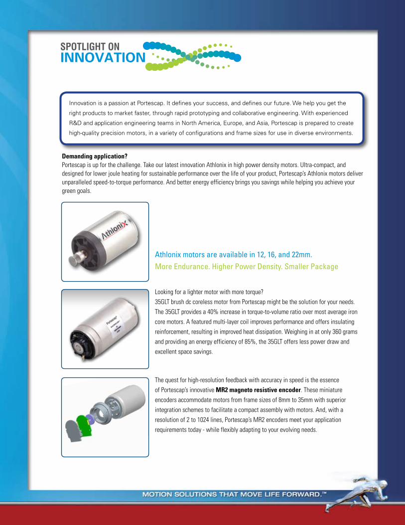
Innovation is a passion at Portescap. It defines your success, and defines our future. We help you get the
right products to market faster, through rapid prototyping and collaborative engineering. With experienced
R&D and application engineering teams in North America, Europe, and Asia, Portescap is prepared to create
high-quality precision motors, in a variety of configurations and frame sizes for use in diverse environments.
SPOTLIGHT ONINNOVATION
Demanding application?Portescap is up for the challenge. Take our latest innovation Athlonix in high power density motors. Ultra-compact, and designed for lower joule heating for sustainable performance over the life of your product, Portescap’s Athlonix motors deliver unparalleled speed-to-torque performance. And better energy efficiency brings you savings while helping you achieve your green goals.
Athlonix motors are available in 12, 16, and 22mm.More Endurance. Higher Power Density. Smaller Package
The quest for high-resolution feedback with accuracy in speed is the essence of Portescap’s innovative MR2 magneto resistive encoder. These miniature encoders accommodate motors from frame sizes of 8mm to 35mm with superior integration schemes to facilitate a compact assembly with motors. And, with a resolution of 2 to 1024 lines, Portescap’s MR2 encoders meet your application requirements today - while flexibly adapting to your evolving needs.

Brush DC motor Basics
All DC motors, including the ironless rotor motors, are composed of three principle sub assemblies: 1. Stator 2. Brush Holder Endcap 3. Rotor
1. The statorThe stator consists of the central, cylindrical permanent magnet, the core which supports the bearings, and the steel tube which completes the magnetic circuit. All three of these parts are held together by the motor front plate, or the mounting plate. The magnetic core is magnetized diametrically after it has been mounted in the magnetic system
2. The Brush Holder EndcapThe Brush Holder Endcap is made of a plastic material. Depending on the intended use of the motor, the brush could be of two different types:
• Carbon type, using copper grahite or silver graphite, such as those found in conventional motors with iron rotors. • Multiwire type, using precious metals.
3. The RotorOf the three sub-assemblies, the one that is most characteristic of this type of motor is the ironless, bell-shaped rotor. There are primarily four different methods of fabricating these ironless armatures utilized in present-day technology.
A — In the conventional way, the various sections of the armature are wound separately, then shaped and assembled to form a cylindrical shell which is glass yarn reinforced, epoxy resin coated, and cured. It is of interest to note the relatively large coil heads which do not participate in the creation of any torque.
Construction of Portescap motors with iron less rotor DC motors
Cable Clamp
Stator tube
Sleeve or Ball Bearing
metallic Alloy Brush Commutation System
Collector
Self Supporting High Packing Density Rotor Coil
High Efficiency High Strength Rare Earth magnet

Brush DC motor Basics B — A method which avoids these coil heads uses an armature wire that is covered with an outer layer of plastic for adhesion, and is wound on a mobile lozenge-shaped support. Later, the support is removed, and a flat armature package is obtained, which is then formed into a cylindrical shape (Figure 1). The difficulty with this method lies in achieving a completely uniform cylinder. This is necessary for minimum ripple of the created torque, and for a minimum imbalance of the rotor.
c) forming of armature in cylindrical shape
a) support arrangement b) armature as flat package
1
1a
2a3
25
Figure 1 - Continuous winding on mobile support
C — A procedure which avoids having to form a perfect cylinder from a flat package consists of winding the wire directly and continuously onto a cylindrical support. This support then remains inside the rotor. Coil heads are reduced to a minimum.Although a large air gap is necessary to accommodate the armature support; this method is, however, easily automated.
D — The Skew-Wound armature method utilizes the same two-layer plastic coated wire described in Method B. This Wire is directly and continuously wound onto a cylindrical support which is later removed, thus eliminating an excessive air gap and minimizing rotor inertia. In this type of winding, inactive coil heads are non-existent. (Figure 2). This kind of armature winding does require relatively complex coil winding machines. Portescap thru its proprietary know how has developed multiple automated winding machines for different frame sizes and continues to innovate in the space so that dense coil windings can be spun in these automated machines.
Figure 2

Features of Ironless Rotor DC motors
The rotor of a conventional iron core DC motor is made of copper wire which is wound around the poles of its iron core. Designing the rotor in this manner has the following results:• A large inertia due to the iron mass which impedes rapid starts and stops• A cogging effect and rotor preferential positions caused by the attraction of the iron poles to the permanent magnet.• A considerable coil inductance producing arcing during commutation. This arcing is responsible on the one hand for an
electrical noise, and on the other hand for the severe electro—erosion of the brushes. It is for the latter reason that carbon type brushes are used in the conventional motors.
A self supporting ironless DC motor from Portescap has many advantages over conventional iron core motors:• high torque to — inertia ratio• absence of preferred rotor positions• very low torque and back EMF variation with armature positions• essentially zero hysteresis and eddy current losses• negligible electrical time constant • almost no risk of demagnetization, thus fast acceleration• negligible voltage drop at the brushes (with multiwire type brushes)• lower viscous damping• linear characteristics
The two biggest contributors to the commutator life in a brush DC motor are the mechanical brush wear from sliding contacts and the erosion of the electrodes due to electrical arcing. The superior surface finish, commutator precision along with material upgrades such as precious metal commutators with appropriate alloys has helped in reducing the mechanical wear of the brushes. To effectively reduce electro erosion in while extending commutator life Portescap innovated its proprietary REE (Reduced Electro Erosion) system of coils. The REE system reduces the effective inductivity of the brush commutation by optimization of the mutual induction of the coil segments. In order to compare and contrast the benefits of an REE system Portescap conducted tests on motors with and with out REE coil optimization. The commutator surface wear showed improvements ranging from 100 -300 percent as shown in Figure 5. Coils 4, 5 and 6 are REE reinforced while 1, 2 & 3 are without REE reinforcement.
REE System proven to increase motor life up to 1000 percent

Brush DC Working PrinciplesThe electromechanical properties of motors with ironless rotors can be described by means of the following equations:
1. The power supply voltage U0 is equal to the sum of the voltage drop produced by the current I in the ohmic resistance RM of the rotor winding, and the voltage Ui induced in the rotor :U0 = I x RM + Ui (1)
2. The voltage Ui induced in the rotor is proportional to the angular velocity ω of the rotor :Ui = kE x ω (2)
It should be noted that the following relationship exists between the angular velocity ω express in radians per second and the speed of rotation n express in revolutions per minute:ω = 2π n 60
3. The rotor torque M is proportional to the rotor current I:M = kT x I (3)
It may be mentioned here that the rotor torque M is equal to the sum of the load torque ML
supplied by the motor and the friction torque M
f of the motor :
M = ML + Mf
By substituting the fundamental equations (2) and (3) into (1), we obtain the characteristics of torque/angular velocity for the dc motor
with an ironless rotor :U0 = M x RM + kE x ω (4)
By calculating the constant kE and kT from the dimensions of the motor, the number of turns per winding, the number of windings, the diameter of the rotor and the magnetic field in the air gap, we find for the direct-current micromotor with an ironless rotor:M = Ui = k (5) I ω
Which means that k = kE = kT
The identity kE = kT is also apparent from the following energetic considerations:
The electric power Pe = U0 x I which is supplied to the motor must be equal to the sum of the mechanical power Pm = M x ω produced by the rotor and the dissipated power (according to Joule’s law) Pv = I2 x RM:Pe = U0 x I = M x ω + I2 x RM
= Pm + Pv
Moreover, by multiplying equation (1) by I, we also obtain a formula for the electric power Pe: Pe = U0 x I = I2 x RM + Ui x I
The equivalence of the two equations givesM x ω = U
i x I
or Ui = M and kE = kT = k ω IQuod erat demonstrandum.
Using the above relationships, we may write the fundamental equations (1) and (2) as follows:U0 = I x RM + k x ω (6)and :U0 = M x RM + k x ω (7) k
Graphic express “speed-torque” characteristic:
To overcome the friction torque Mf due to the friction of the brushes and bearings, the motor consumes a no-load current I0. This givesMf = k x I0
and:
U0 = I0 x RM + k x ω0 where
ω0 = 2π x n0
60hence:k = U0 - I0 x RM (8) ω0
Is it therefore perfectly possible to calculate the motor constant k with the no-load speed n0, the no-load current I0
and the rotor resistance RM.
The starting-current Id is calculated as follows:Id = U0
RM
It must be remembered that the RM depends to a great extent on the temperature; in other words, the resistance of the rotor increases with the heating of the motor due to the dissipated power (Joule’s law):RM = RM0 (1 + γ x ∆T)
Where γ is the temperature coefficient of copper (γ = 0.004/°C).As the copper mass of the coils is comparatively small, it heats very quickly
IRM
UI
U0
0MLML
I
I
ML
M
U0
n
n0

through the effect of the rotor current, particularly in the event of slow or repeated starting. The torque Md produced by the starting-current Id is obtained as follows:Md = Id x k - Mf = (Id - I0)k (9)
By applying equation (1), we can calculate the angular velocity ω produced under a voltage U0 with a load torque Mi. We first determine the current required for obtaining the torque M = ML + Mf :I = ML + Mf
kSince Mf = I0
k
we may also write (10)I = ML + I0
k
For the angular velocity ω, we obtain the relationshipω = U0 − I x RM (11) k
= U0 − RM (ML + Mf) k k2
In which the temperature dependence of the rotor resistance RM must again be considered; in other words, the value of RM at the working temperature of the rotor must be calculated. On the other hand, with the eqation (6), we can calculate the current I and the load torque ML for a given angular velocity ω and a given voltage U0
: I = U0 − k x ω = Id − k ω (12) RM RM
And with equation (10)ML = (I − I0)k
We get the value of ML:ML = (I − I0)k − k2 ω
RM
The problem which most often arises is that of determining the power supply voltage U0
required for obtaining a speed of rotation n for a given load torque ML (angular velocity ω = n x 2π/60). By introducing equation (10) into (6) we obtain:U0 = ML + I0 RM + k x ω (13) k
Practical examples of calculationsPlease note that the International System of Units (S.I.) is used throughout.
1. Let us suppose that, for a Portescap® motor 23D21-216E, we wish to calculate the motor constant k, the starting current Id and the starting torque Md at a rotor temperature of 40°C. With a power supply voltage of 12V, the no-load speed is n0 is 4900 rpm (ω0 = 513 rad/s), the no-load current I0 = 12 mA and the resistance RM0 = 9.5 Ω at 22°C.
By introducing the values ω0, I0, RM0 and U0 into the equation (8), we obtain the motor constant k for the motor 23D21-216E:k = 12 − 0.012 x 9.5 = 0.0232 Vs 15
Before calculating the starting-current, we must calculate the rotor resistance at 40°C. With ∆T = 18°C and RM0 = 9.5Ω, we obtainRM = (1 + 0.004 x 18) = 9.5 x 1.07
= 10.2Ω
The starting-current Id at a rotor temperature of 40°C becomesId = U0 = 12 = 1.18A RM 10.2
and the starting-torque Md, according to equation (9), isMd = k(Id − I0) = 0.0232 (1.18 − 0.012)
= 0.027 Nm
2. Let us ask the following question: what is the speed of rotation n attained by the motor with a load torque of 0.008 Nm and a power supply voltage of 9V at a rotor temperature of 40°C?
Using equation (10) we first calculate the current which is supplied to the motor under these conditions:I = ML + I0 = 0.008 + 0.012 k 0.0232 = 0.357A
Equation (11) gives the angular velocity ω:ω = U0 − I x RM = 9 − 0.357 x 10.2 k 0.0232
= 231 rad/s
and the speed of rotation n:n = 60 ω = 2200 rpm 2π
Thus the motor reaches a speed of 2200 rpm and draws a current of 357 mA.
3. Let us now calculate the torque M at a given speed of rotation n of 3000 rpm (ω = 314 rad/s) and a power supply voltage U0 of 15V; equation (12) gives the value of the current:I = U0 − k x ω = Id − k x ω RM RM
= 1.18 − 0.0232 x 314 = 0.466A 10.2
and the torque load ML:ML = k(I − I0)
= 0.0232 (0.466 − 0.012) = 0.0105 Nm
(ML = 10.5 mNm)
4. Lastly, let us determine the power supply voltage U0 required for obtaining a speed rotation n of 4000 rpm (ω = 419 rad/s) with a load torque of ML of 0.008 Nm, the rotor temperature again being 40°C (RM = 10.2Ω).As we have already calculated, the current I necessary for a torque of 0.008 Nm is 0.357 A
U0 = I x RM + k x ω = 0.357 x 10.2 + 0.0232 x 419 = 13.4 volt
Brush DC Working Principles
22 N 2R 2B - 210E 286
Motor generation/ length:L, C = old generation (C: short, L: long), Alnico MagnetS, N, V = middle generation (S: short, N: normal, V: very long)G, GS = new generation (high power magnet), S: short version
Motor diameter (in mm) Execution codingBearing type:blank = with sleeve bearings2R = with front and rear ball bearings
Coil type:nb of layerwire sizetype connexion
Commutation size & type/ magnet type:Alnico/ Precious Metal = 18, 28, 48, 58 NdFeB/ Precious Metal = 78, 88, 98Alnico/ Graphite & Copper = 12 NdFeB/ Graphite Copper = 82, 83
.
( )

PRODUCT RANGE CHARTFRAME SIZE 08GS 08G 13N 16C 16N28 16G
Max Continuous Torque
mNm (Oz-in) 0.66 (0.093)
0.87 (0.102)
3.33 (0.47) 1.0 (0.14) 2.4 (0.34) 5.4 (0.76)
Motor Regulation R/K2 103/Nms 1900 1200 166 1523 380 77Rotor Inertia Kgm2 10-7 0.03 0.035 0.33 0.27 0.51 0.8
17S 17N 22S 22N28 22V 23LMax Continuous
TorquemNm (Oz-in) 2.6 (0.37) 4.85 (0.69) 9.5 (1.34) 7.3 (1.04) 8.13 (1.15) 6.2 (1.16)
Motor Regulation R/K2 103/Nms 250 97 33 73 58 54Rotor Inertia Kgm2 10-7 0.5 0.8 1.9 3 2.4 3.6
FRAME SIZE 23V 23GST 25GST 25GT 26N 28L 28LTMax Continuous
TorquemNm (Oz-in) 13 (1.8) 22 (3.1) 27 (3.8) 41 (5.8) 17.3 (2.4) 21.0
(2.97)22.8
(3.23)Motor Regulation R/K2 103/Nms 30 11 (0.4) 8 4.2 18 12 13
Rotor Inertia Kgm2 10-7 3.7 4.7 10 13 6 17.5 10.7
28D 28DT 30GT 35NT2R32 35NT2R82 35GLTMax Continuous
TorquemNm (Oz-in) 33.6
(4.8)41 (5.8) 93
(13.2)58.3 (8.3) 115 (16.3) 158.6
Motor Regulation R/K2 103/Nms 6.69 5.9 1.1 3.12 0.83 0.39Rotor Inertia Kgm2 10-7 17.6 20 33 52 71.4 70
How to select your Coreless motor
motor Designation
22 N 2R 2B - 210E 286
Motor generation/ length:L, C = old generation (C: short, L: long), Alnico MagnetS, N, V = middle generation (S: short, N: normal, V: very long)G, GS = new generation (high power magnet), S: short version
Motor diameter (in mm) Execution codingBearing type:blank = with sleeve bearings2R = with front and rear ball bearings
Coil type:nb of layerwire sizetype connexion
Commutation size & type/ magnet type:Alnico/ Precious Metal = 18, 28, 48, 58 NdFeB/ Precious Metal = 78, 88, 98Alnico/ Graphite & Copper = 12 NdFeB/ Graphite Copper = 82, 83
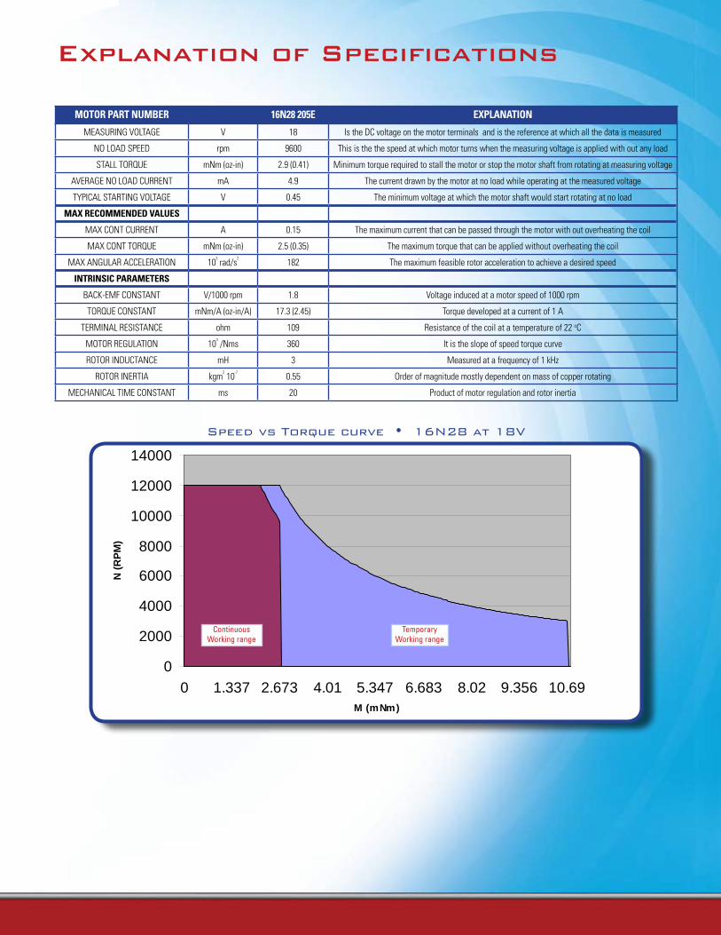
MOTOR PART NUMBER 16N28 205E ExPLANATION
MEASURING VOLTAGE V 18 Is the DC voltage on the motor terminals and is the reference at which all the data is measured
NO LOAD SPEED rpm 9600 This is the the speed at which motor turns when the measuring voltage is applied with out any load
STALL TORQUE mNm (oz-in) 2.9 (0.41) Minimum torque required to stall the motor or stop the motor shaft from rotating at measuring voltage
AVERAGE NO LOAD CURRENT mA 4.9 The current drawn by the motor at no load while operating at the measured voltage
TYPICAL STARTING VOLTAGE V 0.45 The minimum voltage at which the motor shaft would start rotating at no load
MAx RECOMMENDED VALUES
MAX CONT CURRENT A 0.15 The maximum current that can be passed through the motor with out overheating the coil
MAX CONT TORQUE mNm (oz-in) 2.5 (0.35) The maximum torque that can be applied without overheating the coil
MAX ANGULAR ACCELERATION 103 rad/s
2182 The maximum feasible rotor acceleration to achieve a desired speed
INTRINSIC PARAMETERS
BACK-EMF CONSTANT V/1000 rpm 1.8 Voltage induced at a motor speed of 1000 rpm
TORQUE CONSTANT mNm/A (oz-in/A) 17.3 (2.45) Torque developed at a current of 1 A
TERMINAL RESISTANCE ohm 109 Resistance of the coil at a temperature of 22 oC
MOTOR REGULATION 103 /Nms 360 It is the slope of speed torque curve
ROTOR INDUCTANCE mH 3 Measured at a frequency of 1 kHz
ROTOR INERTIA kgm2 10
-70.55 Order of magnitude mostly dependent on mass of copper rotating
MECHANICAL TIME CONSTANT ms 20 Product of motor regulation and rotor inertia
Speed vs Torque curve • 16N28 at 18V
0
2000
4000
6000
8000
10000
12000
14000
0 1.337 2.673 4.01 5.347 6.683 8.02 9.356 10.69M (mNm)
N (
RP
M)
Continuous Working range
Temporary Working range
Explanation of Specifications

markets & Applications
mEDICALPowered surgical instruments•
Dental hand tools•
Infusion, Volumetric & Insulin Pumps•
Diagnostic & scanning equipment•
Benefits: Reduced footprint analyzers with high efficiency & precision sample positioning
SECURItY & ACCESSSecurity cameras•
Locks•
Bar code readers•
Paging systems•
Benefits: Low Noise & Vibration, High Power & Superior Efficiency
AERoSPACE & DEFENSECockpit gauge•
Indicators•
Satellites•
Optical scanners•
Benefits: Low Inertia, Compactness and Weight, High Efficiency
RoBotICS & FACtoRY AUtomAtIoNConveyors•
Remote controlled vehicles•
Industrial robots•
Benefits: High Power & Low Weight
PoWER HAND tooLSShears•
Pruning hand tools•
Nail guns•
Benefits: High Efficiency, Compactness and Weight, Low Noise
otHEROffice equipment•
Semiconductors•
Model railways•
Document handling•
Optics•
Automotive•
Transportation•
Audio & video•
Benefits: Low Noise, High Power, Better Motor Regulation

mEDICAL ANALYZERSPortescap solves multiple application needs in analyzers, from sample draw on assays to rapid scanning and detection of molecular mechanisms in liquids and gases, with its coreless brush dc motors. For high throughput applications—those where over 1,000 assays are analyzed in an hour—high efficiency and higher speed motors such as brush DC coreless motors are a suitable choice. Their low rotor inertia along with short mechanical time constant makes them ideally suited for such applications. As an example, a Portescap 22-mm motor brush coreless DC motor offers no-load speed of 8,000 rpm and a mechanical time constant of 6.8 milliseconds. Another analyzer function that plays a vital role in their output is collecting samples from the vials or assays, and serving them up to measurement systems based on photometry, chromatography, or other appropriate schemes. Here again, a brush DC coreless motor is highly applicable due to the power density it packs in a small frame size. You can maximize your application’s productivity with a 16 or 22mm workhorse from Portescap.
Brush DC motors at Work
INFUSIoN PUmPSCoreless brush DC motors offer significant advantages over their iron core brush counterparts for some of the critical care pump applications where, the benefits range from improved efficiency to higher power density, in a smaller frame size. One of the factors that deteriorates motor performance over long term usage is the heating of the motor with associated Joule loss. In motor terminology this is governed by the motor regulation factor determined by the coil resistance, R, and the torque constant, k. The lower the motor regulation factor (R/k2) the better would the motor perform over its life while sustaining higher efficiencies. With some of the lowest motor regulation factors Portescap’s latest innovation in Athlonix motors is already benefiting applications in the infusion pump space by offering a choice of a higher performance motor with less heat loss, higher efficiency and power density in compact packages.
ELECtRoNICS ASSEmBLY SURFACE moUNt EQUIPmENtPortescap’s versatile 35mm coreless motors with carbon brush commutation excel in electronic assembly, robotics and automated machinery equipment and have been a work horse in some of the pick and place machinery used in surface mount technology. Our 35mm low inertia motors can provide high acceleration, low electro magnetic interference, and frequent start stops that the machines need while maintaining smaller and light weight envelopes.

61www.portescap.com
Miniature Motors
Notes

Executions
Gearbox Page 08GS61
R10 234 7
R08 Contact Portescap
62 www.portescap.com
Precious Metal Commutation System - 5 Segments 0.5 Watt
dimensions in mmmass: 3.8 g 08GS61 3
Continuous working rangeTemporary working range
Values at the output shaft
M(mNm)
n (rpm)
0.5 W
• Thermalresistance: rotor-body 20°C/W body-ambient 100°C/W• Thermaltimeconstantrotor/stator:5s/100s• Max.ratedcoiltemperature:100°C• Recom.ambienttemperaturerange: -30°C to +85°C (-22°F to +185°F)• Max.axialstaticforce:30N• Endplay:≤ 100 µm Radialplay:≤ 15 µm Shaftrunout:≤ 10 µm• Max.sideloadat2mmfrommountingface: -sleevebearings0.5N• Motorfittedwithsleevebearings
Max.RecommendedSpeed
Max.ContinuousOutputPower
Winding Type -107 -105 -105CMeasured ValuesMeasuring voltage V 2 4.5 6No-load speed rpm 7000 10700 10600Stall torque mNm(oz-in) 0.42 (0.06) 0.59 (0.084) 0.64 (0.091)Average No-load current mA 6 4 3Typical starting voltage V 0.2 0.3 0.5Max. Recommended Values Max. continuous current A 0.25 0.168 0.133Max. continuous torque mNm(oz-in) 0.64 (0.09) 0.64 (0.091) 0.66 (0.093)Max. angular acceleration 103 rad/s2 889 859 884Intrinsic ParametersBack-EMF constant V/1000rpm 0.275 0.41 0.53Torque constant mNm/A(oz-in/A) 2.63 (0.372) 3.92 (0.55) 5.1 (0.72)Terminal resistance ohm 12.6 30 45.8Motor regulation R/k2 103/Nms 1800 2000 1900Rotor inductance mH 0.058 0.11 0.2Rotor inertia kgm2 10-7 0.03 0.03 0.03Mechanical time constant ms 5.5 5.9 5.6
08GS61

Miniature Motors
63www.portescap.com
Brushed D
C
08G61
Precious Metal Commutation System - 5 Segments0.7 Watt
Continuous working rangeTemporary working range
Values at the output shaft
M(mNm)
n (rpm )
0.7 W
Max.RecommendedSpeed
Max.ContinuousOutputPower
0,54,5 0-0,1
0,2
4,3
1,55 19,6
1,5
0 -0,0
15
1,9
0,4
2
5
2,1
1
8 0 -0
,08
5,5
Mx0
,5
6 0 -0
,018
dimensions in mmmass: 4.5 g 08G61 3
Winding Type -107 -205C Measured ValuesMeasuring voltage V 3 9No-load speed rpm 9800 11800Stall torque mNm(oz-in) 0.73 (0.103) 1.01 (0.143)Average No-load current mA 5.5 2.5Typical starting voltage V 0.2 0.6Max. Recommended Values Max. continuous current A 0.25 0.124Max. continuous torque mNm(oz-in) 0.7 (0.099) 0.87 (0.102)Max. angular acceleration 103 rad/s2 924 999Intrinsic ParametersBack-EMF constant V/1000rpm 0.3 0.75Torque constant mNm/A(oz-in/A) 2.86 (0.406) 7.2 (1.01)Terminal resistance ohm 11.8 56.5Motor regulation R/k2 103/Nms 1400 1200Rotor inductance mH 0.03 0.16Rotor inertia kgm2 10-7 0.035 0.035Mechanical time constant ms 5 4.4
• Thermalresistance: rotor-body 18°C/W body-ambient 85ºC/W• Thermaltimeconstantrotor/stator:5s/100s• Max.ratedcoiltemperature:100°C• Recom.ambienttemperaturerange: -30°C to +85°C (-22°F to +185°F)• Max.axialstaticforce:30N• Endplay:≤ 100 µm Radialplay:≤ 15 µm Shaftrunout:≤ 10 µm• Max.sideloadat2mmfrommountingface: -sleevebearings0.5N• Motorfittedwithsleevebearings
Executions
Gearbox Page 08GS61
R10 234 5
R08 Contact Portescap
64 www.portescap.com
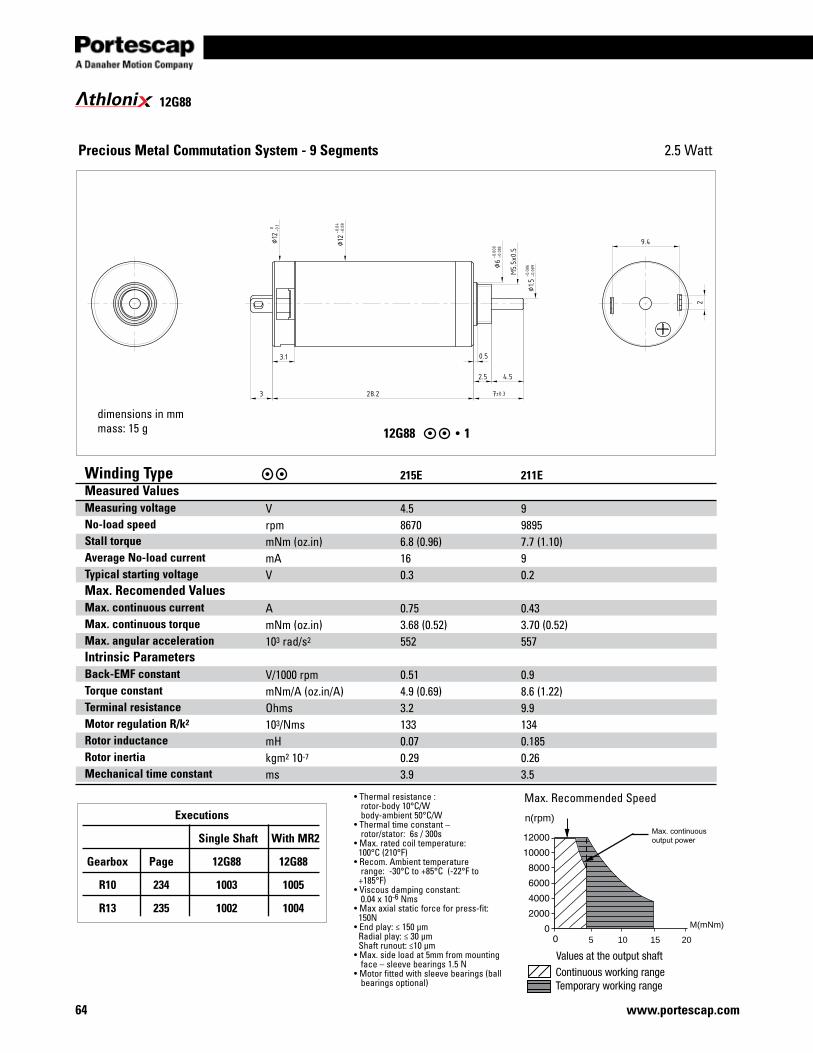
thloni 12G88
12G88 1
Precious Metal Commutation System - 9 Segments
•Thermalresistance: rotor-body 10°C/W body-ambient 50°C/W•Thermaltimeconstant– rotor/stator: 6s / 300s•Max.ratedcoiltemperature: 100°C (210°F)•Recom.Ambienttemperature range: -30°C to +85°C (-22°F to +185°F)•Viscousdampingconstant:0.04x10⁻⁶Nms•Maxaxialstaticforceforpress-fit:150N•Endplay:≤150μmRadialplay:≤30μmShaftrunout:≤10μm•Max.sideloadat5mmfrommountingface–sleevebearings1.5N•Motorfittedwithsleevebearings(ballbearingsoptional)
dimensions in mmmass: 15 g
Winding Type Measured Values Measuring voltageNo-load speed Stall torqueAverage No-load current Typical starting voltageMax. Recomended ValuesMax. continuous currentMax. continuous torqueMax. angular accelerationIntrinsic Parameters Back-EMF constantTorque constantTerminal resistanceMotor regulation R/k2
Rotor inductanceRotor inertiaMechanical time constant
VrpmmNm(oz.in)mAV
AmNm(oz.in)103 rad/s2
V/1000rpmmNm/A(oz.in/A)Ohms103/NmsmHkgm2 10-7
ms
215E 4.586706.8 (0.96)160.3
0.753.68 (0.52)552
0.514.9 (0.69)3.21330.070.293.9
211E 998957.7 (1.10)90.2
0.433.70 (0.52)557
0.98.6 (1.22)9.91340.1850.263.5
Max.RecommendedSpeed
105 15 20
n(rpm)
M(mNm)
Max. continuous output power
2.5 Watt
Executions
Single Shaft With MR2
Gearbox Page 12G88 12G88
R10 234 1003 1005
R13 235 1002 1004

65www.portescap.com
Miniature Motors
13N88
Precious Metal Commutation System - 9 Segments2.5 Watt
dimensions in mmmass: 18 g 13N88 1
Winding Type -213E -110 -107Measured ValuesMeasuring voltage V 6.0 12.0 24.0No-load speed rpm 12300 12400 14100Stall torque mNm(oz-in) 6.5 (0.93) 8 (1.13) 8.4 (1.19)Average No-load current mA 25.6 13.6 8.8Typical starting voltage V 0.08 0.10 0.20Max. Recommended Values Max. continuous current A 0.69 0.38 0.21Max. continuous torque mNm(oz-in) 3.03 (0.43) 3.33 (0.47) 3.18 (0.45)Max. angular acceleration 103 rad/s2 433 405 438Intrinsic ParametersBack-EMF constant V/1000rpm 0.48 0.95 1.67Torque constant mNm/A(oz-in/A) 4.58 (0.65) 9.1 (1.28) 15.9 (2.26)Terminal resistance ohm 4.20 13.7 45.6Motor regulation R/k2 103/Nms 200 166 179Rotor inductance mH 0.07 0.25 0.80Rotor inertia kgm2 10-7 0.28 0.33 0.29Mechanical time constant ms 5.6 5.5 5.2
• Thermalresistance: rotor-body 10°C/W body-ambient 40°C/W• Thermaltimeconstant-rotor/stator:6s/300s• Max.ratedcoiltemperature:100°C(210°F)• Recom.ambienttemperaturerange: -30°C to +85°C (-22°F to +185°F)• Viscousdampingconstant:0.04x10⁻⁶Nms• Max.axialstaticforceforpress-fit:150N• Endplay:≤ 150 µm Radialplay:≤ 30 µm Shaftrunout:≤ 10 µm• Max.sideloadat5mmfrommountingface: -sleevebearings1.5N• Motorfittedwithsleevebearings (ballbearingsoptional)
Max.RecommendedSpeedMax.ContinuousOutputPower
Executions
Gearbox Page 13N88 13N88D12
R13 235 1 3 2.5 W
Brushed D
C

66 www.portescap.com
16C18
Values at the output shaft
Precious Metal Commutation System - 5 Segments 0.85 Watt
- +
4
3,7
5,9
10
1,6M x1,4 max.
3,7
150
±3
6,72 15,7
5,7( )16,5( )1
7,52 15,7
16 0 -0
,1
6 0 -0
,018
1 0 -0,0
06
15
1,5
-0,0
06-0
,00916
0 -0,1
6 0 -0
,01815
dimensions in mmmass: 13 g 16C18•3016C18 •67
Winding Type -115 -210 -207 -205 -204Measured ValuesMeasuring voltage V 1.5 4.0 6.0 12.0 15.0No-load speed rpm 15300 14700 15700 16200 16000Stall torque mNm(oz-in) 1.1 (0.16) 1.3 (0.19) 1.1 (0.16) 1.2 (0.17) 0.8 (0.11)Average No-load current mA 74.8 23.0 18.4 10.4 6.9Typical starting voltage V 0.04 0.05 0.10 0.15 0.25Max. Recommended Values Max. continuous current A 1.19 0.48 0.31 0.16 0.10Max. continuous torque mNm(oz-in) 0.98 (0.14) 1.13 (0.16) 1.0 (0.14) 1.0 (0.14) 0.79 (0.11)Max. angular acceleration 103 rad/s2 127 110 148 99 117Intrinsic ParametersBack-EMF constant V/1000rpm 0.092 0.26 0.36 0.70 0.87Torque constant mNm/A(oz-in/A) 0.88 (0.12) 2.48 (0.35) 3.44 (0.49) 6.68 (0.95) 8.3 (1.18)Terminal resistance ohm 1.20 7.5 18.0 65.0 162Motor regulation R/k2 103/Nms 1555 1217 1523 1455 2347Rotor inductance mH 0.02 0.15 0.25 1.00 2.00Rotor inertia kgm2 10-7 0.31 0.41 0.27 0.41 0.27Mechanical time constant ms 48 50 41 60 63
• Thermalresistance: rotor-body 15°C/W body-ambient 40°C/W• Thermaltimeconstant-rotor/stator: 4 s / 230 s• Max.ratedcoiltemperature:100°C(210°F)• Recom.ambienttemperaturerange: -30°C to +85°C (-22°F to +185°F)• Viscousdampingconstant:0.04x10⁻⁶Nms• Max.axialstaticforceforpress-fit:150N• Endplay:≤ 150 µm Radialplay:≤ 30 µm Shaftrunout:≤ 10 µm• Max.sideloadat5mmfrommountingface: -sleevebearings0.5N -ballbearings3N• Motorfittedwithsleevebearings (ballbearingsoptional)
Max.RecommendedSpeedMax.ContinuousOutputPower
Executions
Single Shaft With F16
Gearbox Page 16C18 16C18
B16 236 67 76
BA16 237 67 76
R16 238 30 76

67www.portescap.com
Miniature Motors
2
10
10M 1,6 x 2,5 max.
15,4
116
68
1,5
1,7
5,5 28
(6,5)
7,5
6
16N28
Precious Metal Commutation System - 9 Segments2.3 Watt
dimensions in mmmass: 24 g 16N28•201
)
Winding Type -111P -210E -208E -207EMeasured ValuesMeasuring voltage V 3 7.5 9.0 12.0 No-load speed rpm 9500 9700 8900 10800 Stall torque mNm(oz-in) 3.7 (0.52) 3.7 (0.52) 3.1 (0.45) 3.1 (0.45) Average No-load current mA 28 13.3 8.4 7.7 Typical starting voltage V 0.10 0.15 0.2 0.3 Max. Recommended Values Max. continuous current A 1.01 0.42 0.29 0.24 Max. continuous torque mNm(oz-in) 2.9 (0.44) 2.9 (0.41) 2.7 (0.38) 2.4 (0.34) Max. angular acceleration 103 rad/s2 161 148 172 192 Intrinsic ParametersBack-EMF constant V/1000rpm 0.31 0.75 1.0 1.1 Torque constant mNm/A(oz-in/A) 2.96 (0.42) 7.2 (1.0) 9.5 (1.35) 10.3 (1.45) Terminal resistance ohm 2.4 14.6 28 40.5 Motor regulation R/k2 103/Nms 270 280 310 380 Rotor inductance mH 0.08 0.5 0.8 0.9 Rotor inertia kgm2 10-7 0.72 0.77 0.63 0.51 Mechanical time constant ms 20 22 20 19
• Thermalresistance: rotor-body 7°C/W body-ambient 28°C/W• Thermaltimeconstant-rotor/stator: 7 s / 390 s• Max.ratedcoiltemperature:100°C(210°F)•Recom.ambienttemperaturerange: -30°C to +85°C (-22°F to +185°F)• Viscousdampingconstant:0.04x10⁻⁶Nms• Max.axialstaticforceforpress-fit:100N (withsleevebearingonly)• Endplay:≤150µmRadialplay:≤ 30 µm Shaftrunout:≤ 10 µm• Max.sideloadat5mmfrom mountingface:-sleevebearings1.5N -ballbearings3N• Motorfittedwithsleevebearings (ballbearingsoptional)
Max.RecommendedSpeedMax.ContinuousOutputPower
Executions
Single Shaft With F16
Gearbox Page 16N28 16N28
B16 200 236 235 235
BA16 200 237 235 235
R16 238 201 201
Maxscrewtorque40mNmMaxtraction230N
Brushed D
C

68 www.portescap.com
2
10
10M 1,6 x 2,5 max.
15,4
116
68
1,5
1,7
5,5 28
(6,5)
7,5
6
16N28
Precious Metal Commutation System - 9 Segments 2.3 Watt
dimensions in mmmass: 24 g 16N28 •201
)
Winding Type -106 -205E 209E 207PMeasured ValuesMeasuring voltage V 16.0 18.0 9 4.8No-load speed rpm 10200 9600 9800 7900Stall torque mNm(oz-in) 3.4 (0.48) 2.9 (0.41) 5.4(0.76) 2.7(0.38)Average No-load current mA 6.3 4.9 8.4 11.9Typical starting voltage V 0.4 0.45 0.35 0.15Max. Recommended Values Max. continuous current A 0.19 0.15 0.41 0.49Max. continuous torque mNm(oz-in) 2.7 (0.38) 2.5 (0.35) 3.5(0.5) 2.7(0.38)Max. angular acceleration 103 rad/s2 200 182 253 211Intrinsic Parameters Back-EMF constant V/1000rpm 1.5 1.8 0.91 0.59Torque constant mNm/A(oz-in/A) 14.6 (2.07) 17.3 (2.45) 8.7 5.6Terminal resistance ohm 68.5 109 14.6 10Motor regulation R/k2 103/Nms 320 360 190 320Rotor inductance mH 2 3 0.7 0.28Rotor inertia kgm2 10-7 0.53 0.55 0.55 0.51Mechanical time constant ms 17 20 11 16
• Thermalresistance: rotor-body 7°C/W body-ambient 28°C/W• Thermaltimeconstant-rotor/stator: 7 s / 390 s• Max.ratedcoiltemperature:100°C(210°F)•Recom.ambienttemperaturerange: -30°C to +85°C (-22°F to +185°F)• Viscousdampingconstant:0.04x10⁻⁶Nms• Max.axialstaticforceforpress-fit:100N (withsleevebearingonly)• Endplay:≤150µmRadialplay:≤ 30 µm Shaftrunout:≤ 10 µm• Max.sideloadat5mmfrom mountingface:-sleevebearings1.5N -ballbearings3N• Motorfittedwithsleevebearings (ballbearingsoptional)
Max.RecommendedSpeedMax.ContinuousOutputPower
Executions
Single Shaft With F16
Gearbox Page 16N28 16N28
B16 200 236 235 235
BA16 200 237 235 235
R16 238 201 201
Maxscrewtorque40mNmMaxtraction230N

69www.portescap.com
Miniature Motors
Brushed D
C
16G88
Precious Metal Commutation System - 9 Segments5 Watt
Max.RecommendedSpeedMax.ContinuousOutputPower
150
0,3
1,82x x4
28 7,5 0,5
1
6 0,5
10
1,6M x2,8 max.
1
10
6,5( )
606x
16 0 -0
,1
6 0 -0
,018
1,5
-0,0
06-0
,009
6 0 -0
,018
dimensions in mmmass: 24 g 16G88•1
Winding Type -220P -213E -211E -210E -214E -205EMeasured ValuesMeasuring voltage V 3 9 12 15 8 32No-load speed rpm 11000 8000 8700 9000 9200 8100Stall torque mNm(oz-in) 16 (2.3) 12.7 (1.80) 12.1 (1.71) 12.2 (1.73) 12.1(1.71) 8.8 (1.25)Average No-load current mA 45 8 6.5 5.5 10 2Typical starting voltage V 0.02 0.12 0.18 0.20 0.09 0.6Max. Recommended Values Max. continuous current A 2.0 0.55 0.42 0.35 0.66 0.131Max. continuous torque mNm(oz-in) 5.2 (0.74) 5.8 (0.82) 5.4 (0.76) 5.4 (0.76) 5.3(0.75) 4.8 (0.68)Max. angular acceleration 103 rad/s2 282 292 273 291 265 241Intrinsic ParametersBack-EMF constant V/1000rpm 0.28 1.12 1.37 1.65 0.86 3.9Torque constant mNm/A(oz-in/A) 2.58 (0.36) 10.7 (1.51) 13.1 (1.85) 15.8 (2.23) 8.2 37.2Terminal resistance ohm 0.5 7.6 13 19.5 5.4 135Motor regulation R/k2 103/Nms 70 66 76 79 80 97Rotor inductance mH 0.01 0.15 0.26 0.40 0.12 1.7Rotor inertia kgm2 10-7 0.8 0.8 0.8 0.74 0.8 0.8Mechanical time constant ms 5.6 5.3 6.1 5.8 6.4 7.8
• Thermalresistance: rotor-body 8°C/W body-ambient 35°C/W• Thermaltimeconstant-rotor/stator: 6 s / 500 s• Max.ratedcoiltemperature:100°C(210°F)• Recom.ambienttemperaturerange: -30°C to +85°C (-22°F to +185°F)• Viscousdampingconstant: 0.05x10⁻⁶Nms• Max.axialstaticforceforpress-fit:100N• Endplay:≤ 150 µm Radialplay:≤ 30 µm Shaftrunout:≤ 10 µm• Max.sideloadat5mmfrommountingface: -sleevebearings1.5N• Motorfittedwithsleevebearings
Executions
Single Shaft
Gearbox Page 16G88
B16 236 5
BA16 237 5
R16 238 1
Maxscrewtorque40mNmMaxtraction230N
°

70 www.portescap.com
16N78 1001
Precious Metal Commutation System - 9 Segments
•Thermalresistance: rotor-body 7°C/W body-ambient 28°C/W•Thermaltimeconstant– rotor/stator: 7s / 390s•Max.ratedcoiltemperature: 100°C (210°F)•Recom.Ambienttemperature range: -30°C to +85°C (-22°F to +185°F)•Viscousdampingconstant:0.04x10⁻⁶Nms•Maxaxialstaticforceforpress-fit:100N(withsleevebearingonly)•Endplay:≤150μmRadialplay:≤30μmShaftrunout:≤10μm•Max.sideloadat5mmfrommountingface–sleevebearings1.5N–ballbearings3N•Motorfittedwithsleevebearings(ballbearingsoptional)
dimensions in mmmass: 24 g
Winding Type Measured Values Measuring voltageNo-load speed Stall torqueAverage No-load current Typical starting voltageMax. Recomended ValuesMax. continuous currentMax. continuous torqueMax. angular accelerationIntrinsic Parameters Back-EMF constantTorque constantTerminal resistanceMotor regulation R/k2
Rotor inductanceRotor inertiaMechanical time constant
VrpmmNmmAV
AmNm103 rad/s2
V/1000rpmmNm/AOhms103/NmsmHkgm2 10-7
ms
135 1.5930011.5600.1
4.006.00220
0.161.50.2890.011.109.4
212P 6930012.2140.15
1.036.20237
0.646.13.0810.101.058.4
214E 9830012.4100.25
0.656.60212
1.0810.37.5710.601.258.8
212E 12840012.450.3
0.496.60220
1.4213.613.2711.801.208.7
210E 18930012.050.45
0.346.20207
1.9318.427.5814.701.209.7
208E 24820011.030.5
0.236.30214
2.9027.760.5797.001.189.3
Max.RecommendedSpeed
105 15 20
n(rpm)
M(mNm)
4 Watt
Executions
Single Shaft With MR2
Gearbox Page 16N78 16N98
B16 236 1005 1008
BA16 237 1005 1008
R16 238 1001 1007
Maxtractionforce:130NMaxscrewtorque:50mNm
16N78thloni
71www.portescap.com
Miniature Motors
2
10
10M 1,6 x 1,5 max.
68
1,5
4,5
5,5 18,7
(6,5)
7,5
6
11715
,4 161
1,7
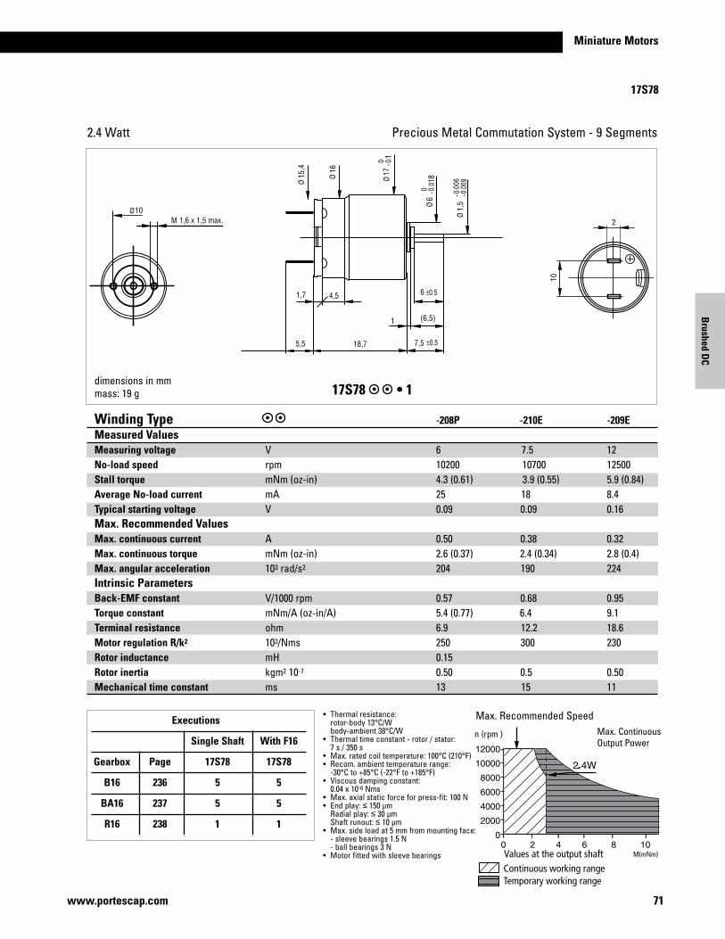
17S78
Precious Metal Commutation System - 9 Segments2.4 Watt
dimensions in mmmass: 19 g 17S78•1
Continuous working rangeTemporary working range
Values at the output shaft
n (rpm )
Winding Type -208P -210E -209EMeasured ValuesMeasuring voltage V 6 7.5 12No-load speed rpm 10200 10700 12500Stall torque mNm(oz-in) 4.3 (0.61) 3.9 (0.55) 5.9 (0.84)Average No-load current mA 25 18 8.4Typical starting voltage V 0.09 0.09 0.16Max. Recommended Values Max. continuous current A 0.50 0.38 0.32Max. continuous torque mNm(oz-in) 2.6 (0.37) 2.4 (0.34) 2.8 (0.4)Max. angular acceleration 103 rad/s2 204 190 224Intrinsic ParametersBack-EMF constant V/1000rpm 0.57 0.68 0.95Torque constant mNm/A(oz-in/A) 5.4 (0.77) 6.4 9.1Terminal resistance ohm 6.9 12.2 18.6Motor regulation R/k2 103/Nms 250 300 230Rotor inductance mH 0.15 Rotor inertia kgm2 10-7 0.50 0.5 0.50Mechanical time constant ms 13 15 11
• Thermalresistance: rotor-body 13°C/W body-ambient 38°C/W• Thermaltimeconstant-rotor/stator: 7 s / 350 s• Max.ratedcoiltemperature:100°C(210°F)• Recom.ambienttemperaturerange: -30°C to +85°C (-22°F to +185°F)• Viscousdampingconstant: 0.04x10⁻⁶Nms• Max.axialstaticforceforpress-fit:100N• Endplay:≤ 150 µm Radialplay:≤ 30 µm Shaftrunout:≤ 10 µm• Max.sideloadat5mmfrommountingface: -sleevebearings1.5N -ballbearings3N• Motorfittedwithsleevebearings
Max.RecommendedSpeedMax.ContinuousOutputPower
Executions
Single Shaft With F16
Gearbox Page 17S78 17S78
B16 236 5 5
BA16 237 5 5
R16 238 1 1
M(mNm)
Brushed D
C

72 www.portescap.com
17N78
Precious Metal Commutation System - 9 Segments 3.2 Watt
Continuous working rangeTemporary working range
Values at the output shaft
n (rpm )
Max.RecommendedSpeedMax.ContinuousOutputPower
1,6M x 1,5 max.
10
6 ±0,5
5,5
2
10
2,8 ±0,1
1 6,5( )
7,5 ±0,525,9
60°6x
1,7 1,515
,4
1,5
-0,0
06-0
,009
6 0 -0
,018
17 0 -0
,1
16 15,9
85 0 -0
,015
17N78 •1
Winding Type -216E -122A -210E -208E -207EMeasured ValuesMeasuring voltage V 6.0 2 12.0 18.0 24.0No-load speed rpm 8500 7000 8500 8500 8900Stall torque mNm(oz-in) 12.5 (1.77) 7.6 (1.08) 9.3 (1.31) 9.4 (1.33) 9.4 (1.33)Average No-load current mA 10.5 60 7.7 4.9 3.5Typical starting voltage V 0.04 0.02 0.08 0.11 0.16Max. Recommended Values Max. continuous current A 0.86 1.5 0.37 0.25 0.19Max. continuous torque mNm(oz-in) 5.69 (0.81) 3.9 (0.55) 4.85 (0.69) 4.89 (0.69) 4.79 (0.68)Max. angular acceleration 103 rad/s2 207 272 243 258 266Intrinsic ParametersBack-EMF constant V/1000rpm 0.70 0.28 1.40 2.10 2.67Torque constant mNm/A(oz-in/A) 6.7 (0.95) 2.67 13.4 (1.89) 20.1 (2.84) 25.5 (3.61)Terminal resistance ohm 3.20 0.7 17.3 38.4 65.0Motor regulation R/k2 103/Nms 72 98 97 95 100Rotor inductance mH 0.11 0.40 0.90 1.41Rotor inertia kgm2 10-7 1.10 0.7 0.80 0.76 0.72Mechanical time constant ms 8 6.9 8 7 7
• Thermalresistance: rotor-body 10°C/W body-ambient 30°C/W• Thermaltimeconstant-rotor/stator: 7 s / 400 s• Max.ratedcoiltemperature:100°C(210°F)• Recom.ambienttemperaturerange: -30°C to +85°C (-22°F to +185°F)• Viscousdampingconstant: 0.04x10⁻⁶Nms• Max.axialstaticforceforpress-fit:100N• Endplay:≤ 150 µm Radialplay:≤ 30 µm Shaftrunout:≤ 10 µm• Max.sideloadat5mmfrommountingface: -sleevebearings1.5N -ballbearings3N• Motorfittedwithsleevebearings (ballbearingsoptional)
Executions
Single Shaft With F16
Gearbox Page 17N78 17N78
B16 236 5 5
BA16 237 5 5
R16 238 1 1
dimensions in mmmass: 27 g
M(mNm)
73www.portescap.com
Miniature Motors
M(mNm)
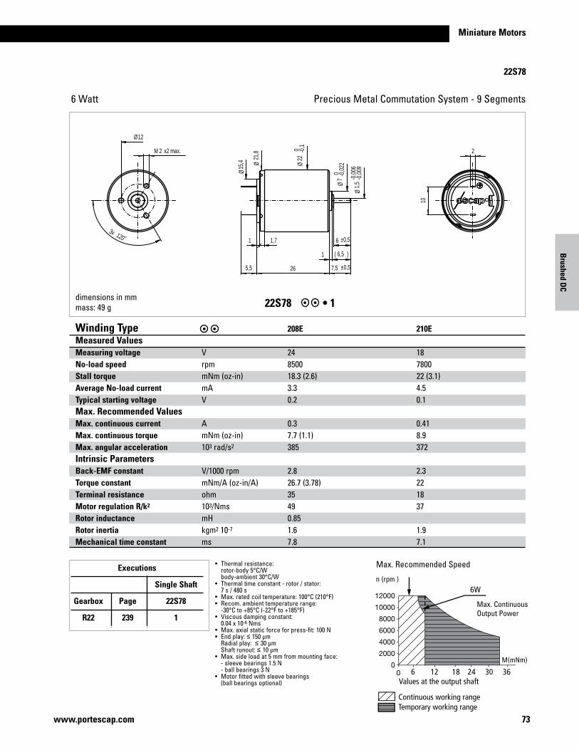
22S78
Precious Metal Commutation System - 9 Segments6 Watt
1 6,5( )
10
22M x2 max.
6 ±0,5
7,5 ±0,55,5 26
120˚3x
1 1,7
12
15,4
1,5
-0,0
06-0
,009
7 0 -0
,022
22 0 -0
,1
21,8
Ø
Ø
Ø Ø
Ø
Ø
dimensions in mmmass: 49 g 22S78 •1
Continuous working rangeTemporary working range
Values at the output shaft
M(mNm)
n (rpm )
6 12 18 24 30 36
6W
Winding Type 208E 210EMeasured ValuesMeasuring voltage V 24 18No-load speed rpm 8500 7800Stall torque mNm(oz-in) 18.3 (2.6) 22 (3.1)Average No-load current mA 3.3 4.5Typical starting voltage V 0.2 0.1Max. Recommended Values Max. continuous current A 0.3 0.41Max. continuous torque mNm(oz-in) 7.7 (1.1) 8.9Max. angular acceleration 103 rad/s2 385 372Intrinsic ParametersBack-EMF constant V/1000rpm 2.8 2.3 Torque constant mNm/A(oz-in/A) 26.7 (3.78) 22 Terminal resistance ohm 35 18 Motor regulation R/k2 103/Nms 49 37 Rotor inductance mH 0.85 Rotor inertia kgm2 10-7 1.6 1.9 Mechanical time constant ms 7.8 7.1
• Thermalresistance: rotor-body 5°C/W body-ambient 30°C/W• Thermaltimeconstant-rotor/stator: 7 s / 480 s• Max.ratedcoiltemperature:100°C(210°F)• Recom.ambienttemperaturerange: -30°C to +85°C (-22°F to +185°F)• Viscousdampingconstant: 0.04x10⁻⁶Nms• Max.axialstaticforceforpress-fit:100N• Endplay:≤ 150 µm Radialplay:≤ 30 µm Shaftrunout:≤ 10 µm• Max.sideloadat5mmfrommountingface: -sleevebearings1.5N -ballbearings3N• Motorfittedwithsleevebearings (ballbearingsoptional)
Max.RecommendedSpeed
Max.ContinuousOutputPower
Executions
Single Shaft
Gearbox Page 22S78
R22 239 1
Brushed D
C

74 www.portescap.com
2.4 4.8 7.2 9.6 12 14.4
22S28
Precious Metal Commutation System - 9 Segments 2.5 Watt
dimensions in mmmass: 49 g 22S28 •1
Winding Type 205E 208E Measured ValuesMeasuring voltage V 24 15 No-load speed rpm 7900 9600 Stall torque mNm(oz-in) 4.9 (0.58) 6.3 (0.89) Average No-load current mA 2.8 6 Typical starting voltage V 0.3 0.2 Max. Recommended Values Max. continuous current A 0.146 0.29 Max. continuous torque mNm(oz-in) 4.1 (0.58) 4.2 (0.59) Max. angular acceleration 103 rad/s2 108 105 Intrinsic ParametersBack-EMF constant V/1000rpm 2.97 1.54 Torque constant mNm/A(oz-in/A) 28.4 14.7 Terminal resistance ohm 140 35 Motor regulation R/k2 103/Nms 170 160 Rotor inductance mH 3.6 0.92 Rotor inertia kgm2 10-7 1.5 1.6 Mechanical time constant ms 26 26
• Thermalresistance: rotor-body 5°C/W body-ambient 30°C/W• Thermaltimeconstant-rotor/stator: 7 s / 480 s• Max.ratedcoiltemperature:100°C(210°F)• Recom.ambienttemperaturerange: -30°C to +85°C (-22°F to +185°F)• Viscousdampingconstant: 0.04x10⁻⁶Nms• Max.axialstaticforceforpress-fit:100N• Endplay:≤ 150 µm Radialplay:≤ 30 µm Shaftrunout:≤ 10 µm• Max.sideloadat5mmfrommountingface: -sleevebearings1.5N -ballbearings3N• Motorfittedwithsleevebearings (ballbearingsoptional)
Max.RecommendedSpeed
Max.ContinuousOutputPower
Executions
Single Shaft
Gearbox Page 22S28
R22 239 1

Miniature Motors
22N28/48
75www.portescap.com
Precious Metal Commutation System - 9 Segments3.8 Watt
22N28 •28622N48 •308
M(
Continuous working rangeTemporary working range
Values at the output shaft
M(mNm)
n (rpm )
Max.RecommendedSpeedMax.ContinuousOutputPower
Executions Single Shaft For F16 For E9 Gearbox Page 22N28 22N28 22N48 R22 239 286 286 308 M22 240 286 286 308 K24 241 286 286 308 K27 242 286 286 308 RG1/8 245 204 204 310 RG1/9 246 204 204 310 K38 244 204 204 310
• Thermalresistance: rotor-body 6°C/W body-ambient 22°C/W• Thermaltimeconstant- rotor / stator: 9 s / 550 s• Max.ratedcoiltemperature: 100°C (210°F)• Recom.ambienttemperature range: -30°C to +65°C (-22°F to +150°F)• Viscousdampingconstant: 0.1x10⁻⁶Nms• Max.axialstaticforcefor press-fit:150N• Endplay:≤ 150 µm Radialplay:≤ 30 µm Shaftrunout:≤ 10 µm• Max.sideloadat5mmfrom mountingface: -sleevebearings3N -ballbearings6N• Motorfittedwithsleeve (ballbearingsoptional)
Winding Type -216P -216E -213E -210E -208E -105Measured ValuesMeasuring voltage V 3.0 6.0 9.0 12.0 18.0 18.0No-load speed rpm 5200 5600 7000 5900 6300 3600Stall torque mNm(oz-in) 10.9 (1.54) 10.6 (1.50) 10.7 (1.51) 8.6 (1.21) 8.2 (1.16) 4.3 (0.61)Average No-load current 1) mA 12.6/27 7.0/14 6.0/11 4.5/9 3.5/7 1.4/3Typical starting voltage 1) V 0.03/0.25 0.05/0.35 0.06/0.45 0.08/0.5 0.12/0.7 0.24/0.90Max. Recommended Values Max. continuous current A 1.50 0.83 0.62 0.38 0.26 0.14Max. continuous torque mNm(oz-in) 8.1 (1.15) 8.4 (1.19) 7.5 (1.06) 7.3 (1.04) 7.0 (0.98) 6.6 (0.93)Max. angular acceleration 103 rad/s2 100 96 107 98 96 132Intrinsic ParametersBack-EMF constant V/1000rpm 0.57 1.07 1.28 2.02 2.83 4.95Torque constant mNm/A(oz-in/A) 5.44 (0.77) 10.2 (1.45) 12.2 (1.73) 19.3 (2.73) 27.0 (3.83) 47.3 (6.69)Terminal resistance ohm 1.50 5.80 10.3 27.0 59.0 200Motor regulation R/k2 103/Nms 51 56 69 73 81 90Rotor inductance mH 0.10 0.35 0.50 1.20 2.30 7.00Rotor inertia kgm2 10-7 3.50 3.50 2.80 3.00 2.90 2.00Mechanical time constant ms 18 19 19 22 23 181)SingleShaft/doubleshaft
Brushed D
C
dimensions in mmmass: 53 g
Maxscrewtorque130mNmMaxtraction300N
max. 5min. 4
33,9
6 ±0,5
7,5 ±0,5
2-0
,006
-0,0
09÷
12 ±0,4
2-0
,006
-0,0
09÷
2M x3 max. 2
10
6 ±0,5
1,64x M x
150
±3
7,5 ±0,55,5
42°
38°
60°6x
1 6,5( )
1,71
1 6,5( )
32
22 0 -0
,1÷
10 0 -0
,022
÷
15,4
÷
1,5
-0,0
06-0
,009
÷
10 0 -0
,022
÷
22 0 -0
,1÷
18,5÷17÷
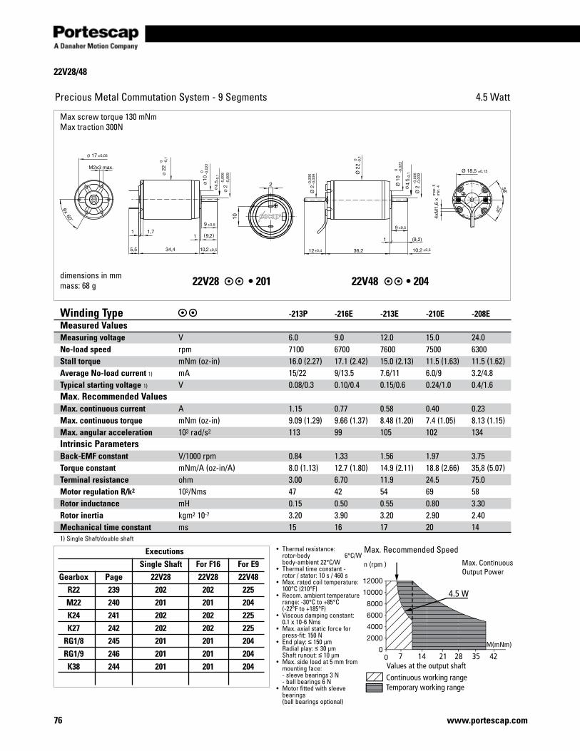
22V28/48
76 www.portescap.com
Precious Metal Commutation System - 9 Segments 4.5 Watt
4.5
4.5
dimensions in mmmass: 68 g 22V28 •20122V48•204
Continuous working rangeTemporary working range
Values at the output shaft
M(mNm)
n (rpm )
7 14 21 28 35 42
4.5 W
• Thermalresistance: rotor-body 6°C/W body-ambient 22°C/W• Thermaltimeconstant- rotor / stator: 10 s / 460 s• Max.ratedcoiltemperature: 100°C (210°F)• Recom.ambienttemperature range: -30°C to +85°C (-22°F to +185°F)• Viscousdampingconstant: 0.1x10⁻⁶Nms• Max.axialstaticforcefor press-fit:150N• Endplay:≤ 150 µm Radialplay:≤ 30 µm Shaftrunout:≤ 10 µm• Max.sideloadat5mmfrom mountingface: -sleevebearings3N -ballbearings6N• Motorfittedwithsleeve bearings (ballbearingsoptional)
Max.RecommendedSpeedExecutions Single Shaft For F16 For E9 Gearbox Page 22V28 22V28 22V48 R22 239 202 202 225 M22 240 201 201 204 K24 241 202 202 225 K27 242 202 202 225 RG1/8 245 201 201 204 RG1/9 246 201 201 204 K38 244 201 201 204
Winding Type -213P -216E -213E -210E -208EMeasured ValuesMeasuring voltage V 6.0 9.0 12.0 15.0 24.0No-load speed rpm 7100 6700 7600 7500 6300Stall torque mNm(oz-in) 16.0 (2.27) 17.1 (2.42) 15.0 (2.13) 11.5 (1.63) 11.5 (1.62)Average No-load current 1) mA 15/22 9/13.5 7.6/11 6.0/9 3.2/4.8Typical starting voltage 1) V 0.08/0.3 0.10/0.4 0.15/0.6 0.24/1.0 0.4/1.6Max. Recommended Values Max. continuous current A 1.15 0.77 0.58 0.40 0.23Max. continuous torque mNm(oz-in) 9.09 (1.29) 9.66 (1.37) 8.48 (1.20) 7.4 (1.05) 8.13 (1.15)Max. angular acceleration 103 rad/s2 113 99 105 102 134Intrinsic ParametersBack-EMF constant V/1000rpm 0.84 1.33 1.56 1.97 3.75Torque constant mNm/A(oz-in/A) 8.0 (1.13) 12.7 (1.80) 14.9 (2.11) 18.8 (2.66) 35,8 (5.07)Terminal resistance ohm 3.00 6.70 11.9 24.5 75.0Motor regulation R/k2 103/Nms 47 42 54 69 58Rotor inductance mH 0.15 0.50 0.55 0.80 3.30Rotor inertia kgm2 10-7 3.20 3.90 3.20 2.90 2.40Mechanical time constant ms 15 16 17 20 141)SingleShaft/doubleshaft
Max.ContinuousOutputPower
Maxscrewtorque130mNmMaxtraction300N

Miniature Motors
77www.portescap.com
Brushed D
C
22N78/98
22N78 22N981001 1005
Precious Metal Commutation System - 9 Segments
•Thermalresistance: rotor-body 6°C/W body-ambient 22°C/W•Thermaltimeconstant– rotor/stator: 9s / 550s•Max.ratedcoiltemperature: 100°C (210°F)•Recom.Ambienttemperature range: -30°C to +65°C (-22°F to +150°F)•Viscousdampingconstant:0.1x10⁻⁶Nms•Maxaxialstaticforceforpress-fit:150N(withsleevebearingonly)•Endplay:≤150μmRadialplay:≤30μmShaftrunout:≤10μm•Max.sideloadat5mmfrom mountingface–sleevebearings3N–ballbearings6N•Motorfittedwithsleevebearings(ballbearingsoptional)
dimensions in mmmass: 53 g
Winding Type Measured Values Measuring voltageNo-load speed Stall torqueAverage No-load current Typical starting voltageMax. Recomended ValuesMax. continuous currentMax. continuous torqueMax. angular accelerationIntrinsic Parameters Back-EMF constantTorque constantTerminal resistanceMotor regulation R/k2
Rotor inductanceRotor inertiaMechanical time constant
VrpmmNmmAV
AmNm103 rad/s2
V/1000rpmmNm/AOhms103/NmsmHkgm2 10-7
ms
324P 3640052.0150.05
3.716.5120
0.474.50.3130.025.457.0
319P 6870066.0100.1
2.415.7130
0.696.60.6140.044.906.8
313P 9680045.0100.1
1.1814.6133
1.3112.52.5160.164.397.0
311P 12730048.070.15
0.9814.8141
1.6415.83.9160.254.206.7
216E 18820049.060.2
0.6713.8117
2.1820.87.7180.504.748.4
215E 24910058.050.3
0.5814.5128
2.6425.210.5170.704.507.4
208E 48640032.010.5
0.1812.9157
7.5072.0107.0217.003.326.9
Max.RecommendedSpeed
3015 45 60
n(rpm)
M(mNm)
9 Watt
Maxtractionforce:300NMaxscrewtorque:130mNm
Executions Single Shaft With MR2 With E9 Gearbox Page 22N78 22N98 22N98 R22 239 1001 1008 1005 M22 240 1001 1008 1005 K24 241 1001 1008 1005 K27 242 1001 1008 1005 RG1/8 245 1007 1009 1006 RG1/9 246 1007 1009 1006 K38 244 1007 1009 1006
thloni

78 www.portescap.com
23L21
Precious Metal Commutation System - 9 Segments 4.2 Watt
10
1,5 11( )
12,534,1
2M x2,2
60°6x
4,6 4,7
23
0 -0,1
10
0 -0,0
22
3-0
,006
-0,0
09
17
23L21 •1
Continuous working rangeTemporary working range
Values at the output shaft
n (rpm )
M(mNm )10 20 30 40
4.2
Winding Type -216E -213E -208E Measured ValuesMeasuring voltage V 9.0 12 24No-load speed rpm 6800 7500 6400Stall torque mNm(oz-in) 16.9 (2.39) 14.9 (2.11) 11.1 (1.57)Average No-load current mA 30 28 11Typical starting voltage V 0.1 0.2 0.5Max. Recommended Values Max. continuous current A 0.77 0.58 0.23Max. continuous torque mNm(oz-in) 9.2 (1.30) 8.2 (1.16) 7.6 (1.08)Max. angular acceleration 103 rad/s2 82 91 87Intrinsic ParametersBack-EMF constant V/1000rpm 1.30 1.55 3.62Torque constant mNm/A(oz-in/A) 12.4 (1.76) 14.8 (2.10) 34.6Terminal resistance ohm 6.6 11.9 75Motor regulation R/k2 103/Nms 43 54 63Rotor inductance mH 0.4 0.55 3.3Rotor inertia kgm2 10-7 4.5 3.6 3.5Mechanical time constant ms 19 20 22
• Thermalresistance: rotor-body 7°C/W body-ambient 16°C/W• Thermaltimeconstant-rotor/stator: 12 s / 460 s • Max.ratedcoiltemperature:100°C• Recom.ambienttemperaturerange: -30°C to +85°C (-22°F to 285°F)• Max.axialstaticforceforpress-fit:250N• Endplay:≤ 150 µm Radialplay:≤ 18 µm Shaftrunout:≤ 10 µm• Max.sideloadat5mmfrommountingface: -sleevebearings6N -ballbearings8N• Motorexec.•1fittedwithsleevebearings (ballbearingsoptional)
Max.RecommendedSpeedMax.ContinuousOutputPower
dimensions in mmmass: 70 g

Miniature Motors
79www.portescap.com
Brushed D
C
Executions Single Shaft Gearbox Page 23LT12-- R22 239 K24 241 5 K27 242 5 K38 244 18 RG1/8 245 20 RG1/9 246 22
23LT12
Graphite/CopperCommutationSystem-9Segments8.4 Watt
23LT12 •1
Values at the output shaftContinuous working rangeTemporary working range
0 4.455 8.911 13.37 17.82 22.28 26.73 31.19 35.64
n (rpm)12000
10000
8000
6000
4000
2000
0
Winding Type 216E 213E Measured ValuesMeasuring voltage V 12 15 No-load speed rpm 8800 9000 Stall torque mNm(oz-in) 22 (3.1) 18.3 (2.6) Average No-load current mA 90 80 Typical starting voltage V -- -- Max. Recommended Values Max. continuous current A 0.92 0.69 Max. continuous torque mNm(oz-in) 10.3 (1.46) 9 (1.27) Max. angular acceleration 103 rad/s2 109 55 Intrinsic ParametersBack-EMF constant V/1000rpm 1.3 1.55 Torque constant mNm/A(oz-in/A) 12.4 14.8 Terminal resistance ohm 6.9 12.2 Motor regulation R/k2 103/Nms 45 55 Rotor inductance mH 0.4 0.55 Rotor inertia kgm2 10-7 4.7 3.8 Mechanical time constant ms 21 21
• Thermalresistance: rotor-body 7 °C/W body-ambient 16 °C/W• Thermaltimeconstant- rotor / stator: 12s/460s• Max.ratedcoiltemperature:155°C• Recom.ambienttemperature range: -30°C to +125°C (-22°F to +257°F)• Max.axialstaticforceforpress-fit:250N• Endplay:≤ 150 µm Radialplay:≤ 30 µm Shaftrunout:≤ 10 µm• Max.sideloadat5mmfrommountingface -sleevebearings6N• Motorfittedwithballbearings
Max.RecommendedSpeed
dimensions in mmmass: 70 g
M(mNm)

80 www.portescap.com
23V58 & 23V48
Executions Single Shaft For E9 Gearbox Page 23V58 23V48 R22 239 4 11 M22 240 4 11 K24 241 4 11 K27 242 4 11 RG1/8 245 1 9 RG1/9 246 1 9 K38 244 1 9
Precious Metal Commutation System - 9 Segments 6.5 Watt
dimensions in mmmass: 100 g 23V58 •1 23V48•9
Continuous working rangeTemporary working range
Values at the output shaft
n (rpm )
M(mNm )
6.5 W
• Thermalresistance: rotor-body 5°C/W body-ambient 12°C/W• Thermaltimeconstant-rotor/stator: 10 s / 580 s• Max.ratedcoiltemperature:100°C• Recom.ambienttemperaturerange: -30°C to +85°C (-22°F to +185°F)• Viscousdampingconstant:0.45x10⁻⁶Nms• Max.axialstaticforceforpress-fit:250N• Endplay:≤ 150 µm Radialplay:≤30 µm Shaftrunout:≤ 10 µm• Max.sideloadat5mmfrommountingface: -sleevebearings6N -ballbearings8N• Motorfittedwithsleevebearings (ballbearingsoptional)• Withrearoutputshaft,theN-loadcurrentis 50%higher
Max.RecommendedSpeed
Winding Type -216P -216E -210EMeasured ValuesMeasuring voltage V 6.0 12.0 24 No-load speed rpm 4500 4800 6400 Stall torque mNm(oz-in) 31 (4.4) 29 (4.1) 23 (3.3)Average No-loadcurrent mA 30.8 18.7 16.5Typical starting voltage V 0.05 0.13 10.2 Max. Recommended ValuesMax. continuous current A 1.49 0.75 0.39 Max. continuous torque mNm(oz-in) 18.2 (2.6) 17.2 (2.4) 13 (1.84) Max. angular acceleration 103 rad/s2 123 116 140Intrinsic ParametersBack-EMF constant V/1000rpm 1.31 2.47 3.64 Torque constant mNm/A(oz-in/A) 12.5 (1.7) 23.5 (3.33) 34.8Terminal resistance ohm 2.45 9.7 35.77 Motor regulation R/k2 103/Nms 16 17 30 Rotor inductance mH 0.20 0.80 1.7 Rotor inertia kgm2 10-7 5.90 5.90 3.7 Mechanical time constant ms 9 10 11
Max.ContinuousOutputPower
max. 5min. 4
150
±3
2 0 -0
,006
÷
12 ±0,4
1,5
3,2
2M x 2,3max.
3-0
,006
-0,0
09÷
10,6
3
17,5
1,64x M x
47,648,8
3-0
,006
-0,0
09÷
10,6
11( )
12,5±0,5
11( )
12,5±0,5
60°6x
38°
42°
1,8 2,7
1,5
18,5÷17÷
10 0 -0
,022
÷
23 0 -0
,1÷
10 0 -0
,022
÷
23 0 -0
,1÷

81www.portescap.com
Miniature Motors
23GST82
Graphite/CopperCommutationSystem-9Segments18 Watt
Continuous working rangeTemporary working range
M(mNm)
n (rpm )
18 W
20 40 60 80 100 120
• Thermalresistance: rotor-body 7°C/W body-ambient 16°C/W• Thermaltimeconstant-rotor/stator: 12 s / 460 s • Max.ratedcoiltemperature:155°C• Recom.ambienttemperaturerange: -30°C to +125°C (-22°F to +257°F)• Max.axialstaticforceforpress-fit:250N• Endplay:≤ 150 µm Radialplay:≤ 30 µm Shaftrunout:≤ 10 µm• Max.sideloadat5mmfrommountingface: -sleevebearings6N• Motorfittedwithballbearings
Max.RecommendedSpeedMax.ContinuousOutputPower
dimensions in mmmass: 80 g 23GST2R82 •123GST2R82 •223GST2R82 •3
Winding Type -216P -216E Measured ValuesMeasuring voltage V 12 24 No-load speed rpm 8700 9100 Stall torque mNm(oz-in) 80 (11.3) 87 (12.3) Average No-load current mA 90 60 Typical starting voltage V - - Max. Recommended Values Max. continuous current A 1.7 0.9 Max. continuous torque mNm(oz-in) 21 (3.0) 22 (3.1) Max. angular acceleration 103 rad/s2 226 231 Intrinsic ParametersBack-EMF constant V/1000rpm 1.36 2.61 Torque constant mNm/A(oz-in/A) 13 (1.84) 25 (3.53) Terminal resistance ohm 1.95 6.85 Motor regulation R/k2 103/Nms 12 (0.1) 11 (0.4) Rotor inductance mH Rotor inertia kgm2 10-7 4.7 4.7 Mechanical time constant ms 5.4 5.2
Executions Single Shaft For E9 Gearbox Page 23GST82 23GST82 R22 239 2 -- M22 240 2 -- K27 242 2 -- RG1/8 245 1 3 RG1/9 246 1 3 K38 244 1 3
23GST2R .323GST .223GST .1
max. 2,8min. 2
168
±3
1,64x M
39,212 ±0,3 12,5 ±0,3
11( )
10
1,51,5
7,5 ±0,3
5,1
2M x 2,2 max.
5,7
2 36
1,5
10
11( )
12,5 ±0,3
40°
40°
60°6x
6( )
3-0
,006
-0,0
09÷ 3
-0,0
06-0
,009
÷
10 0 -0
,022
÷
35,1
23 0 -0
,1÷
2 0 -0
,006
÷
10 0 -0
,022
÷
17÷
3-0
,006
-0,0
09÷
10 0 -0
,022
÷
18,5÷
23 0 -0
,1÷22
0 -0,1
÷
23 0 -0
,1÷
Brushed D
C

82 www.portescap.com
23HL
Precious Metal Commutation System - 9 Segments 4.2 Watt
23HL 21. (1) •1
Continuous working rangeTemporary working range
Values at the output shaft
n (rpm )
M(mNm )10 20 30 40
4.2
Winding Type -216E -213E Measured ValuesMeasuring voltage V 9.0 12 No-load speed rpm 6800 7500 Stall torque mNm(oz-in) 16.9 (2.39) 14.9 (2.11) Average No-load current mA 30 28 Typical starting voltage V 0.1 0.2 Max. Recommended Values Max. continuous current A 0.77 0.58 Max. continuous torque mNm(oz-in) 9.2 (1.31) 8.2 (1.16) Max. angular acceleration 103 rad/s2 82 91Intrinsic ParametersBack-EMF constant V/1000rpm 1.30 1.55 Torque constant mNm/A(oz-in/A) 12.4 (1.76) 14.8 (2.10) Terminal resistance ohm 6.6 11.9Motor regulation R/k2 103/Nms 43 54 Rotor inductance mH 0.4 0.55 Rotor inertia kgm2 10-7 4.5 3.6 Mechanical time constant ms 19 20
• Thermalresistance: rotor-body 7°C/W body-ambient 16°C/W• Thermaltimeconstant-rotor/stator: 12 s / 460 s • Max.ratedcoiltemperature:100°C• Recom.ambienttemperaturerange: -30°C to +85°C (-22°F to 285°F)• Max.axialstaticforceforpress-fit:250N• Endplay:≤ 150 µm Radialplay:≤ 18 µm Shaftrunout:≤ 10 µm• Max.sideloadat5mmfrommountingface: -sleevebearings6N -ballbearings8N• Motorexec.•1fittedwithsleevebearings (ballbearingsoptional)
Max.RecommendedSpeedMax.ContinuousOutputPower
dimensions in mmmass: 184 g
Contact Portescap for Tacho specifications.

Miniature Motors
83www.portescap.com
Brushed D
C
25GST2R82
Graphite/CopperCommutationSystem-9Segments27 Watt
25GST2R82 •125GST2R82 •2
• Thermalresistance: rotor-body 6°C/W body-ambient 13°C/W• Thermaltimeconstant-rotor/stator: 10 s / 450 s• Max.ratedcoiltemperature:155°C• Recom.ambienttemperaturerange: -30°C to +125°C (-22°F to +257°F)• Max.axialstaticforceforpress-fittingwithout holdingshaft(sleeve/ballb.)500N/68N• Axial/radialplay(ballbearings)neglectable• Maxaxial/radialplay(sleeveb.)150µm/30µm•Shaftrunout:≤ 10 µm• Max.sideloadat5mmfrommountingface: -sleevebearings6N -ballbearings12N• Motorfittedwithballbearings• 83Communicationisrecommended forservoapplications• Forfilteradd`f`todesignation beforethecoil
Max.RecommendedSpeed
dimensions in mmmass: 111 g
Max.ContinuousOutputPower
Winding Type -219P -230E -216P -216E Measured ValuesMeasuring voltage V 18 18 24 35 No-load speed rpm 11100 11400 10300 7800 Stall torque mNm(oz-in) 172 (24) 206 (29) 160 (25) 161 (23) Average No-load current 1) mA 110 110 70 118 Typical starting voltage 1) V -- -- -- -- Max. Recommended Values Max. continuous current A 2.1 2.3 1.45 0.75 Max. continuous torque mNm(oz-in) 30 (4.2) 33 (4.7) 30 (4.2) 30 (4.2) Max. angular acceleration 103 rad/s2 151 164 152 148 Intrinsic ParametersBack-EMF constant V/1000rpm 1.6 1.56 2.3 4.4 Torque constant mNm/A(oz-in/A) 15.3 (2.16) 14.9 (2.11) 22 (3.11) 42 (5.9) Terminal resistance ohm 1.6 1.3 3.3 12.5 Motor regulation R/k2 103/Nms 6.9 5.9 6.8 7.1 Rotor inductance mH 0.08 0.1 0.1 0.8 Rotor inertia kgm2 10-7 10 10 10 10 Mechanical time constant ms 6.9 5.9 6.8 7.11)SingleShaft/doubleshaft
÷18,5
4x ÷1,2 x 4,8
25GST 2R .225GST 2R .1
5,5 0,5
33
0,7
2M x 2,7 max.
29
2,8
43,5
3-0
,006
-0,0
09÷
12 ±0,2
0,7
11,5( )1
12,5 ±0,1
3-0
,006
-0,0
09÷
40°
40°
6x60°
10 0 -0
,02
÷
÷25
0 -0,1
43,5
÷17
10 0 -0
,02
÷
10 0 -0
,02
÷
Executions Single Shaft For E9 HED5 Gearbox Page 25GST2R82 25GST2R82 25GST2R82 RG1/8 245 1 2 4 RG1/9 246 1 2 4 K38 244 1 2 4 R32 243 1 2 4 M22 240 5 6 --

25GT2R82
84 www.portescap.com
40 WattGraphite/CopperCommunicationSystem-9Segments
25GT2R82 •125GT2R82 •2
M(mNm)
Continuous working rangeTemporary working range
Values at the output shaft
40 W n (rpm )
0 40 80 120 160 200 240
• Thermalresistance: rotor-body 5°C/W body-ambient 11°C/W• Thermaltimeconstant-rotor/stator: 10 s / 450 s• Max.ratedcoiltemperature:155°C• Recom.ambienttemperaturerange: -30°C to +125°C (-22°F to +257°F)• Max.axialstaticforceforpress-fittedwithout holdingshaft(sleeve/ballb.)500N/100N• Axial/radialplay(ballbearings)neglectable• Maxaxial/radialplay(sleeveb.)150µm/30µm• Shaftrunout:≤ 10 µm• Max.sideloadat5mmfrommountingface: -sleevebearings8N -ballbearings25N• Motorfittedwithballbearings (sleevebearingsoptional)• 83Communicationisrecommended forservoapplications
Max.RecommendedSpeed
Winding Type -222E -222P -219P -219EMeasured ValuesMeasuring voltage V 15 18 24 36 No-load speed rpm 4130 9500 10300 8300 Stall torque mNm(oz-in) 129 (18.3) 249 (35) 258 (37) 200(28) Average No-load current 1) mA 30 140 120 65 Typical starting voltage 1) V -- -- -- --Max. Recommended Values Max. continuous current A 1.44 2.5 2 1.06 Max. continuous torque mNm(oz-in) 48 (6.8) 42 (5.9) 41 (5.8) 41 (5.8)Max. angular acceleration 103 rad/s2 186 165 160 157Intrinsic ParametersBack-EMF constant V/1000rpm 3.6 1.88 2.3 4.3 Torque constant mNm/A(oz-in/A) 34.4 (4.87) 18 (2.54) 22 (3.11) 41.1 (5.89) Terminal resistance ohm 4.2 1.3 2.05 7.4 Motor regulation R/k2 103/Nms 3.4 4 4.2 4.4 Rotor inductance mH 0.3 0.08 0.14 0.5 Rotor inertia kgm2 10-7 13 13 13 13 Mechanical time constant ms 4.4 5.2 5.5 5.7 1)SingleShaft/doubleshaft
dimensions in mmmass: 145 g
Max.ContinuousOutputPower
Executions Single Shaft For E9 HED5 Gearbox Page 25GT2R82 25GT2R82 25GT2R82 K40 247 6 8 -- R32 243 6 8 -- R40 248 1 2 4
0,52,8
29
11
12 ±0,2 53,45 12,5 ±0,1
1 11,5( ) 1,24x ÷ x4,8
3M x 3,3 max.
12,5 ±0,1
1 11,5( )
53,455,5
40°
40°
60°6x
0,7 3
0,7 3
3 0 -0
,006
÷
4-0
,006
-0,0
09÷10
0 -0,0
2÷
14 0 -0
,02
÷
25 0 -0
,1÷
18,5÷10
0 -0,0
2÷
25 0 -0
,1÷
20÷
14 0 -0
,02
÷ 4-0
,006
-0,0
09÷

Miniature Motors
85www.portescap.com
Brushed D
C
26N58/26N48
Precious Metal Commutation System - 9 Segments5.7 Watt
dimensions in mmmass: 114 g 26N58 •126N48 •6
Continuous working rangeTemporary working range
Values at the output shaft
n (rpm )
M (mNm )
Winding Type -216P -216E -113 -110Measured ValuesMeasuring voltage V 6 12 15 24No-load speed rpm 4500 4700 5500 6700Stall torque mNm(oz-in) 29.6 (4.19) 28.6 (4.06) 25 (3.5) 25 (3.54)Average No-load current mA 31 16 15 20Typical starting voltage V 0.08 0.15 0.2 0.28Max. Recommended Values Max. continuous current A 1.47 0.74 0.60 0.41Max. continuous torque mNm(oz-in) 17.9 (2.5) 17.3 (2.4) 15.1 (2.1) 13.3 (1.88)Max. angular acceleration 103 rad/s2 119 115 100 89Intrinsic ParametersBack-EMF constant V/1000rpm 1.29 2.5 2.7 3.5Torque constant mNm/A(oz-in/A) 12.3 (1.74) 23.9 (3.38) 25.8 (3.65) 33.5 (4.74)Terminal resistance ohm 2.5 10 15.2 32Motor regulation R/k2 103/Nms 16 18 23 29Rotor inductance mH 0.2 0.8 1.1 1.7Rotor inertia kgm2 10-7 6 6 6.7 6Mechanical time constant ms 9.7 11 14 17
• Thermalresistance: rotor-body 5°C/W body-ambient 12°C/W• Thermaltimeconstant- rotor / stator: 10 s / 640 s• Max.ratedcoiltemperature: 100°C (210°F)• Recom.ambienttemperature range: -30°C to +85°C (-22°F to +185°F)• Viscousdampingconstant: 0.45x10⁻⁶Nms• Max.axialstaticforcefor press-fit:250N• Endplay:≤ 150 µm Radialplay:≤ 30 µm Shaftrunout:≤ 10 µm• Max.sideloadat5mm frommountingface: -sleevebearings6N -ballbearings8N• Motorfittedwithsleeve bearings(ballbearingsoptional)
Max.RecommendedSpeedMax.ContinuousOutputPower
Executions Single Shaft Double Shaft for E9 Gearbox Page 26N58-- 26N48-- R22 239 5 9 M22 240 5 9 K24 241 5 9 K27 242 5 9 RG1/8 245 1 6 RG1/9 246 1 6 K38 244 1 6
max. 5min. 41,64xM x
150
±3
17,5
3
12,5±0,5
11( )
10,6
3-0
,006
-0,0
09÷
43,3 42,1
10,6
3-0
,006
-0,0
09÷
2M x 2,3 max.
3,2
1,5
12 ±0,4
2 0 -0
,006
÷
12,5 ±0,5
11( )
42°
38°
60°6x
1,5
2,71,8
18,5÷
26 0 -0
,1÷
10 0 -0
,022
÷
26 0 -0
,1÷
10 0 -0
,022
÷
17÷

28L28
86 www.portescap.com
Precious Metal Commutation System - 9 Segments 11 Watt
Max.RecommendedSpeedMax.ContinuousOutputPower
dimensions in mmmass: 125 g 28L28 •4928L28 •164
Winding Type -219 -416E -413E -410E -410Measured ValuesMeasuring voltage V 12.0 24.0 28.0 36.0 36.0No-load speed rpm 5300 5600 5300 5000 5000Stall torque mNm(oz-in) 43 (6.11) 50 (7.08) 42 (5.96) 34 (4.87) 34 (4.87)Average No-load current mA 22.0 11.0 8.8 6.6 6.6Typical starting voltage V 0.10 0.15 0.20 0.40 0.40Max. Recommended Values Max. continuous current A 0.95 0.53 0.40 0.28 0.28Max. continuous torque mNm(oz-in) 19.9 (2.82) 21.0 (2.97) 19.7 (2.78) 18.3 (2.58) 18.3 (2.58)Max. angular acceleration 103 rad/s2 77 48 58 67 67Intrinsic ParametersBack-EMF constant V/1000rpm 2.24 4.26 5.20 7.1 7.1Torque constant mNm/A(oz-in/A) 21.4 (3.03) 40.7 (5.76) 49.7 (7.03) 67.8 (9.60) 67.8 (9.60)Terminal resistance ohm 5.95 19.5 33.0 71.0 71.0Motor regulation R/k2 103/Nms 13 12 13 15 15Rotor inductance mH 0.50 2.40 3.20 7.1 7.1Rotor inertia kgm2 10-7 10.40 17.50 13.50 11.00 11.00Mechanical time constant ms 14 21 18 17 17
• Thermalresistance: rotor-body 5 °C/W body-ambient 12 °C/W• Thermaltime constant - rotor / stator: 20 s / 760 s• Max.ratedcoil temperature:100°C (210°F)• Recom.ambient temperaturerange: -30°C to +85°C (-22°F to +185°F)• Viscousdamping constant:0.5x10⁻⁶ Nms
Executions Single Shaft Double Shaft for E9 Gearbox Page 28L28 28L18 R22 239 164 317 M22 240 164 317 RG1/8 245 49 315 RG1/9 246 49 315 R32 243 49 315 K38 244 49 315 K40 247 49 315
150
±3
7
2M x 3,6 max.
10
43,5
2 2
43,5
7
5,1
(11)
12,5 ±0,2 7,5 ±0,2
60°6x
1,5 6( )1,5
10 0
-0,0
15÷
280 -0
,1÷
17÷
3-0
,006
-0,0
09÷
10 0
-0,0
15÷ 2
0 -0,0
06÷
280 -0
,1÷

Miniature Motors
87www.portescap.com
Winding Type -219 -416E -413E -410E -410Measured ValuesMeasuring voltage V 12.0 24.0 28.0 36.0 36.0No-load speed rpm 5300 5600 5300 5000 5000Stall torque mNm(oz-in) 43 (6.11) 50 (7.08) 42 (5.96) 34 (4.87) 34 (4.87)Average No-load current mA 22.0 11.0 8.8 6.6 6.6Typical starting voltage V 0.10 0.15 0.20 0.40 0.40Max. Recommended Values Max. continuous current A 0.95 0.53 0.40 0.28 0.28Max. continuous torque mNm(oz-in) 19.9 (2.82) 21.0 (2.97) 19.7 (2.78) 18.3 (2.58) 18.3 (2.58)Max. angular acceleration 103 rad/s2 77 48 58 67 67Intrinsic ParametersBack-EMF constant V/1000rpm 2.24 4.26 5.20 7.1 7.1Torque constant mNm/A(oz-in/A) 21.4 (3.03) 40.7 (5.76) 49.7 (7.03) 67.8 (9.60) 67.8 (9.60)Terminal resistance ohm 5.95 19.5 33.0 71.0 71.0Motor regulation R/k2 103/Nms 13 12 13 15 15Rotor inductance mH 0.50 2.40 3.20 7.1 7.1Rotor inertia kgm2 10-7 10.40 17.50 13.50 11.00 11.00Mechanical time constant ms 14 21 18 17 17
Brushed D
C
Executions Single Shaft Double Shaft for E9 Gearbox Page 28LT12-- 28LT12-- R22 239 164 -- M22 240 164 -- RG1/8 245 49 316 RG1/9 246 49 316 R32 243 49 316 K38 244 49 316 K40 247 49 316
28LT12
Graphite/CopperCommutationSystem-9Segments21 Watt
°
°
°
28LT12 •4928LT12 •316
Winding Type -219 -416EMeasured ValuesMeasuring voltage V 18.0 32.0No-load speed rpm 7900 7400Stall torque mNm(oz-in) 63 (8.86) 65 (9.26)Average No-load current mA 65.0 35.0Typical starting voltage V -- --Max. Recommended Values Max. continuous current A 1.13 0.63Max. continuous torque mNm(oz-in) 22.8 (3.23) 24.2 (3.42)Max. angular acceleration 103 rad/s2 107 68Intrinsic ParametersBack-EMF constant V/1000rpm 2.24 4.26Torque constant mNm/A(oz-in/A) 21.4 (3.03) 40.7 (5.76)Terminal resistance ohm 6.15 19.9Motor regulation R/k2 103/Nms 13 12Rotor inductance mH 0.50 2.40Rotor inertia kgm2 10-7 10.70 17.80Mechanical time constant ms 14 21
• Thermalresistance: rotor-body 5 °C/W body-ambient 12 °C/W• Thermaltimeconstant- rotor / stator: 17s / 760 s• Max.ratedcoiltemperature: 155°C (210°F)• Recom.ambienttemperature range: -30°C to +125°C (-22°F to +257°F)• Viscousdampingconstant: 0.5x10⁻⁶Nms• Max.axialstaticforcefor press-fit:250N• Endplay:≤ 150 µm Radialplay:≤ 18 µm Shaftrunout:≤ 10 µm• Max.sideloadat5mm frommountingface -sleevebearings6N -ballbearings8N• Motorfittedwithsleeve bearings (ball bearings optional)• OptionalRFIfilters
Max.RecommendedSpeedMax.ContinuousOutputPower
dimensions in mmmass: 135 g
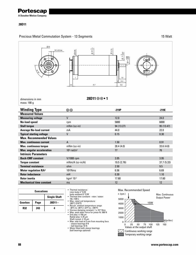
28D11
88 www.portescap.com
Precious Metal Commutation System - 13 Segments 15 Watt
Max.RecommendedSpeedMax.ContinuousOutputPower
°
dimensions in mmmass: 190 g
28D11 •1
Winding Type -219P -219EMeasured ValuesMeasuring voltage V 12.0 24.0No-load speed rpm 5800 6000Stall torque mNm(oz-in) 94 (13.27) 95 (13.47)Average No-load current mA 44.0 22.0Typical starting voltage V 0.15 0.30Max. Recommended Values Max. continuous current A 1.50 0.91Max. continuous torque mNm(oz-in) 28.4 (4.0) 33.6 (4.8)Max. angular acceleration 103 rad/s2 77 76Intrinsic Parameters Back-EMF constant V/1000rpm 2.05 3.95Torque constant mNm/A(oz-in/A) 19.5 (2.76) 37.7 (5.33)Terminal resistance ohm 2.50 9.5Motor regulation R/k2 103/Nms 6.56 6.69Rotor inductance mH 0.30 1.10Rotor inertia kgm2 10-7 17.60 17.60Mechanical time constant ms 12 12
• Thermalresistance: rotor-body 4 °C/W body-ambient 8 °C/W• Thermaltimeconstant-rotor/stator: 18s / 630 s• Max.ratedcoiltemperature: 100°C (210°F)• Recom.ambienttemperaturerange: -30°C to +85°C (-22°F to +185°F)• Viscousdampingconstant:1x10⁻⁶Nms• Max.axialstaticforceforpress-fit:500N• Endplay:≤ 150 µm Radialplay:≤ 25 µm Shaftrunout:≤ 10 µm• Max.sideloadat5mmfrommountingface -sleevebearings8N -ballbearings10N• Motorfittedwithsleevebearings (ballbearingsoptional)
Executions
Single Shaft
Gearbox Page 28D11--
R32 243 4
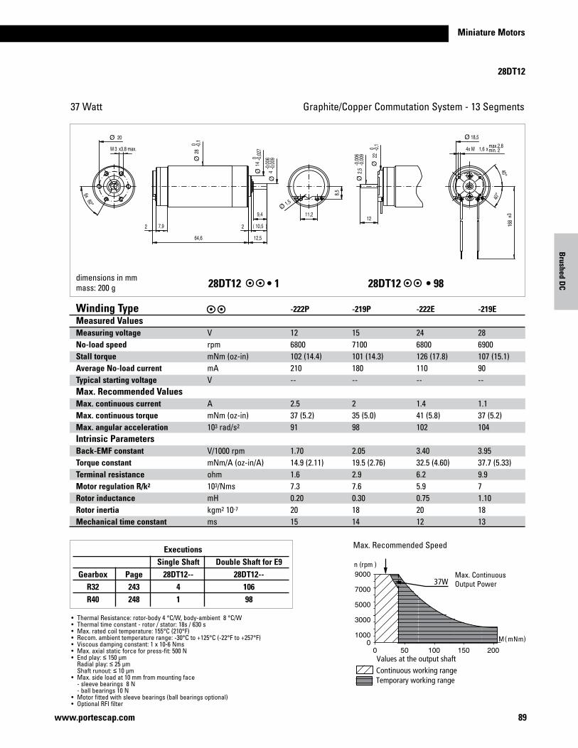
Miniature Motors
89www.portescap.com
28DT12
Graphite/CopperCommutationSystem-13Segments37 Watt
°
°
°
dimensions in mmmass: 200 g28DT12 •128DT12 •98
Winding Type -222P -219P -222E -219EMeasured ValuesMeasuring voltage V 12 15 24 28No-load speed rpm 6800 7100 6800 6900Stall torque mNm(oz-in) 102 (14.4) 101 (14.3) 126 (17.8) 107 (15.1)Average No-load current mA 210 180 110 90Typical starting voltage V -- -- -- --Max. Recommended Values Max. continuous current A 2.5 2 1.4 1.1Max. continuous torque mNm(oz-in) 37 (5.2) 35 (5.0) 41 (5.8) 37 (5.2)Max. angular acceleration 103 rad/s2 91 98 102 104Intrinsic ParametersBack-EMF constant V/1000rpm 1.70 2.05 3.40 3.95Torque constant mNm/A(oz-in/A) 14.9 (2.11) 19.5 (2.76) 32.5 (4.60) 37.7 (5.33)Terminal resistance ohm 1.6 2.9 6.2 9.9Motor regulation R/k2 103/Nms 7.3 7.6 5.9 7Rotor inductance mH 0.20 0.30 0.75 1.10Rotor inertia kgm2 10-7 20 18 20 18Mechanical time constant ms 15 14 12 13
• ThermalResistance:rotor-body4°C/W,body-ambient8°C/W• Thermaltimeconstant-rotor/stator:18s/630s• Max.ratedcoiltemperature:155°C(210°F)• Recom.ambienttemperaturerange:-30°Cto+125°C(-22°Fto+257°F)• Viscousdampingconstant:1x10⁻⁶Nms• Max.axialstaticforceforpress-fit:500N• Endplay:≤ 150 µm Radialplay:≤ 25 µm Shaftrunout:≤ 10 µm• Max.sideloadat10mmfrommountingface -sleevebearings8N -ballbearings10N• Motorfittedwithsleevebearings(ballbearingsoptional)• OptionalRFIfilter
Max.RecommendedSpeed
Max.ContinuousOutputPower
Executions Single Shaft Double Shaft for E9 Gearbox Page 28DT12-- 28DT12-- R32 243 4 106 R40 248 1 98
Brushed D
C

90 www.portescap.com
Executions Single Shaft Double Shaft for E9 Gearbox Page 28HL-- 28HL-- R22 239 164 317 M22 240 164 317 RG1/8 245 49 315 RG1/9 246 49 315 R32 243 49 315 K38 244 49 315 K40 247 49 315
28HL
Precious Metal Commutation System - 9 Segments 11 Watt
28HL •4928HL •164
Values at the output shaftContinuous working rangeTemporary working range
n (rpm)
8000
6000
4000
2000
00 15 30 45 60 75 90
11W
M(mNm)
Winding Type -219 -416EMeasured ValuesMeasuring voltage V 12.0 24.0No-load speed rpm 5300 5600Stall torque mNm(oz-in) 43 (8.86) 50 (7.08)Average No-load current mA 22.0 11.0Typical starting voltage V 0.10 0.15Max. Recommended Values Max. continuous current A 0.95 0.53Max. continuous torque mNm(oz-in) 19.9 (2.82) 21.0 (2.97)Max. angular acceleration 103 rad/s2 77 48Intrinsic ParametersBack-EMF constant V/1000rpm 2.24 4.26Torque constant mNm/A(oz-in/A) 21.4 (3.03) 40.7 (5.76)Terminal resistance ohm 6.15 19.5Motor regulation R/k2 103/Nms 13 12Rotor inductance mH 0.50 2.40Rotor inertia kgm2 10-7 10.70 17.50Mechanical time constant ms 14 21
• Thermalresistance: rotor-body 5 °C/W body-ambient 12 °C/W• Thermaltimeconstant- rotor / stator: 20s / 760 s• Max.ratedcoiltemperature: 100°C (210°F)• Recom.ambienttemperature range: -30°C to +85°C (-22°F to +185°F)• Viscousdampingconstant: 0.5x10⁻⁶Nms
Max.RecommendedSpeedMax.ContinuousOutputPower
dimensions in mmmass: 125 g
Contact Portescap for Tacho specifications.

Miniature Motors
30GT2R82
91www.portescap.com
Graphite/CopperCommutationSystem-13Segments83 Watt
Max.RecommendedSpeedMax.ContinuousOutputPower
dimensions in mmmass: 310 g 30GT2R82 •430GT2R82 •5
Winding Type -234P -234EMeasured ValuesMeasuring voltage V 15 35No-load speed rpm 7100 8600Stall torque mNm(oz-in) 628 (89) 847 (121)Average No-load current mA 180 90Typical starting voltage V -- --Max. Recommended Values Max. continuous current A 4.5 2.5Max. continuous torque mNm(oz-in) 87 (12.3) 93 (13.2)Max. angular acceleration 103 rad/s2 133 139Intrinsic ParametersBack-EMF constant V/1000rpm 2 4.05Torque constant mNm/A(oz-in/A) 20.1 (2.84) 38.7 (5.5)Terminal resistance ohm 0.48 1.6Motor regulation R/k2 103/Nms 1.2 1.1Rotor inductance mH 0.06 0.24Rotor inertia kgm2 10-7 33 33Mechanical time constant ms 3.9 3.5
• ThermalResistance: rotor-body 4.5 °C/W body-ambient 9.0 °C/W• Thermaltimeconstant-rotor/stator: 40s / 920 s• Max.ratedcoiltemperature:155°C• Recom.ambienttemperaturerange: -30°C to +125°C (-22°F to +257°F)• Max.axialstaticforceforpress-fit:100N• Endplay:negligible Radialplay:negligible Shaftrunout:≤ 10 µm• Max.sideloadat10mmfrommountingface -ballbearings35N• Motorfittedwithballbearings• 83Commutationisrecommendedforservo applications• Forfilteradd‘F’todesignationbeforecoil• OnrequestavailablewithHPencoderandbrake
Executions Single Shaft For E9 Gearbox Page 30GT2R82 R32 243 4 5 R40 248 4 5
Brushed D
C

35NT2R32
92 www.portescap.com
Graphite/CopperCommutationSystem-13Segments 52 Watt
scale: 3:4dimensions in mmmass: 310 g35NT2R32•135NT2R32•50
Continuous working rangeTemporary working range
Values at the output shaft
M (mNm)
n (rpm)
0 100 200 300
9000
7000
5000
3000
10000
52 W
Winding Type -228P -228E -416SP Measured ValuesMeasuring voltage V 9.0 15.0 24.0 No-load speed rpm 4990 4320 4370 Stall torque mNm(oz-in) 151 (21) 148 (20.89) 149 (21.11)Average No-load current mA 180 90.0 50.0 Typical starting voltage V -- -- -- Max. Recommended Values Max. continuous current A 3.3 1.87 1.18 Max. continuous torque mNm(oz-in) 52 (7.4) 57.9 (8.2) 58.3 (8.3) Max. angular acceleration 103 rad/s2 54 56 55 Intrinsic ParametersBack-EMF constant V/1000rpm 1.76 3.40 5.40 Torque constant mNm/A(oz-in/A) 16.8 (2.38) 32.5 (4.60) 51.6 (7.30) Terminal resistance ohm 1.0 3.4 8.30 Motor regulation R/k2 103/Nms 3.5 3.4 3.12 Rotor inductance mH 0.13 0.52 1.30 Rotor inertia kgm2 10-7 48.00 48.00 52.00 Mechanical time constant ms 17 15 16
• ThermalResistance: rotor-body 4 °C/W body-ambient 8 °C/W• Thermaltimeconstant- rotor / stator: 40s / 920 s• Max.ratedcoiltemperature:155°C• Recom.ambienttemperaturerange: -55°C to +125°C (-31°F to +257°F)• Max.axialstaticforceforpress-fit: 100N shaftsupported:1000N• Endplay:negligible Radialplay:negligible Shaftrunout:≤ 10 µm• Max.sideloadat5mmfrom mountingface -ballbearings35N• Motorfittedwithballbearings• Forfilteradd`F`todesignation beforecoil• OnrequestavailablewithHP encoder and brake
Max.RecommendedSpeedMax.ContinuousOutputPower
Executions Single Shaft For E9 HED5 Gearbox Page 35NT2R32 35NT2R32 35NT2R32 R32 243 54 66 35 K40 247 54 66 35 R40 248 54 66 35

Miniature Motors
35NT2R82
93www.portescap.com
Graphite/CopperCommutationSystem-13Segments102 Watt
Continuous working rangeTemporary working range
Values at the output shaft
M (mNm)
n (rpm)
0 100 200 300 400 500 600
900080007000600050004000300020001000
0
102 W
Max.RecommendedSpeedMax.ContinuousOutputPower
scale: 3:4dimensions in mmmass: 310 g
35NT2R82 •135NT2R82 •50
Winding Type 426P 426SP 426E 226E Measured ValuesMeasuring voltage V 18 32 60 28No-load speed rpm6700 5900 5700 6900Stall torque mNm(oz-in)838 (117) 756 (107) 782 (111) 676 (96)Average No-load current mA 141 80 40 80Typical starting voltage V -- -- -- --Max. Recommended Values Max. continuous current A 4.4 2.3 1.19 2.6Max. continuous torque mNm(oz-in)108 (15.3) 115 (16.3) 114 (16.1) 97 (13.7)Max. angular acceleration 103 rad/s2 122 125 128 144Intrinsic ParametersBack-EMF constant V/1000rpm2.65 5.40 10.4 4.02Torque constant mNm/A(oz-in/A)25.4 (3.6) 52 (7.3) 99 (14.1) 38.4 (5.4)Terminal resistance ohm0.86 2.20 7.7 1.6Motor regulation R/k2 103/Nms1.3 0.83 0.77 1.1Rotor inductance mH 0.1 0.40 1.7 0.22Rotor inertia kgm2 10-7 71.4 71.4 71.4 54Mechanical time constant ms 6.1 6 5.5 5.8
• ThermalResistance: rotor-body 4 °C/W body-ambient 8 °C/W• Thermaltimeconstant- rotor / stator: 40s / 920 s• Max.ratedcoiltemperature:155°C• Recom.ambienttemperaturerange: -55°C to +125°C (-31°F to +257°F)• Max.axialstaticforceforpress-fit: 100N shaftsupported:1000N• Endplay:negligible Radialplay:negligible Shaftrunout:≤ 10 µm• Max.sideloadat5mmfrom mountingface-ballbearings35N• Motorfittedwithballbearings• Forfilteradd`F`todesignation beforecoil• OnrequestavailablewithHP encoder and brake
Executions Single Shaft For E9 HED5 Gearbox Page 35NT2R82 35NT2R82 35NT2R82 R32 243 54 66 35 R40 248 54 66 35
Brushed D
C

35HNT2R82
94 www.portescap.com
Graphite/CopperCommutationSystem-13Segments 52 Watt
Contact Portescap for Tacho specifications
35HNT2R82•2
Winding Type -426SP -416SP Measured ValuesMeasuring voltage V 32.0 24.0 No-load speed rpm 5900 4470 Stall torque mNm(oz-in) 756 (107) 149 (21.11)Average No-load current mA 80.0 50.0 Typical starting voltage V -- -- Max. Recommended Values Max. continuous current A 2.3 1.18 Max. continuous torque mNm(oz-in) 115 (16.3) 58.3 (8.3) Max. angular acceleration 103 rad/s2 125 55 Intrinsic ParametersBack-EMF constant V/1000rpm 5.40 5.40 Torque constant mNm/A(oz-in/A) 52 (7.3) 51.6 (7.30) Terminal resistance ohm 2.20 8.30 Motor regulation R/k2 103/Nms 0.83 3.12 Rotor inductance mH 0.40 1.30 Rotor inertia kgm2 10-7 71.4 52.00 Mechanical time constant ms 6 16
• ThermalResistance: rotor-body 4 °C/W body-ambient 8 °C/W• Thermaltimeconstant- rotor / stator: 40s / 920 s• Max.ratedcoiltemperature:155°C• Recom.ambienttemperaturerange: -55°C to +125°C (-31°F to +257°F)• Max.axialstaticforceforpress-fit: 100N shaftsupported:1000N• Endplay:negligible Radialplay:negligible Shaftrunout:≤ 10 µm• Max.sideloadat5mmfrom mountingface -ballbearings35N• Motorfittedwithballbearings• Forfilteradd`F`todesignation beforecoil• OnrequestavailablewithHP encoder and brake
Max.RecommendedSpeedMax.ContinuousOutputPower
Executions Single Shaft For E9 HED5 Gearbox Page 35NT2R32 35NT2R32 35NT2R32 R32 243 54 66 35 K40 247 54 66 35 R40 248 54 66 35
Continuous working rangeTemporary working range
Values at the output shaft
M (mNm)
n (rpm)
0 100 200 300 400 500 600
900080007000600050004000300020001000
0
102 W
scale: 3:4dimensions in mmmass: 415 g

95www.portescap.com
Miniature Motors
35GLT2R82
35GLT2R82 •1
Graphite/Copper Commutation System - 13 Segments
•Thermalresistance: rotor-body 4°C/W body-ambient 8°C/W•Thermaltimeconstant– rotor/stator: 40s / 920s•Max.ratedcoiltemperature: 155°C•Recom.Ambienttemperature range: -55°C to +125°C (-31°F to +257°F)•Maxaxialstaticforceforpress-fit:100NShaftsupported:1000N•Endplay:negligibleRadialplay:negligibleShaftrunout:≤10μm•Max.sideloadat5mmfrommountingface–ballbearings35N•Motorfittedwithballbearings•Forfilteradd‘F’todesignationbeforecoil.•OnrequestavailablewithHP encoder and brake
scale: 3:4dimensions in mmmass: 360g
Winding Type Measured Values Measuring voltageNo-load speed Stall torqueAverage No-load current Typical starting voltageMax. Recomended ValuesMax. continuous currentMax. continuous torqueMax. angular accelerationIntrinsic Parameters Back-EMF constantTorque constantTerminal resistanceMotor regulation R/k2
Rotor inductanceRotor inertiaMechanical time constant
VrpmmNmmAV
AmNm103 rad/s2
V/1000rpmmNm/AOhms103/NmsmHkgm2 10-7
ms
426P 2458001421120
4.10155.6148
4.0939.10.660.430.1083.003.6
326P 2458001053120
3.60137.5140
4.0939.10.90.590.1575.004.4
234E 487500130070
2.20129.9160
6.3761.02.250.610.2565.004.0
426SP 486200140960
2.10151.0139
7.7474.02.520.460.4056.004.0
426E 905500148740
1.05158.6185
16.40157.09.50.391.7070.002.7
Max.RecommendedSpeed
300150 450 600
150Wn(rpm)
M(mNm)
Executions Single Shaft For E9 HED5 Gearbox Page 25GT2R82 25GT2R82 R32 243 1 50 35 R40 248 1 50 35
35GLT2R82
150 Watt

Notes
96 www.portescap.com

EnginEErs appEndix
Engineers appendix 264

264
Engineering Section
www.portescap.com
Examples of DC Coreless Motor calculations
This chapter aims to provide all the information necessary to select a DC Coreless Motor and to calculate the values at the desired operating point.
Example: Direct Drive without a gearhead attached to the motor.For this application we are looking for a DC Coreless Motor for a continuous duty application. The application requirements are:
Available voltage: 10 vdcAvailable current: 1 Amp
Motor operating point 2,000 rpm [rpm] desired motor speed 6 mNm [M] desired output shaft torque 30°C [Tamb] operating temperature environment Continuous operation
Motor dimensions 25mm maximum allowable length ∅ 40mm maximum allowable diameter The escap DC Coreless motor 22N is the smallest motor capable of delivering a torque of 6 mNm continuously.
Lets examine the motor series 22N 28 213E.286, which has a nominal voltage of 9 vdc. The characteristics we are mostly interested in is the torque constant (k) of 12.2 mNm/A, and the terminal resistance (R) is 10.3Ω. Neglecting the no-load current (lo), for a load torque (M) of 6 mNm the motor current is: [A] (1)
Now we can calculate the drive voltage (U) required to run the motor at 22º C, for running a speed of 2,000 rpm with a load torque of 6 mNm:
[Vdc] (2) [rad/s] (3)
K
MI =
AAmNm
mNmI 49.0
/2.126
==
srad /44.20960
2000*2 == π
60*2
nπϖ =
VdcU 62.744.209*)10*2.12(492.0*3.10 3 =+= −
ϖ** KIRU +=

265
Miniature Motors
Engineering Section
www.portescap.com
We note the current of 0.492 A, is quite close to the rated continuous current of 0.62 A. We therefore need to calculate the final rotor temperature (Tr) to make sure it stays below the rated value of 100 ºC and the voltage required is within the 10 Vdc available. Pdiss is the dissipated power, RTr is the rotor resistance at the final temperature and α is the thermal coefficient of the copper wire resistance.
[°C] (4)
[W] (5)
[Ω] (6)
[1/°C] (7) [°C/W] (8)
The catalog values for the thermal resistance rotor-body and body-ambient are 6º C/W and 22º C/W, respectively. They are indica-tors for unfavorable conditions. Under <<normal>> operating conditions (mounted to a metal surface, with air circulating around it) we may take half the value for Rth2.By solving equations (4) (5) and (6) we obtain the final rotor temperature Tr: [°C] (9)
With current of 0.48 A the rotor reaches a temperature of:
At that temperature and according to equation (6), the rotor resistance is R82.4 = 12.73Ω, and requires a drive voltage of 7.62 Vdc.
The motor requires an electrical power of 3.75 watts.
The problem is now solved. The DC Coreless motor series 22N 28 213E.286 would be a good choice for the application. In case the application requires a particularly long motor life, use of the next larger motor (series 22V) could possibly be considered.
thdissambr RPTTT *=−=Δ
2* IRP thdiss =
))22(1(*22 −+= rTr TRR α
0039.0=α
21 ththth RRR +=
rpm
6500
0.492
2000
6 8.5 mNm
n t
th
athr RIR
TRIRT
***1
)*221(***2
22
222
α
α
−
+−=
CTr °= 4.82
WVdcAPower 75.362.7*492.0 ==

266
Engineering Section
www.portescap.com
Examples of DC Coreless Gearmotor calculationExample: Direct Drive with a gearhead attached to the motor.
For this application we are looking for a DC Coreless Motor & Gearhead for a continuous duty application. The application requirements are:
Available voltage: 15 vdcAvailable current: 1.5 Amp
Motor operating point 30 rpm [rpm] desired motor speed 500 mNm [M] desired output shaft torque 22°C [Tamb] operating temperature environment Continuous operation
Motor dimensions 80mm maximum allowable length ∅ 25mm maximum allowable diameter The gearhead specification page for the R22 shows this torque can be achieved with this planetary gearhead. When choosing the reduction ratio we should keep in mind the recommended maximum input speed of the R22 gearhead should remain below 5,000 rpm in order to assure low wear and low audible noise.
[-] (10)
The catalog indicates the closest ratio to the desired one calculated above is 111:1, the efficiency for this ratio is 0.6 (or 60%). We may now calculate the motor speed (nm) and the reflected torque (Mm) on the motor shaft. [mNm] (11)
[rpm] (12)
The motor table shows the 22V28 series motor can deliver torque of 7.5 mNm continuously. The 22V28 series motor is available as a standard combination with the planetary gearhead R22. After choosing a voltage winding we can calculate the motor current and voltage the same way as in the previous example.
The motor having a load torque value (M) of 7.5 mNm is required to be driven at a speed of 3,330 rpm. The ambient temperature (Tamb) is 22º. The available voltage in the application is 12 vdc.
Lets examine the motor series 22V 28 213E.202, which has a nominal voltage of 12 vdc. The characteristics we are mostly interested in are the torque constant (k) of 14.9 mNm/A, and the terminal resistance is 11.9Ω. Neglecting the no-load current (lo), for a torque load of 7.51 mNm the motor current is:
[A]
η*iM
M m =
mNmNmmNm
M m 51.710*51.76.0*111
500 3 === −
rpminn chm 330,3111*30* ===
chnn
i max≤
rpmrpm
rpmi 7.166
30
5000=≤
AAmNm
mNmkM
I 50.0/9.14
51.7===

267
Miniature Motors
www.portescap.com
Engineering section
Now we can calculate the drive voltage required to run the motor at 22º C, for a desired speed of 3,300 rpm with a load torque of 7.5 mNm:
[[Vdc]
[rad/s]
We note the current of the motor under load is 0.50, which is quite close to the rated continuous current of 0.58 A. We therefore calculate the final rotor temperature (Tf) to make sure it stays below the rated value of 100º C and the voltage required is within the 12 Vdc available. Pdiss is the dissipated power, RTr is the rotor resistance at the final temperature and α is the thermal coefficient of the copper wire resistance.
[°C] [W]
[Ω]
[1/°C] [°C/W]
The catalog values for the thermal resistance rotor-body and body-ambient are 6º C/W and 22º C/W, respectively. They are indicators for unfavorable conditions. Under <<normal>> operating conditions (mounted to a metal surface and with air circulating around it) we may take half the value for Rth2.By solving equations (4), (5) and (6) we obtain the final rotor temperature Tr:
With a current of 0.50 A the rotor reaches a temperature of
At that temperature and according to equation (6), the rotor resistance is R85 = 14.82Ω, and we need a drive voltage of 12.60 Vdc.
The motor requires an electrical power of 6.3 watts.
The problem is now solved. The gearmotor series 22V28 213E.202 R22 0 111 would be a good choice for the application. In case the application requires a particularly long motor life, use of the next larger motor (type 23V) could possibly also be considered.
VdcU 15.1172.348*)10*9.14(50.0*9.11 3 =+= −
72.34860330,3
*260
*2 === ππϖn
ϖ** KIRU +=
RPTTT dissambr *=−=Δ
2* IRP thdiss =
))22(1(*22 −+= rTr TRR α
0039.0=α
21 ththth RRR +=
th
athr RIR
TRIRT
***1
)*221(***2
22
222
α
α
−
+−= °=
−+−
= 8517*50.0*9.11*0039.01
22)0039.0*221(*17*50.0*9.112
2
CTr °= 85
WVdcAPower 3.660.12*50.0 ==

268
Engineering Section
www.portescap.com
Examples of DC Motor calculationExample: Positioning with a DC Coreless Motor.
In this application we are looking for a DC Coreless Motor to move a load inertia (Jch) of 40 * 10-7 kgm2 to be moved by an angle of 1 rad in 20 ms
The application requirements are:
Available voltage: 48 vdcAvailable current: 4 Amp
Motor operating point 1 rad [radian] desired motor movement 40*10-7 kgm2 [Jch] motor load inertia on the output shaft 20 msec [msec] desired move time 40°C [Tamb] operating temperature environment Intermittent operation
Motor dimensions 68mm maximum allowable length ∅ 35mm maximum allowable diameter Friction is negligible, with this incremental application we consider a duty cycle of 100% and a triangular speed profile.
The motor must rotate 0.5 rad (θ) in 10 ms while accelerating, then another 0.5 rad in 10 ms while decelerating. First let us calculate the angular acceleration α :
[rad/s2] (14)
The torque necessary to accelerate the load is:
[mNm] (15)
If the motor inertia equaled the load inertia, torque would be twice that value. We then speak of matched inertia’s where the motor does the job with the least power dissipation. If we consider that case, the motor torque becomes:
[mNm] (16)
22t
θα =
22 /000,10
01.0
5.02 srad==α
10 ms 10 ms
α*chch JM =
mNmM ch 40000,10*10*40 7 == −
α*)( mchm JJM +=
mNmmNmMM chm 8040*2*2 ===
269
Miniature Motors
www.portescap.com
Engineering section
According to the motor overview, the type 35NT2R 82 can deliver 90 mNm continuously. As an example, let us examine the -426P coil with a resistance (@ 22°C) of 0.85Ω and a torque constant of 25.4 mNm/A. Consider a total thermal resistance of: rotor-body 4° C/W - body-ambient 8° C/W. The rotor inertia is 71.4 * 10-7 kgm2
From equation (1) we obtain:
From equation (9) and (4) we obtain:
For the triangular profile we then calculate the peak motor speed:
[rad/s] (17)
According to the equation (3), we obtain:
We then apply equation (2)
This is the minimum output voltage required by a chopper driver.
The problem is now solved. It is possible to reach the operating point with the DC Coreless motor series 35NT2R 82 426P.1, which could make the desired move quite easily.
AAmNm
mNmkM
I 15.3/4.25
80===
CTr °= 7.101 Ω= 11.1TrR
t*max αϖ =
srad /10001.0*000,10max ==ϖ
rpmsradn 9555493.9*/100max ==
vdcKIRU 22.5100*)10*4.25(()15.3*85(.** 3 =+=+= −ϖ
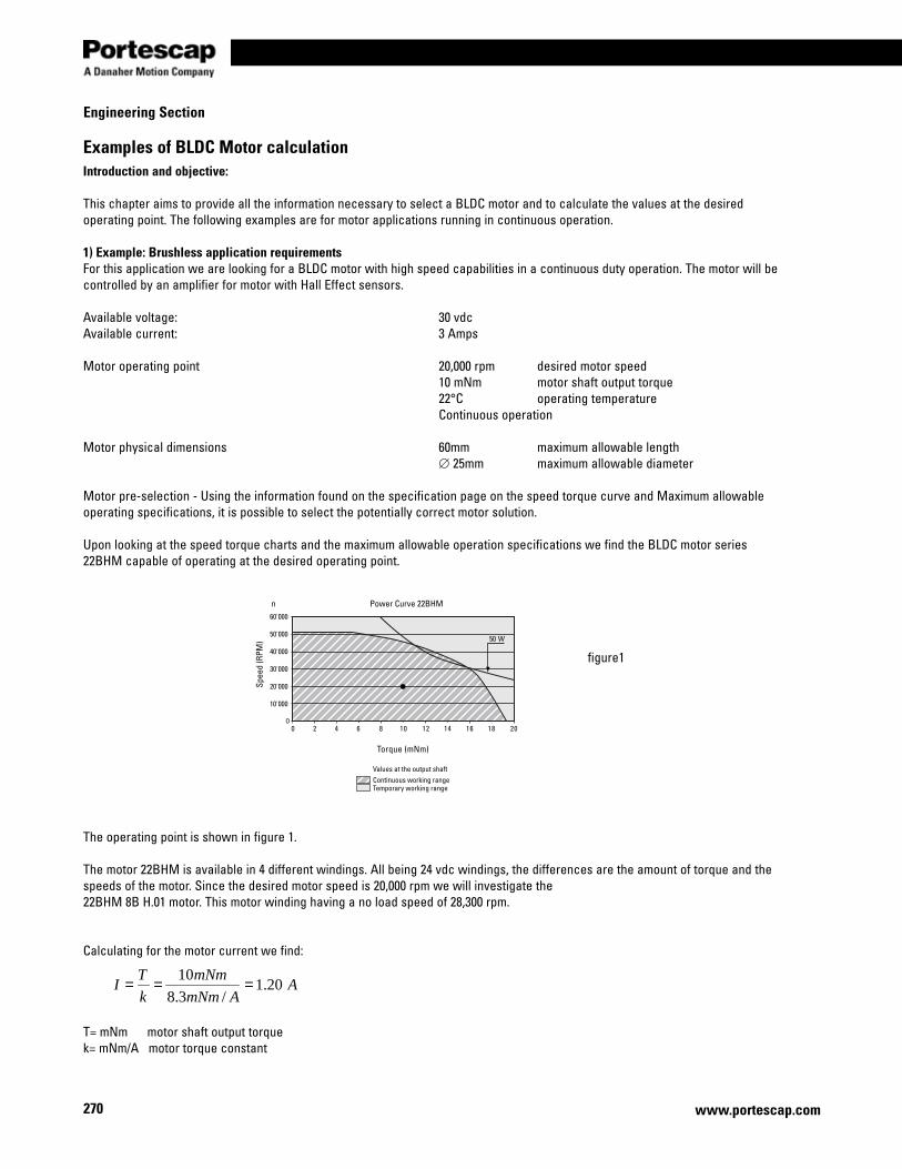
270
Engineering Section
www.portescap.com
Examples of BLDC Motor calculationIntroduction and objective:
This chapter aims to provide all the information necessary to select a BLDC motor and to calculate the values at the desired operating point. The following examples are for motor applications running in continuous operation.
1) Example: Brushless application requirementsFor this application we are looking for a BLDC motor with high speed capabilities in a continuous duty operation. The motor will be controlled by an amplifier for motor with Hall Effect sensors.
Available voltage: 30 vdcAvailable current: 3 Amps
Motor operating point 20,000 rpm desired motor speed 10 mNm motor shaft output torque 22°C operating temperature Continuous operation
Motor physical dimensions 60mm maximum allowable length ∅ 25mm maximum allowable diameter Motor pre-selection - Using the information found on the specification page on the speed torque curve and Maximum allowable operating specifications, it is possible to select the potentially correct motor solution.
Upon looking at the speed torque charts and the maximum allowable operation specifications we find the BLDC motor series 22BHM capable of operating at the desired operating point.
The operating point is shown in figure 1.
The motor 22BHM is available in 4 different windings. All being 24 vdc windings, the differences are the amount of torque and the speeds of the motor. Since the desired motor speed is 20,000 rpm we will investigate the 22BHM 8B H.01 motor. This motor winding having a no load speed of 28,300 rpm.
Calculating for the motor current we find:
T= mNm motor shaft output torquek= mNm/A motor torque constant
10'000
00 2 4 6 8 10 12 14 16 18 20
20'000
30'000
40'000
50'000
60'000
50 W
Power Curve 22BHM
Torque (mNm)
Values at the output shaftContinuous working rangeTemporary working range
Spee
d (R
PM)
n
AAmNm
mNm
k
TI 20.1
/3.8
10===
figure1

271
Miniature Motors
www.portescap.com
Engineering section
The supply current of the system in question is 3 amps and therefore there should be no difficulties.
Calculating the voltage required to run the motor at 20,000 rpm follows the formula:
The problem is now solved. Since the voltage required is less than the available voltage, it is possible to reach the operating point with the BLDC slotless motor series 22BHM 8B H.01, which could do the job quite easily.
The amplifier able to accomplish this is the EBL-50-H-03, which has:•Speedcontrolviahallsensors•Voltageinputsfrom5.5–50vdc•Maximumcontinuouscurrent3Amps
Mechanical power at the motor shaft:
T= mNm motor shaft output torquen= rpm Motor shaft speed
Motor efficiency (ignoring core losses):
U = vdc motor voltageI = Amp Motor current
ϖ*TPmech =
wattmNmPmech 94.2039.2094*10 ==
%5.842.1*65.20
94.20*
====IU
P
P
P mech
elec
mechη
vdcU 65.2039.2094*10*3.8*20.1*99.0 3 == −
sradn
/39.209460000,20
*260
*2 === ππϖ
ϖ** kIRU +=

272
Engineering Section
www.portescap.com
Examples of BLDC Motor calculation2) Example: Brushless motor with a GearheadFor this application we want to drive a load at an extremely low constant speed. The customer needs a combination of a Brushless DC-Servomotor with a gearhead.
Available voltage: 20 vdcAvailable current: 2 Amps
Gearmotor operating point 60 rpm desired gearmotor speed 150 mNm gearmotor shaft output torque 22°C operating temperature Continuous operation
Motor physical dimensions 120mm maximum allowable length ∅ 20mm maximum allowable diameter Gearhead pre-selectionBefore selecting a motor we must first determine which gearhead is suitable for the application. The two important parameters for this are the specifications relating to the operating point at the shaft of the gearhead.
Once an appropriate gearhead has been determined, the working point at the motor shaft can be calculated. From here the motor type can be defined using the same procedure as in the previous example for motor only.
By comparing the desired gearhead output torque with the data of the various gearheads in continuous operation as listed in the catalog specification pages, it is possible to start the elimination process. We find the R16 planetary gearhead (16mm diameter) capable of operating at the desired operating point
For continuous operation, one of the most important gearhead parameters to be considered is the maximum recommended input speed into the gearhead (nmax iput-gearhead). This specification allows us to calculate the maximum reduction ratio (imax) to use for the application.
R16 ==> imax = 125 (nmax input-gearhead = 7,500 rpm)
Continuous working rangeTemporary working range
Values at the output shaft
n (rpm)
M (Nm)
Dynamic torque
0.2 0.4 0.6 0.8 1
12560
500,7maxmax ===
−
−
gearheadoutput
gearheadinput
n
ni
figure2

273
Miniature Motors
www.portescap.com
Engineering section
The actual reduction ratio can be chosen by selecting the nearest lower value to the above results. By reviewing the catalog we choose the following gearhead and ratio.
R16 ==> i = 121
Motor speed at the shaft
Motor torque at the shaft
η = gearhead efficiency
Since the gearhead has a diameter of 16mm we will be looking at a 16mm brushless DC motor.On verifying above the load torque (Tmotor) the motor will be required to turn we select the 16BHS
The motor 16BHS is available in 4 different windings. All being 12 vdc windings, the differences are the amount of torque and the speeds of the motor. Since the desired motor speed is 7,260 rpm we will investigate the 16BHS 8B E.01 motor. This motor winding having a no load speed of 8,150 rpm.
Calculating for the motor current we find:
T= 1.91 mNm motor shaft output torquek= 13.5 mNm/A motor constant
The system is able to supply 2 Amp, therefore there are no problems with the current.The voltage required to run the motor at 7,260 rpm follows the formula:
The problem is now solved. Thanks to the BLDC slotless technology, the motor series 16BHS 8B H.01 with the planetary gearhead series R16 0 121, could do the job quite easily.
The voltage required is less than the available voltage, therefore it is possible to reach the operating point with the BLDC motor series 16BHS 8B E.01.
The amplifier able to accomplish this is the EBL-50-H-03, which has:•Speedcontrolviahallsensors•Voltageinputsfrom5.5–50vdc•Maximumcontinuouscurrent3Amps
rpmnin gearheadoutputmotor 260,760*121* === −
mNmmNm
i
TT gearhead
motor 91.165.*121
150
*===
η
ϖ** kIRU +=
vdcU 94.113.760*)10*5.13(*14.*4.19 3 == −
sradn
/3.76060
260,7*2
60*2 === ππϖ
AAmNm
mNm
K
TI 14.0
/5.13
91.1===
Spee
d (R
PM)
13 W
0 1 2 3 4 5 6 7 80
10'000
20'000
30'000
40'000
50'000
60'000
70'000
Values at the output shaft
Torque (mNm)
Power Curve 16BHS
Continuous working rangeTemporary working range
figure3
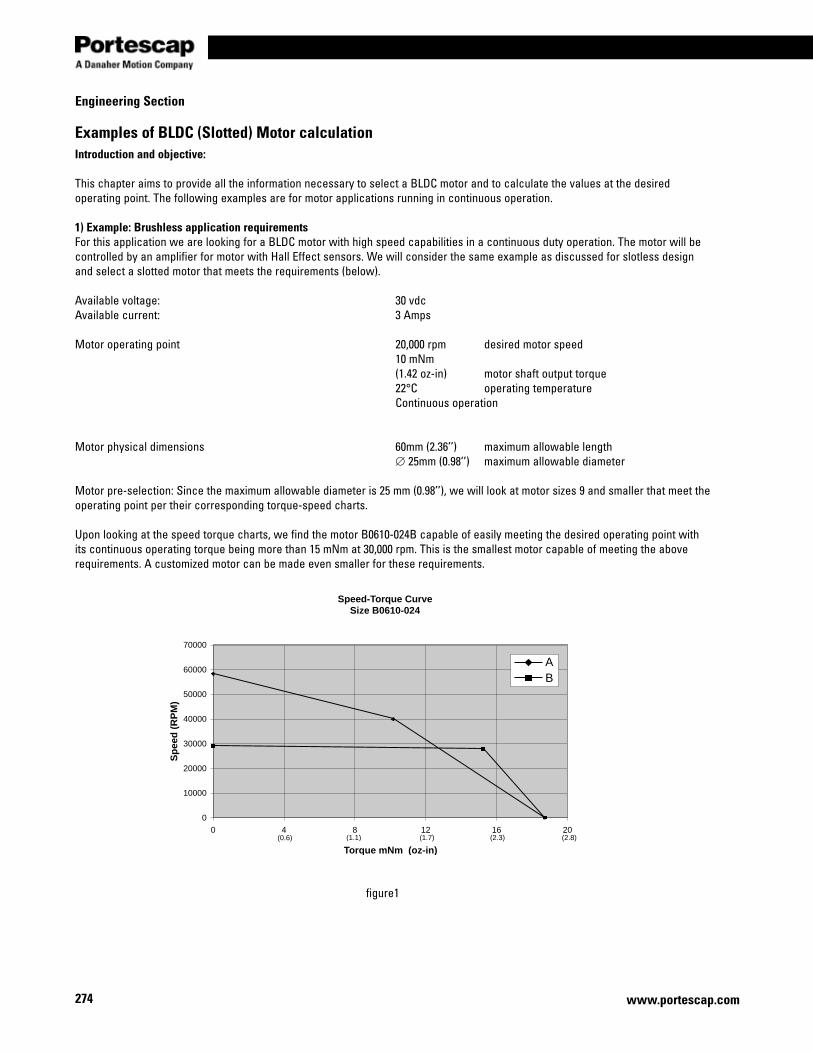
274
Engineering Section
www.portescap.com
Examples of BLDC (Slotted) Motor calculationIntroduction and objective:
This chapter aims to provide all the information necessary to select a BLDC motor and to calculate the values at the desired operating point. The following examples are for motor applications running in continuous operation.
1) Example: Brushless application requirementsFor this application we are looking for a BLDC motor with high speed capabilities in a continuous duty operation. The motor will be controlled by an amplifier for motor with Hall Effect sensors. We will consider the same example as discussed for slotless design and select a slotted motor that meets the requirements (below).
Available voltage: 30 vdcAvailable current: 3 Amps
Motor operating point 20,000 rpm desired motor speed 10 mNm (1.42 oz-in) motor shaft output torque 22°C operating temperature Continuous operation
Motor physical dimensions 60mm (2.36’’) maximum allowable length ∅ 25mm (0.98’’) maximum allowable diameter Motor pre-selection: Since the maximum allowable diameter is 25 mm (0.98’’), we will look at motor sizes 9 and smaller that meet the operating point per their corresponding torque-speed charts.
Upon looking at the speed torque charts, we find the motor B0610-024B capable of easily meeting the desired operating point with its continuous operating torque being more than 15 mNm at 30,000 rpm. This is the smallest motor capable of meeting the above requirements. A customized motor can be made even smaller for these requirements.
Speed-Torque CurveSize B0610-024
0
10000
20000
30000
40000
50000
60000
70000
0 4 8 12 16 20
Torque mNm (oz-in)
Sp
eed
(R
PM
)
AB
(0.6) (1.1) (1.7) (2.3) (2.8)
figure1

275
Miniature Motors
www.portescap.com
Engineering section
The motor B0610-024 is available in 2 different windings. Both being 24 VDC windings, the differences are the amount of torque and the speeds of the motor. Since the desired motor speed is 20,000 rpm we will investigate the B0610-024B motor having a no load speed of 29,197 rpm.
Calculating for the motor current we find:
T= mNm motor shaft output torquek= mNm/A motor torque constant
The supply current of the system in question is 3 amps and therefore there should be no difficulties.
Calculating the voltage required to run the motor at 20,000 rpm follows the formula:
The problem is now solved. Since the voltage required is less than the available voltage, it is possible to reach the operating point with the BLDC slotted motor B0610-024B, which could do the job quite easily.
Mechanical power at the motor shaft:
T= mNm motor shaft output torquen= rpm Motor shaft speed
Motor efficiency (ignoring core losses):
U = vdc motor voltageI = Amp Motor current
vdcU 43.1839.2094*10*84.728.1*57.1 3 =+= −
sradn
/39.209460000,20
*260
*2 === ππϖ
ϖ** kIRU +=
ϖ*TPmech =
WattsmNmPmech 94.2039.2094*10 ==
%8.8828.1*43.18
94.20
*====
IU
P
P
P mech
elec
mechη
AAmNm
mNm
k
TI 28.1
/84.7
10===

276
Engineering Section
www.portescap.com
Examples of BLDC Motor calculation2) Example: Brushless motor with a GearheadFor this application we want to drive a load at a low constant speed. The customer needs a combination of a Brushless DC-Servomotor with a gearhead.
Available voltage: 50 vdcAvailable current: 1 Amp
Gearmotor operating point 2500 rpm desired gearmotor speed 40 mNm gearmotor shaft output torque 10.5 Watts output power at the gearhead 22°C operating temperature Continuous operation
Motor physical dimensions 70mm maximum allowable length ∅ 15mm maximum allowable diameter Gearhead pre-selectionBefore selecting a motor we must first determine which gearhead is suitable for the application. The two important parameters for this are the specifications relating to the operating point at the shaft of the gearhead.
Once an appropriate gearhead has been determined, the working point at the motor shaft can be calculated. From here the motor type can be defined using the same procedure as in the previous example for motor only.
By comparing the desired gearhead output torque and envelope requirements with the data of the various gearheads in continuous operation as listed in the catalog specification pages, it is possible to start the elimination process. We find the Size 5 planetary gearhead (12.7 mm diameter) capable of operating at the desired operating point
For continuous operation, one of the most important gearhead parameters to be considered is the maximum recommended input speed into the gearhead (nmax input-gearhead). This specification allows us to calculate the maximum reduction ratio (imax) to use for the application.
Size 5 Gearhead ==> imax = 32 (nmax input-gearhead = 80,000 rpm)
The actual reduction ratio can be chosen by selecting the nearest lower value to the above results. By reviewing the catalog we choose the following gearhead and ratio.
R16 ==> i = 25
Motor speed at the shaft
Motor torque at the shaft
322500
80000maxmax ===
−
−
gearheadoutput
gearheadinput
n
ni
rpmnin gearheadoutputmotor 500,622500*25* === −
mNmmNm
i
TT gearhead
motor 94.1825.*25
40
*===
η
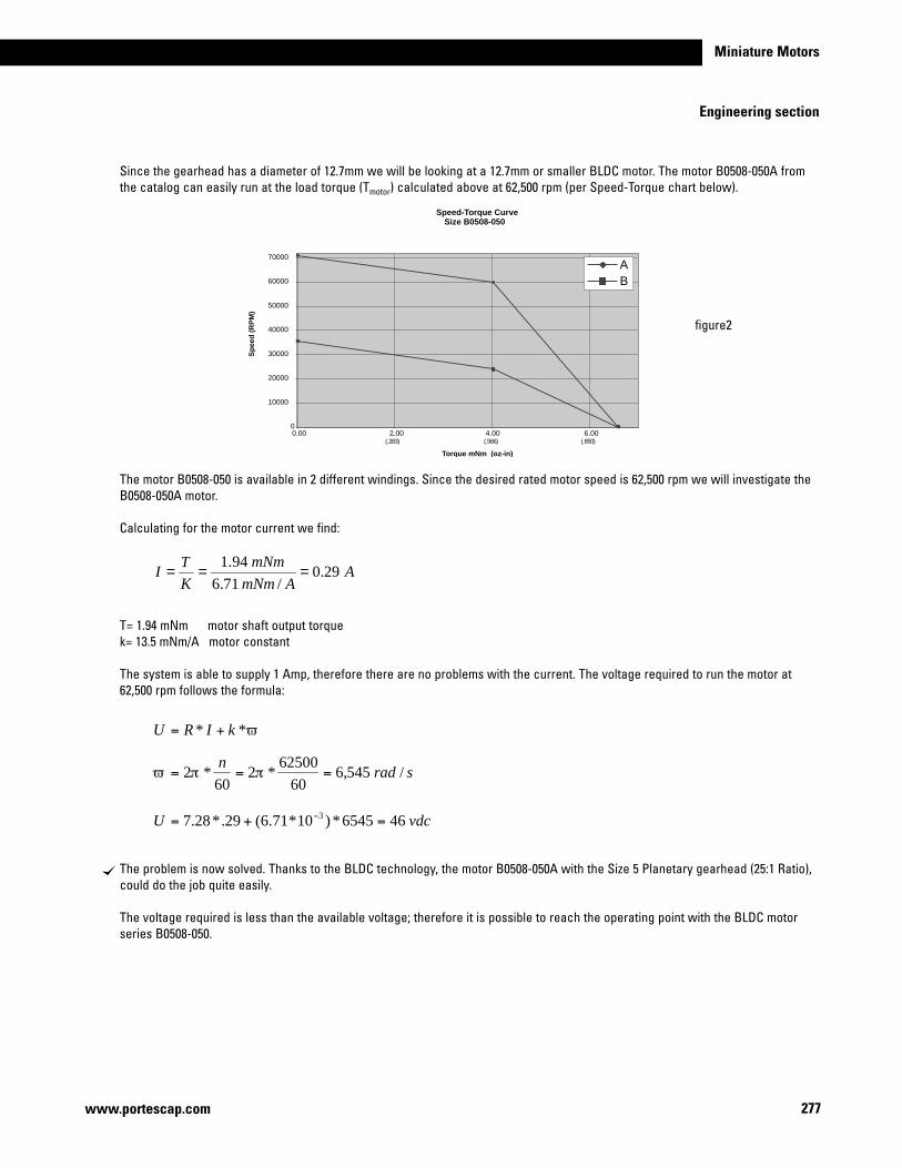
277
Miniature Motors
www.portescap.com
Engineering section
Since the gearhead has a diameter of 12.7mm we will be looking at a 12.7mm or smaller BLDC motor. The motor B0508-050A from the catalog can easily run at the load torque (Tmotor) calculated above at 62,500 rpm (per Speed-Torque chart below).
The motor B0508-050 is available in 2 different windings. Since the desired rated motor speed is 62,500 rpm we will investigate the B0508-050A motor.
Calculating for the motor current we find:
T= 1.94 mNm motor shaft output torquek= 13.5 mNm/A motor constant
The system is able to supply 1 Amp, therefore there are no problems with the current. The voltage required to run the motor at 62,500 rpm follows the formula:
The problem is now solved. Thanks to the BLDC technology, the motor B0508-050A with the Size 5 Planetary gearhead (25:1 Ratio), could do the job quite easily.
The voltage required is less than the available voltage; therefore it is possible to reach the operating point with the BLDC motor series B0508-050.
ϖ** kIRU +=
vdcU 466545*)10*71.6(29.*28.7 3 =+= −
sradn
/545,660
62500*2
60*2 === ππϖ
AAmNm
mNm
KT
I 29.0/71.6
94.1===
Speed-Torque CurveSize B0508-050
0
10000
20000
30000
40000
50000
60000
70000
6.004.00.2.000.00
Torque mNm (oz-in)
Sp
eed
(R
PM
)
AB
)058.()665.()382.(
figure2
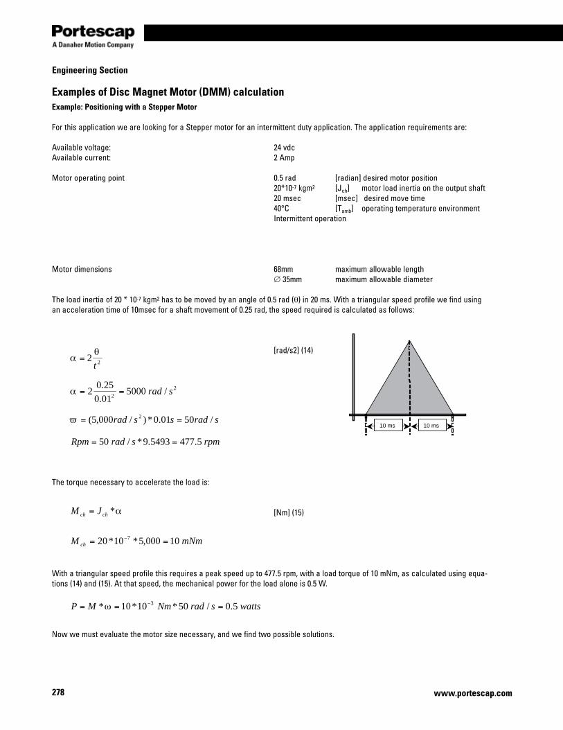
278
Engineering Section
www.portescap.com
Examples of Disc Magnet Motor (DMM) calculationExample: Positioning with a Stepper Motor
For this application we are looking for a Stepper motor for an intermittent duty application. The application requirements are:
Available voltage: 24 vdcAvailable current: 2 Amp
Motor operating point 0.5 rad [radian] desired motor position 20*10-7 kgm2 [Jch] motor load inertia on the output shaft 20 msec [msec] desired move time 40°C [Tamb] operating temperature environment Intermittent operation
Motor dimensions 68mm maximum allowable length ∅ 35mm maximum allowable diameter The load inertia of 20 * 10-7 kgm2 has to be moved by an angle of 0.5 rad (θ) in 20 ms. With a triangular speed profile we find using an acceleration time of 10msec for a shaft movement of 0.25 rad, the speed required is calculated as follows:
[rad/s2] (14)
The torque necessary to accelerate the load is:
[Nm] (15)
With a triangular speed profile this requires a peak speed up to 477.5 rpm, with a load torque of 10 mNm, as calculated using equa-tions (14) and (15). At that speed, the mechanical power for the load alone is 0.5 W.
Now we must evaluate the motor size necessary, and we find two possible solutions.
10 ms 10 ms
wattssradNmMP 5.0/50*10*10* 3 === −ω
α*chch JM =
mNmM ch 10000,5*10*20 7 == −
22t
θα =
22
/500001.0
25.02 srad==α
sradssrad /5001.0*)/000,5( 2 ==ϖ
rpmsradRpm 5.4775493.9*/50 ==
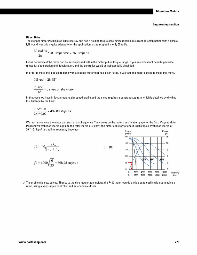
279
Miniature Motors
www.portescap.com
Engineering section
Direct DriveThe stepper motor P430 makes 100 steps/rev and has a holding torque of 60 mNm at nominal current. In combination with a simple L/R type driver this is quite adequate for the application, as peak speed is only 50 rad/s.
Let us determine if the move can be accomplished within the motor pull-in torque range. If yes, we would not need to generate ramps for acceleration and deceleration, and the controller would be substantially simplified.
In order to move the load 0.5 radians with a stepper motor that has a 3.6° / step, it will take the motor 8 steps to make this move.
In that case we have in fact a rectangular speed profile and the move requires a constant step rate which is obtained by dividing the distance by the time:
We must make sure the motor can start at that frequency. The curves on the motor specification page for the Disc Magnet Motor P430 shows with load inertia equal to the rotor inertia of 3 gcm2, the motor can start at about 1700 steps/s. With load inertia of 20 * 10-7 kgm2 this pull-in frequency becomes:
[Hz] (18)
The problem is now solved. Thanks to the disc magnet technology, the P430 motor can do the job quite easily, without needing a ramp, using a very simple controller and an economic driver.
°= 65.285.0 rad
motortheofsteps86.365.28
=°°
chm
m
JJJ
ff+
=2
01
sstepsf /28.868236
700,11 ==
sstepsrevstepssrad
/769/100*2
/50=
π
ssteps /89.49702.0*2
100*5.0=
π

280
Engineering Section
www.portescap.com
Examples of Disc Magnet Motor (DMM) calculationUse of a gearheadThe stepper motor P310 makes 60 steps/rev and has a holding torque 12mNm at nominal current. This is too small for moving the load in a direct drive. However, its mechanical power is more than sufficient. A reduction gearhead can adapt the requirements of the application to the motor capabilities.
Choosing a gearhead and reduction ratioA first choice consists of matching inertias and then making sure that with the selected ratio, the motor speed remains within a rea-sonable range, where the necessary torque can be delivered. With incremental motion, an inertial match assures the shortest move time, with the motor providing constant torque over the speed range considered. In our example this asks for a desired ratio i0 of:
[-] (19)
From the various gearhead models available for combination with the P310 stepper motor, we select the K24. This gearhead offers the smallest ratio of 5:1. Using equations (14), (15) and (19) we find:
load inertia reflected to the motor shaft of 4.71*10-7 kgm2
Motor acceleration = equation [14]
Motor peak speed of 50 rad/s = 477 rpm = 769 steps/s
Necessary motor torque = equation [15]
The problem is now solved. With the drive circuit at 24V the Disc Magnet gearmotor series P310-158-170 + K24 0 5 with coils in par-allel can perform with adequate safety margin. At low step rates the available torque is substantially above the 1.2 mNm required for the triangular speed profile. By adapting this profile to the motor capabilities, the move time can be further reduced.
The smaller P110 motor with the gearhead R16 could also make the move, but would require a driver of very high performance and would be less cost effective for the application.
22
/250002.0
5.02 srad==α
sradssrad /5002.0*)/500,2( 2 ==ϖ
sstepsrevstepssrad
/769/100*2
/50=
π
m
ch
JJ
i =0
82.486.0
200 ==i
mNmsrad 2.1/500,2*10*71.4 7 =−

281
Miniature Motors
www.portescap.com
Engineering section
Examples of Canstack Stepper motor calculationNote: Use the PULL IN curves if the control circuit provides no acceleration and the load is frictional only.
Example: Drive with a Canstack stepper motor with a frictional torque loadFor this application we are looking for a Stepper motor for an intermittent duty application. The application requirements are:
Available voltage: 24 vdcAvailable current: 2 Amp
Motor operating point 67.5° [degree] - desired motor position 15 mNm [M] - desired motor torque < 0.06 [second] - desired move time Intermittent operation
Using a Torque wrench, a frictional load is measured to be 15 mNm. The move profile desired is 67.5° in 0.06 sec. or less.
If a 7.5°/step motor is used, then the motor would have to take nine steps to move 67.5°.
In figure 1 below the maximum PULL IN error rate with a torque of 15 mNm is 275 steps/s (it is assumed that no acceleration control is provided).
Theproblemisnowsolved.TheCanstackmotorseries42M048C1Umotorcouldbeusedat150steps/sec–allowingforasafetyfactor.
Use the PULL OUT curve, in conjunction with a Torque = Inertia x Acceleration (T=Jπ), when the load is inertial and/or acceleration control is provided.
In this equation acceleration or ramping is in rad/s2
steps95.75.67
=°°
sec/150sec06.0
9steps
stepsv ==
2/ sradt
v=
Δ
Δ=α
figure1

282
Engineering Section
www.portescap.com
RampingAcceleration control or ramping is normally accomplished by gating on a voltage controlled oscillator (VCO) and the associated charging capacitor. Varying the RC time constant will give different ramping times. A typical VCO acceleration control frequency plot for an incremental movement with equal acceleration and deceleration time would be as shown below.
Acceleration also may be accomplished by changing the timing of the input pulses (frequency).For example, the frequency could start at a ¼ rate; go to ½ rate, ¾ rate and finally the running rate.
Applications where: Ramping acceleration or deceleration control time is allowed.
Where JT = Rotor inertia (gm2) plus load inertia (gm2)Δv = Step rate changeΔt = Time allowed for acceleration in seconds
K= .13 for 7.5° - 48 steps/rev.K= .26 for 15° - 24 steps/rev.K= .314 for 18° - 20 steps/rev.
In order to solve an application problem using acceleration ramping, it is usually necessary to make several estimates avoiding a procedure similar to the one used to solve the following example:
Kt
vJmNmTJ **)( T Δ
Δ=
revstepsK
/2α
=
figure2

283
Miniature Motors
www.portescap.com
Engineering section
Example: Frictional torque plus inertial load with acceleration controlFor this application we are looking for Stepper motor for an intermittent duty application. The application requirements are:
Available voltage: 24 vdcAvailable current: 3 Amp
Motor operating point 67.5° [degree] - desired motor position 15 mNm (Tf) [M]–frictionalload < 0.5 [second] - desired move time Intermittent operation
Motor dimensions 60mm maximum allowable length ∅ 60mm maximum allowable diameter
An assembly device must move 4 mm in less than 0.5 seconds; the motor will drive a leadscrew through a gear reduction. The leadscrew and gear ratio were selected so that 100 steps of a 7.5°/step motor = 4mm.
The total inertial load (rotor + gear + screw) = 25 * 104 gm2. The frictional load = 15 mNm
(1) Select a stepper motor PULL OUT curve which allows a torque in excess of 15 mNm at a step rate greater than
Referring to the figure below, determine the maximum possible friction load only.
(2) Make a first estimate of a working rate (a running rate less than the maximum) and determine the torque available to accelerate the inertia (excess over TF) TA = Torque available
sec/200sec5.0
100steps
stepsv ==
mNmmNmmNmTT FA 51520 =−=−
figure3

284
Engineering Section
www.portescap.com
(3) Using a 60% safety margin 5 mNm * 0.6 = 3 mNm Calculate Δt to accelerate. (refer to figure 2)
From the equation:
To accelerate Δt = 0.027 sec (note: the same amount of time is allowed to decelerate the load)
(4) The number of steps used to accelerate and decelerate
< OR >
(5) The time to move at the run rate NT=Totalsteps/revolution–Steptomakethedesiredmove.
(6) The total time to move is as follows:
The problem is now solved. The Canstack stepper motor series 42M048C1U is the first estimate. This motor can be moved slower if more of a safety factor is desired.
Kt
vJmNmTJ **)( T Δ
Δ=
027.0**T =
Δ=Δ
jT
KvJt
mNmTJ 3027.0
13.0*250*10*25 4
==
2**2
tv
NN DA Δ=+
tvNN DA Δ=+ * steps7027.0*250 ==
937100 =−=TN
sec37.0125125
93
+=
+=Δ
DA
Trun NN
Nt
totaldecelaccelrun tttt =Δ+Δ+Δ
sec42.0027.0027.037.0 =++

285
Miniature Motors
www.portescap.com
Engineering section
Example: No ramping acceleration or deceleration control is allowed.Even though no acceleration time is provided, the stepper can lag a maximum of two steps or 180° electrical degrees. If the motor goes from zero steps/sec to v steps/sec the lag time Δt would be
The torque equation for no acceleration or deceleration is:
Where : JT = Rotor inertia (gm2) + load inertia (gm2) = 25*104 gm2
Example: Friction plus Inertia – No acceleration ramping. For this application we are looking for Stepper motor for a continuous duty application. The application requirements are: A tape capstan is to be driven by a stepper motor.
Motor operating point 15.3 mNm (Tf) [M]–frictionalload 10*104 (JL) [gm2]–loadinertia continuous operation
The capstan must rotate in 7.5° increments at a rate of 200 steps/sec.
Since a torque greater than 15.3 mNm at 200 steps/sec is required, consider the CanStack stepper motor series 42M048C1U. (refer to figure 4)
The total inertia= motor rotor inertia + load inertia
sec2==Δ
vt
Kv
JmNmtorqueT TJ *2
*)(2
=
250sec/ == ratestepsv
13.048
2
/
2===
ππ
revstepK
LRT JJJ +=
244 )10*1010*5.12( gm+=
2410*5.13 gm=

286
Engineering Section
www.portescap.com
(1) Since non acceleration ramping will be utilized, use the following equation:
(2) Total torque
(3) Refer to the PULL OUT curve figure (4) at a speed of 200 steps/s, where the available torque is 26 mNm.
The problem is now solved. The Canstack stepper motor series 42M048C1U can perform in this application adequately, with a safety margin factor.
)13.0(*2
*2
== KKv
JT TJ
13.0*2
200*10*5.13
24=JT
mNmTJ 5.3=
JFT TTT +=
mNmmNmmNmTT 8.185.33.15 =+=
figure4

287
Miniature Motors
www.portescap.com
Notes

288 www.portescap.com
Notes

289
Miniature Motors
www.portescap.com
Notes

290 www.portescap.com
Notes

© 2009, Portescap, A Danaher Motion Company. All rights reserved. Information and specifications subject to change at any time. All trademarks are property of their respective owners. Lit code: 0123

Global Presence
North AmericaPortescap (Headquarters)110 Westtown RoadWest Chester, Pennsylvania 19382-4978Tel.: +1 (610) 235-5499Fax: +1 (610) [email protected]
EuropePortescapRue Jardiniere 157, Case PostaleCH 2301 La Chaux-de-FondsSwitzerlandTel.: +41 (0)32 925 61 11Fax: +41 (0)32 925 65 [email protected]
AsiaPortescap Singapore Pte. Ltd.Block 3015 A Ubi Road 1#07-08 Kampong Ubi Industrial EstateSingapore 408705Tel.: +65 6747 4888Fax: +65 6743 [email protected]
IndiaPortescapUnit 2, SDF-1, SEEPZ-SEZAndheri East, Mumbai 400 096, IndiaTel.: +91 22 2829 4130 / 4131Fax: +91 22 [email protected]
JapanDanaher Motion Japan2F, Tokyu REIT Building2-7-1 Hatchobori Chuo-kuTokyo 104-0032 JapanTel.: +81 3 6222 1051Fax: +81 3 6222 [email protected]
China Danaher Motion China5th Floor, No.280-6, Linhong RoadChangning District Shanghai, P.R.China 200335Tel.: +86 21 61289814 Fax: +86 21 [email protected]
ChinaDanaher Motion ChinaRM2205, Scitech Tower22 Jianguomenwai StreetBeijing, China 100004 Tel.: +86 10 65150260Fax: +86 10 [email protected]

www.portescap.com
R08
Planetary Gearhead 0.05 Nm
dimensions in mm R08 • 3
Ratio 4 16 64 256
No. of gear stages 1 2 3 4 Direction of Rotation = = = = Efficiency 0.85 0.75 0.65 0.60 L (mm) 9.35 12.85 16.35 19.85 Mass (g) 1.6 2.2 2.8 3.6 Available with motor 08 G 61 • 5 08 GS 61 • 7 PO10 • 028 mm BLDC(Std)
M (Nm)
n (rpm) Dynamic torque
Continuous working rangeTemporary working range
Values at the output shaft0.040.02 0.06 0.08 0.10 0.12
Ø8 0 -0,
05
( )1 4,95 ± 0,2
Ø3 0 -0,
1
( )3,6
Ø5+0
,001
-0,00
8
Ø1,5
-0,00
6-0,
009
5,95 ± 0,2L
Characteristics R08 • 3 R08 2R • 3
Bearing Type sleeve ballMax. static torque mNm (oz-in) 0.15 (21.4) 0.15 (21.4)Max. radial force at 4 mm from mounting face N (lb) 5 (1.1) 10 (2.2)Max. axial force N (lb) 5 (1.1) 10 (2.2)Force for press-fit N (lb) 100 (23) 100 (23)Average backlash at no-load 1º 1ºAverage backlash at 0.1 Nm 3º 3ºRadial play µm ≤50 ≤50Axial play µm 50-150 ≤50Max. recom. input speed rpm 12000 12000Operating temperature range ºC (ºF) -30...+85 (-22...+185)


![Pomoce dydaktyczne do przedmiotu Kanalizacja … · 1 Pomoce dydaktyczne do przedmiotu Kanalizacja (wykład i projekt) i do dyplomów - studia I stopnia (dzienne i zaoczne) [*] Kotowski](https://img.dokumen.tips/doc/110x75/5b6f385d7f8b9aad128bd67f/pomoce-dydaktyczne-do-przedmiotu-kanalizacja-1-pomoce-dydaktyczne-do-przedmiotu.jpg)