Embed Size (px)
Citation preview

Brake Upgrade Kit Fitting Instructions –Bonneville America
1
WARNING: Always have Triumph approved parts, accessories and conversions fittedby a trained technician of an authorised Triumph Dealer. The fitment of parts,
accessories and conversions by a technician who is not of an authorised Triumph dealer mayaffect the handling, stability or other aspects of the motorcycles operation whichmay result inan accident causing injury or death.
WARNING: This brake upgrade kit is designed for use solely on the Triumph BonnevilleAmerica and should not be fitted to any other Triumph model or to any motorcycle of
other manufacturers. Fitting this brake upgrade kit to any other Triumph model or to anymotorcycle of othermanufacturersmay interferewith the rider andcould affect the stability andhandling of the motorcycle leading to an accident causing injury or death.
WARNING: Throughout this operation, ensure that the motorcycle is stabilised andadequately supported to prevent the risk of injury from the motorcycle falling.
1
2
34
5
6
78
9
10 11
12
13
15
14
16
17
18
19
Parts Supplied:
1. Right hand caliper assembly 1 off.
2. Disc 1 off. . . . . . . . . . . . . . . . . . . . . . . .
3. M8 disc bolt 6 off. . . . . . . . . . . . . . . .
4. M8 chrome trim cap 6 off. . . . . . . . .
5. Pad set 1 off. . . . . . . . . . . . . . . . . . . . .
6. Master cylinder assembly 1 off. . . .
7. M10 banjo bolt 1 off. . . . . . . . . . . . . .
8. M10 washer 7 off. . . . . . . . . . . . . . . . .
9. Bridging hose 1 off. . . . . . . . . . . . . . .
10. ‘P’ clip 1 off. . . . . . . . . . . . . . . . . . . . . .
11. Torx bolt 1 off. . . . . . . . . . . . . . . . . . . .
12. Clip 2 off. . . . . . . . . . . . . . . . . . . . . . . .
13. RH outer fork tube 1 off. . . . . . . . . .
14. Fork dust seal 1 off. . . . . . . . . . . . . .
15. Fork oil seal 1 off. . . . . . . . . . . . . . . .
16. Top bush 1 off. . . . . . . . . . . . . . . . . . .
17. Sealing washer 1 off. . . . . . . . . . . . .
18. M8 x 40 hex head bolt 2 off. . . . . . .
19. Bracket, front hose 1 off. . . . . . . . . .
20. Template 1 off. . . . . . . . . . . . . . . . . . .
Publication part number A9900176 issue 1, ADC 1547.
� Triumph Designs Ltd 2003.

!
!
!
Brake Upgrade Kit Fitting Instructions –Bonneville America
2
WARNING: This brake upgrade kit isdesigned for use solely on the
Triumph Bonneville America when fitted withthe cast wheel upgrade kit. Fitting this brakeupgrade kit to a Triumph Bonneville Americawhich has not been converted using the castwheel upgrade kit could affect the stabilityand handling of the motorcycle leading to anaccident causing injury or death.
WARNING: Before starting work,ensure the motorcycle is stabilised
and adequately supported. This will helpprevent it from falling and causing injury tothe operator or damage to the motorcycle.
1. Support the motorcycle so that the front wheel
is clear of the ground.
2. Remove the front wheel spindle bolt.
3. Slacken the wheel spindle clamp bolts on both
forks.
1. Spindle clamp bolts
4. Detach the front brake caliper from the left
hand front fork.
CAUTION: Do not allow the caliperto hang on its brake hose while
detached from the fork as this could damagethe brake hose.
To prevent brake hose damage, always
support the caliper while it is detached fromthe fork.
5. Support the wheel and withdraw the spindle.
1. Wheel Spindle
6. Manoeuvre the wheel out from the forks
collecting the speedometer drive as you do so.
CAUTION: With the wheel removed,
always support the speedometer
cable and drive and do not allow eithercomponent to become twisted or to fall onto
dirty surfaces.
Twisting or falling onto dirty surfaces couldlead to premature wear and/or erratic
speedometer operation.
7. Recover the spacer from the right side of the
hub
CAUTION: Do not allow the wheel torest on the brake disc as this could
damage the disc. To prevent bearingdamage, ensure no dirt enters the wheelbearings whilst the wheel is removed.

Brake Upgrade Kit Fitting Instructions –Bonneville America
3
8. Carefully prise the trim caps from the six boltssecuring the chrome flange to the right hand
side of the wheel as shown below. Remove
the six bolts and the chrome flange.
NOTE:
� The chrome flange, bolts and trim capswill
not be refitted but should be retained forfuture re-use if thebrakeupgrade kit is everremoved.
1 2
34
1. Flange
2. Wheel
3. Bolt
4. Trim cap
9. Ensure the disc and wheel surfaces are clean.Assemble the disc to the right hand side of the
wheel. Secure the disc to the wheel using the
six M8 bolts supplied with the kit. Tighten the
bolts evenly and progressively to a final torque
of 22 Nm. Fit a chrome trim cap from the kit to
each retaining bolt.
1 2
34
1. Disc
2. Wheel
3. Bolt
4. Trim cap
10. Undo the bolts securing the mudguard bracketto the fork legs noting the location of the brake
hose bracket and ‘P’ clip beneath the head of
the left hand rear bolt.
11. Remove the mudguard assembly from the
motorcycle taking care not to damage the
painted surface.
P6270013
1
1. Front mudguard
12. Release the right hand lower fork shroud from
the under-side of the bottom yoke. Protect the
mudguard mountings with tape then allow the
shroud to rest on themudguardmounting lugs.
T908.PIC24
2
1
1. Fork shroud
2. Fork shroud fixings
!
Brake Upgrade Kit Fitting Instructions –Bonneville America
4
13. Slacken the top yoke clamp bolt.
T908.PIC28
1
1. Top yoke clamp bolt
14. Loosen the fork’s top cap.
T908.PIC27
1
1. Top cap
15. Slacken the bottom yoke clamp bolt and slidethe right hand fork out of the yokes. Take care
to not damage the cables in the wire guide.
1T908.PIC25
1. Cable guide
NOTE:
� The upper fork shrouds will remainsituated between the upper and loweryokes.
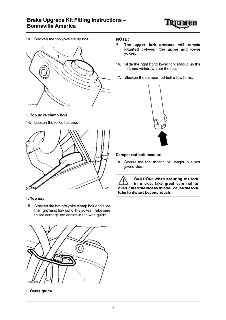
16. Slide the right hand lower fork shroud up thefork and withdraw from the top.
17. Slacken the damper rod bolt a few turns.
Damper rod bolt location
18. Secure the fork inner tube upright in a soft
jawed vice.
CAUTION: When securing the fork
in a vice, take great care not to
overtighten the vice as thiswill cause the forktube to distort beyond repair.

Brake Upgrade Kit Fitting Instructions –Bonneville America
5
19. Carefully unscrew the top cap from the innertube.
WARNING: The top cap is under
pressure from the fork spring. As
the last few threadsof the capareunscrewed,
keep the cap pushed firmly into the tube to
prevent it being forcibly expelled as thethreads release. To prevent injury, always
wear eye, face and hand protection when
removing the top cap.
T908.11.05
1
2
1. Top cap
2. Inner tube
20. Remove the spacer and spring seat.
1
2
1. Spacer2. Spring seat
21. Lift out the spring.
1
2
1. Spring
2. Inner tube
22. Invert the fork and pour out the fork oil into a
suitable container. Pump the fork assembly to
remove all oil.
23. Remove the damper rod bolt and sealing
washer from the base of the outer tube.Discard the sealing washer.
2
1
1. Damper rod bolt
2. Sealing washer

!
Brake Upgrade Kit Fitting Instructions –Bonneville America
6
24. Invert the fork and tip out the damper rod andrebound spring.
21
1. Damper rod
2. Rebound spring
25. Ease the dust seal out of position andslide it off
the inner tube.
2
1
1. Dust seal
2. Inner tube
26. Carefully ease the circlip out from the top of the
outer tube
NOTE:
� Keep the fork fully compressed whilstremoving the circlip. Any accidentaldamage to the inner tube will then beconfined to the area which is normallyabove the oil seal.
27. Compress the fork then pull the inner tubesharply out of the outer tube. Repeat this
procedure until the top bush is forced out of
position and the inner and outer tube can be
separated.
1
2
3
1. Inner tube
2. Top bush
3. Outer tube
28. Invert the outer tube and tip out the damper rod
seat.
NOTE:
� The outer tube will not be refitted butshould be retained for future re-use if thebrake upgrade kit is ever removed.
29. Slide the oil seal, washer and top bush off from
the top of the inner tube. Discard the oil sealand top bush. Retain the washer for refitment.
CAUTION: Do not attempt to
remove the lower bush from the
inner tube.

Brake Upgrade Kit Fitting Instructions –Bonneville America
7
WARNING: The front forks
comprisemany precisionmachined
parts. Total cleanliness must be observed at
all times and, assembly must take place in adirt/dust--free environment.
Dirt ingress may cause damage to the fork
parts, leading to incorrect operation,
instability, loss of control or an accident.
NOTE:
� During assembly of the fork, tool
3880080-T0301 will be used extensively. Inthe text, reference to a plain end and achamfered end will be made. Thisdescribes the the two ends of the tool asshown in the diagram below.
Chamfered end (with internal recess)
Plain end
30. Lubricate the damper rod piston ring and lower
bush with clean fork oil. Also lubricate the top
bush supplied with the kit using clean fork oil.
31. Fit the rebound spring to the damper rod then
insert the assembly into the inner tube.
T908.11.13
1 2
1. Rebound spring
2. Damper rod
32. Fit the seat securely to the end of the damperrod then insert the inner tube assembly into the
right hand outer tube supplied with the kit.
33. Fit the sealing washer supplied with the kit to
the damper rod bolt then apply locking
compound (Three Bond 1342) to the bolt
threads.
34. Ensure the damper rod and seat are correctly
located in the outer tube then fit the damperrod bolt, tightening it to 43 Nm.
1
2
3
4
1. Damper rod
2. Seat
3. Sealing washer
4. Bolt

Brake Upgrade Kit Fitting Instructions –Bonneville America
8
35. Slide the top bush supplied with the kit alongthe inner tube and locate it in the outer tube.
Drift the bush into position using the plain end
of tool 3880080-T0301.
NOTE:
� Keep the fork fully compressed whilstinstalling the bush, oil seal and circlip.Any accidental damage to the inner tubewill then be confined to the area which isnormally above the oil seal.
11.11--2
1
2
3
1. Tool 3880080-T0301
2. Top bush
3. Outer tube
36. Slide the washer along the inner tube and
locate it in the outer tube.
37. Lubricate the lip of the oil seal supplied with the
kit with fork oil. Ensure the seal is the correctway around then ease it onto the inner tube.
Drift the seal into position in the outer tube
using the plain end of tool 3880080-T0301.
11.11--3
1
2
1. Tool 3880080-T0301
2. Dust seal
38. Secure the oil seal in position with the circlip,ensuring it is correctly located in its groove.
39. Fit the dust seal supplied with the kit onto the
inner tube and drift it into position in the outer
tube using the chamfered end of tool
3880080-T0301.
40. Upright the fork and fill it with Kayaba G10 fork
oil until the oil level is slightly above the
recommended level shown below. The fork oilcapacity is 548 cc.
WARNING: Any variation from the
figures quoted could result in an
unsafe riding condition leading to loss of
control and an accident.
166 mm
Fork oil level (fork fully compressed)
41. Pump the fork assembly several times to expelany trapped air then fully compress the fork
and support it in an upright position. Leave the
fork for a few minutes to allow the oil level to
stabilise.

Brake Upgrade Kit Fitting Instructions –Bonneville America
9
42. Set the scale on tool 3880160-T0301 to thespecified level.
11.07--1
1
23
4
1. Tool 3880160-T0301
2. Adjuster plate
3. Scale area
4. Hole (zero position)
NOTE:
� Zero level on the tool is set at the small exithole in the side of the scale tube, NOT ATTHE END TIP. Do not attempt to block thisside hole as this will cause the final fluidlevel to be incorrect.
TEC11.07--2
A
Zero level measured from oil holeSet dimension ‘A’ to the required oil level
43. Insert the scale end of the tool into the fork
inner tube.
44. Hold the tool adjuster plate level with the upper
surface of the fork inner tube and draw fluid
into the syringe until fluid flow ceases (empty
the syringe if the body becomes full before fluidflow stops).
45. The fluid level in the fork is now set to the
height set on the tool scale. Check the tool
scale setting and repeat the process if
incorrectly set.
46. Extend the inner tube and insert the forkspring.
47. Fit the spring seat and spacer.
T908.11.11
1
1. Spring seat
48. Lubricate the O--ring with a smear of fork oil
then screw the top cap fully into the inner tube.
WARNING: Keep the top cap under
pressure until you are sure it is fully
engaged with the inner tube threads. Toprevent injury, always wear eye, face and
hand protection when refitting the top cap.
49. Position the right hand lower fork shroud over
the right hand fork resting it on the mudguard
mounting lugs.
50. Slide the right hand fork into the yokesensuring the right hand upper fork shroud
remains in position.
Brake Upgrade Kit Fitting Instructions –Bonneville America
10
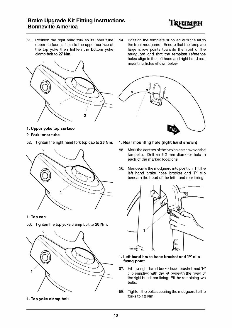
51. Position the right hand fork so its inner tubeupper surface is flush to the upper surface of
the top yoke then tighten the bottom yoke
clamp bolt to 27 Nm.
1
2
1. Upper yoke top surface
2. Fork inner tube
52. Tighten the right hand fork top cap to 23 Nm.
1
1. Top cap
53. Tighten the top yoke clamp bolt to 20 Nm.
1
1. Top yoke clamp bolt
54. Position the template supplied with the kit tothe front mudguard. Ensure that the template
large arrow points towards the front of the
mudguard and that the template reference
holes align to the left hand and right hand rear
mounting holes shown below.
1
1. Rear mounting hole (right hand shown)
55. Mark the centres of the two holes shown on the
template. Drill an 8.2 mm diameter hole in
each of the marked locations.
56. Manoeuvre themudguard into position. Fit the
left hand brake hose bracket and ‘P’ clip
beneath the head of the left hand rear fixing.
P6270014
1
1. Left hand brake hose bracket and ‘P’ clipfixing point
57. Fit the right hand brake hose bracket and ‘P’
clip supplied with the kit beneath the head ofthe right hand rear fixing. Fit the remaining two
bolts.
58. Tighten the bolts securing themudguard to the
forks to 12 Nm.

Brake Upgrade Kit Fitting Instructions –Bonneville America
11
59. Lubricate the lips of the wheel bearing sealswith a smear of multi--purpose grease.
60. Thoroughly clean both sides of both the brake
discs.
61. Position the wheel between the forks and fit
the spacer to right side of the wheel.
1. Spacer
62. Align the speedometer drive gear cut--outs
with the driveplate tabs and fit the drive to the
right side of the wheel.
1. Speedometer drive
2. Drive cut--outs
3. Driveplate tabs
63. Align the wheel to the fitted position and insert
the spindle from the left-hand side.
64. On the right-hand side, fit the bolt to thespindle
and tighten to 60 Nm.
65. Slide the displaced left hand caliper onto thedisc, ensure the pads pass either side, and fit
themounting bolts. Hand tighten themounting
bolts.
66. Lower the motorcycle to the ground and park
on the side stand.
67. Ensure the speedometer drive is positioned as
shown below.
Speedometer drive position
68. Pump the front forks a few times then tighten
the spindle clamp bolt to 20 Nm.
1. Spindle clamp bolts
69. Park the motorcycle on the side stand.
WARNING: Before continuing,ensure the motorcycle is stabilised
and adequately supported. This will helpprevent it from falling and causing injury tothe operator or damage to the motorcycle.
70. Remove the mirror.

Brake Upgrade Kit Fitting Instructions –Bonneville America
12
71. Undo the screws and free the right--handswitchgear assembly from themaster cylinder.
T908.09.08
1
1. Right--hand switchgear assembly
72. Disconnect the wiring from the front brake light
switch.
73. Position a cloth beneath the hose to catch any
spilt fluid then unscrew the banjo bolt and
disconnect the brake hose from the master
cylinder. Discard the sealing washers andkeep the hose upright to minimise fluid loss.
T908.10.08
1
1. Banjo bolt
74. Slacken the reservoir cover screws.
75. Slacken the nut and screw securing the throttlecables to the master cylinder.
T908.09.12
1
2
1. Closing cable nut
2. Opening cable screw
76. Undo the screws and remove the master
cylinder mounting clamp.
77. Free the throttle cables from the twistgrip and
free the master cylinder from the handlebars.
NOTE:
� Keep the master cylinder upright to
prevent fluid spillage.
� If necessary, free the throttle cables from
the carburettor bracket to gain thenecessary freeplay to allow them to bedisconnected from the twistgrip.
78. Remove the screw and slacken the nut then
detach the throttle cables from the master
cylinder.
79. Remove the master cylinder then lift off the
reservoir cover and diaphragm and empty its
contents into a suitable container.
NOTE:
� The master cylinder assembly will not be
refitted but should be retained for futurere-use if the brake upgrade kit is everremoved.

Brake Upgrade Kit Fitting Instructions –Bonneville America
13
80. Fit the throttle cables to the master cylinder
assembly supplied with the kit, tightening the
retaining screw/nut securely.
T908.09.10
1
2
1. Opening cable
2. Closing cable
81. Connect the cables to the twistgrip then seat
the master cylinder on the handlebars.
T908.09.11
2
1
1. Closing cable
2. Opening cable
82. Fit the mounting clamp and bolts. Align theclamp lower split with the punch mark on the
handlebar then evenly tighten the clamp bolts
to 15 Nm.
T908.09.09
1
1. Master cylinder mounting clamp
83. Fit the switchgear assembly to the master
cylinder, tightening the screws to 6 Nm.
NOTE:
� Tuck the indicator wiring and connector
into the recess in the front half of theswitchgear.
84. Position an M10 washer supplied with the kit
on each side of the brake hose end fitting then
secure the hose to the master cylinder using
the banjo bolt from the discarded master
cylinder. Tighten the banjo bolt to 25 Nm.
85. Unscrew the banjo bolt and disconnect thefront brake hose from the left hand caliper.
Place the hose end in a suitable container to
collect any remaining brake fluid and discard
the sealing washers. Retain the banjo bolt.
Brake Upgrade Kit Fitting Instructions –Bonneville America
14
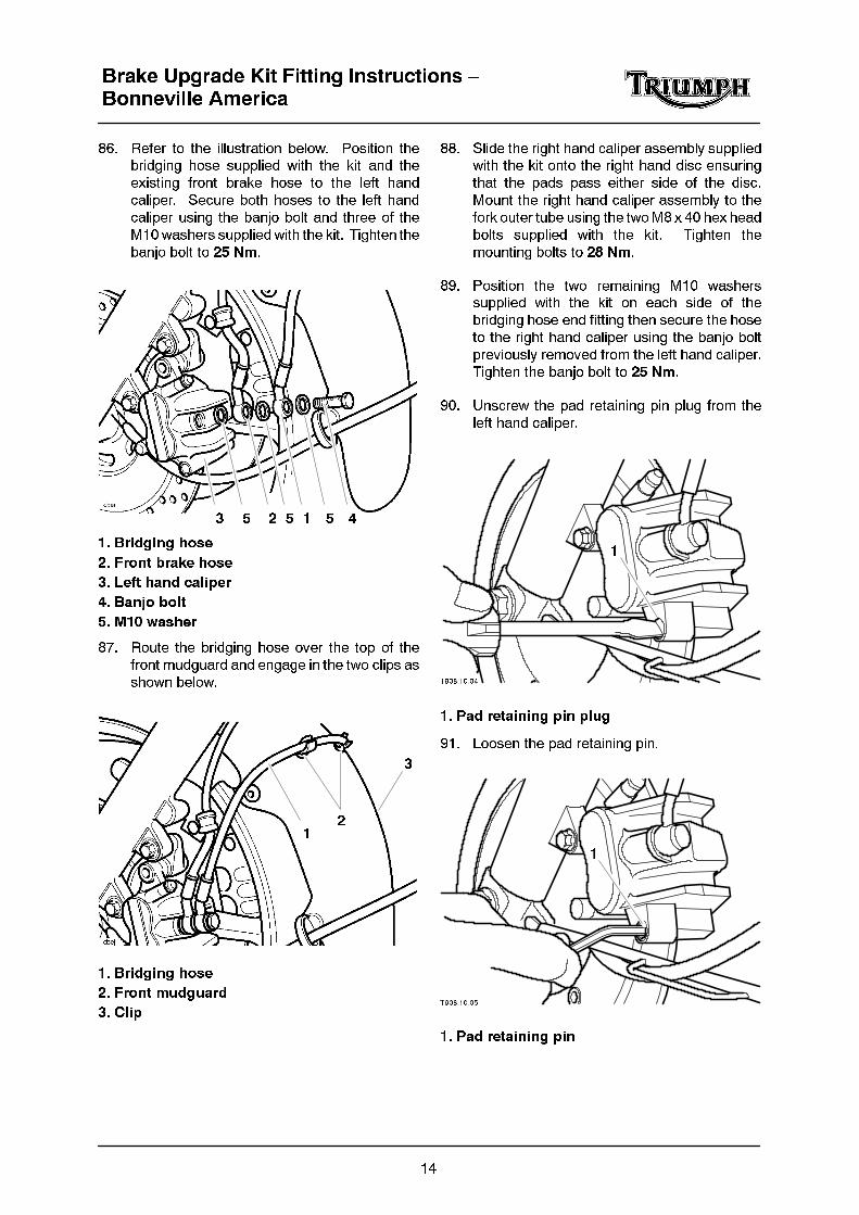
86. Refer to the illustration below. Position thebridging hose supplied with the kit and the
existing front brake hose to the left hand
caliper. Secure both hoses to the left hand
caliper using the banjo bolt and three of the
M10washers supplied with the kit. Tighten the
banjo bolt to 25 Nm.
3 412 555
1. Bridging hose
2. Front brake hose
3. Left hand caliper
4. Banjo bolt
5. M10 washer
87. Route the bridging hose over the top of the
front mudguard and engage in the two clips as
shown below.
12
3
1. Bridging hose
2. Front mudguard
3. Clip
88. Slide the right hand caliper assembly suppliedwith the kit onto the right hand disc ensuring
that the pads pass either side of the disc.
Mount the right hand caliper assembly to the
fork outer tube using the twoM8 x 40 hex head
bolts supplied with the kit. Tighten the
mounting bolts to 28 Nm.
89. Position the two remaining M10 washerssupplied with the kit on each side of the
bridging hose end fitting then secure the hose
to the right hand caliper using the banjo bolt
previously removed from the left hand caliper.
Tighten the banjo bolt to 25 Nm.
90. Unscrew the pad retaining pin plug from the
left hand caliper.
T908.10.04
1
1. Pad retaining pin plug
91. Loosen the pad retaining pin.
T908.10.05
1
1. Pad retaining pin
!
!
Brake Upgrade Kit Fitting Instructions –Bonneville America
15
92. Remove the hand tight caliper mounting boltsand slide the left hand caliper off the disc.
CAUTION: Do not allow the caliperto hang on its brake hose while
detached from the fork as this could damagethe brake hose.
To prevent brake hose damage, alwayssupport the caliper while it is detached from
the fork.
93. Remove the pad retaining pin. Remove and
discard the pads from the left hand caliper.
Take care not to lose the pad retainer from the
mounting bracket or the anti--rattle spring fromthe caliper body.
94. Check the pad retainer, anti--rattle spring andretaining pin. Renew any component which
shows signs of damage or corrosion.
95. Check the caliper body slides easily on the
mounting bracket pins and check there is no
sign of leakage from the piston seals. Rectify
any problems before installing the padssupplied with the kit.
96. Push the pistons fully back into the caliper
body.
97. Ensure the pad retainer is correctly fitted to the
mounting bracket and the anti--rattle spring is
securely clipped onto the caliper body.
98. Lubricate the pad retaining pin with a thin
smear of proprietary high--temperature brake
grease.
WARNING: Do not apply more thana minimum coating of grease to the
pad retaining pin. Excess grease may
contaminate the brake pads, hydraulic seals
and disc causing reduced braking efficiency
which may lead to loss of control and anaccident.
99. Fit the pads suppliedwith the kit to the left handcaliper with their friction material surfaces
facing each other. Locate the pad upper ends
in the mounting bracket retainer then align
them with the caliper body and insert the
retaining pin.
100. Slide the left hand caliper onto the disc, ensurethe pads pass either side, and fit the mounting
bolts. Tighten the mounting bolts to 28 Nm.
101. Tighten the pad retaining pin to 18 Nm.
102. Fit the pad retaining pin plug to the caliper and
tighten to 3 Nm.
103. Bleed each front caliper in turn as follows.
Remove the dust cap from the brake caliper
bleed nipple.
104. Attach a transparent tube to the bleed nipple.
105. Place the other end of the tube in a container
partially filled with new brake fluid. Keep the
tube end below the level of fluid.
106. Turn the handlebars to bring the fluid reservoirto a level position.
107. Undo the screws and remove the cap andrubber diaphragm from the reservoir, taking
care not to spill any fluid.
108. Top the fluid level upto the upper level mark
using new DOT 4 fluid.
WARNING: Ensure absolutecleanlinesswhenadding brake fluid
to the brake fluid reservoir. Do not allowmoisture or debris to enter the cylinder asthis will adversely affect the fluid properties.Always use fluid from a sealed container anddo not use fluid from a container which hasbeen previously opened.
Always check for fluid leakage around
hydraulic fittings and for damage to hoses.Rectify faults as necessary before riding.
A dangerous riding condition leading to anaccident could result if this warning isignored.
CAUTION: To prevent bodydamage, do not spill brake fluid
onto any area of the bodywork.

Brake Upgrade Kit Fitting Instructions –Bonneville America
16
NOTE:
� Ensure the fluid level is kept above thelower level mark at all times duringbleeding. If the level is allowed to fallbelow the lower mark, air may enter thesystem and the bleeding operation willhave to be restarted.
109. Hold the brake lever in gently then loosen the
bleed nipple until fluid is expelled from the
nipple.
1
2
3
4
1. Bleed Nipple
2. Spanner
3. Bleed Tube
4. Container
110. Slowly pump the brake lever a few times thenhold the lever in and tighten the bleed nipple.
111. Repeat steps 109 and 110 until no more air is
visible in the fluid exiting the bleed nipple.
112. Repeat steps 103 to 111 for the other front
brake caliper.
113. Check the operation of the brake lever. If the
lever feels soft, or there is excessive lever
travel before the brake is applied, there is still
air in the system. Repeat the bleedingprocedure.
114. When the brake operation is correct,
disconnect the tube. Tighten the bleed nipple
to 5 Nm and refit the dust cap.
115. Fill the reservoir to the upper level with newDOT 4 fluid.
WARNING: Use only D.O.T. 4specification brake fluid as listed in
the general information section of thismanual. The use of brake fluids other thanthose D.O.T. 4 fluids listed in the generalinformation section may reduce theefficiencyof thebraking system leading to anaccident.
Observe the brake fluid handling warningsgiven earlier in this section of the manual.
116. Wipe clean the rubber diaphragm and seat itcorrectly in the top of the reservoir. Fit the cap
to the reservoir and securely tighten its
retaining screws.
117. Check the throttle cable operation and adjust
the cable freeplay as described in section 9.
WARNING: Operation of the
motorcycle with an incorrectlyadjusted, incorrectly routed or damaged
throttle cable could interfere with the
operation of the brakes, clutch or the throttle
itself. Any of these conditions could result in
loss of control of the motorcycle and anaccident.
WARNING: Move the handlebars to
left and right full lock while
checking that cables and harnesses do not
bind. A cable or harness which binds will
restrict the steering and may cause loss ofcontrol and an accident.
118. Install the rear view mirror tightening its screw
to 10 Nm.
119. Operate the front brake several times to
realign the brake pads.
120. Check the operation of the brake and carry out
a thorough leak check before riding the
motorcycle.