Embed Size (px)
Citation preview
REAR BRAKE DISC KITFITTING INSTRUCTIONS
Our Spridget rear brake disc kit is a direct bolt-on conversion with the exception of the new hand brake cable locating bracket which requires welding into the transmission tunnel.
This kit has been designed to work in balance with our front conversions and is not advised for use with standard front brakes. The new rear brake calipers have a greater displacement of fluid than the standard
rear wheel cylinders and so give greater pedal travel. Upgrading the brake master cylinder to a larger bore compensates for this and gives an improvement in the brake pedal feel. In turn, this will inspire confidence in the brakes. When correctly installed the overall result of these conversions is a great
improvement in pedal feel responsiveness and stopping power.
FITTING THE REAR BRAKE DISC KIT Jack up the rear of the car, support on axle stands and remove the rear wheels. Unbolt and remove the brake drums, brake shoes, half shafts, hub bearings, brake back plates and
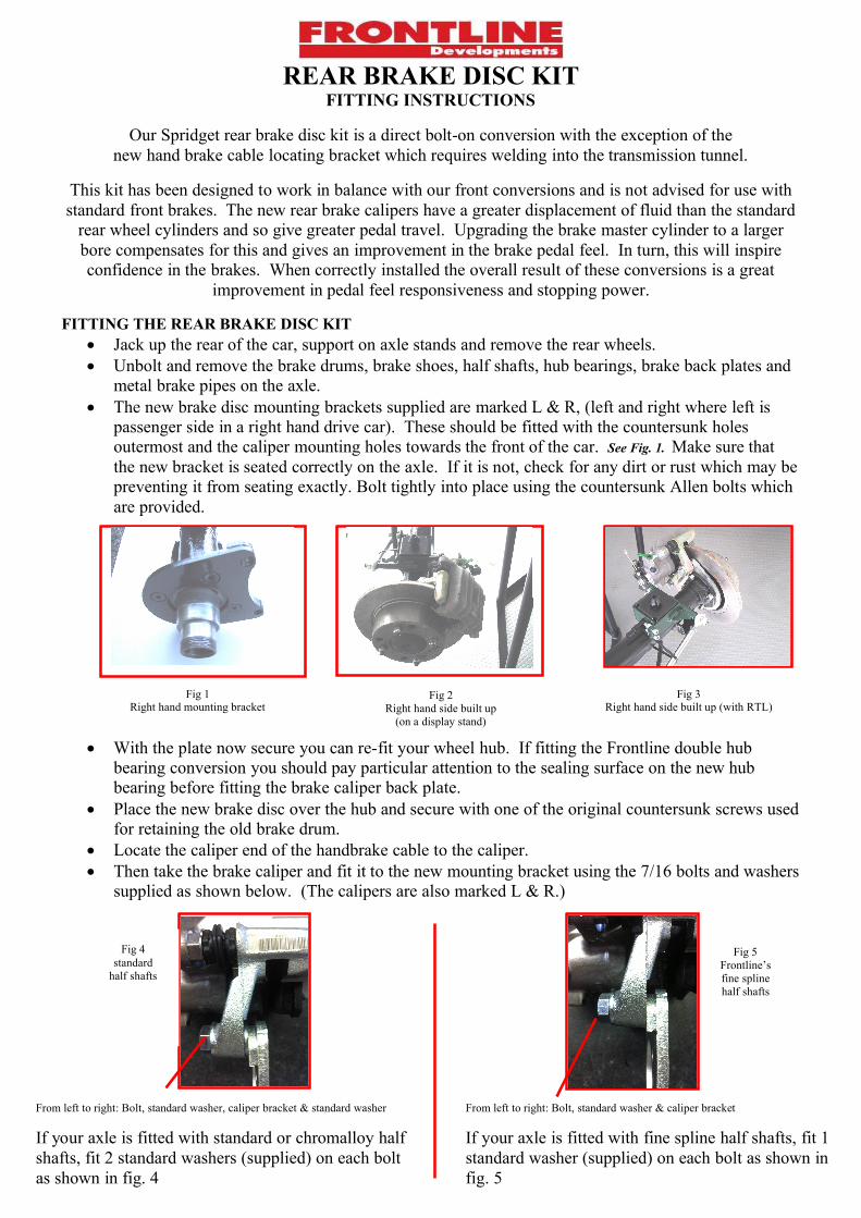
metal brake pipes on the axle. The new brake disc mounting brackets supplied are marked L & R, (left and right where left is
passenger side in a right hand drive car). These should be fitted with the countersunk holes outermost and the caliper mounting holes towards the front of the car. See Fig. 1. Make sure that the new bracket is seated correctly on the axle. If it is not, check for any dirt or rust which may be preventing it from seating exactly. Bolt tightly into place using the countersunk Allen bolts which are provided.
With the plate now secure you can re-fit your wheel hub. If fitting the Frontline double hub bearing conversion you should pay particular attention to the sealing surface on the new hub bearing before fitting the brake caliper back plate.
Place the new brake disc over the hub and secure with one of the original countersunk screws used for retaining the old brake drum.
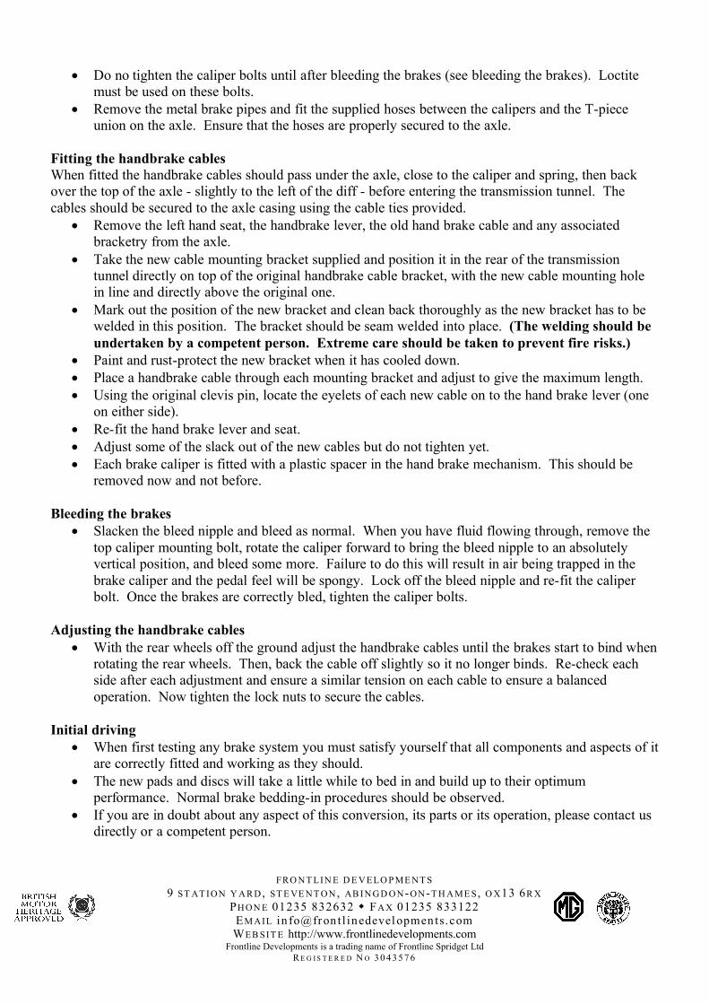
Locate the caliper end of the handbrake cable to the caliper. Then take the brake caliper and fit it to the new mounting bracket using the 7/16 bolts and washers
supplied as shown below. (The calipers are also marked L & R.)
Fig 1Right hand mounting bracket
Fig 3Right hand side built up (with RTL)
Fig 2Right hand side built up
(on a display stand)
From left to right: Bolt, standard washer, caliper bracket & standard washer
If your axle is fitted with standard or chromalloy half shafts, fit 2 standard washers (supplied) on each bolt as shown in fig. 4
Fig 4standard
half shafts
Fig 5Frontline’sfine splinehalf shafts
From left to right: Bolt, standard washer & caliper bracket
If your axle is fitted with fine spline half shafts, fit 1 standard washer (supplied) on each bolt as shown in fig. 5
Do no tighten the caliper bolts until after bleeding the brakes (see bleeding the brakes). Loctite must be used on these bolts.
Remove the metal brake pipes and fit the supplied hoses between the calipers and the T-piece union on the axle. Ensure that the hoses are properly secured to the axle.
Fitting the handbrake cablesWhen fitted the handbrake cables should pass under the axle, close to the caliper and spring, then back over the top of the axle - slightly to the left of the diff - before entering the transmission tunnel. The cables should be secured to the axle casing using the cable ties provided.
Remove the left hand seat, the handbrake lever, the old hand brake cable and any associated bracketry from the axle.
Take the new cable mounting bracket supplied and position it in the rear of the transmission tunnel directly on top of the original handbrake cable bracket, with the new cable mounting hole in line and directly above the original one.
Mark out the position of the new bracket and clean back thoroughly as the new bracket has to be welded in this position. The bracket should be seam welded into place. (The welding should be undertaken by a competent person. Extreme care should be taken to prevent fire risks.)
Paint and rust-protect the new bracket when it has cooled down. Place a handbrake cable through each mounting bracket and adjust to give the maximum length. Using the original clevis pin, locate the eyelets of each new cable on to the hand brake lever (one
on either side). Re-fit the hand brake lever and seat. Adjust some of the slack out of the new cables but do not tighten yet. Each brake caliper is fitted with a plastic spacer in the hand brake mechanism. This should be
removed now and not before.
Bleeding the brakes Slacken the bleed nipple and bleed as normal. When you have fluid flowing through, remove the
top caliper mounting bolt, rotate the caliper forward to bring the bleed nipple to an absolutely vertical position, and bleed some more. Failure to do this will result in air being trapped in the brake caliper and the pedal feel will be spongy. Lock off the bleed nipple and re-fit the caliper bolt. Once the brakes are correctly bled, tighten the caliper bolts.
Adjusting the handbrake cables With the rear wheels off the ground adjust the handbrake cables until the brakes start to bind when
rotating the rear wheels. Then, back the cable off slightly so it no longer binds. Re-check each side after each adjustment and ensure a similar tension on each cable to ensure a balanced operation. Now tighten the lock nuts to secure the cables.
Initial driving When first testing any brake system you must satisfy yourself that all components and aspects of it
are correctly fitted and working as they should. The new pads and discs will take a little while to bed in and build up to their optimum
performance. Normal brake bedding-in procedures should be observed. If you are in doubt about any aspect of this conversion, its parts or its operation, please contact us
directly or a competent person.
FRO N T LIN E D E V ELO P ME N T S9 ST AT IO N Y A RD , ST E VE N T O N , AB IN G D O N-O N-T H A ME S , O X13 6R X
PH O N E 01235 832632 FA X 01235 833122EM AIL in fo@fron t l inedevel opments.comWEB SIT E http://www.frontlinedevelopments.com
Frontline Developments is a trading name of Frontline Spridget LtdR E G I S T E R E D N O 3 0 4 3 5 7 6