Embed Size (px)
Citation preview

2001-2003 BRAKES
Disc
MODEL IDENTIFICATION
Several different brake versions are used by Volkswagen. To aid in identifying brake system installed on a particular model, see BRAKE SYSTEM IDENTIFICATION table.
BRAKE SYSTEM IDENTIFICATION Model Engine Size/M Number Brake System Beetle 1.8L FN3 Beetle 1.9L & 2.0L FS III Cabrio (1) (1)
EuroVan (2) 2.8L 1LU With 15" Wheels FN3
EuroVan (2) 2.8L 1LP With 15" Wheels (3) C54 EuroVan (2) 2.8L 1LE With 15" Wheels (4) RC54 EuroVan (2) 2.8L 1LB With 16" Wheels FN3 Or FNR Golf, GTI & Jetta 1.8L FN3 Golf, GTI & Jetta 1.8L GTI 337 Edition FN3 Golf, GTI & Jetta 1.9L FS III Golf, GTI & Jetta 2.0L FS III Golf, GTI & Jetta 2.8L FN3 Passat 1.6L, 1.8L 1.9L & 2.0L With 15" Wheels (5) FN3 Passat 2.3L, 2.5L & 2.8L With 16" Wheels (5) FN3 Passat 4.0L With 16" Wheels (6) HP2 Passat 4.0L With 17" Wheels (6) 2FN (1) For Cabrio repair procedures and specifications, see DISC & DRUM article in
1999-2000 BRAKES.(2) Identify brake version ("M" number) by reading number on vehicle data plate.
Data plate is located on left "A" pillar, next to central electronics. See Fig. 1 .(3) Equipped with Lucas fist caliper.(4) Equipped with Lucas frame caliper.(5) 2001 year models.(6) 2002 year models.
2003 Volkswagen Passat GLX 4Motion
DISC
1 января 2005 г. 1:37:10 Page 1 © 2004 Mitchell Repair Information Company, LLC.

2003 Volkswagen Passat GLX 4Motion
DISC
1 января 2005 г. 1:37:10 Page 2 © 2004 Mitchell Repair Information Company, LLC.

Fig. 1: Locating & Reading Vehicle Data Plate (EuroVan) Courtesy of VOLKSWAGEN UNITED STATES, INC.
DESCRIPTION & OPERATION
All models are equipped with front and rear disc brakes. Parking brake acts on rear brakes and is cable-actuated. Some models use a pressure regulator between front and rear brake circuits to avoid rear wheel lock-up during hard braking. Vehicles with Mark 60 or Bosch 5.3 Anti-Lock Brake Systems (ABS) do not have a mechanical brake pressure regulator. Specially matched software in the ABS ECU controls pressure regulation to rear axle brake.
Hydraulic brake system uses a tandem master cylinder with vacuum assist. Hydraulic system is diagonally split. Left front and right rear wheels form one circuit. Right front and left rear wheels form the other circuit.
Gasoline models with automatic transmissions are equipped with an auxiliary electric vacuum pump. Vacuum pump supplies vacuum to brake booster ensuring adequate vacuum for proper vacuum assist. Vacuum pump is activated by a signal from ABS control module, and is located under master cylinder. Vacuum sensor located in vacuum line to brake booster sends signal to ABS control module indicating vacuum level.
Brake booster sender 1 and brake pressure sensor 2 (Beetle, Golf, GTI & Jetta) are located on brake master cylinder, and send brake pressure information to ABS control module.
Vehicles manufactured from 02/2002 are equipped with brake assist. When brake pedal is depressed, mechanical brake assist is activated. Brake pedal can now be partially released and pressed again with less force. It is not possible to repair the brake assist, the complete brake booster must be replaced.
BLEEDING BRAKE SYSTEM
BLEEDING PROCEDURES
1. Exhaust vacuum reserve from power unit by depressing brake pedal several times. On ABS-equipped vehicles, depress brake pedal at least 20 times to relieve system pressure.
2. On all vehicles, fill master cylinder with clean brake fluid. If master cylinder was replaced, bleed master cylinder before bleeding wheel calipers. Connect bleeder hose to appropriate bleeder valve.
WARNING: Use only DOT 4 brake fluid from a sealed container. DO NOT mix brake fluid with any other type.
CAUTION: Brake fluid will damage painted surfaces. If brake fluid is spilled on painted surface, wipe it off immediately and clean with alcohol.
CAUTION: If a model equipped with ABS runs out brake fluid in either side of reservoir, it will be necessary to use scan tool (VAG 1551) to bleed brakes. See BLEEDING in appropriate ANTI-LOCK & TRACTION CONTROL article.
CAUTION: Bleeding procedure is same for pressure bleeding with US1116 (pressure bleeder), or manually. DO NOT exceed 14.5 psi. (1 bar) pressure in US1116. Brake system will not bleed completely with excessive pressure.
2003 Volkswagen Passat GLX 4Motion
DISC
1 января 2005 г. 1:37:10 Page 3 © 2004 Mitchell Repair Information Company, LLC.

See BRAKELINE BLEEDING SEQUENCE table.
BRAKELINE BLEEDING SEQUENCE
3. Submerge other end of hose in clean glass jar partially filled with clean brake fluid. Pump brake pedal several times, then hold down. Open bleeder valve. Holding pedal down, close bleeder valve. Release brake pedal.
4. Repeat procedure until brake fluid shows no signs of air bubbles. When bleeding rear brakes, push lever of pressure regulator in direction of rear axle.
5. After bleeding ABS-equipped vehicles, a test drive must be carried out after bleeding brakes. When doing this an ABS regulation must be performed at least once. Turn ignition on. Allow pump to run until it shuts off. If pump runs longer than 2 minutes, allow pump to cool for 10 minutes. On all vehicles, top master cylinder reservoir as necessary.
ADJUSTMENTS
BRAKE LIGHT SWITCH
Passat
With brake pedal released, measure distance "A". See Fig. 2 . If distance is not .020"-.060" (0.5-1.5 mm), loosen lock nut and adjust as necessary.
Application (1) Sequence All Models RR, LR, RF, LF (1) On all vehicles (if equipped), push brake pressure regulator lever in direction of
rear axle when bleeding rear brakes. Pressure regulator is mounted on a bracket near rear trailing arm.
NOTE: For brakelight switch adjustment on all models except Passat, see BRAKELIGHT SWITCH under REMOVAL & INSTALLATION.
2003 Volkswagen Passat GLX 4Motion
DISC
1 января 2005 г. 1:37:10 Page 4 © 2004 Mitchell Repair Information Company, LLC.

Fig. 2: Adjusting Brakelight Switch Courtesy of AUDI OF AMERICA, INC.
BRAKE PRESSURE REGULATOR
NOTE: For brake pressure regulator testing and adjustments, see BRAKE PRESSURE REGULATOR under ADJUSTMENTS in DISC & DRUM article in 1999-2000 BRAKES.
2003 Volkswagen Passat GLX 4Motion
DISC
1 января 2005 г. 1:37:10 Page 5 © 2004 Mitchell Repair Information Company, LLC.

MASTER CYLINDER PUSH ROD
PARKING BRAKE
Rear Disc (Except Passat)
1. Raise and support vehicle. Operate parking brake lever 3 times. Disengage parking brake. Loosen locking nuts at parking brake lever.
2. Tighten adjusting nuts until levers on calipers just move off stops. Measure gap between stop and lever. See Fig. 3 . Maximum clearance between parking brake lever (on caliper) and stop should be as specified. See PARKING BRAKE ADJUSTMENT SPECIFICATION table.
PARKING BRAKE ADJUSTMENT SPECIFICATION
3. Apply and release parking brake. Ensure rear wheels rotate freely. Adjust as necessary. Tighten lock nuts.
NOTE: Master cylinder push rod is not adjustable.
NOTE: Due to self-adjusting rear brakes adjustment is normally only necessary after replacing parking brake cables, brake calipers, brake pads and/or brake discs, backing plate or brake linings.
Model Specification In. (mm) Beetle .060 (1.5) EuroVan .040 (1) Golf, GTI & Jetta .040-.118 (1-3)
2003 Volkswagen Passat GLX 4Motion
DISC
1 января 2005 г. 1:37:10 Page 6 © 2004 Mitchell Repair Information Company, LLC.
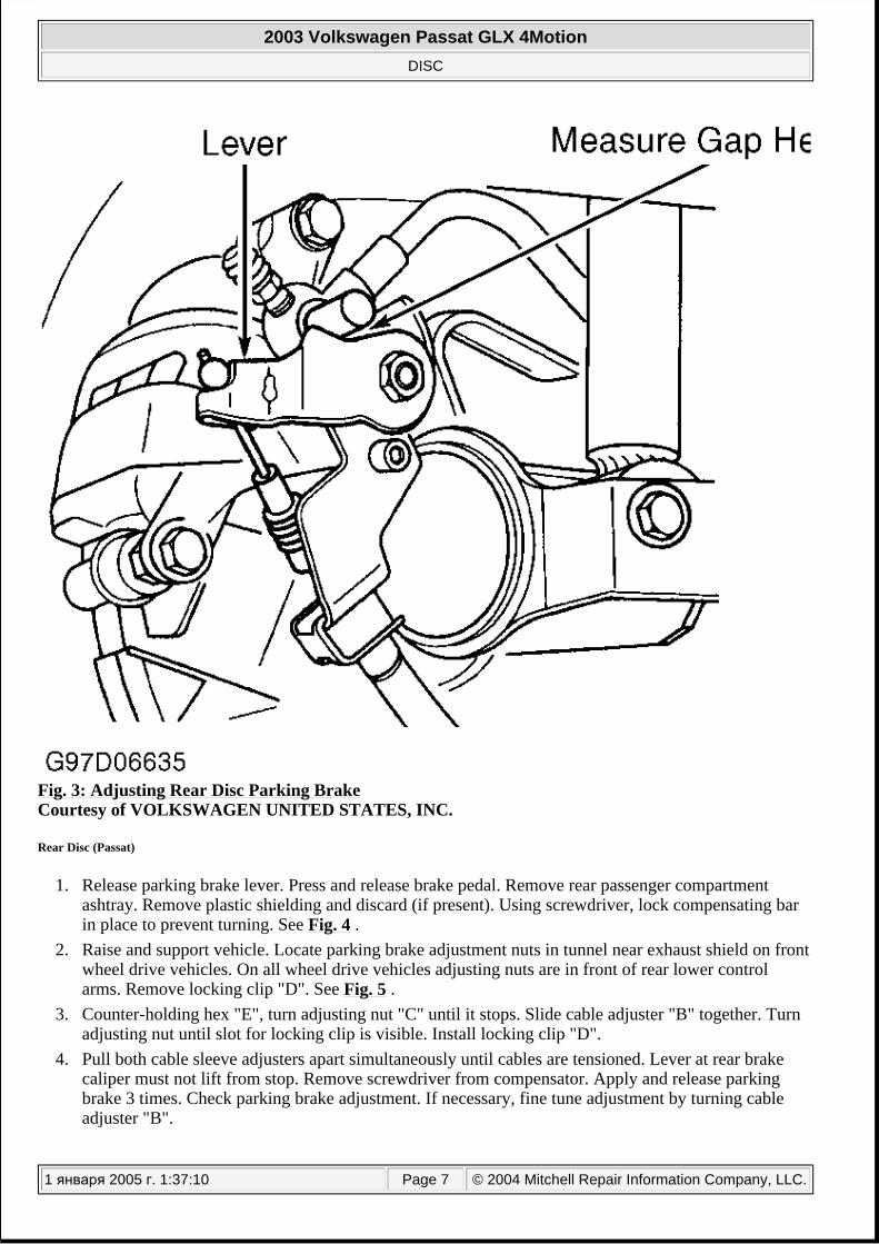
Fig. 3: Adjusting Rear Disc Parking Brake Courtesy of VOLKSWAGEN UNITED STATES, INC.
Rear Disc (Passat)
1. Release parking brake lever. Press and release brake pedal. Remove rear passenger compartment ashtray. Remove plastic shielding and discard (if present). Using screwdriver, lock compensating bar in place to prevent turning. See Fig. 4 .
2. Raise and support vehicle. Locate parking brake adjustment nuts in tunnel near exhaust shield on front wheel drive vehicles. On all wheel drive vehicles adjusting nuts are in front of rear lower control arms. Remove locking clip "D". See Fig. 5 .
3. Counter-holding hex "E", turn adjusting nut "C" until it stops. Slide cable adjuster "B" together. Turn adjusting nut until slot for locking clip is visible. Install locking clip "D".
4. Pull both cable sleeve adjusters apart simultaneously until cables are tensioned. Lever at rear brake caliper must not lift from stop. Remove screwdriver from compensator. Apply and release parking brake 3 times. Check parking brake adjustment. If necessary, fine tune adjustment by turning cable adjuster "B".
2003 Volkswagen Passat GLX 4Motion
DISC
1 января 2005 г. 1:37:10 Page 7 © 2004 Mitchell Repair Information Company, LLC.

Fig. 4: Locking Compensating Bar (Passat - Shown With Center Bracket Removed) Courtesy of AUDI OF AMERICA, INC.
2003 Volkswagen Passat GLX 4Motion
DISC
1 января 2005 г. 1:37:10 Page 8 © 2004 Mitchell Repair Information Company, LLC.

Fig. 5: Adjusting Parking Brake (Passat) Courtesy of AUDI OF AMERICA, INC.
WHEEL BEARINGS
TESTING
BRAKE BOOSTER BRAKE ASSIST
Vehicles manufactured from 02/2002 are equipped with brake assist. To test brake assist, start engine and depress brake pedal to ensure full vacuum boost. When brake pedal is depressed, a "click" must be audible, activating mechanical brake assist. Brake pedal can now be partially released and pressed again with less force. It is not possible to repair the brake assist, complete brake booster must be replaced.
NOTE: Front and rear wheel bearings, also called hub or axle bearings, are sealed units. Bearings are not adjustable.
2003 Volkswagen Passat GLX 4Motion
DISC
1 января 2005 г. 1:37:10 Page 9 © 2004 Mitchell Repair Information Company, LLC.

ELECTRIC VACUUM PUMP
During start-up, brake system vacuum pump must run briefly. To test, raise and support vehicle. Start engine. Check by touch that the brake system vacuum pump is running with the assistance of a second person. See Fig. 6 . If brake system vacuum pump does not run, check for Diagnostic Trouble Codes (DTCs) stored in ECM or ABS ECU memory. See FUNCTION 02 - READING DTC MEMORY in appropriate ENGINE PERFORMANCE or ANTI-LOCK BRAKE SYSTEM article. If any DTCs are retrieved, perform appropriate test. If no DTCs are stored in memory, perform electrical testing. See ELECTRIC VACUUM PUMP under ELECTRICAL TESTING.
2003 Volkswagen Passat GLX 4Motion
DISC
1 января 2005 г. 1:37:11 Page 10 © 2004 Mitchell Repair Information Company, LLC.

2003 Volkswagen Passat GLX 4Motion
DISC
1 января 2005 г. 1:37:11 Page 11 © 2004 Mitchell Repair Information Company, LLC.

Fig. 6: Locating Electric Vacuum Pump Courtesy of VOLKSWAGEN UNITED STATES, INC.
VACUUM CHECK VALVE
To check function of check valve, blow air through valve. Air must pass through in direction of arrow. See Fig. 7 . Valve must remain closed in opposite direction. Ensure that check valve is installed correctly.
Fig. 7: Checking Function Of Vacuum Check Valve Courtesy of VOLKSWAGEN UNITED STATES, INC.
ELECTRICAL TESTING
ELECTRIC VACUUM PUMP (MODELS UP TO 05/2002)
Disconnect electric brake vacuum pump 6-pin harness connector. Vacuum pump is located under brake master cylinder. See Fig. 6 . Check for poor, loose, corroded or damaged terminal connection. Also, check instrument panel fuses No. 31 and 51. If problem is found, repair as necessary. After repair, recheck vacuum pump operation. See ELECTRIC VACUUM PUMP under TESTING.
NOTE: If the measured figures only deviate slightly from the specifications, clean sockets and plugs of the testers and adapter cables (with contact spray G 000 700 04 or equivalent) and repeat check. Before replacing components, check wiring and connections and also, particularly for specifications of less than 10 ohms, repeat resistance check on component.
2003 Volkswagen Passat GLX 4Motion
DISC
1 января 2005 г. 1:37:11 Page 12 © 2004 Mitchell Repair Information Company, LLC.

If no problem with terminals is found, perform electrical testing of vacuum pump. See ELECTRIC VACUUM PUMP TESTING (MODELS UP TO 05/2002) table. For aid in identifying terminals and circuits, see Fig. 8 , also see WIRING DIAGRAMS . For Engine Control Module (ECM) terminal testing and identification, see appropriate article in ENGINE PERFORMANCE.
Fig. 8: Identifying Brake System Vacuum Pump Harness Connector Terminals Courtesy of AUDI OF AMERICA, INC.
ELECTRIC VACUUM PUMP TESTING (MODELS UP TO 05/2002) Test Perform Test
Step No. See Fig.
Brake System Vacuum Pump Resistance 1 Fig. 9Communication Signal From ECM To Brake System 2 Fig. 9
2003 Volkswagen Passat GLX 4Motion
DISC
1 января 2005 г. 1:37:11 Page 13 © 2004 Mitchell Repair Information Company, LLC.

Fig. 9: Vacuum Pump Electrical Test Steps No. 1 & 2 (Models Up To 05/2002) Courtesy of VOLKSWAGEN UNITED STATES, INC.
Fig. 10: Vacuum Pump Electrical Test Step No. 3 (Models Up To 05/2002) Courtesy of VOLKSWAGEN UNITED STATES, INC.
Vacuum Pump Ignition/Starter Switch Voltage Supply To Brake System Vacuum Pump
3 Fig. 10
Resistance Of Ignition/Starter Switch To Brake System Vacuum Pump Circuit
4 Fig. 11
Resistance Of Battery To Brake System Vacuum Pump Circuit
5 Fig. 12
Brake System Vacuum Pump Battery Voltage Supply 6 Fig. 13
2003 Volkswagen Passat GLX 4Motion
DISC
1 января 2005 г. 1:37:11 Page 14 © 2004 Mitchell Repair Information Company, LLC.

Fig. 11: Vacuum Pump Electrical Test Step No. 4 (Models Up To 05/2002) Courtesy of VOLKSWAGEN UNITED STATES, INC.
Fig. 12: Vacuum Pump Electrical Test Step No. 5 (Models Up To 05/2002) Courtesy of VOLKSWAGEN UNITED STATES, INC.
Fig. 13: Vacuum Pump Electrical Test Step No. 6 (Models Up To 05/2002) Courtesy of VOLKSWAGEN UNITED STATES, INC.
ELECTRIC VACUUM PUMP (MODELS FROM 06/2002)
Disconnect electric vacuum pump 6-pin harness connector. Electric vacuum pump is located under brake master cylinder. See Fig. 6 . Check for poor, loose, corroded or damaged terminal connection. Also, check instrument panel fuse No. 51. If problem is found, repair as necessary. After repair, recheck vacuum pump operation. See ELECTRIC VACUUM PUMP under TESTING.
2003 Volkswagen Passat GLX 4Motion
DISC
1 января 2005 г. 1:37:11 Page 15 © 2004 Mitchell Repair Information Company, LLC.

If no problem with terminals is found, perform electrical testing of vacuum pump. See ELECTRIC VACUUM PUMP TESTING (MODELS FROM 06/2002) table. For aid in identifying terminals and circuits, see Fig. 8 . Also, see WIRING DIAGRAMS . For Engine Control Module (ECM) terminal testing and identification, see appropriate article in ENGINE PERFORMANCE.
ELECTRIC VACUUM PUMP TESTING (MODELS FROM 06/2002)
Fig. 14: Vacuum Pump Electrical Test Steps No. 1 & 2 (Models From 06/2002) Courtesy of VOLKSWAGEN UNITED STATES, INC.
Test Perform Test Step No.
See Fig.
Brake System Vacuum Pump Resistance 1 Fig. 14
Communication Signal From ECM To Brake System Vacuum Pump
2 Fig. 14
Resistance Of Battery Power Supply To Brake System Vacuum Pump Circuit
3 Fig. 15
Brake System Vacuum Pump Battery Voltage Supply 4 Fig. 16
2003 Volkswagen Passat GLX 4Motion
DISC
1 января 2005 г. 1:37:11 Page 16 © 2004 Mitchell Repair Information Company, LLC.

Fig. 15: Vacuum Pump Electrical Test Step No. 3 (Models From 06/2002) Courtesy of VOLKSWAGEN UNITED STATES, INC.
Fig. 16: Vacuum Pump Electrical Test Step No. 4 (Models From 06/2002) Courtesy of VOLKSWAGEN UNITED STATES, INC.
SERVICING
Manufacturer recommends replacing brake fluid every 2 years. After replacing brake fluid, bleed brake system. See BLEEDING BRAKE SYSTEM .
REMOVAL & INSTALLATION
WARNING: Use only DOT 4 brake fluid from a sealed container. DO NOT mix brake fluid with any other type.
CAUTION: Brake fluid will damage painted surfaces. If brake fluid is spilled on painted surface, wipe it off immediately and clean with alcohol.
CAUTION: Brake fluid will damage painted surfaces. If brake fluid is spilled on painted surface, wipe it off immediately and wash with water.
CAUTION: When battery is disconnected, vehicle computer and memory systems may lose memory data. Driveability problems may exist until adaptation systems have completed a relearn cycle. See COMPUTER RELEARN PROCEDURES
2003 Volkswagen Passat GLX 4Motion
DISC
1 января 2005 г. 1:37:11 Page 17 © 2004 Mitchell Repair Information Company, LLC.

BRAKE BOOSTER
Removal (Beetle)
1. Disconnect battery. Clamp and remove clutch master cylinder supply hose. Remove ABS control module and hydraulic unit. See REMOVAL & INSTALLATION in appropriate ANTI-LOCK BRAKE SYSTEM article. Disconnect brake lines to master cylinder. Disconnect vacuum hose from brake booster.
2. On vehicles equipped with 1.9L TDI engine, remove retainer for wiring harness from vacuum pump. 3. Remove harness connector from retainer (2). See Fig. 17 . Disconnect in-line harness connector (1). 4. Remove lower instrument panel trim. Remove bolts (1) and remove cover "A". See Fig. 18 . On
vehicles equipped with manual transmission, remove connecting plate between clutch and brake pedals. Remove brake light switch. See appropriate procedure under BRAKELIGHT SWITCH .
5. Remove brake pedal from brake booster by first pressing brake pedal in direction of brake booster and hold. Insert special tool T 10006 and pull in direction of driver's seat, when doing this counter-hold on brake pedal (at this moment the pedal must not be allowed to move backward). See Fig. 19 . Mounting retaining tabs will be pressed off the ball head of the push rod. For ease of illustration separating the brake pedal from the brake booster is shown with the pedal cluster removed.
6. Remove brake booster-to-firewall nuts. Guide brake booster with brake master cylinder forward to remove.
article in GENERAL INFORMATION before disconnecting battery.
NOTE: Before disconnecting battery, on vehicles equipped with coded anti-theft radio, note radio code, obtain if necessary.
2003 Volkswagen Passat GLX 4Motion
DISC
1 января 2005 г. 1:37:11 Page 18 © 2004 Mitchell Repair Information Company, LLC.

Fig. 17: Removing Brake Booster (1 Of 2 - Beetle) Courtesy of VOLKSWAGEN UNITED STATES, INC.
2003 Volkswagen Passat GLX 4Motion
DISC
1 января 2005 г. 1:37:11 Page 19 © 2004 Mitchell Repair Information Company, LLC.

Fig. 18: Removing Brake Booster (2 Of 2 - Beetle) Courtesy of VOLKSWAGEN UNITED STATES, INC.
2003 Volkswagen Passat GLX 4Motion
DISC
1 января 2005 г. 1:37:11 Page 20 © 2004 Mitchell Repair Information Company, LLC.

Fig. 19: Disconnecting Brake Pedal From Booster Courtesy of VOLKSWAGEN UNITED STATES, INC.
Installation (Beetle)
Before installing master cylinder, clean residual brake fluid from brake booster. Ensure push rod is properly centered in master cylinder. To install, reverse removal procedure. Hold push rod ball head in front of mounting and push brake pedal in direction of brake booster until the ball head engages audibly. Tighten fasteners to specification. See TORQUE SPECIFICATIONS . Adjust brake light switch. See BRAKELIGHT SWITCH under ADJUSTMENTS. Bleed brake system. See BLEEDING BRAKE SYSTEM .
Removal (EuroVan)
1. Remove master cylinder from brake booster. See MASTER CYLINDER . 2. Disconnect connections for brake lines (arrows). See Fig. 20 . Remove wire (1) from bracket (2).
Unbolt engine coolant expansion tank and lay aside. DO NOT open coolant system. Disconnect
2003 Volkswagen Passat GLX 4Motion
DISC
1 января 2005 г. 1:37:11 Page 21 © 2004 Mitchell Repair Information Company, LLC.

vacuum hose from brake booster. 3. Remove trim from under driver's side instrument panel. Remove clevis pin clip and pin. Remove
brake booster-to-firewall nuts. Remove brake booster.
Fig. 20: Removing Brake Lines & Wiring To Brake Booster (EuroVan) Courtesy of VOLKSWAGEN UNITED STATES, INC.
Installation (EuroVan)
Before installing master cylinder clean residual brake fluid from brake booster. Ensure push rod is properly centered in master cylinder. To install, reverse removal procedure. Tighten fasteners to specification. See TORQUE SPECIFICATIONS . Bleed brake system. See BLEEDING BRAKE SYSTEM .
Removal (Golf, GTI & Jetta)
1. Disconnect battery. Clamp and remove clutch master cylinder supply hose (if equipped). Remove ABS control module and hydraulic unit. See REMOVAL & INSTALLATION in appropriate ANTI-
2003 Volkswagen Passat GLX 4Motion
DISC
1 января 2005 г. 1:37:11 Page 22 © 2004 Mitchell Repair Information Company, LLC.

LOCK BRAKE SYSTEM article. Disconnect brake lines to master cylinder. Disconnect vacuum hose from brake booster.
2. Remove lower instrument panel trim. Remove bolts (1) and remove cover "A". See Fig. 18 . On vehicles equipped with manual transmission, remove connecting plate between clutch and brake pedals. Remove brake light switch. See appropriate procedure under BRAKELIGHT SWITCH .
3. Remove brake pedal from brake booster by first pressing brake pedal in direction of brake booster and hold. Insert special tool T 10006 and pull in direction of driver's seat, when doing this counter-hold on brake pedal (at this moment the pedal must not be allowed to move backward). See Fig. 19 . Mounting retaining tabs will be pressed off the ball head of the push rod. For ease of illustration separating the brake pedal from the brake booster is shown with the pedal cluster removed.
4. Remove brake booster-to-firewall nuts. Guide brake booster with brake master cylinder forward to remove.
Installation (Golf, GTI & Jetta)
To install, reverse removal procedure. Hold push rod ball head in front of mounting and push brake pedal in direction of brake booster until the ball head engages audibly. Tighten fasteners to specification. See TORQUE SPECIFICATIONS . Adjust brake light switch. See BRAKELIGHT SWITCH under ADJUSTMENTS. Bleed brake system. See BLEEDING BRAKE SYSTEM .
Removal (Passat)
1. Remove master cylinder from brake booster. See MASTER CYLINDER . Remove vacuum hose on brake booster unit.
2. Remove trim from under driver's side instrument panel. On vehicles equipped with a manual transmission, remove connecting piece between brake and clutch pedals. Disconnect brake light switch harness connector. Remove brake light switch. See appropriate procedure under BRAKELIGHT SWITCH .
3. Using Release Tool (T10006), disconnect brake pedal from brake booster. See Fig. 21 . Remove fasteners holding brake booster and master cylinder to firewall. Remove brake booster and master cylinder.
2003 Volkswagen Passat GLX 4Motion
DISC
1 января 2005 г. 1:37:11 Page 23 © 2004 Mitchell Repair Information Company, LLC.

Fig. 21: Removing Brake Booster (Passat)
2003 Volkswagen Passat GLX 4Motion
DISC
1 января 2005 г. 1:37:11 Page 24 © 2004 Mitchell Repair Information Company, LLC.

Courtesy of AUDI OF AMERICA, INC.
Installation (Passat)
Before installing master cylinder, clean residual brake fluid from brake booster. Ensure push rod is properly centered in master cylinder. To install, reverse removal procedure. Hold push rod ball head in front of mounting and push brake pedal in direction of brake booster until the ball head engages audibly. Tighten fasteners to specification. See TORQUE SPECIFICATIONS . Adjust brake light switch. See BRAKELIGHT SWITCH under ADJUSTMENTS. Bleed brake system. See BLEEDING BRAKE SYSTEM .
BRAKELIGHT SWITCH
Brakelight Switch (Beetle, EuroVan, Golf, GTI & Jetta)
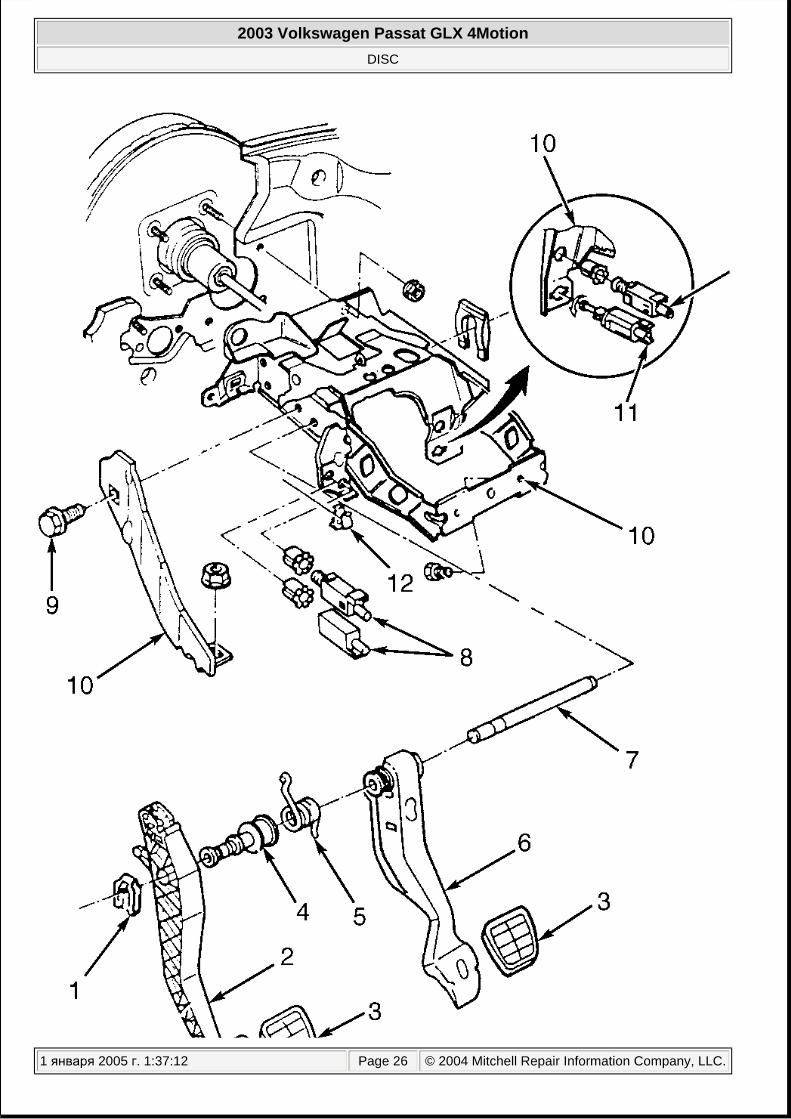
Brakelight switch is located on bracket above brake pedal. To replace, disconnect brakelight switch harness connector. Turn brakelight switch 45° counterclockwise (on Beetle, Jetta, GTI and Golf) or 90° (on EuroVan), and guide switch from bracket. To install, pull switch plunger out to stop. With brake pedal in rest position, guide switch into opening and turn 45° clockwise (on Beetle, Jetta, GTI and Golf) or 90° (on EuroVan). Verify proper functioning of brake lights. See Fig. 22 .
2003 Volkswagen Passat GLX 4Motion
DISC
1 января 2005 г. 1:37:12 Page 25 © 2004 Mitchell Repair Information Company, LLC.
2003 Volkswagen Passat GLX 4Motion
DISC
1 января 2005 г. 1:37:12 Page 26 © 2004 Mitchell Repair Information Company, LLC.

Fig. 22: Locating Brakelight Switch Courtesy of VOLKSWAGEN UNITED STATES, INC.
Brakelight Switch (Passat)
Remove storage compartment on driver's side. Disconnect brakelight switch harness connector. Loosen lock nut, and remove switch by turning switch counterclockwise. Installation is reverse of removal. After installing switch, adjustment is necessary. See BRAKE LIGHT SWITCH under ADJUSTMENTS. Verify proper functioning of brake lights.
ELECTRIC VACUUM PUMP
Remove engine cover. Disconnect electric vacuum pump harness connector. Vacuum pump is located below master cylinder. See Fig. 6 and Fig. 23 . Remove vacuum hose. Unclip pump by hand, and pull up on vacuum pump. To install, reverse removal procedure.
2003 Volkswagen Passat GLX 4Motion
DISC
1 января 2005 г. 1:37:12 Page 27 © 2004 Mitchell Repair Information Company, LLC.

2003 Volkswagen Passat GLX 4Motion
DISC
1 января 2005 г. 1:37:12 Page 28 © 2004 Mitchell Repair Information Company, LLC.

Fig. 23: Removing & Installing Electric Vacuum Pump Courtesy of AUDI OF AMERICA, INC.
FRONT DISC BRAKE PADS
Removal (FS III)
1. Raise and support vehicle. Remove front wheels. Remove guide pin protective caps. See Fig. 24 . Disconnect brake pad wear indicator harness connector.
2. Remove both guide pins from brake caliper. Remove brake caliper housing and secure with wire so that the weight of the brake caliper does not stress or damage brake hose. Remove brake pads from front brake caliper housing.
NOTE: To identify brake system equipped on vehicle, see BRAKE SYSTEM IDENTIFICATION table under IDENTIFICATION.
2003 Volkswagen Passat GLX 4Motion
DISC
1 января 2005 г. 1:37:12 Page 29 © 2004 Mitchell Repair Information Company, LLC.

2003 Volkswagen Passat GLX 4Motion
DISC
1 января 2005 г. 1:37:12 Page 30 © 2004 Mitchell Repair Information Company, LLC.

Fig. 24: Exploded View Of FS III Brake Components (Front Axle) Courtesy of VOLKSWAGEN UNITED STATES, INC.
Installation (FS III)
1. Before inserting new brake pads, press piston back into the cylinder with piston resetting tool. Brake pad with black three finger clip is to be used on the outer side of brake caliper housing.
2. Install brake caliper housing with brake pads on wheel bearing housing, lower part of brake caliper housing first. Brake caliper housing lug must be behind the wheel bearing housing guide. Secure brake caliper housing to brake carrier with both guide pins and tighten to specification. See TORQUE SPECIFICATIONS .
3. Connect brake pad wear indicator harness connector. After brake pad change firmly depress brake pedal several times with vehicle stationary, so that the brake pads are properly seated in their normal operating position. Check brake fluid level.
Removal (FN3)
1. Raise and support vehicle. Remove front wheels. Remove guide pin protective caps. See Fig. 25 . Pry brake pad retaining spring out from brake caliper housing with a screwdriver and remove. Disconnect brake pad wear indicator harness connector.
2. Remove both guide pins from brake caliper. Remove brake caliper housing and secure with wire so that the weight of the brake caliper does not stress or damage brake hose. Remove brake pads from brake caliper housing.
NOTE: Before pressing the piston back, draw off brake fluid from the reservoir with a bleeder bottle. Otherwise if reservoir has been topped off, fluid will overflow and cause damage.
2003 Volkswagen Passat GLX 4Motion
DISC
1 января 2005 г. 1:37:12 Page 31 © 2004 Mitchell Repair Information Company, LLC.

2003 Volkswagen Passat GLX 4Motion
DISC
1 января 2005 г. 1:37:12 Page 32 © 2004 Mitchell Repair Information Company, LLC.

Fig. 25: Exploded View Of FN3 Brake Components (Front Axle) Courtesy of VOLKSWAGEN UNITED STATES, INC.
Installation (FN3)
1. Before inserting new brake pads, press piston back into the cylinder with piston resetting tool. Before pressing the piston back, draw off brake fluid from the reservoir with a bleeder bottle. Otherwise if reservoir has been topped off, fluid will overflow and cause damage. When installed arrow on brake pad backplate must point downward. Ensure this pads are installed correctly. See Fig. 26 .
2. Install brake caliper housing with brake pads on wheel bearing housing, lower part of brake caliper housing first. Brake caliper housing lug must be behind the wheel bearing housing guide. Secure brake caliper housing to brake carrier with both guide pins and tighten to specification. See TORQUE SPECIFICATIONS .
3. Connect brake pad wear indicator harness connector. After brake pad change firmly depress brake pedal several times with vehicle stationary, so that the brake pads are properly seated. Check brake fluid level.
2003 Volkswagen Passat GLX 4Motion
DISC
1 января 2005 г. 1:37:12 Page 33 © 2004 Mitchell Repair Information Company, LLC.

Fig. 26: Identifying Brake Pad Installation Position (FN3) Courtesy of VOLKSWAGEN UNITED STATES, INC.
Removal (C54)
Raise and support vehicle. Remove front wheels. Unscrew lower mounting bolt for brake caliper housing. See Fig. 27 . Counter-hold at guide pin. Swing brake caliper housing upward. Remove brake pads.
2003 Volkswagen Passat GLX 4Motion
DISC
1 января 2005 г. 1:37:12 Page 34 © 2004 Mitchell Repair Information Company, LLC.

Fig. 27: Exploded View Of Lucas C54 Brake Components (Front Axle) Courtesy of VOLKSWAGEN UNITED STATES, INC.
2003 Volkswagen Passat GLX 4Motion
DISC
1 января 2005 г. 1:37:12 Page 35 © 2004 Mitchell Repair Information Company, LLC.

Installation (C54)
Before inserting new brake pads, press piston back into the cylinder with piston resetting tool. Insert brake pads. Swing brake caliper housing downward and tighten mounting bolts to specification. See TORQUE SPECIFICATIONS . Repair kit includes two self-locking hex-bolts which must always be installed.
Removal (RC54)
Remove wheels. Remove securing spring. See Fig. 28 . Drive out brake pad retaining pins using drift. Remove inner brake pad. Shift frame. Loosen outer brake pad from brake pad mounting surface at bridge using a flat-bladed tool. Remove outer brake pad.
NOTE: Before pressing the piston back, draw off brake fluid from the reservoir with a bleeder bottle. Otherwise if reservoir has been topped off, fluid will overflow and cause damage.
2003 Volkswagen Passat GLX 4Motion
DISC
1 января 2005 г. 1:37:12 Page 36 © 2004 Mitchell Repair Information Company, LLC.

2003 Volkswagen Passat GLX 4Motion
DISC
1 января 2005 г. 1:37:12 Page 37 © 2004 Mitchell Repair Information Company, LLC.

Fig. 28: Exploded View Of Lucas RC54 Brake Components (Front Axle) Courtesy of VOLKSWAGEN UNITED STATES, INC.
Installation (RC54)
Press piston back into caliper housing using resetting tool before inserting new brake pads. Clean brake caliper housing, especially the adhesive surface for brake pad, it must be free of residual adhesive and grease. Install inner brake pad. Install pad retaining pins enough that inner pad is held on. Carefully insert outer brake pads. Press brake pad retaining pins completely through and install securing spring. When inserting outer brake pad, be sure that it does not adhere to brake caliper housing prior to achieving correct installation position. Do not damage adhesive surfaces. After installing new brake pads, operate brake pedal powerfully two or three times and hold pedal for 5 to 10 seconds so that outer pads adhere securely to brake caliper housing. This helps ensure a reliable adhesion of the outer pad and noise-free braking.
Removal (FNR)
1. Raise and support vehicle. Remove front wheels. Remove guide pin protective caps. See Fig. 29 . Pry brake pad retaining spring out from brake caliper housing with a screwdriver and remove. Disconnect brake pad wear indicator harness connector. Lift securing strap slightly at bottom of harness connector and then rotate 90°. Remove harness connector from bracket.
2. Remove both guide pins from brake caliper. Remove brake caliper housing and secure with wire so that the weight of the brake caliper does not stress or damage brake hose. Remove brake pads front brake caliper housing.
NOTE: Before pushing back piston, siphon some of the brake fluid out of brake fluid reservoir. If reservoir has been topped off, fluid will overflow and cause damage.
2003 Volkswagen Passat GLX 4Motion
DISC
1 января 2005 г. 1:37:12 Page 38 © 2004 Mitchell Repair Information Company, LLC.
2003 Volkswagen Passat GLX 4Motion
DISC
1 января 2005 г. 1:37:12 Page 39 © 2004 Mitchell Repair Information Company, LLC.

Fig. 29: Exploded View Of FNR Brake Components (Front Axle) Courtesy of VOLKSWAGEN UNITED STATES, INC.
Installation (FNR)
1. Before inserting new brake pads, press piston back into the cylinder with piston resetting tool. Install brake caliper housing with brake pads on wheel bearing housing, lower part of brake caliper housing first. Brake caliper housing lug must be behind the wheel bearing housing guide.
2. Secure brake caliper housing to brake carrier with both guide pins and tighten to specification. See TORQUE SPECIFICATIONS .
3. Connect brake pad wear indicator harness connector. After brake pad change, firmly depress brake pedal several times with vehicle stationary, so that the brake pads are properly seated in their normal operating position. Check brake fluid level.
Removal (HP2)
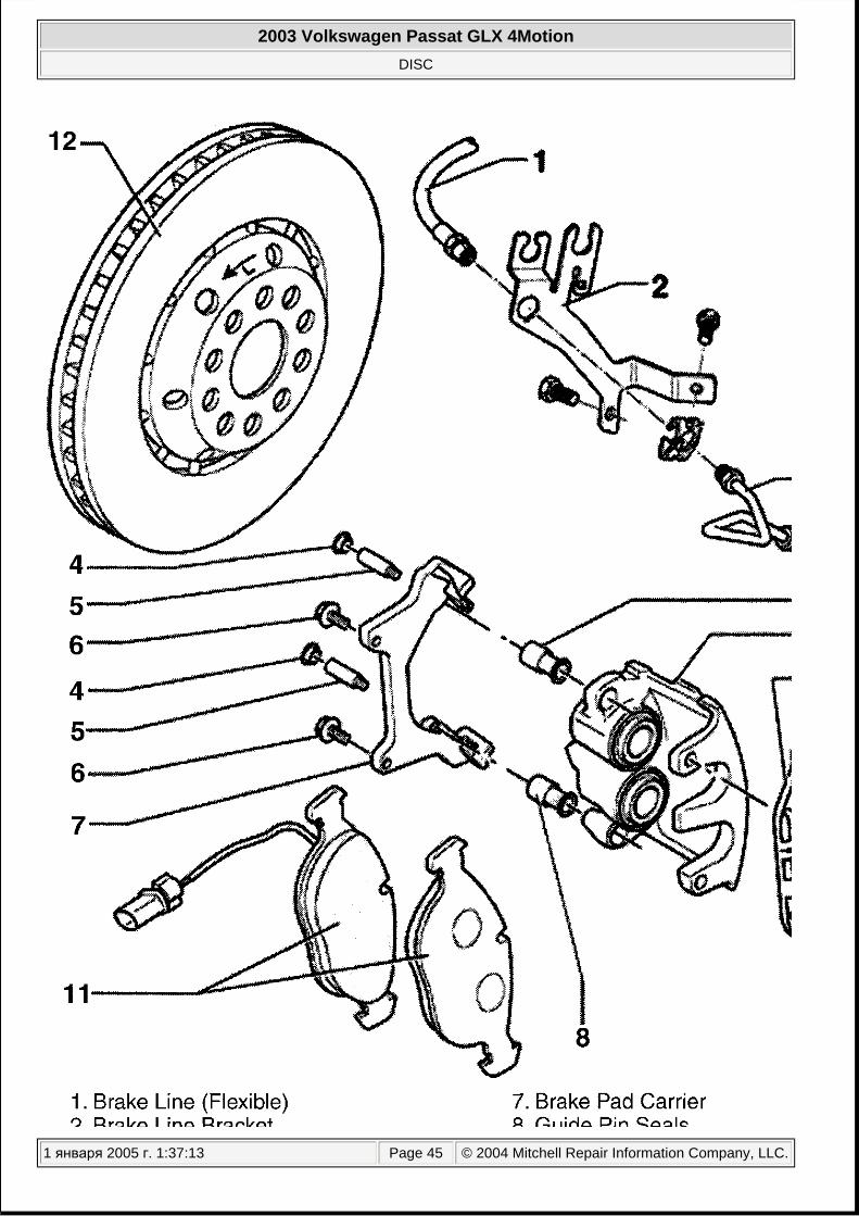
1. Raise and support vehicle. Remove front wheels. Secure brake disc by threading a wheel lug into hub. Unclip upper and lower parts of retaining spring using a pair of pliers. See Fig. 30 and Fig. 31 . Push spring sideways. Spring cannot be completely removed from caliper.
2. Disconnect brake pad wear indicator harness connector. Lift securing strap slightly at bottom of harness connector and then rotate 90° and remove harness connector from bracket.
3. Using a flat-bladed tool, press piston back into the cylinder. Before pressing the piston back, draw off brake fluid from the reservoir with a bleeder bottle. Otherwise if reservoir has been topped off, fluid will overflow and cause damage.
4. Using a flat-bladed tool, first press outer brake pads off caliper and then remove. Push floating caliper in direction of arrow until caliper stops. See Fig. 32 . Carefully press inner brake pads out of pistons and remove from floating caliper. Clean floating caliper, in particular the adhesive surface for outer brake pads. This area must be free of adhesive residue and grease.
NOTE: Before pressing the piston back, draw off brake fluid from the reservoir with a bleeder bottle. Otherwise if reservoir has been topped off, fluid will overflow and cause damage.
2003 Volkswagen Passat GLX 4Motion
DISC
1 января 2005 г. 1:37:12 Page 40 © 2004 Mitchell Repair Information Company, LLC.

Fig. 30: Removing Retaining Spring (HP2) Courtesy of VOLKSWAGEN UNITED STATES, INC.
2003 Volkswagen Passat GLX 4Motion
DISC
1 января 2005 г. 1:37:12 Page 41 © 2004 Mitchell Repair Information Company, LLC.

2003 Volkswagen Passat GLX 4Motion
DISC
1 января 2005 г. 1:37:12 Page 42 © 2004 Mitchell Repair Information Company, LLC.

Fig. 31: Exploded View Of HP2 Brake Components (Front Axle) Courtesy of VOLKSWAGEN UNITED STATES, INC.
Fig. 32: Removing Brake Pads (HP2) Courtesy of VOLKSWAGEN UNITED STATES, INC.
Installation (HP2)
1. Carefully install inner brake pads in caliper. Press floating caliper outwards until it stops. Pull off protective foil on backing plates of outer brake pads. Install outer pads in floating caliper. Ensure that lugs of the backing plates are located correctly in floating caliper.
2. Install brake wear indicator connector into bracket on brake caliper. Clip in upper and lower parts of retaining spring.
3. After brake pad change, firmly depress brake pedal several times with vehicle stationary, so that the brake pads are properly seated in their normal operating position. Check brake fluid level.
2003 Volkswagen Passat GLX 4Motion
DISC
1 января 2005 г. 1:37:12 Page 43 © 2004 Mitchell Repair Information Company, LLC.

Removal (2FN)
1. Raise and support vehicle. Remove front wheels. Push retaining spring in upwards direction and remove from brake caliper sideways. See Fig. 33 . Remove guide pin protective caps. Disconnect brake pad wear indicator harness connector. Lift securing strap slightly at bottom of harness connector and then rotate 90°. Remove harness connector from bracket.
2. Remove both guide pins from brake caliper. Remove brake caliper housing and secure with wire so that the weight of the brake caliper does not stress or damage brake hose. Remove brake pads from brake caliper housing.
2003 Volkswagen Passat GLX 4Motion
DISC
1 января 2005 г. 1:37:12 Page 44 © 2004 Mitchell Repair Information Company, LLC.
2003 Volkswagen Passat GLX 4Motion
DISC
1 января 2005 г. 1:37:13 Page 45 © 2004 Mitchell Repair Information Company, LLC.

Fig. 33: Exploded View Of 2FN Brake Components (Front Axle) Courtesy of VOLKSWAGEN UNITED STATES, INC.
Installation (2FN)
1. Before inserting new brake pads, press piston back into the cylinder with piston resetting tool. Install brake caliper housing with brake pads on wheel bearing housing, lower part of brake caliper housing first. Brake caliper housing lug must be behind the wheel bearing housing guide.
2. Secure brake caliper housing to brake carrier with both guide pins and tighten to specification. See TORQUE SPECIFICATIONS .
3. Connect brake pad wear indicator harness connector. After brake pad change, firmly depress brake pedal several times with vehicle stationary, so that the brake pads are properly seated in their normal operating position. Check brake fluid level.
FRONT & REAR BRAKE CALIPER
Removal & Installation
1. Raise and support vehicle. Remove wheels. Disconnect brakeline from caliper, and plug openings. Bend back locking tabs (if equipped) on mounting bolts. If removing rear brake calipers, disconnect parking brake cables.
2. On all calipers, remove caliper mounting bolts. Remove caliper assembly from wheel bearing housing. To install, reverse removal procedure. Use NEW lock plates (if equipped) and mounting bolts. Bleed hydraulic brake system. See BLEEDING PROCEDURES under BLEEDING BRAKE SYSTEM.
FRONT & REAR BRAKE ROTOR
Removal & Installation
Raise and support vehicle. Remove wheels. Remove brake caliper. See FRONT & REAR BRAKE CALIPER . Secure caliper with wire so that the weight of the brake caliper does not stress or damage brake hose. Remove countersunk screw that holds rotor to hub. Pull rotor off hub. To install, reverse removal procedure. Tighten fasteners to specification. See TORQUE SPECIFICATIONS .
MASTER CYLINDER
Removal (Beetle)
1. Disconnect battery. Remove intake hose and harness connector from mass air flow sensor. Remove air cleaner complete. On vehicles equipped with a 2.0L or 1.8L engines, remove protective housing for relays from cable channel.
2. To catch leaking brake fluid, place sufficient lint free cloths in area of plenum chamber, engine and transmission. Install bleeder hose and bleeder bottle to the front left brake caliper bleeder screw and open bleeder screw. Operate brake pedal until sufficient amount of brake fluid has been pumped out for the brake fluid level in the brake fluid reservoir to sink below the clutch master cylinder supply hose (if equipped). Close front left bleeder screw.
NOTE: Before pressing the piston back, draw off brake fluid from the reservoir with a bleeder bottle. Otherwise if reservoir has been topped off, fluid will overflow and cause damage.
2003 Volkswagen Passat GLX 4Motion
DISC
1 января 2005 г. 1:37:13 Page 46 © 2004 Mitchell Repair Information Company, LLC.

3. Disconnect and clamp clutch master cylinder supply hose (if equipped) and seal with a plug. Disconnect brake fluid level warning indicator sensor harness connector. Disconnect brake pressure sender harness connectors.
4. Disconnect brake lines on brake master cylinder and seal brake lines and threaded holes with plugs from repair kit Part No. 1H0 698 311 A. Remove brake master cylinder nuts. Carefully remove brake master cylinder from brake booster unit.
Installation (Beetle)
To install, reverse removal procedure. Always use NEW "O" ring between master cylinder and brake booster. When installing the brake master cylinder and brake booster unit together, make sure that the push rod is correctly located in the brake master cylinder. Apply slight pressure to the brake pedal to move the push rod towards brake master cylinder; this makes it easier to guide brake master cylinder onto the push rod. Tighten fasteners to specification. See TORQUE SPECIFICATIONS . Bleed hydraulic system. See BLEEDING BRAKE SYSTEM .
Removal (EuroVan & Passat)
1. To catch leaking brake fluid, place sufficient lint free cloths in area of plenum chamber, engine and transmission. Install bleeder hose and bleeder bottle to the front left brake caliper bleeder screw and open bleeder screw. Operate brake pedal until sufficient amount of brake fluid has been pumped out for the brake fluid level in the brake fluid reservoir to sink below the clutch master cylinder supply hose (if equipped). Close front left bleeder screw.
2. Disconnect and clamp clutch master cylinder supply hose (if equipped) and seal with a plug. Disconnect brake fluid level warning indicator sensor harness connector. See Fig. 34 . Remove reservoir retaining bolt. Remove brake fluid reservoir. To do this press down the locking tab on the reservoir and at the same time pull the brake fluid reservoir out of the sealing plugs.
3. Disconnect brake lines on brake master cylinder and seal brake lines and threaded holes with plugs from repair kit Part No. 1H0 698 311 A. Remove brake master cylinder nuts. Remove brake booster unit Torx head bolts (T45) using special tool (3320). Carefully remove brake master cylinder from brake booster unit.
2003 Volkswagen Passat GLX 4Motion
DISC
1 января 2005 г. 1:37:13 Page 47 © 2004 Mitchell Repair Information Company, LLC.

2003 Volkswagen Passat GLX 4Motion
DISC
1 января 2005 г. 1:37:13 Page 48 © 2004 Mitchell Repair Information Company, LLC.

Fig. 34: Removing & Installing Brake Master Cylinder (Passat) Courtesy of VOLKSWAGEN UNITED STATES, INC.
Installation (EuroVan & Passat)
To install, reverse removal procedure. Always use NEW "O" ring between master cylinder and brake booster. When installing the brake master cylinder and brake booster unit together, make sure that the push rod is correctly located in the brake master cylinder. Apply slight pressure to the brake pedal to move the push rod towards brake master cylinder; this makes it easier to guide brake master cylinder onto the push rod. Tighten fasteners to specification. See TORQUE SPECIFICATIONS . Bleed hydraulic system. See BLEEDING BRAKE SYSTEM .
Removal (Golf, GTI & Jetta)
1. To catch leaking brake fluid, place sufficient lint free cloths in area of plenum chamber, engine and transmission. Install bleeder hose and bleeder bottle to the front left brake caliper bleeder screw and open bleeder screw. Operate brake pedal until sufficient amount of brake fluid has been pumped out for the brake fluid level in the brake fluid reservoir to sink below the clutch master cylinder supply hose (if equipped). Close front left bleeder screw.
2. Disconnect and clamp clutch master cylinder supply hose (if equipped) and seal with a plug. Disconnect brake fluid level warning indicator sensor harness connector. Disconnect brake pressure sender No. 1 and 2 harness connectors.
3. Disconnect brake lines on brake master cylinder and seal brake lines and threaded holes with plugs from repair kit Part No. 1H0 698 311 A. Remove heat shield, if equipped. Remove brake master cylinder nuts. Carefully remove brake master cylinder from brake booster unit.
Installation (Golf, GTI & Jetta)
To install, reverse removal procedure. Always use NEW "O" ring between master cylinder and brake booster. When installing the brake master cylinder and brake booster unit together, make sure that the push rod is correctly located in the brake master cylinder. Apply slight pressure to the brake pedal to move the push rod towards brake master cylinder; this makes it easier to guide brake master cylinder onto the push rod. Tighten fasteners to specification. See TORQUE SPECIFICATIONS . Bleed hydraulic system. See BLEEDING BRAKE SYSTEM . After installing master cylinder, a zero compensation of brake pressure sender 1 and brake pressure sensor 2 must be performed in addition to basic settings on vehicles with ABS/EDL/ASR/ESP. See FUNCTION 04 - BASIC SETTING in appropriate ANTI-LOCK BRAKE SYSTEM article.
PRESSURE SWITCHES
Removal & Installation
To catch leaking brake fluid, place sufficient lint free cloths in area of plenum chamber, engine and transmission. Install bleeder hose and bleeder bottle to the front left brake caliper bleeder screw and open bleeder screw. Operate brake pedal until sufficient amount of brake fluid has been pumped out for the brake fluid level in the brake fluid reservoir to sink below the clutch master cylinder supply hose (if equipped). Close front left bleeder screw. Disconnect pressure switch harness connector. Remove pressure switch. To install, reverse removal procedure. Tighten switch to specification. See TORQUE SPECIFICATIONS . Bleed hydraulic system. See BLEEDING BRAKE SYSTEM . A zero compensation of brake pressure sender 1 and brake pressure sensor 2 must be performed in addition to basic settings on vehicles with ABS/EDL/ASR/ESP. See FUNCTION 04 - BASIC SETTING in appropriate ANTI-LOCK BRAKE SYSTEM article.
2003 Volkswagen Passat GLX 4Motion
DISC
1 января 2005 г. 1:37:13 Page 49 © 2004 Mitchell Repair Information Company, LLC.

REAR DISC BRAKE PADS
Removal
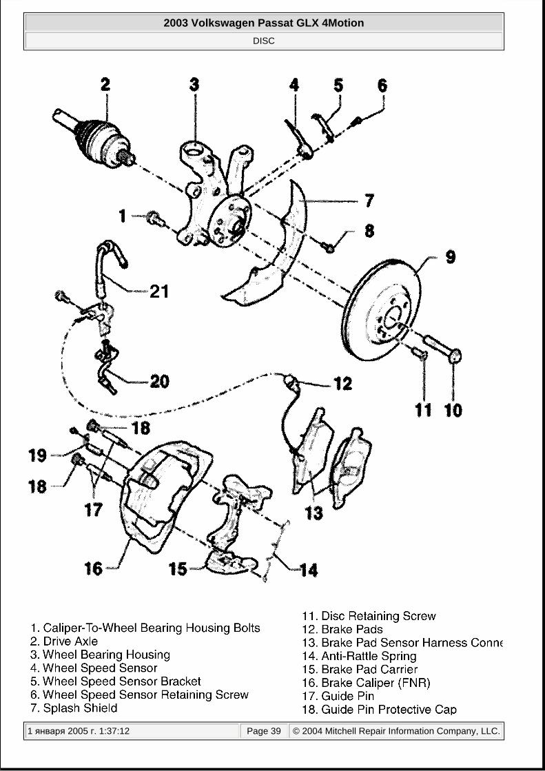
Raise and support vehicle. Remove rear wheels. Disconnect parking brake cable from caliper. Remove guide pins, or caliper mounting bolts. See Fig. 35 . Remove caliper, and wire aside. DO NOT allow caliper to hang by brake hose. Remove pads and retaining springs from caliper support.
2003 Volkswagen Passat GLX 4Motion
DISC
1 января 2005 г. 1:37:13 Page 50 © 2004 Mitchell Repair Information Company, LLC.

2003 Volkswagen Passat GLX 4Motion
DISC
1 января 2005 г. 1:37:13 Page 51 © 2004 Mitchell Repair Information Company, LLC.

Fig. 35: Exploded View Of Rear Brake Components (Typical) Courtesy of VOLKSWAGEN UNITED STATES, INC.
Installation
Use Special Tool (VW 3272) along with Collar (3272/1) or equivalent, to seat caliper piston fully into cylinder bore. See Fig. 36 . Seat piston by turning special tool until piston is bottomed out in bore. Before pressing the piston back, draw off brake fluid from the reservoir with a bleeder bottle. Otherwise if reservoir has been topped off, fluid will overflow and cause damage. Install brake pads, note positioning of pad to caliper (pin on pad must fit into groove on caliper piston). If reusing old pads, ensure that pads are installed in original positions or braking may be uneven. Position caliper. Install caliper mounting bolts. With engine off, depress brake pedal several times to allow pads to move into operating position. Ensure master cylinder reservoir fluid level is full. Adjust parking brake as necessary. See PARKING BRAKE under ADJUSTMENTS.
Fig. 36: Compressing Rear Brake Caliper Piston Courtesy of VOLKSWAGEN UNITED STATES, INC.
OVERHAUL
BRAKE CALIPER
2003 Volkswagen Passat GLX 4Motion
DISC
1 января 2005 г. 1:37:13 Page 52 © 2004 Mitchell Repair Information Company, LLC.

Disassembly
Remove brake caliper. See FRONT & REAR BRAKE CALIPER under REMOVAL & INSTALLATION. Remove caliper from vehicle. Remove pads, and clean exterior surfaces. Use air pressure to force piston from cylinder. Use a block of wood between piston and housing to prevent damage to piston. Remove dust seal. Remove piston seal without damaging bore or groove. Use following illustrations to aid in overhaul. See Fig. 37 -Fig. 43 .
NOTE: Black staining from piston seal wear may show on caliper bore walls and piston. This staining is normal.
2003 Volkswagen Passat GLX 4Motion
DISC
1 января 2005 г. 1:37:13 Page 53 © 2004 Mitchell Repair Information Company, LLC.

Fig. 37: Exploded View Of FS III Caliper (Front Axle) Courtesy of VOLKSWAGEN UNITED STATES, INC.
2003 Volkswagen Passat GLX 4Motion
DISC
1 января 2005 г. 1:37:13 Page 54 © 2004 Mitchell Repair Information Company, LLC.

Fig. 38: Exploded View OF FN3 Caliper (Front Axle) Courtesy of VOLKSWAGEN UNITED STATES, INC.
2003 Volkswagen Passat GLX 4Motion
DISC
1 января 2005 г. 1:37:13 Page 55 © 2004 Mitchell Repair Information Company, LLC.

Fig. 39: Exploded View Of HP2 Caliper (Front Axle) Courtesy of VOLKSWAGEN UNITED STATES, INC.
2003 Volkswagen Passat GLX 4Motion
DISC
1 января 2005 г. 1:37:13 Page 56 © 2004 Mitchell Repair Information Company, LLC.

2003 Volkswagen Passat GLX 4Motion
DISC
1 января 2005 г. 1:37:13 Page 57 © 2004 Mitchell Repair Information Company, LLC.

Fig. 40: Exploded View Of 2FN Caliper (Front Axle) Courtesy of VOLKSWAGEN UNITED STATES, INC.
2003 Volkswagen Passat GLX 4Motion
DISC
1 января 2005 г. 1:37:13 Page 58 © 2004 Mitchell Repair Information Company, LLC.

Fig. 41: Exploded View Of C54 Caliper (Front Axle) Courtesy of VOLKSWAGEN UNITED STATES, INC.
Fig. 42: Exploded View Of RC54 Calliper (Front Axle) Courtesy of VOLKSWAGEN UNITED STATES, INC.
2003 Volkswagen Passat GLX 4Motion
DISC
1 января 2005 г. 1:37:13 Page 59 © 2004 Mitchell Repair Information Company, LLC.

2003 Volkswagen Passat GLX 4Motion
DISC
1 января 2005 г. 1:37:13 Page 60 © 2004 Mitchell Repair Information Company, LLC.

Fig. 43: Exploded View Of Self-Adjusting Rear Brake Caliper Courtesy of VOLKSWAGEN UNITED STATES, INC.
Cleaning & Inspection
Use alcohol or brake cleaning fluid to clean hydraulic chambers. Check cylinder bore and piston for corrosion and damage. Replace defective parts as necessary.
Reassembly
1. Use all parts supplied in repair kit. Coat piston, cylinder bore and NEW seal with clean brake fluid. Fit piston seal into cylinder. Slide dust seal onto piston. Slowly insert piston into bore.
2. Seat inner lip of dust seal in groove on cylinder housing. Open bleed screw and push piston into bore as far as possible. Fit outer lip of dust seal into piston groove.
MASTER CYLINDER
TORQUE SPECIFICATIONS
TORQUE SPECIFICATIONS
NOTE: Manufacturer does not recommend overhaul of master cylinder.
Application Ft. Lbs. (N.m) Front
Beetle, Golf, GTI & Jetta Banjo Bolt (1)
FS III (280mm Disc) 26 (35) FN 3 (288mm Disc) 11 (15)
Caliper Guide Pins 21 (28) Caliper-to-Steering Knuckle Bolts 92 (125)
Cabrio Caliper Guide Pin Bolts (2) 26 (35) Caliper-to-Steering Knuckle Bolts 92 (125)
EuroVan Caliper Guide Pins 18 (25) FN 3 With 15 In. Wheels (280mm Disc)
Caliper-to-Steering Knuckle Bolts 207 (280) FN 3 With 16 In. Wheels (300mm Disc)
Caliper-to-Steering Knuckle Bolts 207 (280) FNR With 16 In. Wheels (313mm Disc)
Caliper-to-Steering Knuckle Bolts 262 (355) Passat
Brake Line 11 (15) Caliper Guide Pins 18 (25) FN 3 With 15 & 16 In. Wheels (1.8 L Turbo & 2.8L V6)
Caliper-to-Steering Knuckle Bolts 89 (120)
2003 Volkswagen Passat GLX 4Motion
DISC
1 января 2005 г. 1:37:14 Page 61 © 2004 Mitchell Repair Information Company, LLC.

DISC BRAKE SPECIFICATIONS
DISC BRAKE SPECIFICATIONS (1)
HP 2 & 2 FN With 16 & 17 In. Wheels (4.0L W8) Caliper-to-Steering Knuckle Bolts 140 (190)
Rear Beetle, Golf, GTI & Jetta
Banjo Bolt (1) 29 (39)
Caliper Guide Pin Bolts (2) 26 (35) Caliper-to-Spindle Bolts 48 (65)
Cabrio Caliper Guide Pin Bolts (2) 26 (35) Caliper-to-Spindle Bolts 41 (56)
EuroVan Caliper Guide Pin Bolts (2) 26 (35) Caliper-to-Control Arm Bolts 126 (170)
Passat Banjo Bolt With Aluminum Sealing Washer (Silver) (1) 33 (45)
Banjo Bolt With Titanium Washer (Black) (1) 28 (38)
Caliper Guide Pin Bolts (2) 26 (35) Caliper-to-Control Arm Bolts 70 (95)
Pressure Switch 18 (25) Wheel Lug Bolt
Beetle, Cabrio, Golf, GTI, Jetta & Passat 89 (120) EuroVan 126 (170)
(1) For brake line-to-caliper.(2) Always replace all self-locking bolts.
Application In. (mm) Front
Beetle, Golf, GTI & Jetta FS III Brake Disc
Disc Diameter 11.023 (280) Original Thickness .866 (22) Wear Limit .748 (19)
FN 3 Brake Disc Disc Diameter 11.338 (288) Original Thickness .984 (25) Wear Limit .866 (22)
Brake Pads Original Thickness .551 (14)
2003 Volkswagen Passat GLX 4Motion
DISC
1 января 2005 г. 1:37:14 Page 62 © 2004 Mitchell Repair Information Company, LLC.
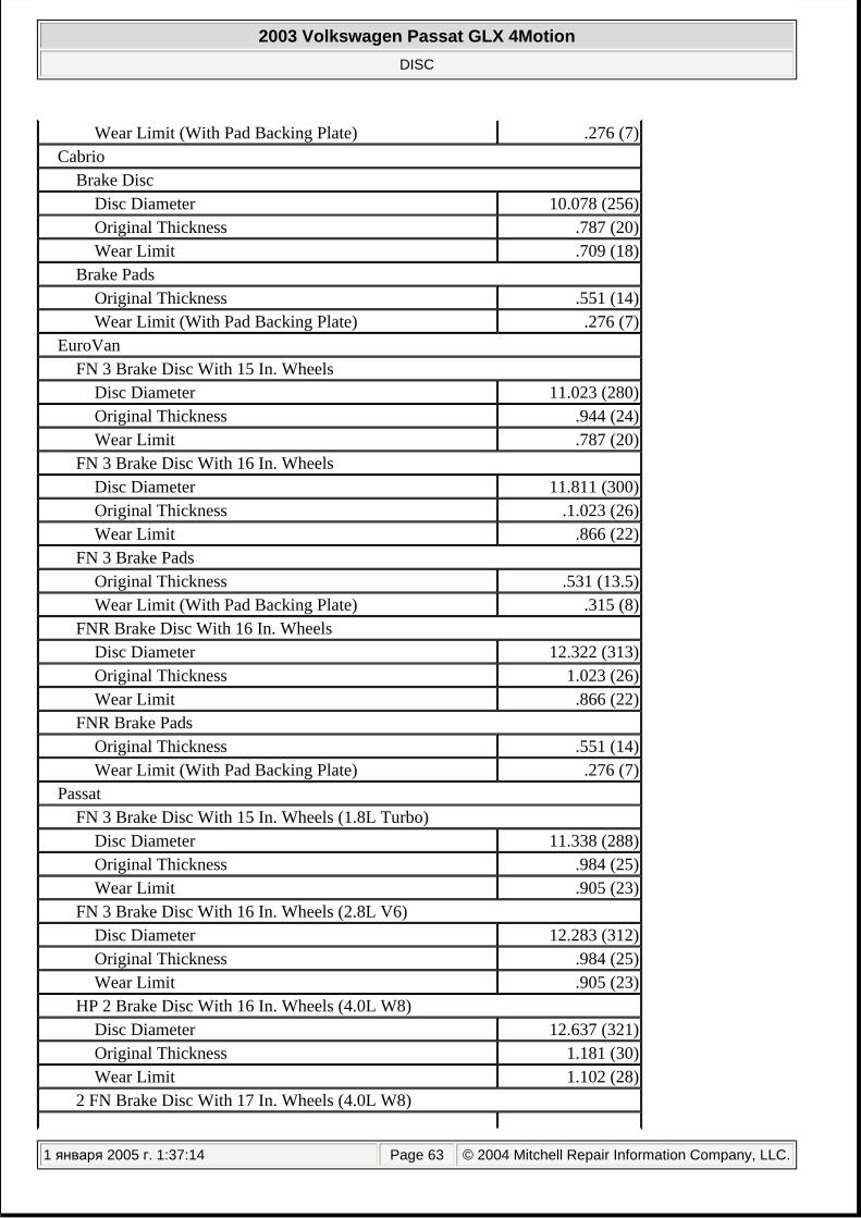
Wear Limit (With Pad Backing Plate) .276 (7) Cabrio
Brake Disc Disc Diameter 10.078 (256) Original Thickness .787 (20) Wear Limit .709 (18)
Brake Pads Original Thickness .551 (14) Wear Limit (With Pad Backing Plate) .276 (7)
EuroVan FN 3 Brake Disc With 15 In. Wheels
Disc Diameter 11.023 (280) Original Thickness .944 (24) Wear Limit .787 (20)
FN 3 Brake Disc With 16 In. Wheels Disc Diameter 11.811 (300) Original Thickness .1.023 (26) Wear Limit .866 (22)
FN 3 Brake Pads Original Thickness .531 (13.5) Wear Limit (With Pad Backing Plate) .315 (8)
FNR Brake Disc With 16 In. Wheels Disc Diameter 12.322 (313) Original Thickness 1.023 (26) Wear Limit .866 (22)
FNR Brake Pads Original Thickness .551 (14) Wear Limit (With Pad Backing Plate) .276 (7)
Passat FN 3 Brake Disc With 15 In. Wheels (1.8L Turbo)
Disc Diameter 11.338 (288) Original Thickness .984 (25) Wear Limit .905 (23)
FN 3 Brake Disc With 16 In. Wheels (2.8L V6) Disc Diameter 12.283 (312) Original Thickness .984 (25) Wear Limit .905 (23)
HP 2 Brake Disc With 16 In. Wheels (4.0L W8) Disc Diameter 12.637 (321) Original Thickness 1.181 (30) Wear Limit 1.102 (28)
2 FN Brake Disc With 17 In. Wheels (4.0L W8)
2003 Volkswagen Passat GLX 4Motion
DISC
1 января 2005 г. 1:37:14 Page 63 © 2004 Mitchell Repair Information Company, LLC.

Disc Diameter 13.149 (334) Original Thickness 1.260 (32) Wear Limit 1.181 (30)
Brake Pads Original Thickness .551 (14) Wear Limit (With Pad Backing Plate) .276 (7)
Rear Beetle, Golf, GTI & Jetta
Brake Disc Disc Diameter 9.133 (232) Original Thickness .354 (9) Wear Limit .276 (7)
Brake Pads Original Thickness .472 (12) Wear Limit (With Pad Backing Plate) .276 (7)
Cabrio Disc Diameter 8.897 (226) Original Thickness .393 (10) Wear Limit .315 (8)
Disc Diameter 12.637 (321) Original Thickness 1.181 (30) Wear Limit 1.102 (28)
Brake Pads Original Thickness .472 (12) Wear Limit (With Pad Backing Plate) .276 (7)
EuroVan Brake Disc With 15 In. Wheels
Disc Diameter 11.023 (280) Original Thickness .472 (12) Wear Limit .393 (10)
Brake Pads With 15 In. Wheels Original Thickness .453 (11.5) Wear Limit .079 (2)
Brake Disc With 16 In. Wheels Disc Diameter (2)
Original Thickness .531 (13.5) Wear Limit .453 (11.5)
Brake Pads With 16 In. Wheels Original Thickness .531 (13.5) Wear Limit (With Pad Backing Plate) .335 (8.5)
Passat Brake Disc With 15 & 16 In. Wheels (Front Wheel Drive)
2003 Volkswagen Passat GLX 4Motion
DISC
1 января 2005 г. 1:37:14 Page 64 © 2004 Mitchell Repair Information Company, LLC.

WIRING DIAGRAMS
Disc Diameter 9.645 (245) Original Thickness .393 (10) Wear Limit .314 (8)
Brake Disc With 15 In. Wheels (All Wheel Drive) Disc Diameter 10.039 (255) Original Thickness .393 (10) Wear Limit .314 (8)
Brake Disc With 16 In. Wheels (2.8L V6 All Wheel Drive) Disc Diameter 10.078 (256) Original Thickness .866 (22) Wear Limit .787 (20)
Brake Disc With 16 & 17 In. Wheels (4.0L W8) Disc Diameter 13.149 (269) Original Thickness .866 (22) Wear Limit .787 (20)
Brake Pads Original Thickness .472 (12) Wear Limit (With Pad Backing Plate) .276 (7)
(1) Maximum lateral runout is .003" (.08 mm).(2) Information is not available from manufacturer.
NOTE: See ANTI-LOCK BRAKES in appropriate SYSTEM WIRING DIAGRAMS - VOLKSWAGEN article.
2003 Volkswagen Passat GLX 4Motion
DISC
1 января 2005 г. 1:37:14 Page 65 © 2004 Mitchell Repair Information Company, LLC.


![VOLKSWAGEN PASSAT B7 [2010-2014] VOLKSWAGEN PASSAT B8 [2014+] VOLKSWAGEN PASSAT ...techdoc.holownicze.pl/pdf/43063.TextMark.pdf · 2020. 8. 17. · VOLKSWAGEN PASSAT B7 [2010-2014]](https://img.dokumen.tips/doc/110x75/60ce7fb7d113c3392507101d/volkswagen-passat-b7-2010-2014-volkswagen-passat-b8-2014-volkswagen-passat.jpg)


