Embed Size (px)
Citation preview


© Future Strategies Inc. This book is published in digital format. The content of this book is fully copyrighted and may not be distributed or data extracted therefrom without written permission by the publisher, Future Strategies Inc. Contact [email protected]. www.FutStrat.com. Tel: +1 954 782 3376.
You are licensed to print one copy for your own use.

BPMN Modeling and Reference Guide
UNDERSTANDING AND USING BPMN
Develop rigorous yet understandable graphical representations of business processes
STEPHEN A. WHITE, PHD DEREK MIERS
Future Strategies Inc. Lighthouse Point, Florida, USA

BPMN Modeling and Reference Guide: Understanding and Using BPMN
Copyright © 2008 by Future Strategies Inc. ISBN10: 0-9777527-2-0 ISBN13: 978-0-9777527-2-0
Published by Future Strategies Inc., Book Division 2436 North Federal Highway, #374, Lighthouse Point, FL 33064 USA 954.782.3376 / 954.782.6365 fax www.FutStrat.com — [email protected] Cover: Hara Allison www.smallagencybigideas.com All brand names and product names mentioned in this book are trademarks or service marks of their respective companies. Any omission or misuse should not be regarded as intent to infringe on the property of others. The Publisher recognizes and respects all marks used by companies, manufacturers and developers as a means to distinguish their products. Neither the authors, the editors nor Future Strategies Inc., accept any responsibility or liability for loss or damage occasioned to any person or property through using the material, instructions, methods, or ideas contained herein, or acting or refraining from acting as a result of such use. The authors and the publisher expressly disclaim all implied warrantees, including merchantability or fitness for any particular purpose. There will be no duty on the authors or Publisher to correct any errors or defects in the software. © All rights reserved. Manufactured in the United States of America. No part of this work covered by the copyright hereon may be reproduced or used in any form or by any means—graphic, electronic, or mechanical, including photocopying, recording, taping, or information storage and retrieval systems—without written permission of the publisher, except in the case of brief quotations embodied in critical articles and reviews.
Publisher’s Cataloging-in-Publication Data ISBN: 978-0-9777527-2-0 Library of Congress Control Number: 2008932799
BPMN Modeling and Reference Guide: Understanding and Using BPMN /Stephen A. White, PhD., Derek Miers p. cm. Includes bibliographical references and appendices. 1. Business Process Management. 2. Process Modeling. 3. Enterprise Architecture. 4. Notation Standard. 5. Workflow. 6. Process Analysis White, Stephen A.; Miers, Derek

Table of Contents
FOREWORD ....................................................................... 9 PART I. UNDERSTANDING BPMN ................................... 13 CHAPTER 1. INTRODUCTION ....................................... 15
BOOK STRUCTURE ............................................................... 16 TYPOGRAPHICAL CONVENTIONS .............................................. 17
CHAPTER 2. THE IMPORTANCE OF MODELING ........... 19 PROCESS MODELS AID COMMUNICATION ................................. 20 PROCESS MODELS THAT DRIVE WORK .................................... 22 PROCESS MODELING IN BPMN ............................................... 23 THE HISTORY AND OBJECTIVES OF BPMN ............................... 24
CHAPTER 3. PROCESSES ............................................ 27 CATEGORIES OF PROCESSES .................................................. 29
Orchestration ........................................................................... 29 Choreography .......................................................................... 30 Collaboration ........................................................................... 32
CHAPTER 4. MODELING ISSUES .................................. 33 “ALL MODELS ARE WRONG, SOME ARE USEFUL” ....................... 33 HOW MANY PROCESSES, WHERE DO THEY FIT? ....................... 35 DEALING WITH COMPLEXITY IN BPMN ..................................... 36
CHAPTER 5. SCENARIO-BASED BPMN INTRODUCTION 39 BUILDING OUT A PROCESS WITH BPMN ................................... 39 SETTING TIMERS .................................................................. 40 LOOPING ............................................................................. 44 DECISIONS BASED ON EVENTS............................................... 45 MEETING SLAS .................................................................... 47 REPRESENTING ROLES IN PROCESSES ..................................... 48 MODELING DATA AND DOCUMENTS ......................................... 50 COORDINATING PARALLEL THREADS OF ACTIVITY ...................... 52 ANOTHER APPROACH TO ESCALATION ...................................... 57 MORE THAN ONE RIGHT ANSWER ........................................... 59
5 BPMN Modeling and Reference Guide
© Published by Future Strategies Inc. www.futstrat.com

PART II. BPMN REFERENCE SECTION ........................... 63 CHAPTER 6. BPMN REFERENCE INTRODUCTION ........ 65 CHAPTER 7. ACTIVITIES ............................................ 67
TASKS ................................................................................ 68 SUB-PROCESSES ................................................................. 69
Types of Sub-Processes ........................................................... 70 CONNECTING ACTIVITIES ....................................................... 73 ACTIVITY BEHAVIOR .............................................................. 73
With Multiple Incoming Sequence Flow ................................... 75 With Multiple Outgoing Sequence Flow ................................... 76 Looping .................................................................................... 77 Multi Instance Activities ........................................................... 78
PROCESS LEVELS ................................................................. 79 Top-Level Processes ................................................................. 80 Behavior Across Process Levels .............................................. 81 Connecting Sub-Processes ....................................................... 83
CHAPTER 8. EVENTS .................................................. 87 START EVENTS .................................................................... 87
Connecting Start Events .......................................................... 89 Start Event Behavior ............................................................... 90 The None Start Event ............................................................... 90 Timer Start Events ................................................................... 91 Message Start Events .............................................................. 91 Signal Start Events .................................................................. 92 Conditional Start Events .......................................................... 93 Multiple Start Events ............................................................... 94 Modeling with More than One Start Event ............................... 95 Start Events and Sub-Processes .............................................. 95 Start Events Are Optional ........................................................ 95
INTERMEDIATE EVENTS ......................................................... 97 Intermediate Event Behavior ................................................. 100 Connecting Intermediate Events ............................................ 101 Interrupting Activities with Events ........................................ 101 None Intermediate Events ..................................................... 105 Timer Intermediate Events .................................................... 105 Message Intermediate Events ............................................... 110 Signal Intermediate Event ..................................................... 112 Error Intermediate Events ..................................................... 119 Cancel Intermediate Event .................................................... 120 Compensation Intermediate Event ........................................ 121 Conditional Intermediate Events ........................................... 121 Link Intermediate Events....................................................... 122 Multiple Intermediate Events ................................................. 126
6 BPMN Modeling and Reference Guide
© Published by Future Strategies Inc. www.futstrat.com

END EVENTS ..................................................................... 127 Connecting End Events .......................................................... 128 End Event Behavior ............................................................... 129 None End Events ................................................................... 130 Message End Events ............................................................. 130 Signal End Event ................................................................... 131 Terminate End Event ............................................................. 131 Error End Event ..................................................................... 132 Cancel End Event .................................................................. 134 Compensation End Event ...................................................... 134 Multiple End Event................................................................. 135
CHAPTER 9. GATEWAYS ............................................ 137 EXCLUSIVE GATEWAYS ........................................................ 139
Exclusive Gateway Splitting Behavior ................................... 140 Exclusive Gateway Merging Behavior ................................... 142
EVENT-BASED EXCLUSIVE GATEWAYS ................................... 144 Event Gateway Splitting Behavior ......................................... 144 Event Gateway Merging Behavior ......................................... 147
PARALLEL GATEWAYS.......................................................... 147 Parallel Gateway Splitting ..................................................... 148 Parallel Gateway Merging ..................................................... 149
INCLUSIVE GATEWAYS ......................................................... 152 Inclusive Gateway Splitting Behavior .................................... 152 Inclusive Gateway Merging Behavior .................................... 154
COMPLEX GATEWAYS .......................................................... 157 Complex Gateway Splitting Behavior .................................... 157 Complex Gateway Merging Behavior ..................................... 158
CHAPTER 10. SWIMLANES .......................................... 161 POOLS .............................................................................. 161 LANES .............................................................................. 163
CHAPTER 11. ARTIFACTS ........................................... 167 DATA OBJECTS .................................................................. 167 GROUPS ........................................................................... 168 TEXT ANNOTATIONS ............................................................ 171 ARTIFACTS ARE EXTENDABLE ............................................... 171
CHAPTER 12. CONNECTORS ....................................... 173 SEQUENCE FLOW ............................................................... 173
Conditional Sequence Flow .................................................... 174 Default Sequence Flow .......................................................... 176
MESSAGE FLOW ................................................................. 177 ASSOCIATION ..................................................................... 178 NORMAL FLOW .................................................................. 179 DATA FLOW ....................................................................... 180
BPMN Modeling and Reference Guide 7
© Published by Future Strategies Inc. www.futstrat.com

CHAPTER 13. ADVANCED CONCEPTS ......................... 185 PERFORMING AN ACTIVITY ................................................... 185
The Life-Cycle of an Activity .................................................. 185 COMPENSATION AND TRANSACTIONS ..................................... 187
Hazards in a Transaction Sub-Process ................................. 189 Cancellation in a Transaction Sub-Process ........................... 190 Compensation without a Transaction Sub-Process ............... 193
AD HOC PROCESSES .......................................................... 194 APPENDICES ................................................................. 197
PROCESS EXECUTION ENVIRONMENTS ................................... 197 TECHNIQUES FOR PROCESS ARCHITECTURE ........................... 199
Functional Decomposition ...................................................... 199 Process Composition .............................................................. 200 Business Services Oriented Architecture ............................... 200 From Business Context to Process Architecture .................... 201 Further Reading..................................................................... 202
BPMN ISSUES AND DIRECTIONS ........................................... 204 Choreography versus Orchestration ...................................... 204 Collaborative Decisions and Meetings ................................... 204 BPMN Futures ........................................................................ 204
BPMN BEST PRACTICES ..................................................... 206 AFTERWORD ................................................................. 209 AUTHOR BIOGRAPHIES................................................. 213 GLOSSARY .................................................................... 217 INDEX ........................................................................... 229
8 BPMN Modeling and Reference Guide
© Published by Future Strategies Inc. www.futstrat.com

Foreword
Richard Mark Soley, Ph.D. Chairman and CEO Object Management Group, Inc. July 2008
Cheaper by the dozen! What kind of crazy couple would care-fully plan out their family to include a dozen children, simply because their detailed study of child-rearing had computed a family of twelve children to be optimal? Only a man and woman so deeply steeped in time-and-motion studies that their entire life revolved around optimization. Though the family of Frank and Lillian Gilbreth has been celebrated on the silver screen, the dehumanizing effects of the view of people as cogs in the machine has also found its way to the klieg lights, most ob-viously in Charlie Chaplin's dark comedy “Modern Times.”
Clearly the optimization of business processes is not a particu-larly new idea. The Industrial Revolution, especially in the late 19th century, focused attention on the systemization of busi-ness to increase revenue and profits, resulting in not only Colt's and Ford's standardized parts and assembly lines, but also the time-and-motion studies of the Gilbreths and Frede-rick Winslow Taylor. Under the headings of “ergonomics” and “human-factors design,” these studies continue to optimize shipping departments, manufacturing organizations, health-care provision, even automotive design.
What about optimizing management practice? Certainly the revolution leading to the common Western management style of the early 20th century put in place a structure that seems quite rigid from the outside, though that rigidity is rarely visible inside. Management is often regarded often as a “soft” science, though certainly decision-making efficacy and efficiency can be measured (and are, in some firms).
At the core of business process optimization has to be a focus on systemizing business practice, whether that practice is the daily function of a telemarketer in a call center, a shipping clerk on the loading dock, an appointments manager in a med-ical office, or a Vice President finalizing an investment decision. Even decision-making processes that cannot be fully auto-mated can nonetheless be mapped, tracked, optimized and edited. The science for doing so is not particularly new; the sys-tems to support managing business processes are not even new. What's new is a focused interest in leveraging a specific man-
BPMN Modeling and Reference Guide 9
© Published by Future Strategies Inc. www.futstrat.com

agement practice to support business agility—and a worldwide standard for specifying business processes, whether they are fully automated, completely manual, or somewhere in-between.
The Business Process Modeling Notation (BPMN) is the culmi-nation of two streams of work from the late 1990's and early in this century. One of those streams was focused on workflow management and planning, while the other was concerned with modeling and architecture. It is amazing to note that after hundreds of years of success in the careful design engineering of bridges, ships and buildings from the 16th century forward, so-called “modern” engineering disciplines like software devel-opment have successfully resisted ancient and relevant engi-neering discipline for decades. This is changing; the recognition that modeling is necessary to the success of large complex software systems is now quite common, just as it became a common recognition in the shipwrights and building trades in the 16th and 17th centuries, and the bridge-builder's trade in the 19th century. Blueprints are just as relevant to software as they are to building designs.
From an abstract viewpoint, software designed to run busi-nesses (like enterprise resource planning systems, shipment management systems, billing systems and the like) are in fact business process descriptions at a startlingly low level. You wouldn't know by looking at the arcane C++ and Java codes that these systems described business processes, but of course they do. In fact, even BPMN business process descriptions are a generalization of what software is about—automating processes. But real processes in real organizations aren't fully automatable. Which means we can't use the same language to define, can't use the same processes to measure, or to optimize. The combination of the ability of “modern” program languages to obscure the intention of function, with their inability to clearly integrate manual and executive processes, makes most programming languages at least inefficient and more likely use-less as process description languages.
This technical stream of practice description, along with the late 20th century trends of workflow management and Busi-ness Process Re-engineering, forged the appearance of an ex-plicit and detailed language to describe business processes, fo-cusing on clearly stating the intent of a process description and fully recognizing that all interesting business processes involve a human touch.
The merger of the Business Process Management Initiative (BPMI) with the Object Management Group (OMG) brought to-
10 BPMN Modeling and Reference Guide
© Published by Future Strategies Inc. www.futstrat.com

gether two well-focused groups into a stronger organization. BPMI had focused on business processes; OMG had focused on the generic modeling problem with its Model Driven Architec-ture, and especially on the modeling of software systems. The new OMG which emerged in 2005 successfully created a single organization focused on the modeling of systems, including business processes, in two dozen vertical markets from health-care to finance, manufacturing to life sciences, and government systems to military systems. Not only did the BPMN language stay, but it gained a detailed technical underpinning with MDA (integrating it with languages for expressing software design, systems engineering design and even hardware design). Most importantly, the expertise stayed with the language—invaluable expertise in business modeling, scarce in OMG before the mer-ger, is now central to OMG's success.
This book represents in clear and certain terms the expertise of two of those experts, with a reference not only of the where's and why's of BPMN but more importantly the how's. How do I represent various sorts of processes? How do I know when I've done it right? How do I get value from those process descrip-tions, and measure and optimize the resulting processes? No-one knows better how to answer these questions than Stephen White and Derek Miers, so if an optimized business is what you're looking for, you've got the right book in your hands.
Angel Luis Diaz Director, Websphere Business Process Management IBM Software Group August 2008
The business landscape is full of challenges, uncertainties and opportunities. For many companies and industries, these changes are becoming more significant—even transformative—in nature. Business Process Management (BPM) helps an or-ganization’s business processes become more flexible and res-ponsive to change. BPM is a discipline, combining software ca-pabilities and business expertise to accelerate process im-provement and facilitate business innovation.
Standards for BPM help the organization harness the power of change through their business processes, leveraging a Service Oriented Architecture (SOA) to quickly accommodate changing business conditions and opportunities.
BPMN Modeling and Reference Guide 11
© Published by Future Strategies Inc. www.futstrat.com

In a rapidly evolving business climate, the proactive develop-ment and use of standards are key to remaining competitive for both BPM vendors and their customers. Process-oriented stan-dards enable organizations to connect the business functions together, both internally and externally with their customers, partners, and suppliers. It's not about technology for the sake of technology—it’s about enabling new ways of doing business. It’s about helping an organization to reach new levels of inno-vation while continuing to deliver the increases in productivity that are necessary to improve the bottom line. Open standards enable business to lower costs, increase revenue and respond quickly to industry pressures.
What is new is that the open standards are now getting closer to business intent, and the pace at which they are emerging is accelerating driven by the layering that occurs. As one set of best practices is agreed, it opens the door to the next opportu-nity for innovation while leveraging the increasing base of open integration, connectivity, and interoperability standards. With the wide spread adoption of Service Oriented Architecture standards (e.g. XML, Web Services…) we now have a solid foundation to build standards for Business Process Manage-ment.
This leads us to the Business Process Modeling Notation (BPMN), one of the key standards that has emerged in the BPM space. BPMN improves organizational BPM efforts by providing a common graphical language, facilitating communication and a better understanding of business processes in both business and IT.
The future of BPMN is bright as we further extend the “rigor” associated with business definition. This rigor will ensure that the investments business people make in defining their processes are quickly translated into reality. Moreover, through points of agility embedded right into the executing process, sys-tems are easily optimized.
Business Process Management puts the business requirements in the driver seat; ensuring clarity of thought across all stake-holders from business leaders, analysts and users, all the way to information technology leaders and developers. I am perso-nally very excited over the publication of this book as it will most definitely help bring BPM power to the masses and pro-vide a valuable resource for all who are developing BPMN mod-els and implementations.
12 BPMN Modeling and Reference Guide
© Published by Future Strategies Inc. www.futstrat.com

Part I. Understanding BPMN
BPMN Modeling and Reference Guide 13
© Published by Future Strategies Inc. www.futstrat.com

14 BPMN Modeling and Reference Guide
© Published by Future Strategies Inc. www.futstrat.com

Chapter 1. Introduction
This book provides a modeling guide and reference for the fea-tures of BPMN Version 1.1.
In Part I, we describe a little of business drivers associated for process modeling, aligning that with the history of the Business Process Modeling Notation (BPMN™),1 standard and discussing expected future developments. We go on to talk about processes and modeling in general to set up and position some of the issues and challenges for BPMN modelers.
We then present the BPMN modeling approach using a pro-gressive scenario that unfolds for the reader. As we elaborate on each new aspect of the scenario, we feature the functionality of BPMN that supports the desired behavior. Rather than at-tempting to explain fully each concept in detail, this part of the book sticks to the fundamental principles, referring the reader to the relevant Reference Section for more detail (i.e., Part II of this book).
The intention is to enable the reader to understand how to ap-ply BPMN against a real world scenario. Moreover, the ap-proach taken here introduces each set of functionality in a non-threatening way, allowing the reader to develop their un-derstanding at their own pace. Throughout this part of the book, we introduce exercises for the reader to complete, helping them cement their comprehension and establish a fundamental level of skill. The answers to those exercises will be made avail-able online (as part of the online training that complements this book).
Part II presents a detailed reference section that covers the pre-cise semantics of the BPMN standard, explaining them and the process behavior that results. 2
For the casual modeler, Part I will provide enough to get up and going. Over time, we expect that you will dip into Part II (the detailed reference) section to familiarize yourself with the precise functionality of the Notation.
<
1 BPMN™ is a Registered Trademark of the Object Management Group.
2 The BPMN specification itself and a list of vendors who support it are available at http://www.bpmn.org/. We chose not to include a list of vendors in this book as it would quickly become out of date.
BPMN Modeling and Reference Guide 15
© Published by Future Strategies Inc. www.futstrat.com

Book Structure The book is organized into 13 main chapters followed by Ap-pendices, a Prologue, Glossary and Index:
Part I Chapter 1—“Introduction”
Chapter 2—“Process Modeling is Important” introduces process modeling in general, highlighting how it sup-ports communication and understanding amongst people. It briefly covers how Process Models can aid communication and drive work through the enterprise.
Chapter 3—“Processes” provides a quick introduction to BPMN Process concepts, covering Orchestration, Cho-reography and Collaboration concepts.
Chapter 4—“Modeling Approaches & Architecture” in-troduces some of the potential approaches to modeling with BPMN.
Chapter 5—“A Scenario-Based Introduction to BPMN” provides an easy to follow introduction to BPMN model-ing. It starts with a simple, easily recognized situation and then builds up on that base, slowly introducing and explaining BPMN functionality to support the evolving behavioral complexity.
Part II Chapter 6—BPMN Reference Section Introduction pro-vides a short preface, explaining the tokens that we use to demonstrate the behavior associated with each BPMN element.
Chapter 7—Activities explores Tasks, Sub-Processes and Process Levels in general. It then goes on to discuss the special issues affecting Sub-Processes.
Chapter 8—Events provides detailed explanations of all the Start, Intermediate and End Events. It goes through each one in turn describing the behavior of each ele-ment.
Chapter 9—Gateways investigates the role of Gateways in BPMN modeling (points where control is required to split and merge paths), going through the precise beha-vior associated with each type.
Chapter 10—Swimlanes sets out the precise semantics and rules associated with Pools and Lanes.
16 BPMN Modeling and Reference Guide
© Published by Future Strategies Inc. www.futstrat.com

Chapter 11—Artifacts discusses how to represent Data, Documents and other things not directly covered with the core process flow diagram objects.
Chapter 12—Connectors explores the meaning asso-ciated with Sequence Flow, Message Flow and Annota-tions.
Chapter 13—Advanced Concepts provides explanations of The Life-Cycle of an Activity, Compensation and Transactions, and Ad Hoc Processes.
Appendices provide a more detailed examination of:
o Process Execution Environments (BPM Suites and Workflow).
o Techniques for Process Architecture—a short dis-cussion of some of the available approaches.
o A collection of BPMN best practices.
o BPMN Directions—discusses the likely direction of the BPMN specification, exploring some of the func-tionality expected in BPMN 2.0 and subsequent revi-sions.
Afterword provided by Prof. Michael zur Muehlin dis-cusses some of the uses of Process Models and, through the use of BPMN, how to avoid the mistakes of the past.
Glossary and Index
Typographical Conventions In this book, we have used the following styles to distinguish BPMN elements over ordinary English. However, these conven-tions are not used in tables or section headings where no dis-tinction is necessary.
Bookman Old Style - 10.5 pt.: Standard text
Indented Italics: Scenarios
Initial Capitals: BPMN Elements
Lower case italics: Important BPMN concepts
Underlined: General emphasis
Calibri – 10.5 pt. Hanging Indent Italics: Key Points and Best Practices
Calibri – 10.5 pt. Indent (No Italics): Exercises
BPMN Modeling and Reference Guide 17
© Published by Future Strategies Inc. www.futstrat.com

18 BPMN Modeling and Reference Guide
© Published by Future Strategies Inc. www.futstrat.com

Chapter 2. The Importance of Modeling
Abstract: This chapter describes the role of Process Modeling in gen‐eral—both as an aid to communication and also to drive the way in which work happens in the modern organization. It then goes on to discuss a little of the history of BPMN.
All organizations are on a journey—a never ending voyage where the focus is on improving how things are done (however that is measured) for the benefit of shareholders, stakeholders and/or profit. This notion is at the heart of Business Process Management (BPM); a way of thinking, a management philoso-phy centered on improving the operational processes of the or-ganization.
The longer an organization has been traveling down this path, the more mature its processes; the more repeatable and scala-ble its operations and the better its overall business perfor-mance. Indeed, management literature is full of examples of firms that have been on this road for some time—Dell, General Electric, Toyota, Nokia, Cisco, Federal Express to name just a few.
Wherever one looks, it is easy to find any number of articles or books that direct firms to engage in operational innovation (with the objective of overwhelming the competition). And yet, all of these examples have one thing in common—an underly-ing emphasis on understanding the business processes of the firm in order to improve them. One could argue that this is a fundamental principle of management discipline.
Around the world, in virtually every firm and organization, people are struggling to communicate with each other on how to best organize work. They are exploring questions such as:
• Which steps are really necessary? • Who should do them? • Should they be kept in house or outsourced? • How they should be done? • What capabilities are needed? • What results do we expect and how will they be moni-
tored?
While the answers to these questions are always situation spe-cific, without the backdrop of a commonly agreed description of the business process in question, such answers are often vague and wooly.
BPMN Modeling and Reference Guide 19
© Published by Future Strategies Inc. www.futstrat.com

Process Models Aid Communication Competitors bring out new products, customers demand faster turnaround times and lower prices, regulations change. Every time an organizational program kicks off to address these sorts of challenges, people find themselves building business process models to illustrate the flow of work and related activity (see Figure 2-1).
Figure 2-1—A sample BPMN Process
People generally use these models to underpin their conversa-tions, supporting communication and understanding, acting as a backdrop for virtually all improvement programs. Such mod-els often form the basis of a comprehensive business reference, detailing how the entire operation fits together. They feature in training materials and act as a basis for sharing best practice inside the firm.
As depicted in Figure 2-2, process models are normally created (discovered or captured) by looking into the business opera-tions as they stand. Potential inputs here are the goals, strate-gy and rules (or regulations) of the organization. Some sort of Analysis takes place before Redesign.
Organizations can choose from many sophisticated methodolo-gies for capturing and designing process models to fit their purpose. This book does not aim to provide such a methodolo-gy, but will provide a basis for understanding the resulting models.
Up until this point, the assumption is that humans are the primary consumers of these models. As we will see later on, these processes can also act as primary inputs to a business support environment.
20 BPMN Modeling and Reference Guide
© Published by Future Strategies Inc. www.futstrat.com

Business Operations
ProcessCapture
ProcessAnalysis
ProcessRedesign
ProcessSupport
StrategyGoals Rules Docs Data
Com
mun
icat
ion
Und
erst
andi
ng
Business Operations
ProcessCapture
ProcessAnalysis
ProcessRedesign
ProcessSupport
StrategyGoals Rules Docs Data
Business Operations
ProcessCapture
ProcessAnalysis
ProcessRedesign
ProcessSupport
StrategyGoals Rules Docs Data
Com
mun
icat
ion
Und
erst
andi
ng
Figure 2-2—Process Models are important in all phases of organizational change
Initially, these models drive communication with work col-leagues inside the organization, helping them form a shared understanding. In a small organization, this is relatively easy to do since employees tend to share a common culture and a shared set of values. But in a larger organization, especially where employees a spread across several physically disparate locations, achieving a common agreed interpretation of what the words really mean is often difficult.
But when sharing process models with suppliers, customers and/or partners—i.e., up and down the value chain, this issue interpretation issue is exacerbated. The participants no longer have the cultural references that help anchor the meaning to the diagram.
Key Point: Without a rigorous way of describing business processes, the interpretation of any given model is always up to the reader (not the modeler), which can defeat the purpose.
Process models also provide the framework within which me-trics have meaning. For example, without some notion of busi-ness process, concepts such as end-to-end cycle time and ac-tivity costs would have no reference points.
BPMN Modeling and Reference Guide 21
© Published by Future Strategies Inc. www.futstrat.com
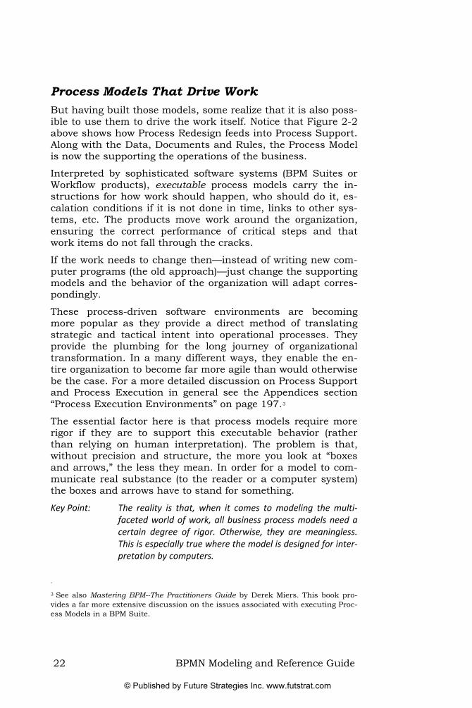
Process Models That Drive Work But having built those models, some realize that it is also poss-ible to use them to drive the work itself. Notice that Figure 2-2 above shows how Process Redesign feeds into Process Support. Along with the Data, Documents and Rules, the Process Model is now the supporting the operations of the business.
Interpreted by sophisticated software systems (BPM Suites or Workflow products), executable process models carry the in-structions for how work should happen, who should do it, es-calation conditions if it is not done in time, links to other sys-tems, etc. The products move work around the organization, ensuring the correct performance of critical steps and that work items do not fall through the cracks.
If the work needs to change then—instead of writing new com-puter programs (the old approach)—just change the supporting models and the behavior of the organization will adapt corres-pondingly.
These process-driven software environments are becoming more popular as they provide a direct method of translating strategic and tactical intent into operational processes. They provide the plumbing for the long journey of organizational transformation. In a many different ways, they enable the en-tire organization to become far more agile than would otherwise be the case. For a more detailed discussion on Process Support and Process Execution in general see the Appendices section “Process Execution Environments” on page 197.3
The essential factor here is that process models require more rigor if they are to support this executable behavior (rather than relying on human interpretation). The problem is that, without precision and structure, the more you look at “boxes and arrows,” the less they mean. In order for a model to com-municate real substance (to the reader or a computer system) the boxes and arrows have to stand for something.
Key Point: The reality is that, when it comes to modeling the multi‐faceted world of work, all business process models need a certain degree of rigor. Otherwise, they are meaningless. This is especially true where the model is designed for inter‐pretation by computers.
<
3 See also Mastering BPM--The Practitioners Guide by Derek Miers. This book pro-vides a far more extensive discussion on the issues associated with executing Proc-ess Models in a BPM Suite.
22 BPMN Modeling and Reference Guide
© Published by Future Strategies Inc. www.futstrat.com

And that is what the Business Process Modeling Notation (BPMN) is all about. It provides a standard way of representing business processes for both high-level descriptive purposes and for detailed, rigorous process-driven software environments.
Process Modeling in BPMN In BPMN, a “Business Process” involves capturing an ordered sequence of business activities and supporting information. Modeling a Business Process involves representing how a busi-ness pursues its overarching objectives; the objectives them-selves are important, but at this point are not captured in the notation. With BPMN, only the processes are modeled.
In developing BPMN, we perceived that there were different le-vels of process modeling:
• Process Maps—simple flow-charts of the activities; a flow diagram without a lot of detail other than the names of the activities and perhaps the broad decision conditions.
• Process Descriptions—provide more extensive informa-tion on the process, such as the people involved in per-forming the process (roles), the data, information and so forth.
• Process Models—detailed flow-charts encompassing sufficient information such that the process is amenable to analysis and simulation. Moreover, this more detailed style of model would also enable either direct execution of the model or import into other tools that could ex-ecute that process (with further work).
BPMN covers all these types of models and supports each level of detail. As such, BPMN is a flow chart-based notation for de-fining business processes from the simple (for example see Figure 2-1 on page 20) to the more complex and sophisti-cated models required to support process execution.
Key Point: BPMN is capable of representing many different levels of details and different sorts of diagrams for different purpos‐es.
BPMN Modeling and Reference Guide 23
© Published by Future Strategies Inc. www.futstrat.com

The History and Objectives of BPMN In 2001 BPMI.org4 began developing BPML (Business Process Modeling Language, an XML process execution language) and realized there was a need for a graphical representation. The individuals and vendors involved at the time decided a notation was required that was oriented toward the needs of a business user—i.e. not a notation that directly (canonically) represented the precise execution language under development. This would mean that a translation was needed from the business-oriented notation to the technical execution language. BPML was later replaced by BPEL as the target execution language.
The Notation Working Group (who originally created BPMN within BPMI.org) formed in August 2001. It was composed of 35 modeling companies, organizations, and individuals who between them brought a wide range of perspectives. This Group developed BPMN 1.0.
When we started the development of BPMN there were—and there still are—a wide range of process modeling notations, de-livered using different tools, and used within a wide variety of methodologies.
The interesting thing about BPMN was the large number of vendors that came together with the shared objective—to con-solidate the underlying principles of process modeling. Their aim was to agree on a single notation (representation) that oth-er tools and users might adopt. Thus, BPMN was not a lofty academic exercise, but rather a practical solution for both process modeling tool vendors and the users of process model-ing tools.
The reasoning was that this approach would help end-users, giving them a single, agreed notation. This would enable con-sistent training, using any number of tools. Companies would not have to retrain every time they bought a new tool or hired people who had studied other tools and notations. In short, it made skills transferable.
Another objective of BPMN was that it would provide a mechan-ism to generate executable processes—initially in BPML (later substituted with BPEL). Thus, BPMN provides a mapping from “valid” BPMN diagrams to BPEL, such that an engine can ex-ecute the process. This does not mean that every BPMN process model is executable, but for those processes intended
<
4 Business Process Management Initiative
24 BPMN Modeling and Reference Guide
© Published by Future Strategies Inc. www.futstrat.com

for execution, BPMN provides the mechanisms to go from origi-nal design through to execution. This traceability was part of the original goal for the development of BPMN.
Key Point: BPMN had two contradictory objectives—to provide an easy to use process modeling notation, accessible to busi‐ness users; and provide facilities to translate models into an executable form such as BPEL.
In May 2004, the BPMN 1.0 specification was released to the public. Since then, over 50 companies have developed imple-mentations of the standard. In February 2006 the BPMN 1.0 specification was adopted as an OMG standard (after BPMI.org was folded into the OMG).
Note that the Notation Working Group did not set out to specify an agreed storage mechanism (serialization) for BPMN. This is both a blessing and a curse—it allowed vendors to adopt the notation without having to change their own internal storage formats (a contributing factor to the widespread adoption of the standard). But it also meant that diagram files were not porta-ble between modeling tools.
Key Point: BPMN did not originally specify a storage format, enabling a wider cross section of vendors to adopt the standard, yet constraining portability of models.
In February 2008, the OMG released the final BPMN 1.1, which is available for public download (see www.bpmn.org). Most of the changes in version 1.1 clarified the specification document itself, making the meaning more explicit.
However, a few graphical changes were made to BPMN in ver-sion 1.1 (all covered in this book). Where changes have oc-curred, we have highlighted them.
The OMG will soon release BPMN 1.2. This version does not include any significant graphical changes; modifications were merely editorial (i.e. cleaning up the language of the specifica-tion itself).
BPMN 2.0 is currently in development and will deliver a major step forward in the capabilities of BPMN. This new version is unlikely to surface until the middle of 2009 at the earliest. For a more extensive discussion on the future of BPMN and the likely facilities of BPMN 2.0 see the Appendix “BPMN Direc-tions” on page 204.
BPMN Modeling and Reference Guide 25
© Published by Future Strategies Inc. www.futstrat.com

26 BPMN Modeling and Reference Guide
© Published by Future Strategies Inc. www.futstrat.com

Chapter 3. Processes
Abstract: The purpose of this chapter is to explore the various defini‐tions of the term Process before going on to introduce a BPMN diagram, pointing to the key elements presented. It then goes on to discuss the different categories of Processes that BPMN is starting to support (Orchestration, Choreo‐graphy and Collaboration).
There are a great many Business Process definitions. Indeed, the notion of a Business Process is an abstract notion at best. In our workshops we often ask people to write down their own definition and are continually amazed at the breadth of the an-swers we receive. Examples proffered have included:
• A sequence of activities performed on one or more in-puts to deliver an output.
• A systematic set of activities that take a “business event” to a successful outcome.
• A collection of business activities that create value for a customer.
• A number of roles collaborating and interacting to achieve a goal.
• An organized collection of business behaviors that satis-fy a defined business purpose, performing according to specified targets.
• Just the way things get done around here.
The current Wikipedia definition is, “A business process or business method is a collection of interrelated tasks, which ac-complish a particular goal.”
The problem, in coming up with a definition for the term Process, is that there are so many of them (definitions)—everyone has a subtly different interpretation. Moreover, we all use the same word and often do not realize that we may mean different things.
So while all these definitions have their merits, we need to set-tle on one for the purposes of this book. In BPMN a Process represents what an organization does—its work—in order to accomplish a specific purpose or objective. In the bulleted list above, the second and third definitions are probably closest.
Within an organization, there are many types of Processes both in terms of their purpose and how they are performed. Most Processes will require some type of input (either electronic or physical), use and/or consume resources, and produce some
BPMN Modeling and Reference Guide 27
© Published by Future Strategies Inc. www.futstrat.com

type of output (either electronic or physical). Most organiza-tions perform hundreds or thousands of different processes in the course of providing value to customers, staff, or satisfying regulations.
Some processes are formal, repeatable, well-structured, and may even be automated. We often refer to these types of processes as “Procedures.” Examples include:
• Healthcare claims processing • Creating a new account • Banking transactions • Expense claims processing
Other processes are informal, very flexible, unpredictable (high-ly variable), and hard to define or repeat. We sometimes refer to these types of processes as “Practices.” Examples include:
• Writing a user manual • Developing a sales strategy • Preparing a conference agenda • Running a consulting engagement
BPMN uses a set of specialized graphical elements to depict a Process and how it is performed (see Figure 3-1). The main elements of a BPMN Process are the “flow objects” (Activities—see page 67; Events—see page 87; and Gateways—see page 137), and Sequence Flow (see page 173).
Figure 3-1—A Process
Key Point: Flow objects (Activities, Events Gateways and Sequence Flow) are the main elements that define the underlying structure and behavior of the Process.
Modelers often add further graphical elements to explain the Process structure and to provide clarifying details. For exam-
28 BPMN Modeling and Reference Guide
© Published by Future Strategies Inc. www.futstrat.com

ple, Data Objects (see page 167) show how data is used with the Process. Other Artifacts such as Groups (see page 168) or Text Annotations (see page 171) help organize or document de-tails of the Process. Lanes can partition the elements by role (or other criteria—see page 163).
Key Point: Data Objects, Artifacts and Lanes provide further detail, describing the performance or behavior of the Process, but they do not significantly modify the underlying structure (as defined by the flow objects and Sequence Flow).
Categories of Processes Since its inception, BPMN has sought to support three main categories of Processes:
• Orchestration • Choreography • Collaboration
These terms have varied, with often conflicting, meanings across the many different business contexts within which they are applied. We have sought to define them for the purposes of BPMN, and then apply them consistently throughout this book. Future versions of BPMN will distinguish more clearly between these types of processes, including robust diagrammatic sup-port for each aspect.
Orchestration Within BPMN, orchestration models tend to imply a single coor-dinating perspective—i.e., they represent a specific business or organization’s view of the process. As such, an orchestration Process describes how a single business entity goes about things. Used mainly in the technical community, “Process Or-chestration” is often aligned with Web Service languages such as BPEL.
The majority of this book explores orchestration-oriented process models. So much so, that we will refer to orchestrations simply as Processes. Figure 3-2 presents a simple orchestration model
BPMN Modeling and Reference Guide 29
© Published by Future Strategies Inc. www.futstrat.com

Figure 3-2—A typical BPMN orchestration
However, a BPMN diagram may contain more than one orches-tration. If so, each orchestration appears within its own con-tainer called a Pool (see page 161). Thus, orchestrations (i.e., Processes) are always contained within a Pool. This is an im-portant distinction when understanding the difference between orchestration and choreography.
Furthermore, the fact that orchestrations are contained within a Pool indicates that they consist of process elements that exist together within a well-defined context, or locus of control. An orchestration model executed by a BPM Suite certainly fits this description, but it also applies to situations that are not part of a semi-automated system. A consequence of the “well-defined context” for an orchestration is that any data is available to all elements of the model.
Choreography A choreography process model is a definition of the expected behavior (a type of procedural contract or protocol) between in-teracting participants. These participants could be general business roles (e.g. a shipper) or are a specific business entity (e.g. FedEx as the shipper).
Like the definition of a ballet, a choreography in BPMN de-scribes the interactions of the participants. In BPMN, a choreo-graphy defines the sequence of interactions between two or more participants. In BPMN, interactions are the communica-tion, in the form of message exchanges between two partici-pants.
A BPMN choreography model shares many of the characteris-tics of an orchestration model in that it has a flow chart form. It includes alternative and parallel paths, as well as Sub-Processes. Thus, the flow objects (Activities, Events, and Gate-way) of orchestration models also apply to choreography models.
30 BPMN Modeling and Reference Guide
© Published by Future Strategies Inc. www.futstrat.com

However, there are dramatic differences between orchestration and choreography models:
• An orchestration is contained within a Pool and normally has a well-formed context.
• A choreography does not exist within a well-formed con-text or locus of control. There is no central mechanism that drives or keeps track of a choreography. Therefore, there are no shared data available to all the elements of the choreography.
• To place choreography within BPMN diagrams is to put them between the Pools.
The first version of BPMN (now 1.1) included some of the con-cepts that support choreography models. And while it is possi-ble to derive the expected behavior of choreography, the ele-ments needed for full definition have yet to be defined. BPMN 2.0 will include full support for choreography diagrams (distinct from orchestration diagrams).
Cus
tom
erM
anuf
actu
rer
Figure 3-3—Choreography in BPMN (as it is now)
Figure 3-3 above demonstrates the current capabilities for cho-reography definition within BPMN 1.1. The diagram shows two Pools, each containing orchestrations. The connectors between the Pools are Message Flow (see page 177). The combination of
BPMN Modeling and Reference Guide 31
© Published by Future Strategies Inc. www.futstrat.com

the Activities and other elements within the Pools and the Mes-sage Flow between the Pools defines an implicit choreography.
We expect BPMN 2.0 to include an explicit choreography dia-gram. Rather than having to derive the choreography from the message exchange, it will be possible to model it “stand-alone” or place it between the Pools.
Collaboration Collaboration has a specific meaning in BPMN. Where a choreo-graphy defines the ordered set (a protocol) of interactions be-tween participants, a collaboration simply shows the partici-pants and their interactions. A collaboration may also contain a choreography (when it is available in BPMN) and one or more orchestrations.
To be more specific, a collaboration is any BPMN diagram that contains two or more participants as shown by Pools. The Pools have Message Flow between them. Any of the Pools may con-tain an orchestration (a Process), but they are not required.
Figure 3-4 shows an example collaboration diagram. It contains two Pools and Message Flow between them. Other collaboration diagrams could show orchestrations within the Pools (as in Figure 3-3, above).
Figure 3-4—An example of a collaboration in BPMN
32 BPMN Modeling and Reference Guide
© Published by Future Strategies Inc. www.futstrat.com

Chapter 4. Modeling Issues
Abstract: The purpose of this chapter is to discuss some of the issues associated with Process modeling in general, and to identify some of the challenges in dealing with these issues. The as‐sociated Appendix (Techniques for Process Architecture on page 199) discusses several of the available approaches that can help the modeler identify an appropriate Process Architecture.5
“All Models are Wrong, Some are Useful” This quotation, variously attributed to Edwards Deming but actually originating from the lesser-known Charles Box,6 de-scribes the predicament in which modelers find themselves. There are usually a great many ways of modeling a desired be-havior, at any number of levels of precision.
Key Point: Many people assume that there is always a correct model (and that somehow other models are wrong) however, there is seldom only one correct model. On the other hand, models might be invalid (in that they incorrectly use a given notation).
Moreover, there is often far more potential detail to capture than is necessary. If we were to model how one goes about making a cup of tea, then a single Activity might be sufficient. Alternatively, one could describe the need to first boil the wa-ter, place a tea bag in a cup and optionally add milk. But what if we liked to brew the tea for several people using a teapot and tea leaves, or should we include the steps involved in filling the kettle, or adding sugar. The modeler is always making deci-sions about what to include and what leave out. So one needs to maintain a perspective about the uses of the model and who will interpret it.
If the audiences (those who will read and interpret the model) are not interested in the fine detail, then do not include it in the model. In other situations, such as where the model will <
5 While this is outside the scope of the BPMN standard itself, this is of interest to modelers as they tend to assume that somehow BPMN will help them decide on what processes exist for a given domain.
6 Charles Box first used it as a heading in a book chapter in 1979—Citation: Box, G.E.P., Robustness in the Strategy of Scientific Model Building, in Robustness in Statistics, R.L. Launer and G.N. Wilkinson, Editors. 1979, Academic Press: New York.
BPMN Modeling and Reference Guide 33
© Published by Future Strategies Inc. www.futstrat.com

support execution on a BPM Suite or where simulation is the objective, then significant detail is normally required.
At the beginning of one of our workshops, we go through a very simple exercise. We ask delegates to brainstorm all the things that they would want represent on process models. It is not long before we have filled a couple of white boards—activities, flow, inputs, outputs, responsibilities, costs, locations, quality, rules, interactions, escalation, etc. Asked if they would want all of these dimensions to appear on a single process, delegates suddenly realize it is a question of removing things from the models to make them useful.
Key Point: The modeler is constantly making modeling decisions about the purpose of the model and the intended audience.7
An anecdotal story drives home the point. During the days of Business Process Reengineering (BPR was sometimes referred to as Bigger People Reductions), a major chemicals giant em-ployed one of the leading consulting firms to assist with the reengineering of their North American sales process. After sev-eral months of work, a presentation was staged for the main board (as this was a highly important project). On one side of the meeting room was an eighty foot flow diagram (the As Is model). On the other wall, a sixty foot flow diagram of the To Be process. The then-Chairman allowed the Consultancy Partner to complete his presentation before asking a very simple ques-tion. “Is that a good process and if so, please explain why.” And therein lay the core of the problem. The detail delivered was wholly inappropriate for the intended audience.
Here are some traits of a good model:8
• Salient—Since no model can represent everything, it must selectively represent those things that are most re-levant to the task at hand.
• Accurate—The model should precisely encode the ac-tual state of affairs and not an erroneous or biased view.
• Complete yet Parsimonious—The model should be as simple as possible, but no simpler.9
<
7 Some vocal modelers seem to feel that notation should provide only one way of representing any particular problem. But this attitude flies in the face of reality and expecting only one possible model for a given scenario is unrealistic; all models are a compromise. BPMN often provides a range of functionality to facilitate different modelling purposes and styles.
8 Marshal Clemens of consultancy firm, Idiagram, offers some excellent guidance on the features that models should exhibit. He is not discussing BPMN, but many of the points are still relevant. http://www.idiagram.com/ideas/models.html
34 BPMN Modeling and Reference Guide
© Published by Future Strategies Inc. www.futstrat.com

• Understandable—Once we perceive the model we must be able to make sense of it; it shouldn't be too compli-cated or unfamiliar for us to understand.
Clemens goes on to point to some of the evolution and adapta-bility issues around modeling. “As all models are, to some de-gree, inaccurate, irrelevant, mistaken, time-sensitive etc., they should be open to recursive revision to reflect new data, our growing understanding, or our evolving needs.”
In the end, models need to be useful. Clemens continues, “Use-fulness is the sum of the above properties and the degree to which they combine to promote understanding and effective action. It is important to note that the most accurate, or the most complete, or the most elegant model is not necessarily the most useful. All models are incomplete. All models are a com-promise. The model maker's art lies in making those shrewd trade-offs that will render the model most useful to the problem at hand.”
Key Point: In order to be useful, all models selectively represent some elements of the real world. The modeler excludes different dimensions of the domain (in order to achieve the modeling goals).
How Many Processes, Where Do They Fit? The temptation is always to leap straight in and start modeling. Yet a more considered approach normally pays significant divi-dends.
The real problem is that as people begin to describe how things happen in an area of their organization, they assume that it is all one big process. We often see it in our workshops. Students try to connect everything up together into one amorphous process description that captures every possible permutation.
Key Point: Very often, it is inordinately difficult to model one “end‐to‐end” process for a given business problem. And even if it were possible, it is challenging to make that model flexible and adaptable.
It is usually far better to break up a given domain problem into a number of discrete “chunks,” that working together solve the problem. So the issue becomes one of how to come up with the
9 Here he is paraphrasing Einstein.
BPMN Modeling and Reference Guide 35
© Published by Future Strategies Inc. www.futstrat.com

right chunks. But when looking for techniques, one finds re-markably few.
For a wider discussion on the various approaches for organiz-ing, scoping models, see the Appendix “Techniques for Process Architecture” on page 199. Here we outline a set of approaches that, between them, provide a translation from the business strategy level right through to a robust process architecture (independent of the reporting structure of the organization). Potentially, these techniques could extend into a stack of IT services (as part of a Service Oriented Architecture).
The point is that BPMN is “methodology agnostic.” Organiza-tions typically have a preferred methodology for capturing and developing their business processes. It is not the role of BPMN to dictate how business process information is collected or how modeling projects are undertaken. Therefore, BPMN supports multiple methodologies (being as simple or complex as it needs to be). It does not specify the level of detail for models—the modeler, modeling tool, or organization makes these decisions. Indeed, as we will see with process modeling in general; usually there exists many different ways of modeling the same situa-tion, with any number of different levels of detail.
Key Point: BPMN does not provide any advice on how to structure a domain or come up with an appropriate architecture for a given area. Yet it provides capabilities that can support many different methods.
Dealing with Complexity in BPMN So as we can see from the above, business processes can be-come complex—very complex (covered in more depth in the Ap-pendix). However, most developers and readers of process mod-els want a simple, graphical language for depicting Business Processes. In fact, the majority of all process models are simple flow charts (activity boxes, decision diamonds, and the connec-tors between them). At the same time, modelers need enough flexibility to represent further levels of complexity if they needed.
The objective of most process modeling projects is to document (understand) and analyze an organizations key business processes. Yet these same models can then become the basis for a more detailed set of Process descriptions for other uses. Elaborated and built upon with further detail, they might then become executable (in a BPM Suite or workflow tool).
36 BPMN Modeling and Reference Guide
© Published by Future Strategies Inc. www.futstrat.com

For example, a rather simplistic model (originally developed for a business model discussion), may end up being adapted for use in establishing appropriate partner relationships (defining the interfaces), which is then further embellished and adapted by both parties to support their respective process execution environments.
Since each company or modeler may want to show different le-vels or areas of complexity, the notation needs enough flexibili-ty to handle virtually all possible business situations or model-ing requirements. But the problem is that such a modeling no-tation, one that is capable of depicting all business situations, is no longer simple, it is complex.
This issue points to the dynamic tension that exists between the two primary goals of BPMN:
• On the one hand, ease of use for business user and business analyst;
• And on the other, executable processes.
To meet the requirements of the first goal, BPMN is structured with a small set of elements (e.g., Activities, Events, and Gate-ways) that have distinctive shapes (e.g., rectangle, circle, and diamond). The small set of main elements supports the simplic-ity and readability of the models.
To meet the requirements of the second goal, the main ele-ments are specialized for specific purposes, each of which carry further information and/or supported with more elements to allow the modeling of the required behavior. In addition, the underlying semantic structure of BPMN must be rigorous, con-taining information that enables the generation of valid BPEL; or at least set the stage for other tools to complete the devel-opment and deployment.10
The BPMN specification includes a lot of information and capa-bilities that make it look complicated. However, it is unlikely that the business analyst or end user needs most of these ca-pabilities (as they relate to the execution semantics). In this book, we will point out the core BPMN elements that should appeal to the Business Analyst, while also providing thorough descriptions of the more advanced BPMN elements.
<
10 With a rigorous definition of the semantics of a BPMN model, some BPM Suites are capable of executing the Process model directly, without further translation to an intermediate language such as BPEL. With the emergence of BPMN 2.0 this capability will be further enhanced as the underlying semantics become yet more rigorous.
BPMN Modeling and Reference Guide 37
© Published by Future Strategies Inc. www.futstrat.com

Key Point: While the BPMN modeling technique may appear a little daunting to the uninitiated, it is only as complex as it needs to be in order to support both ease of use for the business analyst and end user; and at the same time, enable elabo‐ration of models to support process execution.
38 BPMN Modeling and Reference Guide
© Published by Future Strategies Inc. www.futstrat.com

Chapter 5. Scenario-Based BPMN Intro-duction
Abstract: This chapter provides the reader with a gradual introduc‐tion to the BPMN specification, taking an easily understood scenario and then slowly building upon it, bringing in BPMN functionality within that described context.
Designed for those coming to BPMN for the first time, it al‐lows them to familiarize themselves with the core features of the Notation without being overwhelmed by the com‐plexity of some of the more esoteric aspects.
Most of the functionality is limited to the “core” set of BPMN elements with which a Business Analyst should be familiar. This concept of the core set is expanded upon in the reference section.
Building out a Process with BPMN The central scenario used within this chapter revolves around a fictitious organization Mortgage Co. They take applications from potential customers, make an assess-ment whether or not to offer the mortgage, and then either reject the application or make the offer (see Figure 5-1).11
Wait For Application
Form
Offer Mortgage
Send Rejection
Offer?
No
YesMake
Assessment
Figure 5-1—The underlying mortgage offer scenario
Clearly, this is a rather simplistic picture of how such a process might operate. But it will suffice in providing the back-drop for us to introduce the functionality of BPMN. Through <
11 All paragraphs that build on the underlying scenario will share this font style (indented slightly and italics).
BPMN Modeling and Reference Guide 39
© Published by Future Strategies Inc. www.futstrat.com

the remainder of this part of the book, we will systematically build on that underlying scenario, embellishing the story and bringing in the appropriate BPMN modeling features to represent the desired behavior.12
The Process begins on the left with a Start Event (thin line cir-cle), with two Activities (rounded rectangles) connected to the Start Event with Sequence Flow (the arrows). The first Activity is a Task and the second represents a Sub-Process. Following a decision, represented by the diamond (called an Exclusive Ga-teway), the Process then branches to either “Offer Mortgage” or “Send Rejection” (both represented here as simple Tasks). Both branches lead to an End Event (thick circle).
Start Events represent the places that a Process can start, End Events represent different results, some of which might be de-sired and others not. An Exclusive Gateway represents a binary decision—only one outgoing Sequence Flow can evaluate to true. For the purposes of this model, the three Tasks represent sim-ple “atomic” steps, whereas the collapsed Sub-Process has a further level of detail.
More details on the elements introduced are available in the BPMN Reference Section:
Start Events on page 87
• Tasks on page 68. • Sub-Processes on page 69. • Exclusive Gateways on page 139. • End Events on page 127. • Sequence Flow on page 173.
Setting Timers Now, let us assume that we want to represent the fact that our potential customer contacted Mortgage Co to ask for a mortgage application form. For the moment, we will not worry about precisely how they contacted the compa-ny, but let us assume it was a “message” of some sort. Further, we want to set a clock running to send them a reminder after seven days if Mortgage Co does not re-ceive their application form back (see Figure 5-2).
<
12 We refer to the graphical elements of BPMN with Initial Capitals. Where an im-portant BPMN concept is referenced (that is not a graphical element), we have used italics within the sentence.
40 BPMN Modeling and Reference Guide
© Published by Future Strategies Inc. www.futstrat.com

Figure 5-2—A Message Start Event and a Timer Interme-diate Event are introduced
The Process now begins with a Message Start Event representing the message received by Mortgage Co who then sends out the application form; a timer is placed on the waiting task to interrupt it and send a reminder before looping back again to wait for the application form again.
There are many types of Start Events in BPMN; here we have used a Message Start Event to indicate how this Process begins. Intermediate Events placed on the boundary of a Task means that if the Event fires, then it will interrupt the Task and send the Process down its outgoing Sequence Flow. If the Task com-pletes before the Intermediate Event fires, then the Process moves on normally (following the normal flow of the Process). The loop is created explicitly with Sequence Flow although, as we will discover later, there are alternatives (i.e., use a Loop Task).
More details on the elements introduced are available in the BPMN Reference Section:
• Message Start Events on page 91. • Interrupting Activities with Events on page 101. • Timer Intermediate Events on page 105. • Looping on page 77.
There is another way to model this scenario using a Sub-Process for the send out application form and wait for the re-sponse Figure 5-3.
BPMN Modeling and Reference Guide 41
© Published by Future Strategies Inc. www.futstrat.com

Figure 5-3—Using a Sub-Process to represent the applica-tion form and reminders
The Timer Intermediate Event shown in line with the Sequence Flow triggers immediately the Sub-Process begins (the Sub-Process is shown in its expanded form). It waits for seven days before that thread of activity moves to the “Send Reminder” Task before looping back to wait for another seven days. When an Intermediate Event is used in line (as in this case), then it can have only one incoming and one outgoing Sequence Flow. Therefore, merging the incoming Sequence Flow before the Ti-mer Intermediate Event requires an Exclusive Gateway. When merging Sequence Flow, an Exclusive Gateway immediately passes through any incoming Sequence Flow so in this case it serves to clean up the Sequence Flow (but does not represent any sort of delay).
Of course, other flow objects (Activities or Gateways) can nor-mally have multiple incoming and outgoing Sequence Flow. While the Sub-Process could have included a Parallel Gateway to create the split (see Figure 5-4), it is unnecessary as the Se-quence Flow does not require control. Figure 5-3 and Figure 5-4 describe exactly the same behavior. A general rule is that Gateways are only required where Sequence Flow requires con-trol.
42 BPMN Modeling and Reference Guide
© Published by Future Strategies Inc. www.futstrat.com

Figure 5-4—Using a Parallel Gateway is unnecessary
The Sub-Process finishes with a Terminate End Event. The Terminate End Event causes the immediate cessation of the Process on its current level (and below) even if there is still on-going activity. Effectively, it kills off the reminder loop.
More details on the elements introduced are available in the BPMN Reference Section:
• Timer Intermediate Events on page 105. • Terminate End Event on page 131. • Parallel Gateways on page 147. • Text Annotations on page 171.
Exercise One Try modeling this process; it will help ensure that the tech-niques discussed so far sink in:
Every weekday morning, the database is backed up and then it is checked to see whether the “Account Defaulter” table has new records. If no new records are found, then the process should check the CRM system to see whether new returns have been filed. If new returns exist, then register all defaulting accounts and customers. If the defaulting client codes have not been previously advised, pro‐duce another table of defaulting accounts and send to account management. All of this must be completed by 2:30 pm, if it is not, then an alert should be sent to the supervisor. Once the new de‐faulting account report has been completed, check the CRM system to see whether new returns have been filed. If new returns have been filed, reconcile with the existing account defaulters table. This must be completed by 4:00 pm otherwise a supervisor should be sent a message.
BPMN Modeling and Reference Guide 43
© Published by Future Strategies Inc. www.futstrat.com

Looping So far, the loop is expressed using explicit Sequence Flow com-ing back to an earlier part of the Process. BPMN provides another mechanism to represent this sort of behavior—the Loop Task (see Figure 5-5). A Loop Task has a small semi-circular arrow that curls back upon itself.
Figure 5-5--A simple Loop Task
It is possible to set BPMN attributes to support sophisticated looping behavior.13 This is required to support the necessary complexity required by simulation and process execution envi-ronments. These aspects are discussed fully in the BPMN Ref-erence Section.
Now clearly, it does not make much sense to endlessly loop back to wait for an application form that may never arrive. So after two such reminders, Mortgage Co has de-cided to cancel the application and archive the details.
There is another way of setting the loop counter in Figure 5-6. Instead of using a graphically modeled “Set Loop Counter” Task, the “Send Reminder” Task could set an assignment at the level of the attributes. Although invisible, an annotation could then highlight its existence.
It is worth noting that the explicit Sequence Flow loop cannot cycle back to the Start Event. Indeed, Start Events cannot have incoming Sequence Flow. The loop can only go back as far the first Task.
<
13 Looping and other element attributes store information about the Process that is not shown graphically.
44 BPMN Modeling and Reference Guide
© Published by Future Strategies Inc. www.futstrat.com

Figure 5-6—A loop counter is set and after two iterations, the details are archived and the Process ends
More details on the elements introduced are available in the BPMN Reference Section:
• Looping on page 77.
Decisions Based On Events Of course, if the customer never sends back their applica-tion form, then the process will never get to the assess-ment phase. But what if the customer does let Mortgage Co know that they do not wish to proceed with the mort-gage? The model in Figure 5-6 does not adequately represent this subtly different scenario.
Now, after sending the application pack, Mortgage Co waits for one of three different things to happen. Either they receive the application (it moves on to the “Make As-sessment” Task), or they are notified that the customer does not wish to proceed (in which case “Archive De-tails”), or after 7 days a reminder is sent (twice before sending a final advice and archiving the details).
While it is possible to model such a scenario using Activities, Sequence Flow and Exclusive Gateways, the model would be-come very messy and convoluted. There is another way of mod-
BPMN Modeling and Reference Guide 45
© Published by Future Strategies Inc. www.futstrat.com

eling this situation, making use of an Event-Based Exclusive Gateway (see Figure 5-7).
Send Out Application Form Pack
Send Reminder
Set Loop Counter
Loop Count =3?
Yes
No
Final Notification
7 Days
NotInterested
ApplicationReceived
RequestApplication
Make Assessment
Archive Details
Archive Details
Figure 5-7—Using an Event-Based Exclusive Gateway
The Event-Based Exclusive Gateway (or informally, the Event Gateway) and its following Intermediate Events are regarded as a whole (the dot-dashed line around them is a BPMN Group used for emphasis only). To differentiate it from other Gate-ways, the Event Gateway reuses the Multiple Intermediate Event marker in the center of the diamond. Effectively, the Ga-teway waits for one the subsequent Events to occur. Either a message is received (Message Intermediate Event) indicating the customer is “Not Interested” or the “Application Received” Message Intermediate Event occurs (and the Process can progress), or the timer goes off and the reminder loop is in-itiated. Another Sub-Process could represent the reminder loop.
Notice that the “Archive Details” collapsed Sub-Process appears twice on the diagram. This Sub-Process is designed as a reusa-ble Sub-Process. It might appear in other Processes outside the scope of this. Effectively, it represents a stand-alone Process
46 BPMN Modeling and Reference Guide
© Published by Future Strategies Inc. www.futstrat.com

referenced by this one. Of course, one could reorganize the dia-gram to use only one Activity on this model.
More details on each element introduced are available in the BPMN Reference Section:
• Event-Based Exclusive Gateways on page 144. • Message Intermediate Events on page 110. • Groups on page 168. • Multiple Intermediate Events on page 126.
Meeting SLAs Now let us assume that Mortgage Co receives the applica-tion form back and they have decided to institute a Ser-vice Level Agreement with their customers. They are now promising to respond with an offer or rejection within 14 days from the date of receipt of an application form. In support of this, the Process should alert the manager af-ter 10 days if it has not completed, and then every day thereafter. Also, they need to archive the details if the de-cision was to reject the application (before the end of the Process).
Thinking about the alert, the first temptation is probably to use a Sub-Process and then attach a Timer Intermediate Event to its border to create the alert (similar to Figure 5-2 on page 41). The problem with this approach is that it will interrupt the work of the Sub-Process, and a loop back to the beginning would cause the work to start again (not the desired behavior). The work should not stop just to raise an alert to the er. Figure 5-8 shows one approach to solving this problem.
BPMN Modeling and Reference Guide 47
© Published by Future Strategies Inc. www.futstrat.com

Figure 5-8—One approach to the non-interrupt alert prob-lem
A separate Process path (or thread) with a Timer Intermediate Event linked to the Start Event of the Sub-Process is one ap-proach to create a non-interrupting alert. The timer kicks in after 10 days if the work of the other thread has not finished—if that work is completed, then one or other of the Terminate End Events will kill off the timer. Effectively, a race condition occurs between these two strands of the process. Once the “Alert Manager” Task has occurred, it waits another day before looping back.
Representing Roles in Processes The “Alert Manger” Task in Figure 5-8 above seems to imply that the manager receives a message. However, messages have a special importance in BPMN. Message Flow can only move between separate participants in a business-to-business situa-tion. Each participant operates a separate Process represented by Pools. Message Flow coordinates the Processes of each par-ticipant.
Essentially, a Process exists within a single Pool. Labeled boxes display the Pool; they also have square corners as opposed to Tasks and Sub-Processes, which have rounded corners. BPMN uses Pools when representing the interaction between an or-ganization and participants outside of its control. Within a company, a single Pool covers its own internal operations—it is
48 BPMN Modeling and Reference Guide
© Published by Future Strategies Inc. www.futstrat.com

only when it interacts with external participants that additional Pools are required.14
For example, in our Mortgage Co, the Credit Agency (and the Customer) would have a separate Pool (assuming one was trying to represent the interactions between the par-ties).
Figure 5-9—Representing the customer in a separate Pool
Message Flow cannot communicate between Tasks inside a single Pool—that is what Sequence Flow and data flow (as we shall see below) does. It moves the Process from one Activity to another. In this example (see Figure 5-9) the “Customer” Pool is shown interacting with a fragment of the “Mortgage Co” Process.
Mortgage Co does do not know the Customer’s internal Process. Hence, the representation for the Customer is a “Black Box Pool.” Within the Mortgage Co’s Pool, the Message Start Event receives an incoming message from the Customer, which trig-gers the Sub-Process. A race condition starts between the two threads of the Sub-Process.
<
14 Separate Pools might be used where an organization had several independent business units that were collaborating. In such a situation, each business unit would not necessarily know the internal operations of the others, yet would need to indentify the interfaces between them.
BPMN Modeling and Reference Guide 49
© Published by Future Strategies Inc. www.futstrat.com

Two of the Tasks in the Sub-Process are Send types of Tasks, while the third is a Receive Task. In BPMN 1.1, there is no standard graphical way to differentiate Send and Receive Tasks. Their type is implied by the direction of the Message Flow and stored as attributes.
Further details on each element introduced are available in the BPMN Reference Section:
• Message Flow on page 177. • Pools on page 161. • Lanes on page 163. • Send and Receive Tasks on page 68
Exercise 2 Try this exercise.
The Customer Service Representative sends a Mortgage offer to the customer and waits for a reply. If the customer calls or writes back declining the mortgage, the case details are updated and the work is archived prior to cancellation. If the customer sends back the completed offer documents and attaches all prerequisite docu‐ments then the case is moved to administration for completion. If all pre‐requisite documents are not provided a message is generat‐ed to the customer requesting outstanding documents. If no answer is received after 2 weeks, the case details are updated prior to arc‐hive and cancellation. 15
Modeling Data and Documents Mortgage Co handles a lot of documents. They come from lots of different sources—the “Surveyors Report,” the “Credit Report,” the “Title Search” and the “Application Form.” In the context of the Processes of the firm, the documents move through various states as the employees carry out their work. The documents are handled, scanned, sorted, annotated, versioned, archived, etc. Im-ages are linked to customer records, with employees transposing some of their content into data fields for the company’s information systems.
Clearly, there is a need to understand how these data and doc-uments are manipulated within a given process. For example, in Figure 5-10, the “Rejection Letter” and “Assessment” Docu-
<
15 Example answers to these Exercises will be made available online at http://www.bpmnreferenceguide.com/
50 BPMN Modeling and Reference Guide
© Published by Future Strategies Inc. www.futstrat.com

ments are represented by Data Objects. Data Objects are the Artifacts of the Process. They do not move along with the Process flow, but act as inputs and outputs of Tasks.
Figure 5-10—Representing documents in the Process
Data Objects exist outside of the Sequence Flow of the Process, but they are available to all flow objects in a given Process in-stance. Data flow passes information into or out of an Activity. Of course, the implementation mechanism used in any given system is going be specific to the platform used to support the process.
Figure 5-10 above demonstrates two different ways of showing data flow. The “Assessment” Data Object is output from the “Make Assessment” Sub-Process using an Association connec-tor. The “Assessment” Data Object is also input to the “Archive Details” Sub-Process. The arrowheads on the Association indi-cate the direction of the data flow.
The “Rejection Letter” Data Object is attached to the Sequence Flow between “Send Rejection” and “Archive Details.” This is really a sort of shorthand used when the data flow is between two Activities follow each other.
Another subtle implication of the incoming data flow is that it tells the reader that these Data Objects must be available in order for the Tasks to start. For example, when the Sequence Flow arrives at the “Send Rejection” Task, it sets the state of the Activity to ready. It is ready to begin, but it cannot start
BPMN Modeling and Reference Guide 51
© Published by Future Strategies Inc. www.futstrat.com

until all of its inputs (the “Assessment” Data Object) are availa-ble. 16
More details on each of the elements introduced are available in the BPMN Reference Section:
• Data Objects on page 167. • Association on page 178. • Superficial discussion of The Life-Cycle of an Activity on
page 185.
Coordinating Parallel Threads of Activity Coming back to the processes of Mortgage Co, we have so far avoided a core component of their business—making assessments about mortgages and their viability.
The “Make Assessment” Sub-Process is where the real work of the Process happens. Contained within that Ac-tivity are a number of Sub-Processes that need to occur in parallel; the credit check, property title search and prop-erty survey.
The problem is that Mortgage Co also needs to keep its costs down and at the same time respond as quickly as possible to customer requests. So they have teams that need to do things in parallel and yet still have the ability to communicate with the other teams should one team identify a problem that would invalidate the mortgage application. In the past, they have tried using email for this, but have found it inefficient and prone to cases slip-ping through the cracks.
While the detail of each of these Sub-Processes is not so important at this point, the key issue to observe is that a bad result in either of these areas will invalidate the mortgage (or at least imply that work in the other areas should halt).
Of course, a good result in any one of these areas means that work can start immediately on preparing the Mort-gage offer documents, but that work needs to halt should a negative result come back from one of the other areas. In this way Mortgage Co can enable, as much as possi-
<
16 Actually, it is technically possible to set the underlying attributes of the Activity to allow it to start and have updated Data Objects arrive while the Activity is in progress.
52 BPMN Modeling and Reference Guide
© Published by Future Strategies Inc. www.futstrat.com

ble, efficiency and at the same time reduce the cycle time of the process.
There is another way of handling communication in BPMN. In-stead of a directed message (that has to go to a particular ex-ternal participant), or Sequence Flow (that cannot cross a Pool or Sub-Process boundary); Signals offer a general inter-process communication capability. They can operate within a Process or between Pools and they can cross Process boundaries—think of them like a signal flare or fire siren. They are not di-rected a specific recipient, instead all who are interested can look/listen and detect the signal and then act appropriately.
The Signal Intermediate Events have two distinct modes of op-eration. They either send signals or listen for them. In Figure 5-11 below, the Signal Intermediate Events are all set to listen (they are all in the bottom Sub-Process “Prepare Offer Letter”). That is, they catch the Signal broadcast by the Signal End Events. All the Signal End Events send signals—that is they throw the signal.
Where Intermediate Events catch the trigger shown in the cen-ter is white (as in a Start Event); where they throw, the center is solid (like an End Event).
Of course, a Signal Intermediate Event can also throw (in which case it would have two concentric thin lines with a solid trian-gle in the center).
Indeed, all trigger Events (Start, Intermediate, and End), either throw or catch. This is inherent to what Events really are.
All Start Events catch—that is, that they can only receive in-coming triggers. It does not make sense for a Start Event to “send,” it responds to an Event that happens. Somehow, it is detected and that is what triggers the Event. The markers for all Start Events are white-filled.
All End Events throw—they can only fire triggers for other Events to catch. End Events cannot detect things that happen (what would they do with them, they are at the end?). Instead, they can create Events to which others respond. The markers for End Events are black-filled.
Depending on the sort of Intermediate Event and its contextual usage, the Event either throws or catches (or both) the trigger. Some Intermediate Events always come in pairs; others operate independently. The catch Intermediate Event markers are white-filled and the throw Intermediate Event markers are black-filled.
BPMN Modeling and Reference Guide 53
© Published by Future Strategies Inc. www.futstrat.com

Make Assessment
Credit Check
Property Title Check
Surveyor Report
Undertake Property Survey
Undertake Property Title
Check
Undertake Customer
Credit Check
Prepare Offer Letter
Offer Ready
Bad Title
Bad Credit
Bad Credit
Bad Survey
Bad Title
Bad Credit
Bad Survey
Title OK
Credit OK
Survey OK
Bad Survey
Bad Title
Bad Survey Bad Title Bad Credit
Make Mortgage
Offer
Criteria Not Met
Credit OK
Title OK
Survey OK
Prepare Offer Documents
Figure 5-11—Using Signal Intermediate Events to commu-nicate
In Figure 5-11 above, catch Signal Intermediate Events are set to capture the signals broadcast by the End Events of the first three Sub-Processes (the “Credit OK,” “Title OK” or “Survey OK” results). If a “Bad Survey,” “Bad Credit” or “Bad Title” End Event occurs, it will trigger one of the Intermediate Events at-
54 BPMN Modeling and Reference Guide
© Published by Future Strategies Inc. www.futstrat.com

tached to each of the boundaries of the other Sub-Processes, thereby interrupting all of the work going on there.
The “Prepare Offer Letter” Sub-Process starts along with the other three Sub-Processes, but then waits for any one of these signals to occur. As soon as one of them happens (detected by the Signal Intermediate Event), it moves the Process on to the Complex Gateway (diamond with a bold asterisk at its center). This Complex Gateway is used to merge the Sequence Flow from these three Intermediate Events.
A Complex Gateway enables the modeler to capture behavior that does not exist in the other Gateways. Think of it as a warning that here the system is likely to drop into complex rules or code. In this case, the “Prepare Offer Documents” Sub-Process can start upon detection of any of the three signals. But as other signals are detected, a new instance of the Sub-process is not required. A normal Exclusive Gateway would re-sult in duplicate process instances as each new Event hap-pened.
If a “Bad Survey,” “Bad Title” or “Bad Credit” Signal Interme-diate Event fires, then the “Prepare Offer Letter” Sub-Process is also interrupted leading it to fire a “Criteria Not Met” Signal End Event. Assuming none of those things happen, the entire “Make Assessment” Sub-Process will complete normally with a “Make Mortgage Offer” Signal End Event.
The “Make Assessment” Sub-Process (expanded in Figure 5-11 above, but collapsed again in Figure 5-12), will send one of the two possible signals back to the parent Process: “Make Mort-gage Offer” or “Criteria Not Met.”
The decision (using an Event-Base Gateway) to offer the mort-gage now operates in parallel to the “Make Assessment” Sub-Process. It is waiting for either the “Make Mortgage Offer” or the “Criteria Not Met” signal (thrown by the Sub-Process). If the Event-Based Gateway was inline, after the “Make Assessment” Sub-Process, then the signals in the Sub-Process would fire before the parent was ready for them (in which case they are ignored). Notice also that the “Make Assessment” Sub-Process goes to a None End Event—that thread will finish without af-fecting either of the two branches from the “Offer?” Event-Based Gateway.17
<
17 Technically, the signals fire at the end of the sub-process which is also the same time that the Event Gateway fires, so the signal would probably be detected. This model is drawn in parallel to ensure the required behavior occurs.
BPMN Modeling and Reference Guide 55
© Published by Future Strategies Inc. www.futstrat.com
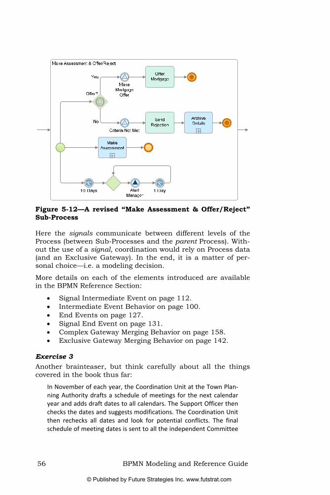
Figure 5-12—A revised “Make Assessment & Offer/Reject” Sub-Process
Here the signals communicate between different levels of the Process (between Sub-Processes and the parent Process). With-out the use of a signal, coordination would rely on Process data (and an Exclusive Gateway). In the end, it is a matter of per-sonal choice—i.e. a modeling decision.
More details on each of the elements introduced are available in the BPMN Reference Section:
• Signal Intermediate Event on page 112. • Intermediate Event Behavior on page 100. • End Events on page 127. • Signal End Event on page 131. • Complex Gateway Merging Behavior on page 158. • Exclusive Gateway Merging Behavior on page 142.
Exercise 3 Another brainteaser, but think carefully about all the things covered in the book thus far:
In November of each year, the Coordination Unit at the Town Plan‐ning Authority drafts a schedule of meetings for the next calendar year and adds draft dates to all calendars. The Support Officer then checks the dates and suggests modifications. The Coordination Unit then rechecks all dates and look for potential conflicts. The final schedule of meeting dates is sent to all the independent Committee
56 BPMN Modeling and Reference Guide
© Published by Future Strategies Inc. www.futstrat.com

Members by email, who then check their diaries and advise the Coordination Unit of any conflicts. Once the dates have been fina‐lized by the Coordination Unit, the Support Officer updates all group calendars and creates meeting folders for each meeting and en‐sures all appropriate documents are uploaded to system. Commit‐tee Members are advised a week before each meeting to read all related documents. The Committee Members hold their meeting, and the Support Office then produces minutes including any Action Points for each Committee Member. Within 5 working days the Coordination Unit must conduct a QA check on the minutes which are then sent to all Committee Members. The Support Officer then updates all departmental records.
Another Approach to Escalation Returning to the non-interrupting alert needed (for the manager discussed for the model in Figure 5-8), it is un-likely that the Manager works for an external business entity, so the Task is not a Send Task.
Figure 5-12 above also uses a Signal Intermediate Event to in-itiate (throw) the interaction with the Manager role. In Figure 5-13, a corresponding Signal Intermediate Event exists in the Manager Lane to listen for such an escalation—i.e., it is waiting to catch. In this case, the Signal Intermediate Event supports communication at the same level within a single Pool but across two Lanes.
Figure 5-13 provides yet another alternative approach to the non-interrupt alert problem. It also provides an overview of the Process developed so far.
BPMN Modeling and Reference Guide 57
© Published by Future Strategies Inc. www.futstrat.com

Figure 5-13—The complete Process employing two Lanes to represent the customer service representative and the manager, making use of Signal Events and to coordinate the offer decision with the Sub-Processes of Figure 5-11
58 BPMN Modeling and Reference Guide
© Published by Future Strategies Inc. www.futstrat.com

More Than One Right Answer Just like decisions taken by the modeler (what detail to include and how to present it), decisions taken within a Process do not always have just one correct answer.
Consider Mortgage Co as it compiles the offer documents for its customers. Depending on the mortgage applied for, different documents are required. So a generic mortgage application Process needs mechanisms to differentiate which sub-set of documents to include—let us assume a main proposal plus any number of supplements.
The precise detail of each rule is not our concern here, but pro-viding a Process backdrop for those decisions is not easy if the modeler is restricted to Exclusive Gateways. Process models would become inordinately complex and difficult to follow.
BPMN provides a couple of mechanisms to handle this sort of challenge. The Inclusive Gateway allows for decisions, where all outgoing Sequence Flow conditions that evaluate to true are ac-tivated. This is in stark contrast to the Exclusive Gateway where only the first condition that evaluates to true is activates (all others are ignored).
Figure 5-14—Dealing with decisions that have more than one right answer
The splitting Inclusive Gateway has a circle at its center to indi-cate that each outgoing Sequence Flow is evaluated. If it re-turns a true value, then the Sequence Flow is activated.
The other approach is to use Conditional Sequence Flow (see Figure 5-15). Each Conditional Sequence Flow has a mini-diamond at the point it leaves and Activity. Each is evaluated
BPMN Modeling and Reference Guide 59
© Published by Future Strategies Inc. www.futstrat.com

in turn and if it returns a true value then the Sequence Flow is activated.
Ensure Offer Details
Available
Main Contract
SupplementA
Supplement B
Include A?
Include B?
Figure 5-15—Using Conditional Sequence Flow
Notice that Figure 5-14 and Figure 5-15 both use a merging Inclusive Gateway to ensure that the correct number of Se-quence Flow are joined together again. While there is no re-quirement that the outgoing flows of an Inclusive Gateway merge (they could each follow independent paths and never come back together), if the intention is to rejoin these threads together, then a merging Inclusive Gateway is needed. If a Pa-rallel Gateway were used, then it would expect incoming Se-quence Flow on all paths. If an Exclusive Gateway were used, it would not merge the paths together at all; instead each thread would pass straight through.
More details on each of the elements introduced are available in the BPMN Reference Section:
• Inclusive Gateways on page 152. • Conditional Sequence Flow on page 174.
60 BPMN Modeling and Reference Guide
© Published by Future Strategies Inc. www.futstrat.com

Exercise 4 After the Expense Report is received, a new account must be created if the employee does not already have one. The report is then reviewed for automatic approval. Amounts under $200 are au‐tomatically approved, whereas amounts equal to or over $200 re‐quire approval of the supervisor.
In case of rejection, the employee must receive a rejection notice by email. The reimbursement goes to the employee’s direct deposit bank account. If the request is not completed in 7 days, then the employee must receive an “approval in progress” email
If the request is not finished within 30 days, then the process is stopped and the employee receives an email cancellation notice and must re‐submit the expense report.
Exercise 5 After the Process starts, a Task is performed to locate and distribute any relevant existing designs, both electrical and physical. Next the design of the electrical and physical systems starts in parallel. Any existing or previous Electrical and Physical Designs are inputs to both Activities. Development of either design is interrupted by a successful update of the other design. If interrupted, then all cur‐rent work is stopped and that design must restart.
In each department (Electrical Design and Physical Design), any ex‐isting designs are reviewed, resulting in an Update Plan for their re‐spective designs (i.e. one in Electrical and another in Physical). Using the Update Plan and the existing Draft of the Electrical/Physical De‐sign, a revised design is created. Once completed the revised design is tested. If the design fails the test, then it is sent back to the first Activity (in the department) to review and create a new Update Plan. If the design passes the test, then it tells the other department that they need to restart their work.
When both of the designs have been revised, they are combined and tested. If the combined design fails the test, then they are both sent back to the beginning to initiate another design cycle. If the de‐signs pass the test, then they are deemed complete and are then sent to the manufacturing Process [a separate Process]. 18
<
18 Example answers to these Exercises will be made available online at http://www.bpmnreferenceguide.com/
BPMN Modeling and Reference Guide 61
© Published by Future Strategies Inc. www.futstrat.com

62 BPMN Modeling and Reference Guide
© Published by Future Strategies Inc. www.futstrat.com

Part II. BPMN Reference Section
BPMN Modeling and Reference Guide 63
© Published by Future Strategies Inc. www.futstrat.com

64 BPMN Modeling and Reference Guide
© Published by Future Strategies Inc. www.futstrat.com

Chapter 6. BPMN Reference Introduction
This Section provides a comprehensive stand-alone reference for BPMN modelers. Our assumption is that the reader will re-fer to this section from time to time; therefore, the reference section is organized conceptually, going through all aspects of behavior for a particular type of BPMN element in a logical fa-shion.
As we introduce each section, we have sought to highlight the aspects that will interest the Business Analyst and End-User (referred to as “Core”). These are differentiated from the more sophisticated aspects that will appeal to those who are looking to execute or simulate processes (referred to as “Advanced”). We also have sought to highlight the best practices that will help the modeler avoid incorrect or confusing models.
Remember that within this book, we have referred to the graph-ical elements of BPMN with Initial Capitals. Where an impor-tant concept is referenced (that is not a graphical BPMN ele-ment), we have used italics within the sentence.
Throughout this book, we use the concept of a “token” to ex-plain some of the underlying behavior of a BPMN model. Think of tokens as moving along Sequence Flow and passing through the other objects of the Process. As a group, these other objects (Events, Activities, and Gateways) are called flow objects.
A token is a “theoretical” object that we use to create a descrip-tive “simulation” of the behavior (it is not currently a formal part of the BPMN specification). Using this mechanism, the performance of the Process (and its elements) is represented by describing how these theoretical tokens travel (or don’t travel) down the available Sequence Flow paths and through the flow objects.
A token traverses Sequence Flow, from the start to the end (to the arrowhead), instantaneously (see Figure 6-1). That is, there is no time associated with the token travelling down a Sequence Flow.
BPMN Modeling and Reference Guide 65
© Published by Future Strategies Inc. www.futstrat.com

Figure 6-1—A token traveling down a Sequence Flow
As a token arrives at the flow objects, it may continue instanta-neously or be delayed, depending on the nature of the flow ob-ject. We will discuss how our theoretical tokens interact with each type of flow object. The flow of a token between the flow objects, as they operate normally, is known as normal flow. Oc-casionally, however, an Activity will not operate normally. It might be interrupted by an error or some other Event, and the resulting token flow is known as exception flow (see section “Interrupting Activities with Events” on page 101 for more de-tail on exception flow).
66 BPMN Modeling and Reference Guide
© Published by Future Strategies Inc. www.futstrat.com

Chapter 7. Activities
An Activity represents the work performed within a Business Process. It has a rounded-corner rectangle shape (see Figure 7-1 and Figure 7-2). An Activity will normally take some time to perform, will involve one or more resources from the organiza-tion, will usually require some type of input, and will usually produce some sort of output.
Activities are either atomic (i.e. they are the lowest level of detail presented in the diagram) or compound (i.e. they are non-atomic in the sense that you can drill down to see another level of process below). The atomic type of Activity is known as a Task and can be seen in Figure 7-1.
Figure 7-1—A Task
The compound type of Activity is called a Sub-Process (see Figure 7-2). The graphical difference between a Task and a Sub-Process is that a Sub-Process has a “plus sign” placed in the lower center of the shape, indicating that it can be opened up for more detail.
Figure 7-2—A Sub-Process
Depending on the process modeling tool, clicking or double clicking may expand the Sub-Process diagram in place or another window may open up. Double-clicking on a Task might also bring up more information such as the role assignment or other attributes of the Activity.19
Activities can be performed once, or they can have internally defined loops. An individual Task with a looping icon
<
19 BPMN uses attributes to store information about the Process (not shown graphi-cally).
BPMN Modeling and Reference Guide 67
© Published by Future Strategies Inc. www.futstrat.com

(see Figure 7-3) may define additional conditions for the Task to be performed properly, e.g. an output being completed in a proper format. For more on Loop Activities see page 77.
Figure 7-3—A Task with an internal loop
Tasks Use a Task when the detail of the Process is not broken down further; although that does not mean the behavior of the Task is not complex. Theoretically, a Task could always be broken down into a further level of detail. However, for the purposes of the model, no further detail is defined.
There are seven specialized types of Task:
• None—A generic or undefined Task, often used during the early stages of Process development.
• Manual—A non-automated Task that a human perfor-mer undertakes outside of the control of a workflow or BPM engine.
• Receive—Waits for a message to arrive from an external participant (relative to the Business Process). Once re-ceived, the Task is complete. These are similar in nature to the catch Message Event (see “Receiving Messages” on page 111).
• Script—Performs a modeler-defined script. • Send—Dispatches a message to an external participant.
These are similar in nature to the throw Message Event (see “Sending Messages” on page 110).
• Service—Links to some sort of service, which could be a Web service or an automated application.
• User—A typical “workflow” Task where a human per-former carries out the Task with the assistance of a software application (usually scheduled through a List Manager or Inbox of some sort).
From the point of view of the Business Analyst, the only core Task type is the None Task type. All other Task types are for more advanced uses of BPMN.
68 BPMN Modeling and Reference Guide
© Published by Future Strategies Inc. www.futstrat.com

Depending on the tool used, drilling down on a Task could re-veal detailed information such as the role assignment or other attributes (presented in a dialog box).
Furthermore, different process-modeling tools may extend BPMN by adding graphical markers to the Task to help distin-guish between different types of Tasks. Any markers added to a Task must not change the footprint of the Task (its overall shape) or conflict with any other standard BPMN element. This is a general rule for extending BPMN.
Best Practice: Sending and Receiving Messages—The modeler could choose to use only Send and Receive Tasks, or to use only the throw and catch Message Intermediate Events. The Best Practice is to avoid mixing both approaches together in the same model.
There are advantages and disadvantages to both ap‐proaches. Message Intermediate Events give the same re‐sult and have the advantage of being graphically distin‐guishable (whereas the Tasks are not). On the other hand, using Tasks, rather than the Events can enable the modeler to assign resources and simulate costs.
Sub-Processes A Sub-Process represents a compound Activity. In this sense, “compound” means that its work is broken down into a finer level of detail (i.e. another Process). Thus, a “hierarchical” Process model is possible with different degrees of detail at each level.
There are two graphical representations of Sub-Processes:
• Collapsed—This version of the Sub-Process shape looks like a Task (a rectangle with rounded corners) with the addition of a small plus sign in the lower center (see Figure 7-4). The details of the Sub-Process are not visible in the diagram.
Figure 7-4—A collapsed Sub-Process (the detail hidden)
• Expanded—This version of the Sub-Process shape is “stretched” and opened such that the details of the Sub-
BPMN Modeling and Reference Guide 69
© Published by Future Strategies Inc. www.futstrat.com

Process are visible within the boundaries of the shape (see Figure 7-5). In this case, there is no marker in the lower center of the shape. However, some process mod-eling tools place a small minus sign in the lower center of the shape to indicate that the Sub-Process is collaps-ible. This is not part of standard BPMN, but is a valid extension.
Figure 7-5—An expanded Sub-Process (the detail visible)
Types of Sub-Processes There are two types of Sub-Processes:
• Embedded—A modeled Process that is actually part of the parent Process. Embedded Sub-Processes are not re-usable by other processes. All “process relevant data” used in the parent Process is directly accessible by the embedded Sub-Process (since it is part of the parent).
• Reusable—A separately modeled Process that could be used in multiple contexts (e.g., checking the credit of a customer). The “process relevant data” of the parent (calling) Process is not automatically available to the Sub-Process. Any data must be transferred specifically, sometimes reformatted, between the parent and Sub-Process. Note that the name of “Reusable” was changed from “Independent” in BPMN 1.1.
Depending on the tool or modeler preference, the Sub-Process diagrams may expand in place, or open up another diagram.
The distinction between embedded and reusable is not impor-tant for most modelers. However, as organizations develop a large number of process models, some of which they would want to reuse, the difference becomes more important—particularly when considering how data is used across the Process levels. These differences become even more important
70 BPMN Modeling and Reference Guide
© Published by Future Strategies Inc. www.futstrat.com

for organizations looking to use their process models in a BPM Suite, or within a Service Oriented Architecture.
Embedded Sub-Processes An embedded Sub-Process is “part of” the Process. That is, it belongs only to the parent Process and is not available for any other Process. In addition, the ‘scope’ of an embedded Sub-Process is ‘local’ to the parent Process in that it can use data that is stored with the parent Process without need for mapping or translation. For example, if data such as “Customer Name” or “Order Number” were part of the parent Process, then Activi-ties within the embedded Sub-Process will have access to this data directly (without any special mapping between the ele-ments).
Figure 7-6—An embedded Sub-Process
An important characteristic of an embedded Sub-Process is that it can only begin with a None Start Event—i.e. without an explicit trigger such as a message (see Figure 7-6 above). Only Top-Level Processes can make use of trigger-based Start Events. The reason is that the token arriving from parent Process acts as the trigger for the Sub-Process.
Reusable Sub-Processes As indicated by its name, a reusable Sub-Process may appear in multiple parent Processes—it is not “part of” the Process when it is instantiated. The reusable Sub-Process is a self-contained set of Activities. It provides a reference mechanism such that a single Process or service (in a Service Oriented Ar-chitecture) is available for any number of Processes that might invoke it.
These reusable Sub-Processes are “semi-independent” of the parent Process and can appear, unchanged, in multiple dia-grams. For example, Figure 7-6 above, shows a “Check Credit”
BPMN Modeling and Reference Guide 71
© Published by Future Strategies Inc. www.futstrat.com

Sub-Process that could feature in many Processes where a cus-tomer’s credit needs checking.
There is no graphical difference between embedded and reusa-ble Sub-Processes. The difference is purely technical—tools will handle them in different ways. However, we expect that BPMN 2.0 will provide a graphical distinction between the two types of Sub-Processes.
Just like an embedded Sub-Process, a reusable Sub-Process must have a None Start Event. Likewise, the token from the parent Process is the trigger for the start of any Sub-Process.
Since a reusable Sub-Process typically provides a well-defined capability (e.g., checking credit), it might also act as a Top-Level Process in its own right. In which case, it can have a trig-ger-laden Start Event for this purpose (see Figure 7-7). When-ever a Process is initiated with a trigger-based Start Event (e.g., by a message), it will create a brand new context—i.e. a new top-level Process, not a Sub-Process. In these situations, the Sub-Process will have at least two Start Events (as a None Start Event is always required for usage as a Sub-Process).
Figure 7-7—A Reusable Sub-Process can also be a Top-Level Process
Another characteristic of the reusable Sub-Process is that any data used by the Sub-Process is completely separate from the data of the invoking parent Process. The reuse capability relies on the fact that its data is completely self-contained. For exam-ple, if data such as “customer name” or “order number” is stored and used by the parent Process, and the reusable Sub-Process needs access to these data elements, it is not directly referenceable. Therefore, a mapping is required so that the reusable Sub-Process can have its own copies.
This is because reusable Sub-Processes exist independently of any particular parent Process, and therefore, the exact names
72 BPMN Modeling and Reference Guide
© Published by Future Strategies Inc. www.futstrat.com

of data elements may not exactly correspond. For example, a parent Process might name a data element “customer name,” the reusable Sub-Process might have used a convention to shorten the name to “cust_name.” Transferring data from the parent Process to the reusable Sub-Process will rely on a “map-ping” between the data elements of the two levels. The mapping is required for both the inputs and the outputs of the reusable Sub-Process. The Activity assignment attribute handles the mapping of data, into and out of the Sub-Process (and as needed for any Activity).
This mapping is not a graphical aspect of BPMN, but it is im-portant when dealing with execution or simulation environ-ments. If the data elements have the exactly the same names, a process modeling tool might have facilities to do this mapping automatically. However, if the data elements have different names, then a modeler will have to choose the data elements that map together (perhaps supported by the modeling tool).
Connecting Activities As described in more detail in the section on “Sequence Flow” on page 173, Sequence Flow connects flow objects, including Activities. Each Activity can have one or more incoming Se-quence Flow and one or more outgoing Sequence Flow.
Typically, an Activity will tend to have a single incoming and a single outgoing Sequence Flow (see Figure 7-8).
Figure 7-8—Sequence Flow connects Tasks
Activity Behavior As discussed earlier, the flow of the Process is determined by the paths of Sequence Flow. When a token arrives at an Activity, that Activity is then ready to start (see Figure 7-9). We will refer to the start and performance of an Activity as an instance of the Activity. A new instance is created whenever a token arrives at that Activity.
BPMN Modeling and Reference Guide 73
© Published by Future Strategies Inc. www.futstrat.com

Figure 7-9—A token arriving at a Task
The Activity will remain ready (to perform) until all the defined requirements, such as inputs of data, become satisfied. Then the Activity is performed—i.e., it becomes “active” (see Figure 7-10).
Figure 7-10—A token within an Active Task (the cross-hairs and curved arrow inside the Activity indicates that is now processing)
After the instance of the Activity is complete, the token then moves down the outgoing Sequence Flow, following the Process path (see Figure 7-11). For more on the life-cycle of an Activity see page 185.
Figure 7-11—A token leaving a completed Task
74 BPMN Modeling and Reference Guide
© Published by Future Strategies Inc. www.futstrat.com

With Multiple Incoming Sequence Flow An Activity can have multiple incoming Sequence Flow. Each incoming Sequence Flow is independent from any other incom-ing Sequence Flow. This means that when a token arrives from one incoming Sequence Flow, the Activity is ready to start (see Figure 7-12). The Activity does not need to wait for tokens from any of the other incoming Sequence Flow.
Accept Cash or Check
Process Credit Card
Prepare Package
Multiple Incoming Sequence Flow
T
Figure 7-12—An example of a Task with multiple incoming Sequence Flow
If another token happens to arrive from any of the other incom-ing Sequence Flow (see Figure 7-13), then the Activity is now ready to start again. Separate instances of the Prepare Package Activity are performed for each token that arrives at the Activity. Technically, it is possible to have two or more instances of the Activity performed at the same time within the same Process.
BPMN Modeling and Reference Guide 75
© Published by Future Strategies Inc. www.futstrat.com

Accept Cash or Check
Process Credit Card
Prepare Package
Multiple Incoming Sequence Flow
T
Figure 7-13—A second incoming Sequence Flow will gener-ate another Prepare Package Activity instance
Note: Multiple incoming Sequence Flow for an Activity represents uncontrolled flow. To control the flow (i.e., have the Activity wait for other incoming Sequence Flow), then use a Pa-rallel Gateway (see the section “Parallel Gateway Merging” on page 149 for more information).
With Multiple Outgoing Sequence Flow An Activity can have multiple, outgoing Sequence Flow. Each outgoing Sequence Flow is independent from the other outgoing Sequence Flow. This means that when the Activity is complete a token moves off down each outgoing Sequence Flow (see Figure 7-14). This creates a set of parallel tokens. This mimics the behavior that would result from using a Parallel Gateway after the Activity (see the section entitled “Parallel Ga-teway Splitting” on page 148).
on).
In order to select the outgoing Sequence Flow that will get the token(s), use a Gateway to control the flow of the tokens (see the section “Gateways” on page 137 for more information). It is also possible to filter the output of tokens by placing conditions directly on the outgoing Sequence Flow (see the sec-tion Conditional Sequence Flow on page 174 for more informa-ti
76 BPMN Modeling and Reference Guide
© Published by Future Strategies Inc. www.futstrat.com

Figure 7-14—An Example of a Task with multiple outgoing Sequence Flow
Looping Looping represents another type of Activity behavior. There are three different ways to create loops in BPMN. Individual Activi-ties can have looping characteristics as in Figure 7-15, or Se-quence Flow can model the loop explicitly as in Figure 7-16.
Figure 7-15—An Activity with an internal loop
On an Activity, it is possible to define a loop condition that de-termines the number of times to perform that Activity. There are two variations for Activity looping:
• While Loop (or While-Do)—shown by a looping symbol in the Activity. The loop condition is checked before the Activity is performed. If the loop condition turns out to be true, then the Activity is performed. If not, the Activi-ty completes and the Process continues (a token moves down the outgoing Sequence Flow), even if the Activity was never performed. After the Activity is performed, then the Activity loops back to check the loop condition again. The cycle of checking the loop condition and per-forming the Activity continues until the loop condition is False.
• Until Loop (or Do-While)—also shown by the same loop-ing symbol in the Activity. The loop condition is tested a-
BPMN Modeling and Reference Guide 77
© Published by Future Strategies Inc. www.futstrat.com

fter the Activity is performed. If the loop condition turns out to be true, then the Activity is performed again. If not, the Activity completes and the Process continues (a token moves down the outgoing Sequence Flow). The cycle of checking the loop condition and performing the Activity continues until the loop condition is false.
Using Activity attributes, it is possible to set the maximum number of loops (loop maximum) for both while and until loops. After the Activity has reached the loop maximum, it will stop (even if the loop condition is still true). The number of times that the Activity is performed is kept in a loop counter attribute that is automatically incremented for each loop. Some modeling tools do not currently support this sort of facility.
Figure 7-16 shows a visually obvious way to create loops using Sequence Flow to connect to an upstream flow object. Such a loop should include a Gateway or an infinite loop would occur. The Gateway checks the conditions on the outgoing Sequence Flow to determine whether to repeat the loop.
Figure 7-16—A loop with Sequence Flow
Multi Instance Activities A subtly different mechanism is needed for behavior where an Activity should be performed many times with different data sets. For example, when a major corporation is checking finan-cial results of all subsidiaries, it needs to carry this out many times.
Graphically represented with three vertical lines in the Activity, the Multi-Instance Activity (or ForEach) supports this behavior. The key point to understand here is that the Activity does not cycle around; each Activity Performance is distinct from the others (even though they are part of the same Process).
78 BPMN Modeling and Reference Guide
© Published by Future Strategies Inc. www.futstrat.com

Figure 7-17—A Multi-Instance Activity
The value of the loop condition attribute determines the number of times that the Activity is performed. It is checked at the start of the Activity and then the Activity is “cloned” that number of times. The condition must resolve to an integer.
The individual instances of a Multi-Instance Activity might oc-cur in sequence or in parallel. Attributes are available to con-trol this behavior. Where this attribute is set to “Parallel,” a fur-ther attribute is available to control how those instances merge back together again. The options (None, One, All or Complex) are equivalent to using Gateways to control parallel threads (paths) of a Process.
In BPMN 1.1, the Multi-Instance marker changed from two ver-tical lines to three vertical lines. The two vertical lines were of-ten misinterpreted to mean a wait condition (it looked too much like a “pause” symbol on a tape or CD player).
Process Levels In BPMN, it is possible to develop hierarchical structures for Processes through the use of one or more levels of Sub-Processes. In this book, we refer to a Process that contains a Sub-Process as the parent Process for the Sub-Process. Con-versely, the Sub-Process is the child Process of the Process that contains it.
Of course, modelers might want to include a Sub-Process with-in another Sub-Process, creating as many Process levels as re-quired. Each level is a complete Process. Figure 7-18 provides an example of a Sub-Process included within a parent Process.
BPMN Modeling and Reference Guide 79
© Published by Future Strategies Inc. www.futstrat.com

Figure 7-18—A Process with Sub-Processes: Showing three Process levels
The Process shown in Figure 7-18, above, has three Process levels—the Activity “Approval” in the “Check Credit” Sub-Process is itself a Sub-Process (collapsed).
Top-Level Processes Any Process that does not have a parent Process is considered a top-level Process—i.e., a Process that is not a Sub-Process is a top-level Process (see Figure 7-19).
Figure 7-19—A Top-Level Process
The assumption is that a top-level Process is triggered by some external stimulus—i.e. outside the Process scope. This trigger is not always modeled and a None Start Event is used. In other cases, the Start Event will show the type of trigger used to in-itiate the Process. For example, a Message Start Event or a Ti-mer Start Event (is in Figure 7-19, above).
80 BPMN Modeling and Reference Guide
© Published by Future Strategies Inc. www.futstrat.com

Behavior Across Process Levels To understand the way in which Process levels interact (across the levels) we again use tokens. When a token from the parent Process arrives at a Sub-Process (see Figure 7-20), it invokes the Start Event of that Sub-Process. However, note that the Se-quence Flow of the parent Process does not extend into the Sub-Process. The Sequence Flow of the parent Process con-nects to the boundary of the Sub-Process and a different set of Sequence Flow and Activities (a different Process) is contained within the Sub-Process.
Figure 7-20—A parent Process token arrives at a Sub-Process (remainder of Sub-Process not visible)
The token from the parent Process now resides in the Sub-Process (see Figure 7-21). The presence of the parent-level to-ken in the Sub-Process triggers the Start Event, thereby initiat-ing the work of the Sub-Process (the Sub-Process is now run-ning—as represented by the symbol next to the token in the figure). A child Process token is created by the Start Event and this token moves off down the outgoing Sequence Flow of the Start Event in the Sub-Process.
BPMN Modeling and Reference Guide 81
© Published by Future Strategies Inc. www.futstrat.com

Figure 7-21—The Start Event of the Sub-Processes is trig-gered, creating a lower-level token
When the child-level token reaches the Sub-Process End Event, the End Event fires (see Figure 7-22). This signifies that the Sub-Process has completed its work (i.e., all the Sub-Process Activities have finished) and the lower-level token is consumed.
Figure 7-22—The Sub-Process token Arrives at the End Event
However, a Sub-Process is still active until all threads (paths) have completed. In an execution environment (BPM Suite), the system might track any outstanding work in a couple of ways—either by tracking tokens or the states of the Activities within the system.
Either way, when the Sub-Process finishes, the parent-level to-ken moves down the outgoing Sequence Flow of the Sub-Process (see Figure 7-23), continuing the flow of the parent Process.
82 BPMN Modeling and Reference Guide
© Published by Future Strategies Inc. www.futstrat.com

Figure 7-23—The parent Process continues after the Sub-Process completes
Remember that although Sequence Flow does not cross Process boundaries (Pools or Sub-Processes), Message Flow and Asso-ciations can cross these boundaries.
Connecting Sub-Processes We have already discussed how Activities are connected (see “Connecting Activities” on page 73). Since Sub-Processes are a type of Activity, the same connection rules apply. However, there are more options when connecting an expanded Sub-Process than when connecting a Task.
So far, we have looked at the typical mechanism—connecting the Sequence Flow to the boundary of the Sub-Process (see Figure 7-24). The Start Event for the Sub-Process is inside the boundary and is not connected to the Sequence Flow of the parent-level Process.
Figure 7-24—The Start Event is inside the Sub-Process
However, to provide greater clarity in Process interaction be-tween levels, it is possible to place the Sub-Process Start Event on its boundary and then connect the incoming Sequence Flow directly to the required Start Event (see Figure 7-25). This capability is only a graphical convenience; otherwise a Start
BPMN Modeling and Reference Guide 83
© Published by Future Strategies Inc. www.futstrat.com

Event would not be placed on the boundary of the Sub-Process. Given this, the behavior of the two versions (Figure 7-24 and Figure 7-25) is exactly the same.
Figure 7-25—The Start Event on the Boundary
However, if the relationship between the parent Process and the Sub-Process is more complex, then the placement of the Start Events on the boundary of the Sub-Process can help clarify the flow between the incoming Sequence Flow (to the Sub-Process) and the Start Events of that Sub-Process.
In Figure 7-26, the path for one incoming Sequence Flow is in-tended for one of the Sub-Process’s Start Events and the other incoming Sequence Flow is intended for the other Start Event.
Figure 7-26—Multiple paths into a Sub-Process guided by Start Events on the boundary
This means that when a token arrives from the “Create Water Order” Task the upper Start Event of the Sub-Process will be triggered (see Figure 7-27).
84 BPMN Modeling and Reference Guide
© Published by Future Strategies Inc. www.futstrat.com

Figure 7-27—Multiple paths into a Sub-Process guided by Start Events on the boundary
However, when a token arrives from the “Create Supply Order” Task the lower Start Event of the Sub-Process will be triggered (see Figure 7-28).
Figure 7-28—Multiple paths into a Sub-Process guided by Start Events on the boundary
Note that each time a Start Event triggers, a new instance of the Sub-Process is created. That is, if there is a “Water Order” and a “Supply Order,” there will be separate instances of the Sub-Process for each order. Depending on the upstream struc-ture of the Process (e.g. leveraging a Parallel Gateway), the two Sub-Process instances could operate in parallel, as part of a single parent Process instance. Alternatively, they could be a part of two separate parent Process instances (where an up-stream Exclusive Gateway was used).
In BPMN 1.1, there were a few technical changes to enable a modeling tool to better support these logical connections (be-tween the parent Process Sequence Flow and the Sub-Process Start Events).
BPMN Modeling and Reference Guide 85
© Published by Future Strategies Inc. www.futstrat.com

86 BPMN Modeling and Reference Guide
© Published by Future Strategies Inc. www.futstrat.com

Chapter 8. Events
An Event is something that “happens” during the course of a Process. These Events affect the flow of the Process and usually have a trigger or a result. They can start, delay, interrupt, or end the flow of the Process.
Represented by circles, the style of the boundary (single line, double line, or thick line) indicates the type. The three types of Events are:
• Start Event (single thin line) • Intermediate Event (double thin line) • End Event (single thick line)
The next three sections explore these types of Events, introduc-ing the various options available.
Start Events A Start Event shows where a Process can begin. A Start Event is a small, open circle with a single, thin lined boundary (see Figure 8-1).
Figure 8-1—A Start Event
There are different types of Start Events to indicate the varying circumstances that can trigger the start of a Process. In fact these circumstances, such as the arrival of a message or a ti-mer “going-off,” are called triggers. All BPMN Events were de-signed to have an open center such that markers for the differ-ent types of Event triggers could appear within the Event shape. A trigger is not required—such details can be hidden or added later.
There are six types of Start Events, each with its own graphical representation. The Events are divided into core and advanced types:
Core Start Events (see Figure 8-2):
• None—No trigger is defined. • Timer—The trigger is specific date and time, or a regu-
lar date-time cycle (e.g., the first Friday of the month at 8am).
BPMN Modeling and Reference Guide 87
© Published by Future Strategies Inc. www.futstrat.com

• Message—The trigger is a message arrives from another business entity or role (participant). For example, a client requests a review of their account.
• Signal—The trigger is a signal broadcast from another Process. For example, a Process broadcasts a change in the prevailing Interest Rate, triggering any number of other processes to start as a result.20
Figure 8-2—Core types of Start Events
Advanced Start Events (see Figure 8-3):
• Conditional—The trigger is a condition expression that must be satisfied for the Process to start.
• Multiple—Defines two or more triggers that can be any combination of messages, timers, conditions, or signals (any one of which will start the Process).
Figure 8-3—Advanced types of Start Events
Modeling tools will also use different types of standard attributes to record the details of each type of Event (often not visible at the diagram level).
<
20 We have included the use of signals in the core set of Events because of their usefulness. Understanding how to model using these features is considered essen-tial for a Business Analyst to represent many of the desired behaviors.
88 BPMN Modeling and Reference Guide
© Published by Future Strategies Inc. www.futstrat.com

Connecting Start Events A key point to remember about a Start Event is that it can only have outgoing Sequence Flow. Sequence Flow is not allowed to connect into a Start Event (since a Start Event represents the start of the flow of a Process). Figure 8-4 shows an incorrect use of a Start Event (i.e., it has incoming Sequence Flow).
Test Complete
Design
A Sequence Flow is not allowed to
connect to a Start Event
Yes, Continue
No, Restart
Figure 8-4—An incorrect use of a Start Event
The correct version of the Process fragment shown in Figure 8-4 would have the Sequence Flow connect back to the first Task (see Figure 8-5).
Figure 8-5—A correct version of Figure 8-4
In this case, in spite of the label of the Sequence Flow that loops backwards, the entire Process does not restart; it loops back to the first Activity.
The only way to restart a Process (at the Start Event) is to end the Process and then trigger the Start Event again. This would create a new instance of the Process.
BPMN Modeling and Reference Guide 89
© Published by Future Strategies Inc. www.futstrat.com

Start Event Behavior Start Events are where the flow of a Process starts, and, thus, are where tokens are created. When a Start Event is triggered, the token is generated (see Figure 8-6).21
Figure 8-6—A token is generated when a Start Event is triggered
Immediately after the Start Event triggers and the token gener-ated, the token will then exit the Start Event and travel down the outgoing Sequence Flow (see Figure 8-7).
Figure 8-7—The token then exits the Start Event down the Sequence Flow
The None Start Event A Start Event without a trigger is known as a None Start Event. It is used where the start of a Process is undefined. Since there is no trigger defined, there is no marker in the center of the shape (see Figure 8-8). Also, a None Start Event is always used to mark the start of Sub-Processes (dropping from one level to the next).
<
21 The lines shown radiating out from the Start Event are for illustrative purposes and are not part of the BPMN specification.
90 BPMN Modeling and Reference Guide
© Published by Future Strategies Inc. www.futstrat.com

Figure 8-8—A None Start Event
Timer Start Events Graphically, the Timer Start Event uses the clock marker with-in the Event shape (see Figure 8-9). It indicates that the Process is started (i.e., triggered) when a specific time condition has occurred. This could be a specific date and time (e.g., Jan-uary 1, 2009 at 8am) or a recurring time (e.g., every Monday at 8am).
Review Issue List
NoAny Issues Ready for
Vote? Yes
The Timer Event triggers the start of the
Process
EveryFriday
Figure 8-9—A Timer Start Event used to Start a Process
Figure 8-9, above, provides an example of a Process, which is started every Friday, that reviews a set of issues that may be voted upon by a group.
Message Start Events The Message Start Event represents a situation where a Process is initiated (i.e. triggered) by the receipt of a message. This type of Event has an envelope marker (see Figure 8-10).
A message is a direct communication between two business participants. These participants must be in separate Pools (i.e., they cannot be sent from another Lane inside a single Pool).
BPMN Modeling and Reference Guide 91
© Published by Future Strategies Inc. www.futstrat.com

Figure 8-10—A Message Start Event used to Start a Process
Figure 8-10, above, provides an example where a “Credit Re-quest” message triggers the start of a Process that will evaluate and approve (or not) the credit of the requester.
Signal Start Events The Signal Start Event uses a triangle marker within the Event shape (see Figure 8-11). It indicates that the Process is started (i.e. triggered) when a signal is detected. This signal was broad-cast communication from a business participant or another Process. Signals have no specific target or recipient—i.e. all Processes and participants can see the signal and it is up to each of them to decide whether or not to react. A signal is ana-logous to a flare or siren; anyone who sees the flare or hears the siren may, or may not, react.
Figure 8-11—A Signal Start Event used to Start a Process
92 BPMN Modeling and Reference Guide
© Published by Future Strategies Inc. www.futstrat.com

Unlike messages, signals can operate within a Process (per-haps between a Sub-Process and its parent calling Process), or across the Processes of different participants. Figure 8-11 above provides an example where an “Accept Order” signal triggers the start of a Process that will evaluate and accept (or not) the order for processing.
BPMN 1.1 added the Signal Start Event and removed the “Link Start Event”. Signals provide a more general way of communi-cating between processes.
Conditional Start Events The Conditional Start Event represents a situation where a Process is started (i.e., triggered) when a pre-defined condition becomes true. This type of Event has a lined paper marker (see Figure 8-12). This type of Event is usually triggered by some change in the “process relevant data” such as in a bank-ing scenario, when the customers balance drops below a cer-tain threshold. A condition is used to define the details of the change in data that is expected.
The start of the Process is triggered when the
condition becomes true
Initiate Sell Order
Stock Price Drops 15% Below Purchase
Price Figure 8-12—A Conditional Start Event used to Start a Process
A condition is a natural language or computer language expres-sion that tests some data. The test will result in an answer of true or false. The expected change occurs (i.e., the Event is triggered) when the result of the condition test is true. The con-dition for the Event must become false and then true again be-fore the Event can be triggered again.
BPMN Modeling and Reference Guide 93
© Published by Future Strategies Inc. www.futstrat.com

When creating a higher-level model (to document a Process), then a natural language condition is usually sufficient. For ex-ample, a condition for a Process that sells a stock:
“The Current Stock Price Drops 15 percent Below The Purchase Price”
While this kind of condition is sufficient at a documentation level, a model designed for execution (by a BPM engine) will re-quire a more formal language that the system can understand.
For example, a formal definition of the same condition for the stock price might read:
“(dataObject[name="StockInfo"]/currentPrice) < ((dataOb-ject[name="StockInfo"]/purchasePrice) * 0.85)
Figure 8-12, above, provides an example of a Process that is started by the above condition (the natural language version is displayed).
In BPMN 1.1, the Rule Start Event was renamed the Condition-al Start Event as it represented a more accurate description of the behavior.
Multiple Start Events The Multiple Start Event uses a pentagon marker within the Event shape (see Figure 8-13). It represents a collection of two or more Start Event triggers. The triggers can be any combina-tion of messages, timers, conditions, and/or signals. Any one of those triggers will instantiate the Process—i.e., as soon as the trigger occurs, a new Process instance is generated and the flow will continue from that Start Event (ignoring other instances that may exist already). If one of the other triggers occurs, or the same trigger occurs again, then another Process instance is generated.
Figure 8-13—A Multiple Start Event
The icon for the Multiple Start Event has changed from a six-pointed star to a pentagon shape in BPMN 1.1 (as shown in Figure 8-3, above) .
94 BPMN Modeling and Reference Guide
© Published by Future Strategies Inc. www.futstrat.com

Modeling with More than One Start Event Most Processes have a single Start Event. However, it is possi-ble to include more than one Start Event within a single Process (see Figure 8-14). This is often needed where there are multiple ways that a Process can start, each starting at differ-ent point in the Process. Sometimes, as in the example below, the Start Events may lead to a different sequence of Activities, but this is not a requirement.
Figure 8-14—A Process with multiple Start Events
Each Start Event is independent of other Start Events in the Process. This means that the Process will start when any one of the Start Events within the Process is triggered. The Process will not wait for all the Start Events. If any other Start Event fires after the Process starts, then a separate instance (perfor-mance) of the Process is created.
Any Process, whether there is one Start Event or multiple, can have multiple instances of the Process active at the same time. Each time a Start Event (any Start Event) triggers, a new in-stance of the Process is created.
Start Events and Sub-Processes Note that trigger-based Start Events can only feature in “Top-Level” Processes. Trigger-based Start Events are never used in Sub-Processes as it is the parent Process that invokes the start of the Sub-Process (when a token arrives from the parent Process to the Sub-Process).
Start Events Are Optional Most Processes have a Start Event to show the position of the start of the Process or to indicate the trigger that will start the
BPMN Modeling and Reference Guide 95
© Published by Future Strategies Inc. www.futstrat.com

Process. However, a Process, either a top-level Process or a Sub-Process, is not required to have a Start Event (see Figure 8-15).
Figure 8-15—The Start of a Process Without a Start Event
If the Start Event is element not used, then the first flow object that does not have an incoming Sequence Flow represents the position where the Process starts. This representation will be-have as if an invisible Start Event existed, connected to the first element in the Process (see Figure 8-16). If there are multiple elements that do not have incoming Sequence Flow, then all of those elements will be initiated at the start of the Process.
Figure 8-16—The Process Acts as if there is a Virtual Start Event
The use of the Start Event is tied to the use of an End Event in the Process. If a Start Event is not used, then an End Event is not used either. If an End Event is used, then a Start Event must also be used.
Best Practice: Use of Start Events—In general, we recommend that mod‐elers use Start and End Events.
However, there are situations where it is more fitting to create a Process without them. Usually, a modeler will do this for small and simple Sub-Processes, when the start and end of the flow is clearly understood. One example of this is the concept of a “parallel box”—a Sub-Process with a set of Activities that must run in parallel (see Figure 8-17). By modeling this behavior with a Sub-Process without Start and End Events, the result-ing diagram is more compact and less cluttered.
96 BPMN Modeling and Reference Guide
© Published by Future Strategies Inc. www.futstrat.com

Request Flights within Parameters
Request Rooms within Parameters
Figure 8-17—An Example of a “Parallel Box” where Start and End Events are not used
Figure 8-18 shows the alternative method of modeling this same behavior. While this method will deliver the appropriate behavior, visually, it is less appealing.
Figure 8-18—An alternative method of a modeling the “Pa-rallel Box” behavior
To provide the capability to model such things as “parallel box-es” (as seen as Figure 8-17, above), Start and End Events were made optional in BPMN.
Intermediate Events An Intermediate Event indicates where something hap-pens/occurs after a Process has started and before it has ended. An Intermediate Event is a small, open circle with a double, thin lined boundary (see Figure 8-19).
BPMN Modeling and Reference Guide 97
© Published by Future Strategies Inc. www.futstrat.com

Figure 8-19—An Intermediate Event
Intermediate Events are placed within the Process flow to represent things that happen during the normal operations of the Process and usually occur in between Activities. They may also interrupt the normal processing of an Activity.
There are nine different types of Intermediate Events, each with its own graphical representation (see Figure 8-21). Each type of Intermediate Events can either throw or catch the event.
Again, we have divided them into core and advanced types:
Core Intermediate Events (see Figure 8-20):
• None—No trigger is defined. • Timer—The trigger is based on a specific date and time,
or a regular date-time cycle (e.g., the first Friday of the month at 8am).
• Message—The trigger is a message. The message must be sent to, or received from, another business entity in the Process. These business entities (participants), if shown in the diagram, are represented by Pools.
• Signal—The trigger is a signal that is broadcast or re-ceived.
Figure 8-20—Core types of Intermediate Events (both throw and catch)
Advanced Intermediate Events (see Figure 8-21):
• Error—Defines an Event that will usually disrupt the Process or require correction (see Interrupting Activities with Events on page 101).
98 BPMN Modeling and Reference Guide
© Published by Future Strategies Inc. www.futstrat.com

• Cancel—Used to cancel a Transaction Sub-Process (see “Compensation and Transactions” on page 187).
• Compensation—Used to establish the behavior required to “undo” Activities in case a Transaction Sub-Process is cancelled or needs to be rolled-back (see “Compensation and Transactions” on page 187).
• Conditional—Defines a rule that must be satisfied in order for the Process to continue.
• Link—Used to create a visual “Go To” mechanism, hid-ing long Sequence Flow or to establish off-page connec-tors for printing.
• Multiple—Defines two or more triggers that can be any combination of messages, timers, errors, conditions, or signals.
Figure 8-21—Advanced types of Intermediate Events (both throw and catch)
This graphical difference between catch and throw is new in BPMN 1.1. Other Intermediate Event related changes for BPMN 1.1 include the addition of the Signal Intermediate Event, the change of the marker for the Multiple Intermediate Event, and the renaming of the Rule Intermediate Event to the Conditional Intermediate Event.
BPMN Modeling and Reference Guide 99
© Published by Future Strategies Inc. www.futstrat.com

Intermediate Event Behavior When a token arrives from an incoming Sequence Flow to an Intermediate Event, it will do one of two things:
• It waits for something to happen (i.e., wait for the cir-cumstance defined on the trigger—see “Receiving Mes-sages on page 111 for an example). This type of Event is known as a catching Intermediate Event. The internal markers for all catching Intermediate Events have a white infill. This includes Start Events, since these types of Events also wait to be triggered.
• It immediately fires (effectively creating the circums-tance defined on the trigger—see “Sending Messages on page 110 for an example). This type of Event is known as a throwing Intermediate Event. The internal markers for all throwing Intermediate Events have a black infill. This includes End Events, as they also immediately trig-ger.
The Events that can catch are:
• Message • Timer • Error • Cancel • Compensation • Conditional • Link • Signal • Multiple (catches any incoming event in the list)
A token arriving at a catch Intermediate Event would wait until the trigger occurs. Then the token would leave immediately and move down the outgoing Sequence Flow.
Events that can throw are:
• Message • Compensation • Link • Signal • Multiple (throws all events in the list)
A token arriving at a throw Intermediate Event would imme-diately fire the trigger. It would then leave immediately and tra-vel down the outgoing Sequence Flow.
100 BPMN Modeling and Reference Guide
© Published by Future Strategies Inc. www.futstrat.com

Connecting Intermediate Events Intermediate Events are either placed within the normal flow of a Process (i.e. between Activities), or they are attached to the boundary of an Activity to trigger an interruption of that Activi-ty—this is discussed in more detail later—see “Interrupting Ac-tivities with Events.”
Since Intermediate Events are not Gateways (discussed further in “Gateways” on page 137), they are not used to split or merge Sequence Flow. Thus, only one incoming and only one outgoing Sequence Flow is allowed for an Intermediate Event within normal flow (see Figure 8-22).
ValidateOrder
Accept
Reject
OrderValidated
Figure 8-22—An Intermediate Event within the normal flow
Interrupting Activities with Events BPMN uses Events attached to the boundary of an Activity as a way of modeling exceptions to the normal flow of the Process. The attached Event indicates that the Activity should be inter-rupted when the Event is triggered (see Figure 8-23). These types of Events always catch the relevant trigger, thus the trig-ger marker will always be white-filled (see Figure 8-19, above).
Figure 8-23—An Intermediate Event attached to the boun-dary of an Activity
BPMN Modeling and Reference Guide 101
© Published by Future Strategies Inc. www.futstrat.com

The way that BPMN handles exceptions is an innovation for process modeling notations. The normal way of exiting an Ac-tivity is for the work in the Activity to complete and for the out-going connector (a Sequence Flow) to show the path to the next Activity (or other flow object). As a means of accentuating the exception paths within a Process, the BPMN approach of at-taching Intermediate Events to the boundary of an Activity pro-vides a natural and obvious way to show the non-normal ways of exiting an Activity. Both Tasks and Sub-Processes are inter-rupted in the same way.
The types of Events that can interrupt an Activity are:
• Timer • Message • Error • Cancel • Conditional • Signal • Multiple
A Compensation Intermediate Event can also be attached to the boundary of an Activity. However, these Events do not inter-rupt the Activity since they are only operational after an Activi-ty has completed. See “Compensation and Transactions” on page 187 for more details about Compensation Events.
Request Re-Order
Problem withOrder
Input Order
T
Figure 8-24—A token arrives at a Task with an attached Error Intermediate Event
Tracing a token allows us to show how exception handling works. The token leaves the previous flow object and arrives at
102 BPMN Modeling and Reference Guide
© Published by Future Strategies Inc. www.futstrat.com

the Activity with the attached Intermediate Event. (see Figure 8-24 above). 22
The token enters the Activity and starts the work and life-cycle of the Activity (for more on this issue, see section “The Life-Cycle of an Activity” on page 185). At the same time, another token is created and resides in the Intermediate Event on its boundary (see Figure 8-25). This readies the interrupting In-termediate Event to fire. If the attached Event happens to be a timer, then the clock is started.
Figure 8-25—A token Resides in Both the Task and the Er-ror Intermediate Event
The Activity and attached Intermediate Event become involved in a race condition. Whichever one finishes first will win the race and take control of the Process with its token. If the Activi-ty finishes before the trigger occurs (in this case error), then the token from the Activity moves down the normal outgoing Se-quence Flow of the Activity (see Figure 8-26) and the additional token is consumed.
<
22 We use an Error Intermediate Event to demonstrate the behavior, but any of the interrupting Intermediate Events listed above could have been used.
BPMN Modeling and Reference Guide 103
© Published by Future Strategies Inc. www.futstrat.com

Request Re-Order
Problem withOrder
Input Order
T
T
Figure 8-26—The token leaves the Task before the Error Intermediate Event fires
However, if the attached Intermediate Event triggers before the Activity finishes, then the Activity is interrupted (all work stops). In this case, the token from the Event moves down its outgoing Sequence Flow, but not the normal outgoing Sequence Flow of the Activity (see Figure 8-27). The token that was on the Activity is consumed.
Figure 8-27—The Error Intermediate Event is triggered in-terrupting the Task
The flow from the Intermediate Events can go anywhere. It can go down a completely new path, it can rejoin the normal path, or it can loop back upstream.
The Events that can interrupt can attach to either Tasks or Sub-Processes. The exception to this is the Cancel Intermediate Event, which is only used on Transaction Sub-Processes (see “Compensation and Transactions” on page 187).
104 BPMN Modeling and Reference Guide
© Published by Future Strategies Inc. www.futstrat.com

None Intermediate Events As with a Start Event, a trigger is not always required for an Intermediate Event. An Intermediate Event without a trigger is known as a None Intermediate Event (as in Figure 8-19, above).
None Intermediate Events are mainly used to document that certain Activities have completed or that the Process has reached a defined state, such as a milestone. The name of the Event can often provide enough information for these purposes.
For a None Intermediate Event, no circumstance is defined (i.e. there is no trigger). Therefore, it fires immediately (see Figure 8-28).
Validate Order
Accept
Reject
T
OrderValidated
Figure 8-28—A token Arrives at an Intermediate Event
Immediately after triggering, the token moves down the out-going Sequence Flow, continuing the Process (see Figure 8-29).
Figure 8-29—A token Leaves an None Intermediate Event
Timer Intermediate Events The Timer Intermediate Event uses the clock marker within the Event shape (see Figure 8-30, below). Timer Intermediate Events can only catch. They add time-based dependencies within a Process and are either inserted into the Sequence Flow to create a delay, or attached to the boundary of an Activity to create a deadline or “time-out” condition. Timer Intermediate
BPMN Modeling and Reference Guide 105
© Published by Future Strategies Inc. www.futstrat.com

Events can also be used as part of an Event-Based Gateway (see page 144).
When a token arrives at a Timer Intermediate Event, the “clock starts” and the token waits for the specified time-related condi-tion to occur (see Figure 8-30).
Figure 8-30—A token leaving a Timer Intermediate Event
Delays When inserted between Activities in a Process, the Timer In-termediate Event represents a delay in the flow of a Process. Timer Intermediate Events can represent a specific date and time (e.g., wait until April 15, at 5pm), a relative time (e.g., wait 6 days), or a relative repetitive date (e.g., wait until next Mon-day at 8am).
Figure 8-31—A Timer Intermediate Event creating a delay in the Process
When the timer “goes off”—i.e. the specified time condition oc-curs—in this case, 6 days after the timer started, then the to-ken moves down the Event’s outgoing Sequence Flow (see Figure 8-30) and the Process continues.
vent.
To show how a delay Timer behaves, we trace a token through the example for the above figure. The token leaves the previous flow object and arrives at the Timer Intermediate Event (see Figure 8-32). The flow object that precedes the Timer can be an Activity, Gateway, or another Intermediate E
106 BPMN Modeling and Reference Guide
© Published by Future Strategies Inc. www.futstrat.com

Figure 8-32—A token arrives at a Timer Intermediate Event
The token will remain at the Timer Intermediate Event (see Figure 8-33) until the clock reaches the time setting of the Event (i.e., the “alarm goes off”).
The clock for relative time delays (e.g., 6 days) starts when the token arrives at the Event. The clock for specific and recurring time/dates is always compared with an actual (or simulated) calendar.
Note that if a specific date and time is set (e.g., January 1, 2007 at 8am) and that date and time has already occurred be-fore the Timer Intermediate Event is active (i.e., before the to-ken arrives), then the Event will never occur. Relative time and date settings cannot fail as the clock starts only when the Event triggers.
Best Practice: Setting Timers—avoid specific date and time conditions as they inhibit the re‐usability of the process.
Figure 8-33—The token will be delayed until the Timer is triggered
When the Event is finally triggered, the token immediately exits the Event and moves off down the outgoing Sequence Flow (see Figure 8-34).
Figure 8-34—When the Timer is triggered, the token con-tinues
BPMN Modeling and Reference Guide 107
© Published by Future Strategies Inc. www.futstrat.com

Deadlines and Time-Outs As discussed above, Timer Intermediate Events can also inter-rupt an Activity. When the Activity starts, so does the timer. If the Activity finishes first, then it completes normally and the Process continues normally. If the timer goes off before the Ac-tivity is completed, the Activity is immediately interrupted and the Process continues down the Sequence Flow from the Timer Intermediate Event (see Figure 8-35).
Figure 8-35—An Activity with a time-out
The behavior of the attached Timer Intermediate Events, and other interrupting Events, is described in “Interrupting Activi-ties with Events on page 101.
Non-Interrupting Time-Outs As we described in the above section, an attached Timer Inter-mediate Event interrupts an Activity when triggered. However, there are times when a timer might need to trigger additional Activities, without interrupting the Activity. For example, if the work of an Activity has not finished in the expected time, then the desired behavior is often required to trigger an email to the Performer’s manager to expedite the situation. We refer to this type of scenario as a Non-Interrupting Event behavior.
In BPMN 1.1, it is impossible to use an attached Intermediate Event to create Non-Interrupting Event behavior. However, there are “Process Patterns” that easily resolve this require-ment.
Figure 8-36 provides an example of a Process Pattern that solves this problem. The pattern relies on a Sub-Process with the Timer Intermediate Event set up in a parallel flow to the Activity, which ends with a Terminate End Event. Both the Ac-tivity and the Timer Intermediate Event follow a Start Event.
108 BPMN Modeling and Reference Guide
© Published by Future Strategies Inc. www.futstrat.com

The timer starts at the same time as the Activity. If the timer triggers before the completion of the “Receive Confirmation” Ac-tivity, then a reminder is sent without interrupting the Activity. The timer is placed in a loop so that reminders are sent out every two days. When the Activity eventually finishes, the work moves to a Terminate End Event, which will stop all the Activi-ty of the Sub-Process, including the Timer loop. The flow then continues at the level of parent Process. See also Terminate End Event on page 131.
Receive Confirmation
2 DaysSend Reminder
Figure 8-36—A Delay Timer Intermediate Event Used for Escalation
Process Pattern: The example shown in Figure 8‐36, above, is an example of a “Process Pattern.” This pattern can be used with different catch Intermediate Events (replacing the Time Intermediate Event) to create various non‐interrupting behaviors based on messages, signals, or other types of triggers.
Another set of examples is provided in the opening scenario in-troduction in the section on “Setting Timers” on page 40, and also in “Another Approach to Escalation” on page 57.
In the next version of BPMN (BPMN 2.0), a non-interrupting ca-pability is being built into Intermediate Events that are at-tached to an Activity boundary. This will enable the use of at-tached Events to either interrupt an Activity, or to trigger a Non-Interrupting Event. Process patterns like Figure 8-36 will still be valid, but no longer necessary. The notation for Non-Interrupting Events is not yet finalized, so we cannot provide an example.
BPMN Modeling and Reference Guide 109
© Published by Future Strategies Inc. www.futstrat.com

Message Intermediate Events The Message Intermediate Event is distinguished from other types of Intermediate Events by the envelope marker placed within the Event shape (see Figure 8-37). Messages are differ-ent from signals in that they are directed between Process par-ticipants—i.e. they always operate across Pools. They cannot be used to communicate between Lanes within a Pool.
Figure 8-37—Message Intermediate Events
As shown in the figure above, there are two types of Message Intermediate Events: throwing and catching—i.e. sending and receiving.23
Sending Messages One type of Message Intermediate Event is a throwing Event that sends a message. Its internal marker is a black-filled envelope (see Figure 8-21, above). This type of Event indicates that the Process will send a message at that point in the Process.
When a token arrives at a throwing Message Intermediate Event, it immediately triggers the Event, which sends the message to a specific participant (see Figure 8-38).
Figure 8-38—A token arriving at a throwing Message In-termediate Event
<
23 In the examples provided here, we show Message Intermediate Events within the normal flow of the Process. We have not shown the Message Flow emanating from these Events that connect to an external participant. For more on Message Flow see page 177.
110 BPMN Modeling and Reference Guide
© Published by Future Strategies Inc. www.futstrat.com

Immediately after the message is sent, the token moves down the outgoing Sequence Flow (see Figure 8-39), continuing the Process.
T
Collect VotesDiscuss Issues
Ballot ofIssues
Figure 8-39—The token leaves a Message Intermediate Event
Receiving Messages The other type of Message Intermediate Event catches—i.e., it waits for a message to arrive. The internal marker is a white-filled envelope (see Figure 8-21, above).
When a token arrives at a catching Message Intermediate Event in normal flow, the Process pauses until the message arrives (see Figure 8-40). Note that if a BPM Suite is executing the model, and the message arrives before the Message Interme-diate Event is “active” (i.e., before the token arrives), then the message is ignored. In such a situation, the Message Interme-diate Event will wait indefinitely unless the message is sent again.
Figure 8-40—A token arriving at a catching Message In-termediate Event
If the token is waiting at the Intermediate Event and the mes-sage arrives, then the Event triggers. The token immediately moves down the outgoing Sequence Flow, continuing the Process (see Figure 8-41).
BPMN Modeling and Reference Guide 111
© Published by Future Strategies Inc. www.futstrat.com

Figure 8-41—A token leaving a catching Message Interme-diate Event
Message Intermediate Events might also appear attached to the boundary of an Activity as a catch. If the Event occurs, then the Activity is interrupted and the token leaves via the Sequence Flow attached to the Message Intermediate Event. For more on the precise nature of this, see the “Deadlines and Time-Outs” section on page 108.
Message Intermediate Events can also form part of an Event-Based Gateway (see page 144).
Signal Intermediate Event Like Signal Start Events, the Signal Intermediate Event uses the triangle marker within the Event shape (see Figure 8-42). As with the Message Intermediate Event, there are two types of Signal Intermediate Events—throwing and catching.
Figure 8-42—Signal Intermediate Events
Examples of how Signal Events are used can be found in the section “Using Signal Events” on page 114.
Signal Events are a new feature of BPMN 1.1. They replace some of the functionality of Link Events, add new capabilities and enable a wide range of process patterns.
Broadcasting a Signal The throw Signal Intermediate Event broadcasts. When a token arrives, it immediately triggers the Event, which broadcasts the signal to whatever other Events might be waiting for it (see Figure 8-43); it does not know anything about Events that
112 BPMN Modeling and Reference Guide
© Published by Future Strategies Inc. www.futstrat.com

might wait to catch the Signal. Its internal marker is a black-filled triangle.
Test Electrical Design
Yes Document Electrical Design
Design OK?
No
T
New ElectricalDesign
Figure 8-43—A token arriving at a throwing Signal Inter-mediate Event
Immediately after the signal is broadcast the token is sent down the outgoing Sequence Flow (see Figure 8-44), continuing the Process.
Figure 8-44—A token leaving a throwing Signal Interme-diate Event
Receiving A Signal The catching Signal Intermediate Event waits for a signal to ar-rive; the Process pauses until the signal is detected. Its internal marker is a white-filled triangle.
When a token arrives at a Signal Intermediate Event, the Process waits to detect the signal (see Figure 8-45). Note that if the signal arrives before the Signal Intermediate Event is ready—i.e. before the token arrives, then the signal is ignored. Unless the same signal is sent again, the Process will wait inde-finitely.
BPMN Modeling and Reference Guide 113
© Published by Future Strategies Inc. www.futstrat.com

Update Design Manual
T
New ElectricalDesign
Figure 8-45—A token arriving at a catching Signal Inter-mediate Event
When the Signal Intermediate Event is identified (i.e. the Event fires), then the token moves down the outgoing Sequence Flow, and the Process continues (see Figure 8-46).
Update Design ManualNew Electrical
DesignT
Figure 8-46—A token leaving a catching Signal Interme-diate Event
Using Signal Events Signal Events provide a general communication capability with-in and between Processes. They have some similarities to Mes-sage Events. Like Message Events, Signal Events have two types: one type sends or throws the signal and the other type receives or catches the signal. Unlike Link Events, Signal Events do not have to be used in pairs. A given Process can have just one throw or catch Signal Event.
On the one hand, a message is directed towards a specific tar-get (i.e., another participant in a business-to-business relation-ship), whereas signals are broadcast generally. Think of signals as being like a signal flare. They fire and any number people looking might choose to react (or not). However, signals also have a name—therefore, catching Events can filter out signals
114 BPMN Modeling and Reference Guide
© Published by Future Strategies Inc. www.futstrat.com

that do not have the correct name (or they can be set to react to any signal).
There are several ways to use Signal Events including:
• Exception handling. • Chaining Processes together; that is, signaling the start
of one Process after the completion of another. • Highlighting that a specific milestone has occurred. • Inter-Process communication—especially useful where
parallel paths of activity require coordination. • As part of an Event-Based Gateway (see page 144).
Signal Events can operate across Process levels (across Sub-Process to parent, vice versa, or between Sub-Processes) or even across Pools. For example, a Signal Event could trigger status reports to a customer, indicating that the Process had reached an agreed milestone (the customer and the organiza-tion are participants operating within their own Pools).
Figure 8-47 presents a milestone example in which there are two Sub-Processes. The two Sub-Processes send signals back to the parent Process. The first Sub-Process also sends a signal to the second Sub-Process. The Sub-Processes are designed for re-use (in other Processes). Thus, to work well with each other and their parent Process, they must send signals at the appro-priate times.
The “Develop Book Cover” Activity in the middle Sub-Process must wait until the “Develop Book Text & Main Concepts” Ac-tivity in the upper Sub-Process has completed. Since Sequence Flow cannot cross Sub-Process boundaries, Signal Events handle the communication and synchronize the two Sub-Processes.
BPMN Modeling and Reference Guide 115
© Published by Future Strategies Inc. www.futstrat.com

Develop Book Text & Main Concepts
Edit Book Text
Develop Book Cover
Develop Book Outline
Publish Book
ConceptsCompleted
CoverCompleted
Text Edited
CoverCompleted
TextEditing
ConceptsCompleted
Figure 8-47—Signal Events can Communicate Across Process levels
In addition to the above milestone constraint, the “Publish Book” Activity in the parent Process must wait until the “Edit Book Text” Activity in the upper Sub-Process and the “Develop Book Cover” Activity in the middle Sub-Process have completed. To do this, the parent Process detects the signal from each of the Sub-Processes.
Tracing a token through the above example, we start at the point where both of the Sub-Processes have begun their work (see Figure 8-48). Each Start Event will generate a token and send them down the Sequence Flow. The token in the upper Sub-Process will go to the “Develop Book Text & Main Con-cepts” Activity. The token in the lower Sub-Process will go to the catch Signal Event, which will cause the Event to wait for a signal.24
<
24 Tokens are also sent to the catching Signal Intermediate Events in the parent Process, but we will not trace them for this example.
116 BPMN Modeling and Reference Guide
© Published by Future Strategies Inc. www.futstrat.com

Figure 8-48—The catch Signal Event in the lower Sub-Process waits for a signal
Eventually the “Develop Book Text & Main Concepts” Activity in the upper Sub-Process will finish and send the token to the throw Signal Event (see Figure 8-49).
BPMN Modeling and Reference Guide 117
© Published by Future Strategies Inc. www.futstrat.com

Figure 8-49—Eventually the token will arrive at the throw Signal Event in the upper Sub-Process
When the token arrives at the throw Signal Event in the upper Sub-Process it triggers the Event that causes the broadcast of the signal (see Figure 8-50). After the signal fires, the token continues down the outgoing Sequence Flow to the “Edit Book Text” Task.
118 BPMN Modeling and Reference Guide
© Published by Future Strategies Inc. www.futstrat.com

Develop Book Text & Main Concepts
Edit Book Text
Develop Book Cover
Develop Book Outline
Publish Book
ConceptsCompleted
CoverCompleted
Text Edited
CoverCompleted
TextEditing
ConceptsCompleted
T
T
Figure 8-50—The throw Signal Event in the upper Sub-Process fires, which is detected by the catch Signal Event in the lower Sub-Process
In the lower Sub-Process, the catch Signal Event detects the signal broadcast by the upper Sub-Process. This will trigger the Event, which means that the token moves off to the “Develop Book Cover” Activity so that it can begin its work.25
Error Intermediate Events The Error Intermediate Event is used to handle the occurrence of an error that would necessitate the interrupting of an Activity (to which it is attached). An error is generated when there is a critical problem in the processing of an Activity. Errors can be generated by applications or systems involved in the work
<
25 Note that the BPMN specification does not define the precise mechanism used to support signals—i.e., the specification is implementation independent. At its sim-plest level, people might interpret the signals sent between each other, or a sophis-ticated software infrastructure such as Message Queuing might ensure that a BPM Engine (workflow engine) detected the relevant changes in state.
BPMN Modeling and Reference Guide 119
© Published by Future Strategies Inc. www.futstrat.com

(which are transparent to the Process) or by End Events (see page 132). The Error Intermediate Event uses a lightning bolt marker within the Event shape (see Figure 8-51).
Figure 8-51—An Error Intermediate Event
This Event can only be used when attached to the boundary of an Activity, thus it can only be used to catch an error, never to throw an error. The Error End Event is used to throw an error (see “Error End Event” on page 132). When an error occurs all work will stop for that Process; thus it does not make sense to use an Intermediate Event to throw an error, since no further work takes place.
When this Event is triggered, then all work within the Activity is stopped. The Activity can be a Task or a Sub-Process. See “Interrupting Activities with Events on page 101 for an example of the behavior of this Event.
Cancel Intermediate Event The Cancel Intermediate Event is designed to handle a situa-tion where a transaction is canceled.26 The Cancel Intermediate Event uses a white filled “X” marker within the Event shape (see Figure 8-52).
Figure 8-52—A Cancel Intermediate Event
Cancel Intermediate Events can only catch a transaction cancel-lation; they are not able to throw them. The Cancel End Event throws the cancellation (see “Cancel End Event” on page 134).
Furthermore, the Cancel Intermediate Event can only be at-tached to the boundary of a Transaction Sub-Process. It can be triggered by a Cancel End Event within the Sub-Process, or through a cancellation received through the transaction protocol assigned to the Transaction Sub-Process. When triggered, the Transaction Sub-Process is interrupted (all work stops) and the
<
26 A transaction is represented by a Transaction Sub-Process.
120 BPMN Modeling and Reference Guide
© Published by Future Strategies Inc. www.futstrat.com

Sub-Process is rolled-back, which may result in the compensa-tion of some of the Activities within the Sub-Process. See “Compensation and Transactions” on page 187 for more details on how Transaction Sub-Processes are cancelled.
Compensation Intermediate Event The Compensation Intermediate Event is distinguished from other types of Intermediate Events by the “rewind” symbol marker that is placed within the Event shape (see Figure 8-53).
Figure 8-53—Compensation Intermediate Events
As shown in the figure above, there are two types of Compensa-tion Intermediate Events: throwing and catching—i.e. sending and receiving. The catching Compensation Intermediate Event can only be used by attaching them to the boundary of an Ac-tivity. Normal flow cannot be used for a catch Compensation Event. However, the throw Compensation Intermediate Event is used in normal flow.
The use of both throwing and catching versions of these Events are detailed in “Compensation and Transactions” on page 187.
Conditional Intermediate Events The Conditional Intermediate Event represents a situation where a Process is waiting for a pre-defined condition to become true. This type of Event has a lined paper marker within the Event shape (see Figure 8-19, above).
Figure 8-54—A Conditional Intermediate Event
There are three ways to use Conditional Intermediate Events:
• In normal flow, but only as catch Events. Conditional Events are not thrown.
• Attached to an Activity boundary to interrupt it. • As part of an Event-Based Gateway (see page 144).
BPMN Modeling and Reference Guide 121
© Published by Future Strategies Inc. www.futstrat.com

This type of Event is triggered by a change in the data related to the Process. For example, a Conditional Intermediate Event might fire if a company’s quarterly sales are 20 percent below the projection, or if the prevailing bank base rate changes. For a more detailed example and description of conditions, see “Conditional Start Events” on page 93.
It would be rare to use a Conditional Intermediate Event in normal flow, but it is possible. When a token arrives at the Event it will wait there until the Event is triggered (the condi-tion becomes true). When the condition does become true, then the Process will continue. However, if the condition never be-comes true, then the Process will become stuck at that point and will never complete normally.
In most cases, a Conditional Intermediate Event is attached to an Activity boundary so that the change of condition interrupts the Activity. See “Interrupting Activities with Events on page 101 for a general description of how Events interrupt Ac-tivities.
In BPMN 1.1, the Rule Intermediate Event was renamed the Conditional Intermediate Event as it represented a more accu-rate description of the behavior.
te Event (with an arrow marker that has a white-colored fill).
Link Intermediate Events Link Intermediate Events are always used in pairs, with a source and a target Event (see Figure 8-55). Informally, we also call them Link Events. To ensure the pairing, both the source and target Link Events must have the same label. The source Link Event is a throwing Intermediate Event (with an arrow marker that has a black-colored fill) and the target Link Event is a catching Intermedia
Figure 8-55—A virtual Sequence Flow is created
pair of Link Events between the two Activities, is equivalent
Using a pair of Link Events creates a virtual Sequence Flow. This means that the diagram in Figure 8-55 above, with the
122 BPMN Modeling and Reference Guide
© Published by Future Strategies Inc. www.futstrat.com

to Figure 8-56, below, where a single Sequence Flow connects the Activities.
Figure 8-56—Equivalent behavior to paired Link Events
The scope of Link Events has changed in BPMN 1.1. As a result, Link Events are now only used as Intermediate Events and must exist within a single Process level. Link Events are no longer used for communicating between Processes or Process levels—Signal Events, which are new in BPMN 1.1, are used instead.
Link Events are used in two ways:
• ‘Off-Page’ Connectors • ‘Go-To’ Objects
Link Intermediate Event Behavior When a token arrives at a source Link Event (from the incoming Sequence Flow), the Event is triggered immediately (see Figure 8-57). Note that the distance between the Events is usually much greater than shown in the figure.
Figure 8-57—A token arrives at the throw Link Event
Once the Source Link Event is triggered (the throw), the token immediately jumps to the catching (Target) Link Event (see Figure 8-58). The arrival of the token at the Target Link Event immediately triggers the Event.
Figure 8-58—The token immediately jumps to the catch Link Event
BPMN Modeling and Reference Guide 123
© Published by Future Strategies Inc. www.futstrat.com

After the Target Link Event is triggered, the token immediately moves down the Event’s outgoing Sequence Flow (see Figure 8-59).
Figure 8-59—Token moving down the outgoing Sequence Flow
In keeping with idea that the paired Link Events act as a vir-tual Sequence Flow, the token travels down the Sequence Flow, jumps between the Events, and moves down the second Se-quence Flow; all in the same time that it would take the token to travel down a single Sequence Flow (i.e., instantaneously).
Off-Page Connectors Link Events can show how Sequence Flow continues from one page to another. Figure 8-60 displays a segment of a Process that can fit on one page. The far right side of the page has the first of a pair of Link Events that connects that segment of the Process to another segment of the Process on another page. Figure 8-61 shows the matching Link Event.
Figure 8-60—A source Link Events at the end of a printed page
124 BPMN Modeling and Reference Guide
© Published by Future Strategies Inc. www.futstrat.com

Figure 8-61—A target Link Events at the start of a printed page
Between them, the pair of Link Events creates a virtual Se-quence Flow that connects the last Activity on Page 1 (“Receive Confirmation”) to the first Activity on Page 2 (“Book Reserva-tions”).
This is useful for printing diagrams or for methodologies where you have a limited number of objects on a page (e.g., IDEF lim-its the number of Activities to 5 or 6 per page).
Go-To Objects Another way to use Link Events is as “Go-To Objects” (as in Figure 8-62).
Figure 8-62—Link Events used as “Go-To” objects
The Process above contains an example of a flow that jumps from one Link Event to another. Generally, paired Link Events used in this way avoid very long Sequence Flow in diagrams (usually for diagrams that are much larger than this small ex-ample).
BPMN Modeling and Reference Guide 125
© Published by Future Strategies Inc. www.futstrat.com

Link Events can direct the flow downstream, as in the example, or they can direct the flow back upstream, creating a loop. The only restriction is that the virtual Sequence Flow created must be a valid connection.
There can be only one Target Link Event, but there may be multiple Source Link Events paired with the same catching Link Event. There would be a separate virtual Sequence Flow for each of the Source Link Events.
Multiple Intermediate Events The Multiple Intermediate Event uses the pentagon marker within the Event shape (see Figure 8-63). It represents a collec-tion of any valid Intermediate Event triggers. However, the col-lection of triggers must be all throwing or all catching Events.
Figure 8-63—Multiple Intermediate Events
When throwing the collection of triggers, then the pentagon marker has a black fill. Link Intermediate Events, being a spe-cial case of paired Events, cannot be used in a Multiple Inter-mediate Event. Thus, the triggers that are valid for this type of Event are: Message, Compensation, and Signal. When a token arrives at the Event it fires (throws) the entire set of triggers in the collection.
When catching the collection of triggers, the pentagon marker has a white fill. Any one of the collection of triggers will trigger the Event.
The icon for the Multiple Intermediate Event has changed from a six-pointed star to a pentagon shape in BPMN 1.1 (as shown in Figure 8-63, above).
126 BPMN Modeling and Reference Guide
© Published by Future Strategies Inc. www.futstrat.com

End Events An End Event marks where a Process, or more specifically, a “path” within a Process, ends.27 An End Event is a small, open circle with a single, thick lined boundary (see Figure 8-64).
Figure 8-64—An End Event
Just like Start Events and Intermediate Events, there are dif-ferent types of End Events that indicate different categories of results for the Process. A result is something that occurs at the end of a particular path of the Process (for example, a message is sent, or a signal is broadcast).
All End Events are throw results (i.e. it does not make sense to catch at the end of a Process). Thus, all the Event markers are black-filled. There are eight different types of End Events, each with its own graphical representation.
Again we have grouped them into core and advanced types:
Core End Events (see Figure 8-65):
• None—No result is defined. • Message—Communication to another Business Entity
(participant or Process). • Signal—Defines a “broadcast” Event that any other
Process can see and react to. • Terminate—Stops all Process Activities, even if there
are ongoing in other Threads (Parallel Paths).
Figure 8-65—Core types of End Events <
27 Paths are sometimes referred to as threads.
BPMN Modeling and Reference Guide 127
© Published by Future Strategies Inc. www.futstrat.com

Advanced Start Events (see Figure 8-66):
• Error—An end state that will disrupt the Process or re-quire correction.
• Cancel—Used with the Transaction Sub-Process, this Event causes the cancellation of the Transaction Sub-Process. It is the throw for the catch that is on the Transaction Sub-Process boundary (see Compensation and Transactions on page 187).
• Compensation—Also used as part of the Transaction Sub-Process behavior, this Event throws the undo trig-ger (in case the instance needs to be rolled-back). It can be linked to a specific Activity, or it can be left as a gen-eral Compensation event in which case it applies global-ly to this instance.
• Multiple—Defines two or more of Message, Error, Com-pensation, or Signal results (fires all triggers).
Figure 8-66—Advanced types of End Events
In BPMN 1.1, the Signal End Event replaces the Link End Event. The Signal Event is a more general way of communicat-ing between or within Processes. This is a new Event type in BPMN 1.1. Also, the Event marker for the Multiple End Event changed in BPMN 1.1. Another addition in 1.1 was the inclu-sion of a global effect for the Compensation End Event.
Connecting End Events End Events have a similar, but opposite, restriction for connec-tions as do Start Events. Only incoming Sequence Flow is per-mitted—i.e. Sequence Flow cannot leave from an End Event—it can only arrive at an End Event (see Figure 8-67).
128 BPMN Modeling and Reference Guide
© Published by Future Strategies Inc. www.futstrat.com

Figure 8-67—An End Event used in a Process
End Event Behavior End Events represents where the flow of a Process ends, and thus, are where tokens are consumed. When a token arrives at an End Event, the result of the Event, if any, occurs and the token is consumed (see Figure 8-68).
Figure 8-68—A token is consumed when it arrives at an End Event
The Process path completes as the token is consumed by the End Event. Of course, multiple End Events can appear within a Process (see Figure 8-69). Because of this, it is possible to have one or more paths (threads) that continue even after the token in one path has reached an End Event and has been consumed. If the Process still contains an unconsumed token, then the Process is still “active.” After all active paths have reached an End Event, the Process is then complete. Note that some paths of a Process may not be traversed by a token during a specific performance of a Process.
BPMN Modeling and Reference Guide 129
© Published by Future Strategies Inc. www.futstrat.com

Figure 8-69—Multiple End Events in a Process
None End Events An End Event without a result is known as a None End Event. Since there is no result defined, there is no marker in the cen-ter of the shape (see Figure 8-70). Also, a None End Event is always used to mark the end of Sub-Processes (moving from one level up to the next).
Figure 8-70—A None End
Message End Events The Message End Event uses the envelope marker within the Event shape (see Figure 8-66, above). It indicates that the end-ing of a Process path results in the sending of a message to another participant or Process (i.e. it cannot communicate with a catching Message Intermediate Event in the same Pool). When a token reaches the message End Event, the message is sent and the token is consumed (see Figure 8-71).
130 BPMN Modeling and Reference Guide
© Published by Future Strategies Inc. www.futstrat.com

Figure 8-71—An Example of a Message End Event
Signal End Event The Signal End Event uses a solid triangle marker within the Event shape (see Figure 8-72). It indicates that the end of a Process path results in the broadcast of a signal. When a token reaches the Signal End Event, it triggers the broadcast before consuming the token.
Figure 8-72—A Signal End Event
For more details on signals and how Signal Events are used, see “Using Signal Events” on page 114.
Terminate End Event The Terminate End Event uses a black filled circle within the Event shape (see Figure 8-66, above). This End Event has a special characteristic, differentiating it from all the other types of End Events. The Terminate End Event will cause the imme-diate cessation of the Process instance at its current level and for any Sub-Processes (even if there is still ongoing activity), but it will not terminate a higher-level parent Process. Effective-ly, it ends the current thread and causes all other active threads to end immediately, regardless of their respective states.
Figure 8-73 provides one example of how a Terminate End Event is often used. In this Process, there are two parallel paths. The upper path is effectively an infinite loop that sends a message every seven days. When the lower path reaches the Terminate End Event the work of the upper path will be stopped, thereby stopping the infinite loop.
BPMN Modeling and Reference Guide 131
© Published by Future Strategies Inc. www.futstrat.com

Figure 8-73—A Terminate End Event
Terminate End Events are used widely as they can facilitate a great deal of flexibility in combination with other BPMN fea-tures. For example, a separate thread might trigger non-interrupting escalations and alerts, but if the process com-pletes in time (with the Terminate End Event); then the other thread never gets to fire. See Figure 8-36 on page 109 for an example.
Error End Event The Error End Event represents a situation where the end of a Process path results in an error. This type of Event has a lightning bolt marker within the Event shape.
Figure 8-74 shows an example where an Error End Event is used. The error thrown by the Event will be caught by an In-termediate Event at a higher level (see Figure 8-75, below).
Figure 8-74—An Example of an Error End Event
In addition to the name of the Event, the definition of the error includes an error code. This error code is used by Events that are waiting to catch the error.
132 BPMN Modeling and Reference Guide
© Published by Future Strategies Inc. www.futstrat.com

Unlike signals, errors are not broadcast throughout or across Processes. Errors have a specific scope of visibility. An error can only be seen by a parent Process. Other Processes at the same level or within different Pools cannot see the error. Errors only move upward in the Process hierarchy. If there happens to be more than one Process level higher than the Error End Event, then first level that has a catch Error Intermediate Event at-tached to its boundary will be interrupted, even if there are higher levels that could possible catch the same error.
Figure 8-75 shows how Error Intermediate Events attached to a Sub-Process boundary are used to catch errors thrown within internal activities. The error thrown by the End Event within the “Handle Shipment” Sub-Process (as shown in Figure 8-74, above) is caught by the “Shipment Failed” Error Intermediate Event.
Figure 8-75—Catching the error of an Error End Event
Note that the above Sub-Process has two different Error Inter-mediate Events attached to its border. Each one is designed to handle a different error.
BPMN Modeling and Reference Guide 133
© Published by Future Strategies Inc. www.futstrat.com

Cancel End Event The Cancel End Event uses an “X” marker within the Event shape (see Figure 8-76). It indicates that the end of a Process path results in the cancellation of a Transaction Sub-Process.
Figure 8-76—A Cancel End Event
To cancel the Transaction Sub-Process, the Cancel End Event must be contained within the Sub-Process or within a lower-level child Sub-Process. See “Compensation and Transactions” on page 187 for more details on how Transaction Sub-Processes are cancelled.
Compensation End Event The Compensation End Event indicates that the ending of a Process path results in the triggering of a compensation. It is distinguished from other types of End Events by the “rewind” symbol marker that is placed within the Event shape (see Figure 8-77).
Figure 8-77—A Compensation End Event
In the definition of the Compensation End Event the name of an Activity can be identified as the Activity that should be com-pensated. The Activity must be within the Process, either at the top-level Process or within a Sub-Process. If the named Activity was completed and it has an attached Compensation Interme-diate Event, then that Activity will be compensated (see more about the “Compensation Intermediate Event” on page 121).
If an Activity is not identified in the definition of the Compensa-tion End Event, then the resulting behavior is blanket compen-sation. All completed Activities within the Process instance that have an attached Compensation Intermediate Event are com-pensated.
An example of how compensation is handled is detailed in “Compensation and Transactions” on page 187.
134 BPMN Modeling and Reference Guide
© Published by Future Strategies Inc. www.futstrat.com

Multiple End Event The Multiple End Event uses a pentagon marker within the Event shape (see Figure 8-78). It represents a collection of two or more End Event results. The results can be any combination of messages, errors, compensations, and/or signals. When a token arrives at the Event it fires (throws) the entire set of re-sults in the collection
Figure 8-78—A Multiple End Event
The icon for the Multiple End Event has changed from a six-pointed star to a pentagon shape in BPMN 1.1 (as shown in Figure 8-78).
BPMN Modeling and Reference Guide 135
© Published by Future Strategies Inc. www.futstrat.com

136 BPMN Modeling and Reference Guide
© Published by Future Strategies Inc. www.futstrat.com

Chapter 9. Gateways
Gateways are modeling elements that control how the Process diverges or converges—i.e. they represent points of control for the paths within the Process. They split and merge the flow of a Process (through Sequence Flow). All Gateways share a di-amond shape (see Figure 9-1).
Figure 9-1—A Gateway
The underlying idea is that Gateways are unnecessary if the Sequence Flow does not require controlling. Examples of con-trolling the flow include the alternative paths of a decision in the Process—e.g. take one path if “Yes” and the other if “No”; or waiting for two separate paths to reach a certain point before the Process can continue (a synchronization point). Both of these examples would use a Gateway to control the flow.
A Gateway splits the flow when it has multiple outgoing Se-quence Flow and will merge the flow when it has multiple in-coming Sequence Flow (see Figure 9-2). A single Gateway may have both multiple incoming and multiple outgoing Sequence Flow (i.e. both merges and splits at the same time).
Figure 9-2—Gateways both split and merge the Process Flow
Since there are different ways of controlling the Process flow, there are different types of Gateways. While they all share the same basic shape footprint (a diamond), internal markers diffe-rentiate the behavior that each represents. The two most com-monly used Gateways are Exclusive and Parallel. The Event
BPMN Modeling and Reference Guide 137
© Published by Future Strategies Inc. www.futstrat.com

Gateway is less commonly used (at this point), but we believe will become more important as modelers become more familiar (educated) with its capabilities.28 These three Gateways make up the set of core Gateways (see Figure 9-3).
Core Gateways:
• Exclusive—Splitting: the Gateway will send a token down only one outgoing path (exclusively) depending on the evaluation of Sequence Flow conditions. Merging: the Gateway will “pass through” any token from any incom-ing paths.
• Event—Splitting: the Gateway sends a token down only one outgoing path (exclusively) depending on the occur-rence of a specified Event (e.g., the arrival of a message). Merging: the Gateway will “pass through” any token from any incoming paths.
• Parallel—Splitting: the Gateway will send a token down all outgoing paths (in parallel). Merging: the Gate-way will wait for a token from all incoming paths.
Parallel
Exclusive
Event
Core Gateways
Figure 9-3—Core Gateways
The remaining two types of Gateways (Inclusive and Complex) make up our list of advanced Gateways (see Figure 9-4):
Advanced Gateways:
• Inclusive—Splitting: the Gateway will send a token down one to all outgoing paths (inclusively) depending on the evaluation of all Sequence Flow conditions. Merg-
<
28 Although the Event-Based Gateway is not widely used at present, we believe this is due to the fact that few people understand it. This is included in our core set as it is such a useful construct.
138 BPMN Modeling and Reference Guide
© Published by Future Strategies Inc. www.futstrat.com

ing: the Gateway will wait for a token from one to all in-coming paths depending on which paths are expecting a token.
• Complex—Splitting: the Gateway will send a token down one to all outgoing paths (inclusively) depending on the evaluation of single Gateway condition. Merging: the Ga-teway will wait for a token from one to all incoming paths depending on the evaluation of a single Gateway condi-tion.
Figure 9-4—Advanced Gateways
The type (splitting and merging) for a single Gateway must be matched—i.e. a Gateway cannot be Parallel on the input side, and Exclusive on the output side. Note that incoming and out-going Sequence Flow can connect to any point on the boundary of the Gateway. They are not required to connect to any prede-termined points of the Gateway’s diamond shape such as the corners of the diamond (although some vendors might impose this restriction in their modeling tools).
Four of the Gateways (Exclusive, Parallel, Inclusive, and Event) have pre-defined behavior (i.e., ways of controlling the flow). The fifth type, the Complex Gateway, provides a way for a Mod-eler to specify (program) any desired behavior.
Exclusive Gateways Exclusive Gateways are locations within a Process where there are two or more alternative paths. Think of them as a “fork in the road” of the Process—usually, they represent a decision. Like all Gateways, the Exclusive Gateway, uses a diamond shape. The criteria for the decision, which the Exclusive Gate-way represents, exist as conditions on each of the outgoing Se-quence Flow. Depending on the level of detail of the model, the conditions are defined as regular text (e.g., “Yes” or “No”) or as expressions (e.g., “order_amount > $100,000.00”).
BPMN Modeling and Reference Guide 139
© Published by Future Strategies Inc. www.futstrat.com

Like all Gateways, Exclusive Gateways have an internal marker (an “X”). However, the display of this marker is optional and, in fact, the default presentation of the Exclusive Gateway is with-out the marker (see Figure 9-5). 29
Figure 9-5—An Exclusive Gateway with, and without, an internal marker
Exclusive Gateway Splitting Behavior Exclusive Gateways will split the flow when they have two or more outgoing paths. The Process (a token) will continue down only one of them. Thus, when considering tokens, even though multiple outgoing Sequence Flow exist, only one token is passed on through one of those Sequence Flow.
When a token arrives at an Exclusive Gateway (see Figure 9-6), there is an immediate evaluation of the conditions that are on the Gateway’s outgoing Sequence Flow. One of those condi-tions must always evaluate to true.
Figure 9-6—A token arrives at an Exclusive Gateway and is directed down one of the outgoing Sequence Flow
<
29 All of the Process examples in this book will use the Exclusive Gateway without the internal marker.
140 BPMN Modeling and Reference Guide
© Published by Future Strategies Inc. www.futstrat.com
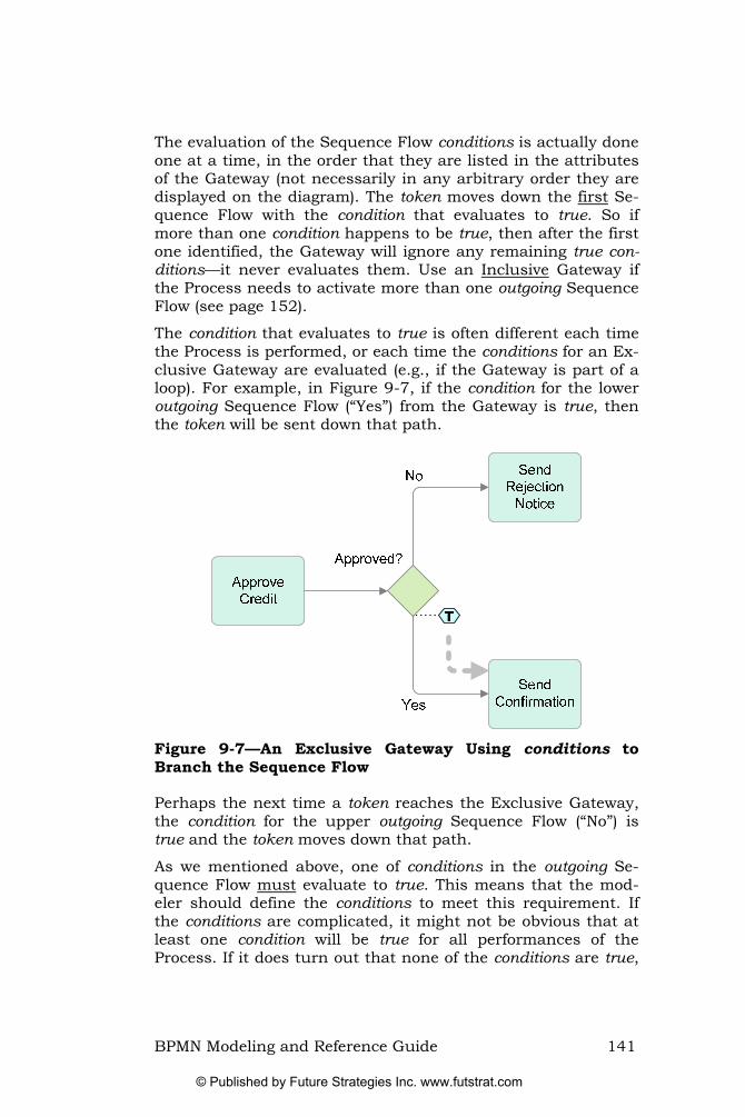
The evaluation of the Sequence Flow conditions is actually done one at a time, in the order that they are listed in the attributes of the Gateway (not necessarily in any arbitrary order they are displayed on the diagram). The token moves down the first Se-quence Flow with the condition that evaluates to true. So if more than one condition happens to be true, then after the first one identified, the Gateway will ignore any remaining true con-ditions—it never evaluates them. Use an Inclusive Gateway if the Process needs to activate more than one outgoing Sequence Flow (see page 152).
The condition that evaluates to true is often different each time the Process is performed, or each time the conditions for an Ex-clusive Gateway are evaluated (e.g., if the Gateway is part of a loop). For example, in Figure 9-7, if the condition for the lower outgoing Sequence Flow (“Yes”) from the Gateway is true, then the token will be sent down that path.
Figure 9-7—An Exclusive Gateway Using conditions to Branch the Sequence Flow
Perhaps the next time a token reaches the Exclusive Gateway, the condition for the upper outgoing Sequence Flow (“No”) is true and the token moves down that path.
As we mentioned above, one of conditions in the outgoing Se-quence Flow must evaluate to true. This means that the mod-eler should define the conditions to meet this requirement. If the conditions are complicated, it might not be obvious that at least one condition will be true for all performances of the Process. If it does turn out that none of the conditions are true,
BPMN Modeling and Reference Guide 141
© Published by Future Strategies Inc. www.futstrat.com

then the Process will be stuck at the Gateway and will not complete normally.
Best Practice: Use a default condition—One way for the modeler to en‐sure that the Process does not get stuck at an Exclusive Ga‐teway is to use a default condition for one of the outgoing Sequence Flow (see Figure 9‐8). This creates a Default Se‐quence Flow (see “Default Sequence Flow” on page 176). The Default is chosen if all the other Sequence Flow condi‐tions turn out to be false.
Figure 9-8—An Exclusive Gateway with a Default Sequence Flow
Exclusive Gateway Merging Behavior Exclusive Gateways can also merge Sequence Flow. That is, they can have multiple incoming Sequence Flow. However, When a token arrives at the Exclusive Gateway, there is no evaluation of conditions (on the incoming Sequence Flow), nor is there any synchronization of tokens that might happen to come down any other of the incoming Sequence Flow. The token, when it arrives, immediately moves down the outgoing Se-quence Flow. Effectively, there is an immediate “pass-through” of the token (see Figure 9-9).
142 BPMN Modeling and Reference Guide
© Published by Future Strategies Inc. www.futstrat.com

Accept Cash or Check
Process Credit Card
Prepare Package for Customer
T
T
The Token is “passed-through.”There is no delay, incoming
Condition evaluation, or synchronization
Figure 9-9—A token “passing-through” one of the Incoming Sequence Flow for an Exclusive Gateway
Note that when the Exclusive Gateway has only one outgoing Sequence Flow, then that Sequence Flow will not have a condi-tion. If the Gateway also has multiple outgoing Sequence Flow, then the Sequence Flow will have conditions to be evaluated as described in the section above.
If another token arrives from another incoming Sequence Flow, then it will also pass straight through, triggering the outgoing Sequence Flow again—i.e., there will be two instances of the Prepare Package for Customer in Figure 9-9, above.
Most of the time, a modeler will probably not need to worry about this behavior as a branching (splitting) Exclusive Gateway normally precedes the merge. In such circumstances, only one token will arrive at the merge anyway. Sometimes it will come down one path and sometimes down the other.
On the other hand, there may be situations where there are (potentially) multiple tokens arriving at a Gateway. In such cir-cumstances, if the desired behavior is that only the first token should pass through (ignoring the rest), then a Complex Gate-way is needed (see Figure 9-32 on page 159).
The behavior of the other types of Gateways usually includes waiting for (synchronizing) other tokens from other incoming Sequence Flow (as we shall discuss later), but Exclusive Gate-ways do not.
BPMN Modeling and Reference Guide 143
© Published by Future Strategies Inc. www.futstrat.com

Event-Based Exclusive Gateways Event-Based Exclusive Gateways represent an alternative branching point where the decision is based on two or more Events that might occur, rather than data-oriented conditions (as in an Exclusive Gateway). We will often use “Event Gate-way,” when referring to this Gateway. Since more than one Event controls the Event-Based Gateway, the marker within the diamond is the same as the Multiple Intermediate Event (a pentagon surrounded by two concentric circles—see Figure 9-10).
Figure 9-10—An Event Gateway
Processes that involve communications with a business partner or some external entity often need this sort of behavior. For ex-ample, if the business partner sends a message that says “Yes, let’s do it” the Process would head off down one path. If, on the other hand, the business partner sends a message that says “No thanks” the Process needs to head off down a different path. And if the business partner did not respond, a Timer is re-quired to avoid the Process becoming deadlocked. Event-Based Gateways allow this sort of flexibility. Several examples of Event-Based Gateways are used in the introductory chapters such as those shown in Figure 5-7 on page 46 and Figure 5-12 on page 56.
Note that the marker for the Exclusive Event Gateway has changed in BPMN 1.1. This is because the Gateway marker is a Multiple Intermediate Event, which has changed to a pentagon from a six-pointed star).
Event Gateway Splitting Behavior The Event Gateway is unique in BPMN in that its normal beha-vior is actually determined by a combination of flow objects. The Gateway by itself is not sufficient to accomplish the exclu-sive splitting of the flow. The Event Gateway also uses a combi-nation of Intermediate Events to create the behavior. These Events, which must be of the catch variety, are the first objects connected by the Gateway’s outgoing Sequence Flow (see Figure 9-11—the Group surrounding the configuration of the Gateway provides emphasis).
144 BPMN Modeling and Reference Guide
© Published by Future Strategies Inc. www.futstrat.com

Figure 9-11—An Event Gateway configuration (with an added Group for emphasis)
The following catch Intermediate Events are valid in an Event Exclusive Gateway:
• Message
• Timer
• Conditional
• Signal
Receive Tasks may also be used in place of Message Interme-diate Events. However, you cannot mix the two (Message In-termediate Events and Receive Tasks).
When the token arrives at the Gateway (see Figure 9-12) it will immediately pass-through the Gateway and then split up send-ing one token to each of the Events that follow the Gateway (see Figure 9-13).
BPMN Modeling and Reference Guide 145
© Published by Future Strategies Inc. www.futstrat.com

Figure 9-12—A token arrives at the Event Gateway
Since all the Intermediate Events are catch Events, the tokens will wait there until one of the Events is triggered.
Figure 9-13—The token is split and sent down all of the Gateway’s outgoing Sequence Flow
The situation here is similar to Activity with attached Interme-diate Events (see “Interrupting Activities with Events” on page 101). The Intermediate Events that are part of the Gate-way configuration become involved in a race condition. Whi-chever one finishes first (fires) will win the race and take con-trol of the Process with its token. Then the token will imme-diately continue down its outgoing Sequence Flow (from that Intermediate Event—see Figure 9-14). The tokens waiting in the other Events are immediately consumed, disabling those paths.
146 BPMN Modeling and Reference Guide
© Published by Future Strategies Inc. www.futstrat.com

Figure 9-14—The Event that is triggered “chooses” the path
There is always a risk that the Events chosen for the Event Ga-teway configuration may not occur for a given Process instance. If none of the Events are triggered, for whatever reason, then the Process will become stuck at the Gateway and will not complete normally. If none of the other Events trigger, then the timer will eventually fire, allowing the Process to continue (and to deal with why the other Events never happened).
Best Practice: Use a Timer Intermediate Event with an Event Gateway—One way for the modeler to ensure that the Process does not get stuck at an Event Based Exclusive Gateway is to use a Timer Intermediate Event as one of the options for the Gateway (see Figure 9‐11, above).
Event Gateway Merging Behavior Unlike all the other Gateways, the Event Gateway is always used to split the Process flow. However, at the same time, they merge Process flow. The merging behavior of the Event Gateway is exactly the same as the merging behavior of the Exclusive Gateway (see “Exclusive Gateway Merging Behavior” on page 142).
Parallel Gateways Parallel Gateways insert a split in the Process to create two or more parallel paths (threads). They can also merge parallel paths. The “+” marker is used to identify this type of Gateway (see Figure 9-15).
BPMN Modeling and Reference Guide 147
© Published by Future Strategies Inc. www.futstrat.com

Figure 9-15—A Parallel Gateway
Parallel Gateway Splitting Parallel Gateways will split the flow when they have two or more outgoing paths. When a token arrives at a Parallel Gate-way (see Figure 9-16), there is no evaluation of any conditions on the outgoing Sequence Flow (unlike the Exclusive Gateway).
Figure 9-16—A single token arriving at a Parallel Gateway
By definition, the Parallel Gateway will create parallel paths. This means that the Gateway will create a number of tokens that are equal to the number of outgoing Sequence Flow. One token moves down each of those outgoing Sequence Flow (see Figure 9-17). There is no delay between the arrival of the token to the Gateway and the tokens leaving the Gateway.
148 BPMN Modeling and Reference Guide
© Published by Future Strategies Inc. www.futstrat.com

Figure 9-17—Two tokens leaving a Parallel Gateway
Parallel Gateway Merging Use a merging Parallel Gateway when parallel paths require synchronization before the Process can continue. To synchron-ize the flow, the Parallel Gateway will wait for a token to arrive from each incoming Sequence Flow. When the first token ar-rives, there is no evaluation of a condition for the incoming Se-quence Flow, but the token is “held” at the Gateway and does not continue (see Figure 9-18).
Ship Order
Accept Payment
Close OrderT
Figure 9-18—A Parallel Gateway merging the Sequence Flow
This “holding” of tokens will continue until a token arrives from all incoming Sequence Flow (see Figure 9-19)
BPMN Modeling and Reference Guide 149
© Published by Future Strategies Inc. www.futstrat.com
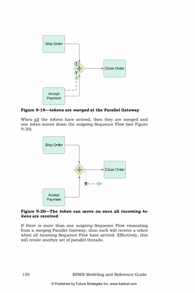
Ship Order
Accept Payment
Close OrderT
T
Figure 9-19—tokens are merged at the Parallel Gateway
When all the tokens have arrived, then they are merged and one token moves down the outgoing Sequence Flow (see Figure 9-20).
Figure 9-20—The token can move on once all incoming to-kens are received
If there is more than one outgoing Sequence Flow emanating from a merging Parallel Gateway, then each will receive a token when all incoming Sequence Flow have arrived. Effectively, this will create another set of parallel threads.
150 BPMN Modeling and Reference Guide
© Published by Future Strategies Inc. www.futstrat.com

Best Practice: Ensure that the number of incoming Sequence Flow is cor‐rect for a Parallel Gateway—The key point is to exercise care, ensuring that merging Parallel Gateways have the correct number of incoming Sequence Flow—especially when used in conjunction with other Gateways. As a guide, modelers should match merging and splitting Parallel Gateways (if the desired behavior is to merge them again).30
If the number of incoming Sequence Flow does not match with the number of tokens that will actually arrive, then the Process will get stuck at the Parallel Gateway, waiting for a token that never materializes—i.e., the Process can never complete proper-ly. Figure 9-21 provides an example of such a Process configu-ration.
Figure 9-21—An example of incorrect use of a Merging Pa-rallel Gateway
umber of incoming Sequence Flow (in this case, down to two).
<
The correct way to model this situation shown is Figure 9-22. It involves placing an Exclusive Gateway prior to the merging Pa-rallel Gateway to reduce the n
30 Of course, it is possible to split the flow at a Parallel Gateway and never have the threads recombine. Ultimately each thread will finish at an End Event.
BPMN Modeling and Reference Guide 151
© Published by Future Strategies Inc. www.futstrat.com

Figure 9-22—Matching the numbers of inputs on a merging Parallel Gateway
Inclusive Gateways Inclusive Gateways support decisions where more than one outcome is possible at the decision point. The “O” marker iden-tifies this type of Gateway (see Figure 9-23).
Figure 9-23—An Inclusive Gateway
Inclusive Gateway Splitting Behavior Like the Exclusive Gateway, an Inclusive Gateway with mul-tiple outgoing Sequence Flow creates alternative paths based on the conditions on those Sequence Flow. The difference is that the Inclusive Gateway activates one or more paths;31 whereas the Exclusive Gateway will only activate one outgoing Sequence Flow and the Parallel Gateway will activate all outgoing Se-quence Flow.
When a token arrives at an Inclusive Gateway (see Figure 9-24), there is an immediate evaluation of all the conditions that are on the Gateway’s outgoing Sequence Flow.
<
31 There is another mechanism for creating an inclusive split. This is achieved us-ing multiple outgoing Conditional Sequence Flow from an Activity (see
on page 174). Conditional
Sequence Flow
152 BPMN Modeling and Reference Guide
© Published by Future Strategies Inc. www.futstrat.com

Figure 9-24—A token arrives at an Inclusive Gateway
Every condition that evaluates to true will result in a token mov-ing down that Sequence Flow. As with the Exclusive Gateway, at least one of those conditions must evaluate to true. This means that any combination of Sequence Flow, from one of them to all of them, may receive a token each time the Gateway is used. In Figure 9-25, if the condition for the upper outgoing Sequence Flow (“Include A?”) and the condition for the lower outgoing Sequence Flow (“Include B?”) are true, then tokens move down both of those paths.
Figure 9-25—A token is directed down one or more of the outgoing Sequence Flow
Another time a token reaches the Exclusive Gateway, it might decide that the condition for the middle outgoing Sequence Flow (“Include B?”) is the only one that evaluates to true, leading to a token moving down that path.
BPMN Modeling and Reference Guide 153
© Published by Future Strategies Inc. www.futstrat.com

As described for the behavior of the splitting Exclusive Gateway, above (see page 140), one of conditions in the outgoing Se-quence Flow must evaluate to true or the Process will be stuck at the Gateway and will not complete normally.
Best Practice: Use a default condition—One way for the modeler to en‐sure that the Process does not get stuck at an Inclusive Ga‐teway is to use a default condition for one of the outgoing Sequence Flow. This Default Sequence Flow will always eva‐luate to true if all the other Sequence Flow conditions turn out to be false (see “Default Sequence Flow” on page 176).
Inclusive Gateway Merging Behavior The merging behavior of the Inclusive Gateway is one of the more complex parts of BPMN to understand. The Gateway will synchronize the flow of the Process like the Parallel Gateway (see page 149), but it does so in a way that mirrors the output of the splitting Inclusive Gateway. That is, the Gateway will synchronize from one to all of the Gateway’s incoming Sequence Flow. The Gateway will determine how many paths are ex-pected to have a token.
We walk through an example to show how the Inclusive Gate-way does this synchronization. When the first token arrives at the Gateway (see Figure 9-26), the Gateway will “look” up-stream for each of the other incoming Sequence Flow to see if there is a token that might arrive at a later time. In the figure, there is another token in the bottom path still in the “Supple-ment C” Task, but there is no token in the middle path (in the “Supplement B” Task or further upstream).
Supplement A
Supplement B
Supplement C
Compile Documents
T
Figure 9-26—A token arrives at an Inclusive Gateway
154 BPMN Modeling and Reference Guide
© Published by Future Strategies Inc. www.futstrat.com

Thus, the Gateway will hold the first token that arrived in the upper path until the other token from the lower path arrives (see Figure 9-27).
Figure 9-27—A second token arrives at an Inclusive Gate-way, synchronizing the flow
When all the expected tokens have arrived at the Gateway, the Process flow is synchronized (the incoming tokens are merged) and then a token moves down the Gateway’s outgoing Sequence Flow (see Figure 9-28).
Supplement A
Supplement B
Supplement C
Compile Documents
T
Figure 9-28—The token is sent down the outgoing Se-quence Flow
Figure 9-29 shows a different instance of the Gateway where a token arrives from the middle path while there are no other to-kens waiting upstream on either the upper or lower path. In
BPMN Modeling and Reference Guide 155
© Published by Future Strategies Inc. www.futstrat.com

this case, the token would immediately move down the outgoing Sequence Flow (as in Figure 9-28, above).
Supplement A
Supplement B
Supplement C
Compile Documents
T
Figure 9-29—A token arrives at an Inclusive Gateway that does not need synchronization
Note that when the Inclusive Gateway has only one outgoing Sequence Flow, then that Sequence Flow will not have a condi-tion. If the Gateway also has multiple outgoing Sequence Flow, then the Sequence Flow will have conditions to be evaluated as described in the section above.
An Inclusive Gateway that merges the flow is usually married up with a corresponding splitting Inclusive Gateway. When used in pairs in this way, the splitting Gateway will continue the flow down one to all paths and the merging Gateway will synchronize (wait for) all the paths that were generated for that instance.
Of course, it is possible to create Processes that include differ-ent combinations of splitting and merging Inclusive Gateways. In some cases, it will be hard to determine the pairing of the Gateways. It is difficult to make a Process deadlock (get stuck) when using Inclusive Gateways, but the actual behavior of the Process might not be what the modeler expects. So exercise caution when using merging Inclusive Gateways.32
<
32 The general guideline used in the development of BPMN was to develop a model-ing capability that did not constrain users too tightly, making the notation as flexi-ble as possible. As a result, careless modeling can lead to problems.
156 BPMN Modeling and Reference Guide
© Published by Future Strategies Inc. www.futstrat.com

Best Practice: Always use Inclusive Gateways in pairs—A way to avoid unexpected behavior is to create models where a merging Inclusive Gateway follows a splitting Inclusive Gateway and that the number of Sequence Flow match between them (see Figure 9‐30).
Figure 9-30—Inclusive Gateways that are paired for split-ting and merging Sequence Flow
Complex Gateways Complex Gateways use a bold asterisk as the marker shape within the diamond (see Figure 9-31). They are part of BPMN to handle situations where the other types of Gateways do not provide support for the desired behavior.
Figure 9-31—A Complex Gateway
Modelers provide their own expressions that determine the merging and/or splitting behavior of the Gateway. They often replace a set of standard Gateways, combining them into a sin-gle, more compact Gateway.
Complex Gateway Splitting Behavior The splitting behavior of the Complex Gateway is the least in-teresting side of the Gateway. It is similar to the behavior of the Inclusive Gateway splitting behavior. The difference is that the Complex Gateway uses a single outgoing assignment within the Gateway, rather than a set of separate conditions on the out-
BPMN Modeling and Reference Guide 157
© Published by Future Strategies Inc. www.futstrat.com

going Sequence Flow. The result is the same in that Gateway activates one or more of the outgoing paths (see “Inclusive Ga-teway Splitting Behavior” on page 152 for an example of this type of behavior).
An assignment has two parts: a condition and an action. When an assignment is performed, it evaluates the condition and if true, it then performs the action such as updating the value of a Process or Data Object property. In the case of a Complex Gateway, the outgoing assignment may send a token down one or more of the Gateway’s outgoing Sequence Flow. The outgoing assignment may refer to data of the Process or its Data Objects and the status of the incoming Sequence Flow (i.e., is there a token there). For example, an outgoing assignment may eva-luate Process data and then select different sets of outgoing Se-quence Flow, based on the results of the evaluation. However, the outgoing assignment should ensure that at least one of the outgoing Sequence Flow will always be chosen.
Complex Gateway Merging Behavior The more interesting side of the Complex Gateways is its merg-ing behavior. There are many patterns that can be performed with the Complex Gateway, such as typical Inclusive Gateway behavior, batching of multiple tokens, accepting tokens from some paths but ignoring the tokens from others, etc. The Gate-way looks the same for each of these patterns, so the modeler should use a Text Annotation to inform the reader of the dia-gram how it is used.
Best Practice: Use a Text Annotation with the Complex Gateway—Since the actual behavior of a Complex Gateway will vary for each usage of the Gateway, use a Text Annotation to tell the reader of the diagram what behavior the Gateway is set to perform (see Figure 9‐32).
The Complex Gateway uses an incoming assignment when to-kens arrive. The condition of the incoming assignment may refer to Process or Data Object information and the status of the in-coming Sequence Flow. If the condition is false, nothing hap-pens other than the token is held there. If the condition is true, then the action could be set to pass the token to the output side of the Gateway, thereby activating the outgoing assignment, or the action could be set to consume the token.
Of the many ways of using a Complex Gateway, we will use the discriminator pattern as a demonstration. In this pattern, there are two or more parallel activities. When one of the Activities
158 BPMN Modeling and Reference Guide
© Published by Future Strategies Inc. www.futstrat.com

completes, then the follow-on Activities can begin, but it does not matter which Activity completes. This is another example of a race condition. All the remaining Activities will complete nor-mally, but they no longer have an impact on the Process flow.
In Figure 9-32, the “Start Analysis” Task should start after “Test A” or “Test B,” it does not matter which one finishes first. But, after the second one finishes, the “Start Analysis” Task should not start again. In contrast, if the modeler chose an Ex-clusive Gateway to merge the flow, the “Start Analysis” Task would start again (i.e., two instances).
Figure 9-32—A Complex Gateway Merging the Sequence Flow
If the “Run Test A” Task completes first, its token is sent to the Gateway while the other token is still in the “Run Test B” Task (see Figure 9-33).
Figure 9-33—A token arrives at a Complex Gateway
BPMN Modeling and Reference Guide 159
© Published by Future Strategies Inc. www.futstrat.com

For this pattern, the first token that arrives is immediately sent out down the outgoing Sequence Flow to the next Activity (see Figure 9-34).
Run Test A
Run Test B
Start AnalysisPrepare Tests
T
T
Figure 9-34—The first token passes through the Complex Gateway
When the other token finally arrives, it is consumed by the Ga-teway (see Figure 9-35)
Run Test A
Run Test B
Start AnalysisPrepare Tests
T
T
Figure 9-35—The second token is stopped at the Complex Gateway
160 BPMN Modeling and Reference Guide
© Published by Future Strategies Inc. www.futstrat.com

Chapter 10. Swimlanes
BPMN uses “swimlanes” to help partition and/organize activi-ties in a diagram. There are two main types:
• Pools—act as containers for a Process, each one representing a participant in a collaborative Business Process Diagram.
• Lanes—often assumed to represent internal business roles within a Process, Lanes actually provide a generic mechanism for partitioning the objects within a Pool based on the characteristics of the Process or elements.
Pools The term “Pool” was derived by extending the swimlane analogy. A swimming pool has lanes. BPMN has two types of swimlane partitions and one type is included in the other. Thus, it made sense to call the sub-partitions Lanes and, the partition that contained the Lanes, a Pool.
In BPMN, Pools represent participants in an interactive or col-laborative Business Process Diagram. A participant is defined as a general business role, e.g. a buyer, seller, shipper, or sup-plier. Alternatively, it could define a specific business entity, e.g. FedEx as the shipper. Each Pool can only represent one partic-ipant.
Pools are depicted as a rectangle box that acts as a container for the flow objects of a participant’s Process. The Business Process Diagram referred to here is really a collaboration, de-tailing how the participants coordinate their behavior. Partici-pants might have an abstract representation (e.g., “Buyer” or “Seller” role) or they may represent a distinct business entity (e.g., “IBM” or “Amazon.com”).33
Since a BPMN diagram can depict the Processes of different participants, each participant may view the diagram differently. That is, each participant will have a different point of view—some Activities are under their control, while other Pools are external to them.
<
33 The term “Participant” references business-to-business collaborators who are each in charge of their own Processes. It does not refer to the roles or job titles of an organization.
BPMN Modeling and Reference Guide 161
© Published by Future Strategies Inc. www.futstrat.com

In practice, each Pool represents a distinct Process and each participant has its own Pool. A Pool is not required to contain a Process. Known as a “black box,” these Pools do not show Ac-tivities or Sequence Flow inside its boundary. Figure 10-1, which was used in Part I of this book, shows a “Mortgage Com-pany” Pool containing a Process and a “Customer” Pool whose Process is a black box (as far as Mortgage Co is concerned, they have no knowledge of the Processes of their Customer). When the Pool is a black box the Pool’s shape can be sized and posi-tioned in a way that is convenient for the modeler (that is, they do not have to extend the entire length of the diagram.
Figure 10-1—A collaboration with two Pools (one a “black box”)
Message Flow handle all interactions between Pools (and their Processes). When the Pool is black box, Message Flow connects to its boundary. Where a Pool has Process elements, the Mes-sage Flow connects to those elements (see Figure 10-1, above).
As discussed in the section on Sequence Flow on page 173, Se-quence Flow cannot cross a Pool boundary—i.e., a Process is fully contained within a Pool. For a discussion on why Message Flow is used to synchronize the Processes between Participants see page 177.
In some cases, when the point of view of the diagram is clear, the boundary of the “main” Pool is not displayed. For example, the modelers for the “Mortgage Co” participant shown in Figure 10-1 above have developed the diagram and may not want to
162 BPMN Modeling and Reference Guide
© Published by Future Strategies Inc. www.futstrat.com

display the boundary of their Pool to emphasize the difference between internal and external participants (see Figure 10-2).
Cus
tom
er
Figure 10-2—A diagram where the boundary of one Pool is not shown
Lanes Lanes create sub-partitions for the objects within a Pool (see Figure 10-3). These partitions are used to group Process elements (showing how they are related), or which roles have responsibility for carrying out the Activities.
Lanes often represent organization roles (e.g., Manager, Admin-istration, Associate, etc), but can represent any desired classifi-cation (e.g., underlying technology, organizational departments, company products, location, etc).
BPMN Modeling and Reference Guide 163
© Published by Future Strategies Inc. www.futstrat.com

Figure 10-3—An example of Lanes within a Pool
It is also possible to nest Lanes (see Figure 10-4 where the “Marketing” Lane is sub-divided into the “Pre-Sales” and “Post-Sales”).
Sale
sM
arke
ting
Sup
plie
r
Pre-
Sale
sPo
st-S
ales
Engi
neer
ing
Figure 10-4—An example of nested Lanes within a Pool
164 BPMN Modeling and Reference Guide
© Published by Future Strategies Inc. www.futstrat.com

The key points to remember about Lanes are:
• In BPMN 1.1 Lanes can represent any logical grouping (not just roles). 34 For example, Lanes can represent functional areas, business systems, business classifica-tions (e.g., customer oriented, support oriented, etc), business locations, etc.
<
• Sequence Flow can cross Lane boundaries. • Lanes can be nested. • Message Flow is not used within or across Lanes of a
Pool.35
34 It is likely that this will be tightened up in BPMN 2.0.
35 For a wider discussion on the reasons for this, see on page 177. Message Flow
BPMN Modeling and Reference Guide 165
© Published by Future Strategies Inc. www.futstrat.com

166 BPMN Modeling and Reference Guide
© Published by Future Strategies Inc. www.futstrat.com

Chapter 11. Artifacts
Artifacts provide a mechanism to capture additional informa-tion about a Process, beyond the underlying flow-chart struc-ture. This information does not directly impact the flow chart characteristics of a Process.
There are three standard Artifacts in BPMN:
• Data Objects—Used to represent the documents and data that are manipulated by Processes. Think of them as representing the “payload” of the Process.
• Groups—Provide a mechanism to highlight and categor-ize a section of the model or a set of Objects.
• Text Annotations—Add further descriptive information to a model (as an aid to understanding).
A modeler or tool can extend BPMN by defining new Artifacts; the only restriction is that they must have their own distinct shape and not conflict with the way existing shapes look and/or are configured.
Data Objects Data Objects represent the data and documents in a Process. Data Objects use a standard document shape (rectangle with one corner bent over—see Figure 11-1).
Figure 11-1—A Data Object
Data Objects usually define the inputs and outputs of Activities. While Data Objects do not affect the structure and flow of the Process, they are intimately tied to performance of Activities. Associations indicate their direction (input or output) (see Figure 11-2). We will discuss the use of Data Objects and their relationship to Activities in more detail in “Data Flow” on page 180.
BPMN Modeling and Reference Guide 167
© Published by Future Strategies Inc. www.futstrat.com

Review and Approve
Order
Fulfill Order
Reject Order
Order[Rejected]
Order[Approved]
Figure 11-2—Data Objects are used for Data and Docu-ments
Data Objects also have “states” that depict how the object (document) is updated within the Process. The state is usually shown under the name of the Data Object and is placed be-tween brackets (as Figure 11-2, above, shows the “Order” Data Object with the states of “Approved” or “Rejected”).
Figure 11-2 also illustrates a unique feature of Data Objects. The same Data Object can appear multiple times in a diagram. If the “Fulfill Order” Task appeared twice in the diagram, that would represent two separate instances of that Task. However, although the “Order” Data Object appears twice, it represents two representations of the same document.
By using the state of a Data Object and placing it within mul-tiple locations within a diagram, the modeler can document the changes that a Data Object will go through during the Process.
Groups A Group is a dashed, rounded rectangle used to surround a group of flow objects in order to highlight and/or categorize them. A long dash and a dot make up the line (see Figure 11-3).
168 BPMN Modeling and Reference Guide
© Published by Future Strategies Inc. www.futstrat.com

Figure 11-3—A Group shape
Groups enclose a section of a model but do not add additional constraints on Process performance—as a Sub-Process would (Sequence Flow can pass through a Group boundary). It is merely a useful graphical mechanism for categorizing objects. Sequence Flow and Message Flow move through Group boun-daries transparently. While Groups do not affect process per-formance, they can acts as a container for reporting.
Figure 11-4 shows a Group across two Pools. The Activities shown are related even though they are performed by different participants within different Pools.
Figure 11-4—Groups graphically highlight any set or cate-gory of BPMN elements
Groups do not affect the flow of the Process and are not part of a Process decomposition. Although the Group will graphically highlight a set of Activities, this Group cannot be interrupted in the same way as a Sub-Process (see Figure 11-5 for an incor-rect example). It is not possible to attach Intermediate Events to the boundary of a Group.
BPMN Modeling and Reference Guide 169
© Published by Future Strategies Inc. www.futstrat.com

Figure 11-5—Incorrect use of a Group (it is not possible to attach Intermediate Events to a Group)
The correct way to interrupt the Activities in the figure above is to use a Sub-Process and then attach the Intermediate Event to the boundary as in Figure 11-6.
Figure 11-6—The Correct way to interrupt a set of Activi-ties
Underpinning the Group element is the category concept (which is a common attribute to all BPMN elements). For ex-ample, Activities could be categorized, for analysis purposes, as “customer valued” or “business valued.” A Group is merely a visual depiction of a single category. The graphical elements within the Group are assigned the category attribute linked to the Group. It is worth noting that categories might use other highlighting mechanisms, such as color, as defined by a mod-eler or a modeling tool. They could also support reporting or analysis (or any other purpose). Since a category is also a BPMN element, a category can have categories, creating a hie-rarchical structure (of categories).
170 BPMN Modeling and Reference Guide
© Published by Future Strategies Inc. www.futstrat.com

Text Annotations Text Annotations provide the modeler with the ability to add further descriptive information or notes about a Process or its elements. Text Annotations can connect to any object on the diagram or they can float freely anywhere on a diagram. The text for the Text Annotation is accompanied by an open box that can appear on either side of the text (see Figure 11-7).
Figure 11-7—An Example of a Text Annotation
The line used to connect a Text Annotation to another object is an Association (see “Association” on page 178).
Note that Text Annotations feature throughout this book to provide descriptions and aid understanding of the examples and concepts presented.
Artifacts are Extendable Modelers and tool vendors can extend BPMN through the addi-tion of new types of Artifacts. Modeling tools may include fea-tures to hide, or show these Artifacts. Either way, the structure of the Process (the flow objects connected by Sequence Flow) will remain the same.
As with other Artifacts, these extensions cannot form part of the normal flow of Activities, Events, and Gateways—that is, Sequence Flow cannot directly connect to or from Artifacts. This was to ensure that BPMN diagrams always have a consis-tent and recognizable structure (i.e., aiding understanding) and to guarantee a consistent behavior of BPMN diagrams.
For example, a database or datastore might be represented by a cylinder graphic (see Figure 11-8). While this is not a stan-dard BPMN Artifact, a modeler might add it.
BPMN Modeling and Reference Guide 171
© Published by Future Strategies Inc. www.futstrat.com

Figure 11-8—New Artifacts can be created by Modelers or Tool Vendors
Furthermore, specific industries or markets might develop their own sets of Artifacts. For example, practitioners in the telecom, insurance, or health industries may develop a set of Artifacts that are meaningful in their industries. The golden rule is that any new Artifact type must have a shape that does not conflict (or could easily be confused with) existing BPMN shapes.
It is possible that future versions of the BPMN specification will standardize further types of Artifacts.
172 BPMN Modeling and Reference Guide
© Published by Future Strategies Inc. www.futstrat.com

Chapter 12. Connectors
Connectors link two objects on a diagram. There are three dif-ferent types of BPMN Connectors (see Figure 12-1):
• Sequence Flow—Defines the order of flow objects in a Process (Activities, Events, and Gateways).
• Message Flow—Defines the flow of communication be-tween two participants or entities (e.g., an organization and its suppliers). The object of the communication is a message.
• Associations—Used to link Artifacts (data and other in-formation) with other diagram objects, including flow ob-jects (Activities, Events, and Gateways).
Figure 12-1—Three types of BPMN Connectors
Sequence Flow Sequence Flow connects the other Process elements (Activities, Events, and Gateways). It orders the flow objects—for example, Activities such as “Send Invoice,” “Receive Payment,” and “Ac-cept Payment” are performed sequentially in Figure 12-2. The Sequence Flow of a Process—the solid lines with solid arrow-heads in between the Activities in the figure—create the paths of the Process navigated during its performance.
BPMN Modeling and Reference Guide 173
© Published by Future Strategies Inc. www.futstrat.com

Figure 12-2—Sequence Flow within a Process
The source and target of the Sequence Flow line (the target shown by the arrowhead on the line) can only connect Events, Activities, and Gateways. Sequence Flow cannot connect any other BPMN elements, but most importantly, Sequence Flow cannot cross a Sub-Process boundary or Process boun-dary (a Pool).
Many modeling techniques and methodologies use the term “control flow” for the connectors between tasks and activities (similar to BPMN Sequence Flow). BPMN specifically does not use the term “control flow” for connectors. It was determined that there were many factors that “control” the performance of a Process or Activity and that the sequence of the activities was just one factor. Other factors that “control” Activities include: the arrival of messages, the availability of data, the availability of resources (such as performers), and built-in timing con-straints (discussed in more detail in “Performing an Activity” on page 185).
Conditional Sequence Flow A Sequence Flow has an internal attribute called condition.36 However, the condition cannot be used in all circumstances. The condition attribute is not available when connecting from:
• An Event • Event, Parallel, and Complex Gateways
The condition attribute is available when connecting from:
• Excusive and Inclusive Gateways • Activities
<
36 Attributes are generally not shown graphically. In this case, they do have a graphical representation (the condition is attached to the Sequence Flow).
174 BPMN Modeling and Reference Guide
© Published by Future Strategies Inc. www.futstrat.com

The use and evaluation of the Sequence Flow conditions for Ex-clusive and Inclusive Gateways has been described above (see “Event Gateway Splitting Behavior” on page 140 and “Inclusive Gateway Splitting Behavior” on page 152).
When a condition is used on the outgoing Sequence Flow of an Activity, it is called A Conditional Sequence Flow. Since the condition controls the flow between Activities, a mini-diamond (like a mini-Gateway) appears at the beginning of the Connec-tor (see Figure 12-3).
Figure 12-3—Conditional Sequence Flow may follow an Ac-tivity
When the Activity has completed and the condition evaluates to true, then a token (flow) will move down the Sequence Flow. If the condition evaluates to false, then the flow does not occur. The behavior of a set of Conditional Sequence Flow for an Ac-tivity is similar to that of an Inclusive Gateway (see “Inclusive Gateway Splitting Behavior” on page 152).
Such an Activity must have at least two outgoing Sequence Flow and at least one of the Sequence Flow must be guaran-teed to occur (otherwise the Process might become stuck).
The modeler must always ensure that the combination of condi-tions represented in the outgoing Sequence Flow always leads to at least one of them firing for every performance of the Activ-ity. One way to do that is to use a standard Sequence Flow or place a Default Sequence Flow on one of the Conditional Se-quence Flow. Figure 12-3, above, uses a standard Sequence Flow following the “Ensure Offer Details Available” Task. Since there is no condition for that Sequence Flow, a token will move
BPMN Modeling and Reference Guide 175
© Published by Future Strategies Inc. www.futstrat.com

down that path. If a Default Sequence Flow is used (see the next section), a token will move down that path only when all the other conditions evaluate to false.
Best Practice: Use a Standard or Default Sequence Flow when using Conditional Sequence Flow—One way for the modeler to ensure that the Process does not become stuck after an Ac‐tivity is to use a standard or Default Sequence Flow when‐ever Conditional Sequence Flow are used (see Figure 12‐3, above).
Default Sequence Flow In the last section, we discussed conditions used with some Se-quence Flow. Alongside those conditions is a special BPMN condition called the default condition. The default condition can complement a set of standard conditions to provide an auto-matic escape mechanism in case all the standard conditions evaluate to false.
The Sequence Flow that has this default condition is called De-fault Sequence Flow. The Default Sequence Flow has a hatch mark near its beginning (see Figure 12-4).
In the example, on the outgoing Sequence Flow of the Exclusive Gateway, it is possible for all conditions to return false. In such circumstances, the Process will become stuck. The default con-dition gets around this problem.
The detail of the mechanism is as follows (to ensure that at least one condition of a set of conditions is true). If any of the set of standard conditions evaluates to true, then the default condi-tion is false. If all of the standard conditions return false, then the default condition becomes true.
Figure 12-4—An example of Default Sequence Flow
176 BPMN Modeling and Reference Guide
© Published by Future Strategies Inc. www.futstrat.com

The Default Sequence Flow can be used in all situations where a set of outgoing Sequence Flow can have conditions. In BPMN, these situations are:
• Exclusive Gateways • Inclusive Gateways • Activities
Message Flow Message Flow defines the messages/communications between two separate participants (shown as Pools) of the diagram (see Figure 12-5). They are drawn with dashed lines that have a small hollow circle at the beginning and a hollow arrowhead at the end.
Message Flow must always occur between two separate Pools and cannot connect two objects within a single Pool. Thus, Message Flow is only used in collaborations (diagrams with two or more Pools).
As shown in Figure 12-5 below, Message Flow can connect to the boundary of the Pool (for a black box Pool). Alternatively, Message Flow can connect to a flow object within a Pool (if ex-panded with its own Process details).
Figure 12-5—Message Flow between two Pools (partici-pants)
BPMN Modeling and Reference Guide 177
© Published by Future Strategies Inc. www.futstrat.com

Key Point: There is a strong distinction between Sequence Flow and Message Flow. Sequence Flow can only be used within a Pool and Message Flow can only be used across Pools.
Many modelers ask why Message Flow cannot be used within a Pool. Processes already have a mechanism to move data be-tween Activities—data flow (see page 180). Therefore, there is no reason to use a message to send data from one part of a Process to another part of the same Process since the “process data” is made available everywhere to the entire process.37 Fur-thermore, using Message Flow within a Process would corrupt the clean separation between Sequence Flow and Message Flow, and would create confusion for modelers trying to make deci-sions about Process structure (e.g., what data mechanism should they use).
If a message is truly required between two Activities, then this would indicate that the Activities reside in two separate con-texts or loci of control. That is, the Activities should be modeled in two separate Pools.
Association An Association will link one diagram object (i.e. creates a rela-tionship) with another diagram object (such as Artifacts and Activities). For example, the dotted line that connects a Text Annotation to another object is actually an Association (see Figure 12-6).
Figure 12-6—Associations connect Annotations to Objects
One of the more important uses of Associations is to show that data is input and output from Activities, e.g. an “Order” is out-put from one Activity and input into a later Activity (as <
37 BPMN does not specify how data flow should be implemented by a BPMS engine. Such transfers of data may, use an underlying messaging system. Other systems may use other mechanisms. But such details are transparent to the modeler and the Processes should behave the same way regardless of the underlying technology used.
178 BPMN Modeling and Reference Guide
© Published by Future Strategies Inc. www.futstrat.com

in Figure 12-7). The directional line (with an open arrowhead) shows the source and target of the Data Object (a type of Arti-fact).
Perform Credit Check
Accept Order
Reject Order
Accept
Reject
Order[Approved]
Output
Input
Figure 12-7—Associations used to show the flow of data
nd out of Activities in more detail in “Data Flow” on page 180.
w does not include Exception Flow or Com-pensation Flow.
<
We discuss the flow of data into a
Normal Flow The concept of normal flow is often referred to as the “Happy Path” or the “Skinny Process.” 38 Normal flow refers to core Process, where the flow objects (Events, Activities, and Gate-ways) are connected through Sequence Flow, beginning with a Start Event and following the core alternative and parallel paths until the Process completes at an End Event (see Figure 12-8). Normal flo
38 In reality, the Happy Path may actually be a sub-set of Normal Flow. For exam-ple, the high-probability conditions for decisions might make up the Happy Path, while other, less probable paths are part of the Normal Flow (but not happy).
BPMN Modeling and Reference Guide 179
© Published by Future Strategies Inc. www.futstrat.com

Figure 12-8—The normal flow of a Process
The normal flow describes the core structure of the Process. Focusing on the normal flow enables the modeler to create a relatively simple, flow-chart diagram. The additional features of BPMN (such as Artifacts, Swimlanes and Exception Flow) pro-vide extra detail if needed.
One of the general rules for BPMN is that Sequence Flow must make it from the start to the finish without any “assumptions” (implicit areas where the Sequence Flow somehow magically jumps from one place to another). This is one of the reasons for the default condition at Exclusive Gateways to ensure that flow is explicitly shown.
Data Flow Data flow represents the movement of Data Objects from into and out of Activities. With many process-modeling notations, the movement of data and the flow of Activities (control flow) are tightly coupled. However, in BPMN, data flow is decoupled from the Sequence Flow. Sequence Flow handles the ordering of the Activities. Directed Associations handle the flow of data to and from Activities. It is possible to combine the Sequence Flow and the data flow when they coincide, but they are native-ly separated to allow modeling flexibility.
In Figure 12-9, an Association exiting the first Task connects to the Data Object (the output) and an Association connected from the same Data Object is then input to the second Task.
180 BPMN Modeling and Reference Guide
© Published by Future Strategies Inc. www.futstrat.com

Figure 12-9—A Data Object as output and input to Activi-ties
When there is a simple progression of data flow from one Activ-ity to another, the data flow is more clearly defined (less clut-ter) by binding the Data Object to the Sequence Flow (see Figure 12-10). An Association connects the Data Object to the Sequence Flow between the two Activities. It means that the Artifact is the output of the first Task and the input to the second. Thus, the diagram in Figure 12-9 is equivalent to the diagram in Figure 12-10.
Figure 12-10—A Data Object bound to a Sequence Flow
While it is possible to associate a Data Object to a Sequence Flow that connects to a Gateway, we do not recommend this type of configuration. It can quickly become difficult to under-stand how the inputs and outputs are applied to the Activities on both sides of the Gateway. This is particularly true where a string of Gateways is used. In BPMN 1.1, this type of Associa-tion is not restricted. In BPMN 2.0, there will be a clarification (and probably some restrictions) placed on this type of model configuration.
Best Practice: Do not Associate a Data Object with a Sequence Flow if the Sequence Flow is connected to a Gateway—The appli‐cation of inputs and outputs are easily confused when one or more Gateways is used for Sequence Flow that are asso‐ciated with Data Objects.
BPMN Modeling and Reference Guide 181
© Published by Future Strategies Inc. www.futstrat.com
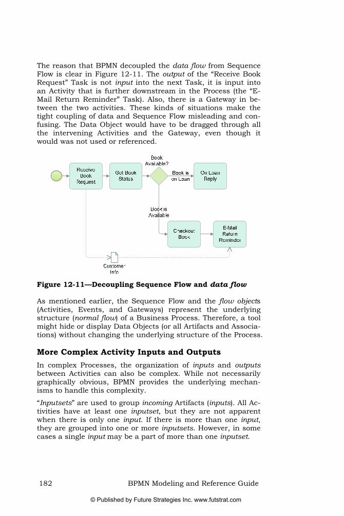
The reason that BPMN decoupled the data flow from Sequence Flow is clear in Figure 12-11. The output of the “Receive Book Request” Task is not input into the next Task, it is input into an Activity that is further downstream in the Process (the “E-Mail Return Reminder” Task). Also, there is a Gateway in be-tween the two activities. These kinds of situations make the tight coupling of data and Sequence Flow misleading and con-fusing. The Data Object would have to be dragged through all the intervening Activities and the Gateway, even though it would was not used or referenced.
Figure 12-11—Decoupling Sequence Flow and data flow
As mentioned earlier, the Sequence Flow and the flow objects (Activities, Events, and Gateways) represent the underlying structure (normal flow) of a Business Process. Therefore, a tool might hide or display Data Objects (or all Artifacts and Associa-tions) without changing the underlying structure of the Process.
More Complex Activity Inputs and Outputs In complex Processes, the organization of inputs and outputs between Activities can also be complex. While not necessarily graphically obvious, BPMN provides the underlying mechan-isms to handle this complexity.
“Inputsets” are used to group incoming Artifacts (inputs). All Ac-tivities have at least one inputset, but they are not apparent when there is only one input. If there is more than one input, they are grouped into one or more inputsets. However, in some cases a single input may be a part of more than one inputset.
182 BPMN Modeling and Reference Guide
© Published by Future Strategies Inc. www.futstrat.com

The purpose for grouping inputs is to combine pieces of incom-plete data into one complete set of data that is sufficient for the Activity to begin work.
Where there is more than one inputset, only one is required to instantiate the Activity. The first inputset that is complete will allow the start of the Activity. If more than one of the inputsets is complete, then the inputset that is first on the list of input-sets (for the Activity) will be used. Note that there are other fac-tors that affect the start of an Activity, which will be described in “Performing an Activity” on page 185.
Figure 12-12 shows that the complete input to the “Review Re-port” Task is a Report, but depending on what happened prior to the Task, the Report may arrive as one document (one input in one inputset), or may arrive in two parts (two inputs in another inputset). Task performance will require either the full document or the two parts, but not a mixture. That is, if “Re-port Part 1” arrives, the Task cannot begin until “Report Part 2” arrives.39 If the “Full Report” arrives at any time before the Task starts, then that inputset would be satisfied and the Task can start.
Figure 12-12—Multiple Activity Inputs and Outputs
<
39 Actually, there are more advanced attribute settings that would allow initiation with just one of the Parts.
BPMN Modeling and Reference Guide 183
© Published by Future Strategies Inc. www.futstrat.com

There are no graphical markers or indicators to differentiate between inputsets. They are considered part of the Activity de-tails, which would add too much complexity to the diagram if exposed. However, there are ways to help the reader of the dia-gram to see where different inputsets are being used. The mod-eler can connect all Associations of an inputset to the same point on the Activity boundary. Figure 12-12 above shows how the two different inputsets for the Activity are connected to two separate points on the Activity boundary. On the other hand, where the Annotation arrows of the two inputs that make up a single inputset are combined, it is clear they make up the ele-ments of that inputset. It is not required to connect the Associ-ations in this way, but it is a convenient way to show that two (or more) Artifacts belong to the same inputset.40
Outputsets can also group outgoing Artifacts (outputs). For a single instantiation of an Activity, only one outputset is pro-duced. The work of the Activity hides the decision as to which outputset is chosen. In this example (Figure 12-12 above), the evaluation will either be positive or negative (but not both).
As with the grouping of Associations connection points for in-putsets, if an Activity produces two outputs that are part of the same outputset, a best practice is to show them coming out the same point on the Activity.
It is also possible to create a mapping from a specific inputset to a particular outputset—i.e. if inputset “One” arrives, then produce outputset “Two.” The definition of the mapping between inputsets and outputsets is all done within the attributes of the Activity (none of these attributes are shown graphically).
Best Practice: Modeling inputsets—If there is more than one inputset, pick a point on the boundary of an Activity and have all in‐puts that belong to a single inputset connect to that point. The inputs for the other inputsets should each connect to separate points on the boundary of the Activity. The same pattern should apply to modeling outputsets.
<
40 In our workshops, delegates have struggled to appreciate the reason for input-sets. They appear confusing since two different inputs (that are not modeled as an inputset) by default, they would both be required before the Activity state would change to running (see on page 185 for Activity states). The reason for inputsets is only fully understood when delegates are asked to find a way of modeling that an Activity can start when either one set of inputs, or another, is available (as in above). This is a complex area, and in BPMN the decision was taken to provide the flexibility but without having an impact on the quality of the diagram. There is always a trade-off between the detail that is shown in the diagram vs. what is hidden in element attributes.
The Life-Cycle of an Activity
Figure 12-12
184 BPMN Modeling and Reference Guide
© Published by Future Strategies Inc. www.futstrat.com

Chapter 13. Advanced Concepts
Performing an Activity A Process model can capture a lot of information about how work happens. The position of an Activity within the Process, and the related Activity information, will affect how and when it is performed.
The first constraint on the Activity is its position in the Process, relative to other Activities (defined by Sequence Flow). By defi-nition, the performance cannot start until the token arrives on its incoming Sequence Flow. As shown in Figure 13-1, the “Send Rejection” Task must complete before the “Archive De-tails” Sub-Process can occur.
Figure 13-1—Sequence Flow is the main constraint on an Activity
We describe the other constraints on the performance of an Ac-tivity in the next section.
The Life-Cycle of an Activity At the start of an Activity, (i.e. when a token arrives at the Ac-tivity), its state changes making it “ready.” This does not mean that the Activity immediately starts. It only means that the Process has reached a state where the Activity could start. Other factors may also affect its performance.
For example, in Figure 13-2, the “Review Current Designs” Task has two separate inputs (design documents). If the inputs are not available when the token arrives, then the Task cannot start.
BPMN Modeling and Reference Guide 185
© Published by Future Strategies Inc. www.futstrat.com
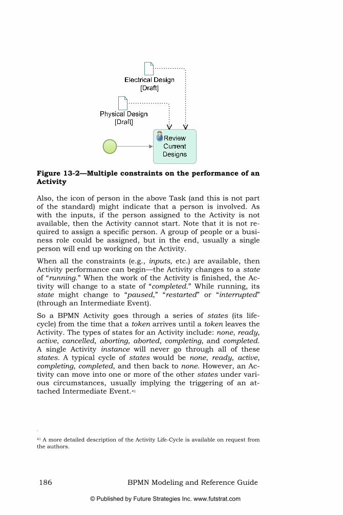
Figure 13-2—Multiple constraints on the performance of an Activity
Also, the icon of person in the above Task (and this is not part of the standard) might indicate that a person is involved. As with the inputs, if the person assigned to the Activity is not available, then the Activity cannot start. Note that it is not re-quired to assign a specific person. A group of people or a busi-ness role could be assigned, but in the end, usually a single person will end up working on the Activity.
When all the constraints (e.g., inputs, etc.) are available, then Activity performance can begin—the Activity changes to a state of “running.” When the work of the Activity is finished, the Ac-tivity will change to a state of “completed.” While running, its state might change to “paused,” “restarted” or “interrupted” (through an Intermediate Event).
So a BPMN Activity goes through a series of states (its life-cycle) from the time that a token arrives until a token leaves the Activity. The types of states for an Activity include: none, ready, active, cancelled, aborting, aborted, completing, and completed. A single Activity instance will never go through all of these states. A typical cycle of states would be none, ready, active, completing, completed, and then back to none. However, an Ac-tivity can move into one or more of the other states under vari-ous circumstances, usually implying the triggering of an at-tached Intermediate Event.41
<
41 A more detailed description of the Activity Life-Cycle is available on request from the authors.
186 BPMN Modeling and Reference Guide
© Published by Future Strategies Inc. www.futstrat.com

Compensation and Transactions In BPMN, a Transaction is a formal business relationship and agreement between two or more participants. For a Transaction to succeed, all parties involved have to perform their own Activ-ities and reach the point where all parties are agreed. If any one of them withdraws or fails to complete, then the Transac-tion cancels and all parties then need to undo all the work that has completed.
A Process model (i.e., within one Pool), shows the Activities of the Transaction Sub-Process for just one of the participants (shown with a double line boundary—see Figure 13-3).
Figure 13-3—An example of a Transaction Sub-Process
Transaction Sub-Processes have special behaviors. Firstly, they are associated with a Transaction Protocol (e.g., WS-Transaction). This means that the companies involved in the
BPMN Modeling and Reference Guide 187
© Published by Future Strategies Inc. www.futstrat.com

Transaction must be able to send and receive all the hand-shaking messages between the participants. Most of these mes-sages are not visible at the level of the Process, but are impor-tant to making sure that the Transaction progresses appro-priately.
Secondly, if the work of all the Activities in the Transaction Sub-Process complete normally and all the tokens reach an End Event (see Figure 13-4), the Sub-Process is still not com-plete.
Bookings
BookingError
BookingError
Book FlightT
T
Cancel Flight
Cancel Hotel
Book Hotel
Figure 13-4—A Transaction Sub-Process is not quite done
Through the hand-shaking messages, there has to be unanim-ous agreement among the participants that everything is OK (i.e., that the other participants’ Transactions also reached their end points successfully). Once that agreement occurs, the Transaction Sub-Process is complete and the token can con-tinue in the parent Process (see Figure 13-5). Prior to this agreement, it would still be possible to cancel the whole Trans-action Sub-Process if one of the parties cancelled.
188 BPMN Modeling and Reference Guide
© Published by Future Strategies Inc. www.futstrat.com

Figure 13-5—A Transaction Sub-Process is complete
Thirdly, if a processing or technical error occurs for one of the participants of the transaction, then there are two possibilities for interrupting the Transaction Sub-Process:
• An attached Error Intermediate Event is triggered (often called a hazard) and the Transaction Sub-Process is in-terrupted.
• An attached Cancel Intermediate Event and the Trans-action Sub-Process is cancelled.
Hazards in a Transaction Sub-Process When there is a hazard, the circumstances are so grievous that normal cancellation and compensation are not sufficient to fix the situation. The transaction is then interrupted in the same way that an Error Intermediate Event interrupts a normal Sub-Process (see section “Interrupting Activities with Events” on page 101). The error can happen within the Transaction Sub-Process or within a Process (unseen) of one the other partici-pants in the transaction. The error from one of the other partic-ipants will be sent through the transaction protocol. The error generated by the Transaction Sub-Process is sent to the other participants through the transaction protocol.
BPMN Modeling and Reference Guide 189
© Published by Future Strategies Inc. www.futstrat.com

When Error Intermediate Event attached to the boundary of the Transaction Sub-Process triggers, all work within the Sub-Process is terminated immediately—there is no compensation. The token then is sent down the outgoing Sequence Flow of the Error Event to reach Activities that will deal with the situation (see Figure 13-6).
Exceptions(Hazards)
Handle through
Customer Service
BookingError
T
Cancel Hotel
Figure 13-6—When a Transaction Sub-Process has a hazard
Cancellation in a Transaction Sub-Process As with a Hazard, a Transaction Sub-Process can be cancelled through an Event internal to the Sub-Process or through a cancellation sent through a transaction protocol.
When a Transaction Sub-Process is cancelled, the Cancel In-termediate Event attached to its boundary is triggered (see Figure 13-7). The token will eventually continue down the Cancel Intermediate Event’s outgoing Sequence Flow, but the behavior of the Transaction Sub-Process involves more than just interrupting the work in the Sub-Process.
Figure 13-7—When a Transaction Sub-Process is Cancelled
190 BPMN Modeling and Reference Guide
© Published by Future Strategies Inc. www.futstrat.com

Indeed, all ongoing work within the transaction is cancelled. However, completed work (in the Transaction Sub-Process) may need to be undone, which requires a “rolling back” before the parent Process can continue. This means that each Activity in turn, in reverse order, is checked to see whether or not it re-quires compensation. Compensation is the undoing of work that has been completed.
A token can be used to trace this rolling back as it travels backward through the Process (see Figure 13-8) after a Trans-action Sub-Process has been cancelled. Many Activities, such as receiving a message, have nothing that requires undoing. But other Activities, such as those that update a database, re-quire compensation. Each of these Activities will have a Com-pensation Intermediate Event attached to its boundary (the Event with a rewind symbol).
Bookings
BookingError
BookingError
T
T
Book Flight
Cancel Flight
Cancel Hotel
Book Hotel
Figure 13-8—When a Transaction Sub-Process is cancelled the Sub-Process starts “rolling back”
Compensation does not just happen automatically. Another Ac-tivity is required to undo the work of the original Activity. A special Activity, a Compensation Activity (Activity shown with a
BPMN Modeling and Reference Guide 191
© Published by Future Strategies Inc. www.futstrat.com

rewind symbol) is used to undo the work. The Compensation Activity links to each Activity via the Compensation Interme-diate Event attached to its boundary. The link between the normal Activity and the Compensation Activity is done through an Association rather than a Sequence Flow.
The Compensation Intermediate Event is never triggered during the normal flow of the Process. It only can be triggered during the roll-back of the Transaction Sub-Process. When the reversal of the token reaches an Activity that has an attached Compen-sation Intermediate Event and that Activity had completed normally (i.e., was not interrupted or incomplete), that Com-pensation Event fires (see Figure 13-9) and the token is then sent to the associated Compensation Activity.
Figure 13-9—Compensation Intermediate Events are trig-gered to initiate Compensation Activities
The Compensation Activity has the “rewind” marker to distin-guish it from Activities performed during the normal flow—compensation is never done during the normal activity of a Process. Since compensation is outside of normal flow, a com-pensation Association, instead of a Sequence Flow, links the Compensation Intermediate Event with the Compensation Ac-tivity (and through it, the Activity that needs to be rolled back). The Compensation Activity must not have any incoming or out-going Sequence Flow. Only one Compensation Activity can be associated with the Compensation Intermediate Event. Tasks can be used, but often Sub-Processes are used since the work necessary to compensate is usually complex.
More precisely, an attached Compensation Intermediate Event only triggers if the Activity has completed normally and is in the completed state (see section “The Life-Cycle of an Activity” on page 185 for more information about Activity states). If the Activity is not yet completed, or was interrupted, then Compen-sation will not take place for that Activity.
192 BPMN Modeling and Reference Guide
© Published by Future Strategies Inc. www.futstrat.com

When the Compensation Activity has completed, the token con-tinues its backward journey through the Transaction by leaving the Activity whose work was just undone (see Figure 13-10).
Figure 13-10—The Transaction completes the roll-back
When all the Activities of the Transaction Sub-Process have been checked and, if necessary, compensated, then the cancel-lation of the Transaction is completed. This allows the token in the parent Process to travel down the outgoing Sequence Flow of the attached Compensation Intermediate Event (see Figure 13-11).
Figure 13-11—The Process continues after the transaction is cancelled
Compensation without a Transaction Sub-Process An attached Compensation Intermediate Event (to an Activity) can also be triggered in any normal Process (not a transaction) when a downstream Compensation Intermediate Event or
BPMN Modeling and Reference Guide 193
© Published by Future Strategies Inc. www.futstrat.com

Compensation End Event “throws” the appropriate trigger. The trigger will either be the name of the Activity to be compensated or a global compensation trigger, which will fire all attached Compensation Intermediate Events.
Ad Hoc Processes The Ad Hoc Process represents Processes where the Activities might occur in any order, and in any frequency—there is no specific ordering or obvious decisions. As such, an Ad Hoc Process represents another special type of BPMN Process. It has a marker, a Tilde (~), to show that it is Ad Hoc (see Figure 13-12). Typically, the Activities in an Ad Hoc Process involve human performers who make the decisions as to what Activities to perform, when to perform them, and how many times. For example, a software developer may need to write, test, and de-bug the code in any order and at any time.
Figure 13-12 presents a Process of developing a book chapter where it is necessary to research the topic, write the text, and add graphics, etc., yet it is impossible to specify and order or frequency in advance.
Write a Book Chapter
Research the Topic
Generate Graphics
Organize References
Finalize Chapter
Topic Graphics[completed]
Research Notes
Chapter Text[draft]
Chapter[completed]
References
Write Text
Write/Edit Text
Include Graphics in
Text
Figure 13-12—An Example of an Ad-Hoc Process
Although there is usually no Sequence Flow used within an Ad Hoc Process, it is possible to use occasional Sequence Flow be-
194 BPMN Modeling and Reference Guide
© Published by Future Strategies Inc. www.futstrat.com

tween some of the Activities to show an ordered dependency between them. But the use of Sequence Flow does not imply that there is a specific start or a specific end to the Process.
It is also possible to show data inputs and outputs of the Activi-ties.
As mentioned above, the performer(s) can undertake the Activi-ties in any order and any number of times. Eventually the work of the Process is finished, but since there is no End Event to mark the end of Process, another mechanism is used. The Ad Hoc Process has a non-graphical completion condition attribute that is used to determine if the work of the Process is complete. At the start of the Process the attribute is false. When the attribute becomes true, the Process ends. The attribute only becomes true when the data expressed in the condition test is updated during the completion of one of the Ad Hoc Process’s Activities.
BPMN Modeling and Reference Guide 195
© Published by Future Strategies Inc. www.futstrat.com

196 BPMN Modeling and Reference Guide
© Published by Future Strategies Inc. www.futstrat.com

Appendices
Process Execution Environments Abstract: This appendix is designed to give the reader a brief over‐
view of the components of a modern BPM Suite.42
The overall approach is not especially new—workflow systems have been around since the late 80s—but they are becoming more mature. XML and Web Services have solved many of the integration problems that plagued the approach through the 90s. Tools now include sophisticated monitoring environments, business rules integration, simulation mechanisms and facili-ties to manage the deployment of process models and other ar-tifacts necessary for proper operation. As they have evolved, many vendors have adopted the term “BPM Suite” to describe the broad nature of their offering (see Figure 13-13).
Workflow
DocumentManagement
BusinessRules
OrganizationalModeling Process
Modeling
Simulation
Business ActivityMonitoring (BAM)
Business Intelligence (BI)
Enterprise Applications
SolutionFrameworks
EAI
BPM Suite
Workflow
DocumentManagement
BusinessRules
OrganizationalModeling Process
Modeling
Simulation
Business ActivityMonitoring (BAM)
Business Intelligence (BI)
Enterprise Applications
SolutionFrameworks
EAI
BPM Suite
Figure 13-13—A Process Modeling component is an impor-tant element in a BPM Suite
Products often include capabilities to chain processes together or to bind fragments of process together at run time (based on the context of the case of work in hand).
<
42 For a more comprehensive discussion of BPM Suites and their capabilities, refer to “Mastering BPM
– The Practitioners Guide” by Derek Miers.
BPMN Modeling and Reference Guide 197
© Published by Future Strategies Inc. www.futstrat.com

In parallel with the functional evolution that has led to the emergence of the BPM Suite, the use of process models has al-so evolved. In the early days, they acted as a guide to develop-ers who then configured the environment. Then vendors started to incorporate modeling capabilities into their products. Over time, these modeling environments became easier to use, but their capabilities were still constrained by the core capabilities of the underlying process engine—i.e., vendors only supported functionality that their proprietary engine needed.
With the appearance of block structured XML-based process languages such as BPML (Business Process Modeling Lan-guage) and later BPEL (Business Process Execution Language), the engine at the heart of the BPM Suite has now evolved to the point it can directly execute a process model (without transla-tion to some proprietary intermediate form).
198 BPMN Modeling and Reference Guide
© Published by Future Strategies Inc. www.futstrat.com

Techniques for Process Architecture Abstract: Our intention with this section is not imply a specific me‐
thodology; it is to highlight the issues and challenges, dis‐cussing some of the approaches available. We also point to a few key techniques that can assist on the journey toward process excellence.
Functional Decomposition Most of us immediately resort to Functional Decomposition43 44 —using it to break up the domain hierarchically, with one part contained within another.45 This often causes problems—that hierarchical structure implies that the world is also hierarchi-cally structured. Yet in reality, the modeler is imposing that structure as a way of simplifying the problem domain.
For example, the Customer Relationship Management (CRM) Process is not contained with Sales, or Marketing, or any other functional group for that matter; it is a “Capability” that the entire organization needs exhibit.
Moreover, Functional Decomposition tends to reinforce the very same silos that a process-oriented initiative is trying to break down. While it might be appealing to the software engineer as a way of breaking up a problem with a set of inputs and outputs to each step, the analogy starts to break down in the world of white-collar office work, services and customer relationships.
Key Point: It is better to think of Processes as a network rather than some statically defined hierarchy.46
Key Point: As a general approach, Functional decomposition should be avoided.
<
43 Functional decomposition is a method of hierarchically structuring business functions, processes, and sub-processes within an organization. The British Cy-berneticist Stafford Beer once aptly described Functional Decomposition as “a me-chanism for apportioning blame”..” Beer was responsible for the Viable System Model.
44 Our use of Initial Capitals in this chapter is to provide emphasis for the key con-cepts discussed. Terms like Capabilities, Services and Functional Decomposition are not parts of the BPMN specification (elsewhere in the book we reserve the use of Initial Capitals to the graphical elements of BPMN).
45 In BPMN, the Embedded Sub-Process concept supports functional decomposi-tion. See E on page 71. mbedded Sub-Processes
46 Indeed, it is more accurate to think of them as a dynamic network of interacting process instances.
BPMN Modeling and Reference Guide 199
© Published by Future Strategies Inc. www.futstrat.com

Process Composition Another way of approaching the chunking problem is to com-pose Processes from a set of constituent parts. On the surface, this seems only subtly different from Functional Decomposi-tion, but is dramatically different in terms of the flexibility and agility delivered.
Where Processes are composed of other Processes, the lower level Processes are also reusable in other processes (rather than constrained to a single context). Of course, this means that such processes require careful design and construction in order to support that reusable context. In a sense, each lower level Process provides a “Service” to a parent level Process.47
Business Services Oriented Architecture While Process composition provides the mechanism, it still does not necessarily help the modeler decide on what processes are required.
Firstly, at the highest level, it is necessary to decide what the business is really all about. What Capabilities are required on an ongoing basis? Processes become ways of implementing those Capabilities through Services. At this level, we are dis-cussing “Process as Purpose” rather than Process as a set of sequential Tasks or Activities.48
The trick is to think of the outcomes that are important to cus-tomers and other stakeholders, and then imagine the “Services” that will deliver those Capabilities. They should be the Services that will delight the customer and provide a superior customer experience. These Services will be composed of other Services, but eventually, a Process (procedure) implements a Service.
As a result, a set of Services implements a business level Ca-pability is implemented through that are composed of other Services.49
<
47 In BPMN, the Reusable Sub-Process construction supports Process Composition (see on page 71). Reusable Sub-Processes
48 For a more extensive discussion on these sorts of issues, see Mastering Business Process Management—The Practitioner’s Guide by Derek Miers (published Septem-ber 2008).
49 We use a set of workshop techniques to support this quest, but they are outside the scope of this book. Those techniques draw on the Services DNA approach de-veloped by Dr Allan Webster and others.
200 BPMN Modeling and Reference Guide
© Published by Future Strategies Inc. www.futstrat.com

The idea is that by understanding what capabilities and beha-viors are required, it becomes possible to derive an appropriate set of Processes and an organization that will support them. This is in stark contrast to the use of Functional Decomposi-tion, where the existing organizational structure is usually the starting point.
Key Point: Developing a high‐level perspective on the Business Capabil‐ities required for organizational success provides a context and scope to Process modeling work.
Key Point: A Business Services approach will allow the organization to align its Processes with the needs of customers and other stakeholders.
From Business Context to Process Architecture Having identified an appropriate business level scope, deriving the discrete Process Architecture is still a challenge. The best technique that we have come across for this is the Unit of Work (UoW) analysis.50
A UoW analysis involves bringing the relevant business people together in a workshop setting and brainstorming a long list of the Essential Business Entities (EBEs). Derived from an under-standing what business the organization is, EBEs refer to the things that represent the “essence” or “subject matter” of the domain in question.
This list is then filtered to identify those items that have a “life-cycle” that the organization needs to manage. These are the Units of Work. For example, in a manufacturing organization, products are developed, taken to market, withdrawn, etc. For a standards body such as the OMG, “Specifications” are drafted, reviewed, approved, distributed, changed, withdrawn, etc.
Then it is a question of looking for the interactions between the Units of Work (Generates, Needs, Requires, Activates, Calls For, etc). One is trying to identify the dynamic relationships be-tween these objects. Then, for each UoW, there will be three processes—Handle an Instance of, Manage the Flow of In-stances and a Strategy Process that looks at improving the first two.
<
50 Proposed by Martyn Ould in Chapter 6 of his book Business Process Manage-ment—A Rigorous Approach. This book is also the key reference for Role Activity Diagrams (RADs). RADs provide a powerful alternative representation of Process, combining both choreography (role interaction) with activities and instantiation.
BPMN Modeling and Reference Guide 201
© Published by Future Strategies Inc. www.futstrat.com

The net result is that, using the Unit of Work Analysis tech-nique, it becomes possible to mechanically generate a Process Architecture for a given target domain.51 This Process Architec-ture is based on the real world needs of that business having been validated and in a sense “designed” by the business spe-cialists concerned.
Moreover, given access to the relevant subject matter experts, it is possible to complete the entire exercise in an afternoon. So regardless of the existing base, it is a valuable validation.
Further Reading In large organizations, it becomes inordinately difficult to keep track of all the related artifacts and information on models, goals, objectives, and perspectives associated with the voyage toward process improvement and operational innovation.
The journey itself is an exercise in growing the organizational competence around business process. Within the OMG there are two specifications that help map out the route and allow an organization to manage the traceability of its assets in this area.52
• The Business Process Maturity Model (BPMM) might be thought of as describing the journey that an organiza-tion embarks upon when engaging in a business process driven transformation initiative. It describes the five stages of organizational maturity (in relation to business process) and the behaviors of an organization at that level of maturity.53
• The Business Motivation Model provides a scheme or structure for developing, communicating and managing business plans in an organized manner. Specifically, the Business Motivation Model identifies factors that moti-vate the creation of business plans, defining the ele-
<
51 Again, this technique is outside the scope of this book. We introduce it here as it offers a viable method of deriving an appropriate Process Architecture—one that is not predicated on the reporting structure of the organization.
52 In the final analysis, Business Process models are just one of the types of assets an organisation will need.
53 BPMM is a fully developed maturity model that rigorously follows the principles of established SEI process maturity frameworks, e.g. CMMI. BPMM is oriented around the needs of the broader business community rather than the IT project orientation of CMMI and CMM. The BPMM incorporates improvements in coverage, structure, and interpretation developed since the publication of its predecessor maturity models.
202 BPMN Modeling and Reference Guide
© Published by Future Strategies Inc. www.futstrat.com

ments of these business plans; and how all these factors and elements interrelate. Among these elements are those that provide governance for and guidance to the business—Business Policies and Business Rules.
BPMN Modeling and Reference Guide 203
© Published by Future Strategies Inc. www.futstrat.com

BPMN Issues and Directions
Choreography versus Orchestration As its core, BPMN is fundamentally a flow diagram oriented no-tation—i.e., it focuses upon the “orchestration” of a Process. More specifically, it views Processes as a sequence of steps viewed from the perspective of the organization that needs to carry out the work.
BPMN can represent a simple choreography-oriented view54 us-ing Message Flow between Pools. But it is difficult to represent the “derived process” that exists in between these Pools. Provid-ing a comprehensive mechanism for modeling choreographies is a requirement for the development of BPMN 2.0
Collaborative Decisions and Meetings As the flow diagram paradigm is applied, work assignment is usually represented via grouping of Activities within Lanes (usually representing organizational roles). As a result, it be-comes very difficult (if not impossible) to reliably represent a collaborative decision (where several organizational roles inte-ract to make a decision).
BPMN Futures With the release of BPMN 2.0, the specification is going to change dramatically. However, the look-and-feel of the notation will remain the same—i.e., a BPMN 2.0 diagram will look much the same as a BPMN 1.1 diagram.
While the acronym (BPMN) remains the same, the words change subtly—it will become Business Process Model and No-tation (instead of Modeling Notation). While this change ap-pears trivial, the emphasis is now on a notation linked to an explicit meta-model and serialization format (storage mechan-ism). The inclusion of a storage format and metamodel will en-able model portability between different vendors tools, yet still provide adequate facilities for vendors to extend and differen-tiate their products.
Graphically, we will see the inclusion of features to better sup-port choreography—there will be a new choreography diagram defined in the specification. A choreography diagram will either
<
54 The interactions of the participants involved
204 BPMN Modeling and Reference Guide
© Published by Future Strategies Inc. www.futstrat.com

stand-alone, or it could appear within the context of a broader collaboration diagrams (diagrams that include Pools).
Some of the new features expected in BPMN 2.0:
• A choreography diagram. • A conversation diagram (related to choreography and
collaboration). • A new type of Intermediate Event: Escalation, which is
like a type of error (and has the same scope) except that it does not interrupt Activities.
• An option on attached Intermediate Events such that they do not interrupt. This will support triggers such as Timer, Message, Escalation, Signal, Conditional, and Multiple.
• Specialized Event Sub-Processes—a type of optional Sub-Process used for non-interrupting Activities or compensation. This will support Triggers such as Timer, Message, Escalation, Signal, Conditional, Compensa-tion, and Multiple.
• An extension to the definition of human activities. • Formalization or enhancement of various technical in-
frastructures; such as execution semantics, mapping to BPEL, Event composition and correlation, use of servic-es, and extension mechanisms.
• An XML schema exchange format for portability (also a XMI version for UML tools). The exchange will work for both model (semantic) information and for diagram layout.
Subsequent versions (following the BPMN 2.0 release) will likely include a number of “compliance levels” (so that vendors can explicitly state the degree of direct BPMN support they provide). This contrasts with the current situation where a vendor can claim BPMN support with just a few of the shapes represented graphically, ignoring the rest of the specification. Indeed, a quick survey of BPMN tool support reveals significant degrees of variability in terms of the support provided.
We expect to see the BPMN 2.0 pass through the relevant committees at the OMG by the end of Q1 2009. It is unlikely to emerge before the end of Q2 2009 (and that will be in Beta form).
BPMN Modeling and Reference Guide 205
© Published by Future Strategies Inc. www.futstrat.com

BPMN Best Practices This appendix collates the individual best practices identified throughout the book:
Best Practice: Sending and Receiving Messages—The modeler could choose to use only Send and Receive Tasks, or to use only the throw and catch Message Intermediate Events. The Best Practice is to avoid mixing both approaches together in the same model.
There are advantages and disadvantages to both ap‐proaches. Message Intermediate Events give the same re‐sult and have the advantage of being graphically distin‐guishable (whereas the Tasks are not). On the other hand, using Tasks, rather than the Events can enable the modeler to assign resources and simulate costs.
Best Practice: Use of Start Events—In general, we recommend that mod‐elers use Start and End Events.
Best Practice: Setting Timers—avoid specific date and time conditions as they inhibit the re‐usability of the process.
Best Practice: Use a Default Condition—One way for the modeler to en‐sure that the Process does not get stuck at an Exclusive Ga‐teway is to use a default condition for one of the outgoing Sequence Flow. This creates a Default Sequence Flow (see “Default Sequence Flow” on page 176). The Default is cho‐sen if all the other Sequence Flow conditions turn out to be false.
Best Practice: Use a Timer Intermediate Event with an Event Gateway—One way for the modeler to ensure that the Process does not get stuck at an Event Based Exclusive Gateway is to use a Timer Intermediate Event as one of the options for the Gateway.
Best Practice: Ensure that the number of incoming Sequence Flow is cor‐rect for a Parallel Gateway—The key point is to exercise care, ensuring that merging Parallel Gateways have the correct number of incoming Sequence Flow—especially when used in conjunction with other Gateways. As a guide, modelers should match merging and splitting Parallel Gateways (if the desired behavior is to merge them again).
206 BPMN Modeling and Reference Guide
© Published by Future Strategies Inc. www.futstrat.com

BPMN Modeling and Reference Guide 207
Best Practice: Use a Default Condition on an Inclusive Gateway—One way for the modeler to ensure that the Process does not get stuck at an Inclusive Gateway is to use a default condition for one of the outgoing Sequence Flow. This Default Se‐quence Flow will always evaluate to true if all the other Se‐quence Flow conditions turn out to be false (see “Default Sequence Flow” on page 176).
Best Practice: Always use Inclusive Gateways in pairs—A way to avoid unexpected behavior is to create models where a merging Inclusive Gateway follows a splitting Inclusive Gateway and that the number of Sequence Flow match between them.
Best Practice: Use a Text Annotation with the Complex Gateway—Since the actual behavior of a Complex Gateway will vary for each usage of the Gateway, use a Text Annotation to tell the reader of the diagram what behavior the Gateway is set to perform (see Figure 9‐32).
Best Practice: Use a Standard or Default Sequence Flow when using Conditional Sequence Flow—One way for the modeler to ensure that the Process does not become stuck after an Ac‐tivity is to use a standard or Default Sequence Flow when‐ever Conditional Sequence Flow are used.
Best Practice: Do not Associate a Data Object with a Sequence Flow if the Sequence Flow is connected to a Gateway—The appli‐cation of inputs and outputs can be easily confused when one or more Gateways is used for Sequence Flow that are associated with Data Objects.
Best Practice: Modeling Inputsets—If there is more than one inputset, pick a point on the boundary of an Activity and have all in‐puts that belong to a single inputset connect to that point. The inputs for the other inputsets should each connect to separate points on the boundary of the Activity. The same pattern should apply to modeling outputsets.
© Published by Future Strategies Inc. www.futstrat.com

BPMN Modeling and Reference Guide 208
© Published by Future Strategies Inc. www.futstrat.com

Afterword
If you wanted to make a cup of coffee, would you draw a dia-gram to describe the process? Probably not. The process is simple, we can easily memorize the necessary steps, and we typically perform all of the process steps by ourselves. Michael Hammer famously said, “If it doesn’t make three people angry it isn’t a process.”55 But if you wanted to teach somebody how to make coffee, or if you wanted to build an automated espresso machine, or if you wanted to standardize how hundreds of franchises of your coffee empire operate, the utility of visual process diagrams becomes immediately apparent.
Natural language is fraught with ambiguity—we often need to understand the context of a particular sentence in order to make sense of it. Process modeling languages reduce this am-biguity by limiting the amount of symbols (i.e. words) we can use to construct diagrams (i.e. sentences). Moreover, every element of a modeling language typically has a well-defined meaning, which reduces the amount of interpretation needed to understand a diagram.
When diagramming processes it is important to select a pers-pective that is appropriate to analyze the problem at hand, and the choice of perspective has implications on the choice of technique. The analysis of processes can focus on three possi-ble perspectives: Activities, Resources, or Objects.
Object-centric process analysis places at the center the subject that is being processed. In the case of a procurement process, the purchase order itself would be the focal object, and the possible process paths are defined by the state changes that the purchase order can go through. Object-centric analysis is useful in processes where the central object is a document or a physical artifact that shapes the process and the resources needed to move it towards a desired target state.
Resource-centric process analysis places the emphasis on the participants that carry out actions in the process. In this world view the processing object is passed between workstations that each have capabilities and perform actions on the object that are appropriate given the characteristics of the object. This view is particularly appropriate if a process takes place within a fixed infrastructure that is too costly or risky to adapt. Re-
<
55 Hammer, M. (1996): Beyond Reengineering. Harper Collins.
BPMN Modeling and Reference Guide 209
© Published by Future Strategies Inc. www.futstrat.com

source-based analysis may uncover social network structures that point to necessary changes in the organizational chart.
Activity-centric process analysis focuses on the processing tasks themselves, their sequencing, and the conditions for their activation and completion. This is the area addressed by the majority of process modeling languages.
The Business Process Modeling Notation (BPMN) is not without precedent—standard diagramming techniques for processes have been developed as early as the 1920s. Flowcharts for ad-ministrative procedures and Nassi-Schneiderman diagrams for structured programming were among the first widely used techniques. Project management brought us Gantt Charts and PERT network diagrams. Carl Adam Petri’s dissertation on Communicating with Automata led to Petri Nets, which have in turn been refined into colored, hierarchical, workflow, and oth-er kinds of net diagrams. The object-oriented development me-thodologies of the 1980s gave way to the Unified Modeling Lan-guage, which brought Sequence Diagrams and Activity Dia-grams to describe the behavior of a system. So why did the world need another process modeling language?
For one, BPMN integrates capabilities from a number of its predecessors. It combines organizational swimlanes from Activ-ity Diagrams with messaging concepts from Sequence Dia-grams, introduces a large selection of event types and multiple ways to hierarchically decompose complex processes. The com-bination of language elements makes it a highly expressive lan-guage.56 This expressiveness has a price, though. With more than 50 graphical symbols there often are multiple ways to capture the same process content.57
There are three aspects to the richness of BPMN: What the lan-guage is capable of expressing, what modelers currently use it for, and what modelers should use it for. BPMN is a rich nota-
<
56 Rosemann, Michael; Recker, Jan; Indulska, Marta and Peter Green: A Study of the Evolution of the Representational Capabilities of Process Modeling Grammars, in E. Dubois and K. Pohl, eds., Advanced Informa-tion Systems Engineering - CAiSE 2006, Vol. 4001, Lecture Notes in Computer Science, Luxembourg, Grand-Duchy of Luxembourg: Sprin-ger, 2006, pp. 447-461.
57 zur Muehlen, Michael; Recker, Jan; Indulska, Marta: Sometimes Less is More: Are Process Modeling Languages Overly Complex? In: Taveter, K.; Gasevic, D. (Eds.): The 3rd International Workshop on Vocabularies, Ontologies and Rules for The Enterprise (VORTE 2007). Baltimore, MD, October 15th, 2007, IEEE Publishers.
210 BPMN Modeling and Reference Guide
© Published by Future Strategies Inc. www.futstrat.com

tion, but knowing all the symbols does not guarantee that a modeler will create sensible diagrams, just like learning all words of the English language does not automatically turn us into a new Ernest Hemingway. In fact, in a recent survey of 120+ BPMN diagrams we have found plenty of modeling errors, and in some instances these errors were deliberate attempts to point out weaknesses in as-is models.58
Here is an example from a large government agency process in BPMN 1.0 format:
Can you spot the modeling mistakes in the diagram? There are two: An event cannot have any attached events, and the start event symbol cannot be attached to any other symbol. Mistakes like these are easily remedied with some training. The overall style of this example leads to a more important question: What was the intention of the modeler, and how could this intention be expressed in a correct, concise, and comprehensible way? In the example above the modeler was confronted by a process that can be triggered by a number of incoming documents that may arrive in a variety of combinations. The modeler chose to capture every possible incoming message in detail while the first process activity is at a comparatively high level. This mis-match of levels of abstraction is not cured by an intense study of the BPMN standard alone. The standard just spells out what
<
58 zur Muehlen, Michael; Recker, Jan: How Much Language is Enough? Theoretical and Practical Use of the Business Process Modeling Nota-tion, 20th International Conference on Advanced Information Systems Engineering (CAiSE 2008), Montpellier, France, June 16-20, 2008, Springer LNCS, pp. 465-479.
BPMN Modeling and Reference Guide 211
© Published by Future Strategies Inc. www.futstrat.com

constitutes a correct diagram, not what constitutes a good dia-gram. Drawing good diagrams requires the aid of a style guide, just as an aspiring author complements an English dictionary with a guidebook such as the Elements of Style.
Since its inception, BPMN has been eagerly adopted by both practitioners and academics, and is being taught in training seminars and university classes around the world. Tool sup-port is building, and a growing number of organizations have declared BPMN the corporate standard for process modeling. But much remains to be done.
Aspiring modelers and seasoned practitioners alike need au-thoritative guidance in terms of how BPMN can be used to maximum effect. The book in your hands, written by two ex-perts on the subject matter, provides this guidance in a com-prehensive and clearly structured fashion. It provides advice that affects both the substance and the style of your process diagrams.
It is my hope that the lessons in this book will help you im-prove the quality of your process designs. Better process de-signs improve communication, and this will in turn lead to bet-ter business results. So let’s turn the page on bad process models.
Michael zur Muehlen,
Stevens Institute of Technology, USA
212 BPMN Modeling and Reference Guide
© Published by Future Strategies Inc. www.futstrat.com

Author Biographies
Stephen A. White, Ph.D. Email: [email protected] BPM Architect IBM Corp.
Stephen A. White is currently a BPM Architect at IBM. He has 25 years experience with process modeling—ranging from de-veloping models, consulting, training, process modeling tool design, product management, and standards development. In the mid-1990s he was product manager at Holosofx (which was later acquired by IBM), where he gained a lot of experience with the business analyst’s perspective through training and con-sulting. After Holosofx, he was at SeeBeyond (later acquired by Sun Microsystems) where he began working in standards, in-cluding the start of BPMN. From SeeBeyond he moved to IBM where he continued work in standards and with BPMN.
While at SeeBeyond and IBM, he served on the BPMI.org Board of Directors (which later merged with the OMG). Within the OMG, he is currently a member of the BPM Steering Committee and is co-chair of an Architecture Board sponsored Special In-terest Group on Process Metamodels.
As Working Group chair and Specification Editor since its in-ception, Stephen A. White was instrumental in creating the BPMN standard and is now guiding its continuing refinement at the OMG.
Derek Miers Email: [email protected] Industry Analyst and Technology Strategist BPM Focus
Derek Miers is a well-known independent industry analyst and technology strategist. He delivers world-class training and con-sulting around BPMN, Process Architecture and BPM in gener-al.
Over the years, he has carried out a wide range of consulting roles including running hundreds of training courses (in busi-ness and process modeling techniques), undertaking detailed technology selection assessments and project-risk assessment studies. Other engagements have involved the provision of stra-tegic consulting advice from facilitating board level conversa-tions around BPM initiatives, through establishing effective
BPMN Modeling and Reference Guide 213
© Published by Future Strategies Inc. www.futstrat.com

BPM Project and Expertise Centers, to helping clients develop new business models that leverage business process strategies.
Clients have included many of the world’s largest and well-known financial services companies (banks, building societies and insurers), pharmaceutical companies, telecoms providers, commercial businesses, product vendors and governmental or-ganizations.
As Co-Chairman of BPMI.org, he helped merge the organization with the OMG and sits on the BPM Steering Committee of the OMG. At BPMI.org he helped create the BPM Think Tank event, and within the OMG, he continues to play an active role in its organization and delivery. He continues to play an active role in the creation of process related standards.
Derek Miers is also author of Mastering BPM—A Practitioners Guide, published by MK Press (ISBN 0-929652-46-0).
Foreword
Richard Mark Soley, Ph.D. Email: [email protected] Chairman and Chief Executive Officer Object Management Group, Inc. (OMG®)
Dr. Richard Mark Soley is Chairman and Chief Executive Offic-er of the Object Management Group, Inc. (OMG®) and Execu-tive Director of the SOA Consortium.
As Chairman and CEO of the OMG, Dr. Soley is responsible for the vision and direction of the world's largest consortium of its type. Dr. Soley joined the nascent OMG as Technical Director in 1989, leading the development of OMG's world-leading stan-dardization process and the original CORBA® specification. In 1996, he led the effort to move into vertical market standards (starting with healthcare, finance, telecommunications and manufacturing) and modeling, leading first to the Unified Mod-eling Language (UML®) and later the Model Driven Architecture (MDA®). He also led the effort to establish the SOA Consortium in January 2007.
Previously, Dr. Soley was a cofounder and former Chair-man/CEO of A. I. Architects, Inc., maker of the 386 Humming-Board and other PC and workstation hardware and software. Prior to that, he consulted for various technology companies and venture firms on matters pertaining to software investment opportunities. Dr. Soley has also consulted for IBM, Motorola,
214 BPMN Modeling and Reference Guide
© Published by Future Strategies Inc. www.futstrat.com

PictureTel, Texas Instruments, Gold Hill Computer and others. He began his professional life at Honeywell Computer Systems working on the Multics operating system.
A native of Baltimore, Maryland, U.S.A., Dr. Soley holds the bachelor's, master's and doctoral degrees in Computer Science and Engineering from the Massachusetts Institute of Technolo-gy.
Angel Luis Diaz, Ph.D. Email: [email protected] Director, Websphere Business Process Management IBM Software Group
Dr. Angel Luis Diaz is IBM's Director for Websphere Business Process Management development, architecture and technology strategy.
Prior to this role, Dr. Diaz was responsible for IBM Software Group Technology Strategy and SOA Innovation. His team was responsible for driving the support of Web services technology across IBM’s entire product line and combined offerings.
Before joining the IBM Software Group in 2003, Dr. Diaz was a member of IBM's Research staff and Senior Manager, where he led advanced technology projects related to XML & Web Servic-es. In 2002, Dr. Diaz initiated the world’s first two standards that make use of web services, the Organization for the Ad-vancement of Structured Information Standards (OASIS) Web Services For Remote Portals (WSRP) and OASIS Web Services For Interactive Applications (WSIA). As a result, Dr. Diaz was nominated to the OASIS Technical Advisory Board, a body that defined the technical agenda for future OASIS standards work. In 1998 Dr. Diaz was co-chair and co-author of the first XML standard, the World Wide Web Consortium (W3C) Mathemati-cal Markup Language (MathML). Since then, Dr. Diaz served on seven W3C activities including the Extensible Style Language (XSL), Cascading Style Sheets (CSS) and Document Object Model (DOM).
Dr. Diaz received his Ph.D. in computer science (distributed computing, programming languages & computer algebra) from Rensselaer Polytechnic Institute.
BPMN Modeling and Reference Guide 215
© Published by Future Strategies Inc. www.futstrat.com

Afterword
Michael zur Muehlen Ph.D. Email: [email protected] Director, Center of Excellence in Business Process Innovation Howe School of Technology Management Stevens Institute of Technology, United States
Dr. Michael zur Muehlen is Assistant Professor of Information Systems at Stevens Institute of Technology in Hoboken, NJ. He directs Stevens’ BPM research center (Center of Excellence in Business Process Innovation) and is responsible for the Univer-sity’s graduate program in Business Process Management and Service Innovation. Prior to his appointment at Stevens, Mi-chael was a senior lecturer at the Department of Information Systems, University of Muenster, Germany, and a visiting lec-turer at the University of Tartu, Estonia. He has over 14 years of experience in the field of process automation and workflow management, and has led numerous process improvement and design projects in Germany and the US and serves as Enter-prise Chief Process Architect of the U.S. Department of Defense Business Transformation Agency. An active contributor to standards in the BPM area, Michael was named a fellow of the Workflow Management Coalition in 2004 and chairs the WfMC working group “Management and Audit.” He studies the prac-tical use of process modeling standards, techniques to manage operational risks in business processes, and the integration of business processes and business rules. SAP Research, the US Army, the Australian Research Council, and private sponsors have funded his research. Michael has presented his research in more than 20 countries. He is the author of a book on workflow-based process controlling, numerous journal articles, conference papers, book chapters and working papers on process management and workflow automation. He has also published widely on BPM standards and standard making in general. He is a founding director of the AIS special interest group on process automation and management (SIGPAM). Mi-chael holds a PhD (Dr. rer. pol.) and an MS in Information Sys-tems from the University of Muenster, Germany.
216 BPMN Modeling and Reference Guide
© Published by Future Strategies Inc. www.futstrat.com

Glossary
Activity: An Activity represents the work performed within a business process. It has a rounded-corner rectangle shape. An Activity will normally take some time to per-form, will involve one or more resources from the organ-ization, will usually require some type of input, and will usually produce some sort of output. Tasks and Sub-Processes are types of Activities.
Activity Life-Cycle: A BPMN Activity goes through a series of states (its life-cycle) from the time that a token arrives until a token leaves the Activity. The types of states for an Activity in-clude: none, ready, active, cancelled, aborting, aborted, completing, and completed. A single Activity instance will never go through all of these states.
Ad Hoc Process: The Ad Hoc Process represents Processes where the Ac-tivities might occur in any order, and in any frequency—there is no specific ordering or obvious decisions.
Advanced BPMN Element: These are BPMN elements that, we suggest, are used to model more complex behaviors. They are likely to be of most interest to those looking to automate Processes us-ing a BPM Suite or Workflow environment.
Artifact: Artifacts provide a mechanism to capture additional in-formation about a Process, beyond the underlying flow-chart structure. There are three standard Artifacts in BPMN: Data Objects; Groups; and Text Annotations.
Assignment: Assignments provide a mechanism to map data into an Activity as it is instantiated, and to update Process data based on the work of the Activity when it finishes. They also feature in Complex Gateways as a means to eva-luate conditions and then control token flow. An assign-ment has two parts: a condition and an action. When an assignment is performed, it will evaluate the condition and if the condition is true, it then will perform the ac-tion such as updating the value of a Process or Data Ob-ject property. Do not confuse assignment attributes with the Performer attribute (used for role assignment).
BPMN Modeling and Reference Guide 217
© Published by Future Strategies Inc. www.futstrat.com

Association: Associations link (i.e. creates a relationship) one dia-gram object with another (such as Artifacts and Activi-ties). Graphically it is represented as a dotted line (such as that connecting a Text Annotation to another object).
Atomic Activity: An atomic Activity is a Task. They are the lowest level of detail presented in the diagram (i.e., they cannot be drilled-down upon to see a lower level of detail).
Black Box Pool: A black-box Pool that is empty. That is, it does not con-tain a Process. The details of the Process are probably unknown to the modeler. Since it does not have any Process elements inside, any Message Flow going to or from the Pool must connect to its boundary.
Business Entity: A business entity is one of the possible types of partici-pant. Examples of business entities include IBM, FedEx, Wal-Mart, etc.
Business Process: In BPMN a Business Process represents what an organi-zation does—its work—in order to accomplish a specific purpose or objective.
Business Role: A business role is one of the possible types of partici-pant. Examples of business roles include buyer, seller, shipper, or supplier.
Catch: Refers to the types of Events that wait for something to happen (e.g., the arrival of a message) before triggering. When they are triggered they allow the Process to con-tinue. All Start Events and some Intermediate Events are catch Events.
Category: A category is BPMN attribute common to all elements. It is used for analysis purposes. For example, Activities could be categorized as “customer valued” or “business valued.” A Group is a graphical mechanism for to high-light a single category. Modeling tools may use other mechanisms (such as color).
218 BPMN Modeling and Reference Guide
© Published by Future Strategies Inc. www.futstrat.com

Child Process: A child Process is a Sub-Process that is contained within another Process. The relationship is from the perspec-tive of the Process—it is the parent Process of the child Process.
Choreography: A choreography process model is a definition of the ex-pected behavior (a type of procedural contract or proto-col) between interacting participants. In a flow chart format, it defines the sequence of interactions between two or more participants. A choreography will share many of the characteristics of an orchestration in that it will look like a process (i.e., a flow chart) and will in-clude alternative and parallel paths, as well as Sub-Processes.
Collaboration: Collaboration has a specific meaning in BPMN. Where a choreography defines the ordered set (a protocol) of inte-ractions between participants (Pools), a collaboration just shows the participants and their interactions. A collabo-ration may also contain a one or more Processes (within the Pools).
Collapsed Sub-Process: A collapsed Sub-Process is a Sub-Process where details of the Sub-Process are not visible in the diagram. Its appearance is the same as a Task with the addition of a small “+” sign at the bottom center of the shape.
Compensation: Compensation relates to undoing work that been com-pleted. It is modeled through Compensation Events and Activities. It is an automatic response to a cancellation of a transaction.
Complex Gateway: Complex Gateways handle situations where the other types of Gateways do not provide support for the desired behavior. Modelers provide their own expressions that determine the merging and/or splitting behavior of the Gateway.
Compound Activity: A compound Activity is a Sub-Process. They are non-atomic in the sense that you can open them up to see another level of process detail.
BPMN Modeling and Reference Guide 219
© Published by Future Strategies Inc. www.futstrat.com

Condition: A condition is a natural language or computer language expression that tests some data. The test will result in an answer of true or false.
Conditional Intermediate Event: The Conditional Intermediate Event represents a situa-tion where a Process is waiting for a pre-defined condi-tion to become true.
Conditional Sequence Flow: When a condition is used on the outgoing Sequence Flow of an Activity, it is called A Conditional Sequence Flow, and a mini-diamond (like a mini-Gateway) appears at the beginning of the Connector. When the Activity has completed and the condition evaluates to true, then a to-ken (flow) will move down the Sequence Flow.
Conditional Start Event: The Conditional Start Event represents a situation where a Process is started (i.e., triggered) when a pre-defined condition becomes true.
Connectors: Connectors are lines that link two objects on a diagram. There are three different types of BPMN Connectors: Se-quence Flow, Message Flow, and Associations.
Conversation: A conversation interaction between two or more partici-pants regarding a specific topic (such as a product or a customer request). There is no specific graphical sup-port in BPMN for a conversation but the interaction may involve multiple Processes, collaborations, and/or cho-reographies. BPMN 2.0 is expected to have more support for this concept (including a specialized diagram).
Core BPMN Element: These are the BPMN elements that we feel are most ap-plicable to the needs of Business Analysts and business people. They can model the majority of Process beha-viors.
Data Flow: Data flow represents the movement of Data Objects from into and out of Activities. Graphically, directed As-sociation connectors show the data flow between a Data Object and an Activity.
220 BPMN Modeling and Reference Guide
© Published by Future Strategies Inc. www.futstrat.com

Data Object: Data Objects represent the data and documents in a Process. Data Objects use a standard document shape (rectangle with one corner bent over). They usually de-fine the inputs and outputs of Activities
Deadlock: A deadlock is a situation where the flow of the Process cannot continue because a requirement of the model is not satisfied. For example, if a Parallel Gateway is ex-pecting a token from all of its incoming Sequence Flow and one never arrives, the Process will deadlock.
Decision: A point in the Process where one (or more) alternative paths is chosen. Decisions are implemented via Exclu-sive, Event, Inclusive, and Complex Gateways.
Default Sequence Flow: A Sequence Flow that has a default condition and has a hatch mark near its beginning. The path for this Se-quence Flow is chosen if the conditions for all the other outgoing Sequence Flow (from a Gateway or Activity) turn out to be false.
Delay: In BPMN, delays are modeling with Timer Intermediate Events place in the normal flow of the Process. When the timer “goes off,” then the Process can continue.
Downstream: From the point of view of a BPMN element (e.g., a Task), the other elements which are connected through a Se-quence Flow path in the direction where tokens are going, are considered downstream.
Embedded Sub-Process: An embedded Sub-Process is actually part of the parent Process. They are not re-usable by other processes. All “process relevant data” used in the parent Process can also be referenced by the embedded Sub-Process (since it is part of the parent).
End Event: An End Event marks where a Process, or more specifi-cally, a “path” within a Process, ends. An End Event is a small, open circle with a single, thick lined boundary. There are eight different types of End Events: None, Message, Signal, Terminate, Error, Cancel, Compensa-tion, and Multiple.
BPMN Modeling and Reference Guide 221
© Published by Future Strategies Inc. www.futstrat.com

Error: An error is generated when there is a critical problem in the processing of an Activity. Errors can be generated by applications or systems involved in the work (which are transparent to the Process) or by End Events.
Event: An Event is something that “happens” during the course of a Process. These Events affect the flow of the Process and usually have a trigger or a result. They can start, delay, interrupt, or end the flow of the Process (they ei-ther throw or catch). The three types of Events are: Start Events, Intermediate Events, and End Events.
Event Gateway: Event-Based Exclusive Gateways (or Event Gateway) represent an alternative branching point where the deci-sion is based on two or more Events that might occur, rather than data-oriented conditions (as in an Exclusive Gateway).
Exception Flow: Exception flow is flow from the outgoing Sequence Flow from Intermediate Events that are attached to the boun-daries of Activities, thereby interrupting the work of those Activities.
Exclusive Gateway: Exclusive Gateways are locations within a Process where there are two or more alternative paths. Based on the conditions on the Gateway’s outgoing Sequence Flow, the Gateway will choose only one of the alternative paths (the first that evaluates to true).
Expanded Sub-Process: An expanded Sub-Process is a Sub-Process where the boundaries of the shape are extended to allow the dis-play of the lower level details (i.e., a flow diagram ap-pears within the Activity shape).
Flow Object: Flow objects are the elements that create the main structure of a Process. These elements are Activities, Events, and Gateways.
Gateway: Gateways are modeling elements that control Sequence Flow, as it diverges and converges within a Process—i.e. they represent points of control for the paths within the Process. All Gateways share the diamond shape.
222 BPMN Modeling and Reference Guide
© Published by Future Strategies Inc. www.futstrat.com

Go-To Object: Go-To objects are paired Link Intermediate Events that enable Sequence Flow to “jump” from one place to another, often over large (screen or page) distances. The pair of Link Events creates a virtual Sequence Flow.
Group: A Group is a dashed, rounded rectangle used to sur-round a group of flow objects in order to highlight and/or categorize them.
Inclusive Gateway: Inclusive Gateways support decisions where more than one outcome is possible at the decision point. The “O” marker identifies this type of Gateway.
Input: An input is a Data Object or a Process property that is required for an Activity to begin work. Data Objects can be shown as inputs by a directed Association where they are the source of the connector.
Inputset: An inputset is a collection of inputs that are all required for the Activity to begin work. An Activity may have more than one inputset. The first one that is complete (i.e., all the inputs are available) will trigger the start of the Ac-tivity (barring any other constraints).
Instance: The start and performance of an Activity as an instance of an Activity or Process. For an Activity, a new instance is created whenever a token arrives at that Activity.
Interaction: In BPMN, an interaction is a communication, in the form of a message exchange, between two participants of a collaboration or choreography. The interaction may in-volve one or more messages.
Intermediate Event: An Intermediate Event is an Event that indicates where something happens/occurs after a Process has started and before it has ended. An Intermediate Event is a small, open circle with a double, thin lined boundary. There are nine types of Intermediate Events: None, Ti-mer, Message, Signal, Error, Cancel, Compensation, Link, and Multiple.
BPMN Modeling and Reference Guide 223
© Published by Future Strategies Inc. www.futstrat.com

Lane: Lanes create sub-partitions for the objects within a Pool and often represent internal business roles within a Process. They provide a generic mechanism for parti-tioning the objects within a Pool based on characteris-tics of the elements.
Loops: There are two types of loops in BPMN. Individual Activi-ties can have looping characteristics (either While or Un-til). An assigned condition for the Activity determines if the performance of the Activity will be repeated. Alterna-tively, Sequence Flow can connect to an upstream object to create a loop in the Process flow.
Message: A message is a direct communication between two busi-ness participants. Messages are different from signals in that they are directed between Process participants—i.e. they operate across Pools.
Message Flow: Message Flow defines the messages/communications between two separate participants (shown as Pools) of the diagram. They are drawn with dashed lines that have a small hollow circle at the beginning and a hollow arrowhead at the end.
Multi-Instance Activities: These are Activities, both Tasks and Sub-Processes, that are repeated based on a set of data (e.g., the number of orders on a list). The Activity does not loop, but has a set of separate instances, that may actually operate in parallel or serially (one after another).
Normal Flow: The flow of a token between the flow objects, as they op-erate normally, is known as normal flow. Occasionally, however, an Activity will not operate normally. It might be interrupted by an Error or some other Event, and the resulting token flow is known as exception flow.
Off-Page Connector: Off-page connectors are paired Link Intermediate Events that are used to place markers between printed pages of a model. The Events help the reader of the model find where a Sequence Flow ends on one page and starts up again on another page. This helps more when there are multiple Sequence Flow crossing the page boundaries.
224 BPMN Modeling and Reference Guide
© Published by Future Strategies Inc. www.futstrat.com

Orchestration: Within BPMN, orchestration models tend to imply a sin-gle coordinating perspective—i.e., they represent a spe-cific business or organization’s view of the process. As such, an orchestration Process describes how a single business entity goes about things.
Output: An output is a Data Object or a Process property that is produced by an Activity when it is completed. Data Ob-jects can be shown as outputs by a directed Association where they are the target of the connector.
Outputset: An outputset is a collection of outputs that are all pro-duced by the Activity when it is completed. An Activity may have more than one outputset. Only one of the out-putsets is produced, but the decision as to which is handled by the work of the Activity and is transparent to the Process.
Parallel Gateway: Parallel Gateways insert a split in the Process to create two or more parallel paths (threads). They can also merge parallel paths. The “+” marker is used to identify this type of Gateway.
Parent Process: A parent Process is a Process that contains a Sub-Process. The relationship is from the Sub-Process’s point of view. The Sub-Process is a child Process of the parent Process.
Participant: Participants define a general business role, e.g. a buyer, seller, shipper, or supplier. Alternatively, they can represent a specific business entity, e.g. FedEx as the shipper. Each Pool can only represent one participant.
Pool: A Pool acts as a container for a Process, each one representing a participant in a Business Process Dia-gram.
Process: A Process in BPMN represents what an organization does—its work—in order to accomplish a specific pur-pose or objective. Most processes will require some type of input (either electronic or physical), use and/or con-sume resources, and produce some type of output (ei-
BPMN Modeling and Reference Guide 225
© Published by Future Strategies Inc. www.futstrat.com

ther electronic or physical).
Reusable Sub-Process: A reusable Sub-Process is a separately modeled process that could be used in multiple contexts (e.g., checking the credit of a customer). The “process relevant data” of the parent (calling) Process is not automatically availa-ble to the Sub-Process. Any data must be transferred specifically, sometimes reformatted, between the parent and child Sub-Process.
Sequence Flow: Sequence Flow connects and orders the Process flow elements (Activities, Events, and Gateways). Graphically, they are solid lines with solid arrowheads. Variations of Sequence Flow include Conditional Sequence Flow and Default Sequence Flow.
Signal: A signal is analogous to a flare or siren; anyone who sees the flare or hears the siren may, or may not, react. They specialize BPMN Events (Start, Intermediate and End) to either broadcast or detect the signal.
Start Event: A Start Event shows where a Process can begin. A Start Event is a small, open circle with a single, thin lined boundary. There are six types of Start Events: None, Timer, Message, Signal, Conditional, and Multiple.
Sub-Process: A Sub-Process is a compound Activity used when the de-tail of the Process is broken down further (i.e. another Process). Thus, a “hierarchical” structure is possible with through the use of Sub-Processes. Being an Activi-ty, it has a rounded-corner rectangle shape with a small “+” marker in the lower center of the shape.
Swimlanes: Swimlanes help partition and/organize activities in a di-agram. There are two main types: Pools and Lanes.
Task: A Task is an atomic Activity that is used when the detail of the Process is not broken down further (i.e., into a lower-level Process). Being an Activity, it has a rounded-corner rectangle shape.
Text Annotation: Text Annotations provide the modeler with the ability to
226 BPMN Modeling and Reference Guide
© Published by Future Strategies Inc. www.futstrat.com

BPMN Modeling and Reference Guide 227
add further descriptive information or notes about a Process or its elements.
Throw: This refers to the types of Events that immediately pro-duce a result (e.g., the sending of a message). All End Events and some Intermediate Events are throw Events.
Time-Out: A time-out is a Timer Intermediate Event attached to the boundary of an Activity. If the timer “goes off” before the Activity has completed, then the Activity is interrupted.
Timer: A timer is a Timer Intermediate Event used as a delay or a time-out. The timer is set to a specific time and date or to a relative time and date.
Token: A token is a “theoretical” object that we have used to create a descriptive “simulation” of the behavior of BPMN elements (it is not currently a formal part of the BPMN specification). Tokens theoretically move along Sequence Flow and pass through the other objects of the Process.
Top-Level Process: Any Process that does not have a parent Process is con-sidered a top-level Process—i.e., a Process that is not a Sub-Process is a top-level Process.
Transaction: A Transaction is a formal business relationship and agreement between two or more participants. For a Transaction to succeed, all parties involved have to per-form their own Activities and reach the point where all parties are agreed. If any one of them withdraws or fails to complete, then the Transaction cancels and all par-ties then need to undo all the work that has completed.
Trigger: The circumstances that cause an Event to happen, such as the arrival of a message or a timer “going-off,” are called triggers.
Upstream: From the point of view of a BPMN element (e.g., a Task), the other elements which are connected through a Se-quence Flow path in the direction where tokens are com-ing from, are considered upstream.
© Published by Future Strategies Inc. www.futstrat.com

228 BPMN Modeling and Reference Guide
© Published by Future Strategies Inc. www.futstrat.com

Index
Activity
Compensation .............. 195
Interrupting ................... 45
Life-Cycle ..................... 190
Multi-Instance ............... 82
Ad Hoc Process ............... 198
Artifacts .......................... 171
Extensibility ................. 175
Assignment ............... 77, 162
Association ..................... 182
BPMN 2.0 ............ 33, 35, 185
Planned Features ... 76, 113
Business Process ........ 27, 31
Cancel End Event ........... 138
Cancel Event ................... 194
Cancel Intermediate Event .................................... 124
Changes for BPMN 1.1 .......... . 89, 97, 98, 103, 116, 126, 127, 130, 132, 139, 148
Child Process .................... 83
Choreography ........... 34, 223
Collaboration .................... 36
Compensation ................. 195
Compensation Activity .... 195
Compensation Association .................................... 196
Compensation End Event 138
Complex Gateway ............ 161
Complex Merging of Flow 162
Complex Splitting of Flow 161
Condition .................. 97, 178
Default ........................ 180
Conditional Intermediate Event ........................... 125
Conditional Sequence Flow .................................... 178
Conditional Start Event ..... 97
Connectors ..................... 177
Data Flow ....................... 184
Data Objects ................... 171
Default Condition ............ 180
Default Sequence Flow .... 180
Embedded Sub-Process .... 75
End Event ....................... 131
Cancel ......................... 138
Compensation ..... 138, 198
Error ........................... 136
Message ....................... 134
Multiple ....................... 139
None ............................ 134
Signal .......................... 135
Terminate .................... 135
Error ............................... 123
Error End Event .............. 136
Error Event ..................... 193
Error Intermediate Event 123
Event ................................ 91
Event Gateway .......... 50, 148
Event-Based Exclusive Gateways ..................... 148
BPMN Modeling and Reference Guide 229
© Published by Future Strategies Inc. www.futstrat.com

Event-Based Merging of Flow .................................... 151
Event-Based Splitting of Flow .................................... 148
Exception Flow ......... 70, 106
Exclusive Gateway .... 44, 143
Exclusive Merging of Flow ..... .................................... 146
Exclusive Splitting of Flow .................................... 144
Extensibility .................... 175
Flow Object ....................... 69
Gateway .......................... 141
Complex ...................... 161
Event ..................... 50, 148
Exclusive ..................... 143
Inclusive ...................... 156
Parallel ........................ 151
Go-To Object ................... 129
Groups ........................... 172
Hazard ............................ 193
Human Performers .......... 198
Inclusive Gateway ........... 156
Inclusive Merging of Flow ...... .................................... 158
Inclusive Splitting of Flow ..... .................................... 156
Input .............................. 186
Inputset .......................... 186
Instance ............................ 77
Intermediate Event .......... 101
Cancel ......................... 194
Conditional .................. 125
Error ................... 123, 193
Link ............................. 126
Message .............. 114, 125
Multiple ....................... 130
None ............................ 109
Signal .......................... 116
Timer ........................... 109
Lane ............................... 167
Link Event ...................... 126
Merging of Flow
Complex ...................... 162
Event-Based ................ 151
Exclusive ..................... 146
Inclusive ...................... 158
Parallel ........................ 153
Message ............................ 95
Message End Event ......... 134
Message Flow .................. 181
Message Intermediate Event ........................... 114, 125
Message Start Event ......... 95
Multi-Instance Activity ...... 82
Multiple End Event ......... 139
Multiple Intermediate Event ................................... 130
Multiple Start Event .......... 98
None End Event .............. 134
None Intermediate Event . 109
None Start Event .............. 94
Non-Interrupting Event ... 112
Normal Flow ............. 70, 183
Off-Page Connector ......... 128
Output ............................ 186
Outputset ....................... 188
230 BPMN Modeling and Reference Guide
© Published by Future Strategies Inc. www.futstrat.com

BPMN Modeling and Reference Guide 231
Parallel Gateway ............. 151
Parallel Merging of Flow .. 153
Parallel Splitting of Flow .. 152
Parent Process .................. 83
Participant ........ 34, 165, 223
Pool ........................... 52, 165
Process ....................... 31, 33
Child ............................. 83
Complexity ..................... 40
Levels ............................ 83
Parent ............................ 83
Top-Level ....................... 84
Process Flow
Exception Flow .............. 70
Getting Stuck .................... 126, 146, 148, 151, 155, 158, 160, 179, 180
Normal Flow .................. 70
Race Condition ...................... .............. 52, 107, 150, 163
Reusable Sub-Process ....... 75
Sequence Flow ................ 177
Conditional .................. 178
Default ........................ 180
Signal ......................... 57, 96
Signal End Event ............ 135
Signal Event .................... 116
Signal Intermediate Event116
Signal Start Event ............. 96
Splitting of Flow
Complex ...................... 161
Event-Based ................ 148
Exclusive ..................... 144
Inclusive ...................... 156
Parallel ........................ 152
Start Event ................. 44, 91
Conditional .................... 97
Event ............................. 95
Multiple ......................... 98
None .............................. 94
Signal ............................ 96
Timer ............................. 95
Sub-Process ...................... 73
Swimlane ........................ 165
Task ................................. 72
Terminate End Event ...... 135
Text Annotations ............. 175
Timer Intermediate Event ...... .................................... 109
Timer Start Event ............. 95
Top-Level Process .............. 84
Transaction ..................... 191
Transaction Protocol ....... 191
Trigger .............................. 91
Catch .......................... 104
Throw .......................... 104
© Published by Future Strategies Inc. www.futstrat.com


![H20youryou[2] · 2020. 9. 1. · 65 pdf pdf xml xsd jpgis pdf ( ) pdf ( ) txt pdf jmp2.0 pdf xml xsd jpgis pdf ( ) pdf pdf ( ) pdf ( ) txt pdf pdf jmp2.0 jmp2.0 pdf xml xsd](https://img.dokumen.tips/doc/110x75/60af39aebf2201127e590ef7/h20youryou2-2020-9-1-65-pdf-pdf-xml-xsd-jpgis-pdf-pdf-txt-pdf-jmp20.jpg)


