Embed Size (px)
Citation preview

التجارب العملية
Programming
Embedded Systems Microcontroller
You Can Practice Microcontroller Programming Easily Now!
Tuesday, December 15, 2009

2
General Introduction about this course
Assembly
AVRBasicBascom-AVR
Proteus
Development Board
50

Practical Class 1 Programming Microcontrollers
Faculty of Electrical and Electronic Eng. 3 Automatic Control & Automation Dept.
Bascom-AVR Bascom-AVR Compiler
Bascom-AVR
•
• _

4
• Compile
•
Bascom-AVR
LCD Designer
Graphic Converter
GLCD*.bgf
Practical Class 1 Programming Microcontrollers
Faculty of Electrical and Electronic Eng. 5 Automatic Control & Automation Dept.
Plugin Manager /
Patch Compiler
TCP/IP
LIB Manager \
Stack Analyzer
PDF Update ATMEL
AVR

6
Export to RTF fileWORD
Export to HTML.
Bascom-AVR 1. . 2
3 Syntax CheckProgram
4
5- Sub Routines
They are sub programs or sub procedures, call from the main program
4- Main Program
Contains all executive instructions such as: Mathematical Instruction.
3- Variables
Dimension all required variables.
2- Configuration
Configuration commands initialize the hardware to the desired state.
1- Directives
Directives are special instructions for the compiler. They can override a setting from the IDE.
، LOOPيتوقع وجود تعليمة .DOهذا صحيح ألنه يوجد
Practical Class 1 Programming Microcontrollers
Faculty of Electrical and Electronic Eng. 7 Automatic Control & Automation Dept.
5 Compile Program
6 Send to programmerProgram
Bascom-AVR
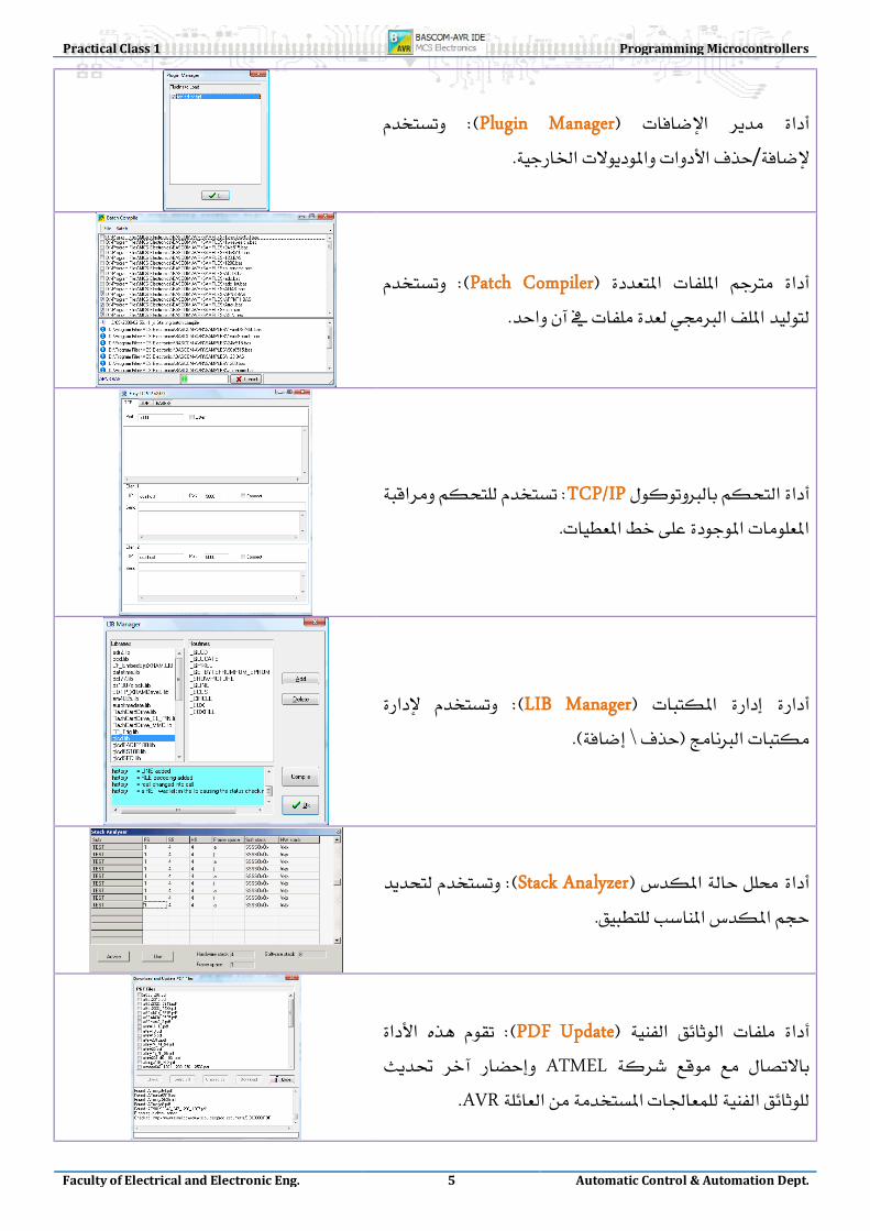
ت لعتلا فينصت جم ربلا ة ب يف ةيجمربلا
Bascom-AVR نع دیز ت لعتلا دد
ةميلعت350
خيراتلاو ت قوتلا ةيطرشلاةئيهت اتالیوحتلاينمزلا ري أتلاتور لو و
1-WIRE
عم لماعتلاا افلمل ت
تاهيجوتلا
اش ا ةش إل اهظ رلا ة موسر
اش ا ةش إل اهظ رةيلات س ركلا
تور اI2C لو و دإل ا او ل إل ارخ ج
ا لحل اق لاو ت فق ز ا مل ؤ ارش تتور لو و
PS2ا اقمل اعط ت
عم لماعتلاا ةر ا جلاعمل مكحتلا
ة فرحملا لسالسلاتور لو و
SPI
تور لو وRS232
دعب نع مكحتلا
ةيباسحلاتاثلثملاو
تور لو وTCP/IP
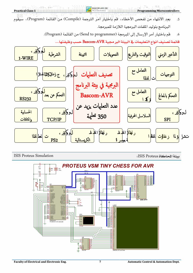
ISIS Proteus ISIS Proteus Simulation

8
Proteus
Comparison between most famous µC families AVR, PIC, 8051
AAVVRR PPIICC 88005511 1166MMHHZZ 2200MMHHZZ 2244MMHHZZ
11CCyyccllee 44CCyyccllee 1122CCyyccllee
1166//11 == 1166MMIIPPSS 2200//44 == 55MMIIPPSS 2244//1122 == 22MMIIPPSS
110000%% 7700%% 5500%%
113322 3355 221155
>>225566KKBByytteess <<6644KKBByytteess <<3322KKBByytteess
LLiinneerr bbaannkkeedd LLiinneerr
RRIISSCC//HHaarrvvaarrdd RRIISSCC//HHaarrvvaarrdd CCIISSCC//VVoonn NNeeuummaannnn
1166 BBiitt 1122 BBiitt 88 BBiitt
AVR® 8-Bit AVR Microcontrollers Family
AVR
Automotive AVR
IEEE 802.15.4 / ZigBee AVR Z-Link 1.8~25 Battery Ma nageme nt AVR
CANCANopen, DeviceNet, OSEK CAN AVR LCD LCD AVR
Lighting AVR USB USB AVR
Tiny AVR 20MIPS MEGA AVR
32MIPS XMEGA AVR MEGA AT90Sxxxx

Practical Class 1 Programming Microcontrollers
Faculty of Electrical and Electronic Eng. 9 Automatic Control & Automation Dept.
AutomotiveAVR
14 ~ 64 PinMAX I/O 6~54
2KB~128KB Flash128B~4KB EPROM128B~4KB SRAMUp To 16MIPS
2.7V – 5.5V
AVR Z-Link
MCU Wireless chipset for:
IEEE 802.15.4and
ZigBee applications.
BatteryM AVR18 ~ 48 Pin
MAX I/O 4~184KB~40KB Flash
256B~1KB EPROM512B~2KB SRAM
Up To 8MIPS1.8V – 25V
CAN AVR
64 Pin32KB~128KB Flash1KB~4KB EPROM
1K~4KB SRAMUp To 16MIPS
2.7V – 5.5V
LCD AVR64 ~ 100 Pin
MAX I/O 54~6916KB~64KB Flash
512B~2KB EPROM1KB~4KB SRAMUp To 20MIPS
1.8V – 5.5V
Lighting AVR24 ~ 32 Pin
MAX I/O 19~278KB~16KB Flash512B EPROM
512B~1KB SRAMUp To 16MIPS
2.7V – 5.5V
USB AVR32 ~ 64 Pin
MAX I/O 22~488KB~128KB Flash
512B~4KB EPROM512B~8KB SRAMUp To 16MIPS
2.7V – 5.5V
megaAVR28 ~ 100 Pin
MAX I/O 23~864KB~256KB Flash
512B~4KB EPROM512B~16KB SRAM
Up To 20MIPS1.8V – 5.5V
tinyAVR8 ~ 32 Pin
MAX I/O 6~281KB~8KB Flash
64B~512B EPROM32B~512B SRAMUp To 20MIPS
1.8V – 5.5V
xmegaAVR44 ~ 100 Pin
MAX I/O 36~7816KB~384KB Flash1KB~4KB EPROM2KB~32KB SRAM
Up To 32MIPS1.8V – 3.6V
AVR® 8-Bit
AVR Reading AVR Package information
AVR––

10
AT :ATMEL. Mega :
88,16,32,64,128,256, etc… L :L 2.7V~5.5V
––4.5V~5.5V 8 :1620 P : PDIPSOIC, TQFP, LQFP…
I : C IM

Practical Class 1 Programming Microcontrollers
Faculty of Electrical and Electronic Eng. 11 Automatic Control & Automation Dept.
Reading Datasheet of ICs
–Datasheet –
Bascom-AVR Assembly
––
ATmega128 Reading Datasheet of ATmega128
• Features 8-bit High-performance, Low-power AVR® 8-bit Microcontroller
• RISC 133 –
32 x 8 – + – – 16 16 MHz –
• Advanced RISC Architecture. – 133 Powerful Instructions Most Single Clock Cycle. – 32 x 8 General Purpose Working Registers + Peripheral
Control Registers – Fully Static Operation – Up to 16 MIPS Throughput at 16 MHz – On-chip 2-cycle Multiplier
• –128KB
10,000 – –4KB EEPROM
100,000 –4KB SRAM –64KB – –SPI
• Nonvolatile Program and Data Memories – 128K Bytes of In-System Reprogrammable Flash
Endurance: 10,000 Write/Erase Cycles – Optional Boot Code Section with Independent Lock Bits
In-System Programming by On-chip Boot Program - True Read-While-Write Operation
– 4K Bytes EEPROM Endurance: 100,000 Write/Erase Cycles
– 4K Bytes Internal SRAM – Up to 64K Bytes Optional External Memory Space – Programming Lock for Software Security – SPI Interface for In-System Programming
• JTAG – –Debug –
• JTAG (IEEE std. 1149.1 Compliant) Interface – Boundary-scan Capabilities According to the JTAG Standard – Extensive On-chip Debug Support –Programming of Flash, EEPROM, Fuses and Lock Bits
through the JTAG Interface

12
• –/8-bit –/16-bit
– –PWM8-bit –PWM16-bit
216 –/10-bit –I2C –USARTs –SPI/ – –
• Peripheral Features –Two 8-bit Timer/Counters with Separate Prescalers and
Compare Modes –Two Expanded 16-bit Timer/Counters with Separate
Prescaler, Compare Mode and Capture Mode – Real Time Counter with Separate Oscillator – Two 8-bit PWM Channels – 6 PWM Channels with Programmable Resolution from 2 to
16 Bits – Output Compare Modulator – 8-channel, 10-bit ADC – Byte-oriented Two-wire Serial Interface – Dual Programmable Serial USARTs – Master/Slave SPI Serial Interface – Programmable Watchdog Timer with On-chip Oscillator – On-chip Analog Comparator
• – – – – – –ATmega103 –
• Special Microcontroller Features – Power-on Reset and Programmable Brown-out Detection – Internal Calibrated RC Oscillator – External and Internal Interrupt Sources – Six Sleep Modes: Idle, ADC Noise Reduction, Power-save,
Power-down, Standby, and Extended Standby – Software Selectable Clock Frequency – ATmega103 Compatibility Mode Selected by a Fuse – Global Pull-up Disable
• / –53/PDIP –64/TQFP
• I/O and Packages – 53 Programmable I/O Lines-PDIP – 64-lead TQFP and 64-pad MLF
• –2.7 - 5.5V ATmega128L –4.5 - 5.5V ATmega128
• Operating Voltages – 2.7 - 5.5V for ATmega128L – 4.5 - 5.5V for ATmega128
• –8-MHz ATmega128L –16-MHz ATmega128
• Speed Grades – 0 - 8 MHz for ATmega128L – 0 - 16 MHz for ATmega128
ATmega128 ATmegaxxx .
Practical Class 1 Programming Microcontrollers
Faculty of Electrical and Electronic Eng. 13 Automatic Control & Automation Dept.
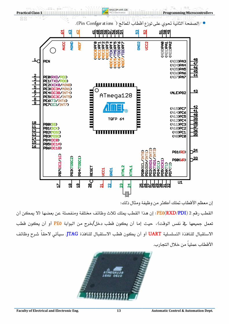
• Pin Configur at ions
2 PE0(RXD/PDI) / PE0 UART JTAG

14
• Block Diagram
AVR Harvard RISC

Practical Class 1 Programming Microcontrollers
Faculty of Electrical and Electronic Eng. 15 Automatic Control & Automation Dept.
Standard Systems Design
HarvardVon Neumann
Von-Neumann
• • • •
Harvard
Methods Architecture Systems Design
CISC :Complex Instruction Set Computer )150 ~ 1500 Instruction(. RISC :Reduced Instruction Set Computer )30 ~ 130 Instruction(. MISC :Minimum Instruction Set Computer )15 ~ 30 Instruction(.
CISC

16
INTEL &AMD
RISC
RISC
MicrocontrollersDSPs
µA
MISC

Practical Class 1 Programming Microcontrollers
Faculty of Electrical and Electronic Eng. 17 Automatic Control & Automation Dept.
AVR AVR Development Board
AVR50
-- Human-Computer Interaction Methods
1.
2.
3. /
4.
5.
6. LCD 20x4.
7. GLCD 128x64

18
8.
9. DTMF
10.
11.
12. RC5, RC5-Extended.
13. RC5, RC5-Extended .
14. 0 – 9
15. 0 – 9999.
16. UART1RS232
17. UART2
18. RS485
19.
20.
21.
22. -45⁰C ~ +100⁰CLM35DZ.
23. NTCADC
24.
25. ADC.
26.
27.
28.
29. PWM
30.
31.
32.
33. LadderDAC
34. DAC
Practical Class 1 Programming Microcontrollers
Faculty of Electrical and Electronic Eng. 19 Automatic Control & Automation Dept.
35.
36. RTC
37. EEPROM.
38.
39. Overflow, Compare & Capture modes
40. MMC
41. Smart Card
42. PS2
43. PS2
44. 1-WireDS1821
45. LED-Matrix Displays
46. RS232USART
47. EEPROM
48.
49.
50.
51.
52. JTAG.
53.
54. PCBsESD, EMC & EMI
55. MultitaskingRTS
56.
57. SPI

20
AVR Development Board Designing schedule
1- AVR
2-
3-
4- EMC,EMR,ESDEmbedded
Systems
5- Proteus
1 - compilers AVR
2 - In System Programming
3 -
4 - 60100
5 - Embedded Systems Design
6 - self learners
7 - USD120 ،
USD700.

Practical Class 1 Programming Microcontrollers
Faculty of Electrical and Electronic Eng. 21 Automatic Control & Automation Dept.
8 - Lab-Center Proteus-7.2
Bascom-AVR
9 - Debugger RS232 Interface
10 - 48 I/O
11 - AVRSPI
12 -
13 -
a :5%
b 85%
c 90%
d 96%
e 98%.
f 45%70150
14 -
15 -
Open Source
16 - LabVIEW, VB6, Matlab, etc…

22
Development Board Layout Diagram

Practical Class 1 Programming Microcontrollers
Faculty of Electrical and Electronic Eng. 23 Automatic Control & Automation Dept.
Development Board Schematic & Board Design

24

Practical Class 1 Programming Microcontrollers
Faculty of Electrical and Electronic Eng. 25 Automatic Control & Automation Dept.

26

Practical Class 1 Programming Microcontrollers
Faculty of Electrical and Electronic Eng. 27 Automatic Control & Automation Dept.
USART

28
I2C EEPROM & RTC

Practical Class 1 Programming Microcontrollers
Faculty of Electrical and Electronic Eng. 29 Automatic Control & Automation Dept.
RS485

30

Practical Class 1 Programming Microcontrollers
Faculty of Electrical and Electronic Eng. 31 Automatic Control & Automation Dept.
MMC/SD
PWM

32
PS2

Practical Class 1 Programming Microcontrollers
Faculty of Electrical and Electronic Eng. 33 Automatic Control & Automation Dept.
1-Wire

34

Practical Class 1 Programming Microcontrollers
Faculty of Electrical and Electronic Eng. 35 Automatic Control & Automation Dept.

36
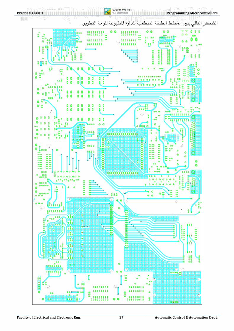
Practical Class 1 Programming Microcontrollers
Faculty of Electrical and Electronic Eng. 37 Automatic Control & Automation Dept.

38

Practical Class 1 Programming Microcontrollers
Faculty of Electrical and Electronic Eng. 39 Automatic Control & Automation Dept.

40
Px.0 Px.1 Px.2 Px.3 Px.4 Px.5 Px.6 Px.7
Port
E
INT4~7 UART1
AIN OC3A,B,C
T3 ICP3
RS485 Interface PWM>DAC Four Buttons/Leds1
UART1 with Hand-checking and LEDs Indicators
8-bit DAC Interface
External Port Connector for further connecting and can be set to Pull Up/Down Resistor
Port
B SPI
OC1A,B OC0,2 OC1C
Programmer
MMC/SD Card SPI Interface Speaker IR Sender PWM IR Receiver
Hexadecimal Keypad
External Port Connector for further connecting and can be set to Pull Up/Down Resistor
Port
D INT0~3
UART2 TWI
T1~2 ICP1
Four Buttons/Leds2 ICP1 Relay1 T1 Relay2
PS2 SCK UART2
RTC & EEPROM
External Port Connector for further connecting and can be set to Pull Up/Down Resistor
Port
C
Ex.MI-H
DS1820 GLCD Control Bus
LCD
Quad Seven Segment Control Lines
Dual Led-Matrix Display Data Bus
External Port Connector for further connecting and can be set to Pull Up/Down Resistor
Port
A
Ex.MI-L
GLCD Data Bus
UART2 Hand-checking Basic Card
Quad Seven Segment Data Bus
External Port Connector for further connecting and can be set to Pull Up/Down Resistor
Port
F ADC0~7 JTAG
LDR Resistor
NTC Resistor
Pressure sensor
Variable Resistor
Variable Resistor
4 Switches On a line
Temperature Sensor
JTAG Interface
Port
G
TOSC WR/RD
Dual Led-Matrix Display Control Lines
RC Circuit 23KHZ Crystal x x x
ASK TR ASK RE PS2 Data x x x x x
1 Buttons for Interrupt 4~7 can be set to VCC or GND by Jumper, connected with led indicators. 2 Buttons for Interrupt 0~3 can be set to VCC or GND by Jumper, connected with led indicators.