Embed Size (px)
Citation preview

BASCOM-AVR-HELPFILE page 1
Index
BASCOM-AVR
Version 1.11a
Problems and solutions »page 202Installation »page 6The BASCOM IDE »page 15
Running BASCOM-AVR »page 15File New »page 15File Open »page 16File Close »page 16File Save »page 16File Save As »page 16File Print Preview »page 16File Print »page 16File Exit »page 17
Edit Undo »page 17Edit Redo »page 17Edit Cut »page 17Edit Copy »page 17Edit Paste »page 17Edit Find »page 17Edit Find Next »page 17Edit Replace »page 17Edit Goto »page 18Edit Toggle Bookmark »page 18Edit Goto Bookmark »page 18Edit Indent Block »page 18Edit Unindent Block »page 18
Program Compile »page 18Program Syntax Check »page 19Program Show Result »page 19Program Simulate »page 20Program Send to Chip »page 25
Tools Terminal Emultator »page 26Tools LCD Designer »page 28

BASCOM-AVR-HELPFILE page 2
Options Compiler »page 28Options Compiler Chip »page 29Options Compiler Output »page 30Options Compiler Communication »page 31Options Compiler I2C,SPI,1WIRE »page 32Options Compiler LCD »page 33
Options Communication »page 34Options Environment »page 35Options Simulator »page 37Options Programmer »page 38
Editor Keys »page 40BASCOM Developing Order »page 42BASCOM and Memory »page 42BASCOM Error codes »page 43BASCOM and Hardware
Additional Hardware »page 46AVR Internal Hardware »page 46AVR Internal Hardware TIMER0 »page 49AVR Internal Hardware TIMER1 »page 50AVR Internal Hardware Watchdog timer »page 51AVR Internal Hardware PORT B »page 51AVR Internal Hardware PORT D »page 52AVR Internal Registers »page 47Attaching an LCD display »page 54Using the I2C protocol »page 54Using the 1 Wire protocol »page 55Using the SPI protocol »page 55Power Up »page 55
Language Fundamentals »page 57Reserved Words »page 56BASCOM Language Reference
$ASM »page 63$BAUD »page 64$CRYSTAL »page 64$DATA »page 65$DEFAULT »page 66$EEPROM »page 67$EXTERNAL »page 68$INCLUDE »page 68$LCD »page 69$LCDRS »page 71$LCDPUTCTRL »page 69$LCDPUTDATA »page 70$LIB »page 72$REGFILE »page 73$SERIALINPUT »page 74$SERIALINPUT2LCD »page 75$SERIALOUTPUT »page 76$XRAMSIZE »page 76$XRAMSTART »page 771WRESET »page 781WREAD »page 791WWRITE »page 80ABS »page 81ALIAS »page 81

BASCOM-AVR-HELPFILE page 3
ASC »page 82BAUD »page 83BCD »page 83BITWAIT »page 84BYVAL »page 85CALL »page 86CHECKSUM »page 203CHR »page 87CLS »page 88CLOCKDIVISION »page 88CLOSE »page 89CONFIG »page 90CONFIG KEYBOARD »page 197CONFIG TIMER0 »page 97CONFIG TIMER1 »page 99CONFIG LCD »page 93CONFIG LCDBUS »page 94CONFIG LCDMODE »page 94CONFIG 1WIRE »page 91CONFIG SDA »page 95CONFIG SCL »page 96CONFIG DEBOUNCE »page 91CONFIG SPI »page 96CONFIG LCDPIN »page 95CONFIG WATCHDOG »page 102CONFIG PORT »page 102COUNTER0 AND COUNTER1 »page 104CONST »page 116CRYSTAL »page 106CPEEK »page 105CURSOR »page 107DATA »page 107DEBOUNCE »page 109DECR »page 110DECLARE FUNCTION »page 111DECLARE SUB »page 112DEFXXX »page 113DEFLCDCHAR »page 113DELAY »page 114DIM »page 114DISABLE »page 116DISPLAY »page 118DO-LOOP »page 118ELSE »page 119ENABLE »page 120END »page 120EXIT »page 121FORMAT »page 202FOR-NEXT »page 121FOURTHLINE »page 122FUSING »page 123GETADC »page 123GETATKBD »page 195GETRC »page 125GETRC5 »page 126GOSUB »page 128

BASCOM-AVR-HELPFILE page 4
GOTO »page 129HEX »page 129HEXVAL »page 130HIGH »page 130HOME »page 131I2CRECEIVE »page 131I2CSEND »page 132I2CSTART,I2CSTOP,I2CRBYTE,I2CWBYTE »page 133IDLE »page 134IF-THEN-ELSE-END IF »page 134INCR »page 135INKEY »page 135INP »page 136INPUTBIN »page 137INPUTHEX »page 137INPUT »page 138INSTR »page 194LCD »page 139LEFT »page 141LEN »page 142LOAD »page 143LOADADR »page 180LOCAL »page 143LOCATE »page 145LOOKUP »page 145LOOKUPSTR »page 146LOW »page 146LOWERLINE »page 147LTRIM »page 142MAKEBCD »page 147MAKEDEC »page 148MAKEINT »page 148MID »page 149ON INTERRUPT »page 150ON VALUE »page 151OPEN »page 152OUT »page 153PEEK »page 154POKE »page 154POWERDOWN »page 155PRINT »page 156PRINTBIN »page 157PULSEOUT »page 199READ »page 158READEEPROM »page 159READMAGCARD »page 204REM »page 159RESET »page 160RESTORE »page 161RETURN »page 161RIGHT »page 162RND »page 194ROTATE »page 163RTRIM »page 162SELECT CASE - END SELECT »page 163SET »page 164

BASCOM-AVR-HELPFILE page 5
SHIFTCURSOR »page 165SHIFTIN »page 165SHIFTOUT »page 167SHIFTLCD »page 168SOUND »page 168SPACE »page 169SPIIN »page 169SPIMOVE »page 193SPIOUT »page 170START »page 171STOP »page 172STR »page 173STRING »page 173SUB »page 174SWAP »page 174THIRDLINE »page 175TRIM »page 175UPPERLINE »page 176VAL »page 176VARPTR »page 177WAIT »page 177WAITKEY »page 177WAITMS »page 178WAITUS »page 178WHILE-WEND »page 179WRITEEEPROM »page 179
International Resellers »page 9Supported Programmers »page 183Assembly Mnemonics »page 183Mixing BASIC with assembly »page 188
If you have questions, remarks or suggestions please let us know.You can contact us by sending an email to [email protected] website is at http://www.mcselec.com
For info on updates : please read the readme.txt file that is installed into the BASCOM-AVR directory
MCS Electronics may update this documentation without notice.Products specification and usage may change accordingly.
MCS Electronics will not be liable for any mis-information or errors found in this document.
All software provided with this product package is provided ' AS IS' without any warrantyexpressed or implied.
MCS Electronics will not be liable for any damages, costs or loss of profits arising from theusage of this product package.
No part of this document may be reproduced or transmitted in any form or by any means,electronic or mechanical, including photocopying and recording, for any purpose, withoutwritten permission of MCS Electronics.
Copyright MCS Electronics. All rights reserved.

BASCOM-AVR-HELPFILE page 6
Installation of BASCOM-AVRInsert the disk labeled 'disk 1 of 2' and double click the file SETUP.EXE from the Windowsexplorer.
The following window will appear:(screen shots may differ a bit)
Click on the Next button to continue installation.
The following license info window will appear:
Read the license agreement and click the Yes button when you agree.A window with additional information is then displayed. This information will be installed as areadme.txt file and contains information on how to get free updates.

BASCOM-AVR-HELPFILE page 7
After reading the information, click the Next button.Now the following window appears:
Fill in your name and company name.Click the Next button to continue.
Now you have the change to select the directory in which BASCOM will be installed.
Select the Browse button to change the directory path if required.By default BASCOM-AVR will be installed into:C:\Program Files\MCS Electronics\BASCOM-AVR

BASCOM-AVR-HELPFILE page 8
After selecting the installation directory, click the Next button.This time you will be asked in which program group the BASCOM-AVR icon must be placed.By default, a new program group named MCS Electronics will be made.
After selecting the group, click the Next button to continue.A summary will be showed. You may go back and change your settings. Otherwise, click theNext button to complete the installation of BASCOM-AVR.
When the installation is completed you must click the Finish-button, and restart Windows.
A sub directory named SAMPLES contains all the BASCOM-AVR sample files.

BASCOM-AVR-HELPFILE page 9
A sub directory named LIB contains the Library files.
When you install BASCOM on NT you need Administrator right during installation. You alsoneed to RUN BASCOM once in order to get the ioport.sys driver installed. After this you mayrun BASCOM as a user without administrator rights.
IMPORTANT FOR THE COMMERCIAL VERSION
The license file is not included in the setup. It is a separate file and must be in the samedirectory as the SETUP.EXE file. SETUP will copy this file to the BASCOM-AVR directoryduring installation.
International Resellers
����������������� �������� �� ��� ����� ���� ������ � ������������� ������� !"�!�
#$��% &'�(�(�)��(*���+�,% &'�(�(�)��(*���
-�� % .��������/0��/1����-���222% $��3%44555�.��������/���-���
�������� �������������6� 7�8�����#��� 9, '�'"� �-����� �*���:;"��<��
-�� % .�0.���������-222% $��3%44555�.���������-
������� ��������� ����7��$ ����� �=�(=�)* 2����:;"���
#$�� % *����()�=**+�, % *����()�=*)
-�� % //���0��9����222 % $��3%44555���9����
������� � ������� �������� �������������� ���� ��7���� 2�����������:� � 6 ; " 7���> ���? # =�*'�(***�<:7 !�: ;�?���;�<
-�� % 5/09 ��/�����9�222% $��3%44555�9 ��/�����9�45/4
������������ �! ��"#"$�!% �� ;��1� <��@�-���' A������ 7��.5� # ���� ;� �7�.����� ���> � 9����"�� �= ?���.�#$��% �*�('�)(=��=+�, % �*�('�=(��*=
-�� % ����$��0����$����-222% $��3%44555�����$����-
��������������������������
��������������������
����������& �#! �'"�� % (��) ��*+#���� ?�5��/�#��� �, ==�'=>;$�- ;$�� #> ��� 8��?��!�
�������������������������
�������������, ���������� *+"+"+7������� .������ % B��� 7�@� �3�3� '����**� <C�9 C���;<�A !��
#$��% &�=)()�(��(���(**> (��(���(*'

BASCOM-AVR-HELPFILE page 10
#$��% &='� ���* *�''+�,% &='� ���' *)�* -�� % 3����0@��������-222% $��3%44@��������-
+�, % &�=)()�(�='()== -�� % C����-�@� �0�1��(� ���222% $��3%44555��1��(� ���
������ ������������ %+'+"+������ ;���@�#���� �*�� ���@)�= *�?D ?� � #:�<�?#$��% &**��*('*)(��=��)+�, % &**��*('*)('��==
��!���� ������������"�%-#���$ . ��%�'�/-��"�6�� ( ���� ? ��� 8��$�� 7��$ ��������� �6(*��'� 6���.�� �7�!E#$��%&������='�*���=+�, %&������='�*���' -�� % ��/0�@��$�� ��$222% $��3%44555��@��$�� ��$
��!����#!0�'"��0#�*!� ��0'" "12-�!' �1/�7����� 6����2� $� -�(7� ���(;��� ==6( ���'= 6��- . �7�!E#$��% &�� '���(=���+�, % &�� '���(=)��� (7�� % �� ��0� �@����@ �.���.�
222% 555�� �@����@ �.���.�A������9�9F�� �� ��-9���> ��� ��> <��3���>+���@/���> 7F��$��
����������, ��*3 �-�$�'4�-�� ��3����� � � �(�>�(�*�� ��.�3����:!��E#$��% &�)� �') )��*+�, % &�)� �') ���) -�� �.�,0-�� �-���1�$�
222 $��3%44555�$3�� �����-4�.�,
"�����'�5"();� 1���� 6�-��A�� .� G�������� =4)�**�) ;����� .� #��� ���"�<E#$��% &�� �'�� =���*'�+�, % &�� �'�� =���))� -�� % ���$0���/���
222% $��3%44555����/��- � �� ���$�222% $��3%44555����/��� ���� ����
#�����$%&'(��������)������ ���������-� ��-�@�5���7�6�!�(!�;��(�(�(=(=*�7�!�(?�"EB�#�! ')�(**��#$��%&=�(���(�=(�=''+�,% &=�(���(�=(�='' -�� --���0-9���/5�9����C3
#�����$�*+��������)���!'����"��# 6�'�% . ��5"'1���"��"+3��*+;$�C� !��@�;����� �(�() "�@�9� ?��H�9���@� #��/�B�#�! �*'(**��#$��% &=�(��=('*(����+�, % &=�(��=('*(���� -�� �� ��0�3�����C3
222 $��3%44555��3�����C3
,�������6�� �#! �'"�� % �"+B���$� 8�-�*) B��$�� ��(�� ;$��@�H E������ ;�� 8���#��� �.� ��*(*�*#$��% =�(�(�*�(�==�+�, % =�(�(�*�(�==� -�� % ��/0��-3 ����@�
222% $��3%44555���-3 ����@�
-��������� ���� �&����7� �@ 7�$�--�. !�5�� �5���'4E> "���I ��! D��6 ?�<�!E> ;���2�<�#�8�;"�!
#$��% *���())�=� -�� % -�09���������3@

BASCOM-AVR-HELPFILE page 11
-������7�&�����9��� 8��3��H�@�?� <7�!;8� � �**'(=�' ��6D�;8 7�D�#�<�!6�
#$��% &�=�� ��� �* ��+�,% &�=�� ��� �* �� -�� �9���@0���1�-3�5�5�3
-������� �������-#��*�$���#3 �*�B�J��- ��1�.�#��� �, ������' �� "���#��":�<#$��% &�'� ( � ( )�*����+�, % &�'� ( � ( �=)���� -�� % ��/0-� ��.����� ��-222% $��3%44555�-� ��.����� ��-
����������� �;5�.��> !�5�H>
6��-��@���$� �! � �"'�8"�?$������B$�������9����� �� ?;(�)� '� ���� $ -;2 6 !#$��% &�) ���(�� ** ==+�, % &�) ���(�� ** == -�� % ��/0$�$��-
222% $��3%44555�$�$��-
�������������<��� 2�������8 �99����� �; (�=� �� "E��! ;2 6 !#$��% &�) �*��'� '�=��+�, % &�) �*��'� '�=�=222% $��3%44555� �5��� ��- -�� % ��/0 �5��� ��-
������/!' "127�J�� D�����?4� .� #���> ��-�� = �9�C�� (*�*��#� -� .� 7� ���;#��!#$��% &�� ��� �� �' )) ��+�, % &�� ��� �� �' )� '= -�� % �9���-30�� ��(��3���
222% $��3%44555��9���-3���
�������� ��1��!* ��'0!�����4� ;@�@ �(� @ !% �4�*��+� ;���H� ?������ ( ���;���H��'�** ���1� ( ��-��
#$��% **�*(���(�)����� ( �=+�,% **�*(���(�)��'�' (-�� % �9. �.0��3��� �����- (-�� % �9.0�9.( �.��- (-�� % �� ��0�9.( �.��- (-�� % /���@0�9.( �.��-222 % 555��9.��-���
�,�������� ��� ����� ���6��� �9��$�-�� 6��1���� ��. �$�-<�.� ; � �;�#$��% *��� ��� '��� � *�=� �== �)=�+�,% *��� =�� )��� -�� % .���0.��������@
222%555�������.��������@4K.���4.���4
����! ���0%3 �� ++���@ ?�3� �#� �, �)�������> !B *=''�:;�#$��% �*=(�==(=���+�,% �*=(�==(==�� -�� % "��$��@�0���$��@���-
222% $��3%44555����$��@���-
����+ �0!'% ���!'2'�%!%7��$�� 2� �@����=** A���H��. �1���� L # �������> ?� ��'))()���:;�#$��% &�(��'()�*(�)**+�,% &�(��'()�*(�)** -�� % ��/0-5�@�����-
222% $��3%44555�-5�@�����-
����"1/-%6�1�. �� <�5�������*� � . 7������ ?���@ ��.����1� �> ;? ��)*�:;�
#$��% &�(=)�(���(=��*+�,% &�(=)�(���(=��� -�� % 5�9-�����0�$-9�������-222% $��3%44555��$-9�������-

BASCOM-AVR-HELPFILE page 12
Installation of BASCOM-AVRInsert the disk labeled 'disk 1 of 2' and double click the file SETUP.EXE from the Windowsexplorer.
The following window will appear:
Click on the Next button to continue installation.
The following license info window will appear:
Read the license agreement and click the Yes button when you agree.A window with additional information is then displayed. This information will be installed as areadme.txt file and contains information on how to get free updates.

BASCOM-AVR-HELPFILE page 13
After reading the information, click the Next button.Now the following window appears:
Fill in your name and company name.Click the Next button to continue.
Now you have the change to select the directory in which BASCOM will be installed.
Select the Browse button to change the directory path if required.By default BASCOM-AVR will be installed into:C:\Program Files\MCS Electronics\BASCOM-AVR

BASCOM-AVR-HELPFILE page 14
After selecting the installation directory, click the Next button.This time you will be asked in which program group the BASCOM-AVR icon must be placed.By default, a new program group named MCS Electronics will be made.
After selecting the group, click the Next button to continue.A summary will be showed. You may go back and change your settings. Otherwise, click theNext button to complete the installation of BASCOM-AVR.
When the installation is completed you must click the Finish-button, and restart Windows.
A sub directory named SAMPLES contains all the BASCOM-AVR sample files.

BASCOM-AVR-HELPFILE page 15
IMPORTANT FOR THE COMMERCIAL VERSION
The license file is not included in the setup. You must copy this file to the\WINDOWS\SYSTEM directory.
The license file is named BSCAVRL.DLL and can be found on the last installation disk named'DISK 2 of 2'.
To copy from the Explorer:Select the file from disk A and drag it into the \WINDOWS\SYSTEM directory.
Of course the name of your system directory can be \W95\SYSTEM or \WINNT\SYSTEM too.
You also need to DELETE the file \windows\system\BASC-AVR.DLL before you install thecommercial version over the DEMO version.
Running BASCOM-AVRDouble-click the BASCOM-AVR icon to run BASCOM.The following window will appear. (If this is your first run, the edit window will be empty.)
The most-recently opened file will be loaded.
File NewThis option creates a new window in which you will write your program.The focus is set to the new window.
File new shortcut: , CTRL + N

BASCOM-AVR-HELPFILE page 16
File OpenWith this option you can load an existing program from disk.BASCOM saves files in standard ASCII format. Therefore, if you want to load a file that wasmade with another editor be sure that it is saved as an ASCII file.
Note that you can specify that BASCOM must reformat the file when it opens it with theOptions Environment option. This should only be necessary when loading files made withanother editor.
File open shortcut : , CTRL+O
File CloseClose the current program.When you have made changes to the program, you will be asked to save the program first.
File close shortcut :
File SaveWith this option, you save your current program to disk under the same file name.If the program was created with the File New option, you will be asked to name the file first.Use the File Save As option to give the file another name.
Note that the file is saved as an ASCII file.
File save shortcut : , CTRL+S
File Save AsWith this option, you can save your current program to disk under a different file name.
Note that the file is saved as an ASCII file.
File save as shortcut :
File Print PreviewWith this option, you can preview the current program before it is printed.Note that the current program is the program that has the focus.
File print preview shortcut :
File PrintWith this option, you can print the current program.Note that the current program is the program that has the focus.
File print shortcut : , CTRL+P

BASCOM-AVR-HELPFILE page 17
File ExitWith this option, you can leave BASCOM.If you have made changes to your program, you can save them upon leaving BASCOM.
File exit shortcut :
Edit UndoWith this option, you can undo the last text manipulation.
Edit Undo shortcut : , CTRL+Z
Edit RedoWith this option, you can redo the last undo.
Edit Redo shortcut : , CTRL+SHIFT+Z
Edit CutWith this option, you can cut selected text into the clipboard.
Edit cut shortcut : , CTRL+X
Edit CopyWith this option, you can copy selected text into the clipboard.
Edit copy shortcut : , CTRL+C
Edit PasteWith this option, you can paste text from the clipboard into the current cursor position.
Edit paste shortcut : , CTRL+V
Edit FindWith this option, you can search for text in your program.Text at the cursor position will be placed in the find dialog box.
Edit Find shortcut : , CTRL+F
Edit Find NextWith this option, you can search for the last specified search item.
Edit Find Next shortcut : , F3
Edit ReplaceWith this option, you can replace text in your program.

BASCOM-AVR-HELPFILE page 18
Edit Replace shortcut : , CTRL+R
Edit GotoWith this option, you can immediately go to a line .
Edit go to line shortcut : ,CTRL+G
Edit Toggle BookmarkWith this option, you can set/reset a bookmark, so you can jump in your code with the Edit Goto Bookmark option. Shortcut : CTRL+K + x where x can be 1-8
Edit Goto BookmarkWith this option, you can jump to a bookmark.There can be up to 8 bookmarks. Shortcut : CTRL+Q+ x where x can be 1-8
Edit Indent BlockWith this option, you can indent a selected block of text.
Edit Indent Block shortcut : , CTRL+SHIFT+I
Edit Unindent BlockWith this option, you can un-indent a block.
Edit Unindent Block shortcut : , CTRL+SHIFT+U
Program CompileWith this option, you can compile your current program.Your program will be saved automatically before being compiled.The following files will be created depending on the Option Compiler Settings.
File Descriptionxxx.BIN Binary file which can be programmed into the microprocessorxxx.DBG Debug file that is needed by the simulator.xxx.OBJ Object file for AVR Studioxxx.HEX Intel hexadecimal file which is needed by some programmers.xxx.ERR Error file. (only when errors are found)xxx.RPT Report file.xxx.EEP EEPROM image file
If a serious error occurs, you will receive an error message in a dialog box and the compilationwill end.All other errors will be displayed at the bottom above the status bar.
When you click on the line with the error info, you will jump to the line that contains the error.The margin will also display the sign.At the next compilation, the error window will disappear.

BASCOM-AVR-HELPFILE page 19
Program compile shortcut : , F7
Program Syntax CheckWith this option, your program is checked for syntax errors. No file will be created except foran error file, if an error is found.
Program syntax check shortcut , CTRL + F7
Program Show ResultUse this option to view the result of the compilation.See the Options Compiler Output for specifying which files must be created.The files that can be viewed are report and error.
File show result shortcut : ,CTRL+W
Information provided in the report:Info DescriptionReport Name of the programDate and time The compilation date and time.Compiler The version of the compiler.Processor The selected target processor.SRAM Size of microprocessor SRAM (internal RAM).EEPROM Size of microprocessor EEPROM (internal EEPROM).ROMSIZE Size of the microprocessor FLASH ROM.ROMIMAGE Size of the compiled program.BAUD Selected baud rate.XTAL Selected XTAL or frequencyBAUD error The error percentage of the baud rate.XRAM Size of external RAM.Stack start The location in memory which the hardware stack points to. The
HW-stack pointer "grows down".S-Stacksize The size of the software stack.S-Stackstart The location in memory which the software stack pointer points to.
The software stack pointer "grows down".Framesize The size of the frame. The frame is used for storing local variables.Framestart The location in memory where the frame starts.LCD address The address that must be placed on the bus to enable the LCD
display E-line.LCD RS The address that must be placed on the bus to enable the LCD
RS-lineLCD mode The mode the LCD display is used with. 4 bit mode or 8 bit mode.

BASCOM-AVR-HELPFILE page 20
Program SimulateWith this option, you can simulate your program.You can simulate your programs with AVR Studio or any other Simulator available or you canuse the build in Simulator.Which one will be used when you press F2 depends on the selection you made in the OptionsSimulator TAB.
Program Simulate shortcut : , F2
To use the build in Simulator the files DBG and OBJ must be selected from the OptionsCompiler Output TAB.The OBJ file is the same file that is used with the AVR Studio simulator.The DBG file contains info on variables used and many more info needed to simulate aprogram.
The Sim window is divided into a few sections:The ToolbarThe toolbar contains the buttons you can press to start an action.
This starts a simulation. It is the RUN button. The simulation will pause when you pressthe pause button. You can also press F5.
This is the pause button. Pressing this button will pause simulation.

BASCOM-AVR-HELPFILE page 21
This is the STOP button. Pressing this button will stop simulation and you can't continue.This because all variables are reset. You need to press this button when you want to simulateyour program again.
This is sthe STEP button. Pressing this button(or F8) will execute one code line of yourBASIC program. After the line is executed the simulator will be in the pause state.
This is the STEP OVER button. It has the same effect as the STEP button but subprograms are executed and there is no step into the SUB program. You can also pressSHIFT+F8
This is the RUN TO button. The simulator will RUN to the current line. The line mustcontain executable code.
This button will show the register window.
The values are show in hexadecimal format. To change a value click the cell of the Val columnand type the new value.
This is the IO button and will show the IO registers.

BASCOM-AVR-HELPFILE page 22
The IO window works the same like the Register window. Blank rows indicate that there is noIO-register assigned to that address.( The blank rows might be deleted later.)
Pressing this button shows the Memory window.
The values can be changed the same way like in the Register window.When you move from cell to cell you can view in the statusbar which variable is stored in theaddress.
Under the toolbar section there is a TAB with the pages:VARIABLES
You can add variables by double clicking in the Variable-column. A list will pop up from whichyou can select the variable.To watch an array variable you can type the name of the variable with the index.During simulation you can change the values of the variables in the Value-column, Hex-column or Bin-column. You must press ENTER to store the change.
To delete a row you can press CTRL+DEL.
LOCALS

BASCOM-AVR-HELPFILE page 23
The LOCAL window show the variables in a SUB or FUNCTION. LOCAL variables are alsoshown. You can not add variables.Changing the value of the variables works the same as for the Variable TAB.
WATCHThe Watch-TAB can be used to enter an expression that will be evaluated during simulation.When the expression is true the simulation is paused.Type the expression in the text-field and press the Add-button.When you press the Modify-button the current selected expression from the list is modifiedwith the typed value.
To delete an expression you must select the expression from the list and press the Remove-button.When the expression becomes true the expression that matches will be selected and theWatch-TAB will be shown.
UP
This TAB shows the status of the microprocessor SREG register.The flags can be changed by clicking their checkboxes.The software stack , hardware stack and frame pointer values are also shown. The minimumor maximum value during simulation is shown. When one of the data is entering another onethere is a case of stack/frame overflow.This will be signalled with a pause and a checkbox.
INTERRUPTS
This TAB shows the interrupt sources. When no ISR's are programmed all buttons will bedisabled.
By clicking a button the corresponding ISR is executed.

BASCOM-AVR-HELPFILE page 24
TERMINAL SectionUnder the TAB window you will find the terminal emulator window.When you use PRINT, the output will be shown in this window.When you use INPUT in your program, you must set the focus to the terminal window andpress the needed value.
SOURCE SectionUnder the Terminal section you find the Source WIndow.It contains the program you simulate. All lines that contain executable code have a yellow pointin the left margin.You can set a breakpoint on these lines by pressing F9.
By moving the mouse cursor over a variable name the value is shown in the status bar.When you select a variable and press ENTER it will be added to the Variable window.
When you want to use the keys (F8 for stepping for example) the focus must be set to theSource Window.
A blue arrow will show the line that will be executed next.
The hardware simulator.
By pressing the hardware simulation button the windows shown below will be displayed.
The top section is a virtual LCD display. It works for display code in PIN mode and busmode.For bus mode only 8-bit bus mode works.The LED bars below are a visual indication of the ports.By clicking a LED it will toggle.
Enable Real Hardware Simulation
By clicking the button you can simulate the ports in circuit!In order to get it work you must compile the basmon.bas file.When compiled program a chip.Lets say you have the DT006 simmstick. And you are using a 2313 AVR chip.

BASCOM-AVR-HELPFILE page 25
Open the basmon.bas file and change the line with $REGFILE = "xxx" into $REGFILE ="2313def.dat"Now compile the program. Program the chip. It is best to set the lockbits so the monitor doesnot get overwritten when you accidently press F4.The real hardware simulation only works when the target micro system has a serial port. Mosthave and so does the DT006.Connect a cable between the COM port of your PC and the DT006. You probably already haveone connected. Normally it is used to send data to the terminal emulator with PRINT.
The monitor program is compile with 19200 baud. The Options Communication settings mustbe set to the same baud rate!The same settings for the monitor program are used as for the Terminal emulator. So selectthe COM port and the baud rate of 19200.
Power up the DT006. It probably was since you created the basmon program and stored it inthe 2313.When you press the real hardware simulation button now the simulator will send and receivedata when a port, pin or ddr register is changed.This allows you to simulate an attached LCD display for example. Or something simplers, theLED. In the SAMPLE dir you will find a program DT006. You can compile thie program andpress F2.When you step through the program the LED's will change!All statements can be simulated this way but the have to be static. Which means that 1wire willnot work because it depends on timing. I2C has a static bus and that will work.It is important that when you finish your simulation sessions that you click the button again todisable the Real hardware simulation.
When the program hangs it probably means that something wend wrong in thecommunication. The only way to escape is to press the Real hardware simulation again.I think the simulation is a cost effective way to test attached hardware.
Program Send to ChipThis option will bring up the selected programmer or will program the chip directly if this optionis selected from the Programmer options.
Program send to chip shortcut , F4
The following window will be shown:

BASCOM-AVR-HELPFILE page 26
Menu item DescriptionFile Exit Return to editorBuffer Clear Clears bufferBuffer Load from file Loads a file into the bufferBuffer Save to file Saves the buffer content to a fileChip Identify Identifies the chipWrite buffer into chip Programs the buffer into the chip ROM or EEPROMRead chipcode intobuffer
Reads the code or data from the chips code memory or datamemory
Chip blank check Checks if the chip is blankChip erase Erase the content of both the program memory and the data
memotyChip verify verifies if the buffer is the same as the chip program or data
memoryChip Set lockbits Writes the selected lock bits LB1 and/or LB2. Only an erase will
reset the lock bitsChip autoprogram Erases the chip and programs the chip. After the programming
is completed, a verification is performed.RCEN Writes a bit to enable the internal oscillator. This RCEN bit is
only available on some AVR chips.
Tools Terminal EmulatorWith this option you can communicate via the RS-232 interface to the microcomputer. Thefollowing window will appear :

BASCOM-AVR-HELPFILE page 27
Information you type and information that the computer board sends are displayed in the samewindow.
Note that you must use the same baud rate on both sides of the transmission. If you compiledyour program with the Compiler Settings at 4800 baud, you must also set the CommunicationSettings to 4800 baud.The setting for the baud rate is also reported in the report file.
File UploadUploads the current program in HEX format. This option is meant forloading the program into a monitor program.
File EscapeAborts the upload to the monitor program.
File ExitCloses terminal emulator.
Terminal ClearClears the terminal window.
Terminal Open LogOpen or closes a LOG file. When there is no LOG file selected you will be asked to enter orselect a filename. All info that is printed to the terminal window is captured into the log file. Themenu caption will change into 'Close Log' and when you choose this option the file will beclosed.
The terminal emulator has a strange bug that you can't select the menu options by using thekeyboard. This is an error in the terminal component and I hope the third party will fix this bug.

BASCOM-AVR-HELPFILE page 28
Tools LCD DesignerWith this option you can design special characters for LCD-displays.The following window will appear:
The LCD-matrix has 7x5 points. The bottom row is reserved for the cursor but can be used.You can select a point by clicking the left mouse button. If a cell was selected it will bedeselected.
Clicking the Set All button will set all points.Clicking the Clear All button will clear all points.
When you are finished you can press the Ok button : a statement will be inserted in your activeprogram-editor window at the current cursor position. The statement looks like this :
Deflcdchar ?,1,2,3,4,5,6,7,8You must replace the ?-sign with a character number ranging from 0-7.
Options CompilerWith this option, you can modify the compiler options.The following TAB pages are available:
Options Compiler Chip »page 29Options Compiler Output »page 30Options Compiler Communication »page 31Options Compiler I2C , SPI, 1WIRE »page 32Options Compiler LCD »page 33

BASCOM-AVR-HELPFILE page 29
Options Compiler Chip
The following options are available:
Options Compiler ChipItem DescriptionChip Selects the target chip. Each chip has a corresponding x.DAT file
with specifications of the chip. Note that some DAT files are notavailable yet.
XRAM Selects the size of the external RAM. KB means Kilo Bytes.For 32 KB you need a 62256 STATIC RAM chip.
Stack size Specifies the size of the software stack.Each local variable uses 2 bytes. Each variable that is passed in asub program uses 2 bytes too. So when you have used 10 locals in aSUB and the SUB passes 3 parameters, you need 13 * 2 = 26 bytes.
Frame size Specifies the size of the frame.Each local is stored in a space that is named the frame.When you have 2 local integers and a string with a length of 10, youneed a framesize of (2*2) + 11 = 15 bytes.The internal conversion routines used when you use INPUTnum,STR(),VAL() etc, also use the frame. They need a maximum of12 bytes. So for this example 15+12 = 27 would be a good value.
XRAM waitstate Select to insert a wait state for the external RAM.Default Press or click this button to use the current Compiler Chip settings as
default for all new projects.

BASCOM-AVR-HELPFILE page 30
Options Compiler Output
Options Compiler OutputItem DescriptionBinary file Select to generate a binary file. (xxx.bin)Debug file Select to generate a debug file (xxx.dbg)Hex file Select to generate an Intel HEX file (xxx.hex)Report file Select to generate a report file (xxx.rpt)Error file Select to generate an error file (xxx.err)AVR Studio objectfile
Select to generate an AVR Studio object file (xxx.obj)
Size warning Select to generate a warning when the code size exceeds theFlash ROM size.

BASCOM-AVR-HELPFILE page 31
Options Compiler Communication
Options Compiler CommunicationItem DescriptionBaud rate Selects the baud rate for the serial statements. You can also type in a
new baud rate.Frequency Select the frequency of the used crystal. You can also type in a new
frequency.
The settings for the internal hardware UART are:No parity8 data bits1 stop bit

BASCOM-AVR-HELPFILE page 32
Options Compiler I2C, SPI, 1WIRE
Options Compiler I2C, SPI, 1WIREItem DescriptionSCL port Select the port that serves as the SCL-line for the I2C related
statements.SDA port Select the port that serves as the SDA-line for the I2C related
statements.1WIRE Select the port that serves as the 1WIRE-line for the 1Wire related
statements.Clock Select the port that serves as the clock-line for the SPI related
statements.MOSI Select the port that serves as the MOSI-line for the SPI related
statements.MISO Select the port that serves as the MISO-line for the SPI related
statements.SS Select the port that serves as the SS-line for the SPI related
statements.Use hardware SPI Select to use built-in hardware for SPI, otherwise software
emulation of SPI will be used.

BASCOM-AVR-HELPFILE page 33
Options Compiler LCD
Options Compiler LCDItem DescriptionLCD type The LCD display used.Bus mode The LCD can be operated in BUS mode or in PIN mode. In PIN mode,
the data lines of the LCD are connected to the processor pins. In BUSmode the data lines of the LCD are connected to the data lines of theBUS.Select 4 when you have only connect DB4-DB7. When the data mode is'pin' , you should select 4.
Data mode Select the mode in which the LCD is operating. In PIN mode, individualprocessor pins can be used to drive the LCD. In BUS mode, theexternal data bus is used to drive the LCD.
LCD address In BUS mode you must specify which address will select the enable lineof the LCD display. For the STK200, this is C000 = A14 + A15.
RS address In BUS mode you must specify which address will select the RS line ofthe LCD display. For the STK200, this is 8000 = A15
Enable For PIN mode, you must select the processor pin that is connected tothe enable line of the LCD display.
RS For PIN mode, you must select the processor pin that is connected tothe RS line of the LCD display.
DB7-DB4 For PIN mode, you must select the processor pins that are connected tothe upper four data lines of the LCD display.

BASCOM-AVR-HELPFILE page 34
Options CommunicationWith this option, you can modify the communication settings for the terminal emulator.
Item DescriptionComport The communication port of your PC that you use for ther terminal
emulator.Baud rate The baud rate to use.Parity Parity, default None.Data bits Number of data bits, default 8.Stop bits Number of stop bits, default 1.Handshake The handshake used, default is none.Emulation Emulation used, default BBS ANSI.Font Font type and color used by the emulator.Back color Background color of the terminal emulator.
Note that the baud rate of the terminal emulator and the baud rate setting of the compileroptions, must be the same in order to work correctly.

BASCOM-AVR-HELPFILE page 35
Options Environment
OPTION DESCRIPTIONAuto Indent When you press return, the cursor is set to the next line at the
current column positionDon't change case When set, the reformatting won't change the case of the text.
Default is that the text is reformatted so every word begins withupper case.
Reformat BAS files Reformat files when loading them into the editor.This is only necessary when you are loading files that wherecreated with another editor. Normally you won't need to set thisoption.
Reformat code Reformat code when entered in the editor.Smart TAB When set, a TAB will go to the column where text starts on the
previous line.Syntax highlighting This options highlights BASCOM statements in the editor.Show margin Shows a margin on the right side of the editor.Comment The position of the comment. Comment is positioned at the right
of your source code.TAB-size Number of spaces that are generated for a TAB.Keymapping Choose default, Classic, Brief or Epsilon.No reformatextension
File extensions separated by a space that will not be reformattedwhen loaded.
Size of new editorwindow
When a new editor window is created you can select how it will bemade. Normal or Maximized (full window)

BASCOM-AVR-HELPFILE page 36
OPTION DESCRIPTIONBackground color The background color of the editor window.Keyword color The color of the reserved words. Default Navy.
The keywords can be displayed in bold too.Comment color The color of comment. Default green.
Comment can be shown in Italic too.ASM color Color to use for ASM statements. Default purple.HW registers color The color to use for the hardware registers/ports. Default maroon.Editor font Click on this label to select another font for the editor window.

BASCOM-AVR-HELPFILE page 37
OPTION DESCRIPTIONTooltips Show tooltips.Show toolbar Shows the toolbar with the shortcut icons.Save File As … fornew files.
Will display a dialogbox so you can give new files a name whenthey must be saved. When you dont select this option the defaultname will be give to the file (nonamex.bas). Where x is a number.
File location Double click to select a directory where your program files arestored. By default Windows will use the My Documents path.
Options SimulatorWith this option you can modify the simulator settings.
OPTION DESCRIPTIONProgram The path with the program name of the simulator.Parameter The parameter to pass to the program. {FILE}.OBJ will supplie
the name of the current program with the extension .OBJ to thesimulator.

BASCOM-AVR-HELPFILE page 38
Options ProgrammerWith this option you can modify the programmer settings.
OPTION DESCRIPTIONProgrammer Select one from the list.Play sound Name of a WAV file to be played when programming is finished.
Press the ..-button to select the file.Erase Warning Set this option when you want a confirmation when the chip is erased.Auto flash Some programmers support auto flash. Pressing F4 will program the
chip without showing the programmer window.Auto verify Some programmers support verifying. The chip content will be verified
after programming.Upload codeand data
Set this option to program both the FLASH memory and the EEPROMmemory
Parallel printer port programmersLPT address Port address of the LPT that is connected to the programmer.
Serial port programmerCOM port The com port the programmer is connected to.
OtherUse HEX Select when a HEX file must be sent instead of the bin file.Program The program to execute. This is your programmer software.Parameter The optional parameter that the program might need.

BASCOM-AVR-HELPFILE page 39
Options MonitorWith this option you can modify the monitor settings.
OPTION DESCRIPTIONUpload speed Selects the baud rate used for uploadingMonitor prefix String that will be send to the monitor before the upload startsMonitor suffix String that us sent to the monitor after the download is completed.Monitor delay Time in millions of seconds to wait after a line has been sent to the
monitor.Prefix delay Time in millions of seconds to wait after a prefix has been sent to
the monitor.
Options PrinterWith this option you can modify the printer settings.There are only settings to change the margins of the paper.
OPTION DESCRIPTIONLeft The left margin.Right The right margin.Top The top margin.Bottom The bottom margin.
Window CascadeCascade all open editor windows.
Window TileTile all open editor windows.
Window Arrange IconsArrange the icons of the minimized editor windows.
Window Minimize AllMinimize all open editor windows.
Help AboutThis option shows an about box as showed below.

BASCOM-AVR-HELPFILE page 40
Your serial number is shown in the about box.You will need this when you have questions about the product.The library version is also shown. In this case, it is 1.00.You can compare it with the one on our web site in case you need an update.
Click on Ok to return to the editor.
Help IndexShows the BASCOM help file.
When you are in the editor window, the current word will be used as a keyword.
Help on HelpShows help on how to use the Windows help system.
Help CreditsShows a form with credits to people I would like to thank for their contributions to BASCOM.
BASCOM Editor KeysKey ActionLEFT ARROW One character to the left
RIGHT ARROW One character to the right
UP ARROW One line up
DOWN ARROW One line down
HOME To the beginning of a line
END To the end of a line
PAGE UP Up one window

BASCOM-AVR-HELPFILE page 41
PAGE DOWN Down one window
CTRL+LEFT One word to the left
CTRL+RIGHT One word to the right
CTRL+HOME To the start of the text
CTRL+END To the end of the text
CTRL+ Y Delete current line
INS Toggles insert/overstrike mode
F1 Help (context sensitive)
F3 Find next text
F4 Send to chip (run flash programmer)
F5 Run
F7 Compile File
F8 Step
F9 Set breakpoint
F10 Run to
CTRL+F7 Syntax Check
CTRL+F Find text
CTRL+G Go to line
CTRL+K+x Toggle bookmark. X can be 1-8
CTRL+L LCD Designer
CTRL+M File Simulation
CTRL+N New File
CTRL+O Load File
CTRL+P Print File
CTRL+Q+x Go to Bookmark. X can be 1-8
CTRL+R Replace text
CTRL+S Save File
CTRL+T Terminal emulator
CTRL+P Compiler Options
CTRL+W Show result of compilation
CTRL+X Cut selected text to clipboard
CTRL+Z Undo last modification
SHIFT+CTRL+Z Redo last undo
CTRL+INS Copy selected text to clipboard
SHIFT+INS Copy text from clipboard to editor
CTRL+SHIFT+J Indent Block
CTRL+SHIFT+U Unindent Block
Select text Hold the SHIFT key down and use the cursor keys to selecttext. or keep the left mouse key pressed and tag the cursorover the text to select.

BASCOM-AVR-HELPFILE page 42
Developing Order• Start BASCOM;• Open a file or create a new one;• Check the chip settings, baud rate and frequency settings for the target system;• Save the file;• Compile the file;• If an error occurs fix it and recompile (F7);• Run the simulator;• Program the chip(F4);
Memory usageEvery variable uses memory. This memory is also called SRAM.The available memory depends on the chip.
A special kind of memory are the registers in the AVR. Registers 0-31 have addresses 0-31.Almost all registers are used by the compiler or might be used in the future.Which registers are used depends on the statements you used.
This brings us back to the SRAM.No SRAM is used by the compiler other than the space needed for the software stack andframe.
Each 8 used bits occupy one byte.Each byte occupies one byte.Each integer/word occupies two bytes.Each Long or Single occupies four bytes.Each String occupies at least 2 byes.A string with a length of 10. occupies 11 byes. The extra byte is needed to indicate the end ofthe string.
Use bits or bytes where you can to save memory. (not allowed for negative values)
The software stack is used to store the addresses of LOCAL variables and for variables thatare passed to SUB routines.Each LOCAL variable and passed variable to a SUB, uses two bytes to store the address. Sowhen you have a SUB routine in your program that passes 10 variables, you need 10 * 2 = 20bytes. When you use 2 LOCAL variables in the SUB program that receives the 10 variables,you need an additional 2 * 2 = 4 bytes.
The software stack size can be calculated by taking the maximum number of parameters in a SUB routine,adding the number of LOCAL variables and multiplying the result by 2. To be safe, add 4 morebytes for internally-used LOCAL variables.
LOCAL variables are stored in a place that is named the frame.When you have a LOCAL STRING with a size of 40 bytes, and a LOCAL LONG, you need 41+ 4 bytes = 45 bytes of frame space.

BASCOM-AVR-HELPFILE page 43
The report will show the result of both calculations.
When you use conversion routines such as STR(), VAL() etc. that convert from numeric tostring and vice versa, you also need a frame. It should be 16 bytes in that case.
Note that the use of the INPUT statement with a numeric variable, or the use of thePRINT/LCD statement with a numeric variable, will also force you to reserve 16 bytes of framespace. This because these routines use the internal numeric<>string conversion routines.
XRAMYou can easy add external memory to a 8515. Then XRAM will become available.(extendedmemory).When you add a 32KB RAM, the first address wil be 0.But because the XRAM can only start after the SRAM, which is &H0260, the lower memorylocations of the XRAM will not be used.
ERAMMost AVR chips have internal EEPROM on board.This EEPROM can be used to store and retrieve data.In BASCOM, this dataspace is called ERAM.An important difference is that an ERAM variable can be written for a maximum of 100.000times. So only assign an ERAM variable when it is needed and not in a loop.
Constant code usageConstants are stored in a constant table.Each used constant in your program will end up in the constant table.
For example:Print "ABCD"Print "ABCD"
This example will only store one constant (ABCD).
Print "ABCD"Print "ABC"
In this example, two constants will be stored because the strings differ.
Error CodesThe following table lists errors that can occur.
Error Description1 Unknown statement2 Unknown structure EXIT statement3 WHILE expected4 No more space for IRAM BIT

BASCOM-AVR-HELPFILE page 44
5 No more space for BIT6 . expected in filename7 IF THEN expected8 BASIC source file not found9 Maximum 128 aliases allowed10 Unknown LCD type11 INPUT, OUTPUT, 0 or 1 expected12 Unknown CONFIG parameter13 CONST already specified14 Only IRAM bytes supported15 Wrong data type16 Unknown Definition17 9 parameters expected18 BIT only allowed with IRAM or SRAM19 STRING length expected (DIM S AS STRING * 12 ,for example)20 Unknown DATA TYPE21 Out of IRAM space22 Out of SRAM space23 Out of XRAM space24 Out of EPROM space25 Variable already dimensioned26 AS expected27 parameter expected28 IF THEN expected29 SELECT CASE expected30 BIT's are GLOBAL and can not be erased31 Invalid data type32 Variable not dimensioned33 GLOBAL variable can not be ERASED34 Invalid number of parameters35 3 parameters expected36 THEN expected37 Invalid comparison operator38 Operation not possible on BITS39 FOR expected40 Variable can not be used with RESET41 Variable can not be used with SET42 Numeric parameter expected43 File not found44 2 variables expected45 DO expected46 Assignment error47 UNTIL expected50 Value doesn't fit into INTEGER51 Value doesn't fit into WORD

BASCOM-AVR-HELPFILE page 45
52 Value doesn't fit into LONG60 Duplicate label61 Label not found62 SUB or FUNCTION expected first63 Integer or Long expected for ABS()64 , expected65 device was not OPEN66 device already OPENED68 channel expected70 BAUD rate not possible71 Different parameter type passed then declared72 Getclass error. This is an internal error.73 Printing this FUNCTION not yet supported74 3 parameters expected80 Code does not fit into target chip81 Use HEX(var) instead of PRINTHEX82 Use HEX(var) instead of LCDHEX85 Unknown interrupt source86 Invalid parameter for TIMER configuration87 ALIAS already used88 0 or 1 expected89 Out of range : must be 1-490 Address out of bounds91 INPUT, OUTPUT, BINARY, or RANDOM expected92 LEFT or RIGHT expected93 Variable not dimensioned94 Too many bits specified95 Falling or rising expected for edge96 Prescale value must be 1,8,64,256 or 102497 SUB or FUNCTION must be DECLARED first98 SET or RESET expected99 TYPE expected100 No array support for IRAM variables101 Can't find HW-register102 Error in internal routine103 = expected104 LoadReg error105 StoreBit error106 Unknown register107 LoadnumValue error108 Unknown directive in device file109 = expected in include file for .EQU110 Include file not found111 SUB or FUNCTION not DECLARED112 SUB/FUNCTION name expected

BASCOM-AVR-HELPFILE page 46
113 SUB/FUNCTION already DECLARED114 LOCAL only allowed in SUB or FUNCTION115 #channel expected116 Invalid register file117 Unknown interrupt200 .DEF not found201 Low Pointer register expected202 .EQU not found, probably using functions that are not supported by the
selected chip203 Error in LD or LDD statement204 Error in ST or STD statement205 } expected10000 DEMO/BETA only supports 1024 bytes of code
Additional HardwareOf course just running a program on the chip is not enough. You will probably attach all kind ofelectronics to the processor ports.BASCOM supports a lot of hardware and so has lots of hardware related statements.
Before explaining about programming the additional hardware, it might be better to talk aboutthe chip.
The AVR internal hardware »page 46Attaching an LCD display »page 54Using the I2C protocol »page 54Using the 1WIRE protocol »page 55Using the SPI protocol »page 55
You can attach additional hardware to the ports of the microprocessor.The following statements will become available:
I2CSEND »page 132 and I2CRECEIVE »page 131 and other I2C related statements.CLS, »page 88 LCD, »page 139 DISPLAY »page 118 and other related LCD-statements.
1WRESET »page 78 , 1WWRITE »page 80 and 1WREAD »page 79
AVR Internal HardwareThe AVR chips all have internal hardware that can be used.For the description we have used the 8515 so some described hardware will not be availablewhen you select a 2313 for example.
Timer / CountersThe AT90S8515 provides two general purpose Timer/Counters - one 8-bit T/C and one 16-bitT/C. The Timer/Counters have individual pre-scaling selection from the same 10-bit pre-

BASCOM-AVR-HELPFILE page 47
scaling timer. Both Timer/Counters can either be used as a timer with an internal clock timebase or as a counter with an external pin connection which triggers the counting.
More about TIMERO »page 49More about TIMER1 »page 50
The WATCHDOG Timer. »page 51
Almost all AVR chips have the ports B and D. The 40 pin devices also have ports A and C thatalso can be used for addressing an external RAM chip. Since all ports are identical but thePORT B and PORT D have alternative functions, only these ports are described.
PORT B »page 51
PORT D »page 52
AVR Internal RegistersYou can manipulate the register values directly from BASIC. They are also reserved words.The internal registers for the AVR90S8515 are :
Addr. Register
$3F SREG I T H S V N Z C
$3E SPH SP15 SP14 SP13 SP12 SP11 SP10 SP9 SP8
$3D SPL SP7 SP6 SP5 SP4 SP3 SP2 SP1 SP0
$3C Reserved
$3B GIMSK INT1 INT0 - - - - - -
$3A GIFR INTF1 INTF0
$39 TIMSK TOIE1 OCIE1A OCIE1B - TICIE1 - TOIE0 -
$38 TIFR TOV1 OCF1A OCF1B -ICF1 -TOV0 -
$37 Reserved

BASCOM-AVR-HELPFILE page 48
$36 Reserved
$35 MCUCR SRE SRW SE SM ISC11 ISC10 ISC01 ISC00
$34 Reserved
$33 TCCR0 - - - - - CS02 CS01 CS00
$32 TCNT0 Timer/Counter0 (8 Bit)
$31 Reserved
$30 Reserved
$2F TCCR1A COM1A1 COM1A0 COM1B1 COM1B0 - -PWM11 PWM10
$2E TCCR1B ICNC1 ICES1 - - CTC1 CS12 CS11 CS10
$2D TCNT1H Timer/Counter1 - Counter Register High Byte
$2C TCNT1L Timer/Counter1 - Counter Register Low Byte
$2B OCR1AH Timer/Counter1 - Output Compare Register A High Byte
$2A OCR1AL Timer/Counter1 - Output Compare Register A Low Byte
$29 OCR1BH Timer/Counter1 - Output Compare Register B High Byte
$28 OCR1BL Timer/Counter1 - Output Compare Register B Low Byte
$27 Reserved
$26 Reserved
$25 ICR1H Timer/Counter1 - Input Capture Register High Byte
$24 ICR1L Timer/Counter1 - Input Capture Register Low Byte
$23 Reserved
$22 Reserved
$21 WDTCR - - - WDTOE WDE WDP2 WDP1 WDP0
$20 Reserved
$1F Reserved - - - - - - - EEAR8
$1E EEARL EEPROM Address Register Low Byte
$1D EEDR EEPROM Data Register
$1C EECR - - - - - EEMWE EEWE EERE
$1B PORTA PORTA7 PORTA6 PORTA5 PORTA4 PORTA3 PORTA2 PORTA1 PORTA0
$1A DDRA DDA7 DDA6 DDA5 DDA4 DDA3 DDA2 DDA1 DDA0
$19 PINA PINA7 PINA6 PINA5 PINA4 PINA3 PINA2 PINA1 PINA0
$18 PORTB PORTB7 PORTB6 PORTB5 PORTB4 PORTB3 PORTB2 PORTB1 PORTB0
$17 DDRB DDB7 DDB6 DDB5 DDB4 DDB3 DDB2 DDB1 DDB0
$16 PINB PINB7 PINB6 PINB5 PINB4 PINB3 PINB2 PINB1 PINB0
$15 PORTC PORTC7 PORTC6 PORTC5 PORTC4 PORTC3 PORTC2 PORTC1 PORTC0
$14 DDRC DDC7 DDC6 DDC5 DDC4 DDC3 DDC2 DDC1 DDC0
$13 PINC PINC7 PINC6 PINC5 PINC4 PINC3 PINC2 PINC1 PINC0
$12 PORTD PORTD7 PORTD6 PORTD5 PORTD4 PORTD3 PORTD2 PORTD1 PORTD0
$11 DDRD DDD7 DDD6 DDD5 DDD4 DDD3 DDD2 DDD1 DDD0
$10 PIND PIND7 PIND6 PIND5 PIND4 PIND3 PIND2 PIND1 PIND0
$0F SPDR SPI Data Register
$0E SPSR SPIF WCOL - - - - - -
$0D SPCR SPIE SPE DORD MSTR CPOL CPHA SPR1 SPR0
$0C UDR UART I/O Data Register
$0B USR RXC TXC UDRE FE OR - - -
$0A UCR RXCIE TXCIE UDRIE RXEN TXEN CHR9 RXB8 TXB8
$09 UBRR UART Baud Rate Register
$08 ACSR ACD - ACO ACI ACIE ACIC ACIS1 ACIS0
$00 Reserved
The registers and their addresses are defined in the xxx.DAT files which are placed in theBASCOM-AVR application directory.

BASCOM-AVR-HELPFILE page 49
The registers can be used as normal byte variables.PORTB = 40 will place a value of 40 into port B.
Note that internal registers are reserved words. This means that they can't be dimensioned asBASCOM variables!
So you can't use the statement DIM SREG As Byte because SREG is an internal register.You can however manipulate the register with the SREG = value statement.
AVR Internal Hardware TIMER0The 8-Bit Timer/Counter0
The 8-bit Timer/Counter0 can select its clock source from CK, pre-scaled CK, or an externalpin. In addition it can be stopped.The overflow status flag is found in the Timer/Counter Interrupt Flag Register - TIFR. Controlsignals are found in the Timer/Counter0 Control Register - TCCR0. The interruptenable/disable settings for Timer/Counter0 are found in the Timer/Counter Interrupt MaskRegister - TIMSK.
When Timer/Counter0 is externally clocked, the external signal is synchronized with theoscillator frequency of the CPU. To assure proper sampling of the external clock, the minimumtime between two external clock transitions must be at least one internal CPU clock period.The external clock signal is sampled on the rising edge of the internal CPU clock.
The 8-bit Timer/Counter0 features both a high resolution and a high accuracy usage with thelower pre-scaling opportunities. Similarly, the high pre-scaling opportunities make theTimer/Counter0 useful for lower speed functions or exact timing functions with infrequentactions.

BASCOM-AVR-HELPFILE page 50
AVR Internal Hardware TIMER1The 16-Bit Timer/Counter1 (8515 other timers may be different)
The 16-bit Timer/Counter1 can select clock source from CK, pre-scaled CK, or an external pin.In addition it can be stopped.The different status flags (overflow, compare match and capture event) and control signals arefound in the Timer/Counter1 Control Registers - TCCR1A and TCCR1B.
The interrupt enable/disable settings for Timer/Counter1 are found in the Timer/CounterInterrupt Mask Register - TIMSK.
When Timer/Counter1 is externally clocked, the external signal is synchronized with theoscillator frequency of the CPU. To assure proper sampling of the external clock, the minimumtime between two external clock transitions must be at least one internal CPU clock period.The external clock signal is sampled on the rising edge of the internal CPU clock.
The 16-bit Timer/Counter1 features both a high resolution and a high accuracy usage with thelower prescaling opportunities.Similarly, the high prescaling opportunities make the Timer/Counter1 useful for lower speedfunctions or exact timing functions with infrequent actions.
The Timer/Counter1 supports two Output Compare functions using the Output CompareRegister 1 A and B -OCR1A and OCR1B as the data sources to be compared to theTimer/Counter1 contents.
The Output Compare functions include optional clearing of the counter on compareA match,and actions on the Output Compare pins on both compare matches.
Timer/Counter1 can also be used as a 8, 9 or 10-bit Pulse With Modulator. In this mode thecounter and the OCR1A/OCR1B registers serve as a dual glitch-free stand-alone PWM withcentered pulses.
The Input Capture function of Timer/Counter1 provides a capture of the Timer/Counter1contents to the Input Capture Register - ICR1, triggered by an external event on the InputCapture Pin - ICP. The actual capture event settings are defined by the Timer/Counter1Control Register -TCCR1B.In addition, the Analog Comparator can be set to trigger the Input Capture.

BASCOM-AVR-HELPFILE page 51
AVR Internal Hardware Watchdog timerThe Watchdog Timer
The Watchdog Timer is clocked from a separate on-chip oscillator which runs at 1MHz. This isthe typical value at VCC = 5V.
By controlling the Watchdog Timer pre-scaler, the Watchdog reset interval can be adjustedfrom 16K to 2,048K cycles (nominally 16 - 2048 ms). The RESET WATCHDOG - instructionresets the Watchdog Timer.Eight different clock cycle periods can be selected to determine the reset period.If the reset period expires without another Watchdog reset, the AT90Sxxxx resets andexecutes from the reset vector.
AVR Internal Hardware Port BPort B
Port B is an 8-bit bi-directional I/O port. Three data memory address locations are allocated forthe Port B, one each for the Data Register - PORTB, $18($38), Data Direction Register -DDRB, $17($37) and the Port B Input Pins - PINB, $16($36). The Port B Input Pins address isread only, while the Data Register and the Data Direction Register are read/write.

BASCOM-AVR-HELPFILE page 52
All port pins have individually selectable pull-up resistors. The Port B output buffers can sink20mA and thus drive LED displays directly. When pins PB0 to PB7 are used as inputs and areexternally pulled low, they will source current if the internal pull-up resistors are activated.The Port B pins with alternate functions are shown in the following table:
When the pins are used for the alternate function the DDRB and PORTB register has to be setaccording to the alternate function description.
Port B Pins Alternate FunctionsPort Pin Alternate FunctionsPORTB.0 T0 (Timer/Counter 0 external counter input)PORTB.1 T1 (Timer/Counter 1 external counter input)PORTB.2 AIN0 (Analog comparator positive input)PORTB.3 AIN1 (Analog comparator negative input)PORTB.4 SS (SPI Slave Select input)PORTB.5 MOSI (SPI Bus Master Output/Slave Input)PORTB.6 MISO (SPI Bus Master Input/Slave Output)PORTB.7 SCK (SPI Bus Serial Clock)
The Port B Input Pins address - PINB - is not a register, and this address enables access tothe physical value on each Port B pin. When reading PORTB, the PORTB Data Latch is read,and when reading PINB, the logical values present on the pins are read.
PortB As General Digital I/OAll 8 bits in port B are equal when used as digital I/O pins. PORTB.X, General I/O pin: TheDDBn bit in the DDRB register selects the direction of this pin, if DDBn is set (one), PBn isconfigured as an output pin. If DDBn is cleared (zero), PBn is configured as an input pin. IfPORTBn is set (one) when the pin configured as an input pin, the MOS pull up resistor isactivated.To switch the pull up resistor off, the PORTBn has to be cleared (zero) or the pin has to beconfigured as an output pin.
DDBn Effects on Port B Pins
DDBn PORTBn I/O Pull up Comment0 0 Input No Tri-state (Hi-Z)0 1 Input Yes PBn will source current if ext. pulled
low.1 0 Output No Push-Pull Zero Output1 1 Output No Push-Pull One Output
AVR Internal Hardware Port DPort D
Port D Pins Alternate Functions
Port Pin Alternate FunctionPORTD.0 RDX (UART Input line )PORTD.1 TDX (UART Output line)

BASCOM-AVR-HELPFILE page 53
PORTD.2 INT0 (External interrupt 0 input)PORTD.3 INT1 (External interrupt 1 input)PORTD.5 OC1A (Timer/Counter1 Output compareA match output)PORTD.6 WR (Write strobe to external memory)PORTD.7 RD (Read strobe to external memory)
RD - PORTD, Bit 7RD is the external data memory read control strobe.
WR - PORTD, Bit 6WR is the external data memory write control strobe.
OC1- PORTD, Bit 5Output compare match output: The PD5 pin can serve as an external output when theTimer/Counter1 com-pare matches.The PD5 pin has to be configured as an out-put (DDD5 set (one)) to serve this f unction. Seethe Timer/Counter1 description for further details, and how to enable the output. The OC1 pinis also the output pin for the PWM mode timer function.
INT1 - PORTD, Bit 3External Interrupt source 1: The PD3 pin can serve as an external interrupt source to the MCU.See the interrupt description for further details, and how to enable the source
INT0 - PORTD, Bit 2INT0, External Interrupt source 0: The PD2 pin can serve as an external interrupt source to theMCU. See the interrupt description for further details, and how to enable the source.
TXD - PORTD, Bit 1Transmit Data (Data output pin for the UART). When the UART transmitter is enabled, this pinis configured as an output regardless of the value of DDRD1.
RXD - PORTD, Bit 0Receive Data (Data input pin for the UART). When the UART receiver is enabled this pin isconfigured as an output regardless of the value of DDRD0. When the UART forces this pin tobe an input, a logical one in PORTD0 will turn on the internal pull-up.
When pins TXD and RXD are not used for RS-232 they can be used as an input or output pin.No PRINT, INPUT or other RS-232 statement may be used in that case.The UCR register will by default not set bits 3 and 4 that enable the TXD and RXD pins for RS-232 communication. It is however reported that this not works for all chips. In this case youmust clear the bits in the UCR register with the following statements:RESET UCR.3RESET UCR.4

BASCOM-AVR-HELPFILE page 54
Attaching an LCD Display
A LCD display can be connected with two methods.
• By wiring the LCD-pins to the processor port pins.This is the pin mode. The advantage is that you can choose the pins and that they don'thave to be on the same port. This can make your PCB design simple. The disadvantage isthat more code is needed.
• By attaching the LCD-data pins to the data bus. This is convenient when you have anexternal RAM chip and will adds little code.
The LCD-display can be connected in PIN mode as follows:
LCD-DISPLAY PORT PINDB7 PORTB.7 14DB6 PORTB.6 13DB5 PORTB.5 12DB4 PORTB.4 11E PORTB.3 6RS PORTB.2 4RW Ground 5Vss Ground 1Vdd +5 Volt 2Vo 0-5 Volt 3
This leaves PORTB.1 and PORTB.0 and PORTD for other purposes.You can change these settings from the Options LCD »page 33 menu.
BASCOM supports many statements to control the LCD-display.For those who want to have more control the example below shows how to use the internalroutines.
$ASMLdi _temp1, 5 'load register R24 with valueRcall _Lcd_control 'it is a control value to control the displayLdi _temp1,65 'load register with new value (letter A)Rcall _Write_lcd 'write it to the LCD-display$END ASM
Note that _lcd_control and _write_lcd are assembler subroutines which can be called fromBASCOM.
See the manufacturer's details from your LCD display for the correct assignment.
Using the I2C protocolThe I2C protocol is a 2-wire protocol designed by Philips. Of course you also need power andground so it really needs 4 wires.

BASCOM-AVR-HELPFILE page 55
The I2C protocol was invented for making designs of TV PCB's more simple. But with theavailability of many I2C chips, it is ideal for the hobbyist too.
The PCF8574 is a nice chip - it is an I/O extender with 8 pins that you can use either as inputor output.
The design below shows how to implement an I2C-bus.R1 and R2 are 330 ohm resistors.R3 and R4 are 10 kilo-ohm resistors. For 5V, 4K7 is a good value in combination with AVRchips.
You can select which port pins you want to use for the I2C interface with the compiler settings.
Using the 1 WIRE protocolThe 1 wire protocol was invented by Dallas Semiconductors and needs only 1 wire for thecommunication. You also need power and ground of course.
This topic is not finished at this stage.
Using the SPI protocolThis topic is not finished yet.
Power UpAt power up all ports are in Tri-state and can serve as input pins.When you want to use the ports (pins) as output, you must set the data direction first with thestatement : CONFIG PORTB = OUTPUT
Individual bits can also be set to be uses as input or output.For example : DDRB = &B00001111 , will set a value of 15 to the data direction register ofPORTB.PORTB.0 to PORTB.3 (the lower 5 bits) can be used as outputs because they are set low.The upper four bits (PORTB.4 to PORTB.7), can be used for input because they are set low.

BASCOM-AVR-HELPFILE page 56
You can also set the direction of a port pin with the statement :CONFIG PINB.0 = OUTPUT | INPUT
Reserved WordsThe following table shows the reserved BASCOM statements or characters.
^
!
;
$BAUD
$CRYSTAL
$DATA
$DEFAULT
$END
$EEPROM
$EXTERNAL
$INCLUDE
$LCD
$LCDRS
$LCDPUTCTRL
$LCDPUTDATA
$LIB
$REGFILE
$SERIALINPUT
$SERIALINPUT2LCD
$SERIALOUTPUT
$XRAMSIZE
$XRAMSTART
1WRESET
1WREAD
1WWRITE
ACK
ABS()
ALIAS
AND
AS
ASC()
AT
BAUD
BCD()
BIT
BITWAIT
BLINK
BOOLEAN
BYTE
BYVAL
CALL
CAPTURE1
CASE
CHR()
CLS
CLOSE
COMPARE1A
COMPARE1B
CONFIG
CONST
COUNTER
COUNTER0
COUNTER1
COUNTER2
CPEEK()
CRYSTAL
CURSOR
DATA
DEBOUNCE
DECR
DECLARE
DEFBIT
DEFBYTE
DEFLNG
DEFWORD
DEGSNG
DEFLCDCHAR
DEFINT
DEFWORD
DELAY
DIM
DISABLE
DISPLAY
DO
DOWNTO
ELSE
ELSEIF
ENABLE
END
ERAM
ERASE
ERR
EXIT
EXTERNAL
FOR
FOURTH
FOURTHLINE
FUNCTION
GATE
GETAD()
GETRC5()
GOSUB
GOTO
HEXVAL()
HIGH()
HOME
I2CRECEIVE
I2CSEND
I2CSTART
I2CSTOP
I2CRBYTE
I2CWBYTE
IDLE
IF
INCR
INKEY
INP()
INPUT
INPUTBIN
INPUTHEX
INT0
INT1
INTEGER
INTERNAL
INSTR
IS
LCASE()
LCD
LEFT
LEFT()
LEN()
LOAD
LOCAL
LOCATE
LONG
LOOKUP()
LOOKUPSTR()
LOOP
LTRIM()
LOW()
LOWER
LOWERLINE
MAKEBCD()
MAKEDEC()
MAKEINT()
MID()
MOD
MODE
NACK
NEXT
NOBLINK
NOSAVE
NOT
OFF
ON
OR
OUT
OUTPUT
PEEK()
POKE
PORTA
PORTB
PORTC
PORTD
PORTE
PORTF
POWERDOWN
PRINTBIN
PULSEOUT
PWM1A
PWM1B
READ
READEEPROM

BASCOM-AVR-HELPFILE page 57
REM
RESET
RESTORE
RETURN
RIGHT
RIGHT()
ROTATE
RTRIM()
SELECT
SERIAL
SET
SHIFT
SHIFTLCD
SHIFTCURSOR
SHIFTIN
SHIFTOUT
SOUND
SPACE()
SPIINIT
SPIIN
SPIMOVE
SPIOUT
START
STEP
STR()
STRING()
STOP
STOP TIMER
SUB
SWAP
THEN
THIRD
THIRDLINE
TIMER0
TIMER1
TIMER2
TO
TRIM()
UCASE()
UNTIL
UPPER
UPPERLINE
VAL()
VARPTR()
WAIT
WAITKEY()
WAITMS
WAITUS
WATCHDOG
WRITEEEPROM
WEND
WHILE
WORD
XOR
XRAM
Language FundamentalsCharacters from the BASCOM character set are put together to form labels, keywords,variables and operators.These in turn are combined to form the statements that make up a program.
This chapter describes the character set and the format of BASCOM program lines. Inparticular, it discusses:
• The specific characters in the character set and the special meanings of some characters.• The format of a line in a BASCOM program.• Line labels.• Program line length.
Character SetThe BASCOM BASIC character set consists of alphabetic characters, numeric characters,and special characters.
The alphabetic characters in BASCOM are the uppercase letters (A-Z) and lowercase letters(az) of the alphabet.
The BASCOM numeric characters are the digits 0-9.The letters A-H can be used as parts of hexadecimal numbers.The following characters have special meanings in BASCOM statements and expressions:
Character NameENTER Terminates input of a line
Blank ( or space)' Single quotation mark (apostrophe)* Asterisks (multiplication symbol)+ Plus sign, Comma- Minus sign

BASCOM-AVR-HELPFILE page 58
. Period (decimal point)/ Slash (division symbol) will be handled as \: Colon" Double quotation mark; Semicolon< Less than= Equal sign (assignment symbol or relational operator)> Greater than\ Backslash (integer/word division symbol)^ Exponent
The BASCOM program lineBASCOM program lines have the following syntax:
[[line-identifier]] [[statement]] [[:statement]] ... [[comment]]
Using Line IdentifiersBASCOM support one type of line-identifier; alphanumeric line labels:
An alphabetic line label may be any combination of from 1 to 32 letters and digits, startingwith a letter and ending with a colon.BASCOM keywords are not permitted.The following are valid alphanumeric line labels:
Alpha:ScreenSUB:Test3A:
Case is not significant. The following line labels are equivalent:
alpha:Alpha:ALPHA:
Line labels may begin in any column, as long as they are the first characters other thanblanks on the line.Blanks are not allowed between an alphabetic label and the colon following it.A line can have only one label.
BASCOM StatementsA BASCOM statement is either " executable" or " non-executable".An executable statement advances the flow of a programs logic by telling the program what todo next.Non executable statement perform tasks such as allocating storage for variables, declaringand defining variable types.

BASCOM-AVR-HELPFILE page 59
The following BASCOM statements are examples of non-executable statements:
• REM or (starts a comment)
• DIM
A "comment" is a non-executable statement used to clarify a programs operation andpurpose.A comment is introduced by the REM statement or a single quote character(').The following lines are equivalent:
PRINT " Quantity remaining" : REM Print report label.PRINT " Quantity remaining" ' Print report label.
More than one BASCOM statement can be placed on a line, but colons(:) must separatestatements, as illustrated below.
FOR I = 1 TO 5 : PRINT " Gday, mate." : NEXT I
BASCOM LineLengthIf you enter your programs using the built-in editor, you are not limited to any line length,although it is advised to shorten your lines to 80 characters for clarity.
Data TypesEvery variable in BASCOM has a data type that determines what can be stored in thevariable. The next section summarizes the elementary data types.
Elementary Data Types• Bit (1/8 byte). A bit can hold only the value 0 or 1.
A group of 8 bits is called a byte. • Byte (1 byte).
Bytes are stores as unsigned 8-bit binary numbers ranging in value from 0 to 255.• Integer (two bytes).
Integers are stored as signed sixteen-bit binary numbers ranging in value from -32,768 to+32,767.
• Word (two bytes).Words are stored as unsigned sixteen-bit binary numbers ranging in value from 0 to65535.
• Long (four bytes).Longs are stored as signed 32-bit binary numbers ranging in value from -2147483648 to2147483647.
• Single.Singles are stored as signed 32 bit binary numbers.
• String (up to 254 bytes).Strings are stored as bytes and are terminated with a 0-byte.A string dimensioned with a length of 10 bytes will occupy 11 bytes.

BASCOM-AVR-HELPFILE page 60
Variables can be stored internal (default) , external or in EEPROM.
VariablesA variable is a name that refers to an object--a particular number.
A numeric variable, can be assigned only a numeric value (either integer, byte, long, single orbit).The following list shows some examples of variable assignments:
• A constant value:A = 5C = 1.1
• The value of another numeric variable:abc = defk = g
• The value obtained by combining other variables, constants, and operators: Temp = a + 5Temp = C + 5
• The value obtained by calling a function:Temp = Asc(S)
Variable NamesA BASCOM variable name may contain up to 32 characters.The characters allowed in a variable name are letters and numbers.The first character in a variable name must be a letter.
A variable name cannot be a reserved word, but embedded reserved words are allowed.For example, the following statement is illegal because AND is a reserved word.
AND = 8
However, the following statement is legal:
ToAND = 8
Reserved words include all BASCOM commands, statements, function names, internalregisters and operator names.(see BASCOM Reserved Words »page 56 , for a complete list of reserved words).
You can specify a hexadecimal or binary number with the prefix &H or &B.a = &HA , a = &B1010 and a = 10 are all the same.
Before assigning a variable, you must tell the compiler about it with the DIM statement.

BASCOM-AVR-HELPFILE page 61
Dim b1 As Bit, I as Integer, k as Byte , s As String * 10
The STRING type needs an additional parameter to specify the length.
You can also use DEFINT, DEFBIT, DEFBYTE ,DEFWORD ,DEFLNG or DEFSNG.For example DEFINT c tells the compiler that all variables that are not dimensioned and thatare beginning with the character c are of the Integer type.
Expressions and OperatorsThis chapter discusses how to combine, modify, compare, or get information aboutexpressions by using the operators available in BASCOM.
Anytime you do a calculation you are using expressions and operators.This chapter describes how expressions are formed and concludes by describing thefollowing kind of operators:
• Arithmetic operators, used to perform calculations.
• Relational operators, used to compare numeric or string values.
• Logical operators, used to test conditions or manipulate individual bits.
• Functional operators, used to supplement simple operators.
Expressions and OperatorsAn expression can be a numeric constant, a variable, or a single valueobtained by combining constants, variables, and other expressions with operators.
Operators perform mathematical or logical operations on values.The operators provided by BASCOM can be divided into four categories, as follows:
1. Arithmetic2. Relational3. Logical4. Functional
ArithmeticArithmetic operators are +, - , * , \, / and ^.
• IntegerInteger division is denoted by the backslash (\).Example: Z = X \ Y
• Modulo Arithmetic Modulo arithmetic is denoted by the modulus operator MOD. Modulo arithmetic provides the remainder, rather than the quotient, of aninteger division.
Example: X = 10 \ 4 : remainder = 10 MOD 4
• Overflow and division by zeroDivision by zero, produces an error.

BASCOM-AVR-HELPFILE page 62
At the moment no message is produced, so you have to make sure yourself that thiswon't happen.
Relational OperatorsRelational operators are used to compare two values as shown in the table below.The result can be used to make a decision regarding program flow.
Operator Relation Tested Expression= Equality X = Y<> Inequality X <> Y< Less than X < Y> Greater than X > Y<= Less than or equal to X <= Y>= Greater than or equal to X >= Y
Logical OperatorsLogical operators perform tests on relations, bit manipulations, or Boolean operators.There four operators in BASCOM are :
Operator MeaningNOT Logical complementAND ConjunctionOR DisjunctionXOR Exclusive or
It is possible to use logical operators to test bytes for a particular bit pattern.For example the AND operator can be used to mask all but one of the bitsof a status byte, while OR can be used to merge two bytes to create a particular binary value.
ExampleA = 63 And 19PRINT AA = 10 Or 9PRINT A
Output1611
Floating point (ASM code used is supplied by Jack Tidwell)
Single numbers conforming to the IEEE binary floating point standard.An eight bit exponent and 24 bit mantissa are supported.Using four bytes the format is shown below:

BASCOM-AVR-HELPFILE page 63
31 30________23 22______________________________0s exponent mantissa
The exponent is biased by 128. Above 128 are positive exponents andbelow are negative. The sign bit is 0 for positive numbers and 1 fornegative. The mantissa is stored in hidden bit normalized format sothat 24 bits of precision can be obtained.
All mathematical operations are supported by the single.You can also convert a single to an integer or word or vise versa:Dim I as Integer, S as SingleS = 100.1 'assign the singleI = S 'will convert the single to an integer
ArraysAn array is a set of sequentially indexed elements having the same type. Each element of anarray has a unique index number that identifies it. Changes made to an element of an arraydo not affect the other elements.
The index must be a numeric constant, a byte, an integer , word or long.The maximum number of elements is 65535.
The first element of an array is always one. This means that elements are 1-based.
Arrays can be used on each place where a 'normal' variable is expected.
Example:Dim a(10) as byte 'make an array named a, with 10 elements (1 to 10)
Dim c as Integer
For C = 1 To 10
a(c) = c 'assign array element
Print a(c) 'print it
Next
a(c + 1) = a 'you can add an offset to the index too
$ASM
ActionStart of inline assembly code block.
Syntax$ASM
RemarksUse $ASM together with $END ASM to insert a block of assembler code in your BASIC code.You can also precede each line with the ! sign.Most ASM mnemonics can be used without the preceding ! too.

BASCOM-AVR-HELPFILE page 64
See also the chapter Mixing BASIC and Assembly »page 188
ExampleDim c as ByteLoadadr c,x 'load address of variable C into register X$ASM Ldi R24,1 'load register R24 with the constant 1 St X,R24 ;store 1 into var c$END ASMPrint c
End
$BAUD
ActionInstruct the compiler to override the baud rate setting from the options menu.
Syntax$BAUD = var
RemarksVar The baud rate that you want to use.
var : Constant.
The baud rate is selectable from the Compiler Settings »page 31. It is stored in a configurationfile. The $BAUD statement is provided for compatibility with BASCOM-8051.
In the generated report, you can view which baud rate is actually generated.
See also$CRYSTAL »page 64 , BAUD »page 83
Example$BAUD = 2400$CRYSTAL = 14000000' 14 MHz crystalPrint "Hello"'Now change the baudrate in a programBAUD = 9600 'Print "Did you change the terminal emulator baud rate too?"END
$CRYSTAL
ActionInstruct the compiler to override the crystal frequency options setting.
Syntax$CRYSTAL = var

BASCOM-AVR-HELPFILE page 65
Remarksvar Frequency of the crystal.var : Constant.
The frequency is selectable from the Compiler Settings »page 31. It is stored in a configurationfile. The $CRYSTAL statement is provided for compatibility with BASCOM-8051.
See also$BAUD »page 64 BAUD »page 83
Example$BAUD = 2400$CRYSTAL = 14000000PRINT "Hello"END
$DATA
ActionInstruct the compiler to store the data in the DATA lines following the $DATA directive, in codememory.
Syntax$DATA
RemarksThe AVR has built-in EEPROM. With the WRITEEEPROM and READEEPROM statements,you can write and read to the EEPROM.To store information in the EEPROM, you can add DATA lines to your program that hold thedata that must be stored in the EEPROM.A separate file is generated with the EEP extension. This file can be used to program theEEPROM.
The compiler must know which DATA must go into the code memory or the EEP file andtherefore two compiler directives were added.$EEPROM and $DATA.
$EEPROM tells the compiler that the DATA lines following the compiler directive, must bestored in the EEP file.To switch back to the default behaviour of the DATA lines, you must use the $DATA directive.
See also$EEPROM »page 67
ASM
ExampleDim B As Byte

BASCOM-AVR-HELPFILE page 66
Restore Lbl 'point to code dataRead BPrint BRestore Lbl2Read BPrint BEnd
Lbl:DATA 100
$EEPROM 'the following DATA lines data will go to the EEP 'file
DATA 200
$DATA 'switch back to normalLbl2:DATA 300
$DEFAULT
ActionSet the default for data types dimensioning to the specified type.
Syntax$DEFAULT = var
RemarksVar SRAM, XRAM, ERAMEach variable that is dimensioned will be stored into SRAM, the internal memory of the chip.You can override it by specifying the data type.Dim B As XRAM Byte , will store the data into external memory.When you want all your variables to be stored in XRAM for example, you can use thestatement : $DEFAULT XRAMEach Dim statement will place the variable in XRAM than.
To switch back to the default behaviour, use $END $DEFAULT
See also
ASM
Example$DEFAULT XRAMDim A As Byte, b As Byte, C As Byte'a,b and c will be stored into XRAM
$DEFAULT SRAMDim D As Byte'D will be stored in internal memory, SRAM

BASCOM-AVR-HELPFILE page 67
$EEPROM
ActionInstruct the compiler to store the data in the DATA lines following the $DATA directive in anEEP file.
Syntax$EEPROM
RemarksThe AVR has build in EEPROM. With the WRITEEEPROM and READEEPROM statements,you can write and read to the EEPROM.To store information in the EEPROM, you can add DATA lines to your program that hold thedata that must be stored in the EEPROM.A separate file is generated with the EEP extension. This file can be used to program theEEPROM.
The compiler must know which DATA must go into the code memory or the EEP file andtherefore two compiler directives were added.$EEPROM and $DATA.
$EEPROM tells the compiler that the DATA lines following the compiler directive, must bestored in the EEP file.To switch back to the default behaviour of the DATA lines, you must use the $DATA directive.
See also$DATA »page 65
ASM
ExampleDim B As ByteRestore Lbl 'point to code dataRead BPrint BRestore Lbl2Read BPrint BEnd
Lbl:DATA 100
$EEPROM 'the following DATA lines data will go to the EEP 'file
DATA 200
$DATA 'switch back to normalLbl2:DATA 300

BASCOM-AVR-HELPFILE page 68
$EXTERNAL
ActionInstruct the compiler to include ASM routines form a library.
Syntax$EXTERNAL Myroutine [, myroutine2]
RemarksYou can place ASM routines in a library file. With the $EXTERNAL directive you tell thecompiler which routines must be included in your program.An automatic search will be added later so the $EXTERNAL directive will not be needed anylonger.
See also$LIB »page 72
ExampleDim B As Byte$LIB "Mylib.LIB"$EXTERNAL TestAsmRcall TestAsmEnd
$INCLUDE
ActionIncludes an ASCII file in the program at the current position.
Syntax$INCLUDE file
RemarksFile Name of the ASCII file, which must contain valid BASCOM statements.
This option can be used if you make use of the same routines inMany programs. You can write modules and include them into yourprogram.If there are changes to make you only have to change the module file, notall your BASCOM programs.You can only include ASCII files!
Example'-----------------------------------------------------------
' (c) 1997-2000 MCS Electronics
'------------------------------------------------------------
' file: INCLUDE.BAS
' demo: $INCLUDE
'------------------------------------------------------------
Print "INCLUDE.BAS"

BASCOM-AVR-HELPFILE page 69
$include c:\bascom\123.bas 'include file that prints Hello
Print "Back in INCLUDE.BAS"
End
$LCD
ActionInstruct the compiler to generate code for 8-bit LCD displays attached to the data bus.
Syntax$LCD = [&H]address
RemarksAddress The address where must be written to, to enable the LCD display
and the RS line of the LCD display.The db0-db7 lines of the LCD must be connected to the data linesD0-D7. (or is 4 bit mode, connect only D4-D7)The RS line of the LCD can be configured with the LCDRSstatement.
On systems with external RAM, it makes more sense to attach theLCD to the data bus. With an address decoder, you can select theLCD display.
See also$LCDRS »page 71
ExampleREM We use a STK200 board so use the following addresses$LCD = &HC000 'writing to this address will make the E-line of the LCD 'high and
the RS-line of the LCD high.$LCDRS = &H8000 'writing to this address will make the E-line of the LCD 'high.
ClsLCD "Hello world"
$LCDPUTCTRL
ActionSpecifies that LCD control output must be redirected.
Syntax$LCDPUTCTRL = label
RemarksLabel The name of the assembler routine that must be called when a
control byte is printed with the LCD statement. The character mustbe placed in R24/_temp1.
With the redirection of the LCD statement, you can use your own routines.

BASCOM-AVR-HELPFILE page 70
See also$SERIALPUTDATA »page 70
Example'define chip to use$regfile = "8535def.dat"
'define used crystal$crystal = 4000000
'dimension used variablesDim S As String * 10Dim W As Long
'inform the compiler which routine must be called to get serial 'characters$LCDPUTDATA = Myoutput$LCDPUTCTRL = MyoutputCtrl'make a never ending loopDo LCD "test"Loop
End
'custom character handling routine'instead of saving and restoring only the used registers'and write full ASM code, we use Pushall and PopAll to save and 'restore'all registers so we can use all BASIC statements'$LCDPUTDATA requires that the character is passed in R24
Myoutput: Pushall 'save all registers'your code here Popall 'restore registersReturn
MyoutputCtrl: Pushall 'save all registers'your code here Popall 'restore registersReturn
$LCDPUTDATA
ActionSpecifies that LCD data output must be redirected.
Syntax$LCDPUTDATA = label
RemarksLabel The name of the assembler routine that must be called when a
character is printed with the LCD statement. The character must beplaced in R24/_temp1.
BASCOM-AVR-HELPFILE page 71
With the redirection of the LCD statement, you can use your own routines.
See also$SERIALPUTCTRL »page 69
Example'define chip to use$regfile = "8535def.dat"
'define used crystal$crystal = 4000000
'dimension used variablesDim S As String * 10Dim W As Long
'inform the compiler which routine must be called to get serial 'characters$LCDPUTDATA = Myoutput
'make a never ending loopDo LCD "test"Loop
End
'custom character handling routine'instead of saving and restoring only the used registers'and write full ASM code, we use Pushall and PopAll to save and 'restore'all registers so we can use all BASIC statements'$LCDPUTDATA requires that the character is passed in R24
Myoutput: Pushall 'save all registers'your code here Popall 'restore registersReturn
$LCDRS
ActionInstruct the compiler to generate code for 8-bit LCD displays attached to the data bus.
Syntax$LCDRS = [&H]address
RemarksAddress The address where must be written to, to enable the LCD display.
The db0-db7 lines of the LCD must be connected to the data linesD0-D7. (or is 4 bit mode, connect only D4-D7)
On systems with external RAM, it makes more sense to attach theLCD to the data bus. With an address decoder, you can select theLCD display.

BASCOM-AVR-HELPFILE page 72
See also$LCD »page 69
ExampleREM We use a STK200 board so use the following addresses$LCD = &HC000 'writing to this address will make the E-line of the LCD 'high and
the RS-line of the LCD high.$LCDRS = &H8000 'writing to this address will make the E-line of the LCD 'high.
ClsLCD "Hello world"
$LIB
ActionInforms the compiler about the use libraries.
Syntax$LIB " libname1" [, " libname2"]
RemarksLibname is the name of the libray that holds ASM routines that are used by your program.More filenames can be specified by separating the names by a comma.The libraries will be searched when you specify the routines to use with the $EXTERNALdirective.The search order is the same as the order you specify the library names.
The MCS.LIB will be searched last and is always included so you don't need to specify it withthe $LIB directive.Because the MCS.LIB is searched last you can include duplicate routines in your own LIB.Now these routines will be used instead of the ones from the default MCS.LIB library. This is agood way when you want to enhance the MCS.LIB routines. Just copy the MCS.LIB to a newfile and make the changes in this new file. When we make changes to the library your changeswill be preserved.
Creating your own LIB fileA library file is a simple ASCII file. It can be created with the BASCOM editor, notepad or anyother ASCII editor.The file must include the following header information. It is not used yet but will be later.
copyright = Your name
www = optional location where people can find the latest source
email = your email address
comment = AVR compiler library
libversion = the version of the library in the format : 1.00
date = date of last modification
statement = A statement with copyright and usage information
The routine must start with the name in brackets and must end with the [END] .

BASCOM-AVR-HELPFILE page 73
The following ASM routine example is from the MCS.LIB library.
[_ClockDiv]; MEGA chips only
;_temp1 holds the division in the range from 0-129
; 0 will set the division to 1
_ClockDiv:
Cpi _temp1,0 ; is it zero?
Breq _ClockDivX ; yes so turn of the division
Subi _temp1,2 ; subtract 2
Com _temp1 ;complement
Clr _temp2
Out XDIV,_temp2 ; enable write by writing zeros
_ClockDivX:
Out XDIV,_temp1 ; write new division
Ret ;return
[END]
See also$EXTERNAL »page 68
Example'define chip to use$regfile = "8535def.dat"
'define used crystal$crystal = 4000000
'dimension used variablesDim S As String * 10Dim W As Byte
$LIB "MYLIB.LIB" , "MCS.LIB"
$EXTERAL _ShiftL1 , _ShiftL2
Shift W , LEFT , 2 'uses _shiftL1
$REGFILE
ActionInstruct the compiler to use the specified register file instead of the selected dat file.
Syntax$REGFILE = var
RemarksVar The name of the register file. The register files are stored in the
BASCOM-AVR application directory and all end with the DATextension.The register file holds information about the chip such as theinternal registers and interrupt addresses.

BASCOM-AVR-HELPFILE page 74
The $REGFILE statement overrides the setting from the Options menu.The settings are stored in a <project>.CFG file and the directive is added for compatibility withBASCOM-8051
The $REGFILE directive must be the first statement in your program.
See also
ASM
Example$REGFILE = "8515DEF.DAT"
$SERIALINPUT
ActionSpecifies that serial input must be redirected.
Syntax$SERIALINPUT = label
RemarksLabel The name of the assembler routine that must be called when a
character is needed from the INPUT routine. The character must bereturned in R24/_temp1.
With the redirection of the INPUT command, you can use your own routines.This way you can use other devices as input devices.Note that the INPUT statement is terminated when a RETURN code (13) is received.
See also$SERIALOUTPUT »page 76
Example'--------------------------------------------------' $myserialinput.bas' (c) 2000 MCS Electronics' demonstrates $SERIALINPUT redirection of serial input'--------------------------------------------------'define chip to use$regfile = "8535def.dat"
'define used crystal$crystal = 4000000
'dimension used variablesDim S As String * 10Dim W As Long

BASCOM-AVR-HELPFILE page 75
'inform the compiler which routine must be called to get serial 'characters$serialinput = Myinput
'make a never ending loopDo 'ask for name Input "name " , S Print S 'error is set on time out Print "Error " ; ErrLoop
End
'custom character handling routine'instead of saving and restoring only the used registers'and write full ASM code, we use Pushall and PopAll to save and 'restore'all registers so we can use all BASIC statements'$SERIALINPUT requires that the character is passed back in R24
Myinput: Pushall 'save all registers W = 0 'reset counterMyinput1: Incr W 'increase counter Sbis USR, 7 ' Wait for character Rjmp myinput2 'no charac waiting so check again Popall 'we got something Err = 0 'reset error In _temp1, UDR ' Read character from UART Return 'end of routineMyinput2: If W > 1000000 Then 'with 4 MHz ca 10 sec delay rjmp Myinput_exit 'waited too long Else Goto Myinput1 'try again End IfMyinput_exit: Popall 'restore registers Err = 1 'set error variable ldi R24, 13 'fake enter so INPUT will endReturn
$SERIALINPUT2LCD
Action
This compiler directive will redirect all serial input to the LCD display instead of echo-ing to theserial port.
Syntax
$SERIALINPUT2LCD
Remarks

BASCOM-AVR-HELPFILE page 76
You can also write your own custom input or output driver with the $SERIALINPUT »page 74and $SERIALOUTPUT statements, but the $SERIALINPUT2LCD is handy when you use aLCD display.
See also
$SERIALINPUT »page 74 , $SERIALOUTPUT »page 76
Example$SERIALINPUT2LCD
Dim v as Byte
CLS
INPUT "Number ", v 'this will go to the LCD display
$SERIALOUTPUT
Action
Specifies that serial output must be redirected.
Syntax
$SERIALOUTPUT = label
Remarkslabel The name of the assembler routine that must be called when a
character is send to the serial buffer (UDR).The character is placed into R24/_temp1.
With the redirection of the PRINT and other serial output related commands, you can use yourown routines.This way you can use other devices as output devices.
See also$SERIALINPUT »page 74 , $SERIALINPUT2LCD »page 75
Example$SERIALOUTPUT = MyOutput 'your program goes hereEND
myoutput: ;perform the needed actions here Ldi _temp1,65 ;serial output buffer (default)ret
$XRAMSIZE
Action
Specifies the size of the external RAM memory.

BASCOM-AVR-HELPFILE page 77
Syntax
$XRAMSIZE = [&H] size
Remarkssize Size of external RAM memory chip.size : Constant.
The size of the chip can be selected from the Options Compiler Chip »page 29 menu.The $XRAMSIZE overrides this setting.
See also$XRAMSTART »page 77
Example$XRAMSTART = &H300
$RAMSIZE = &H1000DIM x AS XRAM Byte 'specify XRAM to store variable in XRAM
$XRAMSTART
Action
Specifies the location of the external RAM memory.
Syntax
$XRAMSTART = [&H]address
Remarksaddress The (hex)-address where the data is stored.
Or the lowest address that enables the RAM chip.You can use this option when you want to runyour code in systems with external RAM memory.
address : Constant.
By default the extended RAM will start after the internal memory so the lower addresses of theexternal RAM can't be used to store information.When you want to protect an area of the chip, you can specify a higher address for thecompiler to store the data. For example, you can specify &H400. The first dimensionedvariable will be placed in address &H400 and not in &H260.
See also$XRAMSIZE »page 76
Example$XRAMSTART = &H400$XRAMSIZE = &H1000
Dim B As Byte

BASCOM-AVR-HELPFILE page 78
1WRESET
Action
This statement brings the 1wire pin to the correct state, and sends a reset to the bus.
Syntax
1WRESET
1WRESET , PORT , PIN
Remarks1WRESET Reset the 1WIRE bus. The error variable ERR will return 1 if an
error occurredport The register name of the input port. Like PINB, PIND.pin The pin number to use. In the range from 0-7. May be a numeric
constant or variable.
The variable ERR is set when an error occurs.New is support for multi 1-wire devices on different pins.To use this you must specify the port and pin that is used for the communication.The 1wreset, 1wwrite and 1wread statements will work together when used with the old syntax.And the pin can be configured from the compiler options or with the CONFIG 1WIREstatement.
The syntax for additional 1-wire devices is :1WRESET port , pin1WWRITE var/constant ,bytes] , port, pinvar = 1WREAD( bytes) , for the configured 1 wire pinvar = 1WREAD(bytes, port, pin) ,for reading multiple bytes
See also1WREAD »page 79 , 1WWRITE »page 80
Example'--------------------------------------------------
' 1WIRE.BAS
' Demonstrates 1wreset, 1wwrite and 1wread()
' pullup of 4K7 required to VCC from PORTB.1
' DS2401 serial button connected to PORTB.1
'--------------------------------------------------
Config 1wire = PORTB.1 'use this pin
Dim Ar(8) As Byte , A As Byte , I As Byte
1wreset 'reset the bus
Print Err 'print error 1 if error
1wwrite &H33 'read ROM command
For I = 1 To 8
Ar(I) = 1wread () 'read byte
Next
BASCOM-AVR-HELPFILE page 79
' or ar(1) = 1wread(8) 'read 8 bytes
For I = 1 To 8
Print hex (Ar(I)); 'print output
Next
Print 'linefeed
End
1WREAD
ActionThis statement reads data from the 1wire bus into a variable.
Syntaxvar2 = 1WREAD( [ bytes] )var2 = 1WREAD( bytes , port , pin )
Remarks
var2 Reads a byte from the bus and places it into var2.Optional the number of bytes to read can be specified.
port The PIN port name like PINB or PIND.pin The pin number of the port. In the range from 0-7. Maybe a
numeric constant or variable.
New is support for multi 1-wire devices on different pins.To use this you must specify the port pin that is used for the communication.The 1wreset, 1wwrite and 1wread statements will work together when used with the old syntax.And the pin can be configured from the compiler options or with the CONFIG 1WIREstatement.
The syntax for additional 1-wire devices is :1WRESET port, pin1WWRITE var/constant , bytes, port, pinvar = 1WREAD(bytes, port, pin) for reading multiple bytes
See also1WWRITE »page 80 , 1WRESET »page 78
Example'--------------------------------------------------
' 1WIRE.BAS
' Demonstrates 1wreset, 1wwrite and 1wread()
' pullup of 4K7 required to VCC from PORTB.1
' DS2401 serial button connected to PORTB.1
'--------------------------------------------------
Config 1wire = PORTB.1 'use this pin
Dim Ar(8) As Byte , A As Byte , I As Byte
1wreset 'reset the bus
Print Err 'print error 1 if error

BASCOM-AVR-HELPFILE page 80
1wwrite &H33 'read ROM command
For I = 1 To 8
Ar(I) = 1wread () 'read byte
Next
' or ar(1) = 1wread(8) 'read 8 bytes
For I = 1 To 8
Print hex(Ar(I)); 'print output
Next
Print 'linefeed
End
1WWRITE
ActionThis statement writes a variable to the 1wire bus.
Syntax1WWRITE var1
1WWRITE var1, bytes
1WWRITE var1 , bytes , port , pin
Remarksvar1 Sends the value of var1 to the bus. The number of bytes can be
specified too but this is optional.bytes The number of bytes to write. Must be specified when port and pin
are used.port The name of the PORT PINx register like PINB or PIND.pin The pin number in the range from 0-7. May be a numeric constant
or variable.
New is support for multi 1-wire devices on different pins.To use this you must specify the port and pin that are used for the communication.The 1wreset, 1wwrite and 1wread statements will work together when used with the old syntax.And the pin can be configured from the compiler options or with the CONFIG 1WIREstatement.
The syntax for additional 1-wire devices is :1WRESET port , pin1WWRITE var/constant, bytes, port , pi n
var = 1WREAD(bytes , port , pin ) ,for reading multiple bytes
See also1WREAD »page 79 , 1WRESET »page 78
Example'--------------------------------------------------'you could create a loop with a variable for the bit number !For I = 0 To 3 'for pin 0-3 1wreset Pinb , I ' reset 1wwrite &H33 , 1 , Pinb , I 'write command Ar(1) = 1wread(8 , Pinb , I) 'read 8 bytes
BASCOM-AVR-HELPFILE page 81
For A = 1 To 8 'print them Print Hex(ar(a)); Next Print 'lfNext
End
ALIAS
ActionIndicates that the variable can be referenced with another name.
Syntaxnewvar ALIAS oldvar
Remarksoldvar Name of the variable such as PORTB.1newvar New name of the variable such as direction
Aliasing port pins can give the pin names a more meaningful name.
See alsoCONST »page 116
Exampledirection ALIAS PORTB.1 'now you can refer to PORTB.1 with the variable directionSET direction 'has the same effect as SET PORTB.1END
ABS()
ActionReturns the absolute value of a numeric signed variable.
Syntaxvar = ABS(var2)
Remarksvar Variable that is assigned the absolute value of var2.Var2 The source variable to retrieve the absolute value from.
var : Byte, Integer, Word, Long.var2 : Integer, Long.
The absolute value of a number is always positive.
See also-

BASCOM-AVR-HELPFILE page 82
Difference with QBYou can not use numeric constants since the absolute value is obvious for numeric constants.Does not work with Singles.
AsmCalls: _abs16 for an Integer and _abs32 for a LongInput: R16-R17 for an Integer and R16-R19 for a LongOutput:R16-R17 for an Integer and R16-R19 for a Long
ExampleDim a as Integer, c as Integera = -1000c = Abs(a)Print cEnd
ASC
ActionConvert a string into its ASCII value.
Syntaxvar = ASC( string)
Remarksvar Target variable that is assigned.String String variable or constant from which to retrieve the ASCII
value.
var : Byte, Integer, Word, Long.string : String, Constant.
Note that only the first character of the string will be used.When the string is empty, a zero will be returned.
See alsoCHR »page 87
AsmCalls: -Input:Output: _temp1=R24
ExampleDim a as byte, s as String * 10s = "ABC"

BASCOM-AVR-HELPFILE page 83
a = Asc(s)Print a 'will print 65End
BAUD
ActionChanges the baud rate for the hardware UART.
SyntaxBAUD = var
BAUD #x , const
RemarksVar The baud rate that you want to use.x The channel number of the software uart.const A numeric constant for the baud rate that you want to
use.
Do not confuse the BAUD statement with the $BAUD compiler directive.And do not confuse $CRYSTAL »page 64 and CRYSTAL »page 106$BAUD overrides the compiler setting for the baud rate and BAUD will change the currentbaud rate.BAUD = ... will work on the hardware UART.BAUD #x, yyyy will work on the software UART.
See also$CRYSTAL »page 64 , $BAUD »page 64
AsmCalls: -Input: -Output: -Code : Ldi _temp1, baud Out UBRR, _temp1
Example$BAUD = 2400$CRYSTAL = 14000000' 14 MHz crystalPrint "Hello"'Now change the baudrate in a programBAUD = 9600 'Print "Did you change the terminal emulator baud rate too?"END
BCD
ActionConverts a variable stored in BCD format into a string.

BASCOM-AVR-HELPFILE page 84
SyntaxPRINT BCD( var )
LCD BCD( var )
RemarksVar Variable to convert.
var1 : Byte, Integer, Word, Long, Constant.
When you want to use an I2C clock device which stores its values as BCD values you can usethis function to print the value correctly.BCD() displays values with a leading zero.
The BCD() function is intended for the PRINT/LCD statements.Use the MAKEBCD function to convert variables from decimal to BCD.Use the MAKEDEC function to convert variables from BCD to decimal.
See alsoMAKEDEC »page 148 , MAKEBCD »page 147
AsmCalls: _BcdStrInput: X hold address of variableOutput: R0 with number of bytes, frame with data.
ExampleDim a as bytea = 65LCD aLowerlineLCD BCD(a)End
BITWAIT
ActionWait until a bit is set or reset.
SyntaxBITWAIT x SET/RESET
RemarksX Bit variable or internal register like PORTB.x , where x ranges from 0-7.
When using bit variables be sure that they are set/reset by software.

BASCOM-AVR-HELPFILE page 85
When you use internal registers that can be set/reset by hardware such as PORTB.0 thisdoesn't apply.
See also
AsmCalls: -Input: -Output: -Code : shown for address 0-31
label1:Sbic PINB.0,label2Rjmp label1Label2:
ExampleDim a as bitBITWAIT a , SET 'wait until bit a is setBITWAIT PORTB.7, RESET 'wait until bit 7 of Port B is 0.End
BYVAL
ActionSpecifies that a variable is passed by value.
SyntaxSub Test(BYVAL var)
RemarksVar Variable name
The default for passing variables to SUBS and FUNCTIONS, is by reference , BYREF. Whenyou pass a variable by reference, the address is passed to the SUB or FUNCTION. When youpass a variable by Value, a temp variable is created on the frame and the address of the copyis passed.When you pass by reference, changes to the variable will be made to the calling variable.When you pass by value, changes to the variable will be made to the copy so the original valuewill not be changed.
By default passing by reference is used.
See alsoCALL »page 86 , DECLARE »page 112 , SUB »page 174 , FUNCTION »page 111
ASM

BASCOM-AVR-HELPFILE page 86
ExampleDeclare Sub Test(Byval X As Byte, Byref Y As Byte, Z As Byte)
CALL
ActionCall and execute a subroutine.
SyntaxCALL Test [ ( var1, var-n) ]
RemarksVar1 Any BASCOM variable or constant.Var-n Any BASCOM variable or constant.Test Name of the subroutine. In this case Test.You can call sub routines with or without passing parameters.
It is important that the SUB routine is DECLARED before you make the CALL to thesubroutine. Of course the number of declared parameters must match the number of passedparameters.
It is also important that when you pass constants to a SUB routine, you must DECLARE theseparameters with the BYVAL argument.
With the CALL statement, you can call a procedure or subroutine.For example: Call Test2
The call statement enables you to implement your own statements.
You don't have to use the CALL statement:Test2 will also call subroutine test2
When you don't supply the CALL statement, you must leave out the parenthesis.So Call Routine(x,y,z) must be written as Routine x,y,x
Unlike normal SUB programs called with the GOSUB statement, the CALL statement enablesyou to pass variables to a SUB routine.
See alsoDECLARE »page 112 , SUB »page 174 , EXIT »page 121 , FUNCTION »page 111 , LOCAL»page 143
ExampleDim A As Byte, B as Byte 'dimension some variablesDeclare Sub Test(b1 As Byte, BYVAL b2 As Byte) 'declare the SUB programa = 65 'assign a value to variable ACall test (a , 5) 'call test with parameter A and constanttest a , 5 'alternative call

BASCOM-AVR-HELPFILE page 87
Print A 'now print the new valueEnd
SUB Test(b1 as byte, BYVAL b2 as byte) 'use the same variable names as 'thedeclared one !!!
LCD b1 'put it on the LCDLowerlineLCD BCD(b2)B1 = 10 'reassign the variableB2 = 15 'reassign the variable
End SUB
One important thing to notice is that you can change b2 but that the change will not bereflected to the calling program!Variable A is changed however.
This is the difference between the BYVAL and BYREF argument in the DECLARE ration of theSUB program.When you use BYVAL, this means that you will pass the argument by its value. A copy of thevariable is made and passed to the SUB program. So the SUB program can use the value andmodify it, but the change will not be reflected to the calling parameter. It would be impossibletoo when you pass a numeric constant for example.
If you do not specify BYVAL, BYREF will be used by default and you will pass the address ofthe variable. So when you reassign B1 in the above example, you are actually changingparameter A.
CHR
ActionConvert a numeric variable or a constant to a character.
SyntaxPRINT CHR(var)s = CHR(var)
RemarksVar Numeric variable or numeric constant.S A string variable.
When you want to print a character to the screen or the LCD display,you must convert it with the CHR() function.
When you use PRINT numvar, the value will be printed.When you use PRINT Chr(numvar), the ASCII character itself will be printed.The Chr() function is handy in combination with the LCD custom characters where you caredefine characters 0-7 of the ASCII table.
See alsoASC() »page 82

BASCOM-AVR-HELPFILE page 88
ExampleDim a As Byte 'dim variablea = 65 'assign variableLCD a 'print value (65)LowerlineLCD HEX(a) 'print hex value (41)LCD Chr(a) 'print ASCII character 65 (A)End
CLS
ActionClear the LCD display and set the cursor to home.
SyntaxCLS
RemarksClearing the LCD display does not clear the CG-RAM in which the custom characters arestored.
See also$LCD »page 69 , LCD »page 139 , SHIFTLCD »page 168 , SHIFTCURSOR »page 165 ,SHIFTLCD »page 168
ExampleCls 'Clear LCD displayLCD "Hello" 'show this famous textEnd
CLOCKDIVISION
ActionWill set the system clock division available in the MEGA chips.
SyntaxCLOCKDIVISON = var
Remarksvar Variable or numeric constant that sets the clock division. Valid
values are from 2-129.A value of 0 will disable the division.
On the MEGA 103 and 603 the system clock frequency can be divided so you can save powerfor instance. A value of 0 will disable the clock divider. The divider can divide from 2 to 127. Sothe other valid values are from 2 - 127.Some routines that rely on the system clock will not work proper anymore when you use thedivider. WAITMS for example will take twice the time when you use a value of 2.

BASCOM-AVR-HELPFILE page 89
See alsoPOWERSAVE »page 156
Example$BAUD = 2400Clockdivision = 2END
CLOSE
ActionOpens and closes a device.
SyntaxOPEN "device" for MODE As #channelCLOSE #channel
Remarksdevice The default device is COM1 and you don't need to open a channel to use
INPUT/OUTPUT on this device.With the implementation of the software UART, the compiler must know towhich pin/device you will send/receive the data.So that is why the OPEN statement must be used. It tells the compiler aboutthe pin you use for the serial input or output and the baud rate you want touse.COMB.0:9600,8,N,2 will use PORT B.0 at 9600 baud with 2 stop bits.
The format for COM1 is : COM1:speed, where the speed is optional and willoverride the compiler settings for the speed.
The format for the sofware UART is: COMpin:speed,8,N,stopbits[,INVERTED]Where pin is the name of the PORT-pin.Speed must be specified and stopbits can be 1 or 2.An optional parameter ,INVERTED can be specified to use inverted RS-232.Open "COMD.1:9600,8,N,1,INVERTED" For Output As #1 , will use pinPORTD.1 for output with 9600 baud, 1 stop bit and with inverted RS-232.
MODE You can use BINARY or RANDOM for COM1, but for the software UARTpins, you must specify INPUT or OUTPUT.
channel The number of the channel to open. Must be a positive constant >0.
The statements that support the device are PRINT , INPUT and INPUTHEX.
Every opened device must be closed using the CLOSE #channel statement. Of course, youmust use the same channel number.The best place for the CLOSE statement is at the end of your program.
The INPUT statement in combination with the software UART, will not echo characters backbecause there is no default associated pin for this.

BASCOM-AVR-HELPFILE page 90
See alsoOPEN »page 152 , PRINT »page 156
Example'---------------------------------------------------' OPEN.BAS' demonstrates software UART'---------------------------------------------------
Dim B As Byte
'open channel for output and use inverted logic
Open "comd.1:9600,8,n,1,inverted" For Output As #1Print #1 , BPrint #1 , "serial output"Close #1
'Now open a pin for input and use inverted logicOpen "comd.2:9600,8,n,1,inverted" For Input As #2Input #2 , BClose #2
'use normal hardware UART for printingPrint B
End
CONFIGThe CONFIG statement is used to configure the hardware devices.
CONFIG TIMER0 »page 97CONFIG TIMER1 »page 99CONFIG KEYBOARDCONFIG LCD »page 93CONFIG LCDBUS »page 94CONFIG LCDMODE »page 94CONFIG 1WIRE »page 91CONFIG SDA »page 95CONFIG SCL »page 96CONFIG DEBOUNCE »page 91CONFIG SPI »page 96CONFIG LCDPIN »page 95CONFIG WATCHDOG »page 102CONFIG PORT »page 102CONFIG KBD »page 93CONFIG I2CDELAY »page 92CONFIG INTx »page 92CONFIG WAITSUART »page 101

BASCOM-AVR-HELPFILE page 91
CONFIG 1WIRE
ActionConfigure the pin to use for 1WIRE statements and override the compiler setting.
SyntaxCONFIG 1WIRE = pin
RemarksPin The port pin to use such as PORTB.0
The CONFIG 1WIRE statement, only overrides the compiler setting.You can have only one pin for the 1WIRE statements because the idea is that you can attachmultiple 1WIRE devices to the 1WIRE bus.
See also1WRESET »page 78 , 1WREAD »page 79 , 1WWRITE »page 80
ExampleConfig 1WIRE = PORTB.0 'PORTB.0 is used for the 1-wire bus1WRESET 'reset the bus
CONFIG DEBOUNCE
ActionConfigures the delay time for the DEBOUNCE statement.
SyntaxCONFIG DEBOUNCE = time
RemarksTime A numeric constant which specifies the delay time in mS.
When debounce time is not configured, 25 mS will be used as a default.
See alsoDEBOUNCE
ExampleCONFIG DEBOUNCE = 30 'when the config statement is not used a default
' of 25mS will be used
'Debounce Pind.0 , 1 , Pr 'try this for branching when high(1)
Debounce Pind.0 , 0 , Pr , Sub
Debounce Pind.0 , 0 , Pr , Sub
' ^----- label to branch to
' ^---------- Branch when PIND.0 goes low(0)
' ^---------------- Examine PIND.0
BASCOM-AVR-HELPFILE page 92
'When Pind.0 goes low jump to subroutine Pr
'Pind.0 must go high again before it jumps again
'to the label Pr when Pind.0 is low
Debounce Pind.0 , 1 , Pr 'no branch
Debounce Pind.0 , 1 , Pr 'will result in a return without gosub
End
Pr:
Print "PIND.0 was/is low"
Return
CONFIG I2CDELAY
ActionCompiler directive that overrides the internal I2C delay routine.
SyntaxCONFIG I2CDELAY = value
Remarksvalue A numeric value in the range of 1-255.
A higher value means a slower I2C clock.
For the I2C routines the clock rate is calculated depending on the used crystal. In order tomake it work for all I2C devices the slow mode is used. When you have faster I2C devices youcan specify a low value.
See alsoCONFIG SCL »page 96 , CONFIG SDA »page 95
ExampleCONFIG SDA = PORTB.7 'PORTB.7 is the SDA lineCONFIG I2CDELAY = 5See I2C example for more details.
CONFIG INTx
ActionConfigures the way the interrupts 0,1 and 4-7 will be triggered.
SyntaxCONFIG INTx = stateWhere X can be 0,1 and 4 to 7 in the MEGA chips.
Remarksstate LOW LEVEL to generate an interrupt while the pin is held low.
Holding the pin low will generate an interrupt over and over again.
FALLING to generate an interrupt on the falling edge.

BASCOM-AVR-HELPFILE page 93
RISING to generate an interrupt on the rising edge..
The MEGA has also INT0-INT3. These are always low level triggered so there is no need/possibility for configuration.
Example'--------------------------------------------------------------Config INT4 = LOW LEVEL
End
CONFIG KBD
ActionConfigure the GETKBD() function and tell which port to use.
SyntaxCONFIG KBD = PORTx
RemarksPORTx The name of the PORT to use such as PORTB or PORTD.
See alsoGETKBD »page 124
CONFIG LCD
ActionConfigure the LCD display and override the compiler setting.
SyntaxCONFIG LCD = LCDtype
RemarksLCDtype The type of LCD display used. This can be :
40 * 4,16 * 1, 16 * 2, 16 * 4, 16 * 4, 20 * 2 or 20 * 4 or 16 * 1aDefault 16 * 2 is assumed.
When you have a 16 * 2 display, you don't have to use this statement.The 16 * 1a is special. It is used for 2 * 8 displays that have the address of line 2, starting atlocation &H8.
ExampleCONFIG LCD = 40 * 4LCD "Hello" 'display on LCDFOURTHLINE 'select line 4LCD "4" 'display 4END

BASCOM-AVR-HELPFILE page 94
CONFIG LCDBUS
ActionConfigures the LCD data bus and overrides the compiler setting.
SyntaxCONFIG LCDBUS = constant
RemarksConstant 4 for 4-bit operation, 8 for 8-bit mode (default)
Use this statement together with the $LCD = address statement.When you use the LCD display in the bus mode the default is to connect all the data lines.With the 4-bit mode, you only have to connect data lines d7-d4.
See alsoCONFIG LCD »page 93
Example$LCD = &HC000 'address of enable and RS signal$LCDRS = &H800 'address of enable signalConfig LCDBUS = 4 '4 bit modeLCD "hello"
CONFIG LCDMODE
ActionConfigures the LCD operation mode and overrides the compiler setting.
SyntaxCONFIG LCDMODE = type
RemarksType PORT will drive the LCD in 4-bit port mode and is the default.
In PORT mode you can choose different PIN's from different PORT's toconnect to the lower 4 data lines of the LCD display. The RS and E canalso be connected to a user selectable pin. This is very flexible since youcan use pins that are not used by your design and makes the board layoutsimple. On the other hand, more software is necessary to drive the pins.
BUS will drive the LCD in bus mode and in this mode is meant when youhave external RAM and so have an address and data bus on your system.The RS and E line of the LCD display can be connected to an addressdecoder. Simply writing to an external memory location select the LCD andthe data is sent to the LCD display. This means the data-lines of the LCDdisplay are fixed to the data-bus lines.
Use $LCD »page 69 = address and $LCDRS »page 71 = address, tospecify the addresses that will enable the E and RS lines.

BASCOM-AVR-HELPFILE page 95
See alsoCONFIG LCD »page 93 , $LCD »page 69 , $LCDRS »page 71
ExampleConfig LCDMODE = PORT 'the report will show the settingsConfig LCDBUS = 4 '4 bit modeLCD "hello"
CONFIG LCDPIN
ActionOverride the LCD-PIN select options.
SyntaxCONFIG LCDPIN = PIN , DB4= PN,DB5=PN, DB6=PN, DB7=PN, E=PN, RS=PN
RemarksPN The name of the PORT pin such as PORTB.2 for example.DUM Actually a dummy you can leave out as long as you don't forget to include
the = sign.
You can override the PIN selection from the Compiler Settings with this statement, so asecond configuration lets you not choose more pins for a second LCD display.
See alsoCONFIG LCD »page 93
ExampleCONFIG LCDPIN = PIN ,DB4= PORTB.1,DB5=PORTB.2,DB6=PORTB.3,DB7=PORTB.4,E=PORTB.5,RS=PORTB.6
The above example must be typed on one line.
CONFIG SDA
ActionOverrides the SDA pin assignment from the Option Compiler Settings »page 32.
SyntaxCONFIG SDA = pin
RemarksPin The port pin to which the I2C-SDA line is connected.
When you use different pins in different projects, you can use this statement to override theOptions Compiler setting for the SDA pin. This way you will remember which pin you used

BASCOM-AVR-HELPFILE page 96
because it is in your code and you do not have to change the settings from the options. InBASCOM-AVR the settings are also stored in the project.CFG file.
See alsoCONFIG SCL »page 96 , CONFIG I2CDELAY »page 92
ExampleCONFIG SDA = PORTB.7 'PORTB.7 is the SDA lineSee I2C example for more details.
CONFIG SCL
ActionOverrides the SCL pin assignment from the Option Compiler Settings »page 32.
SyntaxCONFIG SCL = pin
RemarksPin The port pin to which the I2C-SCL line is connected.
When you use different pins in different projects, you can use this statement to override theOptions Compiler setting for the SCL pin. This way you will remember which pin you usedbecause it is in your code and you do not have to change the settings from the options. Ofcourse BASCOM-AVR also stores the settings in a project.CFG file.
See alsoCONFIG SDA »page 95 , CONFIG I2CDELAY »page 92
ExampleCONFIG SCL = PORTB.5 'PORTB.5 is the SCL line
CONFIG SPI
ActionConfigures the SPI related statements.
Syntax for software SPICONFIG SPI = SOFT, DIN = PIN, DOUT = PIN , SS = PIN, CLOCK = PIN
Syntax for hardware SPICONFIG SPI = HARD, DATA ORDER = LSB|MSB , MASTER = YES|NO , POLARITY =HIGH|LOW , PHASE = 0|1, CLOCKRATE = 4|16|64|128
RemarksSPI SOFT for software emulation of SPI, this lets you choose the PINS to
use.

BASCOM-AVR-HELPFILE page 97
HARD for the internal SPI hardware, that will use fixed pins.DIN Data input or MISO. Pin is the pin number to use such as PINB.0DOUT Data output or MOSI. Pin is the pin number to use such as PORTB.1SS Slave Select. Pin is the pin number to use such as PORTB.2CLOCK Clock. Pin is the pin number to use such as PORTB.3DATAORDER
Selects if MSB or LSB is transferred first.
MASTER Selects if the SPI is run in master or slave mode.POLARITY Select HIGH to to make the CLOCK line high while the SPI is idle. LOW
will make clock LOW while idle.PHASE Refer to a data sheet to learn about the different settings in combination
with polarity. CLOCKRATE
The clockrate selects the division of the of the oscillator frequency thatserves as the SPI clock. So with 4 you will have a clockrate of 4.000000 /4 = 1 MHz , when a 4 MHZ XTAL is used.
The default setting for hardware SPI (when you use CONFIG SPI = HARD) is MSB first,POLARITY = HIGH, MASTER = YES, PHASE = 0, CLOCKRATE = 4
See alsoSPIIN »page 169 , SPIOUT »page 170 , SPIINIT »page 170
ExampleConfig SPI = SOFT, DIN = PINB.0 , DOUT = PORTB.1, SS = PORTB.2, CLOCK = PORTB.3Dim var As ByteSPIINIT 'Init SPI state and pins.
SPIOUT var , 1 'send 1 byte
CONFIG TIMER0
ActionConfigure TIMER0.
SyntaxCONFIG TIMER0 = COUNTER , EDGE=RISING/FALLING
CONFIG TIMER0 = TIMER , PRESCALE= 1|8|64|256|1024
RemarksTIMER0 is a 8 bit counter. See the hardware description of TIMER0.
When configured as a COUNTER:EDGE You can select whether the TIMER will count on the falling or rising edge.
When configured as a TIMER:PRESCALE The TIMER is connected to the system clock in this case. You can
select the division of the system clock with this parameter.Valid values are 1 , 8, 64, 256 or 1024

BASCOM-AVR-HELPFILE page 98
When you use the CONFIG TIMER0 statement, the mode is remembered by the compiler andthe TCCRO register is set.
When you use the STOP TIMER0 statement, the TIMER is stopped.When you use the START TIMER0 statement, the TIMER TCCR0 register is loaded with thelast value that was configured with the CONFIG TIMER0 statement.
So before using the START »page 171 and STOP »page 172 TIMER0 statements, use theCONFIG statement first.
Example'First you must configure the timer to operate as a counter or as a timer'Lets configure it as a COUNTER now'You must also specify if it will count on a rising or falling edge
Config Timer0 = Counter , Edge = Rising'Config Timer0 = Counter , Edge = falling'unremark the line above to use timer0 to count on falling edge
'To get/set the value from the timer access the timer/counter register'let's reset it to 0Tcnt0 = 0
Do Print Tcnt0Loop Until Tcnt0 >= 10'when 10 pulses are counter the loop is exited
'Now configure it as a TIMER'The TIMER can have the system clock as an input or the system clock divided'by 8,64,256 or 1024'The prescale parameter acccepts 1,8,64,256 or 1024Config Timer0 = Timer , Prescale = 1
'The TIMER is started now automatically'You can STOP the timer with the following statement :Stop Timer0
'Now the timer is stopped'To START it again in the last configured mode, use :Start Timer0
'Again you can access the value with the tcnt0 registerPrint Tcnt0
'when the timer overflows, a flag named TOV0 in register TIFR is set'You can use this to execute an ISR'To reset the flag manual in non ISR mode you must write a 1 to the bit position'in TIFR:Set Tifr.1
'The following code shows how to use the TIMER0 in interrupt mode'The code is block remarked with '( en ')

BASCOM-AVR-HELPFILE page 99
'(
'Configure the timer to use the clock divided by 1024Config Timer0 = Timer , Prescale = 1024
'Define the ISR handlerOn Ovf0 Tim0_isr'you may also use TIMER0 for OVF0, it is the same
Do 'your program goes hereLoop
'the following code is executed when the timer rolls overTim0_isr: Print "*";Return
')
End
CONFIG TIMER1
ActionConfigure TIMER1.
SyntaxCONFIG TIMER1 = COUNTER , EDGE=RISING/FALLING , NOICE CANCEL=0/1,CAPTURE EDGE = RISING/FALLINGCONFIG TIMER1 = TIMER , PRESCALE= 1|8|64|256|1024
CONFIG TIMER1 = PWM , PWM = 8 , COMPARE A PWM = CLEAR UP/CLEARDOWN/DISCONNECT , COMPARE B PWM = (see A)
RemarksThe TIMER1 is a 16 bit counter. See the hardware description of TIMER1.
When configured as a COUNTER:EDGE You can select whether the TIMER will count on the falling or
rising edge.CAPTURE EDGE You can choose to capture the TIMER registers to the INPUT
CAPTURE registersWith the CAPTURE EDGE = FALLING/RISING, you can specifyto capture on the falling or rising edge of pin ICP
NOICE CANCELING To allow noise canceling you can provide a value of 1.
When configured as a TIMER:PRESCALE The TIMER is connected to the system clock in this case. You can
select the division of the system clock with this parameter.Valid values are 1 , 8, 64, 256 or 1024

BASCOM-AVR-HELPFILE page 100
The TIMER1 also has two compare registers A and BWhen the timer value matches a compare register, an action can be performedCOMPARE A The action can be:
SET will set the OC1X pinCLEAR will clear the OC1X pinTOGGLE will toggle the OC1X pinDISCONNECT will disconnect the TIMER from output pin OC1X
And the TIMER can be used in PWM modeYou have the choice between 8, 9 or 10 bit PWM modeAlso you can specify if the counter must count UP or down after a matchto the compare registersNote that there are two compare registers A and B
PWM Can be 8, 9 or 10.COMPARE A PWM PWM compare mode. Can be CLEAR UP or CLEAR DOWN
Example'-------------------------------------------------------------------' TIMER1.BAS'-------------------------------------------------------------------
Dim W As Word
'The TIMER1 is a versatile 16 bit TIMER.'This example shows how to configure the TIMER
'First like TIMER0 , it can be set to act as a TIMER or COUNTER'Lets configure it as a TIMER that means that it will count and that'the input is provided by the internal clock.'The internal clock can be divided by 1,8,64,256 or 1024Config Timer1 = Timer , Prescale = 1024
'You can read or write to the timer with the COUNTER1 or TIMER1 variableW = Timer1Timer1 = W
'To use it as a COUNTER, you can choose on which edge it is triggeredConfig Timer1 = Counter , Edge = Falling'Config Timer1 = Counter , Edge = Rising
'Also you can choose to capture the TIMER registers to the INPUT CAPTURE registers'With the CAPTURE EDGE = , you can specify to capture on the falling or rising edgeof pin ICPConfig Timer1 = Counter , Edge = Falling , Capture Edge = Falling'Config Timer1 = Counter , Edge = Falling , Capture Edge = Rising
'To allow noise canceling you can also provide :Config Timer1 = Counter , Edge = Falling , Capture Edge = Falling , Noice Canceling =1
'to read the input capture register :W = Capture1'to write to the capture register :Capture1 = W

BASCOM-AVR-HELPFILE page 101
'The TIMER also has two compare registers A and B'When the timer value matches a compare register, an action can be performedConfig Timer1 = Counter , Edge = Falling , Compare A = Set , Compare B = Toggle'SET , will set the OC1X pin'CLEAR, will clear the OC1X pin'TOGGLE, will toggle the OC1X pin'DISCONNECT, will disconnect the TIMER from output pin OC1X
'To read write the compare registers, you can use the COMPARE1A and COMPARE1BvariablesCompare1a = WW = Compare1a
'And the TIMER can be used in PWM mode'You have the choice between 8,9 or 10 bit PWM mode'Also you can specify if the counter must count UP or down after a match'to the compare registers'Note that there are two compare registers A and BConfig Timer1 = Pwm , Pwm = 8 , Compare A Pwm = Clear Up , Compare B Pwm = Clear Down
'to set the PWM registers, just assign a value to the compare A and B registersCompare1a = 100Compare1b = 200
'Or for better reading :Pwm1a = 100Pwm1b = 200
End
CONFIG WAITSUART
ActionCompiler directive that specifies that software UART waits after sending the last byte.
SyntaxCONFIG WAITSUART = value
Remarksvalue A numeric value in the range of 1-255.
A higher value means a longer delay in mS.
When the software UART routine are used in combination with serial LCD displays it can beconvenient to specify a delay so the display can process the data.
See also
ExampleSee OPEN »page 152 example for more details.

BASCOM-AVR-HELPFILE page 102
CONFIG WATCHDOG
ActionConfigures the watchdog timer.
SyntaxCONFIG WATCHDOG = time
RemarksTime The interval constant in mS the watchdog timer will count to before it will
reset your program.
Possible settings :16 , 32, 64 , 128 , 256 , 512 , 1024 and 2048.
When the WD is started, a reset will occur after the specified number of mS.With 2048, a reset will occur after 2 seconds, so you need to reset the WD in your programsperiodically with the RESET WATCHDOG statement.
See alsoSTART WATCHDOG »page 171 , STOP WATCHDOG »page 172 , RESET WATCHDOG»page 160
Example'-----------------------------------------------------' (c) 2000 MCS Electronics' WATCHD.BAS demonstrates the watchdog timer'-----------------------------------------------------Config Watchdog = 2048 'reset after 2048 mSecStart Watchdog 'start the watchdog timerDim I As WordFor I = 1 To 10000 Print I 'print value ' Reset Watchdog 'you will notice that the for next doesnt finish because of the reset 'when you unmark the RESET WATCHDOG statement it will finish because the 'wd-timer is reset before it reaches 2048 msecNextEnd
CONFIG PORT
ActionSets the port or a port pin to the right data direction.
SyntaxCONFIG PORTx = state
CONFIG PINx.y = state
Remarks

BASCOM-AVR-HELPFILE page 103
state A constant that can be INPUT or OUTPUT.INPUT will set the data direction register to input forport X.OUTPUT will set the data direction to output for port X.You can also use a number for state. &B0001111, willset the upper nibble to input and the lower nibble tooutput.
You can also set one port pin with the CONFIG PIN =state, statement.Again, you can use INPUT, OUTPUT or a number. Inthis case the number can be only zero or one.
state : Constant.
The best way to set the data direction for more than 1 pin, is to use the CONFIG PORT,statement and not multiple lines with CONFIG PIN statements.
Example'--------------------------------------------------------------' (c) 2000 MCS Electronics'--------------------------------------------------------------' file: PORT.BAS' demo: PortB and PortD'--------------------------------------------------------------Dim A As Byte , Count As Byte
'Use port B for OUTPUTConfig Portb = OutputA = Portb 'get inputvalue of port 1A = A And PortbA = Pinb
Print A 'print it
Portb = 10 'set port1 to 10Portb = Portb And 2
Set Portb.0 'set bit 0 of port 1 to 1Bitwait Pinb.0 , Set 'wait until bit is set(1)
Incr Portb
Count = 0Do Incr Count Portb = 1 For A = 1 To 8 Rotate Portb , Left 'rotate bits left Next 'the following 2 lines do the same as the previous loop Portb = 1 Rotate Portb , Left , 8Loop Until Count = 10Print "Ready"
'note that the AVR port pins have a data direction register

BASCOM-AVR-HELPFILE page 104
'when you want to use a pin as an input it must be set low first'you can do this by writing zeros to the DDRx:'DDRB =&B11110000 'this will set portb1.0,portb.1,portb.2 and portb.3 to use asinputs.
'So : when you want to use a pin as an input set it low first in the DDRx!' and when you want to use the pin as output, write a 1 first
End
COUNTER0 and COUNTER1
ActionSet or retrieve the internal 16 bit hardware register.
SyntaxCOUNTER0 = varvar = COUNTER0
TIMER0 can also be used
COUNTER1 = varvar = COUNTER1
TIMER1 can also be used
CAPTURE1 = varvar = CAPTURE1
TIMER1 capture register
COMPARE1A = varvar = COMPARE1A
TIMER1 COMPARE A register
COMARE1B = varvar = COMPARE1B
TIMER1 COMPARE B register
PWM1A = varvar = PWM1A
TIMER1 COMPAREA register. (Is used forPWM)
PWM1B = varvar = PRM1B
TIMER1 COMPARE B register. (Is used forPWM)
RemarksVar A byte, Integer/Word variable or constant that is assigned to the register or
is read from the register.
Because the above 16 bit register pairs must be accessed somewhat differently than you mayexpect, they are implemented as variables.The exception is TIMER0/COUNTER0, this is a normal 8 bit register and is supplied forcompatibility with the syntax.
When the CPU reads the low byte of the register, the data of the low byte is sent to the CPUand the data of the high byte is placed in a temp register. When the CPU reads the data in thehigh byte, the CPU receives the data in the temp register.
When the CPU writes to the high byte of the register pair, the written data is placed in a tempregister. Next when the CPU writes the low byte, this byte of data is combined with the bytedata in the temp register and all 16 bits are written to the register pairs. So the MSB must beaccessed first.
All of the above is handled automatically by BASCOM when accessing the above registers.

BASCOM-AVR-HELPFILE page 105
Note that the available registers may vary from chip to chip.The BASCOM documentation used the 8515 to describe the different hardware registers.
CPEEK
ActionReturns a byte stored in code memory.
Syntaxvar = CPEEK( address )
RemarksVar Numeric variable that is assigned with the content of the program
memory at addressAddress Numeric variable or constant with the address location
There is no CPOKE statement because you can not write into program memory.Cpeek(0) will return the first byte of the file. Cpeek(1) will return the second byte of the binaryfile.
See alsoPEEK »page 154 , POKE »page 154 , INP »page 136 , OUT »page 153
Example'-----------------------------------------------------' (c) 1998-2000 MCS Electronics' PEEK.BAS' demonstrates PEEK, POKE, CPEEK, INP and OUT''-----------------------------------------------------Dim I As Integer , B1 As Byte'dump internal memoryFor I = 0 To 31 'only 32 registers in AVR B1 = Peek(i) 'get byte from internal memory Print Hex(b1) ; " "; 'Poke I , 1 'write a value into internal memory(register)NextPrint 'new line'be careful when writing into internal memory !!
'now dump a part of the code-memory(program)For I = 0 To 255 B1 = Cpeek(i) 'get byte from internal code memory Print Hex(b1) ; " ";Next'note that you can not write into code memory!!
Out &H8000 , 1 'write 1 into XRAM at address 8000B1 = Inp(&H8000) 'return value from XRAMPrint B1

BASCOM-AVR-HELPFILE page 106
CRYSTAL
ActionSpecial byte variable that can be used with software UART routine to change the baudrateduring runtime.
SyntaxCRYSTAL = var (old option do not use !!)___CRYSTAL1 = varBAUD #1, 2400
RemarksWith the software UART you can generate good baudrates. But chips such as the ATtiny22have an internal 1 MHz clock. The clock frequency can change during runtime by influence oftemperature or voltage.The crystal variable can be changed during runtime to change the baud rate.The above has been changed in version 1.11Now you still can change the baud rate with the crystal variable.But you dont need to dimension it. And the name has been changed:___CRYSTALx where x is the channel number.When you opened the channel with #1, the variable will be named ___CRYSTAL1But a better way is provided now to change the baud rate of the software uart at run time. Youcan use the BAUD option now:Baud #1 , 2400 'change baud rate to 2400 for channel 1When you use the baud # option, you must specify the baud rate before you print or use inputon the channel. This will dimension the ___CRYSTALx variable and load it with the right value.When you don't use the BAUD # option the value will be loaded from code and it will not use 2bytes of your SRAM.The ___CRYSTALx variable is hidden in the report file because it is a system variable. But youmay assign a value to it after BAUD #x, zzzz has dimensioned it.
The old CRYSTAL variable does not exist anymore.
Some values for 1 MHz internal clock :Crystal = 66 'for 2400 baudCrystal = 31 'for 4800 baudCrystal = 14 'for 9600 baud
See alsoOPEN »page 152 , CLOSE »page 152
ExampleDim B as byteOpen "comd.1:9600,8,n,1,inverted" For Output As #1Print #1 , BPrint #1 , "serial output"baud #1, 4800 'use 4800 baud nowPrint #1, "serial output"___CRYSTAL1 = 255

BASCOM-AVR-HELPFILE page 107
Close #1End
CURSOR
ActionSet the LCD Cursor State.
SyntaxCURSOR ON / OFF BLINK / NOBLINK
RemarksYou can use both the ON or OFF and BLINK or NOBLINK parameters.At power up the cursor state is ON and NOBLINK.
See alsoDISPLAY »page 118 , LCD »page 139
ExampleDim a As Bytea = 255LCD aCURSOR OFF 'hide cursorWait 1 'wait 1 secondCURSOR BLINK 'blink cursorEnd
DATA
ActionSpecifies constant values to be read by subsequent READ statements.
SyntaxDATA var [, varn]
RemarksVar Numeric or string constant.The DATA related statements use the internal registers pair R8 and R9 to store the datapointer.
To store a " sign on the data line, you can use :DATA $34The $-sign tells the compiler that the ASCII value will follow of the character.You can also use this to store special characters that can't be written by the editor such aschr(7)
Because the DATA statements allows you to generate an EEP file to store in EEPROM, the$DATA »page 65 and $EEPROM »page 67 directives have been added. Read the descriptionof these directives to learn more about the DATA statement.

BASCOM-AVR-HELPFILE page 108
The DATA statements must not be accessed by the flow of your program because the DATAstatements are converted to the byte representation of the DATA.When your program flow enters the DATA lines, unpredictable results will occur.So as in QB, the DATA statement is best be placed at the end of your program or in a placethat program flow will no enter.For example this is fine:
Print "Hello"Goto jumpDATA "test"
Jump:'because we jump over the data lines there is no problem.
The following example will case some problems:Dim S As String * 10Print "Hello"Restore lblRead SDATA "test"Print S
When the END statement is used it must be placed BEFORE the DATA lines.
Difference with QBInteger and Word constants must end with the % -sign.
Long constants must end with the &-sign.
Single constants must end with the !-sign.
See alsoREAD »page 158 , RESTORE »page 161 , $DATA »page 65 , $EEPROM »page 67
Example'-------------------------------------------------------------' READDATA.BAS' Copyright 2000 MCS Electronics'-------------------------------------------------------------
Dim A As Integer , B1 As Byte , Count As ByteDim S As String * 15Dim L As LongRestore Dta1 'point to stored dataFor Count = 1 To 3 'for number of data items Read B1 : Print Count ; " " ; B1Next
Restore Dta2 'point to stored dataFor Count = 1 To 2 'for number of data items

BASCOM-AVR-HELPFILE page 109
Read A : Print Count ; " " ; ANext
Restore Dta3Read S : Print SRead S : Print S
Restore Dta4Read L : Print L 'long type
End
Dta1:Data &B10 , &HFF , 10
Dta2:Data 1000% , -1%
Dta3:Data "Hello" , "World"'Note that integer values (>255 or <0) must end with the %-sign'also note that the data type must match the variable type that is'used for the READ statement
Dta4:Data 123456789&'Note that LONG values must end with the &-sign'Also note that the data type must match the variable type that is used'for the READ statement
DEBOUNCE
ActionDebounce a port pin connected to a switch.
SyntaxDEBOUNCE Px.y , state , label [ , SUB]
RemarksPx.y A port pin like PINB.0 , to examine.state 0 for jumping when PINx.y is low , 1 for jumping when PINx.y is highlabel The label to GOTO when the specified state is detectedSUB The label to GOSUB when the specified state is detected
When you specify the optional parameter SUB, a GOSUB to label is performed instead of aGOTO.The DEBOUNCE statements wait for a port pin to get high(1) or low(0).When it does it waits 25 mS and checks again (eliminating bounce of a switch)When the condition is still true and there was no branch before, it branches to the label.When DEBOUNCE is executed again, the state of the switch must have gone back in theoriginal position before it can perform another branch.Each DEBOUNCE statement which use a different port uses 1 BIT of the internal memory tohold its state.

BASCOM-AVR-HELPFILE page 110
See alsoCONFIG DEBOUNCE »page 91
Example'-----------------------------------------------------' DEBOUN.BAS' Demonstrates DEBOUNCE'-----------------------------------------------------CONFIG DEBOUNCE = 30 'when the config statement is not used a default of 25mS willbe used
'Debounce Pind.0 , 1 , Pr 'try this for branching when high(1) Debounce Pind.0 , 0 , Pr , Sub Debounce Pind.0 , 0 , Pr , Sub ' ^----- label to branch to ' ^---------- Branch when P1.0 goes low(0) ' ^---------------- Examine P1.0
'When Pind.0 goes low jump to subroutine Pr 'Pind.0 must go high again before it jumps again 'to the label Pr when Pind.0 is low
Debounce Pind.0 , 1 , Pr 'no branch Debounce Pind.0 , 1 , Pr 'will result in areturn without gosubEnd
Pr: Print "PIND.0 was/is low"Return
DECR
ActionDecrements a variable by one.
SyntaxDECR var
RemarksVar Variable to decrement.
var : Byte, Integer, Word, Long, Single.
There are often situations where you want a number to be decreased by 1.The Decr statement is provided for compatibility with BASCOM-8051.
See alsoINCR »page 135
Example

BASCOM-AVR-HELPFILE page 111
'--------------------------------------------------------------' (c) 1997,1998 MCS Electronics'--------------------------------------------------------------' file: DECR.BAS' demo: DECR'--------------------------------------------------------------Dim A As Byte
A = 5 'assign value to aDecr A 'dec (by one)Print A 'print itEnd
DECLARE FUNCTION
ActionDeclares a user function.
SyntaxDECLARE FUNCTION TEST[ ( [BYREF/BYVAL] var as type)] As type
Remarkstest Name of the function.Var Name of the variable(s).Type Type of the variable(s) and of the result. Byte,Word/Integer, Long or
String.When BYREF or BYVAL is not provided, the parameter will be passed by reference.Use BYREF to pass a variable by reference with its address.Use BYVAL to pass a copy of the variable.See the CALL »page 86 statement for more details.
You must declare each function before writing the function or calling the function.
See alsoCALL »page 86, SUB »page 174 , FUNCTION »page 111
Example'------------------------------------------------------------------------' (c) 2000 MCS Electronics' Demonstration of user function'------------------------------------------------------------------------
'A user function must be declare before it can be used.'A function must return a typeDeclare Function Myfunction(byval I As Integer , S As String) As Integer'The byval paramter will pass the parameter by value so the original value'will not be changed by the function
Dim K As IntegerDim Z As String * 10Dim T As Integer'assign the valuesK = 5

BASCOM-AVR-HELPFILE page 112
Z = "123"
T = Myfunction(k , Z)Print TEnd
Function Myfunction(byval I As Integer , S As String) As Integer 'you can use local variables in subs and functions Local P As Integer
P = I
'because I is passed by value, altering will not change the original 'variable named k I = 10
P = Val(s) + I
'finally assign result 'Note that the same data type must be used ! 'So when declared as an Integer function, the result can only be 'assigned with an Integer in this case. Myfunction = PEnd Function
DECLARE SUB
ActionDeclares a subroutine.
SyntaxDECLARE SUB TEST[ ( [BYREF/BYVAL] var as type)]
Remarkstest Name of the procedure.Var Name of the variable(s).Type Type of the variable(s). Byte, Word/Integer, Long or String.When BYREF or BYVAL is not provided, the parameter will be passed by reference.Use BYREF to pass a variable by reference with its address.Use BYVAL to pass a copy of the variable.See the CALL »page 86 statement for more details.
You must declare each sub before writing or calling the sub procedure.
See alsoCALL »page 86, SUB »page 174
ExampleDim a As Byte, b1 As Byte, c As ByteDeclare Sub Test(a As Byte)a = 1 : b1 = 2: c = 3
Print a ; b1 ; c

BASCOM-AVR-HELPFILE page 113
Call Test(b1)Print a ;b1 ; cEnd
Sub Test(a as byte) Print a ; b1 ; cEnd Sub
DEFxxx
ActionDeclares all variables that are not dimensioned of the DefXXX type.
SyntaxDEFBIT b Define BITDEFBYTE c Define BYTEDEFINT I Define INTEGERDEFWORD x Define WORDDEFLNG l Define LONGDEFSNG s Define SINGLE
Difference with QBQB allows you to specify a range like DEFINT A - D. BASCOM doesn't support this.
ExampleDefbit b : DefInt c 'default type for bit and integersSet b1 'set bit to 1c = 10 'let c = 10
DEFLCDCHAR
ActionDefine a custom LCD character.
SyntaxDEFLCDCHAR char,r1,r2,r3,r4,r5,r6,r7,r8
Remarkschar Constant representing the character (0-7).r1-r8 The row values for the character.
You can use the LCD designer »page 28 to build the characters.
It is important that a CLS follows the DEFLCDCHAR statement(s).
Special characters can be printed with the Chr »page 87() function.
See also

BASCOM-AVR-HELPFILE page 114
Tools LCD designer »page 28
ExampleDefLCDchar 0,1,2,3,4,5,6,7,8 'define special characterCls 'select LCD DATA RAMLCD Chr(0) 'show the characterEnd
DELAY
ActionDelay program execution for a short time.
SyntaxDELAY
RemarksUse DELAY to wait for a short time.The delay time is ca. 1000 microseconds.
See alsoWAIT , WAITMS
ExampleP1 = 5 'write 5 to port 1DELAY 'wait for hardware to be ready
DIM
ActionDimension a variable.
SyntaxDIM var AS [XRAM/IRAM] type [AT location]
Remarksvar Any valid variable name such as b1, i or longname. var can also
be an array : ar(10) for example.
type Bit, Byte, Word, Integer, Long, Single or StringXRAM Specify XRAM to store variable into external memorySRAM Specify SRAM to store variable into internal memory (default)ERAM Specify ERAM to store the variable into EEPROM
A string variable needs an additional length parameter:Dim s As XRAM String * 10In this case, the string can have a maximum length of 10 characters.

BASCOM-AVR-HELPFILE page 115
Note that BITS can only be stored in internal memory.
The optional AT parameter lets you specify where in memory the variable must be stored.When the memory location already is occupied, the first free memory location will be used.
Difference with QBIn QB you don't need to dimension each variable before you use it. In BASCOM you mustdimension each variable before you use it. This makes for safer code.In addition, the XRAM/SRAM/ERAM options are not available in QB.
See AlsoCONST »page 116 , LOCAL »page 143
Example'--------------------------------------------------------------' (c) 2000 MCS Electronics'--------------------------------------------------------------' file: DIM.BAS' demo: DIM'--------------------------------------------------------------Dim B1 As Bit 'bit can be 0 or 1Dim A As Byte 'byte range from 0-255Dim C As Integer 'integer range from -32767 - +32768Dim L As LongDim W As WordDim S As String * 10 'length can be up to 10 characters
'new feature : you can specify the address of the variableDim K As Integer At 120'the next dimensioned variable will be placed after variable sDim Kk As Integer
'Assign bitsB1 = 1 'orSet B1 'use set
'Assign bytesA = 12A = A + 1
'Assign integerC = -12C = C + 100Print C
W = 50000Print W
'Assign longL = 12345678Print L
'Assign stringS = "Hello world"Print S

BASCOM-AVR-HELPFILE page 116
End
CONST
ActionDeclares a symbolic constant.
SyntaxCONST symbol = numconstCONST symbol = stringconst
RemarksSymbol The name of the symbol.Numconst The numeric value to assign to the symbol.Stringconst The string to assign to the symbol
Assigned constants consume no program memory because they only serve as a reference tothe compiler.The compiler will replace all occurrences of the symbol with the assigned value.
See alsoALIAS »page 81
Difference with BASCOM-8051In BASCOM-8051 only numeric constants can be used.The syntax is also different
Example'----------------------------------------------------' (c) 1997-2000 MCS Electronics' CONST.BAS'----------------------------------------------------Const A = 5 'define numeric constantConst B1 = &B1001Const s = "Hello" 'define string constantWaitms A 'wait for 5 millisecondsPrint APrint B1Print sEnd
DISABLE
ActionDisable specified interrupt.
SyntaxDISABLE interrupt

BASCOM-AVR-HELPFILE page 117
RemarksInterrupt Description
INT0 External Interrupt 0INT1 External Interrupt 1OVF0,TIMER0, COUNTER0 TIMER0 overflow interruptOVF1,TIMER1,COUNTER1
TIMER1 overflow interrupt
CAPTURE1, ICP1 INPUT CAPTURE TIMER1 interruptCOMPARE1A,OC1A TIMER1 OUTPUT COMPARE A interruptCOMPARE1B,OC1B TIMER1 OUTPUT COMPARE B interruptSPI SPI interruptURXC Serial RX complete interruptUDRE Serial data register empty interruptUTXC Serial TX complete interruptSERIAL Disables URXC, UDRE and UTXCACI Analog comparator interruptADC A/D converter interrupt
By default all interrupts are disabled.To disable all interrupts specify INTERRUPTS.To enable the enabling and disabling of individual interrupts use ENABLE INTERRUPTS.
See alsoENABLE »page 120
Example'--------------------------------------------------------------------' SERINT.BAS' serial interrupt example for AVR'--------------------------------------------------------------------Dim B As Bit 'a flag for signalling a received characterDim Bc As Byte 'byte counterDim Buf As String * 20 'serial buffer'Buf = Space(20)'unremark line above for the MID() function in the ISR'we need to fill the buffer with spaces otherwise it will contain garbage
On Urxc Rec_isr 'define serial receive ISREnable Urxc 'enable receive isr
Enable Interrupts 'enable interrupts to occur
Do If B = 1 Then 'we received something Disable Serial Print Buf Print Bc Reset B Enable Serial

BASCOM-AVR-HELPFILE page 118
End IfLoop
Rec_isr: If Bc < 20 Then 'does it fit into the buffer? Incr Bc 'increase buffer counter Buf = Buf + Chr(udr) 'add to buffer ' Mid(buf , Bc , 1) = Udr 'unremark line above and remark the line with Chr() to place 'the character into a certain position B = 1 'set flag End IfReturn
DISPLAY
ActionTurn LCD display on or off.
SyntaxDISPLAY ON / OFF
RemarksThe display is turned on at power up.
See alsoLCD »page 139
ExampleDim a as bytea = 255LCD aDISPLAY OFFWait 1DISPLAY ONEnd
DO-LOOP
ActionRepeat a block of statements until condition is true.
SyntaxDO statementsLOOP [ UNTIL expression ]
RemarksYou can exit a DO..LOOP with the EXIT DO statement.The DO-LOOP is always performed at least once.

BASCOM-AVR-HELPFILE page 119
See alsoEXIT »page 121 , WHILE-WEND »page 179 , FOR-NEXT »page 121
ExampleDim A As ByteDO 'start the loop A = A + 1 'increment A PRINT A 'print itLOOP UNTIL A = 10 'Repeat loop until A = 10Print A
ELSE
ActionExecuted if the IF-THEN expression is false.
SyntaxELSE
RemarksYou don't have to use the ELSE statement in an IF THEN .. END IF structure.You can use the ELSEIF statement to test for another condition.
IF a = 1 THEN ...ELSEIF a = 2 THEN..ELSEIF b1 > a THEN...ELSE...END IF
See alsoIF , END IF , SELECT
ExampleA = 10 'let a = 10IF A > 10 THEN 'make a decision PRINT " A >10" 'this will not be printedELSE 'alternative PRINT " A not greater than 10" 'this will be printedEND IF

BASCOM-AVR-HELPFILE page 120
ENABLE
ActionEnable specified interrupt.
SyntaxENABLE interrupt
RemarksInterrupt Description
INT0 External Interrupt 0INT1 External Interrupt 1OVF0,TIMER0, COUNTER0 TIMER0 overflow interruptOVF1,TIMER1,COUNTER1
TIMER1 overflow interrupt
CAPTURE1, ICP1 INPUT CAPTURE TIMER1 interruptCOMPARE1A,OC1A TIMER1 OUTPUT COMPARE A interruptCOMPARE1B,OC1B TIMER1 OUTPUT COMPARE B interruptSPI SPI interruptURXC Serial RX complete interruptUDRE Serial data register empty interruptUTXC Serial TX complete interruptSERIAL Disables URXC, UDRE and UTXCACI Analog comparator interruptADC A/D converter interrupt
By default all interrupts are disabled.To enable the enabling and disabling of interrupts use ENABLE INTERRUPTS.Other chips might have additional interrupt sources such as INT2, INT3 etc.
See alsoDISABLE »page 116
ExampleENABLE INTERRUPTS 'allow interrupts to be setENABLE TIMER1 'enables the TIMER1 interrupt
END
ActionTerminate program execution.
SyntaxEND
RemarksSTOP can also be used to terminate a program.

BASCOM-AVR-HELPFILE page 121
When an END statement is encountered, all interrupts are disabled and a never-ending loop isgenerated. When a STOP is encountered the interrupts will not be disabled. Only a neverending loop will be created.
See alsoSTOP »page 172
ExamplePRINT "Hello" 'print thisEND 'end program execution and disable all interrupts
EXIT
ActionExit a FOR..NEXT, DO..LOOP , WHILE ..WEND, SUB..END SUB or FUNCTION..ENDFUNCTION.
SyntaxEXIT FOREXIT DOEXIT WHILEEXIT SUBEXIT FUNCTION
RemarksWith the EXIT ... statement you can exit a structure at any time.
ExampleIF a >= b1 THEN 'some silly code DO 'begin a DO..LOOP
A = A + 1 'incr aIF A = 100 THEN 'test for a = 100
EXIT DO 'exit the DO..LOOPEND IF 'end the IF..THEN
LOOP 'end the DOEND IF 'end the IF..THEN
FOR-NEXT
ActionExecute a block of statements a number of times.
SyntaxFOR var = start TO/DOWNTO end [STEP value]
Remarksvar The variable counter to usestart The starting value of the variable var

BASCOM-AVR-HELPFILE page 122
end The ending value of the variable varvalue The value var is increased/decreased with each time NEXT is
encountered.
For incremental loops, you must use TO.For decremental loops, you must use DOWNTO.You must end a FOR structure with the NEXT statement.The use of STEP is optional. By default, a value of 1 is used.
See alsoEXIT FOR »page 121
Example'--------------------------------------------------------------' (c) 2000 MCS Electronics'--------------------------------------------------------------' file: FOR_NEXT.BAS' demo: FOR, NEXT'--------------------------------------------------------------Dim A As Byte , B1 As Byte , C As Integer
For A = 1 To 10 Step 2 Print "This is A " ; ANext A
Print "Now lets try DOWNTO"For C = 10 Downto -5 Print "This is C " ; CNext
Print "You can also nest FOR..NEXT statements."For A = 1 To 10 Print "This is A " ; A For B1 = 1 To 10 Print "This is B1 " ; B1 Next ' note that you do not have to specify the parameterNext A
End
FOURTHLINE
ActionSet LCD cursor to the start of the fourth line.
SyntaxFOURTHLINE
RemarksOnly valid for LCD displays with 4 lines.
See also

BASCOM-AVR-HELPFILE page 123
HOME »page 131 , UPPERLINE »page 176 , LOWERLINE »page 147 , THIRDLINE »page175 ,LOCATE »page 145
ExampleDim a as bytea = 255LCD aFourthlineLCD aUpperlineEND
FUSINGThis statement is for the prof edition only and will be described later.
GETADC
ActionRetrieves the analog value from channel 0-7.
Syntaxvar = GETADC(channel)
Remarksvar The variable that is assigned with the A/D valuechannel The channel to measure
The GETADC() function is only intended for the AVR90S8535 or other chips that have a built-in A/D converter.The pins of the A/D converter input can be used for digital I/O too.But it is important that no I/O switching is done while using the A/D converter.
See also
Example'--------------------------------------------------------------------' ADC.BAS' demonstration of GETADC() function for 8535 micro'--------------------------------------------------------------------'configure single mode and auto prescaler setting'The single mode must be used with the GETADC() function
'The prescaler divides the internal clock by 2,4,8,15,32,64 or 128'Because the ADC needs a clock from 50-200 KHz'The AUTO feature, will select the highest clockrate possibleConfig Adc = Single , Prescaler = Auto'Now give power to the chipStart Adc
'With STOP ADC, you can remove the power from the chip'Stop Adc

BASCOM-AVR-HELPFILE page 124
Dim W As Word , Channel As Byte
Channel = 0'now read A/D value from channel 0Do W = Getadc(channel) Print "Channel " ; Channel ; " value " ; W Incr Channel If Channel > 7 Then Channel = 0LoopEnd
GETKBD
ActionScans a 4x4 matrix keyboard and return the value of the key pressed.
Syntaxvar = GETKBD()
Remarksvar The variable that is assigned with the value read from
the keyboard
The GETKBD() function can be attached to a port of the uP.You can define the port with the CONFIG KBD statement.A schematic for PORTB is shown below
Note that the port pins can be used for other tasks as well.When no key is pressed 16 will be returned.On the STK200 this might not work since other hardware is connected too taht interferes.You can use the Lookup() »page 145 function to convert the byte into another value. Thisbecause the GetKBD() function does not return the same value as the key pressed. It willdepend on which keyboard you use.

BASCOM-AVR-HELPFILE page 125
See alsoCONFIG KBD
ExampleCONFIG KBD = PORTBDim B As ByteDo B = KETKBD() Print BLoopEnd
GETRC
ActionRetrieves the value of a resistor or a capacitor.
Syntax var = GETRC0( pin , number )
RemarksVar The word variable that is assigned with the value.Pin The PIN name for the R/C is connection.number The port pin for the R/C is connection.
The name of the input port (PIND for example) must be passed even when all the other pinsare configured for output. The pinnumber must also be passed. This may be a constant or avariable.A circuit is shown below:
The capacitor is charged and the time it takes to uncharge it is measured and stored in thevariable. So when you vary either the resistor or the capacitor, different values will be returned.This function is intended to return a relative position of a resistor wiper, not to return the valueof the resistor. But with some calculations it can be retrieved.
See also
Example'-------------------------------------------------------------------------' GETRC.BAS' demonstrates how to get the value of a resistor' The library also shows how to pass a variable for use with individual port' pins. This is only possible in the AVR architecture and not in the 8051

BASCOM-AVR-HELPFILE page 126
'-------------------------------------------------------------------------'The function works by charging a capacitor and uncharge it little by little'A word counter counts until the capacitor is uncharged.'So the result is an indication of the position of a pot meter not the actual'resistor value
'This example used the 8535 and a 10K ohm variable resistor connected to PIND.4'The other side of the resistor is connected to a capacitor of 100nF.'The other side of the capacitor is connected to ground.'This is different than BASCOM-8051 GETRC! This because the architecture isdifferent.
'The result of getrc() is a word so DIM oneDim W As WordDo 'the first parameter is the PIN register. 'the second parameter is the pin number the resistor/capacitor is connected to 'it could also be a variable! W = Getrc(pind , 4) Print W Wait 1Loop
GETRC5
ActionRetrieves the RC5 remote code from a IR transmitter.
SyntaxGETRC5( address, command )
UsesTIMER0
Remarksaddress The RC5 addresscommand The RC5 command.
This statement used the AVR 410 application note. Since a timer is needed for accuratedelays and background processing TIMER0 is used by this statement.Also the interrupt of TIMER0 is used by this statement.TIMER0 can be used by your application since the values are preserved by the statement buta delay can occur. The interrupt can not be reused.
The SFH506-36 is used from Siemens. Other types can be used as well.

BASCOM-AVR-HELPFILE page 127
For a good operation use the following values for the filter.
Most audio and video systems are equipped with an infra-red remote control.The RC5 code is a 14-bit word bi-phase coded signal.The two first bits are start bits, always having the value 1.The next bit is a control bit or toggle bit, which is inverted every time a button is pressed on theremote control transmitter.Five system bits hold the system address so that only the right system responds to the code.Usually, TV sets have the system address 0, VCRs the address 5 and so on. The commandsequence is six bits long, allowing up to 64 different commands per address.The bits are transmitted in bi-phase code (also known as Manchester code).
See also
Example'---------------------------------------------------------------'-------------------------------------------------------------------' RC5.BAS' (c) 2000 MCS Electronics

BASCOM-AVR-HELPFILE page 128
' based on Atmel AVR410 application note'-------------------------------------------------------------------'This example shows how to decode RC5 remote control signals'with a SFH506-35 IR receiver.
'Connect to input to PIND.2 for this example'The GETRC5 function uses TIMER0 and the TIMER0 interrupt.'The TIMER0 settings are restored however so only the interrupt can not'be used anymore for other tasks
'tell the compiler which pin we want to use for the reciever input
Config Rc5 = Pind.2
'the interrupt routine is inserted automatic but we need to make it occur'so enable the interruptsEnable Interrupts
'reserve space for variablesDim Address As Byte , Command As Byte
Do 'now check if a key on the remote is pressed 'Note that at startup all pins are set for INPUT 'so we dont set the direction here 'If the pins is used for other input just unremark the next line 'Config Pind.2 = Input Getrc5(address , Command)
'we check for the TV address and that is 0 If Address = 0 Then 'clear the toggle bit 'the toggle bit toggles on each new received command Command = Command And &B10111111 Print Address ; " " ; Command End IfLoopEnd
GOSUB
ActionBranch to and execute subroutine.
SyntaxGOSUB label
RemarksLabel The name of the label where to branch to.
With GOSUB, your program jumps to the specified label, and continues execution at that label.When it encounters a RETURN statement, program execution will continue after the GOSUBstatement.
See also

BASCOM-AVR-HELPFILE page 129
GOTO »page 129 , CALL »page 86 , RETURN »page 161
ExampleGOSUB Routine 'branch to routinePrint "Hello" 'after being at 'routine' print thisEND 'terminate program
Routine: 'this is a subroutinex = x + 2 'perform some mathPRINT X 'print result
RETURN 'return
GOTO
ActionJump to the specified label.
SyntaxGOTO label
RemarksLabels can be up to 32 characters long.When you use duplicate labels, the compiler will give you a warning.
See alsoGOSUB »page 128
ExampleStart: 'a label must end with a colonA = A + 1 'increment aIF A < 10 THEN 'is it less than 10?
GOTO Start 'do it againEND IF 'close IFPRINT " Ready" 'that is it
HEX
ActionReturns a string representation of a hexadecimal number.
Syntaxvar = Hex( x )
Remarksvar A string variable.X A numeric variable of data type Byte, Integer, Word or
Long.
See also

BASCOM-AVR-HELPFILE page 130
HEXVAL »page 130
ExampleDim a as Byte, S as String * 10a = 123s = Hex(a)Print sPrint Hex(a)End
HEXVAL
ActionConvert string representing a hexadecimal number into a numeric variable.
Syntaxvar = HEXVAL( x )
Remarksvar The numeric variable that must be assigned.X The hexadecimal string that must be converted.
Difference with QBIn QB you can use the VAL() function to convert hexadecimal strings.But since that would require an extra test for the leading &H signs that are required in QB, aseparate function was designed.
See alsoHEX »page 129 , VAL »page 176 , STR »page 173
ExampleDim a as Integer, s as string * 15s = "A"a = Hexval(s) : Print aEnd
HIGH
ActionRetrieves the most significant byte of a variable.
Syntaxvar = HIGH( s )
RemarksVar The variable that is assigned with the MSB of var S.S The source variable to get the MSB from.

BASCOM-AVR-HELPFILE page 131
See alsoLOW »page 146
ExampleDim I As Integer , Z As ByteI = &H1001Z = High(I) ' is 16
HOME
ActionPlace the cursor at the specified line at location 1.
SyntaxHOME UPPER / LOWER /THIRD / FOURTH
RemarksIf only HOME is used than the cursor will be set to the upperline.You can also specify the first letter of the line like: HOME U
See alsoCLS »page 88 , LOCATE »page 145
ExampleLowerlineLCD "Hello"Home UpperLCD "Upper"
I2CRECEIVE
ActionReceives data from an I2C serial device.
SyntaxI2CRECEIVE slave, var
I2CRECEIVE slave, var ,b2W, b2R
RemarksSlave A byte, Word/Integer variable or constant with the slave address
from the I2C-device.Var A byte or integer/word variable that will receive the information
from the I2C-device.b2W The number of bytes to write.
Be cautious not to specify too many bytes!b2R The number of bytes to receive.
Be cautious not to specify too many bytes!

BASCOM-AVR-HELPFILE page 132
You can specify the base address of the slave chip because the read/write bit is set/reset bythe software.
See alsoI2CSEND »page 132
Examplex = 0 'reset variableslave = &H40 'slave address of a PCF 8574 I/O ICI2CRECEIVE slave, x 'get the valuePRINT x 'print it
Dim buf(10) as Bytebuf(1) = 1 : buf(2) = 2I2CRECEIVE slave, buf(), 2, 1'send two bytes and receive one bytePrint buf(1) 'print the received byte
I2CSEND
ActionSend data to an I2C-device.
SyntaxI2CSEND slave, var
I2CSEND slave, var , bytes
Remarksslave The slave address off the I2C-device.var A byte, integer/word or numbers that holds the value, which will be,
send to the I2C-device.bytes The number of bytes to send.
See alsoI2CRECEIVE »page 131
Examplex = 5 'assign variable to 5Dim ax(10) As ByteConst slave = &H40 'slave address of a PCF 8574 I/O ICI2CSEND slave, x 'send the value or
For a = 1 to 10 ax(a) = a 'Fill dataspaceNextbytes = 10I2CSEND slave,ax(),bytesEND

BASCOM-AVR-HELPFILE page 133
I2START,I2CSTOP, I2CRBYTE, I2CWBYTE
ActionI2CSTART generates an I2C start condition.I2CSTOP generates an I2C stop condition.I2CRBYTE receives one byte from an I2C-device.I2CWBYTE sends one byte to an I2C-device.
SyntaxI2CSTARTI2CSTOPI2CRBYTE var, ack/nack
I2CWBYTE val
Remarksvar A variable that receives the value from the I2C-device.ack/nack Specify ACK if there are more bytes to read.
Specify NACK if it is the last byte to read.val A variable or constant to write to the I2C-device.
These statements are provided as an addition to the I2CSEND and I2CRECEIVE functions.
See alsoI2CRECEIVE »page 131 , I2CSEND »page 132
Example-------- Writing and reading a byte to an EEPROM 2404 -----------------DIM a As ByteConst adresW = 174 'write of 2404Const adresR = 175 'read address of 2404I2CSTART 'generate startI2CWBYTE adresW 'send slave adsressI2CWBYTE 1 'send address of EEPROMI2CWBYTE 3 'send a valueI2CSTOP 'generate stopWaitMS 10 'wait 10 mS because that is the time that the chip needs towrite the data
----------------now read the value back into the var a -------------------I2CSTART 'generate startI2CWBYTE adresW 'write slave addressI2CWBYTE 1 'write adres of EEPROM to readI2CSTART 'generate repeated startI2CWBYTE adresR 'write slave address of EEPROMI2CRBYTE a,nack 'receive value into a. nack means last byte to receiveI2CSTOP 'generate stopPRINT a 'print received valueEND

BASCOM-AVR-HELPFILE page 134
IDLE
ActionPut the processor into the idle mode.
SyntaxIDLE
RemarksIn the idle mode, the system clock is removed from the CPU but not from the interrupt logic,the serial port or the timers/counters.The idle mode is terminated either when an interrupt is received(from the watchdog, timers,external level triggered or ADC) or upon system reset through the RESET pin.
See alsoPOWERDOWN »page 155
ExampleIDLE
IF-THEN-ELSE-END IF
ActionAllows conditional execution or branching, based on the evaluation of a Boolean expression.
SyntaxIF expression THEN
[ ELSEIF expression THEN ]
[ ELSE ]
END IF
RemarksExpression Any expression that evaluates to true or false.
The one line version of IF can be used :IF expression THEN statement [ ELSE statement ]The use of [ELSE] is optional.
Also new is the ability to test on bits :IF var.bit = 1 THEN
And now (7 may 2000) I also added support for variable bit index :Dim var as byte, idx as byteidx = 1IF var.IDX = 1 THEN

BASCOM-AVR-HELPFILE page 135
See alsoELSE »page 119
ExampleDIM A AS INTEGERA = 10IF A = 10 THEN 'test expression
PRINT "This part is executed." 'this will be printedELSE
PRINT "This will never be executed." 'this notEND IFIF A = 10 THEN PRINT "New in BASCOM"IF A = 10 THEN GOTO LABEL1 ELSE PRINT "A<>10"LABEL1:
REM The following example shows enhanced use of IF THENIF A.15 = 1 THEN 'test for bit PRINT "BIT 15 IS SET"END IFREM the following example shows the 1 line use of IF THEN [ELSE]IF A.15 = 0 THEN PRINT "BIT 15 is cleared" ELSE PRINT "BIT 15 is set"
INCR
ActionIncrements a variable by one.
SyntaxINCR var
RemarksVar Any numeric variable.
See alsoDECR »page 110
ExampleDO 'start loop
INCR a 'increment a by 1PRINT a 'print a
LOOP UNTIL a > 10 'repeat until a is greater than 10
INKEY
ActionReturns the ASCII value of the first character in the serial input buffer.
Syntaxvar = INKEYvar = INKEY(#channel)

BASCOM-AVR-HELPFILE page 136
Remarksvar Byte, Integer, Word, Long or String variable.channel A constant number that identifies the openend channel if
software UART mode
If there is no character waiting, a zero will be returned.
The INKEY routine can be used when you have a RS-232 interface on your uP.The RS-232 interface can be connected to a comport of your computer.
See alsoWAITKEY »page 177
ExampleDO 'start loop
A = INKEY() 'look for characterIF A > 0 THEN 'is variable > 0? PRINT A 'yes , so print itEND IF
LOOP 'loop forever'The example above is for the HARDWARE UART'The OPEN.BAS sample contains a sample for use with the software UART.
INP
ActionReturns a byte read from a hardware port or any internal memory location.
Syntaxvar = INP(address)
Remarksvar Numeric variable that receives the value.address The address where to read the value from. (0- &HFFFF)
The PEEK() function will read only the lowest 32 memory locations (registers).The INP() function can read from any memory location since the AVR has a linear memorymodel.
See alsoOUT »page 153
ExampleDim a As Bytea = INP(&H8000) 'read value that is placed on databus(d0-d7) at
'hex address 8000PRINT aEND

BASCOM-AVR-HELPFILE page 137
INPUTBIN
ActionRead binary values from the serial port.
SyntaxINPUTBIN var1 [,var2]INPUTBIN #channel , var1 [,var2]
Remarksvar1 The variable that is assigned with the characters from the serial port.
var2 An optional second (or more) variable that is assigned with thecharacters from the serial.
The channel is for use with the software UART routine and must be use with OPEN andCLOSE. »page 152
The number of bytes to read depends on the variable you use.When you use a byte variable, 1 character is read from the serial port.An integer will wait for 2 characters and an array will wait until the whole array is filled.
Note that the INPUTBIN statement doesn't wait for a <RETURN> but just for the number ofbytes.
See alsoPRINTBIN »page 157
ExampleDim a as Byte, C as IntegerINPUTBIN a, c 'wait for 3 charactersEnd
INPUTHEX
ActionAllows input from the keyboard during program execution.
SyntaxINPUTHEX [" prompt" ] , var [ , varn ] [ NOECHO ]
Remarksprompt An optional string constant printed before the prompt character.Var,varn A numeric variable to accept the input value.NOECHO Disables input echoed back to the Comport.
The INPUTHEX routine can be used when you have a RS-232 interface on your uP.The RS-232 interface can be connected to a serial communication port of your computer.

BASCOM-AVR-HELPFILE page 138
This way you can use a terminal emulator and the keyboard as input device.You can also use the build in terminal emulator.
If var is a byte then the input can be maximum 2 characters long.If var is an integer/word then the input can be maximum 4 characters long.If var is a long then the input can be maximum 8 characters long.
Difference with QBIn QB you can specify &H with INPUT so QB will recognise that a hexadecimal string is beingused.BASCOM implements a new statement: INPUTHEX.
See alsoINPUT »page 138
ExampleDim x As ByteINPUTHEX "Enter a number " , x 'ask for input
INPUT
ActionAllows input from the keyboard during program execution.
SyntaxINPUT [" prompt" ] , var [ , varn ] [ NOECHO ]
Remarksprompt An optional string constant printed before the prompt character.Var,varn A variable to accept the input value or a string.NOECHO Disables input echoed back to the Comport.
The INPUT routine can be used when you have an RS-232 interface on your uP.The RS-232 interface can be connected to a serial communication port of your computer.This way you can use a terminal emulator and the keyboard as an input device.You can also use the built-in terminal emulator.
Difference with QBIn QB you can specify &H with INPUT so QB will recognise that a hexadecimal string is beingused.BASCOM implements a new statement : INPUTHEX.
See alsoINPUTHEX »page 137 , PRINT »page 156

BASCOM-AVR-HELPFILE page 139
Example'--------------------------------------------------------------' (c) 1997,1998 MCS Electronics'--------------------------------------------------------------' file: INPUT.BAS' demo: INPUT, INPUTHEX'--------------------------------------------------------------'To use another baudrate and crystalfrequency use the'metastatements $BAUD = and $CRYSTAL =$baud = 1200 'try 1200 baud for example$crystal = 12000000 '12 MHz
Dim V As Byte , B1 As ByteDim C As Integer , D As ByteDim S As String * 15 'only for uP with XRAM support
Input "Use this to ask a question " , VInput B1 'leave out for no question
Input "Enter integer " , CPrint C
Inputhex "Enter hex number (4 bytes) " , CPrint CInputhex "Enter hex byte (2 bytes) " , DPrint D
Input "More variables " , C , DPrint C ; " " ; D
Input C Noecho 'suppress echo
Input "Enter your name " , SPrint "Hello " ; S
Input S Noecho 'without echoPrint SEnd
LCD
ActionSend constant or variable to LCD display.
SyntaxLCD x
RemarksX Variable or constant to display.
More variables can be displayed separated by the ; -signLCD a ; b1 ; "constant"The LCD statement behaves just like the PRINT statement.

BASCOM-AVR-HELPFILE page 140
See also$LCD »page 69 , $LCDRS »page 71 , CONFIG LCD »page 93
Example'--------------------------------------------------------------' (c) 2000 MCS Electronics'--------------------------------------------------------------' file: LCD.BAS' demo: LCD, CLS, LOWERLINE, SHIFTLCD, SHIFTCURSOR, HOME' CURSOR, DISPLAY'--------------------------------------------------------------
'note : tested in bus mode with 4-bit
Config Lcdpin = Pin , Db4 = Portb.1 , Db5 = Portb.2 , Db6 = Portb.3 , Db7 = Portb.4 ,E = Portb.5 , Rs = Portb.6Rem with the config lcdpin statement you can override the compiler settings
Dim A As ByteConfig Lcd = 16 * 2 'configure lcd screen'other options are 16 * 4 and 20 * 4, 20 * 2 , 16 * 1a'When you dont include this option 16 * 2 is assumed'16 * 1a is intended for 16 character displays with split addresses over 2 lines
'$LCD = address will turn LCD into 8-bit databus mode' use this with uP with external RAM and/or ROM' because it aint need the port pins !
Cls 'clear the LCD displayLcd "Hello world." 'display this at the top lineWait 1Lowerline 'select the lower lineWait 1Lcd "Shift this." 'display this at the lower lineWait 1For A = 1 To 10 Shiftlcd Right 'shift the text to the right Wait 1 'wait a momentNext
For A = 1 To 10 Shiftlcd Left 'shift the text to the left Wait 1 'wait a momentNext
Locate 2 , 1 'set cursor positionLcd "*" 'display thisWait 1 'wait a moment
Shiftcursor Right 'shift the cursorLcd "@" 'display thisWait 1 'wait a moment
Home Upper 'select line 1 and return homeLcd "Replaced." 'replace the textWait 1 'wait a moment
Cursor Off Noblink 'hide cursor
BASCOM-AVR-HELPFILE page 141
Wait 1 'wait a momentCursor On Blink 'show cursorWait 1 'wait a momentDisplay Off 'turn display offWait 1 'wait a momentDisplay On 'turn display on'-----------------NEW support for 4-line LCD------ThirdlineLcd "Line 3"FourthlineLcd "Line 4"Home Third 'goto home on line threeHome FourthHome F 'first letteer also worksLocate 4 , 1 : Lcd "Line 4"Wait 1
'Now lets build a special character'the first number is the characternumber (0-7)'The other numbers are the rowvalues'Use the LCD tool to insert this line
Deflcdchar 1 , 225 , 227 , 226 , 226 , 226 , 242 , 234 , 228 ' replace ? withnumber (0-7)Deflcdchar 0 , 240 , 224 , 224 , 255 , 254 , 252 , 248 , 240 ' replace ? withnumber (0-7)Cls 'select data RAMRem it is important that a CLS is following the deflcdchar statements because it willset the controller back in datamodeLcd Chr(0) ; Chr(1) 'print the special character
'----------------- Now use an internal routine ------------_temp1 = 1 'value into ACCrCall _write_lcd 'put it on LCDEnd
LEFT
ActionReturn the specified number of leftmost characters in a string.
Syntaxvar = Left( var1 , n )
RemarksVar The string that is assigned.Var1 The source string.n The number of characters to get from the source string.
See alsoRIGHT »page 162 , MID »page 149
ExampleDim s As XRAM String * 15, z As String * 15s = "ABCDEFG"

BASCOM-AVR-HELPFILE page 142
z = Left(s,5)Print z 'ABCDEEnd
LEN
ActionReturns the length of a string.
Syntaxvar = LEN( string )
Remarksvar A numeric variable that is assigned with the length of string.string The string to calculate the length of.Strings can be maximum 254 bytes long.
ExampleDim S As String * 12Dim A As ByteS = "test"A = Len(s)Print A ' prints 4Print Len(s)
LTRIM
ActionReturns a copy of string with leading blanks removed
Syntaxvar = LTRIM( org )
Remarksvar String that receives the result.org The string to remove the leading spaces from
See alsoRTRIM »page 162 , TRIM »page 175
ASM
ExampleDim S As String * 6S = " AB "Print Ltrim(s)Print Rtrim(s)Print Trim(s)End

BASCOM-AVR-HELPFILE page 143
LOAD
ActionLoad specified TIMER with a reload value.
SyntaxLOAD TIMER , value
RemarksTIMER TIMER0Value The variable or value to load.
The TIMER0 dos not have a reload mode. But when you want the timer to generate aninterrupt after 10 ticks for example, you can use the RELOAD statement.It will do the calculation. (256-value)So LOAD TIMER0, 10 will load the TIMER0 with a value of 246 so that it will overflow after 10ticks.
LOCAL
ActionDimesions a variable LOCAL to the function or sub program.
SyntaxLOCAL var As Type
Remarksvar The name of the variabletype The data type of the variable.There can be only LOCAL variables of the type BYTE, INTEGER, WORD, LONG, SINGLE orSTRING.
A LOCAL variable is a temporary variable that is stored on the frame.When the SUB or FUNCTION is terminated, the memory will be released back to the frame.BIT variables are not possible because they are GLOBAL to the system.
The AT , ERAM, SRAM, XRAM directives can not be used with a local DIM statement. Alsoarrays are not possible with LOCAL's.
See alsoDIM »page 114
ASMExample'----------------------------------------------------' (c) 2000 MCS Electronics

BASCOM-AVR-HELPFILE page 144
' DECLARE.BAS' Note that the usage of SUBS works different in BASCOM-8051'----------------------------------------------------' First the SUB programs must be declared
'Try a SUB without parametersDeclare Sub Test2
'SUB with variable that cant be changed(A) and'a variable that can be changed(B1), by the sub program'When BYVAL is specified, the value is passed to the subprogram'When BYREF is specified or nothing is specified, the address is passed to'the subprogram
Declare Sub Test(byval A As Byte , B1 As Byte)
'All variable types that can be passed'Notice that BIT variables cant be passed.'BIT variables are GLOBAL to the applicationDeclare Sub Testvar(b As Byte , I As Integer , W As Word , L As Long , S As String)
Dim Bb As Byte , I As Integer , W As Word , L As Long , S As String * 10 'dimused variablesDim Ar(10) As Byte
Call Test2 'call subTest2 'or use without CALL'Note that when calling a sub without the statement CALL, the enclosing parenthesesmust be left outBb = 1Call Test(1 , Bb) 'call sub with parametersPrint Bb 'print value that is changed
'now test all the variable typesCall Testvar(bb , I , W , L , S )Print Bb ; I ; W ; L ; S
'now pass an array'note that it must be passed by referenceTest 2 , Ar(1)Print "ar(1) = " ; Ar(1)End
'End your code with the subprograms'Note that the same variables and names must be used as the declared ones
Sub Test(byval A As Byte , B1 As Byte) 'start sub Print A ; " " ; B1 'print passed variables B1 = 3 'change value 'You can change A, but since a copy is passed to the SUB, 'the change will not reflect to the calling variableEnd Sub
Sub Test2 'sub without parameters Print "No parameters"End Sub
Sub Testvar(b As Byte , I As Integer , W As Word , L As Long , S As String) Local X As Byte

BASCOM-AVR-HELPFILE page 145
X = 5 'assign local
B = X I = -1 W = 40000 L = 20000 S = "test"End Sub
LOCATE
ActionMoves the LCD cursor to the specified position.
SyntaxLOCATE y , x
RemarksX Constant or variable with the position. (1-64*)y Constant or variable with the line (1 - 4*)
* Depending on the used display
See alsoCONFIG LCD »page 93 , LCD »page 139 , HOME »page 131 , CLS »page 88
ExampleLCD "Hello"Locate 1,10LCD "*"
LOOKUP
ActionReturns a value from a table.
Syntaxvar =LOOKUP( value, label )
RemarksVar The returned valueValue A value with the index of the tableLabel The label where the data starts
The value can be up to 65535. 0 will return the first entry.
See alsoLOOKUPSTR »page 146

BASCOM-AVR-HELPFILE page 146
ExampleDIM b1 As Byte , I as Integerb1 = Lookup(1, dta)Print b1 ' Prints 2 (zero based)
I = Lookup(0,DTA2)End
DTA:DATA 1,2,3,4,5
DTA2: 'integer dataDATA 1000% , 2000%
LOOKUPSTR
ActionReturns a string from a table.
Syntaxvar =LOOKUPSTR( value, label )
Remarksvar The string returnedvalue A value with the index of the table. The index is zero-based. That is, 0
will return the first element of the table.Label The label where the data starts
The index value can be up to 255.
See alsoLOOKUP »page 145
ExampleDim s as string, idx as Byteidx = 0 : s = LookupStr(idx,Sdata)Print s 'will print 'This'End
Sdata:Data "This" , "is" ,"a test"
LOW
ActionRetrieves the least significant byte of a variable.
Syntaxvar = LOW( s )

BASCOM-AVR-HELPFILE page 147
RemarksVar The variable that is assigned with the LSB of var S.S The source variable to get the LSB from.
See alsoHIGH »page 130
ExampleDim I As Integer , Z As ByteI = &H1001Z = Low(I) ' is 1
LOWERLINE
ActionReset the LCD cursor to the lowerline.
SyntaxLOWERLINE
Remarks-
See alsoUPPERLINE, »page 176 THIRDLINE »page 175 , FOURTHLINE »page 122 , HOME »page131
ExampleLCD "Test"LOWERLINELCD "Hello"End
MAKEBCD
ActionConvert a variable into its BCD value.
Syntaxvar1 = MAKEBCD (var2)
Remarksvar1 Variable that will be assigned with the converted value.Var2 Variable that holds the decimal value.

BASCOM-AVR-HELPFILE page 148
When you want to use an I2C clock device, which stores its values as BCD values you can usethis function to convert variables from decimal to BCD.
For printing the bcd value of a variable, you can use the BCD() function which converts a BCDnumber into a BCD string.
See alsoMAKEDEC »page 148 , BCD »page 83
ExampleDim a As Bytea = 65LCD aLowerlineLCD BCD(a)a = MakeBCD(a)LCD " " ; aEnd
MAKEINT
ActionCompact two bytes into a word or integer.
Syntaxvarn = MAKEINT(LSB , MSB)
RemarksVarn Variable that will be assigned with the converted value.LSB Variable or constant with the LS Byte.MSB Variable or constant with the MS Byte.The equivalent code is:varn = (256 * MSB) + LSB
See alsoLOW »page 146 , HIGH »page 130
ExampleDim a As Integer, I As Integera = 2I = MakeINT(a , 1) 'I = (1 * 256) + 2 = 258
End
MAKEDEC
ActionConvert a BCD byte or Integer/Word variable to its DECIMAL value.
Syntax
BASCOM-AVR-HELPFILE page 149
var1 = MAKEDEC (var2)
Remarksvar1 Variable that will be assigned with the converted value.var2 Variable that holds the BCD value.
When you want to use an I2C clock device, which stores its values as BCD values you can usethis function to convert variables from BCD to decimal.
See alsoMAKEBCD »page 147
ExampleDim a As Bytea = 65LCD aLowerlineLCD BCD(a)a = MakeDEC(a)LCD " " ; aEnd
MID
ActionThe MID function returns part of a string (a sub string).The MID statement replaces part of a string variable with another string.
Syntaxvar = MID(var1 ,st [, l] )MID(var ,st [, l] ) = var1
Remarksvar The string that is assigned.Var1 The source string.st The starting position.l The number of characters to get/set.
See alsoLEFT »page 141, RIGHT »page 162
ExampleDim s As XRAM String * 15, z As XRAM String * 15s = "ABCDEFG"z = Mid(s,2,3)Print z 'BCDz="12345"
BASCOM-AVR-HELPFILE page 150
Mid(s,2,2) = zPrint s 'A12DEFGEnd
ON INTERRUPT
ActionExecute subroutine when a specified interrupt occurs.
SyntaxON interrupt label [NOSAVE]
RemarksInterrupt INT0, INT1, INT2, INT3, INT4,INT5, TIMER0 ,TIMER1, TIMER2,
ADC , EEPROM , CAPTURE1, COMPARE1A,COMPARE1B,COMPARE1. Or you can use the AVR nameconvention :
OC2 , OVF2, ICP1, OC1A, OC1B, OVF1, OVF0, SPI, URXC,UDRE, UTXC, ADCC, ERDY and ACI.
Label The label to jump to if the interrupt occurs.NOSAVE When you specify NOSAVE, no registers are saved and restored in
the interrupt routine. So when you use this option be sure to saveand restore used registers.When you ommit NOSAVE all used registers will be saved. Theseare SREG , R31 to R16 and R11 to R0.
You must return from the interrupt routine with the RETURN statement.The first RETURN statement that is encountered that is outside a condition will generate aRETI instruction. You may have only one such RETURN statement in your interrupt routinebecause the compiler restores the registers and generates a RETI instruction when itencounters a RETURN statement in the ISR. All other RETURN statements are converted to aRET instruction.
The possible interrupt names can be looked up in the selected microprocessor register file.2313def.dat for example shows that for the compare interrupt the name is COMPARE1. (lookat the bottom of the file)
What are interrupts good for?An interrupt will halt your program and will jump to a specific part of your program. You canmake a DO .. LOOP and poll the status of a pin for example to execute some code when theinput on a pin changes.But with an interrupt you can perform other tasks and when then pin input changes a specialpart of your program will be executed. When you use INPUT "Name ", v for example to get auser name via the RS-232 interface it will wait until a RETURN is received. When you have aninterrupt routine and the int occurs it will branch to the interrupt code and will execute theinterrupt code. When it is finished it will return to the Input statement, waiting util a RETURN isentered.Maybe a better example is writing a clock program. You could update a variable in yourprogram that updates a second counter. But a better way is to use a TIMER interrupt andupdate a seconds variable in the TIMER interrupt handler.

BASCOM-AVR-HELPFILE page 151
There are multiple interrupt sources and it depends on the used chip which are available.To allow the use of interrupts you must set the global interrupt switch with a ENABLEINTERRUPTS statement. This only allows that interrupts can be used. You must also set theindividual interrupt switches on!ENABLE TIMER0 for example allows the TIMER0 interrupt to occur.With the DISABLE statement you turn off the switches.When the processor must handle an interrupt it will branch to an address at the start of flashmemory. These adresses can be found in the DAT files.The compiler normally generates a RETI instruction on these addresses so that in the eventthat an interrupt occurs, it will return immediately.When you use the ON ... LABEL statetement, the compiler will generate code that jumps tothe specified label. The SREG and other registers are saved at the LABEL location and whenthe RETURN is found the compiler restores the registers and generates the RETI so that theprogram will continue where it was at the time the interrupt occured.When an interrupt is services no other interrupts can occur because the processor(not thecompiler) will disable all interrupts by clearing the master interrupt enable bit. When theinterrupt is services the interrupt is also cleared so that it can occur again when the conditionsare met that sets the interrupt.It is not possible to give interrupts a priority. The interrupt with the lowest address has thehighest interrupt!
Finally some tips :* when you use a timer interrupt taht occurs each 10 uS for example, be sure that the interruptcode can execute in10 uS. Otherwise you would loose time.* it is best to set just a simple flag in the interrupt routine and to determine it's status in themain program. This allows you to use the NOSAVE option that saves stack space andprogram space. You only have to Save and Restore R24 and SREG in that case.
ExampleENABLE INTERRUPTSENABLE INT0 'enable the interruptON INT0 Label2 nosave 'jump to label2 on INT0DO 'endless loopLOOPEND
Label2:Dim a as byteIf a > 1 Then Return 'generates a RET because it is inside a conditionEnd ifReturn 'generates a RETI because it is the first
'RETURN
Return 'generates a RET because it is the second RETURN
ON VALUE
ActionBranch to one of several specified labels, depending on the value of a variable.
SyntaxON var [GOTO] [GOSUB] label1 [, label2 ]

BASCOM-AVR-HELPFILE page 152
Remarksvar The numeric variable to test.
This can also be a SFR such as PORTB.label1,label2
The labels to jump to depending on the value of var.
Note that the value is zero based. So when var = 0, the first specified label isjumped/branched.
Examplex = 2 'assign a variable interruptON x GOSUB lbl1, lbl2,lbl3 'jump to label lbl3x=0ON x GOTO lbl1, lbl2 , lbl3END
lbl3: PRINT " lbl3"RETURN
Lbl1:
Lbl2:
OPEN
ActionOpens a device.
SyntaxOPEN "device" for MODE As #channelCLOSE #channel
Remarksdevice The default device is COM1 and you don't need to open a channel to use
INPUT/OUTPUT on this device.With the implementation of the software UART, the compiler must know towhich pin/device you will send/receive the data.So that is why the OPEN statement must be used. It tells the compiler aboutthe pin you use for the serial input or output and the baud rate you want touse.COMB.0:9600,8,N,2 will use PORT B.0 at 9600 baud with 2 stopbits.
The format for COM1 is : COM1:speed, where the speed is optional and willoverride the compiler settings for the speed.
The format for the software UART is:COMpin:speed,8,N,stopbits[,INVERTED]Where pin is the name of the PORT-pin.Speed must be specified and stop bits can be 1 or 2.7 bit data is also supported for output with Even or Odd parity:

BASCOM-AVR-HELPFILE page 153
speed,7,E,stopbits or speed,7,O,stopbits.
An optional parameter ,INVERTED can be specified to use inverted RS-232.Open "COMD.1:9600,8,N,1,INVERTED" For Output As #1 , will use pinPORTD.1 for output with 9600 baud, 1 stop bit and with inverted RS-232.
MODE You can use BINARY or RANDOM for COM1, but for the software UARTpins, you must specify INPUT or OUTPUT.
channel The number of the channel to open. Must be a positive constant >0.
The statements that support the device are PRINT »page 156 , INPUT »page 138 ,INPUTHEX »page 137 , INKE »page 135Y and WAITKEY »page 177
Every opened device must be closed using the CLOSE #channel statement. Of course, youmust use the same channel number.
The INPUT statement in combination with the software UART, will not echo characters backbecause there is no default associated pin for this.
See alsoCLOSE »page 89 , CRYSTAL »page 106
Example'---------------------------------------------------' OPEN.BAS' demonstrates software UART'---------------------------------------------------
Dim B As Byte
'open channel for output and use inverted logic
Open "comd.1:9600,8,n,1,inverted" For Output As #1Print #1 , BPrint #1 , "serial output"Close #1
'Now open a pin for input and use inverted logicOpen "comd.2:9600,8,n,1,inverted" For Input As #2Input #2 , BClose #2
'use normal hardware UART for printingPrint B
End
OUT
ActionSends a byte to a hardware port or external memory address.
SyntaxOUT address, value

BASCOM-AVR-HELPFILE page 154
Remarksaddress The address where to send the byte to.value The variable or value to send.
The OUT statement can write a value to any AVR memory location.It is advised to use Words for the address. An integer might have a negative value and willwrite of course to a word address. So it will be 32767 higher as supposed. This because aninteger has it's most significant bit set when it is negative.
See alsoINP »page 136
ExampleDim a as byteOUT &H8000,1 'send 1 to the databus(d0-d7) at hex address 8000END
PEEK
ActionReturns the content of a register.
Syntaxvar = PEEK( address )
RemarksVar Numeric variable that is assigned with the content of the memory
location addressAddress Numeric variable or constant with the address location.(0-31)Peek() will read the content of a register.Inp() can read any memory location
See alsoPOKE »page 154 , CPEEK »page 105 , INP »page 136 , OUT »page 153
ExampleDIM A As Bytea = Peek( 0 ) 'return the first byte of the internal memory (r0)End
POKE
ActionWrite a byte to an internal register.
SyntaxPOKE address , value

BASCOM-AVR-HELPFILE page 155
Remarksaddress Numeric variable with the address of the memory location to
set. (0-31)value Value to assign. (0-255)
See alsoPEEK »page 154 , CPEEK »page 105 , INP »page 136 , OUT »page 153
ExamplePOKE 1, 1 'write 1 to R1End
POPALL
ActionRestores all registers that might be used by BASCOM.
SyntaxPOPALL
RemarksWhen you are writing your own ASM routines and mix them with BASIC you are unable to tellwhich registers are used by BASCOM because it depends on the used statements andinterrupt routines that can run on the background.That is why Pushall saves all registers and POPALL restores all registers.
See alsoPUSHALL »page 158
POWERDOWN
ActionPut processor into power down mode.
SyntaxPOWERDOWN
RemarksIn the power down mode, the external oscillator is stopped. The user can use theWATCHDOG to power up the processor when the watchdog timeout expires. Otherpossibilities to wake up the processor is to give an external reset or to generate an externallevel triggered interrupt.
See alsoIDLE »page 134 , POWERSAVE »page 156

BASCOM-AVR-HELPFILE page 156
ExamplePOWERDOWN
POWERSAVE
ActionPut processor into power save mode.
SyntaxPOWERSAVE
RemarksThe POWERSAVE mode is only available on the 8535.
See alsoIDLE »page 134, POWERDOWN »page 155
ExamplePOWERDOWN
ActionSend output to the RS-232 port.
SyntaxPRINT var ; " constant"
Remarksvar The variable or constant to print.
You can use a semicolon (;) to print more than one variable at one line.When you end a line with a semicolon, no linefeed will be added.
The PRINT routine can be used when you have a RS-232 interface on your uP.
The RS-232 interface can be connected to a serial communication port of your computer.This way you can use a terminal emulator as an output device.You can also use the build in terminal emulator.
See alsoINPUT »page 138 ,OPEN »page 152 , CLOSE »page 89
Example'--------------------------------------------------------------' (c) 2000 MCS Electronics'--------------------------------------------------------------' file: PRINT.BAS

BASCOM-AVR-HELPFILE page 157
' demo: PRINT'--------------------------------------------------------------Dim A As Byte , B1 As Byte , C As IntegerA = 1Print "print variable a " ; APrint 'new linePrint "Text to print." 'constant to print
B1 = 10Print Hex(B1) 'print in hexa notationC = &HA000 'assign value to c%Print Hex(C) 'print in hex notationPrint C 'print in decimal notation
C = -32000Print CPrint Hex(C)Rem Note That Integers Range From -32767 To 32768End
PRINTBIN
ActionPrint binary content of a variable to the serial port.
SyntaxPRINTBIN var [,varn]PRINTBIN #channel ; var [; varn]
Remarksvar The variable which value is send to the serial port.varn Optional variables to send.
The channel is optional and for use with OPEN »page 152 and CLOSE »page 89 statements.
PRINTBIN is equivalent to PRINT CHR(var); but whole arrays can be printed this way.
When you use a Long for example, 4 bytes are printed.
See alsoINPUTBIN »page 137
ExampleDim a(10) as Byte, c as ByteFor c = 1 To 10 a(c) = a 'fill arrayNextPRINTBIN a(1) 'print content

BASCOM-AVR-HELPFILE page 158
PUSHALL
ActionSaves all registers that might be used by BASCOM.
SyntaxPUSHALL
RemarksWhen you are writing your own ASM routines and mix them with BASIC you are unable to tellwhich registers are used by BASCOM because it depends on the used statements andinterrupt routines that can run on the background.That is why Pushall saves all registers. Use POPALL to restore the registers.
See alsoPOPALL »page 155
READ
ActionReads those values and assigns them to variables.
SyntaxREAD var
RemarksVar Variable that is assigned data value.
It is best to place the DATA »page 107 lines at the end of your program.
Difference with QBIt is important that the variable is of the same type as the stored data.
See alsoDATA »page 107 , RESTORE »page 161
ExampleDim A As Byte, I As Byte, C As Integer, S As String * 10RESTORE dtaFOR a = 1 TO 3 READ i : PRINT iNEXTRESTORE DTA2READ C : PRINT CREAD C : PRINT CRestore dta3 : Read s : Print sEND
dta:

BASCOM-AVR-HELPFILE page 159
Data 5,10,15dta2:Data 1000%, -2000%dta3:Data "hello"
READEEPROM
ActionReads the content from the DATA EEPROM and stores it into a variable.
SyntaxREADEEEPROM var , address
Remarksvar The name of the variable that must be storedaddress The address in the EEPROM where the data must be
read from.
This statement is provided for compatibility with BASCOM-8051.You can also use :Dim V as Eram Byte 'store in EEPROMDim B As Byte 'normal variableB = 10V = B 'store variable in EEPROMB = V 'read from EEPROMWhen you use the assignment version, the datatypes must be equal!
According to a datasheet from ATMEL, the first location in the EEPROM with address 0, canbe overwritten during a reset so don't use it.
You may also use ERAM variables as indexes. Like :Dim ar(10) as Eram Byte
See alsoWRITEEEPROM »page 179
ASM
ExampleDim B As ByteWriteEEPROM B ,0 'store at first positionReadEEPROM B, 0 'read byte back
REM
ActionInstruct the compiler that comment will follow.

BASCOM-AVR-HELPFILE page 160
SyntaxREM or '
RemarksYou can and should comment your program for clarity and your later sanity.You can use REM or ' followed by your comment.
All statements after REM or ' are treated as comments so you cannotuse statements on the same line after a REM statement.
Block comments can be used too:'( start block commentprint "This will not be compiled') end block comment
Note that the starting ' sign will ensure compatibility with QB/VB
ExampleREM TEST.BAS version 1.00PRINT a ' " this is comment : PRINT " hello"
^--- this will not be executed!
RESET
ActionReset a bit to zero.
SyntaxRESET bit
RESET var.x
Remarksbit Can be a SFR such as PORTB.x, or any bit variable where x=0-7.var Can be a byte, integer word or long variable.x Constant of variable to reset.(0-7) for bytes and (0-15) for Integer/Word.
For longs(0-31)
See alsoSET »page 164
ExampleDim b1 as bit, b2 as byte, I as IntegerRESET PORTB.3 'reset bit 3 of port BRESET b1 'bitvariableRESET b2.0 'reset bit 0 of bytevariable b2RESET I.15 'reset MS bit from I

BASCOM-AVR-HELPFILE page 161
RESTORE
ActionAllows READ to reread values in specified DATA statements by setting data pointer tobeginning of data statement.
SyntaxRESTORE label
Remarkslabel The label of a DATA statement.
See alsoDATA »page 107 , READ »page 158
ExampleDIM a AS BYTE, I AS BYTERESTORE dtaFOR a = 1 TO 3 READ a : PRINT aNEXTRESTORE DTA2READ I : PRINT IREAD I : PRINT IEND
DTA1:Data 5, 10, 100
DTA2:Data -1%, 1000%Integers must end with the %-sign. (Integer : <0 or >255)
RETURN
ActionReturn from a subroutine.
SyntaxRETURN
RemarksSubroutines must be ended with a related RETURN statement.Interrupt subroutines must also be terminated with the Return statement.
See alsoGOSUB »page 128

BASCOM-AVR-HELPFILE page 162
ExampleGOSUB Pr 'jump to subroutinePRINT result 'print resultEND 'program ends
Pr: 'start subroutine with labelresult = 5 * y 'do something stupid
result = result + 100 'add something to itRETURN 'return
RIGHT
ActionReturn a specified number of rightmost characters in a string.
Syntaxvar = RIGHT(var1 ,st )
Remarksvar The string that is assigned.Var1 The source string.st The starting position.
See alsoLEFT »page 141 , MID »page 149
ExampleDim s As String * 15, z As String * 15s = "ABCDEFG"z = Right(s,2)Print z 'FGEnd
RTRIM
ActionReturns a copy of a string with trailing blanks removed
Syntaxvar = RTRIM( org )
Remarksvar String that is assigned with the result.org The string to remove the trailing spaces from
See alsoTRIM »page 175 , LTRIM »page 142
ASM

BASCOM-AVR-HELPFILE page 163
ExampleDim S As String * 6S = " AB "Print Ltrim(s)Print Rtrim(s)Print Trim(s)End
ROTATE
ActionRotate all bits one place to the left or right.
SyntaxROTATE var , LEFT/RIGHT [ , shifts]
RemarksVar Byte, Integer/Word or Long variable.Shifts The number of shifts to perform.
The ROTATE statement rotates all the bits in the variable to the left or right. All bits arepreserved so no bits will be shifted out of the variable.This means that after rotating a byte variable with a value of 1, eight times the variable will beunchanged.When you want to shift out the MS bit or LS bit, use the SHIFT statement.
See alsoSHIFT »page 165 , SHIFTIN »page 165 , SHIFTOUT »page 167
ExampleDim a as Bytea = 128ROTATE a, LEFT , 2Print a '2
SELECT-CASE-END SELECT
ActionExecutes one of several statement blocks depending on the value of an expression.
SyntaxSELECT CASE var
CASE test1 : statements [CASE test2 : statements ] CASE ELSE : statementsEND SELECT
Remarks
BASCOM-AVR-HELPFILE page 164
var Variable. to testTest1 Value to test for.Test2 Value to test for.
See also-
ExampleDim b2 as byteSELECT CASE b2 'set bit 1 of port 1 CASE 2 : PRINT "2" CASE 4 : PRINT "4" CASE IS >5 : PRINT ">5" 'a test requires the IS keyword CASE ELSEEND SELECTEND
SET
ActionSet a bit to one.
SyntaxSET bit
SET var.x
RemarksBit Bitvariable.Var A byte, integer, word or long variable.X Bit of variable (0-7) to set. (0-15 for Integer/Word) and (0-
31) for Long
See alsoRESET »page 160
ExampleDim b1 as Bit, b2 as byte, c as Word, L as LongSET PORTB.1 'set bit 1 of port BSET b1 'bit variableSET b2.1 'set bit 1 of var b2SET C.15 'set highest bit of WordSET L.31 'set MS bit of LONG

BASCOM-AVR-HELPFILE page 165
SHIFT
ActionShift all bits one place to the left or right.
SyntaxSHIFT var , LEFT/RIGHT [ , shifts]
RemarksVar Byte, Integer/Word or Long variable.Shifts The number of shifts to perform.
The SHIFT statement rotates all the bits in the variable to the left or right.
When shifting LEFT the most significant bit, will be shifted out of the variable. The LS bitbecomes zero. Shifting a variable to the left, multiplies the variable with a value of two.
When shifting to the RIGHT, the least significant bit will be shifted out of the variable. The MSbit becomes zero. Shifting a variable to the right, divides the variable by two.
See alsoROTATE »page 163 , SHIFTIN »page 165 , SHIFTOUT »page 167
ExampleDim a as Bytea = 128SHIFT a, LEFT , 2Print a '0
SHIFTCURSOR
ActionShift the cursor of the LCD display left or right by one position.
SyntaxSHIFTCURSOR LEFT / RIGHT
See alsoSHIFTLCD »page 168
ExampleLCD "Hello"SHIFTCURSOR LEFTEnd
SHIFTIN
ActionShifts a bitstream into a variable.

BASCOM-AVR-HELPFILE page 166
SyntaxSHIFTIN pin , pclock , var , option [, bits , delay ]
RemarksPin The port pin which serves as an input.PINB.2 for examplePclock The port pin which generates the clock.Var The variable that is assigned.Option Option can be :
0 – MSB shifted in first when clock goes low1 – MSB shifted in first when clock goes high2 – LSB shifted in first when clock goes low3 – LSB shifted in first when clock goes highAdding 4 to the parameter indicates that an external clock signal is used forthe clock. In this case the clock will not be generated.
Bits Optional number of bits to shift in. Maximum 255.Delay Optional delay in uS. When you specify the delay, the number of bits must
also be specified. When the number of bits is default you can use NULL forthe BITS parameter.
If you do not specify the number of bits to shift, the number of shifts will depend on the type ofthe variable.When you use a byte, 8 shifts will occur and for an integer, 16 shifts will occur. For a Long andSingle 32 shifts will occur.
The SHIFTIN routine can be used to interface with all kind of chips.The PIN is normally connected with the output of chip that will send information.The PCLOCK pin can be used to clock the bits as a master, that is the clock pulses will begenerated. Or it can sample a pin that generates these pulses.The VARIABLE is a normal BASIC variable. And may be of any type except for BIT. The dataread from the chip is stored in this variable.The OPTIONS is a constant that specifies the direction of the bits. The chip that outputs thedata may send the LS bit first or the MS bit first. It also controls on which edge of the clocksignal the data must be stored.When you add 4 to the constant you tell the compiler that the clock signal is not generated butthat there is an external clock signal.The number of bits may be specified. You may omit this info. In that case the number of bits ofthe element data type will be used.The DELAY normally consists of 2 NOP instructions. When the clock is too fast you canspecify a delay time(in uS).
See alsoSHIFTOUT »page 167 , SHIFT »page 165
ExampleDim a as byteSHIFTIN PINB.0, PORTB.1, A, 4, 4,10 'shiftin 4 bits and use external clockSHIFT A, RIGHT,4 'adjust
SHIFTIN PINB.0, PORTB.1 , A 'read 8 bits

BASCOM-AVR-HELPFILE page 167
SHIFTOUT
ActionShifts a bitstream out of a variable into a port pin .
SyntaxSHIFTOUT pin , pclock , var , option [, bits , delay ]
RemarksPin The port pin which serves as a data output.Pclock The port pin which generates the clock.Var The variable that is shifted out.Option Option can be :
0 – MSB shifted out first when clock goes low1 – MSB shifted out first when clock goes high2 – LSB shifted out first when clock goes low3 – LSB shifted out first when clock goes high
Bits Optional number of bits to shift out.Delay Optional delay in uS. When you specify the delay, the number
of bits must also be specified. When the default must be usedyou can also use NULL for the number of bits.
If you do not specify the number of bits to shift, the number of shifts will depend on the type ofthe variable.When you use a byte, 8 shifts will occur and for an integer, 16 shifts will occur. For a Long andSingle 32 shifts will occur.
The SHIFTIN routine can be used to interface with all kind of chips.The PIN is normally connected with the input of a chip that will receive information.The PCLOCK pin is used to clock the bits out of the chip.The VARIABLE is a normal BASIC variable. And may be of any type except for BIT. The datathat is stored in the variable is sent with PIN.The OPTIONS is a constant that specifies the direction of the bits. The chip that reads the datamay want the LS bit first or the MS bit first. It also controls on which edge of the clock signalthe data is sent to PIN.The number of bits may be specified. You may omit this info. In that case the number of bits ofthe element data type will be used.The DELAY normally consists of 2 NOP instructions. When the clock is too fast you canspecify a delay time(in uS).
See alsoSHIFTIN »page 165 , SHIFT »page 165
ExampleDim a as byteSHIFTOUT PORTB.0, PORTB.1, A, 3, 4,10 'shiftout 4 bitsSHIFTIN PINB.0, PORTB.1 , A, 3 'shiftout 8 bits

BASCOM-AVR-HELPFILE page 168
SHIFTLCD
ActionShift the LCD display left or right by one position.
SyntaxSHIFTLCD LEFT / RIGHT
Remarks
See alsoSHIFTCURSOR »page 165
ExampleLCD "Very long text"SHIFTLCD LEFTWait 1SHIFTLCD RIGHTEnd
SOUND
ActionSends pulses to a port pin.
SyntaxSOUND pin, duration, pulses
RemarksPin Any I/O pin such as PORTB.0 etc.Duration The number of pulses to send. Byte, integer/word or constant.Pulses The time the pin is pulled low and high.
This is the value for a loop counter.
When you connect a speaker or a buzzer to a port pin (see hardware) , you can use theSOUND statement to generate some tones.
The port pin is switched high and low for pulses times.This loop is executed duration times.
The SOUND statement is not intended to generate accurate fequencies. Use a TIMER to dothat.
See also
ExampleSOUND PORTB.1 , 10000, 10 'BEEPEnd

BASCOM-AVR-HELPFILE page 169
SPACE
ActionReturns a string that consists of spaces.
Syntaxvar = SPACE(x )
RemarksX The number of spaces.Var The string that is assigned.Using 0 for x will result in a string of 255 bytes because there is no check for a zero lengthassign.
See alsoSTRING »page 173
ExampleDim s as String * 15, z as String * 15s = Space(5)Print " {" ;s ; " }" '{ }
Dim A as ByteA = 3S = Space(a)
SPIIN
ActionReads a value from the SPI-bus.
SyntaxSPIIN var, bytes
Remarksvar The variable which receives the value read from the SPI-bus.bytes The number of bytes to read.
See alsoSPIOUT, »page 170 SPIINIT, »page 170 CONFIG SPI »page 96 , SPIMOVE »page 193
ExampleDim a(10) as byteCONFIG SPI = SOFT, DIN = PINB.0, DOUT = PORTB.1, SS=PORTB.2, CLOCK = PORTB.3SPIINITSPIIN a(1) , 4 'read 4 bytes

BASCOM-AVR-HELPFILE page 170
SPIINIT
ActionSets the SPI pins in the right mode.
SyntaxSPIINIT
RemarksAfter the configuration of the SPI pins, you must initialize the SPI pins to set them for the rightdata direction. When the pins are not used by other hardware/software, you only need to useSPIINIT once.When other routines change the state of the SPI pins, use SPIINIT again before using SPIINand SPIOUT.
See alsoSPIIN »page 169 , SPIOUT »page 170
ASMCalls _init_spi
ExampleDim a(10) as byteCONFIG SPI = SOFT, DIN = PINB.1, DOUT = PORTB.1, SS=PORTB.2, CLOCK = PORTB.3INITSPISPIIN a(1) , 4 'read 4 bytes
SPIOUT
ActionSends a value of a variable to the SPI-bus.
SyntaxSPIOUT var , bytes
Remarksvar The variable whose content must be send to the SPI-bus.bytes The number of bytes to send.
See alsoSPIIN »page 169 , SPIINIT »page 170 , CONFIG SPI »page 96 , SPIMOVE »page 193
ExampleCONFIG SPI = SOFT, DIN = PIND.5, DOUT = PORTD.7, SS=P1.2, CLOCK = PORTD.3SPIINITDim a(10) as Byte , X As ByteSPIOUT a(1) , 5 'send 5 bytes
SPIOUT X , 1 'send 1 byte

BASCOM-AVR-HELPFILE page 171
START
ActionStart the specified device.
SyntaxSTART device
RemarksDevice TIMER0, TIMER1, COUNTER0 or COUNTER1, WATCHDOG, AC
(Analog comparator power) or ADC(A/D converter power).
You must start a timer/counter in order for an interrupt to occur (when the external gate isdisabled).
TIMER0 and COUNTER0 are the same device.The AC and ADC parameters will switch power to the device and thus enabling it to work.
See alsoSTOP »page 172
Example'--------------------------------------------------------------------' ADC.BAS' demonstration of GETADC() function for 8535 micro'--------------------------------------------------------------------'configure single mode and auto prescaler setting'The single mode must be used with the GETADC() function
'The prescaler divides the internal clock by 2,4,8,15,32,64 or 128'Because the ADC needs a clock from 50-200 KHz'The AUTO feature, will select the highest clockrate possibleConfig Adc = Single , Prescaler = Auto'Now give power to the chipStart Adc
'With STOP ADC, you can remove the power from the chip'Stop Adc
Dim W As Word , Channel As Byte
Channel = 0'now read A/D value from channel 0Do W = Getadc(channel) Print "Channel " ; Channel ; " value " ; W Incr Channel If Channel > 7 Then Channel = 0LoopEnd

BASCOM-AVR-HELPFILE page 172
STOP
ActionStop the specified device. Or stop the program
SyntaxSTOP device
STOP
RemarksDevice TIMER0, TIMER1, COUNTER0 or COUNTER1, WATCHDOG, AC
(Analog comparator power) or ADC(A/D converter power).
The single STOP statement will end your program by generating a never ending loop. WhenEND is used it will have the same effect but in addition it will disable all interrupts.
The STOP statement with one of the above parameters, will stop the specified device.
TIMER0 and COUNTER0 are the same device.The AC and ADC parameters will switch power off the device to disable it and thus savepower.
See alsoSTART »page 171 , END »page 120
Example'--------------------------------------------------------------------' ADC.BAS' demonstration of GETADC() function for 8535 micro'--------------------------------------------------------------------'configure single mode and auto prescaler setting'The single mode must be used with the GETADC() function
'The prescaler divides the internal clock by 2,4,8,15,32,64 or 128'Because the ADC needs a clock from 50-200 KHz'The AUTO feature, will select the highest clockrate possibleConfig Adc = Single , Prescaler = Auto'Now give power to the chipStart Adc
'With STOP ADC, you can remove the power from the chip'Stop Adc
Dim W As Word , Channel As Byte
Channel = 0'now read A/D value from channel 0Do W = Getadc(channel) Print "Channel " ; Channel ; " value " ; W Incr Channel If Channel > 7 Then Channel = 0

BASCOM-AVR-HELPFILE page 173
LoopEnd
STR
ActionReturns a string representation of a number.
Syntaxvar = Str( x )
Remarksvar A string variable.X A numeric variable.
The string must be big enough to store the result.
See alsoVAL »page 176 , HEX »page 129 , HEXVAL »page 130
Difference with QBIn QB STR() returns a string with a leading space. BASCOM does not.
ExampleDim a as Byte, S as XRAM String * 10a = 123s = Str(a)Print sEnd
STRING
ActionReturns a string consisting of m repetitions of the character with ASCIICode n.
Syntaxvar = STRING(m ,n )
Remarksvar The string that is assigned.n The ASCII-code that is assigned to the string.m The number of characters to assign.Since a string is terminated by a 0 byte, you can't use 0 for n.Using 0 for m will result in a string of 255 bytes, because there is no check on a length assignof 0.
See also

BASCOM-AVR-HELPFILE page 174
SPACE »page 169
ExampleDim s as String * 15s = String(5,65)Print s 'AAAAAEnd
SUB
ActionDefines a Sub procedure.
SyntaxSUB Name[ (var1)]
RemarksName Name of the sub procedure, can be any non-reserved word.var1 The name of the parameter.
You must end each subroutine with the END SUB statement.You can copy the DECLARE SUB line and remove the DECLARE statement. This ensuresthat you have the right parameters.
See the DECLARE SUB »page 112 topic for more details.
SWAP
ActionExchange two variables of the same type.
SyntaxSWAP var1, var2
Remarksvar1 A variable of type bit, byte, integer, word, long or string.var2 A variable of the same type as var1.
After the swap, var1 will hold the value of var2 and var2 will hold the value of var1.
ExampleDim a as integer,b1 as integera = 1 : b1 = 2 'assign two integersSWAP a, b1 'swap themPRINT a ; b1 'prints 21

BASCOM-AVR-HELPFILE page 175
THIRDLINE
ActionReset LCD cursor to the third line.
SyntaxTHIRDLINE
Remarks-
See alsoUPPERLINE »page 176 , LOWERLINE »page 147 , FOURTHLINE »page 122
ExampleDim a as bytea = 255LCD aThirdlineLCD aUpperlineEnd
TRIM
ActionReturns a copy of a string with leading and trailing blanks removed
Syntaxvar = TRIM( org )
Remarksvar String that receives the result.org The string to remove the spaces from
See alsoRTRIM »page 162 , LTRIM »page 142
ASM
ExampleDim S As String * 6S = " AB "Print Ltrim(s)Print Rtrim(s)Print Trim(s)End

BASCOM-AVR-HELPFILE page 176
UPPERLINE
ActionReset LCD cursor to the upperline.
SyntaxUPPERLINE
Remarks-
See alsoLOWERLINE »page 147 , THIRDLINE »page 175 , FOURTHLINE »page 122
ExampleDim a as bytea = 255LCD aLowerlineLCD aUpperlineEnd
VAL
ActionConverts a string representation of a number into a number.
Syntaxvar = Val( s )
RemarksVar A numeric variable that is assigned with the value of s.S Variable of the string type.
See alsoSTR »page 173
ExampleDim a as byte, s As String * 10s = "123"a = Val(s) 'convert stringPrint aEnd

BASCOM-AVR-HELPFILE page 177
VARPTR
ActionRetrieves the memory-address of a variable.
Syntaxvar = VARPTR( var2 )
RemarksVar The variable that receives the address of var2.Var2 A variable to retrieve the address from.
See also
ExampleDim B As Xram Byte At &H300 , I As Integer , W As WordW = Varptr(b)Print Hex(w) 'Print &H0300End
WAIT
ActionSuspends program execution for a given time.
SyntaxWAIT seconds
Remarksseconds The number of seconds to wait.
No accurate timing is possible with this command.When you use interrupts, the delay may be extended.
See alsoDELAY »page 114 , WAITMS »page 178
ExampleWAIT 3 'wait for three secondsPrint "*"
WAITKEY
ActionWait until a character is received in the serial buffer.
Syntaxvar = WAITKEY

BASCOM-AVR-HELPFILE page 178
Remarksvar Variable that receives the ASCII value of the serial buffer.
See alsoINKEY »page 135
ExampleDim A As ByteA = Waitkey() 'wait for characterPrint A
WAITMS
ActionSuspends program execution for a given time in mS.
SyntaxWAITMS mS
Remarksms The number of milliseconds to wait. (1-255)
No accurate timing is possible with this command.In addition, the use of interrupts can slow this routine.This statement is provided for the I2C statements.When you write to an EEPROM you must wait for 10 mS after the write instruction.
See alsoDELAY »page 114 , WAIT »page 177 , WAITUS »page 178
ExampleWAITMS 10 'wait for 10 mSPrint "*"
WAITUS
ActionSuspends program execution for a given time in uS.
SyntaxWAITUS uS
RemarksuS The number of micriseconds to wait. (1-255)
This must be a constant. No variable!

BASCOM-AVR-HELPFILE page 179
No accurate timing is possible with this command.In addition, the use of interrupts can slow this routine.
See alsoDELAY »page 114 , WAIT »page 177 , WAITUS »page 178
ExampleWAITUS 10 'wait for 10 uSPrint "*"
WHILE-WEND
ActionExecutes a series of statements in a loop, as long as a given condition is true.
SyntaxWHILE condition
statementsWEND
RemarksIf the condition is true then any intervening statements are executed until the WEND statementis encountered.BASCOM then returns to the WHILE statement and checks the condition.If it is still true, the process is repeated.If it is not true, execution resumes with the statement following the WEND statement.So in contrast with the DO-LOOP structure, a WHILE-WEND condition is tested first so that ifthe condition fails, the statements in the WHILE-WEND structure are never executed.
See alsoDO-LOOP »page 118
ExampleWHILE a <= 10 'if a is smaller or equal to 10
PRINT a 'print variable aINCR a
WEND
WRITEEEPROM
ActionWrite a variables content to the DATA EEPROM.
SyntaxWRITEEEPROM var , address
Remarks

BASCOM-AVR-HELPFILE page 180
var The name of the variable that must be storedaddress The address in the EEPROM where the variable must
be stored.
This statement is provided for compatibility with BASCOM-8051.You can also use :Dim V as Eram Byte 'store in EEPROMDim B As Byte 'normal variableB = 10V = B 'store variable in EEPROMWhen you use the assignment version, the data types must be the same!
According to a datasheet from ATMEL, the first location in the EEPROM with address 0, canbe overwritten during a reset.
See alsoREADEEPROM »page 159
ASM
ExampleDim B As ByteWriteEEPROM B ,0 'store at first positionReadEEPROM B, 0 'read byte back
LOADADR
ActionLoads the address of a variable into a register pair.
SyntaxLOADADR var , reg
Remarksvar A variable which address must be loaded into the register pair X,
Y or Z.reg The register X, Y or Z.
The LOADADR statement serves as an assembly helper routine.
ExampleDim S As String * 12Dim A As Byte$ASM loadadr S , X 'load address into R26 and R27 ld _temp1, X 'load value of location R26/R27 into R24(_temp1)$END ASM

BASCOM-AVR-HELPFILE page 181
Changes compared to BASCOM-8051
The design goal was to make BASCOM-AVR compatible with BASCOM-8051.The standard edition is intended as a replacement for BASCOM-LT.The professional edition is intended as a replacement for BASCOM-8051.
For the AVR compilers I had to remove some statements.New statements are also added. And some statements were changed.They need specific attention, but the changes to the syntax will be made available toBASCOM-8051 too in the future.
Statements that were removed
STATEMENT DESCRIPTION$LARGE Not needed anymore.$ROMSTART Code always starts at address 0 for the AVR.$LCDHEX Use LCD Hex(var) instead.$NOINIT Not needed anymore$NOSP Not needed anymore$NOBREAK Can't be used anymore because there is no object code
that can be used for it.$SIM Removed because there is no simulator yet.$OBJ Removed.BREAK Can't be used anymore because there is no object code
that can be used for it.PRIORITY AVR does no allow setting priority of interruptsPRINTHEX You can use Print Hex(var) nowLCDHEX You can use Lcd Hex(var) now
Statements that were addedSTATEMENT DESCRIPTIONFUNCTION Now you can define your own user FUNCTIONS.LOCAL You can have LOCAL variables in SUB routines or
FUNCTIONS.^ New math statement. Var = 2 ^ 3 will return 2*2*2SHIFT Because ROTATE was changed, I added the SHIFT
statement. SHIFT works just like ROTATE, but whenshifted left, the LS BIT is cleared and the carry doesn't goto the LS BIT.
LTRIM LTRIM, trims the leftmost spaces of a string.RTRIM RTRIM, trims the rightmost spaces of a string.TRIM TRIM, trims both the leftmost and rightmost spaces of a
string.
Statements that behave differentlySTATEMENT DESCRIPTIONROTATE Rotate now behaves like the ASM rotate, this means that
the carry will go to the most significant bit of a variable orthe least significant bit of a variable.

BASCOM-AVR-HELPFILE page 182
CONST String were added to the CONST statement. I also changedit to be compatible with QB.
DECLARE BYVAL has been added since real subprograms are nowsupported.
DIM You can now specify the location in memory of the variable.Dim v as byte AT 100, will use memory location 100.
GETRC Is named GETRC0 now to indicate that it works withTIMER0.
ISP programmerBASCOM supports the STK200 ISP programmer from Kanda.This is a very reliable parallel printer port programmer.The STK200 ISP programmer is included in the STK200 starter kit.
All programs were tested with the STK200.
For those who don't have this kit and the programmer the following schematic shows how tomake your own programmer:
The dongle has a chip with no identification but since the schematic is all over the web, I haveincluded it. Kanda also sells a very cheap seperate programmer dongle. So I suggest you buythis one!

BASCOM-AVR-HELPFILE page 183
Supported ProgrammersBASCOM supports the following programmers
AVR ICP910 based on the AVR910.ASM application note
STK200 ISP programmer »page 182 from Atmel/Kanda
The PG302 programmer »page 183 from Iguana Labs
The simple cable programmer »page 191 from Sample Electronics.
Eddie McMullen's SPI programmer.
KITSRUS KIT122 Programmer »page 198
PG302 programmerThe PG302 is a serial programmer. It works and looks exactly as the original PG302 software.
Select the programmer from The Option Programmer menu or right click on the button toshow the Option Programmer »page 38 menu.
Assembler mnemonicsBASCOM supports the mnemonics as defined by Atmel.The Assembler accepts mnemonic instructions from the instruction set.
A summary of the instruction set mnemonics and their parameters is given here. For a detaileddescription of the Instruction set, refer to the AVR Data Book.

BASCOM-AVR-HELPFILE page 184
Mnemonics Operands Description Operation Flags Clock
ARITHMETIC ANDLOGICINSTRUCTIONS
ADD Rd, Rr Add without Carry Rd = Rd + Rr Z,C,N,V,H 1
ADC Rd, Rr Add with Carry Rd = Rd + Rr + C Z,C,N,V,H 1
SUB Rd, Rr Subtract withoutCarry
Rd = Rd – Rr Z,C,N,V,H 1
SUBI Rd, K SubtractImmediate
Rd = Rd – K Z,C,N,V,H 1
SBC Rd, Rr Subtract withCarry
Rd = Rd - Rr - C Z,C,N,V,H 1
SBCI Rd, K SubtractImmediate withCarry
Rd = Rd - K - C Z,C,N,V,H 1
AND Rd, Rr Logical AND Rd = Rd · Rr Z,N,V 1
ANDI Rd, K Logical AND withImmediate
Rd = Rd · K Z,N,V 1
OR Rd, Rr Logical OR Rd = Rd v Rr Z,N,V 1
ORI Rd, K Logical OR withImmediate
Rd = Rd v K Z,N,V 1
EOR Rd, Rr Exclusive OR Rd = Rd Å Rr Z,N,V 1
COM Rd OnesComplement
Rd = $FF - Rd Z,C,N,V 1
NEG Rd TwosComplement
Rd = $00 - Rd Z,C,N,V,H 1
SBR Rd,K Set Bit(s) inRegister
Rd = Rd v K Z,N,V 1
CBR Rd,K Clear Bit(s) inRegister
Rd = Rd · ($FFh -K)
Z,N,V 1
INC Rd Increment Rd = Rd + 1 Z,N,V 1
DEC Rd Decrement Rd = Rd - 1 Z,N,V 1
TST Rd Test for Zero orMinus
Rd = Rd · Rd Z,N,V 1
CLR Rd Clear Register Rd = Rd Å Rd Z,N,V 1
SER Rd Set Register Rd = $FF None 1
ADIW Rdl, K Add Immediate toWord
Rdh:Rdl =Rdh:Rdl + K
None 1
SBIW Rdl, K SubtractImmediate fromWord
Rdh:Rdl =Rdh:Rdl - K
None 1
MUL Rd,Rr Multiply Unsigned R1, R0 = Rd * Rr C 2 *
BRANCHINSTRUCTIONS
RJMP k Relative Jump PC = PC + k + 1 None 2
IJMP Indirect Jump to(Z)
PC = Z None 2
JMP k Jump PC = k None 3
RCALL k Relative CallSubroutine
PC = PC + k + 1 None 3
ICALL Indirect Call to (Z) PC = Z None 3
CALL k Call Subroutine PC = k None 4
RET Subroutine Return PC = STACK None 4
RETI Interrupt Return PC = STACK I 4
CPSE Rd,Rr Compare, Skip ifEqual
if (Rd = Rr) PC =PC + 2 or 3
None 1 / 2
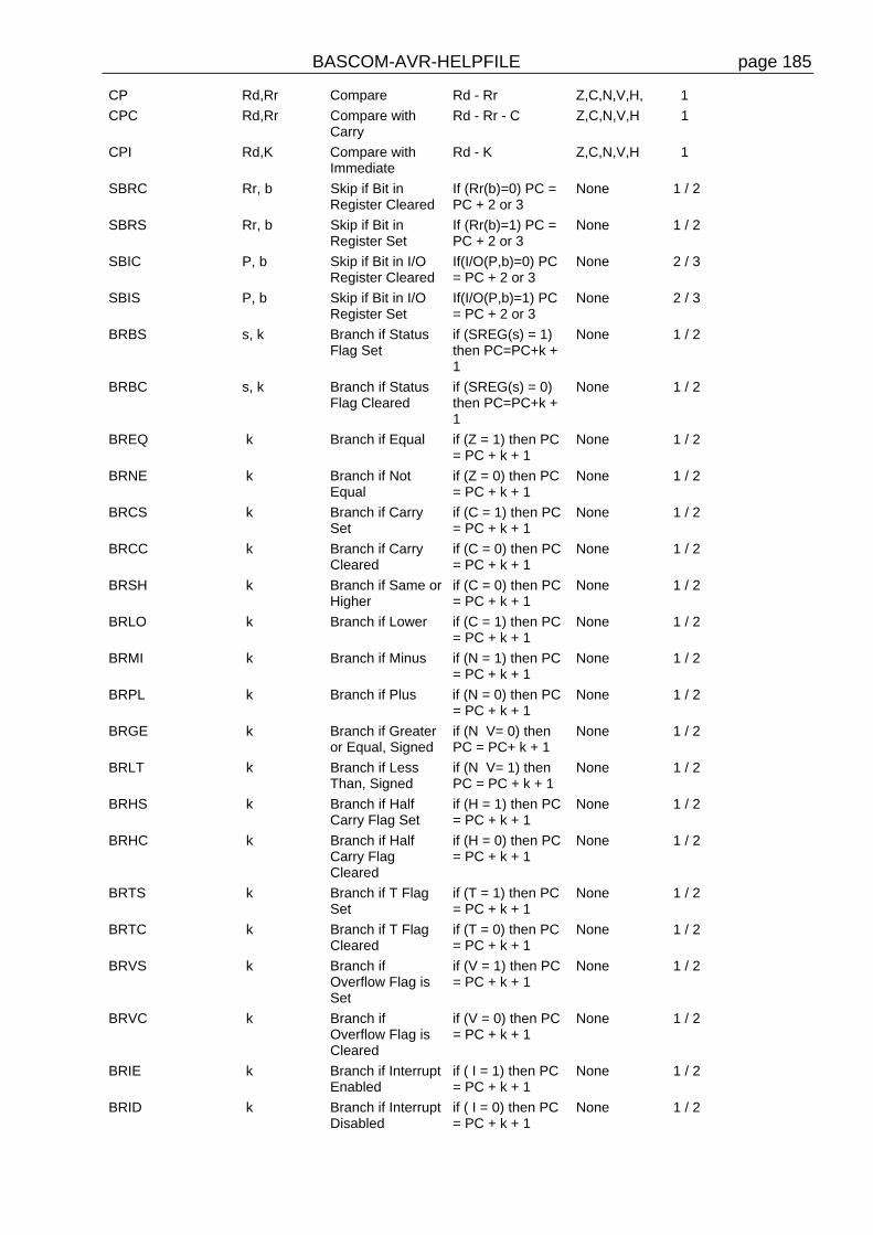
BASCOM-AVR-HELPFILE page 185
CP Rd,Rr Compare Rd - Rr Z,C,N,V,H, 1
CPC Rd,Rr Compare withCarry
Rd - Rr - C Z,C,N,V,H 1
CPI Rd,K Compare withImmediate
Rd - K Z,C,N,V,H 1
SBRC Rr, b Skip if Bit inRegister Cleared
If (Rr(b)=0) PC =PC + 2 or 3
None 1 / 2
SBRS Rr, b Skip if Bit inRegister Set
If (Rr(b)=1) PC =PC + 2 or 3
None 1 / 2
SBIC P, b Skip if Bit in I/ORegister Cleared
If(I/O(P,b)=0) PC= PC + 2 or 3
None 2 / 3
SBIS P, b Skip if Bit in I/ORegister Set
If(I/O(P,b)=1) PC= PC + 2 or 3
None 2 / 3
BRBS s, k Branch if StatusFlag Set
if (SREG(s) = 1)then PC=PC+k +1
None 1 / 2
BRBC s, k Branch if StatusFlag Cleared
if (SREG(s) = 0)then PC=PC+k +1
None 1 / 2
BREQ k Branch if Equal if (Z = 1) then PC= PC + k + 1
None 1 / 2
BRNE k Branch if NotEqual
if (Z = 0) then PC= PC + k + 1
None 1 / 2
BRCS k Branch if CarrySet
if (C = 1) then PC= PC + k + 1
None 1 / 2
BRCC k Branch if CarryCleared
if (C = 0) then PC= PC + k + 1
None 1 / 2
BRSH k Branch if Same orHigher
if (C = 0) then PC= PC + k + 1
None 1 / 2
BRLO k Branch if Lower if (C = 1) then PC= PC + k + 1
None 1 / 2
BRMI k Branch if Minus if (N = 1) then PC= PC + k + 1
None 1 / 2
BRPL k Branch if Plus if (N = 0) then PC= PC + k + 1
None 1 / 2
BRGE k Branch if Greateror Equal, Signed
if (N V= 0) thenPC = PC+ k + 1
None 1 / 2
BRLT k Branch if LessThan, Signed
if (N V= 1) thenPC = PC + k + 1
None 1 / 2
BRHS k Branch if HalfCarry Flag Set
if (H = 1) then PC= PC + k + 1
None 1 / 2
BRHC k Branch if HalfCarry FlagCleared
if (H = 0) then PC= PC + k + 1
None 1 / 2
BRTS k Branch if T FlagSet
if (T = 1) then PC= PC + k + 1
None 1 / 2
BRTC k Branch if T FlagCleared
if (T = 0) then PC= PC + k + 1
None 1 / 2
BRVS k Branch ifOverflow Flag isSet
if (V = 1) then PC= PC + k + 1
None 1 / 2
BRVC k Branch ifOverflow Flag isCleared
if (V = 0) then PC= PC + k + 1
None 1 / 2
BRIE k Branch if InterruptEnabled
if ( I = 1) then PC= PC + k + 1
None 1 / 2
BRID k Branch if InterruptDisabled
if ( I = 0) then PC= PC + k + 1
None 1 / 2

BASCOM-AVR-HELPFILE page 186
DATA TRANSFERINSTRUCTIONS
MOV Rd, Rr Copy Register Rd = Rr None 1
LDI Rd, K Load Immediate Rd = K None 1
LDS Rd, k Load Direct Rd = (k) None 3
LD Rd, X Load Indirect Rd = (X) None 2
LD Rd, X+ Load Indirect andPost-Increment
Rd = (X), X = X +1
None 2
LD Rd, -X Load Indirect andPre-Decrement
X = X - 1, Rd =(X) None 2
LD Rd, Y Load Indirect Rd = (Y) None 2
LD Rd, Y+ Load Indirect andPost-Increment
Rd = (Y), Y = Y +1
None 2
LD Rd, -Y Load Indirect andPre-Decrement
Y = Y - 1, Rd = (Y) None 2
LDD Rd,Y+q Load Indirect withDisplacement
Rd = (Y + q) None 2
LD Rd, Z Load Indirect Rd = (Z) None 2
LD Rd, Z+ Load Indirect andPost-Increment
Rd = (Z), Z = Z+1 None 2
LD Rd, -Z Load Indirect andPre-Decrement
Z = Z - 1, Rd = (Z) None 2
LDD Rd, Z+q Load Indirect withDisplacement
Rd = (Z + q) None 2
STS k, Rr Store Direct (k) = Rr None 3
ST X, Rr Store Indirect (X) = Rr None 2
ST X+, Rr Store Indirect andPost-Increment
(X) = Rr, X = X + 1 None 2
ST -X, Rr Store Indirect andPre-Decrement
X = X - 1, (X) = Rr None 2
ST Y, Rr Store Indirect (Y) = Rr None 2
ST Y+, Rr Store Indirect andPost-Increment
(Y) = Rr, Y = Y + 1 None 2
ST -Y, Rr Store Indirect andPre-Decrement
Y = Y - 1, (Y) = Rr None 2
STD Y+q,Rr Store Indirect withDisplacement
(Y + q) = Rr None 2
ST Z, Rr Store Indirect (Z) = Rr None 2
ST Z+, Rr Store Indirect andPost-Increment
(Z) = Rr, Z = Z + 1 None 2
ST -Z, Rr Store Indirect andPre-Decrement
Z = Z - 1, (Z) = Rr None 2
STD Z+q,Rr Store Indirect withDisplacement
(Z + q) = Rr None 2
LPM Load ProgramMemory
R0 =(Z) None 3
IN Rd, P In Port Rd = P None 1
OUT P, Rr Out Port P = Rr None 1
PUSH Rr Push Register onStack
STACK = Rr None 2
POP Rd Pop Register fromStack
Rd = STACK None 2
BIT AND BIT-TESTINSTRUCTIONS
LSL Rd Logical Shift Left Rd(n+1)=Rd(n),Rd(0)=0,C=Rd(7)
Z,C,N,V,H 1
LSR Rd Logical Shift Right Rd(n) = Rd(n+1), Z,C,N,V 1
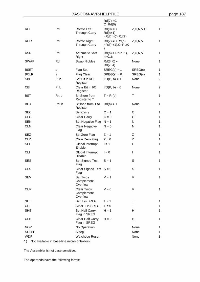
BASCOM-AVR-HELPFILE page 187
Rd(7) =0,C=Rd(0)
ROL Rd Rotate LeftThrough Carry
Rd(0) =C,Rd(n+1)=Rd(n),C=Rd(7)
Z,C,N,V,H 1
ROR Rd Rotate RightThrough Carry
Rd(7) =C,Rd(n)=Rd(n+1),C¬Rd(0)
Z,C,N,V 1
ASR Rd Arithmetic ShiftRight
Rd(n) = Rd(n+1),n=0..6
Z,C,N,V 1
SWAP Rd Swap Nibbles Rd(3..0) «Rd(7..4)
None 1
BSET s Flag Set SREG(s) = 1 SREG(s) 1
BCLR s Flag Clear SREG(s) = 0 SREG(s) 1
SBI P, b Set Bit in I/ORegister
I/O(P, b) = 1 None 2
CBI P, b Clear Bit in I/ORegister
I/O(P, b) = 0 None 2
BST Rr, b Bit Store fromRegister to T
T = Rr(b) T 1
BLD Rd, b Bit load from T toRegister
Rd(b) = T None 1
SEC Set Carry C = 1 C 1
CLC Clear Carry C = 0 C 1
SEN Set Negative Flag N = 1 N 1
CLN Clear NegativeFlag
N = 0 N 1
SEZ Set Zero Flag Z = 1 Z 1
CLZ Clear Zero Flag Z = 0 Z 1
SEI Global InterruptEnable
I = 1 I 1
CLI Global InterruptDisable
I = 0 I 1
SES Set Signed TestFlag
S = 1 S 1
CLS Clear Signed TestFlag
S = 0 S 1
SEV Set TwosComplementOverflow
V = 1 V 1
CLV Clear TwosComplementOverflow
V = 0 V 1
SET Set T in SREG T = 1 T 1
CLT Clear T in SREG T = 0 T 1
SHE Set Half CarryFlag in SREG
H = 1 H 1
CLH Clear Half CarryFlag in SREG
H = 0 H 1
NOP No Operation None 1
SLEEP Sleep None 1
WDR Watchdog Reset None 1
* ) Not available in base-line microcontrollers
The Assembler is not case sensitive.
The operands have the following forms:

BASCOM-AVR-HELPFILE page 188
Rd: R0-R31 or R16-R31 (depending on instruction)
Rr: R0-R31
b: Constant (0-7)
s: Constant (0-7)
P: Constant (0-31/63)
K: Constant (0-255)
k: Constant, value range depending on instruction.
q: Constant (0-63)
Rdl: R24, R26, R28, R30. For ADIW and SBIW instructions
Mixing ASM and BASICBASCOM allows you to mix BASIC with assembly.This can be very useful in some situations when you need full control of the generated code.
Almost all assembly mnemonics are recognized by the compiler. The exceptions are : SUB,SWAP and OUT. These are BASIC reserved words and have priority over the ASMmnemonics. To use these mnemonics precede them with the ! - sign.For example :
Dim a As Byte At &H60 'A is stored at location &H60Ldi R27 , $00 'Load R27 with MSB of addressLdi R26 , $60 'Load R26 with LSB of addressLd R1, X 'load memory location $60 into R1!SWAP R1 'swap nibbles
As you can see the SWAP mnemonic is preceded by a ! sign.
Another option is to use the assembler block directives:$ASM
Ldi R27 , $00 'Load R27 with MSB of addressLdi R26 , $60 'Load R26 with LSB of addressLd R1, X 'load memory location $60 into R1SWAP R1 'swap nibbles
$END ASM
A special assembler helper function is provided to load the address into the register X or Z. Ycan may not be used because it is used as the soft stack pointer.
Dim A As Byte 'reserve spaceLOADADR a, X 'load address of variable named A into register pair X
This has the same effect as :Ldi R26 , $60 'for example !Ldi R27, $00 'for example !
Some registers are used by BASCOMR4 and R5 are used to point to the stack frame or the temp data storage

BASCOM-AVR-HELPFILE page 189
R6 is used to store some bit variables:R6 bit 0 = flag for int/word conversionR6 bit 1 = temp bit space used for swapping bitsR6 bit 2 = error bit (ERR variable)R6 bit 3 = show/noshow flag when using INPUT statement
R8 and R9 are used as a data pointer for the READ statement.
All other registers are used depending on the used statements.
To Load the address of a variable you must enclose them in brackets.Dim B As BitLds R16, {B} 'will replace {B} with the address of variable B
To refer to the bitnumber you must precede the variable name by BIT.Sbrs R16 , BIT.B 'notice the point!Since this was the first dimensioned bit the bitnumber is 7. Bits are stored in bytes and the firstdimensioned bit goes in the LS bit.
To load an address of a label you must use :LDI ZL, , Low(lbl * 2)LDI ZH , High(lbl * 2)Where ZL = R30 and may be R24, R26, R28 or R30And ZH = R31 and may be R25, R27, R29 or R31.These are so called register pairs that form a pointer.Because the AVR stores the object code in Word format the * 2 is used.LBL is the name of your label.
Atmel mnemonics must be used to program in assembly.You can download the pdf from www.atmel.com that shows how the different mnemonics areused.Some points of attention :* All instructions that use a constant as a parameter only work on the upper 16 registers (r16-r31)So LDI R15,12 WILL NOT WORK
* The instruction SBR register, Kwill work with K from 0-255. So you can set multiple bits!
The instruction SBI port, K will work with K from 0-7 and will set only ONE bit in a IO-portregister.
The same applies to the CBR and CBI instructions.
How to make your own libraries and call them from BASIC?The files for this sample can be found as libdemo.bas in the SAMPLES dir and as mylib.lib inthe LIB dir.
First determine the used parameters and their type.Also consider if they are passed by reference or by value
For example the sub test has two parameters: x which is passed by value (copy of the variable) y which is passed by reference(address of the variable)

BASCOM-AVR-HELPFILE page 190
In both cases the addres of the variable is put on the soft stack which is indexed by the Y pointer.
The first parameter (or a copy) is put on the soft stack firstTo refer to the address you must use: ldd r26 , y + 0 ldd r27 , y + 1This loads the address into pointer X
The second parameter will also be put on the softstack so :The reference for the x variable will be changed :
To refer to the address of x you must use: ldd r26 , y + 2 ldd r27 , y + 3
To refer to the last parameter y you must use ldd r26 , y + 0 ldd r27 , y + 1
Write the sub routine as you are used too but include the name within brackets []
[test]test: ldd r26,y+2 ; load address of x ldd r27,y+3 ld r24,x ; get value into r24 inc r24 ; value + 1 st x,r24 ; put back ldd r26,y+0 ; address of y ldd r27,y+1 st x,r24 ; store ret ; ready[end]
To write a function goes the same way.A function returns a result so a function has one additional parameter.It is generated automatic and it has the name of the function.This way you can assign the result to the function nameFor example:
Declare Function Test(byval x as byte , y as byte) as byteA virtual variable will be created with the name of the function in this case test .It will be pushed on the softstack with the Y-pointer.To reference to the result or name of the function (test) the address will be: y + 0 and y + 1The first variable x will bring that to y + 2 and y + 3And the third variable will cause that 3 parameters are saved on the soft stackTo reference to test you must use : ldd r26 , y + 4 ldd r27 , y + 5
To reference to x ldd r26 , y + 2 ldd r27 , y + 3

BASCOM-AVR-HELPFILE page 191
And to reference y ldd r26 , y + 0 ldd r27 , y + 1
When you use exit sub or exit function you also need to provide an additional label. It startswith sub_ and must be completed with the function / sub routine name. In our example:sub_test:
When you use local variables thing become more complicated.Each local variable address will be put on the soft stack tooWhen you use 1 local variable its address will become ldd r26, y+0 ldd r27 , y + 1All other parameters must be increased with 2 so the reference to y variable changes from ldd r26 , y + 0 to ldd r26 , y + 2 ldd r27 , y + 1 to ldd r27 , y + 3And of course also for the other variables.
When you have more local variables just add 2 for each.Finally you save the file as a .lib fileUse the library manager to compile it into the lbx format.The declare sub / function must be in the program where you use the sub / function.
The following is a copy of the libdemo.bas file :
'define the used library$lib "mylib.lib"
'also define the used routines$external Test
'this is needed so the parameters will be placed correct on the stackDeclare Sub Test(byval X As Byte , Y As Byte)
'reserve some spaceDim Z As Byte
'call our own sub routineCall Test(1 , Z)
'z will be 2 in the used exampleEnd
This chapter is not intended to learn you ASM programming. But when you find a topic ismissing to interface BASCOM with ASM send me an email.
Sample Electronics cable programmer
The simple cable programmer was submitted by Sample Electronics.They produce professional programmers too. This simple programmer you can make yourselfwithin a 10 minutes.
What you need is a DB25 centronics male connector, a flatcable and a connector that can beconnected to the target MCU board.
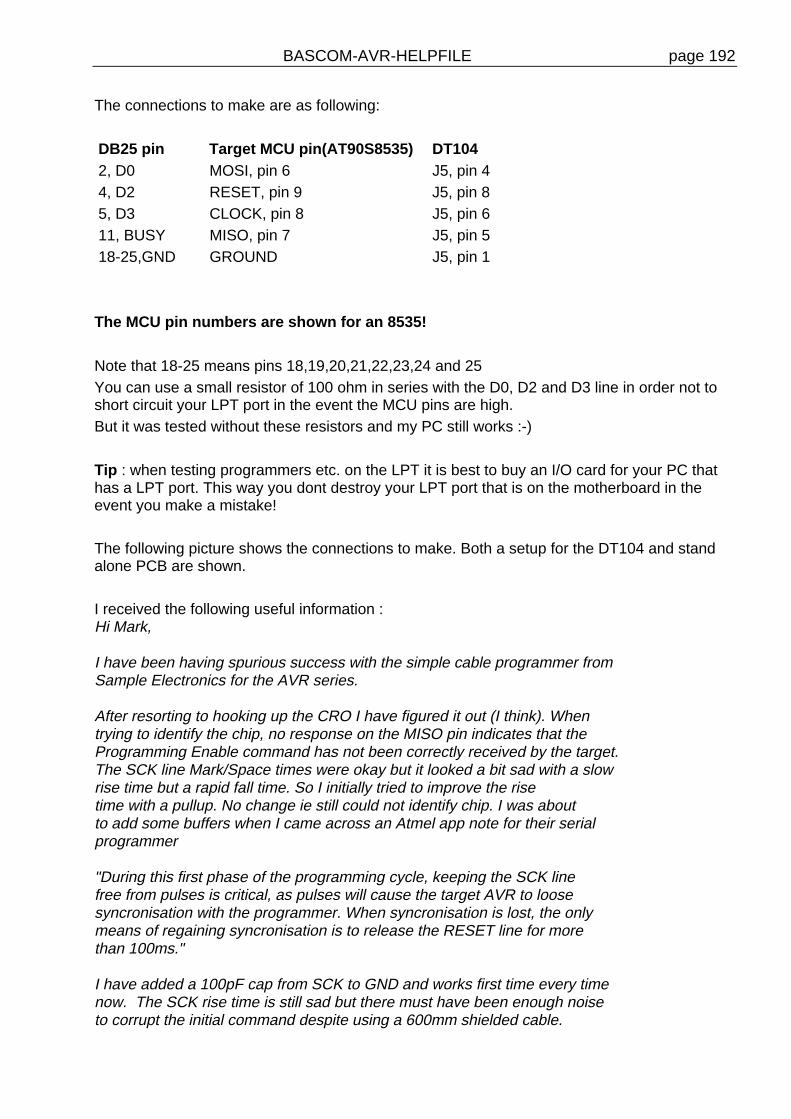
BASCOM-AVR-HELPFILE page 192
The connections to make are as following:
DB25 pin Target MCU pin(AT90S8535) DT1042, D0 MOSI, pin 6 J5, pin 44, D2 RESET, pin 9 J5, pin 85, D3 CLOCK, pin 8 J5, pin 611, BUSY MISO, pin 7 J5, pin 518-25,GND GROUND J5, pin 1
The MCU pin numbers are shown for an 8535!
Note that 18-25 means pins 18,19,20,21,22,23,24 and 25You can use a small resistor of 100 ohm in series with the D0, D2 and D3 line in order not toshort circuit your LPT port in the event the MCU pins are high.But it was tested without these resistors and my PC still works :-)
Tip : when testing programmers etc. on the LPT it is best to buy an I/O card for your PC thathas a LPT port. This way you dont destroy your LPT port that is on the motherboard in theevent you make a mistake!
The following picture shows the connections to make. Both a setup for the DT104 and standalone PCB are shown.
I received the following useful information :Hi Mark,
I have been having spurious success with the simple cable programmer fromSample Electronics for the AVR series.
After resorting to hooking up the CRO I have figured it out (I think). Whentrying to identify the chip, no response on the MISO pin indicates that theProgramming Enable command has not been correctly received by the target.The SCK line Mark/Space times were okay but it looked a bit sad with a slowrise time but a rapid fall time. So I initially tried to improve the risetime with a pullup. No change ie still could not identify chip. I was aboutto add some buffers when I came across an Atmel app note for their serialprogrammer
"During this first phase of the programming cycle, keeping the SCK linefree from pulses is critical, as pulses will cause the target AVR to loosesyncronisation with the programmer. When syncronisation is lost, the onlymeans of regaining syncronisation is to release the RESET line for morethan 100ms."
I have added a 100pF cap from SCK to GND and works first time every timenow. The SCK rise time is still sad but there must have been enough noiseto corrupt the initial command despite using a 600mm shielded cable.

BASCOM-AVR-HELPFILE page 193
This may be useful to your users.
Regards,
Mark Hayne
SPIMOVE
ActionSends and receives value or a variable to the SPI-bus.
Syntaxvar = SPIMOVE( byte )
Remarksvar The variable that is assigned with the received byte from the SPI-bus.byte The variable or constant whose content must be send to the SPI-bus.
See alsoSPIIN »page 169 , SPIINIT »page 170 , CONFIG SPI »page 96
ExampleCONFIG SPI = SOFT, DIN = PINB.0, DOUT = PORTB.1, SS=PORTB.2, CLOCK = PORTB.3SPIINITDim a(10) as Byte , X As ByteSPIOUT a(1) , 5 'send 5 bytes
SPIOUT X , 1 'send 1 byte
A(1) = SpiMove(5) ' move 5 to SPI and store result in a(1)
End

BASCOM-AVR-HELPFILE page 194
INSTR
Action
Returns the position of a substring in a string.
Syntax
var = INSTR( start , string , substr )
var = INSTR( string , substr )
RemarksVar Numeric variable that will be assigned with the position of the
substring in the string. Returns 0 when the substring is notfound.
Start An optional numeric parameter that can be assigned with thefirst position where must be searched in the string. By default(when not used) the whole string is searched starting fromposition 1.
String The string to search.Substr The search string.
No constant can be used for string it must be a string.Only substr can be either a string or a constant.
See also
ExampleDim S As String * 10 , Z as String * 5
Dim bP as Byte
s = "This is a test"
Z = "is"
bP = Instr(s,z) : Print bP 'should print 3
bP = Instr(4,s,z) : Print bP 'should print 6
End
RND
ActionReturns a random number.
Syntaxvar = RND( limit )
Remarkslimit Word that limits the returned random number.var The variable that is assigned with the random number.
The RND() function returns an Integer/Word and needs an internal storage of 2 bytes.(___RSEED). Each new call to Rnd() will give a new positive random number.

BASCOM-AVR-HELPFILE page 195
See also
ExampleDim I As IntegerDo I = Rnd(100) 'get random number from 0-99 Print I Wait 1LoopEnd
GETATKBD
ActionReads a key from a PC AT keyboard.
Syntaxvar = GETATKBD()
Remarksvar The variable that is assigned with the key read from the
keyboard.It may be a byte or a string variable.When no key is pressed a 0 will be returned.
The GETAKBD() function needs 2 input pins and a translation table for the keys. You can readmore about this at the CONFIG KEYBOARD »page 197 compiler directive.
See alsoCONFIG KEYBOARD
Example
'-------------------------------------------------------------------------' PC AT-KEYBOARD Sample' (c) 2000 MCS Electronics'-------------------------------------------------------------------------'For this example :'connect PC AT keyboard clock to PIND.2 on the 8535'connect PC AT keyboard data to PIND.4 on the 8535'The GetATKBD() function does not use an interrupt.'But it waits until a key was pressed!
'configure the pins to use for the clock and data'can be any pin that can serve as an input'Keydata is the label of the key translation tableConfig Keyboard = Pind.2 , Data = Pind.4 , Keydata = Keydata
'Dim some used variablesDim S As String * 12Dim B As Byte
'In this example we use SERIAL(COM) INPUT redirection$serialinput = Kbdinput
'Show the program is runningPrint "hello"

BASCOM-AVR-HELPFILE page 196
Do 'The following code is remarked but show how to use the GetATKBD() function ' B = Getatkbd() 'get a byte and store it into byte variable 'When no real key is pressed the result is 0 'So test if the result was > 0 ' If B > 0 Then ' Print B ; Chr(b) ' End If
'The purpose of this sample was how to use a PC AT keyboard 'The input that normally comes from the serial port is redirected to the 'external keyboard so you use it to type Input "Name " , S 'and show the result Print SLoopEnd
'Since we do a redirection we call the routine from the redirection routine'Kbdinput: 'we come here when input is required from the COM port 'So we pass the key into R24 with the GetATkbd function' We need some ASM code to save the registers used by the function$asm push r16 ; save used register push r25 push r26 push r27
Kbdinput1: rCall _getatkbd ; call the function tst r24 ; check for zero breq Kbdinput1 ; yes so try again pop r27 ; we got a valid key so restore registers pop r26 pop r25 pop r16 $end Asm 'just returnReturn
'The tricky part is that you MUST include a normal call to the routine'otherwise you get an error'This is no clean solution and will be changedB = Getatkbd()
'This is the key translation table
Keydata:'normal keys lower caseData 0 , 0 , 0 , 0 , 0 , 0 , 0 , 0 , 0 , 0 , 0 , 0 , 0 , 0 , &H5E , 0Data 0 , 0 , 0 , 0 , 0 , 113 , 49 , 0 , 0 , 0 , 122 , 115 , 97 , 119 , 50 , 0Data 0 , 99 , 120 , 100 , 101 , 52 , 51 , 0 , 0 , 32 , 118 , 102 , 116 , 114 , 53 , 0Data 0 , 110 , 98 , 104 , 103 , 121 , 54 , 7 , 8 , 44 , 109 , 106 , 117 , 55 , 56 , 0Data 0 , 44 , 107 , 105 , 111 , 48 , 57 , 0 , 0 , 46 , 45 , 108 , 48 , 112 , 43 , 0Data 0 , 0 , 0 , 0 , 0 , 92 , 0 , 0 , 0 , 0 , 13 , 0 , 0 , 92 , 0 , 0Data 0 , 60 , 0 , 0 , 0 , 0 , 8 , 0 , 0 , 49 , 0 , 52 , 55 , 0 , 0 , 0Data 48 , 44 , 50 , 53 , 54 , 56 , 0 , 0 , 0 , 43 , 51 , 45 , 42 , 57 , 0 , 0
'shifted keys UPPER caseData 0 , 0 , 0 , 0 , 0 , 0 , 0 , 0 , 0 , 0 , 0 , 0 , 0 , 0 , 0 , 0Data 0 , 0 , 0 , 0 , 0 , 81 , 33 , 0 , 0 , 0 , 90 , 83 , 65 , 87 , 34 , 0Data 0 , 67 , 88 , 68 , 69 , 0 , 35 , 0 , 0 , 32 , 86 , 70 , 84 , 82 , 37 , 0Data 0 , 78 , 66 , 72 , 71 , 89 , 38 , 0 , 0 , 76 , 77 , 74 , 85 , 47 , 40 , 0Data 0 , 59 , 75 , 73 , 79 , 61 , 41 , 0 , 0 , 58 , 95 , 76 , 48 , 80 , 63 , 0Data 0 , 0 , 0 , 0 , 0 , 96 , 0 , 0 , 0 , 0 , 13 , 94 , 0 , 42 , 0 , 0Data 0 , 62 , 0 , 0 , 0 , 8 , 0 , 0 , 49 , 0 , 52 , 55 , 0 , 0 , 0 , 0Data 48 , 44 , 50 , 53 , 54 , 56 , 0 , 0 , 0 , 43 , 51 , 45 , 42 , 57 , 0 , 0

BASCOM-AVR-HELPFILE page 197
CONFIG KEYBOARD
ActionConfigure the GETATKBD() function and tell which port pins to use.
SyntaxCONFIG KEYBOARD = PINX.y , DATA = PINX.y , KEYDATA = table
RemarksKEYBOARD The PIN that serves as the CLOCK input.DATA The PIN that serves as the DATA input.KEYDATA The label where the key translation can be found.
The AT keyboard returns scan codes instead of normal ASCIIcodes. So a translation table s needed to convert the keys.BASCOM allows the use of shifted keys too. Special keys likefunction keys are not supported.
The AT keyboard can be connected with only 4 wires : clock,data, gnd and vcc.Some info is displayed below. This is copied from an Atmel datasheet.The INT0 or INT1 shown can be in fact any pin that can serve as an INPUT pin.The application note from Atmel works in interrupt mode. For BASCOM I rewrote the code sothat no interrupt is needed/used.
See alsoGETATKBD »page 195

BASCOM-AVR-HELPFILE page 198
KITSRUS ProgrammerThe K122 is a KIT from KITSRUS. (www.kitsrus.com)The programmer supports the most popular 20 and 40 pins AVR chips.On the Programmer Options tab you must select this programmer and the COM port it isconnected to.On the Monitor Options tab you must specify the upload speed of 9600, Monitor delay of 1 andPrefix delay 1.When you press the Program button the Terminal Emulator screen will pop up:
A special toolbar is now visible.You must press the Program enable button
to enable theprogrammer.When you enable the programmer the right baud rate will be set.

BASCOM-AVR-HELPFILE page 199
When you are finished you must press the Enable button again to disable it.This way you can have a micro connected to your COM port that works with a different BAUDrate.There is an option to select between FLASH and EEPROM.The prompt will show the current mode which is set to FLASH by default.
The buttons on the toolbar allow you to :ERASE, PROGRAM, VERIFY, DUMP and set the LOCK BITS.When DUMP is selected you will be asked for a file name.When the DUMP is ready you must CLOSE the LOGFILE where the data is stored. This canbe done to select the CLOSE LOGFILE option form the menu.
PULSEOUT
ActionGenerates a pulse on a pin of a PORT of specified period in 1uS units for 4 MHz.
SyntaxPULSEOUT PORT , PIN , PERIOD
RemarksPORT Name of the PORT. PORTB for examplePIN Variable or constant with the pin number (0-7).PERIOD Number of periods the.
The pulse is generated by toggling the pin twice, thus the initial state of the pin determines thepolarity.The PIN must be configured as an output pin before this statement can be used.
See also
ExampleDim A As ByteCONFIG PORTB = OUTPUT 'PORTB all output pinsPORTB = 0 'all pins 0DOFOR A = 0 TO 7 PULSEOUT PORTB , A, 60000 'generate pulse WAITMS 250 'wait a bitNEXTLOOP 'loop for ever

BASCOM-AVR-HELPFILE page 200
Tools LIB ManagerWith this option the following window will appear:
The Libraries are shown in the left pane. When you select one the routines that are in thelibrary will be shown in the right pane.
By selecting a routine you can DELETE it.By clicking the ADD button you can add an ASM routine to the library.
The COMPILE button works only in the commercial edition. When you click it the selectedlibrary will be compiled into a LBX file.
A compiled LBX file does not contain comment and a huge amount of mnemonics is compiledinto object code. This object code is inserted at compile time of the main BASIC program. Andthis results in faster compilation.
The DEMO version comes with the compiled MCS.LIB file and is named MCS.LBX. The ASMsource is included with the commercial edition.
With the ability to create LBX files you can create add on packages for BASCOM and sellthem. The LBX files could be distributed for free and the ASM source could be sold.
Two examples you will find soon :- A library to read IDE harddisks.- MODBUS slave routines
LinksHere are some links to software or information that might be useful:
A WINZIP clone to ZIP and UNZIP softwarehttp://ipsoft.cjb.net/

BASCOM-AVR-HELPFILE page 201
Adding XRAMSome AVR chips like the 8515 for example can be extended with external RAM memory.
On these chips Port A serves as a Multiplexed Address/Data input/output.Port C also serves as Address output when using external SRAM.
The maximum size of an XRAM chip can be 64Kbytes.
The STK200 has a 62256 ram chip (32K x 8 bit).
Here is some info from the BASCOM userlist :
If you do go with the external ram , be careful of the clock speed.Using a 4Mhz crystal , will require a Sram with 70nS access timeor better. Also the data latch (74HC573) will have to be from a fasterfamily such as a 74FHC573 if you go beyond 4Mhz.
You can also program an extra wait state, which slow it down a bit.
Here you find a pdf file showing STK200 schematics:http://www.avr-forum.com/Stk200_schematic.pdf
If you use 32kRAM, then connect the /CS signal to A15 which giveto the range of &H0000 to &H7FFF, if you use a 64kRAM, thentie /CS to GND, so the RAM is selected all the time.
$SIM
ActionInstruct the compiler to generate empty wait loops for the WAIT and WAITMS statements.This to allow faster simulation.
Syntax$SIM
RemarksSimulation of a WAIT statement can take along time especially when memory view windowsare opened.The $SIM compiler directive instructs the compiler to not generate code for WAITMS andWAIT. This will of course allows faster simulation.When your application is ready you must remark the $SIM directive or otherwise the WAIT andWAITMS statements will not work as expected.
See also
ASM
Example$SIMDo Wait 1Loop

BASCOM-AVR-HELPFILE page 202
Newbie problemsWhen you are using the AVR without knowledge of the architecture you can experience someproblems.
-I can not set a pin high or low-I can not read the input on a pinThe AVR has 3 registers for each port. A port normally consist of 8 pins. A port is named witha letter from A-F.All parts have PORTB.When you want to set a single pin high or low you can use the SET and RESET statements.But before you use them the AVR chip must know in which direction you are going to use thepins.Therefore there is a register named DDRx for each port. In our sample it is named DDRB.When you write a 0 to the bit position of the pin you can use the pin as an input. When youwrite a 1 you can use it as output.
After the direction bit is set you must use either the PORTx register to set a logic level or thePINx register to READ a pin level.Yes the third register is the PINx register. In our sample PINB.
For example :DDRB = &B1111_0000 ' upper nibble is output, lower nibble is inputSET PORTB.7 'will set the MS bit to +5VRESET PORTB.7 'will set MS bit to 0 V
To read a pin :Print PINB.0 'will read LS bit and send it to the RS-232
You may also read from PORTx but it will return the value that was last written to it.
To read or write whole bytes use :PORTB = 0 'write 0 to register making all pins lowPRINT PINB 'print input on pins
FORMAT
ActionFormats a numeric string.
Syntaxtarget = Format(source, "mask")
Remarkstarget The string that is assigned with the formatted string.source The source string that holds the number.mask The mask for formatting the string.
When spaces are in the mask, leading spaces will be added when thelength of the mask is longer than the source string." " '8 spaces when source is "123" it will be " 123".When a + is in the mask (after the spaces) a leading + will be assignedwhen the number does not start with the - sign."+" with number "123" will be "+123".When zero's are provided in the mask, the string will be filled with leadingzero;s.

BASCOM-AVR-HELPFILE page 203
" +00000" with 123 will be " +00123"An optional decimal point can be inserted too:"000.00" will format the number 123 to "001.23"Combinations can be made but the order must be : spaces, + , 0 anoptional point and zero's.
See also
Example'--------------------------------------------------------------' (c) 2000 MCS Electronics'--------------------------------------------------------------Dim S As String * 10Dim I As Integer
S = "12345"S = Format(s , "+")Print S
S = "123"S = Format(s , "00000")Print S
S = "12345"S = Format(s , "000.00")Print S
S = "12345"S = Format(s , " +000.00")Print SEnd
CHECKSUM
ActionReturns a checksum of a string.
SyntaxPRINT Checksum( var)b = Checksum( var)
RemarksVar A string variable.b A numeric variable that is assigned with
the checksum.
The checksum is computed by counting all the bytes of the string variable.Checksums are often used with serial communication.
See also
ExampleDim s As String * 10 'dim variables = "test" 'assign variablePrint checksum(s) 'print value (192)End

BASCOM-AVR-HELPFILE page 204
READMAGCARD
ActionRead data from a magnetic card.
SyntaxReadmagcard var , count , 5|7
Remarksvar A byte array the receives the data.count A byte variable that returns the number of bytes read.5|7 A numeric constant that specifies if 5 or 7 bit coding is used.
There can be 3 tracks on a magnetic card.Track 1 strores the data in 7 bit including the parity bit. This is handy to store alpha numericdata.On track 2 and 3 the data is tored with 5 bit coding.The ReadMagCard routine works with ISO7811-2 5 and 7 bit decoding.The returned numbers for 5 bit coding are:Returned number ISO characterT0 01 12 23 34 45 56 67 78 89 910 hardware control11 start byte12 hardware control13 separator14 hardware control15 stop byte
Example'------------------------------------------------------------------' (c) 2000 MCS Electronics' MAGCARD.BAS' This example show you how to read data from a magnetic card'It was tested on the DT006 SimmStick.'------------------------------------------------------------------'[reserve somespace]Dim Ar(100) As Byte , B As Byte , A As Byte
'the magnetic card reader has 5 wires'red - connect to +5V

BASCOM-AVR-HELPFILE page 205
'black - connect to GND'yellow - Card inserted signal CS'green - clock'blue - data
'You can find out for your reader which wires you have to use by connecting +5V'And moving the card through the reader. CS gets low, the clock gives a clock pulseof equal pulses'and the data varies'I have little knowledge about these cards and please dont contact me about magnecticreaders'It is important however that you pull the card from the right direction as I wasdoing it wrong for'some time :-)'On the DT006 remove all the jumpers that are connected to the LEDs
'[We use ALIAS to specify the pins and PIN register]_mport Alias Pinb 'all pins are connectedto PINB_mdata Alias 0 'data line (blue)PORTB.0_mcs Alias 1 'CS line (yellow)PORTB.1_mclock Alias 2 'clock line (green)PORTB.2
Config Portb = Input 'we only need bit 0,1and 2 for inputPortb = 255 'make them high
Do Print "Insert magnetic card" 'print a message Readmagcard Ar(1) , B , 5 'read the data Print B ; " bytes received" For A = 1 To B Print Ar(a); 'print the bytes Next PrintLoop
'By sepcifying 7 instead of 5 you can read 7 bit data
Sept 2000 Ma

BASCOM-AVR-HELPFILE page 206
—$—
$ASM 63$BAUD 64$CRYSTAL 64$DATA 65$DEFAULT 66$EEPROM 67$EXTERNAL 68$INCLUDE 68$LCD 69$LCDPUTCTRL 69$LCDPUTDATA 70$LCDRS 71$LIB 72$REGFILE 73$SERIALINPUT 74$SERIALINPUT2LCD 75$SERIALOUTPUT 76$SIM 201$XRAMSIZE 76$XRAMSTART 77
—1—
1WREAD 791WRESET 781WWRITE 80
—A—
A word of thank 12ABS 81Adding XRAM 200Additional Hardware 46ALIAS 81ASC 82Assembler mnemonics 183Attaching an LCD Display 54AVR Internal Hardware 46AVR Internal Hardware Port B 51AVR Internal Hardware Port D 52AVR Internal Hardware TIMER1 50AVR Internal Hardware Watchdog timer 51AVR Internal Registers 47
—B—
BASCOM Editor Keys 40BAUD 83BCD 83BITWAIT 84BYVAL 85
—C—
CALL 86CASE 163Changes compared to BASCOM-8051 180CHECKSUM 203CHR 87CLOCKDIVISION 88
CLOSE 89CLS 88CONFIG 90CONFIG 1WIRE 91CONFIG DEBOUNCE 91CONFIG I2CDELAY 92CONFIG INTx 92CONFIG KBD 93CONFIG KEYBOARD 196CONFIG LCD 93CONFIG LCDBUS 94CONFIG LCDMODE 94CONFIG LCDPIN 95CONFIG PORT 102CONFIG SCL 96CONFIG SDA 95CONFIG SPI 96CONFIG TIMER0 97CONFIG TIMER1 99CONFIG WAITSUART 101CONFIG WATCHDOG 102CONST 116Constants 42COUNTER0 and COUNTER1 104CPEEK 105CRYSTAL 106CURSOR 107
—D—
DATA 107DEBOUNCE 109DECLARE FUNCTION 111DECLARE SUB 112DECR 110DEFBIT 113DEFINT 113DEFLCDCHAR 113DEFLNG 113DEFSNG 113DEFWORD 113DEFxxx 113DELAY 114Developing Order 42DIM 114DISABLE 116DISPLAY 118DO 118DOWNTO 121
—E—
Edit Copy 17Edit Cut 17Edit Find 17Edit Find Next 17Edit Goto 18Edit Goto Bookmark 18Edit Indent Block 18Edit Paste 17Edit Redo 17Edit Replace 17Edit Toggle Bookmark 18Edit Undo 17Edit Unindent Block 18ELSE 119; 134ENABLE 119END 120

BASCOM-AVR-HELPFILE page 207
END IF 134END SELECT 163ERAM 42Error Codes 43EXIT 121
—F—
File Close 16File Exit 17File New 15File Open 16File Print 16File Print Preview 16File Save 16File Save As 16FOR 121FORMAT 202FOR-NEXT 121FOURTHLINE 122FUSING 123
—G—
GETAD 123GETATKBD 195GETKBD 124GETRC0 125GETRC5 126GOSUB 128GOTO 129
—H—
Help About 39Help Credits 40Help Index 40Help on Help 40HEX 129HEXVAL 130HIGH 130HOME 131
—I—
I2CRBYTE 133I2CRECEIVE 131I2CSEND 132I2CSTART 133I2CSTOP 133I2CWBYTE 133I2START,I2CSTOP, I2CRBYTE, I2CWBYTE 133IDLE 133IF 134IF-THEN-ELSE-END IF 134INCR 135Index 1INKEY 135INP 136INPUT 138INPUTBIN 137INPUTHEX 137Installation 6INSTR 193ISP programmer 182
—K—
KITSRUS Programmer 197
—L—
Language Fundamentals 57LCD 139LEFT 141LEN 142Links 200LOAD 143LOADADR 180LOCAL 143LOCATE 145LOOKUP 145LOOKUPSTR 146LOOP 118LOW 146LOWERLINE 147LTRIM 142
—M—
MAKEBCD 147MAKEDEC 148MAKEINT 148Memory usage 42MID 149Mixing ASM and BASIC 188
—N—
Newbie problems 202NEXT 121
—O—
ON INTERRUPT 150ON VALUE 151OPEN 152Options Communication 34Options Compiler 28; 32Options Compiler 1WIRE 32Options Compiler Chip 29Options Compiler Communication 31Options Compiler I2C 32Options Compiler LCD 33Options Compiler Output 30Options Compiler SPI 32Options Environment 35Options Monitor 39Options Printer 39Options Programmer 38Options Simulator 37OUT 153
—P—
PEEK 154PG302 programmer 183POKE 154POPALL 155Power Up 55

BASCOM-AVR-HELPFILE page 208
POWERDOWN 155POWERSAVE 156PRINT 156PRINTBIN 157Program Compile 18Program Send to Chip 25Program Show Result 19Program Simulate 20Program Syntax Check 19PULSEOUT 199PUSHALL 157
—R—
READ 158READEEPROM 159READMAGCARD 204REM 159Resellers 9Reserved Words 56RESET 160RESTORE 161RETURN 161RIGHT 162RND 194ROTATE 163RTRIM 162Running BASCOM-AVR 15
—S—
Sample Electronics cable programmer 191SELECT 163SELECT-CASE-END SELECT 163SET 164SETUP 6SHIFT 164SHIFTCURSOR 165SHIFTIN 165SHIFTLCD 167SHIFTOUT 166SOUND 168SPACE 168SPIIN 169SPIINIT 169SPIMOVE 193SPIOUT 170START 170STEP 121STOP 171STR 172
STRING 173SUB 174Supported Programmers 182SWAP 174
—T—
THEN 134THIRDLINE 174TIMER0 49Tools LCD Designer 28Tools LIB Manager 199Tools Terminal Emulator 26TRIM 175
—U—
UPPERLINE 175Using the 1 WIRE protocol 55Using the I2C protocol 54Using the SPI protocol 55
—V—
VAL 176VARPTR 176
—W—
WAIT 177WAITKEY 177WAITMS 178WAITUS 178WEND 179WHILE 179WHILE-WEND 179Window Arrange Icons 39Window Minimize All 39Window Tile 39Windows Cascade 39WRITEEEPROM 179
—X—
XRAM 42


![Bascom AVR Programming [Basic]](https://img.dokumen.tips/doc/110x75/544a8b55b1af9f0f568b4d6d/bascom-avr-programming-basic.jpg)