Embed Size (px)
Citation preview

Using I2C/TWI with BASCOM-AVR
Tested with BASCOM-AVR Version 2.0.2.0
December 2010
Version 0.5

1. What you need to get started2. I2c/TWI Addressing3. Hardware connection4. Why 2 different Slave Libraries ?5. Config I2CISLAVE6. Config TWISLAVE7. I2C/TWI MASTER8. You have different Voltages like 5V and 3.3V on Slave Side9. You have long cable distance
and several Slaves10. I2c with ATXMEGA Family

What you need to get started
• The commercial I2CSLAVE Library from MCS http://www.mcselec.com
• BASCOM-AVR FULL VERSION already installed• Copy following files from the I2CSLAVE ZIP-File to
Bascom-AVR LIB folder (e.g. C:\.....\BASCOM-AVR\LIB):• i2c_TWI-slave-acknack.LBX (is the latest available Library) and is
used when under CONFIG TWISLAVE the parameter USERACK = On is used
• i2c_TWI-slave.LBX and is used when under CONFIG TWISLAVE the parameter USERACK = OFF is used (This is also the DEFAULT VALUE)
• i2cslave.LBX (is the latest available Library)

I2c/TWI Addressing7-Bit Addressing
A7 | A6 | A5 | A4 | A3 | A2 | A1 | R/W
1 | 0 | 1 | 1 | 0 | 0 | 0 | 0
Example (WRITE Address = &B1011000 = &HB0)MASTER = TRASMITTER and SLAVE = RECEIVER
1 | 0 | 1 | 1 | 0 | 0 | 0 | 1
Example (READ Address = &B1011001 = &HB1)MASTER = RECEIVER and SLAVE = TRANSMITTER
I2c/TWI Addressing
• General Call Address = &B00000000 = &H00
• Most of the Slaves have Address Inputs (forexample A1, A2 and A3) which can be set byjumper or hardwired.
• So there are 112 Addresses possible (withoutthe reserved addresses like General Call Address)
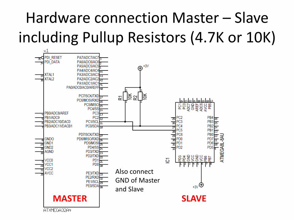
Hardware connection Master – Slaveincluding Pullup Resistors (4.7K or 10K)
MASTER SLAVE
Also connectGND of Master and Slave

Why 2 different Slave Libraries ?• Because there are AVR Chips with hardware TWI/I2C interface (e.g.
ATMEGA8 or ATMEGA128) and AVR Chips which have no hardwareTWI/I2C interface like ATTINY2313 or ATTINY13)
AVR‘s with hardware TWI/I2C(ATMEGA8 or ATMEGA128….)
AVR‘s which have no hardwareTWI/I2C
(ATTINY2313 or ATTINY13…)
Used Library = i2c_TWI-slave-acknack.LBX (USERACK = ON)
i2c_TWI-slave.LBX (USERACK = OFF)The hardware SDA and SCL pins are used
Used Library = i2cslave.LBX
TIMER0 and INTO is used for SDA and SCLTimer0 Pin = SCLINT0 Pin = SDA
Config TWISLAVE Config I2CISLAVE

Config I2CISLAVE
• CONFIG I2CSLAVE = address , INT = interrupt , TIMER = tmr– Address: The slave address you want to assign to the I2C slave chip.
This is an address that must be even like 60. So 61 cannot be used.
– Interrupt: The interrupt that must be used. This is INT0 by default.
– Tmr: The timer that must be used. This is TIMER0 by default.
• Example: see i2c_pcf8574.bas

Config TWISLAVE
• CONFIG TWISLAVE = address , BTR = value , BITRATE = value , SAVE=option [,GENCALL=value] [,USERACK=ack]– Address: The slave address that is assigned to the slave chip. This must be an
Even number. The address 0 is the general call address and may not be used. While a slave address is 7 bit since bit 0 is used to indicate read/write, BASCOM uses byte notation where you can ignore the last bit. The last bit will be set by BASCOM automatically.
– BTR: Bytes to receive. With this constant you specify how many bytes will be expected when the slave receives bytes.
– Bit rate: This is the I2C/TWI clock frequency. Most chips support 400 KHz (400000) but all I2C chips support 100000.
– SAVE: SAVE = NOSAVE : this can be used when you do not change a lot of registers in the interrupt. SAVE = SAVE : this is best to be used when you do not use ASM in the TWI interrupt. See the explanation below. When you do not specify SAVE, the default will be SAVE=SAVE.

Config TWISLAVE continued
– GENCALL: General call address activated or not. When you specify 1 or YES, the General call address will be activated which mean that the slave will respond not only to it's own address, but also to the general call address 0. When you omit the option or specify 0 or NO, the general call address will not be honored.
– USERACK: Default is OFF. When you use ON, an alternative library will be used. This library will create a variable named TWI_ACK. Each time your code is called this variable is filled with the value 255. If you do not alter the value, the slave will send an ACK as it is supposed to. If you reset the value to 0, the slave will send a NACK. You can use this to send data with variable length to the slave. In this case, BTR only serves as an index. You must make sure to reset TWI_ACK when you have send the last byte to the master.

Config TWISLAVE continued
• Automatically created BYTE variables:– Twi (The variable TWI holds the received value the
Master has sent)
– Twi_btw (The byte TWI_BTW is an index that holds the value of the number of received bytes. The first received byte will have an index value of 1.
– Twi_btr (The variable TWI_BTR can be inspected to see which index byte was needed. With the CONFIG BTR, you specify how many bytes the master will read.)
• The TWI interrupt is enabled but you need to enabled the global interrupt
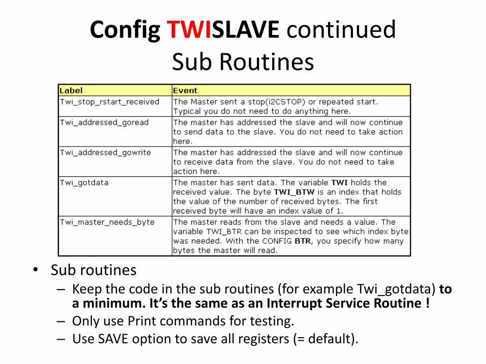
Config TWISLAVE continuedSub Routines
• Sub routines– Keep the code in the sub routines (for example Twi_gotdata) to
a minimum. It’s the same as an Interrupt Service Routine !– Only use Print commands for testing.– Use SAVE option to save all registers (= default).

Config TWISLAVE continuedExamples
• Slave example
– M88-TWI-slave.bas
• Master example which belong to the Slave example
– M88-TWI-master.bas

Config TWISLAVE continuedSoftware Structure TWI SLAVE
Config TWISLAVE = ….
Enable Interrupts
DoLoop
End
Sub Routines

Config TWISLAVE continuedSubroutines
• You can use TWI_BTR as an Index for yourSEND Array (which is read by Master)
Twi_master_needs_byte:Twi = Send_array(twi_btr)
Return
Config TWISLAVE continuedSubroutines
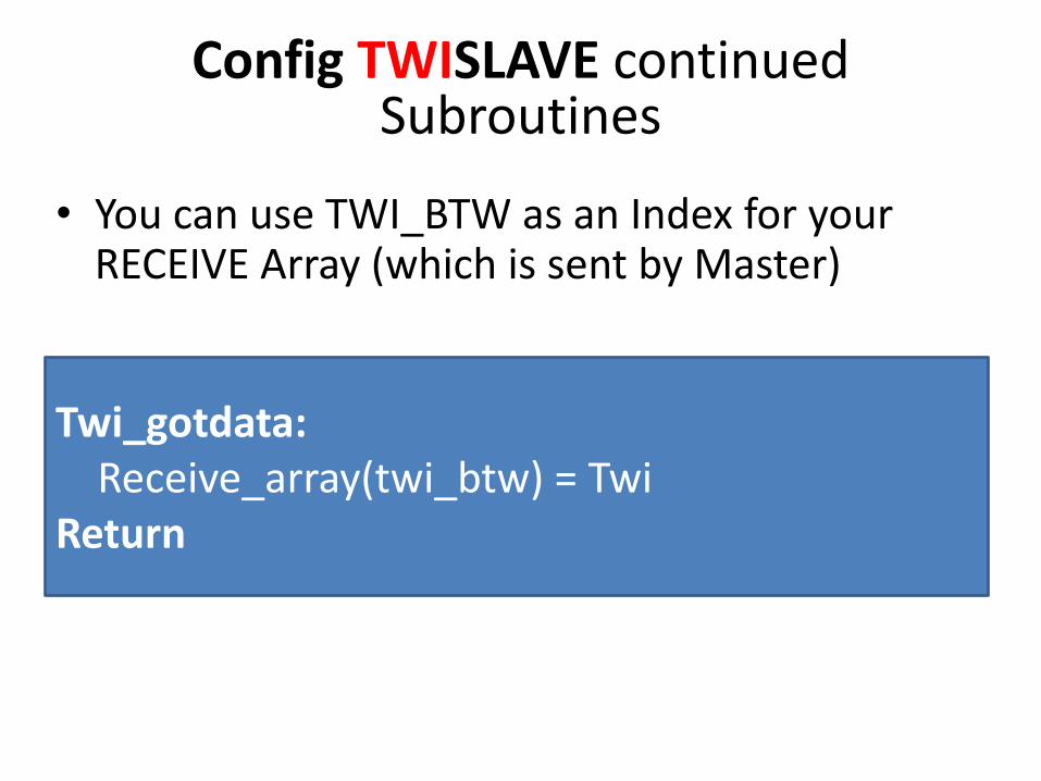
• You can use TWI_BTW as an Index for yourRECEIVE Array (which is sent by Master)
Twi_gotdata:Receive_array(twi_btw) = Twi
Return

I2C/TWI MASTER
• With I2C/TWI MASTER you also have twochoices
– Use any SDA/SCL pin you want and choose(I2C is handled in software)
– Force BASCOM-AVR to use the hardware I2C/TWI by using: $lib "i2c_twi.lbx" (I2C ishandled in hardware)
I2C/TWI MASTERUse any SDA/SCL pin you want
• By default BASCOM will use software routines when you use I2C statements. This because when the first AVR chips were introduced, there was no TWI yet. Atmel named it TWI because Philips is the inventor of I2C. But TWI is the same as I2C.

I2C/TWI MASTER Force BASCOM-AVR to use the hardware I2C/TWI by using:
$lib "i2c_twi.lbx"• With the I2C_TWI lib you can use the hardware TWI which has
advantages like:
– It require less code
– This special Pins have Noise Suppression Circuitry which Rejects Spikes on Bus Lines and Slew-rate Limited Output Drivers
– Address Recognition causes Wake-up when AVR is in Sleep Mode
• Therefore you need to use the hardware SDA and SCL Pins according datasheet of AVR (for example ATMEGA32: SDA = PC 1 , SCL = PC 0 )
• The hardware TWI will save code but the disadvantage is that you can only use the fixed SCL and SDA pins.

I2C/TWI MASTER Force BASCOM-AVR to use the hardware I2C/TWI by using: $lib "i2c_twi.lbx"
• When using the TWI (hardware I2C) AND you have externalPullup Resistors on SDA and SCL (4.7K or 10K) there is no need to use config scl/sda because these pins are fixed just like the UART tx/rx pins. So you don’t need config SDA, config SCL and also not i2cinit !
• When you want to use the internal Pullup AND there are no external Pullup Resistors on SDA and SCL of the AVR Pin you need to use config SDA, config SCL and also I2CINIT because I2CINIT will then enable the internal Pullup for the configured Pins.

I2C/TWI MASTER Force BASCOM-AVR to use the hardware I2C/TWI by using: $lib "i2c_twi.lbx"
• When your default settings for scl/sda (options) point to an invalid SDA and SLC Pin, you should also use config SDA, configSCL and I2CINIT.

I2C/TWI MASTER continuedSoftware Structure I2C/TWI MASTER
$lib "i2c_twi.lbx“
DoI2cstartI2cwbyte &H70 ' slave addressI2cwbyte &B10101010 ' write one Byte to SlaveI2cwbyte 2
I2cstopLoop
End
The preconditions for the following example are:- External Pullup Resistors on SDA and SCL- SDA and SCL Pin‘s are correct configured under Options (I2C, SPI, 1-WIRE)
You have different Voltages like 5V and3.3V on Slave Side
• One solution for this is using Multiplexer likePCA9546
• Another solution is using a Level translatingI2C-bus repeater like PCA9517
• When you also have long cables then considerP82B96 on both Side (Master and Slave Side)

You have long cable distanceand several Slaves
• Use P82B96 in Multipoint architecture.
P82B96 I2C MASTERUp to 15V
P82B96 I2C Slave
P82B96 I2C Slave
P82B96 I2C Slave
1.8V
3.3V
5V
3.3V
P82B96 I2C Slave3.3V
You also need isolation of I2C Bus:http://www.eetimes.com/design/embedded/4025023/Opto-electrical-isolation-of-the-I2C-Bus

I2c/TWI MASTER with ATXMEGA Family• For example an ATXMEGA128A1 has 4 hardware I2C/TWI
Interfaces on Port C, D , E and F• You can run the different I2C/TWI Interfaces with
different TWI Baud rates (for example one with 100000 and the other with 400000)
Dim Twi_start As Byte 'This Variable is used by the I2C functionsOpen "twic" For Binary As #2
' Portc.0 = SDA Pin of Port C (ATXMEGA128A1)' Portc.1 = SCL Pin of Port C (ATXMEGA128A1)
I2cinit #2 'set i2c pins to right stateConfig Twic = 100000 'Set TWI Baud Rate and Enable TWI Master
Initialization of I2C/TWI Interface of PORT C in BASCOM-AVR:

I2c MASTER with ATXMEGA Family continued
I2cstart #2I2cwbyte Writeaddress, #2I2cwbyte Write_a_byte , #2I2cstop #2
Using the I2C/TWI functions (you always need to add the interface number !):
Array_to_write(1) = AddressbyteI2creceive Array_to_write(1) , 1 , 3 , #2
Using high level functions (example for write one byte and read 3 Bytes)