Embed Size (px)
Citation preview

www.provision-isr.com
Digital CCTV CameraBOX CAMERA
www.provision-isr.com
AWB
BLC
CCD
Auto Iris
MANUALEnglish / Spanish
ENES

GeneralThank you for using our products. Before use, please read this manual carefully to ensure correct use of this series of products. Please keep the manual properly for future use.This series of cameras take high-sensitivity CCD as the image sensor, all circuits have long work life and high reliability. Excellent image will be top choice for your camera.
Main Features1. Easy to install and assemble.2. High resolution, high sensitivity and high s/n ratio.3. Low illumination, high quality image.4. CCD sensor can prolong the work life of camera.5. With SONY DSP and CCD chip, image is clear and stable.
Precautions
1. Do not install the camera in places where the temperature is above 50°C or under -10°C.2. Do not touch the CCD surface with your finger. If cleaning is needed, please wipe it using a soft cloth with a little bit of alcohol.3. Do not install in places with high humidity, it can seriously damage the quality of the picture.4. Do not drop the camera and avoid physical shock.5. Do not face your camera to a strong light, it can damage the CCD.6. Do not expose the camera to rain or dusty surroundings.7. Its highly important to use the correct and suitable power supply(DC12V) for the camera.8. Only professional and qualified technician can install and test9. During use, if any errors occur, cut off the power immediately and contact your local distributor.
1 2
EN
ES
2
12
English Manual
Manual en Español
EN
Content
Note:In order to avoid electrical shock or �re, please use proper power according to the manual.
WARNING
Note: Only professional technicians is allowed to open the front or back cover of this camera.
RISK OF ELECTRIC SHOCKDO NOT OPEN
Nota:Para prevención de choques electricos o fuego, por favor use la corriente apropiada, acorde con el manual.
ADVERTENCIA
NotA: Solo técnicos profesionales pueden abrir las cubiertas frontal o posterior de esta cámara.
PELIGRO DE CHOQUESNO ABRIR

③ On the camera casing
2. Case D
Tailplate
Mount screw
Lens
Back focus screw
Lens mount ringMicrophone
1
2
4
5
66DC 12V
6DC 24V
7
8
3 4
Tailplate Sketch
1. Case B
Tailplate
Mount screw
Lens
Back focus screw
Lens mount ringMicrophone
1
2
3
4
5
67
8
EN EN
Structure and Components
Tailplate Sketch
Structure and Components
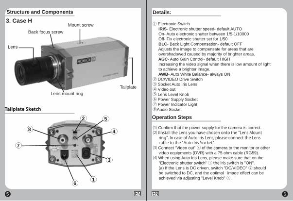
Details:
① Electronic Switch IRIS- Electronic shutter speed- default AUTO On- Auto electronic shutter between 1/5-1/10000 Off- Fix electronic shutter set for 1/50 BLC- Back Light Compensation- default OFF Adjusts the image to compensate for areas that are overshadowed caused by majority of brighter areas. AGC- Auto Gain Control- default HIGH Increasing the video signal when there is low amount of light to achieve a brighter image. AWB- Auto White Balance- always ON② DC/VIDEO Drive Switch③ Socket Auto Iris Lens④ Video out⑤ Lens Level Knob⑥ Power Supply Socket⑦ Power Indicator Light⑧Audio Socket
⑴ Confirm that the power supply for the camera is correct.⑵ IInstall the Lens you have chosen onto the "Lens Mount ring". In case of Auto Iris Lens, please connect the Lens cable to the "Auto Iris Socket".⑶ Connect “Video out” ④ of the camera to the monitor or other video equipments (DVR) with a 75 ohm cable (RG59).⑷ When using Auto Iris Lens, please make sure that on the "Electronic shutter switch” ① the Iris switch is "ON". (a) If the Lens is DC driven, switch "DC/VIDEO" ② should be switched to DC, and the optimal image effect can be achieved via adjusting "Level Knob" ⑤.
Operation Steps
5 6
3. Case H
Tailplate
Mount screw
Lens
Back focus screw
Lens mount ring
1
2
4
5
6
7
8
3
EN EN
Tailplate Sketch
Structure and Components

System connection
① Use one camera and one monitor
② Use Several Cameras and one Monitor
7 8
BNC
BNC
DC 12V
Monitor
Monitor
MULTIPLEXER Video Divider
DVRVCN
SN Video Control Power Supply Control1 +12V DAMP-2 NC DAMP+
4 GND DRIVE-3 VIDEO DRIVE+
Equip with automatic aperture lens. The definitions of the pins of the control cable are as follows (e.g. Tail Plate Sketch)
Automatic Aperture
(b) If the Lens is VIDEO driven, then the switch "DC/VIDEO" ② should be switched to VIDEO position.⑸ Plug the power supply (a) Case model B- direct plug is used and after connecting the plug "Power Indicator Light" ⑦ is on, at this point the monitor displays the images taken. (b) Case model D/H- power is connected by two wires. Make sure you plug the power in the right direction "+" / "-".(6) Adjust the zoom and the focus of the Lens to get your optimal image.⑺ Back Focus- Back Focus is adjusted when the camera leaves the factory; therefore, no more adjustment is needed. However, in case you can't reach optimize focus by the lens focus ring, untie the "Back Focus Screw", then turn the "Lens Mount Ring" clockwise or counter clockwise until the image is clear. Then retighten the "Lens Mount Screw".
EN EN

9 10EN EN
SONY DSP Chipset
330g
PAL:537(H)×597(V)NTSC:537(H)×505(V)
0.5 LUX/F1.2
AWB ON (ATW OFF PUSH) Switchable
110L x 60W x 55H mm
1/3” SONY Super HAD 1/4” SONY Super HAD
BX-425CSBX-325CS
SONY DSP Chipset
PAL:795(H)x596(V)NTSC:811(H)x508(V)
PAL:537(H)×597(V)NTSC:537(H)×505(V)
0.05 LUX/F1.2
DC 12V or DC12V/AC24V Dual Voltage (Opcional)
0.02 LUX/F1.2
AWB
1/3” SONY Super HAD
BX-322CSBX-352CS
540TVL
SONY HQ1
320g
105L x 66W x 52H mm
Camera Speci�cation Camera Speci�cation

Camera Speci�cation
HITACHI DSP Chipset
320g
PAL:752H x 582V / NTSC:768H x 492V
0.001 LUX/F1.2
AWB
105L x 66W x 52H mm
1/3” SONY Super HAD
BX-351CS
540TVL High resolution.
0
55
DC 12V or DC12V/AC24V Dual Voltage (Opcional)
11 12EN ES
GeneralGracias por utilizar nuestros productos. Antes de usar, por favor lea atentamente este manual para garantizar el correcto uso de los mismos. Por favor, guarde el manual correctamente para uso futuro. Esta serie de cámaras tienen un CCD de alta sensibilidad como sensor de imagen, todos los circuitos tienen una larga vida útil y alta fiabilidad. Una excelente imagen que sera la mejor elección para su cámara.
Características principales1.Fácil de instalar y ensamblar.2.Alta resolución, alta sensibilidad y alto rango s/n.3.Baja iluminación, alta calidad de imágen.4.El sensor CCD prolonga la vida útil de la cámara.5.Con DSP y chip CCD SONY, imagen clara y estable.
Precauciones
1. No instale la cámara en lugares donde la temperatura es mayor a 50°C o inferior a -10°C.2. No toque la superficie del CCD con el dedo. Si es necesario limpiar, use un trapo suave con un poco de alcohol.3. No instalar en lugares altamente húmedos,puede causar serios daños en la imágen.4. Cuidar de que no reciba golpes fuertes o se caiga.5. No exponer la cámara frente a luz fuerte, esto puede dañar el CCD.6. No exponga la cámara a un ambiente polvoriento o lluvioso.7. Es sumamente importante usar la electricidad correcta (DC12V) para la cámara.8. Solo personal profesional y calificado tecnicamente puede instalar y probar esta cámara.9. Durante el uso, si alguna falla ocurre, corte la corriente inmediata mente y contacte a su distribuidor local.

③ En la carcasa de la cámara
2. Carcasa D
Placaposterior
Tornillo de montaje
Lentes
Tornillo foco fondo
Anillo de montajepara lentes Micrófono
1
2
4
5
66DC 12V
6DC 24V
7
8
13 14
Placa posterior
1. Carcasa B
Placaposterior
Tornillo de montaje
Lentes
Tornillo foco fondo
Anillo de montajepara lentes
Micrófono
1
2
3
4
5
67
8
ES ES
Estructura y componentes
Placa posterior
Estructura y componentes

Estructura y componentes Detalles:
① Interruptor electrónico IRIS- Velocidad electronica del obturador - default AUTO On- Obturador electronico automático entre 1/5-1/10000 Off- Obturador electronico fijo para 1/50 BLC- Compensación de contraluz - default OFF Ajusta la imagen para compensar las zonas que están ensombrecidas causado por las áreas brillantes. AGC- Control de auto-ganancia - default ALTA Aumento de la señal de video cuando hay baja cantidad de luz para lograr una mejor imagen. AWB- Balance automático de blancos - Siempre ON② Interruptor DC/VIDEO③ Enchufe para lentes con Iris automático④ Salida de Video⑤ Botón para nivelar lente⑥ Entrada de corriente⑦ Luz indicadora de poder⑧ Entrada de audio
⑴ Confirme que el suministro de energía es el correcto.⑵ Instale el lente elegido en el "Anillo de montaje". En caso de ser lentes con Iris automático conecte el cable en el "enchufe para lentes con Iris automático".⑶ Conecte la “Salida de Video” ④ de la cámara al monitor u otro equipo de video (DVR) con un cable de 75 ohm (RG59).⑷ Cuando use lentes de Iris automático, Asegúrese de que el "Interruptor de disparo electrónico” ① este en Iris "ON". (a) si el lente funciona con DC, el "DC/VIDEO" ② debe star en DC, el efecto óptimo de la imágen puede ser logrado ajustando el "botón de nivel" ⑤.
Pasos de Operación
15 16
3. Carcasa H
Placaposterior
Tornillo de montaje
Lentes
Tornillo foco fondo
Anillo de montajepara lentes
1
2
4
5
6
7
8
3
ES ES
Placa posterior

① Uso de una cámara y un monitor
②Uso de varias Cámaras y un Monitor
17 18
BNC
BNC
DC 12V
Monitor
Monitor
MULTIPLEXER Video Divider
DVRVCN
SN Control de Video Control de poder1 +12V DAMP-2 NC DAMP+
4 GND DRIVE-3 VIDEO DRIVE+
Equipado con apertura automática de lentes. La definicion de los pines del cable de control son los siguientes (ejemplo en la grafica de parte posterior)
Apertura Automática
(b) Si el lente es manejado por el VIDEO, el interruptor "DC/VIDEO" ② debe estar en la posision de VIDEO.⑸ Conecte la corriente (a) Carcasa B- usa plug directo y luego de conectarlo la "Luz indicadora de poder" ⑦ se enciende, hasta este punto el monitor muestra la imágen tomada. (b) Carcasas D/H- el poder se conecta mediante dos cables. verifique que conecto el cable en el punto correcto "+" / "-".(6) Ajuste el Zoom y el foco del lente para obtener la imágen optima.⑺ Foco de fondo- El foco de fondo es ajustado al salir de fabricación; por lo tanto, no se necesitan mas ajustes. Sin embargo en el caso que no pueda optimizar el foco por el lente desatornille el "tornillo de foco de fondo", gire el "anillo de montaje del lente" hacia los lados hasta que la imágen sea clara. luego regrese el "tornillo de montaje del lente".
ES ES
Conexión del sistema

19 20ES ES
SONY DSP Chipset
330g
PAL:537(H)×597(V)NTSC:537(H)×505(V)
0.5 LUX/F1.2
AWB ON (ATW OFF PUSH) Cambiable
110L x 60W x 55H mm
1/3” SONY Super HAD 1/4” SONY Super HAD
BX-425CSBX-325CS
Compuesta
Disp. de imágen
Sistema DSP
Sistema de video
Temp. en operación
Dimensiones
Peso neto
Control auto iris
Lentes
Fuente alimentación
Velocidad disparo
Corrección gama
Sistema de sinc.
Rango S/N
Salida video
Balance de blancos
Pixels efectivos
Res. horizontál
Iluminación máx.
MODELO
Interno
Video/DC Cambiable
SONY DSP Chipset
PAL:795(H)x596(V)NTSC:811(H)x508(V)
PAL:537(H)×597(V)NTSC:537(H)×505(V)
0.05 LUX/F1.2
DC 12V or DC12V/AC24V Voltage Dual (Opcional)
0.02 LUX/F1.2
AWB
1/3” SONY Super HAD
BX-322CSBX-352CS
540TVL
SONY HQ1
320g
105L x 66W x 52H mm
Disp. de imágen
Sistema DSP
Sistema de video
Temp. en operación
Dimensiones
Peso neto
Control auto iris
Lentes
Fuente alimentación
Velocidad disparo
Corrección gama
Sistema de sinc.
Rango S/N
Salida video
Balance de blancos
Pixels efectivos
Res. horizontál
Iluminación máx.
Compuesta
Video/DC Cambiable
Interno
MODELO
Especi�caciones Especi�caciones

21 ES
HITACHI DSP Chipset
320g
PAL:795(H)x596(V) / NTSC:811(H)x508(V)
0.001 LUX/F1.2
AWB
105L x 66W x 52H mm
1/3” SONY Super HAD
BX-351CS
540TVL High resolution.
0
55
DC 12V or DC12V/AC24V Voltage Dual (Opcional)
MODELO
Disp. de imágen
Sistema DSP
Sistema de video
Temp. en operación
Dimensiones
Peso neto
Control auto iris
Lentes
Fuente alimentación
Velocidad disparo
Corrección gama
Sistema de sinc.
Rango S/N
Salida video
Balance de blancos
Pixels efectivos
Res. horizontál
Iluminación máx.
Compuesta
Video/DC Cambiable
Interno
Especi�caciones