Embed Size (px)
Citation preview
Marquette Universitye-Publications@MarquetteBiomedical Engineering Faculty Research andPublications Biomedical Engineering, Department of
2-1-2012
BiomechanicsBrooke A. SlavensMarquette University, [email protected]
Gerald F. HarrisMarquette University, [email protected]
Published version. "Biomechanics," in Handbook of Research on Biomedical Engineering Education andAdvanced Bioengineering Learning: Interdisciplinary Concepts. Eds. Ziad O. Abu-Faraj. Hershey, PA:Medical Information Science Reference, 2012, pp. 284-338. Permalink: www.igi-global.com/viewtitlesample.aspx?id=63395. © 2012 Medical Information Science Reference (IGI Global). Usedwith permission.Brooke A. Slavens was affiliated with the University of Wisconsin - Milwaukee at the time ofpublication.

Ziad O. Abu-FarajAmerican University of Science and Technology, Lebanon
Handbook of Research on Biomedical Engineering Education and Advanced Bioengineering Learning:Interdisciplinary Concepts
Volume I
Biomedical engineering education and advanced bioengineering learning: interdisciplinary concepts / Ziad O. Abu-Faraj, editor. p. cm. Includes bibliographical references and index. Summary: “This book explores how healthcare practices have been steered toward emerging frontiers, including, among others, functional medical imaging, regenerative medicine, nanobiomedicine, enzyme engineering, and artificial sensory substitution”-- Provided by publisher. ISBN 978-1-4666-0122-2 (hardcover) -- ISBN 978-1-4666-0123-9 (ebook) -- ISBN 978-1-4666-0124-6 (print & perpetual access) 1. Biomedical engineering--Study and teaching. I. Abu-Faraj, Ziad O., 1964- R856.3.B56 2012 610.28076--dc23 2011042007
British Cataloguing in Publication DataA Cataloguing in Publication record for this book is available from the British Library.
All work contributed to this book is new, previously-unpublished material. The views expressed in this book are those of the authors, but not necessarily of the publisher.
Managing Director: Lindsay JohnstonSenior Editorial Director: Heather Probst Book Production Manager: Sean WoznickiDevelopment Manager: Joel GamonAcquisitions Editor: Erika GallagherTypesetter: Jennifer RomanchakCover Design: Nick Newcomer, Lisandro Gonzalez
Published in the United States of America by Medical Information Science Reference (an imprint of IGI Global)701 E. Chocolate AvenueHershey PA 17033Tel: 717-533-8845Fax: 717-533-8661 E-mail: [email protected] site: http://www.igi-global.com
Copyright © 2012 by IGI Global. All rights reserved. No part of this publication may be reproduced, stored or distributed in any form or by any means, electronic or mechanical, including photocopying, without written permission from the publisher.Product or company names used in this set are for identification purposes only. Inclusion of the names of the products or companies does not indicate a claim of ownership by IGI Global of the trademark or registered trademark.
Library of Congress Cataloging-in-Publication Data
284
Copyright © 2012, IGI Global. Copying or distributing in print or electronic forms without written permission of IGI Global is prohibited.
Chapter 7
7.1. CHAPTER OBJECTIVES
This chapter on biomechanics aims to introduce the reader to the specialty area of biomechanics, the study of human and biological movement mechanics. The topic of biomechanics is broad by nature due to the complex and variety of biological
organisms and systems; thus, this chapter presents a subset of biomechanics topics and principles, including motion analysis, postural stability, reha-bilitation, trauma, and biomechanical modeling. It further identifies the biomechanics professional societies and organizations.
Brooke SlavensUniversity of Wisconsin-Milwaukee, USA
Gerald F. HarrisMarquette University & Medical College of Wisconsin, USA
Biomechanics
ABSTRACT
Biomechanics is a vast discipline within the field of Biomedical Engineering. It explores the underlying mechanics of how biological and physiological systems move. It encompasses important clinical appli-cations to address questions related to medicine using engineering mechanics principles. Biomechanics includes interdisciplinary concepts from engineers, physicians, therapists, biologists, physicists, and mathematicians. Through their collaborative efforts, biomechanics research is ever changing and ex-panding, explaining new mechanisms and principles for dynamic human systems. Biomechanics is used to describe how the human body moves, walks, and breathes, in addition to how it responds to injury and rehabilitation. Advanced biomechanical modeling methods, such as inverse dynamics, finite ele-ment analysis, and musculoskeletal modeling are used to simulate and investigate human situations in regard to movement and injury. Biomechanical technologies are progressing to answer contemporary medical questions. The future of biomechanics is dependent on interdisciplinary research efforts and the education of tomorrow’s scientists.
DOI: 10.4018/978-1-4666-0122-2.ch007
285
Biomechanics
7.2. INTRODUCTION
Biomechanics is a vast discipline within the field of Biomedical Engineering. It dates back to the fifteenth century, when Leonardo da Vinci (1452-1519), during his biological studies, noted the importance of mechanics. The field encompasses biology, basic sciences, engineering, and important clinical applications to address questions related to medicine, using principles of engineering mechan-ics. Biomechanics has improved our understanding and knowledge within numerous areas, such as clinical pathologies, neuromuscular control, the cardiovascular system, tissue mechanics, and im-aging. It encompasses expanding interdisciplinary concepts from various fields of specialization, namely engineering, medicine, therapy, biology, physics, and mathematics.
Biomechanics is used to describe how the human body walks, stands still, and breathes; in addition to studying the body’s response to injury. Advanced biomechanical modeling methods, such as inverse dynamics, finite element analysis, and musculoskeletal modeling are used to simulate and investigate human situations when in movement and/or in injury. New technologies brought on by the field of Biomechanics are endless; they are ever progressing to answer new medical ques-tions. The future of biomechanics is dependent on interdisciplinary research efforts and the education of tomorrow’s scientists.
7.3. A COMPREHENSIVE DEFINITION OF BIOMECHANICS
Biomechanics is the application of the principles of engineering and life science mechanics on living systems. It is an interdisciplinary field based on knowledge of physics, chemistry, mathematics, physiology and anatomy. Therefore, this branch of science is very broad, covering a range of top-ics from the cellular level to the whole organ; it includes disciplines such as biomaterials, bioflu-
ids, cardiovascular biomechanics, bioelectronics, respiratory biomechanics, motion analysis, reha-bilitation, posturography, trauma, occupational biomechanics, and sports biomechanics.
The study of Biomechanics requires a thorough understanding of basic terminology and concepts, which are delineated herein.
Anatomical locations and motions are often described in terms of planes. The midsagittal plane divides the body into two symmetric halves along the midline. Sagittal planes are parallel to the midsagittal plane, but do not divide the body into symmetric halves. The frontal or coronal plane is perpendicular to the midsagittal plane and divides the body into anterior and posterior sections. Planes that are perpendicular to the mid-sagittal and frontal planes are transverse planes (Enderle, Bronzino, & Blanchard, 2005).
Stress is a force divided by the cross-sectional area. Strain is defined as the amount of elongation divided by the original length of the specimen in the direction of elongation (Özkaya & Nordin, 1999).
Springs and dashpots are often used to model viscoelastic system: springs account for the elastic solid behavior, while dashpots define the viscous fluid behavior. In a spring, a constantly applied force, or stress, produces a constant deformation or strain, which is recoverable. Whereas, in a dashpot, the force produces a constant rate of deformation or strain rate which is permanent. The Maxwell model is a system formed by connecting a spring and a dashpot in series. The Kelvin-Voigt model is a system comprising of a spring and a dashpot connected in a parallel arrangement (Özkaya & Nordin, 1999).
Kinematics is defined by time-dependent as-pects of motion in terms of displacement, velocity, and acceleration. Linear kinematics describes translational motion from a net force applied to an object. Angular kinematics is the rotational motion resulting from a net torque. Articular kinematics describes motions that pertain to the joints of the body (Özkaya & Nordin, 1999).
286
Biomechanics
The orientation of a body is given by attaching a coordinate system to the body and then describ-ing this coordinate system with respect to a refer-ence system. A body-attached coordinate system is described by unit vectors of its three principal axes relative to the reference system. The three unit vectors, X, Y, and Z, can be stacked together as columns of a 3 x 3 matrix. This is a rotation matrix. Subsequently, the set of three vectors specifying the orientation of a body make up the rotation matrix. All columns of a rotation matrix are mutually orthogonal and have unit magnitudes (Craig, 2005).
Euler angles are the angles that define the orientation of one reference frame with respect to another in three-dimensional space (Zatsiorsky, 1998). Each rotation is performed about an axis of the moving system, as opposed to a fixed reference. Rotations are about X, Y, and Z of the moving system and each rotation takes place about an axis whose location depends upon the preceding rota-tions. Such a set of three rotations are called Euler angles. There are 12 Euler angle-set conventions describing the possible rotation sequences – e.g., ZXY, YZX, XYZ, etc. (Craig, 2005).
Newtonian, Lagrangian, and Hamiltonian dynamics are the bases of classical mechanics, which is based on continuity principles from calculus. Most biomechanics mathematics is based on Newtonian and Lagrangian mechanics (Bronzino, 2006).
Newton’s three laws of motion form the basis of classical mechanics; they are stated herein in a slightly reworded form:
1. A particle originally at rest, or moving in a straight line with a constant velocity, will remain in this state provided the particle is not subjected to an unbalanced force.
2. A particle acted upon by an unbalanced force experiences an acceleration that has the same direction as the force and a magnitude that is directly proportional to the force.
3. The mutual forces of action and reaction between two particles are equal, opposite, and collinear.
Biomechanics based on Newtonian mechanics, includes concepts such as length, time and mass. Each concept is absolute and independent of the others. Length describes size; time describes the order of events; and mass is a property of matter which is a quantitative measurement of inertia. Inertia is resistance of matter to changes in motion.
Other basic concepts of biomechanics include static and dynamic principles. Metrics such as force, moment, velocity, acceleration, work power, impulse, stress, and strain are important concepts for quantitative biomechanics.
Force is a mechanical load applied to a body. Moment is the force causing a body to rotate, acting at a distance from the point of rotation. Velocity is the measurement of rate of change of position. Acceleration is the rate of change of velocity (Özkaya & Nordin, 1999).
Lagrangian formulation is a systematic pro-cess, whereby equations of motion can be derived independently of the reference coordinate frame (Sciavicco & Siciliano, 2000). However, this process is often less efficient than Newtonian methods. Lagrangian dynamic formulation allows derivation of the equations of motion from a scalar function called the Lagrangian (Craig, 2005). This function is the difference between the kinetic and potential energy of a mechanical system.
Hamiltonian mechanics express the system as a sum of kinetic and potential energy with time-invariant constraints (Sciavicco & Siciliano, 2000).
7.4. HISTORICAL BACKGROUND AND LITERATURE REVIEW
Biomechanics can be traced back to the early first century. The following is an overview of signifi-cant historical events pertaining to biomechanics
287
Biomechanics
(Bronzino, 2006; Enderle, Bronzino, & Blanchard, 2005). For deeper and more comprehensive out-look on the history of biomechanics, the reader is referred to the work of Fung, Nigg, or Singer and Underwood (Fung, 1993; Nigg, 1994; Singer & Underwood, 1962).
7.4.1. Founding Scientists, Early Work, and Historical Events
• Galen of Pergamon (129-199), anatomist, published De Motu Muscularum (On the Movements of Muscles). His medical text severed as the world’s standard for the next 1,400 years.
• Leonardo da Vinci (1452-1519), studied anatomy in the context of mechanics. He had an understanding of components of force vectors, friction coefficients, and the acceleration of falling objects. He set the first accurate descriptions of ball-and-socket joints. He analyzed mechani-cal force acting along the line of muscle filaments.
• Andreas Vesalius (1514-1564), physician, wrote De Humani Corporis Fabrica (The Fabric of the Human Body). His work, which was based on human cadaver dis-sections, led to a more accurate anatomi-cal description of human musculature than that given by Galen. He showed that mo-tion results from the contraction of mus-cles, which shorten and thicken.
• Galileo Galilei (1564-1642) studied medi-cine and physics and concluded that math-ematics is an essential tool of science. His analyses included the biomechanics of jumping, gait analysis of horses and in-sects, and dimensional analysis of animal bones.
• William Harvey (1578-1657) is known to be the father of biofluid mechanics.
• Santorio Santorio (1561-1636) used Galileo’s method of measurement and
analysis and found that the weight of the human body changes with time; this find-ing has led to the study of metabolism.
• Giovanni Borelli (1608-1679), mathemati-cian, investigated body dynamics, muscle contraction, animal movement, and motion of the heart and intestines. He also deter-mined the position of the human center of gravity. He measured and calculated in-spired and expired air volumes, proving that inspiration is muscle-driven and expi-ration is due to tissue elasticity. In 1680, he published De Motu Animalium (On the Motion of Animals).
• Jan Swammerdam (1637-1680) introduced the nerve-muscle preparation. He was able to stimulate muscle contraction by pinch-ing the attached nerve in the frog leg. He also showed that muscles contract with little change in volume.
• Robert Hooke (1635-1703) derived Hooke’s law, relating stress and elonga-tion of elastic materials, and used the term “cell” in biology.
• Isaac Newton (1642-1727) invented cal-culus, the classical laws of motion, and the constitutive equation for viscous fluid. Newton’s three laws of motion serve as the basis for classical mechanics principles used in biomechanics.
• Nicholas Andre (1658-1742) coined the term “orthopaedics”. He believed that muscular imbalances cause skeletal deformities.
• Leonard Euler (1707-1783) generalized Newton’s laws of motion to continuum representations for rigid body motion de-scription; he also studied pulse waves in arteries.
• Thomas Young (1773-1829) studied voice and wave theory of light and vision, vibra-tions, and formulated Young’s modulus of elasticity.
288
Biomechanics
• Ernst Weber (1795-1878) and Eduard Weber (1806-1871) published Die Mechanik der meschlichen Gerwerkzeuge (On the Mechanics of the Human Gait Tools) in 1836 and pioneered the scientific study of human gait.
• Hermann von Helmholtz (1821-1894) stud-ied a variety of subjects including acous-tics, electrodynamics, thermodynamics, optics, physiology, and fluid mechanics.
• Etienne Jules Marey (1830-1904) analyzed the motion of horses, birds, insects, fish, and humans. He invented force plates to measure ground-reaction-forces, and the motion picture camera.
• Eadweard Muybridge (1830-1904) used multiple cameras triggered sequentially to record motion during gait.
• Wilhelm Braune and Otto Fischer conduct-ed research from 1895-1904 and published Der Gang des Menschen (The Human Gait), which details the mathematical analysis of human gait. They also invented cyclography, pioneered the use of multiple cameras to reconstruct 3-D motion data, and applied Newtonian mechanics to es-timate joint forces and limb accelerations.
These early founding fathers, physicians and physiologists, developed the basic principles of physics and engineering. More recently, biomedi-cal engineers have been at the forefront of advanc-ing medical and physiologic sciences.
7.4.2. Current State-of-the-art in Biomechanics
Cutting edge technologies allow biomechanical science to continuously move forward. Advance-ment in the field of Biomechanics depends on research utilizing state-of-the-art laboratories with high-tech equipment and resources. This involves being up to date with high-level research in all
areas of biomechanics, including orthopaedics, tissue biomechanics, muscle dynamics, prosthet-ics and orthotics, cardiovascular biomechanics, among many others. Interdisciplinary work is becoming a key role in advancing biomechanics.
7.5. BIOMECHANICS OF TISSUES OF THE MUSCULOSKELETAL SYSTEM
7.5.1. Bone
The human skeletal system consists of 206 bones connected by soft tissue including cartilage, liga-ments, tendons, and muscles to provide mechanical support. Bone is a strong and hard tissue composed of a mineral phase (60%), an organic collagen matrix (30%), and water (10%).
As a composite material composed of a soft protein matrix and hard mineral phase, it is elastic and strong. Bones are subjected to different types of loading such as bending, compression, and shear. Structural stiffness is the resistance to deformation under an applied load. Structural strength is the maximum load that a bone can withstand without fracturing. Generally speaking, bones that have larger cross-sections are structurally stiffer and stronger than those with smaller cross-sections. Structural stiffness and strength are furthermore dependent on the cross-sectional area, moment of inertia in bending, and on the polar moment of inertia in torsion. These moments of inertia are properties of the cross-section that describe how the area is distributed about the axis of loading. For example, for a given cross-sectional area, stiffness and strength in bending would be lower in a narrow bone than in a wider one, the latter having more bone material situated further from the neutral bending axis.
Structural stiffness and structural strength are sometimes referred to as structural properties. However, they are not really properties as they are dependent on the type of loading, bone geometry, and bone material properties. In a structural analy-
289
Biomechanics
sis, local (tensile, compressive, and shear) stresses and strains can be calculated from known loads and/or deformation. The stresses and strains can be compared to the material properties to assess the fracture risk.
Material properties, unlike structural prop-erties, are intrinsic to and independent of the geometry of the structure. However, as bone is a heterogeneous material, its material properties are dependent on its constituents and its microstruc-ture. Bone is made up of microscopic components (nanometers to micrometers) including collagen molecules, fibrils and fibers, hydroxyapatite mi-crocrystals, osteocyte lacuna, canaliculi, lamella, haversian canals and osteons (Saltzman, 2009). Because bone is highly directional in arrangement, its material properties are anisotropic, or depen-dent on the direction of loading (Saltzman, 2009).
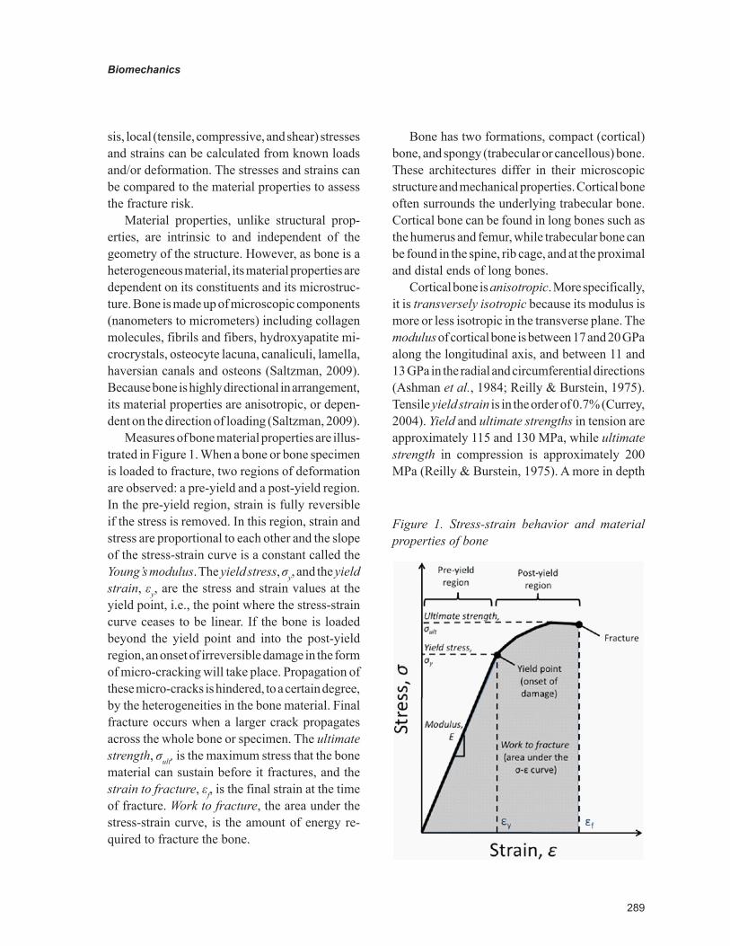
Measures of bone material properties are illus-trated in Figure 1. When a bone or bone specimen is loaded to fracture, two regions of deformation are observed: a pre-yield and a post-yield region. In the pre-yield region, strain is fully reversible if the stress is removed. In this region, strain and stress are proportional to each other and the slope of the stress-strain curve is a constant called the Young’s modulus. The yield stress, σy, and the yield strain, εy, are the stress and strain values at the yield point, i.e., the point where the stress-strain curve ceases to be linear. If the bone is loaded beyond the yield point and into the post-yield region, an onset of irreversible damage in the form of micro-cracking will take place. Propagation of these micro-cracks is hindered, to a certain degree, by the heterogeneities in the bone material. Final fracture occurs when a larger crack propagates across the whole bone or specimen. The ultimate strength, σult, is the maximum stress that the bone material can sustain before it fractures, and the strain to fracture, εf, is the final strain at the time of fracture. Work to fracture, the area under the stress-strain curve, is the amount of energy re-quired to fracture the bone.
Bone has two formations, compact (cortical) bone, and spongy (trabecular or cancellous) bone. These architectures differ in their microscopic structure and mechanical properties. Cortical bone often surrounds the underlying trabecular bone. Cortical bone can be found in long bones such as the humerus and femur, while trabecular bone can be found in the spine, rib cage, and at the proximal and distal ends of long bones.
Cortical bone is anisotropic. More specifically, it is transversely isotropic because its modulus is more or less isotropic in the transverse plane. The modulus of cortical bone is between 17 and 20 GPa along the longitudinal axis, and between 11 and 13 GPa in the radial and circumferential directions (Ashman et al., 1984; Reilly & Burstein, 1975). Tensile yield strain is in the order of 0.7% (Currey, 2004). Yield and ultimate strengths in tension are approximately 115 and 130 MPa, while ultimate strength in compression is approximately 200 MPa (Reilly & Burstein, 1975). A more in depth
Figure 1. Stress-strain behavior and material properties of bone
290
Biomechanics
review of the material properties of bone can be found in the book by Currey (Currey, 2002).
Because individual trabeculae are so small, few studies have attempted to measure their intrinsic material properties. A wide range of intrinsic modulus values have been reported; some studies measured roughly the same intrinsic modulus as that of cortical bone – e.g., (Choi, 1990), while others found much lower values – e.g., (Rho, Ashman, & Turner, 1993). For structural analyses, however, the effective tissue-level properties of trabecular bone, which account for porosity, are more relevant than the intrinsic material properties of individual trabeculae. The effective strength and modulus of trabecular bone are approximately proportional to the square and to the cube of the apparent density, respectively (Carter & Hayes, 1977).
As stated before, bone is a viscoelastic material and its properties are somewhat dependent on load-ing rate. For example, modulus tends to increase with increasing strain rate, while yield stress tends to decrease – e.g., (Hansen et al., 2008). For this reason, the strain rate should be considered in structural analyses dealing with bones.
Bone properties can vary as a person ages. For example, children’s bones tend to have lower cortical modulus and strength, but higher strain to failure and work to fracture than adult bones (Currey & Butler, 1975). The process of aging also adversely affects the material properties of adult cortical bone. Modulus, strength and work to fracture tend to decrease with age (Zioupos & Currey, 1998).
Several medical conditions can affect bone strength. Two such conditions are osteoporosis and osteogenesis imperfecta. Osteoporosis is a condition characterized by an abnormally low trabecular density, resulting in an increase in local stresses in the bone, and which can cause fracture to occur under loads that would not cause fracture in individuals with healthy bones. Osteogenesis Imperfecta (OI), also known as brittle bone disease, is a genetic condition that affects the production
of type I collagen. In the moderate and severe forms of OI, individuals can experience multiple fractures over their lifetimes, and these fractures can also result in considerable bone deformity. In OI, both the bone material and the bone structure are affected. In addition to the abnormal collagen, increased bone mineralization has been observed in individuals with OI (Boyde et al., 1999). Al-though the material strength of bone in OI has not yet been characterized in humans; however, mouse models with this condition have demonstrated that the material properties are affected – e.g., (Miller et al., 2007). At the structural level, individuals with OI also tend to have thinner cortical bone, as well as fewer and thinner trabeculae (Rauch et al., 2000). Therefore, the increased risk of fracture in OI is likely to be the result of both higher stresses and compromised material properties.
Treatments for these two conditions often include the use of bisphosphonates. These drugs affect the structural strength of bones by increas-ing the amount of bone through deactivation of bone-resorbing cells (osteoclasts), rather than increasing the quality of the bone material itself.
Micro-FEM Bone Modeling
Methods combining technologies of High-Resolution peripheral Quantitative Computed Tomography (HR-pQCT) and Finite Element Analysis (FEA) are currently underway. Mueller et al. employed these techniques to investigate the feasibility for assessing the effectiveness of a tissue-engineered bone implant (Mueller et al., 2011). The forearm bones were scanned us-ing HR-pQCT and then biomechanically tested. FEA-derived stiffness was validated against the experimental data (Mueller et al., 2011). This study was the first account of microstructural finite element analyses being performed on bone-implant constructs in a clinical setting. HR-pQCT derived morphometric and mechanical parameters were proven to be highly reproducible such that differences in bone structure and strength can
291
Biomechanics
be detected with a reproducibility error smaller than 3% (Mueller et al., 2009). HR-pQCT-based micro-finite element analyses may have potential to quantify bone quality and healing in patients. Other recent advances have been made which utilize imaging and microstructural FEA to de-termine bone stiffness and strength (Bekas et al., 2010). This application may be useful for bone fracture risk prediction.
Additional novel methods using state of the art technology are now underway to examine bone modeling. Schulte et al. recently quantified in vivo bone formation and bone resorption param-eters three-dimensionally using micro-computed tomography (μCT) (Schulte et al., 2011). Time-lapsed imaging was used to directly acquire bone formation and resorption parameters of bone. The parameters obtained included Mineralizing Surface (MS), Mineral Apposition Rate (MAR), Bone Formation Rate (BFR), Eroded Surface (ES), Mineral Resorption Rate (MRR,) and Bone Resorption Rate (BRR). These new parameters were applied to a murine in vivo loading model for comparison during normal remodeling of bone tissue. This study concluded that the noninvasive direct technique is well suited to extract dynamic bone morphometric parameters; and eventually gain more insight into the processes of bone adaptation, not only for formation but also for resorption (Schulte et al., 2011).
7.5.2. Tendon
Tendons connect muscles to bones. Their function is to transmit forces generated by the contracted muscles to move the limbs. Since tendons transmit tension, they are composed of parallel collagen fiber bundles, similar to ligaments. Human tendons have an ultimate stress of 50-100 MPa. They also are characterized by nonlinear behavior. They demonstrate nonlinear properties such as hyster-esis, viscoelasticity, creep, and stress relaxation (Enderle, Bronzino, & Blanchard, 2005).
7.5.3. Ligament
Ligaments join bones together and serve as part of the skeletal system. They function to transmit tension from loading (Enderle, Bronzino, & Blanchard, 2005). Ligaments exhibit three phases of behavior when mechanically loaded. Phase I is the toe or primary region, when deformation occurs easily with small amounts of stress and behaves elastically. Collagen fibers within the tissue deform without stretching. Phase II is the linear or secondary region, where ligament stiff-ness can be measured. During this phase, as strain increases, collagen fibers become deformed and straighten in the direction of the strain, increasing the ligament stiffness. Phase III occurs when the applied load approaches the load to failure. When the increased loads are approaching the ultimate tensile strength, the collagen fibers are stretched and aligned in the direction of the applied load. This can be represented as a saw-tooth appearance in the stress-strain curve, indicating breaking of individual fibers (Saltzman, 2009).
7.5.4. Articular Cartilage
Articular cartilage is a highly collagen material that covers articulating surfaces of bones and serves as the joint bearing surface. Cartilage is a porous and strong viscoelastic material. Fluids move in and out of the tissue when joint loading occurs. Cartilage is also anisotropic, and demonstrates hysteresis during cyclic loading. The ultimate compressive stress of cartilage is approximately 5 MPa (Enderle, Bronzino, & Blanchard, 2005).
Cells in soft tissue such as articular cartilage, tendons, ligaments, skin, and blood vessels are sparsely distributed in the extracellular matrix, which provides the tissue’s mechanical properties. These tissues are usually flexible and deformable. Viscoelasticity often defines the mechanical prop-erties of soft tissues, due to their heterogeneity of structure of the extracellular matrix protein fibers
292
Biomechanics
embedded in a fluid phase. The bulk mechanical behavior is dictated by the structure and orienta-tion of the collagen and elastin fibers, making up the fiber phase (Saltzman, 2009).
7.5.5. Muscle
Skeletal muscle, smooth muscle, and cardiac muscle comprise the muscle types in the human body. Movement is a result of skeletal muscle. The muscular system consists of 700 skeletal muscles and makes up 40% of the mass of the human body (Enderle, Bronzino, & Blanchard, 2005). Skeletal muscle is made of muscle fibers, which are composed of myofibrils. Myofibrils are further subdivided into sarcomeres, the contractile units of a muscle. Sarcomeres are composed of actin and myosin molecules, which constitute respectively the thin and thick myofilaments that are made up of contractile proteins. These components enable muscle contraction, which allows movement to occur. Contraction may occur due to muscle shortening, lengthening, or with no change in length, resulting in tension (Özkaya & Nordin, 1999). When muscles shorten it is a concentric contraction and the muscle is called an agonist. Eccentric contraction occurs when the muscle lengthens, and the muscle is described as an antagonist. An isometric contraction is when the muscle length remains the same.
Muscle is a force generating tissue, exhibiting active force generation. It exhibits viscoelastic behavior. Several models have been developed to describe muscle tissue. They include descrip-tions based on A.V. Hill’s contractile element and crossbridge models based on A.F. Huxley’s single sarcomere description. The sliding filament theory is the most widely accepted contraction mecha-nism theory. In this theory, muscle force generation is described as the product of crossbridge bonds formed between thick and thin filaments. Ad-ditional models include complex attachment and detachment dynamics. Newer distributed muscle model include the idea of sarcomeres consisting of
thick and thin filaments overlapped and connected by crossbridge bonds formed during activation (Enderle, Bronzino, & Blanchard, 2005).
7.6. BIOMECHANICS OF JOINTS
Joint-articulating surface motion is an important concept for the assessment of joint wear, stability, and degeneration, as well as the determination of proper diagnosis and treatment of joint disease. Kinematics of human movement are described by the gross movement of limb segments con-nected by joints or the detailed analysis of joint articulating surface motion (Bronzino, 2006). Three-dimensional joint rotation is expressed us-ing Euler rotations to describe gross movement. The concept of the screw displacement axis is used to describe the three-dimensional uncon-strained rotation and translation of an articulating joint. The screw displacement axis is the most commonly used method for describing the six-degree-of-freedom displacement of a rigid body (Bronzino, 2006). The ankle, knee, hip, hand, wrist, elbow, and shoulder can be described with this method. The specific characteristics of the joint will determine its musculoskeletal function. The articulating surface motion is determined by the unique joint surface geometry and the capsule ligaments constraints. These characteristics dic-tate the joint range of motion, joint stability, and the ultimate functional joint strength (Bronzino, 2006). A congruent joint typically has a limited range of motion but a high degree of stability, while a less congruent joint will have a relatively larger range of motion but less degree of stability (Bronzino, 2006). The joint-articulating surface characteristics will determine the joint contact pattern and axes of rotation. The stresses on the joint surface will then influence the degree of articular cartilage degeneration in an anatomic joint and the amount of wear of an artificial joint.
A description of the joint biomechanics, anatomy, and kinesiology is provided herein. A
293
Biomechanics
full understanding of the joints allows increased accuracy when developing kinematic and kinetic inverse dynamics and musculoskeletal models.
7.6.1. Shoulder
The study of the upper limb begins with the shoul-der complex. The shoulder complex is a set of four articulations involving the sternum, clavicle, ribs, scapula, and humerus. The series of joints allow extensive range of motion of the upper extremity, thus increasing the ability to manipulate objects. Disease or trauma frequently limits shoulder motion, causing a significant reduction in the effectiveness of the entire limb.
The most proximal articulation within the shoulder complex is the sternoclavicular joint. The clavicle holds the scapula at a relatively fixed distance from the trunk through its attachment to the sternum. The acromioclavicular joint is located at the lateral end of the clavicle. This joint, along with ligaments, firmly attach the scapula to the clavicle. In the anatomic position, the clavicle is deviated approximately 20 degrees posterior to the frontal plane (Neumann, 2002). The scapula is deviated 35 degrees anterior to the frontal plane. This is known as the scapular plane. Retroversion of the humeral head is roughly 30 degrees posterior to the medial-lateral axis at the elbow (Neumann, 2002). The scapulothoracic joint is the interface between the anterior surface of the scapula and the posterior-lateral surface of the thorax. Move-ments occurring at the scapulothoracic joint are a result of combined sternoclavicular and acromio-clavicular movements. The most distal link in the shoulder complex is the glenohumeral joint. It is formed by the head of the humerus articulating with the glenoid fossa of the scapula. It is a syno-vial, ball-and-socket joint with three degrees of freedom providing flexion/extension, adduction/abduction, and internal/external rotation. Shoulder movement is a combination of glenohumeral and scapulothoracic motions.
Typical healthy glenohumeral range of motion is 120 degrees of abduction, 120-180 degrees of flexion, 45-55 degrees of extension, 75-85 degrees of internal rotation, and 60-70 degrees of external rotation (Neumann, 2002).
The glenohumeral joint is protected by an arch formed by the acromion and coracoid process of the scapula and the clavicle. Two ligaments and one retinaculum surround and support the shoulder joint. The coracohumeral ligament extends from the coracoid process of the scapula to the greater tubercle of the humerus. The joint capsule is re-inforced with three ligamentous bands called the glenohumeral ligaments. The transverse humeral retinaculum is a thin band that extends from the greater tubercle to the lesser tubercles of the hu-merus providing additional support to the joint.
Muscles that elevate the scapulothoracic joint include the upper trapezius, levator scapulae, and, to a lesser extent, the rhomboids. Depression of the scapulothoracic joint is performed by the lower trapezius, latissimus dorsi, pectoralis mi-nor, and the subclavius. Protraction is primarily completed by the serratus anterior muscle, while retraction is completed by the middle trapezius, and synergistically by the rhomboids and the lower trapezius muscles.
Glenohumeral joint abduction occurs simul-taneously with scapular upward rotation. Sixty degrees of scapulothoracic joint upward rotation along with 120 degrees of glenohumeral joint abduction total 180 degrees of abduction of the arm (Neumann, 2002).
Several muscles are responsible for elevation of the arm. The glenohumeral muscles involved are the deltoid, supraspinatus, coracobrachilais, and the long head of the biceps. The scapular muscles that control upward rotation and protraction of the scapulothoracic joint are the serratus anterior and trapezius muscles. The rotator cuff muscles – supraspinatus, infraspinatus, teres minor, and subscapularis – control the dynamic stability and arthrokinematics at the glenohumeral joint.
294
Biomechanics
The latissimus dorsi and the sternocostal head of the pectoralis major are the largest adductor and extensor muscles of the shoulder. The teres major, long head of the triceps, posterior deltoid, infraspinatus, and teres minor are also primary muscles for shoulder adduction and extension.
The primary muscles that internally rotate the glenohumeral joint are the subscapularis, anterior deltoid, pectoralis major, latissimus dorsi, and teres major. External rotators of the glenohumeral joint are the infraspinatus, teres minor, and posterior deltoid.
7.6.2. Elbow and Forearm
The elbow and forearm complex consists of the humerus, radius, and ulna. Four articulations occur within the elbow and forearm complex: i) humeroulnar joint, ii) humeroradial joint, iii) proximal radioulnar joint, and iv) distal radioulnar joint. The elbow joint is a modified hinge joint composed of two articulations, the humeroulnar joint, and the humeroradial joint. The trochlea of the humerus and the trochlear notch of the ulna form the humeroulnar joint. The humeroradial joint is formed by the capitulum of the humerus and the head of the radius. Both of these articulations are enclosed in a single joint capsule. A radial collateral ligament reinforces the elbow joint on the lateral side, and an ulnar collateral ligament strengthens the medial side. A third joint, the proximal radioulnar joint, not part of the hinge joint, occurs in the elbow region. At this joint, the head of the radius fits into the radial notch of the ulna and is held in place by the annular liga-ment. These joints allow two degrees of freedom of movement, flexion/extension, and internal/external rotation. The typical healthy range of motion of the forearm is 75 degrees of pronation and 85 degrees of supination (Neumann, 2002).
The elbow causes a natural frontal plane angle of 15 degrees called cubitus valgus (Neumann, 2002). From medial to lateral, the flexion/exten-sion axis of rotation courses slightly superiorly
owing in part to the distal prolongation of the medial lip of the trochlea. This asymmetry in the trochlea causes the ulna to deviate laterally rela-tive to the humerus.
The maximal range of passive motion in the elbow is from 5 degrees of hyperextension through 145 degrees of flexion. Several common activi-ties of daily living use only a limited range of motion between 30 and 130 degrees of flexion (Neumann, 2002).
The primary elbow flexors include the biceps brachii, brachialis, brachioradialis, and pronator teres. The triceps brachii and anconeus muscles are the elbow extensors. The forearm supinators are the biceps brachii and supinator muscles. The forearm pronators include the pronator quadratus and pronator teres.
7.6.3. Wrist
The wrist consists of eight carpal bones located between the forearm and the hand. The proximal row of carpal bones contains the scaphoid, lunate, triquetrum, and pisiform. The distal row of carpal bones is comprised of the trapezium, trapezoid, capitate, and hammate. The wrist functions as two major articulations as well as several small intercarpal joints. The radiocarpal joint is found be-tween the distal end of the radius and the proximal row of carpal bones. It is a diarthrodial ellipsoid joint providing movement of flexion, extension, radial, and ulnar deviation. The midcarpal joint is located between the proximal and distal row of carpal bones.
Ligaments of the wrist are essential to main-taining intercarpal alignment and transferring forces through and across the carpus. There are numerous ligaments of the wrist, which can be classified as extrinsic or intrinsic ligaments. The major extrinsic ligaments include the dorsal radio-carpal ligaments, the radial collateral ligament, the palmar radiocarpal ligament, and the ulnocarpal complex. The intrinsic ligaments are grouped as short, intermediate, or long.
295
Biomechanics
Radial and ulnar deviation is measured as the angle between the radius and the shaft of the third metacarpal. In the sagittal plane, the wrist can move approximately 130-140 degrees. The wrist has a flexion range of motion of 65-80 de-grees and an extension range of motion of 55-70 degrees. Total flexion usually exceeds extension by 10-15 degrees. In the frontal plane, the wrist can deviate about 45-55 degrees. A total range of 15 degrees of radial deviation occurs, while there is an average of 30 degrees of ulnar deviation (Neumann, 2002).
The muscles of the wrist supply the forces needed for movement. The wrist extensors can be divided into primary and secondary groups. The primary extensors are the extensor carpi radialis longus, extensor carpi radialis brevis, and the extensor carpi ulnaris. The extensor digitorum communis, extensor indicis, extensor minimi, and extensor pollicis function as the secondary wrist extensors. The wrist flexors are also grouped as primary and secondary. The primary flexor mus-cles include the flexor carpi radialis, flexor carpi ulnaris, and the palmaris longus. The secondary flexors are the flexor digitorum profundus, flexor digitorum superficialis, and the flexor pollicis lon-gus. Radial deviators of the wrist are the extensor carpi radialis longus, extensor carpi radialis brevis, extensor pollicis longus, extensor pollicis brevis, flexor carpi radialis, abductor pollicis longus, and flexor pollicis longus. The two main ulnar devia-tors of the wrist are the extensor carpi ulnaris and flexor carpi ulnaris (Neumann, 2002).
7.6.4. Hip
In regard to the lower extremity, typical healthy ranges of motion are necessary for activities such as gait. The average hip flexion is 12 degrees and extension is 20 degrees. Hip abduction is typically 40 degrees while adduction is 25 degrees. Hip internal rotation is approximately 35 degrees and external rotation is 45 degrees (Neumann, 2002).
7.6.5. Knee
The knee joint exhibits biplanar motion often in conjunction with the movement of other lower extremity joints, such as the hip. The motion of a healthy knee ranges from 140 degrees of flexion to 10 degrees of hyperextension. Knee rotation typically increases with knee flexion. For example, a knee at 90 degrees of flexion permits 40-50 degrees of total rotation (Neumann, 2002).
7.6.6. Ankle
Active range of motion for the ankle joint complex has been shown to be an average inversion of 23 degrees, 13 degrees of eversion, 38 degrees of abduction, and 34 degrees of adduction. At the talocrural joint, an average of 26 degrees of dor-siflexion and 48 degrees of plantar flexion occur (Neumann, 2002).
7.7. APPLIED BIOMECHANICS
7.7.1. Postural Stability
Postural control has been described as a com-plex skill based on the interaction of dynamic sensorimotor processes (Horak, 2006). Sensory information collected from the environment by the visual, somatosensory, and vestibular systems provide the individual with an internal representa-tion of the body’s position in space. The reaction forces between the feet and the support surface can be summed over the contact areas and described as the center of pressure (COP) (Harris, Smith, & Marks, 2008). This point is where the ground-reaction-forces are balanced. The COP is a point within the base of support (BOS) described by the contact perimeter around the feet and sup-port surface. The center of mass (COM) is the average location of the mass of the body where the total mass is concentrated. For the body to be in equilibrium, the COM should fall within the
296
Biomechanics
boundary of the BOS and onto the COP when projected downward onto the support surface. A combination of reflexive and pre-programmed strategies organized by the motor system allow the body to orient the center of gravity (COG) within the BOS, initiate movement, and complete movement tasks. The human body is inherently unstable due to the COM being carried above the support surface, at the height of the pelvis and anterior to the ankle joints when standing upright (Harris, Smith, & Marks, 2008). The body must integrate sensory information, modulate reflexes, and coordinate multi-segment synergistic move-ments for postural control.
Measurement of posture can be completed using various hardware systems. The most com-mon include force plates and EMG systems. More advanced systems, such as the NeroCom SMART EquiTest System (Clackamas, OR, USA), are gaining popularity. These provide objective as-sessment of balance control and postural stability under various dynamic conditions simulating real life. The SMART EquiTest System uses a dynamic dual force plate that can rotate and translate, and record 3-D forces exerted by the feet. In a study by Graf et al. the NeuroCom SMART EquiT-est System was applied to measure balance and posture in normal children (Harris, Smith, & Marks, 2008). The Motor Control Test (MCT) was administered to assess the ability of the automatic motor system to recover following an unexpected external disturbance. The Adaptation Test (ADT) was also performed to measure the subject’s ability to minimize sway when exposed to surface irregularities and unexpected changes in support surface inclination. Metrics including weight symmetry (98.09), latency (144.70 msec), amplitude scaling (2.27), strength symmetry (102.91), and sway energy – toes up (73.33) and toes down (56.40) – were quantified (Harris, Smith, & Marks, 2008). This study was used to gain insight to the characteristics of balance and postural control.
Cerebral Palsy (CP) is a disorder that exhibits impairment of postural control. Motor disorders of CP are often accompanied by disturbances of sensation, cognition, communication, perception, behavior, and/or a seizure disorder (Rosenbaum et al., 2007). The impact of these sensory and motor impairments may produce an inability to efficiently and effectively control the COG over the BOS in the following: i) an environment where necessary sensory feedback may be absent or conflicting, ii) when experiencing a sudden slip or trip, and iii) when stability is necessary to self-initiate a destabilizing movement, such as during reaching. These impairments typically lead to functional deficits, reduction in participation and activity restriction.
As a result of the complex sequelae associated with CP, understanding postural instability in the pediatric population requires objective analysis, describing how sensory information is processed and how the resulting motor patterns are generated. Computerized testing offers a wide variety of static/dynamic systems that track ground-reaction-forces from single/double force plate(s), and measures neuromuscular activity from electromyographic (EMG) signals. These systems provide quantita-tive methods to characterize unique aspects of postural control in able-bodied population as well as in the CP population. Computerized test-ing supplements clinical evaluations where no functional test exists, such as automatic/reactive balance responses. It can quantitatively compare the impact of various interventions designed to address postural instability.
The presence of sensory and motor deficits associated with postural instability in children with CP has been long recognized in the litera-ture (Burtner, Qualls, & Woollacott, 1998; Chen & Woollacott, 2007; Cherng et al., 1999; Liu, Zaino, & McCoy, 2007; Nashner, Shumway-Cook, & Marin, 1983; Woollacott & Burtner, 1996; Woollacott et al., 1998). The objective data used to characterize unique impairments that impact posture has significantly evolved in
297
Biomechanics
this population with technological advances in system components and analytical techniques. As a result, there is a multitude of metrics extrapo-lated from force plates and EMG systems that provide insight into body segment location and neuromuscular recruitment strategies within the context of postural control. The following sections describe some of the predominant metrics used to characterize postural control in children with CP.
7.7.1.1. Essential Clinical Metrics
Postural stability is often characterized by the location of the subject’s COP and its anterior/posterior or lateral displacement within the BOS. The COP is defined as the point location of the vertical ground-reaction-force vector; and it rep-resents a weighted average of pressure over the surface area in contact with the ground (Winter, 1995). It is important to note that COP and COG are distinct metrics, yet complex coupling charac-teristics exist between the two within the construct of postural control. Typically, COP trajectories are represented in a stabilogram, which is a graphical representation of the location of the COP over a given time series (Prieto et al., 1996).
Distance measures of the COP quantify the path traveled over a specific interval in the anterior/posterior and/or medial/lateral directions. Maxi-mum distance, mean distance, and root-mean-square values provide data regarding the position of the COP in relation to a central starting point (Prieto et al., 1996). Path length per unit time in seconds (sway velocity) can also be calculated by averaging the COP distance traveled per second during the time period of one sample (Rose et al., 2002). Clinically, these metrics are used to quantify the child’s ability to control the COG within the BOS through reflex modulation and multi-segment movement strategies.
The frequency spectra of the ground-reaction-forces are also an intuitive metric used to char-acterize postural control. Frequency quantifies the repetition of postural sway over a given time
series. It is believed that in situations where dis-tance measures are not sensitive enough to detect changes in postural control, frequency metrics can provide further detailed information about system characteristics and changes in system function in the presence of pathology (Newell & Corcos, 1993).
In the event of an unexpected perturbation to balance (sudden slip or trip) the period of time until initial torque generation required to counteract the displacement of the COG, or latency, is considered as important as the magnitude of the torque gener-ated (McCollum & Leen, 1989; Nashner, 1976). As latency increases, the horizontal path of the COG becomes greater until the torque necessary to stabilize sway eventually exceeds the capacity of the system. Thus, a quicker response time can facilitate the generation of appropriate torques and the minimization of the sway path. Timing of muscle activation is also important when the per-turbation is self-initiated, such as during reaching. Certain muscle groups are predictably recruited prior to the initiation of a reaching task to anticipate and control an anterior displacement of the COG (Riach & Hayes, 1990). Therefore, knowing when neuromuscular synergies are utilized in relation to a specific event quantifies system efficiency within the context of postural control.
7.7.1.2. Multivariate Metrics
Standing postural sway has been described as stochastic in nature by several authors (Harris et al., 1992; Newell et al., 1993; Newell et al., 1997). Details on signal stationarity have been further eluded to by Harris and colleagues (Harris et al.,1992). In the presence of pathology, however, ineffective postural control strategies become less complex and more predictable (Donker et al., 2008). Analytical techniques combining different metrics have been used to describe the regularity of COP data in children with CP. The randomness of COP position over a given time series can be expressed using the Brownian short term diffusion
298
Biomechanics
coefficient (Rose et al., 2002). The likelihood that the COP position will continue to change along the same direction can be quantified through the use of a long term scaling exponent (Collins & De Luca, 1993; Rose et al., 2002). Other measures of regularity or complexity of postural sway include sample entropy (SEn). SEn is the negative natural logarithm of the conditional probability that two subseries (epochs) containing similar amounts of data points remains similar at the next subsequent point. Therefore, as the value of SEn decreases, the self-similarity of COP data increases for that specific time series (Donker et al., 2008; Richman & Moorman, 2000).
7.7.2. Motion Analysis
Kinematics, the study of motion, is used to relate displacement, velocity, acceleration, and time without reference to the cause of motion. Kine-matic techniques, in the analysis of human loco-motion, have been used to study body movements in both two-dimensional and three-dimensional space. While there are many kinds of kinematic measurements that can be used, relative segmental angular motions have been used most frequently (Hallgren et al., 1988; Harris & Smith, 1996). Rela-tive segmental angular measurements have been extensively applied in measurement of activities of daily living. To describe the rigid body orientation, it is convenient to consider an orthonormal frame attached to the body and express its unit vectors with respect to a reference frame. In many cases, the orientation of a body segment is described with respect to the reference frame attached to the proximal adjacent segment. A minimal representa-tion of orientation can be obtained by using a set of three angles. Classically, Euler angles are used to provide the 3-D representation (Chao, 1980; Grood & Suntay, 1983; Ramakrishnan & Kadaba, 1991). When determining the rotational sequence, the axis with the most motion should be rotated first, and the one with the least amount of motion is to be rotated last. Other methods for describing 3-D motion include direction cosines (Shames,
1967), helical axes (Shiavi et al., 1987; Woltring et al., 1985), and the method of Grood and Suntay (Grood & Suntay, 1983). The anatomical defini-tions of angular joint movements are potentially ambiguous (Harris & Smith, 1996) – (Slavens & Harris, 2008)1.
An accurate definition of complex joint mo-tion is essential for understanding normal and pathological bone and joint kinematics. According to Harris et al., a detailed and thorough method to study joint motion should have the following characteristics: i) it should consider all six degrees of freedom (three translations and three rotations) to define 3-D motion completely; ii) it should be noninvasive in nature to preserve all intact struc-tures and to have potential clinical applications; and iii) it should provide an accurate mathematical definition of the joint motion (Harris & Smith, 1996). Many previous studies of joint kinematics have not adequately satisfied these characteris-tics. Particularly, most six degrees-of-freedom kinematic studies have used invasive methods (Engsberg, 1987; Harris & Smith, 1996; Siegler, Chen, & Schneck, 1988; Siegler et al., 1994; van Langelaan, 1983) – (Slavens & Harris, 2008)1.
The design of a model begins with a need to describe the human body and its motion for a certain purpose: the aim of a model may be the study of an abnormality by comparison with nor-mal individuals; the study of physical stresses and the avoidance of injury; the study of mechanical efficiency and its improvement; or the study of a sporting skill.
The body must first be divided into segments, which are assumed to behave as rigid elements, connected at joints. The concept of modeling the body as a number of linked rigid segments is based on the anatomical fact that the skeleton is composed of rigid bones, which are linked by various kinds of joints. For the upper extremity (UE) body, segments often include the torso, upper arm, forearm, and hand. A minimum of three, non-collinear markers are used to define each segment.
299
Biomechanics
Modeling the body as rigid segments linked by joints and the use of surface markers is subject to inherent errors and approximations.
To begin with, there is an error associated with the movement of skin relative to bone when measuring the motion of the skeletal components. This error can be reduced but not eliminated by careful choice of marker location. It is desirable to use easy locatable bony landmarks in order to minimize the effects of skin movement (Slavens & Harris, 2008)1.
Secondly, there is some uncertainty involved in the relationship of the marker positions to the underlying skeletal structure and joints (Anglin & Wyss, 2000; Hingtgen et al., 2006). This source of error may also be reduced by choosing eas-ily located anatomical points at which the bony structure can be found close to the skin, or by correcting for the uncertainty after the measure-ment by using adjustable parameters. However, it is not possible to eliminate such error.
Thirdly, the rigid-body concept is an approxi-mation (Anglin & Wyss, 2000; Hingtgen et al., 2006). Bone is not perfectly rigid. Joints contain elastic components such as cartilage and ligaments. These are assumed to be insignificant sources of error compared to the movement of soft tissue.
Finally, the measurements of marker trajec-tories are themselves subject to error. Position-measurement error, although small in absolute terms, are amplified when calculating quantities such as moments.
7.7.2.1. Measurement Methods
Several technologies exist for studying kinematics and kinetics. Dynamic gait variables, such as stride and temporal parameters may be measured using simple or advanced techniques. Simple measures can be taken using a stopwatch and a tape measure. More complex systems may include foot switches, and/or video camera system. Camera-based mo-tion analysis systems, with or without force plate
technology, may also be employed. Body segment spatial position and orientation can be captured using electrogoniometry, accelerometry, high-speed photography, and video-based digitizers. Video-based camera systems are commonly used for clinical motion assessment. This involves the placement of external passive (retroreflective) or active (light-emitting diodes - LEDs) markers on bony landmarks to identify joint centers. Passive systems use strobe light sources or electronically shuttered cameras. Active systems record the light from the LED markers. These camera systems track the position of the markers during movements such as gait. Stereophotogrammetric techniques are used to produce the instantaneous 3-D coor-dinates of each marker relative to a fixed labora-tory coordinate system from the two-dimensional (2-D) camera images (Bronzino, 2006; Harris & Smith, 1996). Velocity and acceleration can then be derived from the 3-D position coordinates.
Passive marker systems such as Vicon (Vicon, Oxford, England) and Raptor (Motion Analysis Corporation, Santa Rosa, CA) use light sources placed near each camera to generate light, which is then reflected from the highly reflective markers. Active marker systems such as Selcon (Selspot Systems, Ltd., Southfield, MI) and Optotrack (Northern Digital, Inc., Waterloo, Canada) use small LEDs placed directly on the subject to generate the light that is recorded by the motion cameras (Harris & Smith, 1996).
To measure kinetics, force platforms or force transducers are often used. Force platforms pro-vide the three components of the ground reaction force vector, the vertical ground reaction torque, and the point of application of the ground reac-tion force vector (Bronzino, 2006). Foot pressure distributions may also be measured using a sensor array, which is often integrated as a shoe insole.
Muscle activity is often measured using dy-namic electromyography. Surface or fine wire electrodes can be utilized to measure the voltage potentials of the muscles (Bronzino, 2006).
300
Biomechanics
7.7.2.2. Lower Extremity Gait
Gait is the study of the manner or style of walk-ing (Whittle, 2003). It is often used for clinical applications for normal and pathologic gait char-acterization. Reciprocal contact patterns by each lower limb occur to advance one forward. Body weight is transferred from one limb to the other while contact with the floor is made by both feet. A single sequence of these limb movements is a gait cycle (Perry & Burnfield, 2010). Several terms are often used when describing gait. Stride length is the distance between two sequential points of initial contact by the same foot (Perry & Burn-field, 2010; Whittle, 2003). Step length is used to describe the distance between sequential points of initial contact by the two feet. Two steps make one stride, or gait cycle. Cadence is the number of steps per unit of time, typically minutes. Speed is the distance traveled divided by the duration of the travel time (Whittle, 2003). Velocity is the speed of walking in a specific direction.
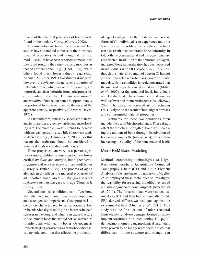
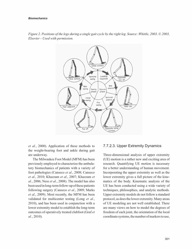
The gait cycle is typically defined as the time from initial contact to initial contact, with the same foot. Major events of the gait cycle include initial contact, opposite toe-off, heel rise, opposite initial contact, toe-off, feet adjacent, and tibia vertical (Figure 2). This cycle is repeated and is divided into two periods, stance and swing. Stance is the period when the foot is on the ground, and is typically 60% of the gait cycle in normal gait. It includes events of initial contact through toe-off. It is further divided into loading response, mid-stance, terminal stance, and pre-swing. Swing is the period that occurs when the foot is off the ground, advancing forward, and is usually 40% of the gait cycle in normal gait. The events of swing phase include toe off until initial contact. It is subdivided into initial swing, mid-swing, and terminal swing.
Gait is measured and analyzed three-dimen-sionally. The largest movements typically occur in the sagittal plane. Force plates can be used in conjunction with camera systems to obtain joint
reaction forces and moments in addition to joint motions. Electromyography can also be used concurrently to obtain muscle activity data during gait. The 3-D analysis of gait provides metrics such as temporal-stride parameters, joint angles, joint range of motion, joint reaction forces, joint reaction moments, and joint powers. This data is then often used for clinical assessment of normal or pathologic gait.
The use of quantitative motion analysis meth-ods for the modeling of ambulatory and functional phenomena is a recognized treatment planning tool (Cook et al., 2003; DeLuca et al., 1997; Gage et al., 1984; Gage & Novacheck, 2001; Schwartz et al., 2004). The models most frequently employed for lower extremity gait analysis have noted deficiencies in their means of estimating joint centers and intertarsal motion (Camomilla et al., 2006; Harris, 1991; Perry, 1992; Piazza, Okita, & Cavanagh, 2001; Piazza et al., 2004). Functional means for determining subject-specific axes and centers of rotation provide a better method for calculating joint dynamics (Camomilla et al., 2006), and multi-segmental foot models address the limitations of a single-segment model (Kid-der et al., 1996; Kitaoka et al., 2006; Leardini et al., 2007; MacWilliams, Cowley, & Nicholson, 2003). The bone-based referencing methods used by the Milwaukee Foot Model use measures from weightbearing radiographs to index the orienta-tion of skin-mounted markers to the underlying bony anatomy (Long, Eastwood, & Harris, 2009; Long et al., 2008). This model has been used in a series of studies quantifying the gait of patients with foot and ankle pathology (Canseco et al., 2008; Canseco et al., 2009; Khazzam et al., 2007; Khazzam et al., 2006; Marks et al., 2009; Ness et al., 2008). An extension of the model’s ability to measure the motion of bone-based axes has been realized in the use of high-speed fluoroscopy to radiographically analyze motion at the bony level. Applications of this technology have been reported for the knee (Li et al., 2008; Varadarajan et al., 2008) and non-weight-bearing ankle (Komistek
301
Biomechanics
et al., 2000). Application of these methods to the weight-bearing foot and ankle during gait are underway.
The Milwaukee Foot Model (MFM) has been previously employed to characterize the ambula-tory biomechanics of patients with a variety of foot pathologies (Canseco et al., 2008; Canseco et al., 2010; Khazzam et al., 2007; Khazzam et al., 2006; Ness et al., 2008). The model has also been used in long-term follow-up of these patients following surgery (Canseco et al., 2009; Marks et al., 2009). Most recently, the MFM has been validated for multicenter testing (Long et al., 2010), and has been used in conjunction with a lower extremity model to establish the long-term outcomes of operatively treated clubfoot (Graf et al., 2010).
7.7.2.3. Upper Extremity Dynamics
Three-dimensional analysis of upper extremity (UE) motion is a rather new and exciting area of research. Quantifying UE motion is necessary for a better understanding of human movement. Incorporating the upper extremity as well as the lower extremity gives a full picture of the kine-matics of the body. Kinematic analysis of the UE has been conducted using a wide variety of techniques, philosophies, and analytic methods. Upper extremity models do not follow a standard protocol, as does the lower extremity. Many areas of UE modeling are not well established. There are many views on how to model the degrees of freedom of each joint, the orientation of the local coordinate systems, the number of markers to use,
Figure 2. Positions of the legs during a single gait cycle by the right leg. Source: Whittle, 2003. © 2003, Elsevier - Used with permission.
302
Biomechanics
and the appropriate Euler rotation sequence. This makes it very difficult to compare and contrast results between studies. Therefore, it is necessary to develop validated UE models that consist of standardized parameters, so as to make it sufficient for clinical application.
The measurement of 3-D kinematics of the UE has generally not received as much scientific attention as that of the lower limb. Upper limb motion may be rapid and is spatially complex, particularly at the shoulder. The elbow and wrist are relatively simple to model geometrically. They are often described as having the center of rota-tion located at the geometric center of the joint. Movement of the elbow and wrist is frequently simplified with two degrees of freedom. Model-ing of the shoulder could be agreed upon to be the most complicated joint in the upper extremity. The shoulder joint complex is an articulation that challenges simple kinematic description.
The UE consists of four segments: the thorax, the upper arm, the forearm, and the hand. These segments are connected via the shoulder joint, elbow joint, and wrist joint. It is important to understand the anatomy and kinesiology for ac-curate and precise modeling.
7.7.2.4. Modeling of the Upper Extremity
7.7.2.4.1. International Society of Biomechan-ics (ISB) Standards
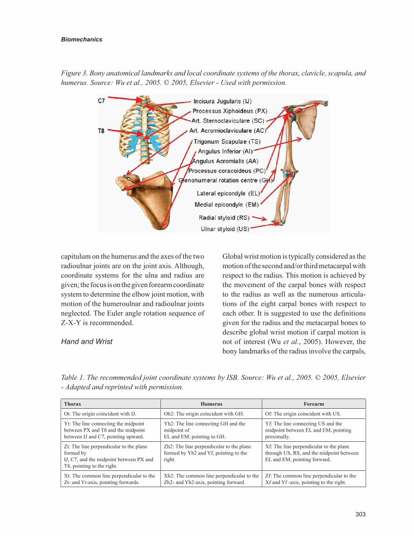
The International Society of Biomechanics has proposed a definition of a joint coordinate system for the shoulder, elbow, wrist, and hand (Wu et al., 2005). For each joint, the standard includes the body segment coordinate system and the joint coordinate system, as well as the motion for the constituent joints (Figure 3 and Table 1). The joint coordinate systems are based on that of Grood and Suntay’s knee joint (Grood & Suntay, 1983). These recommendations were set by the Standardization and Terminology Committee to lead to stronger
communication among researchers and clinicians. The proposals are based on the ISB standard for reporting kinematic data, first published by Wu and Cavanagh in 1995 (Wu & Cavanagh, 1995).
Thorax
The model for the thorax uses four bony landmarks: spinous process of the 7th cervical vertebra (C7), spinous process of the 8th thoracic vertebra (T8), suprasternal notch (IJ), and xiphoid process (PX) (Wu et al., 2005). The order of rotation follows the conventional Cardan sequence of flexion, lateral bending, and rotation (Z-X-Y).
Shoulder
The model for the shoulder stems from the work done by van der Helm and Pronk (van der Helm & Pronk, 1995). Bony landmarks of the humerus include the glenohumeral rotation center (GH), the lateral epicondyle (EL), and the medial epicondyle (EM) (Wu et al., 2005). Rotations are described using Euler angles, Y-X-Y. Convention suggests anatomical orientation of the coordinate systems for initial alignment. The distal coordinate system is then described with respect to the proximal co-ordinate system. For most shoulder motions, the rotation center would be a rough estimate, since only the glenohumeral joint resembles a ball-and-socket joint. When modeling the sternoclavicular joint and acromioclavicular joint, the definition of the rotation centers is left to the researcher’s discretion.
Elbow
Bony landmarks of the forearm include the medial epicondyle, lateral epicondyle, radial styloid, and ulnar styloid. The following approximations were made at the elbow joint: i) the glenohumeral joint is a ball joint; ii) the humeroulnar joint is a hinge joint; and iii) the radioulnar joint (proximal and distal) is a hinge joint (Wu et al., 2005). The joint coordinate system of the forearm utilizes the radial and ulnar styloid bony landmarks. The center of the
303
Biomechanics
capitulum on the humerus and the axes of the two radioulnar joints are on the joint axis. Although, coordinate systems for the ulna and radius are given; the focus is on the given forearm coordinate system to determine the elbow joint motion, with motion of the humeroulnar and radioulnar joints neglected. The Euler angle rotation sequence of Z-X-Y is recommended.
Hand and Wrist
Global wrist motion is typically considered as the motion of the second and/or third metacarpal with respect to the radius. This motion is achieved by the movement of the carpal bones with respect to the radius as well as the numerous articula-tions of the eight carpal bones with respect to each other. It is suggested to use the definitions given for the radius and the metacarpal bones to describe global wrist motion if carpal motion is not of interest (Wu et al., 2005). However, the bony landmarks of the radius involve the carpals,
Figure 3. Bony anatomical landmarks and local coordinate systems of the thorax, clavicle, scapula, and humerus. Source: Wu et al., 2005. © 2005, Elsevier - Used with permission.
Table 1. The recommended joint coordinate systems by ISB. Source: Wu et al., 2005. © 2005, Elsevier - Adapted and reprinted with permission.
Thorax Humerus Forearm
Ot: The origin coincident with IJ. Oh2: The origin coincident with GH. Of: The origin coincident with US.
Yt: The line connecting the midpoint between PX and T8 and the midpoint between IJ and C7, pointing upward.
Yh2: The line connecting GH and the midpoint of EL and EM, pointing to GH.
Yf: The line connecting US and the midpoint between EL and EM, pointing proximally.
Zt: The line perpendicular to the plane formed by IJ, C7, and the midpoint between PX and T8, pointing to the right.
Zh2: The line perpendicular to the plane formed by Yh2 and Yf, pointing to the right.
Xf: The line perpendicular to the plane through US, RS, and the midpoint between EL and EM, pointing forward.
Xt: The common line perpendicular to the Zt- and Yt-axis, pointing forwards.
Xh2: The common line perpendicular to the Zh2- and Yh2-axis, pointing forward.
Zf: The common line perpendicular to the Xf and Yf -axis, pointing to the right.
304
Biomechanics
which are difficult to palpate. The distal head and center of base are suggested landmarks for the metacarpals and phalanges.
The coordinate system for the hand is given with the forearm initially in the standard anatomi-cal position, with the palm anterior and the thumb lateral. For the right arm, the positive Yi axis is directed proximally, the positive Xi axis is directed volarly, and the positive Zi axis is directed to the right in the anatomical position (radially) (Wu et al., 2005). It is recommended to have the same sign convention for clinical motion of left and right arms. Thus, for the left arm, Yi is directed distally, Xi is directed dorsally, and Zi is directed to the right in the anatomical position (ulnarly) (Wu et al., 2005).
7.7.2.4.2. Single Joint Models
A common method for describing three-dimen-sional joint motion is with the use of Euler angels. Euler angles represent three sequential rotations about anatomical axes. Karduna et al. showed that for a given motion, different rotational sequences theoretically result in different angle calculations with differences up to 50 degrees for some angles (Karduna, McClure, & Michener, 2000). In order to compare results across different laboratories it is desired that a standard sequence be proposed and adopted.
Qualitative descriptions of the location of the axes or center of rotation of UE joints have been given in several studies. Poppen and Walker de-scribed the center of rotation of the glenohumeral joint (Poppen & Walker, 1976). Morrey and Chao, Youm et al., and Deland et al. described the axes of rotation for the elbow joint (Morrey & Chao, 1976; Youm et al., 1979; Deland, Garg, & Walker, 1987). No report was found on quantitative de-scriptions of the locations of these axes and centers of rotation of the UE. Veeger et al. took on this challenge when they proposed parameters for the development of a musculoskeletal model of the upper extremity (Veeger et al., 1997). These
parameters included the 3-D locations of muscle attachment sites, muscle volumes, muscle lengths, pennation angles, the center of rotation for the glenohumeral joint, and axes of rotation for the humeroulnar and radioulnar joints. This was ac-complished using five cadaver specimens with four magnetic tracking sensors. Three-dimensional kinematics of the humerus, ulna, and radius in different movements of the glenohumeral, humer-oulnar, and radioulnar joints were measured for each specimen. The instantaneous rotation center of the glenohumeral joint and the instantaneous rotation axes of elbow flexion and forearm pro-nation were determined for each specimen from the kinematic data.
The results showed that the rotation center of the glenohumeral joint was very close to the geometric center of the joint with a mean distance of 4 mm. The results indicated that it is reasonable to model the glenohumeral joint as a ball-and-socket joint with three degrees of freedom and center of rotation in the geometric center of the joint. These findings were consistent with those reported by Högfors et al. (Högfors, Sigholm, & Herberts, 1987). The location of the glenohumeral joint obtained in this study agreed with that de-scribed by Poppen and Walker, who reported that the center of rotation of the glenohumeral joint was 6 mm from its geometric center (Poppen & Walker, 1976).
The mean angle between the flexion-extension and pronation-supination axes of the elbow joint was 94°, essentially perpendicular. The minimum distance between these two axes was about 4 mm. The estimated elbow axis and elbow cylinder confirmed previous qualitative observations of a flexion-extension axis passing through the center of the trochlea and the capitulum humeri (Deland et al., 1987; Morrey & Chao, 1976; Youm et al., 1979). Thus, it is reasonable to model the humer-oulnar joint as a uniaxial joint. This research made a major contribution to upper extremity research by quantitatively showing that the glenohumeral joint can be modeled as a ball-and-socket joint
305
Biomechanics
with three degrees of freedom and that the elbow joint can be modeled as a double hinge joint with two degrees of freedom.
The position of the kinematic rotation center has scarcely been measured. Poppen and Walker, and Jackson et al. reported on the position of the rotation center relative to the humeral head during walking (Poppen & Walker, 1976; Jackson, Joseph, & Wyard, 1977). Their method was based on a two-dimensional estimation. However, it was still to be determined whether the assumption that the geometric rotation center was also the kinematic rotation center. Veeger recently furthered his work by validating this assumption, and that the geo-metric center of rotation in the glenohumeral joint can be described based on the center of a sphere fitted through the glenoid surface (Veeger, 2000).
Engin et al. were the first to give a three-dimensional mathematical modeling of the human shoulder complex, based on a statistical in vivo database (Engin & Tumer, 1989). The motion range of the axial rotation of the upper arm was not reported. Thus, Wang et al. extended this work to quantify the motion range of the upper arm ro-tation along the longitudinal axis of the humerus throughout its workspace. Their model consisted of eight markers placed on bony landmarks with data collected via a sonic digitizer. Rotations were calculated using an Euler sequence of ZY´X´´ (Wang et al., 1998). The joint center of the shoul-der was determined though the optimization of a sphere, while the elbow and wrist joint centers were determined from the geometric midpoint of specific markers. An original surface regression fitting method using an orthogonal homogeneous polynomial basis was presented. The method was used to establish a statistical database of motion range of the upper arm. It was shown that the axial range of motion of the upper arm depends strongly on the position of the upper arm in the shoulder sinus cone, and varies on average from 94° to 157° (Wang et al., 1998). This model seemed to have a high value of residual error of the fit.
7.7.2.4.3. Full Upper Extremity Models
Few models have incorporated the shoulder, elbow, and wrist joints. Biryukova et al. used spatial tracking system recording to obtain the kinematics of the human arm in terms of angles of rotation in the joints (Biryukova et al., 2000). The arm was modeled as three rigid bodies with seven degrees of freedom. Euler angles were applied in the ZYX sequence. Four spatial tracking system markers were used, operating at an update rate of 30 Hz. The joint centers were determined with an optimization method. Validation of the model proved it was reliable (Slavens & Harris, 2008)1.
Rab et al. developed a model of the upper extremity using a standard 3-D video-based tech-nique and 18 retroreflective skin markers (Rab, Petuskey, & Bagley, 2002). The model consists of 10 segments (head, neck, shoulder girdle, right/left upper arms, right/left forearms, right/left hands, and pelvis) whose local coordinate systems are used to calculate upper extremity motion. All joints were assumed to have fixed centers of rotation. The shoulder joint was modeled as a ball-and-socket joint with three degrees of free-dom, located in the center of the humeral head. Movement was calculated between the humerus and the trunk, and scapular contribution to shoulder motion is ignored, similar to conventions adopted by Veeger and colleagues (Veeger et al., 1997). The elbow was modeled as a rotating hinge joint with two degrees of freedom, with a single joint center in the distal humerus. Forearm pronation and supination were modeled as rotation about an axis connecting the elbow center and distal ulna. The wrist joint was modeled as a universal joint with two degrees of freedom, where movement occurred in flexion/extension and radial/ulnar de-viation. Movement between the hand and forearm segments, determined by a vector connecting the geometric wrist center and the calculated elbow center, represented wrist movement (Slavens & Harris, 2008)1.
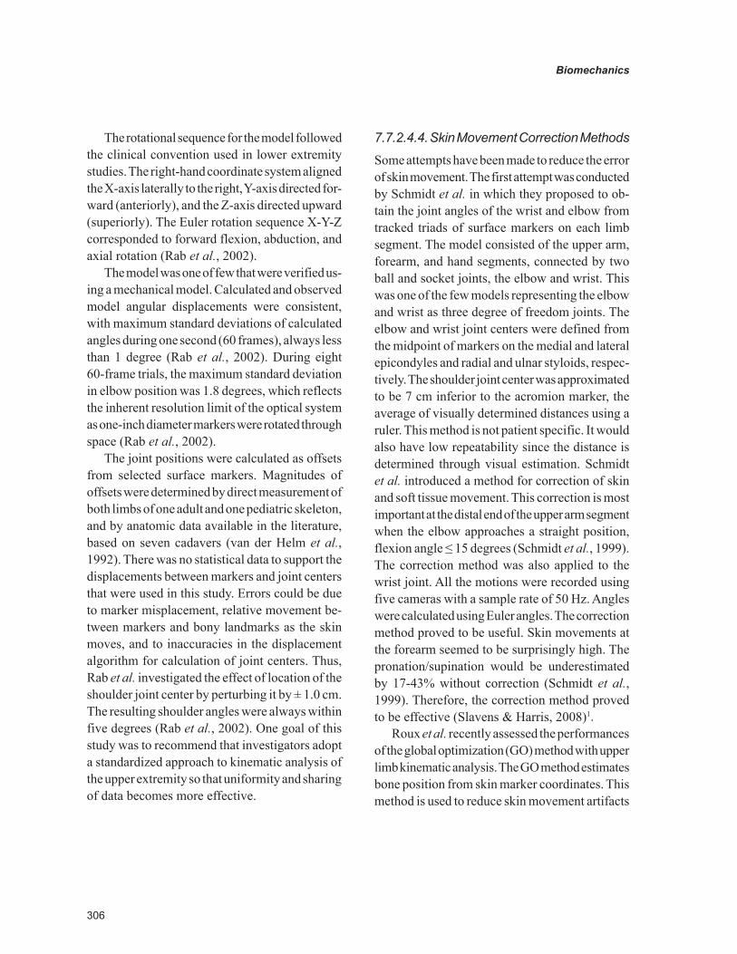
306
Biomechanics
The rotational sequence for the model followed the clinical convention used in lower extremity studies. The right-hand coordinate system aligned the X-axis laterally to the right, Y-axis directed for-ward (anteriorly), and the Z-axis directed upward (superiorly). The Euler rotation sequence X-Y-Z corresponded to forward flexion, abduction, and axial rotation (Rab et al., 2002).
The model was one of few that were verified us-ing a mechanical model. Calculated and observed model angular displacements were consistent, with maximum standard deviations of calculated angles during one second (60 frames), always less than 1 degree (Rab et al., 2002). During eight 60-frame trials, the maximum standard deviation in elbow position was 1.8 degrees, which reflects the inherent resolution limit of the optical system as one-inch diameter markers were rotated through space (Rab et al., 2002).
The joint positions were calculated as offsets from selected surface markers. Magnitudes of offsets were determined by direct measurement of both limbs of one adult and one pediatric skeleton, and by anatomic data available in the literature, based on seven cadavers (van der Helm et al., 1992). There was no statistical data to support the displacements between markers and joint centers that were used in this study. Errors could be due to marker misplacement, relative movement be-tween markers and bony landmarks as the skin moves, and to inaccuracies in the displacement algorithm for calculation of joint centers. Thus, Rab et al. investigated the effect of location of the shoulder joint center by perturbing it by ± 1.0 cm. The resulting shoulder angles were always within five degrees (Rab et al., 2002). One goal of this study was to recommend that investigators adopt a standardized approach to kinematic analysis of the upper extremity so that uniformity and sharing of data becomes more effective.
7.7.2.4.4. Skin Movement Correction Methods
Some attempts have been made to reduce the error of skin movement. The first attempt was conducted by Schmidt et al. in which they proposed to ob-tain the joint angles of the wrist and elbow from tracked triads of surface markers on each limb segment. The model consisted of the upper arm, forearm, and hand segments, connected by two ball and socket joints, the elbow and wrist. This was one of the few models representing the elbow and wrist as three degree of freedom joints. The elbow and wrist joint centers were defined from the midpoint of markers on the medial and lateral epicondyles and radial and ulnar styloids, respec-tively. The shoulder joint center was approximated to be 7 cm inferior to the acromion marker, the average of visually determined distances using a ruler. This method is not patient specific. It would also have low repeatability since the distance is determined through visual estimation. Schmidt et al. introduced a method for correction of skin and soft tissue movement. This correction is most important at the distal end of the upper arm segment when the elbow approaches a straight position, flexion angle ≤ 15 degrees (Schmidt et al., 1999). The correction method was also applied to the wrist joint. All the motions were recorded using five cameras with a sample rate of 50 Hz. Angles were calculated using Euler angles. The correction method proved to be useful. Skin movements at the forearm seemed to be surprisingly high. The pronation/supination would be underestimated by 17-43% without correction (Schmidt et al., 1999). Therefore, the correction method proved to be effective (Slavens & Harris, 2008)1.
Roux et al. recently assessed the performances of the global optimization (GO) method with upper limb kinematic analysis. The GO method estimates bone position from skin marker coordinates. This method is used to reduce skin movement artifacts
307
Biomechanics
that imply relative movement between markers and bones. Results showed a significant reduc-tion of the error and of the variability due to skin movement. As was discussed previously, Schmidt et al. compensated skin movement artifacts by controlling relative position and orientation of the segments during voluntary movements (Slavens & Harris, 2008)1.
The model by Roux et al. consists of the trunk, arm, forearm and hand segments with marker locations very similar to the protocol proposed by Schmidt et al. (Roux et al., 2002). However, as opposed to Schmidt’s model, a sphere-fitting method was used for determination of the shoulder and wrist joint centers, which is more accurate. The elbow center was defined as the midpoint between the medial and lateral elbow markers. Angles were computed using Euler rotations. The GO method was applied to the upper limb to minimize relative movement between markers and bones. The relative movement between the hand and forearm during internal/external rota-tion of the shoulder presented greater error with the application of the GO method than without it. Errors were compensated with pronation/supination of the elbow (Roux et al., 2002). The GO method significantly reduced skin movement errors (Slavens & Harris, 2008)1.
7.7.2.5. Sports Biomechanics
Three-dimensional analyses in sports have proved to be useful in assessing movement patterns and relating the movements to potential injury mechanisms. Whiting et al. conducted a kinematic analysis of human upper extremity movements in boxing (Whiting, Gregor, & Finerman, 1988). Four subjects were assessed using only two high-speed 16 mm motor-driven cameras. The model was composed of markers to delineate the shoulder el-bow and wrist joint centers along with joints on the hand and glove. Markers were placed directly on
the approximated location of the joint centers, not on bony landmarks. High-speed cinematography was used to provide 3-D locations of the points. Elbow angle measurements were calculated using standard spatial geometry formula, with angular velocity and acceleration data being calculated using finite difference formulations. Euler rota-tions were not employed. Instead, the direct linear transformation (DLT) method was used. Due to these differential methods, and the small number of cameras, error was introduced as indicated by the high standard deviation (Whiting, Gregor, & Finerman, 1988).
The effectiveness of arm segment rotations in producing racquet head speed during tennis was also investigated. Ten bony landmarks were used in the model and were captured by three cine cameras (Sprigings et al., 1994). The joint centers were approximated using the midpoint of mark-ers placed at the upper arm, elbow, wrist, hand, and racquet. A DLT algorithm was developed to analyze the angular velocity and racquet-head position. The algorithm depends on the following assumption: a) the constructed orthogonal axes for the upper limb segments closely approximate their anatomical axes; b) the varus-valgus rotation at the elbow joint is zero; c) the longitudinal rotation of the hand about the wrist joint is zero; and, d) the hand and the racquet are a single rigid body (Sprigings et al., 1994).
Dillman et al. investigated the biomechanics of pitching with emphasis upon shoulder kinematics (Dillman, Fleisig, & Andrews, 1993). Each subject was marked with retro-reflective, 1-in. diameter balls, which were tracked by four cameras at 200 Hz. The body markers were used to mathemati-cally construct a system of local segmental three-dimensional coordinate system for calculating the motion of the arm in anatomical reference planes. This modeling technique required estimation of two coordinate axes and a translation from surface markers to joint centers.
308
Biomechanics
More recently, Aguinaldo and colleagues, investigated baseball pitching kinematics and kinetics. Out of concern for high rotational torques during pitching leading to overuse injuries, re-search was conducted to quantify the effects of trunk rotation on shoulder rotational torques (An-derson, Ellis, & Weiss, 2007). The study suggested specific kinematic patterns be identified to increase efficiency and decrease risk of injury. To follow up, the correlation of throwing mechanics with elbow valgus load in 69 adult baseball pitchers was studied (Aguinaldo & Chambers, 2009). Whole body dynamics were acquired. Valgus torque at the elbow was associated with six biomechanical variables of sequential body motion. Late trunk rotation, reduced shoulder external rotation, and increased elbow flexion movements appeared to be most closely related to valgus torque.
7.7.3. Hand Biomechanics
The hand is a vastly mobile organ of high com-plexity. The intricacy of the bony arrangement, articulations, and musculature enable the hand to perform an array of movements. Several new endeavors are underway to investigate the bio-mechanics of the pathological hand.
Pathological movement of the hand in persons with stroke has been examined by Seo et al. Due to altered force production following stroke, misdirected digit force may lead to finger-object slip and failure to grasp (Seo, Rymer, & Kamper, 2010). Therapies to redirect the force direction of the digits may improve stroke survivors’ ability to stably grip an object. Seo and colleagues further investigated visual feedback for the index fingertip and thumb to determine if this force production can be corrected (Seo et al., 2011). It was shown that with repeated practice of pinch along with visual feedback of force direction, improvement of grip force control in persons with stroke may be achieved.
7.7.4. Musculoskeletal Modeling
7.7.4.1. Finite Element Modeling
The finite element method (FEM) is a powerful computational technique, with numerous applica-tions in the field of Rehabilitation Engineering. The major benefit of FEM lies in being able to non-invasively evaluate biological structures. Math-ematical numerical approximation methods form the basis of FEM. These numerical methods are used to obtain an output, the field variables, from a system of equations, and the field, in response to inputs, the boundary conditions. Finite elements represent regular straight-side geometric 2-D or 3-D shapes that enclose a finite area or volume. Field variables are explicitly calculated at each vertex of the element, the “node” (Hutton, 2004).
In musculoskeletal modeling, the field is generally a geometrically complex biological structure such as bone, muscle, ligament or joint; a physical structure such as a trauma fixation de-vice, an implant or an endoprosthesis; or a system of interaction between the two. Computerized tomography (CT) scans can be utilized to derive fairly accurate physical domains of these complex entities. These volumes are converted by FEM to a set of finite elements, known as a mesh. Bound-ary conditions comprise loads and constraints that act on the system. Other inputs include material properties. An appropriately constrained field has a unique solution that is specific to that particular set of boundary conditions and inputs. The type of analysis depends upon the physical behavior of the system. Most studies, involving whole bone FE models, utilize the assumption of geometric and material linearity and static equilibrium to perform linear, static analyses.
FEM solutions are approximate in nature. To obtain an exact solution, the mesh is sequentially refined. This involves increasing the number or order of the finite elements in the mesh. Greater area from the curved-boundary physical domain is incorporated into the solution, thus increasing
309
Biomechanics
field representation accuracy. The approximate FE solution asymptotically approaches the exact solution with sufficient mesh refinement. Since FEM is a computationally intensive tool, mesh refinement has to be balanced with computational resources available.
Biomechanical FE models require verification, validation, and optimization to be considered utilizable. Verification involves establishing the mathematical and implementation accuracy. Notable are code verification using benchmark problems, and calculation verification using mesh convergence. Validation reflects predictive capability, and is carried out by statistical com-parison of experimental data and FE simulation data. Finally, the model is optimized based upon sensitivity studies, to material properties, geom-etry and boundary conditions (Anderson et al., 2007). Three levels of FE model development have been reported (Viceconti et al., 2005). The first and second levels are targeted at a research FE model, and address verification and sensitivity analysis, and validation, respectively. The third level targets clinical applicability, and requires risk-benefit analyses as well as application in prospective and retrospective studies.
Several medical and surgical fields employ human FE models. These include orthopaedic surgery, maxillofacial surgery, neurosurgery, and cardiovascular surgery, to name a few. While fluid mechanics plays an important role in valve design in cardiovascular surgery, most other fields utilize solid mechanics for FE model design. Hence, strength, stress, strain, and displacement are the most commonly evaluated field variables.
The FE modeling of bone is performed at many levels. Tissue level modeling involves microstructural cortical and cancellous bone. Structural modeling would involve part of a bone such as the tibial plateau or whole bone. System modeling involves inclusion of the bone as part of a joint (Henninger et al., 2010). Whole bone
FE models documented in literature include the femur, tibia, radius, metacarpals, scapula, pelvis, and clavicle. Sources of geometry for whole bone models include cadavers, composite bones, and standardized image datasets such as the NIH Vis-ible Human Project. The most common research application of these models is for evaluation of trauma fixation implants and prosthesis follow-ing implantation in bone. Industry applications predominantly address implant design. The trend towards development of patient specific FE models has potential clinical applications. An alternative approach today is the development of standardized FE bone models such as the Muscle-Standardized Femur, which can be adapted with patient-specific geometry, material, kinetic, kinematic and EMG inputs to develop patient specific models (Cris-tofolini et al., 2010).
Microstructural FE models of cancellous bone, derived using CT scan, focus on pathological frac-ture risk, such as in osteoporosis and metastasis. Automated FE solvers can utilize CT scan density data to incorporate individual element material properties, specifically the elastic modulus. Soft tissue FE modeling includes muscles, ligaments, and joints. Non-linearity in geometry and me-chanical behavior such as hysteresis and creep, necessitate non-linear and sometimes dynamic assumptions for analysis.
Limitations of whole bone FE models include accurate incorporation of muscle forces, exclu-sion of microstructural mechanical behavior, and inability to directly validate output parameters. However, geometry and material properties can be accurately incorporated using CT scanning and clinical/experimental setups can be carefully ana-lyzed to derive biofidelic FE boundary conditions. In short, FEM is an important tool in present-day musculoskeletal research, with significant poten-tial for clinical applicability.
310
Biomechanics
7.7.4.1.1. Finite Element Modeling (FEM) Software
Finite element modeling and analyses can be completed using a number of software packages. Abaqus (Simulia, Dassault Systemes; Providence, RI, USA), COMSOL (COSMOL AB, Stockholm, Sweden) and ANSYS (ANSYS, Inc., Canonsburg, PA, USA) are common examples of software suites used for finite element analysis. They have the capability for solid modeling, meshing, linear and nonlinear modeling, implicit and explicit methods, and computational fluid dynamics.
7.7.4.2. Musculoskeletal Modeling Methods
7.7.4.2.1. SIMM Software
SIMM (Musculographics Inc., Santa Rosa, CA, USA) is a biomechanics software package for the construction, modeling, animation, and analysis of 3-D musculoskeletal systems. It integrates mus-culoskeletal components such as bones, muscles, ligaments, and tendon. SIMM may be used to model muscle-tendon lengths, velocities, mo-ment arms, and accelerations during gait. SIMM may also be implemented to analyze surgical procedures, such as osteotomies and total joint replacements. It was introduced in the early 1990’s and is widely accepted and used throughout the biomechanics community.
7.7.4.2.2. OpenSim Software
OpenSim is the free counterpart to SIMM for further musculoskeletal model features. It was designed at Simbios, an NIH center at Stanford University for simulation of biological structures. This open-source software enables users to create and customize dynamics simulations of move-ment. It can be used to develop subject-specific models for inverse and forward dynamics. Open-
Sim allows import and export of SIMM models for advanced design.
7.7.4.2.3. Adams Software
Adams (MSC Software, Santa Ana, CA, USA) is a multi-body dynamics simulation software. It is used for dynamics analysis of mechanical systems implementing equations for kinematics, statics, quasi-statics, and dynamics. It can perform both linear and nonlinear dynamics problems.
7.7.4.2.4. LifeMOD Software
LifeMOD™ (LifeModeler, Inc., San Clemente, CA, USA) is a virtual human modeling and simulation software package. It is used for the development of biomechanical human models. LifeMOD is built on MD Adams software and can be integrated into computer-aided engineering (CAE) systems. LifeMOD can import complex product geometry from many computer-aided design (CAD) systems, such as CATIA, Pro/E, SolidWorks, and Unigraphics. It is also capable of importing MRI and CT data. LifeMOD out-puts metrics of force, displacement, velocity, acceleration, torque, and angles. It includes an-thropomorphic databases for automatic model creation, and can perform inverse and forward dynamics. It is also capable of building a virtual human model with 3-D motion, bones, joints, and muscle components.
7.7.4.2.5. AnyBody Modeling System Soft-ware
The AnyBody Modeling System™ (AnyBody Technology A/S, Denmark) is a software system for simulating the biomechanics of the human body in its environment. The model may be defined using external forces and boundary conditions for the environment given for any specified posture or motion. AnyBody computes the mechanical
311
Biomechanics
properties for the body-environment system. Muscle forces, joint forces and moments, metabo-lism, elastic energy in tendons, and antagonistic muscle actions can be determined. Patient-specific or optimization models can be designed. Data may be imported from motion capture systems or exported for input to FE models.
7.7.4.2.6. Virtual Interactive Musculoskeletal System (VIMS) Software
Virtual Interactive Musculoskeletal System (VIMS) is biomechanical simulation software for human musculoskeletal system physiology. Its purpose is for the investigation of joint and connective tissue mechanics. Visualization in both static and animated states is possible. Adaptable anatomical models such as prosthetic implants and fracture fixation devices are integrated in the system along with computational capabilities for static, kinematic, kinetic, and stress analyses. A database containing long bone dimensions, con-nective tissue material properties, and a library of skeletal joint system functional activities and loading conditions are available. These can be modified, updated, and expanded. Application software is also available to allow end-users to perform biomechanical analyses interactively. The intent of this system, model library, and database, is for application to orthopaedic education, basic research, device development and application, and clinical patient-care related to musculoskeletal joint system reconstruction, trauma management, and rehabilitation (Chao et al., 2007).
7.7.4.2.7. Locomotion Models
Applications of modeling efforts have been em-ployed for better understanding of locomotion. Geyer et al. investigated muscle and energy demands in passive compliant structures such as tendons and ligaments during bouncing gaits – running, hopping, and trotting (Geyer, Seyfarth, & Blickhan, 2003). It was shown that these structures store and release energy. The afferent information from muscle receptors was examined using a two-
segment leg model with one Hill-type extensor muscle. Model parameters included values from literature such as segment lengths, moment arms, joint angles, isometric force, eccentric force, and excitation-contraction coupling, among others. This was completed using Matlab and Simulink software (MathWorks, Natick, MA, USA) in a forward dynamic simulation. It was concluded that position force feedback may stabilize running.
Additional research has also investigated running stability (Geyer, Seyfarth, & Blickhan, 2005; Knuesel, Geyer, & Seyfarth, 2005; Rum-mel & Seyfarth, 2008). A model was developed, which consisted of a spring-mass system for the stance phase and a functional control model for the swing phase – represented by a passive or actively driven pendulum. The model was vali-dated against treadmill running. The results of the model indicated that for certain running speeds and pendulum lengths, the behavior of the mechanical system was stable (Knuesel, Geyer, & Seyfarth, 2005). Furthermore, a two-segment leg model was used to investigate the effects of leg compliance originating from the joint level on running stability (Rummel & Seyfarth, 2008). Due to leg geometry, a non-linear relationship between leg force and leg compression was found. The two-segment model serves as a conceptual model between the simpler spring-mass model and more detailed segmented models of human bodies.
7.8. CLINICAL BIOMECHANICS
Clinical biomechanics refers to an area of biome-chanics that is focused on clinical application. It includes an interdisciplinary approach to make a direct impact on evidence-based medicine. Evidence-based medicine involves a clinician’s practice to be based on scientific evidence, re-quiring relevant clinical questions, a thorough literature search, a critical appraisal of evidence and its applicability, and an application of the findings to the clinical problem (Buckwalter et al.,
312
Biomechanics
2007). Clinical science and research may lead the clinician to change health care practice and treat-ment methods based on solid evidence. Clinical biomechanics encompasses such areas as cardiac biomechanics and orthopaedic biomechanics.
7.8.1. Pathologies
Common pathologies associated with biomechani-cal impairments include stroke, myelomeningo-cele (MM), spinal cord injury (SCI), cerebral palsy (CP), and osteogenesis imperfecta (OI).
7.8.1.1. Stroke
Stroke is a leading cause of disability and the third leading cause of death in the U.S. (Ameri-can Stroke Association, 2011). Approximately 795,000 Americans suffer a new or recurrent stroke each year. Ischemic stroke results from an obstruction of blood flow to the brain. Recovery and rehabilitation from a stroke is largely related to the location and severity of the lesion. Success-ful rehabilitation involves relearning skills and activities, recovery of ischemically injured cells, and brain plasticity.
7.8.1.2. Myelomeningocele (MM)
Myelomeningocele (MM) is the most common central nervous system birth defect (Davis et al., 2005). It is defined as the failure of the neural tube to close, resulting in a cystic dilatation of meninges and protuberance of the spinal cord through the vertebral defect (Farley & Dunleavy, 1996). In the United States, approximately 1340 infants are born with MM each year (CDC, 2006). Birth incidence of the disease was reported to be 3.68 cases per 10,000 live births from 1999-2001 (Canfield et al., 2006). Patients with MM present with a multitude of impairments, but the primary functional deficits are lower limb paralysis and sensory loss. Paraplegia from the myelodysplasia
typically causes some impairment of mobility and musculoskeletal complications may also result.
7.8.1.3. Spinal Cord Injury (SCI)
It is estimated that approximately 253,000 persons are living with spinal cord injury (SCI). The esti-mated annual incidence is approximately 40 cases per million population, or approximately 11,000 new cases each year (University of Alabama at Birmingham: http://www.spinalcord.uab.edu). Those with incomplete SCI (54%) have partial preservation of their lower extremity function, which indicates the potential for ambulation. Due to the reduced strength in the hip and trunk extensor musculature, upper extremity devices are commonly prescribed to assist ambulation. Waters et al. reported 76% of individuals with incomplete paraplegia and 46% of those with incomplete tetraplegia achieve community am-bulation – with the help of bracing and mobility aids (Waters et al., 1994a).
7.8.1.4. Cerebral Palsy (CP)
Cerebral palsy (CP) is a condition characterized by orthopedic impairments of the lower extremities. The Centers for Disease Control and Prevention (CDC) estimates that 10,000 children in the United States develop CP each year (Schendel, Schuchat, & Thorsen, 2002). CP is caused by brain damage and has symptoms including postural instability and abnormal muscle tone. In patients with CP, voluntary movement becomes uncoordinated and restricted, and may result in a co-contraction of antagonist and agonist muscles (Miller & Clark, 1998). One of the most common types of CP is spastic diplegic cerebral palsy. It is estimated that 75-87% of patients with CP have a spastic type (Stanley, Blair, & Alberman, 2000). Spastic diplegic CP severely affects the lower extremi-ties, and many of these children rely on assistive devices for ambulation.
313
Biomechanics
7.8.1.5. Osteogenesis Imperfecta (OI)
Osteogenesis imperfecta (OI), a genetic disorder characterized by bones that break easily, is a pe-diatric pathology associated with crutch usage. OI has a prevalence of 1/5,000 to 1/10,000 with an estimated 20,000 to 50,000 cases in the U.S. (Byers & Steiner, 1992). Weak musculature and bowing of the long bones often requires the use of braces and mobility aids for ambulation.
7.8.2. Advanced Clinical Approaches to Postural Stability
Clearly, many different metrics can be calculated from COP data, and more than one measure is necessary to characterize posture in children with CP (Prieto et al., 1996). However, it is not clear which parameters are most effective for detecting differences in sway between typically developing children and children with CP, nor under what conditions children with CP are bal-ance-compromised. These observations provide the impetus for some of the more current work. Bustamante et al. (Bustamante Valles et al., 2006) introduced a biomechanical model of postural control in children with CP that resulted in a com-prehensive characterization, including metrics in the time, distance, and frequency spectra, as well as, multivariate analyses. A composite measure that included sway in both anterior/posterior and medial/lateral planes was also provided. The au-thors then compared the aforementioned metrics to a control group.
The metrics selected to describe postural sway included time and frequency domain measures and stabilogram diffusion coefficients. The sway metrics were chosen to provide a comprehensive description including amplitude (time domain), regulation (frequency domain) and control (stabi-logram diffusion coefficients) characteristics. These combined metrics have been used by other researchers but not in the same groupings or with the same patient populations. In the study by Busta-mante Valles and colleagues (Bustamante Valles,
et al., 2006), metrics were calculated for both the AP and ML planes; sway area (SA) was computed using both AP and ML components. Four metrics in the time domain were used to describe the tra-jectories of the COP from the center point of the stabilogram and include a Mean Distance (MD), Total Traveled Distance (TX), Mean Velocity (MV) and Sway Area (SA). MD gives an indica-tion of the average distance from the mean COP. TX is the total path excursion of the COP; MV is the average velocity of the COP; and SA is a composite measure that estimates the area covered by the COP path. Increases in measured values of time domain metrics are related to instability. Fre-quency domain parameters were calculated using a Fast Fourier Transform and included frequency dispersion (FD), centroidal frequency (CF) and 95% of power frequency (P95). FD provides an indication of the variability of the COP signal; CF is the frequency point at which the spectral mass is concentrated; and P95 is the frequency point below which 95% of the power is concentrated. All of the time and frequency domain metrics were calculated according to methods reported by Pri-eto et al. (Prieto et al., 1996). While time domain metrics give an indication of the amount of sway, frequency domain metrics may indicate different postural strategies or regulation of sway. Lower frequencies are related to higher steadiness. It has been suggested that frequency domain metrics can help clinicians to detect minor changes in balance deficits (Collins & De Luca, 1993; Richman & Moorman, 2000).
Stabilogram diffusion coefficients were calcu-lated according to Collins and De Luca (Collins & De Luca, 1993), and were used to examine the open- and closed-loop mechanisms controlling posture. The diffusion coefficients indicate the amount of postural instability; therefore, a larger coefficient indicates reduced control of posture. The short-term coefficient (DS) indicates the slope during the open-loop mechanism and the long-term coefficient (DL) indicates the slope during the closed-loop mechanism.
314
Biomechanics
7.8.3. Upper Extremity Inverse Dynamics Models for Clinical Application
Quantitative movements of the upper extremity (UE) are critical for accurate clinical and reha-bilitation assessment. Inverse dynamics models of kinematics and kinetics can be used to facilitate the recovery of movements necessary for daily activities of living. The following studies dem-onstrate the utility of motion analysis modeling for quantitative rehabilitation assessment.
A prior study by Strifling et al. examined UE kinematics of 10 children with spastic diplegic cerebral palsy, using anterior and posterior walkers (Strifling et al., 2008). The study methodology included testing of each subject with both types of walkers in a motion analysis laboratory after an acclimation period of at least one month. Analyses included evaluations of the torso, shoulders (gle-nohumeral), elbows, and wrists. Torso motion was determined by calculating the point-wise average of the kinematics from the left and right side gait cycles. Kinematic data were collected at a rate of 60 samples per second using a 12 camera (Vicon, Oxford, UK) system. A unique UE marker set, consisting of 18 markers, allowed calculation of UE kinematics. The 18 marker locations included the left and right anterior superior iliac spines (ASIS), sternal notch, vertebra C7, left and right acromion processes, mid-humeri, olecranon, mid-radii, ulnar styloid processes, and the third and fifth metacarpals. A standard LE model permitted the calculation of the temporal stride parameters, which included cadence, walking speed, step length, and stride length. The results demonstrated that anterior and posterior walkers may be more statistically similar than different. For example, there were similarities in walking speed between the walkers. It was concluded that a walker choice does not impact stride length. Differences in ca-dence were not statistically significant between the two walker types.
Yang et al. developed a model for synergic analysis of upper limb target-reaching movements. The seven degree of freedom model consists of three segments and 14 markers placed on the up-per arm, forearm, and hand (Yang et al., 2002). A general statement was made concerning joint center calculation as determined from several calibration and static measurements. The shoulder center was determined from a reference measure-ment of the subject. Rotation order of Euler angles was unspecified. This model focused on using the least number of parameters to describe the syner-gies of movement in the simplest manner. It was found that topological invariance and synergies can be found in target-reaching movements of human upper limbs (Slavens & Harris, 2008)1.
A second study concerning reaching move-ments involving the trunk was conducted by Ad-amovich et al. (Adamovich et al., 2001). Subjects were asked to move their arm to reach from an initial position to one of two remembered targets (without vision) placed in the ipsilateral or contra-lateral workspace. The endpoint and trunk posi-tions were obtained using an optoelectronic 3-D motion analysis system. Infrared light-emitting diodes were placed on bony landmarks including the tip of the index finger, head of the ulna, lateral epicondyle, right and left acromion processes, and sternal notch. The coordinates of the mark-ers at the fingertip and sternal notch were used to compute the arm endpoint and trunk trajectories, respectively. Tangential velocities were computed based on a five-point differentiation algorithm (Adamovich et al., 2001). This study failed to mention how joint centers, global positioning, and joint angles were calculated.
Michaelsen et al. analyzed the effect of trunk restraint on the recovery of reaching movements in hemiparetic patients (Michaelsen et al., 2001). The work involved developing a kinematic model composed of 10 infrared light-emitting diodes placed on the tips of the thumb and index, the wrist ulnar styloid process, the lateral humeral epicondyle, bilateral acromion processes, two
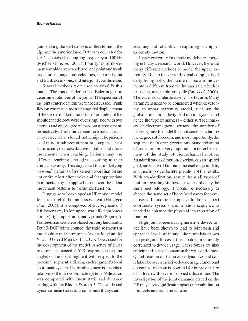
315
Biomechanics
points along the vertical axis of the sternum, the hip, and the anterior knee. Data was collected for 2-6.5 seconds at a sampling frequency of 100 Hz (Michaelsen et al., 2001). Four types of move-ment variables were analyzed: end point and trunk trajectories, tangential velocities, maximal joint and trunk excursions, and interjoint coordination.
Several methods were used to simplify this model. The model failed to use Euler angles to determine rotations of the joints. The specifics of the joint center locations were not discussed. Trunk flexion was measured as the sagittal displacement of the sternal marker. In addition, the models of the shoulder and elbow were over simplified with two degrees and one degree of freedom of movement, respectively. These movements are not anatomi-cally correct. It was found that hemiparetic patients used more trunk recruitment to compensate for significantly decreased active shoulder and elbow movements when reaching. Patients may use different reaching strategies according to their clinical severity. This suggested that underlying “normal” patterns of movement coordination are not entirely lost after stroke and that appropriate treatments may be applied to uncover the latent movement patterns to maximize function.
Hingtgen et al. developed an UE motion model for stroke rehabilitation assessment (Hingtgen et al., 2006). It is composed of five segments: i) left lower arm, ii) left upper arm, iii) right lower arm, iv) right upper arm, and v) trunk (Figure 4). Fourteen markers were placed on bony landmarks. Four 3-DOF joints connect the rigid segments at the shoulder and elbow joints. Vicon BodyBuilder V3.55 (Oxford Metrics, Ltd., U.K.) was used for the development of the model. A series of Euler rotations sequenced Z-Y-X, expressed the joint angles of the distal segment with respect to the proximal segment, utilizing each segment’s local coordinate system. The trunk segment is described relative to the lab coordinate system. Validation was completed with linear static and dynamic testing with the Biodex System-3. The static and dynamic linear test results confirmed the system’s
accuracy and reliability in capturing 3-D upper extremity motion.
Upper extremity kinematic models are emerg-ing in today’s research world. However, there are many different methods to model the upper ex-tremity. Due to the variability and complexity of daily living tasks, the nature of free arm move-ments is different from the human gait, which is restricted, repeatable, or cyclic (Rau et al., 2000). There are no standard activities for the arm. Many parameters need to be considered when develop-ing an upper extremity model, such as: the global orientation; the type of motion system and hence the type of markers – either surface mark-ers or electromagnetic sensors; the number of markers; how to model the joint centers including the degrees of freedom; and most importantly, the sequence of Euler angle rotations. Standardization of joint motions is very important for the enhance-ment of the study of biomechanical motion. Standardization of motion description is an aspired goal, since it will facilitate the exchange of data, and thus improve the interpretation of the results. With standardization, results from all types of motion-recording studies can be described by the same methodology. It would be necessary to choose the same set of bony landmarks for com-parisons. In addition, proper definition of local coordinate systems and rotation sequence is needed to enhance the physical interpretation of rotation.
High joint forces during assistive device us-age have been shown to lead to joint pain and approach levels of injury. Literature has shown that peak joint forces at the shoulder are directly correlated to device usage. These forces are also anticipated to be of concern at the wrist and elbow. Quantification of 3-D inverse dynamics and cor-relation between assistive device usage, functional outcomes, and pain is essential for improved care of children with severe orthopedic disabilities. The investigation of the joint demands placed on the UE may have significant impact on rehabilitation protocols and transitional care.
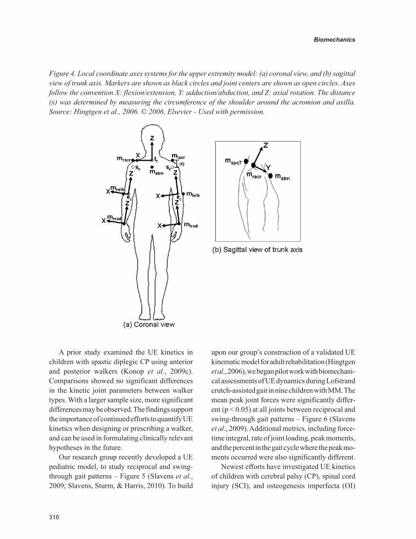
316
Biomechanics
A prior study examined the UE kinetics in children with spastic diplegic CP using anterior and posterior walkers (Konop et al., 2009c). Comparisons showed no significant differences in the kinetic joint parameters between walker types. With a larger sample size, more significant differences may be observed. The findings support the importance of continued efforts to quantify UE kinetics when designing or prescribing a walker, and can be used in formulating clinically relevant hypotheses in the future.
Our research group recently developed a UE pediatric model, to study reciprocal and swing-through gait patterns – Figure 5 (Slavens et al., 2009; Slavens, Sturm, & Harris, 2010). To build
upon our group’s construction of a validated UE kinematic model for adult rehabilitation (Hingtgen et al., 2006), we began pilot work with biomechani-cal assessments of UE dynamics during Lofstrand crutch-assisted gait in nine children with MM. The mean peak joint forces were significantly differ-ent (p < 0.05) at all joints between reciprocal and swing-through gait patterns – Figure 6 (Slavens et al., 2009). Additional metrics, including force-time integral, rate of joint loading, peak moments, and the percent in the gait cycle where the peak mo-ments occurred were also significantly different.
Newest efforts have investigated UE kinetics of children with cerebral palsy (CP), spinal cord injury (SCI), and osteogenesis imperfecta (OI)
Figure 4. Local coordinate axes systems for the upper extremity model: (a) coronal view, and (b) sagittal view of trunk axis. Markers are shown as black circles and joint centers are shown as open circles. Axes follow the convention X: flexion/extension, Y: adduction/abduction, and Z: axial rotation. The distance (x) was determined by measuring the circumference of the shoulder around the acromion and axilla. Source: Hingtgen et al., 2006. © 2006, Elsevier - Used with permission.
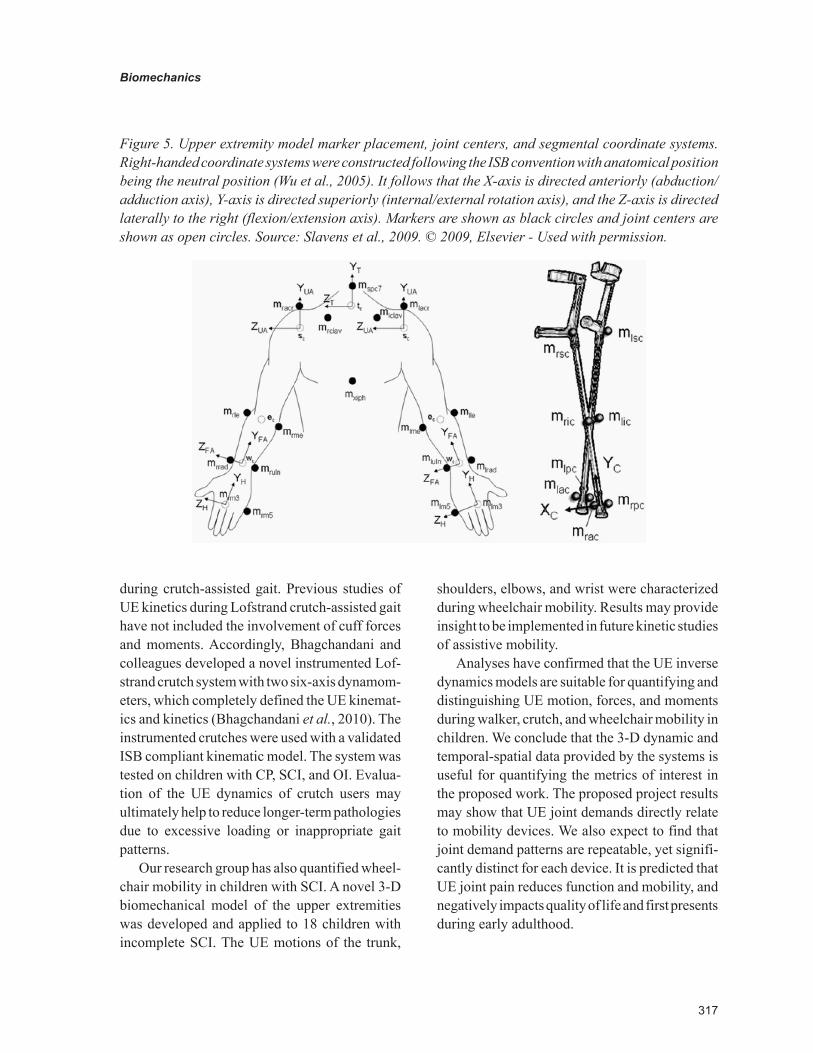
317
Biomechanics
during crutch-assisted gait. Previous studies of UE kinetics during Lofstrand crutch-assisted gait have not included the involvement of cuff forces and moments. Accordingly, Bhagchandani and colleagues developed a novel instrumented Lof-strand crutch system with two six-axis dynamom-eters, which completely defined the UE kinemat-ics and kinetics (Bhagchandani et al., 2010). The instrumented crutches were used with a validated ISB compliant kinematic model. The system was tested on children with CP, SCI, and OI. Evalua-tion of the UE dynamics of crutch users may ultimately help to reduce longer-term pathologies due to excessive loading or inappropriate gait patterns.
Our research group has also quantified wheel-chair mobility in children with SCI. A novel 3-D biomechanical model of the upper extremities was developed and applied to 18 children with incomplete SCI. The UE motions of the trunk,
shoulders, elbows, and wrist were characterized during wheelchair mobility. Results may provide insight to be implemented in future kinetic studies of assistive mobility.
Analyses have confirmed that the UE inverse dynamics models are suitable for quantifying and distinguishing UE motion, forces, and moments during walker, crutch, and wheelchair mobility in children. We conclude that the 3-D dynamic and temporal-spatial data provided by the systems is useful for quantifying the metrics of interest in the proposed work. The proposed project results may show that UE joint demands directly relate to mobility devices. We also expect to find that joint demand patterns are repeatable, yet signifi-cantly distinct for each device. It is predicted that UE joint pain reduces function and mobility, and negatively impacts quality of life and first presents during early adulthood.
Figure 5. Upper extremity model marker placement, joint centers, and segmental coordinate systems. Right-handed coordinate systems were constructed following the ISB convention with anatomical position being the neutral position (Wu et al., 2005). It follows that the X-axis is directed anteriorly (abduction/adduction axis), Y-axis is directed superiorly (internal/external rotation axis), and the Z-axis is directed laterally to the right (flexion/extension axis). Markers are shown as black circles and joint centers are shown as open circles. Source: Slavens et al., 2009. © 2009, Elsevier - Used with permission.
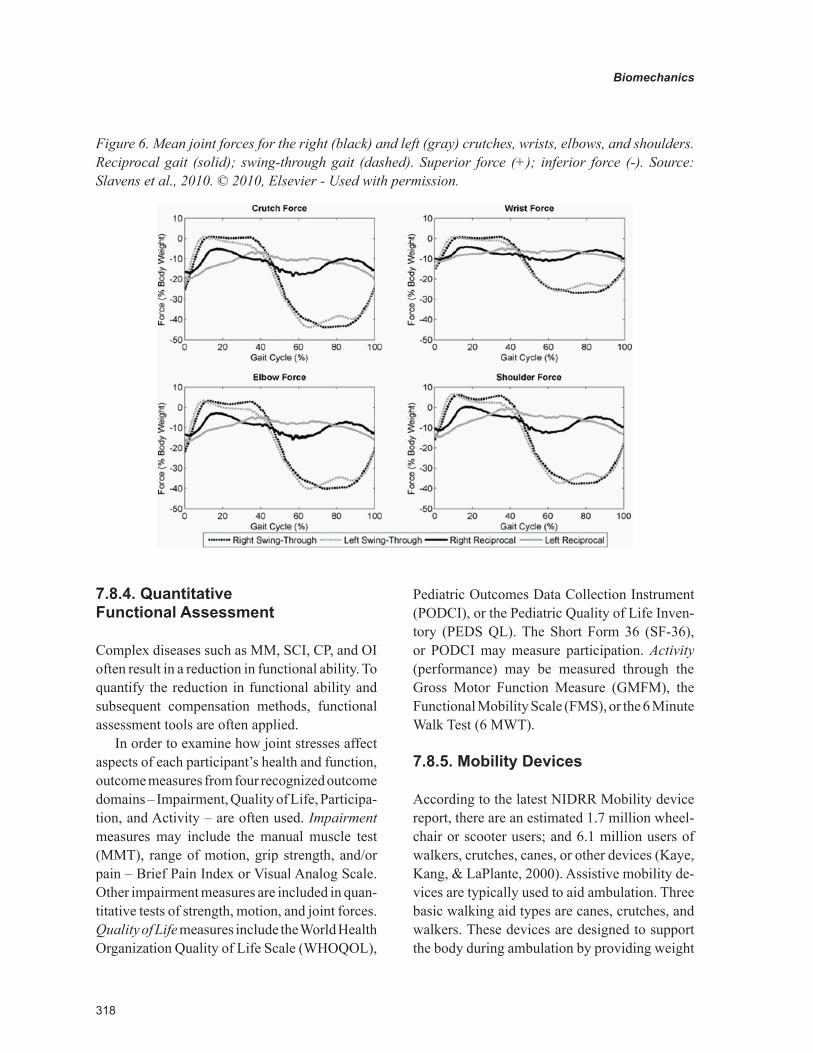
318
Biomechanics
7.8.4. Quantitative Functional Assessment
Complex diseases such as MM, SCI, CP, and OI often result in a reduction in functional ability. To quantify the reduction in functional ability and subsequent compensation methods, functional assessment tools are often applied.
In order to examine how joint stresses affect aspects of each participant’s health and function, outcome measures from four recognized outcome domains – Impairment, Quality of Life, Participa-tion, and Activity – are often used. Impairment measures may include the manual muscle test (MMT), range of motion, grip strength, and/or pain – Brief Pain Index or Visual Analog Scale. Other impairment measures are included in quan-titative tests of strength, motion, and joint forces. Quality of Life measures include the World Health Organization Quality of Life Scale (WHOQOL),
Pediatric Outcomes Data Collection Instrument (PODCI), or the Pediatric Quality of Life Inven-tory (PEDS QL). The Short Form 36 (SF-36), or PODCI may measure participation. Activity (performance) may be measured through the Gross Motor Function Measure (GMFM), the Functional Mobility Scale (FMS), or the 6 Minute Walk Test (6 MWT).
7.8.5. Mobility Devices
According to the latest NIDRR Mobility device report, there are an estimated 1.7 million wheel-chair or scooter users; and 6.1 million users of walkers, crutches, canes, or other devices (Kaye, Kang, & LaPlante, 2000). Assistive mobility de-vices are typically used to aid ambulation. Three basic walking aid types are canes, crutches, and walkers. These devices are designed to support the body during ambulation by providing weight
Figure 6. Mean joint forces for the right (black) and left (gray) crutches, wrists, elbows, and shoulders. Reciprocal gait (solid); swing-through gait (dashed). Superior force (+); inferior force (-). Source: Slavens et al., 2010. © 2010, Elsevier - Used with permission.
319
Biomechanics
transfer from the lower body to the upper body. This type of force transmission compensates for the lack of strength in the legs; however, it can lead to pain and pathology in the wrist, elbow, or shoulder joints, since the upper body is not designed for weight bearing. Previous studies have shown that long-term assistive device usage may lead to the development of pain and upper limb pathologies, including destructive shoulder arthropathy, coracoacromial pathology, degenera-tive arthritis of the shoulder and wrist, and carpal tunnel syndrome (CTS) (Bateni & Maki, 2005; Collinger et al., 2008; Kellner et al., 1986; Kli-maitis, Carroll, & Owen, 1988; Lal, 1998; Mercer et al., 2006; Opila, Nicol, & Paul, 1987; Waring & Werner, 1989).
7.8.5.1. Crutches
According to the recent mobility device report, there are an estimated 566,000 crutch users in the United States (Kaye, Kang, & LaPlante, 2000). Among these individuals, the leading causes of crutch usage include orthopedic impairments of the lower extremities, back, and neck. Many of these impairments lead to later serious conditions such as osteoarthrosis and other inflammatory polyarthropathies.
Axillary crutches are usually prescribed for short-term or acute injuries. Axillary crutches fit under the axilla. They are designed with a top padded surface and a handle placed at the sides. Prolonged use of this type of crutch may lead to blood vessel or nerve damage. Lofstrand (forearm or Canadian) crutches, on the other hand, are typically prescribed to those in need of a long-term assistive device. Each Lofstrand crutch has a forearm cuff, as well as a handle for support. These crutches are often lighter in weight, have increased mobility, have less risk of tissue dam-age, and are more cosmetic than axillary crutches (Whittle, 2003). The vertical force is transmitted from the ground, through the shaft of the crutch, to the handle and hand interface.
Ambulatory ability is known to relate closely to quadriceps function (Schopler et al., 1987). Studies have shown that approximately 50-60% of young adult patients ambulate in the household or community, with approximately 23% of these patients using an assistive device (Johnson et al., 2007; Kolaski, 2006). During crutch walking, peak axial loads are substantial and reported to be 22% BW to 50% BW, where BW is the Body Weight (Bhagchandani et al., 2010; Haubert et al., 2006; Melis et al., 1999; Slavens et al., 2009; Slavens et al., 2010; Waters et al., 1994b). Haubert and col-leagues reported the peak superior shoulder joint forces in 14 subjects (mean age of 37 years) to be 48.9 N, and have a loading rate of 311.6 N/s during crutch-assisted walking (Haubert et al., 2006).
Forearm crutches are often prescribed to those with CP, SCI, MM, OI, and other orthopaedic im-pairments. However, mobility devices may place long-term crutch users at risk for development of upper limb pathologies. Current literature dem-onstrates that long-term crutch usage may result in upper limb pathologies, such as destructive shoulder arthropathy, degenerative arthritis of the shoulder and wrist, or carpal tunnel syndrome (CTS) (Lal, 1998; Opila et al., 1987). Repetitive impulse loading combined with prolonged wrist extension and radial deviation are proposed risk factors associated with the use of crutches (Sala et al., 1998; Waring & Werner, 1989). Klimaitis and colleagues reported that bearing weight through the upper limbs may hasten the development of degenerative arthritis in the shoulder, possibly by contributing to the mechanical disruption of the rotator cuff (Klimaitis, Carroll, & Owen, 1988). Also, large superiorly directed weight-bearing forces may potentially threaten glenohumeral joint integrity as translation of the humeral head, and subsequent impingement of subacromial structures may occur if forces are not matched by an appropriate response of the rotator cuff and thoracohumeral depressor musculature (Newsam et al., 2003; Sharkey & Marder, 1995). An as-sociation between the development of CTS and
320
Biomechanics
the use of assistive devices by patients has also been described in the literature (Kellner et al., 1986; Sala et al., 1998; Waring & Werner, 1989). Clinically, patients using forearm crutches have reported hand pain and sensory disturbances; symptoms associated with CTS (Sala et al., 1998).
7.8.5.2. Walkers
Walkers are widely employed to improve mobility for persons with balance and stability challenges, as well as lower limb impairments. The overall population of wheelchair and walker users doubled from 1980 to 1990 (Kaye et al., 2000); there are more than 1.5 million walker users in the United States today (Bateni & Maki, 2005). Most walk-ers have adjustable handle height, and some have other adjustable parts. Posterior walkers are pulled behind and are widely prescribed. A walker allows a person to use his/her upper body to aid in the weight-bearing and stability aspects of ambulation, which his/her legs cannot fully provide (Mattsson & Andersson, 1997; Park, Park, & Kim, 2001). Today, most walkers that are prescribed for long-term usage are posterior walkers likely due to the perception that these walkers decrease forward trunk lean and provide a greater amount of energy efficiency (Levangie et al., 1990; Logan, Byers-Hinkley, & Ciccone, 1990).
It is important to biomechanically quantify the joint forces and moments acting on the upper extremities during walking aid usage because of the altered quadrupedal gait patterns and increased magnitude and frequency of arm loads (Haubert et al., 2006; Melis et al., 1999; Requejo et al., 2005). Previous studies, using advanced modeling techniques, have found peak vertical loads exerted on a walker average between 6% BW and 48% BW (Haubert et al., 2006; Konop et al., 2009a; Konop et al., 2009b; Melis et al., 1999; Waters et al., 1994b). Joint load-related pathologies, in-cluding shoulder injury and arthritis later in life, are linked to the prolonged use of walking aids and wheelchairs (Bateni & Maki, 2005; Opila et al., 1987).
7.8.5.3. Canes
Canes are the simplest form of assistive ambula-tory devices. They are used to improve stability, generate a moment, and to redistribute or reduce limb loading (Whittle, 2003). Canes typically have a single shaft with a handle to transmit forces from the ground to the upper limb. The point of contact occurs at the hand, with typically small loads. Force transmission occurs along the length of the cane. Canes can be used unilater-ally or bilaterally, depending on the amount of support needed by the user. With a single cane, the cane is typically advanced forward during the stance phase of the strongest leg. When two canes are used, they are typically advanced forward separately, during double limb support, provid-ing maximum stability (Whittle, 2003). A cane may also be used to generate a moment, so as to reduce the amount of force the contralateral hip must generate to keep the pelvis balanced. The cane would be placed on the opposite side of the weak or painful hip. Canes may also be used to reduce limb loading in an affected leg. For this type of application, the cane is usually placed on the affected side close to the foot; thus, making it easier to transfer loads from the affected leg to the cane. The cane will, therefore, be advanced forward in synchrony with the affected leg during the swing phase. This mechanism is often useful for those with joint pain.
7.8.5.4. Wheelchairs
According to the Disability Statistics Abstract by the National Institute on Disability and Rehabilita-tion Research (NIDRR), there are approximately 1.6 million Americans living outside of institu-tions using wheelchairs (Kaye, Kang, & LaPlante, 2002). The majority (1.5 million) of these people use manual wheelchairs.
A wheelchair is a mobility orthosis offering additional support to the body for persons with a disability (Bergen, 1994). It can provide biome-chanical strength to reduce or alter forces that
321
Biomechanics
may further weaken the body. The wheelchair provides the user with maximum functional mobility along with support. Best designs are cosmetic, strong, and lightweight, and allow for custom modifications. The prescriptive wheelchair includes a postural support system and mobility base (Bergen, 1994). The components should be adjusted to the user for maximal manual function, and optimization of biomechanics for wheelchair propulsion and transfers. A biomechanical assess-ment of mobility, function, medical, and surgical history is an important aspect for the therapist to assess. Physical assessment should be performed to provide insight to the user’s biomechanics, such as range of motion, movement of the body, and spinal alignment.
Performance of the wheelchair is directly related to the user’s position in the wheelchair. This includes the mass distribution with respect to the wheel axis and the positions of the user’s shoulder axis relative to the handrim. Ergonomic factors such as, rolling resistance, downhill turning tendency, yaw and pitch axis control, propulsion efficiency, static stability, and weight and portability influence wheelchair performance (Brubaker, 1990).
The biomechanics of wheelchair propulsion depends on the user’s characteristics such as anthropometry, physiology, strength, range of motion, and mobility goals and the wheelchair’s mass, dimensions, and additional features (Cooper, 1995). Wheelchair mobility should be optimized for comfort, safety, and performance. Wheelchair efficiency is closely related to the user’s physiology, biomechanics of the stroke, and appropriateness of the wheelchair design to the user. Wheelchair propulsion has been shown to range from approximately 10% gross mechani-cal efficiency up to 30% when fully optimized for performance (Cooper, 1995). Kinematics and kinetics of wheelchair mobility may be quantified using advanced motion analysis techniques and in-strumented hardware such as the SMARTwheelTM, which can acquire pushrim forces and moments
(Cooper, 1995). Upper extremity joint forces and moments can thus be determined. Wheelchair use has shown high loading, where the highest forces have been reported at the shoulder joint ranging from 7% BW (0.9 m/s) to 11% BW (1.8 m/s) (Collinger et al., 2008; Mercer et al., 2006). Estimates of shoulder pain among manual wheel-chair users with paraplegia range from 30% to 73% (Ballinger, Rintala, & Hart, 2000; Collinger et al., 2008; Pentland & Twomey, 1991). Further analyses may explain the underlying biomechan-ics as it relates to mobility and orthopaedic injury from long-term wheelchair usage.
7.8.6. Assistive Technology
Assistive technologies encompass numerous de-vices designed to augment and assist those with disabilities. Rehabilitation engineering applica-tions are used for the development of assistive technologies. Public Law 100-407 defines assis-tive technology as “any item, piece of equipment or product system whether acquire commercially off the shelf, modified, or customized that is used to increase or improve functional capabilities of individuals with disabilities.” It can include devices, strategies, or services to help someone increase activity performance.
Major categories of assistive technologies include prosthetics and orthotics, those for visual impairment, auditory impairments, tactile impair-ments, alternative and augmentative communica-tion devices, manipulation and mobility aids, and recreational assistive devices.
Principles have been established to help match appropriate assistive technology to the person to enhance usability and acceptance (Enderle, Bronzino, & Blanchard, 2005). These principles are:
1. The user’s goals, needs, and tasks must be clearly defined, listed and incorporated as early as possible in the intervention process.
322
Biomechanics
2. Involvement of rehabilitation profession-als with differing skills and know-how will maximize the probability for a successful outcome.
3. The user’s preferences, cognitive and physi-cal abilities and limitations, living situation, tolerance for technology, and future changes must be thoroughly assessed, analyzed, and quantified.
4. Careful and thorough consideration of avail-able technology to meet the user’s needs must be carried out to avoid overlooking potentially useful solutions.
5. The user’s preferences and choices must be considered in the selection of the assistive technology device.
6. The assistive technology device must be customized and installed in the location and setting where it will be primarily used.
7. Not only must the users be trained to use the assistive device, but also the attendant or family members must be made aware of the device’s intended purpose, benefits, and limitations.
8. Follow-up, readjustments, and reassessments of the user’s usage patterns and needs are necessary at periodic intervals.
7.8.7. Biomechanics of Trauma
7.8.7.1. Head and Neck Injuries
Injuries to the head may occur to the brain, skull, or scalp. Injury may occur as a laceration, abra-sion, fracture, or other form of tissue disruption (Newman, 2002). These types of injuries typically occur due to excessive movement of part of the head relative to another. Acceleration, in terms of gravity units (g’s), is used to measure movement.
Translational and rotational motions are key components of head injury (Newman, 2002). Translation is linear movement, without rotation. It is described by displacement, velocity, and accel-eration. Rotational motion is that motion whereby
the angular orientation of an object changes. Rotation is described by angular displacement, angular velocity, and angular acceleration.
The body can be further characterized by in-jury tolerances. For the head, the tolerance level for internal injury depends on the limitation of the g-level in the anterior-posterior direction. A value of 80g over a time period greater than 3 ms should not be exceeded (Seiffert & Wech, 2007).
The head injury criterion (HIC) was developed to describe the g-level time dependency and injury severity. The HIC is computed in an iterative manner so that the measured acceleration time function is maximum.
HICt t
a dt t trt
t
36
2 1
2 5
2 1
1
1
2
=−( )
−( )∫.
;
where t is time in seconds, ar is the resultant ac-celeration measured in the head, and t1 and t2 are arbitrary time points. The maximum of 1000 is the guideline not to be exceeded for a unidirectional acceleration measurement. The limit of 1000 is used on a worldwide basis for vehicle accident simulations. HIC does not account for rotational influence.
Criteria for the basic requirement in rule-mak-ing are defined in FMVSS 208 (U.S Department of Transportation), the EEC directive for frontal impacts (European Parliament and Council on the protection of occupants of motor vehicles in the event of a frontal impact and amending Directive 70/156/EEC), and the EEC directive for lateral impact (European Parliament and Council on the protection of occupants of motor vehicles in the event of lateral impacts and amending Directive 70/156/EEC). Head protection criteria, HIC, should not exceed 1000. It is computed in the following way:
• For any two points in time, t1 and t2, dur-ing the impact event separated by not more than a 36-ms time interval, and where
323
Biomechanics
t1 is less than t2, the head injury criterion (HIC36) shall be computed using the resul-tant head acceleration at the center of grav-ity of the dummy head, ar, expressed as a multiple of g.
• The maximum calculated HIC36 value should not exceed 1000.
The severity of injury is quite high for neck trauma, possibly resulting in permanent paralysis. Fortunately, injury statistics show only 2% to 4% of serious trauma to the neck (McElhaney et al., 2002). Neck trauma may result from common activities such as football, diving, skilling, or gymnastics. Neck injury is characterized by several criteria defined herein (Seiffert & Wech, 2007):
• The shear force (Fy), axial force (Fz), and bending moment (My), should be measured by the dummy upper neck load cell for the duration of the crash event.
• The axial force (Fz) during the event can be in tension or compression. The occipi-tal condyle bending moment (Mocy) can be in flexion or extension. This allows four possible Nij loading conditions: tension-extension (Nte), tension-flexion (Ntf), com-pression-extension (Nce), or compression-flexion (Ncf).
• Critical values for Fzc and Myc for the Nij equation are Fzc = 6806 N for Fz in tension; Fzc = 6160 N for Fz in compression; Myc = 310 Nm when the there is a flexion mo-ment at the occipital condyle; Myc = 135 Nm when the occipital condyle has an ex-tension moment.
• Only one of the four loading conditions oc-curs at any point in time. The Nij value at the point for the specific loading condition can be computed according toN F F M Mij z zc ocy yc= ( )+ ( ).
• The Nij value shall not exceed 1 at any time.
• Peak tension force, Fz, shall not exceed 4170 N at any time.
• Peak compression force (Fz), shall not ex-ceed 4000 N at any time.
These criteria have been used for the devel-opment of protection devices against trauma for the neck.
7.8.7.2 Chest and Abdomen Injuries
Thoracic and abdomen injury often occur during motor vehicle accidents. Impact occurs with the steering wheel, instrument panel, restraints, and/or airbags (Cavanaugh, 2002). Frontal and side impacts are the most common. Several limits were developed as the criteria for the chest and abdo-men. Resultant chest acceleration should be less than 60 g (> 3 ms). The Thoracic Trauma Index (TTI) was developed for two-door and four-door vehicles, with < 85 g, and < 90g, respectively. The TTI is equal to 0.5 multiplied by the sum of RIBY and T12Y; where, RIBY is the maximum absolute value of lateral acceleration in g’s of the fourth or eighth rib on the struck side, and T12Y is the maximum absolute value of lateral acceleration in g’s of the twelfth thoracic vertebra after filter-ing of the acceleration signal (Cavanaugh, 2002; Seiffert & Wech, 2007). Force of the chest should not exceed 8000 kN.
The resultant acceleration of the pelvis should be less than 130 g. The force of the abdomen and symphysis should be less than 2.5 kN and 10 kN, respectively.
7.9. OCCUPATIONAL BIOMECHANICS
7.9.1. Injury Mechanics
Biomechanics research had led the way to defin-ing load limitations on humans. Colonel John Stapp was a pioneer in establishing human impact

324
Biomechanics
tolerance levels. Protection criteria have been de-veloped which serve as limits for the human body.
Injury tolerance limits serve as criterion to describe fractures, injuries of organs, and other human body injuries. Classifications of single or total injuries are summarized by the Abbreviated Injury Scale (AIS) or Overall Abbreviated Injury Scale (OAIS). The AIS scale is described through a severity code: 0 is no injury, 1 is minor, 2 is moderate, 3 is serious, 4 is severe, 5 is critical, 6 is maximum injury (virtually unsurvivable), and 9 is unknown (Abbreviated Injury Scale-1990 revision, 1990). Limits of injury level depend on variables such as age, gender, anthropometrics, and mass.
7.9.2. NIOSH Standards
The National Institute for Occupational Safety and Health (NIOSH), a division of the Centers for Disease Control and Prevention is the federal agency responsible for making recommendations on the prevention of work-related injury and ill-ness. NIOSH conducts and disseminates occu-pational safety and health information nationally and internationally for the well being of workers. NIOSH focuses on the prevention of work-related illness, injury, disability, and death and provides recommendations for improving workplace safety (http://www.cdc.gov/niosh).
NIOSH has set forth several research initiatives centering around workplace safety and health including: Prevention through Design, WorkLife Initiative, and the Health Hazard Evaluation Program. These programs are apt to help prevent injury in the workplace.
In regard to musculoskeletal disorders, NIOSH has reported evidence for work-related injuries of the shoulder, elbow, hand, and wrist. There have been positive associations identified between highly repetitive work and shoulder musculoskel-etal disorders (NIOSH, 1997b). It has been shown that repeated or sustained shoulder postures with greater than 60° of flexion or abduction are cor-
related with shoulder musculoskeletal disorders (NIOSH, 1997b). Shoulder pain and shoulder tendinitis have been documented.
An association between highly repetitive work and carpal tunnel syndrome (CTS) has also been identified (NIOSH, 1997a). The relationship between forceful work and CTS has also been recognized, as well as an association between hand/wrist vibration and CTS. Strong evidence exists between a combination of risk factors, such as force and repetition, force and posture, and CTS (NIOSH, 1997a). Preventative measures can be developed and implemented based on this knowledge.
7.10. THE FUTURE OF BIOMECHANICS
The future of biomechanics will be highly dependent on interdisciplinary collaborations with basic sciences and engineering. Emerging technologies will be integrated to develop more advanced biomechanical methods and theories. These could include technologies to reduce time, distance, location, and communication limits that are currently in place. More advanced certifica-tion of engineers, training, and education will be needed. Advances in biomechanical subdisciplines and related engineering fields will be developed. New research areas such as those presented here on musculoskeletal modeling, micro-FEM, upper extremity and hand biomechanics are gaining popularity. Clinical implementation of advanced technologies such as gait-aided surgeries, as well as biomechanically-guided robotic surgeries may develop from advanced musculoskeletal and dy-namics models. Surgical simulation may also exist based on novel soft tissue and musculoskeletal computer modeling techniques. Applications to a variety of new diseases and cancers are forth-coming. Future research opportunities exist in biomechanics areas related to biomedical imag-ing, tissue engineering, molecular engineering,
325
Biomechanics
and nanotechnologies. Further development of clinical engineering for evidence-based research will be needed for the advancement of medicine. Biomechanical technology will also need to be developed for transfer to those with limited resources.
7.11. PROFESSIONAL SOCIETIES AND ORGANIZATIONS
Several professional organizations and societies specialize in biomechanics. A subset of the most common biomechanics organizations is listed herein. Other societies exist based on specific disciplines within biomechanics and their mis-sion. Additional resources can be found online.
• Institute of Electrical and Electronic Engineers - Engineering in Medicine and Biology Society (IEEE EMBS) http://www.embs.org http://www.ieee.org
• Gait and Clinical Movement Analysis Society (GCMAS) http://www.gcmas.org/
• European Society of Movement Analysis for Adults and Children (ESMAC) http://www.esmac.org/
• Rehabilitation Engineering and Assistive Technology Society of North America (RESNA) http://resna.org/
• International Society of Biomechanics (ISB) http://isbweb.org/
• American Society of Biomechanics (ASB) http://www.asbweb.org/
• Orthopaedic Research Society (ORS) http://www.ors.org/
• American Society of Mechanical Engineers - Summer Bioengineering Conference (ASME SBC) http://www.asme.org/
• Rocky Mountain Bioengineering Society (RMBS) http://www.rmbs.org/
• American Institute for Medical and Biological Engineering (AIMBE) http://www.aimbe.org/
• Biomedical Engineering Society (BMES) http://www.bmes.org/
• International Federation for Medical and Biological Engineering (IFMBE) http://www.ifmbe.org/
Additional resources for reading and refer-ences for biomechanics topics can be found in the following journals and forums. Due to the vast field of Biomechanics, this is an abbreviated list.
• IEEE Transactions on Neural Systems and Rehabilitation Engineering
• Gait and Posture• Journal of Biomechanics• Assistive Technology• Clinical Biomechanics• Journal of Bone and Joint Surgery• Journal of Orthopaedic Research• Journal of Applied Biomechanics• Biomch-L Forum http://biomch-l.isbweb.
org/forum.php
7.12. CHAPTER SUMMARY
This chapter presented an overview of several disciplines of Biomechanics. Upper and lower ex-tremity dynamics of human motion analysis were described. Rehabilitation engineering with regard to assistive mobility devices and postural stability highlighted the importance of technology for dis-ability. Head, neck, chest, and abdomen trauma biomechanics gave insight to human limits and tolerance for injury. Safety in the workplace was discussed as the field of occupational biomechan-ics. Modeling methodologies for musculoskeletal system using finite element analysis and other software packages demonstrated the complexity in this subdiscipline. Since Biomechanics is a vast field, many other subdisciplines exist or are currently being developed. Readers are advised to refer to the aforementioned professional societies and organizations for further information.
326
Biomechanics
REFERENCES
Adamovich, S. V., Archambault, P. S., Ghafouri, M., Levin, M. F., Poizner, H., & Feldman, A. G. (2001). Hand trajectory invariance in reaching movements involving the trunk. Experimental Brain Research, 138(3), 288–303. doi:10.1007/s002210100694
Aguinaldo, A. L., & Chambers, H. (2009). Cor-relation of throwing mechanics with elbow valgus load in adult baseball pitchers. The American Journal of Sports Medicine, 37(10), 2043–2048. doi:10.1177/0363546509336721
American Stroke Association. (2011). About stroke. Retrieved March 14, 2011, from: http://www.strokeassociation.org/
Anderson, A. E., Ellis, B. J., & Weiss, J. A. (2007). Verification, validation and sensitivity studies in computational biomechanics. Computer Methods in Biomechanics and Biomedical Engineering, 10(3), 171–184. doi:10.1080/10255840601160484
Anglin, C., & Wyss, U. P. (2000). Review of arm motion analyses. Proceedings of the Institu-tion of Mechanical Engineers. Part H, Journal of Engineering in Medicine, 214(5), 541–555. doi:10.1243/0954411001535570
Ashman, R. B., Cowin, S. C., Van Buskirk, W. C., & Rice, J. C. (1984). A continuous wave technique for the measurement of the elastic properties of cortical bone. Journal of Biomechanics, 17(5), 349–361. doi:10.1016/0021-9290(84)90029-0
Ballinger, D. A., Rintala, D. H., & Hart, K. A. (2000). The relation of shoulder pain and range-of-motion problems to functional limitations, disabil-ity, and perceived health of men with spinal cord injury: A multifaceted longitudinal study. Archives of Physical Medicine and Rehabilitation, 81(12), 1575–1581. doi:10.1053/apmr.2000.18216
Bateni, H., & Maki, B. E. (2005). Assistive de-vices for balance and mobility: benefits, demands, and adverse consequences. Archives of Physical Medicine and Rehabilitation, 86(1), 134–145. doi:10.1016/j.apmr.2004.04.023
Bekas, C., Curioni, A., Arbenz, P., Flaig, C., Van Lenthe, G. H., Müller, R., & Wirth, A. J. (2010). Extreme scalability challenges in micro-finite element simulations of human bone. Concurrency and Computation, 22, 2282–2296. doi:10.1002/cpe.1591
Bergen, A. F. (1994). The prescriptive wheel-chair: An orthotic device. In O’Sullivan, S. B., & Schmitz, T. J. (Eds.), Physical rehabilitation (3rd ed., pp. 685–706). Philadelphia, PA: F.A. Davis.
Bhagchandani, N., Slavens, B. A., Graf, A., Krzak, J., Wang, M., Sturm, P. F., et al. (2010). Upper extremity dynamics in children using Lofstrand crutches. Paper presented at the RESNA Annual Conference, Las Vegas, Nivada.
Biryukova, E. V., Roby-Brami, A., Frolov, A. A., & Mokhtari, M. (2000). Kinematics of human arm reconstructed from spatial tracking system record-ings. Journal of Biomechanics, 33(8), 985–995. doi:10.1016/S0021-9290(00)00040-3
Boyde, A., Travers, R., Glorieux, F. H., & Jones, S. J. (1999). The mineralization density of iliac crest bone from children with osteogenesis imperfecta. Calcified Tissue International, 64(3), 185–190. doi:10.1007/s002239900600
Bronzino, J. D. (2006). The biomedical engineer-ing handbook (3rd ed.). Boca Raton, FL: CRC/Taylor & Francis.
Brubaker, C. (1990). Choosing a wheelchair system. Journal of Rehabilitation Research and Development. Clinical Supplement, 2, 1–116.
327
Biomechanics
Buckwalter, J. A., Einhorn, T. A., O’Keefe, R. J., & American Academy of Orthopaedic Surgeons. (2007). Orthopaedic basic science: Foundations of clinical practice, 3rd ed. Rosemont, IL: American Academy of Orthopaedic Surgeons.
Burtner, P. A., Qualls, C., & Woollacott, M. H. (1998). Muscle activation characteristics of stance balance control in children with spastic cerebral palsy. Gait & Posture, 8(3), 163–174. doi:10.1016/S0966-6362(98)00032-0
Bustamante Valles, K. D., Schneider, J. M., Long, J. T., Riedel, S. A., Johnson, M. J., & Harris, G. F. (2006). Combined sagittal and coronal plane postural stability model. Proceedings of the In-ternational Conference of the IEEE Engineering in Medicine and Biology Society, 1, 4576-4579.
Byers, P. H., & Steiner, R. D. (1992). Osteogenesis Imperfecta. Annual Review of Medicine, 43, 269–282. doi:10.1146/annurev.me.43.020192.001413
Camomilla, V., Cereatti, A., Vannozzi, G., & Cap-pozzo, A. (2006). An optimized protocol for hip joint centre determination using the functional method. Journal of Biomechanics, 39(6), 1096. doi:10.1016/j.jbiomech.2005.02.008
Canfield, M. A., Honein, M. A., Yuskiv, N., Xing, J., Mai, C. T., & Collins, J. S. (2006). National estimates and race/ethnic-specific variation of selected birth defects in the United States, 1999-2001. Birth Defects Research. Part A, Clinical and Molecular Teratology, 76(11), 747–756. doi:10.1002/bdra.20294
Canseco, K., Long, J., Marks, R., Khazzam, M., & Harris, G. (2009). Quantitative motion analysis in patients with hallux rigidus before and after cheilectomy. Journal of Orthopaedic Research, 27(1), 128–134. doi:10.1002/jor.20711
Canseco, K., Rankine, L., Long, J., Smedberg, T., Marks, R., & Harris, G. (2010). Motion of the multisegmental foot in hallux valgus. Foot & Ankle International, 31(2), 146–152. doi:10.3113/FAI.2010.0146
Canseco, K. C., Long, J. T., Marks, R. M., Khaz-zam, M., & Harris, G. F. (2008). Quantitative characterization of gait kinematics in patients with hallux rigidus using the Milwaukee foot model. Journal of Orthopaedic Research, 26(4), 419–427. doi:10.1002/jor.20506
Carter, D. R., & Hayes, W. C. (1977). The com-pressive behavior of bone as a two-phase porous structure. Journal of Bone and Joint Surgery - American, 59(7), 954-962.
Cavanaugh, J. M. (2002). Biomechanics of tho-racic trauma. In Nahum, A. M., & Melvin, J. (Eds.), Accidental injury: Biomechanics and prevention (2nd ed., pp. 374–404). New York, NY: Springer.
CDC. (2006). Improved national prevalence esti-mates for 18 selected major birth defects - United States, 1999-2001. Morbidity and Mortality Weekly Report, 54(51), 1301–1305.
Chao, E. Y. (1980). Justification of triaxial go-niometer for the measurement of joint rotation. Journal of Biomechanics, 13(12), 989–1006. doi:10.1016/0021-9290(80)90044-5
Chao, E. Y., Armiger, R. S., Yoshida, H., Lim, J., & Haraguchi, N. (2007). Virtual Interactive Musculoskeletal System (VIMS) in orthopaedic research, education and clinical patient care. Journal of Orthopaedic Surgery and Research, 2, 2. doi:10.1186/1749-799X-2-2
Chen, J., & Woollacott, M. H. (2007). Lower extremity kinetics for balance control in children with cerebral palsy. Journal of Motor Behavior, 39(4), 306–316. doi:10.3200/JMBR.39.4.306-316
328
Biomechanics
Cherng, R. J., Su, F. C., Chen, J. J., & Kuan, T. S. (1999). Performance of static standing balance in children with spastic diplegic cerebral palsy under altered sensory environments. American Journal of Physical Medicine & Rehabilitation, 78(4), 336–343. doi:10.1097/00002060-199907000-00008
Choi, K., Kuhn, J. L., Ciarelli, M. J., & Goldstein, S. A. (1990). The elastic moduli of human sub-chondral, trabecular, and cortical bone tissue and the size-dependency of cortical bone modulus. Journal of Biomechanics, 23(11), 1103–1113. doi:10.1016/0021-9290(90)90003-L
Collinger, J. L., Boninger, M. L., Koontz, A. M., Price, R., Sisto, S. A., Tolerico, M. L., & Cooper, R. A. (2008). Shoulder biomechanics during the push phase of wheelchair propulsion: A multisite study of persons with paraplegia. Archives of Physical Medicine and Rehabilitation, 89(4), 667–676. doi:10.1016/j.apmr.2007.09.052
Collins, J. J., & De Luca, C. J. (1993). Open-loop and closed-loop control of posture: A random-walk analysis of center-of-pressure trajectories. Experimental Brain Research, 95(2), 308–318. doi:10.1007/BF00229788
Cook, R. E., Schneider, I., Hazlewood, M. E., Hillman, S. J., & Robb, J. E. (2003). Gait analysis alters decision-making in cerebral palsy. Journal of Pediatric Orthopedics, 23(3), 292. doi:10.1097/01241398-200305000-00004
Cooper, R. A. (1995). Rehabilitation engineer-ing applied to mobility and manipulation. Rory A. Cooper. Bristol, PA: Institute of Physics Pub.doi:10.1887/0750303433
Craig, J. J. (2005). Introduction to robotics: Mechanics and control (3rd ed.). Upper Saddle River, NJ: Pearson/Prentice Hall.
Cristofolini, L., Schileo, E., Juszczyk, M., Tad-dei, F., Martelli, S., & Viceconti, M. (2010). Me-chanical testing of bones: The positive synergy of finite-element models and in vitro experiments. Philosophical Transactions of the American Mathematics and Physics Engineering Sciences, 368(1920), 2725-2763.
Currey, J. (2002). Bones: Structure and mechan-ics (2nd ed.). Princeton, NJ: Princeton University Press.
Currey, J. D. (2004). Tensile yield in compact bone is determined by strain, post-yield behaviour by mineral content. Journal of Biomechanics, 37(4), 549–556. doi:10.1016/j.jbiomech.2003.08.008
Currey, J. D., & Butler, G. (1975). The mechanical properties of bone tissue in children. Journal of Bone and Joint Surgery, 57(6), 810–814.
Davis, B. E., Daley, C. M., Shurtleff, D. B., Du-guay, S., Seidel, K., Loeser, J. D., & Ellenbogan, R. G. (2005). Long-term survival of individuals with myelomeningocele. Pediatric Neurosurgery, 41(4), 186–191. doi:10.1159/000086559
Deland, J. T., Garg, A., & Walker, P. S. (1987). Biomechanical basis for elbow hinge-distractor design. Clinical Orthopaedics and Related Re-search, 215, 303–312.
DeLuca, P. A., Davis, R. B. III, Ounpuu, S., Rose, S., & Sirkin, R. (1997). Alterations in surgical decision making in patients with cerebral palsy based on three-dimensional gait analysis. Journal of Pediatric Orthopedics, 17(5), 608.
Dillman, C. J., Fleisig, G. S., & Andrews, J. R. (1993). Biomechanics of pitching with emphasis upon shoulder kinematics. The Journal of Or-thopaedic and Sports Physical Therapy, 18(2), 402–408.
329
Biomechanics
Donker, S. F., Ledebt, A., Roerdink, M., Savels-bergh, G. J., & Beek, P. J. (2008). Children with cerebral palsy exhibit greater and more regular postural sway than typically developing children. Experimental Brain Research, 184(3), 363–370. doi:10.1007/s00221-007-1105-y
Enderle, J. D., Bronzino, J. D., & Blanchard, S. M. (2005). Introduction to biomedical engineering (2nd ed.). Amsterdam, The Netherlands: Elsevier Academic Press.
Engin, A. E., & Tumer, S. T. (1989). Three-dimensional kinematic modelling of the human shoulder complex - Part I: Physical model and determination of joint sinus cones. Journal of Biomechanical Engineering, 111(2), 107–112. doi:10.1115/1.3168351
Engsberg, J. R. (1987). A biomechanical analysis of the talocalcaneal joint - in vitro. Journal of Biomechanics, 20(4), 429–442. doi:10.1016/0021-9290(87)90050-9
European Parliament. (2007). Council on the protection of occupants of motor vehicles in the event of a frontal impact and amending Directive 70/156/EEC. Brussels, Belgium.
European Parliament. (2007). Council on the protection of occupants of motor vehicles in the event of lateral impacts and amending Directive 70/156/EEC. Brussels, Belgium.
Farley, J. A., & Dunleavy, M. J. (1996). My-elodysplasia. In Jackson, P. L., & Vessey, J. A. (Eds.), Primary care of the child with a chronic condition (4th ed., pp. 630–643). St. Louis, MO: Mosby-Year Book, Inc.
Fung, Y. C. (1993). Biomechanics: Mechanical properties of living tissues (2nd ed.). New York, NY: Springer-Verlag.
Gage, J. R., Fabian, D., Hicks, R., & Tashman, S. (1984). Pre- and postoperative gait analysis in patients with spastic diplegia: A preliminary report. Journal of Pediatric Orthopedics, 4(6), 715. doi:10.1097/01241398-198411000-00012
Gage, J. R., & Novacheck, T. F. (2001). An up-date on the treatment of gait problems in cerebral palsy. Journal of Pediatric Orthopaedics. Part B, 10(4), 265.
Geyer, H., Seyfarth, A., & Blickhan, R. (2003). Positive force feedback in bouncing gaits? Pro-ceedings. Biological Sciences, 270, 2173–2183. doi:10.1098/rspb.2003.2454
Geyer, H., Seyfarth, A., & Blickhan, R. (2005). Spring-mass running: Simple approximate solution and application to gait stability. Jour-nal of Theoretical Biology, 232(3), 315–328. doi:10.1016/j.jtbi.2004.08.015
Graf, A., Hassani, S., Krzak, J., Long, J., Cau-dill, A., & Flanagan, A. (2010). Long-term outcome evaluation in young adults following clubfoot surgical release. Journal of Pediatric Orthopedics, 30(4), 379–385. doi:10.1097/BPO.0b013e3181d8fbd7
Grood, E. S., & Suntay, W. J. (1983). A joint coordinate system for the clinical description of three-dimensional motions: Application to the knee. Journal of Biomechanical Engineering, 105(2), 136–144. doi:10.1115/1.3138397
Hallgren, R. C., Reynolds, H. M., Soutas-Little, R. W., Hubbard, R. P., & Rechtien, J. J. (1988). 3-D analysis and display of sequential position data in the lumbar spine. Journal of Clinical Engineering, 13, 51–57.
Hansen, U., Zioupos, P., Simpson, R., Currey, J. D., & Hynd, D. (2008). The effect of strain rate on the mechanical properties of human cortical bone. Journal of Biomechanical Engineering, 130(1), 011011. doi:10.1115/1.2838032
330
Biomechanics
Harris, G. F. (1991). Analysis of ankle and subtalar motion during human locomotion. In Stiehl, J. B. (Ed.), Inman’s joints of the ankle (2nd ed., p. 75). Baltimore, MD: Williams & Wilkins.
Harris, G. F., Riedel, S. A., Matesi, D. V., & Smith, P. A. (1992). Signal stationarity in postural stability assessment of children. Engineering in Medicine and Biology Magazine, IEEE, 11(4), 57–58. doi:10.1109/51.256961
Harris, G. F., & Smith, P. A. (1996). Human motion analysis. New York, NY: IEEE Press.
Harris, G. F., Smith, P. A., & Marks, R. M. (2008). Foot and ankle motion analysis: Clinical treatment and technology. Boca Raton, FL: CRC Press.
Haubert, L. L., Gutierrez, D. D., Newsam, C. J., Gronley, J. A. K., Mulroy, S. J., & Perry, J. (2006). A comparison of shoulder joint forces during am-bulation with crutches versus a walker in persons with incomplete spinal cord injury. Archives of Physical Medicine and Rehabilitation, 87, 63–70. doi:10.1016/j.apmr.2005.07.311
Henninger, H. B., Reese, S. P., Anderson, A. E., & Weiss, J. A. (2010). Validation of computa-tional models in biomechanics. Proceedings of the Institution of Mechanical Engineers, Part H, 224(7), 801-812.
Hingtgen, B. A., McGuire, J. R., Wang, M., & Harris, G. F. (2006). An upper extremity kinematic model for evaluation of hemiparetic stroke. Journal of Biomechanics, 39(4), 681–688. doi:10.1016/j.jbiomech.2005.01.008
Hogfors, C., Sigholm, G., & Herberts, P. (1987). Biomechanical model of the human shoulder - I. Elements. Journal of Biomechanics, 20(2), 157–166. doi:10.1016/0021-9290(87)90307-1
Horak, F. B. (2006). Postural orientation and equilibrium: What do we need to know about neural control of balance to prevent falls? Age and Ageing, 35(Suppl 2), ii7–ii11. doi:10.1093/ageing/afl077
Hutton, D. V. (2004). Fundamentals of finite element analysis, international edition. Boston, MA: McGraw-Hill.
Injury, A. (1990). Scale-1990 revision. Des Plaines, IL, United States: Association for the Advancement of Automotive Medicine.
Jackson, K. M., Joseph, J., & Wyard, S. J. (1977). Sequential muscular contraction. Journal of Biomechanics, 10(2), 97–106. doi:10.1016/0021-9290(77)90073-2
Johnson, K. L., Dudgeon, B., Kuehn, C., & Walker, W. (2007). Assistive technology use among adolescents and young adults with spina bifida. American Journal of Public Health, 97(2), 330–336. doi:10.2105/AJPH.2004.050955
Karduna, A. R., McClure, P. W., & Michener, L. A. (2000). Scapular kinematics: Effects of altering the Euler angle sequence of rotations. Journal of Biomechanics, 33(9), 1063–1068. doi:10.1016/S0021-9290(00)00078-6
Kaye, H. S., Kang, T., & LaPlante, M. P. (2000). Mobility device use in the United States. Dis-ability Statistics Report (14). U.S. Department of Education, National Institute on Disability and Rehabilitation Research, Washington, D.C.
Kaye, S., Kang, T., & LaPlante, M. P. (2002). Wheelchair use in the United States. Washington, DC: US Department of Education.
Kellner, W. S., Felsenthal, G., Anderson, J. M., Hil-ton, E. B., & Mondell, D. L. (1986). Carpal tunnel syndrome in the nonparetic hands of hemiplegics. Stress-induced by ambulatory assistive devices. Orthopaedic Review, 15(9), 608–611.
331
Biomechanics
Khazzam, M., Long, J. T., Marks, R. M., & Harris, G. F. (2006). Preoperative gait characterization of patients with ankle arthrosis. Gait & Posture, 24(1), 85–93. doi:10.1016/j.gaitpost.2005.07.006
Khazzam, M., Long, J. T., Marks, R. M., & Harris, G. F. (2007). Kinematic changes of the foot and ankle in patients with systemic rheumatoid arthritis and forefoot deformity. Journal of Orthopaedic Research, 25(3), 319–329. doi:10.1002/jor.20312
Kidder, S. M., Abuzzahab, F. Jr, Harris, G. F., & Johnson, J. E. (1996). A system for the analysis of foot and ankle kinematics during gait. IEEE Transactions on Rehabilitation Engineering, 4(1), 25. doi:10.1109/86.486054
Kitaoka, H. B., Crevoisier, X. M., Hansen, D., Katajarvi, B., Harbst, K., & Kaufman, K. R. (2006). Foot and ankle kinematics and ground reaction forces during ambulation. Foot & Ankle International, 27(10), 808.
Klimaitis, A., Carroll, G., & Owen, E. (1988). Rapidly progressive destructive arthropathy of the shoulder- a viewpoint on pathogenesis. The Journal of Rheumatology, 15(12), 1859–1862.
Knuesel, H., Geyer, H., & Seyfarth, A. (2005). Influence of swing leg movement on running sta-bility. Human Movement Science, 24(4), 532–543. doi:10.1016/j.humov.2005.08.002
Kolaski, K. (2006). Myelomeningocele, (vol. 2009, T. L. Massagli, Ed.) Retrieved from http://emedi-cine.medscape.com/article/311113-overview
Komistek, R. D., Stiehl, J. B., Buechel, F. F., Northcut, E. J., & Hajner, M. E. (2000). A deter-mination of ankle kinematics using fluoroscopy. Foot & Ankle International, 21(4), 343.
Konop, K. A., Strifling, K. M., Wang, M., Cao, K., Eastwood, D., & Jackson, S. (2009a). Upper extremity kinetics and energy expenditure during walker-assisted gait in children with cerebral palsy. Acta Orthopaedica et Traumatologica Turcica, 43(2), 156–164. doi:10.3944/AOTT.2009.156
Konop, K. A., Strifling, K. M., Wang, M., Cao, K., Schwab, J. P., & Eastwood, D. (2009b). A biomechanical analysis of upper extremity kinetics in children with cerebral palsy using anterior and posterior walkers. Gait & Posture, 30(3), 364–369. doi:10.1016/j.gaitpost.2009.06.012
Konop, K. A., Strifling, K. M., Wang, M., Cao, K., Schwab, J. P., & Eastwood, D. (2009c). A biomechanical analysis of upper extremity kinetics in children with cerebral palsy using anterior and posterior walkers. Gait & Posture, 30(3), 364–369. doi:10.1016/j.gaitpost.2009.06.012
Lal, S. (1998). Premature degenerative shoulder changes in spinal cord injury patients. Spinal Cord, 36(3), 186–189. doi:10.1038/sj.sc.3100608
Leardini, A., Benedetti, M. G., Berti, L., Bet-tinelli, D., Nativo, R., & Giannini, S. (2007). Rear-foot, mid-foot and fore-foot motion during the stance phase of gait. Gait & Posture, 25(3), 453. doi:10.1016/j.gaitpost.2006.05.017
Levangie, P. K., Brouwer, J., McKeen, S. H., Parker, K. L., & Shelby, K. A. (1990). The effects of the standard rolling walker and two posterior roll-ing walkers on gait variables of normal children. Physical & Occupational Therapy in Pediatrics, 9(4), 19–31. doi:10.1080/J006v09n04_02
Li, G., Van de Velde, S. K., & Bingham, J. T. (2008). Validation of a non-invasive fluoroscopic imaging technique for the measurement of dynamic knee joint motion. Journal of Biomechanics, 41(7), 1616. doi:10.1016/j.jbiomech.2008.01.034
332
Biomechanics
Liu, W. Y., Zaino, C. A., & McCoy, S. W. (2007). Anticipatory postural adjustments in children with cerebral palsy and children with typical develop-ment. Pediatric Physical Therapy, 19(3), 188–195. doi:10.1097/PEP.0b013e31812574a9
Logan, L., Byers-Hinkley, K., & Ciccone, C. D. (1990). Anterior versus posterior walkers: a gait analysis study. Developmental Medicine and Child Neurology, 32(12), 1044–1048. doi:10.1111/j.1469-8749.1990.tb08521.x
Long, J. T., Eastwood, D., & Harris, G. F. (2009, February 22-25, 2009). Intersite reliability of multisegmental foot kinematics assessed with the Milwaukee Foot Model.
Long, J. T., Eastwood, D. C., Graf, A. N., Smith, P. A., & Harris, G. F. (2010). Repeatability and sources of variability in multi-center assessment of segmental foot kinematics in normal adults. Gait & Posture, 31(1), 32–36. doi:10.1016/j.gaitpost.2009.08.240
Long, J. T., Wang, M., Winters, J. M., & Harris, G. F. (2008, August 20-24, 2008). A multisegmental foot model with bone-based referencing: Sensi-tivity to radiographic input parameters. Paper presented at the IEEE EMBS Annual International Conference.
MacWilliams, B. A., Cowley, M., & Nicholson, D. E. (2003). Foot kinematics and kinetics dur-ing adolescent gait. Gait & Posture, 17(3), 214. doi:10.1016/S0966-6362(02)00103-0
Marks, R. M., Long, J. T., Ness, M. E., Khazzam, M., & Harris, G. F. (2009). Surgical reconstruction of posterior tibial tendon dysfunction: Prospective comparison of flexor digitorum longus substitu-tion combined with lateral column lengthening or medial displacement calcaneal osteotomy. Gait & Posture, 29(1), 17–22. doi:10.1016/j.gaitpost.2008.05.012
Mattsson, E., & Andersson, C. (1997). Oxygen cost, walking speed, and perceived exertion in children with cerebral palsy when walking with anterior and posterior walkers. Developmental Medicine and Child Neurology, 39(10), 671–676. doi:10.1111/j.1469-8749.1997.tb07361.x
McCollum, G., & Leen, T. K. (1989). Form and exploration of mechanical stability limits in erect stance. Journal of Motor Behavior, 21(3), 225–244.
McElhaney, J. H., Nightingale, R. W., Winkelstein, B. A., Chancey, V. C., & Myers, B. S. (2002). Biomechanical aspects of cervical trauma. In Nahum, A. M., & Melvin, J. (Eds.), Accidental injury: Biomechanics and prevention (2nd ed., pp. 324–373). New York, NY: Springer.
Melis, E. H., Torres-Moreno, R., Barbeau, H., & Lemaire, E. D. (1999). Analysis of assisted-gait characteristics in persons with incomplete spinal cord injury. Spinal Cord, 37(6), 430–439. doi:10.1038/sj.sc.3100850
Mercer, J. L., Boninger, M., Koontz, A., Ren, D., Dyson-Hudson, T., & Cooper, R. (2006). Shoulder joint kinetics and pathology in manual wheelchair users. Clinical Biomechanics (Bristol, Avon), 21(8), 781–789. doi:10.1016/j.clinbio-mech.2006.04.010
Michaelsen, S. M., Luta, A., Roby-Brami, A., & Levin, M. F. (2001). Effect of trunk restraint on the recovery of reaching movements in hemiparetic patients. Stroke, 32(8), 1875–1883. doi:10.1161/01.STR.32.8.1875
Miller, E., Delos, D., Baldini, T., Wright, T. M., & Pleshko Camacho, N. (2007). Abnormal mineral-matrix interactions are a significant contributor to fragility in oim/oim bone. Calcified Tissue International, 81(3), 206–214. doi:10.1007/s00223-007-9045-x
333
Biomechanics
Miller, G., & Clark, G. D. (1998). The cerebral palsies: Causes, consequences, and management. Boston, MA: Butterworth-Heinemann.
Morrey, B. F., & Chao, E. Y. (1976). Passive mo-tion of the elbow joint. Journal of Bone and Joint Surgery, 58(4), 501–508.
Mueller, T. L., Stauber, M., Kohler, T., Eckstein, F., Müller, R., & van Lenthe, G. H. (2009). Non-invasive bone competence analysis by high-resolution pQCT: An in vitro reproducibility study on structural and mechanical properties at the hu-man radius. Bone, 44(2), 364–371. doi:10.1016/j.bone.2008.10.045
Mueller, T. L., Wirth, A. J., van Lenthe, G. H., Goldhahn, J., Schense, J., & Jamieson, V. (2011). Mechanical stability in a human radius fracture treated with a novel tissue-engineered bone sub-stitute: A non-invasive, longitudinal assessment using high-resolution pQCT in combination with finite element analysis. Journal of Tissue Engineering and Regenerative Medicine, 5(5). doi:10.1002/term.325
Nashner, L. M. (1976). Adapting reflexes con-trolling the human posture. Experimental Brain Research, 26(1), 59–72. doi:10.1007/BF00235249
Nashner, L. M., Shumway-Cook, A., & Marin, O. (1983). Stance posture control in select groups of children with cerebral palsy: Deficits in sen-sory organization and muscular coordination. Experimental Brain Research, 49(3), 393–409. doi:10.1007/BF00238781
Ness, M. E., Long, J., Marks, R., & Harris, G. (2008). Foot and ankle kinematics in patients with posterior tibial tendon dysfunction. Gait & Posture, 27, 331–339. doi:10.1016/j.gait-post.2007.04.014
Neumann, D. A. (2002). Kinesiology of the Mus-culoskeletal System: Foundations for Physical Rehabilitation (1st ed.). St. Louis, MO: Mosby.
Newell, K. M., Carlton, L. G., Kim, S., & Chung, C. H. (1993). Space-time accuracy of rapid move-ments. Journal of Motor Behavior, 25(1), 8–20. doi:10.1080/00222895.1993.9941635
Newell, K. M., & Corcos, D. M. (1993). Vari-ability and motor control. Champaign, IL: Human Kinetics Publishers.
Newell, K. M., Slobounov, S. M., Slobounova, E. S., & Molenaar, P. C. (1997). Stochastic pro-cesses in postural center-of-pressure profiles. Experimental Brain Research, 113(1), 158–164. doi:10.1007/BF02454152
Newman, J. A. (2002). Biomechanics of head trauma: head protection. In Nahum, A. M., & Melvin, J. (Eds.), Accidental injury: Biomechan-ics and prevention (2nd ed., pp. 303–323). New York, NY: Springer.
Newsam, C. J., Lee, A. D., Mulroy, S. J., & Perry, J. (2003). Shoulder EMG during depression raise in men with spinal cord injury: The influence of lesion level. The Journal of Spinal Cord Medicine, 26(1), 59–64.
Nigg, B. M. (1994). Introduction. In Nigg, B. M., & Herzog, W. (Eds.), Biomechanics of the musculo-skeletal system (pp. 3–35). New York, NY: Wiley.
NIOSH. (1997a). Hand/wrist musculoskeletal disorders (carpal tunnel syndrome, hand/wrist tendinitis, and hand-arm vibration syndrome): Evidence for work-relatedness. A critical review of epidemiology for work related musculoskel-etal disorders of the neck, upper extremity, and low back. Cincinnati, OH: National Institute for Occupational Safety and Health, Pubications Dissemination.
334
Biomechanics
NIOSH. (1997b). Shoulder musculoskeletal dis-orders: Evidence for work-relatedness. A critical review of epidemiology for work related muscu-loskeletal disorders of the neck, upper extremity, and low back. Cincinnati, OH: National Institute for Occupational Safety and Health, Pubications Dissemination.
Opila, K. A., Nicol, A. C., & Paul, J. P. (1987). Upper limb loadings of gait with crutches. Journal of Biomechanical Engineering, 109(4), 285–290. doi:10.1115/1.3138682
Özkaya, N., & Nordin, M. (1999). Fundamen-tals of biomechanics: Equilibrium, motion, and deformation (2nd ed.). New York, NY: Springer.
Park, E. S., Park, C. I., & Kim, J. Y. (2001). Comparison of anterior and posterior walkers with respect to gait parameters and energy expenditure of children with spastic diplegic cerebral palsy. Yonsei Medical Journal, 42(2), 180–184.
Pentland, W. E., & Twomey, L. T. (1991). The weight-bearing upper extremity in women with long term paraplegia. Paraplegia, 29(8), 521–530. doi:10.1038/sc.1991.75
Perry, J. (1992). Gait analysis: Normal and pathologic function (1st ed.). Thorofare, NJ: SLACK Inc.
Perry, J., & Burnfield, J. M. (2010). Gait analy-sis: Normal and pathological function (2nd ed.). Thorofare, NJ: SLACK Inc.
Piazza, S. J., Erdemir, A., Okita, N., & Cavanagh, P. R. (2004). Assessment of the functional method of hip joint center location subject to reduced range of hip motion. Journal of Biomechanics, 37(3), 349. doi:10.1016/S0021-9290(03)00288-4
Piazza, S. J., Okita, N., & Cavanagh, P. R. (2001). Accuracy of the functional method of hip joint center location: Effects of limited motion and varied implementation. Journal of Biomechanics, 34(7), 967. doi:10.1016/S0021-9290(01)00052-5
Poppen, N. K., & Walker, P. S. (1976). Normal and abnormal motion of the shoulder. Journal of Bone and Joint Surgery, 58(2), 195–201.
Prieto, T. E., Myklebust, J. B., Hoffmann, R. G., Lovett, E. G., & Myklebust, B. M. (1996). Measures of postural steadiness: Differences between healthy young and elderly adults. IEEE Transactions on Bio-Medical Engineering, 43(9), 956–966. doi:10.1109/10.532130
Rab, G., Petuskey, K., & Bagley, A. (2002). A method for determination of upper extremity kinematics. Gait & Posture, 15(2), 113–119. doi:10.1016/S0966-6362(01)00155-2
Ramakrishnan, H. K., & Kadaba, M. P. (1991). On the estimation of joint kinematics during gait. Journal of Biomechanics, 24(10), 969–977. doi:10.1016/0021-9290(91)90175-M
Rau, G., Disselhorst-Klug, C., & Schmidt, R. (2000). Movement biomechanics goes upwards: from the leg to the arm. Journal of Biomechan-ics, 33(10), 1207–1216. doi:10.1016/S0021-9290(00)00062-2
Rauch, F., Travers, R., Parfitt, A. M., & Glo-rieux, F. H. (2000). Static and dynamic bone histomorphometry in children with osteogenesis imperfecta. Bone, 26(6), 581–589. doi:10.1016/S8756-3282(00)00269-6
Reilly, D. T., & Burstein, A. H. (1975). The elastic and ultimate properties of compact bone tissue. Journal of Biomechanics, 8(6), 393–405. doi:10.1016/0021-9290(75)90075-5
Requejo, P. S., Wahl, D. P., Bontrager, E. L., Newsam, C. J., Gronley, J. K., Mulroy, S. J., & Perry, J. (2005). Upper extremity kinetics during Lofstrand crutch-assisted gait. Medical Engi-neering & Physics, 27(1), 19–29. doi:10.1016/j.medengphy.2004.08.008
335
Biomechanics
Rho, J. Y., Ashman, R. B., & Turner, C. H. (1993). Young’s modulus of trabecular and cortical bone material: Ultrasonic and microtensile measure-ments. Journal of Biomechanics, 26(2), 111–119. doi:10.1016/0021-9290(93)90042-D
Riach, C. L., & Hayes, K. C. (1990). Anticipatory postural control in children. Journal of Motor Behavior, 22(2), 250–266.
Richman, J. S., & Moorman, J. R. (2000). Physi-ological time-series analysis using approximate entropy and sample entropy. American Journal of Physiology. Heart and Circulatory Physiology, 278(6), H2039–H2049.
Rose, J., Wolff, D. R., Jones, V. K., Bloch, D. A., Oehlert, J. W., & Gamble, J. G. (2002). Postural balance in children with cerebral palsy. Devel-opmental Medicine and Child Neurology, 44(1), 58–63. doi:10.1017/S0012162201001669
Rosenbaum, P., Paneth, N., Leviton, A., Goldstein, M., Bax, M., & Damiano, D. (2007). A report: The definition and classification of cerebral palsy April 2006. Developmental Medicine and Child Neurology. Supplement, 109, 8–14.
Roux, E., Bouilland, S., Godillon-Maquinghen, A. P., & Bouttens, D. (2002). Evaluation of the global optimization method within the upper limb kinematics analysis. Journal of Biomechanics, 35, 1279–1283. doi:10.1016/S0021-9290(02)00088-X
Rummel, J., & Seyfarth, A. (2008). Stable run-ning with segmented legs. The International Journal of Robotics Research, 27, 919–934. doi:10.1177/0278364908095136
Sala, D. A., Leva, L. M., Kummer, F. J., & Grant, A. D. (1998). Crutch handle design: effect on pal-mar loads during ambulation. Archives of Physical Medicine and Rehabilitation, 79(11), 1473–1476. doi:10.1016/S0003-9993(98)90247-7
Saltzman, W. M. (2009). Biomedical engineering: Bridging medicine and technology. New York, NY: Cambridge University Press.
Schendel, D. E., Schuchat, A., & Thorsen, P. (2002). Public health issues related to infection in pregnancy and cerebral palsy. Mental Retar-dation and Developmental Disabilities Research Reviews, 8(1), 39–45. doi:10.1002/mrdd.10011
Schmidt, R., Disselhorst-Klug, C., Silny, J., & Rau, G. (1999). A marker-based measurement procedure for unconstrained wrist and elbow mo-tions. Journal of Biomechanics, 32(6), 615–621. doi:10.1016/S0021-9290(99)00036-6
Schopler, S. A., Menelaus, M. B., Schopler, S. A., & Menelaus, M. B. (1987). Significance of the strength of the quadriceps muscles in children with myelomeningocele. Journal of Pediatric Or-thopedics, 7(5), 507–512. doi:10.1097/01241398-198709000-00001
Schulte, F. A., Lambers, F. M., Kuhn, G., & Müller, R. (2011). In vivo micro-computed tomography allows direct three-dimensional quantification of both bone formation and bone resorption pa-rameters using time-lapsed imaging. Bone, 48(3), 433–442. doi:10.1016/j.bone.2010.10.007
Schwartz, M. H., Viehweger, E., Stout, J., Nova-check, T. F., & Gage, J. R. (2004). Comprehensive treatment of ambulatory children with cerebral pal-sy: An outcome assessment. Journal of Pediatric Orthopedics, 24(1), 45. doi:10.1097/01241398-200401000-00009
Sciavicco, L., & Siciliano, B. (2000). Modelling and control of robot manipulators. London, UK: Springer.
Seiffert, U., & Wech, L. (2007). Automotive safety handbook (2nd ed.). Warrendale, PA: SAE International.
336
Biomechanics
Seo, N. J., Fischer, H. W., Bogey, R. A., Rymer, W. Z., & Kamper, D. G. (2011). Use of visual force feedback to improve digit force direction during pinch grip in persons with stroke: A pilot study. Archives of Physical Medicine and Rehabilitation, 92(1), 24–30. doi:10.1016/j.apmr.2010.08.016
Seo, N. J., Rymer, W. Z., & Kamper, D. G. (2010). Altered digit force direction during pinch grip following stroke. Experimental Brain Research, 202(4), 891–901. doi:10.1007/s00221-010-2193-7
Shames, I. H. (1967). Engineering mechanics (2nd ed.). Englewood Cliffs, NJ: Prentice-Hall.
Sharkey, N. A., & Marder, R. A. (1995). The rotator cuff opposes superior transla-tion of the humeral head. The American Journal of Sports Medicine, 23(3), 270–275. doi:10.1177/036354659502300303
Shiavi, R., Limbird, T., Frazer, M., Stivers, K., Strauss, A., & Abramovitz, J. (1987). Helical motion analysis of the knee - II. Kinematics of uninjured and injured knees during walking and pivoting. Journal of Biomechanics, 20(7), 653–665. doi:10.1016/0021-9290(87)90032-7
Siegler, S., Chen, J., & Schneck, C. D. (1988). The three-dimensional kinematics and flex-ibility characteristics of the human ankle and subtalar joints - Part I: Kinematics. Journal of Biomechanical Engineering, 110(4), 364–373. doi:10.1115/1.3108455
Siegler, S., Wang, D., Plasha, E., & Berman, A. T. (1994). Technique for in vivo measurement of the three-dimensional kinematics and laxity characteristics of the ankle joint complex. Jour-nal of Orthopaedic Research, 12(3), 421–431. doi:10.1002/jor.1100120315
Singer, C., & Underwood, E. A. (1962). A short history of medicine (2nd ed.). New York, NY: Oxford University Press.
Slavens, B. A., & Harris, G. F. (2008). The biome-chanics of upper extremity kinematic and kinetic modeling: Applications to rehabilitation engineer-ing. Critical Reviews in Biomedical Engineering, 36(2-3), 93–125.
Slavens, B. A., Sturm, P. F., Bajorunaite, R., & Harris, G. F. (2009). Upper extremity dynamics during Lofstrand crutch-assisted gait in children with myelomeningocele. Gait & Posture, 30, 511–517. doi:10.1016/j.gaitpost.2009.07.125
Slavens, B. A., Sturm, P. F., & Harris, G. F. (2010). Upper extremity inverse dynamics model for crutch-assisted gait assessment. Journal of Biomechanics, 43(10), 2026–2031. doi:10.1016/j.jbiomech.2010.03.026
Sprigings, E., Marshall, R., Elliott, B., & Jen-nings, L. (1994). A three-dimensional kinematic method for determining the effectiveness of arm segment rotations in producing racquet-head speed. Journal of Biomechanics, 27(3), 245–254. doi:10.1016/0021-9290(94)90001-9
Stanley, F., Blair, E., & Alberman, E. (2000). Cere-bral palsies: Epidemiology and causal pathways. London, UK: Mac Keith Press.
Strifling, K. M. B., Lu, N., Wang, M., Cao, K., Ackman, J. D., & Klein, J. P. (2008). Comparison of upper extremity kinematics in children with spastic diplegic cerebral palsy using anterior and posterior walkers. Gait & Posture, 28, 412–419. doi:10.1016/j.gaitpost.2008.01.018
University of Alabama at Birmingham. (2006). Spinal cord injury: Facts and figures at a glance. Birmingham, AL: National Spinal Cord Injury Statistical Center.
U.S Department of Transportation, National High-way Traffic Safety Administration (NHTSA) and Federal Motor Vehicle Safety Standard (FMVSS). FMVSS 208 49 CFR Parts 552, 571, 585, and 595 Occupant Crash Protection. Washington, DC, United States.
337
Biomechanics
van der Helm, F. C., & Pronk, G. M. (1995). Three-dimensional recording and description of motions of the shoulder mechanism. Journal of Biomechanical Engineering, 117(1), 27–40. doi:10.1115/1.2792267
van der Helm, F. C., Veeger, H. E., Pronk, G. M., Van der Woude, L. H., & Rozendal, R. H. (1992). Geometry parameters for musculoskeletal modelling of the shoulder system. Journal of Biomechanics, 25(2), 129–144. doi:10.1016/0021-9290(92)90270-B
van Langelaan, E. J. (1983). A kinematical analysis of the tarsal joints. An X-ray photogrammetric study. Acta Orthopaedica Scandinavica. Supple-mentum, 204, 1–269.
Varadarajan, K. M., Moynihan, A. L., D’Lima, D., Colwell, C. W., & Li, G. (2008). In vivo contact kinematics and contact forces of the knee after total knee arthroplasty during dynamic weight-bearing activities. Journal of Biomechanics, 41(10), 2159. doi:10.1016/j.jbiomech.2008.04.021
Veeger, H. E. (2000). The position of the rota-tion center of the glenohumeral joint. Journal of Biomechanics, 33(12), 1711–1715. doi:10.1016/S0021-9290(00)00141-X
Veeger, H. E., Yu, B., An, K. N., & Rozendal, R. H. (1997). Parameters for modeling the up-per extremity. Journal of Biomechanics, 30(6), 647–652. doi:10.1016/S0021-9290(97)00011-0
Viceconti, M., Olsen, S., Nolte, L. P., & Burton, K. (2005). Extracting clinically relevant data from finite element simulations. Clinical Biomechanics (Bristol, Avon), 20(5), 451–454. doi:10.1016/j.clinbiomech.2005.01.010
Wang, X., Maurin, M., Mazet, F., Maia, N. D., Voinot, K., Verriest, J. P., & Fayet, M. (1998). Three-dimensional modeling of the motion range of axial rotation of the upper arm. Journal of Biomechanics, 31, 899–908. doi:10.1016/S0021-9290(98)00098-0
Waring, W. P. III, & Werner, R. A. (1989). Clini-cal management of carpal tunnel syndrome in patients with long-term sequelae of poliomyelitis. The Journal of Hand Surgery, 14(5), 865–869. doi:10.1016/S0363-5023(89)80092-9
Waters, R. L., Adkins, R., Yakura, J., & Vigil, D. (1994b). Prediction of ambulatory performance based on motor scores derived from standards of the American Spinal Injury Association. Archives of Physical Medicine and Rehabilitation, 75(7), 756–760.
Waters, R. L., Adkins, R., Yakura, J. S., & Vigil, D. (1994a). Prediction of ambulatory performance based on motor scores derived from standards of the American Spinal Injury Association. Archives of Physical Medicine and Rehabilitation, 75, 756–760.
Whiting, W. C., Gregor, R. J., & Finerman, G. A. (1988). Kinematic analysis of human upper extremity movements in boxing. The American Journal of Sports Medicine, 16(2), 130–136. doi:10.1177/036354658801600207
Whittle, M. (2003). Gait analysis: An introduc-tion (3rd ed.). Edinburgh, UK: Butterworth-Heinemann.
Winter, D. A. (1995). Human balance and pos-ture control during standing and walking. Gait & Posture, 3(4), 193–214. doi:10.1016/0966-6362(96)82849-9
Woltring, H. J., Huiskes, R., de Lange, A., & Veld-paus, F. E. (1985). Finite centroid and helical axis estimation from noisy landmark measurements in the study of human joint kinematics. Journal of Biomechanics, 18(5), 379–389. doi:10.1016/0021-9290(85)90293-3
338
Biomechanics
Woollacott, M. H., & Burtner, P. (1996). Neural and musculoskeletal contributions to the develop-ment of stance balance control in typical children and in children with cerebral palsy. Acta Paedi-atrica (Oslo, Norway). Supplement, 416, 58–62. doi:10.1111/j.1651-2227.1996.tb14279.x
Woollacott, M. H., Burtner, P., Jensen, J., Jasie-wicz, J., Roncesvalles, N., & Sveistrup, H. (1998). Development of postural responses during standing in healthy children and children with spastic diplegia. Neuroscience and Biobehavioral Reviews, 22(4), 583–589. doi:10.1016/S0149-7634(97)00048-1
Wu, G., & Cavanagh, P. R. (1995). ISB recom-mendations for standardization in the reporting of kinematic data. Journal of Biomechanics, 28(10), 1257–1261. doi:10.1016/0021-9290(95)00017-C
Wu, G., van der Helm, F. C., Veeger, H. E., Makh-sous, M., Van Roy, P., & Anglin, C. (2005). ISB recommendation on definitions of joint coordinate systems of various joints for the reporting of human joint motion - Part II: Shoulder, elbow, wrist and hand. Journal of Biomechanics, 38(5), 981–992. doi:10.1016/j.jbiomech.2004.05.042
Yang, N., Zhang, M., Huang, C., & Jin, D. (2002). Synergic analysis of upper limb target-reaching movements. Journal of Biomechanics, 35(6), 739–746. doi:10.1016/S0021-9290(02)00018-0
Youm, Y., Dryer, R. F., Thambyrajah, K., Flatt, A. E., & Sprague, B. L. (1979). Biomechanical analyses of forearm pronation-supination and elbow flexion-extension. Journal of Biome-chanics, 12(4), 245–255. doi:10.1016/0021-9290(79)90067-8
Zatsiorsky, V. M. (1998). Kinematics of human motion. Champaign, IL: Human Kinetics.
Zioupos, P., & Currey, J. D. (1998). Changes in the stiffness, strength, and toughness of human cortical bone with age. Bone, 22(1), 57–66. doi:10.1016/S8756-3282(97)00228-7
ENDNOTE
1 Reprinted from Critical Reviews in Bio-medical Engineering, Volume 36, Issues 2-3, Brooke A. Slavens and Gerald F. Har-ris, “The Biomechanics of Upper Extremity Kinematic and Kinetic Modeling: Applica-tions to Rehabilitation Engineering,” pages 93-125, Copyright 2008, with permission from Begell House, Inc.