Embed Size (px)
Citation preview
BFCMA GUIDE TO CHOOSING & USING FLUES & CHIMNEYS FOR DOMESTIC GAS BURNING APPLIANCESMay 2021
1
BFCMA
This document has been produced by the BFCMA to provide advice andgeneral guidelines on choosing and maintaining chimneys and flues for maximum performance, safety and durability. It is important to ensure that the chosen chimney and heating arrangement as a whole are suitable for the purpose intended and conform to the relevant regulations and standards.
The BFCMA is Britain’s only Trade Association for chimney and flue products. It was established to promote the advantages of chimneys and encourage continued improvements in standards, efficiency and service.
Practically all the products manufactured by members of the British Flue andChimney Manufacturers Association are suitable for gas fired appliances. Some products are specifically produced for gas equipment only. This leaflet is designed to act as a guide and to indicate which products may be specified and incorporated according to the appliances being used.
All members of the BFCMA offer a free information service on request.
Other BFCMA guides include:- Wood burning and multi fuel appliances in residential properties. - Installation guidelines for wood and multi fuel appliances.- Guide to flues and chimneys for biomass appliances.- Commercial Flue Guide.
All guides can be downloaded from the website www.bfcma.co.uk
Published by the:-BRITISH FLUE & CHIMNEY MANUFACTURERS ASSOCIATION2 Waltham Court, Milley Lane, Hare Hatch, Berks, RG10 9THTel: 0118 940 3416 Fax: 0118 940 6258Email: [email protected] Website: www.bfcma.co.uk
Please note that January 2021 saw the introduction of the UK CA mark (UK Conformity Assessed) which replaces the CE mark in Great Britain. (The CE mark will still be required in Northern Ireland and for products being sold into the European Union). The CE mark will no longer be valid in Great Britain from 1st January 2022. BS EN standards will become BS standards.
2
GUIDE TO FLUES& CHIMNEYS FOR GAS APPLIANCES
INTRODUCTION
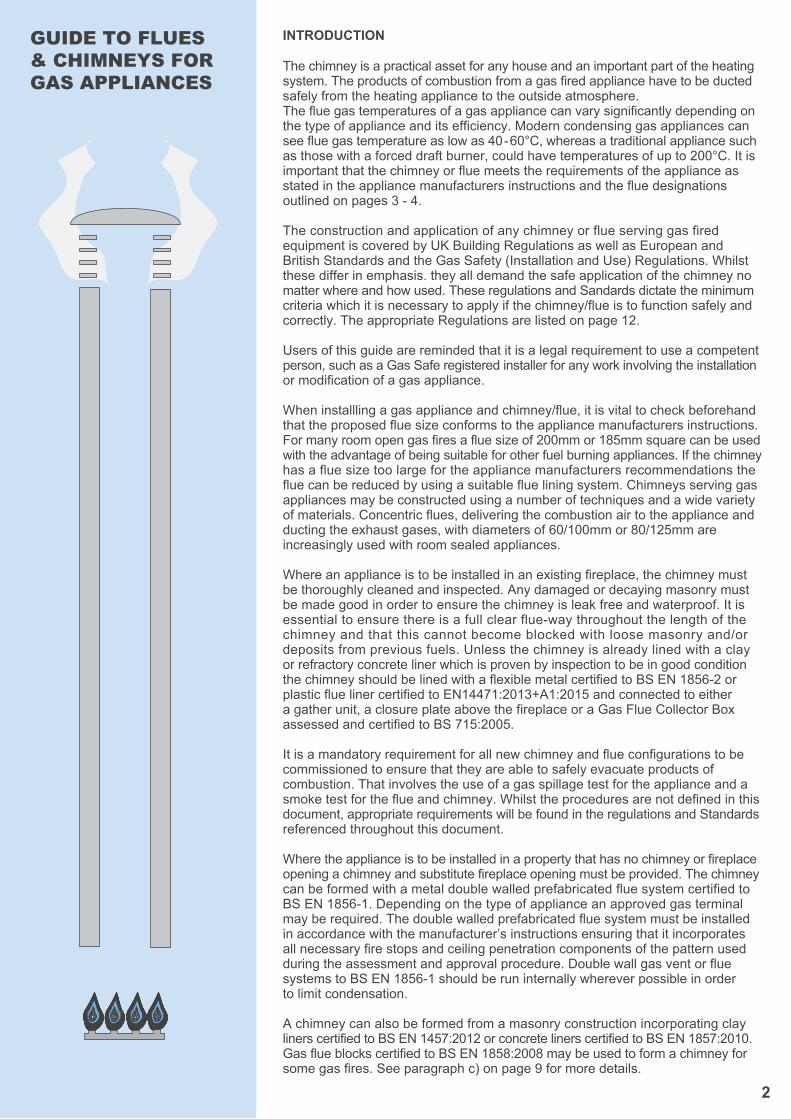
The chimney is a practical asset for any house and an important part of the heatingsystem. The products of combustion from a gas fired appliance have to be ducted safely from the heating appliance to the outside atmosphere.The flue gas temperatures of a gas appliance can vary significantly depending on the type of appliance and its efficiency. Modern condensing gas appliances can see flue gas temperature as low as 40-60°C, whereas a traditional appliance such as those with a forced draft burner, could have temperatures of up to 200°C. It is important that the chimney or flue meets the requirements of the appliance as stated in the appliance manufacturers instructions and the flue designations outlined on pages 3 - 4.
The construction and application of any chimney or flue serving gas fired equipment is covered by UK Building Regulations as well as European andBritish Standards and the Gas Safety (Installation and Use) Regulations. Whilstthese differ in emphasis. they all demand the safe application of the chimney no matter where and how used. These regulations and Sandards dictate the minimum criteria which it is necessary to apply if the chimney/flue is to function safely and correctly. The appropriate Regulations are listed on page 12.
Users of this guide are reminded that it is a legal requirement to use a competentperson, such as a Gas Safe registered installer for any work involving the installationor modification of a gas appliance.
When installling a gas appliance and chimney/flue, it is vital to check beforehand that the proposed flue size conforms to the appliance manufacturers instructions. For many room open gas fires a flue size of 200mm or 185mm square can be used with the advantage of being suitable for other fuel burning appliances. If the chimneyhas a flue size too large for the appliance manufacturers recommendations the flue can be reduced by using a suitable flue lining system. Chimneys serving gasappliances may be constructed using a number of techniques and a wide varietyof materials. Concentric flues, delivering the combustion air to the appliance and ducting the exhaust gases, with diameters of 60/100mm or 80/125mm are increasingly used with room sealed appliances.
Where an appliance is to be installed in an existing fireplace, the chimney mustbe thoroughly cleaned and inspected. Any damaged or decaying masonry must be made good in order to ensure the chimney is leak free and waterproof. It is essential to ensure there is a full clear flue-way throughout the length of the chimney and that this cannot become blocked with loose masonry and/or deposits from previous fuels. Unless the chimney is already lined with a clay or refractory concrete liner which is proven by inspection to be in good condition the chimney should be lined with a flexible metal certified to BS EN 1856-2 or plastic flue liner certified to EN14471:2013+A1:2015 and connected to either a gather unit, a closure plate above the fireplace or a Gas Flue Collector Box assessed and certified to BS 715:2005.
It is a mandatory requirement for all new chimney and flue configurations to be commissioned to ensure that they are able to safely evacuate products ofcombustion. That involves the use of a gas spillage test for the appliance and asmoke test for the flue and chimney. Whilst the procedures are not defined in thisdocument, appropriate requirements will be found in the regulations and Standardsreferenced throughout this document.
Where the appliance is to be installed in a property that has no chimney or fireplaceopening a chimney and substitute fireplace opening must be provided. The chimneycan be formed with a metal double walled prefabricated flue system certified toBS EN 1856-1. Depending on the type of appliance an approved gas terminal may be required. The double walled prefabricated flue system must be installed in accordance with the manufacturer’s instructions ensuring that it incorporates all necessary fire stops and ceiling penetration components of the pattern used during the assessment and approval procedure. Double wall gas vent or flue systems to BS EN 1856-1 should be run internally wherever possible in order to limit condensation.
A chimney can also be formed from a masonry construction incorporating clayliners certified to BS EN 1457:2012 or concrete liners certified to BS EN 1857:2010. Gas flue blocks certified to BS EN 1858:2008 may be used to form a chimney for some gas fires. See paragraph c) on page 9 for more details.
3
It is important to check that the flue characteristics match the technical specification of the appliance to which it is to be connected. Gas fire appliances fall into two main categories room sealed and room open. Room sealed appliances are generally condensing and operate under positive pressure. The combustion air for room sealed appliances is ducted to the appliance from outside. Whereas room open appliances take air from the room and operate under atmospheric pressure.
The flue designation details the flue characteristics and reveals the use to which it can be put.
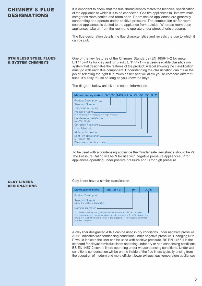
One of the key features of the Chimney Standards (EN 1856-1+2 for metal, EN 1457-1+2 for clay and for plastic EN14471) is a user-readable classification system that designates the features of the product. A label showing the classification must go with each flue component. Understanding the classification can make the job of selecting the right flue much easier and will allow you to compare different flues. It’s easy to use so long as you know the keys.
The diagram below unlocks the coded information.
CHIMNEY & FLUE DESIGNATIONS
STAINLESS STEEL FLUES & SYSTEM CHIMNEYS
Clay liners have a similar classiication.CLAY LINERS DESIGNATIONS
To be used with a condensing appliance the Condensate Resistance should be W. The Pressure Rating will be N for use with negative pressure appliances, P for appliances operating under positive pressure and H for high pressure.
A clay liner designated A1N1 can be used in dry conditions under negative pressure. A3N1 indicates wet/condensing conditions under negative pressure. Changing N to P would indicate the liner can be used with positive pressure. BS EN 1457-1 is the standard for clay/ceramic flue liners operating under dry or non-condensing conditions. BS EN 1457-2 covers liners operating under wet/condensing conditions. Under wet conditions condensation will be on the inside of the flue liners typically arising from the operation of modern and more efficient lower exhaust gas temperature appliances.
Product Description
Standard Number(either EN1457-1 or EN1457-2)
Nominal diameter
Clay/Ceramic liners EN 1457-2: 150 A3N1
This code specifies the conditions under which the liner can be used. The first number in the designation indicate wet or dry: 1 or 2 indicated dry and 3 or 4 wet. The second letter is the pressure: N for negative and P for positive pressure.
Product DescriptionStandard NumberTemperature RatingPressure Rating (N = Negative, P = Pressure, H = High Pressure)
Condensate Resistance(W = Wet, D = Dry)
Corrosion ResistanceLiner MaterialMaterial ThicknessSoot Fire Resistance(G = Yes, O = No)
Distance to combustibles
Metal chimney system EN 1856: T400 N1 W V2 L50 050 G 75
4
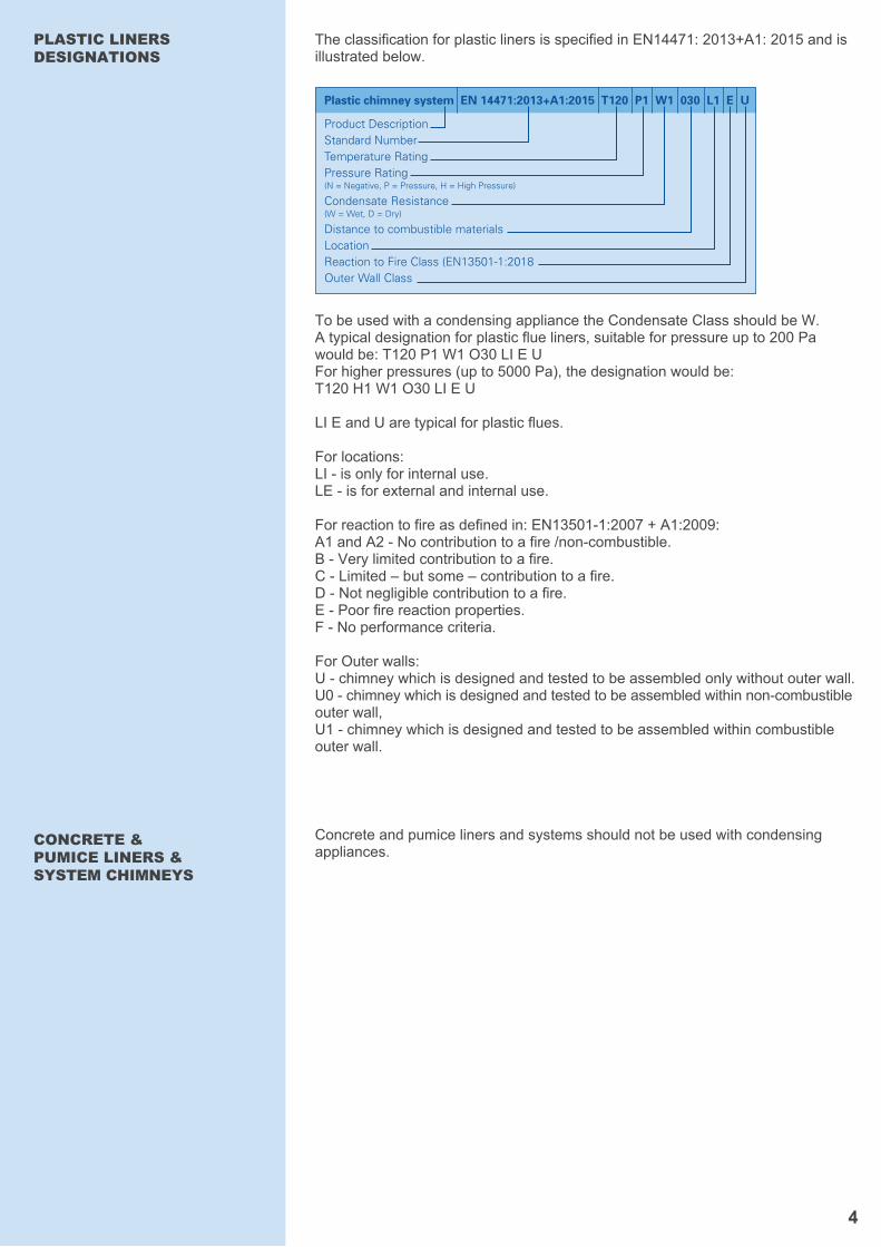
The classification for plastic liners is specified in EN14471: 2013+A1: 2015 and is illustrated below.
To be used with a condensing appliance the Condensate Class should be W.A typical designation for plastic flue liners, suitable for pressure up to 200 Pa would be: T120 P1 W1 O30 LI E UFor higher pressures (up to 5000 Pa), the designation would be: T120 H1 W1 O30 LI E U
LI E and U are typical for plastic flues.
For locations: LI - is only for internal use.LE - is for external and internal use.
For reaction to fire as defined in: EN13501-1:2007 + A1:2009: A1 and A2 - No contribution to a fire /non-combustible.B - Very limited contribution to a fire.C - Limited – but some – contribution to a fire.D - Not negligible contribution to a fire.E - Poor fire reaction properties.F - No performance criteria.
For Outer walls:U - chimney which is designed and tested to be assembled only without outer wall.U0 - chimney which is designed and tested to be assembled within non-combustible outer wall,U1 - chimney which is designed and tested to be assembled within combustible outer wall.
PLASTIC LINERS DESIGNATIONS
CONCRETE & PUMICE LINERS & SYSTEM CHIMNEYS
Concrete and pumice liners and systems should not be used with condensing appliances.
Product DescriptionStandard NumberTemperature RatingPressure Rating (N = Negative, P = Pressure, H = High Pressure)
Condensate Resistance(W = Wet, D = Dry)
Distance to combustible materialsLocationReaction to Fire Class (EN13501-1:2018Outer Wall Class
Plastic chimney system EN 14471:2013+A1:2015 T120 P1 W1 030 L1 E U
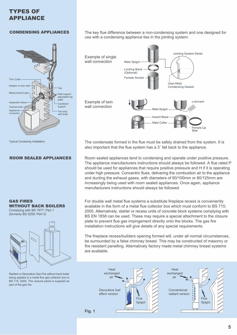
Fig. 1
Heatexchanged
air
FlueSpigot
Decorative fueleffect version
FlueSpigot
Conventionalradiant version
Heatexchanged
air
5
For double wall metal flue systems a substitute fireplace recess is convenientlyavailable in the form of a metal flue collector box which must conform to BS 715:2005. Alternatively, starter or recess units of concrete block systems complying withBS EN 1858 can be used. These may require a special attachment to the closureplate to prevent flue gas impingement directly onto the blocks. The gas fireinstallation instructions will give details of any special requirements.
The fireplace recess/builders opening formed will, under all normal circumstances,be surrounded by a false chimney breast. This may be constructed of masonry orfire resistant panelling. Alternatively factory made metal chimney breast systems are available.
The key flue difference between a non-condensing system and one designed for use with a condensing appliance lies in the jointing system.
The condensate formed in the flue must be safely drained from the system. It is also important that the flue system has a 3˚ fall back to the appliance.
Room sealed appliances tend to condensing and operate under positive pressure. The appliance manufacturers instructions should always be followed. A flue rated P should be used for appliances that require positive pressure and H if it is operating under high pressure. Concentric flues, delivering the combustion air to the appliance and ducting the exhaust gases, with diameters of 60/100mm or 80/125mm are increasingly being used with room sealed appliances. Once again, appliance manufacturers instructions should always be followed.
TYPES OF APPLIANCE
Radiant or Decorative Gas Fire without back boiler being applied to a metal flue gas collector box to BS 715: 2005. The closure panel is supplied as part of the gas fire.
GAS FIRES WITHOUT BACK BOILERSComplying with BS 7977: Part 1(formerly BS 5258: Part 5)
Typical Condesing Installation
CONDENSING APPLIANCES
ROOM SEALED APPLIANCES
Trim Collar
Tee
Tee plug with drain
Wall supportadjustable top plate
Cantilever support
Adaptor to twin wall
Measurement pipe
Inspection elbow
Vertical drainApplianceconnector
Example of single wall connection
Example of twin wall connection
Male Spigot
User-fittedCondensing Gasket
Jointing System Detail
Locking Band(Optional)
Female Socket
Male Collar
Male Spigot
Inward Bead
Lubricant
Female Lip Seal
The minimum internal flue diameter for this type of appliance is normally 175mm diameter. However, there are now many appliances approved for use with a 125mm diameter flue which meets the requirements of BS EN 1856-2, or for use with gas flue blocks complying to BS EN 1858. It is especially important to have the full set of the appliance installation instructions available in order to ensure the correct flue size is selected. The advice on flueing detailed above in the introduction is applicable. However, the following additional points should be noted.
1) Where a 175mm flue is needed this may need to be constructed to a solidfuel flue and chimney specification. As such consideration should be given tothe use of a 200mm diameter chimney suitable for solid fuel. This will thenprovide for future changes of appliances.
2) Flue collector boxes for this type of appliance are available with a variety offlue connections to suit various applications. It is important to ensure the correctdesign of box is used with the correct appliance. The appliance manufacturer’sinstructions should give appropriate advice. Alternatively, contact members of the BFCMA for guidance.
The installation of these appliances is covered by BS 5871-4:2007 Part 2.
With the availability of gas fires that simulate a solid fuel fire and other new designs of gas appliances, there is now a greater variety of appliances from which to choose.With such a large variety, it is essential that the appliance manufacturers instructionsare adhered to because there may be special requirements to be met. The followingsections outline the basic choices available.
These types of fires have a small flue spigot outlet and represent what has been for many years the traditional type or radiant gas fire. Some may be combined with a back boiler unit. These types of appliance are also available with a simulated solid fuel bed instead of radiant panels. Under such circumstances the fire front will usually be enclosed with glass and a typical arrangement is shown in Figure 1.
The minimum size of flue for this category is normally 125mm diameter. The fireshoiuld be fitted to the front of a closure plate which is normally supplied with theheating appliance. The flue spigot will fit through the opening in the closure plateand discharge the flue gases into the existing fireplace recess, builders openingor into a flue collector box complying with BS 715: 2005. Gas Flue Block systemscomplying with BS EN 1858:2008+A1:2011 may also be used. The installation of these appliances is covered by BS 5871-4:2007 Part 1.
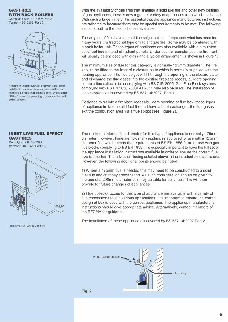
Designed to sit into a fireplace recess/builders opening or flue box, these typesof appliance imitate a solid fuel fire and have a heat exchanger. the flue gasesexit the combustion area via a flue spigot (see Figure 2).
GAS FIRES WITH BACK BOILERSComplying with BS 7977: Part 2(formerly BS 5258: Part 8)
Radiant or Decorative Gas Fire with back boiler installed into a false chimney breast with a non combustible horizontal closure panel which seals off the flue and the plumbing pipework to the backboiler location.
Flue spigot
Heat exchanged air
Fig. 2
INSET LIVE FUEL EFFECT GAS FIRESComplying with BS 7977(formerly BS 5258: Part 16)
Inset Live Fuel Effect Gas Fire
6
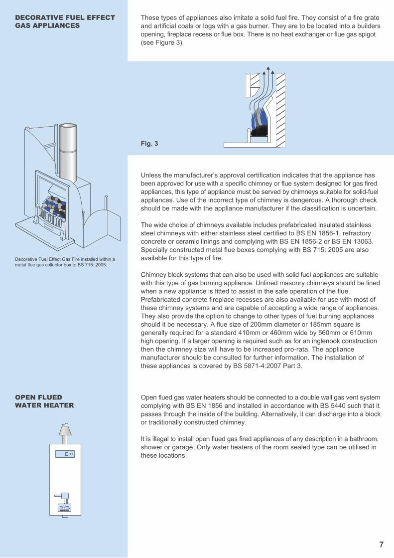
These types of appliances also imitate a solid fuel fire. They consist of a fire grateand artificial coals or logs with a gas burner. They are to be located into a buildersopening, fireplace recess or flue box. There is no heat exchanger or flue gas spigot(see Figure 3).
Unless the manufacturer’s approval certification indicates that the appliance hasbeen approved for use with a specific chimney or flue system designed for gas firedappliances, this type of appliance must be served by chimneys suitable for solid-fuelappliances. Use of the incorrect type of chimney is dangerous. A thorough checkshould be made with the appliance manufacturer if the classification is uncertain.
The wide choice of chimneys available includes prefabricated insulated stainlesssteel chimneys with either stainless steel certified to BS EN 1856-1, refractory concrete or ceramic linings and complying with BS EN 1856-2 or BS EN 13063. Specially constructed metal flue boxes complying with BS 715: 2005 are also available for this type of fire.
Chimney block systems that can also be used with solid fuel appliances are suitablewith this type of gas burning appliance. Unlined masonry chimneys should be lined when a new appliance is fitted to assist in the safe operation of the flue. Prefabricated concrete fireplace recesses are also available for use with most ofthese chimney systems and are capable of accepting a wide range of appliances.They also provide the option to change to other types of fuel burning appliancesshould it be necessary. A flue size of 200mm diameter or 185mm square isgenerally required for a standard 410mm or 460mm wide by 560mm or 610mmhigh opening. If a larger opening is required such as for an inglenook constructionthen the chimney size will have to be increased pro-rata. The appliance manufacturer should be consulted for further information. The installation ofthese appliances is covered by BS 5871-4:2007 Part 3.
7
DECORATIVE FUEL EFFECT GAS APPLIANCES
Decorative Fuel Effect Gas Fire installed within ametal flue gas collector box to BS 715: 2005.
Open flued gas water heaters should be connected to a double wall gas vent systemcomplying with BS EN 1856 and installed in accordance with BS 5440 such that itpasses through the inside of the building. Alternatively, it can discharge into a blockor traditionally constructed chimney.
It is illegal to install open flued gas fired appliances of any description in a bathroom,shower or garage. Only water heaters of the room sealed type can be utilised inthese locations.
OPEN FLUEDWATER HEATER
Fig. 3
8
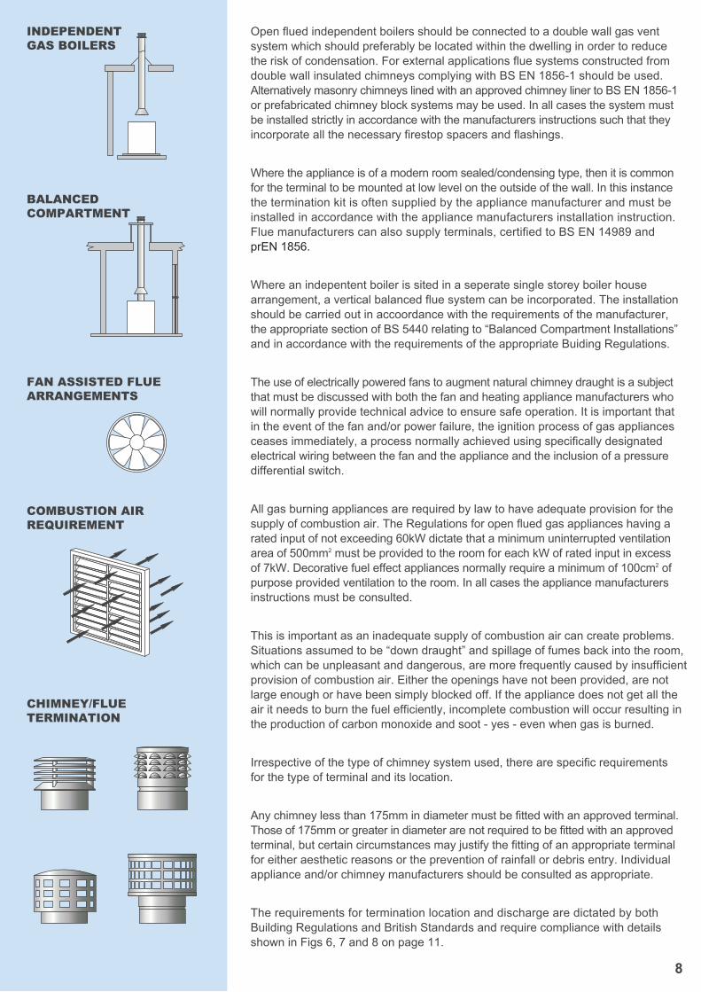
Open flued independent boilers should be connected to a double wall gas ventsystem which should preferably be located within the dwelling in order to reduce the risk of condensation. For external applications flue systems constructed fromdouble wall insulated chimneys complying with BS EN 1856-1 should be used.Alternatively masonry chimneys lined with an approved chimney liner to BS EN 1856-1 or prefabricated chimney block systems may be used. In all cases the system must be installed strictly in accordance with the manufacturers instructions such that they incorporate all the necessary firestop spacers and flashings.
Where the appliance is of a modern room sealed/condensing type, then it is common for the terminal to be mounted at low level on the outside of the wall. In this instance the termination kit is often supplied by the appliance manufacturer and must be installed in accordance with the appliance manufacturers installation instruction.Flue manufacturers can also supply terminals, certified to BS EN 14989 and prEN 1856.
Where an indepentent boiler is sited in a seperate single storey boiler housearrangement, a vertical balanced flue system can be incorporated. The installationshould be carried out in accoordance with the requirements of the manufacturer,the appropriate section of BS 5440 relating to “Balanced Compartment Installations”and in accordance with the requirements of the appropriate Buiding Regulations.
The use of electrically powered fans to augment natural chimney draught is a subjectthat must be discussed with both the fan and heating appliance manufacturers whowill normally provide technical advice to ensure safe operation. It is important that in the event of the fan and/or power failure, the ignition process of gas appliancesceases immediately, a process normally achieved using specifically designatedelectrical wiring between the fan and the appliance and the inclusion of a pressuredifferential switch.
All gas burning appliances are required by law to have adequate provision for thesupply of combustion air. The Regulations for open flued gas appliances having arated input of not exceeding 60kW dictate that a minimum uninterrupted ventilationarea of 500mm2 must be provided to the room for each kW of rated input in excess of 7kW. Decorative fuel effect appliances normally require a minimum of 100cm2 of purpose provided ventilation to the room. In all cases the appliance manufacturers instructions must be consulted.
This is important as an inadequate supply of combustion air can create problems.Situations assumed to be “down draught” and spillage of fumes back into the room,which can be unpleasant and dangerous, are more frequently caused by insufficientprovision of combustion air. Either the openings have not been provided, are notlarge enough or have been simply blocked off. If the appliance does not get all the air it needs to burn the fuel efficiently, incomplete combustion will occur resulting inthe production of carbon monoxide and soot - yes - even when gas is burned.
Irrespective of the type of chimney system used, there are specific requirementsfor the type of terminal and its location.
Any chimney less than 175mm in diameter must be fitted with an approved terminal.Those of 175mm or greater in diameter are not required to be fitted with an approvedterminal, but certain circumstances may justify the fitting of an appropriate terminalfor either aesthetic reasons or the prevention of rainfall or debris entry. Individualappliance and/or chimney manufacturers should be consulted as appropriate.
The requirements for termination location and discharge are dictated by bothBuilding Regulations and British Standards and require compliance with detailsshown in Figs 6, 7 and 8 on page 11.
INDEPENDENTGAS BOILERS
BALANCEDCOMPARTMENT
FAN ASSISTED FLUEARRANGEMENTS
COMBUSTION AIRREQUIREMENT
CHIMNEY/FLUETERMINATION
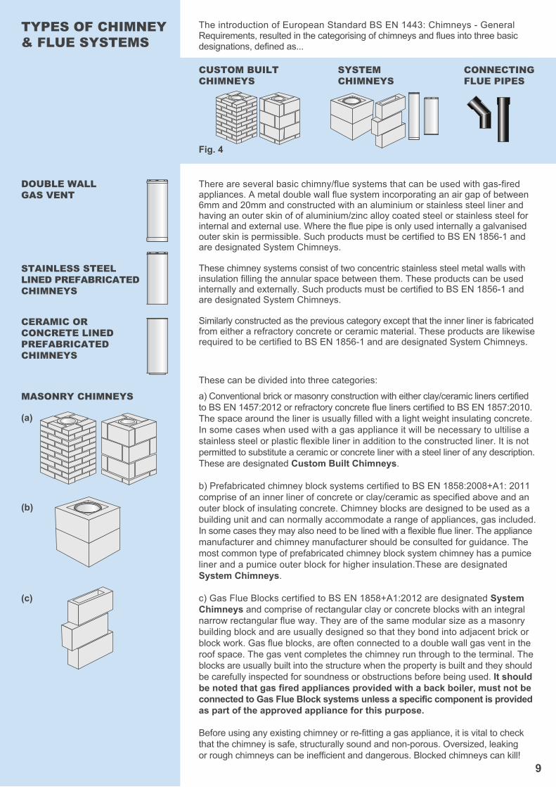
Fig. 4
CUSTOM BUILTCHIMNEYS
SYSTEMCHIMNEYS
CONNECTINGFLUE PIPES
9
The introduction of European Standard BS EN 1443: Chimneys - General Requirements, resulted in the categorising of chimneys and flues into three basic designations, defined as...
There are several basic chimny/flue systems that can be used with gas-firedappliances. A metal double wall flue system incorporating an air gap of between 6mm and 20mm and constructed with an aluminium or stainless steel liner and having an outer skin of of aluminium/zinc alloy coated steel or stainless steel for internal and external use. Where the flue pipe is only used internally a galvanised outer skin is permissible. Such products must be certified to BS EN 1856-1 and are designated System Chimneys.
These chimney systems consist of two concentric stainless steel metal walls withinsulation filling the annular space between them. These products can be usedinternally and externally. Such products must be certified to BS EN 1856-1 andare designated System Chimneys.
Similarly constructed as the previous category except that the inner liner is fabricatedfrom either a refractory concrete or ceramic material. These products are likewiserequired to be certified to BS EN 1856-1 and are designated System Chimneys.
DOUBLE WALLGAS VENT
STAINLESS STEEL LINED PREFABRICATED CHIMNEYS
CERAMIC OR CONCRETE LINED PREFABRICATED CHIMNEYS
MASONRY CHIMNEYS
(a)
(b)
(c)
TYPES OF CHIMNEY & FLUE SYSTEMS
These can be divided into three categories:
a) Conventional brick or masonry construction with either clay/ceramic liners certified to BS EN 1457:2012 or refractory concrete flue liners certified to BS EN 1857:2010.The space around the liner is usually filled with a light weight insulating concrete.In some cases when used with a gas appliance it will be necessary to ultilise a stainless steel or plastic flexible liner in addition to the constructed liner. It is not permitted to substitute a ceramic or concrete liner with a steel liner of any description.These are designated Custom Built Chimneys.
b) Prefabricated chimney block systems certified to BS EN 1858:2008+A1: 2011comprise of an inner liner of concrete or clay/ceramic as specified above and an outer block of insulating concrete. Chimney blocks are designed to be used as abuilding unit and can normally accommodate a range of appliances, gas included.In some cases they may also need to be lined with a flexible flue liner. The appliancemanufacturer and chimney manufacturer should be consulted for guidance. The most common type of prefabricated chimney block system chimney has a pumice liner and a pumice outer block for higher insulation.These are designated System Chimneys.
c) Gas Flue Blocks certified to BS EN 1858+A1:2012 are designated System Chimneys and comprise of rectangular clay or concrete blocks with an integral narrow rectangular flue way. They are of the same modular size as a masonry building block and are usually designed so that they bond into adjacent brick or block work. Gas flue blocks, are often connected to a double wall gas vent in the roof space. The gas vent completes the chimney run through to the terminal. The blocks are usually built into the structure when the property is built and they should be carefully inspected for soundness or obstructions before being used. It should be noted that gas fired appliances provided with a back boiler, must not be connected to Gas Flue Block systems unless a specific component is provided as part of the approved appliance for this purpose.
Before using any existing chimney or re-fitting a gas appliance, it is vital to checkthat the chimney is safe, structurally sound and non-porous. Oversized, leakingor rough chimneys can be inefficient and dangerous. Blocked chimneys can kill!
10
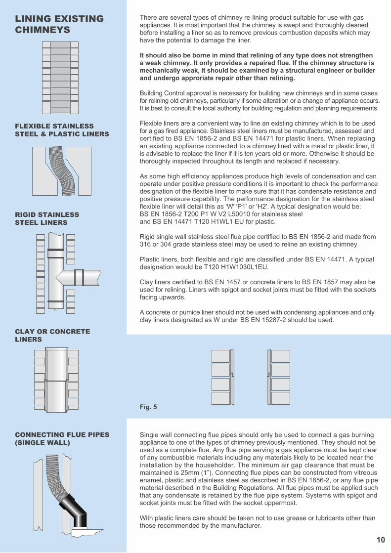
There are several types of chimney re-lining product suitable for use with gasappliances. It is most important that the chimney is swept and thoroughly cleanedbefore installing a liner so as to remove previous combustion deposits which mayhave the potential to damage the liner.
It should also be borne in mind that relining of any type does not strengthen a weak chimney. It only provides a repaired flue. If the chimney structure ismechanically weak, it should be examined by a structural engineer or builderand undergo approriate repair other than relining.
Building Control approval is necessary for building new chimneys and in some casesfor relining old chimneys, particularly if some alteration or a change of appliance occurs.It is best to consult the local authority for building regulation and planning requirements.
Flexible liners are a convenient way to line an existing chimney which is to be used for a gas fired appliance. Stainless steel liners must be manufactured, assessed and certified to BS EN 1856-2 and BS EN 14471 for plastic liners. When replacing an existing appliance connected to a chimney lined with a metal or plastic liner, it is advisable to replace the liner if it is ten years old or more. Otherwise it should be thoroughly inspected throughout its length and replaced if necessary.
As some high efficiency appliances produce high levels of condensation and can operate under positive pressure conditions it is important to check the performance designation of the flexible liner to make sure that it has condensate resistance and positive pressure capability. The performance designation for the stainless steel flexible liner will detail this as 'W' 'P1' or 'H2'. A typical designation would be: BS EN 1856-2 T200 P1 W V2 L50010 for stainless steel and BS EN 14471 T120 H1WL1 EU for plastic.
Rigid single wall stainless steel flue pipe certified to BS EN 1856-2 and made from316 or 304 grade stainless steel may be used to reline an existing chimney.
Plastic liners, both flexible and rigid are classified under BS EN 14471. A typical designation would be T120 H1W1030L1EU.
Clay liners certified to BS EN 1457 or concrete liners to BS EN 1857 may also be used for relining. Liners with spigot and socket joints must be fitted with the sockets facing upwards.
A concrete or pumice liner should not be used with condensing appliances and only clay liners designated as W under BS EN 15287-2 should be used.
Single wall connecting flue pipes should only be used to connect a gas burningappliance to one of the types of chimney previously mentioned. They should not beused as a complete flue. Any flue pipe serving a gas appliance must be kept clear of any combustible materials including any materials likely to be located near theinstallation by the householder. The minimum air gap clearance that must bemaintained is 25mm (1”). Connecting flue pipes can be constructed from vitreousenamel, plastic and stainless steel as described in BS EN 1856-2, or any flue pipe material described in the Building Regulations. All flue pipes must be applied such that any condensate is retained by the flue pipe system. Systems with spigot and socket joints must be fitted with the socket uppermost.
With plastic liners care should be taken not to use grease or lubricants other than those recommended by the manufacturer.
FLEXIBLE STAINLESSSTEEL & PLASTIC LINERS
RIGID STAINLESSSTEEL LINERS
CLAY OR CONCRETE LINERS
CONNECTING FLUE PIPES (SINGLE WALL)
LINING EXISTINGCHIMNEYS
Fig. 5
11
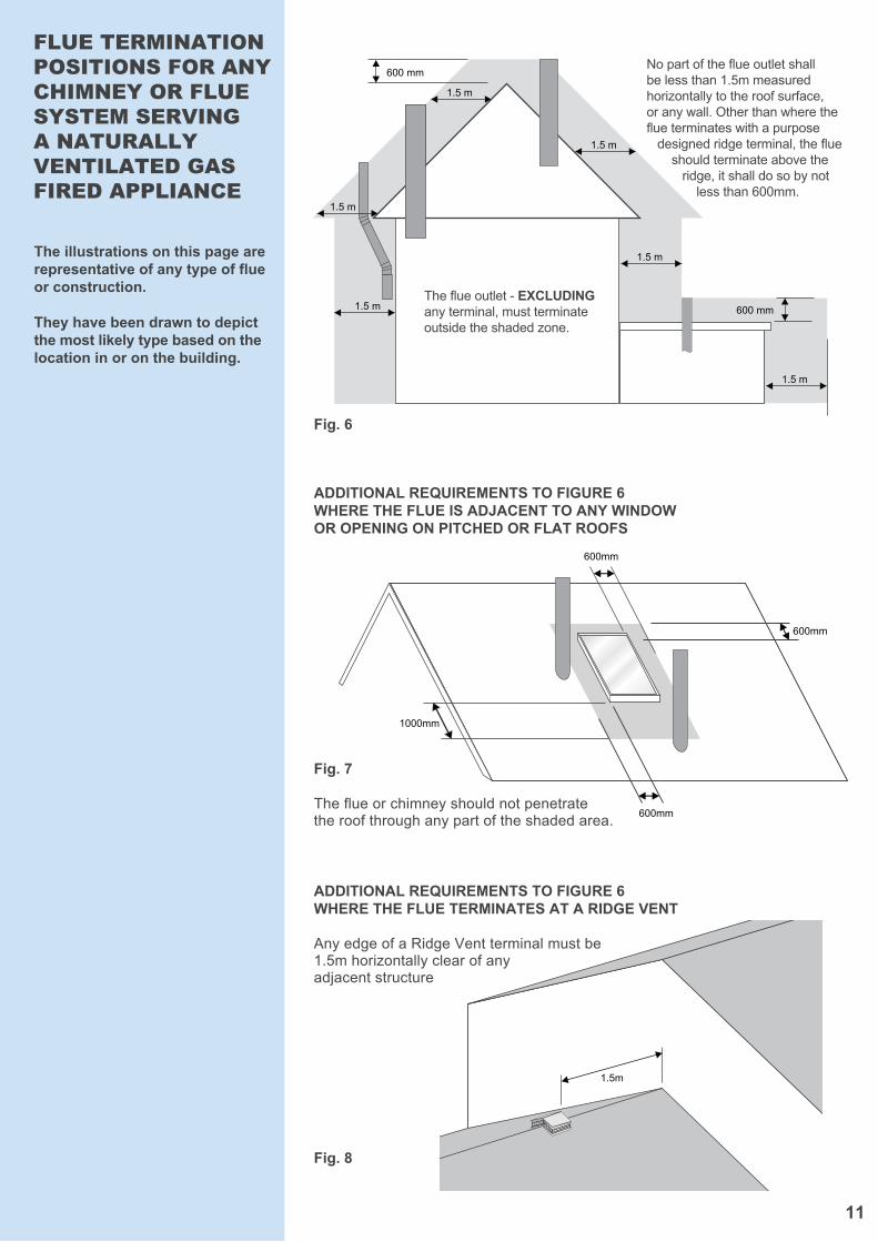
FLUE TERMINATIONPOSITIONS FOR ANY CHIMNEY OR FLUE SYSTEM SERVING A NATURALLYVENTILATED GAS FIRED APPLIANCE
The illustrations on this page arerepresentative of any type of flue or construction.
They have been drawn to depict the most likely type based on the location in or on the building.
600mm
600mm
600mm
1000mm
1.5m
Fig. 8
Fig. 7
The flue or chimney should not penetrate the roof through any part of the shaded area.
Fig. 6
ADDITIONAL REQUIREMENTS TO FIGURE 6 WHERE THE FLUE IS ADJACENT TO ANY WINDOW OR OPENING ON PITCHED OR FLAT ROOFS
ADDITIONAL REQUIREMENTS TO FIGURE 6 WHERE THE FLUE TERMINATES AT A RIDGE VENT
Any edge of a Ridge Vent terminal must be1.5m horizontally clear of any adjacent structure
1.5 m
1.5 m
1.5 m
1.5 m
1.5 m
1.5 m
600 mm
600 mm
The flue outlet - EXCLUDINGany terminal, must terminateoutside the shaded zone.
No part of the flue outlet shall be less than 1.5m measuredhorizontally to the roof surface, or any wall. Other than where theflue terminates with a purpose designed ridge terminal, the flue should terminate above the ridge, it shall do so by not less than 600mm.
12
CHIMNEY, FLUE &APPLIANCE ON SITEIDENTIFICATION(Notice Plate)
BUILDING REGULATIONS& STANDARD REFERENCESBuilding Regulations appropriate to the UK are:-
England & Wales.The Building RegulationsApproved Document J
ScotlandBuilding RegulationsTechnical StandardsSection 3
Northern IrelandBuilding Regulations Northern IrelandTechnical Booklet L
Copies of these Building Regulations can be obtained from the Stationery Office.
Advice is also available from LocalAuthority Building Control Departments.IGEM also publishes guidance documents.
The installation of all flues must comply with the Clean Air Act, the Gas Safety Regulations and Local Authority Regulations.
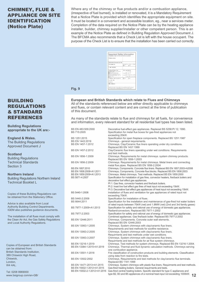
Where any of the chimney or flue products and/or a combustion appliance,(irrespective of fuel burned), is installed or renovated, it is a Mandatory Requirementthat a Notice Plate is provided which identifies the appropriate equipment on site.It must be located in a convenient and accessible location, eg., near a services meter.Completion of the data required on the Notice Plate can be by the heating applianceinstaller, builder, chimney supplier/installer or other competent person. This is anexample of the Notice Plate as defined in Building Regulation Approved Document J.The BFCMA also recommends that a Check List is left with the house occupant. The purpose of the Check List is to ensure that the installation has been carried out correctly.
Fig. 9
European and British Standards which relate to Flues and ChimneysAll of the standards referenced below are either directly applicable to chimneys and flues, or contain relevant content and are correct at the time of publication of this document.
As many of the standards relate to flue and chimneys for all fuels, for convenience and information, every relevant standard for all residential fuel types has been listed.
Copies of European and British Standards can be obtained from:British Standards Institution, 389 Chiswick High Road, Chiswick, London, W4 4AL.
Tel: 0208 9969000 www.bsigroup.com/en-GB/
BS EN 483:509:2000 Decorative fuel-effect gas appliances. Replaced BS 5258:Pt 12; 1990.BS 715:2005 Specification for metal flue boxes for gas-fired appliances not exceeding 20kW.BS 1251:2015 Specification for open fireplace components. Replaced BS 1251:1987BS EN 1443:2019 Chimneys - general requirements.BS EN 1457-1:2012 Chimneys, Clay/Ceramic flue liners operating under dry conditions. Replaced BS EN 1457:1999BS EN 1457-2:2012 Clay/Ceramic flue liners operating under wet conditions. Requirements and test methods.BS EN 1856-1:2009 Chimneys. Requirements for metal chimneys. system chimney products. Replaced BS EN 1856-1:2003BS EN 1856-2:2009 Chimneys. Requirements for metal chimneys. Metal liners and connecting metal flue pipes. Replaced BS EN 1856-2:2004BS EN 1857:2010 Chimneys, Components. Concrete flue liners. Replaced BS EN 1857:2003+A2008BS EN 1858:2008+A1:2011 Chimneys, Components, Concrete flue blocks. Replaced BS EN 1858:2003BS EN 1859:2009+A1:2013 Chimneys. Metal chimneys. Test methods. Replaced BS EN 1859:2000BS 5871-4:2007 Specification for installation of gas fires, convector heaters, fire/back boilers and decorative fuel effect gas appliances. Pt 1: Gas fires, convector heaters and fire/back boilers. Pt 2: Inset live fuel effect gas fires of heat input not exceeding 15kW. Pt 3: Decorative fuel effect gas appliances of heat input not exceeding 15kW.BS 5440-1:2008 Installation of flues and ventilation for gas appliances of rated input not exceeding 70kW.BS 5440-2:2009 Specification for installation of flues.BS 6644:2011 Specification for the installation and maintenance of gas-fired hot water boilers of rated inputs between 70kW (net) and 1.8MW (net) (2nd and 3rd family gases)BS 7977-1:2009+A1:2013 Specification for safety and rational use of energy of domestic gas appliances. Radiant/convectors. Replaced BS 7977-1:2002BS 7977-2:2003 Specification for safety and rational use of energy of domestic gas appliances. Combined appliances. Gas fire/back boiler. Replaced BS 7977-2:2002BS EN 12446:2011 Chimneys. Components. Concrete outer wall elements. Replaced BS EN 12446:2003BS EN 13063-1:2005 Chimneys. System chimneys with clay/ceramic flue liners. Requirements and test methods for sootfire resistance.BS EN 13063-2:2005 Chimneys. System chimneys with clay/ceramic flue liners. Requirments and test methods under wet conditions.BS EN 13063-3:2007 Chimneys. System chimneys with clay/ceramic flue liners. Requirments and test methods for air flue system chimneys.BS EN 13216-1:2019 Chimneys. Test methods for system chimneys. Replaced BS EN 13216-1:2004.BS EN 13384-1:2015+A1:2019 Chimneys. Thermal and fluid dynamic calculation methods. Chimneys serving one combustion appliance.BS EN 13501-1:2018 Fire classification of construction products and building elements. Classification using data from reaction to fire tests.BS EN 13502:2002 Chimneys. Requirements and test methods for clay/ceramic flue terminals. Replaced BS 1181:1999BS EN 14471:2013+A1:2015 Chimneys. System chimneys with plastic flue liners. Requirments and test methods.BS EN 15502-1:2012+A1:2015 Gas-fired heating boilers. General requirments and tests.BS EN 15502-2-1:2012+A1:2016 Gas-fired central heating boilers. Specific standard for type C appliances and type B2, B3 and B5 appliances of a nominal heat input not exceeding 1000kW.
13
SOME DOs & DON’Ts
Do... DO ensure that when an appliance is fitted to an existing chimney system that it is inspected and tested for soundness and any defects are rectified.
DO ensure that a chimney or flue system is always installed and supported and that all joints are properly, securely and efficiently made strictly in accordance with the manufacturers instructions.
DO ensure that the flue pipe connection from the appliance rises vertically for at least 600 mm (24”) before any change of direction is contemplated. The reason for this is that the flue draught is crucial nearer the appliance because of the higher flue gas temperature. Any horizontal or angled runs at the bottom of the flue will create severe restriction to gas movement and affect appliance operation.
DO try to construct the chimney vertically all the way to the terminal. Where bends are necessary, no part of the flue should be installed at an angle more than 45° from the vertical.
DO ensure that the flue diameter is not less than the diameter of the appliance outlet.
DO ensure that the effective height of any chimney with bends (vertical distance between appliance and terminal) is at least twice the horizontal distance between the appliance and terminal.
DO try to position the chimney inside the building to avoid excessive cooling and risk of condensation.
Don’t... DON'T use uninsulated flue systems externally.
DON'T allow clothes, furnishings or any combustible materials to come intocontact with the surface of any flue pipe or prefabricated metal chimney.
DON'T connect the gas appliance until the installation has been checked and approved by a gas engineer registered with Gas Safe.
DON'T use bends if they can be avoided.
DON'T position the chimney externally if it can be avoided.
DON'T be tempted to use non BS EN certificated flue and chimney systems;they may only last for a short time and will have to be replaced by the correctproduct. It will then be at least twice as expensive in the long run.
14
BFCMAMEMBERSLIST
Brewer Metalcraft Units C & D,Ford Lane Industrial Estate,Ford, Arundel,West Sussex,BN18 0DF,T: 01243 539 639E: [email protected]
Exodraft10 Crestway,Tarleton,Preston,PR4 6BE,T: 01494 465166E: [email protected]
Forterra Building ProductsAtherstone Road,Measham,Swadlincote,Derbyshire,DE12 7EL,T: 01530 273737E: [email protected]
Jeremias UKUnit 2-4, Long Stoop Way,Sovereign CourtCrown Farm Industrial Estate,Forest Town,MansfieldNG19 0FQ,T: 01623 889219E: [email protected]
M&G Group Europe Ltd2 The Oaks,Mill Farm Courtyard,Beachampton,MK19 6DS,T: 01908 569887E: [email protected]
Midtherm Flue SystemsKirklands Estate,New Road,Netherton,Dudley,West Midlands,DY2 8SY,T: 01384 458800E: [email protected]
Mi-FluesSpiro House,Cocker Avenue,Poulton Business Park,Poulton-Le-Fylde,Lancashire,FY6 8JU,T: 01253 600060E: [email protected]
Pennine SystemsCrossley Works, Stockfield Mount,Off Peel Street, Chadderton,Oldham,Lancashire,OL9 9LR,T: 0161 678 2998E: [email protected]
Poujoulat (UK)Unit 1, Quadrum Park,Old Portsmouth Road,Guildford,Surrey,GU3 1LU,T: 01483 461700E: [email protected]
Schiedel Chimney SystemsCrowther Estate, Washington,Tyne & Wear,NE38 0AQSchiedel Rite-Vent T: 0191 416 1150Schiedel IsokernT: 01202 861650E: [email protected]/uk
SFL Flues & ChimneysPottington Business Park,Barnstaple,Devon,EX31 1LZ,T: 01271 326633E: [email protected]
Wavin Hepworth TerracottaEdlington Lane,Edlington,Doncaster,South Yorkshire,DN12 1BY,T: 0844 856 5152E: [email protected]
W.T. Knowles & SonsAsh Grove Pipe Works,Elland,West Yorkshire,HX5 9JA,T: 01422 372 833E: [email protected]