Embed Size (px)
Citation preview
GRAUPNER GmbH & Co. KG D-73230 KIRCHHEIM/TECK GERMANY #0060376 Keine Haftung für Druckfehler. Technische Änderungen vorbehalten! No liability for printing errors. We reserve the right to introduce modifications. Sous réserve de modifications! Nous ne sommes pas responsables d’éventuelles erreurs d’impression! 03/2009
1
Betriebsanleitung für das Modell racing MICRO MAGIC, Best.-Nr.: 2014 und racing MICRO MAGIC Carbon Edition, Best.-Nr. 2014.C
Beschreibung des Modells Die racing MICRO MAGIC wurde anhand der Entwicklungen in der MICRO MAGIC Regattaszene ausgearbeitet und stellt bereits ab Werk eine für den ambitionierten Regattaeinsatz modifizierte Version dar, die als Ergänzung zur bisherigen beliebten MICRO MAGIC gedacht ist. Die racing MICRO MAGIC besitzt ein Kohlefaser-Rigg mit dünnem 5 mm Mast, verbesserte Segel und einen komplett neuen Satz hochwertiger Kunststoffbeschlagteile. Dazu gibt es erstmalig bei einem Bausatzmodell einen in Längsachse verschiebbaren Kiel, durch den das Modell sehr schnell auf unterschiedliche Segelbedingungen aber auch Vorlieben eines Skippers angepasst werden kann. Kielflosse und Ruder haben zur Verringerung des Widerstands leicht reduzierte Flächen und geringere Profildicken. Das etwas schwerere, längere Ballastgewicht wirkt sich dagegen kursstabiler aus. Die RC-Anlage ist auf den Einsatz von kleineren, leichteren RC-Bauteilen ausgelegt und die Anordnung dazu optimiert worden. Zusätzlich ist eine ferngesteuerte Fockschottrimmung über ein Microservo vorgesehen, so dass der Segeltrimm auch während der Fahrt justiert werden kann. Die Segelverstellung wurde reibungsreduziert mit einem Doppelsteuerarm und Umlenkrollen ausgelegt, so dass auch hier ein leichteres Servo eingesetzt werden kann. Die leichte optische Überarbeitung der Formgebung am Bug und Heck lassen das Boot moderner erscheinen, aber die Grundlinien des bisherigen Rumpfes sind unverändert beibehalten worden, um den deutschen Klassenregeln zu entsprechen. Die racing MICRO MAGIC Carbon Edition ist, bedingt durch das dickere Material (1,5mm anstatt 1,0mm) ca. 50 bis 60g schwerer.
Technische Daten Länge ü.a. ca. 535 mm Breite ca. 180 mm Gesamthöhe ca. 980 mm Gesamtgewicht ca. 850 g (910g bei 2014.C) Segelfläche ca. 1450 cm²
Wichtige Sicherheitshinweise Sie haben ein Modell erworben, aus dem – zusammen mit entsprechendem geeigneten Zubehör – ein funktionsfähiges RC-Modell fertiggestellt werden kann. Die Einhaltung der Montage- und Betriebsanleitung im Zusammenhang mit dem Modell sowie die Installation, der Betrieb, die Verwendung und Wartung der mit dem Modell zusammenhängenden Komponenten können von GRAUPNER nicht überwacht werden. Daher übernimmt GRAUPNER keinerlei Haftung für Verluste, Schäden oder Kosten, die sich aus dem fehlerhaften Betrieb, aus fehlerhaftem Verhalten bzw. in irgendeiner Weise mit dem Vorgenannten zusammenhängend ergeben. Soweit vom Gesetzgeber nicht zwingend vorgeschrieben, ist die Verpflichtung der Firma GRAUPNER zur Leistung von Schadensersatz, aus welchem Grund auch immer ausgeschlossen (inkl. Personenschäden, Tod, Beschädigung von Gebäuden sowie auch Schäden durch Umsatz- oder Geschäftsverlust, durch Geschäftsunterbrechung oder andere indirekte oder direkte Folgeschäden), die von dem Einsatz des Modells herrühren. Die Gesamthaftung ist unter allen Umständen und in jedem Fall beschränkt auf den Betrag, den Sie tatsächlich für dieses Modell gezahlt haben. Die Inbetriebnahme und der Betrieb des Modells erfolgt einzig und allein auf Gefahr des Betreibers. Nur ein vorsichtiger und überlegter Umgang beim Betrieb schützt vor Personen- und Sachschäden. Prüfen Sie vor dem ersten Einsatz des Modells, ob Ihre Privat-Haftpflichtversicherung den Betrieb von Modellschiffen dieser Art mit einschließt. Schließen Sie gegebenenfalls eine spezielle RC-Modell-Haftpflichtversicherung ab. Diese Sicherheitshinweise müssen unbedingt aufbewahrt werden und müssen bei einem Weiterverkauf des Modells an den Käufer weitergegeben werden.
GRAUPNER GmbH & Co. KG D-73230 KIRCHHEIM/TECK GERMANY #0060376 Keine Haftung für Druckfehler. Technische Änderungen vorbehalten! No liability for printing errors. We reserve the right to introduce modifications. Sous réserve de modifications! Nous ne sommes pas responsables d’éventuelles erreurs d’impression! 03/2009
2
Garantiebedingungen Die Garantie besteht aus der kostenlosen Reparatur bzw. dem Umtausch von solchen Teilen, die während der Garantiezeit von 24 Monaten, ab dem Datum des Kaufes nachgewiesene Fabrikations- oder Materialfehler aufweisen. Weitergehende Ansprüche sind ausgeschlossen. Transport-, Verpackungs- und Fahrtkosten gehen zu Lasten des Käufers. Für Transportschäden wird keine Haftung übernommen. Bei der Einsendung an GRAUPNER bzw. an die für das jeweilige Land zuständige Servicestelle sind eine sachdienliche Fehlerbeschreibung und die Rechnung mit dem Kaufdatum beizufügen. Die Garantie ist hinfällig, wenn der Ausfall des Teils oder des Modells von einem Unfall, unsachgemäßer Behandlung oder falscher Verwendung herrührt. Folgende Punkte müssen unbedingt beachtet werden: • Das Modell ist nicht für Kinder unter 14 Jahren geeignet. • Das Kielgewicht besteht aus Blei! Dieses Material ist giftig und darf niemals in den Körper gelangen.
Besonders die Schleifspäne bzw. der Materialabtrag ist gefährlich, da dies leicht aufgenommen werden kann. Reinigen Sie nach der Bearbeitung des Bleis sofort den Arbeitsplatz und die Hände. Tragen Sie auch Handschuhe.
• Das Bleigewicht muss später gemäß den geltenden Gesetzen entsorgt werden und darf niemals über den Haushaltsmüll gegeben werden. Erkundigen Sie sich bei Ihrer Gemeinde, wo Sie das Blei abgeben können (meist auf den kommunalen Wertstoffhöfen).
• Die hervorstehenden Teile an dem Modell können scharf sein und die Antennen bzw. Masten können Augenverletzungen hervorrufen.
• Die Erziehungsberechtigten müssen die Montage des Modells überwachen, da durch die Verwendung von Werkzeugen und Klebstoffen Gefahren ausgehen können.
• Das Modell vorsichtig betreiben, wenn sich Menschen und Tiere im Wasser befinden. Halten Sie immer ausreichend Abstand zwischen den Menschen bzw. Tieren.
• Lassen Sie Ihr Modell nicht in Naturschutz-, Landschaftsschutz-, oder Gewässerschutzgebieten fahren. Informieren Sie sich bei Ihrer Gemeinde über die für den Schiffsmodellbau freigegebenen Gewässer.
• Fahren Sie niemals im Salzwasser. • Fahren Sie niemals bei widrigen Witterungsbedingungen, wie z.B. Regen, Gewitter, Wind ab 4
Windstärken (Beaufort) sowie höherem Wellengang, Strömung des Gewässers usw.. • Da das Modell vom Wind abhängig ist, sollten Sie das Modell nur bei geringen Windstärken von 1 bis 3
Beaufort betreiben (Blätter bewegen sich im Wind!). Bei stärkerem Wind kann das Modell sich auf die Seite legen und unsteuerbar werden. Auch wenn der Wind böig ist sollte es nicht betrieben werden.
• Der Antrieb des Modells ist nur der Wind, d.h. bei Windstille bleibt das Modell auf dem Gewässer stehen. Dieses muss bei jeder Fahrt berücksichtigt werden.
• Kontrollieren Sie, bevor Sie das Modell fahren lassen, dieses auf eine sichere Funktion der Fernsteuerung. • Die Reichweite der Fernsteuerung muss vor Fahrtbeginn überprüft worden sein. Laufen Sie hierzu mit
eingeschaltetem Modell ca. 50m vom Sender weg. Hierbei müssen alle Funktionen problemlos ausgeführt werden können.
• Prüfen Sie, ob der von Ihnen genutzte Kanal frei ist. Fahren Sie niemals, wenn Sie sich nicht sicher sind, ob der Kanal frei ist.
• Beachten Sie, dass Funkgeräte oder Sendeanlagen die Funktion des Modells stark stören können. Achten Sie möglichst darauf, dass keines dieser Geräte in der Nähe betrieben wird während Sie das Modell betreiben.
• Arbeiten Sie am Modell nur im ausgeschalteten Zustand. • Die Batterien und Akkus dürfen nicht kurzgeschlossen werden, sowie nicht direkt dem Wasser ausgesetzt
werden. • Entnehmen Sie sämtliche Akkus im Modell und Sender bei Nichtgebrauch des Modells. • Setzen Sie das Modell nicht starker Luftfeuchtigkeit, Hitze, Kälte sowie Schmutz aus. • Sichern Sie das Modell und den Sender beim Transport gegen Beschädigung sowie Verrutschen. • Betreiben Sie niemals das Modell an einem bewegten Wasser (z.B. Fluss), da bedingt durch die nicht
einschätzbaren Windverhältnisse das Modell abtreiben kann. • Bringen Sie bei einer evtl. Bergung des Modells sich nicht selbst sowie andere in Gefahr. • Achten Sie besonders auf die Wasserdichtheit des Modells. Ein Modellboot wird bei entsprechendem
Wassereinbruch sinken. Kontrollieren Sie das Modell vor jeder Fahrt, ob irgendeine Beschädigung vorliegt und ob Wasser eindringen kann.
• Lassen Sie das Modell nach Gebrauch gut austrocknen.

GRAUPNER GmbH & Co. KG D-73230 KIRCHHEIM/TECK GERMANY #0060376 Keine Haftung für Druckfehler. Technische Änderungen vorbehalten! No liability for printing errors. We reserve the right to introduce modifications. Sous réserve de modifications! Nous ne sommes pas responsables d’éventuelles erreurs d’impression! 03/2009
3
Pflege und Wartung • Säubern Sie das Modell nach jedem Gebrauch. Entfernen Sie evtl. eingedrungenes Wasser. Sollte Wasser
in die RC-Komponenten gedrungen sein, legen Sie diese trocken und schicken Sie das Modell zur Kontrolle an die zuständige GRAUPNER Servicestelle ein.
• Säubern Sie das Modell und den Sender nur mit geeigneten Reinigungsmitteln. Geeignet ist ein fusselfreies Tuch. Verwenden Sie niemals chemische Reiniger, Lösungsmittel, Reinigungsbenzin, Spiritus oder ähnliches.
Hinweise zum Bau des Modells • Dieses Modell ist nicht für den Modellbaueinsteiger gedacht, daher sind nicht alle Arbeitsschritte
aufgeführt, da angenommen wird, dass diese dem erfahrenen Modellbauer bekannt sind. • Bei der racing MICRO MAGIC Carbon Edition müssen genauere Anpassarbeiten ausgeführt werden, da
bis auf die angepasste Haube, die Tiefzieh- und Laserteile auf das Material der normalen racing MICRO MAGIC ausgelegt sind. Diese geringen Arbeiten sind für den Modellbauer aber leicht zu erledigen.
• Um sich die neuesten Infos zur Einstellung und Tipps für die Montage des Modells zu holen, gehen Sie im Internet auf die Homepage www.micromagic.info
• Sollten Ihnen die Fachbegriffe beim Segelboot nicht bekannt sein, können Sie auf der obigen Internetseite auch eine Skizze mit den Begriffen herunterladen.
• Vor dem Bau des Modells sollte man unbedingt den Bauplan und die Anleitung bis zum Schluss studieren. Die Stückliste ist als Hilfsmittel zu benutzen. Anleitung und Stückliste sind weitgehend in der Reihenfolge des Zusammenbaus gehalten.
• Schneiden Sie die Stege, die die gelaserten Holzteile in der Platte halten, mittels eines scharfen Messers beidseitig an und brechen Sie dann erst die Teile aus der Platte.
• Die gelaserten Holzteile haben fertigungsbedingt immer eine schwarze Schneidelinie. Diese lässt sich durch Abschleifen beseitigen.
• Die Holzteile für den Innenausbau müssen trotz der präzisen Vorfertigung noch der Rumpf- bzw. Deckskontur angepasst werden. Wenn diese Druck auf den ABS-Rumpf ausüben würden, drücken sich die Spanten unschön durch das Rumpfmaterial. Daher ist dieser Anpassvorgang ein wichtiger Arbeitsschritt und muss sorgfältig ausgeführt werden.
• TIPP: Wenn Sie die Spitze der Schnur mit Sekundenkleber verfestigen und dann abschneiden, lässt sich diese leichter in kleine Öffnungen einfädeln.
• Um die Positionsnummer der gelaserten Teile zuordnen zu können, vergleichen Sie die Skizzen am Ende der Bauanleitung mit den Teilen.
• Mit Porenfüller GLATTFIX gestrichene Holzteile können mit UHU acrylit bzw. STABILIT express nicht mehr geklebt werden. Außerdem ist zu vermeiden, dass unnötig Klebstoff über die Klebestelle hinaus verschmiert wird, sonst ist mit manchen Farben die Lackierung nicht mehr einwandfrei möglich. Dies gilt besonders beim Verkleben der Kunststoff-Tiefziehteile.
• Achten Sie beim Einsatz von Werkzeugen auf die möglichen Gefahren. • Verlegen Sie die Empfangsantenne möglichst weit oben im Rumpf. Wenn sie unterhalb der Wasserlinie
liegt ist der Empfang sehr schlecht und die Reichweite wird stark verkürzt. • Säubern Sie jede Klebeverbindung von Fettresten, bevor Sie diese verkleben. Dies sollte durch
Anschleifen und säubern mit einem nicht nachfettenden Spülmittel bzw. Spiritus erfolgen. Das gleiche gilt für die zu lackierenden Oberflächen um eine gute Haltbarkeit der Farbe zu erreichen.
• Die Großbuchstaben A bis G auf dem Bauplan sind die Übergangsstellen der jeweiligen Schnüre. • Empfohlene Klebstoffe bei einer Verbindung untereinander: Material – Material Geeignete Klebstoffe Metall – Metall Sekundenkleber, UHU plus ABS – Holz Sekundenkleber, UHU acrylit ABS – ABS Sekundenkleber, UHU acrylit, UHU plast spezial ABS – Metall Sekundenkleber, UHU acrylit Holz – Holz Sekundenkleber, UHU hart, Weißleim Holz – Metall Sekundenkleber Beachten Sie die Verarbeitungshinweise der Klebstoffe! Achten Sie auf besondere Hinweise in der Montageanleitung über den Einsatz bestimmter Klebstoffe! Bei Verwendung von Aceton, Spiritus und anderen Lösungsmitteln als Reinigungsmittel, sind besondere Vorsichtsmaßnahmen nötig. Richten Sie sich nach den jeweiligen Verarbeitungsrichtlinien.
GRAUPNER GmbH & Co. KG D-73230 KIRCHHEIM/TECK GERMANY #0060376 Keine Haftung für Druckfehler. Technische Änderungen vorbehalten! No liability for printing errors. We reserve the right to introduce modifications. Sous réserve de modifications! Nous ne sommes pas responsables d’éventuelles erreurs d’impression! 03/2009
4
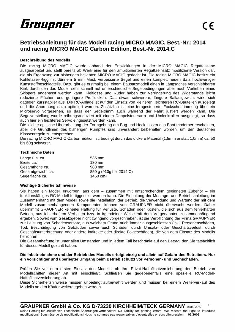
Montageanleitung • Stecken Sie den Schiffsständer aus dem vorderen
(Pos. 1), dem hinteren Stützbrett (Pos. 2) und den Seitenteilen (Pos. 3) zusammen und danach können Sie den Ständer verkleben. Lackieren Sie den Ständer und kleben Sie Schutzauflage (Pos. 4) auf (nicht auf dem Foto abgebildet). Diese soll den lackierten Rumpf vor dem Zerkratzen schützen.
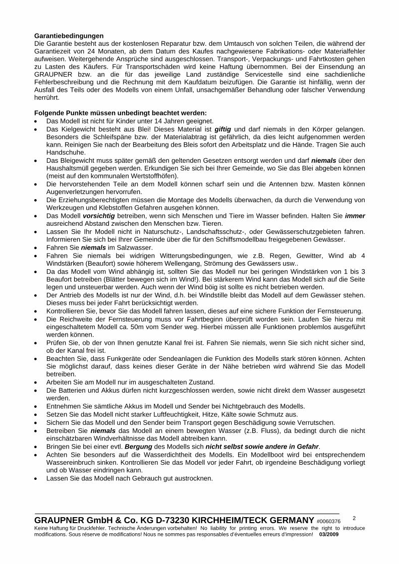
• Kleben Sie die Kielmasttasche (Pos. 5) zusammen. WICHTIG: Richten Sie sich beim Verkleben nicht an die Außenkontur der Tiefziehteile, sondern der Innenbereich für den Kiel muss genau parallel ausgerichtet werden. Sonst passt der Kiel später nicht richtig in die Tasche. HINWEIS: bei 2014.C muss die fertige Kielmasttasche oben und unten um je 0,5mm an der Auflagefläche abgearbeitet werden.
• Kleben Sie je eine Verstärkung für das Mastlager (Pos. 6) unten an die halbrundförmigen Laschen an der Kielmasttasche.
• Kleben Sie die beiden Servoträgerlager (Pos. 7) aufeinander, passen den Spalt für die Kielmasttasche so an, dass das Lager ohne Druck auf die Kielmasttasche passt. HINWEIS: bei 2014.C muss der Spalt um ca. 1mm aufgearbeitet werden. Kleben Sie die Einheit dann genau ausgerichtet an die Kielmasttasche. Nehmen Sie hierzu die Maße aus dem Bauplan ab. HINWEIS: eins der Lager hat einen tieferen Einschnitt für die Kielmasttasche, dies ist das untere Lager.
• Kleben Sie die fertige Kielmasttasche gerade ausgerichtet in den Rumpf (Pos. 8). Um die Tasche richtig wasserdicht zu bekommen, sollten Sie diese unten mit UHU acrylit rundherum abdichten.
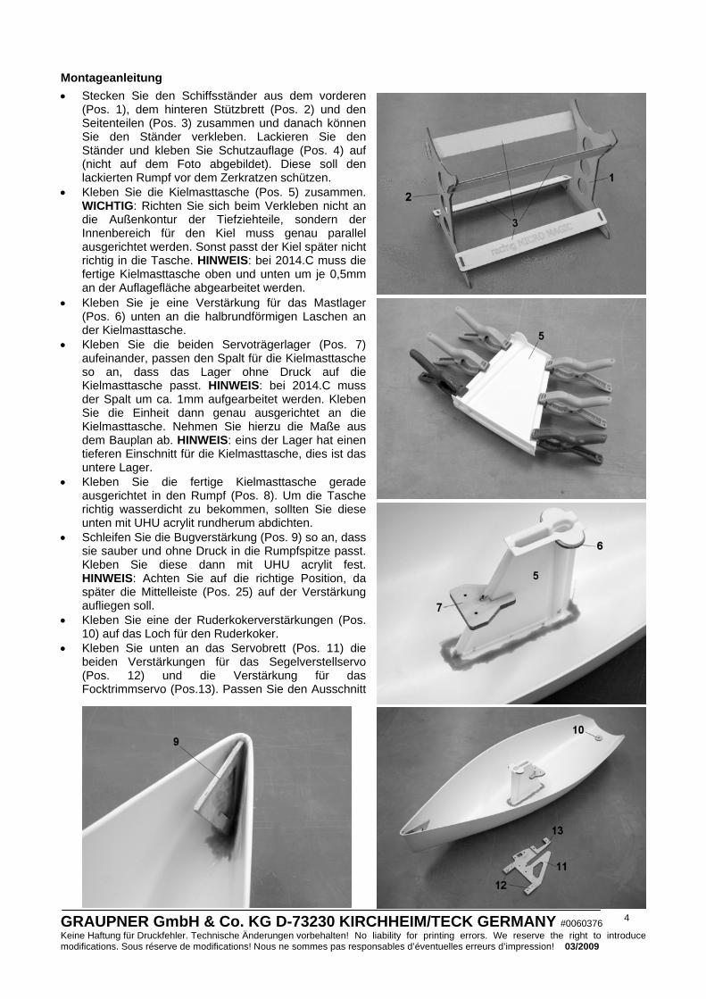
• Schleifen Sie die Bugverstärkung (Pos. 9) so an, dass sie sauber und ohne Druck in die Rumpfspitze passt. Kleben Sie diese dann mit UHU acrylit fest. HINWEIS: Achten Sie auf die richtige Position, da später die Mittelleiste (Pos. 25) auf der Verstärkung aufliegen soll.
• Kleben Sie eine der Ruderkokerverstärkungen (Pos. 10) auf das Loch für den Ruderkoker.
• Kleben Sie unten an das Servobrett (Pos. 11) die beiden Verstärkungen für das Segelverstellservo (Pos. 12) und die Verstärkung für das Focktrimmservo (Pos.13). Passen Sie den Ausschnitt
GRAUPNER GmbH & Co. KG D-73230 KIRCHHEIM/TECK GERMANY #0060376 Keine Haftung für Druckfehler. Technische Änderungen vorbehalten! No liability for printing errors. We reserve the right to introduce modifications. Sous réserve de modifications! Nous ne sommes pas responsables d’éventuelles erreurs d’impression! 03/2009
5
für die Kieltasche so an, dass das Brett spielfrei, aber ohne die Kielmasttasche zusammenzudrücken, aufgeschoben werden kann. HINWEIS: Das Servobrett ohne den Ausschnitt für das Segelverstellservo ist für den Einsatz von anderen Segelverstellservos vorgesehen. Schneiden Sie den Ausschnitt für das Servo mit einer Laubsäge zu. Legen Sie den Ausschnitt so an, dass die Servodrehachse später in der Mitte des Rumpfes liegt.
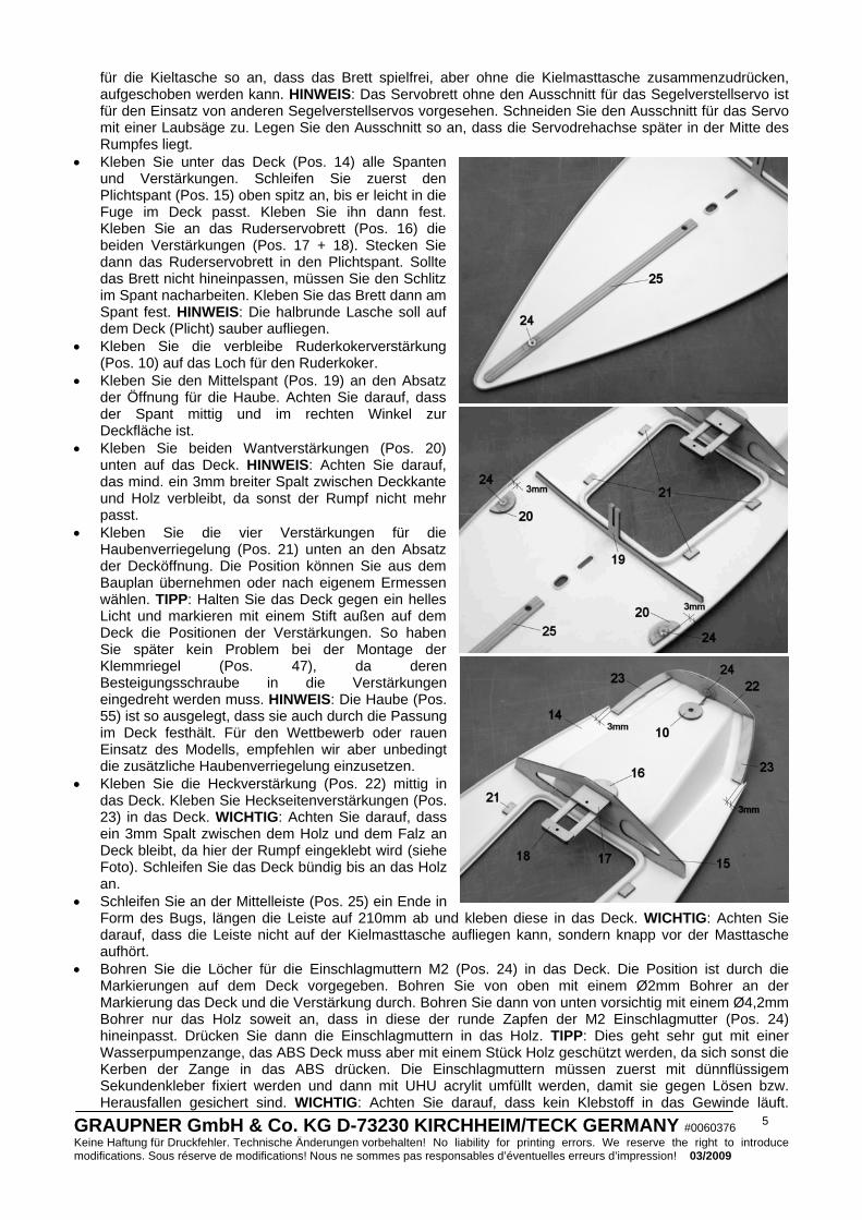
• Kleben Sie unter das Deck (Pos. 14) alle Spanten und Verstärkungen. Schleifen Sie zuerst den Plichtspant (Pos. 15) oben spitz an, bis er leicht in die Fuge im Deck passt. Kleben Sie ihn dann fest. Kleben Sie an das Ruderservobrett (Pos. 16) die beiden Verstärkungen (Pos. 17 + 18). Stecken Sie dann das Ruderservobrett in den Plichtspant. Sollte das Brett nicht hineinpassen, müssen Sie den Schlitz im Spant nacharbeiten. Kleben Sie das Brett dann am Spant fest. HINWEIS: Die halbrunde Lasche soll auf dem Deck (Plicht) sauber aufliegen.
• Kleben Sie die verbleibe Ruderkokerverstärkung (Pos. 10) auf das Loch für den Ruderkoker.
• Kleben Sie den Mittelspant (Pos. 19) an den Absatz der Öffnung für die Haube. Achten Sie darauf, dass der Spant mittig und im rechten Winkel zur Deckfläche ist.
• Kleben Sie beiden Wantverstärkungen (Pos. 20) unten auf das Deck. HINWEIS: Achten Sie darauf, das mind. ein 3mm breiter Spalt zwischen Deckkante und Holz verbleibt, da sonst der Rumpf nicht mehr passt.
• Kleben Sie die vier Verstärkungen für die Haubenverriegelung (Pos. 21) unten an den Absatz der Decköffnung. Die Position können Sie aus dem Bauplan übernehmen oder nach eigenem Ermessen wählen. TIPP: Halten Sie das Deck gegen ein helles Licht und markieren mit einem Stift außen auf dem Deck die Positionen der Verstärkungen. So haben Sie später kein Problem bei der Montage der Klemmriegel (Pos. 47), da deren Besteigungsschraube in die Verstärkungen eingedreht werden muss. HINWEIS: Die Haube (Pos. 55) ist so ausgelegt, dass sie auch durch die Passung im Deck festhält. Für den Wettbewerb oder rauen Einsatz des Modells, empfehlen wir aber unbedingt die zusätzliche Haubenverriegelung einzusetzen.
• Kleben Sie die Heckverstärkung (Pos. 22) mittig in das Deck. Kleben Sie Heckseitenverstärkungen (Pos. 23) in das Deck. WICHTIG: Achten Sie darauf, dass ein 3mm Spalt zwischen dem Holz und dem Falz an Deck bleibt, da hier der Rumpf eingeklebt wird (siehe Foto). Schleifen Sie das Deck bündig bis an das Holz an.
• Schleifen Sie an der Mittelleiste (Pos. 25) ein Ende in Form des Bugs, längen die Leiste auf 210mm ab und kleben diese in das Deck. WICHTIG: Achten Sie darauf, dass die Leiste nicht auf der Kielmasttasche aufliegen kann, sondern knapp vor der Masttasche aufhört.
• Bohren Sie die Löcher für die Einschlagmuttern M2 (Pos. 24) in das Deck. Die Position ist durch die Markierungen auf dem Deck vorgegeben. Bohren Sie von oben mit einem Ø2mm Bohrer an der Markierung das Deck und die Verstärkung durch. Bohren Sie dann von unten vorsichtig mit einem Ø4,2mm Bohrer nur das Holz soweit an, dass in diese der runde Zapfen der M2 Einschlagmutter (Pos. 24) hineinpasst. Drücken Sie dann die Einschlagmuttern in das Holz. TIPP: Dies geht sehr gut mit einer Wasserpumpenzange, das ABS Deck muss aber mit einem Stück Holz geschützt werden, da sich sonst die Kerben der Zange in das ABS drücken. Die Einschlagmuttern müssen zuerst mit dünnflüssigem Sekundenkleber fixiert werden und dann mit UHU acrylit umfüllt werden, damit sie gegen Lösen bzw. Herausfallen gesichert sind. WICHTIG: Achten Sie darauf, dass kein Klebstoff in das Gewinde läuft.
GRAUPNER GmbH & Co. KG D-73230 KIRCHHEIM/TECK GERMANY #0060376 Keine Haftung für Druckfehler. Technische Änderungen vorbehalten! No liability for printing errors. We reserve the right to introduce modifications. Sous réserve de modifications! Nous ne sommes pas responsables d’éventuelles erreurs d’impression! 03/2009
6
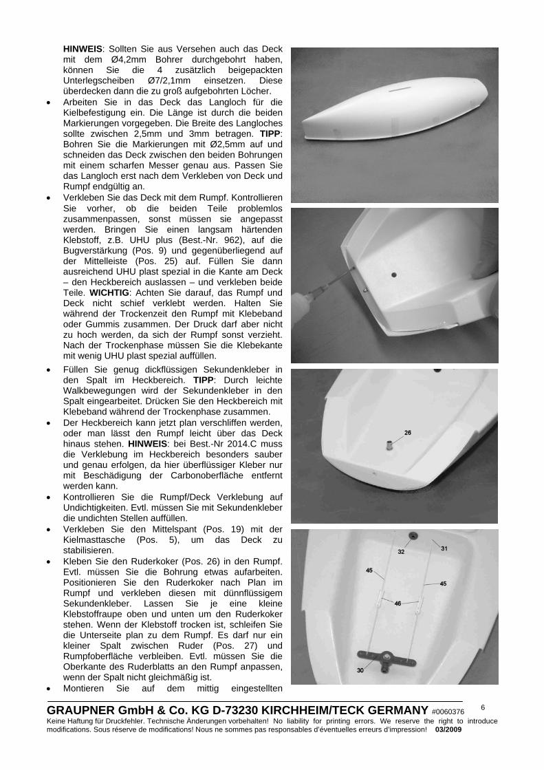
HINWEIS: Sollten Sie aus Versehen auch das Deck mit dem Ø4,2mm Bohrer durchgebohrt haben, können Sie die 4 zusätzlich beigepackten Unterlegscheiben Ø7/2,1mm einsetzen. Diese überdecken dann die zu groß aufgebohrten Löcher.
• Arbeiten Sie in das Deck das Langloch für die Kielbefestigung ein. Die Länge ist durch die beiden Markierungen vorgegeben. Die Breite des Langloches sollte zwischen 2,5mm und 3mm betragen. TIPP: Bohren Sie die Markierungen mit Ø2,5mm auf und schneiden das Deck zwischen den beiden Bohrungen mit einem scharfen Messer genau aus. Passen Sie das Langloch erst nach dem Verkleben von Deck und Rumpf endgültig an.
• Verkleben Sie das Deck mit dem Rumpf. Kontrollieren Sie vorher, ob die beiden Teile problemlos zusammenpassen, sonst müssen sie angepasst werden. Bringen Sie einen langsam härtenden Klebstoff, z.B. UHU plus (Best.-Nr. 962), auf die Bugverstärkung (Pos. 9) und gegenüberliegend auf der Mittelleiste (Pos. 25) auf. Füllen Sie dann ausreichend UHU plast spezial in die Kante am Deck – den Heckbereich auslassen – und verkleben beide Teile. WICHTIG: Achten Sie darauf, das Rumpf und Deck nicht schief verklebt werden. Halten Sie während der Trockenzeit den Rumpf mit Klebeband oder Gummis zusammen. Der Druck darf aber nicht zu hoch werden, da sich der Rumpf sonst verzieht. Nach der Trockenphase müssen Sie die Klebekante mit wenig UHU plast spezial auffüllen.
• Füllen Sie genug dickflüssigen Sekundenkleber in den Spalt im Heckbereich. TIPP: Durch leichte Walkbewegungen wird der Sekundenkleber in den Spalt eingearbeitet. Drücken Sie den Heckbereich mit Klebeband während der Trockenphase zusammen.
• Der Heckbereich kann jetzt plan verschliffen werden, oder man lässt den Rumpf leicht über das Deck hinaus stehen. HINWEIS: bei Best.-Nr 2014.C muss die Verklebung im Heckbereich besonders sauber und genau erfolgen, da hier überflüssiger Kleber nur mit Beschädigung der Carbonoberfläche entfernt werden kann.
• Kontrollieren Sie die Rumpf/Deck Verklebung auf Undichtigkeiten. Evtl. müssen Sie mit Sekundenkleber die undichten Stellen auffüllen.
• Verkleben Sie den Mittelspant (Pos. 19) mit der Kielmasttasche (Pos. 5), um das Deck zu stabilisieren.
• Kleben Sie den Ruderkoker (Pos. 26) in den Rumpf. Evtl. müssen Sie die Bohrung etwas aufarbeiten. Positionieren Sie den Ruderkoker nach Plan im Rumpf und verkleben diesen mit dünnflüssigem Sekundenkleber. Lassen Sie je eine kleine Klebstoffraupe oben und unten um den Ruderkoker stehen. Wenn der Klebstoff trocken ist, schleifen Sie die Unterseite plan zu dem Rumpf. Es darf nur ein kleiner Spalt zwischen Ruder (Pos. 27) und Rumpfoberfläche verbleiben. Evtl. müssen Sie die Oberkante des Ruderblatts an den Rumpf anpassen, wenn der Spalt nicht gleichmäßig ist.
• Montieren Sie auf dem mittig eingestellten

GRAUPNER GmbH & Co. KG D-73230 KIRCHHEIM/TECK GERMANY #0060376 Keine Haftung für Druckfehler. Technische Änderungen vorbehalten! No liability for printing errors. We reserve the right to introduce modifications. Sous réserve de modifications! Nous ne sommes pas responsables d’éventuelles erreurs d’impression! 03/2009
7
Ruderservo (Pos. 28) den Ruderservoarm (Pos. 29). Schrauben Sie dann das Ruderservo in das Ruderservobrett.
• Montieren Sie den Ruderhebel (Pos. 30) aus dem Kunststoffteil, dem Stellring und der M3 Schraube zusammen. Schrauben Sie diesen dann auf die Ruderwelle.
• Bohren Sie die beiden Ø2mm Löcher für die Seildurchführungen (Pos. 31), längen diese aus dem Bowdenzuginnenrohr auf 15mm ab und kleben diese mit Sekundenkleber in den Rumpf. WICHTIG: Achten Sie bei dieser Arbeit darauf, dass die späteren Zugseile möglichst gerade laufen.
• Bohren Sie die beiden Ø4mm Löcher für die Schotführungen (Pos. 32) nach Bauplan in den Rumpf. Kleben Sie diese dann ein.
• Drehen Sie zwei Linsenkopfschrauben (Pos. 33) nach Bauplan auf das Deck. Lassen Sie einen ca. 0,5mm breiten Spalt zwischen Deck und Kopf der Schrauben stehen. Die Schrauben werden später für die Fockbaumbefestigung und Wantenbefestigung benötigt.
• Drehen Sie aus den Spannern die Augenschraube (Pos. 34) an der Seite ohne der Kerbe heraus. Nur an dieser Seite befindet sich die mit dem M2 Rechtsgewinde. Drehen Sie dann die Augenschraube mit der Unterlegscheibe (Pos. 35) in die M2 Einschlagmutter im Deck. WICHTIG: Drücken Sie auf keinen Fall die Schraube mit Gewalt in die Mutter, da diese sich sonst im Rumpf lösen kann.
• Schrauben Sie das Segelverstellservo (Pos. 36), das Focktrimmservo (Pos. 37) und den Schalter (Pos. 38) in das Servobrett (Pos. 11). Nehmen hierzu die Schauben, die bei den Servos mitgeliefert werden. Kürzen Sie den 4-armigen Servoarm des Focktrimmservo so, wie auf dem Bauplan dargestellt. Schrauben Sie den Segelverstellhebel (Pos. 39) auf den Ruderservoarm (Pos. 29) mit 4 Linsenkopfschrauben (Pos. 33). Schleifen Sie die Schrauben soweit ab, bis die überstehenden Spitzen plan zum Segelverstellhebel sind.
• Montieren Sie die Rollenblöcke (Pos. 40) zusammen. Achten Sie darauf, dass die Rolle sich leicht drehen lässt. Evtl. müssen Sie hierzu den Grad abschleifen. HINWEIS: Die Rollenblöcke sind aus einem speziellen Kunststoff mit besonders guten Gleiteigenschaften gefertigt. Schrauben Sie dann die Rollenblöcke mit Linsenkopfschrauben (Pos. 33) auf dem Segelverstellhebel an. Achten Sie darauf, dass die flache Platte vom Rollenblock auf dem Hebel liegt. HINWEIS: Die Rollenblöcke sollten sich nicht auf dem Hebel drehen lassen, sondern fest verschraubt werden. HINWEIS: Sollte der Laufweg für die Schoten zu groß sein, schrauben Sie die Rollenblöcke an ein weiter innenliegendes Loch um den Weg zu verkürzen. Oder passen Sie den Ausschlag über den Sender an (Computersender der mc oder mx Serie vorrausgesetzt).
• Fädeln Sie die Fockschot (Pos. 42) von außen durch die Schotführung in den Rumpf. Führen Sie die Schot rechts neben der Kielmasttasche vorbei, stecken sie in den Rollenblock und knoten diese am Servohebel des Focktrimmservo an. TIPP: fixieren Sie den Knoten mit einem Tropfen Sekundenkleber. TIPP: Damit die Fockschot während des Weiterbaus nicht im Rumpf verschwindet, können Sie am Ende z.B. einen Zahnstocher anknoten. HINWEIS: Wenn Sie kein Focktrimmservo verwenden wollen, knoten Sie die Fockschot an dem hinteren Befestigungsloch für das Focktrimmservo fest.
• Schrauben Sie das Servobrett auf das Servoträgerlager im Rumpf mit zwei Linsenkopfschrauben (Pos. 41) und zwei Unterlegscheiben (Pos. 43) fest (zur besseren Übersicht ist der Rumpf auf dem Foto ohne Deck abgebildet).
• Bohren Sie ein Ø1,5mm Loch links neben dem Ruderservo. Lassen Sie genügend Material stehen, damit dieses nicht ausbricht. Knoten Sie hier die Großschot (Pos. 44) fest. Führen Sie diese dann durch den Rollenblock und dann durch die Schotführung.
• Knoten Sie die beiden Ruderanlenkungsseile (Pos. 45) am Ruderservoarm des Ruderservo an. Fädeln Sie diese dann durch die Seildurchführungen. Stecken Sie die Anlenkungseile dann durch den Ruderhebel und fädeln diese dann durch die Klemmschieber (Pos. 46). Das Anschlussschema der Klemmschieber ist auf dem Bauplan als Prinzipskizze dargestellt. Achten Sie aus optischen Gründen darauf, dass beide
GRAUPNER GmbH & Co. KG D-73230 KIRCHHEIM/TECK GERMANY #0060376 Keine Haftung für Druckfehler. Technische Änderungen vorbehalten! No liability for printing errors. We reserve the right to introduce modifications. Sous réserve de modifications! Nous ne sommes pas responsables d’éventuelles erreurs d’impression! 03/2009
8
Klemmschieber etwa auf der gleichen Position sind. • Schrauben Sie die vier Klemmriegel (Pos. 47) mit vier Linsenkopfschrauben (Pos. 33) fest. WICHTIG:
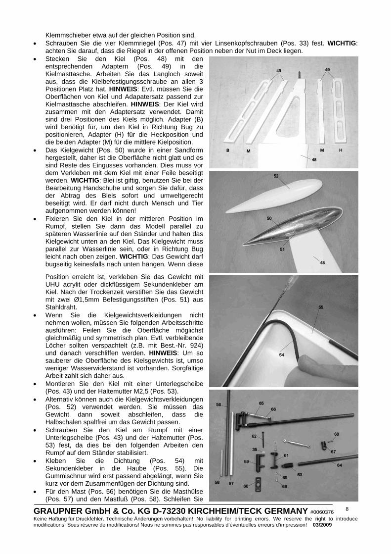
achten Sie darauf, dass die Riegel in der offenen Position neben der Nut im Deck liegen. • Stecken Sie den Kiel (Pos. 48) mit den
entsprechenden Adaptern (Pos. 49) in die Kielmasttasche. Arbeiten Sie das Langloch soweit aus, dass die Kielbefestigungsschraube an allen 3 Positionen Platz hat. HINWEIS: Evtl. müssen Sie die Oberflächen von Kiel und Adapatersatz passend zur Kielmasttasche abschleifen. HINWEIS: Der Kiel wird zusammen mit den Adaptersatz verwendet. Damit sind drei Positionen des Kiels möglich. Adapter (B) wird benötigt für, um den Kiel in Richtung Bug zu positionieren, Adapter (H) für die Heckposition und die beiden Adapter (M) für die mittlere Kielposition.
• Das Kielgewicht (Pos. 50) wurde in einer Sandform hergestellt, daher ist die Oberfläche nicht glatt und es sind Reste des Eingusses vorhanden. Dies muss vor dem Verkleben mit dem Kiel mit einer Feile beseitigt werden. WICHTIG: Blei ist giftig, benutzen Sie bei der Bearbeitung Handschuhe und sorgen Sie dafür, dass der Abtrag des Bleis sofort und umweltgerecht beseitigt wird. Er darf nicht durch Mensch und Tier aufgenommen werden können!
• Fixieren Sie den Kiel in der mittleren Position im Rumpf, stellen Sie dann das Modell parallel zu späteren Wasserlinie auf den Ständer und halten das Kielgewicht unten an den Kiel. Das Kielgewicht muss parallel zur Wasserlinie sein, oder in Richtung Bug leicht nach oben zeigen. WICHTIG: Das Gewicht darf bugseitig keinesfalls nach unten hängen. Wenn diese
Position erreicht ist, verkleben Sie das Gewicht mit UHU acrylit oder dickflüssigem Sekundenkleber am Kiel. Nach der Trockenzeit verstiften Sie das Gewicht mit zwei Ø1,5mm Befestigungsstiften (Pos. 51) aus Stahldraht.
• Wenn Sie die Kielgewichtsverkleidungen nicht nehmen wollen, müssen Sie folgenden Arbeitsschritte ausführen: Feilen Sie die Oberfläche möglichst gleichmäßig und symmetrisch plan. Evtl. verbleibende Löcher sollten verspachtelt (z.B. mit Best.-Nr. 924) und danach verschliffen werden. HINWEIS: Um so sauberer die Oberfläche des Kielsgewichts ist, umso weniger Wasserwiderstand ist vorhanden. Sorgfältige Arbeit zahlt sich daher aus.
• Montieren Sie den Kiel mit einer Unterlegscheibe (Pos. 43) und der Haltemutter M2,5 (Pos. 53).
• Alternativ können auch die Kielgewichtsverkleidungen (Pos. 52) verwendet werden. Sie müssen das Gewicht dann soweit abschleifen, dass die Halbschalen spaltfrei um das Gewicht passen.
• Schrauben Sie den Kiel am Rumpf mit einer Unterlegscheibe (Pos. 43) und der Haltemutter (Pos. 53) fest, da dies bei den folgenden Arbeiten den Rumpf auf dem Ständer stabilisiert.
• Kleben Sie die Dichtung (Pos. 54) mit Sekundenkleber in die Haube (Pos. 55). Die Gummischnur wird erst passend abgelängt, wenn Sie kurz vor dem Zusammenfügen der Dichtung sind.
• Für den Mast (Pos. 56) benötigen Sie die Masthülse (Pos. 57) und den Mastfuß (Pos. 58). Schleifen Sie
GRAUPNER GmbH & Co. KG D-73230 KIRCHHEIM/TECK GERMANY #0060376 Keine Haftung für Druckfehler. Technische Änderungen vorbehalten! No liability for printing errors. We reserve the right to introduce modifications. Sous réserve de modifications! Nous ne sommes pas responsables d’éventuelles erreurs d’impression! 03/2009
9
den Mastfuß soweit ab, das er ohne Druck in den Mast passt. Kleben Sie diesen dann mit dem Ende des Mast bündig fest. Schleifen Sie das Ende plan und runden die Enden leicht ab. Längen Sie dann die Masthülse auf 115mm ab. Stecken Sie die Hülse dann in die Mastöffnung.
• Nehmen Sie das Großbaumlager (Pos. 59) und die Mastplatte (Pos. 60) und schieben beide über die Masthülse bis aufs Deck. Verschrauben Sie dann die Mastplatte mit Linsenkopfschrauben (Pos. 33), vorher alles mittig ausrichten, mit dem Deck.
• Montieren Sie das Großbaumdrehlager (Pos. 61) mit der Unterlegscheibe (Pos. 35) und der Drehachse (Pos. 62) zusammen. Es muss sich sehr leicht drehen lassen, evtl. müssen Sie es soweit abschleifen, bis es sich leicht drehen lässt.
• Kleben Sie in die Großbaumhülse (Pos. 63) den Großbaum (Pos. 64). Schrauben Sie in den Niederdrücker (Pos. 65) die Klemmmutter (Pos. 66) rein. TIPP: das richtige Gewinde ist auf der Seite mit der eingedrehten Kerbe. Schieben Sie einen großen Klemmwinkel (Pos. 67) auf den Großbaum, stecken ein Auge des Niederdrückers in den Klemmwinkel und verschrauben das mit einer Fixierschraube (Pos. 68). Der Klemmwinkel muss sich aber noch verschieben lassen.
• Verschrauben Sie dann den Großbaum mit dem Großbaumdrehlager mit zwei Fixierschrauben (Pos. 68) und zwei Haltemuttern (Pos. 69).
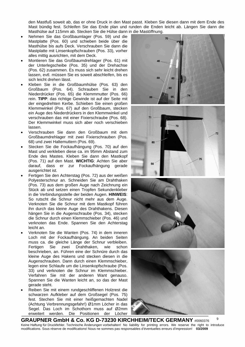
• Stecken Sie die Fockaufhängung (Pos. 70) auf den Mast und verkleben diese ca. im 95mm Abstand zum Ende des Mastes. Kleben Sie dann den Mastkopf (Pos. 71) auf den Mast. WICHTIG: Achten Sie aber darauf, dass er zur Fockaufhängung gerade ausgerichtet ist.
• Fertigen Sie den Achterstag (Pos. 72) aus der weißen Polyesterschnur an. Schneiden Sie am Drahthaken (Pos. 73) aus dem großen Auge nach Zeichnung ein Stück ab und setzen einen Tropfen Sekundenkleber in die Verbindungsstelle der beiden Augen. HINWEIS: So rutscht die Schnur nicht mehr aus dem Auge. Verknoten Sie die Schnur mit dem Mastkopf führen ihn durch das kleine Auge des Drahthakens. Diesen hängen Sie in die Augenschraube (Pos. 34), stecken die Schnur durch einen Klemmschieber (Pos. 46) und verknoten das Ende. Spannen Sie den Achterstag leicht an.
• Verknoten Sie die Wanten (Pos. 74) in dem inneren Loch mit der Fockaufhängung. An beiden Seiten muss ca. die gleiche Länge der Schnur verbleiben. Fertigen Sie zwei Drahthaken, wie schon beschrieben, an. Führen eine der Schnüre durch das kleine Auge des Hakens und stecken diesen in die Augenschrauben. Dann durch einen Klemmschieber, legen eine Schlaufe um die Linsenkopfschraube (Pos. 33) und verknoten die Schnur im Klemmschieber. Verfahren Sie mit der anderen Want genauso. Spannen Sie die Wanten leicht an, so das der Mast gerade steht.
• Reiben Sie mit einem rundgeschliffenen Holzrest die schwarzen Aufkleber auf dem Großsegel (Pos. 75) fest. Stechen Sie mit einer heißgemachten Nadel (Achtung Verbrennungsgefahr!) Ø1mm Löcher in das Segel. Das Loch im Schothorn muss auf Ø2mm erweitert werden. Die Positionen der Löcher
GRAUPNER GmbH & Co. KG D-73230 KIRCHHEIM/TECK GERMANY #0060376 Keine Haftung für Druckfehler. Technische Änderungen vorbehalten! No liability for printing errors. We reserve the right to introduce modifications. Sous réserve de modifications! Nous ne sommes pas responsables d’éventuelles erreurs d’impression! 03/2009
10
entnehmen Sie dem Bauplan. HINWEIS: durch die heiße Nadel verschmilzt das Segelmaterial und franst nicht aus.
• Kleben Sie die Segellatten (Pos. 76) nach Maßvorgabe im Bauplan auf das Segel. Die Enden der Latten müssen mit den runden Aufklebern (Pos. 77) gegen Ablösen gesichert werden. Kleben Sie die Aufkleber am Achterliek um das Segel mittig herum.
• Knoten Sie am Segelhals den Großsegelvorliekstrecker (Pos. 78) fest. Knoten Sie dann das Großfall (Pos. 79) an den Großsegelkopf an und stecken dieses in die Bohrung im Mastkopf. Verknoten Sie die Schnur so, dass das Großsegel ca. 4mm über dem Großbaulager ist. Stecken Sie Schnur des Vorliekstreckers in die beiden Bohrungen im Großbaumlager (Pos. 59), stecken diese in einen Klemmschieber (Pos. 46), legen die Schnur um die Augenschraube und verknoten diese im Klemmschieber. Spannen Sie das Großsegel leicht an.
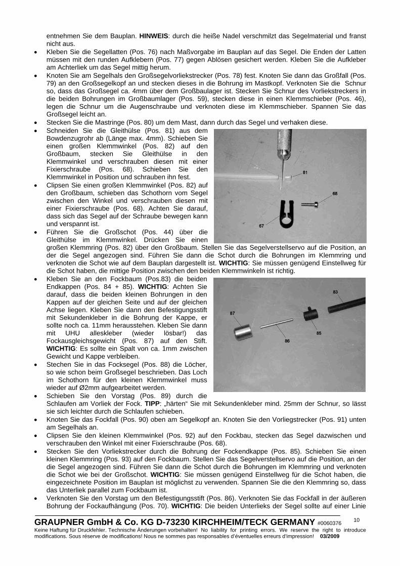
• Stecken Sie die Mastringe (Pos. 80) um dem Mast, dann durch das Segel und verhaken diese. • Schneiden Sie die Gleithülse (Pos. 81) aus dem
Bowdenzugrohr ab (Länge max. 4mm). Schieben Sie einen großen Klemmwinkel (Pos. 82) auf den Großbaum, stecken Sie Gleithülse in den Klemmwinkel und verschrauben diesen mit einer Fixierschraube (Pos. 68). Schieben Sie den Klemmwinkel in Position und schrauben ihn fest.
• Clipsen Sie einen großen Klemmwinkel (Pos. 82) auf den Großbaum, schieben das Schothorn vom Segel zwischen den Winkel und verschrauben diesen mit einer Fixierschraube (Pos. 68). Achten Sie darauf, dass sich das Segel auf der Schraube bewegen kann und verspannt ist.
• Führen Sie die Großschot (Pos. 44) über die Gleithülse im Klemmwinkel. Drücken Sie einen großen Klemmring (Pos. 82) über den Großbaum. Stellen Sie das Segelverstellservo auf die Position, an der die Segel angezogen sind. Führen Sie dann die Schot durch die Bohrungen im Klemmring und verknoten die Schot wie auf dem Bauplan dargestellt ist. WICHTIG: Sie müssen genügend Einstellweg für die Schot haben, die mittige Position zwischen den beiden Klemmwinkeln ist richtig.
• Kleben Sie an den Fockbaum (Pos.83) die beiden Endkappen (Pos. 84 + 85). WICHTIG: Achten Sie darauf, dass die beiden kleinen Bohrungen in den Kappen auf der gleichen Seite und auf der gleichen Achse liegen. Kleben Sie dann den Befestigungsstift mit Sekundenkleber in die Bohrung der Kappe, er sollte noch ca. 11mm herausstehen. Kleben Sie dann mit UHU alleskleber (wieder lösbar!) das Fockausgleichsgewicht (Pos. 87) auf den Stift. WICHTIG: Es sollte ein Spalt von ca. 1mm zwischen Gewicht und Kappe verbleiben.
• Stechen Sie in das Focksegel (Pos. 88) die Löcher, so wie schon beim Großsegel beschrieben. Das Loch im Schothorn für den kleinen Klemmwinkel muss wieder auf Ø2mm aufgearbeitet werden.
• Schieben Sie den Vorstag (Pos. 89) durch die Schlaufen am Vorliek der Fock. TIPP: „härten“ Sie mit Sekundenkleber mind. 25mm der Schnur, so lässt sie sich leichter durch die Schlaufen schieben.
• Knoten Sie das Fockfall (Pos. 90) oben am Segelkopf an. Knoten Sie den Vorliegstrecker (Pos. 91) unten am Segelhals an.
• Clipsen Sie den kleinen Klemmwinkel (Pos. 92) auf den Fockbau, stecken das Segel dazwischen und verschrauben den Winkel mit einer Fixierschraube (Pos. 68).
• Stecken Sie den Vorliekstrecker durch die Bohrung der Fockendkappe (Pos. 85). Schieben Sie einen kleinen Klemmring (Pos. 93) auf den Fockbaum. Stellen Sie das Segelverstellservo auf die Position, an der die Segel angezogen sind. Führen Sie dann die Schot durch die Bohrungen im Klemmring und verknoten die Schot wie bei der Großschot. WICHTIG: Sie müssen genügend Einstellweg für die Schot haben, die eingezeichnete Position im Bauplan ist möglichst zu verwenden. Spannen Sie die den Klemmring so, dass das Unterliek parallel zum Fockbaum ist.
• Verknoten Sie den Vorstag um den Befestigungsstift (Pos. 86). Verknoten Sie das Fockfall in der äußeren Bohrung der Fockaufhängung (Pos. 70). WICHTIG: Die beiden Unterlieks der Segel sollte auf einer Linie
GRAUPNER GmbH & Co. KG D-73230 KIRCHHEIM/TECK GERMANY #0060376 Keine Haftung für Druckfehler. Technische Änderungen vorbehalten! No liability for printing errors. We reserve the right to introduce modifications. Sous réserve de modifications! Nous ne sommes pas responsables d’éventuelles erreurs d’impression! 03/2009
11
liegen. • Führen Sie die Schnur des Vorstags durch einen Klemmschieber (Pos. 46) und dann durch die äußere
Bohrung in der Fockaufhängung. Dann wieder durch den Klemmschieber und verknoten die Schnur. • Clipsen Sie einen kleinen Klemmring (Pos. 93) auf den Fockbaum. Verknoten Sie im Klemmring die
Focksegelbefestigung (Pos. 94), wie schon bei der Schot. Fertigen Sie ein Drahthaken (Pos. 73), wie schon bekannt, an. Hängen Sie den Haken in die Augenschraube ein und führen die Schnur der Focksegelbefestigung durch das kleine Auge des Hakens, dann durch einen Klemmschieber (Pos. 46), legen eine Schlaufe um die Linsenkopfschraube (Pos. 33) und verknoten die Schnur wieder im Klemmschieber. Spannen Sie die Focksegelbefestigung an. Die Position der Fock kann durch Verschieben des Klemmrings so eingestellt werden, dass das Fockausgleichsgewicht sich genau hinter der Bugspitze befindet.
• Führen Sie die Fockschot (Pos. 42) durch die große Bohrung im der Endkappe (Pos. 84). Clipsen Sie einen kleinen Klemmring (Pos. 93) auf den Fockbaum, führen die Fockschot durch die Bohrungen und verknoten diese wie bei der Großschot. WICHTIG: Sie müssen genügend Einstellweg für die Schot haben, ein Abstand von ca. 30mm zum kleinen Klemmwinkel ist geeignet.
• Knoten Sie die Dirk (Pos. 95) an der Fockendkappe (Pos. 84) fest. Führen Sie die Schnur der Dirk dann durch einen Klemmschieber (Pos. 46), dann durch die äußere Bohrung der Fockaufhängung (Pos. 70) und verknoten Sie die Schnur wieder mit dem Klemmschieber. Die Dirk sollte nur ganz leicht angespannt werden und darf das Focksegel nicht zusammenziehen.
Die Lackierung • Bei Best.-Nr. 2014.C ist eine Lackierung nicht notwendig! • Fragen Sie Ihren Modellbauhändler oder den Farbenfachhändler nach den optimalen Farben. • Verwenden Sie NUR Farben vom gleichen Hersteller und Lacktyp, da sonst die Farben miteinander
reagieren können und sich wieder ablösen bzw. Blasen werfen. Seien Sie besonders vorsichtig bei der Kombination von Sprühdosenfarben und Streichfarben, probieren Sie immer an Reststücken, ob die Farben miteinander reagieren. Achtung: Lexanfarben sind nur mit sich selbst kompatibel, sie dürfen niemals mit anderen Farben oder einer Grundierung zusammen verwendet werden.
• Um eine gute Haftung der Farben zu erreichen, schleifen Sie die Oberflächen mit feinem Nassschleifpapier (Körnung 600 bis 800) an. Entfetten Sie danach die Oberfläche mit einem nicht nachfettenden Spülmittel oder Spiritus. Bis zur Lackierung sollte die Oberfläche möglichst nicht mehr angefasst werden, da selbst der Hautschweiß wieder neues Fett auf die Oberfläche bringt.
• Bedenken Sie, dass Klebeverbindungen auf lackierten Flächen nur so gut halten wie die Farbe auf dem Modell, d.h. oft wird dann das Teil abgebrochen indem die Farbe am Modell abreißt. Für Teile die leicht abbrechen können, sollten Sie die Farbe im Klebebereich entfernen.
• Die Holzteile sollten mit mehrmaligem Anstrich mittels Porenfüller (z.B. GLATTFIX Best.-Nr. 207) oder Klarlack (z.B. HYDRO-AEROFIX Best.-Nr. 926.1) gegen Wasser geschützt werden.
• Kleben Sie beim Spritzen der Farbe alle Bereiche, die nicht lackiert werden sollen, komplett ab. Dichten Sie alle Öffnungen ab, da der feine Farbnebel in alle noch so kleinen Öffnungen kommt.
• Beachten Sie die Verarbeitungshinweise der Lacke.
Farbgebung Damit der richtige Farbton leichter ausgewählt werden kann, wird die Farbe nur in dem RAL-Ton angegeben. Mit diesen Angaben können Sie sich über die Farbe in jedem Farbenfachgeschäft beraten lassen. Teilen Sie dem Fachberater im Farbenfachgeschäft den vorgesehenen Einsatzzweck der Farbe mit, damit er den richtigen Lacktyp auswählt. Wir empfehlen einen Kunstharztyp. Die Farbe RAL 9016 (Verkehrsweiß) eignet sich optimal als Grundfarbe für das Modell, da die Dekors auf eine weiße Grundfarbe abgestimmt sind. Das Modell lässt sich natürlich auch nach eigenem Ermessen gestalten.
Das Anbringen der Dekors Schneiden Sie mit einer scharfen Schere die einzelnen Dekors sauber und möglichst ohne Rand aus. Kleben Sie diese dann auf die lackierte und staubfreie Oberfläche des Modells. Um das große Rumpfdekor sauber auf den Rumpf zu bekommen, schneiden es nahezu randlos aus und legen Sie es noch mit der Schutzfolie passend auf den Rumpf und fixieren dann ein Ende mit einem Klebestreifen. Ziehen Sie dann die Schutzfolie ab und kleben es vorsichtig auf. Das große Dekor kann auch in die einzelnen Farbfelder zerschnitten werden, so lässt es sich auch leichter aufbringen. Die anderen Dekors können nach Kartonbild platziert oder nach eigenem Ermessen aufgeklebt werden.
GRAUPNER GmbH & Co. KG D-73230 KIRCHHEIM/TECK GERMANY #0060376 Keine Haftung für Druckfehler. Technische Änderungen vorbehalten! No liability for printing errors. We reserve the right to introduce modifications. Sous réserve de modifications! Nous ne sommes pas responsables d’éventuelles erreurs d’impression! 03/2009
12
Das Segeln Segeln mit Modellyachten ist nicht schwer, wenn man die Zusammenhänge zwischen Windrichtung, Bootsrichtung und entsprechender Segeleinstellung kennt. Machen Sie sich mit der Segeltheorie vertraut (z.B. durch Fachliteratur), bevor Sie das Modell das erste Mal einsetzen. Wir können Ihnen mit den folgenden Hinweisen nur eine kleine, grundsätzliche Hilfestellung geben.
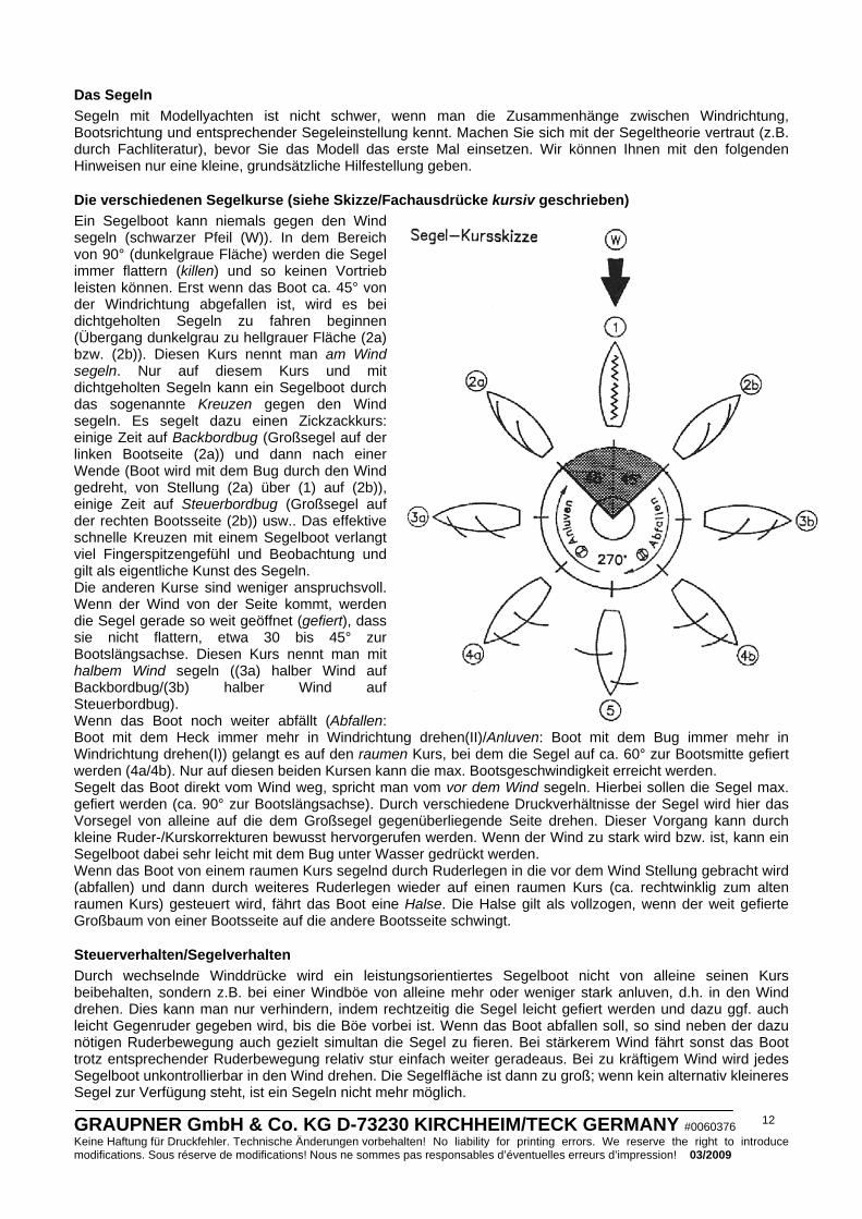
Die verschiedenen Segelkurse (siehe Skizze/Fachausdrücke kursiv geschrieben) Ein Segelboot kann niemals gegen den Wind segeln (schwarzer Pfeil (W)). In dem Bereich von 90° (dunkelgraue Fläche) werden die Segel immer flattern (killen) und so keinen Vortrieb leisten können. Erst wenn das Boot ca. 45° von der Windrichtung abgefallen ist, wird es bei dichtgeholten Segeln zu fahren beginnen (Übergang dunkelgrau zu hellgrauer Fläche (2a) bzw. (2b)). Diesen Kurs nennt man am Wind segeln. Nur auf diesem Kurs und mit dichtgeholten Segeln kann ein Segelboot durch das sogenannte Kreuzen gegen den Wind segeln. Es segelt dazu einen Zickzackkurs: einige Zeit auf Backbordbug (Großsegel auf der linken Bootseite (2a)) und dann nach einer Wende (Boot wird mit dem Bug durch den Wind gedreht, von Stellung (2a) über (1) auf (2b)), einige Zeit auf Steuerbordbug (Großsegel auf der rechten Bootsseite (2b)) usw.. Das effektive schnelle Kreuzen mit einem Segelboot verlangt viel Fingerspitzengefühl und Beobachtung und gilt als eigentliche Kunst des Segeln. Die anderen Kurse sind weniger anspruchsvoll. Wenn der Wind von der Seite kommt, werden die Segel gerade so weit geöffnet (gefiert), dass sie nicht flattern, etwa 30 bis 45° zur Bootslängsachse. Diesen Kurs nennt man mit halbem Wind segeln ((3a) halber Wind auf Backbordbug/(3b) halber Wind auf Steuerbordbug). Wenn das Boot noch weiter abfällt (Abfallen: Boot mit dem Heck immer mehr in Windrichtung drehen(II)/Anluven: Boot mit dem Bug immer mehr in Windrichtung drehen(I)) gelangt es auf den raumen Kurs, bei dem die Segel auf ca. 60° zur Bootsmitte gefiert werden (4a/4b). Nur auf diesen beiden Kursen kann die max. Bootsgeschwindigkeit erreicht werden. Segelt das Boot direkt vom Wind weg, spricht man vom vor dem Wind segeln. Hierbei sollen die Segel max. gefiert werden (ca. 90° zur Bootslängsachse). Durch verschiedene Druckverhältnisse der Segel wird hier das Vorsegel von alleine auf die dem Großsegel gegenüberliegende Seite drehen. Dieser Vorgang kann durch kleine Ruder-/Kurskorrekturen bewusst hervorgerufen werden. Wenn der Wind zu stark wird bzw. ist, kann ein Segelboot dabei sehr leicht mit dem Bug unter Wasser gedrückt werden. Wenn das Boot von einem raumen Kurs segelnd durch Ruderlegen in die vor dem Wind Stellung gebracht wird (abfallen) und dann durch weiteres Ruderlegen wieder auf einen raumen Kurs (ca. rechtwinklig zum alten raumen Kurs) gesteuert wird, fährt das Boot eine Halse. Die Halse gilt als vollzogen, wenn der weit gefierte Großbaum von einer Bootsseite auf die andere Bootsseite schwingt.
Steuerverhalten/Segelverhalten Durch wechselnde Winddrücke wird ein leistungsorientiertes Segelboot nicht von alleine seinen Kurs beibehalten, sondern z.B. bei einer Windböe von alleine mehr oder weniger stark anluven, d.h. in den Wind drehen. Dies kann man nur verhindern, indem rechtzeitig die Segel leicht gefiert werden und dazu ggf. auch leicht Gegenruder gegeben wird, bis die Böe vorbei ist. Wenn das Boot abfallen soll, so sind neben der dazu nötigen Ruderbewegung auch gezielt simultan die Segel zu fieren. Bei stärkerem Wind fährt sonst das Boot trotz entsprechender Ruderbewegung relativ stur einfach weiter geradeaus. Bei zu kräftigem Wind wird jedes Segelboot unkontrollierbar in den Wind drehen. Die Segelfläche ist dann zu groß; wenn kein alternativ kleineres Segel zur Verfügung steht, ist ein Segeln nicht mehr möglich.
GRAUPNER GmbH & Co. KG D-73230 KIRCHHEIM/TECK GERMANY #0060376 Keine Haftung für Druckfehler. Technische Änderungen vorbehalten! No liability for printing errors. We reserve the right to introduce modifications. Sous réserve de modifications! Nous ne sommes pas responsables d’éventuelles erreurs d’impression! 03/2009
13
Segeltrimm Das Vorsegel soll im dichtgeholten Zustand (Großsegel ca. 2° mittschiffs) stets etwas offener als das Großsegel eingestellt sein, also ca. 10° bis 15° dichtgeholt sein, damit der Luftstrom vom Vorsegel nicht in das Großsegel, sondern auf dessen Rückseite gelenkt wird. Dies ist je nach Wind und Wetter unterschiedlich und kann bei der racing MICRO MAGIC durch die Klemmringe entweder am Groß- oder Fockbaum eingestellt werden. Wenn das Boot bei konstant gleichmäßigem, leichten Wind und leichter Schräglage (Kränkung) auf Halbwind-Kurs/Am-Wind-Kurs nicht seinen Kurs hält, so stimmt der Riggtrimm nicht, d.h. der gemeinsame Segeldruckpunkt muss verändert werden. Dies erreicht man bei der racing MICRO MAGIC, z.B. durch Verstellen der Mastneigung: Situation/Verhalten Lösung/Einstellung Luvgierig (Boot dreht von alleine tendenziell in den Wind (es luvt an))
Der Mast ist zu sehr nach hinten geneigt und muss mehr nach vorne gekippt werden (Achterstag lösen, Masttrimmer lösen, Vorstag/Fockfall anziehen)
Leegierig (Boot dreht von alleine tendenziell aus dem Wind (es fällt ab))
Der Mast ist zu sehr nach vorne geneigt und muss mehr nach hinten gekippt werden.
Achtung: Luv-/Leegierigkeit wird auch durch die Segeleinstellung beeinflusst, etwa wenn das Großsegel mit dem Niederholer zu straff eingestellt wird, oder das Vorsegel zu dicht/zu offen eingestellt ist. Im allgemeinen ist ein Segelboot mit einer leichten Luvgierigkeit am leistungsfähigsten. Diese optimale Einstellung muss durch eigene Versuche ermittelt werden, und ist nicht für jedes Wetter gleich.
Jungfernfahrt Wählen Sie einen Tag mit optimalen Windverhältnissen und ein Gewässer aus wo Sie das Modell leicht bergen können. Laden Sie die Akkus und testen Sie die Funktionen des Modells. Kontrollieren Sie, ob alle Teile fest sitzen. Nun können Sie die Jungfernfahrt starten. Lassen Sie es bei der Jungfernfahrt vorsichtig angehen, machen Sie sich erst mit dem Fahrverhalten vertraut. Fahren Sie nicht zu weit weg vom Ufer.
Viel Spaß beim Fahren mit Ihrem Modell racing MICRO MAGIC.

GRAUPNER GmbH & Co. KG D-73230 KIRCHHEIM/TECK GERMANY #0060376 Keine Haftung für Druckfehler. Technische Änderungen vorbehalten! No liability for printing errors. We reserve the right to introduce modifications. Sous réserve de modifications! Nous ne sommes pas responsables d’éventuelles erreurs d’impression! 03/2009
14
Stückliste Pos. Benennung Anzahl Material Abmessung und Stärke in mm 1 Stützbrett, vorderes 1 Sperrholz 4mm, ausgelasert 2 Stützbrett, hinteres 1 Sperrholz 4mm, ausgelasert 3 Seitenteil 4 Sperrholz 4mm, ausgelasert 4 Schutzauflage 1 Schaumstoffklebeband Passende Streifen abschneiden 5 Kielmasttasche 2 ABS Tiefgezogen, CNC bearbeitet 6 Verstärkung, Mastlager 2 Sperrholz 2mm, ausgelasert 7 Servoträgerlager 2 Sperrholz 2mm, ausgelasert 8 Rumpf 1 ABS Tiefgezogen, CNC bearbeitet 9 Bugverstärkung 1 Sperrholz 2mm, ausgelasert 10 Ruderkokerverstärkung 2 Sperrholz 2mm, ausgelasert 11 Servobrett 1 Sperrholz 2mm, ausgelasert 12 Verstärkung, Segelverstellservo 2 Sperrholz 2mm, ausgelasert 13 Verstärkung, Focktrimmservo 1 Sperrholz 2mm, ausgelasert 14 Deck 1 ABS Tiefgezogen, CNC bearbeitet 15 Plichtspant 1 Sperrholz 2mm, ausgelasert 16 Ruderservobrett 1 Sperrholz 2mm, ausgelasert 17 Verstärkung, Ruderservo, groß 1 Sperrholz 2mm, ausgelasert 18 Verstärkung, Ruderservo, klein 1 Sperrholz 2mm, ausgelasert 19 Mittelspant 1 Sperrholz 2mm, ausgelasert 20 Wantverstärkung 2 Sperrholz 2mm, ausgelasert 21 Verstärkung, Haubenverriegelung 4 Sperrholz 2mm, ausgelasert 22 Heckverstärkung 1 Sperrholz 2mm, ausgelasert 23 Heckseitenverstärkung 2 Sperrholz 2mm, ausgelasert 24 Einschlagmutter 4 Metall M2 25 Mittelleiste 1 Kiefernleiste 3x8x210mm 26 Ruderkoker 1 Messingrohr Ø4x3,1x30mm 27 Ruder 1 Kunststoff Fertigteil 28 Ruderservo 1 Best.-Nr. 5125.LOSE Fertigteil 29 Ruderservoarm 2 Best.-Nr. 3941.50 Fertigteil 30 Ruderhebel 1 Kunststoff Fertigteil 31 Seildurchführungen 2 Bowdenzuginnenrohr Ø2x0,8x15mm 32 Schotführungen 2 Kunststoff Fertigteil 33 Linsenkopfschraube 14 Edelstahl Ø2,2x6,5mm 34 Augenschraube 4 Ms, vernickelt Ø3,8x1,5x11mm 35 Unterlegscheibe 5 Ms, vernickelt Ø4,5x2,2x0,5mm 36 Segelverstellservo 1 Best.-Nr. 4103.LOSE Fertigteil 37 Focktrimmservo 1 Best.-Nr. 5125.LOSE Fertigteil 38 Schalter 1 Best.-Nr. 3934.1 Fertigteil 39 Segelverstellhebel 1 Kunststoff Fertigteil 40 Rollenblock 2 Kunststoff Fertigteil 41 Linsenkopfschraube 2 Edelstahl Ø2,2x9,5mm 42 Fockschot 1 Polyesterschnur Ø0,4x500mm 43 Unterlegscheibe 3 Ms, vernickelt Ø7,0x2,8x0,5mm 44 Großschot 1 Polyesterschnur Ø0,4x500mm 45 Ruderanlenkungsseile 2 Polyesterschnur Ø0,4x300mm 46 Klemmschieber 9 Kunststoff Fertigteil 47 Verschlussriegel 4 Kunststoff Fertigteil 48 Kiel 1 Kunststoff Fertigteil 49 Adaptersatz 4 Kunststoff Fertigteil 50 Kielgewicht 1 Blei (GIFTIG!) Fertigteil 51 Befestigungsstift 2 Stahl Ø1,5x15mm 52 Kielgewichtsverkleidungen 2 ABS Tiefgezogen 53 Haltemutter 1 Ms, vernickelt M2,5 54 Dichtung 1 Gummischnur Ø2,5mm, Länge anpassen 55 Haube 1 ABS Tiefgezogen, CNC bearbeitet 56 Mast 1 CFK-Rohr Ø5x4x850mm

GRAUPNER GmbH & Co. KG D-73230 KIRCHHEIM/TECK GERMANY #0060376 Keine Haftung für Druckfehler. Technische Änderungen vorbehalten! No liability for printing errors. We reserve the right to introduce modifications. Sous réserve de modifications! Nous ne sommes pas responsables d’éventuelles erreurs d’impression! 03/2009
15
57 Masthülse 1 Alurohr Ø6x5x115mm 58 Mastfuß 1 Holzstift Ø4x50mm 59 Großbaumlager 1 Kunststoff Fertigteil 60 Mastplatte 1 Kunststoff Fertigteil 61 Großbaumdrehlager 1 Kunststoff Fertigteil 62 Drehachse 1 Kunststoff Fertigteil 63 Großbaumhülse 1 Kunststoff Fertigteil 64 Großbaum 1 CFK-Rohr Ø6x5x205mm 65 Niederdrücker 1 Aluminium Fertigteil 66 Klemmmutter 1 Ms., vernickelt M2,6 67 Klemmwinkel, groß 3 Kunststoff Fertigteil 68 Fixierschraube 6 Edelstahl M2x8mm 69 Haltemutter 2 Ms., vernickelt M2 (Stoppmutter) 70 Fockaufhängung 1 Kunststoff Fertigteil 71 Mastkopf 1 Kunststoff Fertigteil 72 Achterstag 1 Polyesterschnur Ø0,4x1100mm 73 Drahthaken 4 Metall Fertigteil, n.Z. bearbeiten 74 Wanten 1 Polyesterschnur Ø0,4x2000mm 75 Großsegel 1 Polyesterfolie Fertigteil 76 Segellatten 3 CFK-Profil Fertigteil 77 Aufkleber 6 Textilfolie Fertigteil 78 Großsegelvorliekstrecker 1 Polyesterschnur Ø0,4x300mm 79 Großfall 1 Polyesterschnur Ø0,4x200mm 80 Mastring 6 Metall Fertigteil 81 Gleithülse 1 Kunststoff Ø3,2x2,2x4mm 82 Klemmring, groß 1 Kunststoff Fertigteil 83 Fockbaum 1 CFK-Rohr Ø4x3x202mm 84 Fockbauendkappe 1 Kunststoff Fertigteil 85 Fockbauendkappe mit Bohrung 1 Kunststoff Fertigteil 86 Befestigungsstift 1 Metall Ø1,5x20mm 87 Fockausgleichsgewicht 1 Messing Ø7,8x10mm 88 Focksegel 1 Polyesterfolie Fertigteil 89 Vorstag 1 Polyesterschnur Ø0,4x1000mm 90 Fockfall 1 Polyesterschnur Ø0,4x200mm 91 Vorliekstrecker 1 Polyesterschnur Ø0,4x200mm 92 Klemmwinkel, klein 1 Kunststoff Fertigteil 93 Klemmring, klein 3 Kunststoff Fertigteil 94 Focksegelbefestigung 1 Polyesterschnur Ø0,4x300mm 95 Dirk 1 Polyesterschnur Ø0,4x900mm In der Stückliste sind auch Komponenten aufgelistet, die nicht im Baukasten enthalten sind. Diese müssen gesondert erworben werden. n. Z. = nach Zeichnung, Maße aus dem Bauplan entnehmen Ferner wird benötigt (nicht im Lieferumfang enthalten) Best.-Nr. Bezeichnung 4709 RC-Set ECO-SPORT SYSTEM X-306 FM (40MHz)
Es sind auch andere Graupner FM Fernsteuersysteme ab 3 Kanälen geeignet. 5125.LOSE Servo C 261 (2 Stück erforderlich), als Ruder- und Focktrimmservo 4103.LOSE Servo C 5077, als Segelverstellservo oder 5120.LOSE Servo C 3341, als Segelverstellservo oder 3900.LOSE Servo C 3241, als Segelverstellservo 2585 Graupner 4N-600 AA 2/3 NiMH, als Stromversorgung für das Modell Ersatzteile Best.-Nr. Bezeichnung 2014.1 Satz CNC-konturgefräste Tiefziehteile (Rumpf, Deck, Haube, Kiel-/Masttasche) 2014.2 Kielflosse, glasfaserverstärkter Kunststoff, mit M2,5 Befestigungsstift, mit Adaptersatz 2014.3 Ruder, glasfaserverstärkter Kunststoff, mit Ø3mm Achse 2014.4 Kielballastgewicht, aus Blei, Gewicht ca. 370g 2014.5 Tuningsegelsatz, aus hochwertigen, wasserabweisenden und verzugsfreiem Kunststoffmaterial Andere Ersatzteile, z.B. die Mastbeschlagteile, siehe Graupner Hauptkatalog.

GRAUPNER GmbH & Co. KG D-73230 KIRCHHEIM/TECK GERMANY #0060376 Keine Haftung für Druckfehler. Technische Änderungen vorbehalten! No liability for printing errors. We reserve the right to introduce modifications. Sous réserve de modifications! Nous ne sommes pas responsables d’éventuelles erreurs d’impression! 03/2009
16
Pos.-Nr. der Laserteile/Part Numbers of the laser-cut components/Numéros des pièces découpées au Laser
1
2
3
19
20
6
7
7
9
10
11
11
12
13
15
16
17
18
21
2323
22
GRAUPNER GmbH & Co. KG D-73230 KIRCHHEIM/TECK GERMANY #0060376 Keine Haftung für Druckfehler. Technische Änderungen vorbehalten! No liability for printing errors. We reserve the right to introduce modifications. Sous réserve de modifications! Nous ne sommes pas responsables d’éventuelles erreurs d’impression! 03/2009
17
Building instructions for the racing MICRO MAGIC model boat, Order No. 2014
Description of the model The racing MICRO MAGIC has been developed to reflect progress in the MICRO MAGIC regatta scene. In its standard form the boat represents a modified version of the original model designed for the ambitious regatta skipper; it is intended to complement the earlier MICRO MAGIC, which has proved to be very popular. The racing MICRO MAGIC includes a carbon fibre rig with a slim 5 mm Ø mast, improved sails and a completely new set of high-quality plastic fittings. A new feature - unprecedented in a kit model - is the variable-position keel (fore-and-aft direction), which enables the operator to adjust the model very quickly to suit varying sailing conditions, and to satisfy the operator’s personal preferences. The revised keel fin and rudder are of slightly reduced area and thinner profiles in order to reduce water resistance. The slightly heavier ballast bulb is also longer, resulting in enhanced directional stability. The boat is designed for an RC system consisting of fairly small, lightweight components, and the internal arrangement has been optimised with such a system in mind. An additional micro-servo can also be fitted to provide jib sheet trim control from the transmitter, so that the sail trim can be fine-tuned while the boat is on the water. The sail adjustment system has been designed for reduced friction, with a double control arm and return pulleys, with the result that a lighter servo can also be employed safely. The shape of the bow and stern have been re-worked slightly to give the boat a more modern appearance, but the basic lines of the original hull have been left unchanged in order to stay within the German class rules. Due to the thicker material (1.5 mm instead of 1,0 mm) this boat version, racing MICRO MAGIC gains weight, approx. 50 up to 60 g more.
Specification Overall length approx. 535 mm Beam approx. 180 mm Overall height approx. 980 mm All-up weight approx. 850 g (910 g for version 2014.C) Sail area approx. 1450 cm² Important safety notes You have purchased a kit which can be assembled to produce a fully working RC model when fitted out with the appropriate accessories. As manufacturers, we at GRAUPNER are not in a position to influence the way you install, operate and maintain the model, nor the other components used in connection with the model. For this reason we are obliged to deny all liability for loss, damage or costs which are incurred due to the incompetent or incorrect use and operation of our products, or which are connected with such operation in any way. Unless otherwise prescribed by binding law, the obligation of the GRAUPNER company to pay compensation, regardless of the legal argument employed, is excluded. This includes personal injury, death, damage to buildings, loss of trade or turnover, interruption of business or other indirect or direct damages which are caused by the operation of the model. Under all circumstances and in all cases the company’s overall liability is limited to the amount which you actually paid for this model. The model is operated at the sole risk of the operator. To avoid injury to persons and damage to property please handle your model boat carefully and operate it conscientiously at all times. Before you run the boat for the first time it is important to check that your private third party insurance policy provides cover when you are operating model boats of this kind. If you are not sure, take out a special insurance policy designed to cover the risks of RC modelling. These safety notes are important, and must be kept in a safe place. If you ever dispose of the model, be sure to pass them on to the new owner. Guarantee conditions The guarantee covers replacement of any parts which can be shown to exhibit manufacturing faults or material defects within the guarantee period of 24 months from the initial date of purchase. No other claims will be considered. Cost of transport, packing and freight are payable by the purchaser. We accept no liability for damage in transit. When you send the product to GRAUPNER, or to the approved Service Centre for your country, you must include a clear and concise description of the fault together with the invoice showing the date

GRAUPNER GmbH & Co. KG D-73230 KIRCHHEIM/TECK GERMANY #0060376 Keine Haftung für Druckfehler. Technische Änderungen vorbehalten! No liability for printing errors. We reserve the right to introduce modifications. Sous réserve de modifications! Nous ne sommes pas responsables d’éventuelles erreurs d’impression! 03/2009
18
of purchase. The guarantee is invalid if the component or model fails due to an accident, incompetent handling or incorrect usage. The following points are important and must be observed at all times: • This model is not suitable for young persons under fourteen years of age. • The keel ballast bulb is made of lead! This material is toxic, and must not be allowed to enter the body.
Sanding dust and slivers of the metal are particularly dangerous, as they can easily be ingested. After working on the lead weight, clean the work place immediately, and wash your hands thoroughly. If possible wear gloves when handling this material.
• If you need to dispose of the lead weight at any time, be sure to take it to your local toxic waste collection point. It must never be discarded in the household refuse. If you are not sure where you can take scrap lead, ask your local authority for information.
• The projecting parts of the model may be sharp, and the aerials and masts may cause eye injuries. • If the model is to be built by a youngster, a parent or guardian must monitor the assembly process, as tools
and adhesives can be hazardous. • Please operate the model carefully when there are persons or animals in the water; always keep a safe
distance between the boat and man or beast. • Never run your boat in a protected site, an animal or plant sanctuary or a site of special scientific interest
(SSSI). Check with your local authority that the stretch of water you wish to use is suitable for model boats. • Do not sail the vessel in salt water. • Never run your boat in adverse conditions, e.g. rain, storm, strong wind (above Beaufort 4), choppy water
or strong currents. • As the model is propelled solely by the wind, it should only be sailed in wind strengths of 1 to 3 on the
Beaufort scale (leaves moving in the wind). If the wind is stronger, the boat could heel severely and be impossible to control. Gusty conditions should also be avoided.
• The model requires a breeze in order to move, i.e. in flat calm conditions the boat will just remain stationary on the water. Please bear this in mind before sailing the model.
• Before you operate the boat, please check that the radio control system is working reliably. • It is important to check the range of the radio control system: switch the radio control system on, hold the
transmitter in your hands, and walk about 50 m away from the boat. All the radio-controlled functions should continue to work normally at this range.
• Ensure that the channel you intend to use is not already occupied by another modeller. Never run the boat if you are not certain that your channel is free.
• Note that other radio equipment and transmitting stations may cause serious interference to the model’s receiving system. If possible, ensure that no such apparatus is in use in the vicinity while you are operating the boat.
• Switch the model’s radio system off before carrying out any work on the boat. • Dry cells and rechargeable batteries must never be short-circuited, nor allowed to come into direct contact
with water. • Remove all batteries from the model and the transmitter when you know you will not be using them in the
near future. • Do not subject the model to high levels of humidity, heat, cold or dirt. • Secure the model and the transmitter when transporting them, as they may be seriously damaged if they
are free to slide about. • Never operate the model on moving water (e.g. a river), as it could easily be washed away downstream if
the wind conditions change. • If you have to salvage the model, take care not to risk your own life or that of others. • Check regularly that the boat is completely watertight, as it may sink if too much water enters the hull.
Check the model for damage before every run, and ensure that water cannot penetrate the hull. • Allow the boat to dry out thoroughly after use. Care and maintenance • Clean the model carefully after every run, and remove any water which gets inside the hull. If water gets
into any of the RC components, dry them out and send them to your nearest GRAUPNER Service Centre for checking.
• Clean the model and the transmitter using suitable cleaning agents only. We recommend wiping with a lint-free cloth. Never use chemical cleaners, solvents, petrol, white spirit or similar.
GRAUPNER GmbH & Co. KG D-73230 KIRCHHEIM/TECK GERMANY #0060376 Keine Haftung für Druckfehler. Technische Änderungen vorbehalten! No liability for printing errors. We reserve the right to introduce modifications. Sous réserve de modifications! Nous ne sommes pas responsables d’éventuelles erreurs d’impression! 03/2009
19
Notes on building the model • This model is not intended for the beginner to modelling, and for this reason the instructions do not cover
every single step of construction, as we assume that the experienced model builder will be familiar with these standard techniques.
• The version racing MICRO MAGIC Carbon requires more detailed adjustment, because all laser-cut and vacuum-moulded parts – except the canopy, which fits exactly, have been adjusted to the normal version, racing MICRO MAGIC. But this work can be easily done by the modeller himself.
• We recommend that you visit the Internet website www.micromagic.info for the latest information on assembling and setting up the model.
• If you do not understand the technical terms relating to sailing boats, you can download a sketch showing the basic terminology from the Internet site mentioned above.
• Before you start building the boat, please take the time to study the plan and read right through the instructions, referring constantly to the Parts List. In general terms the instructions and parts list reflect the sequence of assembly.
• The laser-cut wooden components are retained in their sheets by small lugs. Cut them through from both sides using a sharp knife, then break the parts away from the waste material.
• All the laser-cut parts have a black outline caused by the cutting process. You can easily sand this off if you wish.
• The wooden internal parts for the hull are accurately pre-cut, but it is still important to trim them to match the shape of the hull and deck precisely. If the bulkheads are a tight fit, they will show through on the outside of the hull, so it is important to trim the parts as carefully and as accurately as you can.
• TIP: the rigging cord is easier to thread through small holes and openings if you first apply a drop of cyano to the end to harden it, then cut off the frayed extremity.
• Compare the laser-cut parts with the sketches at the end of these instructions to help you identify them and assign the part numbers.
• Wooden parts which have been coated with GLATTFIX sanding sealer cannot be glued satisfactorily using UHU acrylit or STABILIT express, so keep the sealer away from the joint areas. You should also avoid smearing excess adhesive onto the model’s surfaces, as this will often prevent paint adhering properly. This applies in particular when you are gluing the vacuum-moulded plastic parts.
• Please bear in mind that many tools can be dangerous if misused or handled carelessly. • Deploy the receiver aerial as high up in the hull as possible. Reception will be very poor if it is positioned
below the waterline, and effective range will be greatly reduced. • It is important to clean the joint surfaces carefully before gluing parts together. This is best done by
sanding lightly, followed by wiping with a non-greasy liquid detergent or methylated spirit (“meths”). The same applies to all surfaces which are to be painted, as this improves the paint’s adhesion considerably.
• Recommended adhesives for joining particular materials: Material – material Suitable adhesives Metal – metal Cyano-acrylate, UHU plus ABS – wood Cyano-acrylate, UHU acrylit ABS – ABS Cyano-acrylate, UHU acrylit, UHU plast spezial ABS – metal Cyano-acrylate, UHU acrylit Wood – wood Cyano-acrylate, UHU hart, white glue Wood – metal Stabilit express Read the instructions supplied with the adhesives. Be sure to observe any special notes in the instructions regarding particular adhesives. If you are using acetone, methylated spirits or any other solvent as a cleaning agent, special safety measures are necessary. Read the instructions supplied with these materials.

GRAUPNER GmbH & Co. KG D-73230 KIRCHHEIM/TECK GERMANY #0060376 Keine Haftung für Druckfehler. Technische Änderungen vorbehalten! No liability for printing errors. We reserve the right to introduce modifications. Sous réserve de modifications! Nous ne sommes pas responsables d’éventuelles erreurs d’impression! 03/2009
20
Assembly instructions • Assemble the boatstand by fitting together the front
support (part 1), the rear support (part 2) and the side panels (part 3); take care to glue the joints securely. Paint the finished stand when the glue is dry, and apply the self-adhesive foam tape (part 4) to the contact surfaces (not shown in the photo). The tape avoids scratches to the painted hull.
• Assemble the keel / mast socket (part 5). IMPORTANT: don’t follow the outside shape of the vacuum-moulded parts when gluing the parts together. It is the inside area, which accepts the keel, which is important: the sides must be exactly parallel, otherwise the keel will not fit properly later. Note: For the version 2014.C the keel / mast socket must be corrected at the top and at the bottom by
0.5 mm for better fitting. • Glue a mast support reinforcement (part 6) on each
side of the keel / mast socket on the underside, at the position of the semi-circular lugs.
• Glue together the two servo mount supports (part 7), and adjust the slot for the keel / mast socket so that the supports are an easy sliding fit on the socket. Note: For the version 2014.C the gap in-between should be processed for approx. 1 mm. Glue this assembly to the keel / mast socket, aligned exactly as shown; the dimensions are stated on the plan. NOTE: one of the supports has a deeper slot for the keel / mast socket; this part should face down.
• Glue the completed keel / mast socket in the hull (part 8), taking care to position it accurately. Apply a fillet of UHU acrylit all round on the underside, to ensure that the socket is completely watertight.
• Sand back the bow reinforcement (part 9) until it is an easy, snug fit in the tip of the bow. Glue the reinforcement in place securely using UHU acrylit. NOTE: take care to position the reinforcement accurately, as the central girder (part 25) must rest on it later.
• Glue one of the rudder bush reinforcements (part 10) over the hole for the rudder bush.
• Glue the two reinforcements for the sail servo (part 12) and the reinforcement for the jib trim servo
GRAUPNER GmbH & Co. KG D-73230 KIRCHHEIM/TECK GERMANY #0060376 Keine Haftung für Druckfehler. Technische Änderungen vorbehalten! No liability for printing errors. We reserve the right to introduce modifications. Sous réserve de modifications! Nous ne sommes pas responsables d’éventuelles erreurs d’impression! 03/2009
21
(part 13) to the underside of the servo plate (part 11). Adjust the opening for the keel / mast socket so that the plate is a snug sliding fit over it, without compressing the socket. NOTE: the servo plate without the servo opening should be used if you intend to install a sail servo other than those specified. Mark the outline of the servo opening and cut it out using a fretsaw. Position the opening so that the servo pivot axis will coincide with the hull centreline.
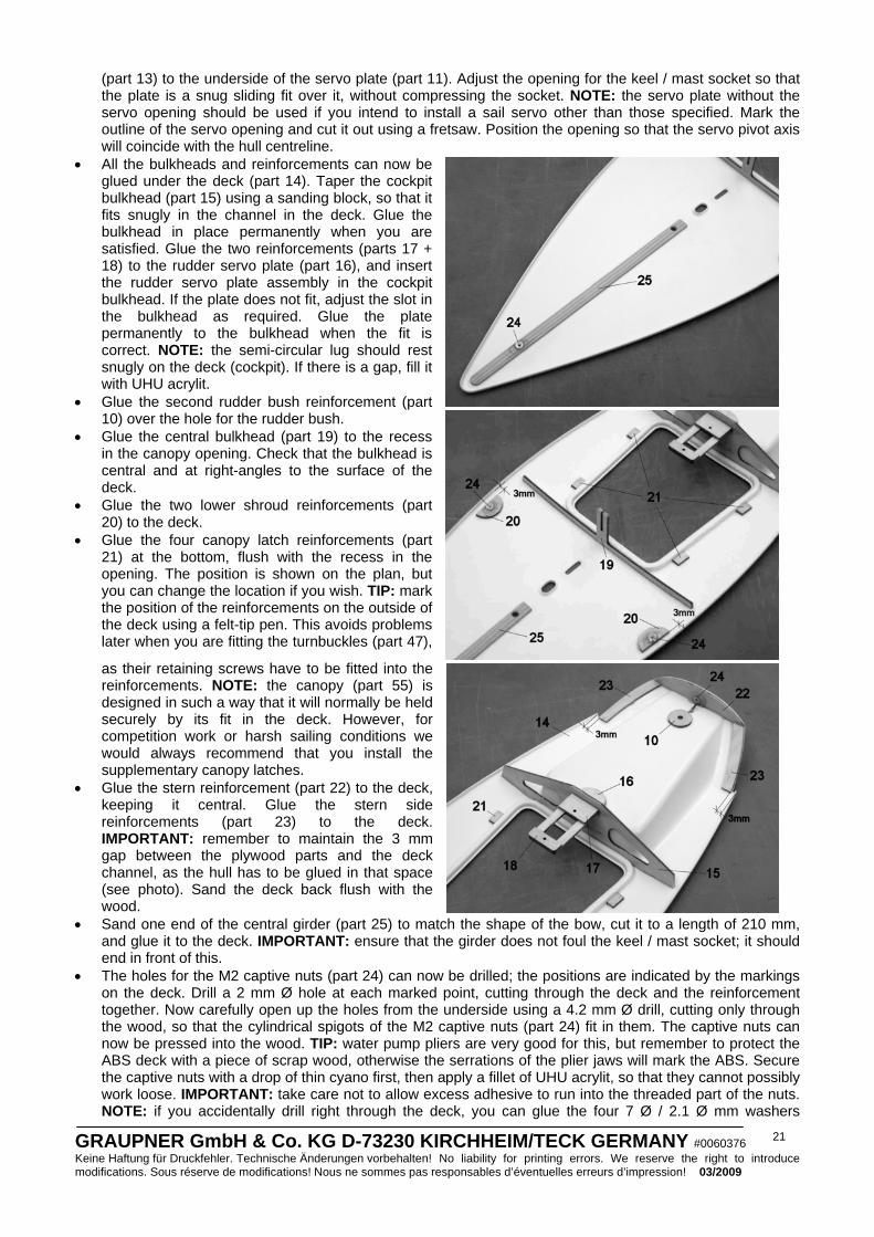
• All the bulkheads and reinforcements can now be glued under the deck (part 14). Taper the cockpit bulkhead (part 15) using a sanding block, so that it fits snugly in the channel in the deck. Glue the bulkhead in place permanently when you are satisfied. Glue the two reinforcements (parts 17 + 18) to the rudder servo plate (part 16), and insert the rudder servo plate assembly in the cockpit bulkhead. If the plate does not fit, adjust the slot in the bulkhead as required. Glue the plate permanently to the bulkhead when the fit is correct. NOTE: the semi-circular lug should rest snugly on the deck (cockpit). If there is a gap, fill it with UHU acrylit.
• Glue the second rudder bush reinforcement (part 10) over the hole for the rudder bush.
• Glue the central bulkhead (part 19) to the recess in the canopy opening. Check that the bulkhead is central and at right-angles to the surface of the deck.
• Glue the two lower shroud reinforcements (part 20) to the deck.
• Glue the four canopy latch reinforcements (part 21) at the bottom, flush with the recess in the opening. The position is shown on the plan, but you can change the location if you wish. TIP: mark the position of the reinforcements on the outside of the deck using a felt-tip pen. This avoids problems later when you are fitting the turnbuckles (part 47),
as their retaining screws have to be fitted into the reinforcements. NOTE: the canopy (part 55) is designed in such a way that it will normally be held securely by its fit in the deck. However, for competition work or harsh sailing conditions we would always recommend that you install the supplementary canopy latches.
• Glue the stern reinforcement (part 22) to the deck, keeping it central. Glue the stern side reinforcements (part 23) to the deck. IMPORTANT: remember to maintain the 3 mm gap between the plywood parts and the deck channel, as the hull has to be glued in that space (see photo). Sand the deck back flush with the wood.
• Sand one end of the central girder (part 25) to match the shape of the bow, cut it to a length of 210 mm, and glue it to the deck. IMPORTANT: ensure that the girder does not foul the keel / mast socket; it should end in front of this.
• The holes for the M2 captive nuts (part 24) can now be drilled; the positions are indicated by the markings on the deck. Drill a 2 mm Ø hole at each marked point, cutting through the deck and the reinforcement together. Now carefully open up the holes from the underside using a 4.2 mm Ø drill, cutting only through the wood, so that the cylindrical spigots of the M2 captive nuts (part 24) fit in them. The captive nuts can now be pressed into the wood. TIP: water pump pliers are very good for this, but remember to protect the ABS deck with a piece of scrap wood, otherwise the serrations of the plier jaws will mark the ABS. Secure the captive nuts with a drop of thin cyano first, then apply a fillet of UHU acrylit, so that they cannot possibly work loose. IMPORTANT: take care not to allow excess adhesive to run into the threaded part of the nuts. NOTE: if you accidentally drill right through the deck, you can glue the four 7 Ø / 2.1 Ø mm washers

GRAUPNER GmbH & Co. KG D-73230 KIRCHHEIM/TECK GERMANY #0060376 Keine Haftung für Druckfehler. Technische Änderungen vorbehalten! No liability for printing errors. We reserve the right to introduce modifications. Sous réserve de modifications! Nous ne sommes pas responsables d’éventuelles erreurs d’impression! 03/2009
22
(supplied) on top; these will conceal the oversized holes. • The next step is to cut the slot in the deck for the
keel attachment: the length is indicated by the two marked points. The slot should be between 2.5 mm and 3 mm wide. TIP: drill 2.5 mm Ø holes in the deck at the marked points, then form the slot by running a sharp knife between the two holes, working as accurately as you can. The slot should only be trimmed to final size when the deck and hull have finally been joined.
• The deck can now be glued to the hull: the first step is to check that the two parts are a snug fit together; if not, trim them carefully until they are an accurate fit. Apply UHU plus (e.g. Order No. 962) to the bow reinforcement (part 9) and the central girder (part 25) where the parts meet. Now apply
plenty of UHU plast spezial to the edge of the deck - omitting the stern area - and join the parts without delay. IMPORTANT: ensure that neither the hull nor the deck is distorted when the parts are joined. Hold the hull and deck together using adhesive tape or rubber bands while the glue is hardening. However, don’t apply too much pressure, or the hull will distort. Allow the glue to cure completely, then apply a little UHU plast spezial along the joint edges to fill any lurking gaps.
• Apply plenty of high-viscosity (thick) cyano-acrylate glue to the unglued gap at the stern. TIP: move the parts relative to each other to persuade the adhesive to work its way into the joint. Tape the stern area together while the cyano is hardening.
• The stern area can now be sanded flat; alternatively you can leave the hull projecting slightly beyond the deck. Note: For version 2014.C please be assured that the bonding and adhesion at the stern area is made properly and exactly, because otherwise it is very difficult to remove the glue from the carbon surface (it could be damaged).
• At this point you must check the hull / deck joint for leaks. You may need to run more cyano along the joint to fill any remaining gaps.
• The deck can now be stiffened by gluing the central bulkhead (part 19) to the keel / mast socket (part 5).
• The rudder bush (part 26) is glued in the hull next; you may need to trim the hole slightly. Position the rudder bush in the hull as shown on the plan, and glue it in place using think cyano, forming a narrow fillet of adhesive round the bush at top and bottom. Allow the glue to cure completely, then sand back the underside flush with the hull. It is important that the gap between the rudder (part 27) and the surface of the hull is as small as possible. If the gap is not even, you may need to trim the top edge of the rudder blade to match the shape of the hull.
• Set the rudder servo (part 28) to centre from the transmitter, fit the output arm (part 29) on it, and install the servo in the servo plate using the retaining screws provided.
• Assemble the tiller (part 30) from the plastic lever,
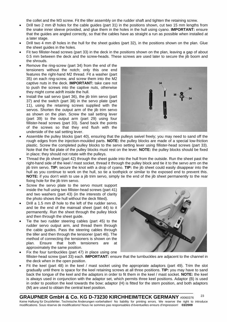
GRAUPNER GmbH & Co. KG D-73230 KIRCHHEIM/TECK GERMANY #0060376 Keine Haftung für Druckfehler. Technische Änderungen vorbehalten! No liability for printing errors. We reserve the right to introduce modifications. Sous réserve de modifications! Nous ne sommes pas responsables d’éventuelles erreurs d’impression! 03/2009
23
the collet and the M3 screw. Fit the tiller assembly on the rudder shaft and tighten the retaining screw. • Drill two 2 mm Ø holes for the cable guides (part 31) in the positions shown, cut two 15 mm lengths from
the snake inner sleeve provided, and glue them in the holes in the hull using cyano. IMPORTANT: ensure that the guides are angled correctly, so that the cables have as straight a run as possible when installed at a later stage.
• Drill two 4 mm Ø holes in the hull for the sheet guides (part 32), in the positions shown on the plan. Glue the sheet guides in the holes.
• Fit two fillister-head screws (part 33) in the deck in the positions shown on the plan, leaving a gap of about 0.5 mm between the deck and the screw-heads. These screws are used later to secure the jib boom and the shrouds.
• Remove the ring-screw (part 34) from the end of the tensioners without the notch; only this one end features the right-hand M2 thread. Fit a washer (part 35) on each ring-screw, and screw them into the M2 captive nuts in the deck. IMPORTANT: take care not to push the screws into the captive nuts, otherwise they might come adrift inside the hull.
• Install the sail servo (part 36), the jib trim servo (part 37) and the switch (part 38) in the servo plate (part 11), using the retaining screws supplied with the servos. Shorten the output arm of the jib trim servo as shown on the plan. Screw the sail setting lever (part 39) to the output arm (part 29) using four fillister-head screws (part 33). Sand back the points of the screws so that they end flush with the underside of the sail setting lever.
• Assemble the pulley blocks (part 40), ensuring that the pulleys swivel freely; you may need to sand off the rough edges from the injection-moulded parts. NOTE: the pulley blocks are made of a special low-friction plastic. Screw the completed pulley blocks to the servo setting lever using fillister-head screws (part 33). Note that the flat plate of the pulley blocks must rest on the lever. NOTE: the pulley blocks should be fixed in place; they should not rotate with the pulleys.
• Thread the jib sheet (part 42) through the sheet guide into the hull from the outside. Run the sheet past the right-hand side of the keel / mast socket, thread it through the pulley block and tie it to the servo arm on the jib trim servo. TIP: secure the knot with a drop of cyano. TIP: the jib sheet could easily disappear into the hull as you continue to work on the hull, so tie a toothpick or similar to the exposed end to prevent this. NOTE: if you don’t wish to use a jib trim servo, simply tie the end of the jib sheet permanently to the rear fixing hole for the jib trim servo.
• Screw the servo plate to the servo mount support inside the hull using two fillister-head screws (part 41) and two washers (part 43) (in the interests of clarity the photo shows the hull without the deck fitted).
• Drill a 1.5 mm Ø hole to the left of the rudder servo, and tie the end of the mainsail sheet (part 44) to it permanently. Run the sheet through the pulley block and then through the sheet guide.
• Tie the two rudder steering cables (part 45) to the rudder servo output arm, and thread them through the cable guides. Pass the steering cables through the tiller and then through the tensioner (part 46). The method of connecting the tensioners is shown on the plan. Ensure that both tensioners are at approximately the same position.
• Fix the four turnbuckles (part 47) in place using one fillister-head screw (part 33) each. IMPORTANT: ensure that the turnbuckles are adjacent to the channel in the deck when in the open position.
• Fit the keel (part 48) in the keel / mast socket using the appropriate adaptors (part 49). Trim the slot gradually until there is space for the keel retaining screws at all three positions. TIP: you may have to sand back the tongue of the keel and the adaptors in order to fit them in the keel / mast socket. NOTE: the keel is always used in conjunction with the adaptor set, which permits three keel positions. Adaptor (B) is used in order to position the keel towards the bow; adaptor (H) is fitted for the stern position, and both adaptors (M) are used to obtain the central keel position.
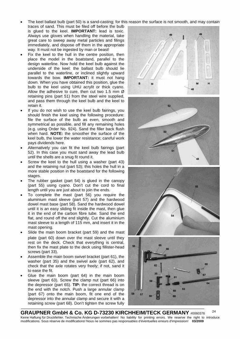
GRAUPNER GmbH & Co. KG D-73230 KIRCHHEIM/TECK GERMANY #0060376 Keine Haftung für Druckfehler. Technische Änderungen vorbehalten! No liability for printing errors. We reserve the right to introduce modifications. Sous réserve de modifications! Nous ne sommes pas responsables d’éventuelles erreurs d’impression! 03/2009
24
• The keel ballast bulb (part 50) is a sand-casting; for this reason the surface is not smooth, and may contain traces of sand. This must be filed off before the bulb is glued to the keel. IMPORTANT: lead is toxic. Always use gloves when handling the material, take great care to sweep away metal particles and filings immediately, and dispose off them in the appropriate way. It must not be ingested by man or beast!
• Fix the keel to the hull in the centre position, then place the model in the boatstand, parallel to the design waterline. Now hold the keel bulb against the underside of the keel: the ballast bulb should lie parallel to the waterline, or inclined slightly upward towards the bow. IMPORTANT: it must not hang down. When you have obtained this position, glue the bulb to the keel using UHU acrylit or thick cyano. Allow the adhesive to cure, then cut two 1.5 mm Ø retaining pins (part 51) from the steel wire supplied, and pass them through the keel bulb and the keel to retain it.
• If you do not wish to use the keel bulb fairings, you should finish the keel using the following procedure: file the surface of the bulb as even, smooth and symmetrical as possible, and fill any remaining holes (e.g. using Order No. 924). Sand the filler back flush when hard. NOTE: the smoother the surface of the keel bulb, the lower the water resistance; careful work pays dividends here.
• Alternatively you can fit the keel bulb fairings (part 52). In this case you must sand away the lead bulb until the shells are a snug fit round it.
• Screw the keel to the hull using a washer (part 43) and the retaining nut (part 53); this holes the hull in a more stable position in the boatstand for the following stages.
• The rubber gasket (part 54) is glued in the canopy (part 55) using cyano. Don’t cut the cord to final length until you are just about to join the ends.
• To complete the mast (part 56) you require the aluminium mast sleeve (part 57) and the hardwood dowel mast base (part 58). Sand the hardwood dowel until it is an easy sliding fit inside the mast, then glue it in the end of the carbon fibre tube. Sand the end flat, and round off the end slightly. Cut the aluminium mast sleeve to a length of 115 mm, and insert it in the mast opening.
• Slide the main boom bracket (part 59) and the mast plate (part 60) down over the mast sleeve until they rest on the deck. Check that everything is central, then fix the mast plate to the deck using fillister-head screws (part 33).
• Assemble the main boom swivel bracket (part 61), the washer (part 35) and the swivel axle (part 62), and check that the axle rotates very freely; if not, sand it to ease the fit.
• Glue the main boom (part 64) in the main boom sleeve (part 63). Screw the clamp nut (part 66) into the depressor (part 65). TIP: the correct thread is on the end with the notch. Push a large annular clamp (part 67) onto the main boom, fit one end of the depressor into the annular clamp and secure it with a retaining screw (part 68). Don’t tighten the screw fully
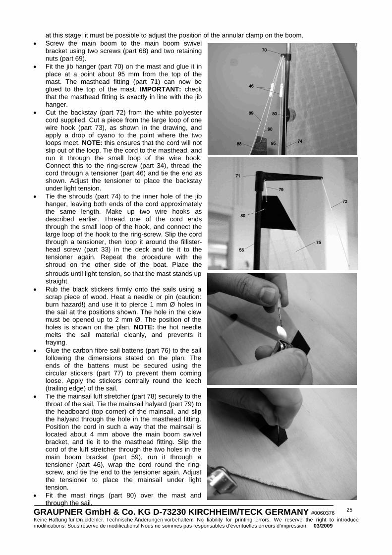
GRAUPNER GmbH & Co. KG D-73230 KIRCHHEIM/TECK GERMANY #0060376 Keine Haftung für Druckfehler. Technische Änderungen vorbehalten! No liability for printing errors. We reserve the right to introduce modifications. Sous réserve de modifications! Nous ne sommes pas responsables d’éventuelles erreurs d’impression! 03/2009
25
at this stage; it must be possible to adjust the position of the annular clamp on the boom. • Screw the main boom to the main boom swivel
bracket using two screws (part 68) and two retaining nuts (part 69).
• Fit the jib hanger (part 70) on the mast and glue it in place at a point about 95 mm from the top of the mast. The masthead fitting (part 71) can now be glued to the top of the mast. IMPORTANT: check that the masthead fitting is exactly in line with the jib hanger.
• Cut the backstay (part 72) from the white polyester cord supplied. Cut a piece from the large loop of one wire hook (part 73), as shown in the drawing, and apply a drop of cyano to the point where the two loops meet. NOTE: this ensures that the cord will not slip out of the loop. Tie the cord to the masthead, and run it through the small loop of the wire hook. Connect this to the ring-screw (part 34), thread the cord through a tensioner (part 46) and tie the end as shown. Adjust the tensioner to place the backstay under light tension.
• Tie the shrouds (part 74) to the inner hole of the jib hanger, leaving both ends of the cord approximately the same length. Make up two wire hooks as described earlier. Thread one of the cord ends through the small loop of the hook, and connect the large loop of the hook to the ring-screw. Slip the cord through a tensioner, then loop it around the fillister-head screw (part 33) in the deck and tie it to the tensioner again. Repeat the procedure with the shroud on the other side of the boat. Place the shrouds until light tension, so that the mast stands up straight.
• Rub the black stickers firmly onto the sails using a scrap piece of wood. Heat a needle or pin (caution: burn hazard!) and use it to pierce 1 mm Ø holes in the sail at the positions shown. The hole in the clew must be opened up to 2 mm Ø. The position of the holes is shown on the plan. NOTE: the hot needle melts the sail material cleanly, and prevents it fraying.
• Glue the carbon fibre sail battens (part 76) to the sail following the dimensions stated on the plan. The ends of the battens must be secured using the circular stickers (part 77) to prevent them coming loose. Apply the stickers centrally round the leech (trailing edge) of the sail.
• Tie the mainsail luff stretcher (part 78) securely to the throat of the sail. Tie the mainsail halyard (part 79) to the headboard (top corner) of the mainsail, and slip the halyard through the hole in the masthead fitting. Position the cord in such a way that the mainsail is located about 4 mm above the main boom swivel bracket, and tie it to the masthead fitting. Slip the cord of the luff stretcher through the two holes in the main boom bracket (part 59), run it through a tensioner (part 46), wrap the cord round the ring-screw, and tie the end to the tensioner again. Adjust the tensioner to place the mainsail under light tension.
• Fit the mast rings (part 80) over the mast and through the sail.
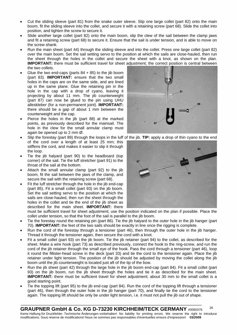
GRAUPNER GmbH & Co. KG D-73230 KIRCHHEIM/TECK GERMANY #0060376 Keine Haftung für Druckfehler. Technische Änderungen vorbehalten! No liability for printing errors. We reserve the right to introduce modifications. Sous réserve de modifications! Nous ne sommes pas responsables d’éventuelles erreurs d’impression! 03/2009
26
• Cut the sliding sleeve (part 81) from the snake outer sleeve. Slip one large collet (part 82) onto the main boom, fit the sliding sleeve into the collet, and secure it with a retaining screw (part 68). Slide the collet into position, and tighten the screw to secure it.
• Slide another large collet (part 82) onto the main boom, slip the clew of the sail between the clamp jaws and fit a retaining screw (part 68) to secure it. Ensure that the sail is under tension, and is able to move on the screw shank.
• Run the main sheet (part 44) through the sliding sleeve and into the collet. Press one large collet (part 82) over the main boom. Set the sail setting servo to the position at which the sails are close-hauled, then run the sheet through the holes in the collet and secure the sheet with a knot, as shown on the plan. IMPORTANT: there must be sufficient travel for sheet adjustment; the correct position is central between the two collets.
• Glue the two end-caps (parts 84 + 85) to the jib boom (part 83). IMPORTANT: ensure that the two small holes in the caps are on the same side, and are lined up in the same plane. Glue the retaining pin in the hole in the cap with a drop of cyano, leaving it projecting by about 11 mm. The jib counterweight (part 87) can now be glued to the pin using UHU alleskleber (for a non-permanent joint). IMPORTANT: there should be a gap of about 1 mm between the counterweight and the cap.
• Pierce the holes in the jib (part 88) at the marked points, as previously described for the mainsail. The hole in the clew for the small annular clamp must again be opened up to 2 mm Ø.
• Slip the forestay (part 89) through the loops in the luff of the jib. TIP: apply a drop of thin cyano to the end of the cord over a length of at least 25 mm; this stiffens the cord, and makes it easier to slip it through the loop.
• Tie the jib halyard (part 90) to the headboard (top corner) of the sail. Tie the luff stretcher (part 91) to the throat of the sail at the bottom.
• Attach the small annular clamp (part 92) to the jib boom, fit the sail between the jaws of the clamp, and secure the sail with the retaining screw (part 68).
• Fit the luff stretcher through the hole in the jib end-cap (part 85). Fit a small collet (part 93) on the jib boom. Set the sail setting servo to the position at which the sails are close-hauled, then run the sheet through the holes in the collet and tie the end of the jib sheet as described for the main sheet. IMPORTANT: there must be sufficient travel for sheet adjustment; use the position indicated on the plan if possible. Place the collet under tension, so that the foot of the sail is parallel to the jib boom.
• Tie the forestay round the retaining pin (part 86). Tie the jib halyard to the outer hole in the jib hanger (part 70). IMPORTANT: the feet of the two sails should be exactly in line once the rigging is complete.
• Run the cord of the forestay through a tensioner (part 46), then through the outer hole in the jib hanger. Thread it through the tensioner again, then secure the cord with a knot.
• Fit a small collet (part 93) on the jib boom. Tie the jib retainer (part 94) to the collet, as described for the sheet. Make a wire hook (part 73) as described previously, connect the hook to the ring-screw, and run the cord of the jib retainer through the small eye of the hook. Pass the cord through a tensioner (part 46), loop it round the fillister-head screw in the deck (part 33) and tie the cord to the tensioner again. Place the jib retainer under light tension. The position of the jib should be adjusted by moving the collet along the jib boom until the jib counterweight is located just aft of the tip of the bow.
• Run the jib sheet (part 42) through the large hole in the jib boom end-cap (part 84). Fit a small collet (part 93) on the jib boom, run the jib sheet through the holes and tie it as described for the main sheet. IMPORTANT: there must be sufficient travel for sheet adjustment; about 30 mm to the small collet is a good starting point.
• Tie the topping lift (part 95) to the jib end-cap (part 84). Run the cord of the topping lift through a tensioner (part 46), then through the outer hole in the jib hanger (part 70), and finally tie the cord to the tensioner again. The topping lift should be only be under light tension, i.e. it must not pull the jib out of shape.

GRAUPNER GmbH & Co. KG D-73230 KIRCHHEIM/TECK GERMANY #0060376 Keine Haftung für Druckfehler. Technische Änderungen vorbehalten! No liability for printing errors. We reserve the right to introduce modifications. Sous réserve de modifications! Nous ne sommes pas responsables d’éventuelles erreurs d’impression! 03/2009
27
Painting • For version 2014.C painting is not necessary! • We recommend that you ask your local model shop (or specialist paint supplier) for advice on the best
types of paint to use. • Use ONLY paints of the same type, made by the same manufacturer, otherwise they may react with each
other; dissolving the earlier coats or producing unsightly bubbles. Caution: Lexan paints are only compatible with each other; they must never be used in combination with other types or paint or primer.
• To ensure that the paint adheres well, it is essential to sand the surfaces with fine wet-and-dry paper (600-grit or 800-grit), then de-grease them using a non-greasy cleaning agent or white spirit. Try not to touch the cleaned surfaces again before painting, as your skin will just apply new grease to the surface.
• Do bear in mind that parts glued to painted surfaces can only adhere as well as the paint sticks to the model, i.e. such parts are often knocked off, tearing the paint from the model at the same time. Parts which are exposed and vulnerable should be glued directly to the sub-surface, i.e. the paint should be scraped off beforehand.
• Apply several coats of sanding sealer (e.g. GLATTFIX, Order No. 207) or clear lacquer (e.g. HYDRO-AEROFIX, Order No. 926.1) to all the wooden parts to prevent them absorbing water.
• When spraying paint, take care to mask off all areas which are not to be coloured. Seal all holes, as the fine mist of paint will find its way into any opening, no matter how small.
• Read and observe the instructions supplied by the paint manufacturer. Colour scheme The recommended colours are stated below with their RAL numbers, to ensure that you will be able to select the correct hues. Armed with this information, any paint supplier will be able to produce the right colours for you. Let your specialist paint supplier or advisor know what you intend to use the paints for, as this will help him select the correct type. We always recommend synthetic enamels. The colour RAL 9016 (transport white) is the ideal base colour for the model, as the decals are designed to be applied to a white surface. However, there is no reason why you should not paint the boat in any colour scheme you like. Applying the decals Cut out the individual decals neatly using a pair of sharp scissors, leaving as little margin round them as possible. They should be applied to the model’s surface once painting is complete; all traces of dust must be removed beforehand. To apply the large hull decal neatly, cut it out leaving virtually no margin, lay it on the hull without removing the backing film, and move it carefully into exact position. Fix one end of the decal with a strip of tape, then peel off the backing film in stages, rubbing the decal down onto the hull as you do so. An alternative method is to cut the large decal into its separate colour areas, as these are easier to apply neatly. The other decals can be positioned as shown in the kit box illustration, or applied in an arrangement of your choice.
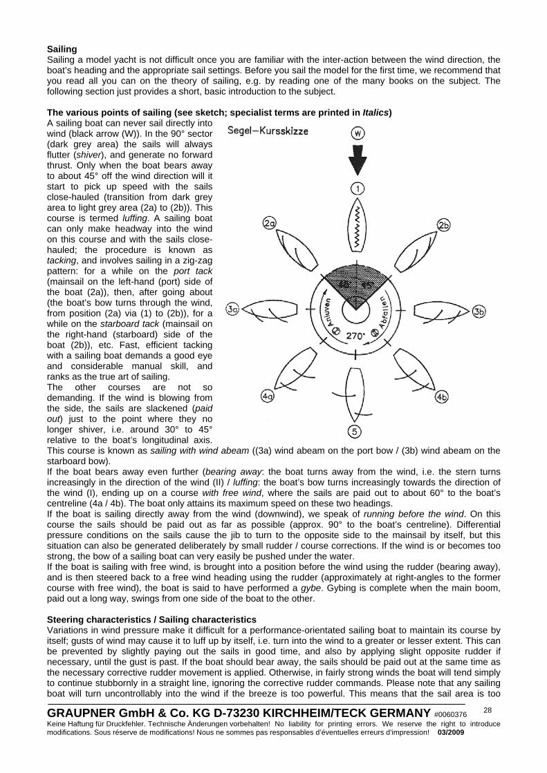
GRAUPNER GmbH & Co. KG D-73230 KIRCHHEIM/TECK GERMANY #0060376 Keine Haftung für Druckfehler. Technische Änderungen vorbehalten! No liability for printing errors. We reserve the right to introduce modifications. Sous réserve de modifications! Nous ne sommes pas responsables d’éventuelles erreurs d’impression! 03/2009
28
Sailing Sailing a model yacht is not difficult once you are familiar with the inter-action between the wind direction, the boat’s heading and the appropriate sail settings. Before you sail the model for the first time, we recommend that you read all you can on the theory of sailing, e.g. by reading one of the many books on the subject. The following section just provides a short, basic introduction to the subject. The various points of sailing (see sketch; specialist terms are printed in Italics) A sailing boat can never sail directly into wind (black arrow (W)). In the 90° sector (dark grey area) the sails will always flutter (shiver), and generate no forward thrust. Only when the boat bears away to about 45° off the wind direction will it start to pick up speed with the sails close-hauled (transition from dark grey area to light grey area (2a) to (2b)). This course is termed luffing. A sailing boat can only make headway into the wind on this course and with the sails close-hauled; the procedure is known as tacking, and involves sailing in a zig-zag pattern: for a while on the port tack (mainsail on the left-hand (port) side of the boat (2a)), then, after going about (the boat’s bow turns through the wind, from position (2a) via (1) to (2b)), for a while on the starboard tack (mainsail on the right-hand (starboard) side of the boat (2b)), etc. Fast, efficient tacking with a sailing boat demands a good eye and considerable manual skill, and ranks as the true art of sailing. The other courses are not so demanding. If the wind is blowing from the side, the sails are slackened (paid out) just to the point where they no longer shiver, i.e. around 30° to 45° relative to the boat’s longitudinal axis. This course is known as sailing with wind abeam ((3a) wind abeam on the port bow / (3b) wind abeam on the starboard bow). If the boat bears away even further (bearing away: the boat turns away from the wind, i.e. the stern turns increasingly in the direction of the wind (II) / luffing: the boat’s bow turns increasingly towards the direction of the wind (I), ending up on a course with free wind, where the sails are paid out to about 60° to the boat’s centreline (4a / 4b). The boat only attains its maximum speed on these two headings. If the boat is sailing directly away from the wind (downwind), we speak of running before the wind. On this course the sails should be paid out as far as possible (approx. 90° to the boat’s centreline). Differential pressure conditions on the sails cause the jib to turn to the opposite side to the mainsail by itself, but this situation can also be generated deliberately by small rudder / course corrections. If the wind is or becomes too strong, the bow of a sailing boat can very easily be pushed under the water. If the boat is sailing with free wind, is brought into a position before the wind using the rudder (bearing away), and is then steered back to a free wind heading using the rudder (approximately at right-angles to the former course with free wind), the boat is said to have performed a gybe. Gybing is complete when the main boom, paid out a long way, swings from one side of the boat to the other. Steering characteristics / Sailing characteristics Variations in wind pressure make it difficult for a performance-orientated sailing boat to maintain its course by itself; gusts of wind may cause it to luff up by itself, i.e. turn into the wind to a greater or lesser extent. This can be prevented by slightly paying out the sails in good time, and also by applying slight opposite rudder if necessary, until the gust is past. If the boat should bear away, the sails should be paid out at the same time as the necessary corrective rudder movement is applied. Otherwise, in fairly strong winds the boat will tend simply to continue stubbornly in a straight line, ignoring the corrective rudder commands. Please note that any sailing boat will turn uncontrollably into the wind if the breeze is too powerful. This means that the sail area is too
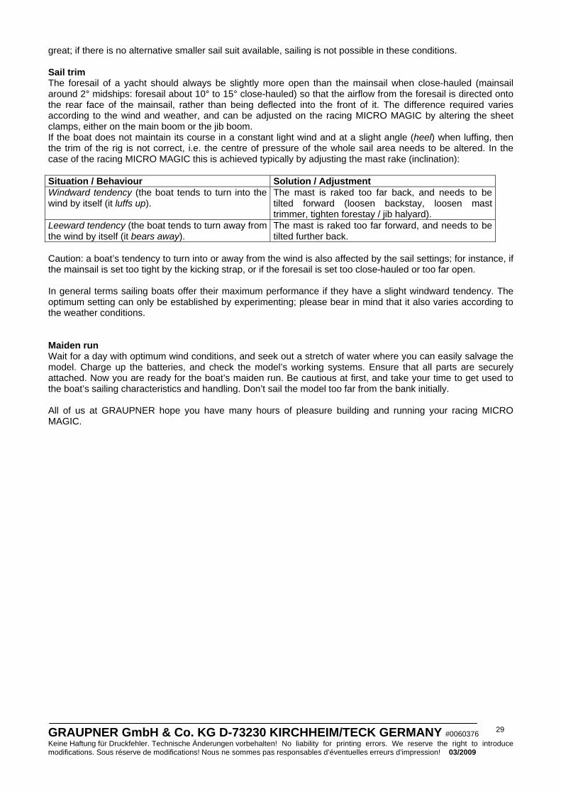
GRAUPNER GmbH & Co. KG D-73230 KIRCHHEIM/TECK GERMANY #0060376 Keine Haftung für Druckfehler. Technische Änderungen vorbehalten! No liability for printing errors. We reserve the right to introduce modifications. Sous réserve de modifications! Nous ne sommes pas responsables d’éventuelles erreurs d’impression! 03/2009
29
great; if there is no alternative smaller sail suit available, sailing is not possible in these conditions. Sail trim The foresail of a yacht should always be slightly more open than the mainsail when close-hauled (mainsail around 2° midships: foresail about 10° to 15° close-hauled) so that the airflow from the foresail is directed onto the rear face of the mainsail, rather than being deflected into the front of it. The difference required varies according to the wind and weather, and can be adjusted on the racing MICRO MAGIC by altering the sheet clamps, either on the main boom or the jib boom. If the boat does not maintain its course in a constant light wind and at a slight angle (heel) when luffing, then the trim of the rig is not correct, i.e. the centre of pressure of the whole sail area needs to be altered. In the case of the racing MICRO MAGIC this is achieved typically by adjusting the mast rake (inclination): Situation / Behaviour Solution / Adjustment Windward tendency (the boat tends to turn into the wind by itself (it luffs up).
The mast is raked too far back, and needs to be tilted forward (loosen backstay, loosen mast trimmer, tighten forestay / jib halyard).
Leeward tendency (the boat tends to turn away from the wind by itself (it bears away).
The mast is raked too far forward, and needs to be tilted further back.
Caution: a boat’s tendency to turn into or away from the wind is also affected by the sail settings; for instance, if the mainsail is set too tight by the kicking strap, or if the foresail is set too close-hauled or too far open. In general terms sailing boats offer their maximum performance if they have a slight windward tendency. The optimum setting can only be established by experimenting; please bear in mind that it also varies according to the weather conditions. Maiden run Wait for a day with optimum wind conditions, and seek out a stretch of water where you can easily salvage the model. Charge up the batteries, and check the model’s working systems. Ensure that all parts are securely attached. Now you are ready for the boat’s maiden run. Be cautious at first, and take your time to get used to the boat’s sailing characteristics and handling. Don’t sail the model too far from the bank initially. All of us at GRAUPNER hope you have many hours of pleasure building and running your racing MICRO MAGIC.

GRAUPNER GmbH & Co. KG D-73230 KIRCHHEIM/TECK GERMANY #0060376 Keine Haftung für Druckfehler. Technische Änderungen vorbehalten! No liability for printing errors. We reserve the right to introduce modifications. Sous réserve de modifications! Nous ne sommes pas responsables d’éventuelles erreurs d’impression! 03/2009
30
Parts List No. Description No. off Material Size in mm 1 Front support plate (boatstand) 1 Plywood 4 mm, laser-cut 2 Rear support plate (boatstand) 1 Plywood 4 mm, laser-cut 3 Side panel (boatstand) 4 Plywood 4 mm, laser-cut 4 Protective stand lining material 1 Self-adhesive foam tape Cut lengths to suit 5 Keel / mast socket 2 ABS Vac.-moulded, CNC-trimmed 6 Mast support reinforcement 2 Plywood 2 mm, laser-cut 7 Servo mount support 2 Plywood 2 mm, laser-cut 8 Hull 1 ABS Vac.-moulded, CNC-trimmed 9 Bow reinforcement 1 Plywood 2 mm, laser-cut 10 Rudder bush reinforcement 2 Plywood 2 mm, laser-cut 11 Servo plate 1 Plywood 2 mm, laser-cut 12 Sail servo reinforcement 2 Plywood 2 mm, laser-cut 13 Jib trim servo reinforcement 1 Plywood 2 mm, laser-cut 14 Deck 1 ABS Vac.-moulded, CNC-trimmed 15 Cockpit bulkhead 1 Plywood 2 mm, laser-cut 16 Rudder servo plate 1 Plywood 2 mm, laser-cut 17 Rudder servo reinforcement, large 1 Plywood 2 mm, laser-cut 18 Rudder servo reinforcement, small 1 Plywood 2 mm, laser-cut 19 Central bulkhead 1 Plywood 2 mm, laser-cut 20 Shroud reinforcement 2 Plywood 2 mm, laser-cut 21 Canopy latch reinforcement 4 Plywood 2 mm, laser-cut 22 Stern reinforcement 1 Plywood 2 mm, laser-cut 23 Stern side reinforcement 2 Plywood 2 mm, laser-cut 24 Captive nut 4 Metal M2 25 Central girder 1 Spruce strip 3 x 8 x 210 mm 26 Rudder bush 1 Brass tube 4 Ø x 3.1 Ø x 30 mm 27 Rudder 1 Plastic Ready made 28 Rudder servo 1 Order No. 5125.LOSE Ready made 29 Rudder servo output arm 2 Order No. 3941.50 Ready made 30 Tiller 1 Plastic Ready made 31 Cable guide 2 Snake inner sleeve 2 Ø x 0.8 x 15 mm 32 Sheet guide 2 Plastic Ready made 33 Fillister-head screw 14 Stainless steel 2.2 Ø x 6.5 mm 34 Ring-screw 4 Nickel-plated brass 3.8 Ø x 1.5 Ø x 11 mm 35 Washer 5 Nickel-plated brass 4.5 Ø x 2.2 Ø x 0.5 mm 36 Sail-setting servo 1 Order No. 4103.LOSE Ready made 37 Jib trim servo 1 Order No. 5125.LOSE Ready made 38 Switch 1 Order No. 3934.1 Ready made 39 Sail-setting lever 1 Plastic Ready made 40 Pulley block 2 Plastic Ready made 41 Fillister-head screw 2 Stainless steel 2.2 Ø x 9.5 mm 42 Jib sheet 1 Polyester cord 0.4 Ø x 500 mm 43 Washer 3 Nickel-plated brass Ready made 44 Mainsail sheet 1 Polyester cord 0.4 Ø x 500 mm 45 Rudder steering cable 2 Polyester cord 0.4 Ø x 300 mm 46 Tensioner 9 Plastic Ready made 47 Turnbuckle 4 Plastic Ready made 48 Keel 1 Plastic Ready made 49 Keel adaptor set 4 Plastic Ready made 50 Keel ballast bulb 1 Lead (TOXIC !) Ready made 51 Retaining pin 2 Steel 1.5 Ø x 15 mm 52 Keel bulb fairing 2 ABS Vac.-moulded 53 Retaining nut 1 Nickel-plated brass M2.5 54 Gasket 1 Rubber cord 2.5 mm Ø, overlength 55 Canopy 1 ABS Vac.-moulded, CNC- trimmed 56 Mast 1 CFRP tube 5 Ø x 4 Ø x 850 mm 57 Mast sleeve 1 Aluminium tube 6 Ø x 5 Ø x 115 mm

GRAUPNER GmbH & Co. KG D-73230 KIRCHHEIM/TECK GERMANY #0060376 Keine Haftung für Druckfehler. Technische Änderungen vorbehalten! No liability for printing errors. We reserve the right to introduce modifications. Sous réserve de modifications! Nous ne sommes pas responsables d’éventuelles erreurs d’impression! 03/2009
31
58 Mast base 1 Hardwood dowel 4 Ø x 50 mm 59 Main boom bracket 1 Plastic Ready made 60 Mast plate 1 Plastic Ready made 61 Main boom swivel bracket 1 Plastic Ready made 62 Swivel axle 1 Plastic Ready made 63 Main boom sleeve 1 Plastic Ready made 64 Main boom 1 CFRP tube 6 Ø x 5 Ø x 205 mm 65 Depressor 1 Aluminium Ready made 66 Clamp nut 1 Nickel-plated brass M2.6 67 Annular clamp, large 3 Plastic Ready made 68 Retaining screw 6 Stainless steel M2 x 8 mm 69 Retaining nut 2 Nickel-plated brass M2 70 Jib hanger 1 Plastic Ready made 71 Masthead fitting 1 Plastic Ready made 72 Backstay 1 Polyester cord 0.4 Ø x 1100 mm 73 Wire hook 4 Metal Ready made, shape as plan 74 Shroud 1 Polyester cord 0.4 Ø x 2000 mm 75 Mainsail 1 Polyester film Ready made 76 Sail batten 3 CFRP strip Ready made 77 Sticker 6 Textile film Ready made 78 Mainsail luff stretcher 1 Polyester cord 0.4 Ø x 300 mm 79 Mainsail halyard 1 Polyester cord 0.4 Ø x 200 mm 80 Mast ring 6 Metal Ready made 81 Sliding sleeve 1 Plastic 3.2 Ø x 2.2 Ø x 4 mm 82 Collet, large 1 Plastic Ready made 83 Jib boom 1 CFRP tube 4 Ø x 3 Ø x 202 mm 84 Jib boom end-cap 1 Plastic Ready made 85 Jib boom end-cap, bored 1 Plastic Ready made 86 Retaining pin 1 Metal 1.5 Ø x 20 mm 87 Jib counterweight 1 Brass 7.8 Ø x 10 mm 88 Jib 1 Polyester film Ready made 89 Forestay 1 Polyester cord 0.4 Ø x 1000 mm 90 Jib halyard 1 Polyester cord 0.4 Ø x 200 mm 91 Luff stretcher 1 Polyester cord 0.4 Ø x 200 mm 92 Annular clamp, small 1 Plastic Ready made 93 Collet, small 3 Plastic Ready made 94 Jib retainer 1 Polyester cord 0.4 Ø x 300 mm 95 Topping lift 1 Polyester cord 0.4 Ø x 900 mm The Parts List includes components which are not included in the kit; these must be acquired separately. As plan = refer to the plan for the exact size and shape.
The following items are also required (not included in the kit): Order No. Name 4709 X-306 FM ECO-SPORT SYSTEM (40 MHz) RC set Other Graupner FM radio control systems with three or more channels may also be used. 5125.LOSE C 261 servo (two required), as rudder and jib trim servo 4103.LOSE C 5077 servo, as sail-setting servo or 5120.LOSE C 3341 servo, as sail-setting servo or 3900.LOSE C 3241 servo, as sail-setting servo 2585 Graupner 4N-600 AA 2/3 NiMH, as model’s power supply Replacement parts Order No. Name 2014 Set of CNC-trimmed vacuum-moulded parts (hull, deck, canopy, keel / mast socket) 2015 Keel fin, glass fibre reinforced plastic, with M2.5 retaining pin and adaptor set 2016 Rudder, glass fibre reinforced plastic, with 3 mm Ø shaft 2017 Keel ballast bulb, lead, weight approx. 370 g 2018 Upgrade sail set: high-quality, water-repellent, distortion-free plastic material

GRAUPNER GmbH & Co. KG D-73230 KIRCHHEIM/TECK GERMANY #0060376 Keine Haftung für Druckfehler. Technische Änderungen vorbehalten! No liability for printing errors. We reserve the right to introduce modifications. Sous réserve de modifications! Nous ne sommes pas responsables d’éventuelles erreurs d’impression! 03/2009
32
Instructions d’utilisation pour le modèle MICRO MAGIC racing, Réf. N° 2014
Description du modèle Le MICRO MAGIC racing a été perfectionné en fonction des développements sur la scène des régates MICRO MAGIC et représente dès sa sortie de fabrication une version modifiée en complément au fameux MICRO MAGIC existant jusqu’alors. Le MICRO MAGIC racing comprend un gréement en fibre de carbone avec un mât affiné de 5mm, des voiles améliorées et un jeu totalement nouveau de pièces d’accastillage en plastique de haute qualité. Pour la première fois dans une boite de construction de modèle, une quille déplaçable dans l’axe longitudinal est fournie et grâce à laquelle le modèle pourra être très rapidement adapté à différentes conditions de voiles, mais aussi aux préférences d’un Skipper. Le plan de quille et le safran du gouvernail ont une surface légèrement réduite et une épaisseur de profil plus faible pour une diminution de la résistance. Le poids du lest un peu lourd et long agit sur la stabilité de la course. L’installation R/C est prévue pour le montage d’éléments petits et légers et leur disposition a été optimisée pour cela. Un trim d’écoute de foc commandé par un micro-servo a été prévu en supplément, de sorte que le trim de voile pourra aussi être réglé durant la navigation. Le frottement du réglage de la voile a été réduit avec un double-bras de commande et des poulies de renvoi, de sorte qu’un servo plus léger pourra également être utilisé ici. La légère modification optique de forme à la proue et à la poupe donne au modèle une apparence moderne, mais les lignes de base de la coque existante jusqu’alors ont été maintenues inchangées pour correspondre à la classe des régates Allemandes. En raison du matériel plus fort dans la version racing MICRO MAGIC (1,5 mm à la place de 1.0 mm), le poids du modèle prend 50 ou 60 en plus. Caractéristiques techniques Longueur hors-tout, env. 535mm Largeur, env. 180mm Hauteur totale, env. 980mm Poids total env. 850 g. (910 g pour la version 2014.C) Surface des voiles, env. 1450 cm²
Conseils de sécurité importants Vous avez fait l'acquisition d'une boite de construction avec les accessoires correspondants qui vont vous permettre la réalisation d'un modèle radiocommandé. Le respect des instructions de montage et d'utilisation relatives au modèle ainsi que l'installation, l'utilisation et l'entretien des éléments de son équipement ne peuvent pas être surveillés par la Firme GRAUPNER. C'est pourquoi nous déclinons toute responsabilité concernent les pertes, les dommages ou les coûts résultants d'une mauvaise utilisation ou d'un fonctionnement défectueux. Tant qu'elle n'y a pas été contrainte par le législateur, la responsabilité de la Firme GRAUPNER n'est aucunement engagée pour les dédommagements (incluant les dégâts personnels, les cas de décès, la détérioration de bâtiments ainsi que le remboursement des pertes commerciales dues à une interruption d'activité ou à la suite d'autres conséquences directes ou indirectes) provenant de l'utilisation du modèle. L'ensemble de sa responsabilité est en toutes circonstances et dans chaque cas strictement limitée au montant que vous avez réellement payé pour ce modèle. L'utilisation du modèle se fait uniquement aux risques et périls de son utilisateur. Seule une utilisation prudente et responsable évitera de causer des dégâts personnels et matériels. Avant la première utilisation du modèle, vérifiez si votre assurance privée couvre ce genre de risque. Le cas échéant, contractez une assurance spéciale pour les modèles radiocommandés. Ces conseils de sécurité devront être soigneusement conservés et remis à l’acheteur en cas de vente du modèle. Conditions de garantie: La garantie comprend la réparation gratuite ou l'échange des pièces présentant un défaut de fabrication ou de matière pendant une durée de 24 mois, à compter de la date de l'achat. Toutes autres réclamations sont exclues. Les frais de transport et d'emballage sont à la charge de l'acheteur. Nous déclinons toute responsabilité pour les détériorations survenues au cours du transport. Le retour au Service après vente GRAUPNER, ou du Pays concerné doit être accompagné d'une description du défaut constaté et de la facture correspondante avec la date de l'achat. Le bénéfice de la garantie sera perdu lorsque le défaut de la pièce ou du modèle sera dû à un accident, à une manipulation incorrecte ou à une mauvaise utilisation.
GRAUPNER GmbH & Co. KG D-73230 KIRCHHEIM/TECK GERMANY #0060376 Keine Haftung für Druckfehler. Technische Änderungen vorbehalten! No liability for printing errors. We reserve the right to introduce modifications. Sous réserve de modifications! Nous ne sommes pas responsables d’éventuelles erreurs d’impression! 03/2009
33
Les points suivants devront être impérativement observés: • Ce modèle ne convient pas aux enfants en dessous de 14 ans. • Le lest de quille est en plomb ! Cette matière est toxique et ne doit jamais pénétrer dans le corps. La
poussière de ponçage et les débris de matière sont particulièrement dangereux, car ils peuvent être facilement absorbés. Après avoir travaillé le plomb, lavez-vous immédiatement les mains et nettoyez la place de travail. Portez aussi es gants de protection.
• La version racing MICRO MAGIC en carbone demande un travail plus détaillé. Toutes les pièces, découpées en Laser et les pièces moulées sans la verrière ont été ajustées à la version normale, à la racing MICRO MAGIC. Pour un modéliste ce travail n’est pas difficile.
• Vous devrez vous débarrasser éventuellement du plomb conformément aux dispositions légales ; il ne devra jamais être jeté dans une poubelle domestique. Renseignez-vous auprès de l’administration de votre commune pour savoir où le plomb peut être déposé (généralement dans des containers communaux).
• Certaines pièces dépassant sur le modèle sont coupantes et les antennes ou les mâts peuvent causer des blessures aux yeux.
• Les parents devront surveiller le montage du modèle par leur enfant, car des dangers peuvent survenir avec l’utilisation des outils et des colles.
• Faites naviguer le modèle avec précaution lorsque des personnes et des animaux se trouvent dans l’eau. Tenez-vous toujours à une distance suffisante des personnes et des animaux.
• Ne faites pas naviguer le modèle dans des eaux se trouvant dans une nature protégée. Informez-vous s'il existe dans votre commune un plan d'eau autorisé pour la navigation des modèles de bateaux
• Ne naviguez jamais dans de l’eau salée. • Ne naviguez jamais par de mauvaises conditions atmosphériques, par ex. sous la pluie, un orage, un vent
fort, sur une eau agitée ou avec un fort courant, etc… • Comme le modèle est dépendant du vent, il devra naviguer uniquement par des forces de vent de 1 à 3
Beaufort (faibles mouvements des feuilles sur les arbres). Par un vent plus fort, le modèle pourra se coucher sur le côté et devenir incontrôlable. Le modèle ne devra pas naviguer non plus lorsque le vent souffle par rafales.
• La propulsion du modèle est uniquement le vent, c'est-à-dire que par temps calme il restera à l’arrêt sur l’eau ; ceci devra être pris en compte à chaque navigation.
• Avant de faire naviguer le modèle, vérifiez le parfait fonctionnement de l’ensemble R/C. • La portée de l’installation R/C devra être vérifiée avant chaque séance de navigation. Pour cela, éloignez-
vous du modèle à env. 5 m avec la réception mise en contact et vérifiez avec l’émetteur si toutes les fonctions se font sans problème.
• Vérifiez si la fréquence que vous utilisez est libre. Ne naviguez jamais tant que vous n’êtes pas sûr qu’elle n’est pas déjà utilisée.
• Notez que des émetteurs radio ou d’autres émetteurs R/C peuvent fortement perturber le fonctionnement du modèle. Veillez dans la mesure du possible à ce qu’aucun de ces appareils ne soit utilisé à proximité durant la navigation du modèle.
• Travaillez sur le modèle uniquement avec le contact de la réception coupé. • Les batteries et les accus ne devront pas être mis en court-circuit, ni en contact direct avec l'eau. • Retirez les batteries de l’émetteur et du modèle lorsqu’il n’est pas utilisé. • Ne soumettez pas le modèle à une forte humidité, au froid ainsi qu’aux salissures. • Protégez le modèle et l’émetteur contre les chocs et les détériorations durant leur transport. • Ne faites jamais naviguer le modèle dans une eau courante (Par ex. une rivière), car en raison d’une force
de vent insuffisante, il pourrait dériver. • En cas de tentative de récupération du modèle, ne vous mettez pas vous-même ni une autre personne
en danger. • Veillez particulièrement à l’étanchéité du modèle. Un modèle de bateau peut couler à la suite d’une
infiltration d’eau dans la coque. Avant chaque séance de navigation, vérifiez si le modèle ne présente pas une détérioration quelconque par laquelle de l’eau pourrait s’infiltrer.
• Laissez bien sécher le modèle après chaque utilisation. Entretien • Nettoyez le modèle après chaque utilisation. Evacuez l’eau qui se serait éventuellement infiltrée. Si de
l’eau à pénétré dans les éléments R/C, laissez sécher le modèle et retournez-le au S.A.V. GRAUPNER concerné pour contrôle.
• Nettoyez le modèle, le chargeur et l’émetteur uniquement avec un produit adapté. Le mieux est d’utiliser un chiffon doux ; n’employez jamais de nettoyant chimique, de solvant, d’essence, d’alcool ou similaires.
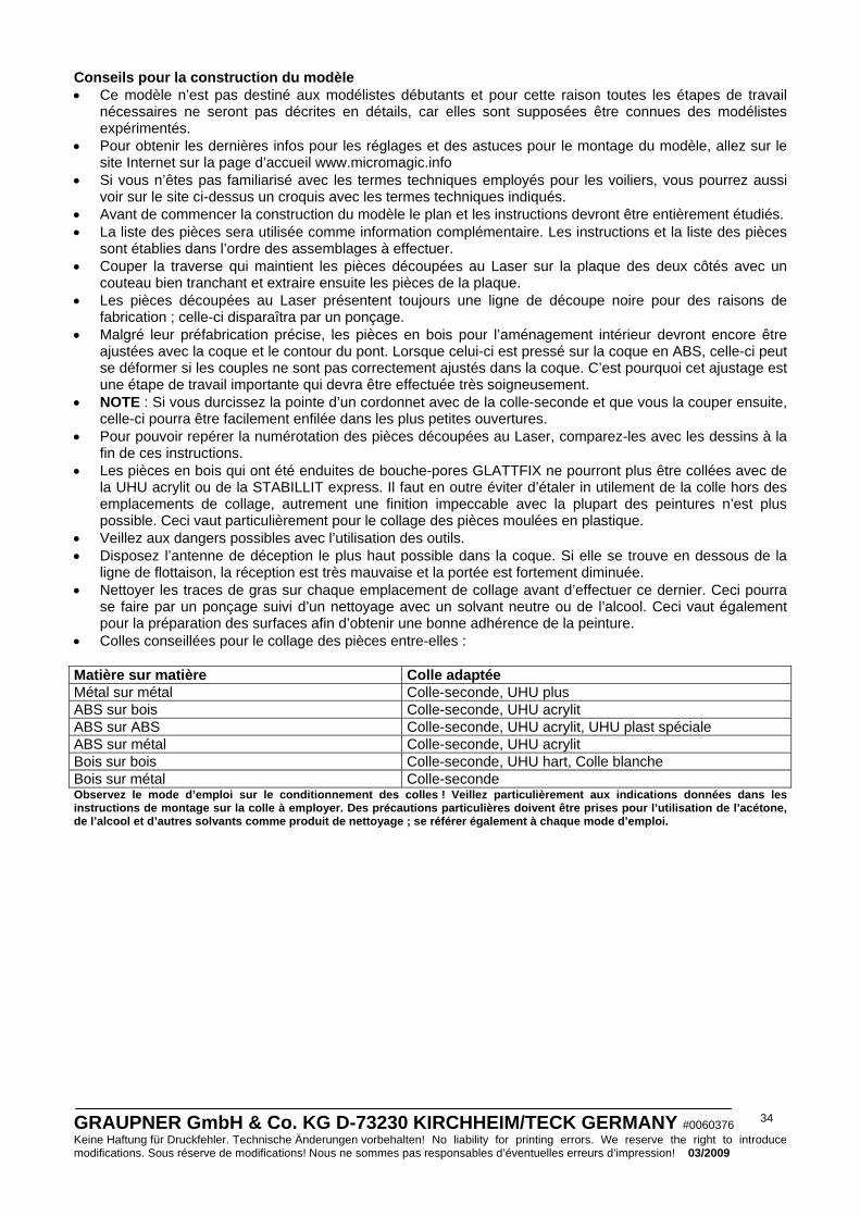
GRAUPNER GmbH & Co. KG D-73230 KIRCHHEIM/TECK GERMANY #0060376 Keine Haftung für Druckfehler. Technische Änderungen vorbehalten! No liability for printing errors. We reserve the right to introduce modifications. Sous réserve de modifications! Nous ne sommes pas responsables d’éventuelles erreurs d’impression! 03/2009
34
Conseils pour la construction du modèle • Ce modèle n’est pas destiné aux modélistes débutants et pour cette raison toutes les étapes de travail
nécessaires ne seront pas décrites en détails, car elles sont supposées être connues des modélistes expérimentés.
• Pour obtenir les dernières infos pour les réglages et des astuces pour le montage du modèle, allez sur le site Internet sur la page d’accueil www.micromagic.info
• Si vous n’êtes pas familiarisé avec les termes techniques employés pour les voiliers, vous pourrez aussi voir sur le site ci-dessus un croquis avec les termes techniques indiqués.
• Avant de commencer la construction du modèle le plan et les instructions devront être entièrement étudiés. • La liste des pièces sera utilisée comme information complémentaire. Les instructions et la liste des pièces
sont établies dans l’ordre des assemblages à effectuer. • Couper la traverse qui maintient les pièces découpées au Laser sur la plaque des deux côtés avec un
couteau bien tranchant et extraire ensuite les pièces de la plaque. • Les pièces découpées au Laser présentent toujours une ligne de découpe noire pour des raisons de
fabrication ; celle-ci disparaîtra par un ponçage. • Malgré leur préfabrication précise, les pièces en bois pour l’aménagement intérieur devront encore être
ajustées avec la coque et le contour du pont. Lorsque celui-ci est pressé sur la coque en ABS, celle-ci peut se déformer si les couples ne sont pas correctement ajustés dans la coque. C’est pourquoi cet ajustage est une étape de travail importante qui devra être effectuée très soigneusement.
• NOTE : Si vous durcissez la pointe d’un cordonnet avec de la colle-seconde et que vous la couper ensuite, celle-ci pourra être facilement enfilée dans les plus petites ouvertures.
• Pour pouvoir repérer la numérotation des pièces découpées au Laser, comparez-les avec les dessins à la fin de ces instructions.
• Les pièces en bois qui ont été enduites de bouche-pores GLATTFIX ne pourront plus être collées avec de la UHU acrylit ou de la STABILLIT express. Il faut en outre éviter d’étaler in utilement de la colle hors des emplacements de collage, autrement une finition impeccable avec la plupart des peintures n’est plus possible. Ceci vaut particulièrement pour le collage des pièces moulées en plastique.
• Veillez aux dangers possibles avec l’utilisation des outils. • Disposez l’antenne de déception le plus haut possible dans la coque. Si elle se trouve en dessous de la
ligne de flottaison, la réception est très mauvaise et la portée est fortement diminuée. • Nettoyer les traces de gras sur chaque emplacement de collage avant d’effectuer ce dernier. Ceci pourra
se faire par un ponçage suivi d’un nettoyage avec un solvant neutre ou de l’alcool. Ceci vaut également pour la préparation des surfaces afin d’obtenir une bonne adhérence de la peinture.
• Colles conseillées pour le collage des pièces entre-elles : Matière sur matière Colle adaptée Métal sur métal Colle-seconde, UHU plus ABS sur bois Colle-seconde, UHU acrylit ABS sur ABS Colle-seconde, UHU acrylit, UHU plast spéciale ABS sur métal Colle-seconde, UHU acrylit Bois sur bois Colle-seconde, UHU hart, Colle blanche Bois sur métal Colle-seconde Observez le mode d’emploi sur le conditionnement des colles ! Veillez particulièrement aux indications données dans les instructions de montage sur la colle à employer. Des précautions particulières doivent être prises pour l’utilisation de l’acétone, de l’alcool et d’autres solvants comme produit de nettoyage ; se référer également à chaque mode d’emploi.
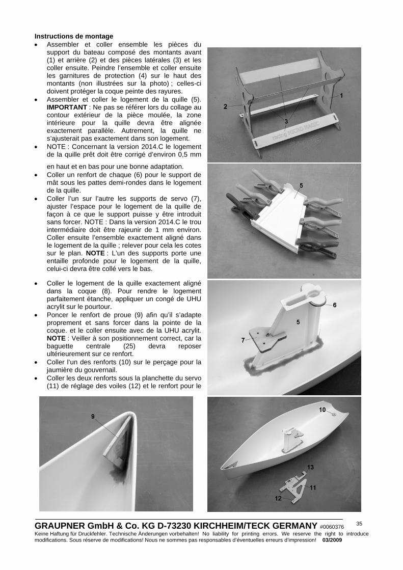
GRAUPNER GmbH & Co. KG D-73230 KIRCHHEIM/TECK GERMANY #0060376 Keine Haftung für Druckfehler. Technische Änderungen vorbehalten! No liability for printing errors. We reserve the right to introduce modifications. Sous réserve de modifications! Nous ne sommes pas responsables d’éventuelles erreurs d’impression! 03/2009
35
Instructions de montage • Assembler et coller ensemble les pièces du
support du bateau composé des montants avant (1) et arrière (2) et des pièces latérales (3) et les coller ensuite. Peindre l’ensemble et coller ensuite les garnitures de protection (4) sur le haut des montants (non illustrées sur la photo) ; celles-ci doivent protéger la coque peinte des rayures.
• Assembler et coller le logement de la quille (5). IMPORTANT : Ne pas se référer lors du collage au contour extérieur de la pièce moulée, la zone intérieure pour la quille devra être alignée exactement parallèle. Autrement, la quille ne s’ajusterait pas exactement dans son logement.
• NOTE : Concernant la version 2014.C le logement de la quille prêt doit être corrigé d’environ 0,5 mm
en haut et en bas pour une bonne adaptation. • Coller un renfort de chaque (6) pour le support de
mât sous les pattes demi-rondes dans le logement de la quille.
• Coller l’un sur l’autre les supports de servo (7), ajuster l’espace pour le logement de la quille de façon à ce que le support puisse y être introduit sans forcer. NOTE : Dans la version 2014.C le trou intermédiaire doit être rajeunir de 1 mm environ. Coller ensuite l’ensemble exactement aligné dans le logement de la quille ; relever pour cela les cotes sur le plan. NOTE : L’un des supports porte une entaille profonde pour le logement de la quille, celui-ci devra être collé vers le bas.
• Coller le logement de la quille exactement aligné dans la coque (8). Pour rendre le logement parfaitement étanche, appliquer un congé de UHU acrylit sur le pourtour.
• Poncer le renfort de proue (9) afin qu’il s’adapte proprement et sans forcer dans la pointe de la coque. et le coller ensuite avec de la UHU acrylit. NOTE : Veiller à son positionnement correct, car la baguette centrale (25) devra reposer ultérieurement sur ce renfort.
• Coller l’un des renforts (10) sur le perçage pour la jaumière du gouvernail.
• Coller les deux renforts sous la planchette du servo (11) de réglage des voiles (12) et le renfort pour le

GRAUPNER GmbH & Co. KG D-73230 KIRCHHEIM/TECK GERMANY #0060376 Keine Haftung für Druckfehler. Technische Änderungen vorbehalten! No liability for printing errors. We reserve the right to introduce modifications. Sous réserve de modifications! Nous ne sommes pas responsables d’éventuelles erreurs d’impression! 03/2009
36
servo de trim de foc (13). Ajuster la découpe pour le logement de la quille de façon à ce que la planchette puisse y être introduite sans jeu, mais sans forcer. NOTE : La planchette de servo sans la découpe est à utiliser pour le montage d’autres servos pour le réglage des voiles. Effectuer la découpe pour le servo avec une scie à chantourner. Placer la découpe de façon à ce que l’axe de sortie du servo se trouve ultérieurement au milieu de la coque.
• Coller tous les couples et les renforts sous le pont (14). Poncer d’abord le haut du couple (15) jusqu’à ce qu’il s’ajuste facilement dans le joint du pont et le coller ensuite. Coller les deux renforts (17 + 18) sur la planchette du servo de gouvernail (16). Introduire ensuite la planchette du servo de gouvernail dans le couple (15) ; si celle-ci ne s’encastre pas correctement, la fente dans le couple devra être rectifiée. Coller ensuite la planchette en place dans le couple. NOTE : La patte demi-ronde doit reposer proprement sur le pont ; s’il subsiste un espace, remplir celui-ci avec de la UHU acrylit.
• Coller le renfort restant (10) sur le perçage de la jaumière du gouvernail. • Coller le couple du milieu (19) sur le talon de l’ouverture pour le capot ; veiller à ce que ce couple soit
centré et à angle droit par rapport à la surface du pont. • Coller les deux renforts de haubans (20) sous le pont. • Coller les quatre renforts pour le verrouillage du capot (21) sous le talon de l’ouverture. Leur position
pourra être relevée sur le plan ou choisie sur initiative personnelle. NOTE : Marquer les positions des renforts extérieurement sur le pont avec un feutre. Il n’y aura ainsi ultérieurement aucun problème pour le montage des verrous (47), car leur vis de pivotement pourra être filetées dans les renforts. NOTE : L’ajustage du capot (55) est conçu pour être fermement maintenu dans le pont. Mais pour la compétition ou l’utilisation intensive du modèle, nous conseillons le montage d’un verrouillage supplémentaire.
• Coller le renfort de poupe (22) centralement dans le pont. Coller également les renforts de poupe latéraux (23) dans le pont. IMPORTANT : Veiller à ce qu’il subsiste un espace de 3mm entre le bois et la feuillure sur le pont, car la coque sera collée ici (Voir la photo) ; poncer le pont en correspondance.
• Poncer une extrémité de la baguette centrale (25) à la forme de la proue, la couper sur une longueur de 210mm et la coller dans le pont. IMPORTANT : Veiller à ce que la baguette ne repose pas sur le logement de la quille, mais devant celui-ci.
• Percer le trou dans le pont pour l’écrou spécial M2 (24) ; sa position est donnée par un marquage sur le pont. Percer le trou par le dessus dans le pont et au travers du renfort avec un foret de φ 2mm. Percer ensuite soigneusement par le dessous seulement le renfort avec un foret de φ 4,2mm de façon à ce que les pointes de l’écrou spécial pénètrent dans le bois. Fixer d’abord l’écrou avec de la colle-seconde fluide et remplir ensuite avec de la UHU acrylit. IMPORTANT : Veiller à ce que de la colle ne pénètre pas dans le taraudage de l’écrou. NOTE : Si le pont a été également traversé par mégarde lors du perçage, 4 rondelles plates supplémentaires de Ø 7/2,1mm pourront combler le trop gros perçage.
• Pratiquer la boutonnière dans le pont pour la fixation de la quille ; sa longueur est donnée par les deux marquages. La largeur de la boutonnière devra être comprise entre 2,5mm et 3mm. NOTE : Percer les marquages à φ 2,5mm et découper exactement le pont entre les deux perçages avec un couteau bien tranchant. La boutonnière sera

GRAUPNER GmbH & Co. KG D-73230 KIRCHHEIM/TECK GERMANY #0060376 Keine Haftung für Druckfehler. Technische Änderungen vorbehalten! No liability for printing errors. We reserve the right to introduce modifications. Sous réserve de modifications! Nous ne sommes pas responsables d’éventuelles erreurs d’impression! 03/2009
37
définitivement ajustée après le collage du pont avec la coque. • Coller le pont avec la coque. Contrôler d’abord si
les deux pièces peuvent s’adapter ensemble sans problème, autrement les ajustages devront être rectifiés. Appliquer de la UHU plus (par ex. Réf. N°962) sur le renfort de proue. (9) et sur la baguette centrale (25). Remplir ensuite suffisamment de UHU plast spéciale les bords du pont (sauf au niveau de la poupe) et coller les deux pièces. IMPORTANT : Veiller à ce que la coque et le pont ne soient pas collés de travers. Maintenir la coque durant le temps de séchage avec du ruban adhésif ou des bandes élastiques ; mais la pression ne devra pas être trop forte, car autrement la coque se déformerait. Après le temps de séchage, les bords de collage devront être remplis avec un peu de UHU plast spéciale.
• Remplir l’espace au niveau de la poupe avec suffisamment de colle-seconde fluide. NOTE : La colle-seconde s’infiltrera dans l’espace par capillarité. Presser l’espace à la poupe avec du ruban adhésif durant le temps de séchage.
• La poupe pourra maintenant être poncée ou on pourra laisser dépasser légèrement la coque au dessus du pont.
• NOTE : Pour la version 2014.C veuillez vérifier que l’agglutination á la coque/pont sera effectuée avec soin, car d’autrefois il est très difficile d’éliminer la colle de la surface carbone (peut-être endommagée).
• Vérifier l’étanchéité du collage coque/pont ; les endroits éventuellement non étanches pourront être remplis avec de la colle-seconde.
• Coller le couple central (19) avec le logement de la quille (5) pour stabiliser le pont.
• Coller la jaumière du gouvernail (26) dans la coque ; le perçage devra éventuellement être un peu rectifié. Positionner la jaumière dans la coque conformément au plan et la coller avec de la colle-seconde fluide. Appliquer un petit congé de colle sur le haut et le bas de la jaumière. Lorsque la colle est prise, surfacer le dessous de la jaumière de niveau avec la coque. Il doit subsister seulement un petit espace entre le safran du gouvernail (27) et la surface de la coque. Le bord supérieur du safran devra éventuellement être ajusté lorsque l’espace n’est pas régulier.
• Monter le palonnier (29) sur le servo de gouvernail (28) réglé au neutre. Fixer ensuite le servo dans la planchette de servo.
• Assembler le bras de gouvernail en plastique (30) avec la bague d’arrêt et la vis M3 et le fixer sur la mèche du gouvernail.
• Percer les deux trous de φ 2mm pour les guides de cordage (31), couper ceux–ci sur une longueur de 15mm dans la gaine intérieure de la transmission Bowden et les coller dans la coque avec de la colle-seconde. IMPORTANT : Veiller dans ce travail à ce que les cordages coulissent ultérieurement le plus rectilignement possible.
• Percer les deux trous de Ø 4mm dans la coque
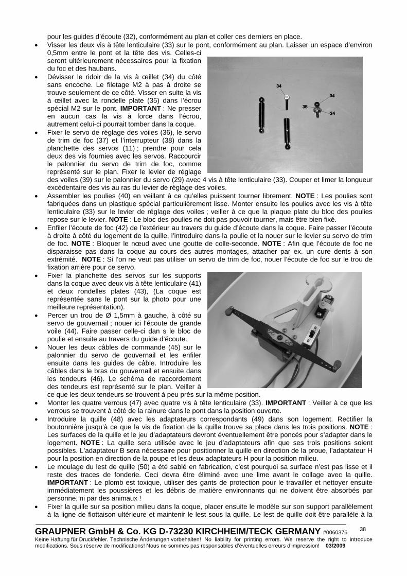
GRAUPNER GmbH & Co. KG D-73230 KIRCHHEIM/TECK GERMANY #0060376 Keine Haftung für Druckfehler. Technische Änderungen vorbehalten! No liability for printing errors. We reserve the right to introduce modifications. Sous réserve de modifications! Nous ne sommes pas responsables d’éventuelles erreurs d’impression! 03/2009
38
pour les guides d’écoute (32), conformément au plan et coller ces derniers en place. • Visser les deux vis à tête lenticulaire (33) sur le pont, conformément au plan. Laisser un espace d’environ
0,5mm entre le pont et la tête des vis. Celles-ci seront ultérieurement nécessaires pour la fixation du foc et des haubans.
• Dévisser le ridoir de la vis à œillet (34) du côté sans encoche. Le filetage M2 à pas à droite se trouve seulement de ce côté. Visser en suite la vis à œillet avec la rondelle plate (35) dans l’écrou spécial M2 sur le pont. IMPORTANT : Ne presser en aucun cas la vis à force dans l’écrou, autrement celui-ci pourrait tomber dans la coque.
• Fixer le servo de réglage des voiles (36), le servo de trim de foc (37) et l’interrupteur (38) dans la planchette des servos (11) ; prendre pour cela deux des vis fournies avec les servos. Raccourcir le palonnier du servo de trim de foc, comme représenté sur le plan. Fixer le levier de réglage des voiles (39) sur le palonnier du servo (29) avec 4 vis à tête lenticulaire (33). Couper et limer la longueur excédentaire des vis au ras du levier de réglage des voiles.
• Assembler les poulies (40) en veillant à ce qu’elles puissent tourner librement. NOTE : Les poulies sont fabriquées dans un plastique spécial particulièrement lisse. Monter ensuite les poulies avec les vis à tête lenticulaire (33) sur le levier de réglage des voiles ; veiller à ce que la plaque plate du bloc des poulies repose sur le levier. NOTE : Le bloc des poulies ne doit pas pouvoir tourner, mais être bien fixé.
• Enfiler l’écoute de foc (42) de l’extérieur au travers du guide d’écoute dans la coque. Faire passer l’écoute à droite à côté du logement de la quille, l’introduire dans la poulie et la nouer sur le levier su servo de trim de foc. NOTE : Bloquer le nœud avec une goutte de colle-seconde. NOTE : Afin que l’écoute de foc ne disparaisse pas dans la coque au cours des autres montages, attacher par ex. un cure dents à son extrémité. NOTE : Si l’on ne veut pas utiliser un servo de trim de foc, nouer l’écoute de foc sur le trou de fixation arrière pour ce servo.
• Fixer la planchette des servos sur les supports dans la coque avec deux vis à tête lenticulaire (41) et deux rondelles plates (43), (La coque est représentée sans le pont sur la photo pour une meilleure représentation).
• Percer un trou de Ø 1,5mm à gauche, à côté su servo de gouvernail ; nouer ici l’écoute de grande voile (44). Faire passer celle-ci dan s le bloc de poulie et ensuite au travers du guide d’écoute.
• Nouer les deux câbles de commande (45) sur le palonnier du servo de gouvernail et les enfiler ensuite dans les guides de câble. Introduire les câbles dans le bras du gouvernail et ensuite dans les tendeurs (46). Le schéma de raccordement des tendeurs est représenté sur le plan. Veiller à ce que les deux tendeurs se trouvent à peu près sur la même position.
• Monter les quatre verrous (47) avec quatre vis à tête lenticulaire (33). IMPORTANT : Veiller à ce que les verrous se trouvent à côté de la rainure dans le pont dans la position ouverte.
• Introduire la quille (48) avec les adaptateurs correspondants (49) dans son logement. Rectifier la boutonnière jusqu’à ce que la vis de fixation de la quille trouve sa place dans les trois positions. NOTE : Les surfaces de la quille et le jeu d’adaptateurs devront éventuellement être poncés pour s’adapter dans le logement. NOTE : La quille sera utilisée avec le jeu d’adaptateurs afin que ses trois positions soient possibles. L’adaptateur B sera nécessaire pour positionner la quille en direction de la proue, l’adaptateur H pour la position en direction de la poupe et les deux adaptateurs H pour la position milieu.
• Le moulage du lest de quille (50) a été sablé en fabrication, c’est pourquoi sa surface n’est pas lisse et il reste des traces de fonderie. Ceci devra être éliminé avec une lime avant le collage avec la quille. IMPORTANT : Le plomb est toxique, utiliser des gants de protection pour le travailler et nettoyer ensuite immédiatement les poussières et les débris de matière environnants qui ne doivent être absorbés par personne, ni par des animaux !
• Fixer la quille sur sa position milieu dans la coque, placer ensuite le modèle sur son support parallèlement à la ligne de flottaison ultérieure et maintenir le lest sous la quille. Le lest de quille doit être parallèle à la
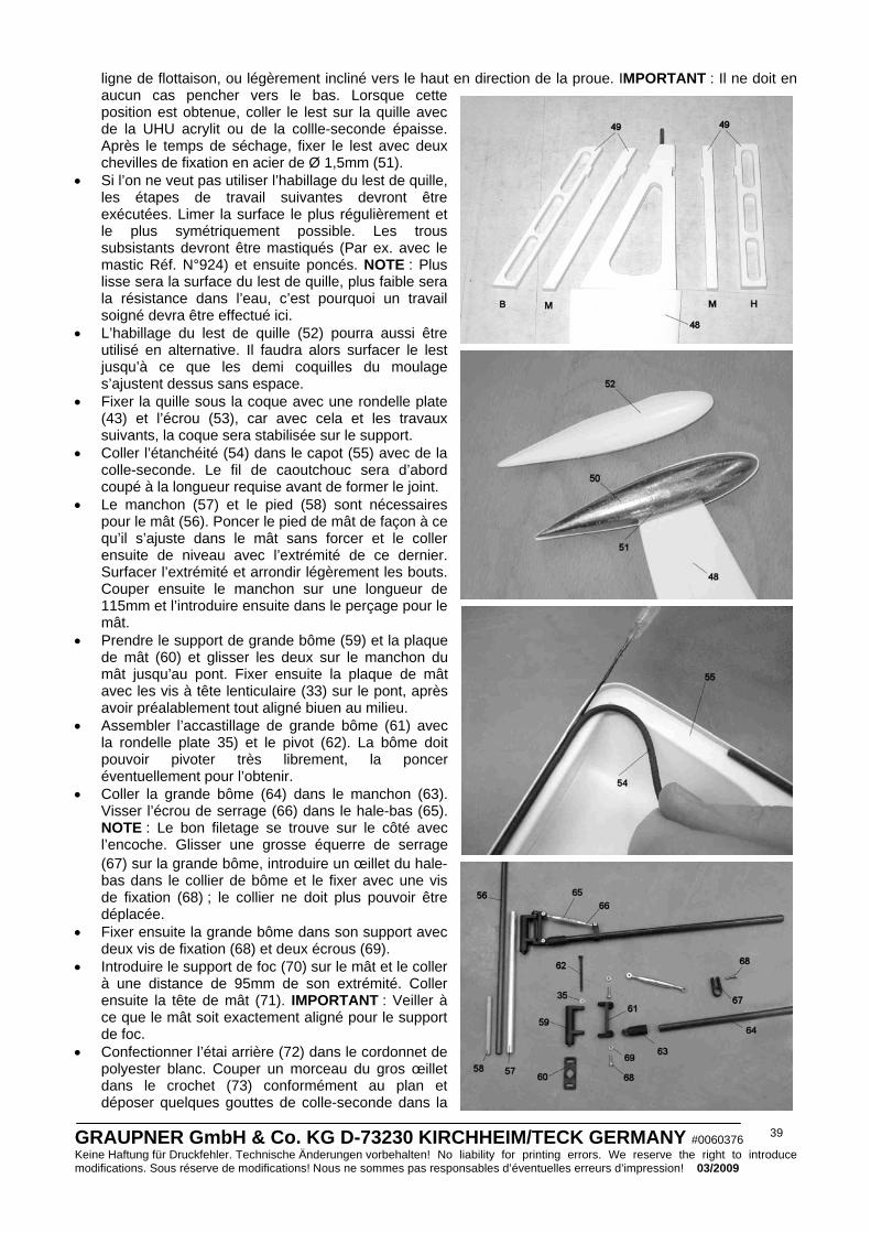
GRAUPNER GmbH & Co. KG D-73230 KIRCHHEIM/TECK GERMANY #0060376 Keine Haftung für Druckfehler. Technische Änderungen vorbehalten! No liability for printing errors. We reserve the right to introduce modifications. Sous réserve de modifications! Nous ne sommes pas responsables d’éventuelles erreurs d’impression! 03/2009
39
ligne de flottaison, ou légèrement incliné vers le haut en direction de la proue. IMPORTANT : Il ne doit en aucun cas pencher vers le bas. Lorsque cette position est obtenue, coller le lest sur la quille avec de la UHU acrylit ou de la collle-seconde épaisse. Après le temps de séchage, fixer le lest avec deux chevilles de fixation en acier de Ø 1,5mm (51).
• Si l’on ne veut pas utiliser l’habillage du lest de quille, les étapes de travail suivantes devront être exécutées. Limer la surface le plus régulièrement et le plus symétriquement possible. Les trous subsistants devront être mastiqués (Par ex. avec le mastic Réf. N°924) et ensuite poncés. NOTE : Plus lisse sera la surface du lest de quille, plus faible sera la résistance dans l’eau, c’est pourquoi un travail soigné devra être effectué ici.
• L’habillage du lest de quille (52) pourra aussi être utilisé en alternative. Il faudra alors surfacer le lest jusqu’à ce que les demi coquilles du moulage s’ajustent dessus sans espace.
• Fixer la quille sous la coque avec une rondelle plate (43) et l’écrou (53), car avec cela et les travaux suivants, la coque sera stabilisée sur le support.
• Coller l’étanchéité (54) dans le capot (55) avec de la colle-seconde. Le fil de caoutchouc sera d’abord coupé à la longueur requise avant de former le joint.
• Le manchon (57) et le pied (58) sont nécessaires pour le mât (56). Poncer le pied de mât de façon à ce qu’il s’ajuste dans le mât sans forcer et le coller ensuite de niveau avec l’extrémité de ce dernier. Surfacer l’extrémité et arrondir légèrement les bouts. Couper ensuite le manchon sur une longueur de 115mm et l’introduire ensuite dans le perçage pour le mât.
• Prendre le support de grande bôme (59) et la plaque de mât (60) et glisser les deux sur le manchon du mât jusqu’au pont. Fixer ensuite la plaque de mât avec les vis à tête lenticulaire (33) sur le pont, après avoir préalablement tout aligné biuen au milieu.
• Assembler l’accastillage de grande bôme (61) avec la rondelle plate 35) et le pivot (62). La bôme doit pouvoir pivoter très librement, la poncer éventuellement pour l’obtenir.
• Coller la grande bôme (64) dans le manchon (63). Visser l’écrou de serrage (66) dans le hale-bas (65). NOTE : Le bon filetage se trouve sur le côté avec l’encoche. Glisser une grosse équerre de serrage (67) sur la grande bôme, introduire un œillet du hale-bas dans le collier de bôme et le fixer avec une vis de fixation (68) ; le collier ne doit plus pouvoir être déplacée.
• Fixer ensuite la grande bôme dans son support avec deux vis de fixation (68) et deux écrous (69).
• Introduire le support de foc (70) sur le mât et le coller à une distance de 95mm de son extrémité. Coller ensuite la tête de mât (71). IMPORTANT : Veiller à ce que le mât soit exactement aligné pour le support de foc.
• Confectionner l’étai arrière (72) dans le cordonnet de polyester blanc. Couper un morceau du gros œillet dans le crochet (73) conformément au plan et déposer quelques gouttes de colle-seconde dans la
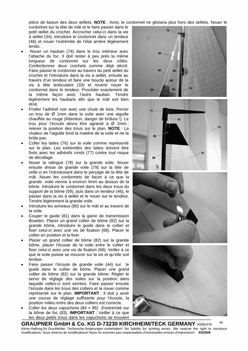
GRAUPNER GmbH & Co. KG D-73230 KIRCHHEIM/TECK GERMANY #0060376 Keine Haftung für Druckfehler. Technische Änderungen vorbehalten! No liability for printing errors. We reserve the right to introduce modifications. Sous réserve de modifications! Nous ne sommes pas responsables d’éventuelles erreurs d’impression! 03/2009
40
pièce de liaison des deux œillets. NOTE : Ainsi, le cordonnet ne glissera plus hors des œillets. Nouer le cordonnet sur la tête de mât et le faire passer dans le petit œillet du crochet. Accrocher celui-ci dans la vie à œillet (34), introduire le cordonnet dans un tendeur (46) et nouer l’extrémité de l’étai arrière légèrement tendu.
• Nouer un hauban (74) dans le trou intérieur avec l’attache du foc. Il doit rester à peu près la même longueur de cordonnet sur les deux côtés. Confectionner deux crochets comme déjà décrit. Faire passer le cordonnet au travers du petit œillet du crochet et l’introduire dans la vis à œillet, ensuite au travers d’un tendeur et faire une boucle autour de la vis à tête lenticulaire (33) et revenir nouer le cordonnet dans le tendeur. Procéder exactement de la même façon avec l’autre hauban. Tendre légèrement les haubans afin que le mât soit bien droit.
• Frotter l’adhésif noir avec une chute de bois. Percer un trou de Ø 1mm dans la voile avec une aiguille chauffée au rouge (Attention, danger de brûlure !). Le trou pour l’écoute devra être agrandi à Ø 2mm ; relever la position des trous sur le plan. NOTE : La chaleur de l’aiguille fond la matière de la voile et ne la brûle pas.
• Coller les lattes (76) sur la voile comme représenté sur le plan. Les extrémités des lattes doivent être fixés avec les adhésifs ronds (77) contre tout risque de décollage.
• Nouer la ralingue (78) sur la grande voile. Nouer ensuite drisse de grande voile (79) sur la tête de celle-ci en l’introduisant dans le perçage de la tête de mât. Nouer les cordonnets de façon à ce que la grande voile vienne à environ 4mm au dessus de la bôme. Introduire le cordonnet dans les deux trous du support de la bôme (59), puis dans un tendeur (46), le passer dans la vis à œillet et le nouer sur le tendeur. Tendre légèrement la grande voile.
• Introduire les anneaux (80) sur le mât et au travers de la voile.
• Couper le guide (81) dans la gaine de transmission Bowden. Placer un grand collier de bôme (82) sur la grande bôme, introduire le guide dans le collier et fixer celui-ci avec une vis de fixation (68). Placer le collier en position et la fixer.
• Placer un grand collier de bôme (82) sur la grande bôme, placer l’écoute de la voile entre le collier et fixer celui-ci avec une vis de fixation (68). Veiller à ce que la voile puisse se mouvoir sur la vis et qu’elle soit tendue.
• Faire passer l’écoute de grande voile (44) sur le guide dans le collier de bôme. Placer une grand collier de bôme (82) sur la grande bôme. Régler le servo de réglage des voiles sur la position dans laquelle celles-ci sont serrées. Faire passer ensuite l’écoute dans les trous des colliers et la nouer comme représenté sur le plan. IMPORTANT : Il doit y avoir une course de réglage suffisante pour l’écoute, la position milieu entre des deux colliers est correcte.
• Coller les deux capuchons (84 + 85) d’extrémité sur la bôme de foc (83). IMPORTANT : Veiller à ce que les deux petits trous dans les capuchons se trouvent

GRAUPNER GmbH & Co. KG D-73230 KIRCHHEIM/TECK GERMANY #0060376 Keine Haftung für Druckfehler. Technische Änderungen vorbehalten! No liability for printing errors. We reserve the right to introduce modifications. Sous réserve de modifications! Nous ne sommes pas responsables d’éventuelles erreurs d’impression! 03/2009
41
sur le même côté et dans le même axe. Coller ensuite la cheville de fixation dans le perçage des capuchons avec de la colle-seconde ; elle devra dépasser sur env. 11mm. Coller ensuite le lest de compensation du foc (87) sur la cheville avec de la UHU Alleskleber (décollable par la suite). IMPORTANT : Il doit rester un espace d’env. 1mm entre le poids et le capuchon.
• Percer le trou dans le foc (88) comme il a déjà été décrit pour la grande voile ; le trou pour l’écoute devra être agrandi à Ø 2mm.
• Faire passer l’étai avant (89) au travers de la boucle de la ralingue du foc. NOTE : ‘’Durcir’’ au minimum 25mm de cordonnet avec de la colle-seconde afin de pouvoir le passer facilement dans la boucle.
• Nouer la drisse de foc (90) sur la tête et la ralingue (91) sous le col de la voile.
• Fixer les deux petits colliers de bôme (92) sur la bôme de foc, introduire la voile dedans et les fixer avec une vis de fixation (68).
• Introduire la ralingue dans le perçage du capuchon de foc (85). Glisser un petit collier de bôme (93) sur la bôme de foc. Régler le servo de réglage des voiles sur la position dans laquelle celles-ci sont serrées. Faire passer ensuite l’écoute dans les trous du collier et la nouer comme il a été indiqué pour l’écoute de la grande voile. IMPORTANT : Il doit y avoir une course de réglage suffisante pour l’écoute, la position indiquée sur le plan est à utiliser si possible. Tendre le collier de bôme de façon à ce que la ralingue soit parallèle à la bôme de foc.
• Nouer l’étai avant autour de la cheville de fixation (86). et la drisse de foc dans le trou extérieur de l’attache de foc (70). IMPORTANT : Les deux ralingues de la voile doivent se trouver sur une même ligne.
• Introduire le cordonnet de l’étai avant dans un tendeur (46) et ensuite au travers de l’autre trou de l’attache de foc. Revenir ensujte sur le tendeur et nouer le cordonnet.
• Glisser un petit collier de bôme (93) sur la bôme de foc. Nouer la fixation du foc (94) dans le collier comme il a déjà été indiqué pour l’écoute. Confectionner un crochet (73) comme déjà décrit. Accrocher le crochet dans la vis à œillet et faire passer le cordonnet de l’attache de foc au travers du petit œillet du crochet, ensuite dans un tendeur (46), faire une boucle autour de la vis à tête lenticulaire (33) et nouer le cordonnet sur le tendeur. Tendre l’attache de foc. La position du foc pourra être réglée par le déplacement du collier de bôme, de façon à ce que le lest de compensation du foc se trouve exactement derrière la pointe de la proue.
• Introduire l’écoute du foc (42) dans le gros perçage du capuchon d’extrémité (84). Placer un petit collier de bôme (93) sur la bôme de foc, faire passer l’écoute au travers des trous et la nouer comme il a été indiqué pour l’écoute de la grande voile. IMPORTANT : Il doit y avoir une course de réglage suffisante pour l’écoute ; une distance à env. 30mm du petit collier de bôme est correcte.
• Nouer le cordage (95) sur le capuchon (84). Faire passer le cordage dans un tendeur (46), ensuite dans le trou extérieur de l’attache de foc (70), puis le nouer sur le tendeur. Ce cordage devra être seulement légèrement tendu et ne devra pas tirer sur le foc.
GRAUPNER GmbH & Co. KG D-73230 KIRCHHEIM/TECK GERMANY #0060376 Keine Haftung für Druckfehler. Technische Änderungen vorbehalten! No liability for printing errors. We reserve the right to introduce modifications. Sous réserve de modifications! Nous ne sommes pas responsables d’éventuelles erreurs d’impression! 03/2009
42
La peinture • Pour la version 2014.C une peinture n’est pas nécessaire ! • Utiliser UNIQUEMENT des peintures du même fabricant et de même base chimique, car autrement elles
peuvent réagir entre-elles et se décomposer. Il faut être particulièrement vigilant avec les combinaisons de peintures en bombe et de celles pour l’application au pinceau ; faire toujours un essai préalable sur des chutes pour voir si elles ne réagissent pas entre-elles.
• Pour obtenir une bonne adhérence de la peinture, poncer légèrement les surfaces avec du papier abrasif fin mouillé (Grain 600 à 800) et les dégraisser ensuite avec un solvant neutre. Ne plus toucher les surfaces si possible jusqu’à l’application de la peinture, car la transpiration de la peau laisserait à nouveau des traces de gras sur celles-ci.
• Noter que les collages sur les surfaces peintes ne tiennent pas aussi bien que la peinture sur le modèle, c’est-à-dire que si une pièce se casse, elle arrache en même temps la peinture sur le modèle. La peinture devra ainsi être retirée sur la surface de collage des pièces pouvant facilement casser.
• Les pièces en bois seront enduites de plusieurs couches de bouche-pores (Par ex. GLATTFIX, Réf. N°207) ou de vernis transparent (Par ex. HYDRO-AEROFIX, Réf. N°926.1) pour les protéger de l’humidité.
• Pour l’application de la peinture en bombe, masquer entièrement toutes les surfaces qui ne devront pas recevoir de peinture. Obturer toutes les ouvertures, car le fin nuage de peinture vaporisée peut pénétrer par les plus petites.
• Observer le mode d’emploi des peintures. Décoration Afin de pouvoir sélectionner facilement les teintes de peintures correctes, les teintes RAL sont seulement indiquées. Avec ces indications, les teintes pourront être obtenues dans chaque magasin de peintures. Indiquer au vendeur le but d’utilisation prévu pour les peintures afin qu’il choisisse le type correct. Nous conseillons les peintures synthétiques. La teinte RAL (Blanc) est optimalement adaptée comme teinte de base pour ce modèle, car la décoration ressort bien sur une teinte de base blanche. Le modèle pourra aussi naturellement être décoré au goût personnel de chacun.
Pose de la décoration Découper proprement les différents motifs sur la planche de décoration avec des ciseaux en laissant le moins de bordures possible. Coller les motifs sur les surfaces peintes et exemptes de poussière du modèle. Pour poser proprement les grands motifs de décoration sur les flancs de la coque, les découper presque au ras des bords, les poser sur la coque sans encore enlever la feuille de protection et les fixer à une extrémité avec du ruban adhésif. Tirer ensuite progressivement la feuille de protection et coller proprement le film adhésif. Ces grands motifs pourront aussi être coupés dans les différentes parties de couleurs pour pouvoir les poser encore plus facilement. Les autres motifs pourront être posés conformément à l’illustration sur le cartonnage ou au goût personnel.
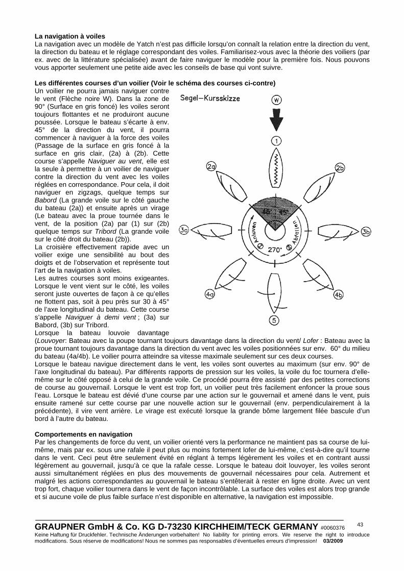
GRAUPNER GmbH & Co. KG D-73230 KIRCHHEIM/TECK GERMANY #0060376 Keine Haftung für Druckfehler. Technische Änderungen vorbehalten! No liability for printing errors. We reserve the right to introduce modifications. Sous réserve de modifications! Nous ne sommes pas responsables d’éventuelles erreurs d’impression! 03/2009
43
La navigation à voiles La navigation avec un modèle de Yatch n’est pas difficile lorsqu’on connaît la relation entre la direction du vent, la direction du bateau et le réglage correspondant des voiles. Familiarisez-vous avec la théorie des voiliers (par ex. avec de la littérature spécialisée) avant de faire naviguer le modèle pour la première fois. Nous pouvons vous apporter seulement une petite aide avec les conseils de base qui vont suivre.
Les différentes courses d’un voilier (Voir le schéma des courses ci-contre) Un voilier ne pourra jamais naviguer contre le vent (Flèche noire W). Dans la zone de 90° (Surface en gris foncé) les voiles seront toujours flottantes et ne produiront aucune poussée. Lorsque le bateau s’écarte à env. 45° de la direction du vent, il pourra commencer à naviguer à la force des voiles (Passage de la surface en gris foncé à la surface en gris clair, (2a) à (2b). Cette course s’appelle Naviguer au vent, elle est la seule à permettre à un voilier de naviguer contre la direction du vent avec les voiles réglées en correspondance. Pour cela, il doit naviguer en zigzags, quelque temps sur Babord (La grande voile sur le côté gauche du bateau (2a)) et ensuite après un virage (Le bateau avec la proue tournée dans le vent, de la position (2a) par (1) sur (2b) quelque temps sur Tribord (La grande voile sur le côté droit du bateau (2b)). La croisière effectivement rapide avec un voilier exige une sensibilité au bout des doigts et de l’observation et représente tout l’art de la navigation à voiles. Les autres courses sont moins exigeantes. Lorsque le vent vient sur le côté, les voiles seront juste ouvertes de façon à ce qu’elles ne flottent pas, soit à peu près sur 30 à 45° de l’axe longitudinal du bateau. Cette course s’appelle Naviguer à demi vent ; (3a) sur Babord, (3b) sur Tribord. Lorsque la bateau louvoie davantage (Louvoyer: Bateau avec la poupe tournant toujours davantage dans la direction du vent/ Lofer : Bateau avec la proue tournant toujours davantage dans la direction du vent avec les voiles positionnées sur env. 60° du milieu du bateau (4a/4b). Le voilier pourra atteindre sa vitesse maximale seulement sur ces deux courses. Lorsque le bateau navigue directement dans le vent, les voiles sont ouvertes au maximum (sur env. 90° de l’axe longitudinal du bateau). Par différents rapports de pression sur les voiles, la voile du foc tournera d’elle-même sur le côté opposé à celui de la grande voile. Ce procédé pourra être assisté par des petites corrections de course au gouvernail. Lorsque le vent est trop fort, un voilier peut très facilement enfoncer la proue sous l’eau. Lorsque le bateau est dévié d’une course par une action sur le gouvernail et amené dans le vent, puis ensuite ramené sur cette course par une nouvelle action sur le gouvernail (env. perpendiculairement à la précédente), il vire vent arrière. Le virage est exécuté lorsque la grande bôme largement filée bascule d’un bord à l’autre du bateau.
Comportements en navigation Par les changements de force du vent, un voilier orienté vers la performance ne maintient pas sa course de lui-même, mais par ex. sous une rafale il peut plus ou moins fortement lofer de lui-même, c’est-à-dire qu’il tourne dans le vent. Ceci peut être seulement évité en réglant à temps légèrement les voiles et en contrant aussi légèrement au gouvernail, jusqu’à ce que la rafale cesse. Lorsque le bateau doit louvoyer, les voiles seront aussi simultanément réglées en plus des mouvements de gouvernail nécessaires pour cela. Autrement et malgré les actions correspondantes au gouvernail le bateau s’entêterait à rester en ligne droite. Avec un vent trop fort, chaque voilier tournera dans le vent de façon incontrôlable. La surface des voiles est alors trop grande et si aucune voile de plus faible surface n’est disponible en alternative, la navigation est impossible.
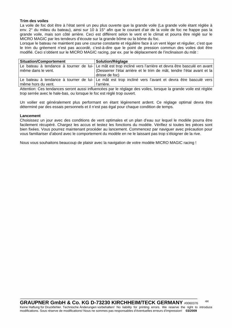
GRAUPNER GmbH & Co. KG D-73230 KIRCHHEIM/TECK GERMANY #0060376 Keine Haftung für Druckfehler. Technische Änderungen vorbehalten! No liability for printing errors. We reserve the right to introduce modifications. Sous réserve de modifications! Nous ne sommes pas responsables d’éventuelles erreurs d’impression! 03/2009
44
Trim des voiles La voile de foc doit être à l’état serré un peu plus ouverte que la grande voile (La grande voile étant réglée à env. 2° du milieu du bateau), ainsi sur 10 à 15° afin que le courant d’air de la voile de foc ne frappe pas la grande voile, mais son côté arrière. Ceci est différent selon le vent et le climat et pourra être réglé sur le MICRO MAGIC par les tendeurs d’écoute sur la grande bôme ou la bôme du foc. Lorsque le bateau ne maintient pas une course constante et régulière face à un vent léger et régulier, c’est que le trim du gréement n’est pas accordé, c’est-à-dire que le point de pression commun des voiles doit être modifié. Ceci s’obtient sur le MICRO MAGIC racing, par ex. par le déplacement de l’inclinaison du mât : Situation/Comportement Solution/Réglage Le bateau à tendance à tourner de lui-même dans le vent.
Le mât est trop incliné vers l’arrière et devra être basculé en avant (Desserrer l’étai arrière et le trim de mât, tendre l’étai avant et la drisse de foc)
Le bateau à tendance à tourner de lui-même hors du vent.
Le mât est trop incliné vers l’avant et devra être basculé vers l’arrière.
Attention: Ces tendances seront aussi influencées par le réglage des voiles, lorsque la grande voile est réglée trop serrée avec le hale-bas, ou lorsque le foc est réglé trop ouvert. Un voilier est généralement plus performant en étant légèrement ardent. Ce réglage optimal devra être déterminé par des essais personnels et il n’est pas égal pour chaque condition de temps. Lancement Choisissez un jour avec des conditions de vent optimales et un plan d’eau sur lequel le modèle pourra être facilement récupéré. Chargez les accus et testez les fonctions du modèle. Vérifiez si toutes les pièces sont bien fixées. Vous pourrez maintenant procéder au lancement. Commencez par naviguer avec précaution pour vous familiariser d’abord avec le comportement du modèle en ne le laissant pas trop s’éloigner de la rive. Nous vous souhaitons beaucoup de plaisir avec la navigation de votre modèle MICRO MAGIC racing !

GRAUPNER GmbH & Co. KG D-73230 KIRCHHEIM/TECK GERMANY #0060376 Keine Haftung für Druckfehler. Technische Änderungen vorbehalten! No liability for printing errors. We reserve the right to introduce modifications. Sous réserve de modifications! Nous ne sommes pas responsables d’éventuelles erreurs d’impression! 03/2009
45
Liste des pièces N° Désignation Qté Matériel Diumensions en mm 1 Montant avant de support 1 C.T.P. 4mm, Découpe Laser 2 Montant arrière de support 1 C.T.P. 4mm, Découpe Laser 3 Pièces latérales 4 C.T.P. 4mm, Découpe Laser 4 Garniture de protection 1 Mousse adhasive à couper en bandes 5 Logement de quille (2 pces) 2 ABS Pces moulées, usinées CNC 6 Renforts de support de mât 2 C.T.P. 2mm, Découpe Laser 7 Supports de servo 2 C.T.P. 2mm, Découpe Laser 8 Coque 1 ABS Pce moulké’, usinée CNC 9 Renfort de proue 1 C.T.P. 2mm, Décloupe Laser 10 Renforts de jaumière 2 C.T.P. 2mm, Décloupe Laser 11 Platine de servo 1 C.T.P. 2mm, Décloupe Laser 12 Renfort de servo de réglage voiles 2 C.T.P. 2mm, Décloupe Laser 13 Renfort de servo de trim de foc 1 C.T.P. 2mm, Décloupe Laser 14 Pont 1 ABS Pce moulé“, usinée CNC 15 Couple 1 C.T.P. 2mm, Décloupe Laser 16 Planchette de servo de gouvernail 1 C.T.P. 2mm, Décloupe Laser 17 Renfort de servo, grand 1 C.T.P. 2mm, Décloupe Laser 18 Renfort de servo, petit 1 C.T.P. 2mm, Décloupe Laser 19 Couple central 1 C.T.P. 2mm, Décloupe Laser 20 Renforts de hauban 2 C.T.P. 2mm, Décloupe Laser 21 Renfoirts de verrouillages 4 C.T.P. 2mm, Décloupe Laser 22 Renfort de poupe 1 C.T.P. 2mm, Décloupe Laser 23 Renforts latéraux de poupe 2 C.T.P. 2mm, Décloupe Laser 24 Ecrous spéciaux 4 Métal M2 25 Baguette centrale 1 Pin 3x8x210mm 26 Jaumière de gouvernail 1 Tube de laiton Ø4x3,1x30mm 27 Safrean de gouvernail 1 Plastique Pièce finie 28 Servo de gouvernail 1 Réf. N° 5125.LOSE Pièce finie 29 Poalonniers de servo 2 Réf. N° 3941.50 Pièces finies 30 Bvras de gouvernail 1 Plastique Pièce finie 31 Guides de cordage 2 Gaine intérieure
Bowden Ø2x0,8x15mm
32 Guides d’écoute 2 Plastique Pièces finies 33 Vis à tête lenticulaire 14 Aciere inox Ø2,2x6,5mm 34 Vis à oeillet 4 Laiton nickelé Ø3,8x1,5x11mm 35 Rondelles plates 5 Laiton nickelé Ø4,5x2,2x0,5mm 36 Servo de réglage des voiles 1 Réf. N° 4103.LOSE Pièce finie 37 Servo de trim de foc 1 Réf. N° 5125.LOSE Pièce finie 38 Interrupteur 1 Réf. N° 3934.1 Pièce finie 39 Levier de réglage de voile 1 Plastique Pièce finie 40 Poulies 2 Plastique Pièces finies 41 Vis à tête lenticulaire 2 Acier inox Ø2,2x9,5mm 42 Ecoute de foc 1 Cordonnet polyester Ø0,4x500mm 43 Rondelkles plates 3 Laiton nickelé Ø7,0x2,8x0,5mm 44 Grande écoute 1 Cordonnet polyester Ø0,4x500mm 45 Câbles de commande gouvernail 2 Cordonnet polyester Ø0,4x300mm 46 Tendeurs 9 Plastique Pièces finies 47 Verrous 4 Plastique Pièces finies 48 Quille 1 Plastique Pièce finie 49 Jeu d’adaptateurs 4 Plastique Pièces finies 50 Lest de quille 1 Plomb (TOXIQUE !) Pièce finie 51 Chevilles de fixation 2 Acier Ø1,5x15mm 52 Habillages de lest de quille 2 ABS Pces moulées 53 Ecrou d’arrêt 1 Laiton nickelé M2,5 54 Etanchéité 1 Fil de caoutchouc Ø2,5mm, Couper de longueur 55 Capot 1 ABS Pce moulée, usinée CNC 56 Mâtt 1 Tube fibre de carbone Ø5x4x850mm 57 Manchon de mât 1 Tube d’aluminium Ø6x5x115mm
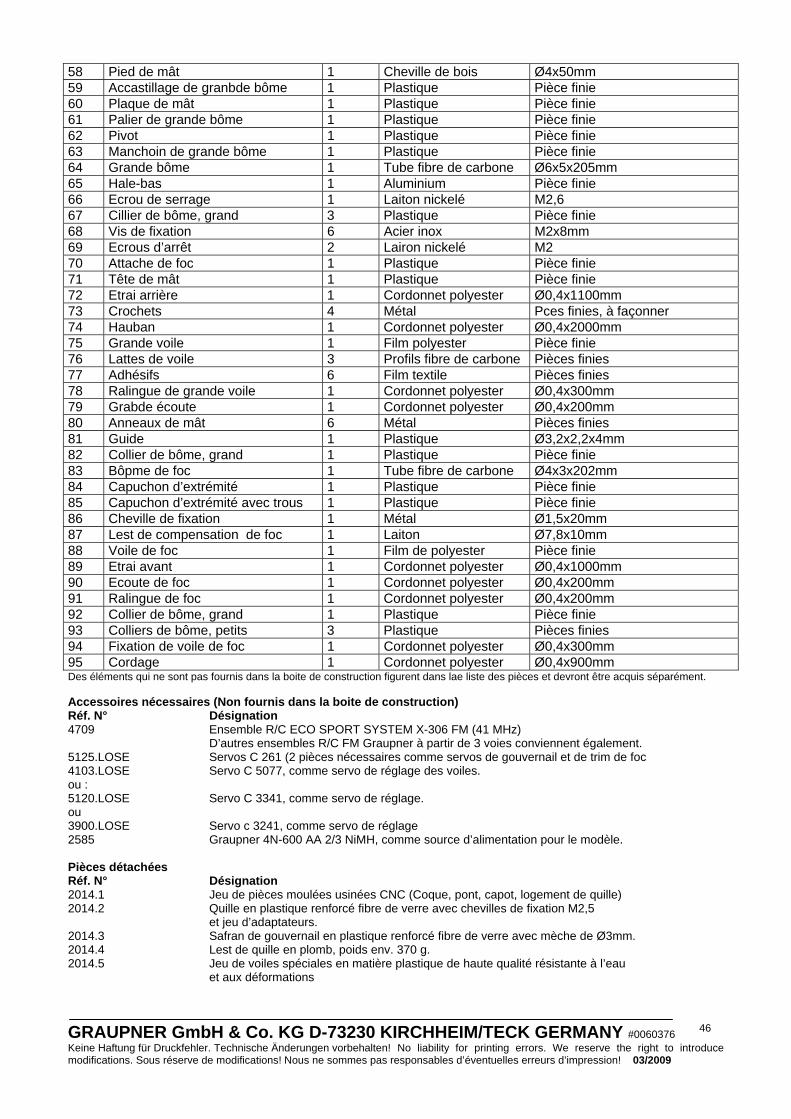
GRAUPNER GmbH & Co. KG D-73230 KIRCHHEIM/TECK GERMANY #0060376 Keine Haftung für Druckfehler. Technische Änderungen vorbehalten! No liability for printing errors. We reserve the right to introduce modifications. Sous réserve de modifications! Nous ne sommes pas responsables d’éventuelles erreurs d’impression! 03/2009
46
58 Pied de mât 1 Cheville de bois Ø4x50mm 59 Accastillage de granbde bôme 1 Plastique Pièce finie 60 Plaque de mât 1 Plastique Pièce finie 61 Palier de grande bôme 1 Plastique Pièce finie 62 Pivot 1 Plastique Pièce finie 63 Manchoin de grande bôme 1 Plastique Pièce finie 64 Grande bôme 1 Tube fibre de carbone Ø6x5x205mm 65 Hale-bas 1 Aluminium Pièce finie 66 Ecrou de serrage 1 Laiton nickelé M2,6 67 Cillier de bôme, grand 3 Plastique Pièce finie 68 Vis de fixation 6 Acier inox M2x8mm 69 Ecrous d’arrêt 2 Lairon nickelé M2 70 Attache de foc 1 Plastique Pièce finie 71 Tête de mât 1 Plastique Pièce finie 72 Etrai arrière 1 Cordonnet polyester Ø0,4x1100mm 73 Crochets 4 Métal Pces finies, à façonner 74 Hauban 1 Cordonnet polyester Ø0,4x2000mm 75 Grande voile 1 Film polyester Pièce finie 76 Lattes de voile 3 Profils fibre de carbone Pièces finies 77 Adhésifs 6 Film textile Pièces finies 78 Ralingue de grande voile 1 Cordonnet polyester Ø0,4x300mm 79 Grabde écoute 1 Cordonnet polyester Ø0,4x200mm 80 Anneaux de mât 6 Métal Pièces finies 81 Guide 1 Plastique Ø3,2x2,2x4mm 82 Collier de bôme, grand 1 Plastique Pièce finie 83 Bôpme de foc 1 Tube fibre de carbone Ø4x3x202mm 84 Capuchon d’extrémité 1 Plastique Pièce finie 85 Capuchon d’extrémité avec trous 1 Plastique Pièce finie 86 Cheville de fixation 1 Métal Ø1,5x20mm 87 Lest de compensation de foc 1 Laiton Ø7,8x10mm 88 Voile de foc 1 Film de polyester Pièce finie 89 Etrai avant 1 Cordonnet polyester Ø0,4x1000mm 90 Ecoute de foc 1 Cordonnet polyester Ø0,4x200mm 91 Ralingue de foc 1 Cordonnet polyester Ø0,4x200mm 92 Collier de bôme, grand 1 Plastique Pièce finie 93 Colliers de bôme, petits 3 Plastique Pièces finies 94 Fixation de voile de foc 1 Cordonnet polyester Ø0,4x300mm 95 Cordage 1 Cordonnet polyester Ø0,4x900mm Des éléments qui ne sont pas fournis dans la boite de construction figurent dans lae liste des pièces et devront être acquis séparément. Accessoires nécessaires (Non fournis dans la boite de construction) Réf. N° Désignation 4709 Ensemble R/C ECO SPORT SYSTEM X-306 FM (41 MHz) D’autres ensembles R/C FM Graupner à partir de 3 voies conviennent également. 5125.LOSE Servos C 261 (2 pièces nécessaires comme servos de gouvernail et de trim de foc 4103.LOSE Servo C 5077, comme servo de réglage des voiles. ou : 5120.LOSE Servo C 3341, comme servo de réglage. ou 3900.LOSE Servo c 3241, comme servo de réglage 2585 Graupner 4N-600 AA 2/3 NiMH, comme source d’alimentation pour le modèle. Pièces détachées Réf. N° Désignation 2014.1 Jeu de pièces moulées usinées CNC (Coque, pont, capot, logement de quille) 2014.2 Quille en plastique renforcé fibre de verre avec chevilles de fixation M2,5 et jeu d’adaptateurs. 2014.3 Safran de gouvernail en plastique renforcé fibre de verre avec mèche de Ø3mm. 2014.4 Lest de quille en plomb, poids env. 370 g. 2014.5 Jeu de voiles spéciales en matière plastique de haute qualité résistante à l’eau
et aux déformations