Embed Size (px)
Citation preview

®
NOZZLES FOR INDUSTRY, POLLUTION CONTROL AND FIRE PROTECTIONNOZZLES FOR INDUSTRY, POLLUTION CONTROL AND FIRE PROTECTION
www.bete.com

Table of Contents
With thousands of different spray nozzles available in hundreds of different materials,it’s often hard to know where to start. So, we’ve incorporated a number of uniquecharts and other aids into this catalog to simplify your selection process.
Still unsure of which nozzle to use? We canhelp. Use the BETE ZAP FAX on page 17 or 119to describe your application to our engineers.They’ll put their years of experience to work onyour problem and respond within hours with arecommendation.
Nozzle IndexBJ........................72, 73CLUMP...................48CW...........................59EZ...................100-103FF.......................70, 71FINZ......................104IS............................105L...............................32LEM.........................29LP ..........................106MP .....................46, 47MW .........................66MWHead..............107N........................30, 31NC .....................34, 35NCFL ......................33NCJ..........................38NCK ........................39NCS .........................40NCSQ................36, 37NF............................67NFD.........................68NFS..........................69OC ...........................77P...............................75PJ..............................76PSR ........................108RTW ......................109SA ......................78, 79
SAM...................80, 81SC.......................42, 43SCSQ .................44, 45SF...................110, 111SJ..............................99SM..................112, 113SPN..........................74SS ...........................114ST.............................27STXP........................28TC............................41TD.......................60-63TDL ...................64, 65TF.......................22, 23TF29-180 .................26TFXP........................24TFXPW....................25TH .....................54, 55THW..................56, 57TM .........................115TW.........................116UM ........................117WL...........................58WT.....................50, 51WTX ..................52, 53WTZ ........................49XA ......................82-98
This catalog is also available with English units and multilingualversions.
Payment with Visa, Mastercard and AmericanExpress now accepted.
a b d
IntroductionHistory, Applications & Design..........................1Materials & Casting..............................................2Machining & Assembly .......................................3Customer Service & Quality Control.................4Drop Size & Spray Pattern Analysis..................5Nozzle Selection Guide...........................6, 7
How to orderIf you know... turn to pageNozzle appearance..................................................6, 7Nozzle spray pattern ......................................8, 9, 124Nozzle function or application .........................10-16Nozzle flow rate or connection size ................18, 19Nozzle material....................................................20, 21
NozzlesSpiral ...............................................................22-32Whirl................................................................32-66Fan...................................................................67-74Impingement..................................................75-77Air Atomizing................................................78-98Special Purpose & Accessories..................99-118
Technical InformationEngineering Data ........................................120-126Conversion Data .....................Inside Back Cover

Since 1950, BETE has put nozzles into deep sea,deep space and everywhere in between.
John Bete startedthe company in1950 in a base-ment machineshop.
The headquartersare now in a55,000 squarefoot facility on13 acres, built in 1988.
Innovative BETEnozzles havemade the com-pany a worldwideleader in the pollution controlindustry.
The first showerin space wastaken by a U.S.astronaut using a special BETE nozzle.
BETE nozzles provide life-saving fire protection onoffshore oil rigs, clean
compact disk masters betweenplatings, cool off the hogs downon the farm, reduce SO2 emis-sions at coal-fired generatingstations and even spray relish intohuge mixing vats at food processing plants.
Virtually every business usesnozzles—in equipment, manu-facturing or fire protection.Their spray droplets can neu-tralize micron-size pollutants,extinguish fires, cool hot gases,coat delicate electronic compo-nents and much more.
BETE is a pioneer in all areasof nozzle manufacturing. Thecompany was formed to pro-duce John Bete’s unique spiral(corkscrew) nozzle which candeliver a fine, high velocityspray at the lowest possiblepressure.
Later, BETE developed theindustry’s leading clog-resis-tant design: the MaxiPass™ whirl nozzle, which boaststhe maximum free passage possible.
More recently, BETE has devel-oped the SA Series of air atomizing nozzles whichuse compressed air or steam toconvert large volumes of liquidinto a finely atomized fog.
In each case, these innova-tions have provided solutionsto performance problems
encountered with traditionalnozzle designs. In fact, if there’sone hallmark to The BETEDifference it’s the ability torespond quickly and effectivelyto any kind of spraying chal-lenge—whether simple or com-plex—anywhere in the world.
Nozzles may be a rather small component ofmajor systems, but they are absolutely critical to performance and efficiency.
1

BETE is the only nozzle manufacturer with acomplete in-house investment casting foundry.
It takes eight min-utes to heat 60lbs. of StainlessSteel to the2900°F requiredfor casting.
BETE pioneeredthe use of manynozzle materialsincluding PTFEand titanium.
Platinum is themost expensivematerial the com-pany has everused--every scrapwas saved.
Traditional NewEngland craft-manship in astate-of-the-artmanufacturingfacility.
Virtually any materialthat can be machined,cast or molded can be
used to make a nozzle. Theselection depends on the fluidbeing sprayed andoperating conditionssuch as temperature,abrasiveness, andcorrosiveness.
BETE has always takenadvantage of the latest develop-ments in materials technologyto create the most efficient nozzles possible. In the late1960s, the company beganexperimenting with nozzlesmade from the ceramic Silicon
Nitride Bonded Silicon Carbide(SNBSC) because of its excel-lent corrosion and abrasionresistance. Later, BETE madethe first nozzle out of the evenstronger Reaction BondedSilicon Carbide (RBSC); makingthe production of ceramic spiralnozzles practical. In the 1970sBETE pioneered the use of
Cobalt Alloy 6, a cobalt-basedalloy with excellent corrosionand abrasion resistance, andhas led the way in the use ofengineering plastics, particular-ly PTFE, in nozzle manufac-ture.
In 1977 BETE made a signifi-cant new produc-tion commitment bysetting up an in-house castingfoundry. This estab-lished total controlof quality andscheduling for
orders requiring cast alloyssuch as Stainless Steel, CobaltAlloy 6 and Nickel Alloy.
In the late ‘80s and early ‘90sBETE became one of the firstfoundries in the world to castNickel Alloy C-22®, a newchromium nickel-based alloy.
When evaluating variousmaterials, it’s important to con-sider the impact of nozzle lifeon plant efficiency. BETE canhelp you select the material formaximum effectiveness and op-erating life in your application.
2

BETE can perform every procedure in-house –from casting to machining to assembly.
Continued invest-ments in ourfoundry include aRapid Protoypemachine that, incombination withour three dimen-sional software,allows BETE tocustomize anynozzle our cus-tomers desire.
Complete in-house design andmanufacturingmean on timedelivery.
How do they getthe candy coatingon all those littleM&M®s? With aBETE XA nozzle.
BETE uses three basicmanufacturing process-es: injection molding,
machining from barstock and invest-ment casting. Injec-tion molding is usedfor large quantities of nozzlesmade from plastics such asPVC, ABS and PVDF. Bar stockmachining is often used formetal alloy and plastic nozzleswhich have relatively simpleshapes or are made in smallquantities. Investment castingoffers a precise and economicalway to produce complexshapes in alloys that are diffi-cult or expensive to machine.
In addition, BETE offersmany specialized processes.The welding department,which is fully qualified toASME Section VIII, has made aspecialty of joining dissimilarmetals. This makes it possibleto design nozzles combiningalloys having superior anti-
abrasion or corrosion proper-ties with those having excellentma-chinability or weldability.Other specialized processesinclude plasma spray coating,plating, heat treating, grinding,ceramic fabrication and fila-ment winding of FRP.
BETE’s advanced CIM(Computer Integrated Manu-
facturing) environment linksCAD workstations, a CAM part programming system andCNC machine tools. The com-puterized scheduling systemsequences every step in the pro-duction process, constantly ad-justing the loads at each work-station to maximize through-put. This makes it possible tomanufacture any one of thou-sands of products within ashort time, while providingreliable delivery forecasts.
3

BETE is well known for its ability to find creativesolutions to difficult spraying challenges.
BETEApplicationsEngineersprovide effectivesolutions tothousands ofnozzle requestsevery year.
The Spiral TFXPand MaxiPassTM
are the industry’s two leading clog-resistantdesigns.
In 1990 thecompany startedusing environ-mentally soundpopcorn as apacking material.
Advanced com-puter technologythroughout theplant keep trackof the status ofyour order.
When a power compa-ny needed spraynozzles to keep the
windmill blades clean at theirwind turbine farm, they calledBETE. When an LPG facility inNew Jersey needed to design awater deluge system that metthe NFPA recommended cover-age density, they called BETE.When a paper company had toengineer aheat-recoverysystem thatrequireddroplets in avery tight size range, theycalled BETE. When a Britishpower company needed a widerange of pollution control noz-zles for the largest flue gasdesulphurization installation inthe world, they called BETE.
Before you buy just any noz-zle, give BETE a call. If it’s acommon application, the com-pany’s sales reps or customerservice personnel will makesure you’re aware of the latestdevelopments and recommen-dations in the field. If it’s a new
application (or a new twist toan old one) BETE Engineerswill put their years of experienceto work helping to determinethe best way to provide thespray coverage and perfor-mance you need.
You see, BETE’s mission goesway beyond just selling noz-
zles: it is to provide sprayingsolutions that meet or exceedcustomer expectations in every
detail.Extensivein-housecapabili-ties—fromCADdesignthrough
pattern testing—make it possi-ble to offer the highest level ofquality control throughoutevery phase of productionwhile providing the mostresponsive customer service inthe industry.
4

BETE has greatly advanced spray analysis withtechniques to measure every aspect of any drop.
BETE also doescontract testingof nozzles andspray systems formany customers.
A small change ina droplet’s size,shape, or speedcan have a majorimpact onperformance.
When testingnozzles wherefar-reachingspray is critical,the 30’ removablelaboratory wall isopened.
Anozzle’s effectiveness isbased on the size,shape, velocity and
distribution of its droplets. The goal of the BETE testing
laboratory is to find new waysto help customers maximize
performance while using lessliquid and lower pumpingpressure.
BETE’s computer modelingoptimizes nozzle selection bytaking into consideration the
effects of gravity, fluid pres-sure, gas velocity and distanceon spray coverage.
BETE’s advanced, computer-ized Droplet Analyzer can mea-sure in-spray droplets from 2.5to over 15,000 microns at highvelocities. The spray images areilluminated by a strobe, dis-
played on a monitor, analyzed,and stored—all in less thanone-tenth of a second. Sincedroplet size has become so criti-cal for many engineered appli-cations, the BETE DropletAnalyzer is often used from theprototype stage through finalmanufacture to make sure thedesign meets specifications.
Liquid distribution is just ascritical to system design and
overall nozzle effectiveness.BETE's high-speed “Pattern-ator” provides detailed infor-mation on spray density andcoverage at various locations inthe spray area and is totallyintegrated with the DropletAnalyzer, permitting completeand precise measurement ofspray performance.
Whether you’re working ona new application or a modifi-cation, BETE’s lab can quicklyevaluate your requirements anddevelop an effective solution.
5

TFThe stan-dard spiralline, avail-able in a wide range of flows,angles, and materials. 1/8”- 4”pp. 22, 23
TFXPSame as the TF plus maximum free passage.3/8”- 4” p. 24
NSpeciallydesigned forfireprotection.Factory Mu-tual approved.1/2”-1 1/2”pp. 30, 31
LA low-flow,hollow cone spiral nozzle. 1/8” & 1/4” p. 32
LEMA specialtankwashingassembly withomnidirectionalspray. 3/4”& 1”p. 29
SPIRAL • High energy
efficiency• Fine atomization• Clog-resistant• High discharge
velocity• Small physical
size• Full and hollow
cone spraypatterns
• 50° to 180° sprayangles
• 0.14 to 3320 gpm
WHIRL• Complete line of
full and hollowcone spraypatterns
• Uniformdistribution
• Medium to coarseatomization
• Relatively largefree passage
• 15° to 140° sprayangles
• 0.05 to 4505 gpm
Full Cone
Hollow Cone
* CW is also ahollow cone.
NCFLLarge plastic nozzles with highflow rates forapplications whereflanged connectionsare required. 4”- 12” p. 33
NCCompleteline of fullcone nozzlesavailable in avariety of plasticmaterials. 3/4”- 6” pp. 34, 35
NCSQSame as theNC withsquarespraypattern.3/4”- 6”pp. 36, 37
Narrow spray angle injector. NCJ is hollow cone, NCK is full cone. 3/4”- 6” pp. 38, 39
TCHigh
capacityfull conemetalnozzles. 6”- 12” p. 41
SCMetal fullcone nozzles available in a widerange of alloys. 3/4”- 6”pp. 42, 43
SCSQSame as theSC withsquare spraypattern. 3/4”- 6”pp. 44, 45
MP“Maxi-Pass”“S”-shapedvanes forsuperior distributionand largest free passage.3/8” - 4”pp. 46, 47
WTXSimilar toWT, withdesign features forextended life. 1/8”- 3/4”pp. 52, 53
THLargertangentialhollow conenozzle cast as onepiece. 1”- 3” pp. 54, 55
THWSame as TH,with widespray pattern. 1”- 3”pp. 56, 57
A tankwashingmanifoldwith 6 largefree passage MPnozzles. 3/4” - 1” p. 48
NCS“Stubbies”;short NC-typenozzles for use wherespace is at apremium. 1”- 4” p. 40
WTZ
6 BETE
A wide coverage2-turn spiraldesigned for fire protection1”- 1 1/2”p. 25
STXPSame as the ST with extra ruggedconstruction plus maximum free passage. 3/8”- 4” p. 28
STA Cobalt Alloy tip and 316 stainlessconnection forspraying abrasiveliquids. 1/4”- 4”p. 27
WLLow flowrate full conenozzles. 1/8” - 1” p. 58
CW*Low flowrate full orhollow cone,3-piece con-struction with optionalstrainer and cover.1/8”- 3/8” p. 59
CLUMP
WTTangentialhollow conenozzle with 2-piece construction. 1/8”- 3/4”pp. 50, 51
TFXPWUltra-wide fire protection nozzle has full cone spraycoverage close to the nozzle1/2”p. 26
TF29-180Nozzle Selection Guide
NCJ/NCK
TDStainlessSteel,FDA compliantnozzles for foodprocessing &spray drying. 1/4” - 3/4” pp. 60-63
TDLStainlessSteel, FDAcompliantnozzles withlow flow rates for foodprocessing and spraydrying applications.1/8”- 3/8” pp. 64, 65
MWLow profile andsuperfineatomization.1/8”, 1/4”, 3/8”-24UNFp. 66
Tangential full cone nozzle with 3-piece construction. 1/4”- 1/2”p. 49
TD-KHighpressureTwist &Dry nozzle. 1/4” - 3/4” pp. 60-63

7
Quickconnection system, ramped engage-ment for auto-matic alignment.1/8” - 1/2” pp. 100-103
NFStandardfan nozzlefeaturinghigh impact fan orstraight jet spray.1/8”- 2” p. 67
BJLow flownozzle with inter-changeable tips;fan spray.1/8”- 3/8”pp. 72, 73
FFDeflector-style; extra-wide angle flat fan spray.1/8”- 1”pp. 70, 71
SPNDeflector-style; highimpact,narrowfan spray. 1/4”- 3/4”p. 74
PLiquid“impinges”on pin forextra fineatomization.1/4”p. 75
PJ
SA XATwo-fluid nozzles for low flow applica-tions.0.1- 72GPHpp. 82-98
ISMountedin pairs forrectangularcoverage. 1/16”- 1 1/2”p. 105
LPSelf-aligning,interchangeablefamily of showernozzles. p. 106
A specialtankmixingeductornozzle. 3/8” - 8”p. 115
OCTwo-piecedesign forsimplifiedthrough-holeinstallation. 1/2”- 3”p. 77
SJSwiveljoints allowcustomalignment of nozzles without piping changes.1/4”- 3/4” p. 99
Stubbyfan nozzle for usewhere space is at a premium. 1/4”- 2” p. 69
NFDFlat fannozzlewith self-aligningdovetailconnection andinterchangeabletips. 1/4”- 1 1/4” p. 68
NFS
TMA specialtank wash-ing spiraldesign thatsprays bothforward and back. 3/8” & 1”p. 116
TW
SFSnaprelease nozzle system features clamp-onadapters for easyinstallation. 1” - 2”pp. 110, 111
EZ
SSDurablenozzlewith multiple fanpatterns to providedense fog 3/4”- 1 1/4”p. 114
Self pro-pelled rotat-ing tank and drum washing nozzle with hard driving fantips. 3/4”p. 109
RTWPSRSmallphysicalsize, hard drivinghigh velocity,straight jet9/16” - 24 UNEFp. 108
Two-fluidnozzles forhigh flow applica-tions.0.3-20GPM pp. 78, 79
Combines small size and super-fine atomization. 1/8” & 1/4”p. 76
SMRotarytank anddrumwashingnozzleespecially suited tofood processing. 1/2” - 1 1/2”pp. 112, 113
Nozzles designedfor specific customer requirements.pp. 99-118
UMMistingnozzlesproducehigh number ofdroplets under 60microns. 1/8”- 1/4”p. 117
SpecialPurpose
AccessoriesStrainers,bushings,adapters,couplingsandflanges to completeyour installation. p. 118
BETE
FAN• Complete line of
uniform flat fansprays
• High impactcoarse spray
• 0° to 145° Sprayangle
• 0.003 to 870 gpm
AIR ATOMIZING• Extremely fine
atomization• Replaceable wear
components• Full range of spray
patterns
IMPINGEMENT• High energy
efficiency• Finest atomization
in direct pressurenozzles
• No internal parts
SPECIALPURPOSE &ACCESSORIES
• Designed to meetspecific customerrequirements
Highim-pact airfan nozzle,versatile cleaningnozzle.1/4”p. 104
Externalmix/flatfan ornarrow roundvariable coverage,fine control of drop-size. 0.1-72 GPH pp. 80, 81
SAM
MWHLow flow super-fine atomi-zation, misting head1/2”p. 107
FINZ

BETEto o
rder
. How
to o
rder
. How
to o
rder
. How
to o
rder
. How
toSPIRAL
Our original design remains oneof the major advances in nozzletechnology. The liquid is atom-ized into small droplets by acontinuously descending spiraland, therefore, enters and exitswith no internal restrictionsthrough relatively large pas-sages. The result is a higher dis-charge velocity so lower pump-ing pressures can be used toproduce the required atom-ization. Note: The spiral full conepattern is developed from a series ofconcentric hollow cones whichcombine to give a full cone effect.pp. 22-32
Full ConeTFTFXPSTSTXPN
Extra WideTFXWTWTF29 -180TFXP-150
Hollow Cone TF(N)TF(W)TFXW
WHIRL, Axial
In general, Whirl Nozzlesprovide uniform distribution ofrelatively large droplets. In-lineor Axial Whirl Nozzles featurean internal vane within thenozzle body which causes theliquid to “whirl.” OurMaxiPassTM can pass fluid withlarger lumps than any otherfull cone nozzle.pp. 33-68
Axial Full Cone CW NCKCLUMP NCSMP SCMW TCNC WLNCFL WTZ
Axial Square PatternNCSQSCSQ
Axial Hollow ConeCW TD TDLNCJ TD-K
Tangential Hollow ConeTHTHWWTWTX
8
WHIRL, TangentialIn Tangential Whirl Nozzles theliquid is introduced from theside of the chamber whichcauses the liquid to whirl andproduces a hollow cone patternwithout the need for aninternal vane.pp. 49-61
Nozzle Types/Spray Patterns
to order. How
to order. How
to order. How
to order. How
toBETE
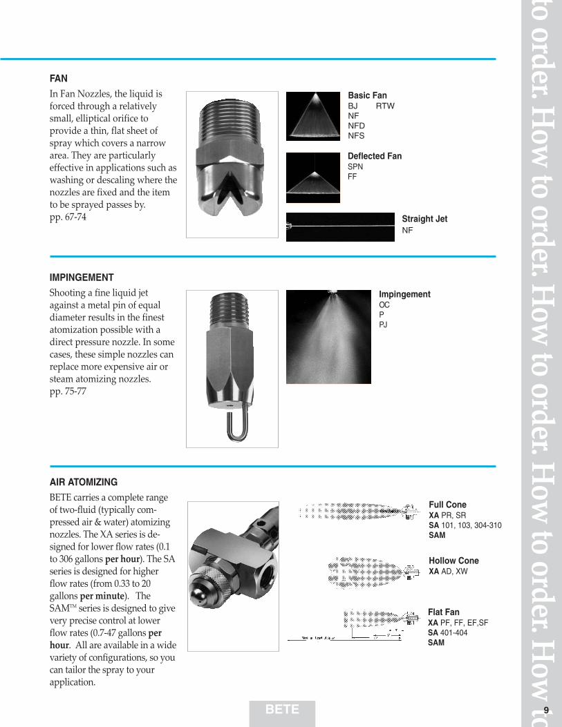
FAN
In Fan Nozzles, the liquid isforced through a relativelysmall, elliptical orifice toprovide a thin, flat sheet ofspray which covers a narrowarea. They are particularlyeffective in applications such aswashing or descaling where thenozzles are fixed and the itemto be sprayed passes by.pp. 67-74
Basic FanBJ RTWNFNFDNFS
Deflected FanSPNFF
Straight JetNF
IMPINGEMENT
Shooting a fine liquid jetagainst a metal pin of equaldiameter results in the finestatomization possible with adirect pressure nozzle. In somecases, these simple nozzles canreplace more expensive air orsteam atomizing nozzles.pp. 75-77
ImpingementOCPPJ
AIR ATOMIZING
BETE carries a complete rangeof two-fluid (typically com-pressed air & water) atomizingnozzles. The XA series is de-signed for lower flow rates (0.1to 306 gallons per hour). The SAseries is designed for higherflow rates (from 0.33 to 20gallons per minute). TheSAMTM series is designed to givevery precise control at lowerflow rates (0.7-47 gallons perhour. All are available in a widevariety of configurations, so youcan tailor the spray to yourapplication.
Full ConeXA PR, SRSA 101, 103, 304-310SAM
Hollow ConeXA AD, XW
Flat FanXA PF, FF, EF,SFSA 401-404SAM
9

BETEto o
rder
. How
to o
rder
. How
to o
rder
. How
to o
rder
. How
to
10
ApplicationsChoosing the correct nozzle for your application fromBETE’s 20,000+ products can be daunting. To help,here is a list of some of the more common uses forspray nozzles. Each application is followed by severalBETE nozzle series which have been used in thisapplication. The series used most often is listed first.
The operating pressures, flow rate and spray angleranges are typical for each application. The fulloperating range for each series is generally broader. If you don't see your application, or need advicemaking a nozzle selection, please use our Zap Fax on page 17 or 119.
Color Code:
AbsorptionScrub hydrofluoric acid, ammonia, and other highly soluble gases
AdditivesApply small volumes of a solution onto mov-ing product or into amixture
AerationAerate waste water treatment, fish pondsand impoundment ponds
Air ConditioningCooling air at gas tur-bine inlets
Air and SteamClean or dry productmoving past nozzle;inject gases and odorantsinto process lines; sparg-ing; bubbling
50- 100 psi5- 30 gpm90°-120°
pp. 22, 23
TF
20- 60 psi105- 25 gph20°-60°1- 8.6 scfmpp. 82-98
XA
20- 40 psi30- 150 gpm90°-120°
pp. 22, 23
TF
30- 80 psi120°0.5- 75 scfm
pp. 67-69
NF (S,D)
50- 100 psi5- 30 gpm90°-120°
p. 24
TFXP
60- 100 psi0.35- 1.6 gpm65°-120°
p. 67
NF
20- 40 psi30- 150 gpm90°-120°lumpy liquidsp. 24
TFXP
30- 80 psi145°0.5- 75 scfm
pp. 70, 71
FF
60- 100 psi0.12- 1.6 gpm50°-80°
pp. 72, 73
BJ
10- 40 psi20- 150 gpm90°-120°lumpy liquidspp. 46, 47
MP
30- 80 psi15°- 50°0.5- 75 scfm
p. 74
SPN
Blowoff NozzlesRemove water or dustfrom strips and convey-ors
30- 80 psi120°0.5- 75 scfm
p. 67
NF30- 80 psi120°0.5- 75 scfm
pp. 70, 71
FF30- 80 psi120°0.5- 75 scfm
p. 74
SPN
30- 60 psi20°-60°0.5- 14 scfm
pp. 82-98
XA
Spiral
Whirl
Fan
Impingement
Special
Air Atomizing
60- 1000 psi0.01- 1.4 gpm90°
p. 76
PJ30- 400 psi0.05-2.31 gpm90°
p. 77
OC
7- 15 psi100- 500 gpm90°-120°lumpy liquidspp. 46, 47
MP7- 15 psi100- 500 gpm54°-95°SNBSC avail.pp. 54, 55
TH7- 15 psi100- 500 gpm90°-120°
pp. 34, 35
NC7- 15 psi100- 500 gpm90°-120°metal nozzlepp. 42, 43
SC
1000-3000 psi0.023- 0.076gpm90°p. 66
MW
10- 15 psi20°-70°0.44- 19 scfmpp. 80, 81
SAM
Air NozzleBlowoff nozzle uses com-pressed air only 10- 90 psi
4- 41 scfm
p. 104
FINZ

to order. How
to order. How
to order. How
to order. How
toBETE 11
7-15 psi20- 120 gpm90°-120°lumpy liquidsp. 24
TFXP7-15 psi20- 120 gpm90°-120°
pp. 22, 23
TF3- 15 psi16-90 gpm80°-100°
pp. 54, 55
THCooling:PondCool pond water; heatrecovery
10- 20 psi6- 90 gpm90°
pp. 46, 47
MP5- 20 psi1.70-49.5 gpm
p. 114
SS
CoatingApply thin coatings (wet or dry) on product mov-ing past nozzles
Concrete CuringHumidify concrete tocontrol curing process
Cooling: DelugeProcess cooling for food,chemical and industrialprocesses
Cooling:EvaporativeCool hot (+ 300°F) flue gases prior to entering abaghouse or tempera-ture-sensitive equipment
Cooling:PartsCool hot parts on convey-ors from pre-treatmentovens
20- 60 psi2.9- 70 gph20°0.4-10 scfmpp. 82-98
XA
30- 60 psi0.4- 30 gph20°- 70°0.6- 17 scfmpp. 82-98
XA
10- 20 psi12-250 gpm90°-120°
pp. 22, 23
TF
40- 100 psi0.33- 18 gpm20°-60°25- 137 scfmpp. 78, 79
SA
30- 80 psi0.22- 17 gpm50°-120°
pp. 67-69
NF (S,D)
3-20 psi6-240 gpm90°-120°lumpy liquidspp. 46, 47
MP
10- 60 psi1.25- 219 gpm90°-120°lumpy liquidspp. 46, 47
MP
60- 150 psi1.6- 18 gpm90°-120°
pp. 22, 23
TF
10- 400 psi3-3320 gpm90°-120°lumpy liquidsp. 24
TFXP3- 80 psi0.7- 938 gpm30°-120°lumpy liquidspp. 46, 47
MP10- 200 psi0.5- 44.7 gpm15°-50°
p. 74
SPN
Car Wash NozzlesHigh pressure wash noz-zles used in automatedcar wash units.
Clean in PlaceNozzlesStationary bottle, drumand tank washing noz-zles
Clog-resistantNozzlesWide free passage tospray lumpy, viscous liq-uids with less clogging
60- 100 psi0.014- 0.44gpm90°p. 76
PJ
60- 100 psi0.014- 1.4 gpm90°
p. 76
PJ
5-20 psi0.5- 14 gpm80°-120°
p. 58
WL
10- 60 psi0.13-24.2 gpm90°-120°
p. 58
WL
60-150 psir1.6- 18 gpm90°-120°lumpy liquidsp. 24
TFXP
40- 100 psi0.28- 1.18 gpm90°p. 32
L
60- 200 psi0.33- 5.6 gpm90°
p. 32
L60- 200 psi0.33- 5.6 gpm90°
p. 75
P20- 60 psi2.9- 26 gph20°-60°0.8-12 scfmpp. 82-98
XA
30- 80 psi0.09- 10 gpm25°-80°
pp. 72, 73
BJ
30- 400 psi0.05- 2.31 gpm90°
p. 77
OC
30- 60 psi5.2- 63.0 gpm180°- 270°very compactp. 116
TW40-60 psi13.8- 68 gpm360°lumpy liquidsp. 48
CLUMP40- 60 psi8.4- 121 gpm360°even rinsingp. 29
LEM
3-40 psi4.1- 564 gpm54°-95°SNBSC avail.pp. 54, 55
TH5- 100 psi0.18-15.4 gpm90°-110°
p. 49
WTZ
10- 60 psi2.96- 165 gpm90°-120°metal nozzlepp. 42, 43
SC
3- 200 psi0.014-235 gpm145°
pp. 70, 71
FF
3-20 psi6-240 gpm90°-120°
pp. 34, 35
NC
10- 60 psi0.7- 158 gpm90°-120°
pp. 22, 23
TF10- 60 psi0.7- 158 gpm90°-120°
p. 24
TFXP
10-40 psi5-45 gpm360°high impactp. 109
RTW20- 60 psi20- 75 gpm360°
pp. 112, 113
SM
40- 60 psi1.0- 102 gpm120°
p. 67
NF40- 60 psi1.0-102 gpm105°-145°
pp. 70, 71
FF40- 60 psi1.0-102 gpm35°- 50°
p. 74
SPN
10-15 psi20°-70°0.44- 19 scfmpp. 80, 81
SAM
1000-3000 psi0.023- 0.076gpm90°p. 66
MW
1000-3000 psi0.023- 0.076gpm90°p. 66
MW

BETEto o
rder
. How
to o
rder
. How
to o
rder
. How
to o
rder
. How
to
12
3-20 psi3-3500 gpm90°-120°plastic nozzlepp. 34, 35
NC
30- 80 psi1.2-11.4 gpm90°-120°
pp. 22, 23
TF
30- 80 psi1.2-11.4 gpm90°-120°
pp. 22, 23
TF
3- 20 psi1-510 gpm90°-120°lumpy liquidspp. 46, 47
MP
30-80 psi5.2- 11.4 gpm90°-120°lumpy liquidsp. 24
TFXP
30-80 psi5.2- 11.4 gpm150°wide coveragepp. 22, 23
TF150
3- 20 psi2-422 gpm90°-120°metal nozzlepp. 42, 43
SC
40- 80 psi2.4-12.5 gpm90°-120°lumpy liquidspp. 46, 47
MP
40- 80 psi2.4-12.5 gpm90°-120°lumpy liquidspp. 46, 47
MP
1- 10 psi217- 3500 gpm60°-120°
p. 41
TC
30- 80 psi5.2- 15 gpm150°wide coveragepp. 22, 23
TF150
30- 80 psi1.2-11.4 gpm90°-120°lumpy liquidsp. 24
TFXP
0.5-10 psi0.5-115 gpmused in pairslumpy liquidsp. 105
IS
40- 80 psi0.28-3.42 gpm90°very fine dustp. 32
L
30- 80 psi5.2-15 gpm170°wide coveragepp. 22, 23
TF170
5-20 psi1.1- 15 gpm90°-120°
p. 58
WL
40- 80 psi0.067-3.83 gpm90°very fine dustp. 75
P
40- 100 psi0.28-3.83 gpm90°transfer pointp. 32
L
DistributionDistribute fluids uni-formly onto packing,trickle bed media, andhorticultural beds; VOCstripping
Dust Control: Air-Handling DuctsSuppress stone, coal andother dust in vent ducts;control paint spraycarry-over
Dust Control: AreaSuppress dust at con-veyor transfer points,dump pits and loadinghoppers
Etching:ElectronicsWash and rinse circuitboards and wafers
EZ Change/ 1/4Turn NozzlesQuick change-out nozzle base assemblywith 1/4 turn rampedengagement
10- 40 psi0.12- 43 gpm60°-120°
p. 58
WL10- 40 psi0.5- 4 gpm35°-50°
p. 74
SPN3- 20 psi0.014-3.8 gpm145°
pp. 70, 71
FF
5- 500 psi0.02-43 gpm0°-145°
pp. 100, 101
EZ FF, NF, SPN5- 500 psi0.02- 58 gpm30°-120°
pp. 102, 103
EZ WL, TF, WT
10-40 psi0.12- 7 gpm50°-120°
pp. 67-69
NF (S,D)
40- 120 psi2.6- 70 gpm90°-120°lumpy liquidsp. 24
TFXP40- 120 psi2.6- 70 gpm90°-120°
pp. 22, 23
TF40- 120 psi5.6- 65 gpm90°-120°lumpy liquidspp. 46, 47
MPDisposal: EvaporativeEvaporate tailing pondsor volatile waste
DryingRemove excess waterafter washing or rinsing 40- 80 psi
0.4- 50 scfm
p. 67
NF40- 80 psi0.2- 50 scfm
pp. 70, 71
FF40- 80 psi0.4- 50 scfm
p. 74
SPN10- 90 psi4- 41 scfm
p. 104
FINZ
DebarkingRemove bark from logsprior to pulping 0- 1000 psi
75- 1380 gpm30°-90°
p. 67
NF1000 psi20- 100 gpm35°-50°
p. 74
SPN
1000-3000 psi0.023- 0.076gpm90°p. 66
MW
5- 400 psi0.5- 3320 gpm90°-120°super alloyspp. 22, 23
TF3- 80 psi0.74- 938 gpm90°-120°super alloyspp. 46, 47
MPCorrosionResistantNozzlesCast metal or PTFEnozzles designed formaximum life in
3-100 psi2.0-2150 gpm90°-120°PTFEpp. 34, 35
NC

3- 15 psi1.5- 115 gpm90°-120°lumpy liquidspp. 46, 47
MP
10- 80 psi0.25- 5 gpm145°
pp. 70, 71
FF
5- 20 psi2.8- 14.1 gpm90°-120°
p. 58
WLFoam ControlControl build-up offoam in aeration andsettling basins, mixingvessels and below weirsand spillways
30- 60 psi0.4- 60 gph20°-40°0.6- 17 scfmpp. 82-98
XA
10- 100 psi0.4- 60 gph60°-120°
pp. 82-98
XA
60- 200 psi0.014- 0.63gpm90°p. 76
PJ
5- 15 psi60-650 gpm90°-120°recycle slurryp. 28
STXP5- 15 psi60- 650 gpm90°-120°resist erosionp. 27
ST3- 20 psi52- 510 gpm90°-120°recycle slurrypp. 46, 47
MP
3- 80 psi0.74- 938 gpm30°-120°
pp. 46, 47
MP
3- 30 psi45- 610 gpm90°-120°SNBSC avail.pp. 54, 55
TH3- 20 psi11- 422 gpm90°-120°plastic nozzlepp. 34, 35
NC3- 20 psi24- 345 gpm90°-120°metal nozzlepp. 42, 43
SC
60- 200 psi0.014- 0.63gpm90°p. 76
PJ80- 200 psi2- 6 gpm120°hollow conepp. 22, 23
TF
10- 400 psi3-3320 gpm90°- 120°
p. 24
TFXP
10- 100 psi1- 20 gpm90°-120°hollow conepp. 22, 23
TF
80- 200 psi2- 6 gpm90°
p. 32
L60- 100 psi0.3- 15 gpm20°-60°71-186 scfmpp. 78, 79
SA
40- 100 psi0.1- 20 gpm20°
pp. 78, 79
SA
60- 200 psi0.084- 1.36gpm90°p. 77
OCHumidificationHumidify air in ducts,drying kilns, curingrooms, greenhouses andother open areas; areamisting
Large FreePassage NozzleClog-resistant; allowlumpy viscous liquids topass easily
Fog NozzlesFine atomization mist-ing; movie special effects
Food ProcessingApplying flavorants orcolorants
Gas ScrubbingSpray reagent into gas
7- 20 psi40- 120 gpm90°-120°lumpy liquidsp. 25
TFXP
60- 150 psi52- 300 gpm90°-120°lumpy liquidsp. 24
TFXP
50- 150 psi52- 340 gpm90°-120°FM approvedpp. 30, 31
N
60- 150 psi52- 300 gpm90°-120°
pp. 22, 23
TF
60- 150 psi52- 340 gpm90°-120°FM approvedpp. 30, 31
N
50- 150 psi52- 300 gpm180°wide coveragep. 26
TF29-180
60- 150 psi52- 300 gpm150°wide coveragepp. 22, 23
TF150
60- 120 psi47- 178 gpm90°-120°lumpy liquidspp. 46, 47
MP
40- 100 psi0.3- 19 gpm20°-40°23- 115 scfmpp. 78, 79
SA
60- 150 psi52- 300 gpm170°horiz. spraypp. 22, 23
TF170
60- 150 psi52- 300 gpm150°wide coveragepp. 22, 23
TF150
40- 200 psi116- 327 gpm80°-120°
p. 59
CW
20- 80 psi17- 150 gpm145°wall wettingpp. 70, 71
FF
Fire Protection: SpecialProtect coal conveyors,fueling and vulcanizingcabinets, warehousesand munitions storage
Fire Protection: Water WallProtect personnel, evacu-ation muster areas,equipment and structuresfrom heat radiation
Fire Protection:DelugeProtect offshore plat-forms, storage tanks,hazardous loading areas,and equipment bays
60- 120 psi20-195 gpm90°-120°
pp. 67-69
NF (S,D)
60- 150 psi116- 327 gpm150°lumpy liquidp. 25
TFXPW
3- 20 psi1.7- 98 gpm90°-120°
pp. 42, 43
SC
10- 60 psi0.3- 29 gph20°-40°
pp. 82-98
XA500- 2000 psi0.5- 7 gpm100°- 110°
p. 117
UM
to order. How
to order. How
to order. How
to order. How
toBETE 13
1000-3000 psi0.023- 0.076gpm90°p. 66
MW
60- 150 psi52- 300 gpm90°-120°lumpy liquidsp. 25
TFXP
1000-3000 psi1.1- 1.9 gpm
p. 107
MWH
1000-3000 psi0.023- 0.076gpm90°p. 66
MW

500- 2000 psi0.5- 7 gpm100°- 110°
p. 117
UM
10- 100 psi7- 12700 gpm
p. 115
TM
10- 100 psi7- 1220 gpm30°plastic nozzlepp. 38, 39
NCJ/K
MistingMoisten paper; mist pro-duce; compost piles ofcrushed products
MixingKeep solids suspendedby injection
Mixing EductorsKeep solids suspendedby eduction
MoisteningWetting, humidifyingproducts on conveyor
Odor ControlSpray odor neutralizingagents
PackingDistribute scrubbingliquor in scrubbers orwater in humidifiers
Pollution ControlDistribute slurry inopen towers
3-7 bar0-16 l/h60°-120°
pp. 82-98
XA
40- 100 psi0.4- 100 gph60°-120°
pp. 82-98
XA
7-150 bar0.14-5 l/min90°
p. 76
PJ
100- 200 psi0.04- 1 gpm90°
p. 76
PJ
40- 100 psi0.7- 100 gph60°-120°
pp. 82-98
XA100- 2000 psi0.04- 1 gpm90°
p. 76
PJ40- 400 psi1- 20 gpm90°- 120°
pp. 22, 23
TF
3-30 bar0.7-30 l/min90°
p. 75
P
Mist EliminatorWashClean mist eliminatorsin packed or open towerscrubbers
20- 50 psi3- 40 gpm90°
pp. 34, 35
NC20- 50 psi3- 40 gpm90°
pp. 46, 47
MP2- 50 psi0.25- 10 gpm90°-120°
p. 58
WL
3- 20 psi3- 3500 gpm120° plastic nozzlepp. 34, 35
NC3- 20 psi1- 510 gpm90°- 120°lumpy liquidspp. 46, 47
MP20- 50 psi0.25- 10 gpm90°-120°
p. 58
WL3- 20 psi2- 422 gpm90°-120°metal nozzlepp. 42, 43
SC1- 10 psi217- 3500 gpm60°-120°metal nozzlep. 41
TC0.5- 10 psi0.5- 115 gpmused in pairslumpy liquidsp. 105
IS
60- 500 psi0.05- 44 gpm0°-60°
p. 106
LP60- 200 psi0.084- 1.36gpm90°p. 77
OC
4-15 bar3.3-6.4 l/min90°
p. 77
OC
BETEto o
rder
. How
to o
rder
. How
to o
rder
. How
to o
rder
. How
to
14
5- 15 psi60- 650 gpm90°-120°RBSC availablep. 28
STXP5- 15 psi60-650 gpm90°-120°RBSC availablep. 27
ST3- 20 psi52- 510 gpm90°-120°recycle slurrypp. 46, 47
MP3- 30 psi45- 610 gpm90°-120°SNBSC avail.pp. 54, 55
TH3- 20 psi11- 422 gpm90°-120°plastic nozzlepp. 34, 35
NC3- 20 psi24- 345 gpm90°-120°metal nozzlepp. 42, 43
SC
1000-3000 psi0.023- 0.076gpm90°p. 66
MW
1000-3000 psi0.023- 0.076gpm90°p. 66
MW
1000-3000 psi0.023- 0.076gpm90°p. 66
MW50-100 psi0.3- 15 gpm20°-60°18-113 scfmpp. 78, 79
SA
20- 60 psi1.5- 25 gph20°-60°1.0- 8.6 scfmpp. 82-98
XALubricationLubricate dies andmoulds; roll bite in stripmills
60- 100 psi0.4- 2 gpm65°- 120°
pp. 67-69
NF (S,D)60- 1000 psi0.1- 2 gpm50°- 80°
pp. 72, 73
BJ

50- 100 psi1.4- 15 gpm20°-60°37-186 scfmpp. 78, 79
SA
200- 3500 psi8.9- 1570 gph50°- 80°
pp. 60- 63
TD
40- 60 psi0.7- 44 gph20°-40°1.5-22 scfmpp. 82-98
XA
15- 40 psi4.2- 30 gph70°-75° pp. 64, 65
TDL
60- 150 psi0.12- 15 gpm80°-130°
pp. 50, 51
WT
5- 500 psi3.5- 1000 gpm30°- 60°
p. 106
LP
20- 100 psi20- 105 gpm145°wide coveragepp. 70, 71
FF
Scrubbing: DryInject lime slurry; injectfood and chemical prod-uct into spray dryer
Self CleaningNozzles/ ShowersClean webs in papermills, wash or rinse steelstrip or conveyor belts
Street Flushing &CleaningHigh impact wash down,clear loose debris fromstreets; walkways
Spray DryingProcessing of milk, otherfoods and chemical prod-ucts
20- 100 psi2- 20 gpm15°-50°high impactp. 74
SPN20- 1000 psi20- 200 gpm50°-90°
p. 67
NF
5- 15 psi60- 650 gpm90°-120°recycle slurryp. 28
STXP5- 15 psi60- 650 gpm90°-120°resist erosionp. 27
ST
Scrubbing:Direct ContactSpray water or reagentslurry into open tower;flue gas desulphuriza-tion
30- 60 psi0.4- 30 gph20°-40°0.8-22 scfmpp. 82-98
XA60- 200 psi0.014- 0.63gpm90°p. 76
PJ80- 200 psi0.4- 1.8 gpm90°
p. 32
L60- 100 psi0.3- 15 gpm20°-60°49-124 scfmpp. 78, 79
SA
30- 100 psi0.3- 20 gpm37-115 scfm20°-90°pp. 78, 79
SA
Scrubbing:ConditioningInject ammonia or waterupstream of electrostaticprecipitators; inject odorcontrol additives
Pulp BleachingWall wash bleachingtanks
QuenchEvaporatively quenchhot gases
Roll CoolingCool rolls in steel stripmills
20- 60 psi0- 50 gpm105°-145°
pp. 70, 71
FF40- 100 psi1- 10 gpm20°-60°
p. 67
NF
40- 100 psi0.5- 10 gpm60°-120°
pp. 67-69
NF
30- 100 psi0- 50 gpm21-112 scfm20°-90°pp. 78, 79
SA
to order. How
to order. How
to order. How
to order. How
toBETE 15
5- 15 psi60- 650 gpm90°-120°recycle slurryp. 28
STXP5- 15 psi60- 650 gpm90°-120°resist erosionp. 27
ST3- 20 psi52- 510 gpm90°-120°recycle slurrypp. 46, 47
MP3- 30 psi45- 610 gpm90°-120°SNBSC avail.pp. 54, 55
TH3- 20 psi11- 422 gpm90°-120°plastic nozzlepp. 34, 35
NC3- 20 psi24- 345 gpm90°-120°metal nozzlepp. 42, 43
SC
1000-3000 psi0.023- 0.076gpm
p. 66
MW
60- 150 psi0.12- 15 gpm70°-140°
pp. 52, 53
WTX
1000-3000 psi1.1- 1.9 gpm
p. 107
MWH
3500-10000 psi70°-75° pp. 60- 63
TD-K

10- 80 psi3- 72 gpm210°very compactp. 116
TW10- 80 psi3- 135 gpm150°wide coveragep. 23
TF15010- 40 psi7.52- 57 gpm360°lumpy liquidsp. 48
CLUMPWashing: TankRinsing and solventcleaning of tanks, drumsand process equipment
Washing: Dairy and FoodProductsRinsing and cleaning oftanks, drums and foodprocess equipment wheresanitary nozzles arerequired
10- 80 psi8- 140 gpm360°even rinsingp. 29
LEM10- 40 psi4- 45 gpm360°high impactp. 109
RTW
20- 80 psi0.7- 16 gpm35°-95°
pp. 110, 111
SF
10- 60 psi21- 76 gpm360°
pp. 112, 113
SM
10- 60 psi0.37- 24.5 gpm90°-120°p. 58
WL10- 40 psi3.6- 38 gpm60°-120°plastic nozzlepp. 34, 35
NC10- 40 psi3- 44 gpm60°-120°metal nozzlepp. 42, 43
SCWashing:PartsHigh impact parts wash-ing and surface prepara-tion
10- 80 psi2- 28 gpm15°-50°high impactp. 74
SPN20- 80 psi0.18- 28 gpm65°-120°
pp. 67-69
NF (S,D)
20- 60 psi1.7- 15.8 gpm60°-120°lumpy liquidspp. 46, 47
MP15- 40 psi4.2- 30 gpm60°-120°plastic nozzlepp. 34, 35
NC20- 80 psi0.18- 28 gpm80°-120°
p. 58
WL15- 40 psi4.5- 32 gpm60°-120°metal nozzlepp. 42, 43
SCWashing:IntermittentPeriodic wash down ofmist eliminator, filterpads, sieve screens anddistribution plates
5- 500 psi0.02- 43 gpm0°-145°
pp. 100, 101
EZ FF, NF, SPN5- 500 psi0.02- 58 gpm30°-120°
pp. 102, 103
EZ WL, TF, WT
BETEto o
rder
. How
to o
rder
. How
to o
rder
. How
to o
rder
. How
to
16
7- 40 psi2.8- 42 gpm90°-120°lumpy liquidsp. 24
TFXP3- 40 psi0.68- 38 gpm60°-120°lumpy liquidspp. 46, 47
MP3- 60 psi0.4- 29 gpm145°wide coveragepp. 70, 71
FF40- 60 psi0.28- 3 gpm90°transfer pointp. 32
LWashing:ConveyorWash coal, sand, graveland crushed rock; pre-wetto reduce dust at hoppersand transfer points
10- 80 psi2- 28 gpm15°-50°high impactp. 74
SPN5- 60 psi1.4- 449 gpm65°-120°
pp. 67-69
NF

to order. How
to order. How
to order. How
to order. How
toBETE
BETE Fog Nozzle, Inc.Application Intake Sheet
Sketch a simple representation of the application below:
Name:
Telephone:
FAX: email:
Company:
Company Address:
BETE Cust. #
• What is the piping material?
• What liquid is being sprayed?
• What are the environmental conditions surrounding thenozzle?
• What is the available pressure?
• What is the desired spray angle or coverage?
• What is the desired material of construction?
17
FAX: 413 772-6729
• What is the desired flow rate?
• What is the flow rate?
• What are you trying to accomplish with the spray?
• What are the size and connection types desired?
• What is the distance from the nozzle to the target?

BETEto o
rder
. How
to o
rder
. How
to o
rder
. How
to o
rder
. How
to
18
Flow Rate ComparisonTo assist in your selection of the correct nozzle foryour needs, the chart on these two pages shows acomparison of the different BETE nozzle seriesavailable for different pipe sizes and flow rates.
Each nozzle series is color coded to match the tabsthroughout the catalog. The darker shading indicatesthe flow rates at 40 psi.
Pipe FLOW RATES IN GALLONS PER MINUTESize 0.01 0.1 1.0 10 100
L p. 32
1/8"WL p. 58
WT pp. 50, 51
PJ p. 76FF pp. 70, 71
NF p. 67XA pp. 82-98
TF pp. 22, L p. 32
CW p. 59WL p. 58
1/4" WT pp. 50, 51
P p. 75BJ pp. . 72, 73
FF pp. 70, 71SPN p. 74
NF p. 67NFD p. 68NFS p. 69
XA pp. 82-98TF pp. 22, 23
MP pp. 46, 47WL p. 58
3/8" WT pp. 50, 51
BJ p. 72, 73FF pp. 70, 71
SPN p. 74NF p. 67
TF pp. 22, 23N pp. 30, 31
MP pp. 46, 47
1/2" WL p. 58WT pp. 46, 47
FF pp. 70, 71SPN p. 74NF p. 67
XA pp. 82-98 TF pp. 22, 23
MP pp. 46, 47SC pp. 42, 43
NC pp. 34, 35WL p. 58
3/4" WT pp. 50, 51FF pp. 70, 71
SPN p. 74NF p. 67
NFD p. 68NFS p. 69
SS p. 114
Pipe 0.01 0.1 1.0 10 100Size FLOW RATES IN GALLONS PER MINUTE
23
TF pp. 22, 23
MW p. 66
MW p. 66
MW p. 66
Spiral Whirl Impingement Fan Air Atomizing

to order. How
to order. How
to order. How
to order. How
toBETE 19
FLOW RATES IN GALLONS PER MINUTE Pipe1.0 10 100 1,000 10,000 Size
TF pp. 22, 23N pp. 30, 31
MP pp. 46, 47SC pp. 42, 43NC pp. 34, 35 1"WL pp. 58
TH pp. 54, 55 FF pp. 70, 71
NF p. 67SA pp. 78, 79
SS p. 114MP pp. 46, 47
SC pp. 42, 43NC pp. 34,35 1 1/4"
TH pp. 54, 55NF p. 67
NFD p. 68NFS p. 69
SS p. 114TF pp. 22, 23N pp. 30,31
MP pp 46, 47SC pp. 42, 43 1 1/2"
NC pp. 34, 35TH pp. 54, 55
NF p. 67SA
TF pp. 22, 23MP pp. 46, 47
SC pp. 42, 43 2"NC pp. 34, 35
TH pp. 54, 55NF p. 67
MP pp. 46, 47SC pp. 42, 43NC pp. 34, 35 2 1/2"
TH pp. 54, 55TF pp. 22, 23
MP pp. 46, 47SC pp. 42, 43 3"
NC pp. 34, 35TH pp. 54, 55
TF pp. 22, 23MP pp. 46, 47 4"SC pp. 42, 43NC pp. 34, 35
NC pp. 34, 35 6"TC p. 41
NC pp. 34, 35 8"TC p. 41
NC pp. 34, 35 12"TC p. 41
1.0 10 100 1,000 10,000 PipeFLOW RATES IN GALLONS PER MINUTE Size
Spiral Whirl Impingement Fan Air Atomizing

BETEto o
rder
. How
to o
rder
. How
to o
rder
. How
to o
rder
. How
to
BETE manufactures nozzles in hundreds ofdifferent materials and combinations ofmaterials. The chart on the bottom of these twopages shows which nozzles are readilyavailable in the materials most often specified.If you don’t know which material is best foryour application, BETE ApplicationsEngineering can help you with your selection.Some factors which influence thenozzle material selection processare:Temperature: Melting orsoftening of materialestablishes maximumtemperature limits.However, these temperaturelimits must be reduced whencorrosion, oxidation, orchemical attack are alsopresent. See column in bluefor general temperature limitsfor various materials.Corrosion. Plastics offersuperior corrosion resistanceat relatively low cost, but canonly be used in low-temperature applications. Ingeneral, metals can be rankedin the following order ofcorrosion resistance (fromlowest to highest): cast iron,brass, stainless steels, nickel-based alloys, refractorymetals and precious metals.Ceramics have excellentcorrosion resistance except invery high pH environments.Chemical attack. There arefew general guidelines to thiscomplex subject, but thematerial used for piping mayprovide a useful indicator of asuitable nozzle material. Ifthe environment of yourapplication is known tocontain substances whichmay attack the spray nozzle,
contact BETE Applications Engineeringfor advice.Abrasion. Hardened Stainless Steel,Cobalt Alloy 6, tungsten carbide andceramics are commonly used inapplications where abrasive fluids aresprayed.
Cost. There are exceptions, but materials can generally be ranked in thefollowing order in terms of cost (fromlowest to highest): brass, cast iron,plastics, stainless steels, cobalt-basedalloys, nickel-base alloys, ceramics,
Materials
The following are registered trademarks: Teflon®,Viton® (E.I. DuPont de Nemours & Co.); Hastelloy®(Haynes International, Inc.); Incoloy®, Monel® (TheInternational Nickel Company, Inc.); Inconel® (IncoNickel Sales, Inc.); Kynar® (Penwalt Corporation);REFRAX® (Carborundum Company); Stellite®(Stoody Deloro Stellite, Inc.); Nitronic® (Armco SteelCo.); and M&M (Mars, Inc.) The BETE logo andMaxiPass are registered trademarks of BETE FogNozzle, Inc. ©BETE Fog Nozzle, Inc.
20
BETE Temp. U.S. ASTM or U.S. Material Material (DIN) Rating Trade AMS Cast ASTM Bar Description No. (MN) Description (° F) Name* Specification Specification
Brass 4 Messing 450° B30 C85700 B16 C36000Naval Brass 64 750° B21 C46400Bronze 1E Bronze 750° B30 C95400 B103 C54400L.C. Steel 72 C-Stahl 400° A108 Gr 12L14Cast Iron 28 Gusseisen 450°218 4K 1800° Nitronic 60 A276 S21800303 5 1.4305 800° A 743 CF-16F A582 S30300304 6 1.4301 800° A 743 CF-8 A276 S30400304L 1.4306 800° A 743 CF-3 A276 S30403Duplex 2205 2X 600° A 890 J92205 A276 S32205316 7 1.4401 800° A 743 CF-8M A276 S31600Tungsten Carbide 7HAlumina 26Boron Carbide 7P 1500°316L 20 1.4404 800° A 743 CF-3M A276 S31603317 21 1.4440 800° A 743 CG-8M A276 S31700317L 22 1.4438 800° A 743 CG-3M A276 S31725416 1.4005 800° A582 S41600904L 74 1.4539 800°Alloy 20 70 2.4660 900° Carpenter® 20 A 743 CN-7M B473 N08020Nickel Alloy M30C 37 2.4360/2.4366 1000° Monel® A 494 M-30C B164 N04400Nickel Alloy 600 35 2.4816 2000° Inconel® 600Nickel Alloy 625 3B 2.4856 2000° Inconel® 625 AMS 5402 B446 N06625Nickel Alloy 800 33 1.4876 1850° Incoloy® 800 B408 N08800Nickel Alloy 825 2.4858 1850° Incoloy® 825 B425 N08825Nickel Alloy B 31 2.4800/2.4810 1400° Hastelloy® B A 494 N-12MV B335 N10665
w/2.5 Max. CoNickel Alloy G 32 2.4619 2000° Hastelloy® G B 581 N06007 B581 N06007Nickel Alloy G30 49 2.4603 2000° Hastelloy® G30 B581 N06030Nickel Alloy C276 81 2.4819 2000° Hastelloy® C276 A 494 CW-2M B574 N10276Nickel Alloy C22 2A 2.4602 2000° Hastelloy® C22 A 494 CX-2MW B574 N06022Nickel 38 Nickel 650° B160 N02200Titanium 11 Titan 900° B348 Gr 2Tantalum 40 Tantal 2700° B708 R05200Zirconium 61 Zirkonium 1000° B550 R60702Cobalt Alloy 6 9 1900° Stellite® 6 AMS 5387SNBSC ceramic 62 3000° Refrax®RBSC ceramic 59 2500°PTFE 3 PTFE 300° Teflon® D1710 G1, T2, CA PVDF 36 PVDF 245° Kynar® D3222 Tp 1, Cl 2 PVC 1 PVC 135°CPVC 16 CPVC 185°Polypropylene 2 Polypropylen 155°UHMW 17 180°Polyurethane 69 176°ABS 15 155°* BETE does not represent that it manufactures its products with materials sold under any of these brand names. Customers sometimes ask for BETE
products without using a USA standard specification for the material they require. When materials are described incompletely, with DIN specifications or with a
commonly used brand name, BETE will usually supply materials according to the USA specifications listed above. Specifications for forms other than cast or
bar may differ from the above.

BETE
Materials by Nozzle TypeThe chart below shows the most common materialsused for different types of nozzles – as indicated bya solid dot ( ), as well as those materials that areused less often – as indicated by an open dot ( ) (allsizes may not be available in “open dot” materials.)While nozzles in many of these materials would be
considered “specials” by other companies, we cantypically deliver them within “standard” schedulesand at very competitive prices, thanks to our in-house foundry and state-of-the-art CNCmachining capabilities.
21
BBJJ CCWW EEZZ NNFFFF IISSSSSS
NNCCSSQQNNCCSSNNCCFFLLNNCC
LL NNCCKKNNCCJJ
NNFFSSNNFF
OOCC PPJJPP
PPSSRR SSAA TTWW WWLL WWTTZZWWTTXXWWTT
XXAASSCCFFLLSSCC
SSPPNN TTCC TTHHWWTTHH
TTFFXXPPWWTTFFXXPPTTFF2299TTFF
SSTTXXPPSSTT
CCaappBBaassee
TTiipp
TTDDLLTTDD
BBooddyyCCaarrrriieerr
WWeeaarrPPaarrttss
LLEEMM MMPPCCLLUUMMPP
BBJJ CCWW EEZZ NNFFFFSSSSIISS
NNCCNNCCFFLLNNCCSS
NNCCSSQQLLNNCCJJNNCCKK
NNFFNNFFSS OOCC
PPPPJJ PPSSRR SSAA TTWW WWLL
WWTTWWTTXXWWTTZZ XXAA
SSCCSSCCFFLL SSPPNN TTCC
TTHHTTHHWW
TTFFTTFF2299TTFFXXPP
TTFFXXPPWW
SSTTSSTTXXPP
CCaappBBaassee TTiipp
TTDDTTDDLL
BBooddyyCCaarrrriieerr
WWeeaarrPPaarrttssLLEEMM
CCLLUUMMPPMMPP
MMWWHHMMWW
MMWWMMWWHH

SP
IRA
L
BETE
TO O
RD
ER:s
peci
fy p
ipe
size
, con
nect
ion
type
,no
zzle
num
ber,
spra
y an
gle,
and
mat
eria
l.
22
TF
TF Full Cone Flow Rates and DimensionsFull Cone, 60˚ (NN), 90˚ (FCN or FFCN), 120˚ (FC or FFC), 150˚ and 170˚ Spray Angles, 1/8" to 4" Pipe Sizes
Operation above High PSI operation Approx. (in.) Wt. (oz.)
Male Available GALLONS PER MINUTE @ PSI60 PSI not recom.
for PTFErecom. for Metal
Only Free Dim. (in.) for 60˚ 90˚
Pipe Nozzle Spray Angles K 5 10 20 30 40 50 60 80 100 200 400 Orif. Pass. Metal Only* 120˚Size Number 60˚ 90˚ 120˚150˚170˚ Factor PSI PSI PSI PSI PSI PSI PSI PSI PSI PSI PSI Dia. Dia. A B C Metal Plas.
1/8TF6 60˚ 90˚ 120˚ 0.221 0.495 0.70 0.99 1.21 1.40 1.57 1.71 1.98 2.21 3.13 4.43 0.09 0.09 1.69 0.56
1.00 0.20TF8 60˚ 90˚ 120˚ 0.411 0.919 1.30 1.84 2.25 2.60 2.91 3.18 3.68 4.11 5.81 8.22 0.13 0.13
1/4TF6 60˚ 90˚ 120˚ 0.221 0.495 0.70 0.99 1.21 1.40 1.57 1.71 1.98 2.21 3.13 4.43 0.09 0.09
1.88 0.56 1.25 0.20TF8 60˚ 90˚ 120˚ 0.411 0.919 1.30 1.84 2.25 2.60 2.91 3.18 3.68 4.11 5.81 8.22 0.13 0.13TF10 60˚ 90˚ 120˚ 0.632 1.41 2.00 2.83 3.46 4.00 4.47 4.90 5.66 6.32 8.94 12.6 0.16 0.13
3/8
TF6 60˚ 0.221 0.495 0.70 0.99 1.21 1.40 1.57 1.71 1.98 2.21 3.13 4.43 0.09 0.09
1.88 0.69 2.38 1.63 0.25
TF8 60˚ 0.411 0.919 1.30 1.84 2.25 2.60 2.91 3.18 3.68 4.11 5.81 8.22 0.13 0.13
TF10 60˚ 0.632 1.41 2.00 2.83 3.46 4.00 4.47 4.90 5.66 6.32 8.94 12.6 0.16 0.13TF12 60˚ 90˚ 120˚ 150˚ 170˚ 0.949 2.12 3.00 4.24 5.20 6.00 6.71 7.35 8.49 9.49 13.4 19.0 0.19 0.13TF14 60˚ 90˚ 120˚ 150˚ 170˚ 1.28 2.86 4.05 5.73 7.01 8.10 9.06 9.92 11.5 12.8 18.1 25.6 0.22 0.13
TF16 60˚ 90˚ 120˚ 150˚ 170˚ 1.68 3.75 5.30 7.50 9.18 10.6 11.9 13.0 15.0 16.8 23.7 33.5 0.25 0.13TF20 60˚ 90˚ 120˚ 150˚ 170˚ 2.61 5.83 8.25 11.7 14.3 16.5 18.4 20.2 23.3 26.1 36.9 52.2 0.31 0.13
1/2TF24 60˚ 90˚ 120˚ 150˚ 170˚ 3.81 8.52 12.1 17.0 20.9 24.1 26.9 29.5 34.1 38.1 53.9 76.2 0.38 0.19
2.50 0.88 3.06 3.00 0.50TF28 60˚ 90˚ 120˚ 150˚ 170˚ 5.22 11.7 16.5 23.3 28.6 33.0 36.9 40.4 46.7 52.2 73.8 104 0.44 0.19
3/4 TF32 60˚ 90˚ 120˚ 150˚ 170˚ 6.64 14.8 21.0 29.7 36.4 42.0 47.0 51.4 59.4 66.4 93.9 133 0.50 0.19 2.75 1.13 3.50 5.50 0.88
1TF40 60˚ 90˚ 120˚ 150˚ 170˚ 10.6 23.7 33.5 47.4 58.0 67.0 74.9 82.1 94.8 106 150 212 0.63 0.25
3.63 1.38 4.38 8.50 2.50TF48 60˚ 90˚ 120˚ 150˚ 170˚ 15.0 33.6 47.5 67.2 82.3 95.0 106 116 134 150 212 300 0.75 0.25
1 1/2TF56 60˚ 90˚ 120˚ 150˚ 170˚ 20.4 45.6 64.5 91.2 112 129 144 158 182 204 288 408 0.88 0.31
4.38 2.005.38
22.0 4.25TF64 60˚ 90˚ 120˚ 150˚ 170˚ 26.7 59.7 84.5 120 146 169 189 207 239 267 378 534 1.00 0.31 5.38TF72 60˚ 90˚ 120˚ 150˚ 170˚ 30.4 67.9 96.0 136 166 192 215 235 272 304 429 607 1.13 0.31 5.63
2TF88 90˚ 120˚ 150˚ 170˚ 44.3 99.0 140 198 242 280 313 343 396 443 626 885 1.38 0.44 5.63 2.50 5.88 46.0 8.00TF96 1 90˚ 120˚ 150˚ 170˚ 55.9 125 177 250 306 354 395 433 500 559 791 1120 1.50 0.44 6.88 2.50 7.00 54.0 9.00
3TF112 1 90˚ 120˚ 81.0 181 256 362 443 512 572 627 724 810 1150 1620 1.75 0.56
8.63 3.50 114 20.0TF128 1 90˚ 120˚ 107 239 339 480 588 679 759 831 960 1070 1510 2150 2.00 0.56
4 TF160 1 90˚ 120˚ 166 371 525 742 909 1050 1170 1290 1480 1660 2350 3320 2.50 0.63 10.1 4.50 169 27.0
Flow Rate (GPM ) = K √⎯⎯⎯⎯PSI *Dimensions are for bar stock, cast sizes may vary. 1 Three turn nozzles
Standard Materials: Brass, 316 Stainless Steel, PVC, Polypropylene and PTFE (Poly. not available for TF6 thru TF10). See chart on page 21 for complete list.
60˚60˚
60˚60˚
60˚
150˚ 170˚150˚ 170˚
150˚ 170˚150˚ 170˚
150˚ 170˚ 1.88 0.56 1.882.382.381.88 0.56
1.692.191.69 0.56
Wide Range of Flows and Angles
DESIGN FEATURES• The original spiral nozzle invented by
BETE and continuously improved!• High energy efficiency• One-piece/no internal parts• Clog-resistant performance• High discharge velocity• Male connection standard; female
connection available by special order
SPRAY CHARACTERISTICS• Wide range of flow rates and spray
angles• Fine atomizationSpray patterns: Full and Hollow ConeSpray angles: 50° to 180°Flow rates: 0.5 to 3320 gpm(Higher flow rates available)
Full Cone 90° (FCN) Full Cone 150°/170° 60°, 90°, 120° 150°, 170°Full Cone 60° (NN)
60°, 90°, 120° Metal

SP
IRA
L
23
CA
LL 413-772-2166C
all for the name of your nearest B
ET
E representative.
TF Hollow Cone Flow Rates and DimensionsHollow Cone, 50˚ (N), 60˚ (V), 90˚ (M), 120˚ (W), and 180˚ (XW) Spray Angles, 1/4" to 4" Pipe Sizes
AvailableOperation above High PSI operation Approx. (in.)
Male Spray GALLONS PER MINUTE @ PSI 60 PSI not recom. for
PTFErecom. for Metal
Only Free Dim. (in.) for Wt. (oz.)
Pipe Nozzle Angles K 5 10 20 30 40 50 60 80 100 200 400 Orif. Pass. Metal Only* 180˚Size Number 50˚ 60˚ 90˚ 120˚ 180˚ Factor PSI PSI PSI PSI PSI PSI PSI PSI PSI PSI PSI Dia Dia. A B C Metal Plas.
1/4TF6 50˚ 60˚ 90˚ 120˚ 0.221 0.495 0.70 0.99 1.21 1.40 1.57 1.71 1.98 2.21 3.13 4.43 0.09 0.09 1.88 0.56
1.25 0.25TF8 50˚ 60˚ 90˚ 120˚ 180˚ 0.411 0.919 1.30 1.84 2.25 2.60 2.91 3.18 3.68 4.11 5.81 8.22 0.13 0.13 1.88 0.56 1.88TF10 50˚ 60˚ 90˚ 120˚ 180˚ 0.632 1.41 2.00 2.83 3.46 4.00 4.47 4.90 5.66 6.32 8.94 12.6 0.16 0.13 1.88 0.56 1.88
3/8
TF12 50˚ 60˚ 90˚ 120˚ 180˚ 0.949 2.12 3.00 4.24 5.20 6.00 6.71 7.35 8.49 9.49 13.4 19.0 0.19 0.13
1.88 0.69 1.88 1.75 0.25TF14 50˚ 60˚ 90˚ 120˚ 180˚ 1.28 2.86 4.05 5.73 7.01 8.10 9.06 9.92 11.5 12.8 18.1 25.6 0.22 0.13TF16 50˚ 60˚ 90˚ 120˚ 180˚ 1.68 3.75 5.30 7.50 9.18 10.6 11.9 13.0 15.0 16.8 23.7 33.5 0.25 0.13TF20 50˚ 60˚ 90˚ 120˚ 180˚ 2.61 5.83 8.25 11.7 14.3 16.5 18.4 20.2 23.3 26.1 36.9 52.2 0.31 0.13
1/2TF24 50˚ 60˚ 90˚ 120˚ 180˚ 3.81 8.52 12.1 17.0 20.9 24.1 26.9 29.5 34.1 38.1 53.9 76.2 0.38 0.19
2.50 0.88 1 2.38 3.00 0.50TF28 50˚ 60˚ 90˚ 120˚ 180˚ 5.22 11.7 16.5 23.3 28.6 33.0 36.9 40.4 46.7 52.2 73.8 104 0.44 0.19
3/4 TF32 50˚ 60˚ 90˚ 120˚ 180˚ 6.64 14.8 21.0 29.7 36.4 42.0 47.0 51.4 59.4 66.4 93.9 133 0.50 0.19 2.75 1.13 3.00 3.00 1.00
1TF40 60˚ 90˚ 120˚ 180˚ 10.6 23.7 33.5 47.4 58.0 67.0 74.9 82.1 94.8 106 150 212 0.63 0.25
1.38 2 3.63 15.0 3.00TF48 60˚ 90˚ 120˚ 180˚ 15.0 33.6 47.5 67.2 82.3 95.0 106 116 134 150 212 300 0.75 0.25
1 1/2TF56 60˚ 90˚ 120˚ 180˚ 20.4 45.6 64.5 91.2 112 129 144 158 182 204 288 408 0.88 0.31
2.00 4.38 30.0 6.00TF64 60˚ 90˚ 120˚ 180˚ 26.7 59.7 84.5 120 146 169 189 207 239 267 378 534 1.00 0.31
TF72 60˚ 90˚ 120˚ 180˚ 30.4 67.9 96.0 136 166 192 215 235 272 304 429 607 1.13 0.31
2TF88 60˚ 90˚ 120˚ 180˚ 44.3 99.0 140 198 242 280 313 343 396 443 626 885 1.38 0.44 5.63 2.50 5.00 46.0 8.00TF96 60˚ 90˚ 120˚ 180˚ 55.9 125 177 250 306 354 395 433 500 559 791 1120 1.50 0.44 6.88 2.50 5.00 54.0 9.00
3TF112 60˚ 90˚ 120˚ 81.0 181 256 362 443 512 572 627 724 810 1150 1620 1.75 0.56
8.63 3.50TF128 60˚ 90˚ 120˚ 107 239 339 480 588 679 759 831 960 1070 1510 2150 2.00 0.56
4 TF160 60˚ 90˚ 120˚ 166 371 525 742 909 1050 1170 1290 1480 1660 2350 3320 2.50 0.63 10.1 4.50
Flow Rate (GPM ) = K √⎯⎯⎯⎯PSI *Dimensions are for bar stock, cast sizes may vary. 1 1.00 for 180˚ 2 1.63 for 180˚
Standard Materials: Brass, 316 Stainless Steel, PVC, Polypropylene and PTFE (Poly, not available for TF6 thru TF10). See chart on page 21 for complete list.
3.63
4.38
BETE
Hollow Cone 50° (N) Hollow Cone 120° (W) 50°, 60°, 90°, 120° 180°Hollow Cone 180° (XW)
150°, 170° Metal
180° Metal
50° Metal
TF 24 150° available in Factory Mutual approved brass

SP
IRA
L TFXP
TFXP Flow Rates and DimensionsFull Cone, 90˚ (XPN) and 120˚ (XP) Spray Angles, 3/8" to 4" Pipe Sizes
High PSI Operation Approx.
Male GALLONS PER MINUTE @ PSI recom. for Metal Only Free Pass.Approximate
Pipe Nozzle K 10 20 30 40 50 60 80 100 200 400 & OrificeDimensions (in.)
Wt. (lbs.)Size Number Factor PSI PSI PSI PSI PSI PSI PSI PSI PSI PSI Dia. (in.) Metal Plas.
3/8
TF12 0.949 3.00 4.24 5.20 6.00 6.71 7.35 8.49 9.49 13.4 19.0 0.19
0.20 0.04TF14 1.28 4.05 5.73 7.01 8.10 9.06 9.92 11.5 12.8 18.1 25.6 0.22
TF16 1.68 5.30 7.50 9.2 10.6 11.9 13.0 15.0 16.8 23.7 33.5 0.25
TF20 2.61 8.25 11.7 14.3 16.5 18.4 20.2 23.3 26.1 36.9 52.2 0.31
1/2TF24 3.81 12.1 17.0 20.9 24.1 26.9 29.5 34.1 38.1 53.9 76.2 0.38
0.41 0.06TF28 5.22 16.5 23.3 28.6 33.0 36.9 40.4 46.7 52.2 73.8 104 0.44
3/4 TF32 6.64 21.0 29.7 36.4 42.0 47.0 51.4 59.4 66.4 93.9 133 0.50 1.56 0.22
1TF40 10.6 33.5 47.4 58.0 67.0 74.9 82.1 94.8 106 150 212 0.63 1.56 0.25
TF48 15.0 47.5 67.2 82.3 95.0 106 116 134 150 212 300 0.75 2.06 0.47
1 1/2
TF56 20.4 64.5 91.2 112 129 144 158 182 204 288 408 0.88 . .5 4.00 0.59
TF64 26.7 84.5 120 146 169 189 207 239 267 378 534 1.00 2.44 0.53
TF72 30.4 96.0 136 166 192 215 235 272 304 429 607 1.13 2.81 0.53
2TF88 44.3 140 198 242 280 313 343 396 443 626 885 1.38 5.12 1.25
TF96 55.9 177 250 306 354 395 433 500 559 791 1120 1.50 6.31 1.25
3TF112 81.0 256 362 443 512 572 627 724 810 1150 1620 1.75** 0 8.37 1.37
TF128 107 339 480 588 679 759 829 960 1070 1510 2150 2.00** 9.75 1.50
4 TF160 166 525 742 909 1050 1170 1290 1480 1660 2350 3320 2.50** . 15.6 1.87
Flow Rate (GPM) = K √⎯⎯⎯⎯PSI **Free passage is 1.5"
Standard Materials: Brass, 316 Stainless Steel, PVC, Polypropylene and PTFE. See chart on page 21 for complete list.
Operation above60 PSI not recom.
for PTFE
.
A B
2.88 0.88
3.50 1.13
5.38 1.75
5.25 2.00
6.63 2.00
6 97 2 0
6.94 2.50
7.41 2.50
10.5 2.63
12. 3.50
12 0 4.50
2.88 0.88
3.12 0.88
2.75 0.88
3.47 1.13
11.0 2.63
11 7 3.50
for Metal Only
BETE
Largest Free Passage
DESIGN FEATURES• Largest free passage in the original
spiral nozzle invented by BETE andcontinuously improved!
• Passes particles equal to orifice size• Clog-resistant• One-piece, extra heavy construction• High energy efficiency• Male connection
SPRAY CHARACTERISTICS• Wide range of flow rates• Fine atomizationSpray pattern: Full Cone(Hollow Cone available by special order)
Spray angles: 90° and 120°Flow rates: 3.0 to 3320 gpm
24
Full Cone 90° (XPN) Full Cone 120° (XP) Metal Plastic
TO O
RD
ER:s
peci
fy p
ipe
size
, con
nect
ion
type
,no
zzle
num
ber,
spra
y an
gle,
and
mat
eria
l.
Metal Plastic

25
CA
LL 413-772-2166C
all for the name of your nearest B
ET
E representative.
BETE
FireBeter Large Free Passage
TFXPWDESIGN FEATURES• Two turn spiral nozzle• Large free passage• One-piece extra heavy construction
SPRAY CHARACTERISTICS• Wide coverageSpray pattern: Full ConeSpray angle: 150°Flow rates: 33.6 to 534 gpm
Full Cone 150°
Metal
SPRAY COVERAGE
VER
TIC
AL R
EAC
H (
feet
)
VER
TIC
AL R
EAC
H (
feet
)
-20 -20-15 -15-10 -10-5 -50 05 510 1015 1520 20
1" TF48-150 at 40 psi
0
-10
-20-30 30
1" TF64-150 at 40 psi
0
-10
-20
SPRAY COVERAGE
SP
IRA
L
GALLONS PER MINUTE @ PSI
Male Approx Approx. Approx.Pipe Nozzle K 5 10 20 30 40 50 60 80 100 200 400 Free Pass Orifice Dim.(in.) Wt.Size Number Factor PSI PSI PSI PSI PSI PSI PSI PSI PSI PSI PSI Dia. (in.) Dia. (in.) A B (lbs.)
1 TF48XPW 15.0 33.6 47.5 67.2 82.3 95.0 106 116 134 150 212 300 0.50 0.75 6.50 2.25 2.06
1 1/2 TF64XPW 26.7 59.8 84.5 120 146 169 189 207 239 267 378 534 0.50 1.00 6.75 2.50 2.44
Standard Materials: Brass and 316 Stainless Steel. See chart on page 21 for complete list.
TFXPW Flow Rates and DimensionsFull Cone, 150 Wide Spray Angle, 1" & 1-1/2" Pipe Size
Flow Rate (GPM ) = K √⎯⎯⎯⎯PSI

BETE
TO O
RD
ER:s
peci
fy p
ipe
size
, con
nect
ion
type
,no
zzle
num
ber,
spra
y an
gle,
and
mat
eria
l.
26
FireBeter: Ultra-Wide Full Cone Coverage
TF29-180DESIGN FEATURES• Two turn spiral• Ultra-wide spray coverage very close to
the nozzle• One-piece design/no internal parts• Excellent choice for deluge applications
where there is little distance betweennozzle and material being protected
SPRAY CHARACTERISTICS• Wide spray coverage• Fine atomizationSpray patterns: circular sheet
with maximum coverage and excellentatomization
Spray angle: 180° extra wide angleFlow rates: 3.80 to 110 gpm
Full Cone 180o
Metal
SPRAY COVERAGESPRAY COVERAGEVE
RTI
CAL
REA
CH
(fe
et)
VER
TIC
AL R
EAC
H (
feet
)
-12 -12-10 -10-8 -8-6 -6-4 -4-2 -20 02 24 46 68 810 1012 12
1/2" TF29-18 at 40 psi 1/2" TF29-28 at 40 psi
0 0-2 -2-4 -4-6 -6-8 -8
-10 -10-20 -15 15 20
SP
IRA
L
TF29-180 Flow Rates and DimensionsFull Cone, 180˚ Extra-wide Spray Angle, 1/2" Pipe Size
GALLONS PER MINUTE @ PSI Approx.Free Pass.Male
Pipe Nozzle K 10 20 30 40 50 60 80 100 200 400 & OrificeSize Number Factor PSI PSI PSI PSI PSI PSI PSI PSI PSI PSI Dia. (in.)
TF29-180-16 1.20 3.80 5.37 6.58 7.60 8.50 9.31 10.7 12.0 17.0 24.0 0.203
TF29-180-18 1.90 6.00 8.49 10.4 12.0 13.4 14.7 17.0 19.0 26.8 37.9 0.250
1/2 TF29-180-21 2.29 7.25 10.3 12.6 14.5 16.2 17.8 20.5 22.9 32.4 45.9 0.281
TF29-180-24 3.00 9.50 13.4 16.5 19.0 21.2 23.3 26.9 30.0 42.5 60.1 0.328
TF29-180-28 3.91 12.4 17.5 21.4 24.7 27.6 30.3 34.9 39.1 55.2 78.1 0.375
TF29-180-32 5.50 17.4 24.6 30.1 34.8 38.9 42.6 49.2 55.0 77.8 110 0.438
Standard Materials: Brass and 316 Stainless Steel. See chart on page 21 for complete list.
Flow Rate (GPM ) = K √⎯⎯⎯⎯PSI

27
ST
3-pieceMale or 2-piece
Approx. (in)
Female Female GALLONS PER MINUTE @ PSI Free Wt.
Pipe Pipe Nozzle K 5 10 15 20 30 40 50 60 80 100 200 400 Orifice Pass. Dimensions (in.) (lbs.)Size Size Number Factor PSI PSI PSI PSI PSI PSI PSI PSI PSI PSI PSI PSI Dia. Dia. A B C D E F Male
1/4
ST6 0.221 0.495 0.700 0.857 0.990 1.21 1.40 1.57 1.71 1.98 2.21 3.13 4.43 0.09 0.09 2.56 2.560.19ST8 0.411 0.919 1.30 1.59 1.84 2.25 2.60 2.91 3.18 3.68 4.11 5.81 8.22 0.13 0.13
ST10 0.632 1.41 2.00 2.45 2.83 3.46 4.00 4.47 4.90 5.66 6.32 8.94 12.6 0.16 0.13
3/8
ST12 0.949 2.12 3.00 3.67 4.24 5.20 6.00 6.71 7.35 8.49 9.49 13.4 19.0 0.19 0.13
0.31ST14 1.28 2.86 4.05 4.96 5.73 7.01 8.10 9.06 9.92 11.5 12.8 18.1 25.6 0.22 0.13
ST16 1.68 3.75 5.30 6.49 7.50 9.18 10.6 11.9 13.0 15.0 16.8 23.7 33.5 0.25 0.13
ST20 2.61 5.83 8.25 10.1 11.7 14.3 16.5 18.4 20.2 23.3 26.1 36.9 52.2 0.31 0.13
3/4
ST24 3.81 8.52 12.1 14.8 17.0 20.9 24.1 26.9 29.5 34.1 38.1 53.9 76.2 0.38 0.19
ST28 5.22 11.7 16.5 20.2 23.3 28.6 33.0 36.9 40.4 46.7 52.2 73.8 104 0.44 0.19
ST32 6.64 14.8 21.0 25.7 29.7 36.4 42.0 47.0 51.4 59.4 66.4 93.9 133 0.50 0.19
1ST40 10.6 23.7 33.5 41.0 47.4 58.0 67.0 74.9 82.1 94.8 106 150 212 0.63 0.25 1.25ST48 15.0 33.6 47.5 58.2 67.2 82.3 95.0 106 116 134 150 212 300 0.75 0.25
1 1/2
ST56 20.4 45.6 64.5 79.0 91.2 112 129 144 158 182 204 288 408 0.88 0.31
ST64 26.7 59.8 84.5 103 120 146 169 189 207 239 267 378 534 1.00 0.31
ST72 30.4 67.9 96.0 118 136 166 192 215 235 272 304 429 607 1.12 0.31
22 1/2 ST88 44.3 99.0 140 171 198 242 280 313 343 396 443 626 885 1.37 0.44 7.63 6.31 4.56 3.00 3.50 3.50 5.00
3 ST961 55.9 125 177 216 250 306 354 395 433 500 559 791 1120 1.50 0.44 9.00 7.38 5.63 3.63 4.00 4.00 7.00
3 3ST1121 81.0 181 256 314 362 443 512 572 627 724 810 1150 1620 1.75 0.56 10.3 6.84 3.63 4.00 4.00 9.00ST1281 107 239 339 414 480 588 679 759 831 960 1070 1510 2150 2.00 0.56 10.7 7.28 3.63 4.00 4.00
4 4 ST1601 166 371 525 643 742 909 1050 1170 1290 1480 1660 2350 3320 2.50 0.63 11.9 8.25 4.56 5.00 5.00 14.0
Flow Rate (GPM) = K √⎯⎯⎯⎯PSI 1 Three turn nozzles
Standard Materials: Base and Caps - 316 Stainless Steel; Tip - Cobalt Alloy 6 or RBSC Ceramic. (RBSC not availableon nozzle numbers ST6 thru ST32). See chart on page 21 for complete list.
ST Flow Rates and DimensionsFull Cone, 90˚ (FCN or FFCN) and 120˚ (FC or FFC) Spray Angles, 1/4" to 4" Pipe Sizes
2.56 2.56
2.56 2.56 0.69 0.69 0.81
0.69 0.69 0.81
0.69 0.69 0.81
Approximate
2.94 2.94 0.94 0.94 1.13
2.88 2.88 0.94 0.94 1.13
3.00 3.00 0.94 0.94 1.13
2.88 2.88 0.94 0.94 1.13
3.56 3.56 1.38 1.38 1.50
3.53 3.53 1.38 1.38 1.50 0.62
3.50 3.50 1.38 1.38 1.50
4.50 4.50 1.88 1.75 2.00
4.50 4.50 1.88 1.75 2.00
5.75 5.75 1.94 2.13 2.19
5.75 5.75 1.94 2.13 2.19
5.75 5.75 1.94 2.13 2.19
1.75
BETE
Abrasion Resistant
DESIGN FEATURES• Cobalt Alloy 6 or RBSC ceramic parts
in high-wear areas• High energy efficiency • No internal parts• Clog-resistant• Male and female connections• Flanged and special connections
available as required
SPRAY CHARACTERISTICS• Fine atomizationSpray pattern: Full Cone(Hollow Cone available by special order)
Spray angles: 90° and 120° standard Flow rates: 0.5 to 3320 gpm(Higher flow rates available)
Full Cone 90° (FCN) Full Cone 120° (FFC) 3-piece Male 3-piece Female
3-piece Male
2-piece Female
3-piece Female
CA
LL 413-772-2166C
all for the name of your nearest B
ET
E representative.
SP
IRA
L
2-piece Female

STXP
STXP Flow Rates & DimensionsFull Cone, 90˚ (XPN) and 120˚ (XP) Spray Angles, 3/8" to 4" Pipe Sizes
3-pieceMale or 2-piece
Approx. (in.)
Female Female GALLONS PER MINUTE @ PSI Orifice Approximate Wt. (lbs.)
Pipe Pipe Nozzle K 5 10 15 20 30 40 50 60 80 100 200 400 & Free Dimensions (in.) MetalSize Size Number Factor PSI PSI PSI PSI PSI PSI PSI PSI PSI PSI PSI PSI Pass. Dia. A B C D E F Male Fem.
3/8
ST12 0.949 2.12 3.00 3.67 4.24 5.20 6.00 6.71 7.35 8.49 9.49 13.4 19.0 0.19
0.5 0.5ST14 1.28 2.86 4.05 4.96 5.73 7.01 8.10 9.06 9.92 11.5 12.8 18.1 25.6 0.22
ST16 1.68 3.75 5.30 6.49 7.50 9.18 10.6 11.9 13.0 15.0 16.8 23.7 33.5 0.25
ST20 2.61 5.83 8.25 10.1 11.7 14.3 16.5 18.4 20.2 23.3 26.1 36.9 52.2 0.31
3/4
ST24 3.81 8.52 12.1 14.8 17.0 20.9 24.1 26.9 29.5 34.1 38.1 53.9 76.2 0.38 4.56 3.81 1.19 1.19 1.75 1.1 1.1
ST28 5.22 11.7 16.5 20.2 23.3 28.6 33.0 36.9 40.4 46.7 52.2 73.8 104 0.44 4.56 3.81 1.19 1.19 1.75 1.1 1.1
ST32 6.64 14.8 21.0 25.7 29.7 36.4 42.0 47.0 51.4 59.4 66.4 93.9 133 0.50 6.00 5.12 1.50 1.50 2.19 2.0 2.0
1ST40 10.6 23.7 33.5 41.0 47.4 58.0 67.0 74.9 82.1 94.8 106 150 212 0.63 6.31 5.30 1.88 1.88 2.75
3.0 2.6ST48 15.0 33.6 47.5 58.2 67.2 82.3 95.0 106 116 134 150 212 300 0.75 7.44 6.44 1.88 1.88 2.75
1 1/2 2 1/2
ST56 20.4 45.6 64.5 79.0 91.2 112 129 144 158 182 204 288 408 0.88 8.56 7.25 5.50 3.00 3.00 3.50
6.0 3.4ST64 26.7 59.8 84.5 103 120 146 169 189 207 239 267 378 534 1.00 8.56 7.25 5.71 3.00 3.00 3.50
ST72 30.4 67.9 96.0 118 136 166 192 215 235 272 304 429 607 1.13 8.81 7.63 5.73 3.00 3.00 3.50
2 3ST88 44.3 99.0 140 171 198 242 280 313 343 396 443 626 885 1.38 11.8 8.00 8.38
8.0 4.0ST96 55.9 125 177 216 250 306 354 395 433 500 560 791 1120 1.50 11.4 10.2
3 3ST112 81.0 181 256 314 362 443 512 572 627 724 810 1150 1620 1.75**
10 5.9ST128 107 239 339 414 480 588 679 759 829 960 1070 1510 2150 2.00**
4 4 ST160 166 371 525 643 742 909 1050 1170 1290 1480 1660 2350 3320 2.50** 13.0 13.0 10.0 5.00 5.00 5.00 12 10
Flow Rate (GPM ) = K √⎯⎯⎯⎯PSI ** Free Passage is 1.5"
Standard Materials: Base and Caps - 316 Stainless Steel; Tip - Cobalt Alloy 6 or RBSC Ceramic. (RBSC notavailable on nozzle numbers STXP12 thru STXP32). See chart on page 21 for complete list.
3.94 3.38 1.38 1.38 1.50
3.94 3.38 1.38 1.38 1.50
3.94 3.38 1.38 1.38 1.50
3.94 3.38 1.38 1.38 1.50
2.13
2.11
2.12
2.12
2.68
2.68
4.22
4.05
5.56
3.63 3.63 4.00
3.63 3.63 4.008.60
11.9 11.8 8.56 3.63 4.00 4.00
12.6 11.8 8.56 3.63 4.00 4.00
BETE
Largest Free Passage
DESIGN FEATURES• Abrasion resistant• Cobalt Alloy 6 or RBSC ceramic parts
in high-wear areas• High energy efficiency• Largest free passage in spiral design• Extra heavy, rugged construction• Male and female connections• Flanged and special connections
available as required
SPRAY CHARACTERISTICS• Fine atomizationSpray pattern: Full Cone(Hollow Cone available by special order)
Spray angles: 90° and 120° standard Flow rates: 2.12 to 3320 gpm(Higher flow rates available)
28
Full Cone 90° (XPN) Full Cone 120° (XP) 3-piece Female 2-piece Female3-piece Male
3-piece male
TO O
RD
ER:s
peci
fy p
ipe
size
, con
nect
ion
type
,no
zzle
num
ber,
spra
y an
gle,
and
mat
eria
l.S
PIR
AL

SP
IRA
L
29
CA
LL 413-772-2166C
all for the name of your nearest B
ET
E representative.
LEM
LEM Flow Rates and DimensionsSpherical, 360˚ Spray Angle, 3/4" and 1" Pipe Sizes
Minimum
Female GALLONS PER MINUTE @ PSI Entrance Weight
Pipe Nozzle K 10 20 30 40 60 80 100 Open. (in.) (lbs.) (oz.)Size Number Factor PSI PSI PSI PSI PSI PSI PSI A Metal Plas.
3/4
LEM6 1.33 4.20 5.94 7.27 8.40 10.3 11.9 13.3
4.50 2.25 6.00LEM8 2.53 8.00 11.3 13.9 16.0 19.6 22.6 25.3
LEM10 3.95 12.5 17.7 21.7 25.0 30.6 35.4 39.5
1
LEM12 5.69 18.0 25.5 31.2 36.0 44.1 50.9 56.9
5.25 4.13 11.0 LEM14 7.68 24.3 34.4 42.1 48.6 59.5 68.7 76.8
LEM16 9.96 31.5 44.5 54.6 63.0 77.2 89.1 99.6
LEM20 15.7 49.5 70.0 85.7 99.0 121 140 157
Flow Rate (GPM) = K √⎯⎯⎯⎯PSI
Standard Materials: Brass, 316 Stainless Steel, PVC and PTFE. See page 21 for complete list.
BETE
Tank Washing Nozzle
DESIGN FEATURES• Each nozzle in the stationary cluster is
a BETE clog-resistant spiral nozzle ofthe TF Series
• Can be supplied with various otherBETE nozzles for any desiredapplication
• Female connection
SPRAY CHARACTERISTICS• Spherical omnidirectional coverage• Six nozzles arranged in cluster to
project spray in all directionsFlow rates: 4.2 to 157 gpm(special flow rates available; special tipsupon request)
LEM Coverage Chart When Spraying at 40 - 50 PSI
FemalePipe Nozzle Scrubbing RinsingSize Number Diameter (ft.) Diameter (ft.)
3/4
LEM6 1.5 3.0
LEM8 3.0 6.0
LEM10 4.5 9.0
LEM12 6.5 13.0
1
LEM14 6.8 13.5
LEM16 7.2 14.5
LEM20 8.0 16.0
Typical LEM installation

N
N Flow Rates and DimensionsFull Cone, Medium 90˚ and Wide 120˚ (W) Spray Angles, 1/2" to 1 1/2" Pipe Sizes
Approx. (in.) Approximate
Male GALLONS PER MINUTE @ PSI Free Dimensions Wt.
Pipe Nozzle K 10 20 30 40 60 80 100 200 400 Orifice Pass. (inches) (oz.)Size Number Factor PSI PSI PSI PSI PSI PSI PSI PSI PSI Dia. Dia. A B Metal
1/2
N1 0.949 3.00 4.24 5.20 6.00 7.35 8.49 9.49 13.4 19.0 0.19 0.13
2.50 0.88 3.00
N2 1.68 5.30 7.50 9.18 10.6 13.0 15.0 16.8 23.7 33.5 0.25 0.13
N3 2.61 8.25 11.7 14.3 16.5 20.2 23.3 26.1 36.9 52.2 0.31 0.13
N4 3.81 12.1 17.0 20.9 24.1 29.5 34.1 38.1 53.9 76.2 0.38 0.19
N5 5.22 16.5 23.3 28.6 33.0 40.4 46.7 52.2 73.8 104 0.43 0.19
N6 6.64 21.0 29.7 36.4 42.0 51.4 59.4 66.4 93.9 133 0.50 0.19
1N6 6.64 21.0 29.7 36.4 42.0 51.4 59.4 66.4 93.9 133 0.50 0.19
3.63 1.38 8.50N7 10.6 33.5 47.4 58.0 67.0 82.1 94.8 106 150 212 0.63 0.25
N8 15.0 47.5 67.2 82.3 95.0 116 134 150 212 300 0.75 0.25
4.38 2.00 27.01 1/2 N9 20.4 64.5 91.2 112 129 158 182 204 288 408 0.88 0.31
N10 26.7 84.5 120 146 169 207 239 267 378 534 1.00 0.31
Flow Rate (GPM) = K √⎯⎯⎯⎯PSI
Standard Materials: Brass and 316 Stainless Steel. See chart on page 21 for complete list.
Fire ProtectionDESIGN FEATURES• Simplicity of design• One-piece/no internal parts• Clog-resistant• Three standard pipe sizes—1/2”, 1”,
and 1-1/2”• Male connection• Factory Mutual, U.S. Coast Guard, and
Lloyd's Register approved models
SPRAY CHARACTERISTICS• Two spray cones, an outer wide angle
cone and a narrower inner cone,combine to give full cone effect
Spray pattern: Full ConeSpray angles: 90° and 120° standardFlow rates: 3.0 to 534 gpm
Full Cone 90° Full Cone 120° (W)
Nozzle with optionalprotective cover
BETE
TO O
RD
ER:s
peci
fy p
ipe
size
, con
nect
ion
type
,no
zzle
num
ber,
spra
y an
gle,
and
mat
eria
l.S
PIR
AL
30

31BETE
Fire Protection ApprovedThis BETE high efficiency spiral wasdesigned specifically with critical fire andexplosion suppression applications in mind.These nozzles feature superior performanceunequalled by traditional whirl nozzles.
SUPERIOR PERFORMANCECHARACTERISTICS• Sprays composed of droplets 30% to 50%
smaller than conventional designs at equivalentpressures
• Extraordinarily large surface area of sprayenhances evaporation and cooling
• Rugged, compact design• Multiple concentric cone spray, unique to spiral
pattern, maximizes contact
SUPERIOR FIRE/LOSS PREVENTIONAPPLICATIONS• Gas wellhead protection• Safeguarding ship-borne cargo• Storage tank protection• Secondary explosion protection in explosive
dusty environments• Mitigation of HF and other toxic gas releases
Certified for useon ships and offshoreinstallations byLloyd’s Register
*U.S. Coast Guard approved
N6 nozzles protect a propane storage tank from fire and explosion.
All modelsFactory MutualApproved
CA
LL 413-772-2166C
all for the name of your nearest B
ET
E representative.
SP
IRA
L
TF 24 150° also available in Factory Mutual approved brass (see page 22.)
ULapproved
These diagrams represent 50 psi

L
L Flow Rates L DimensionsHollow Cone, 90˚ Spray Angle, 1/8" and 1/4" Pipe Sizes, BSP or NPT
Male GALLONS PER MINUTE @ PSIHigh PSI operation
recom. for Metal Only Approx. Male Dimensions (in.) Wt.
Pipe Nozzle K 10 20 30 40 50 60 70 80 90 100 Orifice Pipe (oz.)
Size Number Factor PSI PSI PSI PSI PSI PSI PSI PSI PSI PSI Dia. (in.) Size A B D H Metal
1/8 L40 0.044 0.14 0.20 0.24 0.28 0.31 0.34 0.37 0.40 0.42 0.44 0.040 24 12
L48 0.063 0.20 0.28 0.35 0.40 0.45 0.49 0.53 0.57 0.60 0.63 0.048 1/8" 1.12 0.56 27 14 0.60
or L54 0.084 0.27 0.37 0.46 0.53 0.59 0.65 0.70 0.75 0.80 0.84 0.054 30 15
L66 0.119 0.38 0.53 0.65 0.75 0.84 0.92 0.99 1.06 1.13 1.19 0.066 36 18
1/4 L80 0.171 0.54 0.76 0.94 1.08 1.21 1.32 1.43 1.53 1.62 1.71 0.080 1/4" 1.31 0.56 48 24 0.75
L120 0.384 1.22 1.72 2.10 2.43 2.72 2.98 3.21 3.44 3.65 3.84 0.120 60 30
Flow Rate (GPM ) = K √⎯⎯⎯⎯PSI
Standard Materials: Brass, 303 Stainless Steel, 316 Stainless Steel and PTFE (L40, L48, L54 not available in PTFE and316 Stainless Steel). See chart on page 21 for complete list.
BSP or NPT
BETE
Low FlowDESIGN FEATURES• A series of small spiral nozzles with
orifice diameters of 1.02mm to 3.05mm• Male connection
SPRAY CHARACTERISTICSSpray pattern: Hollow Cone Fog,nearly as fine as P Series
Spray angles: 90° standard(120° available by special order)
Flow rates: 0.14 to 3.84 gpm
32
Hollow Cone 90° Fog Pattern
Metal
TO O
RD
ER:s
peci
fy p
ipe
size
, con
nect
ion
type
,no
zzle
num
ber,
spra
y an
gle,
and
mat
eria
l.S
PIR
AL

WH
IRL
CA
LL 413-772-2166C
all for the name of your nearest B
ET
E representative.
33
NCFL
NCFL Flow Rates and DimensionsFull Cone, Narrow 60˚ (N), Medium 90˚ (M) and Wide 120˚ (W) Spray Angles, Flanged Connection
Approx.
GALLONS PER MINUTE @ PSI Approx. Free Wt.
Pipe Nozzle K 3 5 7 10 12 15 20 Orifice Pass. Dim. (in.) PVCSize Number Factor PSI PSI PSI PSI PSI PSI PSI Dia. (in.) Dia. (in.) A B (lbs.)
4
NCFL40140 56.1 94.0 120 140 166 180 200 229 1.48 1.00
5.88 4.50NCFL40180 72.1 121 154 180 213 232 258 295 1.69 1.31 8.0
NCFL40250 100 168 213 250 296 322 358 409 1.98 1.58
6
NCFL60350 140 235 299 350 414 451 501 573 2.38 1.70
10.0 6.62NCFL60480 192 322 410 480 568 618 687 786 2.75 1.75 14
NCFL60615 246 413 525 615 727 792 880 1010 3.11 1.97
8
NCFL80665 266 447 568 665 786 857 951 1090 3.25 2.12
12.0 8.62NCFL80775 311 520 662 775 916 998 1110 1270 3.52 2.38 26
NCFL80885 355 594 756 885 1050 1140 1270 1450 3.75 2.62
12
NCFL1201280 513 860 1090 1280 1510 1650 1830 2100 4.50 2.88
18.0 12.7NCFL1201910 765 1280 1630 1910 2260 2460 2730 3130 5.50 3.25 70
NCFL1202665 1070 1790 2270 2665 3150 3430 3810 4360 6.25 3.50
Flow Rate (GPM ) = K (PSI ) 0.47
Standard Materials: PVC, Polypropylene and PTFE. See chart on page 21 for complete list.
BETE
Flange Connection/Plastic Material
DESIGN FEATURES• Large internal passages• Uniform spray coverage• High flow rates with coarse atomization• Variety of polymer materials available,
offering high corrosion resistance• For metal alloy nozzles refer to SC and
TC pages 41, 42 and 43
SPRAY CHARACTERISTICSSpray pattern: Full ConeSpray angles: 60°, 90°, and 120°Flow rates: 94 to 4360 gpm(Special flow rates available)
Full Cone 60° (N) Full Cone 120° (W) Flanged Flanged 120°
Plastic Flanged

WH
IRL
BETE34
NC
NC Flow Rates and DimensionsFull Cone, Narrow 60˚(N), Medium 90˚(M) and Wide 120˚ (W) Spray Angles, 3/4" to 6" Pipe Sizes
Male orApprox.
Female GALLONS PER MINUTE @ PSI Approx. Free Wt.
Pipe Nozzle K 3 5 7 10 20 40 60 80 100 Orifice Pass. Dimensions (in.) (oz.)Size Number Factor PSI PSI PSI PSI PSI PSI PSI PSI PSI Dia. (in.) Dia. (in.) A B C D Male
3/4
NC 0703 1.20 2.01 2.56 3.00 3.55 4.91 6.81 8.23 9.43 10.5 0.25 0.16
1.75 1.12 2.12 1.50 1.00NC 0704 1.60 2.69 3.41 4.00 4.73 6.55 9.07 11.0 12.6 14.0 0.25 0.19
NC 0707 2.80 4.70 5.98 7.00 8.28 11.5 15.9 19.2 22.0 24.4 0.33 0.23
1NC 1009 3.61 6.04 7.68 9.00 10.6 14.7 20.4 24.7 28.3 31.4 0.38 0.25
2.19 1.38 2.50 1.75 1.25NC 1012 4.81 8.06 10.2 12.0 14.2 19.7 27.2 32.9 37.7 41.9 0.45 0.30
1 1/4NC 1214 5.61 9.40 12.0 14.0 16.6 22.9 31.8 38.4 44.0 48.9 0.47 0.34
3.25 1.75 3.25 2.00 3.75NC 1217 6.81 11.4 14.5 17.0 20.1 27.8 38.6 46.7 53.4 59.3 0.53 0.38
1 1/2
NC 1516 6.41 10.7 13.7 16.0 18.9 26.2 36.3 43.9 50.3 55.8 0.50 0.38
4.25 2.00 4.25 2.50 6.75NC 1520 8.01 13.4 17.1 20.0 23.7 32.8 45.4 54.9 62.8 69.8 0.56 0.41
NC 1524 9.62 16.1 20.5 24.0 28.4 39.3 54.4 65.9 75.4 83.8 0.61 0.44
2
NC 2017 6.81 11.4 14.5 17.0 20.1 27.8 38.6 46.7 53.4 59.3 0.53 0.38
5.81 2.50 5.81 3.00 12.7
NC 2020 8.01 13.4 17.1 20.0 23.7 32.8 45.4 54.9 62.8 69.8 0.56 0.41
NC 2033 13.2 22.2 28.2 33.0 39.0 54.1 74.9 90.6 104 115 0.72 0.55
NC 2040 16.0 26.9 34.1 40.0 47.3 65.5 90.7 110 126 140 0.80 0.63
NC 2045 18.0 30.2 38.4 45.0 53.2 73.7 102 124 141 157 0.84 0.63
Flow Rate (GPM) = K (PSI ) 0.47
Standard Materials: PVC, Polypropylene, and PTFE. See chart on page 21 for complete list.
Approximate
Threaded Connection/Plastic Material
DESIGN FEATURES• Complete line of full cone nozzles
made of plastic and some bar stockmetal alloy materials
• Uniform coverage• Male and female connections• Flanged connection available in larger
models—see NCFL (p.33)• For metal alloy nozzles refer to MP
(pp. 46, 47), SC (pp. 42, 43), or TC (p. 41) Series
SPRAY CHARACTERISTICS• High flow rates with coarse atomizationSpray pattern: Full Cone. For square patterns see NCSQ, page 36
Spray angles: 60°, 90°, and 120°standard
Flow rates: 2.01 to 2150 gpm(Higher flow rates available)
Full Cone 60° (N) Full Cone 90° (M) Full Cone 120° (W)
Male 120°
TO O
RD
ER:s
peci
fy p
ipe
size
, con
nect
ion
type
,no
zzle
num
ber,
spra
y an
gle,
and
mat
eria
l.

BETE
WH
IRL
CA
LL 413-772-2166C
all for the name of your nearest B
ET
E representative.
NC Flow Rates and DimensionsFull Cone, Narrow 60˚ (N), Medium 90˚ (M) and Wide 120˚ (W) Spray Angles, 3/4" to 6" Pipe Sizes
Male orApprox.
Female GALLONS PER MINUTE @ PSI Approx. Free Wt.
Pipe Nozzle K 3 5 7 10 20 40 60 80 100 Orifice Pass. Dimensions (in.) (lbs.)Size Number Factor PSI PSI PSI PSI PSI PSI PSI PSI PSI Dia. (in.) Dia. (in.) A B C D Male
2
NC 2050 20.0 33.6 42.7 50.0 59.1 81.9 113 137 157 174 0.89 0.60
5.81 2.50 5.81 3.00 0.79NC 2060 24.0 40.3 51.2 60.0 71.0 98.3 136 165 189 209 0.94 0.63
NC 2065 26.0 43.6 55.5 65.0 76.9 106 147 178 204 227 1.00 0.67
NC 2070 28.1 47.0 59.8 70.0 82.8 115 159 192 220 244 1.05 0.68
2 1/2
NC 2570 28.1 47.0 59.8 70.0 82.8 115 159 192 220 244 1.05 0.68
5.88 3.00 5.88 3.50 1.23NC 2580 32.1 53.7 68.3 80.0 94.6 131 181 220 251 279 1.13 0.69
NC 2590 36.1 60.4 76.8 90.0 106 147 204 247 283 314 1.19 0.78
3
NC 3058 23.2 38.9 49.5 58.0 68.6 95.0 132 159 182 202 0.95 0.63
5.88 3.50 5.88 4.00 1.42NC 3084 33.7 56.4 71.7 84.0 99.3 138 191 231 264 293 1.17 0.88
NC 3096 38.5 64.5 82.0 96.0 114 157 218 264 302 335 1.12 0.95
NC 30117 46.9 78.6 99.9 117 138 192 265 321 368 408 1.36 0.97
4
NC 40125 50.1 83.9 107 125 148 205 284 343 393 436 1.39 0.98
5.88 4.50 7.25 5.00 2.90NC 40130 52.1 87.3 111 130 154 213 295 357 409 454 1.42 1.00
NC 40180 72.1 121 154 180 213 295 408 494 566 628 1.69 1.31
NC 40250 100 168 213 250 296 409 567 686 786 872 1.98 1.586
6
NC 60350 140 235 299 350 414 573 794 961 1100 1220 2.38 1.70
9.50 6.63 11.0 7.19 8.12NC 60480 192 322 410 480 568 786 1090 1320 1510 1670 2.75 1.75
NC 60615 246 413 525 615 727 1010 1390 1690 1930 2150 3.11 1.97
Flow Rate (GPM) = K (PSI ) 0.47
Standard Materials: PVC, Polypropylene and PTFE. See chart on page 21 for complete list.
Approximate
Male 120° Female 120°
35
Male 60°/90° Female 60°/90°
Female 120°

WH
IRL
36
NCSQ
NCSQ Flow Rates and DimensionsSquared Full Cone, Narrow 60˚ (N), Medium 90˚ (M) and Wide 120˚ (W) Spray Angles, 3/4" to 6" Pipe Sizes
Male orApprox.
Female GALLONS PER MINUTE @ PSI Approx. Free Wt.
Pipe Nozzle K 3 5 7 10 20 40 60 80 100 Orifice Pass. Dimensions (in.) (oz.)Size Number Factor PSI PSI PSI PSI PSI PSI PSI PSI PSI Dia. (in.) Dia. (in.) A B C D Male
3/4
NC 0703SQ 1.20 2.01 2.56 3.00 3.55 4.91 6.81 8.23 9.43 10.5 0.25 0.16
1.75 1.12 2.12 1.50 1.00NC 0704SQ 1.60 2.69 3.41 4.00 4.73 6.55 9.07 11.0 12.6 14.0 0.25 0.19
NC 0707SQ 2.80 4.70 5.98 7.00 8.28 11.5 15.9 19.2 22.0 24.4 0.33 0.23
1NC 1009SQ 3.61 6.04 7.68 9.00 10.6 14.7 20.4 24.7 28.3 31.4 0.38 0.25
2.19 1.38 2.50 1.75 1.25NC 1012SQ 4.81 8.06 10.2 12.0 14.2 19.7 27.2 32.9 37.7 41.9 0.45 0.30
1 1/4NC 1214SQ 5.61 9.40 12.0 14.0 16.6 22.9 31.8 38.4 44.0 48.9 0.47 0.34
3.25 1.75 3.25 2.00 3.75NC 1217SQ 6.81 11.4 14.5 17.0 20.1 27.8 38.6 46.7 53.4 59.3 0.53 0.38
1 1/2
NC 1516SQ 6.41 10.7 13.7 16.0 18.9 26.2 36.3 43.9 50.3 55.8 0.50 0.38
4.25 2.00 4.25 2.50 6.75NC 1520SQ 8.01 13.4 17.1 20.0 23.7 32.8 45.4 54.9 62.8 69.8 0.56 0.41
NC 1524SQ 9.62 16.1 20.5 24.0 28.4 39.3 54.4 65.9 75.4 83.8 0.61 0.44
2
NC 2017SQ 6.81 11.4 14.5 17.0 20.1 27.8 38.6 46.7 53.4 59.3 0.53 0.38
5.81 2.50 5.81 3.00 12.7
NC 2020SQ 8.01 13.4 17.1 20.0 23.7 32.8 45.4 54.9 62.8 69.8 0.56 0.41
NC 2033SQ 13.2 22.2 28.2 33.0 39.0 54.1 74.9 90.6 104 115 0.72 0.55
NC 2040SQ 16.0 26.9 34.1 40.0 47.3 65.5 90.7 110 126 140 0.80 0.63
NC 2045SQ 18.0 30.2 38.4 45.0 53.2 73.7 102 124 141 157 0.84 0.63
Flow Rate (GPM) = K (PSI ) 0.47
Standard Materials: PVC, Polypropylene and PTFE. See chart on page 21 for complete list.
BETE
Plastic Line/Square Pattern
DESIGN FEATURES• Complete line of square pattern
nozzles made of plastic and some barstock metal alloy materials
• Uniform square coverage• Flanged connections available in all
larger models• Male or female connections• For metal alloy nozzles refer to SCSQ
Series (pp. 44, 45)
SPRAY CHARACTERISTICSSpray pattern: Square Full ConeSpray angles: 60°, 90°, and 120°
standard across the cornersFlow rates: 2.01 to 2150 gpm(Higher flow rates available)
Full Cone 60° (NSQ) Full Cone 90° (MSQ) Full Cone 120° (WSQ)
120° PVC
TO O
RD
ER:s
peci
fy p
ipe
size
, con
nect
ion
type
,no
zzle
num
ber,
spra
y an
gle,
and
mat
eria
l.

WH
IRL
CA
LL 413-772-2166C
all for the name of your nearest B
ET
E representative.
NCSQ Flow Rates and DimensionsSquared Full Cone, Narrow 60˚ (N), Medium 90˚ (M) and Wide 120˚ (W) Spray Angles, 3/4" to 6" Pipe Sizes
Male orApprox.
Female GALLONS PER MINUTE @ PSI Approx. Free Wt.
Pipe Nozzle K 3 5 7 10 20 40 60 80 100 Orifice Pass. Dimensions (in.) (lbs.)Size Number Factor PSI PSI PSI PSI PSI PSI PSI PSI PSI Dia. (in.) Dia. (in.) A B C D Male
2
NC 2050SQ 20.0 33.6 42.7 50.0 59.1 81.9 113 137 157 174 0.89 0.6
5.81 2.50 5.81 3.00 0.79NC 2060SQ 24.0 40.3 51.2 60.0 71.0 98.3 136 165 189 209 0.94 0.63
NC 2065SQ 26.0 43.6 55.5 65.0 76.9 106 147 178 204 227 1.00 0.67
NC 2070SQ 28.1 47.0 59.8 70.0 82.8 115 159 192 220 244 1.05 0.68
2 1/2
NC 2570SQ 28.1 47.0 59.8 70.0 82.8 115 159 192 220 244 1.05 0.68
5.88 3.00 5.88 3.50 1.20NC 2580SQ 32.1 53.7 68.3 80.0 94.6 131 181 220 251 279 1.13 0.69
NC 2590SQ 36.1 60.4 76.8 90.0 106 147 204 247 283 314 1.19 0.78
3
NC 3058SQ 23.2 38.9 49.5 58.0 68.6 95.0 132 159 182 202 0.95 0.63
5.88 3.50 5.88 4.00 1.40NC 3084SQ 33.6 56.4 71.7 84.0 99.3 138 191 231 264 293 1.17 0.88
NC 3096SQ 38.5 64.5 82.0 96.0 114 157 218 264 302 335 1.12 0.95
NC 30117SQ 46.9 78.6 99.9 117 138 192 265 321 368 408 1.36 0.97
4
NC 40125SQ 50.1 83.9 107 125 148 205 284 343 393 436 1.39 0.98
5.88 4.50 7.25 5.00 2.91NC 40130SQ 52.1 87.3 111 130 154 213 295 357 409 454 1.42 1.00
NC 40180SQ 72.1 121 154 180 213 295 408 494 566 628 1.69 1.31
NC 40250SQ 100 168 213 250 296 409 567 686 786 872 1.98 1.58
6
NC 60350SQ 140 235 299 350 414 573 794 961 1100 1220 2.38 1.70
9.50 6.63 11.0 7.19 8.12NC 60480SQ 192 322 410 480 568 786 1090 1320 1510 1680 2.75 1.75
NC 60615SQ 246 413 525 615 727 1010 1400 1690 1930 2150 3.11 1.97
Flow Rate (GPM) = K (PSI ) 0.47
Standard Materials: PVC, Polypropylene and PTFE. See chart on page 21 for complete list.
BETE
Male Narrow or Medium Angle Female Narrow or Medium Angle
37
Male Wide Angle Female Wide Angle
90° Polypropylene
Special Note: The square spray pattern generated by the NCSQ nozzle will not line up corner to corner withthe “points” of the nozzle nose. The square pattern will be rotated 10° - 15° counter clockwise when viewedfrom above. The figures above illustrate the angle of rotation of the pattern. R = 10° - 15°.
Note: Corners ofpattern do notcome from“corners” of thenozzle.

WH
IRL
38
NCJ
NCJ Flow Rates and DimensionsHollow Cone, 15˚, 20˚ and 30˚ Spray Angles, 3/4" to 6" Pipe Sizes
Male orFemale GALLONS PER MINUTE @ PSI Approx. Dimensions for Wt.
Pipe Nozzle K 10 20 30 40 60 80 100 Orifice Metal Only (in.) (lbs.)Size Number Factor PSI PSI PSI PSI PSI PSI PSI Dia. (in.) A B C PVC Metal
3/4 NC 0706J 2.40 7.10 9.83 11.9 13.6 16.5 18.9 20.9 0.30 3.25 1.38 1.12 0.09 0.75
1 NC 1012J 4.81 14.2 19.7 23.8 27.2 32.9 37.7 41.9 0.41 3.50 1.75 1.38 0.12 1.00
1 1/4 NC 1218J 7.21 21.3 29.5 35.7 40.8 49.4 56.6 62.8 0.48 4.00 2.00 1.75 0.25 1.25
1 1/2 NC 1526J 10.4 30.7 42.6 51.5 59.0 71.4 81.7 90.7 0.60 5.00 2.50 2.00 0.44 2.25
2 NC 2048J 19.2 56.8 78.6 95.1 109 132 151 168 0.80 6.00 3.00 2.50 0.82 2.50
2 1/2 NC 2572J 28.8 85.1 118 143 163 198 226 251 0.97 7.00 3.25 3.00 1.37 5.75
3 NC 30105J 42.1 124 172 208 238 288 330 366 1.16 8.00 3.84 3.50 1.87 6.25
4 NC 40190J 76.1 225 311 377 431 522 597 663 1.60 9.88 5.00 4.50 4.50 15.0
6 NC 60350J 140 414 573 694 794 961 1100 1220 2.13 13.5 7.19 6.62 6.12 35.0
Flow Rate (GPM) = K (PSI ) 0.47
Standard Materials: Brass, 316 Stainless Steel, PVC, Polypropylene and PTFE. See chart on page 21 for complete list.
BETE
Hollow Cone/Narrow Angle Injector
DESIGN FEATURES• Narrow spray angles • High velocity• Male and female connections• Flanged connections available• Available in plastic and metal alloys
SPRAY CHARACTERISTICS• Spray is coarse and extremely hard
drivingSpray pattern: Hollow ConeSpray angles: 15°, 20° and 30°Flow rates: 7.1 to 1220 gpm(Special flow rates available)
Hollow Cone 20° Hollow Cone 30° MaleHollow Cone 15° Female
TO O
RD
ER:s
peci
fy p
ipe
size
, con
nect
ion
type
,no
zzle
num
ber,
spra
y an
gle,
and
mat
eria
l.
Metal

WH
IRL
CA
LL 413-772-2166C
all for the name of your nearest B
ET
E representative.
39
NCK
NCK Flow Rates and DimensionsFull Cone, 15˚, 20˚ and 30˚ Spray Angles, 3/4" to 6" Pipe Sizes
Male orFemale GALLONS PER MINUTE @ PSI Approx. Dimensions for Wt.
Pipe Nozzle K 10 20 30 40 60 80 100 Orifice Metal Only (in.) (lbs.)Size Number Factor PSI PSI PSI PSI PSI PSI PSI Dia. (in.) A B C PVC Metal
3/4 NC 0706K 2.40 7.10 9.83 11.9 13.6 16.5 18.9 20.9 0.30 3.25 1.38 1.12 0.09 0.75
1 NC 1012K 4.81 14.2 19.7 23.8 27.2 32.9 37.7 41.9 0.41 3.50 1.75 1.38 0.12 1.00
1 1/4 NC 1218K 7.21 21.3 29.5 35.7 40.8 49.4 56.6 62.8 0.48 4.00 2.00 1.75 0.25 1.25
1 1/2 NC 1526K 10.4 30.7 42.6 51.5 59.0 71.4 81.7 90.7 0.60 5.00 2.50 2.00 0.44 2.25
2 NC 2048K 19.2 56.8 78.6 95.1 109 132 151 168 0.80 6.00 3.00 2.50 0.82 2.50
2 1/2 NC 2572K 28.8 85.1 118 143 163 198 226 251 0.97 7.00 3.25 3.00 1.37 5.75
3 NC 30105K 42.1 124 172 208 238 288 330 366 1.16 8.00 3.84 3.50 1.87 6.25
4 NC 40190K 76.1 225 311 377 431 522 597 663 1.60 10.0 5.00 4.50 4.50 15.0
6 NC 60350K 140 414 573 694 794 961 1100 1220 2.13 13.5 7.19 6.62 6.12 35.0
Flow Rate (GPM) = K (PSI ) 0.47
Standard Materials: Brass, 316 Stainless Steel, PVC, Polypropylene and PTFE. See chart on page 21 for complete list.
BETE
Full Cone/Narrow Angle Injector
DESIGN FEATURES• Narrow spray angles• High velocity• Male and female connections• Flanged connections available
SPRAY CHARACTERISTICS• Coarse and extremely hard driving
spray with even distributionSpray pattern: Full ConeSpray angles: 15°, 20° and 30°Flow rates: 7.1 to 1220 gpm(Special flow rates available)
Full Cone 15° Full Cone 30° MaleFull Cone 20° Female
Plastic

WH
IRL
40
NCS
NCS Flow Rates and DimensionsFull Cone, Narrow 70˚ (N), Medium 90˚ (M) and Wide 110˚ (W) Spray Angles, 1" to 4" Pipe Sizes
Approx.
Male GALLONS PER MINUTE @ PSI Approx. Free Wt.
Pipe Nozzle K 3 5 7 10 20 40 60 80 100 Orifiice Pass. Dim. (in.) (oz.)Size Number Factor PSI PSI PSI PSI PSI PSI PSI PSI PSI Dia. (in.) Dia. (in.) A B PVC
1
NCS1003 1.20 2.01 2.56 3.00 3.55 4.91 6.81 8.23 9.43 10.5 0.22 0.15
1.88 1.38 1.50NCS1005 2.00 3.36 4.27 5.00 5.91 8.19 11.3 13.7 15.7 17.4 0.28 0.22
NCS1007 2.81 4.70 5.98 7.00 8.28 11.5 15.9 19.2 22.0 24.4 0.33 0.21
1 1/2
NCS1510 4.01 6.72 8.54 10.0 11.8 16.4 22.7 27.4 31.4 34.9 0.41 0.28
2.38 2.00 3.00NCS1513 5.21 8.73 11.1 13.0 15.4 21.3 29.5 35.7 40.9 45.4 0.45 0.38
NCS1516 6.41 10.7 13.7 16.0 18.9 26.2 36.3 43.9 50.3 55.8 0.50 0.36
2
NCS2020 8.01 13.4 17.1 20.0 23.7 32.8 45.4 54.9 62.8 69.8 0.56 0.41
2.63 2.50 6.00NCS2025 10.0 16.8 21.3 25.0 29.6 40.9 56.7 68.6 78.6 87.2 0.64 0.45
NCS2030 12.0 20.1 25.6 30.0 35.5 49.1 68.1 82.3 94.3 105 0.69 0.52
NCS2035 14.0 23.5 29.9 35.0 41.4 57.3 79.4 96.1 110 122 0.75 0.55
2 1/2
NCS2540 16.0 26.9 34.1 40.0 47.3 65.5 90.7 110 126 140 0.8 0.63
3.00 3.00 9.00NCS2545 18.0 30.2 38.4 45.0 53.2 73.7 102 124 141 157 0.84 0.63
NCS2550 20.0 33.6 42.7 50.0 59.1 81.9 113 137 157 174 0.89 0.63
3
NCS3060 24.0 40.3 51.2 60.0 71.0 98.3 136 165 189 209 0.94 0.63
3.31 3.50 14.0NCS3070 28.0 47.0 59.8 70.0 82.8 115 159 192 220 244 1.05 0.58
NCS3085 34.0 57.1 72.6 85.0 101 139 193 233 267 297 1.16 0.66
4NCS40100 40.1 67.2 85.4 100 118 164 227 274 314 349 1.25 0.95
4.00 4.50 20.0NCS40120 48.1 80.6 102 120 142 197 272 329 377 419 1.38 1.00
Flow Rate (GPM) = K (PSI ) 0.47
Standard Materials: Brass, 316 Stainless Steel, Polypropylene, PVC and PTFE. See chart on page 21 for complete list.
BETE
Stubbies/Minimize Head Space
DESIGN FEATURES• Takes no more room than pipe plug,
yet performs like full-size nozzle• Small projection• Can be used with standard pipe
couplings to form female nozzle, withelbows to form right angle nozzle, orwith tees or crosses for multipleinstallations
• Male connection• Metal and plastic materials
SPRAY CHARACTERISTICSSpray pattern: Full ConeSpray angles: 70°, 90°, and 110°
standardFlow rates: 2.0 to 419 gpm(Special flow rates available)
Full Cone 90° (M) Full Cone 110° (W) Plastic 70°-90° Plastic 110°
Plastic
Metal
TO O
RD
ER:s
peci
fy p
ipe
size
, con
nect
ion
type
,no
zzle
num
ber,
spra
y an
gle,
and
mat
eria
l.

WH
IRL
CA
LL 413-772-2166C
all for the name of your nearest B
ET
E representative.
TC
TC Flow Rates and DimensionsFull Cone, Narrow 60˚ (N), Medium 90˚(M) and Wide 120˚(W) Spray Angles, 6" to 12" Pipe Sizes
Male orApprox.
Female Available GALLONS PER MINUTE @ PSI Free Dimensions (in.)
Pipe Spray Nozzle K 1 3 5 7 10 15 20 30 40 60 Pass. 60˚ 90˚ 120˚ Wt.Size Angles Number Factor PSI PSI PSI PSI PSI PSI PSI PSI PSI PSI Dia. (in.) A B C D (lbs.)
6
60˚ TC 532 217 217 360 456 532 627 755 862 1040 1190 1430
1.75
10.2 6.60 25
90˚ TC 588 240 240 398 504 588 693 835 953 1150 1310 1580 10.2 6.60 25
90˚ 120˚ TC 827 338 338 560 708 827 974 1170 1340 1610 1840 2220 10.3 12.3 6.60 25
8
60˚ TC 962 393 393 651 824 962 1130 1370 1560 1880 2140 2580
2.06
12.8 8.60 40
90˚ 120˚ TC 1120 458 458 758 959 1120 1320 1590 1810 2190 2500 3010 12.8 15.3 8.60 40
90˚ 120˚ TC 1260 515 515 853 1080 1260 1480 1790 2040 2460 2810 3380 12.8 15.3 8.60 40
120˚ TC 1480 605 605 1000 1270 1480 1740 2100 2400 2890 3300 3980 15.3 8.60 40
Flanged Connection
6
60˚ TCFL532 217 217 360 456 532 627 755 862 1040 1190 1430
1.75
9.4 6.60
11.0 6090˚ TCFL588 240 240 398 504 588 693 835 953 1150 1310 1580 9.4 6.60
90˚ 120˚ TCFL827 338 338 560 708 827 974 1170 1340 1610 1840 2220 9.4 11.5 6.60
8
60˚ TCFL962 393 393 651 824 962 1130 1370 1560 1880 2140 2580
2.06
11.9 8.60
14.0 8590˚ 120˚ TCFL1120 458 458 758 959 1120 1320 1590 1810 2190 2500 3010 11.9 14.7 8.60
90˚ 120˚ TCFL1260 515 515 853 1080 1260 1480 1790 2040 2460 2810 3380 11.9 14.7 8.60
90˚ 120˚ TCFL1480 605 605 1000 1270 1480 1740 2100 2400 2890 3300 3980 11.9 14.7 8.60
12
60˚ TCFL2070 846 846 1400 1770 2070 2440 2940 3350 4040 4610 5560
2.25
17.0 12.7
19.0 160
90˚ TCFL2360 960 960 1590 2010 2350 2770 3340 3810 4590 5240 6310 17.0 12.7
90˚ 120˚ TCFL2510 1025 1030 1700 2150 2510 2960 3560 4070 4900 5600 6740 17.0 21.4 12.7
90˚ 120˚ TCFL2660 1087 1090 1800 2280 2660 3130 3780 4310 5190 5930 7150 17.0 21.4 12.7
90˚ 120˚ TCFL2960 1209 1210 2000 2540 2960 3490 4200 4800 5780 6600 7950 17.0 21.4 12.7
90˚ TCFL3250 1328 1330 2200 2780 3250 3830 4610 5270 6350 7250 8730 17.0 12.7
Flow Rate (GPM) = K (PSI ) 0.46
Standard Materials: 316 Stainless Steel. See page 21 for complete list.
90˚
90˚
90˚
90˚
90˚
90˚
BETE
High Flow Rate/Metal Alloy
DESIGN FEATURES• One-piece body with integral vanes• Male, female and flanged connections available
SPRAY CHARACTERISTICS• Extremely high flow ratesSpray pattern: Uniform Full ConeSpray angles: 60°, 90°, and 120°Flow rates: 217 to 8730 gpm(Special flow rates available)
Full Cone 90° (M) Male 60°/90° Male 120°
41
60°/90° Flanged 120° Flanged
Flanged

WH
IRL
42
SC
SC Flow Rates & DimensionsFull Cone, Narrow 60˚ (N), Medium 90˚ (M) and Wide 120˚ (W) Spray Angles, 3/4" to 6" Pipe Sizes
Male orApprox.
Female AvailableGALLONS PER MINUTE @ PSI Approx. Free Wt.
Pipe Nozzle Spray Angles K 3 5 7 10 20 40 60 80 100 Orifice Pass. Dim. (in.) (lbs.)Size Number 60˚ 90˚ 120˚ Factor PSI PSI PSI PSI PSI PSI PSI PSI PSI Dia. (in.) Dia. (in.) A B Metal
3/4
SC 2.5 60˚ 1.00 1.68 2.13 2.50 2.96 4.09 5.67 6.86 7.86 8.72 0.19
0.19 2.00 1.22 0.3
SC 3 60˚ 90˚ 1.20 2.01 2.56 3.00 3.55 4.91 6.81 8.23 9.43 10.5 0.20
SC 4 60˚ 90˚ 120˚ 1.60 2.69 3.41 4.00 4.73 6.55 9.07 11.0 12.6 14.0 0.28
SC 6 120˚ 2.40 4.03 5.12 6.00 7.10 9.83 13.6 16.5 18.9 20.9 0.30
SC 7 90˚ 2.81 4.70 5.98 7.00 8.28 11.5 15.9 19.2 22.0 24.4 0.35
1
SC 4.2 60˚ 1.68 2.82 3.59 4.20 4.97 6.88 9.53 11.5 13.2 14.7 0.25 0.25
2.88 1.50 0.7
SC 7 60˚ 2.80 4.70 5.98 7.00 8.28 11.5 15.9 19.2 22.0 24.4 0.33 0.31
SC 8 60˚ 3.21 5.37 6.83 8.00 9.46 13.1 18.1 22.0 25.1 27.9 0.35 0.31
SC 9 90˚ 120˚ 3.61 6.04 7.68 9.00 10.6 14.7 20.4 24.7 28.3 31.4 0.40 0.31
SC 10 90˚ 4.01 6.72 8.54 10.0 11.8 16.4 22.7 27.4 31.4 34.9 0.42 0.31
SC 11 120˚ 4.41 7.39 9.39 11.0 13.0 18.0 25.0 30.2 34.6 38.4 0.40 0.31
SC 12 90˚ 120˚ 4.81 8.06 10.2 12.0 14.2 19.7 27.2 32.9 37.7 41.9 0.46 0.31
1 1/4
SC 6 60˚ 2.40 4.03 5.12 6.00 7.10 9.83 13.6 16.5 18.9 20.9 0.30 0.30
3.50 1.88 1.3
SC 10 60˚ 4.01 6.72 8.54 10.0 11.8 16.4 22.7 27.4 31.4 34.9 0.39 0.38
SC 12 60˚ 4.81 8.06 10.2 12.0 14.2 19.7 27.2 32.9 37.7 41.9 0.42 0.38
SC 14 90˚ 5.61 9.40 12.0 14.0 16.6 22.9 31.8 38.4 44.0 48.9 0.46 0.38
SC 16 120˚ 6.41 10.7 13.7 16.0 18.9 26.2 36.3 43.9 50.3 55.8 0.48 0.38
SC 17 90˚ 6.81 11.4 14.5 17.0 20.1 27.8 38.6 46.7 53.4 59.3 0.53 0.38
SC 20 90˚ 120˚ 8.01 13.4 17.1 20.0 23.7 32.8 45.4 54.9 62.8 69.8 0.63 0.38
Flow Rate (GPM ) = K (PSI )0.47
Standard Materials: Brass, Carbon Steel and 316 Stainless Steel. See chart on page 21 for complete list.
90˚
120˚
90˚
120˚
90˚
120˚90˚
120˚90˚
60˚
120˚60˚
90˚60˚
90˚
90˚ 120˚
90˚ 120˚
60˚ 120˚
60˚ 90˚
120˚60˚
Male
BETE
Cast Metal Alloy
DESIGN FEATURES• Complete line of full cone nozzles
made in cast metal alloys• Internal removable vane• Male and female connections• Flanged connections available• For plastic nozzles, see NC (pp. 34,
35), or MP (pp. 46, 47)
SPRAY CHARACTERISTICS• Spray pattern: Full Cone with uniform
distribution• Spray angles: 60°, 90°, and 120°• Flow rates: 1.68 to 2150 gpmFor square spray patterns see SCSQ (p. 44)
Full Cone 90°(M) Full Cone 120° (W) 60° / 90° / 120° Female 60° / 90° / 120° Male
Male
TO O
RD
ER:s
peci
fy p
ipe
size
, con
nect
ion
type
,no
zzle
num
ber,
spra
y an
gle,
and
mat
eria
l.

WH
IRL
CA
LL 413-772-2166C
all for the name of your nearest B
ET
E representative.
SC Flow Rates & DimensionsFull Cone, Narrow 60˚ (N), Medium 90˚ (M) and Wide 120˚ (W) Spray Angles, 3/4" to 6" Pipe Sizes
Male orApprox.
Female Available GALLONS PER MINUTE @ PSI Approx. Free Wt.
Pipe Nozzle Spray Angles K 3 5 7 10 20 40 60 80 100 Orifice Pass. Dim. (in.) (lbs.)Size Number 60˚ 90˚ 120˚ Factor PSI PSI PSI PSI PSI PSI PSI PSI PSI Dia. (in.) Dia. (in.) A B Metal
1 1/2
SC 10 60˚ 4.01 6.72 8.54 10.0 11.8 16.4 22.7 27.4 31.4 34.9 0.39 0.38
3.88 2.19 1.8
SC 16 60˚ 90˚ 120˚ 6.41 10.7 13.7 16.0 18.9 26.2 36.3 43.9 50.3 55.8 0.53 0.38
SC 20 60˚ 90˚ 120˚ 8.01 13.4 17.1 20.0 23.7 32.8 45.4 54.9 62.8 69.8 0.56 0.41
SC 24 90˚ 120˚ 9.62 16.1 20.5 24.0 28.4 39.3 54.4 65.9 75.4 83.8 0.63 0.41
SC 29 120˚ 11.6 19.5 24.8 29.0 34.3 47.5 65.8 79.6 91.1 101 0.69 0.41
SC 30 90˚ 12.0 20.1 25.6 30.0 35.5 49.1 68.1 82.3 94.3 105 0.75 0.41
2
SC 17 60˚ 6.81 11.4 14.5 17.0 20.1 27.8 38.6 46.7 53.4 59.3 0.48 0.48
5.12 2.75 3.3
SC 30 60˚ 12.0 20.1 25.6 30.0 35.5 49.1 68.1 82.3 94.3 105 0.64 0.56
SC 35 90˚ 14.0 23.5 29.9 35.0 41.4 57.3 79.4 96.1 110 122 0.72 0.56
SC 40 90˚ 16.0 26.9 34.1 40.0 47.3 65.5 90.7 110 126 140 0.78 0.56
SC 47 120˚ 18.8 31.6 40.1 47.0 55.6 77.0 107 129 148 164 0.97 0.56
SC 50 90˚ 120˚ 20.0 33.6 42.7 50.0 59.1 81.9 113 137 157 174 1.10 0.56
SC 60 90˚ 120˚ 24.0 40.3 51.2 60.0 71.0 98.3 136 165 189 209 1.14 0.75
2 1/2
SC 25 60˚ 10.0 16.8 21.3 25.0 29.6 40.9 56.7 68.6 78.6 87.2 0.61 0.61
6.28 3.25 6.5
SC 50 60˚ 20.0 33.6 42.7 50.0 59.1 81.9 113 137 157 174 0.87 0.75
SC 60 90˚ 24.0 40.3 51.2 60.0 71.0 98.3 136 165 189 209 0.96 0.75
SC 70 90˚ 120˚ 28.1 47.0 59.8 70.0 82.8 115 159 192 220 244 1.07 0.75
SC 80 90˚ 120˚ 32.1 53.7 68.3 80.0 94.6 131 181 220 251 279 1.15 0.75
SC 90 90˚ 120˚ 36.1 60.4 76.8 90.0 106 147 204 247 283 314 1.27 0.75
3
SC 42 60˚ 16.8 28.2 35.9 42.0 49.7 68.8 95.3 115 132 147 0.75 0.75
7.16 3.75 9.4
SC 58 60˚ 23.2 38.9 49.5 58.0 68.6 95.0 131.6 159 182 202 0.90 0.90
SC 80 90˚ 24.0 53.7 68.3 80.0 94.6 131 181 220 251 279 1.10 1.00
SC 90 90˚ 120˚ 36.1 60.4 76.8 90.0 106 147 204 247 283 314 1.20 1.00
SC 95 120˚ 38.1 63.8 81.1 95.0 112 156 216 261 299 332 1.13 1.00
SC 100 90˚ 40.1 67.2 85.4 100 118 164 227 274 314 349 1.34 1.00
SC 117 120˚ 46.9 78.6 99.9 117 138 192 265 321 368 408 1.42 1.00
SC 120 90˚ 48.1 80.6 102 120 142 197 272 329 377 419 1.5 1.00
SC 135 90˚ 120˚ 54.1 90.7 115 135 160 221 306 371 424 471 1.64 1.00
4
SC 125 60˚ 50.1 83.9 107 125 148 205 284 343 393 436 1.35
1.33 8.64 4.75 15.8
SC 130 60˚ 52.1 87.3 111 130 154 213 295 357 409 454 1.38
SC 160 90˚ 64.1 107 137 160 189 262 363 439 503 558 1.60
SC 180 90˚ 120˚ 72.1 121 154 180 213 295 408 494 566 628 1.72
SC 188 120˚ 75.3 126 161 188 222 308 427 516 591 656 1.69
SC 200 90˚ 80.1 134 171 200 237 328 454 549 628 698 1.88
SC 210 90˚ 84.1 141 179 210 248 344 476 576 660 733 2.03
SC 250 90˚ 120˚ 100 168 213 250 296 409 567 686 786 872 2.50
6
SC 350 60˚ 90˚ 120˚ 140 235 299 350 414 573 794 961 1100 1220 2.60 1.38 * * *
SC 480 90˚ 120˚ 192 322 410 480 568 786 1090 1320 1510 1680 2.80 1.69 * *
SC 615 90˚ 120˚ 246 413 525 615 727 1010 1400 1690 1930 2150 3.00 1.69 * *
Flow Rate (GPM ) = K (PSI )0.47
Standard Materials: Brass, Carbon Steel and 316 Stainless Steel. See chart on page 21 for complete list.
90˚
60˚
90˚
120˚
90˚
90˚
120˚
60˚ 120˚
60˚ 120˚
90˚60˚
60˚
90˚
90˚
60˚ 120˚
60˚
60˚
90˚
90˚
60˚ 120˚
60˚
90˚60˚
120˚60˚
120˚60˚
90˚60˚
90˚
90˚
60˚
60˚
90˚60˚
120˚60˚
120˚60˚
*
*
* Dimensions vary with spray angle ordered, please call for dimensions
BETE 43
60° / 90° / 120° Female 60° / 90° / 120° Male

WH
IRL
BETE
TO O
RD
ER:s
peci
fy p
ipe
size
, con
nect
ion
type
,no
zzle
num
ber,
spra
y an
gle,
and
mat
eria
l.
44
SCSQ
SCSQ Flow Rates and DimensionsSquared Full Cone, Narrow 60˚ (N), Medium 90˚ (M) and Wide 120˚ (W) Spray Angles, 3/4" to 6" Pipe Sizes
Male orApprox. Wt.
Female Available GALLONS PER MINUTE @ PSI Approx. Free Dim. (in.) (lbs.)Pipe Nozzle Spray Angles K 3 5 7 10 20 40 60 80 100 Orifice Pass. MetalSize Number 60˚ 90˚ 120˚ Factor PSI PSI PSI PSI PSI PSI PSI PSI PSI Dia. (in.) Dia. (in.) A B Male
3/4
SCSQ2.5 60˚ 1.00 1.68 2.13 2.50 2.96 4.09 5.67 6.86 7.86 8.72 0.19
0.19 2.00 1.22 0.30
SCSQ3 60˚ 90˚ 1.20 2.01 2.56 3.00 3.55 4.91 6.81 8.23 9.43 10.5 0.20
SCSQ4 60˚ 90˚ 120˚ 1.60 2.69 3.41 4.00 4.73 6.55 9.07 11.0 12.6 14.0 0.28
SCSQ6 120˚ 2.40 4.03 5.12 6.00 7.10 9.83 13.6 16.5 18.9 20.9 0.30
SCSQ7 90˚ 2.81 4.70 5.98 7.00 8.28 11.5 15.9 19.2 22.0 24.4 0.35
1
SCSQ4.2 60˚ 1.68 2.82 3.59 4.20 4.97 6.88 9.53 11.5 13.2 14.7 0.25 0.25
2.88 1.50 0.70
SCSQ7 60˚ 2.80 4.70 5.98 7.00 8.28 11.5 15.9 19.2 22.0 24.4 0.33 0.31
SCSQ8 60˚ 3.21 5.37 6.83 8.00 9.46 13.1 18.1 22.0 25.1 27.9 0.35 0.31
SCSQ9 90˚ 120˚ 3.61 6.04 7.68 9.00 10.6 14.7 20.4 24.7 28.3 31.4 0.40 0.31
SCSQ10 90˚ 4.01 6.72 8.54 10.0 11.8 16.4 22.7 27.4 31.4 34.9 0.42 0.31
SCSQ11 120˚ 4.41 7.39 9.39 11.0 13.0 18.0 25.0 30.2 34.6 38.4 0.40 0.31
SCSQ12 90˚ 120˚ 4.81 8.06 10.2 12.0 14.2 19.7 27.2 32.9 37.7 41.9 0.46 0.31
1 1/4
SCSQ6 60˚ 2.40 4.03 5.12 6.00 7.10 9.83 13.6 16.5 18.9 20.9 0.30 0.30
3.50 1.88 1.30
SCSQ10 60˚ 4.01 6.72 8.54 10.0 11.8 16.4 22.7 27.4 31.4 34.9 0.39 0.38
SCSQ12 60˚ 4.81 8.06 10.2 12.0 14.2 19.7 27.2 32.9 37.7 41.9 0.42 0.38
SCSQ14 90˚ 5.61 9.40 12.0 14.0 16.6 22.9 31.8 38.4 44.0 48.9 0.46 0.38
SCSQ16 120˚ 6.41 10.7 13.7 16.0 18.9 26.2 36.3 43.9 50.3 55.8 0.48 0.38
SCSQ17 90˚ 6.81 11.4 14.5 17.0 20.1 27.8 38.6 46.7 53.4 59.3 0.53 0.38
SCSQ20 90˚ 120˚ 8.01 13.4 17.1 20.0 23.7 32.8 45.4 54.9 62.8 69.8 0.63 0.38
Flow Rate (GPM) = K (PSI )0.47
Standard Materials: Brass, Carbon Steel and 316 Stainless Steel. See page 21 for complete list.
90˚
120˚
90˚
120˚
90˚
90˚ 120˚
90˚ 120˚
60˚
120˚60˚
90˚60˚
90˚
90˚ 120˚
90˚ 120˚
60˚ 120˚
90˚60˚
120˚60˚
Metal Alloy/Square Pattern
DESIGN FEATURES• Complete line of squared full cone
nozzles made in cast metal alloys• Internal removable vane• Male and female connections• Flanged connections available• For plastic and bar stock metal alloys
nozzles see NCSQ Series (pp. 32, 33)
SPRAY CHARACTERISTICSSpray pattern: Square Full Cone with
uniform distributionSpray angles: 60°, 90°, and 120° across the corners
Flow rates: 1.68 to 2150 gpm
Full Cone 60° (N) Full Cone 90° (M) Full Cone 120° (W)
Female

CA
LL 1-413-772-2166C
all for the name of your nearest B
ET
E representative.
BETE
WH
IRL
SCSQ Flow Rates and DimensionsSquared Full Cone, Narrow 60˚ (N), Medium 90˚ (M) and Wide 120˚(W) Spray Angles, 3/4" to 6" Pipe Sizes
Male orApprox. Wt.
Female Available GALLONS PER MINUTE @ PSI Approx. Free Dim. (in.) (lbs.)
Pipe Nozzle Spray Angles K 3 5 7 10 20 40 60 80 100 Orifice Pass. MetalSize Number 60˚ 90˚ 120˚ Factor PSI PSI PSI PSI PSI PSI PSI PSI PSI Dia. (in.) Dia. (in.) A B Male
1 1/2
SCSQ10 60˚ 4.01 6.72 8.54 10.0 11.8 16.4 22.7 27.4 31.4 34.9 0.39 0.38
3.88 2.19 1.8
SCSQ16 60˚ 90˚ 120˚ 6.41 10.7 13.7 16.0 18.9 26.2 36.3 43.9 50.3 55.8 0.53 0.38
SCSQ20 60˚ 90˚ 120˚ 8.01 13.4 17.1 20.0 23.7 32.8 45.4 54.9 62.8 69.8 0.56 0.41
SCSQ24 90˚ 120˚ 9.62 16.1 20.5 24.0 28.4 39.3 54.4 65.9 75.4 83.8 0.63 0.41
SCSQ29 120˚ 11.6 19.5 24.8 29.0 34.3 47.5 65.8 79.6 91.1 101 0.69 0.41
SCSQ30 90˚ 12.0 20.1 25.6 30.0 35.5 49.1 68.1 82.3 94.3 105 0.75 0.41
2
SCSQ17 60˚ 6.81 11.4 14.5 17.0 20.1 27.8 38.6 46.7 53.4 59.3 0.48 0.48
5.12 2.75 3.3
SCSQ30 60˚ 12.0 20.1 25.6 30.0 35.5 49.1 68.1 82.3 94.3 105 0.64 0.56
SCSQ35 90˚ 14.0 23.5 29.9 35.0 41.4 57.3 79.4 96.1 110 122 0.72 0.56
SCSQ40 90˚ 16.0 26.9 34.1 40.0 47.3 65.5 90.7 110 126 140 0.78 0.56
SCSQ47 120˚ 18.8 31.6 40.1 47.0 55.6 77.0 107 129 148 164 0.97 0.56
SCSQ50 90˚ 120˚ 20.0 33.6 42.7 50.0 59.1 81.9 113 137 157 174 1.10 0.56
SCSQ60 90˚ 120˚ 24.0 40.3 51.2 60.0 71.0 98.3 136 165 189 209 1.14 0.75
2 1/2
SCSQ25 60˚ 10.0 16.8 21.3 25.0 29.6 40.9 56.7 68.6 78.6 87.2 0.61 0.61
6.28 3.25 6.5
SCSQ50 60˚ 20.0 33.6 42.7 50.0 59.1 81.9 113 137 157 174 0.87 0.75
SCSQ60 90˚ 24.0 40.3 51.2 60.0 71.0 98.3 136 165 189 209 0.96 0.75
SCSQ70 90˚ 120˚ 28.0 47.0 59.8 70.0 82.8 115 159 192 220 244 1.07 0.75
SCSQ80 90˚ 120˚ 32.1 53.7 68.3 80.0 94.6 131 181 220 251 279 1.15 0.75
SCSQ90 90˚ 120˚ 36.1 60.4 76.8 90.0 106 147 204 247 283 314 1.27 0.75
3
SCSQ42 60˚ 16.8 28.2 35.9 42.0 49.7 68.8 95.3 115 132 147 0.75 0.75
7.16 3.75 9.4
SCSQ58 60˚ 23.2 38.9 49.5 58.0 68.6 95.0 132 159 182 202 0.90 0.75
SCSQ80 90˚ 24.0 53.7 68.3 80.0 94.6 131 181 220 251 279 1.10 1.00
SCSQ90 90˚ 120˚ 36.1 60.4 76.8 90.0 106 147 204 247 283 314 1.20 1.00
SCSQ95 120˚ 38.1 63.8 81.1 95.0 112 156 216 261 299 332 1.13 1.00
SCSQ100 90˚ 40.1 67.2 85.4 100 118 164 227 274 314 349 1.34 1.00
SCSQ117 120˚ 46.9 78.6 99.9 117 138 192 265 321 368 408 1.42 1.00
SCSQ120 90˚ 48.1 80.6 102 120 142 197 272 329 377 419 1.50 1.00
SCSQ135 120˚ 54.1 90.7 115 135 160 221 306 371 424 471 1.64 1.00
4
SCSQ125 60˚ 50.1 83.9 107 125 148 205 284 343 393 436 1.35
8.64 4.75 15.8
SCSQ130 60˚ 52.1 87.3 111 130 154 213 295 357 409 454 1.38
SCSQ160 90˚ 64.1 107 137 160 189 262 363 439 503 558 1.60
SCSQ180 90˚ 120˚ 72.1 121 154 180 213 295 408 494 566 628 1.72
SCSQ188 120˚ 75.3 126 161 188 222 308 427 516 591 656 1.69
SCSQ200 90˚ 80.1 134 171 200 237 328 454 549 628 698 1.88
SCSQ210 90˚ 84.1 141 179 210 248 344 476 576 660 733 2.03
SCSQ250 90˚ 120˚ 100 168 213 250 296 409 567 686 786 872 2.50
6
SCSQ350 60˚ 90˚ 120˚ 140 235 299 350 414 573 794 961 1100 1220 2.60 1.38 * *
SCSQ480 90˚ 120˚ 192 322 410 480 568 786 1090 1320 1320 1680 2.80 1.69 * *
SCSQ615 90˚ 120˚ 246 413 525 615 727 1010 1400 1690 1930 2150 3.00 1.69 * *
Flow Rate (GPM) = K (PSI )0.47
Standard Materials: Brass, Carbon Steel and 316 Stainless Steel. See page 21 for complete list.
90˚
60˚
90˚
120˚
90˚
90˚ 120˚
60˚ 120˚
60˚ 120˚
90˚60˚
60˚
90˚
90˚
60˚ 120˚
60˚
60˚
90˚
90˚
60˚ 120˚
60˚
60˚ 90˚
120˚60˚
120˚60˚
90˚60˚
90˚
90˚
90˚
60˚
60˚
90˚60˚
120˚60˚
120˚60˚
*
1.33
1.33
1.33
1.33
1.33
1.33
1.33
1.33
*
*
*Dimensions vary with spray angle ordered, please call for dimensions
60° / 90° / 120° Female 60° / 90° / 120° Male
45
For more information on theorientation of the “square” patternplease see the NCSQ on page 36.

WH
IRL
BETE
TO O
RD
ER:s
peci
fy p
ipe
size
, con
nect
ion
type
,no
zzle
num
ber,
spra
y an
gle,
and
mat
eria
l.
46
MP
MP Flow Rates and DimensionsFull Cone, Extra Narrow 30˚ (NN), Narrow 60˚ (N), Medium 90˚ (M) and Wide 120˚ (W) Spray Angles, 3/8 " to 4" Pipe Sizes
Male orApprox. Approx. Dimensions (in.)
Female GALLONS PER MINUTE @ PSI Free Overall length Wt.*
Pipe Nozzle K 3 5 7 10 15 20 30 40 60 80 Passage 30˚ 60˚ 90˚ 120˚ (lbs.)Size Number Factor PSI PSI PSI PSI PSI PSI PSI PSI PSI PSI Dia. (in.) A A A A B Metal
3/8MP125 0.416 0.70 0.89 1.04 1.23 1.49 1.70 2.06 2.35 2.85 3.26 0.125
3.00 1.50 1.50 1.50 0.880.19
MP156 0.661 1.11 1.41 1.65 1.95 2.36 2.70 3.27 3.74 4.52 5.18 0.156 0.19MP187 0.954 1.60 2.03 2.38 2.82 3.41 3.90 4.72 5.40 6.54 7.48 0.188 0.16
1/2MP187 0.954 1.60 2.03 2.38 2.82 3.41 3.90 4.72 5.40 6.54 7.48 0.188
4.00 1.88 1.88 1.88 1.000.28
MP218 1.517 2.54 3.23 3.79 4.48 5.42 6.20 7.50 8.59 10.39 11.89 0.219 0.25
MP250 1.712 2.87 3.65 4.27 5.05 6.11 7.00 8.47 9.70 11.73 13.43 0.250 0.25
3/4
MP281 2.104 3.53 4.48 5.25 6.21 7.51 8.60 10.41 11.91 14.41 16.50 0.281
4.00 2.50 2.38 2.50 1.25
0.50MP312 2.544 4.26 5.42 6.35 7.51 9.08 10.40 12.58 14.41 17.43 19.95 0.313 0.50MP343 3.107 5.21 6.62 7.75 9.17 11.09 12.70 15.37 17.59 21.28 24.37 0.344 0.44
MP375 3.670 6.15 7.82 9.16 10.83 13.10 15.00 18.15 20.78 25.14 28.78 0.375 0.44
1MP375 3.670 6.15 7.82 9.16 10.83 13.10 15.00 18.15 20.78 25.14 28.78 0.375
4.38 2.94 2.94 2.94 1.500.78
MP406 4.403 7.38 9.38 10.99 13.00 15.72 18.00 21.78 24.93 30.17 34.53 0.406 0.72MP437 5.137 8.61 10.95 12.82 15.16 18.34 21.00 25.41 29.09 35.19 40.29 0.438 0.72
1 1/4
MP437 5.137 8.61 10.95 12.82 15.16 18.34 21.00 25.41 29.09 35.19 40.29 0.438 5.38 3.38 3.38 3.38 2.00MP500 6.605 11.07 14.07 16.48 19.49 23.59 27.00 32.67 37.40 45.25 51.80 0.500 6.44 3.38 3.38 3.38 2.00
MP531 7.339 12.30 15.64 18.32 21.66 26.21 30.00 36.30 41.55 50.28 57.56 0.531 6.44 3.38 3.38 3.38 2.00MP562 8.073 13.53 17.20 20.15 23.82 28.83 33.00 39.93 45.71 55.30 63.31 0.562 6.44 3.38 3.38 3.38 2.00
1 1/2
MP562 8.073 13.53 17.20 20.15 23.82 28.83 33.00 39.93 45.71 55.30 63.31 0.563 6.81 4.38 4.38 4.38 2.25MP593 9.174 15.37 19.55 22.90 27.07 32.76 37.50 45.37 51.94 62.85 71.94 0.594 7.25 4.38 4.38 4.38 2.25
MP625 9.785 16.40 20.85 24.42 28.88 34.94 40.00 48.40 55.40 67.04 76.74 0.625 7.25 4.38 4.38 4.38 2.25MP656 11.865 19.88 25.28 29.61 35.02 42.37 48.50 58.68 67.18 81.28 93.05 0.656 7.25 4.38 4.38 4.38 2.25
MP687 12.476 20.91 26.58 31.14 36.82 44.55 51.00 61.71 70.64 85.47 97.84 0.688 7.25 4.38 4.38 4.38 2.25
Flow Rate (GPM ) = K (PSI ) 0.47 * Weights given are for 60˚, 90˚ and 120˚
Standard Materials: Brass, 316 Stainless Steel, PVC, Polypropylene, and PTFE. (PTFE not available in 3/8" and 1/2"sizes). See chart on page 21 for complete list.
1.341.34
1.341.34
2.002.00
2.002.00
2.00
Maximum Free Passage
DESIGN FEATURES• Ultimate clog-resistant design with
largest free passage available in a fullcone nozzle
• Two unique S-shaped internal vanesallow free passage of particles
• High energy efficiency• Easily handles dirty, lumpy liquids• Male and female connections• Flanged connection available
SPRAY CHARACTERISTICS• High reliability spray performance
under the most difficult conditionsSpray pattern: Full Cone*(Square patterns to special order)
Spray angles: 30°, 60°, 90°, and 120°Flow rates: 0.7 to 938 gpm(Flow rates up to 4500 gpm available;call our Engineering Department fordetails.)
Full Cone 30° (NN) Full Cone 60° (N) Full Cone 120° (W)Full Cone 90° (M)
Wide Angle Metal
*The spray angle of wide and medium angle whirl nozzles is affected by increasing pressure. Contact BETE Applications Engineering when using the MP above 3 bar (40 PSI).
Design pressure 20 psi. Spray pattern data varies with pressure. Call BETE with any questions.

A cutaway view of the MP nozzleshowing the S-shaped vaneswhich enable thenozzle to successfully handle large particles withoutclogging.
MaxiPassTM
Free PassageTraditional Full ConeFree Passage
A comparison of the free passage available with the BETEMP nozzle compared to the free passage of a traditionalfull cone nozzle. The BETE MP is designed to pass solidparticles which are 2-3 times larger in diameter thanparticles that will pass through a traditional full conenozzle.
Note: For plastic dimensions, please call customerservice.
CA
LL 1-413-772-2166C
all for the name of your nearest B
ET
E representative.
BETE
WH
IRL
47
MP Flow Rates and DimensionsFull Cone, Extra Narrow 30˚(NN), Narrow 60˚ (N), Medium 90˚(M) and Wide 120˚(W) Spray Angles, 3/8" t o 4" Pipe Sizes
Approx. Dimensions (in.)Male or
Approx.
Female GALLONS PER MINUTE @ PSI Free Overall Length Wt.*
Pipe Nozzle K 3 5 7 10 15 20 30 40 60 80 Passage 30˚ 60˚ 90˚ 120˚ (lbs.)
Size Number Factor PSI PSI PSI PSI PSI PSI PSI PSI PSI PSI Dia. (in.) A A A A C1 Metal
2
MP750 15.167 25.42 32.32 37.85 44.76 54.16 62.00 75.02 85.88 103.91 118.95 0.750 8.25 7.19 5.75 6.25 2.63 3.50
MP812 16.635 27.88 35.44 41.52 49.09 59.40 68.00 82.28 94.19 113.96 130.46 0.813 8.25 7.19 5.75 6.25 2.63 3.50
MP875 20.549 34.44 43.78 51.29 60.65 73.38 84.00 101.63 116.35 140.78 161.16 0.875 8.25 7.19 5.75 6.25 2.63 3.50
MP937 22.996 38.54 49.00 57.39 67.86 82.11 94.00 113.73 130.20 157.53 180.34 0.938 9.00 7.63 6.00 6.50 3.25 3.75
MP1000 26.910 45.10 57.34 67.16 79.42 96.09 110.00 133.09 152.36 184.35 211.04 1.00 10.3 7.63 6.00 6.63 3.25 3.75
MP1125 33.026 55.35 70.37 82.42 97.47 117.93 135.00 163.34 186.99 226.25 259.00 1.12 10.3 7.63 6.00 6.75 3.25 3.75
2 1/2
MP1125 33.026 55.35 70.37 82.42 97.47 117.93 135.00 163.34 186.99 226.25 259.00 1.12 10.5 8.38 6.50 7.00 3.25 4.50
MP1250 39.631 66.42 84.44 98.91 116.96 141.51 162.00 196.01 224.39 271.50 310.80 1.25 12.0 9.63 6.50 7.13 3.25 4.50
MP1375 47.459 79.54 101.12 118.44 140.06 169.47 194.00 234.73 268.71 325.12 372.19 1.37 12.0 9.63 8.38 9.00 4.00 6.25
MP1500 58.223 97.58 124.05 145.31 171.83 207.90 238.00 287.97 329.66 398.86 456.61 1.50 13.0 10.5 8.38 9.00 4.00 6.25
3
MP1500 58.223 97.58 124.05 145.31 171.83 207.90 238.00 287.97 329.66 398.86 456.61 1.50 13.5 11.0 9.00 9.75
MP1625 68.497 114.79 145.95 170.95 202.15 244.59 280.00 338.78 387.83 469.25 537.19 1.62 13.5 11.0 9.00 9.88
MP1750 78.283 131.19 166.79 195.37 231.03 279.53 320.00 387.18 443.24 536.29 613.93 1.75 13.5 11.0 9.00 9.88
4
MP1750 78.283 131.19 166.79 195.37 231.03 279.53 320.00 387.18 443.24 536.29 613.93 1.75 16.0 14.0 8.88 9.75 4.75 8.00
MP1875 88.068 147.59 187.64 219.79 259.91 314.47 360.00 435.58 498.64 603.32 690.67 1.87 16.0 14 8.88 9.75 4.75 8.00
MP2000 103.235 173.01 219.96 257.65 304.67 368.63 422.00 510.59 584.52 707.23 809.62 2.00 16.0 14 11.2 12.2 6.00 16.0
MP2125 114.978 192.69 244.98 286.95 339.32 410.56 470.00 568.67 651.00 787.67 901.71 2.12 16.0 14.0 11.2 12.2 6.00 16.0
MP2250 124.763 209.09 265.83 311.37 368.20 445.50 510.00 617.07 706.41 854.71 978.45 2.25 16.0 14.0 11.2 12.2 6.00 16.0
Flow Rate (GPM) = K (PSI ) 0.47 1 C dimension for 30˚ (NN) is larger * Weights given are for 60˚, 90˚ and 120˚
Standard Materials: Brass, 316 Stainless Steel, PVC, Polypropylene, and PTFE. See chart on page 21 for complete list.
4.75 7.25
4.75 7.25
4.75 7.25
The spray angle of wide and medium angle whirl nozzles is affected by increasing pressure. Contact BETE Applications Engineering when using the MP above 3 bar (40 PSI).

CLUMPTank Washing Nozzles
TO O
RD
ER:
Spe
cify
pip
e si
ze, c
onne
ctio
n ty
pe,
nozz
le n
umbe
r, sp
ray
angl
e, a
nd m
ater
ial
WHI
RL
48
DESIGN FEATURES• Each nozzle in the stationary cluster is
a BETE clog-resistant full cone nozzleof the MaxiPassTM series
• Can be supplied with various other BETE nozzles for any desired application
• Female connection
SPRAY CHARACTERISTICS• Spherical omnidirectional
coverage• Six nozzles arranged in cluster
to project spray in all directionsFlow rates: 7.52 to 77.3 gpm(Special flow rates available)
Typical CLUMP installation
Metal
FemalePipe Nozzle Scrubbing RinsingSize Number Diameter (ft.) Diameter (ft.)
CLUMP125 4 8
3/4" CLUMP156 4 12
CLUMP187 6 14
CLUMP187 6 14
1" CLUMP218 8 14
CLUMP250 10 16
CLUMP Coverage ChartWhen spraying at 40-50 psi
BETE
GALLONS PER MINUTE @ PSI MinimumFemale Entrance WeightPipe Nozzle K 10 15 20 30 40 60 80 Opening (in.) (oz.) Size Number Factor PSI PSI PSI PSI PSI PSI PSI A Metal Plas.
CLUMP125 2.73 7.52 8.99 10.2 12.2 13.8 16.5 18.8
CLUMP156 4.34 11.9 14.3 16.2 19.4 22.0 26.3 29.8 4.75 2.85 8.03/4"
CLUMP187 6.26 17.2 20.6 23.4 28.0 31.7 37.9 43.1
CLUMP187 6.26 17.2 20.6 23.4 28.0 31.7 37.9 43.1
1" CLUMP218 9.96 27.4 32.8 37.2 44.5 50.5 60.3 68.5 5.75 5.16 14
CLUMP250 11.24 31.0 37.0 42.0 50.2 57.0 68.1 77.3
Flow Rate (GPM ) = K (PSI)0.47
Standard Materials: 316 Stainless Steel and Brass. Other materials available on request. See chart on page 21 for
CLUMP Flow Rates and DimensionsSpherical, 360˚ Spray Angle, 3/4" and 1" Pipe Size
complete list.

WHIRL
49
DESIGN FEATURES• No internal parts, clog-resistant• Uniform distribution• Male and female connections • Large free passage
SPRAY CHARACTERISTICSSpray pattern: Full ConeSpray angle: 90° and 110°Flow rates: 0.18 to 15.4 gpm
Full Cone 90° Full Cone 110°
D
C
AB
Metal
Metal
Right Angle Full Cone
CA
LL 1-413-772-2166C
all for the name of your nearest B
ET
E representative.
WTZ
BETE
WTZ Flow Rates and DimensionsFull Cone, 90˚ and 110˚ Spray Angles, 1/4", 3/8" and 1/2" Pipe Size
Male or GALLONS PER MINUTE @ PSIFemale Approx. Dimensions (in.)Pipe Nozzle K 5 10 15 20 30 40 60 80 100 Orifice Metal OnlySize Number Factor PSI PSI PSI PSI PSI PSI PSI PSI PSI Dia. (in) A B C D
WTZ 50 0.0785 0.18 0.25 0.30 0.35 0.43 0.50 0.61 0.70 0.79 0.0751/4” WTZ 56 0.0881 0.20 0.28 0.34 0.39 0.48 0.56 0.68 0.79 0.88 0.079 1.31 1.00 0.80 0.63
WTZ 62 0.0981 0.22 0.31 0.38 0.44 0.54 0.62 0.76 0.88 0.98 0.083WTZ 77 0.122 0.27 0.39 0.47 0.55 0.67 0.77 0.95 1.10 1.22 0.091
WTZ 98 0.155 0.35 0.49 0.60 0.69 0.85 0.98 1.20 1.38 1.55 0.102WTZ 120 0.196 0.44 0.62 0.76 0.88 1.07 1.24 1.52 1.75 1.96 0.118WTZ 150 0.245 0.55 0.77 0.95 1.10 1.34 1.55 1.90 2.19 2.45 0.130WTZ 170 0.275 0.61 0.87 1.06 1.23 1.50 1.74 2.13 2.46 2.75 0.138
3/8" WTZ 200 0.309 0.69 0.98 1.20 1.38 1.69 1.95 2.39 2.76 3.09 0.146 1.50 1.12 1.17 0.75WTZ 250 0.392 0.88 1.24 1.52 1.75 2.15 2.48 3.04 3.51 3.92 0.163WTZ 280 0.441 0.99 1.39 1.71 1.97 2.42 2.79 3.42 3.95 4.41 0.173WTZ 310 0.490 1.10 1.55 1.90 2.19 2.69 3.10 3.80 4.39 4.90 0.183WTZ 390 0.613 1.37 1.94 2.37 2.74 3.36 3.88 4.75 5.48 8.67 0.205WTZ 500 0.785 1.75 2.48 3.04 3.51 4.30 4.96 6.08 7.02 7.85 0.228
WTZ 620 0.980 2.19 3.10 3.80 4.38 5.37 6.20 7.59 8.77 9.80 0.2871/2" WTZ 780 1.23 2.74 3.88 4.75 5.48 6.71 7.75 9.49 11.0 12.3 0.315 1.87 1.38 1.48 1.00
WTZ 980 1.54 3.45 4.88 5.98 6.91 8.46 9.77 12.0 13.8 15.4 0.343
Flow Rate (GPM) = K √PSI
Standard Materials: Brass, PVC, 303 Stainless Steel and 316 Stainless Steel. See chart on page 21 for complete list.

WH
IRL
FemaleMale
WT
BETE
Right Angle/Hollow Cone
DESIGN FEATURES• Conventional design using tangential
whirl method of atomization• Durable• Use where a circular pattern is required
or in large area multiple installationswhere there is considerable over-lapping of sprays
• Male and female connections• Large free passage
SPRAY CHARACTERISTICSSpray pattern: Hollow ConeSpray angles: 70° to 120°Flow rates: 0.04 to 38.0 gpm
Hollow Cone 80° Hollow Cone 120°
50
Male Metal
TO O
RD
ER:s
peci
fy p
ipe
size
, con
nect
ion
type
,no
zzle
num
ber,
spra
y an
gle,
and
mat
eria
l.
WT Flow Rates and DimensionsHollow Cone, Medium and Extra Wide Spray Angles, 1/8" to 3/4" Pipe Sizes
Male orFemale GALLONS PER MINUTE @ PSI Approx. (in.)
Pipe Nozzle Spray K 5 10 20 30 40 60 80 100 Inlet Orifice Dimensions for Metal Only (in.) Wt. (oz.)Size Number Angle Factor PSI PSI PSI PSI PSI PSI PSI PSI Dia. Dia. A B C D E F G H Metal Plas.
1/8
WT10 70˚ 110˚ 0.0158 0.04 0.05 0.07 0.09 0.10 0.12 0.14 0.16 0.04 0.05
1.12 0.88 0.63 0.50 1.00 0.75 0.65 0.50 1.00 0.50
WT20 70˚ 115˚ 0.0316 0.07 0.10 0.14 0.17 0.20 0.24 0.28 0.32 0.06 0.06
WT40 70˚ 0.0632 0.14 0.20 0.28 0.35 0.40 0.49 0.57 0.63 0.09 0.09
WT50 115˚ 0.0791 0.18 0.25 0.35 0.43 0.50 0.61 0.71 0.79 0.09 0.09
WT60 70˚ 115˚ 0.0949 0.21 0.30 0.42 0.52 0.60 0.73 0.85 0.95 0.10 0.11
WT70 115˚ 0.111 0.25 0.35 0.49 0.61 0.70 0.86 0.99 1.11 0.10 0.11
WT80 120˚ 0.126 0.28 0.40 0.57 0.69 0.80 0.98 1.13 1.26 0.11 0.12
WT100 70˚ 115˚ 0.158 0.35 0.50 0.71 0.87 1.00 1.22 1.41 1.58 0.13 0.13
WT130 120˚ 0.206 0.46 0.65 0.92 1.13 1.30 1.59 1.84 2.06 0.14 0.14
WT160 70˚ 0.253 0.57 0.80 1.13 1.39 1.60 1.96 2.26 2.53 0.15 0.16
WT180 120˚ 0.285 0.64 0.90 1.27 1.56 1.80 2.20 2.55 2.85 0.17 0.16
WT200 70˚ 0.316 0.71 1.00 1.41 1.73 2.00 2.45 2.83 3.16 0.17 0.19
1/4
WT12 80˚ 0.0190 0.04 0.06 0.08 0.10 0.12 0.15 0.17 0.19 0.04 0.05
1.31 1.00 0.79 0.63 1.12 0.81 0.79 0.63 1.75 0.50
WT18 80˚ 0.0285 0.06 0.09 0.13 0.16 0.18 0.22 0.25 0.28 0.06 0.06
WT20 70˚ 110˚ 0.0316 0.07 0.10 0.14 0.17 0.20 0.24 0.28 0.32 0.06 0.06
WT27 80˚ 0.0427 0.10 0.14 0.19 0.23 0.27 0.33 0.38 0.43 0.07 0.08
WT35 100˚ 0.0553 0.12 0.18 0.25 0.30 0.35 0.43 0.49 0.55 0.08 0.09
WT40 70˚ 80˚ 0.0632 0.14 0.20 0.28 0.35 0.40 0.49 0.57 0.63 0.08 0.09
WT42 120˚ 0.0664 0.15 0.21 0.30 0.36 0.42 0.51 0.59 0.66 0.08 0.09
WT48 105˚ 0.0759 0.17 0.24 0.34 0.42 0.48 0.59 0.68 0.76 0.09 0.11
Flow Rate ( GPM ) = K √⎯⎯⎯⎯⎯ PSI
Standard Materials: Brass, 303 Stainless Steel, 316 Stainless Steel. See chart on page 21 for complete list.
B
D

WH
IRL
CA
LL 413-772-2166C
all for the name of your nearest B
ET
E representative.
WT Flow Rates and DimensionsHollow Cone, Medium and Extra Wide Spray Angles, 1/8" to 3/4" Pipe Sizes
Male orFemale GALLONS PER MINUTE @ PSI Approx. (in.)
Pipe Nozzle Spray K 5 10 20 30 40 60 80 100 Inlet Orifice Dimensions for Metal Only (in.) Wt. (oz.)Size Number Angle Factor PSI PSI PSI PSI PSI PSI PSI PSI Dia. Dia. A B C D E F G H Metal Plas.
1/4
WT53 80˚ 0.084 0.19 0.27 0.37 0.46 0.53 0.65 0.75 0.84 0.09 0.11
1.31 1.00 0.79 0.63 1.12 0.81 0.79 0.63 1.75 0.50
WT60 70˚ 0.095 0.21 0.30 0.42 0.52 0.60 0.73 0.85 0.95 0.10 0.11
WT68 120˚ 0.108 0.24 0.34 0.48 0.59 0.68 0.83 0.96 1.08 0.10 0.13
WT80 135˚ 0.126 0.28 0.40 0.57 0.69 0.80 0.98 1.13 1.26 0.13 0.13
WT100 70˚ 115˚ 0.158 0.35 0.50 0.71 0.87 1.00 1.22 1.41 1.58 0.13 0.14
WT130 130˚ 0.206 0.46 0.65 0.92 1.13 1.30 1.59 1.84 2.06 0.15 0.16
WT150 130˚ 0.237 0.53 0.75 1.06 1.30 1.50 1.84 2.12 2.37 0.16 0.17
WT160 70˚ 0.253 0.57 0.80 1.13 1.39 1.60 1.96 2.26 2.53 0.16 0.17
WT180 130˚ 0.285 0.64 0.90 1.27 1.56 1.80 2.20 2.55 2.85 0.18 0.18
WT200 70˚ 120˚ 0.316 0.71 1.00 1.41 1.73 2.00 2.45 2.83 3.16 0.18 0.19
WT220 130˚ 0.348 0.78 1.10 1.56 1.91 2.20 2.69 3.11 3.48 0.18 0.22
WT240 120˚ 0.379 0.85 1.20 1.70 2.08 2.40 2.94 3.39 3.79 0.20 0.20
WT260 80˚ 0.411 0.92 1.30 1.84 2.25 2.60 3.18 3.68 4.11 0.20 0.20
WT280 80˚ 0.443 0.99 1.40 1.98 2.42 2.80 3.43 3.96 4.43 0.20 0.22
WT300 70˚ 100˚ 0.474 1.06 1.50 2.12 2.60 3.00 3.67 4.24 4.74 0.20 0.22
WT340 80˚ 0.538 1.20 1.70 2.40 2.94 3.40 4.16 4.81 5.38 0.22 0.24
WT400 80˚ 0.632 1.41 2.00 2.83 3.46 4.00 4.90 5.66 6.32 0.25 0.28
WT480 80˚ 0.759 1.70 2.40 3.39 4.16 4.80 5.88 6.79 7.59 0.25 0.27
WT580 80˚ 0.917 2.05 2.90 4.10 5.02 5.80 7.10 8.20 9.17 0.27 0.30
WT640 80˚ 1.012 2.26 3.20 4.53 5.54 6.40 7.84 9.05 10.12 0.27 0.30
WT680 80˚ 1.075 2.40 3.40 4.81 5.89 6.80 8.33 9.62 10.75 0.27 0.34
WT800 80˚ 1.265 2.83 4.00 5.66 6.93 8.00 9.80 11.31 12.65 0.27 0.34
3/8
WT100 70˚ 0.158 0.35 0.50 0.71 0.87 1.00 1.22 1.41 1.58 0.14 0.15
1.50 1.12 0.97 0.75 1.34 0.97 0.97 0.75 3.25 1.00
WT130 130˚ 0.206 0.46 0.65 0.92 1.13 1.30 1.59 1.84 2.06 0.14 0.18
WT150 140˚ 0.237 0.53 0.75 1.06 1.30 1.50 1.84 2.12 2.37 0.17 0.18
WT160 70˚ 0.253 0.57 0.80 1.13 1.39 1.60 1.96 2.26 2.53 0.17 0.18
WT180 120˚ 0.285 0.64 0.90 1.27 1.56 1.80 2.20 2.55 2.85 0.17 0.19
WT200 70˚ 115˚ 0.316 0.71 1.00 1.41 1.73 2.00 2.45 2.83 3.16 0.19 0.20
WT220 120˚ 0.348 0.78 1.10 1.56 1.91 2.20 2.69 3.11 3.48 0.19 0.20
WT240 125˚ 0.379 0.85 1.20 1.70 2.08 2.40 2.94 3.39 3.79 0.19 0.20
WT260 120˚ 0.411 0.92 1.30 1.84 2.25 2.60 3.18 3.68 4.11 0.19 0.23
WT270 120˚ 0.427 0.95 1.35 1.91 2.34 2.70 3.31 3.82 4.27 0.20 0.23
WT300 70˚ 115˚ 0.474 1.06 1.50 2.12 2.60 3.00 3.67 4.24 4.74 0.20 0.23
WT350 115˚ 0.553 1.24 1.75 2.47 3.03 3.50 4.29 4.95 5.53 0.24 0.25
WT400 70˚ 105˚ 0.632 1.41 2.00 2.83 3.46 4.00 4.90 5.66 6.32 0.24 0.27
WT440 105˚ 0.696 1.56 2.20 3.11 3.81 4.40 5.39 6.22 6.96 0.26 0.30
WT500 70˚ 105˚ 0.791 1.77 2.50 3.54 4.33 5.00 6.12 7.07 7.91 0.26 0.28
WT560 105˚ 0.885 1.98 2.80 3.96 4.85 5.60 6.86 7.92 8.85 0.26 0.31
WT600 70˚ 0.949 2.12 3.00 4.24 5.20 6.00 7.35 8.49 9.49 0.31 0.31
WT1000 70˚ 1.581 3.54 5.00 7.07 8.66 10.0 12.3 14.1 15.8 0.34 0.38
1/2
WT500 70˚ 0.791 1.77 2.50 3.54 4.33 5.00 6.12 7.07 7.91 0.30 0.30
1.87 1.37 1.25 1.00 1.81 1.31 1.25 1.00 6.50 2.25
WT600 70˚ 0.949 2.12 3.00 4.24 5.20 6.00 7.35 8.49 9.49 0.33 0.31
WT800 70˚ 1.265 2.83 4.00 5.66 6.93 8.00 9.80 11.3 12.7 0.36 0.36
WT1000 70˚ 110˚ 1.581 3.54 5.00 7.07 8.66 10.0 12.3 14.1 15.8 0.36 0.44
WT1200 70˚ 1.897 4.24 6.00 8.49 10.4 12.0 14.7 17.0 19.0 0.40 0.48
3/4
WT800 70˚ 1.265 2.83 4.00 5.66 6.93 8.00 9.80 11.3 12.7 0.36 0.38
2.25 1.62 1.50 1.25 2.19 1.56 1.50 1.25 12.00 3.00
WT1000 70˚ 1.581 3.54 5.00 7.07 8.66 10.0 12.3 14.1 15.8 0.40 0.44
WT1200 70˚ 1.897 4.24 6.00 8.49 10.4 12.0 14.7 17.0 19.0 0.44 0.44
WT1400 80˚ 2.214 4.95 7.00 9.90 12.1 14.0 17.2 19.8 22.1 0.47 0.48
WT1600 80˚ 115˚ 2.530 5.66 8.00 11.3 13.9 16.0 19.6 22.6 25.3 0.48 0.51
WT1800 80˚ 2.846 6.36 9.00 12.7 15.6 18.0 22.1 25.5 28.5 0.50 0.56
WT2000 90˚ 3.162 7.07 10.0 14.1 17.3 20.0 24.5 28.3 31.6 0.52 0.59
WT2200 90˚ 3.479 7.78 11.0 15.6 19.1 22.0 26.9 31.1 34.8 0.53 0.63
WT2400 90˚ 3.795 8.49 12.0 17.0 20.8 24.0 29.4 33.9 38.0 0.55 0.69
Flow Rate ( GPM ) = K √⎯⎯⎯⎯⎯ PSI
Standard Materials: Brass, 303 Stainless Steel, 316 Stainless Steel. See chart on page 21 for complete list.
BETE 51

WH
IRL
WTX
BETE
Extended Life/Hollow Cone
DESIGN FEATURES• Tangential whirl• Oversized body for extended life• Male and female connections• Large free passage
SPRAY CHARACTERISTICSSpray pattern: Hollow ConeSpray angles: 70° to 140°Flow rates: 0.04 to 38.0 gpm
Hollow Cone 80° Hollow Cone 120° Male Female
52
Metal
TO O
RD
ER:s
peci
fy p
ipe
size
, con
nect
ion
type
,no
zzle
num
ber,
spra
y an
gle,
and
mat
eria
l.
WTX Flow Rates and DimensionsHollow Cone, Medium and Extra Wide Spray Angles, 1/8" to 3/4" Pipe Sizes
Male orFemale GALLONS PER MINUTE @ PSI Approx. (in.)
Pipe Nozzle Spray K 5 10 20 30 40 60 80 100 Inlet Orifice Dimensions for Metal Only (in.)WT. (oz.)
Size Number Angle Factor PSI PSI PSI PSI PSI PSI PSI PSI Dia. Dia. A B C D E F G H Metal
1/8
WTX10 70˚ 110˚ 0.0158 0.04 0.05 0.07 0.09 0.10 0.12 0.14 0.16 0.04 0.05
1.12 0.88 0.88 0.75 1.00 0.75 0.88 0.75 1.13
WTX20 70˚ 115˚ 0.0316 0.07 0.10 0.14 0.17 0.20 0.24 0.28 0.32 0.06 0.06
WTX40 70˚ 0.0632 0.14 0.20 0.28 0.35 0.40 0.49 0.57 0.63 0.09 0.09
WTX50 115˚ 0.0791 0.18 0.25 0.35 0.43 0.50 0.61 0.71 0.79 0.09 0.09
WTX60 70˚ 115˚ 0.0949 0.21 0.30 0.42 0.52 0.60 0.73 0.85 0.95 0.10 0.11
WTX70 115˚ 0.111 0.25 0.35 0.49 0.61 0.70 0.86 0.99 1.11 0.10 0.11
WTX80 120˚ 0.126 0.28 0.40 0.57 0.69 0.80 0.98 1.13 1.26 0.11 0.12
WTX100 70˚ 115˚ 0.158 0.35 0.50 0.71 0.87 1.00 1.22 1.41 1.58 0.13 0.13
WTX130 120˚ 0.206 0.46 0.65 0.92 1.13 1.30 1.59 1.84 2.06 0.14 0.14
WTX160 70˚ 0.253 0.57 0.80 1.13 1.39 1.60 1.96 2.26 2.53 0.15 0.16
WTX180 120˚ 0.285 0.64 0.90 1.27 1.56 1.80 2.20 2.55 2.85 0.17 0.16
WTX200 70˚ 0.316 0.71 1.00 1.41 1.73 2.00 2.45 2.83 3.16 0.17 0.19
1/4
WTX12 80˚ 0.0190 0.04 0.06 0.08 0.10 0.12 0.15 0.17 0.19 0.04 0.05
1.31 1.00 0.88 0.75 1.12 0.81 0.88 0.75 2.61
WTX18 80˚ 0.0285 0.06 0.09 0.13 0.16 0.18 0.22 0.25 0.28 0.06 0.06
WTX20 70˚ 110˚ 0.0316 0.07 0.10 0.14 0.17 0.20 0.24 0.28 0.32 0.06 0.06
WTX27 80˚ 0.0427 0.10 0.14 0.19 0.23 0.27 0.33 0.38 0.43 0.07 0.08
WTX35 100˚ 0.0553 0.12 0.18 0.25 0.30 0.35 0.43 0.49 0.55 0.08 0.09
WTX40 70˚ 80˚ 0.0632 0.14 0.20 0.28 0.35 0.40 0.49 0.57 0.63 0.08 0.09
WTX42 120˚ 0.0664 0.15 0.21 0.30 0.36 0.42 0.51 0.59 0.66 0.08 0.09
WTX48 105˚ 0.0759 0.17 0.24 0.34 0.42 0.48 0.59 0.68 0.76 0.09 0.11
Flow Rate ( GPM ) = K √⎯⎯⎯⎯⎯ PSI
Standard Materials: Brass, 303 Stainless Steel, 316 Stainless Steel. See chart on page 21 for complete list.
B
D

WH
IRL
CA
LL 413-772-2166C
all for the name of your nearest B
ET
E representative.
WTX Flow Rates and DimensionsHollow Cone, Medium and Extra Wide Spray Angles, 1/8" to 3/4" Pipe Sizes
Male orFemale GALLONS PER MINUTE @ PSI Approx. (in.)
Pipe Nozzle Spray K 5 10 20 30 40 60 80 100 Inlet Orifice Dimensions for Metal Only (in.)WT. (oz.)
Size Number Angle Factor PSI PSI PSI PSI PSI PSI PSI PSI Dia. Dia. A B C D E F G H Metal
1/4
WTX53 80˚ 0.084 0.19 0.27 0.37 0.46 0.53 0.65 0.75 0.84 0.09 0.11
1.31 1.00 0.88 0.75 1.12 0.81 0.88 0.75 2.61
WTX60 70˚ 0.095 0.21 0.30 0.42 0.52 0.60 0.73 0.85 0.95 0.10 0.11
WTX68 120˚ 0.108 0.24 0.34 0.48 0.59 0.68 0.83 0.96 1.08 0.10 0.13
WTX80 120˚ 0.126 0.28 0.40 0.57 0.69 0.80 0.98 1.13 1.26 0.13 0.13
WTX100 70˚ 115˚ 0.158 0.35 0.50 0.71 0.87 1.00 1.22 1.41 1.58 0.13 0.14
WTX130 120˚ 0.206 0.46 0.65 0.92 1.13 1.30 1.59 1.84 2.06 0.15 0.16
WTX150 120˚ 0.237 0.53 0.75 1.06 1.30 1.50 1.84 2.12 2.37 0.16 0.17
WTX160 70˚ 0.253 0.57 0.80 1.13 1.39 1.60 1.96 2.26 2.53 0.16 0.17
WTX180 120˚ 0.285 0.64 0.90 1.27 1.56 1.80 2.20 2.55 2.85 0.18 0.18
WTX200 70˚ 120˚ 0.316 0.71 1.00 1.41 1.73 2.00 2.45 2.83 3.16 0.18 0.19
WTX220 120˚ 0.348 0.78 1.10 1.56 1.91 2.20 2.69 3.11 3.48 0.18 0.22
WTX240 120˚ 0.379 0.85 1.20 1.70 2.08 2.40 2.94 3.39 3.79 0.20 0.20
WTX260 80˚ 0.411 0.92 1.30 1.84 2.25 2.60 3.18 3.68 4.11 0.20 0.20
WTX280 80˚ 0.443 0.99 1.40 1.98 2.42 2.80 3.43 3.96 4.43 0.20 0.22
WTX300 70˚ 100˚ 0.474 1.06 1.50 2.12 2.60 3.00 3.67 4.24 4.74 0.20 0.22
WTX340 80˚ 0.538 1.20 1.70 2.40 2.94 3.40 4.16 4.81 5.38 0.22 0.24
WTX400 80˚ 0.632 1.41 2.00 2.83 3.46 4.00 4.90 5.66 6.32 0.25 0.28
WTX480 80˚ 0.759 1.70 2.40 3.39 4.16 4.80 5.88 6.79 7.59 0.25 0.27
WTX580 80˚ 0.917 2.05 2.90 4.10 5.02 5.80 7.10 8.20 9.17 0.27 0.30
WTX640 80˚ 1.012 2.26 3.20 4.53 5.54 6.40 7.84 9.05 10.12 0.27 0.30
WTX680 80˚ 1.075 2.40 3.40 4.81 5.89 6.80 8.33 9.62 10.75 0.27 0.34
WTX800 80˚ 1.265 2.83 4.00 5.66 6.93 8.00 9.80 11.31 12.65 0.27 0.34
3/8
WTX100 70˚ 0.158 0.35 0.50 0.71 0.87 1.00 1.22 1.41 1.58 0.14 0.15
1.50 1.12 1.06 0.88 1.34 0.97 1.00 0.88 3.50
WTX130 120˚ 0.206 0.46 0.65 0.92 1.13 1.30 1.59 1.84 2.06 0.14 0.18
WTX150 120˚ 0.237 0.53 0.75 1.06 1.30 1.50 1.84 2.12 2.37 0.17 0.18
WTX160 70˚ 0.253 0.57 0.80 1.13 1.39 1.60 1.96 2.26 2.53 0.17 0.18
WTX180 120˚ 0.285 0.64 0.90 1.27 1.56 1.80 2.20 2.55 2.85 0.17 0.19
WTX200 70˚ 115˚ 0.316 0.71 1.00 1.41 1.73 2.00 2.45 2.83 3.16 0.19 0.20
WTX220 120˚ 0.348 0.78 1.10 1.56 1.91 2.20 2.69 3.11 3.48 0.19 0.20
WTX240 120˚ 0.379 0.85 1.20 1.70 2.08 2.40 2.94 3.39 3.79 0.19 0.20
WTX260 120˚ 0.411 0.92 1.30 1.84 2.25 2.60 3.18 3.68 4.11 0.19 0.23
WTX270 120˚ 0.427 0.95 1.35 1.91 2.34 2.70 3.31 3.82 4.27 0.20 0.23
WTX300 70˚ 115˚ 0.474 1.06 1.50 2.12 2.60 3.00 3.67 4.24 4.74 0.20 0.23
WTX350 115˚ 0.553 1.24 1.75 2.47 3.03 3.50 4.29 4.95 5.53 0.24 0.25
WTX400 70˚ 105˚ 0.632 1.41 2.00 2.83 3.46 4.00 4.90 5.66 6.32 0.24 0.27
WTX440 105˚ 0.696 1.56 2.20 3.11 3.81 4.40 5.39 6.22 6.96 0.26 0.30
WTX500 70˚ 105˚ 0.791 1.77 2.50 3.54 4.33 5.00 6.12 7.07 7.91 0.26 0.28
WTX560 105˚ 0.885 1.98 2.80 3.96 4.85 5.60 6.86 7.92 8.85 0.26 0.31
WTX600 70˚ 0.949 2.12 3.00 4.24 5.20 6.00 7.35 8.49 9.49 0.33 0.31
WTX1000 70˚ 1.581 3.54 5.00 7.07 8.66 10.0 12.3 14.1 15.8 0.34 0.38
1/2
WTX500 70˚ 0.791 1.77 2.50 3.54 4.33 5.00 6.12 7.07 7.91 0.30 0.30
1.87 1.37 1.50 1.25 1.88 1.38 1.50 1.25 11.3
WTX600 70˚ 0.949 2.12 3.00 4.24 5.20 6.00 7.35 8.49 9.49 0.33 0.31
WTX800 70˚ 1.265 2.83 4.00 5.66 6.93 8.00 9.80 11.3 12.7 0.36 0.36
WTX1000 70˚ 110˚ 1.581 3.54 5.00 7.07 8.66 10.0 12.3 14.1 15.8 0.36 0.44
WTX1200 70˚ 1.897 4.24 6.00 8.49 10.4 12.0 14.7 17.0 19.0 0.40 0.48
3/4
WTX800 70˚ 1.265 2.83 4.00 5.66 6.93 8.00 9.80 11.3 12.7 0.36 0.38
2.25 1.62 1.75 1.50 2.19 1.56 1.75 1.50 16.2
WTX1000 70˚ 1.581 3.54 5.00 7.07 8.66 10.0 12.3 14.1 15.8 0.40 0.44
WTX1200 70˚ 1.897 4.24 6.00 8.49 10.4 12.0 14.7 17.0 19.0 0.44 0.44
WTX1400 80˚ 2.214 4.95 7.00 9.90 12.1 14.0 17.2 19.8 22.1 0.47 0.48
WTX1600 80˚ 115˚ 2.530 5.66 8.00 11.3 13.9 16.0 19.6 22.6 25.3 0.48 0.51
WTX1800 80˚ 2.846 6.36 9.00 12.7 15.6 18.0 22.1 25.5 28.5 0.50 0.56
WTX2000 90˚ 3.162 7.07 10.0 14.1 17.3 20.0 24.5 28.3 31.6 0.52 0.59
WTX2200 90˚ 3.479 7.78 11.0 15.6 19.1 22.0 26.9 31.1 34.8 0.53 0.63
WTX2400 90˚ 3.795 8.49 12.0 17.0 20.8 24.0 29.4 33.9 38.0 0.55 0.69
Flow Rate ( GPM ) = K √⎯⎯⎯⎯⎯ PSI
Standard Materials: Brass, 303 Stainless Steel, 316 Stainless Steel. See chart on page 21 for complete list.
BETE 53

WH
IRL
TH
TH Flow Rates and DimensionsHollow Cone, Narrow to Medium Spray Angles, 1" to 3" Pipe Sizes
Female Spray Ang. GALLONS PER MINUTE @ PSl Approx. Free Dimensions
Pipe Nozzle 5 15 40 K 3 5 7 10 15 20 30 40 Orifice Pass. (in.) Wt.Size Number PSI PSI PSI Factor PSI PSI PSI PSI PSI PSI PSI PSI Dia. (in.) Dia. (in.) A B C D (lbs.)
1
THF1508 54˚ 54˚ 54˚ 2.37 4.11 5.30 6.27 7.50 9.19 10.6 13.0 15.0 0.34 0.34
2.31 3.12 2.00 1.06 0.40
THF1808 56˚ 56˚ 56˚ 2.85 4.93 6.36 7.53 9.00 11.0 12.7 15.6 18.0 0.38 0.38
THF2308 63˚ 66˚ 66˚ 3.64 6.30 8.13 9.62 11.5 14.1 16.3 19.9 23.0 0.44 0.44
THF2708 66˚ 70˚ 70˚ 4.27 7.39 9.55 11.3 13.5 16.5 19.1 23.4 27.0 0.47 0.47
THF3208 68˚ 72˚ 71˚ 5.06 8.76 11.3 13.4 16.0 19.6 22.6 27.7 32.0 0.44 0.44
THF3808 68˚ 72˚ 71˚ 6.01 10.4 13.4 15.9 19.0 23.3 26.9 32.9 38.0 0.60 0.60
1 1/4
THF3210 66˚ 66˚ 66˚ 5.06 8.76 11.3 13.4 16.0 19.6 22.6 27.7 32.0 0.55 0.55
2.88 3.85 2.62 1.50 1.20
THF3810 68˚ 70˚ 70˚ 6.01 10.4 13.4 15.9 19.0 23.3 26.9 32.9 38.0 0.63 0.63
THF4110 73˚ 74˚ 74˚ 6.48 11.2 14.5 17.2 20.5 25.1 29.0 35.5 41.0 0.66 0.66
THF5210 79˚ 80˚ 80˚ 8.22 14.2 18.4 21.8 26.0 31.8 36.8 45.0 52.0 0.78 0.78
THF7010 83˚ 85˚ 85˚ 11.1 19.2 24.7 29.3 35.0 42.9 49.5 60.6 70.0 1.03 0.89
1 1/2
THF6112 58˚ 60˚ 60˚ 9.65 16.7 21.6 25.5 30.5 37.4 43.1 52.8 61.0 0.77 0.77
2.94 4.09 3.22 1.88 2.20
THF7012 63˚ 65˚ 65˚ 11.1 19.2 24.7 29.3 35.0 42.9 49.5 60.6 70.0 0.84 0.84
THF7712 63˚ 66˚ 66˚ 12.2 21.1 27.2 32.2 38.5 47.2 54.4 66.7 77.0 0.92 0.92
THF9012 67˚ 70˚ 70˚ 14.2 24.6 31.8 37.6 45.0 55.1 63.6 77.9 90.0 1.03 1.03
THF12712 75˚ 80˚ 80˚ 20.1 34.8 44.9 53.1 63.5 77.8 89.8 110 127 1.30 1.06
THF14512 80˚ 63˚ 83˚ 22.9 39.7 51.3 60.7 72.5 88.8 103 126 145 1.42 1.06
Flow Rate (GPM) = K √⎯⎯⎯⎯PSI
Standard Materials: Brass, Carbon Steel and 316 Stainless Steel. See page 21 for complete list.
BETE
Tangential Inlet/Right Angle
DESIGN FEATURES• Large free passage• Clog-resistant; nozzles have no
internal parts• One-piece casting• Female connection• Flanged connection available• U.S. Patent 4,231,524• Inlet and outlet are in-line
SPRAY CHARACTERISTICS• Most even spray distribution of any
tangential whirl nozzle in the industrySpray pattern: Hollow ConeSpray angles: Narrow to MediumFlow rates: 4.11 to 564 gpm
Hollow Cone - Narrow Angle Hollow Cone - Medium Angle
54
Metal
TO O
RD
ER:s
peci
fy p
ipe
size
, con
nect
ion
type
,no
zzle
num
ber,
spra
y an
gle,
and
mat
eria
l.

WH
IRL
CA
LL 413-772-2166C
all for the name of your nearest B
ET
E representative.
TH Flow Rates and DimensionsHollow Cone, Narrow to Medium Spray Angles, 1" to 3" Pipe Sizes
Female Spray Ang. GALLONS PER MINUTE @ PSl Approx. Free Dimensions
Pipe Nozzle 5 15 40 K 3 5 7 10 15 20 30 40 Orifice Pass. (in.) Wt.Size Number PSI PSI PSI Factor PSI PSI PSI PSI PSI PSI PSI PSI Dia. (in.) Dia. (in.) A B C D (lbs.)
2
THF8516 63˚ 65˚ 65˚ 13.4 23.3 30.1 35.6 42.5 52.1 60.1 73.6 85.0 0.86 0.86
3.62 5.10 4.19 2.47 4.00
THF10516 65˚ 67˚ 67˚ 16.6 28.8 37.1 43.9 52.5 64.3 74.2 90.9 105 1.00 1.00
THF12516 68˚ 70˚ 70˚ 19.8 34.2 44.2 52.3 62.5 76.5 88.4 108 125 1.14 1.14
THF14516 74˚ 79˚ 79˚ 22.9 39.7 51.3 60.7 72.5 88.8 103 126 145 1.27 1.27
THF17016 77˚ 80˚ 80˚ 26.9 46.6 60.1 71.1 85.0 104 120 147 170 1.39 1.39
THF19216 77˚ 80˚ 80˚ 30.4 52.6 67.9 80.3 96.0 118 136 166 192 1.52 1.44
THF20516 77˚ 83˚ 83˚ 32.4 56.1 72.5 85.8 103 126 145 178 205 1.63 1.44
THF23016 76˚ 83˚ 83˚ 36.4 63.0 81.3 96.2 115 141 163 199 230 1.75 1.44
2 1/2
THF17020 85˚ 85˚ 85˚ 26.9 46.6 60.1 71.1 85.0 104 120 147 170 1.33 1.33
4.94 6.77 5.22 3.06 6.40
THF19020 70˚ 73˚ 73˚ 30.0 52.0 67.2 79.5 95.0 116 134 165 190 1.42 1.42
THF20520 72˚ 75˚ 73˚ 32.4 56.1 72.5 85.8 103 126 145 178 205 1.47 1.47
THF23020 76˚ 78˚ 78˚ 36.4 63.0 81.3 96.2 115 141 163 199 230 1.58 1.58
THF28020 79˚ 80˚ 80˚ 44.3 76.7 99.0 117 140 171 198 242 280 1.81 1.75
THF32020 83˚ 85˚ 85˚ 50.6 87.6 113 134 160 196 226 277 320 2.02 1.75
THF34020 87˚ 90˚ 90˚ 53.8 93.1 120 142 170 208 240 294 340 2.09 1.75
THF43520 92˚ 95˚ 95˚ 68.8 119 154 182 218 266 308 377 435 2.44 1.75
3
THF18524 58˚ 58˚ 58˚ 29.3 50.7 65.4 77.4 92.5 113 131 160 185 1.28 1.28
5.72 7.88 6.03 3.50 9.00
THF23024 65˚ 65˚ 65˚ 36.4 63.0 81.3 96.2 115 141 163 199 230 1.44 1.44
THF28024 70˚ 70˚ 70˚ 44.3 76.7 99.0 117 140 171 198 242 280 1.63 1.63
THF32024 65˚ 70˚ 70˚ 50.6 87.6 113 134 160 196 226 277 320 1.78 1.78
THF34024 68˚ 70˚ 70˚ 53.8 93.1 120 142 170 208 240 294 340 1.84 1.84
THF41224 75˚ 78˚ 78˚ 65.1 113 146 172 206 252 291 357 412 2.11 2.11
THF46924 75˚ 80˚ 80˚ 74.2 128 166 196 235 287 332 406 469 2.28 2.13
THF52624 78˚ 80˚ 80˚ 83.2 144 186 220 263 322 372 456 526 2.48 2.13
THF56424 78˚ 80˚ 80˚ 89.2 154 199 236 282 345 399 488 564 2.59 2.13
Flow Rate (GPM) = K √⎯⎯⎯⎯PSI
Standard Materials: Brass, Carbon Steel and 316 Stainless Steel. See page 21 for complete list.
BETE 55
Silicon Carbide, Flanged
For more effective distribution of multiple nozzle arrays,BETE junction boxes can be used. See page 118 formore detailed information.
JunctionBox
On application, please contact BETE for information

WH
IRL
THW
THW Flow Rates and DimensionsHollow Cone, Wide Spray Angles, 1" to 3" Pipe Sizes
Female Spray Ang. GALLONS PER MINUTE @ PSl Approx. Free Dimensions
Pipe Nozzle 5 15 40 K 3 5 7 10 15 20 30 40 Orifice Pass. (in.) Wt.Size Number PSI PSI PSI Factor PSI PSI PSI PSI PSI PSI PSI PSI Dia. (in.) Dia. (in.) A B C D (lbs.)
1
THFW1508 100˚ 100˚ 100˚ 2.37 4.11 5.30 6.27 7.50 9.19 10.6 13.0 15.0 0.34 0.34
2.31 3.12 2.31 1.38 0.40
THFW1808 115˚ 115˚ 115˚ 2.85 4.93 6.36 7.53 9.00 11.0 12.7 15.6 18.0 0.38 0.38
THFW2308 120˚ 120˚ 120˚ 3.64 6.30 8.13 9.62 11.5 14.1 16.3 19.9 23.0 0.44 0.44
THFW2708 120˚ 120˚ 120˚ 4.27 7.39 9.55 11.3 13.5 16.5 19.1 23.4 27.0 0.47 0.47
THFW3208 120˚ 120˚ 120˚ 5.06 8.76 11.3 13.4 16.05 19.6 22.6 27.7 32.0 0.44 0.44
THFW3808 120˚ 120˚ 120˚ 6.01 10.4 13.4 15.9 19.0 23.3 26.9 32.9 38.0 0.60 0.60
1 1/4
THFW3210 120˚ 120˚ 120˚ 5.06 8.76 11.3 13.4 16.0 19.6 22.6 27.7 32.0 0.55 0.55
2.88 3.85 2.88 1.75 1.20
THFW3810 125˚ 125˚ 125˚ 6.01 10.4 13.4 15.9 19.0 23.3 26.9 32.9 38.0 0.63 0.63
THFW4110 125˚ 125˚ 125˚ 6.48 11.2 14.5 17.2 20.5 25.1 29.0 35.5 41.0 0.66 0.66
THFW5210 125˚ 125˚ 125˚ 8.22 14.2 18.4 21.8 26.0 31.8 36.8 45.0 52.0 0.78 0.78
THFW7010 125˚ 125˚ 125˚ 11.1 19.2 24.7 29.3 35.0 42.9 49.5 60.6 70.0 1.03 0.89
1 1/2
THFW6112 110˚ 110˚ 110˚ 9.65 16.7 21.6 25.5 30.5 37.4 43.1 52.8 61.0 0.77 0.77
2.94 4.09 3.62 2.30 2.20
THFW7012 112˚ 115˚ 115˚ 11.1 19.2 24.7 29.3 35.0 42.9 49.5 60.6 70.0 0.84 0.84
THFW7712 117˚ 120˚ 120˚ 12.2 21.1 27.2 32.2 38.5 47.2 54.4 66.7 77.0 0.92 0.92
THFW9012 117˚ 120˚ 120˚ 14.2 24.6 31.8 37.6 45.0 55.1 63.6 77.9 90.0 1.03 1.03
THFW12712 117˚ 120˚ 120˚ 20.1 34.8 44.9 53.1 63.5 77.8 89.8 110 127 1.30 1.06
THFW14512 117˚ 120˚ 120˚ 22.9 39.7 51.3 60.7 72.5 88.8 103 126 145 1.42 1.06
Flow Rate (GPM) = K √⎯⎯⎯⎯PSI
Standard Materials: Brass, Carbon Steel and 316 Stainless Steel. See page 21 for complete list.
BETE
Tangential Inlet/Wide Spray Band
DESIGN FEATURES• Large free passage• Clog-resistant; nozzles have no
internal parts• Wide spray band• Female connection• Flanged connection available• U.S. Patent 4,231,524• Inlet and outlet are in-line
SPRAY CHARACTERISTICSSpray pattern: Hollow ConeSpray angle: WideFlow rates: 4.11 to 564 gpm
Hollow Cone - Wide Angle
56
TO O
RD
ER:s
peci
fy p
ipe
size
, con
nect
ion
type
,no
zzle
num
ber,
spra
y an
gle,
and
mat
eria
l.
Metal

WH
IRL
CA
LL 413-772-2166C
all for the name of your nearest B
ET
E representative.
THW Flow Rates and DimensionsHollow Cone, Wide Spray Angles, 1" to 3" Pipe Sizes
Female Spray Ang. GALLONS PER MINUTE @ PSl Approx. Free Dimensions
Pipe Nozzle 5 15 40 K 3 5 7 10 15 20 30 40 Orifice Pass. (in.) Wt.Size Number PSI PSI PSI Factor PSI PSI PSI PSI PSI PSI PSI PSI Dia. (in.) Dia. (in.) A B C D (lbs.)
2
THFW8516 112˚ 115˚ 115˚ 13.4 23.3 30.1 35.6 42.5 52.1 60.1 73.6 85.0 0.86 0.86
3.62 5.10 4.50 2.78 4.00
THFW10516 120˚ 122˚ 122˚ 16.6 28.8 37.1 43.9 52.5 64.3 74.2 90.9 105 1.00 1.00
THFW12516 119˚ 122˚ 122˚ 19.8 34.2 44.2 52.3 62.5 76.5 88.4 108 125 1.14 1.14
THFW14516 122˚ 125˚ 125˚ 22.9 39.7 51.3 60.7 72.5 88.8 103 126 145 1.27 1.27
THFW17016 125˚ 125˚ 125˚ 26.9 46.6 60.1 71.1 85.0 104 120 147 170 1.39 1.39
THFW19216 125˚ 125˚ 125˚ 30.4 52.6 67.9 80.3 96.0 118 136 166 192 1.52 1.44
THFW20516 125˚ 125˚ 125˚ 32.4 56.1 72.5 85.8 103 126 145 178 205 1.63 1.44
THFW23016 125˚ 125˚ 125˚ 36.4 63.0 81.3 96.2 115 141 163 199 230 1.75 1.44
2 1/2
THFW17020 117˚ 120˚ 120˚ 26.9 46.6 60.1 71.1 85.0 104 120 147 170 1.33 1.33
4.94 6.77 5.62 3.47 6.40
THFW19020 117˚ 120˚ 120˚ 30.0 52.0 67.2 79.5 95.0 116 134 165 190 1.42 1.42
THFW20520 117˚ 120˚ 120˚ 32.4 56.1 72.5 85.8 103 126 145 178 205 1.47 1.47
THFW23020 123˚ 125˚ 125˚ 36.4 63.0 81.3 96.2 115 141 163 199 230 1.58 1.58
THFW28020 128˚ 130˚ 130˚ 44.3 76.7 99.0 117 140 171 198 242 280 1.81 1.75
THFW32020 128˚ 130˚ 130˚ 50.6 87.6 113 134 160 196 226 277 320 2.02 1.75
THFW34020 128˚ 130˚ 130˚ 53.8 93.1 120 142 170 208 240 294 340 2.09 1.75
THFW43520 128˚ 130˚ 130˚ 68.8 119 154 182 218 266 308 377 435 2.44 1.75
3
THFW18524 122˚ 122˚ 122˚ 29.3 50.7 65.4 77.4 92.5 113 131 160 185 1.28 1.28
5.72 7.88 6.81 4.28 9.00
THFW23024 122˚ 122˚ 122˚ 36.4 63.0 81.3 96.2 115 141 163 199 230 1.44 1.44
THFW28024 122˚ 122˚ 122˚ 44.3 76.7 99.0 117 140 171 198 242 280 1.63 1.63
THFW32024 125˚ 125˚ 125˚ 50.6 87.6 113 134 160 196 226 277 320 1.78 1.78
THFW34024 125˚ 125˚ 125˚ 53.8 93.1 120 142 170 208 240 294 340 1.84 1.84
THFW41224 128˚ 130˚ 130˚ 65.1 113 146 172 206 252 291 357 412 2.11 2.11
THFW46924 129˚ 132˚ 135˚ 74.2 128 166 196 235 287 332 406 469 2.28 2.13
THFW52624 129˚ 132˚ 135˚ 83.2 144 186 220 263 322 372 456 526 2.48 2.13
THFW56424 129˚ 132˚ 135˚ 89.2 154 199 236 282 345 399 488 564 2.59 2.13
Flow Rate (GPM) = K √⎯⎯⎯⎯PSI
Standard Materials: Brass, Carbon Steel and 316 Stainless Steel. See page 21 for complete list.
BETE 57
Silicon Carbide, Flanged
The THW AdvantageThe BETE THW Series is an enhancedversion of the patented TH designwhich produces a wide spray band,giving the THW several very desirablefeatures which are unmatched in theindustry:
• Exceptionally uniform spraydensity
• Very wide band of spray• Droplet size 20% - 50% smaller
than competitive hollow conenozzles
Note: spray angles are for cast alloynozzles only, not SNBSC.
The figure below shows a spraypattern for the THW design comparedwith a typical spray pattern for anordinary hollow cone nozzle of equalflow rate. Note that the THW has anexceptionally wide spray band and agreatly reduced spray density. Inaddition, the sauter mean dropletdiameter of the ordinary nozzle is 50%greater than for the TH nozzle.
On application, please contact BETE for information

WH
IRL
WL
WL Flow Rates and DimensionsFull Cone, 30˚, 60˚, 90˚ and 120˚ Spray Angles
GALLONS PER MINUTE @ PSI Approx. Dimensions for
Pipe Nozzle K 10 20 30 40 60 80 100 150 200 400 Orifice Metal Only (in.) Wt. (oz.)Size Number Factor PSI PSI PSI PSI PSI PSI PSI PSI PSI PSI Dia. (in.) A B C D Metal Plas.
1/8
WL 1/4 0.044 0.13 0.18 0.22 0.25 0.30 0.35 0.38 0.47 0.53 0.74 0.043
0.88 1.13 0.44 0.56 1.00 0.25WL 1/2 0.088 0.26 0.36 0.44 0.50 0.60 0.69 0.77 0.93 1.07 1.48 0.055
WL 3/4 0.132 0.39 0.54 0.66 0.75 0.91 1.04 1.15 1.40 1.60 2.21 0.072
1/4WL 1 0.177 0.52 0.72 0.87 1.00 1.21 1.39 1.54 1.86 2.13 2.95 0.082
1.06 1.38 0.56 0.69 1.50 0.38WL 1 1/2 0.265 0.78 1.08 1.31 1.50 1.81 2.08 2.31 2.79 3.20 4.43 0.109
3/8
WL 2 0.353 1.04 1.44 1.75 2.00 2.42 2.77 3.08 3.72 4.26 5.90 0.125
WL 3 0.530 1.56 2.17 2.62 3.00 3.63 4.16 4.61 5.58 6.39 8.85 0.156 1.25 1.50 0.69 0.88 2.00 0.50
WL 4 0.706 2.08 2.89 3.49 4.00 4.84 5.54 6.15 7.44 8.52 11.8 0.188
1/2
WL 5 0.883 2.61 3.61 4.37 5.00 6.05 6.93 7.69 9.31 10.6 14.8 0.203
WL 6 1.06 3.13 4.33 5.24 6.00 7.26 8.31 9.23 11.2 12.8 17.7 0.219 1.50 2.00 0.88 1.13 3.00 1.00
WL 7 1.24 3.65 5.05 6.11 7.00 8.47 9.70 10.8 13.0 14.9 20.7 0.228
3/4
WL 8 1.41 4.17 5.78 6.99 8.00 9.68 11.1 12.3 14.9 17.0 23.6 0.234
1.75 2.13 1.13 1.38 6.00 1.50WL 10 1.77 5.21 7.22 8.74 10.0 12.1 13.8 15.4 18.6 21.3 29.5 0.281
WL 12 2.12 6.25 8.66 10.5 12.0 14.5 16.6 18.5 22.3 25.6 35.4 0.312
1WL 15 2.65 7.82 10.8 13.1 15.0 18.1 20.8 23.1 27.9 32.0 44.3 0.328
2.19 2.38 1.38 1.63 14.0 3.50WL 20 3.53 10.4 14.4 17.5 20.0 24.2 27.7 30.8 37.2 42.6 59.0 0.375
Flow Rate (GPM ) = K ( PSI )0.47
Standard Materials: Brass, 303 Stainless Steel, 316 Stainless Steel, PVC, Polypropylene and PTFE (1/8" PTFE andPolypropylene not available in 120˚) . See chart on page 21 for complete list.
Male orFemale
BETE
Low Flow/Full Cone
DESIGN FEATURES• Advanced whirl plate design produces
uniform coverage• Male and female connections
SPRAY CHARACTERISTICS• Medium to coarse atomizationSpray pattern: Full Cone. Square pattern available
Spray angles: 30°, 60°, 90° and 120°standard
Flow rates: 0.13 to 59 gpm
Full Cone 90° Full Cone 120° Female Metal Male Metal
58
Metal
TO O
RD
ER:s
peci
fy p
ipe
size
, con
nect
ion
type
,no
zzle
num
ber,
spra
y an
gle,
and
mat
eria
l.

WH
IRL
CW
CW Flow Rates and DimensionsFull and Hollow Cone, 80˚ and 120˚ Spray Angles, 1/8" to 3/8" Pipe Sizes
Male orFemale GALLONS PER MINUTE @ PSI Approx. Wt.
Pipe Nozzle K 10 20 30 40 50 60 70 80 90 100 Orifice Dimensions (in.) (oz.)Size Number Factor PSI PSI PSI PSI PSI PSI PSI PSI PSI PSI Dia. (in.) A B C Metal1/8 or CW25 0.044 0.13 0.18 0.22 0.25 0.28 0.30 0.33 0.35 0.37 0.38 0.045 2.06 0.68 0.81
2.51/4 CW50 0.088 0.26 0.36 0.44 0.50 0.56 0.60 0.65 0.69 0.73 0.77 0.054
or CW75 0.132 0.39 0.54 0.66 0.75 0.83 0.91 0.98 1.04 1.10 1.15 0.063
3/8 CW100 0.177 0.52 0.72 0.87 1.00 1.11 1.21 1.30 1.39 1.46 1.54 0.086
Flow Rate (GPM) = K (PSI )0.47
Standard Materials: Brass, 303 Stainless Steel and 316 Stainless Steel. See chart on page 21 for complete list.
D
0.68
2.06 0.68 0.81 0.81
1/8 - 1/4
3/8
Male orFemale
PipeSize
BETE
Low Flow
DESIGN FEATURES• Standard 3-piece construction• Optional 50- or 100-mesh strainer
(refer to page 115 for additionalinformation)
• Protective cover available• Male and female connections• Interchangeable spray tips
SPRAY CHARACTERISTICSSpray patterns: Full (F) or Hollow Cone (H)
Spray angles: 80° and 120°Flow rates: 0.13 to 1.54 gpm
Full Cone 80° (F) Hollow Cone 80° (H)
59
Male Metal
CA
LL 413-772-2166C
all for the name of your nearest B
ET
E representative.
Male Female

BETE60
TO O
RD
ER:s
peci
fy p
ipe
size
, con
nect
ion
type
,no
zzle
num
ber,
spra
y an
gle,
and
mat
eria
l.W
HIR
L
TDTwist & DryTM Component SystemThe Twist & DryTM componentsystem was developed for the spraydryer industry. The TD-K wasnext developed as an innovativesolution to expand spray dryercapacity up to 10,000 psi. Thepatented locking system lockscomponents into place prior toinstallation. There are manyinterchangeable Swirls and Orificedisks available for varying the flowrates of the nozzles. Manymaterials (Nohi, T, hiP) are alsoavailable to allow for hightemperature usage without leakage.
SPRAY SET-UPSTD nozzles produce over 81different flow rates and angles,depending on whichinterchangeable swirl and orificeare selected. The spray angle andflow rate are determined by the”swirl/orifice set-up”—a specificcombination of one swirl disc andone orifice. To locate the rightswirl and orifice combination referto the following TD-K, TD andTDL pages.
Spray angle is determined by theorifice geometry. Carriers andbodies differ in both material and
design to accomodate both hightemperature and pressure. Therobust design allows for manymaterial choices and combinations.
TD-K High Pressure Series
The TD-K is a high pressure nozzlein the TD series. The series includesmodels TD-7K rated up to 7,000 psi(483 bar) and the TD-10K rated up to10,000 psi (689 bar). Often higherpressures can increase yield andsave money. Please visitwww.bete.com/td-k.html.
TD Series
The TD is a BETE original designthat answers the needs of the spraydrying industry. The BETE designoffers superior performance as wellas an innovative patented lockingmechanism. Replace the wear partsof your spray dry nozzles withoutturning the lances upside down. The BETE Twist & DryTM is
designed with the operator in mind.If you operate and maintain a spray
dryer, you know just how difficult itcan be to replace the nozzle wearparts. These unique features of theTwist & DryTM design makes thischore much easier: fewer parts;rugged design—one piece swirlunit greatly reduces breakage oftungsten carbide pieces; easyassembly—the BETE TD lockingsystem keeps the swirl chamber andorifice “locked” into positionduring assembly; Materials—corrosion resistant 303 StainlessSteel carrier, Tungsten Carbide swirlunit and orifice disk, Viton® O-rings, other materials areavailable. BETE provides softwaresupport: also users of the Twist &Dry receive free-of-charge computersoftware that greatly simplifiesselecting the correct swirl unit andorifice disk.
Side View: TD-K body with PEEK backup ring
Unique“locking”mechanismkeepscomponentssecurely inplace duringassembly andchange out.
One pieceswirl unit
FDAcompliantmaterials
Unobstructed fluidpassages for clogresistance and reliableoperation.
Cutaway view of the TD carrier
TDL Low Flow Twist & DryTM
Assembly
SiliconeO-ring
PEEKbackup ring
Viton® 90 O-ring also available
TD swirl disc TD orifice disc

CA
LL 413-772-2166C
all for the name of your nearest B
ET
E representative.
BETE 61
WH
IRL
Twist & DryTM Components & Options
Carrier 1 (CI1) (shown)
Carrier 11 (CI11) - without lugs
Carrier 2 (CI2) (shown)
Carrier 5 (CI5) - without lugs
Carrier 10 (CI10) (shown)
Carrier 12 (CI12) - without lugs
Standard TD Carrier
¼ TD 2 - 025 - CI1 - 7K – 45 – B @7H
pipe size
series
swirl number
orifice
carrier style
pressureomit for TDL or if pressure is less than or equal to 3,500 psi (241 bar)
7K7K if pressure is greater than 3,500 psi and less than or equal to 7,000 psi; needs PEEK backup ring
10K10K if pressure is greater than 7,000 psi and less than or equal to 10,000 psi;
needs PEEK backup ring + Duplex 2205 carrier material
omit for TDL, or standard carrier, model #2
material
threadomit if NPT
temperatureomit if temperature is less than or equal to 400˚F (204˚C)
4545 if temperature is greater than 400˚F and less than or equal to 450˚F (232˚C); needs Silicone O-ring
To Order: Spray Set-up Number

TD/TD-KTwist & DryTM Hollow ConeDESIGN FEATURES• Patented locking mechanism for quick
and easy change-out and maintenance
• Choose TD-K to operate at highpressures for greater yield capacity
• PEEK backup ring with Viton® 90 O-rings or Silicone (for highertemperatures)
• Female threaded or butt weld pipe connections
• Easy assembly, no special toolsrequired
• Orifice size: 0.034” through 0.182”• Interchangeable swirl and orifice discs
for variable patterns and flow rates• Please visit www.bete.com/td-k.html
for more information on the TD-Knozzle
SPRAY CHARACTERISTICS• Hollow ConeFlow rates: 8.94 to 1,570 gphSpray angle: 50°, 55°, 60°, 65°, 70°,
75°, 80°
Cutaway view ofcarrier showinglugs and BETE’sunique lockingdesign
80° Hollow Cone
62
TD Assembly
GALLONS PER HOUR @ PSIFemalePipe Nozzle Spray Dia. K 200 500 750 1000 1250 1500 1750 2000 2500 3000 4000 5000 Size Number Angle Swirl (in.) Factor PSI PSI PSI PSI PSI PSI PSI PSI PSI PSI PSI PSI
TD2-34 70˚ SW2 0.034TD1-37 80˚ SW1 0.037 0.632 8.94 14.1 17.3 20.0 22.4 24.5 26.5 28.3 31.6 34.6 40.0 44.7
TD2-40 75˚ SW2 0.040TD1-49 85˚ SW1 0.049 0.791 11.2 17.7 21.7 25.0 28.0 30.6 33.1 35.4 39.5 43.3 50.0 55.9
1/4” 60˚ SW4 0.034OR TD3-40 70˚ SW3 0.040 0.949 13.4 21.2 26.0 30.0 33.5 36.7 39.7 42.4 47.4 52.0 60.0 67.1
3/8” TD5-34 50˚ SW5 0.034OR TD4-40 65˚ SW4 0.040 1.11 15.7 24.7 30.3 35.0 39.1 42.9 46.3 49.5 55.3 60.6 70.0 78.3
1/2” TD4-43 65˚ SW4 0.043OR TD3-49 75˚ SW3 0.049 1.26 17.9 28.3 34.6 40.0 44.7 49.0 52.9 56.6 63.2 69.3 80.0 89.4
3/4” TD6-37 50˚ SW6 0.037TD5-40 60˚ SW5 0.040 1.42 20.1 31.8 39.0 45.0 50.3 55.1 59.5 63.6 71.2 77.9 90.0 101TD4-46 70˚ SW4 0.046TD3-55 75˚ SW3 0.055
TD6-40 50˚ SW6 0.040TD5-43 60˚ SW5 0.043 1.58 22.4 35.4 43.3 50.0 55.9 61.2 66.1 70.7 79.1 86.6 100 112TD4-52 70˚ SW4 0.052
TD5-49 60˚ SW5 0.049TD4-58 70˚ SW4 0.058 1.74 24.6 38.9 47.6 55.0 61.5 67.4 72.8 77.8 87.0 95.3 110 123TD3-67 80˚ SW3 0.067
Flow Rate (GPH) = K√PSI
Standard Materials: Stainless Steel, Tungsten Carbide. Other materials available.
TD/TD-K Flow Rates and DimensionsHollow Cone, 50˚ to 80˚ Spray Angles, 1/4”, 3/8”, 1/2” and 3/4” Pipe Size NPT, BSP or Welded
TD4-34
Use TD-K for operationover 3,500 psi
WH
IRL
BETE
TO O
RD
ER:s
peci
fy p
ipe
size
, con
nect
ion
type
,no
zzle
num
ber,
and
mat
eria
l.

CA
LL 1-413-772-2166C
all for the name of your nearest B
ET
E representative.
WH
IRL
63BETE
TD/TD-K Flow Rates and DimensionsHollow Cone, 50˚ to 80˚ Spray Angles, 1/4”, 3/8”, 1/2” and 3/4” Pipe Size NPT, BSP or Welded
GALLONS PER HOUR @ PSIFemalePipe Nozzle Spray Dia. K 200 500 750 1000 1250 1500 1750 2000 2500 3000 4000 5000 Pipe Wt.Size Number Angle Swirl (in.) Factor PSI PSI PSI PSI PSI PSI PSI PSI PSI PSI PSI PSI Size (oz.)
TD6-46 55˚ SW6 0.046TD5-52 65˚ SW5 0.052 1.90 26.8 42.4 52.0 60.0 67.1 73.5 79.4 84.9 94.9 104 120 134TD4-61 75˚ SW4 0.061TD3-70 80˚ SW3 0.070
TD6-52 55˚ SW6 0.052TD5-58 65˚ SW5 0.058 2.21 31.3 49.5 60.6 70.0 78.3 85.7 92.6 99.0 111 121 140 157TD4-70 75˚ SW4 0.070
TD7-49 50˚ SW7 0.049TD6-55 60˚ SW6 0.055
1/4” TD5-64 70˚ SW5 0.0642.53 35.8 56.6 69.3 80.0 89.4 98.0 106 113 126 139 160 179
1/4 19
OR TD4-76 80˚ SW4 0.076
3/8” TD7-52 50˚ SW7 0.052OR TD6-61 60˚ SW6 0.061 2.85 40.2 63.6 77.9 90.0 101 110 119 127 142 156 180 201
TD5-70 70˚ SW5 0.0701/2”
OR TD7-58 55˚ SW7 0.0583/4” TD6-64 65˚ SW6 0.064 3.16 44.7 70.7 86.6 100 112 122 132 141 158 173 200 224
TD5-76 75˚ SW5 0.076TD4-91 80˚ SW4 0.091
TD7-61 55˚ SW7 0.061TD6-70 65˚ SW6 0.070 3.48 49.2 77.8 95.3 110 123 135 146 156 174 191 220 246
TD5-82 75˚ SW5 0.082
TD7-64 55˚ SW7 0.064TD6-76 65˚ SW6 0.076 3.79 53.7 84.9 104 120 134 147 159 170 190 208 240 268
TD5-88 75˚ SW5 0.088
TD8-67 50˚ SW8 0.067TD7-76 60˚ SW7 0.076TD6-88 70˚ SW6 0.088
4.74 67.1 106 130 150 168 184 198 212 237 260 300 335
3/8 18.5
TD5-109 80˚ SW5 0.109
TD8-76 50˚ SW8 0.076TD7-85 65˚ SW7 0.085 5.69 80.5 127 156 180 201 221 238 255 285 312 360 402
TD6-103 75˚ SW6 0.103
TD8-82 55˚ SW8 0.082TD7-97 65˚ SW7 0.097 6.64 93.9 148 182 210 235 257 278 297 332 364 420 470
TD6-115 75˚ SW6 0.115
TD9-82 50˚ SW9 0.082TD8-91 60˚ SW8 0.091TD7-106 70˚ SW7 0.106
7.59 107 170 208 240 268 294 317 339 379 416 480 537
TD6-127 80˚ SW6 0.127
TD9-88 50˚ SW9 0.088TD8-100 60˚ SW8 0.100TD7-118 70˚ SW7 0.118
8.54 121 191 234 270 302 331 357 382 427 468 540 604 1/2 18
TD6-142 80˚ SW6 0.142
TD9-94 55˚ SW9 0.094TD8-106 65˚ SW8 0.106 9.49 134 212 260 300 335 367 397 424 474 520 600 671
TD7-127 75˚ SW7 0.127
TD9-106 55˚ SW9 0.106TD8-121 65˚ SW8 0.121 11.1 157 247 303 350 391 429 463 495 553 606 700 783
TD7-145 75˚ SW7 0.145
TD10-103 50˚ SW10 0.103TD9-115 60˚ SW9 0.115 12.7 179 283 346 400 447 490 529 566 632 693 800 894
TD8-133 70˚ SW8 0.133
TD10-118 55˚ SW10 0.118TD9-127 60˚ SW9 0.127 14.2 201 318 390 450 503 551 595 636 712 779 900 1010
TD8-145 70˚ SW8 0.145
TD9-136 65˚ SW9 0.136TD8-157 75˚ SW8 0.157
15.8 224 354 433 500 559 612 661 707 791 866 1000 1120 3/4 17
TD9-148 65˚ SW9 0.148 17.4 246 389 476 550 615 674 728 778 870 953 1100 1230
TD10-136 60˚ SW10 0.136TD9-154 70˚ SW9 0.154
19.0 268 424 520 600 671 735 794 849 949 1040 1200 1340
TD10-151 60˚ SW10 0.151 20.6 291 460 563 650 727 796 860 919 1030 1130 1300 1450
TD10-157 65˚ SW10 0.157 22.1 313 495 606 700 783 857 926 990 1110 1210 1400 1570
Flow Rate (GPH) = K√ PSI
Standard Materials: Stainless Steel, Tungsten Carbide. Other materials available.
Use TD-K for oper-ation over 3,500 psi

TDLTwist & DryTM Low Flow Hollow Cone
WH
IRL
BETE
TO O
RD
ER:s
peci
fy p
ipe
size
, con
nect
ion
type
,no
zzle
num
ber a
nd m
ater
ial.
DESIGN FEATURES• Patent pending • Locking mechanism for quick and easy
change-out • 2 piece body for easy maintenance• Lower flow rates than TD series• Female threaded or butt weld pipe
connections• Orifice size: 0.018” through 0.058”• Interchangeable swirl and orifice discs
for variable patterns and flow rates
SPRAY CHARACTERISTICS• Hollow ConeFlow rates: 2.86 to 123 gphSpray angle: 70° - 75°
TDL Assembly
70° Hollow Cone
64
GALLONS PER HOUR @ PSIFemalePipe Nozzle Dia. K 200 500 750 1000 1250 1500 1750 2000 2500 3000 4000 5000 Pipe Wt.Size Number Swirl (in.) Factor PSI PSI PSI PSI PSI PSI PSI PSI PSI PSI PSI PSI Size (oz.)
TDL4-18 SW4 0.018 0.202 2.86 4.53 5.54 6.40 7.16 7.84 8.47 9.1 10.1 11.1 12.8 14.3TDL4-20 SW4 0.020 0.215 3.04 4.81 5.89 6.80 7.60 8.33 9.00 9.62 10.8 11.8 13.6 15.2TDL4-22 SW4 0.022 0.237 3.35 5.30 6.50 7.50 8.39 9.19 9.92 10.6 11.9 13.0 15.0 16.8TDL4-24 SW4 0.024 0.272 3.85 6.08 7.45 8.60 9.62 10.5 11.4 12.2 13.6 14.9 17.2 19.2 1/4 4.2
1/4” SW4 0.027 0.316 4.47 7.07 8.66 10.0 11.2 12.2 13.2 14.1 15.8 17.3 20.0 22.4
TDL1-22 SW1 0.022 0.348 4.92 7.78 9.53 11.0 12.3 13.5 14.6 15.6 17.4 19.1 22.0 24.6TDL1-24 SW1 0.024 0.395 5.59 8.84 10.8 12.5 14.0 15.3 16.5 17.7 19.8 21.7 25.0 28.0
OR TDL1-27 SW1 0.027 0.459 6.48 10.3 12.6 14.5 16.2 17.8 19.2 20.5 22.9 25.1 29.0 32.4TDL1-30 SW1 0.030 0.522 7.38 11.7 14.3 16.5 18.4 20.2 21.8 23.3 26.1 28.6 33.0 36.9
TDL2-30 SW2 0.030 0.632 8.94 14.1 17.3 20.0 22.4 24.5 26.5 28.3 31.6 34.6 40.0 44.73/8” TDL2-33 SW2 0.033 0.712 10.1 15.9 19.5 22.5 25.2 27.6 29.8 31.8 35.6 39.0 45.0 50.3 3/8 3.8
TDL2-36 SW2 0.036 0.791 11.2 17.7 21.7 25.0 28.0 30.6 33.1 35.4 39.5 43.3 50.0 55.9TDL2-38 SW2 0.038 0.838 11.9 18.7 22.9 26.5 29.6 32.5 35.1 37.5 41.9 45.9 53.0 59.3TDL2-40 SW2 0.040 0.917 13.0 20.5 25.1 29.0 32.4 35.5 38.4 41.0 45.9 50.2 58.0 64.8TDL2-42 SW2 0.042 0.949 13.4 21.2 26.0 30.0 33.5 36.7 39.7 42.4 47.4 52.0 60.0 67.1
Flow Rate (GPH ) = K √PSI
Standard Materials: Stainless Steel, Tungsten Carbide. Other materials available.
TDL Flow Rates and DimensionsHollow Cone, 70˚ to 75˚ Spray Angles, 1/4”, and 3/8” Pipe Size NPT, BSP or Welded
TDL4-27

CA
LL 1-413-772-2166C
all for the name of your nearest B
ET
E representative.
BETE
WH
IRL
65
70° Hollow Cone
GALLONS PER HOUR @ PSIFemalePipe Nozzle Dia. K 200 500 750 1000 1250 1500 1750 2000 2500 3000 4000 5000 Pipe Wt.Size Number Swirl (in.) Factor PSI PSI PSI PSI PSI PSI PSI PSI PSI PSI PSI PSI Size (oz.)
TDL2-44 SW2 0.044 0.980 13.9 21.9 26.8 31.0 34.7 38.0 41.0 43.8 49.0 53.7 62.0 69.3TDL2-46 SW2 0.046 1.03 14.5 23.0 28.1 32.5 36.3 39.8 43.0 46.0 51.4 56.3 65.0 72.7TDL2-48 SW2 0.048 1.11 15.7 24.7 30.3 35.0 39.1 42.9 46.3 49.5 55.3 60.6 70.0 78.3 1/4 4.2
1/4” TDL2-50 SW2 0.050 1.15 16.3 25.8 31.6 36.5 40.8 44.7 48.3 51.6 57.7 63.2 73.0 81.6TDL2-52 SW2 0.052 1.25 17.7 27.9 34.2 39.5 44.2 48.4 52.3 55.9 62.5 68.4 79.0 88.3TDL2-54 SW2 0.054 1.30 18.3 29.0 35.5 41.0 45.8 50.2 54.2 58.0 64.8 71.0 82.0 91.7
OR TDL2-56 SW2 0.056 1.33 18.8 29.7 36.4 42.0 47.0 51.4 55.6 59.4 66.4 72.7 84.0 93.9
TDL3-50 SW3 0.050 1.42 20.0 31.7 38.8 44.8 50.1 54.9 59.3 63.4 70.8 77.6 89.6 100TDL3-52 SW3 0.052 1.51 21.4 33.8 41.4 47.8 53.4 58.5 63.2 67.6 75.6 82.8 95.6 107 3/8 3.8
3/8” TDL3-54 SW3 0.054 1.60 22.6 35.7 43.7 50.5 56.5 61.8 66.8 71.4 79.8 87.5 101 113TDL3-56 SW3 0.056 1.69 23.9 37.8 46.3 53.5 59.8 65.5 70.8 75.7 84.6 92.7 107 120TDL3-58 SW3 0.058 1.74 24.6 38.9 47.6 55.0 61.5 67.4 72.8 77.8 87.0 95.3 110 123
Flow Rate (GPH ) = K √PSI
Standard Materials: Stainless Steel, Tungsten Carbide. Other materials available.
TDL Flow Rates and DimensionsHollow Cone, 70˚ to 75˚ Spray Angles, 1/4” and 3/8” Pipe Size NPT, BSP or Welded
Body O-ringOrificeDisk NutCarrierO-ringSwirl

MWW
HIR
L
BETE
TO O
RD
ER:s
peci
fy p
ipe
size
, con
nect
ion
type
,no
zzle
num
ber a
nd m
ater
ial.
66
Fine Atomization
DESIGN FEATURES• Finest atomization of any direct pressure nozzle
• Rugged construction• Drip-free pinless design• 70 micron polypropylene filter to
prevent clogging• Safety wire hole available• Patent pending• Minimum operating pressure 1000 psi
SPRAY CHARACTERISTICS• Finest fog of any direct pressure nozzleSpray pattern: Cone-shaped FogFlow rates: 0.023 to 0.076 gpm
Fog
Metal
MW Flow Rates and DimensionsFogging, 90˚ Spray Angle, 1/8", 1/4" BSP or NPT or 3/8" - 24 UNF Pipe Sizes
Male
GALLONS PER MINUTE @ PSI Approx. Approx. Wt.
Pipe Nozzle K 1000 2000 3000 100 150 200Orifice Dim. (in.) (oz.)
Size Number Factor PSI PSI PSI bar bar barDia. (in.) A B Metal
1/8
MW105 0.00093 0.134 0.164 0.1900.013 0.550 5/8 0.25
MW125 0.00138 0.199 0.244 0.2810.015 0.425 9/16
1/4
Flow Rate (GPM) = K √⎯⎯⎯⎯PSI
Standard Materials: 303 and 316 Stainless Steel, Polypropylene filter and Viton O-ring seal* (*supplied for 3/8"-24 UNF connection).
MW075 0.00073 0.023 0.033 0.040 0.105 0.129 0.1490.010
3/8 - 24UNF
0.029 0.042 0.051
0.044 0.062 0.076
KFactor
0.01340
0.01989
0.01052
Approx. Approx. Wt.
Orifice Dim. (mm) (g)
Dia. (mm) A B Metal
0.330 14.0 15.9 7.09
0.381 10.8 14.3
10.8
Flow Rate (l/min ) = K √⎯⎯⎯⎯bar
0.25
0.25
7.09
7.09
14.30.2540.425 9/16
LITERS PER MINUTE @ BAR
OR
OR
70bar
0.109
0.166
0.088
Shown with optional 1/16” (1.59mm) diameter safety wire hole
1/8” NPT or BSP 1/4” NPT or BSP 3/8-24 UNF

NFStandard Fan Nozzle
DESIGN FEATURES• One-piece construction• No internal parts• Sizes for all applications• Male connection
SPRAY CHARACTERISTICS• High impact• Uniform distribution with tapered edges
for overlapping sprays• Extra-wide angles availableSpray pattern: Fan and Straight JetSpray angles: 0° to 120°Flow rates: 0.103 to 1380 gpm
Fan 50°
Metal
NF Flow Rates NF DimensionsFan and Straight Jet, 0˚, 15˚, 30˚, 50˚, 65˚, 80˚, 90˚, 110˚, and 120˚ Spray Angles, 1/8" to 2" Pipe Sizes
Male GALLONS PER MINUTE @ PSI Equiv. Dim. for MetalPipe Nozzle K 5 10 15 20 30 40 60 80 100 150 200 400 Orifice Pipe Only (in.) Wt. (oz.)Size Number Factor PSI PSI PSI PSI PSI PSI PSI PSI PSI PSI PSI PSI Dia. (in.) Size A B Metal Plas.
NF01 0.0158 0.03 0.05 0.06 0.07 0.09 0.10 0.12 0.14 0.16 0.19 0.22 0.32 0.0261/8 0.88 0.44 1.00 0.251/8 NF015 0.0237 0.05 0.08 0.09 0.11 0.13 0.15 0.18 0.21 0.24 0.29 0.34 0.47 0.031
NF02 0.0316 0.07 0.10 0.12 0.14 0.17 0.20 0.25 0.28 0.32 0.39 0.45 0.63 0.036or NF025 0.0395 0.09 0.13 0.15 0.18 0.22 0.25 0.31 0.35 0.40 0.48 0.56 0.79 0.040
NF03 0.0474 0.11 0.15 0.18 0.21 0.26 0.30 0.37 0.42 0.47 0.58 0.67 0.95 0.0431/4 1.06 0.56 1.50 0.381/4 NF04 0.0632 0.14 0.20 0.25 0.28 0.35 0.40 0.49 0.57 0.63 0.78 0.89 1.25 0.052
NF05 0.0791 0.18 0.25 0.31 0.35 0.43 0.50 0.61 0.71 0.79 0.97 1.12 1.58 0.057NF06 0.0949 0.21 0.30 0.37 0.42 0.52 0.60 0.74 0.85 0.95 1.16 1.34 1.90 0.062NF08 0.126 0.28 0.40 0.49 0.57 0.69 0.80 0.98 1.13 1.26 1.55 1.79 2.53 0.072
3/8 1.25 0.69 2.00 0.501/8 NF10 0.158 0.35 0.50 0.61 0.71 0.87 1.00 1.22 1.41 1.58 1.94 2.24 3.16 0.080or NF15 0.237 0.53 0.75 0.92 1.06 1.30 1.50 1.84 2.12 2.37 2.90 3.35 4.74 0.0941/4 NF20 0.316 0.71 1.00 1.22 1.41 1.73 2.00 2.45 2.83 3.16 3.87 4.47 6.32 0.109or NF30 0.474 1.06 1.50 1.84 2.12 2.60 3.00 3.67 4.24 4.74 5.81 6.71 9.49 0.141
1/2 1.50 0.88 3.00 1.003/8 NF40 0.632 1.41 2.00 2.45 2.83 3.46 4.00 4.90 5.66 6.32 7.75 8.94 12.6 0.156
1/4 NF50 0.791 1.77 2.50 3.06 3.54 4.33 5.00 6.12 7.07 7.91 9.68 11.2 15.8 0.172or NF60 0.949 2.12 3.00 3.67 4.24 5.20 6.00 7.35 8.49 9.49 11.6 13.4 19.0 0.1863/8 NF70 1.11 2.47 3.50 4.29 4.95 6.06 7.00 8.57 9.90 11.1 13.6 15.6 22.1 0.203
3/4 1.75 1.13 6.00 1.50NF60 0.949 2.12 3.00 3.67 4.24 5.20 6.00 7.35 8.49 9.49 11.6 13.4 19.0 0.1863/8 NF70 1.11 2.47 3.50 4.29 4.95 6.06 7.00 8.57 9.90 11.1 13.6 15.6 22.1 0.203or NF80 1.26 2.83 4.00 4.90 5.66 6.93 8.00 9.80 11.3 12.6 15.5 17.9 25.3 0.2191/2 NF90 1.42 3.18 4.50 5.51 6.36 7.79 9.00 11.0 12.7 14.2 17.4 20.1 28.5 0.234
1 2.19 1.38 8.00 2.00NF100 1.58 3.54 5.00 6.12 7.07 8.66 10.0 12.2 14.1 15.8 19.4 22.4 31.6 0.250NF120 1.90 4.24 6.00 7.35 8.49 10.4 12.0 14.7 17.0 19.0 23.2 26.8 37.9 0.266
1/2 NF150 2.37 5.30 7.50 9.19 10.6 13.0 15.0 18.4 21.2 23.7 29.0 33.5 47.4 0.297NF200 3.16 7.07 10.0 12.2 14.1 17.3 20.0 24.5 28.3 31.6 38.7 44.7 63.2 0.344
1 1/4 2.50 1.75 12.0 3.003/4 NF300 4.74 10.6 15.0 18.4 21.2 26.0 30.0 36.7 42.4 47.4 58.1 67.1 94.9 0.422
NF400 6.32 14.1 20.0 24.5 28.3 34.6 40.0 49.0 56.6 63.2 77.5 89.4 126 0.500
1 NF400 6.32 14.1 20.0 24.5 28.3 34.6 40.0 49.0 56.6 63.2 77.5 89.4 126 0.5001 1/2 3.00 2.00 20.0 5.00NF750 11.9 26.5 37.5 45.9 53.0 64.9 75.0 92.0 106 119 145 168 237 0.688
1 1/4 NF800 12.6 28.3 40.0 49.0 56.6 69.3 80.0 98.0 113 126 155 179 253 0.719NF1150 18.2 40.7 57.5 70.4 81.3 100 115 141 163 182 223 257 364 0.859
2 3.50 2.50 56.0 10.01 1/2 NF1500 23.7 53.0 75.0 91.9 106 130 150 184 212 237 290 335 474 0.969
2 NF2250 35.6 79.5 113 138 160 195 225 276 318 356 436 500 715 1.31
Flow Rate (GPM ) = K √⎯⎯⎯⎯PSI Standard Materials: Brass, 303 Stainless Steel, 316 Stainless Steel, PVC and PTFE (PTFEnot available in nozzle numbers below NF025). See chart on page 21 for complete list.
3/8” - 2” Metal
B
A
FAN
CA
LL 413-772-2166C
all for the name of your nearest B
ET
E representative.
BETE 67

FAN
BETE68
TO O
RD
ER:s
peci
fy p
ipe
size
, con
nect
ion
type
, no
zzle
num
ber,
spra
y an
gle,
and
mat
eria
l.
Assemblywith weldedconnection
NFD Components NFD Base
Offset Angle -EMaleBase
Cap- A, B, C
Tip- A, B, C
WeldBase
Female Base
NFDDESIGN FEATURES• Dovetail joint guarantees alignment of
interchangeable tips• Dimensionally compatible with
standard dovetail systems• Tips offset 5° or 15° for overlapping
spray patterns• Tapered overlapping spray provides
uniform coverage • Male, female and welded connections• Other sizes available upon request
SPRAY CHARACTERISTICS• Spray pattern: Flat Fan • Spray angles: 20°, 30°, 45°, 60°,
90°, and 120°. Special angles are available on request
• Flow rates: 0.04 to 295 gpm
Dovetail Flat Fan
Fan 45°
Metal
NFD Tip
GALLONS PER MINUTE @ PSICap& Base Equiv. Approximate Tip BSP Approx. BaseTip Nozzle Sizes* K 10 20 40 60 80 100 200 400 Orifice Dimensions (in.) Wt. NPT Dim. (in.) Size Number Available Factor PSI PSI PSI PSI PSI PSI PSI PSI Dia. (in.) A B C D E (Oz.) Pipe J K
NFD 010 1/4 3/8 1/2 0.016 0.049 0.070 0.10 0.12 0.14 0.16 0.22 0.31 0.028 NFD 014 1/4 3/8 1/2 0.022 0.070 0.10 0.14 0.17 0.20 0.22 0.31 0.44 0.035NFD 019 1/4 3/8 1/2 0.031 0.10 0.14 0.19 0.24 0.28 0.31 0.44 0.62 0.039 0.58 1/4” 0.69 1.44 NFD 031 1/4 3/8 1/2 0.049 0.15 0.22 0.31 0.38 0.44 0.49 0.69 0.98 0.047NFD 039 1/4 3/8 1/2 0.061 0.19 0.27 0.39 0.47 0.55 0.61 0.87 1.22 0.053 0.47 5˚ 1.5
A NFD 050 1/4 3/8 1/2 0.078 0.25 0.35 0.50 0.61 0.70 0.78 1.10 1.56 0.059NFD 059 1/4 3/8 1/2 0.093 0.29 0.42 0.59 0.72 0.83 0.93 1.32 1.86 0.065 0.28NFD 077 1/4 3/8 1/2 0.122 0.39 0.55 0.77 0.95 1.10 1.22 1.73 2.44 0.079NFD 097 1/4 3/8 1/2 0.154 0.49 0.69 0.97 1.19 1.38 1.54 2.18 3.08 0.087 0.47 3/8” 0.69 1.44NFD 12 1/4 3/8 1/2 0.196 0.62 0.88 1.24 1.52 1.75 1.96 2.77 3.92 0.098NFD 15 1/4 3/8 1/2 0.233 0.74 1.04 1.47 1.80 2.08 2.33 3.30 4.66 0.106NFD 49 1/4 3/8 1/2 0.781 2.47 3.49 4.94 6.05 6.98 7.81 11.0 15.6 0.197
NFD 20 3/4 0.309 0.98 1.38 1.95 2.39 2.76 3.09 4.37 6.18 0.118NFD 25 3/4 0.392 1.24 1.75 2.48 3.04 3.50 3.92 5.54 7.84 0.138 1/2” 0.88 1.75NFD 31 3/4 0.488 1.54 2.18 3.09 3.78 4.37 4.88 6.90 9.76 0.157NFD 39 3/4 0.612 1.94 2.74 3.87 4.74 5.48 6.12 8.65 12.2 0.177 0.94
B NFD 50 3/4 0.785 2.48 3.51 4.95 6.08 7.02 7.85 11.1 15.6 0.197NFD 62 3/4 0.981 3.10 4.39 6.21 7.60 8.77 9.81 13.9 19.6 0.217 0.59 6.0 NFD 77 3/4 1.22 3.87 5.48 7.72 9.49 11.0 12.2 17.2 24.4 0.236NFD 87 3/4 1.37 4.34 6.14 8.66 10.6 12.3 13.7 19.4 27.4 0.252 0.36 15˚ 3/4” 1.12 2.00NFD 104 3/4 1.64 5.19 7.34 10.4 12.7 14.7 16.4 23.2 32.8 0.283NFD 124 3/4 1.96 6.20 8.77 12.4 15.2 17.5 19.6 27.7 39.2 0.315 0.79NFD 155 3/4 2.45 7.75 11.0 15.5 19.0 21.9 24.5 34.6 49.0 0.354NFD 195 3/4 3.08 9.75 13.8 19.5 23.9 27.6 30.8 43.6 61.6 0.394
NFD 124 1- 1/4 1.96 6.20 8.77 12.4 15.2 17.5 19.6 27.7 39.2 0.315NFD 195 1- 1/4 3.08 9.75 13.8 19.5 23.9 27.6 30.8 43.6 61.6 0.394 1.51 0.87 0.53 1.26 15˚ 8.0 1-1/4” 1.75 2.50
C NFD 309 1- 1/4 4.88 15.4 21.8 30.9 37.8 43.7 48.8 69.1 97.6 0.475NFD 496 1- 1/4 7.85 24.8 35.1 49.6 60.8 70.2 78.5 111 157 0.591
Flow Rate (GPM) = K √PSI *NPT, BSP, male or female or weldable pipe connections. Dimensions are for male base, female and weldable vary
Standard Materials: Brass, 303 Stainless Steel and 316 Stainless Steel. Weldable adapters also available in mild steel. See charton page 21 for complete list.
NFD Flow Rates and DimensionsFan, 20˚, 30˚, 45˚, 60˚, 90˚, 120˚ Spray Angles, 1/4", 3/8”, 1/2”, 3/4" and 1-1/4" Pipe Size, or Welded Connections

FAN
CA
LL 1-413-772-2166C
all for the name of your nearest B
ET
E representative.
BETE 69
NFSDESIGN FEATURES• Extremely short length for
minimum projection and maximum clearance
• Produces a flat fan spray pattern available in a variety of spray angles
• Available in straight (parallel) threads only, NPS and BSPP
• Requires gasket to seal connection
SPRAY CHARACTERISTICSSpray pattern: FanSpray angles: 20°, 30°, 45°, 60°,
90°, and 120° standardFlow rates: 0.049 to 157 gpm
Fan 45° Fan 90° Metal Plastic
Stubby Flat Fan
Metal
GALLONS PER MINUTE @ PSIMale Equiv.Pipe Nozzle K 5 10 15 20 30 40 60 80 100 150 200 OrificeSize Number Factor PSI PSI PSI PSI PSI PSI PSI PSI PSI PSI PSI Dia. (in)
NFS 012 0.020 0.04 0.06 0.08 0.09 0.11 0.12 0.15 0.18 0.20 0.24 0.28 0.0315NFS 019 0.031 0.07 0.10 0.12 0.14 0.17 0.19 0.24 0.28 0.31 0.38 0.44 0.0394NFS 031 0.049 0.11 0.16 0.19 0.22 0.27 0.31 0.38 0.44 0.49 0.60 0.70 0.0472NFS 039 0.061 0.14 0.19 0.24 0.27 0.34 0.39 0.47 0.55 0.61 0.75 0.87 0.0531
1/4 NFS 050 0.078 0.18 0.25 0.30 0.35 0.43 0.50 0.61 0.70 0.78 0.96 1.11 0.0591NFS 059 0.093 0.21 0.29 0.36 0.42 0.51 0.59 0.72 0.83 0.93 1.14 1.32 0.0650NFS 077 0.122 0.27 0.39 0.47 0.55 0.67 0.77 0.95 1.10 1.22 1.50 1.73 0.0787NFS 098 0.155 0.35 0.49 0.60 0.69 0.85 0.98 1.20 1.38 1.55 1.89 2.19 0.0866NFS 12 0.196 0.44 0.62 0.76 0.88 1.07 1.24 1.52 1.75 1.96 2.40 2.77 0.0984NFS 15 0.233 0.52 0.74 0.90 1.04 1.28 1.47 1.80 2.08 2.33 2.85 3.29 0.106
NFS 20 0.309 0.69 0.98 1.20 1.38 1.69 1.97 2.39 2.76 3.09 3.78 4.36 0.118NFS 25 0.392 0.88 1.24 1.52 1.75 2.15 2.48 3.04 3.51 3.92 4.80 5.55 0.138
1/4 NFS 31 0.492 1.10 1.56 1.91 2.20 2.70 3.11 3.81 4.40 4.92 6.03 6.96 0.157or NFS 39 0.612 1.37 1.94 2.37 2.74 3.35 3.87 4.74 5.48 6.12 7.50 8.66 0.1773/4" NFS 50 0.785 1.75 2.48 3.04 3.51 4.30 4.96 6.08 7.02 7.85 9.61 11.1 0.197
NFS 62 0.981 2.19 3.10 3.80 4.39 5.37 6.25 7.60 8.77 9.81 12.0 13.9 0.217NFS 77 1.22 2.74 3.87 4.74 5.48 6.71 7.75 9.49 11.0 12.2 15.0 17.3 0.236
NFS 93 1.47 3.28 4.65 5.69 6.57 8.05 9.29 11.4 13.1 14.7 18.0 20.8 0.2723/4 NFS 124 1.96 4.39 6.20 7.60 8.77 10.7 12.4 15.2 17.5 19.6 24.0 27.7 0.315or NFS 155 2.45 5.48 7.75 9.49 11.0 13.4 15.5 19.0 21.9 24.5 30.0 34.6 0.3541-1/4 NFS 185 2.92 6.53 9.24 11.3 13.1 16.0 18.5 22.6 26.1 29.2 35.8 41.3 0.374
NFS 195 3.09 6.91 9.77 12.0 13.8 16.9 19.5 23.9 27.6 30.9 37.8 43.7 0.394
NFS 309 4.88 10.9 15.4 18.9 21.8 26.7 30.9 37.8 43.7 48.8 59.8 69.1 0.4721-1/4NFS 496 7.85 17.5 24.8 30.4 35.1 43.0 49.6 60.8 70.2 78.5 96.1 111 0.591
NFS 557 8.81 19.7 27.8 34.1 39.4 48.2 55.7 68.2 78.8 88.1 108 125 0.630NFS 620 9.81 21.9 31.0 38.0 43.9 53.7 62.0 76.0 87.7 98.1 120 139 0.669NFS 775 12.2 27.4 38.7 47.4 54.8 67.1 77.5 94.9 110 122 150 173 0.748
2 NFS 977 15.5 34.5 48.9 59.8 69.1 84.6 97.7 120 138 155 189 219 0.827NFS 1130 17.9 40.0 56.6 69.3 80.0 98.0 113 139 160 179 219 253 0.886NFS 1320 20.9 46.6 65.9 80.8 93.3 114 132 162 187 209 255 295 0.965
Flow Rate (GPM) = K √PSI *NF93 available in 120˚ only
Standard Materials: Brass, 316 Stainless Steel, 303 Stainless Steel and PVC. See chart on page 21 for complete list
NFS Flow Rates and DimensionsFlat Fan, 20˚, 30˚, 45˚, 60˚, 90˚ & 120˚ Spray Angles, 1/4" to 2" Pipe Sizes
NFS Dimensions and Spray Angles
Spray DimensionsPipe Nozzle Angles (in)Size Number Available A B C D
NFS 012 20˚ 30˚ 45˚ 0.47To 60˚ 90˚ 120˚
NFS 39 0.28
1/4 NFS 50 20˚ 30˚ 45˚60˚ 90˚ 0.69
NFS 62 45˚ 60˚ 90˚
NFS 77 45˚ 0.75
NFS 20 20˚ 30˚ 45˚ 0.59To 60˚ 90˚ 120˚
NFS 77
NFS 93 120˚ 0.31
3/4 NFS 124 20˚ 30˚ 45˚60˚ 90˚ 120˚
NFS 155 20˚ 30˚ 45˚ 1.2560˚ 90˚ 120˚
NFS 185 120˚
NFS 195 20˚ 30˚ 45˚ 1.3860˚ 90˚ 120˚
NFS 309 20˚ 30˚ 45˚ 60˚ 90˚ 120˚
NFS 124* 20˚ 30˚ 45˚ 0.87 0.471-1/4 To 60˚ 90˚ 120˚ 2.0
NFS 496 2.18
NFS 557 20˚ 30˚ 45˚ 1.25 0.792 To 60˚ 90˚ 120˚ 2.75
NFS 1320 3.0

FAN
FF
FF Flow Rates FF Fan, 105˚ and 145˚ Spray Angles, 1/8" to 1" Pipe Sizes Dimensions
Male GALLONS PER MINUTE @ PSI Approx.Pipe Nozzle Spray K 3 5 10 20 30 40 50 60 80 100 200 Orifice Pipe Dim. (in.)Size Number Angle Factor PSI PSI PSI PSI PSI PSI PSI PSI PSI PSI PSI Dia. (in.) Size A B C
1/8
FF016 105˚ 0.00791 0.014 0.018 0.025 0.035 0.043 0.050 0.056 0.061 0.071 0.079 0.112 0.016
1/8 1.00 0.44 0.50
FF024 105˚ 0.0158 0.027 0.035 0.050 0.071 0.087 0.100 0.112 0.122 0.141 0.158 0.224 0.024
FF028 105˚ 0.0237 0.041 0.053 0.075 0.106 0.130 0.150 0.168 0.184 0.212 0.237 0.335 0.028
FF033 105˚ 0.0316 0.055 0.071 0.100 0.141 0.173 0.200 0.224 0.245 0.283 0.316 0.447 0.033
FF041 145˚ 0.0474 0.082 0.106 0.150 0.212 0.260 0.300 0.335 0.367 0.424 0.474 0.671 0.041
FF046 145˚ 0.0632 0.110 0.141 0.200 0.283 0.346 0.400 0.447 0.490 0.566 0.632 0.894 0.046
FF052 145˚ 0.0791 0.137 0.177 0.250 0.354 0.433 0.500 0.559 0.612 0.707 0.791 1.11 0.052
FF057 145˚ 0.0949 0.164 0.212 0.300 0.424 0.520 0.600 0.671 0.735 0.849 0.949 1.34 0.057
FF065 145˚ 0.126 0.219 0.283 0.400 0.566 0.693 0.800 0.894 0.980 1.13 1.26 1.79 0.065
FF073 145˚ 0.158 0.274 0.354 0.500 0.707 0.866 1.00 1.12 1.22 1.41 1.58 2.24 0.073
FF093 145˚ 0.237 0.411 0.530 0.750 1.06 1.30 1.50 1.68 1.84 2.12 2.37 3.35 0.093
1/8 FF104 145˚ 0.316 0.548 0.707 1.00 1.41 1.73 2.00 2.24 2.45 2.83 3.16 4.47 0.104
or FF116 145˚ 0.379 0.657 0.849 1.20 1.70 2.08 2.40 2.68 2.94 3.39 3.79 5.37 0.116
1/4 1.38 0.56 0.63
1/4 FF125 145˚ 0.395 0.685 0.884 1.25 1.77 2.17 2.50 2.80 3.06 3.54 3.95 5.59 0.125
FF129 145˚ 0.474 0.822 1.06 1.50 2.12 2.60 3.00 3.35 3.67 4.24 4.74 6.71 0.129
FF141 145˚ 0.569 0.986 1.27 1.80 2.55 3.12 3.60 4.02 4.41 5.09 5.69 8.05 0.141
FF148 145˚ 0.632 1.10 1.41 2.00 2.83 3.46 4.00 4.47 4.90 5.66 6.32 8.94 0.148
1/4
FF156 145˚ 0.696 1.20 1.56 2.20 3.11 3.81 4.40 4.92 5.39 6.22 6.96 9.84 0.156
FF161 145˚ 0.759 1.31 1.70 2.40 3.39 4.16 4.80 5.37 5.88 6.79 7.59 10.7 0.161
FF173 145˚ 0.854 1.48 1.91 2.70 3.82 4.68 5.40 6.04 6.61 7.64 8.54 12.1 0.173
Flow Rate (GPM) = K √⎯⎯⎯⎯PSI
Standard Materials: Brass, 303 Stainless Steel, 316 Stainless Steel, PVC, and PTFE (PTFE not available in nozzlenumbers FF016 to FF065). See chart on page 21 for complete list.
BETE
Extra-Wide Angle
DESIGN FEATURES• One-piece construction• Clog-resistant• Durable• All 3/8” FFs in Brass have UL approval, 3/8” FF187145 in Brass has FM approval
• Male connection
SPRAY CHARACTERISTICS• Extra-wide 145° spray angle• Medium-impact spray• Spray discharge deflected 75° from
inlet axis• Coarse atomizationSpray pattern: Flat FanSpray angle: 105° and 145°Flow rates: 0.014 to 235 gpm
Fan 145° Metal
70
Plastic
Plastic
TO O
RD
ER:s
peci
fy p
ipe
size
, con
nect
ion
type
, no
zzle
num
ber,
spra
y an
gle,
and
mat
eria
l.

FAN
CA
LL 413-772-2166C
all for the name of your nearest B
ET
E representative.
BETE 71
Metal
Metal Plastic
All 3/8” FFs in Brass haveUL approval
All 3/8” FF187145 nozzlesin Brass have FM approval
FF Flow Rates FF Fan, 105˚ and 145˚ Spray Angles, 1/8" to 1 " Pipe Sizes Dimensions
Male GALLONS PER MINUTE @ PSI Approx.Pipe Nozzle Spray K 3 5 10 20 30 40 50 60 80 100 200 Orifice Pipe Dim. (in.)Size Number Angle Factor PSI PSI PSI PSI PSI PSI PSI PSI PSI PSI PSI Dia. (in.) Size A B C
3/8
FF187 145˚ 0.949 1.64 2.12 3.00 4.24 5.20 6.00 6.71 7.35 8.49 9.49 13.4 0.187
3/8 1.75 0.68 0.75FF196 145˚ 1.11 1.92 2.47 3.50 4.95 6.06 7.00 7.83 8.57 9.90 11.1 15.7 0.196
FF218 145˚ 1.26 2.19 2.83 4.00 5.66 6.93 8.00 8.94 9.80 11.3 12.6 17.9 0.218
FF221 145˚ 1.42 2.46 3.18 4.50 6.36 7.79 9.00 10.1 11.0 12.7 14.2 20.1 0.221
1/2
FF218 145˚ 1.26 2.19 2.83 4.00 5.66 6.93 8.00 8.90 9.80 11.3 12.6 17.9 0.218
1/2 2.00 0.88 0.88
FF250 145˚ 1.66 2.88 3.71 5.25 7.42 9.09 10.5 11.7 12.9 14.8 16.6 23.5 0.250
FF256 145˚ 1.90 3.29 4.24 6.00 8.49 10.4 12.0 13.4 14.7 17.0 19.0 26.8 0.256
FF281 145˚ 2.21 3.83 4.95 7.00 9.90 12.1 14.0 15.7 17.1 19.8 22.1 31.3 0.281
FF312 145˚ 2.53 4.38 5.66 8.00 11.3 13.9 16.0 17.9 19.6 22.6 25.3 35.8 0.312
FF375 145˚ 3.79 6.57 8.49 12.0 17.0 20.8 24.0 26.8 29.4 33.9 37.9 53.7 0.375
3/4
FF316 145˚ 2.85 4.93 6.36 9.00 12.7 15.6 18.0 20.1 22.0 25.5 28.5 40.2 0.316
3/4 2.63 1.38 1.50
FF332 145˚ 3.16 5.48 7.07 10.0 14.1 17.3 20.0 22.4 24.5 28.3 31.6 44.7 0.332
FF348 145˚ 3.48 6.02 7.78 11.0 15.6 19.1 22.0 24.6 26.9 31.1 34.8 49.2 0.348
FF375 145˚ 3.79 6.57 8.49 12.0 17.0 20.8 24.0 26.8 29.4 33.9 37.9 53.7 0.375
FF406 145˚ 4.43 7.67 9.90 14.0 19.8 24.2 28.0 31.3 34.3 39.6 44.3 62.6 0.406
FF437 145˚ 5.06 8.76 11.3 16.0 22.6 27.7 32.0 35.8 39.2 45.3 50.6 71.6 0.437
FF453 145˚ 5.69 9.86 12.7 18.0 25.5 31.2 36.0 40.2 44.1 50.9 56.9 80.5 0.453
FF484 145˚ 6.64 11.5 14.8 21.0 29.7 36.4 42.0 47.0 51.4 59.4 66.4 93.9 0.484
FF500 145˚ 7.59 13.1 17.0 24.0 33.9 41.6 48.0 53.7 58.8 67.9 75.9 107 0.500
1
FF578 145˚ 9.49 16.4 21.2 30.0 42.4 52.0 60.0 67.1 73.5 84.9 94.9 134 0.578
1 3.38 2.00 2.00FF625 145˚ 11.5 20.0 25.8 36.5 51.6 63.2 73.0 81.6 89.4 103 115 163 0.625
FF703 145˚ 14.2 24.6 31.8 45.0 63.6 77.9 90.0 101 110 127 142 201 0.703
FF750 145˚ 16.6 28.8 37.1 52.5 74.2 90.9 105 117 129 148 166 235 0.750
Flow Rate (GPM) = K √⎯⎯⎯⎯PSI
Standard Materials: Brass, 303 Stainless Steel, 316 Stainless Steel, PVC, and PTFE. See chart on page 21 for complete list
145˚ 1.18 2.04 2.64 3.73 5.28 6.46 7.46 8.34 9.14 10.1FF209 11.8 16.7 0.196
145˚ 1.18 2.04 2.64 3.73 5.28 6.46 7.46 8.34 9.14 10.1FF209 11.8 16.7 0.196

FAN
BETE72
BJLow Flow
DESIGN FEATURES• Three-piece construction• Interchangeable spray tips• Integral strainer available (refer to page 118 for more information)
• Male and female connections
SPRAY CHARACTERISTICS• Relatively coarse atomization• Uniform distribution with tapered edges
for use in overlapping spraysSpray pattern: Flat FanSpray angles: 0° to 110°Flow rate: 0.003 to 24.7 gpm
Fan 50° Fan 80°
Metal
48 mm
BJ Spray Angles and WeightsFan, 0˚ to 110˚ Spray Angles, 1/8", 1/4" and 3/8" Pipe Size, Male and Female
Flow Pipe Nozzle Rate @ Available Spray Angle Optional Strainer Wt.Size Number 40 psi 0˚ 15˚ 25˚ 40˚ 50˚ 65˚ 73˚ 80˚ 95˚ 110˚ Mesh Size (Oz.)
BJ 0009 0.009 0˚BJ 0012 0.012 0˚BJ 0017 0.017 15˚ 25˚ 40˚ 50˚ 65˚BJ 0019 0.019 0˚ 200 2
1/8 BJ 0021 0.021 0˚B J 0023 0.023 73˚BJ 0025 0.025 15˚ 25˚ 40˚ 50˚ 65˚BJ 0033 0.033 15˚ 25˚ 40˚ 50˚ 65˚BJ 0039 0.039 73˚
OR BJ 005 0.050 0˚ 15˚ 25˚ 40˚ 50˚ 65˚ 80˚BJ 0067 0.067 0˚ 15˚ 25˚ 40˚ 50˚ 65˚BJ 0077 0.077 73˚ 100 2BJ 01 0.10 0˚ 15˚ 25˚ 40˚ 50˚ 65˚ 80˚ 95˚ 110˚BJ 0116 0.12 73˚
1/4 BJ 015 0.15 0˚ 15˚ 25˚ 40˚ 50˚ 65˚ 80˚ 95˚ 110˚BJ 0154 0.15 73˚BJ 02 0.20 0˚ 15˚ 25˚ 40˚ 50˚ 65˚ 80˚ 95˚ 110˚BJ 0231 0.23 73˚BJ 03 0.30 0˚ 15˚ 25˚ 40˚ 50˚ 65˚ 80˚ 95˚ 110˚
OR BJ 0308 0.31 73˚BJ 0385 0.39 73˚BJ 04 0.40 0˚ 15˚ 25˚ 40˚ 50˚ 65˚ 80˚ 95˚ 110˚ 50 2BJ 0462 0.46 73˚BJ 05 0.50 0˚ 15˚ 25˚ 40˚ 50˚ 65˚ 80˚ 95˚ 110˚
3/8 BJ 06 0.60 0˚ 15˚ 25˚ 40˚ 50˚ 65˚ 80˚ 95˚ 110˚BJ 0616 0.62 73˚B J 077 0.77 73˚B J 08 0.80 0˚ 15˚ 25˚ 40˚ 50˚ 65˚ 80˚ 95˚ 110˚B J 0924 0.92 73˚B J 10 1.0 0˚ 15˚ 25˚ 40˚ 50˚ 65˚ 80˚ 95˚ 110˚B J 15 1.5 0˚ 15˚ 25˚ 40˚ 50˚ 65˚ 80˚ 95˚ 110˚B J 20 2.0 0˚ 15˚ 25˚ 40˚ 50˚ 65˚ 80˚ 95˚ 110˚B J 30 3.0 0˚ 15˚ 25˚ 40˚ 50˚ 65˚ 80˚ 95˚ 110˚
B J 40 4.0 0˚ 15˚ 25˚ 40˚ 50˚ 65˚ 80˚ 95˚ 110˚3/8 B J 50 5.0 15˚ 25˚ 40˚ 50˚ 65˚ 80˚ 95˚ 110˚ 50 2
B J 60 6.0 15˚ 25˚ 40˚ 50˚ 65˚ 80˚ 95˚ 110˚B J 70 7.0 15˚ 25˚ 40˚ 50˚ 65˚ 80˚ 95˚ 110˚
TO O
RD
ER:s
peci
fy p
ipe
size
, con
nect
ion
type
, no
zzle
num
ber,
spra
y an
gle,
and
mat
eria
l.

Ø30.0mm
23.9mm4.32mm
CC
THREAD A B CTHREAD A B C
1/8" MALE 0.44" 1.38" 11/16"1/8" MALE 0.44" 1.38" 11/16"1/8" FEM N/A 1.38" 11/16"1/8" FEM N/A 1.38" 11/16"
1/4" MALE 0.56" 1.38" 11/16"1/4" MALE 0.56" 1.38" 11/16"1/4" FEM N/A 1.38" 11/16"1/4" FEM N/A 1.38" 11/16"
3/8" FEM N/A 1.38" 13/16"3/8" FEM N/A 1.38" 13/16"
1/2" MALE 0.62" 1.38" 7/8"1/2" MALE 0.62" 1.38" 7/8"1/2" FEM N/A 1.38" 1 1/8"1/2" FEM N/A 1.38" 1 1/8"
3/8" MALE 0.56" 1.38" 11/16"3/8" MALE 0.56" 1.38" 11/16"
BB
AA
THREADTHREAD
16.5mm
11.7mm
Ø15.2mm
Ø9.65mm
20.6mm
15.2mm9.65mm
Ø24.6mm
Tip Cap Nut Optional Integral Strainer
Base
FAN
CA
LL 413-772-2166C
all for the name of your nearest B
ET
E representative.
BETE 73
BJ Flow RatesFan, 0˚, 15˚, 25˚, 40˚, 50˚, 65˚, 73˚, 80˚, 95˚, 110˚ Spray Angles, 1/8", 1/4" and 3/8" Pipe Size, Male and Female
GALLONS PER MINUTE @ PSIEquiv.
Pipe Nozzle Orifice K 5 10 20 40 60 80 100 200 300 500Size Number Dia. (in.) Factor PSI PSI PSI PSI PSI PSI PSI PSI PSI PSI
BJ 0009 0.008 0.0014 0.003 0.005 0.006 0.009 0.011 0.013 0.014 0.02 0.025 0.032BJ 0012 0.010 0.0019 0.004 0.006 0.008 0.012 0.015 0.017 0.019 0.027 0.033 0.042BJ 0017 0.011 0.0027 0.006 0.009 0.012 0.017 0.021 0.024 0.027 0.038 0.047 0.06BJ 0019 0.012 0.0030 0.007 0.010 0.013 0.019 0.023 0.027 0.03 0.042 0.052 0.067
1/8 BJ 0021 0.013 0.0033 0.007 0.011 0.015 0.021 0.026 0.03 0.033 0.047 0.058 0.074B J 0023 0.013 0.0036 0.008 0.012 0.016 0.023 0.028 0.033 0.036 0.051 0.063 0.081BJ 0025 0.013 0.0040 0.009 0.013 0.018 0.025 0.031 0.035 0.04 0.056 0.068 0.088BJ 0033 0.015 0.0052 0.012 0.017 0.023 0.033 0.040 0.047 0.052 0.074 0.090 0.12BJ 0039 0.016 0.0062 0.014 0.020 0.028 0.039 0.048 0.055 0.062 0.087 0.11 0.14
OR BJ 005 0.020 0.0079 0.018 0.025 0.035 0.050 0.061 0.071 0.079 0.11 0.14 0.18BJ 0067 0.023 0.0106 0.024 0.034 0.047 0.067 0.082 0.095 0.11 0.15 0.18 0.24BJ 0077 0.023 0.0122 0.027 0.039 0.054 0.077 0.094 0.11 0.12 0.17 0.21 0.27BJ 01 0.028 0.0158 0.035 0.050 0.071 0.10 0.12 0.14 0.16 0.22 0.27 0.35BJ 0116 0.028 0.0183 0.041 0.058 0.082 0.12 0.14 0.16 0.18 0.26 0.32 0.41
1/4 BJ 015 0.033 0.0237 0.053 0.075 0.11 0.15 0.18 0.21 0.24 0.34 0.41 0.53BJ 0154 0.033 0.0243 0.054 0.077 0.11 0.15 0.19 0.22 0.24 0.34 0.42 0.54BJ 02 0.039 0.0316 0.071 0.10 0.14 0.20 0.24 0.28 0.32 0.45 0.55 0.71BJ 0231 0.040 0.0365 0.082 0.12 0.16 0.23 0.28 0.33 0.37 0.52 0.63 0.82BJ 03 0.047 0.0474 0.11 0.15 0.21 0.30 0.37 0.42 0.47 0.67 0.82 1.1
OR BJ 0308 0.047 0.0487 0.11 0.15 0.22 0.31 0.38 0.44 0.49 0.69 0.84 1.1BJ 0385 0.051 0.0609 0.14 0.19 0.27 0.39 0.47 0.54 0.61 0.86 1.1 1.4BJ 04 0.055 0.0632 0.14 0.20 0.28 0.40 0.49 0.57 0.63 0.89 1.1 1.4BJ 0462 0.056 0.0730 0.16 0.23 0.33 0.46 0.57 0.65 0.73 1.0 1.3 1.6BJ 05 0.061 0.0791 0.18 0.25 0.35 0.50 0.61 0.71 0.79 1.1 1.4 1.8
3/8 BJ 06 0.067 0.0949 0.21 0.30 0.42 0.60 0.73 0.85 0.95 1.3 1.6 2.1BJ 0616 0.067 0.0974 0.22 0.31 0.44 0.62 0.75 0.87 0.97 1.4 1.7 2.2B J 077 0.072 0.1217 0.27 0.39 0.54 0.77 0.94 1.09 1.2 1.7 2.1 2.7B J 08 0.074 0.1265 0.28 0.40 0.57 0.80 0.98 1.1 1.3 1.8 2.2 2.8B J 0924 0.076 0.1481 0.33 0.46 0.65 0.92 1.1 1.3 1.5 2.1 2.5 3.3B J 10 0.086 0.1581 0.35 0.5 0.71 1.0 1.2 1.4 1.6 2.2 2.7 3.5B J 15 0.107 0.2372 0.53 0.75 1.1 1.5 1.8 2.1 2.4 3.4 4.1 5.3
B J 20 0.125 0.3162 0.71 1.0 1.4 2.0 2.4 2.8 3.2 4.5 5.5 7.1B J 30 0.141 0.4743 1.1 1.5 2.1 3.0 3.7 4.2 4.7 6.7 8.2 10.6
3/8 B J 40 0.156 0.6325 1.4 2.0 2.8 4.0 4.9 5.7 6.3 8.9 11.0 14.1B J 50 0.172 0.7906 1.8 2.5 3.5 5.0 6.1 7.1 7.9 11.2 13.7 17.7B J 60 0.188 0.9487 2.1 3.0 4.2 6.0 7.3 8.5 9.5 13.4 16.4 21.2B J 70 0.203 1.1068 2.5 3.5 4.9 7.0 8.6 9.9 11.1 15.7 19.2 24.7
Flow Rate (GPM) = K √PSI
Standard Materials: Brass, 303 Stainless Steel and 316 Stainless Steel (for nozzle number BJ01 and higher).

FAN
BETE74
TO O
RD
ER:s
peci
fy p
ipe
size
, con
nect
ion
type
, noz
-zl
e nu
mbe
r, sp
ray
angl
e, a
nd m
ater
ial.
SPN
SPN Flow Rates and DimensionsFan, 15˚, 25˚, 35˚, 40˚ and 50˚ Spray Angles, 1/8" to 3/4" Pipe Sizes
Approx. Dimensions
Male Available GALLONS PER MINUTE @ PSI Orifice Deflection Angle (inches)
Pipe Nozzle Spray K 10 20 30 40 50 60 80 100 200 Dia. @ Spray Angle Metals OnlySize Number Angles Factor PSI PSI PSI PSI PSI PSI PSI PSI PSI (in.) 15˚ 25˚ 35˚ 40˚ 50˚ A B C
1/4
SPN 10 15˚ 35˚ 50˚ 0.158 0.50 0.71 0.87 1.00 1.12 1.21 1.40 1.58 2.20 0.078 5˚ 35˚ 55˚
2.00 0.88 0.75SPN 20 15˚ 35˚ 50˚ 0.316 1.00 1.41 1.73 2.00 2.24 2.50 2.80 3.16 4.50 0.109 5˚ 35˚ 45˚SPN 25 50˚ 0.395 1.30 1.80 2.20 2.50 2.80 3.10 3.50 3.95 5.60 0.120 50˚SPN 40 25˚ 50˚ 0.633 2.00 2.83 3.50 4.00 4.47 4.90 5.66 6.33 8.90 0.141 20˚ 45˚
3/8
SPN 20 35˚ 0.316 1.00 1.41 1.73 2.00 2.24 2.40 2.83 3.16 4.50 0.109 30˚
3.00 1.12 1.00
SPN 25 35˚ 50˚ 0.395 1.25 1.77 2.17 2.50 2.80 3.06 3.54 3.95 5.59 0.120 28˚ 45˚SPN 30 15˚ 35˚ 0.474 1.50 2.12 2.60 3.00 3.35 3.67 4.24 4.74 6.71 0.125 5˚ 28˚SPN 40 15˚ 35˚ 40˚ 50˚ 0.633 2.00 2.83 3.46 4.00 4.47 4.90 5.66 6.33 9.00 0.156 5˚ 35˚ 35˚ 50˚SPN 50 35˚ 40˚ 0.791 2.50 3.54 4.33 5.00 5.59 6.12 7.07 7.91 11.2 0.171 23˚ 33˚SPN 60 15˚ 35˚ 40˚ 50˚ 0.949 3.00 4.24 5.20 6.00 6.71 7.35 8.49 9.49 13.4 0.187 5˚ 20˚ 33˚ 35˚SPN 70 40˚ 1.11 3.50 4.95 6.06 7.00 7.83 8.57 9.90 11.1 15.7 0.199 29˚SPN 80 15˚ 35˚ 40˚ 50˚ 1.26 4.00 5.66 6.93 8.00 8.90 9.80 11.3 12.6 17.9 0.209 5˚ 25˚ 26˚ 35˚SPN 90 40˚ 1.42 4.50 6.36 7.80 9.00 10.1 11.0 12.7 14.2 20.1 0.218 28˚SPN 100 15˚ 35˚ 40˚ 50˚ 1.58 5.00 7.10 8.60 10.0 11.2 12.2 14.1 15.8 22.3 0.234 5˚ 25˚ 28˚ 40˚SPN 120 15˚ 35˚ 50˚ 1.90 6.00 8.49 10.4 12.0 13.4 14.7 17.0 19.0 26.8 0.265 5˚ 25˚ 40˚SPN 125 50˚ 1.98 6.25 8.84 10.8 12.5 14.0 15.3 17.7 19.8 28.0 0.272 38˚SPN 160 50˚ 2.53 8.00 11.3 13.9 16.0 17.9 19.6 23.0 25.3 35.8 0.312 37˚SPN 200 50˚ 3.16 10.0 14.2 17.0 20.0 22.4 24.0 28.0 31.6 44.7 0.328 32˚
1/2
SPN 60 15˚ 35˚ 0.949 3.00 4.24 5.20 6.00 6.71 7.35 8.49 9.49 13.4 0.187 5˚ 27˚
4.50 1.38 1.25SPN 80 15˚ 35˚ 1.26 4.00 5.66 6.93 8.00 8.14 9.80 11.3 12.6 17.9 0.209 5˚ 25˚SPN 100 15˚ 35˚ 1.58 5.00 7.10 8.60 10.0 11.2 12.2 14.1 15.8 22.4 0.234 5˚ 19˚SPN 140 15˚ 35˚ 50˚ 2.21 7.00 10.0 12.0 14.0 15.7 17.0 20.0 22.1 32.0 0.296 5˚ 25˚ 40˚SPN 160 15˚ 35˚ 50˚ 2.53 8.00 11.3 13.9 16.0 17.9 19.5 22.5 25.2 35.5 0.312 5˚ 25˚ 40˚
3/4 SPN 160 35˚ 2.53 8.00 11.3 13.9 16.0 17.9 19.6 22.6 25.3 35.8 0.312 23˚4.88 1.75 1.69
SPN 200 15˚ 35˚ 3.16 10.0 14.2 17.0 20.0 22.4 24.0 28.0 31.6 44.7 0.328 5˚ 22˚
Flow Rate (GPM) = K √⎯⎯⎯⎯PSI
Standard Materials: Brass, 303 Stainless Steel, 316 Stainless Steel, PVC and PTFE. See chart on page 21 for complete list.
1/8 SPN 04 35˚ 0.063 0.20 0.28 0.35 0.40 0.45 0.49 0.56 0.63 0.89 0.049 15˚ 0.70 0.50 0.56
50˚
35˚
High Impact/Narrow Fan Spray
DESIGN FEATURES• One-piece/heavy construction• Straight-through orifice minimizes clog-
ging• Machined from bar stock to exacting
standards• Male connection
SPRAY CHARACTERISTICS• Yields highest impact, narrow, flat
spray with least atomization• Spoon-shaped deflector surface effi-
ciently forms a hard driving spraySpray pattern: FanSpray angles: 15°, 25°, 35°, 40°, 50°Flow rates: 0.50 to 100 gpm
Fan 50° Metal
Metal
Plastic
Plastic

IMP
ING
EM
EN
T
P
P Flow Rates and DimensionsCone-Shaped Fog, 90˚ Spray Angle, 1/4" Pipe Size
Approx. Approx.
Male GALLONS PER MINUTE @ PSI Approx. Coverage Spray Approx. Wt.
Pipe Nozzle K 10 20 30 40 50 60 70 80 90 100 200 400 Orifice (inches) Height Dim. (in.) (oz.)
Size Number Factor PSI PSI PSI PSI PSI PSI PSI PSI PSI PSI PSI PSI Dia. (in.) D H (in.) A B Metal
1/4
P20 0.0106 0.034 0.047 0.058 0.067 0.075 0.082 0.089 0.095 0.10 0.11 0.15 0.21 0.020 12.0 6
2.00 0.63 2
P24 0.0158 0.050 0.071 0.087 0.10 0.11 0.12 0.13 0.14 0.15 0.16 0.22 0.32 0.024 16.0 8
P28 0.0206 0.065 0.09 0.11 0.13 0.15 0.16 0.17 0.18 0.20 0.21 0.29 0.41 0.028 18.0 9
P32 0.0285 0.090 0.13 0.16 0.18 0.20 0.22 0.24 0.25 0.27 0.28 0.40 0.57 0.032 22.0 11
P40 0.0443 0.14 0.20 0.24 0.28 0.31 0.34 0.37 0.40 0.42 0.44 0.63 0.89 0.042 24.0 12
P48 0.0633 0.20 0.28 0.35 0.40 0.45 0.49 0.53 0.57 0.60 0.63 0.89 1.26 0.047 28.0 14
P54 0.0838 0.27 0.37 0.46 0.53 0.59 0.65 0.70 0.75 0.80 0.84 1.19 1.68 0.054 30.0 15
P66 0.119 0.38 0.53 0.65 0.75 0.84 0.92 0.99 1.06 1.13 1.19 1.68 2.37 0.065 36.0 18
P80 0.171 0.54 0.76 0.94 1.08 1.21 1.32 1.43 1.53 1.62 1.71 2.41 3.42 0.085 48.0 24
P120 0.384 1.22 1.72 2.10 2.43 2.72 2.98 3.21 3.44 3.65 3.84 5.43 7.68 0.130 60.0 30
Flow Rate (GPM) = K √⎯⎯⎯⎯PSI
Standard Materials: Brass, 303 Stainless Steel and 316 Stainless Steel. See chart on page 21 for complete list.
BETE
Fine Atomization
DESIGN FEATURES• High energy efficiency• One-piece construction• No whirl vanes or internal parts• Highly efficient laminar jet impinges on
target pin generating fine fog• Male connection
SPRAY CHARACTERISTICS• Finest fog of any direct pressure nozzle• Produces high percentage of droplets
in the 25-400 micron range; ideal fordust suppression
Spray pattern: Cone-shaped FogSpray angle: 90°. For best 90° patternoperate nozzle at or above 60 psiFlow rates: 0.034 to 7.68 gpm
Fog Male
75
Metal
Fog Pattern
CA
LL 413-772-2166C
all for the name of your nearest B
ET
E representative.

IMP
ING
EM
EN
T
BETE76
TO O
RD
ER:s
peci
fy p
ipe
size
, con
nect
ion
type
, no
zzle
num
ber,
spra
y an
gle,
and
mat
eria
l.
PJ
PJ Flow Rates and DimensionsImpingement, 90˚ Spray Angle, 1/8" or 1/4" Pipe Sizes
Approx. Approx.
Male GALLONS PER MINUTE @ PSI Approx. Coverage Spray Approx. Wt.
Pipe Nozzle K 30 40 50 60 80 100 200 400 1000 Orifice (inches) Height Pipe Dim. (in.) (oz.)
Size Number Factor PSI PSI PSI PSI PSI PSI PSI PSI PSI Dia. (in.) D H (in.) Size A B Metal
1/8
PJ8 0.00180 0.013 0.014 0.016 0.018 0.025 0.036 0.057 0.008 10 5
1/8 0.75 0.44
0.25
PJ10 0.00269 0.017 0.019 0.021 0.024 0.027 0.038 0.054 0.085 0.010 10 5
PJ12 0.00364 0.023 0.026 0.028 0.033 0.036 0.051 0.073 0.115 0.012 10 5
OR
PJ15 0.00585 0.032 0.037 0.041 0.045 0.052 0.059 0.083 0.117 0.19 0.015 10 5
PJ20 0.0106 0.058 0.067 0.075 0.082 0.095 0.11 0.15 0.21 0.34 0.020 12 6
1/4 0.97 0.56
PJ24 0.0158 0.087 0.10 0.11 0.12 0.14 0.16 0.22 0.32 0.50 0.024 16 8
1/4
PJ28 0.0206 0.11 0.13 0.15 0.16 0.18 0.21 0.29 0.41 0.65 0.028 18 9
PJ32 0.0285 0.16 0.18 0.20 0.22 0.25 0.28 0.40 0.57 0.90 0.032 22 11
PJ40 0.0443 0.24 0.28 0.31 0.34 0.40 0.44 0.63 0.89 1.40 0.040 24 12
Flow Rate (GPM) = K √⎯⎯⎯⎯PSI
Standard Materials: Brass, 303 Stainless Steel and 316 Stainless Steel. See chart on page 21 for complete list.
PJ6 0.00095 0.006 0.007 0.008 0.010 0.013 0.019 0.030 0.006 10 5
Smallest Physical SizeDESIGN FEATURES• High energy efficiency• One-piece, compact construction• No whirl vanes or internal parts • 1/8” or 1/4” male connection• 100-mesh screen, 10 micron paper fil-
ter or polypropylene filter optional
SPRAY CHARACTERISTICS• Finest fog of any direct pressure nozzle• Produces high percentage of droplets
under 50 micronsSpray pattern: Cone-shaped FogSpray angle: 90°. For best 90° patternoperate nozzle at or above 60 psiFlow rates: 0.013 to 1.4 gpm
Fog Male Fog Pattern
Metal
PJ with polypropylene filter

BETE 77
IMP
ING
EM
EN
TC
ALL 413-772-2166
Call for the nam
e of your nearest BE
TE
representative.
OC
OC Flow Rates and DimensionsImpingement, 90˚ Spray Angle, 1/2" to 3" Pipe Sizes
Approx. Approx.
GALLONS PER MINUTE @ PSI Approx. Coverage Spray Dimensions (in.) Wt.
Pipe Nozzle K 30 40 50 60 80 100 200 400 Orifice (inches) Height (oz.)
Size Number Factor PSI PSI PSI PSI PSI PSI PSI PSI Dia. (in.) D (in.) H A B C Metal
1/2OC20 0.0098 0.054 0.062 0.069 0.076 0.088 0.098 0.139 0.20 0.020 12 6
0.31 0.50 0.50 0.5
OC32 0.0239 0.131 0.151 0.169 0.185 0.21 0.24 0.34 0.48 0.032 22 11
TO OC48 0.0459 0.25 0.29 0.32 0.36 0.41 0.46 0.65 0.92 0.048 28 14
3OC66 0.0822 0.45 0.52 0.58 0.64 0.74 0.82 1.16 1.64 0.066 36 18
OC80 0.115 0.63 0.73 0.82 0.89 1.03 1.15 1.63 2.31 0.080 48 24
Flow Rate (GPM) = K √⎯⎯⎯⎯PSI
Standard Materials: Brass Body with 316 Stainless Steel Pin. See chart on page 21 for complete list.
Fine Atomization
DESIGN FEATURES• No internal parts• Two-piece unit with O-ring seals• Installation requires only single drill
hole and finger tightening• Withstands pressures to 500 psi• Removable for cleaning or replacement
without tools• Ideal for manifold installation
SPRAY CHARACTERISTICS• Finest fog of any direct pressure nozzle• Produces high percentage of droplets
under 50 micronsSpray pattern: Cone-shaped FogSpray angle: 90°. For best 90° patternoperate nozzle at or above 60 psiFlow rates: 0.054 to 2.31 gpm
Homogeneous Fog
OC Installed in Pipe
Fog Pattern

AIR
ATO
MIZ
ING
BETE78
1 1/2” SA (Set-up #) - A - 00
TO O
RD
ER:s
peci
fy p
ipe
size
, spr
ay s
et-u
p #,
ha
rdw
are
and
mat
eria
l.
High-Flow Air AtomizingDESIGN FEATURES• A two-fluid nozzle using any gas as the
atomizing fluid• Three-stage atomization for highest
performance• Designed for high reliability in extreme-
ly hostile environments• Efficient design reduces compressed
air consumption• U.S. Patent #5,240,183
SPRAY CHARACTERISTICSSpray patterns: Full Cone and Flat FanSpray Angles: 20° to 90°
(Other angles available by special order)
Flow rates: 0.33 to 20 gpm
Narrow Round 20° Wide Round 90° Flat Fan 60°
SA
Approx.Spray Spiral Free Dimensions (in.)
Pipe Set-up Tip Spray Spray Pass. Pipe Wt.Size No. No. Angle Type Dia. (in.) Size A B C D (lbs)
SA 101 20°Narrow
0.19Round
SA 308 90° Wide 0.108
SA 310 14 60° Round 0.108 1 5.83 2.00 2.00 2.00 1.4
SA 402 90°Flat Fan
0.166
1” SA 404 60° 0.166
SA 103 20°Narrow
0.281Round
SA 307 90° Wide 0.137
SA 309 20 60° Round 0.137 1 5.83 2.00 2.00 2.00 1.4
SA 401 90°Flat Fan
0.205
SA 403 60° 0.205
SA 2100 20°Narrow
0.365
1 1/2” 28Round
1 1/2 9.00 2.00 2.19 4.45 3.3
SA 2300 90° Wide 0.213
SA 2301 60° Round 0.213
Standard Materials: 316 Stainless Steel with Cobalt Alloy 6 wear components.
SA Spray Set-up, Spiral Tip and Dimensions
1 1/2” SA (Set-up #) - A -00
1 SA (Set-up #) - A -00

79
AIR
ATOM
IZING
CA
LL 413-772-2166C
all for the name of your nearest B
ET
E representative.
BETE
254mm
176mm
113mm
2" HEX 2 13/16" HEX2" HEX
1 1/2" AIR INLET
1" LIQUID INLET1/2" LIQUID INLET
1" AIR INLET
2" HEX1 3/8" HEX
170mm
106mm
51.6mm
The SA can be configured to fit anyinstallation requirement. The examplesshown are just a few of the customassemblies available. For more infor-mation, contact the BETE ApplicationsEngineering Department.
A guide with additional engineering data about the SA series is available on request.
Since very small variations in liquid pressureproduce large variations in liquid flow, BETErecommends using a metering pump or otherflow metering device to control the liquid flow.
Lance Assembly C1” SA (Set-up #) - C -10
1” SA with Right Angle Adapter1” SA (Set-up #) - B -00
1 1/2” SA with Right Angle Adapter1 1/2” SA (Set-up #) - B -00
Lance Assembly F1” SA (Set-up #) - F -10
1” LIQUID INLET1/2” LIQUID INLET
1” AIR INLET
1 1/2” AIR INLET
2” HEX
2” HEX 2” HEX 2 3/16” HEX1 3/8” HEX
106mm
SA Set-up Flow RatesNarrow, Wide and Flat Fan Patterns 1" and 1 1/2" Pipe Size
Spiral 30 PSI Air 40 PSI Air 50 PSI Air 60 PSI Air 70 PSI Air 80 PSI AirPipe Tip PSI PSI PSI PSI PSI PSISize Rating GPM liquid SCFM GPM liquid SCFM GPM liquid SCFM GPM liquid SCFM GPM liquid SCFM GPM liquid SCFM
0.33 26 37 0.33 34 52 0.33 44 68 0.33 53 85 0.33 64 103 0.33 75 1210.66 28 24 0.66 37 34 0.66 46 45 0.66 56 56 0.66 67 68 0.66 78 791.00 30 19 1.00 39 27 1.00 48 35 1.00 58 44 1.00 69 53 1.00 80 62
14 1.33 31 16 1.33 40 22 1.33 50 30 1.33 60 37 1.33 71 44 1.33 82 521.66 32 14 1.66 41 20 1.66 51 26 1.66 61 32 1.66 72 39 1.66 83 452.00 33 12 2.00 42 18 2.00 52 23 2.00 62 29 2.00 73 35 2.00 85 412.33 34 11 2.33 43 16 2.33 53 21 2.33 63 26 2.33 74 31 2.33 86 372.66 35 10 2.66 44 15 2.66 54 19 2.66 64 24 2.66 75 29 2.66 87 343.00 35 10 3.00 45 14 3.00 55 18 3.00 65 22 3.00 76 27 3.00 88 32
1” 1.0 27 38 1.0 34 52 1.0 42 65 1.0 51 79 1.0 59 92 1.0 69 1062.0 29 27 2.0 37 36 2.0 45 45 2.0 54 55 2.0 63 64 2.0 72 743.0 31 22 3.0 39 29 3.0 47 37 3.0 56 45 3.0 65 52 3.0 75 604.0 33 19 4.0 41 25 4.0 49 32 4.0 58 38 4.0 67 45 4.0 76 52
20 5.0 35 17 5.0 42 22 5.0 51 28 5.0 59 34 5.0 69 40 5.0 78 466.0 35 15 6.0 43 20 6.0 52 26 6.0 61 31 6.0 70 36 6.0 79 427.0 36 14 7.0 44 19 7.0 53 24 7.0 62 29 7.0 71 34 7.0 81 398.0 37 13 8.0 45 18 8.0 54 22 8.0 63 27 8.0 72 31 8.0 82 369.0 38 12 9.0 46 17 9.0 55 21 9.0 64 25 9.0 73 30 9.0 83 3410 39 12 10 47 16 10 56 20 10 65 24 10 74 28 10 84 32
10 46 36 10 54 51 10 64 67 10 73 85 10 84 10511 46 34 11 55 47 11 65 63 11 74 79 11 85 9812 47 31 12 56 44 12 65 59 12 75 74 12 85 9113 48 30 13 57 42 13 66 55 13 76 70 13 86 8614 48 28 14 57 39 14 67 52 14 77 66 14 87 81
1 1/2" 28 15 49 27 15 58 37 15 67 49 15 77 63 15 88 7716 50 25 16 59 36 16 68 47 16 78 60 16 88 7317 50 24 17 59 34 17 69 45 17 79 57 17 89 7018 51 23 18 60 32 18 69 43 18 79 54 18 90 6719 51 22 19 60 31 19 70 41 19 80 52 19 90 6420 52 21 20 61 30 20 70 40 20 80 50 20 91 62
Standard Materials: 316 Stainless Steel with Cobalt Alloy 6 wear components. See chart
90 PSI Air 100 PSI AirPSI PSI
GPM liquid SCFM GPM liquid SCFM0.33 86 139 0.33 98 1580.66 90 92 0.66 102 1041.00 92 71 1.00 104 811.33 94 60 1.33 106 681.66 95 52 1.66 107 592.00 96 47 2.00 109 532.33 98 43 2.33 110 482.66 99 39 2.66 111 453.00 100 37 3.00 112 421.0 78 120 1.0 88 1332.0 82 84 2.0 92 933.0 84 68 3.0 94 764.0 86 58 4.0 96 655.0 88 52 5.0 98 586.0 89 47 6.0 100 537.0 91 44 7.0 101 498.0 92 41 8.0 102 459.0 93 38 9.0 103 4310 94 36 10 104 4110 94 126 10 105 14811 95 117 11 106 13712 96 109 12 107 12813 97 103 13 108 12114 98 97 14 109 11415 98 92 15 109 10816 99 88 16 110 10317 100 84 17 111 9818 100 80 18 111 9419 101 77 19 112 9020 102 74 20 113 87
on page 21 for complete list.
Lance Assembly B1” SA (Set-up #) - B -10

Air Flow Rates
Fluid Cap Atomizing Air CapacitySpray and SCFM @ PSI
Pipe Set-Up Air Cap 10 15 20 30 40 50 60 70 80 90 Size No. No. PSI PSI PSI PSI PSI PSI PSI PSI PSI PSI
SAM-01-02 FCS 01 & ACS 020.44 0.53 0.62 0.82 1.0 1.3 1.5 1.7 2.0 2.2
1/8
SAM-02-02 FCS 02 & ACS 02SAM-03-02 FCS 03 & ACS 02SAM-04-03 FCS 04 & ACS 03
1.6 2.0 2.4 3.2 4.0 4.7 5.5 6.3 7.0 7.8SAM-05-03 FCS 05 & ACS 03SAM-06-04 FCS 06 & ACS 04 1.6 2.0 2.4 3.1 3.9 4.7 5.4 6.2 7.0 7.8
SAM-07-05 FCS 07 & ACS 05 1.8 2.2 2.6 3.6 4.4 5.3 6.2 7.0 7.8 8.6
Fluid Cap Fan Air CapacitySpray and SCFM @ PSI
Pipe Set-Up Air Cap 10 15 20 30 40 50 60 70 80 90 Size No. No. PSI PSI PSI PSI PSI PSI PSI PSI PSI PSI
SAM-01-02 FCS 01 & ACS 022.2 2.7 3.3 4.4 5.5 6.6 7.6 8.6 9.6 10.6
1/8
SAM-02-02 FCS 02 & ACS 02SAM-03-02 FCS 03 & ACS 02SAM-04-03 FCS 04 & ACS 03 3.5 4.4 5.4 7.2 8.9 10.6 12.3 14.0 15.5 17.2SAM-05-03 FCS 05 & ACS 03SAM-06-04 FCS 06 & ACS 04 3.9 4.9 6.0 8.1 10.2 12.3 14.3 16.3 18.2 20
SAM-07-05 FCS 07 & ACS 05 3.9 4.8 5.8 7.8 9.8 11.7 13.6 15.4 17.2 18.8
Standard Materials: 303 Stainless Steel, Blue-gard® gasket, Viton® o-rings
Liquid Flow Rates
Fluid Cap Liquid CapacitySpray and GPH @ PSI
Pipe Set-Up Air Cap 3 5 10 15 20 Size No. No. PSI PSI PSI PSI PSI
SAM-01-02 FCS 01 & 0.7 1.0 1.4 1.7 1.9
1/8
ACS 02
SAM-02-02 FCS 02 & 1.1 1.5 2.1 2.5 2.9ACS 02
SAM-03-02 FCS 03 & 2.2 2.8 4.0 4.9 5.6ACT 02
SAM-04-03 FCS 04 & 3.6 4.7 6.6 8.0 9.4ACS 03
SAM-05-03 FCS 05 & 4.9 6.4 9.0 11.0 12.8ACS 03
SAM-06-04 FCS 06 & 10.0 13.0 18.4 23 26ACS 04
SAM-07-05 FCS 07 & 18.3 24 33 41 47ACS 05
SAM
SAM
SAMTMA
IR A
TOM
IZIN
G
BETE80
TO O
RD
ER:s
peci
fy p
ipe
size
, spr
ay s
et-u
p #,
ha
rdw
are
and
mat
eria
l.
External Mix/Flat Fan or Narrow RoundDESIGN FEATURES• Separate atomizing and fan air lines
provide variable coverage and finecontrol of drop size without affectingliquid flow rates. Higher Atomizing airpressure yields finer drop size; higher Fan air pressureyields broader patterns
• External mix; allows spraying ofviscous materials
• Liquid flow rates are independent of air• Precise metering of the liquid flow rate
Note: Spray set-upsconsist of fluid andair caps. Set-ups are interchangeable buteach uses a differentneedle size.
Replacement aircaps include replace-ment Blue-gard®gaskets.

81
AIR
ATOM
IZING
CA
LL 413-772-2166C
all for the name of your nearest B
ET
E representative.
BETE
SAM Coverage ChartVariable Spray, Pressure Fed, Flat Fan or *Narrow Round Spray Pattern
103 2 3 4 7 9 10 6 8 11 6 8 1110 2.5 3.5 4.5 7.5 10 12 7 8 11 7 8 1220 2 3 4 8 12 14 9 11 14 8 10 13
303 2 3 4.5 5 6 7 8 10 14 8 11 1410 2 2.5 .5 6 7.5 10 8 10 13 8 10 1220 2 3 4 7 9 13 10 12 15 9.5 11.5 14.5
403 2.5 3.5 6 5 6 8 8 10 14 9 11 1410 2 3 5 6 7 10 9 11 14 9 11 1320 2 3 4.5 7 8 12 10 12 14 10 12 15
603 2.5 3.5 6 4 5 6 8 11 13 9 11 1410 2 3 5 4.5 5 7 8 10 14 9 12 1520 2 3 4.5 5 7 9 9 12 16 10 13 17
103 2 3 4 8 10 12 6.5 8.5 11 6 9 1210 2.5 3.5 4.5 8 12 15 9 14 18 7 10 1320 2 3 4 8 12 15 8 10 13
303 2 3 4.5 5.5 7 8 8 10 14 8 11 14
1/8
10 2 3 5 7 9 12 10 12 14 9 10 1320 2 3 4 7 10 12 13 16 18 9.5 11.5 14.5
403 2.5 3.5 6 5 7 9 8 10 14 9 11 1410 2 3 5 7 8 6.5 9.5 12 14 9 12 1520 2 3 4.5 6.5 9 12.5 11.5 15 17 11 14 18
603 2.5 3.5 6 4.5 5.5 7 8 10.5 13 9 11 1410 2.5 4 5.5 5 6 8.5 9 11 14 10 12 1520 2 3 4.5 5.5 7.5 9.5 10 14 18 11 14 18
103 2 3 5 9 12 15 7 9 11 7 9 1210 2 2.5 4 12 15 21 12 20 2320 10 12 16
303 2.5 3 4.5 6 8 9 8 10 13 8 10 1310 2 3 5 8 11 15 11 13 13 10 11 1320 2 2.5 4 8 12 14 16 20 22
403 2.5 3.5 5 5 7 10 8 10 13 8 11 1310 2 3 5 7 8 11 11 13 15 10 12 1320 2 3 5 7 9 13.5 13 18 21 12 17 21
603 2.5 3.5 5.5 5 6 8 8 10 13 8 10 1310 2.5 3.5 5.5 6 7 9.5 10 13 16 11 13 1520 2 3 4.5 6 8 10 12 18 22 13 18 21
103 2.5 3.5 5 9 13 1710 2 3 4.5 10 14 1620 9 13 17 18 24 29
303 2.5 3 5 4 5 7 11 15 18 12 15 1810 2.5 3.5 5 5 7 9 13 17 22 18 21 2620 2.5 3.5 5.5 5 6 9 13 20 24 17 22 27
403 2.5 3 5 3.5 4.5 6.5 9 12 14 11 13 1810 2.5 3.5 5 4 5 7 10 14 18 15 18 2220 2.5 3.5 5 4 5.5 8 11 15 21 16 20 25
603 2.5 3.5 5 3 4 6 8 10 13 10 12 1710 2.5 3.5 4.5 3 4 6 8 11 14 11 15 1820 2.5 3.5 4.5 3 4.5 7 10 12 16 12 17 22
10 3 3 4 6 9 12 1810 8 11 15 24 29 3520 9 12 15 21 28
30 3 2.5 3.5 6 4 6 8 12 15 19 12 15 1910 2.5 3.5 5 4.5 6 8 14 18 23 17 22 2520 2 3 5 4.5 6 9 15 19 27 18 23 27
40 3 2.5 3.5 6 3.5 5 7 10 13 17 12 14 1810 2.5 3.5 5.5 4 6 8 12 16 20 15 18 2220 2.5 3.5 5.5 3.5 5 9 13 17 22 16 20 24
60 3 2.5 3.5 6 2.5 4 7 9 11 14 10 12 1710 2.5 3.5 5.5 3 4 6 10 13 16 13 16 2020 2.5 3.5 5.5 3 4 6 9 13 17 12 17 23
103 3 4 5 7 10 1310 21 26 3320 17 22 30 22 27 34
303 3 4 5 4 6 8 12 14 21 15 19 2210 2.5 3.5 5 4 6 8.5 13 16 22 16 21 2320 11 16 21 18 18 24
403 3 4 5.5 3.5 5 7 10 12 17 12 17 2110 2.5 3.5 5 4 5 7 11 14 20 14 18 2520 2.5 3.5 5 3 5 8 9 13 17 13 18 26
603 3 4 6 3 4 6 8 10 13 10 13 1810 3 4 5 3.5 4.5 7 9 12 16 12 16 2120 3 3.5 5 3 4 5.5 8 10 15 12 16 21
103 3 4 5 8 11 1510 21 27 3520 19 24 33
303 3 4 5 5 6.5 9 13 18 2310 6 7 10 13 17 22 17 25 2720 14 17 24 18 22 29
403 3 4 5.5 5.5 6 9 11 15 19 17 24 3010 3 3.5 5 4.5 7 7.5 12 15 20 16 20 2920 12 14 21 14 19 27
603 3 4 6 4 6 8 9 12 16 14 17 2110 3 4 6.5 5 6.5 7.5 10 13 17 13 17 2320 2.5 3 5 3.5 4.5 6 7 14 15 12 16 24
PipeSize
SpraySet-up
No.
Fluid Capand
Air CapNo.
PSIair
PSIliquid
Ain.
Cin.
Bin.
0* PSIAin.
Cin.
Bin.
10 PSIAin.
Cin.
Bin.
40 PSIAin.
Cin.
Bin.
60 PSISpray Dimensions with Varied Fan Air Pressure
FCS 01&
ACS 02
FCS 02&
ACS 02
FCS 03&
ACS 02
FCS 04&
ACS 03
FCS 05&
ACS 03
FCS 06&
ACS 04
FCS 07&
ACS 05
SAM-01-02
SAM-02-02
SAM-03-02
SAM-04-03
SAM-05-03
SAM-06-04
SAM-07-05

have a viscosity that is above 200centipoise.
External Mix Set-upsThe air and liquid streams exit thenozzle independently and are com-bined and mixed outside of thenozzle. Because there is no connec-tion between the air and liquid lineswithin the nozzle, the air and liquidflow rates can be controlled indepen-
XA
BETE
Low Flow Air Atomizing
82
The XA nozzle system uses the energy in compressed air to produce highlyatomized sprays at low flow rates. Thereare many interchangeable componentsthat can be assembled to achieve avariety of spraying objectives.
SPRAY SET-UPSXA nozzles produce eight distinctlydifferent types of sprays, dependingon which interchangeable air andfluid caps are selected. The spraytype and flow rate are determined bythe ”set-up”—a specific combinationof one air cap and one fluid cap.Internal Mix Set-upsLiquid and air streams meet withinthe nozzle and are mixed togetherand expelled through the same ori-fice(s). This internal mixing meansthe streams are not independent; achange in air flow will affect the liq-uid flow. This makes precise meter-ing of the liquid more difficult thanwith an External Mix Set-up. InternalMix Set-ups are able to produce thefinest atomization of any of the XAset-ups, but they are generally notsuitable for use with liquids which
dently, allowing precise metering ofthe liquid. The atomization can becontrolled by adjusting the air flowrate—more air produces finer atomi-zation. In most cases these set-ups donot atomize as finely as Internal MixSet-ups.
External Mix Set-ups may be usedwith liquids having a viscosity above200 centipoise and for abrasive sus-pensions. BETE ApplicationsEngineering can provide guidancefor spraying high viscosity liquids.
Siphon Set-upsInternal and External Mix Set-upsrequire the liquid to be supplied tothe nozzle under pressure from amunicipal water supply, pump, orpressure pot. Siphon Set-ups use the
Cutaway View: Internal Mix Set-up
Cutaway View: External Mix Set-up
AIR
ATO
MIZ
ING
E. Air Operated Shut-off
A. End Plug
Bold letters (A, B, C, D, E, F) refer to hardware assembliesshown on p. 84.
D. Clean-out/Shut-offB. Shut-off
TO O
RD
ER:s
peci
fy p
ipe
size
, bod
y st
yle,
spr
ay s
et-u
p #,
hard
war
e an
d m
ount
ing
asse
mbl
ies,
and
mat
eria
l. S
ee p
age
84.
ANNULAR AREA AIR FEED
LIQUID FEED
AIR FEEDLIQUID FEEDAIR ORIFICES
LIQUID ORIFICES

Spray Set-up Numbers
PIPESPRAY SIZE SET-UP FLUID AIRSET-UP BSP or NPT NO. CAP CAP
EF
EF 050 FC7 AC1001EF 100 FC7 AC1003EF 150 FC4 AC1001
1/8
OR
1/4
EF 200 FC4 AC1003EF 250 FC3 AC1001EF 300 FC3 AC1003
FLATFAN
(EXTERNALMIX)
EF 350 FC6 AC1002EF 400 FC6 AC1004EF 450 FC2 AC1002EF 500 FC2 AC1004EF 550 FC1 AC1002EF 600 FC1 AC1004EF 650 FC8 AC1005EF 700 FC9 AC1005EF 800 FC5 AC1005
1/2 EF 5050 FC501 AC5001
SFSIPHON
FLATFAN
1/8OR1/4
SF 050 FC3 AC1101SF 100 FC6 AC1102SF 150 FC2 AC1103SF 200 FC2 AC1104
SR
SR 050 FC7 AC1201
1/8OR1/4
SR 150 FC4 AC1201
SIPHONROUND
SR 200 FC4 AC1202SR 250 FC3 AC1202SR 400 FC1 AC1204SR 450 FC5 AC1205
1/2 SR 5050 FC501 AC5201
PF
PF 050 FC4 AC1301PF 100 FC3 AC1303
1/8OR1/4
PF 150 FC3 AC1301
PRESSUREFLATFAN
PF 200 FC3 AC1302PF 250 FC2 AC1304PF 300 FC1 AC1304PF 350 FC1 AC1305PF 400 FC5 AC1306
1/2PF 5050 FC501 AC5301PF 5100 FC502 AC5302
XWEXTRA
WIDE-ANGLEROUND
1/8 OR 1/4 XW 050 FC8 AC1401
1/2 XW 5050 FC502 AC5401
PR
PR 050 FC4 AC15011/8OR1/4
PR 100 FC4 AC1502PR 150 FC3 AC1502
PRESSURE ROUND
PR 200 FC2 AC1503PR 250 FC1 AC1503PR 300 FC5 AC1504
1/2PR 5050 FC501 AC5501PR 5100 FC502 AC5502
AD
AD 050 FC4 AC1601AD 100 FC2 AC1603AD 150 FC2 AC1602
WIDEANGLEROUND
AD 200 FC1 AC1603AD 250 FC1 AC1604AD 300 FC5 AC1605
1/ 2
AD 5050 FC501 AC5601AD 5100 FC501 AC5602AD 5150 FC501 AC5603AD 5200 FC502 AC5604
FF DEFLECTEDFLAT FAN 1/8 OR 1/4 FF 050 FC10 AC1701
1/8OR1/4
CA
LL 413-772-2166C
all for the name of your nearest B
ET
E representative.
BETE
AIR
ATOM
IZING
XA Components & Options
Overall Dimensions of XA Assemblies with XA00 Body (Shown with E or FHardware)
Overall Dimensions for Assemblies with XA01 or XA02 Bodies
Dimensions with Hardware Options for XA00 Body, BSP or NPT
Pipe
Size
Hardware
Option
W X Y Max. "Z"
A
13/16 1 11/16 1 15/16
9/16
1/8 B 1 5/8
OR C 2 5/8
1/4 D 3 3/16
E 4 1/16
F 4 1/16
1/2 A 1 1/4 2 1/2 2 11/16 1
Dimensions in inches
87
X
W
ZYMAX.
Ø 1 5/8”
4 1/16”1 15/16”MAX.
CENTERLINE FORAIR & LIQUID INLETS

BETE84
TO O
RD
ER:s
peci
fy p
ipe
size
, bod
y st
yle,
spr
ay s
et-u
p #,
hard
war
e an
d m
ount
ing
asse
mbl
ies,
and
mat
eria
l. A
IR A
TOM
IZIN
GXA Components & Options
Spray Set-up Body Styles and Seals Hardware Assemblies
SF
SR
PR
PF
AD
EF
FF
XW
Fluid Cap
Front Gasket
Air Caps
XA 00
Rear Gasket
Rear Gasket
Replaceable E orF Tip assembly
A End Plug
B Shut-off
C Clean-out
D Clean-out/Shut-off
E Air Operated Shut-off
F Air Operated Clean-out/Shut-off
Adapter
ReplaceableE or F Tipassembly
Rear Gasket Seal Kit: 39572
Bushing
Large O-rings
MountingBracket
Mount Lock Nut
Thick & Thin WallMounting Bracket
Thin WallMounting Gasket
Replaceable Components and Gaskets
Seal KitFront GasketRear GasketBody SealCap NutAdapterThin Wall Mount. GasketsMount. Bracket
Thin Wall Lock NutThick & Thin Wall Mount Adpt.E Replac. Tip*F Replac. Tip**
*Specify body type**Specify fluid cap.
Spray Set-up Number
Sizes and Series1/8”B, 1/4”B, 1/2”B - BSP 1/8”, 1/4”, 1/2” - NPT
Body Styles00 01 02 03 05
Air Cap StylePR FF AD XW PF EF SR SF
Mounting Hardware01 02 03
Extension Size12”
Hardware AssembliesA B C D E F
Combination Number
1/4 XA 01 PR 250 E 01 12
TO ORDER
XA 08 Directional spray,2 nozzle spray setups
XA 06 (4-5 spray setups)Parallel inlets
XA 05 Spray parallel to parallel inlets
XA 03 spray perpendicular to parallel inlets
XA 07 Diminutive bodyspray perpendicular to1/8” parallel inlets
XA 01
XA 02

AIR
ATOM
IZING
CA
LL 413-772-2166C
all for the name of your nearest B
ET
E representative.
BETE 85
For critical applications which re-quire automatic, no-drip, or high-speed spray shut-off, the XA can besupplied with an air-cylinder-operated shut-off or clean-out/shut-off. These air cylinders provide virtu-ally instantaneous liquid shut-off atrates of up to 180 cycles per minute.The air cylinders require a minimum of 30 PSI.
The XA01 and XA02 Round Bodiesare rugged, highly reliable, and wellsuited to the rigors of high-cycleautomatic operation. They have beendesigned to simplify the feed pipingrequired for installing automatic noz-zles by providing a constant locationfor the air inlet piping. With theirneat, professional appearance, theyare particularly recommended forOEM applications.
The XA01 Round Body has oneinlet for air and one for liquid. Be-cause the air inlet supplies air forboth cylinder movement and liquidatomization, spraying during start-up and shut-off is not as crisp andprecise as with the XA02. The XA01body cannot be used with atomizing airpressure under 30 PSI.
The XA02 Round Body has twoinlets for air and one inlet for liquid.One of the air inlets supplies thecylinder and the other suppliesatomizing air. The XA02 body
must be used when the air cylinderoperates at a different pressure fromthe atomizing air or where the atomi-zing air is supplied below 30 PSI.NOTE: The XA00 Square and XA03Bodies used for non-automatic operationcan also be used, with hardware assem-blies E or F, for automatic operation.Special design features allow fieldupgrading to automatic operation.
E. Air-Operated Shut-off. Removalof air pressure to the cylinder causesa spring-loaded poppet valve actua-tor to shut off liquid flow.F. Air-Operated Clean-out/Shut-off.Operation similar to E, but includesa clean-out needle.
Electrically operated solenoid valvescan be used to control the operationof any XA nozzle. BETE can supplysolenoid valves matched to yourspecific application.
A 3-way, quick-exhaust solenoidvalve is required to operate the E orF hardware assembly. The valve islocated in the line that supplies air to
the cylinder, as close to the nozzle aspossible. Independent control of theatomizing air of an XA02 or squarebody requires an additional 2-waysolenoid valve.
Two-way solenoid valves can beused to stop and start the flow of airand liquid to any non-automatic XA nozzle.
For optimum reliability, everypressure-fed XA nozzle should havea strainer and regulator in the liquidfeed line and a filter and regulator inthe air feed line. Every XA nozzlewith a Siphon Feed Set-up shouldhave a filter and regulator in the airline. The size and type of each ofthese components depends on theapplication, and can be determinedby your BETE sales representative.BETE maintains an inventory offilters, strainers, and regulators thatcan be supplied with your XA nozzleto ensure reliable operation. Thesecomponents can be purchasedindividually or in kit form.
XA Components & Options
Water Pressure Regulator
Air RegulatorAir Filter
AUTOMATIC OPERATION
Bodies for Automatic Operation Hardware Assemblies for Automatic Operation
SOLENOID VALVES
Solenoids for Automatic XA Nozzles.
Solenoids for Non-Automatic XA Nozzles.
FILTERS, REGULATORS AND STRAINERS

BETE86
The spray set-up can be moved awayfrom the nozzle body by usingoptional 6” or 12” extensions. Theseallow the spray to be moved closer tothe target while keeping the nozzlebody and associated piping at adistance.
In many XA installations the nozzleis supported by the rigid metal pipethat supplies air or liquid. There areseveral components which canprovide support for the XA Bodieswhen it isn’t appropriate to suspendthe nozzle from piping; for example,when the nozzle will spray throughthe wall of a tank or duct, or whenthe air and liquid will be suppliedthrough flexible tubing. All XAbodies except the XA03 can be usedwith any of the mounting hardwaredescribed here.
Three-piece adapter used to supportan XA nozzle with the body locatedoutside a tank or duct having arelatively thin (less than 3/8”) walland the spray directed into theinterior. To use this adapter, a 1-1/16”diameter hole must be drilledthrough the wall. This adapter bothsecures the air cap and attaches thenozzle body to the tank wall.
Similar in design and function to theThin Wall Adapter, but intended foruse with tanks or ducts with wallsthat are thick enough (3/8” or over)to be drilled and tapped for a 3/4”NPT thread.
This bracket is used in combinationwith a Thin Wall Adapter to supportan XA nozzle from a 1/2”-diametermetal rod. The bracket allowsflexibility in aiming the spray.
The standard materials for the XAseries are nickel-plated brass and 303and 316 stainless steels. Other metalsand plastics can be supplied onrequest. See pages 20 and 21 for acomplete material list.
The air cylinders used for XAhardware assemblies E and F haverods and cylinders made of stainlesssteel and end caps made of anodizedaluminum. All metal parts in contactwith the spray liquid are 316 stainless steel.
The standard material for XA gasketsis compressed fiber with a neoprenebinder. For installations requiringFDA approval, SBR gaskets areavailable. Other elastomeric andmetallic gasket materials can besupplied on request.
The standard material for O-rings inXA automatics is Viton®. Othermaterials available on request.
TO O
RD
ER:s
peci
fy p
ipe
size
, bod
y st
yle,
spr
ay s
et-u
p #,
hard
war
e an
d m
ount
ing
asse
mbl
ies,
and
mat
eria
l. S
ee p
age
84.
AIR
ATO
MIZ
ING
XA Components & Options
XA02 with Thin Wall 02 Adapter
XA02 with Thick Wall 01 Adapter
Liquid Strainer
Spray Extension
XA03 MountingBracket
SPRAY EXTENSIONS
MOUNTING HARDWARE
Thin Wall 02 Adapter
Thick Wall 01 Adapter
Mounting Bracket 03 Adapter
MATERIALSBodies, Fluid Caps, Air Caps,Hardware Assemblies, MountingHardware
Air Cylinders
Seals
2XA9890Gasket
2XA9886B - 3/4” BSP2XA9886 - 3/4” NPT
2XA9889Locking nut
Minimum wall thickness

Spray Set-up Numbers
PIPESPRAY SIZE SET-UP FLUID AIRSET-UP BSP or NPT NO. CAP CAP
EF
EF 050 FC7 AC1001EF 100 FC7 AC1003EF 150 FC4 AC1001
1/8
OR
1/4
EF 200 FC4 AC1003EF 250 FC3 AC1001EF 300 FC3 AC1003
FLATFAN
(EXTERNALMIX)
EF 350 FC6 AC1002EF 400 FC6 AC1004EF 450 FC2 AC1002EF 500 FC2 AC1004EF 550 FC1 AC1002EF 600 FC1 AC1004EF 650 FC8 AC1005EF 700 FC9 AC1005EF 800 FC5 AC1005
1/2 EF 5050 FC501 AC5001
SFSIPHON
FLATFAN
1/8OR1/4
SF 050 FC3 AC1101SF 100 FC6 AC1102SF 150 FC2 AC1103SF 200 FC2 AC1104
SR
SR 050 FC7 AC1201
1/8OR1/4
SR 150 FC4 AC1201
SIPHONROUND
SR 200 FC4 AC1202SR 250 FC3 AC1202SR 400 FC1 AC1204SR 450 FC5 AC1205
1/2 SR 5050 FC501 AC5201
PF
PF 050 FC4 AC1301PF 100 FC3 AC1303
1/8OR1/4
PF 150 FC3 AC1301
PRESSUREFLATFAN
PF 200 FC3 AC1302PF 250 FC2 AC1304PF 300 FC1 AC1304PF 350 FC1 AC1305PF 400 FC5 AC1306
1/2PF 5050 FC501 AC5301PF 5100 FC502 AC5302
XWEXTRA
WIDE-ANGLEROUND
1/8 OR 1/4 XW 050 FC8 AC1401
1/2 XW 5050 FC502 AC5401
PR
PR 050 FC4 AC15011/8OR1/4
PR 100 FC4 AC1502PR 150 FC3 AC1502
PRESSURE ROUND
PR 200 FC2 AC1503PR 250 FC1 AC1503PR 300 FC5 AC1504
1/2PR 5050 FC501 AC5501PR 5100 FC502 AC5502
AD
AD 050 FC4 AC1601AD 100 FC2 AC1603AD 150 FC2 AC1602
WIDEANGLEROUND
AD 200 FC1 AC1603AD 250 FC1 AC1604AD 300 FC5 AC1605
1/ 2
AD 5050 FC501 AC5601AD 5100 FC501 AC5602AD 5150 FC501 AC5603AD 5200 FC502 AC5604
FF DEFLECTEDFLAT FAN 1/8 OR 1/4 FF 050 FC10 AC1701
1/8OR1/4
CA
LL 413-772-2166C
all for the name of your nearest B
ET
E representative.
BETE
AIR
ATOM
IZING
XA Components & Options
Overall Dimensions of XA Assemblies with XA00 Body (Shown with E or FHardware)
Overall Dimensions for Assemblies with XA01 or XA02 Bodies
Dimensions with Hardware Options for XA00 Body, BSP or NPT
Pipe
Size
Hardware
Option
W X Y Max. "Z"
A
13/16 1 11/16 1 15/16
9/16
1/8 B 1 5/8
OR C 2 5/8
1/4 D 3 3/16
E 4 1/16
F 4 1/16
1/2 A 1 1/4 2 1/2 2 11/16 1
Dimensions in inches
87
X
W
ZYMAX.
Ø 1 5/8”
4 1/16”1 15/16”MAX.
CENTERLINE FORAIR & LIQUID INLETS

BETE88
TO O
RD
ER:s
peci
fy p
ipe
size
, bod
y st
yle,
spr
ay s
et-u
p #,
hard
war
e an
d m
ount
ing
asse
mbl
ies,
and
mat
eria
l. S
ee p
age
84.
AIR
ATO
MIZ
ING
XA Components & Options
BETE carries a complete line ofcontrols and accessories requir-ed for setting up a system usingthe XA Series nozzles.
Contact your BETE represent-ative for details.
In a pressure-fed system, theliquid is supplied underpressure to either internal orexternal mix BETE XA Seriesnozzles.
Air and liquid regulatorscontrol the fluid delivery pres-sure, while the air filter andliquid strainer ensure that thesupplied fluids are free ofparticulate.
Operational control is main-tained by manual or solenoidvalves used in conjunction with the various hardwareassemblies.
In a siphon-fed system, theliquid is supplied by either asiphon or gravity feed.
An air regulator controls the airdelivery pressure, while the airfilter ensures that the com-pressed air is of high quality.
Operational control is main-tained by manual or solenoidvalves used in conjunction withthe various hardwareassemblies.
When used as a gravity feedset-up, a positive liquid shutoffcapability should be provided.
Filters, regulators, andstrainers matched to your XAapplication are available fromstock.
SYSTEM SET-UPS ANDACCESSORIES
Pressure System Set-up
Siphon System Set-up
SIPHON SYSTEM
PRESSURE SYSTEM

CA
LL 413-772-2166C
all for the name of your nearest B
ET
E representative.
BETE
XAPR
XA PR Set-up Flow Rates and DimensionsPressure-fed, Internal Mix, Round Spray Pattern, 1/8" and 1/4" Pipe Sizes
Fluid 10 PSI Liquid 20 PSI Liquid 30 PSI Liquid 40 PSI Liquid 60 PSI Liquid Spray DimensionsSpray and
AnglePipe Set-up Air Cap PSI GPH SCFM PSI GPH SCFM PSI GPH SCFM PSI GPH SCFM PSI GPH SCFM PSI "B" "D"Size Number Numbers air air air air air air liquid deg. in. feet
10 0.7 0.6 14 1.5 0.4 24 1.7 0.6 32 1.9 0.7 50 2.3 1.0Fluid Cap 12 0.5 0.7 18 1.2 0.5 28 1.4 0.6 36 1.6 0.8 54 2.1 1.1 12 10 13 12 9’0
PR 050 FC4 14 0.4 0.8 22 1.0 0.6 32 1.1 0.8 40 1.3 0.9 58 1.8 1.2 24 20 13 13 10’0& 24 0.9 0.7 36 0.8 1.0 44 1.1 1.1 62 1.6 1.4 36 30 13 14 11’0
Air Cap 26 0.7 0.8 38 0.7 1.0 48 0.9 1.2 66 1.3 1.5 44 40 14 16 12’0AC1501 28 0.6 0.8 40 0.7 1.1 50 0.7 1.3 68 1.2 1.6 62 60 15 18 14’0
30 0.5 0.9 42 0.5 1.2 52 0.7 1.4 70 1.1 1.710 0.7 0.7 18 1.4 0.9 24 2.0 1.0 30 2.4 1.1 40 3.3 1.4
Fluid Cap 12 0.5 0.8 20 1.3 1.0 28 1.7 1.2 34 2.2 1.3 46 2.9 1.5 12 10 12 17 12’0PR 100 FC4 14 0.4 0.9 22 1.2 1.1 32 1.4 1.4 38 1.9 1.5 52 2.6 1.8 20 20 13 18 13’0
& 24 1.1 1.2 34 1.3 1.5 42 1.6 1.7 58 2.3 2.1 34 30 13 19 14’0Air Cap 26 0.9 1.3 36 1.2 1.6 44 1.5 1.8 62 2.1 2.3 42 40 13 20 15’0AC1502 38 1.1 1.7 46 1.4 1.9 66 1.9 2.5 58 60 15 22 17’0
40 1.0 1.8 48 1.3 2.0 70 1.7 2.712 1.3 0.7 22 2.2 1.1 30 2.9 1.2 36 4.3 1.3 48 5.8 1.5
Fluid Cap 16 1.1 0.9 26 1.7 1.3 34 2.5 1.4 40 3.9 1.4 52 5.3 1.7 22 10 12 19 13’0PR 150 FC3 20 0.9 1.2 30 1.4 1.5 38 2.1 1.7 44 3.6 1.6 56 4.9 1.7 34 20 13 20 14’0
& 22 0.8 1.3 34 1.3 1.7 42 1.7 1.9 48 2.8 1.8 60 4.6 1.9 42 30 13 21 15’0Air Cap 24 0.8 1.4 38 1.1 1.9 46 1.5 2.0 52 2.5 2.0 64 4.1 2.1 48 40 14 22 16’0
1/8 AC1502 26 0.8 1.4 40 1.0 2.0 50 1.2 2.3 56 2.2 2.2 68 3.7 2.3 60 60 15 24 17’028 0.8 1.6 42 0.9 2.0 52 1.2 2.4 60 1.8 2.4 70 3.6 2.3
or 16 3.4 2.7 28 5.0 3.7 40 6.1 4.7 48 7.8 5.3 65 10.7 6.7Fluid Cap 20 2.4 3.2 32 3.7 4.2 44 5.0 5.2 55 6.0 6.1 75 8.7 7.7 24 10 18 26 16’0
PR 200 FC2 22 1.9 3.5 36 2.6 4.7 48 4.0 5.7 65 3.6 7.3 80 7.7 8.3 40 20 20 30 20’01/4 & 24 1.5 3.7 40 1.9 5.1 55 2.3 6.5 75 2.0 8.5 85 6.7 8.8 55 30 20 32 22’0
Air Cap 26 1.2 4.0 44 1.3 5.6 60 1.6 7.1 80 1.4 9.1 90 5.6 9.4 75 40 21 36 26’0AC1503 28 1.0 4.2 48 0.9 6.1 65 1.1 7.8 85 1.0 9.7 95 4.6 10.0 85 60 21 38 28’0
30 0.7 4.5 50 0.8 6.4 70 0.7 8.4 90 0.7 10.3 100 3.6 10.612 8.1 2.0 20 13.6 2.6 30 16.3 3.3 38 19.5 3.7 54 25.7 4.7
Fluid Cap 14 6.6 2.3 22 12.0 2.9 34 13.1 3.8 42 16.5 4.2 60 21.8 5.3 14 10 17 24 16’0PR 250 FC1 16 4.9 2.7 24 10.2 3.2 38 9.9 4.3 46 13.6 4.7 65 18.5 6.0 26 20 18 27 18’0
& 18 3.4 3.0 26 8.6 3.5 40 8.7 4.6 50 10.8 5.3 70 15.2 6.7 40 30 20 30 22’0Air Cap 28 7.2 3.8 42 7.6 4.9 52 9.6 5.6 75 12.2 7.8 50 40 20 31 23’0AC1503 30 5.9 4.1 44 6.6 5.2 54 8.6 5.9 80 10.0 8.1 70 60 21 36 25’0
32 4.6 4.4 46 5.6 5.5 56 7.6 6.1 85 8.0 8.914 11.7 3.1 20 27.5 3.0 28 36.6 3.6 32 49.4 3.3 42 70.6 3.2
Fluid Cap 16 8.5 3.6 22 23.0 3.5 30 32.6 4.0 36 42.2 4.1 46 65.0 3.9 14 10 19 35 20’0PR 300 FC5 24 18.0 4.0 32 28.7 4.4 40 35.1 4.9 50 59.0 4.6 24 20 20 39 23’0
& 26 14.4 4.4 34 24.8 4.8 44 28.0 5.7 54 53.2 5.4 34 30 21 41 25’0Air Cap 28 11.3 4.9 36 20.9 5.2 46 24.5 6.1 58 47.4 6.2 44 40 21 42 26’0AC1504 38 17.5 5.6 48 21.0 6.5 65 37.8 7.5 54 60 22 46 28’0
40 14.6 6.0 50 18.4 6.9 70 30.0 8.6
Standard Materials: Nickel Plated Brass, 303 Stainless Steel and 316 Stainless Steel. See chart on page 21 for complete list.
Pressure-fed/Int. Mix/Narrow Angle Round
DESIGN/SPRAY CHARACTERISTICS• Internal mix• Finest atomization• Narrow spray angle (12°- 22°)
• Full cone pattern• Large forward projection (up to 28 feet)
AIR
ATOM
IZING
1/4” XA 02 PR050 EXA 02 Body; E Hardware
89

XAPF
XA PF Set-up Flow Rates and DimensionsPressure-fed, Internal Mix, Round Spray Pattern, 1/8" and 1/4" Pipe Sizes, BSP or NPT
Fluid 10 PSI Liquid 20 PSI Liquid 30 PSI Liquid 40 PSI Liquid 60 PSI Liquid Spray DimensionsSpray and
Pipe Set-up Air Cap PSI GPH SCFM PSI GPH SCFM PSI GPH SCFM PSI GPH SCFM PSI GPH SCFMPSI A B C D
Size Number Numbers air air air air air air liquid (in.) (in.) (in.) (feet)10 1.4 0.8 18 2.2 1.5 28 2.5 1.5 38 2.8 1.8 55 3.4 2.4
PF 050
Fluid Cap 12 1.3 1.0 22 1.8 1.6 32 2.2 1.6 42 2.5 2.0 65 2.8 2.9 16 10 10 14 18 8FC4 14 1.1 1.1 26 1.5 1.8 36 1.9 1.8 46 2.2 2.2 75 2.3 3.3 30 20 14 20 26 9& 16 0.9 1.2 30 1.2 2.0 40 1.6 2.0 50 1.9 2.4 85 1.7 3.7 40 30 14 20 30 10
Air Cap 18 0.8 1.3 34 0.9 2.2 44 1.3 2.2 60 1.3 2.8 90 1.4 3.9 50 40 18 24 34 11AC1301 20 0.7 1.4 38 0.7 2.4 48 1.0 2.4 65 0.9 3.0 95 1.1 4.1 85 60 22 28 36 13
22 0.5 1.6 40 0.6 2.7 55 0.7 2.7 70 0.7 3.3 100 0.9 4.320 0.8 1.2 34 1.1 1.6 44 1.8 1.9 60 1.6 2.4 80 2.7 2.9
PF 100
Fluid Cap 22 0.6 1.3 36 0.9 1.7 46 1.6 1.9 65 1.2 2.6 85 2.2 3.1 22 10 10 14 18 6FC3 24 0.5 1.4 38 0.7 1.8 48 1.4 2.0 70 0.8 2.9 90 1.8 3.4 38 20 14 20 28 6& 26 0.4 1.5 40 0.6 1.9 50 1.1 2.1 46 30 23 28 36 7
Air Cap 28 0.3 1.6 42 0.5 2.0 55 0.7 2.4 60 40 24 28 37 7AC1303 44 0.4 2.1 80 60 25 30 38 8
12 2.2 0.7 20 3.4 1.0 30 4.0 1.3 38 4.7 1.5 65 4.8 2.4
PF 150
Fluid Cap 14 1.8 0.8 24 2.7 1.1 34 3.4 1.5 42 4.1 1.7 70 4.2 2.6 16 10 14 18 28 7FC3 16 1.5 1.0 28 2.1 1.3 38 2.9 1.6 46 3.6 1.9 75 3.6 2.9 30 20 16 24 32 8& 18 1.1 1.1 30 1.8 1.5 42 2.3 1.9 50 3.1 2.1 80 3.1 3.1 42 30 20 26 35 8
Air Cap 20 0.8 1.2 32 1.4 1.6 46 1.7 2.1 60 1.8 2.6 85 2.5 3.4 50 40 22 28 38 9AC1301 34 1.2 1.7 48 1.4 2.2 65 1.2 2.8 90 2.0 3.6 80 60 23 30 38 10
36 0.9 1.8 50 1.2 2.3 70 0.8 3.1 95 1.6 3.914 2.4 0.9 22 3.2 1.1 34 3.4 1.6 40 4.4 1.8 60 5.0 2.5
PF 200
Fluid Cap 16 2.1 1.1 26 2.8 1.4 38 2.9 1.9 44 3.8 2.0 65 4.4 2.7 20 10 4 5 7 10FC3 18 1.7 1.1 30 2.1 1.6 42 2.3 2.1 48 3.3 2.2 70 3.9 3.0 34 20 5 6 8 12& 20 1.4 1.3 34 1.5 1.9 46 1.8 2.4 54 2.6 2.6 75 3.4 3.3 46 30 5 7 9 13
1/8 Air Cap 24 0.8 1.5 38 1.2 2.1 50 1.4 2.6 60 1.9 3.0 80 3.0 3.6 54 40 6 9 11 14AC1302 28 0.5 1.8 42 0.7 2.4 60 0.6 3.2 70 1.1 3.5 90 2.3 4.1 75 60 8 10 12 16
OR 32 0.3 2.0 48 0.4 2.7 70 0.3 3.7 85 0.4 4.3 100 2.0 4.716 3.0 1.9 28 4.5 2.7 38 5.9 3.2 46 7.5 3.7 65 9.7 4.8
1/4
PF 250Fluid Cap 18 2.3 2.1 30 3.9 2.8 40 5.4 3.4 50 6.5 4.0 70 8.6 5.2 20 10 6 7 8 9
FC2 20 1.7 2.3 32 3.3 3.0 42 4.9 3.6 52 5.9 4.2 72 8.0 5.6 32 20 9 11 12 10& 24 1.3 2.5 34 2.8 3.2 44 4.3 3.7 54 5.4 4.3 80 6.4 6.0 42 30 10 13 18 11
Air Cap 1.0 2.7 36 2.3 3.4 46 3.8 3.9 56 4.9 4.5 85 5.3 6.5 54 40 12 15 18 12AC1304 48 3.3 4.1 58 4.3 4.7 90 4.3 7.0 75 60 13 16 19 13
60 3.8 4.912 7.0 1.2 22 11.5 1.7 34 12.4 2.2 46 13.7 2.8 65 18.3 3.6
PF 300
Fluid Cap 14 5.4 1.4 26 8.3 2.0 38 9.8 2.6 50 10.9 3.1 75 12.6 4.5 16 10 7 9 12 10FC1 16 4.2 1.6 30 6.0 2.4 42 7.8 3.0 54 8.7 3.5 80 10.6 5.0 32 20 9 12 14 11& 18 3.3 1.7 32 5.1 2.6 46 5.9 3.3 56 7.8 3.7 85 8.7 5.4 46 30 10 13 16 12
Air Cap 20 2.7 2.0 34 4.3 2.8 48 5.0 3.5 60 6.4 4.1 90 6.9 5.9 56 40 12 15 19 12AC1304 22 2.0 2.2 36 3.6 3.0 50 4.3 3.7 65 4.6 4.5 95 5.5 6.3 85 60 13 16 20 14
38 3.0 3.2 52 3.7 3.9 70 3.3 5.0 100 4.5 6.814 4.5 0.8 24 7.5 1.2 34 9.5 1.7 44 11.1 2.2 56 19.8 2.6
PF 350
Fluid Cap 16 2.9 1.0 26 6.0 1.4 36 7.8 2.0 46 9.7 2.5 60 16.7 3.0 16 10 4 5 6 8FC1 18 2.0 1.2 28 4.5 1.7 38 6.5 2.2 48 8.4 2.7 65 13.5 3.5 30 20 4 5 7 10& 20 0.8 1.4 30 3.4 1.8 40 5.2 2.5 52 5.7 3.3 70 9.7 4.3 40 30 5 7 9 11
Air Cap 32 2.4 2.1 42 4.1 2.7 56 3.9 3.8 80 4.8 5.7 52 40 6 8 11 12AC1305 34 1.3 2.3 46 2.6 3.3 60 2.4 4.4 90 1.8 7.4 70 60 8 10 12 13
36 0.8 2.6 50 1.1 3.7 65 1.1 5.0 95 0.7 8.414 7.7 3.2 26 10.5 4.6 34 20.8 4.8 42 29.4 5.2 58 44.7 6.1
PF 400
Fluid Cap 16 5.0 3.8 28 7.0 5.2 36 16.6 5.3 44 25.1 5.6 60 41.0 6.4 14 10 7 8 10 11FC5 38 12.8 5.8 46 20.8 6.1 65 31.4 7.5 26 20 10 12 16 12& 40 9.5 6.4 48 16.7 6.6 70 22.5 8.8 38 30 10 12 18 14
Air Cap 42 6.7 6.9 50 13.1 7.2 75 15.0 10.1 48 40 12 16 20 15AC1306 52 10.1 7.8 80 8.7 11.5 70 60 14 17 23 16
7.3 8.3
Standard Materials: Nickel Plated Brass, 303 Stainless Steel and 316 Stainless Steel. See chart on page 21 for complete list
BETE
Pressure-fed/Internal Mix/Flat Fan
• Flat fan, wide angle spray patterns(between 80° and 90°)
90
AIR
ATO
MIZ
ING
DESIGN/SPRAY CHARACTERISTICS• Internal mix• Finest atomization
1/4” XA PF300 AXA 00 Body; A Hardware
TO O
RD
ER:s
peci
fy s
pray
set
-up
#, p
ipe
size
, bod
y st
yle,
hard
war
e an
d m
ount
ing
asse
mbl
ies,
and
mat
eria
l. S
ee p
age
84.

CA
LL 413-772-2166C
all for the name of your nearest B
ET
E representative.
BETE
XASR
XA SR Set-up Flow Rates and DimensionsSiphon-fed, External Mix, Round Spray Pattern, 1/8" and 1/4" Pipe Sizes
Liquid Capacity in GPH (Gallons Per Hour) Spray Dimensions at 8" Siphon Height
ATOMIZINGFluid AIR Gravity Head Siphon HeightSpray and Air
Pipe Set-up Air Cap PSI Capacity PSI Angle B DSize Number Numbers air SCFM 18" 12" 6" 4" 8" 12" 24" 36" air deg. in. feet
Fluid Cap 10 0.4 0.4 0.4 0.3 0.2 0.2 0.1 0.1 10 18 11 6SR 050 FC7 20 0.6 0.5 0.4 0.4 0.3 0.3 0.3 0.3 20 18 11 6
& 40 1.0 0.5 0.5 0.5 0.4 0.4 0.4 0.3 0.2 40 18 12 7Air Cap 60 1.3 0.6 0.5 0.5 0.4 0.4 0.4 0.2 60 18 14 8AC1201
Fluid Cap 10 0.8 0.7 0.6 0.5 0.4 0.4 0.3 10 18 12 8SR 200 FC4 20 1.2 0.8 0.7 0.6 0.6 0.5 0.4 0.2 20 18 13 9
& 40 1.9 0.9 0.9 0.8 0.8 0.7 0.7 0.5 0.3 40 19 15 111/8 Air Cap 60 2.7 1.0 1.0 0.9 0.9 0.9 0.8 0.7 0.6 60 20 17 12
AC1202or
1/4Fluid Cap 10 0.7 1.2 1.1 0.9 0.6 0.5 0.4 10 21 15 10
SR 250 FC3 20 1.0 1.4 1.3 1.1 0.9 0.8 0.7 0.5 20 21 16 11& 40 1.7 1.6 1.5 1.3 1.2 1.1 0.9 0.6 0.3 40 21 18 12
Air Cap 60 2.4 1.5 1.4 1.3 1.1 1.0 0.9 0.7 0.5 60 22 20 14AC1202
Fluid Cap 20 1.9 5.8 5.2 4.2 3.1 2.7 1.9 0.6 20 17 18 12SR 400 FC1 40 3.0 6.5 6.0 5.1 4.3 3.7 3.0 1.7 0.7 40 18 20 13
& 60 4.1 6.8 6.4 5.6 4.9 4.2 3.5 2.2 1.3 60 18 21 15Air Cap 80 5.2 6.8 6.4 5.8 5.2 4.5 3.9 2.6 1.6 80 19 23 16AC1204
Fluid Cap 30 5.3 7.2 6.0 4.6 30 20 20 22SR 450 FC5 40 6.5 7.8 6.8 5.3 40 20 21 23
& 60 8.8 11.4 10.6 8.3 7.4 6.2 3.2 60 21 23 25Air Cap 80 11.1 11.6 11.0 10.3 8.3 7.5 6.4 3.6 2.2 80 22 25 27AC1205
Standard Materials: Nickel Plated Brass, 303 Stainless Steel and 316 Stainless Steel. See chart on page 21 for complete list.
Fluid Cap 10 0.5 0.6 0.6 0.5 0.4 0.3 0.2 10 18 12 7SR 150 FC4 20 0.7 0.7 0.7 0.6 0.5 0.5 0.4 0.2 20 18 13 8
& 40 1.1 0.9 0.8 0.8 0.7 0.7 0.6 0.4 0.3 40 18 15 9Air Cap 60 1.5 1.0 0.9 0.9 0.8 0.8 0.7 0.6 0.4 60 19 17 10AC1201
0.1
Siphon-fed Round
• Full cone pattern• Short to moderate forward spray
projection
AIR
ATOM
IZING
DESIGN FEATURES• Lowest flow available• Very fine atomization• Narrow spray angle (12°- 22°)
1/4”XA SR 200 BXA 00 Body; B Hardware
91

BETE92
XAEF
XA EF Set-up Flow Rates and DimensionsPressure-fed, External Mix, Flat Fan Spray Pattern, 1/8" and 1/4" Pipe Sizes
Fluid 3 PSI Liquid 5 PSI Liquid 10 PSI Liquid 20 PSI Liquid 40 PSI Liquid Spray DimensionsSpray and
Pipe Set-up Air Cap PSI GPH SCFM PSI GPH SCFM PSI GPH SCFM PSI GPH SCFM PSI GPH SCFM PSI "A" "B" "C" "D"Size Number Numbers air air air air air air liquid in. in. in. feet
6 5 8 11 13 4’0Fluid Cap 5 0.8 5 0.8 6 0.9 8 1.0 10 1.2 8 10 9 12 16 6’0
EF 050 FC7 6 0.9 6 0.9 8 1.0 10 1.2 15 1.6 8 20 11 14 18 6’0& 0.8 1.0 1.4 2.0 2.8 15 20 11 13 17 8’0
Air Cap 7 1.0 8 1.0 10 1.2 15 1.6 25 2.2 20 20 10 12 16 8’0AC1001 8 1.0 10 1.2 12 1.4 20 1.9 35 2.8 15 30 11 14 19 9’0
20 10 12 15 20 7’0
3 0.9 5 0.9 10 1.1 20 1.6 40 2.6 3 3 4 6 9 3’0Fluid Cap 5 0.9 10 1.1 15 1.4 25 1.9 50 3.0 15 3 4 6 9 4’0
EF 100 FC7 10 1.1 15 1.4 20 1.6 30 2.1 60 3.6 20 5 4 6 9 4’0& 15 0.8 1.4 20 1.0 1.6 25 1.4 1.9 40 2.0 2.6 70 2.8 4.2 20 20 5 7 10 5’0
Air Cap 20 1.6 25 1.9 30 2.1 50 3.0 75 4.5 25 10 5 6 10 5’0AC1003 25 1.9 30 2.1 40 2.6 60 3.6 80 4.9 40 20 5 7 11 6’0
30 2.1 40 2.6 50 3.0 80 4.9 90 5.6 70 40 6 7 10 8’0
10 5 11 13 16 5’0Fluid Cap 5 0.8 5 0.8 8 1.0 10 1.2 15 1.6 15 10 12 15 19 6’0
EF 150 FC4 8 1.0 10 1.2 10 1.2 20 2.9 20 1.9 10 20 15 18 23 7’0& 1.2 1.6 2.2 3.1 4.4 20 20 14 17 22 8’0
Air Cap 10 1.2 15 1.6 20 1.9 30 2.5 30 2.5 25 20 13 16 20 9’01/8 AC1001 15 1.6 20 1.9 30 2.5 35 2.8 35 2.8 25 30 15 18 23 10’0
25 40 16 19 26 10’0
or 5 0.9 10 1.1 15 1.4 25 1.9 45 2.9 5 3 3 6 9 4’0Fluid Cap 10 1.1 15 1.4 20 1.6 30 2.1 50 3.0 20 3 4 6 9 5’0
EF 200 FC4 15 1.4 20 1.6 25 1.9 40 2.6 60 3.6 25 5 4 7 9 6’01/4 & 20 1.2 1.6 25 1.6 1.9 30 2.2 2.1 50 3.1 3.0 70 4.4 4.2 25 20 5 8 12 7’0
Air Cap 25 1.9 30 2.1 40 2.6 60 3.6 75 4.5 30 10 5 7 10 6’0AC1003 30 2.1 40 2.6 50 3.0 70 4.2 90 5.6 50 20 5 9 12 8’0
40 2.6 50 3.0 60 3.6 90 5.6 95 5.8 75 40 6 8 10 10’0
8 5 14 19 24 5’0Fluid Cap 6 0.9 6 0.9 6 0.9 10 1.2 20 1.9 8 10 14 19 25 6’0
EF 250 FC3 7 1.0 8 1.0 8 1.0 12 1.4 25 2.2 10 20 15 19 25 6’0& 2.3 3.0 4.2 5.9 8.4 15 20 16 20 26 7’0
Air Cap 8 1.0 9 1.1 10 1.2 15 1.6 30 2.5 20 20 17 21 26 8’0AC1001 10 1.2 10 1.2 12 1.4 20 1.9 35 2.8 25 30 16 20 27 9’0
30 40 16 20 27 10’0
10 1.1 15 1.4 20 1.6 35 2.4 50 3.0 10 3 5 7 10 4’0Fluid Cap 15 1.4 20 1.6 25 1.9 40 2.6 60 3.6 25 3 5 7 10 5’0
EF 300 FC3 20 1.6 25 1.9 30 2.1 50 3.0 70 4.2 30 5 5 7 10 6’0& 25 2.3 1.9 30 3.0 2.1 40 4.2 2.6 60 5.9 3.6 75 8.4 4.5 35 20 6 8 13 8’0
Air Cap 30 2.1 40 2.6 50 3.0 70 4.2 80 4.9 40 10 6 8 12 7’0AC1003 40 2.6 50 3.0 60 3.6 80 4.9 90 5.6 60 20 6 8 14 10’0
50 3.0 60 3.6 70 4.2 90 5.6 100 6.2 75 40 7 8 12 12’0
Standard Materials: Nickel Plated Brass, 303 Stainless Steel and 316 Stainless Steel. See chart on page 21 for complete list.
Pressure-fed/External Mix/Flat Fan
• Moderate spray angle (60°- 90°)• Precise metering of the liquid flow rate
AIR
ATO
MIZ
ING
DESIGN FEATURES• External mix: allows spraying of
viscous materials• Variable atomization
1/4”XA EF 150 EXA 00 Body; E Hardware
TO O
RD
ER:s
peci
fy s
pray
set
-up
#, p
ipe
size
, bod
y st
yle,
hard
war
e an
d m
ount
ing
asse
mbl
ies,
and
mat
eria
l. S
ee p
age
84.

CA
LL 413-772-2166C
all for the name of your nearest B
ET
E representative.
XA EF Set-up Flow Rates and DimensionsPressure-fed, External Mix, Flat Fan Spray Pattern, 1/8" and 1/4" Pipe Sizes
Fluid 3 PSI Liquid 5 PSI Liquid 10 PSI Liquid 20 PSI Liquid 40 PSI Liquid Spray DimensionsSpray and
Pipe Set-up Air Cap PSI GPH SCFM PSI GPH SCFM PSI GPH SCFM PSI GPH SCFM PSI GPH SCFM PSI "A" "B" "C" "D"Size Number Numbers air air air air air air liquid in. in. in. feet
20 5 13 15 19 10’0Fluid Cap 8 3.2 10 3.6 20 5.5 30 7 45 10 30 10 13 16 22 12’0
EF 350 FC6 10 3.6 15 4.6 30 7.4 40 9 60 13 30 20 14 18 23 13’0& 3.6 4.7 6.6 9.3 13.2 45 20 15 19 26 14’0
Air Cap 15 4.6 25 6.5 35 8.3 50 11 75 15 60 20 15 19 25 15’0AC1002 20 5.5 30 7.4 40 9.1 60 13 80 16 55 30 16 20 27 15’0
60 40 15 20 28 16’0
10 3.0 15 3.6 20 4.1 35 6 45 8 10 3 5 8 10 6’0Fluid Cap 15 3.6 20 4.1 25 4.9 40 7 50 8 25 3 5 8 10 8’0
EF 400 FC6 20 4.1 25 4.9 30 5.5 50 8 55 9 30 5 6 8 11 10’0& 25 3.6 4.9 30 4.7 5.5 35 6.6 6.3 60 9.3 9 60 13.2 10 35 10 6 9 11 11’0
Air Cap 30 5.5 40 6.9 40 6.9 70 11 70 11 35 20 7 9 14 12’0AC1004 40 6.9 50 8.0 50 8.0 80 13 80 13 60 20 7 9 15 13’0
50 8.0 60 9.4 60 9.4 90 15 90 15 70 40 7 9 13 15’0
15 3 13 15 20 18’0Fluid Cap 8 3.2 10 3.6 15 4.6 35 8 50 11 25 10 14 19 25 10’0
EF 450 FC2 15 4.6 20 5.5 25 6.5 45 10 65 14 35 20 15 18 25 12’0& 4.8 6.2 8.7 12.3 17.4 45 20 13 17 24 14’0
Air Cap 20 5.5 25 6.5 35 8.3 55 12 85 17 60 20 12 17 23 16’0AC1002 25 6.5 30 7.4 40 9.1 60 13 95 19 60 30 13 17 24 16’0
70 40 13 17 24 14’0
1/8 10 3.0 20 4.1 25 4.9 40 7 50 8 10 3 6 8 11 7’0Fluid Cap 15 3.6 25 4.9 30 5.5 45 8 60 10 25 3 6 8 11 10’0
EF 500 FC2 20 4.1 30 5.5 35 6.3 50 8 70 11 35 5 6 9 13 11’0or & 25 4.8 4.9 35 6.1 6.3 40 8.7 6.9 60 12.3 9 75 17.4 12 40 10 6 9 14 12’0
Air Cap 30 5.5 40 6.9 50 8.0 70 11 80 13 40 20 7 10 15 13’0AC1004 40 6.9 50 8.0 60 9.4 80 13 90 15 60 20 7 10 15 14’0
1/4 50 8.0 60 9.4 70 11.0 90 15 95 15 75 40 7 9 14 17’0
30 5 16 22 30 11’0Fluid Cap 10 3.6 15 4.6 25 6.5 45 10 75 15 40 10 18 23 32 13’0
EF 550 FC1 15 4.6 20 5.5 30 7.4 50 11 85 17 45 20 19 23 31 14’0& 9.9 12.7 18.0 25.5 36.0 65 20 17 21 30 16’0
Air Cap 20 5.5 30 7.4 40 9.1 70 14 95 19 80 20 15 20 26 19’0AC1002 25 6.5 35 8.3 45 10.0 80 16 100 19 55 30 19 25 33 14’0
90 40 16 22 31 18’0
15 3.6 25 4.9 35 6 45 8 55 9 15 3 6 8 10 8’0Fluid Cap 20 4.1 30 5.5 40 7 50 8 60 10 30 3 6 9 12 10’0
EF 600 FC1 25 4.9 35 6.3 45 8 55 9 65 11 40 5 7 10 14 11’0& 30 10.0 5.5 40 12.9 6.9 50 18.0 8 60 25.5 9 70 36.0 11 45 20 8 11 16 12’0
Air Cap 35 6.3 45 7.5 60 9 70 11 80 13 50 10 8 11 15 13’0AC1004 40 6.9 50 8.0 70 11 80 13 90 15 60 20 8 11 16 14’0
50 8.0 60 9.4 80 13 90 15 100 16 80 40 7 10 15 18’0
25 8 25 8 35 11 55 15 25 3 6 8 12 10’0Fluid Cap 30 9 30 9 40 12 60 16 40 3 6 8 12 11’0
EF 650 FC8 35 11 35 11 45 13 65 17 40 5 6 8 12 13’0& 40 10.0 12 40 12.9 12 50 18.0 13 70 25.5 18 50 10 7 9 13 14’0
Air Cap 45 13 45 13 55 15 75 20 55 20 7 9 14 15’0AC1005 50 13 50 13 60 16 80 21 60 15 7 9 13 15’0
60 16 60 16 70 18 90 24 70 20 7 9 14 18’0
30 9 40 12 55 15 70 18 30 3 7 10 14 11’0Fluid Cap 35 11 45 13 60 16 75 20 45 3 7 10 14 13’0
EF 700 FC9 40 12 50 13 65 17 80 21 55 5 7 10 14 14’0& 45 17.4 13 55 22.5 15 70 31.5 18 85 44.7 23 70 10 7 10 14 17’0
Air Cap 50 13 60 16 75 20 90 24 70 20 8 10 15 18’0AC1005 60 16 70 18 80 21 75 15 7 10 15 18’0
70 18 80 21 90 24 80 20 8 10 15 19’0
40 12 50 13 65 17 80 21 40 3 8 10 14 14’0Fluid Cap 45 13 55 15 70 18 85 23 55 3 8 10 15 15’0
EF 750 FC5 50 13 60 16 75 20 90 24 65 5 8 10 15 17’0& 55 27.9 15 65 36.0 17 80 50.6 21 72.0 75 10 9 11 15 18’0
Air Cap 60 16 70 18 85 23 80 15 9 11 16 18’0AC1005 65 17 75 20 90 24 80 20 9 11 16 19’0
70 18 80 21 85 20 9 11 16 19’0
Standard Materials: Nickel Plated Brass, 303 Stainless Steel and 316 Stainless Steel. See chart on page 21 for complete list.
BETE
AIR
ATOM
IZING
93

BETE94
AIR
ATO
MIZ
ING
XASF
XA SF Set-up Flow Rates and DimensionsSiphon-fed, Internal Mix, Flat Fan Spray Pattern, 1/8" and 1/4" Pipe Sizes
Liquid Capacity in GPH (Gallons Per Hour) Spray Dimensions at 8" Siphon Height
ATOMIZINGFluid AIR Gravity Head Siphon HeightSpray and Air
Pipe Set-up Air Cap PSI Capacity PSI "A" "B" "C" "D"Size Number Numbers air SCFM 18" 12" 6" 4" 8" 12" 24" 36" air in in. in feet
Fluid Cap 10 1.0 0.4 0.3 0.3 0.3 0.3 0.2 0.2 0.1 10 8 11 15 7’0SF 050 FC3 20 1.4 0.3 0.3 0.3 0.3 0.3 0.2 0.2 0.2 20 9 12 15 7’0
& 30 1.8 0.2 0.2 0.2 0.1 0.1 30 9 12 15 6’0Air CapAC1101
Fluid Cap 20 1.9 1.0 1.0 0.9 0.8 0.7 0.7 0.6 0.6 20 9 13 15 8’0SF 100 FC6 30 2.4 0.9 0.8 0.8 0.8 0.7 0.7 0.6 0.6 30 10 14 17 9’0
& 40 3.0 0.8 0.7 0.7 0.7 0.6 0.6 0.5 0.5 40 11 15 18 10’01/8 Air Cap 60 4.1 0.4 0.4 0.4 0.3 0.3 0.3 60 11 16 19 9’0
AC1102or
1/4Fluid Cap 20 2.3 1.4 1.3 1.2 1.0 1.0 0.9 0.8 0.6 20 8 9 11 10’0
SF 150 FC2 30 2.9 1.3 1.2 1.1 0.9 0.9 0.8 0.7 0.6 30 8 10 11 11’0& 40 3.5 1.0 0.9 0.9 0.7 0.6 0.5 0.4 40 9 11 12 10’0
Air Cap 50 4.1 0.6 0.5 0.4AC1103
Fluid Cap 20 2.1 2.0 1.9 1.7 1.5 1.4 1.3 1.2 0.9 20 7 9 11 10’0SF 200 FC2 30 2.7 2.0 1.9 1.8 1.6 1.5 1.5 1.3 1.0 30 7 9 12 11’0
& 40 3.3 1.8 1.7 1.6 1.4 1.3 1.2 1.0 40 8 11 13 11’0Air Cap 50 3.9 1.1 1.0 0.9 0.7AC1104
Standard Materials: Nickel Plated Brass, 303 Stainless Steel and 316 Stainless Steel. See chart on page 21 for complete list.
Siphon-fed Flat FanDESIGN/SPRAY CHARACTERISTICS• Lowest flow available• Very fine atomization• Flat fan spray pattern
• Moderate spray angle (60° - 85°)• Moderate forward projection• Siphon-fed
1/4”XA02 SF 050 FXA 02 Body; F Hardware
TO O
RD
ER:s
peci
fy s
pray
set
-up
#, p
ipe
size
, bod
y st
yle,
hard
war
e an
d m
ount
ing
asse
mbl
ies,
and
mat
eria
l. S
ee p
age
84.

CA
LL 413-772-2166C
all for the name of your nearest B
ET
E representative.
BETE
AIR
ATOM
IZING
XAFFPressure-fed/Int. Mix/Deflected Flat Fan
XAXWPressure-fed/Int. Mix/Extra-wide Angle
DESIGN/SPRAY CHARACTERISTICS• Internal mix• 180° Extra-wide Hollow Cone
DESIGN/SPRAY CHARACTERISTICS• Internal mix• Deflected flat fan spray pattern
1/4”XA 01 FF050 FXA01 Body; F Hardware
1/4”XA 03 XW050 AXA 03 Body; A Hardware
95
XA FF Set-up Flow RatesPressure-fed, Internal Mix, Deflected Flat Fan Spray Pattern, 1/8" and 1/4" Pipe Sizes
Fluid 10 PSI Liquid 20 PSI Liquid 30 PSI Liquid 40 PSI Liquid 60 PSI LiquidSpray and
Pipe Set-up Air Cap PSI GPH SCFM PSI GPH SCFM PSI GPH SCFM PSI GPH SCFM PSI GPH SCFMSize Number Numbers air air air air air
1/8 Fluid Cap 6 2.9 1.6 14 3.9 2.6 22 4.7 3.3 26 5.8 3.6 38 7.4 4.6FC10 8 2.5 1.9 16 3.5 2.8 24 4.3 3.6 32 4.8 4.4 46 6.4 5.5
or FF 050 & 10 2.0 2.3 18 3.1 3.1 26 4.0 3.8 38 3.8 5.3 54 5.3 6.6Air Cap 12 1.5 2.7 20 2.8 3.5 30 3.3 4.5 44 2.8 6.2 62 4.2 7.8
1/4 AC1701 22 2.3 3.8 34 2.3 5.2 46 2.3 6.6 70 2.8 9.4
XA XW Set-up Flow RatesPressure-fed, Internal Mix, Extra-Wide Spray pattern, 1/8" and 1/4" Pipe Sizes
Fluid 10 PSI Liquid 20 PSI Liquid 30 PSI Liquid 40 PSI Liquid 60 PSI LiquidSpray and
Pipe Set-up Air Cap PSI GPH SCFM PSI GPH SCFM PSI GPH SCFM PSI GPH SCFM PSI GPH SCFMSize Number Numbers air air air air air
Fluid Cap 20 4.0 2.5 34 6.6 4.1 50 7.1 6.4 60 11.0 7.6 85 14.4 11.81/8 FC8 22 2.8 2.7 38 4.4 4.8 52 6.2 6.8 65 8.3 8.6 90 12.0 13.0or XW 050 & 24 2.0 3.0 42 2.8 5.5 56 4.4 7.6 70 6.1 9.8 95 9.8 14.11/4 Air Cap 26 1.5 3.3 46 1.7 6.3 60 3.2 8.4 80 3.1 12.4 100 7.8 15.4
AC1401 28 1.1 3.6 48 1.3 6.9 70 1.3 11.8 90 1.4 15.4
Standard Materials: Nickel Plated Brass, 303 Stainless Steel and 316 Stainless Steel. See chart on page 21 for complete list.

BETE96
XAAD
XA AD Set-up Flow Rates and DimensionsPressure Fed, Internal Mix, Wide Angle Round Spray Pattern, 1/8" and 1/4" Pipe Sizes
Spray Dimensions10 PSI Liquid 20 PSI Liquid 30 PSI Liquid 40 PSI Liquid 60 PSI Liquid
PS I GPH SCFMPS I GPH PS I GPH PSI GPH PSI GPH PSI PSI "A" "B" "C" "D"air a ir a ir a ir a ir a ir liquid in . in . in8 1.4 0.4 14 2.1 0.4 22 2.4 0.6 30 2.5 0.7 44 3.0 0.810 1.1 0.4 16 1.9 0.5 26 2.0 0.7 34 2.2 0.8 48 2.7 0.9 10 10 6 7 9 5’0
AD 0 50 12 0.8 0.5 18 1.7 0.6 30 1.6 0.8 38 1.9 0.9 55 2.3 1.2 20 20 6 8 10 6’014 0.5 0.6 20 1.4 0.6 34 1.2 1.0 42 1.5 1.1 60 1.9 1.4 34 30 7 8 10 7’0
22 1.2 0.7 36 0.9 1.1 46 1.1 1.3 65 1.5 1.6 42 40 7 8 11 9’024 0.9 0.8 38 0.7 1.2 48 0.9 1.4 70 1.1 1.8 60 60 8 9 12 12’026 0.6 0.9 40 0.4 1.3 50 0.7 1.5 75 0.7 2.1
12 1.9 1.8 22 3.3 2.3 30 5.1 2.5 38 6.4 2.8 54 8.8 3.414 0.6 2.2 24 2.2 2.8 32 4.3 2.9 42 4.7 3.4 56 8.1 3.7 12 10 7 10 13 6’0
AD 1 00 26 1.2 3.1 34 3.4 3.2 44 3.9 3.7 58 7.4 4.0 24 20 8 10 13 8’036 2.5 3.5 46 3.1 4.1 60 6.8 4.3 34 30 8 10 13 10’038 1.6 3.9 48 2.3 4.4 65 5.1 5.1 46 40 8 11 14 13’040 0.7 4.3 50 1.4 4.8 70 3.5 6.0 60 60 9 11 15 16’0
52 0.6 5.3 75 1.9 7.0
16 3.2 1.4 28 4.6 2.0 42 5.3 2.7 55 5.7 3.3 80 7.1 4.518 2.6 1.6 32 3.4 2.3 46 4.0 3.0 60 4.2 3.7 85 5.8 4.9 22 10 6 8 9 9’0
AD 1 50 20 2.1 1.8 36 2.5 2.6 48 3.5 3.1 65 3.2 4.1 90 4.7 5.3 40 20 7 8 10 15’022 1.6 1.9 40 1.8 2.9 50 3.0 3.3 70 2.3 4.4 95 3.8 5.7 50 30 7 8 10 18’0
1/8 24 1.3 2.1 42 1.5 3.0 55 2.1 3.6 75 1.7 4.8 100 3.0 6.0 70 40 7 9 10 22’026 1.0 2.2 44 1.2 3.1 60 1.5 4.0 80 1.3 5.2 90 60 8 10 11 26’028 0.8 2.4 46 1.0 3.3 65 1.0 4.4 85 1.1 5.6
or10 6.3 1.1 20 9.0 1.6 30 11.2 2.0 40 12.4 2.5 56 16.2 2.812 3.6 1.5 22 6.9 2.0 32 9.3 2.4 42 10.6 2.9 58 14.8 3.1 12 10 8 10 14 7’0
1/4 AD 2 00 14 2.0 2.0 24 5.1 2.4 34 7.4 2.8 44 8.8 3.3 60 13.8 3.5 22 20 8 11 15 10’026 3.3 2.8 36 5.4 3.2 46 7.1 3.7 65 9.8 4.4 34 30 8 11 15 12’0
38 3.6 3.6 48 5.4 4.1 70 6.5 5.4 46 40 8 11 15 15’040 2.3 4.0 50 3.6 4.5 75 4.0 6.3 65 60 8 11 16 19’0
52 2.2 4.9 80 2.4 6.5
18 9.4 3.0 30 13.4 4.2 44 15.3 5.5 60 15.6 7.1 80 21.4 8.622 7.7 3.6 34 11.9 4.7 48 13.8 5.9 70 12.5 8.3 85 19.5 9.2 28 10 8 10 13 18’0
AD 2 50 26 6.0 4.1 38 10.3 5.1 55 11.3 6.8 80 9.3 9.5 90 17.9 9.8 42 20 8 11 14 21’028 5.2 4.4 42 8.9 5.6 65 7.8 8.0 85 7.8 10.1 95 16.5 10.4 65 30 9 11 15 22’030 4.4 4.7 46 7.3 6.1 70 6.1 8.6 90 6.2 10.7 100 15.1 11.0 85 40 9 12 15 24’032 3.7 5.0 50 5.8 6.7 75 4.5 9.3 95 4.8 11.3 90 60 10 13 16 28’034 3.0 5.3 60 2.4 8.0 80 3.3 9.9 100 3.7 11.9
24 6.7 5.5 38 10.7 7.4 48 16.5 8.8 60 18.6 10.4 85 29.2 13.726 5.2 5.9 42 7.6 8.3 52 12.5 9.6 65 13.7 11.4 90 24.6 14.7 28 10 10 13 18 18’0
AD 3 00 28 4.0 6.3 44 6.2 8.7 56 9.2 10.4 70 10.0 12.4 95 20.7 15.8 46 20 10 14 19 20’030 3.0 6.8 46 5.0 9.1 60 6.6 11.3 75 7.4 13.5 100 17.5 16.9 60 30 11 15 20 24’032 2.0 7.2 48 4.0 9.5 62 5.6 11.7 80 5.5 14.5 75 40 12 15 21 26’0
50 3.0 9.9 65 4.4 12.3 85 4.0 15.5 90 60 13 17 23 28’052 2.4 10.3 70 2.6 13.3 90 2.5 16.6
Standard Materials: Nickel Plated Brass, 303 Stainless Steel and 316 Stainless Steel. See chart on page 21 for complete list.
SCFM SCFM SCFMSCFMPipeSize
Fluidand
Air CapNumbers
SpraySet-up
Number
Fluid CapFC4
&Air CapAC1601
Fluid CapFC2
&Air CapAC1603
Fluid CapFC2
&Air CapAC1602
Fluid CapFC1
&Air CapAC1603
Fluid CapFC1
&Air CapAC1604
Fluid CapFC5
&Air CapAC1605
feet
Pressure-fed/Int. Mix/Wide Angle Round
• 70° Hollow Cone spray pattern• Moderate forward spray projection
DESIGN/SPRAY CHARACTERISTICS• Internal mix• Finest atomization
AIR
ATO
MIZ
ING
TO O
RD
ER:s
peci
fy s
pray
set
-up
#, p
ipe
size
, bod
y st
yle,
hard
war
e an
d m
ount
ing
asse
mbl
ies,
and
mat
eria
l. S
ee p
age
84.
1/4” XA AD100 CXA 00 Body; C Hardware

BETE
1/2 XAAD
1/2" XA AD Set-up Flow Rates and DimensionsPressure-fed, Internal Mix, Wide Angle Round Spray Pattern, 1/2" Pipe Sizes
Pipe PS I GPH PS I GPH PS I GPH PS I GPH PS I GPH PSI A B C DSize air air a ir a ir air air liquid ( in .) ( in .) ( in .) ( f ee t )
28 33.0 8.40 40 28.8 11.3 58 66.0 12.2 30 25 13.5 19.0 26.5 2230 19.8 10.8 42 15.6 13.9 60 42.0 15.0 40 35 13.5 19.0 26.5 24
AD 5050 62 25.5 18.2 60 55 14.0 19.5 27.0 28
8 27.0 6.50 18 42.0 7.00 32 47.0 11.0 46 42.6 18.1 70 81.0 30.0 10 5.0 13.0 18.5 25.5 2010 15.0 8.20 20 29.4 8.80 34 36.0 12.8 48 32.4 20.2 75 45.0 35.0 20 15 13.5 19.0 25.5 26
AD 5100 12 8.4 9.80 22 20.2 10.5 36 25.2 14.7 50 25.8 22.2 80 22.2 39.6 36 25 13.0 18.5 26.5 2124 14.4 12.2 38 18.6 16.6 52 19.8 24.0 50 35 13.5 19.0 26.5 24
40 13.8 18.6 54 15.6 25.8 75 55 14.0 19.0 27.0 27
1/210 34.2 11.4 26 46.2 20.2 40 62.6 27.5 54 75.6 32.6 75 127 39.0 12 5.0 14.0 19.5 27.0 2612 21.6 13.0 28 37.2 22.0 42 52.8 29.6 56 57.0 34.3 80 108 42.0 30 15 13.5 19.0 26.5 24
AD 5150 14 12.0 14.7 30 28.4 23.7 44 42.0 31.6 58 46.8 35.8 85 98 46.0 46 25 13.0 18.5 26.0 2332 21.6 25.3 46 33.6 33.6 60 39.0 37.3 60 35 14.0 19.5 27.0 2834 16.2 27.0 48 25.2 35.6 62 33.0 38.8 80 55 14.0 19.5 28.0 30
50 18.0 37.5 65 25.8 41.2
10 35.4 11.1 18 103 15.4 26 155 17.7 36 180 23.0 54 222 29.1 10 5.0 13.0 25.0 36.0 1112 26.4 13.4 20 81.6 17.6 28 135 20.0 38 162 25.4 56 204 31.2 20 15 11.0 26.0 36.0 16
22 63.6 19.8 30 115 22.5 40 147 27.8 58 192 34.0 32 25 11.0 22.0 32.0 2024 49.3 22.6 32 100 25.1 42 131 30.2 60 180 36.3 44 35 11.0 21.0 29.0 22
34 84.0 27.5 44 116 32.6 62 166 38.9 64 55 11.0 22.0 31.0 2536 69.5 30.0 46 101 35.1 64 154 41.6
AD 5200 38 56.4 32.6 48 85.0 37.6 66 142 44.140 45.7 35.3 50 75.0 40.2 68 130 46.6
52 62.4 42.7 70 119 49.372 108 51.674 97.4 54.276 87.5 57.1
PR
1/2" XA PR Set-up Flow Rates and DimensionsPressure-fed Internal Mix Round Spray Pattern, 1/2" Pipe Sizes
5 PSI Liquid 15 PSI Liquid 25 PSI Liquid 35 PSI Liquid 55 PSI Liquid
Pipe PS I GPH PS I GPH PS I GPH PS I GPH PS I GPH PSI A B C DSize air air a ir a ir air air liquid ( in .) ( in .) ( in .) ( f ee t )
18 9.00 12.4 28 31.7 14.9 38 58.0 17.3 48 80.0 19.3 20 5.0
3.5 6.5 10
2220 6.70 13.7 32 22.5 17.0 44 37.7 20.8 54 55.2 23.6 36 15 24
PR 5050 22 5.40 14.7 38 15.9 19.3 50 24.7 24.8 60 40.0 27.5 50 25 2724 4.10 15.7 36 13.2 20.4 54 19.5 27.5 66 30.0 32.1 60 35 30
1/2
40 11.1 21.5 58 16.0 30.2 72 23.3 37.042 9.20 22.6 60 14.5 31.8 78 18.3 42.2
10 35.4 11.1 18 103 15.4 26 155 17.7 36 180 23.0 54 222 29.1 10 5.0 4.0 7.0 9.0 2312 26.4 13.4 20 81.6 17.6 28 135 20.0 36 162 25.4 56 205 31.2 20 15 6.0 10 13 21
22 63.6 19.8 30 115 22.5 40 147 27.8 58 190 34.0 32 25 5.0 8.0 10 3724 49.3 22.6 32 100 25.1 42 131 30.2 60 178 36.3 44 35 4.0 7.0 10 41
34 84.0 27.5 44 116 32.6 62 166 38.9 64 55 4.0 7.0 10 47
PR 5100 36 69.5 30.0 48 101 35.1 64 154 41.638 56.4 32.6 48 85.0 37.6 66 142 44.140 45.7 35.3 50 73.0 40.2 68 130 46.6
52 62.4 42.7 70 119 49.372 108 51.674 97.4 54.276 87.5 57.1
Standard Materials : Nickel Plated Brass, 303 Stainless Steel and 316 Stainless Steel. See chart on page 21 for complete list.
SCFM SCFM SCFM SCFM SCFM
SCFMSCFMSCFMSCFMSCFM
5 PSI Liquid 15 PSI Liquid 25 PSI Liquid 35 PSI Liquid 55 PSI Liquid Spray Dimensions
Spray Dimensions
Fluid CapFC 501
&Air CapAC 5601
Fluid CapFC 501
&Air CapAC 5602
Fluid CapFC 501
&Air CapAC 5603
Fluid CapFC 501
&Air CapAC 5604
Fluid CapFC 501
&Air CapAC 5501
Fluid CapFC 502
&Air CapAC 5502
Fluidand
Air CapNumbers
SpraySet-up
Number
Fluidand
Air CapNumbers
SpraySet-up
Number
Air Atomizing
AIR
ATOM
IZING
CA
LL 413-772-2166C
all for the name of your nearest B
ET
E representative.
97

BETE98
AIR
ATO
MIZ
ING
TO O
RD
ER:s
peci
fy p
ipe
size
, bod
y st
yle,
spr
ay s
et-u
p #,
hard
war
e an
d m
ount
ing
asse
mbl
ies,
and
mat
eria
l. S
ee p
age
84.
EF
1/2" XA EF Set-up Flow Rates and DimensionsPressure-fed, External Mix, Flat Fan Spray Pattern, 1/2" Pipe Sizes
Spray DimensionsFluid 3 PSI Liquid 5 PSI Liquid 7 PSI Liquid 10 PSI Liquid 15 PSI LiquidSpray and
Pipe Set-up Air Cap PSI GPH SCFM PSI GPH SCFM PSI GPH SCFM PSI GPH SCFM PSI GPH SCFM PSI A B C DSize Number Numbers air air air air air air liquid (in.) (in.) (in.) (feet)
1/2
Fluid Cap 30
138
31.0 40
180
38.0 45
210
41.5 55
252
48.0 80
306
65 35 3 8.5 14.5 20.5 19
FC501 35 34.0 45 41.5 50 45.0 60 51.5 85 69 50 5 9.0 16.5 21.5 22
EF 5050 & 40 38.0 50 45.0 55 48.0 70 58.0 90 72 55 7 9.5 17.5 23.0 23
Air Cap 45 41.5 55 48.0 60 51.5 75 62.0 95 75 70 10 9.5 18.5 24.0 25
AC5001 60 51.5 65 55.0 80 65.0 100 78 90 15 10 19.5 26.0 2970 58.0 85 69.0
PF
1/2" XA PF Set-up Flow Rates and DimensionsPressure-fed, Internal Mix, Flat Fan Spray Pattern, 1/2" Pipe Sizes
Spray DimensionsFluid 5 PSI Liquid 15 PSI Liquid 25 PSI Liquid 35 PSI Liquid 55 PSI LiquidSpray and
Pipe Set-up Air Cap PSI GPH SCFM PSI GPH SCFM PSI GPH SCFM PSI GPH SCFM PSI GPH SCFM PSI A B C DSize Number Numbers air air air air air air liquid (in.) (in.) (in.) (feet)
Fluid Cap 28 39.0 22.4 44 44.1 31.5 58 53.0 40.0 20 10 17 28 35 18
FC501 30 31.8 24.0 46 37.2 33.5 60 45.6 42.0 30 15 18 29 36 19
PF5050 & 32 24.6 25.9 48 31.2 35.1 62 38.0 44.0 40 20 19 30 37 21
Air Cap 34 19.8 27.5 50 26.0 36.9 65 31.0 47.0 50 25 20 31 38 23
1/2
AC5301 36 15.0 29.1 60 20.6 38.7 70 21.0 52.5 60 35 24 36 43 2770 40 26 39 46 29
10 35.4 11.1 18 103 15.4 26 155 17.7 36 180 23.0 54 222 29.112 26.4 13.4 20 81.6 17.6 28 135 20.1 36 162 25.4 56 205 31.2 10 5.0 20 34 47 13
22 63.6 19.8 30 115 22.5 40 147 27.8 58 190 34.0 20 15 34 62 83 15
Fluid Cap 24 49.3 22.6 32 100 25.1 42 131 30.2 60 178 36.3 32 25 34 62 82 17
FC502 34 84.0 27.5 44 116 32.6 62 166 38.9 44 35 36 66 85 19
PF 5100 & 36 69.5 30.0 46 101 35.1 64 154 41.6 64 55 36 67 89 21
Air Cap 38 56.4 32.6 48 85.0 37.6 66 142 44.1
AC5302 40 45.7 35.3 50 73.0 40.2 68 130 46.652 62.4 42.7 70 119 49.3
72 108 51.674 97.4 54.276 87.5 57.1
SR
1/2" XA SR Set-up Flow Rates and DimensionsSiphon-fed, External Mix, Round Spray Pattern, 1/2" Pipe Sizes
Liquid Capacity in GPH (Gallons Per Hour) Spray DimensionsFluid ATOMIZING AIR at 8" Siphon Ht.
Spray and Gravity Head Siphon HeightPipe Set-up Air Cap PSI Air Capacity PSI B DSize Number Numbers air SCFM 18" 12" 6" 4" 8" 12" 24" air (in.) (feet)
10 12.7 10.7 20
6
2020 18.5 22.8 13.9 30 22
Fluid Cap 30 24.0 32.4 24.8 13.8 40 24
FC501 43 29.2 67.6 58.8 38.8 31.2 22.7 50 261/2 SR 5050 & 50 34.8 79.8 70.5 62.8 43.0 35.2 27.6 60 29
Air Cap 60 40.1 81.9 72.1 63.5 45.4 38.3 30.5 9.50 70 32
AC5201 70 46.1 83.2 74.5 66.0 48.0 41.4 33.9 13.8 80 3580 51.0 84.6 76.2 67.6 49.8 43.2 36.0 16.5
XW 1/2" XA XW Set-up Flow Rates and DimensionsPressure-fed, Internal Mix, Extra-Wide Angle, Hollow Cone Spray Pattern, 1/2" Pipe Sizes
Fluid 10 PSI Liquid 20 PSI Liquid 30 PSI Liquid 40 PSI Liquid 40 PSI LiquidSpray and
Pipe Set-up Air Cap PSI GPH SCFM PSI GPH SCFM PSI GPH SCFM PSI GPH SCFM PSI GPH SCFMSize Number Numbers air air air air air
14 56.4 12.2 24 104 16.0 36 116 22.4 48 122 27.8 72 128 40.216 38.4 14.8 26 85.8 18.6 38 98.4 24.8 50 110 29.8 74 116 42.3
Fluid Cap 18 25.8 16.8 28 70.0 20.3 40 85.2 26.5 52 98.4 31.5 76 108 44.3
FC502 20 15.6 19.0 30 54.6 22.7 42 73.2 28.9 54 85.8 33.8 78 96.6 46.3
1/2 XW 5050 & 32 42.0 24.8 44 61.0 30.9 56 74.4 36.0 80 85.8 48.3
Air Cap 34 30.6 26.8 46 49.8 35.0 58 66.0 38.3 82 78.6 50.5
AC5401 36 20.0 29.3 48 38.4 35.0 60 55.2 40.1 84 67.8 52.538 7.20 31.8 50 30.0 37.8 62 44.4 42.0 86 60.0 54.8
64 37.2 44.5 90 48.0 59.066 20.4 45.8
Standard Materials: Nickel Plated Brass, 303 Stainless Steel and 316 Stainless Steel. See chart on page 21 for complete list.

CA
LL 413-772-2166C
all for the name of your nearest B
ET
E representative.
SP
EC
IAL P
UR
PO
SE
99
SJ
BETE
Swivel Joints
DESIGN FEATURES• Adjustable swivel joints allow custom
alignment of spray nozzles withoutexpensive piping changes
• Leak-proof design• Standard materials are brass and
stainless steel• Other materials available upon request
SPRAY CHARACTERISTICS• Adjustment angles: From 40° to 70°• Greater control of spray direction for
precise coverage
Adjustable Swivel Jointsaid in aligning spray nozzles
(Optional NF nozzle shown, choose nozzle when ordering)
Since BETE’s founding in 1950, we havedeveloped an enviable reputation forour willingness to modify nozzles tomeet customer requirements. As aresult, a wide variety of special-pur-pose units have become “standards” inthe BETE line while remaining “spe-cials” with competitors. Some arenewly patented; some are improve-ments of long known concepts.
All of the products in this catalog canbe changed if desired. BETE FogNozzle is always ready to produce pro-prietary items and will use yourimprint if you wish. If your applicationrequires spray nozzles of any type, callthe BETE Sales Department. We maybe able to improve your product, saveyou money—or both.BETE produces a wide variety of special nozzles to customer specifications.
Specials
A B C D E FPart Inlet Pipe Conn. Outlet Pipe Conn. Overall Length Hex Size Angle of Hex Net Wt.*
Number BSP or NPT BSP or NPT (in.) (in.) Adjustment Size (oz.)1/8 x 1/8 SJ 1/8 M 1/8 F 1.25 0.813 45˚ 0.813 2.01/4 x 1/4 SJ 1/4 M 1/4 F 1.50 1.13 45˚ 1.00 3.93/8 x 1/4 SJ 3/8 M 1/4 F 1.75 1.50 45˚ 1.38 8.63/8 x 3/8 SJ 3/8 M 3/8 F 1.75 1.50 45˚ 1.38 8.61/2 x 3/8 SJ 1/2 M 3/8 F 2.00 1.75 45˚ 1.63 12.9
1/2 x 1/2 SJ 1/2 M 1/2 F 2.00 1.75 45˚ 1.63 12.23/4 x 1/2 SJ 3/4 M 1/2 F 2.13 2.00 45˚ 1.88 17.83/4 x 3/4 SJ 3/4 M 3/4 F 2.13 2.00 45˚ 1.88 16.41x1 SJ 1 M 1 F 3.00 2.44 45˚ 2.25 34.11 1/4 x 1 1/4 SJ 1 1/4 M 1 1/4 F 3.50 3.13 30˚ 2.88 67.01 1/2 x 1 1/2 SJ 1 1/2 M 1 1/2 F 3.88 3.38 30˚ 3.38 94.52 x 2 SJ 2 2 4.13 4.00 40˚ 3.50 103
* Weights are based on brass and represent one of the heavier materials
Swivel Joint Dimensions

DESIGN FEATURES• Nozzles can be changed in seconds
without tools• Three part nozzle, base, gasket and
interchangeable tip• Exclusive ramped engagement for effi-
cient automatic alignment • Threaded adapters will accommodate
other standard BETE nozzles. Shut-offplugs are also available.
• Sanitary EZs are available with weldconnection and no knurling
SPRAY CHARACTERISTICS• Available in six standard tips: EZFF;
EZNF; EZSPN; EZWL*; EZTF* andEZWT*
Flow rates: 0.02 to 42.5 gpmSpray Angle:
EZFF: 105° and 145°EZNF: 0°, 15°, 30°, 50°, 65°, 80°, 90°,110°, 120°EZSPN: 15°, 25°, 35°, 40° and 50°
*See pages 102 and 103
EZ Change Quick Connection System
145° Fan 50° Fan
EZFF NF SPN
SP
EC
IAL
PU
RP
OS
E
BETE100
TO O
RD
ER:s
peci
fy p
ipe
size
, con
nect
ion
type
,no
zzle
num
ber,
spra
y an
gle,
and
mat
eria
l.
EZNF
EZNF exploded
Base Gasket Tip
GALLONS PER MINUTE @ PSI Approx.Approx. Assembly
Nozzle K 5 10 20 30 40 60 80 100 200 400 500 Orifice Dim. (in.) Wt.Number Factor PSI PSI PSI PSI PSI PSI PSI PSI PSI PSI PSI Dia. (in.) Hex Length (oz.)
EZFF016+ 0.00791 0.02 0.02 0.03 0.04 0.05 0.06 0.07 0.08 0.11 0.16 0.18 0.016EZFF024+ 0.0158 0.03 0.05 0.71 0.09 0.10 0.12 0.14 0.16 0.22 0.32 0.35 0.024EZFF028+ 0.0237 0.05 0.07 0.11 0.13 0.15 0.18 0.21 0.237 0.34 0.47 0.53 0.028EZFF033+ 0.0316 0.07 0.10 0.14 0.17 0.20 0.24 0.28 0.32 0.48 0.63 0.71 0.033 1/8” 0.88 1.99 2.2EZFF041 0.0474 0.11 0.15 0.21 0.26 0.30 0.37 0.42 0.47 0.67 0.95 1.06 0.041EZFF046 0.0632 0.14 0.20 0.25 0.37 0.40 0.49 0.57 0.63 0.89 1.26 1.41 0.046EZFF052 0.0791 0.18 0.25 0.35 0.43 0.50 0.61 0.71 0.79 1.11 1.58 1.77 0.052EZFF057 0.0949 0.21 0.30 0.42 0.52 0.60 0.74 0.85 0.95 1.34 1.90 2.12 0.057EZFF065 0.126 0.28 0.40 0.57 0.69 0.80 0.98 1.13 1.26 1.79 2.52 2.82 0.065EZFF073 0.158 0.35 0.50 0.71 0.87 1.00 1.22 1.41 1.58 2.24 3.16 3.53 0.073 1/4” 0.88 2.11 2.2EZFF093 0.237 0.53 0.75 1.06 1.30 1.50 1.84 2.12 2.37 3.35 4.74 5.30 0.093EZFF104 0.316 0.71 1.00 1.41 1.73 2.00 2.45 2.83 3.16 4.47 6.32 7.07 0.104EZFF116 0.379 0.85 1.20 1.70 2.08 2.40 2.94 3.39 3.79 5.37 7.58 8.48 0.116EZFF125 0.395 0.88 1.25 1.77 2.17 2.50 3.06 3.54 3.95 5.59 7.90 8.83 0.125EZFF129 0.474 1.06 1.50 2.12 2.60 3.00 3.67 4.24 4.74 6.71 9.48 10.6 0.129EZFF141 0.569 1.27 1.80 2.55 3.12 3.60 4.41 5.09 5.69 8.05 11.4 12.7 0.141 3/8” 0.88 2.17 2.6 EZFF148 0.632 1.41 2.00 2.83 3.46 4.00 4.90 5.66 6.32 8.94 12.6 14.1 0.148EZFF156 0.696 1.58 2.20 3.11 3.81 4.40 5.39 6.22 6.96 9.84 13.9 15.6 0.156EZFF161 0.759 1.70 2.40 3.39 4.16 4.80 5.88 6.79 7.59 10.7 15.2 17.0 0.161EZFF173 0.854 1.91 2.70 3.82 4.68 5.40 6.61 7.64 8.54 12.1 17.1 19.1 0.173EZFF187 0.949 2.12 3.00 4.24 5.20 6.00 7.35 8.49 9.49 13.4 19.0 21.2 0.187EZFF196 1.11 2.47 3.50 4.95 6.06 7.00 8.57 9.90 11.1 15.7 22.2 24.8 0.196 1/2” 0.88 2.23 2.9EZFF218 1.26 2.83 4.00 5.66 6.93 8.00 9.80 11.3 12.6 17.9 25.2 28.2 0.218EZFF221 1.42 3.18 4.50 6.36 7.79 9.00 11.0 12.7 14.2 20.1 28.4 31.8 0.221EZFF250 1.66 3.71 5.25 7.42 9.09 10.5 12.9 14.8 16.6 23.5 33.2 37.1 0.250EZFF256 1.90 4.24 6.00 8.49 10.4 12.0 14.7 17.0 19.0 26.8 38.0 42.5 0.256
+Available in 105˚ only all others 145˚ FF218 - FF256 not available with 1/8” base
Standard Materials: 303 Stainless Steel, 316 Stainless Steel, Brass, Viton and Buna-N gaskets standard.
EZFF Flow Rates and DimensionsDeflected Flat Fan 105˚ and 145˚ Spray Angles 1/8” to 1/2” Pipe Sizes
PipeSize
PipeSize
1/8"
TO
1/2"
1/4"TO1/2"
Flow Rate (GPM) = K √⎯⎯⎯⎯PSI

101
CA
LL 413-772-2166C
all for the name of your nearest B
ET
E representative.
BETE
SP
EC
IAL P
UR
PO
SE
GALLONS PER MINUTE @ PSI Approx.Equivalent Assembly
Nozzle K 5 10 20 30 40 60 80 100 200 400 500 Orifice Dim. (in.) Wt.Number Factor PSI PSI PSI PSI PSI PSI PSI PSI PSI PSI PSI Dia. (in.) Hex Length (oz.)EZNF01 0.0158 0.03 0.05 0.07 0.09 0.10 0.12 0.14 0.16 0.22 0.31 0.35 0.026EZNF015 0.0237 0.05 0.07 0.11 0.13 0.15 0.18 0.21 0.24 0.33 0.47 0.53 0.031EZNF02 0.0316 0.07 0.10 0.14 0.17 0.20 0.24 0.28 0.32 0.48 0.63 0.71 0.036 1/8” 0.88 1.63 2.2EZNF025 0.0395 0.09 0.12 0.18 0.22 0.25 0.31 0.35 0.40 0.56 0.79 0.88 0.040EZNF03 0.0474 0.15 0.21 0.26 0.30 0.37 0.42 0.47 0.67 0.95 1.06 0.043EZNF04 0.0632 0.14 0.20 0.28 0.35 0.40 0.49 0.57 0.63 0.89 1.26 1.41 0.052EZNF05 0.0791 0.18 0.25 0.35 0.43 0.50 0.61 0.71 0.79 1.12 1.58 1.77 0.057 1/4” 0.88 1.75 2.2EZNF06 0.0949 0.21 0.30 0.42 0.52 0.60 0.73 0.85 0.95 1.34 1.90 2.12 0.062EZNF08 0.126 0.28 0.40 0.57 0.69 0.80 0.98 1.13 1.26 1.79 2.53 2.83 0.072EZNF10 0.158 0.35 0.50 0.71 0.87 1.00 1.22 1.41 1.58 2.24 3.16 3.54 0.080EZNF15 0.237 0.53 0.75 1.06 1.30 1.50 1.84 2.12 2.37 3.35 4.74 5.30 0.094 3/8” 0.88 1.81 2.6EZNF20 0.316 0.71 1.00 1.41 1.73 2.00 2.45 2.83 3.16 4.47 6.32 7.07 0.109EZNF30 0.474 1.06 1.50 2.12 2.60 3.00 3.67 4.24 4.74 6.71 9.49 10.6 0.141EZNF40 0.632 1.41 2.00 2.83 3.46 4.00 4.90 5.66 6.32 8.94 12.6 14.1 0.156EZNF50 0.791 1.77 2.50 3.54 4.33 5.00 6.12 7.07 7.91 11.2 15.8 17.7 0.172 1/2” 0.88 1.87 2.9EZNF60 0.949 2.12 3.00 4.24 5.20 6.00 7.35 8.49 9.49 13.4 19.0 21.2 0.185EZNF70 1.11 2.47 3.50 4.95 6.06 7.00 8.57 9.90 11.1 15.6 22.1 24.8 0.203EZNF80 1.26 2.83 4.00 5.66 6.93 8.00 9.80 11.3 12.6 17.9 25.3 28.3 0.219EZNF90 1.42 3.18 4.50 6.36 7.79 9.00 11.0 12.7 14.2 20.1 28.4 31.8 0.234
Standard Materials: 303 Stainless Steel, 316 Stainless Steel, Brass, Viton and Buna-N gaskets standard.
EZNF Flow Rates and DimensionsFan and Straight Jet 0˚, 15˚, 30˚, 50˚, 65˚, 80˚, 90˚ , 110˚ and 120˚ Spray Angles 1/8” to 1/2” Pipe Sizes
0.11
PipeSize
1/8"
TO
1/2"
1/4" - 1/2"
Flow Rate (GPM) = K √⎯⎯⎯⎯PSI
GALLONS PER MINUTE @ PSI Approx.Equiv. Deflection Angle Assembly
Nozzle Available Spray K 5 10 20 40 80 100 200 400 500 Orifice @ Spray Angle Dim. (in.) Wt.Number Angles Factor PSI PSI PSI PSI PSI PSI PSI PSI PSI Dia. (in.) 15˚ 25˚ 35˚ 40˚ 50˚ Hex Length (oz.)EZSPN10 15˚ 35˚ 50˚ 0.158 0.35 0.50 0.71 1.00 1.40 1.60 2.20 3.16 3.54 0.057 5˚ 35˚ 55˚
1/8” 0.88 1.99 2.2EZSPN20 15˚ 35˚ 50˚ 0.316 0.71 1.00 1.41 2.00 2.83 3.16 4.47 6.32 7.07 0.080 5˚ 35˚ 45˚EZSPN25 50˚ 0.395 0.88 1.25 1.77 2.50 3.54 3.90 5.59 7.91 8.84 0.094 30˚ 50˚EZSPN30 15˚ 35˚ 0.474 1.06 1.50 2.12 3.00 4.24 4.74 6.71 9.49 10.6 0.109 5˚ 28˚ 1/4” 0.88 2.11 2.2EZSPN40 15˚ 25˚ 35˚ 40˚ 50˚ 0.632 1.41 2.00 2.83 4.00 5.66 6.32 9.00 12.6 14.1 0.141 5˚ 20˚ 35˚ 35˚ 55˚EZSPN50 35˚ 40˚ 0.791 1.77 2.50 3.54 5.00 7.07 7.91 11.2 15.8 17.7 0.156 23˚ 33˚EZSPN60 15˚ 35˚ 40˚ 50˚ 0.949 2.12 3.00 4.24 6.00 8.49 9.49 13.4 19.0 21.2 0.172 5˚ 20˚ 33˚ 35˚ 3/8” 0.88 2.17 2.6EZSPN70 40˚ 1.11 2.47 3.50 4.95 7.00 9.90 11.1 15.7 22.1 24.7 0.185
EZSPN80 15˚ 35˚ 40˚ 50˚ 1.27 2.83 4.00 5.66 8.00 11.3 12.6 17.9 25.3 28.3 0.203 5˚ 25˚ 26˚ 35˚EZSPN90 40˚ 1.42 3.18 4.50 6.36 9.00 12.7 14.2 20.1 28.5 31.8 0.219 28˚ 1/2” 0.88 2.23 2.9
EZSPN100 15˚ 35˚ 40˚ 50˚ 1.58 3.54 5.00 7.07 10.0 14.1 15.8 22.4 31.6 35.4 0.234 5˚ 25˚ 28˚ 40˚
Standard Materials: 303 Stainless Steel, 316 Stainless Steel, Brass, Viton and Buna-N gaskets standard.
EZSPN Flow Rates and DimensionsFan 15˚, 25˚, 35˚, 40˚ and 50˚ Spray Angles 1/8” to 1/2” Pipe Sizes
29˚
PipeSize
1/8"
TO
1/2"
1/4"TO1/2"
Flow Rate (GPM) = K √⎯⎯⎯⎯PSI SPN80 - SPN100 not available with 1/8" base
FNPT / RP FNPT / RP
NPT / RNPT / RNPT / R
FNPT / RP
NPT / R
FNPT / RP

SP
EC
IAL
PU
RP
OS
E
BETE102
TO O
RD
ER:s
peci
fy p
ipe
size
, con
nect
ion
type
,no
zzle
num
ber,
spra
y an
gle,
and
mat
eria
l.
DESIGN FEATURES• Nozzles can be changed in seconds
without tools• Three part nozzle, base, gasket and
interchangeable tip• Exclusive ramped engagement for effi-
cient automatic alignment • Threaded adapters will accommodate
other standard BETE nozzles. Shut-off plugs are also available
• Sanitary EZs are available with weldconnection and no knurling
SPRAY CHARACTERISTICS• Available in six standard tips: EZTF;
EZWL; EZWT; EZFF; EZNF; EZSPNFlow rates: 0.04 to 58.4 gpmSpray Angle:
EZTF: 60°, 90°& 120° (Full or HollowCone, please specify when ordering),
150°& 170° (Full cone only),180°(Hollow cone only)
EZWL: 30°, 60°, 90°, 120°EZWT: 70° and 110°See page 100 and 101 for more EZ
EZ Change Quick Connection System
EZTF
EZTF WL WT
120° Full Cone 120° Hollow Cone 90° Full Cone Spiral
GALLONS PER MINUTE @ PSI Approx. Approx. Assembly
Nozzle K 5 10 20 30 40 60 80 100 200 400 500 Orifice Dim. (in.) Wt.Number Factor PSI PSI PSI PSI PSI PSI PSI PSI PSI PSI PSI Dia. (in.) Hex Length (oz.)
EZTF6 0.221 0.49 0.70 0.99 1.21 1.40 1.71 1.98 2.21 3.13 4.43 4.94 0.09 1/8” 0.88 2.41 2.2EZTF8 0.411 0.92 1.30 1.84 2.25 2.60 3.18 3.68 4.11 5.81 8.22 9.19 0.13EZTF10 0.632 1.41 2.00 2.83 3.46 4.00 4.90 5.66 6.32 8.94 12.6 14.1 0.16 1/4” 0.88 2.53 2.2EZTF12 0.949 2.12 3.00 4.24 5.20 6.00 7.35 8.49 9.49 13.4 19.0 21.2 0.19
EZTF14 1.28 2.86 4.05 5.73 7.01 8.10 9.92 11.5 12.8 18.1 25.6 28.6 0.22 3/8” 0.88 2.59 2.6EZTF16 1.68 3.76 5.30 7.50 9.18 10.6 13.0 15.0 16.8 23.7 33.5 37.6 0.25EZTF20 2.61 5.83 8.25 11.7 14.3 16.5 20.2 23.3 26.1 36.9 52.2 58.4 0.31 1/2” 0.88 2.65 2.6
TF14-TF20 not available with 1/8” base
Standard Materials: Brass, Viton and Buna-N gaskets standard. 316 Stainless Steel available upon request.
EZTF Flow Rates and DimensionsFull or Hollow Cone Spiral 60˚ (NN or V), 90˚ (FCN or M), 120˚ (FC or W), 150˚, 170˚ or 180˚ (XW) Spray Angle 1/8” to 1/2” Pipe Sizes
Flow Rate (GPM) = K √⎯⎯⎯⎯PSI
Pipe Size
1/8"TO1/2"
1/4"TO1/2"

103
CA
LL 413-772-2166C
all for the name of your nearest B
ET
E representative.
BETE
SP
EC
IAL P
UR
PO
SE
NPT / R NPT / R NPT / R NPT / R
FNPT / RPFNPT / RPFNPT / RPFNPT / RP
GALLONS PER MINUTE @ PSI Approx. Approx. Assembly
Nozzle K 5 10 20 30 40 60 80 100 200 400 500 Orifice Dim. (in.) Wt.Number Factor PSI PSI PSI PSI PSI PSI PSI PSI PSI PSI PSI Dia. (in.) Hex Length (oz.)
EZWL 1/4 0.044 0.09 0.13 0.18 0.22 0.25 0.30 0.35 0.38 0.53 0.74 0.82 0.043EZWL 1/2 0.088 0.19 0.26 0.36 0.44 0.50 0.60 0.69 0.77 1.07 1.48 1.64 0.055 1/8” 0.88 1.63 2.2EZWL 3/4 0.132 0.28 0.39 0.54 0.66 0.75 0.91 1.04 1.15 1.60 2.21 2.46 0.072EZWL1 0.177 0.38 0.52 0.72 0.87 1.00 1.21 1.39 1.54 2.13 2.95 3.28 0.082 1/4” 0.88 1.75 2.2EZWL 1 1/2 0.265 0.56 0.78 1.08 1.31 1.50 1.81 2.08 2.31 3.20 4.43 4.92 0.109EZWL2 0.353 0.75 1.04 1.44 1.75 2.00 2.42 2.77 3.08 4.26 5.90 6.56 0.125 3/8” 0.88 1.81 2.6EZWL3 0.530 1.13 1.56 2.17 2.62 3.00 3.63 4.16 4.61 6.39 8.85 9.83 0.156EZWL4 0.706 1.51 2.08 2.89 3.49 4.00 4.84 5.54 6.15 8.52 11.8 13.1 0.188 1/2” 0.88 1.87 2.9EZWL5 0.883 1.88 2.26 3.61 4.37 5.00 6.05 6.93 7.69 9.31 10.6 14.8 0.203EZWL6 1.06 2.26 3.13 4.33 5.24 6.00 7.26 8.31 9.23 11.2 12.8 17.7 0.219
Flow Rate (GPM) = K (PSI) 0.47 Note: Square pattern also available
Standard Materials: 303 Stainless Steel, 316 Stainless Steel, Brass, Viton and Buna-N gaskets standard.
EZWL Flow Rates and DimensionsFull Cone Whirl 30˚, 60˚, 90˚, 120˚ Spray Angle 1/8” to 1/2” Pipe Sizes
PipeSize
1/8"
TO
1/2"
GALLONS PER MINUTE @ PSIApprox. Assembly
Nozzle K 5 10 20 40 60 80 100 200 400 500 Orifice Dim. (in.) Wt.Number Factor PSI PSI PSI PSI PSI PSI PSI PSI PSI PSI Dia. (in.) Hex Length (oz.)
EZWT10 0.0158 0.04 0.05 0.07 0.10 0.12 0.14 0.16 0.22 0.32 0.35 0.03EZWT12 0.0190 0.04 0.06 0.08 0.12 0.15 0.17 0.19 0.27 0.38 0.42 0.03EZWT18 0.0285 0.06 0.09 0.13 0.18 0.22 0.25 0.28 0.40 0.57 0.64 0.05EZWT20 0.0316 0.07 0.10 0.14 0.20 0.24 0.28 0.32 0.45 0.63 0.71 0.06 1/8” 0.88 1.99 2.2EZWT27 0.0427 0.10 0.14 0.19 0.27 0.33 0.38 0.43 0.60 0.85 0.95 0.05EZWT35 0.0553 0.12 0.18 0.25 0.35 0.43 0.49 0.55 0.78 1.11 1.24 0.06EZWT40 0.0632 0.14 0.20 0.28 0.40 0.49 0.57 0.63 0.89 1.26 1.41 0.08EZWT42 0.0664 0.15 0.21 0.30 0.42 0.51 0.59 0.66 0.94 1.33 1.48 0.06EZWT48 0.0759 0.17 0.24 0.34 0.48 0.59 0.68 0.76 1.07 1.52 1.70 0.06EZWT50 0.0791 0.18 0.25 0.35 0.50 0.61 0.71 0.79 1.12 1.58 1.77 0.08EZWT53 0.084 0.19 0.27 0.37 0.53 0.65 0.75 0.84 1.19 1.68 1.87 0.11 1/4” 0.88 2.11 2.2EZWT60 0.095 0.21 0.30 0.42 0.60 0.73 0.85 0.95 1.34 1.90 2.12 0.09EZWT68 0.108 0.24 0.34 0.48 0.68 0.83 0.96 1.08 1.52 2.15 2.40 0.13EZWT70 0.111 0.25 0.35 0.49 0.70 0.86 0.99 1.11 1.57 2.21 2.47 0.09EZWT80 0.126 0.28 0.40 0.57 0.80 0.98 1.13 1.26 1.79 2.53 2.83 0.08EZWT100 0.158 0.35 0.50 0.71 1.00 1.22 1.41 1.58 2.24 3.16 3.54 0.13EZWT130 0.206 0.46 0.65 0.92 1.30 1.59 1.84 2.06 2.91 4.11 4.60 0.13 3/8” 0.88 2.17 2.6EZWT150 0.237 0.53 0.75 1.06 1.50 1.84 2.12 2.37 3.35 4.74 5.30 0.22EZWT160 0.253 0.57 0.80 1.13 1.60 1.96 2.26 2.53 3.58 5.06 5.66 0.16EZWT180 0.285 0.64 0.90 1.27 1.80 2.20 2.55 2.85 4.02 5.69 6.36 0.17EZWT200 0.316 0.71 1.00 1.41 2.00 2.45 2.83 3.16 4.47 6.32 7.07 0.22EZWT220 0.348 0.78 1.10 1.56 2.20 2.69 3.11 3.48 4.92 6.96 7.78 0.22EZWT240 0.379 0.85 1.20 1.70 2.40 2.94 3.39 3.79 5.37 7.59 8.49 0.20EZWT260 0.411 0.92 1.30 1.84 2.60 3.18 3.68 4.11 5.81 8.22 9.19 0.22 1/2” 0.88 2.23 2.9EZWT270 0.427 0.95 1.35 1.91 2.70 3.31 3.82 4.27 6.04 8.54 9.55 0.22EZWT280 0.443 0.99 1.40 1.98 2.80 3.43 3.96 4.43 6.26 8.85 9.90 0.20EZWT300 0.474 1.06 1.50 2.12 3.00 3.67 4.24 4.74 6.71 9.49 10.6 0.25EZWT340 0.538 1.20 1.70 2.40 3.40 4.16 4.81 5.38 7.60 10.8 12.0 0.28EZWT350 0.553 1.24 1.75 2.47 3.50 4.29 4.95 5.53 7.83 11.1 12.4 0.23EZWT400 0.632 1.41 2.00 2.83 4.00 4.90 5.66 6.32 8.94 12.7 14.1 0.25
Standard Materials: 303 Stainless Steel, 316 Stainless Steel, Brass, Viton and Buna-N gaskets standard.
EZWT Flow Rates and DimensionsHollow Cone, Narrow (70˚) and Wide (110˚) Spray Angles 1/8” to 1/2” Pipe Sizes
PipeSize
1/8"
TO
1/2"
Flow Rate (GPM) = K √⎯⎯⎯⎯PSI

SP
EC
IAL
PU
RP
OS
E
BETE104
TO O
RD
ER:s
peci
fy p
ipe
size
, con
nect
ion
type
, no
zzle
num
ber a
nd m
ater
ial.
FINZHigh Impact Fan Air Nozzle
• Rugged construction of Ryton® or ABS plastic. Ryton® rated to 300°F (149°C ) at 40 psi (3 bar)
• Maximum operating pressure 100 psi(7 bar)
SPRAY CHARACTERISTICSSpray patterns: FanAir Flow Rates: 4 to 41 SCFM at 10 to90 psi (7 to 65 Nm3/hr at 0.7 to 6 bar)
DESIGN FEATURES• Controlled wide uniform distribution and
high impact coverage of compressedair
• Can be mounted individually or side by side for greater coverage
• Efficient air flow rates with unique eductor feature
• Safe operation—meets OSHA specifications for noise and deadheadpressure
• 1/4” male connection is molded to fiteither NPT or BSP
• Up to 2dB quieter than competingdesigns
FINZHigh Impact Air Nozzle
Air Capacity Air CapacityMale SCFM Approx. Nm3/hr Approx.NPT Nozzle 10 30 60 90 Dim. in. Wt. 0.7 2 4 6 Dim. (mm) Wt.BSP Number PSI PSI PSI PSI A B (oz.) bar bar bar bar A B (g)
FZ20 4 8 12 16 7 12 19 26
1/4” FZ29 7 13 21 28 3.58 1.85 1.0 11 21 32 43 91 47 28.3
FZ41 9 18 30 41 15 28 47 65
Standard Materials: Ryton® and ABS plastic. Ryton is a trademark of Phillips Petroleum company
1/4 NPTor BSP

105
CA
LL 413-772-2166C
all for the name of your nearest B
ET
E representative.
BETE
SP
EC
IAL P
UR
PO
SE
ISRectangular Coverage/Mounted in PairsDESIGN FEATURES• Effective wherever rectangular pattern
is required• High energy efficiency• Low coefficient of discharge and large
unimpeded openings• Excellent clog resistance• Mounted in opposing pairs• Male connection
SPRAY CHARACTERISTICS• Pattern widths of 18” to 120” can be
achieved• Good distribution with pressures as
low as 0.5 psi• Thick bands of droplets from opposing
pairs intersect and fall uniformlySpray pattern: RectangularSpray angle: See Pattern Width and
Coverage ChartFlow rates: 0.5 to 164 gpm per pair
Rectangular Spray
Coverage Chart
Metal Plastic
Metal
IS Flow Rates and Dimensions CoverageRectangular Spray Pattern, 1/16" to 1 1/2" Pipe Sizes 12" Mounting Height
Male GALLONS PER MINUTE PER PAIR @ PSI Spacing Approx. Cover. (in.) @ PSI
Pipe Nozzle K 0.5 1 2 3 4 6 8 10 15 20 Dim. (in.) Wt. (oz.) (In.) 1 PSI 2 PSI 4 PSI 8 PSISize Number Factor PSI PSI PSI PSI PSI PSI PSI PSI PSI PSI A B C MetalPlas. F D E D E D E D E
1/16IS2 0.71 0.50 0.71 1.0 1.2 1.4 1.7 2.0 2.2 2.7 3.2
0.75 0.31 0.38 0.13 0.06 3 24 18 34 26 60 30 72 30IS3 1.06 0.75 1.1 2.0 1.8 2.1 2.6 3.0 3.4 4.1 4.7
1/8IS4 1.41 1.0 1.4 2.0 2.4 2.8 3.5 4.0 4.5 5.5 6.3
0.88 0.44 0.50 1.0 0.25 4 20 14 32 18 42 30 46 36IS6 2.12 1.5 2.1 3.0 3.7 4.2 5.2 6.0 6.7 8.2 9.5
1/4IS8 2.83 2.0 2.8 4.0 4.9 5.7 6.9 8.0 8.9 11 13
1.06 0.56 0.62 1.5 0.38 5 30 18 42 22 60 36 78 42IS10 3.54 2.5 3.5 5.0 6.1 7.1 8.7 10 11 14 16
3/8
IS12 4.24 3.0 4.2 6.0 7.3 8.5 10 12 13 16 19
1.25 0.69 0.75 2.0 0.5 6 26 12 36 20 54 24 60 24IS14 4.95 3.5 4.9 7.0 8.6 9.9 12 14 16 19 22
IS16 5.66 4.0 5.7 8.0 9.8 11 14 16 18 22 25
1/2
IS20 7.07 5.0 7.1 10 12 14 17 20 22 27 32
1.50 0.88 0.88 3.0 1.0 8 36 12 60 30 84 36 88 42IS24 8.49 6.0 8.5 12 15 17 21 24 27 33 38
IS28 9.90 7.0 9.9 14 17 20 24 28 31 38 44
3/4
IS32 11.3 8.0 11 16 20 23 28 32 36 44 51
1.75 1.13 1.13 6.0 1.5 10 42 12 60 20 66 24 90 26IS40 14.1 10 14 20 24 28 35 40 45 55 63
IS48 17.0 12 17 24 29 34 42 48 54 66 76
1IS56 19.8 14 20 28 34 40 48 56 63 77 89
2.19 1.38 1.38 8.0 2.0 12 30 18 48 20 66 24 90 38IS64 22.6 16 23 32 39 45 55 64 72 88 101
1 1/4IS72 25.5 18 25 36 44 51 62 72 80 99 114
2.50 1.75 1.75 12 3.0 14 48 14 60 18 88 20 108 24IS80 28.3 20 28 40 49 57 69 80 89 110 126
1 1/2
IS88 31.1 22 31 44 54 62 76 88 98 120 139
3.00 2.00 2.00 20 5.0 16 36 14 48 18 72 24 120 38IS96 33.9 24 34 48 59 68 83 96 107 131 152
IS104 36.8 26 37 52 64 74 90 104 116 142 164
Flow Rate (GPM) = K √⎯⎯⎯⎯PSI
Standard Materials: Brass, 303 Stainless Steel, 316 Stainless Steel and PVC. See chart on page 21 for complete list.

SP
EC
IAL
PU
RP
OS
E
BETE106
TO O
RD
ER:s
peci
fy p
ipe
size
, con
nect
ion
type
, noz
-zl
e nu
mbe
r, sp
ray
angl
e, a
nd m
ater
ial.
30° Fan
Low Profile
LPDESIGN FEATURES• Provides effective cleaning with low
water consumption• Interchangeable family of shower
nozzles• Self-aligning• Orifice designed for efficient cleaning
SPRAY CHARACTERISTICSSpray patterns: Straight Jet and Flat
Fan. Other patterns available withBETE EZ-Change system
Spray Angles: 0°, 30° and 60°Flow rates: 0.041 to 43.9 gpm
0.162 to 155 l/min
Locking nut LP nozzle Gasket
GALLONS PER MINUTE @ PSI LITERS PER MINUTE @ BARAvailable Equivalent Equivalent
Nozzle Spray Angle K 40 60 100 250 500 Orifice Dia. K 3 4 5 10 30 Orifice Dia. Number 0˚ 30˚ 60˚ Factor PSI PSI PSI PSI PSI (in) Factor bar bar bar bar bar (mm)
LP0041 0˚ 0.0065 0.041 0.050 0.065 0.103 0.14 0.016 0.0937 0.162 0.187 0.209 0.296 0.513 0.4
LP0073 0˚ 0.0116 0.073 0.089 0.12 0.18 0.26 0.024 0.167 0.290 0.334 0.374 0.529 0.916 0.6
LP0090 0˚ 0.0142 0.090 0.11 0.14 0.23 0.32 0.028 0.205 0.354 0.409 0.458 0.647 1.12 0.7
LP013 0˚ 0.0207 0.13 0.16 0.21 0.33 0.46 0.031 0.298 0.517 0.597 0.667 0.943 1.63 0.8
LP023 0˚ 30˚ 60˚ 0.0361 0.23 0.28 0.36 0.58 0.81 0.039 0.520 0.901 1.04 1.16 1.65 2.85 1.0
LP033 0˚ 30˚ 60˚ 0.0516 0.33 0.40 0.52 0.83 1.17 0.047 0.744 1.29 1.49 1.66 2.35 4.07 1.2
LP043 0˚ 30˚ 60˚ 0.0671 0.42 0.51 0.66 1.05 1.48 0.059 0.967 1.68 1.93 2.16 3.06 5.30 1.5
LP08 0˚ 30˚ 60˚ 0.127 0.80 0.98 1.26 2.00 2.83 0.079 1.83 3.17 3.66 4.09 5.79 10.0 2.0
LP12 0˚ 30˚ 60˚ 0.196 1.24 1.52 1.96 3.10 4.38 0.098 2.82 4.89 5.65 6.32 8.93 15.5 2.5
LP20 0˚ 30˚ 60˚ 0.312 1.98 2.42 3.13 4.95 7.00 0.118 4.50 7.79 8.99 10.1 14.2 24.6 3.0
LP31 60˚ 0.497 3.14 3.85 4.96 7.85 11.1 0.157 7.16 12.4 14.3 16.0 22.7 39.2 4.0
LP49 60˚ 0.775 4.90 6.00 7.75 12.3 17.3 0.197 11.2 19.3 22.3 25.0 35.3 61.2 5.0
LP78 60˚ 1.24 7.84 9.60 12.4 19.6 27.7 0.236 17.9 31.0 35.7 40.0 56.5 97.9 6.0
LP99 60˚ 1.56 9.88 12.1 15.6 24.7 34.9 0.276 22.5 38.9 45.0 50.3 71.1 123 7.0
LP124 60˚ 1.96 12.4 15.2 19.6 31.0 43.9 0.315 28.2 48.9 56.5 63.2 89.3 155 8.0
Flow Rate ( GPM ) = K √ PSI Flow Rate ( l/min ) = K √ bar
Standard Materials: 316 Stainless Steel
LP Flow Rates and DimensionsFan and Straight Jet, 0˚, 30˚ and 60˚ Spray Angles
60° Fan0° Fan

107
CA
LL 413-772-2166C
all for the name of your nearest B
ET
E representative.
BETE
SP
EC
IAL P
UR
PO
SE
MWHLow Flow Misting HeadDESIGN FEATURES• Finest atomization of any direct pres-
sure multi-nozzle• Rugged construction• Narrow drop spectrum• Minimum operating pressure 1000 psi
(70 bar)• Other manifolds and flow rates
available• Patent pending
SPRAY CHARACTERISTICS• Finest fog of any direct pressure
nozzleSpray pattern: Cone-shaped FogFlow rates: 1.1 to 1.9 gpm
Fog
Coverage Chart
GALLONS PER MINUTE @ PSI LITERS PER MINUTE @ BAR
Approx. Approx.Pipe Nozzle K 1000 2000 3000 Orifice Wt. K 70 150 300 Orifice Wt.Size Number Factor PSI PSI PSI Dia. (in.) (oz.) Factor bar bar bar Dia. (mm) (g)
1/2” MW1207 0.035 1.1 1.6 1.9 0.022 6.5 0.5 4.2 6.1 8.7 0.56 184
Flow Rate (GPM) = K√ PSI Flow Rate (l/min) = K√ bar
Standard Materials: 316 Stainless Steel, Viton® O-ring.
MW Head Flow Rates and DimensionsFogging, 90° Spray Angle

SP
EC
IAL
PU
RP
OS
E
BETE108
TO O
RD
ER:s
peci
fy p
ipe
size
, con
nect
ion
type
, no
zzle
num
ber,
spra
y an
gle,
and
mat
eria
l.
DESIGN FEATURES• High velocity jet• Small physical size• Small orifice size: 0.014” through
0.125”• Interchangeable with most other nee-
dle type showers
SPRAY CHARACTERISTICS• Hard driving straight jetFlow rates: 0.028 to 8.21 gpmSpray angle: 0°
TYPICAL APPLICATIONSCleaning, Degreasing,Cleaning Wires and Felts—Pulp and
Paper
Small Physical Size Straight Jet
0° Straight Jet Male
PSR
GALLONS PER MINUTE @ PSI
Equivalent Approx.Nozzle K 30 40 50 60 100 200 400 800 Orifice Dim. (in.) Wt.Number Factor PSI PSI PSI PSI PSI PSI PSI PSI Dia. (in.) A B (oz.)
PSR03 0.00565 0.028 0.032 0.036 0.039 0.049 0.068 0.094 0.13 0.014PSR11 0.0194 0.096 0.11 0.12 0.13 0.17 0.23 0.33 0.45 0.028PSR16 0.0272 0.14 0.16 0.18 0.19 0.25 0.35 0.48 0.67 0.033PSR23 0.0392 0.20 0.23 0.26 0.29 0.33 0.50 0.70 0.97 0.040PSR40 0.0681 0.35 0.40 0.45 0.49 0.62 0.87 1.21 1.68 0.055 0.55 0.69 0.5PSR67 0.114 0.58 0.67 0.75 0.81 1.04 1.45 2.02 2.82 0.070PSR120 0.204 1.05 1.20 1.34 1.46 1.86 2.60 3.62 5.05 0.094PSR195 0.332 1.70 1.95 2.17 2.37 3.03 4.22 5.89 8.21 0.125
Flow Rate (GPM ) = K ( PSI ) 0.48
Standard Materials: 316 Stainless Steel.
PSR Flow Rates and DimensionsStraight Jet 9/16”-24 UNEF Thread

DESIGN FEATURES• Fits through a 1.77” (45mm) opening • Low leakage, resulting in water and
chemical savings, and reduction intreatment costs
• Hardened 400 series Stainless Steelbearings.
SPRAY CHARACTERISTICS• Slow rotation speed provides better
cleaning• Wide coverageFlow rates: 5.00 to 55.1 gpm
Rotating Tank and Drum Washing Nozzles
Typical RTW installation
Metal
GALLONS PER MINUTE @ PSI
Female Equivalent Approx.Pipe Nozzle K 10 20 30 40 50 60 Orifice Dim. (in.) Wt.Size Number Factor PSI PSI PSI PSI PSI PSI Dia. (in.) A B (lbs.)
RTW10 1.581 5.00 7.07 8.66 10.0 11.2 12.2 0.156
RTW18 2.846 9.00 12.7 15.6 18.0 20.1 22.0 0.186 6.75 1.75 2.13/4"
RTW21 3.320 10.5 14.8 18.2 21.0 23.5 25.7 0.203
RTW45 7.115 22.5 31.8 39.0 45.0 50.3 55.1 0.297
Flow Rate (l/min) = K√ PSI
Standard Materials: 316 Stainless Steel. See chart on page 21 for complete list.
RTW Coverage ChartWhen spraying at 40 PSI
Pipe Nozzle Scrubbing RinsingSize Number Diameter (ft.) Diameter (ft.)
RTW 10 2.0 6.0
3/4" RTW 18 4.0 8.0
RTW 21 4.0 12.0
RTW 45 6.0 14.0
RTW Flow Rates and DimensionsWide Spray Angle, 3/4" Pipe Size, BSP or NPT
109
CA
LL 413-772-2166C
all for the name of your nearest B
ET
E representative.
BETE
SP
EC
IAL P
UR
PO
SE
RTW

DESIGN FEATURES• Nozzles can be quickly changed and
aligned by hand without tools• Clamp-on adapter fits any style nozzle• Quick set-up system features special
“Snap-in” tips• Polypropylene, resistant to most acids
and alkalies• Double clamp base or adapter avail-
able for higher pressure operation
SPRAY CHARACTERISTICS• Quick Set-up System can be provided
with fan or hollow or full cone spray tips• Full 45° alignment of spray without
toolsFlow rates: 0.35 to 15.8 gpmSpray angles:
Fan: 40°, 50°, 65°, 80°, 95°Hollow Cone: 50°, 65°, 90°Full Cone: 35°, 65°, 80°
Snap Release Nozzle System
Snap-In Fan Tip
50° Fan 80° Full Cone 90° Hollow Cone
SF
A
B
2.1”45°
NOTE: Drill 21/32” (16.7mm) hole in pipe to install SF.
NOTE: Maximum recommended pressures for SF assemblies: with single clamp 70 psi for 1” pipe; 50 psi for 1-1/4” and 1-1/2” pipe; and35 psi for 2” pipe; with double clamp up to 150 psi.
SP
EC
IAL
PU
RP
OS
E
BETE110
TO O
RD
ER:s
peci
fy p
ipe
size
, con
nect
ion
type
, no
zzle
num
ber,
spra
y an
gle,
and
mat
eria
l.
GALLONS PER MINUTE @ PSI
Available Equiv. Approx.Nozzle Spray K 5 10 15 20 30 40 60 80 100 Orifice Pipe Body Dim. (in.) Wt.No. Angles Factor PSI PSI PSI PSI PSI PSI PSI PSI PSI Dia. (in.) Size Color A B (oz.)
SF10 80° 0.158 0.35 0.50 0.61 0.71 0.87 1.00 1.22 1.41 1.58 0.078 1” blue 3.3 1.7 2.0SF20 65° 0.316 0.71 1.00 1.22 1.41 1.73 2.00 2.45 2.83 3.16 0.109SF30 65° 0.474 1.06 1.50 1.84 2.12 2.60 3.00 3.67 4.24 4.74 0.141 1-1/4” red 3.4 1.9 2.2SF40 65° 0.632 1.41 2.00 2.45 2.83 3.46 4.00 4.90 5.66 6.32 0.156 SF50 40° 50° 65° 0.791 1.77 2.50 3.06 3.54 4.33 5.00 6.12 7.07 7.91 0.172 1-1/2” purple 3.6 2.0 2.2SF60 50° 65° 80° 95° 0.949 2.12 3.00 3.67 4.24 5.20 6.00 7.35 8.49 9.49 0.188 SF70 50° 80° 1.11 2.47 3.50 4.29 4.95 6.06 7.00 8.57 9.90 11.1 0.203 2” green 3.7 2.2 2.2SF100 50° 1.58 3.53 5.00 6.12 7.07 8.65 10.0 12.2 14.1 15.8 0.250
Flow Rate (GPM) = K√ PSI
Standard Materials: Polypropylene, 302 Stainless Steel clamp, EPDM seal.Optional Materials: Viton seal.
SF Flow Rates and DimensionsSF Fan 40°, 50°, 65°, 80°, 95° Spray Angles 1”, 1-1/4”, 1-1/2” and 2” Pipe Sizes

111
CA
LL 413-772-2166C
all for the name of your nearest B
ET
E representative.
BETE
SP
EC
IAL P
UR
PO
SE
CLAMP-ON ADAPTER• Available for 1”, 1-1/4”, 1-1/2” and 2” pipe.• Available with 1/8”, 1/4”, 3/8”, 1/2” NPT or BSP female
threads (BSP threads available only in 1/8” size)• Available with single or double clamp.• TO ORDER ADAPTER Specify: Pipe Size, thread size,
thread type, number of clamps, materials.
Double-Clamp Adapter
Single-Clamp Base
Retainer Cap
“SNAP-IN”Flat-Fan
Nozzle Tip
“SNAP-IN”Hollow Cone Nozzle Tip
“SNAP-IN”Threaded Swivel Ball
Available with 1/8”, 1/4”, 3/8”, 1/2”NPT or BSP
Female threads
Single-Clamp Adapter
Double Clamp Adapter with Spiral Nozzle
Please call andask about QuickConnect FlatSprays.
GALLONS PER MINUTE @ PSI
Available Approx.Nozzle Spray K 5 10 15 20 30 40 60 80 100 Pipe Body Dim. (in.) Wt.Number Angle Factor PSI PSI PSI PSI PSI PSI PSI PSI PSI Size Color A B (oz.)SF15HC 90˚ 0.237 0.53 0.75 0.92 1.06 1.30 1.50 1.84 2.12 2.37 1” blue 3.3 1.7 2.0SF58HC 50˚ 0.917 2.05 2.90 3.55 4.10 5.20 5.80 7.10 8.20 9.17 1-1/4” red 3.4 1.9 2.2SF100HC 65˚ 1.581 3.53 5.00 6.12 7.07 8.65 10.0 12.2 14.1 15.8 1-1/2” purple 3.6 2.0 2.2
2” green 3.7 2.2 2.2
Standard Materials: Polypropylene, 302 Stainless Steel clamp, EPDM seal.Optional Materials: Viton seal.
GALLONS PER MINUTE @ PSI
Available ApproxNozzle Spray K 5 10 15 20 30 40 60 80 100 Pipe Body Dim. (in.) Wt.Number Angle Factor PSI PSI PSI PSI PSI PSI PSI PSI PSI Size Color A B (oz.)SF31FC 35˚ 0.527 1.14 1.59 1.94 2.22 2.70 3.10 3.77 4.32 4.81 1” blue 3.3 1.7 2.0SF32FC 80˚ 0.545 1.18 1.64 2.00 2.29 2.79 3.20 3.89 4.46 4.97 1-1/4” red 3.4 1.9 2.2SF102FC 65˚ 1.736 3.76 5.24 6.37 7.31 8.88 10.2 12.4 14.2 15.8 1-1/2” purple 3.6 2.0 2.2
2” green 3.7 2.2 2.2
Flow Rate (GPM) = K(PSI) 0.48
Standard Materials: Polypropylene, 302 Stainless Steel clamp, EPDM seal.Optional Materials: Viton seal.
SF Flow Rates and DimensionsSF Hollow Cone 50˚, 65˚ and 90˚ Spray Angles 1”, 1-1/4”, 1-1/2” and 2” Pipe Sizes
SF Flow Rates and DimensionsSF Full Cone 35˚, 65˚ and 80˚ Spray Angles 1”, 1-1/4”, 1-1/2” and 2” Pipe Sizes
Flow Rate (GPM) = K √⎯⎯⎯⎯PSI

SP
EC
IAL
PU
RP
OS
E
BETE112
TO O
RD
ER:s
peci
fy p
ipe
size
, con
nect
ion
type
, no
zzle
num
ber,
spra
y an
gle,
and
mat
eria
l.
DESIGN FEATURES• Compact design fits through small
openings. O.D.: SM50- 1.93” (49mm),SM75- 2.83” (72mm), SM30- 1.38”(35mm)
• Superior cleaning at low pressures andlow flow rates for greater economy
• Self cleaning• Patented mist reducing head• No ball bearings to corrode
SPRAY CHARACTERISTICS• High impact scrubbing action • Slow rotation speed provides better
cleaning• Wide coverageFlow rates: 21 to 76 gpm
66 to 283 l/min
ScrubMateTM Rotating Washing Nozzles
Flow Rate ( l⁄min ) = K √⎯⎯⎯⎯⎯ bar
GALLONS PER MINUTE @ PSI
ApproximateFree
Tube Nozzle K 20 30 40 Passage Dim. (in.) Wt.O.D. No. Factor PSI PSI PSI Dia. (in.) A B (oz.)
SM50 4.585 21 25 29 0.1101 4.9 1.93 6.5
SM75 9.803 44 54 62 0.1851 1/2
Flow Rate (GPM ) = K √PSI
Standard Materials: Body/Shaft - 316 Stainless Steel, Rotor - Acetal-CoPolymer or PTFE.
ScrubMateTM Flow Rates and DimensionsScrubMateTM 360˚, 1" and 1 1/2" Pipe Sizes, Sanitary Connection
50PSI
32
69
LITERS PER MINUTE @ BAR
ApproximateFree
K 1 2 3 Passage Dim. (mm) Wt.Factor bar bar bar Dia. (mm) A B (kg)
3.5bar
60PSI
36
76 6.5 2.83 15.5
4bar
66.09 66 93 114 2.794 124 49 0.19
141.3 141 200 245 4.699
124
264
132
283 165 72 0.44
ScrubMateTM Coverage ChartWhen spraying at 40 PSI, 3 BAR
Pipe Nozzle Scrubbing RinsingSize Number Diameter (ft.) Diameter (ft.)
SM50 7.0 14.01"
SM75 9.0 18.0
Scrubbing RinsingDiameter (mm) Diameter (mm)
2100 4200
2700 54001 1/2"
TM
ScrubMateTM SM50

113
CA
LL 413-772-2166C
all for the name of your nearest B
ET
E representative.
BETE
SP
EC
IAL P
UR
PO
SE
Flow Rate ( l⁄min ) = K √⎯⎯⎯⎯⎯ bar
GALLONS PER MINUTE @ PSI
ApproximateFree
Pipe Nozzle K 20 30 40 Passage Dim. (in.) Wt.Size No. Factor PSI PSI PSI Dia. (in.) A B (oz.)
SM30 5.14 23 28 32 0.0551/2 6.8 1.38 9.5
Flow Rate (GPM ) = K √PSI
Standard Materials: Body/Shaft - 316 Stainless Steel, Rotor - Acetal-CoPolymer or PTFE.
ScrubMateTM Flow Rates and DimensionsScrubMateTM 360˚, 1/2" Pipe Sizes
50PSI
36
LITERS PER MINUTE @ BAR
ApproximateFree
K 1 2 3 Passage Dim. (mm) Wt.Factor bar bar bar Dia. (mm) A B (kg)
3.5bar
60PSI
39
4bar
72.95 73 103 126 1.397 175 34 0.27136 146
Male
C
D
ScrubMateTM SM30ScrubMateTM SM75

SP
EC
IAL
PU
RP
OS
E
BETE114
TO O
RD
ER:s
peci
fy p
ipe
size
, con
nect
ion
type
, no
zzle
num
ber,
spra
y an
gle,
and
mat
eria
l.
SSSmall Droplet Size Dense Fog
DESIGN FEATURES• Multiple flat fan patterns• Solid one-piece construction• Female connection
SPRAY CHARACTERISTICS• Relatively small dropletsSpray pattern: Dense full coneFlow rates: 2.40 to 157 gpmSpray angles: SS4.8 thru SS25- 35°
SS35 thru SS70- 45°
Fog
Metal
GALLONS PER MINUTE @ PSI FemalePipe Nozzle K 10 20 30 40 50 60 80 100 150 200 Dimensions (in.) Wt.Size Number Factor PSI PSI PSI PSI PSI PSI PSI PSI PSI PSI A B (oz.)
SS4.8 0.759 2.40 3.39 4.16 4.80 5.37 5.88 6.79 7.59 9.3 10.7
3/4 SS9 1.42 4.50 6.36 7.79 9.00 10.1 11.0 12.7 14.2 17.4 20.1 1.0 1.38 3
SS12 1.90 6.00 8.49 10.4 12.0 13.4 14.7 17.0 19.0 23.2 26.8
SS18 2.85 9.00 12.7 15.6 18.0 20.1 22.0 25.5 28.5 34.9 40.2
SS25 3.95 12.5 17.7 21.7 25.0 28.0 30.6 35.4 39.5 48.4 55.9 1.16 1.66 51
SS35 5.53 17.5 24.7 30.3 35.0 39.1 42.9 49.5 55.3 67.8 78.3
SS50 7.91 25.0 35.4 43.3 50.0 55.9 61.2 70.7 79.1 96.8 112 1.22 2.09 81 1/4 SS70 11.1 35.0 49.5 60.6 70.0 78.3 85.7 99.0 111 136 157
Flow Rate (GPM) = K √PSI
Standard Materials: Brass, 303 and 316 Stainless Steel.
SS Flow Rates and DimensionsFull Cone, 3/4", 1” and 1-1/4" Pipe Size

DESIGN FEATURES• Effective, economical way to circulate
liquids in closed or open tanks• No moving parts• Inherently clog-resistant• Requires minimal maintenance• Nozzle operation creates multiplying
effect on fluid flow, the volume of dis-charge liquid will be 4-5 times greaterthan the motive liquid pumped
SPRAY CHARACTERISTICS• Cone-shaped plume• Wide coverageFlow rates: 37 to 12700 gpm
(discharge)
TMTurboMixTM Eductor Mixing Nozzle
Metal
Metal Plastic
115
CA
LL 413-772-2166C
all for the name of your nearest B
ET
E representative.
BETE
SP
EC
IAL P
UR
PO
SE
TurboMixTM in MetalGALLONS PER MINUTE @ PSI*NPT or BSP
Connection TurboMixTM K 10 20 30 40 60 80 100 Dimensions (In.)Size Number Factor PSI PSI PSI PSI PSI PSI PSI A B3/8
TM70 2.2Motive 7 9.8 12.1 13.9 17.1 19.8 22.1
1.75 4.5Male Discharge 28 40 48 56 68 79 881/2
TM110 3.5Motive 11 15.6 19.1 22 26.9 31.1 34.8
2 5Male Discharge 44 62 76 88 108 124 1393/4
TM150 4.7Motive 15 21.2 25.7 29.7 36.7 42.4 47.4
2.25 6Male Discharge 60 85 104 120 147 170 1901
TM230 7.3Motive 23 32.5 39.8 46 56.3 65.1 72.7
2.75 6.5Male Discharge 92 130 159 184 225 260 2911 1/2
TM320 10.1Motive 32 45.3 55.4 63.9 78.4 90.5 101
3 7.25Female Discharge 128 181 222 256 314 362 4042
TM620 19.6Motive 62 87.7 107 124 152 175 196
4.25 11.25Female Discharge 248 351 428 496 608 700 7843
TM1500 47.4Motive 150 212 260 300 367 424 474
6.5 19.38Female Discharge 600 848 1040 1200 1470 1700 19004
TM2510 79.4Motive 251 355 435 502 615 710 794
8.38 34150# Flange Discharge 1004 1420 1740 2010 2460 2840 31806
TM6010 190Motive 601 850 1040 1200 1470 1700 1900
12.63 52150# Flange Discharge 2404 3400 4160 4810 5890 6800 76008
TM10050 318Motive 1005 1420 1740 2010 2460 2840 3180
16.38 68150# Flange Discharge 4020 5690 6960 8040 9850 11400 12700Motive Flow Rate (GPM) = K √ PSI
Standard Material: (3/8” - 3”) Bronze, Cast Iron, 316 Stainless Steel; (4” - 8”) Carbon Steel, 316 Stainless Steel. * PSI = supply pressure at the TurboMix minus the pressure in the tank
TurboMixTM in Molded Plastic
GALLONS PER MINUTE @ PSI*NPT or BSPConnection TurboMixTM K 10 15 20 25 30 40 50 Dimensions (In.)Size Number Factor PSI PSI PSI PSI PSI PSI PSI A B3/8
TM73 2.3Motive 7.3 8.9 10.3 11.5 12.6 14.6 16.3
2.13 4.5Male Discharge 37 45 52 58 63 73 821/2
TM120 3.8Motive 12 14.7 17 19 20.8 24 26.8
2.5 6.5Male Discharge 60 74 85 95 104 120 1343/4
TM137 4.3Motive 13.7 16.8 19.4 21.7 23.7 27.4 30.6
2.88 6.38Male Discharge 69 84 97 109 119 137 1531
TM240 7.6Motive 24 29.4 33.9 37.9 41.6 48 53.7
3.5 9.5Male Discharge 120 147 170 190 208 240 2691 1/2
TM340 10.8Motive 34 41.6 48.1 53.8 58.9 68.3 76.4
4.5 9.75Male Discharge 170 208 241 269 295 340 380Standard Material: Glass-Filled Polypropylene. * PSI = supply pressure at the TurboMix minus the pressure in the tank

TWTank Washing
DESIGN FEATURES• Clog-resistant spiral design• Energy efficient; uses less water than
conventional designs• Compact design; fits small openings
SPRAY CHARACTERISTICS• Easy to maintain• Unique patterns that spray in opposing
directions• See LEM on page 29 for other tank-
washing applicationsFlow rates: 3.0 to 163 gpm
TW 1TW 12-TW 20 (180°)
TW 20 TW 1
GALLONS PER MINUTE @ PSI Approx. (in.)Male Available FreePipe Nozzle Spray K 10 20 30 40 50 60 80 100 200 400 Orifice Pass. Dimensions (in.) Wt.Size Number Angle Factor PSI PSI PSI PSI PSI PSI PSI PSI PSI PSI Dia Dia. A B C (oz.)
TW12 180˚ 0.949 3.00 4.24 5.20 6.00 6.71 7.35 8.49 9.49 13.4 19.0 0.19 0.13
3/8 TW14 180˚ 1.28 4.05 5.73 7.01 8.10 9.06 9.92 11.5 12.8 18.1 25.6 0.22 0.13 2.88 0.75 1.75TW16 180˚ 1.68 5.30 7.50 9.18 10.6 11.9 13.0 15.0 16.8 23.7 33.5 0.25 0.13TW20 180˚ 2.61 8.25 11.7 14.3 16.5 18.4 20.2 23.3 26.1 36.9 52.2 0.31 0.13
1 TW1 270˚ 8.06 26.0 36.0 45.0 51.0 57.0 63.0 72.0 80.6 115 163 0.56 0.20 5.12 10.5
Flow Rate (GPM) = K √PSI
Standard Materials: Brass 303 and 316 Stainless Steel. See chart on page 21 for complete list.
Tank Washing Flow Rates and DimensionsTW 180˚and 270˚, 3/8" and 1" Pipe Sizes
270˚270˚270˚270˚
D
3.63
Pipe Nozzle Scrubbing RinsingSize Number Diameter (ft.) Diameter (ft.)
TW12 1.25 2.53/8 TW14 1.5 4.0
TW16 2.0 5.0TW20 3.0 7.0
1 TW1 8.0 20
Tank Washing TW Coverage ChartWhen spraying at 30-40 PSI
SP
EC
IAL
PU
RP
OS
E
BETE116
TO O
RD
ER:s
peci
fy p
ipe
size
, con
nect
ion
type
, no
zzle
num
ber,
spra
y an
gle,
and
mat
eria
l.
TW 12-TW 20 (270°)

NPT, BSPMale or GALLONS PER HOUR @ PSI LITERS PER HOUR @ BARFemalePipe Nozzle K 40 100 500 1000 1200 K 3 10 40 70 80Size Number Factor PSI PSI PSI PSI PSI Factor bar bar bar bar bar
UM37M 0.059 0.37 0.59 1.3 1.9 2.0 0.84 1.5 2.7 5.3 7.1 7.51/8 UM50M 0.079 0.50 0.79 1.8 2.5 2.7 1.14 2.0 3.6 7.2 9.5 10.2
UM75M 0.119 0.75 1.2 2.7 3.8 4.1 1.71 3.0 5.4 10.8 14.3 15.3or UM100M 0.158 1.0 1.6 3.5 5.0 5.5 2.28 3.9 7.2 14.4 19.1 20.4
UM150M 0.237 1.5 2.4 5.3 7.5 8.2 3.42 5.9 10.8 21.6 28.6 30.61/4 UM200M 0.316 2.0 3.2 7.1 10.0 11.0 4.56 7.9 14.4 28.8 38.1 40.8
UM250M 0.395 2.5 4.0 8.8 12.5 13.7 5.70 9.9 18.0 36.0 47.7 51.0UM300M 0.474 3.0 4.7 10.6 15.0 16.4 6.84 11.8 21.6 43.2 57.2 61.1
Flow Rate (GPH) = K √ PSI Flow Rate (l/hr) = K √ bar
Standard Material: 416 Stainless Steel Tip, Brass Body
Mist
NPT GALLONS PER HOUR @ PSI LITERS PER HOUR @ BARMalePipe Nozzle K 40 60 100 200 1000 K 3 5 10 20 70 Size Number Factor PSI PSI PSI PSI PSI Factor bar bar bar bar bar
UML63M 0.100 0.63 0.77 1.0 1.4 3.2 1.44 2.5 3.2 4.6 6.4 12.11/8 UML63W 0.100 0.63 0.77 1.0 1.4 3.2 1.44 2.5 3.2 4.6 6.4 12.1
UML126M 0.200 1.3 1.5 2.0 2.8 6.3 2.88 5.0 6.4 9.1 12.9 24.1UML170M 0.270 1.7 2.1 2.7 3.8 8.5 3.89 6.7 8.7 12.3 17.4 32.6
Flange UML180M 0.170 1.1 1.3 1.7 2.4 5.4 2.45 4.2 5.5 7.7 11.0 20.5
Flow Rate (GPH) = K √ PSI Flow Rate (l/hr) = K √ bar
Standard Material: Polyacetal
DESIGN FEATURESMetal:• 416 Stainless Steel tip• Brass body• 1/8" and 1/4" sizes• Male or female connections• Integral 100 mesh strainerPlastic:• All plastic construction • 1/8" Male connection• Available with flanged connection
SPRAY CHARACTERISTICS • Very fine, fog-like mist• Produces high number of droplets
under 60 micronsSpray pattern: Hollow cone
Medium angleFlow rates: Metal- 0.37 - 16.4 GPH
(1.5 - 61.1 l/h)Plastic- 0.63 - 8.5 GPH
(2.5 - 32.6 l/h)
UltiMistTM Misting NozzlesUM
UM Metal Flow Rates and DimensionsHollow Cone, Medium Spray Angle, 1/8" and 1/4" Pipe Sizes
1.88 [48 mm]
0.75 [19mm] HEX
0.63 [16mm] HEX
UM Plastic Flow RatesHollow Cone, Wide Spray Angle, 1/8" Pipe Size and Flange Connection
Plastic Nozzle
0.86 [22mm]
0.48 [12mm] HEX
Metal
Body Strainer Tip
117
CA
LL 413-772-2166C
all for the name of your nearest B
ET
E representative.
BETE
SP
EC
IAL P
UR
PO
SE
9/16”-UNF24 thread

Adapters andCouplings
ReducingBushings
Used to facilitate the assembly ofspray clusters typically used inspray ponds.
Flange Sizes:2” - 12”DN 50 - DN 300
BETE recommends the use ofstrainers to minimize clogging. The1/4” and 3/8” strainers areequipped with 100-mesh screens,while 1/2” - 2” strainers come with80-mesh screens. Screens withmesh sizes of 20, 24, 50 and 60available on special order. Screensare easily removed for cleaning.150 psi rating.
Strainer Sizes: 1/4, 3/8,1/2, 3/4, 1, 1-1/2, 2
Mesh ScreenSizes Opening100 0.005”80 0.007”50 0.011”24 0.028”20 0.034”
BETE nozzles are often installedin pipe sizes larger than their con-nection. These bushings will adaptBETE nozzles to existing piping.
316 stainless steelnickel alloy C-276nickel alloy 625PVCPTFE
316 stainless steelnickel alloy C-276nickel alloy 625PVCPTFEFRP
Bushing Sizes:1/4 x 1/83/8 x 1/8, 1/41/2 x 1/8, 1/4, 3/81 x 1/4, 3/8, 1/2, 3/41-1/2 x 1/4, 1/2, 12 x 1/2, 1
Reducing couplings, socketadapters, elbows, and variousother fittings are available to meetspecific applications.
Wide range of materials available.
Sizes available asrequired
Used to attach nozzles too large tobe threaded. 150# rating, ANSIstandard; 300# and specific ratingsalso available.
316 stainless steelbrasscarbon steel
Port Sizes:Inlet Outlet # of outlets
2” 1-1/4” 43” 1-1/2” 44” 2” 46” 2-1/2” 4
Components Materials Sizes
NozzleStrainers
Y-TypeLineStrainers
Flanges
JunctionBox
AccessoriesComponents & Sizes
Optional strainer to fit BJ and CWnozzles. All strainers equippedwith 316 stainless steel screens ofvarious mesh sizes.
316 stainless steel Mesh Sizes:50 (S201)100 (S202)200 (S203)
SP
EC
IAL
PU
RP
OS
E
BETE118
TO O
RD
ER:s
peci
fy p
ipe
size
, con
nect
ion
type
, no
zzle
num
ber,
spra
y an
gle,
and
mat
eria
l.
Bronze body withheavy-duty stainlesssteel wire mesh.

BETE
to order. How
to order. How
to order. How
to order. How
119
BETE Fog Nozzle, Inc.Application Intake Sheet
Sketch a simple representation of the application below:
Name:
Telephone:
FAX: email:
Company:
Company Address:
BETE Cust. #
• What is the piping material?
• What liquid is being sprayed?
• What are the environmental conditions surrounding thenozzle?
• What is the available pressure?
• What is the desired spray angle or coverage?
• What is the desired material of construction?
FAX: 413 772-6729
• What are you trying to accomplish with the spray?
• What is the desired flow rate?
• What is the flow rate?
• What are the size and connection types desired?
• What is the distance from the nozzle to the target?

SPECIFYING SPRAY NOZZLESSpray nozzles have three basicfunctions:
The process of choosing a nozzleincludes specifying:
FLOW RATEThe volume of liquid flowingthrough a nozzle depends primari-ly on the difference in fluid pres-sure upstream of its orifice and thepressure into which the nozzle dis-charges (normally that of the at-mosphere). Pressures that are list-ed in the flow rate tables of eachnozzle series are gauge pressures.
Flow rates for pressures not tab-ulated may be calculated using theequation given at the bottom ofeach table. The factor “K” is listedfor each nozzle and has units ofgpm ÷ PSIx.
A nozzle may discharge into avessel where the pressure is notatmospheric. Since the nozzleflow rate is determined by the dif-ferential pressure across it, the flowrate may be calculated by subtract-ing the gauge pressure inside the
vessel from the gauge pressure atthe nozzle inlet as shown:
FLUID PROPERTIESSpecific gravity primarily affectsnozzle flow. Flow rates of liquidsdenser than water are lower thanflow rates of water at the samepressure because more energy isrequired to accelerate denser flu-ids. The following relationshipexists between flow rates of fluidswith different specific gravities:
Viscosity also affects nozzle per-formance. High viscosities inhibit
atomization. In general, fluidswith viscosities greater than 100 cPare difficult to atomize except withair atomizing nozzles.
SYSTEM DESIGNThe piping system that suppliesthe nozzles must be designed to deliver the correct pressure at the
Engineering Information
Fluid Viscosity Specific Gravity
Water 1cP SG=1
10W-30 Oil 110 cP SG=0.88
Honey 1500 cP SG=1.05
FLUID PROPERTIES(at room temperature)
• meter flow• distribute liquid• break up a liquid stream
into droplets
a.) its flow-rate-versus-pressurecharacteristics (see catalogflow rate tables)
b.) how the droplets will be distri-buted after leaving the nozzle(see spray pattern, pp. 8, 9)
c.) the size of the droplets that willbe produced (contact BETEApplications Engineering ifdroplet size is critical)
d.) the nozzle connection to thefeed pipe (see dimensiontables)
e.) the material of construction(see page 21 for complete list)
GPM = K (PSIInlet - PSIVessel ) x
Calculate Total Water Flow and Pressure at Pump for Nozzles Operating at 10 PSI
Total Flow (p. 47) = (2 nozzles)(99.5 GPM/nozzle) = 199 GPMPump Pressure Formula:
Ppump = Pnozzle + Ppipe losses + ρρgh/1000
Calculate Pipe Loss:Pipe Friction (p. 125): 11.68 PSI/100’ (50’/100’)(11.68) PSI = 5.8 PSIFitting Loss (p. 125): (2 elbows)(1.83m/elbow) = 3.7m
(12’/100’)(11.68 PSI) = 1.4 PSITotal Piping Losses: 5.8 PSI + 1.4 PSI = 7.2 PSI
Calculate Elevation Losses: (62.4)(40’)/ 144 = 17.3 PSICalculate Pump Pressure Required Using Pump Pressure Formula:
10 PSI + 7.2 PSI + 17.3 PSI = 34.5 PSI
3m
Nozzles:
(2) 2” MP937N
2 1/2” Pipe
35 psi
40’ = height
BETEneer
ing.
Eng
inee
ring.
Eng
inee
ring.
Eng
inee
ring.
Eng
inee
rin
120

BETE
nozzle inlet. The following formu-la is useful in estimating the pres-sure a pump will have to supply toa nozzle system:
where:ρ = density of fluid (lbs/ft3)[water = 62.4 lbs/ft3]h = height of nozzle abovepump (ft) - negative if thenozzle is below the pumpp = pressure (PSI)
A chart of pipe friction losses ispresented on page 125. In using the chart be sure to look at the totalsystem flow if there are multiplenozzles to be supplied by one pipe.Elbows, tees and other pipe fit-tings (see p. 125) also contribute topressure loss and can be signifi-cant, especially in short, convolu-ted runs.
SPRAY ANGLEThe spray angle chosen for a par-ticular application depends on thecoverage required.
The spray angle for spiral noz-zles is relatively stable over a widerange of pressures, while the sprayangle for whirl nozzles tends todecrease as the pressure is increas-ed. For additional information seepage 124.
NOZZLE SPRAY PATTERNThe term “Spray Pattern”describes the location and spraydensity of the liquid emitted from
a nozzle. Two examples of patternmeasurement are shown above.The height of the curve at anypoint is the spray density in unitsof GPM/ft2.
DROPLET SIZEDroplet size is often critical. Manyprocesses such as gas scrubbingdepend on exposing the maximumpossible amount of liquid surfaceto a gas stream. Other applica-tions require that the droplets be aslarge as possible, such as when the spray must project into a fast mov-ing gas stream.
Exposing the maximum surfacearea requires breaking the liquidinto droplets as small as possible.To get an idea of how this works,imagine a cube of water with a vol-ume of 1gallon. This cube has asurface area of 1.6 ft2. If we nowsplit it in two, we expose some ofthe inner surface and increase the
total surface area to 2.1 ft2. Atom-izing the liquid into spheres 1 mm(1,000 microns) in diameter wouldincrease the surface area of thisgallon of liquid to 244 ft2.
A nozzle actually produces arange of droplet sizes from thesolid liquid stream. Since it isinconvenient to list all the sizesproduced, droplet size (inmicrons) is usually expressed by amean or median diameter. Anunderstand-ing of diameter terms is essential.
The following definitions aregiven for the most frequently usedmean and median diameters:
Arithmetic MeanDiameter (D10):• The average of the diameters ofall the droplets in the spray sample.
Volume Mean Diameter (D30):• The diameter of a droplet whose
volume, if multiplied by the total
Engineering
Particle Size SpectrumDiameter, µ m
0.001 0.01 0.1 1 10 100 1,000 10,000 100,0002 4 6 8 2 4 6 8 2 4 6 8 2 4 6 8 2 4 6 8 2 4 6 8 2 4 6 8 2 4 6 8
SMOKES
PERMNT. SUSPND AEROSOL
TEMPORARILY SUSPENDED ATMOSPHERIC AEROSOL
HAZE FOG MIST DRIZZLE RAIN
SNOW
SLEET
HAIL
AIR ATOMIZING NOZZLE DIRECT PRESSURE NOZZL
PPump = PNozzle + PPipe Losses + ρ h144 Radial Distance (inches)
GP
M /
ft2
GP
M /
ft2
Radial Distance (inches)
neering. Engineering. Engineering. Engineering.
121

number of droplets, will equal thetotal volume of the sample.
Sauter Mean Diameter (D32): • The diameter of a droplet whose
ratio of volume to surface area isequal to that of the completespray sample.
Mass (Volume) MedianDiameter (DV05):• The diameter which divides the
mass (or volume) of the sprayinto two equal halves. Thus 1/2 ofthe total mass is made up ofdroplets with diameters smallerthan this number and the otherhalf with diameters that arelarger.
The Sauter Mean Diameter is oneof the most useful ways to charac-terize a spray. The ratio of volume
to surface area for the Sauter Meanis the same as that ratio for theentire spray volume. For this rea-son, the use of the Sauter Mean ispreferred for process calculations.
Whirl nozzles generally producelarger droplets than spiral nozzles,and air-atomizing nozzles such asthe XA or SA Series typically pro-duce the smallest droplets of all.
It is sometimes useful to predictthe effect a change in pressure willhave on the droplet size producedby the nozzle. For single fluidnozzles the following equationmay be used for modest changes inpressure:
TROUBLESHOOTING BASICSThe following are some of thethings to look for when a system is not performing as intended:
Nozzle Wear or Corrosion• may cause excessive flow rate
due to enlarged passages• may increase droplet size• degrades spray pattern
Nozzle Clogging• low flow rates• poor spray pattern
Inadequate Pipe Size• excessive pipe pressure
losses leading to low nozzlepressures
• high velocities in headers thatdisrupt fluid entering the nozzle
Incorrect Nozzle Location• poor gas/liquid contact in
scrubbers and quenchers• poor area coverage
Incorrect Nozzle for Application• drop size too small or too large• incorrect pattern type
Careful system design and se-lection of the proper BETE nozzle
D2D1
P2P1( )-0.3=
BETEneer
ing.
Eng
inee
ring.
Eng
inee
ring.
Eng
inee
ring.
Eng
inee
rin
122
RELATIVE DROP SIZE BY NOZZLE SERIES
The BETE Droplet Analyzer is capable of characterizing non-spherical droplets like those seen in this actual image.
Actual droplet images captured using the BETE Model 700Spray Analysis System.

Research & D
evelopment. Research &
Developm
ent. Research 123BETE
RESEARCH & DEVELOPMENTBETE’s state-of-the-art Spray Lab-oratory plays a key role in sup-porting both product R&D and ourcustomer service network.
Equipped with sophisticatedvideo-image processing and digi-tal analysis technology, the SprayLab makes possible rapid nozzledevelopment and evaluation.
The Spray Lab is also availableon a contract basis to provide con-fidential, quantitative evaluationof nozzle performance. Industrialapplications for contract testingrange from comparative nozzleperformance testing to develop-ment of proprietary designs. Thesecapabilities allow our customers tooptimize process performancewhile minimizing capital andoperating costs—a winning combi-nation in today’s competitive glo-bal marketplace.
Spray Laboratory Capabilities• Flow rate (water) measure-
ments from 0.01 to 2000 gpm• Flow rate (air) measurements
to 3000 scfm• Pressure measurements to
10,000 psi• Automated drop size distribu-
tion measurement from lessthan 2 to greater than 15,000microns
• Computerized spray distribu-tion analysis
• Two-fluid capabilities up to3000 scfm air / 2000 gpm water
• 30 ft. x 50 ft. x 22 ft. high testarea
DROPLET ANALYSISFrustrated by the limited capabili-ties of laser-based instruments,BETE’s Greenfield InstrumentsDivision developed the Model 700Video Particle Analyzer. This flex-ible system allows BETE to char-acterize the difficult sprays con-
taining significant numbers oflarge and non-spherical dropsoften encountered in industrialapplications. The Model 700 is avideo-imaging system combining aCCD video camera, microscopelens, fast strobed xenon lightsource, and image processinghardware and software running ona host PC-compatible computer.
PATTERN DISTRIBUTION ANALYSISThe BETE Patternator is a uniquedigital video system for accuratelyanalyzing the volumetric distribu-tion of liquid emitted from a noz-zle. The system uses a standardtube patternator combined withBETE's custom shape recognitionand timing software. From thisdigitized information, spray den-sity and effective spray angles arecalculated.
Because data collection and ana-lyses are handled by computer, the device is very well-suited forhandling the large amount of datarequired for nozzle developmentand assessment programs.
Consistently and accuratelyselecting appropriate samplingpositions is extremely importantwhen performing drop size analy-sis. The challenge lies in samplingthe spray in such a way that thenumber and locations of the indi-vidual tests chosen present a rea-sonable representation of theentire spray. Recognizing this,BETE has integrated the patterna-tor with the Model 700 analyzer ona calibrated X-Y-Z positioner anddeveloped a number of samplingprotocols for droplet size analysis.These protocols ensure that thereported drop size distributionsmost accurately reflect the overallspray performance, thus allowinga high degree of repeatability andconfidence.
COMPUTER MODELING ANDSIMULATIONThere are instances when duplicat-ing the operating environment inthe spray lab is impossible. Whenthe nozzle is to be used in a high-temperature or pressure environ-ment or sprayed in a high velocitygas stream, BETE’s ApplicationsEngineers use computer modelingand simulation software devel-oped in-house to assist in specify-ing the proper nozzle.
Spray-modeling has also beenused to predict spray behavior inHF mitigation systems and to specify nozzles and layouts on off-shore drilling platforms. Otherapplications include predictingspray drift from cooling ponds anddust suppression systems and esti-mating evaporation rates from dis-posal ponds.
Working with engineering com-panies and consulting groups,BETE engineers tap this modelingand simulation technology to offer customized spray nozzle solutions to some of the most vexing prob-lems facing industry today.
INDUSTRY COOPERATIVEDEVELOPMENT PROGRAMSBETE has worked closely withmajor industries in research anddevelopment programs addressingpersonnel safety and environmen-tal protection issues.
BETE has provided technicalexpertise, computer simulation,testing, and nozzle prototypes in avariety of projects, including:
• fire control aboard offshoredrilling platforms
• toxic gas control• oil spill cleanup• reducing CFC use in the semi-
conductor industry
Research & Development

neer
ing.
Eng
inee
ring.
Eng
inee
ring.
Eng
inee
ring.
Eng
inee
rinSpray CoverageFour terms are commonly used todescribe spray coverage:
Spray Angle:(A) The included angle of the sprayas measured close to the nozzleorifice. Since the droplets areimmediately acted upon byexternal forces (gravity andmoving gases, for example), thismeasurement is useful only fordetermining spray coverage closeto the nozzle. The spray angles lis-ted for nozzles in this catalog areangles at the nozzle, measured atthe nozzle’s design pressure, whichis highlighted in each chart of flowrate vs. pressure.Actual Spray Coverage:
The actual coverage at a speci-fied distance from the nozzle.Effective Spray Angle:
The angle calculated from theactual coverage at a distance
.Theoretical Spray Coverage:
The coverage at distance ifthe spray moved in a straight line.
EXAMPLES:Problem: To achieve a 10” diameter spray coverage from anozzle mounted 15” from thetarget, what spray angle would be required?Solution: 40° Spray Angle
Problem: How far from the targetshould a nozzle with a 110° sprayangle be mounted in order toachieve a 36” diameter spray?Solution: Approximately 15”.(Actual coverage will be less thantheoretical coverage listed in the table.)
NOTE: For applications wherecoverage is critical, contact BETEApplications Engineering using theZap Fax form on pages 17 and 119.
(B)(D)
(C)(B)
(D)
(D)
(E)
BETE124
THEORETICAL SPRAY COVERAGE (E) IN INCHESIncluded Spray Distance From Nozzle Orifice (D) (inches)
Angle (A) 2 4 6 8 10 12 15 18 24 30 36
10° 0.4 0.7 1.1 1.4 1.8 2.1 2.6 3.1 4.2 5.2 6.3
20° 0.7 1.4 2.1 2.8 3.5 4.2 5.3 6.4 8.5 10.6 12.7
30° 1.1 2.1 3.2 4.3 5.4 6.4 8.1 9.7 12.8 16.1 19.3
40° 1.5 2.9 4.4 5.8 7.3 8.7 10.9 13.1 17.5 21.8 26.2
50° 1.9 3.7 5.6 7.5 9.3 11.2 14.0 16.8 22.4 28.0 33.6
60° 2.3 4.6 6.9 9.2 11.5 13.8 17.3 20.6 27.7
70° 2.8 5.6 8.4 11.2 14.0 16.8 21.0 25.2 33.6
80° 3.4 6.7 10.1 13.4 16.8 20.2 25.2 30.3 40.3
90° 4.0 8.0 12.0 16.0 20.0 24.0 30.0 36.0 48.0
100° 4.8 9.5 14.3 19.1 23.8 28.6 35.8 43.0
110° 5.7 11.4 17.1 22.8 28.5 34.3 42.8 51.4
120° 6.9 13.9 20.8 27.7 34.6 41.6 52.0 62.4
130° 8.6 17.2 25.7 34.3 42.9 51.5 64.4
140° 10.9 21.9 32.9 43.8 54.8 65.7
150° 14.9 29.8 44.7 59.6 74.5
170° 45.8 91.6
NOTE: Data shown is theoretical and does not take into consideration theeffects of gravity, gas flow, or high pressure operation.

neering. Engineering. Engineering. Engineering.
125BETE
Water Flow DataFLOW OF WATER THROUGH SCHEDULE 40 STEEL PIPE
Pressure Drop per 100 feet and Velocity in Schedule 40 Pipe for Water at 60˚ F
Discharge Veloc- Press. Veloc- Press. Veloc- Press. Veloc- Press. Veloc- Press. Veloc- Press. Veloc- Press. Veloc- Press.ity Drop ity Drop ity Drop ity Drop ity Drop ity Drop ity Drop ity Drop
Cubic Ft. feet Lbs. feet Lbs. feet Lbs. feet Lbs. feet Lbs. feet Lbs. feet Lbs. feet Lbs.per per per per per per per per per per per per per per per per per per
Minute Second Second Sq. In. Second Sq. In. Second Sq. In. Second Sq. In. Second Sq. In. Second Sq. In. Second Sq. In. Second Sq. In.
1/8" 1/4" 3/8" 1/2"0.2 0.000446 1.13 1.86 0.616 0.359
3/4"0.3 0.000668 1.69 4.22 0.924 0.903 0.504 0.159 0.317 0.0610.4 0.000891 2.26 6.98 1.23 1.61 0.672 0.345 0.422 0.0860.5 0.00111 2.82 10.5 1.54 2.39 0.840 0.539 0.528 0.167 0.301 0.0330.6 0.00178 3.39 14.7 1.85 3.29 1.01 0.751 0.633 0.240 0.361 0.041
1" 1 1/4"0.8 0.00178 4.52 25.0 2.46 5.44 1.34 1.25 0.844 0.408 0.481 0.102
1 1/2"1 0.00223 5.65 37.2 3.08 8.28 1.68 1.85 1.06 0.600 0.602 0.155 0.371 0.0482 0.00446 11.29 134.4 6.16 30.1 3.36 6.58 2.11 2.10 1.20 0.526 0.743 0.164 0.429 0.0443 0.00668 9.25 64.1 5.04 13.9 3.17 4.33 1.81 1.09 1.114 0.336 0.644 0.09 0.473 0.0434 0.00891
2"12.33 111.2 6.72 23.9 4.22 7.42 2.41 1.83 1.49 0.565 0.858 0.150 0.630 0.071
5 0.011142 1/2"
8.40 36.7 5.28 11.2 3.01 2.75 1.86 0.835 1.073 0.223 0.788 0.1046 0.01337 0.574 0.044 10.08 51.9 6.33 15.8 3.61 3.84 2.23 1.17 1.29 0.309 0.946 0.1458 0.01782 0.765 0.073 13.44 91.1 8.45 27.7 4.81 6.60 2.97 1.99 1.72 0.518 1.26 0.24110 0.02228 0.956 0.108 0.670 0.046
3"10.56 42.4 6.02 9.99 3.71 2.99 2.15 0.774 1.58 0.361
15 0.03342 1.43 0.224 1.01 0.0943 1/2"
9.03 21.6 5.57 6.36 3.22 1.63 2.37 0.75520 0.04456 1.91 0.375 1.34 0.158 0.868 0.056 12.03 37.8 7.43 10.9 4.29 2.78 3.16 1.2825 0.05570 2.39 0.561 1.68 0.234 0.090 0.083 0.812 0.041
4"9.28 16.7 5.37 4.22 3.94 1.93
30 0.06684 2.87 0.786 2.01 0.327 1.30 0.114 0.974 0.056 11.14 23.8 6.44 5.92 4.73 2.7235 0.07798 3.35 1.05 2.35 0.436 1.52 0.151 1.14 0.074 0.882 0.041 12.99 32.2 7.51 7.90 5.52 3.6440 0.08912 3.83 1.35 2.68 0.556 1.74 0.192 1.30 0.095 1.01 0.052 14.85 41.5 8.59 10.24 6.30 4.6545 0.1003 4.30 1.67 3.02 0.668 1.95 0.239 1.46 0.117 1.13 0.064 9.67 12.80 7.09 5.8550 0.1114 4.78 2.03 3.35 0.839 2.17 0.288 1.62 0.142 1.26 0.076
5"10.74 15.66 7.88 7.15
60 0.1337 5.74 2.87 4.02 1.18 2.60 0.406 1.95 0.204 1.51 0.107 12.89 22.2 9.47 10.2170 0.1560 6.70 3.84 4.69 1.59 3.04 0.540 2.27 0.261 1.76 0.143 1.12 0.047 11.05 13.7180 0.1782 7.65 4.97 5.36 2.03 3.47 0.687 2.60 0.334 2.02 0.180 1.28 0.060
6"12.62 17.59
90 0.2005 8.60 6.20 6.03 2.53 3.91 0.861 2.92 0.416 2.27 0.224 1.44 0.074 14.20 22.0
100 0.2228 9.56 7.59 6.70 3.09 4.34 1.05 3.25 0.509 2.52 0.272 1.60 0.090 1.11 0.036 15.78 26.9125 0.2785 11.97 11.76 8.38 4.71 5.43 1.61 4.06 0.769 3.15 0.415 2.01 0.135 1.39 0.055 19.72 41.4150 0.3342 14.36 16.70 10.05 6.69 6.51 2.24 4.87 1.08 3.78 0.580 2.41 0.190 1.67 0.077
8"175 0.3899 16.75 22.3 11.73 8.97 7.60 3.00 5.68 1.44 4.41 0.774 2.81 0.253 1.94 0.102200 0.4456 19.14 28.8 13.42 11.68 8.68 3.87 6.49 1.85 5.04 0.985 3.21 0.323 2.22 0.130225 0.5013 - - 15.09 14.63 9.77 4.83 7.30 2.32 5.67 1.23 3.61 0.401 2.50 0.162 1.44 0.043250 0.5570 - - - - 10.85 5.93 8.12 2.84 6.30 1.46 4.01 0.495 2.78 0.195 1.60 0.051275 0.6127 - - - - 11.94 7.14 8.93 3.40 6.93 1.79 4.41 0.583 3.05 0.234 1.76 0.061300 0.6684 - - - - 13.00 8.36 9.74 4.02 7.56 2.11 4.81 0.683 3.33 0.275 1.92 0.072350 0.7798 - - - - 11.36 5.41 8.82 2.84 5.62 0.919 3.89 0.367 2.24 0.095400 0.8912
10"- - 12.98 7.03 10.08 3.68 6.42 1.19 4.44 0.471 2.56 0.121
450 1.0030 - - 14.61 8.80 11.34 4.60 7.22 1.48 5.00 0.590 2.89 0.151
12"500 1.114 2.03 0.059 - - - - 12.60 5.65 8.02 1.81 5.55 0.720 3.21 0.182600 1.337 2.44 0.083
14"- - 15.12 8.04 9.63 2.55 6.66 1.02 3.85 0.258
700 1.560 2.85 0.112 2.01 0.047 - - - - 11.23 3.43 7.78 1.35 4.49 0.343800 1.782 3.25 0.143 2.29 0.061
16"- - 12.83 4.43 8.88 1.75 5.13 0.443
900 2.005 3.66 0.179 2.58 0.075 2.13 0.047 - - 14.44 5.58 9.99 2.18 5.77 0.5541000 2.228 4.07 0.218 2.87 0.091 2.37 0.057 16.04 6.84 11.10 2.68 6.41 0.6751200 2.674 4.88 0.306 3.44 0.128 2.85 0.080 2.18 0.042
18"- - 13.33 3.81 7.70 0.948
1400 3.119 5.70 0.409 4.01 0.171 3.32 0.107 2.54 0.055 - - 15.55 5.13 8.98 1.281600 3.565 6.51 0.527 4.59 0.219 3.79 0.138 2.90 0.071 - - 17.77 6.61 10.26 1.651800 4.010 7.32 0.663 5.16 0.276 4.27 0.172 3.27 0.088 2.58 0.050 19.99 8.37 11.54 2.082000 4.456 8.14 0.808 5.73 0.339 4.74 0.209 3.63 0.107 2.87 0.060 22.21 10.3 12.82 2.55
Gallons
Valve & Fitting Losses in Expressed in Equivalent Feet of PipePipe Fitting Nominal Pipe or Tube Size (inches)
or Valve 3/8 1/2 3/4 1 1 1/4 1 1/2 2 2 1/2 3 3 1/2 4 5 6 81 90˚ Standard Elbow 1.4 1.6 2.0 2.6 3.3 4.0 5.0 6.0 7.5 9.0 10 13 16 20
2 45˚ Standard Elbow 0.7 0.8 0.9 1.3 1.7 2.1 2.6 3.2 4.0 4.7 5.2 6.5 7.9 10
3 Flow-Through Branch Tee 2.7 3.0 4.0 5.0 7.0 8.0 10 12 15 18 21 25 30 40
4 Straight Through Flow Tee - No Reduction 0.9 1.0 1.4 1.7 2.3 2.6 3.3 4.1 5.0 5.9 6.7 8.2 10 13
5 Straight Through Flow Tee- Reduced 1/4 1.2 1.4 1.9 2.3 3.1 3.7 4.7 5.6 7.0 8.0 9.0 12 14 18
6 Straight Through Flow Tee - Reduced 1/8 1.4 1.6 2.0 2.6 3.3 4.0 5.0 6.0 7.5 9.0 10 13 16 20
7 Globe Valve - Fully opened 17 18 22 29 38 43 55 69 84 100 120 140 170 220
8 Gate Valve - Fully opened 0.6 0.7 0.9 1.0 1.5 1.8 2.3 2.8 3.2 4.0 4.5 6.0 7.0 9.0

BETE126
Notes! BETE Sales & ApplicationsPHONE: 413-772-2166 or Fax to: 413-772-6729
FLOW OF AIR THROUGH SCHEDULE 40 STEEL PIPE
Free Air Compressedq’m ft 3/min. Air ft3/min. Pressure Drop per 100’ of Schedule 40 Pipe For Air
at 60˚F at 60˚F& 1.47 psia at 100 psig For 60˚ and 100 Pounds Per Square Inch (PSI)
1/8" 1/4" 3/8" 1/2"1 0.128 0.361 0.083 0.018
3/4"2 0.256 1.31 0.285 0.064 0.020
3 0.384 3.06 0.605 0.133 0.042
4 0.513 4.83 1.04 0.226 0.071
5 0.641 7.45 1.58 0.343 0.106 0.027
1" 1 1/4"6 0.769 10.6 2.23 0.408 0.148 0.037
1 1/2"8 1.025 18.6 3.89 0.848 0.255 0.062 0.019
10 1.282 28.7 5.96 1.26 0.356 0.094 0.029
15 1.922 1 3.0 2.73 0.834 0.201 0.062
20 2.563 2 2.8 4.76 1.43 0.345 0.102 0.026
25 3.204 3 5.6 7.34 2.21 0.526 0.156 0.039 0.019
30 3.845 1 0.5 3.15 0.748 0.219 0.055 0.026
35 4.486 1 4.2 4.24 1.00 0.293 0.073 0.035
40 5.126 1 8.4 5.49 1.30 0.379 0.095 0.0442"45 5.767 2 3.1 6.90 1.62 0.474 0.116 0.055
50 6.408 2 8.5 8.49 1.99 0.578 0.149 0.067 0.019
60 7.690 4 0.7 12.2 2.85 0.819 0.200 0.094 0.027
70 8.971 1 6.5 3.83 1.10 0.270 0.126 0.036
80 10.25 0 21.4 4.96 1.43 0.350 0.162 0.046
90 11.53 0
2 1/2".019.023 27.0 6.25 1.80 0.437 0.203 0.058

Flow rate
Q = K (PSI)x
PSI = (Q)1/X
K
(Q2)Q1 = (PSI2)X
PSI1
(Q2)Q1 = √ SG1
SG2
Vessel with internal pressure:
GPM = K (PSI inlet - PSI Vessel )x
Terms and Conditions.Prices quoted are FOB, Greenfield, MA. Terms are 1%/10 net 30 days for approved ac-counts. Minimum order is $50.00 net. A restocking charge of 15% will apply for standardproduct accepted for return up to one year from the date of purchase. BETE FOG NOZZLEreserves the right to charge interest on past-due accounts. No goods may be returned with-out prior authorization. Non-Standard items are not subject to return.
BETE FOG NOZZLE reserves the right to make changes in specifications or design at anytime without notice. Illustrations shown in this catalog are for information only.Warranty- all goods are warranteed for good workmanship in accordance with industrystandard and will perform in accordance with the products’ specification.Limitation of Liability- BETE’s liability shall be limited to the value of the product billedarising from a purchase order.
Conversion DataMULTIPLY BY TO OBTAINfeet/sec 18.29 meters/min
feet of water 0.0295 atmospheres
feet of water 0.884 inches of mercury
feet of water 0.433 psi
gallons 3785 cm3
gallons 0.1337 ft3
gallons 0.83267 imperial gallons
gallons 3.785 liters
gallons/min 0.06308 liters/sec
imperial gallons 1.2 gallons
horsepower 1.014 horsepower (metric)
horsepower 33.000 foot pounds/min
horsepower 746 Watts
inches 2.54 centimeters
kg/cm2 14.22 psi
kiloWatts 1.340 horsepower
liters 1000 cm3
liters 0.264 gallons
liters 0.22 imperial gallons
liters 33.8 ounces (fluid)
meters 3.281 feet
microns (µm) 0.0394 thousandth of an inch
miles/hr 44.7 centimeters/sec
miles/hr 1.467 feet/sec
millimeters 0.0394 inches
psi 0.068 atmospheres
psi 0.06895 bar
psi 2.307 feet of water
psi 0.0703 kg/cm2
psi 6.895 kPa
Conversion DataMULTIPLY BY TO OBTAINatmospheres 1.013 bar
atmospheres 33.931 feet of water
atmospheres 1.0332 kg/cm3
atmospheres 101.3 kiloPascals (kPa)
atmospheres 14.696 psi
bar 100 kPa
bar 14.5 psi
barrels (oil) 42 gallons
centimeters 0.3937 inches
centiStokes Sp. gravity centiPoise
cm3 0.061 in3
cm3 0.000264 gallons
cm3 0.001 liters
ft3 1728 inches
ft3 0.02832 m3
ft3 7.48 gallons
ft3 28.32 liters
ft3 (water) 62.43 pounds (water)
in3 16.39 cm3
in3 0.00433 gallons
in3 0.164 liters
m3 35.31 ft3
m3 61.024 in3
m3 264.2 gallons
m3 1000 liters
degree (angle) 60 minutes
degree (Celsius) (°C x 1.8) +32 degree (Fahrenheit)
degree (Fahrenheit) (°F-32) x 0.56 degree (Celsius)
feet 0.3048 meters
feet/sec 30.48 centimeters/sec
Nozzle Exponent Nozzle ExponentSeries x Series xBJ 0.50 OC 0.50CW 0.47 P 0.50F 0.50 PJ 0.50FF 0.50 SC 0.47IS 0.50 SCFL 0.47L 0.50 SPN 0.50LEM 0.50 ST 0.50MP 0.47 STXP 0.50N 0.50 TC 0.46NC 0.47 TF 0.50NCJ 0.47 TFXP 0.50NCK 0.47 TH, THW 0.50NCS 0.47 WL 0.47NCSQ 0.47 WT 0.50NF 0.50 WTX 0.50
Dropsize System Design
(D2D1
) = (P2)-0.3 PSIPump = PSINozzle + PSIPipe Losses + ρρh
144P1
Conversions & Equations
BETE

BETE Fog Nozzle, Inc.50 Greenfield StreetGreenfield, MA 01301www.bete.com
Telephone: 413-772-2166 Telephone: 413-772-0846FAX: [email protected]
Manual No. 106USA
®®