Embed Size (px)
Citation preview


Best Management Practices for Placer Mining Technical Report
by Entrix, Inc.
principal Authors: L.A. Rundquist
N.E. Bradley J.E. Baldrige P.D. Hampton T.R. Jennings
M.R. Joyce
Alaska Department of Fish and Game Division of Habitat
P.O. Box 3-2000 Juneau, Alaska 99803
January 1986


TABLE OF CONTENTS
ACKNOWLEDGEMENTS
1.0 INTRODUCTION. . . • . . . . . . . • • . . . . • • . . . • . . • . . . • .• ......•••.....••......•. 1 1.1 OBJECTIVE. 1 1.2 SCOPE......••.•.................•........•.•.•••.......•....... ,2 1. 3 REPORT ORGANIZATION " , 3
MINING PLAN
2.0 MINING PLAN.......................................................... 9 2.1 PRE-MINING SITE CONDITIONS ......•...•.......•.........•......... 11 2.2 SITE PLANNING AND DESIGN 13
2.2.1 General 13 2.2.2 Site Preparation 14 2.2.3 Site Operation 16 2.2.4 Site Closure and Rehabilitation 17
NONPOINT-SOURCE POLLUTION CONTROL
3.0 INTRODUCTION TO NONPOINT-SOURCE POLLUTION CONTROL ••.•.....•.......... 23 3.1 OBJECTIVE AND SCOPE...................... . . . . . . . . • . • . . . • . . . . . . .. 23 3.2 SUMMARy.................. • . • . . . • . . . • .. ..••........•...•..••.... 24
4.0 DRAINAGE CONTROL 31 4.1 OBJECTIVES AND SCOPE 31 4.2 SETTLING PONDS 32
4.2.1 Settling-Pond Siting 33 4.2.2 Settling-Pond Design 35 4.2.3 Settling-Pond Construction 36 4.2.4 Settl ing-Pond Operation 36 4.2.5 Settling-Pond Rehabilitation 37
4.3 STREAM CHANNEL DIVERSION 38 4.3.1 Diversion-Channel Siting 38 4.3.2 Diversion-Channel Design 39 4.3.3 Diversion-Channel Construction 48 4.3.4 Diversion-Channel Rehabilitation 50
4.4 BEDROCK DRAINS •...•..........•.•....•.....•..................... 50 4.5 OVERLAND FLOW................................................... 53
5.0 SITE GRADING ............•..........•.•............................... 59 5.1 OBJECTIVES AND SCOPE 59 5.2 PROGRESSIVE SITE GRADING 59
6.0 STOCKPILE PLACEMENT AND PROTECTION ............•.....••........•...... 65 6.1 OBJECTIVES AND SCOPE.................. 65 6.2 STOCKPILING........................... 65
SITE REHABILITATION
7.0 INTRODUCTION TO SITE REHABILITATION ......•............•..•........... 75 7.1 OBJECTIVE AND SCOPE 75 7.2 SUMMARy ......•......••....••...•..•......•.•....•...••..••...... 75

TABLE OF CONTENTS (Continued)
8.0 STREAM REHABILITATION 83 8.1 OBJECTIVES AND SCOPE 83 8.2 DESIGN FLOWS 84
8.2.1 Risk Assessment and Recurrence-Interval Selection 85 8.2.2 Design Flow Computation 88
8.3 STREAM PATTERN AND PLACEMENT••.•.•....••.•.•••..•••...••••.•... 92 8.3.1 Definitions 92 8.3.2 Sel ection of Stream Pattern 94 8.3.3 Stream Length l 00 8.3.4 Placement of Stream Pattern 100 8.3.5 Stream Bed Elevation 102
8.4 HYDRAULIC DESIGN 105 8.4.1 Meandering-Stream Design l05 8.4.2 Mountain-Stream Design 114 8.4.3 Braided-Stream Design 126
8.5 CHANNEL STABILITy 128 8.5.1 Bed Stability 128 8.5.2 Bank Stability 131 8.5.3 Riprap Design 131
9.0 FISH HABITAT REHABILITATION 139 9.1 OBJECTIVES AND SCOPE 139 9.2 FISH HABITAT COMPONENTS 142 9.3 HABITAT REqUIREMENTS , 142
9.3.1 Anadromous Fish. . . .. . . . . . . . .. . .. . 144 9.3.2 Resident Fish 151
9.4 HABITAT DESIGN FOR FISH STREAMS ••••••• , .••••••••••••.•.••.•••••• 154 9.4.1 Meandering Streams 157 9.4.2 Mountain Streams 166 9.4.3 Braided Streams 170
10.0 FLOODPLAIN REHABILITATION 175 10.1 OBJECTIVES AND SCOPE 175 10.2 SITE GRADING 176
10.2.1 Riparian Zone 177 10.2.2 Inactive Floodplain 183 10.2.3 Valley Terrace 188 10.2.4 Valley Bench 188
10.3 STOCKPILE DISPERSEMENT•..•.•••.•..••...••.•..•••••••..•••..••.. 190 10.4 REVEGETATION 197
APPENDIX A REFERENCES CITED ' 203
APPENDIX B GLOSSARY •..•••••..••••..••••••••....••••...••.•..•.••.•••.. 217
APPENDIX C MAPS OF MEAN ANNUAL PRECIPITATION 227

LIST OF TABLES
Table 1. Minimizing nonpoint-source pollution. 25
Table 2. Maximum permissible mean velocities to the diversion channel.
avoid erosion in 41
Table 3. Suggested maximum bank slopes for unlined channels. 41
Table 4. Manning's coefficients of channel roughness. 44
Table 5. Summary of issues and rehabilitation.
design objectives for site 78
Table 6. Acceptable risks of flooding for stream,. 85
Table 7. Recurrence interval (years) corresponding to acceptablerisk and project life. 86
Table 8. Equations for evaluating high flows of varying recurrence intervals and mean annual flows. 90
Table 9. Relationship between stream categories used for rehabilitation and those defined by various authors. 94
Table 10. Type of data for selecting stream pattern category for three types of sites. 95

LIST OF FIGURES
Page
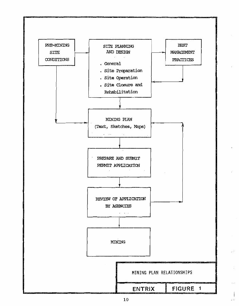
Figure 1. Mining plan relationships. 10
Figure 2. Groundwater seepage. 34
Figure 3. Dimensions of a channel diversion. 43
Figure 4. Superelevation of flow caused by bend in channel. 47
Figure 5. Overflow spillway. 49
Figure 6. Diversion channel construction. 51
Figure 7. Bedrock drain system with gravity ditch. 52
Figure 8. Overland flow. 55
Figure 9. Slope effect on the amount of erosion. 60
Figure 10. Stockpile protection. 67
Figure 11. Cross section sketches defining topographic features. 76
Figure 12. Regional boundaries of equations. 89
Figure 13. Plan views of meandering, mountain, and braided streams. 93
Figure 14. Relationship between valley slope and sinuosity. 98
Figure 15. Graph for initial selection of stream pattern. 99
Figure 16. Effect of channel length on stream equilibrium. 101
Figure 17. Shifting a meandering stream from one side of the valley to the other. 103
Figure 18. Effect of streambed level on channel equilibrium. 104
Figure 19. Definition sketch of meandering channel pattern descriptors. 109
Figure 20. Side view and plan view of a pool-riffle sequence. 112
Figure 21. Cross section shape in pools and riffles. 113
Figure 22. Locations of shallow and deep zones in channels of different sinuosity. 115
Figure 23 Typical channel cross sections. 116

LIST OF FIGURES (Continued)
Fi gure 24. Theoretical geometry of pool cross section. 117
Figure 25. Recommended pool and riffle cross section configuration. 118
Figure 26. Mountain stream design, triangular channel, 2:1 sideslopes. 120
Figure 27. Mountain stream design, trapezoi da1 channel, 2:1 sideslopes, 6 ft base width. 121
Figure 28. Mountain stream design, trapezoi da1 cnarme1, 2:1 sideslopes, 10 ft base width.
Figure 29. Mountain stream design, trapezoi da1 channel, 14 ft base width.
Figure 30. Mountain stream design, trapezoi da1 c.hannel, 20 ft base width.
Figure 31. Sloped drop structure.
Figure 32. Bed stabil ity.
Figure 33. Bank stabil ity.
Figure 34. Riprap design.
Figure 35. Riprap protection of end and toe sections.
122
2:1 sideslopes,123
2:1 sideslopes,124
125
130
132
134
136
Figure 36. Flow chart for selecting and spacing habitat features. 140
Figure 37. Major components of riverine fish habitat. 143
Figure 38. Swimming capabil ity of selected anadnmous and resident fish. 146
Figure 39. Water interchange between stream and gravel in a riffle. 149
Figure 40. Typical wing deflector constructed from rock. 159
Figure 41. Submerged-rock weir. 161
Figure 42. Bank overhang cover for a sharp bend in a stream. 162
Figure 43. Trees and root wad. 164
Figure 44. A large rock island forming a pool w; rh cover. 165

LIST OF FIGURES (Continued)
Figure 45. Stream habitat features for rehabilH .t i on of a meandering stream. 167
Figure 46. Stream habitat features for rehabilitation of a mountain stream. 169
Figure 47. Rock used to control grade in a channsl . 171
Figure 48. Overflow channel in a meandering stream. 179
Figure 49. Mountain stream. 180
Figure 50. Braided stream. 182
Figure 51. Floodplain graded to create wildlife habitat. 185
Figure 52. Site grading in inactive floodplain. 186
Figure 53. Plan and cross-section diagram of topography for wildlife migration corridors. 189
Figure 54. Grading on valley bench. 191
Figure 55. Revegetation priorities for meandering streams with and without fish. 193
Figure 56. Revegetation priorities for mountain streams with and without fi sh, 194
Figure 57. Revegetation priorities for braided rivers with and without fish. 195
Figure 58. Revegetation priorities for valley terraces and valleybenches. 196
Figure 59. Distribution of stockpile materials. 198
Figure 60. Revegetation techniques. 199

INTRODUCTION

ACKNOWLEDGEMENTS
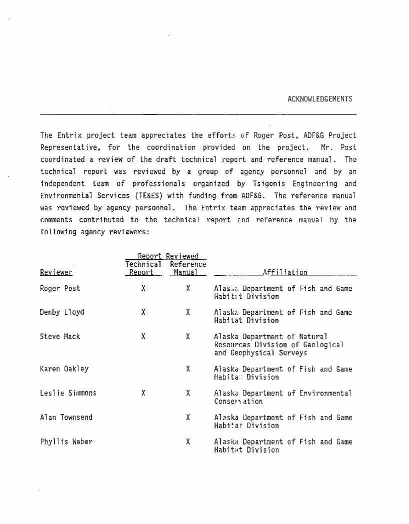
The Entri x project team appreci ates the effort, (I f Roger Post, ADF&G Project Representative, for the coordination provided on the project. Mr. Post coordinated a review of the draft technical report and reference manual. The technical report was reviewed by a group of agency personnel and by an independent team of professionals organized by Tsigonis Engineering and Environmental Services (TE&ES) with funding from ADF&G. The reference manual was reviewed by agency personnel. The Entrix team appreciates the review and comments contributed to the technical report ,nd reference manual by the following agency reviewers:
ReportTechnical
Reviewed Reference
Reviewer Report Manual Affiliation
Roger Post x x Al as, .. Department of Fish and Game Habit,t Division
Denby Lloyd x x Alask1. Department of Fish and Game Habitat Division
Steve Mack x x Alaska Department of Natural Resources Division of Geologicaland Geophysical Surveys
Karen Oakl ey x Alaska Department of Fish and Game Hab l ta: Division
Leslie Simmons x x Alaska Department of Environmental Consenat ion
Alan Townsend x Alaska Department of Fish and Game Habi~ar Division
Phyllis Weber x Alaskd Department of Fish and Game Hab l t.at Di vi si on

The project team also appreciates the review and comments contributed to the technical report by the TE&ES team of reviewers:
Contributor
Robert C. Tsigonis
James W. Aldrich
Laurence A. Peterson
Karl L. Hanneman
Larry Johnson
We also appreciate the individuals:
Contributor
Bill Lawrence
Bob Madison
Denby Lloyd
Rob McIntire
Phyllis Weber
reference
Affi 1i at ion
Tsigonis [iJineering and Environmental Services
Arctic Hydlologic Consultants
L.A. Peter: on &Associates, Inc.
Arcti c Mi !,j,1g Systems
Dikos ConsuHing
materials provided by the following
Affil i at ion
u. S. Dapa:: '-',lent of the Interi or National Pirk Service
U.S. Depal':ment of the Interior Geological SurveyWater Resot.rces Division
Alaska Der,':rtment of Fish and Game Habitat Division
Department of Indian and Northern Affairs Canc:da
Alaska D".!prtment of Fish and Game Habitat 0' .'i si on
The Entrix project team is also grateful to Rhonda Steward for report production.

1.0
INTRODUCTION
This report presents best management practices (BMP's) for placer mining that are designed to minimize nonpoint-source pollution and to promote and enhance the natural recovery of the site. This document details and presents some of the supporting information behind the BMP's. Numerous references to publicati ons conta ini ng more detailed i nformat i on are i ncl uded when address i ng the various subjects in the document~ A second document, Best Management Practices for Placer Mining Reference Manual, presents a summary of the BMP's in a user-oriented format that is more suitable for design use.
1.1 OBJECTIVE
This project was funded by the Alaska Department of Fish and Game with the primary objective of providing information to enhance the Department's ability to carry out its responsibilities for protection of fish and wildlife habitats and populations affected by placer mining. Specifically, the BMP's are designed to provide guidance to the Department of Fish and Game and other state and federal resource management agencies reviewing placer mining appl i cat ions, wi th part i cular emphas is placed on the control of nonpoi ntsource pollution and site rehabilitation.
Although the mining industry was not intended as the primary audience for the BMP documents, the BMP's should also be useful to placer miners and their technical consultants in developing their mining plans to include the design elements and details that may be required by resource management agencies.
1

1.2 SCOPE
The development of the BMP's was based on a review of literature in the fields of mining engineering, drainage and erosion control, hydrology and hydraulics, aquatic and terrestrial biology, and aquatic and terrestrial habitat rehabilitation. The literature review focused on references with application to stream valleys in Alaska or other northern environments. Technical evaluation or analyses of the information obtained, and the experience of the project team, provided the basis for applying or adapting this information to placer mi ni ng BMP's for Alaska . Although several act i ve placer mi ne sites were visited during the course of this project, site-specific scientific data were not collected, since the wide variety of site conditions found in Alaskan floodplains do not require major alterations to the concepts and designs presented herein. Economic and time constraints prevent this report and the associated manual from being all-inclusive. The user is encouraged to collect si te- specifi c data to support the design recommendations presented in th is report and to refer to the literature cited for additional information.
Design recommendations are provided; few construction techniques are provided, since they will depend upon the equipment that is available. at any particular mine site.
This report presents recommendations and supporting information for preparing a mining plan, controlling nonpoint-source pollution, and rehabilitating a site. The mining plan chapter provides recommendations for what information should be included in the plan and provides specific criteria for site descriptions, design, operation, and rehabilitation.
Chapters on contro 11 i ng nonpoi nt-source poll uti on concentrate on temporary features that are used primarily during preparation and operation of the site, but shoul d be incorporated into fi na1 design features duri ng site rehabilitation. Topics covered include drainage control, site grading, and stockpile placement and protection.
The design of permanent features that continue to control nonpoint-source pollution and that enhance recovery of the site is the subject of the site
2
rehabil itati on chapters. Topi cs covered incl ude stream-channel rehabil itation, fish-habitat rehabilitation, and floodplain rehabilitation. The streamchannel and fish-habitat rehabilitation chapters recommend design features for a final channel configuration below bankfull level. The floodplain rehabilitation chapter provides design recommendations for that portion of the va11 ey above the bankfull channel and i ncludes the ri pari an zone, i nact ive floodplain, terraces, and benches.
1.3 REPORT ORGANIZATION
This BMP technical report is divided into three major divisions plus appendices. The major divisions are:
o Mining Plan o Nonpoint-Source Pollution Control o Site Rehabilitation
The accompanying reference manual uses a parallel format to present its technical recommendations.
The first major division of this technical report is the mining plan. It
provides a brief checklist of the important components of each sequential step in the planning, design, operation, and rehabilitation of a placer mine site. These components should be described in a mining plan and submitted with the permit application.
The second major di vi sion of thi s report presents design recommend at ions for temporary features to minimize nonpoint-source pollution from the site. These pollution-control features are temporary measures that are used during preparation and operation of the site. References to the site rehabilitation chapters of the report are provided to encourage the user to consider final site rehabilitation features when selecting the location and design of temporary features.
The third major division of this report discusses site rehabilitation and provides design recommendations for permanent features that will enhance
3

recovery of the site. These chapters describe those mitigative measures that should be implemented as final site work following the completion of all mining operations.
Three appendices are included in the report:
Appendix A. List of references cited in this report Appendix B. Glossary of terms used in this report Appendix c. Maps of mean annual precipitation
4


MINING PLAN
7


2.0
MINING PLAN
Placer mining applications should include a mrn mq plan. It is generally agreed th at a thorough mi ning plan fi 1ed at the start of a new operat ion benefits both the applicant, by providing better knowledge and recognition of sol ut ions to potent i a1 site prob1ems, and the revi ewers of permi t applications, by allowing a more thorough understanding of how the site is to be sequent i ally operated and rehabil i tated (Figure 1). Adequate site assessment work in the form of test-pitting, trenchi ng, dri 11 i ng, or other prospecting methods can lead to a well-planned ·operation that minimizes surface disturbance and excavation requi rements. Development of a deta il ed mi ni ng pl an famil i ari zes the miner wi th the best management pract ices and promotes more accurate costing of annual activities.
The mining plan should include two major parts:
1. Description of pre-mining site conditions to guide the development and rehabilitation of the site
2. Site planning and design including site preparation, operation, and rehabil itat ion
A list of items to be included in the mining plan is presented in this chapter of the report. Subsequent chapters include best management practices (BMP's) for designing those elements of the mining plan related to nonpcf nt.-source pollution control and site rehabilitation. The mining plan should be completed in sufficient detail to provide accurate descriptions and designs of site features. These written descri pt ions and designs shoul d be supported with scaled sketches showing both plan views and cross-sectional profiles of
9
PRE-MINING
SITE
CDNDITIONS
SITE PIANNING AND DESIGN
, General
· site Preparation
· site Crj;leration
• site Closure am Rehabilitation
BEST
MANAGEMENT
PRACI'IC&S
MINING PI.AN
(Text, Sketches, Maps)
PREPARE AND SUJ'H[T
PERMIT APPLICATION
REVIEW OF APPLICATICN
BY AGENCIE'3
MINING PLAN RELATIONSHIPS I~--I
ENTRIX FIGURE 1
10

proposed site work and locations. A minimum of five site maps is recommended to illustrate features discussed in the following sections of the mining plan:
1. Pre-mining site conditions 2. General site planning 3. Site-preparation plan 4. Site-operation plan 5. Site-rehabilitation plan
Where possible, ground or aerial photographs of site conditions prior to the proposed activity should also be submitted. The mining plan should be prepared following site inspection by the applicant.
If the proposed mining is to be a multi-year operation, the plan also should describe the progression and sequence for both temporary and final locations of major site features such as settl ing ponds, stream channels, and stream diversions. The plan should also address seasonal site closure to protect site features from spring flooding. For multi-year sites the plan should recognize that encountered site conditions or other factors may dictate that the original proposals may need to be altered. If alterations to the mining plan are necessary, supplemental plans describing these changes should be submitted to the permitting agency in time to allow review prior to the next mining season.
While several formats may be appropriate for a detailed mmmq plan, the recommended approach is to submit a narrative description with site sketches and photos that is attached to the application form. This plan should address, in recommended order, the following points.
2.1 PRE-MINING SITE CONDITIONS
Describe and map the existing condition at the proposed mine site and immediately upstream and downstream of this site. The site description should be based on a site visit by the applicant.
11

A. Site Conditions
A description of known previous nn m nq activity, if any, should be provided. A site base map should be prepared for each claim to scale at a convenient scale large enough for the site to fill an 8 1/2 x 11 inch or larger sheet of paper (e.g. 1 in. = 200 ft). A copy of this base map should be used to mark the location and approximate size of existing site features such as streams, ponds, abandoned settling ponds, and tailing piles. Knowledge of aufeis occurrence and location should be noted.
B. Biological Characteristics
The amount and type of vegetation in the mine site should be described and marked on the base map containing site conditions. The presence of fish in the stream should be discussed, if known by the applicant. Stream surveys for fish presence are usually not necessary, since the Alaska Department of Fish and Game has i nventori ed numerous streams throughout the state and woul d be knowledgeable about the likelihood of fish in any particular stream.
An important element of site planning and the preparation of a mining plan is assessing the risks associated with flooding and erosion at the site. The pre-mining site condition section should address the value of the stream for aquatic habitat at and downstream of the mine site in sufficient detail to evaluate the acceptable level of risk for design purposes, as discussed in Sect i on 8.2.1. Coordi nat i on wi th ADF&G is recommended for thi s task. The 1eve1 of ri sk ident i fi ed will affect the design of the temporary eros i on control features discussed in later sections of this report.
C. Stream Characteristics
A description of the stream and local drainage is an important element of the site description. The configuration of the stream, or stream pattern, is an important feature to describe and should be drawn to scale on the site map containing existing site features. If the stream has more than one channel at a normal summer flow, the number of channels should be noted and the percent of stream length in the site with more than one channel should be estimated.
12

The water qual ity characteristics should be noted based on visual
observations. Turbidity is the most obvious characteristic and can be
assessed vi sua11y. The seasonality and magnitude of fl ood events shoul d be
descri bed based on di scuss ions with 1oca1 res i dents or mi ners in the area.
Flood debris in the mine site should be described and the extent and elevation
noted. Loca1 drai nage patterns through the mi ne site i ncl udi ng creeks and
gullies, should be described and noted on the base map containing existing
site features.
D. Legal Claim
The location of the boundaries of the mrrnnq claim should be described and
plotted on the base map containing existing site features.
2.2 SITE PLANNING AND DESIGN
2.2.1 General
This section of the mlnlng plan should present descriptions and sketches of
yearly and multiple-year work area locations and boundaries. The overall
plans and schedules for sequential site operation and rehabilitation should be
presented for the duration of mining at the site.
A. Site Boundaries
The overall boundari es of the cl aim as descri bed in the previ ous section
should be transferred to a clean copy of the scale base map. This map will be
used only for general site planning. On this map, delineate the
placer-bearing zones identified during the site exploratory program consisting
of digging test pits or trenches, drill ing, or other techniques. Use these
zones and the operation pl ans to pl an the boundari es of each seri es of cuts
and the total boundary for the year. Such planning may reduce surface
disturbance and increase profi ts by mi nimi zing excavation requi rements. For
multi-year sites, outline and label the planned operational boundaries for
subsequent years. Although these boundaries will likely change slightly, they
still provide valuable information for designing drainage-control structures.
13

B. General Schedule
The general schedule of site activity should be described for each year of mlnlng. The estimated dates of moving equipment to and from the site should be provided. List the planned mining activities and note in which month{s) the activity is likely to occur. Examples of activities that should be listed include, but are not limited to, clearing, constructing settling ponds, sluicing, grading of tailing piles, constructing and maintaining drainage-control structures, and site rehabilitation. Although work in or near stream or di vers i on channels is di scouraged, some such work may be requi red. Any such work shoul d be descri bed, and the planned dates and duration of such activity should be provided.
C. Site Facilities
All site facilities should be described and drawn on the general site planning map. Access routes into and within the site should be identified. The location and description of work areas and housing should be included. The methods of domestic waste storage, treatment, and disposal should be described in this section of the mining plan. The storage and handl ing of fuel s or other toxi c materi a1s shoul d be descri bed and the storage site marked on the map.
2.2.2 Site Preparation
This section of the mining plan should present more specific information on how the site wi 11 be prepared for each year of mi ning. The 1eve1 of detail should be greatest for the upcoming mining season. Note that if major revisions of the mining plan occur, the agencies should be informed. Narrative, with frequent plan view and profile sketches, should be provided.
A. Clearing and Stockpiling
A plan for clearing the mine site prior to mlnlng activity should be developed. The plan should describe the method of clearing and the schedule for clearing relative to when the area is to be mined. The amount of each
14

type of material to be cleared should be estimated and the storage locations should be drawn on a copy of the base map for ill ustrat i ng site-preparat ion features. It is recommended that the miner develop a site-rehabilitation plan (Section 2.2.4) prior to selecting locations of stockpiles so that the stockpiles can be placed to minimize handling before or during site rehabilitation. Stockpiles may be required for a variety of materials, including trees, woody slash and debris, organic material, inorganic overburden, fine silts, and oversized materials. The mining plan should also include a description of the approach for protecting the stockpiles from
erosion.
Cl eari ng a site can cause aufei s to form. Aufei s , also referred to as an icing, naled, or glacier, is composed of ice that has formed on the surface of any substance (e.g., ground or river ice), usually followed by the progressive buildup of ice upon itself. Aufeis most commonly occurs in areas containing permafrost ground, but the exi stence of permafrost is not requi red for its formation. Aufeis may form downstream of a spring, with flow from the spring feedi ng the growth of the aufei s , Aufei s may also form when a flow of water (e.g., groundwater or streamflow) is constricted between the annual frost or ice layer on top and a layer with relatively low permeability (e.g., permafrost, bedrock, or streambed) on the bottom. The constricted water supply builds up pressure and may rel ieve the pressure by flowing to the surface through a crack. Th i s flow freezes on the surface. A cont i nuous water source can continue to emerge and freeze on the surface throughout the winter. Clearing a site can cause a spring to develop, thus increasing the potential for aufeis. Aufeis may also result from the removal of the insulating effect of the vegetative mat, allowing deeper growth of the annual frozen layer.
B. Site Drainage Control
The site drainage-control plan is one of the most important elements of the mining plan. Completion of the site-rehabilitation plan is recommended prior to deve1opi ng the site drai nage-control pl an. Incl uded in the dra i nagecontrol plan should be the designs and locations of settling ponds, diversion channels, bedrock drains, and diversion and containment berms. The locations
15

of these structures should be selected so that they can function effectively for the maximum length of time before they must be relocated. Review of the base maps depicting site conditions, general site planning, and site rehabilitation will aid in the selection of locations for drainage control structures.
The diversion channel should be located to minimize the number of times that the stream must be moved. While not moving the stream at all is the preferred alternative, moving it once into a final location is preferred for those si tuat ions where the stream must be moved. A temporary diversi on channel should only be necessary if the entire stream valley bottom is to be mined.
While drainage-control structures may reduce the potential for aufeis to form withi n the site, aufei s growth at a drai nage-control structure may decrease the effectiveness of the structure. The diversion channel, bedrock drain, and gravity ditch system may all cause aufeis to form in their channels, reducing the capacity of the channels to transport their design flows. This potential should be evaluated and, if aufeis is likely, the reduced capacity should be considered when designing the channel.
2.2.3 Site Operation
The operation plan should present the details of how the actual mine area will be worked, including reference to the specifics of how material will be handled, processed, and discharged.
A. Mining Activities
The nn mnq plan should include a discussion of nn mnq activities such as equipment types, area of activity, and resultant material-size classificat ions. The area and depth of each cut shoul d be 1i sted for each cut to be made during the mining season. The sequence of cuts should be noted on the base map for site operation. The equipment used for each mining operation should be listed in the plan. Details should be provided on the size classes of material produced in the mining operation and whether these materials will be mixed back together as mining progresses. Plans for saving certain
16

quantities of some size classes for site rehabilitation should be discussed.
The required quantities of materials should be based on estimates developed
for the site rehabilitation plan (Section 2.2.4).
B. Site Drainage-Control Maintenance
Inspect i on and maintenance of dra i nage-contro1 structures is important to
minimize nonpoint-source pollution. The plan should identify the expected
frequency and methods of cleaning or protecting settling ponds. It should
identify the location and design of additional ponds, if such are required.
The sites should be drawn on the operation base map. The diversion channel
should be inspected at least once each month and after each f'l ood event for
damage from erosion or for excessive sediment deposition. The plan should
identify what materials and methods would be available for making repairs to
the di vers i on channel if requi red. The schedul e for constructing bedrock
drai ns and surface fl ow-control structures shoul d be outli ned. The
maintenance of the bedrock drain and surface erosion-control structures should
also be described.
C. Erosion-Control Measures
Erosion-control measures that will be carried out concurrently with mmmq
activities should be presented in this section of the mining plan. Site
sloping and contouring measures should be described and the schedule relative
to other mining activities should be noted. The location and protection of
stockpiles of classified material and the schedule for setting these materials
aside should be described.
2.2.4 Site Closure and Rehabilitation
The site-closure discussion should focus on describing and mapping the details
of final site-rehabilitation measures and emphasize what steps will be taken
to expedite site recovery and enhance the value of rehabilitated areas to fish
and wi 1dl ife.
17

A. Stream Rehabilitation
The stream rehabil Hat ion plan shoul d i ncl ude the details of the channel design up to the bankfull level. The plan view of the stream channel should be drawn to scale on the base map for site rehabilitation, showing the stream pattern, location in the floodplain, locations of pools and riffles, and locations of fish-habitat features. A side view of the stream channel design should be provided to show the planned sequence of pools and ri ffl es. End views, or cross sections, should be provided with dimensions for typical pools and typical riffles. Design drawings of fish-habitat features should be i ncl uded in the pl an. Ali st of parameters and thei r values shoul d be provided, including but not limited to, drainage basin size, mean annual precipitation, design recurrence interval and discharge, valley slope, channel slope, and bed material size.
B. Floodplain Rehabilitation
The floodplain-rehabilitation plan should include the details of site rehabi 1Hat i on above the bankfull 1eve1 of the stream channel. The plan should describe in detail the methods for rehabilitating settling ponds. The final configuration of all drainage-control structures should be sketched in plan, end, and side views. A description of the util ity of any structures planned to be left in place should be included. Final site sloping and contouring should be descri bed in detail and drawn in plan, end, and side views. This should include discussions of terraces, sediment basins, overflow channels, and other site features relevant to the site. The distribution of stockpiled material should be mapped on the base map. Revegetation efforts should be described and mapped on the base map.
18


INTRODUCTION TO NON POINT -SOLIRCE POLLUTION CONTROL
21


3.0
INTRODUCTION TO NONPOINT-SOURCE POLLUTION CONTROL
3.1 OBJECTIVE AND SCOPE
The primary objective of this major division of the report is to provide
design recommendations for temporary control measures that can be used during
site preparat i on and operat i on to mi nimi ze nonpoi nt-source poll ut i on at an
active placer mine site. These control measures are temporary in nature,
since they typically require modification or replacement during final site
rehabilitation. A secondary objective is that the site be prepared and
operated in a manner that facilitates final restoration of the site. Final
site rehabilitation, including long-term control of nonpoint-source pollution,
is discussed in Chapters 6.0 to 9.0.
For thi s report, the term "nonpoi nt-source poll uti on" incl udes all stream
turbidity, suspended sediment, and siltation (deposition of sol ids on the
stream bed) resulting from soil erosion caused by human activity that cannot
be traced to a single discharge point. Point-source pollution, in contrast,
is highly localized, and the origin can be traced to an identifiable point
where the polluted discharge reaches a body. of water. For example, turbi d
effluent from the outlet of a settling pond is point-source pollution, while
sediment washed off an exposed hillside is nonpoint-source pollution. Another
common point-source of potentially large quantities of sediment pollution is
eros i on of abandoned settl i ng ponds. Unstabil i zed tail i ng pi l es and steep
slopes along streams are the predominant causes of nonpoint-source pollution
(Vesil ind and Peirce 1982). These definitions of point and nonpoint-source
poll ution may not conform to the definitions used by state and federal
agencies.
23

3.2 SUMMARY
The approach to cantrall i ng nonpoi nt-source poll ut ion is to ident ify the causes of erosion and to plan and operate the site from the beginning of the project to include measures to avoid excessive erosion and to include treatment methods for that erosion that does occur. This section and Table 1 summarize the key issues and typical solutions.
Nonpoint-source pollution of adjacent streams can occur during all phases of placer-mine development and operation. Frequently, when mining begins at a site, particularly at a previously undisturbed site, vegetation and the surface layers of organic and inorganic soils are removed. This site preparation exposes large areas of silts and fines to potential erosion. In addition, the organic stockpile (consisting principally of woody vegetation and soil) is susceptible to erosion either by rain events or surface drainage. Finally, unvegetated tailings piles left after site closure can contribute sediment to adjacent streams.
The amount of erosion that occurs at a site depends upon local hydrologic and topographic characteri st ics such as the amount of ra infa11 or snowmelt, the type of vegetation and soil, the characteristics of surface drainage, and the length and steepness of slopes (Beasley 1972). A decrease in rainfall or snowmelt will likely reduce the amount of erosion. The removal of vegetation will increase erosion as the soil is no longer protected by its organic cover. In addition, rain fall ing directly on the bare soil will loosen the soil particles (Beasley 1972). The type of soil also affects erosion as some soils erode more readily than others. The steepness and length of an exposed surface are factors which can be manipulated to reduce erosion. A decrease in the length and/or steepness of the slope will reduce erosion.
If appropriate erosion control procedures for surface water drainage, grading, and stockpiling are outlined during the planning phase and implemented during site operation, nonpoint-source pollution can be substantially minimized. Appropriate measures most often include development of drainage systems; construct ion, mai ntenance, and rehabil itat i on of an adequate sett1 i ng -pond
24

Mining Activity
Removing vegetationand organic material
Drainage systemdesign/construction
Cutting and working slopes
Other
Issues
· timingstockpile· 1ocation
· stockpileprotection
exposure of· natural water to mine site
· minimizingerosion
minimizingerosion
Summary of Pollution Control Techniques
minimize time between strippingand mining
· collect and treat runoff from exposed slopes
· stockpile stripped material ·. locate so as to minimize
erosion potential ·. armor sides of stockpile if
erosion potential exists ·. locate to minimize rehandling
requirements ·. collect and treat stockpile
runoff
· divert natural streams around site · install settling ponds--water
contacting excavated areas must go through settling ponds
· divert surface runoff around site · decrease length/steepness · furrow steep slopes · minimize removal of vegetation
grade in same season of mining·
· stabilize dewatered settlingponds•• vegetation•• coarse material
· roughen exposed soils to minimize wind erosion· · evaluate effects of aufeis
NONPOINT-SOURCE POLLUTION CONTROL
. TABLE 1ENTRIX
system; proper di versi on of stream channel s; gradi ng of tail i ngs pil es; and
siting and protection of stockpiles.
A drainage system is usually required to divert surface water around the
mining site and to retain sediment-laden water within the site. Before mining
commences, particularly when working adjacent to streams, channel diversions
should be constructed to reroute streams and surface runoff around the site
(Section 4.3). Water that comes into contact with excavated areas will
require routing through the settling pond system, since the water will likely
contain sediments (Section 4.2). An investigation of the drainage pattern
before mining will assist in identifying areas with a greater potential for
erosion (Toups Corporation 1978).
Grading of tailing piles and overburden concurrently with seasonal mining
act i vi ty will improve erosi on control and reduce efforts duri ng site
rehabilitation. Annual grading plans should be included in the overall mining
and restoration plans. Material which is not stockpiled for later use
(Section 10.3) should be regraded as soon as possible. Constructing
fl oodpl ain terraces and furrows along steep side slopes whil e gradi ng wi11
reduce the effective lengths of the slopes and 1imit erosion (Section 5.2).
In addition, slope failures in graded sites are less likely (Section 5.2).
Final site grading (Section 10.2) should be performed prior to site closure.
Remova1 of vegetat i on and the 1ayers of organi c and i norgan i c materi a1sis
usually the first activity that takes pl ace before placer gravels can be
processed. The amount of time between the stripping operation and the mining
of the underlying gravels should be minimized. This will reduce the amount of
time that soils are subjected to surface runoff and hence will reduce soil
erosion. If stripping must be done in advance of mining to thaw the
permafrost soil s, the cl earing shoul d be done early in the summer so that
depth of thaw can be maximi zed; thi s wi 11 help to reduce the potent i a1 for
aufei s development. Contai nment berms shoul d be i nsta11 ed near the base of
the slopes to isolate streams from runoff from stripped slopes. Once
removed, vegetation and soil should be stockpiled (Chapter 6.0) in areas where
the potential for erosion of the material is minimized. Stockpiling materials
assists in reducing nonpoint-source pollution and helps to retain material
26

that will be beneficial in later revegetation efforts (Section 10.4). Stockpiles may need to be protected from erosion by armoring the sides of the piles (Section 8.5.3). Runoff containment berms may need to be constructed to direct runoff from the stockpiles through a treatment system.
Wind erosion also may contribute to nonpoint-source pollution. Wind, like water, has the power to detach and transport soil particles (Troeh et al , 1980). The amount of wind erosion is related to the type of soil, the amount of wind, the vegetation, and the unsheltered distance along the prevailing wind direction (Beasley 1972). Roughening the soil surface will assist in minimizing wind erosion. Wind erosion may also be decreased by siting tailing piles in sheltered areas (Toups Corporation 1978). Fine material is likely to be carried aloft by the wind as dust until a coarser layer is formed (Troeh et al. 1980). Dewatered settl ing ponds and any fine material removed from the ponds should be stabilized by revegetation or by placing coarser material over the finer materials.
27


DRAINAGE CONTROL
29

4.0 DRAINAGE CONTROL
4.1 OBJECTIVES AND SCOPE
Prior to the initiation of mlnlng activity, a drainage plan should be developed which delineates the surface flow pattern through the site. Drainage control has two objectives: to divert water around a mine site to minimize the amount of water that contacts erodible material within the site and to collect all turbid water within the site to allow for treatment prior to discharge to the stream. Methods of drainage control include:
Settling Ponds (4.2) Stream Diversion (4.3) Bedrock Drains (4.4) Overland Flow (4.5)
Water in contact with surfaces disturbed by mlnlng will become sediment laden and turbid. Therefore, water that is not diverted around the site will require treatment in the settling pond system (Section 4.2) prior to discharge. Settling ponds should be designed to retain all sediments origi nat i ng on the site. Efforts to prevent water from becomi ng sedi ment laden appear to be more efficient than efforts to treat sediment-laden water (Vesilind and Peirce 1982).
Active streams running through the mlnlng site should be diverted around the site. If mining in a stream channel is necessary, the surface flow should be diverted and isol ated from the activity occurring within the site. Section 4.3 details the criteria to be considered in stream diversion. Surface runoff from the valley walls also should be intercepted and diverted around the site. Gull ies or other topographical features which may concentrate runoff can
31
provide significant amounts of flow during or after rainfall events. Section 4.5 describes measures to reduce overland flow contributions to nonpointsource pollution.
Groundwater flow should also be diverted around the mlnlng site. Bedrock drains (Section 4.4) located upstream of the excavation area may be used to divert groundwater before it seeps into the excavation area. The water collected in an upstream bedrock drain can be routed into the stream. However, groundwater or surface water which contacts unstabilized slopes or enters the excavat i on area shauld be channeled through the settl i ng pond system (Section 4.2). Combinations of both surface and subsurface drainage control will likely provide better and more economical results (USSCS 1979).
Concurrent with mining activity, or at least at the end of each mining season, the overland flow drainage pattern should be reestablished and stabil ized. Surface water control is the primary concern in the design of the drainage pattern. Any water that is detained or impounded within the site will reduce the rate and amount of surface runoff (Beasley 1972) and thus reduce erosion. Storage of water wi 11 occur when small depressi ons or terraces along the contours are constructed (Frank Moolin and Associates 1985). Chapter 5.0 and Section 10.2 describe the grading of the floodplain to reestablish a drainage pattern to limit sediment contributions to the system.
4.2 SETTLING PONDS
Although settling ponds are essential to the control of point-source po 11 ut ion, sett1i ng ponds are also an important aspect of nonpoi nt-source pollution control. Settl ing ponds are used to clarify water which has been used in mining activities such as sluicing or hydraulicking which produce point-source pollution. Settling ponds should also be used to clarify sediment-l aden surface water and seepage from excavated or stri pped areas which would otherwise contribute to nonpoint-source pollution. Surface water and seepage from the mining area must be controlled to limit nonpoint-source pollution; all sediment-laden water produced on the site should be routed through the settl ing pond system. However, the flow of clean water into a settling pond sh6uld be minimized to increase the settling pond efficiency.
32

Settling ponds should be located, designed, and protected to meet the acceptabl e ri sks of fl oodi ng duri ng site operat ion. The acceptable ri sks at the site should be assessed as described in Section 8.2.
Settling ponds should be rehabilitated to prevent future contributions to both point-source and nonpoint-source pollution. Settling ponds located within the act i ve fl oodp1ain must be cl eaned of all sediments and rehabili tated when no longer required for use (Section 4.2.5).
4.2.1 Settling-Pond Siting
Potential settling pond locations should be identified during the planning phase. The arrangement and size of the settling pond system is dependent on the type of mining activity and the physical parameters of the site. Settling ponds may have permanent locations for the duration of the mining operation or may be moved with the mining activity. The location of the active floodplain of the final stream channel is the most important physical parameter which should be considered, since any settling pond located within the active floodplain must have all sediments removed during rehabilitation.
Settling ponds should be sited to minimize the amount of clean water entering the ponds. Surface water should be routed outside the site to the greatest extent practicable as settling pond efficiency will be increased by minimizing the volume of surface drainage entering the pond (Bell 1974). Section 4.5 descri bes overl and flow contri butions to nonpoi nt-source poll ut ion. Groundwater seepage may also substantially increase the amount of water entering the settling pond if the pond is located in a low-lying area (Figure 2). Groundwater seepage may be reduced by installing a cut-off trench between the settl i ng pond and the source of water to di vert cl ean water around the settling pond. Alternatively, an impermeable liner of plastic or clay is suggested to prevent or minimize grQundwater seepage into the pond.
Settl ing ponds should not be located within the active floodpl ain unless the stream has been adequately diverted (Section 4.3) and all sediments will be removed from the settling pond during rehabilitation. The settling pond must be protected to a 1eve1 appropri ate for the acceptabl e ri sks at the site
33

- Settling Pond
e---- - Seepage'<:----------;/'"
Seepage ~
.... -. - ..... --::::::::. Seepage Active
Channel
- --- -Acti ve---- Seepage ..........
Channel .:»: .:«
Seepage ~
Settling Pond
""-'--= Seepage
-
---,..,. ---.....
Active Channel
-Settl i ng Pond
Impermeabl~'<·~!l:J::z::r:zECO::~~ Liner
-
-Settling Pond
- ---- Seepage / Seepage
I..- -r
Active GROUNDWATER SEEPAGE
Channel
ENTRIX FIGURE 2
34

(Section 8.2). Washouts of settling ponds will result in both point-source
and nonpoint-source pollution as large amounts of previously deposited sedi
ments will be entrained and subsequently deposited downstream (Guy 1979). The
fine material which becomes deposited in the settl ing pond will be readily
eroded by water moving rapidly through the pond. Erosion within a washed-out
pond may continue to add fine sediments to the stream for several years (Cook
and King 1983). Therefore, any settl ing pond located in the active floodplain
must be protected and must have all sediments removed duri ng rehabi 1itat ion
(Section 4.2.5).
4.2.2 Settling-Pond Design
Settl ing ponds should be designed to obtain the residence time necessary to
allow fine sediments to deposit. The Alaska Department of Environmental
Conservation (ADEC) Pl acer Mining Settl ing Pond Design Handbook (R&M
Consultants 1983) describes the proper design, construction, and operation of
settling ponds. The size of the settling pond should be selected according to
the volume of water, including surface water and seepage, to be clarified, the
amount of sediment to be removed, and the physical configuration of the site.
An easily cleaned presettling pond is recommended below the sluice tailrace to
minimize sediment inflow to the settling pond.
Alternative settling pond configurations should be considered. Long settling
ponds may be constructed along the contours of valley wall s to mi nimi ze the
problems associated with settling pond washouts located within the active
floodplain. However, since low water velocities enhance particle settling,
the velocity of the water movi ng through along pond shoul d be evaluated to
cert i fy that excess i ve vel oci ties are not produced in these narrow-cross
sect i oned ponds. The re1at i onshi p Q = AV where Q = the vol ume of water
flowing through the pond (cfs), A = cross-sectional area (ft2) and V = the
velocity of the water (fps) should be used. The forward water velocity is
incorporated into the detention time within a basin; R&M Consultants (1983)
i dentifi ed the importance of the forward water vel oc i ty when descri bi ng the
overflow rate.
35

4.2.3 Settling-Pond Construction
Before material washing commences, the settling pond system must be in place
and able to retain sediment-laden water. In some cases, particularly when
making the first cut in a new site, the pond may be excavated in virgin
ground. Placer material present at the sett1 ing pond site may be stockpiled
to be washed at a later time, while non-p1acer-bearing material may be used in
dam construction. Excavated material should be properly compacted when
constructing the dam (Bell 1974). If the dam is built of tailing sand and
gravel, seepage through the dam is common (Yukon Department of Indian and
Northern Affairs 1979). Excessive seepage through the dam may cause the
failure of the dam (Brawner 1975). Cutoff trenches and anti-seep collars
around cu1verts may be i nsta11 ed to 1imit seepage. Turbi d seepage from the
settling pond should be minimized by increasing the length of the seepage path
(Bel11974). The length of seepage path required to clarify the water is
dependent on the materi a1 used to construct the dam. The outl et from the
settling pond should be armored with coarse material to prevent erosion at the
toe of the dam. Detailed descriptions of the construction of settl ing pond
dams are available (R&M Consultants 1983, Wilson 1981, U.S. Bureau of
Reclamation 1977).
4.2.4 Settling-Pond Operation
Material deposited in the sluice tailrace will consist of coarser sands and
sma11 gravels and shou1 d be removed frequent1 y. The sand and gravel mi xture
will be useful in site rehabilitation (Section 10.3). The approximate
quantities required during rehabilitation should be roughly determined during
the development of the rehabi 1i tat ion p1 an and stockpil ed as descri bed in
Chapter 6.0. Water from the presett1 i ng pond should be channel ed into the
main settling pond where finer material will settle out.
During the mining season, materials which are deposited in the settling pond
should be removed when sediments accumu1 ate to 60% of the design sediment
storage volume (Guy 1979), or when sediments are less than 2 ft from the water
surface (Alaska Department of Environmental Conservation No Date). Sediments
removed from sett1 ing ponds should be handled and stockpiled in a manner to
36

minimize contact with surface waters (Chapter 6.0). Flow through the settling pond should be halted during cleaning as disturbances in settling ponds will have adverse impacts on downstream water quality (Shannon and Wilson 1985). If sediments cannot be removed, design and construct a new settling pond and rehabilitate the old pond.
4.2.5 Settling-Pond Rehabilitation
Settling-pond rehabilitation is suggested during site operation or site rehabilitation when the settling pond is no longer needed. Rehabilitation of the settling ponds should be considered during the selection of the settlingpond locations (Section 4.2.1). Three options are available for settling-pond rehabilitation. The selection of the option depends on site-specific condit ions, such as the 1ocat i on of the settl ing pond re1ati ve to the fi nal rehabil itated stream channel (Chapter 8.0) and the amount of organic and fine inorganic material available at the site. The risks of flooding should be assessed (Section 8.2), and the settling ponds should be protected accordingly by riprapping nearby streambanks to prevent the lateral movement of the stream into the pond.
One option available for settling-pond rehabilitation is the removal of all fine sediments from the settling pond. Sediment removal is suggested if ponds are located in the active floodplain of the final rehabilitated stream or if the pond is to be used for fish rearing (Section 10.2.2). The pond should be dewatered and all sediment-laden water should be treated elsewhere. A dragline can remove deep sediments, or sediments in thin layers can be removed with front-end loaders. Frozen sedi ments can be ri pped and removed with bull dozers or front-end loaders. The resulting depression shoul d be fi 11 ed during site grading (Chapter 5.0) or rehabilitated as a fish rearing pond (Section 10.2.2). Sediment removal is expected to be very difficult and siting the pond to avoid the active floodplain may be the preferred alternative.
Settl i ng ponds may also be rehabi 1itated in place if the pond is above the active floodplain and little organic or fine-grained inorganic material is available on site. Some sediments should be removed from the settling ponds
37

and placed in areas of revegetat ion pri ori ty. The perimeter of the pond should be made irregular by adding and removing sediments as described in Section 10.2.2.
The third option for settling pond rehabilitation consists of stabilizing the sediments in place. This option is preferred if the pond is out of the active floodplain and a large amount of organic or fine-grained inorganic material is available on site. Oversize material should be placed over the fine sediments to a 3-ft or greater thickness. The oversize material should be graded to conform to the surrounding topography (Chapter 5.0). Prevent lateral migration of the stream channel into the rehabil itated settl ing pond if necessary using riprap (Section 8.5.3).
Sediments removed from the ponds should be stockpiled in an area that will not drain directly into the stream or other clearwater drainages. Containment berms constructed between the sediment stockpile and the stream will prevent silts from being washed into the stream. Stockpiles should be located in areas where they are protected from streamflow and surface drainage to reduce erosion as described in Chapter 6.0.
4.3 STREAM CHANNEL DIVERSION
At sites where mining activity will take place within an active floodplain, the stream channel may need to be diverted to minimize water flow through the excavation area. The diversion should be sited, designed, constructed, and operated to avoid excessive erosion or deposition, to contain floods within the range of acceptable risks (Section 8.2), and to meet fish passage requirements if fish are present (Section 9.3).
4.3.1 Diversion-Channel Siting
The location for the diversion channel should be identified during the pl anning phase and will depend on the physical parameters of the site, the equipment available to construct the channel, the proposed sequence of site operation, and the acceptable risk of flooding. In a narrow valley, the channe1 di vers i on may be routed along the vall ey wall s or along one side of
38

the floodplain. The general guidelines presented for channel diversion should be applied to site-specific conditions to properly design a diversion unique to each mining site.
Preferabl y, the stream shoul d be placed permanently into a newl y constructed or rehabil Hated stream channel. At sites where mining cuts as wide as the ent ire fl oodpl ain are not necessary, a permanent stream channel could be constructed on the mined portion of the floodplain prior to mining the other port ion. Des i gn recommendat ions for permanent stream channel s are presented in Chapter 8.0. The stream would be diverted only once and impacts to fish and wildl ife would be minimized. The mining area should be protected as necessary by constructing levees with stable side slopes (3 to 1 recommended). If a permanent relocation is not possible, a temporary diversion channel should be designed, constructed, and rehabilitated as described in the following sections.
4.3.2 Diversion-Channel Design
The actual design of a temporary diversion channel involves the interaction of hydrology, hydrauli c engi neeri ng, and geotechn ica1 engineeri ng. Thi s interaction may be complex, and the miner may be well advised to seek the assistance of engineers knowledgeable in the design and construction of open channel s. However, the fo11 owi ng guidel ines represent a simpl ifi ed approach to the design of channel diversions suitable for use at placer-mining operat ions. Add it i ona1 i nformat ion may be obtained in the Surface Mi ning Water Diversion Design Manual (Simons, Li and Associates 1982).
Diversi on channel s should be designed for reaches of rel ati ve1y constant slope. Therefore, if the channel slope changes, a separate desi gn will be necessary. If the diversion channel is placed along the valley wall, the upstream and downstream ends of the channel will likely have different slopes and will require separate designs. Transitions between the sections should be gradual. Note that deposition can be expected in the diversion channel if the slope is substantially less than the slope of the original channel. If deposition is expected, increasing the freeboard of the diversion channel and periodic maintenance of the channel should ensure that the diversion channel
39

retai ns adequate capacity. The designer should al so consider the potenti al for aufeis buildup in the channel and consequent loss of channel capacity; increased freeboard may be required in this case.
A channel diversion should be designed to discharge a specified volume of water while resisting erosive forces of the flow. This volume of water can be estimated from hydrologic conditions upstream from the mining site. Section 8.2 describes the methods of estimating the volume of water for a given flood. The fl ood for use in design (design fl ood) is selected on the basis of the acceptable risks at the site (Section 8.2) and the period of time during which the channel diversion will be used (the design 1ife). The probabil i ty of occurrence of a flood can be used to evaluate the consequences and ri sks associated with the design life of the channel diversion. Section 8.2 provides information on the selection of the design recurrence i nterva1 of stream-channel diversions constructed for more than one mining season.
After the design-flood discharge (Q) of the channel has been estimated, the channel size may be evaluated. The relationship Q=AminV is used to evaluatee the minimum area of the channel cross section, where Q=design-flood discharge (cfs), Amin=minimum cross-sectional area of the channel (ft2), and Ve=maximum permissible mean velocity in the channel (fps). The maximum permissible mean velocity in the channel is defined as the velocity to avoid the erosion of the bed and bank material. Table 2 presents the maximum permissible mean velocities to avoid erosion in diversion channels. The number and sharpness of bends in the channel affects the design velocity because an increase in channel curvature decreases the mean velocity associated with a given maximum velocity (Chow 1959, Simons, Li and Associates 1982). In addition, the requirements for fish passage evaluated at the mean annual flow (Section 8.2) may limit the permissible velocity in the channel. Fish passage requirements are discussed following the initial design of the channel.
40

Table 2. Maximum permissible mean velocities to avoid erosion in the diversion channel.
Max. Channel
Velocity in With
feet per second Channel With
Materi a1 Few, Mil d Bends Many, Sharp Bends
Very light loose sand Average sandy soil Average loam or alluvial soil Stiff clay or ordinary gravel Coarse gravel or cobbles Conglomerate, cemented gravel,
soft rock Boulders 1 ft in diameter Boulders 2 ft in diameter Bedrock
1.4 1.1 1.8 1.5 2.2 1.9 3.6 3.0 4.3 3.5 6.3 5.3
9.0 7.5 12.0 10.0 12.0 10.0
Reference: Simons, Li and Associates (1982), Neill (1973), Chow (1959)
A trapezoidal channel shape is suggested (Simons, Li and Associates 1982) with bank slopes selected to avoid erosion and slope failure while minimizing the amount of excavation. Table 3 lists the suggested maximum bank slopes for unl ined channels. Slopes of 2 to 1 or 3 to 1 are recommended for most channels.
Table 3. Suggested maximum bank slopes for unlined channels.
Horizontal to Vertical
For cuts in firm rock nearly vertical
For cuts in fissured or partly disintegrated rock, rough hard pan. 1/2 to 1 For cuts in cemented gravel, stiff clay soils, ordinary hard pan .. 3/4 to 1 For cuts in firm, gravelly, clay soil, or for side-hill cross
section in average loam . 2 to 1 For cuts or fills in coarse gravel to cobbles . 1 to 1 For cuts or fills in average or gravelly soils 1 1/2 to 1 For cuts or fills in loose sandy soils . 2 to 1 For cuts or fill sin boul ders . 2 to 1 For cuts or fills in very sandy soil .. 3 to 1
Reference: Simons, Li and Associates (1982)
41

The dimensions of the diversion channel should be evaluated given the channel size and shape. The standard design procedure using maximum permissible velocity can result in a very wide and shallow channel, which is generally not desireable. Empirical formulas have been developed that provide guidance in assessing the practicality of a channel design based on the size of a trapezoidal channel (Simons, cross-sectional area (A) and equat ions can be sol ved for bottom width (b) (Figure 3):
Li and Associates side slopes (Z) ob recommended channel
1982). tained
depth
Using above, the (d) and
the minimum following
recommended
d = 0.5 AD.S
b = (4-Z) d
With the channel dimensions known, the hydraul ics of the channel should be checked with Manning's Equation. This requires first to calculate the wetted perimeter and hydraulic radius as follows:·
R = /:,p
where p. = wetted perimeter (ft) b = bottom width (ft) Z = side slope, Z horizontal to 1 vertical d = channel depth (ft) R = hydraulic radius (ft) A = cross-sectional area (ft)
Next, a Manning roughness coefficient must be selected for the channel. Manning's roughness coeffi ci ent is a function of the type of materi ali n the channel cut or to be used to 1ine the channel. Table 4 1ists a range of roughness coefficients for constructed channel conditions.
42

1 ft. Freeboard
d
I. vv '1
"'" w I. ·1b
Area = A ~ (b. zd)d Wetted Perimeter ~ P ~ b+2J 1+z2'd Hydraulic Radius ~ R - AlP
DIMENSIONS OF A CHANNEL DIVERSION
ENTRIl< Figure 3

Table 4. Manning's coefficients of channel roughness.
Constructed Channel Condition
Gravel bottom with riprap or rubble sides Clean gravelGravels and cobbles Cobbles to boulders Dragline-excavated or dredgedEarth channel s , straight and uniform Rock channels, straight and uniform Rock channels, jagged and irregular
Minimum
0.023 0.022 0.030 0.040 0.025 0.017 0.025 0.035
Values of n Maximum
0.036 0.030 0.050 0.070 0.033 0.025 0.035 0.045
Average
0.033 0.025 0.040 0.050 0.028 0.022 0.033 0.045
Reference: Simons, Li and Associates (1982), Chow (1959)
The channel slope (5) should be evaluated from surveys or topographic maps showing the location identified for the diversion channel. The diversionchannel bed elevation should be matched to the stream bed at the upstream and downstream ends of the diversion.
The mean velocity that would be expected during the design flood can be calculated using Manning's equation:
where V = mean flow velocity (fps) R = hydraulic radius (ft) S = channel slope (ft/ft)
Graphical methods for the evaluation of Manning's equation are available (Joyce et al. 1980).
The expected velocity cal culated with Mann ing' s equation should be compared with the maximum permissible velocity to avoid erosion in the diversion channel. If the calculated velocity is less than or equal to the design velocity, then the channel dimensions, slope, and bed and bank material should be appropri ate for the selected design flood. However, if the cal culated
44

velocity exceeds the maximum permissible, it would be likely for erosion to
occur during the design flood, possibly destroying the diversion channel.
Thus, the channel should be redesigned in this case.
Channel redesign involves modifying one or more of the design parameters and
repeating the design computations to check the recomputed velocity against the
maximum permissible velocity. Design parameters that may be changed include
channel cross-section dimensions, materials that 1ine the channel, and the
channel slope.
Channe1 cross-section dimens ions may be mod i fi ed by i ncreas i ng wi dth and
decreasing depth to retain approximately the same cross-sectional area.
Adjustments should be limited to a maximum of 20% increase in bottom width and
5% decrease in channel depth to retain a desirable width to depth ratio. This
order of magnitude of change will make re1at ively small adjustments to the
velocity (on the order of 10%).
Small adjustments can also be made to the velocity by reducing the slope of
the diversion channel by lengthening the channel. Realigning the channel to
increase 1ength by putting more bends in· the channel wi11 decrease the
cal cul ated vel oci ty. However, if many sharp bends are introduced to the
channel, the maximum permissible velocity may need to be reduced (Table 2).
Larger adjustments can be made to the velocity if larger materials are
ava il abl e to use as a channel 1i ner. Larger bed and bank materi a1sa" ow a
1arger maximum permi ssi bl e vel oci ty and also decrease the computed velocity
due to increased roughness and smaller hydraulic radius.
The channel slope can be reduced by designing drop structures for the
diversion channel to allow a more gradual slope between the drop structures.
This technique allows economical material to be used over much of the channel
length while larger bed and bank materials are required at each drop
structure. Special design may be required if this technique is used for a
diversion channel requiring fish passage. The design of drop structures is
presented in Section 8.4.2.A.
45
An approach that is generally not recommended is to use a fabric liner in the diversion channel. Such liners would increase maximum permissible velocities in the channel. Special design may be required if the diversion channel is to be used for fish passage. Manufacturer's recommendations on design and construction should be followed.
Fish passage should be considered in the design if maintenance of fish passage is required. If a stream has been identified as a fish stream at, or upstream from, the mining site, fish passage must be maintained throughout the mining season. Sect i on 9.3ident ifi es the depth and velocity requi rements whi ch are necessary to rna i nta in passage of anadromous or res ident fi sh, Fish passage should be assessed for the mean annual flow (Sections 8.2 and 9.3). Manning's equat ion should be sol ved to evaluate the area correspondi ng to the mean annual discharge. The velocity and the depth of flow should then be determined. Tables to assist in obtaining the velocity and depth values are presented in U.S. Bureau of Reclamation (1974). If the velocity is too large, the channel must be redesigned with a larger bottom width. If the depth is too small to permit fish passage, a trench O.5-ft deep should be dug in the channel bottom to channelize the flow under low-flow conditions.
A freeboard should be provided in the channel. A 1-ft minimum freeboard is recommended for all channels (Chow 1959). If the slope of the channel is shallow relative to the original stream slope, the freeboard should be increased to account for potential sediment deposition. The freeboard should also be increased to account for the area occupied by ice if aufeis is expected to form in the diversion channel.
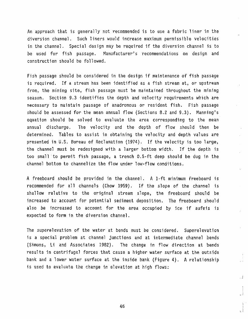
The superelevation of the water at bends must be considered. Superelevation is a special problem at channel junctions and at intermediate channel bends (Simons, Li and Associates 1982). The change in flow direction at bends results in centrifugal forces that cause a higher water surface at the outside bank and a lower water surface at the inside bank (Figure 4). A relationship is used to evaluate the change in elevation at high flows:
46

A
AFlOW-:/; -/'
r,- Radius of Curvature W - Width
PLAN VIEW
Water Surface
i+--------W------t--Il'I Zs
Superelevation of flow atLevel Water Surlace
\----1.------::-::""..-==---------1__J.!_outside of bend
SECTION A-A
47
SUPERELEVATION OF FLOW CAUSED BY BEND IN CHANNEL
ENTRIX Figure 4

Is = v2w/ grc
where Is change in elevation (ft) V = velocity (fps) W
g =
=
top width of channel 32.2 (ft/sec2)
(ft)
rc radius of curvature to the center of the stream (ft)
The berm height, especially at the upstream junction of the channel diversion, should be great enough to contain the superelevated flow and provide a 1-ft-minimum freeboard.
A low area in the diversion berm should be provided as a potential overflow spillway for flows which exceed the design high flows. The overflow should be located near the upstream junction of the channel diversion to minimize damage to the diversion channel (Figure 5). The low area should have a O.5-ft
freeboard instead of a 1-ft freeboard. The berm should be armored with large rocks on both sides to reduce erosion. Where possible, the overflow spillways should be routed into a depression running through the mine site but separated from the active operation and settl ing ponds. The upstream bedrock drain (Section 4.4) is one alternative. Overflows must be diverted around settling ponds. For multiple-year operations with a high potential for aufeis growth in the diversion channel, a diversion around the settl ing ponds should be constructed at the end of each mining season to divert flood waters displaced by excessive aufeis growth in the channel during the breakup of the following year.
4.3.3 Diversion-Channel Construction
The channel diversion should be completed prior to the initiation of mmmq
activities within the original channel. The bed elevation of the channel diversion should match the bed elevation of the natural channel (Simons, Li and Associates 1982) when possible. The channel diversion may be excavated or a levee may be constructed from the downstream end to allow water seeping into the diversion to drain downstream. A plug should separate the channel diversion from the active channel at both ends until the diversion structure
48

.l. 0.5 ft. Freeboard 1.0ft. Freeboard
---,
Channel Cross Section at Overflow Spillway
Channel Settling Pond
OVERFLOW SPILLWAY
ENTRIX FIGURE 5
49
is almost complete (Figure 6). Then the downstream channel plug can be removed and the diversion channel cleaned of any accumulated sediments. Materi a1s necessary for divert i ng the stream shoul d be stockpil ed near the upstream junction. The upstream plug can then be removed to allow the stream to flow through the diversion channel. The upstream end of the stream should be blocked with a dam after the plugs are removed. Riprap protection may be necessary on the diversion dam (Section 8.5.3). A pulse of sediment-laden water will occur as the stream is moved into the channel diversion. However, this pulse should be of short duration if channel banks are properly stabilized and diversion is accomplished as rapidly as possible.
4.3.4 Diversion-Channel Rehabilitation
Diversion channels should be rehabil itated at site closure. After construction of the permanent rehabilitated stream channel (Chapter 8.0), the stream should be diverted from the diversion into the rehabil itated stream channel. The diversion-channel structure on the valley walls should be graded into a backslopi ng terrace as descri bed in Secti on 10.2. Di vers ions on the valley bottom should be rehabilitated to conform to the overall final rehabilitation plan and may range from complete backfilling to leaving in place to form a large capacity high-water channel.
4.4 BEDROCK DRAINS
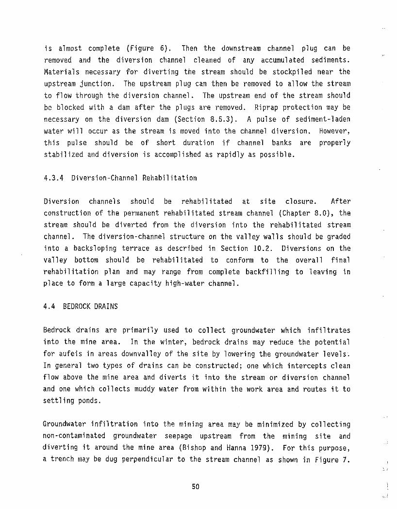
Bedrock drai ns are primarily used to collect groundwater whi ch i nfi ltrates into the mine area. In the winter, bedrock drains may reduce the potential for aufeis in areas downvalley of the site by lowering the groundwater levels~
In general two types of drains can be constructed; one which intercepts clean flow above the mine area and diverts it into the stream or diversion channel and one which collects muddy water from within the work area and routes it to settling ponds.
Groundwater infiltration into the mining area may be minimized by collecting non-contaminated groundwater seepage upstream from the mining site and diverting it around the mine area (Bishop and Hanna 1979). For this purpose, a trench may be dug perpendicular to the stream channel as shown in Figure 7.
so

,.
Diversion Channel~ _ -./ -
) J ..- "" ...
_ \.r "",
UNDISTURBED VEGETATIONUNDISTURBED
VEGETATION i -'"\- .
.. Upstream PI;/?•
, .".'-~./ '-'~~
" Dive~sion Channe~ ~J
«." ~
i
Stream Channel
~-------Stream Channel
1. EXCAVATION INITIATED 2. REMOVAL OF DOWNSTREAM PLUG
UNDISTURBEDUNDISTURBED " VEGETATIONVEGETATION
Stream Channel
~ ORIGINAL STREAM CHANNEL ~._.
SECTION A-A 3. REMOVAL OF UPSTREAM PLUG 4. DIVERSION OF STREAM CHANNEL
DIVERSION CHANNEL CONSTRUCTION
ENTRIX FIGURE 6
51

PLAN VIEW
~----=-- -Waterdrains from excavation area into settling pond
Bedrock Drain
I
Excavation Area
--. -.----.. -. --=::-::::- 1
Gravity DitchInto Stream
SIDE VIEW
BEDROCK DRAIN SYSTEM WITH GRAVITY DITCH
ENTRIX Figure 7
A trench excavated to a depth of 4 ft into the bedrock was found to be effective in reducing groundwater infiltration into the excavation area (Peele 1941) . Whil e the trench shoul d generally be only deep enough to prevent seepage from flowing into the active mining area, the drain should be designed to have sufficient capacity for aufeis growth. A gravity ditch can be used to divert the flow from the trench around the mine site to a location downstream of the site. The groundwater-diversion channel should not be routed near the stream or diversion until the beds of both channels are approximately equal to minimize seepage losses in the surface-water channel. A pump may be used to dewater the trench into a runoff-d ivers ion ditch or the diverted stream channel. Although a pump system will remove water faster, the costs will be greater (Sowers 1979). The trench may be backfilled with cobbles and large gravels to act as a french drain (Sowers 1979). A series of groundwaterdiversion channels may be dug throughout the mining site to collect additional groundwater infiltration from the valley walls (Peele 1941). The groundwaterdiversion channel will be most cost effective when built in an area that will eventually be mi ned. Bedrock drains can be backfi11 ed and graded when no longer needed to dewater the site.
Any turbid groundwater seepage or rainfall within the mine site should be collected and routed to the settling-pond system. Water ponding in the excavation area should be avoided. Within the mine site, an effective bedrock drain will slope downhill along the bedrock from the working face of the mining excavation (Figure 7). Water will drain from the excavation area and should be routed through a settling pond as the water in the excavation area during mining will become turbid and sediment laden.
4.5 OVERLAND FLOW
Overland flow from rainfall and snowmelt on the valley walls and terraces should be diverted around the mining site to limit nonpoint-source pollution. Overl and flow originating within the mining site should be collected and routed through the settling-pond system. Overland flow can result from melting permafrost, groundwater seepage, rainfall, and snowmelt. A gravity-flow drainage system can divert most of the overland flow around the mining site and retain the remaining sediment-laden water within the site.
53

Overland flow originating outside the site should be diverted. Upslope berms, approximately 2 ft in height, may be used to divert water around the site (Herricks et al. 1974, Becker and Mills 1972). Gravity ditches should drain the intercepted flow around the site (Kenney 1972). In areas of permafrost, gravity ditches should follow the contours closely and have a maximum slope of 0.25 ft to 100 ft to avoid degradation. Overland flow may also be diverted by stockpiles of strippings and overburden pushed uphill out of the active mining area as shown in Figure 8. Riprap should be placed as needed to avoid eros ion. The berms and di tches shoul d be inspected after heavy ra infa11 events and may require maintenance during the mining season.
Overland flow within the site should be isolated from clearwater streams. Downs lope berms and gravity ditches shoul d route turbid overl and flow into settl i ng ponds. When feas i ble, the amount of time of exposure of stri pped slopes should be minimized to reduce erosion. Aufeis may also form on exposed slopes.
Drainage structures in areas of permafrost will likely transport significantly larger amounts of water than those constructed in non-permafrost areas, and should be sized accordingly. In areas with permafrost-underlain terrain, the amount of overland flow from precipitation is expected to be large. Areas of permafrost exhibit rapid responses to precipitation. In a study of similar si zed streams wi th and wi thout permafrost, 51 aughter et a1. (1983) found that the presence of permafrost resulted in greater amounts of overland runoff.
54

Overland Flow
, Riprap Armor
Stockpile
Stockpile
Gravity Ditch to Stream .. ) I \\ \\\ \
Berm
Mining Area
Overland Fiow . Gravity Ditch to Settling Pond
..... IT
\ \ \ \ \ \ \ 1 \ \. \ '\ \ \ \ \ \ \ \ \ \ \ \ \\\\\\\\\\\\\\\\ ,\\\ \ \ \\
Berm
Stream
OVERLAND FLOW
ENTRIX FIGURE
55
8


SITE GRADING
57

5.0
SITE GRADING
5.1 OBJECTIVES AND SCOPE
Grading the tail ing piles and steep excavated slopes within the mmmq site will reduce erosion and encourage revegetation (Becker and Mills 1972). A gradi ng plan shoul d descri be the site gradi ng to be done concurrent wi th mining activity, at the conclusion of each cut, or at least at the end of each mining season. If tailings are properly placed and graded during mining, additional grading will not be necessary upon site closure.
5.2 PROGRESSIVE SITE GRADING
Grading of tailing and overburden piles at a mining site is integral to erosion reduction. The mining plan should include a temporary and final plan for sloping and contouring which addresses the reestablishment of desired elevations within the site and provides for an appropriate drainage pattern. Grading during mine operation will benefit seasonal erosion control.
Steep slopes and tailing piles should be graded as soon as possible. Surface erosion from slopes is greatest during the first year following disturbance (Cook and King 1983). Reducing the steepness of tailing piles will significantly reduce surface-water pollution (Vesilind and Peirce 1982). A slope of 3 horizontal to 1 vertical, or less is recommended (Becker and Mills 1972, Dryden and Stein 1975). Large piles of stripped loess with thawing ice lenses should be graded to slopes of 3 to 1 when placed. Slopes that are steeper toward the top and shallower toward the bottom are preferred as they have been shown to have less sediment loss than flat slopes or slopes that are steepest at the base (Haan and Barfield 1978, Meyer and Romkens 1976) as shown in Figure 9.
59

Convex Slope ~~ ~/
~,/' sr••~"rod"=Less/' / / ' /' Erosion than Convex Slope
Steep Slope at Base ofHIII/' / /} Produces More Erosion \' .....- Concave Slope Produces . / / Least Amount of Erosion
y// SIDE VIEW
SLOPE EFFECT ON THE AMOUNT OF EROSION
ENTRIX Figure 9
(;0

Grad i ng steep slopes will also reduce potenti a1 slope fa il ures wh i ch can release large amounts of sediments into nearby streams. Slope failures are generally avoided with 3 to 1 slopes (Schwab 1982). In addition, earthmoving equipment such as front end loaders and bulldozers are able to operate on slopes as steep as 3 to 1 (Johnson 1966). Permafrost terrain that will be worked after thawing should be graded to a shallow grade to minimize erosion of the materi a1s as they thaw. Permafrost terrai n that will not be worked should be excavated as a cut face for the duration of adjacent mining operations. This will minimize the surface area of the permafrost exposed to ,warm air, water, or radiation and will minimize disturbance to the insulating vegetation on the top of the cut bank. Tailings should be pushed up against the cut face following the conclusion of mining at that location.
Terraci ng and furrowing para11 e1 to the contours should be incorporated in site grading, particularly outside the active floodplain, to reduce the effective length of the slope and thus decrease further erosion. Backsloping terraces perpendicular to the slope should have minimum widths of 14 ft and a maximum slope length between terraces of 100 ft (Beasley 1972). Small furrows (trenches) approximately 0.5 ft in depth and spaced closely together along the contours of the slope can effectively reduce erosion (Doyle 1976, Becker and Mills 1972, Cuske1ly 1969).
Tailing piles and steep slopes should be roughened or scarified to reduce erosion by increasing water infiltration, minimizing slope failures, and encouraging natural revegetation (Rutherford and Meyer 1981, Troehet a1. 1980). Tailing piles should be reduced in height. Section 10.2 provides additional information on site grading to be completed prior to site closure.
The mining site should be graded throughout mining to cause surface water from erodible areas to flow through the settling pond system. However, an overflow channel near the di vers i on channel shou1 d be mai nta i ned to divert potent i a1 flood flows around the settling ponds. The overflow channel should match the acceptable risks specified for the sett1 ing ponds and any other structures, such as the camp, to be protected by the overflow channel. The overflow channel can function as a site access road except during periods of flood flow in excess of the diversion channel design flood.
61

Site grading during site operation most likely will be more cost effective and
efficient than site grading at the end of each mining season since the
equipment will already be in the immediate vicinity and grading at the
completion of each cut rather than at the end of the mining season will
di scourage repeated handl i ng of materi a1 . Mov; ng and handl i ng materi a1 will
increase the time and costs involved in grading. In addition, a lesser amount
of material will be handled at one time. Tailing piles and overburden may be
mi xed and graded together unless stockpil ed for use ins i te rehabil itat ion;
the quantities necessary for rehabilitation should be roughly determined
duri ng rehabil Hat ion p1anni ng (Chapter 8.0 and Sect i on 10.3). Progress i ve
site grading can' realize the benefits of improved erosion control and
vegetation reestablishment (Johnson 1966).
62

STOCKPILE PLACEMENT AND PROTECTION
63

6.0
STOCKPILE PLACEMENT AND PROTECTION
6.1 OBJECTIVES AND SCOPE
Proper placement and protection of stockpil es will mi ni mi ze erosi on of the
stockpil es, ensure maximum retention of materi a1s for site rehabil itat ion
(Chapter 10.0), and minimize distances that stockpiled materials must be moved
during site rehabilitation. Thorough knowledge of the site-rehabilitation
pl an is requi red for imp1ementat i on of the best management pract ices for
stockpile placement and protection.
Stockpile placement and protection, if properly planned and executed, will
hel p to control erosi on. Stockpil es shoul d not be located near an act i ve
channel or within the active floodplain where high flows could erode the
sediments. Areas of concentrated surface runoff shaul d al so be avoided.
Organic materi a1 and settli ng pond fi nes may have a high moi sture content and
may require containment berms around the perimeter of these stockpiles.
Stockpile locations should be identified after consideration of drainage
patterns and the eventual use of the material (Section 10.3). Stockpiles
should be located in areas where they can be easily protected and where
rehandling will be minimized. The amount and type of material required during
site rehabil itation should be estimated to determine the quantities of each
material to be stockpiled.
6.2 STOCKPILING
Materials to be stockpiled include six types of material that can be removed
from a work area to be stored for use in site rehabilitation. These are:
1) trees (greater than 6 inches in diameter at breast height); 2) small trees,
shrubs, and grasses with the top layer of organic soil; 3) shallow soils,
65

often containing a mixture of fine organic and inorganic material; 4) 1arge
quant it i es of fi ne i norgani c materi a1, such as deep loess deposits;
5) oversi ze inorgan i c materi al such as 1arge boul ders; and 6) fi nes removed
from settling ponds. If the top layer of organic soil is very thin, the upper
six inches of the surface material should be removed and stockpiled with the
shrubs and grasses. Dependi ng on the area of the state where the mi ne is
located, one or more of these categories may not be present.
Nonpoint-source pollution from stockpiles can be minimized through proper
siting and containment procedures. The principal objective in selecting sites
for stockpil e placement is to place the materi ali n a 1ocat i on where the
material is protected from surface flow, including active stream channels and
runoff from rain or snow melt. Stockpiles should be located and protected
according to the acceptable risks at the site (Section 8.2). Stockpiles
shoul d genera11 y be located in elevated areas away from flood waters such as
on the valley walls or in flat areas where flood waters often have shallow
depths and low velocities (Figure 10). Armoring the lower slopes of the
stockpiles with riprap and large rocks is suggested if protection is needed.
An armori ng 1ayer of cobbl es or ri prap may i nhibi t the eros i on of fi ne
sediments. Stockpiles should preferably be located where the results of the
site assessment work indicate unproductive material.
Location of stockpiles should also be based on mlnlmlzlng handling. Properly
choos i ng washpl ant, screen i ng pl ant, grizzly, or stacker 1ocat ions and the
directions in which tailings are pushed can result in stockpiling in the
proper location without expending additional equipment time for material
redistribution.
Large trees require the least protection since surface flow past a stockpile
of trees will not substantially contribute to nonpoint-source pollution.
Stockpiles of trees should be placed in an area where they will not interfere
with the mining operation and be available to enhance stream and floodplain
habitats after the site is closed. As described in Section 10.3, trees will
be used separately from other types of organic material during site
rehabil i tat ion. Therefore, 1arge trees shoul d be stockpil ed separately from
other types of materi a1 and not mixed with other organi c materi a1 duri ng
66
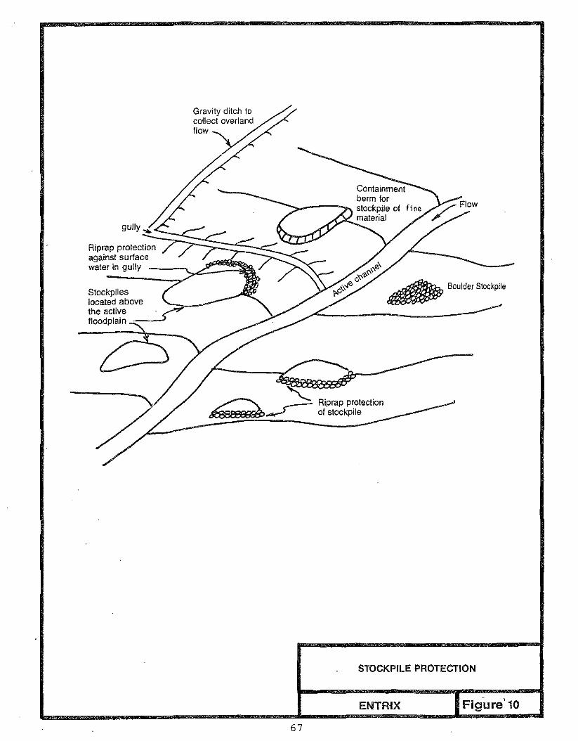
Gravity ditch to collect overland flow
gully ....
/Riprap protection against surface water in gully
Stockpiles located above the active . ./"? floodplain .-.->
Containment berm for stockpile of fine material
II!!J!/JfJP Boulder Stockpile
Riprap protection of stockpile
STOCKPILE PROTECTION
ENTmx Figure'10
67
temporary storage. In some cases, the trees can be used to construct log crib
containment berms for smaller organic material.
The most common forms of vegetat i on that are removed duri ng a placer ml m ng
operat i on are the small trees and shrubs that occupy previ ousl y undi sturbed
floodplain riparian zones. Proper stockpiling and protection of this material
is important since it will serve as the stock for natural revegetation, and
since the material is easily eroded. The small trees, shrubs, and grasses
should be piled with the top layer of organic soil. Placing these two types
af materials together accomplishes several objectives. First, the woody
materi a1 wi11 provi de some protection for the organi c soil from wind and
surface water erosion. Second, many species of shrubs and grasses will
continue to grow within the stockpile. This will improve the survival rate of
vegetation placed during site closure. Third, when the shrub layer and
surface soil are removed together, disturbance of the root zones will be
reduced, thus enhancing survival of the vegetation. This material should be
kept moist to maintain the Viability of the woody slash.
The shallow soils often consisting of fine organic material, sands, and
perhaps some gravel and cobble should be piled separately from the trees and
the shrub-organic soil piles. This material should be protected since it can
be eroded easily. If necessary, large rocks can be used for containment along
the side slopes of the pil es. Contai nment berms may also be constructed
around the stockpiles.
At some locations deep deposits of loess, or fine inorganic soil, must be
removed to expose pl acer-beari ng gravel s. In these s i tuat ions the 1arge
vol ume of materi a1 that must be handl ed dictates that it be moved a short
distance and only handled once. Typically, the most efficient handling of
this material is to push it up the valley side slopes into fan-shaped,
flat-topped mounds (Figure 8). At sites where large volumes of this material
must be handl ed, fi na1 stockpil e 1ocat ions shoul d prov i de maximum protection
from wind and surface-water runoff since this material is easily eroded. If
organic rehabilitation material is limited at the site, portions of this loess
materi a1 may be used both as a 1eve1i ng layer and as a seedbed to enhance
vegetative recovery (Section 10.3).
68

Oversize inorganic material, including large boulders, should be stockpiled
separately. The large rocks available on site may be used to temporarily
armor other stockpiles if necessary (Section 8.5.3). During stream
rehabil i tat i on, the 1arge boul ders will be useful as ri prap for bank and
channel stabilization (Section 8.5) or as fish habitat features (Sections
9.4.1 and 9.4.2). The larger cobble sizes, such as the material segregated by
grizzlies, may also be used during stream rehabilitation as streambed material
(Chapter 8.0). Stockpil ing this material may not be necessary during bench
mining.
In situations where highly erodibl e stockpiled materi al cannot be protected
us i ng berms and ri prap as descri bed, temporary seeding and fert il i zi ng us i ng
annual grasses may be useful to help stabilize this material.
69


INTRODUCTION TO SITE REHAB! LITATION
73

7.0 INTRODUCTION TO SITE REHABILITATION
7.1 OBJECTIVE AND SCOPE
The objective of the site-rehabilitation BMP's is to present design recommendat ions for permanent features that wi 11 promote and enhance the
natural recovery of aquatic and terrestri al habitats di sturbed by placer mining operations.
The site-rehabi 1itation BMP's are separated into three chapters discussi ng stream, fish habitat, and floodplain rehabilitation. Discussions in each chapter present preferred 1ocat ions and designs for stream and fl oodpl ai n features. Figure 11 shows floodplain cross sections for meandering, mountain, and braided streams identifying the riparian zone, inactive floodplain, valley terrace, and valley bench.
Stream rehabilitation covers design flows, stream pattern and placement, hydraulic design, and channel stability. A stream rehabilitated following these recommendations wi 11 be simil ar to the natural stream occurri ng above and below the mine site.
The fish-habitat-rehabilitation BMP's can be used to refine the stream design to improve habitat quality. Physical characteristics that affect fish habitat are discussed. Habitat requirements are presented for anadromous and resident fish in order to provide the basis for designing appropriate habitat features.
The fl oodpl ai n-rehabil itati on BMP's address the ri pari an zone, the i nact i ve floodplain, and valley terraces and benches. Recommendations for site grading and di spersement of stockpil es of overburden and organic soil sin each of
75
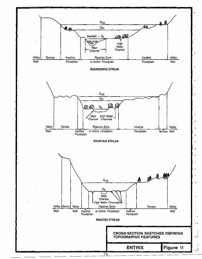
Valley Terrace Inactive
Bankfull ~ a, aan Annu ,,~
Main Channel
Riparian Zone
High Waler
Channel
Inactive Valle Wall Floodplain or Active Floodplain Floodplain Wall
MEANDERING STREAM
- 0100 r--I 1\ Q2S
\ W16-/m.~ Q2
~in High Water_ ChannAl Channels
Valley Terrace Riparian Zone Inactive Valley .Wall Inactive or Active Floodplain
Floodplain
MOUNTAIN STREAM
Floodplain Terrace Wall ,
Valley Bench Valley
Main Channel
High Waler Channels Riparian Zone Terrace Valley
Inactive Floodplain
Wall Wall Inaclive or Active Floodplain Wall Floodplain
BRAIDED STREAM
CROSS-5ECTION SKETCHES DEFINING TOPOGRAPHIC FEATURES "
ENTRIX Figure 11
76
i
these areas are provi ded. Finally, techni ques for revegetation to enhance natural recovery of each site are discussed.
7.2 SUMMARY
Site rehabilitation at placer mines includes providing areas within the disturbed site that can rapidly recover to provide productive habitat for local fish and wildlife. A summary of important issues and design objectives that should be addressed in site rehabilitation is presented in Table 5.
Stream rehabil itation following the completion of mining should provide a stream channel with proper configuration, size, and profile to safely pass a 2-year flood event. If fish are present in the stream, or if there is a high potent i al for fi sh to return to the stream from el sewhere in the drainage basin, then the stream design should also incorporate features to restore fishery habitat. Design recommendations are provided for streams of meandering, mountain, and braided configurations that create areas with proper velocity, depth, substrate, and cover for selected fish.
In general, final channel designs for fish streams should emphasize development of habitat for juvenile rearing, adult and juvenile feeding, and adult and juvenile passage. It is difficult to create spawning areas for species whose eggs incubate for long periods in redds that are highly dependent upon intragravel flow. The replacement of lost spawning habitat is extremely important to local populations, particularly where such habitat is the dominant factor limiting a population. In areas where spawning habitat did not exist, habitats for other life stages should be emphasized. Replacement of spawning gravels for broadcast spawners such as grayling has a greater probabil ity of providing usable habitat and is thus more easily justified.
Floodplain rehabilitation consists of final sloping and contouring of disturbed areas, and dispersement of stockpiled vegetative slash, overburden, and organic material to enhance site revegetation. Final site grading, if not done concurrently with mining activities, should focus on removing or reducing tailing piles to recommended slopes, providing controlled site drainage
77

Table 5. Summary of Issues and Design Objectives for Site Rehabilitation.
Activity Issues Design Criteria
Stream channel meandering, mountain, or braided rehabil i tat i on structure configuration
design for 2-yr recurrence flood proper slope, channel geometry,and bed and bank material channe1 profil e
Fish-habHat anadromous or channel profile and configurationrehabil Hat ion resident fish .. pools and riffles
adult and juve .. instream cover nile rearing ., riparian vegetation spawning habitat parameters passage .. depth, velocity, substrate
Floodplain site grading active and inactive floodplains rehabilitation .. drainage control
terrace and bench .. erosion and sediment control
. site revegetation preferred locations for organicsfish stream - riparian zone non-fish stream - riparian,settling ponds, catchment basins, wildlife corridors
78

patterns, stabilizing or cleaning settling ponds, and contouring steep slopes to control si te erosi on and si ltat ion. Fi na1 slopes and contours are most important in the active floodplain, or riparian zone where it is critical that the stream remain in its designed channel for the first several years.
The stream rehabilitation section provides design details for preferred final slopes in the active floodplain. In the inactive floodplain and valley terrace, contouring should provide a series of connected depressions between graded tailing piles to act as high water drainages and silt catchment basins. If steep slopes have been disturbed on the valley wall, a series of side contour benches should be created to minimize erosion.
Following site grading, all stockpiled overburden, organics, and vegetative slash and trees shoul d be pl aced in preferred 1ocat ions for enhancement of site vegetation recovery. The preferred locations for enhancing revegetation will vary by si te and are dependent upon stream confi gurat ion, presence of fi sh, and overa11 amount of site disturbance. Desi gn recommendat ions are provided for selection of preferred locations. In all cases, the objective of the stockpil e di spersement is to enhance the rapi d development of shrub thickets dominated by willows, birch, and alder.
79


STREAM REHABILITATION
81


8.0
STREAM REHABILITATION
8.1 OBJECTIVES ANO SCOPE
The objective of stream rehabil itation is to design a stream channel with natural stream patterns, cross-sectional geometry, longitudinal profile, and sediment-transport characteristics. Fish passage and, when appropriate, fish habitat should be provided in the rehabilitated stream. A channel so designed should require minimal self adjustment and thus should recover to its natural equilibrium condition rapidly. A combination of theoretical and empirical approaches is presented to meet thi s objective. Some el ements of permanent stream rehabil itat ion desi gn are a1so appl icable to temporary stream diversions.
The first steps of stream rehabil itation are to assess the acceptable risks at the site, select a design flow recurrence interval for channel design, and compute the corresponding discharge. The risks at the site should be assessed for temporary structures by considering the value of the stream, the structures to be protected, and the extent of mining at the site. Important recurrence-interval design flows for permanent rehabilitation include the mean annual flow for evaluating fish passage, the 2-year flood for designing the bankfull channel, the 25-year flood for defining the lowest terrace level, and the 100-year flood to define the upper limit of the inactive floodplain.
Once the desi gn-fl ood recurrence interva1 and di scharge value are obtained, stream pattern and placement must be considered. Stream patterns selected for use in stream rehabil itat i on desi gn are meanderi ng, mountai n, and brai ded. Recommendat ions are provided for sel ect i ng the stream pattern that woul d likely occur naturally in the valley being mined. Placement of the stream in
83

the valley is important in both the horizontal and vertical directions. The horizontal or plan view placement within the valley may in part be dictated by the miner's plan of operation but must also consider alternatives that will enhance habitat development and recovery. The vert i ca1 placement of the stream in the valley is very important to the long-term stability of the stream.
The stream-channel design should be based on bankfull flow. Design considerat ions i ncl ude channel geometry, hydraul i cs, stabi 1i ty, pattern, and profil e. Des ign of meanderi ng, mountai n, and braided streams use different techni ques. Meandering and braided streams are designed using the concept of regimechanne1 hydraul ic geometry. With thi s method, the hydraul i c geometry of numerous natural streams with the same pattern are used to develop equations for the hydraulie-geometry parameters of top wi dth, mean depth, and mean velocity. These equations are used to si ze the rehabi 1i tated stream. These streams will have a simil ar level of stabil ity to natural streams with the same pattern. Mountain streams, which are generally armored and relatively stable, are designed using channel stability as the basis for design.
In addition to including channel stability as a general consideration in the design process, a separate section is provided that discusses specific techniques to maintain bed and bank stabil ity. Bed and bank armoring and riprap protection are discussed and design recommendations are provided. This section is useful in the design of bed or bank protection at specific locations along the rehabilitated stream.
At mining sites where the stream is rehabilitated prior to the completion of mining at the site, areas of mining activity within the inactive floodplain of the stream should be protected with levees sufficient to satisfy the acceptable risks at the site. The levees should have maximum bank slopes of 3
to 1.
8.2 DESIGN FLOWS
Design flows consist of maximum and mean flows that may occur during the period of mine operation. Design-flow selection should be based on the
84

acceptabl e ri sks at the site. Desi gn flows must be eval uated for the design of temporary di versi on channels and for fi na1 rehabil itat i on of a stream channel. Two characteristics of design flows are the recurrence interval and the discharge.
8.2.1 Risk Assessment and Recurrence-Interval Selection
The acceptable risks for the structure to be designed and the value of the stream should be assessed. Table 6 presents initial design values of acceptabl e ri sks for temporary structures whi ch maybe modi fi ed to meet agency management goalsand site-specifi c conditions. The acceptabl e ri sk may be represented by the probabil ity that a flood event will occur. A higher probability indicates a higher risk that the event will occur. Classification of the value of the stream is based on its value in providing fish habitat, as described in Section 9.1.
Table 6. Acceptable risks of flooding for streams.
Va1ue of Stream Structure Diversion Channel
High30%
Medium 50%
Low 50%
Settling Ponds StockpilesHazardous material and camp
5% 5%
<5%
10% 10% <5%
20% 20% <5%
Following the evaluation of the acceptable flood probability for the temporary structures, the number of years of operation at the site should be determined. The site pl an, incl uding consideration of the amount of reserves in the ground, shoul d prov i de the bas i s to determine the duration of mi ning. The probability of occurrence of a certain event increases with the design life. A specific recurrence-interval flow is more likely to occur when more than 1 year is considered. For example, a 2-year recurrence-interval flood has a 50% probability of occurring in 1 year. If a mine is operated over 2 years, the probabil i ty that a 2-year recurrence- interval flood will occur increases to 75%.
85
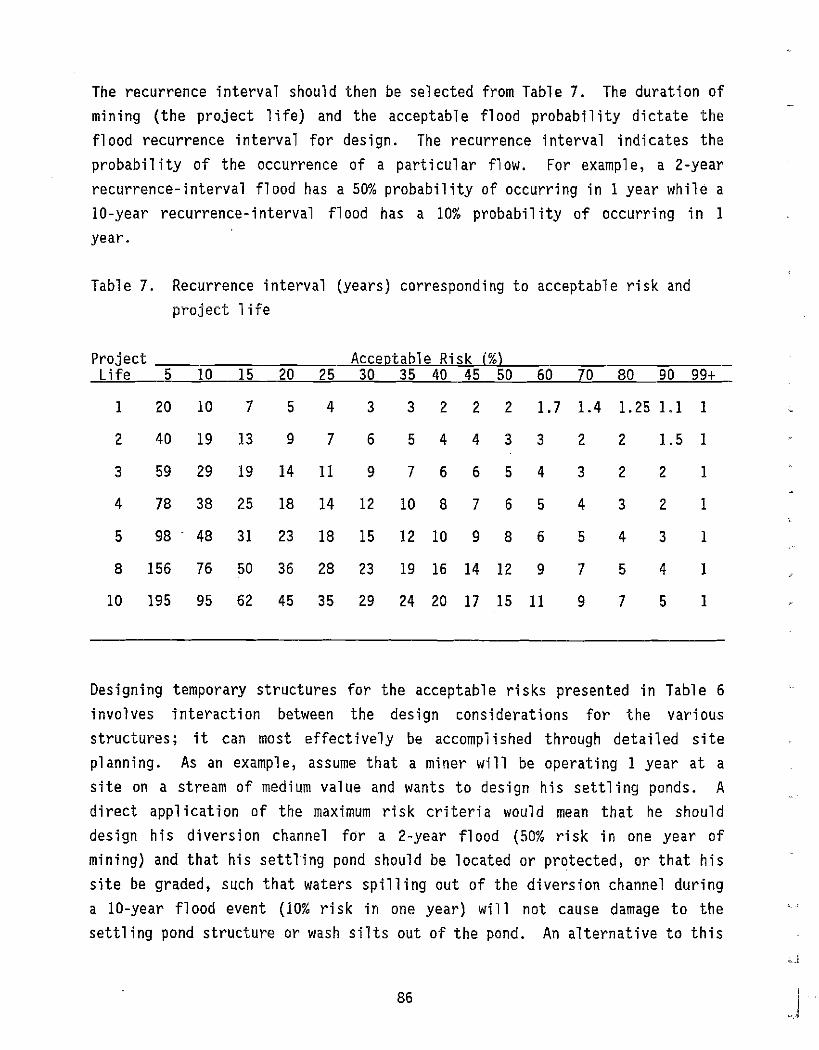
The recurrence interval should then be selected from Table 7. The duration of
mining (the project 1i fe) and the acceptabl e flood probabil ity dictate the
flood recurrence interval for design. The recurrence interval indicates the
probabil ity of the occurrence of a part i cui ar flow. For example, a 2-year
recurrence-interval flood has a 50% probability of occurring in 1 year while a
10-year recurrence-interval flood has a 10% probabil i ty of occurri ng in 1
year.
Table 7. Recurrence interval (years) corresponding to acceptable risk and
project 1ife
Project Acceptable Risk j%) Life 5 10 15 20 25 30 35 40 45 50 60 70 80 90 99+
1 20 10 7 5 4 3 3 2 2 2 1.7 1.4 1.25 1.1 I
2 40 19 13 9 7 6 5 4 4 3 3 2 2 1.5 I
3 59 29 19 14 11 9 7 6 6 5 4 3 2 2 1
4 78 38 25 18 14 12 10 8 7 6 5 4 3 2 1
5 98 48 31 23 18 15 12 10 9 8 6 5 4 3 1
8 156 76 50 36 28 23 19 16 14 12 9 7 5 4 I
10 195 95 62 45 35 29 24 20 17 15 11 9 7 5 I
Designing temporary structures for the acceptable risks presented in Table 6
involves interaction between the design considerations for the various
structures; it can most effectively be accompl ished through detailed site
planning. As an example, assume that a miner will be operating I year at a
site on a stream of medium value and wants to design his settling ponds. A
direct appl ication of the maximum risk criteria would mean that he should
design his diversion channel for a 2-year flood (50% risk in one year of
mining) and that his settling pond should be located or protected, or that his
site be graded, such that waters spilling out of the diversion channel during
a 10-year flood event (10% risk in one year) will not cause damage to the
settling pond structure or wash silts out of the pond. An alternative to this
86

approach may be to design the diversion ditch for a 5-year flood (20% risk in one year of mining) and design the settl ing pond for protection from the lesser quantity of water that would spill out of the diversion channel during the 10-year flood event. The mi ner shoul d evaluate whi ch approach woul d be most applicable for his particular situation.
The mean annual flow should be utilized as an index flow to assess the depth and velocity for fish passage and other habitat conditions (Section 9.3). The mean annual flow is approximately equal to the mean summer flow.
The design-flood recurrence interval for permanent stream channel rehabilitation is recommended on the basis of matching natural hydrologic and hydraulic processes. A natural gravel-bed stream channel generally adjusts its channel pattern, channel geometry, and 1ongi tudina1 profil e through a process of erosion and deposition. The controlling variables of the erosion and deposition process include stream discharge, sediment transport, bed and bank material, and valley slope (Hey 1982). Of these controlling variables, the bed and bank material and valley slope change slowly under natural conditions, while the stream discharge and sediment transport fluctuate widely each year.
Sediment transport processes, which are related to stream discharge, control the process of eros i on and deposit ion. Whil e rare flood events (e. g., 100year flood) can transport large quantities of sediment, they occur infrequently and are not dominant in forming the channel shape. A smaller flood, but one which has significant sediment transport capabil ity, would be the dominant flood. The frequently accepted flood for defining the channel cross section is the bankfull flood (Hey 1982, Parker 1979, Nixon 1959, Leopold and Wolman 1957). The recurrence interval of bankfull conditions was investigated by Emmett (1972) for streams in the Southcentral and Yukon regions of Alaska. The average value of bankfull frequency was about 1.5 years. Bray (1979) selected a 2-year flood to represent a relatively high in-bank flow on gravelbed rivers in Alber-ta, A 2-year recurrence interval flood is recommended for bankfull discharge for stream channel design so that the rehabilitated stream flows at bankfull conditions as frequently as natural streams. Calculation of the 2-year flood discharge is described in Section 8.2.2.
87

The 25-year and 100-year flood-recurrence intervals have been selected as
reference floods for floodplain rehabilitation. The 25-year flood level
should be selected as the minimum level below which the configuration is based
primarily on flood conveyance and flood protection as descri bed inSect i on
10.2. From this level up to the 100-year flood level, the rehabilitated
topography can reflect other concerns, such as wildlife habitat in addition to
the flooding concerns.
8.2.2 Design Flow Computation
After the acceptabl e recurrence i nterva1s have been selected, correspondi ng
d i scharqes must be evaluated. If the si te is located near a stream gagi ng
station, the gage records should be used to assess potential high and low
flows as described by the U.S. Water Resources Council (1981). Actual
streamfl ow data are preferred when eva1uat i ng flows. The des igner shoul d
contact the U.S. Geological Survey and the Alaska Department of Natural
Resources, Division of Geological and Geophysical Surveys to ask for flow data
on his stream. When mining sites are not located in the vicinity of a stream
gage, the high and mean annual flows must be estimated.
Parks and Madison (1985) have developed equations specific to Alaska for
predi cti ng hi gh and mean annual flows of varyi ng recurrence i nterva1s gi ven
drai nage area and mean annual preci pi tati on. These equations represent the
most current and extensive compilation of data collected by U.S. Geological
Survey on Alaska streams. Equations for four regions of Alaska (Figure 12)
were developed; for sites outside these four regions, the statewide equations
should be used. Table 8 presents the equations and the standard error
calculated for each equation.
The standard error of the equations should be considered when evaluating high
and mean annual flows. The range withi n whi ch the true val ue is expected to
occur 67 percent of the time is approximately bounded by the val ues one
standard error greater and less than the predi cted val ue. Therefore, where
equations are used to estimate the flows, the potential range of values should
be considered. For high flow cases, the standard error should be added to the
flow predi cted by the equation. For mean annual flows, the standard error
88
, I
_.J
J I
kJ

..---.......
•
ARCTIC SLOPE
" .._00-- :..,J NORTHWEST -,~,•....---- \
j \ /'~ IYUKON I \
" \ LEGEND:~ j \ Regional Boundaryoo
,/ 00
..'/ 0'
to,"", ____
ISOUTH-CENTRAL I C. ISOUTHWEST I [ ~
,.....~ 'i?.r?_
o 100 200 Ii' I I'
:.....- .. J/ \~_
Region for which Equations\I , were developed~ '0
\I
~ \ \...... ,...,
p7.&3"'"
7~ ta'"
300 Miles i 1
Kilometers
00 \0
REGIONAL BOUNDARIES OF EQUATIONS
Source: Parks andMadison 1985 ENTRIX Figure 12

Table 8. Equations for evaluating high flows of varying recurrence intervals and mean
Q = aAb1 pb2 log Q = log a + b1
log A + b2 log P
Q = flow (ofs) 2 A = drainage area (mf ) P = mean annual ~recipitation (in)
annuaL flows.
\!)
a
Statewide Southeast Region SQuthcentral Region Standard Standard Standard Error in Error in Error ; n
Parameters log units Parameters log units Parameters log units
QA 1 log a = ·1.51 .15 log a = -0.46 .14 log a = -1.33 .16 b1 =+0.98 b1 =+1.01 b1 = +0.96 b2 =+1.19 b2 =+0.68 b2 =+1.11
Q 2 log a = '0.41 .27 log a = +1.25 .19 log a = -0.69 .252 b1 =+0.88 b1 =+0.81 b1 =+0.87 b2 =+1. 20 b2 = +0.49 b2 =+1.31
Q5 tog a =: +0.10 .28 log a = +1.52 .20 log a = '0.25 .25
b1 =+0.84 b1 =+0.78 b1 = +0.83 b2 = +1.04 b2 =+0.44 b2 =+1.19
Q10 log a =+0.39 .28 log a =+1.66 .21 log a ::; +0.03 .26
b1 =+0.82 b1 =+0.77 b1 =+0.81 b2 = +0.95 b2 =+0.44 b2 =+0.13
Q25 log a =+0.73 .30 log a = +1.81 .22 log a =+0.25 .28
b. = +0.79 b1 =+0.76 b1 =+0.79 b' =+0.84 b2 =+0.38 b2 = +1.052
Q50 Log a = +0.97 .32 log a = +1.92 .23 Log a = +0.44 .29
b1 =+0.77 b1 = +0.75 b1 =+0.77 b2 =+0.76 b2 = +0.36 b2
=+0.99
Q100 tog a = +1.20 .33 log a =+2.01 .24 log a :;:; +0.63 .31
b1 =+0.75 b1 =+0.74 b1 =+0.75 b2 =+0.69 b2 = +0.34 b2 =+0.94
-QA :;:; mean annual flow
2 Q2 = High fLow of 2-year recurrence interval.
Note: Use statewide equation for regions without specified equations.
Source: Parks and Madison, 1985
Southwest Region Standard Error in
Parameters Log units
log a = -1.38 .15 b1 =+0.98 b2 = +1.13
log a = +0.37 .18 b1 =+0.86 b2 = +0.59
log a = +0.97 .16 b1 =+0.84 b2 =+0.34
log a = +1.33 .15 b1 =+0.83 b2 =+0.19
log a =+1.73 .15 b1 =+0.82 b2 =+0.02
log a = +2.01 .15 b1 =+0.81 b2 = -0.10
log a = +2.27 .16 b1 =+0.80 b2 = -0.20
Yukon Region Standard Error in
Parameters log units
log a = -2.04 .10 b1 =+1. 05 b2 =+1.39
log a = -0.20 .25 b1 =+0.91 b2 =+1.02
l09 a = +0.39 .26 b1 =+0.85 b2 =+0.85
log a =+0.73 .28 b1 =+0.82 b2 =+0.74
log a =+'.13 .30 b, =+0.78 b2 ::: +0.62
log a = +1.39 .32 b1 =+0.76 b2 =+0.54
log a = +1.64 .34 b1 = +0.73 b2 =+0.47
L (

shoul d be subtracted from the flow pred i cted by the equation. The use of the
standard error wi11 decrease the uncerta int i es associ ated with usi ng the
generalized equations, especially in the case of small or high mountain
basins.
Other methods of estimating high flows are available. Ashton and Carlson
(1984) developed alternative equations for evaluating spring, summer, and fall
high flows in southcentral and interior Alaska. These equations may be useful
if flows during only one part of the mining season are of concern. High
spri ng fl ows pred i cted by Ashton and Carl son (1984) appear to be s imil ar to
the annual high flows predicted by Parks and Madison (1985). The Alaska
region of the U.S. Forest Service (1979) presented several graphs of high
flows versus drainage area for streams in southeast Alaska.
High and mean annual flows may be evaluated from the easily measured variables
of drainage area and mean annual precipitation. Although additional physical
and cl imat i c characteri st i cs are known to i nfl uence streamflow, the
reliability of the equations developed by Parks and Madison (1985) did not
significantly increase when other variables were included.
The drainage area upstream of the mining site may be obtained from topographic
maps of the region. The USGS topographic maps which depict the site in the
greatest detail should be used. The drainage basin should be del ineated and
the area should be calculated. A planimeter or the grid-sampling method of
determining drainage area may be used (Jones 1983).
Mean annual precipitation data for Alaska are presented in Appendix C (Lamke
1979). The data are generally from low-lying coastal and river valley areas
and may not adequately predict precipitation at higher elevations. In
portions of the Southcentral and Southeast regions, more accurate maps of mean
annual preci pi tat i on adjusted for el evat i on have been prepared (Ott Water
Engineers, Inc. 1979). Although the actual mean annual precipitation at a
site is 1i kely to be greater than the values obtained from Appendi xC, the
development of the fl ow-predi ct ion equat ions was based on unadjusted mean
annual precipitation values. If the equations developed by Parks and Madison
(1985) are used, the maps in Appendix C shoul d al so be used. The use of
91
unadjusted precipitation values should not cause a significant error in the flow prediction.
8.3 STREAM PATTERN AND PLACEMENT
8.3.1 Definitions
Stream pattern is the configuration of the stream as it is seen from the air. Natural streams may take any of a number of patterns depending on the slope of the vall ey through whi ch the stream is fl owi ng, the amount of fl ow in the stream channel at bankfull flow levels, and the amount of sediment carried by the stream. For the purposes of stream rehabilitation, streams will be classified into one of three types:
1. Meandering streams wind back and forth within the floodpl ain in a regular pattern and typically have gravel-bar deposits on the inside of each bend.
2. Mountain streams are high-gradient, single-channel systems carrying relatively low sediment loads.
3. Braided streams contain two or more interconnect ing channel s , separated by unvegetated gravel bars or sparsely vegetated islands, and transport large quantities of sediment during most summer flow levels.
Schematic diagrams of each are shown in Figure 13. Other stream patterns have been used in the past by various investigators (e.g. Leopold and Wolman 1957, Karaki, et al. 1974, Joyce et al. 1980). The categories selected for stream rehabilitation design include the other patterns as shown in Table 9.
92
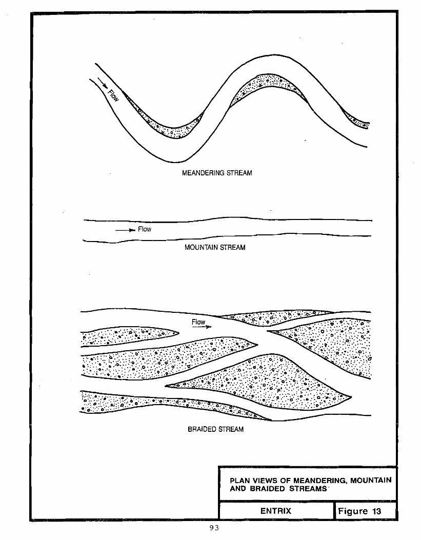
--
MEANDERING STREAM
_____-_- F~IO~W~ --------------------
MOUNTAIN STREAM
.<Jitf';;'::~:::':-~~':.;;.::ll:'" . . : Flow
. . . .. . .' O·.'·J)
" t •• o· .. "0;:::3:>.
~ '.'
BRAIDED STREAM
PLAN VIEWS OF MEANDERING, MOUNTAIN AND BRAIDED STREAMS'
ENTRIX Figure 13
93

Table 9. Relationship between stream categories used for rehabilitation and those defined by various authors.
StraightSinuous MeanderingSpl it Braided All uv i al Fan Mountain
Meandering
X X X X
Braided Mountain
X X
X
For example, a stream that has been classified as sinuous should be rehabilitated using the BMP's for meandering streams.
8.3.2 Selection of Stream Pattern
The stream pattern for the rehabilitated stream channel should be selected to match the pattern that woul d 1i kely occur naturall y. Eva1uat ing the natural pattern can be difficult since defining the channel-pattern categories requires selection of an indistinct boundary in a continuum of stream patterns. When uncerta int ies exist, the more stabl e meanderi ng and mountai n patterns should be selected.
The selection of a stream pattern should be based on actual data when available; theoretical data should be used only when actual data are unavailable. The type and amount of data which should be collected will depend on the previous amount of disturbance within the valley; three types of sites are defined in Table 10 and discussed further below.
-"--"
94

Table 10. Type of data for selecting stream pattern category for threetypes of sites.
Actual Theoreti cal
Site not previously mined x Site previously mined but upstream or
downstream has not been mined x x Entire valley has been mined X
A. Site Not Mined
Actual stream observations and data should be used at sites which have not been previously mined and which have not been disturbed by upstream mining. This will enable the miner to design his rehabilitation plan to return the stream channel to a near-natural pattern. Data that should be collected and mapped to scale include:
'1. stream channel course or position
2. number and length of pools and riffles
3. location of multiple-channel reaches and number of channels
These data can be collected from one or a combination of any of the following techniques, which are listed in order of decreasing accuracy:
1. field surveying measurements
2. aerial photographs with known scale
3. topographic maps
Field observations and estimates are helpful to support methods 2, 3, and 4.
95

The stream-rehabilitation plan should define a stream pattern that is similar to the natural pattern. The position within the floodplain may be different, but the length, number and degree of bends, and number and location of pools and riffles should be equivalent to those in the natural stream. Additional pools may be needed in mountain streams to increase stability. Multiplechannel reaches should be evaluated for stability and designed as meandering reaches if stable, or braided reaches if unstable. The stabil ity can be eva1uated by observi ng sediment-transport trends and channel shi ft ing. Unstable braided streams typically transport suspended sediments and even bed load at flows 1ess than those cl earing flood events; many braided channel s also shift frequently resulting in unvegetated floodplains. If the valley slope is nonuni form or unknown, then the desi gn shoul d be based on valley segments, with the relocated stream havi ng the same characteri st ic as the natural stream within each segment.
B. Site Mined but Valley Not Mined
The valley slope should be surveyed in the field or measured on topographic maps for the site, as well as for similar lengths of undisturbed segments of the valley upstream or downstream of the site. If a valley segment upstream or downstream has a slope that is relatively uniform and nearly equal to the slope at the site, then the data collection recommended for unmined sites can be conducted at the undisturbed valley segment for appl ication to the site. If the valley slope elsewhere is nonuniform or different from that at the site, then the theoretical approach presented below for mined valleys should be used to support measurements and observations of stream patterns elsewhere in the valley.
C. Valley Mined
Theoretical data must be used to evaluate an appropri ate stream pattern in valleys which have been mined to the extent that natural stream patterns are not evident in the near Vicinity of the site. Channel pattern was studied by Leopold and Wolmon (1957) based on field and laboratory data. They found that categorizing streams into braided, meandering, and straight patterns was difficult. Braided streams can change to meandering streams over a short
96
distance, while individual channels of a braided stream may meander. They did observe that braided patterns could be differentiated from meandering patterns with certain combinations of channel slope, discharge, and width-to-depth ratio. A relation was developed between channel slope (S) and bankfull di scharge (QBF) that separates meanderi ng streams, whi ch were taken to be those streams with a sinuosity greater than 1.5, from braided streams:
S = 0.06 QBF- 0. 44
For a given discharge, meandering streams would have channel slopes less than that calculated by the equation while slopes of braided channels would be greater. Straight channels did not follow this trend as they occurred throughout the range of slopes considered. Thus, other variables that may control the stream pattern are not considered. Bray (1982) plotted data from gravel-bed streams in A"lberta on a graph relating channel slope (S) to the 2-year flood (Q2)' He found that many of his meandering 9ravel-bed streams had channel slopes greater than the slope indicated by the Leopold and Wolmon (1957) equation. He refined the equation to include most of his streams with sinuosities greater than 1.25:
S = 0.16 Q2- 0. 44
Laboratory experiments by Schumm and Khan (1972) showed that there is a relationship between the slope on which the channel is formed, or the valley slope, and the sinuosity of the thalweg and channel (Figure 14). The thalweg is a fine line following the lowest or deepest part of the stream bed. Note that Figure 14 is illustrative of the effect of valley slope only, since discharge is not included as a variable.
The studies discussed above illustrate that the causative factors for meandering and braided channel patterns as defined for these BMP's cannot be clearly differentiated. There are trends in stream pattern relating to channel and valley slopes, bankfull discharge, and possibly bed-material size. Using data on gravel-bed rivers in Alberta (Bray 1979), a graph was developed that relates channel pattern to valley slope and 2-year flood (Figure 15) for initial selection of stream pattern. The slope of the valley at the mine site
97

I
c3 1
i ~
Q "
... ••.:s,
,----,!! .t---': -8: --7
",r,
J.
~r1r~-<\ I.
I "q
L-+'--i--1-11
I.. ~
...-: i
2:
f.: d-Q~
\'~ i
~ III
-+-+
\ I.,.
2(/), ..~
~ I~. I
.. ~.
<:
~'
It IZ
'W
!I'"
98

.1 L I I I I I I I II I I Iii I j II I I I , I I I II I I I I I I I I I I I I I I I I 0
.01
cJ;
co
'" .001
Mountainous or Braided o
A
o
1.00 -
1.25 -
1.55 -
SINUOSITY
1.25
1.55
+
x
1.85 -
2.15 -
1.85
2.15
2.45
Meandering ..... 0to,. ~ c:
~ to,.
o to,. to,.0to,.
to,. ~ 0o to,.
00 0 0
to,.c: -I 0 00
o o0 °0-1t to,. 0 o
to,. to,. to,. o o0 0 o to,.0
io 0
l< r:A
o
o
100 1000 10000 100000
Q2, CFS
GRAPH FOR INITIAL SELECTION OF· STREAM PATTERNNOTE: Line is modified from Bray's line for channel slope
Source: Modified from Bray 1982 Figure 15ENTRIX

should be measured in the field or from topographic maps and the bankfull, or
2-year, discharge should be obtained as described in Section 8.2.2. These
values should be used on Figure 15 to evaluate if the valley slope is mild
enough to design a meandering stream. An equilibrium-slope technique can be
used to estimate the value of sinuosity (Section 8.4.1). If the slope is too
steep for a meandering stream, then in general, a mountain stream pattern
should be selected. If the bed-load transport in the stream under natural
conditions would be expected to be high during most summer flow levels, a
braided pattern can be selected.
8.3.3 Stream Length
The stream pattern is important since it defines the length and consequently
the slope of the stream channel. The 1ength of the streambed is a crit i ca1
element of stream rehabilitation. The length of the stream is related to the
stream pattern and valley length (Figure 16). If the stream is shorter than
the original stream length, then the slope will be steeper. The steeper slope
can cause erosion at the upper end of the site; this material will typically
be transported through the steep reach to downstream reaches where it will
deposit (Bray and Cullen 1976). The opposite can occur if the stream is
longer than natural through the site. Material will deposit in the upper end
of the site and will erode in the upper end of downstream reaches. An
equilibrium configuration without excessive aggradation or degradation can be
achieved only if the stream bed is of proper length and slope. Thus, natural
(unaffected by mining) stream lengths should be used for design. In cases
where the natural stream 1ength cannot be measured, the hydraul i c des ign of
the stream channel should be used to evaluate an appropriate length.
8.3.4 Placement of stream Pattern
It is preferable to locate the stream adjacent to undisturbed veqetated areas
whenever possible. This can often be accomplished by locating the stream
along one valley wall. In wide valleys, this can allow final stream placement
to be made on previously mined ground instead of using a temporary diversion
while the other side of the floodplain is worked. This minimizes the number
of times that a stream must be handled. It may also be advantageous to use J 100 i .
~,J

Natural Stream Pattern
Straighter Pattern
More Meandering Pattern
PLAN VIEWS
Channel Length
c: o
~ ill
Too Long
Equilibrium Steeper Slope Milder Slope
PROFILES
Correct
Length
T
EFFE"cr OF CHANNEL LENGTH ON STREAM EQUILIBRIUM
ENTRIX Figure 16
101

part of the diversion channel if final design is taken into account in the design of the divers ion. Equi pment shoul d be conf'i ned to the excavated channel or previ ously disturbed areas to avoi d di sturbi ng vegetated banks. The stream can be placed so that it shifts from one side of the valley to the other, within the stream-length constraints placed by the stream pattern. The shift across the valley should be designed with a shallow angle between the stream-pattern axis and the valley axis (Figure 17).
The location of the settl ing pond system is an important consideration when relocating the stream pattern. Settling ponds within a stream channel should be avoided. Section 10.2 describes the rehabilitation of settling ponds which are not located within the stream channel. If site constraints necessitate the routing of a stream through an area containing an existing settling pond, extens ive c1 eaning wi 11 be requi red. The pond must be c1 eaned of fi ne sediments as described in Section 4.2.5. The sediments should be stockpiled outside the active floodplain, contained, and protected to prevent the silty material from entering the stream. Section 10.2 describes the stockpiling and distribution of silty material from the settling pond. The settling-pond dam should also be rehabilitated to conform to the configuration of the rehabilitated stream.
8.3.5 Stream Bed Elevation
The level, or elevation, of the stream bed should be equivalent to that of the natural stream bed. The stream-bed level affects the local slope at the transit i on to the natural stream bed upstream and downstream of the mi ned site.
The level of the stream bed is important for the same reasons as the stream length. If the stream is located lower than its natural level, erosion or headcutting can occur at the upstream end (Figure 18). The channel bed will also be closer to the bedrock surface than the natural channel and thus more susceptible to aufeis formation. If the channel were placed too high, deposition would occur at the upper end, while headcutting would occur within the site (Figure 18).
102

( Valley Width
SHIFTING A MEANDERING STREAM FROM ONE SIDE OF THE VALLEY TO THE OTHER
ENTRIX Figure 17
103

0
~
eo .!: '" ::;;
-, <:: .9e ~'" u
i .<
:: .52' ::c 0
.<::
F? e;, <::
...J '" Cii <:: c s: '" 0
<.> '"
'"'0 ~
'"
::J
CO
(/)
E"5
ee 0
-, ~-o
Ci5~
II
" -, -,
<::
.9
'" e W
UO!IEAaI3
10
4
z 0 oJ W
Cl)
... .. Q)
::J C
l.-U
.
>< it IZ
" >W
oJ
~::m
;:)::c(D
: W
!Ea::::! 1
-;:)(1)0 LL W
O
oJ w
· t>~ w
Z
LL
c(LL::t: W
eJ
< F
,

Careful attention to the consistency of the materials at and below the streambed will help to minimize the loss of surface water to the underlying gravel s. The channel shoul d be formed ina mi xture of the sand and small gravel tailings and some of the oversize materials consisting of large gravels and cobbles. A mixture of the sluice tailings and oversize material in the approximate proportions of the material at the site should be used. A layer of oversize material consisting of large gravels and cobbles should be placed above the finer materi al to form the bed and banks of the stream channel. Boul ders and the remain ing 1arge gravel sand cobbl es shoul d be retained for other uses (Section 8.5). The channel should either be excavated to the proper 1eve1 and confi gurat i on in the existi ng materi a1s, or appropri ate materials should be backfilled onto bedrock to bring the streambed up to the desired 1eve1. - -- -
Erosion and deposition resulting from incorrect stream length or level are the natural processes through whi ch the stream adjusts its channel shape and longitudinal profile to equilibrium conditions. If large adjustments are required, stream-recovery time is longer. Deposition can also reduce the channel's capacity to carry floods.
8.4 HYDRAULIC DESIGN
Hydraulic design of the bankfull channel includes the design of channel cross sect ions, stabl e bed slope, channel-pattern dimens ions, and channel profil e. Different design approaches are used for meandering, mountain, and braided stream patterns. The requirements for fish passage are incorporated into the stream design approaches.
8.4.1 Meandering-Stream Design
A number of parameters must be defined for the design of a meandering stream:
1. Channel geometry and bed stability a. Top width, W b. Mean depth, d
105
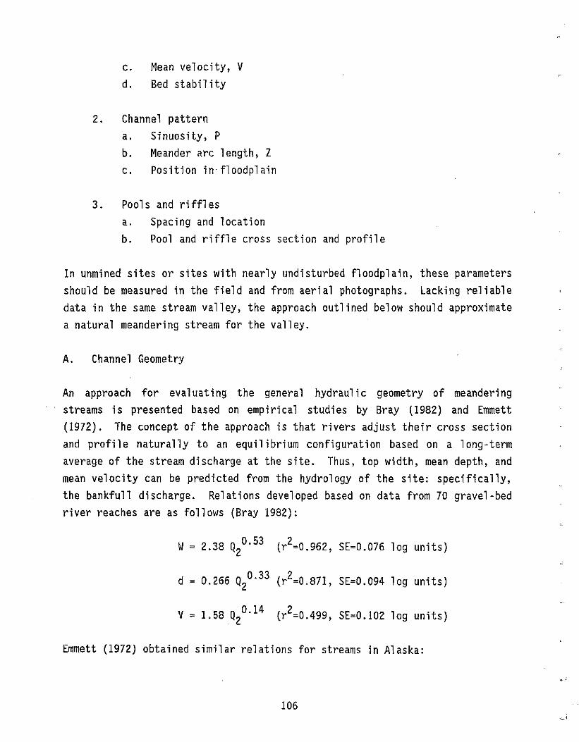
c. Mean velocity, V d. Bed stabil i ty
2. Channel pattern a. Sinuosity, P b. Meander arc length, Z c. Position in· floodplain
3. Pools and riffles a. Spacing and location b. Pool and riffle cross section and profile
In unmined sites or sites with nearly undisturbed floodplain, these parameters should be measured in the field and from aerial photographs. Lacking reliable data in the same stream valley, the approach outlined below should approximate a natural meandering stream for the valley.
A. Channel Geometry
An approach for evaluating the general hydraulic geometry of meandering streams is presented based on empirical studies by Bray (1982) and Emmett (1972). The concept of the approach is that rivers adjust their cross section and profile naturally to an equilibrium configuration based on a long-term average of the stream discharge at the site. Thus, top width, mean depth, and mean velocity can be predicted from the hydrology of the site: specifically, the bankfull discharge. Relations developed based on data from 70 gravel-bed river reaches are as follows (Bray 1982):
2W= 2.38 Q20. 53 (r =0.962, SE=0.076 log units)
d = 0.266 Q20. 33 (r2=0.871, SE=0.094 log units)
2V = 1.58 Q20. 14 (r =0.499, SE=0.102 log units)
Emmett (1972) obtained similar relations for streams in Alaska:
106

W= 2.39 Q 0.50BF
d = 0.26 QBFO. 35
V = 1.62 QBFO. 15
These two sets of equations are very similar. The 2-year discharge calculated for the mine site should be used in Bray's equations to evaluate the general size and mean velocity of the channel.
B. Bed Stability
The slope of the rehabil i tated stream should be compared to the equ il i bri urn slope to identify the bed stability. The slope of the rehabil itated stream (Sc) can be obtained from the change in bed elevation between the upstream and· downstream boundary of the site (H) divided by the channel length If(Lc)' the natural channel 1ength cannot be measured due to previous mini ng in the valley, the channel should be designed on the basis of the equilibrium slope. The condition of stability should be evaluated for a flow level equal to 3/4 of the bankfull flow level because this level has been found to represent the level at which median-sized bed material begins moving in meandering streams (Dunne and Leopold 1978). The equilibrium slope, or slope at which bed material is about to move for the given flow, geometry, and bed material size, is represented by the equation developed by Simons, Li and Associates (1982):
where Se = the equilibrium slope = the median size of the bed material (ft)D50
R = the hydraulic radius at 3/4 bankfull (ft)
The median size of the bed material (D50) should be estimated through a visual inspection during a site visit or by a sieve analysis of a material sample collected during the site exploratory program. The design may need to be modified if the size of the available material is found to be significantly
107
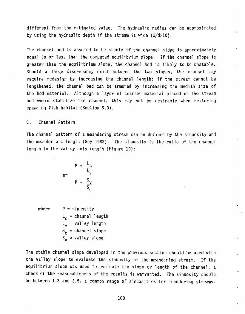
different from the estimated value. The hydraulic radius can be approximated by using the hydraulic depth if the stream is wide (Wjd>10).
The channel bed is assumed to be stable if the channel slope is approximately equal to or less than the computed equilibrium slope. If the channel slope is greater than the equilibrium slope, the channel bed is likely to be unstable. Should a large discrepancy exist between the two slopes, the channel may require redesign by increasing the channel length; if the stream cannot be lengthened, the channel bed can be armored by increasing the median size of the bed material. Although a layer of coarser material placed on the stream bed would stabilize the channel, this may not be desirable when restoring spawning fish habitat (Section 9.0),
C. Channel Pattern
The channel pattern of a meandering stream can be defined by the sinuosity and the meander arc length (Hey 1983). The sinuosity is the ratio of the channel length to the valley-axis length (Figure 19):
P = Lc Lv
or P = Sv
Sc
where P = sinuosity Lc = channel length Lv = valley length Sc = channel slope Sv = valley slope
The stable channel slope developed in the previous section should be used with the valley slope to evaluate the sinuosity of the meandering stream. If the equilibrium slope was used to evaluate the slope or length of the channel, a check of the reasonableness of the results is warranted. The sinuosity should be between 1.3 and 2.5, a common range of sinuosities for meandering streams.
108
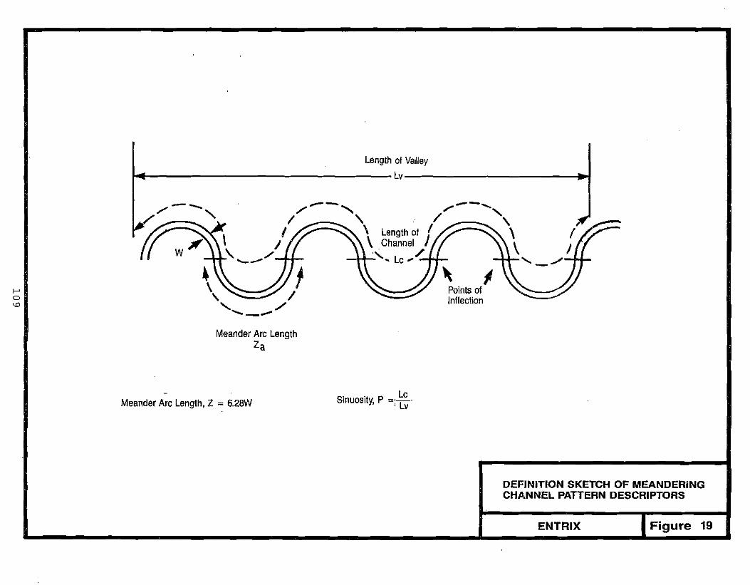
f-' o
""
Length of Valley
I~ ~ -I
I /--,
,
\ /~\ .~ /-+f-.
1 ,~/
.......<:»?
Meander Arc Length Za
Lc Meander Arc Length, Z = 6.28W Sinuosity, P =: Lv
DEFINITION SKETCH OF MEANDERING CHANNEL PATTERN DESCRIPTORS
ENTRIX Figure 19

If the calculated sinuosity is less than this range, the stream should be designed for a sinuosity of 1.3 in order to maintain a meandering stream pattern; such a sinuosity will be more stable than the equilibrium condition. If the sinuosity is calculated to be greater than 2.5, consideration should be gi ven to whether the vall ey physical constrai nts allow a greater s inuos i ty and/or whether drop structures could be used to reduce channel slope, and thus sinuosity.
The meander arc length is the channel distance between two points of inflection (Figure 19j. The rel ation for meander arc length is given by Hey (1983) as follows:
Z = 6.28 W a
Since bankfull channel width (W), sinuosity (P), and the length of the site (Lv) are known, the number of meander arcs (N ) in the site can be calculated a by:
A meander arc is half of a full meander sequence, so the number of meander sequences is:
Nm = N/2
= PLv 12.56W
The 1ength of the si te shaul d be subd i vided into N segments, each of whi ch m will have a similar design. Partial segments should be split between the upstream and downstream ends for use as transi t i on segments. Each segment should be further designed as described in the next section.
The segments must also be linked into a somewhat regular sequence of meanders through the site. While it is likely and preferable that the entire sequence
110
~' e
. , ~

of meanders wi 11 foll ow one vall ey wall through the site, conditions may necessitate shifting from one side of the valley to the other.
D. Pools and Riffles
Pools and riffles are characteristic of most streams, but are most prevalent in meandering streams. The spacing of the pools and riffles is related to the meander arc length discussed in the previous section. Generally, pools are spaced 5 to 7 channel widths apart, as are riffles (Leopold, Wolman, and Miller 1964). In an unmined site, the lengths of pools and riffles and the distance between riffles should be measured at a relatively low flow.
Pools and riffles are formed by an undulating streambed. At low flows, the water surface is nearly fl at in the pools and steep on the ri ffl es (Figure 20). As flows increase, the water surface in the pool increases while the riffle water surface decreases its steepness. At about three-fourths bankfull, the riffles are drowned out and the water surface is relatively uniform (Dunne and Leopold 1978).
The shape of the channel through pools and riffles continuously changes from deep, asymmetric pool cross sections to more shallow, nearly symmetric riffles or crossings (Figure 21). Several characteristics can be summarized from these cross sections:
1. Pool (bend) cross sections are deepest in the apex of the bend
2. Pool cross sections have a steep outer bank
3. Pool cross sections ri se slightly less steeply on the inside of the bend than the outside
4. Pool cross sect ions 1eve1 off significantly on the point bar
5. Pool cross sections sometimes have a small depression on the inside edge of the channel
III

---------
•
,
... ...... t:. P I ---. ";~:':o:. 00 .~. ------- _
Riffle "!::. o:::O::<!": .... o' .;.0 -,~.:.~ :: ...~ ........:.-=-:.:-:;-;-;;-;.:~:.:
Riffle -------
Pool
SIDE VIEW
,
Pool
PLAN VIEW
r------------------------I't.1SIDE VIEW AND PLAN VIEW OF A POOLRIFFLE SEQUENCE ;J
ENTRIX Figure 20
112
I

Measurement reach on Fall River at Horseshoe Park, Rocky Mountain National Park, 24·27 August 1983
-
SCALE (FT.) -
[;/-----;7 SCALE FOR ALL CROSS SECTIONS SECTION 1: BEND A, ENTRANCE
SECTION 5: BEND B, ENTRANCE
SECTION 6: BEND B, APEX
CROSS SECTION SHAPE IN POOLSSECTION 4: INFLECTION POINT AND RIFFLES
ENTRIX Figure 21Source: Thorne and Rais 1983
Two
One
Bend A _ Three
\ l ,
Distance (ft.) o 10 20 30
1 !
___ Section Used in Field Section Corrected ForContinuity
i.,,,,, Exposed Point Bar Sand Cut Bank :1-------- 10
. Five
Discharge Approx. 30% of Bankfuil
SECTION 7: BEND B, EXIT
113

6. Riffle cross sections (inflection points) are slightly asymmetric
The locations of pools and riffles vary somewhat as a function of sinuosity, as shown in Figure 22. The depth and length of a pool is dependent upon the radius of curvature of the bend, sediment load, and stream size (Karaki et al. 1974). Sharp bends are normally deeper and have larger bars than long-radius bends (Figure 23). The shape of a cross section ina bend is developed theoretically by Bridge (1975) (Figure 24). A simple approach was taken to develop a meandering channel out of a previously channelized stream in North Carolina; an asymmetric channel was developed by cutting a 2 to 1 slope on one bank and a 3 to 1 slope on the other bank with the bed undisturbed (Keller 1976). Following construction, point bars formed on the 3 to 1 slope as planned. A simple approach illustrated in Figure 25 is recommended for use as a guide establishing cross sections during stream rehabilitation. The grades and channel-width proportions provided in Figure 25 are general guidelines for obtaining appropriate cross-section shapes for a meandering stream. These guidelines should be used for the initial design but can be modified slightly in the final design to simplify construction. Abrupt changes in cross-section shapes should be avoided. Bank configuration above the bankfull level is considered in Section 10.2.
8.4.2 Mountain-Stream Design
A mountain stream is characterized by narrow valley walls and/or steep gradi ents. The stream may be confi ned by the narrow vall ey. The steep gradient contributes to a relatively straight, single channel with rapid flow.
Stability within the stream channel is the predominant hydraulic-design parameter. High channel velocities would erode small materials on the stream bed and banks. In addition, flow will tend to cascade around rocks creating uplifting forces rather than flowing over the rocks (Simons, Li and Associates 1982). Therefore, large rocks should be used to armor the channel. Details of stream-bed armoring are provided in Section 8.5.1.
114
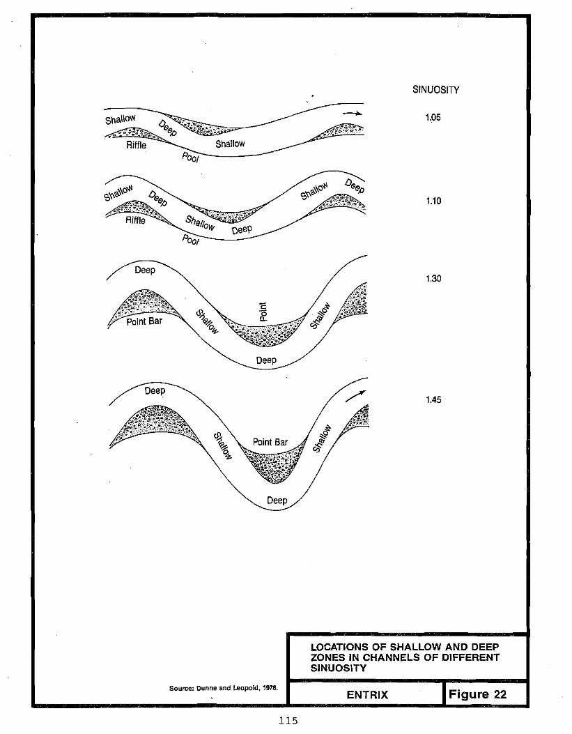
SINUOSITY
1.05sn~\~o:.. ~"O. b&~·····~·~;'e-"~~;~1\~~~-~"
• 0 -0.Riffle Shallow
Poo,----
1.10
Deep 1.30
Deep
Deep
Deep 1.45
LOCATIONS OF SHALLOW AND DEEP ZONES IN CHANNELS OF DIFFERENT SINUOSITY
Source: Dunne and Leopold, 1978. Figure 22ENTRIX
115
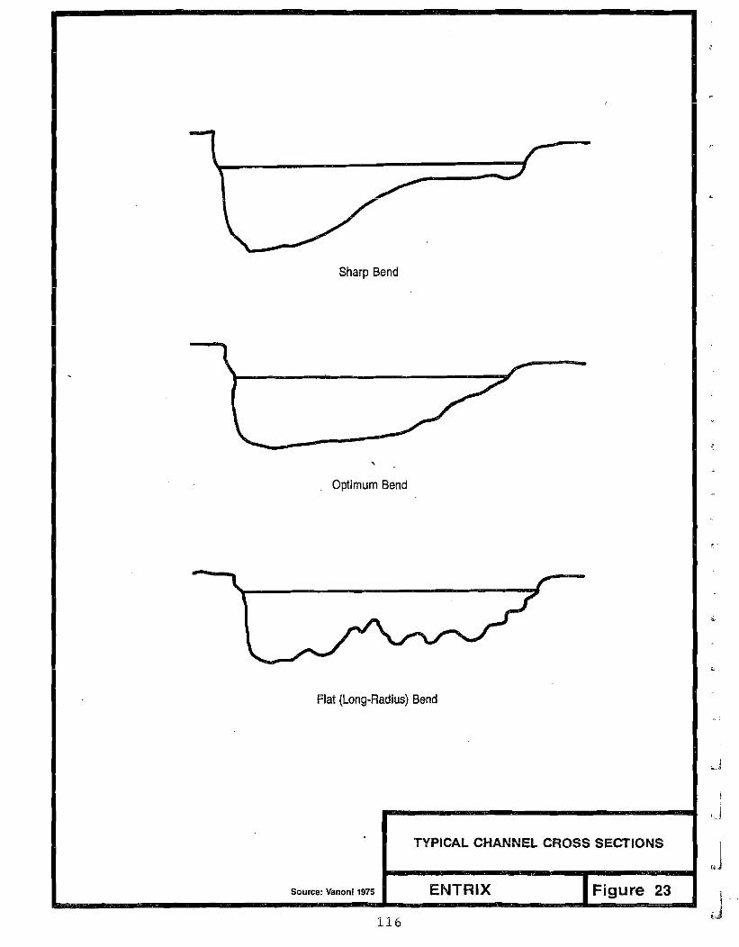
Sharp Bend
Optimum Bend
Flat(Long-Radius) Bend
TYPICAL CHANNEL CROSS SECTIONS
Source: Vanoni 1975 ENTRIX Figure 23
116

xellE
C
! ""C
~x
~
?!:
<X:!0
?!: cq0
~O'!0a-Ie
x d
""C
II '<
l;0
xE'"?!: x?!: Nd
o "!
....00ll.u..0~JW:E0W
zC)o.... (H
i-wJ-1
IlWlI:lIlo IIIw
OX
li:J-()
o:tC'Il
Ql
..::l
. Cl
II.Xa:IZW
11
7
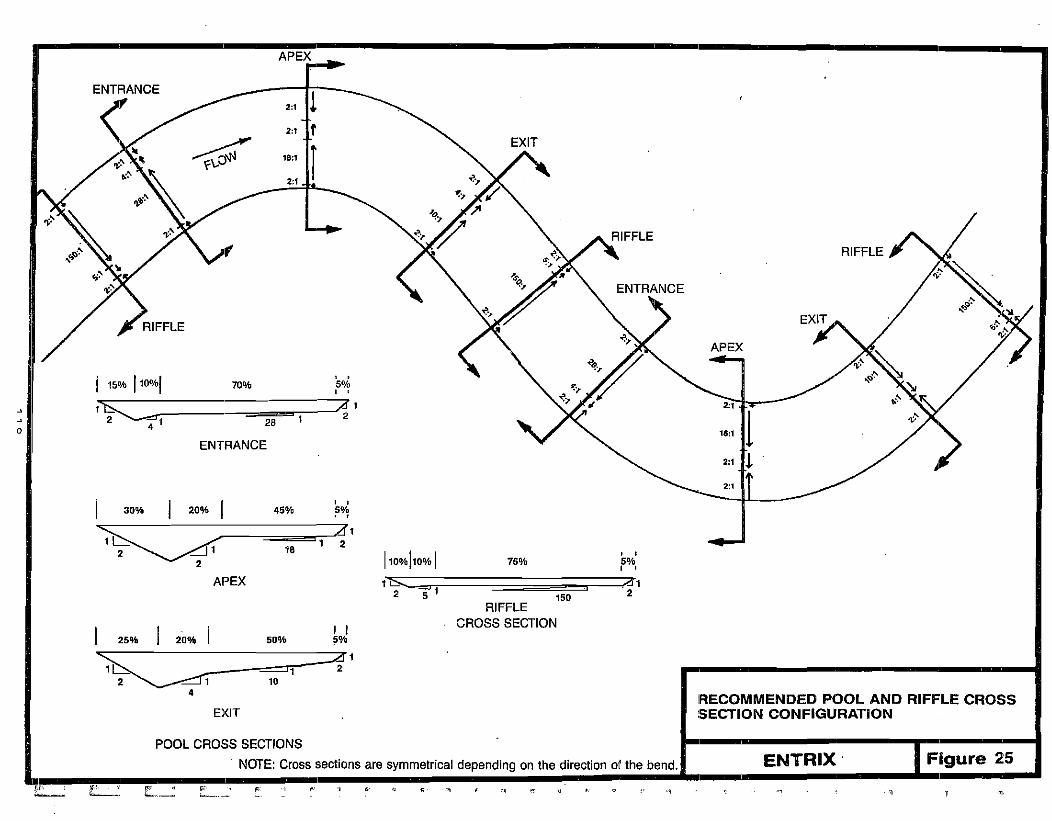
APEX
ENTRANCE ---:11 2" If
ta.t Ir 2:1 I
ENTRANCE
APEX
'-.. \. "~, // <, --, ' 0'4 70% 5%I 15% 1 ..
, , ::=;4 , 2:1
I~, 28 1 2
4~ II ENTRANCE -»: ., !l
2:' ! ..
2:1
RIFFLE
30% I 20% I ~ '~ ~1
2
APEX
25% 20% I ~
' , 45% ~~
<11 18 1 2 , ,
110%110% I , ,75% 5%
I I 50% 5%
:::AI1 ~ =:::::::J1 2 2 1 10
4
EKIT IRECOMMENDED POOL AND RIFFLE CROSS SECTION CONFIGURATION
POOL CROSS SECTIONS
NOTE: Cross sections are symmetrical depending on the direction 01 the bend. ENTRIX' Figure 25
r,':·; f'!" \1 W' " f;i: • ,1; "'l ~ -'J , "~ ',\1 ~I -- " "~--
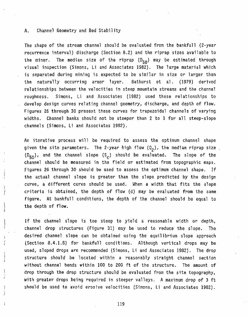
1 (
i J
J
A. Channel Geometry and Bed Stability
The shape of the stream channel should be evaluated from the bankfull (2-year
recurrence interval) discharge (Section 8.2) and the riprap sizes available to
the miner. The median size of the riprap (D may be estimated through50) visual inspection (Simons, Li and Associates 1982). The large material which
is separated during mi ni ng is expected to be s imil ar ins i ze or 1arger than
the naturally occurri ng armor 1ayer. Bathurst et a1 . (1979) deri ved
relationships between the velocities in steep mountain streams and the channel
roughness. Simons, Li and Associates (1982) used these relationships to
develop design curves relating channel geometry, discharge, and depth of flow.
Figures 26 through 30 present these curves for trapezoidal channels of varying
widths. Channel banks should not be steeper than 2 to 1 for all steep-slope
channels (Simons, Li and Associates 1982).
An iterative process will be required to assess the optimum channel shape
given the site parameters. The 2-year high flow (Q2)' the median riprap size
and the channel slope (Sc) should be evaluated. The slope of the(D50), channel should be measured in the field or estimated from topographic maps.
figures 26 through 30 should be used to assess the optimum channel shape. If
the actual channel slope is greater than the slope predicted by the design
curve, a different curve should be used. When a width that fits the slope
cri teri a is obtai ned, the depth of f1 ow (d) may be evaluated from the same
figure. At bankfull conditions, the depth of the channel should be equal to
the depth of flow.
If the channel slope is too steep to yield a reasonable width or depth,
channel drop structures (Figure 31) may be used to reduee the slope. The
des i red channel slope can be obtai ned us i ng the equil i bri um slope approach
(Section 8.4.1.B) for bankfull conditions. Although vertical drops may be
used, sloped drops are recommended (Simons, Li and Associates 1982). The drop
structure should be located within a reasonably straight channel section
without channel bends within 100 to 200 ft of the structure. The amount of
drop through the drop structure should be evaluated from the site topography,
with greater drops being required in steeper valleys. A maximum drop of 3 ft
should be used to avoid erosive velocities (Simons, Li and Associates 1982).
119
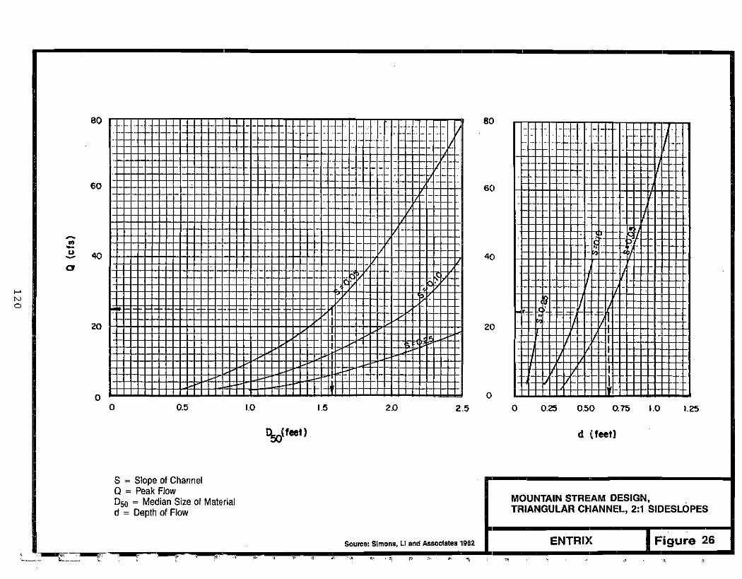
- -- - - - - - --- -
-- - -
- -
--
- -
- - --- - - -- --
--
f-' N a
I
eo eo- ,. - . _ .. . •. .. .... . ._. - ........ -- ... - - -- _.. , . - . . . - . - ._. . ... . . .- .... - - - .. - . .,. _._' .. _.'-- . _..... ...... _... - . - - _. _... - - - - - . - . .
-_. .. _. -- - - ..• -- _. - _.. _. - -. _. - - ..- .- .. - - -- - . . .-- -- ... -.. _.. - - .-60 60
. - - - - - -- -- .. - - . - . -.... - . - - .-.
- ._ .
. .. - -r, ... - . - - ..•--
~
u 4Q40 ... -a -... - . -
, -
-.. - ..- - -- -_.. - - - - . -_. .. - -I ..•.
20 20
-.. - ..
. I -
00 0 0.5 1_0 1.5 2.0 2.5 0 0.25 0.50 0.75 \.0 1.25
'!,olfeet) d Ifeet)
S = Slope of Channel Q = Peak Flow
MOUNTAIN STREAM DESIGN, = Median Size 01 MaterialD50 TRIANGULAR CI-IANNEL, 2:1 SIDESLOPES d = Depth of Flow
ENTRIX Figure 26 ._,:"" '-n': .. ., " . . .. £. . .
Source: Simons, LI and Associates 1982
~'- .' " -
- --I
,< ",~

------
600 f Iii i J i i 600
!I iii! ! I Iii Iii i II jU+-+'-:Tlj [I -, i- 1'" ~
III Iii i i [I ! I: j I~ 500
'j'I i i!!il : 1'1,'1 it", J [.• :Jtt:,"/1 ' t 1i _ .' " '1'"' 1/' ....'1'"!;: 'I
i !
, l l l . I ! ~ ,I , l'
..I i, L.;.!.iiI I' I' l l
0,-: 'Ii-I. I"I' rILl" I!!'
II
'iI
i :.j , . (1'1<>1 1····1';: i,I i ! I.i I I' ,i! en I' I'!I, . :i'i-:;: :::: iii, I ,! :: iii i 1'/ ,f i i II !400 ,! j
400
, i, Ii I! I'yi~ 11'li ~i,. , I' ' II, II I' I I! : !, II I' . . " " . Ir- '. . .; .___ _ i, ! ' i 1
+ r! 1]1,1' "rt i ,iTI-~I'-;;;
( 1 i : i I, :..1 ",I I 1 I ,2. 300 300
a i ' . ., : Ju':,;~: Ij 1r _ ___+ __ I .. 01' .... .., ' .1 __ . ~, ..:. ! :: I· ',' I'l lI 1i I,~ 11' 1/:'ili'" i i : I'!I I I' I
. .. 1-:'" "I i ., -" .. - ._.. :! i : fL.. .! 'l--!' .s: --H I.:.. :. ;Ii r: , :: .. .-:-,H-tr I " ! I . I, II I1,0 I I' ii, I' i u : 1 ~ ; [ o .Il: , I v' 'Irv I • ~ ~:i I r200:.: .::: ,.:. :::: : O~ I:'"'I :'j
---t-,,0'
, ' i l'" , I I ' _ ••••, •• r ; I " :! .. : ~~. ;. j 1 ~ ..... 'ir$·l. y. i~ i I
I _. ;_-\-_ ..j. __::'. . ---- .1I: .. -- .. , I')! . . I ' ,
i .' 1 ! 1 . 1 ,. • i' i j v. 1/1t . • I i ~.. I , U_ J!J1100 . /1' ..,1
1 11 -- .. ~; 0]::.: j Lii 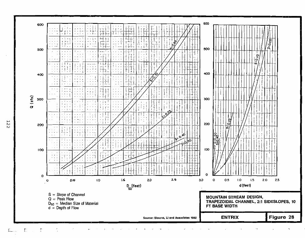
I-' N N
.• ~ t .• ;.
,
~ .. ~. ~ j ";:I';~ ,. 1"'( t
·Lf i'!... ... ~--.. ,~tr:.
, i . r IjJ.:' Ij.;.; t-' -W-:-I-j....... '+i-"'"
"1 L"·i· .'f".j'1t ...-~,'
I'· II j:1 I'1- rH'I" -rl -}
,i \ i .\' ,r~'I';j:f lfT
l Ii ~it i·lll! i [1ir': r "1 J r !rL
; I !
.. j !
;
.+-~
.-.,- . Ji j.
! ':+.-i_~. . ; i I.. ,, , , Tr 1
I ·'t"
, I ri 1 -,. ','1'
t .: ,. i"j
; I. ",!.. . ...
I I ! . I . I: i
.' ..t!..~ i 1'.1..[, -1 .~-! -!
, , : I ; .•
:
1 ' . I
. :; ": ~ .~ : : i
600600
I i I; I I'III 'I~'++-1-'-1 II -1
.8 !500 I: ~ I500
I I I,N:,' I-I'I - -~0!1-
400 400 .\ ITII - . 'r l!{ ~+lH1/1 : I II- soo ~
Ul~ 300 u
r I I I' I" I': i :a jJ h- . I; :HrL !II 0; I! r i I I! [ !II!
, I I :;'I,II.~: iii! !i!i200 200 i! ,,::lJn 7] ni,: , '
~llli !l;r il':: il ~~ 11 II!- Illl iIn itll
100 100
l J1U I; iii il! Vl~ IIItiIll l l'1t iTT!"!
I I : r I I: i I ! ;o o 0.0; 1.0 I.'; 2.0 2.S ao o 0.5 1.0 1.5 2.0 25
o (feet) d (feet) so
S = Slope of Channel MOUNTAIN STREAM DESIGN, Q = Paak Flow TRAPEZOIDAL CHANNEL, 2:1 SIDIESLOPES, 10 D50 = Median Size of Material FT BASE WIDTH d = Depth of Flow
Source: Simons, LI and AS90clateEl 1982 ENTRIX Figure 28
e 1" C
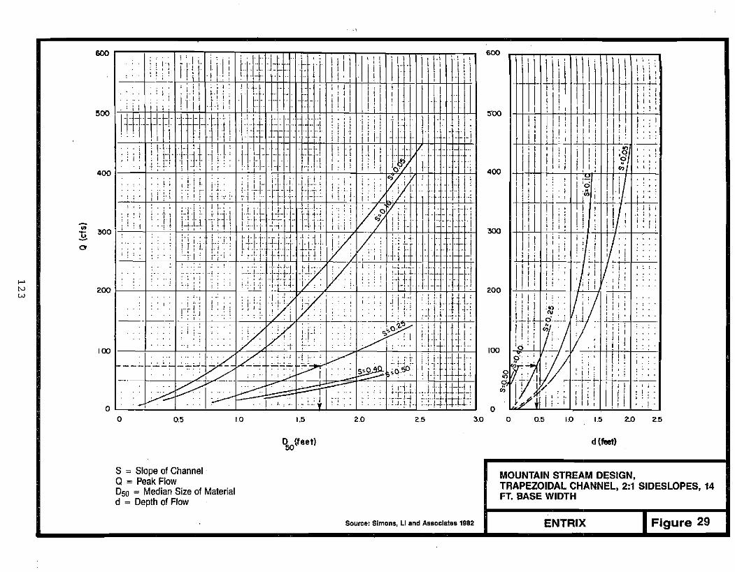
I-' N W
. , I I. " I J I"l ~ I"
li IIJ':\ :. "l j'J i j II. i : i I r ~ iii iii \1:\.\ I\\'j II ii,t +1-.. .. I 1i ' _. 1'_"c..lIliJ ! i ' -r-t-r- ' . I 600 -'t
i
~-t1-l.~ _~\; 1\\\ '\ i~!til.. I. I. . 1 L t"~ .l' .-.; .: !! ~ - ~ ~.! ~ t. . t-tTJ I"·'i I J' I' II, .. til I ; I.i l !I , I .. . .. IIII it ~ :-1 'ill., .: II' 1 i i ' 1' I I nI'"I: I I i I ... .' :.! '·.!. , 1 ! " I I I.' 1'1:!500 • I I ', ., II ' , I.. :·t 'i"•• - '1' .l·I": , .
lli I Iii, I"!;,i I I ' i '1•.,.. " •. -, • ,J ....1 ~Irrr: l"l-f+ .... -r! I'; , ' i l I_I' '.-' . r r ::.. ii'"'j 1,TrT - .. --I .!'.:\1 1 - _.. . _.. . .. , •.1. , . , I.... _. l' u ~'II' :,Ii i::'... , .. " i. 1 :I!l :" +- 1 Ji i ; i i :. i.r.
I I;,·· -.- ,-I, ,'I I I I ('I
' . 11"1"1' -I,;. 1 ' II f : II : ~} j~';: ~ 1'1 I I ' , . , , i i : :"1' +'''j T .l ,',' l'l:~:::J- I U' !I iill I',_:: : ':.[, .... , I...... I . ,I '/)"') , I ~ j. . , . ! f;: I, I: '-1··· 1-,1, I'::! Ii: I Jo-:-/ "i . - - " , , I I I: .• 1 400 I I " ' ; i i :!
, Iii :;' . ."~" .. , i', "; .::'1"'/)1I_: j " "':1 i,' .1 ':. ';I'-I-j'II.; I;: ""Vi ill. ... II : 'i 1.:. ;,,-1 TiTi- 'I' li':,/ ,'·f iH-lj:
11 : Lit 1~1!'~ ~~ "--':,...;...1-./ . ,~. I:; ',;;:: ;i':-I':::::'-::: l~:' oV:, !J'·::I.+j: , ,.! Ii:1 ;";, : i... iT.'1 ... 'I 'II.r"l",_L "t+:ill-"" .[.hL !;. . 74 i! !I j'_[' II L '. '... 'I . t' l.I.·\. i- "1"'. ~- . I ~ I i,.' ._. I
: i . I t I L..LI. L [ • I '... - j' -'1" . -1' ~ "I" r t I I , I"I i I ~ i I j!: I;I : I!'"2. 300 soo ", I: t r t • :i'" '''': ':" :: : :.'.,.,__ ~!:.~ '''-[' Vi': /'. i :-il~-_:t·· 'j' I i ; , : ,:'i! i·ii, lJ.i-!-+:!-fjh,j :; i lill :_.Jo ,! ! I : I:[;:. U;: f:iT LHJ H l f ' .;:II.l-1d.-- : 4-4- 1-H--'v I I J i ;:'
-r
;' ..~; . ': :'_T:_ JJjJ -1.!: ,': :::: :J~:L!:', '_ Ti I, " , .' I':,:' ·,·'ll,J:HY' .. : ,I., :l_fT i.. I-~ _1,_'. "... ;" '·':_~--·-J·t.J-L I;' -": ,-I, F . I ' i r t r !
200 tJ..J.'-t-t-+-;----t-r:--'---fr
I,J! i""I:li:li';;:lii!;liy'j/ ., ;·.:I·!rl-: .iil:i'l 1 i I• ! ; j, , ,---~-1~:··':9;f .• :... ·:.-~t;i~· :-;['1_1 TTf! ri ; i ! ; i, Jy, , ~ ! : l.i-:' %.::~.> '1 '•[?( TII"I! ; , : , ! i I. '. :.. _.. ... I·····
; j
I ,., . .. : t. " , " '.+ h· I .j ;.,; 100 ! It! i
: I. ,. . .. . ---, "-''-:''- "- I 'I
r .~+l~ t~: ;100
~ __ c.. j~~f-'=[" iJ''':'':'. .£1:-_1 , i ; i !III; III i I . ; .•.• J. .• , '.•.: I !'i . '.- .L1. I f i I I If! !a a
a 0.5 '0 1.5 2.0 25 3.0 o 0.5 1.0 1.5 2..0 2.5
D5Q(feetl d (feet)
S = Slope of Channel MOUNTAIN STREAM DESIGN,Q = Peak Flow TRAPEZOIDAL CHANNEL, 2:1 SIDESLOPES, 14050 = Median Sizeof Material FT. BASE WIDTHd = Depth of Flow
Source: Simons. LI and Associates 1982 Figure 29ENTRIX
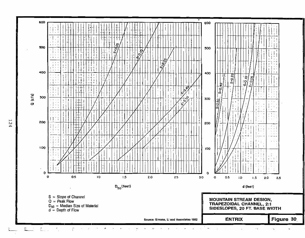
f--' tv
""
. 6001, 1 I I I 11111111111171 I1I1111 11' ;CI i , ; rTTll 600 I i I ~' ," I i, '1'1. ! . - .... ,.1 1 :1-11\:1.. , I \ i
' :~I
I
j I 'I
I+++HH++I- f- L. ;-t_·~L~,." ," I 4'Jl ! i !;! , r Ii. i ;
500 tt+-++t-f-l,-;1++1. , .. I . ;
I[! ! i 'I' j I:! iI I . I ,1.;-1-, t i nn :~ I; ': , Iii: i : I ! ' I ! t i i : I..." " ' , '
'I "6:1 'S?&llil l!I:':;, I I·I ' : I
o -": t..., .1 ~4 -~~-+~
; I 1I'I I:':"I ;! . 1'1
I, ~
i I I ' ,
£11 - " CAl I :
: ; :.~--i 7
,1:l
ill i······ n ' ,I ! : : \ , ': I :'" ..
1·1-:_ J 1-:"-: U:':"-:., 1 1:' I I II'," i ; : I ' ' o
0,5 ',0 1.5 2,0 2,5 30 o 05 1.0 1.5 2,0 2-5
D d (feet) 50lfeet)
S = Slope of Channel MOUNTAIN STREAM DESIGN,Q = Peak Flow TRAPEZOIDAL CHANNEL, 2:1D50 = Median Size of Material SIDESLOPES, 20 FT. BASE WIDTHd = Depth of Flow
Source: Simons, LI and Associates 1982 ENTRIX Figure 3D'.
~. c -,<1,.._.. - '--

>< iE IZ
W
wa: ;j
U
;j
~ Q.
oa: Q
Q
W
Q.
9 11l1
-±
"0 e
12
5
Large riprap should be used to reinforce the channel bed at the sloped drop structure (Figure 31). The width of the channel at the structure should match the wi dths selected duri ng channel design. Addi tiona1 information on the design of drop structures is available (Simons, Li and Associates 1982).
To maintain fish passage, a narrow trench 0.5 ft deep should be provided in the bottom of the stream channel. The trench will concentrate flow to permit fish passage at low flows.
B. Channel Pattern and Profile
The channel pattern and profile of a mountain stream is expressed by pools and riffles located within a steep, straight channel. In natural mountain-stream systems, the pool and riffle sequence repeats approximately every 5 to 7 bankfull-channel widths.
Alternat ing fl atter sections and shorter, steeper sections throughout the length of the channel will create a pool and riffle sequence. Sloped drop structures can be used to create a riffle as shown in Figure 31. In mountain streams with relatively less steep slopes, pools 1 to 3 ft in depth or deeper in fi sh streams should be excavated every 5 to 7 channel wi dths along the channel. The average slope should be used to design the channel geometry.
8.4.3 Braided-Stream Design
Braided channels are unstable channels that frequently adjust their position in the fl oodp1ain. Because of thi s unstabl e character, thei r i ni t i a1 desi gn configuration is less critical than that for other stream patterns. Design parameters include:
1. Channel geometry a. Top width, W b. Mean depth, d c. Mean velocity, V
2. Channel pattern J
126
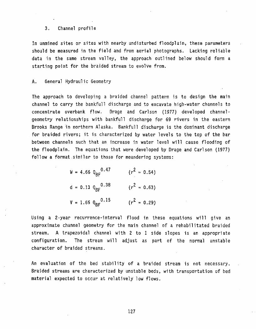
3. Channel profile
In unmined sites or sites with nearby undisturbed floodplain, these parameters should be measured in the field and from aerial photographs. Lacking reliable data in the same stream valley, the approach outl ined below should form a starting point for the braided stream to evolve from.
A. General Hydraulic Geometry
The approach to developing a braided channel pattern is to design the main channel to carry the bankfull discharge and to excavate high-water channels to concentrate overbank flow. Drage and Carlson (1977) developed channelgeometry re1at ionships wi th bankfull di scharge for 69 ri vers in the eastern Brooks Range in northern Al aska. Bankfull discharge is the dominant discharge for braided rivers; it is characterized by water levels to the top of the bar between channels such that an increase in water level will cause flooding of the floodplain. The equations that were developed by Drage and Carlson (1977) follow a format.similar to those for meandering systems:
W= 4.66 QBFO. 47 (r2 = 0.54)
d = 0.13 Q 0.38 (r2 = 0.63)BF
2V = 1.65 Q 0.15 (r = 0.29)BF
Using a 2-year recurrence-interval flood in these equations will give an approximate channel geometry for the main channel of a rehabilitated braided stream. A trapezoidal channel with 2 to 1 side slopes is an appropri ate configuration. The stream will adjust as part of the normal unstable character of braided streams.
An eva1uati on of the bed stabil i ty of a braided stream is not necessary. Braided streams are characterized by unstable beds, with transportation of bed material expected to occur at relatively low flows.
127
A comparison of the above equations for braided streams with the equations in Section 8.4.1 for meanderi ng streams shows that the braided channels are typi call y wider and shall ower than meanderi ng streams. Thi sis a common characteristic of braided streams (Leopold and Wolman, 1957).
B. Channel Pattern
The pattern of the braided stream should have a main channel that carries most of the flow and several high-water channels that carry some flow, even at flows less than bankfull. Although the main channel should have some variation in its alignment, straight channels would be acceptable. High-water channels are discussed further in the floodplain-rehabilitation section (Section 9.2).
C. Channel Profile
Braided streams, 1ike meandering and mountain streams, have non-uniform bed profiles. While the pattern of deep and shallow channel sections is less defined and more variable than in meandering streams, it is recommended that depressions of 1 to 3 ft be excavated below average bed level at intervals of about 5 to 7 bankfull-channel widths along the channel.
8.5 CHANNEL STABILITY
Channel stabil ity should be evaluated to assure that stream rehabil itation measures will not be damaged or destroyed during subsequent high-flow events. Unstable stream channels will erode causing the transport of material from the bed and banks, and possible failure of the channel. The lateral movement of the channel into a recently rehabilitated riparian zone (Section 10.2) should be avoided.
8.5.1 Bed Stability
The bed stability of the rehabilitated stream should be similar to the stabil i ty of a natural stream wi th the same stream pattern. A meanderi ng
.stream is expected to have a stable bed until bed motion occurs at about
128
-.

three-fourths bankfull (Dunne and Leopol d 1978). A mountain stream shoul d
have low sediment transport and a stabl e channel at bankfull conditions. A
braided stream has an unstable configuration and is 1i kely to transport bed
material at relatively low flows. If slightly greater bed stability is
des ired, an armor 1ayer can be developed or the armor-l ayer si zes can be
increased.
Bed armori ng occurs in many natural mountain and meanderi ng streams. Hi gh
velocities at bankfull conditions transport smaller-sized material until an
armor 1ayer develops. The armor 1ayer wi 11 be composed of the 1arger bed
materials which remain after the smaller material has been transported
downstream (Figure 32). The system thus reaches an equilibrium condition with
relatively little sediment transport occurring except during large flood
events.
In des i gni ng a bed 'armor 1ayer , several 1ayers of different sized materi a1
should be used to form the stream channel. A gravel layer with an optimum
size range from 0.2 in. to 3.5 in. should be placed first (Joyce et al. 1980).
This layer should be at least 6 in. in depth. In low velocity streams, a
second 1ayer of materi a1 consi st i ng of 1arge cobbl es and sma11 boul ders shoul d
be placed above the gravel-sized material to armor the channel bed. If
further bed stabil ity is required in higher velocity streams, riprap may be
placed on the stream bed in areas where scour should be avoided. The minimum
thickness of this larger layer should be greater than the longest dimension of
the largest rock used in the layer (Joyce et al. 1980). Figure 32 illustrates
a rehabilitated stream channel with a filter layer of gravel material and an
armor layer placed on the stream bed.
The gravel material will' resist movement and stabilize the armor layer
(Simons, Li and Associates 1982). In the absence of a gravel filter layer,
cavities in the underlying material may be formed by turbulent eddies and jets
penetratt ng the armor 1ayer or by water flow at the interface of the 1ayer
(Simons, Li and Associates 1982). Large cavities beneath the armor layer
which could result in the failure of the stream bed and/or banks will be
minimized by the presence of a gravel filter layer.
129

Plan View
0
" •• • D
• • 0
'0
• •
Cross Section
Armor Layer
~ Filter Layer
130
BED STABILITY
ENTRIX FIGURE 32

8.5.2 Bank Stability
Erosion of channel banks may be avoided by protecting the bank with revetment. Revetment will preclude vegetative development on the banks, however. Revetment on stream banks will prevent the lateral movement of the channel (Jackson and Van Haveren 1984). Figure 33 illustrates several types of revetment.
Riprap of large rocks, rubble, or quarry stone is generally the most reliable and economical revetment (U.S. Army Corps of Engineers 1981). Proper riprap gradation and sizing (Section 8.5.3) is important. Filter layers of finer materials should be placed beneath the riprap layer (Section 8.5.3).
In the absence of properly sized and graded riprap, stone-filled wire baskets (gabions) can be used as revetment. The baskets must be sol idly fill ed wi th stones large enough to prevent loss through the gabion mesh. Stones are typically at least 4 inches in diameter (U.S. Army Corps of Engineers 1981). Gabions may require maintenance.
Burl ap bags fi 11 ed wi th sand or 1ean concrete mix may also be used as revetment. Bags filled with set sand-cement mixture may be piled two-deep on the face of the slope. These bags will interlock slightly and resist removal or displacement.
8.5.3 Riprap Design
Several factors are important in the design of rock riprap (Joyce etal. 1980):
o shape, size, and gradation of the rock o density and durability of the rock o velocity and depth of flow near the rock o steepness of the slope being protected o thickness of the riprap layer o filter layer presence and design o end and toe protection
131

WAVES
on revetment GRADED LAYERS with smaller stones on slope, armored with larger stones
FILTER CLOTH to aid drainage and help prevent settling
\ ::::::::::::::=~break and run up
Revetment extends above HIGH WATER LEVEL
TOE REINFORCEMENT to prevent scour
( VEGETATION
TOPSOIL
FILTER-+------~.""'!!
BAGS FILLED WITH .[ LEAN CONCRETE MIX
TOPSOIL
SAND FILL
FILTER-
BANK STABILITY
SOURCE: u.s. Army Co~ps of Engineers 1981 Figure 33ENTRIX
132
The shape, size, and gradation of the rock riprap are the primary properties in resisting erosion. The shape should be angular to provide an interlocking of the rocks. The size of a rock is generally determined from its middle dimension; large rock should be used as large rock is more erosion resistant than small rock and the rock size should be selected for the velocity expected in the channel as shown in Figure 34. Well-graded material improves the interl ocking of the rock and reduces spaces between rocks; a recommended gradation is shown in Figure 34.
The rock used for ri prap should be hard, dense, and durabl e to withstand cycles of wetting and drying, and freezing and thawing. These cycles can cause cracking of the rock, resulting in reduction of size and erosion resi stance. Density and durabil i ty are generally determined by 1aboratory tests.
A primary factor influencing erosion is the local velocity of the flow. Direct flow measurements are recommended, but these may be difficult to obtain during flood events. In the absence of measured data, the velocity against a slope should be evaluated as two-thirds of the average velocity in straight reaches or four-thirds of the average velocity in severe bends (Joyce et al. 1980). Rock size should increase with increasing depth as the shear stress on the rock riprap is proportional to the depth of flow above the riprap.
The stability of riprap decreases with increasing steepness of slope. Riprap should be placed on slopes with a maximum steepness of 2 to 1 (Simons, Li and Associates 1982).
The thickness of the riprap should be sufficient to provide the desired protection of the slope. The minimum thickness should be equal to the longest dimensi on of the 1argest rock or be 50 percent 1arger than the medi an rock size (050), whichever is larger (Joyce et al. 1980). This minimum thickness should be increased by 50 percent if wave action is possible, the gradation is not as recommended, the r ipr-ap is to be placed in flowing water, or if a filter is not used when recommended (Joyce et al. 1980).
133

26
24
22
" c: 20 0 0
rn '" 18 o, '" ~
Qi 16 ~ .!: 14
c '" B 12 rn en c: 10'iii -c
8 '" .i:'(3 0
~ 6
4
2
0 1 2 3 4
./
.; /'
1/ /'
io"
/ /
DSO(ft)
Reference: Neil 1973
, 00
= Mediat'l Rfprap DiameterDso ~
~
i:c: :" '" ~~ ~~ '" o.n ~
0.10,., O.sD,o 0,. 20,. Sieve Size
Suggested Gradation for Riprap
RIPRAP DESIGN
Reference: Karalci et al 1974 ENTRIX FIGURE 34
134
,
,
,
"
-
"',
""-
l

A filter layer may be recommended for placement beneath the rock riprap layer
to prevent the loss of bank material through the voids in riprap. If the bank
material will be easily eroded, a filter 1ayer is recommended. Poor riprap
gradation is also a reason to recommend a filter.
Gravel filters should use gravels ranging from about 0.2 in. to 3.5 in.
Dependi ng on the cl assifi cat ion si zes obta ined duri ng washi ng, materi a1 from
the sluice tailrace should be mixed with a larger classified size from the
screening plant to provide an optimum filter layer. The filter thickness
shoul d be no 1ess than 5 in. A fi lter thi ckness equal to half the ri prap
thickness is recommended (Joyce et al. I980).
The ends and base of the ri prap along the channel may be subject to eros i on
and should be protected. Riprap should be extended to areas along the channel
not having erosive velocities (Figure 35). If this is not possible, the
thickness of the riprap 1ayer at the end should be increased to twice that
otherwise needed by excavating a recess in the bank and backfilling with
gravel (Joyce et al. I980). The riprap layer should be extended below the
1eve1 of the bed to the expected depth of scour to avoi d undercut of the
riprap. If this is not possible, the thickness of the riprap layer at the toe
should be increased to twice that otherwise needed (Joyce et al. I980).
135

a
Schematic showing plan view of end protection configurations: a) extension out of the zone of erosion with a potential reduction in thickness, and b) increasing the thickness at the ends of the revetment.
Riprap---~1fI
L-----'Thickness Depends Cf'l Potential for Scour
a b
Schematic showing cross section of .toe protection configurations: a) extension of the riprap below the dry bed and backfilling, and b) placement of extra material along the bed to launch itself into developing scour holes.
RIPRAP PROTECTION OF END AND TOE SECTIONS
ENTRIX Figure 35SOURCE; JOYCE ET Al 1980
136

FISH-HABITAT REHABILITATION
137


9.0
FISH-HABITAT REHABILITATION
9.1 OBJECTIVES AND SCOPE
Since much of the placer-mining activity takes place in active floodplains and may affect fish resources of the streams, fish-habitat concerns are central to the stream rehabilitation. Reconstructing fish habitat is a complex task that requires an understanding of the major physical and biological components of the stream environments, their interactions, and the habitat requirements of fish. The objectives of this section are to identify the major stream-habitat components and fish-habitat requirements and to present stream reconstruction and rehabilitation techniques that modify various habitat components to better meet fish-habitat requirements.
There is a relationship between the amount and quality of habitat and the size of fish populations; therefore, mitigation measures for stream-altering activities usually focus on habitat rehabilitation. Stream alterations resulting from placer mining can reduce habitat quality resulting in similar reductions to associated fish populations. In some cases, rehabilitation may result in improved habitat conditions, as the reconstructed stream channel can be designed to compensate for natural deficiencies.
Desirable habitat features must be included in the rehabilitation plan to ensure that fi sh ut il i ze the rehabil itated mi ne site. The select i on and spaci ng of these habitat features for the restorat i on of fi sh habitat ina mined stream depends on several factors: stream type, value of the stream as fish habitat prior to mining, and the degree of habitat alteration or degradation resulting from mining. The decision-making flow chart for se1ect i ng and spaci ng habitat features (Figure 36) was developed wi th the
.assumption that mining had significantly altered and degraded fish habitat in
139

Hobltot F.otur!,CStrum Type Volu. as FIsh Habltata ond Spoclng
.-----lowb'---- A
§iB4 C4
f-------Medl umb-_____ E~
FZ Meonderlngl--------1 3
§~3~
L----IHIgh b' , EZ
F1 Z
lowb--------A
edlumb'-----~6~Mountaln'---------~
B Highb'-------;E
011
lowb--------IA
blIed; um -------A I Hi9hb.--------,A
IValue prior to mining in unmined stream or assessment of value in previously .iRed stream
blow. no significant fish populations: Medium' noderate resident and/or anadromous fish populations? High significant resident and/or anadromousg
fish populations
CHabitat Features Codes: A• no habitat features needed,
design for hydraulic parameters C • boulder grouping E • tree cover G• overhanging bank cover
B • rock is13nd
0 • submerged rock weir F • wing deflector
dspacing Codes: 1 • one e,ery two pool/riffle
sequences (P/R)3 • one every four P/R5 • three e'ery one P/R
Z • one every three P/R4 • three every two P/R
(Note: one pool/rIffle sequence. approximately six st .... widths)
FLOW CHART FOR SELECTING AND SPACING HABITAT FEATURES
FIGURE 36ENTRIX
140
the mined stream. The suggested spacings of habitat features ina restored
stream are general guidelines that can be modifi ed to site- specifi c
condit ions.
The instream habitat features for rehabil itating a stream create habitat
diversity by altering local stream hydraul ics (depth, velocity, and stream
wi dth) and structure (substrate, cover) . The change in local stream
hydraulics will cause minor bed scour, bank erosion, or deposition in the
vi ci ni ty of the habitat feature as the stream readj usts its confi gurat ion.
These readjustments in the bed are part of habitat rehabil itation and are
incorporated in the design of the habitat feature. Habitat features used in
areas with bed or bank protection should be carefully designed since desired
readjustment in the cross section may be prevented.
To rehabil itate a stream for fi sh, the types of fi sh occurri ng wi thi nand
adjacent to the mi ne site shoul d be determi ned and thei r seasonal habitat
utilization patterns evaluated. In some cases previous mining activities may
have el imi nated fi sh speci es from the stream reach. If thi s has occurred,
habitat features should be included during stream rehabil itation to prepare
the stream for recolonization by displaced fish species.
Fish can be d i vi ded into two major categories: anadromous and resident.
These two categories of fish have different habitat requirements. Important
anadromous species inA1aska streams generall y include salmon, Dolly
Varden/Arctic charr, steel head, and some whitefishes. Important resident fish
generally include Arctic grayling, rainbow trout, Dolly Varden/Arctic charr,
northern pike, burbot, and other whitefishes. Salmon are selected as the
anadromous evaluation species while Arctic grayling is selected as the
resident evaluation species. Habitat requirements vary with species and life
stage.
In the stream environment, physical and biological factors combine to create
fish habitat. Generally, .fish do not occupy all portions of a stream but
select specific areas that have conditions meeting their habitat requirements.
Understandi ng these requ i rements is. important for successful stream
rehabilitation. Physical characteristics determine the amount and quality of
141

habitat available to the fish. Biological factors such as food availability, predation, or harvest are important factors in controll ing fish population size.
9.2 FISH HABITAT COMPONENTS
Fish habitat consists of several interdependent physical and biological components including: channel structure, streamflow, water quality, and food-web relationships (Figure 37). The channel structure component includes factors such as channel geometry, substrate or streambed materials, and instream objects used as cover by fish. Each of these factors contributes to habitat quality. Streamflow, the second major component, determines instream hydraulics. In a given channel structure, the depth and velocity of flow are a function of stream discharge. Water quality also influences habitat quality. Turbidity and dissolved solids are two water-quality parameters commonly altered by placer-mining operations. Placer mining typically also alters channel structure. In addition to the physical components, a biological component, food-web relationships, is an important habitat determinant for resident and young anadromous fish.
The four major habitat components are interrelated and each can influence the factors of other components. For example, changes in channel geometry will alter depth and velocities of a given discharge. High streamflow can change the substrate compos it ions of part icul ar areas by removi ng or depos it ing smaller particles. Increased turbidity can reduce 1ight penetration and, in turn, food production. Reducing the amount of fine particles in the substrate can enhance production of aquatic insects and other food organisms. Since changes in one component of fi sh habitat can affect the factors of other components, the four major habitat components must be evaluated in concert to develop sound rehabilitation plans.
9.3 HABITAT REQUIREMENTS
Fish occupy areas that have habitat factors within their tolerance limits. Within specific tolerance limits, a narrow range of values provides optimal or preferred habitat. Fish production is assumed to be best under optimal
142
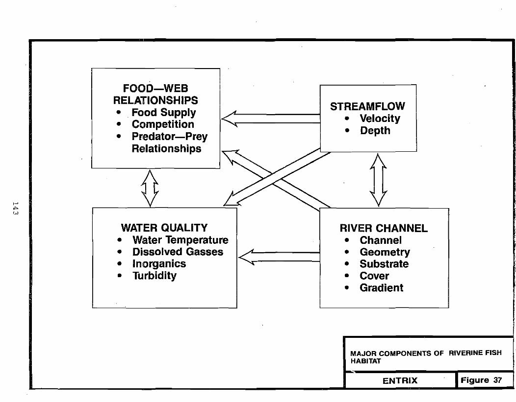
FOOD-WEB RELATIONSHIPS STREAMFLOW• .Food Supply • Velocity• Competition
• Depth• Pr1edator-Prey Relationships
t-' .."
''''>
WATER QUALITY • Water Temperature • Dissolved Gasses • Inorganics • Turbidity
RIVER CHANNEL • Channel • Geometry • Substrate • Cover • Gradient
MAJOR COMPONENTS OF RIVERINE FISH HABITAT
Figure 37ENTRIX

habitat conditions. For habitat to be usable, each factor must be within an acceptable range. If the value of one factor is beyond the tolerance range, then its associated area becomes unusable regardless of the suitability of other factors. For example, if the substrate is too large for spawning then no spawning will occur, even though optimal depths and velocities are provided.
In order to establish self-sustaining fish populations, the habitat requirements for all species and 1ife stages present must be considered. To accommodate the divergent habitat preferences, a diversity of habitat characteristics is necessary for successful stream rehabilitation.
Since different life stages use different types of habitat and habitat is available in varying amounts, there is often a limiting habitat that controls the size of the population. In Alaskan streams, limiting habitat is often rel ated to severe environmenta1 condi t ions encountered duri ng wi nter. Other habitats often limiting fish populations include spawning or rearing areas. limit i ng habi tats vary based on phys ica1 characteri st i cs of the stream and habitat requirements of different life stages.
Habitat requirements differ from species to species and change from life stage to life stage. For example, the range of velocities that a fish is able to use increases with fish size and sWimming capabil ities. Since fry are small and have 1imited swimming capabil it i es, they occupy a narrow range of low velocities. Larger juveniles can use a broader range of velocities, while spawning adults have different velocity requirements than either juveniles or fry. Hence, fish with different habitat preferences will occupy different areas of the stream.
9.3.1 Anadromous Fish
A. Passage
Adult salmon, as with other anadromous fish, return to their natal stream for spawning. Timing of spawning migration is species, drainage, and site
. specific but generally occurs in summer and fall. Thus, when evaluating fish
144

passage and designing the hydraulics of a restored stream channel (Chapter
8.0), the mean annual flow, which approximates the mean summer flow, can be
used. Adult fish swim upstream, holding occasionally for short periods in
pool s or backwater areas. Passage requi rements usually cons i der only
hydraul ic conditions, depth, and velocity, although resting areas formed by
pools, backwaters, and substrate roughness are important considerations.
Suitabl e hydraul i c cond i t ions depend of the si ze and swimmi ng capabil ity of
the fish (Bell 1973).
For adult salmon, depths of 0.5 ft or greater allow easy passage (Thompson
1972, Blakely et al. 1985). Adult salmon can move upstream through shallower
depths for short distances. Passage studies completed on the Susitna
Hydroelectric Project indicate that adult chum salmon were able to pass 80-ft
reaches with thalweg depths of 0.3 ft (Blakely et al. 1985).
Velocity is also a major factor in passage requirements. High velocities
inhibit passage (Bell 1973, Thompson 1972). Passage criteria are generally
based on swimming performance of the fish. Swimming performance is generally
divided into three categories: bursting (darting), sustained (prolonged) and
cruising. Bursting speed is defined as the speed which a fish can maintain
for a short time (5 to 10 minutes). Sustained speed is the speed that a fish
can maintain for a prolonged period but would ultimately result in fatigue.
Cruising speed, the third category, can be maintained for an extended period
of time without fatigue. For passage requirements, sustained speed is used as
the upper 1imit for velocity. Figure 38 presents the relationship between
horizontal distance traversed and maximum velocity for common anadromous and
resident fish. Salmon can pass velocities of 8-11 fps for short distances (10
ft) and velocities of 5-8 fps for longer distances (50 ft) (Ziemar 1961).
Smaller fish can pass through shallower depths but require lower velocities.
B. Spawning
When sal mon reach thei r spawni ng areas they select habitat with specifi c
attributes. Salmon-spawning habitat is generally composed of definable ranges
of depth, velocity, substrate, and intragravel flow. Several recent Alaskan
studies have identified microhabitat conditions for spawning salmon (Estes and
145

......,. '"
10
V ftls
1
0.3
-- ............. - ' ....'""'...... Curve lor Steelhead, Coho, Sockeye, Chinook
....... /' (Based on Fish Passage Velocity 012 ft. per sec.) , ...... ." .. ,
... <,.... • ...... ............ ...... ......... ......... . ........ ...... ........ <... .....
'.. ................. ...... .....,Estimated Curve lor Grayling .............. .......... ....
........ ......
I , ! ! ! I , , I ) I ! I I I I I " , , 0 ' , I I I
3 10 100 1000
D ft.
SWIMMING CAPABILITY OF SELECTED ANADROMOUS AND RESIOIENT FISH
Source: Fisheries and Ot:eena 1980 Adapted from Ziemer, G.L. 1961 Figure 38ENTIRIX
fF '

Vincent-Lang ed. 1984, Estes et al. 1981, Wilson et a1. 1981, Woodward-Clyde
1983, and Burger et al. 1983). Earlier studies also addressed habitat
requi rements for spawni ng (Burner 1951, Thompson 1972, Smi th 1973, Sams and
Pearson 1963, Co11 ings 1974) and most of these are summarized by Wesche and
Rechard (1980).
Spawning salmon use a wide variety of depths. Minimum depths appear to be
most restrictive to spawning. Depths suitable for salmon spawning range from
0.3 ft to 10.0 ft. The optimal range appears to be 1. 0 to 3.0 ft, although
the lower end of the range is more critical than the upper range. Spawning
salmon are also sensitive to velocity. Mean-column velocities associated with
salmon spawning range from 0.2 to 4.5 fps. The optimal range for velocity is
between 1.0 and 2.5 fps.
Substrate requirements for spawning salmon are described by dominant particle
size and percent fines. Suitable particle sizes range from small gravels to
cobbles with larger fish being able to use larger substrates. Salmon
generally prefer particle sizes ranging from 1.5 to 3 in. gravels.
Recommended content of fines (less than 0.084 mm diameter) is 5 percent or
1ess, although successful embryo development has occurred with 20 percent
fines (McNeil and Ahnell 1964, Tagart 1976). The percentage of fines
generally affects i ncubat ion. Deve1opi ng embryos depend on i ntragrave1 flow
to bring in oxygen and carry away metabol ic wastes. Substrates with high
percentages of fines have reduced porosity and less intragravel flow (McNeil
and Ahne1l 1964).
The most successful spawning areas have strong intragrave1 flow. Upwell ing
has also been i dent i fi ed as an important feature of spawni ng areas for some
species, particularly chum salmon (Wilson et al. 1981, Estes and Vincent-Lang
ed. 1984).
Creation of successful spawning habitat is a complex task. The design must
incorporate species and site-specific features that require the combined
efforts of both biologists and engineers skilled in habitat rehabilitation.
147

C. Incubat i on
After fertil ization, salmon embryos undergo a 4- to 6-week period during which they are sensitive to disturbance. Once embryos reach the eyed stage, habitat
disruptions (e.g., reduced streamflows or temperatures) are not as critical.
The embryos develop in the gravels throughout the winter and hatch in February or March •. Development rate is dependent on temperature. After hatching, the
alevins remain in the gravel until yolk absorption, and they then become free
swimming fry.
Ouring incubation, successful embryo development is subject to the environmental conditions surrounding them. Even as alevins, fish have limited
mobility. If the spawning area dewaters, freezes, or has insufficient intragravel flow, embryo mortality will result. Habitat requirements for
incubation center on preventing spawning areas from dewatering and maintaining
intragrave1 flows. Water depths of 0.1 ft are suitable for incubation if ice does not freeze to the streambed. Mean-column velocities of 0.5 to 1.0 fps have been required (Bovee 1978). However, the hydrau1 ic connection between surface and intragrave1 flows that influences the rate of percolation is site specifi c.
Poo1-riffl e sequences provi de good spawni ng and i ncubat ion habi tat. Velocities in the tail of the pool and riffles are generally high enough to
prevent the deposit i on of silts and debri s that may clog the i nterst ices of streambed gravel s. In unaltered streams, the pool-riff1 e sequence usually
enhances intragravel flow. The undulation of the streambed longitudinally
through the pool-riffle sequence causes downwell ing at the tail of the pool
(Figur-e 39). However, in a mined stream the streambed materials are often
cemented with fine particles, which Bjerklie and La Perri ere (1985) have shown to reduce or cut off the interchange between groundwater and streamflow.
D. Juvenile Rearing
Each of the salmon species has different juvenile rearing patterns (Morrow 1980). Emergence from the gravels takes place in the spring (March to June)
following spawning. Upon fry emergence, juvenile pink salmon and chum salmon
148

----------------------------------- ---....
Riffle
WATER INTERCHANGE BETWEEN STREAM AND GRAVEL IN A RIFFLE
Source: Fisheries and Oceans 1980 Adapled.1rom Vaux 1968 Figure 39ENTRIX
149

outmigrate immediately to the ocean during or after the spring breakup. In
some rivers, chum salmon fry may spend 1 to 3 months rearing in freshwater.
Juvenile chinook salmon usually remain in rivers and streams for 1 or 2 years
before moving to sea. Most juvenile coho in Alaska rear for one to 2 years in
rivers and streams. Sockeye salmon juveniles usually move from streams into
1akes where they spend 1 to 2 years. In ri vers wi thout connecting 1akes,
juvenile sockeye remain in stream habitats.
Habitat requirements for juvenile fish include many interrelated factors and
change on a seasonal basis. Factors usually evaluated to assess juvenile
rearing habitat include depth, velocity, substrate, cover, food availability,
and water quality. Several Alaskan studies have characterized juvenile salmon
habitat (Burger et al. 1983, Wilson et al. 1981, Schmidt et al. 1984). Fry
(0+ fi sh) habitat is generally separated from that of older juvenil es (1+
fish). After emergence, fry occupy areas with low velocities (less than
0.5 fps) and shallow depths (less than 1.0 ft). Most fry are associated with
backwater areas and stream margins. Cover is important for all juveniles.
Log debris, overhanging vegetation, undercut banks, and substrate (> 1 in.
diameter). are commonly used cover objects. Juvenile fish use cover to escape
from predators and as a barrier from high velocities.
As the fish grow, they move from early nursery areas into less sheltered
rearing habitats in the stream channel. Juvenile fish utilize depths ranging
from 0.2 ft to 10 ft, but are most commonly associated with depths of 0.5 to
4.0 ft. Juvenil e fi sh are more sensi ti ve to vel ocit i es than depths. They use
mean-column velocities ranging from 0.0 to 2.5 fps. Preferred velocities
change from speci es to speci es but are generally between 0.0 and 1. 5 fps.
Juvenil e chi nook sal mon prefer faster water than coho, sockeye, or chum
juvenil es.
E. Overwintering
Chinook, coho, and sockeye j uveni 1es usually overwi nter in freshwater bE:'
moving into the ocean. Overwintering habitat has not been fully definer
streams, adequate depths (>3.0 ft) to maintain living space and veloci'
maintain sufficient dissolved oxygen concentrations are required. Vf
150
less than 1.0 fps are usually preferred, so that overwintering juveniles can maintain their positions in the stream. Substrate (>5 in. diameter) can provide important resting places for overwintering fish.
9.3.2 Resident Fish
A. Passage
Arctic grayling spawn during spring just after breakup (Morrow 1980). It is suspected that grayling, similar to salmon, return to natal streams for spawning. Prior to spawning, there is a migration from overwintering areas to spawning areas. Passage requirements for grayling are primarily a function of water depth and velocity, although blockages due to ice jams may temporarily occur because of the timing of the spawning migration relative to spring breakup.
Grayl i ng can rna i nta in sustained swimmi ng speeds for prolonged peri ods, thus sustained swimming tolerances are used as the upper range of velocities suitable _for passage. Bell (1973) and Dane (1978) reported that sustained swimming speeds for an average adult grayling range from 2.6 to 7.2 fps, while MacPhee and Watts (1975) found that IS-inch (38-cm) grayl ing could maintain sustained swimming speeds ranging from 5.9 to 7.5 fps. Grayling have a lower maximum velocity criterion than salmon, but because of their size, grayl ing are not as restricted by depths. Thus, the 0.5-ft-depth criterion for salmon passage exceeds that which is needed for the upstream passage of grayling and other resident species. Wesche and Rechard (1980) suggest a minimum depth of 0.4 ft for trout less than 20 inches. This criterion should approximate, or exceed, the minimum depth requirement for adult grayling.
Smaller grayling can migrate through shallower reaches of rivers, but, due to slower sustained swimming speeds, require lower current veloclties. Arctic Hydrologic Consultants (1985) has developed passage criteria for grayl ing negotiating culverts. A regression equation was developed that allows estimating the average velocity required for successful passage under a variety of conditions. One important variable in the equation is fish length.
151

Evaluation of passage requirements generally focuses on maintaining sufficient water depths. Since grayling migrate during higher flows associated with breakup, attention is focused on high stream velocities that may occur during floods. Although high velocities are associated with flood flows, the roughness Qf the bed in natural channels is generally sufficient to create turbulance and eddies with low velocities near the streambed. Grayling and other fish often take advantage of low velocities near the bottom for migration. Unless associated with extensive rapids or cascades, velocities in natural channels rarely create passage barriers.
B. Spawning
Once grayling reach their spawning sites they select areas with suitable spawning habitat. Depth, velocity, and substrate are generally the important factors defining grayling-spawning habitat.
Grayl ing have been observed spawning in depths ranging from 0.2 to 3.0 ft
(Krueger 1981). An optimal depth may be about 1.0 ft, as Tack (1980) reported that this was the. mean value for 22 observations. Mean-column velocities ranging from 0.5 to 4.8 fps have been measured at grayl ing-spawning sites (Krueger 1981). However, an optimal range of velocity is likely between 0.5 and 2.0 fps. The range of substrate size used by spawning grayl ing is from silt to gravels of 1.5 in. diameter (Krueger 1981). Grayling do not excavate a redd. Instead, they spawn over the substrate and their eggs sink to the bottom, adhering to the substrate. Embryos are usually covered by a thin 1ayer of substrate (up to 2 in.), as a result of spawni ng act i on and water velocity.
The percentage of fines is generally not considered when evaluating grayling spawning substrate. Grayling embryos are not deposited as deep in the substrate as salmon embryos (2 in. or 1ess versus 9 to 12 in.) and therefore are less dependent on streng upwelling or intragravel flows to maintain development. Additionally, grayling occasionally spawn over silt substrates. Thus, for grayling it appears that larger substrate is more restrictive than smaller substrate, since material larger than 1.5 in. is not used for spawning
152
(Krueger 1981). The optimal substrate size for grayling spawning appears to be pea-size gravel.
C. Incubation
The incubation period for grayling normally lasts from 2 to 3 weeks (Morrow 1980), during which time the developing embryos are susceptible to habitat disruptions. Flooding, associated with spring breakup, may wash embryos downstream since the embryos are covered by only a thi n 1ayer of substrate. Velocities that cause bedload movement would likely be sufficient to dislodge embryos downstream.
The siltation of grayl ing spawning areas during embryo incubation should be prevented. A heavy silt layer (greater than 2 in.) covering incubating embryos can cause mortalities due to reduction in the supply of oxygen to the embryos and reduction in the removal of metabolic wastes.
D. Juvenile and Adult Rearing
Habitat characteristics for juvenile and adult grayl ing in Alaska have been addressed by Krueger (1981) and Aquatic Environments Incorporated (1984).
After fry emergence, young-of-the-year grayling seek out areas of low velocities along the stream margins and in backwater areas. As young-of-the-year fi sh grow 1arger and become stronger swimmers, they move into slightly higher velocities where food availability from drifting aquatic organisms is higher. Juvenile grayl ing use velocities ranging from 0.0 to 2.0 fps. Preferred velocities are probably less than 1.0 fps.
Juvenile grayling utilize a wide range of depths, from 0.2 to 10 ft, and are more commonly associated with depths between 0.5 and 4.0 ft. Newly emergent fry typically are found in shallow, low-velocity areas along stream margins and in backwater areas. Larger juvenile grayling tend to occupy slightly deeper, higher-velocity areas.
153

Juvenile and adult grayling are sight-feeding fish, primarily on aquatic and
terrestrial insects. Therefore, they are dependent on clear water for active
feeding and growth. While grayling are known to migrate in turbid rivers,
they normally do not remain in these rivers. Instead, grayling are generally
found in clearwater or tannin-stained streams where aquatic insect production
and sight-feeding responses are improved.
Cover is an important component of rearing habitat for juvenile and adult
grayl ing. Log debris, overhanging riparian vegetation, undercut banks, and
substrate {>1 in. diameter) are commonly used cover objects. Cover functions
i n t~IO important ways for grayl i ng: to protect fi sh from predators and, in
the case of substrate and debris, provide resting places from high velocities.
In some instances, overhanging riparian vegetation becomes an important source
of terrestrial insects.
E. Overwintering
Grayl i ng overwi nter in the deeper pools of ri vers and in 1akes . In small er
tributari~s, there is usually a fall migration from small streams into larger
rivers and lakes. Thus, passage requirements should be considered for a fall
migration to overwintering areas as well as a spring-spawning migration.
Overwintering habitat has not been fully defined. In streams, adequate depths
(>3.0 ft) to maintain living space under an ice cover and velocities to
maintain sufficient dissolved oxygen concentrations are required. Velocities
less than 1.0 fps are usually preferred, so that overwintering fish can
maintain their positions in the stream. Substrate (>5 in. diameter) can
provide important resting places for Qverwintering fish.
9.4 HABITAT DESIGN FOR FISH STREAMS
Rehabil itation of streams containing fish should be undertaken with adequate
care and forethought to produce the desired effect of replacing lost fish
habitat. Although stream rehabil itation follows the cessation of the mining
operat ion, proper pl anni ng before and duri ng mi ni ng will insure that
. rehabilitation will be accompl ished in a cost-efficient, effective manner.
154

For example, materials to be used during rehabilitation should be properly stockpiled and located during the mining operation (Chapter 6.0). This will minimize the amount of material handling during rehabilitation.
Stream rehabil itation focuses on the habitat components that the miner can control or strongly influence: channel structure and water quality (refer to Figure 37). Habitat rehabilitation is achieved through designing or modifying the factors associated with the river-channel component. Habitat designs di scussed below for each stream pattern recommend modificat ions of channel structure to create specific desirable habitat features. Channel-structure modi fi cat i on creates habi tat features such as pool-ri ffl e sequences, cover, spawning substrates, and resting areas. Channel structure provides fish passage and rearing habitat.
Placer mining influences the water quality component through introduction of sediments, toxi c metal s, and potenti ally through the i ntroduct ion of fuel s (Bjerkl ie and La Perri ere 1985, La Perriere et al. 1985). With respect to this habitat component, rehabilitation focuses on avoiding habitat degradat ion. Beyond these 3 factors, the mi ner has 1i ttl e abil i ty to aHer the water quality characteristics of a basin. By following the recommendation for control of nonpoi nt-source poll ut i on (Chapter 3.0), and careful handl i ng of fuel and other toxic materials including pond sediments containing adsorbed metals (Section 2.2.1), water quality should be similar to pre-mined conditions.
Design of channel structure (Chapter 8.0) is used to influence depth and velocity, factors associated with the streamflow component of habitat. Since the cross-sectional area and slope of the channel dictate the distribution of depths and velocities for a given flow, channel design is used to increase the diversity of depths and velocities in the rehabilitated stream. Depth and velocity change with stream discharge and the stream discharge will vary seasonally in response to cl imatic and precipitation patterns. Even though the miner has no influence over the stream discharge, the channel can be designed to function at both high and low flows. By designing for diversity, suitable habitat conditions are present over a variety of flows.
155

Channel structure can al so i nfl uence bi01 ogical factors, part icularly food production. The diversity and abundance of fish food organisms, aquatic and terrestrial invertebrates, is inf1uenced by channel structure and vegetation, as well as water quality. Constructing riffles from gravels or cobbles with low levels of fine particles will encourage aquatic food production. Promoting streamside riparian vegetation will increase the number of terrestri ali nsects avail able to fi sh, Areas near pools are the fi rst pri ority for revegetation in fish streams (see Section 10.3). Although channel structure and erosion control can influence food availability, they do not directly infl uence the presence or absence of competi tors and predators. The development of adequate cover can increase fi sh survi va1 by reduci ng the effect i veness of predat ion. The creation of habitat divers ity may promote coexistance of competing species by allowing alternate habitat selection.
Habitat diversity is a key element in successful rehabil itation and often a notable failing in mined streams without habitat restoration. After being mined to bedrock, the stream channel usually 1acks substrates suitable for food production, cover, or spawning. The steep-gradient, high-velocity environment normally left affords little opportunity for rearing. Providing a diversity of habitat conditions is accomplished through construction of an undulating streambed with a variety of substrate types. Adding streamstabilization structures to enhance the perpetuation of pools and presence of cover are the major elements of habitat rehabilitation.
Rehabilitation for fish use should focus initially on fish passage since it provides fish access to habitats within and upstream from the stream reach of the mine site. Passage· reqUirements for fish are based primarily on depth and velocity criteria (Section 9.3). These should be considered in the hydraulic design of the restructured channel at a mean annual flow (Section 8.2).
Once passage conditions have been addressed, various channel structures or modifications to promote rearing habitat should be evaluated. Channel structures and modifi cat ions should be sel ected based on the stream type (meandering, mountain, or braided) and specific site conditions. The goal in rearing-habitat restoration is to provide good water qual ity (low turbidity
156

and suspended-sediment levels) and a diversity of pool, riffle, and run habitats that encompass a variety of depths, velocities, and substrates.
Fish cover should also be incorporated in the design. The rehabilitation of rearing habitat usually requires a higher degree of complexity in channel design compared to simply providing passage conditions, and will necessitate more time and care. Various channel structures and modifications that promote rearing are presented in the sections on habitat design by river type.
The restoration of spawning habitat, particularly for salmon, is a complex undertaking that may require considerable biological and hydraulic engineering. Spawning may occur in the rehabil itated stream reach if the channel is rebuilt with a variety of riffle, run, and pool habitats that have suitable depths, velocities, and substrates (see spawning criteria in Sections 9.3.1 and 9.3.2).
Stream systems are dynamic, changing with fluctuating streamflows. Hence, channe1 modifi cat ions and structures shoul d be desi gned and operabl e for a range of hydraulic conditions, including both flood and low flows. Even where structures and modi fi cat ions have been implemented wi th changi ng streamflows in mind, the habitats created will be somewhat transitory over the range of natural streamflows, resulting in a range and diversity of habitats.
9.4.1 Meandering Streams
In the rehabilitation of a meandering stream, it is desirable to maintain or promote the original channel sinuosity (meander pattern) to maintain habitat diversity (Hardy Associates, Ltd. 1982). The channel design of an altered meandering stream was described in detail in Section 8.4.
Passage requirements for fish (Sections 9.3.1 and 9.3.2) should be evaluated in the rehabilitation of an altered channel at a mean annual flow (Section 8.2). Depths and velocities must be within an acceptable range so that fish can utilize habitats available within the mine site, and upstream of the mine. Thus, passage requirements should be included during the channel-design phase of stream rehabilitation.
157

Once the stream channel has been designed for fish passage, stream modifications can be added to promote rearing habitat in a meandering stream. Wing deflectors are designed to enlarge pools on the opposite bank in the river (Fisheries and Oceans 1980, U.S. Department of Transportation 1979). These structures are often constructed in sequence down a river channel to maintain the normal meander pattern. Because the wing deflector guides and concentrates the flow, pools and banks on bends will become deeper and more steep, respectively. This will create more rearing habitat in the stream for fish. A wing deflector is considered to be one of the best all-around devices for improving fish habitat (White and Brynildson 1967). A typical wing deflector is shown in plan view and cross-section profile in Figure 40.
Fisheries and Oceans (1980) recommend the following guidelines for using wing defl ectors:
(I) Boulders are the best material to use for the construction of wing deflectors. Rocks should normally be larger than 2 ft in diameter, but size depends on site-specific characteristics. Rocks should be of suffi ci ent size to avoid downstream di spl acement duri ng normal flood flows.
(2) The point of connection, where the wing deflector is attached to the river bank, must be protected with riprap (Section 8.5.3) of sufficient height to prevent erosion around the end of the deflector (Figure 40).
(3) Locate the defl ector toward the lower end of a riffl e, so that it will not impound water upstream.
(4) Deflectors should be positioned at an angle of 45 0 or less in relation to the stream bank.
(5) The height of the deflector should be set so that the deflector slopes downward into the channel and is sufficiently low to pass logs and debris during flood flows (Figure 40).
158

~\\ Rock or Gabion
~\
Wing Deflector
t
JRL(,
" ,~ <
Fill with Cobbles Where Flood Flows Frequently Overtop Deflector
Large Rock at End of Wing
Rock (riprap) to Protect Bank at High FlOWS)
~ Flood FIOW-----;..1-', ----3. 9 )
Large Rock at I. End of Deflector
TYPICAL WING DEFLECTOR CONSTRUCTED Height Varies FROM ROCK SECTION X-X (min. 10·12 in.)
Figure 40Source: Fisheries lind Oceans 1980 ENTRIX
I-' U1 <D
(6) To minimize undermining at the base of the deflector, use two rows of rocks with the joints staggered. The second row should be set into the river bed so that the top of the second row is lower than the first.
(7) The deflector should be triangular in shape (Figure 40).
(8) The bank opposite the deflector should be protected with riprap to prevent erosion.
(9) Pre-excavation of the intended pool or run is required to help the natural erosion process.
In some situations an inclined submerged-rock weir may be preferable to the wi ng defl ector. The submerged-rock weir functions simi 1arly to the wi ng deflector. It concentrates and guides the streamflow to deepen runs or pools (Figure 41). The inclined submerged-rock weir is often used in steepgradient, high-velocity streams (Fisheries and Oceans 1980) (see discussion under mountain stream, Section 9.4.2).
Like wing deflectors, submerged-rock weirs are constructed of boulders and are located at the lower end of a riffle or run. The weir can be either straight across the stream, angled, or bent depending on local conditions and desired scour pattern. The weir is sloped down toward the deep part of the cross section or toward the outside bank to direct flow in that direction.
Fish cover is an important component of rearing habitat (Section 9.3). In many situations, the natural stream cover (riparian vegetation, debris, deadfall s , boul ders) is removed duri ng the mi ning operati on. Thus, duri ng stream rehabilitation the provision for fish cover will need to be evaluated on a site-specific basis.
There are various methods to prOVide fish cover during stream rehabilitation. A log and riprap structure is one way to create overhanging bank cover (Figure 42). Submerged logs are lashed together and carefully held in place by rocks,
160

SUbmerged-Rock or~Gabion Weir (Sloped Down from banKs
Aiprap
Shaded Area Indicates Deepened Pool towards turn)
Rood Aow
Low Flow
,1:......
CROSS SECTION OF STREAM CHANNEL (IooI<lng """"""'J
SUBMERGED-ROCK WEIR
Ad.pled from Fishe,{es .nd OCeans. '980. ENTRIX Figure 41
161

Soil Cover and Vegetation Removed to Show Logs \
'. '
:; :~'".: :.~
, " .: -:.
rr:__ Filter Fabric
Water Level
-;;::""" Logs
,. " BANK OVERHANG COVER FOR A SHARP BEND IN A STREAM
Source: Fisheries and Oceans 1980 ENTRIX Figure 42
162

cobbles, and vegetation. This will create rearing habitat on a sharp bend in a river.
Another method of providing cover to improve rearing habitat is to anchor trees, large branches, or root wads to the stream bank (Figure 43). The fol Iowi ng guide1ines wi" aid in devel oping funct i ona1 cover for fi sh from trees (Fisheries and Oceans 1980):
(1) Cover should be incorporated with other stream modifications such as boulder groupings, overhanging bank cover, riprap opposite wing deflectors, and other structures.
(2) Anchor trees to avoid damming the flow (Figure 43). Trees can be anchored with cable to a stake or to buried logs.
(3) When anchoring root wads, approximately 10 ft of the butt should be buried in the stream bank and positioned so that the root wad angles downstream.
(4) To avoid snagging debri s on anchoring systems, anchor tree butts above the high water line (Figure 43).
(5) When entire trees are used, branches should trail downstream with the tree butt anchored to the stream bank.
(6) Trees, 1arge branches, and floating logs anchored along the stream bank must drag parallel to the flow (Figure 43).
(7) Cut trees, branches and floating logs have limited life due to decay and physical damage. In Alaska, birch or spruce is preferred. Alder, cottonwood and aspen should be avoided.'
Fish cover can be created by carefully placing a large rock or boulder in the stream (Figure 44). This is one of the most simple and effective means of improving rearing habitat. A pool is usually scoured out on the downstream side of the boulder during high streamflows when water spills over the
163
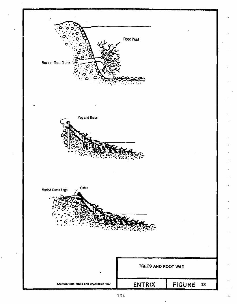
. .:'o·:·O:O'·~----------'... '.' .. '
" : ... :' 0 .() ~
'·9'. ." '0:' Root Wad :0':',":':0:" . . .,. , . '. .. ." '."N D.
""",.' "
";'::0 r·-~::.~~~Buried Tree Trunk';;;-_:--
:' . ,'0:'.1'\'" .• ' • :~ .:';;): .~ '.,
-: ,' .. ··0...·~ ... ~.. t::R:~~~~o . ·~:·I·:·········:·· .. :~··
Peg and Brace
Buried Cross logs Cable
TREES AND ROOT WAD
Adaptedtrom Whll~ :md 8rynlld~n 1957 FIGURE 43
164
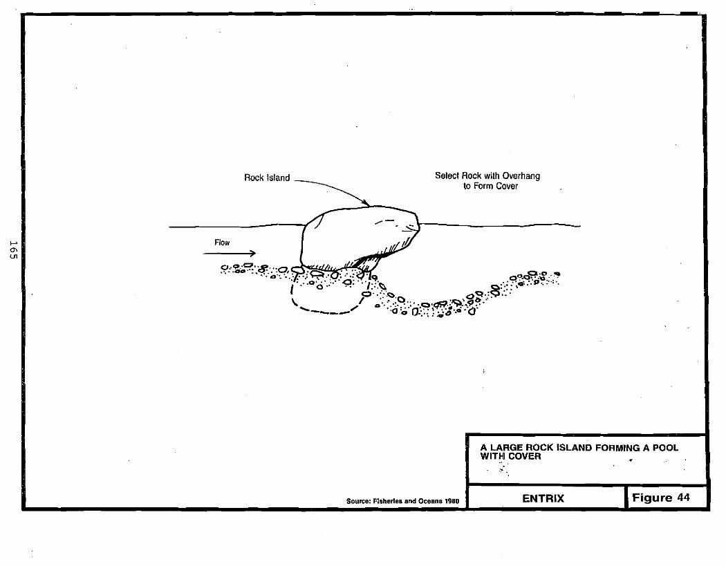
'-' '"U1
Select Rock with OverhangRock Island ~ to Form Cover
-r>: -.:J\------ Flow I/J
~ CI'.,o"'o .,........... q . .----.::) I .. ':., . a::::..,.... :.q.o'.'.'~.oO.oo'p'o...:. o''''~'':.q'.. '; .', """"'="" .•"~....,...... ~<q.:. " ..... - "C>. ".: 0 .. · ... "'"!. . ..~ '~b'
t ." o· C).....<:>.() ..c>:~..9 .. ' I ." ." . . ':" C)''''~'tIII ••••~. 0'· ·•·• .. ·0· .. '.:".0 V
\ ....... _----", "0'0 ':-"'"
A LARGE ROCK ISLAND FORMING A POOL WITH COVER
~
Figure 44ENTRIXSource: Fisheries and Oceans 1980

e
boulder. The scour pool provides a resting place for fish and protection from predators. Boulders screened during mining can be used to create rock islands. A 3 to 4-ft diameter boulder, or the largest available, should be • used. While the overhanging rock depicted in Figure 44 is desirable, rocks with no overhang are also effective. The boulder should be set into the river bed with the overhang positioned downstream. Boulders are most effective when placed near the upstream end of a shallow pool or run, or in the middle and downstream portions of riffles (Fisheries and Oceans 1980, U.S. Department of Transportation 1979). Careful pre-exacavation of the intended scour pool will speed the natural erosion process.
After stream modifications and structures similar to the ones described above are in place, the restored stream reach will provide improved rearing habitat for fish. Figure 45 shows some of the suggested habitat features in a rehabilitated meandering stream. Guidelines for spacing habitat features were presented in Section 9.1.
If a stream reach is designed and implemented with care, incorporating recommended pool/riffle ratios (Section 8.4.1), spawning may occur within the reach of rehabilitated stream at the downstream ends of riffles and upstream • ends of pools. The placement of small to large gravels (1 to 5 in. diameter) at these locations will provide sUitable. spawning substrate for salmon, while smaller sized gravels and sands (0.1 to 1.5 in. diameter) should be provided for grayling (Sections 9.3.1 and 9.3.2). The normal split in classification of screened materi a1s by a washpl ant occurs at 0.5 to 0.75 in. The sma11 er materi a1s shculd be used for grayl i ng spawni ng whi lethe 1arger sizes shauld be used in salmon spawning areas. Some larger material (up to la-in. diameter) will not greatly diminish the usefulness of the substrate for spawning. However, substrates that contain predominantly large materials (10-in. diameter or greater) should be avoided in areas where spawning is desired.
9.4.2 Mountain Streams
Mountain streams are high-gradient streams that usually have straight channels with little meandering or channel sinuosity. Because of the steep gradient
j,;,.i
166

Riprap and Treecover
Boulder Grouping
Log Undercut Bank
Submerged-Rock Weir
STREAM-HABITAT FEATURES FOR REHABILITATION OF A MEANDERING STREAM
Adapted from Plsherles and Oceans, 1980. Figure" 45 ENTRIX
167

and relatively straight channel, velocities in mountain streams tend to be
high. Riffles and runs are the dominant habitats, while pool habitat is often
scarce. Thus, the goal of stream restoration for fish use in mountain streams
is to avoid a uniform, straight-channel stream that has little or no
structural ~iversity (i.e., boulders, pool/riffle configuration) and resembles
a drainage ditch. Instead, channel structures and modifications that create
habitat diversity should be emphasized (Hardy Associates, Ltd. 1982).
As previously mentioned, fish-passage requirements should be evaluated at a
mean annual flow during the hydraulic design phase of the stream
rehabil itation (Section 8.2). In mountain streams, care must be taken to
avoid waterfalls or cascades that will prevent the upstream movement of fish.
After passage requirements have been incorporated in .the stream design,
rearing habitat shoul d be eval uated. Two rel atively simpl e channel
modifications can greatly add to the habitat diversity and provide rearing
habitat for fish in mountain streams. They are the boulder grouping or rock
island and the submerged-rock weir.
If properly sized and p1 aced, boulders can provide cover and velocity breaks
(small pockets or pools) important for juvenile anadromous and juvenile and
adult resident fish. Boulders can be placed either singly or in carefully
spaced groupings. In general, boulders should be 3 to 4 ft in diameter.
Another method of slz1ng is to use the larger boulders that were separated
during the mining operation. This will insure that boulders are not washed
downstream by flood events.
Boulders are best placed near the upstream end of a shallow pool or run, or in
the middle and downstream portions of riffles (Fisheries and Oceans 1980, U.S.
Department of Transportation 1979). If boulders are placed in groupings of 2,
3, or 4, they should normally be positioned 5 tolD ft apart to avoid
deposition of bedload materials or debris in between the boulders. However in
steep-gradient streams, where deposition is less likely due to high
vel ocit i es , they can be grouped closer. Boul der groupi ngs can be repeated
down the length of ri ffl es in 1arger streams. Figure 46 shows a boul der
placement, with a pool forming on the downstream side of the rock island.
168
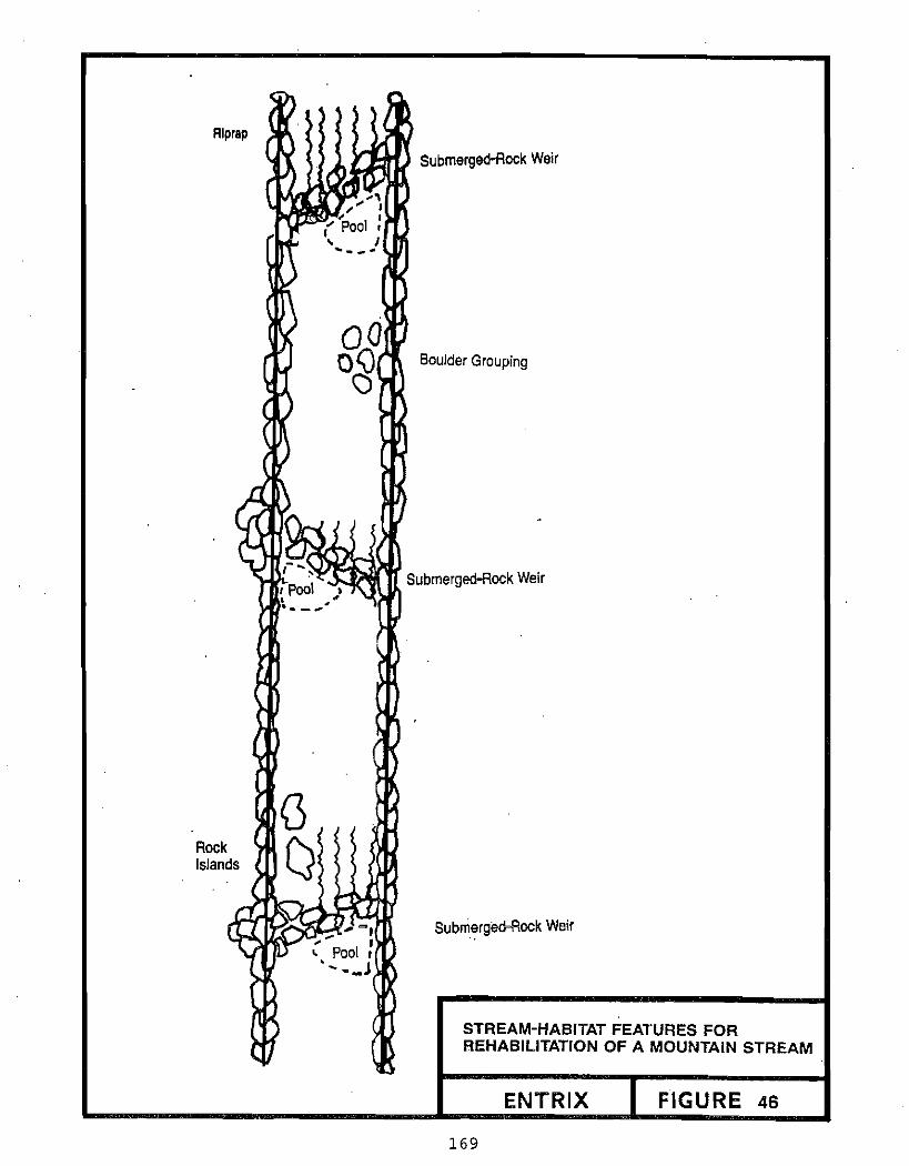
Rlprap
Rock Islands
I pool. ".. _.....
Submerged-Rock Weir
Boulder Grouping
Submerged-Rock Weir
Submerged-Rock Weir
STREAM-HABITAT FEATURES FOR REHABILITATION OF A MOUNTAIN STREAM
ENTRIX FIGURE 46
169

The doubl e-step submerged-rock wei r is an effective modifi cat i on for steepgradient, high-velocity streams (Fisheries and Oceans 1980; White and Brynildson 1967). This structure is designed to reduce velocities and increase depths by creating small plunge pools on the downstream side of the wei r. Reduced velocities and more pool habi tat wi 11 increase the amount of rearing habitat in mountain streams. Fish passage is maintained where the streamflow is concentrated between rocks.
The ends of the rock weir that abut the stream bank must be riprapped (Section 8.5.3) to a sufficient height to prevent flood flows from eroding around the ends of the weir. A height of 2 ft above the high water mark should suffice. The rocks chosen for the weir should be flat or slightly rounded on their top sides so that the crest of the weir is relatively flat. Rocks should be sized using the bed- and bank-stabilization criteria (Section 9.5) so that they will not wash downstream at high flows. Spacing of the rocks must be sufficient to allow fish passage at low flows. A cross-section of a rock weir in Figure 47 illustrates these concepts. Where the stream gradient is particularly steep, a double-step rock weir can be used (Figure 47). Weirs can be placed straight across a stream channel, or angled downstream as shown in Figure 46.
Spawning may occur if gravels of suitable size are placed in the downstream ·end of riffles and at the head end of pools. Sections 9.3.1 and 9.3.2 discuss the range of substrate preferred by spawning fish. In general, small to large gravel (1- to 5-in. diameter) will suffice for spawning substrate. Refer to previous section for further details (Section 9.4.1).
9.4.3 Braided Streams
Braided streams often have unstable stream channels that shift within the fl oodpl ai n over short time interval s , Stream modi fi cat i oris and structures used to enhance fish habitat are generally not recommended for this river type since the dynamic nature of the stream most likely will result in frequently altered channel locations and shapes (U.S. Department of Transportation 1979). Therefore, when rehabil itat ing a braided stream for fi sh use, it is best to design for fish passage, and avoid stream modifications for rearing or spawning that· may quickly become ineffective.
oj
170

• - -- ~ -.--__, • C"'- -. '~' __ .. -,- - - - .
...... -.J ......
Stagger Upstream Rock to Overlap Joints Between Downstream Rocks I
~r~~y~j1~~1,jf~ .~
Use Large Rock to Form Weir Crest (minimum size 2 It. deep)
.. ··~:~i1:1:~i~wi~;}~~
~~"';../~/"""""""'"
Processed Gravel and Cobble
PROFILE OF DOUBLE-STEP WEIR
Concentration 01 Flow Between Rocks to Improve Fish Passage at Low Flow
• Flood Flow
CROSS SECTION OF STREAM CHANNEL (looking upstream) ROCK USED TO CONTROL GRADE IN A
CHANNEL
Source: Fisheries and Oceans 1980 ENTRIX Figure 47

Fish passage cri teri a for resi dent and anadromous fi sh were presented in Sections 9.3.1 and 9.3.2. Depth and velocity are usually the two important factors to consider when providing fish passage. If the stream channel affected by mi ni ng is restored to a gradi ent and channel structure wi th a
configuration similar to pre-mined conditions, passage requirements will usually be met. However, passage requirements should be considered in the hydraul i c desi gn of an altered stream channel to ensure that fi sh wi 11 continue to have access to upstream habitats and will have free movement in the river (Section 8.2).
-. <'
"f""
", .~
_.
• ~
,
ii..;.
C lkJ
F ..
l (f"
Ii,;.
, 'iJ
172 ]

FLOODPLAIN REHABILITATION
173


10.0
FLOODPLAIN REHABILITATION
10.1 OBJECTIVES AND SCOPE
Floodplain rehabilitation is the final phase of placer-mine site closure. The
primary goal of rehabilitation is to return the floodplain to a condition that
promotes rapi d recovery to pre-development condi t ions (Berry 1974). Thi s
process is begun through stabil i zat i on of fl oodpl ain materi al s , the
establishment of natural vegetative communities, and the enhancement of
vegetative recovery (Dick 1974). Complete short-term rehabil itation of the
floodplain is not expected to be accomplished by performing the procedures
outlined in the following sections. Instead, these techniques are designed to
enhance natural recovery. Without enhancement, a fl oodpl ain may not be fully
recovered even after 100 years (Hardy Associ ates 1978; Crocker and Di ckson
1957). Use of the prescribed rehabilitation techniques can accelerate
recovery so that the floodplain is returned to pre-disturbance condition in 20
.to 50 years with significant vegetative recovery often noted within the first
5 to 10 years (Joyce 1980, Johnson 1981).
Wil dl i fe speci es adapted to early and mid-success i ona1 stages of fl oodp1ain
vegetation are those most likely to receive short-term benefits from
terrestrial rehabilitation. The big game species that will benefit most
frequently is the moose. Terrestri al furbearers are usually associ ated wi th
mature forests and thus would not benefi t from rehabi 1i tat ion in the near
term. Beaver might benefit from i ntermedi ate successi ona1 stages at
rehabilitated sites. For most sites, elaborate manipulation of invading
vegetative communities will not be indicated. Rehabilitated floodplains and
upl ands can be expected to support different fauna at each successional stage.
At sites where specific migitation of habitat loss to benefit specific species
. is requi red by a resource management agency, it is recommended that more
175

detailed references preparation.
be examined and species experts be consulted during plan
Rehabil itat i on of the fl oodpl ain shoul d be conducted in three phases: site gradi ng, stockpil e di spersement, and revegetation (Keller and Leroy 1975). Site grading is performed over the entire disturbed area, including adjacent to stream channels (riparian zone), in the inactive floodplain, on the valley terraces, and on the vall ey benches. Specifi c recommendat ions for slope, contour, and methods of stabi 1izat i on vary for each of these zones. The second phase of fl oodp1ai n rehabil itati on is stockpile di spersement. Since organic stockpiled material may be present in insufficient quantities to cover the entire disturbed area, speciric areas in each zone should be selected to receive organic material. At sites where organic material is not available, and large stockpiles or fine organic material (loess) or settling pond deposits are present, these inorganics may be used in place of the organics. The selection of these sites is based on providing maximum habitat value for fish and wildlife (Morrison 1982). The third phase of rehabilitation is revegetat ion. Techni ques descri bed for revegetat i on are desi gned to enhance and expedite natural recovery of fl oodpl ain species. This can be accompl i shed by several methods, including broadcasting woody debris, planting viable portions of live shrubs (sprigging), transplanting live vegetation from areas adjacent to the di sturbed area, and seeding (Dabbs et al. 1974, Johnson and Van Cleve 1976, Billings 1974, Saville 1972, Joyce 1980).
In addition to establishing vegetation, other techniques of wildl ife habitat enhancement should be conducted. These include creating log piles by placing large, woody vegetation. in strategically located sites to attract small birds and mammals, placement of tree trunks in the riparian zone to provide habitat for birds, and construct ing small rock pil es that are occasi onally used by small mammals (Herricks 1982, Szafoni 1982).
10,2 SITE GRADING
The first task of floodplain rehabilitation is to grade the tailings piles to final slopes and contours. Much of this grading should have been done during operation of the site. The goal of site grading is to modify the topography i
J
176

of the site to reduce the potential for nonpoint-source pollution and prepare
the floodplain materials for later revegetation (Leroy 1973). Although the
goal is the same for all areas of the floodplain, different techniques should
be employed in different zones of disturbance. Dimensions provided within
these best management practices are guidel ines that may need to be adjusted
for the available quantity of materials.
Settling ponds should also be rehabilitated during site grading. Settling
ponds in the active floodplain must have all sediments removed. Settl ing
ponds in the inactive floodplain may be rehabilitated by excavation for use as
fi sh habitat or if the sed iments are requi red for revegetation. SeUl i ng
ponds may also be stabil i zed by pl aci ng oversi ze materi alover the fi ne
sediments and grading level with the surrounding topography.
10.2.1 Riparian Zone
The riparian zone is defined as the area within the active floodplain adjacent
to active stream channels. The final grade of materials in the riparian zone
is dictated by hydrologic and engineering constraints as well as the type of
stream channel that has been designed .. Sediments must be removed from all
settl i ng ponds located in the ri pari an zone. The settl i ng- pond depressi on
must be graded to conform to the surrounding· topography.
The hydrologic and engi neeri ng constraints are control 1ed by the stream type
within the site. Chapter 8.0 describes the reestablishment of an appropriate
channel Within the site. The channel should be located to avoid settling
ponds if possible. If settling ponds are located within the riparian zone,
special rehabilitation measures will be required as described in Sections 4.2
and 8.3.4. Following the design and selection of the stream-channel location,
the remai nder of the fl oodp1ain shoul d be graded. The features that are
developed by site grading are specific to the type of stream that has been
establ i shed. However, a11 slopes shoul d be graded to 3 hori zonta1 to 1
vertical or less.
The final elevations of the floodplain materials to be established within a
meandering stream should conform to the elevations established by the stream
177

channel. For a meandering stream, the bankfull elevation may be used as a reference. On the inside of meanders, a grade of 50 to 1 (ADEe 1979), sloping away from the stream should be provided from the bankfull stream channel toward the valley wall. Although a grade of 50 to 1 is recommended, site
constraints, may require the use of a slope with maximum steepness of 10 to 1.
The grade should commence at the bankfull el evat ion at the stream margi n
(Figure 48).
An overflow channel may be provided within a meander to carry flows greater than bankfull. Overflow channel s woul d not be needed at each meander bend. The overflow channel must be designed and constructed with caution to minimize the potential for the channel to develop into a permanent cutoff. The
overflow channel should connect the outside stream margins of the previous and subsequent meanders (Figure 48). The overflow channel should consist' of a depression approximately 1 ft in depth and with a width of 12 ft or 1arger. Small depressions on either side of the overflow channel may be required if
ripari an vegetati on is to be establ i shed at the channel margi ns , Ri prap should be placed on a small berm at the upstream junction of the overflow channel to a level slightly less than the adjacent bank height.
A small berm should also be constructed at the downstream end of the overflow channel. The berm should be riprapped and have a total height slightly less than the adjacent bank. The berm will likely pond water within the overflow
area (Figure 48). Natural overflow channels often contain ponded water in the
downstream areas. The pond may encourage silt deposition and raise the groundwater table, which would promote revegetation.
On the outside of the meander, slopes should be graded to a maximum steepness
of 3 to 1. A terrace should be provi ded at 1east 2 ft above the bankfull
elevation on the outside bend to minimize runoff entering the stream and to promote development of riparian vegetation (Figure 48). The terrace should be at least 14 ft wide with a depression between 1 and 2 ft deep.
In a mountain stream, the size of the valley and the amount of tailing pile
materi al to be graded wi 11 govern the fi na1 site topography. Terraces at bankfull level should be sloped away from the stream channel (Figure 49) to
178

A
'naclive A,panan Small Depressions For FloodPiaJ.n I i;'-;;-~'- Erosion Control and Cover'
"'-----
~ 'w ,"It __ Small Terrace For Erosion Conlrol and Cover Vegelation--r- Vegetation 1
Bankfull Channel50 / 11
+/0 \ ..ov.~o~ I
Channel
SECTION A-A
Overllow Channel
A
I-' -.I \0
Riparian Zone Inactive Floodplain
OVERFLOW CHANNEL IN A MEANDERING STREAM
VERTICAL SCALE IS EXAGGERATED FOR ILLUSTRATIVE PURPOSES Figure 48ENTRIX

..... (X)
o
Slope
Valley Wall Slope
Valley Wall
50 Bankfull1 . Elevation 50
1
1
Stream Channel
MOUNTAIN STIREAM
VE':TlCAL SCALE IS EXAGGERATED FOR ILLUSTRATIVE PURPOSES _ ENTRIX _ FIgure 49rL~,..,....~""'!'""""!!!"""""."''''''''''''''~~~~~--.-~~~~I , ~ , I,,~ I~'!', ,~,"'JI1 ".,.----:-- ,,> ,~W" f~" ,,;'1] p....1jj, ~. <3 111 '\ '" "':10. ~•....,.. ~: ~(

control nonpoi nt-source poll ut i on by coll ect ing sediments. Terrace slopes
should range between 10 to 1 and 50 to 1 (ADEC 1979). Terraces function as
high-water channels for flows above bankfull.
The main channel in a braided stream should be designed to contain the
bankfull flow with hi qhwat.er channels available to discharge higher flows
(Section 7.4.3). The highwater channels should be graded with undulating beds
approximately 1 to 2 ft in depth and widths of 12 ft or more (Joyce et al.
1980). The channels should wind through the floodplain, occasionally
rejoining the main channel. At the downstream junctions, small berms should
be left in the highwater channels to slow water velocities (Figure 50).
After the slopes and elevations of the riparian zone have been established for
hydraulic design, additional grading may be necessary for areas where organic
or inorganic material is to be placed. At some placer mining sites, the
quantity of organic material available for distribution is limited. At these
sites, organi c materi a1 shoul d be pl aced in areas that wi 11 provi de the
greatest benefit to fi sh and wil dl i fe, whereas fi ne-i norgani c materi a1, when
available, should be used in areas of lower priority. Placing organic
material in the riparian zone puts the material at risk. A single high flow
event could wash the material away before vegetation has a chance to become
establ ished. However, the potential benefits of riparian vegetation to fish
and wildlife communities make the risk acceptable with proper hydraulic
design.
To minimize the chances of organic material being removed during a high flow
event, protective devices should be installed in the riparian zone at all
locations where organic material is to be placed. Protective devices can be
any object or material capable of remaining in place when subjected to
moderate flows. Materials could include tree stumps, tree trunks, and large
rocks. The material should be placed in the riparian zone, perpendicular to
the flow and downstream of the site where organic material is to be placed.
These devices will reduce the amount of material lost if a moderate flow event
occurs. Under more extreme flood conditions, it is likely that the barriers
and the organic material may be lost; however, as stated, the value of a newly
created vegetated ri pari an zone to fi sh and wil dl ife is worth the potent i a1
181

A
.' . .. o •• o. • o. ." ,': 0 .. Q... ~ ..
• •
.. ~ .... ~~
c. ' ••: ......".~ .
.0':' , "
•• ,. 0 • • ••••• CI', ~ ;\ -:
eo, ,; :. •• ', .• w'o ...... ~.
Flow-Main Channel
LEGEND:A ATTrD Small Berms at Downstream Junction
QlJJI-'" with Main Channel
Inactive Floodplain __ / .... Riparian Riparian Inactivezone ZOne.. _Floodplain
Highwater Channel Highwater
ChannelI Bankfull 7l- .-y-'\.t__ --'" Elevation
SECTIONA-A
...
Tailing Pile
Islands
"""'".. After Grading
Prior 10 Grading
BRAIDED STREAM
VERTICAL SCALE IS EXAGGERATED FOR ILLUSTRATIVE PURPOSES ENTRIX Figure 50
~.-,.J182 I

risk. As described in other ·sections, creating a new riparian zone adjacent to active channels is probably more desirable at sites where fish occur in the stream.
In braided floodplains riparian zones. can also be constructed on large islands. These islands would consist of graded tailings piles between active channels. Due to the dynamic nature of braided channels, a special design is required to maintain the integrity of the island. Organic material should be placed in the centers of the islands to encourage colonization by vegetation.
Tailing piles within the active floodplain of a braided river should be graded and stabilized to conform with the stream pattern. The tailing piles should be graded primarily parallel to the river flow; this grading will elongate the piles into a shape similar to braided gravel bars. The graded tailing piles should have a maximum elevation of about 5 ft above bankfull conditions with a maximum slope of 3 to 1. The maximum elevation cf the piles will be on the outer margins, as a depression should be scraped in the middle of the pile to a depth of about 1 ft as shown in Figure SO. A berm along the edge of the island should be maintained between the scraped center and the active channel. Upstream, the berm should be increased in width to protect against overtopping. The upstream end of the island should be stabil ized by placing riprap to minimize erosion. Riprap will also reduce wave runup and assist in preventing berm breaching.
10.2.2 Inactive Floodplain
The inactive floodplain is defined as the area between the riparian zone and the IOO-year floodplain (Figure 11). It is likely that this portion of the mine site will contain settling ponds and numerous tailings piles. As in the riparian zone, the final topography of the inactive floodplain is dictated by hydrologic and engineering constraints.
The physical configuration of the site and the stream channel location and pattern may constrai n the gradi ng of the i nact i ve fl oodpl ain. The i nact i ve floodplain should be shaped to allow floods in excess of bankfull to spread out as shallow flow on the floodplain while maintaining some degree of
183
conta i nment. From the ri pari an zone, a 3 to 1 slope or 1ess shoul d be provided. This slope should continue until an elevation gain of 0.6 times the mean bankfull depth at bankfull stage has been exceeded (Figure 51). This elevation represents the depth of about the 25-year recurrence-interval flood in many natural systems (Emmett 1972). A terrace should be provided at this elevation, and should be sloped away from the active channel at a slope between 30 to 1 and 20 to 1 (Stoecker 1982). Further up the bank, a slope of 3 to 1 or less should be maintained until an elevation of 2 times the mean depth at bankfull is reached (Figure 51). This depth corresponds to about the 100-year recurrence-interval flood event i nmany natural systems (Emmett 1972).
The fi na1 topography of the inact ive fl oodpl ain shoul d include appropri ate grading for wildlife habitat (Figure 51) (Stoecker 1982). Ponds should be created by modifying the final shoreline configuration of the settling ponds, removing the majority of the accumul ated sediments from the ponds ," and, if necessary, improving the integrity of retaining walls, dikes, and dams (Stoecker 1982). Pond modification should create high habitat diversity and provide feeding and nesting areas for waterfowl, shorebirds, and passerines by developing a diverse shoreline configuration, islands, and variable water depths. A stabiliZing layer of riprap, if available, should be placed along the dikes or berms nearest the active channel to prevent breaching. Armoring the section of the structure where the largest velocities are expected should have the highest priority when distributing riprap (Section 8.5.3).
If necessary, most accumulated sediments should be removed from the settling ponds during final site grading for use in revegetation. These sediments should be placed in a depression located on an elevated area on the opposite side of the settl ing ponds from the active channel. In addition to the depression (of at least 1 ft) a berm may be required to contain the sediments and prevent them from returning to the pond. This will allow the sediments to dry and will reduce the potential for the sediments to be carried into the active channel.
As sediments are be i ng removed from the pond, the shoreline confi gurat ion should be made more complex (Figure 52). Bays, spits, and peninsulas can be
184

-o:::::f
6 1 3 Of lesstOIle O·6de 20 to30
\ Riparian Zone
~"lBankfill Depth, de
\ J Active Channel
3 or less Terrace\. ~ 2O-3OFT
Inactive Floodplain
CROSS SECTION
PRELIMINARY GRADING
;... . " ,', . .', "
.,-;., .. ~:-.•..•..•.•.n,.,
DESIGN 1. MUO BAA AND SMALL ISLAND
. " ..
.""""I
• c••• · • ...'~', •. ".
-.. OESiG~ 2. OESCE~Or~G ISLANOS
- ... _- --- - _- --...
FLOODPLAIN GRADED TO CREATE WILDLIFE HABITAT
Source: Stoecker 1982
Figure 51ENTRfX
185

" I \
~ j,dB 1" ./~ 'I ~. " I
Active Channel .....
Tailings Pile
Final Grade
CROSS SECTION
Water Level
Minimum Berm Height
Settling Pond
CROSS SECTION
~.•. " . • •..... . ': . • . J~
, .
, I ' \
\ ./
\ /, , \ , ..
Sediments Removed
Initial SiltLevel
Settling Pond Before Grading
Source: Herricks 1982
Settling Pond After Grading
SITE GRADING IN INACTIVE FLOODPLAIN
ENTRIX FIGURE 52
186
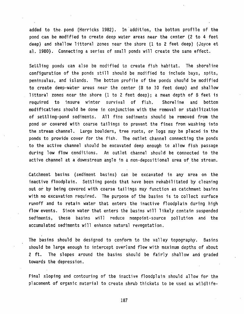
added to the. pond (Herricks 1982). In addition, the bottom profile of the pond can be modified to create deep water areas near the center (2 to 4 feet deep) and shallow littoral zones near the shore (1 to 2 feet deep) (Joyce et al. 1980). Connecting a series of small ponds will create the same effect.
Settling ponds can also be modified to create fish habitat. The shoreline configuration of the ponds still should be modified to include bays, spits, peninsulas, and islands. The bottom profile of the ponds should be modified to create deep-water areas near the center (8 to 10 feet deep) and shall ow 1ittoral zones near the shore (1 to 2 feet deep); a mean depth of 8 feet is required to insure winter survival of fish. Shoreline and bottom modifications should be done in conjunction with the removal or stabilization of settling-pond sediments. All fine sediments should be removed from the pond or covered with coarse tail ings to prevent the fines from washing into the stream channel. Large boulders, tree roots, or logs may be placed in the ponds to provide cover for the fish. The outlet channel connecting the ponds to the active channel should be excavated deep enough to allow fish passage during low flow conditions. An outlet channel should be connected to the active channel at a downstream angle in a non-depositional area of. the stream.
·Catchment basins (sediment basins) can be excavated in any area on the inactive floodplain. Settling ponds that have been rehabilitated by cleaning out or by being covered with coarse tailings may function as catchment basins with no excavation required. The purpose of the basins is to collect surface runoff and to retain water that enters the inact ive fl oodpl ai n duri ng high flow events. Since water that enters the basins will likely contain suspended sediments, these basins will reduce nonpoint-source pollution and the accumulated sediments will enhance natural revegetation.
The basins should be designed to conform to the valley topography. Basins should be large enough to intercept overland flow with maximum depths of about 2 ft. The slopes around the basins should be fairly shallow and graded towards the depression.
Final sloping and contouring of the inactive floodplain should allow for the placement of organic material to create shrub thickets to be used as wildlife
187

migration corridors. The purpose of the corridors is to provide a meandering
stri p of vegetat i on between the undi sturbed vegetation adjacent to the mi ne
site and settling ponds, active channels, or catchment basins in the disturbed
area (Figure 53). The corridor should be graded so that the elevations of
material at the ends of the corridor are the same el evation as the shore of
the waterbody and the ground 1ayer in the undi sturbed zone. The corri dor
should be relatively flat, about 10 to 20 feet wide, and should be slightly
lower (shallow depression) than the surrounding grade of the inactive
fl oodpl ai n, This des i gn wi 11 encourage natural revegetat i on in the corridor
since runoff, sediments, and wind-borne seeds will accumulate in this area.
10.2.3 Valley Terrace
The valley terrace is the section of the floodplain outside of the IOO-year
floodplain, yet on relatively level ground (Figure II). After mining has been
completed, this area will 1ikely contain settl ing ponds and tail ings piles
similar to those found on the inactive floodplain (Section 10.2.2).
The goals of final grading on the valley terrace are to return the area to its
approximate pre-development topography and to mitigate loss of wildlife
habitat. Specific features that can enhance natural revegetation and create
wildlife habitat are similar to the features described for the inactive
floodplain. These include ponds with complex shorelines and diverse bottom
profiles, catchment basins, and wildlife-migration corridors.
10.2.4 Valley Bench
The valley bench is a relatively flat and narrow area iocated on the steep
slopes of the valley side wall. Frequently the placer gravel s located on
these benches are mined and processed in place, resulting in all mining
operations, including tail ing piles and settling ponds, being located on the
bench. Since these operations are usually confined to these narrow benches,
extensive site grading is not always required.
The goal of site grading on a valley bench is to return the site to the pre-development slopes and control erosion (Berry 1974). On steep vall ey
188
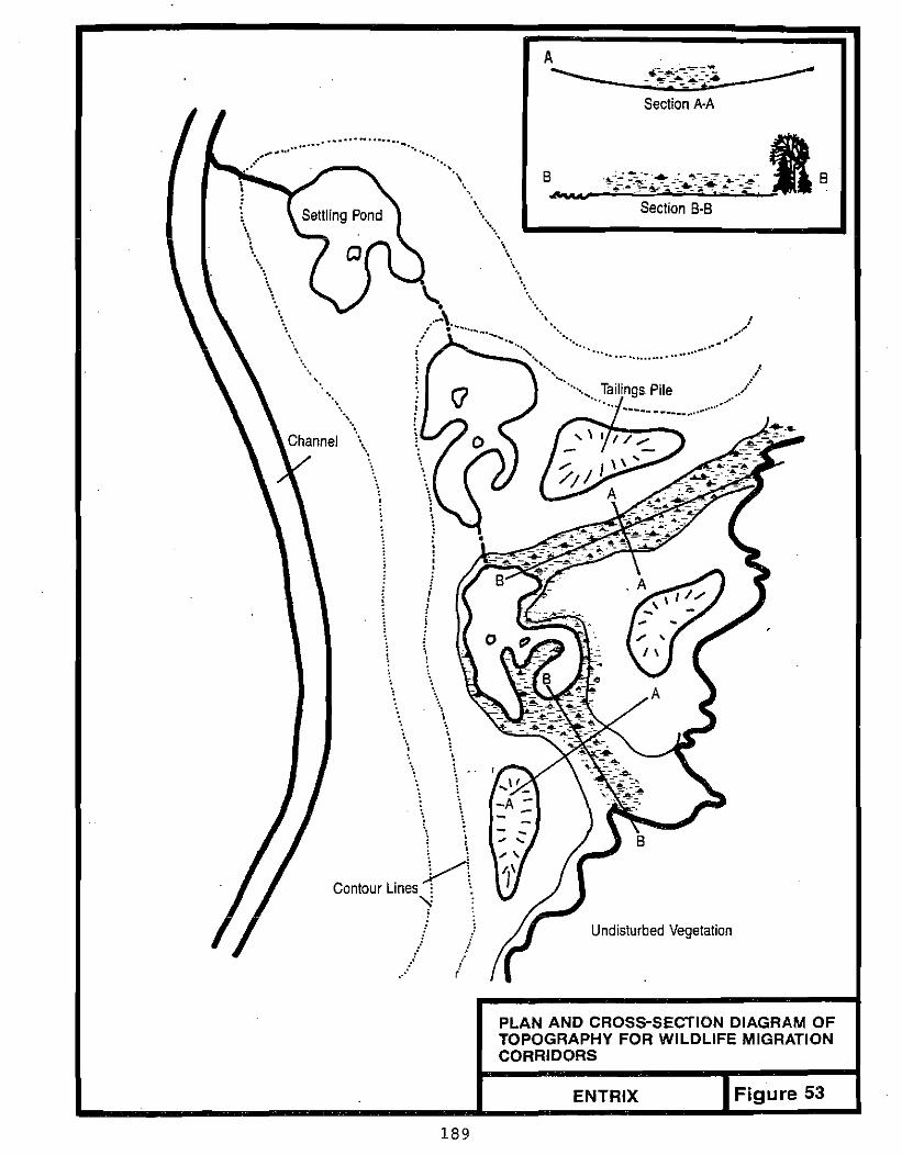
Section A·A
\
.................... ..........
", "
... "
\ \",
... ...,, " \.,
'. ...
"''''\ B "
" ~.1
'. .....•.\
.,., "",
'. \
\.A, "" I " ~:/' - "<. . . ",.'"
.......... .. ... ."
.. ••• '1. ./~""", Tailings Pile ./...... ......
..... ..•..•
.... ,,
:, ),,,• !i, , I !
\t !
, " ... \ ,,,
" \
\'.
~! Contour Lines: ~
'1 Undisturbed Vegetation
,. / ....
,,' r/
PLAN AND CROSS-SECTION DIAGRAM OF TOPOGRAPHY FOR WILDLIFE MIGRATION CORRIDORS
Figure 53ENTRIX
189

wall s , terraces and catchment basins may need to be constructed to trap sediments originating on the bench (Doyle 1976).
Settling ponds should be rehabilitated by burial or by removing sediments, or be reinforced to ensure the long-term integrity of the structures (Figure 54). Removal of sediments from the settling ponds can provide habitat for wildlife; they shoul d be removed as descri bed for the inactive fl oodp1ai n (Section 10.2.2). Since these sediments may be on a stopa.: additional containment structures may need to be constructed. Materials that could be used include tree stumps, tree trunks, and large rocks.
10.3 STOCKPILE DISPERSEMENT
The amount of organic material available for distribution will vary for each placer-mining site. Some sites that were recently opened may have an abundance of organic material. Other sites, including large braided floodplains may have few, if any, organic materials to distribute. Due to the normally limited quantity of organic material available, a list of priorities has been established so that placement of the available organic material provides maximum habitat value for fish and wildl ife. At those sites where organics are not available, but large quantities of inorganic fines are available (from settling ponds or loess stockpiles), these inorganics may be used in lieu of organic material.
The first criteria for deciding where to place organic material is whether the stream supports fi sh or is being rehabil i tated to provide fi sh habitat. In this instance, the highest priority location in all stream types is to place the material in the riparian zone. If excess material remains after placement in the riparian zone or if fish are not present in the stream, the objective is to create wil<!llife habitat over as much of the disturbed area as posstb'l e. At those sites that contain an over-abundance of organic material, only the material necessary for rehabilitation should be distributed.
The goal of creating wildlife·habitat will be best achieved by rehabilitating the floodplain to pre-development conditions. In this way, species of birds
.and mammals that utilized the floodplain prior to commencement of mining will
19D
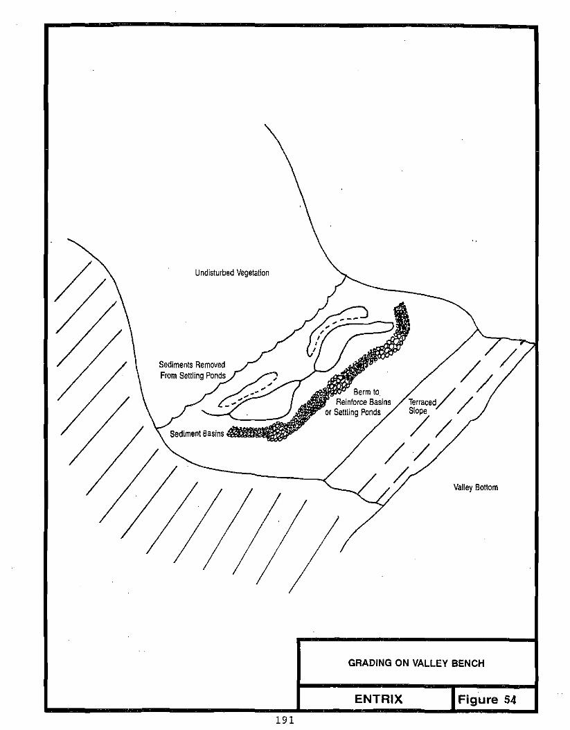
\
/ Terraced//Slope
//// ~
Berm to. Reinforce Basins
or Settling Ponds
Undisturbed Vegetation
//
Valley Bottom
GRADING ON VALLEY BENCH
ENTRIX Figure 54
191

have that habitat replaced. Speci ali zed habi tats des i gned for particular
wildlife species need not be created, unless they existed pri or to
development.
Pri ority 1ocat ions for the placement of organi c materi al in the three types of
floodplains (meandering, mountain, and braided), as well as valley terraces
and valley benches, are depicted in Figures 55, 56, 57, and 58. In general,
vegetation should be established in three areas: adjacent to ponds and
catchment basins, in the riparian zone, and in the wildlife migration
corridors created during final site grading. Note that if settling ponds are
connected to the act i ve channel s, the fi ne sediments in the ponds must be
removed or stabil i zed pri or to maki ng the connection to prevent fi nes from
entering the stream.
The greatest impediment to natural revegetation is the lack of moisture in the
organic material (Berry 1970; Johnson et al. 1981). Typically, organic
material is mixed with, or placed on top of tailings piles consisting of
coarse, porous gravels. Water that enters the organic layer rapidly
percolates through the gravels and is lost. At sites where moisture can be
retained in the organic material, natural revegetation is accelerated (Berry
1970).
Before materials from the organic stockpiles are distributed, a leveling layer
of material should be dispersed. Optimally, this material can be obtained
from the stockpil e contai ning the sha 11 ow soil s removed when the site was
opened. This material serves as a moisture retention layer since it consists
of fine sediments, sand, and fine-textured organic material. If the shallow
soils are not available, settling pond sediments, loess overburden, or sand
can be used.
After the level i ng layer has been applied, the organ i c stockpil e contai ni ng
the top layer of soil, root systems, and shrubs can be dispersed over the
site. This layer generally should be applied at a lightly compacted thickness
of 6 to.8 inches, although actual depth will depend upon the availability of
organic material at each site. Large stumps and trees that were stockpiled
192

Revegetation Priorities for a Fish Stream
Revegetation Priorities for a Stream with No Fish
Undisturbed Vegetation
LEGEND:
~~~ ~"!i'~~~f
; 1 f:~t~';:,'i, ;,;~\ ,,,,.';,~
-";f-- Modified Seltling Ponds
~ ...... )O'~.;: -:: CROSS SECTION
High-Water Channel __"~,, / .is,~",
• -:'''.'l) .;?,~--~.
-r;; -e." _.' -
, . _ .... ... <
LEGEND
t, isolated areas of vegetation between the stream and theundisturbed zone ofvegetation, located adjacent to seltling ponds,
2, Riparian vegetation established along the stream yet within close proximity toseltling REVEGETATION PRIORITIES FOR MEANDERING ponds and other pockets of veqetation, STREAMS WITH AND WITHOUT FISH
3, Corridors of vegetation between the undisturbed vegetation and the stream or ponds, ENTRIX Figure 55
193

LEGEND
1. Isolated areas 01 vegetation between the stream and theundisturbed zone ofvegetation, located adjacent to settling ponds.
2. Riparian vegetation established along the stream yet within close proximity tosettling ponds and other pockets of vegetation.
3. Corridors of vegetation between the undisturbed vegetation and the stream or ponds.
I ' ,. o ~ ,.;
J :, , . > h:'...,.
> " ... '
:l,~ ~ :'.. ,. ,.
LEGEND: Revegetation Priorities for a Fish Stream
~. ". ..... ~.- Revegetation Priorities-i>... s:~~ - . - - - - .... for a Stream with No Fish
CROSS SECTION
Channel
Depression From Grading
Elevated Riparian Zone -.. ,
REVEGETATION PRIORITIES FOR MOUNTAIN STREAMS WITH AND WITHOUT FISH
t----------.....-----... E.; ENTRIX Figure 56
194

• • •. . . ., •• • • '. n• • ••0 .' , .
0
0 . '0: • o. .. . 0
o· ' . . ·0
' .. 0
0' . ····0 '1~ " O'l,t, • '0
•
• • • -, . 0
.-. -,
CROSS SECTION Settling Pond,
~.- -I -e--~ - --....... I LEGEND:
LEGEND Revegetation PrioritiesJ for a Fish Stream1. Isolated areas of vegetation between the
stream and theundisturbed zone ofvegeta Revegetation Priorities
I tion, located adjacent to settling ponds. for a Stream with NoFish j 2. Riparian vegetation established along the
thestream yetwithin close proximityto set REVEGETATION PRIORITIES FOR BRAIDED tling ponds and other pockets ofvegetation. RIVERS WITH AND WITHOUT FISH
3. Corridors of vegetation between the undisturbed vegetation and the stream or ponds. ENTRIX Figure 57
195
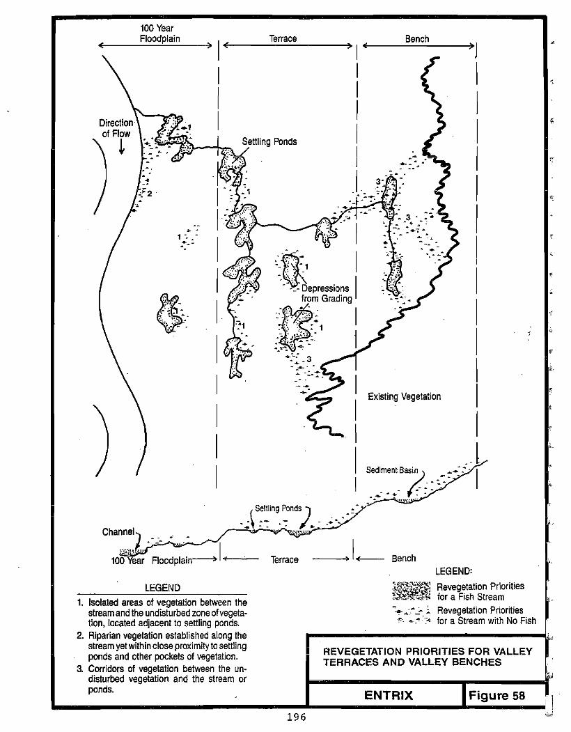
100Year Floodplain Terrace Bench
( ) I( ) I ( )J
•
,
,
~ -.' t"".,r. Channel) • _ .' •
10g·;:~~ . ~~od;;~in~ I...,-~ Terrace LEGEND:
LEGEND 'f~~~; Revegetation Priorities
II II I II
1
I I I I I _.. I I
Existing Vegetation
( Settling Ponds 1 .~ .., ..••\. > J_.. , .~.
Bench
'f..iK!iW"&." for a Fish Stream1. Isolated areas of vegetation between the -~ ~:.~..:...;. Revegetation Prioritiesstream and the undisturbed zone ofvegeta
<0.. ~ .-" for a Stream with No Fishtion, located adjacent to settling ponds. 2. Riparian vegetation establi7h!!d along ~he ....--.....----------,L
stream yet within close proximity tosettling REVEGETATION PRIORITIES FOR VALLEY ponds and other pockets of vegetation. TERRACES AND VALLEY BENCHES
3. Corridors of vegetation between the undisturbed vegetation and the stream or ponds. ENTRIX Figure 58
196

during site clearing can also be dispersed to create wildlife habitat (Figure 59). As stated, the optimal location for these materials is adjacent to ponds or in the riparian zone (Szafoni 1982).
10.4 REVEGETATION
The goal of the revegetation program is to enhance recovery by native species, particularly woody shrubs, and to mitigate wildlife habitat losses by maximizing development of riparian shrub thickets. By encouraging revegetation, nonpoint-source pollution can be reduced and wildlife habitat is created (Dick 1974).
Rates of revegetation vary for different geographic locations and for different areas of the fl oodp1ain. Hardy Assoc. (1978) found that without enhancement, shrub communities formed at placer-mi ning sites in the Kl ond i ke within 20 years. Full recovery to coniferous forest required 80 to 100 years (Hardy Assoc. 1978). Revegetation can be accelerated by planting viable stem or branch cutt i ngs, or roots of shrubs that are native to the area, broadcasting woody debris over organic soil, or transplanting intact .sections of tundra mats. Using these techniques, shrub thickets can often be produced in less than 10 y~ars.
The rate of revegetation can be slowed by several factors. Planting non-native grasses impedes the invasion of the area by woody plants (Dabbs et al. 1974; Johnson et al. 1981). Excessive appl ication of fertil izers, 1ime, and other chemicals can alter the soil chemistry, thus also impeding natural revegetation. Attempting to grow vegetation in soil contaminated by gasoline, diesel fuel, and other petroleum products is us~ally unsuccessful (Johnson 1981).
The two techniques that have had the. highest success in enhancing natural revegetation. are surface broadcast of organic material containing woody debris wi th viabl e wi 11 ow and alder stems and rootstocks, and 1arge-scal e transplanting (Figure 60) (Joyce 1980; Dick 1974; Lowenberger 1973; Zasada and Epps 1976). Surface broadcasting of organics is a technique where 1ive branches, roots, and trunks of small to medium size shrubs are spread across the top layers of organic soil (Joyce 1980). With adequate moisture retention
197

Soil, Roo! Systems and Woody Debris Compacled to Leveling Layer (Sand and Other Fine Materiai) 4· ro 8" Depth
Appiication of Leveling Layer and Organic Material
Wildlife Habitat Enhancement- Slash Pile for Smail Mammais and Birds
WilUife Habitat Enhancement Woody Debris in Riparian Zone
DISTRIBUTION OF STOCKPILE MATERIALS
ENTRIX FIGURE 59
198
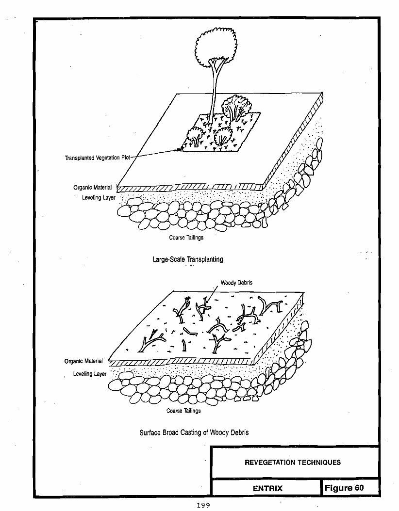
Transplanted Vegelation Plot
Organic Material Leveling Layer
/I"~ZzZ2.Z2ZLZZ?2.P'll,~~?2.V;T:flf:v:.qJr,
Coarse Tailings
Large-Scale Transplanting
Woody Debris
Organic Material
Leveling Layer
Coarse Tailings
Surface Broad Casting ofWoody Debris
REVEGETATION TECHNIQUES
ENTRfX Figure 60
199
in the soil, these woody plant parts will sprout stems and roots. This
technique can accelerate vegetative recovery by eliminating primary
successional stages (grasses) and beginning with mid-range successional
species (shrubs) (Viereck 1970).
When stockpiling organics and woody slash for use in rehabilitation it is
important to mi nimize the time these materi a1s are stockpi 1ed. Although
little data are available, roots and buried seeds may die quickly when
stockpiled, particularly when they are not kept moist. Thus, if possible
these materials should be placed directly on areas that have been final graded
and are ready for revegetation, or used within one year of stockpiling.
The second technique that has proven to be successful in enhancing natural
revegetation is large-scale transplanting (Lowenberger 1973). This technique
involves using a piece of heavy equipment, such as a front-end loader, to
scoop up soil and vegetation from an undisturbed location, and place the
entire mass of material in a single location. For this method to be most
successful, 12 to 18 inches of soil, as well as the above-ground vegetation
must be moved intact (Zasada and Epps 1976), and the transpl ant shoul d be
placed in an area that will retain ground moisture. If the vegetation is
scarred or broken, or if the soi 1 and root mass is broken, survi va1 of the
vegetation will be reduced. There is no optimal size for the piece of soil
and vegetation that is to be moved; however, the survival rate is higher when
large plots are moved.
Sections of undisturbed soil and vegetation can be acquired from two types of
sites. The first option is to collect soil and vegetation plots from the
undisturbed edges of the floodplain where mining activity will not be
occurring. This option should only be used if revegetation of the mine site
is essential due to fish and wildlife habitat considerations and if no other
organic material is available at the site. Plots should be removed from
scattered locations so that a large, disturbed site is not created.
The most efficient means of obtaining plots of soil and vegetation is to
collect material that is being cleared for future mine operations. Even if
. the operator is not yet ready to revegetate aporti on of the mi ne site, the
200
soil and vegetat i on plots can be stored in temporary 1ocat ions until they are needed. Recommendations concerning plot storage are the same as for organic stockpile placement. This includes protecting the material from surface runoff and high streamflow, but choos ing a 1ocat i on where the materi al will collect and retain moisture.
At sites where organic material is unavailable and fine-grained inorganic material (such as settling-pond fines or loess overburden) has been used in its pl ace, it may be appropri ate to use 1ight appl i cati ons of ferti 1i zer if
nutrients are thought to be limiting.
Although seeding is known to impede natural revegetation, it may be necessary to complement site sloping and contouring by seeding annual grasses on steep slopes with exposed erodible materials. Seeding should be conducted only if it is judged that substantial material would 1ikely enter adjacent streams. If available, native grass seed should be used. If soil nutrients are thought to be limiting, the area can be lightly fertilized. If seeding and fertilizing are conducted, the seed and fertilizer should be "raked" into the upper several inches of soil. Thi s wi 11 increase germi nati on and decrease loss of seed and fertilizer. Raking can be accomplished by dragging a section of chain-link fence behind a truck or dozer. The methods used to seed an area should be consistent with Miller et al. (1983).
In addition to the above uses of light applications of fertilizer, carefully designed fertil ization programs may be used on a site-specific basis to speed the revegetation process.
The time of year that revegetation occurs can affect the success of the effort by influencing the survival rate of the vegetation. Grading and distribution of the 1eve1 i ng 1ayer of materi a1 can be conducted duri ng any time of the year. Broadcasting organic material, planting live portions of shrubs, and transplanting plots of soil and vegetation should occur during the late spring to early summer, or during freeze-up. Schwendiman (1973) found the highest survival of vegetation occurred when planting occurred immediately after the surface soils were free of ice. Johnson and Van Cleve (1976) had reduced survival rates when planting in late August. Higher survival is achieved by
201

early planting since the vegetation has the opportunity to sprout roots before winter, and thus reduce winter-kill. If seeding is necessary, it also should be completed by mid-summer, although if site work does not allow seeding until late summer, it should be delayed until freeze-up. If seed is sowed too early prior to freeze-up, the seeds will sprout but not mature prinr to snowfall and then will winter kill.
202 I


NONPOINT-SOURCE POLLUTION REFERENCES
Al aska Department of Envi ronmenta1 Conservation. No Date. Gui de1ines for reducing sediment in placer mining wastewater.
Beasley, R.P. 1972. Erosion and Sediment Pollution Control. The Iowa State University Press. Iowa.
Becker, B.C. and T.R. Mills. 1972. Guidelines for erosion and sediment control planning and implementation. Prepared for Office of Research and Monitoring U.S. Environmental Protection Agency. Washington, D.C. EPA-R2-72-015.
Bell, A.V. 1974. The tailings pond as a waste treatment system. In: Canadian Institute of Mining Bulletin April 1974.
Bishop, H.F. and B.E. Hanna. 1979. Gravel mining and land development can gohand in hand. In: Civil Engineering Feb. 1979.
Brauner, C.O. 1975. Tailings and waste disposal is challenge of economics and environment. In: The Northern Miner. May 1, 1975, p. 33, 42, 45.
Chow, V.T. 1959. Open-Channel Hydraulics. McGraw-Hill Book Company. New York.
Cook, M.J. and J.G. King. 1983. Construction cost and erosion control effect iveness of fi Her wi ndrows on fi 11 slopes. Intermountain Forest and Range Experiment Station Research. Ogden, Ugah. Note: INT-335.
Cuskelly, S.L. 1969. Erosion-control problems and practices on National forest lands. Trans. Am. Soc. Agric. Eng. 12(1): 69-70, 85.
Doyle, W.S. 1976. Strip Mining of Coal: Environmental Solutions. Noyes Data Corporation. Park Ridge, New Jersey.
Dryden, R.L. and J.N. Stein. 1975. Guidelines for the protection of the fish resources of the Northwest Territori es during highway constructi on and operation.
Frank Moolin and Associates, Inc. 1985. Best management practices manual on erosion and sedimentation control. Prepared for the Alaska Power Authority.
Gutrath, G.C. 1985. Review of Queenstake's placer mining operation, Yukon Territory. Presented at the Alaska Miners Conference, Fairbanks. 1985.
Guy, H.P. 1979. Performance and environmental effects of sedimentation pondsrequired for surface coal mining operations. Proc. of the Institute of Environmental Sciences.
205
Haan, C.T. and B.J. Barfield. 1978. Hydrology and Sedimentology of Surface Mined Lands. University of Kentucky. Lexington, Kentucky.
Herricks, E.E., J. Cairns, and v.a. Shanholtz. 1974. Preplanning miningoperations to reduce the environmental impact of in use drainage on streams. l!!: Water Resources Problems Related to Mining. R.F. Hadleyand D.T. Snow (eds). American Water Resources Association. Minnesota.
Johnson, C. 1965. Practical operating procedures for progressiverehabilitation of sand and gravel sites. National Sand and Gravel Association.
Joyce, M.R., L.A. Rundquist, and L.L. Moulton. 1980. Gravel removal guide1ines manual for arctic and subarcti c fl oodpl ains. Prepared for U.S. Fish and Wildlife Service by Woodward-Clyde Consultants.
Karaki, S., K. Mahmood, E.V. Richardson, D.S. Simons, and M.A. Stevens. 1974. Hi ghways in the Ri ver Environment, Hydraul i c and Envi ronmenta1 DesignConsiderations. Prepared for the U.S. federal Highway Administration.
Kenney, T.C. 1972. Stability of slopes in overburden excavations. l!!: Geotechnical practice for stability in open pit mining. c.a. Brawner and V. Milligan (eds.).
Meyer, L.D. and M.J. Romkens. 1976. Erosion and sediment control on reshaped1and. Proc. Third Federal Inter-Agency Sedimentation Conference, Water Resources Council. Washington, D.C.
Neill, C.R. 1973. Guide to Bridge Hydraulics. University of Toronto Press, Buffalo, 191 p,
Peele, Robert. 1941. Mining Engineers' Handbook. John Wiley and Sons, Inc. New York.
R&M Consultants, Inc. 1983. Placer mining settling pond design handbook. Prepared for State of Alaska Department of Environmental Conservation.
Rutherford, C. and K. Meyer. 1981. Revegetation on gold dredge tailings,Nyac, Alaska. Prepared for BLM, Anchorage, Alaska.
Schwab, G.O. 1982. Slope stability of disturbed soil. In: Abandoned Mine Reclamation Symposium. N. Smeck, and P. Sutton (eds.).
Simons, Li and Associates, Inc. 1982. Surface mining water diversion designmanual. Prepared for U.S. Department of the Interior Office of Surface Mining.
Shannon and Wilson, Inc. 1985. Placer mining wastewater treatment technologyproject. Prepared for State of Alaska Department of Environmental Conservation.
Slaughter, C.W., J.W. Hilgert, and LH. Culp. 1983. Summer streamflow and sediment yi el d from disconti nuous-permafrost headwaters catchments. Proc. Fourth Annual Conference on Permafrost 1983. Fairbanks, Alaska.
206

Sowers, G.F. 1979. Soil Mechanics and Foundations: Geotechnical Engineering.MacMillan Publishing Co., Inc. New York.
Toups Corporation. 1978. Res idential erosi on and sediment control. Preparedfor the Urban Land Institue, the American Society of Civil Engineers and the National Association of Home Builders.
Troeh, F.R., J.A. Hobbs, and R.L. Donahue. 1980. Soil and water conservation for productivity and environmental protection. Prentice-Hall, Inc. New
Technical Publication. Washington, D.C.
Jersey.
U.S. Bureau of Reclamation. .Tables. Washington, D.C.
1974. 2nd Edition. Hydraulic and Excavation
U.S. Bureau of Reclamation. 1977. Design of small dams. Water Resources
U.S. Soil Conservation Service; 1973. Drainage of Agricultural Land. Water Information Center, Inc. Port Washington, NY.
Vesilund, P.A. and J.J. Peirce. 1982. Environmental Engineering. Ann Arbor Science. Michigan.
Wilson, D. 1981. Design and construction of tailings dams. Proc. of a Seminar 1980. Colorado School of Mines Press. Golden, Colorado.
Yukon Department of Indian and Northern Affairs. 1979. Settling facilities at Yukon placer mines. Water Resources Section, Whitehorse, Yukon.
207

STREAM REHABILITATION REFERENCES
Ashton, W.S. and R.F. Carlson. 1984. Determination of seasonal, frequency and durat i ona1 aspects of streamflow wi th regard to fi sh passage throughroadway drai nage structures. Institute of Water Resources, November, 51 p.
Bathurst, J.C., R.M. Li and D.B. Simons. 1979. Hydraulics of mountain rivers. Civil Engineering Dept., Colorado State Univ., CER 78-79 JCB-RML-DB555.
Bray, D. I. 1979. Estimating average velocity in gravel-bed rivers. J. of Hydraulics Div. ASCE, Vol. 105, No. HY9, September, pp. 1103-1122.
Bray, D.!. 1982. Regime equations for gravel-bed rivers. In: Gravel-Bed Rivers, Ed. by R.D. Hey, J.C. Bathurst, and C.R. Thorne, John Wiley & Sons Ltd., pp. 517-542.
Bray, 0.1. and A.J. Cullen. 1976. Study of artificial cutoffs on gravel-bedrivers. In: Rivers '76, Vol. II, Fort Collins, Colorado, 10-12 August,ASCE, pp. 1399-1417.
Bridge, J.S. 1975. Computer simulation of sedimentation in meandering streams. Sedimentology Vol. 22, pp. 3-43.
Drage, B. and R.F. Carls?n. 1977. Hydraulic geometry relationships for northern braided rlvers. In: Proceedings of Third National Hydrotechnical Conference, Quebec, 30-31 May, pp. 235-251.
Dunne, 1. and L.B. Leopold. 1978. Water in environmental planning. W.H. Freeman and Company, S.F. pp. 590-660.
Emmett, W.W. 1972. The hydraulic geometry of some Alaskan streams south of the Yukon River. U.S. Geological Survey open-file report, 102 p.
Hey, R.D. 1982. Design equations for mobile gravel-bed rivers. In: Gravel-Bed Rivers, Ed. by R.D. Hey, J.C. Bathurst, and C.R. Thorne, John Wiley &Sons Ltd., pp. 553-574.
Hey, R. 1983. Plan geometry or river meanders. In: River Meandering, Proc. of the Conference Rivers '83, New Orleans, Louisiana, 24-26 October, C.M. Elliott, Ed., ASCE, pp. 30-43.
Jackson, W.L. and B.P. Van Haveren. 1984. Design for a stable channel in coarse alluvium for riparian zone restoration. Water Resources Bulletin, October 1984.
Jones, S.H. 1983. Floods from small drainage basins in Alaska. U.S. Geological Survey Open-File Report 83-258, 60 p. + 1 plate.
Joyce, M.R., L.A. Rundquist, and L.L. Moulton. 1980. Gravel removal guidel ines manual for arctic and subarctic fl oodpl ai ns. Prepared for U.S. Fish and Wildlife Service, by Woodward-Clyde Consultants.
208

Karaki, S., K. Mahmood, E.V. Richardson, D.B. Simons, and M.A. Stevens. 1974. Highways in the river environment, hydraul i c and environmental designconsiderat ions: trai ni ng and design manual prepared for the Federal Highway Administration, National Highway Institute, Office of Research and Development, Office of Engineering, September.
Keller, E.A. 1976. Channelization: environmental, geomorphic and engineering aspects. Selected Water Resources Abstracts, Offi ce of Water Resource and Technology, Washington D.C. 52 p.
Lamke, R.L. 1979. Flood characteristics of Alaskan streams. U.S. GeologicalSurvey Water-Resources Investigations 78-129, 61 p.
Leopold, L.B. and M.G. Wolman. 1957. River channel patterns: braided, meandering, and straight. U.S. Geological Survey Prof. Paper 282-B.
Leopold, L.B., M.G. Wolman, and J.P. Miller. 1964.. Fluvial Processes in Geomorphology. W.H. Freeman and Company,S.F. 522 p.
Neill, C.R. 1973. Guide to Bridge Hydraulics. University of Toronto Press, Buffalo, 191 p.
Nixon, M. 1959. A study of the bankfull discharges of rivers in England and Wales. Proc. of the Inst. of Civil Engineers, Vol. 12.
Ott Water Engineers, Inc. 1979. Water resources atlas for USDA Forest Service, Region 10 Juneau, Alaska: Redding, Calif., 7 p., 5 appendices.
Parker, G. 1979. Hydraulic geometry of active gravel rivers. J. of Hydraulics Div. ASCE, Vol. 105, No. HY9, September, pp. 1185-1201.
Parks, B. and R.J. Madison. 1985. Estimation of selected flow and water quality characteristics of Alaskan streams. U.S. Geological SurveyWater-Resources Investigations Report 84-4247, 64 p.
Schumm, S.A. and H.R. Khan. 1972. Experimental study of channel patterns.Geological Society of America Bulletin, Vol. 83, June, pp. 1755-1770.
Simons, Li &Associates. 1982. Surface mining water diversion design manual. Prepared for U.S. Dept. of the Interior Office of Surface Mining.September.
Thorne, C.R. and S. Rais. 1983. Secondary current measurements in a meandering river. In: River Meandering, Proc. of the Conference Rivers '83, New Orleans, Louisiana, 24-26 October, C.M. Elliott, ra., ASCE, pp , 675-686.
U.S. Army Corps of Engineers. 1981. Low cost shore protection. Brochure developed by Seattle District, 36 p.
U.S. Forest Service. 1979. Roadway drainage guide for installing culverts to accommodate fish. Alaska Region Report Number 42, September, 120 p.
209
u.s.Water Resources Council. 1981. Guide] ines for determining flood flowfrequenci es. U. S. Water Resources Council Bull et in 17B, 28 p., 14appendices.
210

FISH HABITAT REHABILITATION REFERENCES
Aquat i c Envi ronments Incorporated. 1984. Results of studi es of the long-termeffects of the Trans Alaska Pipeline System on fish and aquatic habitats Volumes II and III. Prepared for Alyeska Pipeline Service Company. Anchorage, Alaska
Arctic Hydrologic Consultants. 1985. Discharge velocities in cul verts that ensure passage of Arcti c grayl i ng (Thymanus arct i cus) . Prepared for Alaska Department of Fish and Game. Fairbanks, Alaska.
Bell, M.C. 1973. Fisheries handbook of engineering requi rements and biological criteria. Fisheries-Engineering Research Program, Corps of Engineers, North Pacific Division. Portland, Oregon.
Bjerklie, D.M. and J.D. LaPerriere. 1985. Gold-mining effects on stream hydrology and water quality, Circle Quadrangle, Alaska. Water Resources BUlletin 21(2), p. 235-243.
Blakely, J., J. Sautner, L. Rundquist and N. Bradley. 1985. Addendum to Alaska Department of Fish and Game Report No.3, Chapter 6: Salmon passage validation studies, August-October 1984.
Bovee, Ken D. 1978. Probabil ity-of-use criteria for the family Salmonidae. Instream Flow Information Paper No.4. FWS/OBS-78/07. 80 p.
Burger, C.V., D.B. Wangaard, R.L. Wilmot, and A.M. Palmisano. 1982. Salmon investigations in the Kenai River, Alaska 1979-1981. U.S. Fish and Wildlife Service, Anchorage, Alaska.
Burner, C.J. 1951. Characteristics of spawning nests of Columbia River salmon. U.S ..Fish and Wildlife Service - Fishery Bulletin 61:97-110.
Collings, M.R. 1974. Generalization of spawning and rearing discharges for several Pacific salmon species in western Washington. USGS, Open File Report. 39 p.
Dane, B.G. 1978. A review and resolution of fish passage problems at culvert sites in British Columbia. Fisheries and Marine Service, Tech. Rept. No. 810. 126 p.
Estes, C.C., K.R. Hepler and A.G. Hoffman. 1981. Willow and Deception Creeks instream flow demonstration study. Vol. 1. Prepared for the U.S. Department of Agriculture, Soil Conservati on Servi ce, Interagency Coop. Susitna River Basin Study. Alaska Department of Fish and Game. Habitat and Sport Fish Division. Anchorage, Alaska.
Estes, C. and D.L. Vincent-Lang. eds. 1984. Chapter 7. In Report No.3: Aquatic habitat and instream flow investigations (May-October 1983).Susitna Hydro Aquatic Studi es. Al aska Department of Fish and Game. Anchorage, AK. 178 p.
211

Fisheries and Oceans. 1980. Stream enhancement guide. Vancouver, B.C. 82 p.
Freeze, R.A. and J.A. Cherry. 1979. Groundwater. Prentice-Hall, Inc. New Jersey.
Hardy Associates, Ltd. 1982. Fish and wildl ife habitat recovery in placermined areas of the Yukon. Calgary, Alberta. 131 p.
Krueger, S.W. 1981. Freshwater habitat relationships of Arctic grayling(Thymallus arcticus). Alaska Department of Fish and Game, Habitat Division. Anchorage, Alaska. 65 p.
LaPerriere, J.D., S.M. Wagener, and D.M. Bjerklie. 1985. Gold-mining effects on heavy metals in Streams, Circle Quadrangle, Alaska. Water Resources Bulletin 21(2), p. 245-251.
McNeil, W.J., and W:H. Ahnell. 1964. SUCcess of pink salmon spawning relative to size of spawning bed materials. U.S. Fish and Wildlife Service Special Science Report on Fisheries 469. 15 p.
McPhee, C. and F. Watts. 1975. Swimmi ng performance of Arctic grayl i ng in highway culverts. Progress Report to U.S. Fish and Wildlife Service. Anchorage, Alaska. 39 p.
Morrow, J.E. 1980. The Freshwater Fishes of Alaska. Alaska Northwest Publishing Company. Anchorage, Alaska.
Nunnally, N.. R. 1978. Stream renovation: an alternative to channelization.
Resident and juvenile anadromous fish investigations (May-October 1983).
Environmental Management, Vol. 2, No.5, p. 403-411.
Sams, R.E., and L.S. Pearson. 1963. A studydetermining spawning flows for anadromous Commission, Portland. 56 p. (unpublished).
to developsalmonids.
methods Oregon
for Fish
Schmidt, D., S. Hale, D. Crawford, and P. Suchanek, eds. 1984. Report No.2:
Susitna Hydro Aquatic Studies. Alaska Department of Fish and Game. Anchorage, AK 395 pp.
Smith, A.K. 1973. Development and application of spawning velocity and depthcriteria for Oregon salmonids. Trans. Amer. Fish. Soc. 102:312-316.
Tack, S. 1980. Di stri bution, abundance and natural history of the Arctic grayl i ng in the Tanana Ri ver drainage. Alaska Dept. of Fish and Game. Federal Aid in Fish Restoration, Annual Report of Progress, 1979-1980. 21 (F-90-12). 32 p.
Tagart, J.V. 1976. The survival from egg deposition to emergence of coho salmon in the Clearwater River, Jefferson County, Washington. M.S. Thesis, University of Washington, Seattle. 101 p.
Thompson, K.E. 1972. Determining streamflows for fish life. In Proc. Instream Flo\1 Requirement Workshop, Pacific N.W. River Basins Comm.,Portland, Oregon. pp. 31-50.
212

U.S. Department of Transportation. 1979. Restoration of fish habitat in relocated streams. FHWA-IP-79-3. 63 p.
Wesche, T.A. and P.A. Rechard. 1980. A summary of instream flow methods for fisheries and related research needs. Eisenhower Consortium Bulletin 9. University of Wyoming, Laramie. 122 p.
White, R.J. and a.M. Brynildson. 1967. Guidelines for management of trout stream habitat in Wisconsin. Wisconsin Dept. Nat. Resources Tech. Bull. No. 39, 64 p.
Wilson, W.J., E.W. Trihey, J.E. Baldrige, C.D. Evans, J.G. Thiele, and D.E. Trudgen. 1981. An assessment of environmental effects of construct ion and operation of the proposed Terror Lake Hydroelectric Facility, Kodiak, Al aska, Instream flow studi es. Final Report. Arcti c Envi ronmental Informati on and Data Center, Uni versity of Al aska, Anchorage, Alaska. 419 pp.
Woodward-Clyde Consultants. 1983. Bradley River instream flow studies. Anchorage, Alaska. 75 p. + appendices.
Ziemer, G.L. 1961. Fish transport in waterways. Alaska Department of Fish and Game.
213
FLOODPLAIN REHABILITATION REFERENCES
Alaska Dept. of Environmental Conservation. 1979. Placer m1nlng and water qua1ity. Al aska Water Qua1ity Management Pl anni ng Program. Nonpoint-source study series. Section 208, PL 92-500, 95-217
8erry, C.B. 1970. Revegetation program tailings pond dyke. Great Canadian Oil Sands Limited. Reports One and Two. Unpublished Reports.
Berry, C.B. 1974. Reclamation of disturbed land. Revision 1. G.C.O.S. Lease Site Tar Island, Alberta. Great Canadian Oil Sands Limited, Mine Engineering Dept. 12 p.
Billings, W.D. 1974. Arctic and alpine vegetation: plant adaptations to cold summer climates. In: J.D. Ives and R.G. Barry, eds. Arctic and alpineenvironments. London: Methuen and Co. Ltd. p. 403-443.
Cook, C. W. 1976. Surface mi ne rehabil itat i on in the Ameri can West. Environmental Conservation 3:179-183.
Crocker, R.L. and B.A. Dickson. 1957. Soil development on the recessional mora ines of the Herbert and Mendenhall Gl aci ers, south-eastern Al aska. Journal of Ecology 45:169-185.
Dabbs, D.L., W. Friesen, and S. Mitchell. 1974. Pipeline revegetation.Prepared by Northern Engineering Services Company Ltd. for Canadian Arctic Gas Study Ltd. Biological Report Series, Volume 2. 67 p.
Dick, J.H. 1974. Selection and propogation of woody plant species for reclamation in British Columbia. In: Land reclamation short course, sponsored by Faculty of Forestry, U. of British Col umbi a, Centre for Continuing Education, and Minin9 Association of British Columbia.
Doyle, W.S. 1976. Strip Mining of Coal: Environmental Solutions. Noyes Data Corporation. Park Ridge, New Jersey.
Emmett, W. W. 1972. The hydraul i c geometry of some Alaskan streams south of the Yukon River. USGS Open-File Report.
Hardy Assoc. 1978. Fish and wildlife habitat recovery in placer mined areas of the Yukon. Final Report. Prepared for Dept. of Indian Affairs and Northern Development.
Herricks, E.E. 1982. Development of aquatic habitat potential of gravel pits.In: W.D. Svedarsky and R.D. Crawford eds. Wildlife values of gravelpits. Symposium Proceedings. U. of Minnesota. Misc. Publ. 17-1982.
Johnson, L.A. 1981. Revegetation and selected terrain disturbances along the Trans-Alaska pipeline, 1975-1978. CRREL Report 81-12. 124 p.
Johnson, L.A. and K. Van Cleve. 1975. Revegetation in arctic and subarctic North America. A literature review. CRREL Report 76-15. 32 p.
1 . 214

Johnson, l.A., S.D. Rindge, and D.A. Gaskin. 1981. Chena River lakes Projectrevegetation study. Three-year summary. CRREl Report 81-18, 66 pp.
Joyce, M.R. 1980. Effects of gravel removal on terrestrial biota. In: Gravel removal studies in arctic and subarctic floodplains in Alaska. Woodward-Clyde Consultants. U.S. Fish and Wildl ife Service, BiologicalServices Program. FWS/OBS-80/08. pp. 215-271.
Joyce, M.R., L.A. Rundquist, and L.L. Moulton. 1980. Gravel removal guidelines manual for arctic and subarctic floodplains. Prepared for U.S. Fish and Wildlife Service by Woodward-Clyde Consultants.
Keller, H. and J. C. leroy 1975. The systematic reel amat i on of gold mi ne tailings. Canadian Mining Journal 96:45-46.
leroy, J.C. 1973. How to establish and maintain growth on tailings in Canadian· cold winters and short growing seasons. In: c.L, Alpin and G.O. Argall, Jr., Eds. Tailing disposal today. Mi 11 er Freeman Publications. San Francisco, CA. pp. 411-476.
lowenberger, F.J. 1973. Reel amati on of stri p mi ned overburden through tree planting. U. of British Columbia, Vancouver B.C., M.F. thesis.
Miller, C.R., R. Parkerson, J. Zasada, A. Epps, and J. Smith. 1983. A revegetative guide for Alaska. Rural Development Council Publication No. 2. A-00145.
Morrison, D.G. 1982. Principles of revegetating mined lands. In: W.O. Svedarsky and R.D. Crawford eds. Wildlife values of gravel pits.Symposium Proceedings. U. of Minnesota. Misc. Pub1. 17-1982.
Rutherford, C. and K. Meyer. 1981. Revegetation on gold dredge tailings,Nyak, Alaska. Prepared for BlM, Anchorage, Alaska.
Saville, D.B. 1972. Arctic adaptations in plants. Monograph No.5, Research Branch, Canada. Dept. of Agriculture.
Schwendiman, J.l. 1973. Site preparation and seedi ng methods for crit i ca1 areas. In: 1973 Alaska Revegetation Workshop Notes, Co-operativeExtension Services, U. of Alaska, Fairbanks, RP-239. 838-40.
Stoecker, R.E. 1982. Creating small islands for wildlife visual enhancement. In: W.O. Svedarsky and R.D. Crawford eds. Wildl ife values of gravelpits. Symposium Proceedings. U. of Minnesota. Misc. Pub1. 17-1982.
Szafoni, R. E. 1982. Wil dl ife considerat ions in the development of ri pari an communities. In: W.D. Svedarsky and R.D. Crawford eds. Wildlife values of gravel pits. Symposium Proceedings. U. of Minnesota. Misc. Publ. 17-1982.
Viereck, l.A. 1970. Forest succession and soil development adjacent to the Chena River in Interior Alaska. Arctic and Alpine Research 2:1-26.
215

Zasada, J.C. and A.C. Epps. 1976. Use of woody plant material in soil and site stabilization and rehabilitation. In: M.N. Evans, ed. Proceedingsof the surface protection seminar, theme: Travel and transportation pract ices to prevent surface destruct i on in the northern environment. BLM. Anchorage, Alaska. P. 284-295.
216


GLOSSARY
active channel -- That portion of the channel or channels that transports the 2-year recurrence interval flood.
active floodplain -- That portion of the floodplain that contains the active channel or channels and adjacent riparian strips: same as riparian zone.
anadromous -- Aquatic organism migrating from marine waters to freshwater for reproduction.
armor layer -- a layer of sediment that is coarse relative to the material underlying it and is erosion resistant to frequently occurring floods; it may form naturally by the erosion of finer sediment, leaving coarser sediment in place or it may be placed by man to prevent erosion.
aufeis -- An ice feature that is formed by water overflowing onto a surface, such as river ice or gravel deposits, and freezi ng, with subsequentlayers formed by water overflowing onto the ice surface itself and freezing. A frequent source of the water is shallow groundwater flow forced to the surface by a constriction in the flow area. Also referred to as icings, glaciation, and naleds.
bank -- A comparatively steep side of a channel or floodpl ain formed by an erosional process; its top is often vegetated.
bankfull discharge -- Discharge corresponding to the 2-year recurrence interval flood.
bar -- An alluvial deposit or bank of sand, gravel, or other material in the stream channel.
bed -- The bottom of a watercourse.
bed load -- Sand, silt, gravel or soil and rock detritus carried by a stream on, or immediately above its bed.
bed, stream -- The bottom of a stream below the low summer flow.
bench -- A relatively flat area occurring on the valley walls.
BMP -- Best Management Practice.
braided stream -- A river containing two or more interconnecting channels separated by unvegetated gravel bars, sparsely vegetated i sl ands, and, occasionally, heavily vegetated islands. Its floodplain is typicallywide and sparsely vegetated, and contains numerous high-water channel s. The lateral stability of these systems is quite low within the boundaries of the active floodplain.
219

--
carrying capacity, discharge -- The maximum rate of flow that a channel is capable of passing.
channel -- A natural or artificial waterway of perceptible extent which periodically or continuously contains moving water. It has a definite bed and banks which serve to confine the water.
configuration -- The pattern of a river channel (5) as it would appear by
energy due reduction in the force of the
looking vertically down at the water: same as pattern.
contour A line of equal elevation above a specified datum.
cover, fish -protection
Areas of shelter from predators or
in a stream channel a place in which to
that rest,
provide fish or both, and
conserve to a current, e.g.,pools, boulders, water depths, surface turbulence, undercut banks, overhanging vegetation, accumulated debris, and others.
cross-section area -- The area of a stream, channel, or waterway opening,usually taken perpendicular to the stream centerline.
current -- The flowing of water, or other fluid. That portion of a stream of water which is moving with a velocity much greater than the average or in which the progress of the water is principally concentrated (not to be confused with a unit of measure, see velocity).
cut Excavated area.
dbh Diameter of a tree at breast height.
dewater -- The draining or removal of water from an enclosure or channel.
discharge -- The rate of flow, or volume of water flowing in a given stream at a given place and within a given period of time, expressed as cu ft per sec or cfs.
dragline -- A type of excavating equipment that uses a bucket and a boom. It is capable of the removal of underwater material.
detention time -- Period of time that water remains in a settling pond and equals the flow rate divided by the volume of the pond.
drainage area -- The entire area drained by a river or system of connecting streams such that all stream flow originating in the area is dischargedthrough a single outlet.
duration curve -- A curve which expresses the relation of all the units of some item such as head and flow, arranged in order of magnitude along the ordinate, and time, frequently expressed in percentage, along the abscissa; a graphical representation of the number of times givenquantities are equaled or exceeded during a certain period of record.
erosion -- process of sediment removal by wind or water.
220

erosion, stream bed -- The scouring of material from the water channel and the cutting of the banks by running water. The cutting of the banks is also known as stream bank erosion.
fines -- The finer grained particles of a mass of soil, sand, or gravel. The material, in hydraulic sluicing, that settles last to the bottom of a mass of water.
flood -- Any flow which exceeds the bankfull capacity of a stream or channel and flows out on the floodplain; greater than bankfull discharge.
fl oodpl ai n - - The re1at ive1y 1evel 1and composed of primari 1y unconso1 idated ri ver deposi ts that is located adjacent to a ri ver and is subject to flooding; it contains an active floodplain and sometimes contains an inactive floodplain or terrace(s), or both.
flow-- The movement of a stream of water or other mobile substances, or both, from place to place; discharge; total quantity carried by a stream.
flow, low -- The lowest discharge recorded over a specified period of time.
flow, low summer -- The lowest flow during a typical open-water season.
flow, mean -- See mean flow.
flow, uniform -- A flow in which the velocities are the same in both magnitude and direction from point to point. Uniform flow is possible only in a channel of constant cross section.
flow, varied -- Flow occurring in streams having a variable cross section or slope. When the discharge is constant, the velocity changes with each change of cross section and slope.
freeboard -- The vertical distance from the top of the channel to the water surface at the design condition.
frequency curve -- A curve of the frequency of occurrence of specific events. The event that occurs most frequently is termed the mode.
gage-- A device for indicating or registering magnitude or position in specific units, e.g., the elevation of a water surface or the velocity of flowing water. A staff graduated to indicate the elevation of a water surface.
geomorphology -- The study of the form and development of landscape features.
gri zzl i es - - Iron or steel bars used to sort or separate 1arge rocks from placer bearing materials.
habitat -- The place where a population of animals live and its surroundings,both liVing and nonliving; includes the provision of life requirementssuch as food and shelter.
221
high-water channel "- A channel that is dry most of the ice-free season, but contains flowing water during floods.
hydraulics -- The science dealing with the mechanical properties of fluids and their application to engineering; river hydraulics deals with mechanics of the conveyance of water in a natural watercourse.
hydraul ic depth -- The average depth of water in a stream channel. It is equal to the cross-sectional area divided by the surface width.
hydraulic geometry -- Those measures of channel configuration, includingdepth, width, velocity, discharge, slope, and others.
hydraulic radius -- The cross-sectional area of a stream of water divided bythe length of that part of its periphery in contact with its containingchannel; the ratio of area to wetted perimeter.
hydraulicing -- A soil loosening operation which uses water at high pressures to move earth downgrade. It can be used to thaw frozen material.
hydrograph -- A graph showing, for a given point on a stream, the discharge,stage, velocity, or another property of water with respect to time.
hydrology -- The study of the origin, distribution, and properties of water on or near the surface of the earth.
ice-rich material -- Permafrost material with a high water content in the form of ice, often taking the shape of a vertical wedge or a horizontal lens.
impervious -- A term applied to a material through which water cannot pass or through which water passes with great difficulty.
inactive floodplain -- The portion of a floodplain that lies between the riparian zone and the 100-year recurrence interval flood boundary.
island -- A sediment deposit located between two channels.
lateral bar -- An unvegetated or lightly vegetated sediment deposit located adjacent to a channel that is not associated with a meander.
Manning's equation -- In current usage, an empirical formula for the calculation of discharge in a channel. The formula is usually written
mean flow -- The average discharge at a given stream location computed for the period of record by dividing the total volume of flow by the number of days, months, or years in the specified period.
mean column velocity -- The water velocity measured at 0.6 of the depth or the average of the velocities as measured at 0.2 and 0.8 of the depth.
222
mean water velocity -- The average velocity of water in a stream channel, which is equal to the discharge in cubic feet per second divided by the cross-sectional area in square feet.
meander wave length -- The average downvalley distance of two meanders.
meanderi ng stream - - A stream wi ndi ng back and forth withi n the fl oodpl ain. The meandering channel shifts downvalley by a regular pattern of erosion and deposition. Few islands are found in this type of river and graveldeposits typically are found on the point bars at the insides of meanders.
mid-channel bar -- An unvegetated or lightly vegetated sediment depositlocated between two channels.
mountain stream -- A single channel, high gradient stream.
nonpoint-source pollution all turbidity, suspended sediment, and sedimentat ion resul t ing from soil eros i on caused by human acti vity and emanating from a widespread area.
overburden -- Any organic or inorganic material lying on top of placergravels.
overflow rate -- rate of flow through a settling pond divided by the surface area of the settling pond.
parameter -- A variable in a mathematical function which, for each of its particular values, defines other variables in the function.
permafrost -- Perennially frozen ground.
point bar -- An unvegetated sediment deposit located adjacent to the inside edge of a channel in a meander bend.
point-source pollution -- Pollution which originates at a single entry point into a body of water.
pool -- A body of water or portion of a stream that is deep and quiet relative to the main current.
pool, plunge -- A pool, basin, or hole scoured out by falling water at the base of a waterfall.
profile -- In open channel hydraulics, it is the water or bed surface elevation graphed against channel distance.
reach -- A comparatively short length of a stream, channel, or shore.
regional analysis -- A hydrologic analysis, the purpose of which is to estimate hydrologic parameters of a river by use of measured values of the same parameters at other rivers within a selected region.
223
resident fish -- remaining in freshwater for entire life cycle.
riffle -- A shallow rapids in an open stream, where the water surface is broken into waves by obstructions wholly or partly submerged.
riparian Pertaining to the banks of a stream or other body of water.
ri pari an vegetation - - Vegetation borderi ng f1 oodp1 ains and occurri ng wi thi n the active floodplain.
riparian zone -- Area within the active floodplain adjacent to active stream channel s.
riprap -- Large sediments or angular rock used as an artificial armor layer.
river regime -- A state of equilibrium attained by a river in response to the average water and sediment loads it receives.
root stock -- Any root or lower stem mass from woody shrubs and small trees.
run -- A stretch of re1 at ive1y deep fast f1 owi ng water, wi th the surface essentially nonturbu1ent.
scour -- The removal of sediments by running water, usually associated with removal from the channel bed or floodplain surface.
screen -- Device used to separate material into size classifications.
settling ponds -- Artificial structures designed to prevent downstream po11 ut ion by trappi ng and removi ng sediment from waters drai ni ng the mining operation.
sinuous river -- Sinuous channels are similar to meandering channels with a less pronounced winding pattern. The channel may contain smaller pointbars and have 1ess tendency for downva11 ey shift i ng. The channels are more stable with respect to lateral shifting.
sinuosity -- A measure of the amount of Winding of a river within its floodplain; expressed as a ratio of the river channel length to the corresponding valley length.
slope -- The inclination or gradient from the horizontal of a line or surface.
sluicing -- A general term applied to many forms of placer mining. A sluice is an inc1 ined channel or trough through which gravel is carried by a stream of water with the intent to separate gold and heavy metals.
split river -- A river having numerous islands diViding the flow into two channels. The islands and banks are usually heavily vegetated and stable. The channels tend to be narrower and deeper and the floodplain narrower than for a braided system.
stage -- The elevation of a water surface above or below an established datum or reference.
224

straight river -- The thalweg of a straight river typically winds back and forth within the channel. Gravel bars form opposite where the thalwegapproaches the side of the channel. These gravel bars may not be exposedduring low flow. Banks of straight systems tpyically are stable and floodplains are usually narrow. These river systems are considered to be an unusual configuration in transition to some other configuration.
substrate -- Stream bottom materials including silts, sands, gravels, cobbles, boulder and bedrock.
suspended sediment -- The portion of stream load moving in suspension and made up of particles having such density of grain size as to permit movement far above and for along distance out of contact wi th the stream bed. The particles are held in suspension by the upward components of turbulent currents or by colloidal suspension.
tailing piles -- Material processed through a placer mining operation.
terrace -- An elevated abandoned floodplain formed as a result of stream degradation and that is expected to be inundated only by infrequent flood events.
thalweg -- The line following the lowest part of a valley, whether under water or not; also usually the line following the deepest part or middle of the bed or channel of a river or stream.
top width -- The width of the effective area of flow across a stream channel.
turbidity -- An expression of the optical property that causes 1ight to be scattered and adsorbed rather than transmitted in straight lines through a water sample. Turbidity in water is caused by the presence of suspended matter such as clay, silt, finely divided organic and inorganicmatter, plankton, and other microscopic organisms.
velocity -- The time rate of motion; the distance traveled divided by the time required to travel that distance.
wash load In a stream system, the relatively fine material in near-permanent suspension, which is transported entirely through the system, without deposition. That part of the sediment load of a stream which is composed of particle sizes smaller than those found in appreciable quantities in the shifting portions of the stream bed.
water quality -- A term used to describe the chemical, physical, and biological characteristics of water in reference to its suitability for a particular use.
wetted perimeter -- The 1ength of the wetted contact between the stream of flowing water and its containing channel, measured in a plane at rightangles to the direction of flow.
225


MAPS OF MEAN ANNUAL PRECIPITATION
Maps of mean annual precipitation (Lamke 1979) are presented in this appendix. During the rehabilitation of stream channels (Chapter 7.0), mean annual precipitation values are used to evaluate design flows (Section 7.2). Mean minimum January temperatures are also presented (Lamke 1979) although not used within this report.
229
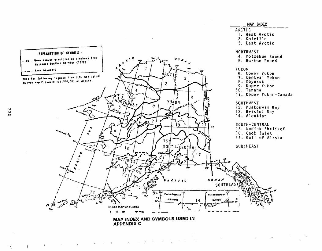
__ _
MAP INDEX ARCTI C
1. West Arctic 2. Colville 3. East Arctic
EIPLAMATION OF SYMBOLS .
•••• I.f $u''''Y ••p E
N W o
oc ....... "'"
AlElJfJltN
ro!J[).,
,,
"... ,,," _", d Of_.I~"
.' 14 I ,SLAMDSA 0 ~ • c:::.:.-,t'
'"
~ n.. U~
c'o'O ,., [ul 010'"11.111,
"".,..
~ ....... '.. ....
...
""'0)..,,,,,\
",•• _lynll,'WO
f.II •• inl lieurel frDI u.S. "oIOaical (a".'_ 1;2,500.00) pI o\1"kll
--40-- ••••••a•• ' pf.ciptetiQ~ (inth.,) troM .I\i,nl' , •• 'h.' selviee (1912)
NORTHWEST 4. Kotzebue Sound 5. Norton Sound
YUKON 6. Lower Yukon 7. Central Yukon 8. Koyukuk 9. Upper Yukon
1O. Tanana 11. Upper Yukon-Canada
SOUTHWEST 12. K~IS kokwim Bay 13. Bri s t o l Bay 14. Aleutian
SOUTH-CENTRAL 15. Kodiak-Shelikof 16. Cook Inlet 17. Gulf of Alaska
SOUTHEAST
MAP INDEX AND SYMBOLS USED IN APPENDIX C
y r

« ~w~
'"« "" '"~
n
u.... ih'"
~
u 1...-,_...
w
«"" o
....L
.., ~ '"3: J
i •
I ="~i
.,,~jib
.J'::.
~I ::
:..
I
.==.:-..I, •c
---_.__._
=
-----_s,; _
==
--s,;__ ---_
.-:._._
.-._._
-------
...._.•.-.-
..
.... -.... _""--.....
............. ceo=
23
1
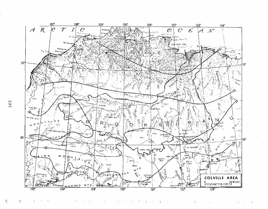
\60' 1561. 151' 150() 146'
l{ 'Li-c1 c e, .IV u.,'.
..,'
10 Qr "~.-.~.- 10'
, ":fl\ .. -.....;. .':',
~, ,•.,~,'.f.}.,~
.\~, ..,'....
/. ,/t ., ....,.
\;1)\\.",\, ':~.
1'. . \ ....'\ " , - -' , j
'." '~.r ~ /;''',
".
,,;( "
NW
::1\ /,' " :::? ~
"'~~" .1./ ~.\H!'t • ~;Z.;
N
"""", "'I "{ ''' ... \,<'0... "if '-.. !,
~>1-, . f):\: ! " ,<:,:'! ":"l'p';r~ . \',:. ,..~1l. \ '1
""!~ 'r~N '" " (~i\,' . .('-.. G, .,1-.'f',,' .~,,'
•• ('I o fN .,. ,... .,1 N 5, \
"i'<' •. , ". i.;'/
, :~~/, f' ',..
~_,·~'1 ..: . 0\ ··r':'" li'~
~
68 ~_ 't""1"" :r;·,~A :_,,_..4·H"~";' 66'
f'~;~~-,:'I~ '( .~ .::.-:.0.----
" ~ / 20
.e / R 0 M 0 '~''''''''''J/:"N r .4 ,{:,,~!,>~.'; -/ W~"';'V
;,~I.'f' / ..l<rGO. '" ," :\\;;l;~; }'(;,,,~. I Y\-(. '" , .;,,, ......
.~:, ... '>. '<~~.::r'
COLVILLE AREA
, H
\:~t. .i -A>, ,~'UJ?likt, I I) •._ .__ 50 lllllES ~' \~d~'t c:=.E,,:;~~::,::3:".::J
WP.RI'~NG MT~ .< I" ,( 160" 154& 1520 150~
~i' .'f,.;. ,.'

152' 15011 148' _.__.. 144' 142:) 138' _....1.36'-'-7'--- \ ,
.'''1 F( c C/1)\I o . E A\ .J"V \ \, \
\ \\ \A\ s E\, \\,
\ \ 10'
+ lO,t""" "".'."",,'
\ elf, 1:': rl 2
n;\ Y?i:ft:o\ :'
\
\ """';"",1
~?l\ "'.N
!.-."
\ j' , , ',':
W ,x
W
'."1.' . "I,]f('\':,i~:>:;~,'i /\ , l:'~~'~f'l""\-'''~'.~ .. ,- tfr'('''': \ r r : \ /\.) , .'.. °i. . • [ .. ," ,."". \ <./
, M·1·.~,·J /\~"\i;' \ ,,(. "\' .'" -V i ~. ~ IJ.. ;.;:r;;.>....,-...
'j'
\
[iONlLES~::,':"E7.3::::: E::;:;::L:~'.::J
,.," ..." 140'

166' 164' ill' 158° 156~ -,-.-,~7,C ",.,. 154"..~.C''';;;,J~'''.CvC,-.,~,.,,~c,-," 'i) ':X';;:;~"''''' .~r;
(~~I'':' B'lIluf,~rl ,\., " t~~;(~'>l\~ ~'("
68'
IV W ",.
66'
154'
. ", ,~, ~1 1/-""'"' ,I
Y" I,v' (u». 1
I, ~}~~Y._-' ) .;.~/.J":'''''' 1%1 )'
,"..' ~(""'(
,/ ~1:;:: -?"v( "_.. ; ~,/ i
'" ,,'"~'(.<./ ....-.f!- .e,"·"~r. ~.a\.... .:..,·._, ,Q- ,6'1_
156'
o 50 MILES C:=C::_T::: J : I
i . ''-'4.:;: :.~ . . \ ····1
~HPA<;\\'~ ,0
••~''''. \,6, 'AA'" ...... I ,Il.: ~
v 'j ",•. ;');; ::-11\i ",.~ ~ A.J:c, .
'-- " W...!k~r,. ..('1.> .\:.. ~::", '..,:--:....~t!, ,(l') ''-.
""... ;,i '. ,;';t';,· ", "~ . J r N "';,,' Co'\:,. ,I
'./'01 ':jr'~~/-/
';:\,
:~i :,fj '" ~ /'", !. " ( ..." ...r.~( ~ <"t \ "{,\./;,\,<"~i '~j \:"? ) //~:.(K t s :5'~o,,,,~{( Aile. (~' ~ ,In ~,
.,..
16U'162'
1, ". ",:.~ / ,,' "', .. ,§" J
M O!I~::'NT h ,..
,") . {9, ' '~.: d:
~ f 1:/I;;r;J'''''.f ".,00-' :1.,'.... .:.' ;,;,It ',',
• 0 " ," ." ,"., I. » I . . --""'2' ('~"': I .~ ..;iJ' " O·
./T.J~~~:(>.
KOTZEBUE SOUND AREA
0 • ~.,,>A I ry'.~o/';:',t'/s.. ...'G·?
/ ~\
:F> '(', ... :1:./' _, 'j Joi ::...'; \L"'lll":') ··-----r l i,"'c. \~
;~) ~ l '.,;5 ,'J:'i",.j.~,~ "Y ~I(.;",~· 'tjl ~"';:::.f~.'.;~:·'.iJ~"... ?;~ \'I~ ". "}. ,'4,' .~"', • ~~ {II 1". )M'IIlI!o\ltl (. :'\",c '1.:. , \'),1
, ,:~ " ~, : • !IiUlm!~ ",}f- (!i II"'() ' (yr f - ,'. 1 "1"-':-''':' . ,\',., '~:':-c. ~ ~ [ ~ ""tI " '\ \'. o: ~.,
.,",.....~ f/ . "- .. ~~' Rji,,,,,·,s;\'., '! ··,i .,.....-""~"":"r ,..t. "";. : .\' / I' };!"/)/ \ ! i
';t. '-.' '" \' ',>'" ~b',,' A_" 'I t::
p:, 4'¥1(:'IolI~h(!,l!" !l!T'I:··••:t, ··.1'/'...·;, ··i.~:r :', t' p~~~~;.~.T1 '-""4 ... M ",. '. ." "._ '··"f·l( ...
·.h~$ .:~J:.·c.t.,'<~:':.~,.\,,'
M" HI,
'.".,~
'.v,"" ~,.,.I ~ "'.... l r ~/ , , . i ~.:;: " ~ \.,Jl.~
.-r;.... -r--- ., ,"> ,A I ':/.n • ....-::~!S:;l·0~.::~,) .~~~'".~:.::.~. "'"R I V . ..:./... ! ~ ·i't .). ... .:<.J...,.::....., £:.
.'
,l!
"'~\,.. , .•
,0 o?::- r..
c <it " (/~,
C;"p";! Sabj!,~.
r:'H ,.
66'
I';

tv W U1
66'
100'
160' ~~~~/·1;;~~~!1~~... l~' \~~!~:.i.~~~~~;;~~;~ :t.t\r.~~~·:··· \},:;i:${;)~.
Hel dr."" ~al;o~>.,·' • ,,:;j ,
~, ····~"J>~;t~L
<;f~.). '1~"
101'
NORTON SOUND AREA o '.... ..._.?O MilES ~.3..,,_._::E:::::L::::J
(Ji '>, ,; /.~\ ;.,)
,I I ~ ;:f'.?'!w; I ' ~L~A.rt>?
'" ; ".j
co•
s
161l"
N!O R TON
KCll!.orrllll
,rl
166'
Sk·Ji" J.l
Ii:
C'lllf,
-s
Pc'int
160'
108'
l':''''':\~ G;lr;'.~ Iti"'Oil
G
Eh~: C"'r/. ")o:'''n:J~ iro
110'
N
C:"fll; K!"'''I::'~ :f>:lII!"~lI!;t C.lr.r ,
'I
170'
R
rj~f!iiolti.'l
p;
172'
wr L"'WRENGI: fSLAND !
B
..
.... ; '''~r.~1 ~
171'
.;'
i ,;-~." Chll"JlI"".~ '''. 'f~, ...1 Ull: (f) • V), .' v -, ..•. ; Vl/,;,;:;:/" i .. ::J ~. i. "" .;' 12;/:! .," I'::i
.. lOJP."
~. (n.r.h'U"I\. if" ' ,_.",:{" •. ~. 1·'1~'P. DC'2'·l,r,e.I ' ,.d"~l1'" ' ,.. . ... i,l
.. "~,, "., in." r..,,,,,,,,,,,_ , A.,.~, ft"·,ol L,I;i~ '. •('c. C;J,p~ IilJr . !.";''''1;!d~'1
~'" : '\"ll~!II" ,
""i>,:Hg{~. ' Ie;'l'''' r;w,Il!I!~I. \.0/": Ilfll'.t: II <\/ "f W;ll('~, ,.",
~ r: ,,/ ,~,,,o. A~~f', K " ,,)'
~ '\1.".1"0'1' / o~ f
I
/. .,'
/'<t.'~'"/ '\("
, ('I ,/ GO''''
.(~~:';;:"'" Ai' ,;/"",,'C'
641,.."...";'
66'
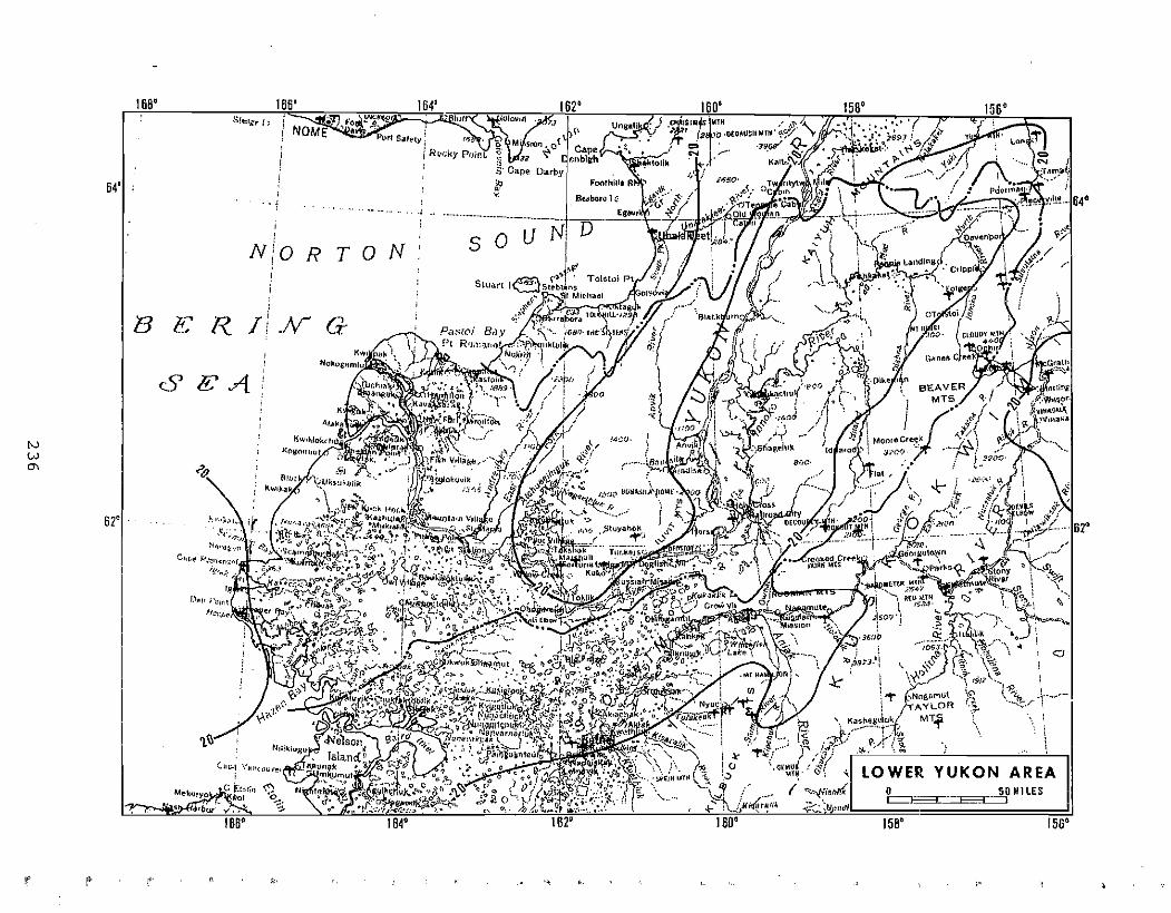
. '"' =
'"' =.
. ;t;---j; ..
E\ '.. ~I
i I~ o (J
)
. '"' =
23
6
'0\,.

:,\ ~
\ ·f
23
7
. ~ =
«..."'ww
« ~
2 :!"
z ~M .~
0 :.:: :::l ~>
... « il.
'"oiJ
... z... u . ~ =

·./ ."
""" ~
I /
u:I
23
8
. = .~

=
o =
.~
......'
a. :::>
.;_..
'7;::"",.:;:
-,
:i ~'.-'
..<~;;~. ;;,." r:.
.. ,----,"
j.
~~.t'······_· -
-, ..-
..j .~.
.....
...(;..-i.;('i....'.>.:.. .'!"
../i·~'-.,-~
""
c1:
.~.
;. .:.:.:. -. ----:---....
sr
....._..,-~~--~
(--'Iw ~"
C
;,,;
W'
l'
.~~J .,j
" "\ <
r;::,h'l
, .. :/'>".;:~rt;:·'.);,· ~
/;J°l~J ::~,,~.:
Z ,.:;:'~~~.~;_ ::R•.•~,~~...f-.iJ.... -" '.
<
j1./lr.":,:",t;. •
7"""
" .
;;:.
~~~"}1t; I.
o = -e
23
9

151' 148' 148'...-. 142D 140' " 0'"
,1"" ··--·····r· / " ", J' ,/ /
"'(~ "IlI
;:'...~~: ';
;\ ..~.(
:! .' V~~...'\""··... ,,·
\StR~'~T'~~ ,. ;rB~I'/I!!l~""l' ,"' ~Q'" !
, . '\ l'
~~~''''''!. .1 .......... \. ·;""".'!\'~164' "Ia,<:<'C' •
f tlt)r"oHIt ~'?
~,.'.,::. .. .!,;t)5·/;lI·_·"~
N ... • )::>r·.\~7:< '.'0". r . .\ .,")::0. .'.;
o tfl,6·16au~~rz .. ·~... ~.c: J
'I~:';,",-\" ~.".···-·0··....·-7',',;~~, l".·.·'
.r,tV
~~.
81 81'
TANANA AREA o .. _ !:iOMILES I .._.E~:::;:::r...:::J
152Cl 146' 141'
,t"t' t' c. ,,':I, '4 Iii

•N ~
<C w
'"<C <C ~
c
~
<C Z
<C u I Z
o ~ ::l >
C,;', •
;.., .-
-;--
§'f)·:.i-t '\
:;, iU
;, £;
/
•. T....
! n C•
24
1
= ~
:.. ~ i "'~ to.""'-
( ;;:.,.~",'S~.~:~-:.. ~
~<.
!~i-~
J~~""'~' ~;?,~"t(~~\: -! ~.~:~~~; _,:~.~r;~:-;':~i.,...: "~...t,,
~_ ~ f
~.1:~'; ..~
r.:"~:F-;'-.~~~:oX
tr)±¥f~'~
,-, . ..~. .....;
',':~: ' ,
. ~/
(~.
",,{T ~~_.,
r \ ,.'-e;
,,~
...:-..
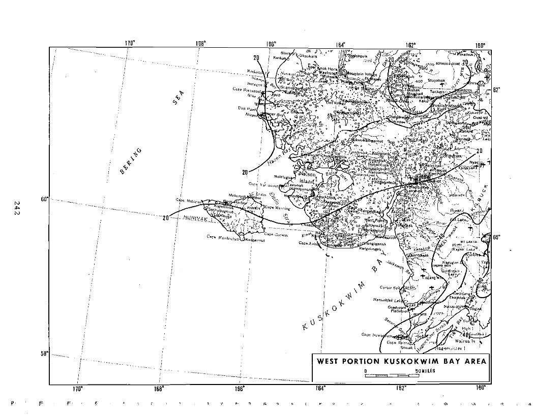
«w'"« .
>--
«'":E w
-~
~ ~z
::.= 0""!
0::.=II>
:::J::.=Z0
c ...'"0......'"w
~
~
Iif
f!
rf
.== ..
l illjJ.J
--._-..... -.
•-;,~""1<0--,,,,0
.,;..o*iD? ':t-
,
.~=
..... ...., ...
..-"-.
• ........_
0
~
-" --..
== 2
42

UJ
-, ;:
24
3
« w
'"« >« cc
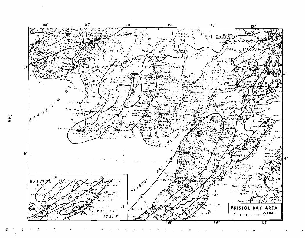
,
,==
\
.'-c-: '"
.. J
-
rl:?o." !
'.n
.,: .',
" -
" :;
~ ,J
1''\1.:
eI: ~
.....
~
~ ~
eI: •~.~
l>
ei:a:l
~i ....0
.. 0
nc,
II>0
"" 0
a:l
leo~
/--.-
00:
'6~
(,.; ~
.... ""'" .....
'-' '-'
.:::> .~
""'
'"
24
4

i.'
"'"'~:;~~r I
t 7:~O 1/4':' 1'76'"' East (d Gr:':(~r'!'wic.h 1?;:"!rJ i ~~()"
I
A"':. ,'."L'"" ./"<~·~':3 in.,•., ii 18 E R / N c,j ;::::;;' . . ':~, ::.';:. ''1,,",
in. A k ut: T 1 A N;;.;. "QI,.','i /
~'I ! ..(~ , ,'0, .: ---~::-;-:~-~{ ..-,i§·:~>r;--~;.:·,:,'~:;~~~·t;,-,;,1 -+-..•.1 .• ."."'Irc" ...~ ;''l'lll'"\lCl VL'~~I ...$·K~; ~ \
',-,.< l'J'r,~ ~'-' '" i< ~ ' .--. \ '; I
-1', ./It \ ", .:1 r . ~, I n'/! :,' t~l1tt ,,,\;' • t. ,'J I~ ,', \ ....
I -r i; ;.p AI1~cbitl«: :~.:
I !F \
\
.;.:A c I I i I c i
~ :J
N ... U1
}c'~ WE':;I .•• Gr.~r~n;·>·rr,:t1 171.,0 l .:·~f ~ :;["
~
- ....., .• 1' '
5
s
A
L
.{>,,, .
'""'
,,"~' ,.
\
,
,i 1I1r' . . .
I\NOy<t,
C
rd.
\, ~ IN 0 .
\,::: A
\ 8(p;; ,~~:;'" ::.{9't: ,;.-....
.Fe;;::.v'" .."p,,,,,,',, \~~-T---<-~:~:::"" ,.... ,\t'f,.,l , \\ ~ () ",'
, . ~ S l,.~ \
\ -. \ \
\ WEST PORTION ALEUTIAN AREA
o 50MIlES N \
",.. ,·0"'" 0 ,0-------< !\

"";1" ,
"",.
~~~56
...,sf.<; N c; i'
-,>5 L"
I, ~'~_U~JI~80';~.~l'f~'l"""
~:~
(;~.:;,
182
I ,....._~".,., ...
(;,to& l.{'¢I'~,!J~,r
....._..•_~~-~_ ..-._..~...-.~,
A··
184
! I
f ;', f .~
. Ur'lr
ll a.k fh.i'J.r,(/'~\.1. r:<nf'ill ".,'
~ "~',,! ( .. -"
s
Sf.A
;.;~·:;f~ i;~~~
168 188
I I
i BERING
/! v
o ':;.~:,,(. M~,,·:t;!!".'f~
\.-- ;
s54 r~ c
\=-L";;:',,' ..."". ,r ",1."
~ g'"f' .,(;;;Jj?~<,.,. " ...",,<;.1:, ;.,.
,. , : r, ':',~. .'~";:~~~~~E! ~ ;;~,,' ~ stv ~~-~ "'J'"...
',::"~,, ';J.",r \) -. ;. -""I~ ~(, "~'!~""~':':~' /1:" !'
N, \...
'" s 54
;z PACIFIC OCf.AN
oF 168 180 164 162 160
170
UERI.H; _ "T 170
53 l-, ..._ SEA /
U / l' <,.," ..A--" b__..... Ii:. JI \ p,
57.~"";-;~";,_,,, "::::,~ :'/"0,','0. . .,.
" ." ,. . '0' , • ".".,," -:
0../ <. ",,,,,, ~..;n<;;" '\."" "';',;' 0 o Q ..,. """ ..,"';.'iIi ,", .,," , it
"""" , ".,,:,:".:.~:~;;,:,:; ",;:".,...".... Ii·i ;.. 53 .:'1!'!';!" .,\~
-.... 1 ,
":>~, l<
,-..····-----·--··..··151
I . 5! P'wi I '23.8 In.
W.,I.,,~ IO')';C'~I.I:""~. 511"~::~,"t':" {1;,
.(.'H~, I
PRISILOF. I!SLANDS ~llLJ ,
I> f. It D•• ,..!. ""~"'.?'"' II! f~~I~ ':'i~ .,:. U t-or foil 1
I EAST PORTION170II'AClfTC DC/iAN ALEUTIAN AREA
170 o 50MllES ~=' I
, , ,~.

------------
r--
--
--
--
--
--
--
--
--
-.. ;_...;-
--
.. /
<
-------_.
-c
----'
.2
_ __
---
---_..
-------_._--
;; :~ -
,"
z...
(f e.
.:T"'-'t-"~-
24
7

24
8
b =
«... Of:
« ......... Z
lo<: o o u ~ ~;~
. . .. ? ".":.'
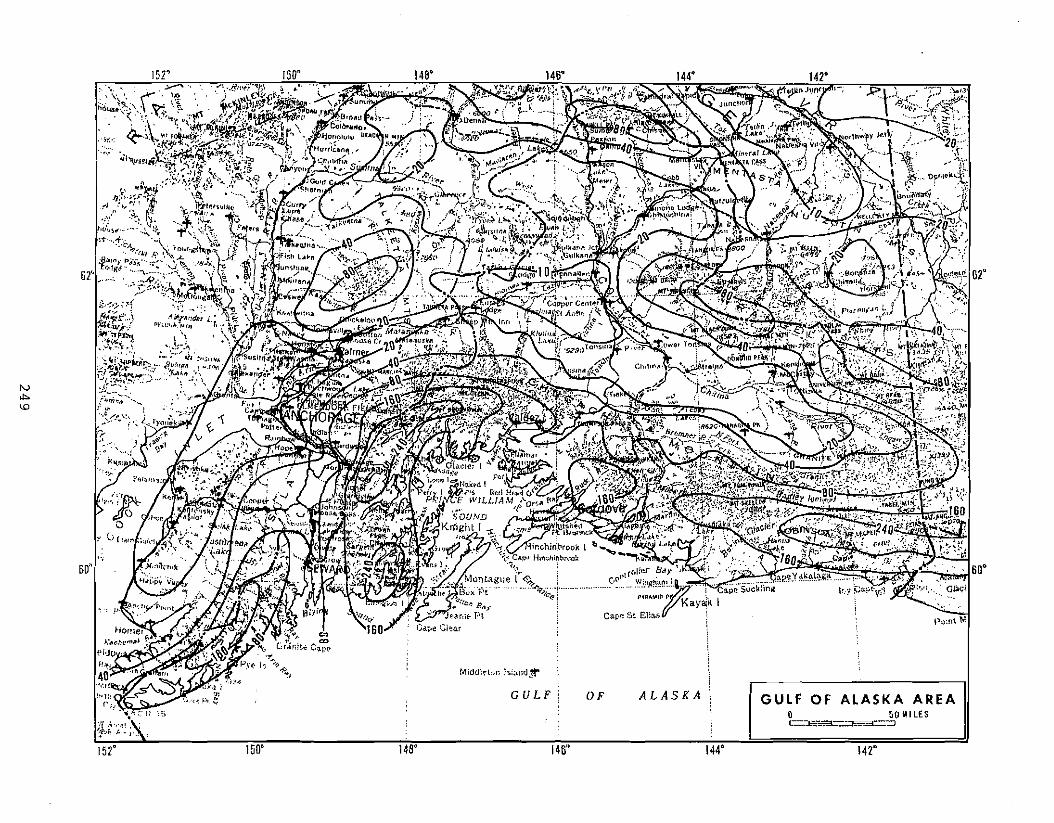
..1.._
< w
'" ~
< ~
~
< ,.
:..: ~n
II>
il
0
<
~ ~
:!.... <
II
..... ~
0 W
....
Ii ....
~"
::> C>
... :! -e
'" '" ..,.., .., "o
;"
:!
"f" .., -g
:;, .:~
CJ
, " i ~
"
10 ~
24
9
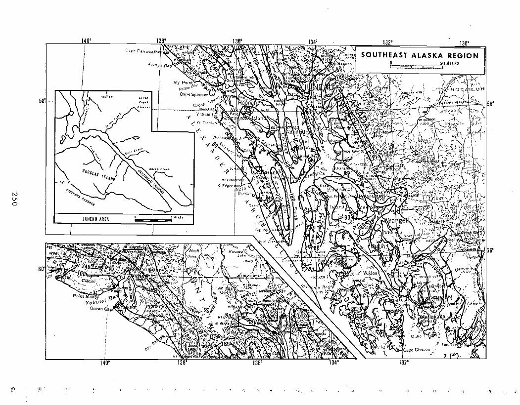
=
.~
,
"
.-". : .~~;~._----_._---~
~
~ ~;;:!
-"""""""",,,,
-"
'i------r-::r
,......,'" ,.
t(
Z
i6
0 ::;
e w
III
w
J
~ ;;
... ~n
.'1:
-lo: ~
""',III
i~c(
:f.... ~
0...
•~~
:::
III c(
I'.
cU~
III
~
:::t ~
:l 0 III
.1 =
:!----._
-_
.. t-.....r-r-..... -~-.
25
0