Embed Size (px)
Citation preview

MIRL Report No. 89
Applicability of Siberian Placer Mining Technology - -
to Alaska
Dr. Frank J. Skudrzyk, Project Manager E++W Engineering Consultants
461 1 Dartmouth Fairbanks, Alaska
James C, Barker U.S. Bureau of Mines
Alaska Field Operations Cenkr Fairbanks. Alaska
Daniel E. Walsh School of Mineral Engineering University of Alaska Fairbanks
Fairbanks, Alaska
Rocky MacDonald American Arctic Company
Fairbanks, Alaska

Library of Congress Cataloging in Publication Data
Library of Congress Catalog Card Number: 9 1-6 1923 ISBN 0-91 1043-12-8
May, 1991
Published bv
Mined Industry Research Laboratory 212 ONeill Building
University of Alaska Fairbanks Fairbanks, Alaska 99775-1 180
Alaska Science and Technology Foundation 550 West 7th Avenue
Suite 360 Anchorage, Alaska 99501

ABSTRACT
The result of Perestroyka and Glasnost has been an awakening of potential for cooperation between East and West. Nowhere has that been better demonstrated than between Alaska and Magadan Province, USSR.
This report summarizes a one year effort financed by ASTF, with participation from several technical organizations, to establish contacts with the Siberian placer mining industry. The purpose of the project was to provide initial assessment of the Soviet technology for placer mining in permafrost. A ten day trip to Magadan province by an ASTF team and a similar length visit to Alaska by the Soviet mining group representing the All Union Scientific and Research Institute of Gold and Rare Metals, (VNII-I), Magadan are described. The report also reviews translated data on mining in permafrost and describes surface and underground placer mining technology developed by the Soviets. The report also lists relevant publications on Soviet mining research and state of the art Soviet mining technology and expertise.
Magadan province is the size of Alaska. It has a similar population, which is largely derived horn the settled portion of the USSR. These people face the same logistical and climatic problems we have in Alaska. Yet Magadan province has a mining industry at least 20 times larger than that of Alaska. Many innovative mining methods and practices have been developed and implemented there, despite shortcomings of the Soviet equipment and materials, This presents excellent opportunities for transfer of Soviet experience to Alaska and to cooperate in joint development of a new generation of mining technology applicable to placer deposits in permafrost.

ACKNOWLEDGEMENTS
The grant recipients would like to thank the Alaska Science and Technology Foundation for the opportunity to work on this exciting project. We hope it will contribute to the exchange of ideas and ultimately to more profitable and safer mining technology in Alaska. Acknowledgements are also extended to the U. S. Bureau of Mines (Alaska Field Operations Center), the University of Alaska Fairbanks, School of Mineral Engineering, the State of Alaska, Division of Geological and Geophysical Surveys, Usibelli Coal Mine, Alaska Gold, Westgold, and many other private companies, individuals and organizations that contributed to the project. The authors also wish to thank the Alaska Science and Technology Foundation reviewers, in particular Messcrs. Richard Hughes of BTW Mining and Exploration Corp. and Karl Hanueman of Alaska Placer Development, Inc., for their valuable comments and suggestions concerning the final report.
Special thanks are directed to the Soviet organization, All Union Scientific and Research Institute of Gold and Rare Metals, (VNII-I), Magadan, its leaders, Dr. A. A. Yegupov and Mr. G S. Evsiovich, and many VNII-1 staff members and Magadan province miners who were so hospitable during our visit to the Soviet Union. Their courage and commitment to establishing open communications between Alaska and Magadan province made this project a success.

TABLE OF CONTFNL'S
PAGE
......................................................................................................... ABSTRACT i
. . ............................................................................. ACKNOWLEDGEMENTS ii
... ................................................................................ TABLE OF CONTENTS iu
UST OF FIGURES ........................................................................................... v
. . LIST OF TABLES ........................................................................................... wi
UNITS OF MEASURE AND NOMENCLATURE ... .......................................................................... USED IN THE REPORT vm
..................................................... INTRODUCTION ..................................... ... 1 Contacts between Alaska and Siberia Renewed ............................... 1 Visit by ASTF Team to Upper Kolyma .............................................. 3 Visit by a Soviet Team to Alaska ......................................................... 6
HISTORICAL BACKGROUND: MINING IN THE EASTERN ................................................................................................ SOVIET UNION 7
MINING INDUSTRY IN MAGADAN OBLAST ....................................... 8
GEOTECHNICAL AND CLIMATIC SETTINGS OF THE ...................................................... NORTHEASTERN SOVIET UNION 10
.......................................................................... Geotechnical Settings 10 Hydro-Climatic Settings .................................................................... 11
ECONOMIC DEPTH OF SURFACE MINING ....................................... 17
SURFACE MINING ....................................................................................... 22 ........................................................................................... Introduction 22
............................................................................. Ground Preparation 26 ..................................................................... Surface Mining Methods 26
..................................... Environmental and Reclamation Practices 33
UNDERGROUND MINING ........................................................................ 33 Stability of Support of Underground Openings
in Frozen Ground ............................................................................. 34 Access to an Underground Mine ....................................................... 34
iii

TABLE OF CONTENTS (Continued)
PAGE
Development and Mining Systems of ..................................................................... an Underground Mine 39
............................................................ Ventilation and Heat Control 39
PROCESSING .................................................................................................. 46
RECENT DEVELOPMENTS AND NEW MINING CONCEPTS ..................................................................................... 56
Surface Mining ...................................................................................... 56 Underground Mining ........................................................................... 61 Processing .............................................................................................. 64
APPLITCABILITY OF THE SIBERIAN PLACER TECHNOLOGY TO ALASKA .................................................................... 64
CONCLUSIONS .............................................................................................. 67
COLLECTED SOVIET TECHNICAL PUBLICATIONS ...................... 68 Papers in VNII-1's Collections of
Scientific Works ................................................................................ 68 Other Soviet Articles on Soviet
Placer Mining .................................................................................... 71 Flyers and Brochures on Soviet Placer Equipment .................................................................. 72
.......................................................... Soviet Books on Placer Mining 74
REFERENCES ................................................................................................ 74
PRESENTATIONS AND PUBLICATIONS BY ASTF ........................................... TEAM MEMBERS ON SIBERIAN MINING 76

LIST OF FIGURES
FIGURE PAGE
............................................................................ 1. Far East of the Soviet Union 2
2. Upper Kolyma Region ....................................................................................... S
3. Typical vertical cross section through placer deposits in the Soviet Northeast (Upper Kolyma) and Soviet
............................................................................................................ grain size 14
4. Distribution of yearly temperature amplitudes and " ..*...................................................*. average annual air temperatures in C 16
5. Thawing and freezing indexes based on average daily ............................................................................... . temperatures of air, in C 16
6. Distribution of annual precipitation and its component ............................................................................... during cold period, in mm 18
7. Dependence on depth of stripping, H (in meters) of the total cost, C, of removal of lm3 of overburden during the
....................................................................................................... summertime 20
8. Dependence on depth of stripping, H (in meters), of total cost, C, or removal of lm3 of overburden during wintertime .......................................................................................................... 21
9. Charts indicating the relationship between the cost of summer stripping and width of mining block .......................................... 27
10. Charts indicating the relationship between the cost of winter stripping and width of mining block ............................................. 28
11. Methods of protection of thawholes .............................................................. 29
12. Blasting - filtration method of thawing frozen ground ............................................................................................................... -29
13. Mechanization of surface placer mining using mobile equipment ......................................................................................................... -3 1
14. Current and recommended system of surface mining ................................ 32
15. Skip decline in timber support ........................................................................ 37

LIST OF FIGURES (Continued)
FIGURE PAGE
16 . Blast design for a decline ................................................................................. 38
17 . Cross sections of declines for the following conveyance methods; a .skip. b -belt conveyor. c -scraper and d -low profile truck ....................................................................................................... 40
........................................... 18 . Schemes of panel development of a paystreak 41
19 . Dependence of mine width on its length for different extraction costs .................................................................................................. 42
20 . 'Room and pillar' system with continuous lowering of roof or with the use of props. for wide paystreaks ............................................... 42
..................................... 21 . Chamber . longwall system with interpanel pillars 43
22 . Mixed system for narrow paystreaks .............................................................. 43
23 . Chamber system ................................................................................................ 43
24 . Longwall face with drilling and blasting ....................................................... 44
25 . Blasting patterns for production (longwall) blasting ............................................................................................................... 44
26 . Longwall face with a shearer .......................................................................... 45
............................................. 27 . Development of a mine for a longwall system 45
. 28 . Scheme of mine ventdabon ............................................................................. 47
. . 29 . Mixed method of ventdabon ........................................................................... 47
30 . Heat control by two parallel heat absorbing openings ............................................................................................................. 48
31 . Technological schemes of mechanical and hydraulic feed washing plants ........................................................................................... 49
32 . Principle operation of the OMT machine .................................................... 51
33 . Schematic view of PGB-75 processing plant ................................................ 52

LIST OF FIGURES (Continued)
FIGURE PAGE
. 34 Sluice ShGm-6x700 ........................................................................................... 57
............................................................................................. . 35 OZP-1000 stacker 58
............................................ 36 . Design scheme of excavating and loading unit 59
37 . Stripping schemes using ELU ......................................................................... 60
38 . Prototype of ELU ........................................................................................... ..60
..................................................................... 39 . Schemes of trenching with ELU 62
40 . Method Orotukan of stripping using large diameter horizontal blastholes ............................................................................................................ 63
. ............................................. 4 1 Combination drag-tricone bit RShD.214. 5TZ 63
42 . Scheme of making ice pillars .......................................................................... 65
TABLE LIST OF TABLIB
PAGE
1 . Classification of Roof Strata fox the Purpose of Underground Mining of Fozen Placer .......................................................... 12
2 . Basic Textural Forms of Frozen Placer Materials ...................................... 15
........................................................ 3 . Examples of Soviet Mining Equipment 23
....................................................... 4 . Stability of Openings in Frozen Ground 35
5 . Span of Stable Extraction Openings .............................................................. 35 6 . Recommended Pillar Size ............................................................................... 36
7 . Technical Data on Soviet Sluice Washing Plants with ............................................................................................... Mechanical Feed 53
8. Technical Data on Soviet Sluice Washing Plants with Hydraulic Lift .................................................................................................... 54
vii

UNITS OF MEGSURE AND NOMENCLGTURE USED IN THE REPORT
a , a, = metal production from paygravel extracted using underground and surface mining method, respectively, oz.tr/yd3 (bank)
A, = area of land purchased for mining, acre
cl = economic unit value of paygravel, $/yd3 (bank)
c m = cost of 1 acre of mining land, $/acre
Co = unit cost of pay ravel extraction using surface mining methods (without strip- 8 ping cost), $/yd (bank)
Cr = unit cost of stripping during typical lifetime of a mine, $/yd3 (bank)
C, = unit cost of extraction of paygravel using underground method, $/yd3 (bank)
C , C, = unit cost of metal from paygravel extracted using underground and surface mining methods, respectively, $/oz.tr
kl = limit coefficient of stripping
k, = mining stripping coefficient, yd3/yd3
k,, k, = coeEcient of dilution in underground and surface mining, respectively
nb = additional volume of overburden per yd3 of associated paygravel (based on profitability), yd3/yd3
PO = paygravel reserves, yd3
9 = value of by-product with respect to the value of main metal, dimensionless fraction
SO = cost of land per unit volume of extracted paygravel, $/yd3
st = short ton = 2,000 lb = 0.91 t
t = metric tonne = 1,000 kg = 2,200 lb = 1.1 st

The Soviet Union, since its origin in 1917, has placed much importance on development of the basic sectors of its economy and the mining industry in particular. Each of their 5 year national economic plans called for si@cant increases in mining output. Precious and strategic metals were given much priority, as they contribute to the Soviet hard curren- cy balance. Considerable effort has been placed on providing the mining industry with technical and scientific assistance in the form of creating many mining research organizations housed in the Soviet Academy of Sciences, Ministry of Science and Higher Education, and various ministries overseeing particular braaches of mining and processing indus- tries. Despite overall failure of the Soviet economic system, some of the technical concepts and ideas developed, and to some extent implemented in the mining industry, seem to have practical validity. This is particularly true if their ideas could be combined with the superior mining equipment and materials available in Western Countries.
Much of the Soviet gold has been and still is produced from deep placer deposits located in permafrost. This has prompted extensive studies concerning all aspects of underground placer mining including exploration and evaluation methods, determination of break-even depth (depth at which underground mining becomes more economically attractive than surface mining), optimum layouts of underground openings, various aspects of underground technology and safety.
Siberia is a vast region of the Soviet Union located between the Ural Mountains on the west and the Pacific Ocean on the east and extending southward from the Arctic Ocean to the hills of north central Kazakhstan and to the borders of Mongolia and China. In Soviet usage, the areas of the Pacific seaboard (Soviet Far East) and the eastern flanks of the Urals are excluded from Siberia. From the south, the Russian Soviet Far East consists of Primorskiy Kray (territory), Khabarovskiy Kray, Magadan Oblast (region) consisting of the Upper Kolyma and Chukotka Peninsula, and Kamchatka Peninsula (see Figure 1). West of the Soviet Far East lies the large Autonomous Socialist Yakut Republic (Yakutya), approximately twice as large as Alaska. Yakutya and the Soviet Far East contain tremendous, nonrenewable, natural resources of which gold, diamonds, coal, silver, tungsten and tin are the best known.
Professional contacts within the project have been limited to the Magadan region, which historically was the first Soviet placer gold mining region located in permafrost and developed by the Soviet government.
Contacts B e h n Alaska and Siberla Renewed
With perestroyka and glasnost being firmly introduced in the Soviet Union by President Gorbachev, a series of governmental, scientific, and cultural exchanges between the State of Alaska and Magadan Oblast (administrative unit within the Soviet Federated Socialistic Republic) have been initiated. The Bering Bridge Ekpdtion was orgaaized by both states in March, 1989, and received direct support from Presidents Bush and Gorbachev. As part of this expedition a group of professionals associated with Alaskan mining organizations briefly visited Magadan, the capital of Magadan Oblast and the headquarters of the Severovostokzoloto (Northeast Gold Mining Association) and Sewostugol (Northeast Coal). Severovostokzoloto administers all hardrock and placer mining in Magadan Oblast, whereas Sewostugol oversees all coal mining in this province. During the visit a protocol was signed, which among other industrial pursuits initiated contacts between the University of Alaska Fairbanks (UAF) and the VNII-1 (All Union Scientific and Research Institute of Gold and Rare Metals), a research organization within the Soviet Glavalmazzoloto (federal organization for mining of diamonds and gold). The VNII-1 institute conducts industrial research in hardrock and placer mining, with emphasis on permafrost mining. A formal agreement of cooperation between UAF and VNII-1 was signed in September, 1989. This document called for cooperation in the areas of arctic mining research, tecbaology development, technology transfer and professional exchange and paved the way for the present project, "Applicability of Siberian Placer Mining Technology to Alaska." The project was financed by the Alaska Science and Technology Foundation, with in-kind contributions by the U. S. Bureau of Mines (Alaska Field Operations Center), University of Alaska Fairbanks and the private sector of the Alaskan mining industry.
Parallel with the cooperation initiated by UAF, several organbations in Alaska have taken steps to establish contacts with the Siberian mining industry. Bering Straits Native Corporation and Great Land Exploration Inc., have formed a joint venture, SVZAL, with Severovostokzoloto and have been engaged in development of mining properties on both


sides of the Bering Sea. The State of Alaska, Division of Geological and Geophysical Surveys and the U. S. Geological Survey have established contacts with the Soviet geological professionals organized in the USSR Academy of Sciences, Ministry of Geology and mining organizations. In November, 1990, the Alaska Miners Assodation convention in Anchorage was devoted to "Geology and Metallogeny of the Soviet Far East and Alaska"
Contacts between the mining professionals of Siberia and Alaska are not new. They were begun many years ago as a result of geographical and political proximity and the climatic simhities of the two regions.
Russia, as a former owner of Alaska until its sale to the United States in 1867, gained a familiarity with the 'Great Land', its native people and those who migrated to the territory years ago. The people who lived in the colony during Soviet ownership and remained in Alaska played a substantial part in the development of the U. S. temtory.
History reveals that the first investigation of Alaska's mineral resources was undertaken ia 1849 by Peter Doroshin, a graduate of the Imperial Mining School at St. Petersburg. His reconnaissance efforts included mining some gold on the Soviet River of the Kenai Peninsula and producing coal from the nearby Homer area.
In the 1920s and 1930s the Soviet Union offered employment contracts to persons, experienced ia both placer and lode mining, from the United States, including the then Territory of Alaska. Most interesting is the experience of a mine manager, who had gained experience operating gold mines in southeastern Alaska. Jack Littlepage worked in Russia from 1928 to 1937 where he held several key positions including Deputy Chief Engineer of the Soviet Gold Trust. His experiences in the Soviet Union are well described in the book "In Search of Soviet Gold" by John D. Littlepage and Demaree Bess, first published in 1937. For his engineering achievements, Jack was awarded the "Order of the Red Banner of Labor" in the Kremlin by the President of the USSR, M. Kalinin (Beistline, 1990).
Another Alaskan who worked in Siberia was Jack Hosler. Jack, a former student of the University of Alaska Fairbanks, was an expert in drilling frozen ground and the evaluation of placer deposits based on drill hole results. While still in Siberia, Jack wrote
hteresting letters to his parents in Anchorage. Several of these letters, describing in detail his experiences in the Soviet Union, were published in the Anchorage Daily Times newspaper in 1930-32. They described, in a most readable manner, his work assignments, means of travel, areas visited, Soviet life and the Soviet people. One of them, published in the November 28,1930, Anchorage Daily Times, states:
"All of the Americans here have been traveling great distances in looking over the work in the various districts, which are widely scattered. The plamr mines alone ate tremendous, in numbers, in distribution, number of men employed and in output. For instance, in the Alden district on the headwaters of the Lena River, hundreds of creeks are being operated, over ten thousand men are employed and the output is greater than that of all Alaska combined."
Another quote published in the January 16, 1931 issue reads:
"Many of the Russian girls are very good looking or striking in appearance. Having become quite friendly with a couple of well educated married women, who seem sensible, charming and friendly; I think we Americans will make a mistake if we do not try to establish social relations with the Russians." (Beistline, 1990).
Yisit by ASTF Team to Upper Kolyma
Three members of this project's team, Frank Skudrzyk, Jim Barker, and Rocky MacDonald, accompanied by a representative of UAF, Paul Metz, visited Magadan Oblast in September, 1989. They were hosted by the All Union Research Scientific Institute of Gold and Rare Metals (VNn-1).
The party flew to Nome and then by a chartered aircraft to the town of Providenya (see Fwe 1). There the party was greeted by Dr. Valery Andreyevich MIROSHNICHENKO, Chief of the VNII-1 Reliability Laboratory of Northern Mining Techniques. On the same day we were able to reach Magadan, flying first to Anadyr on an Aeroflot transport twia propeller plane (AN-24B, 30 passenger capacity) and then on a jet plane, IL 62M (185 passenger capacity). We were greeted by VNII-1 Deputy Director for Research, Dr. Anatoly

Afanasevich YEGUPOV and Deputy Director for Economics, Dr. Alexandr KOSTANOY. The following day we had a full day visit the VNII-1 Insti- tute, including a general meeting with the VNII-1 staff represented by:
- Dr. YEGUPOV (Dr. Alexandr Semyonovich EVSIOVICH, VNII-1 Director, was at the time on a business trip in the People's Republic of China),
- Dr. KOSTYANOY, - Dr. Valery Gavrilovich LUKYANJWKO, Deputy
Director - Dr. Evgeny Demianovich KUDLAI, Senior
Specialist, Underground Placer Laboratory, - Dr. Ni Vasilevna MAKSIMOVA, Senior Scientist and Learned Secretary of the Institute,
- Mr. Alemdr Phyodorovich KURZLCHUK, Cbief of Permafrost Laboratory,
- Mr. Alexandr Nikolayevich DUSHIUN, Senior Specialist, Underground Placer Mining Laboratory,
- Oleg Evgenyevich STEPANOV, Senior Scientist and Chief, Earth Moving Equipment Laboratory,
- Dr. Vyacheslav Stepanovich SHAPOVALOV, Senior Scientist, Geological and Surveying Laboratory,
- Dr. Avenir I. OSIPOV, Head, Drrlling Equipment Laboratory,
- Dr. Mikhail Naymovich ZAMOSHCH, Chief of a section of Environmental Protection Laboratory and
- Lrena A~exandrovna BRAGINA, Interpreter.
After the meeting we were shown to an exhibition hall where we were further acquainted with mining technology and equipment developed and tested by VNII-1. In particular, we were shown: a model of a vibratory drill SBVG-5650 (for drilling thaw point holes of 56 mm dia. up to 50 m long); a range of explosive products (inert substitutes); devices for collecting dust during drilling in a permafrost environment; pipes made of special plastics and electric welders for plastics for cold weather applications; a model depicting overburden removal by prefracturing blasting and cold water circulation; a model depicting an overburden removal method using large diameter horizontal blastholes (up to 1.5 m in diameter, 60 m length) drilled with low pressure (80 psi) high volume (1,300 gpm) water jets; posters showing layouts of underground mining systems; methods of frozen ground excavation (using tunneling machines in development openings and shearers on long wall faces); means for ground support and
monitoring of convergence; planetary concentrators KPR-1 and KP-2 ch-3 (up to 3 t/hr throughput) used by exploration crews and several other models and posters. In the afternoon we made a presentation (attended by about 60 VNII-1 employees) on mining and research activities in Alaska and later continued discussions concerning Siberian placer mining practices.
During September 5 through 8, we traveled by bus and visited several mining operations in Karamken (underground hardrock gold and silver); Orotukan (placer mining reclamation, steel mill and foundry, and drilling equipment plant); Y agodnoye and Burhalya (surface placer gold mines) and proceded further to the northwest to Susuman, Shirokiy and Experimentalniy. At the latter three localities we observed surface placer gold mines, dredging and cold water thawing, overburden stripping using large diameter (250 mm) blastholes, reclamation projects, a VNII-1 underground placer mine where we saw artificial pillars and gold concen- trate processing. At Burkandya we went underground to see an operational placer mine. Our bus route is shown in Figure 2. During the trip we were accompanied by twelve VNII-1 staff members, most of them mentioned earlier. We met many mining professionals ind-
- Mr. Leonid Danilovich KXIMELEVOY, Director, Orotukan Mining Equipment Company, - Dr. S. F. MIKHAYLOV, Director Yagodnoye GOK, - Mr. Yuriy Vasilyevich SIDOROV, Director Burhala Placer Mine, Yagodnoye GOK,
- Mr. Fyedor Alexandrovich SHEFER, Director, Beryelekhskiy GOK,
- Dr. Mikhail Yurevich KATZMAN, Director Shirokiy Placer Mine, Beryelekhskiy GOK,
- Mr. Sergey Nikolayevich USYENKO, Director, Burkandya Underground Placer Mine, Beryelekhskiy GOK and
- Mr. Vladimir Kirilovich KHRISTOV, Chief Engineer, Susuman GOK
During our flight from Susurnan back to Magadan we saw some of the ongoing placer operations in the Upper Kolyma, got an overview of the mining regions, which bare similarity to interior and particularly western Alaska, and witnessed extensive agricultural activities in the vicinity of Magadan. The next two days were spent in Magadan continuing &CUSS~OIL~ with VNII-1, concerning Soviet

Fig. 2. Upper Kolyma Region. (-ASTI? team bus route during 1989 visit) (From 1989 Map of Magadan Oblast , Novosibirsk)

placer mining technology. A proposed program for the VNII-1 delegation's visit to Alaska was also discussed, as well as future areas of cooperation between VNII-1 and UAF, and on a broader scale, between the mining industries of Alaska, USA, Magadan Oblast and USSR. Topics for further Alaska - Soviet cooperation are reflected in the Protocol from our visit.
While in Magadan, we also visited the Geology Museum of the Soviet Academy of Sciences, where we were given a tour by the museum Director, Dr. German Fedorovich PAVLOV; two libraries (including the library of VNII-1) and several bookstores.
On September 11, we departed Magadan aud stopped overnight in Anadyr where we met with representatives of the local mining industry
- Mr. Ivanov Vladimir KONSTANTINOVICH, Deputy Director of local quarries and gravel pits, former deputy director of the local underground coal mine "Otroshniy" and
- Mr. Roman Isayevich ISAKOV, Diector, Iultin's GOK [tin and tungsten, both placer and hardrock).
During the visit to Magadan Province we collected technical literature on Soviet placer mining practices and maps. A listing of literature with brief descriptions of their content is given in Section 14 of this report. The literature was also used extensively in the preparation of this report.
Visit by a Soviet Team to Alaska
As part of this ASTF project, a delegation from M I - 1 visited Alaska during the period of time, May 18 through May 26, 1990. The Soviet guests were hosted by the University of Alaska Fairbanks, the Alaska Science and Technology Foundation, the U.S. Bureau of Mines (Alaska Field Operations Center) and several other organizations. The delegation was headed by Dr. Anatoly Afanasevich Yegupov, Deputy Director for Research, and included Drs. Evgeny Kudlai, Head of Underground Mining Methods Laboratory and Mikhail Zamoshch, Head of Environmental Laboratory. They were accompanied by their interpreter, Ms. Irena Bragina.
The Soviet delegation visited Nome, where it toured placer operations of the Alaska Gold Company and Westgold Inc. At Alaska Gold Company, the
Soviets met with Mr. Joe Fisher, Manager of Alaska Gold and Mr. Matt Ddarnos, Chief Engineer. The Soviet researchers showed much interest in winter stripping by drilling and blasting, and also thawing of ground in preparation for dredging. When visiting the Westgold dredge, BIMA, they were provided with information on its recent remodeling, which included the autogeneous clay ball attrition circuit. They also showed much interest in the primary and secondary jigs, used as an alternative to sluicing on the BIMA. While in Nome, the delegation also participated in a local meeting organized by the Chamber of Commerce and met many local miners and prospectors during a potluck hosted by the Bering Straights Native Corporation and the Nome Mining District. Lonnie 07Connor, President and Jeff Burton, Vice President for Land and Resources, Bering Straits Native Corporation and Joe Fisher of Alaska Gold Co. were instrumental in the success of the Nome mine tour.
Subsequently, the delegation flew to Fairbanks and from there drove to the Circle Mining District to visit placer mining operations. The delegation visited Bob Casey's and Paul Manuel's operations on Portage Creek and Earl Beistline's operation on Eagle Creek. The Soviet guests were amazed with the variety of technologies used in mining of placer deposits in the district. The diversity of skills of mine operators, who often perform all tasks from exploration and evaluation to selection of mining method, design and construction of equipment, maintenance and repairs, bookkeeping, reclamation, etc., also impressed the Soviets. They showed interest in the modern equipment being used, including hydraulically powered belt conveyors and large size dozers and loaders. They were impressed with the high productivity, but at the same time they were surprised to see very little exploration being done in preparation for mining.The lack of cooperation among small operators, evident by duplication of repair shops and equipment used on an infrequent basis (e.g. drills, backhoes, clean-up plants, fuel trucks) puzzled them.
At the University of Alaska Fairbanks, the delegation met with Dr. Russell Ostermann, Acting Dean of the School of Mineral Engineering and Acting Director of the Mineral Industry Research Laboratory, Dr. John Zarling, Director of the Institute of Northern Engineering and Associate Dean of the School of Engineering, and several faculty members of both engineering schools. The Soviet guests were provided with information on current UAF research and shown laboratories pertinent to engineering in

permafrost.
The VNII-1 delegation participated in a half day agency meeting. Mr. Earl Beiistline of the Alaska Minerals Commission, Dr. John Siebert of the Alaska Scientific Technology Foundation, Dr. Dick Swainbank of the Department of Commerce and Economic Development, Dr. Robert Forbes and Mr. Tom Bundtzen of the Division of Geological and Geophysical Surveys, Mr. John Wood of the Division of Mining, Mr. Conrad Christianson of the Department of Environmental Conservation, Mr. Harry Noyes of Doyon Native Corporation, Mr. Jim Deininger of the Bureau of Land Mauagement, and several other individuals provided brief summaries on the various agencies' and organizations' involvement in Alaskan miaiug. The Soviet visitors were provided with many brochures, charts and much data on all aspects of the mining industry in Alaska.
On another field trip the delegation visited Usibeli Coal Mine and Valdez Creek Mine. The Soviet guests were highly impressed with engineering, automation and computerization of the only coal mine in Alaska. They showed much interest in drilling and blasting practices used in stripping of frozen overburden, in water quality control and reclamation. Dr. Zamoshch was offered samples of grasses which have been successfully used in revegetation of reclaimed lands at Usibeli Coal Mine. He will use them in the Soviet Union in comparative studies. The visit to Valdez Creek Mine was an opportunity for the Soviet guests to get exposure to the complexity of state and federal regulations pertaining to mining in Alaska. They were in disbelief when told about the possibfity of catching and transporting grayling to the headwaters of Valdez Creek, because of the Valdez Creek diversion in connection with the planned mining operations. They also showed much interest in the proposed changes in the mining operations at Valdez Creek Mine. In particular, Dr. Yegupov promised to have his people evaluate the changes, which are being contemplated in the processing plant. Soviet guests were impressed by the scale of mining operations at Valdez Creek and by winter processing, which employs steam pads for thawing the frozen gravel.
The Soviet guests also visited the Polar Placer Mine and Citigold's heap leach gold operation near Fairbanks. On the last day's visit to Anchorage they met with representatives of Atlas Powder and Alaska Explosives Companies, Westgold and Alaska Miners Association. During the meeting with Atlas Powder
the discussion concentrated on possible ways of upgrading of the Soviet explosives based on American technology formanufacturing porous ammonia nitrate and emulsions. The Soviets showed interest in bulk loading of explosives under cold weather conditions. Atlas Powder personnel were overwhelmed with the volume of explosives used in the Soviet Far East and the potential for future business oppommities.
Dr. Richard Garnett of Westgold provided the Soviet guests with an overview of offshore exploration and dredging technology, including technology in use and a prototype remote underwater dredge currently being tested. The subsequent discussion concentrated on possible ways of introducing this technology to the vast offshore placer deposits of the Soviet Union.
The Alaska Miners Association hosted a luncheon meeting for the Soviets. Some forty businessmen of the Anchorage area involved in mining, exploration, banking and international business attended. Mr. Steve Borell, Executive Director, AMA, and Dr. Yegupov exchanged toasts to the new Soviet - American cooperation. Dr. Yegupov gave a talk on mining in the Soviet Union and the similarities of mining in Siberia and Alaska. He also indicated that his delegation's visit to Ataska was very informative and a good starting point for increased cooperation between the two regions. His talk was extremely well received and was followed by many questions.
HISTORICAL BACKGROUND: MINING IN THE EASTERN SOVIET UNION (EMELANOV, 1985)
From a technical point of view, the development of placer deposits in permafrost in the Eastern Soviet Union can be divided into four stages. In the first stage (until 1946) all mining activities, including extraction, transport, and processing of gravels was done manually. During this stage, extractions of gold and tin were conducted from deposits of the highest grades. This allowed maximum production of gold with hand methods from a relatively small volume of ground.
In the second stage (1946-1959), shovels, dozers, draglines, belt conveyers, movable prmessing plants, stackers, compressors, and other equipment, such as bucket ladder dredges of Yuba class, were introduced. The dozers were introduced on a large

scale, because they were capable of removing gravels in layers as the frozen ground thawed when exposed. Mechanization lead to the development of major mine organizations by the end of the 1950's that could treat lower grade materials.
During the third stage (1960-1975), mechanization of basic mining operations was introduced. However, during this stage a slow down in technical progress was observed due to a significant increase in labor intensity (author's comment: This likely means bureaucratization of the industry), which in turn reflected in a negative way on extraction costs.
In the fourth stage, high-power dozers, loaders, scrapers, draglines, wheel excavators, rotary drills, processing units and Soviet made dredges were implemented. Utilization of this new equipment has lead to profitable surface mining of deep, low grade deposits. The application of high-power dozers allowed the ripping of frozen ground. The practical length of push dictated by application of dozers require that the processing plants be moved many times (up to 100 moves in one season). This in turn requires that the processing plants are small and self- contained, which may cause greater losses of precious metals.
The tendency to intensify extraction from unit area and utilization of high productivity equipment is typical of mining industries in industrialized countries. With higher productivity the depth of extraction can be increased by increasing the stripping ratio, but with increased surface distrubance and higher capital costs. Conversely, in order to minimize the impact of higher expenditures, the metal recovery technology and application of high-productivity equipment should increase.
During the last 10 years, the grades and overall mining conditions have become worse in Yakutya and Magadan Province. Consequently, the depth of mining increased with an attendant increase in the stripping ratio by a factor of 1.5.
MINING INDUSTRY IN MAGADAN O B W T (PROVINCE)
The Magadan region is an administrative unit (oblast) of the Russian Soviet Federated Socialistic Republic of the Soviet Union. It covers an area approximately the same size as Alaska (463,000 mi2, as compared to 586,400 mi2 for Alaska) and has a
population of 542,000 (1987 data), which compares very closely with Alaska's population of 520,000. Magadan province geographically consists of two areas, the Upper Kolyma and Chukotka Peninsula (Figure 1). The latter, Chukotka Autonomous Administrative Area, has recently been showing determination to become independent from the provincial government located in Magadan City. Geologically, both the northwestern part of Alaska and Chukotka are very similar and mineral terrains can be traced across the Bering Straits. Magadan province, however, has over 80,000 metal miners working primarily gold, silver, tin and tungsten deposits. In addition, it is estimated that this province produces 7 lo6 st of coal per year. Both regions, Alaska and Magadan province, are underlain by large areas of continuous permafrost. However, compared to Alaska the permafrost in Magadan province extends deeper and is colder, reflecting more severe climatic conditions.
Gold mining has been the main driving force behind the economic development of Magadan province. It started in the early 1930s when Stalin ordered the organization of the the Dalstroy system. Dalstroy was run jointly by Sovietzoloto (today's Glavalmazzoloto, a statewide gold mining monopoly administered directly by the Soviet government), the Red Army and the NKVD (today's KGB). Until 1957, the organization used prisoners to construct the regional infrastructure and operate the mines. It is estimated that 5 to 7 million people died in the Dalstroy concentration camp system. Each prisoner, on the average, produced about 50 to 65 oz.tr. of gold before his/her death (Cieslewicz). Additional background information on gold mining in the Soviet Union during the years 1929-1936 and the involvement of American mining engineers may be found in an account provided by Jack Littlepage (refer to Page 4). In the early 1960s, mining in Magadan Oblast was reorganized and a major mining organization, Severovostokzoloto (Northeast Gold Mining Association), with its headquarters in Magadan, was created.
The Severovostokzoloto is organized into 16 regional enterprises conducting mining throughout the entire Magadan province. Annually, Severovostokzoloto moves about 520 lo6 yd3 of earth materials (including overburden, ore, gravels and reclamation material) and has produced about 25 to 40% of the Soviet Union's gold. (At present the total Soviet annual gold production is estimated at 10 lo6 oz.tr., U. S. Bureau of Mines data.) Gold production

statistics are still tightly guarded as state secrets by the Soviets. Only about 10% of the gold produced in Magadan Oblast comes from bardrock & p i t s (none from heap leaching). The remaining 90% is mined by underground methods (25%) dredging (lo%), and by surface methods (55%). About 2 to 3% of gold comes from fully mechanized longwall operations that employ shearers.
The Northeast Gold Mining Association's 16 regional enterprises are called GOKs (mining and processing complexes). Most of the WKs are listed below. The first six (all in Upper Kolyma) were visited by the ASTF team;
- Karamken GOK (hardrock, underground gold and silver, apparently at present working much below its planned capacity due to severe water inflow below the permahost),
- Orotukan GOK (placer gold and steel plant), - Yagodaoye GOK (surface gold placer), - Susuman GOK (surface and underground placer and hardrock gold),
- Priisk Experimentalniy GOK (surface and underground placer, testing of new technology),
- Dukat GOK (Dukat hardrock gold and silver mine, both underground and surface, and underground tin mine).
The following GOKs are located in Chukotka:
- Matrosov GOK (hardrock), - Pevek GOK (tin placer Krasnoarmeysky mine
and hardrock tin Valkumey mine currently mining under the Chaun Bay). Tin ore is of greisen cassiterite-tourmaline-sulfide type. Further increase of tin production is expected from a new Pyrkakay deposit,
- Bilibinio GOK (placer gold), - Iultin GOK (underground hardrock tin and
tungsten, and placer mining), four mines in operation, a 5th larger one to open soon,
- Polarniy GOK (placer hardrock in development).
Many of the GOKs negotiate with and supervise mining conducted by "private" organizations called "arteli". Nevertheless, the arteli mine properties, wbich were earlier explored and evaluated in detail by the government exploration companies. Often they get pieces of ground that are too small, or too remotely located, to be mined by a GOK In some cases up to 25% of a GOK's gold production (e.g. Yagodnoye GOK) is provided by the artelis. Their productivities are higher, and they usually end up with
higher incomes.
A separate Magadan province based organization, the Sewostugol (Northeast Coal) is in charge of mining coal. Several mines located throughout the province in Arkagala, Shakhterskiy (near Anadyr), Beringovskiy and others collectively produced 7 10% of coal in 1989; most or all for internal consumption.
The placer and hardrock mining operations in Magadan Oblast are supported by two research and design organizations, VNII-1 and Dalstroy Proyekt, one steel plant, several ore processing plants (no smelters though), several coal-burning power plants, one 100 MW atomic power plant at Bilibino (the only one in the world operating above the Arctic Circle), one hydroelectric plant of 1,000 MW on the Kolyma River, several equipment repair and manufacturing plants and several auto/truck transport enterprises.
The two research and design organizations mentioned earlier are: All Union Scientific and Research Institute of Gold and Rare Metals (VNn-1) and the State Design Institute (Dalstroy Proyekt). VNII-1 was established in 1948 and has been a state (USSR) institute under the minsterial level, national organization, Glavalmazmloto. It has strong ties with Severovostokzoloto and with that is heavily involved in arctic mining (hardrock and placer) research. It covers all aspects of mining, from exploration and evaluation to mining methods, equipment, safety, explosives and blasting, transportation systems and reclamation. It employs 400 scientific and support workers who are involved in industrial research, quite often at mine sites and experimental field facilities. W - 1 has been instrumental in full implementation of new approaches to underground placer mining in permafrost. The research, conducted for many years, has resulted in designs of underground mining systems, that economically optimized geometries and outputs, such as longwall.
"Dalstroy Proyekt" was established in 1935 and today is a part of the Severovostokzoloto. It employs 700 s p e d k t s and support staff in the area of research, design, production planning and residential construction. It has been involved in the designing of all stages of life in the northeastern part of the Soviet Union, assists exploration and mining, urban development and transportation systems. It designs schools, hospitals, water supplies, shopping centers, sanitation systems, bridges, underground permdrost oil storage facilities and heating plants.

All mineral exploration activities in the Oblast are conducted by Sewostgeologiya (Union Northeast Geology), a company working directly under the USSR Ministry of G e o w . It is estimated that approximately 15,000 geologists (induding drilling crews and logistical support), organized in 13 expeditions and based throughout the Oblast, are working for this association. The Soviets have developed a geological classification system for deposits (classes A, B, C1 and C2) that requires certain minimum evaluation work to be conducted (trenching, drilling, drifting) before a deposit is allowed to be mind
The mining industry of Magadan province is additionally supported by a branch of the Soviet Academy of Sciences, which in Magadan employs approximately 200 scientists in the areas of geology, economics, ecology, anthropology and climatology. Since 1936, the mining industry of Magadan Oblast has published a joumal KOLYMA, which each month features several technical articles related to various aspects of mining with emphasis on mining in permafrost.
Most of the long distance transport in Magadan proviace is done by air and sea along the coast of the two oceans, Pacific and Arctic. A railroad was built in the Upper Kolyma on permafrost in the 1930s, but was soon abandoned because of maintenance problems. The existing road system is very limited. The heavily traveled and dusty Golden Circle road in the Upper Kolyma connecSs that region to the Soviet road system of the Far East. Many locations not served by the road system are accessed by ice roads (ledniky) during the winter to allow seasonal transportation of heavy equipment and sup- plies. Based on the Soviet data, it is estimated that 470 mi2 of land have been disturbed by mining in the Magadan Oblast. Annually, 12 to 20 mi2 of disturbed land are added to this total. At present, 5 mi2 of mined laud is reclaimed annually, mostly as grazing ground for reindeer and other wildlife, but also for agricultural development. The newly formed state organization for protection of the environment, with several offices in Magadan Oblast, has been implementiug regulations concerning reclamation and water quality. The Soviet water quality law requires that the content of settleable solids 500 rn downstream of discharge should not exceed 0.25 mg/l above the ambient content 1,000 m above the intake. Measurements are to be conducted every 10 days during wasbing operations. Many placer operations are using closed-circuit water circulation. Operations
using cyanide are required to keep the level of cyanide in effluent water below 50 mg/l.
The soviets have developed a system of wage and employee benefit incentives to attract sufficient numbers of workers and engineers to this remote area with harsh climatic conditions. The salaries are adjusted (for eamhgs up to 300 rubles a month) using a "northern coefficient" (1.7 for Upper Kolyma and 2.0 for Chukotka) and an additional premium (0.8 for both) as an award for satisfactory performance (mostly presence at work and not being under the influence of alcohol). For example, an experienced technician in Moscow making 400 rubles a month would be making 850 (25 x 300 t 100) rubles a month in Kolyma and 940 rubles in Chukotka.
An employee is entitled to 42 working days of leave per year after 11 months of work. (The Soviets are still on a 6-day work week). The leave can be allowed to accumulate for up to three years. Most of the citizens of the Magadan Oblast have strong ties with the 'materik' (a Russian word for something close to "motherland" in English, or what we in Alaska call the Lower 48), where they often have second apartments. Air or rail travel is provided at nominal cost for travel to native regions in Western Russia.
Mines in the northeastern part of the Soviet Union are almost exclusively powered by electricity, which is supplied on a grid net from central power plants. The remote geographic location of the region, lengthy cold season, almost continuous distribution of permafrost, poor infrastructure and low density of population are all factors which contribute to the high costs and labor intensity of the mining industry.
GEOTECHNICAL AND CLIMATIC SE'lTINGS: NORTHEASTERN SOVIET UNION
Many of the Soviet placer deposits are of considerable size and some are true bonanzas. Paystreaks 400 to 600 feet wide, extending for several miles in length and at depths from 0 to 200 - 300 ft are common. The deepest reported placers have depths approaching 1000 ft with multiple auriferous horizons. Although the richest deposits have been mined out, improved mining methods now permit development of lower grade paystreaks. Because early mining methods led to poor gold recovery, some deposits

have been reworked as many as four times. The Soviets have classified these gold-bearing placer tailings as technogenic placers (created by previous mining).
Geotechnical properties of a deposit and strata above and below it, are recognized as essential parameters to mine design and engineering. They control the stability of underground openings, surface slopes and dictate layout of development and extrac- tion openings and their support requirements. It is obvious that geotechnid properties of placer deposits vary from those of hardrocks, reflecting grain size distribution, ice content, porosity, temperature, presence of pure ice as ice leases and wedges, salinity (content of salts in placer deposits of marine or evaporite origin), etc. The Soviets (Emelanov et al., 1982; Aripov et al., 1989) have developed a classification system for stability of frozen placer materials which recognizes the geotechnical properties and provides guidelines for design of size and support of underground openings, (e.g. length or width of longwall face or width of a stope, their required support, size and spacing between pillars, etc.). Use of this system provides maximum extraction ratio and required protection from ground fall. The d d c a t i o n system (Table 1) contains five classes of frozen granular materials which reflect the difference in origin and composition, temperature, ice content and texture. In the field, at any given site, several classes of ground may be encountered between the surface and bedrock. A vextical cross section through a typical placer deposit in the Soviet Upper Kolyma is shown in Figure 3. The figure also includes grain size nomenclature as used by the Soviets. It is worth noting that placer deposits in Upper Kolyma are typically not buried under thick accumulations of loess.
The basic types of texture, such as massive with interstitial ice, massive with megascopic ice, basal, ataxic, porous, porphyritic, lenticular, lattice, layered and blocky are defused in Table 2 (Aripov et al., 1989). In frozen materials, texture controls their mechanical properties. The classification system is used in determination of stability of underground openings. We will come back to this subject in Section 8, Underground Mining.
Hydro-Climatic Settings
Hydro-climatic conditions in the Soviet northeast are controlled intermittently by the land mass of Siberia and the two bordering oceans, Pacifrc
and Arctic. Total annual solar radiation varies from WOO to 1,900 ~ t u / i a ~ along the southern coastal regions and 2,200 to 2,400 ~ t u / i n ~ in the interior. Cloud cover is up to 75% along the coast and 55% in the interior. In mountainous regions, cooling of land occurs even faster due to frequent temperature inversions. Uneven absorption of heat by land and water, and rapid cooling of land during winter, produces sirmificant gradients in barometric pressures with consequent winds known as the monsoons of Eastern Asia (Iguatenko et al).
As a result, the interior climate is extreme continental and harsh, whereas along the coast it is less harsh and characteristic of an arctic maritime &ate similar to northwest Alaska A good measure of continental features of a climate is the amplitude of average daily temperatures throughout a year (Figure 4). A difference greater than 50 " C (90 ' F) between mean high and mean low temperatures indicates strongly prevailing continental climate. Data on the amplitude and mean annual air temperature for Magadan province are given in F i e 5 (Igaatenko et all-
Wind velocity in the Upper Kolyma region varies and increases near coastal areas and at higher elevations. In the interior valleys the average annual velocity is 4.5 - 6.8 mph and maximum velocity does not exceed 45 mph. Along the coastal areas, the average annual wind velocity is 16-18 mph and maximum wind velocities reach 90 mph.
From an engineering point of view air temperatures can be conveniently characterized by freezing index ( a sum of average daily temperatures below freezing for the cold season) and thawing index (a sum of average daily temperatures above freezing for one warm season). Data on the indices (in " C day) for the Magadan Oblast are shown in Figure S (Ignatenko et al). Susuman, for example, in the interior of Upper Kolyma has a freezing index of about 5500 ' C day (9900 ' F day) aud a thawing index of 1400 " C day (2500 " F day), whereas these figures for Magadan City are 3000 " C day (5400 " F day) and 1100 ' C day (2000 ' F day), respectively. For comparison, Fairbauks has a freezing index of 5500 " F day and a thawing index of 3000 " F day.
Relative humidity varies from 80-90% in coastal regions, but quickly decreases to 5060% in the interior, Rainfall is closely related to circulations in the atmosphere and topography. Slopes of mountains facing the Pacific Ocean get the highest rainfall
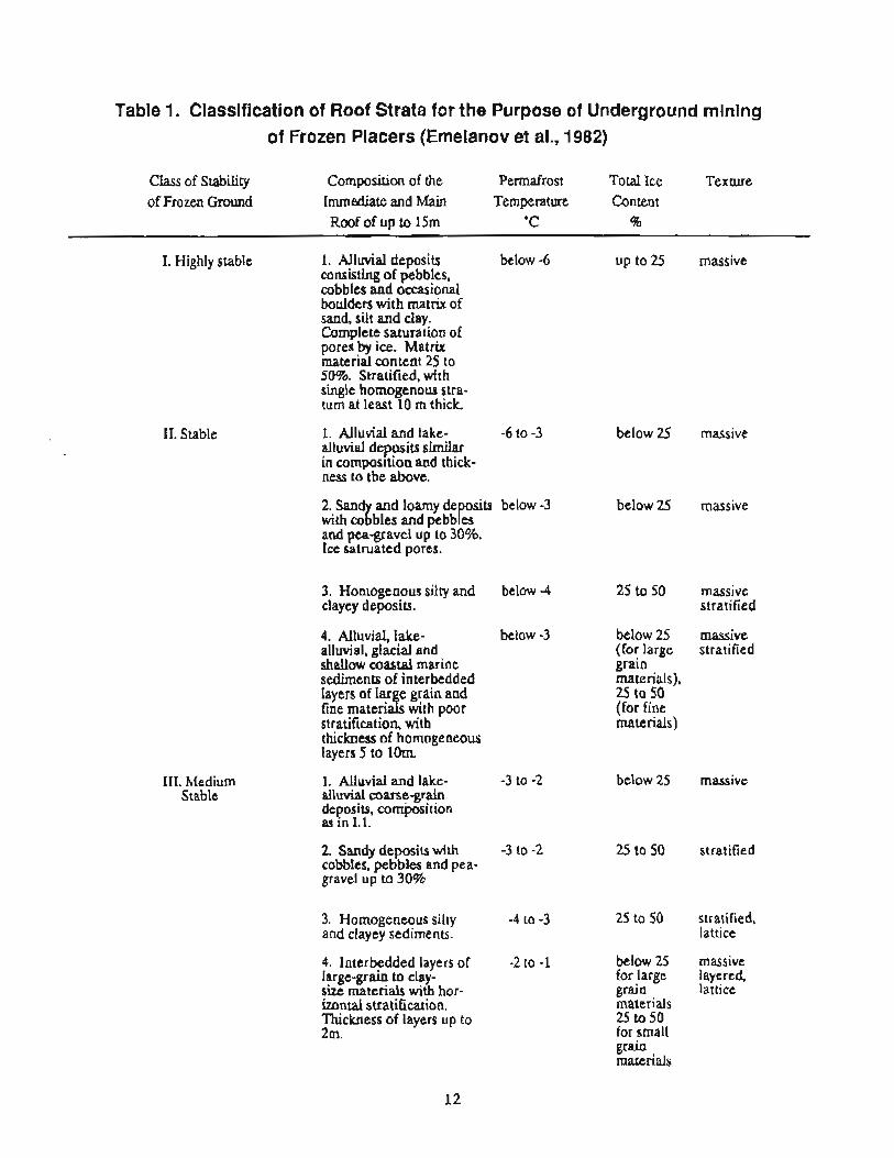
Table 1. Classification of Roof Strata for the Purpose of Underground mining of Frozen Placers (Emelanov et al., 1982)
Class of Stability Composition of the Permafrost Total Ice Texture of Frozen Ground Immediate and Main Temperature Content
Roof of up to 15m 'C %
I. Highly stable
11. Stable
111. Medium Stable
1. Alluvial deposits below -6 consisting of pebbles, cobbles and occasional boulders with matrix of sand, silt and clay. Complete saturation of pores by ice. Matrix material content 25 to 50%. Stratified, with single homogenous stra- tum at least 10 m thick
1. Alluvial and lake- -6 to -3 alluviai deposits similar in compos~tion and thick- ness to the above.
2. Sand and loamy de osits below -3 b with co bles and pebb f' es and pea-gravel up to 30%. Ice satruatcd pores.
3. Homogenous silty and below 4 clayey deposits.
4. Alluvial, lake- below -3 alluvial, glacial and shallow coastal marine sediments of interbedded layers of lar e grain and fine materi 3 s with poor stratification, with thickness of homogeneous layers 5 to lorn.
1. Alluvial and lake- -3 to -2 alluvial coarse-grain deposits, composition as In 1,l.
2. Sandy deposits with -3 to -2 cobbles. pebbles and pea- gravel up to 30%
3. Homogeneous silty -4 to -3 and clayey sediments.
4. Interbedded layers of -2 to -1 large-grain to clay- size materials with hor- izontal stratification. Thickness of layers up to 2m.
up to 25 massive
below 25 massive
below 25 massive
25 to 50 massive stratified
below 25 massive (for large stratified grain materials). 25 to 50 (for fine materials)
below 25 massive
25 to 50 stratified
25 to 50 stratified, lattice
below 25 massive for large layered, grain lattice materials 25 to 50 for smaU grain materials
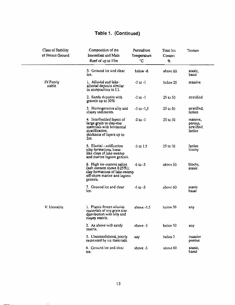
Table 1. (Continued)
Class of Stability Composition of the Permafrost Total Ice Texture of Frozen Ground Immediate and Main Temperature Content
Roof of up to 15m 'C 96
5. Ground ice and clear below -6 ice.
1V.Poorly 1. Alluvial and lake- -2 to -1 stable alluvial deposits similar
in composition to 1.1.
V. Unstable
2. Sandy deposits with -2 to -1 gravels up to 30%
3. Homogeneous silty and -3 to -1,5 clayey sediments.
4. Interbedded layers of -2 to -1 large grain to clay-size matenals with horizontal stratification, thickness of layers up to 2x11.
5. Eluvial - solifluction -3 to 1.5 silty formations, loess- like clays of lake-swamp and marine lagoon genesis.
6. High ice-content saline -6 to -3 (salt content above 0.25%); cla formations of lake-swamp odshore marine and lagoon genesis*
7. Ground ice and clear -6 to -3 ice.
1. Plastic frozen alluvial above -1.5 materials of any grain size distribution with silty and clayey matrix.
2. As above with sandy above -1 matrix.
3. Unconsolidated, poorly any cemented by ice materials.
4. Ground ice and clear above -3 ice.
above 60 ataxic, basal
below 25 massive
25 to 50 stratified
25 to 50 stratified, lattice
25 to 50 massive, porous, stratified, lattice
25 to 50 lattice blocky
above 50 blocky, ataxic
above 60 ataxic basal
below 50 any
below 3 massive porous
above 60 ataxic. basal

Surface
* '. 0"-
Vegetation layer 0.1 to 0.1Srn
E N 0
G d
Sand - gravel - silt dt depositions with pebbles up to 40%, icc content up to 25 - 30%
-..,--
?".:., m i . ,/,,TI . . ' A ' . . . . ' 0. * 0; :-.. A .-- - .
///// 1 L I
Silty depositions with ice content up to 15%
Sand - ebble - boulder depositions with lenticu f) ar ice; ice content up to 4 - 50% boulder content up to 20%
An lar gravel silt - clay depositions I? wit ice content 10 - 20%
Depositions of an ular to semi-an ular boulders, pebble,. gravels, silts and c f ay, ice content f 5%
Weathered bedrock, ice content up to 15%
h g e n d Soviet grain sizes
- silt
- clay
- sand
- angular pebbles Boulders - above lOOmm
Pebbles - 10 to 1 0 0 m
- gravel, pebbles Gravel - 1 to lOmm
Sand - 0.01 to lmm
-.
- ice - angular gravel
Fig. 3. Typical vertical cross section through placer deposits in the Soviet Northesast (Upper Kolyma) and Soviet grain sizes
14

TABLE 2
BASIC TEXTURAL, FORMS OF FROZEN PLACER MATERIALS (ARIPOV et al, 1989)
Schematic view Textural Form Description of Texture
cemented by ice, ice inclusions not visible
rnassive- porous
ice fills all pores, volume ice content does not exceed porosi of the thawe material
mineral components are separated by ice, volume ice content greater than porosity of thawed material 1-10
Remarks
typical for ravel 1 occurs in a f 1 types 1 of frozen placer I materials
1 typical for coarse frozen materials
as above
cemented ice, rare
ice occurs in lenses of varying shape and size
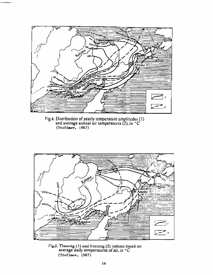
Fig.4 Distribution of yearly temperature am litudes (1) and average annual air temperatures 2), in .C (Trofimov, 1987) ?
Fig.5. Thawing (1) and freezing (2) indues based on average daily temperatures of air, in ' C (Trofimov, 1987)

(Figure 6). During the cold season, both snow and rain may occur along the southern coast of Magadan Oblast (frequent icing). Snowfall is sparse in the interior, where most precipitation is summer rain.
From the aspect of hydro-geographic origin, most (86%) of the permafrost placers in Magadan Oblast are found in a region of mountainous topography and dense network of creeks. This region can be divided into 3 climatic ma: arctic, subarctic and cold northern. The arctic zone is characterid by the most severe climate, with a cold season of 300 to 315 days. The active layer there is frozen for 10 to 105 months. In the subarctic and cold northern zones the cold season is 240 to 280 and 200 to 240 days, respectively; there the active layers remain f r o m for 8 to 9 months and 7 to 8 months respectively. As a result of a severe climate nearly the entire region is underlain by continuous permafrost. The depth of summer thawing of the active layer is from 0.6 to over 10 ft. Processing of gravels and overburden thawing with cold water can be conducted for 130 to 135 and 90 to 110 days in the sub-arctic and arctic regions respectively.
which allow calculation of the maximum economic depth. One of them is based on comparison of the limit coefficient of stripping, k,, with the stripping coefficient calculated for different contours of the open pit and for different time stages of the mining sequence. A method of comparing gross stripping coefficients with limit stripping coefficient is used when large deposits are evaluated and also in cases where the deeper parts of a deposit can be mined underground. A method of comparing some of the initial aad the largest coeffiaents of stripping with the Limit coefficient is used in the mines, which are planned for surface mining because of grades too low for underground mini*
When the above principles are used, the actual unit cost of mining at anytime during the proposed mine life does not exceed the maximum allowable value. Consequently, the specified depth of mining is conservative and extractable paygravel volume is reduced. This drawback can be eliminated by comparing the average coefficient of stripping with the limit coefficient of stripping, since the actual value of paygravel in some stages of mining will be higher than the economic value, whereas during the other stages it will be lower.
ECONOMIC DEPTH OF SURFACE MINING Limit coefficient of stripping (yd3/yd3) can be
determined based on the following formula, (Emela- Much Soviet research concerns the critical nov, Fedorov):
depth at which underground mining becomes economically advantageous to surface mining. There 4 = (c~ - CO)/C, (5-1) are obvious advantages of surface stripping over underground mining: where:
- higher extraction ratio (for underground mining in wide paystrealis, pillars usually have to be left for roof support), - possible application of high-capacity, off-highway equipment (underground diesel equipment creates ventilation problems and heat which may lead to extensive thawing during summer),
- higher productivity, - greater safety
The disadvantages of surface work include: extensive overburden removal, significant surface disturbance and the seasonal character of operations due to climatic conditions. The following discussion is based on a publication by Emelanav (1985).
k, = limit coefficient of stripping,
q = unit value of pay gravel, $/yd3,
c, = unit cost of pay gravel extraction using surface mining method without including the expenditure for stripping S/yd3,
$ = unit cost of stripping during typical operation of a mine, $/yd3.
When in addition to primary metal, a byproduct is also recovered, the limit coefficient of stripping can be calculated using the following formula:
In the design of surface mines, determination of the maximum economic depth is of much importance. There are several methods available

Fig.6. Distribution of annual percipitation (1) and its component during cold period (2), in mm. (Trofimov, 1987)

where: As can be seen from Eq. 5.1, a limit stripping
c, = unit cost of extraction of paygravel using coefficient is generally determined by q, which can be underground method, $/yd3, assumed as:
q = economic contribution of associated by- cl 5 % product with respect to the primary ore, dimensionless fraction, (when for exam- q = C/(1+ E) and ple, silver or tungsten minerals associated q = ( ~ - r * k ~ ) u , with gold, the latter being the primary ore), where:
nb = additional volume of overburden per yd3 of associated paygravel based on profitability, yd3/yd3.
When the value of surface land has to be considered in limit coefficient calculation, the formula becomes:
C/(l+E) = unit wst of extraction of paygravel taking into account efficiency of capital investment or degree of profitability, $/yd3
(C-rm kyd) @ a, = value of metal per unit volume, $/yd3
r = profitability, dimensionless fraction, where:
so = cost of land per unit volume of extracted paygravel $/yd3,
where:
Cm = cost of one acre of mining land, $,
A,,, = area of land purchased for mining, acres,
Po = mining section reserves, yd3,
' Formula 5.1 is recommended in case when the volume of paygravel to be extracted from both underground and surface mining is the same. When the volumes are not equal (e.g. pillars), it is recommended that the following formula be used:
where:
a,,a, = metal production from paygravel extracted using underground and surface mining methods, respectively, oz.tr./yd3, (5.4)
Cu,C, = unit cost of metal from paygravels extracted using underground and surface mining methods, respectively, $/oz.tr.
= the sum of capital and operating costs during the entire production cycle (extraction, concentration, recovery of metal), with respect to one oztr. of metal $/oztr.
a, = recovery of metal from one yd3 of paygravel, oz.br./yd3
Based on earlier existing regulations for the placer mining industry, the maximum allowable depth of surface mining was 16 to 20 ft, which corresponds to the minimum depth of underground mining from the aspect of safety (instability of openings due to possible development of sinkholes).
Current guidelines for surface mining of frozen placer deposits recommend a depth of up to 26 ft. For depths of 26 to 50 ft, it is recommended that an economic analysis evaluates production cost of one oz.tr. Au for surface mining (c,, $/oz.tr.) versus underground mining (c,,, $/oztr.), taking into account losses of paygravel in both methods, dilution of paygravel and recovery of metal during processing. Some authors recommend that deposits greater than 50 ft. deep be developed with underground methods.
It has been statistically documented that the overburden unit stripping a t increases approximately linearly with depth. Flgure 7 and 8 (Emelanov, 1985) provide much data on this subject. Graphs a, b, c, and d in each of the figures were constructed for different

Figure 7- Dependence on depth of strlpplng, H (in meters) on the total cast, C,, of removal of lm3 of overburden during summer time (Emelanov, 1985).
a,b,c,d - respectively for mining front width of 60, 120. 180 and 210m (approx. 197,394, 590 and 689ft). 1 - with self powered scrapers 0-567, 2 - with scrapers D-511 pulled by dozers, 3 - dozers ND-41 with a stacker CPZ-700 (BOO), 4 - dozers NO-41 in complex with dragline ESh-15/90A, 5 -dozers ND-41 in complex with shovel EKG-4,6B and truck BelAZ-540, 6 - dozers NO-41, 7 - dozer ND-41 in complex with slurry pump 16 GRUT-8, 8 - dragline ESh-15/90A, 9 - shovel EKG-4,6B in complex with trucks BelAZ-540, 10 - dragline ESh-15/90A, 11 -pulled scrapers 0-51 1, 12 - shovel EKG-4,68 in complex with trucks BelAZ-540, 1 - 9 for thawed overburden (removal in layers with solar thawing), 10 - 12 for frozen overburden being disintegrated by hydraulicing.

a b
24# 7
220 7 I
ZW 6 J
f80 t f
l6U I J
roo 4 4 1
f00
eo a 60
h +# 0
Figure 8. Dependence on depth of stripping, H (In meters) on the total cost, Cow, of removal of lm3 of overburden during winter time (Emelanov, 1985).
a,b,c,d - respectively for mining front width of 60, 120.180 and 21 Om (approx. 197,394,590 and 689ft). 1 - dragline ESh-15/90A, 2 - shovel in complex with trucks BelAf-540.3 - dragline ESh-lOnOA, 4 -dozers ND-41 in complex with dragline ESh-1 OffOA, 5 -dozers ND-41 in complex with dragline ESh-1 !?BOA, 6 -dozers NO-41,7 -dozers 0-9,8 -dozer DET-250, (the frozen overburden was fragmented by drilling and blasting or ripping).

widths of mining front (from approx 200 to 700 ft), and method of stripping and equipment used P i e 7 provides cost data for summer season work (stripping in layers as solar or hydraulic thawing occurs), whereas Figure 8 provides cost data for winter stripping (drilling and blasting or ripping).
The costs (vertical axes C,, and Cow for summer and winter stripping in relative units of currency), as a function of depth (the horizontal axis, H, from 8 to 2il meters) can be compared with cost of underground mining to determine the break-even depth below which the underground mining will be more profitable (this is to assume that the gold grade aud gold prices are high enough to warrant the underground mining). In addition the two figures provide cost comparison of the various methods of surface mining.
SURFACE MINING
As indicated earlier, about 75% of all gold produced in Magadaa province comes from surface mining, of which only 10% is produced by dredging. Dredging has never been a principle mining method in the Soviet northeast, likely due to severe climatic conditions.
Exhaustion of shallow rich placer deposits has led to a significant increase in the volume of excavated ground and consequently a demand to optimize surface mining aperatioas. Much research has been done in this area which has led to improved mining methods and efficiencies. Results of this research are usually published in the form of costs (in relative units of currency) per unit volume of excavated material as functions of controlling parameters. Obviously, the Soviet unit cost data can not be directly compared with the American counterpart as they are based on low labor productivities, low fuel and labor costs and the artificial prices of equipment in the subsidized Soviet economy.
However, it is interesting to look at the range of values the Soviets researchers have been using for various parameters to mathematically model mining operations. These ranges give indications of typical Soviet deposits and equipment capabilities, and indicate trends in mining met hod developments. Emelanov (1985) lists the following parameters:
- average width of paystreaks, ft 66660
- t h i h of pay gravels, ft 1.610
- thickness of overburden, ft 6.6-66
- strength category of formations*, dimensionless 1-10
- maximum slope angle of haulage routes, deg 12 (9)
- angle of repose for stripped over- burden rnatedal, deg 3045
- maximum pit slope, deg 20-55
- slope angle for wheel scrapers, deg 620
- content per cubic yard of precious mineral g/yd3, 20.1
- flywheel power of bulldozers, h 100-5U)**
- capacity of dragline buckets, yd3 13-20
- capacity of front end loader buckets yd3 1.3-105**
- capacity of scrapers, yd3 7.84
- capacity of off-highway trucks, yd3 5.2-20
- p r m y p l a n t throughput m3/hr,(yd /hr) (loose VOIU~T~ 35-115 (46-150)
- throughput (of the solid) af processing lant with f: hydrolift, m /hr @d3/hr) 130-330 (170-430)
- number of sections of belt conveyor stackers in a series 1-8
- base plate height of a stacker, ft 1.1-13.2
- horizontal angle of tailings piles when using dozers, deg 30-180
- distance one way for haulage with tnrh, ft 660-1,300
- distance between pit ramps (feed hoppers) ft 66-1,600
* M e t strength classification developed by PIDtodyakonw, the strength category b obtained by dividing the compmaivc strength (in MPa) by 10. ** larger units are a h ustd, see Table 3.

TABLE 3 EXAMPLES OF SOVIET MINING EQUIPMENT
TECHNICAL DATA
1. DRAGLJNES AND SHOVEL
2. SCRAPERS AND HAULTRUCK
Parameter I ESh-10170 I
Bucket size, yd3 I
13 I Digging depth, yd ! 38
Digging radius, yd 73
Digging height, yd I
I Dump radius, yd I 73 I Dump height, yd I
I 30
ESh-15/90A
20
46.5
89
91
46
1.18
0.1
1760
Swing speed, rpm
Forward speed, rnph
Weight, st
.. Parameter
Rated load, st
Volume capacity, d3
In pit velocity, mph
Hwy velacity, mph
Flywheel power, hp
Depth of cut, in.
Width of cut, in.
I Min. turning radius, ft
I Dimensions, ft I -length
-width
-height
EKE-4,6
6
- 16
11
14
7
3-3.5
0.7
209
1.32
0.3
7 15 L
BelAZ-540 - 29.7
16.8
4-5
38
360 & 375
- -
27.9
23.8
11.4
11.1
D-5 1 1
33
19.8
1.25-4
up to 12
300
14
112
37.2
11.4
10.5
D-567
19.8
13.2
1.25-4
up to 32
300
17
123
26
36.0
10.6
10.9

Tab. 3. (cont'd)
3. SLURRY PUMPS -- --
Weight, st
-with tractor
-without tractor
Tire size, in.
Power transmission &
4. BULLDOZERS
45.4
18.1
21-28
Paramater
Power of motor, kW
Flow rate, gpm
Discharge head, ft of water
R P ~
Suction head, ft of water
Diameter of impeller, in
25.7
- 26.5-27
hyciro- mechanic
16GRUL-8u
500
6,350- 10,300
208- 177
585
U.6
40.5
I Flywheel power, hp
Length of blade, ft
Height of blade, ft
, Dozer (with blade) : deminsions, ft j I length I I width
i Number of rippers
b
23.1
18-25
hydro- mechanic
- 16GRUT-8
630
7,900-1 1,100
202-185
585
23.6
40.5 -
Bulldozer type
41NTz D-385 41N
Track-type tractor
DET-250
300
14.9
4.6
22
14.9
1
41-B
524
17.0
7.1
41-B
524
20.0
7.2
I 36.4
20
3
36.4
20
3

Tab. 3. (cont'd)
Velocity, mph 1st gear
2nd gear
3rd gear
Weight, st .
1.43
7.46
30
2.61
4.47
6.53
71.5
2.61
4.47
6.53
71.5
*

The analysis of various alternatives has led to optimum system design for both summer and winter weather conditions. For example, Figures 9 and 10 (Emelanov, 1985) provide guidelines for selecting the width of a block of placer ground to be mined during summer and winter seasons, respectively. Some of the curves have minimum cost values, for stripping per 1 m3 of pay gravel, which directly indicate the optimum width of a block.
Ground Preparation
The most effective methods of frozen ground preparation for stripping (Emelanov, 1985) utilize thawholw sprinlding systems and &ation-drainage. These are widely used in placer mines where the permeability of overburden containing coarse fractions is high. After thawing and draining the overburden, the ground freezes very quickly with the arrival of the cold season. Its new strength depends on residual moisture content. At water (ice) content above 5% the strength increases significantly. The residual moisture content in free drained placer materials depends on their grain size distribution; for h e sands it is 4 to 5%, coarse sand about 2%, and gravels and cobbles with sandy matrix below 1%.
Thawholes (1.8 in. diameter) for cold water thawing with points (called "hydroneedles" by the Soviets) are drilled with vibratory drills, SDVV-I1 or SVV-IV. The SDW-I1 can drill 6MJ to 1,320 ft of hole per day. A portion of the hole drilled through the active layer is cased, usually with a polyethylene pipe or protected some other way (see Figure 11). The holes are drilled on an equilateral triangle pattern with spacing dependent on ice content and depth, typically 18 ft apart. Thawing is complete within 2 to 3 months. Water is provided by high volume pumping units such as the OVG-II-3fl50, which has a capability of thawing 520,000 yd3 of ground per season by supplying water to 1000-1500 hydroneedles. This unit is equipped with 3 pumps, each delivering 1260 m3/hr (5,600 gpm) and capable of generating 120 ft of total head.
Most Soviet placers have overburden with relatively high permeability, typically 490 to 2,000 ft/day on a thawed basis, and an ice content of 150 to 250 kg/m3 (250 to 420 lb of ice per yd3). As long as permeability is above 260 ft/day, which corresponds to less than 5% clay/silt size content and less than 30% of minus 2 mm size material; the overburden can be thawed and drained, with residual moisture content low enough to prevent a buildup of strength when
frozen.
In the filtration - drainage method, to thaw and drain the overburden, holes are drilled 50 to 66 ft apart along lines spaced up to 1,000 ft. Warm water is is provided (naturally heated in shallow ponds) and cold water is collected in a trench along the foot of the highwall and pumped back to the shallow pond. For draining overbutden where no highwall is available, some of the holes are used for return water, which is pumped to the shallow reservoir. The cost of thawing and drainage is estimated at 0.03 to 0 3 rubles/m3(late 70, early '80 data), The water table has to be lowered 0.6 to 3.2 ft below the pit floor to prevent an increase of moisture content due to capillary forces, Again, the drained ground will freeze very quickly with the arrival of the cold season. However, due to its very low moisture content it has very little strength and can be readily ripped.
Where the overburden's permeability is below 260 ft/day, a method of thawing and draining by prefracturing with explosive charges is used. A schematic drawing depicting this method is shown in Figure 12 (VNTI-1, 1983). The ditches are excavated ahead of blasting. Blasting each production block is conducted in two stages. First, cut holes ate initiated then the "production" holes. During the following 10 to 15 days after blasting, water is allowed to percolate under gravity from a ditch through the fractured block thawing the ground This method allows handling (2.6 to 3.3) lo6 yd3 of overburden per season. The powder factor is 0.3 to 0.5 kg/m3 (0.5 to 0.85 lb/yd3) and the effective depth of stripping is 33 to 100 ft. The water use is 9 to 10 yd3/yd3 and the cost of ground preparation is estimated at 0.2 ruble/m3(late '80 data).
Surface Mining Methads
The basic tecb.uid factors, which control the selection of mobile technology for stripping and transportation of pay gravels are transport distance, required throughput of the system and moisture content of the ground. For scrapers, the grain size distribution also plays a significant role (size of individual pains should not exceed 16 in. for a 20 yd3 hopper and 32 in. for 33 to 52 yd3 hoppers).
The optimum distance of transportation depends on the load capacity, type of undercarriage and resistance to movement. For dozers of 100 to 175 hp and above 175 hp, the distance approaches 260 to 330 ft and 330 to 500 ft, respectively. For scrapers and

Fik. 9. Chary indicating the relationship between the cost of sui ping during the summertune per lrn of pa gravel vs. the width of rninin block; a, b, c, 8- for overburden thickness of 8, 12, 16, and I Om, respectively; 1 - 12 as in f ig. 7. (Emelanov, 1985)
27

Fig. 10. Ch rts indicatin the relationship between the cost of stripping durin the
P 9 f thickness o 8, 12, 16 and 20m, respectively; 1 - 8 as in f ig. 8. (Emelanov, 1985)
d wintertime er lm of paygrave vs. the width of minin block; a, b, c, d - for overbur en

Fig. 11. Methods of protection of thawholes; 1 -drillhole, 2 -polyethylene "hydroneedle", 3 -casing, 4 -plug of frozen soil. 5 -tube connecting with atmos here, 6 -lower boundary of active layer, 7 -supporting disk, 8 -direction of water flow (VNI !I -1, 1985).
Fig. 12. Blasting - filtration method of thawing of frozen ground, 1 -warm water ditch, 2 -draining ditch, 3 -blastholes of the cut, 4 -production blastholes, 5 -block of ground being dnlled, 6 -block of ground being thawed, 7 -block of ground ready for strip- ping (VNU-1, 1983).
29

dump trucks, the distance is 650 and 1,700 ft, respectively. It should be noted here, that the haulage with trucks we observed in the Upper Kolyma pits was over distances much longer than the recommended 1,700 ft.
The moisture content of the stripped soil has a significant effect on transport efficiency. Equipment works most efficiently at a moisture content of 8 to 14%. Clay/silt so& at about 25% moisture content begin to adhere to the moving components of the equipment.
In soils with a bearing capacity of 6 to 15 psi, track dozers are recommended: above 15 psi rubber tire equipment is suitable. For a bearing capacity below 6 psi, mobile equipment is difficult to use and excessive wear results. Thawed clays and silts must be drained before strippitlg can proce.de.
Various schemes of mobile equipment for stripping and pay gravel mining are shown in Figure 13. For example, an analysis of experience with mobile equipment indicates that stripping thawed ground with dozers up to 350 hp can be done for an overburden thickness of up to 16 ft, a pit width up to 200 ft, solar thawing, and a dozer push distance up to 250 to 330 ft. Dozers 350 to 500 hp and 500 to 800 hp can be used for overburdens up to 33ft thick, the width of the pit 260 to 300 ft, a pushing distance of 330 to 500 ft for summer work (solar energy thawing in layers) and winter stripping (ripping), respectively. Schemes of stripping with the application of 350 to 800 hp dozers, mobile hoppers and trucks (BelAZ 540) are recommended for an overburden thickness up to 50 ft when gravel - pebble overburden is thawed using solar energy and up to 100 ft with conventional hydraulicking. In this case, the transportation distance should not exceed 160 and 3300 ft for dozers and trucks, respectively.
Schemes of stripping with scrapers having a capacity of 20 to 52 yd3 and dozers (D9N class) as pushers are used for overburden up to 50 ft thick (summer thawing and spring/fall ripping) and up to 100 ft when hydraulicking is used. The equipment here consists of three scrapers and one dozer. For scrapers up to 20 yd3 capacity, a DET-250 dozer (see Table 3) can be used as a pusher.
For transport distances up to 650 ft, loaders with a bucket size of 4 to 20 yd3 should be used in a combination with D9N dozers for stripping overburden up to 50 ft thick. For overburden up to
100 ft thick, haul trucks should be used.
For stripping with an excavating and loading unit (see Frgure 13 and Section 9, -nous mining e, the overburden thickness should be below 100 ft. In this scenario the transport system can consist of slurry pipe, belt conveyor, truck or a combination of these. For slurry pipe it is recommended to use sluny pumps UGO-40, UGO-70 and UGO-100 with flow rates of 160, 290, and 420 yd3/hr, respectively.
For conveyor transportation, 40 in. belt conveyor KLSH-500 with a capacity of 240 yd3/hr and stacker OZP-1,000 should be used. Where truck haulage is used the ratio of bucket volume of loader to truck volume should be 1/(2-4).
Farrow transverse p it with intern-
As efficiency of internal (in-pit) dumping of stripped material increases as the overburden becomes thicker, a new mining system called here, "the narrow cross pit with internal dumping, utilidng high power, mobile equipment can be recommended. This method can employ cold water thawing or drilling and blasting for ground disintegration. The design width of the iaitial pit (Figure 14) depends on the thickness of overburden and pay gravel, type of bulldozer and width of subsequent pits. Overburden material from the initial pit has to be piled outside of the pit. After processing the pay gravel, the overburden from subsequent pits can be moved into the excavated space of the previous pit. This method allows signif~cant extension of the mining season, in some situations to a full year, if pay gravel is stock- piled for summer processing. Dozers used for overburden stripping and pay gravel mining should be selected based on the stripping ratio (thickness of overburden to paygravel) for optimum economics. This method allows lowering unit mining costs by 20- 30% and increases volumes of ground mined by 1.5 to 2 times as compared to a mining method, which employs dumpiag overburden out of the pit.
The stripping of overburden using drrlling and blasting with removal of overburden material in the frozen state has recently become more popular. The Soviet laws do not differentiate between explosives proper and blasting agents, which adds additional difficulties to the already complicated problem of explosives transport from chemical plants located far

Fig. 13. Mechanization of surface placer mining using mobile equipment, a through u -various schemes of mining; 1 -dozer-ripper; 2 -scraper; 3 -front end loader; 4 -excavating and loading unit, 5 -loading hopper; 6 -haul truck; 7 -stationary belt conveyor; 8 -pit con- veyor; 9 -slurry ipe; 10 -sluice; 11 -sluice with trornrnel; 12 -conveyor - stacker system, E distance in m; ( melanov, 1985).


west. Explosive manufacturing is still controlled by the military. Ammonium nitrate (AN) is produced as solid prills (fertilizer grade), which requires an additional booster for adequate initiation. It is interesting to note that one explosive promoted for winter use (Emelanov, 1985) is a mixture of fertilizer grade AN with ground (in a frozen state) heavy carbohydrates. The two components are mixed before being charged into blastholes and detonated after the fuel component thaws in the ground. To improve water resistance, the Soviets mix AN with TNT. Emulsions are just now being introduced to the Soviet industry.
Attempts have been made to combine blasting with the injection of warm water into frozen ground. The injections are made through additional holes or even through vertical shafts excavated using conventional sinking methods. Detonation of explosives in water saturated ground produces hydrofractuxing, improved fragmentation and faster thawing afterwards.
Electric drilling rigs (rotary tricone) such as SBSH-250 are used for drilling 10 in diameter holes up to 50 ft in length. A local explosive plant prepares AN based explosives (such as Igdanit, Igdanit A-6 or Granulit ACD), which are loaded on explosive trucks for delivery to the blast sites and charging blastholes. The explosive plants have been found reliable under the climatic conditions prevailing in the Soviet northeast, where temperatures range from 86 to -60 " F.
rubles/hectare (Iha = 2.47 acres). Some cost savings are realized by using a "fragmentary reclamation' approach, particularly suited for forestry. With this method some tailings mounds and small ponds are left. The exposed water enhances natural forest growth and reindeer range. Other intervening areas are leveled: some, where convenient, are sloped.
Mining is now affected by several operational regulations. Use of mercury for gold recovery is prohibited. Furthermore, mine water discharge is to meet a maximum settleable solids content of 0.25 mg/l above background as measured SO0 m downstream and 1,000 m upstream. Measurements are taken every 10 days during the washing season. Operations observed in the Upper Kolyma recycled al l discharge waters from downstream settling ponds.
Past and present placer mining in Magadan province have disturbed 470 mi2 and 310 mi2 in Yakutya. Annually 12 to 20 mi2 are added to this total in Magadan province. Present reclamation efforts are treating about 5 mi2 per year there. An example of reclamation was demonstrated near Orotukum, where several hundred hectares were reclaimed in 1986 for grain production. At this site tailing gravels were leveled and the fines from the settling ponds then slurry pumped over the coarse gravel. Fertilizer, consisting of 80 lb KNO3, 140 lb NaOH, and 110 lb P205 per acre, was added and the area seeded in grain.
UNDERGROUND MINING Environmental and Reclamation Practices
Environmental concerns have only recently surfaced in the USSR. In 1988 the Soviets established the Government Committee for Protection of Nature, a fledlging equivalent to the American EPA. Field offices in Susuman, Pevek, and Anadyr now have some degree of authority over placer mining. At a minimum, plans for reclamation are now required for new operations. Unlike the Alaskan reclamation practice of restoration of native species, Soviet efforts are primarily devoted to the improvement of mine lands for some practical use. Soviet planners place high value on enhanced land uses made possible with thawed ground, e.g. agriculture, habitation, or forestry.
Underground mining is widely used in deep, Soviet placer deposits located in permafrost. Many mines, in particular those located in the subarctic regions, are worked year round. Several mining systems have been developed for those conditions, of which high productivity longwall mining and its modifications are the newest approaches. Ground breaking, ventilation, dust control and stability of openings are specific problems in the frozen environment. Most mines are accessed with inclined ramps, use drilling and blasting for ground disintegration, scrapers for face transport, and belt conveyors and skips for the main haulage and hoisting. The underground mine technology is well developed and successfully competes with surface mining.
Research is continuing to develop novel uses for reclaimed land at minimal cost. At present, reclamation costs are placed at 8,000 to 10,000

Stability and Support of Underground Openings in Frozen Ground
The various classes of ground stability discussed earlier (Section 4.1), have been correlated with the strength of frozen materials, class I (highly stable) has long term compressive strength of 18-25 MPa (2,600-3,600 psi), class 11 has 15-20 MPa (2,200- 2,900 psi), Class I11 has 12-16 MPa (1,750-2,300 psi), Class IV has 9-13 MPa (1,300-1,900 psi) and class V (unstable), 5-10 MPa (725-1,450 psi). Data obtained by the Soviet researchers (Emelanov et al. 1982) indicate that long-term strength of frozen materials in compression is 2 to 2.5 times less than instant strength, and 12-15 times less than tensile instantaneous strength.
To evaluate the stability of openings at a given depth, in addition to data on the compressive ground strength, information on stress levels is needed. Obviously t b is a function of depth. Table 4 shows data on the stability of openings versus depth and the corresponding stress level (column 2). An instability probability of 20% and above indicates possible roof falls. For these conditions, extensive support would be required. Based on Soviet experience, local instabilities (small falls of individual thin roof layers, occasional dislodging and fall of a boulder, and warping of layered roof) can occur in any class of stability, though in classes I and I1 separation of roof strata no more than 1.0 to 2.0 ft thick is typical (rarely up to 3 ft). In the higher, more stable classes, thickness of unstable layers may be as much as 10 ft.
The selection of a mining system (designs of development and extraction openings) is based on the deposit size, class of ground stability and equipment used. For high grade deposits, systems providing high extraction ratios are selected. This could be longwall mining or a type of room and pillar system, with subsequent extraction of pillars (by construction of 6 c i a l pillars). The selection of appropriately sized rooms and pillars has to take into account the depth and class of material (Table 4) and the thickness of the paygravel.
The Soviets (Emelanov et al., 1982) developed guidelines which allow the selection of appropriate sizes of openings (Table 5) and pillars (Table 6). For example, rooms up to 130 ft wide can be extracted in 6 ft thick paygravel where ground stability is class I, provided that pillar width be at least 11.8 ft (Table 5 and 6). This opening could be used at a depth up to 320 ft (Table 4). The design
data for a specific deposit can be obtained from Tables 4 to 6 by using interpolation.
The strength of all frozen granular materials is highly dependent on the time of loading (how long a load is applied), strength decreasing with time, as indicated at the beginning of this section. Consequently, it is recommended that the rate of extraction should be high enough to assure movement of the work faces (longwall) by at least 80-100 ft/month. This will avoid excessive deterioration of the pillars around active open@.
Ground support may be required locally. As in the case of hardrock mines, the purpose of any support is to protect miners from possible roof falls due to locally weak ground. Because the use of rock bolts in the frozen granular materials is questionable, the most popular support systems are single timber props, timber sets and steel sets (arches). Longwall hydraulically operated supports have recently been introduced in Chukotka.
Access to an Underground Mine
Studies conducted by the Soviets indicate that the development of a deep placer deposit using a decline is advantageous over a shaft. This conclusion is supported by both economic and safety considerations. Although neither Soviet economics nor their safety regulations can be directly transferred to this country, the relative shallow depth of placers ( ~ 4 0 0 ft) together with low production rates, minimum crew size, short-term mine lie, and cold climate seem to favor declines.
A typical &dine for skip haulage, with portal aad transfer point protected by timber support, and a typical cross section are shown in Figure 15 (Emelanov et al., 1982). In compliance with Soviet mining laws, the decline has a separate man-way compartment (see cross section I-I). In preparation for construction of a decline, a dipping trench is excavated first on the surface (Figure 16a), followed by driving the decline and installation of support. The space in the trench above the decline's roof is filled with loose material (gravel or insulation) and a well- insulated portal shed is constructed (Figure 15a). Blast-hole c o ~ a t i o n s for various stages of decline construction are shown in Figure 16, (Emelanov et al, 1982).
For haulage, the Soviets recommend either a belt conveyor, low profile truck with emissions

STABILITY OF OPENINGS IN FROZEN GROUND, (Emelanov et al, 1982)
TABLE 5
SPAN OF STABLE EXTRACTION OPENINGS (Emelmov et al, 1982)
- - . - - - -- Depth of opening, f t
66 100 265 330 490
Note; Data on resistance of ground to compression is given in parentheses
- Stress, MPa (psi)
83 125 207 415 625
-,-.---
Max. span of extraction openings, ft
Room and Pillar Longwall Stratified (intact roof) (cavmg roof)
Monolitic Stratified Monolitic Stratified
I11 IV V
P-
.-- Probability (%) of instability of openings depending on class of ground (strength, psi)
33-43 23-36 13-26
V(143)
1.6 24.5 100 100 100
I(357)
0.01 0.03 1.6 20 100
23-29 13-20 7- 13
IV(185)
0.3 4.5 100 100 100
II(285)
0.03 0.2 7.6 70 100
66-82 33-49 20-33
III(230)
0.2 1.1 29.8 100 100
49-66 26-39 16-26
62-79 26-39 16-23
43-56 23-36 13-20

TABLE 6
RECOMMENDED PILLAR SIZE, (Emelanov et al, 1982)
Width of stable pillars, ft. for given width of rooms, ft
130 I 100 66 33 I 16.5
- 'Thickness of extracted paygravel ft
Class of Stabiliry
I
Tr
III
4.5
9.8
I:"
6
11.8
11..
8 -- 14.4
10 , ..-- 17.1
6.6
7.2
8.2
4.5
7.5
8.2
11.8
I
9.5 7.9
8.5
13.4
6
8.9
9.5
9.8
10.5
8 .-. 10.5
11.8
11.5
12.5
10
12.8
13.4
5.9
4.5
6.6
7.2
4.5 6 8 I0 4.5 6 8 10 6
7.9
9.5 11.5
7.2
7.5
8
9.5
10.2
10.8
8.5
8.6
10
11.1
11.5
12.5

Fig. 15. Skip decline in timber support; a -portal with elevated skip loading point; 1-1 cross section through decline; all dimensions in 1982)

Fig. 16. B la t design for a decline; a -first lift for a dippin trench; b -wide cross section; c -narrow cross section, (underground opening and loa m g point); all dimensions in m, (Emelanov et al, 1982)
ti.

scrubber, skip or scrapper. Typical cross sections of a decline for each conveyance are shown in Figure 17. All of them include a separate man-way. The slope of decline is predicated on the haulage method; maximum recommended slope is 16" for belt conveyors, 27 " for skips, 22' for scrappers and 8 " (14%) for trucks.
The location of an access decline with respect to the &posit is an important amsideration. Placing a decline outside of the paystreak (Figure 18a, d) increases haulage distance but allows complete extraction of the deposit. A protective pillar under a decline, placed within the deposit (l3lgure 18b, c), will exclude a significant volume of paygravel from mining.
Development and Mining Systems of an Underground Mime
The geometry (length, width and thickness of the mining section), grade and depth of a deposit will dictate the most economic placement of access and ventilation openings, design of underground openings, sequence of extraction, selection of mining method, (equipment) and production costs. An economic analysis will determine whether the mine plan at current metal prices will produce an acceptable rate of return.
Typical simplified layouts of underground mining systems are shown in Figure 18. For a specific example the width and length of a paystreak unit developed with a single decline can be determined using economic modeling. Several other factors, in addition to the ones mentioned above, will have to be taken into account (mine lifespan vs. daily output, exclusive winter operations vs. temperature control during warm weather, etc.). These are extremely important considerations that the Soviets have analyzed with respect to their economic, regulatory and dimatic c~nditions. To illustrate the point, F i e 19 shows some of the results of the economic analyses. The curves designated by numbers (costs of extraction of lm3 of paygravel in assumed units of currency for a given layout, selected technology and several other factors) show relationships between the width and length of the proposed mine. Curves with the lowest numbers indicate the optimum relationship. The graphs indicate a significant difference (at least 10 to 15%) in unit costs, stressing the importance of ewnomiC analysis.
The optimum size of a mine is dependent on many factors. For example, the ventilation scheme
has to be included. Spacing of ventilation boreholes (shafts) is dependent on the selected mining system (e.g. longwall vs. r a m and pillar) and the direction of face movement (perpendicular or parallel to the deposit main axes), etc.
M a y mining systems for frozen placers have been proposed, Some of them are shown in Figures Ul through 23 (Emelanov et d., 1982). They have been &velopd for a low level of mdaukation (hand held drills, scrappers). Increasingly popular longwall mining systems have been adopted during the last 10 years. Figure 24 shows a cross section through a mechanized longwall. Barrier frames with wire or plastic screens are used to prevent spreading the blasted r& The support system Sputnik, consisting of high bearing capacity individual props, is used to induce roof fall behind the advancing face. The gathering arm loader dumps broken gravel on an armored chain conveyor. The chain conveyor, support . and barrier are advanced using hydraulic jacks. The blast pattern design for the longwall is shown in Figure 25 for various thicknesses of a mining section. In most cases 43 mm (1.7 in) diameter blastholes are drilled for packaged ammonia dynamites (Ammonit 6ZhV) having diameters of 32 mm or 36 mm (1.26 and 1.42 in.), and water resistant ahminized dynamite (Ammonal) with a diameter of 32 and 36 mm.
Figure 26 shows a cross section through a longwall face employing equipment adapted from coal mining. The equipment has been modified to account for the difference in the geotechnical properties between coal and frozen ground. Reduced cutting tool velocities, more power and greater resistance to abrasion are needed for frozen ground. The shearers do not handle large boulders very well, however, the problem has recently been solved (see Sec. 9. Recent Developments). The lifetime of this equipment used in frozen materials is considerably shorter than in coal. For example, the heavy duty chain conveyor, SR-704 capable of transporting 2,000 yd3/day of c o d lasts about 5 years in a coal mine. It lasts only 05 to 3 years in a placer mine. Figure 27 shows a layout for twin longwalls each employing a shearer. Minimum development, simplified layout and high productivity and extraction ratios are the advantages of the system.
Ventilation and Heat Control
The underground environment in a frozen placer mine is very sensitive to temperature. In winter, excessive outside air can be too cold for mining crews aud equipment, and in summer, too hot

Fig. 17. Cross sections of declines for the following conveyances; a -skip; b -belt conveyor; c -scraper; d -low profile truck; all dimensions in mm, (Emelanov et ai, 1982)
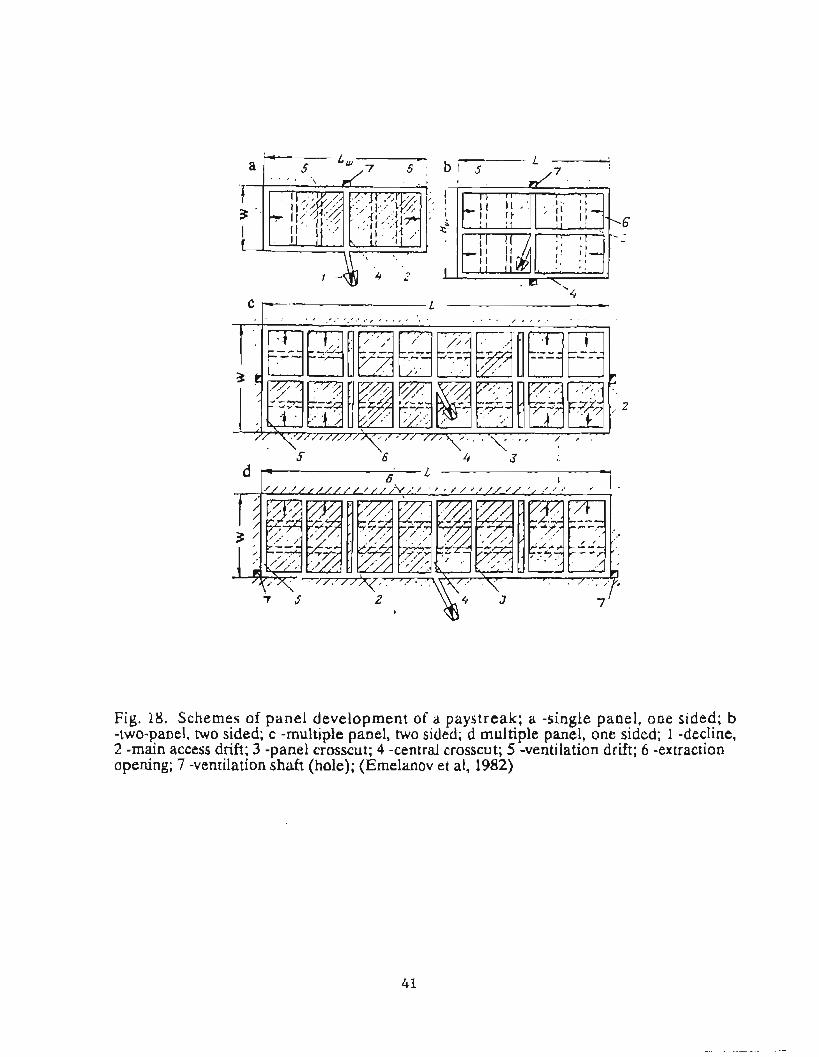
Fig. 18. Schemes of panel development of a paystreak; a -single panel, one sided; b -two-panel, two sided; c -multiple panel, two sided; d multiple panel, one sided; 1 -decline, 2 -main access drift; 3 -panel crosscut; 4 -central crosscut; 5 -ventilation drift; 6 -extraction opening; 7 -ventilation shaft (hole); (Emeianov et al, 1982)

Fig. 19. Dependence of width of mine (W) on its length (L) for different costs of extrac- 3 tion of lrn of pay gravel (in assumed units of currency); a -single panel, one sided; b -two
panel, two sided; c -multiple panel, one sided; d -multiple panel, two sided; (Emelanov et al, 1982)
Fig. 20. Room and pillar system with continuous lowering of roof or with the use of props, for wide paystreah, (Emelanov et al, 1982)
42

Fig. 21. Chamber - longwall system with inter-panel pillars left on the side of gob (a) and on the side of panel being mined next (b), (Emelanov ct al, 1982)
Fig. 22. Mixed system for narrow paystreaks, (a) with haulageway along the side of the paystreak, (b) with haulageway along the axis of paystreak, (Emelanov et al, 1982)
Fig. 23. Chamber system (a) single sided, (b) double sided (Emelanov et d, 1982)
43
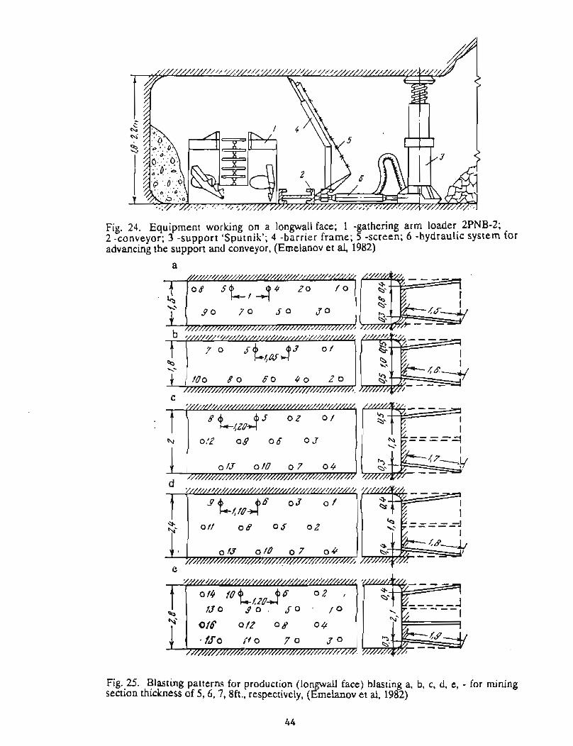
Fig. 24. Equipment working on a longwall face; 1 -gathering arm loader 2PNB-2; 2 -conveyor; 3 -support 'Sputnik'; 4 -barrier frame; 5 -screen; 6 -hydraulic system for advancing the support and conveyor, (Emelanov et al, 1982)
Fig. 25. Blasting patterns for production (longwall face) blasting a, b, c, d, e, - for mining section thickness of 5,6, 7,8ft., respectively, (Ernelanov et al, 1982)

Fig. 26. Longwall face with a shearer; 1 -shearer; 2 -chain conveyor; 3 -support 'Sputnik'; 4 -frame; 5 -screen; 6 -hydraulic jack; dimensions in m, (Emelanov et al, 1982)
Fig. 27. Develo ment of a mine for a longwall system; 1 -belt conveyor KLSh-500; 2 chain conveyor SR-7 (Y A; 3 -shearer 2K-52; 4 -chain conveyor SP-63M; 5 -support 'Sputnik'; dimensions in m, (Emelanov et al, 1982)

for ground stability. In addition, because of ice sublimation and the movement of equipment, dust control becomes a serious problem. These factors, in addition to crew size, weight of explosives blasted (dilution of fumes) and power of operating diesel equipment (dilution of exhaust), need to be accounted for when designing a ventilation system. A typical scheme of a ventilation system in a Soviet placer mine is shown in Figure 28.
The ventilation system in F q p e 28a consists of auxiliary fans located at exhaust holes connecting the mine with the surface. The fresh air enters the mine through the decline and then is distributed through the mine according to the pressure differential generated by local fans and resistances of the ventilation openings. In Figure 28b, a central exhaust fan is used and distribution of air in the underground space is controlled by stoppings and check curtains. In this scheme, the fresh air path crosses with the exhaust air path and overcasts have to be constructed to avoid mixing the two air streams.
Control of dust may occasionally be a difficult problem. One possible solution is shown in *re 29. A portion of the dusty underground air is cleaned and returned to the underground openings. This keeps to a minimum the amount of fresh air brought from outside, thus helping to maintain the heat balance.
To extend the operating season for an underground mine during warmer months, warm air from outside needs to be cooled prior to entry into the mine. This can be done by moving the fresh air through the old workings of the mine or by excavating two parallel downcast openings in ice-rich overburden, as shown in F"lgure 30. The air flow is switched from the first opening to the second, when significant accumulation of water takes place in the first. This allows refreezing of water accumulated in the first downcast while the second is in use.
PROCESSING
The problem of achieving maximum heavy mineral recovery from placer deposits has received much attention in the Soviet Union. Many ideas have been offered, some of them tested in the field. However, as in many other techno1ogical areas, there seems to be a significant disparity between the published design concepts and the equipment the industry is using.
It is weU recognkd that economics of placer mining is highly &pendent on efficient technology for processing gravels. Not only is the recovery of valuable minerals important, but also water use, energy coasumption, labor intensity, process plant mobiity, environmental impact and plant capital costs must be conside,red.
Technological schemes of the Soviet placer gold and tin processing plants are shown in Figure 31 (Bogdanov, 1978). Feed material is usually sorted into 3 sizes; coarse, dl = 50 to 150 mm; medium, d2 = 25 to 40 mm; and fine, d3 = 18 to 20 mm and finer. Sluices for sorted material are called deep-filled for coarse material, medium-filled for medium material and low-6lled for fine material.
Scheme I was commonly used in the early Far Northeast trommel and sluice washing plants, MPD-1, GSP-14 and MPD-2. In recent years this scheme is employed by some scrubber washing plants, the movable washing p h t MPDdM used by arteli and on most dredges. Also, this design is used in tin wasbiug plants. Scheme I does not assure high recovery of useful minerals. For example, in medium and low filled sluices, the coefficient of equal velocity (ratio of maximum normal size of material entering sluice to minimum normal size of gold caught in the sluice) is 80 to 100. In deep fdled sluices the ratio is 2 9 to 300 due to much higher solids loading. Consequently, 0.35 mm and smaller gold may be washed through the sluice. Attempts to replace fine sorting with medium sorting in this scheme minimize the loss of fine gold but increase loss of coarse gold and nuggets. For a long time it was believed that Scheme I assured a high degree of recovery of frne gold. However, based on extensive recent studies, it was proven that gold with attached quartz, nuggets and coarse gold can escape recovery. Very high losses of cassiterite nuggets in plants employing scheme I occurred in tin placers of Yakutya.
To eliminate drawbacks of scheme I, Bogdanov proposed scheme 11, which is used in washing plants MPD-5, MPD-4M, PKS-1-700 and PKS-1-1200. This scheme is intended for processing material in which nuggets, flakes and fme gold are present and have high coefficients of equal velocity and equal fallout. In this scheme fine sorting with screens having size d3 is used to improve fine and flaky gold recovery. The value of d3 should be the smdest possible; for example, for trommel sorting it usually is 12<d3 <I6 mm. This diameter also minimizes water and energy use. The presence of

Fig. 28. Scheme of mine ventilation; a -local, with individual fans providing ventilation of longwall faces; b -central, with main fan; 1 -curtain, 2 -st0 ing, 3 -overcast, 4 -main haul- age drift, 5 -main ventilation drift, 6 -fan (Emclanov ct al, &2)
Fig. 29. Mixed method of ventilation; 1 -stream of fresh air, 2 -exhaust air; 3 -air cleaned from dust, 4 -main fan, 5 -ventilation hole, 6 -fans of dust removal units, 7 -cloth filter, 8 -ventilation curtains, 4, -decline, 10 -main transport drift, 1 1 -crosscut, 12 -ventilation crosscut, (Emelanov et al, 1982)
47

Fig. 30. Heat control by two parallel heat absorbing openings; 1 -inclined part of the downcast openings, 2 -ventilation stoppings, 3 -horizontal part of heat control openings, 4 -lower part of the downcast opening, 5 -existing opening of the mine, (Emelanov et al, 1982)

Fig. 31. Technological schemes of (a) mechanical and (b) hydraulic feeder washing plants for placer gold and tin employing:
I -medium sorting of single fraction; I1 -sorting of two fractions with a sharp differ- ence in the size of produced classes; 111 -main sluice and single fraction fine sorting; IV -single fraction coarse sorting and OMT (see below); V -single fraction coarse sorting and deep sluice; VI -two fraction sorting and main sluice; VII -two fraction sorting and OMT; 1 -breaking up and medium sorting in a scrubber-trommel, 2 -breaking up, coarse and medium sorting in a scrubber, 3 -processing in main steep sluice, 4 -bre&ng u and coarse sorting in a scrubber-trommel, 5 -coarse sorting and partial breaking up at ? eed paint of hydrotransport, 6 - recessing in medium sluice or tertiary and secondary jigs, 7 -enrich- S ment in OMT or eep (nugget) sluice, 8 -processing in fine sluice or In tertiary jig, 9 -breaking up and fine sorting in scrubber-trornmel, 10 -processing in OMT, 11 -processing in deep sluice, 12 -processing in main deep sluice, 13 -fine break up in tromrnel, 14 -concentrate for final recover, 15 -water free pebbles to tailin piles, 16 - water containing fines to tailings, 17 -water-free cbbles and fines to tailings, I f -water containing finer and pebbles into tailings, 19 -cobb es to tailings, dl < 50 to 150mm, d2 5 25 to 40mm, d3 5 18 to 20mm, (Bogdanov, 1978)
P

coarse gold grains (e.g. 1-2 g) necessitates that the oversize be treated on screen dl. For dl the coefficients of equal velocity may be significantly larger than d3. Therefore, the main feature of Scheme Il is the differences in sizes of the minus dl and the plus d3. Optimum diameter dl should be determined for each deposit, taking into account grain size distribution of the product and economics of the process plant (value of recovered dl metal vs. additional costs of the processing plant at this size range).
Parallel to scheme It, scheme 111 is also used for recovery of placer gold. Its basic concept includes a short main sluice (nugget race) for recovery of all metal coarser than the size of trommel openings. It is used in MPD-4 washing plants. The deep sluice has to be indined at 13 to 15 ' to achieve flow of the coarse ftaction. The attendant high water velocity leads to coarse metal losses, some 2.5 to 3 times higher than for scheme 11. With respect to metal losses, scheme I occupies an intermediate rank
Scheme IV is experimental. The feeder is mechanical, and after coarse sorting the material is processed in OMT (see below).
Schemes V, VI, and VII employ hydraulic feeders. Initially, coarse screening is done; however, before feeding into a slurry pump or hydrolift, the paygravel has to be sorted. Two fractions with a wide difference in the size are sorted at this stage. Due to a larger water use, the deep sluice does not have to be excessively tilted. During hydraulic transport increased washing of paygravel takes place, which allows use of a lighter trommel without heavy scrubbers.
Scheme V is used with a deep sluice. The main advantage of the scheme is simplicity and high reliability. The main drawback is low recovery of fme and flaky gold. Tailinnr; are not divided into fractions and contain water.
The most effective schemes among those employing hydraulic feeders are schemes VI and VZI, which include fines sluicing or alternatively, secondary and tertiary jigs. Fine sorting can be done with stationary screens using dry vs. wet or hydraulic washing, vibrating screens, or trommels. Based on experience in the Soviet northeast, trommels are most appropriate and reliable. Scheme VI is modified to allow fme-sized sorting on a screen placed in stream along the lower section of deep sluice (by replacing
the lower rZfles). Rowsing of the underflow is done in un&tsluia. The overflow goes to a trommel and the coarse fraction from the tunnel is dumped together with fine tailings from the undersluices. Undersize from the trommel goes to the main sluices. Thii scheme is used in 4AS plants and is believed to be the most effective means for fine gold recovery.
Scheme VII, as compared with VI, allows parallel separate sluicing of coarse and fine Eractions. In scheme VI, sluices are in series, and the coarse fraction is processed in the main sluices together with frne fractions. Schemes I, 11, V and VI are primarily for recovery of gold, whereas schemes I, I1 and VII ate used in recovery of tin.
The OMT unit mentioned earlier, is a jig plant developed by Bogdanov in the' late '60s (Bogdanov, 1978). It is schematically shown in F'gure 32. As the feed is concentrated by pulsating water, fine concentrate continuously passes through the hutch screen (size 3 to 5 mm), coarse concentrate accumulates on the screen and is periodically unloaded. Barren de-watered coarse gravel is continuously disposed by the bucket chain conveyor. Several versions of this device were built for commercial applications. The largest unit, OMT-10- 1050, has a throughput of 105 to 130 yd3/hr. It uses a 41 in. wide bucket chain conveyor, accepts a maximum feed size of 140 mm, requires 40 kW electric power for jigging and 28 kW power for the conveyor. Its main hutch screen length is loft and the whole unit weighs 45.2 st. Stroke-frequency may range from 72 to 95 pulses per miuute and stroke length varies from 4 to 8 in. Water use to achieve continuous removal of the fine concentrate is only 160 to 3Ul gpm. Recovery depends on deasity and is given as 100% for specific gravities above 12,97 to 98% for specific gravity 9 to 11 and 90 to 94% for speci.6~ gravity 6 to 8.
A schematic view of a common Soviet gravel processing plant is shown in Figure 33. Material is initially sorted on a grizzly with the help of a hydromonitor. Underflow from the grizzly is lifted to a coarse (nugget) sluice and subsequently sorted in a trommel. Underflow from the trommel is processed in main sluices. concentrates from the coarse and main sluices are further processed in a fine sluice. Technical data on several of the Soviet washing plants are shown in Tables 7 and 8. The largest unit, PGB- 75, has a throughput of 98 yd3/hr. During our visit to Upper Kolyma, we saw operating units with rated throughputs of 260 yd3. Some of the Soviet sluice boxes are equipped with mechanical lifters for riffles

Fig. 32. Principles of operation of the OMT jig; 1 -main body: 2 -rotatable main screen; 3 -bucket chain conveyor located above the main screen; 4 -piston; 5 -feed; 6 -hatch for unloading the main screen concentrate; 7 -hatch for unloading the fine concentrate (pass- ing through the screen); 8 -control of water level; (Bogdanov, 1978)


TABLE 7
TECHNICAL DATA ON SOVIET SLUICE WASHING PLANTS WITH MECHANICAL FEED (VNII- 1,1990)
L
Parameter
Throughput, yd3/hr/yd3/day
Water use, gpm Hopper:
fie weight$
Conveyor: We
width of belt, in length, ft weight, st
Sizing device: tYPe
size of perforations, in weight, st
Nugget sluice: number of sluices width, in length of working section, £t weight, st
Fine sluice number of sluices working length, ft width, ~n
Gravel Stacker 0"Pe
width of belt, in length, ft weight,st
Total weight of plant, st Power of the plant, kW Pumping unit:
type of pump power of motor, kW
t
MPD-4
40/780
1,270
BBK-Sh-800
5.75
TSShM
27.5 230 13.8
DS-53
0.70 5.6
1 23.6
8.8 3.7
2 40.7 28.3
SPZ-IV-600
23.6 147 6,7
38.5 48
8NK 40
Plant type
MPD-6 I PKS-700 PKS-1200
26/390 1 461920 1 80/1600
1,900
BBK-P-M
6.29
KPPSh-P-800
790 1 1,900
Sluice plate
0.11
BBK-Sh-800
5.75
KPPSh-PSOO
31.5 230
- 1 19.5 1 :;i 1 25.2
ASK-1200
0.79; 1.97 16.7
1 31.5
31.5 19.5
I
B-1948
1.18 4.7
none -
ASK-700
0.79; 1.97 13.6
1 17.7
17.7 5.4 ?
I
2 12 i 4 40.7 36.7 1 31.5 28.3 / 283 28.3
SPZ-800
31.5 144 9.9
76.4 113
SPZ-1-650
25.6 91 5.8
SPZ-1-650
25.6 143
, 6.4
17.9 ! 47.8 27.5 90
SNDV 75
1 6NK ' 8NDV 20 75 I

TABLE 8 TECHNlCAL DATA O N SOVIET SLUICE WASHING PLANTS
WITH HYDRAULIC LIFT (VNII-I, 1990)
Parameter
Throughput, yd3/hr Water use; gpm Hydraulic lift:
Ve &a. of nozzle, in. dia. of pi e, in. P height o slurry lift, ft
Hopper: size (width x length x height), ft screen size, in.
Hydrogrizzly : we sue of openings, in. slope angle,
Hydromonitor:
%=of nonel in.
Deep (nugget) sluice: we dimensions, ft. slope, %
.r
PGSh-Sh-30
40 2,200
UGE-140/250 2.4-2.7 9.8 36-47
3.3x8.2x3.3 3.9
VG-1000 1.97-3.9 15
GMN-250s 1.2- 1.4
ShG-1-720 2.3x86.3x1.6 8-12
PGSh-Sh-50
65 3,9004,800
UGE- 170/350 3.3-3.9 13.8 36-47
3.9xlO.lx3.9 4.9
VG-1200 2.4-3.9 15
GMN-250s 1.6-2.4
ShG-Sh-1000 33x85.3x1.6 8- 12
Plant type
PGS h-Sh-75
98 5,200
UGE-190/ 1400 3.7-4.1 15.7 38-52.5
PGB-I- 1000
92 4,800-5,500
UGE-170/350 3.3-3.9 13.8 38-54
PGB-75
98 5,200
UGE-170/350 3.3-3.9 13.8
3.9xlO.Ix3.9 4.9
VG- 1200 2.4-3.9 15
GMN-250s 1.6-2.4
Shg-Sh-1000 3.3~85.3~ 1.6 8- 12
-
39x10. Ix3.9 5.5
VG- 1200 2.4-3.9 I5
GMN-250S 1.6-2.4
ShG-Sh-1250 3.3x85.3x1.6 8-12
3.9xlO.lx3.9 4.9
VG- 1200 2.4-3.9 15
GMN-250s 1.6-2.4
ShG-Sh-1000 3 3 ~ 8 5 3 ~ 1 . 6 8-12
--

Tab. 8 Cont'd
Trommel: type size, (dia. x length), ft slope angle, rPm
Gravel Stacker
Sluice box: We number of sections width x length, ft
Concentrate coilector: Ve &a. slurry pipe, in.
shrry water hea usef"m , ft.
Pumping Unit: W e power of motor, k W total weight, st
none
none
Data missing
none
AN-I-8NDV 160 18.7-26.4
none
none
Data missing
none
AN-1-1 2NDs 190-250 27.5-28.6
none
none
Data missing
none
AN-I-14NDs 320 29.7-30.8
NBG-I- 1000 4.9x13.1 3 19
SPZ-800 (see Tab. 7)
ASbGM-D-1000 6-7 2.3x21.3
AGEP-1-200 7.9 860 16.4
AN-I- 14NDs 250-320 53.9-55
NBG-75 4.9x13.1 3 19
SPZ-800 (see Tab. 7)
ShGM-6-70 6 2.3x30.2
AGEP-1-200 7.9 860 16.4
AN-I- 1 4 N D s 320 473

(Figure 34). The stacking of tailings is usually done with a belt conveyor stacker (Table 7 and F i e 35). Stacker OZP-1000 has a throughput of 210 yd3/hr, employs a 39.4 in. wide belt, operates at 15" maximum angle up to a distance of 220 ft and can produce a tailing pile of 175,000 yd3 from one location It is powered by a 45 kW electric motor and the whole unit weighs 28 st at maximum length.
RECENT DEVELOPMENTS AND NEW MINING CONCEPTS
The Soviet miuiug industry and orgadzations, together with the entire Soviet Unioqarc in the period of time called Perestroyka. We have witnessed tremendous changes for the Soviet people during even the short span of this project. During our frrst visit in September, 1989, we were refused most publications and production and grade data. However, by the time of the VNII-1 visit to Alaska in May of 1990, we were given some of their journals, although with some sections deleted. In very recent months, we are now seeing the easing of restrictions on travel to Magadan and a nearly free exchange of information.
Subsequently, we have been able to collect much technical data and literature, though this is only a glimpse of the vast Soviet literature bank. We have met many Soviet engineers and scientists who worked closely and openly with us, we thank THEM ALL for their help, though unfortunately we still feel that it would be premature to mention their names...
The few new mining concepts, which were selected for enclosure in this report, should be viewed as a sample of ideas, which have been devised by the Soviet professionals. There are likely many more, which would be worth mentioning
Sudace Miniug
Contirruous Muunsc U&g an Excava . . tian and Loading
unit
As mentioned in Sec. 6, Surface Mining, a new machine for surface stripping was developed (Emelanav, 1985), referred to as an excavating and loading unit (ELU). It is estimated that about 90% of all transport effort (by both volume and distance) is done with dozers. Dozers are well suited for stripping the ground in layers as solar thaw penetrates, though they are limited by short efficient transport distance. At a thaw thickness of 4 in., filling a blade requires 17
to 57 ft of drifting, Therefore excavation by dozers is limited to about 3-6% of the total stripping effort. With the overburden stripping thickness now increasing above 33 ft, the role of dozers as excavating machines will be even smaller because of their transport function due to weasing distances. Based on the above it is clear that dozers can be used most efficiently as excavating devices but not as transport- ing devices.
This problem led to development of a dozer- pulled excavating unit, which offers more efficient transport of excavated ground and improved solar thawing efficiency. Full utilization of solar energy would allow of stripping 30 to 50 ft of averburden during one season in Upper Kolyma (climate similar to the interior of Alaska) and 2040 ft h arctic regions (similar to north of the Brooks Range).
The design of such a unit is shown in Figure 36, (Emelanov, 1985). The excavating and loading unit (ELU) is capable of stripping 0.7ft of thawed ground in one pass and transferring the muck to a belt conveyor. The ELU is a version of a commercially available trench excavator (ETR-253A), which works in tandem with the tractor DET-25OM (see Table 3). It consists of a self propelled undercarriage, which through the lifting mechanism (plows) is connected with a bucket wheel loader. The frame of the bucket wheel loader is equipped with plow-shares, which direct the material being excavated into the loader. During rotation the bucket wheel loader transfers material to a belt conveyor. The ELU is powered either electrically or hydraulically from a 200 kW generator on the dozer. Using hydraulic cylinders, plow-shares can be positioned at angles of 90-160" , with respect to each other, thus controUitlg the volume of excavated material and the width of a single pass. The unit has a rated capacity of 910 yd3/hr (13,100 to 14,300 yd3/day) and requires a surface area being stripped at one time (season), of 70,000 to 100,000 yd2. The use of an ELU in several mining schemes is shown in Figure 37 (Emelanov, 1985).
Tests of the prototype FLU unit (Flgure 38), conducted by VNII-1 in 1983-84, optimized the shape of plow-shares. A 27 t truck was loaded in about 2 minutes, and the hourly excavating and loading rate was 390 yd3 from a thawed layer thickness of 4 to 12 in. Excavation costs were 1.7 to 2 2 times lower than when using the EKG04,6B (loader, see Table 3) and D9N. Energetics (amount of work per unit volume) and fuel consumption were 1.9 to 3.1 and 2.8 to 2.9 times less compared to the EKG-4,6 and D9N


Fi .36. Design scheme of the excavating and loading unit; 1 -power unit (dozer); 2 -frame o f the power unit; 3 -hydraulic cylinders; 4 -frame of the working unit; 5 -double hinge; 6 -protective canopy; 7 -undercarriage; 8 -undercarriage axle; 9 -brackets; 10 -wheel; 1 1 -bucket: 12 -bucket wheel drive; 13 -belt conveyor: 14 -belt conveyor drive; 15 -hydrau- lic pump; 16 - lowshare; 17 -hinge; 18 -plate of the unit's frame; 19, 20 -hydraulic cylinders (Ernelanov, 1 g 85)

Fig. 37. Stripping schemes using the excavating and loading unit (ELU); a - f show ELR working with haul trucks; Stationary belt and stacking conveyors; trucks and slurry pipeline; and with moving, stationary and stacking conveyors; 1 -ELU; 2 -truck; 3 -station- ar conveyor; 4 -stacking conveyor; 5 -movable conveyor; 6 -slurry pump; 7 -pipcline (&melanov, 1985)
Fig. 38. Prototype of the excavating and loading unit (Emelanov, 1985)
60

tandem, respectively. It is believed that tbis unit will also fmd extensive application for trenching placer prospects, and for de-watering development (cold water thawing), as shown in Figure 39 (Emelanov, 1985).
A metbod developed by VNII-l(1981) allows stripping frozen alluvial overburden with large scale blasting in horizontal holes. The blasting can be conducted for one of three purposes:
1) cast blast of overburden,
2) blasting overburden for its subsequent removal in a fiomn state (with full ice content) and
3) prefracturing overburden for subsequent thawing with cold water circulation, dewatering and removal in thawed or dry f r o ~ n (low ice content) state.
A schematic view of the method is shown in Figure 40, (VNII-1, 1981). Horizontal holes 100 to 165 ft long are drilled during the summer time with two jets of water produced by a 'Pioneer' unit. The jets working at relatively low pressure (55 to 85 psi) and high volume (2,200 gpm) produce a blasthole having a cross section of about 1.2 to 1.8 yd2. Holes are charged with Soviet ANFO (with fertilizer grade p a ) by the same Pioneer unit. Spacing between the holes is approximately equal to the highwall thickness of overburden (usually 35 to 100 ft). The powder factor varies depending on the purpose intended. For cast blasting it is up to 4.8 lb/yd3, regular blasting is 1.7 lb/yd3, and for prefracturing, 0.3 to 1.3 lb/yd3. Usually one blast involves 100,000 to 200,000 yd3 of the overburden. It is claimed that cast blasting can cast-displace up to 85% of overburden into the earlier excavated pit.
In reviewing publications on drilling equipment for permafrost blasthole drilling (Strabykin, N. N., 1989), several new concepts of drill bits were noticed. The most innovative concept is a combination bit intended for frozen formations of varying hardness. A rotary tricone array far hard rock drilling is combined with a drag bit (cbisel or h e r ) , which performs best in softer formations (Figure 41). Drilling ia softer ground requires less thrust and the
spring is not fully compressed, thus the attached hgerbits are ahead of the cones and do the drilling. When hard material is encountered, however, the thrust is increased, the spring compresses and the cones engage the rock. Testing of prototypes indicated good performaace and improved wearability and drilling rates.
Several years ago the State of Alaska b c e d several research grants to improve the technology for placer mining in permafrost. One of the concepts tried was borehole slurry mining, a method well known from applications in mining soluble minerals such as phosphate, salt, trona and others. Most recently, the U. S. Bureau of Mines has revitalized this idea and research is being undertaken by the Minneapolis Research Center. The Soviets have conducted research in this area since at least 1975, (Cherney et al). Recently published papers (Khurulev et al., 1988; Khurulev et al., 1989a and Khurulev et al, 1989b) indicate that the method has gone through full scale field testing.
Tests were conducted at pressures of 70 to 360 psi. At maximum pressure the rate of water jet drilling (using a 40 mm nozzle) is 17.3 ~ d ~ / h r with water use of 22 yd3lyd3 excavated. The Soviets claim their experiments proved that transport of placer material over a horizontal distance up to 29 yd, along strongly weathered bedrock, can be done without losses of gold.
In mother test, the feasibiity of this method to mine tin placers up to 2M) ft thick at a depth of 330 ft was evaluated. It was concluded that from a 40 ft thick section, 13,000 to 26,000 yd3 of gravel can be mined from one borehole, at a water duty of 5 to 10 yd3/yd3~vated.
Undeqmund Mining
Artificial ~ i U a q
As mentioned in Sec. 7, mining systems leaving natural pillars do not allow a high extraction ratio. This problem may be overcome with artificial pillars, by selective flooding of the mine and subsequent freezing of the water. Freezing water requires much heat dissipation, but can be successfully done in subarctic and arctic climates where permafrost is cold ( ~ 2 6 " F). If abundant low- temperature air from outside can be circulated

Fig. 39. Schemes of trenching with ELU; (a) single pass, and (b) double pass. (Emelanov, 1985)

Fig. 40. Method Orotukan of striping using a lar e diameter blasting, 1 -unit 'Pion- er' for hydraulic drilling and loading blastholes; 2 -diese f fuel tank; 3 compressor; 4 -trailer with ammonium nitrate, 5 - umping station; 6 -pipeline; 7 -explosives loading machine; 8 -scrapper with pusher; ( d l , 1981)
Fig. 41. Combination dra -tricone bit RShd-24214,5TZ; 1 -nut; 2 -spring; 3 -body of the bit; 4 -cone's arm; 5 -pin; f!-cone; 7 -finger drag bit; 8 -pick (finger), dimensions in mm; (Strabykin, N. N., 1989)
through the mine (Flgure 42) the £razing rate can be increased by fre&ng layers of water. In this manner 3 to 5 in./day of ice can be formed at underground temperahues of + 5 to -40 ' F.
In order to make this technology available for warmer regions, in permafrost where artificial ice pillars are W ~ c u l t to construct due ta insufficiently low ground and air temperatures, a mixture of tailings and water is used. Dry cold tailings mixed with ice on the surface are used initially to fill the excavated spaces. Subsequently, cold water is supplied. The artificial pillars, produced this way, require less time to freeze and offer higher strength than pure ice (VNII-1,1986).
New Shearer. KI-E&
A coal miaiug shearer, IGSh-68, was recently adapted to underground mining of frozen gravel. Its original rotational velocity of 43 to 58 rpm has been reduced to 16 rpm. In addition, the main transmission drive has been equipped with a mechanical clutch mounted in the shearer's drum. When the drum's picks encounter a boulder too hard to break at the fist contact, the torque of the mechanical clutch is exceeded. Instead of continuous rotation, the drum's motion changes to percussive with increased impact energy of the picks due to a mechanical accumulator (spring) present in the clutch (Figure 43). This design doubles the shearer productivity in frozen ground from the original W] yd3/shift to 260 yd3/shift in ground with a Protodyakonov's strength index of 8 (origdly up to 4) without huging the power of 250 kW.
Recently (VNII- 1,1989) two planetary concentrators have been developed for placer exploration. These gravity devices are capable of recovering heavy minerals with a specitic gravity above 5.0. A smaller unit, KPR-1, processes 1.1 st/hr, the larger, KP-2Ch-2, handles 33 st/hr. Recovery of gold is claimed to be 99%. The units accept a maximum feed size of 80 mm and weigh 2641b (KPR-1) and 77Olb (18-2Ch-3).
APPLICABILITY OF THE SIBERIAN PLACER TECHNOLOGY TO ALASKA
As is well known, the Soviet economic system is highly centralized. Despite the many disadvantages
of this system, it does offer some benefits, which may be adaptable to free enterprise. In the case of mining in Alaska, some services offered to mining companies could be centralized. Several centralized service oriented tasks were observed to have merits for transfer to Alaska. These included exploration equipment use, 6nal recovery of metals and research and desiga
Exploration has been conducted on an immense scale. Magadan province is well explored, with some placer targets as deep as 1,000 ft already well evaluated Reportedly three million feet of churn drilling is performed each year. This costly effort is paying off well, by delineating new minable ground. Engineering design of new mines or mdcat ions to existing mines are done through technical and economic analysis based on extensive exploration data and accumulated local experience of the engineering staff.
In Magadan Oblast, equipment fleets and mining crews can be shifted between mine sites as needs arise, such as during wash plant moves or initial stripping development. Similarly, equipment maintenance can be centralized and staffed with full time mechanics. All too often, Alaskan miners must cease production activities to undertake maintenance in poorly equipped facilities.
Reducing concentrates to raw gold is an expensive, time consuming task for many Alaskan miners. Concentrates from individual Soviet sluice plants are tramported by sealed container trucks and processed by large, full time processing plants with tight security. This eliminates the tedious job of l i d metal recovery by individual miners, who can devote their time to mining activities instead.
Obviously these suggestions are not to advocate a centralistic system for Alaska. However, the small scale placer mining industry in The Last Frontier could benefit from certain centralized services.
The major exploration organization in Magadan province, Northeast Geology, has accumulated much experience in exploring for large and deep placer deposits in climatic and geological settings similar to Alaska. Many of the large bulk mineable Soviet placers underlie larger river vdeys and fluvial plains in similar settings not well explored in Alaska (if at all). Our placer industry is still dominated by attention to upland creeks. Coopera-

Fig. 42. Scheme of making ice pillars; a - with leaving a onion of excavated depos- it for start-up of a new mining front; b - full loading; 1 -woo en dam with impermeable B lining; 2 -chamber to be filled; 3 -hole for water supply and cold air circulation; 4 exit for used air; 5 ,6 -preparation openings; (Emelanov et al. 1982)


tion with Northeast Geology by various state and federal geologic agencies and mining companies in Alaska, cauld prove to be very benefic3 to the state.
The Soviets have perfected several methods of overburden stripping at minimal cost. The use of solar energy for direct thawing and cold water drcula- tion has proven to be much cheaper than winter rip- ping or blasting. This is generally true where thawed ground permeability is high enough to allow water circulation and/or drainage. Electric vibratory drills, which the Soviets use for drilling small diameter thaw point holes (below 2in.), appear more efficient than our present practice. Granted, these are not new ideas, but the t&ology which the Soviets developed to put them into practice, allows large scale miaiag of relatively low grade materid
Surface mining methods are well developed in Magadan province. Examples here include direct in- pit dumping of overburden material (by equipment which is selected based on solid economics), optimiza- tion of mining block size and optimum frequency of washing plant moves. The new excavating and loading unit is particularly worth evaluation. Regarding underground placer mifiino in permafrost, the Soviet experience has no equal. In the areas of design of stability of openings, and design of layouts, frozen ground fragmentation, ventilation and heat balance, they have proven their engineering on a scale which eliminates surprises. The well known industrial re- search institute, All Union Scientific and Research Institute of Gold and Rare Metals (VNII-1) has expressed interest in and submitted proposals for joint work with Alaska. This is an offer which has yet to be considered by the state organizations involved in mining.
The state of the Soviet placer mining industry is not without problems. Most notably, they lag behind the U.S. in sufficient equipment manufacturing capabilities and they lack modern electronic and hydraulic controls to reduce labor requirements. This opens possibilities for American manufacturers. With the development of free market economic forces in the Soviet Union and the low cost but well educated army of miners, techaicians and engineers, the Soviet mining experience could be successfully combined with American superiority in communications, electronics and hydraulics to offer a new generation of mining technology and development.
CONCLUSIONS
Due to extensive mining in the past 50 years, the placer gold deposits in the Soviet Far East are slowly becoming mined out. The extent of mining (some 500 million yd3 of frozen ground moved each year in Magadan province alone) and accumulated experience and expertise make the Soviet placer mining technology of much interest to the Alaskan placer community.
1. This project included a visit to Magadan Oblast, contacts with the Soviet professionals and studies of their technical literature. There is strong evidence that across the Bering Straight from Alaska, in Magadan Province, a giant mining industry exists with a value of mining production, on an annual basis, at least 20 times larger than that of Alaska. The historical gold production of Magadan province (almost 100% of which came from placer deposits) must be also at least 20 times greater than that of Alaska.
Major mineral resources of hard rock gold, tungsten, silver, tin, mercury and coal in Magadan province have been identilied and evaluated. Nearly a dozen hardrock mines are already in production. This puts it even farther ahead of Alaska in terms of mineral resource development and future prospects. A natural question to ask here is HAVE WE FAlLED TO LOCATE MAJOR PLACER AND HARD ROCK DEPOSlTS IN ALASKA? And the answer to this question seems to be YES.
2. Placer mining technology in North Eastern Soviet Union is well developed. It is simple, reliable, efficient and in most cases based on good economics. Although lackrag in computer and high-tech electronics, many innovative ideas have been implemented there. These include highly efficient stripping methods based on solar and cold water thawing and dewatering of overburden (where practical due to absence of massive loess); surface mining methods with internal (in the pit) dumping of overburden, and borehole many aspects of underground mining and concepts of processing plants and recovery units. Nevertheless, the Soviet equipment is heavy and lacks labor-saving hydraulics and electronics.
3. There is a potential for direct application of some of the innovative Soviet ideas to the Alaskan placer mining industry. For specific

technologies, further studies of the Soviet concepts will be needed to fully assess their applicability to Alaska. For example, permeability of ground, so critical in the Soviet stripping methods using solar energy and cold water circulation for thawing, very likely is different in Alaska. Also, VNII-1 indicated interest (submitted a proposal) to joint venture further underground placer mining method development with the Alaska placer mining industry. This may be another opportunity of techuology transfer and adaptation
COLLECTED SOVIET TECHNICAL PUBLICATIONS
Papers in VNII-1's Collections of Scientific Works (CSW)
As mentioned earlier we were provided with 8 issues of the Collections, which were published between 1985 and 1988. The Collections are published in Magadan by the VNII-I. Institute. Each issue is devoted to a particular subject. Out of the total 103 papers published in the Collections, we were provided with the full text of 68 papers. Here is a listing of all the papers related to placer mining:
A From the 1988/1 publication of CSW devoted to: "Increasing efficiency of extractions of deep placers". The following papers and abstracts were provided:
Bezuglaya, V.M., Plotnikov, B.D., and Fedotchenko, A.M., Analysis of efficiency of surface mining of a placer deposit under changing geological and technical conditions, (abstract only)
Brayko, V.N., Zaytzeva, O.V., and Hrulev, AS., Economic evaluation of application of borehole mining to extraction of auriferous frozen placer
Hrulev, A.S., Papko, V.P., and Yakunin, O.N., Experimental investigation of technological processes of borehole mining of auriferous pla~er, (abstract only)
Lavrov, N.P. and Lukanov, D.N., Determination of areas of effective application of the surface- underground mining method in frozen placers, (this method has recently been getting much attention in USSR)
Fedotchenko, A.M., Methodology for determination of technical productivity of machines and determination of strength characteristics of frozen ground when using dozers, (abstract only)
Obidin, A.D., Selection of criteria and classification of frozen ground with respect to rippability, (abstract only)
Kraven, V. U., Shabaltas, D.B., and Koshel, G.G., Investigation of the effect of depth of digging from uudemter on the productivity of ESh-6/45 excavator
Shapavalov, V.S., Pristavko, V h . Yakobson, UA., Klepikov, V.N., and Troytzkiy, V.V., On methodology of exploration for major technogenic auriferous placers in Central Kolyma
Dushkin, A.N., Pozdnakov, E.S., and Pyanih, L.S., On selection of parameters of a room and pillar system for a frozen placer deposit
Kudlai, E.V. and Privolotzkiy, AA., Experimental investigation and technological schemes for extraction of frozen gravels using shearers
Kudlai, E.V., Peculiarities of load distribution on mechanized roof support systems in longwall mining
Surkov, G.I., Types of loading forces and wear of chain conveyors during transportation of frozen gravels
Miroshnichenko, V.A., Yakovlev, V.I., Kolpakov, V.D., and Rogozhin, V.I., Investigation of the wear processes of dozer undercarriages depending on design parameters, (abstract only)
Kravchenko, U.F., Miroshnichenko, VA., Korsun, V.I., and Krivonuk, V.N., Peculiarities of pump wear and methods of combating it, (abstract O ~ Y )
B. The lW/1 of CSW was devoted to problems of technogenesis and reclamation of placer deposits in permafrost
Zamoshch, M.N. and Papernov, I.M., Geophysical delineation and principles of reclamation of land disturbed by placer mining in the northeastern USSR

Zamoshch, M. N., Analysis of disturbance of river valleys and directions of their reclamation in the process of placer mining in the Upper Kolyma Basin
Payusova, EA. and Morozova, V.V., Zonal aspects of technogenesis and prognosis of fertility of land reclaimed from placer mining
Goncharov, U.T., Regional peculiarities of placer m- and reclamation of disturbed land under the conditions of southern Yakutka
Tvorogov, V.A. and Neustroyeva, EA., Peculiarities of reclamation in arctic and subarctic regions of Western Siberia
Mikhaylov, A.B. and Yakovishina, SK, Hydrology of reclaimed dredged land
Motrich, L.T., Evaluation of physical and mechanical properties of Chukotka glacial loess as a constituent for topsoil reclamation
Goncharov, U.T. and Antonenkova, M.M., Investigation, optimization, and selection of composition of topsoil layer for reclamation of lands in the Northeast
Iguatenko, LV., Prospects of utilization of current and relic soils of Magadan Oblast in reclamation
Pavlov, BA. and Iguatenko, I.V., Reestablishment of Chukotka tundra disturbed by vehicles
Zaporov, A.U., Peculiarities of reclamation of drinking water in Khabarovsk Kray
C. The 1987/2 CSW was devoted to improvements in exploration and extraction of hardrock deposits in the Northeast. There are 12 articles.
D. The 198713 CSW edition concentrated on improvements in methods and technology of deep placer mining. It contained the following articles:
Knishenko, N.S., Mikulevich, AS. and ShchuLin, V.P., High efficiency method of extraction of deep placer deposits located below water table in the North by using bucket wheel dredges and excavators
Mikulevicb, A.P., Burakov, A.M., Yermanov, SA., and Adamov, R.G., Rational areas of application of nehaulage mining method for placer deposits
Isakova, O.F., Denisov, A.P., Maleyeva, E.H., and Fedorova, L.V., The influence of technical progress in mining on the degree of mechanization
Fedotchenko, A.M., Mamayev, UA., and Plotnikov, B.D., Investigation of the influence of climatic factors on seasonal efficiency of domestic and imported dozers in placer mining in permafrost
Churkin, A.E. and Lavrov, N.P., Basic principles of increasing efficiency of hydraulicking of placer deposits
Obidin, A.D. and Duragin, B.C., Evaluation of rippability of frozen rock, (abstract only)
Kazakov, V.U., Evsiovich, A. S., and Bersenev, V.G., Approximate evaluation of resist- to breaking of thawed blocky rock, (abstract only)
Polovinko, VA., Miroshnichenko, V A , and Fedulov, A.I., Determination of machine wear characteristics by rock, (abstract only)
Kravchenko, U.F., Classification of hydroabrasive wear processes of machines and equipment used in deep submerged placer deposits, (abstract only)
Dushkin, A.N., Ways of improvements of uuderground placer mbhg methods for deposits irr pemafrost
Sherstov, V.A., Tarasov, S.I., and Kivileva, N.M., Increase of efficiency of utilization of self- propelled equipment in placer mines of the Arctic
Kudlai, E.D., and Privolotzkiy, AA., Determination of placer deposit characteristics suitable for application of mechanized systems for underground extraction in permafrost
Kudlai, E.D., Pozdnakov, E.S., Dushkin, A.N., Badmayev, R.S., and Danzanov, V.B., Selection of rational parameters of a panel for extraction of placer deposit using self-propelled machines

Popkov, V.E., Sleptzov, A.E., and Imkson, V.U., On design of tunneling machine with impacting ground breaking tool for underground mining of frozen placers
Lashenko, V.P., Ivanov, V.G., Rodin, A.I., and Losev, A.N., Determination of properties with respect to energy indexes of structurally complex rocks
E. The 198611 edition of Collections was devoted to engineering of heat transfer during extraction of placer deposits. It contains the following papers:
Evsiovich, A.S., and Kazakov, V.U., Application of progressive methods of thawing in extraction of frozen placer deposits using front end loaders
K u r i l a A.F., Taybasbev, V.N., and Soldatov, A.G., Peculiarities of heated water preparation of frozen placer deposits of Indigirsk GOK, (I~adighdc GOK is one of the minifirr enterprises in Yakutya)
Kapronov, V.E., Improvements in technology and equipment for point thawing, (abstract only)
Volobev, I.B., On solution of heat dissipation into Savenko, L.P., Evaluation of the possibility of frozen layer during sptinkling of water application of synthetic materials in the water
supplying systems for hydrothawing Kornev, KG., Dynamics of frozen zone formed during
heezing with a single thermosyphon in liltrating Babicbev, AV., and Osipov, A.I., Robotics for burying soil of polyethylene points
Makarevich, A.L., Simplified solution for hydroexplosive thawing of frozen ground. This paper discusses thawing with fluid injected into frozen ground fractured by detonation of explosives. (abstract only)
Ignatov, Ah., Buyskikh, AA., and Budnikova, I.V., Analysis of parameters of filtration-drainage method of thawing using two dimensional model
F. The 198612 Collections contain 15 articles concerning exploitation of mining equipment under the conditions of arctic region; papers not listed here due to their specialized nature.
G. The 198511 Collections take an the subject of improvements of methods and technology for extraction of frozen placer deposits. Here is a listing of the articles:
Samishin, V.K, Influence of physical and mechanical Kudlai, E.D. and Privolotzkiy, AA., Investigation of properties of dispersive soils on intensity of their performance of cutting mechanisms of extraction erosion shearers
Perlshteyn, G. Z., Volobuev, I.B., and Pankratova, E. Kudlai, E.D. and Privolotzkiy, A.A., Selection of E., Permeability of frozen ground not fully rational schemes of emaction of placer deposits saturated with ice using shearers, (abstract only)
Yamshchikov, V.S., Rusilo, PA., Kudlai, E.D., and Lashenko, V.P., and Ivanov, V.G., ClassZcation of Surkov, G.I., Thermal effect in stress- properties of frozen ground with respect to deformation state of frozen ground mining with shearers, (abstract only)
Taybashev, V.N., and Yegupov, AA., O n blastabiity of frozen placer deposits in the Northeast
Kurilchik, A.F., Principles of evaluation and classification of permafrost conditions for preparation of deposits to extraction using heat and water treatment
Antonov, V.I., Lavrov, N.P., and Perlshteyn, G.Z., Methods of fighting seasonal frost in dredging operations of the Northeast
Lashenko, V.P., Ivanov, V.G., and Fridland, I.B., Analysis of characteristics of cutting device of a tunneling machine, (abstract only)
Danzanov, V.B., The use of ice as means of roof artificial support, (abstract only)
Lavrov, N.P., Basic technological processes, parameters and equipment for hydraulicking of b.tgh-ice-content ground, (abstract only)

Bezuglaya, V.M., and Denisov, A.P., Improvements in efficient use of a fleet of excavators
Isakova, O.F., and Denisov, A.P., Improvements in efficient w+tion of u-on of dozers
Kapranov, V.E., Kmtzov, R.V., and Savenko, L.P., Investigation of water sprinkling method of thawing
Kravchenko, UP., and Mamayev, UA., Investigation of laws governing wear of blades of slurry pumps
Vlasov, A.S., Gorobetz, N.G., Nikolayev, B.A., and Kolemikow, I.V., Investigation of placer deposits with the use of a borehole enlarger, (abstract only)
Osipov, AI., and Nekrasov, A. Ya., On construction of a self-propelled drillixlg rig for placer deposits
H. The 198512 Collections have the following articles devoted to processing of ore and placer material:
Gorbunova, T.T., and Frolov, U.I., Investigation of coupled processing using flotation concentrators for gold and silver. The paper discusses the use of gravity method and flotation in hydrocyclones in order to improve overall efficiency of recovery of silver and gold, (abstract only)
Lysochcnko, V.S., Petrishak, M. D., Kharkova, V.G., and Ivanova, S.I., Development of a scheme for processing silver-polymetalic ore
Lysochenko, V.S., Petrishak, M.D., Gorbunova, T.T., and Sharanova, O.N., Investigation of technological properties of silver ore containing gold, (abstract ody)
Kim, D.H., Terekhov, VA., Shcherbakov, V.I., and others, Concentration of silver minerals and metal nuggets during gravity processing of silver- gold ore, (abstract only)
Pronishchev, A.V., Design and testing of an electronic nugget detector, (abstract only)
Gorbunov, N.T., Determination of parameters controlling dedcat ion of ore dust
Pankov, P.I., Development of technology for reprocessing of coarse reconsolidated tailings of
Iyltin Plant, (abstract only)
Frolov, UJ., Sharapova, O.N., and Pronishchev, A.B., Development of technology for hydrometalurgic processing of gravity concentrates, (abstract only)
Smiraova, K.M., Yugova, E.D., Ivanova, S.I., and Litovcbellko, A.N., Investigation of methods for ~rocessing various tin ores, (abstract only)
Kim, D.H., and Tufanova, A.K., Prognosis of size of fractions in milling of ore
Yegupov, P.E., and Terekhov, VA., Selection of gold processing equipment based on economic and technological indexes, (abstract only)
Rabov, L.I., Modeling of enrichment in hydraulic transport of gravels under pressure, (abstract only)
Vasagin, A.I., Major directions of improvements of methods and technology for processing gravels under the conditions of the Northeast
Other Soviet Artkles on Placer Mining
The following is the listing of Soviet papers collected within the project which have been published in various Soviet journals and other publications. Some of the papers are available in English translation;
Akopov, M.G., and Bunin, E.D., 1972, Development and improvements in gravitational methods of enrichment of ore, Polez. Iskop., p. 36-14
Flatness of gold particles and mechanisms of their migration in the formation process of alluvial placers
Gorbunov, EA., 197'7, Characteristics of distribution of minerals in alluvial placer deposits, Izd. Yakutskm Frliala SO AN USSR, p. 17-24
Karasev, KA, and Kuzminykh, V.M., 1969, Industrial tests on processing platinum slimes obtained by dredging operations, The Soviet Journal of Non- ferrous Metals, V. 42 (12), translated
Karnaukhov, I.M., 1965, Finishing gold-containing slimes and concentrates by electrostatic
separation, translated
Krasnov, G.D., Guiyankhh, E.V., Mayemki, U.R., and Lipshitz, V.I., 1971, Use of low frequency vibrations for improving the conditions of ore separation in heavy suspensions, Trudy Instihlta Obogashcheniya Tvordykh Goryuchikh Iskopae- mykh
Lopatin, A.G., and Demina, N.N., Forms of placer gold particles in different sizes
Mankov, V.M., and Sandova, N.P., 1976, Improving the efficiency of auriferous sand concentration in short-cone wet cyclones, Nan-ferrous Metals, translated
Mankov, V.M., Lopatin, A.G., Nikolayeva, T.S., and Artemev, I.V., 1981, Concentration of sand from placer deposits
Melnikov, MS., Nikulh, Al., Teplenina, G.V., Banai- kov, V.F., and Rabtzeva, A.G., 1976, Study of the beneficiating capacity of sea sands, Tsentralny Nauchno-Isledovatelski Geologorazvedochny Institute Tsvetnykh i Blagorodnykh Metalov (acronym TNIGITBM), Trudy V. 125, p. 109- 113
Melnikov, M.S., and Prokopev, GA., Testing a field beneficiating unit for processing medium volume, TNIGITBM, Trudy, p. 98-102
Mullov, V.M., 1977, Amalgamation-free technology for the treatment of gold gravitation concen- trates, Nauch. Tr. Irkutski VII Redkikh i Tsvet- nykh Metali, USSR
Nedogovorou, D.I., 1974, An effective method of recovering fine heavy particles of minerals and gold, Non-ferrous Metals, V. 6, translated
Pereyaslov, V.P., 1970, Reliable bulk sampling during prospecting for placer gold, Mater. Method. Tekh. Geologarazved. Rab., No. 2
Plaksin, I.N., 1938, The change in cosine of contact angle and time of wetting in the electroamalga- mation of gold
Publication by USSR Academy of Sciences, Division of Far East in Magadan; Problem of Environmental Protection; This publication contains 8 papers authored by scientists from the Soviet Academy of
Sciences and other research organizations. The papers deal with various aspects of environmental protection.
Sherstov, V.A., and Skuba, V.N., 1980, Increasing stability of openings in underground placer mines, Nauka, Novosibirsk, p. S6
Slavnin, G.P., 1936, Flotation of placer gold, Soviet Zolotoprom, No. 2
Slavnin, G.P., Flotation of gold from fine concentrates
Trofimov, V.S., 1971, Two varieties of economic mineral placers of littoral-marine origin, Half a Century of Soviet Serials V. 1, p. 611 #9895
Yampolskaya, M. Ya., Seroshtan, T.A., and Kartaevskaya, T.N., 1976, Centrifugal concentration of gold-bearing marine sands, Non-ferrous Metals, V. 5, translated
Yampolskaya, M. Ya., Savchenka, LA. and Vtorina, L.S., 1975, Extraction of gold from coastal marine sands, Non-ferrous Met&, translated
Zamyatin, O.V., and Konyukova, A.T., 1970, Extracting various sizes of gold from sands on a concentrating table, translated
Zamyatin, O.V., 1973, Extraction of heavy mineral grains as a function of sluice length, translated
Zamyatin, O.V., 1974, Efficiency criterion for concentration of slime minerals when beneficiating gravels in sluices, translated
Flyers and brochures on Soviet placer mining equipment
The listing in this section covers technology and equipment developed by VNII-1 and other Soviet organizations. They are being made available for exportation through licenses or purchases of hardware:
Experience of underground placer mining, 40 page brochure describing various layouts of extraction openings properly selected to fit geothermal conditions, developed by VNII-1
System "Berelekh" for mixing and loading of Igdanit (type of Soviet explosive commonly used in

placer mines), developed by VNII-1
Mining method 'Orotukan' for placer deposits with cast blasting of overburden, VNII-14. System "Pioneer" for removal of frozen overburden with the use of explosives deto-nated in water-filled blastholes, developed by VNn-1
Technology for underground mining of frozen placer deposits with blasting of ore and shielding of the gob space, developed by VNII-1
Technology for preparation of frozen ground for stripping using a combination of blasting and drainage, developed by VNII-1
Multiple-use water and heat resources of disturbed ground, VNTI-1
Multiple-use water and heat resources of disturbed ground, VNII-1
Method 'Rain-5OSh' for thawing placer deposits, VNII-1
New technology of thawing of frozen ground with points using cold water and polyethylene points in holes, developed by VNII-1
A device, TRD-75, for flame-jet piercing of frozen ground, developed by Kasakhsky Polytechnic Institute, Atma-Ata
Bits series KBV for rotary-vibratory drilling of blast holes, diameter 105 and 125 mm, developed by VNII-1
Bits BKPM-43V, KKP43-25M and KKP 52-25M for rotary percussive drills, diameter 43 mm, developed by VNII-1
Bits series KVG-56 for drilling of holes for thawing points, diameter 56 mm., developed by VNII-1
Mining jumbo drill UBSh-221P for drilling of holes up to 2.2 m long using PK-60 drills, developed by VNII-1
Vibratory drilling rig S W-IV for drilling of holes 42 mm diameter holes and up to 50 m long for thawing points and also drilling of blast holes up to 80 mm in diameter, developed by VNII-1
Drilling rig and crane BKM-3 for power line
installation for subarctic conditions, VNn-1
Vibratory drilling rig SDW-I1 for dniiling of thawing and blast holes up to 105 mm in diameter, developed by M I - 1
Set of equipment for delivery of water to thawing points, model OVG-11--3~350, capable of delivering up to 400,000 m3 water per season, developed by VNlI-1
Technology for making artificial pillars in frozen deposits. The pillars are made of a mixture of properly selected fractio~llr of granular materials, ice and water, VNII-1
Portable prospecting instrument for sample washing during geological exploration of mineral deposits, capacity 0.25 m3/hr, developed by VNII-1
Placer processing plant, PGB-75, VNII-1
Rotary separator RS-400, VNLI-1
Hydraulic sluicing system with mechanical riffles hoisting, ShGmndHSOO, VNII-1
Planetary concentrators KPR-1 and KP-2Ch-3, VNII- 1
Method of gravity flotation for coarse grain sulfide, VNII-1 and Glavalmazzoloto
Technology of three-dimensional hard-facing for parts of mining machines and loading buckets subjected to extensive abrasive wear. It is claimed that this technology is advantageous comparing to hard-facing offered by "Esco" and "Amscow, developed by VNII-1
Teeth for earth-moving equipment, a new technology for teeth having 1.5 to 3 times higher wear resistance and 1.5 to 1.7 times lower cost, developed by VNII-1
Radioactive instrument RKV-1 for monitoring concentrations of suspended solids, VNII-1 and SKI3
Optical instrument ODUP-1 for monitoring swing angle of a dredge, VNII-1
Reamer DR 180/500 for reaming holes from 180 mm to 500 mm, VNII-1

Reclamation of land disturbed by mining operations under cold climate conditions, Ministry of Nonferrous Metals
Portable radioactive meter to monitor dust concentrations in ah, PRIZ, VNII-1
Method of mining ore bodies with the use of broken ore as a means of support for excavated stopes (shhkage stopping); VNII-1
Foam generator PPG-1 for dust control, VNII-1
Bailing device MP-150, VNII-1+
Soviet Books on Placer Mining
Arinov, N. F., Karpishev, E. S., Molokov, L. A., Parfiyanovich, V. A*, Engineering and geological investigations, Nedra, Moscow, 1989,288 p. This book covers aspects of geological investigations related to construction and minjn&
Emelyanov, V. I., Mamayev, Y. A., Kudlai, E. D., Underground mining of frozen placers, Nedra, Moscow 1982,240 p. This book covers climatic, geologic, and mining characteristics of placer deposits in permafrost; development and mine layouts, and all technical and economic aspects of underground placer mining in permafrost.
Egnatyenko, I.V., Papernov, I. M., Pavlov, B. A., Zamoshch, M. N., Skoroidymov, I., (edited by Trofhov, S. S.), Geophysical and environmental changes of Chukotka; Nauka, Moscow, 1987, 272 p., This book covers climatic and hydrological conditions of Chukotka Peninsula. Emphasis is placed on water and heat balance and their role in formation of permafrost. Impact of mining and other human activities on tundra and methods of redamation are discussed in this publication.
Kolyma; Three publications of this monthly journal (Jan, Feb and April, 1989). April's journal contained an article on mining in Alaska which was translated and edited by Frank Skudnyk and Jim Barker and subsequently published by the Alaska Miner (Journal of the Alaska Miners Association) in its October '89 issue.
Multipurpose underwater electric suction-tube dredges, Moscow Mining Institute, Basic Research Laboratory of Wet Extraction of
Useful Minerals from Sea and Oceanic Floor, Moscow 1989,14 p.
Nuruk, G, B e Y. V., Bubis, Y. V., Technology of mining from the bottom of lakes, seas and oceans, Moscow, 1979, Nedra Publishers, copies of selected sections applicable to the Far Northeast.
Sbilo, N. A., (editor), Tin Formations of Arctic and Subarctic Regions of Soviet Part of Eastern Asia; 48th publication of the Far Eastern Center; USSR Academy of Sciences, Trudy of Northeastern Interdisciplinary Institute, Magadan, 1973, 192 p; includes descriptive information of the tin deposits in the Chukotka Peninsula
Shilo, N. A*, (editor), Geological and geochemical anomalous features of ore deposits in the northeastern part of the Soviet Union; 69th publication of the Far Eastern Center, USSR Academy of Sciences, Northeastern Interdisciplinary Institute, Magadan, 1976,236 p.,
Sbilo, N. A., (editor) Fundamental concepts of placer formation, 2nd ed., Nauka, 1985. This four hundred page volume was written by the Soviet academician is considered the most comprehensive text on geology of world-wide placer deposits. Basic questions concerning formation of placer deposits are covered from a point of view of physics of solid bodies, hydrodynamics, and phase forms of water.
Stabikin, N. N., Technology of blasthole drilling in frozen mineral deposits, Nedra, Moscow, 1989, 174 p. The book discuses results of testing and exploitation of drilling rigs in diamond and coal . deposits in permafrost.
REFERENCES
1. Aripov, N.F., Karpayshev, E.S., Molokov, L.A., and Parfiyamovich, V.A., 1989, Engineering and Geological Investigations; published by Nedra, Moscow, 288 p.
2. Beistline, E.H., 1990 Russian - Alaskan Memories and Cooperation Renewed, unpublished paper

Bogdanov, Ye. I., 1978, Equipment for Haulage and Processing Placer Materials, Nedra, Moscow, 240 p.
Suenti6c Works, VNII-1, p. 20-28
Khrulev, A. S., Papko, V. P., Umerenko, V. V., 1989A, Major Directions of Research Concerning Borehole M i n i of Auriferous Gravel, Collection of ScientiGc Works, VNII- I., p. 29-35
Cherney, E. I., Babichev, I. I., Kurylev, A. I., 1975, Modeling of the Process of Disintegration of Frozen Auriferous Gravel with Application to Borehole Minin& Kolyma J o ~ N0.3, p. 7-9 Khrulev, A. S., Papko, V.P., Shutko, N. V.,
1989B, Problems with Excavation of Underground Cavities in Borehole Mining of Thick Gravel Deposits in Permafrost, Collection of Scientfic Works, VNII-1, p. 42- 46
Cieslewia, W. J., 1987, Gold in Northeastern Siberia, SME Amual Meeting, Denver, CO, Feb. 24-27
Emelyanov, V. I., Nazartchik, A. F., F'yerlshtyen, G. Z., Yegupov, A.A., Alyebas- trov, V. P., and Dombrovsky, G. A., 1978, Methods and Technology of Preparation of Placer Deposits for Extraction, Nedra, Moscow, 280 p.
Kudryashov, B. B., Yakovlyev, A. M., 1983, Drilling Holes in Frozen Formations, Nedra, Moscow, 286 p.
Lesnoy, V.G., 1989, Northeast Interdiscipli- nary Scientific and Research Institute of the USSR Academy of Sciences in Magadan, tallc given at UAF, October 25
Emelanov, V. I., Mamayev, Y. A., Kudlai, E. D., 1982, Underground Mining of Frozen Placers, Nedra, Moscow, p. 240
Littlepage, J.D., 1938, In Search of Soviet Gold, 310 p. Emelanov, V. I., Fedorov, A. N., 1984,
Determination of Depth of Surface Placer Mining; Survey of Theory and Practice, Kolyma No. 2, p. 8-12
Pyerlshtyen, G. A., 1979, Water and Heat Reclamation of Permafrost Formations in Northeastern USSR, Nauka, Novosibirsk, 304 P* Emelanov, V.I., 1985, Surface Mining of
Placer Deposits; published by Nedra, Moscow, 175 p. Sergeev, A. I., 1961, Digging Frozen Ground,
Translation 65, U. S. Army Snow Ice and Permafrost Research Establishment, Corps of Engineers, January
Experience of Underground Permafrost Placer Mining of the North East, 1989; Licenses
Strabylcin, N.N., 1989, Drilling of Blastholes in Frozen Ground, Nedra, Moscow, p. 172 Fedulov, A. I., Labutin, V. N., 1988, Choice of
Parameters of Impact Breakage of Frozen Soils and Rocks, Proceedings 5th International Permafrost Conference, Trondheim, Norway, August, (in W h )
Swinzow, G. K., 1964, Tunneling in Perma- frost, 11, CRREL Technical Report 91, January, (in E W )
Trofmov, C.C. (editor), 1987, Geologic and Man-made Changes of Chukatka Gemor- phology, Nauka, Moscow, p. 271
Ignatenko, I. V., Papernov, I. M., Pavlov, B. A., Zamoshch, M. N., Skorodumov, M., 1987, Geophysics and Man-introduced Changes in Landscapes of Chukotka, publ. by Nauka, 271 p. Tsytovich, N. A*, Sumgin, M. I., 1937, Prina-
ples of Mechanics of Frozen Ground, Pub- lished by USSR Academy of Sciences Moscow - Leningrad, Translated to English in 1959
KhnJev, A. S., Papko, V. P., Yakunin, 0. N., 1988, Experimental Testing of Technological Processes Associated with Borehole Mining of Frozen Auriferous Gravel, Collection of

25. Tsytovich, N. A., Kronik, Ya. A., Markin, K. 1. F., Aksenov, V. I., Sameulson, M. V., 1978, Physical and Mechanical Properties of Saline Soils, Proceedings 2nd International Perrna- frost Conference, Yakutsk, USSR Contribu- tions
26. VNII-1, April, 1980, Segmented, STacking Conveyor OZP-1000, Madadan, p. 4
27. VNII-1, June, 1981, "Oratukan" System for 2 Extraction of Placer Deposits with In-Pit Disposal of Overburden, Magadan, p. 5
28. VNII-1, 1983, Technology of Preparation of Frozen Ground for Removal Using Blasting- 3. Draining-Filtration Method, Feb. 28, Maga- C h 3 P.
B. VNII-1,1985, New Technology of Thawhole ("Hydroneedle"), Thawing of Frozen Ground with Cold Season Drilling of Holes and Preserving in Them of Hydroneedles, Dec, 4. 16, Magadan, 3 p.
30. VNII-1, 1986, Technology for Making Artifi- cial Pillars, Dec. 16, Magadan 2 p.
5. 31. VNII-1, February, 1988, Trommel Washing
Plant with Hydraulic Lift PGB-75, Magadan, P. 4
32. VNII-1, June, 1988, Sluice with Mechanical 6. Lifting Riffles, Magadan, p. 6
33. VNII-1, 1989, Planetary Concentrator, Li- censes know-how Engineering, 4p, Magadan
7. 34. Ziryanov, A.G., 1989, Mining Industry in
Alaska, Alaska Miner, vol. 17, no. 10, Oct. 1989, (translated from an article in Kolyma Journal, April, by Frank Skudrzyk and Jim 8. Barker)
PRESENTATIONS AND PUBLICATIONS BY ASTF TEAM MEMBERS ON SIBERI- AN MINING 9.
In connection with the project the following talks have been 'ven and writings ublished by the ASTF- AF team mem- Cs: B
10.
Bundtzen, T, Barker, J.C., and Skudrzyk, I?. J., "Mining in Eastern Siberia," three hour presentation to a joint meeting of the Fair- banks Chapter of Alaska Miners Association, AIME and AIPG on aspects of geology, exploration and mining in Primorski Kray (Vladivostok area), Kabarovsk Kray, Maga- dan Oblast and Kamchatka Oblast; Nov. 17, 1989, Dredge #8 Fox, over 100 participants.
Skudrzyk, F. J., "Mining in Magadan Prov- ince," a talk given as part of the mining and Gm10pia.I Engineering Department Seminar, Nov. 2 1 UAF,25 participants
Barker, J.C., Bundtzen, T., and Skudrzyk, FJ., "Gold Mining in Siberia," presentation by Jim Barker during a conference on "Interna- tional Metals and Mining Conference" the Western Gold Show, San Francisco, Nov. 28- 30,1989, 1000 participants.
Skudrzyk, F. J., "Mining in Magadan Prov- ince," presentation to U. S. Bureau of Mines, Spokane Research Center, Spokane, WA, Dec. 5,1989; 40 participants
Skudrzyk, F. J., Arctic Mining Research Priorities, a report for U. S. Bureau of Mines, Alaska Field Operations Center, Dec. 5, 1989, 4P.
Barker, J. C., "Mining in Siberia," presenta- tion to Anchorage Chapter of Society of Mining Engineers, Dec. 20, 1989, Anchorage, 60 participants
Barker, J.C., Skudrzyk, F. J., Mining in Sibe- ria - Americans Get a Look, USBM, Mineral Issue, Jan-Feb., 1990
Skudrzyk, F, J,, Underground Placer mining in Permafrost in the Soviet Far Northeast, 12th Annual Conference on Alaska Placer mining, Fairbanks, March 29-30, Alaska, 1990
Barker, J. C., Placer Mining (Surface) in the Soviet Far East; 12th Annual Conference on Alaska Placer Mining, Fairbanks, March 29- M, Alaska, 1990
MacDonald, R., Drrlling Practices in Perma- frost; 12th Annual Conference on Alaskan

Placer Mining, Fairbanks, March 29-30, Alaska, 1990
11. Skudrzyk, F. J., Soviet Blasting Practices; Paper accepted for the Society of Explosives Engineers 17th h u a l Conference on Explo- sives and Blasting Technique, Las Vegas Nevada, February 3-7,1991
12. Skudrzyk, F.J., Applicability of Soviet Arctic Mining Technology to Northern America, paper accepted for the 1991 Society of Petro- leum Engineers International Arctic Tech- nology Conference, Anchorage, Alaska, May 28-31, 1991.

Fig. 31. Technological schemes of (a) mechanical and (b) hydraulic feeder washing plants for placer gold and tin employing:
I -medium sorting of single fraction; I1 -sorting of two fractions with a sharp differ- ence in the size of produced classes; 111 -main sluice and single fraction fine sorting; IV -single fraction coarse sorting and OMT (see below); V -single fraction coarse sorting and deep sluice; VI -two fraction sorting and main sluice; VII -two fraction sorting and OMT; 1 -breaking up and medium sorting in a scrubber-trornmel, 2 -breakink up, coarse and medium sorting in a scrubber, 3 -processing in main steep sluice, 4 -brealung up and coarse sorting in a scrubber-trommel, 5 -coarse sorting and partial breaking up at feed point of hydrotrans ort 6 rocessing in medium sluice or tertiary and secondary jigs, 7 -enrich- R i ' S ment in 0 T or eep (nugget) sluice, 8 -processing in fine sluice or in tertiary jig, 9 -breaking up and fine sorting in scrubber-trommel, 10 -processing in OMT, 11 -processing in deep sluice, 12 -processing in main deep sluice, 13 -fine break up in trommel, 14 -concentrate for final recover, 15 -water free pebbles to tailing piles, 16 - water containing fines to tailings, 17 -water-free ebbles and fines to tailings, 18 -water containing fines and pebbles into tailings. 19 -cobb es to tailings. dl 5 SO to 150mm. dl I 25 to 40mm. dl 5 18 to 20rnrn, (Bogdanov, 1978)
P