Embed Size (px)
Citation preview

Placer Gold Recovery Research
Final S u m m a r y
Prepared for the
Klondike Placer Miners Association
by
Randy Clarkson P.Ehg.
NEW ERA Engineering Corporation P.O. Box 449 1, Whitehorse, Yukon Y l A 2R8
' Telephone and Facsimile (403)668-3978
Dedication
This work is dedicated to the men and women of the Yukon who endured hardship and deprivation in their quest for gold and who through their hard work, resourcefulness and determination have helped develop this remarkable frontier. May they continue to mine and prosper.

TABLE OF CONTENTS
. . . . . . . . . . . . . . . . . . . . . . . . . . ... 2 COPICL S.?? 'S 2.1 Overall Losses 4 . . . . . . . . . . . . . . . . . . . . . . 2.2 Recoverable Losses 4
2.3 Sizes & Shapes of Klondike Placer Gold . . 5 2.4 Effect of Screening on Gold Recovery . . . . 6 2.5 Effect of Riffle Type and Matting . . . . . . . 6 2.6 Effect of Feed Rate on Gold Recovery . . . . 7
. . . . . . . . . . . . . . . . . 2.7 Oscillating Sluiceboxes 7 . . . . . . . . . . . . . . . . . . . . . . . 2.8 Hydraulic Riffles 7
. . . 2.9 Limitations of T~iple-Run Slulceboxes 8
. . . . . . . . . . . . . . . . . . . . . . . . . . . . . . . . . 3 STANDARD RECOMMENDATIONS 9
. . . . . . . . . . . . . . . . . . . . . . ACKNOWLEDGMENTS
5 OBJECTIVES . . . . . . . . . . . . . . . . . . . . . . . . . . . . . . . . . . . . . . . . . . . . . . 11
6 PROCEDURES 6.1 Common Gold Recovery Misconceptions . . . 12 6.2 Conventional Sampling . . . . . . . . . . . . . . . . . 13
. . . . . . . . . . . . . . . . . . . . . . . 6.3 Nuclear Tracers 13 6.4 Laboratory Analysis of Riffles . . . . . . . . 14
7 DISCUSSION 7.1 Placer Mining . . . . . . . . . . . . . . . . . . . . . . . . . 15 7.2 The Sluicebox . . . . . . . . . . . . . . . . . . . . . . . . . 15 7.3 Gold Recovery Fechanism . . . . . . . . . . . . . . . 15 7.4 Riffle Spacing . . . . . . . . . . . . . . . . . . . . . . . . 17 7.5 Recommended Feed Rates . . . . . . . . . . . . . . . . 18 7.6 Angle Iron Riffles . . . . . . . . . . . . . . . . . . . . 19 7.7 Flat Bar Riffles . . . . . . . . . . . . . . . . . . . . . . 19
. . . . . . . . . . . . . . . . 7.8 Expanded Metal Riffles 19 7.9 Matting . . . . . . . . . . . . . . . . . . . . . . . . . . . . . . . 20 7.10 Oscillating Sluiceboxes . . . . . . . . . . . . . . . 21 7.11 Hydraulic Riffles . . . . . . . . . . . . . . . . . . . . . 21 7.12 Punch Plate . . . . . . . . . . . . . . . . . . . . . . . . . . . 22
. . . . . . . . . . . . . . . . 7.13 Triple-Run Sluiceboxes 22 . . . . . . . . . . . . . . . . . . . . . . . . . . 7.14 Prescreening 25
8 CALCULATIONS 8.1 Screening Equipment . . . . . . . . . . . . . . . . . . . 26 . . . . . . . . . . . . . . . . . . . . 8.2 Sluicing Equipment 27
8.3 Pay Gravel Feed Rates . . . . . . . . . . . . . . . . . 28 8.4 Process Water Flow Rates . . . . . . . . . . . . . . 29 8.5 Size Distribution of Gold Particles . . . 30 8.6 Sizes from Consecutive Tests . . . . . . . . . . 31
. . . . . . . . . . . 8.7 Distribution of Gold Values 32 8.8 Corey Shape Factors . . . . . . . . . . . . . . . . . . . 34 8.9 Location of Radiotracers in Sluice Run34 8.10 Radiotracer Recovery Consecutive Tests37 8.11 Recovery of Sluicing Systems . . . . . . . . . . 39 8.12 Recovery of Systems After Modification40 8.13 Monetary Value of Gold Losses . . . . . . . . . 42
. . . . . . . . . . . . . . . . . . . . 8.14 Recoverable Losses 43 . . . . . . . . . . . . . 8.15 Accuracy of These Results 46
NEW ERA Engineering Corporation page ?

PLACER GOLD RECOVERY RESEARCH FINAL SUMMARY
9 REFERENCES . . . . . . . . . . . . . . . . . . . . . . . . . . . . . . . . . . . . . . . . . . . . . 47
10 APDENDLCES 10.1 A Comparison of Standard Sieve Sizes . . 48 10.2 Placer Mining Measurement Conversions.49
LIST OF FIGURES
1 Detailed Cross-Section of Recovery Mechanism . . . . . . . . . . . 16
2 Raised Vortex . . . . . . . . . . . . . . . . . . . . . . . . . . . . . . . . . . . . . . . . . . 18
3 Wide Riffles . . . . . . . . . . . . . . . . . . . . . . . . . . . . . . . . . . . . . . . . . . . 18
4 Modified Angle Iron Riffles . . . . . . . . . . . . . . . . . . . . . . . . . . . . 20
5 Expanded Metal Riffles . . . . . . . . . . . . . . . . . . . . . . . . . . . . . . . . . 20
6 Components of a Triple-Run Sluicebox . . . . . . . . . . . . . . . . . . . 24
LIST OF GRAPHS
1 Consecutive Size Distributions of Gold from Mine H . . . . . 31
2 Consecutive Size Distributions of Gold from Mine Q . . . . . 32 3 Average and Extreme Gold Distributions in Pay Gravels . . 33 4 Distributions of Recovered and Lost Gold . . . . . . . . . . . . . . . 33
5 Location of Radiotracers in Sluicing Systems . . . . . . . . . . . 36
6 Cumulative Radiotracer Recovery at Mine G . . . . . . . . . . . . . . 37
7 Cumulative Radiotracer Recovery at Mine H . . . . . . . . . . . . . . 38
8 Cumulative Radiotracer Recovery at Mine Q . . . . . . . . . . . . . . 38
9 Averaged Recovery of Sluicing Systems . . . . . . . . . . . . . . . . . . 40 10 Recovery After Modifications at Mine H . . . . . . . . . . . . . . . . . 41
11 Recovery After Modifications at Mine Q . . . . . . . . . . . . . . . . . 41 . . . . . . . . . . . . . . . . . . . . . . . . . . 12 Monetary Value of Gold Losses 43
13 Recoverable Gold Losses . . . . . . . . . . . . . . . . . . . . . . . . . . . . . . . . . 45
. . . . . . . . . . . . 14 Recoverable Gold Losses at Mines H, K and Q 45
NEW ERA Engineering Corporation Page 2

P L A C E R GOLD RECOVERY RESEARCH F INhL SUMMAR-{
1 SUMMARY
S:::lseboxes can provide a much higher concentration ratlo than most other gravity concentrators at very high overall placer gold recoveries (as much as 99.9%, K90). They are also very reliable, inexpensive and simple to operate. This combination is very difficult to beat and explains why the slulcebox is still the most important placer gold concentrator in the Yukon.
A sluicebox is a rectangular flume containing riffles on matting, through which a dilute slurry of water and alluvial gravel flows. Sluiceboxes operating under ideal conditions are actually centrifugal concentrators whose riffles overturn ribbons of slurry to form vortices. At the bottom of these vortices, centrifugal and gravitational forces combine to drive placer gold particles into matting. The standard recommendations (section 3) which have been developed over three years of field and laboratory testing ensure sluicing conditions which optimize gold recovery.
Testing sluiceboxes with conventional sampling and evaluation techniques is very costly, time consuming and problematic. The effect of a single gold particle can cause large unpredictable errors (nugget effect) even when large sample volumes are processed with care. Nuclear tracer tests are more accurate, faster, cheaper and safer than conventional sampling. In 1989 and 1990 the recovery efficiency at several sluicing systems was determined by mixing radioactive gold particles (tracers) into the feed streams of 24 placer mines in the Yukon Territory. Four distinct sizes of radiotracers were used and their recovery was related to the design and operational characteristics of the individual sluiceboxes and their pay gravels.
Of the mines which were tested in 1989 and 1990, ten used bulldozer-fed triple-run sluiceboxes, nine used fine screening equipment, two used Derocker moving-deck grizzlies and two used raised stationary screen decks. Two operators installed screening equipment which increased their gold recovery by 20% and three made significant modifications to their sluicing systems and increased their gold recovery by 4 to 44%.
Many of the miners tested in 1990 had already implemented recommendations from the 1989 test program including the use of unbacked Nomad matting, coarse expanded metal and one inch angle iron rrffles. None were using doubled expanded metal riffles and few were using cocoa matting or Monsanto matting.
This paper presents a summary of the existing and potential gold recoveries, and recommends sluicebox designs and opkrating parameters based on the results of nuclear tracer testwork in 1989 and 1990, conventional sampling in 1988 and laboratory investigation in 1989/90.
NEW ERA Engineering Corporation page 3
PLACER GOLD RECOVERY RESEAECH F I N A L SUMMARY
2 CONCLUSIONS
2.1 OVERALL L O S S E S
Oy~erall gold losses ranged between 71 and 0 percent or from $2.5 million (mine H) to less than $1000 (mines G2, J and K 9 C ) per 1200 hour season (graph 12). Unscreened single and triple-run sluiceboxes were the biggest losers with average losses of $516,000 per 1200 hour season. Sluiceboxes using Derockers or raised stationary decks for coarse (2.5 inch) screening had much lower losses averaging $98,000 per season. The fine (minus 1 inch) screened sluiceboxes had the lowest losses of all, averaging only $47,000 per season.
One of the triple-run boxes (H) and a single-run box (Z) lost more gold than they recovered, while three of the fine screened systems with recommended sluicebox designs (mines G2, J and K90) recovered 99% of their placer gold.
2.2 RECOVERABLE LOSSES
These gold losses could be reduced to a maximum of 10% (mine H) and an average of 2% by screening the pay gravels to minus one inch and modifying the sluiceboxes according to recommendations detailed in section 3. This would result in an average increase in revenue of $210,000 per mine (graph 13). In many cases screening systems would also lower operating costs by reducing labour, water pumping and/or heavy equipment requirements.
Virtually all of the mines without screening equipment (I, L, M, 0, P, U and 2 ) would pay back their capital investment in screening equipment in less than one season. Many others should have additional revenue in the first season of operation. The installation of screens and/or relatively minor sluicebox modifications at mines H, Q, G and K resulted in gold recovery increases of 54, 20, 3 and 4 percent respectively (graph 14).
In 1989 the overall recovery at mine H was increased from 29% to 62% (graphs 7 and 10) by replacing its doubled expanded metal riffles and cocoa matting with single expanded metal riffles and Nomad matting. These minor modifications resulted in additional revenues of $1.2 million per sluicebox/season. In 1990 mine H had constructed a raised stationary screen and recommended sluice runs. Its recovery increased a further 21% to an overall total of 83%.
NEW ERA Engineering Corporation Page 4

P L A C E R GOLD RECOVERY R E S E A R C H F I N A L SUMMARY
In 1990 mine Q constructed recommended sluice runs and a finger grizzly which screened its pay gravels to minus one inch. These changes increased its overall gold recovery from 76 to 96Od while increasing its throughput by 50% (graphs 8 and 11). These two improvements will extend its mine life by allowing it to profitably mine low grade reserves it has recently delineated with auger drilling.
The sluiceboxes with screened pay gravels ( A , B, G, J, K and R) had the highest recoveries but even these systems required modifications to improve their gold recovery. ~n 1989, the addition of one inch angle iron riffles to mine G's oscillating sluice runs increased its overall recovery from 96 to 99% (graph 6). When mine K replaced its triple-run sluicebox in 1990 with a recommended design, its overall recovery increased from 96 to 100%. Mine K's new sluicebox is much easier to clean up than its old triple-run sluicebox.
Almost all of the mines tested have or are planning to install screening equipment or construct recommended sluice runs. Mine M constructed a stationary screening platform in 1990. Mine 0 has purchased fine screening equipment to replace its triple-run sluicebox. Mines W and X are planning to replace their triple- run sluiceboxes with recommended deaigns in 1991. Mine Z intends to purchase screening eqtlipment and modify its single-run sluicebox extensively. Both mines I and L constructed minor modifications to their sluice runs in 1990.
Estimated recovery improvements were based on comparisons between screened operations from the field research programs. There is very little reliable data regarding the recovery of jigs and other gravity concentration devices but they are unlikely to provide cost-effective alternatives to sluiceboxes for primary placer gold recovery except for deposits with extremely fine gold.
2 . 3 SIZES AND SHAPES OF KLONDIKE PLACER GOLD
The most common gold size in the pay gravels was + 0 . 3 0 mm (+48 mesh) but ranged from the finest at 0.15 mm (+I00 mesh) at mine R to greater than + 1 . 2 mm (+I4 mesh) at mines V and N. The tracer testwork indicated that there is very little gold (less than 2% on average) finer than 0.15 nun (100 mesh) in active Klondike placer deposits. These data do not provide information about gold particles beyond the + 1 . 2 mm (+I4 mesh) size fraction to protect the participant's privacy.
On average most of the lost gold was 0.3 mm (48 mesh) in size. However, each operation had its greatest gold losses in a different size fraction depending on its gold size distribation, pay gravel clay content, and the design and operation of its sluicebox.
NEW ERA Engineering Corporation page 5
PLACER GOLD RECOVERY RESEARCH FINAL SUMMARY
On average , t h e Corey Shape F a c t o r s f o r gold from these Yukon p l a c e r mines were f a i r l y s i m i l a r . However t h e gold s i z e d i s t r i b u t i o n and Corey Shape F a c t o r s i n any g iven p l a c e r d e p o s i t were v a r i a b l e even w i t h i n success ive p i t s of t h e same d e p o s i t . There was no s i g n i f i c a n t d i f f e r e n c e i n t h e shape f a c t o r s of t h e recovered and l o s t go ld a t 5 of t h e 6 mines sampled i n 1988.
2 . 4 EFFECT OF SCREENING ON GOLD RECOVERY
The d a t a on graphs 5 t o 9 c l e a r l y demonstrate t h e e f f z c t of sc reen ing on gold recovery. The averaged gold l o s s e s of mines wi th unscreened s ing le - run and t r i p l e - r u n boxes were t e n t imes h i g h e r t h a n those wi th s c r e e n i n g equipment. When pay g r a v e l s a r e screened b e f o r e s l u i c i n g , gold r ecovery i s improved d r a m a t i c a l l y , bar ren g r a v e l s a r e e l imina ted from t h e f eed , and r i f f l e wear i s reduced. Screens a l s o improve washing by b reak ing up clumps of c l a y and cemented p a r t i c l e s .
2 . 5 EFFECT OF RIFFLE TYPE AND MATTING
Coarse (10 H and 4-6 l b / f t 2 ) expanded metal r i f f l e s a r e e f f e c t i v e a t r ecover ing gold p a r t i c l e s f i n e r t h a n 1 mm, however one i n c h angle i r o n r i f f l e s a r e r e q u i r e d t o e f f i c i e n t l y r ecover gold c o a r s e r t h a n 1 mrn. Coarse g o l d (+1 mm) l o s s e s w i t h expanded metal can b e v e r y dramatic as t h e p a r t i c l e s i z e i n c r e a s e s .
Angle i r o n r i f f l e s r e q u i r e h i g h e r water f lows (320 Igpm), s t e e p e r g r a d i e n t s (.3 i n / f t ) and s p e c i f i e d gaps ( 1 . 5 t o 2 . 5 i n c h e s ) and i n c l i n a t i o n s ( -15 d e g r e e s ) f o r optimum gold recovery ( f i g u r e s 2 t o 4 ) . One i n c h a n g l e i r o n r i f f l e s do n o t t end t o pack a s r e a d i l y a s l a r g e r a n g l e i r o n r i f f l e s .
Doubled expanded metal r i f f l e s a r e n o t recommended due t o t h e i r s u s c e p t i b i l i t y t o r i f f l e packing . F l a t b a r r i f f l e s a r e no t recommended because t h e y c r e a t e extreme t u r b u l e n c e and d e f l e c t most o f t h e pay g r a v e l s t o t h e t o p of t h e s l u r r y f low.
Unbacked Nomad ma t t ing appea r s t o b e t h e b e s t m a t t i n g i n common u s e because it does n o t i n t e r f e r e wi th r i f f l e o p e r a t i o n , most of i t s volume i s a v a i l a b l e f o r gold s t o r a g e , it does n o t r e l e a s e e n t r a i n e d g o l d p a r t i c l e s i n a s lu i cebox and it i s e a s y t o c l e a n . Cocoa m a t t i n g , a s t r o - t u r f and Monsanto m a t t i n g a r e no t recommended.
S t a t i o n a r y punch p l a t e i s a ve ry i n e f f i c i e n t s c r e e n and l i m i t s e f f e c t i v e r i f f l e a c t i o n . R i f f l e s which a r e l o c a t e d t o o c l o s e t o punch p l a t e a r e s u s c e p t i b l e t o packing and once packed &e d i f f i c u l t t o c l e a r .
NEW ERA Engineering Corpora t ion Page 6

PLACER GOLD RECOVERY RESEARCH FINAL SUMMARY
2.6 EFFECT OF FEED RATE ON GOLD RECOVERY
Pay gravel feed rates which exceed 100% of recommended values (8 loose cubic yards per hour per foot of sluice width for expanded metal riffles, 16 for one inch angle iron riffles) are one of the greatest factors contributing to gold losses. Water flow rates which are less than 100% of recommended values ( 1 6 0 Igpm/ft of sluice width for expanded metal riffles) or more than 250 % of recommended values also reduce gold recovery. These recommended rates have been confirmed in three years of field testing by Clarkson and in laboratory testing by Poling and Clarkson.
2 . 7 OSCILLATING SLUICEBOXES
An oscillating sluicebox may be an advisable alternative for pay gravels with a high proportion of clays or heavy minerals which would otherwise pack the riffles of a conventional sluicebox. When riffles are packed, gold particles are unable to pass through to the matting resulting in extreme gold losses. An oscillating sluicebox has its sluice runs suspended from cables and is oscillated in a horizontal circular "panning" motion by the rotation of a motor driven eccentric.
2.8 HYDRAULIC RIFFLES
Hydraulic riffles consist of alternating two inch flat bar riffles and one inch square tubing which is perforated on the bottom. Low pressure water introduced into the square tubing keeps full riffles loose. Unlike conventional riffles which rely on the formation of vortices, hydraulic riffles appear to rely only on the settling velocity of gold.
Two hydraulic riffle tests at mines V and Y yielded both relatively low and high gold recoveries. The higher recovery was achieved with extremely low feed rates and water flows. These results indicate the need for more testing to determine optimum operating parameters before hydraulic riffles receive widespread application in the Yukon.

PLACER GOLD RECOVERY RESEARCH FINAL SUMMARY
2.9 LIMITATIONS OF TRIPLE-RUN SLIJICEBOXES
Triple-run sluiceboxes rely on the ability of their distributor's stationary punch plate to screen fine pay gravels to the side runs. Most of the water entering the distributor has to stay above the punch plate to push large rocks along. Fine pay gravels and gold are inevitably trapped in these excessive volumes of turbulent water and are swept off with the boulders at high speed (10-17 ft/s) down the center run.
These distributors are often so inefficient that they reduce gold recovery by underutilizing the side rims (7-70% of recommended values) and overloading the center run with boulders and fine pay gravels (300-700% of recommended values). The short sections of punch plate which are installed in some center runs to direct fine gravels to an undercurrent run are even less effective. Additional gold losses occur in the center runs when rocks are wedged between the riffles, disrupting proper riffle action.
Triple-run sluiceboxes fabricated with large distributors (greater than 100 ft2) which contain large holes ( + 3 / 4 inch) in their punch plate, sluice gates to control flows to the side runs, adjustable side run slopes and manually controlled wash monitors are the most efficient triple-run sluiceboxes. However, on the average, triple-run sluiceboxes lose ten times as much gold (average losses of over $500,000 per 1200 hour season) as sluiceboxes of a recommended design using prescreened pay gravels. Almost all of the unscreened triple-run sluiceboxes tested to date would return the cost of a screening system in less than a season.
Mines H and Q increased their gold recoveries by 20% when they replaced their triple-run sluiceboxes with pre-screened sluice runs and mine Q increased its feed rate by 50%. The high volume portable screening/sluicing plant that mine Q constructed in 1990 would find wide application in the Yukon as a replacement for triple-run sluiceboxes.
Mines Q'S prototype screens to minus one inch and regulates the feed rate with unmanned wash manifolds. Its screen deck can be fed directly and skidded with a bulldozer. It requires the same feed ramp and mining layout as triple-run sluiceboxes. The prototype had a number of design problems with its Super Sluice finger-grizzly. However these problems would be eliminated by replacing the finger-grizzly with a very heavy duty vibrating screen deck.
NEW ERA Engineering Corporation - . - -
page 8

PLACER GOLD RECOVERY RESEARCH FINAL SUMMARY
3 STANDARD RECOMMENDATIONS
The highest percentage gold recoveries occurred at mines which screened their feed to minus one inch, used both expanded metal and angle iron riffles on top of Nomad matting for every sluice run and fed their runs at recommended feed and water rates. Expanded metal riffles are efficient at recovering placer gold particles finer than 1 mm while angle iron riffles are more efficient at recovering those greater than 1 mm. Slick plates allow gold particles to segregate to the bottom of the pay gravel slurry where they are more readily available for recovery by the riffles.
Pilot scale and field testwork (Clarkson 1989 and 1990) has indicated that sluice runs should be designed and operated at the following specifications for optimum recovery levels:
a) Pay gravels should be prescreened to at least minus one inch, washed thoroughly prior to sluicing and feed rates should be controlled with mechanical feeders, vibrating screen decks or manually operated wash monitors;
b) Every sluice run should have a sixteen foot long section of coarse expanded metal riffles (4-6 lbs/ft2) which is wide enough to process 8 loose cubic yards/hr/ft with at least 160 Igpm of process water per foot of sluice width. The riffles must be tight against the Nomad matting to prevent scouring between the riffles and the matting;
c) Optimum slopes for the expanded metal riffles section will range from 1.5 to 2.5 inches/foot and should be set at a slope at which they do not pack and do deposit a crescent of heavy minerals and gold directly downstream of each individual riffle (loose gravels may partially fill the rest of the riffle);
d) The expanded metal section of the sluicebox should be followed or preceded by a narrower eight foot length of sluice run fitted with one inch angle iron riffles at a steeper gradient of 3 inches/foot to avoid packing. At least 360 Igpm of slurry per foot of sluice width is required to operate the angle iron riffles. Try to reduce or avoid rooster tails by gradually narrowing runs or by using baffles;
e) The one inch angle iron riffles should be aligned at 15 degrees from the sluicebox's vertical towards the top of the box, located with a gap of 2 inches between each riffle and mounted tightly on top of Nomad matting;
f) Riffles and matting must be easily removed so that more frequent cleanups (every 24 hours) will be performed (tracers which a* not retained in matting will move down the sluice run, especially during start up periods); and
NEW ERA Engineering Corporation page 3

P L A C E R GOLD RECOVERY R E S E A R C H F I N A L SUMMARY
h) A section of slick plate at least four feet long should be placed in front of riffle sections to allow gold segregation in the slurry.
Mines A, GZ, J and Kg0 demonstrated thst a sluicebox can recover almost all of the placer gold in a Klondike deposit when feed control, adequate washing and fine (-3/4 inch) screening are provided to a sluicebox. Mines G2 and B also illustrated that an oscillating sluicebox was a reasonably efficient gold recovery device for fine pay gravels which tend to pack the riffles of conventional sluiceboxes.
The washability of pay gravels and the size distributions of placer gold particles should be determined before deciding on the .type of gold recovery equipment to be used. Once the equipment is in operation, periodic tests should be conducted to detect the extent and causes of gold losses.
Additional field testing of existing placer operations should be conducted to expand the knowledge of gold recovery at a greater variety of deposit types and recovery equipment such as hydraulic riffles.
eq Project Manager /*
NEW ERA Engineering Corporation page 10
PLACER GOLD RECOVERY RESEARCH FINAL SUMMARY
4 ACKNOWLEDGMENTS
The author gratefully acknowledge the following support for this placer research program:
1) The funding received from the National Research Council's Industrial Research Assistance Program, the Yukon ~overnment's Applied Research Program and the Canada/Yukon Economic Development Agreement;
2) The field and laboratory assistance of Owen Peer in 1989;
3) The technical advice provided by Dan Walsh (University of Alaska), Gordon Haverland (University of Alberta), Tad Cienski (Canada Centea for Minerals and Energy Technology, CANMET) and Ron Johnson (KPMA);
4) The use of laboratory facilities at the Yukon College; and
5) The administrative support provided by Alan Fry (KPMA).
5 OBJECTIVES
The primary objectives of the Gold Recovery Project are to evaluate gold losses with statistically based sampling programs, determine how to improve gold recovery, assist miners with the recommended technology, and make this information available to the entire placer industry.
An additional objective of the 1990 research program is the development of nuclear tracing technology as a cost-effective method of determining gold losses.
NEW ERA Engineering Corporation page 11

PLACER GOLD RECOVERY RESEARCH FINAL SUMMARY
6 GOLD RECOVERY TESTING PROCEDURES
6.1 SOME COMMON GOLD RECOVERY MISCONCEPTIONS
Testing sluiceboxes with conventional sampling is very costly, time consuming, and problematic. Some miners, geologists and engineers have tried to determine the relative recovery efficiency of a sluicebox with the following indicators which are erroneous and misleading:
PRESENCE O F FINE GOLD - The presence or absence of fine gold in a sluicebox is not a valid recovery test because even the crudest sluicebox will recover some proportion of the fine gold present in a placer deposit;
PRESENCE OF NUGGETS - The presence or absence of nuggets is not a valid recovery test because some of the coarse (+1 mm) gold particles are recovered in even the finest expanded metal riffles. Expanded metal mesh is more efficient at recovering gold finer than 1 mm, however it may lose up to 70% of the gold coarser than 5 mrn (Clarkson 1989);
INITIAL CONCENTRATION - A high concentration of gold in the first few feet of sluice run is not a good indicator of recovery efficiency. Tracer tests revealed that sluiceboxes with overall recoveries of less than 30% still had most of the recovered gold in the first few feet of the sluice run;
TRIAL AND ERROR TESTS - False conclusions will result when estimates of the efficiency of sluicebox modifications are based on the quantity of gold recovered. This is due to the wide variations in the size distribution and quantities of gold present in different areas of a placer deposit;
GOLD PAN SAMPLES - A gold pan is a very small sample and prone to the "nugget" or coarse gold particle effect. Tailings piles are particularly difficult to sample due to gold segregation;
COMMON USAGE - Conventional sampling and radiotracer technology have indicated that many popular sluicebox designs and operating procedures are very wasteful. Often the long term survival of gold recovery devices has very little to do with their recovery efficiency;
LONG TERM SURVIVAL - The long term survival of a placer gold mine is dependent on many factors. Operators with high grade gold deposits will survive even if they employ poor recovery and mining practices;
YOU CAN'T GET IT ALL - It is generally considered impossible to recover all of the gold in a placer deposit, however that does not mean that an operator should be content with the amount fl gold he is currently losing. Minor modifications doubled' the overall recovery at mine H and increased its profitability dramatically.
NEW ERA Engineering Corporation page 12

PLACER GOLD RECOVERY R E S E A R C H F I N A L SUMMARY
6.2 CONVENTIONAL SAMPLING
In 1988, Clarkson conducted a detailed tailings sampling program (Clarkson 1990) at six operating placer mines. He collected hundreds of tailings sample increments in duplicate from across the full width of each sluicebox discharge over a two to four day mining period. The entire volumes (2 to 7 cubic yards each) were screened and processed several times on a shaking table to determine gold losses. Despite the large size, numerous increments, and extreme care taken in the design and implementation of the program, the standard errors ranged from a low of 8% to unacceptable values as high as 50% when high and/or coarse gold losses were encountered.
Testing sluiceboxes with conventional sampling and evaluation techniques is very costly, time consuming, and problematic. Most placer gold ores are of very low value and contain a very small number of gold particles in a large volume of pay gravels. Sluiceboxes lose coarse gold particles and the presence or absence of one of these in a tailings sample can lead to high unpredictable errors (nugget effect). The collection of head samples is even more impractical than tailings samples due to the more frequent occurrence of coarse gold particles.
Every time conventional samples are upgraded, additional errors are introduced due to the inefficiency of recovery equipment. Significant losses are often discovered several months after testing, when it is too late for modifications and more tests in the same season.
6.3 NUCLEAR TRACERS
In 1989 and 1990 Clarkson conducted 30 radiotracer tests at 24 placer mines. For each test, 100 placer gold particles from four size ranges (1.4, 0.72, 0.36 and 0.18 mm or +14 to +I00 mesh) were irradiated in a nuclear reactor. These tracers were thoroughly mixed with pay gravels and salted into the sluicebox's feed hopper 12 to 24 hours before clean-up. At clean-up, scintillometers were used to detect the very low level X-ray and gamma ray radiation emitted by these tracers to locate them in the sluice runs.
At every mine the gravel feed rates, water flows, equipment dimensions and riffle performance were measured. After the gold tracers were removed from the final concentrate and counted, the concentrate was sieved and weighed. These gold recovery, weight and sieve data were used to calculate the quantities and size distributions of the gold particles in the original pay gravels and those lost in the tailings. The expired tracers were stored in a lead lined container until their radioactivity was near background levels @bout 2 months).
NEW ERA Engineering Corporation page 13
PLACER GOLD RECOVERY RESEARCH FINAL SUMMARY
The standard errors from these radiotracer tests were estimated from binomial probability theory. Each overall recovery estimate would be within one standard error of the true recovery value 14 times out of 20. The maximum standard error with 100 tracers was 5% and occurs when the recavery approached 5C%. With higher recoveries, standard errors usually ranged from 2 to 3%.
Nuclear tracers have increased the scope and safety for the field testing of sluiceboxes while reducing errors, costs and evaluation times dramatically. When tracers are used, it is not necessary to take continuous tailings samples from the sluicebox's discharge while dodging boulders and heavy equipment. The gold tracers are irradiated to extremely low levels and create personal exposure levels several times lower than nuclear industry standards.
Each 1990 radiotracer test was only 10% of the cost of a conventional tailings sampling test carried out in 1988. With nuclear tracers, no assaying or upgrading is required, tests can be completed in 48 hours and this allows sluiceboxes to be modified and retested in the same week. Tracers can be used outdoors and in dirty gold rooms without introducing errors or concerns about tampering. The tracers can be readily identified with a scintillometer and are available only to licensed agents.
6.4 LABORATORY ANALYSIS OF RIFFLE PERFORMANCE
During the winter of 1989/90, a pilot scale testing facility was constructed at the Yukon College in Whitehorse. It used a gravel pump and cyclone to continuously cycle -1/2 inch placer gravels through an 8 foot by 6 inch wide sluice run. The sluice run was constructed with Plexiglas sides to allow visual interpretation. Several sizes, types, spacings and orientations of riffles were tested under a variety of feed rates, water rates and sluice run slopes to determine the optimum scour and deposition patterns.
Once the optimum conditions had been observed, the feed was salted with irradiated gold particles to confirm the riffle's effectiveness. In addition, the effects of Monsanto matting, suspended punch plate and the screening efficiency of stationary punch plate were also investigated.
NEW ERA Engineering Corporation page 14

PLACER GOLD RECOVERY RESEARCH F I N A L SUMMARY
7 D I S C U S S I O N
7 . 1 PLACER M I N I N G
Yukon placer mines rely on the excavation and processing of relatively large volumes (60 to 250 cubic yards per hour) of low grade material. This is usually done with diesel powered earth moving equipment such as tracked dozers, rubber tired loaders, backhoes and scrapers. Most placer mining areas in the Yukon are in continuous permafrost and the barren overburden and/or organic "black muck" must be stripped off with bulldozers and the ground left to thaw before mining can commence. Stripping is often started as early as March and can continue into November, but the period of frost free weather available for sluicing placer gravels is often as little as 100 days.
7.2 THE SLUICEBOX
The sluicebox has been used for the recovery of placer gold since ancient Greece (Jason's golden fleece) and it is still the most important placer gold concentrator in the Yukon. Sluiceboxes provide a much higher concentration ratio than most other gravity concentrators such as jigs and spirals. Sluices are also very reliable, inexpensive and simple to operate.
A sluicebox is a rectangular flume containing riffles through which a dilute slurry of water and alluvial gravel flows. The most common sluice riffles include expanded metal, angle iron (Hungarian) and flat bar. Matting is usually placed under the riffles to help retain the gold particles. To remove the gold concentrates, sluiceboxes are shut down and the riffles and matting are taken apart and cleaned.
7.3 GOLD RECOVERY MECHANISM
Previous researchers disagreed on the exact mechanism of gold recovery in a sluicebox but most related it to settling velocity (Peterson, MacDonald). Sluiceboxes are actually centrifugal concentrators and settling velocity plays a minor role in the gold recovery mechanism of a riffle. old's greater settling velocity allows a gold particle to descend to the bottom of the slurry column where it is preferentially cut into the streamline feeding a riffle's vortex (figure 1).
As the segregated slurry flow approaches the open space between the riffles it encounters a low pressure zone which draws as ribbon of the slurry column down into the riffle. Under ideal conditions, this ribbon of slurry will be overturned as it flows down the rear of the following riffle and will continue flowing in a circular path to form a vortex.

PLACER GOLD RECOVERY RESEARCH FINAL SUMMARY
FIGURE 1 DETAILED CROSS SECTION OF RECOVERY MECHANISM
Free iv'a ter w k e v
4
\
\
Back of Dormstream
/ / I Riffle Suppor t ing Vortex
The energy of this vortex is derived from the velocity of the slurry above the riffle and is slowly reduced due to friction as it flows down the back of the riffle, across the matting and up the live sorting crescent in its oval path. The gold contained in the streamline is driven by centrifugal force to the outside of the vortex. At the bottom of the vortex, &ntrifugal and gravitational forces combine to drive the gold'particles into (or through) the matting.
NEW ERA Engineering Corporation page 16

PLACER GOLD RECOVERY RESEARCH FINAL SUMMARY
If a gold particle cannot enter the matting it continues to a crescent of loose gravels which are continually being sorted by the reduced upward velocity of the vortex. Lighter weight particles continue flowing up and along the surface of this crescent and are ejected into the slurry flow above the vortex. Gold and heavier minerals which were not previously driven into the matting tend to remain near the bottom and inside of this sorting crescent.
When a sluicebox is shut down the sorting crescent slumps into the area previously occupied by the vortex. This material is very well washed, loose and composed of heavier minerals. The volume under the riffle's horizontal lip which is not occupied by the vortex and sorting crescent is comprised of packed mineral particles which rarely contain gold. Gold particles are usually unable to penetrate into the packed solids under a riffle or under a raised vortex.
The slurry velocity provides the energy which powers the vortex. If the velocity of the slurry is reduced through overloading with solids, insufficient water flow or shallow gradients it may not sustain a vortex. If the riffles are too close, too far apart, too tall, or if there is not enough energy available to the vortex, the vortex will not be formed properly.
7.4 RIFFLE SPACING
If the riffles are located too close, there is not a long enough contact between the slurry flow and the vortex to transfer the required energy. Under these conditions, the backside of the downstream riffle will begin to collect material and the bottom of the vortex will rise off the mat and isolate the gold concentrating vortex from the matting (figure 2). When the riffles are spaced too far apart, the streamline which is drawn down into the riffle is not overturned and continues up and over the back of the next riffle. Under these conditions the space between the riffles fills up to form a shallow depression. Gold which is deposited in this depression is very sensitive to loss from scouring (figure 3).
NEW ERA Engineering Corporation page 17

PLACER GOLD RECOVERY RESEARCH FINAL S U M M A l Y
FIGURE 2 RAISED VORTEX FIGURE 3 WIDE RIFFLES
- - - - .---- One I n c h A n g l e I r o n
-C- -
2 -
t o o n a r r o w
2 -
t o o n a r r o w
I--- 3 inches, too wide -1
In a t y p i c a l s l u i c i n g environment t h e maximum s i zed vor tex which can be sus ta ined i s approximately one inch i n diameter . I f t h e r i f f l e s a r e t a l l e r than one inch, then t h e vor tex w i l l r e a d i l y r i s e o f f t h e mat and pack the r i f f l e s with mate r ia l .
7 . 5 RECOMMENDED FEED RATES
Poling recommended pay grave l feed r a t e s of 8 loose cubic yards/hr and water flow r a t e s a t 160 Igpm per foo t of s l u i c e width. F ie ld experience i n 1989 and 1990 i n d i c a t e s t h a t t h i s feed r a t e should no t be exceeded f o r expanded metal r i f f l e s bu t can be doubled f o r angle i r o n r i f f l e s . Water flow r a t e s were l e s s c r i t i c a l and could range from a minimum value of 160 Igpm/foot (ang le i r o n r i f f l e s r equ i r e a t l e a s t 320 Igpm/foot) and can be increased up t o 2 . 5 times without gold l o s s .
P a y gravel feed r a t e s which exceed 100% of recommended va lues a r e one of t h e g r e a t e s t f a c t o r s con t r i bu t ing t o gold l o s s e s . s Pay gravel feed r a t e s below 100% of recommended va lues may improve gold recovery s l i g h t l y .
NEW ERA Ensineerina Coraorat ion

PLACER GOLD RECOVERY RESE-ARCH FINAL SUMMARY
7.6 ANGLE IRON RIFFLES
Clarkson recommended the use of angle iron riffles to retain gold particles coarser than 1 mm (14 mesh) and expanded metal riffles to retain gold finer than 1 mm (Clarkson 1989). Angle iron riffles required much steeper slopes (3 inches/ft), higher water flow rates (at least 320 Igpm per 'foot of width) and can tolerate higher feed rates (16 loose cubic yards/ft of sluice width) than expanded metal riffles. Modified one inch angle iron riffles (top leg reduced from 1 to 1/2 inch in length) and ordinary one 'nch angle iron riffles were the most consistently efficient coarse riffles. The modified riffle had a much smaller deposit of packed grav@ls and therefore higher proportion of clear matting because of its shorter top leg (figure 4).
Regular or modified angle iron riffles should have a two inch gap and be tilted at 15 degrees upstream of the sluicebox's vertical in a sluice run with a slope of 3 inches/foot. The riffles have better performance at this steep slope because the increased slurry velocity provides more energy for the vortex. The efficiency of the vertically aligned riffles is slightly lower.
7.7 FLAT BAR RIFFLES
Flat bar riffles are not recommended for the recovery of gold particles smaller than 2.4 mm (8 mesh) because they create excessive turbulence and reduce the vertical segregation of gold particles. The material rejected by a flat bar's vortex is launched up to the top of a turbulent slurry column instead of on to the next riffle. This severely reduces the opportunity for gravels and anything except very coarse gold nuggets to enter the riffles. Flat bar riffles may be suitable for a coarse (+1/2 inch) nugget trap, however more research would be required to confirm this application.
7.8 EXPANDED METAL RIFFLES
Expanded metal riffles are recommended (Clarkson 1989) to retain gold particles finer than 1 mm (14 mesh). Expanded metal riffles create vortices similar to those in the angle iron riffles but they cut a shorter height of the slurry column into their vortices (figure 5 ) . Due to its small size and shallow live sorting crescent, the expanded metal riffle is very sensitive to changes in slurry density such as those caused by surging.
NEW ERA Enaineerina Cnrnnrati nn

P , A C E R GOLD RECOVERY RESEARCH F I N A L SUMMARY
F I X R E 4 FIGURE 5 M O D I F I E D ANGLE I R O N R I F F L E S EXPANDED METAL R I F F L E S
7 l o d i f i e d - b & / 2 inch l i p
4 l b s / f t 2 Heavy Metal Grat ing
Two Inch Gap, 3 . in/f?t .S,k&e / 7 - 1 5 ' ~ i l t , one inch T a l l - / / Note ?eduction i n Packed
S o l i d s Volume over Angle I ron R i f f l e s Therefore expanded metal riffles require lower feed
rates (8 loose cubic yards/hr per foot of sluice width) and shallower gradients (1.5 to 2.5 in/ft) than angle iron riffles. Expanded metal riffles must be kept tight to the matting to prevent high gold losses caused by excessive scour above the matting (i.e. use heavy weight expanded metal [ 4 to 6 lb/ft2] and flip over warped sections at each cleanup).
Doubled expanded metal riffles are not recommended because the bottom layer of expanded metal fills up and hardens with use. This prevents the gold particles from penetrating into the matting and makes the riffles even more sensitive to surging than single expanded metal riffles. When the doubled sections were separated with a 3/8 inch bar, the space eventually became clogged with gravels or they created erratic hydraulic patterns which lowered recovery.
7 . 9 MATTING
Unbacked Nomad matting appears to be the best matting in common use because it does not interfere with vortex formation, most of its volume is available for gold storage, it does not release entrained gold particles in a sluicebox and it is easy to clean. Cocoa matting and Astro Turf are not recommended because of their limited storage capacity a-d difficulty in cleaning. Monsanto matting is not recommended because its bottom sections pack hard and its long needles protrude between the expanded metal riffles and disrupt the formation of regular large vortices.
5
NEW ERA Engineering Corporation page 20

PLACER GOLD RECOVERY RESEARCH FIqAL SUMMARY
7.10 OSCILLATING SLUICEBOXES
Pay gravels containing a high proportion of high specific gravity minerals such as magnetite, or a high percentage of clay are susceptible to riffle packing. Extreme gold losses occur when a sluice's riffles become packed because the gold is unable to get through to the matting. For these deposits, oscillating sluiceboxes may be advisable alternatives.
An oscillating sluicebox consists of a pair of sluice runs suspended from a frame with cables. A direct current electric motor is mounted between and above the sluice runs and rotates a weighted bent shaft through an angle drive. The motor-drive combination creates a horizontal circular "panning" motion with a 5/8 inch diameter circle oscillated at 130 to 180 rpm. Oscillating sluiceboxes should not be used i3r pay gravels which don't have a tendency to pack riffles because conventional sluiceboxes have higher gold recoveries when processing normal pay gravels.
7.11 HYDRAULIC RIFFLES
Hydraulic riffles have recently been introduced into the Yukon from New Zealand. These riffles consist of alternating two inch flat bar riffles and one inch square tubing perforated on the bottom. Low pressure water is introduced into the square tubing from a manifold on the side. The pressure of the water must be controlled so that it keeps the riffles loose but does not eject fine gold particles (about 10 psi), Even with a screened water intake, the manifolds and tubing must be cleaned periodically to ensure that water flows evenly throughout the riffles.
At mine Y, gold recovery was relatively high. Its hydraulic riffles operated with feed rates and water flows at less than half of recommended values for conventional riffles. The riffles remained full and relied on settling velocity to lower gold particles through the low velocity water flows into the loose bed of material. Its hydraulic riffles did not develop the scouring vortices common to conventional riffles and therefore required a trommel scrubber unit to ensure that gold particles were washed free of clays and other waate minerals. Matting was not used and was probably unnecessary due to the absence of turbulence - in the tall riffles.
t
Mine V used a trommel screen but had very low gold recovery with hydraulic riffles. Thia low recovery occurred even though its feed and water addition rates were at recommended values (for conventional riffles) and the riffles remainec),loose. This extreme variability in gold recovery for two,very similar systems indicate the need for detailed testing to determine the optimum operating parameters for this type of riffle.
NEW ERA Engineering Corporation page 21

PLACER GOLD RECOVERY RESEARCH FINAL SUMMARY
7.12 PUNCH PLATE
Stationary punch plate is not recommended because it is a very inefficient screen and it reduces the velocity of the slurry above the riffles. Its efficiency is even lower at steeper (3 in/ft) slopes and/or high slurry velocities. Sections of punch plate shorter than two feet (in common use) are almost completely useless.
If punch plate is too close to riffles, the slurry velocity becomes too slow to power a vortex and the riffles will fill and pack. Riffles located below punch plate are much more sensitive to changes in slurry velocity and once filled (i .e. due to surging), take a long time to clear. It is impossible to check how well the riffles are operating when they are located below punch plate.
7.13 TRIPLE-RUN SLUICEBOXES
Several large Yukon placer operations use triple-run sluiceboxes consisting of some combination of a slick plate, dump box recovery area, distributor, center run, undercurrent run and side runs (figure 6). The slick plates are mixing areas where the pay gravels are washed with either stationary or manually operated water monitors. Manually operated monitors provide better washing and help control surges of pay gravels.
Triple-run sluiceboxes rely on the ability of their distributor's stationary punch plate to screen and distribute fine pay gravels to the side runs. Most of the water entering the distributor has to stay above the punch plate to push large rocks along. Fine pay gravels and gold are inevitably trapped in these turbulent excessive water flows (300% to 600% of recommended values) and are swept down the center run with the boulders at high speed (10 to 17 ft/s).
Distributors are often too small (less than 100 ft2), are fitted with punch plates with small holes (less than 3/4 in) and pass the slurry over at very high velocities. These distributors are often so inefficient that they reduce gold recovery by underutilizing the side runs (7970% of recommended values) and overloading the center run with boulders and fine pay gravels (300-700% of recommended values). Additional gold losses occur in the center runs when rocks are wedged between the riffles and disrupt proper vortex formation in the riffles.
The short sections of punch plate which are installed in some center runs to direct fine gravels to an undercurrent run are even less effective. The center runs have to be completely dismantled before an undercurrent can be cleaned, and con)equently are not cleaned as often as they should be. It is also impossible to observe the riffle action and adjust the slope of an undercurrent run.
NEW ERA Engineering Corporation page 22

PLACER GOLD RECOVERY F.ESEARCH FINi iL SUMMARY
Some mines ( M I 0, P, Q, 090, W and X) improved their gold recovery significantly by installing riffles under punch plate in the dump box area in front of their inefficient distributors. A t mines 0 , P, Q, W and X the dump box's undersize gravels were not distributed to the side runs but were discharged back on top of the distributor to be screened once again. The heavy sections of punch plate above the riffles in a dump box had to be raised before its riffles and matting could be cleaned.
The mines using the Ross Box (mines K, 0, P, 090, W and X) had their side runs fixed at the same steep slopes as the center run, underflow and dump box recovery area. The operators attempted to control pay gravel and process water flows to the side runs by blocking or opening holes in the punch plate distributor. It was virtually impossible to control the allocation of water and pay gravels to the various runs if the gravel sizes changed with depth or from pit to pit.
In a Pearson Rock Box (mine U) and the homemade "LD" boxes (large distributor, mines H, I, L and T), the allocation of water to the various runs was more easily controlled with sluice gates located at the distributor's discharge. These mines also were able to adjust their side run slopes to optimize riffle performance. The "LD" boxes also had a much larger punch plate distributor and a manned wash monitor. This combination resulted in more efficient screening and helped to control pay gravel surging.
The other homemade triple-run sluiceboxes had features from both the Ross and Pearson sluiceboxes. The homemade sluicebox at mine M had a stationary four inch grizzly, a large dump box gold recovery area and side runs with fixed slopes. Mine Q ' s homemade sluicebox had a gold recovery area in the dump box and adjustable side runs.
'i
NEW ERA Engineering Corporation page 23

PLACER GOLD RECOVk-RY RESEARCH FINAL SUMMARY
FIGURE 6 COMPONENTS OF A TRIPLE-RUN SLUICEBOX
TYPICAL THREE RUN "LD" SLUICEBOX With very l a r g e d i s t r i b u t o r , ad jus t ab l e s i d e runs and stepped punch p l a t e i n c e n t e r run.
S l i c k P l a t e
Center Run w i t h Stepped Punch P l a t e
TYPICAL THREE RUN SLUICEBOX With small d i s t r i b u t o r , c en t e r undercurrent run.and dump box recovery a rea .
S l i c k P l a t e
Undercurrent
NEW ERR Engineering Corporation page 2 4

PLACER GOLD RECOVERY RESEARCH FINAL SUMMARY
7.14 PRE-SCREENING
When pay gravels are screened before sluicing, gold recovery is improved dramatically, much less water is required for sluicing, barren gravels are eliminated from the sluicebox feed and riffle wear is significantly reduced. Pre-screening eliminates the need for a triple-run box and the corresponding problems in allocating fine gravels and water to the various sluice runs.
Screens also improve washing by breaking up clumps of clay and cemented particles. Inadequate washing is a very common cause of gold losses. When triple-run boxes are replaced with pre-screened sluiceboxes constructed in accordance with the recommendations in Section 3 (i.e. mine K and Q) these capital costs are usually recovered within the first mining season and often in a few weeks of operation.
The Derocker is a well known and reliable moving deck grizzly-feeder which does a good job of washing and rejecting coarse boulders. It can be fed with a dozer providing additional wings are added to its entrance. Its main limitation is its. feed rate (generally less than 150 loose cubic yardsfiour) and its coarse undersize (2.5 inch).
Trommel screens are very good at scrubbing pay gravels but can be large and relatively inefficient screening devices. The feed rate must be controlled with a manned monitor or by short feeding cycle times. Large boulders must be sorted out of the feed to reduce impact damage. The long gradient required of a trommel screen also requires high feed ramps.
A vibrating screen has a higher throughput, lower height requirements and lower capital costs than a trommel. Two or three decks can be stacked on top of each other and result in very efficient, high volume screening. Very large boulders should be sorted from the feed or removed by stationary grizzlies constructed above a hopper. Mine Q90 constructed a very efficient, high volume, portable sluicebox which is fed directly with a bulldozer. This prototype could be fitted with a vibrating screen deck.
Super Sluice finger grizzly-feeders are not recommended for high volume applications due to their low throughput (100 loose cubic yardsbour) and the extensive down time experienced at mine Q90. The design of the hydraulic controls and the layout of the grizzly bars required extensive modifications at mine Q90. Other mines with lower throughputs have reported low operating costs and satisfactory service with a Super Sluice.
3
NEW ERA Engine-ering Corporation paqe 2 5

PLACER GOLD RECOVERY RESE.iRCH FINAL SUMMARY
8 CALCULATIONS
8.1 SCREENING EQUIPMENT
The following is a brief tabulation of the screening equipment at each of the mines. Mine Z used a bulldozer fed single-run sluicebox. Several other mines used different homemade and manufactured versions of triple-run boxes including the homemade "LD" (or large distributor) boxes with sluice gates and adjustable side runs. Mines H90 and W used raised stationary screening platforms lined with punch p l ~ t e . Mines D, N and X used Derocker moving-bed grizzly-feeders while mine Q90 used a moving finger-grizzly. Mines B, S, V and Y used rotary trommel screens and mines A , G, J, K and R used vibrating screens.
TABLE 8.1 SCREENING EQUIPMENT
Single Run
DISTRIBUTOR Z Length ft None Area ft2 Slope in/ft Opening in Efficiency*
Homemade Triple M Q 12 8 100 41 2.9 2.6 0.5 0.75 34% 69%
Ross Box -Triple Run--
DIST/GRIZZLY 0 090 P Length ft 6 8 6 Width (Dia) ft 12 12 10 Area ft2 49 97 43 Slope in/ft 2.5 2.7 2.8 Opening in 0.5 0.5 0.5 Efficiency* 39% 62% 14%
Homemade LDn ----- Triple Run---- H I L T 12 10 14 11 133 105 96 149 3.7 2.8 3.8 0.5 0.5 0.5 0.5 79% 75% 64% 61%
Pearson Triple
U 6 63 3.5 0.5
62%
Stationary --Decks-- H90 W 8 15 18 13 88 203 3.0 5.7 0.5 2.0 92% 95%
Finger ---Derocker--- Grizzly
D N X Q90 18 20 12 10 14 8 182 280 96
2.5 -0.5 2.5 2.5 2.0 1.0 100% 100% 100% 100%
--Rotating Trommel-- ---Vibrating Screen Decks--- SCREENS B S V Y A G J K Kg0 R Length ft 4 24 18 4 8 12 12 12 12 Width (Dia) ft 4 5 4 5 8 7 5 5 4 Area ft2 N/A N/A N/A N/A 20 63 83 57 57 48 Opening in 1.00 0.50 1.4 0.5 0.19 0.75 0.39 0.75 0.75 0.38 Efficiency* 100% 100% 98% 100% 100% 100% 100% 100% 100% 100%
Notes: * Efficiency refers to the proportion of -1/4 inch gravels which got through a screen. The operator at mine 090 effectively enlarged his distributor by keeping more of the gravels screened in the dump box recovery area under his distributor. The manually monitored "LD" triple-run boxes had much higher screening efficiencies than other triple-run boxes. %screening efficiency also increases with the size of the distributors. The stationary decks were fairly efficient screens but were not as good at washing pay gravels and regulating feed as conventional screens and grizzly-feeders.
PLACER GOLD RECOVERY RESEARCH F I N A L SUMMARY
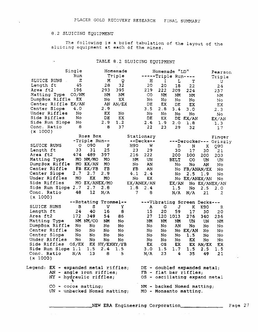
8.2 S L U I C I N G EQUIPMENT
The f o l l o w i n g i s a b r i e f t a b u l a t i o n of the l a y o u t of the s l u i c i n g e q u i p m e n t a t each of the m i n e s .
TABLE 8 . 2 S L U I C I N G EQUIPMENT
S i n g l e H o m e m a d e H o m e m a d e "LD" P e a r s o n R u n T r ip l e ----- T r i p l e R u n - - - - T r i p l e
S L U I C E RUNS Z M E! H I L T U L e n g t h f t 45 28 32 20 20 18 22 2 4 A r e a ft2 19 6 293 395 2 1 9 222 209 224 237 M a t t i n g T y p e CO/NM NM NM CO NM NM NM NM D u m p B o x R i f f l e EX N o EX N o N o N o N o N o C e n t e r R i f f l e EX/AN AN AN/EX DE EX DE EX EX C e n t e r S lope 4.0 2.9 3.5 2.8 3.4 3.0 2.3 U n d e r R i f f l e s N o EX N o No N o N o N o N o Side R i f f l e s N o DE EX DE EX DE E X / W EX/AN S ide R u n Slope N o 2.9 1 . 2 2 . 6 1.9 2.0 1.8 1.3 C o n c . R a t i o 8 8 37 22 23 29 32 17 ( x 1000)
R o s s B o x S t a t i o n a r y F i n g e r - T r i p l e R u n - - - - D e c k s - - - - - D e r o c k e r - - - G r i z z l y
S L U I C E RUNS 0 090 P H 9 0 W D N X Q90 L e n g t h f t 33 31 25 23 29 30 17 30 21 A r e a f t 2 474 489 397 216 222 200 100 200 203 M a t t i n g T y p e MO NM/MO MO NM UN BELT CO UN UN D u m ~ B o x R i f f l e MO EX/AN MO N o AN N o N o AN N o C e n t e r R i f f l e F B EX/FB FB F B AN N o FB/ANAN/EX N o C e n t e r S lope 2 . 7 2 . 7 2.9 4.1 2.4 N o 2.5 1.9 N o U n d e r R i f f l e s MO EX MO N o EX N o EX/ANEX/AN N o Side R i f f l e s MO EX/ANEX/MO EX/ANEX/AN EX/AN N o EX/ANEX/AN S i d e R u n Slope 2.7 2.7 2 . 8 1.8 2.4 1.5 N o 2.5 2.0 C o n c . R a t i o 48 12 N/A 7 8 N/A N/A 21 2 ( x 1000)
- - R o t a t i n g T r o m m e l - - - - - V i b r a t i n g Screen D e c k s - - - S L U I C E RUNS B S V Y A G J K Kg0 R L e n g t h f t 2 4 40 16 8 15 20 59 17 30 20 A r e a f t 2 172 349 54 86 27 120 1013 276 340 236 M a t t i n g T y p e NM NM/CO NM N o N M N M N M U N U N N M D u m p B o x R i f f l e N o N o N o N o N o N o AN N o N o N o C e n t e r R i f f l e N o N o N o N o N o N o N o EX/AN N o N o C e n t e r S lope N o N o N o N o N o N o N o 1.5 N o N o U n d e r R i f f l e s N o N o N o N o N o N o N o EX N o N o Side R i f f l e s OS/EX EX HY/EXHY/FB EX O S EX E X AN/EX E X Side R u n Slope 1.1 1.5 2 . 4 1.5 3.0 1.5 1.7 1.5 2.5 1.5 C o n c . R a t i o N/A 13 8 5 N/A 23 4 35 49 21 ( x 1000)
L e g e n d : E X - expanded m e t a l r i f f l e s ; DE - doubled expanded m e t a l ; AN - angle i r o n r i f f l es ; F B - f l a t bar r i f f l e s ; HY - h y d r a u l i c r i f f les ; O S - o s c i l l a t i n g expand m e t a l
3 C O - cocoa m a t t i n g ; NM - backed N o m a d m a t t i n g ; UN - unbacked N o m a d m a t t i n g ; MO - M o n s a n t o m a t t i n g .
NEW ERA E n g i n e e r i n g C o r p o r a t i o n Page 2 7

PLACELC GOLD RECOVERY RESEARCH F I N A L SUMMARY
Notes: Many of the miners tested in 1990 had implemented recommendations from the 1989 test program including the use of Nomad matting, coarse expanded metal and one inch angle riffles. There were no doubled expanded metal riffles and few using cocoa and Monsanto matting or flat bar riffles.
~ 0 t h mines V and Y used hydraulic riffles and small amounts of gold (7 and 3% respectively) were recovered in the extremely overloaded (mine V) and packed riffles (mine Y) following the hydraulic riffles. The oscillating riffles used at mines B and G yielded high recoveries with the clay rich gravels which would have packed conventional riffles.
8.3 PAY GRAVEL FEED RATES
Pay gravel feed rates are compared to the recommended 8 loose cubic yards/hr/ft of sluice width (for expanded metal riffles). Excessive pay gravel feed rates are one of the greatest factors contributing to gold losses.
TABLE 8.3 PROPORTION OF RECOMMENDED FEED RATES
Single Homemade Homemade "LD" Run Triple -----Triple Run----
FEED RATE Z M Q H I L T Total Lyd3/hr 70 132 250 240 240 142 110 % Recommended 254% 89% 104% 158% 177% 104% 135% % Center Run 338% 389% 675% 446% 394% 305% 336% % Undercurrent No 59% No No No No No % Side Runs No 65% 34% 189% 203% 72% 53% Feed Surging? Yes Yes Mod Mod Mod Mod Yes
Ross Box -Triple Run--
FEED RATE 0 090 P Total Lyd3/hr 250 200 100 % Recommended 134% 118% 57% % Center Run 450% 468% 291% % Undercurrent 115% 20% 13% % Side Runs 70% 40% 7% Feed Surging? Yes Yes Yes
--Rotating Trommel-- FEED RATE B S V Y Total Lyd3/hr 57 240 69 60 % Recommended 87% 186% 100% 37% % Center Run No No No No % Undercurrent No No No No % Side Runs 87% 186% 100% 37% Feed Surging? No Min Min No
Pearson Triple
u 170 2 10% 567% No 8 4%
Yes
Stationary --Decks-- H90 W 200 196 169% 85% 554% 211% No 21% 41% 54% No Mod
Flnger ---Derocker--- Grizzly
D N X Q90 69 70 185 200 103% 101% 85% 76% No N/A 286% No No N/A 35% No 103% No 85% 76% No No No No
---Vibrating Screen Decks- A G J K Kg0 28 40 40 225 218 98% 69% 7% 141% 112% No No No 317% No No No No 43% No 98% 69% 7% 174% 112% No No No No No
Notes: In triple-run boxes, the poor screening efficiency of the distribwtors always overloaded the center runs with water and fine pap gravels and underutilized the side runs. Surging feed rates were common with unscreened sluicing systems.
NEW ERA Engineering Corporation Page 28
P L A C E R GOLD RECOVERY RESEARCH F I N A L SUMMARY
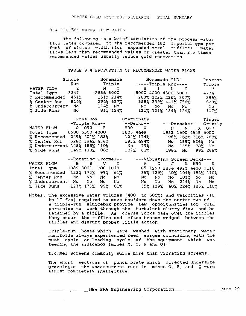
8.4 PROCESS WATER FLOW RATES
The following is a brief tabulation of the process water flow rates compared to the recommended 160 Imperial gpm per foot of sluice width (for expanded metal riffler). Water flows less than recommended values or greater than 2.5 times recommended values usually reduce gold recoveries.
TABLE 8.4 PROPORTION OF RECOMMENDED WATER FLOWS
Single Run
WATER FLOW Z Total Igpm 3247 % Recommended 451% % Center Run 814% % Undercurrent No % Side Runs No
Homemade Homemade " LD" Eearson Triple ----- Triple Run---- Triple M Q H I L T U
2656 5000 5000 4000 4500 5000 4774 151% 214% 283% 222% 236% 307% 296% 294% 627% 588% 399% 441% 756% 82 8% 114% No No No No No No 81% 124% 131% 133% 134% 124% 107%
Ross Box -Triple Run--
WATER FLOW 0 090 P Total Igpm 6500 6500 4000 % Recommended 249% 201% 183% % Center Run 528% 394% 438% % Undercurrent 145% 188% 110% % Side Runs 149% 138% 86%
Stationary --Decks-- H 9 0 W 3603 4449 124% 174% 193% 494% No 79% 107% 61%
Finger ---Derocker--- Grizzly
D N X Q90 1923 1500 4545 5000 198% 162% 216% 268% No 189% 526% No No 135% 78% No 198% No 99% 268%
--Rotating Trommel-- ---Vibrating Screen Decks--- WATER FLOW B S V Y A G J K Kg0 R Total Igpm 1089 3001 700 1078 85 1250 2834 4923 4400 2116 % Recommended 123% 173% 99% 61% 35% 129% 40% 194% 183% 110% % Center Run No No No No No No No 103% No No % Undercurrent No No No No No No No 224% No No % Side Runs 123% 173% 99% 61% 35% 129% 40% 224% 183% 110%
Notes: The excessive water volumes (400 to 600%) and velocities (10 to 17 f/s) required to move boulders down the center run of a triple-run sluicebox provide few opportunities for gold particles to work through the turbulent slurry flow and be retained by a riffle. As coarse rocks pass over the riffles they scour the riffles and often become wedged between the riffles and disrupt proper riffle action.
Triple-run boxes which were washed with stationary water manifolds always experienced feed surges coinciding with the push cycle or loading cycle of the equipment which was feeding the sluicebox (mines M, 0, P and Q).
Trommel Screens commonly su'rge more than vibrating screens.
The short sections of punch plate which directed undersize gravelsrto the undercurrent runs in mines 0, P, and Q were almost completely ineffective.
NEW ERA Engineering Corporation Page 29

PLACER GOLD RECOVERY RESEARCH FINAL SUMMARY
8 . 5 SIZE DISTRIBUTIONS O F GOLD PARTICLES
The fo l lowing t a b l e d i s p l a y s t h e p e r c e n t of go ld p a r t i c l e s i n t h e o r i g i n a l pay g rave l s which a r e r e t a i n e d on t h e i n d i c a t e d s i e v e . This t a b l e does no t provide informat ion about gold p a r t i c l e s c o a r s e r than 14 mesh t o p r o t e c t t h e p a r t i c i p a t i n g mines' p r ivacy .
TABLE 8 . 5 SIZE DISTRIBUTION OF GOLD PARTICLES IN PAY GRAVELS
Tyler S i n g l e Homemade Homemade " LD" Pearson Mesh Dia Run T r i p l e ----- T r i p l e Run---- T r i p l e
mrn Z M Q H I L T U + 4 4 . 7 6 + 8 2 . 3 8
+14 1 . 1 9 1% 33% 16% 11% 10% 10% 2% 8% +28 0 .59 13% 37% 66% 35% 32% 49% 19% 28% +48 0 .29 66% 24% 17% 43% 43% 34% 46% 44%
+ l o 0 0 . 1 4 20% 6% 2% 9% 14% 5% 29% - 100 0 .9% 0 .5% 0.1% 0 .9% 1.2% 0 .7% 3% 3%
18%
Tota l 100% 100% 100% 100% 100% 100% 100% 100%
Tyle r Dia Mesh mm
+ 4 4 . 7 6 + 8 2 .38
+14 1 .19 +28 0 .59 +48 0 . 2 9
+ l o 0 0 .14 - 100 T o t a l
Ross Box S t a t i o n a r y F inge r - T r i p l e Run-- --Decks-- ---Derocker--- G r i z z l y
0 090 P H 9 0 W D N X Q90
Ty le r Dia - -Ro ta t ing Trommel-- - - -Vibra t ing Screen Decks--- Mesh mm B S V Y A G J K Kg0 R Avg
+ 4 4.76 + 8 2 . 3 8
+14 1 . 1 9 0% 6% 65% 42% 7% 40% 2% 2% 8% 0 . 2 % 18% +28 0 .59 35% 28% 27% 50% 39% 41% 18% 25% 33% 5% 33% +48 0 . 2 9 38% 41% 7% 8% 24% 18% 53% 58% 49% 37% 34%
+ l o 0 0 . 1 4 21% 23% 1 % 0 . 4 % 25% 1% 19% 14% 10% 47% 13% - 100 5% 2% 0 .0% 0 .0% 5% 0.0% 8% 0 .6% 0.0% 10% 2% T o t a l 100% 100% 100% 100% 100% 100% 100% 100% 100% 100% 100%
Notes: There i s a wide v a r i a t i o n i n t h e s i z e d i s t r i b u t i o n s of p l a c e r g o l d i n t h e Yukon. However t h e r e i s u s u a l l y n o t much g o l d ( ave rage of 2%) f i n e r than 0 .14 mrn (100 mesh).
Mines R and Z have some of t h e f i n e s t go ld d i s t r i b u t i o n s whi l e mines V and N have t h e c o a r s e s t go ld .
NEW ERA Engineer ing Corpora t ion Page 3 0

PLACER GOLD RECOVERY RESEARCH FINAJ, SUMMARY
8.6 SIZE DISTRIBUTIONS OF GOLD FROM CONSECUTIVE TESTS
The following table displays the percent of gold particles from pay gravels which are retained on the indicated sieve for conaecutive tests at the same minee.
TABLE 8.6 CONSECUTIVE SIZE DISTRIBUTIONS OF GOLD PARTICLES (Graphs 1 and 2)
Tyler Dia Mesh mrn H1 H3 H4 H90 K Kg0 Q1 Q2 Q90
+ 4 4.76 +8 2.38 +14 1.19 18% 6% 10% 13% 2% 8% 22% 16% 25% +28 0.59 24% 43% 39% 39% 25% 33% 51% 66% 44% +48 0.29 55% 35% 39% 37% 58% 49% 23% 17% 23% +lo0 0.14 3% 15% 11% 11% 14% 10% 4% 2% 7% - 100 0.2% 1.3% 1.3% 0.6% 0.6% 0.0% 0.3% 0.1% 0 % Total 100% 100% 100% 100% 100% 100% 100% 100% 100%
Notes: Significant variations in size distribution of placer gold can occur for clean ups from three succeesive pits (HI to H4), over two mining seasons ( H1 versus H90 and K versus K90) and over three mining season (Ql, Q2 and Q90).
GRAPH 1 CONSECUTIVE SIZE DISTRIBUTIONS OF GOLD FROM MINE H
GOLD DISTRIBUTION VS SIZE 70% - - - - 0
+lo0 +48 + 28 + 14 +8 +"
Note: Variability of the Most
i n Common ode) Gold Size at Mine H in 1 9 8 9 / 9 0 Tests
GOLD PARTICLE D W k 3 E R (rnrn)
.&ne H 1st Test + Mine H 2nd Test 0 Mine H Last 09 Test A Mine H 1989
NEW ERA Engineering Corporation Page

PLACER GOLD RECOVERY RESEARCH FINAL SUMMARY
GRAPH 2 CONSECUTIVE SIZE DISTRIBUTIONS OF GOLD FROM MINE Q
GOLD DIS RlBUTlON YS SIZE 70% - - -
+28 +
* +14 +8 + 1
0 Mine Q 1988
N o t e : M o s t Common G o l d - S i z e i s + 2 8 Mesh
b u t D i s t r i b u t i o n V a r i e s a t M i n e Q - i n 1988 t o 1990
-
-
-
-
I I I I I I I I I I I I I I
GOLD PARTlCLE DWV1izrER (mm) + Mine Q 1989 0 Mine Q 1990
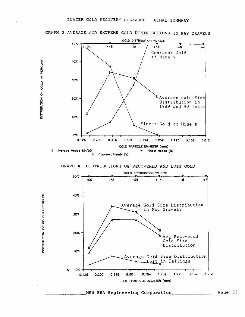
8.7 DISTRIBUTION OF GOLD VALUES
The following table displays the average, finest and coarsest distributions of gold in pay gravels as well as the averaged distributions of recovered and lost gold particles.
TABLE 8.7 DISTRIBUTION OF AVERAGE GOLD VALUES (Graphs 3 and 4)
Tyler Dia Average Finest Coarsest Average Average Mesh mm Of All Mine R Mine V Recovered Lost +4 4.76 +8 2.38
+14 1.19 21.1% 0.2% 64.6% 18.3% 2.8% +28 0.59 31.0% 5.3% 27.4% 26.9% 4.1% +48 0.29 34.3% 37.2% 7.0% 27.2% 7.1% +lo0 0.14 11.8% 47.1% 1.0% 9.2% 2.6% - 100 r 1.7% 10.1% 0.0% 1.4% 0.4% Total 100% 100% 100% 83 .O% 16.9%
NEW ERA Engineering Corporation Page 3 2
PLACER GOLD RECOVERY RESEARCH FINAL SUMMARY
GRAPH 3 AVERAGE AND EXTREME GOLD DISTRIBUTIONS IN PAY GRAVELS
GOLD DISTRIBUTION VS SlZE - 5 +8 +r
Coarsest Gold at Mine V
40% -
30% -
Average Gold S i z e Distribution in 1989 and 90 Test?
Finest Gold at Mine R
COLD PARTlCLE D W E T U I (mm) 0 Avwogo Heodr 89/90 + Rnost Heads (R)
0 Cwraest Hood8 (V)
GRAPH 4 DISTRIBUTIONS OF RECOVERED AND LOST GOLD
GOLD DlSTRlBUTION VS SlZE 50% " - - - - 5
+ 100 +48 +28 +14 +8 +I
Gold S i z e Distribution in Pay Gravels
Avg Recovered Gold Size Distribution
ge Gold S i z e Distribution Lost in Tailings
0.126 0.200 0.316 0.501 0.794 1.259 1.995 3.162 5.012
GOLD PARTICLE DLPMETER (mm)
NEW ERA Engineering Corporation Page 33

PLACER GOLD RECOVERY RESEARCH FINAL SUMMARY
8.8 COREY SHAPE FACTORS
The Corey Shape Factor is a measure of the flatness of placer gold. It is the ratio of the thizkness of a gold flake to the square root of its area. For example, the c.S.F. of a ball or cube is 1 and of a dime is 0.05. The following table summarizes the C.S.F. of the gold recovered by the sluiceboxes. The 1988 conventional sampling program data indicated that in 5 of the 6 mines sampled there was no significant difference in the shape factors of the recovered and lost gold.
TABLE 8.8 COREY .SHAPE FACTORS OF RECOVERED GOLD
Mesh Dia mm Average Minimum Maximum Standard Error
Notes: The Corey Shape Factors for gold from these Yukon placer mines are fairly similar as noted by the low standard errors. Corey Shape Factors can only be estimated to the nearest 0.1 and often varied in successive tests at each mine (H, Q, 0 and K)by plus or minus 0.1 to 0.2.
8.9 LOCATION OF RADIOTRACERS IN SLUICE RUNS
Before the sluiceboxes were cleaned up, the radiotracers were located in each sluice run with a scintillometer. The following data show how far down the sluice runs the gold tracers traveled before they were recovered.
NEW ERA Engineering Corporation Page 34

Recovery Di stance
feet
Overall Recovery
Recovery Distance
feet
Overall Recovery
Notes:
PLACER GOLD RECOVERY RESEARCH FINAL SUMMARY
TABLE 8.9 CUMULATIVE RADIOTRACER RECOVERY VERSUS TRAVEL (Graph 5)
Single Run
z 2 0% 4 2% 6 6% 8 9% 10 12% 12 14% 14 15% 16 15% 18 22% 20 22% 22 27% 24 31% 26 33% 28 36% 30 38% 32 38%
48%
Homemade Triple M Q 12% 2% 22% 11% 25% 18% 38% 30% 43% 37% 43% 45% 49% 54% 63% . 62% 65% 64% 73% 67% 78% 72% 80% 75% 84% 75% End 75%
7 6% End
84% 76%
Ross Box -Triple Run-- 0 090 P
79% 80% 8 4% 84% 87%
End 87%
70% 73% End
73%
Homemade " LD " - -_- - Triple Run---- H1 I L T
5% 23% 31% 26% 9% 54% 45% 42% 18% 65% 69% 52% 20% 69% 72% 72% 22% 72% 82% 84% 23% 72% 86% 84% 2 7% 2 8% 29% End
72% 72% 86% End
88% 88% 89% End
87% 87%
End
Stationary --Decks-- H9 0 W 29% 1% 55% 12% 63% 21% 72% 29% 77% 54% 78% 61% 84% 67% 84% 88% 84% 88% 84% 88% 84% 88% 84% 88% End 90%
90% 90% 90%
83% 92%
Pearson Triple
u 17% 35% 48% 50% 57% 59% 60% 6 1% 62% 67% 72% End
72%
Finger ---Derocker--- Grizzly
D N X Q90 N/A 65% 1% 37%
70% 4% 62% 75% 13% 74%
End- 87% 94% 96% 96% 97% End 97% 97% 97%
87% 85% 98% 96%
Sluice runs with significant numbers of tracers along the full length of their run usually had poorer overall recoveries.
Radiotracers generally travelled further down the center runs of triple run boxes due to high water velocity and excessive overloading with water and coarse pay gravels. It is very difficul* for gold particles to pass through stationary punch plate under these conditions.
NEW ERA Engineerins Corporation D a n e 7 5

Recovery Distance
feet
Overall Recovery
PLACER GOLD RECOVERY RESEARCH FINAL SUMMARY
TABLE 8.9 Continued
--Rotating Trommel-- B S V Y
N/A 17% N/A 87% 45% 93% 5 4% 94% 76% 97% 82% 97% 84% End 84% 88% 90% 90% 91% 93%
---Vibrating Screen Decks--- A G J K Kg0 R
N/A 51% 70% 36x 24% 19% 93% 89% 76% 40% 45% 96% 89% 87% 52% 62% 96% 93% 95% 61% 77% 96% 98% 95% 69% 81% 96% 98% 95% 74% 86% 96% 98% 95% 76% 89% 96% 98% 95% 83% '92% 96% 98% 96% 87% 92%
End End End 89% 92% 91% End 9 7 O / - ' /O
95% 97% 97% 99% 97% 100% 97% End
79% 97% 77% 98% 98% 96% 98% 96% 100% 92%
Notes: The screened systems recovered more of the gold tracers sooner than the single or triple run boxes due to superior pay gravel washing and riffle operation.
GRAPH 5 LOCATION OF RADIOTRACERS IN SLUICING SYSTEMS
AVERAGE RADIOTRACER TRAVEL CUMULATIVE RECOVERY VS DISTANCE
100% S c r e e n e d F i n g e r G r z
9 D e r o c k e r
b 0 4 8 12 16 2 0 24 2 8 32 f
DISTANCE FROM START OF SLUICE RUNS (ft)
0 Single Run + Average Triple Run 0 Raised Decks Demcker 2" x Finger Grizzly 1" V Average Screen 3/4"
NEW ERA Engineering Corporation - - -
Page 3 6
PLACER GOLD RECOVERY RESEARCH FINAL SUMMARY
Recovery Distance
2 4 6 8 10 12 14 16 18 20 22 24 26 28 30
Overall Recovery
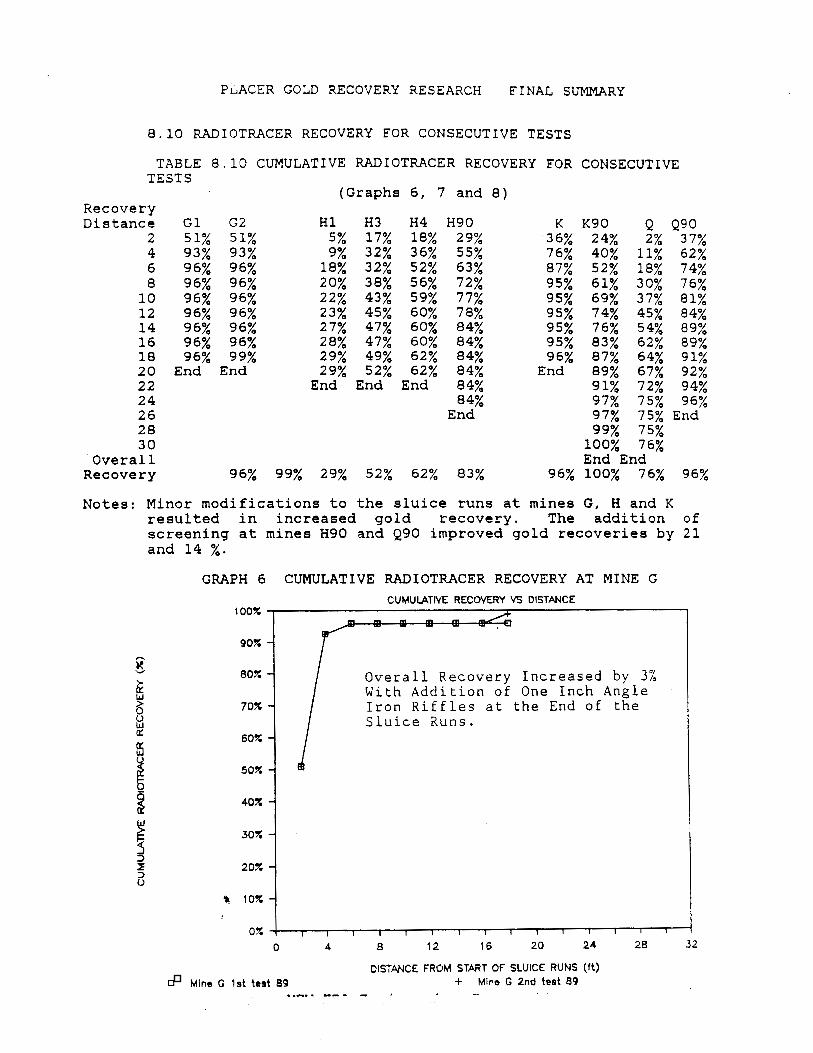
8.10 RADIOTRACER RECOVERY FOR CONSECUTIVE TESTS
TABLE 8.10 CUMULATIVE RADIOTWCER RECOVERY FOR CONSECUTIVE TESTS
G 1 G2 51% 51% 93% 93% 96% 96% 96% 96% 96% 96% 96% 96% 96% 96% 96% 96% 96% 99%
End End
(Graphs 6, 7 and 8)
27% 47% 60% 84% 28% 47% 60% 84% 29% 49% 62% 84% 29% 52% 62% 84% End End End 84%
84% End
K Kg0 Q Q90 36% 24% 2% 37% 76% 40% 11% 62% 87% 52% 18% 74% 95% 61% 30% 76% 95% 69% 37% 81% 95% 74% 45% 84% 95% 76% 54% 89% 95% 83% 62% 89% 96% 87% 64% 91% End 89% 67% 92%
91% 72% 94% 97% 75% 96%
100% 76% End End
96% 100% 76% 96%
Notes: Minor modifications to the sluice runs at mines G, H and K resulted in increased gold recovery. The addition of screening at mines H90 and Q90 improved gold recoveries by 21 and 14 %.
GRAPH 6 CUMULATIVE RADIOTRACER RECOVERY AT MINE G CUMULATM RECOYERY VS DISTANCE
100% m m m - -
90% -
Overall Recovery Increased by 3% With Addition of One Inch Angle
70% Iron Riffles at the End of the Sluice Runs.
DISTANCE FROM START OF SLUICE RUNS (ft) Mine G 1st test 89 + Mino G 2nd test 89 ..-. . -- - - I -.
PLACER GOLD RECOVERY RESEARCH FINAL SUMMARY
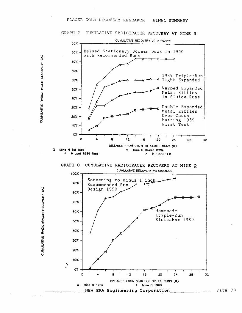
GRAPH 7 CUMULATIVE RADIOTRACER RECOVERY AT MINE H
CUMULATIVE RECOVERY VS OISTPNCE 00%
DISTANCE FROM START OF SLUICE RUNS (ft) 0 Mine H l e t Teat 0 Mine H Bowed Riffle
A H Last 1989 Teat X H 1990 Test
GRAPH 8 CUMULATIVE RADIOTRACER RECOVERY AT MINE Q
9 0 x -
CUMULATIVE RECOVERY VS DISTANCE
Raised Stationary Screen Deck in 1990 with Recommended Runs
Screening Recommended Run Design 1990
" 809. -
70% - 1989 Triple-Run Tight Expanded
Warped Expanded Metal Riffles in Sluice Runs
Double Expanded Metal Riffles Over Cocoa Matting 1989 First Test
OISTANCE FROM START OF SLUICE RUNS (ft) 0 Mine Q 1989 + Mine Q 1990
NEW ERA Engineering Corporation Page 38
PLACER GOLD RECOVERY RESEARCH FINAL SUMMARY
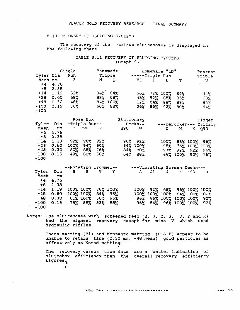
8.11 RECOVERY OF SLUICING SYSTEMS
The recovery of the various sluiceboxes is displayed in the following chart.
TABLE 8.11 RECOVERY OF SLUICING SYSTEMS (Graph 9)
Single Homemade Homemade "LD" Pearson Tyler Dia Run Triple -----Triple Run---- Triple Mesh mm Z M Q H1 I L T U +4 4.76 +8 2.38 +14 1.19 52% 84%' 84% 56% 72% 100% 84% 44% +28 0.60 68% 88% 68% 48% 92% 88% 96% 68% +48 0.30 48% 84% 100% 12% 84% 88% 88% 84% +I00 0.15 36% 60% 88% 36% 86% 92% 80% - 100 64%
Tyler Mesh +4 +8 +14 +28 + 48
+ 100 - 100
Ross Box Stationary Finger Dia -Tripie Run-- --Decks-- ---Derocker--- Grizzly mm 0 090 P H90 W D N X Q90
4.76 2.38 1.19 92% 96% 92% 96% 92% 100% 88% 100% 96% 0.60 100% 84% 80% 84% 100% 98% 76% 100% 100% 0.30 80% 88% 76% 84% 80% 93% 92% 92% 96% 0.15 49% 80% 56% 64% 88% 66% 100% 90% 76%
--Rotating Trommel-- ---Vibrating Screen Decks--- Tyler Dia B S V Y A G1 J K Kg0 R Mesh mm +4 4.76 +8 2.38
Notes: The sluiceboxes with screened feed (B, S, Y, G, J, K and R) had the highest recovery except for mine V which used hydraulic riffles.
Cocoa matting (HI) and Monsanto matting (0 & P) appear to be unable to retain fine (0.30 mm, -48 mesh) gold particles as effectively as Nomad matting.
The recovery versus size data are a better indication of sluicebox efficiency than the overall recovery efficiency figures 'a
I
PLACER GOLD RECOVERY RESEARCH FINAL SUMMARY
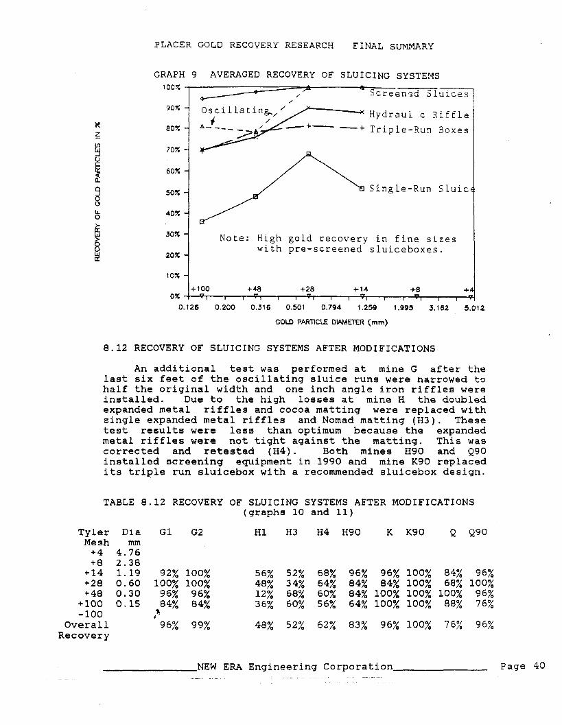
GRAPH 9 AVERAGED RECOVERY OF SLUICING SYSTEMS 1ocz 2 A
* / . / Screenzd Sluices
Hydraui c Riffle
Triple-Run Boxes
Single-Run Sluic
Note: High gold recovery in fine sizes with pre-screened sluiceboxes.
20%
COLD PPRTlCLE D ~ ~ R (mrn)
8.12 RECOVERY OF SLUICING SYSTEMS AFTER MODIFICATIONS
An additional test was performed at mine G after the last six feet of the oscillating sluice runs were narrowed to half the original width and one inch angle iron riffles were installed. Due to the high losses at mine H the doubled expanded metal riffles and cocoa matting were replaced with single expanded metal riffles and Nomad matting (H3). These test results were less than optimum because the expanded metal riffles were not tight against the matting. This was corrected and retested (H4). Both mines H90 and Q90 installed screening equipment in 1990 and mine Kg0 replaced its triple run sluicebox with a recommended sluicebox design.
TABLE 8.12 RECOVERY OF SLUICING SYSTEMS AFTER MODIFICATIONS (graphs 10 and 11)
Tyler Dia G1 G2 H1 H3 H4 H90 K Kg0 Q Q9Q Mesh mm +4 4.76 +8 2.38 +14 1.19 92% 100% 56% 52% 68% 96% 96% 100% 84% 96% +28 0.60 100% 100% 48% 34% 64% 84% 84% 100% 68% 100% +48 0.30 96% 96% 12% 68% 60% 84% 100% 100% 100% 96%
+lo0 0.15 84% 84% 36% 60% 56% 64% 100% 100% 88% 76% -100 A
Overall 96% 99% 48% 52% 62% 83% 96% 100% 76% 96% Recovery
NEW ERA Engineering Corporation Page 40 . - - -

PLACER GOLD RECOVERY RESEARCH FINAL SUMMARY
GRAPH 10 RECOVERY AFTER MODIFICATIONS AT MINE H
COLD RECOVERY VS. SIZES 1 OOX
Raised S tationar go?; - Screen Deck with
Recommended Runs 80% - in 1990
1989 Triple-Run Tight Expanded
Warped Expanded Metal Riffles Double Expanded Metal Riffles Over Cocoa Matting 1989 First Test
GOLD PARTICLE O W ~ R (rnrn) H 1989 Double Exp + H 1989 warped exp
4 Final Teat H 1989 A Mine H 1990
GRAPH 11 RECOVERY AFTER MODIFICATIONS AT MINE Q COW RECOVERY VS. SIZES
100% - - -screening to -1"
90% - Recommended Run
Homemade 80% - Triple-Run
Sluicebox 1989 70% -
C. 126 0.200 0.316 0.501 0.794 1.259 1.995 3.162 5.012
COLD PARTlCLE DWETER (mm)
NEW ERA Engineering Corporation Page 41
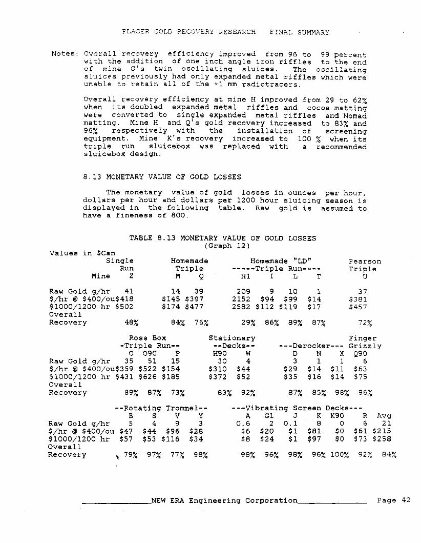
PLACER GOLD RECOVERY RESEARCH F I N A L SUMMARY
Notes: Overall recovery efficiency improved from 96 to 99 percent with the addition of one inch angle iron riffles to the end of mine G ' s twin oscillating sluices. The oscillating sluices previously had only expanded metal riffles which were unable to retain all of the +1 mrn radiotracers.
Overall recovery efficiency at mine H improved from 29 to 62% when its doubled expanded metal riffles and cocoa matting were converted to single expanded metal riffles and Nomad matting. Mine H and Q's gold recovery increased to 83% and 96% respectively with the installation of screening equipment. Mine K's recovery increased to 100 % when its triple run sluicebox was replaced with a recommended sluicebox design.
8.13 MONETARY VALUE OF GOLD LOSSES
The monetary value of gold losses in ounces per hour, dollars per hour and dollars per 1200 hour sluicing season is displayed in the following table. Raw gold is assumed to have a fineness of 800.
TABLE 8.13 MONETARY VALUE OF GOLD LOSSES (Graph 12)
Values in $Can Single Homemade Homemade " LD" Pearson
Run Triple -----Triple Run---- Triple Mine Z M Q H1 I L T U
Raw Gold g/hr 41 14 39 209 9 10 1 37 $fir @ $400/ou$418 $145 $397 2152 $94 $99 $14 $381 $1000/1200 hr $502 $174 $477 2582 $112 $119 $17 $45 7 Overall Recovery 48% 84% 76% 29% 86% 89% 87% 72%
Ross Box Stationary Finger -Triple Rung- --Decks-- ---Derocker--- Grizzly 0 090 P H90 W D N X Q90
Raw Gold g/hr 35 51 15 30 4 3 1 1 6 $/hr @ $400/ou$359 $522 $154 $310 $44 $29 $14 $11 $63 $1000/1200 hr $431 $626 $185 $372 $52 $35 $16 $14 $75 Overall Recovery 89% 87% 73% 83% 92% 87% 85% 98% 96%
--Rotating Tromrnel-- ---Vibrating Screen Decks--- B S V Y A GI J K Kg0 R Avg
Raw Gold g/hr 5 4 9 3 0.6 2 0.1 8 0 6 21 $fir @ $400/ou $47 $44 $96 $28 $6 $20 $1 $81 $0 $61 $215 $1000/1200 hr $57 $53 $116 $34 $8 $24 $1 $97 $0 $73 $258 Overall Recovery 5 79% 97% 77% 98% 98% 96% 98% 96% 100% 92% 84%
NEW ERA Engineering Corporation Page 42

PLACER GOLD RECOVERY RESEARCH FINAL SUMMARY
GRAPH 12 MONETARY VALUE OF GOLD L O S S E S
GOLD LOSSES AT E4CH MlNE 1.1300 T o t a l a t N i n e H 1 o f $ 2 . 5 M i l l i o n
7 /
? Z M O H 1 I L T U 00QW HQW O N X B S V Y AGlJKK9OR
0.800
MlNE SAMPLED IN 1989/90 Losaea $lM/eeaeon
~ n s c r e g ~ e d S l u i c e b o x e s
8.14 RECOVERABLE LOSSES
0.700
The following estimates of recoverable gold are based on comparison with sluiceboxes operating with screened feed and under recommended processing parameters. The capital and operating costs are in $1000, negative operating costs reflect a savings where the modifications eliminate the need for some personnel or equipment.
The proposed modifications were completed at mine G and some modifications resulting in a doubling of recovery at mine H were completed in 1989. Mines H and Q installed screening systems in 1990. Mine K ' s perfect recovery is the result of screening and replacement of a triple run eluicebox with a recommended sluicebox design.
NEW ERA Engineering Corporation Page 43

PLACER GOLD RECOVERY RESEARCH FINAL SUMMARY
Values in $Can Single
Run Mine Z
Raw Gold g/hr 39 $fir @ $400/ou$390 $1000/1200 hr $468 Capital Cost $50 Operating Cost $5
TABLE 8.14 RECOVERABLE GOLD LOSSES (Graphs 13 and 14)
Homemade Triple M Q 11 28
$113 $288 $135 $345 $100 $100 $10 $10
Homemade "LD" ----- Triple Run---- H1 I L T 177 -7 6 1 1817 $76 $59 $11 2180 $91 $70 $13 $100 $100 $100 $100 ($30) ($30) ($80) ($30)
Pearson Triple
u 36
$367 $440 $100 $10
Overall 9 6% 96% 93% 89% 95% 96% 98% 99% Recovery
Ross Box -Triple Run-- 0 090 P
Raw Gold g/hr 24 49 14 $fir @ $400/ou$245 $501 $141 $1000/1200 hr $293 $602 $169 Capital Cost $100 $100 $100 Operating Cost $10 $10 $10
Stationary --Decks-- H90 W 13 4
$130 $42 $156 $51 $100 $50 ($30) $10
Finger ---Derocker--- Grizzly
D N X Q90 2 1 1 6
$18 $13 $10 $57 $21 $16 $12 $68 $60 $60 $60 $30 $10 $10 $10 $0
Overall 96% 99% 98% 90% 99% 99% 95% 99% 99% Recovery
--Rotating Trommel-- B S V Y
Raw Gold g/hr 4 3 9 3 $fir @ $400/ou $44 $29 $96 $28 $1000/1200 hr $53 $34 $115 $33 Capital Cost $1 $3 $10 $2 Operating Cost $0 $0 $0 $0 Overall Recovery 99% 99% 99% 99%
---Vibrating Screen Decks--- A G1 J K Kg0 R Avg
0.3 1.5 0.03 4 0 3 17 $3 $15 $0.3 $44 $0 $26 $175 $3 $19 $0.3 $53 $0 $31 $210 $1 $1 $1 $50 $0 5 $57 $0 $0 $0 ($5) $0 0 ($4)
Notes: Virtually all of the mines without screening (I, L, M I 0 and P) will pay back the capital investment in screening equipment in less than one season. Many others should have additional revenue in the first season of operation.
Mines G and H reduced their gold losses following modifications after the first tests in 1989.
In 1990, mines H and Q constructed screening systems and mine K constructed sluice runs in accordance with the standard recommendations. These costs were recovered in less than one season.
NEW ERA Engineering Corporation Page 44

PLACER GOLD RECOVERY RESEARCH F1:JAL SUMMARY
GRAPH 13 RECOVERABLE GOLD LOSSES
RECOYEWLE GOLD LOSSES AT E42H MINE 500.000 r v I
T o t a l Recoverable at Mine H I of $ 2 . 2 M i l l i o n
Z M Q H I 1 L T U 0 P W O N X B S V Y A C 1 J kK9W
MINE WPED IN iga9/90 [77;1 Losses $1000/season
GRAPH 14 RECOVERED GOLD LOSSES AT MINES H, K AND Q
MlNE SAMPLED IN 1989/90 Losses tkl/season
NEW ERA Engineering Corporation Page 45

PLACER GOLD RECOVERY RESEARCH F INAT, SUMMARY
8.15 ACCURACY OF THESE RESULTS
The standard errors from these radiotracer tests were estimated from binomial probability theory with the equation: SE = {(n*p*q)-0.5j/r-. Where n is the total number of radiotracers added, p is the proportion recovered and q is the proportion lost. Each overall recovery estimate would be within one standard error of the true recovery (14 times out of 20) and almost always within two standard errors of the true recovery (19 times out of 20).
TABLE 8.15 STANDARD ERRORS OF 88/89/90 TESTING PROGRAM
Single Homemade Homemade " LD" Pearson Run Triple ----- Triple Run---- Triple
Z M Q H I L T U Standard Error 5% 4% 4% 5% 4% 3% 3% 5%
Ross Box Stationary Finger -Triple Run-- --Decks-- ---Derocker--- Grizzly 0 090 P H9 0 W D N X Q90
Standard Error 4% 3% 4% 4% 3% N/A 3% 2% 3%
--Rotating Trommel-- ---Vibrating Screen Decks--- Avg B S V Y A G J K Kg0 R
Standard Error 17% 2% 5% 2% 8% 2% 3% 2% 1% 2% 3%
The standard errors encountered in the 1988 conventional sampling program were much higher and ranged from 8% for mine A which had relatively low gold losses to as high as 50% for mines with much higher losses. These higher standard errors occurred despite the large volumes of tailings (2 to 7 loose cubic yards) processed and were due to the frequent occurrence of coarse gold particles in the tailings from conventional sluiceboxes.
The 1988 conventional sampling program proved that conventional sampling techniques 'are very expensive, time consuming and often have high errors which cannot be determined until all of the testwork and analysis is completed. Radiotracer tests are more appropriate for placer gold testwork because they have much lower standard errors which can be predicted in advance of testing. Radiotracer tests can be completed in 48 hours allowing the sluiceboxes to be modified and retested immediately.
NFW F R A Enni n ~ e r i n n f nrnnra+i nn

PLACER GOLD RECOVERY RESEARCH F I N A L SUMM4RY
9 REFERENCES
CLARKSON, R . R . , 1989. Gold Losses at Klondike Placer Mines, (1988 Conventional Sampling Program). Prepared for the Klondike Placer Miners Association. Available at Northern Affairs Program, 200 Range Road, Whitehorse, Yukon Y1A 3V1.
CLARKSON, R.R., 1990. The Use of Radiotracers to Evaluate Gold Losses at Klondike Placer Mines. Prepared for the Klondike Placer Miners Association. Available at Northern Affairs Program, 200 Range Road, Whitehorse, Yukon Y1A 3V1.
CLARKSON, R.R. and PEER, 0. 1990. An Analysis of Sluicebox Riffle Performance. Prepared for the Klondike Placer Miners Association. Available at Northern Affairs Program, 200 Range Road, Whitehorse, Yukon Y1A 3V1.
MACDONALD, E.H., 1983. The Geology, Technology and Economics of Placers. Publishers Chapman and Hall, New York, N.Y.
PETERSON, L.A., et all, 1984. Investigation of the Effect of Total Suspended Solids Levels on Gold Recovery in a Pilot Scale Sluice. Prepared for Kohlmann Ruggiero Engineers.
PETERSON, L.A., et all, 1986. Evaluation of the Effect of Suspended Solids on Riffle Packing and Fine Gold Recovery in a Pilot Scale Sluice. Prepared for Centec Applied Technologies, Inc.
POLING, G.W. and HAMILTON, J.F., 1986. Fine Gold Recovery of Selected Sluicebox Configurations. Available at Northern Affairs Program, 200 Range Road, Whitehorse, Yukon Y1A 3V1.
R
NEW ERA Engineering Corporation page 47

PLACER GOLI RECOVFRY RESEARCH FINAL SUMMARY
10 APPENDICES
10.1 A COMPARISON OF STANDARD SIEVE SIZES
National Tyler B u r e a u o f
Standards mesh inches
Tyler N. S. B. mesh number
A. S. T. M. Sieve
Open i n g mm
101.60 76.10 SO. 80 25.40 19.00 12.70 6 . 3 5
A. S. T. m. o p e n mm
A. S. T. M. Sieve
Open i ng i n c he5
inches
NEW ERA Engineering Corporation page 48
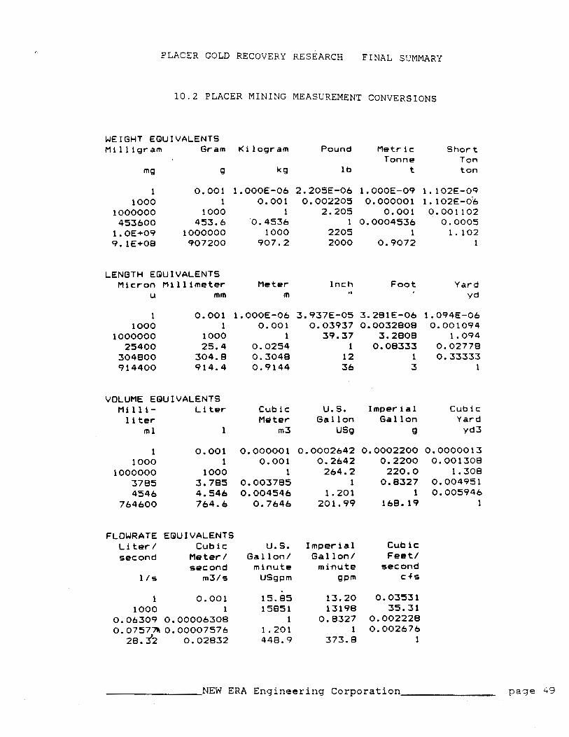
P L A C E R GOLD RECOVERY RESEARCH FINAL SUMMARY
1 0 . 2 PLACER M I N I N G MEASUREMENT C O N V E R S I O N S
WEIGHT E Q U I V A L E N T S M i 1 1 i g r a m G r a m K i l o g r a m P o u n d M e t r i c S hor t
T o n n e T o n
Q 9 kg l b t ton
L E N G T H E Q U I V A L E N T S M i c r o n M i 11 i m e t e r M e t e r I n c h Foot Y a r d
u mm m , I yd
VOLUME E Q U I V A L E N T S M i l l i - L i t e r
1 i t e r m l 1
FLOWRATE E Q U I V A L E N T S L i t e r / C u b i c second M e t e r /
second l / s m 3 / s
C u b i c U. S. I m p e r i a l C u b i c M e t e r G a l l o n G a l l o n Y a r d
m 3 us9 Q ~ d 3
U. S. G a l l o n /
m i n u t e U S g p m
15.85 15851
1 1.201 448.9
I m p e r i a l C u b i c G a l l o n / Feet /
m i n u t e second QP'" c f s
NEW ERA Engineering Corporation paqe 49

This page is lhlTEhlTlONALLY BLANK