Embed Size (px)
Citation preview

S
AM E DAY
S
HI PM E N
TGuarante
ed
Same Day Shipment
UPC INDUSTRIAL CODE NUMBER — 781711
We Never Miss!
Our Guarantee –Boston Gear will ship any in stock product the same day
it’s ordered, with no additional charge, up to 8 p.m. Eastern time...
WE NEVER MISS…but if we do, we’ll pay the freight!
Call your local Boston Gear distributorand request your
“GUARANTEED SAME DAY SHIPMENT” order today!
For the name and number of your nearest distributor, please call
1-888-999-9860In Canada: 1-800-221-5079
Please see page 246 for the terms and conditions of this program.
Bearing Catalog 1
BOST-BRONZ (Oil-Impregnated Sintered Bronze) .................................................. 9-17BEAR-N-BRONZ (SAE 660 Cast Bronze) .............................................................. 18-26Bronze Bearing Emergency Banks .............................................................................. 27BOStonE F-1 (Glass Filled Teflon).......................................................................... 28-30RULON® 641 Bearings ........................................................................................... 31-32BOStonE Molded Plastic ........................................................................................ 33-44BOStonE Molded Nylon.......................................................................................... 45-46Anti-Friction (Ball Bearings) .................................................................................... 56-70Self-Aligning (Rod End & Spherical Bearings)........................................................ 71-79Linear Bearings....................................................................................................... 85-90Mounted Bearings
Washdown ...................................................................................................... 95-100Pillow Blocks ................................................................................................. 103-110Flanged-units................................................................................................. 111-118Shaft Supports...................................................................................................... 119
Take-Up Frames .........................................................................................................120Couplings............................................................................................................ 129-135Universal Joints .................................................................................................. 136-142Shaft Collars
Setscrew ...............................................................................................................143Clamping........................................................................................................144-146Washdown .....................................................................................................147-148
Washers & Bushings........................................................................................... 149-150Round Belt Pulleys..................................................................................................... 151Miniature Timing Belts & Pulleys ........................................................................ 152-165Roller Chain ........................................................................................................ 169-178Roller Chain Attachments .......................................................................................... 177Block Chain & Leaf (Cable) Chain ............................................................................. 179Ladder Chain ............................................................................................................. 180Miniature Roller Chain ............................................................................................... 181Chain Pullers & Chain Breaking Tools ....................................................................... 182Roller Chain Sprockets ....................................................................................... 184-215Block Chain Sprockets............................................................................................... 216Ladder Chain Sprockets ..................................................................................... 217-218Idler Sprockets ........................................................................................................... 219Roller Chain Drive Tensioners ............................................................................ 219-222Clutches...............................................................................................................226-238Terms and Conditions ......................................................................................... 245-246Index to Catalog Numbers .................................................................................. 247-249
Engineering Data is at end of each section
TABLE OF CONTENTS

2 Bearing Catalog
BOST-BRONZ®
OILIMPREGNATED
SINTEREDBRONZE
BEAR-N-BRONZ ®
660 CASTBRONZE
BRONZEEMERGENCY
BEARING BANKS
BOSton E® F-1GLASS FILLED
TEFLON
Rulon ®
BOSton E®
MOLDEDPLASTIC
PRODUCT SELECTION / REFERENCE GUIDE
PLAIN CYLINDRICAL FLANGED TYPE THRUST TYPE
Pages 11–13 Pages 14–15 Page 16
PLATE STOCK CORED BARS SOLID BARS
Page 16 Page 17 Page 17PLAIN CYLINDRICAL CORED BARS SOLID BARS
Pages 19–23 Pages 24–26 Page 26
BOST-BRONZ & BEAR-N-BRONZ PLAIN CYLINDRICAL
Page 27 Page 29
FLANGED THRUST TYPE SOLID BARS(EXTRUDED)
Page 29 Page 30 Page 30
RULON® 641 BEARINGS PLAIN CYLINDRICAL FLANGED
Pages 31-32 Page 34 Page 34
ROLL END FOR TUBING EXTRA LENGTH BLIND ROLL END ADAPTER GUIDE ROLL& STANDARD PIPE BORE INSERTS FOR HEX SHAFT
Pages 35-41 Page 42 Page 42 Page 43ROLLERS SHAFT CLIP STUB SHAFT FOR
ROLLERS
Page 43 Page 44 Page 44
BOSTONE® F-1GLASS FILLED
TEFLON
BOSTONE®
MOLDED PLASTIC

Bearing Catalog 3
BALLBEARINGWHEELS
PRODUCT SELECTION / REFERENCE GUIDE
BOSton E®
MOLDEDNYLON
RADIALBALL
BEARINGS
THRUSTBALL
BEARINGS
BALLBEARINGSHEAVES
RODEND
BEARINGS
PLAIN CYLINDRICAL FLANGED THRUST TYPE CABLE PULLEYS
Page 45 Page 45 Page 46 Page 46
1600 SERIES 7500 SERIES 7600 SERIES 6900 SERIES
Pages 58–59 Page 60 Page 61 Page 62
3000 SERIES 400F SERIES FLANGED
Pages 63–64 Page 65
GROUND, UNBANDED 600 SERIES
Page 66 Page 67
2000 SERIES 2100 SERIES 2200 SERIES
Page 68 Page 69 Page 70
KF FEMALE SERIES HM-C SERIES CMHD MALE SERIES HM MALE SERIESHF-C FEMALE SERIES CFHD FEMALE SERIES HF FEMALE SERIES
Page 71 Page 72 Page 73 Page 74
HME MALE SERIES HMX MALE SERIESHFE FEMALE SERIES HFX FEMALE SERIES
Page 75 Page 76

4 Bearing Catalog
SPHERICALBEARINGS
LINEARBALL
BEARINGS
WASHDOWNDUTY
BEARINGS
REPLACEMENTBEARINGS &
LOCKINGCOLLAR SERIES
PILLOWBLOCKS
LHA-LHB-LHSS LHSSE-LHSSVV LS SERIESSERIES SERIES
Page 77 Page 78 Page 79
PRECISION SERIES OPEN SERIES COMMERCIAL SERIES INSTRUMENT SERIES
Page 86 Page 87 Page 88 Page 88
SOLID HARDENED& GROUND SHAFTS
Pages 89-90
NMPSS SERIES NMPSS2 SERIES (2 Bolt) NMSLA SERIES NMSTA SERIES
Page 95 Page 96 Page 97 Page 98
NMPPB SERIES NMPTB SERIES (Two Bolt)NMPFB SERIES (Four Bolt)
Page 99 Page 100
L, H, F, T, A PS/XL-S-MB SERIESSERIES
Page 101 Page 102
PPB SERIES PS SERIES XL SERIES L-SERIESH-SERIES
Page 103 Page 104 Page 105 Pages 106–107
SL/SH SERIES MB SERIES
Pages 108–109 Page 110
PRODUCT SELECTION / REFERENCE GUIDE

Bearing Catalog 5
TAKE-UPFRAMES
PRODUCT SELECTION / REFERENCE GUIDE
FLANGEDUNITS
SHAFTSUPPORTS
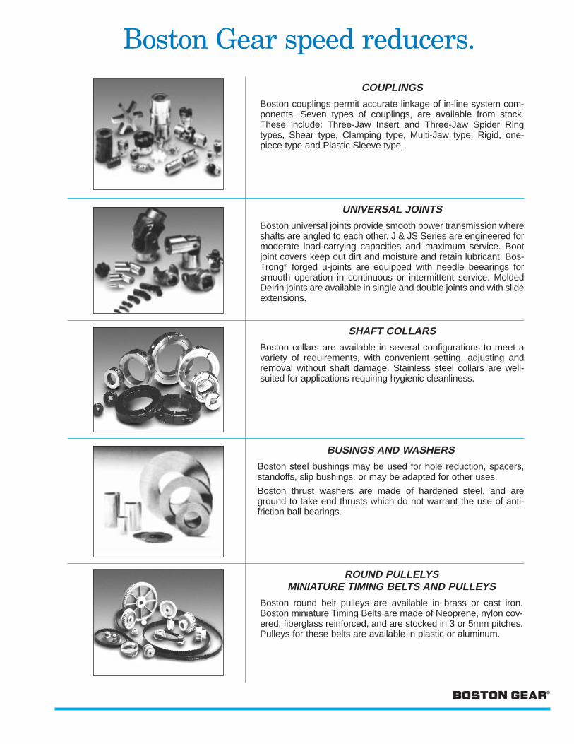
COUPLINGS
UNIVERSALJOINTS
COLLARS
PS2/PS3 SERIES XL2/XL3 SERIES F SERIES SF/ST SERIEST-SERIES
Page 111 Page 112 Pages 113–114 Pages 115–116
MBF SERIES MBP SERIES
Page 117 Page 118
A SERIES TU SERIES
Page 119 Page 120
INSERT (3 JAW) SPIDER RING SHEAR
FC Type – Pages 129–130 BF Type – Page 131 BG Type – Page 132
CLAMP MULTI-JAW RIGID SLEEVE
SCC Type – Page 133 FA Type – Page 134 CR Type – Page 134 FCP Type – Page 135
PIN & BLOCK FORGED MOLDED MOLDED WITHSLIDE EXTENSION
J Type – Pages 136–137 UJN Type – Pages 138–140 JP Type – Page 141 JPE Type – Page 142
SETSCREW CLAMPING–THREADED CLAMPING – 1 PIECE CLAMPING – 2 PIECE
SC Type – Page 143 CSC Type – Page 144 CS Type – Page 145 2CS Type – Page 146
Washdown Duty Washdown Duty
NSC Series – Page 147 2NSC Series – Page 148

6 Bearing Catalog
BUSHINGS
ROLLER CHAINSINGLE AND
DOUBLE PITCH
PRODUCT SELECTION / REFERENCE GUIDE
WASHERS
PULLEYS
MINIATURETIMING BELTS
& PULLEYS
CHAIN
SPROCKETS
HARDENED STEEL WASHERS SOFT STEEL BUSHINGS
Page 149 Page 150
GROOVED
Page 151TIMING BELTS PULLEYS
Pages 152–155 & 161 Pages 156–160 & 162–165
MULTIPLE WIDTHS TRANSMISSION CONVEYOR SERIES HEAVY SERIESANSI STANDARD SERIES
Page 171 Page 172 Page 172 Page 172
ATTACHMENTS HOLLOW PIN BLOCK
Page 177 Page 178 Page 179LEAF (CABLE) LADDER MINIATURE ROLLER CHAIN PULLERS &
CHAIN CHAIN BREAKINGTOOLS
Page 179 Page 180 Page 181 Page 182
PLASTIC & STAINLESS ROLLER CHAIN BLOCK CHAIN LADDER CHAINSTEEL
Page 192 Pages 193–215 Page 216 Pages 217–218

Bearing Catalog 7
PRODUCT SELECTION / REFERENCE GUIDE
DRIVETENSIONERS
CLUTCHPRODUCTS
SCREW/SPRING ADJUSTABLE SHAFT MOUNTED DRIVE TENSIONERS
TYPE LG TYPE BG TYPE HG & UG
Page 220 Pages 220–221 Page 222
TLF LMB/LSR TMB/TSR/TSN
Page 227–229 Page 230–232 Page 233–236

8 Bearing Catalog
BEARINGS
BOST-BRONZ (Oil-Impregnated Sintered Bronze)– General Description ..................................................................................... 9-10– Catalog Number Selections/Dimensions .................................................. 11-17– Engineering ................................................................................................. 47-55
BEAR-N-BRONZ (660 Cast Bronze)– General Description ......................................................................................... 18– Catalog Number Selections/Dimensions ................................................. 19-26– Engineering ................................................................................................. 47-55
Bronze Bearing Emergency Bank– BOST-BRONZ & BEAR-N-BRONZ .................................................................. 27
BOStonE F-1 (Glass Filled Teflon)– General Description/Engineering ................................................................... 28– Catalog Number Selections/Dimensions ................................................. 29-30
RULON® 641 Bearings– General Description ......................................................................................... 31– Catalog Number Selections/Dimensions ....................................................... 32
BOStonE Molded Plastic– General Description/Engineering ................................................................... 33– Catalog Number Selections/Dimensions ................................................. 34-44
BOStonE Molded Nylon– Catalog Number Selections/Dimensions ................................................. 45-46
Anti-Friction (Ball Bearings)– General Description ................................................................................... 56-57– Catalog Number Selections/Dimensions ................................................. 58-70
Self-Aligning (Rod End & Spherical Bearings)– Catalog Number Selections/Dimensions ................................................. 71-79– Engineering ................................................................................................. 80-84
Linear Bearings– General Description ......................................................................................... 85– Catalog Number Selections/Dimensions ................................................. 86-90– Engineering ................................................................................................. 91-93
Mounted Bearings– General Description ......................................................................................... 94– Washdown Duty Bearings ........................................................................95-100– Replacement Bearings & Locking Collars ........................................... 101-102– Pillow Blocks .......................................................................................... 103-110– Flanged Units .......................................................................................... 111-118– Shaft Supports ............................................................................................... 119– Take-Up Frames ............................................................................................. 120
SECTION CONTENTS

Bearing Catalog 9
Density in Grams Tensile Yield StrengthComposition per Cu. Cent. Strength in Compression Elongation in Porosity by
% Impregnated Lbs. per Sq. In. (0.2% Offset) One Inch % Volume %Lbs. per Sq. In.
Copper (Cu) 87.5-90.56.4/6.8 14,000 11,000 1.0 19 Min.Iron 1.0 Max.
Lead (a)Carbon (Graphite Max.) 1.75 Max. Conforms to ASTM B438-73 Grade 1, Type 2, and SAE-841Tin 9.5-10.5Total OtherElements .05
BOST-BRONZ OIL-IMPREGNATED SINTERED BRONZE BEARINGS
BOST-BRONZ is Boston Gear’s all-purpose, oil-impregnatedporous bronze bearing material. It is manufactured of highestpurity metal powders by the powder metallurgy process. Thisprocess provides uniformly distributed pores between themetal particles which absorb oil by capillary action. BOST-BRONZ has a self-contained oil supply (approximately 20% byvolume) which provides a uniform, protective film over theentire bearing surface. Composition and physical propertiesare as follows: –
BOST-BRONZ can be used for production and replacementrequirements in practically every known industry. It has provento be efficient under heavy loads at moderate speeds and alsounder light loads at high speeds. It is ideally suited forapplications where normal lubrication is difficult or impossibleto provide.
ACCURACYThe close tolerances of BOST-BRONZ bearings are madepossible through expertly controlled manufacturing methods.In addition, the lubricating features of BOST-BRONZ permitreduced shaft clearances — a precision product with precisionperformance.
PERFORMANCEBecause of its porous construction, BOST-BRONZ bearingshave an oil reservoir when idle — an oil film to start on — anoil film to run on, assuring low starting torque and smooth,quiet positive performance.
ADAPTABILITYBOST-BRONZ bearings are designed for immediateinstallation and may be used in most applications withoutadditional machining. Oil holes or grooves are not requiredand turning or boring bearing diameters is normallyunnecessary.
(a) Included in other elements

BOST-BRONZ OIL-IMPREGNATED SINTERED BRONZE BEARINGS
NON-LISTED SIZESThe stock sizes of BOST-BRONZ bearings listed in thiscatalog will satisfy the majority of industrial applications.Tooling is available for many metric and additional inch sizes.Where tooling is not available, special sizes can be made toorder.
SPECIAL SHAPESMany special shapes can be made economically by thepowdered metal process. This process is particularlyeconomical for the production of comparatively simple shapesin large volume. More complicated shapes may also beeconomical to produce by this process when the savings inmachining justify the cost of more expensive tooling.
SPECIAL COMPOSITIONSIn addition to our standard BOST-BRONZ, many specialcompositions can be furnished on a made-to-order basis.
APPLICATIONSBOST-BRONZ bearings can be used on any applicationwhere the load-carrying capacity required falls within thecapabilities of the material. BOST-BRONZ bearings operateefficiently under heavy loads at slow speeds. Because thesebearings are supplied with oil impregnation, the original oilcontent provides long-lasting lubrication. For even longer liferequirements, many applications incorporate impregnated feltsor other reservoir techniques about the bearing.
SELECTIONIn general, sleeve bearings should be selected with a length ofone to two times the shaft diameter and an O.D.approximately 25% larger than the shaft diameter.
A general guide to determination of limiting load and velocityvalues for sleeve bearings has been established by the use ofPV calculations. PV represents Pressure x Velocity, forexample 100 psi x 20 fpm yields a PV of 2000.
Maximum PV values for BOST-BRONZ bearings:
Cylindrical & Flange Bearings - 50,000Thrust Bearings - 10,000
For complete selection and application information, seeEngineering Section, Pages 47-55.
10 Bearing Catalog

ALL DIMENSIONS IN INCHESORDER BY CATALOG NUMBER OR ITEM CODE
BOST-BRONZ OIL-IMPREGNATED SINTERED BRONZE BEARINGS
PLAIN CYLINDRICALBEARINGS
Catalog ItemA B C Number Code1/8 B24-1 34504
1/4 1/4 B24-2 34506.252 3/8 B24-3 34508
1/8 1/2 B24-4 34510.127 1/8 B25-1 34512
5/16 1/4 B25-2 34514.315 3/8 B25-3 34516
1/2 B25-4 345185/8 B25-5 345201/4 B34-2 34522
1/4 3/8 B34-3 34524.252 1/2 B34-4 34526
5/8 B34-5 345283/4 B34-6 345301/4 B35-2 34532
3/16 5/16 3/8 B35-3 34534.189 .314 1/2 B35-4 34536
5/8 B35-5 345383/4 B35-6 345403/8 B36-3 13561
3/8 1/2 B36-4 13563.377 5/8 B36-5 13565
3/4 B36-6 135671/4 B45-2 13569
5/16 3/8 B45-3 13571.315 1/2 B45-4 13573
3/4 B45-6 135751/4 B46-2 345425/16 B46-2 1/2 345443/8 B46-3 34546
3/8 1/2 B46-4 34548.377 5/8 B46-5 34550
3/4 B46-6 345527/8 B46-7 345541 B46-8 34556
1/4 1-1/4 B46-10 34558.252 3/8 B47-3 34560
1/2 B47-4 345627/16 5/8 B47-5 34564.439 3/4 B47-6 34566
7/8 B47-7 345681 B47-8 34570
3/8 B48-3 345721/2 B48-4 34574
1/2 5/8 B48-5 34576.502 3/4 B48-6 34578
7/8 B48-7 345801 B48-8 34582
1-1/4 B48-10 345843/8 B56-3 345861/2 B56-4 34588
3/8 5/8 B56-5 34590.377 3/4 B56-6 34592
7/8 B56-7 345941 B56-8 34596
1/4 B57-2 345983/8 B57-3 346001/2 B57-4 34602
5/16 7/16 5/8 B57-5 34604.314 .439 3/4 B57-6 34606
7/8 B57-7 346081 B57-8 34610
1-1/4 B57-10 346121-3/8 B57-11 346143/8 B58-3 346161/2 B58-4 346185/8 B58-5 34620
1/2 3/4 B58-6 34622.502 7/8 B58-7 34624
1 B58-8 346261-1/4 B58-10 346281-1/2 B58-12 346301-3/4 B58-14 346321/2 B67-4 13577
7/16 5/8 B67-5 13579.440 3/4 B67-6 13581
1 B67-8 13583
3/8 3/8 B68-3 34634.377 1/2 B68-4 34636
1/2 5/8 B68-5 34638.502 3/4 B68-6 34640
7/8 B68-7 346421 B68-8 34644
1-1/4 B68-10 34646
Bearing Catalog 11
Catalog ItemA B C Number Code3/8 B69-3 346481/2 B69-4 34650
9/16 5/8 B69-5 34652.5645 3/4 B69-6 34654
7/8 B69-7 346561 B69-8 34658
1-14 B69-10 346603/8 B610-3 346761/2 B610-4 34678
3/8 5/8 5/8 B610-5 34680.377 .627 3/4 B610-6 34682
7/8 B610-7 346841 B610-8 34686
1-1/4 B610-10 346883/8 B612-3 34690
3/4 1/2 B612-4 34692.753 3/4 B612-6 34694
1 B612-8 346961-1/4 B612-10 346983/8 B79-3 346621/2 B79-4 34664
9/16 5/8 B79-5 34666.5645 3/4 B79-6 34668
7/8 B79-7 346701 B79-8 34672
1-1/4 B79-10 346747/16 3/8 B710-3 34700.439 1/2 B710-4 34702
5/8 5/8 B710-5 34704.628 3/4 B710-6 34706
7/8 B710-7 347081 B710-8 34710
1-1/4 B710-10 34712
11/16 1/2 B711-4 34714.690 1 B711-8 34716
1-1/2 B711-12 347181/2 B810-4 347205/8 B810-5 347223/4 B810-6 34724
5/8 7/8 B810-7 34726.628 1 B810-8 34728
1-1/8 B810-9 347301-1/4 B810-10 347321-1/2 B810-12 347341/2 B811-4 347365/8 B811-5 347383/4 B811-6 34740
11/16 7/8 B811-7 34742.690 1 B811-8 34744
1-1/8 B811-9 347461-1/4 B811-10 347481-1/2 B811-12 347501/2 B812-4 347525/8 B812-5 347543/4 B812-6 347567/8 B812-7 34758
1/2 3/4 1 B812-8 34760.503 .753 1-1/8 B812-9 34762
1-1/4 B812-10 347641-1/2 B812-12 347661-3/4 B812-14 34768
2 B812-16 347701/2 B813-4 34772
13/16 3/4 B813-6 34774.815 1 B813-8 34776
1-1/2 B813-12 347781/2 B814-4 347805/8 B814-5 34782
7/8 3/4 B814-6 34784.878 7/8 B814-7 34786
1 B814-8 347881-1/4 B814-10 347901-1/2 B814-12 347923/4 B816-6 13585
1 1 B816-8 135871.004 1-1/2 B816-12 13589
2 B816-16 135911/2 B911-4 34794
9/16 11/16 3/4 B911-6 34796.565 .690 1 B911-8 34798
1-1/2 B911-12 34800
On A and B dimensions, tolerances apply to actual (decimal) dimensions.
STANDARD TOLERANCES
B A
C
Dimensions Tolerance.127 – 1.441 +.0000 to – .0010A 1.503 – 2.379 +.0000 to – .0015
2.504 – 3.255 +.0000 to – .0020B 3.505 +.0000 to – .00251/8 – 1-1/2" ± .005
C 1-1/2 – 3 ± .00754 ± .010
STANDARD CONCENTRICITY
Dimensions T.I.R. (A to B)
A .127 – 1.503 .0031.628 – 3.004 .004
Prices on unlisted sizes and other BostonGear powder metal parts provided on request.

12 Bearing Catalog
BOST-BRONZ OIL-IMPREGNATED SINTERED BRONZE BEARINGS
ALL DIMENSIONS IN INCHESORDER BY CATALOG NUMBER OR ITEM CODE
PLAIN CYLINDRICALBEARINGS
Catalog ItemA B C Number Code1/2 B912-4 34802
3/4 3/4 B912-6 34804.753 1 B912-8 34806
9/16 1-1/2 B912-12 34808.565 1/2 B913-4 34810
13/16 3/4 B913-6 34812.815 1 B913-8 34814
1-1/4 B913-10 348161-1/2 B913-12 348181/2 B1012-4 348205/8 B1012-5 348223/4 B1012-6 34824
3/4 7/8 B1012-7 34826.753 1 B1012-8 34828
1-1/8 B1012-9 348301-1/4 B1012-10 348341-1/2 B1012-12 348321/2 B1013-4 348365/8 B1013-5 348383/4 B1013-6 34840
13/16 7/8 B1013-7 354005/8 .815 1 B1013-8 34842.627 1-1/4 B1013-10 34844
1-1/2 B1013-12 348462 B1013-16 34848
5/8 B1014-5 348503/4 B1014-6 348527/8 B1014-7 34854
7/8 1 B1014-8 34856.878 1-1/4 B1014-10 34858
1-1/2 B1014-12 348601-3/4 B1014-14 34862
2 B1014-16 348641/2 B1016-4 348665/8 B1016-5 348683/4 B1016-6 34870
5/8 1 7/8 B1016-7 34872.628 1.003 1 B1016-8 34874
1-1/4 B1016-10 348761-1/2 B1016-12 348781-3/4 B1016-14 34880
2 B1016-16 348823/4 B1114-6 348841 B1114-8 34886
11/16 7/8 1-1/4 B1114-10 34888.690 .878 1-1/2 B1114-12 34890
1-3/4 B1114-14 348922 B1114-16 34894
1/2 B1214-4 348965/8 B1214-5 348983/4 B1214-6 34900
7/8 7/8 B1214-7 34902.878 1 B1214-8 34904
1-1/4 B1214-10 349061-1/2 B1214-12 349081-5/8 B1214-13 349101/2 B1215-4 349125/8 B1215-5 349143/4 B1215-6 34916
15/16 7/8 B1215-7 34918.9405 1 B1215-8 34920
3/4 1-1/4 B1215-10 34922.753 1-1/2 B1215-12 34924
1-3/4 B1215-14 349262 B1215-16 34928
1/2 B1216-4 349305/8 B1216-5 349323/4 B1216-6 349347/8 B1216-7 34936
1 1 B1216-8 349381.003 1-1/8 B1216-9 34940
1-1/4 B1216-10 349421-1/2 B1216-12 349441-3/4 B1216-14 34946
2 B1216-16 349482-1/2 B1216-20 34950
Catalog ItemA B C Number Code1/2 B1218-4 349523/4 B1218-6 34954
1-1/8 1 B1218-8 349561.128 1-1/4 B1218-10 34958
3/4 1-1/2 B1218-12 34960.753 1-3/4 B1218-14 34962
2 B1218-16 349643/4 B1220-6 349661 B1220-8 34968
1-1/4 1-1/4 B1220-10 349701.253 1-1/2 B1220-12 34972
1-3/4 B1220-14 349742 B1220-16 34976
3/4 B1316-6 349781 B1316-8 34980
13/16 1 1-1/4 B1316-10 34982.8155 1.003 1-1/2 B1316-12 34984
1-3/4 B1316-14 349862 B1316-16 39488
3/4 B1416-6 349901 7/8 B1416-7 34992
1.003 1 B1416-8 349941-1/4 B1416-10 349961-1/2 B1416-12 349983/4 B1418-6 350007/8 B1418-7 350021 B1418-8 35004
1-1/8 B1418-9 350067/8 1-1/8 1-1/4 B1418-10 35008.878 1.128 1-3/8 B1418-11 35010
1-1/2 B1418-12 350121-3/4 B1418-14 35014
2 B1418-16 350162-1/2 B1418-20 350183/4 B1420-6 35020
1-1/4 1 B1420-8 350221.253 1-1/4 B1420-10 35024
1-1/2 B1420-12 350262 B1420-16 35028
3/4 B1519-6 350301-3/16 1 B1519-8 350321.1905 1-1/4 B1519-10 35034
1-1/2 B1519-12 350362 B1519-16 35038
15/16 3/4 B1520-6 35040.9405 1 B1520-8 35042
1-1/4 1-1/4 B1520-10 350441.253 1-1/2 B1520-12 35046
1-3/4 B1520-14 350482 B1520-16 35050
3/4 B1618-6 350521 B1618-8 35054
1-1/8 1-1/4 B1618-10 350561.128 1-1/2 B1618-12 35058
1-3/4 B1618-14 350602 B1618-16 35062
3/4 B1619-6 135931 B1619-8 13595
1-3/16 1-1/4 B1619-10 135971.190 1-1/2 B1619-12 13599
1-3/4 B1619-14 136012 B1619-16 13603
3/4 B1620-6 350647/8 B1620-7 350661 B1620-8 35068
1-1/4 B1620-10 350701 1-1/4 1-3/8 B1620-11 35072
1.004 1.253 1-1/2 B1620-12 350741-3/4 B1620-14 35076
2 B1620-16 350782-1/4 B1620-18 350802-1/2 B1620-20 35082
3 B1620-24 350841 B1621-8 35086
1-1/4 B1621-10 350881-5/16 1-1/2 B1621-12 350901.3155 1-3/4 B1621-14 35092
2 B1621-16 350942-1/2 B1621-20 35096
3 B1621-24 35098
On A and B dimensions, tolerances apply to actual (decimal) dimensions.
B A
C
STANDARD TOLERANCES
Dimensions Tolerance.127 – 1.441 +.0000 to – .0010A 1.503 – 2.379 +.0000 to – .0015
2.504 – 3.255 +.0000 to – .0020B 3.505 +.0000 to – .00251/8 – 1-1/2" ± .005
C 1-1/2 – 3 ± .00754 ± .010
STANDARD CONCENTRICITY
Dimensions T.I.R. (A to B)
A .127 - 1.503 .0031.628 - 3.004 .004
Prices on unlisted sizes and other Boston Gearpowder metal parts provided on request.

Bearing Catalog 13
BOST-BRONZ OIL-IMPREGNATED SINTERED BRONZE BEARINGS
ALL DIMENSIONS IN INCHESORDER BY CATALOG NUMBER OR ITEM CODE
PLAIN CYLINDRICALBEARINGS
Catalog ItemA B C Number Code1 B1622-8 35100
1-1/4 B1622-10 351021-3/8 1-1/2 B1622-12 351041.378 1-3/4 B1622-14 35106
2 B1622-16 351081 2-1/2 B1622-20 35110
1.003 3 B1622-24 351121 B1624-8 35114
1-1/4 B1624-10 351161-1/2 1-1/2 B1624-12 351181.503 2 B1624-16 35120
2-1/2 B1624-20 351223 B1624-24 351241 B1721-8 35126
1-1/16 1-5/16 1-1/2 B1721-12 351281.0655 1.3155 2 B1721-16 35130
2-1/2 B1721-20 35132
1-1/4 1/2 B1820-8 136051.254 1-1/4 B1820-10 13639
1-1/2 B1820-12 136411 B1821-8 35134
1-5/16 1-1/4 B1821-10 351361.3155 1-1/2 B1821-12 35138
2 B1821-16 351403/4 B1822-6 35142
1-1/8 1 B1822-8 351441.129 1-1/4 B1822-10 35146
1-3/8 1-1/2 B1822-12 351481.378 1-3/4 B1822-14 35150
2 B1822-16 351522-1/2 B1822-20 35154
3 B1822-24 35156
1-1/2 1 B1824-8 351581.503 1-1/2 B1824-12 35160
2 B1824-16 351621-1/4 B1923-10 35164
1-7/16 2 B1923-16 351661.441 2-1/2 B1923-20 35168
3 B1923-24 351701 B1924-8 35172
1-1/4 B1924-10 351741-3/16 1-1/2 1-1/2 B1924-12 357161.1905 1.503 1-3/4 B1924-14 35178
2 B1924-16 351802-1/2 B1924-20 35182
3 B1924-24 351841 B2024-8 35186
1-1/8 B2024-9 351881-1/4 B2024-10 351901-3/8 B2024-11 351921-1/2 1-1/2 B2024-12 35194
1.503 1-5/8 B2024-13 351961-3/4 B2024-14 35198
1-1/4 2 B2024-16 352001.254 2-1/4 B2024-18 35202
2-1/2 B2024-20 352043 B2024-24 352061 B2026-8 35208
1-1/4 B2026-10 352101-5/8 1-1/2 B2026-12 352121.628 1-3/4 B2026-14 35214
2 B2026-16 352162-1/2 B2026-20 35218
3 B2026-24 352201-1/2 B2028-12 13643
1-3/4 1-3/4 B2028-14 136451.754 2 B2028-16 13647
2-1/2 B2028-20 136493 B2028-24 13651
1-1/4 B2126-10 352221-5/16 1-5/8 1-1/2 B2126-12 352241.3155 1.628 2 B2126-16 35226
2-1/2 B2126-20 352283 B2126-24 352301 B2226-8 35232
1-5/8 1-1/2 B2226-12 352341.628 2 B2226-16 35236
2-1/2 B2226-20 352381-3/8 3 B2226-24 352401.378 1 B2228-8 35242
1-3/4 1-1/2 B2228-12 352441.753 2 B2228-16 35246
2-1/2 B2228-20 352483 B2228-24 35250
Catalog ItemA B C Number Code1 B2328-8 35252
1-1/4 B2328-10 352541-7/16 1-3/4 1-1/2 B2328-12 352561.4405 1.753 1-3/4 B2328-14 35258
2 B2328-16 352602-1/2 B2328-20 35262
3 B2328-24 352641 B2428-8 35266
1-1/4 B2428-10 352681-3/4 1-1/2 B2428-12 352701.753 2 B2428-16 35272
2-1/2 B2428-20 352743 B2428-24 35276
1-13/16 1-1/2 B2429-12 352781.816 3 B2429-24 35280
1-1/2 B2430-12 352821-1/2 1-7/8 2 B2430-16 352841.503 1.878 2-1/2 B2430-20 35286
3 B2430-24 352881 B2432-8 35290
2 1-1/2 B2432-12 352922.004 2 B2432-16 35294
2-1/2 B2432-20 352963 B2432-24 35298
1-1/4 B2630-10 353001-7/8 1-1/2 B2630-12 353021.878 2 B2630-16 35304
1-5/8 2-1/2 B2630-20 353061.628 3 B2630-24 35308
2 1 B2632-8 353102.004 2 B2632-16 35312
3 B2632-24 353141-3/4 B2735-14 35316
1-11/16 2-3/16 2 B2735-16 353181.6905 2.191 3 B2735-24 35320
4 B2735-32 35322
2 2 B2832-16 353242.004 2-1/2 B2832-20 35326
1-3/4 3 B2832-24 353281.753
2-1/8 1-1/2 B2834-12 353302.129 2 B2834-16 35332
3 B2834-24 35334
1-15/16 2-5/16 2 B3137-16 353361.9405 2.316 3 B3137-24 35338
4 B3137-32 353401-3/4 B3238-14 35342
2-3/8 2 B3238-16 353442.379 2-3/4 B3238-22 35346
2 3 B3238-24 353482.003 4 B3238-32 35350
2-1/2 1 B3240-8 353522.504 2 B3240-16 35354
3 B3240-24 35356
2-1/4 2-3/4 2 B3644-16 353642.254 2.754 3 B3644-24 35366
4 B3644-32 35368
2-3/8 2-3/4 2 B3844-16 353702.379 2.754 3 B3844-24 35372
4 B3844-32 35374
2-1/2 3 2 B4048-16 353822.504 3.005 3 B4048-24 35384
4 B4048-32 35386
2-3/4 3-1/4 2 B4452-16 353882.755 3.255 3 B4452-24 35390
4 B4452-32 35392
3 3-1/2 2 B4856-16 353943.004 3.505 3 B4856-24 35396
4 B4856-32 35398
On A and B dimensions, tolerances apply toactual (decimal) dimensions.
B A
C
STANDARD TOLERANCES
Dimensions Tolerance.127 – 1.441 +.0000 to – .0010A 1.503 – 2.379 +.0000 to – .0015
2.504 – 3.255 +.0000 to – .0020B 3.505 +.0000 to – .00251/8 – 1-1/2" ± .005
C 1-1/2 – 3 ± .00754 ± .010
STANDARD CONCENTRICITY
Dimensions T.I.R. (A to B)
A .127 – 1.503 .0031.628 – 3.004 .004
Prices on unlisted sizes and other Boston Gearpowder metal parts provided on request.

BOST-BRONZ OIL-IMPREGNATED SINTERED BRONZE BEARINGS
FLANGED TYPE
Catalog ItemA B C D E Number Code
1/8 5/16 1/4 .375 3/64 FB25-2 35516.127 .315 3/8 FB25-3 35518
3/16 5/16 1/8 FB35-1 35520
.189 .3145 1/4 .375 3/64 FB35-2 355223/8 FB35-3 355241/4 FB46-2 35526
1/4 3/8 3/8 FB46-3 35528
.252 .377 1/2 .500 3/64 FB46-4 355305/8 FB46-5 355323/4 FB46-6 35534
1/4 1/2 5/85/8 1/16
FB48-5 13607.252 .503 3/4 FB48-6 13609
3/8 3/8 .500 3/64 FB56-3 35536.377
3/8 FB57-3 355381/2 FB57-4 69191
5/16 7/16 5/8 .625 3/32 FB57-5 69192.314 .439 3/4 FB57-6 35540
7/8 FB57-7 691931 FB57-8 69194
1/2 3/8 FB58-3 35542
.502 1/2 .6875 3/32 FB58-4 355445/8 FB58-5 355463/8 FB68-3 35548
13/32 FB68-3 1/4 355501/2 FB68-4 35552
1/2 5/8 .6875 3/32 FB68-5 35554.502 3/4 FB68-6 35556
7/8 FB68-7 691951 FB68-8 35558
1-1/4 FB68-10 35560
3/8 9/16 1/2 FB69-4 69196
.377 .5645 3/4 .750 1/8 FB69-6 355621-1/4 FB69-10 355643/8 FB610-3 691971/2 FB610-4 35566
5/8 5/8 .875 1/8 FB610-5 39198.627 3/4 FB610-6 35568
1 FB610-8 691991-1/4 FB610-10 35570
3/4 1/2 1.00 1/8 FB612-4 35572.753
9/161/2 FB79-4 13611
.5655/8 11/16 1/16 FB79-5 13613
7/163/4 FB79-6 13615
.439 5/8 5/8 FB710-5 35574
.628 3/4 .875 1/8 FB710-6 692001-1/4 FB710-10 355761/2 FB810-4 355785/8 FB810-5 355803/4 FB810-6 35582
5/8 7/8 .875 1/8 FB810-7 69201.628 1 FB810-8 35584
1-1/4 FB810-10 355861-1/2 FB810-12 355881-3/4 FB810-14 35590
1/2 11/16 1/2 FB811-4 35592
.502 .690 5/8 .938 1/8 FB811-5 692023/4 FB811-6 355941/2 FB812-4 355965/8 FB812-5 69203
3/4 3/4 FB812-6 35598
.753 7/8 1.00 1/8 FB812-7 356001 FB812-8 35602
1-1/4 FB812-10 356041-1/2 FB812-12 35606
9/16 3/4 1/2 FB912-4 69204
.565 .753 3/4 1.00 1/8 FB912-6 692051 FB912-8 35608
14 Bearing Catalog
ALL DIMENSIONS IN INCHESORDER BY CATALOG NUMBER OR ITEM CODE
On A and B dimensions, tolerances apply to actual (decimal) dimensions.
B A
C
D
E
.020 RADIUSMAX.
STANDARD TOLERANCES
Dimensions Tolerance.127 – 1.441 +.0000 to – .0010
A 1.503 – 2.379 +.0000 to – .00152.504 – 3.255 +.0000 to – .0020
B 3.505 +.0000 to – .00251/8 – 1⁄2" ± .005
C 1⁄2 – 3 ± .00754 ± .010
D .375 – 1.250 ±.0051.375 – 2.313 ±.0010 to ±.010
E* .375 – 1.250 ±.005 to ±.00251.375 – 2.313 ±.0010 to ±.0050
STANDARD CONCENTRICITY
Dimensions T.I.R. (A to B)
A .127 - 1.503 .0031.628 - 3.004 .004
Prices on unlisted sizes and other Boston Gearpowder metal parts provided on request.
*Based on Flange OD

Bearing Catalog 15
BOST-BRONZ OIL-IMPREGNATED SINTERED BRONZE BEARINGS
FLANGED TYPE
Catalog ItemA B C D E Number Code
1/2 FB1012-4 356105/8 3/4 5/8 FB1012-5 35612
.626 .753 3/4 1.00 1/8 FB1012-6 356141 FB1012-8 35616
1-1/4 FB1012-10 356185/8 FB1013-5 692063/4 FB1013-6 35620
13/16 1 FB1013-8 35622
.815 1-1/4 1.063 5/32 FB1013-10 356241-7/16 FB1013-111/2 35626
5/8 1-1/2 FB1013-12 35628.627 2 FB1013-16 35630
5/8 FB1014-5 692077/8 3/4 1.125 5/32 FB1014-6 35632
.878 1 FB1014-8 356341-3/4 FB1014-14 35636
1 3/4 1.250 5/32 FB1016-6 392081.003 1 FB1016-8 35638
7/8 3/4 FB1214-6 35644
.878 1 1.125 5/32 FB1214-8 356461-1/4 FB1214-10 69209
15/16 1 FB1215-8 356483/4 .940 1-1/4 1.188 5/32 FB1215-10 69213.752 1-1/2 FB1215-12 35650
5/8 FB1216-5 692143/4 FB1216-6 35652
1 1 1.250 5/32 FB1216-8 356541.003 1-1/4 FB1216-10 35656
1-1/2 FB1216-12 356582 FB1216-16 35660
1 3/4 FB1416-6 35662
1.003 1 1.250 5/32 FB1416-8 692107/8 1-1/4 FB1416-10 35664
.877 1 FB1418-8 356661-1/8 1-1/4 1.375 5/32 FB1418-10 692111.128 1-1/2 FB1418-12 35668
3/4 FB1620-6 35672
1-1/4 1 FB1620-8 35674
1.253 1-1/4 1.500 3/16 FB1620-10 356761 1-1/2 FB1620-12 35678
1.002 2 FB1620-16 35680
1-3/8 1 FB1622-8 35682
1.378 1-1/2 1.625 3/16 FB1622-12 692151-3/4 FB1622-14 35684
1-1/8 1-3/83/4 FB1822-6 13617
1.127 1.3771 1-3/4 1/8 FB1822-8 13619
1-1/4 FB1822-10 136211-1/4 1-1/2 1 FB2024-8 692161.252 1.503 1-1/4 1.750 3/16 FB2024-10 35686
1-1/2 FB2024-12 692171-3/8 1-5/8 3/4
2 1/8FB2226-6 13623
1.377 1.628 1 FB2226-8 136251-1/2 1-3/4 1-1/2 2.063 3/16 FB2428-12 356881.503 1.754
2 2-1/43/4 FB3236-6 13627
2.003 2.2541 2-1/2 1/8 FB3236-8 13629
1-1/4 FB3236-10 136312 2-1/2
2-3/8 3 3/8 FB3240-19 136332.002 2.5012-3/4 3-1/4
1-1/2 4 3/16 FB4452-12 136352.752 3.2553 3-1/2
2-3/8 4 3/8 FB4856-19 136373.002 3.502
ALL DIMENSIONS IN INCHESORDER BY CATALOG NUMBER OR ITEM CODE
On A and B dimensions, tolerances apply to actual (decimal) dimensions.
B A
C
D
E
.020 RADIUSMAX.
STANDARD TOLERANCES
Dimensions Tolerance.127 – 1.441 +.0000 to – .0010
A 1.503 – 2.379 +.0000 to – .00152.504 – 3.255 +.0000 to – .0020
B 3.505 +.0000 to – .00251/8 – 1⁄2" ± .005
C 1⁄2 – 3 ± .00754 ± .010
D .375 – 1.250 ±.0051.375 – 2.313 ±.0010 to ±.010
E* .375 – 1.250 ±.00251.375 – 2.313 ±.0050 to ±.0050
STANDARD CONCENTRICITY
Dimensions T.I.R. (A to B)
A .127 – 1.503 .0031.628 – 3.004 .004
Prices on unlisted sizes and other Boston Gearpowder metal parts provided on request.
*Based on Flange OD

16 Bearing Catalog
PLATE STOCK
BOST-BRONZ is stocked in thisconvenient Plate form for ease inmachining to required bearing size or shape — at your service for allemergencies.
BOST-BRONZ OIL-IMPREGNATED SINTERED BRONZE BEARINGS
ALL DIMENSIONS IN INCHESORDER BY CATALOG NUMBER OR ITEM CODE
THRUST TYPE
Catalog ItemA B C Number Code7/16
1/16 TB47 13515.43751/4 1/2
1/16 TB48 13517.255 .5005/8 1/16 TB410 35766.6255/8
1/16 TB510 135195/16 .625.315 3/4 1/16 TB512 35768.750
5/81/16 TB610 13521.625
3/8 3/4 1/16 TB612 35770.385 .7503/4 1/8 TB612-2 13523.750
7/16 3/4 1/16 TB712 69218.439 .7501/2 3/4 1/16 TB812 35772.507 .7501/2 7/8 3/16 TB814 35774.505 .8751/2 1 1/16 TB816 35776.510 1.0009/16 1-1/4 1/8 TB920 35778.565 1.2505/8 1 1/8 TB1016 35780.628 1.0005/8 1-3/16 3/32 TB1019 35782.627 1.1875/8 1-1/4 1/8 TB1020 69219.6285 1.2505/8 1-1/2 1/8 TB1024 69220.6265 1.503/4 1-1/4 1/8 TB1220 69221.7515 1.2503/4 1-3/8 1/8 TB1222 69222.7520 1.375
Catalog ItemA B C Number Code1-9/16 3/32 TB1225 357843/4 1.562
.765 1-3/4 1/8 TB1228 357861.7501-1/2 1/8 TB1424 357881.500
7/8 21/8 TB1432 13525.890 2.000
2-1/8 1/8 TB1434 357902.1251 1-1/2 1/8 TB1624 357921.003 1.5041 1-1/2
3/16 TB1624-3 135271.016 1.5001 1-5/8
1/4 TB1626-4 135291.012 1.6251 1-3/4
1/8 TB1628 135311.016 1.7501 2 1/8 TB1632 357941.016 2.000
2-7/8 1/8 TB1646 135332.8751-1/8 1-7/8
1/8 TB1830 135351.140 1.8751-3/4 1/8 TB2028 357961.750
21/8 TB2032 135371-1/4 2.000
1.253 2-3/81/8 TB2038 135392.375
3-5/161/8 TB2053 135413.312
1-3/8 1-15/161/8 TB2231 135431.379 1.940
21/8 TB2432 135452.000
1-1/2 2-1/21/8 TB2440 135471.510 2.505
3-1/2 3/16 TB2456 357983.5001-9/16 2-7/16
1/8 TB2539 135491.578 2.43751-3/4 2-5/8
1/8 TB2842 135511.765 2.6253
1/4 TB3248 135532 3.0002.011 3-5/8
3/16 TB3258 135552.6252-1/16 4
1/8 TB3364 135572.062 4.0002-1/2 3-1/4
1/8 TB4052 135592.502 3.250
On A and B dimensions, tolerances apply toactual (decimal) dimensions.
Catalog ItemA B CNumber Code
1/8 PB5602 356923/16 5 6 PB5603 356941/4 PB5604 35696
5/16 PB5605 356983/8 PB5606 357001/2 PB5608 357025/8 5 6 PB5610 357043/4 PB5612 357061 PB5616 35708
3/16 5 8 PB5803 357101/4 PB5804 35712
B
C
A
C
B
A
STANDARD TOLERANCES
Dimensions Tolerance.255 – 1.253 ±.005
A 1.510 ±.010.625 – 1.500 ±.010
B 1.504 – 2.125 ±.0153.500 ±.020
C All ± .0025
STANDARD TOLERANCES
Dimensions ToleranceA All ±.010 to –.005 Keep BOST-BRONZ plate stock on hand for: Breakdowns – maintenance
and repairs – Producing small lots of special sizes – Experimental anddevelopment work.
ALL DIMENSIONS IN INCHESORDER BY CATALOG NUMBER OR ITEM CODE

Bearing Catalog 17
BOST-BRONZ OIL-IMPREGNATED SINTERED BRONZE BEARINGS
SOLID BARS
ALL DIMENSIONS IN INCHESORDER BY CATALOG NUMBER OR ITEM CODE
CORED BARS
Catalog ItemA B Number Code1 CB816 35402
1/2 1-1/4 CB820 354041-1/2 CB824 35406
1 CB1016 354081-1/4 CB1020 35410
5/8 1-3/8 CB1022 354121-1/2 CB1024 354141-3/4 CB1028 354161-1/4 CB1220 354181-1/2 CB1224 35420
3/4 1-3/4 CB1228 354222 CB1232 35424
2-1/2 CB1240 354267/8 1-3/8 CB1422 35428
1-1/2 CB1624 354301-3/4 CB1628 35432
1 2 CB1632 354342-1/4 CB1636 354362-1/2 CB1640 35438
3 CB1648 354401-3/4 CB2028 35442
2 CB2032 354441-1/4 2-1/4 CB2036 35446
2-1/2 CB2040 354483 CB2048 35450
1-3/8 2 CB2232 354522 CB2432 35456
2-1/4 CB2436 354581-1/2 2-1/2 CB2440 35460
3 CB2448 354623-1/2 CB2456 35464
Catalog ItemA B Number Code2-1/4 CB2836 354662-1/2 CB2840 35468
1-3/4 2-3/4 CB2844 354703 CB2848 35472
3-1/2 CB2856 354742-3/4 CB3244 35476
3 CB3248 354782 3-1/4 CB3252 35480
4 CB3264 354824-1/2 CB3272 35484
5 CB3280 354863 CB3648 35488
2-1/4 3-1/2 CB3656 354903-3/4 CB3660 35492
2-3/8 3 CB3848 354942-1/2 3-1/2 CB4056 35496
3-3/4 CB4860 354983 4 CB4864 35500
5 CB4880 355026 CB4896 35504
3-1/2 4-3/4 CB5676 355064 6 CB6496 355125 7 CB80112 35514
All bars are 6 1/2" long.
Catalog ItemB LengthNumber Code
1/4 2 SB4 357143/8 3 SB6 357161/2 SB8 357185/8 6-1/2 SB10 357203/4 SB12 357227/8 SB14 357241 SB16 35726
1-1/8 6-1/2 SB18 357281-1/4 SB20 357301-3/8 SB22 357321-1/2 SB24 357341-5/8 6-1/2 SB26 357361-3/4 SB28 35738
2 SB32 357422-1/4 6-1/2 SB36 357442-1/2 SB40 35746
3 SB48 357483-1/2 SB56 35750
4 6-1/2 SB64 357524-1/2 SB72 35754
5 SB80 357565-1/2 SB88 35758
6 6-1/2 SB96 357607 SB112 357628 SB128 35764
ALL DIMENSIONS IN INCHESORDER BY CATALOG NUMBER OR ITEM CODE
BOST-BRONZ is stocked in these convenient Bar forms for ease inmachining to required bearing size or shape — at your service for allemergencies.
B A
B
STANDARD TOLERANCES
Dimensions ToleranceA All –1/8”B All +1/8”
STANDARD TOLERANCES
Dimensions ToleranceB All + 1/8”

BEAR-N-BRONZ 660 CAST BRONZE BEARINGS
BEAR-N-BRONZ is Boston Gear’s general purpose cast, solidbronze bearing material. It is a high grade, leaded-tin bronze,having good hardness, strength, wear-resistance, andexceptional anti-friction qualities. It is particularly suited formoderate to heavy loads at normal to relatively high speeds.
QUALITYBEAR-N-BRONZ is chemically and metallurgically tested toassure conformance to specifications. All parts are rigidlyinspected to assure freedom from porosity and conformanceto dimensional tolerances.
ADAPTABILITYBEAR-N-BRONZ bearings are completely machined to closetolerances permitting wider housing-bore tolerances. BEAR-N-BRONZ bars are machined all over.
Avg.Avg. Yield
Elonga- BrinnellComposition
Tensile Strengthtion in Hardness
(%)Strength 0.2%
Two Inch (500 Kg(Lbs. Per Offset
(%) Load)Sq. In.) (Lbs. Per
Sq. In.)
Copper (Cu) 83 35,000 20,000 15 60
Tin (Sn) 7 Bear-N-Bronz conforms to SAE CA932 (660)Lead (Pb) 7 and ASTM B584-78 (alloy C93200)Zinc (Zn) 3 specifications.
SPECIAL COMPOSITIONSIn addition to our standard BEAR-N-BRONZ (SAE CA 932)material, many special compositions can be furnished on a made-to-order basis.
The Chemical compositions and physical properties of someof the more popular are listed.
206 Copper (Cu) 88Leaded CA927 Tin (Sn) 10 40,000 20,000 25 70Gun Metal Lead (Pb) 2
210 Copper (Cu) 88Gun CA905 Tin (Sn) 10 45,000 22,000 25 65Metal Zinc (Zn) 2
305 Copper (Cu) 80Phosphor CA937 Tin (Sn) 10 35,000 18,000 20 63Bronze Lead (Pb) 10
319 Copper (Cu) 78Semi-Plastic CA938 Tin (Sn) 7 30,000 17,000 15 55Bronze Lead (Pb) 15
SELECTIONIn general, sleeve bearings should be selected with a length ofone to two times the shaft diameter and an O.D.approximately 25% larger than the shaft diameter.
A general guide to determination of limiting load and velocityvalues for sleeve bearings has been established by the use ofPV calculations. PV represents Pressure x Velocity, forexample 100 psi x 20 fpm yields a PV of 2000.
Maximum PV value for BEAR-N-BRONZ bearings: 75,000.
For complete selection and application information, seeEngineering Section, Pages 47-55.
18 Bearing Catalog
Grad
e
Equi
vale
ntS.
A.E.
Num
ber
Com
posi
tion
(%)
Aver
age
Yiel
d St
reng
th0.
2% O
ffset
(Lbs
. Per
Sq.
In.)
Aver
age
Tens
ile S
treng
th(L
bs. P
er S
q. In
.)El
onga
tion
in
Two
Inch
(%)
Brin
nell
Hard
ness
(500
Kg
Load
)

Bearing Catalog 19
BEAR-N-BR ONZ 660 CAST BRONZE BEARINGS
ALL DIMENSIONS IN INCHESORDER BY CATALOG NUMBER OR ITEM CODE
PLAIN CYLINDRICALBEARINGS
Catalog ItemA B C Number Code1/2 M35-4 31308
3/16 5/16 3/4 M35-6 313101 M35-8 31312
3/4 M46-6 313143/8 1 M46-8 31316
1/4 1-1/4 M46-10 313183/4 M47-6 31320
7/16 1 M47-8 313221-1/4 M47-10 313243/4 M57-6 31326
7/16 1 M57-8 313285/16 1-1/4 M57-10 31330
3/4 M58-6 313321/2 1 M58-8 31334
1-1/4 M58-10 313363/4 M68-6 31338
1/2 1 M68-8 313401-1/4 M68-10 313421-1/2 M68-12 313443/4 M69-6 31346
3/8 9/16 1 M69-8 313481-1/4 M69-10 313503/4 M610-6 31362
5/8 1 M610-8 313641-1/4 M610-10 313661-1/2 M610-12 31368
1 M79-8 313529/16 1-1/4 M79-10 31354
1-1/2 M79-12 313561 M710-8 31370
5/8 1-1/4 M710-10 313727/16 1-1/2 M710-12 31374
2 M710-16 3137611/16 1-1/2 M711-12 31378
1 M712-8 313803/4 1-1/4 M712-10 31382
1-1/2 M712-12 3138413/16 1-1/2 M713-12 31386
5/8 M810-5 313883/4 M810-6 313907/8 M810-7 313921 M810-8 31394
5/8 1-1/4 M810-10 313961-3/8 M810-11 313981-1/2 M810-12 314001-3/4 M810-14 31402
2 M810-16 314042-1/4 M810-18 314063/4 M811-6 314081 M811-8 31410
1-1/4 M811-10 3141211/16 1-1/2 M811-12 31414
1-3/4 M811-14 314162 M811-16 31418
2-1/4 M811-18 314201/2 2-1/2 M811-20 31422
3/4 M812-6 314241 M812-8 31426
1-1/4 M812-10 314281-1/2 M812-12 31430
3/4 1-3/4 M812-14 314322 M812-16 31434
2-1/4 M812-18 314362-1/2 M812-20 314382-3/4 M812-22 31440
1 M813-8 3144213/16 1-1/2 M813-12 31444
2-1/4 M813-18 314461 M814-8 31448
1-1/4 M814-10 314507/8 1-1/2 M814-12 31452
1-3/4 M814-14 314542 M814-16 31456
1 1 M816-8 31458
Catalog ItemA B C Number Code1-1/2 M816-12 31460
1/2 1 2 M816-16 314622-1/4 M816-18 31464
1 M911-8 314661-1/4 M911-10 31468
11/16 1-1/2 M911-12 314701-3/4 M911-14 31472
2 M911-16 314742-1/4 M911-18 31476
1 M912-8 314801-1/4 M912-10 31482
3/4 1-1/2 M912-12 314849/16 1-3/4 M912-14 31486
2 M912-16 314882-1/2 M912-20 31492
1 M913-8 314941-1/4 M913-10 31496
13/16 1-1/2 M913-12 314981-3/4 M913-14 31500
2 M913-16 315021 M914-8 31506
7/8 1-1/2 M914-12 315082 M914-16 315101 M1012-8 31512
1-1/8 M1012-9 315141-1/4 M1012-10 31516
3/4 1-1/2 M1012-12 315181-3/4 M1012-14 31520
2 M1012-16 315222-1/4 M1012-18 315242-1/2 M1012-20 31526
1 M1013-8 315281-1/4 M1013-10 315301-1/2 M1013-12 31532
13/16 1-3/4 M1013-14 315342 M1013-16 31536
2-1/4 M1013-18 315382-1/2 M1013-20 315403/4 M1014-6 315421 M1014-8 31544
1-1/4 M1014-10 315485/8 1-1/2 M1014-12 31550
7/8 1-3/4 M1014-14 315522 M1014-16 31554
2-1/4 M1014-18 315562-1/2 M1014-20 31558
3 M1014-24 315601 M1015-8 31562
15/16 1-1/2 M1015-12 315642-1/2 M1015-20 31568
1 M1016-8 315701-1/2 M1016-12 31572
1 2 M1016-16 315742-1/4 M1016-18 315762-1/2 M1016-20 31578
3 M1016-24 315801-1/2 M1018-12 31582
1-1/8 2 M1018-16 315842-1/4 M1018-18 31586
1 M1113-8 3158813/16 1-1/2 M1113-12 31592
1-3/4 M1113-14 315942 M1113-16 315961 M1114-8 31600
1-1/4 M1114-10 316027/8 1-1/2 M1114-12 31604
11/16 2 M1114-16 316082-1/2 M1114-20 31612
1 M1115-8 3161415/16 1-1/4 M1115-10 31616
1-1/2 M1115-12 316182-1/2 M1115-20 316261-1/4 M1116-10 31628
1 2-1/4 M1116-18 316342-1/2 M1116-20 31636
B A
C
STANDARD TOLERANCES
Dimensions Tolerance3/16 – 3 ±.001A 3-1/4 – 4-1/2 ±.00155/16 – 3 +.002 to +.003B 3-1/8 – 5 +.003 to +.005
C All ±.005
STANDARD CONCENTRICITY
Dimensions T.I.R. (A to B)A All .003
For Oil Grooves see Page 52.

20 Bearing Catalog
BEAR-N-BR ONZ 660 CAST BRONZE BEARINGS
ALL DIMENSIONS IN INCHESORDER BY CATALOG NUMBER OR ITEM CODE
PLAIN CYLINDRICALBEARINGS
Catalog ItemA B C Number Code3/4 M1214-6 316401 M1214-8 31642
1-1/4 M1214-10 316447/8 1-1/2 M1214-12 31646
1-3/4 M1214-14 316482 M1214-16 31650
2-1/4 M1214-18 316522-1/2 M1214-20 31654
1 M1215-8 316561-1/4 M1215-10 316581-1/2 M1215-12 31662
15/16 1-3/4 M1215-14 316642 M1215-16 31666
2-1/4 M1215-18 316682-1/2 M1215-20 31670
3 M1215-24 316743/4 M1216-6 316761 M1216-8 31678
1-1/8 M1216-9 316801-1/4 M1216-10 316821-3/8 M1216-11 316841-1/2 M1216-12 31686
1 1-3/4 M1216-14 316883/4 2 M1216-16 31690
2-1/8 M1216-17 316922-1/4 M1216-18 316942-1/2 M1216-20 316962-3/4 M1216-22 31698
3 M1216-24 317003-1/2 M1216-28 31702
1 M1217-8 317041-1/16 1-1/2 M1217-12 31706
2 M1217-16 317083 M1217-24 317141 M1218-8 31716
1-1/2 M1218-12 317181-1/8 2 M1218-16 31720
2-1/2 M1218-20 317243 M1218-24 31726
1-3/16 1-1/2 M1219-12 317282 M1219-16 31730
1-3/4 M1220-14 317341-1/4 2 M1220-16 31736
2-1/2 M1220-20 317403 M1220-24 317421 M1315-8 31744
15/16 1-1/2 M1315-12 317482 M1315-16 31750
1-1/2 M1316-12 317521 2 M1316-16 31756
13/16 2-1/2 M1316-20 317581-1/2 M1317-12 31760
1-1/16 2 M1317-16 317622-3/4 M1317-22 31766
1-1/8 1-1/2 M1318-12 317702 M1318-16 317721 M1416-8 31788
1-1/4 M1416-10 317901 1-3/8 M1416-11 31792
1-1/2 M1416-12 317941-5/8 M1416-13 31796
2 M1416-16 317981 M1417-8 31800
1-1/4 M1417-10 318021-1/2 M1417-12 31804
7/8 1-1/16 1-3/4 M1417-14 318062 M1417-16 31808
2-1/4 M1417-18 318102-1/2 M1417-20 31812
3 M1417-24 318163/4 M1418-6 31818
1-1/8 1 M1418-8 318201-1/4 M1418-10 318221-3/8 M1418-11 31824
Catalog ItemA B C Number Code1-1/2 M1418-12 318261-3/4 M1418-14 31828
2 M1418-16 318301-1/8 2-1/4 M1418-18 31832
2-1/2 M1418-20 318343 M1418-24 31836
3-1/4 M1418-26 318383-1/2 M1418-28 31840
7/8 1-3/16 1 M1419-8 318423 M1419-24 31852
1-1/2 M1420-12 318541-3/4 M1420-14 31856
2 M1420-16 318581-1/4 2-1/4 M1420-18 31860
2-1/2 M1420-20 318623 M1420-24 31864
3-1/2 M1420-28 318661-1/2 M1422-12 31868
1-3/8 2 M1422-16 318722-1/2 M1422-20 31874
3 M1422-24 31876
1-1/8 1-1/2 M1518-12 318782 M1518-16 31880
1-1/4 M1519-10 318841-3/16 1-1/2 M1519-12 31886
2 M1519-16 3188815/16 3 M1519-24 31894
1 M1520-8 318961-1/2 M1520-12 31898
1-1/4 2 M1520-16 319002-1/2 M1520-20 319022-3/4 M1520-22 31904
1-5/16 1-1/2 M1521-12 319062 M1521-16 31910
1-3/8 M1618-11 319161-1/2 M1618-12 31918
1-1/8 1-3/4 M1618-14 319202 M1618-16 31922
2-1/2 M1618-20 319247/8 M1619-7 31926
1-1/4 M1619-10 319281-3/16 1-1/2 M1619-12 31930
1-3/4 M1619-14 319322 M1619-16 31934
2-1/2 M1619-20 319363/4 M1620-6 319381 M1620-8 31940
1-1/8 M1620-9 319421-1/4 M1620-10 319441-3/8 M1620-11 319461-1/2 M1620-12 319481-5/8 M1620-13 31950
1 1-1/4 1-3/4 M1620-14 319522 M1620-16 31954
2-1/4 M1620-18 319562-1/2 M1620-20 319582-3/4 M1620-22 31960
3 M1620-24 319624 M1620-32 31968
4-1/2 M1620-36 319701-1/2 M1621-12 31972
2 M1621-16 319741-5/16 2-1/4 M1621-18 31976
2-1/2 M1621-20 319783 M1621-24 31980
3-1/2 M1621-28 319821-1/4 M1622-10 31988
1-3/8 1-1/2 M1622-12 319901-3/4 M1622-14 31992
2 M1622-16 31994
B A
C
STANDARD TOLERANCES
Dimensions Tolerance3/16 – 3 ±.001A 3-1/4 – 4-1/2 ±.00155/16 – 3 +.002 to +.003B 3-1/8 – 5 +.003 to +.005
C All ±.005
STANDARD CONCENTRICITY
Dimensions T.I.R. (A to B)A All .003
For Oil Grooves see Page 52.

Bearing Catalog 21
BEAR-N-BR ONZ 660 CAST BRONZE BEARINGS
ALL DIMENSIONS IN INCHESORDER BY CATALOG NUMBER OR ITEM CODE
PLAIN CYLINDRICALBEARINGS
Catalog ItemA B C Number Code2-1/2 M1622-20 319962-3/4 M1622-22 31998
1-3/8 3 M1622-24 320003-1/2 M1622-28 32004
4 M1622-32 320064-1/2 M1622-36 320081-1/2 M1624-12 320101-3/4 M1624-14 32012
1-1/2 2 M1624-16 320141 2-1/2 M1624-20 32016
3 M1624-24 320184 M1624-32 320202 M1626-16 32022
1-5/8 2-1/2 M1626-20 320243 M1626-24 32026
3-1/2 M1626-28 320281-3/4 6-1/2 M1628-52 32030
2 3 M1632-24 320326-1/2 M1632-52 320341-1/2 M1721-12 32036
1-5/16 2 M1721-16 320381-1/16 2-1/2 M1721-20 32040
1-7/16 2-1/2 M1723-20 320501-1/2 M1820-12 32062
1-1/4 1-3/4 M1820-14 320642 M1820-16 32066
1-5/16 2-1/4 M1821-18 320682-1/2 M1821-20 32070
1 M1822-8 320721-1/4 M1822-10 320741-1/2 M1822-12 320761-3/4 M1822-14 32078
2 M1822-16 320801-3/8 2-1/4 M1822-18 32082
2-1/2 M1822-20 320843 M1822-24 32086
3-1/4 M1822-26 320883-1/2 M1822-28 32090
1-1/8 4 M1822-32 32092
1-7/16 1-1/2 M1823-12 320943 M1823-24 32098
1-1/2 M1824-12 321022 M1824-16 32104
1-1/2 2-1/2 M1824-20 321063 M1824-24 32108
3-1/2 M1824-28 321104 M1824-32 32112
1-3/4 M1826-14 321142 M1826-16 32116
1-5/8 2-1/2 M1826-20 321183 M1826-24 32120
3-1/2 M1826-28 321224-1/2 M1826-36 32126
1-7/8 6-1/2 M1830-52 321282 3 M1832-24 32130
1-3/4 M1922-14 321341-3/8 2 M1922-16 32136
2-1/2 M1922-20 321381-1/4 M1923-10 321401-1/2 M1923-12 32142
1-7/16 2 M1923-16 321442-1/2 M1923-20 32146
1-3/16 3 M1923-24 321483-1/2 M1923-28 32150
2 M1924-16 321521-1/2 3 M1924-24 32154
4 M1924-32 32158
1-9/16 3 M1925-24 321623-1/2 M1925-28 32164
2 M1926-16 321661-5/8 2-1/2 M1926-20 32168
3 M1926-24 32170
Catalog ItemA B C Number Code2 M1927-16 32172
1-3/16 1-11/16 2-1/2 M1927-20 321743 M1927-24 32176
1-7/16 2-1/2 M2023-20 321803 M2023-24 321821 M2024-8 32184
1-1/8 M2024-9 321861-1/4 M2024-10 321881-3/8 M2024-11 321901-1/2 M2024-12 321921-5/8 M2024-13 321941-3/4 M2024-14 32196
2 M2024-16 321982-1/4 M2024-18 32200
1-1/2 2-1/2 M2024-20 322022-3/4 M2024-22 32204
3 M2024-24 322063-1/4 M2024-26 322083-1/2 M2024-28 32210
4 M2024-32 322124-1/4 M2024-34 322144-1/2 M2024-36 32216
5 M2024-40 322185-1/2 M2024-44 32220
2 M2025-16 322222-1/2 M2025-20 32224
1-9/16 3 M2025-24 322261-1/4 3-1/2 M2025-28 32228
3-3/4 M2025-30 322301-3/4 M2026-14 32232
2 M2026-16 322342-1/2 M2026-20 32236
3 M2026-24 322381-5/8 3-1/4 M2026-26 32240
3-1/2 M2026-28 322424 M2026-32 32244
4-1/2 M2026-36 322464-3/4 M2026-38 32248
1-11/16 2 M2027-16 322503-1/4 M2027-26 322541-3/4 M2028-14 32258
2 M2028-16 322602-1/4 M2028-18 322622-1/2 M2028-20 32264
1-3/4 2-3/4 M2028-22 322663 M2028-24 32268
3-1/2 M2028-28 322703-3/4 M2028-30 32272
4 M2028-32 322745 M2028-40 322762 M2030-16 32278
1-7/8 2-1/2 M2030-20 322804 M2030-32 322843 M2032-24 32286
2 4 M2032-32 322886-1/2 M2032-52 32290
1-1/2 1-3/4 M2124-14 322963 M2124-24 322982 M2126-16 32306
1-5/16 1-5/8 3 M2126-24 323104-3/4 M2126-38 32314
1-13/16 3 M2129-24 323244 M2129-32 32328
1-7/8 3-1/2 M2130-28 323301-3/4 M2224-14 32334
1-1/2 2 M2224-16 323362-1/2 M2224-20 32338
2 M2226-16 323401-3/8 3 M2226-24 32342
1-5/8 3-1/4 M2226-26 323443-1/2 M2226-28 32346
4 M2226-32 323481-11/16 3-1/2 M2227-28 32352
B A
C
STANDARD TOLERANCES
Dimensions Tolerance3/16 – 3 ±.001A 3-1/4 – 4-1/2 ±.00155/16 – 3 +.002 to +.003B 3-1/8 – 5 +.003 to +.005
C All ±.005
STANDARD CONCENTRICITY
Dimensions T.I.R. (A to B)A All .003
For Oil Grooves see Page 52.

22 Bearing Catalog
BEAR-N-BR ONZ 660 CAST BRONZE BEARINGS
ALL DIMENSIONS IN INCHESORDER BY CATALOG NUMBER OR ITEM CODE
PLAIN CYLINDRICALBEARINGS
Catalog ItemA B C Number Code2 M2228-16 32354
2-1/4 M2228-18 323561-3/4 2-1/2 M2228-20 32358
3 M2228-24 323603-1/2 M2228-28 32362
1-3/8 4 M2228-32 323643 M2230-24 32366
1-7/8 3-1/2 M2230-28 323684 M2230-32 32370
4-1/2 M2230-36 32372
2 3 M2232-24 323744 M2232-32 32376
2-1/8 6-1/2 M2234-52 323781-3/4 M2326-14 32380
1-5/8 2-3/4 M2326-22 323823 M2326-24 32384
2-1/2 M2327-20 323861-11/16 3 M2327-24 32388
3-1/2 M2327-28 323904 M2327-32 32392
2-1/4 M2328-18 323961-7/16 1-3/4 3 M2328-24 32398
4 M2328-32 32400
1-13/16 3 M2329-24 324024-1/4 M2329-34 32410
3 M2330-24 324141-7/8 4 M2330-32 32416
4-1/2 M2330-36 324205 M2330-40 32422
1-15/16 2 M2331-16 324243 M2331-24 32426
2 4 M2332-32 324381-5/8 2 M2426-16 32440
1-11/16 2-3/4 M2427-22 324421-3/4 M2428-14 32444
2 M2428-16 324462-1/4 M2428-18 324482-1/2 M2428-20 32450
1-3/4 3 M2428-24 324523-1/2 M2428-28 32454
4 M2428-32 324564-1/2 M2428-36 32458
5 M2428-40 324605-1/2 M2428-44 32462
1-13/16 3 M2429-24 324642 M2430-16 32466
2-1/2 M2430-20 324682-3/4 M2430-22 32470
3 M2430-24 324721-7/8 3-1/2 M2430-28 32474
1-1/2 4 M2430-32 324764-1/2 M2430-36 32478
5 M2430-40 324805-1/2 M2430-44 324822-1/2 M2432-20 32484
3 M2432-24 324862 3-1/2 M2432-28 32488
4 M2432-32 324904-1/2 M2432-36 32492
5 M2432-40 32494
2-1/8 3 M2434-24 324964 M2434-32 324983 M2436-24 32500
2-1/4 4 M2436-32 325025 M2436-40 32504
6-1/2 M2436-52 32506
1-13/16 3 M2529-24 325081-9/16 3-1/2 M2529-28 32510
1-15/16 3-1/2 M2531-28 325142-1/4 M2530-18 32518
1-5/8 1-7/8 3 M2530-24 325203-3/4 M2530-30 32522
Catalog ItemA B C Number Code1-3/4 M2632-14 325262-1/2 M2632-20 32528
2 2 M2632-24 325301-5/8 4 M2632-32 32534
5 M2632-40 325385-1/2 M2632-44 32540
2-1/8 3 M2634-24 325424 M2634-32 32544
1-15/16 3 M2731-24 325503-1/2 M2731-28 32552
2 3-1/2 M2732-28 325544-1/2 M2732-36 32556
3 M2733-24 325582-1/16 4 M2733-32 32562
1-11/16 4-1/2 M2733-36 325645-1/2 M2733-44 32568
2 M2735-16 325702-3/16 3 M2735-24 32574
4 M2735-32 32578
2-1/4 3 M2736-24 325864-1/2 M2736-36 325882-1/4 M2832-18 325902-1/2 M2832-20 32592
2 3 M2832-24 325944 M2832-32 32596
4-1/2 M2832-36 325985-1/4 M2832-42 32600
2-1/16 3-1/2 M2833-28 326022-3/4 M2834-22 326043-1/4 M2834-26 32606
2-1/8 3-1/2 M2834-28 326084 M2834-32 32610
1-3/4 4-1/4 M2834-34 326125 M2834-40 32614
1-3/4 M2836-14 326182 M2836-16 32620
2-1/2 M2836-20 326222-1/4 3 M2836-24 32624
3-1/2 M2836-28 326264 M2836-32 32628
4-1/4 M2836-34 326305 M2836-40 32632
2-3/8 3-1/2 M2838-28 326345 M2838-40 32638
2-1/2 6-1/2 M2840-52 326402-3/16 4 M2935-32 32642
1-13/16 2-5/16 4 M2937-32 326465 M2937-40 32648
2-1/2 M3034-20 326502-1/8 3 M3034-24 32652
4 M3034-32 326541-7/8 2-1/4 3 M3036-24 32656
5 M3036-40 326623 M3038-24 32664
2-3/8 4 M3038-32 326665-1/4 M3038-42 32668
2-3/16 2 M3135-16 326703 M3135-24 32672
2-1/4 3 M3136-24 326764-1/2 M3136-36 326783-1/2 M3137-28 32680
2-5/16 4 M3137-32 326821-15/16 5 M3137-40 32684
6-1/4 M3137-50 32688
2-3/8 4 M3138-32 326925-1/2 M3138-44 32694
2-7/16 3 M3139-24 326964 M3139-32 32698
2-1/2 3 M3140-24 327045 M3140-40 32706
B A
C
STANDARD TOLERANCES
Dimensions Tolerance3/16 – 3 ±.001A 3-1/4 – 4-1/2 ±.00155/16 – 3 +.002 to +.003B 3-1/8 – 5 +.003 to +.005
C All ±.005
STANDARD CONCENTRICITY
Dimensions T.I.R. (A to B)A All .003
For Oil Grooves see Page 52.

Bearing Catalog 23
BEAR-N-BR ONZ 660 CAST BRONZE BEARINGS
ALL DIMENSIONS IN INCHESORDER BY CATALOG NUMBER OR ITEM CODE
PLAIN CYLINDRICALBEARINGS
Catalog ItemA B C Number Code
2 M3236-16 327082-1/2 M3236-20 32710
2-1/4 3 M3236-24 327123-1/2 M3236-28 32714
4 M3236-32 327184-1/2 M3236-36 32720
3 M3238-24 327242-3/8 3-1/2 M3238-28 32726
4 M3238-32 327282 4-1/2 M3238-36 32730
2-1/2 M3240-20 327323 M3240-24 32734
3-1/2 M3240-28 327362-1/2 4 M3240-32 32738
4-1/2 M3240-36 327405 M3240-40 327426 M3240-48 32746
2-5/8 4 M3242-32 327482-3/4 6-1/2 M3244-52 32750
2-1/2 3 M3440-24 327524 M3440-32 32754
2-1/8 4 M3442-32 327562-5/8 5 M3442-40 32758
6 M3442-48 32760
2-5/8 4 M3542-32 327625 M3542-40 32764
3-1/2 M3543-28 327662-11/16 4-1/2 M3543-36 32770
2-3/16 5 M3543-40 327724-1/2 M3544-36 32774
2-3/4 5-1/4 M3544-42 327766 M3544-48 32778
2-7/8 4-1/2 M3546-36 32780
2-1/2 3-1/2 M3640-28 327824 M3640-32 327843 M3642-24 32786
2-5/8 4 M3642-32 327885 M3642-40 32790
2-11/16 4-3/4 M3643-38 327922-1/4 3-1/2 M3644-28 32794
4 M3644-32 327962-3/4 4-1/2 M3644-36 32798
5 M3644-40 328006 M3644-48 32802
3 3-1/2 M3648-28 328065 M3648-40 32808
2-3/4 4 M3844-32 328122-3/8 6 M3844-48 32816
2-7/8 4 M3846-32 328185 M3846-40 32820
2-3/4 4 M3944-32 328245 M3944-40 32826
2-7/8 3 M3946-24 328285 M3946-40 32830
2-7/16 4 M3947-32 328322-15/16 5 M3947-40 32834
6-1/4 M3947-50 328363-3/4 M3948-30 32838
3 5 M3948-40 328406-/14 M3948-50 32842
2-3/4 4 M4044-32 328445 M4044-40 32846
2-7/8 3-1/4 M4046-26 328482-1/2 4-1/2 M4046-36 32850
4 M4048-32 328523 5 M4048-40 32854
6 M4048-48 328567 M4048-56 32858
Catalog ItemA B C Number Code
3-1/2 M4050-28 328603-1/8 4 M4050-32 32862
4-1/2 M4050-36 328642-1/2 4 M4052-32 32868
3-1/4 5 M4052-40 328706 M4052-48 32872
7-1/4 M4052-58 328743-1/2 6-1/2 M4056-52 32876
3 3 M4248-24 328785 M4248-40 32882
2-5/8 5 M4250-40 328843-1/8 6 M4250-48 32886
7-1/4 M4250-58 328883-1/4 7 M4252-56 328903-3/8 6-1/2 M4254-52 32892
2-11/16 3-3/16 6-1/4 M4351-50 328984 M4450-32 32900
3-1/8 5 M4450-40 329022-3/4 6 M4450-48 32904
4 M4452-32 329063-1/4 5 M4452-40 32908
6 M4452-48 32910
2-7/8 3-1/2 4-1/2 M4656-36 329266-3/4 M4656-54 329283-1/2 M4755-28 32930
2-15/16 3-7/16 5 M4755-40 329326-1/2 M4755-52 32934
3-3/8 4-1/2 M4854-36 329368 M4854-64 32938
4-1/2 M4856-36 329403 3-1/2 6 M4856-48 32942
9 M4856-72 329443-5/8 5 M4858-40 329463-3/4 6-1/4 M4860-50 32952
4 6-1/2 M4864-52 32954
3-1/4 3-1/2 4 M5256-32 329563-3/4 5 M5260-40 32958
3-7/16 3-15/16 4-1/2 M5563-36 329646-1/2 M5563-52 32966
4 5-1/2 M5664-44 329687 M5664-56 32970
3-1/2 4-1/8 6 M5666-48 329724-1/2 M5668-36 32974
4-1/4 7 M5668-56 329769-3/4 M5668-78 32978
4-1/4 5 M6068-40 329803-3/4 7 M6068-56 32982
4-1/2 6-1/2 M6072-52 329844 M6472-32 32986
4-1/2 6 M6472-48 329884 7 M6472-56 32990
5 5 M6480-40 329926 M6480-48 329945 M6876-40 32998
4-3/4 6 M6876-48 330004-1/4 7 M6876-56 33002
5 M6880-40 330045 6 M6880-48 33006
7 M6880-56 330086 M7280-48 33010
4-1/2 5 7 M7280-56 330128 M7280-64 33014
B A
C
STANDARD TOLERANCES
Dimensions Tolerance3/16 – 3 ±.001A 3-1/4 – 4-1/2 ±.00155/16 – 3 +.002 to +.003B 3-1/8 – 5 +.003 to +.005
C All ±.005
STANDARD CONCENTRICITY
Dimensions T.I.R. (A to B)A All .003
For Oil Grooves see Page 52.

24 Bearing Catalog
BEAR-N-BR ONZ 660 CAST BRONZE BEARINGS
ALL DIMENSIONS IN INCHESORDER BY CATALOG NUMBER OR ITEM CODE
CORED BARS
Aprx.A B Wgt. Catalog Item
(Lbs.) Number Code
1 2-3/4 MCB816 330161-1/8 3-3/4 MCB818 33018
1/2 1-1/4 4-3/4 MCB820 330201-1/2 7 MCB824 330241-3/4 9-3/4 MCB828 33026
2 12-3/4 MCB832 330281 2 MCB1016 47640
1-1/8 3 MCB1018 330301-1/4 4 MCB1020 330321-3/8 5 MCB1022 33034
5/8 1-1/2 6-1/2 MCB1024 330361-5/8 7-1/2 MCB1026 330381-3/4 9 MCB1028 33040
2 12 MCB1032 330422-1/8 14 MCB1034 33044
1 1-1/2 MCB1216 476411-1/8 2-1/2 MCB1218 476421-1/4 3-1/2 MCB1220 330461-3/8 4-1/2 MCB1222 330481-1/2 5-1/2 MCB1224 33050
3/4 1-5/8 7 MCB1226 330521-3/4 8 MCB1228 33054
2 11-1/2 MCB1232 330582-1/8 13-1/2 MCB1234 330602-1/4 15 MCB1236 330622-1/2 19-1/2 MCB1240 330642-3/4 24 MCB1244 330661-1/8 1-7/8 MCB1418 476431-1/4 2-7/8 MCB1420 476441-3/8 4 MCB1422 33068
7/8 1-1/2 5 MCB1424 330701-5/8 6-1/2 MCB1426 330721-3/4 7-1/2 MCB1428 330741-7/8 9 MCB1430 33076
2 11 MCB1432 330781-1/4 2 MCB1620 476451-3/8 3-1/8 MCB1622 476461-1/2 4-1/2 MCB1624 330841-5/8 5-1/2 MCB1626 330861-3/4 7 MCB1628 330881-7/8 8-1/2 MCB1630 33090
2 10 MCB1632 33092
1 2-1/8 12 MCB1634 330942-1/4 13-1/2 MCB1636 330962-3/8 16 MCB1638 330982-1/2 17-1/2 MCB1640 331002-3/4 22 MCB1644 33102
3 27 MCB1648 331042-1/4 32 MCB1652 331063-1/2 37-1/2 MCB1656 33108
4 50 MCB1664 33110
Aprx.A B Wgt. Catalog Item
(Lbs.) Number Code
1-3/8 2-1/4 MCB1822 476471-1/2 4-1/2 MCB1824 476481-5/8 5 MCB1826 331121-3/4 6-1/2 MCB1828 331141-7/8 8 MCB1830 33116
1-1/8 2 9-1/2 MCB1832 331182-1/8 11-1/2 MCB1834 331202-1/4 13 MCB1836 331222-3/8 15 MCB1838 331242-1/2 16-1/2 MCB1840 331262-3/4 21 MCB1844 331282-7/8 24 MCB1846 331301-1/2 2-1/2 MCB2024 476491-5/8 3-7/8 MCB2026 476501-3/4 5-1/2 MCB2028 331321-7/8 7 MCB2030 33134
2 8-1/2 MCB2032 331362-1/8 10-1/2 MCB2034 331382-1/4 12 MCB2036 33140
1-1/4 2-3/8 14 MCB2038 331422-1/2 16 MCB2040 331442-3/4 20 MCB2044 331482-7/8 23 MCB2046 33150
3 25 MCB2048 331523-1/4 30 MCB2052 331543-1/2 35-1/2 MCB2056 33156
4 48 MCB2064 331581-3/4 4-1/4 MCB2228 476521-7/8 6 MCB2230 33160
2 7-1/2 MCB2232 331622-1/8 9-1/2 MCB2234 33164
1-3/8 2-1/4 11 MCB2236 331662-3/8 12-1/2 MCB2238 331682-1/2 15 MCB2240 331702-5/8 17 MCB2242 331722-3/4 19 MCB2244 331741-3/4 3 MCB2428 476531-7/8 4-1/2 MCB2430 47654
2 6 MCB2432 331782-1/8 8 MCB2434 331802-1/4 10 MCB2436 331822-3/8 11-1/2 MCB2438 33184
1-1/2 2-1/2 14 MCB2440 331862-5/8 16 MCB2442 331882-3/4 18 MCB2444 331903-1/4 27-1/2 MCB2452 331943-1/2 33 MCB2456 331963-3/4 40 MCB2460 33198
4 45 MCB2464 332004-1/2 62 MCB2472 33202
All bars are 13" long.Contact factory for bars longer than 13". Available in lengths up to 105".
B A
STANDARD TOLERANCES
Dimensions Tolerance1/2 – 4 – 1/16A 4-1/4 – 8 – 1/81 – 4 + 1/16B 4-1/4 – 9 + 1/8

Bearing Catalog 25
BEAR-N-BR ONZ 660 CAST BRONZE BEARINGS
ALL DIMENSIONS IN INCHESORDER BY CATALOG NUMBER OR ITEM CODE
CORED BARS
Aprx.A B Wgt. Catalog Item
(Lbs.) Number Code
2 4-7/8 MCB2632 476552-1/8 7 MCB2634 332042-1/4 9 MCB2636 33206
1-5/8 2-3/8 10-1/2 MCB2638 332082-1/2 12-1/2 MCB2640 332102-3/4 17 MCB2644 33214
3 22 MCB2648 332162 3-3/8 MCB2832 47656
2-1/8 5-1/8 MCB2834 476572-1/4 7-1/2 MCB2836 332182-3/8 9 MCB2838 332202-1/2 11 MCB2840 332222-5/8 13-1/2 MCB2842 33224
1-3/4 2-3/4 15-1/2 MCB2844 332263 20 MCB2848 33230
3-1/4 25 MCB2852 332323-1/2 31 MCB2856 332343-3/4 37-1/2 MCB2860 33236
4 42-1/2 MCB2864 332384-1/4 50 MCB2868 332402-1/4 5-1/2 MCB3036 476582-3/8 7-1/2 MCB3038 332422-1/2 9-3/4 MCB3040 33244
1-7/8 2-5/8 12 MCB3042 332462-3/4 13 MCB3044 33248
3 18-3/4 MCB3048 332523-1/4 23 MBC3052 332542-1/4 3-7/8 MCB3236 476592-1/2 8-1/2 MCB3240 332562-5/8 10 MCB3242 332582-3/4 12-1/4 MCB3244 332602-7/8 14-1/2 MCB3246 33262
3 16-1/2 MCB3248 332642 3-1/4 22 MBC3252 33266
3-1/2 29 MCB3256 332683-3/4 34 MCB3260 33270
4 39-1/2 MCB3264 332724-1/2 54 MCB3272 33274
5 69 MCB3280 332766 105-1/2 MCB3296 33278
2-5/8 8-1/2 MCB3442 332802-3/4 11 MCB3444 332822-7/8 13 MCB3446 33284
2-1/8 3 15 MCB3448 332863-1/4 21 MBC3452 332883-1/2 27 MCB3456 332902-3/4 9 MCB3644 332942-7/8 11-1/2 MCB3646 33296
3 13-1/2 MCB3648 332983-1/8 16-1/2 MCB3650 33300
2-1/4 3-1/4 19 MBC3652 333023-1/2 25 MCB3656 333043-3/4 30-1/2 MCB3660 33306
4 37 MCB3664 333084-1/4 43 MCB3668 33310
Aprx.A B Wgt. Catalog Item
(Lbs.) Number Code
2-3/4 6-7/8 MCB3844 476602-7/8 10 MCB3846 33312
3 12 MCB3848 333142-3/8 3-1/4 17 MCB3852 33316
3-1/2 22-1/2 MCB3856 333183-3/4 29 MCB3860 33320
4 35 MCB3864 333223 9-7/8 MCB4048 47661
3-1/8 13 MCB4050 333243-1/4 15 MCB4052 333263-1/2 21 MCB4056 333283-3/4 27 MCB4060 33330
4 33-1/2 MCB4064 333322-1/2 4-1/4 40 MCB4068 33334
4-1/2 46 MCB4072 333364-3/4 54 MCB4076 33338
5 61 MCB4080 333405-1/2 78 MCB4088 33342
6 98 MCB4096 333443-1/2 18 MCB4256 333463-3/4 25-1/2 MCB4260 33348
2-5/8 4 30-1/4 MCB4264 333504-1/2 44 MCB4272 333523-1/2 19-1/2 MCB4456 476623-3/4 22-1/2 MCB4460 33354
2-3/4 4 28-1/2 MCB4464 333564-1/4 35 MCB4468 333584-1/2 42 MCB4472 333604-3/4 50 MCB4476 33362
2-7/8 4 26-3/4 MCB4664 333643-1/2 11-1/2 MCB4856 476633-3/4 18-1/4 MCB4860 33366
4 24-1/2 MCB4864 333684-1/4 31 MCB4868 33370
3 4-1/2 38 MCB4872 333724-3/4 45 MCB4876 33374
5 52 MCB4880 333765-1/2 70 MCB4888 33378
6 89-1/2 MCB4896 333806-1/2 110 MCB48104 33382
4 19-1/2 MCB5264 476644-1/4 25-1/2 MCB5268 33384
3-1/4 4-1/2 34 MCB5272 333864-3/4 41 MCB5276 33388
5 48 MCB5280 333905-1/2 66 MCB5288 333924-1/4 20-7/8 MCB5668 476654-1/2 30 MCB5672 333944-3/4 35-1/2 MCB5676 33396
3-1/2 5 44 MCB5680 333985-1/2 61 MCB5688 33400
6 79 MCB5696 334026-1/2 107-1/2 MCB56104 476664-1/2 22-1/4 MCB6072 476674-3/4 29 MCB6076 33404
3-3/4 5 38 MCB6080 334065-1/2 54-1/2 MCB6088 33408
6 74 MCB6096 33410
All bars are 13" long.Contact factory for bars longer than 13". Available in lengths up to 105".
B A
STANDARD TOLERANCES
Dimensions Tolerance1/2 – 4 – 1/16A 4-1/4 – 8 – 1/81 – 4 + 1/16B 4-1/4 – 9 + 1/8

26 Bearing Catalog
BEAR-N-BR ONZ 660 CAST BRONZE BEARINGS
ALL DIMENSIONS IN INCHESORDER BY CATALOG NUMBER OR ITEM CODE
ALL DIMENSIONS IN INCHESORDER BY CATALOG NUMBER OR ITEM CODE
CORED BARS
SOLID BARS
Aprx.A B Wgt. Catalog Item
(Lb.) Number Code
4-3/4 22-3/4 MCB6476 476685 32-1/4 MCB6480 47669
5-1/2 49 MCB6488 334124 6 67-1/2 MCB6496 33414
6-1/2 87 MCB64104 334167 109 MCB64112 33510
7-1/2 134 MCB64120 335125-1/2 41-1/4 MCB6888 47670
4-1/4 6 61 MCB6896 334186-1/2 82 MCB68104 335145-1/2 36 MCB7288 47671
4-1/2 6 56-1/2 MCB7296 476726-1/2 75 MCB72104 33420
7 97 MCB72112 334224-3/4 6 67 MCB7696 47673
6-1/2 89 MCB76104 334246 39 MCB8096 33428
5 7 81 MCB80112 334307-1/2 104 MCB80120 33516
8 130 MCB80128 33518
Aprx.A B Wgt. Catalog Item
(Lb.) Number Code
5-1/4 7 77 MCB84112 476757-1/2 97 MCB84120 334326-1/2 43 MCB88104 47676
5-1/2 7 67-1/4 MCB88112 476777-1/2 91 MCB88120 33434
8 113 MCB88128 334365-3/4 7-1/2 79 MCB92120 33438
8-1/2 132 MCB92136 335207 46-1/2 MCB96112 47678
7-1/2 72-1/2 MCB96120 476796 8 94 MCB96128 33440
8-1/2 130 MCB96136 476809 151 MCB96144 33522
7-1/2 50-1/4 MCB104120 476816-1/2 8 84 MCB104128 47682
9 130 MCB104144 334428 9 61 MCB128144 47684
All bars are 13" long.Contact factory for bars longer than 13". Available in lengths up to 105".
Aprx.B Wgt. Catalog Item
(Lb.) Number Code
1/2 1 MS8 334445/8 1-1/2 MS10 334463/4 2 MS12 334487/8 2-3/4 MS14 334501 3-1/2 MS16 33452
1-1/8 4-1/2 MS18 334541-1/4 5-1/2 MS20 334561-3/8 6-1/2 MS22 334581-1/2 7-1/2 MS24 334601-5/8 8-1/2 MS26 334621-3/4 10-1/4 MS28 334641-7/8 11-1/2 MS30 33466
2 14 MS32 334682-1/8 15 MS34 334702-1/4 17 MS36 334722-3/8 19-1/2 MS38 334742-1/2 21-1/2 MS40 334762-5/8 23-1/2 MS42 334782-3/4 25-1/2 MS44 33480
Aprx.B Wgt. Catalog Item
(Lb.) Number Code
2-7/8 27 MS46 334823 30 MS48 33484
3-1/4 35-1/2 MS52 334863-1/2 41 MS56 334883-3/4 47 MS60 33490
4 53 MS64 334924-1/4 59 MS68 334944-1/2 67 MS72 334964-3/4 73 MS76 33536
5 82 MS80 334985-1/2 98 MS88 33500
6 118 MS96 335026-1/2 139 MS104 33538
7 161 MS112 335047-1/2 186 MS120 33506
8 210-1/2 MS128 335089 273 MS144 33544
All Bars are 13" long.Contact Factory for Bars longer than 13". Available in lengths up to 105".
B A
B
STANDARD TOLERANCES
Dimensions Tolerance1/2 – 4 – 1/16A 4-1/4 – 8 – 1/8
1 – 4 + 1/16B 4-1/4 – 9 + 1/8
STANDARD TOLERANCES
Dimensions Tolerance1/2 – 4 + 1/16 approx.B 4-1/4 – 9 + 1/8 approx.

BRONZE BEARING EMERGENCY BANKS
SAVES MONEY — Reduce time lost when breakdowns occur due to bearingfailures. You own stock — any time — day or night.
COMPACT — Handy metal kit keeps bearings together in conveniently labeledcompartments. Bearings where you want them — when you need them.
REFILLS AVAILABLE — Both kit and replacement bearings are availablefrom stock.
See your Boston Gear Distributors, in all major cities — from coast to coast.
Bearing Catalog 27
Actual Size of Bank 10-1/2 x 13-1/2"
There are two each of the 47 bearing sizes below in the bank.
BOST-BRONZ EMERGENCY BEARING BANKOrder by Catalog Number-34500 BBB-1
B46-8 1/4 x 3/8 x 1B47-8 1/4 x 7/16 x 1B48-8 1/4 x 1/2 x 1B56-8 5/16 x 3/8 x 1B58-8 5/16 x 1/2 x 1B68-10 3/8 x 1/2 x 1-1/4B69-10 3/8 x 9/16 x 1-1/4B610-10 3/8 x 5/8 x 1-1/4B79-10 7/16 x 9/16 x 1-1/4B710-10 7/16 x 5/8 x 1-1/4B711-12 7/16 x 11/16 x 1-1/2B810-12 1/2 x 5/8 x 1-1/2B812-16 1/2 x 3/4 x 2B813-12 1/2 x 13/16 x 1-1/2B814-12 1/2 x 7/8 x 1-1/2B912-12 9/16 x 3/4 x 1-1/2
B913-12 9/16 x 13/16 x 1-1/2B1012-12 5/8 x 3/4 x 1-1/2B1013-16 5/8 x 13/16 x 2B1014-16 5/8 x 7/8 x 2B1016-16 5/8 x 1 x 2B1114-16 11/16 x 7/8 x 2B1214-12 3/4 x 7/8 x 1-1/2B1215-16 3/4 x 15/16 x 2B1216-20 3/4 x 1 x 2-1/2B1218-16 3/4 x 1-1/8 x 2B1316-16 13/16 x 1 x 2B1416-12 7/8 x 1 x 1-1/2B1418-20 7/8 x 1-1/8 x 2-1/2B1420-16 7/8 x 1-1/4 x 2B1519-16 15/16 x 1-3/16 x 2B1520-16 15/16 x 1-1/4 x 3
B1618-16 1 x 1-1/8 x 2B1620-20 1 x 1-1/4 x 3B1622-24 1 x 1-3/8 x 3B1624-16 1 x 1-1/2 x 2B1721-20 1-1/16 x 1-5/16 x 2-1/2B1822-24 1-1/8 x 1-3/8 x 3B1824-16 1-1/8 x 1-1/2 x 2B1923-24 1-3/16 x 1-7/16 x 3B1924-24 1-3/16 x 1-1/2 x 3B2024-24 1-1/4 x 1-1/2 x 3B2026-16 1-1/4 x 1-5/8 x 2B2126-24 1-5/16 x 1-5/8 x 3B2228-16 1-3/8 x 1-3/4 x 2B2328-24 1-7/16 x 1-3/4 x 3B2430-16 1-1/2 x 1-7/8 x 2
Bank #1 Bank #2There are two each of the 20
There are two each of the 30 bearing sizes below in the bank. bearing sizes below in the bank.
BEAR-N-BRONZ EMERGENCY BEARING BANKOrder by Item Code Bank #1 Item Code – 31300
Bank #2 Item Code – 31304
M46-10 1/4 x 3/8 x 1-1/4M58-10 5/16 x 1/2 x 1-1/4M69-10 3/8 x 9/16 x 1-1/4M710-10 7/16 x 5/8 x 1-1/4M812-12 1/2 x 3/4 x 1-1/2M816-16 1/2 x 1 x 2M912-12 9/16 x 3/4 x 1-1/2M1014-12 5/8 x 7/8 x 1-1/2M1115-12 11/16 x 15/16 x 1-1/2M1216-12 3/4 x 1 x 1-1/2M1316-12 13/16 x 1 x 1-1/2M1420-14 7/8 x 1-1/4 x 1-3/4M1520-20 15/16 x 1-1/4 x 2-1/2M1620-16 1 x 1-1/4 x 2M1624-16 1 x 1-1/2 x 2M1723-20 1-1/16 x 1-7/16 x 2-1/2
M1824-16 1-1/8 x 1-1/2 x 2M1923-16 1-3/16 x 1-7/16 x 2M1926-16 1-3/16 x 1-5/8 x 2M2026-20 1-1/4 x 1-5/8 x 2-1/2M2228-18 1-3/8 x 1-3/4 x 2-1/4M2230-24 1-3/8 x 1-7/8 x 3M2328-24 1-7/16 x 1-3/4 x 3M2330-32 1-7/16 x 1-7/8 x 4M2428-18 1-1/2 x 1-3/4 x 2-1/4M2430-20 1-1/2 x 1-7/8 x 2-1/2M2432-28 1-1/2 x 2 x 3-1/2M2630-30 1-5/8 x 1-7/8 x 3-3/4M2632-36 1-5/8 x 2 x 4-1/2M2832-32 1-3/4 x 2 x 4
M1219-12 3/4 x 1-3/16 x 1-1/2M1318-12 13/16 x 1-1/8 x 1-1/2M1419-16 7/8 x 1-3/16 x 2M1420-12 7/8 x 1-1/4 x 1-1/2M1620-16 1 x 1-1/4 x 2M1624-16 1 x 1-1/2 x 2M1824-16 1-1/8 x 1-1/2 x 2M1923-16 1-3/16 x 1-7/16 x 2M2028-16 1-1/4 x 1-3/4 x 2M2126-16 1-5/16 x 1-5/8 x 2M2228-16 1-3/8 x 1-3/4 x 2M2330-24 1-7/16 x 1-7/8 x 3M2428-18 1-1/2 x 1-3/4 x 2-1/4M2430-20 1-1/2 x 1-7/8 x 2-1/2M2432-20 1-1/2 x 2 x 2-1/2M2630-18 1-5/8 x 1-7/8 x 2-1/4M2632-24 1-5/8 x 2 x 3M2832-24 1-3/4 x 2 x 3M3238-32 2 x 2-3/8 x 4M3644-32 2-1/4 x 2-3/4 x 4

28 Bearing Catalog
BOStonE F-1 GLASS FILLED TEFLON BEARINGS
BOStonE F-1 glass filled material is completely self-lubricatingwith outstanding wear and corrosion resistance properties,machined from extruded rods to close tolerances. BOStonE F-1 material has a wide temperature capability and an excellentPV value. BOStonE F-1 bearings are green in color.
Lubrication of these bearings is not required. Teflon®, themajor ingredient of BOStonE F-1 material, has excellent self-lubricating characteristics and a low coefficient of friction.
BOStonE F-1 bearing material has excellent strength andwearability and was developed to withstand high loads atmoderate speeds. The allowable operating temperature rangeis –400° to +550°F.
Typical applications for BOStonE F-1 bearings are textilemachinery, farm implements, food processing equipment, pulpand paper machinery, business machinery, aircraft, homeappliances, automotive and machine tools as well as manyothers, in both the electrical and chemical fields.
Cylindrical, Flanged and Thrust Bearings and Solid Bars arestocked in BOStonE F-1 material.
SELECTIONIn general, sleeve bearings should be selected with a length ofone to two times the shaft diameter and an O.D.approximately 25% larger than the shaft diameter.
A general guide to determination of limiting load and velocityvalues for sleeve bearings has been established by the use ofPV calculations. PV represents Pressure x Velocity, forexample 100 psi x 20 fpm yields a PV of 2000.
Maximum PV value for BOStonE F-1 bearings: 20,000(50,000 for intermittent service).
For complete selection and application information, seeEngineering Section, Pages 47-55.

Bearing Catalog 29
BOSton E F-1 GLASS FILLED TEFLON BEARINGS
PLAIN CYLINDRICALBEARINGS
ALL DIMENSIONS IN INCHESORDER BY CATALOG NUMBER OR ITEM CODE
Catalog ItemA B C Number Code
1/8 1/4 1/4 P24-2 56819.129 .251 3/8 P24-3 56820
3/16 5/16 1/4 P35-2 56821
.191 .313 3/8 P35-3 568221/2 P35-4 56823
1/4 3/8 1/4 P46-2 56824
.254 .376 3/8 P46-3 568251/2 P46-4 56826
5/16 1/2 3/8 P58-3 56827.316 .501 1/2 P58-4 568283/8 9/16 3/8 P69-3 56829
.379 .563 1/2 P69-4 568303/4 P69-6 56831
7/16 5/8 3/8 P710-3 56832
.441 .626 1/2 P710-4 568333/4 P710-6 56834
1/2 3/4 1/2 P812-4 56835
.504 .751 3/4 P812-6 568361 P812-8 56837
9/16 13/16 1/2 P913-4 56838
.567 .813 3/4 P913-6 568391 P913-8 56840
5/8 7/8 5/8 P1014-5 56841
.630 .876 3/4 P1014-6 568421 P1014-8 56843
11/16 15/163/4 P1115-6 56844.693 .938
Catalog ItemA B C Number Code
3/4 1 1/2 P1216-4 56845
.755 1.001 3/4 P1216-6 568461 P1216-8 56847
7/8 1-1/8 3/4 P1418-6 56848.880 1.126 1 P1418-8 56849
1 1-1/4 3/4 P1620-6 56850
1.005 1.251 1 P1620-8 568511-1/2 P1620-12 56852
1-1/8 1-3/8 3/4 P1822-6 56853
1.130 1.376 1 P1822-8 568541-1/2 P1822-12 56855
1-1/4 1-1/2 3/4 P2024-6 56856
1.255 1.501 1 P2024-8 568571-1/2 P2024-12 56858
1-3/8 1-5/8 1 P2226-8 568591.380 1.626 1-1/2 P2226-12 568601-1/2 1-3/4 1 P2428-8 568611.506 1.751 1-1/2 P2428-12 56862
2 P2428-16 568631-5/8 1-7/8 1-3/4 P2630-14 568641.631 1.8761-3/4 2 1-3/4 P2832-14 568651.756 2.0011-7/8 2-1/8 2 P3034-16 568661.881 2.126
2 2-1/4 2 P3236-16 568672.006 2.251
On A and B dimensions, tolerances apply to actual (decimal) dimensions
B A
C
FLANGED BEARINGS
B A
C
D
E
ALL DIMENSIONS IN INCHESORDER BY CATALOG NUMBER OR ITEM CODE
Catalog ItemA B C D E Number Code
3/16 5/16 1/4 .437 1/16 FP35-2 56868.191 .313 1/2 FP35-4 568691/4 3/8 3/8 .500 1/16 FP46-3 56870.254 .376 1/2 FP46-4 568713/8 5/8 1/2 .875 1/8 FP610-4 56872.379 .626 3/4 FP610-6 568731/2 3/4 1/2 FP812-4 56874
.504 .751 3/4 1.000 1/8 FP812-6 568751 FP812-8 56876
5/8 7/8 3/4 1.000 1/8 FP1014-6 56877.630 .876 1 FP1014-8 568783/4 1 1 1.250 1/8 FP1216-8 56879
.755 1.001
STANDARD TOLERANCES
Dimensions ToleranceAB All +.002 to –.000
C All ±.005
STANDARD CONCENTRICITY
Dimensions T.I.R. (A to B)
A.129 – 1.005 .003
1.130 – 2.006 .004
STANDARD TOLERANCES
Dimensions ToleranceAB All +.002 to –.000
C All ±.005D All ±.005E All ±.003
STANDARD CONCENTRICITY
Dimensions T.I.R. (A to B)A All .003

30 Bearing Catalog
BOStonE F-1 GLASS FILLED TEFLON BEARINGS
THRUST TYPE
B
C
A
ALL DIMENSIONS IN INCHESORDER BY CATALOG NUMBER OR ITEM CODE
Catalog ItemA B C Number Code
1/4 5/8 .060 TP410 56880.254 .6253/8 3/4 .060 TP612 56881
.379 .7501/2 1 .060 TP816 56882
.504 1.000
On A and B dimensions, tolerances apply to actual (decimal) dimensions.
SOLID BARS(EXTRUDED)
B
ALL DIMENSIONS IN INCHESORDER BY CATALOG NUMBER OR ITEM CODE
Approx. Weight Catalog ItemB (In Lbs.) Number Code
1/4 .065 SP4 509583/8 .135 SP6 509591/2 .233 SP8 509603/4 .504 SP12 509611 .878 SP16 50962
1-1/4 1.355 SP20 509631-1/2 1.937 SP24 50964
2 3.250 SP32 50965
All Bars are 13" long.Other Diameters and longer Lengths are available on special order.
Other BOStonE F-1 SHAPES AVAILABLE ON SPECIAL ORDER
CORED BARS CIRCULAR DISCS TUBING PLATES
STANDARD TOLERANCES
Dimensions ToleranceA All +.005 to –.000C All ±.003E All ±.003
STANDARD TOLERANCES
Dimensions Tolerance1/4 - 1/2 –.000 to +.0151/4 - 1/2 –.000 to +.020
B 1/4 - 1/2 –.000 to +.0301/4 - 1/2 –.000 to +.040

Bearing Catalog 31
RULON® 641 BEARINGS
Boston Gear’s RULON 641 Bearings are designed toovercome the chronic problems that plague bearings used infood and pharmaceutical applications.
FEATURES• FDA cleared, USDA accepted non-toxic materials
• RULON 641 compound of virgin PTFE and fillers designedto meet poultry and meat industry specs
• FDA drug master file numbered to allow for incidentalcontact with body fluids
• Excellent load and wear characteristics for continuous non-lubricated service
• Compatible with food and drug industries standard stainlesssteels 303 and 316 as well as 1018 mild steel
• Designed for performance at extremely high temperatures.PV value of 10,000 with 316 stainless steel
• Capable of speeds up to 400 ft/minute under dry, low-loadoperation
• Stick-slip is virtually nonexistent due to low friction at startupand slow speeds. Ideal for oscil lating or start/stopapplications
• Corrosion resistant, unaffected by all common acids, bases,and solvents
• Shatter proof design to eliminate sudden breakdowns
WHY RULON 641 FOR FOOD ANDPHARMACEUTICAL APPLICA TIONS• White natural color and lower friction than when using
carbon bearings
• No metallic debris to drop into a process such as when usingbronze bearings
• No leaky lubricants or lubricants damaged by high or lowtemperatures or cleaning solutions such as when usingbronze bearings
• RULON 641 has a wider temperature tolerance and betterload carrying capabilities than UHMWPE materials
• RULON 641 has better wear properties and better hightemperature load carrying capabilities than virgin PTFEalone
• Reduced downtime
• No lubrication required

32 Bearing Catalog
RULON 641 BEARINGS
APPLICATIONS
RULON 641 bearings are perfect for use in machinery and equipment in the following areas:
• Prepared meat products• Frozen foods• Cookies and crackers• Candy• Animal and marine fats and oils• Malt beverages
• Medicinal chemicals• Pharmaceutical preparations• Soaps and detergents• Perfumes and cosmetics• Food-related packing and sealing
devices• Food and drug conveyors
• Coffee• Food preparations• Biological products• Food process machinery• Vending machines• Household cooking equipment
and appliances
Recommended Operating Limits RULON 641
Temperature — Typical Range °F – 400/+500Maximum PV (continuous) 10,000Maximum P — PSI (static) 1,000Maximum V — SFM (no load) 400Shaft Hardness — Minimum RB25Shaft Finish Recommended RMS 8 – 16
Mild Steel, 303+316 Stainless Steel
Engineering Information RULON 641
Friction—Static & Dynamic .10–.30Water Absorption ASTM D570 0%Flammability ASTM D635 Non-FlammableChemical Resistance InertThermal Conductivity BTU/hr/sq. ft/°F/in. 2.60Linear Coefficient of 78°F–200°F B3.9 x 10-5
Thermal Expansion C4.9 x 10-5
78°F–300°F B4.2 x 10-5
C5.7 x 10-5
Note: B = Bearing Diameter C = Bearing Length
SLEEVE BEARINGS FLANGED BEARINGSA B Recommended Recommended
–.000 –.000Housing Shaft
C Catalog Item+.002 +.002
Bore* Size±.005 Number Code
ID OD
1/4 3/8 .375/.374 .2500/.2490 .250 RP46-2 56790.254 .376 .375 RP46-3 567913/8 9/16 .562/.561 .3750/.3740 .375 RP69-3 56792
.379 .5631/2 3/4 .750/.749 .5000/.4990 .500 RP812-4 56793
.504 .7515/8 7/8 .875/.874 .6250/.6240 .625 RP1014-5 56794
.630 .876 RP1014-8 567953/4 1 1.000/.999 .7500/.7490 .750 RP1216-6 56796
.755 1.001 1.500 RP1216-12 567971 1-1/4 1.250/1.249 1.000/.9990 1.000 RP1620-8 56798
1.005 1.251 1.500 RP1620-12 567991-1/4 1-1/2 1.500/1.499 1.250/1.249 2.000 RP2024-16 568001.255 1.5011-1/2 1-3/4 1.750/1.749 1.500/1.499 2.000 RP2428-16 568011.506 1.751
Other ShapesAvailable OnSpecial Order
B A
C
A B Recommended Recommended C Flange–.000 –.000 Housing Shaft Lgth. D E Catalog Item+.002 +.002 Bore* Size ±.005 ±.005 ±.003 Number Code
1/4 3/8 .375/.374 .2500/.2490 .500 .500 .062 RFP46-4 56802.254 .3763/8 5/8 .625/.624 .3750/.3740 .500 .875 .125 RFP610-4 56803.379 .6261/2 3/4 .750/.749 .5000/.4990 1.000 1.000 .125 RFP812-8 56804.504 .7515/8 7/8 .875/.874 .6250/.6240 1.000 1.000 .125 RFP1014-8 56805.630 .8763/4 1 1.000/.999 .7500/.7490 1.000 1.250 .125 RFP1216-8 56817.755 1.001
B A
C
D
E
SOLID BARS
B Standard Approx. Catalog Item(Dia.) Tolerances Wt.Lbs. Number Code
1/2 –.000-/+.015 .233 RSP-8 56786.5043/4 –.000/+.015 .503 RSP-12 56787.7551 –.000/+.020 .878 RSP-16 567881.005
All Bars are 13" longOther Diameters and longer lengths are availableon special order.
*Press fit. .004/.001Note: On A and B dimensions, tolerances apply to actual (decimal) dimensions.
PLATES CORED BARS
B

Bearing Catalog 33
BOStonE MOLDED PLASTIC BEARINGS
Boston stocks Cylindrical, Flanged and Roll End Bearings infive materials —
1. Nylon (N) exhibits good chemical and corrosion resistance.Excellent abrasion resistance and low surface frictionprovide long wear without lubrication. These nylon bearingsare black.
2. Delrin® and Celcon® (D) are trademarks for equivalentAcetal Resins produced by Du Pont and Celaneserespectively. Acetals possess excellent moisture resistancecharacteristics. These materials are white.
3. Nylatron® GS (GS) is a trademark for molybdenumdisulfide filled nylon produced by the Polymer Corp.Nylatron® GS exhibits excellent abrasion resistance.Nylatron® GS is dark gray in color.
4. Teflon filled Acetal (AF) — Teflon.® This material hasexcellent abrasion and corrosion resistance and highlubricity against steel.
5. Teflon filled Nylon (TN) used for Hanger Bearings only, islight gray in color.
ROLL END BEARINGSThese bearings are available in almost every conceivable sizedirectly from stock — no costly waiting, tooling or set-upcharges.
Sizes are interchangeable with existing wood and ballbearings. Several objectives can be met with Roll EndBearings made of our selected plastic resins.
1. No lubricant required
2. Clean — Neat appearance
3. Non-contamination
4. Resistant to moisture & chemicals
5. Quiet operation
6. Excellent load & wear ratings
Roll End Bearings have ribbed construction to allow closerdimensional control, to help dissipate heat and to reduce cost.These designs help prevent distortion or seizure of bearingbore, normally caused by high press fits, temperature changeand moisture absorption.
Size variation is easily accomplished by rebore or remachineoperations, simply state size desired. Bores can be reducedwith bushing inserts. Adaptors are available for hex shafts.
(AF) Roll End Bearings, 3" and up, are Delrin or Celcon with aTeflon filled Acetal bushing. This combination provides a lowcost unit with the superior properties of a Teflon filled bearing.However, one piece Teflon filled Acetal bearings can beoffered upon request.
For bearings not shown — write for prices stating quantitydesired.
BLIND BORE BEARINGSBlind Bore Bearings are available on special order. Minimumquantities will apply. They are available for roll end bearingsizes 818 through 2216 and 8P40 through 20P40. Depth ofblind bores is 1/8" less than total bearing length. Whenordering, add “B” to Catalog Number.
SELECTIONA general guide to determination of limiting load and velocityvalues for sleeve bearings has been established by the use ofPV calculations. PV represents Pressure x Velocity, forexample: 100 psi x 20 fpm yields a PV of 2000.
Maximum PV values for BostonE Molded Plastic Bearings are:
Nylon (N) — 3,000
Delrin or Celcon (D) — 3,000
Nylatron GS (GS) — 4,000
Teflon filled Acetal (AF) — 8,000
Teflon filled nylon (TN) — 10,000
For complete selection and application information, seeEngineering Section, Pages 47-55.
Teflon® is a registered trademark of Dupont.

34 Bearing Catalog
BOStonE MOLDED PLASTIC BEARINGS
PLAIN CYLINDRICAL BEARINGS
MATERIALDelrin or Celcon (Acetals) — DNylatron GS (Molybdenum disulfide filled nylon) — GSTeflon filled Acetal (Teflon added to Delrin or Celcon) — AF
ALL DIMENSIONS IN INCHESORDER BY CATALOG NUMBER OR ITEM CODE
Catalog ItemA* B* C Number Code
1/4 1/2 7/8 GS48-7 575515/16 1/2 7/8 GS58-7 575523/8 1/2 7/8 GS68-7 575531/2 5/8 1 AF810-8 57555
5/8 3/4 3/4 GS1012-6 57557AF1012-6 57558
5/8 3/4 1-1/2 GS1012-12 57559AF1012-12 57560
3/4 1 1-1/2 GS1216-12 57561AF1216-12 57562
7/8 1-1/8 1-1/4 D1418-10 5756315/16 1-1/4 1-3/16 D1520-9-1/2 57564
1 1-1/4 2 GS1620-16 575651 1-1/4 1-1/2 AF1620-12 57566
B A
C
FLANGED TYPE
MATERIALNylatron GS (Molybdenum disulfide filled nylon) — GSTeflon filled Acetal (Teflon added to Delrin or Celcon) — AF
*Approx. dimensions. Actual size related to molding variations,however, wall thickness will be quite uniform making it practical touse these bearings for many applications.
ALL DIMENSIONS IN INCHESORDER BY CATALOG NUMBER OR ITEM CODE
Catalog ItemA* B* C D E Number Code
5/8 1 7/8 1/16 FGS610-8 575773/8 3/4 1-1/2 1 1/16 FAF610-8 57578
FAF612-12 575857/16 3/4 1-1/2 1 1/16 FAF712-12 57586
5/8 1 7/8 1/16 FGS810-8 57579
1/2 FAF810-8 57580
3/4 1-1/2 1 1/16 FAF812-12 575872 FGS812-16 57582
9/16 3/4 1-1/2 1 1/16 FAF912-12 575882 FGS912-16 57583
1-1/2 FGS1012-12 575895/8 3/4 2 1 1/16 FGS1012-16 57584
1-1/2 FAF1012-12 57590
3/4 1 1-1/2 1-1/4 1/8 FGS1216-12 57591FAF1216-12 57592
1 1-1/4 2 1-1/2 1/8 FGS1620-16 57593FAF1620-16 57594
1-1/2 1-3/4 1-1/2 2 1/8 FAF2428-12 57606
B A
C
D
E

Bearing Catalog 35
BOStonE MOLDED PLASTIC BEARINGS
ROLL END BEARINGS FOR STEEL TUBING
MATERIAL
Delrin or Celcon (Acetals) — DNylatron GS (Molybdenum disulfide filled nylon) — GSTeflon filled Acetal (Teflon added to Delrin or Celcon) — AF
*These dimensions are approximately 1/64" larger than listed.
†Any item listed WITHOUT an Item Code Number is available on a SPECIALORDER BASIS and minimum quantities may apply.
BLIND BORE Bearings are available on special order — minimum quantitieswill apply.
B A
E
D
C
PRESSFIT INTO
ROLL SIZE
ALL DIMENSIONS IN INCHESORDER BY CATALOG NUMBER OR ITEM CODE †
B Catalog Item †(Tube Size) A* C D E Number Code
622D-1/8 569201/8 622GS-1/8 56923
622AF-1/8 56926622D-3/16 56921
3/4 3/16 9/16 5/32 3/32 622GS-3/16 5692422 ga. 622AF-3/16 56927
622D-1/4 56922.750 O.D. 1/4 622GS-1/4 56925.694 I.D. 622AF-1/4 56928
720D-3/16 569293/16 720GS-3/16 —
720AF-3/16 —720D-1/4 56930
7/8 1/4 9/16 5/32 3/32 720GS-1/4 —20 ga. 720AF-1/4 —
720D-3/8 56931.875 O.D. 3/8 720GS-3/8 —.805 I.D. 720AF-3/8 —
818D-1/4 569381/4 818GS-1/4 56941
818AF-1/4 56944818D-3/8 56939
1 3/8 9/16 3/16 1/8 818GS-3/8 5694218 ga. 818AF-3/8 56945
818D-1/2 569401.000 O.D. 1/2 818GS-1/2 56943.902 I.D. 818AF-1/2 56946
1016D-1/4 569471/4 1016GS-1/4 56950
1016AF-1/4 569531016D-3/8 56948
1-1/4 3/8 5/8 3/16 1/8 1016GS-3/8 5695116 ga. 1016AF-3/8 56954
1016D-1/2 569491.250 O.D. 1/2 1016GS/1/2 569521.120 I.D. 1016AF-1/2 56955
1118D-1/4 569561/4 1118GS-1/4 56960
1118AF-1/4 —1118D-5/16 56957
5/16 1118GS-5/16 569611-3/8 3/4 1/4 1/8 1118AF-5/16 —18 ga. 1118D-3/8 56958
3/8 1118GS-3/8 569621118AF-3/8 —1118D-1/2 56959
1.375 O.D. 1/2 1118GS-1/2 569631.277 I.D. 1118AF-1/2 —
1216D-1/4 569681/4 1216GS-1/4 56972
1216AF-1/4 569761216D-3/8 56969
3/8 1216GS-3/8 569731-1/2 7/8 5/16 3/16 1216AF-3/8 5697716 ga. 1216D-1/2 56970
1/2 1216GS-1/2 569741216AF-1/2 569781216D-5/8 56971
1.500 O.D. 5/8 1216GS-5/8 569751.370 I.D. 1216AF-5/8 56979
12EMD-1/4 —1/4 12EMGS-1/4 —
12EMAF-1/4 —12EMD-3/8 —
3/8 12EMGS-3/8 —1-1/2 1 5/16 3/16 12EMAF-3/8 —EMT 12EMD-1/2 56982
1/2 12EMGS-1/2 5698612EMAF-1/2 —12EMD-5/8 56983
1.740 O.D. 5/8 12EMGS-5/8 569871.610 I.D. 12EMAF-5/8 —

36 Bearing Catalog
BOStonE MOLDED PLASTIC BEARINGS
ROLL END BEARINGS FOR STEEL TUBING
MATERIAL
Delrin or Celcon (Acetals) — DNylatron GS (Molybdenum disulfide filled nylon) — GSTeflon filled Acetal (Teflon added to Delrin or Celcon) — AF
*These dimensions are approximately 1/64" larger than listed.
†Any item listed WITHOUT an Item Code Number is available on a SPECIALORDER BASIS and minimum quantities may apply.
BLIND BORE Bearings are available on special order — minimum quantitieswill apply.
ALL DIMENSIONS IN INCHESORDER BY CATALOG NUMBER OR ITEM CODE †
B Catalog Item †(Tube Size) A* C D E Number Code
1316D-1/4 —1/4 1316GS-1/4 56996
1316AF-1/4 —1316D-3/8 56993
3/8 1316GS-3/8 569971-5/8 1 5/16 3/16 1316AF-3/8 —16 ga. 1316D-1/2 56994
1/2 1316GS-1/2 569981316AF-1/2 —1316D-5/8 56995
1.625 O.D. 5/8 1316GS-5/8 569991.495 I.D. 1316AF-5/8 —
1416D-1/4 570701/4 1416GS-1/4 57075
1416AF-1/4 570801416D-3/8 57071
3/8 1416GS-3/8 570761416AF-3/8 570811416D-1/2 57072
1-3/4 1/2 1 5/16 3/16 1416GS-1/2 5707716 ga. 1416AF-1/2 57082
1416D-5/8 570735/8 1416GS-5/8 57078
1416AF-5/8 570831416D-3/4 57074
1.750 O.D. 3/4 1416GS-3/4 570791.620 I.D. 1416AF-3/4 —
1516D-1/4 —1/4 1516GS-1/4 —
1516AF-1/4 —1516D-3/8 —
3/8 1516GS-3/8 —1516AF-3/8 —1516D-1/2 57087
1-7/8 1/2 1 5/16 3/16 1516GS-1/2 5709216 ga. 1516AF-1/2 —
1516D-5/8 570885/8 1516GS-5/8 57093
1516AF-5/8 —1516D-3/4 —
1.875 O.D. 3/4 1516GS-3/4 —1.745 I.D. 1516AF-3/4 —
1618D-1/4 571181/4 1618GS-1/4 —
1618AF-1/4 —1618D-3/8 —
3/8 1618GS-3/8 —1618AF-3/8 —1618D-1/2 57874
2 1/2 1 5/16 3/16 1618GS-1/2 5787918 ga. 1618AF-1/2 —
1618D-5/8 578755/8 1618GS-5/8 57880
1618AF-5/8 —1618D-3/4 57876
2.000 O.D. 3/4 1618GS-3/4 578811.902 I.D. 1618AF-3/4 —
1616D-1/4 571001/4 1616GS-1/4 57105
1616AF-1/4 —1616D-3/8 57101
3/8 1616GS-3/8 571061616AF-3/8 —1616D-1/2 57102
2 1/2 1 5/16 3/16 1616GS-1/2 5710716 ga. 1616AF-1/2 57112
1616D-5/8 571035/8 1616GS-5/8 57108
1616AF-5/8 571131616D-3/4 57104
2.000 O.D. 3/4 1616GS-3/4 —1.8701 I.D. 1616AF-3/4 —
B A
E
D
C
PRESSFIT INTO
ROLL SIZE

Bearing Catalog 37
BOStonE MOLDED PLASTIC BEARINGS
ROLL END BEARINGS FOR STEEL TUBING
MATERIAL
Delrin or Celcon (Acetals) — DNylatron GS (Molybdenum disulfide filled nylon) — GSTeflon filled Acetal (Teflon added to Delrin or Celcon) — AF
*These dimensions are approximately 1/64" larger than listed.
†Any item listed WITHOUT an Item Code Number is available on a SPECIALORDER BASIS and minimum quantities may apply.
BLIND BORE Bearings are available on special order — minimum quantitieswill apply.
ALL DIMENSIONS IN INCHESORDER BY CATALOG NUMBER OR ITEM CODE †
B Catalog Item †(Tube Size) A* C D E Number Code
16EMD-1/4 —1/4 16EMGS-1/4 —
16EMAF-1/4 —16EMD-3/8 —
3/8 16EMGS-3/8 —16EMAF-3/8 —16EMD-1/2 57117
2 1/2 1 5/16 3/16 16EMGS-1/2 —EMT 16EMAF-1/2 —
16EMD-5/8 571185/8 16EMGS-5/8 —
16EMAF-5/8 —16EMD-3/4 —
2.190 O.D. 3/4 16EMGS-3/4 —2.067 I.D. 16EMAF-3/4 —
1818D-1/4 —1/4 1818GS-1/4 —
1818AF-1/4 —1818D-3/8 —
3/8 1818GS-3/8 —1818AF-3/8 —1818D-1/2 —
2-1/4 1/2 1 5/16 3/16 1818GS-1/2 —18 ga. 1818AF-1/2 —
1818D-5/8 —5/8 1818GS-5/8 —
1818AF-5/8 —1818D-3/4 —
2.250 O.D. 3/4 1818GS-3/4 —2.152 I.D. 1818AF-3/4 —
1816D-1/4 571301/4 1816GS-1/4 —
1816AF-1/4 —1816D-3/8 57131
3/8 1816GS-3/8 —1816AF-3/8 —1816D-1/2 57132
2-1/4 1/2 1 5/16 3/16 1816GS-1/2 —16 ga. 1816AF-1/2 —
1816D-5/8 571335/8 1816GS-5/8 —
1816AF-5/8 —1816D-3/4 —
2.250 O.D. 3/4 1816GS-3/4 —2.120 I.D. 1816AF-3/4 —
2018D-1/4 —1/4 2018GS-1/4 —
2018AF-1/4 —2018D-3/8 —
3/8 2018GS-3/8 —2018AF-3/8 —2018D-1/2 —
2-1/2 1/2 1 5/16 3/16 2018GS-1/2 —18 ga. 2018AF-1/2 —
2018D-5/8 —5/8 2018GS-5/8 —
2018AF-5/8 —2018D-3/4 —
2.500 O.D. 3/4 2018GS-3/4 —2.402 I.D. 2018AF-3/4 —
2016D-1/4 —1/4 2016GS-1/4 —
2016AF-1/4 —2016D-3/8 —
3/8 2016GS-3/8 —2016AF-3/8 —2016D-1/2 57147
2-1/2 1/2 1 5/16 3/16 2016GS-1/2 5715216 ga. 2016AF-1/2 —
2016D-5/8 571485/8 2016GS-5/8 57153
2016AF-5/8 —2016D-3/4 57149
2.500 O.D. 3/4 2016GS-3/4 571542.370 I.D. 2016AF-3/4 —
B A
E
D
C
PRESSFIT INTO
ROLL SIZE

38 Bearing Catalog
BOStonE MOLDED PLASTIC BEARINGS
ROLL END BEARINGS FOR STEEL TUBING
MATERIAL
Delrin or Celcon (Acetals) — DNylatron GS (Molybdenum disulfide filled nylon) — GSTeflon filled Acetal (Teflon added to Delrin or Celcon) — AF
*These dimensions are approximately 1/64" larger than listed.
†Any item listed WITHOUT an Item Code Number is available on a SPECIALORDER BASIS and minimum quantities may apply.
AF Bearings with 3" or larger O.D. will be supplied with an AF Flanged bushing inserted into a D or GS Roll End Bearing. For these AF Bearings it is recommended to reduce the shaft diameter or increase bushing I.D. to obtain proper clearance.
BLIND BORE Bearings are available on special order. Minimum quantities will apply.
ALL DIMENSIONS IN INCHESORDER BY CATALOG NUMBER OR ITEM CODE †
B Catalog Item †(Tube Size) A* C D E Number Code
2216D-1/4 571601/4 2216GS-1/4 —
2216AF-1/4 —2216D-3/8 57161
3/8 2216GS-3/8 —2216AF-3/8 —2216D-1/2 57162
2-3/4 1/2 1 5/16 3/16 2216GS-1/2 —16 ga. 2216AF-1/2 —
2216D-5/8 571635/8 2216GS-5/8 —
2216AF-5/8 —2216D-3/4 —
2.750 O.D. 3/4 2216GS-3/4 —2.620 I.D. 2216AF-3/4 —
1-1/2 3/8 2416D-3/8 576073/8 1-1/2 3/8 3/16 2416GS-3/8 57611
1-5/8 1/2 2416AF-3/8 576151-1/2 3/8 2416D-1/2 57608
1/2 1-1/2 3/8 3/16 2416GS-1/2 576123 1-5/8 1/2 2416AF-1/2 57616
16 ga. 1-1/2 3/8 2416D-5/8 576095/8 1-1/2 3/8 3/16 2416GS-5/8 57613
1-5/8 1/2 2416AF-5/8 576171-1/2 3/8 2416D-3/4 57610
3.000 O.D. 3/4 1-1/2 3/8 3/16 2416GS-3/4 576142.870 I.D. 1-5/8 1/2 2416AF-3/4 57618
1-1/2 3/8 2411D-3/8 571753/8 1-1/2 3/8 3/16 2411GS-3/8 57179
1-5/8 1/2 2411AF-3/8 571831-1/2 3/8 2411D-1/2 57176
1/2 1-1/2 3/8 3/16 2411GS-1/2 571803 1-5/8 1/2 2411AF-1/2 57184
11 ga. 1-1/2 3/8 2411D-5/8 571775/8 1-1/2 3/8 3/16 2411GS-5/8 57181
1-5/8 1/2 2411AF-5/8 571851-1/2 3/8 2411D-3/4 57178
3.000 O.D. 3/4 1-1/2 3/8 3/16 2411GS-3/4 571822.760 I.D. 1-5/8 1/2 2411AF-3/4 57186
2 3/8 3211D-1/2 571871/2 2 3/8 3/16 3211GS-1/2 57192
2-1/8 1/2 3211AF-1/2 571972 3/8 3211D-5/8 57188
5/8 2 3/8 3/16 3211GS-5/8 571932-1/8 1/2 3211AF-5/8 57198
4 2 3/8 3211D-3/4 5718911 ga. 3/4 2 3/8 3/16 3211GS-3/4 57194
2-1/8 1/2 3211AF-3/4 571992 3/8 3211D-1 57190
1 2 3/8 3/16 3211GS-1 571952-1/8 1/2 3211AF-1 57200
2 3/8 3211D-1-1/4 571914.000 O.D. 1-1/4 2 3/8 3/16 3211GS-1-1/4 571963.760 I.D. 2-1/8 1/2 3211AF-1-1/4 57201
1-3/4 3/8 3611D-1/2 —1/2 1-3/4 3/8 3/16 3611GS-1/2 —
1-7/8 1/2 3611AF-1/2 —1-3/4 3/8 3611D-5/8 —
5/8 1-3/4 3/8 3/16 3611GS-5/8 —1-7/8 1/2 3611AF-5/8 —
4-1/2 1-3/4 3/8 3611D-3/4 —11 ga. 3/4 1-3/4 3/8 3/16 3611GS-3/4 —
1-7/8 1/2 3611AF-3/4 —1-3/4 3/8 3611D-1 —
1 1-3/4 3/8 3/16 3611GS-1 —1-7/8 1/2 3611AF-1 —1-3/4 3/8 3611D-1-1/4 —
4.500 O.D. 1-1/4 1-3/4 3/8 3/16 3611GS-1-1/4 —4.260 I.D. 1-7/8 1/2 3611AF-1-1/4 —
B A
E
D
C
PRESSFIT INTO
ROLL SIZE

Bearing Catalog 39
BOStonE MOLDED PLASTIC BEARINGS
ROLL END BEARINGS FOR STEELTUBING AND STANDARD PIPE
MATERIAL
Delrin or Celcon (Acetals) — DNylatron GS (Molybdenum disulfide filled nylon) — GSTeflon filled Acetal (Teflon added to Delrin or Celcon) — AF
*These dimensions are approximately 1/64" larger than listed.
†Any item listed WITHOUT an Item Code Number is available on a SPECIALORDER BASIS and minimum quantities may apply.
BLIND BORE Bearings are available on special order. Minimum quantities will apply.
ALL DIMENSIONS IN INCHESORDER BY CATALOG NUMBER OR ITEM CODE †
B Catalog Item †(Pipe Size) A* C D E Number Code
8P40D-1/4 573341/4 8P40GS-1/4 57337
8P40AF-1/4 —1 8P40D-3/8 57335
Sch. 40 3/8 5/8 3/16 1/8 8P40GS-3/8 573388P40AF-3/8 —8P40D-1/2 57336
1.315 O.D. 1/2 8P40GS-1/2 573391.049 I.D. 8P40AF-1/2 —
12P40D-1/4 573431/4 12P40GS-1/4 57347
12P40AF-1/4 5735112P40D-3/8 57344
3/8 1 5/16 3/16 12P40GS-3/8 573481-1/2 12P40AF-3/8 57352
Sch. 40 12P40D-1/2 573451/2 12P40GS-1/2 57349
12P40AF-1/2 5735312P40D-5/8 57346
1.900 O.D. 5/8 12P40GS-5/8 573501.610 I.D. 12P40AF-5/8 57354
12P80D-1/4 —1/4 12P80GS-1/4 —
12P80AF-1/4 —12P80D-3/8 —
3/8 1 5/16 3/16 12P80GS-3/8 —1-1/2 12P80AF-3/8 —
Sch. 80 12P80D-1/2 576631/2 12P80GS-1/2 —
12P80AF-1/2 —12P80D-5/8 57664
1.900 O.D. 5/8 12P80GS-5/8 —1.500 I.D. 12P80AF-5/8 —
16P40D-1/4 573551/4 16P40GS-1/4 —
16P40AF-1/4 —16P40D-3/8 57356
3/8 16P40GS-3/8 —16P40AF-3/8 —
2 16P40D-1/2 57357Sch.40 1/2 1 5/16 3/16 16P40GS-1/2 57362
16P40AF-1/2 —16P40D-5/8 57358
5/8 16P40GS-5/8 5736316P40AF-5/8 —16P40D-3/4 57359
2.375 O.D. 3/4 16P40GS-3/4 573642.067 I.D. 16P40AF-3/4 —
B A
E
D
C
PRESSFIT INTO
ROLL SIZE

40 Bearing Catalog
BOStonE MOLDED PLASTIC BEARINGS
ROLL END BEARINGS FOR STANDARD STEEL PIPE
MATERIAL
Delrin or Celcon (Acetals) — DNylatron GS (Molybdenum disulfide filled nylon) — GSTeflon filled Acetal (Teflon added to Delrin or Celcon) — AF
*These dimensions are approximately 1/64" larger than listed.
†Any item listed WITHOUT an Item Code Number is available on a SPECIALORDER BASIS and minimum quantities may apply.
AF Bearings with 3" or larger O.D. will be supplied with an AF Flanged bushinginserted into a D or GS Roll End Bearing. For these AF Bearings it isrecommended to reduce the shaft diameter or increase bushing I.D. to obtainproper clearance.
BLIND BORE bearings are available on special order. Minimum quantities will apply.
ALL DIMENSIONS IN INCHESORDER BY CATALOG NUMBER OR ITEM CODE †
B Catalog Item(Pipe Size) A* C D E Number Code †
16P10D-1/4 —1/4 16P10GS-1/4 —
16P10AF-1/4 —16P10D-3/8 —
3/8 16P10GS-3/8 —16P10AF-3/8 —
2 16P10D-1/2 —Sch.10 1/2 1 5/16 3/16 16P10GS-1/2 —
16P10AF-1/2 —16P10D-5/8 —
5/8 16P10GS-5/8 —16P10AF-5/8 —16P10D-3/4 —
2.375 O.D. 3/4 16P10GS-3/4 —2.152 I.D. 16P10AF-3/4 —
16P80D-1/4 —1/4 16P80GS-1/4 —
16P80AF-1/4 —16P80D-3/8 —
3/8 16P80GS-3/8 —16P80AF-3/8 —
2 16P80D-1/2 57690Sch.80 1/2 1 5/16 3/16 16P80GS-1/2 —
16P80AF-1/2 —16P80D-5/8 57691
5/8 16P80GS-5/8 —16P80AF-5/8 —16P80D-3/4 57692
2.375 O.D. 3/4 16P80GS-3/4 —1.939 I.D. 16P80AF-3/4 —
20P40D-1/4 573701/4 20P40GS-1/4 —
20P40AF-1/4 —20P40D-3/8 57371
3/8 20P40GS-3/8 —20P40AF-3/8 —
2-1/2 20P40D-1/2 57372Sch.40 1/2 1 5/16 3/16 20P40GS-1/2 —
20P40AF-1/2 —20P40D-5/8 57373
5/8 20P40GS-5/8 —20P40AF-5/8 —20P40D-3/4 57374
2.875 O.D. 3/4 20P40GS-3/4 —2.469 I.D. 20P40AF-3/4 —
1-1/4 3/8 24P40D-3/8 573853/8 1-1/4 3/8 3/16 24P40GS-3/8 —
1-3/8 1/2 24P40AF-3/8 —1-1/4 3/8 24P40D-1/2 —
1/2 1-1/4 3/8 3/16 24P40GS-1/2 —1-3/8 1/2 24P40AF-1/2 —
3 1-1/4 3/8 24P40D-5/8 —Sch.40 5/8 1-1/4 3/8 3/16 24P40GS-5/8 —
1-3/8 1/2 24P40AF-5/8 —1-1/4 3/8 24P40D-3/4 —
3/4 1-1/4 3/8 3/16 24P40GS-3/4 —1-3/8 1/2 24P40AF-3/4 —1-1/4 3/8 24P40D-1 —
3.500 O.D. 1 1-1/4 3/8 3/16 24P40GS-1 —3.068 I.D. 1-3/8 1/2 24P40AF-1 57399
B A
E
D
C
PRESSFIT INTO
ROLL SIZE

Bearing Catalog 41
BOStonE MOLDED PLASTIC BEARINGS
ROLL END BEARINGS FOR STANDARD STEEL PIPE
MATERIALDelrin or Celcon (Acetals) — DNylatron GS (Molybdenum disulfide filled nylon) — GSTeflon filled Acetal (Teflon added to Delrin or Celcon) — AF*These dimensions are approximately 1/64” larger than listed.
†Any item listed WITHOUT an Item Code Number is available on a SPECIALORDER BASIS – minimum quantities may apply.
ALL DIMENSIONS IN INCHESORDER BY CATALOG NUMBER OR ITEM CODE †
B Catalog Item †(Pipe Size) A* C D E Number Code
1-3/4 3/8 32P40D-1/2 574001/2 1-3/4 3/8 3/16 32P40GS-1/2 —
1-7/8 1/2 32P40AF-1/2 —1-3/4 3/8 32P40D-5/8 —
5/8 1-3/4 3/8 3/16 32P40GS-5/8 —1-7/8 1/2 32P40AF-5/8 —1-3/4 3/8 32P40D-3/4 —
4 3/4 1-3/4 3/8 3/16 32P40GS-3/4 —Sch. 40 1-7/8 1/2 32P40AF-3/4 —
1-3/4 3/8 32P40D-1 —1 1-3/4 3/8 3/16 32P40GS-1 —
1-7/8 1/2 32P40AF-1 —1-3/4 3/8 32P40D-1-1/4 —
4.500 O.D. 1-1/4 1-3/4 3/8 3/16 32P40GS1-1/4 —4.026 I.D. 1-7/8 1/2 32P40AF-1-1/4 57414
AF bearings with 3" or larger O.D. will be supplied with an AF Flanged bushinginserted into a D or GS Roll End Bearing. For these AF Bearings it isrecommended to reduce the shaft diameter or increase bushing I.D. to obtainproper clearance.
BLIND BORE bearings are available on special order — minimum quantities willapply.
B A
E
D
C
PRESSFIT INTO
ROLL SIZE

42 Bearing Catalog
BOStonE MOLDED PLASTIC BEARINGS
EXTRA LENGTH—BLIND BOREBEARING INSERTS
* These dimensions are approximately 1/64" larger than listed.
ALL DIMENSIONS IN INCHESORDER BY CATALOG NUMBER OR ITEM CODE
RollEnd Max. Catalog ItemBrg. A* B C Depth D Number CodeBore
7/16 F7612B 57482
3/4 1/2 1 1-1/2 1-3/8 1/16 F8612B 574839/16 F9612B 574845/8 F10612B 57485
7/16 F7616B 57486
3/4 1/2 1 2 1-7/8 1/16 F8616B 574879/16 F9616B 574885/8 F10616B 57489
C
A
B
PRESS FIT INTOROLL END BRG.BORE
BEARING
D
ROLL END ADAPTER FOR HEX SHAFT
*7/8" I.D. Roll End Bearings are not available from stock. They may bemachined from any 3/4" bore size. Prices on application.
+I.D. of “AF” Roll End bearings may have to be enlarged approximately 1/64" toobtain proper clearance.
ALL DIMENSIONS IN INCHESORDER BY CATALOG NUMBER OR ITEM CODE
A RollHex End Catalog Item
Shaft Brg. B C D Number CodeSize Bore +
5/16 1/2 3/4 7/8 1/16 FH547 574793/8 5/8 7/8 1 1/16 FH658 57480
7/16 5/8 7/8 1 1/16 FH758 574815/8 7/8* 1-1/8 1-1/4 3/32 FH10710 57707
11/16 7/8* 1-1/8 1-1/4 3/32 FH11710 57708
Extra length Blind Bore inserts are available for Roll EndBearings from 1-3/4" to 6" outside diameter. All Blind BoreBearing inserts listed below are made from Nylatron GS andare designed to press fit into 3/4" I.D. Roll End Bearings.
Hex shaft adapter bushings are available for Roll End Bearingsfrom 1" to 6" outside diameter. All hex shaft adapter bushingsare made from Nylatron GS and are designed to provide arunning fit with the Roll End Bearing bores listed below.
C
A
B
RUNNING FITWITH ROLL ENDBEARING BORE
ADAPTORBUSHING
D

Bearing Catalog 43
BOStonE MOLDED PLASTIC BEARINGS
GUIDE ROLL BEARINGS
Nylatron GS Roll End Bearing has an oversized flange.Designed for use as a belt guide on conveyor rollers, oron light duty trolley conveyors. Using 2" 16 GageTubing.
Also suitable to take 5/16, 3/8 and 7/16" hex shaft bushing.
ALL DIMENSIONS IN INCHESORDER BY CATALOG NUMBER
OR ITEM CODE
ROLLERS
These rollers are made from roll end bearings shown on pages 35through 41. (Ribbed Construction)
D
C
E
B A
MATERIALNylatron GS (Molybdenum disulfide fillednylon) — GS
MATERIALDelrin or Celcon (Acetals) — DNylatron GS (Molybdenum disulfide filled nylon) — GS
*These dimensions are approximately 1/64" larger than listed.
ALL DIMENSIONS IN INCHESORDER BY CATALOG NUMBER OR ITEM CODE
MadeFrom Catalog ItemB A* C D E
Cat. No. Number Code
.700 1/8 9/16 1/2 1/16 622D-1/8 R700D 57492622GS-1/8 R700GS 57493
.800 3/16 9/16 5/8 1/16 720D-3/16 R800D 57494720GS-3/16 R800GS 57495
.900 1/4 9/16 5/8 1/16 818D-1/4 R900D 57496818GS-1/4 R900GS 57497
1.120 3/8 5/8 5/8 1/16 1016D-3/8 R1120D 574981016GS-3/8 R1120GS 57499
1.370 1/2 7/8 7/8 1/8 1216D-1/2 R1370D 575001216GS-1/2 R1370GS 57501
1.500 1/2 1 1 1/8 1316D-1/2 R1500D 575021316GS-1/2 R1500GS 57503
1.620 1/2 1 1 1/8 1416D-1/2 R1620D 575041416GS-1/2 R1620GS 57505
1.870 1/2 1 1 1/8 1616D-1/2 R1870D 575061616GS-1/2 R1870GS 57507
2.120 1/2 1 1 1/8 1816D-1/2 R2120D 575081816GS-1/2 R2120GS 57509
2.370 1/2 1 1 1/8 2016D-1/2 R2370D 575102016GS-1/2 R2370GS 57511
2.750 3/4 1-1/2 1-1/2 3/16 2411D-3/4 R2750D 575122411GS-3/4 R2750GS 57513
3.000 3/4 1-1/4 2 3/16 24P40D-3/4 R3000D 5751424P40GS-3/4 R3000GS 57515
3.750 1 2 2 3/16 3211D-1 R3750D 57516
4.250 1 1-3/4 2 3/16 3611D-1 R4250D 57518
1"
3"O.D.
A
3/8
1"
PRESSFIT
INTOROLL
Catalog ItemA Number Code
1/2 G1616GS-1/2 577045/8 G1616GS-5/8 57706

44 Bearing Catalog
BOStonE MOLDED PLASTIC BEARINGS
SHAFT CLIPSecures round shaft to conveyor frame. Shaft can't turn or slide out.Clip required on one end only, conventional cotter pin can be used onother end.
Available from stock for 1/2" dia. shaft.
ORDER BY CATALOG NUMBEROR ITEM CODE
Catalog ItemNumber Code
SC-4 57490
1/8 DIA.
5/16
1 1/4
STUB SHAFT FOR ROLLERS
This stainless steel screw and stub assembly fits Blind Bore Roll EndBearings.
ORDER BY CATALOG NUMBEROR ITEM CODE
Catalog ItemNumber Code
SS-4 57491
1/2 DIA.
1"1/8
1/8 DIA. HOLECAP SCREW

Bearing Catalog 45
BOStonE MOLDED NYLON BEARINGS
PLAIN CYLINDRICAL BEARINGS
B A
C
STANDARD TOLERANCES
Dimensions ToleranceA
All ± .015B
C All ± .015
FLANGED TYPE
STANDARD TOLERANCESDimensions Tolerance
AB
All ± .015DE
C All ± .015
ALL DIMENSIONS IN INCHESORDER BY CATALOG NUMBER OR ITEM CODE
Catalog ItemA B C Number Code
3/16 5/16 5/16 NS35-2-1/2 568831/4 3/8 3/8 NS46-3 56884
5/16 7/16 7/16 NS57-3-1/2 568853/8 1/2 1/2 NS68-4 56886
7/16 9/16 9/16 NS79-4-1/2 568871/2 5/8 5/8 NS810-5 56888
9/16 11/16 11/16 NS911-5-1/2 568895/8 3/4 3/4 NS1012-6 56890
11/16 13/16 13/16 NS1113-6-1/2 568913/4 7/8 7/8 NS1214-7 568927/8 1 1 NS1416-8 56894
15/16 1-1/16 1-1/16 NS1517-8-1/2 568951 1-1/8 1-1/8 NS1618-9 56896
ALL DIMENSIONS IN INCHESORDER BY CATALOG NUMBER OR ITEM CODE
Catalog ItemA B C D E Number Code
3/16 5/16 5/16 7/16 1/16 NF35-2-1/2 568971/4 3/8 3/8 1/2 1/16 NF46-3 568985/16 7/16 7/16 9/16 1/16 NF57-3-1/2 568993/8 1/2 1/2 5/8 1/16 NF68-4 56900
7/16 9/16 9/16 11/16 1/16 NF79-4-1/2 569011/2 5/8 5/8 3/4 1/16 NF810-5 569029/16 11/16 11/16 15/16 1/16 NF911-5-1/2 569035/8 3/4 3/4 7/8 1/16 NF1012-6 56904
11/16 13/16 13/16 1 1/16 NF1113-6-1/2 569053/4 7/8 7/8 1-1/16 1/16 NF1214-7 569067/8 1 1 1-3/16 1/16 NF1416-8 56908
15/16 1-1/16 1-1/16 1-1/4 1/16 NF1517-8-1/2 569091 1-1/8 1-1/8 1-5/16 1/16 NF1618-9 56910
B A
C
D
E

46 Bearing Catalog
BOStonE MOLDED NYLON BEARINGS
THRUST TYPE
STANDARD TOLERANCESDimensions Tolerance
AB All ± .015C
CABLE PULLEYS
A
C HTYP.
J
G
FTYP.
STANDARD TOLERANCES
Dimensions Tolerance
C All + .005 to + .010
ALL DIMENSIONS IN INCHESORDER BY CATALOG NUMBER OR ITEM CODE
Catalog ItemA B C Number Code
3/16 3/4 1/16 NT312 56911.189 .750 .0701/4 5/8 3/32 NT410 56912
.255 .620 .0971/2 13/16 3/32 NT813 56913
.503 .820 .0959/16 13/16 3/32 NT913 56914.565 .812 .0955/8 1 3/32 NT1016 56915
.630 1.000 .0943/4 1-1/16 3/32 NT1217 56916
.760 1.063 .0947/8 1-1/8 3/32 NT1418 56917
.890 1.125 .0941-1/4 2-1/8 3/32 NT2034 569181.290 2.140 .0981-1/2 2-1/16 1/8 NT2533 569191.555 2.058 .120
ALL DIMENSIONS IN INCHESORDER BY CATALOG NUMBER OR ITEM CODE
Cable Catalog ItemA C G F H J Size Number Code
1-1/4 1/4 .400017
1/2 31/32 1/4 P1250-2 575222-5/8 3/8 .500 3/4 2-1/8 1/4 P2625-3 575252-5/8 1/2 .500 — 3/4 2-1/8 1/4 P2625-4 57526
Tolerances apply to actual (decimal) dimensions.
B
C
A

ENGINEERING INFORMATION
Bearing Catalog 47
The performance of a bearing is influenced by the conditionsof speed, mating materials, clearances, temperature,lubrication, type of loading, etc. Of primary importance, is themaintenance of an oil film between the bearing surfaces toreduce friction, dissipate heat and retard wear by minimizingmetal to metal contact. The most critical periods of operationare during starting and stopping, when the load may cause thebearing surfaces to come into contact with each other. Forthese reasons it is not practical to predict the wear rate ofbronze bearings.
The selection of the best bearing for an application can be avery complicated problem because the combined influence ofthe many factors affecting the operation is difficult to predict.
The following information may be used as a guide for selectinga Bronze sleeve bearing which should satisfy therequirements.
For practical reasons, the length of the bearing shouldnormally be between one and two times the shaft diameterand the O.D. approximately 25% larger than the shaftdiameter.
Starting and Stopping/Oscillatory Motion/Cyclical Overload conditions mean a fullfilm of oil cannot be maintained. When this happens, metal-to-metal contact occurs and causes bearing wear. Because ofthe continual interruption of the oil film, a larger safety factor isrequired when designing bearings for applications of this type.A lower permissible PV factor must be considered.
Speed/Oil Viscosity must also be considered. The properviscosity oil must be selected for each particular speedapplication, to achieve optimum bearing operation.
For high speed applications, a light oil (150 SUS at 100°F) isrequired to keep internal oil friction at a minimum and assureproper metering of the oil to the bearing/shaft surface.
For moderate speeds, a medium-viscosity oil (400 SUS at100°F) is required.
For very low shaft speeds under moderate or heavy loads, aheavier oil with an extreme pressure additive may be requiredto prevent complete oil film rupture and give sufficientlubrication for proper operation.
Shaft Consideration is extremely important in bearingapplications. For optimum operation the shaft must be ofproper material, hardness, surface finish, roundness anddimensions. Experience indicates that carbon steels, andpreferably C1137, offer the best operating results. If stainlesssteel shafts are to be used, 400 Series is recommended.Austenitic 300 Series stainless steel tends to gall, whichresults in extreme wear and shortened life. If 300 Seriesstainless is required for its non-magnetic qualities, it is stronglyrecommended that shafts be work-hardened or chrome-platedfor satisfactory operation.
For best results, a shaft surface finish of 4 to 12 RMS isrecommended. Nicks, gouges, and burrs should be avoidedbecause they rupture the oil film and cause metal-to-metalcontact.
Shaft roundness and dimensions also contribute greatly tobearing life. The more round the shaft, the less the bearingand shaft wear, with longer life resulting. Dimensions also playan important role in operation and should always be in accordwith the recommended bearing clearance charts.
As stated, for practical reasons the bearing length shouldnormally be between one and two times the shaft diameter.However, the recommended practice is by using the PVfactor. PV is a means of measuring the performancecapabilities of bearings. P is expressed as pressure or poundsper square inch on the projected area of the bearing. V isvelocity in feet per minute of the wear surface (surface feet perminute).
“PV” is expressed by the following:
PV = W x ¹dn = ¹Wn = .262Wn__ ____ ____ ______Ld 12 12L L
P = W_________________A (Brg. I.D. x Length)
V = Surface velocity of the shaft, ft./min.(.262 x RPM x Shaft Dia.)
W = Bearing load in pounds
L = Bearing length in inches
d = I.D. of bearing in inches(cancels out of formula)
n = Shaft speed, RPM
SLEEVE BEARING SELECTION

48 Bearing Catalog
ENGINEERING INFORMATION
SLEEVE BEARING SELECTION (CONTINUED)
Each material has a specific maximum PV rating, as shown inthe following Table. In addition, it also has a maximumpressure (P) and velocity (V) limitation. These values shouldnot be exceeded. At no time can all maximum values beutilized.
All values based on 72°F ambient temperature and standardlubricant, when required.
NOTE: Above figures should be considered maximum andnot to be exceeded.
EXAMPLE
Select a BOST-BRONZ (oil impregnated) bearing to satisfythe following conditions.
Known—
5/8" Shaft Diameter
n = 500 RPM
W1
= Load Bearing I = L I = 52.5 Lbs.
W2
= Load Bearing II = LII= 157.5 Lbs.
L = Length of Bearing
For Bearing I—
PV = .262 x W1 x nL (In. of Lgth)
= .262 x 52.5 x 5001
= 6877
For Bearing II—
PV =.262 x W2 x nL (In. of Lgth.)
= .262 x 157.5 x 5001
= 20632
With the calculated PV of 6877, Bearing I, and 20,632,Bearing II, it can be seen from the Table, that a BOST-BRONZ bearing, one inch long, will not exceed Maximum PV.
NOTE: An increase in L will decrease the value of PV;conversely, a shortening of L increases the value ofPV.
A check of PV calculations should now be performed toassure that Max. “P” and Max. “V” is not exceeded.
PV Max. = P Max. x V Max.
V = .262 x Shaft Dia. x n
= .262 x .625 x 500 = 81.9
Bearing I P = PV = 6877 = 83.9V 81.9
Bearing II P = PV = 20632 = 251.9V 81.9
As can be seen, we have not exceeded any maximum values.We can now select an actual Bost-Bronz bearing.
Knowing:
Shaft Dia. 5/8" = Bearing I.D. 5/8"
Bearing O.D. should be approximately 25% larger than I.D.
Bearing O.D. = .625 x 1.25 = .781"
Referring to Bost-Bronz listings, Page 12, we find 5/8" I.D.bearings listed with O.D.’s from 3/4 to 1" and lengths from 1/2to 2".
From this selection of bearings, we may choose a bearing tofit the requirements.
Since Bearing I is lightly loaded, for practical reasons, weselect a bearing length of one times bearing I.D. We select aB1013-5 (5/8" I.D. x 13/16 O.D. x 5/8" long).
Material Max. PV Max. P Max. V
BEAR-N-BRONZ 75,000 3,000 750BOST-BRONZ 50,000 2,000 1,200BOST-BRONZ
(Thrust Washers) 10,000 2,000 1,200F1 20,000 1,000 400TN 10,000 800 300AF 8,000 750 300GS 4,000 500 300D 3,000 480 300N 3,000 480 300
UHMW-PE 2,300 1,400 100Nyloil 16,000 2,000 400
UHMW-PE with Internal Wear Strip 4,000 1,400 100
Nyloil with Internal Wear Strip 16,000 2,000 400

ENGINEERING INFORMATION
Bearing Catalog 49
SLEEVE BEARING SELECTIONEXAMPLE (Continued):
For Bearing II we will select a length of two times bearing I.D.— B1013-10. (In actual practice, it may be more suitable toselect one common size — B1013-10.)
For a double-check of PV, we should use actual bearingselected:
PV Actual = PVL (Actual Bearing)
Bearing I PVA= 6877 = 10043.625
Bearing II PVA = 20632 = 165051.25
Actual PV values are below Maximum PV values shown inTable.
Wear l ife cannot be applied to BOST-BRONZ (oil-impregnated) or BEAR-N-BRONZ (SAE CA932/660) bearings.Under ideal conditions the shaft rides on a film of oil, and willgive almost infinite life. If this film of oil is disrupted, intimatemetal-to-metal contact results leading to eventual failure.
NON-METALLIC AND NON-LUBRICA TEDBEARINGSWear rate is generally defined as the volumetric loss ofmaterial over a unit of time. Several mechanisms operatesimultaneously to remove material from the wear interface,however, the primary mechanism is adhesive wear which ischaracterized by fine particles of polymer being removed fromthe surface. The presence of this powder is a good indicationthat the rubbing surfaces are wearing properly. The presenceof melted polymer or large gouges or grooves at the interfaceis normally an indication that the materials are abrading andwearing and/or the pressure velocity limits of the materials arebeing exceeded.
Once a Wear Rate factor (K) has been established it can beused by the engineer to calculate wear rates of bearings,gears, etc. However, because wear rates is affected bymaterial types, finishes and hardness as well asenvironmental temperature and part design, large errors mayresult as end use variables begin to differ from those selectedfor the test procedure.
As a relative measure of the performance of one compositevs. another at the same operating conditions, the K factorshave proven to be highly reliable.
t = K (PVT)
t = Wear in inches
P = W (Total Load) A (Brg. I.D. x Lgth.)
V = Velocity in ft. per minute(.262 x RPM x Shaft Dia.)
T = t KPV
T = Running time in hours
K = Wear rate factor
KDelrin or Celcon (D) 50 x 10-10
Nylatron GS . . . (GS) 35 x 10-10
Teflon filled Acetal (AF) 17 x 10-10
Teflon filled Nylon (TN) 13 x 10-10
Glass Filled Teflon (F-1) 12 x 10-10
Nylon 12 x 10-10
Values for plastic resins assume no trace of lubricant present.
A simple calculation could be made as follows:
Assumptions: 1. 1616D-1/2 Delrin Roll End Bearing2. .020 inch allowable wear limit3. 50 lbs. load on roll (25 lbs. per bearing)4. 100 RPM5. Normal environment with no lubrication
Problem: Find estimated wear life
Solution:
PV = ¹Wn = ¹ x 25 x 100 = 65512L 12 x 1
t = K (PVT)
T = t or .020 x 655KPV 50 x 10-10
T = 6100 hrs.
The use of low viscosity lubricant applied initially and/orperiodically during operation of the bearing would extend thelife several times.
BostonE F-1 material is generally limited to a bearingmaximum of 1,000 p.s.i. For more detailed design calculationsFig. 2 shows actual deformation values as a function oftemperature and load.
The coefficient of friction of BostonE F-1 varies with changesin load and speed when operated dry. Figure 3 shows thevariation with load and Figure 4 shows the variation withspeed.
SLEEVE BEARING WEAR LIFE

ENGINEERING INFORMATION
50 Bearing Catalog
SLEEVE BEARING WEAR LIFE (CONTINUED)
For optimum performance of BostonE F-1 bearings, themating surface should be as hard as possible. Mild steel,however, will give satisfactory results.
A surface finish range of 8-16 micro-inches is preferred;however, good results will be obtained with finishes to 32micro-inches.
Figures 1 through 6 apply to BostonE F-1 material only.
FIGURE 1 — TIME VS. RADIAL WEAR(UNLUBRICATED)
FIGURE 2 — DEFORMATIONUNDER LOAD
FIGURE 3 — LOAD VS. FRICTION
FIGURE 4 — SPEED VS. FRICTION
Load Deformation (%)
(psi) 78°F 300°F
250 .1 .4500 .3 1.4750 .5 2.9
1000 .8 —1250 1.1 —1500 1.6 —
COEFFICIENT OF FRICTIONShaft Material
Hardened Steel 0.15Stainless Steel 0.15Chromium Plated Steel 0.16Cast Iron 0.19Hard Anodized Aluminum 0.20Monel 0.23Cold Rolled Steel 0.25
*Brass 0.33*Aluminum 0.35
Temperature C.D. M.D.Range (all values are x 10-5)
+68°F. to – 400° –1.8 –3.5+68°F. to – 300° –2.3 –4.0+68°F. to – 200° –2.9 –4.3+68°F. to – 100° –3.5 –4.8+68°F. to 0° –4.4 –5.9+68°F. to +78° 12 25
(approximate data)+78°F. to +100° 3.5 6.0+78°F. to +200° 3.5 6.2+78°F. to +300° 3.6 7.0+78°F. to +400° 4.2 7.8+78°F. to +500° 5.0 8.5
M.D. = Molded Direction (parallel to length of molded orextruded rod or tube)
C.D. = Cross Direction (perpendicular to length of molded orextruded rod or tube)
All tubes are approximately ± 5%.
FIGURE 6 — COEFFICIENT OF LINEAR THERMALEXPANSION
*High rate of shaft wear
FIGURE 5 — EFFECT OF MATING SURFACES WITH BOSTONE F-1
COEFFICIENT OF EXPANSION
TIM
E (
HR
S)
RADIAL WEAR (IN.)
0 .0020 .0040 .0060
200
20,000PV
10,000PV
15,000PV
400
600
800
1000
LOA
D (
P.S
.I.)
COEFFICIENT OF FRICTION (F)
0 .05 .10 .15
500
1000
1500
2000
.20
SLI
DIN
G S
PE
ED
(F.
P.M
.)
COEFFICIENT OF FRICTION (F)
0 0.1 0.2 0.3
100
200
300
400
500
0.4

ENGINEERING INFORMATION
Bearing Catalog 51
LUBRICATION—BOST-BRONZ
All standard BOST-BRONZ bearings, bars and plates areimpregnated with a high grade, oxidation-resistant mineral oilof SAE30 (ISO 100) viscosity. If properly stored, BOST-BRONZ parts retain their oil supply indefinitely. To preventloss of lubricant, BOST-BRONZ should be stored in non-absorbent materials (metal, plastic, or suitably l inedcontainers, etc.) The bearings should be covered to keep outdirt and dust.
REMOVING LUBRICANT: If it becomes necessary to removethe oil from BOST-BRONZ, for example to replace withanother type or viscosity of lubricant, the following proceduremay be used.:
Immerse parts in a good grade of oil solvent, such as lead-freegasoline, naptha, carbon tetrachloride or alcohol. Changesolvent often, until solvent appears clear. Agitation will hastenthe process.
RE-OILING: BOST-BRONZ parts may be re-impregnated bysubmerging in oil (pre-heated to about 150°F) forapproximately 30 minutes. More time should be allowed forlarger parts.
SUPPLEMENTARY LUBRICATIONThe following designs illustrate simple, effective arrangementsfor providing supplementary lubrication.
LUBRICATION—BEAR-N-BR ONZThe maintenance of an oil film between the shaft and bearingsurfaces is extremely important, serving to reduce friction,dissipate heat, and retard wear by minimizing any metal tometal contact.
Lubricant is usually supplied into the bearing from an oil cup orfitting through an oil hole.
The drawings below illustrate two typical methods.
OILCUP
BOST-BRONZBEARING
BOST-BRONZBEARING
BOST-BRONZBEARINGS
OIL RESERVOIR OIL SATURATEDFELT WASHER
BOST-BRONZBEARING
FELTWICK
SLEEVE BEARING
GREASE FITTING
SLEEVE BEARING
A. Oil Cup
Oil is fed from the oil cup to the bearing by gravity.
B. Oil or Grease Fitting
Lubricant is fed through the fitting under pressure anddistributed through grooves by the rotation of the shaft.

ENGINEERING INFORMATION
52 Bearing Catalog
LUBRICATION—BEAR-N-BR ONZ (CONTINUED)
GROOVING1. An oil feeder hole is normally sufficient for small bearingsunder light loads.
The oil hole should be in a position to introduce the lubricantto the non-loaded area of the bearing. The lubricant will thennormally be carried to the loaded area by the rotation of theshaft.
For larger bearings under heavy loads, it may be desirable tofacilitate the flow of lubricant to the pressure area by means ofgrooves machined into the bearing surface.
2. Type I or Type II grooves have proven adequate for mostapplications requiring an oil groove. In either case, the oil feedhole introducing the lubricant should always be located in theunloaded bearing area.
3. Very long bearings may require two feeder holes connectedby one straight (axial) groove.
4. Oil grooves should stop short of the bearing ends tominimize oil leakage.
5. Grease lubricants are normally restricted to applicationssubjected to heavy loads at low speeds. Grease should bedistributed under pressure along oil grooves to the loadedarea. Type VI or Type VII grooves may be used for greaselubrication.
Below are illustrations of some popular styles of oil grooves:
Depth of oil groove is 1/8" max. if wall permits. On thin wallbearings depth of groove is normally less than 1/2" wall thickness.When applicable groove is located 1/8" from ends.

ENGINEERING INFORMATION
Bearing Catalog 53
SHAFT CLEARANCES
The following graphs may be used as a guide to determineshaft clearance for proper running fit.
BOST-BRONZ
SH
AF
T C
LEA
RA
NC
E IN
INC
HE
S
SHAFT DIAMETER IN INCHES
0 .5 1.0 1.5 2.0 2.5 3.0 3.5.000
.001
.002
.003
.004
.005
.006
.007
MAXIMUM
MINIMUM
MEAN
BEAR-N-BRONZ
SH
AF
T C
LEA
RA
NC
E IN
INC
HE
S
SHAFT DIAMETER IN INCHES0 .5 1.0 1.5 2.0 2.5 3.0 3.5
.000
.001
.002
.005
.006
.007
.008
MAXIM
UM
MINIMUM
4.0 4.5 5.0
.003
.004
.009
.010
PLASTICS
AP
PR
OX
. SH
AF
T C
LEA
RA
NC
E IN
INC
HE
S
SHAFT DIAMETER IN INCHES
0 .5 1.0 1.5 2.0.000
.005
.010
.025
.030
MAXIMUM
MINIMUM
.015
.020
MAXIMUMF-1
MINIMUMF-1

ENGINEERING INFORMATION
54 Bearing Catalog
PRESS FIT ALLOWANCES
The allowance for press fit into a housing will vary dependingupon bearing size, wall thickness, housing material, andhousing construction. The accompanying graphs will be auseful guide in determining allowances for press fits.
BEAR-N-BRONZ
PR
ES
S F
IT IN
INC
HE
S
HOUSING DIAMETER IN INCHES
0 .5 1.0 1.5 2.0 2.5 3.0 3.5.000
.001
.003
.004
MAXIMUM
MINIMUM
4.0 4.5 5.0
.002
.005
BOST-BRONZWhen a BOST-BRONZ bearing is pressed into a housing, theinside diameter (I.D.) will close-in (becoming smaller). Theamount will depend upon the same factors influencing thePress Fit, but will average approximately 75% of the Press Fitallowance.
PR
ES
S F
IT IN
INC
HE
S
HOUSING DIAMETER IN INCHES
0 .5 1.0 1.5 2.0 2.5 3.0.000
.001
.003
.004
MAX. F
OR S
OFT
META
L HO
USING
MINIMUM.002
.005
3.5
.006
.007
MAX. IRON O
R STEEL H
OUSING
PLASTICSDue to normal variations in molded bearings, practicalitydictates the measuring of actual bearing O.D. and adjustingbore size accordingly.
For this reason, the minimum required press fit depicted ingraph, for F-1 material and other plastic material isapproximate and may be used as a guide.
PR
ES
S F
IT IN
INC
HE
S
HOUSING DIAMETER IN INCHES
0 .5 1.0 1.5 2.0 2.5 3.0.000
.001
.003
.004
.002
.005
.006
.007
MIN
IMU
M
MINIMUM F-1 ONLY
3.5
.008
.009
.010

ENGINEERING INFORMATION
Bearing Catalog 55
MACHINING
In cases where it is desired to alter a standard stock bearingor to manufacture parts from a bronze bar or plate stock, thefollowing machining practices are suggested.
BOST-BRONZBOST-BRONZ may be readily machined. For best results, usecarbide tools. For finishing cuts on bearing surfaces, thecutting tool should be extremely sharp. Use feeds and speedsthat are normal for machining regular bronze. Finish with alight cut (up to .005"). This method avoids the pulling orspreading of metal over the surface pores. Cutting oils orcoolants should not be used. After machining, parts should bereoiled, using a good grade of oxidation-resistant mineral oil ofabout SAE20 (ISO 68) viscosity. For re-oiling procedure, seelubrication, Page 51.
BEAR-N-BRONZThe use of carbide tools or high speed tools is recommendedfor machining Bear-N-Bronz. Carbide tools should be used atspeeds of 500 to 1000 surface feet per minute. High speedsteel tools should be used to 200 to 500 surface feet perminute. Either tool should be held to a minimum clearanceangle for best results. Cutting solutions are not required.
ASSEMBLY AND SIZING—BOST-BRONZIn most instances, sizing the bore of BOST-BRONZ bearing isnot necessary. The desired inside diameter will be obtained byproper press fit (and close-in) at assembly. In applicationswhere sizing is necessary, it may be accomplished duringassembly by the use of a shouldered sizing arbor, asillustrated in Figure 1. The arbor should be ground and lappedto a size slightly larger (.0002" to .0003" approx.) than the holedesired. A multiple step burnishing tool (see Figure 2) mayalso be used to size the hole in BOST-BRONZ bearings afterassembly.
ARBOR
BOST-BRONZBEARING
HOUSING
6" 1.0022" DIA1.0023" DIA1.0023" DIA1.0020" DIA1.0015" DIA1.0010" DIA1.0000" DIA
.9990" DIA
.9960" DIA
PILOT
3/64"
3/32"
1/32" RAD
.9960" DIA
ARBOR
BOST-BRONZBEARING
HOUSING
ASSEMBLY—BEAR-N-BR ONZBEAR-N-BRONZ can be easily assembled by using ashouldered arbor, as illustrated, to maintain proper bearingalignment. A steady, even pressure should be applied. Thearbor diameter should be of a size to allow for close-in ofbearing I.D. at assembly. The surface of the arbor should belightly oiled to facilitate withdrawal after assembly.
FIGURE 1. FIGURE 2.
BEAR-N-BRONZBEARING

56 Bearing Catalog
ANTI-FRICTION BEARINGS
Boston Gear’s line of unmounted, inch size ballbearings, rod ends, spherical and linear bearings, givethe designer freedom to choose from a wide range ofquality bearing products that will resolve numerousapplication problems.
Boston Gear’s inch size ball bearings are offered inPrecision Ground, Semi- and Unground Radial andThrust bearings. Our rod end and linear bearings areoffered in Precision and Commercial Series.
BALL BEARINGS
Boston Ball Bearings provide improved performanceover a wide range of operating conditions.
Major features include: Honed raceways on precisionball bearings for maximum life and smoother, quieteroperation. Superior, low friction (low torque) seals, tomore effectively exclude foreign matter and retainlubricant over a longer period.
The line of Ball Bearings include close toleranceprecision units and inexpensive steel assemblies of thesemi-ground type. These anti-friction items, availablequickly from stock, make it easier to use a superiorbearing “exactly right” for the majority of applications.

Bearing Catalog 57
ANTI-FRICTION BEARINGS
BALL BEARINGS (CONTINUED)
The bearings listed in this catalog are made from steel ofvarious analyses. Carburizing grades are case hardened tothe desired depths and hardness values, insuring highresistance to wear and breakdown. High carbon chromealloy steels are through hardened. If you have a specialmaterial application, Boston Gear engineers will welcomethe opportunity to help you make a proper bearingselection.
Bearings in this catalog may be selected according to finishor accuracy: ground bearings are available in the radial andthrust designs primarily. With boundary dimensions andinternal fit-up held to exacting tolerances and with groundand polished ball grooves, ground bearings arerecommended for applications requiring greater speedsand loads and where quiet accurate operation is essential.Normal tolerance level is .005"/.0010".
Unground bearings are designed for applications wherespeeds and loads are moderate and the requirements ofrunning accuracy and noise level do not warrant the moreexpensive ground precision bearing. The three basicdesign types are available. Normal tolerance level is.005"/.010".
ROD END AND SPHERICAL BEARINGSBoston Gear’s broad line of rod end and spherical bearingsserve many markets, which include textile, agriculture andoff-highway vehicles along with military.
LINEAR BEARINGS
Boston Gear linear bearings are available in three degreesof Precision, Open and Instrument series.

58 Bearing Catalog
ANTI-FRICTION BEARINGS
RADIAL B ALL BEARINGS GROUND, SINGLE ROW1600 SERIES
HIGH QUALITY INCH DIMENSIONAL BEARINGS for adaptation to manyprecision bearing applications. Suitable for speeds in the neighborhood of5000 R.P.M.
IMPROVED BALL GROOVE FINISH for smoother, quieter operation.
GROUND BORES held to a tolerance of + .0000" to –.0005" on all sizes,1/4" bore and over.
NYLON BALL RETAINERS (TN) furnished as standard. Steel retainers (J)available on special production order.
GREASE PACKED as standard on Types DC and DS. Types SC, SS andNS can be grease packed on special order.
NYLON SEALS more effectively retain lubricant and exclude foreign matter.
SPECIAL FEATURES including dimensions, tolerances, etc. available onspecial order.
ORDER BY CATALOG NUMBER OR ITEM CODE
Double Shield Double SealedCatalog Item Catalog ItemBoreNumber Code Number Code
.2500 1602DS 50724 1602DC 50701
.3125 1603DS 50725 1603DC 50702
.3750 1604DS 50726 1604DC 50703
.3125 1605DS 50727 1605DC 50704
.3750 1606DS 50728 1606DC 50705
.4375 1607DS 50729 1607DC 50706
.3750 1614DS 50730 1614DC 50707
.4375 1615DS 50731 1615DC 50708
.5000 1616DS 50732 1616DC 50709
.4375 1620DS 50733 — —
.5000 1621DS 50734 1621DC 50710
.6250 1623DS 50736 1623DC 50712
.6250 1628DS 50737 1628DC 50713
.7500 1630DS 50738 1630DC 50714
.6250 1633DS 50739 1633DC 50715
.7500 1635DS 50740 1635DC 50716
.7500 1638DS 50741 1638DC 50717
.8750 1640DS 50742 1640DC 507181.0000 1641DS 50743 1641DC 507191.1250 1652DS 50744 1652DC 507201.2500 1654DS 50745 1654DC 507211.2500 1657DS 50746 1657DC 50722
NOTE: Dimensions and load data on next page.
SEAL AND SHIELD ARRANGEMENTS
DOUBLESEALED
DC
DOUBLESHIELD
DS
SINGLESEAL
SC
SINGLESHIELD
SS
NOSHIELDS
NS
TYPES SC, SS and NSare available viaspecial order only

Bearing Catalog 59
RADIAL B ALL BEARINGS GROUND, SINGLE ROW1600 SERIES
ANTI-FRICTION BEARINGS
A
C
R
B
STANDARD TOLERANCESDimensions Tolerance
A 2500–1.2500 +.0000 to – .0005
B .6875–1.7500 +.0000 to – .00052.0000–2.5625 +.0000 to – .0006
C All +.000 to – .005
ALL DIMENSIONS IN INCHES
Basic R BallsBearing No. A B C
Radius No. Dia.1602 .2500 .6875 1/4+ .012 6 1/81603 .3125 .8750 9/32++ .012 7 5/321604 .3750 .0151605 .3125 .0121606 .3750 .9063 5/16 .015 9 1/81607 .4375 .0151614 .37501615 .4375 1.1250 3/8 .025 7 3/161616 .50001620 .43751621 .5000 1.3750 7/16 .025 8 15/641623 .62501628 .6250 1.6250 1/2 .025 8 1/41630 .75001633 .6250 1.7500 1/2 .025 8 1/41635 .75001638 .75001640 .8750 2.0000 9/16 .035 10 1/41641 1.00001652 1.1250 2.5000 5/8 .035 10 5/161654 1.25001657 1.2500 2.5625 11/16 .035 9 3/8
*Maximum fillet on shaft or in housing which bearing corner will clear.+ Width SC & DC = 5/16"++ Width SC & DC = 11/32"
For recommended shaft and housing fits, seeengineering section, page 126.
LOAD DATAThe indicated load ratings arebased on 2500 hours averagelife. (L50) to determine the loadratings at 3500 and 5000hours, 90 percent and 80percent respectively, of theabove ratings should be used.
Basic Radial Capacity (Lbs.) LimitingBearing Revolutions Per Minute ThrustNumber 50 100 300 500 1200 1800 2500 5000 (Lbs.)1602 230 185 130 110 80 70 65 50 421603 380 300 210 175 130 115 105 80 75160416051606 305 245 170 140 105 95 85 65 65160716141615 530 420 290 245 185 160 145 115 110161616201621 860 690 475 400 300 260 235 185 200162316281630 980 780 540 460 340 300 265 210 2251633163516381640 1140 905 630 530 395 345 310 245 28016411652 1695 1345 935 790 590 515 460 365 44016541657 2200 1750 1215 1025 765 665 600 475 570

60 Bearing Catalog
ANTI-FRICTION BEARINGS
RADIAL B ALL BEARINGS GROUND, SINGLE ROW 7500 SERIES
NYLON BALL RETAINERS (TN) standard on all sizes.
SINGLE LIP CONTACT SEALS effectively retainlubricant and exclude foreign material.
GREASE PACKED as standard on all “Double Sealed”Type DL and DLG.
SPECIAL FEATURES including dimensions, tolerances,single or without seals, steel retainers available on specialorder if quantity warrants.
SNAP RINGS included on all Type DLG sizes. Type DLsizes include snap ring groove but no snap rings furnished.
B
E
J
HG
A
CD D
F
R
7500 DLDOUBLE SEAL
7500 DLGDOUBLE SEAL
WITH SNAP RING
STANDARD TOLERANCESDimensions Tolerance
A All +.0000 to –.0005
B1.7500 +.0000 to –.0005
2.0000-2.5625 +.0000 to –.0006
C All +.000 to –.005E All +.000 to –.005
G All ±.005
ALL DIMENSIONS IN INCHESORDER BY CATALOG NUMBER OR ITEM COD E
R Balls DL Series DLG SeriesRadius Catalog Item Catalog ItemA B C D E F G H J
* No. Dia. Number Code Number Code
.5000 7508DL 50587 7508DLG 50581
.6250 1.7500 5/8 1/16 3/4 .993 .136 .042 1-59/64 .035 8 1/4 7510DL 50588 7510DLG 50582
.7500 7512DL 50589 7512DLG 505831.0000 2.0000 5/8 1/16 3/4 1.290 .136 .042 2-5/32 .035 10 1/4 7516DL 50591 7516DLG 505851.2500 2.5625 3/4 1/16 7/8 1.631 .190 .065 2-49/64 .035 9 3/8 7520DL 50592 7520DLG 50586
LOAD DATAThe indicated load ratingsare based on 2500 hoursaverage life (L50). Todetermine the load ratingsat 3500 and 5000 hours,90 percent and 80 percentrespectively, of the aboveratings should be used.
Basic Radial Capacity (Lbs.) Max.Bearing Revolutions Per Minute ThrustNumber 50 100 300 500 1000 1200 1800 2500 3600 5000 Lbs.
7508-7512 1180 940 650 550 435 410 360 320 285 255 3407516 1365 1085 750 635 505 475 415 370 330 295 3757520 2640 2100 1460 1230 975 915 805 715 635 570 740
*Maximum fillet on shaft or housing which bearing will clear.For recommended shaft and housing fits, see engineering section, page 126.

Bearing Catalog 61
ANTI-FRICTION BEARINGS
RADIAL B ALL BEARINGS GROUND, SINGLE ROW EXTENDED INNER RACE
7600 SERIES
NYLON BALL RETAINERS (TN) standard on all sizes.
SINGLE LIP CONTACT SEALS effectively retainlubricant and exclude foreign material.
GREASE PACKED as standard on all “Double Sealed”Type DL and DLG.
SPECIAL FEATURES including dimensions, tolerances,single or without seals, steel retainers available on specialorder if quantity warrants.
SNAP RINGS included on all Type DLG sizes. Type DLsizes include snap ring groove but no snap rings furnished.
STANDARD TOLERANCES
Dimensions Tolerance
A All +.0008 to –.0000
B 1.7500 +.0000 to –.00052.0000-2.5625 +.0000 to –.0006
C All +.000 to –.005E All +.000 to –.005G All ±.005
K All +.000 to –.005
ALL DIMENSIONS IN INCHESORDER BY CATALOG NUMBER OR ITEM CODE
R* Balls DL Series DLG SeriesRadius Catalog Item Catalog ItemA B C D F G H J K L M N
*No. Dia. Number Code Number Code
.62501.7500 5/8 1/16 .993 .136 .042 1-59/64 1.092 .405 .233 10-32 .035 8 1/4
7610DL 50600 7610DLG 50594.7500 7612DL 50601 7612DLG 50595
1.0000 2.0000 5/8 1/16 1.290 .136 .042 2-5/32 1.179 .492 .261 10-32 .035 10 1/4 7616DL 50603 7616DLG 505971.2500 2.5625 3/4 1/16 1.631 .190 .065 2-49/64 1.417 .605 .261 1/4-28 .035 9 3/8 7620DL 50604 7620DLG 50598
LOAD DATAThe indicated load ratings arebased on 2500 hours averagelife (L50). To determine the loadratings at 3500 and 5000 hours,90 percent and 80 percentrespectively, of the aboveratings should be used.
*Maximum fillet on shaft or housing which bearing will clear.
For recommended shaft and housing fits, see engineering section, page 126.
Basic Radial Capacity (Lbs.) Max.Bearing Revolutions Per Minute ThrustNumber 50 100 300 500 1000 1200 1800 2500 3600 5000 (Lbs.)
7610-7612 1180 940 650 550 435 410 360 320 285 255 3407616 1365 1085 750 635 505 475 415 370 330 295 3757620 2640 2100 1460 1230 975 915 805 715 635 570 740
B
K
J
HG
A
CD
F
R
7600 DLDOUBLE SEAL
7600 DLGDOUBLE SEAL
WITH SNAP RING
L
MN

62 Bearing Catalog
ANTI-FRICTION BEARINGS
RADIAL B ALL BEARINGS GROUND, SINGLE ROW FLANGE MOUNTED
6900 SERIES
AVAILABLE AS COMPLETE ASSEMBLY, BEARING only orHOUSING only.
INNER RACE includes 2 setscrews.
GREASE PACKED, COMPOSITION SEALED.
NYLON RETAINERS (TN) furnished as standard.
H
G
JC
P
STANDARD TOLERANCES
Dimensions ToleranceA All +.005 to –.000
B .9062-1.6250 +.0000 to –.00052.000 +.0000 to –.0006
C All +.000 to –.005
ALL DIMENSIONS IN INCHESORDER BY CATALOG NUMBER OR ITEM CODE
G Assembly* Bearing OnlyBolt Catalog Item Catalog ItemA B C D E FCtrs.
H J K L M N O P SNumber Code Number Code
.3750 .9062 5/16 11/16 .555 3/8 1-7/8 2-1/2 1-1/8 11/32 11/32 11/16 .035 8-32 5/16 .000 N6906 50572 N6906B 50571
.5000 1.6250 1/2 1 .995 1/2 2-7/8 3-3/4 1-7/8 7/16 11/16 1 .062 1/4-28 7/16 .010 N6908 50574 N6908B 50573
.6250 N6910 50576 N6910B 50575
.7500 2.0000 9/16 1-1/16 1.293 1/2 3-1/4 4-1/8 2-1/4 7/16 11/16 1-1/8 .062 1/4-28 7/16 1/16 N6912 50578 N6912B 505771.0000 10-32 N6916 50580 N6916B 50579
LOAD DATAThe indicated load ratings are based on 2500 hoursaverage life (L50). To determine the load ratings at 3500and 5000 hours, 90 percent and 80 percent respectively, ofthe above ratings should be used.
*Housings do not have Catalog Numbers. To order specify bearing size-housing. Example: 6906-Housing.
Basic Radial Capacity (Lbs.)Bearing Revolutions Per MinuteNumber 50 100 500 1800
6906 305 245 140 956908-6910 735 585 340 225
6912 850 675 395 2606916 1140 905 530 345
BA
MLK
N
O
S
F
E
C
D
ASSEMBLY BEARINGONLY

DOUBLESEALED
DC
DOUBLESHIELD
DS
SINGLESEAL
SC
SINGLESHIELD
SS
NOSHIELDS
NS
Bearing Catalog 63
ANTI-FRICTION BEARINGS
RADIAL B ALL BEARINGS SEMI-GROUND, SINGLE ROW 3000 SERIES
LOW COST INCH DIMENSIONAL BEARINGS similarto 1600 Series in construction and dimensions andsuitable for speeds up to 2500 R.P.M.
NYLON BALL RETAINERS (TN) furnished as standard.Steel retainers (J) available on special production order.
GREASE PACKED as standard on Types DC and DS.Types SC, SS and NS can be grease packed on specialorder.
NYLON SEALS more effectively retain lubricant andexclude foreign matter.
SPECIAL FEATURES including dimensions,tolerances, etc. available on special order.
ORDER BY CATALOG NUMBER OR ITEM CODE
Double Shield Double SealedCatalog Item Catalog ItemBoreNumber Code Number Code
1/4 3002DS 50768 3002DC 50749
3/8 3004DS 50770 — —
3/8 3014DS 50774 3014DC 50755
1/2 3016DS 50776 3016DC 50757
1/2 3021DS 50778 3021DC 50758
5/8 3023DS 50779 3023DC 50759
5/8 3028DS 50780 3028DC 50760
3/4 3030DS 50781 3030DC 50761
3/4 3035DS 50783 3035DC 50763
7/8 3040DS 50785 — —
1 3041DS 50786 3041DC 50766
SEAL AND SHIELD ARRANGEMENTS
TYPES SC, SS and NSare available viaspecial order only.

64 Bearing Catalog
ANTI-FRICTION BEARINGS
RADIAL B ALL BEARINGS SEMI-GROUND, SINGLE ROW3000 SERIES
A
C
R
B
STANDARD TOLERANCESDimensions Tolerance
A All +.005 to –.000
B 11/16-1-3/4 +.0000 to –.00052 +.0000 to –.0006
C All ±.005
ALL DIMENSIONS IN INCHES
BasicBearing A B C
R * Balls
Number Radius No. Dia.
3002 1/4 11/16 1/4+ .012 6 1/83004 3/8 7/8 9/32++ .012 7 5/323014 3/8
1-1/8 3/8 .025 7 3/163016 1/23021 1/2
1-3/8 7/16 .025 8 15/643023 5/83028 5/8
1-5/8 1/2 .025 8 1/43030 3/43035 3/4 1-3/4 1/2 .025 8 1/43040 7/8
2 9/16 .035 10 1/43041 1
*Maximum fillet on shaft or in housing which bearing corner will clear.+ Width SC & DC = 5/16"++ Width SC = 11/32"
For recommended shaft and housing fits, see engineering section, page 126.
LOAD DATALoad ratings are provided only as a guide for bearingselection and are not to be used for life calculation.
Basic Radial Capacity (Lbs.) LimitingBearing Revolutions Per Minute ThrustNumber 50 100 500 1800 2500 (Lbs.)
3002 150 120 70 45 40 303004 250 200 120 80 70 503014
350 280 165 105 95 7530163021
575 460 270 175 155 135302330283030 650 520 305 200 180 15030353040
760 605 355 230 205 1853041

Bearing Catalog 65
ANTI-FRICTION BEARINGS
RADIAL B ALL BEARINGS UNGROUND, SINGLE ROW FLANGED 400F SERIES
FULL BALL TYPE (V) without retainer.
SUITABLE for SPEEDS up to 1200 RPM.
SOFT STEEL BAND on O.D. permits bearing to bepressed in a housing without the necessity of closehousing tolerances.
B
E
D
C FG
A
ALL DIMENSIONS IN INCHESORDER BY CATALOG NUMBER OR ITEM CODE
Balls Catalog ItemA B C D E F G Number Dia. Number Code
1/4 11/16 13/65 3/4 1/4 3/64 0 10 1/8 5561 505663/8 29/32 17/64 1 .350 .088 .048 15 1/8 5543 505653/8 1-1/8 .305 1-1/4 7/16 .132 1/16 18 1/8 5368 505621/2 1-1/8 .305 1-1/4 7/16 .132 1/16 18 1/8 5491 505641/2 1-1/8 .305 1-1/4 7/16 .132 1/16 18 1/8 5491 505645/8 1-3/8 11/32 1-1/2 .475 1/8 1/32 15 3/16 5273 505591/2 1-1/2 3/8 1-21/32 11/16 .320 1/4 11 1/4 5327 505613/4 1-3/4 .462 1-15/16 37/64 1/8 1/64 14 1/4 5891 505703/4 2 13/32 2-1/8 9/16 5/32 1/16 17 1/4 5875 505681 2 13/32 2-1/8 5/8 7/32 1/8 17 1/4 5418 50563
LOAD DATALoad ratings are provided only as a guide for bearing selection and are not to be used for life calculation.
Basic Radial Capacity (Lbs.)Bearing Revolutions Per MinuteNumber 50 200 600 1200
5561 110 53 30 215543 167 80 45 32
5368-5491 200 96 54 385881-5273 375 180 101 71
5327 492 236 132 925891 625 300 168 177
5875-5418 757 362 204 142
TYPICAL APPLICA TIONFlang ed Series
STANDARD TOLERANCES
Dimensions Tolerance
A All +.005 to –.000B All +.005 to –.000
C All ±.010

66 Bearing Catalog
ANTI-FRICTION BEARINGS
THRUST BALL BEARINGS GROUND, UNBANDED
Hardened Allo y Steel — A O SeriesHardened Stainless Steel — SA O Series
FOR LIGHT LOADS
HIGH QUALITY HARDENED STEEL BALLS, retained ina nylon cage.
HARDENED THRUST WASHERS, are ground bothsides to provide smooth, flat, parallel ball racewaysurfaces.
QUALITY and NUMBER OF BALLS assure high loadcarrying capacity.
NYLON RETAINER assures minimum frictional losses.
C
B
A
STANDARD TOLERANCES
Dimensions Tolerance
A* All +.002 to +.007B All +.000 to –.005
C All +.000 to –.010
ALL DIMENSIONS IN INCHESORDER BY ITEM CODE (2 WASHERS AND 1 NYLON CAGE)
Basic AO Series SAO SeriesBalls Bearing Alloy Stainless SteelA B C
Number Diameter Number Washer Nylon Cage Washer Nylon Cage
3/16 7/16 3/16 9 1/16 AO/SAO1 06724 56807 06760 568131/4 9/16 7/32 10 3/32 AO/SAO5 06726 56808 06762 568145/16 5/8 1/4 10 3/32 AO/SAO8 06728 56809 06764 56815
3/8 11/16 9/32 12 3/32 AO/SAO10 06730 56810 06766 568161/2 7/8 3/8 10 1/8 AO/SAO16 06734 56812 06770 56818
LOAD DATAThe indicated load ratings are based on 2500 hours averagelife (L50). To determine the load ratings at 3500 and 5000hours, 90 percent and 80 percent respectively, of the aboveratings should be used.
Basic Thrust Capacity (Lbs.)Bearing Revolutions Per MinuteNumber 50 100 500 1000
AO/SAO1 30 25 14 11AO/SAO5 64 56 31 25AO/SAO8 68 60 34 27
AO/SAO10 85 72 42 32AO/SAO16 250 125 70 58
*AO/SAO 16 +.002 to +.010

Bearing Catalog 67
ANTI-FRICTION BEARINGS
THRUST BALL BEARINGS UNGROUND, BANDED600 SERIES
C
BA
A1
FULL BALL TYPE (V) without retainer.
STANDARD TOLERANCESDimensions Tolerance
A All –.000 to +.010A1 All ±.010B All ±.010
C All ±.010
ALL DIMENSIONS IN INCHESORDER BY CATALOG NUMBER OR ITEM CODE
Balls Catalog ItemA A1 B C
No. Dia. Number Code
.250 .275 27/32 .333 10 5/32 601 50537
.375 .400 1-3/64 .359 14 5/32 602 50538
.453 .478 55/64 .281 15 1/8 602-3/4 50540
.500 .525 1-17/64 .437 10 1/4 603 50541
.500 .525 1 .344 12 3/16 603-1/4 50542
.625 .656 1-1/8 .344 16 5/32 605 50543
.625 .656 1-27/64 .456 12 1/4 606 50544
.750 .775 1-21/32 .545 15 1/4 607 50545
.875 .900 1-57/64 .594 17 1/4 608 50547
1.000 1.075 2 .640 12 3/8 609 505481.000 1.031 1-31/32 .625 18 1/4 610 505491.016 1.031 1-3/4 .625 16 1/4 610-1/4 50550
1.063 1.094 1-31/32 .625 18 1/4 611 505511.125 1.150 2-3/32 .625 19 1/4 613 50552
1.457 1.462 2-15/32 .625 23 1/4 619 505551.500 1.525 2-19/32 .625 25 1/4 621 50556
LOAD DATALoad ratings are provided only as a guide for bearingselection and are not to be used for life calculation.
Thrust Capacity (Lbs.)Bearing
Revolutions Per Minute CraneNumber
10 50 100 250 500 1000Hook
601 304 246 182 98 71 51 912
602 426 344 254 138 100 71 1277
602-3/4 292 236 174 94 68 48 873603 780 630 465 252 182 129 2325603-1/4 526 425 314 170 123 87 1570
605 487 394 291 158 114 81 1460606 936 750 558 302 218 155 2790
607 1170 945 698 378 273 194 3490608 1326 1071 791 428 309 220 3960
609 1706 1378 1017 551 398 284 5080610 1404 1134 837 454 328 233 4190610-1/4 1248 1008 744 403 291 207 3730
611 1404 1134 837 454 328 233 4190
613 1482 1197 883 479 346 246 4420
619 1794 1449 1069 579 419 298 5350
621 1950 1575 1162 630 455 324 5820
CRANE HOOKSWIVEL APPLICA TION
BEARING NO. 605This standard product providedthe exact bearing needed bythis crane hoist manufacturer.An unground bearing providedthe economy, while a full ballcomplement provided therequired high thrust-loadcapacity. The bearing featuresa bonded non-separableassembly that provides easyinstallation and lubrication.
Special platings and stainlesssteel balls are readily availableas a cost-effective way to fightcorrosion and increase servicelife.

68 Bearing Catalog
Radial Load Capacity (Lbs.) BallsSheave Revolutions Per MinuteNumber
50 100 200 300 600 900 No. Diam.
NR2000 88 62 42 34 24 19 10 1/8NR2006NR2008 300 210 144 116 81 66 14 1/4NR2010NR2011 293 208 146 121 82 70 14 1/4NR2012 300 210 144 116 81 66 14 1/4NR2012-1NR2013 230 164 115 95 65 55 14 1/4NR2014NR2015 300 210 144 116 81 66 14 1/4NR2016NR2017 15 3/16NR2024 14 1/4NR5378 471 334 235 194 132 112 15 3/16NR2025 14 1/4NR2018 300 210 144 116 81 66 15 3/16NR2020 293 208 146 121 82 70 19 1/4NR5623
ANTI-FRICTION BEARINGS
BALL BEARINGS SHEA VES UNGROUND2000 SERIES
NR 2000 Series are unground, of pressed steel construction withhardened raceways. For rope, wire rope, etc. and special uses requiring asemi-circular tread.
LOAD DATALoad ratings are provided only as a guidefor bearing selection and are not to be usedfor life calculation.
ALL DIMENSIONS IN INCHESORDER BY CATALOG NUMBER OR ITEM CODE
Catalog ItemA B C D E F H Number Code
.166 1-1/4 9/32 7/16 3/8 1 7/32 NR2000 671351-21/32 5/16 7/16 3/8 1-11/32 7/32 NR2006 67136
1/4 2-7/8 17/32 1/2 1 2-9/16 13/32 NR2008 671373-1/16 37/64 1/2 1 2-9/16 13/32 NR2010 67138
5/16 3 19/32 3/4 1 2-5/8 1/2 NR2011 671392-3/4 1/2 7/16 1 2-3/8 3/8 NR2012 671402-3/4 1/2 9/16 1 2-3/8 3/8 NR2012-1 671412-3/4 9/16 7/16 1 2-3/8 7/16 NR2013 671422-7/8 17/32 1/2 1 2-9/16 13/32 NR2014 67143
3/8 3 1/2 11/16 1 2-3/8 3/8 NR2015 671443-1/16 37/64 1/2 1 2-9/16 13/32 NR2016 671453-5/16 3/4 13/16 13/16 2-3/8 7/8 NR2017 671464-1/16 17/32 3/4 1 3-9/16 13/32 NR2024 67149
1/2 2-7/8 11/16 13/16 13/16 2-1/4 17/32 NR5378 672674-1/16 17/32 3/4 1 3-9/16 13/32 NR2025 67150
5/8 2-3/4 7/16 9/16 13/16 2-3/16 5/16 NR2018 671473 19/32 3/4 1 2-5/8 1/2 NR2020* 67148
1 7-1/8 13/16 5/8 1-3/8 6 17/32 NR5623 67275* Inner race “D” dimension not centered.
B
C
AD
E
F
H
STANDARD TOLERANCESDimensions Tolerance
A All +.005 to -.000

ANTI-FRICTION BEARINGS
Bearing Catalog 69
LOAD DATALoad ratings are provided only as a guidefor bearing selection and are not to be usedfor life calculation.
H
B
AD
F
E
C
J
STANDARD TOLERANCESDimensions Tolerance
A All +.005 to -.000
Radial Load Capacity in PoundsBalls
Sheave Revolutions Per MinuteNumber 50 100 200 300 600 900 No. Diam.
NR2105 220 153 119 85 59 48 11 3/16
NR2106 356 247 170 137 96 78 10 1/4
NR2111-1NR2111 327 232 163 135 92 78 10 5/16NR2112NR2113
NR2118 500 344 240 192 134 109 14 1/4
NR2120 293 208 146 121 82 70 14 1/4
BALL BEARINGS SHEA VES UNGROUND2100 SERIES
NR 2100 Series are unground, of pressed steelconstruction with hardened raceways. For chain or beltapplication.
ALL DIMENSIONS IN INCHESORDER BY CATALOG NUMBER OR ITEM CODE
Catalog ItemA B C D E F H J No. Code
.372 2-1/4 19/32 7/8 9/16 1-5/8 15/32 15/32 NR2105 67151
2-5/8 1/2 5/8 13/16 2 3/8 3/8 NR2106 671523/8 3-1/4 19/32 11/16 1 2-11/16 15/32 7/16 NR2111-1 67154
3-3/8 19/32 11/16 1 2-11/16 15/32 7/16 NR2111 67153
3-3/8 19/32 7/8 1 2-11/16 15/32 7/16 NR2112 671551/2 3 5/8 15/16 1 2-13/16 1/2 1/2 NR2113 67156
4-15/16 3/4 7/8 1 4 5/8 9/16 NR2118 67157
5/8 4-7/16 5/8 3/4 1 3-7/8 27/64 27/64 NR2120 67158

ANTI-FRICTION BEARINGS
70 Bearing Catalog
B
C
A
D E
BALL BEARINGS WHEELS UNGROUND2200 SERIES
The NR 2200 series pressed steel, ball bearing type wheels conformto the drawings showing their tread types. NR2201, 2204 and 2205have ball races and outer housing carefully hardened. NR 2203 and2206 have hardened races and unhardened outer housings.
LOAD DATA*
Radial Load Capacity in PoundsBallsWheel Revolutions Per Minute
Number 50 100 200 300 600 900 No. Diam.NR2201 91 66 47 37 25 23 15 1/8NR2203 230 164 115 95 65 55 15 3/16NR2204 136 100 71 56 38 34 14 1/4NR2205NR2206 327 232 163 135 92 78 14 1/4
ALL DIMENSIONS IN INCHESORDER BY CATALOG NUMBER OR ITEM CODE
Catalog ItemA B C D E R No. Code
1/4 1.400 1/2 7/16 9/16 — NR2201 671593/8 2-1/8 1/2 5/8 13/16 — NR2203 671603/8 2-1/2 11/16 11/16 1 — NR2204 67161
17/32 2-1/2 11/16 11/16 1 — NR2205 671621/2 2-3/4 9/16 11/16 1 3/4 NR2206 67163
UNGROUND, FLANGED 2300 SERIES
D
H
A
B
C
F
EG
The NR 2300 Series pressed steel, ball bearing type wheels areadvantageous for application to wooden rollers or steel tubes, pipes,etc. The flange serves as an economical method of locating the rollerin its nest. The ball races are carefully hardened while the outerhousing is unhardened.
Radial Load Capacity in Pounds BallsWheel Revolutions Per Minute
Number 50 100 200 300 600 900 No. Diam.
NR2308 77 56 40 32 21 19 15 1/8NR2312 220 153 119 85 59 48 15 1/8NR2324 327 232 163 135 92 78 14 1/4
ALL DIMENSIONS IN INCHESORDER BY CATALOG NUMBER OR ITEM CODE
Catalog ItemA B C D E F G H No. Code
3/8 2 1/2 11/16 9/16 1.875 1.875 7/16 NR2308 671653/8 2-1/4 9/16 3/4 9/16 1.625 1.625 1/2 NR2312+ 671661/2 3 9/16 15/16 1 2.781 2.810 1/2 NR2324 67167
*Load ratings are provided only as a guide forbearing selection and are not to be used forlife calculation.
+Screw holes in Flange, for application to Wood Rollers.
B
C
A
D E
A
D
3/4"
B
C
E
LOAD DATA*
STANDARD TOLERANCESDimensions Tolerance
A All +.005 to -.000
STANDARD TOLERANCESDimensions Tolerance
A All +.005 to -.000
2203 220122042205 2206

Bearing Catalog 71
SELF-ALIGNING BEARINGS
ORDER BY CATALOG NUMBER OR ITEM CODE
ALL DIMENSIONS IN INCHES
Bore BallB W H AF FF D J O Dia. Thread
+.0025±.005 REF ±.060 ±.030 ±.030 REF REF REF
Class–.0005 UNF-2.1900 .312 .250 .500 1.062 .750 .450 .296 .430 10-32.2500 .375 .287 .687 1.312 .850 .515 .346 .510 1/4-28.3125 .437 .305 .687 1.375 1.015 .590 .438 .618 5/16-24.3750 .500 .400 .875 1.625 1.125 .725 .508 .713 3/8-24.5000 .625 .500 1.125 2.125 1.470 1.010 .690 .931 1/2-20
ROD ENDS — ECONOMICAL KF FEMALE SERIES
LOAD DATA
Basic Ultimate Static Approx.Bearing Load (Radial) Wt.Number Rating (Lbs.) (Lbs.)
3 1,000 .024 1,900 .045 2,300 .076 3,000 .118 6,100 .23
SPECIFICATIONS
Outer Low carbon steel stampingMember plated for corrosion resistance
Low carbon steel, case Ball hardened plated for corrosion
resistance and wear
NOTES: To order with optional studs, add letters “Y” or “S” to suffix. For stud specifications, see Page 84. For Engineering Data, see Pages 80-83.
Right Hand Left Hand
Bore Catalog Item Catalog ItemNumber Code Number Code
.1900 KF-3 65001 KFL-3 65070
.2500 KF-4 65002 KFL-4 65140
.3125 KF-5 65041 KFL-5 65141
.3750 KF-6 65042 KFL-6 65142
.5000 KF-8 65069 KFL-8 65252
CONE ANGLE
45° WITHBALL STUD
30° WITHBALL ONLY
AN “L”DESIGNATESLEFT HANDTHREAD
W
H
B O
AF
J
D
FF

72 Bearing Catalog
SELF-ALIGNING BEARINGS
ORDER BY CATALOG NUMBER OR ITEM CODE
ROD ENDS — COMMERCIAL HM-C MALE SERIES HF-C FEMALE SERIES
W
H
B O
AM
D
FM
Q
W
H
B O
AF
GDIA
D
FF
EACROSS FLATS
Q
APPROX.LOCATION OFLUBRICATORIF REQD.
GROOVE DEPICTSLEFT HAND THREAD
LOAD DATA
Ultimate StaticBasic Load (Radial) Approx.
Bearing Rating (Lbs.) Wt. (Lbs.)Number Male Female Male Female
3 1,600 1,800 .04 .044 2,250 2,300 .05 .065 2,850 2,900 .08 .096 3,900 4,300 .12 .167 5,300 5,350 .17 .208 7,400 8,400 .27 .3210 9,350 9,550 .40 .4812 10,450 10,500 .72 .72
SPECIFICATIONS
Outer Low carbon steel plated for Member corrosion resistance
Ball Case hardened steel plated forcorrosion resistance and wear
Insert Oil impregnated sintered bronze
+Tolerance +.015/–.010
NOTES:To order with optional studs, add letter “Y” or "S" to suffix. For stud specifications, see Page 84. Lubricators available on sizes 4 through 12 only, studs available on all sizes.For Engineering Data, see Pages 80-83.
Right Hand Left HandWith Without With Without
Bore Lubricator Lubricator Lubricator LubricatorCatalog Item Catalog Item Catalog Item Catalog ItemNumber Code Number Code Number Code Number Code
MALE TYPE.1900 — — HM-3C 48193 — — HML-3C 48208.2500 HM-4CG 48201 HM-4C 48194 HML-4CG 48216 HML-4C 48209.3125 HM-5CG 48202 HM-5C 48195 HML-5CG 48217 HML-5C 48210.3750 HM-6CG 48203 HM-6C 48196 HML-6CG 48218 HML-6C 48211.4375 HM-7CG 48204 HM-7C 48197 HML-7CG 48219 HML-7C 48212.5000 HM-8CG 48205 HM-8C 48198 HML-8CG 48220 HML-8C 48213.6250 HM-10CG 48206 HM-10C 48199 HML-10CG 48221 HML-10C 48214.7500 HM-12CG 48207 HM-12C 48200 HML-12CG 48222 HML-12C 48215FEMALE TYPE.1900 — — HF-3C 48163 — — HFL-3C 48178.2500 HF-4CG 48171 HF-4C 48164 HFL-4CG 48186 HFL-4C 48179.3125 HF-5CG 48172 HF-5C 48165 HFL-5CG 48187 HFL-5C 48180.3750 HF-6CG 48173 HF-6C 48166 HFL-6CG 48188 HFL-6C 48181.4375 HF-7CG 48174 HF-7C 48167 HFL-7CG 48189 HFL-7C 48182.5000 HF-8CG 48175 HF-8C 48168 HFL-8CG 48190 HFL-8C 48183.6250 HF-10CG 48176 HF-10C 48169 HFL-10CG 48191 HFL-10C 48184.7500 HF-12CG 48177 HF-12C 48170 HFL-12CG 48192 HFL-12C 48185
ALL DIMENSIONS IN INCHES
Bore BallB W H AM FM AF FF D G E O Dia. Q Thread
+.0025±.005 REF ±.060 ±.030 ±.060 ±.030 ±.010 REF REF REF REF REF
Class-.0005 UNF-2
.1900 .312 .250 .750 1.250 .562 1.062 .750 .406 .312 .296 .430 ±5-1/2° 10-32
.2500 .375 .281 1.000 1.562 .750 1.312 .7501 .468 .375 .346 .510 ±6-1/2° 1/4-28
.3125 .437 .344 1.250 1.875 .750 1.375 .875 .500 .437 .438 .618 ±5-1/2° 5/16-24
.3750 .500 .406 1.250 1.938 .937 1.625 1.000 .687 .562 .508 .713 ±5° 3/8-24
.4375 .562 .437 1.375 2.125 1.062 1.812 1.125 .750 .625 .578 .806 ±6° 7/16-20
.5000 .625 .500 1.500 2.438 1.187 2.125 1.312 .875 .750 .690 .931 ±5° 1/2-20
.6250 .750 .562 1.625 2.625 1.500 2.500 1.500 1.000 .875 .801 1.098 ±6° 5/8-18
.7500 .875 .687 1.750 2.875 1.750 2.875 1.750 1.125 1.000 1.010 1.336 ±5° 3/4-16
MALE FEMALE

Bearing Catalog 73
SELF-ALIGNING BEARINGS
ORDER BY CATALOG NUMBER OR ITEM CODE
ROD ENDS — COMMERCIAL CMHD MALE SERIESSELF LUBRICATING CFHD FEMALE SERIES
W
H
B O
AM
D
FM
Q
W
H
B O
AF
GDIA
D
FF
EACROSS FLATS
Q
APPROX.LOCATION OFLUBRICATORIF REQD.
GROOVE DEPICTSLEFT HAND THREAD
LOAD DATA
Ultimate StaticBasic Load (Radial) Approx.Bearing Rating (Lbs.) Wt.Number
Male Female(Lbs.)
3 1,150 1,200 .024 1,600 1,650 .045 2,700 2,800 .076 3,200 3,250 .117 3,750 3,800 .158 5,800 6,400 .23
10 7,050 7,100 .3812 8,800 9,000 .58
SPECIFICATIONS
Outer Low carbon steel plated for Member corrosion resistance
Ball Case hardened steel electrolessnickel plated
Insert Reinforced nylon
NOTES:To order with optional studs, add letter “Y” or "S" to suffix. For stud specifications, see Page 84.For Engineering Data, see Pages 80-83.
Right Hand Left HandBore Catalog Item Catalog Item
Number Code Number CodeMALE TYPE
.1900 CMHD-3 48307 CMHDL-3 48315
.2500 CMHD-4 48308 CMHDL-4 48316
.3125 CMHD-5 48309 CMHDL-5 48317
.3750 CMHD-6 48310 CMHDL-6 48318
.4375 CMHD-7 48311 CMHDL-7 48319
.5000 CMHD-8 48312 CMHDL-8 48320
.6250 CMHD-10 48313 CMHDL-10 48321
.7500 CMHD-12 48314 CMHDL-12 48322FEMALE TYPE
.1900 CFHD-3 48291 CFHDL-3 48299
.2500 CFHD-4 48292 CFHDL-4 48300
.3125 CFHD-5 48293 CFHDL-5 48301
.3750 CFHD-6 48294 CFHDL-6 48302
.4375 CFHD-7 48295 CFHDL-7 48303
.5000 CFHD-8 48296 CFHDL-8 48304
.6250 CFHD-10 48297 CFHDL-10 48305
.7500 CFHD-12 48298 CFHDL-12 48306
ALL DIMENSIONS IN INCHES
Bore BallB W H AM FM AF FF D G E O Dia. Thread Q
+.0025±.005 REF ±.060 ±.030 ±.060 ±.030 ±.010 REF REF REF REF
Class-.0005 UNF-2
REF
.1900 .312 .250 .750 1.250 .562 1.062 .625 .406 .312 .296 .430 10-32 ±6°
.2500 .375 .281 1.000 1.562 .750 1.312 .750 .468 .375 .346 .510 1/4-28 ±7°
.3125 .437 .344 1.250 1.875 .750 1.375 .875 .500 .437 .438 .618 5/16-24 ±6°
.3750 .500 .406 1.250 1.938 .937 1.625 1.000 .687 .562 .508 .713 3/8-24 ±5-1/2°
.4375 .562 .437 1.375 2.125 1.062 1.812 1.125 .750 .625 .578 .806 7/16-20 ±6°
.5000 .625 .500 1.500 2.438 1.187 2.125 1.312 .875 .750 .690 .931 1/2-20 ±5°
.6250 .750 .562 1.625 2.625 1.500 2.500 1.500 1.000 .875 .801 1.098 5/8-18 ±7-1/2°
.7500 .875 .687 1.750 2.875 1.750 2.875 1.750 1.125 1.000 1.010 1.336 3/4-16 ±6°
MALE FEMALE

74 Bearing Catalog
SELF-ALIGNING BEARINGS
ORDER BY CATALOG NUMBER OR ITEM CODE
ROD ENDS — PRECISION HM MALE SERIES HF FEMALE SERIES
W
H
B O
AM
D
FM
Q
W
H
B O
AF
GDIA
D
FF
EACROSS FLATS
Q
APPROX.LOCATION OFLUBRICATORIF REQD.
GROOVE DEPICTSLEFT HAND THREAD
NOTES:To order with optional studs, add letter “Y” or “S” to suffix. For stud specifications, see Page 84. Lubricators available on sizes 4 through 16 only, studs available on sizes 3 through 12 only.For Engineering Data, see Pages 80-83.
LOAD DATA
Ultimate Static Approx.Basic Load (Radial) Wt.
Bearing Rating (Lbs.) (Lbs.)Number Male Female Male Female
3 1,600 1,800 .04 .044 2,250 2,300 .05 .065 2,850 2,900 .08 .096 3,900 4,300 .12 .167 5,300 5,350 .17 .208 7,400 8,400 .27 .32
10 9,350 9,550 .40 .4812 10,450 10,500 .62 .7216 43,540 43,540 2.41 2.13
Right Hand Left HandWith Without With Without
Bore Lubricator Lubricator Lubricator LubricatorCatalog Item Catalog Item Catalog Item Catalog ItemNumber Code Number Code Number Code Number Code
MALE TYPE.1900 — — HM-3 48259 — — HML-3 48276.2500 HM-4G 48267 HM-4 48260 HML-4G 48284 HML-4 48277.3125 HM-5G 48268 HM-5 48261 HML-5G 48285 HML-5 48278.3750 HM-6G 48269 HM-6 48262 HML-6G 48286 HML-6 48279.4375 HM-7G 48270 HM-7 48263 HML-7G 48287 HML-7 48280.5000 HM-8G 48271 HM-8 48264 HML-8G 48288 HML-8 48281.6250 HM-10G 48272 HM-10 48265 HML-10G 48289 HML-10 48282.7500 HM-12G 48273 HM-12 48266 HML-12G 48290 HML-12 482831.0000 HM-16G 48103 HM-16 48102 HML-16G 48107 HML-16 48106FEMALE TYPE.1900 — — HF-3 48225 — — HFL-3 48242.2500 HF-4G 48233 HF-4 48226 HFL-4G 48250 HFL-4 48243.3125 HF-5G 48234 HF-5 48227 HFL-5G 48251 HFL-5 48244.3750 HF-6G 48235 HF-6 48228 HFL-6G 48252 HFL-6 48245.4375 HF-7G 48236 HF-7 48229 HFL-7G 48253 HFL-7 48246.5000 HF-8G 48237 HF-8 48230 HFL-8G 48254 HFL-8 48247.6250 HF-10G 48238 HF-10 48231 HFL-10G 48255 HFL-10 48248.7500 HF-12G 48239 HF-12 48232 HFL-12G 48256 HFL-12 482491.0000 HF-16G 48105 HF-16 48104 HFL-16G 48109 HFL-16 48108
SPECIFICATIONS
Sizes 3 - 12 Size 16
Outer Low carbon steel plated forMember corrosion resistance
Case hardened 52100 steel heat
Ballsteel for corrosion treated plated resistance and for corrosionwear resistance
Low carbon
InsertOil impregnated steel plated sintered bronze for corrosion
resistance
ALL DIMENSIONS IN INCHES
Bore BallB W H AM FM AF FF D G E O Dia. Q Thread
+.0015±.005 REF ±.060 ±.030 ±.060 ±.030 ±.010 REF REF REF REF REF
Class-.0005 UNF-2.1900 .312 .250 .750 1.250 .562 1.062 .750 .406 .312 .296 .430 ±5-1/2° 10-32.2500 .375 .281 1.000 1.562 .750 1.312 .750(1) .468 .375 .346 .510 ±6-1/2° 1/4-28.3125 .437 .344 1.250 1.875 .750 1.375 .875 .500 .437 .438 .618 ±5-1/2° 5/16-24.3750 .500 .406 1.250 1.938 .937 1.625 1.000 .687 .562 .508 .713 ±5° 3/8-24.4375 .562 .437 1.375 2.125 1.062 1.812 1.125 .750 .625 .578 .806 ±6° 7/16-20.5000 .625 .500 1.500 2.438 1.187 2.125 1.312 .875 .750 .690 .931 ±5° 1/2-20.6250 .750 .562 1.625 2.625 1.500 2.500 1.500 1.000 .875 .801 1.098 ±6° 5/8-18.7500 .875 .687 1.750 2.875 1.750 2.875 1.750 1.125 1.000 1.010 1.336 ±5° 3/4-16
1.0000 1.375 1.000 2.125 4.125 2.125 4.125 2.750(2) 1.625 1.500 1.269 1.875 7° 1-1/4-12(4)
(1) Tolerance +.015/–.010 (2) Tolerance +.030/–.010 (3) Tolerance +.000/–.005 (4) Class 3 Threads
MALE FEMALE

Bearing Catalog 75
SELF-ALIGNING BEARINGS
ORDER BY CATALOG NUMBER OR ITEM CODE
ROD ENDS — PRECISION HME MALE SERIESSELF LUBRICATING HFE FEMALE SERIES
W
H
BO
D
FM
Q
TEFLON®
FABRICLINER
AM
W
H
BO
AF
D
FF
Q
J
K
N
.070 DIA
TEFLON®
FABRICLINER
SPECIFICATIONSOuter Low carbon steel plated for corrosion Member resistance
Ball 52100 Steel - heat treated Rc 56 Minhard chrome plated
Insert Carbon steel - plated for corrosionresistance or stainless steel
Liner Teflon® fabric permanently bonded to insert I.D.
NOTE:
For Engineering Data, see Pages 80-84.
Right Hand Left HandBore Catalog Item Catalog Item
Number Code Number Code
MALE TYPE
.1900 HME-3 48038 HMLE-3 48059
.2500 HME-4 48039 HMLE-4 48063
.3125 HME-5 48040 HMLE-5 48065
.3750 HME-6 48041 HMLE-6 48067
.4375 HME-7 48043 HMLE-7 48068
.5000 HME-8 48044 HMLE-8 48069
.6250 HME-10 48045 HMLE-10 48076
.7500 HME-12 48046 HMLE-12 480771.0000 HME-16 48047 HMLE-16 48078
FEMALE TYPE
.1900 HFE-3 48079 HFLE-3 48004
.2500 HFE-4 48080 HFLE-4 48006
.3125 HFE-5 48086 HFLE-5 48007
.3750 HFE-6 48088 HFLE-6 48008
.4375 HFE-7 48091 HFLE-7 48010
.5000 HFE-8 48093 HFLE-8 48012
.6250 HFE-10 48094 HFLE-10 48014
.7500 HFE-12 48095 HFLE-12 460171.000 HFE-16 48096 HFLE-16 48019
LOAD DATA
Ultimate Static Approx.Basic Load (Radial) Wt.
Bearing Rating (Lbs.) (Lbs.)Number Male Female Male Female
3 1,169 1,531 .03 .044 2,158 2,539 .04 .065 2,784 3,133 .08 .096 3,915 3,915 .12 .167 4,218 4,218 .16 .208 6,660 6,660 .25 .32
10 7,364 7,364 .39 .4812 11,518 11,518 .60 .7216 43,540 43,540 2.41 2.13
ALL DIMENSIONS IN INCHES
Bore BallB W H AM FM AF FF D O J K N Dia. Q Thread
+ .0015 +.000 ±.005 +.060 ±.010 +.060 ±.010 ±.010 REF ±.010 ±.010 +.000 REF REF Class–.0005 –.005 –.030 –.030 –.005 UNF-3.1900 .312 .250 .750 1.250 .562 1.062 .625 .306 .312 .406 .312 .406 ±6-1/2° 10-32.2500 .375 .281 1.000 1.562 .750 1.312 .750 .331 .375 .468 .312 .500 ±8° 1/4-28.3125 .437 .344 1.250 1.875 .750 1.375 .875 .447 .437 .500 .406 .625 ±7° 5/16-24.3750 .500 .406 1.250 1.938 .937 1.625 1.000 .517 .562 .687 .469 .713 ±6° 3/8-24.4375 .562 .437 1.375 2.125 1.062 1.812 1.125 .586 .625 .750 .531 .813 ±7° 7/16-20.5000 .625 .500 1.500 2.438 1.187 2.125 1.312 .656 .750 .875 594 .906 ±6° 1/2-20.6250 .750 .562 1.625 2.625 1.500 2.500 1.500 .832 .875 1.000 .750 1.125 ±8° 5/8-18.7500 .875 .687 1.750 2.875 1.750 2.875 1.750 .978 1.000 1.125 .875 1.312 ±7° 3/4-16
1.0000 1.375 1.000(1) 2.125 4.125 2.125 4.125 2.750(2) 1.269 1.500 1.625 — 1.875 ±7° 1-1/4-12
(1) Tolerance +.015/–.010 (2) Tolerance +.030/–.010
Teflon® is a trade name of E.I. DuPont de Nemours & Co. Inc.
MALE FEMALE

76 Bearing Catalog
SELF-ALIGNING BEARINGS
ORDER BY CATALOG NUMBER OR ITEM CODE
ROD ENDS — EXTRA CAPACITY HMX MALE SERIESHFX FEMALE SERIES
W
H
BO
D
FM
Q
TEFLON®
FABRICLINER
AM
W
H
BO
AF
K
D
FF
Q
APPROX.LOCATION OFLUBRICATOR
.070 DIA.J
N
LOAD DATABasic Ultimate Static Load Approx.
Bearing (Radial) (Lbs.) Wt. (Lbs.)Number Male Female Male Female
4 5,390 6,190 .06 .065 7,500 7,639 .09 .096 9,590 9,544 .13 .157 11,000 10,285 .18 .208 13,575 16,238 .30 .3210 17,300 17,955 .46 .4812 23,225 28,081 .72 .72
NOTEFor Engineering Data, see Pages 80-84.
Right Hand Left Hand with Lubricator with Lubricator
Bore Catalog Item Catalog ItemNumber Code Number Code
MALE TYPE
.2500 HMX-4G 48337 HMXL-4G 48344
.3125 HMX-5G 48338 HMXL-5G 48345
.3750 HMX-6G 48339 HMXL-6G 48346
.4375 HMX-7G 48340 HMXL-7G 48347
.5000 HMX-8G 48341 HMXL-8G 48348
.6250 HMX-10G 48342 HMXL-10G 48349
.7500 HMX-12G 48343 HMXL-12G 48350FEMALE TYPE
.2500 HFX-4G 48323 HFXL-4G 48330
.3125 HFX-5G 48324 HFXL-5G 48331
.3750 HFX-6G 48325 HFXL-6G 48332
.4375 HFX-7G 48326 HFXL-7G 48333
.5000 HFX-8G 48327 HFXL-8G 48334
.6250 HFX-10G 48328 HFXL-10G 48335
.7500 HFX-12G 48329 HFXL-12G 46336
SPECIFICATIONS
HMX Series HFX Series
Alloy steel, heat Steel alloy, heat
Outertreated magnetic treated plated
Memberparticle inserted for corrosionplated for corrosion resistanceresistance
52100 steel heat 52100 steel heatBall treated, hard treated, hard
chrome plated chrome plated
Alloy steel, heat treated plated
Insert Aluminum bronzefor corrosion resistance or stainless steel,heat treated
ALL DIMENSIONS IN INCHES
Bore Ball Female MaleB W H AM FM AF FF D O J K N Dia. Q Thread Thread
+.0015 +.000 ±.005 +.060 ±.010 +.060 ±.010 ±.010 REF ±.010 ±.010 +.000 REF REF Class Class–.0005 –.005 –.030 –.030 –.005 UNF-3B UNF-3A.2500 .375 .281 1.000 1.562 .750 1.312 .750 .331 .375 .468 .312 .500 ±8° 1/4-28 5/16-24.3125 .437 .344 1.250 1.875 .750 1.375 .875 .447 .437 .500 .406 .625 ±7° 5/16-24 3/8-24.3750 .500 .406 1.250 1.938 .937 1.625 1.000 .517 .562 .687 .469 .718 ±6° 3/8-24 7/16-20.4375 .562 .437 1.375 2.125 1.062 1.812 1.125 .586 .625 .750 .531 .813 ±7° 7/16-20 1/2-20.5000 .625 .500 1.500 2.438 1.187 2.125 1.312 .656 .750 .875 .594 .906 ±6° 1/2-20 5/8-18.6250 .750 .562 1.625 2.625 1.500 2.500 1.500 .832 .875 1.000 .750 1.125 ±8° 5/8-18 3/4-16.7500 .875 .687 1.750 2.875 1.750 2.875 1.750 .978 1.000 1.125 .875 1.312 ±7° 3/4-16 7/8-14.7500 .875 .687 1.750 2.875 1.750 2.875 1.750 .978 1.000 1.125 .875 1.312 ±7° 3/4-16 7/8-14
MALE FEMALE

Bearing Catalog 77
SELF-ALIGNING BEARINGS
ORDER BY CATALOG NUMBER OR ITEM CODEALL DIMENSIONS IN INCHES
LHA Series LHB Series LHSS SeriesBore Ball
Catalog Item Catalog Item Catalog ItemB D F T W O Dia.
Number Code Number Code Number Code+.0000 +.0000 REF ±.005 ±.005 REF REF–.0005 –.0005
.1650 .4687 .020 .187 .250 .235 .343 LHA-2 48405 LHB-2 48417 LHSS-2 48429
.1900 .5625 .020 .218 .281 .293 .406 LHA-3 48406 LHB-3 48418 LHSS-3 48430
.2500 .6562 .022 .250 .343 .364 .500 LHA-4 48407 LHB-4 48419 LHSS-4 48431
.3125 .7500 .032 .281 .375 .419 .562 LHA-5 48408 LHB-5 48420 LHSS-5 48432
.3750 .8125 .032 .312 .406 .517 .656 LHA-6 48409 LHB-6 48421 LHSS-6 48433
.4375 .9062 .032 .343 .437 .572 .718 LHA-7 48410 LHB-7 48422 LHSS-7 48434
.5000 1.0000 .032 .390 .500 .642 .813 LHA-8 48411 LHB-8 48423 LHSS-8 48435
.5625 1.0937 .032 .437 .562 .670 .906 LHA-9 48412 LHB-9 48424 LHSS-9 48436
.6250 1.1875 .032 .500 .625 .739 .968 LHA-10 48413 LHB-10 48425 LHSS-10 48437
.7500 1.4375 .044 .593 .750 .920 1.187 LHA-12 48414 LHB-12 48426 LHSS-12 48438
.8750 1.5625 .044 .703 .875 .980 1.312 LHA-14 48415 LHB-14 48427 LHSS-14 484391.0000 1.7500 .044 .797 1.000 1.118 1.500 LHA-16 48416 LHB-16 48428 LHSS-16 48440
SPHERICALS — PRECISION LHA-LHB-LHSS SERIES
W
BO D
45°
LUBRICATIONGROOVES
LUBRICATIONHOLES (2)
F
T
LOAD DATA
Basic Maximum Static Approx. Bearing Radial Load (Lbs.) WeightNumber LHA/LHSS LHB (Lbs.)
2 2,000 1,000 .013 5,400 2,700 .024 8,400 4,200 .025 11,600 5,800 .036 15,600 7,800 .047 18,600 9,300 .058 22,400 11,200 .079 30,000 15,000 .0910 40,000 20,000 .1112 50,000 30,000 .2114 86,000 43,000 .2716 104,000 52,000 .39
SPECIFICATIONSLHA LHB LHSS
4130 Steel or equal Aluminum 410 or equalOuter heat treated Bronze Stainless Member plated for corrosion Steel
resistance
Ball 52100 Steel heat treated, plated for corrosionresistance and wear
NOTES:
For Engineering Data, see Pages 80-84.For Housing Bores, see Page 83.

78 Bearing Catalog
SELF-ALIGNING BEARINGS
ORDER BY CATALOG NUMBER OR ITEM CODEALL DIMENSIONS IN INCHES
LHSSE Series LHSSVV SeriesBore Ball
BO D F T W Dia. Catalog Item Catalog Item
+.0000 REF +.0000 REF ±.005 +.000 REF Number Code Number Code–.0005 –.0005 –.005
.1650 .235 .4687 .020 .187 .250 .343 LHSSE-2 48021 LHSSVV-2 48453
.1900 .293 .5625 .020 .218 .281 .406 LHSSE-3 48023 LHSSVV-3 48454
.2500 .364 .6562 .022 .250 .343 .500 LHSSE-4 48025 LHSSVV-4 48455
.3125 .419 .7500 .032 .281 .375 .562 LHSSE-5 48027 LHSSVV-5 48456
.3750 .517 .8125 .032 .312 .406 .656 LHSSE-6 48029 LHSSVV-6 48457
.4375 .572 .9062 .032 .343 .437 .718 LHSSE-7 48030 LHSSVV-7 48458
.5000 .642 1.0000 .032 .390 .500 .813 LHSSE-8 48032 LHSSVV-8 48459
.5625 .670 1.0937 .032 .437 .562 .906 LHSSE-9 48033 LHSSVV-9 48460
.6250 .739 1.1875 .032 .500 .625 .968 LHSSE-10 48034 LHSSVV-10 48461
.7500 .920 1.4375 .044 .593 .750 1.187 LHSSE-12 48035 LHSSVV-12 48462
.8750 .980 1.5625 .044 .703 .875 1.312 LHSSE-14 48036 LHSSVV-14 484631.0000 1.118 1.7500 .044 .797 1.000 1.500 LHSSE-16 48037 LHSSVV-16 48464
SPHERICALS — PRECISION LHSSE-LHSSVV SERIESSELF LUBRICATING
W
BO D
45°
LUBRICATIONGROOVES
LUBRICATIONHOLES (2)
F
T
LOAD DATA
Basic Maximum Static Radial Load (Lbs.) Approx. Bearing
LHSSE LHSSVVWt.
Number (Lbs.)
2 1,200 1,200 .0103 3,250 3,250 .0144 4,900 4,900 .0225 6,450 6,450 .036 8,250 8,250 .047 10,200 10,200 .058 13,600 13,600 .079 15,900 15,900 .09
10 21,000 21,000 .1112 30,000 30,000 .2114 41,100 41,100 .2616 54,700 54,700 .39
SPECIFICATIONS
LHSSE Series LHSSVV Series
Outer Member 410 Stainless Steel 410 Stainless Steel
52100 Steel 52100 Steel
Ball heat treated plated heat treated platedfor corrosion resistance for corrosion resistanceand wear and wear
Self LubricatingTeflon® Teflon® FabricLiner
NOTES:For Engineering Data, see Pages 80-84.
Teflon® is a trade name of E. I. DuPont de Nemours & Co. Inc.

ORDER BY CATALOG NUMBER OR ITEM CODEALL DIMENSIONS IN INCHES
Bore BallB D H w Dia. O C LS Series
.+.0025 +.0000 ±.005 ±.005 REF REF +.015 Catalog Item–.0005 –.0005 –.000 Number Code
.1900 .6250 .187 .281 .400 .285 .016 LS-3 48381
.2500 .7500 .281 .375 .510 .346 .016 LS-4 48382
.3125 .8750 .313 .437 .618 .438 .016 LS-5 48383
.3750 1.0000 .375 .500 .713 .508 .016 LS-6 48384
.4375 1.1875 .437 .562 .806 .578 .032 LS-7 48385
.5000 1.3125 .531 .687 .931 .627 .044 LS-8 48386
.6250 1.5625 .687 .875 1.178 .789 .044 LS-10 48387
.7500 2.2500 .937 1.250 1.625 1.038 .044 LS-12 48388
1.0000 2.3750 .875 1.125 1.750 1.345 .062 LS-16 48389
1.1875 2.6250 1.000 1.250 2.000 1.562 .085 LS-19 48390
1.5000 3.2500 1.250 1.500 2.500 2.000 .085 LS-24 48391
1.8750 4.0000 1.313 1.625 3.000 2.521 .125 LS-30 48392
Bore BallB D H w Dia. O C LSS Series
.+.0000 +.0000 ±.005 ±.000 (REF) (REF) +.000 Catalog Item–.0005 –.0005 -.005 -.000 –.005 Number Code
.1900 .5625 .218 .281 .406 .293 .020 LSS-3 48394
.2500 .6562 .250 .343 .500 .364 .022 LSS-4 48395
.3125 .7500 .281 .375 .562 .419 .032 LSS-5 48396
.3750 .8125 .312 .406 .656 .517 .032 LSS-6 48397
.4375 .9062 .343 .437 .718 .572 .032 LSS-7 48398
.5000 1.0000 .390 .500 .813 .642 .032 LSS-8 48399
.5625 1.0937 .437 .562 .906 .670 .032 LSS-9 48400
.6250 1.1875 .500 .625 .968 .739 .032 LSS-10 48401
.7500 1.4375 .593 .750 1.187 .920 .044 LSS-12 48402
.8750 1.5625 .703 .875 1.312 .980 .044 LSS-14 48403
1.0000 1.7500 .797 1.000 1.500 1.118 .044 LSS-16 48404
SELF-ALIGNING BEARINGS
Bearing Catalog 79
SPHERICALS — SPECIAL PURPOSE LS SERIESLSS SERIES
W
H
BO
D
C x 45°CHAMBER
LUBRICATIONGROOVE AROUND
BALL
W
H
BO
D
C x 45°CHAMBER
NOTES:
For Engineering Data, see Pages 80–84.
LOAD DATA
LS SERIES LSS SERIESBasic Maximum Static Maximum Static
Bearing Radial Load Approx. Radial Load Approx.Number in Lbs. Wt.(Lbs.) in Lbs. Wt.(Lbs.)
3 1,520 .02 5,400 .014
4 2,900 .04 8,400 .022
5 3,900 .05 11,600 .030
6 5,400 .08 15,600 .038
7 7,100 .12 18,600 .048
8 9,900 .18 22,400 .065
9 30,000 .086
10 16,300 .33 40,000 .110
12 47,600 .94 50,000 .204
14 86,000 .263
16 48,200 1.00 104,000 .386
19 63,000 1.27
24 98,000 2.38
30 123,000 3.75
SPECIFICATIONS
LS Series LSS SeriesSize 3 - 10 Size 12 - 30 All
Outer Low carbon Carbon steel, 4130 Steel orMember steel, plated for cadmium or zinc equal, RC 36-42
corrosion resistance plated cadmium plated
BallLow carbon steel,
Chrome steelS.A.E. 52100
case hardened,heat treated
Steel heat treatedplated for corrosion and chrome plated
InsertSintered Bronze
Brass NoneOil impregnated
LS/LSS 3 – 10 LS 12 – 30

80 Bearing Catalog
ENGINEERING INFORMATION
ENGINEERING DATA
ENVIRONMENT AND MOUNTING
Corrosive EnvironmentsAll components are protected by plating or corrosioninhibiting oil.
Lubrication and ContaminantsThe rating of all series with metal-on-metal bearingmembers is based on the presence of an adequatelubricant film. Ratings for the Reinforced Nylon raceseries are based on dry operation with the inherentlubrication provided by the bronze ball.
A controlled internal clearance is present in all metal-on-metal bearings. The reinforced Nylon race series aremolded with a positive interference fit-up whichexcludes contaminants and results in an excellent self-wiping action.
Protection from contaminants should be provided wher-ever possible. Grease fittings or lubricant entry provi-sions are available for most metal-on-metal bearings.Periodic relubrication will improve operation undersevere conditions. Contaminants are also flushed outduring relubrication. Where relubrication is difficult orimpractical, the self-lubricating features of the sinteredball or race materials and the reinforced Nylon race pro-vide built-in protection.
Caution:The lubricator mounting hole in housings reduces thestrength of housings by varying amounts depending onsize and location.
MountingSintered bronze balls may be distorted by excessiveclamping pressure. Care should be used in tightening anut against the ball to prevent distortion or binding. Cau-tion: certain ANSI bolt series with fillets under the headwill interfere with proper assembly. Use of a countersunkwasher is suggested.
Temperature and W ater ImmersionSelf Aligning bearings may be operated between –30°Fand +300°F, with wider ranges obtained by the use ofspecial lubricants. Reinforced nylon race bearings maybe operated between –30°F and +150°F. Prolongedimmersion of Nylon races in water can cause anincrease in torque.

Bearing Catalog 81
ENGINEERING INFORMATION
ENGINEERING DATA
Mounting and Misalignment FactorsThe single biggest reason rod end bearings are used isfor their ability to absorb gross misalignment and still transmit motion in the preferred direction. To overcomemisalignment, the ball or housing rotates as far as nec-essary or until it strikes an obstruction. The amount ofmisalignment a bearing can absorb is limited by themounting arrangement. Shown below are commonmounting arrangements, along with an indication of themisalignment absorbing capabilities of each. The tablelists the maximum angular displacement in each mount-ing mode.
Rod Ends offer the least misalignment absorbing capa-bility when fitted closely between the legs of a clevis orwhen the ball is bolted against the face of a lever. Thelimit is reached when the housing head strikes themounting member.
Adding a standoff washer with the same diameter as theball face increases misalignment absorbing capability.The limit is reached when the washer strikes the face.
The greatest misalignment compensation results whenthe ball is fitted with a stud, the shank diameter of whichequals the ball bore chamfer, (see A). One piece ballstuds (see B) of similar proportions also allow similarmisalignment. Exceeding these dimensional limits maydeform the race, so care should be taken to choose theproper mounting arrangement.
STANDOFF WASHERS
MOUNTING ARRANGEMENTS
A B
C
BA
C
a1
a1
Reference LettersD – Head Diameter or Outer Race DiameterH – Housing WidthW – Ball WidthA1=Sin–1 W – Sin–1 H
ANGLE OF MISALIGNMENT (A1)
SERIES
Size KFHM-C/HF-C
CMHD/CFHDHME/HFE
HM/HF HMX/HFX
-3 ±15° ±5-1/2° ±6° ±6-1/2°
-4 ±15° ±6-1/2° ±7° ±8°
-5 ±15° ±5-1/2° ±6° ±7°
-6 ±15° ±5° ±5-1/2° ±6°
-7 — ±6° ±6° ±7°
-8 ±15° ±5° ±5° ±6°
-10 — ±6° ±7-1/2° ±8°
-12 — ±5° ±6° ±7°
-16 — ±7° — ±7°
D D

82 Bearing Catalog
ENGINEERING DATA
Spherical bearings offer a greater variety of mounting positions compared to the rod end bearings. The angle of mis-alignment is calculated based on its mounting arrangement. Shown are three common mountings and the formulaefor calculating the angle of misalignment.
ENGINEERING INFORMATION
SPHERICAL BEARINGS
SeriesLHA
Series Mounting LHB MountingLS Arrangements LHSS Arrangements
LHSSEa2 a3 a4 LHSSVV a2 a3 a4
-3 ±9° ±16 1/2° ±34 1/2° -2 ±8 1/2° ±13 1/2° ±28°-4 ±8° ±14 1/2° ±29° -3 ±7° ±11° ±29 1/2°-5 ±9° ±14° ±30° -4 ±9° ±13° ±30°-6 ±8° ±12 1/2° ±27° -5 ±8° ±12° ±26°-7 ±6 1/2° ±11° ±25° -6 ±7 1/2° ±10 1/2° ±23°-8 ±7 1/2° ±12 1/2° ±23° -7 ±6 1/2° ±9 1/2° ±20 1/2°
-10 ±8° ±12° ±23° -8 ±7° ±10° ±20°-12 ±9° ±15° ±27° -9 ±7 1/2° ±10° ±20°-16 ±6 1/2° ±10° ±25° -10 ±7° ±9° ±19°-19 ±6° ±18 1/2° ±23 1/2° -12 ±7° ±9° ±21°-24 ±5° ±7° ±23° -14 ±7° ±9° ±16°-30 ±5° ±7° ±25° -16 ±7 1/2° ±9 1/2° ±16°
a2
a2
a3
a3
a4
a4
Reference LettersB – Ball BoreC – Outer Race ChamferD – Head Diameter or Outer Race DiameterE – Ball DiameterH – Housing Width
A – (D-2C)2 + H2
W – Ball Width
a2=Sin–1 W – Sin–1 HA A
a3=Sin–1 W – Sin–1 HE E
a4=Sin–1 B – Sin–1 HE E

Bearing Catalog 83
ENGINEERING INFORMATION
ENGINEERING DATA HOUSING BORE FOR PRESS FIT OF SPHERICAL BEARINGS
Basic D HOUSING BOREBearing Bearing O.D. RECOMMENDED
Size +.0000 /-.0005 (Aluminum or Steel)
LS SERIES3 .6250 .6248/.62434 .7500 .7498/.74935 .8750 .8748/.87436 1.0000 .9998/.99937 1.1875 1.1873/1.18688 1.3125 1.3123/1.3118
10 1.5625 1.5623/1.561812 2.2500 2.2498/2.249316 2.3750 2.3748/2.374319 2.6250 2.6248/2.624324 3.2500 3.2498/3.249330 4.0000 3.9998/3.9993
Basic D HOUSING BOREBearing Bearing O.D. RECOMMENDED
Size +.0000 /-.0005 (Aluminum or Steel)
LHA, LHB, LHSSE, LHSSVV SERIES2 .4687 .4685/.46803 .5625 .5623/.56184 .6562 .6560/.65555 .7500 .7498/.74936 .8125 .8123/.81187 .9062 .9060/.90558 1.0000 .9998/.99939 1.0937 1.0935/1.0930
10 1.1875 1.1873/1.186812 1.4375 1.4373/1.436814 1.5625 1.5623/1.561816 1.7500 1.7498/1.7493

84 Bearing Catalog
ENGINEERING INFORMATION
STUD — SPECIFICATIONS
Steel studs are available in the CMHD/CFHD, HM/HF,HM-C/HF-C and KF Series to facilitate right angle con-nections. Standard misalignment is 50° in all sizes.Threads are only available as right hand. There are twotypes of studs available:
High Tensile Steel Studs–(Y Suffix) High tensile steel studs are available for sizes 3 through12. These studs are machined for exact fit-up within the ball bore, providing smooth operation and high performance. The studs are assembled to maintain theinternal clearances inherent in the Rod Ends. They arepermanently secured in the bore of the ball, threaded foreasy mounting and have a hex section to facilitate tight-ening. The stud is designed to accommodate 50°misalignment in any direction, and provides maximumload capacity.
Integral Ball Studs–(S Suffix)The ball and stud are combined into a single unit ofcase hardened machined plated steel. Wrench flats are provided for tightening. These studs offer the sameoperational features as the high tensile studs, withslightly reduced load capacity. The integral studs areavailable in sizes 3 through 8 only.
NUMBERING SYSTEM
High Tensile Steel StudsUse a “Y” suffix after the complete catalog number
Example: CFHDL-3Y
Integral Ball StudUse a “S” suffix after the complete catalog number
Example: HF-5S
Materials
Rod End: Refer to basic Rod End specification page
Stud: High tensile steel - Plated for corrosionresistance
Integral Stud: Low carbon steel - case hardened -plated for corrosion resistance
L
M
K
50°
H
HIGH TENSILE STUDS
STAKEDSIDE
INTEGRAL STUDS
L
M
K
50°
H
STAKEDSIDE
To Fit StudRod End Thread
H K L M Static Load Rating (Lbs.)
Size UNF-2 ±.005 ±.010 ±.015 MIN High-Tensile Stud Ball Stud
3 10-32 .312 .500 1.016 .437 350 2504 1/4-28 .375 .562 1.047 .500 850 5505 5/16-24 .438 .687 1.234 .594 1,600 1,050
6 3/8-24 .500 .906 1.570 .812 2,400 1,5007 7/16-20 .625 1.125 1.968 .938 2,700 1,8008 1/2-20 .625 1.125 2.000 .938 3,100 2,200
10 5/8-18 .750 1.500 2.500 1.250 4,500 N/A12 3/4-16 1.000 1.812 3.000 1.625 6,000 N/A
DIMENSIONS AND LOAD DATADIMENSIONS IN INCHES

Bearing Catalog 85
LINEAR BEARINGS
MATERIALS
The chart below lists the materials used for componentsof the various series.
*Max. recommended operating temperature 185°F
STAINLESS STEEL LINEAR BEARINGS
Stainless Steel Precision, Extra Precision, and OpenSeries linear bearings are stocked in sizes through 1".Consult factory for price and availability for larger sizes.
INTEGRALLY SEALED LINEAR BEARINGS
Integrally sealed linear bearings are available for opera-tion in contaminated environments.
The integral seal is also suitable for viscous fluid andlight grease retention. The lip diameter of the seal iscontrolled to allow for a slight interference fit with theshaft. The resultant coefficient of friction is comparablewith seals of this type.
Integrally Sealed Precision, Extra Precision, and OpenSeries linear bearings are stocked in sizes through 2”.Consult factory for price and availability for larger sizes.
Special configurations such as double-length bearings,bearings having a single integral seal or bearings withbuilt-in self-alignment can also be supplied. Consult fac-tory for additional product information and prices.
Black Oxide: For limited corrosion protection, the outersleeve of the linear bearing can be supplied with blackoxide finish.
Plastic Balls: Where extremely quiet operation isrequired, linear bearings can be supplied with plasticballs. Load ratings should be considered 10% of thoselisted for bearings with steel balls.
Prices and other information on black oxide finish andplastic balls are available on request.
Linear Bearings are available in Commercial, Precision and Instrument Series, in Open and Closed types. Standardand sealed models are stocked.
Outer Balls Ball End InternalType Shell Retainer Rings Seals
Extra Precision Hardened SteelPrecision Chrome Acetal Black Nitrile
Open Steel Resin* OxideAdjustable
Carbon Steel Acetal SteelCommercial Case Hardened Resin* Black Nitrile
OxideExtra Precision
Precision Open 440C Acetal Stainless —
Adjustable Resin* SteelInstrument in
Stainless Steel

86 Bearing Catalog
LINEAR BEARINGS
LINEAR BALL BEARINGS PRECISION SERIES
STANDARD TOLERANCES
Dimensions Tolerance
.2500 - 1.0000 +.0000 to –.00051.2500 - 1.5000 +.0000 to –.00061.8000 - 2.0000 +.0000 to –.0008
A 2.5000 +.0000 to –.00103.0000 +.0000 to –.00124.0000 +.0000 to –.0020
.5000 - 1.5625 +.0000 to –.00042.0000 - 2.3750 +.0000 to –.0005
B 3.0000 +.0000 to –.00063.7500 +.0000 to –.00084.5000 +.0000 to –.00106.0000 +.0000 to –.0012
.750 - 2.250 +.000 to –.0152.625 - 4.000 +.000 to –.020
C 5.000 +.000 to –.0256.000 +.000 to –.0308.000 +.000 to –.040
.938 - 2.500 +.000 to –.0153.125 - 4.750 +.000 to –.020
C1 5.750 +.000 to –.0257.0000 +.000 to –.0309.0000 +.000 to –.040
.437 - 1.625 ±.010D 1.875 - 4.500 ±.015
6.000 ±.020
D1.531 - .844 ±.010
1.031 - 1.531 ±.015
ALL DIMENSIONS IN INCHES
A Max.Working Shaft Ball
BoreB C C1 D D1
Dia.* Dia.
.2500 .5000 .750 .938 .437 — .2490 1/16
.3750 .6250 .875 1.062 .562 — .3740 1/16
.5000 .8750 1.250 1.438 .875 .531 .4990 5/64
.6250 1.1250 1.500 1.688 1.000 — .6240 7/64
.7500 1.2500 1.625 1.875 1.062 .687 .7490 7/641.0000 1.5625 2.250 2.500 1.625 .844 .9990 1/81.2500 2.0000 2.625 3.125 1.875 1.031 1.2490 3/161.5000 2.3750 3.000 3.438 2.250 1.219 1.4989 7/322.0000 3.0000 4.000 4.750 3.000 1.531 1.9987 1/42.5000 3.7500 5.000 5.750 3.750 — 2.4985 5/163.0000 4.5000 6.000 7.000 4.500 — 2.9983 3/84.0000 6.0000 8.000 9.000 6.000 — 3.9976 1/2
ORDER BY CATALOG NUMBER OR ITEM CODE
Work- Standard Stainless Steel Integrally Sealeding Catalog Item Catalog Item Catalog Item
Bore Number Code Number Code Number Code.2500 LBB-250 48465 LBB-250SS 48520 — —.3750 LBB-375 48466 LBB-375SS 48521 — —.5000 LBB-500 48467 LBB-500SS 48522 LBB-500PP 48540.6250 LBB-625 48468 LBB-625SS 48523 LBB-625PP 48541.7500 LBB-750 48469 LBB-750SS 48524 LBB-750PP 48542
1.0000 LBB-1000 48470 LBB-1000SS 48525 LBB-1000PP 485431.2500 LBB-1250 48471 — — LBB-1250PP 485441.5000 LBB-1500 48472 — — LBB-1500PP 485452.0000 LBB-2000 48473 — — LBB-2000PP 485462.5000 LBB-2500 48474 — — — —3.0000 LBB-3000 48475 — — — —4.0000 LBB-4000 48476 — — — —
D
B
C
A
D
B
C1
A
D1
EF
BasicRolling Load in PoundsBearing
Number Normal Maximum
250 25 35375 51 72500 102 145625 180 255750 205 290
1,000 385 5501,250 540 7201,500 750 1,0002,000 1,080 1,4302,500 1,760 2,3403,000 2,600 3,4004,000 5,000 6,500
*Slightly larger shafts may be used with caution.
STANDARD SEALED
LOAD DATALoad ratings are based on 2,000,000” of travel and a shaft hard-ness of Rockwell 60C. See Engineering Data, Page 91.
Ball circuits: all sizes have six ball circuits except the LBB250 whichhas five.
SHAFTING FOR LINEAR BEARINGS SEE PAGES 89 AND 90

Bearing Catalog 87
LINEAR BEARINGS
LINEAR BALL BEARINGS OPEN SERIES
STANDARD TOLERANCES
Dimensions Tolerance
.5000 - 1.0000 ±.00051.2500 - 1.5000 ±.0006
A 1.8000 - 2.0000 ±.00082.5000 ±.00103.0000 ±.00124.0000 ±.0020
.8750 - 3.0000 –.0000 to +.0010B 3.7500-4.5000 –.0000 to +.0015
6.0000 –.0000 to +.0020
1.250- 2.250 +.000 to –.0152.625 - 4.000 +.000 to –.020
C 5.000 +.000 to –.0256.000 +.000 to –.0308.000 +.000 to –.040
1.438 - 2.500 +.000 to –.0153.125 - 4.750 +.000 to –.020
C1 5.750 +.000 to –.0257.000 +.000 to –.0309.000 +.000 to –.040
.875 - 1.062 ±.010D 1.625 - 4.500 ±.015
6.000 ±.020
D1 .531 - .687 ±.010.844 - 1.531 ±.015
ALL DIMENSIONS IN INCHESMax.
A B C C1 D D1 E F Shaft Ball† †† Dia. Dia.
.5000 .8750 1.250 1.438 .875 .531 9/32 60° .4995 5/64
.6250 1.1250 1.500 1.688 1.000 — 3/8 60° .6245 7/64
.7500 1.2500 1.625 1.875 1.062 .687 13/32 60° .7495 7/641.0000 1.5625 2.250 2.500 1.625 .844 9/16 60° .9995 1/81.2500 2.0000 2.625 3.125 1.875 1.031 5/8 50° 1.2495 3/161.5000 2.3750 3.000 3.438 2.250 1.212 3/4 50° 1.4994 7/322.0000 3.0000 4.000 4.750 3.000 1.531 1 50° 1.9994 1/42.5000 3.7500 5.000 5.750 3.750 — 1-1/4 50° 2.4993 5/163.0000 4.5000 6.000 7.000 4.500 — 1-1/2 50° 2.9992 3/84.0000 6.0000 8.000 9.000 6.000 — 2 50° 3.9988 1/2
ORDER BY CATALOG NUMBER OR ITEM CODEWork- Standard Stainless Steel Integrally Sealed
ing Catalog Item Catalog Item Catalog ItemBore Number Code Number Code Number Code.5000 OPN-500 48499 OPN-500SS 48532 OPN-500PP 48554.6250 OPN-625 48500 OPN-625SS 48533 OPN-625PP 48555.7500 OPN-750 48501 OPN-750SS 48534 OPN-750PP 48556
1.0000 OPN-1000 48502 OPN-1000SS 48535 OPN-1000PP 485571.2500 OPN-1250 48503 — — OPN-1250PP 485581.5000 OPN-1500 48504 — — OPN-1500PP 485592.0000 OPN-2000 48505 — — OPN-2000PP 485602.5000 OPN-2500 48506 — — — —3.0000 OPN-3000 48507 — — — —4.0000 OPN-4000 48508 — — — —
D
B
C
A
D
B
C1
A
D1
G
BasicRolling Load in PoundsBearing
Number Normal Maximum
500 102 128625 180 225750 205 256
1,000 385 4871,250 540 6371,500 750 8852,000 1,080 1,2662,500 1,760 2,0723,000 2,600 3,1104,000 5,000 5,755
†Before Adj. — After installation in Normal Housing Bore (Column B).††Before Adj. — To allow for controlled adjustment of the housing and attain desired operating fits, thehousing should be machined as close as possible to the minimum bore with the tolerance taken plus.
STANDARD SEALED
LOAD DATALoad ratings are based on 2,000,000” of travel and a shaft hard-ness of Rockwell 60C. See Engineering Data, Page 91.
Ball circuits: all sizes have five ball circuits. Do not exceed 1/2 ofrated values when load is applied on open half of the bearing.
SHAFTING FOR LINEAR BEARINGS SEE PAGES 89 AND 90

88 Bearing Catalog
LINEAR BEARINGS
LINEAR BALL BEARINGS COMMERCIAL SERIES
D
B
C
A
STANDARD TOLERANCES
Dimensions Tolerance
A All +.0020 to –.0000
B .5000-.8750 +.0000 to –.00151.1250-2.3750 +.0000 to – .0020
C.750-.1.500 +.000 to –.0201.625-2.250 +.000 to –.0252.625-3.000 +.000 to –.030
D .437-1.000 ±.0101.062-2.250 ±.015
SHAFTING FOR LINEAR BEARINGSSEE PAGES 89 AND 90.Note: Commercial Series linear bearings can besupplied in adjustable and open configurations.Consult factory for price and availability.
*Load ratings are based on 2,000,000 inches oftravel and shaft hardness of Rockwell 60C. SeeEngineering Data, Page 91.
ALL DIMENSIONS IN INCHES
A Max. No. ofWorking B C D Shaft Ball Ball
Bore Dia.* Dia. Circuits
.2500 .5000 .750 .437 .2495 1/16 5
.3750 .6250 .875 .562 .3745 1/16 6
.5000 .8750 1.250 .875 .4995 5/64 6
.6250 1.1250 1.500 1.000 .6245 7/64 6
.7500 1.2500 1.625 1.062 .7495 7/64 61.0000 1.5625 2.250 1.625 .9995 1/8 61.2500 2.0000 2.625 1.875 1.2495 3/16 61.5000 2.3750 3.000 2.250 1.4995 7/32 6
ORDER BY CATALOG NUMBER OR ITEM CODE LOAD DATA*
RollingCatalog Item Load RatingsBoreNumber Code (Pounds)
Norm Max.
.2500 CLBB-250 48509 17 25
.3750 CLBB-375 48510 35 50
.5000 CLBB-500 48511 71 101
.6250 CLBB-625 48512 126 179
.7500 CLBB-750 48513 143 2031.0000 CLBB-1000 48514 270 3851.2500 CLBB-1250 48515 395 5061.5000 CLBB-1500 48516 525 700
INSTRUMENT SERIESD
B
C
A
STANDARD TOLERANCES
Dimensions Tolerance Concentricity–TIR
A All +.0020 to –.0003 .0005B All +.0000 to –.0004 .0005C All +.000 to –.015 —D All ±.010 —
SHAFTING FOR INSTRUMENT SERIES, CONSULT FACTORY.
*Load ratings are based on 2,000,000 inches of travel and shaft hardness of Rockwell 60C. See Engineering Data, Page 91.
ALL DIMENSIONS IN INCHESA Max. No. of
Working Shaft Ball BallBore
B C DDia.* Dia. Circuits
.1250 .3125 .500 .312 .1246 1MM 4
.1875 .3750 .562 .375 .1871 3/64 5
.2500 .5000 .750 .437 .2496 1/16 5
ORDER BY CATALOG NUMBER OR ITEM CODE+ LOAD DATA*
Catalog Item Rolling Load in Lbs.Bore
Number Code Norm Max.1250 ILBB-125 48517 7 9.1875 ILBB-187 48518 9 11.2500 ILBB-250 48519 11 25

Bearing Catalog 89
LINEAR BEARINGS
The shaft on which the Ball Bushing operates acts as the inner bearingrace. To assure a long service life for all but lightly loaded applications,it should be hardened to Rockwell 60-65C to an adequate depth. Toprovide smooth operation and high precision, it must be smooth, roundand unusually straight. Boston hardened and ground shafts are of high-est quality to meet these requirements . . . are manufactured specifical-ly for Linear Bearing applications.
Shaft Specifications — Solid parts (of 1060 Steel) are case hardenedto Rockwell 60-65C. Stainless Steel is hardened to Rockwell 50-55C.Tubular is 52100 Steel hardened to 58-63C Ends are chamfered 1/16”x 45° but not precision finished unless otherwise specified. Bostonshafts are unusually straight within .001/.002” per foot depending onsize. Straighter shafts can be supplied at slightly extra cost. Surface fin-ish is from 12 to 24 micro inches rms. The length tolerance is ±1/32” forshafts up to 2” diameter and ±1/16” for shafts 2” and over. Closerlength tolerance can be maintained at extra cost.
Random Lengths — Shafting is available in 14’ and 17’ randomlengths. If neither of these two lengths is specified on an order for ran-dom lengths, the 14’ random length will be shipped. Several inches onone or both ends may not be within tolerance due to out-of-roundnessor bending from the mill cut, hence the designation “random lengths”.
Longer Lengths For information concerning lengths longer than listedplease contact factory.
Special Machining — Complete facilities are available for specialmachine work. When special machine work is required, send a sketchor print with your request for quotation and advise the quantity required.
SOLID HARDENED AND GROUND SHAFTS
ALL DIMENSIONS IN INCHES (UNLESS OTHERWISE SPECIFIED)
Please specify Tolerance “Class” on orderClass L Class S Max. MinimumNominal
Use with Series OPNMax.
Use with Series LLB Length Depth ofDiameterand Normal Fit
Lengthand Press Fit (fee) Hardness
Series CLBB(feet)
Series CLBB
1/4 .2495/.2490 8 .2490/.2485 8 .0403/8 .3745/.3740 12/14 .3740/.3735 12/14 .0401/2 .4995/.4990 12/14 .4990/.4985 12/14 .0605/8 .6245/.6240 12/14 .6240/.6235 12/14 .0603/4 .7495/.7490 16/18 .7490/.7485 12/14 .0601 .9995/.9990 16/18 .9990/.9985 12/14 .080
1-1/4 1.2495/1.2490 16/18 1.2490/1.2485 12/14 .0801-1/2 1.4994/1.4989 16/18 1.4989/1.4984 12/14 .080
2 1.9994/1.9987 16/18 1.9987/1.9980 12/14 .1002-1/2 2.4993/2.4985 16/18 2.4985/2.4977 12/14 .100
3 2.9992/2.9983 16/18 2.9983/2.9974 12/14 .1004 3.9988/3.9976 16/18 3.9976/3.9964 12/14 .100
(Continued)
Material: 1060 SteelHardness: Rockwell 60-65C

90 Bearing Catalog
LINEAR BEARINGS
SOLID STAINLESS STEEL HARDENED AND GROUND SHAFTS
Material: 440C Stainless SteelHardness: Rockwell 50-55C
ALL DIMENSIONS IN INCHES (UNLESS OTHERWISE SPECIFIED)Please specify Tolerance “Class” on order
Class L Class S Max. MinimumNominal Use with Series XLBB, ADJ, OPN Use with Series LLB Length Depth ofDiameter and Normal Fit and Press Fit (feet) HardnessSeries CLBB Series CLBB
1/4 .2495/.2490 .2490/.2485 5 .0403/8 .3745/.3740 .3740/.3735 12 .0401/2 .4995/.4990 .4990/.4985 12 .0605/8 .6495/.6490 .6240/.6235 12 .0603/4 .7495/.7490 .7490/.7485 12 .0601 .9995/.9990 .9990/.9985 12 .080
1-1/4 1.2495/1.2490 1.2490/1.2485 12 .0801-1/2 1.4994/1.4989 1.4989/1.4984 12 .080
2 1.9994/1.9987 1.9987/1.9980 12 .1002-1/2 2.4993/2.4985 2.4985/2.4977 12 .100
TUBULAR AND GROUND SHAFTS
Material: 52100 SteelHardness: Rockwell 58-63C
ALL DIMENSIONS IN INCHES (UNLESS OTHERWISE SPECIFIED)
Please specify Tolerance “Class” on orderClass L Class S
Nominal Nominal Use with Series XLBB, ADJ, OPN Use with Series LLB Max. MinimumO.D. I.D. and Normal Fit and Press Fit Length Depth of
Series CLBB Series CLBB (feet) Hardness
1-1/2 .890±5% 1.4994/1.4989 1.4989/1.4984 12 .0802 1.250±5% 1.9994/1.9987 1.9987/1.9980 12 .1003 2.000±10% 2.9992/2.9983 2.9983/2.9974 12 .100
SHAFTS FOR INSTRUMENT LINEAR BEARINGS (ILBB)
Material: 440C Stainless SteelHardness: Rockwell 55-60C
Available on special order
CONSULT FACTORY

Bearing Catalog 91
ENGINEERING INFORMATION
ENGINEERING DATA LOAD-LIFE DETERMINA TION
The design load that can be applied to linear bearings isaffected by the design life, the shaft hardness, and theorientation of the bearing for load distribution on therows of balls.
In the specification tables two dynamic load ratings aregiven for each bearing size.
Normal — To be used in applications where the orien-tation of the ball tracks relative to the load cannot beprecisely controlled.
Maximum — To be used when the loading is at themidpoint between two ball tracks.
The normal load rating is based on empirical tests withloads imposed directly over one ball track. In thesetests, as in actual applications, the load is shared tosome degree by one of the adjacent ball tracks. There-fore, the normal load rating shown in the specificationtables is slightly greater than would be a mathematicallycalculated rating based on one track loading.
FIGURE 1.La
LOAD FORMULA: Le = ————RL x Rh
Where:Le = Dynamic Equivalent Load = Minimum bearing capacity to
meet design life requirementsLa = Applied Load = Design LoadRL= Load-Life Ratio Factor = La ÷ (Rated load rating x Rh)Rh= Shaft Hardness Ratio = La÷ (Rated load rating xRL)
FactorExample:A shaft assembly weighing 80 pounds is supported bytwo linear bearings. The unit reciprocates 120 times perminute with a three inch stroke and the shaft has ahardness of 58 Rc. The design life of the machine is4,000 hours. Find the proper size Precision Series bear-ing to satisfy this application.
The Maximum load rating assumes that the linear bear-ing is positioned so that the load is applied halfwaybetween working tracks as illustrated above.
The Normal and Maximum load ratings are based on ashaft hardness of Rockwell 60c and a travel life of twomillion inches.
The useful life of a bearing system may be extended inservice by repositioning the bearing or shaft to bringnew bearing surfaces into load carrying positions.
FIGURE 1.The Load-Life Curve below establishes the travel lifeexpectancy for a linear bearing system operating at fullrated load (RL=1.0) or at a lesser percentage of rated load.
FIGURE 2.The Shaft Hardness Curve establishes a shaft hardnesscorrection factor, Rh, which compensates for the effectof shaft hardness on load capacity and life of a linearbearing system.
FIGURE 2.Solution:Travel Life = 3in./stroke x (2x120) strokes/min. x 60min./hr. x 4000 hrs = 172.8 x 106 inches.Load-Life Ratio Factor (RL) from Figure 1 based on thecomputed total life travel = .22Shaft Hardness Ratio Factor (Rh) from Figure 2 for ashaft with a hardness of Rockwell 58C = .90Applied Load (La) per linear bearing = 80/2 = 40 lbs.Substituting in the load formula and solving for theDynamic Equivalent Load:
La 40L = ———— = ———— = 202 pounds
RL x Rh .22 x 90From the Precision Series bearing load table on page 86,the proper size would be the LBB-750. However, if theapplication is such that the bearing could be oriented formaximum capacity, then the LBB-625 could be used.
MAXIMUMLOAD
NORMALLOAD
1 2 3 4 5 7 10 20 30 50 70 100 200 500 1000 2000
1.0
.7
.5
.3
.2
.1
TRAVEL LIFE (IN MILLIONS OF INCHES)
LOA
D-L
IFE
RAT
IO F
AC
TOR
, RL
60 3050 40
1.0
.8
.6
.4
.2
0
SHAFT HARDNESS (ROCKWELL C)
SH
AF
T H
AR
DN
ES
S R
ATIO
FA
CTO
R, R
h

92 Bearing Catalog
ENGINEERING INFORMATION
ENGINEERING DATA
LUBRICATION
In applications where operating speeds are low andloads are light, linear bearings can be used withoutlubrication. However, to protect the highly polishedbearing surfaces from corrosion and wear, a lubricant isrecommended for most applications.
Where linear speeds are high, a light oil should be usedand provision for relubrication should be made to avoidoperating the bearings dry for prolonged periods of time.A medium-heavy oil has greater surface adhesion andaffords greater bearing protection.
COEFFICIENT OF FRICTION
Linear Bearings exhibit an extremely low coefficient offriction ranging from 0.0008 to 0.0035.
Coefficient of static and rolling friction obtained throughlaboratory testing are used to estimate the forcesrequired to overcome frictional resistance in specificapplications.
Determination of Frictional Resistance — The formulasfor determining static and rolling friction resistance are:
Static state F = L x f s
Rolling state F = L x f d
WhereF = frictional resistance (pounds)L = applied radial loads (pounds)fs = coefficient of static frictionfd = coefficient of rolling friction
Following are tables of coefficients of friction for linearbearings operated on hardened and ground shafts orrecommended diameters:
Variables affecting the Rolling FrictionOf Linear Bearings
Speed — The coefficient of friction is not measurablyaffected by variations in operating speed.
Lubrication — Dry linear bearings exhibit the lowestcoefficient of friction due to the absence of lubricant sur-face tension. Friction values for oil lubricated bearingsare 20 percent higher than those of dry bearings whilegrease lubricated bearings show friction values slightlyhigher than those of oiled bearings.
Seals — When frictional resistance calculations aremade the resistance of the sealing elements must beincluded.
Contamination — It is desirable to keep linear bearingsfree from contamination in operation. However, thepresence of minute foreign particles in linear bearingsdoes not appreciably affect their performance as the ballaction tends to push such particles aside.
INSTALLA TION SLIP FIT
In most installations, Precision, Extra Precision andCommercial linear bearings are slip fitted into the hous-ing bore and secured by any of the following means:
COEFFICIENTS OF ROLLING FRICTION (fd)
Type of Load in % of Rated LoadBearing
Lubrication 100% 75% 50% 25%
None .0008 .0009 .0013 .0018Oil .0012 .0013 .0016 .0021
Grease .0013 .0015 .0019 .0026
COEFFICIENTS OF STATIC FRICTION (fs)
Type of Load in % of Rated LoadBearing
Lubrication 100% 75% 50% 25%
Any .0024 .0026 .0029 .0035
1. Between an internal housing shoulder and a threaded cap.
2. Between external retaining rings.

Bearing Catalog 93
ENGINEERING INFORMATION
ENGINEERING DATA INSTALLA TION (Continued)
EXCESSIVE PRELOAD FIT
Oversized shaft diameters or misalignment between theinstalled bearings can cause excessive preloadingbetween the shaft and the working bore of the bearing.Under this condition, it is impossible to freely rotate theshaft relative to the bearing. An excessive preload con-dition should be corrected before operating the bearing.
PRESS FIT
For some applications a simple press fit is adequate toretain a linear bearing, but care must be exercised toavoid reducing the working bore through excessive
interference fits which would result in damage to boththe bearing and the shaft. To avoid this problem thehousing bore should never be smaller than the mini-mum recommended size for the type of bearing used.
LINE TO LINE FIT
When using Precision linear bearings, line-to-line fitscan be obtained by selectively fitting a shaft of desireddiameter to the installed linear bearing. It is importantthat the selected shaft does not preload the bearing.
3. Between internal snap ringsin the bore of the housing.
4. A cover plate holding an external retaining ring against the housing face.
5. Between an inner spacer ring anda cover plate.
RECOMMENDED HOUSING BORES
PRECISION SERIES
Part Normal Fit Press FitNumber Min. Max. Min. Max.
LBB-250 .5000 .5005 .4990 .4995LBB-375 .6250 .6255 .6240 .6245LBB-500 .8750 .8755 .8740 .8745LBB-625 1.1250 1.1255 1.1240 1.1245LBB-750 1.2500 1.2505 1.2490 1.2495LBB-1000 1.5625 1.5630 1.5615 1.5620LBB-1250 2.0000 2.0010 1.9983 1.9993LBB-1500 2.3750 2.3760 2.3733 2.3743LBB-2000 3.0000 3.0010 2.9982 2.9992LBB-2500 3.7500 3.7510 3.7492 3.5002LBB-3000 4.5000 4.5010 4.4992 4.5002LBB-4000 6.0000 6.0010 5.9992 6.0002
COMMERCIAL SERIES
Part Normal Fit Press FitNumber Min. Max. Min. Max.
CLBB-250 .500 .501 .4980 .4985CLBB-375 .625 .626 .6230 .6235CLBB-500 .875 .876 .8730 .8735CLBB-625 1.125 1.126 1.1225 1.1230CLBB-750 1.250 1.251 1.2475 1.2480CLBB-1000 1.5625 1.5635 1.5600 1.5605CLBB-1250 2.000 2.001 1.9970 1.9980CLBB-1500 2.375 2.376 2.3720 2.3730

94 Bearing Catalog
MOUNTED BEARINGS
Mounted Bearings offer a simple, convenient method ofproviding load support. Selection for most applicationsmay be readily accomplished from a single selectionchart, based on shaft size, radial and thrust loadrequirements. Installation normally requires only boltingto a suitable mounting surface and securing bearing toshaft with setscrews or eccentric locking collar provided.
The Boston Gear Mounted Bearing line is one of themost comprehensive available to industry. Ranging fromlight duty, plain bearing blocks to precision units. Theyall feature Boston Gear’s tradition of design excellenceand precision manufacture.
LIGHT DUTY SERIES
PPB — Split cast iron housing withbore and mounting base machined.
SRP — PPB Series with a Bost-Bronz(oil impregnated) sleeve bearing.
PS — Stamped steel housing withpillow block, 2 bolt and 3 bolt flangeconfiguration. Extended inner race,(2) setscrews locking to shaft. Prelu-bricated spherical O.D. bearing.
XL — Ductile iron housing with pillowblock, 2 bolt and 3 bolt flange config-uration. Extended inner race, (2)setscrews locking to shaft. Prelub-ricated spherical O.D. bearing.
STANDARD DUTY SERIES
All Series — Solid one-piece castiron housing of American manufac-ture with removable zerk-type thread-ed grease fitting. Precision machinedbase and spherical bore. Available inpillow block, 2 bolt and 4 bolt flanges.
H & L Series — Eccentric shaft lockof international manufacture.
S Series — Extended inner race withdouble setscrews for positive shaftlocking.
MEDIUM DUTY SERIES
MB Series — Solid one-piece heavyduty cast iron housing with remov-able zerk-type threaded grease fit-ting. Available in pillow block 4 boltflange and piloted flange with preci-sion machined base, pilot diameterand spherical bore. Spherical O.D.bearing of international manufacturewith extended inner race and doublesetscrews for positive shaft lockingand smoothness of operation.

Bearing Catalog 95
WASHDOWN DUTY BEARINGS
ORDER BY CATALOG NUMBER OR ITEM CODE
PRESSED STEEL MOUNTED NMPSS SERIESNON-METALLIC BEARINGS PILLOW BLOCK
NOTES:(1) * Denotes that the bearing does not contain the internal lubrication strip. Material (Suffix), UH=Oil Filled UHMW-PE (Grey)(2) Maximum allowable limits, combined P x V cannot exceed PV value. See ratings on page 48.
FOR COMPLETE SELECTION AND APPLICATION INFORMATION SEE ENGINEERING SECTION PAGES 47-55.
Dimensions (Inches) Maximum Limits (2)
Bore C D E F G H J BoltCatalog Item
RPM Load PV TempDia.
Number (1) Code(°F)
1/2 NMPSS-1/2UH* 38691 760 870 4000 1605/8 NMPSS-5/8UH* 38692 610 1090 4000 1603/4 1-1/4 1-3/4 2-7/8 29/32 1-1/8 3-15/16 1/8 5/16 NMPSS-3/4SUH 38694 500 1310 4000 1607/8 NMPSS-7/8SUH — 430 1530 4000 1601 NMPSS-1SUH 38844 380 1750 4000 160
3/4 NMPSS-3/4UH 38693 500 1570 4000 1607/8 NMPSS-7/8UH — 430 1830 4000 1601
1-1/2 2-1/16 3-1/4 1-1/16 1-5/16 4-9/16 1/8 3/8NMPSS-1UH 38695 380 2100 4000 160
1-1/8 NMPSS-1-1/8UH — 330 2360 4000 1601-3/16 NMPSS-1-3/16UH — 320 2490 4000 1601-1/4 NMPSS-1-1/4 38696 300 2620 4000 160
FEATURES -Stainless Steel HousingsSelf Aligning BearingOil Filled UHMW BearingInterchangeable with Standard BearingsUSDA/FDA ApprovedMoisture ResistantInternal Lubrication Strip for Extended Ratings
The internal lubrication strip provides lubricity whichdoubles the PV value when tested against non-lubricated UHMW or nylon bearings. The internallubrication strip emits lubrication at the point of friction. You can easily see droplets of our oil locatedinside the bore. The oil is FDA/USDA approved.
BORE
J
E
H
F
D
G
C
INTERNAL LUBRICA TION STRIP

96 Bearing Catalog
WASHDOWN DUTY BEARINGS
PRESSED STEEL HOUSING NMPSS2 SERIESNON-METALLIC BEARINGS TWO BOLT HOUSINGS
ORDER BY CATALOG NUMBER OR ITEM CODE
NOTES:(1) * Denotes that the bearing does not contain the internal lubrication strip. Material (Suffix), UH=Oil Filled UHMW-PE (Grey)(2) Maximum allowable limits, combined P x V cannot exceed PV value. See ratings on page 48.
FOR COMPLETE SELECTION AND APPLICATION INFORMATION SEE ENGINEERING SECTION PAGES 47-55.
Dimensions (Inches) Maximum Limits (2)
Bore B C D E F G Bolt Catalog ItemRPM Load PV Temp
Dia. Number (1) Code (°F)
1/2 NMPSS2-1/2UH* 38697 760 870 4000 1605/8 NMPSS2-5/8UH* 38698 610 1090 4000 1603/4 2-3/4 3-3/8 1-13/16 2-7/16 5/32 1-7/16 5/16 NMPSS2-3/4SUH 38700 500 1310 4000 1607/8 NMPSS2-7/8SUH — 430 1530 4000 1601 NMPSS2-1SUH 38845 380 1750 4000 160
3/4 NMPSS2-3/4UH 38699 500 1560 4000 1607/8 NMPSS2-7/8UH — 430 1830 4000 1601
3-9/32 4 2-5/32 2-3/4 1/16 1-9/16 3/8NMPSS2-1UH 38701 380 2100 4000 160
1-1/8 NMPSS2-1-1/8UH — 330 2360 4000 1601-3/16 NMPSS2-1-3/16UH — 320 2490 4000 1601-1/4 NMPSS2-1-1/4UH 38702 300 2620 4000 160
FEATURES -Stainless Steel HousingSelf Aligning BearingInterchangeable with Standard BearingsOil Filled UHMW Bearing, USDA/FDA ApprovedMoisture ResistantInternal Lubrication Strip for Extended Ratings
BORE
DE
F
G
B
C
REPLACEMENT BEARINGS FOR NMPSS & NMPSS2 BEARINGS
BoreSpherical
LTBBoston Gear Boston Gear
OD Catalog Number Item Code
1/2 NMBG10-1/2UH 388225/8 NMBG10-5/8UH 388233/4 1-11/16 1-1/4 NMBG10-3/4SUH 388247/8 NMBG10-7/8SUH —1 NMBG10-1SUH —
3/4 NMBG10-3/4UH 388257/8 NMBG10-7/8UH —1 2 1-1/2 NMBG10-1UH 38829
1-1/8 NMBG10-1-1/8UH —1-3/16 NMBG10-1-3/16UH —1-1/4 NMBG10-1-1/4UH 38831

Bearing Catalog 97
WASHDOWN DUTY BEARINGS
ORDER BY CATALOG NUMBER OR ITEM CODE
NON-METALLIC NMSLA SERIESPILLOW BLOCKS
NOTES:(1) Material (Suffix), UH=Oil Filled UHMW-PE (Grey), NY=Nyloil (Green), US=Oil Filled UHMW-PE (Grey) with Stainless Steel Sleeve, NS=Nyloil (Green) with Stainless Steel Sleeve(2) Maximum allowable limits, combined P x V cannot exceed PV value. See ratings on page 48.
FOR COMPLETE SELECTION AND APPLICATION INFORMATION SEE ENGINEERING SECTION PAGES 47-55.
Dimensions (Inches) Maximum Limits (2)
Bore A B C D E F G HCatalog Item
RPM Load PV TempNumber (1) Code(°F)
NMSLA-7/8UH 38708 420 1530 2300 160NMSLA-7/8NY 38732 1700 2170 16000 210
7/8 3/8 5/8 4 5-3/8 1-5/16 2-3/4 1/2 1-7/16 NMSLA-7/8US 38707 310 1650 2300 160NMSLA-7/8NS 38731 1290 2950 16000 210NMSLA-15/16UH 38709 400 1630 2300 160NMSLA-15/16NY 38734 1630 2330 16000 210
15/16 3/8 5/8 4 5-3/8 1-5/16 2-3/4 1/2 1-7/16 NMSLA-15/16US 38710 310 1650 2300 160NMSLA-15/16NS 38733 1290 2950 16000 210NMSLA-1UH 38711 370 1750 2300 160NMSLA-1NY 38735 1500 2500 16000 210
1 3/8 5/8 4 5-3/8 1-5/16 2-3/4 1/2 1-7/16 NMSLA-1US 28712 310 1650 2300 160NMSLA-1NS 28736 1290 2950 16000 210NMSLA-1-1/4UH 38714 290 2880 2300 160NMSLA-1-1/4NY 38738 1200 4120 16000 210
1-1/4 1/2 7/8 5-1/8 6-3/8 1-7/8 3-3/4 11/16 1-3/4 NMSLA-1-1/4US 38713 210 3630 2300 160NMSLA-1-1/4NS 38737 880 5150 16000 210NMSLA-1-3/8UH 38715 270 2880 2300 160NMSLA-1-3/8NY 38740 1100 4120 16000 210
1-3/8 1/2 7/8 5-1/8 6-3/8 1-7/8 3-3/4 11/16 1-3/4 NMSLA-1-3/8US 38716 210 3630 2300 160NMSLA-1-3/8NS 38739 880 5150 16000 210NMSLA-1-7/16UH 38717 260 3320 2300 160NMSLA-1-7/16NY 38741 1000 4720 16000 210
1-7/16 1/2 7/8 5-1/8 6-3/8 1-7/8 3-3/4 11/16 1-3/4 NMSLA-1-7/16US 38718 210 3630 2300 160NMSLA-1-7/16NS 38742 880 5150 16000 210
FEATURES -Acetel Housing, USDA/FDA ApprovedSelf Aligning Inserts
Oil Filled UHMW-PE, USDA/FDA ApprovedNyloil for Higher Speeds and Greater LoadsStainless Steel Shaft Protectors
Interchangeable with Cast Iron UnitsInternal Lubrication Strip for Extended Ratings
STAINLESS STEEL SHAFT PROTECTORS — NMSLA & NMSTA SERIESBoston Gear’s stainless steel shaft protectors with locking screws are standard on bearingsending with US or NS. These flanged collars lock to standard shafting and provide a perma-nently smooth bearing surface. In addition, shaft protectors offer protection from expensiveshaft wear which sometimes occurs with journal bearings. Protectors also eliminate the needfor shaft collars, and increase load capacity by extending bearing surface area.
B
A
C
D
GE
F
H
BEARING HOUSING
INSERT
SHAFT PROTECTOR

98 Bearing Catalog
WASHDOWN DUTY BEARINGS
NON METALLIC NMSTA SERIESTWO BOLT FLANGE
A B
D
F
EC
FEATURES -Acetel Housing, USDA/FDA ApprovedSelf Aligning Inserts
Oil Filled UHMW-PE, USDA/FDA ApprovedNyloil for Higher Speeds and Greater LoadsStainless Steel Shaft Protectors
Interchangeable with Cast Iron UnitsInternal Lubrication Strip for Extended Ratings
ORDER BY CATALOG NUMBER OR ITEM CODE
Dimensions (Inches) Maximum Limits (2)
Bore A B C D E F BoltCatalog Item
RPM Load PV TempDia. Number (1) Code (°F)
NMSTA-7/8UH 38720 420 1530 2300 160NMSTA-7/8NY 38744 1700 2170 16000 210
7/8 5-1/8 3-7/8 2-11/16 23/32 1-3/16 1/2 3/8 NMSTA-7/8US 38719 310 1650 2300 160NMSTA-7/8NS 38743 1290 2950 16000 210NMSTA-15/16UH 38721 400 1630 2300 160NMSTA-15/16NY 38746 1630 2330 16000 210
15/16 5-1/8 3-7/8 2-11/16 23/32 1-3/16 1/2 3/8 NMSTA-15/16US 38722 310 1650 2300 160NMSTA-15/16NS 38745 1290 2950 16000 210NMSTA-1UH 38723 370 1750 2300 160NMSTA-1NY 38747 1500 2500 16000 210
1 5-1/8 3-7/8 2-11/16 23/32 1-3/16 1/2 3/8 NMSTA-1US 28724 310 1650 2300 160NMSTA-1NS 28748 1290 2950 16000 210NMSTA-1-1/4UH 38726 290 2880 2300 160NMSTA-1-1/4NY 38750 1200 4120 16000 210
1-1/4 6-5/16 5-1/8 3-5/8 7/8 1-7/16 9/16 1/2 NMSTA-1-1/4US 38725 210 3630 2300 160NMSTA-1-1/4NS 38749 880 5150 16000 210NMSTA-1-3/8UH 38727 270 2880 2300 160NMSTA-1-3/8NY 38752 1100 4120 16000 210
1-3/8 6-5/16 5-1/8 3-5/8 7/8 1-7/16 9/16 1/2 NMSTA-1-3/8US 38728 210 3630 2300 160NMSTA-1-3/8NS 38751 880 5150 16000 210NMSTA-1-7/16UH 38729 260 3320 2300 160NMSTA-1-7/16NY 28753 1000 4720 16000 210
1-7/16 6-5/16 5-1/8 3-5/8 7/8 1-7/16 9/16 1/2 NMSTA-1-7/16US 38730 210 3630 2300 160NMSTA-1-7/16NS 38754 880 5150 16000 210
NOTES:(1) Material (Suffix), UH=Oil Filled UHMW-PE (Grey), NY=Nyloil (Green), US=Oil Filled UHMW-PE (Grey) with Stainless Steel Sleeve, NS=Nyloil (Green) with Stainless Steel Sleeve(2) Maximum allowable limits, combined P x V cannot exceed PV value. See ratings on page 48.
FOR COMPLETE SELECTION AND APPLICATION INFORMATION SEE ENGINEERING SECTION PAGES 47-55.
REPLACEMENTS INSERTS FOR NMSTA/NMSLA BEARINGSCatalog Item ShaftBore ODNumber Code
MaterialProtector
NMBG25-7/8UH 38826 O.F.UHMW No
7/8 2.047 NMBG25-7/8NY 38836 Nyloil NoNMBG25-7/8US — O.F.UHMW YesNMBG25-7/8NS — Nyloil YesNMBG25-15/16UH 38827 O.F.UHMW No
15/16 2.047 NMBG25-15/16NY 38837 Nyloil NoNMBG25-15/16US — O.F.UHMW YesNMBG25-15/16NS — Nyloil YesNMBG25-1UH 38828 O.F.UHMW No
1 2.047 NMBG25-1NY 38838 Nyloil NoNMBG25-1US — O.F.UHMW YesNMBG25-1NS — Nyloil Yes
Catalog Item ShaftBore ODNumber Code
MaterialProtector
NMBG25-1-1/4UH 38830 O.F.UHMW No
1-1/4 2.835 NMBG25-1-1/4NY 38839 Nyloil NoNMBG25-1-1/4US — O.F.UHMW YesNMBG25-1-1/4NS — Nyloil YesNMBG25-1-3/8UH 38832 O.F.UHMW No
1-3/8 2.835 NMBG25-1-3/8NY 38840 Nyloil NoNMBG25-1-3/8US — O.F.UHMW YesNMBG25-1-3/8NS — Nyloil YesNMBG25-1-7/16UH 38833 O.F.UHMW No
1-7/16 2.835 NMBG25-1-7/16NY 38841 Nyloil NoNMBG25-1-7/16US — O.F.UHMW YesNMBG25-1-7/16NS — Nyloil Yes

Bearing Catalog 99
WASHDOWN DUTY BEARINGS
SOLID NON-METALLIC NMPPB SERIESBEARINGS PILLOW BLOCK
ORDER BY CATALOG NUMBER OR ITEM CODE
Dimensions (Inches) Maximum Limits (2)
Bore A B C E F G H J KCatalog Item
RPM Load PV TempNumber (1) Code(°F)
1/2 1-3/16 2-3/16 1-1/2 3-3/8 4-3/4 5/8 3/4 7/16 7/8NMPPB-1/2UP* 38760 740 1050 2300 180NMPPB-1/2NY* — 3050 1500 16000 210
5/8 1-3/16 2-3/16 1-1/2 3-3/8 4-3/4 5/8 3/4 7/16 7/8NMPPB-5/8UP* 38761 590 1310 2300 180NMPPB-5/8NY* — 2440 1870 16000 210
3/4 1-5/16 2-1/2 1-1/2 3-3/4 5-1/4 5/8 3/4 7/16 15/16NMPPB-3/4UP 38762 490 1570 4000 180NMPPB-3/4NY 38778 2030 2250 16000 210
13/16 1-5/16 2-1/2 1-1/2 3-3/4 5-1/4 5/8 3/4 7/16 15/16 NMPPB-13/16UP — 460 1700 4000 180
7/8 1-7/16 2-3/4 1-1/2 4 5-1/2 3/4 3/4 7/16 15/16NMPPB-7/8UP — 420 1830 4000 180NMPPB-7/8NY — 1740 2625 16000 210
15/16 1-7/16 2-3/4 1-1/2 4 5-1/2 3/4 3/4 7/16 15/16NMPPB-15/16UP — 390 1960 4000 180NMPPB-15/16NY — 1620 2810 16000 210
1 1-7/16 2-3/4 1-1/2 4 5-1/2 3/4 3/4 7/16 15/16NMPPB-1UP 38763 370 2100 4000 180NMPPB-1NY 38779 1520 3000 16000 210
1-1/16 1-11/16 3-1/4 1-1/2 4-3/4 6-1/4 7/8 3/4 9/16 1-1/16NMPPB-1-1/16UP — 350 2230 4000 180NMPPB-1-1/16NY — 1430 3180 16000 210
1-1/8 1-11/16 3-1/4 1-1/2 4-3/4 6-1/4 7/8 3/4 9/16 1-1/16NMPPB-1-1/8UP — 330 2360 4000 180NMPPB-1-1/8NY — 1350 3370 16000 210
1-3/16 1-11/16 3-1/4 1-1/2 4-3/4 6-1/4 7/8 3/4 9/16 1-1/16NMPPB-1-3/16UP — 310 2490 4000 180NMPPB-1-3/16NY — 1280 3560 16000 210
1-1/4 1-7/8 3-5/8 1-3/4 5 6-1/2 7/8 7/8 9/16 1-1/16NMPPB-1-1/4UP 38764 290 3060 4000 180NMPPB-1-1/4NY 38780 1220 4370 16000 210
1-3/8 1-7/8 3-5/8 1-3/4 5 6-1/2 7/8 7/8 9/16 1-1/16 NMPPB-1-3/8UP — 270 3360 4000 180
1-7/16 1-7/8 3-5/8 1-3/4 5 6-1/2 7/8 7/8 9/16 1-1/16NMPPB-1-7/16UP 38765 260 3520 4000 180NMPPB-1-7/16NY 38781 1060 5030 16000 210
1-1/2 2 4 1-3/4 5-3/8 7 7/8 1 9/16 1-1/16NMPPB-1-1/2UP 38766 240 3670 4000 180NMPPB-1-1/2NY 38782 1010 5250 16000 210
FEATURES -Dimensionally Interchangeable with most Conventional BearingsUHMW-PE and Nyloil MaterialInternal Lubrication StripUHMW-PE is USDA/FDA ApprovedSelf Lubricating
K
J
GA
B
E
F
H
C
NOTES:(1) * Denotes that the bearing does not contain the internal lubrication strip. Material (Suffix), UP=UHMW-PE (White), NY=Nyloil (Green)(2) Maximum allowable limits, combined P x V cannot exceed PV value. See ratings on page 48.
FOR COMPLETE SELECTION AND APPLICATION INFORMATION SEE ENGINEERING SECTION PAGES 47-55.

100 Bearing Catalog
WASHDOWN DUTY BEARINGS
SOLID NON-METALLIC NMPTB SERIES TWO BOLTFLANGE BEARINGS NMPFB SERIES FOUR BOLT
TWO BOLT FLANGESORDER BY CATALOG NUMBER OR ITEM CODE
Dimensions (Inches) Maximum Limits (2)
Bore A B C D BoltCatalog Item
RPM Load PV TempDia.
Number (1) Code(°F)
1/2 3-7/8 3 2-1/8 1-1/4 3/8 NMPTB-1/2UP* 38767 740 870 2300 180
3/4 4-7/16 3-9/16 2-1/2 1-1/2 3/8NMPTB-3/4UP 38768 490 1570 4000 180NMPTB-3/4NY 38783 2030 2250 16000 210
1 4-15/16 3-7/8 2-3/4 1-1/2 7/16NMPTB-1UP 38769 370 2100 4000 180NMPTB-1NY 38784 1520 3000 16000 210
1-3/16 5-5/8 4-5/8 3-1/4 1-1/2 7/16NMPTB-1-3/16UP — 310 2490 4000 180NMPTB-1-3/16NY — 1280 3560 16000 210
1-1/4 6-1/8 5-1/8 3-5/8 1-3/4 1/2NMPTB-1-1/4UP 38770 290 3060 4000 180NMPTB-1-1/4NY 38785 1220 4375 16000 210
1-7/16 6-1/8 5-1/8 3-5/8 1-3/4 1/2NMPTB-1-7/16UP 38771 260 3520 4000 180NMPTB-1-7/16NY 38786 1060 5030 16000 210
1-1/2 6-13/16 5-5/8 4 2 1/2NMPTB-1-1/2UP 38772 240 4200 4000 180NMPTB-1-1/2NY 38787 1010 6000 16000 210
NOTES:(1) * Denotes that the bearing does not contain the internal lubrication strip. Material (Suffix), UP=UHMW-PE (White), NY=Nyloil (Green)(2) Maximum allowable limits, combined P x V cannot exceed PV value. See ratings on page 48.
FOR COMPLETE SELECTION AND APPLICATION INFORMATION SEE ENGINEERING SECTION PAGES 47-55.
FEATURES -Dimensionally Interchangeable with most Conventional BearingsUHMW-PE and Nyloil MaterialInternal Lubrication StripUHMW-PE is USDA/FDA ApprovedSelf Lubricating
C
BA
BORE
D
FOUR BOLT FLANGESORDER BY CATALOG NUMBER OR ITEM CODE
Dimensions (Inches) Maximum Limits (2)
Bore A B C D BoltCatalog Item
RPM Load PV TempDia.
Number (1) Code(°F)
1/2 3 1-1/2 2-1/8 1 3/8 NMPFB-1/2UP* — 740 700 2300 180
3/4 3-3/8 1-11/16 2-1/2 1-1/4 3/8NMPFB-3/4UP 38755 490 1310 4000 180NMPFB-3/4NY 38773 2030 1870 16000 210
1 3-3/4 1-7/8 2-3/4 1-1/4 7/16NMPFB-1UP 38756 370 1750 4000 180NMPFB-1NY 38774 1520 2500 16000 210
1-3/16 4-1/4 2-1/8 3-1/4 1-1/2 7/16NMPFB-1-3/16UP — 310 2490 4000 180NMPFB-1-3/16NY — 1280 3560 16000 210
1-1/4 4-3/4 2-1/8 3-5/8 1-1/2 1/2NMPFB-1-1/4UP 38757 290 2620 4000 180NMPFB-1-1/4NY 38775 1220 3750 16000 210
1-7/16 4-3/4 2-3/8 3-5/8 1-1/2 1/2NMPFB-1-7/16UP 38758 260 3610 4000 180NMPFB-1-7/16NY 38776 1060 4310 16000 210
1-1/2 5-1/8 2-9/16 4 1-3/4 1/2NMPFB-1-1/2UP 38759 260 3610 4000 180NMPFB-1-1/2NY 38777 780 6780 16000 210
D
B
C
A
BORE

Bearing Catalog 101
MOUNTED BEARINGS
REPLACEMENT BEARINGS AND LOCKING COLLARSFOR ECCENTRIC LOCKING COLLAR SERIES
ORDER BY CATALOG NUMBER OR ITEM CODEINTERNATIONAL BEARINGS
Replacement Locking Bearing and CarrierBore Bearings Collars (A Series Only)
Catalog Item Catalog Item Catalog ItemNumber Code Number Code Number Code
1/2 NX3008M 67374 NX3008LC 67373 3A-1/2 B&C 070305/8 NX3010M 67377 NX3010LC 67376 3A-5/8 B&C 070323/4 NX4012M 67380 NX4012LC 67379 4A-3/4 B&C 070147/8 NX5014M 67383 NX5014LC 67382 5A-7/8 B&C 07034
15/16 NX5015M 67386 NX5015LC 67385 5A-15/16 B&C 070361 NX5016M 67389 NX5016LC 67388 5A-1 B&C 07022
1-1/8 NX6018M 67392 NX6018LC 67391 6A-1-1/8 B&C 070381-3/16 NX6019M 67395 NX6019LC 67394 6A-1-3/16 B&C 070401-1/4S NX6020M 67398 NX6020LC 67397 6A-1-1/4 B&C 070421-1/4 NX7104M 67401 NX7104LC 67400 — —
1-5/16 NX7105M 67404 NX7105LC 67403 — —1-3/8 NX7106M 67407 NX7106LC 67406 — —1-7/16 NX7107M 67410 NX7107LC 67409 — —1-1/2 NX8108M 67413 NX8108LC 67412 — —1-5/8 NX9110M 67416 NX9110LC 67415 — —
1-11/16 NX9111M 67419 NX9111LC 67418 — —1-3/4 NX9112M 67422 NX9112LC 67421 — —
1-15/16 NX10115M 67425 NX10115LC 67424 — —2 NX11200M 67428 NX11200LC 67427 — —
2-3/16 NX11203M 67431 NX11203LC 67430 — —2-1/4 NX11204M 67434 NX11204LC 67433 — —
2-7/16 NX11207M 67437 NX11207LC 67436 — —
(FOR USE WITH THE L, H, F, T AND A SERIES BEARINGS)

102 Bearing Catalog
MOUNTED BEARINGS
REPLACEMENT BEARINGS FOR SETSCREW LOCKING SERIES
PS & XL SERIES
Catalog ItemBoreNumber Code
1/2 BG15-1/2 688805/8 BG15-5/8 688813/4 BG15-3/4 688827/8 BG15-7/8 68883
15/16 BG15-15/16 688841 BG15-1 68885
1-1/16 BG15-1-1/16 688861-1/8 BG15-1-1/8 68887
1-3/16 BG15-1-3/16 688881-1/4S BG15-1-1/4S 688891-5/16 BG15-1-5/16 688901-3/8 BG15-1-3/8 68891
1-7/16 BG15-1-7/16 68892
S SERIES
Catalog ItemBore Number Code
1/2 BG25-1/2 688935/8 BG25-5/8 688943/4 BG25-3/4 688957/8 BG25-7/8 68896
15/16 BG25-15/16 688971 BG25-1 68898
1-1/16 BG25-1-1/16 688991-1/8 BG25-1-1/8 68900
1-3/16 BG25-1-3/16 689011-1/4S BG25-1-1/4S 689021-5/16 BG25-1-5/16 689031-3/8 BG25-1-3/8 68904
1-7/16 BG25-1-7/16 689051-1/2 BG25-1-1/2 689061-5/8 BG25-1-5/8 68907
1-11/16 BG25-1-11/16 689081-3/4 BG25-1-3/4 68909
1-15/16 BG25-1-15/16 689102 BG25-2 68911
2-3/16 BG25-2-3/16 689122-1/4 BG25-2-1/4 68913
2-7/16 BG25-2-7/16 68914
MB SERIES
Catalog ItemBore Number Code
1-7/16 BG35-1-7/16 689151-1/2 BG35-1-1/2 68916
1-11/16 BG35-1-11/16 689171-3/4 BG35-1-3/4 68918
1-15/16 BG35-1-15/16 689192 BG35-2 68920
2-3/16 BG35-2-3/16 689212-1/4 BG35-2-1/4 68922
2-7/16 BG35-2-7/16 689232-1/2 BG35-2-1/2 68924
2-11/16 BG35-2-11/16 689252-15/16 BG25-2-15/16 68926
3 BG35-3 689273-3/16 BG35-3-3/16 689283-1/4 BG35-3-1/4 68929
3-7/16 BG35-3-7/16 689303-1/2 BG35-3-1/2 68931
(FOR USE WITH THE PS, PS2,PS3, XL, XL2 AND XL3 SERIESBEARINGS)
(FOR USE WITH THE SF, SH, SLAND ST SERIES BEARINGS)
(FOR USE WITH THE MB, MBFAND MBP SERIES BEARINGS)

Bearing Catalog 103
STANDARD TOLERANCESDimensions Tolerance
PPB Series
Bore All +.000 to –.001
SRP Series
Bore .252–1.003 +.000 to –.0011.1905–1.2530 +.000 to –.002
MOUNTED BEARINGS
PILLOW BLOCKS — LIGHT DUTY PPB SERIESSPLIT CAST IRON SRP SERIES — WITH BOST-BRONZ BUSHINGS
ORDER BY CATALOG NUMBER OR ITEM CODE
SRP SERIESPPB SERIES Pillow Blocks Replacement Bearing
Bore Catalog Item Catalog Item Catalog ItemNumber Code Number Code Number Code
1/4 PPB4 34304 SRP4 34434 B46-2 345423/8 PPB6 34306 SRP6 34436 B68-3 346341/2 PPB8 34308 SRP8 34438 B812-4 347525/8 PPB10 34310 SRP10 34440 B1014-6 348523/4 PPB12 34312 SRP12 34442 B1216-6 349347/8 PPB14 34314 — — — —
15/16 PPB15 34316 SRP15 34444 B1520-8 350421 PPB16 34318 SRP16 34446 B1620-8 35068
1-3/16 PPB19 34320 SRP19 34448 B1924-8 351721-1/4 PPB20 34322 SRP20 34450 B2024-8 351861-7/16 PPB23 34324 — — — —1-1/2 PPB24 34326 — — — —
The bottom surface and the split surfaces are ground. Both end surfaces ofthe bore are finished perpendicular to the base. Bolt holes in the base areslotted except Cat. No. PPB4 which has drilled holes. PPB Series blockshave an oil hole drilled in center of cap.†
*Two required. +The 1/4” size is made of brass and has no oil holes.
K
F
J
D
C
E G
H
DB
L
MA
ALL DIMENSIONS IN INCHES
A (Bore) B C D E F G H J K L M
PPB SERIES.2500 1/4 1-1/8 1/8 1-1/2 1/2 1/2 3/8 1/4 3/4 3/8 7/16.3760 9/16 2-1/8 5/16x3/16 2-3/4 1-1/8 1 5/8 5/16 1-7/16 7/16 1.5010.6260 13/16 2-7/8 1/2x5/16 3-3/4 1-5/8 1-1/2 1 1/2 2 11/16 1-1/2.7510.8760.9385 1-1/8 3-3/4 5/8x3/8 5 2-1/4 2 1-1/4 5/8 2-1/2 7/8 2
1.00101.18851.2510 1-3/8 4-1/2 3/4x1/2 6 2-3/4 2-1/2 1-1/2 3/4 3 1 2-1/21.43851.5010
SRP SERIES.2510 9/16 2-1/8 5/16x3/16 2-3/4 1-1/8 1 5/8 5/16 1-7/16 7/16 1.3770.5020 13/16 2-7/8 1/2x5/16 3-3/4 1-5/8 1-1/2 1 1/2 2 11/16 1-1/2.6270 1-1/8 3-3/4 5/8x3/8 5 2-1/8 2 1-1/4 5/8 2-1/2 7/8 2.7530.9405
1.0030 1-3/8 4-1/2 3/4x1/2 6 2-3/4 2-1/2 1-1/2 3/4 3 1 2-1/21.19051.2530

104 Bearing Catalog
MOUNTED BALL BEARINGS
PILLOW BLOCKS—LIGHT DUTYSETSCREW LOCKING
STANDARD TOLERANCES
Dimensions Tolerance
Bore All +.001 to –.000
PS SERIESPRESSED STEEL HOUSING
FEATURES —
Quality pressed steel outer housing.Deep groove ball bearings for high radial and thrust loads.Spherical outer race for full self-alignment.Synthetic lip type seals.Positive locking by setscrews through extended inner race.Lubricated for life.Housing halves snap together for ease of assembly.
ORDER BY CATALOG NUMBER OR ITEM CODECatalog Item
Bore Number Code
1/2 PS-1/2 645005/8 PS-5/8 645013/4 PS-3/4 645027/8 PS-7/8 64503
15/16 PS-15/16 645041 PS-1 64505
1-1/16 PS-1-1/16 645061-1/8 PS-1-1/2 64507
1-3/16 PS-1-3/16 645081-1/4S PS-1-1/4S 64509
PB
R
S L
G
C
E MIN.
F
HE MAX.
AK
J
ALL DIMENSIONS IN INCHES
R* Approx.Setscrew Bolt WeightBore A B C E F G H L P
UNFS
Size (Lbs.)
1/2 7/8 1-3/4 1.125 2-11/16 3-5/8 1 .133 15/64 31/32 10—32 5/8 5/16 .525/8 .483/4 1 2-1/16 1.203 3 4-1/8 1 .178 9/32 1-11/64 10—32 45/64 5/16 .587/8 .67
15/16 1-1/8 2-7/32 1.328 3-3/8 4-1/2 1-1/8 .208 19/64 1-11/32 10—32 49/64 3/8 .641 .61
1-1/16 1.101-1/8 1-5/16 2-5/8 1.390 3-3/4 4-7/8 1-1/8 .238 5/16 1-39/64 1/4—28 53/64 3/8 1.05
1-3/16 1.001-1/4S .95
*2 at 120°Eccentric Locking Collar bearings are available to special order.For Load Ratings, See Engineering Section, Page 124.Replacement Bearings are shown on Page 102.

Bearing Catalog 105
MOUNTED BALL BEARINGS
PILLOW BLOCKS — LIGHT DUTYSETSCREW LOCKING
STANDARD TOLERANCES
Dimensions Tolerance
Bore All +.001 to –.000
XL SERIESCAST DUCTILE HOUSING
FEATURES —One-piece housing (ductile casting).Deep groove ball bearings for high radial and thrust loads.Machined housing bore and spherical outer race for full self-alignment.Synthetic lip type seal.Positive locking by setscrews through extended inner race.
ORDER BY CATALOG NUMBER OR ITEM CODECatalog Item
Bore Number Code
1/2 XL-1/2 645345/8 XL-5/8 645353/4 XL-3/4 645367/8 XL-7/8 64537
15/16 XL-15/16 645381 XL-1 64539
1-1/16 XL-1-1/16 645401-1/8 XL-1-1/8 645411-3/16 XL-1-3/16 645421-1/4S XL-1-1/4S 645431-5/16 XL-1-5/16 645441-3/8 XL-1/3/8 645451-7/16 XL-1-7/16 64546
PB
R
S L
G
C
E MIN.
F
HE MAX.
AK
J
ALL DIMENSIONS IN INCHES
R* Approx.Bore A B C E E F G H J K L P Setscrew S Bolt Weight
Min. Max. UNF Size (Lbs.)1/2
1-3/16 2-5/32 1-1/8 3-3/16 3-11/16 4-1/2 1 9/32 7/16 11/16 15/64 31/32 10—32 5/8 3/8 .65/83/4 1-5/16 2-7/16 1-15/64 3-5/8 3-7/8 4-3/4 1-1/16 5/16 7/16 9/16 9/32 1-11/64 10—32 45/64 3/8 .87/8
15/16 1-7/16 2-21/32 1-11/32 3-7/8 4-1/8 5 1-1/8 11/32 7/16 9/16 19/64 1-11/32 10—32 49/64 3/8 1.01
1-1/161-1/8
1-3/161-11/16 3-5/32 1-31/64 4-1/2 4-3/4 6 1-5/16 3/8 9/16 11/16 5/16 1-39/64 1/4—28 53/64 1/2 1.4
1-1/4S1-5/161-7/8
1-7/8 3-9/16 1-11/16 4-3/4 5 6-3/8 1-3/8 13/32 9/16 11/16 11/32 1-27/32 1/4—28 1 1/2 1.9
*2 at 120°These units also available with Eccentric Locking Collars on Special Order.For Load Ratings, see Engineering Section, Page 125.Replacement Bearings are shown on Page 102.

106 Bearing Catalog
MOUNTED BALL BEARINGS
PILLOW BLOCKS — ST ANDARD DUTY L SERIESECCENTRIC LOCKING COLLAR H SERIES
L SERIES LOW BACKINGH SERIES HIGH BACKING
FEATURES —Rigid one piece housing.Chrome alloy steel balls. Spherical outer race.Synthetic lip type seals.Eccentric locking collar.1/4-28 threaded grease fitting.
ORDER BY CATALOG NUMBER OR ITEM CODE
Low Backing High Backing
L Series H SeriesBore
Catalog Item Catalog ItemNumber Code Number Code
1/2 3L-1/2 06906 3H-1/2 069025/8 3L-5/8 06908 3H-5/8 069043/4 4L-3/4 06912 4H-3/4 069107/8 5L-7/8 06920 5H-7/8 06914
15/16 5L-15/16 06922 5H-15/16 069161 5L-1 06924 5H-1 06918
1-1/8 6L-1-1/8 06928 6H-1-1/8 069321-3/16 6L-1-3/16 06930 6H-1-3/16 069361-1/4S 6L-1-1/4S 06934 6H-1-1/4S 069261-1/4 7L-1-1/4* 06858 7H-1-1/4* 06850
1-5/16 7L-1-5/16* 06860 7H-1-5/16* 068521-3/8 7L-1-3/8* 06862 7H-1-3/8* 06854
1-7/16 7L-1-7/16* 06864 7H-1-7/16* 068561-1/2 8L-1-1/2* 06868 8H-1-1/2* 068661-5/8 9L-1-5/8* 06876 9H-1-5/8* 06870
1-11/16 9L-1-11/16* 06878 9H-1-11/16* 068721-3/4 9L-1-3/4* 06880 9H-1-3/4* 06874
1-15/16 10L-1-15/16* 06884 10H-1-15/16* 068822 11L-2* 06890 11H-2* 06886
2-3/16 11L-2-3/16* 06892 11H-2-3/16* 068882-1/4 12L-2-1/4* 06898 12H-2-1/4* 06894
2-7/16 12L-2-7/16* 06900 12H-2-7/16* 06896
*Bearings equipped with steel flinger.Replacement Bearings are shown on Page 101.

Bearing Catalog 107
MOUNTED BALL BEARINGS
PILLOW BLOCKS — ST ANDARD DUTY L SERIESECCENTRIC LOCKING COLLAR H SERIES
STANDARD TOLERANCES
Dimensions Tolerance
Bore All +.0012 to –.0000
PB
R
S L
G
C
E MIN.
F
HE MAX.
AK
J
SHAFT HEIGHT DIMENSIONS IN INCHES
Low Backing High BackingBore
A B H A B H
1/25/8
1-1/16 2-5/32 1/2 1-3/16 2-9/32 5/8
3/4 1-1/4 2-15/32 9/16 1-5/16 2-17/32 5/87/8
15/16 1-5/16 2-21/32 5/8 1-7/16 2-25/32 3/41
1-1/81-3/16 1-9/16 3-1/8 3/4 1-11/16 3-1/4 7/81-1/4S1-1/4
1-5/161-3/8 1-13/16 3-11/16 1 1-7/8 3-3/4 1-1/16
1-7/161-1/2 1-15/16 4 1-1/8 2 4-1/16 1-3/161-5/8
1-11/16 2-1/16 4-1/4 1-1/4 2-1/8 4-5/16 1-5/161-3/4
1-15/16 2-3/16 4-1/2 1-3/8 2-1/4 4-9/16 1-7/162
2-3/16 2-7/16 4-15/16 1-1/2 2-1/2 5 1-9/16
2-1/42-7/16 2-11/16 5-7/16 1-5/8 2-3/4 5-1/2 1-11/16
ALL DIMENSIONS IN INCHES
R Approx.E Setscrew Bolt Wt. (Lbs.)Bore C
Min. Max.F G J K L P
UNFS Size L H
1/25/8 1-5/8 3-5/16 4 5-1/16 1-1/2 7/16 25/32 1/4 1-9/64 1/4-28 7/8 3/8 1.1 1.2
3/4 1-45/64 3-7/16 4-1/8 5-1/4 1-9/16 7/16 25/32 19/64 1-19/64 1/4-28 59/64 3/8 1.6 1.67/8
15/16 1-47/64 3-7/16 4-1/4 5-1/2 1-5/8 7/16 11/16 19/64 1-1/2 1/4-28 59/64 3/8 1.9 1.91
1-1/81-3/16 1-59/64 4-5/16 4-15/16 6-1/4 1-3/4 9/16 7/8 23/64 1-3/4 5/16-24 1-3/64 1/2 2.6 2.71-1/4S1-1/4
1-5/16 2-13/64 4-3/4 5-3/8 6-11/16 1-7/8 9/16 7/8 47/64 2-3/16 3/8-24 1-17/64 1/2 4.1 4.31-3/81-7/161-1/2 2-3/8 5-1/4 5-13/16 7-1/4 2 9/16 27/32 27/32 2-23/64 3/8-24 1-3/8 1/2 5.5 5.61-5/8
1-11/16 2-7/16 5-9/16 6-1/8 7-3/4 2-1/8 9/16 27/32 27/32 2-1/2 3/8-24 1-3/8 1/2 6.5 6.61-3/4
1-15/16 2-5/8 6-1/16 6-5/8 8-1/4 2-1/4 11/16 31/32 31/32 2-3/4 3/8-24 1-1/2 5/8 8.0 8.12 2-29/32 6-7/16 7-3/8 8-7/8 2-3/8 11/16 1-5/32 1-3/32 3 7/16-20 1-23/32 5/8 9.5 10.0
2-3/162-1/4 3-3/32 6-15/16 7-7/8 9-5/8 2-1/2 11/16 1-5/32 1-7/32 3-5/16 7/16-20 1-27/32 5/8 11.8 11.92-7/16
For Load Ratings, see Engineering Section, Page 125.

108 Bearing Catalog
MOUNTED BALL BEARINGS
PILLOW BLOCKS — ST ANDARD DUTY SL SERIESEXTENDED INNER RACE — SETSCREW LOCKING SH SERIES
SL SERIES LOW BACKINGSH SERIES HIGH BACKING
FEATURES —One-piece, high grade cast iron housing.Deep groove ball bearings for high radial and thrust loads.Precision machined housing bore and spherical outer race for self-alignment.Synthetic lip type seals with steel flinger.Positive locking by setscrews through extended inner race.1/4-28 threaded grease fitting and channel through outer race allowrelubrication.
ORDER BY CATALOG NUMBER OR ITEM CODE
Low Backing High Backing
Catalog Item Catalog ItemBoreNumber Code Number Code
1/2 SL-1/2* 64680 SH-1/2* 646795/8 SL-5/8* 64682 SH-5/8* 646813/4 SL-3/4 64684 SH-3/4 646837/8 SL-7/8 64686 SH-7/8 64685
15/16 SL-15/16 64688 SH-15/16 656871 SL-1 64690 SH-1 64689
1-1/8 SL-1-1/8 64692 SH-1-1/8 646911-3/16 SL-1-3/16 64694 SH-1-3/16 646931-1/4S SL-1-1/4S 64696 SH-1-1/4S 646951-1/4 SL-1-1/4 64698 SH-1-1/4 64697
1-5/16 SL-1-5/16 64700 SH-1-5/16 646991-3/8 SL-1-3/8 64702 SH-1-3/8 647011-7/16 SL-1-7/16 64704 SH-1-7/16 647031-1/2 SL-1-1-1/2 64706 SH-1-1/2 647051-5/8 SL-1-5/8 64708 SH-1-5/8 64707
1-11/16 SL-1-11/16 64710 SH-1-11/16 647091-3/4 SL-1-3/4 64712 SH-1-3/4 64711
1-15/16 SL-1-15/16 64714 SH-1-15/16 647132 SL-2 64716 SH-2 64715
2-3/16 SL-2-3/16 64718 SH-2-3/16 647172-1/4 SL-2-1/4 64720 SH-2-1/4 64719
2-7/16 SL-2-7/16 64722 SH-2-7/16 64721
*Bearings not equipped with steel flinger.Replacement Bearings are shown on Page 102.

Bearing Catalog 109
MOUNTED BALL BEARINGS
PILLOW BLOCKS — ST ANDARD DUTY SL/SH SERIESEXTENDED INNER RACE — SETSCREW LOCKING
STANDARD TOLERANCES
Dimensions Tolerance
Bore All +.0012 to –.0000
PB
R
S L
G
C
E MIN.
F
H
E MAX.
K
J
A
SHAFT HEIGHT DIMENSIONS IN INCHESLow Backing High Backing
Bore A B H A B H
1/25/8
1-1/16 2-5/32 1/2 1-3/16 2-9/32 5/8
3/4 1-1/4 2-15/32 9/16 1-5/16 2-17/32 5/87/8
15/16 1-5/16 2-21/32 5/8 1-7/16 2-25/32 3/41
1-1/81-3/16 1-9/16 3-1/8 3/4 1-11/16 3-1/4 7/81-1/4S1-1/4
1-5/161-3/8 1-13/16 3-11/16 1 1-7/8 3-3/4 1-1/16
1-7/161-1/2 1-15/16 4 1-1/8 2 4-1/16 1-3/161-5/8
1-11/16 2-1/16 4-1/4 1-1/4 2-1/8 4-5/16 1-5/161-3/4
1-15/16 2-3/16 4-1/2 1-3/8 2-1/4 4-9/16 1-7/162
2-3/16 2-7/16 4-15/16 1-1/2 2-1/2 5 1-9/16
2-1/42-7/16 2-11/16 5-7/16 1-5/8 2-3/4 5-1/2 1-11/16
ALL DIMENSIONS IN INCHES
R* Approx.E Setscrew Bolt Wt. (Lbs.)Bore CMin. Max.
F G J K L P(UNF)
SSize L H
1/25/8
1-3/8 3-5/16 4 5-1/16 1-1/2 7/16 25/32 9/32 31/32 10-32 5/8 3/8 1.25 1.38
3/4 1-1/2 3-7/16 4-1/8 5-1/4 1-9/16 7/16 25/32 1/2 1-11/64 10-32 23/32 3/8 1.75 1.757/8
15/16 1-37/64 3-3/4 4-1/4 5-1/2 1-5/8 7/16 11/16 9/16 1-21/64 10-32 25/32 3/8 2.00 2.001
1-1/81-3/16 1-3/4 4-5/16 4-15/16 6-1/4 1-3/4 9/16 7/8 5/8 1-39/64 1/4-28 7/8 3/8 2.75 2.881-1/4S1-1/4
1-5/161-15/16 4-3/4 5-3/8 6-11/16 1-7/8 9/16 7/8 11/16 1-27/32 1/4-28 1 1/2 4.25 4.501-3/8
1-7/161-1/2 2-3/16 5-1/4 5-13/16 7-1/4 2 9/16 27/32 3/4 2-3/32 5/16-24 1-3/16 1/2 5.63 5.751-5/8
1-11/16 2-33/64 5-9/16 6-1/8 7-3/4 2-1/8 9/16 27/32 3/4 2-17/64 5/16-24 1-3/16 1/2 6.63 6.751-3/4
1-15/16 2-13/32 6-1/16 6-5/8 8-1/4 2-1/4 11/16 31/32 3/4 2-29/64 5/16-24 1-5/16 5/8 8.25 8.252
2-1/2 6-7/16 7-3/8 8-7/8 2-3/8 11/16 1-5/32 7/8 2-23/32 5/16-24 1-5/16 5/8 10.00 10.252-3/162-1/4
2-13/16 6-15/16 7-7/8 9-5/8 2-1/2 11/16 1-5/32 1 3-1/32 3/8-24 1-9/16 5/8 12.25 12.382-7/16
*2 at 120°For Load Ratings, see Engineering Section, Page 125.

110 Bearing Catalog
MOUNTED BALL BEARINGS
PILLOW BLOCKS — MEDIUM DUTY EXTENDED INNER RACE — SETSCREW LOCKING
STANDARD TOLERANCESDimensions Tolerance
Bore All +.001 to –.000
MB SERIES
FEATURES —One-piece high grade cast iron housing.Deep groove ball bearings for high radial and thrust loads.Precision machined housing bore and spherical race for full self-alignment.Synthetic lip type seal with steel flinger.Positive locking by setscrews through extended inner race.1/4-28 threaded grease fitting and channel through outer race allow relubrication.
ORDER BY CATALOG NUMBER OR ITEM CODECatalog Item
Bore Number Code
1-7/16 MB-1-7/16 645731-1/2 MB-1-1/2 64574
1-11/16 MB-1-11/16 645751-3/4 MB-1-3/4 64576
1-15/16 MB-1-15/16 645772 MB-2 64578
2-3/16 MB-2-3/16 645792-1/4 MB-2-1/4 64580
2-7/16 MB-2-7/16 645812-1/2 MB-2-1/2 64582
2-11/16 MB-2-11/16 645832-15/16 MB-2-15/16 64584
3 MB-3 645853-3/16 MB-3-3/16 645863-1/4 MB-3-1/4 64587
3-7/16 MB-3-7/16 645883-1/2 MB-3-1/2 64589
PB
R S L
GC
E MIN.
F
H
E MAX.
A
K
J
ALL DIMENSIONS IN INCHESR* Approx.
Bore A B C E E F G H J K L P Setscrew S Bolt WeightMin. Max. (UNF) Size (Lbs.)
1-7/16 2-1/8 4-3/16 2-17/64 5-1/16 6-5/16 6-1/2 2-1/4 3/4 9/16 1-3/16 3/4 1-27/32 5/16-24 1-9/64 1/2 6.81-1/2 2-5/16 4-9/16 2-1/2 5-9/16 6-11/16 8-1/4 2-5/8 13/16 11/16 1-1/4 3/4 2-3/32 5/16-24 1-3/16 5/8 9.0
1-11/162-5/16 4-5/8 2-19/32 5-1/2 6-3/4 8-1/4 2-5/8 13/16 11/16 1-5/16 3/4 2-17/64 5/16-24 1-9/32 5/8 9.51-3/4
1-15/162-1/2 5-1/16 2-3/4 6 7-1/2 8-7/8 2-7/8 7/8 11/16 1-7/16 7/8 2-23/32 5/16-24 1-5/16 5/8 11.72
2-3/162-3/4 5-5/8 3-1/8 6-5/8 7-7/8 9-5/8 3-1/8 1-1/16 13/16 1-7/16 1 3-1/32 3/8-24 1-9/16 3/4 16.22-1/4
2-7/163 6-3/16 3-1/8 7-3/16 8-13/16 10-3/8 3-1/4 1-1/16 13/16 1-5/8 1-3/16 3-27/64 3/8-24 1-3/4 3/4 21.52-1/2
2-11/16 3-1/2 6-15/16 3-3/8 7-15/16 10-1/16 11-7/8 3-1/2 1-1/8 15/16 2 1-5/16 3-43/64 3/8-24 1-3/4 7/8 29.22-15/16
3-1/2 7-1/8 3-11/16 7-15/16 10-1/16 11-7/8 3-1/2 1-1/4 15/16 2 1-5/16 3-7/8 1/2-20 1-15/16 7/8 31.533-3/16
4 8 4-1/32 9-3/4 12-1/2 15 4 1-1/4 15/16 2-5/16 1-11/32 4-3/16 1/2-20 2-1/32 7/8 41.13-1/43-7/16
4 8-1/4 4-13/32 9-11/16 12-9/16 15 4-3/8 1-5/16 15/16 2-3/8 1-9/16 4-25/64 1/2-20 2-7/32 7/8 47.83-1/2
*2 at 120°For Load Ratings, See Engineering Section, Page 125.Replacement Bearings are shown on Page 102.

Bearing Catalog 111
MOUNTED BALL BEARINGS
FLANGED UNITS —LIGHT DUTY SETSCREW LOCKING
STANDARD TOLERANCES
Dimensions Tolerance
Bore All +.001 to –.000
PS2/PS3 SERIESPRESSED STEEL HOUSING
ORDER BY CATALOG NUMBER OR ITEM CODE
3-BOLT 2-BOLTBore Catalog Item Catalog Item
Number Code Number Code
1/2 PS3-1/2 64520 PS2-1/2 645105/8 PS3-5/8 64521 PS2-5/8 645113/4 PS3-3/4 64522 PS2-3/4 645127/8 PS3-7/8 64523 PS2-7/8 64513
15/16 PS3-15/16 64524 PS2-15/16 645141 PS3-1 64525 PS2-1 64515
1-1/16 PS3-1-1/16 64526 PS2-1-1/16 645161-1/8 PS3-1-1/8 64527 PS2-1-1/8 64517
1-3/16 PS3-1-3/16 64528 PS2-1-3/16 645181-1/4S PS3-1-1/4S 64529 PS2-1-1/4S 645191-1/4 PS3-1-1/4 64530
1-5/16 PS3-1-5/16 64531 — —1-3/8 PS3-1-3/8 645321-7/16 PS3-1-7/16 64533
B
A
FR
PJA
B
SK C
L
D
MEF
MIN.FRAME
OPENING
ALL DIMENSIONS IN INCHES
R* Approx.Bore A B C D E F J K L M P Setscrew S Bolt Weight (Lbs.)Sq. UNF Size PS3 PS2
1/23-3/16 2-1/2 .150 23/64 45/64 9/32 1-15/16 2-5/16 15/64 13/64 31/32 10-32 5/8 1/4
.63 .515/8 .59 .473/4 3-9/16 2-13/16 .166 25/64 25/32 11/32 2-3/16 2-5/8 9/32 7/32 1-11/64 10-32 45/64 5/16 .74 .607/8 .87 .70
15/16 3-3/4 3 .166 27/64 27/32 11/32 2-3/8 2-51/64 19/64 1/4 1-11/32 10-32 49/64 5/16 .84 .671 .81 .64
1-1/16 1.42 1.081-1/8
4-7/16 3-9/16 .208 29/64 15/16 13/32 2-13/16 3-5/16 5/16 1/4 1-39/64 1/4-28 53/64 3/81.37 1.03
1-3/16 1.32 .981-1/4S 1.27 .931-1/4 1.93
1-5/164-13/16 3-15/16 .208 31/64 1-7/64 13/32 3-3/16 — 11/32 9/32 1-27/32 1/4-28 1 3/8
1.88 —1-3/8 1.841-7/16 1.74
*2 at 120°Eccentric Locking Collar bearings are available to special order. On 1-1/4” through 1-7/16” Hole Diameters, Eccentric Collar bearings will have extended inner races on both sides and will projectbeyond “M” dimension.For Load Ratings, see Engineering Section, Page 124.Replacement Bearings are shown on Page 102.

112 Bearing Catalog
MOUNTED BALL BEARINGS
FLANGED UNITS —LIGHT DUTY SETSCREW LOCKING
STANDARD TOLERANCES
Dimensions Tolerance
Bore All +.001 to –.000
XL2/XL3 SERIESCAST DUCTILE HOUSING
ORDER BY CATALOG NUMBER OR ITEM CODE
3-BOLT 2-BOLTBore Catalog Item Catalog Item
Number Code Number Code1/2 XL3-1/2 64560 XL2-1/2 645475/8 XL3-5/8 64561 XL2-5/8 645483/4 XL3-3/4 64562 XL2-3/4 645497/8 XL3-7/8 64563 XL2-7/8 64550
15/16 XL3-15/16 64564 XL2-15/16 645511 XL3-1 64565 XL2-1 64552
1-1/16 XL3-1-1/16 64566 XL2-1-1/16 645531-1/8 XL3-1-1/8 64567 XL2-1-1/8 64554
1-3/16 XL3-1-3/16 64568 XL2-1-3/16 645551-1/4S XL3-1-1/4S 64569 XL2-1-1/4S 645561-5/16 XL3-1-5/16 64570 XL2-1-5/16 645571-3/8 XL3-1-3/8 64571 XL2-1-3/8 64558
1-7/16 XL3-1-7/16 64572 XL2-1-7/16 64559
B
A
F
R
P
A
B S
K
L
DE
FJ
J
C
ALL DIMENSIONS IN INCHES
R* Approx.Bore A B C D E F J K L P Setscrew S Bolt Weight (Lbs.)
Sq. UNF SizeXL3 XL2
1/23-3/16 2-1/2 27/64 11/16 1 9/32 1-13/16 1-15/16 15/64 31/32 10-32 5/8 1/4 .6 .55/8
3/4 3-9/16 2-13/16 7/16 3/4 1-1/8 11/32 2-1/16 2-1/4 9/32 1-11/64 10-32 45/64 3/16 .7 .77/8
15/16 3-3/4 3 7/16 3/4 1-1/8 11/32 2-5/16 2-1/2 19/64 1-11/32 10-32 49/64 5/16 .8 .81
1-1/161-1/8
4-7/16 3-9/16 15/32 27/32 1-19/64 13/32 2-13/16 2-15/16 5/16 1-39/64 1/4-28 53/64 3/8 1.2 1.21-3/161-1/4S1-5/161-3/8 4-13/16 3-15/16 1/2 29/32 1-1/2 13/32 3-3/16 3-3/8 11/32 1-27/32 1/4-28 1 3/8 1.6 1.5
1-7/16
*2 at 120°These units also available with Eccentric Locking Collars on Special Order.For Load Ratings, See Engineering Section, Page 125.Replacement Bearings are shown on Page 102.

Bearing Catalog 113
MOUNTED BALL BEARINGS
FLANGED UNITS — STANDARD DUTYECCENTRIC LOCKING COLLAR
F SERIES 4-BOLTT SERIES 2-BOLT
FEATURES —Rigid one-piece high housing.Chrome alloy steel balls. Spherical outer race.Synthetic lip type seals.Eccentric locking collar.1/4-28 threaded grease fitting.
F SERIEST SERIES
ORDER BY CATALOG NUMBER OR ITEM CODE
4-BOLT FLANGES 2-BOLT FLANGESBore F SERIES T SERIES
Catalog Item Catalog Item Number Code Number Code
1/2 3F-1/2 06938 3T-1/2 069825/8 3F-5/8 06940 3T-5/8 06984
3/4 4F-3/4 06942 4T-3/4 069867/8 5F-7/8 06944 5T-7/8 06988
15/16 5F-15/16 06946 5T-15/16 069901 5F-1 06948 5T-1 06992
1-1/8 6F-1-1/8 06950 6T-1-1/8 069941-3/16 6F-1-3/16 06952 6T-1-3/16 069961-1/4S 6F-1-1/4S 06954 6T-1-1/4S 069981-1/4 7F-1-1/4* 06956 7T-1-1/4* 07000
1-5/16 7F-1-5/16* 06958 7T-1-5/16* 070021-3/8 7F-1-3/8* 06960 7T-1-3/8* 07004
1-7/16 7F-1-7/16* 06962 7T-1-7/16* 070061-1/2 8F-1-1/2* 06964 — —1-5/8 9F-1-5/8* 06966 — —
1-11/16 9F-1-11/16* 06968 — —1-3/4 9F-1-3/4* 06970 — —
1-15/16 10F-1-15/16* 06972 10T-1-15/16* 506952 11F-2* 06974 — —
2-3/16 11F-2-3/16* 06976 — —2-1/4 12F-2-1/4* 06978 — —
2-7/16 12F-2-7/16* 06980 — —
*Bearings equipped with steel flinger.
Replacement Bearings are shown on Page 101.

114 Bearing Catalog
MOUNTED BALL BEARINGS
FLANGED UNITS — STANDARD DUTYECCENTRIC LOCKING COLLAR
B
A
F
K
R
C
PJ
E
D
S L
ASQUARE
BSQUARE
F
STANDARD TOLERANCES
Dimensions Tolerance
Bore All +.0012 to –.0000
F SERIEST SERIES
ENVELOPE AND BOLT SPACING DIMENSIONS IN INCHES
4-BOLT 2-BOLTBore A B A B K1/2 2-7/8 2-1/8 3-3/4 3 2-9/325/83/4 3-3/8 2-1/2 4-13/32 3-17/32 2-37/647/8
15/16 3-3/4 2-3/4 4-57/64 3-57/64 2-53/641
1-1/81-3/16 4-1/4 3-1/4 5-19/32 4-19/32 3-19/641-1/4S1-1/4
1-5/16 4-5/8 3-5/8 6-1/8 5-1/8 3-11/641-3/81-7/161-1/2 5-1/8 4 — — —1-5/8
1-11/16 5-3/8 4-1/8 — — —1-3/4
1-15/16 5-5/8 4-3/8 7-7/16 6-3/16 4-9/162
6-3/8 5-1/8 — — —2-3/162-1/4
6-7/8 5-5/8 — — —2-7/16
ALL DIMENSIONS IN INCHES
P R* Approx.Bore C D E
FJ L F Setscrew S Weight (Lbs.)
Bolt T UNF F T1/2 7/16 1-1/16 1-37/64 3/8 2 1/4 1-9/64 1/4-28 7/8 .9 .95/83/4 1/2 1-7/32 1-13/16 3/8 2-1/4 19/64 1-19/64 1/4-28 59/64 1.7 1.27/8
15/16 9/16 1-1/4 1-27/32 7/16 2-1/2 19/64 1-1/2 1/4-28 59/64 2.0 1.61
1-1/81-3/16 9/16 1-11/32 2 7/16 2-15/16 23/64 1-3/4 5/16-24 1-3/64 2.7 2.11-1/4S1-1/4
1-5/16 5/8 1-3/8 2-1/8 1/2 3-1/4 47/64 2-3/16 3/8-24 1-17/64 3.7 2.81-3/81-7/161-1/2 11/16 1-37/64 2-11/32 1/2 3-3/4 27/32 2-23/64 3/8-24 1-3/8 5.0 —1-5/8
1-11/16 11/16 1-39/64 2-11/32 9/16 3-7/8 27/32 2-1/2 3/8-24 1-3/8 5.4 —1-3/4
1-15/16 11/16 1-51/64 2-19/32 9/16 4-1/8 31/32 2-3/4 3/8-24 1-1/2 6.0 4.82
3/4 1-31/32 2-15/16 5/8 4-1/2 1-3/32 3 7/16-20 1-23/32 8.4 —2-3/162-1/4
3/4 2-1/8 3-3/16 5/8 4-7/8 1-7/32 3-5/16 7/16-20 1-27/32 10.0 —2-7/16
*2 at 120°.For Load Ratings, See Engineering Section, Page 125.

Bearing Catalog 115
MOUNTED BALL BEARINGS
FLANGED UNITS — STANDARD DUTYEXTENDED INNER RACE—SETSCREW LOCKING
SF SERIES 4-BOLTST SERIES 2-BOLT
FEATURES —One-piece high grade cast iron housing.Deep groove ball bearings for high radial and thrust loads.Precision machined housing bore and spherical outer race for self-alignment.Synthetic lip type seal with steel flinger.Positive locking by setscrews through extended inner race.1/4-28 threaded grease fitting and channel through outer race allow relubrication.
SF SERIESST SERIES
ORDER BY CATALOG NUMBER OR ITEM CODE
4-BOLT 2-BOLTBore Catalog Item Catalog Item
Number Code Number Code1/2 SF-1/2 64736 ST-1/2 647235/8 SF-5/8 64737 ST-5/8 647243/4 SF-3/4 64738 ST-3/4 647257/8 SF-7/8 64739 ST-7/8 64726
15/16 SF-15/16 64740 ST-15/16 647271 SF-1 64741 ST-1 64728
1-1/8 SF-1-1/8 64742 ST-1-1/8 647291-3/16 SF-1-3/16 64743 ST-1-3/16 647301-1/4S SF-1-1/4S 64744 ST-1-1/4S 647311-1/4 SF-1-1/4 64745 ST-1-1/4 64732
1-5/16 SF-1-5/16 64746 ST-1-5/16 647331-3/8 SF-1-3/8 64747 ST-1-3/8 647341-7/16 SF-1-7/16 64748 ST-1-7/16 647351-1/2 SF-1-1/2 64749 — —1-5/8 SF-1-5/8 64750 — —
1-11/16 SF-1-11/16 64750 — —1-3/4 SF-1-3/4 64751 — —
1-15/16 SF-1-15/16 64752 ST-1-15/16 506962 SF-2 64754 — —
2-3/16 SF-2-3/16 64755 — —2-1/4 SF-2-1/4 64756 — —
2-7/16 SF-2-7/16 64757 — —
Replacement Bearings are shown on Page 102.

116 Bearing Catalog
MOUNTED BALL BEARINGS
FLANGED UNITS — STANDARD DUTYEXTENDED INNER RACE — SETSCREW LOCKING
B
A
F
K R
C
PJ
D
E
S
L
ASQUARE
BSQUARE
F
STANDARD TOLERANCES
Dimensions Tolerance
Bore All +.0012 to –.0000
SF/ST SERIES
ENVELOPE AND BOLT SPACING DIMENSIONS IN INCHES
4-BOLT 2-BOLTBore A B A B K1/2 2-7/8 2-1/8 3-3/4 3 2-9/325/83/4 3-3/8 2-1/2 4-13/32 3-17/32 2-37/647/8
15/16 3-3/4 2-3/4 4-57/64 3-57/64 2-53/641
1-1/81-3/16 4-1/4 3-1/4 5-19/32 4-19/32 3-19/641-1/4S1-1/4
1-5/16 4-5/8 3-5/8 6-1/8 5-1/8 3-11/641-3/81-7/161-1/2 5-1/8 4 — — —1-5/8
1-11/16 5-3/8 4-1/8 — — —1-3/4
1-15/16 5-5/8 4-3/8 7-7/16 6-3/16 4-9/162 6-3/8 5-1/8 — — —
2-3/162-1/4 6-7/8 5-5/8 — — —2-7/16
ALL DIMENSIONS IN INCHES
R* Approx.Bore C D E F J L P Setscrew S Weight (Lbs.)
Bolt UNF SF ST1/2
7/16 1-1/16 1-17/64 3/8 2 9/32 31/32 10-32 5/8 .9 .95/83/4 1/2 1-7/32 1-31/64 3/8 2-1/4 1/2 1-11/64 10-32 23/32 1.7 1.27/8
15/16 9/16 1-1/4 1-9/16 7/16 2-1/2 9/16 1-11/32 10-32 25/32 2.0 1.61
1-1/81-3/16 9/16 1-11/32 1-11/16 7/16 2-15/16 5/8 1-39/64 1/4-28 7/8 2.7 2.11-1/4S1-1/4
1-5/165/8 1-3/8 1-27/32 1/2 3-5/16 11/16 1-27/32 1/4-28 1 3.7 2.81-3/8
1-7/161-1/2 11/16 1-37/64 2-1/64 1/2 3-3/4 3/4 2-3/32 5/16-24 1-3/16 5.0 —1-5/8
1-11/16 11/16 1-39/64 2-1/64 9/16 3-7/8 3/4 2-17/64 5/16-24 1-3/16 5.4 —1-3/4
1-15/16 11/16 1-51/64 2-3/8 9/16 4-1/8 3/4 2-29/64 5/16-24 1-9/32 6.0 4.82
3/4 1-31/32 2-17/32 5/8 4-1/2 7/8 2-23/32 5/16-24 1-5/16 8.4 —2-3/162-1/4
3/4 2-1/8 2-29/32 5/8 4-7/8 1 3-1/32 3/8-24 1-9/16 10.0 —2-7/16
*2 AT 120°For Load Ratings, See Engineering Section, Page 125.

Bearing Catalog 117
MOUNTED BALL BEARINGS
FLANGED UNITS — MEDIUM DUTYEXTENDED INNER RACE — SETSCREW LOCKING
STANDARD TOLERANCES
Dimensions Tolerance
Bore 1-7/16-1-3/4 +.0010 to –.00001-15/16-3-1/2 +.0012 to –.0000
MBF SERIES
ALL DIMENSIONS IN INCHES
R* Approx.Bore A B C D E F J L P Setscrew S Weight Bolt UNF (Lbs.)
1-7/16 5-1/8 4 11/16 1-37/64 2-5/32 1/2 3-3/4 3/4 1-27/32 5/16-24 1-9/64 5.51-1/2 5-3/8 4-1/8 11/16 1-39/64 2-5/32 9/16 3-7/8 3/4 2-3/32 5/16-24 1-3/16 6.0
1-11/16 5-5/8 4-3/8 11/16 1-51/64 2-3/8 9/16 4-1/8 3/4 2-17/64 5/16-24 1-9/32 6.81-3/41-15/16 6-3/8 5-1/8 3/4 1-31/32 2-17/32 5/8 4-1/2 7/8 2-23/32 5/16-24 1-5/16 10.522-3/16 6-7/8 5-5/8 3/4 2-1/8 2-29/32 5/8 4-7/8 1 3-1/32 3/8-24 1-9/16 12.12-1/42-7/16 7-1/8 5-7/8 3/4 2-5/32 3-1/16 5/8 5-3/4 1-3/16 3-27/64 3/8-24 1-3/4 16.42-1/2
2-11/16 7-5/8 6 3/4 2-5/16 3-3/16 3/4 5-3/4 1-5/16 3-43/64 3/8-24 1-3/4 20.62-15/16 7-5/8 6 13/16 2-7/16 3-1/2 3/4 6-1/4 1-5/16 3-7/8 1/2-20 1-15/16 21.433-3/16 8-3/8 6-3/4 15/16 2-13/32 3-17/32 3/4 6-7/8 1-11/32 4-3/16 1/2-20 2-1/32 26.73-1/43-7/16 8-3/8 6-3/4 15/16 2-11/16 3-31/32 3/4 7 1-9/16 4-25/64 1/2-20 2-7/32 20.03-1/2
*2 AT 120°For Load Ratings, See Engineering Section, Page 125.Replacement Bearings are shown on Page 102.
ORDER BY CATALOG NUMBER OR ITEM CODE
Catalog ItemBore Number Code1-7/16 MBF-1-7/16 645901-1/2 MBF-1-1/2 64591
1-11/16 MBF-1-11/16 645921-3/4 MBF-1-3/4 64593
1-15/16 MBF-1-15/16 645942 MBF-2 64595
2-3/16 MBF-2-3/16 645962-1/4 MBF-2-1/4 645972-7/16 MBF-2-7/16 645982-1/2 MBF-2-1/2 64599
2-11/16 MBF-2-11/16 646002-15/16 MBF-2-15/16 64601
3 MBF-3 646023-3/16 MBF-3-3/16 646033-1/4 MBF-3-1/4 646043-7/16 MBF-3-7/16 646053-1/2 MBF-3-1/2 64606
FEATURES —One-piece high grade cast iron housing.Deep groove ball bearings for high radial and thrust loads.Precision machined housing bore and spherical outer race for full self-alignment.Synthetic lip type seal with steel flinger.Positive locking by setscrews through extended inner race.1/4-28 threaded grease fitting and channel through outer race allow relubrication.
R
C
PJ
D
ES L
ASQUARE
BSQUARE
F

118 Bearing Catalog
MOUNTED BALL BEARINGS
PILOTED FLANGED UNITS — MEDIUM DUTYEXTENDED INNER RACE — SETSCREW LOCKING
STANDARD TOLERANCES
Dimensions Tolerance
Bore 1-7/16-1-3/4 +.0010 to –.00001-15/16-3-1/2 +.0012 to –.0000
K All +.000 to –.002
MBP SERIES
ALL DIMENSIONS IN INCHES
R* Approx.Bore A B D E F G H J K L M N P Setscrew S Weight Bolt UNF (Lbs.)
1-7/16 4-1/4 3-3/32 1-5/16 1-17/32 7/16 13/32 7/8 4 3-5/8 3/4 7/16 2-1/4 1-27/32 5/16-24 1-9/64 5.51-1/2 4-1/4 3-3/32 1-11/32 1-9/16 7/16 3/8 29/32 4 3-5/8 3/4 7/16 2-9/32 2-3/32 5/16-24 1-3/16 6.0
1-11/164-15/16 3-5/8 1-3/8 1-11/16 1/2 11/32 15/16 4-1/2 4-1/4 3/4 7/16 2-9/16 2-17/64 5/16-24 1-9/32 6.81-3/4
1-15/165-3/16 3-13/16 1-3/8 1-21/32 1/2 17/32 15/16 4-3/4 4-1/2 7/8 7/16 2-3/4 2-23/32 5/16-24 1-5/16 10.52
2-3/16 5-13/16 4-1/4 1-15/32 1-7/8 1/2 11/16 31/32 5-3/8 5 1 1/2 3-1/16 3-1/32 3/8-24 1-9/16 12.12-1/42-7/16
6-1/4 4-19/32 1-5/8 2-1/8 1/2 13/16 1-1/8 5-3/4 5-1/2 1-3/16 1/2 3-9/32 3-27/64 3/8-24 1-3/4 16.42-1/22-11/16 7-1/8 5-5/16 1-21/32 2-5/32 5/8 29/32 1-5/32 6-9/16 6-3/8 1-5/16 1/2 3-11/32 3-43/64 3/8-24 1-3/4 20.62-15/16
7-1/8 5-5/16 1-7/8 2-3/8 5/8 7/8 1-1/4 6-9/16 6-3/8 1-5/6 5/8 3-23/32 3-7/8 1/2-20 1-15/16 21.433-7/16
8-3/8 6-3/32 1-31/32 2-21/32 3/4 1-1/8 1-11/32 7-3/4 7-3/8 1-9/16 5/8 4-5/16 4-25/64 1/2-20 2-7/32 30.03-1/2
*2 AT 120°For Load Ratings, See Engineering Section, Page 125.Replacement Bearings are shown on Page 102.
ORDER BY CATALOG NUMBER OR ITEM CODE
Catalog ItemBore Number Code
1-7/16 MBP-1-7/16 646071-1/2 MBP-1-1/2 64608
1-11/16 MBP-1-11/16 646091-3/4 MBP-1-3/4 64610
1-15/16 MBP-1-15/16 646112 MBP-2 64612
2-3/16 MBP-2-3/16 646132-1/4 MBP-2-1/4 64614
2-7/16 MBP-2-7/16 646152-1/2 MBP-2-1/2 64616
2-11/16 MBP-2-11/16 646172-15/16 MBP-2-15/16 64618
3 MBP-3 646193-7/16 MBP-3-7/16 646203-1/2 MBP-3-1/2 64621
FEATURES —One-piece high grade cast iron housing.Deep groove ball bearings for high radial and thrust loads.Precision machined housing bore and spherical outer race for full self-alignment.Synthetic lip type seal with steel flinger.Positive locking by setscrews through extended inner race.1/4-28 threaded grease fitting and channel through outer race allow relubrication.
R
P K
D
E
S L
F
N
B SQUARE
A SQUARE
G
M
H
J

Bearing Catalog 119
MOUNTED BALL BEARINGS
ADJUSTABLE SHAFT SUPPORTS — ST ANDARD DUTY A SERIESECCENTRIC LOCKING COLLAR
STANDARD TOLERANCES
Dimensions Tolerance
Bore All +.001 to –.000
ALL DIMENSIONS IN INCHES
D G HBore A B C Min. Max. E F Max. Min. Max.
1/2 7-1/8 5-1/8 3-1/8 2-13/32 6-1/16 4-7/8 2-3/4 7-7/16 2-1/2 3-21/325/83/4 7-1/8 5-1/8 3-1/8 2-17/32 6-1/16 4-7/8 2-3/4 7-9/16 2-13/16 3-17.32’7/8
15/16 8-1/4 6-1/4 3-3/4 2-25/32 7-1/16 5-11/16 3-1/8 8-11/16 3 4-9/321
1-1/81-3/16 11-1/4 8-1/8 4-1/2 3-1/2 9-15/16 7-11/16 4-3/8 11-25/32 3-7/16 6-7/161-1/4S
BoltBore K L M N O R S WSize
1/2 5/8 3-15/16 2-1/4 5/8 3/8 1-9/16 11/16 15/16 5/165/83/4 5/8 3-15/16 2-1/4 5/8 3/8 1-23/32 11/16 1-3/64 5/167/8
15/16 3/4 4-13/16 2-3/4 3/4 1/2 1-3/4 15/16 1-1/16 7/161
1-1/81-3/16 1 6-3/8 3-1/4 1-1/4 5/8 2-5/16 1-1/8 1-3/16 9/161-1/4S
NOTE: For applications where direction of radial bearing load is away from base, it is recommended that a hole be drilled near theend of each post and a suitable size pin inserted, as a safety precaution.
Replacement Bearings are shown on Page 101.
ORDER BY CATALOG NUMBER OR ITEM CODE
Catalog ItemBore Number Code1/2 3A-1/2 070085/8 3A-5/8 070103/4 4A-3/4 070127/8 5A-7/8 07016
15/16 5A-15/16 070181 5A-1 07020
1-1/8 6A-1-1/8 070241-3/16 6A-1-3/16 070261-1/4S 6A-1-1/4S 07028
FEATURES —Rigid one piece housing.Chrome alloy steel balls.Spherical outer race.Synthetic lip type seals.Eccentric locking collar.1/4-28 threaded grease fitting.
L
B
E
F
DMIN.
DMAX.
A
G
H
O
SN
R
W
M
C
K

120 Bearing Catalog
MOUNTED BEARINGS
TAKE-UP FRAMES TU SERIES
ALL DIMENSIONS IN INCHES
Pillow Block Adjust- FBore ment B C D E Bolts G H K L R
6 16 171/2-1 9 19 20 1-3/4 2-5/8 3/8 1-5/8 3/16 5 2-1/8 1-3/4
12 22 236 19-1/8 20-1/4
1-1/8-1-3/4 9 22-1/8 23-1/4 2-3/8 3-1/8 1/2 2-1/8 1/4 6-9/16 2-11/16 2-3/1612 25-1/8 26-1/418 31-1/8 32-1/49 25-5/16 26-9/16
1-15/16-2-7/16 12 28-5/16 29-9/16 3 4 5/8 2-3/4 5/16 8-5/32 3-5/16 2-3/418 34-5/16 35-9/1624 40-5/16 41-9/16
Pillow Block Adjust- Bolts W Catalog ItemBore ment T T1 U V Min. Max. Y Z Number Code
6 15-1/4 TU816-6 298271/2-1 9 5/16 3/8 18-1/4 1-1/16 3 5 1-1/16 15/16 TU816-9 29828
12 21-1/4 TU816-12 298296 18-1/8 TU1828-6 29830
1-1/8-1-3/4 9 3/8 1/2 21-1/8 1-11/32 3-3/4 7-1/4 1-11/32 1-3/32 TU1828-9 2983112 24-1/8 TU1828-12 1983218 30-1/8 TU1828-18 298339 24-1/16 TU3139-9 29834
1-15/16-2-7/16 12 1/2 5/8 27-1/16 1-5/8 4-1/4 9 1-11/16 1-13/16 TU3139-12 2983518 33-1/16 TU3139-18 2983624 39-1/16 TU3139-24 29837
Boston Gear Take-up Frames are designed for use with Boston’s StandardDuty Pillow Blocks. Pillow Block units are not included.
FEATURES —Bolted steel frame3 or 4 bolt frame mountingBolt hole centers adjustable
W
V
GE
D
C
U
B
D D
EY
VZ
YZ
E
V
R
K KADJUST-MENT
“T” BOLTS
T' BOLTS
MOUNTINGBOLTS “F”
L
H
ORDER BY CATALOG NUMBER OR ITEM CODE

ENGINEERING INFORMATION
ANALYSIS OF RADIAL BEARING LOADSFOR UNMOUNTED AND MOUNTED ROLLING ELEMENTS
RADIAL LOAD
Radial bearing loads are determined by analysis of all theforces applied to a shaft. In many instances this becomesa complex analysis and should be performed with exper-tise. However, many applications involve simple loadingand may be calculated with basic information.
Many shafts are supported by two bearings, with a load“L” applied either between two bearings, as in Figure 1;or with load overhung, as in Figure 2. In either case, thereaction on the bearing is dependent upon:
a. The point of load applicationb. The magnitude of the load.c. The distance between the bearing centers.
With the above information known, the reactions, due tothe loads, on the bearings, may be calculated.
FIGURE 1.When the applied load is located between the two bear-ings, it is commonly referred to as “Straddle” loading.
FIGURE 2.
When the applied load is located outside the two bear-ings, it is commonly referred to as “Overhung” loading.
The loading of a shaft usually is the result of forces gen-erated by gearing, sprockets or pulleys, the weight ofthese parts and friction.
Normally the weight of the parts and friction are ignored.However, if the weight of these parts is large, theyshould be considered.
In this text we are mainly considering radial loading ofthe shaft. Each load should be calculated individually asthe sum of these will be used to calculate the loadimposed on the bearings.
LOAD CONNECTION FACTOR
Loads applied by various types of drives may be calcu-lated with use of the following load connection factorsand formula:
2TKL = ———
DL =Load (Lbs.)
(63025)(H.P.)T = Torque (Lb-Ins.) T = ———————
RPMK = Load Connection Factor
D = P.D. of Sprocket, Pinion, or Pulley (In.)
Load Connection Factors (K)
Sprocket or Timing Belt . . . . . . . . . . . . . . . . . . . . . . 1.00Pinion and Gear Drive . . . . . . . . . . . . . . . . . . . . . . . 1.25Pulley and V-Belt Drive . . . . . . . . . . . . . . . . . . . . . . 1.50Pulley and Flat-Belt Drive. . . . . . . . . . . . . . . . . . . . . 2.50
Example “A”
Load smooth and steady 8 hours per day.
#40 Chain Drive30 Tooth Sprocket4.783 Sprocket P.D.2 HP500 RPM5/8 Shaft Dia.
With the above information the load can be calculatedas follows:
2TKL = ———
D
63025 x 2T = ————— = 252 In. Lbs.
RPM
K = 1.0 From Load Connection Factor Table
D = 4.783
2 x 252 x 1.0L = ————————
4.783
L =105 lbs. Radial Load
BEARING1
BEARING2
BEARING 1 BEARING 2
Bearing Catalog 121

ENGINEERING INFORMATION
ANALYSIS OF RADIAL BEARING LOADSFOR UNMOUNTED AND MOUNTED ROLLING ELEMENTS ( Continued)
MAGNITUDE OF LOAD ACTING ON BEARINGS
Once the applied load or loads that act on the shaft isdetermined, we may now apply it to the bearings.
There are many types of loadings that can be imposedon a bearing:
Straddle Loaded Bearings
Radial Applied Load Acting On Shaft
L A x BLoad Bearing I = L I = ———
C
LA x ALoad Bearing II = L II = ———
C
Check L I + L II = L A
Overhung Loaded Bearings
Radial Applied Load Acting On Shaft
L A x BLoad Bearing I = L I = ———
A
LA x CLoad Bearing II = L II = ———
A
Check L II – L I = L A
Example “B”
Load given in Example “A” = 105 lbs. is in overhungcondition, as shown.
LOAD BEARING IL A x B
L I = ———A
105 x 1.50L I = —————
3.00
L I = 52.5 lbs.
LOAD BEARING IILA x C
L 2 = ———A
105 x 4.5L 2 = ————
3.0
L 2 = 157.5 lbs.
CHECKL II – L I = LA
157.5 – 52.5 = 105
105 = 105
BRG.1
BRG.2
4.50
1.503.00
AL105
BRG.1
BRG.2
C
BA
AL
BRG.1
BRG.2
C
BA
AL
122 Bearing Catalog

ENGINEERING INFORMATION
BALL AND MOUNTED BALL BEARING SELECTION
Bearing selection for the majority of applications can bemade directly from the Load Rating Tables. Mountedbearings are listed individually on each page. Themounted bearings tables are located on Pages 124-125.
The following procedure may be followed:
1. Determine the actual radial load to be supported bythe bearing. For applications involving heavy shockloads or severe vibration, actual load should bemultiplied by a service factor from 1.1 to 1.5depending on the severity of these conditions.
2. Select a bearing from the table that has a radialload rating equal to or greater than the actual radialload determined in Step 1, for the life desired at therequired operating speed.
Ball bearing rating tables are based on an “Aver-age” bearing life of 2500 hours. Average or mediumlife (L50) is the life that may be expected from 50%or more of a given group of bearings operatingunder an identical steady load condition. The mini-mum life (L10) is the life expectancy of at least 90%of a group of bearings and is approximately 1/5average.
Example ‘C’
Using loading from Example “B,” select a mounted bear-ing suitable to give an average life (L50) of 15,000 hours.
Known—
Load Bearing I = 52.5Load Bearing II = 157.5Shaft Diameter 5/8 (From Example “A”)Service Factor 1 (From Example “A”)500 RPM (From Example “A”)
From the Rating Table, Page 125, as shown, a standardduty bearing (either eccentric collar or extended setscrew inner race) may be selected.
Bearing Catalog 123
ServiceFactor
Operating Conditions
.8 Uniform — not more than 15 minutes in 2 hours.
1.0 Moderate Shock — not more than 15 minutes in 2 hours.Uniform — not more than 10 hours per day
1.25 Moderate Shock — not more than 10 hours per day.Uniform — more than 10 hours per day.
1.50 Heavy Shock — not more than 15 minutes in 2 hours.Moderate Shock — more than 10 hours per day.
1.75 Heavy Shock — not more than 10 hours per day.2.0 Heavy Shock — more than 10 hours per day.

124 Bearing Catalog
Average Speed (R.P.M.)Shaft Life (L50) Radial Load (Pounds)Sizes Hours 50 100 500 1000 1500 1800 2000 2500
2,500 300 300 300 300 300 300 300 3001/2 5,000 300 300 300 300 300 300 300 3005/8 7,500 300 300 300 245 215 200 195 180
15,000 300 300 280 220 195 180 175 16575,000 300 300 245 195 170 160 155 1402,500 350 350 350 350 350 350 350 3505,000 350 350 350 350 350 350 350 350
3/4 7,500 350 350 350 330 285 270 260 24015,000 350 350 350 300 260 245 235 22075,000 350 350 350 260 225 215 205 1902,500 400 400 400 400 400 400 400 400
7/8 5,000 400 400 400 400 400 400 400 40015/16 7,500 400 400 400 360 315 295 285 265
1 15,000 400 400 400 325 285 270 260 24075,000 400 400 360 285 250 235 225 210
1-1/16 2,500 600 600 600 600 600 600 600 6001-1/8 5,000 600 600 600 600 600 600 600 600
1-3/16 7,500 600 600 600 500 435 410 395 3701-1/4 15,000 600 600 570 455 395 375 360 335
75,000 600 600 500 395 345 325 315 295
Average Speed (R.P.M.)Shaft Life (L50) Radial Load (Pounds)Sizes Hours 50 100 500 1000 1500 1800 2000 25002,500 600 600 600 530 460 435 420 390
1/2 5,000 600 600 530 420 365 385 330 3105/8 7,500 600 530 310 245 215 200 195 180
15,000 600 480 280 220 195 180 175 16575,000 530 420 245 195 170 160 155 1402,500 700 700 700 700 620 585 560 5205,000 700 700 700 560 490 460 445 415
3/4 7,500 700 700 415 330 285 270 260 24015,000 700 645 375 300 260 245 235 22075,000 700 560 330 260 225 215 205 1902,500 800 800 800 775 680 640 615 570
7/8 5,000 800 800 775 615 540 505 490 45515/16 7,500 800 775 455 360 315 295 285 265
1 15,000 800 705 410 325 285 270 260 24075,000 775 615 360 285 250 235 225 210
1-1/16 2,500 1100 1100 1100 1080 940 885 855 7951-1/8 5,000 1100 1100 1080 855 750 700 680 630
1-3/16 7,500 1100 1080 630 500 435 410 395 3701-1/4S 15,000 1100 980 570 455 395 375 360 335
75,000 1080 855 500 395 345 325 315 2951-1/4 2,500 1400 1400 1400 1400 1245 1175 1130 1050
1-5/16 5,000 1400 1400 1400 1130 990 930 895 8351-3/8 7,500 1400 1400 835 660 580 545 525 485
1-7/16 15,000 1400 1295 755 600 525 495 475 44075,000 1400 1130 660 525 460 430 415 385
ENGINEERING INFORMATION
MOUNTED BALL BEARING RADIAL LOAD CAP ACITIESLIGHT DUTY
PS SERIES PILLOW BLOCKS
PS2 AND PS3 SERIES FLANGED UNITS

Bearing Catalog 125
ENGINEERING INFORMATION
MOUNTED BALL BEARING RADIAL LOAD CAP ACITIES
SeriesXL All Average
Speed (R.P.M.)
S (All) MB Life (L50) Radial Load (Pounds)
H-L-F-T (All) Hours 50 100 500 1000 1500 1800 2000 2500 3000 3600 4000 4500 5000SHAFT SHAFT 2,500 1580 1255 730 580 505 475 460 425 400 375 365 350 340SIZE SIZE 5,000 1255 995 580 460 400 375 365 340 320 300 290 275 2701/2 7,500 730 580 340 270 235 220 210 195 185 175 170 160 1555/8 — 15,000 665 525 305 245 210 200 195 180 170 160 155 145 140
75,000 580 460 270 210 185 175 170 155 150 140 135 130 1252,500 1930 1530 895 710 620 585 560 520 490 460 445 430 4155,000 1530 1215 710 560 490 460 445 415 390 365 355 335 330
3/4 — 7,500 895 710 415 330 285 270 260 240 225 215 205 200 19015,000 810 645 375 300 260 245 235 220 205 195 185 180 17575,000 710 560 330 260 225 215 205 190 180 170 165 155 150
2,500 2115 1675 980 775 680 640 615 570 540 505 490 470 4557/8 5,000 1675 1330 775 615 540 505 490 455 425 400 385 370 360
15/16 — 7,500 980 775 455 360 315 295 285 265 250 235 225 215 2101 15,000 890 705 410 325 285 270 260 240 225 210 205 195 190
75,000 775 615 360 285 250 235 225 190 200 185 180 170 1652,500 2955 2340 1370 1085 945 890 860 800 750 705 685 655
1-1/8 5,000 2340 1855 1085 860 750 705 680 635 595 560 540 5151-5/16 — 7,500 1370 1085 635 505 440 415 400 370 350 325 315 3051-1/4S 15,000 1245 985 575 455 400 375 360 335 315 295 285 275
75,000 1085 860 505 400 350 325 315 295 275 260 250 2401-1/4 2,500 3890 3085 1805 1430 1250 1175 1135 1055 990 930 900
1-5/16 5,000 3085 2445 1430 1135 990 930 900 835 785 740 7151-3/8 — 7,500 1805 1430 835 665 580 545 525 490 460 430 415
1-7/16 15,000 1635 1300 760 600 525 495 475 445 415 390 38075,000 1430 1135 665 525 460 430 415 385 365 340 330
2,500 4935 3915 2290 1815 1585 1495 1440 1335 1260 11805,000 3915 3105 1815 1440 1260 1180 1140 1060 1000 940
1-1/2 1-7/16 7,500 2290 1815 1060 845 735 690 665 620 585 55015,000 2080 1605 965 765 665 630 605 565 530 50075,000 1815 1440 845 665 585 550 530 490 465 435
2,500 5295 4200 2455 1950 1700 1600 1545 1435 13501-5/8 5,000 4200 3330 1950 1545 1350 1270 1225 1140 1070
1-11/16 1-1/2 7,500 2455 1950 1140 905 790 740 715 665 6251-3/4 15,000 2230 1770 1035 820 715 675 650 605 570
75,000 1950 1545 905 715 625 590 570 530 5002,500 5295 4200 2455 1950 1700 1600 1545 1435 1350
1-11/16 5,000 4200 3330 1950 1545 1350 1270 1225 1140 10701-15/16 1-3/4 7,500 2455 1950 1140 905 790 740 715 665 625
15,000 2230 1770 1035 820 715 675 650 605 57075,000 1950 1545 905 715 625 590 570 530 500
2,500 6545 5190 3035 2410 2100 1980 1910 17752 1-15/16 5,000 5190 4120 2410 1910 1670 1570 1515 1410
2-3/16 2 7,500 3035 2410 1410 1120 975 915 885 82515,000 2755 2190 1280 1015 885 835 805 74575,000 2410 1910 1120 885 775 725 705 655
2,500 7910 6275 3670 2910 2540 2390 2310 21452-1/4 2-3/16 5,000 6275 4975 2910 2310 2020 1805 1830 1700
2-7/16 2-1/4 7,500 3670 2910 1700 1350 1180 1110 1070 99515,000 3330 2645 1545 1225 1070 1010 970 90575,000 2910 2310 1350 1070 935 880 850 790
2,500 9395 7455 4360 3455 3020 2840 2740 25452-7/16 5,000 7455 5910 3455 2740 2400 2250 2175 2020
— 2-1/2 7,500 4630 3455 2020 1605 1400 1315 1270 118015,000 3955 3140 1835 1455 1270 1200 1155 107575,000 3455 2740 1605 1270 1110 1045 1010 940
2,500 9990 7925 4635 3675 3210 3020 2915 27055,000 7925 6285 3675 2915 2550 2395 2310 2150
— 2-11/16 7,500 4635 3675 2150 1705 1490 1400 1350 125515,000 4210 3340 1950 1550 1350 1275 1230 114075,000 3675 2915 1705 1350 1180 1110 1075 995
2,500 11720 9300 5440 4315 3765 3545 3420 31752-15/16 5,000 9300 7375 4315 3420 2990 2810 2715 2525
— 3 7,500 5400 4315 2525 2000 1750 1645 1585 147515,000 4935 3920 2290 1820 1585 1495 1440 134075,000 4315 3420 2000 1585 1385 1305 1260 1170
2,500 12630 10020 5860 4645 4055 3820 3685 34203-3/16 5,000 10020 7945 4645 3685 3225 3025 2925 2720
— 3-1/4 7,500 5860 4645 2720 2160 1885 1770 1710 159015,000 5320 4225 2470 1960 1710 1610 1555 144575,000 4645 3685 2160 1710 1495 1405 1360 1260
2,500 14500 11505 6730 5335 4660 4385 4235 39303-7/16 5,000 11505 9125 5335 4235 3700 3475 3355 3120
— 3-1/2 7,500 6730 5335 3120 2480 2165 2035 1965 182515,000 6110 4850 2835 2250 1965 1850 1785 165575,000 5335 4235 2480 1965 1715 1615 1560 1450
XL, S, H, L, F, T AND MB SERIES
These ball bearings will also accommodate thrust loads of up to 50% of the radial load ratings listed with noresultant decrease in the radial load capacity. For ratings higher than 5000 RPM, consult Factory.

ENGINEERING INFORMATION
APPLICATION DATA — UNMOUNTED BEARINGS
LUBRICATION
Either oil or grease can be used for lubricating bearings.Boston bearings are supplied slushed (open bearings)with a rust inhibiting oil, or prepacked with grease(sealed or shielded bearings) at the factory. However,special purpose lubricants can be used when required.It is recommended that bearing selection include con-sideration of the lubricant specifications and whether thelubricant will be applied in service or prepacked at thefactory. Good lubrication adds measurably to the life ofa bearing.
PRECAUTIONS
1. Keep bearings clean and protected with coveringuntil ready to install.
2. Make preliminary examination of shaft and housingfor correct window size. Also check for chips, filingsand burrs.
3. Press inner race on shaft or outer race in housingpreferably by use of arbor press. Never transmitmounting press forces through balls from one raceto the other.
4. Avoid hammer blows.
126 Bearing Catalog
Shaft Rotating Shaft StationaryBearingShaft Theoretical Shaft TheoreticalBore Diameter Fit Diameter Fit
Max. Min. Max. Min. Tight Loose Max. Min. Tight Loose.2500 .2495 .2500 .2495 .0005 .0005 .2495 .2490 .0000 .0010.3125 .3120 .3125 .3120 .0005 .0005 .3120 .3115 .0000 .0010.3750 .3745 .3750 .3745 .0005 .0005 .3745 .3740 .0000 .0010.4375 .4370 .4375 .4370 .0005 .0005 .4370 .4365 .0000 .0010.5000 .4995 .5000 .4995 .0005 .0005 .4995 .4990 .0000 .0010.6250 .6245 .6250 .6245 .0005 .0005 .6245 .6240 .0000 .0010.7500 .7495 .7500 .7495 .0005 .0005 .7495 .7490 .0000 .0010.8750 .8745 .8752 .8747 .0007 .0003 .8745 .8740 .0000 .0010
1.0000 .9995 1.0002 .9997 .0007 .0003 .9995 .9990 .0000 .00101.1250 1.1245 1.1252 1.1247 .0007 .0003 1.1245 1.1240 .0000 .00101.2500 1.2405 1.2502 1.2497 .0007 .0003 1.2495 1.2490 .0000 .0010
Bearing Housing Rotating Housing StationaryOutside Housing Inside Theoretical Housing Inside Theoretical
Diameter Diameter Fit Diameter FitMax. Min. Max. Min. Tight Loose Max. Min. Tight Loose.6875 .6870 .6877 .6870 .0005 .0007 .6880 .6875 .0000 .0010.8750 .8745 .8752 .8745 .0005 .0007 .8755 .8750 .0000 .0010.9063 .9058 .0965 .9058 .0005 .0007 .9068 .9063 .0000 .0010
1.1250 1.1245 1.1252 1.1242 .0008 .0007 1.1255 1.1250 .0000 .00101.3750 1.3745 1.3752 1.3742 .0008 .0007 1.3755 1.3750 .0000 .00101.6250 1.6245 1.6252 1.6242 .0008 .0007 1.6258 2.6250 .0000 .00131.7500 1.7495 1.7502 1.7492 .0008 .0007 1.7508 1.7500 .0000 .00132.0000 1.9994 2.0002 1.9990 .0010 .0008 2.0010 2.0000 .0000 .00162.5000 2.4994 2.5002 2.4990 .0010 .0008 2.5010 3.5000 .0000 .00162.5625 2.5619 2.5627 2.5615 .0010 .0008 2.5635 2.5625 .0000 .0016
Note: 3000 Series Dim Are Nom. +.00057600 Series Dim Are Nom. +.0008
RECOMMENDED HOUSING FITS — 1600-3000-7500-7600 SERIES
RECOMMENDED SHAFT FITS — 1600-3000-7500-7600 SERIES

ENGINEERING INFORMATION
APPLICATION DATA — MOUNTED BEARINGS
LUBRICATION
Boston Gear ball and tapered roller bearing PillowBlocks and Flanged Cartridges are factory lubricatedprior to shipping. Those designed with the relubricationfeature periodically require grease during operation. Theinterval between relubrication and the amount neces-sary to insure a long operational life are determined bythe specific application.
Loading, speed, and environmental conditions must beconsidered when determining the proper intervalbetween relubrication.
The table above may be used as a guide for establish-ing lubrication intervals for applications where contami-nation is not present.
For unusual operating conditions not covered by thetable, consult the factory for our recommendations. Nor-mal bearing operation temperatures range from “cool-to-the-touch” to “too-hot-to-touch” for more than a few sec-onds, depending on the load, speed, and ambienttemperature.
The type of grease used in Boston bearing units allowssatisfactory operation at temperatures to 225°F andspeeds to 6500 RPM.
Bearings are prelubricated with a No. 2 consistency lithi-um base grease, and it is recommended that the LithEP-2 or an equivalent grease be used when relubrica-tion is requierd. When relubricating bearings, it is prefer-able that the shaft be rotating. This rotation of the shaftwill aid in preventing excessive filling and insure properdistribution of the grease.
Grease should be added slowly to the bearing. When aslight bead appears from under the seal, the bearing willusually contain the proper amount of lubricant.
PRECAUTIONS
The shaft must be clean, straight and free from nicks andburns and should fit the bearing as snugly as possible.Recommended shaft tolerance — Low Speed (or LightLoad) +.0 to –.002; Normal Speed (or Load) +.0 to –.001;High Speed (or Heavy Load) a light press fit is desirable.
The use of flats at setscrew locations will permit ease ofshaft removal.
MOUNTING
Setscrew Locking T ypeHousing should be fastened to the mounting structure.Back out setscrews to clear shaft. After lubricating theshaft, slide it through the bearings and tightensetscrews to recommended torque, see Table below.
Eccentric Locking Collar T ypeWhen sliding the shaft through the bore bearing innerring, be sure that the counterbore of eccentric collar “A”is toward eccentric boss “B” on inner ring.
Turn eccentric collar “A” in the direction in which theshaft will rotate. Hand tight is often sufficient but a span-ner wrench or drift pin may be inserted in spannerwrench hole “C” and used to set the collar (Note: DONOT USE A DIRECT HAMMER BLOW to set the collaras such a blow may fracture the inner ring.) Not recom-mended for severe reversing applications.
Tighten set screw in eccentric collar firmly against shaftto recommended torque, see Table below.
NOTE: PS, PS2 and PS3 series: It is particularly impor-tant on these units that shaft be in place beforethe housing is secured to the mounting struc-ture. The self-aligning steel stampings clamp theouter race when bolts are tightened making fur-ther shaft alignment impossible.
Bearing Catalog 127
Set Hex Width TighteningScrew Across Torque
Diameter Flats (In.-Lbs.)1/4 1/8 70
5/16 5/32 1403/8 5/16 220
7/16 7/32 3501/2 1/4 5155/8 5/16 1200
WeeksHours 1- 251- 501- 751- 1001- 1501- 2001- 2501Operated 250 500 750 1000 1500 2000 2500 3000Per Day RPM RPM RPM RPM RPM RPM RPM RPM
8 12 12 10 7 5 4 3 216 12 7 5 4 2 2 1 124 10 5 3 2 1 1 1 1

128 Bearing Catalog
SHAFT ACCESSORIES
SHAFT COUPLINGS— Catalog Number Selections/Dimensions ....................................129-135— Engineering....................................................................................166-167
UNIVERSAL JOINTS— General Description..............................................................................136— Catalog Number Selections/Dimensions ....................................137-142— Engineering....................................................................................166-167
SHAFT COLLARS— Set Screw Collars .................................................................................143— Clamping Collars ...........................................................................144-146— Washdown Duty Collars................................................................147-148
THRUST WASHERS— Catalog Number Selections/Dimensions............................................149
BUSHINGS— Catalog Number Selections/Dimensions............................................150
PULLEYS (ROUND)— Catalog Number Selections/Dimensions............................................151
MINIATURE TIMING BELTS AND PULLEYS— General Description/Engineering........................................................152— Timing Belt Selections/Dimensions............................................155, 161— Timing Belt Pulleys Selections/Dimensions ..............................156-160
162-165
SECTION CONTENTS

Bearing Catalog 129
SHAFT COUPLINGS
INSERT (3-JAW) TYPE FC SERIES
PRECISION MACHINED BORED OR SOLID HUBS
THREE TYPES OF INSERTS for different service requirements
NO LUBRICATION NEEDED
BORE SIZES FROM 3/8" TO 2-1/8"
COMPLETE WITH KEYWAY AND SETSCREW
REFERENCE PAGES
Alignment—166Keyways and Setscrews—167
COUPLING INSERTS
OIL-IMPREGNATED BOST-BRONZ— Recommended for high torque loads, particularly at slower speeds.
OIL-RESISTANT SYNTHETIC RUBBER—Recommended where quietness is desired, particularly at motor speeds.
POLYURETHANE—Recommended where moderate to heavy shock loads are encountered.
SELECTION PROCEDURE1. From Table select Service Factor.2. Determine Design Load
Design HP = Application HP x S.F.or
Design Torque = Application Torque x S.F.3. Select coupling size from Load Rating
Table which has a rating equal to orgreater than the design load.
COUPLING SERVICE FACTORS
Load ServiceClassification Factor
Uniform 1.0Moderate Shock 1.75
Heavy Shock 2.50
HORSEPOWER AND TORQUE RATING ATRECOMMENDED SPEEDS FOR INSERTS INDICATED
LOAD DATA
Shaft Maximum Horsepower Rating At RPM Of * Max.Coupling Diameter TorqueSize Range 50 100 300 690 870 1150 1750 3450 (Lb. Ins.)
XFCBB BOST-BRONZ INSERTSFC12 3-8–1/2 .16 .32 .95 2.2 2.8 3.6 5.6 — 200FC15 1/2–7/8 .40 .79 2.4 5.5 6.9 9.1 13.9 — 500FC20 1/2-1 .79 1.6 4.8 10.9 13.8 18.2 — — 1000FC25 3/4–1-1/4 1.4 2.9 8.6 19.7 24.8 — — — 1800FC30 1–1-1/2 2.5 5.1 15.2 35.0 — — — — 3200FC38 1-1/4–1-7/8 5.6 11.1 33.3 — — — — — 7000FC45 1-3/4–2-1/8 8.7 17.5 — — — — — — 11000
XFCR RUBBER INSERTSFC12 3/8–1/2 — .10 .31 .71 .90 1.2 1.8 3.6 65FC15 1/2–7/8 — .20 .60 1.4 1.7 2.3 3.5 56.8 125FC20 1/2–1 — .40 1.2 2.7 3.5 4.6 6.9 13.7 250FC25 3/4–1-1/4 — .71 2.1 4.9 6.2 8.2 12.5 24.6 450FC30 1–1-1/2 — 1.3 3.8 8.8 11.0 14.6 22.2 43.8 800FC38 1-1/4–1-7/8 — 2.5 7.6 17.5 22.1 29.2 44.4 — 1600FC45 1-3/4–2-1/8 — 4.4 13.3 30.7 38.7 51.1 77.7 — 2800
XFCA POLYURETHANE INSERTSFC12 3/8–1/2 .09 .19 .56 1.2 1.6 2.0 3.0 5.7 125FC15 1/2–7/8 .18 .37 1.1 2.5 3.1 4.0 6.0 11.3 250FC20 1/2–1 .35 .70 2.1 4.6 5.7 7.5 11.1 20.7 470FC25 3/4–1-1/4 .62 1.2 3.7 8.1 10.1 13.1 19.3 35.8 845FC30 1–1-1/2 1.1 2.2 6.5 14.4 17.9 23.3 34.3 63.6 1500FC38 1-1/4–1-7/8 2.2 4.3 12.9 28.4 35.3 45.8 67.3 — 3000FC45 1-3/4–2-1/8 3.7 7.5 22.4 49.2 61.0 79.0 115.9 — 5250
*For uniform load.

130 Bearing Catalog
SHAFT COUPLINGS
INSERT (3-JAW) TYPE FC SERIESBORED AND SOLID HUBS
SETSCREW
O.D. HUBDIA.BORE
HUBPROJ.
KEYWAY
BORELENGTH
OVERALLLENGTH
STANDARD TOLERANCESDimensions Tolerance
Bore All +.001 – .000
ALL DIMENSIONS IN INCHESORDER BY CATALOG NUMBER OR ITEM CODE
To order complete coupling order two coupling halves and one coupling insert
Hub Coupling Halves Bost-Bronz Rubber PolyurethaneCouplingBore
BoreO.D.
Overall AssemblyCatalog Item Catalog Item Catalog Item Catalog ItemSize Length+ Length++ Dia. Proj. ClearanceNumber Code Number Code Number Code Number Code
— — FC12 SOLID 47448
FC12 3/8 27/32 1-1/4 2-5/16 1 5/8 3-3/16 FC12-3/8 08246 XFCBB12 08064 XFCR12 08078 XFCA12 080507/16 FC12-7/16 082481/2 FC12-1/2 08250— — FC15 SOLID 474491/2 FC15-1/2 08252
FC15 9/16 1-1/32 1-1/2 2-3/4 1-1/4 3/4 3-3/4 FC15-9/16 61421 XFCBB15 08066 XFCR15 08080 XFCA15 080525/8 FC15-5/8 082543/4 FC15-3/4 082567/8 FC15-7/8 614221/2 FC20 SOLID 474509/16 FC20-1/2 08258
FC205/8
1-7/16 2 3-11/16 1-3/4 1-1/8 4-13/16FC20-5/8 08260
XFCBB20 08068 XFCR20 08082 XFCA20 080543/4 FC20-3/4 082627/8 FC20-7/8 08264
15/16 FC20-15/16 082661 FC20-1 08268— — FC25 SOLID 474513/4 FC25-3/4 082707/8 FC25-7/8 08272
FC25 1 1-19/32 2-1/2 4-1/8 2-1/4 1-1/4 5-3/8 FC25-1 08274 XFCBB25 08070 XFCR25 08084 XFCA25 080561-1/8 FC25-1-1/8 08276
1-3/16 FC25-1-3/16 082781-1/4 FC25-1-1/4 08280
— — FC30 SOLID 474521 FC30-1 08282
1-1/8 FC-1-1/8 08284 XFLBB50 08072 XFCR30 08080 XFCA30 08058FC301-1/4
2-5/32 3 5-15/32 2-3/4 1-11/16 7FC30-1-3/8 08288
1-7/16 FC30-1-7/16 082901-1/2 FC30-1-1/2 08292
— — FC38 SOLID 246501-1/4 FC38-1-1/4 082941-1/2 FC38-1-1/2 08296
FC38 1-9/16 2-5/8 3-3/4 6-5/16 3-1/2 1-7/8 8-3/16 FC38-1-9/16 08298 XFCBB38 08074 XFCR38 08088 XFCA38 080601-5/8 FC38-1-5/8 083001-3/4 FC38-1-3/4 083021-7/8 FC38-1-7/8 08304
— — FC45 SOLID 248161-3/4 FC45-1-3/4 08306
FC45 1-7/8 3 4-1/2 7-3/16 4 2-1/8 9-5/16 FC45-1-7/8 08308 XFCBB45 08076 XFCR45 08090 XFCA45 080622 FC45-2 08310
2-1/8 FC45-2-1/8 08312
+Length of hole in each half.++Total length of coupling with jaws engaged full depth.
†Total length of coupling with jaws completely disengaged for insert assembly.

Bearing Catalog 131
SHAFT COUPLINGS
SPIDER RING (3-JAW) TYPE BF SERIESBOST-FLEX®
STANDARD TOLERANCES
Dimensions Tolerance
Bore All +.001 – .000
ALL DIMENSIONS IN INCHESORDER BY CATALOG NUMBER OR ITEM CODE
To order complete coupling order two coupling halves and one coupling insert
ReplacementCoupling Bore Hub Overall Assembly
Approx. CouplingInsert
Size Diameter O.D. LengthE F
ClearanceWeight
Catalog Item ItemA B (Oz.)Number Code Code
3/8 BF7 3/8–3/8 11730BF7 3/8 1/2 7/8 1-7/32 1-5/16 1/2 5/16 1-5/8 2 BF7 3/8–1/2 11734 11722
1/2 1/2 BF7 1/2–1/2 117321/2 BF10 1/2–1/2 11736
1/2 5/8 BF10 1/2–5/8 11742
BF10 3/4 1-1/4 1-19/32 1-15/16 3/4 7/16 2-3/8 6.5 BF10 1/2–3/4 11744 117245/8 5/8 BF10 5/8–5/8 11738
3/4 BF10 5/8–3/4 117463/4 3/4 BF10 3/4–3/4 11740
3/4 BF13 3/4–3/4 117483/4 7/8 BF13 3/4–7/8 11754
BF13 1 1-5/8 1-31/32 2-7/16 15/16 9/16 3 14 BF13 3/4–1 11756 117267/8 7/8 BF13 7/8–7/8 11750
1 BF13 7/8–1 117581 1 BF13 1–1 11752
1 BF18 1–1 117601 1-1/8 BF18 1–1-1/8 11766
BF181-1/4
2-1/4 2-23/32 2-15/16 1-1/8 11/16 3-5/8 37BF18 1–1-1/4 11768
117281-1/8 1-1/8 BF18 1-1/8–1-18 11762
1-1/4 BF18 1-1/8–1-1/4 117701-1/4 1-1/4 BF18 1-1/4–1-1/4 11764
REFERENCE PAGESAlignment—166Keyways and Setscrews—167
SELECTION PROCEDUREFor Service Factors and Procedures,refer to FC Couplings (Page 129).
ECONOMICAL 3-JAW COUPLING
SPIDER RING URETHANE INSERT absorbs shock andvibration. Provides through opening for close coupling ofshafts.
BORE SIZES FROM 3/8” TO 1-1/4”
COMPLETE WITH KEYWAY AND SETSCREW.
KEYWAY
O.D. HUBDIA.BORE
SETSCREW
OVERALLLENGTH
E F
HORSEPOWER AND TORQUE RATINGS
Revolutions per Minute Max TorqueSize
100 300 690 870 1150 1750 3450 (Lb. Ins.)
BF 7 .044 .13 .31 .39 .51 .78 1.5 28BF 10 .11 .34 .78 1.00 1.30 2.00 3.9 72BF13 .25 .76 1.70 2.20 2.90 4.40 8.8 160BF 18 .48 1.40 3.30 4.10 5.50 8.30 16.4 300

132 Bearing Catalog
SHAFT COUPLINGS
SHEAR TYPE BG SERIES
STANDARD TOLERANCES
Dimensions Tolerance
1/8 – 3/8 +.001 – .000Bore 1/2 – 5/8 +.0015 – .000
3/4 – 1 +.002 – .000
REFERENCE PAGESAlignment—166Keyways and Setscrews—167
METAL HUBS JOINED BY PERMA -NENTLY BONDED ELASTOMERrequire no lubrication. Flexible in anydirection—accommodates misalignmentup to 1/32” parallel, 2” angular.
HIGH TORSIONAL DEFLECTIONisolates low frequency vibration.
BORE SIZES FROM 1/8” TO 1”
COMPLETE WITH STANDARDSETSCREWS (Not installed).
ALL DIMENSIONS IN INCHESORDER BY CATALOG NUMBER OR ITEM CODE
Coupling Bore Hub Overall Catalog ItemSize A B Diameter O.D. Length F Number Code
1/8 BG47-2-2 498871/8 3/16 BG47-2-3 49888
BG47 1/4 7/16 9/16 13/16 3/16 BG47-2-4 498893/16 3/16 BG47-3-3 49890
1/4 BG47-3-4 478911/4 1/4 BG47-4-4 47892
3/16 3.16 BG11-1-3-3 498931/4 BG11-1-3-4 49394
BG11-1 1/4 1/4 5/8 13/16 1-3/8 11/32 BG11-1-4-4 493955/16 BG11-1-4-5 49896
5/16 5/16 BG11-1-5-5 498971/4 BG11-2-4-4 49898
1/4 5/16 BG11-2-4-5 49899BG11-2 3/8 3/4 1 1-3/4 13/32 BG11-2-4-6 49900
5/16 5/16 BG11-2-5-5 499013/8 BG11-2-5-6 49902
3/8 3/8 BG11-2-6-6 499035/16 BG11-3-5-5 49904
5/16 3/8 BG11-3-5-6 49905BG11-3 1/2 7/8 1-1/4 2-1/8 15/32 BG11-3-5-8 49906
3/8 3/8 BG11-3-6-6 499071/2 BG11-3-6-8 49908
1/2 1/2 BG11-3-8-8 499093/8 BG11-4-6-6 49910
3/8 1/2 BG11-4-6-8 49912BG11-4 5/8 1 1-3/8 2-1/4 17/32 BG11-4-6-10 49913
1/21/2 BG11-4-8-8 499145/8 BG11-4-8-10 49915
5/8 5/8 BG11-4-10-10 499151/2 BG11-5-8-8 49916
1/2 5/8 BG11-5-8-10 49917BG11-5 3/4 1-1/8 1-5/8 2-1/2 19/32 BG11-5-8-12 49918
5/8 5/8 BG11-5-10-10 499193/4 3/4 BG11-5-12-12 49920
1/2 1/2 BG11-6-8-8 499213/4 BG11-6-8-12 49922
BG11-6 5/8 5/8 1-3/8 1-13/16 2-11/16 11/16 BG11-6-10-10 499233/4 BG11-6-10-12 49924
3/4 3/4 BG11-6-12-12 499251/2 3/4 BG11-7-8-12 49926
5/8 5/8 BG11-7-10-10 49927BG11-7 3/4 1-1/2 2 2-7/8 3/4 BG11-7-10-12 49928
3/4 3/4 BG11-7-12-12 499297/8 BG11-7-12-14 49930
1 1 BG11-7-16-16 49931
HORSEPOWER AND TORQUE RATINGS
Revolutions per Minute Max TorqueSize 100 300 690 870 1150 1750 3450 (Lb. Ins.)
BG-47 .001 .003 .008 .010 .013 .020 .039 .72BG11-1 .004 .011 .025 .031 .041 .062 .123 2.25BG11-2 .007 .021 .049 .062 .082 .125 .246 4.50BG11-3 .014 .043 .099 .124 .164 .250 .493 9.00BG11-4 .019 .057 .131 .166 .219 .333 .657 12.00BG11-5 .029 .086 .197 .248 .328 .500 .985 18.00BG11-6 .043 .129 .296 .313 .493 .750 1.478 27.00BG11-7 .057 .171 .394 .497 .657 1.000 1.971 36.00
LOAD DATA
O.D.HUBDIA.
BORE“A”
SETSCREW
OVERALLLENGTH
F
BORE“B”

Bearing Catalog 133
SHAFT COUPLINGS
CLAMPING TYPE SCC SERIES
Load DataCapacity is based on a standardsteel, one piece coupling mount-ed with recommended screwtorque on a dry shaft. Capacitiesshown are for general guidanceonly. In applications involvingcontrol of torque loads, capacityshould be determined experi-mentally on actual parts involved.
ALL DIMENSIONS IN INCHESORDER BY CATALOG NUMBER OR ITEM CODE
ClampBoreO.D. Length Screws Catalog Item
A B (4) Number Code
1/4 1/4 13/16 1-1/4 4-40 SCC1/4 x 1/4 49289
3/8 1/4 1-1/16 1-5/8 6-32 SCC3/8 x 1/4 492903/8 SCC3/8 x 3/8 49291
1/2 3/8 1-1/4 1-7/8 8-32 SCC1/2 x 3/8 492921/2 SCC1/2 x 1/2 49293
5/8 1/2 1-1/2 2-1/4 10-32 SCC4/8 x 1/2 492945/8 SCC5/8 x 5/8 492951/2 SCC3/4 x 1/2 49296
3/4 5/8 1-3/4 2-5/8 1/4-28 SCC3/4 x 5/8 492973/4 SCC3/4 x 3/4 49298
7/8 5/8 1-7/8 2-7/8 1/4-28 SCC7/8 x 5/8 492997/8 SCC7/8 x 7/8 49300
1 1 2 3 1/4-28 SCC1 x 1 49302
1-1/8 1 2-1/8 3-1/4 1/4-28 SCC1-1/8 x 1 493031-1/8 SCC1-1/8 x 1-1/8 49304
1-1/4 1 2-1/4 3-3/8 1/4-28 SCC1-1/4 x 1 493051-1/4 SCC1-1/4 x 1-1/4 49306
1-3/8 1 2-3/8 3-5/8 1/4-28 SCC1-3/8 x 1 493071-3/8 SCC1-3/8 x 1-3/8 49308
1-1/2 1 2-1/2 3-3/4 1/4-28 SCC1-1/2 x 1 493091-1/2 SCC1-1/2 x 1-1/2 49310
1-3/4 1-3/4 3 4-1/2 516-24 SCC1-3/4 x 1-3/4 493122 2 3-1/4 4-7/8 5/16-24 SCC2 x 2 49314
STANDARD TOLERANCES
Dimensions Tolerance
Bore All +.001 – .000
LOW CARBON STEEL COUPLINGS with a black oxide finish.
BORE SIZES FROM 1/4” to 2”
TORQUE CAPACITY
Torque RecommendedBore Capacity Screw Screw Torque
(Lb. Ins.) Size (Lb. Ins.)
1/4 72 4-40 203/8 192 6-32 301/2 480 8-32 555/8 1200 10-32 903/4 15007/8 16801 1920
1-1/8 2200 1/4-28 2201-1/4 30001-3/8 35001-1/2 40001-3/4 5400
5/16-24 4352 6000
LENGTH
OUTSIDEDIA.
BORE(A) BORE (B)
CLAMP SCREW

134 Bearing Catalog
SHAFT COUPLINGS
MULTI-JAW TYPE FA SERIES
STANDARD TOLERANCES
Dimensions Tolerance
Bore All ± .0005
REFERENCE PAGESAlignment—166Keyways and Setscrews—167
UNTREATED STEEL COUPLINGS for use in light duty applications,require no lubrication.
BORE SIZES FROM 3/16” to 1/2”
COMPLETE WITH STANDARD SETWCREWS
OVERALLLENGTH
HUBDIA.BOREO.D.
HUBPROJ.
SETSCREW
BORELENGTH
ALL DIMENSIONS IN INCHESORDER BY CATALOG NUMBER OR ITEM CODE
Hub SteelCoupling Bore O.D. Length† Bore Assembly Teeth Catalog Item
Size Length++ Clearance‡ Dia. Proj. Number Code3/16 FA5 3/16-3/16 07900
FA5 7/32 1/2 1-1/8 1/2 1-9/32 7/16 7/16 10 FA5 7/32-7/32 079021/4 FA5 1/4-1/4 07904
FA75 5/16 3/4 1-1/2 5/8 1-3/4 11/16 33/64 10 FA75 5/16-5/16 079103/8 FA75 3/8-3/8 07912
FA10 7/16 1 2 7/8 2-9/32 15/16 3/4 12 FA10 7/16-7/16 079081/2 FA10 1/2-1/2 07906
†Total length of coupling with jaws engaged full depth.++Length of hole in each half.‡Approximate total length of coupling with jaws completely disengaged.
RIGID (ONE PIECE) TYPE CR SERIES
SETSCREW
OVERALLLENGTH
AA
BOREO.D.
BORE SIZES FROM 1/4” to 1-1/4”COMPLETE WITH STANDARD SETSCREWS
ALL DIMENSIONS IN INCHESORDER BY CATALOG NUMBER OR ITEM CODE
Overall Catalog ItemBore O.D. Length A Number Code1/4 1/2 3/4 3/16 CR4 34200
5/16 5/8 1 1/4 CR5 342023/8 3/4 1 1/4 CR6 342041/2 1 1-1/2 3/8 CR8 342065/8 1-1/4 2 1/2 CR10 342083/4 1-1/2 2 1/2 CR12 342107/8 1-3/4 2 1/2 CR14 342121 2 3 3/4 CR16 34214
1-1/4 2-1/4 4 1 CR20 34216
STANDARD TOLERANCESDimensions Tolerance
Bore All +.001 – .000
REFERENCE PAGESKeyways and Setscrews—167

Bearing Catalog 135
SHAFT COUPLINGS
SLEEVE TYPE FCP SERIES
MATERIALSUrethane SleevesDelrin HubsAluminum Alloy Inserts
STANDARD TOLERANCES
Dimensions Tolerance
Bore All +.001 – .000
SPLINED HUBS AND URETHANE SLEEVE accommodate misalign-ment to 5°.
SLEEVE STOCK available for producing special lengths.
NO LUBRICATION NEEDED
COMPLETE WITH SETSCREWS
SETSCREW
BORE
H
INSERT
HUBE
O.D.
A
L
116
A2
ALL DIMENSIONS IN INCHESORDER BY CATALOG NUMBER OR ITEM CODE
Complete Insert and Hub SleeveCoupling Assembly Only
Bore O.D. A E H L Setscrew Catalog Item Catalog Item Catalog ItemNumber Code Number Code Number Code
.125 4 – 40 FCP21 – 1/8 54893 XFCP21 – 1/8 54903.1875 37/64 7/32 7/16 9/16 15/16 6 – 32 FCP21 – 3/16 54894 XFCP21 – 3/16 54904 X5R21 – 16 54913.250 FCP21 – 1/4 54895 XFCP21 – 1/4 54905
.3125 8 – 32 FCP23 – 5/16 54899 XFCP23 – 5/16 54909.375 10 – 32 FCP23 – 3/8 54900 XFCP23 – 3/8 54910
.43751-5/64 3/8 11/16 1 1-9/16
1/4 – 20FCP23 – 7/16 54901 XFCP23 – 7/16 54911 X5R23 – 32 54915
.500 FCP23 – 1/2 54902 XFCP23 – 1/2 54912
LOAD DATA SLEEVE STOCK
HORSEPOWER RATINGS (MAXIMUM)AT 1750 RPM
Size Horsepower
FCP21 1/20FCP23 1/2
ORDER BY CATALOG NUMBEROR ITEM CODE
Length Catalog ItemO.D. (Inches) Number Code
1/2 12 5R21 – 16S 549161 5R23 – 32S 54918


![AHR International ball bearings roller bearings slewing rings ......o. 020 0.010 -0.010 - 0.020 [Condition of fitting] Bearing: 035 Housing: 035 Housing material: aluminum Oue at 100](https://img.dokumen.tips/doc/110x75/60ca5c60549b3c174e1160bf/ahr-international-ball-bearings-roller-bearings-slewing-rings-o-020-0010.jpg)