Embed Size (px)
Citation preview

www.basler.com
BE1-46N
Negative Sequence Protection
Washington State University
Hands-On Relay School

BE1-46N
IA
IB
IC
IA
IB
IC
Positive-sequence
A-B-C
Negative-sequence
A-C-B
Zero-sequence
IA
IB
IC 120 ° 120 °
Sequence Currents

BE1-46N
Style Chart Pg 1-2

BE1-46N
5-A CT
• 5 A nominal; 10 A continuous; 250 A for 1 s Burden: < 2 VA
• Tap Adjust: 3.0 A to 5.0 A
1-A CT
• 1 A nominal; 2 A continuous; 50 A for 1 s Burden: < 2 VA
• Tap Adjust: 0.6 A to 1.0 A
Frequency, 50 Hz: 45–55 Hz
Frequency, 60 Hz: 55–65 Hz
Input Ratings
Pg 1-3

BE1-46N
• Pickup and Alarm › Range: 1–50%, increments of 1%
› Accuracy: ±5% of I2
› Dropout: Better than 98% of pickup
• Time Delay—factory set at 3.0 s
• K Set Timing Accuracy: ±5% of selected curve
• Minimum Trip Timer Accuracy › 200 ±25 ms
• Max Time (• 10 s) › Range: 10–990 s, increments of 10 s
› Accuracy: ±5%
Settings
Pg 1-3

BE1-46N
• Resistive Ratings › 120 Vac: Make, break, and carry 7 Aac continuous
› 250 Vdc: Make and carry 30 Adc for 0.2 s, carry 7 Adc continuous, and break 0.3 Adc
• 500 Vdc: Make and carry 15 Adc for 0.2 s, carry 7 Adc continuously, and break 0.3 Adc
• Inductive Ratings › 120 Vac, 125 Vdc, 250 Vdc:
Break 0.3 A (L/R = 0.04) (L/R of 0.04 is about 15.1 X/R at 60-Hz, inductive)
• Oscillograph-Start Output: 0.5 A at 48 Vdc
Contact-Outputs Ratings
Pg 1-3

BE1-46N
Two Types of Targets
Pg 1-3
Internally operated or current operated targets
Internally operated–electronically latching • Manual-reset targets indicate that a setpoint
contact has energized.
• Select internally operated targets if the relay has normally closed output contacts.
Current-operated • Require a minimum trip circuit current of 200 mA
› Continuous rating of 3 amperes
› Two-minute rating of 7 amperes
› One-second rating of 30 amperes

BE1-46N
Power-Supply Options
Pg 1-4 Wide-range, isolated, low-burden, switching
Input power (source voltage) is NOT polarity sensitive
Type
Input Voltage Burden
(Nominal) Nominal Range
K (midrange) 48 Vdc 24 to 150 Vdc 3.8 W
J (midrange) 125 Vdc 25 to 150 Vdc 4.0 W
120 Vac 90 to 132 Vac 17.1 VA
L (low range) 24 Vdc 12 to 32 Vdc* 3.9 W
Y (midrange) 48 Vdc 24 to 150 Vdc 3.8 W
125 Vdc 25 to 150 Vdc 4.0 W
Z (high range 250 Vdc 68 to 280 Vdc 4.1 W
240 Vac 90 to 270 Vac 28.4 VA
*Type L begins operation at 14 Vdc;
Once operating, voltage can be reduced to 12 Vdc

BE1-46N
Front-Panel Controls
Pg 2-1
BE1-46N
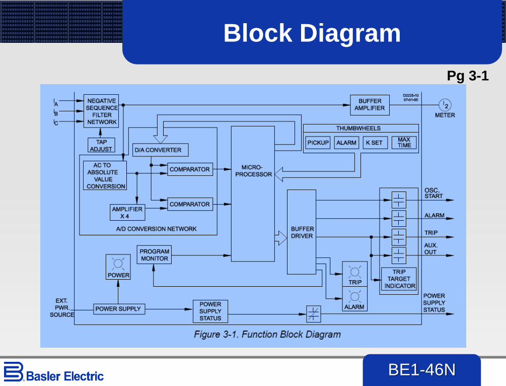
Block Diagram
Pg 3-1

BE1-46N
Single-Phase Calcs
Pg 3-6
With a generator FLC = 3.92A, and a 50% I2 pickup:
Single-phase test source

BE1-46N
Three-Phase Calcs Pg 3-6
With a generator FLC = 3.92A, and a 50% I2 pickup:

BE1-46N
46N Timing
Pg 3-9
K factor
specifies
approximate
delay at 100% I2

BE1-46N
DC Connections Pg 4-10

BE1-46N
AC Connections
Pg 4-11

BE1-46N
Internal Connections
Pg 4-12

BE1-46N
Testing
Follow test routine in the instruction manual, at page 5-2
Your Lab Facilitator can help you do a 3-phase test
Pg 5-1

BE1-46N
Single-Phase Testing Pg 3-5
When testing with single-phase source,
I2 = Isingle_phase / 3
Solve for Isingle_phase:
Isingle_phase = 3 • (Inominal) • I2pu

BE1-46N
Pick-up Tests
Single-Phase Test
Inject current into one of the phases and ramp
up
The relay should pick up at 3 • (setting • TAP)
(Note– manufacturers are not agreed on
whether the setting should be based on a
single-phase quantity or a three-phase quantity)
BE1-46N
Three-Phase Test
Inject current into all phases
Reverse phase sequence (ABC to ACB)
Ramp up
The relay should pick up at (setting • TAP)

BE1-46N
Two-Phase Test
Inject current into two of the phases, 180
degrees apart
Ramp up
Relay should pick up at
173% • (setting • TAP)

BE1-46N
Two-Phase Test, cont.
If you have a single-phase test set, you can
jumper two phase inputs in series
Be sure polarity is reversed so the phases
are 180 degrees apart
Again, ramp to 173% • (setting • TAP)

BE1-46N
Timing Tests
Alarm
Test 3.0-second alarm delay by injecting
negative-sequence current above Alarm
pickup setting and time LED light
You can also monitor terminals 11-12 for
alarm output

BE1-46N
K Set Setting
Think of K SET setting as a time dial
Represents an inverse-time curve–the more negative-sequence current, the faster the relay responds
See graph from the IM–changing K SET moves curve up and down time axis
Similar to how time-dial setting moves an overcurrent curve up and down

BE1-46N
K SET I2t Heating

BE1-46N
Timing Tests
K SET Setting
Test the K SET setting delay by injecting negative-sequence current above the Pickup setting and time the pickup LED light
You can also monitor terminals 1-10 for the trip output
The time is based on this formula from IM 5-3:
If K = 10 and PU = 0.5 : (± 2 seconds)

BE1-46N
Test a Setting - 1
This is a setting for a small hydro generator. Set your relay
with these settings and test the relay.

BE1-46N
Test a Setting - 2
Next, do the following:
• Change TAP to 4.5
• K SET to 2
• Test again
Is there a difference between K SET time
and MAX TIME (see IM pg 5-3)?
Try different settings for K SET and MAX
TIME to get a sense of how these interact

BE1-46N
Questions?