Embed Size (px)
Citation preview
:)- . .] "�·
*Case Model No. (/) H, S BE1-GPS100 E Q) X BE1-1051 (j) >. H,S BE1-951 (/) ro F,H,S BE1-851 (.) -� X BE1-CDS220 E ::J H BE1-MMS100 z
M BE1-24 s BE1-25 M BE1-25/79S R BE1-25/79TR s BE1-27 s BE1-27/59 M,S BE1-320/U M,S BE1-32R s BE1-40Q s BE1-46N s BE1-47N s BE1-49 s BE1-50
(/) s BE1-50BF >. A, S BE1-50/51B co Qi a: c BE1-50/51 M Q) R > BE1-BPR u
� M,S BE1-51 a_ M,S BE1-51/27C
M,S BE1-51/27R M,S BE1-51TC s BE1-59 s BE1-59N s BE1-59NC s BE1-60 M BE1-67 M BE1-67N s BE1-79M s BE1-79S M,S BE1-810/U M,S BE1-87B s BE1-87G M BE1-87T R BE1-25A
PROTECTION and CONTROL DEVICES STANDARDS, DIMENSIONS
and ACCESSORIES
Relay Type Bulletin Generator Protection System UHQ Overcurrent Protection System UHS Overcurrent Protection System w/voltage UHR Overcurrent Protection System UHM Current Differential Protection System UHP Multifunction Metering System LAD Volts per Hertz Overexcitation UDN Sync-Check UBP Sync-Check/Single Shot Reclosing UBQ Sync-Check/Reclosing UDW Undervoltage UBF Over/Undervoltage UBF Directional Over/Underpower UBU Directional Power UBU Loss of Excitation UBW Negative Sequence Overcurrent UDJ WARRANTY Negative Sequence Voltage UDK INFORMATION Temperature UBJ Page2 Instantaneous Overcurrent UBC Breaker Failure UBT Time Overcurrent UHD Time Overcurrent UHE
RELAY STANDARDS Pages 2 and 3
Breaker Protection UHG Time Overcurrent UDA Time Overcurrent w/Voltage Control UDA CONSTRUCTION Time Overcurrent w/Voltage Restraint UDA Pages 4-6 Time Overcurrent w/Torque Control UDP Overvoltage UBF DIMENSIONS and Ground Fault Overvoltage UBG Capacitor Neutral Overvoltage UHF Voltage Balance UBS
DRILLING DIAGRAMS Pages 7- 19
Phase Directional Time Overcurrent UDQ Ground Directional Time Overcurrent UDR RELAY ACCESSORIES Multishot Reclosing UDL Pages 20-24 Single Shot Reclosing UBN Digital Frequency UBR High Impedance Bus Differential UHC Variable Percentage Differential UBK Transformer Differential UHA Automatic Synchronizer UIM
* A=A1 Case size; C=C1; F=F1; H=H1; M=M1; R-19" rack; S=S1; X=MX
§l Basler Electric P. 0. BOX 269 HIGHLAND, ILLINOIS 62249, U.S.A. PHONE 618-654-2341 FAX 618-654-2351
SDA-5 8-01 www .
Elec
tricalP
artM
anua
ls . c
om

PROTECTION and CONTROL DEVICES
2
WARRANTY
Basler Electric Company warrants its BE1 Numerical Systems to be free from defects in material and workmanship for a period of 7 years from date of shipment. It further warrants its BE1 Protective Relays to be free from defects in material and workmanship for a period of 5 years from date of shipment. To determine which of the two product lines an individual Protection and Control product belongs to, consult the table on the previous page (cover).
Basler Electric's sole obligation under its warranty shall be, at its option, to either issue a credit, or repair or replace an article or part thereof, which is proved to be other than as warranted.
If an article is claimed to be defective in material or workmanship, Basler Electric Company will either examine the articles on site or issue shipping instructions for return to the factory. This warranty shall not extend to any articles or parts that have been installed, used or serviced, other than in conformity with Basler Electric's applicable specifications, manuals, bulletins, or instructions, or if none, shall have been subjected to improper installation, misuse or neglect.
Complete warranty information can be found in Basler Electric's "Terms and Conditions of Sale" form FA 100001, located in the pricing section of the Basler Electric Power Products Catalog.
RELAY STANDARDS
APPLICABLE STANDARDS Basler Electric protective relays are designed to meet or exceed industry standards as well as those set by Basler Electric.
Industry Standards • IEEE C37.90-1989, IEEE Standard for Relays
and Relay Systems Associated with Electric Power Apparatus.
• IEEE C37.90.1-1989, IEEE Standard Surge Withstand Capability (SWC) Tests for Protective Relays and Relay Systems.
• IEEE C37.90.2, IEEE Trial-Use Standard on Withstand Capability of Relay Systems to Radiated Electromagnetic Interference from Transceivers.
• IEC 255-5, Electrical Relays, Part 5: Insulation Tests for Electrical Relays.
• IEC 255-6, Electrical Relays, Part 6: Measuring Relays with more than one Input Energizing Quantity. Includes high frequency disturbance test.
• IEC 255-22-2, Electrical disturbance tests for measuring relays and protection equipment, Electrostatic Discharge Tests
• IEC 255-22-3, Electrical disturbance tests for measuring relays and protection equipment, Radiated Electromagnetic Field Disturbance Tests IEC 255-22-4, Electrical disturbance tests for measuring relays and protection equipment, Fast Transient Disturbance Tests
• IEC 255-22-6, Electromagnetic Compatibility (E MC), Immunity to Conducted Disturbances, Induced by Radio-frequency Fields
• IEC 255-25, Limits and Methods of Measurement of Radio Disturbance Characteristics of Industrial, Scientific and Medical ( I S M) Radiofrequency Equipment
AGENCY RECOGNITION Relays requiring certification are submitted for recognition under U L 508, as well as CSA certification and CE compliance. Many models are recognized. Check with Basler Electric for the latest list.
GENERAL SPECIFICATIONS The following general specifications apply to all Basler BE1 Series protective relays. Functional specifications are found in the individual product bulletins.
Power supply voltages
Nominal Operating Voltage Frequency Voltage Range Range
48Vdc 24 to 60 Vdc N/A 125Vdc 62 to 150 Vdc N/A
110/120 Vac 90 to 132 Vac 40-70 Hz 24 Vdc 14 to 32 Vdc N/A 48 Vdc 24 to 60 Vdc N/A
125 Vdc 62 to 150 Vdc N/A 250 Vdc 140 to 280 Vdc N/A 230 Vac 190 to 270 Vac 40-70 Hz
www . El
ectric
alPar
tMan
uals
. com
PROTECTION and CONTROL DEVICES
RELAY STANDARDS, Continued
Output contacts Resistive Inductive
Rated Make 0.2 Carry Voltage sec. Continuous Break Break L/R
120/240 Vac 30A ?A ?A 0.3A 0.04
125 Vdc 30A ?A 0.3A 0.3A 0.04
250 Vdc 30A ?A 0.3A 0.3A 0.04
500 Vdc 15A ?A 0.1A --- ---
Output contact status is defined by Basler Electric as the state of the output contact when relay operating power has been removed. The following Tables define contact status for relays that have an "over" trip function, an "under" trip function or an "over/under" trip capability.
"Over" Trip Function
Operating Power ON Contact Operating Sensing Input Sensing Input Configuration Power Less Than Greater Than
OFF Trip Setting Trip Setting
Normally Open Open Closed Open (NO)
Normally Closed Closed Open Closed (NC)
"Under" Trip Function Operating Power ON
Contact Operating Sensing Input Sensing Input Configuration Power Less Than Greater Than
OFF Trip Setting Trip Setting
Normally Open Closed Open Open (NO) Normally Closed Open Closed Closed (NC)
"Over/Under" Trip Function
Operating Power ON
Contact Operating Sensing Input Sensing Input Configuration Power Less Than Greater Than
and Trip OFF Trip Setting Trip Setting Function
NO (Over) Open Open Closed NC (Over) Closed Closed Open
NO (Under) Open Closed Open NC (Under) Closed Open Closed
Targets Either current operated or internally operated targets may be selected. The individual relay product bulletin will identify the availability and configuration of targets for each model relay.
A current operated target requires a minimum of 0.2A (ac or de) to flow through the output trip circuit to actuate the indicator. This target type can only be specififed when the main output relay contacts are specified as normally open (NO).
An internally operated target is operated by an electronic signal in parallel with the output relay drive signal. This type of target may be selected for use with either normally open (NO) or normally closed (NC) output contacts.
Operating Temperature
-40° C (-40° F) to 70° C (158° F).
Vibration Withstands 2g in each of three mutually perpendicular planes over the frequency range of 10 to 500Hz without structural damage or degradation of performance.
Shock Withstands 15g in each of three mutually perpendicular planes without structural damage or degradation of performance.
3 www . El
ectric
alPar
tMan
uals
. com
PROTECTION and CONTROL DEVICES
RELAY CASES
A1
51
C1
M1
19" RACK F1
, -
I MX RACK H1 HALF-RACK
4 www . El
ectric
alPar
tMan
uals
. com

PROTECTION and CONTROL DEVICES
CONSTRUCTION OF A1, M1 and S1 CASES
Relay Case
Each case (A 1 , M 1 and S 1) consists of a fabricated steel and phenolic enclosure that is resistant to dust and moisture. They are designed to house either single or double-ended relay units with one or two connecting plugs as required for the specific relay type. Round, washer head terminal screws are located on the rear of the case for ease of connection. These cases are capable of semi-flush or projection mounting as shown in the dimension and drilling diagrams, pages 6 through 13.
Drawout Cradle
The relay unit (drawout cradle) is a steel frame that houses the motherboard, magnetics chassis and all printed circuit boards that are required for the specific relay type. Locking levers at the top and bottom secure the drawout cradle to the case and enable easy removal for inspection.
Connecting Plugs
One or two connecting plugs, as required, electrically connect the drawout cradle to the system interconnections at the top and/or bottom of the relay case. The contact fingers of the connecting plugs and the relay case and cradle terminal blocks are silver-plated.
Front Cover
The front cover is a gasketed phenolic frame with clear acrylic window to enable visual inspection of the relay's setting adjustments and indicators. The front cover is secured to the case by a flange at the top and a single sealable knob with screw inset at the bottom center of the front cover. The target reset lever projects from the bottom or front of the cover and enables the targets to be reset without removal of the front cover.
CONSTRUCTION OF C1 CASE
Relay Case
The C1 case is a fabricated steel enclosure resistant to dust and moisture. The case is available in only one size and is designed for semi-flush mounting. The case includes guides to support the cradle assembly when mounted horizontally or vertically. Round washer head terminal screws are located on the rear of the case for ease of connection, see page 14. External test provisions must be provided to test the relay in its case, or the drawout cradle may be removed for testing in a test jig.
Drawout Cradle
The relay unit (drawout cradle) consists of a steel chassis upon which all the parts for the relay are mounted. The cradle is designed so that the front cover cannot be installed on the case unless the cradle is fully inserted into the connection block on the rear of the relay case. Input current circuits are shorted when the cradle is removed from the case.
Front Cover
The front cover is molded out of clear flame retardant plastic conforming to the requirements of UL 508. The cover includes a target reset button that extends out from the front cover.
CONSTRUCTION OF RACK MOUNT CASES
Rack Mount Case
Rack mount cases conform to standard 19-inch rack mount dimensions. The heights of the cases are specified in terms of the number (n) of standard rack units. Each rack unit is 1.75 inches, and Basler cases range from 2 to 5 rack units. This is shown on page 16. The depth of rack mount cases varies depending on the relay model. Some relay models include built-in test provisions for testing the relay in the case. Other relay models require external provisions to test the relay in its case, or the relay module may be removed and tested in a test jig.
Construction All relays are made with drawout capability. Some units have several drawout modules; others have one complete drawout assembly.
Front Cover Front covers for rack mount cases come in two styles depending on the relay model. One has a glass window and the others are made with plastic windows. Covers include a means to reset targets without removing the cover.
5 www . El
ectric
alPar
tMan
uals
. com

6
CONSTRUCTION OF H1 and F1 CASES
Relay Cases
H1 and F1 cases are extruded, brushed aluminum, fabricated enclosures resistant to dust and moisture. Internal side extrusions act as a guide for the drawout assembly and provide a means to secure the drawout assembly in place with two knurled knobs on the faceplate. Surface mounted handles on the face of the drawout assembly facilitate extraction of the drawout assembly from the case. Terminal blocks in the rear of the case mate directly with the drawout assembly when it is in the fully-inserted position. Special automatic shorting terminal blocks at the rear of the case are used on all current transformer connections.
The H1 case is a half-rack design, two rack units (3.5") high. Using dovetail extrusions on the external sides of the case, two H1 cases can be fitted together to form a
standard 19" rack mount assembly. Optional adapter plates (pages 17 and 22) allow the H1 case to be used in a variety of applications. Two H1 case configurations are available. Relay style dictates which configuration will be used. The F1 case dimensions are similar to the Westinghouse FT11 case.
Drawout Assembly
The drawout assembly is a unitized, fabricated aluminum cradle. The assembly contains all of the PC boards used in the relay. The front of the drawout assembly serves as the face/cover for the relay assembly. Threaded bolts with knurled knobs on the faceplate fasten the drawout assembly securely to the case. Handles mounted on the faceplate aid in extracting the drawout assembly from the case.
CONSTRUCTION OF MX CASES
Relay Cases
MX cases are painted, aluminum fabricated enclosures, resistant to dust and moisture when fitted with the optional cover. Internally mounted guides on the ends of the case aid in directing the drawout assembly to the case terminals at the back of the case during insertion. Terminal blocks in the rear of the case mate directly with the drawout assembly when it is in the fullyinserted position. Special automatic shorting terminal blocks at the rear of the case are used on all current transformer connections.
Three MX case configurations are available. Relay style dictates which configuration will be used.
Drawout Assembly
The drawout assembly is a unitized, fabricated aluminum cradle. It contains all of the PC boards used with the relay. The front of the drawout assembly serves as the face/cover for the relay assembly. Locking levers at the ends of the drawout assembly face/cover aid in the extraction and insertion of the assembly, and provide a means for securing the assembly to the case. The drawout assembly is available in either vertical or horizontal configurations.
Front Cover
The optional front cover is a single piece, clear acrylic unit. Screw-driven levers at the ends of the cover secure it to the relay case. A target reset button is provided on the front of the cover.
www . El
ectric
alPar
tMan
uals
. com
PROTECTION and CONTROL DEVICES
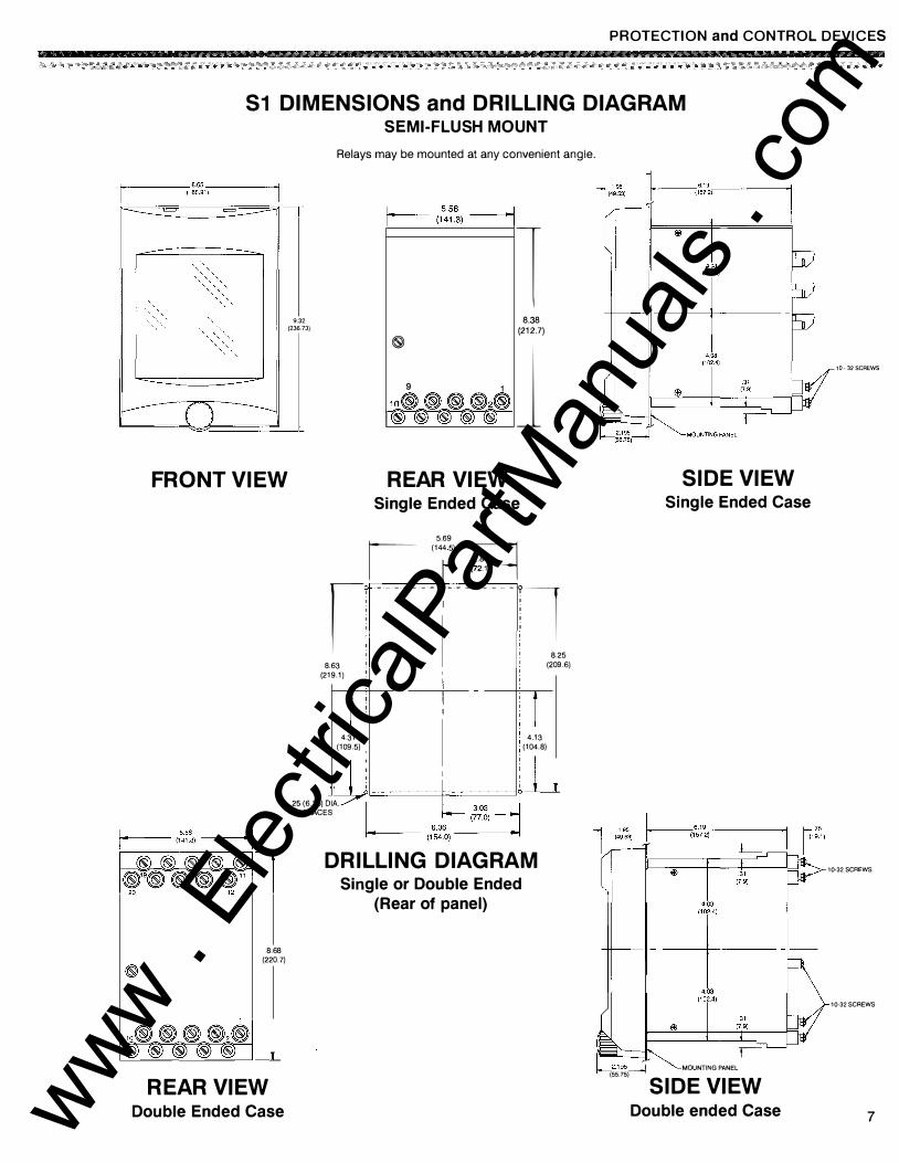
S1 DIMENSIONS and DRILLING DIAGRAM SEMI-FLUSH MOUNT
FRONT VIEW
8. 6 8 (220.7)
REAR VIEW Double Ended Case
9.32 (236.73}
Relays may be mounted at any convenient angle.
I--- 5.56 ----J 1 (141.3) 1
�
9 1 10®®®®2® ICW CW CW CW CW
1 8.38
(212.7)
J REAR VIEW
Single Ended Case
I (1�:
95) �
I! - -·- -·- - ,- - -·- -·- - ll I I i ! 8.25
8.63 I I (209.6) (219.1)
4.31 (109.5)
4.13 (104.8)
.25 (6.35) DIA. 4 PLACES
DRILLING DIAGRAM Single or Double Ended
(Rear of panel)
SIDE VIEW Single Ended Case
t2.195 ---J MOUNTING PANEL r-(55.75) SIDE VIEW
Double ended Case
10- 32 SCREWS
10-32 SCREWS
10-32 SCREWS
7 www . El
ectric
alPar
tMan
uals
. com
PROTECTION and CONTROL DEVICES
8
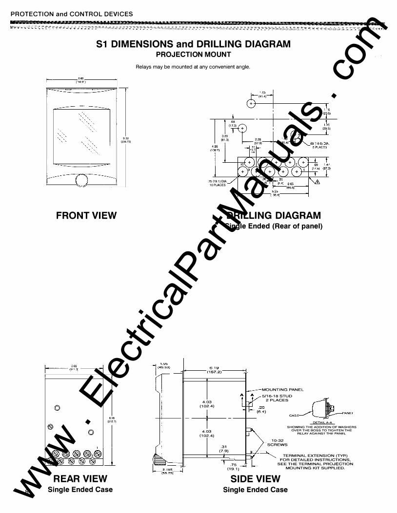
S1 DIMENSIONS and DRILLING DIAGRAM PROJECTION MOUNT
FRONT VIEW
It--•�-- (1s4��l __ __,_,I r---------------�,-�
8.38 (21 2.7)
REAR VIEW Single Ended Case
9.32 {236.73)
Relays may be mounted at any convenient angle.
0 1 63
� +
(41.4)
.68 +
3.20
(1np_.3)
(81.3) 2.28 (57.9)
'
I 1.16 (29.5)
.75 (19.1) DIA. 10 PLACES
4.03 (102.4)
DRILLING DIAGRAM Single Ended (Rear of panel)
MOUNTING PANEL
5/16-18 STUD 2PLACES �
-+------+-- CAS�PANEL
DETAIL A-A SHOWING THE ADDITION OF WASHERS
OVER THE BOSS TO TIGHTEN THE RELAY AGAINST THE PANEL 4.03 (102.4)
.31 (7.9)
T--: .75 ---1
(19.1)
10-32 SCREWS
TERMINAL EXTENSION (TYP.) FOR DETAILED INSTRUCTIONS,
SEE THE TERMINAL PROJECTION MOUNTING KIT SUPPLIED.
SIDE VIEW Single Ended Case www .
Elec
tricalP
artM
anua
ls . c
om
PROTECTION and CONTROL DEVICES
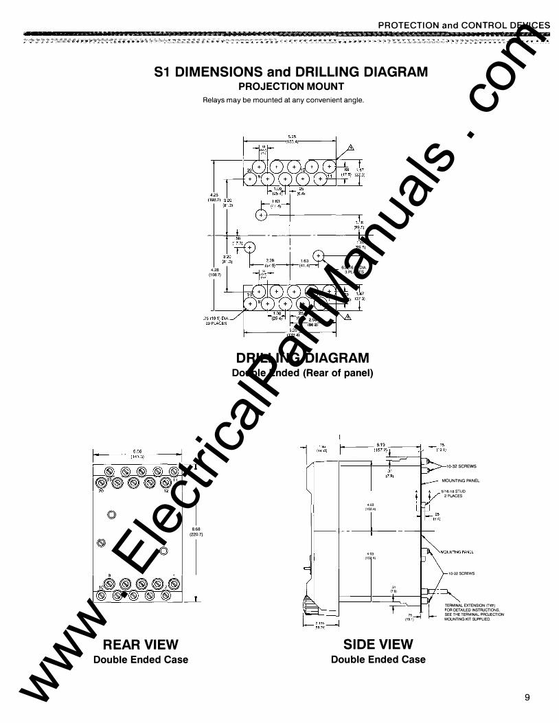
51 DIMENSIONS and DRILLING DIAGRAM PROJECTION MOUNT
Relays may be mounted at any convenient angle.
4.28 (108.7)
1.16
1.63
� �r� (41.4) 63 (16.0) DIA.
3 PLACES
DRILLING DIAGRAM Double Ended (Rear of panel)
403 (1024)
10-32 SCREWS
MOUNTING PANEL
5/16-18 STUD
2 PLACES
8.68
(220.7) �-+----+----
REAR VIEW Double Ended Case
403 (1024)
" (79)
1,, (19.1�
SIDE VIEW Double Ended Case
10-32 SCREWS
L TERMINAL EXTENSION (TYP.) FOR DETAILED INSTRUCTIONS, SEE THE TERMINAL PROJECTION
MOUNTING KIT SUPPLIED.
9 www . El
ectric
alPar
tMan
uals
. com
PROTECTION and CONTROL DEVICES
10
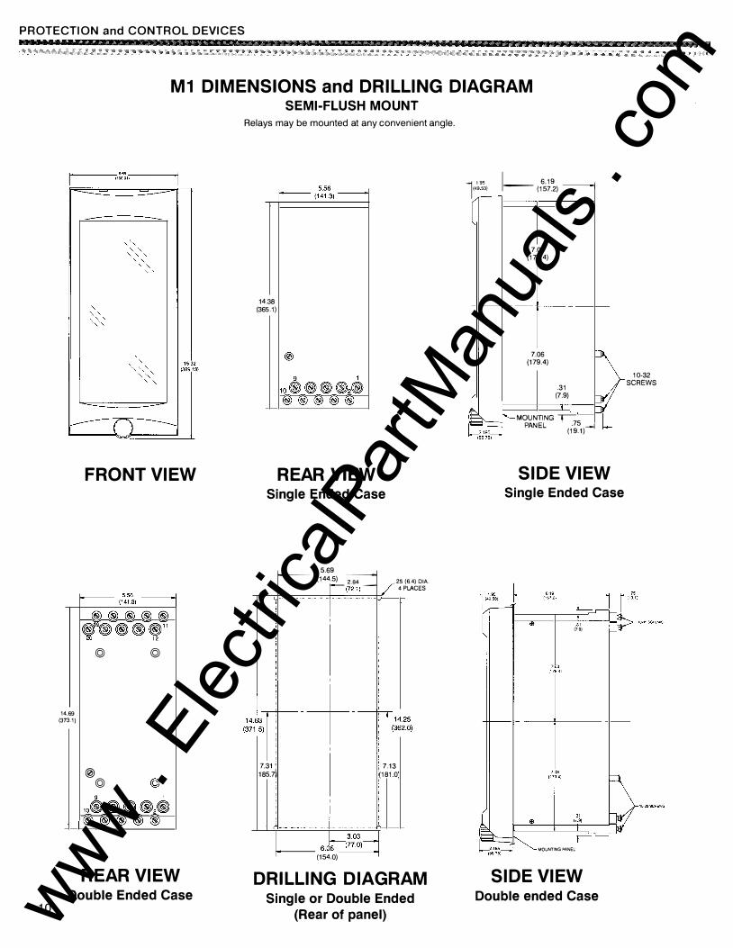
M1 DIMENSIONS and DRILLING DIAGRAM SEMI-FLUSH MOUNT
14.69 (373.1)
FRONT VIEW
1-------- 5.56 --------1 1 (141 31 1
@ @
@ @
REAR VIEW Double Ended Case
Relays may be mounted at any convenient angle.
14.38 (365.1)
I---- 5.56 -------1 1 (141 31 1
REAR VIEW Single Ended Case
7.31' 185.7�
(144.5) 2.84 1 5.69 M r-(72.1) . - - � · - . --
,
1--,3 0�,
-1---- 6.06 (77 .0)
(154.0)
25 (6.4) DIA.
4 PLACES
'7.13 �181.0
DRILLING DIAGRAM Single or Double Ended
(Rear of panel)
l 195 1 6.19 _ (4953) -- (157.2) '
7.06 (179.4)
7.06 (179.4)
.31 (7.9)
MOUNTING j, PANEL .75 --1
(19.1)
SIDE VIEW Single Ended Case
<lj 31 (79)
MOUNTING PANEL
SIDE VIEW Double ended Case
10-32 SCREWS
www . El
ectric
alPar
tMan
uals
. com
PROTECTION and CONTROL DEVICES
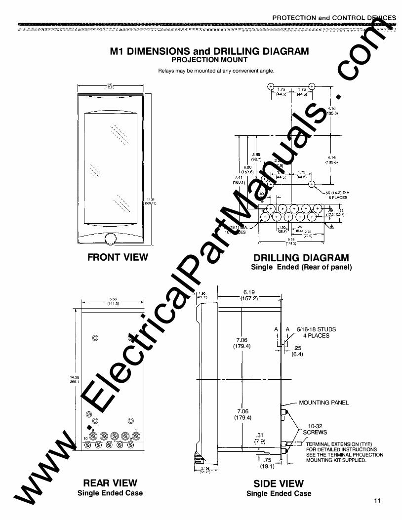
M1 DIMENSIONS and DRILLING DIAGRAM PROJECTION MOUNT
1--------.,.('1��1 . .,-) ------1
FRONT VIEW
556 (141.3)
© ©
4.38 65.1
@ © © 9 1
1o@@@@l�) @)@)@)@5@5
REAR VIEW Single Ended Case
Relays may be mounted at any convenient angle.
.75 (19.1) DIA. 10 PLACES
DRILLING DIAGRAM Single Ended (Rear of panel)
I 6.19 1-(157.2) ---l
7.06 (179.4)
7.06 (179.4)
A A 5/16-18 STUDS I I 4 PLACES ·� .25
(6.4)
MOUNTING PANEL
10-32 .31 SCREWS
f---
--1,...---(
--17,.--.9-) ---t:-::T : �ERMINAL EXTENSION (TYP.)
FOR DETAILED INSTRUCTIONS SEE THE TERMINAL PROJECTION MOUNTING KIT SUPPLIED. T75
(19.1)-l
SIDE VIEW Single Ended Case
11 www . El
ectric
alPar
tMan
uals
. com
PROTECTION and CONTROL DEVICES
14 (37
:--
.69 3.1)
'--
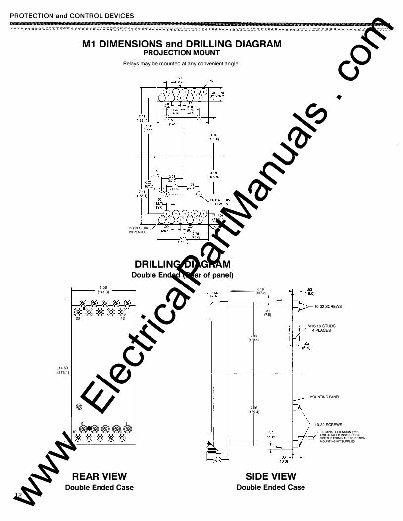
M1 DIMENSIONS and DRILLING DIAGRAM PROJECTION MOUNT
Relays may be mounted at any convenient angle .
. 75 (19.1) DIA 20 PLACES
DRILLING DIAGRAM Double Ended (Rear of panel)
5 56 I· (141.3) 6.19 ----(157.2) -,--i ------1
@@@@@ !fi®®®11
20 12
@ 9 1
10 ®®®�® ®®®®®
REAR VIEW
7.06 (179.4)
7.06 (179.4)
.31 (7.9)
SIDE VIEW
10-32 SCREWS
5/16-18 STUDS 4 PLACES
MOUNTING PANEL
10-32 SCREWS
�TERMINAL EXTENSION (TYP.) FOR DETAILED INSTRUCTION �: SEE THE TERMINAL PROJECTION MOUNTING KIT SUPPLIED.
Double Ended Case Double Ended Case 12 www .
Elec
tricalP
artM
anua
ls . c
om
PROTECTION and CONTROL DEVICES
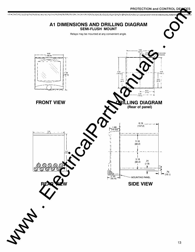
A1 DIMENSIONS AND DRILLING DIAGRAM SEMI-FLUSH MOUNT
6.65 r----(16 8.9 1) -----i
FRONT VIEW
556 (141.3)
663 (168.3)
REAR VIEW
Relays may be mounted at any convenient angle.
I I
2.84 .25 (6.4) DIA 1(1���5)� (72.2) 4 PlACES
r I l 663 -+-(168.3) - - 6.50 (165.1) 3.31 1 ,�:2�, I
j__j_()\,(841 }
�==:d6il L �;��} 6.06 (1 54.0)
DRILLING DIAGRAM (Rear of panel)
6.19 ----J (157.2)
I
+-3.16
(80.2)
3.16 (80.2)
-.-----J �(1��) MOUNTING PANEL
SIDE VIEW
13 www . El
ectric
alPar
tMan
uals
. com
PROTECTION and CONTROL DEVICES
14
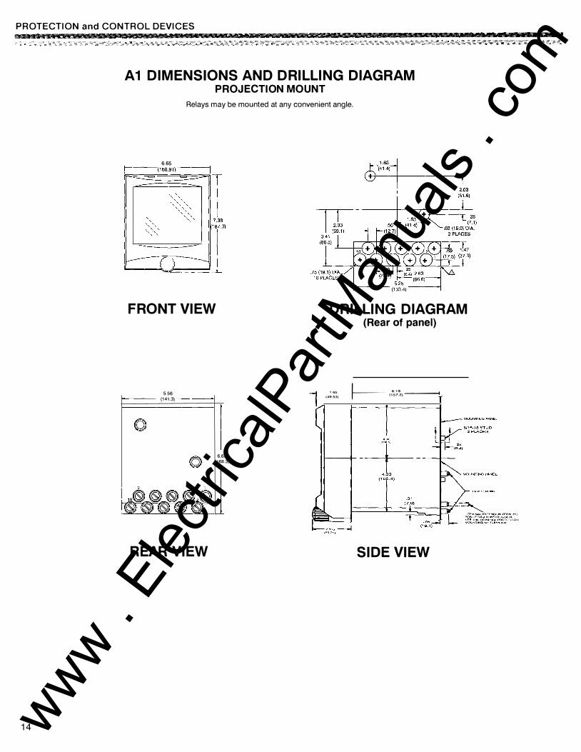
A1 DIMENSIONS AND DRILLING DIAGRAM PROJECTION MOUNT
Relays may be mounted at any convenient angle.
6.65 1----(168.91) ----j
FRONT VIEW
5.56 (141.3)
REAR VIEW
6.63 (168.3)
DRILLING DIAGRAM (Rear of panel)
"' �·-- 6.'9 --� (49.53) (157.2)
SIDE VIEW
www . El
ectric
alPar
tMan
uals
. com
0
� 0
9 I
PROTECTION and CONTROL DEVICES
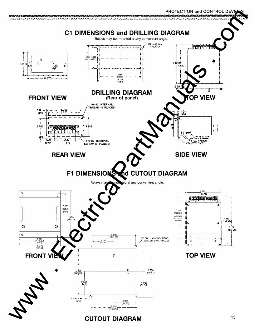
C1 DIMENSIONS and DRILLING DIAGRAM
1---- 6.875 -------1
FRONT VIEW
Relays may be mounted at any convenient angle.
_;- .187 (4.7) DIA. m _. _ . _. _ . _ . _ . _ . . _ . _ . _ . _ ·- . _ ·- · 1 4 PLACES
I . I
3.550 2.900 j + I
(90�.2) (73.7) i - - -- - : I .
I
·- · ·-�-·- · -·- · - ·- ·
5.690 (144.5) 6.250 (158.8)
DRILLING DIAGRAM (Rear of panel)
#8-32 INTERNAL THREAD (4 PLACES)
#10-32 TERMINAL SCREW (8 PLACES)
REAR VIEW
.850 r-
TOP VIEW
SIDE VIEW
F1 DIMENSIONS and CUTOUT DIAGRAM
5.563 (141.30)
(TYP) 6.376
(161.95)
o-Goo [ 0
<( I
(165.1) (TYP)
7.2 50 15) (184.
t--
FRONT VIEW
.875 r 9.23)
5 (14
.125 R I
2.938 (7r)
. (4PLc·sV 3.18)
Relays may be mounted at any convenient angle.
r= 5.563�
(141.30) .250 DIA .. . 190·32 MOUNTING 2.781� v (6.35) SCREWS. (4 PLC"S) (70.64)
(f)
(
c L
fil (_..._,2.938 (74.63)--
5.875 (149.23)
6.50
31 0 1) (16 .
(82r5)
CUTOUT DIAGRAM
I -��� ���,��;�-rl 7.10
(180.34) Alternate mounting 7.850 location ) L�Uuuum t� .Jr�
TOP VIEW
15 www . El
ectric
alPar
tMan
uals
. com
PROTECTION and CONTROL DEVICES
o c � 0
0 6;) l0 � I
�
(±)
[\..._ -
I (±)
I
16
H1 DIMENSIONS
Relays may be mounted at any convenient angle.
� 6;)
9.815 (249.3)
10.500 (266.7)
FRONT VIEW
TOP VIEW
(±)
(±)
7.850 (199.4)
9.100 231.1
SIDE VIEW
� -cD ! CD IT 3.47 (88.1
"1.750 TYP. (44.5)
LI 3000
CB-(76.2)
T :=.CB I
0] 5J OJ
www . El
ectric
alPar
tMan
uals
. com
PROTECTION and CONTROL DEVICES
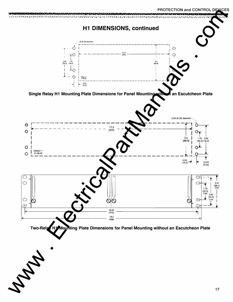
H1 DIMENSIONS, continued
� --.25 (6.35) diameter 1 1£ ;---------------�----------r---.: : 3.00 1.75
(76.2) (44.5)
L1 I 3.5 I
i �-------------------------L ___ ! : I 0.53 � -(13.5)
Single Relay H1 Mounting Plate Dimensions for Panel Mounting without an Escutcheon Plate
0.25 (6.35) diameter·� 0 .--------------------------------[ , \'
0 , ,':,� 1 ·: ; r I 3.s I 1.75 3.oo
� l = -----------------------------�IJ �'l 0.53 J
(13.5)1 0.375 (9.53)
oc P CDj t 0 � ��� � CD-1.
3.4 (88.1
7 )
1.75 TYP (44.5) TYP 3.00
0�·(76.2) 0 (S) (S)!(S) (9 p $ J ,Q) c ,
L 18.52 .I I (470) "I
19.2 (488)
Two-Relay H1 Mounting Plate Dimensions for Panel Mounting without an Escutcheon Plate
17 www . El
ectric
alPar
tMan
uals
. com
PROTECTION and CONTROL DEVICES
18
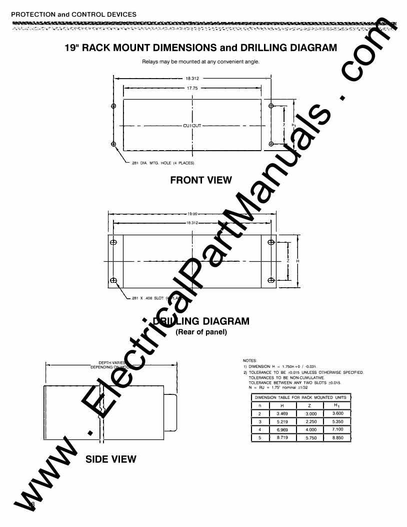
19 .. RACK MOUNT DIMENSIONS and DRILLING DIAGRAM
Relays may be mounted at any convenient angle.
1--------- 18.312
1--------- 17.75 --------1
' I L---------�--- -
--------C_U_T, I-OU _T_-_-_
-_-_-_-_-_-_-_-__ ...-.J ill
.281 DIA. MTG. HOLE (4 PL ACES)
FRONT VIEW
I...__� --19.00------�: I . 18.312 "
I E9
IE�
! - I -
'
I \_ .281 X .406 SLOT 4 PL ACES
I
DRILLING DIAGRAM (Rear of panel)
E:T
E:T
11 Z H
dl
DEPTH VARIES =J DEPENDING ON MODEL
n---------l
NOTES:
1) DIMENSION H � 1.750n +0 I -0.031.
2) TOLERANCE TO BE ±0.015 UNLESS OTHERWISE SPECIFIED. TOLERANCES TO BE NON-CUMULATIVE. TOLERANCE BETWEEN ANY TWO SLOTS ±0.015. N � RU � 1.75" nominal ±1/32
---., DIMENSION TABLE FOR RACK MOUNTED UNITS
n H z H1 2 3.469 3.000 3.600
3 5.219 2.250 5.350
4 6.969 4.000 7.100
5 8.719 5.750 8.850
SIDE VIEW
www . El
ectric
alPar
tMan
uals
. com
PROTECTION and CONTROL DEVICES
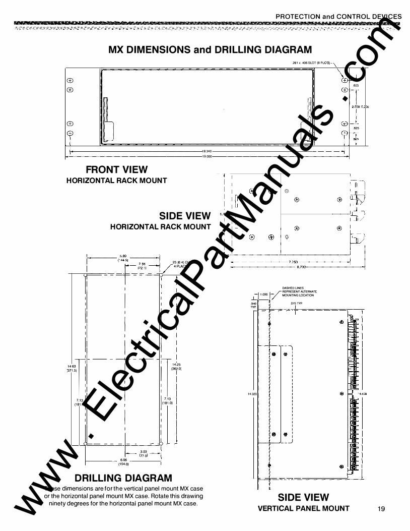
MX DIMENSIONS and DRILLING DIAGRAM
(±)
(±)
(±) J ll I
FRONT VIEW HORIZONTAL RACK MOUNT
18.340
19.000
SIDE VIEW HORIZONTAL RACK MOUNT
1 (1�=��� 25 ( 6 4) DIA . LACES r-- . 84 4P (72.1)
r--- -r-
I
I I I I I
I I I I I I I I I
I I I I -- - -----+--- - -- - I
;;,-,� I �"" (362.0 I
I 713 1 , 7.13 (181.0) I (181.0) I I I I I l I
r------- (;a�, -6.06 (1 54.0) DRILLING DIAGRAM
These dimensions are for the vertical panel mount MX case or the horizontal panel mount MX case. Rotate this drawing
ninety degrees for the horizontal panel mount MX case.
.2 1 X .406 SLOT (8 P C'S) L J �
\r W-.625
CB-IT [ CB-
[ 5.220
.625 f II 810
J
r� ©
I�u __ ®_� --®�-©-
®
-------
®
� 1-------7.750--------1·1 ' i--------- 8.700--�·
DASHED LINES /REPRESENT ALTERNATE � 1.000 � MOUNTING LOCATION
j__" :iv� lj .075 TYP.
14.320
--, • Ql- :
I I I I I I
I I I I
e •: lt----'.1----"·- -_)
SIDE VIEW VERTICAL PANEL MOUNT 19 www .
Elec
tricalP
artM
anua
ls . c
om
PROTECTION and CONTROL DEVICES
RELAY ACCESSORIES
Accessories
The Basler Electric Company offers several accessories to aid in the testing, calibrating and troubleshooting of protective relays. The accessories available through Basler Electric are described in the paragraphs that follow.
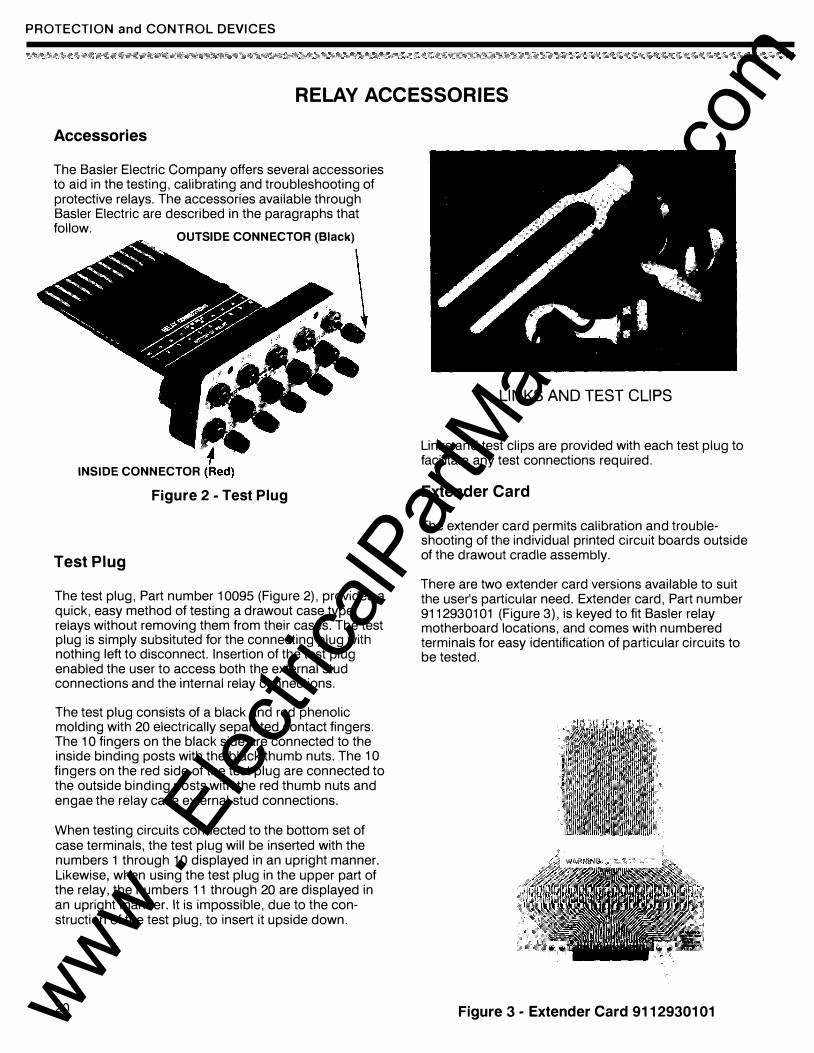
OUTSIDE CONNECTOR {Black)
INSIDE CONNECTOR
Figure 2 - Test Plug
Test Plug
\
The test plug, Part number 10095 ( Figure 2), provides a quick, easy method of testing a drawout case type relays without removing them from their cases. The test plug is simply subsituted for the connecting plug with nothing left to disconnect. Insertion of the test plug enabled the user to access both the external stud connections and the internal relay connections.
The test plug consists of a black and red phenolic molding with 20 electrically separated contact fingers. The 1 0 fingers on the black side are connected to the inside binding posts with the black thumb nuts. The 10 fingers on the red side of the test plug are connected to the outside binding posts with the red thumb nuts and engae the relay case external stud connections.
When testing circuits connected to the bottom set of case terminals, the test plug will be inserted with the numbers 1 through 10 displayed in an upright manner. Likewise, when using the test plug in the upper part of the relay, the numbers 11 through 20 are displayed in an upright manner. It is impossible, due to the construction of the test plug, to insert it upside down.
20
LINKS AND TEST CLIPS
Links and test clips are provided with each test plug to facilitate any test connections required.
Extender Card
The extender card permits calibration and troubleshooting of the individual printed circuit boards outside of the drawout cradle assembly.
There are two extender card versions available to suit the user's particular need. Extender card, Part number 9112930101 ( Figure 3), is keyed to fit Basler relay motherboard locations, and comes with numbered terminals for easy identification of particular circuits to be tested.
Figure 3 - Extender Card 9112930101 www . El
ectric
alPar
tMan
uals
. com
PROTECTION and CONTROL DEVICES
RELAY ACCESSORIES, continued
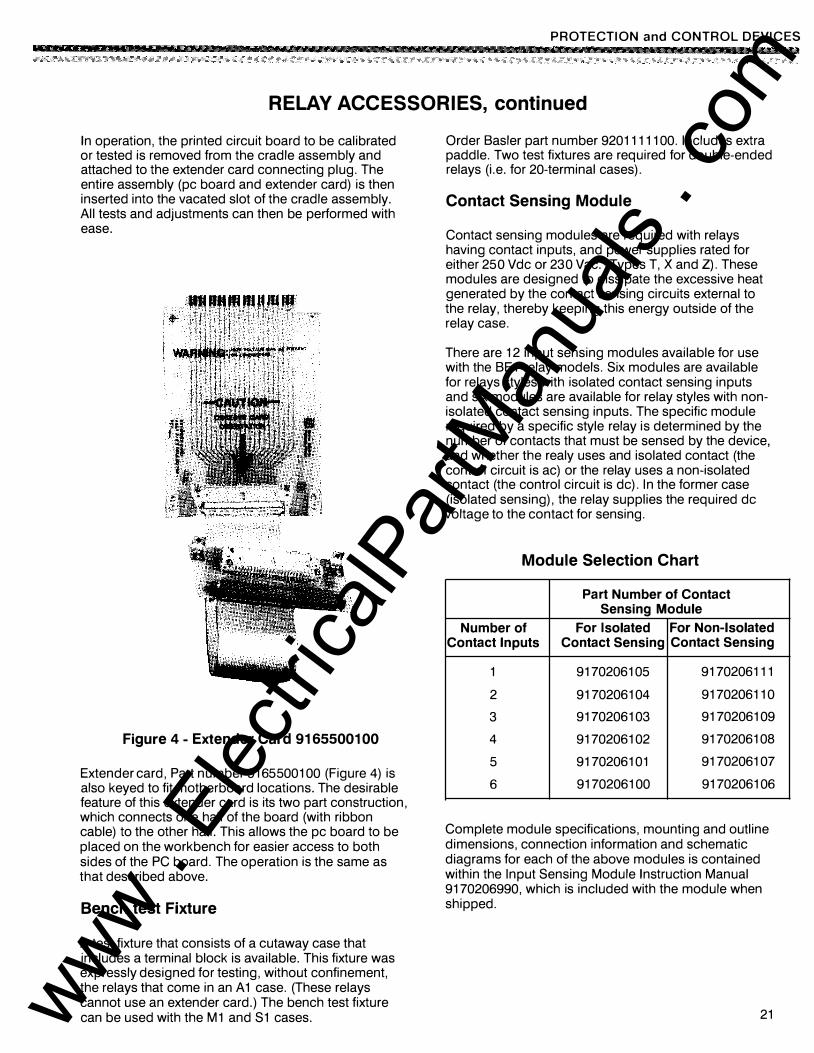
In operation, the printed circuit board to be calibrated or tested is removed from the cradle assembly and attached to the extender card connecting plug. The entire assembly (pc board and extender card) is then inserted into the vacated slot of the cradle assembly. All tests and adjustments can then be performed with ease.
Figure 4 - Extender Card 91655001 00
Extender card, Part number 9165500100 ( Figure 4) is also keyed to fit motherboard locations. The desirable feature of this extender card is its two part construction, which connects one half of the board (with ribbon cable) to the other half. This allows the pc board to be placed on the workbench for easier access to both sides of the PC board. The operation is the same as that described above.
Bench test Fixture
A test fixture that consists of a cutaway case that includes a terminal block is available. This fixture was expressly designed for testing, without confinement, the relays that come in an A 1 case. (These relays cannot use an extender card.) The bench test fixture can be used with the M1 and S1 cases.
Order Basler part number 9201111100. Includes extra paddle. Two test fixtures are required for double-ended relays (i.e. for 20-terminal cases).
Contact Sensing Module
Contact sensing modules are required with relays having contact inputs, and power supplies rated for either 250 Vdc or 230 Vac. (Types T, X and Z). These modules are designed to dissipate the excessive heat generated by the contact sensing circuits external to the relay, thereby keeping this energy outside of the relay case.
There are 12 input sensing modules available for use with the B E1 relay models. Six modules are available for relays styles with isolated contact sensing inputs and six modules are available for relay styles with nonisolated contact sensing inputs. The specific module required by a specific style relay is determined by the number of contacts that must be sensed by the device, and whether the realy uses and isolated contact (the control circuit is ac) or the relay uses a non-isolated contact (the control circuit is de). In the former case (isolated sensing), the relay supplies the required de voltage to the contact for sensing.
Module Selection Chart
Part Number of Contact Sensing Module
Number of For Isolated For Non-Isolated Contact Inputs Contact Sensing Contact Sensing
1 9170206105 9170206111
2 9170206104 9170206110
3 9170206103 9170206109
4 9170206102 9170206108
5 9170206101 9170206107
6 9170206100 9170206106
Complete module specifications, mounting and outline dimensions, connection information and schematic diagrams for each of the above modules is contained within the Input Sensing Module Instruction Manual 9170206990, which is included with the module when shipped.
21 www . El
ectric
alPar
tMan
uals
. com
PROTECTION and CONTROL DEVICES
RELAY ACCESSORIES, continued
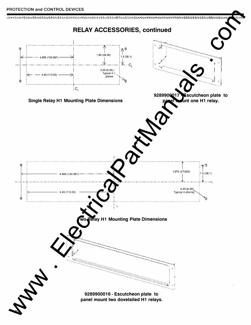
;----------------------------------------------f-------, <t> : I : <t> : I :if ' 1 1 9o (48.26) :
i 4 905 (124.587) >: t : 1 5 (38 1)
-- �------------- � ------------ i �- c 1 I I L
l 1 o.25 (6.35) �: : 4.45 (113_03) ' Typical4 :
1 1 places 1
$ l _ _ _ _ ____ _ _ _ __ _ _ _ __ _ _ _ _ __ _ _ _ � _ _ _ _ _ __ _ _ _ _ _ _ _ ____ _ _ _ _ _ _ _ _ _ j ; CL
Single Relay H1 Mounting Plate Dimensions
I
9289900017 - Escutcheon plate to panel mount one H1 relay.
$ · · · · · · · · · · · · · · · · · · · · · · · · · · · · · · · · · · · · · · · · · · · · · · · · · · · · · · · · · · · · .... .... i...........................
r :T. 1.875 (47.625) : . 4.905 (124.587) I l :1.5 (38.1)
-·- -·l·-·-·-·-·-·-·-·-·-·-·-·-·-·-·-·-·-·-·-·-·-·-·-·�·-·-·-·-·-·-·-·-·-·-·-·-·-·-·-·-·-·- -·-·-·-·�·1·-·-C,
22
� i . I 0.25 (6.35)k:
$ 4.45 (113.03) ------�: Typical 4 places
, �
: ............................................................................. ! .................................... ...................................... ." I i CL
Two-Relay H1 Mounting Plate Dimensions
9289900016 - Escutcheon plate to
panel mount two dovetailed H1 relays.
www . El
ectric
alPar
tMan
uals
. com
PROTECTION and CONTROL DEVICES
RELAY ACCESSORIES, continued
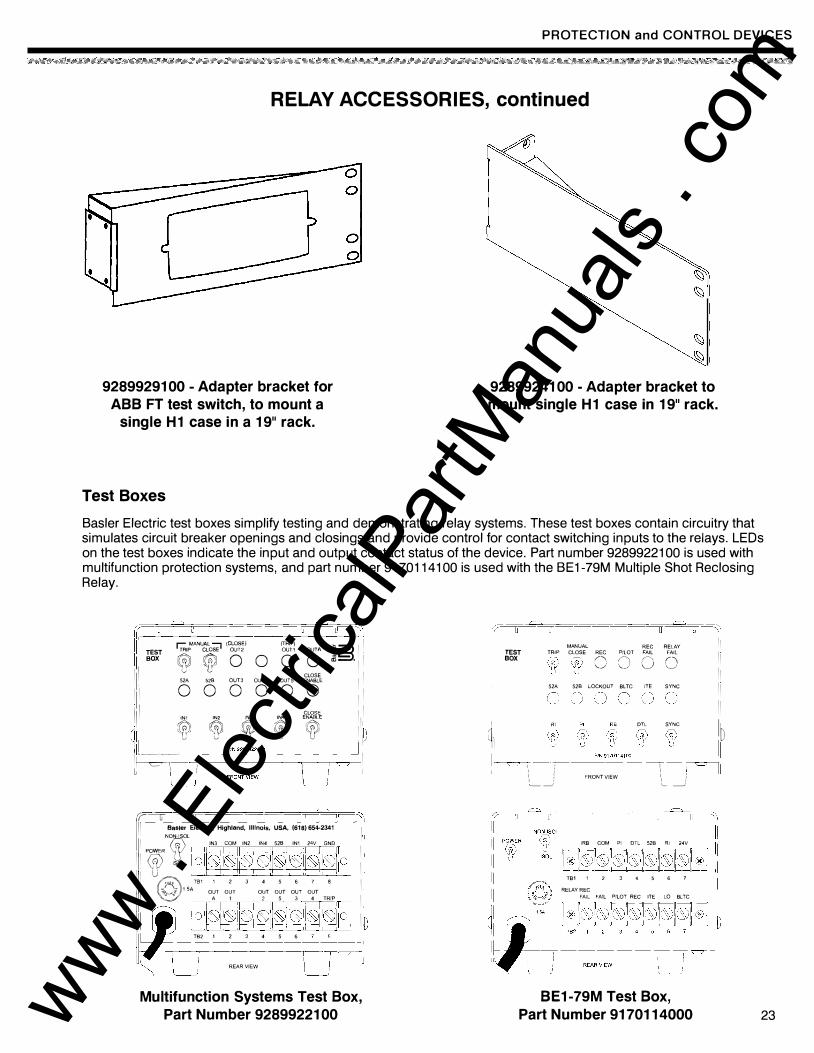
92899291 00 - Adapter bracket for ABB FT test switch, to mount a
single H1 case in a 19" rack.
Test Boxes
92899241 00 - Adapter bracket to mount single H1 case in 19" rack.
Basler Electric test boxes simplify testing and demonstrating relay systems. These test boxes contain circuitry that simulates circuit breaker openings and closings and provide control for contact switching inputs to the relays. L EOs on the test boxes indicate the input and output contact status of the device. Part number 9289922100 is used with multifunction protection systems, and part number 9170114100 is used with the B E1-79M Multiple Shot Reclosing Relay.
(rl�----111 ���T �M
AN
U�7 (Cg�) 0 g 0 J§.l� � Ill CLOSE I ' 52A 528 OUT3 OUT4 OUTS ENABLE I Ill o o o o o o 11 ill CCOSE Ill n111 � � � � 'C@' 1 h l1 P/N9289922100 J�� 1·-- I �1 1 I 1=u L_) FAONTVIEW \ ___ _ )'
7----u-----u----- U I Ill Basler Electric, Highland, Illinois, USA, (618)654-2341 I NON-I SOL I <{? IN3 COM IN2 IN4 526 IN1 24V GND I I P�R
��0, i'1°1!oliojioiiol]o)ioiio(io i I II @�' TB1 1 2 3 4 5 6 7 8 I II ;Q 1 SA OUT OUT OUT OUT OUT OUT A 1 2 5 3 4 TRIP I ql � Hlo[io!l0m]§i)oiioiH I
TB21 2 3 4 56 7�
REAR VIEW
Multifunction Systems Test Box, Part Number 9289922100
(r----o -=---c--� �-------u���� MANUAL REC RELAY II TEST TRIP CLOSE REG PILOT FAIL FAIL II BOX C) 0 0 0 II
52A 528 LOCKOUT BL TC JTE SYNC I I II 11 Rl DTC SYNC lo I L� ----�91701141�-- �! L [ � II i I
I i u 11 ,: FRONT VIEW 11 ,: ,________! L- _)
IRB COM PI DTL 528 Rl 24Y
TB1 1 2 3 4 5 6 7 RELAY REC
FAIL FAIL PILOT REC ITE LO BLTC
BE1-79M Test Box,
Part Number 9170114000 23 www . El
ectric
alPar
tMan
uals
. com
PROTECTION and CONTROL DEVICES
RELAY ACCESSORIES, continued
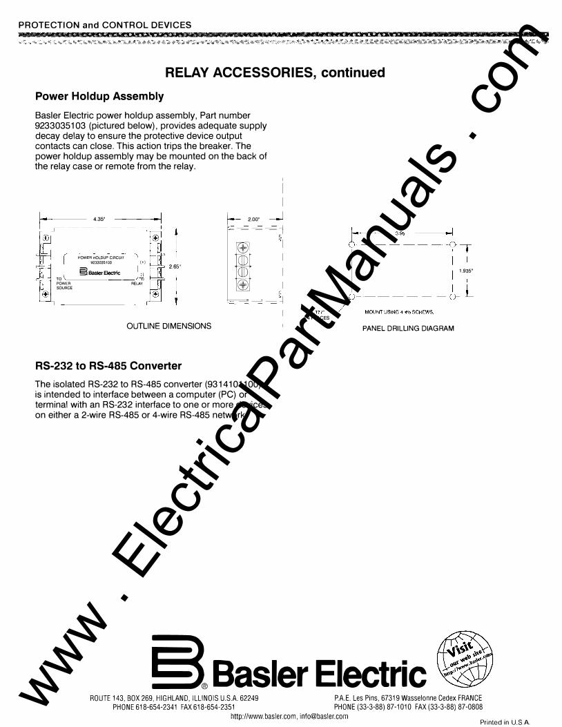
Power Holdup Assembly
Basler Electric power holdup assembly, Part number 92330351 03 (pictured below), provides adequate supply decay delay to ensure the protective device output contacts can close. This action trips the breaker. The power holdup assembly may be mounted on the back of the relay case or remote from the relay.
·�· �--:� 1 t= 2.00''
POWER HOLDUP CIRCUOT
I±J
9233035103 (+) §.Basler Electric
2.65''
-
[
1.935'' ll TO �� tiJ POWER RELAY SOURCE
I±J [ .177"" J -M-OU_N
_T U
-S-ING_4_# _8 S-CR
-E-W S-
.
_u OUTLINE DIMENSIONS
RS-232 to RS-485 Converter
The isolated R S-232 to R S-485 converter (93141 011 00) is intended to interface between a computer (PC) or terminal with an R S-232 interface to one or more devices on either a 2-wire R S-485 or 4-wire RS-485 network.
4 PLACES
PANEL DRILLING DIAGRAM
§®Basler Electric ROUTE 143, BOX 269, HIGHLAND, ILLINOIS U.S.A. 62249 P.A.E. Les Pins, 67319 Wasselonne Cedex FRANCE
PHONE 618-654-2341 FAX 618-654-2351 PHONE (33-3-88) 87-1010 FAX (33-3-88) 87-0808
http://www.basler.com, [email protected] Printed in U.SA
www . El
ectric
alPar
tMan
uals
. com