Embed Size (px)
Citation preview

Relion® 650 series
Bay control REC650 2.1 IECProduct guide

Contents
1. Application..................................................................... 3
2. Available functions..........................................................5
3. Control......................................................................... 12
4. Multipurpose protection................................................14
5. Secondary system supervision..................................... 14
6. Scheme communication...............................................15
7. Logic............................................................................ 15
8. Monitoring.................................................................... 17
9. Metering.......................................................................19
10. Human machine interface............................................20
11. Basic IED functions..................................................... 20
12. Station communication ...............................................20
13. Hardware description.................................................. 21
14. Connection diagrams.................................................. 23
15. Technical data............................................................. 24
16. Ordering for pre-configured IED...................................58
17. Ordering for Accessories............................................. 61
Disclaimer
The information in this document is subject to change without notice and should not be construed as a commitment by ABB. ABB assumes no responsibility for any
errors that may appear in this document. Drawings and diagrams are not binding.
© Copyright 2016 ABB.
All rights reserved.
Trademarks
ABB and Relion are registered trademarks of the ABB Group. All other brand or product names mentioned in this document may be trademarks or registered
trademarks of their respective holders.
1MRK 511 387-BEN BBay control REC650 2.1 IEC Product version: 2.1
2 ABB

1. ApplicationGUID-0021B61F-B1F1-4B39-81C5-E1FB78EA87ED v2
REC650 is used for the control, protection and monitoring ofdifferent types of bays in power networks. The IED isespecially suitable for applications in control systems withdistributed control IEDs in all bays with high demands onreliability. It is suitable for the control of all apparatuses in thefollowing switchgear arrangements:
• Single busbar, with a single circuit breaker• Double busbar, with a single circuit breaker
The control is performed from remote (SCADA/Station)through various communication protocols or from the localHMI.
Different control configurations can be used, and one controlIED per bay is recommended. Interlocking modules areavailable for common types of switchgear arrangements. Thecontrol is based on the select before execute principle to givehighest possible security. A synchronism control function isavailable to interlock breaker closing. A synchronizingfunction where breaker closes at the right instance inasynchronous networks is also provided..
Disturbance recording is available to allow independent post-fault analysis after primary disturbances.
One pre-configured package has been defined for thefollowing application:
• Single breaker for double busbar (A02)
The package is configured and ready for direct use. Analogand control circuits have been pre-defined and other signalsneed to be applied as required for each application. The pre-configured IED can be changed and adapted to suit specificapplications with the graphical configuration tool.
Forcing of binary inputs and outputs is a convenient way totest wiring in substations as well as testing configuration logicin the IEDs. Basically it means that all binary inputs andoutputs on the IED I/O modules (BOM, BIM and IOM) can beforced to arbitrary values.
Central Account Management is an authenticationinfrastructure that offers a secure solution for enforcingaccess control to IEDs and other systems within a substation.This incorporates management of user accounts, roles andcertificates and the distribution of such, a procedurecompletely transparent to the user.
The Flexible Product Naming allows the customer to use anIED-vendor independent 61850 model of the IED. Thiscustomer model will be used as the IEC 61850 data model,but all other aspects of the IED will remain unchanged (e.g.,names on the local HMI and names in the tools). This offerssignificant flexibility to adapt the IED to the customers systemand standard solution
Description of A02GUID-FC962706-6409-4D2D-9745-7A30F2C44A0D v1
Single breaker for double busbar.
1MRK 511 387-BEN BBay control REC650 2.1 IEC Product version: 2.1 Issued: June 2017
Revision: B
ABB 3

QB1
REC650 A02 – Double busbar in single breaker arrangement
S CILO
3 Control
S CSWI
3 Control
S XSWI
3 Control
S CILO
3 Control
S CSWI
3 Control
S XSWI
3 Control
SES RSYN
25 SC/VC
VN MMXU
MET UN
S CILO
3 Control
S CSWI
3 Control
S XCBR
3 Control
VN MMXU
MET UN
WA1
WA2
WA2_VT
WA1_VT
S CILO
3 Control
S CSWI
3 Control
S XSWI
3 Control
S CILO
3 Control
S CSWI
3 Control
S XSWI
3 Control
IEC09000649-5-en.vsd
Other Functions available from the function library
R ESIN
3 Control
CCS SPVC
87 INd/I
CV GAPC
2(I>/U<)
LMB RFLO
21FL FL
QB9
S CILO
3 Control
S CSWI
3 Control
S XSWI
3 Control
S CILO
3 Control
S CSWI
3 Control
S XSWI
3 Control
DRP RDRE
DFR/SER DR
CV MMXN
MET P/Q
VN MMXU
MET UN
ETP MMTR
MET W/Varh
QC9
Q CBAY
3 Control
Q CRSV
3 Control
V MMXU
MET U
V MSQI
MET Usqi
C MMXU
MET I
C MSQI
MET IsqiLINE_CT
LINE_VT
FUF SPVC
U>/I<
S SIMG
63
S SIML
71
S SCBRS SCBR
S SCBR
QA1
QC1
QC2
QB2
12AI (7I + 5U)
QB1
QB2
QC1
QA1
QC2
QB9
QC9
IEC09000649 V5 EN-US
Figure 1. Configuration diagram for configuration A02
1MRK 511 387-BEN BBay control REC650 2.1 IEC Product version: 2.1
4 ABB

2. Available functions
Back-up protection functionsGUID-A8D0852F-807F-4442-8730-E44808E194F0 v11
IEC 61850 ANSI Function description Bay Control
REC650 (A02)
Multipurpose protection
CVGAPC General current and voltage protection 1
1MRK 511 387-BEN BBay control REC650 2.1 IEC Product version: 2.1
ABB 5

Control and monitoring functionsGUID-E3777F16-0B76-4157-A3BF-0B6B978863DE v13
IEC 61850 ANSI Function description Bay control
REC650 (A02)
Control
SESRSYN Synchrocheck, energizing check and synchronizing 1
APC10 Apparatus control for single bay, max 10 app. (1CB) incl. Interlocking 1
QCBAY Apparatus control 1
LOCREM Handling of LRswitch positions 1
LOCREMCTRL LHMI control of PSTO 1
SLGAPC Logic Rotating Switch for function selection and LHMI presentation 15
VSGAPC Selector mini switch 20
DPGAPC Generic communication function for Double Point indication 16
SPC8GAPC Single Point Generic Control 8 signals 5
AUTOBITS AutomationBits, command function for DNP3.0 3
SINGLECMD Single command, 16 signals 4
I103CMD Function commands for IEC 60870-5-103 1
I103GENCMD Function commands generic for IEC 60870-5-103 50
I103POSCMD IED commands with position and select for IEC 60870-5-103 50
I103POSCMDV IED direct commands with position for IEC 60870-5-503 50
I103IEDCMD IED commands for IEC 60870-5-103 1
I103USRCMD Function commands user defined for IEC 60870-5-103 4
Secondary system supervision
CCSSPVC Current circuit supervison 1
FUFSPVC Fuse failure supervision 1
Logic
TMAGAPC Trip matrix logic 12
ALMCALH Logic for group alarm 5
WRNCALH Logic for group warning 5
INDCALH Logic for group indication 5
AND, GATE, INV,LLD, OR,PULSETIMER,RSMEMORY,SRMEMORY,TIMERSET, XOR
Basic configurable logic blocks (see Table 1) 40–420
1MRK 511 387-BEN BBay control REC650 2.1 IEC Product version: 2.1
6 ABB

IEC 61850 ANSI Function description Bay control
REC650 (A02)
ANDQT,INDCOMBSPQT,INDEXTSPQT,INVALIDQT,INVERTERQT,ORQT,PULSETIMERQT,RSMEMORYQT,SRMEMORYQT,TIMERSETQT,XORQT
Configurable logic blocks Q/T (see Table 2) 1
FXDSIGN Fixed signal function block 1
B16I Boolean 16 to Integer conversion 18
BTIGAPC Boolean 16 to Integer conversion with Logic Node representation 16
IB16 Integer to Boolean 16 conversion 18
ITBGAPC Integer to Boolean 16 conversion with Logic Node representation 16
TEIGAPC Elapsed time integrator with limit transgression and overflow supervision 12
INTCOMP Comparator for integer inputs 12
REALCOMP Comparator for real inputs 12
Monitoring
CVMMXN,VMMXU, CMSQI,VMSQI, VNMMXU
Measurements 6
CMMXU Measurements 10
AISVBAS Function block for service value presentation of secondary analog inputs 1
SSIMG Gas medium supervision 21
SSIML Liquid medium supervision 3
SSCBR Circuit breaker condition monitoring 3
EVENT Event function 20
DRPRDRE,A1RADR-A4RADR,B1RBDR-B8RBDR
Disturbance report 1
B9RBDR-B22RBDR
Disturbance report 1
SPGAPC Generic communication function for Single Point indication 64
SP16GAPC Generic communication function for Single Point indication 16 inputs 24
MVGAPC Generic communication function for Measured Value 24
BINSTATREP Logical signal status report 3
RANGE_XP Measured value expander block 66
LMBRFLO Fault locator 1
I103MEAS Measurands for IEC 60870-5-103 1
I103MEASUSR Measurands user defined signals for IEC 60870-5-103 3
1MRK 511 387-BEN BBay control REC650 2.1 IEC Product version: 2.1
ABB 7

IEC 61850 ANSI Function description Bay control
REC650 (A02)
I103AR Function status auto-recloser for IEC 60870-5-103 1
I103EF Function status earth-fault for IEC 60870-5-103 1
I103FLTPROT Function status fault protection for IEC 60870-5-103 1
I103IED IED status for IEC 60870-5-103 1
I103SUPERV Supervison status for IEC 60870-5-103 1
I103USRDEF Status for user defined signals for IEC 60870-5-103 20
L4UFCNT Event counter with limit supervision 30
TEILGAPC Running hour-meter 6
Metering
PCFCNT Pulse-counter logic 16
ETPMMTR Function for energy calculation and demand handling 6
Table 1. Total number of instances for basic configurable logic blocks
Basic configurable logic block Total number of instances
AND 280
GATE 40
INV 420
LLD 40
OR 280
PULSETIMER 40
RSMEMORY 40
SRMEMORY 40
TIMERSET 60
XOR 40
Table 2. Total number of instances for configurable logic blocks Q/T
Configurable logic blocks Q/T Total number of instances
ANDQT 120
INDCOMBSPQT 20
INDEXTSPQT 20
INVALIDQT 22
INVERTERQT 120
ORQT 120
PULSETIMERQT 40
RSMEMORYQT 40
SRMEMORYQT 40
TIMERSETQT 40
XORQT 40
1MRK 511 387-BEN BBay control REC650 2.1 IEC Product version: 2.1
8 ABB

CommunicationGUID-5F144B53-B9A7-4173-80CF-CD4C84579CB5 v13
IEC 61850 ANSI Function description Bay control
REC650 (A02)
Station communication
LONSPA, SPA SPA communication protocol 1
ADE LON communciation protocol 1
HORZCOMM Network variables via LON 1
PROTOCOL Operation selection between SPA and IEC 60870-5-103 for SLM 1
RS485PROT Operation selection for RS485 1
RS485GEN RS485 1
DNPGEN DNP3.0 communication general protocol 1
DNPGENTCP DNP3.0 communication general TCP protocol 1
CHSERRS485 DNP3.0 for EIA-485 communication protocol 1
CH1TCP, CH2TCP,CH3TCP, CH4TCP
DNP3.0 for TCP/IP communication protocol 1
CHSEROPT DNP3.0 for TCP/IP and EIA-485 communication protocol 1
MSTSER DNP3.0 for serial communication protocol 1
MST1TCP,MST2TCP,MST3TCP,MST4TCP
DNP3.0 for TCP/IP communication protocol 1
DNPFREC DNP3.0 fault records for TCP/IP and EIA-485 communication protocol 1
IEC 61850-8-1 Parameter setting function for IEC 61850 1
GOOSEINTLKRCV Horizontal communication via GOOSE for interlocking 59
GOOSEBINRCV GOOSE binary receive 16
GOOSEDPRCV GOOSE function block to receive a double point value 64
GOOSEINTRCV GOOSE function block to receive an integer value 32
GOOSEMVRCV GOOSE function block to receive a measurand value 60
GOOSESPRCV GOOSE function block to receive a single point value 64
MULTICMDRCV/MULTICMDSND
Multiple command and transmit 60/10
FRONT, LANABI,LANAB, LANCDI,LANCD, GATEWAY
Ethernet configuration 1
OPTICAL103 IEC 60870-5-103 Optical serial communication 1
RS485103 IEC 60870-5-103 serial communication for RS485 1
AGSAL Generic security application component 1
LD0LLN0 IEC 61850 LD0 LLN0 1
SYSLLN0 IEC 61850 SYS LLN0 1
LPHD Physical device information 1
PCMACCS IED configuration protocol 1
SECALARM Component for mapping security events on protocols such as DNP3 and IEC103 1
1MRK 511 387-BEN BBay control REC650 2.1 IEC Product version: 2.1
ABB 9

IEC 61850 ANSI Function description Bay control
REC650 (A02)
FSTACCS,FSTACCSNA
Field service tool access via SPA protocol over ethernet communication 1
ACTIVLOG Activity logging parameters 1
ALTRK Service Tracking 1
SINGLELCCH Single ethernet port link status 1
PRPSTATUS Dual ethernet port link status 1
PRP IEC 62439-3 parallel redundancy protocol 1-P03
1MRK 511 387-BEN BBay control REC650 2.1 IEC Product version: 2.1
10 ABB

Basic IED functionsGUID-C8F0E5D2-E305-4184-9627-F6B5864216CA v10
Table 3. Basic IED functions
IEC 61850 or functionname
Description
INTERRSIG Self supervision with internal event list
SELFSUPEVLST Self supervision with internal event list
TIMESYNCHGEN Time synchronization module
BININPUT, SYNCHCAN,SYNCHGPS,SYNCHCMPPS,SYNCHLON,SYNCHPPH,SYNCHPPS, SNTP,SYNCHSPA,SYNCHCMPPS
Time synchronization
TIMEZONE Time synchronization
DSTBEGIN,DSTENABLE, DSTEND
GPS time synchronization module
IRIG-B Time synchronization
SETGRPS Number of setting groups
ACTVGRP Parameter setting groups
TESTMODE Test mode functionality
CHNGLCK Change lock function
SMBI Signal matrix for binary inputs
SMBO Signal matrix for binary outputs
SMAI1 - SMAI12 Signal matrix for analog inputs
3PHSUM Summation block 3 phase
ATHSTAT Authority status
ATHCHCK Authority check
AUTHMAN Authority management
FTPACCS FTP access with password
SPACOMMMAP SPA communication mapping
SPATD Date and time via SPA protocol
DOSFRNT Denial of service, frame rate control for front port
DOSLANAB Denial of service, frame rate control for OEM port AB
DOSLANCD Denial of service, frame rate control for OEM port CD
DOSSCKT Denial of service, socket flow control
GBASVAL Global base values for settings
PRIMVAL Primary system values
ALTMS Time master supervision
ALTIM Time management
MSTSER DNP3.0 for serial communication protocol
1MRK 511 387-BEN BBay control REC650 2.1 IEC Product version: 2.1
ABB 11

Table 4. Local HMI functions
IEC 61850 or functionname
ANSI Description
LHMICTRL Local HMI signals
LANGUAGE Local human machine language
SCREEN Local HMI Local human machine screen behavior
FNKEYTY1–FNKEYTY5FNKEYMD1–FNKEYMD5
Parameter setting function for HMI in PCM600
LEDGEN General LED indication part for LHMI
OPENCLOSE_LED LHMI LEDs for open and close keys
GRP1_LED1–GRP1_LED15GRP2_LED1–GRP2_LED15GRP3_LED1–GRP3_LED15
Basic part for CP HW LED indication module
3. Control
Synchrocheck, energizing check, and synchronizingSESRSYN
M12480-3 v15
The Synchronizing function allows closing of asynchronousnetworks at the correct moment including the breaker closingtime, which improves the network stability.
Synchrocheck, energizing check, and synchronizingSESRSYN function checks that the voltages on both sides ofthe circuit breaker are in synchronism, or with at least oneside dead to ensure that closing can be done safely.
SESRSYN function includes a built-in voltage selectionscheme for double bus and 1½ breaker or ring busbararrangements.
Manual closing as well as automatic reclosing can bechecked by the function and can have different settings.
For systems, which are running asynchronous, asynchronizing function is provided. The main purpose of thesynchronizing function is to provide controlled closing ofcircuit breakers when two asynchronous systems are going tobe connected. The synchronizing function evaluates voltagedifference, phase angle difference, slip frequency andfrequency rate of change before issuing a controlled closingof the circuit breaker. Breaker closing time is a parametersetting.
Autorecloser SMBRRECM12390-3 v14
The autorecloser SMBRREC function provides high-speedand/or delayed auto-reclosing for single or multi-breakerapplications.
Up to five three-phase reclosing attempts can be included byparameter setting. The first attempt can be single-, twoand/or three phase for single phase or multi-phase faultsrespectively.
Multiple autoreclosing functions are provided for multi-breakerarrangements. A priority circuit allows one circuit breaker toclose first and the second will only close if the fault proved tobe transient.
Each autoreclosing function is configured to co-operate withthe synchrocheck function.
The autoreclosing function provides high-speed and/ordelayed three pole autoreclosing.
Apparatus control APCM13444-3 v14
The apparatus control functions are used for control andsupervision of circuit breakers, disconnectors and earthingswitches within a bay. Permission to operate is given afterevaluation of conditions from other functions such asinterlocking, synchrocheck, operator place selection andexternal or internal blockings.
Apparatus control features:• Select-Execute principle to give high reliability• Selection function to prevent simultaneous operation• Selection and supervision of operator place• Command supervision• Block/deblock of operation• Block/deblock of updating of position indications• Substitution of position and quality indications• Overriding of interlocking functions
1MRK 511 387-BEN BBay control REC650 2.1 IEC Product version: 2.1
12 ABB

• Overriding of synchrocheck• Operation counter• Suppression of mid position
Two types of command models can be used:• Direct with normal security• SBO (Select-Before-Operate) with enhanced security
Normal security means that only the command is evaluatedand the resulting position is not supervised. Enhancedsecurity means that the command is evaluated with anadditional supervision of the status value of the controlobject. The command sequence with enhanced security isalways terminated by a CommandTermination serviceprimitive and an AddCause telling if the command wassuccessful or if something went wrong.
Control operation can be performed from the local HMI withauthority control if so defined.
M16909-3 v3
Features of the apparatus control function are:
• Operation of primary apparatuses• Select-Execute principle to give high reliability• Selection and reservation function to prevent
simultaneous operation• Selection and supervision of operator place• Command supervision• Block/deblock of operation• Block/deblock of updating of position indications• Substitution of position indications• Overriding of interlocking functions• Overriding of synchrocheck• Pole discordance supervision• Operation counter
The apparatus control function is realized by means of anumber of function blocks designated:
• Bay control QCBAY• Switch controller SCSWI• Circuit breaker SXCBR• Circuit switch SXSWI
The three latter functions are logical nodes according to IEC61850-8-1. To realize the reservation function also thefunction blocks Reservation input (RESIN) and Bay reserve(QCRSV) are included in the apparatus control function.
InterlockingM13531-3 v4
The interlocking function blocks the possibility to operateprimary switching devices, for instance when a disconnectoris under load, in order to prevent material damage and/oraccidental human injury.
Each apparatus control function has interlocking modulesincluded for different switchyard arrangements, where eachfunction handles interlocking of one bay. The interlocking
function is distributed to each IED and is not dependent onany central function. For the station-wide interlocking, theIEDs communicate via the system-wide interbay bus (IEC61850-8-1) or by using hard wired binary inputs/outputs. Theinterlocking conditions depend on the circuit configurationand apparatus position status at any given time.
For easy and safe implementation of the interlocking function,the IED is delivered with standardized and tested softwareinterlocking modules containing logic for the interlockingconditions. The interlocking conditions can be altered, tomeet the customer’s specific requirements, by addingconfigurable logic by means of the graphical configurationtool.
The following interlocking modules are available:
• Line for double and transfer busbars, ABC_LINE• Bus coupler for double and transfer busbars, ABC_BC• Transformer bay for double busbars, AB_TRAFO• Bus-section breaker for double busbars, A1A2_BS• Bus-section disconnector for double busbars, A1A2_DC• Busbar earthing switch, BB_ES• Double CB Bay, DB_BUS_A, DB_LINE, DB_BUS_B• 1 1/2-CB diameter, BH_LINE_A, BH_CONN, BH_LINE_B
Switch controller SCSWIM13486-3 v7
The Switch controller (SCSWI) initializes and supervises allfunctions to properly select and operate switching primaryapparatuses. The Switch controller may handle and operateon one three-phase device or up to three one-phase devices.
Circuit breaker SXCBRM13489-3 v6
The purpose of Circuit breaker (SXCBR) is to provide theactual status of positions and to perform the controloperations, that is, pass all the commands to primaryapparatuses in the form of circuit breakers via binary outputboards and to supervise the switching operation and position.
Circuit switch SXSWIM16492-3 v6
The purpose of Circuit switch (SXSWI) function is to providethe actual status of positions and to perform the controloperations, that is, pass all the commands to primaryapparatuses in the form of disconnectors or earthing switchesvia binary output boards and to supervise the switchingoperation and position.
Reservation function QCRSVM13506-3 v4
The purpose of the reservation function is primarily to transferinterlocking information between IEDs in a safe way and toprevent double operation in a bay, switchyard part, orcomplete substation.
Reservation input RESINM16501-3 v5
The Reservation input (RESIN) function receives thereservation information from other bays. The number ofinstances is the same as the number of involved bays (up to60 instances are available).
1MRK 511 387-BEN BBay control REC650 2.1 IEC Product version: 2.1
ABB 13

Bay control QCBAYM13447-3 v7
The Bay control QCBAY function is used together with Localremote and local remote control functions to handle theselection of the operator place per bay. QCBAY also providesblocking functions that can be distributed to differentapparatuses within the bay.
Local remote LOCREM/Local remote control LOCREMCTRLM17086-3 v8
The signals from the local HMI or from an external local/remote switch are connected via the function blocksLOCREM and LOCREMCTRL to the Bay control QCBAYfunction block. The parameter ControlMode in function blockLOCREM is set to choose if the switch signals are comingfrom the local HMI or from an external hardware switchconnected via binary inputs.
Logic rotating switch for function selection and LHMIpresentation SLGAPC
SEMOD114908-4 v9
The logic rotating switch for function selection and LHMIpresentation SLGAPC (or the selector switch function block)is used to get an enhanced selector switch functionalitycompared to the one provided by a hardware selector switch.Hardware selector switches are used extensively by utilities,in order to have different functions operating on pre-setvalues. Hardware switches are however sources formaintenance issues, lower system reliability and an extendedpurchase portfolio. The selector switch function eliminates allthese problems.
Selector mini switch VSGAPCSEMOD158756-5 v8
The Selector mini switch VSGAPC function block is amultipurpose function used for a variety of applications, as ageneral purpose switch.
VSGAPC can be controlled from the menu, from a symbol onthe single line diagram (SLD) on the local HMI or from Binaryinputs
Generic communication function for Double Point indicationDPGAPC
SEMOD55850-5 v6
Generic communication function for Double Point indicationDPGAPC function block is used to send double indications toother systems, equipment or functions in the substationthrough IEC 61850-8-1 or other communication protocols. Itis especially used in the interlocking station-wide logics.
Single point generic control 8 signals SPC8GAPCSEMOD176462-4 v9
The Single point generic control 8 signals SPC8GAPCfunction block is a collection of 8 single point commands thatcan be used for direct commands for example reset of LED'sor putting IED in "ChangeLock" state from remote. In thisway, simple commands can be sent directly to the IEDoutputs, without confirmation. Confirmation (status) of theresult of the commands is supposed to be achieved by othermeans, such as binary inputs and SPGAPC function blocks.The commands can be pulsed or steady with a settable pulsetime.
AutomationBits, command function for DNP3.0 AUTOBITSSEMOD158591-5 v7
AutomationBits function for DNP3 (AUTOBITS) is used withinPCM600 to get into the configuration of the commandscoming through the DNP3 protocol. The AUTOBITS functionplays the same role as functions GOOSEBINRCV (for IEC61850) and MULTICMDRCV (for LON).
Single command, 16 signalsM12446-6 v5
The IEDs can receive commands either from a substationautomation system or from the local HMI. The commandfunction block has outputs that can be used, for example, tocontrol high voltage apparatuses or for other user definedfunctionality.
4. Multipurpose protection
General current and voltage protection CVGAPCM13083-11 v9
The General current and voltage protection (CVGAPC) can beutilized as a negative sequence current protection detectingunsymmetrical conditions such as open phase orunsymmetrical faults.
CVGAPC can also be used to improve phase selection forhigh resistive earth faults, outside the distance protectionreach, for the transmission line. Three functions are used,which measures the neutral current and each of the threephase voltages. This will give an independence from loadcurrents and this phase selection will be used in conjunctionwith the detection of the earth fault from the directional earthfault protection function.
5. Secondary system supervision
Current circuit supervision CCSSPVCM12444-3 v10
Open or short circuited current transformer cores can causeunwanted operation of many protection functions such asdifferential, earth-fault current and negative-sequence currentfunctions.
Current circuit supervision (CCSSPVC) compares the residualcurrent from a three phase set of current transformer coreswith the neutral point current on a separate input taken fromanother set of cores on the current transformer.
A detection of a difference indicates a fault in the circuit andis used as alarm or to block protection functions expected togive inadvertent tripping.
Fuse failure supervision FUFSPVCSEMOD113820-4 v11
The aim of the fuse failure supervision function FUFSPVC is toblock voltage measuring functions at failures in the secondarycircuits between the voltage transformer and the IED in orderto avoid inadvertent operations that otherwise might occur.
The fuse failure supervision function basically has threedifferent detection methods, negative sequence and zero
1MRK 511 387-BEN BBay control REC650 2.1 IEC Product version: 2.1
14 ABB

sequence based detection and an additional delta voltageand delta current detection.
The negative sequence detection algorithm is recommendedfor IEDs used in isolated or high-impedance earthednetworks. It is based on the negative-sequence quantities.
The zero sequence detection is recommended for IEDs usedin directly or low impedance earthed networks. It is based onthe zero sequence measuring quantities.
The selection of different operation modes is possible by asetting parameter in order to take into account the particularearthing of the network.
A criterion based on delta current and delta voltagemeasurements can be added to the fuse failure supervisionfunction in order to detect a three phase fuse failure, which inpractice is more associated with voltage transformerswitching during station operations.
6. Scheme communication
Scheme communication logic for distance or overcurrentprotection ZCPSCH
M13860-3 v9
To achieve instantaneous fault clearance for all line faults,scheme communication logic is provided. All types ofcommunication schemes for permissive underreaching,permissive overreaching, blocking, delta based blocking,unblocking and intertrip are available.
The built-in communication module (LDCM) can be used forscheme communication signaling when included.
Current reversal and weak-end infeed logic for distanceprotection ZCRWPSCH
M13896-3 v14
The ZCRWPSCH function provides the current reversal andweak end infeed logic functions that supplement the standardscheme communication logic. It is not suitable for standaloneuse as it requires inputs from the distance protectionfunctions and the scheme communications function includedwithin the terminal.
On detection of a current reversal, the current reversal logicprovides an output to block the sending of the teleprotectionsignal to the remote end, and to block the permissive trippingat the local end. This blocking condition is maintained longenough to ensure that no unwanted operation will occur as aresult of the current reversal.
On verification of a weak end infeed condition, the weak endinfeed logic provides an output for sending the receivedteleprotection signal back to the remote sending end andother output(s) for local tripping. For terminals equipped forsingle- and two-pole tripping, outputs for the faulted phase(s)are provided. Undervoltage detectors are used to detect thefaulted phase(s).
Local acceleration logic ZCLCPSCH
M13823-3 v6
To achieve fast clearing of faults on the whole line, when nocommunication channel is available, local acceleration logicZCLCPSCH can be used. This logic enables fast fault clearingand re-closing during certain conditions, but naturally, it cannot fully replace a communication channel.
The logic can be controlled either by the autorecloser (zoneextension) or by the loss-of-load current (loss-of-loadacceleration).
7. Logic
Tripping logic SMPPTRCM12275-3 v10
A function block for protection tripping is always provided asbasic for each circuit breaker involved in the tripping of thefault. It provides a settable pulse prolongation to ensure a trippulse of sufficient length, as well as all functionality necessaryfor correct co-operation with autoreclosing functions.
The trip function block also includes a settable latchfunctionality for evolving faults and breaker lock-out.
Trip matrix logic TMAGAPCM15321-3 v11
The trip matrix logic TMAGAPC function is used to route tripsignals and other logical output signals to different outputcontacts on the IED.
The trip matrix logic function has 3 output signals and theseoutputs can be connected to physical tripping outputsaccording to the specific application needs for settable pulseor steady output.
Group alarm logic function ALMCALHGUID-16E60E27-F7A8-416D-8648-8174AAC49BB5 v3
The group alarm logic function ALMCALH is used to routeseveral alarm signals to a common indication, LED and/orcontact, in the IED.
Group warning logic function WRNCALHGUID-F7D9A012-3AD4-4D86-BE97-DF2A99BE5383 v3
The group warning logic function WRNCALH is used to routeseveral warning signals to a common indication, LED and/orcontact, in the IED.
Group indication logic function INDCALHGUID-D8D1A4EE-A87F-46C6-8529-277FC1ADA9B0 v3
The group indication logic function INDCALH is used to routeseveral indication signals to a common indication, LED and/orcontact, in the IED.
Basic configurable logic blocksM11396-4 v15
The basic configurable logic blocks do not propagate the timestamp and quality of signals (have no suffix QT at the end oftheir function name). A number of logic blocks and timers arealways available as basic for the user to adapt theconfiguration to the specific application needs. The list belowshows a summary of the function blocks and their features.
These logic blocks are also available as part of an extensionlogic package with the same number of instances.
1MRK 511 387-BEN BBay control REC650 2.1 IEC Product version: 2.1
ABB 15

• AND function block. Each block has four inputs and twooutputs where one is inverted.
• GATE function block is used for whether or not a signalshould be able to pass from the input to the output.
• INVERTER function block that inverts one input signal tothe output.
• LLD function block. Loop delay used to delay the outputsignal one execution cycle.
• OR function block. Each block has up to six inputs and twooutputs where one is inverted.
• PULSETIMER function block can be used, for example, forpulse extensions or limiting of operation of outputs, settablepulse time.
• RSMEMORY function block is a flip-flop that can reset orset an output from two inputs respectively. Each block hastwo outputs where one is inverted. The memory settingcontrols if, after a power interruption, the flip-flop resets orreturns to the state it had before the power interruption.RESET input has priority.
• SRMEMORY function block is a flip-flop that can set orreset an output from two inputs respectively. Each blockhas two outputs where one is inverted. The memory settingcontrols if, after a power interruption, the flip-flop resets orreturns to the state it had before the power interruption.The SET input has priority.
• TIMERSET function has pick-up and drop-out delayedoutputs related to the input signal. The timer has a settabletime delay.
• XOR function block. Each block has two outputs where oneis inverted.
Extension logic packageGUID-144BAAA3-A5EF-49AF-8876-93CC5F3D0234 v1
The logic extension block package includes additional tripmatrix logic and configurable logic blocks.
Logic rotating switch for function selection and LHMIpresentation SLGAPC
SEMOD114908-4 v9
The logic rotating switch for function selection and LHMIpresentation SLGAPC (or the selector switch function block)is used to get an enhanced selector switch functionalitycompared to the one provided by a hardware selector switch.Hardware selector switches are used extensively by utilities,in order to have different functions operating on pre-setvalues. Hardware switches are however sources formaintenance issues, lower system reliability and an extendedpurchase portfolio. The selector switch function eliminates allthese problems.
Fixed signal function block
M15322-3 v11
The Fixed signals function FXDSIGN generates nine pre-set(fixed) signals that can be used in the configuration of an IED,either for forcing the unused inputs in other function blocks toa certain level/value, or for creating certain logic. Boolean,integer, floating point, string types of signals are available.
One FXDSIGN function block is included in all IEDs.
Elapsed time integrator with limit transgression and overflowsupervision (TEIGAPC)
GUID-2D64874A-F266-4251-8EED-E813F40513D7 v2
The Elapsed time integrator function TEIGAPC is a functionthat accumulates the elapsed time when a given binary signalhas been high.
The main features of TEIGAPC
• Applicable to long time integration (≤999 999.9seconds).
• Supervision of limit transgression conditions andoverflow.
• Possibility to define a warning or alarm with theresolution of 10 milliseconds.
• Retaining of the integration value.• Possibilities for blocking and reset.• Reporting of the integrated time.
Boolean 16 to Integer conversion B16ISEMOD175725-4 v4
Boolean 16 to integer conversion function B16I is used totransform a set of 16 binary (logical) signals into an integer.
Boolean 16 to Integer conversion with logic noderepresentation BTIGAPC
SEMOD175781-4 v7
Boolean 16 to integer conversion with logic noderepresentation function BTIGAPC is used to transform a set of16 binary (logical) signals into an integer. The block input willfreeze the output at the last value.
BTIGAPC can receive remote values via IEC 61850depending on the operator position input (PSTO).
Integer to Boolean 16 conversion IB16SEMOD158373-5 v5
Integer to boolean 16 conversion function IB16 is used totransform an integer into a set of 16 binary (logical) signals.
Integer to Boolean 16 conversion with logic noderepresentation ITBGAPC
SEMOD158421-5 v8
Integer to boolean conversion with logic node representationfunction ITBGAPC is used to transform an integer which istransmitted over IEC 61850 and received by the function to16 binary coded (logic) output signals.
ITBGAPC function can only receive remote values over IEC61850 when the R/L (Remote/Local) push button on the frontHMI, indicates that the control mode for the operator is inposition R (Remote i.e. the LED adjacent to R is lit ), and thecorresponding signal is connected to the input PSTOITBGAPC function block. The input BLOCK will freeze the
1MRK 511 387-BEN BBay control REC650 2.1 IEC Product version: 2.1
16 ABB

output at the last received value and blocks new integervalues to be received and converted to binary coded outputs.
Comparator for integer inputs INTCOMPGUID-A93564FA-0017-4939-A9C1-095DA0FD9832 v1
The function gives the possibility to monitor the level ofinteger values in the system relative to each other or to afixed value. It is a basic arithmetic function that can be usedfor monitoring, supervision, interlocking and other logics.
Comparator for real inputs REALCOMPGUID-E17A88D7-D095-4F36-9CD5-64EBFD2A1DEA v1
The function gives the possibility to monitor the level of realvalue signals in the system relative to each other or to a fixedvalue. It is a basic arithmetic function that can be used formonitoring, supervision, interlocking and other logics.
8. Monitoring
Measurements CVMMXN, CMMXU, VNMMXU, VMMXU,CMSQI, VMSQI
M12024-3 v8
The measurement functions are used to get on-lineinformation from the IED. These service values make itpossible to display on-line information on the local HMI andon the Substation automation system about:
• measured voltages, currents, frequency, active, reactiveand apparent power and power factor
• primary phasors• positive, negative and zero sequence currents and
voltages• mA, input currents• pulse counters
Supervision of mA input signalsM16054-3 v2
The main purpose of the function is to measure and processsignals from different measuring transducers. Many devicesused in process control represent various parameters such asfrequency, temperature and DC battery voltage as low currentvalues, usually in the range 4-20 mA or 0-20 mA.
Alarm limits can be set and used as triggers, e.g. to generatetrip or alarm signals.
The function requires that the IED is equipped with the mAinput module.
Disturbance report DRPRDREM12153-3 v11.1.1
Complete and reliable information about disturbances in theprimary and/or in the secondary system together withcontinuous event-logging is accomplished by the disturbancereport functionality.
Disturbance report DRPRDRE, always included in the IED,acquires sampled data of all selected analog input and binarysignals connected to the function block with a, maximum of40 analog and 352 binary signals.
The Disturbance report functionality is a common name forseveral functions:
• Event list• Indications• Event recorder• Trip value recorder• Disturbance recorder• Fault locator
The Disturbance report function is characterized by greatflexibility regarding configuration, starting conditions,recording times, and large storage capacity.
A disturbance is defined as an activation of an input to theAnRADR or BnRBDR function blocks, which are set to triggerthe disturbance recorder. All connected signals from start ofpre-fault time to the end of post-fault time will be included inthe recording.
Every disturbance report recording is saved in the IED in thestandard Comtrade format as a reader file HDR, aconfiguration file CFG, and a data file DAT. The same appliesto all events, which are continuously saved in a ring-buffer.The local HMI is used to get information about the recordings.The disturbance report files may be uploaded to PCM600 forfurther analysis using the disturbance handling tool.
Event list DRPRDREM12412-6 v8
Continuous event-logging is useful for monitoring the systemfrom an overview perspective and is a complement to specificdisturbance recorder functions.
The event list logs all binary input signals connected to theDisturbance recorder function. The list may contain up to1000 time-tagged events stored in a ring-buffer.
Indications DRPRDREM12030-3 v6
To get fast, condensed and reliable information aboutdisturbances in the primary and/or in the secondary system itis important to know, for example binary signals that havechanged status during a disturbance. This information is usedin the short perspective to get information via the local HMI ina straightforward way.
There are three LEDs on the local HMI (green, yellow andred), which will display status information about the IED andthe Disturbance recorder function (triggered).
The Indication list function shows all selected binary inputsignals connected to the Disturbance recorder function thathave changed status during a disturbance.
Event recorder DRPRDREM12033-3 v8
Quick, complete and reliable information about disturbancesin the primary and/or in the secondary system is vital, forexample, time-tagged events logged during disturbances.This information is used for different purposes in the shortterm (for example corrective actions) and in the long term (forexample functional analysis).
1MRK 511 387-BEN BBay control REC650 2.1 IEC Product version: 2.1
ABB 17
The event recorder logs all selected binary input signalsconnected to the Disturbance recorder function. Eachrecording can contain up to 150 time-tagged events.
The event recorder information is available for thedisturbances locally in the IED.
The event recording information is an integrated part of thedisturbance record (Comtrade file).
Trip value recorder DRPRDREM12128-3 v7
Information about the pre-fault and fault values for currentsand voltages are vital for the disturbance evaluation.
The Trip value recorder calculates the values of all selectedanalog input signals connected to the Disturbance recorderfunction. The result is magnitude and phase angle before andduring the fault for each analog input signal.
The trip value recorder information is available for thedisturbances locally in the IED.
The trip value recorder information is an integrated part of thedisturbance record (Comtrade file).
Disturbance recorder DRPRDREM12156-3 v10
The Disturbance recorder function supplies fast, completeand reliable information about disturbances in the powersystem. It facilitates understanding system behavior andrelated primary and secondary equipment during and after adisturbance. Recorded information is used for differentpurposes in the short perspective (for example correctiveactions) and long perspective (for example functionalanalysis).
The Disturbance recorder acquires sampled data fromselected analog- and binary signals connected to theDisturbance recorder function (maximum 40 analog andbinary signals). The binary signals available are the same asfor the event recorder function.
The function is characterized by great flexibility and is notdependent on the operation of protection functions. It canrecord disturbances not detected by protection functions. Upto ten seconds of data before the trigger instant can be savedin the disturbance file.
The disturbance recorder information for up to 100disturbances are saved in the IED and the local HMI is usedto view the list of recordings.
Event functionM12805-6 v10
When using a Substation Automation system with LON orSPA communication, time-tagged events can be sent atchange or cyclically from the IED to the station level. Theseevents are created from any available signal in the IED that isconnected to the Event function (EVENT). The EVENTfunction block is used for LON and SPA communication.
Analog and double indication values are also transferredthrough the EVENT function.
Generic communication function for Single Point indicationSPGAPC
SEMOD55713-5 v7
Generic communication function for Single Point indicationSPGAPC is used to send one single logical signal to othersystems or equipment in the substation.
Generic communication function for Measured ValueMVGAPC
SEMOD55872-5 v9
Generic communication function for Measured ValueMVGAPC function is used to send the instantaneous value ofan analog signal to other systems or equipment in thesubstation. It can also be used inside the same IED, to attacha RANGE aspect to an analog value and to permitmeasurement supervision on that value.
Measured value expander block RANGE_XPSEMOD52450-4 v7
The current and voltage measurements functions (CVMMXN,CMMXU, VMMXU and VNMMXU), current and voltagesequence measurement functions (CMSQI and VMSQI) andIEC 61850 generic communication I/O functions (MVGAPC)are provided with measurement supervision functionality. Allmeasured values can be supervised with four settable limits:low-low limit, low limit, high limit and high-high limit. Themeasure value expander block (RANGE_XP) has beenintroduced to enable translating the integer output signal fromthe measuring functions to 5 binary signals: below low-lowlimit, below low limit, normal, above high limit or above high-high limit. The output signals can be used as conditions in theconfigurable logic or for alarming purpose.
Gas medium supervision SSIMGGUID-0692CD0D-F33E-4370-AC91-B216CAAAFC28 v5
Gas medium supervision SSIMG is used for monitoring thecircuit breaker condition. Binary information based on the gaspressure in the circuit breaker is used as input signals to thefunction. In addition, the function generates alarms based onreceived information.
Liquid medium supervision SSIMLGUID-3B1A665F-60A5-4343-85F4-AD9C066CBE8D v5
Liquid medium supervision SSIML is used for monitoring thecircuit breaker condition. Binary information based on the oillevel in the circuit breaker is used as input signals to thefunction. In addition, the function generates alarms based onreceived information.
Breaker monitoring SSCBRGUID-E1FD74C3-B9B6-4E11-AA1B-7E7F822FB4DD v10
The breaker monitoring function SSCBR is used to monitordifferent parameters of the breaker condition. The breakerrequires maintenance when the number of operations reachesa predefined value. For a proper functioning of the circuitbreaker, it is essential to monitor the circuit breakeroperation, spring charge indication or breaker wear, traveltime, number of operation cycles and estimate theaccumulated energy during arcing periods.
1MRK 511 387-BEN BBay control REC650 2.1 IEC Product version: 2.1
18 ABB
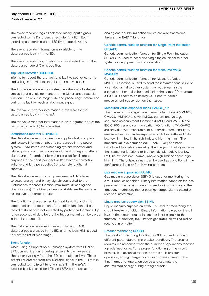
Fault locator LMBRFLOM13970-3 v12
The accurate fault locator is an essential component tominimize the outages after a persistent fault and/or to pin-point a weak spot on the line.
The fault locator is an impedance measuring function givingthe distance to the fault in km, miles or % of line length. Themain advantage is the high accuracy achieved bycompensating for load current and for the mutual zero-sequence effect on double circuit lines.
The compensation includes setting of the remote and localsources and calculation of the distribution of fault currentsfrom each side. This distribution of fault current, together withrecorded load (pre-fault) currents, is used to exactly calculatethe fault position. The fault can be recalculated with newsource data at the actual fault to further increase theaccuracy.
Especially on heavily loaded long lines, where the sourcevoltage angles can be up to 35-40 degrees apart, theaccuracy can be still maintained with the advancedcompensation included in fault locator.
Event counter with limit supervison L4UFCNTGUID-13157EAB-1686-4D2E-85DF-EC89768F3572 v5
The 30 limit counter L4UFCNT provides a settable counterwith four independent limits where the number of positiveand/or negative flanks on the input signal are counted againstthe setting values for limits. The output for each limit isactivated when the counted value reaches that limit.
Overflow indication is included for each up-counter.
Running hour-meter (TEILGAPC)GUID-464FB24F-B367-446C-963A-A14841943B87 v1
The Running hour-meter (TEILGAPC) function is a functionthat accumulates the elapsed time when a given binary signalhas been high.
The main features of TEILGAPC are:
• Applicable to very long time accumulation (≤ 99999.9hours)
• Supervision of limit transgression conditions and rollover/overflow
• Possibility to define a warning and alarm with theresolution of 0.1 hours
• Retain any saved accumulation value at a restart• Possibilities for blocking and reset• Possibility for manual addition of accumulated time• Reporting of the accumulated time
9. Metering
Pulse-counter logic PCFCNTM13394-3 v7
Pulse-counter logic (PCFCNT) function counts externallygenerated binary pulses, for instance pulses coming from anexternal energy meter, for calculation of energy consumption
values. The pulses are captured by the binary input moduleand then read by the PCFCNT function. A scaled servicevalue is available over the station bus. The special Binaryinput module with enhanced pulse counting capabilities mustbe ordered to achieve this functionality.
Function for energy calculation and demand handling(ETPMMTR)
GUID-6898E29B-DA70-421C-837C-1BBED8C63A7A v2
Measurements function block (CVMMXN) can be used tomeasure active as well as reactive power values. Function forenergy calculation and demand handling (ETPMMTR) usesmeasured active and reactive power as input and calculatesthe accumulated active and reactive energy pulses, in forwardand reverse direction. Energy values can be read orgenerated as pulses. Maximum demand power values arealso calculated by the function. This function includes zeropoint clamping to remove noise from the input signal. Asoutput of this function: periodic energy calculations,integration of energy values, calculation of energy pulses,alarm signals for limit violation of energy values and maximumpower demand, can be found.
The values of active and reactive energies are calculated fromthe input power values by integrating them over a selectedtime tEnergy. The integration of active and reactive energyvalues will happen in both forward and reverse directions.These energy values are available as output signals and alsoas pulse outputs. Integration of energy values can becontrolled by inputs (STARTACC and STOPACC) and EnaAccsetting and it can be reset to initial values with RSTACCinput.
The maximum demand for active and reactive powers arecalculated for the set time interval tEnergy and these valuesare updated every minute through output channels. Theactive and reactive maximum power demand values arecalculated for both forward and reverse direction and thesevalues can be reset with RSTDMD input.
1MRK 511 387-BEN BBay control REC650 2.1 IEC Product version: 2.1
ABB 19

10. Human machine interface
Local HMIAMU0600442 v14
IEC13000239-2-en.vsd
IEC13000239 V2 EN-US
Figure 2. Local human-machine interface
The LHMI of the IED contains the following elements:• Graphical display capable of showing a user defined single
line diagram and provide an interface for controllingswitchgear.
• Navigation buttons and five user defined command buttonsto shortcuts in the HMI tree or simple commands.
• 15 user defined three-color LEDs.• Communication port for PCM600.
The LHMI is used for setting, monitoring and controlling.
11. Basic IED functions
Time synchronizationM11344-3 v9
The time synchronization function is used to select a commonsource of absolute time for the synchronization of the IEDwhen it is a part of a control and a protection system. Thismakes it possible to compare events and disturbance databetween all IEDs within a station automation system and inbetween sub-stations.
12. Station communication
Communication protocols
M14815-3 v12
Each IED is provided with a communication interface,enabling it to connect to one or many substation levelsystems or equipment, either on the Substation Automation(SA) bus or Substation Monitoring (SM) bus.
Available communication protocols are:
• IEC 61850-8-1 communication protocol• LON communication protocol• SPA or IEC 60870-5-103 communication protocol• DNP3.0 communication protocol
Several protocols can be combined in the same IED.
IEC 61850-8-1 communication protocolM14787-3 v13
IEC 61850 Ed.1 or Ed.2 can be chosen by a setting inPCM600. The IED is equipped with single or double opticalEthernet rear ports (order dependent) for IEC 61850-8-1station bus communication. The IEC 61850-8-1communication is also possible from the electrical Ethernetfront port. IEC 61850-8-1 protocol allows intelligent electricaldevices (IEDs) from different vendors to exchange informationand simplifies system engineering. IED-to-IED communicationusing GOOSE and client-server communication over MMS aresupported. Disturbance recording file (COMTRADE) uploadingcan be done over MMS or FTP.
The front port shall not be used due tointerference.
LON communication protocolSEMOD120140-5 v2
Existing stations with ABB station bus LON can be extendedwith use of the optical LON interface. This allows full SAfunctionality including peer-to-peer messaging andcooperation between the IEDs.
SPA communication protocolSEMOD120134-5 v1
A single glass or plastic port is provided for the ABB SPAprotocol. This allows extensions of simple substationautomation systems but the main use is for SubstationMonitoring Systems SMS.
IEC 60870-5-103 communication protocolSEMOD120137-5 v3
A single glass or plastic port is provided for the IEC60870-5-103 standard. This allows design of simplesubstation automation systems including equipment fromdifferent vendors. Disturbance files uploading is provided.
DNP3.0 communication protocolSEMOD153688-5 v1
An electrical RS485 and an optical Ethernet port is availablefor the DNP3.0 communication. DNP3.0 Level 2communication with unsolicited events, time synchronizingand disturbance reporting is provided for communication toRTUs, Gateways or HMI systems.
1MRK 511 387-BEN BBay control REC650 2.1 IEC Product version: 2.1
20 ABB

Multiple command and transmitM14791-3 v3
When IEDs are used in Substation Automation systems withLON, SPA or IEC 60870-5-103 communication protocols, theEvent and Multiple Command function blocks are used as thecommunication interface for vertical communication to stationHMI and gateway, and as interface for horizontal peer-to-peercommunication (over LON only).
IEC 62439-3 Parallel Redundancy ProtocolGUID-A90FDBA7-D4D7-4CBD-9F05-13DCC9971779 v5
Redundant station bus communication according to IEC62439-3 Edition 1 and IEC 62439-3 Edition 2 parallelredundancy protocol (PRP) are available as options whenordering IEDs. Redundant station bus communicationaccording to IEC 62439-3 uses both port AB and port CD onthe OEM module.
13. Hardware description
Hardware modulesIP14529-1 v1
Power supply module PSMM11595-3 v5
The power supply module is used to provide the correctinternal voltages and full isolation between the IED and thebattery system. An internal fail alarm output is available.
Binary input module BIMM1769-3 v4
The binary input module has 16 optically isolated inputs andis available in two versions, one standard and one withenhanced pulse counting capabilities on the inputs to beused with the pulse counter function. The binary inputs arefreely programmable and can be used for the input of logicalsignals to any of the functions. They can also be included inthe disturbance recording and event-recording functions. Thisenables extensive monitoring and evaluation of operation ofthe IED and for all associated electrical circuits.
Binary output module BOMM6938-3 v4
The binary output module has 24 independent output relaysand is used for trip output or any signaling purpose.
Binary input/output module IOMM6939-3 v6
The binary input/output module is used when only a few inputand output channels are needed. The ten standard outputchannels are used for trip output or any signaling purpose.The two high speed signal output channels are used forapplications where short operating time is essential. Eightoptically isolated binary inputs cater for required binary inputinformation.
Optical ethernet module OEMM16073-3 v6
The optical fast-ethernet module is used for fast andinterference-free communication of synchrophasor data overIEEE C37.118 and/or IEEE 1344 protocols. It is also used toconnect an IED to the communication buses (like the stationbus) that use the IEC 61850-8-1 protocol (port A, B). Themodule has one or two optical ports with ST connectors.
Serial and LON communication module SLM, supportsSPA/IEC 60870-5-103, LON and DNP 3.0
M14933-3 v4
The serial and LON communication module (SLM) is used forSPA, IEC 60870-5-103, DNP3 and LON communication. Themodule has two optical communication ports for plastic/plastic, plastic/glass or glass/glass. One port is used for serialcommunication (SPA, IEC 60870-5-103 and DNP3 port) andone port is dedicated for LON communication.
Galvanic RS485 serial communication moduleSEMOD158664-5 v3
The Galvanic RS485 communication module (RS485) is usedfor DNP3.0 and IEC 60870-5-103 communication. Themodule has one RS485 communication port. The RS485 is abalanced serial communication that can be used either in 2-wire or 4-wire connections. A 2-wire connection uses thesame signal for RX and TX and is a multidrop communicationwith no dedicated Master or slave. This variant requireshowever a control of the output. The 4-wire connection hasseparated signals for RX and TX multidrop communicationwith a dedicated Master and the rest are slaves. No specialcontrol signal is needed in this case.
IRIG-B Time synchronizing moduleSEMOD141113-4 v7
The IRIG-B time synchronizing module is used for accuratetime synchronizing of the IED from a station clock.
Electrical (BNC) and optical connection (ST) for 0XX and 12XIRIG-B support.
Transformer input module TRMM14875-3 v9
The transformer input module is used to galvanically separateand adapt the secondary currents and voltages generated bythe measuring transformers. The module has twelve inputs indifferent combinations of currents and voltage inputs.
Alternative connectors of Ring lug or Compression type canbe ordered.
High impedance resistor unitM16727-3 v2
The high impedance resistor unit, with resistors for pick-upvalue setting and a voltage dependent resistor, is available ina single phase unit and a three phase unit. Both are mountedon a 1/1 19 inch apparatus plate with compression typeterminals.
1MRK 511 387-BEN BBay control REC650 2.1 IEC Product version: 2.1
ABB 21

Layout and dimensionsIP14539-1 v1
DimensionsIP14826-1 v1M2152-3 v5
IEC04000448 V2 EN-US
Figure 3. Case without rear cover
IEC04000464 V2 EN-US
Figure 4. Case without rear cover with 19” rack mounting kit
M15243-12 v8
Case size(mm)/(inches)
A B C D E F G H J K
6U, 1/2 x 19” 265.9/10.47
223.7/8.81
242.1/9.53
255.8/10.07
205.7/8.10
190.5/7.50
203.7/8.02
- 228.6/9.00
-
The H and K dimensions are defined by the 19” rack mounting kit.
Mounting alternativesM16079-3 v13
• 19” rack mounting kit• Flush mounting kit with cut-out dimensions (h) 259.3
mm/10.21”(w) 434.7 mm/17.11“ for 1/1 case size.• Flush mounting kit with cut-out dimensions:
– 1/2 case size (h) 254.3 mm/10.01” (w) 210.1 mm/8.27”
• Wall mounting kit
See ordering for details about available mounting alternatives.
1MRK 511 387-BEN BBay control REC650 2.1 IEC Product version: 2.1
22 ABB

14. Connection diagrams
Connection diagramsGUID-CF4EFFA5-3081-4FC7-9A14-ED127C3C0FDE v4
The connection diagrams are delivered on the IEDConnectivity package DVD as part of the product delivery.
The latest versions of the connection diagrams can bedownloaded from http://www.abb.com/substationautomation.
Connection diagrams for Configured products
650 series ver. 2.1, IEC symbols 1MRK006501-AF
650 series ver. 2.1, ANSI symbols 1MRK006502-AF
Connection diagram, REC650 2.1, A02 1MRK006505-CA
1MRK 511 387-BEN BBay control REC650 2.1 IEC Product version: 2.1
ABB 23
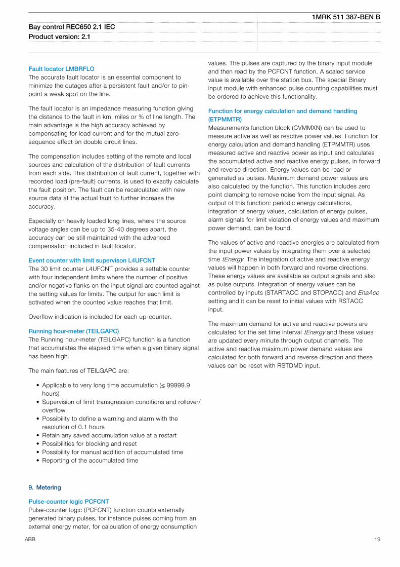
15. Technical data
GeneralIP11376-1 v2M10993-1 v3
Definitions
Reference value The specified value of an influencing factor to which are referred the characteristics of the equipment
Nominal range The range of values of an influencing quantity (factor) within which, under specified conditions, the equipment meets thespecified requirements
Operative range The range of values of a given energizing quantity for which the equipment, under specified conditions, is able to perform itsintended functions according to the specified requirements
Energizing quantities, rated values and limitsIP15765-1 v2
Analog inputsIP15842-1 v1M16988-1 v10
Table 5. TRM - Energizing quantities, rated values and limits for protection transformer modules
Quantity Rated value Nominal range
Current Ir = 1 or 5 A (0.2-40) × Ir
Operative range (0-100) x Ir
Permissive overload 4 × Ir cont.100 × Ir for 1 s *)
Burden < 150 mVA at Ir = 5 A< 20 mVA at Ir = 1 A
AC voltage Ur = 110 V 0.5–288 V
Operative range (0–340) V
Permissive overload 420 V cont.450 V 10 s
Burden < 20 mVA at 110 V
Frequency fr = 50/60 Hz ±5%
*) max. 350 A for 1 s when COMBITEST test switch is included.SEMOD55310-2 v9
Table 6. OEM - Optical ethernet module
Quantity Rated value
Number of channels 1 or 2 (port A, B for IEC 61850-8-1 / IEEE C37.118)
Standard IEEE 802.3u 100BASE-FX
Type of fiber 62.5/125 mm multimode fibre
Wave length 1300 nm
Optical connector Type ST
Communication speed Fast Ethernet 100 Mbit/s
1MRK 511 387-BEN BBay control REC650 2.1 IEC Product version: 2.1
24 ABB

Auxiliary DC voltageIP15843-1 v3M12286-1 v5
Table 7. PSM - Power supply module
Quantity Rated value Nominal range
Auxiliary DC voltage, EL (input) EL = (24-60) VEL = (90-250) V
EL ±20%EL ±20%
Power consumption 32 W typically -
Auxiliary DC power in-rush < 10 A during 0.1 s -
Binary inputs and outputsIP15844-1 v1M12576-1 v8
Table 8. BIM - Binary input module
Quantity Rated value Nominal range
Binary inputs 16 -
DC voltage, RL 24/30 V48/60 V110/125 V220/250 V
RL ±20%RL ±20%RL ±20%RL ±20%
Power consumption24/30 V, 50 mA48/60 V, 50 mA110/125 V, 50 mA220/250 V, 50 mA220/250 V, 110 mA
max. 0.05 W/inputmax. 0.1 W/inputmax. 0.2 W/inputmax. 0.4 W/inputmax. 0.5 W/input
-
Counter input frequency 10 pulses/s max -
Oscillating signal discriminator Blocking settable 1–40 HzRelease settable 1–30 Hz
Debounce filter Settable 1–20 ms
1MRK 511 387-BEN BBay control REC650 2.1 IEC Product version: 2.1
ABB 25

Maximum 176 binary input channels maybe activated simultaneously with influencingfactors within nominal range.
M50609-2 v6
Table 9. BIM - Binary input module with enhanced pulse counting capabilities
Quantity Rated value Nominal range
Binary inputs 16 -
DC voltage, RL 24/30 V48/60 V110/125 V220/250 V
RL ±20%RL ±20%RL ±20%RL ±20%
Power consumption24/30 V48/60 V110/125 V220/250 V
max. 0.05 W/inputmax. 0.1 W/inputmax. 0.2 W/inputmax. 0.4 W/input
-
Counter input frequency 10 pulses/s max -
Balanced counter input frequency 40 pulses/s max -
Oscillating signal discriminator Blocking settable 1–40 HzRelease settable 1–30 Hz
Debounce filter Settable 1-20 ms
Maximum 176 binary input channels maybe activated simultaneously with influencingfactors within nominal range.
M12573-1 v8
Table 10. IOM - Binary input/output module
Quantity Rated value Nominal range
Binary inputs 8 -
DC voltage, RL 24/30 V48/60 V110/125 V220/250 V
RL ±20%RL ±20%RL ±20%RL ±20%
Power consumption24/30 V, 50 mA48/60 V, 50 mA110/125 V, 50 mA220/250 V, 50 mA220/250 V, 110 mA
max. 0.05 W/inputmax. 0.1 W/inputmax. 0.2 W/inputmax. 0.4 W/inputmax. 0.5 W/input
-
Counter input frequency 10 pulses/s max
Oscillating signal discriminator Blocking settable 1-40 HzRelease settable 1-30 Hz
Debounce filter Settable 1-20 ms
1MRK 511 387-BEN BBay control REC650 2.1 IEC Product version: 2.1
26 ABB

Maximum 176 binary input channels maybe activated simultaneously with influencingfactors within nominal range.
M12318-1 v7
Table 11. IOM - Binary input/output module contact data (reference standard: IEC 61810-2)
Function or quantity Trip and signal relays Fast signal relays (parallelreed relay)
Binary outputs 10 2
Max system voltage 250 V AC, DC 250 V DC
Test voltage across open contact, 1 min 1000 V rms 800 V DC
Current carrying capacityPer relay, continuousPer relay, 1 sPer process connector pin, continuous
8 A10 A12 A
8 A10 A12 A
Making capacity at inductive load with L/R > 10 ms 0.2 s1.0 s
30 A10 A
0.4 A0.4 A
Making capacity at resistive load 0.2 s1.0 s
30 A10 A
220–250 V/0.4 A110–125 V/0.4 A48–60 V/0.2 A24–30 V/0.1 A
Breaking capacity for AC, cos φ > 0.4 250 V/8.0 A 250 V/8.0 A
Breaking capacity for DC with L/R < 40 ms 48 V/1 A110 V/0.4 A125 V/0.35 A220 V/0.2 A250 V/0.15 A
48 V/1 A110 V/0.4 A125 V/0.35 A220 V/0.2 A250 V/0.15 A
Maximum capacitive load - 10 nF
Maximum 72 outputs may be activatedsimultaneously with influencing factorswithin nominal range. After 6 ms anadditional 24 outputs may be activated.The activation time for the 96 outputs mustnot exceed 200 ms. 48 outputs can be
activated during 1 s. Continued activationis possible with respect to currentconsumption but after 5 minutes thetemperature rise will adversely affect thehardware life. Maximum two relays per
1MRK 511 387-BEN BBay control REC650 2.1 IEC Product version: 2.1
ABB 27

BOM/IOM should be activated continuouslydue to power dissipation.
M12584-1 v6
Table 12. IOM with MOV and IOM 220/250 V, 110mA - contact data (reference standard: IEC 61810-2)
Function or quantity Trip and Signal relays Fast signal relays (parallel reed relay)
Binary outputs IOM: 10 IOM: 2
Max system voltage 250 V AC, DC 250 V DC
Test voltage across opencontact, 1 min
250 V rms 250 V rms
Current carrying capacityPer relay, continuousPer relay, 1 sPer process connector pin,continuous
8 A10 A12 A
8 A10 A12 A
Making capacity at inductiveloadwith L/R > 10 ms0.2 s1.0 s
30 A10 A
0.4 A0.4 A
Making capacity at resistive load 0.2 s1.0 s
30 A10 A
220–250 V/0.4 A110–125 V/0.4 A48–60 V/0.2 A24–30 V/0.1 A
Breaking capacity for AC, cos j> 0.4
250 V/8.0 A 250 V/8.0 A
Breaking capacity for DC withL/R < 40 ms
48 V/1 A110 V/0.4 A220 V/0.2 A250 V/0.15 A
48 V/1 A110 V/0.4 A220 V/0.2 A250 V/0.15 A
Maximum capacitive load - 10 nF
Maximum 72 outputs may be activatedsimultaneously with influencing factorswithin nominal range. After 6 ms anadditional 24 outputs may be activated.The activation time for the 96 outputs mustnot exceed 200 ms. 48 outputs can be
activated during 1 s. Continued activationis possible with respect to currentconsumption but after 5 minutes thetemperature rise will adversely affect thehardware life. Maximum two relays per
1MRK 511 387-BEN BBay control REC650 2.1 IEC Product version: 2.1
28 ABB

BOM/IOM should be activated continuouslydue to power dissipation.
M12441-1 v8
Table 13. BOM - Binary output module contact data (reference standard: IEC 61810-2)
Function or quantity Trip and Signal relays
Binary outputs 24
Max system voltage 250 V AC, DC
Test voltage across open contact, 1 min 1000 V rms
Current carrying capacityPer relay, continuousPer relay, 1 sPer process connector pin, continuous
8 A10 A12 A
Making capacity at inductive load with L/R > 10 ms0.2 s1.0 s
30 A10 A
Breaking capacity for AC, cos j > 0.4 250 V/8.0 A
Breaking capacity for DC with L/R < 40 ms 48 V/1 A110 V/0.4 A125 V/0.35 A220 V/0.2 A250 V/0.15 A
Influencing factorsIP15846-1 v1M16705-1 v10
Table 14. Temperature and humidity influence
Parameter Reference value Nominal range Influence
Ambient temperature, operatevalue
+20°C -20°C to +55°C 0.02%/°C
Relative humidityOperative range
10-90%0-95%
10-90% -
Storage temperature - -40°C to +70°C -
Table 15. Auxiliary DC supply voltage influence on functionality during operation
Dependence on Reference value Within nominalrange
Influence
Ripple, in DC auxiliary voltageOperative range
max. 2%Full wave rectified
15% of EL 0.01%/%
Auxiliary voltage dependence, operatevalue
±20% of EL 0.01%/%
Interrupted auxiliary DC voltage
24-60 V DC ± 20% 90-250 V DC ±20%
Interruptioninterval0–50 ms
No restart
0–∞ s Correct behaviour at power down
Restart time < 300 s
1MRK 511 387-BEN BBay control REC650 2.1 IEC Product version: 2.1
ABB 29

Table 16. Frequency influence (reference standard: IEC 60255–1)
Dependence on Within nominal range Influence
Frequency dependence, operate value fr ±2.5 Hz for 50 Hzfr ±3.0 Hz for 60 Hz
±1.0%/Hz
Harmonic frequency dependence (20% content) 2nd, 3rd and 5th harmonic of fr ±1.0%
Type tests according to standardsIP15778-1 v1M16706-1 v9
Table 17. Electromagnetic compatibility
Test Type test values Reference standards
1 MHz burst disturbance 2.5 kV IEC 60255-26
100 kHz slow damped oscillatory wave immunity test 2.5 kV IEC 61000-4-18, Class III
Ring wave immunity test, 100 kHz 2-4 kV IEC 61000-4-12, Class IV
Surge withstand capability test 2.5 kV, oscillatory4.0 kV, fast transient
IEEE/ANSI C37.90.1
Electrostatic dischargeDirect applicationIndirect application
15 kV air discharge8 kV contact discharge8 kV contact discharge
IEC 60255-26 IEC 61000-4-2, Class IV
Electrostatic dischargeDirect applicationIndirect application
15 kV air discharge8 kV contact discharge8 kV contact discharge
IEEE/ANSI C37.90.1
Fast transient disturbance 4 kV IEC 60255-26, Zone A
Surge immunity test 2-4 kV, 1.2/50 mshigh energy
IEC 60255-26, Zone A
Power frequency immunity test 150-300 V, 50 Hz IEC 60255-26, Zone A
Conducted common mode immunity test 15 Hz-150 kHz IEC 61000-4-16, Class IV
Power frequency magnetic field test 1000 A/m, 3 s100 A/m, cont.
IEC 61000-4-8, Class V
Pulse magnetic field immunity test 1000 A/m IEC 61000–4–9, Class V
Damped oscillatory magnetic field test 100 A/m IEC 61000-4-10, Class V
Radiated electromagnetic field disturbance 20 V/m, 80-1000 MHz 1.4-2.7 GHz
IEC 60255-26
Radiated electromagnetic field disturbance 20 V/m80-1000 MHz
IEEE/ANSI C37.90.2
Conducted electromagnetic field disturbance 10 V, 0.15-80 MHz IEC 60255-26
Radiated emission 30-5000 MHz IEC 60255-26
Radiated emission 30-5000 MHz IEEE/ANSI C63.4, FCC
Conducted emission 0.15-30 MHz IEC 60255-26
Table 18. Insulation
Test Type test values Reference standard
Dielectric test 2.0 kV AC, 1 min. IEC 60255-27ANSI C37.90
Impulse voltage test 5 kV, 1.2/50 ms, 0.5 J
Insulation resistance > 100 MW at 500 VDC
1MRK 511 387-BEN BBay control REC650 2.1 IEC Product version: 2.1
30 ABB

Table 19. Environmental tests
Test Type test value Reference standard
Cold operation test Test Ad for 16 h at -25°C IEC 60068-2-1
Cold storage test Test Ab for 16 h at -40°C IEC 60068-2-1
Dry heat operation test Test Bd for 16 h at +70°C IEC 60068-2-2
Dry heat storage test Test Bb for 16 h at +85°C IEC 60068-2-2
Change of temperature test Test Nb for 5 cycles at -25°C to +70°C IEC 60068-2-14
Damp heat test, steady state Test Ca for 10 days at +40°C and humidity 93% IEC 60068-2-78
Damp heat test, cyclic Test Db for 6 cycles at +25 to +55°C and humidity 93 to 95% (1 cycle =24 hours)
IEC 60068-2-30
Table 20. CE compliance
Test According to
Immunity EN 60255–26
Emissivity EN 60255–26
Low voltage directive EN 60255–27
Table 21. Mechanical tests
Test Type test values Reference standards
Vibration response test Class II IEC 60255-21-1
Vibration endurance test Class I IEC 60255-21-1
Shock response test Class I IEC 60255-21-2
Shock withstand test Class I IEC 60255-21-2
Bump test Class I IEC 60255-21-2
Seismic test Class II IEC 60255-21-3
1MRK 511 387-BEN BBay control REC650 2.1 IEC Product version: 2.1
ABB 31

Multipurpose protectionM13095-2 v7
1MRK 511 387-BEN BBay control REC650 2.1 IEC Product version: 2.1
32 ABB

Table 22. General current and voltage protection CVGAPC
Function Range or value Accuracy
Measuring current input phase1, phase2, phase3, PosSeq, -NegSeq, -3*ZeroSeq, MaxPh, MinPh,UnbalancePh, phase1-phase2, phase2-phase3, phase3-phase1, MaxPh-Ph,MinPh-Ph, UnbalancePh-Ph
-
Measuring voltage input phase1, phase2, phase3, PosSeq, -NegSeq, -3*ZeroSeq, MaxPh, MinPh,UnbalancePh, phase1-phase2, phase2-phase3, phase3-phase1, MaxPh-Ph,MinPh-Ph, UnbalancePh-Ph
-
Start overcurrent, step 1 - 2 (2 - 5000)% of IBase ±1.0% of Ir at I ≤ Ir±1.0% of I at I > Ir
Start undercurrent, step 1 - 2 (2 - 150)% of IBase ±1.0% of Ir at I ≤ Ir±1.0% of I at I > Ir
Independent time delay, overcurrent at 0 to 2 x Iset, step 1 - 2 (0.00 - 6000.00) s ±0.2% or ±35 ms whichever isgreater
Independent time delay, undercurrent at 2 to 0 x Iset, step 1 - 2 (0.00 - 6000.00) s ±0.2% or ±35 ms whichever isgreater
Overcurrent (non-directional):
Start time at 0 to 2 x Iset Min. = 15 msMax. = 30 ms
-
Reset time at 2 to 0 x Iset Min. = 15 msMax. = 30 ms
-
Start time at 0 to 10 x Iset Min. = 5 msMax. = 20 ms
-
Reset time at 10 to 0 x Iset Min. = 20 msMax. = 35 ms
-
Undercurrent:
Start time at 2 to 0 x Iset Min. = 15 msMax. = 30 ms
-
Reset time at 0 to 2 x Iset Min. = 15 msMax. = 30 ms
-
Overcurrent:
Inverse time characteristics, see table 103, "" and table "" 16 curve types See table 103, "" and table ""
Overcurrent:
Minimum operate time for inverse curves, step 1 - 2 (0.00 - 6000.00) s ±0.2% or ±35 ms whichever isgreater
Voltage level where voltage memory takes over (0.0 - 5.0)% of UBase ±0.5% of Ur
Start overvoltage, step 1 - 2 (2.0 - 200.0)% of UBase ±0.5% of Ur at U ≤ Ur±0.5% of U at U > Ur
Start undervoltage, step 1 - 2 (2.0 - 150.0)% of UBase ±0.5% of Ur at U ≤ Ur±0.5% of U at U > Ur
Independent time delay, overvoltage at 0.8 to 1.2 x Uset, step 1 -2
(0.00 - 6000.00) s ±0.2% or ±35 ms whichever isgreater
1MRK 511 387-BEN BBay control REC650 2.1 IEC Product version: 2.1
ABB 33

Table 22. General current and voltage protection CVGAPC , continued
Function Range or value Accuracy
Independent time delay, undervoltage at 1.2 to 0.8 x Uset, step 1- 2
(0.00 - 6000.00) s ±0.2% or ±35 ms whichever isgreater
Overvoltage:
Start time at 0.8 to 1.2 x Uset Min. = 15 msMax. = 30 ms
-
Reset time at 1.2 to 0.8 x Uset Min. = 15 msMax. = 30 ms
-
Undervoltage:
Start time at 1.2 to 0.8 x Uset Min. = 15 msMax. = 30 ms
-
Reset time at 1.2 to 0.8 x Uset Min. = 15 msMax. = 30 ms
-
Overvoltage:
Inverse time characteristics, see table 104 4 curve types See table 104
Undervoltage:
Inverse time characteristics, see table "" 3 curve types See table ""
High and low voltage limit, voltage dependent operation, step 1 -2
(1.0 - 200.0)% of UBase ±1.0% of Ur at U ≤ Ur±1.0% of U at U > Ur
Directional function Settable: NonDir, forward and reverse -
Relay characteristic angle (-180 to +180) degrees ±2.0 degrees
Relay operate angle (1 to 90) degrees ±2.0 degrees
Reset ratio, overcurrent > 95% -
Reset ratio, undercurrent < 105% -
Reset ratio, overvoltage > 95% -
Reset ratio, undervoltage < 105% -
Overcurrent:
Critical impulse time 10 ms typically at 0 to 2 x Iset -
Impulse margin time 15 ms typically -
Undercurrent:
Critical impulse time 10 ms typically at 2 to 0 x Iset -
Impulse margin time 15 ms typically -
Overvoltage:
Critical impulse time 10 ms typically at 0.8 to 1.2 x Uset -
Impulse margin time 15 ms typically -
Undervoltage:
Critical impulse time 10 ms typically at 1.2 to 0.8 x Uset -
Impulse margin time 15 ms typically -
1MRK 511 387-BEN BBay control REC650 2.1 IEC Product version: 2.1
34 ABB

SEMOD175176-2 v5
Table 23. Rotor earth fault protection based on General current and voltage protection (CVGAPC) and RXTTE4
Function Range or value
For machines with:
• rated field voltage up to 350 V DC
• static exciter with rated supplyvoltage up to
700 V 50/60 Hz
Supply voltage 120 or 230 V 50/60 Hz
Operate earth fault resistancevalue
Approx. 1–20 kΩ
Influence of harmonics in the DCfield voltage
Negligible influence of 50 V, 150Hz or 50 V, 300 Hz
Permitted leakage capacitance (1–5) μF
Permitted shaft earthingresistance
Maximum 200 Ω
Protective resistor 220 Ω, 100 W, plate(the height is 160 mm (6,2inches) and width 135 mm (5,31inches))
1MRK 511 387-BEN BBay control REC650 2.1 IEC Product version: 2.1
ABB 35

Secondary system supervisionM12358-1 v8
Table 24. Current circuit supervision CCSSPVC
Function Range or value Accuracy
Operate current (10-200)% of IBase ±10.0% of Ir at I ≤ Ir±10.0% of I at I > Ir
Reset ratio, Operate current >90%
Block current (20-500)% of IBase ±5.0% of Ir at I ≤ Ir±5.0% of I at I > Ir
Reset ratio, Block current >90% at (50-500)% of IBase M16069-1 v11
Table 25. Fuse failure supervision FUFSPVC
Function Range or value Accuracy
Operate voltage, zero sequence (1-100)% of UBase ±0.5% of Ur
Operate current, zero sequence (1–100)% of IBase ±0.5% of Ir
Operate voltage, negative sequence (1-100)% of UBase ±0.5% of Ur
Operate current, negative sequence (1–100)% of IBase ±0.5% of Ir
Operate voltage change level (1-100)% of UBase ±10.0% of Ur
Operate current change level (1–100)% of IBase ±10.0% of Ir
Operate phase voltage (1-100)% of UBase ±0.5% of Ur
Operate phase current (1–100)% of IBase ±0.5% of Ir
Operate phase dead line voltage (1-100)% of UBase ±0.5% of Ur
Operate phase dead line current (1–100)% of IBase ±0.5% of Ir
Operate time, start, 1 ph, at 1 to 0 x Ur Min. = 10 msMax. = 25 ms
-
Reset time, start, 1 ph, at 0 to 1 x Ur Min. = 15 msMax. = 30 ms
-
1MRK 511 387-BEN BBay control REC650 2.1 IEC Product version: 2.1
36 ABB

ControlM12359-1 v13
Table 26. Synchronizing, synchrocheck and energizing check SESRSYN
Function Range or value Accuracy
Phase shift, jline - jbus (-180 to 180) degrees -
Voltage high limit for synchronizing and synchrocheck (50.0-120.0)% of UBase ±0.5% of Ur at U ≤ Ur±0.5% of U at U > Ur
Reset ratio, synchrocheck > 95% -
Frequency difference limit between bus and line for synchrocheck (0.003-1.000) Hz ±2.5 mHz
Phase angle difference limit between bus and line for synchrocheck (5.0-90.0) degrees ±2.0 degrees
Voltage difference limit between bus and line for synchronizing andsynchrocheck
(0.02-0.5) p.u ±0.5% of Ur
Time delay output for synchrocheck when angle difference between busand line jumps from “PhaseDiff” + 2 degrees to “PhaseDiff” - 2 degrees
(0.000-60.000) s ±0.2% or ±35 ms whichever isgreater
Frequency difference minimum limit for synchronizing (0.003-0.250) Hz ±2.5 mHz
Frequency difference maximum limit for synchronizing (0.050-0.500) Hz ±2.5 mHz
Breaker closing pulse duration (0.050-60.000) s ±0.2% or ±15 ms whichever isgreater
tMaxSynch, which resets synchronizing function if no close has beenmade before set time
(0.000-6000.00) s ±0.2% or ±35 ms whichever isgreater
Minimum time to accept synchronizing conditions (0.000-60.000) s ±0.2% or ±35 ms whichever isgreater
Voltage high limit for energizing check (50.0-120.0)% of UBase ±0.5% of Ur at U ≤ Ur±0.5% of U at U > Ur
Reset ratio, voltage high limit > 95% -
Voltage low limit for energizing check (10.0-80.0)% of UBase ±0.5% of Ur
Reset ratio, voltage low limit < 105% -
Maximum voltage for energizing (50.0-180.0)% of UBase ±0.5% of Ur at U ≤ Ur±0.5% of U at U > Ur
Time delay for energizing check when voltage jumps from 0 to 90% ofUrated
(0.000-60.000) s ±0.2% or ±100 ms whichever isgreater
Operate time for synchrocheck function when angle difference betweenbus and line jumps from “PhaseDiff” + 2 degrees to “PhaseDiff” - 2degrees
Min. = 15 msMax. = 30 ms
–
Operate time for energizing function when voltage jumps from 0 to 90%of Urated
Min. = 70 msMax. = 90 ms
–
1MRK 511 387-BEN BBay control REC650 2.1 IEC Product version: 2.1
ABB 37
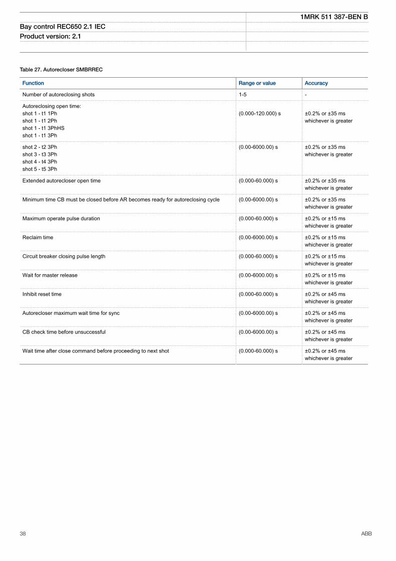
M12379-1 v12
Table 27. Autorecloser SMBRREC
Function Range or value Accuracy
Number of autoreclosing shots 1-5 -
Autoreclosing open time:shot 1 - t1 1Phshot 1 - t1 2Phshot 1 - t1 3PhHSshot 1 - t1 3Ph
(0.000-120.000) s
±0.2% or ±35 mswhichever is greater
shot 2 - t2 3Phshot 3 - t3 3Phshot 4 - t4 3Phshot 5 - t5 3Ph
(0.00-6000.00) s ±0.2% or ±35 mswhichever is greater
Extended autorecloser open time (0.000-60.000) s ±0.2% or ±35 mswhichever is greater
Minimum time CB must be closed before AR becomes ready for autoreclosing cycle (0.00-6000.00) s ±0.2% or ±35 mswhichever is greater
Maximum operate pulse duration (0.000-60.000) s ±0.2% or ±15 mswhichever is greater
Reclaim time (0.00-6000.00) s ±0.2% or ±15 mswhichever is greater
Circuit breaker closing pulse length (0.000-60.000) s ±0.2% or ±15 mswhichever is greater
Wait for master release (0.00-6000.00) s ±0.2% or ±15 mswhichever is greater
Inhibit reset time (0.000-60.000) s ±0.2% or ±45 mswhichever is greater
Autorecloser maximum wait time for sync (0.00-6000.00) s ±0.2% or ±45 mswhichever is greater
CB check time before unsuccessful (0.00-6000.00) s ±0.2% or ±45 mswhichever is greater
Wait time after close command before proceeding to next shot (0.000-60.000) s ±0.2% or ±45 mswhichever is greater
1MRK 511 387-BEN BBay control REC650 2.1 IEC Product version: 2.1
38 ABB

Scheme communicationM16038-1 v12
Table 28. Scheme communication logic for distance or overcurrent protection ZCPSCH
Function Range or value Accuracy
Scheme type OffIntertripPermissive URPermissive ORBlockingDeltaBlocking
-
Operate voltage, Delta U (0–100)% of UBase ±5.0% of ΔU
Operate current, Delta I (0–200)% of IBase ±5.0% of ΔI
Operate zero sequence voltage,Delta 3U0
(0–100)% of UBase ±10.0% of Δ3U0
Operate zero sequence current,Delta 3I0
(0–200)% of IBase ±10.0% of Δ3I0
Co-ordination time for blockingcommunication scheme
(0.000-60.000) s ±0.2% or ±10 ms whichever is greater
Minimum duration of a carrier sendsignal
(0.000-60.000) s ±0.2% or ±10 ms whichever is greater
Security timer for loss of guardsignal detection
(0.000-60.000) s ±0.2% or ±10 ms whichever is greater
Operation mode of unblocking logic OffNoRestartRestart
-
M16039-1 v15
Table 29. Current reversal and weak-end infeed logic for distance protection ZCRWPSCH
Function Range or value Accuracy
Detection level phase-to-neutralvoltage
(10-90)% of UBase ±0.5% of Ur
Detection level phase-to-phasevoltage
(10-90)% of UBase ±0.5% of Ur
Operate time for current reversallogic
(0.000-60.000) s ±0.2% or ±15 ms whichever is greater
Delay time for current reversal (0.000-60.000) s ±0.2% or ±15 ms whichever is greater
Coordination time for weak-endinfeed logic
(0.000-60.000) s ±0.2% or ±15 ms whichever is greater
1MRK 511 387-BEN BBay control REC650 2.1 IEC Product version: 2.1
ABB 39

LogicM12380-1 v10
Table 30. Tripping logic common 3-phase output SMPPTRC
Function Range or value Accuracy
Trip action 3-ph, 1/3-ph, 1/2/3-ph -
Minimum trip pulse length (0.000-60.000) s ±0.2% or ±15 ms whichever is greater
3-pole trip delay (0.020-0.500) s ±0.2% or ±15 ms whichever is greater
Evolving fault delay (0.000-60.000) s ±0.2% or ±15 ms whichever is greater
Table 31. Number of SMPPTRC instances
Function Quantity with cycle time
3 ms
SMPPTRC 6GUID-3AB1EE95-51BF-4CC4-99BD-F4ECDAACB75A v1
Table 32. Number of TMAGAPC instances
Function Quantity with cycle time
3 ms 8 ms 100 ms
TMAGAPC 6 6 -GUID-A05AF26F-DC98-4E62-B96B-E75D19F20767 v1
Table 33. Number of ALMCALH instances
Function Quantity with cycle time
3 ms 8 ms 100 ms
ALMCALH - - 5GUID-70B7357D-F467-4CF5-9F73-641A82D334F5 v1
Table 34. Number of WRNCALH instances
Function Quantity with cycle time
3 ms 8 ms 100 ms
WRNCALH - - 5GUID-EAA43288-01A5-49CF-BF5B-9ABF6DC27D85 v1
Table 35. Number of INDCALH instances
Function Quantity with cycle time
3 ms 8 ms 100 ms
INDCALH - 5 -GUID-D1179280-1D99-4A66-91AC-B7343DBA9F23 v1
Table 36. Number of AND instances
Logic block Quantity with cycle time
3 ms 8 ms 100 ms
AND 60 60 160
1MRK 511 387-BEN BBay control REC650 2.1 IEC Product version: 2.1
40 ABB

GUID-45DF373F-DC39-4E1B-B45B-6B454E8E0E50 v1
Table 37. Number of GATE instances
Logic block Quantity with cycle time
3 ms 8 ms 100 ms
GATE 10 10 20GUID-0EC4192A-EF03-47C0-AEC1-09B68B411A98 v1
Table 38. Number of INV instances
Logic block Quantity with cycle time
3 ms 8 ms 100 ms
INV 90 90 240GUID-B2E6F510-8766-4381-9618-CE02ED71FFB6 v1
Table 39. Number of LLD instances
Logic block Quantity with cycle time
3 ms 8 ms 100 ms
LLD 10 10 20GUID-35A795D7-A6BD-4669-A023-43C497DBFB01 v2
Table 40. Number of OR instances
Logic block Quantity with cycle time
3 ms 8 ms 100 ms
OR 60 60 160GUID-E05E5FB1-23E7-4816-84F2-1FBFFDFF2B43 v1
Table 41. Number of PULSETIMER instances
Logic block Quantity with cycle time Range or Value Accuracy
3 ms 8 ms 100 ms
PULSETIMER 10 10 20 (0.000–90000.000) s ±0.5% ±10 msGUID-BE6FD540-E96E-4F15-B2A2-12FFAE6C51DB v1
Table 42. Number of RSMEMORY instances
Logic block Quantity with cycle time
3 ms 8 ms 100 ms
RSMEMORY 10 10 20GUID-7A0F4327-CA83-4FB0-AB28-7C5F17AE6354 v1
Table 43. Number of SRMEMORY instances
Logic block Quantity with cycle time
3 ms 8 ms 100 ms
SRMEMORY 10 10 20GUID-C6C98FE0-F559-45EE-B853-464516775417 v1
Table 44. Number of TIMERSET instances
Logic block Quantity with cycle time Range or Value Accuracy
3 ms 8 ms 100 ms
TIMERSET 15 15 30 (0.000–90000.000) s ±0.5% ±10 ms
1MRK 511 387-BEN BBay control REC650 2.1 IEC Product version: 2.1
ABB 41

GUID-0B07F78C-10BD-4070-AFF0-6EE36454AA03 v1
Table 45. Number of XOR instances
Logic block Quantity with cycle time
3 ms 8 ms 100 ms
XOR 10 10 20GUID-23D4121A-4C9A-4072-BBE3-6DB076EDAB79 v1
Table 46. Number of ANDQT instances
Logic block Quantity with cycle time
3 ms 8 ms 100 ms
ANDQT - 20 100GUID-27DF23C0-A0B2-4BB0-80B5-FC7B7F7FE448 v1
Table 47. Number of INDCOMBSPQT instances
Logic block Quantity with cycle time
3 ms 8 ms 100 ms
INDCOMBSPQT - 10 10GUID-C1E61AE5-22CF-4198-97CF-8C8043EE96D2 v1
Table 48. Number of INDEXTSPQT instances
Logic block Quantity with cycle time
3 ms 8 ms 100 ms
INDEXTSPQT - 10 10GUID-77FEBE9B-0882-4E85-8B1A-7671807BFC02 v1
Table 49. Number of INVALIDQT instances
Logic block Quantity with cycle time
3 ms 8 ms 100 ms
INVALIDQT - 6 6GUID-F25B94C6-9CC9-48A0-A7A3-47627D2B56E2 v1
Table 50. Number of INVERTERQT instances
Logic block Quantity with cycle time
3 ms 8 ms 100 ms
INVERTERQT - 20 100GUID-88B27B3C-26D2-47AF-9878-CC19018171B1 v1
Table 51. Number of ORQT instances
Logic block Quantity with cycle time
3 ms 8 ms 100 ms
ORQT - 20 100GUID-61263951-53A8-4113-82B5-3DB3BF0D9449 v1
Table 52. Number of PULSETIMERQT instances
Logic block Quantity with cycle time Range or Value Accuracy
3 ms 8 ms 100 ms
PULSETIMERQT - 10 30 (0.000–90000.000) s ±0.5% ±10 ms
1MRK 511 387-BEN BBay control REC650 2.1 IEC Product version: 2.1
42 ABB

GUID-94C803B4-6C5A-4072-AB5C-20DDE98C9A70 v1
Table 53. Number of RSMEMORYQT instances
Logic block Quantity with cycle time
3 ms 8 ms 100 ms
RSMEMORYQT - 10 30GUID-341562FB-6149-495B-8A63-200DF16A5590 v1
Table 54. Number of SRMEMORYQT instances
Logic block Quantity with cycle time
3 ms 8 ms 100 ms
SRMEMORYQT - 10 30GUID-B6231B97-05ED-40E8-B735-1E1A50FDB85F v1
Table 55. Number of TIMERSETQT instances
Logic block Quantity with cycle time Range or Value Accuracy
3 ms 8 ms 100 ms
TIMERSETQT - 10 30 (0.000–90000.000) s ±0.5% ±10 msGUID-1C381E02-6B9E-44DC-828F-8B3EA7EDAA54 v1
Table 56. Number of XORQT instances
Logic block Quantity with cycle time
3 ms 8 ms 100 ms
XORQT - 10 30GUID-19810098-1820-4765-8F0B-7D585FFC0C78 v6GUID-65A2876A-F779-41C4-ACD7-7662D1E7F1F2 v1
Table 57. Number of B16I instances
Function Quantity with cycle time
3 ms 8 ms 100 ms
B16I 6 4 8GUID-3820F464-D296-4CAD-8491-F3F997359D79 v1
Table 58. Number of BTIGAPC instances
Function Quantity with cycle time
3 ms 8 ms 100 ms
BTIGAPC 4 4 8GUID-B45901F4-B163-4696-8220-7F8CAC84D793 v1
Table 59. Number of IB16 instances
Function Quantity with cycle time
3 ms 8 ms 100 ms
IB16 6 4 8GUID-A339BBA3-8FD0-429D-BB49-809EAC4D53B0 v1
Table 60. Number of ITBGAPC instances
Function Quantity with cycle time
3 ms 8 ms 100 ms
ITBGAPC 4 4 8
1MRK 511 387-BEN BBay control REC650 2.1 IEC Product version: 2.1
ABB 43

GUID-B258726E-1129-47C9-94F9-BE634A2085FA v3
Table 61. Elapsed time integrator with limit transgression and overflow supervision TEIGAPC
Function Cycle time (ms) Range or value Accuracy
Elapsed time integration 3 0 ~ 999999.9 s ±0.2% or ±20 ms whichever isgreater
8 0 ~ 999999.9 s ±0.2% or ±100 ms whichever isgreater
100 0 ~ 999999.9 s ±0.2% or ±250 ms whichever isgreater
Table 62. Number of TEIGAPC instances
Function Quantity with cycle time
3 ms 8 ms 100 ms
TEIGAPC 4 4 4GUID-F5E124E3-0B85-41AC-9830-A2362FD289F2 v1
Table 63. Running hour-meter TEILGAPC
Function Range or value Accuracy
Time limit for alarm supervision, tAlarm (0 - 99999.9) hours ±0.1% of set value
Time limit for warning supervision, tWarning (0 - 99999.9) hours ±0.1% of set value
Time limit for overflow supervision Fixed to 99999.9 hours ±0.1%
1MRK 511 387-BEN BBay control REC650 2.1 IEC Product version: 2.1
44 ABB

MonitoringM12386-1 v14
Table 64. Measurements CVMMXN
Function Range or value Accuracy
Frequency (0.95-1.05) x fr ±2.0 mHz
Voltage (10 to 300) V ±0.3% of U at U≤ 50 V±0.2% of U at U> 50 V
Current (0.1-4.0) x Ir ±0.8% of I at 0.1 x Ir< I < 0.2 x Ir± 0.5% of I at 0.2 x Ir< I < 0.5 x Ir±0.2% of I at 0.5 x Ir< I < 4.0 x Ir
Active power, P (10 to 300) V(0.1-4.0) x Ir
±0.5% of Sr at S ≤0.5 x Sr
±0.5% of S at S > 0.5 x Sr
(100 to 220) V(0.5-2.0) x Ircos φ< 0.7
±0.2% of P
Reactive power, Q (10 to 300) V(0.1-4.0) x Ir
±0.5% of Sr at S ≤0.5 x Sr
±0.5% of S at S > 0.5 x Sr
(100 to 220) V(0.5-2.0) x Ircos φ> 0.7
±0.2% of Q
Apparent power, S (10 to 300) V(0.1-4.0) x Ir
±0.5% of Sr at S ≤0.5 x Sr
±0.5% of S at S >0.5 x Sr
(100 to 220) V(0.5-2.0) x Ir
±0.2% of S
Power factor, cos (φ) (10 to 300) V(0.1-4.0) x Ir
<0.02
(100 to 220) V(0.5-2.0) x Ir
<0.01
GUID-5E04B3F9-E1B7-4974-9C0B-DE9CD4A2408F v5
Table 65. Phase current measurement CMMXU
Function Range or value Accuracy
Current at symmetrical load (0.1-4.0) × Ir ±0.3% of Ir at I ≤ 0.5 × Ir±0.3% of I at I > 0.5 × Ir
Phase angle at symmetrical load (0.1-4.0) × Ir ±1.0 degrees at 0.1 × Ir < I ≤ 0.5 × Ir±0.5 degrees at 0.5 × Ir < I ≤ 4.0 × Ir
GUID-374C2AF0-D647-4159-8D3A-71190FE3CFE0 v4
Table 66. Phase-phase voltage measurement VMMXU
Function Range or value Accuracy
Voltage (10 to 300) V ±0.5% of U at U ≤ 50 V±0.2% of U at U > 50 V
Phase angle (10 to 300) V ±0.5 degrees at U ≤ 50 V±0.2 degrees at U > 50 V
1MRK 511 387-BEN BBay control REC650 2.1 IEC Product version: 2.1
ABB 45
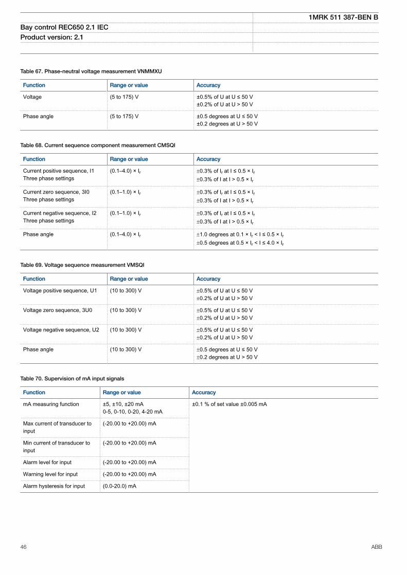
GUID-ED634B6D-9918-464F-B6A4-51B78129B819 v5
Table 67. Phase-neutral voltage measurement VNMMXU
Function Range or value Accuracy
Voltage (5 to 175) V ±0.5% of U at U ≤ 50 V±0.2% of U at U > 50 V
Phase angle (5 to 175) V ±0.5 degrees at U ≤ 50 V±0.2 degrees at U > 50 V
GUID-9B8A7FA5-9C98-4CBD-A162-7112869CF030 v4
Table 68. Current sequence component measurement CMSQI
Function Range or value Accuracy
Current positive sequence, I1Three phase settings
(0.1–4.0) × Ir ±0.3% of Ir at I ≤ 0.5 × Ir±0.3% of I at I > 0.5 × Ir
Current zero sequence, 3I0Three phase settings
(0.1–1.0) × Ir ±0.3% of Ir at I ≤ 0.5 × Ir±0.3% of I at I > 0.5 × Ir
Current negative sequence, I2Three phase settings
(0.1–1.0) × Ir ±0.3% of Ir at I ≤ 0.5 × Ir±0.3% of I at I > 0.5 × Ir
Phase angle (0.1–4.0) × Ir ±1.0 degrees at 0.1 × Ir < I ≤ 0.5 × Ir±0.5 degrees at 0.5 × Ir < I ≤ 4.0 × Ir
GUID-47094054-A828-459B-BE6A-D7FA1B317DA7 v5
Table 69. Voltage sequence measurement VMSQI
Function Range or value Accuracy
Voltage positive sequence, U1 (10 to 300) V ±0.5% of U at U ≤ 50 V±0.2% of U at U > 50 V
Voltage zero sequence, 3U0 (10 to 300) V ±0.5% of U at U ≤ 50 V±0.2% of U at U > 50 V
Voltage negative sequence, U2 (10 to 300) V ±0.5% of U at U ≤ 50 V±0.2% of U at U > 50 V
Phase angle (10 to 300) V ±0.5 degrees at U ≤ 50 V±0.2 degrees at U > 50 V
M16080-1 v5
Table 70. Supervision of mA input signals
Function Range or value Accuracy
mA measuring function ±5, ±10, ±20 mA0-5, 0-10, 0-20, 4-20 mA
±0.1 % of set value ±0.005 mA
Max current of transducer toinput
(-20.00 to +20.00) mA
Min current of transducer toinput
(-20.00 to +20.00) mA
Alarm level for input (-20.00 to +20.00) mA
Warning level for input (-20.00 to +20.00) mA
Alarm hysteresis for input (0.0-20.0) mA
1MRK 511 387-BEN BBay control REC650 2.1 IEC Product version: 2.1
46 ABB

GUID-C43B8654-60FE-4E20-8328-754C238F4AD0 v2
Table 71. Limit counter L4UFCNT
Function Range or value Accuracy
Counter value 0-65535 -
Max. count up speed 30 pulses/s (50% duty cycle) -M12760-1 v9.1.1
Table 72. Disturbance report DRPRDRE
Function Range or value Accuracy
Pre-fault time (0.05–9.90) s -
Post-fault time (0.1–10.0) s -
Limit time (0.5–10.0) s -
Maximum number of recordings 100, first in - first out -
Time tagging resolution 1 ms See table 101
Maximum number of analog inputs 30 + 10 (external + internallyderived)
-
Maximum number of binary inputs 352 -
Maximum number of phasors in the Trip Value recorder per recording 30 -
Maximum number of indications in a disturbance report 96 -
Maximum number of events in the Event recording per recording 150 -
Maximum number of events in the Event list 1000, first in - first out -
Maximum total recording time (3.4 s recording time and maximum number ofchannels, typical value)
340 seconds (100 recordings) at50 Hz, 280 seconds (80recordings) at 60 Hz
-
Sampling rate 1 kHz at 50 Hz1.2 kHz at 60 Hz
-
Recording bandwidth (5-300) Hz -GUID-F034B396-6600-49EF-B0A5-8ED96766A6A0 v6
Table 73. Insulation gas monitoring function SSIMG
Function Range or value Accuracy
Pressure alarm level 1.00-100.00 ±10.0% of set value
Pressure lockout level 1.00-100.00 ±10.0% of set value
Temperature alarm level -40.00-200.00 ±2.5% of set value
Temperature lockout level -40.00-200.00 ±2.5% of set value
Time delay for pressure alarm (0.000-60.000) s ±0.2% or ±250ms whichever is greater
Reset time delay for pressure alarm (0.000-60.000) s ±0.2% or ±250ms whichever is greater
Time delay for pressure lockout (0.000-60.000) s ±0.2% or ±250ms whichever is greater
Time delay for temperature alarm (0.000-60.000) s ±0.2% or ±250ms whichever is greater
Reset time delay for temperature alarm (0.000-60.000) s ±0.2% or ±250ms whichever is greater
Time delay for temperature lockout (0.000-60.000) s ±0.2% or ±250ms whichever is greater
1MRK 511 387-BEN BBay control REC650 2.1 IEC Product version: 2.1
ABB 47

GUID-83B0F607-D898-403A-94FD-7FE8D45C73FF v6
Table 74. Insulation liquid monitoring function SSIML
Function Range or value Accuracy
Oil alarm level 1.00-100.00 ±10.0% of set value
Oil lockout level 1.00-100.00 ±10.0% of set value
Temperature alarm level -40.00-200.00 ±2.5% of set value
Temperature lockout level -40.00-200.00 ±2.5% of set value
Time delay for oil alarm (0.000-60.000) s ±0.2% or ±250ms whichever is greater
Reset time delay for oil alarm (0.000-60.000) s ±0.2% or ±250ms whichever is greater
Time delay for oil lockout (0.000-60.000) s ±0.2% or ±250ms whichever is greater
Time delay for temperature alarm (0.000-60.000) s ±0.2% or ±250ms whichever is greater
Reset time delay for temperature alarm (0.000-60.000) s ±0.2% or ±250ms whichever is greater
Time delay for temperature lockout (0.000-60.000) s ±0.2% or ±250ms whichever is greaterGUID-B6799420-D726-460E-B02F-C7D4F1937432 v7
Table 75. Breaker monitoring SSCBR
Function Range or value Accuracy
Alarm level for open and close travel time (0 – 200) ms ±3 ms
Alarm level for number of operations (0 – 9999) -
Independent time delay for spring chargingtime alarm
(0.00 – 60.00) s ±0.2% or ±30 ms whichever is greater
Independent time delay for gas pressure alarm (0.00 – 60.00) s ±0.2% or ±30 ms whichever is greater
Independent time delay for gas pressurelockout
(0.00 – 60.00) s ±0.2% or ±30 ms whichever is greater
CB Contact Travel Time, opening and closing ±3 ms
Remaining Life of CB ±2 operations
Accumulated Energy ±1.0% or ±0.5 whichever is greaterM14987-1 v6
Table 76. Fault locator LMBRFLO
Function Value or range Accuracy
Reactive and resistive reach (0.001-1500.000) Ω/phase ±2.0% static accuracyConditions:Voltage range: (0.1-1.1) x UrCurrent range: (0.5-30) x Ir
Phase selection According to input signals -
Maximum number of faultlocations
100 -
M12700-1 v4
Table 77. Event list
Function Value
Buffer capacity Maximum number of events in the list 1000
Resolution 1 ms
Accuracy Depending on time synchronizing
1MRK 511 387-BEN BBay control REC650 2.1 IEC Product version: 2.1
48 ABB

M13765-1 v4
Table 78. Indications
Function Value
Buffer capacity Maximum number of indications presented for single disturbance 96
Maximum number of recorded disturbances 100M12702-1 v4
Table 79. Event recorder
Function Value
Buffer capacity Maximum number of events in disturbance report 150
Maximum number of disturbance reports 100
Resolution 1 ms
Accuracy Depending on timesynchronizing
M13747-1 v5
Table 80. Trip value recorder
Function Value
Buffer capacity
Maximum number of analog inputs 30
Maximum number of disturbance reports 100M12384-1 v6.1.1
Table 81. Disturbance recorder
Function Value
Buffer capacity Maximum number of analog inputs 40
Maximum number of binary inputs 352
Maximum number of disturbance reports 100
Maximum total recording time (3.4 s recording time and maximum numberof channels, typical value)
340 seconds (100 recordings) at 50 Hz280 seconds (80 recordings) at 60 Hz
GUID-C43B8654-60FE-4E20-8328-754C238F4AD0 v2
Table 82. Limit counter L4UFCNT
Function Range or value Accuracy
Counter value 0-65535 -
Max. count up speed 30 pulses/s (50% duty cycle) -
1MRK 511 387-BEN BBay control REC650 2.1 IEC Product version: 2.1
ABB 49

MeteringM13404-2 v5
Table 83. Pulse-counter logic PCFCNT
Function Setting range Accuracy
Input frequency See Binary Input Module (BIM) -
Cycle time for report of countervalue
(1–3600) s -
SEMOD153707-2 v4
Table 84. Energy metering ETPMMTR
Function Range or value Accuracy
Energy metering kWh Export/Import, kvarh Export/Import
Input from MMXU. No extra error at steady load
1MRK 511 387-BEN BBay control REC650 2.1 IEC Product version: 2.1
50 ABB

Station communicationM15031-1 v7
Table 85. Communication protocols
Function Value
Protocol IEC 61850-8-1
Communication speed for the IEDs 100BASE-FX
Protocol IEC 60870–5–103
Communication speed for the IEDs 9600 or 19200 Bd
Protocol DNP3.0
Communication speed for the IEDs 300–19200 Bd
Protocol TCP/IP, Ethernet
Communication speed for the IEDs 100 Mbit/sM11927-1 v2
Table 86. LON communication protocol
Function Value
Protocol LON
Communication speed 1.25 Mbit/sM11901-1 v2
Table 87. SPA communication protocol
Function Value
Protocol SPA
Communication speed 300, 1200, 2400, 4800, 9600, 19200 or 38400 Bd
Slave number 1 to 899M11921-1 v4
Table 88. IEC 60870-5-103 communication protocol
Function Value
Protocol IEC 60870-5-103
Communication speed 9600, 19200 BdM12589-1 v4
Table 89. SLM – LON port
Quantity Range or value
Optical connector Glass fiber: type STPlastic fiber: type HFBR snap-in
Fiber, optical budget Glass fiber: 11 dB (1000m/3000 ft typically *)Plastic fiber: 7 dB (10m/35ft typically *)
Fiber diameter Glass fiber: 62.5/125 mmPlastic fiber: 1 mm
*) depending on optical budget calculation
1MRK 511 387-BEN BBay control REC650 2.1 IEC Product version: 2.1
ABB 51

SEMOD117441-2 v5
Table 90. SLM – SPA/IEC 60870-5-103/DNP3 port
Quantity Range or value
Optical connector Glass fiber: type STPlastic fiber: type HFBR snap-in
Fiber, optical budget Glass fiber: 11 dB (1000m/3000ft m typically *)Plastic fiber: 7 dB (25m/80ft m typically *)
Fiber diameter Glass fiber: 62.5/125 mmPlastic fiber: 1 mm
*) depending on optical budget calculationSEMOD158710-2 v2
Table 91. Galvanic RS485 communication module
Quantity Range or value
Communication speed 2400–19200 bauds
External connectors RS-485 6-pole connectorSoft ground 2-pole connector
GUID-8651FF22-C007-4D53-B7E3-686A30F37CB6 v4
Table 92. IEC 62439-3 Edition 1 and Edition 2 parallel redundancy protocol
Function Value
Communication speed 100 Base-FX
1MRK 511 387-BEN BBay control REC650 2.1 IEC Product version: 2.1
52 ABB

HardwareIED
SEMOD53385-1 v1M11778-1 v4
Table 93. Case
Material Steel sheet
Front plate Steel sheet profile with cut-out for HMI
Surface treatment Aluzink preplated steel
Finish Light grey (RAL 7035)M12327-1 v3
Table 94. Water and dust protection level according to IEC 60529
Front IP40 (IP54 with sealing strip)
Sides, top and bottom IP20
Rear side IP20 with screw compression typeIP10 with ring lug terminals
M11777-1 v4
Table 95. Weight
Case size Weight
6U, 1/2 x 19” £ 10 kg/22 lb
Electrical safetyGUID-2825B541-DD31-4DAF-B5B3-97555F81A1C2 v1GUID-1CF5B10A-CF8B-407D-8D87-F4B48B43C2B2 v1
Table 96. Electrical safety according to IEC 60255-27
Equipment class I (protective earthed)
Overvoltage category III
Pollution degree 2 (normally only non-conductive pollution occurs except that occasionally a temporary conductivity caused bycondensation is to be expected)
Connection systemSEMOD53371-1 v1SEMOD53376-2 v6
Table 97. CT and VT circuit connectors
Connector type Rated voltage and current Maximum conductor area
Screw compression type 250 V AC, 20 A 4 mm2 (AWG12)2 x 2.5 mm2 (2 x AWG14)
Terminal blocks suitable for ring lug terminals 250 V AC, 20 A 4 mm2 (AWG12)M12583-1 v5
Table 98. Auxiliary power supply connectors
Connector type Rated voltage Maximum conductor area
Screw compression type 250 V AC 2.5 mm2 (AWG14)2 × 1 mm2 (2 x AWG18)
Terminal blocks suitable for ring lug terminals 300 V AC 3 mm2 (AWG14)
Table 99. Binary I/O connectors
Connector type Rated voltage Maximum conductor area
Screw compression type 250 V AC 2.5 mm2 (AWG14)2 × 1 mm2 (2 x AWG18)
1MRK 511 387-BEN BBay control REC650 2.1 IEC Product version: 2.1
ABB 53

Basic IED functionsM11963-1 v5
Table 100. Self supervision with internal event list
Data Value
Recording manner Continuous, event controlled
List size 40 events, first in-first outM12331-1 v7
Table 101. Time synchronization, time tagging
Function Value
Time tagging resolution, events and sampled measurement values 1 ms
Time tagging error with synchronization once/min (minute pulse synchronization), events and sampledmeasurement values
± 1.0 ms typically
Time tagging error with SNTP synchronization, sampled measurement values ± 1.0 ms typicallySEMOD141136-2 v8
Table 102. IRIG-B
Quantity Rated value
Number of channels IRIG-B 1
Number of optical channels 1
Electrical connector:
Electrical connector IRIG-B BNC
Pulse-width modulated 5 Vpp
Amplitude modulated– low level– high level
1-3 Vpp3 x low level, max 9 Vpp
Supported formats IRIG-B 00x, IRIG-B 12x
Accuracy +/-10μs for IRIG-B 00x and +/-100μs for IRIG-B 12x
Input impedance 100 k ohm
Optical connector:
Optical connector IRIG-B Type ST
Type of fibre 62.5/125 μm multimode fibre
Supported formats IRIG-B 00x
Accuracy +/- 1μs
1MRK 511 387-BEN BBay control REC650 2.1 IEC Product version: 2.1
54 ABB

Inverse characteristicM12388-1 v19
Table 103. ANSI Inverse time characteristics
Function Range or value Accuracy
Operating characteristic:
( )1PAt B k tDef
I
æ öç ÷= + × +ç ÷ç - ÷è ø
EQUATION1249-SMALL V2 EN-US
Reset characteristic:
( )2 1= ×
-
trt kI
EQUATION1250-SMALL V1 EN-US
I = Imeasured/Iset
0.10 ≤ k ≤ 3.001.5 x Iset ≤ I ≤ 20 x Iset
ANSI/IEEE C37.112 ,±2.0% or ±40 mswhichever is greater
ANSI Extremely Inverse A=28.2, B=0.1217, P=2.0 , tr=29.1
ANSI Very inverse A=19.61, B=0.491, P=2.0 , tr=21.6
ANSI Normal Inverse A=0.0086, B=0.0185, P=0.02, tr=0.46
ANSI Moderately Inverse A=0.0515, B=0.1140, P=0.02, tr=4.85
ANSI Long Time Extremely Inverse A=64.07, B=0.250, P=2.0, tr=30
ANSI Long Time Very Inverse A=28.55, B=0.712, P=2.0, tr=13.46
ANSI Long Time Inverse A=0.086, B=0.185, P=0.02, tr=4.6
1MRK 511 387-BEN BBay control REC650 2.1 IEC Product version: 2.1
ABB 55

SEMOD116978-2 v9
Table 104. Inverse time characteristics for overvoltage protection
Function Range or value Accuracy
Type A curve:
=- >
>
æ öç ÷è ø
tk
U U
UEQUATION1436-SMALL V1 EN-US
U> = UsetU = Umeasured
k = (0.05-1.10) in steps of 0.01 ±5.0% or ±45 mswhichever is greater
Type B curve:
2.0
480
32 0.5
=⋅
− >⋅ −
0.035+
>
tk
U U
UEQUATION1437-SMALL V2 EN-US
k = (0.05-1.10) in steps of 0.01
Type C curve:
3.0
480
32 0.5
=⋅
⋅ −− >
0.035+
>
tk
U U
UEQUATION1438-SMALL V2 EN-US
k = (0.05-1.10) in steps of 0.01
Programmable curve:
×= +
- >× -
>
æ öç ÷è ø
P
k At D
U UB C
UEQUATION1439-SMALL V1 EN-US
k = (0.05-1.10) in steps of 0.01A = (0.005-200.000) in steps of 0.001B = (0.50-100.00) in steps of 0.01C = (0.0-1.0) in steps of 0.1D = (0.000-60.000) in steps of 0.001P = (0.000-3.000) in steps of 0.001
1MRK 511 387-BEN BBay control REC650 2.1 IEC Product version: 2.1
56 ABB

Table 105. Inverse time characteristics for residual overvoltage protection
Function Range or value Accuracy
Type A curve:
=- >
>
æ öç ÷è ø
tk
U U
UEQUATION1436-SMALL V1 EN-US
U> = UsetU = Umeasured
k = (0.05-1.10) in steps of0.01
±5.0% or ±45 ms whichever is greater
Type B curve:
2.0
480
32 0.5
=⋅
− >⋅ −
0.035+
>
tk
U U
UEQUATION1437-SMALL V2 EN-US
k = (0.05-1.10) in steps of0.01
Type C curve:
3.0
480
32 0.5
=⋅
⋅ −− >
0.035+
>
tk
U U
UEQUATION1438-SMALL V2 EN-US
k = (0.05-1.10) in steps of0.01
Programmable curve:
×= +
- >× -
>
æ öç ÷è ø
P
k At D
U UB C
UEQUATION1439-SMALL V1 EN-US
k = (0.05-1.10) in steps of0.01A = (0.005-200.000) insteps of 0.001B = (0.50-100.00) in stepsof 0.01C = (0.0-1.0) in steps of0.1D = (0.000-60.000) insteps of 0.001P = (0.000-3.000) in stepsof 0.001
1MRK 511 387-BEN BBay control REC650 2.1 IEC Product version: 2.1
ABB 57

16. Ordering for pre-configured IEDGUID-985AAFE8-0541-484A-AB50-0FC28D9AAB3D v3.1.1
GuidelinesCarefully read and follow the set of rules to ensure problem-free order management.Please refer to the available functions table for included application functions.PCM600 can be used to make changes and/or additions to the delivered factory configuration of the pre-configured.
To obtain the complete ordering code, please combine code from the tables, as given in the example below.Example code: REC650*2.1-A02X00- P03-B1A12-AC-MP-B-A3X0-D1AB1N1-GXFX-AX. Using the code of each position #1-13 specified as REC650*1-2 2-3-44-5-6-7 7-8-9-10 10 10 10-11 11 11-12 12 12 12-13 13
# 1 - 2 - 3 - 4 - 5 6 - 7 8 - 9 -REC650* - - - - - - -
10 - 11 - 12 - 13 - . -
Po
sitio
n
SOFTWARE #1 Notes and Rules
Version number Version no 2.1
Selection for position #1.
Configuration alternatives #2 Notes and Rules
Single breaker, double busbar A02 ACT configuration ABB Standard configuration X00 Selection for position #2.
Software options #3 Notes and Rules
No option X00 All fields in the ordering form donot need to be filled in
IEC 62439-3 parallel redundancy protocol P03 Note! Requires 2-channel OEM Selection for position #3
First local HMI user dialogue language #4 Notes and Rules
HMI language, English IEC B1 Additional local HMI user dialogue language No additional HMI language X0 HMI language, English US A12 Selection for position #4.
Casing #5 Notes and Rules
1/2 x 19" case A Selection for position #5. A
Mounting details with IP40 of protection from the front #6 Notes and Rules
No mounting kit included X 19" rack mounting kit for 1/2 x 19" case of 2xRHGS6 or RHGS12 A Wall mounting kit D Note: Wall mounting not
recommended withcommunication modules withfibre connection (SLM, OEM,LDCM)
Flush mounting kit E Flush mounting kit + IP54 mounting seal F Selection for position #6.
1MRK 511 387-BEN BBay control REC650 2.1 IEC Product version: 2.1
58 ABB

Connection type #7 Notes and Rules
Connection type for Power supply module Compression terminals M Ringlug terminals N Connection type for input/output modules Compression terminals P Selection for position #7. P
Auxiliary power supply #8 Notes and Rules
24-60 VDC A 90-250 VDC B Selection for position #8.
Human machine hardware interface #9 Notes and Rules
Medium size - graphic display, IEC keypad symbols B Medium size - graphic display, ANSI keypad symbols C Selection for position #9.
Connection type for Analog modules #10 Notes and Rules
Compression terminals A Ringlug terminals B Analog system TRM, 7I+5U 1A 12 TRM, 7I+5U 5A 13 TRM, 6I, 5A + 1I, 1A + 5U 14 TRM, 3I, 5A + 4I, 1A + 5U 15 Selection for position #10.
Binary input/output module, mA and time synchronization boards. #11 Notes and Rules
For pulse counting, for example kWh metering, the BIM with enhanced pulse counting capabilities must be used.Note: 1 BIM and 1 BOM always included.
Slot position (rear view)
X31
X41
X51 Note: Max 3 positions in
1/2 rack.1/2 Case with 1 TRM No board in slot X Binary output module 24 output relays (BOM) A A BIM 16 inputs, 24-30 VDC, 50mA B1 B1 BIM 16 inputs, 48-60 VDC, 50mA C1 C1 BIM 16 inputs, 110-125 VDC, 50mA D1 D1 BIM 16 inputs, 220-250 VDC, 50mA E1 E1 BIM 16 inputs, 220-250 VDC, 120mA E2 E2 BIMp 16 inputs, 24-30 VDC, 30mA, for pulse counting F BIMp 16 inputs, 48-60 VDC, 30mA, for pulse counting G BIMp 16 inputs, 110-125 VDC, 30mA, for pulse counting H BIMp 16 inputs, 220-250 VDC, 30mA, for pulse counting K IOM 8 inputs 10+2 output relays, 24-30 VDC, 50mA L1 IOM 8 inputs 10+2 output relays, 48-60 VDC, 50mA M1 IOM 8 inputs 10+2 output relays, 110-125 VDC, 50mA N1 IOM 8 inputs 10+2 output relays, 220-250 VDC, 50mA P1 IOM 8 inputs 10+2 output relays, 220-250 VDC, 110mA P2 IOM with MOV 8 inputs ,10 out, 2 high-speed, 24-30 VDC, 30mA U IOM with MOV 8 inputs 10 out, 2 high-speed, 48-60 VDC, 30mA V IOM with MOV 8 inputs 10 out, 2 high-speed, 110-125 VDC, 30mA W IOM with MOV 8 inputs 10 out, 2 high-speed, 220-250 VDC, 30mA Y
Selection for position #11.
1MRK 511 387-BEN BBay control REC650 2.1 IEC Product version: 2.1
ABB 59

Remote end communication, DNP serial comm. and time synchronizationmodules
#12 Notes and Rules
Slot position (rear view)
X312
X313
X302
X303
Available slots No remote communication board included X X X X IRIG-B Time synchronization module F F F F Galvanic RS485 communication module G G G G Selection for position #12.
Serial communication unit for station communication #13 Notes and Rules
Slot position (rear view)
X301
X311
No communication board included X X Serial SPA/LON/DNP/IEC 60870-5-103 plastic interface A Serial SPA/LON/DNP/IEC 60870-5-103 plastic/glass interface B Serial SPA/LON/DNP/IEC 60870-5-103 glass interface C Optical ethernet module, 1 channel glass D Optical ethernet module, 2 channel glass E Selection for position #13.
1MRK 511 387-BEN BBay control REC650 2.1 IEC Product version: 2.1
60 ABB

17. Ordering for Accessories
AccessoriesIP15151-1 v1
Test switchSEMOD111888-5 v11
The test system COMBITEST intended for use with the IEDsis described in 1MRK 512 001-BEN and 1MRK 001024-CA.Please refer to the website:www.abb.com/substationautomation for detailed information.
Test switches type RTXP 24 is ordered separately. Pleaserefer to Section Related documents for references tocorresponding documents.
RHGS 6 Case or RHGS 12 Case with mounted RTXP 24 andthe on/off switch for dc-supply are ordered separately. Pleaserefer to Section Related documents for references tocorresponding documents.
Protection coverM15040-3 v5
Protective cover for rear side of RHGS6, 6U, 1/4 x 19” Quantity: 1MRK 002 420-AE
Protective cover for rear side of terminal, 6U, 1/2 x 19” Quantity: 1MRK 002 420-AC
External resistor unitSEMOD120228-4 v7
High impedance resistor unit 1-ph with resistor and voltage dependent resistor for20-100V operating voltage
Quantity:
1 2 3 RK 795 101-MA
High impedance resistor unit 3-ph with resistor and voltage dependent resistor for20-100V operating voltage
Quantity: RK 795 101-MB
High impedance resistor unit 1-ph with resistor and voltage dependent resistor for100-400V operating voltage
Quantity:
1 2 3 RK 795 101-CB
High impedance resistor unit 3-ph with resistor and voltage dependent resistor for100-400V operating voltage
Quantity: RK 795 101-DC
CombiflexIP15161-1 v1
Key switch for settingsSEMOD130356-4 v5
Key switch for lock-out of settings via LCD-HMI Quantity: 1MRK 000 611-A
Note: To connect the key switch, leads with 10 A Combiflex socket on one end must be used.SEMOD130267-5 v6
Mounting kit Ordering number
Side-by-side mounting kit Quantity: 1MRK 002 420-Z
Configuration and monitoring toolsIP15162-1 v2M15042-3 v3
Front connection cable between LCD-HMI and PC Quantity: 1MRK 001 665-CA
SEMOD131414-4 v3
LED Label special paper A4, 1 pc Quantity: 1MRK 002 038-CA
LED Label special paper Letter, 1 pc Quantity: 1MRK 002 038-DA
ManualsM15161-3 v12
Note: One (1) IED Connect CD containing user documentation (Operation manual, Technical manual,Installation manual, Commissioning manual, Application manual and Getting started guide), Connectivitypackages and LED label template is always included for each IED.
1MRK 511 387-BEN BBay control REC650 2.1 IEC Product version: 2.1
ABB 61
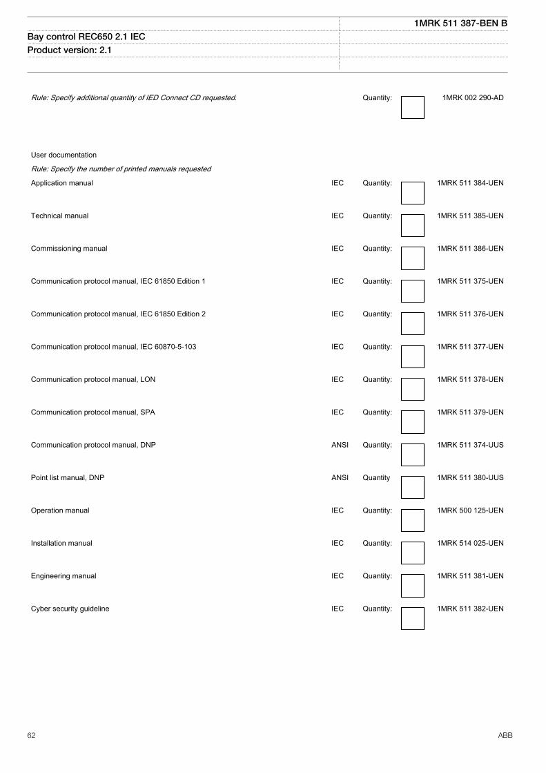
Rule: Specify additional quantity of IED Connect CD requested. Quantity: 1MRK 002 290-AD
User documentation
Rule: Specify the number of printed manuals requested
Application manual IEC Quantity: 1MRK 511 384-UEN
Technical manual IEC Quantity: 1MRK 511 385-UEN
Commissioning manual IEC Quantity: 1MRK 511 386-UEN
Communication protocol manual, IEC 61850 Edition 1
IEC Quantity: 1MRK 511 375-UEN
Communication protocol manual, IEC 61850 Edition 2 IEC Quantity: 1MRK 511 376-UEN
Communication protocol manual, IEC 60870-5-103 IEC Quantity: 1MRK 511 377-UEN
Communication protocol manual, LON IEC Quantity: 1MRK 511 378-UEN
Communication protocol manual, SPA IEC Quantity: 1MRK 511 379-UEN
Communication protocol manual, DNP ANSI Quantity: 1MRK 511 374-UUS
Point list manual, DNP ANSI Quantity 1MRK 511 380-UUS
Operation manual IEC Quantity: 1MRK 500 125-UEN
Installation manual IEC Quantity: 1MRK 514 025-UEN
Engineering manual IEC Quantity: 1MRK 511 381-UEN
Cyber security guideline IEC Quantity: 1MRK 511 382-UEN
1MRK 511 387-BEN BBay control REC650 2.1 IEC Product version: 2.1
62 ABB

Reference informationM2175-3 v4
For our reference and statistics we would be pleased to be provided with the following application data:
Country: End user:
Station name: Voltage level: kV
Related documentsGUID-94E8A5CA-BE1B-45AF-81E7-5A41D34EE112 v3
Documents related to REC650 Document numbers
Application manual 1MRK 511 384-UEN
Commissioning manual 1MRK 511 386-UEN
Product guide 1MRK 511 387-BEN
Technical manual 1MRK 511 385-UEN
Type test certificate 1MRK 511 387-TEN
650 series manuals Document numbers
Operation manual 1MRK 500 125-UEN
Engineering manual 1MRK 511 381-UEN
Installation manual 1MRK 514 025-UEN
Communication protocol manual,DNP3
1MRK 511 374-UUS
Communication protocol manual,IEC 60870-5-103
1MRK 511 377-UEN
Communication protocol manual,IEC 61850 Edition 1
1MRK 511 375-UEN
Communication protocol manual,IEC 61850 Edition 2
1MRK 511 376-UEN
Communication protocol manual,LON
1MRK 511 378-UEN
Communication protocol manual,SPA
1MRK 511 379-UEN
Point list manual, DNP3 1MRK 511 380-UUS
Accessories guide IEC: 1MRK 514 012-UENANSI: 1MRK 514 012-UUS
Cyber security deploymentguideline
1MRK 511 382-UEN
Connection and Installationcomponents
1MRK 513 003-BEN
Test system, COMBITEST 1MRK 512 001-BEN
1MRK 511 387-BEN BBay control REC650 2.1 IEC Product version: 2.1
ABB 63

64

Contact us
For more information please contact:
ABB ABSubstation Automation ProductsSE-721 59 Västerås, SwedenPhone +46 (0) 21 32 50 00
www.abb.com/protection-control
Note:We reserve the right to make technical changes or modifythe contents of this document without prior notice. ABB ABdoes not accept any responsibility whatsoever for potentialerrors or possible lack of information in this document.We reserve all rights in this document and in the subjectmatter and illustrations contained herein. Any reproduction,disclosure to third parties or utilization of its contents – inwhole or in part – is forbidden without prior written consentof ABB AB.
© Copyright 2016 ABB.
All rights reserved.
Scan this QR code to visit our website
1MR
K 5
11 3
87-B
EN