Embed Size (px)
Citation preview
No.
832
951
E ·
Edi
tion
0807
; Sub
ject
to m
odifi
catio
n. R
epla
ces
Edi
tion
0602
.
Obje
ct
Dete
cti
on
– M
echa
nica
l and
Indu
ctiv
e S
ingl
e an
d M
ultip
le P
ositi
on S
witc
hes
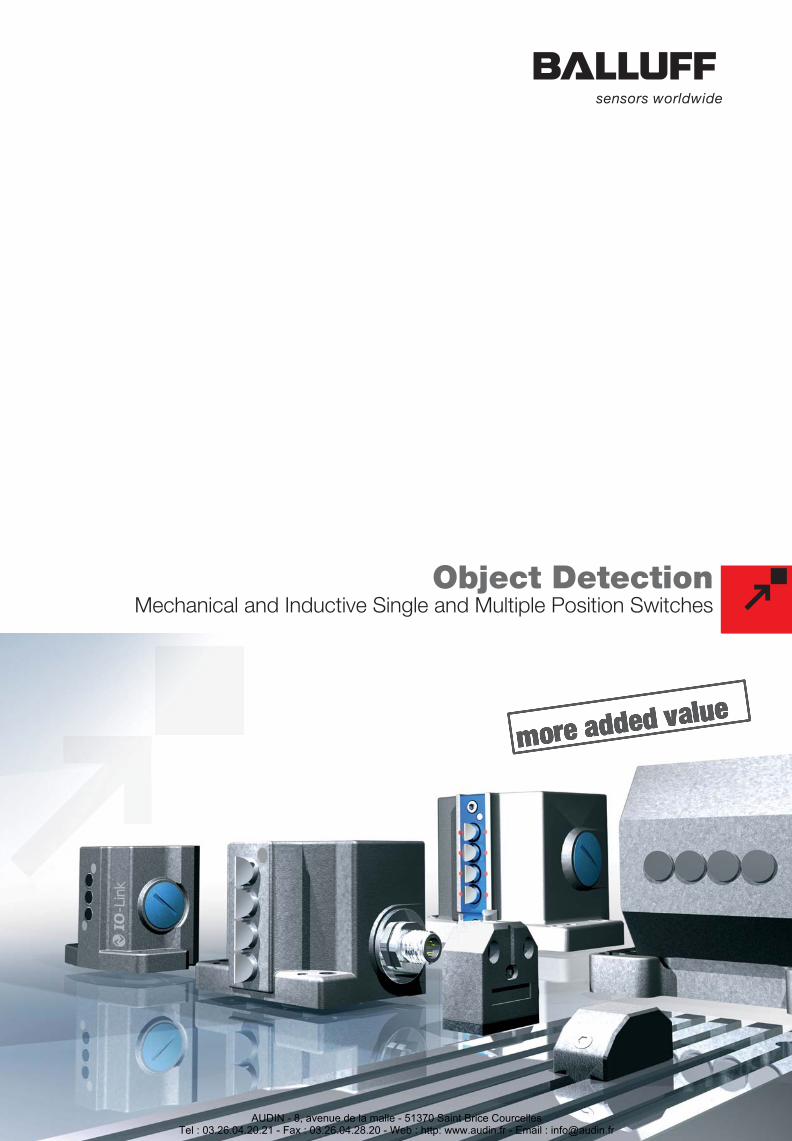
Object DetectionMechanical and Inductive Single and Multiple Position Switches
Balluff GmbHSchurwaldstrasse 973765 Neuhausen a.d.F.GermanyPhone +49 7158 173-0Fax +49 7158 [email protected] www.balluff.com
Object Detection
Linear Position Sensing
Industrial Identifi cation
Industrial Networking and Connectivity
Mechanical Accessories
AUDIN - 8, avenue de la malle - 51370 Saint Brice CourcellesTel : 03.26.04.20.21 - Fax : 03.26.04.28.20 - Web : http: www.audin.fr - Email : [email protected]
Balluff is a worldwideleading company in the fieldof position detection.
Our products range includeselectronic sensors,transducers based onvarious operating principles,identification systems, bus-compatible sensors as wellas mechanical and inductivesingle and multiple positionswitches. Balluff productsare found wherever accuracyand reliability are in demand.
Wherever there is a needto automate, sense objects,or report linear and rotarymotion to controllers – Balluffis always the right partner.
Our QM system meetsthe requirements ofDIN EN ISO 9001:2000.Eleven Balluff companieshave a certified QM system,two a certified environmentalprotection system.
By mastering process-capable production andassembly techniques andstatistical process controlwe achieve consistentlyhigh product quality.Intensive testing before serialproduction beginsguarantees reliable function.
With more than 50 years ofexperience in the field ofsensor technology, Ballufftoday is one of the mostcapable manufacturers ofboth standardized andcustom limit switches.Innovative technology andapplication-specificcustomer solutions are theoutstanding features ofthe entire product range.
Highly-qualified developmentengineers and experienceddesigners work closely withthe manufactures to ensuremature series products thatare used successfully inevery area of automation –even under extreme andaggressive operatingconditions.
AUDIN - 8, avenue de la malle - 51370 Saint Brice CourcellesTel : 03.26.04.20.21 - Fax : 03.26.04.28.20 - Web : http: www.audin.fr - Email : [email protected]
Object Detection
1.1
1.2
1.3
1.4
2.1
3
4
5.1
iGeneral Information
Principles of Mechanical andInductive Single and Multiple Position Switches
Mechanical Single and Multiple Position Switches
Mechanical Single and Multiple Position Switcheswith Safety Switch Positions
Mechanical Single and Multiple Position Switcheswith Forced Opening
Mechanical Multiple Position Switcheswith Quick-Change Plunger Unit
Inductive Single and Multiple Position Switches
2.2Inductive Multiple Position Switcheswith Extended Switching Distance 4 mm
Special Form Factors
Wireless System
Mechanical and Inductive Switch Elements
5.2Cam Trays and Cams
5.3Connectors and Function Indicators
www.balluff.com 3AUDIN - 8, avenue de la malle - 51370 Saint Brice Courcelles
Tel : 03.26.04.20.21 - Fax : 03.26.04.28.20 - Web : http: www.audin.fr - Email : [email protected]

4
ArgentinaNortécnica S.R.L103 – Heredia 638B1672BKDVilla Lynch – San MartinPcia. de Buenos AiresPhone +54 11 47573129Fax +54 11 [email protected]
AustraliaBalluff-Leuze Pty. Ltd.12 Burton CourtBayswater VIC 3153Phone +61 397 204100Fax +61 397 [email protected]
AustriaBalluff GmbHIndustriestraße B162345 Brunn am GebirgePhone +43 2236 32521-0Fax +43 2236 [email protected]
BelarusBalluffzentrum OOO.Prospekt Nezavisimosti 185Anlage 19, Office 1220125 MinskPhone +375 17 2181713Fax +375 17 [email protected]
BelgiumBalluff bvbaInterleuvenlaan 62, Zone 23001 LeuvenPhone +32 16 397800Fax +32 16 [email protected]
BrazilBalluff ControlesElétricos Ltda.Rua Francisco Foga, 25Distrito IndustrialCEP 13280.000Vinhedo – Sao PauloPhone +55 19 38769999Fax +55 19 [email protected]
BulgariaBPS AG41, Nedelcho Bonchev St.1528 SofiaPhone +359 2 9609875Fax +359 2 [email protected]
CanadaBalluff Canada Inc.2840 Argentia Road, Unit 2Mississauga, OntarioL5N 8G4Phone +1 905 816-1494Toll-free 1-8 00-927-9654Fax +1 905 [email protected]
ChileBalluff ControlesElétricos Ltda.Brazil
HungaryBalluff Elektronika Kft.Pápai út. 55.8200 VeszprémPhone +36 88 421808Fax +36 88 [email protected]
Balluff Elektronika Kft.Vihar utca 22.1221 BudapestPhone +36 1 4820002Fax +36 88 [email protected]
IndiaBalluff India405 Raikar ChambersDeonar Village Road,Govandi, Mumbai 400088Phone +91 22 67551646Fax +91 22 [email protected]
IndonesiaPT. Multiguna CemerlangBumi Serpong DamaiSektor XIMultipurpose IndustrialBuildingBlock H 3-31Serpong Tangerang15314 Jawa BaratPhone +62 21 75875555Fax +62 21 [email protected]
IranIran Technical Supply Co.Apt. #14, 3rd Floor, No. 141North Sohrevardi Ave.Teheran 15589Phone +98 21 8763731Fax +98 21 [email protected]
IsraelAncitech Ltd.21 Haorgim St. 21bIndustrial ZoneHolon 58857Phone +972 3 5568351Fax +972 3 [email protected]
ItalyBalluff Automation S.R.L.Via Morandi 410095 Grugliasco, TorinoPhone +39 11 3150711Fax +39 11 [email protected]
JapanBalluff Co., Ltd.Ishikawa Bldg. 2nd Fl.1-5-5 Yanagibashi, Taito-KuTokyo 111-0052Phone +81 03 5833-5440Fax +81 03 [email protected]
ChinaBalluff (Shanghai) TradingCo. Ltd.Room 337, Xinxing Building2005 Yanggao Rd. North200131 ShanghaiPhone +86 21 51698788Fax +86 21 [email protected]
ColumbiaBalluff ControlesElétricos Ltda.Brazil
CroatiaHSTEC d.d.Zagrebacka 10023000 ZadarPhone +385 23 205-405Fax +385 23 [email protected]
Czech RepublicBalluff CZ, s.r.oPelušková 1400198 00 Praha 9 – KyjePhone +420 281 940099Fax +420 281 [email protected]
DenmarkBalluff ApSÅbogade 158200 Århus NPhone +45 70 234929Fax +45 70 [email protected]
FinlandMurrelektronik OyKoukkukatu 115700 LahtiPhone +358 3 8824000Fax +358 3 [email protected]
FranceBalluff SASZI Nord de Torcy-Bat 3Rue des Tanneurs – BP 4877201 Marne La ValléeCedex 1Phone +33 1 64111990Fax +33 1 [email protected]
Great BritainBalluff Ltd.4 Oakwater AvenueCheadle Royal Business ParkCheadle, Cheshire SK8 3SRPhone +44 161 282-4700Fax +44 161 [email protected]
GreecePILI S.A.Ar. Klirotemaxiou 1196N. MagnisiaPost Box 9957008 ThessalonikiPhone +30 2310 784062Fax +30 2310 [email protected]
Hong KongSensortech CompanyNo. 43, 18th StreetHong Lok Yuen,Tai Po, NTPhone +852 26510188Fax +852 [email protected]
KoreaMahani Electric Co. Ltd.792-7 Yeoksam-DongKangnam-Gu, SeoulPost code: 135-080Phone +82 2 21943300Fax +82 2 [email protected]
Lithuaniainterautomatika UABKêstuèio 4708127 VilniusPhone +370 5 2607810Fax +370 5 [email protected]
MalaysiaSumber Engineering (M)Sdn. Bhd. 20T 558Jalan Subang 6077 Persiaran Subang,Sungai Penaga Industrial Parc47500 Subang Jaya,SelangorPhone +60 3 56334227Fax +60 3 [email protected]
MexicoBalluff de México S.A. de C.V.Prol. Av. Luis M. Vega #109Col. Ampliación CimatarioC.P. 76030Queretaro, Qro.Phone +52 442 2124882Fax +52 442 [email protected]
NetherlandsBalluff B.V.Kempenlandstraat 11H5262 GK VughtPhone +31 73 6579702Fax +31 73 [email protected]
New ZealandBalluff-Leuze Pty. Ltd.Australien
NorwayPrimatec asLillesandsveien 444877 GrimstadPhone +47 37 258700Fax +47 37 [email protected]
PhilippinesTechnorand SalesCorporation803 Wilshire AnnapolisPlaza,No. 11 Annapolis Street,San Juan,Metro Manila 1500Phone +63 2 7245006Fax +63 2 [email protected]
AUDIN - 8, avenue de la malle - 51370 Saint Brice CourcellesTel : 03.26.04.20.21 - Fax : 03.26.04.28.20 - Web : http: www.audin.fr - Email : [email protected]

Worldwide Sales
www.balluff.com
Headquarters
Germany
Balluff GmbHSchurwaldstrasse 973765 Neuhausen a.d.F.Phone +49 7158 173-0Fax +49 7158 [email protected]
1.1
1.2
1.3
1.4
2.1
3
4
5.1
i
2.2
5.2
5.3
5
PolandBalluff Sp. z o.o.Ul. Muchoborska 1654-424 WroclawPhone +48 71 3384929Fax +48 71 [email protected]
PortugalLA2P Lda.Rua Teofilo Braga, 156 AEscrit. F – Edificio S.DomingosCabeco Do Mouro 2785-122 S. Domingos De RanaPhone +351 21 4447070Fax +351 21 [email protected]
RomaniaEast Electric s.r.l.256 Basarabia Blvd.030352 BucurestiPhone +40 31 4016301Fax +40 31 [email protected]
RussiaBalluff OOOM. Kaluzhskaja Str. 15Building 17, Office 500119071 MoscowPhone +7 495 78071-94Fax +7 495 [email protected]
SerbiaENEL d.o.o.Vasilja Pavlovica 101400 ValjevoPhone +381 14 291161Fax +381 14 [email protected]
SingaporeBalluff Asia Pte. Ltd.BLK 1004 Toa PayohInd. ParkLorong 8, #03-1489Singapore 319076Phone +65 62524384Fax +65 [email protected]
Slovak RepublicBalluff Slovakia s.r.o.Jána Bottu 497401 Banská BystricaPhone +421 48 4148386/87Fax +421 48 [email protected]
SloveniaSenzorji SB d.o.oProizvodnja,trgovina in storitve d.o.oulica Kirbisevih 53a2204 Miklavz naDravskem poljuPhone +386 2 6290300Fax +386 2 [email protected]
South AfricaRetron ccP.O. Box 39448Bramley, 2018Phone +27 11 7860553Fax +27 11 [email protected]
SpainBalluff S.L.Edificio Forum SCV-Planta5°, Oficina 4°
Carretera Sant Cugat a RubiKm01, 40-5008190 Sant Cugat del VallésBarcelonaPhone +34 93 5441313Fax +34 93 [email protected]
SwedenBalluff ABIndustrivägen 243361 SävedalenPhone +46 31 3408630Fax +46 31 [email protected]
SwitzerlandBalluff Sensortechnik AGRiedstrasse 68953 DietikonPhone +41 43 3223240Fax +41 43 [email protected]
TaiwanCanaan Electric Corp.6F-5, No. 63 Sec. 2Chang An East RoadTaipeiPhone +886 22 5082331Fax +886 22 [email protected]
ThailandCompomax Co. Ltd.16 Soi Ekamai 4,Sukhumvit 63 Rd.Prakanongnua, Vadhana,Bangkok 10110Phone +66 2 7269595Fax +66 2 [email protected]
TurkeyBalluff Sensor OtomasyonSanayi Ve Ticaret Ltd. Sti.Perpa Ticaret Is MerkeziA Blok, Kat 1-2-3No: 0013-001434381 Okmeydani/IstanbulPhone +90 212 3200411Fax +90 212 [email protected]
UkraineMicronlogistic37, Promyischlennaya St.Odessa, 65031Phone +380 482 358760Fax +380 482 [email protected]
USABalluff Inc.8125 Holton DriveFlorence, KY 41042-0937Phone +1 859 727-2200,Toll-free 1-800-543-8390Fax +1 859 [email protected]
VenezuelaBalluff ControlesElétricos Ltda.Brazil
AUDIN - 8, avenue de la malle - 51370 Saint Brice CourcellesTel : 03.26.04.20.21 - Fax : 03.26.04.28.20 - Web : http: www.audin.fr - Email : [email protected]
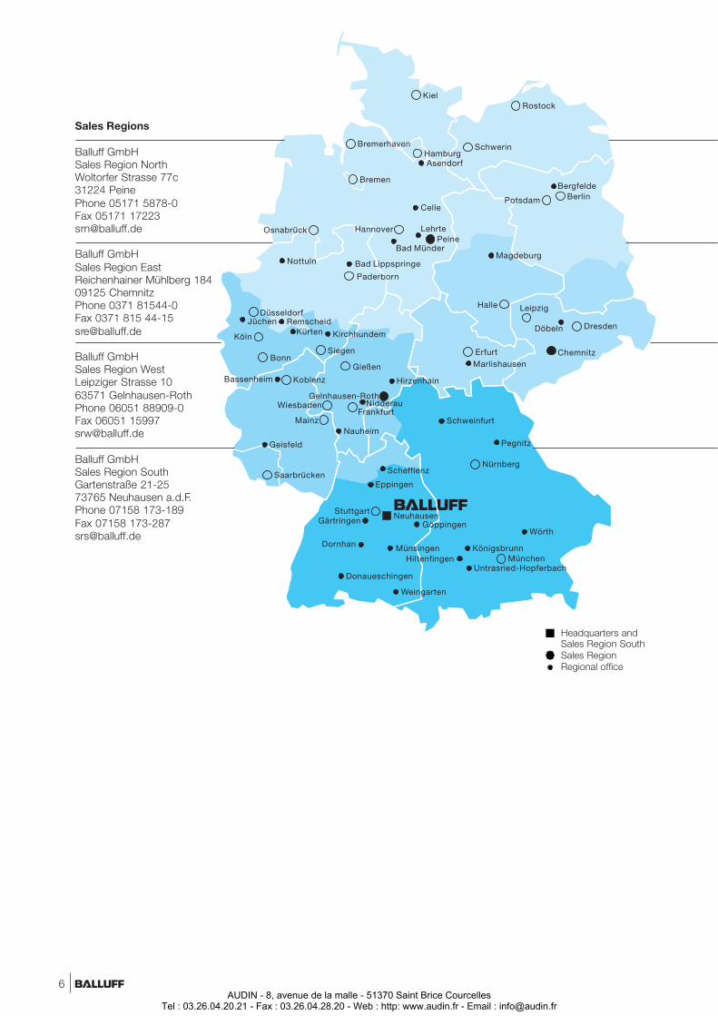
Sales Regions
Balluff GmbHSales Region NorthWoltorfer Strasse 77c31224 PeinePhone 05171 5878-0Fax 05171 [email protected]
Balluff GmbHSales Region EastReichenhainer Mühlberg 18409125 ChemnitzPhone 0371 81544-0Fax 0371 815 [email protected]
Balluff GmbHSales Region WestLeipziger Strasse 1063571 Gelnhausen-RothPhone 06051 88909-0Fax 06051 [email protected]
Balluff GmbHSales Region SouthGartenstraße 21-2573765 Neuhausen a.d.F.Phone 07158 173-189Fax 07158 [email protected]
Headquarters andSales Region SouthSales RegionRegional office
6AUDIN - 8, avenue de la malle - 51370 Saint Brice Courcelles
Tel : 03.26.04.20.21 - Fax : 03.26.04.28.20 - Web : http: www.audin.fr - Email : [email protected]
Sales Germany
Sales Region NorthPostal Codes:10000 – 3451937000 – 3729937400 – 3877939300 – 3935939510 – 39649
Sales Region EastPostal Codes:01000 – 0999936400 – 3646937300 – 3735938800 – 3929939360 – 39449
Sales Region WestPostal Codes:34520 – 3639940000 – 4184947000 – 4792950100 – 5764858740 – 58849
Sales Region SouthPostal Codes:70000 – 7467975000 – 7670977600 – 7987980000 – 9648997000 – 97799
42000 – 4656948000 – 4984958000 – 5873959000 – 59969
96500 – 9652998500 – 9874999000 – 99999
60000 – 6951874700 – 7493976710 – 7689197800 – 97999
www.balluff.com
1.1
1.2
1.3
1.4
2.1
3
4
5.1
iGeneral Information
Principles of Mechanical andInductive Single and Multiple Position Switches
Mechanical Single and Multiple Position Switches
Mechanical Single and Multiple Position Switcheswith Safety Switch Positions
Mechanical Single and Multiple Position Switcheswith Forced Opening
Mechanical Multiple Position Switcheswith Quick-Change Plunger Unit
Inductive Single and Multiple Position Switches
2.2Inductive Multiple Position Switcheswith Extended Switching Distance 4 mm
Special Form Factors
Wireless System
Mechanical and Inductive Switch Elements
5.2Cam Trays and Cams
5.3Connectors and Function Indicators
Headquarters
Balluff GmbHSchurwaldstrasse 973765 Neuhausen a.d.F.Phone 07158 173-0Fax 07158 [email protected]
7AUDIN - 8, avenue de la malle - 51370 Saint Brice Courcelles
Tel : 03.26.04.20.21 - Fax : 03.26.04.28.20 - Web : http: www.audin.fr - Email : [email protected]
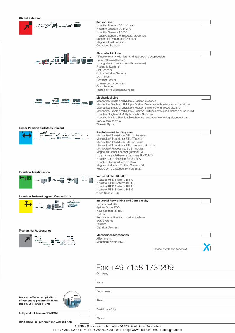
Mechanical LineMechanical Single and Multiple Position SwitchesMechanical Single and Multiple Position Switches with safety switch positionsMechanical Single and Multiple Position Switches with forced openingMechanical Single and Multiple Position Switches with quick-change plunger unitInductive Single and Multiple Position SwitchesInductive Multiple Position Switches with extended switching distance 4 mmSpecial form factorsWireless System
Sensor LineInductive Sensors DC 3-/4-wireInductive Sensors DC 2-wireInductive Sensors AC/DCInductive Sensors with special propertiesSensors for Pneumatic CylindersMagnetic Field SensorsCapacitive Sensors
Displacement Sensing LineMicropulse® Transducer BTL profile seriesMicropulse® Transducer BTL AT seriesMicropulse® Transducer BTL rod seriesMicropulse® Transducer BTL compact rod seriesMicropulse® Processors, BUS modulesMagnetic Linear Encoder Systems BMLIncremental and Absolute Encoders BDG/BRGInductive Linear Position Sensor BIWInductive Distance Sensors BAWMagneto-inductive Position Sensors BILPhotoelectric Distance Sensors BOD
Industrial IdentificationIndustrial RFID Systems BIS CIndustrial RFID Systems BIS LIndustrial RFID Systems BIS MIndustrial RFID Systems BIS SVision Sensor BVS
Industrial Networking and ConnectivityConnectors BKSSplitter Boxes BSBValve Connectors BNIIO-LinkRemote Inductive Transmission SystemsBUS SystemsWirelessElectrical Devices
Photoelectric LineDiffuse energetic with fore- and background suppressionRetro-reflective SensorsThrough-beam Sensors (emitter/receiver)Fiberoptic SystemsSlot SensorsOptical Window SensorsLight GridsContrast SensorLuminescence SensorsColor SensorsPhotoelectric Distance Sensors
Mechanical AccessoriesAttachmentsMounting System BMS
Please check and send fax!
Company
Name
Department
Street
Phone
Postal code/city
Object Detection
Linear Position and Measurement
Industrial Identification
Industrial Networking and Connectivity
Mechanical Accessories
Full product line on CD-ROM
DVD-ROM Full product line with 3D data
We also offer a compilationof our entire product lines onCD-ROM or DVD-ROM!
Fax +49 7158 173-299
AUDIN - 8, avenue de la malle - 51370 Saint Brice CourcellesTel : 03.26.04.20.21 - Fax : 03.26.04.28.20 - Web : http: www.audin.fr - Email : [email protected]
Contents
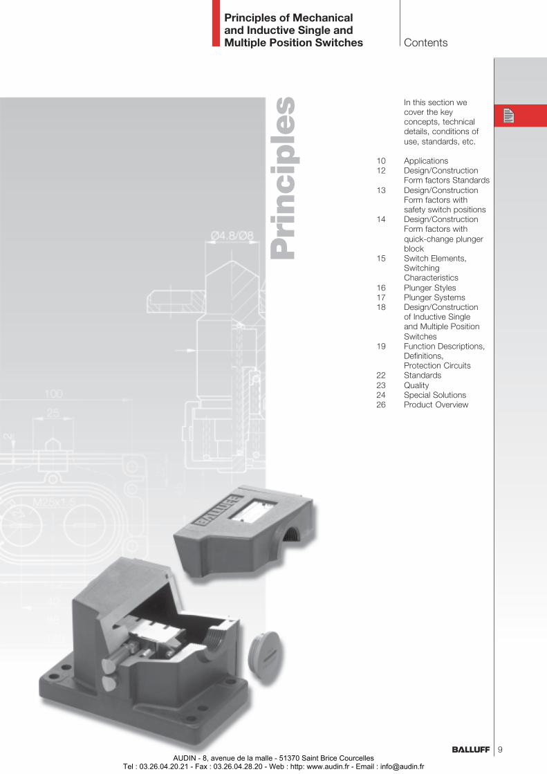
Principles of Mechanicaland Inductive Single andMultiple Position Switches
In this section wecover the keyconcepts, technicaldetails, conditions ofuse, standards, etc.
10 Applications12 Design/Construction
Form factors Standards13 Design/Construction
Form factors withsafety switch positions
14 Design/ConstructionForm factors withquick-change plungerblock
15 Switch Elements,SwitchingCharacteristics
16 Plunger Styles17 Plunger Systems18 Design/Construction
of Inductive Singleand Multiple PositionSwitches
19 Function Descriptions,Definitions,Protection Circuits
22 Standards23 Quality24 Special Solutions26 Product Overview
9
Pri
nci
ple
s
AUDIN - 8, avenue de la malle - 51370 Saint Brice CourcellesTel : 03.26.04.20.21 - Fax : 03.26.04.28.20 - Web : http: www.audin.fr - Email : [email protected]
Mechanical andInductive Single and MultiplePosition Switches Applications
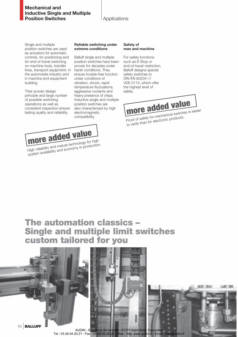
The automation classics –Single and multiple limit switchescustom tailored for you
Single and multipleposition switches are usedas actuators for automaticcontrols, for positioning andfor end-of-travel switchingon machine tools, transferlines, transport equipment, inthe automobile industry andin machine and equipmentbuilding.
Their proven designprinciple and large numberof possible switchingoperations as well asconsistent inspection ensurelasting quality and reliability.
Reliable switching underextreme conditions
Balluff single and multipleposition switches have beenproven for decades underharsh conditions. Theyensure trouble-free functionunder conditions ofvibration, shock, rapidtemperature fluctuations,aggressive coolants andheavy presence of chips.Inductive single and multipleposition switches arealso characterized by highelectromagneticcompatibility.
Safety ofman and machine
For safety functionssuch as E-Stop orend-of-travel restriction,Balluff designs specialsafety switches toDIN EN 60204-1/VDE 0113, which offerthe highest level ofsafety.
High reliability and mature technology for high
system availability and economy in production.
Proof of safety for mechanical switches is easier
to verify than for electronic products.
10AUDIN - 8, avenue de la malle - 51370 Saint Brice Courcelles
Tel : 03.26.04.20.21 - Fax : 03.26.04.28.20 - Web : http: www.audin.fr - Email : [email protected]
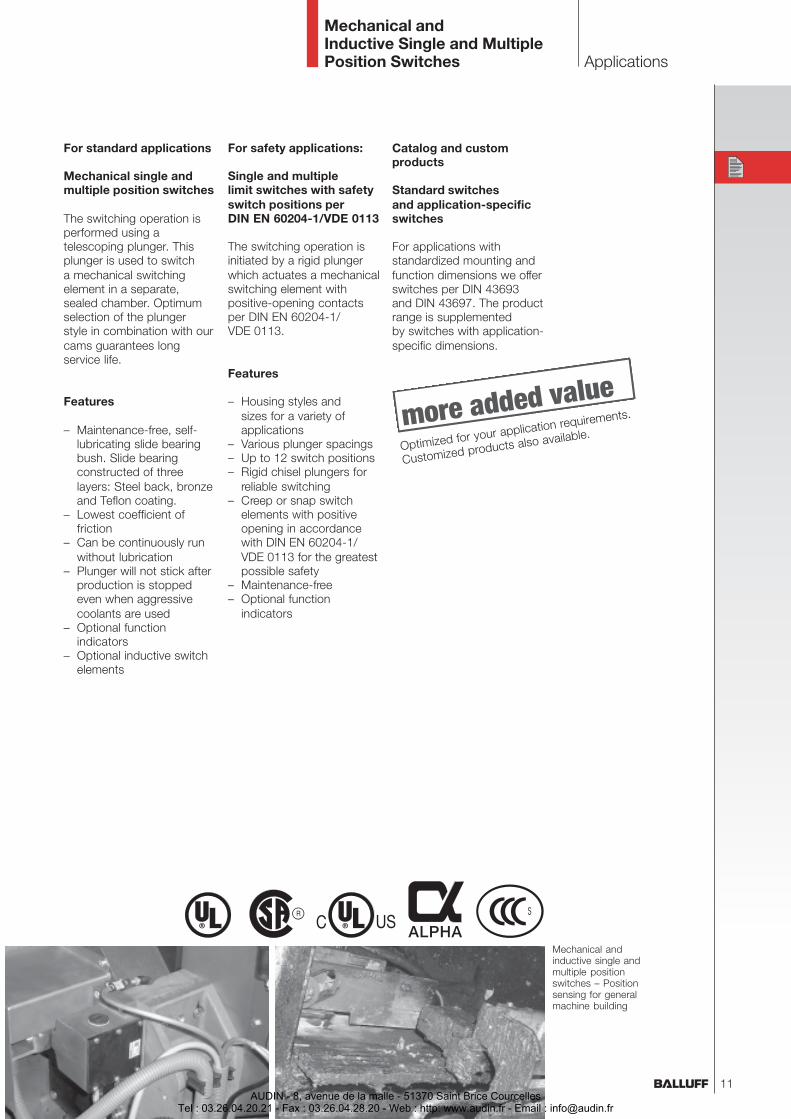
Mechanical andinductive single andmultiple positionswitches – Positionsensing for generalmachine building
Mechanical andInductive Single and MultiplePosition Switches Applications
For safety applications:
Single and multiplelimit switches with safetyswitch positions perDIN EN 60204-1/VDE 0113
The switching operation isinitiated by a rigid plungerwhich actuates a mechanicalswitching element withpositive-opening contactsper DIN EN 60204-1/VDE 0113.
Features
– Housing styles andsizes for a variety ofapplications
– Various plunger spacings– Up to 12 switch positions– Rigid chisel plungers for
reliable switching– Creep or snap switch
elements with positiveopening in accordancewith DIN EN 60204-1/VDE 0113 for the greatestpossible safety
– Maintenance-free– Optional function
indicators
For standard applications
Mechanical single andmultiple position switches
The switching operation isperformed using atelescoping plunger. Thisplunger is used to switcha mechanical switchingelement in a separate,sealed chamber. Optimumselection of the plungerstyle in combination with ourcams guarantees longservice life.
Features
– Maintenance-free, self-lubricating slide bearingbush. Slide bearingconstructed of threelayers: Steel back, bronzeand Teflon coating.
– Lowest coefficient offriction
– Can be continuously runwithout lubrication
– Plunger will not stick afterproduction is stoppedeven when aggressivecoolants are used
– Optional functionindicators
– Optional inductive switchelements
Catalog and customproducts
Standard switchesand application-specificswitches
For applications withstandardized mounting andfunction dimensions we offerswitches per DIN 43693and DIN 43697. The productrange is supplementedby switches with application-specific dimensions.
Optimized for your application requirements.
Customized products also available.
11AUDIN - 8, avenue de la malle - 51370 Saint Brice Courcelles
Tel : 03.26.04.20.21 - Fax : 03.26.04.28.20 - Web : http: www.audin.fr - Email : [email protected]
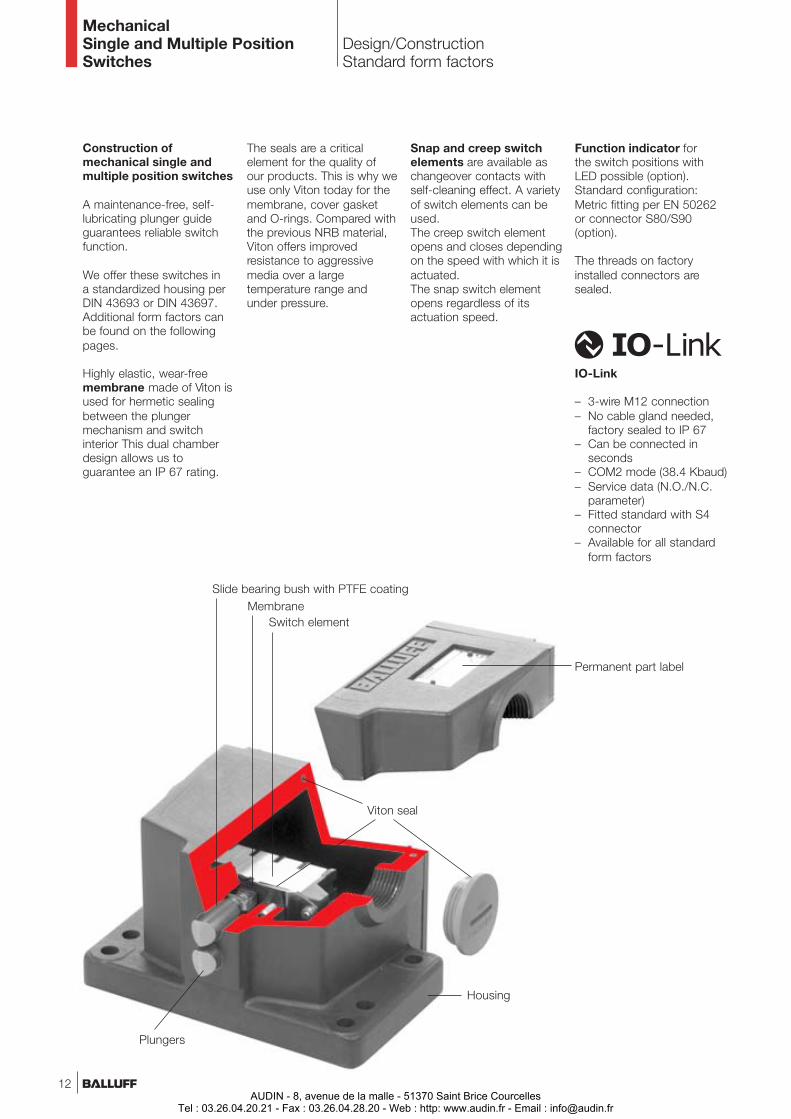
Slide bearing bush with PTFE coatingMembrane
Housing
Switch element
Viton seal
Plungers
Design/ConstructionStandard form factors
Construction ofmechanical single andmultiple position switches
A maintenance-free, self-lubricating plunger guideguarantees reliable switchfunction.
We offer these switches ina standardized housing perDIN 43693 or DIN 43697.Additional form factors canbe found on the followingpages.
Highly elastic, wear-freemembrane made of Viton isused for hermetic sealingbetween the plungermechanism and switchinterior This dual chamberdesign allows us toguarantee an IP 67 rating.
The seals are a criticalelement for the quality ofour products. This is why weuse only Viton today for themembrane, cover gasketand O-rings. Compared withthe previous NRB material,Viton offers improvedresistance to aggressivemedia over a largetemperature range andunder pressure.
Snap and creep switchelements are available aschangeover contacts withself-cleaning effect. A varietyof switch elements can beused.The creep switch elementopens and closes dependingon the speed with which it isactuated.The snap switch elementopens regardless of itsactuation speed.
Function indicator forthe switch positions withLED possible (option).Standard configuration:Metric fitting per EN 50262or connector S80/S90(option).
The threads on factoryinstalled connectors aresealed.
IO-Link
– 3-wire M12 connection– No cable gland needed,
factory sealed to IP 67– Can be connected in
seconds– COM2 mode (38.4 Kbaud)– Service data (N.O./N.C.
parameter)– Fitted standard with S4
connector– Available for all standard
form factors
Permanent part label
12
MechanicalSingle and Multiple PositionSwitches
AUDIN - 8, avenue de la malle - 51370 Saint Brice CourcellesTel : 03.26.04.20.21 - Fax : 03.26.04.28.20 - Web : http: www.audin.fr - Email : [email protected]
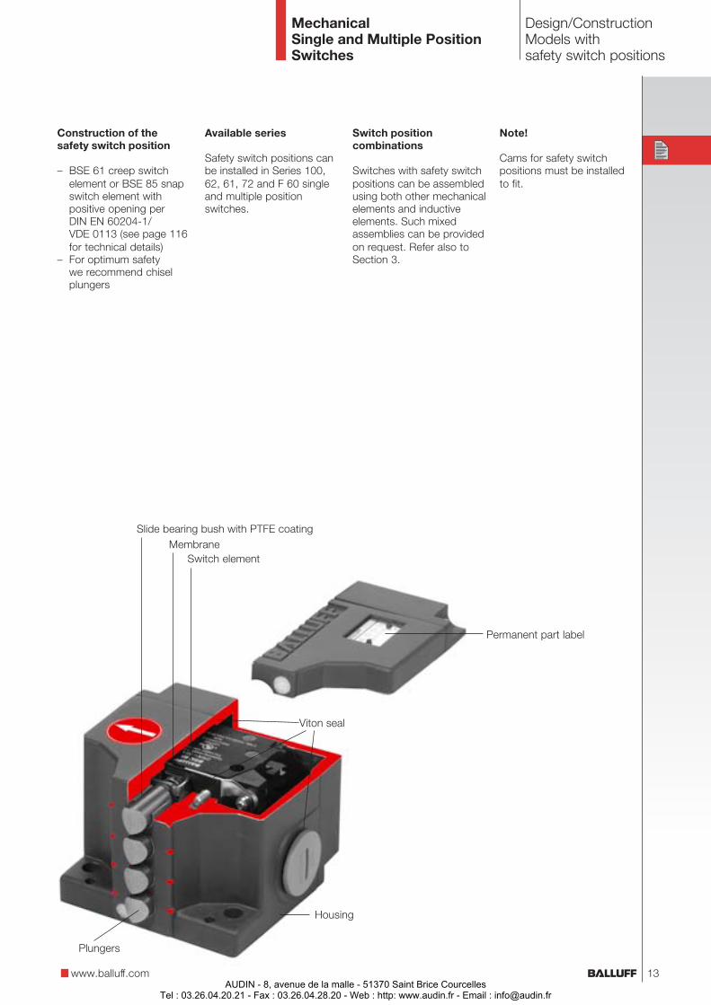
Design/ConstructionModels withsafety switch positions
www.balluff.com
Construction of thesafety switch position
– BSE 61 creep switchelement or BSE 85 snapswitch element withpositive opening perDIN EN 60204-1/VDE 0113 (see page 116for technical details)
– For optimum safetywe recommend chiselplungers
Available series
Safety switch positions canbe installed in Series 100,62, 61, 72 and F 60 singleand multiple positionswitches.
Switch positioncombinations
Switches with safety switchpositions can be assembledusing both other mechanicalelements and inductiveelements. Such mixedassemblies can be providedon request. Refer also toSection 3.
Note!
Cams for safety switchpositions must be installedto fit.
Slide bearing bush with PTFE coatingMembrane
Housing
Switch element
Viton seal
Plungers
Permanent part label
13
MechanicalSingle and Multiple PositionSwitches
AUDIN - 8, avenue de la malle - 51370 Saint Brice CourcellesTel : 03.26.04.20.21 - Fax : 03.26.04.28.20 - Web : http: www.audin.fr - Email : [email protected]
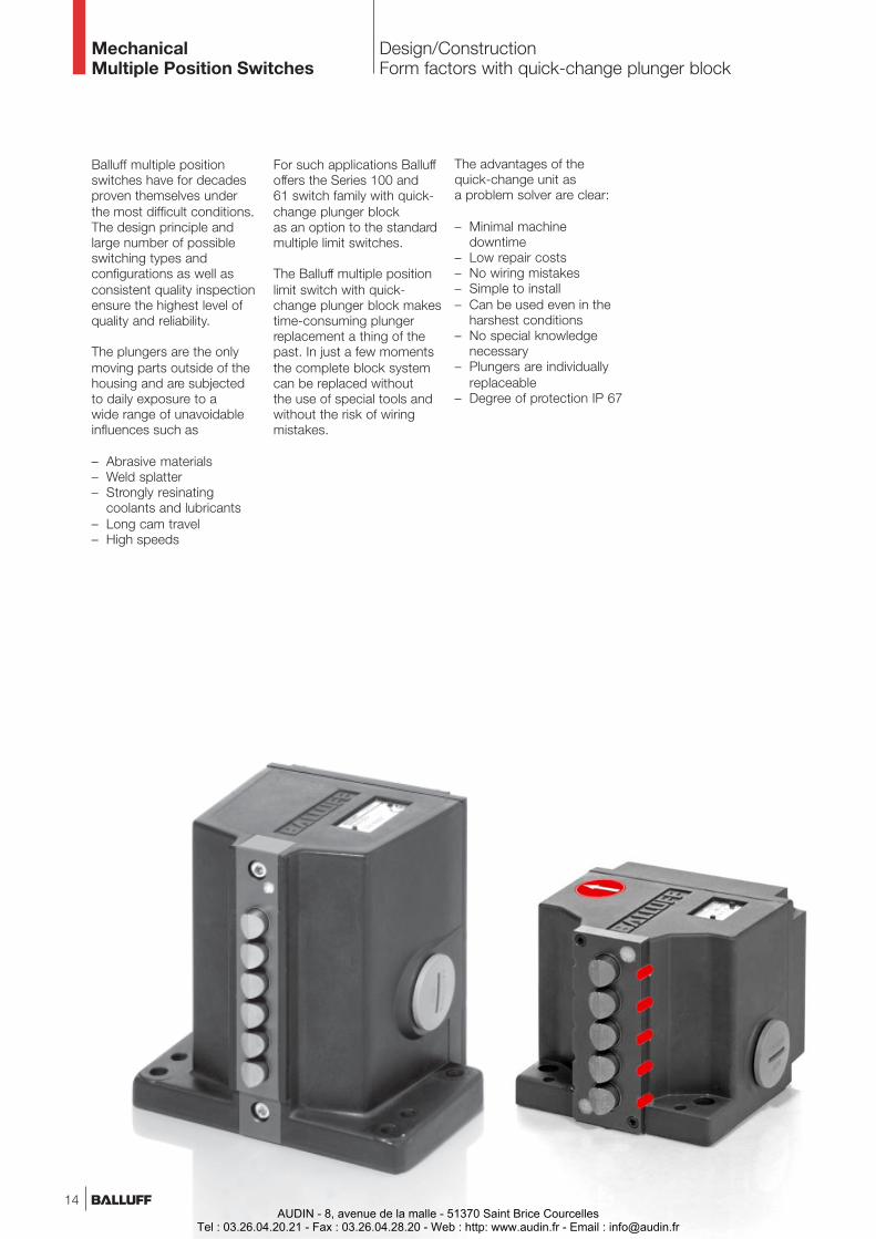
Balluff multiple positionswitches have for decadesproven themselves underthe most difficult conditions.The design principle andlarge number of possibleswitching types andconfigurations as well asconsistent quality inspectionensure the highest level ofquality and reliability.
The plungers are the onlymoving parts outside of thehousing and are subjectedto daily exposure to awide range of unavoidableinfluences such as
– Abrasive materials– Weld splatter– Strongly resinating
coolants and lubricants– Long cam travel– High speeds
For such applications Balluffoffers the Series 100 and61 switch family with quick-change plunger blockas an option to the standardmultiple limit switches.
The Balluff multiple positionlimit switch with quick-change plunger block makestime-consuming plungerreplacement a thing of thepast. In just a few momentsthe complete block systemcan be replaced withoutthe use of special tools andwithout the risk of wiringmistakes.
The advantages of thequick-change unit asa problem solver are clear:
– Minimal machinedowntime
– Low repair costs– No wiring mistakes– Simple to install– Can be used even in the
harshest conditions– No special knowledge
necessary– Plungers are individually
replaceable– Degree of protection IP 67
MechanicalMultiple Position Switches
Design/ConstructionForm factors with quick-change plunger block
14AUDIN - 8, avenue de la malle - 51370 Saint Brice Courcelles
Tel : 03.26.04.20.21 - Fax : 03.26.04.28.20 - Web : http: www.audin.fr - Email : [email protected]
MechanicalSingle and Multiple PositionSwitches
Switch elements,Switch characteristics
www.balluff.com
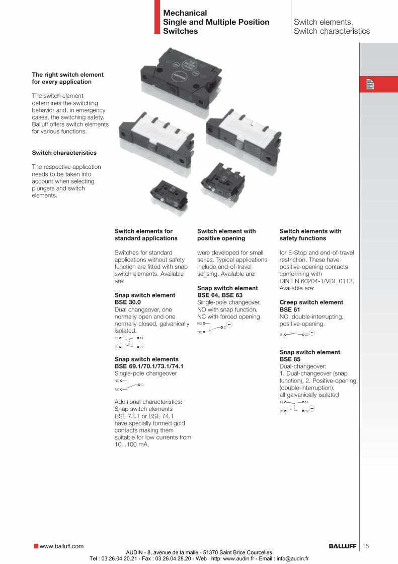
The right switch elementfor every application
The switch elementdetermines the switchingbehavior and, in emergencycases, the switching safety.Balluff offers switch elementsfor various functions.
Switch characteristics
The respective applicationneeds to be taken intoaccount when selectingplungers and switchelements.
Switch elements forstandard applications
Switches for standardapplications without safetyfunction are fitted with snapswitch elements. Availableare:
Snap switch elementBSE 30.0Dual changeover, onenormally open and onenormally closed, galvanicallyisolated.
Snap switch elementsBSE 69.1/70.1/73.1/74.1Single-pole changeover
Additional characteristics:Snap switch elementsBSE 73.1 or BSE 74.1have specially formed goldcontacts making themsuitable for low currents from10...100 mA.
Switch element withpositive opening
were developed for smallseries. Typical applicationsinclude end-of-travelsensing. Available are:
Snap switch elementBSE 64, BSE 63Single-pole changeover,NO with snap function,NC with forced opening
Switch elements withsafety functions
for E-Stop and end-of-travelrestriction. These havepositive-opening contactsconforming withDIN EN 60204-1/VDE 0113.Available are:
Creep switch elementBSE 61NC, double-interrupting,positive-opening.
Snap switch elementBSE 85Dual-changeover:1. Dual-changeover (snapfunction), 2. Positive-opening(double-interruption),all galvanically isolated
www.balluff.com 15AUDIN - 8, avenue de la malle - 51370 Saint Brice Courcelles
Tel : 03.26.04.20.21 - Fax : 03.26.04.28.20 - Web : http: www.audin.fr - Email : [email protected]
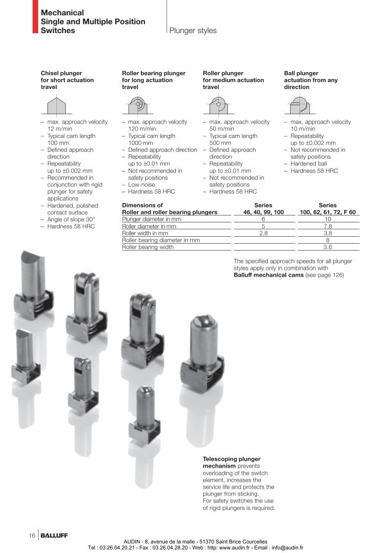
MechanicalSingle and Multiple PositionSwitches Plunger styles
Roller plungerfor medium actuationtravel
– max. approach velocity50 m/min
– Typical cam length500 mm
– Defined approachdirection
– Repeatabilityup to ±0.01 mm
– Not recommended insafety positions
– Hardness 58 HRC
Roller bearing plungerfor long actuationtravel
– max. approach velocity120 m/min
– Typical cam length1000 mm
– Defined approach direction– Repeatability
up to ±0.01 mm– Not recommended in
safety positions– Low-noise– Hardness 58 HRC
Ball plungeractuation from anydirection
– max. approach velocity10 m/min
– Repeatabilityup to ±0.002 mm
– Not recommended insafety positions
– Hardened ball– Hardness 58 HRC
Dimensions of Series SeriesRoller and roller bearing plungers 46, 40, 99, 100 100, 62, 61, 72, F 60Plunger diameter in mm 6 10Roller diameter in mm 5 7.8Roller width in mm 2.8 3.8Roller bearing diameter in mm 8Roller bearing width 3.6
The specified approach speeds for all plungerstyles apply only in combination withBalluff mechanical cams (see page 126)
Chisel plungerfor short actuationtravel
– max. approach velocity12 m/min
– Typical cam length100 mm
– Defined approachdirection
– Repeatabilityup to ±0.002 mm
– Recommended inconjunction with rigidplunger for safetyapplications
– Hardened, polishedcontact surface
– Angle of slope 30°– Hardness 58 HRC
Telescoping plungermechanism preventsoverloading of the switchelement, increases theservice life and protects theplunger from sticking.For safety switches the useof rigid plungers is required.
16AUDIN - 8, avenue de la malle - 51370 Saint Brice Courcelles
Tel : 03.26.04.20.21 - Fax : 03.26.04.28.20 - Web : http: www.audin.fr - Email : [email protected]
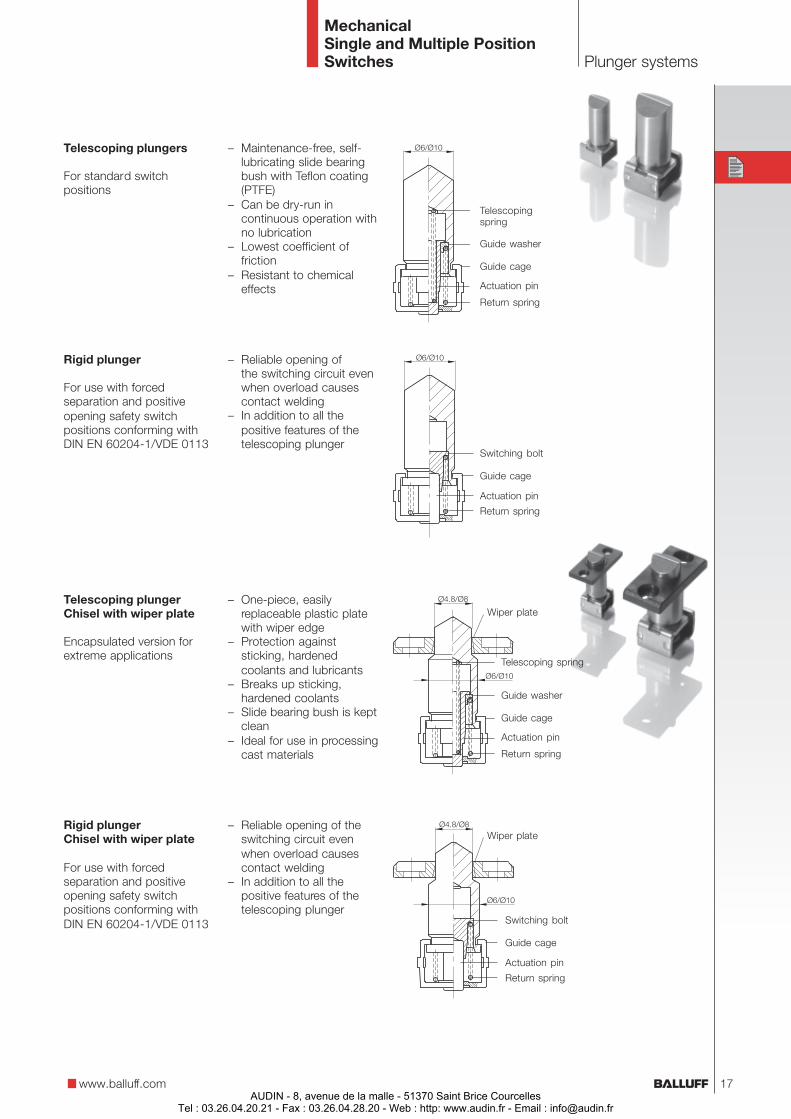
MechanicalSingle and Multiple PositionSwitches
Rigid plungerChisel with wiper plate
For use with forcedseparation and positiveopening safety switchpositions conforming withDIN EN 60204-1/VDE 0113
Plunger systems
Switching bolt
Return spring
Actuation pin
Guide cage
Wiper plate
Guide washer
Return spring
Actuation pin
Guide cage
Telescopingspring
Telescoping plungers
For standard switchpositions
Wiper plateTelescoping plungerChisel with wiper plate
Encapsulated version forextreme applications
Rigid plunger
For use with forcedseparation and positiveopening safety switchpositions conforming withDIN EN 60204-1/VDE 0113
– Maintenance-free, self-lubricating slide bearingbush with Teflon coating(PTFE)
– Can be dry-run incontinuous operation withno lubrication
– Lowest coefficient offriction
– Resistant to chemicaleffects
– Reliable opening ofthe switching circuit evenwhen overload causescontact welding
– In addition to all thepositive features of thetelescoping plunger
– One-piece, easilyreplaceable plastic platewith wiper edge
– Protection againststicking, hardenedcoolants and lubricants
– Breaks up sticking,hardened coolants
– Slide bearing bush is keptclean
– Ideal for use in processingcast materials
– Reliable opening of theswitching circuit evenwhen overload causescontact welding
– In addition to all thepositive features of thetelescoping plunger
www.balluff.com
Guide washer
Return spring
Actuation pin
Guide cage
Telescoping spring
Switching bolt
Return spring
Actuation pin
Guide cage
17AUDIN - 8, avenue de la malle - 51370 Saint Brice Courcelles
Tel : 03.26.04.20.21 - Fax : 03.26.04.28.20 - Web : http: www.audin.fr - Email : [email protected]
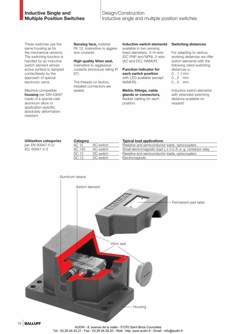
Inductive Single andMultiple Position Switches
Design/ConstructionInductive single and multiple position switches
These switches use thesame housing as forthe mechanical versions.The switching function ishandled by an inductiveswitch element whoseactive surface is dampedcontactlessly by theapproach of specialelectronic cams.
Machine-compatiblehousing per DIN 43697made of a special castaluminum allow orapplication-specific,absolutely deformationresistant.
Switching distances
For adapting to variousworking distances we offerswitch elements with thefollowing rated switchingdistances sn:0...1.1 mm0...2 mm0...5 mm
Inductive switch elementswith extended switchingdistance available onrequest!
Sensing face, materialPA 12, insensitive to aggres-sive coolants.
High quality Viton seal,insensitive to aggressivecoolants (enclosure rating IP67).
The threads on factoryinstalled connectors aresealed.
Aluminum sleeve
Housing
Switch element
Viton seal
Inductive switch elementsavailable in two sensinghead diameters, 3-/4-wire(DC PNP and NPN), 2-wire(AC and DC), NAMUR.
Function indicator foreach switch positionwith LED available (exceptNAMUR).
Metric fittings, cableglands or connectors,flexible cabling for eachposition.
Utilization categoriesper EN 60947-5-2/IEC 60947-5-2
Typical load applicationsResistive and semiconductor loads, optocouplersSmall electromagnetic load Ia ≤ 0.2 A; e. g. contactor relayResistive and semiconductor loads, optocouplersElectromagnets
CategoryAC 12 AC-switchAC 140 AC-switchDC 12 DC-switchDC 13 DC-switch
Permanent part label
18AUDIN - 8, avenue de la malle - 51370 Saint Brice Courcelles
Tel : 03.26.04.20.21 - Fax : 03.26.04.28.20 - Web : http: www.audin.fr - Email : [email protected]

Inductive Single andMultiple Position Switches
Function descriptions,Definitions
Supply voltage UB
Voltage drop Ud
Ratedoperating current Ie
Off-state current Ir
Inrush capacity Ik
Minimumoperating current Im
Ambienttemperature range Ta
Rated operatingdistance sn
Effectiveoperating distance sr
Usefuloperating distance su
Assured operatingdistance sa
Hysteresis H(switching hysteresis whentarget is backed off)
... is the permissibleswitching distance of anindividual switch elementwithin the specified voltage
and temperature conditions.(0.81sn ≤ su ≤ 1.21 sn).
... is the switching distanceat which assured operationof the switch elementis guaranteed at specified
voltage and temperatureconditions.(0 ≤ sa ≤ 0.81 sn).
... is the switching distanceof a single inductive switchelement measured under thespecified conditions
(installation, voltage,temperature).Ta = +23 °C ±5(0.9 sn ≤ sr ≤ 1.1 sn)
... is a theoretical value,which does not take intoaccount manufacturing
tolerances, operatingtemperatures, supplyvoltages, etc.
... is given as a percentageof the effective operatingdistance sr. It is measured atan ambient temperature of+23 °C ±5 and at the ratedoperational voltage. It must
be less than 20 % of theeffective operating distance(sr).H ≤ 0.2 sr
Sen
sing
fac
e
sn
sr
su
sa
81 % 0 %100 %
121 %
110 % 90 %
Sta
ndar
d ta
rget
Standard target
Hysteresis
Turn-on curveTurn-off curve
Standard target
... is the permissible voltagerange in which certain safe
operation of the switch isguaranteed (including ripple σ).
... is the voltage measuredacross the load of a closed
(conducting) switch elementat load current Ie.
... is the permissibleconstant output current that
... is the residual currentflowing through the load
flow during a given turn-ontime tk (ms) and at a givenfrequency (Hz).
... in the case of alternatingcurrent indicates the currentIk (Aeff) which is permitted to
when a switch element is notconducting (open).
may flow through the load Rl.
... is the smallest load currentrequired for function of the
switch element when ON.
... is the temperature rangeover which the function of
the switch is guaranteed..
www.balluff.com 19AUDIN - 8, avenue de la malle - 51370 Saint Brice Courcelles
Tel : 03.26.04.20.21 - Fax : 03.26.04.28.20 - Web : http: www.audin.fr - Email : [email protected]
Inductive Single andMultiple Position Switches
Function descriptions,Definitions,Protection circuits
... AC or AC/DC sensorsare often operated witha relay or contactor as theload.AC switching devices(contactors/relays) create asignificantly higher load(6...10 × rated current) whenthey are first energized ascompared with their staticoperation due to the factthat the core is still open.The static value of the load(current) is not reached untilseveral milliseconds later.
... is achieved for inductiveswitch elements with pulsingor thermal short circuitprotection. The output stageis thereby protected againstoverload and short circuit.
The trigger current for theshort circuit protection ishigher than the ratedoperating current Ie. Currentsfrom switching and loadcapacitances are specified in
the sensor data and do notresult in triggering, but ratherare masked by a short delayin the output circuit.
Not until the magnetic fieldis closed does the max.permissible rated operatingcurrent Ie flow through thesensor.This means that thethreshold value for a shortcircuit condition in theseswitch elements must liesignificantly higher andwould, if for examplethe contactor is preventedfor mechanical or electricalreasons from fully closing,result in an overload on theswitch elements. This iswhere the overloadprotection comes into play.It is designed as slow-acting(time-delayed). Its triggerthreshold lies only slightlyabove the maximumpermissible Ie.
A response (i. e. turn-off)is delayed, depending on themagnitude of the overload,by more than 20milliseconds. This ensuresthat properly working relaysand contactors can beswitched normally, whiledefective devices will notdestroy the Balluff switchelements. The short circuit/overload protection isgenerally of a bi-stabledesign, which means that itmust be reset by turningoff the supply voltage to theswitch element.
Switching frequency f
Polarity reversalprotected
Short circuit protectedwith maximum voltage60 V DC)
Short circuit/overloadprotected(for operating with AC or DCsupply)
.. refers to the maximumnumber of switchingoperations per second.
Damping is perEN 60947-5-2 with standardtargets on a rotating, non-conducting disk. The surfacearea ratio of iron to non-conductor must be 1 : 2.
The rated value of theswitching frequency isreached when– either the
turn-on signal t1 = 50 µsor the
– turn-off signal t2 = 50 µs.
... against reversal of plus/minus leads for inductiveswitch elements without shortcircuit protection.
... protected against anypossible lead reversal forinductive switch elementswith short circuit protection.
20AUDIN - 8, avenue de la malle - 51370 Saint Brice Courcelles
Tel : 03.26.04.20.21 - Fax : 03.26.04.28.20 - Web : http: www.audin.fr - Email : [email protected]
Inductive Single andMultiple Position Switches
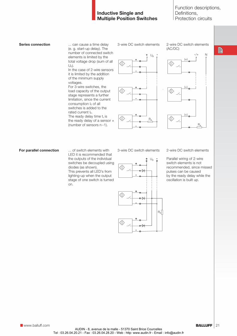
Series connection ... can cause a time delay(e. g. start-up delay). Thenumber of connected switchelements is limited by thetotal voltage drop (sum of allUd).In the case of 2-wire sensorsit is limited by the additionof the minimum supplyvoltages.For 3-wire switches, theload capacity of the outputstage represents a furtherlimitation, since the currentconsumption I0 of allswitches is added to therated current Ie.The ready delay time tv isthe ready delay of a sensor ×(number of sensors n–1).
... of switch elements withLED it is recommended thatthe outputs of the individualswitches be decoupled usingdiodes (as shown).This prevents all LED’s fromlighting-up when the outputstage of one switch is turnedon.
For parallel connection
3-wire DC switch elements 2-wire DC switch elements(AC/DC)
3-wire DC switch elements 2-wire DC switch elements
Parallel wiring of 2-wireswitch elements is notrecommended, since missedpulses can be causedby the ready delay while theoscillation is built up.
Function descriptions,Definitions,Protection circuits
www.balluff.com 21AUDIN - 8, avenue de la malle - 51370 Saint Brice Courcelles
Tel : 03.26.04.20.21 - Fax : 03.26.04.28.20 - Web : http: www.audin.fr - Email : [email protected]
Mechanical andInductive Single and MultiplePosition Switches
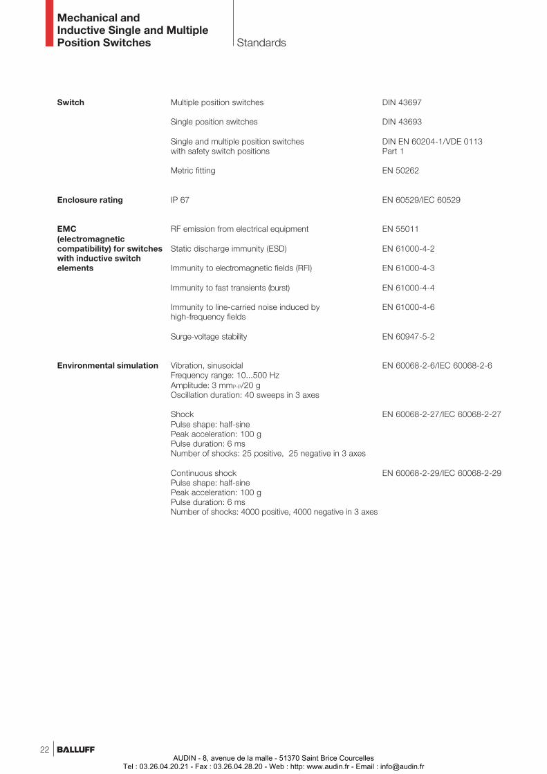
Switch
Enclosure rating
EMC(electromagneticcompatibility) for switcheswith inductive switchelements
Environmental simulation
Multiple position switches
Single position switches
Single and multiple position switcheswith safety switch positions
Metric fitting
IP 67
RF emission from electrical equipment
Static discharge immunity (ESD)
Immunity to electromagnetic fields (RFI)
Immunity to fast transients (burst)
Immunity to line-carried noise induced byhigh-frequency fields
Surge-voltage stability
Vibration, sinusoidalFrequency range: 10...500 HzAmplitude: 3 mmP-P/20 gOscillation duration: 40 sweeps in 3 axes
ShockPulse shape: half-sinePeak acceleration: 100 gPulse duration: 6 msNumber of shocks: 25 positive, 25 negative in 3 axes
Continuous shockPulse shape: half-sinePeak acceleration: 100 gPulse duration: 6 msNumber of shocks: 4000 positive, 4000 negative in 3 axes
DIN 43697
DIN 43693
DIN EN 60204-1/VDE 0113Part 1
EN 50262
EN 60529/IEC 60529
EN 55011
EN 61000-4-2
EN 61000-4-3
EN 61000-4-4
EN 61000-4-6
EN 60947-5-2
EN 60068-2-6/IEC 60068-2-6
EN 60068-2-27/IEC 60068-2-27
EN 60068-2-29/IEC 60068-2-29
Standards
22AUDIN - 8, avenue de la malle - 51370 Saint Brice Courcelles
Tel : 03.26.04.20.21 - Fax : 03.26.04.28.20 - Web : http: www.audin.fr - Email : [email protected]
Mechanical andInductive Single and MultiplePosition Switches Quality
www.balluff.com
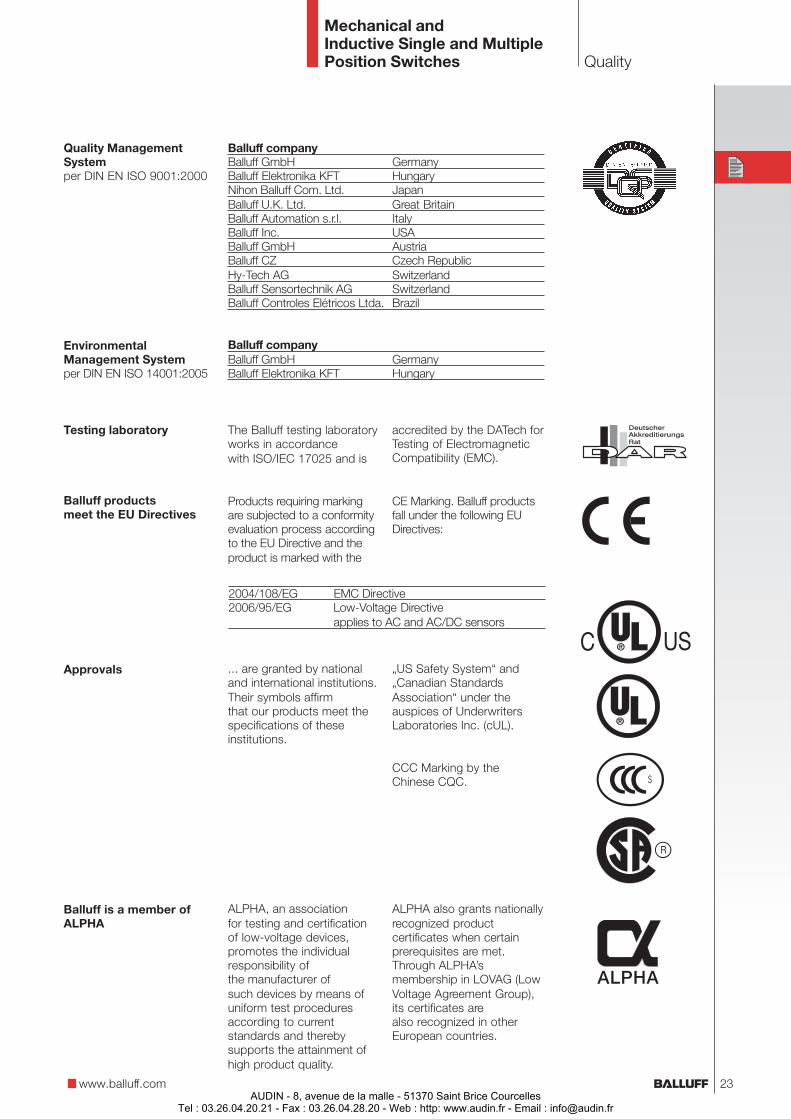
Quality ManagementSystemper DIN EN ISO 9001:2000
EnvironmentalManagement Systemper DIN EN ISO 14001:2005
Testing laboratory
Balluff productsmeet the EU Directives
Approvals
Balluff is a member ofALPHA
The Balluff testing laboratoryworks in accordancewith ISO/IEC 17025 and is
Products requiring markingare subjected to a conformityevaluation process accordingto the EU Directive and theproduct is marked with the
... are granted by nationaland international institutions.Their symbols affirmthat our products meet thespecifications of theseinstitutions.
„US Safety System“ and„Canadian StandardsAssociation“ under theauspices of UnderwritersLaboratories Inc. (cUL).
CCC Marking by theChinese CQC.
accredited by the DATech forTesting of ElectromagneticCompatibility (EMC).
Balluff companyBalluff GmbH GermanyBalluff Elektronika KFT HungaryNihon Balluff Com. Ltd. JapanBalluff U.K. Ltd. Great BritainBalluff Automation s.r.l. ItalyBalluff Inc. USABalluff GmbH AustriaBalluff CZ Czech RepublicHy-Tech AG SwitzerlandBalluff Sensortechnik AG SwitzerlandBalluff Controles Elétricos Ltda. Brazil
Balluff companyBalluff GmbH GermanyBalluff Elektronika KFT Hungary
ALPHA, an associationfor testing and certificationof low-voltage devices,promotes the individualresponsibility ofthe manufacturer ofsuch devices by means ofuniform test proceduresaccording to currentstandards and therebysupports the attainment ofhigh product quality.
ALPHA also grants nationallyrecognized productcertificates when certainprerequisites are met.Through ALPHA’smembership in LOVAG (LowVoltage Agreement Group),its certificates arealso recognized in otherEuropean countries.
CE Marking. Balluff productsfall under the following EUDirectives:
2004/108/EG EMC Directive2006/95/EG Low-Voltage Directive
applies to AC and AC/DC sensors
23AUDIN - 8, avenue de la malle - 51370 Saint Brice Courcelles
Tel : 03.26.04.20.21 - Fax : 03.26.04.28.20 - Web : http: www.audin.fr - Email : [email protected]
Special solutions
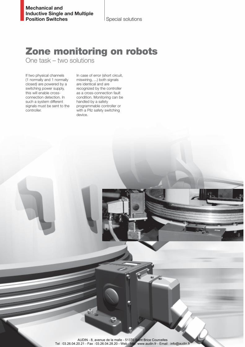
If two physical channels(1 normally and 1 normallyclosed) are powered by aswitching power supply,this will enable cross-connection detection. Insuch a system differentsignals must be sent to thecontroller.
Zone monitoring on robotsOne task – two solutions
Mechanical andInductive Single and MultiplePosition Switches
In case of error (short circuit,miswiring, ...) both signalsare identical and arerecognized by the controlleras a cross-connection faultcondition. Monitoring can behandled by a safetyprogrammable controller orwith a Pilz safety switchingdevice.
AUDIN - 8, avenue de la malle - 51370 Saint Brice CourcellesTel : 03.26.04.20.21 - Fax : 03.26.04.28.20 - Web : http: www.audin.fr - Email : [email protected]

Special solutions
Axis 3
Mechanical andInductive Single and MultiplePosition Switches
www.balluff.com
Two solutions –simpleinstallation andsetup of theallowed zone
Solution 1Mechanical switches –the classic solution
– Reliability assured byrugged cast housing forharsh industrialenvironments
– Safety ensured by switchelements with positive-opening contacts andrigid plungers as well asproper selection of thecam tracks
– Long service life thanks tomaintenance-free, self-lubricating plunger guidewith slide bearing bush
Solution 2Inductive switch –the modern solution
– Likewise in rugged casthousing for harshindustrial applications
– Function monitoring usingsafety controller withpulsed supply voltage forthe switches
– Non-contacting, wear-free,
– For extremely high traver-se speeds
Axis 2
Axis 1
Mechanical Inductive
Mechanical Inductive
Mechanical Inductive
25AUDIN - 8, avenue de la malle - 51370 Saint Brice Courcelles
Tel : 03.26.04.20.21 - Fax : 03.26.04.28.20 - Web : http: www.audin.fr - Email : [email protected]
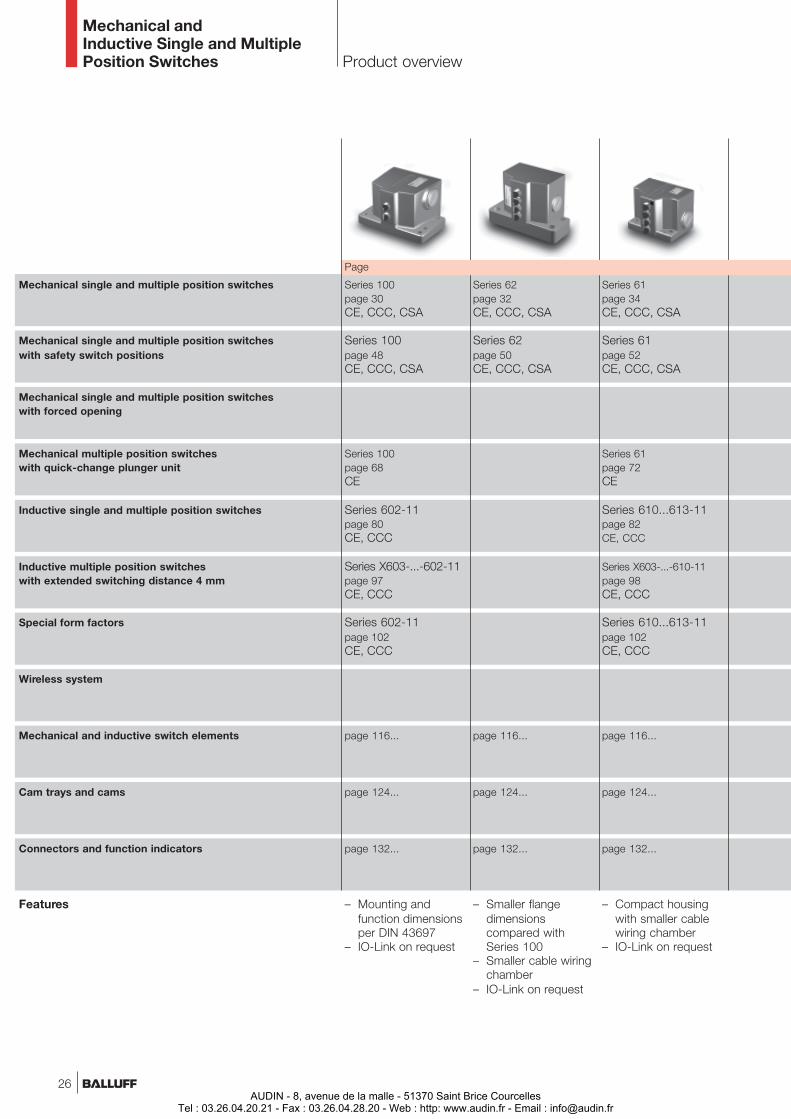
Mechanical single and multiple position switches
Mechanical single and multiple position switcheswith safety switch positions
Mechanical single and multiple position switcheswith forced opening
Mechanical multiple position switcheswith quick-change plunger unit
Inductive single and multiple position switches
Inductive multiple position switcheswith extended switching distance 4 mm
Special form factors
Wireless system
Mechanical and inductive switch elements
Cam trays and cams
Connectors and function indicators
Features
Series 100page 30CE, CCC, CSA
Series 100page 48CE, CCC, CSA
Series 100page 68CE
Series 602-11page 80CE, CCC
Series X603-...-602-11page 97CE, CCC
Series 602-11page 102CE, CCC
page 116...
page 124...
page 132...
– Mounting andfunction dimensionsper DIN 43697
– IO-Link on request
Series 62page 32CE, CCC, CSA
Series 62page 50CE, CCC, CSA
page 116...
page 124...
page 132...
– Smaller flangedimensionscompared withSeries 100
– Smaller cable wiringchamber
– IO-Link on request
Series 61page 34CE, CCC, CSA
Series 61page 52CE, CCC, CSA
Series 61page 72CE
Series 610...613-11page 82CE, CCC
Series X603-...-610-11page 98CE, CCC
Series 610...613-11page 102CE, CCC
page 116...
page 124...
page 132...
– Compact housingwith smaller cablewiring chamber
– IO-Link on request
Mechanical andInductive Single and MultiplePosition Switches Product overview
Page
26AUDIN - 8, avenue de la malle - 51370 Saint Brice Courcelles
Tel : 03.26.04.20.21 - Fax : 03.26.04.28.20 - Web : http: www.audin.fr - Email : [email protected]
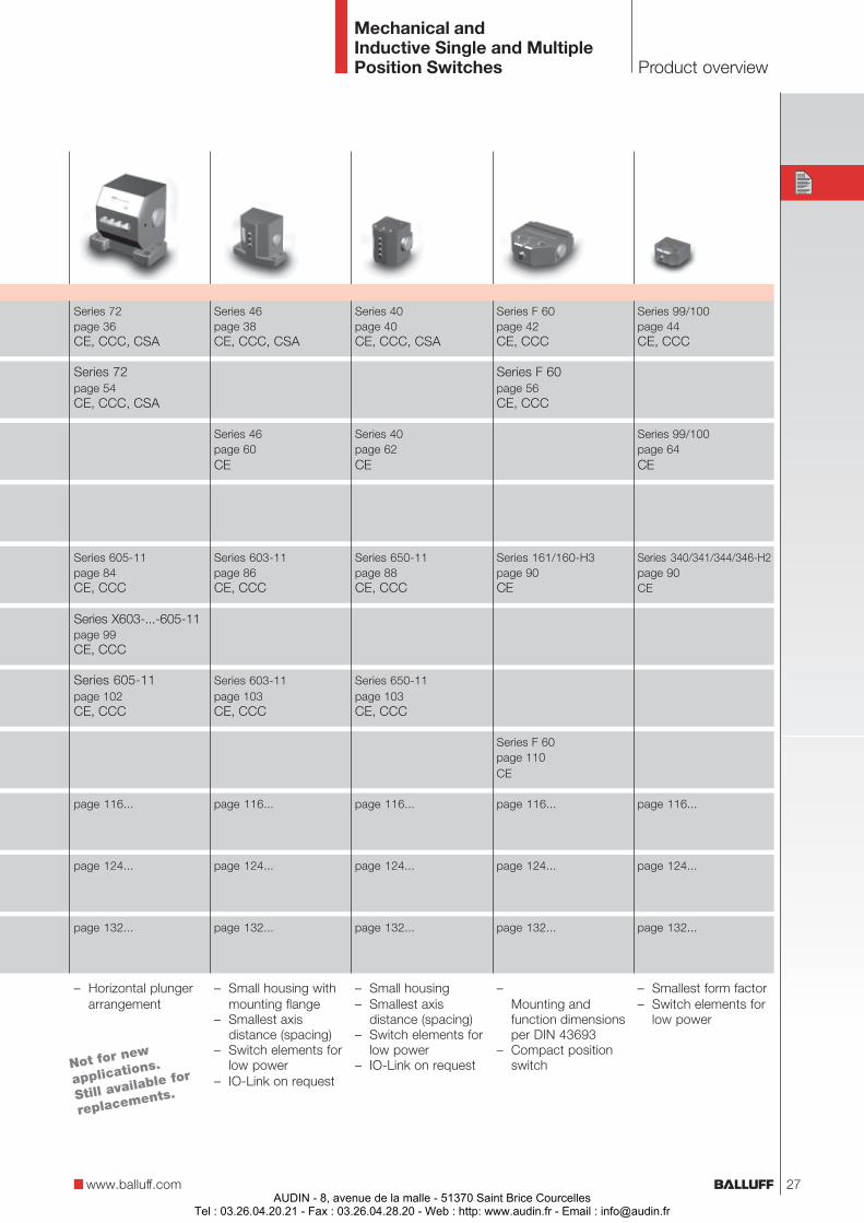
Series 72page 36CE, CCC, CSA
Series 72page 54CE, CCC, CSA
Series 605-11page 84CE, CCC
Series X603-...-605-11page 99CE, CCC
Series 605-11page 102CE, CCC
page 116...
page 124...
page 132...
– Horizontal plungerarrangement
Series 46page 38CE, CCC, CSA
Series 46page 60CE
Series 603-11page 86CE, CCC
Series 603-11page 103CE, CCC
page 116...
page 124...
page 132...
– Small housing withmounting flange
– Smallest axisdistance (spacing)
– Switch elements forlow power
– IO-Link on request
Series 40page 40CE, CCC, CSA
Series 40page 62CE
Series 650-11page 88CE, CCC
Series 650-11page 103CE, CCC
page 116...
page 124...
page 132...
– Small housing– Smallest axis
distance (spacing)– Switch elements for
low power– IO-Link on request
Series F 60page 42CE, CCC
Series F 60page 56CE, CCC
Series 161/160-H3page 90CE
Series F 60page 110CE
page 116...
page 124...
page 132...
–Mounting andfunction dimensionsper DIN 43693
– Compact positionswitch
Series 99/100page 44CE, CCC
Series 99/100page 64CE
Series 340/341/344/346-H2page 90CE
page 116...
page 124...
page 132...
– Smallest form factor– Switch elements for
low power
Mechanical andInductive Single and MultiplePosition Switches Product overview
www.balluff.com 27
Not for new
applications.
Still available for
replacements.
AUDIN - 8, avenue de la malle - 51370 Saint Brice CourcellesTel : 03.26.04.20.21 - Fax : 03.26.04.28.20 - Web : http: www.audin.fr - Email : [email protected]

Objekterkennung
AUDIN - 8, avenue de la malle - 51370 Saint Brice CourcellesTel : 03.26.04.20.21 - Fax : 03.26.04.28.20 - Web : http: www.audin.fr - Email : [email protected]
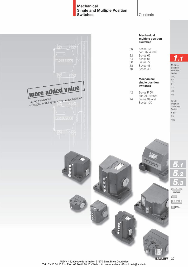
MechanicalSingle and Multiple PositionSwitches
Mechanicalmultiple positionswitches
30 Series 100per DIN 43697
32 Series 6234 Series 6136 Series 7238 Series 4640 Series 40
Mechanicalsingle positionswitches
42 Series F 60per DIN 43693
44 Series 99 andSeries 100
Multiplepositionswitchesseries
100
62
61
72
46
40
SinglePositionSwitchesSeries
F 60
99
100
Contents
1.1
5.1
5.2
5.3
– Long service life
– Rugged housing for extreme applications
29AUDIN - 8, avenue de la malle - 51370 Saint Brice Courcelles
Tel : 03.26.04.20.21 - Fax : 03.26.04.28.20 - Web : http: www.audin.fr - Email : [email protected]

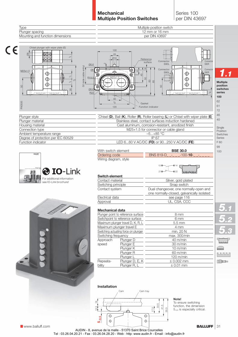
Multiple position switchesper DIN 43697 forstandard applications
– Dual-chamber systemwith IP 67 protection:wear-free membrane withhermetic sealing fromplunger mechanism andswitch chamber
– Maintenance-free, self-lubricating plunger guidewith slide bearing
Multiple position switcheswith wiper plate
– Increased functionsecurity under extremeconditions of use
– Wiper plate preventsplunger from sticking inthe guide
– For use in wet areas withstrongly adhering media
Connection options
– Thread for cable glandM25×1.5 on side and inflange (Gaskets and plugsincluded)
– Connector (notepermissible operatingvoltage for the connectors,see page 132).
Plungertype
12 12 mm16 16 mm
Plungerspacing
02 2×03 3×04 4×...
D ChiselK BallR RollerL Roller bearingE Chisel with
wiper plate
Ordering example:BNS 819-D02-D16-100-10-FE-S80R
BNS 819-D_ _-_ _ _-100-10-_ _-_ _ _ _
FD 6...60V AC/DC
FE 90...250V AC/DC
optionalFunctionindication
S80R 5-pin, rightS80L 5-pin, leftS80S 5-pin, right and leftS90R 12-pin, rightS90L 12-pin, leftS90S 12-pin, right and leftS4R-I 4-pin, right
only for IO-LinkS4L-I 4-pin, left
only for IO-Link
optionalConnector
No. ofplungers
Series 100per DIN 43697
MechanicalMultiple Position Switches
Multiple position switcheswith function indication
– Function indication fordual voltage range option
Available sizes
Number of plungers 2 3 4 5 6 8 10 12Dimension Dimension l1 = 12 mm 70 80 90 105 120 140 170 200l2 when Dimension l3 88 88 88 88 88 80 80 80
Dimension l4 14 14 14 14 14 20 20 20Dimension l1 = 16 mm 70 90 105 120 140 170 200 240Dimension l3 88 88 88 88 80 80 80 80Dimension l4 14 14 14 14 20 20 20 20
Number of S80 without FD/FE 1 1 2 2 2connectors S80 with FD/FE 1 2 2 3 3
S90 without FD/FE 1 1 1 1 1 1 1 2S90 with FD/FE 1 1 1 1 1 1 2 2S4 without FD (IO-Link) 1 1 1 1 1 1 1 1S4 with FD (IO-Link) 1 1 1 1 1 1 1 1
Dimensions in mm
30AUDIN - 8, avenue de la malle - 51370 Saint Brice Courcelles
Tel : 03.26.04.20.21 - Fax : 03.26.04.28.20 - Web : http: www.audin.fr - Email : [email protected]
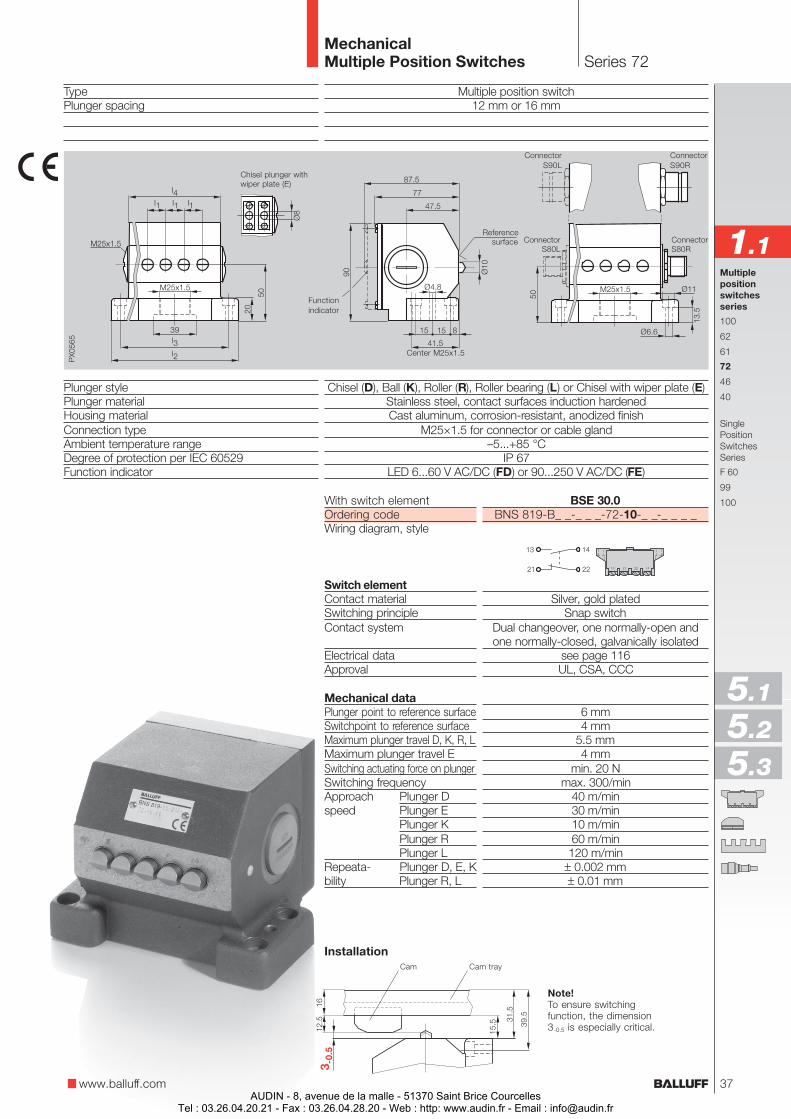
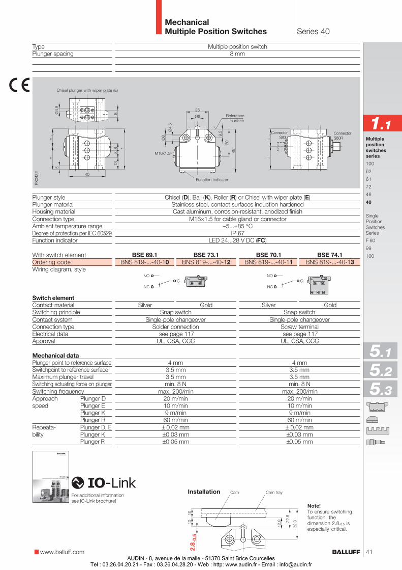
With switch elementOrdering codeWiring diagram, style
Switch elementContact materialSwitching principleContact system
Electrical dataApproval
Mechanical dataPlunger point to reference surfaceSwitchpoint to reference surfaceMaximum plunger travel D, K, R, LMaximum plunger travel ESwitching actuating force on plungerSwitching frequencyApproach Plunger Dspeed Plunger E
Plunger KPlunger RPlunger L
Repeata- Plunger D, E, Kbility Plunger R, L
BSE 30.0BNS 819-D_ _-_ _ _-100-10-_ _-_ _ _ _
Silver, gold platedSnap switch
Dual changeover, one normally-open andone normally-closed, galvanically isolated
see page 116UL, CSA, CCC
8 mm6 mm
5.5 mm4 mm
min. 20 Nmax. 300/min
40 m/min30 m/min10 m/min60 m/min
120 m/min± 0.002 mm± 0.01 mm
TypePlunger spacingMounting and function dimensions
Plunger stylePlunger materialHousing materialConnection typeAmbient temperature rangeDegree of protection per IEC 60529Function indicator
Multiple position switch12 mm or 16 mm
per DIN 43697
Chisel (D), Ball (K), Roller (R), Roller bearing (L) or Chisel with wiper plate (E)Stainless steel, contact surfaces induction hardenedCast aluminum, corrosion-resistant, anodized finish
M25×1.5 for connector or cable gland–5...+85 °C
IP 67LED 6...60 V AC/DC (FD) or 90...250 V AC/DC (FE)
Series 100per DIN 43697
MechanicalMultiple Position Switches
Cam Cam tray
Multiplepositionswitchesseries
100
62
61
72
46
40
SinglePositionSwitchesSeries
F 60
99
100
www.balluff.com
1.1
5.1
5.2
5.3
Installation
Note!To ensure switchingfunction, the dimension5-0.5 is especially critical.
Chisel plunger with wiper plate (E)
50 (s
ide
cabl
e en
try)
ConnectorS80R
ConnectorS90R
ConnectorS80L
ConnectorS90L
GasketFunction indicator
Referencesurface
For additional informationsee IO-Link brochure!
31AUDIN - 8, avenue de la malle - 51370 Saint Brice Courcelles
Tel : 03.26.04.20.21 - Fax : 03.26.04.28.20 - Web : http: www.audin.fr - Email : [email protected]
Plungertype
12 12 mm16 16 mm
Plungerspacing
02 2×03 3×04 4×...
D ChiselK BallR RollerL Roller bearingE Chisel with
wiper plate
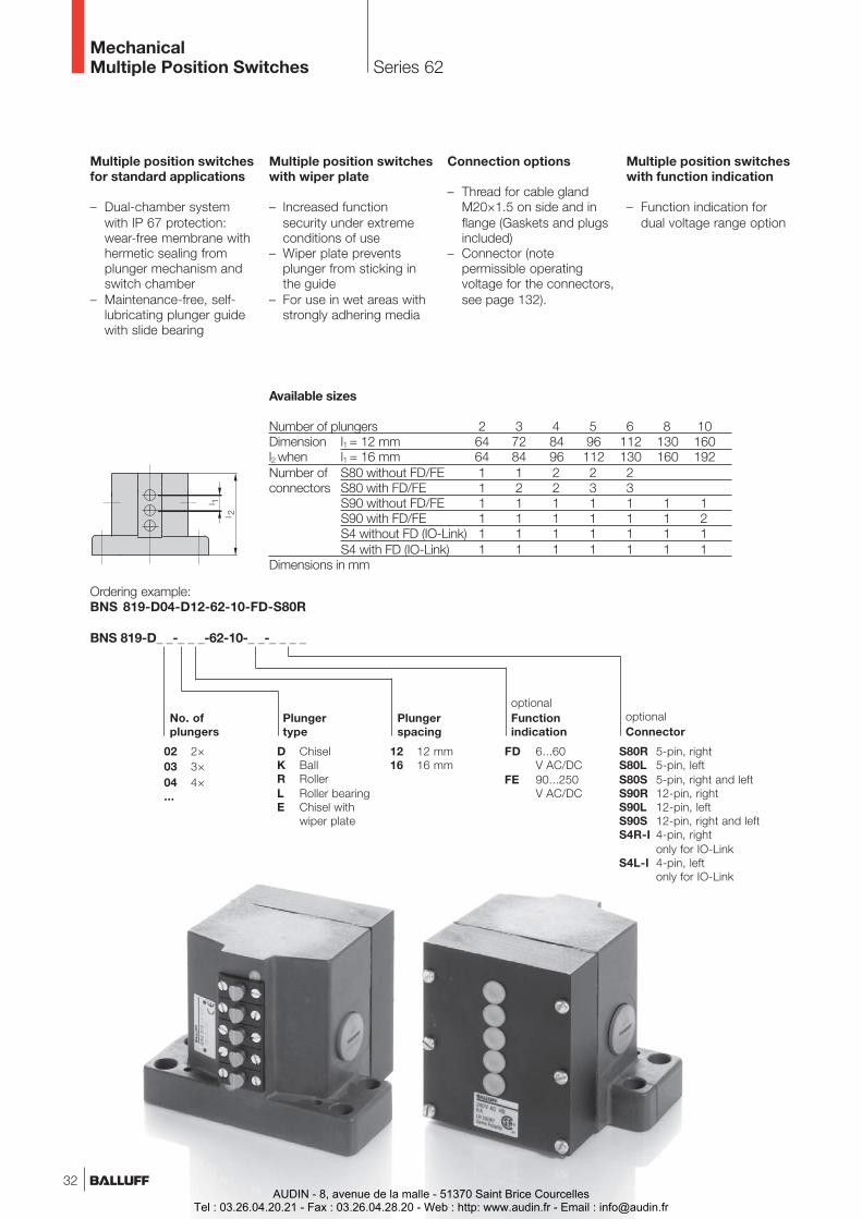
Ordering example:BNS 819-D04-D12-62-10-FD-S80R
BNS 819-D_ _-_ _ _-62-10-_ _-_ _ _ _
FD 6...60V AC/DC
FE 90...250V AC/DC
optionalFunctionindication
S80R 5-pin, rightS80L 5-pin, leftS80S 5-pin, right and leftS90R 12-pin, rightS90L 12-pin, leftS90S 12-pin, right and leftS4R-I 4-pin, right
only for IO-LinkS4L-I 4-pin, left
only for IO-Link
optionalConnector
No. ofplungers
Series 62MechanicalMultiple Position Switches
Multiple position switchesfor standard applications
– Dual-chamber systemwith IP 67 protection:wear-free membrane withhermetic sealing fromplunger mechanism andswitch chamber
– Maintenance-free, self-lubricating plunger guidewith slide bearing
Multiple position switcheswith wiper plate
– Increased functionsecurity under extremeconditions of use
– Wiper plate preventsplunger from sticking inthe guide
– For use in wet areas withstrongly adhering media
Connection options
– Thread for cable glandM20×1.5 on side and inflange (Gaskets and plugsincluded)
– Connector (notepermissible operatingvoltage for the connectors,see page 132).
Available sizes
Number of plungers 2 3 4 5 6 8 10Dimension l1 = 12 mm 64 72 84 96 112 130 160l2 when l1 = 16 mm 64 84 96 112 130 160 192Number of S80 without FD/FE 1 1 2 2 2connectors S80 with FD/FE 1 2 2 3 3
S90 without FD/FE 1 1 1 1 1 1 1S90 with FD/FE 1 1 1 1 1 1 2S4 without FD (IO-Link) 1 1 1 1 1 1 1S4 with FD (IO-Link) 1 1 1 1 1 1 1
Dimensions in mm
Multiple position switcheswith function indication
– Function indication fordual voltage range option
32AUDIN - 8, avenue de la malle - 51370 Saint Brice Courcelles
Tel : 03.26.04.20.21 - Fax : 03.26.04.28.20 - Web : http: www.audin.fr - Email : [email protected]

BSE 30.0BNS 819-D_ _-_ _ _-62-10-_ _-_ _ _ _
Silver, gold platedSnap switch
Dual changeover, one normally-open andone normally-closed, galvanically isolated
see page 116UL, CSA, CCC
8 mm6 mm
5.5 mm4 mm
min. 20 Nmax. 300/min
40 m/min30 m/min10 m/min60 m/min
120 m/min± 0.002 mm± 0.01 mm
With switch elementOrdering codeWiring diagram, style
Switch elementContact materialSwitching principleContact system
Electrical dataApproval
Mechanical dataPlunger point to reference surfaceSwitchpoint to reference surfaceMaximum plunger travel D, K, R, LMaximum plunger travel ESwitching actuating force on plungerSwitching frequencyApproach Plunger Dspeed Plunger E
Plunger KPlunger RPlunger L
Repeata- Plunger D, E, Kbility Plunger R, L
Multiplepositionswitchesseries
100
62
61
72
46
40
SinglePositionSwitchesSeries
F 60
99
100
Multiple position switch12 mm or 16 mm
Chisel (D), Ball (K), Roller (R), Roller bearing (L) or Chisel with wiper plate (E)Stainless steel, contact surfaces induction hardenedCast aluminum, corrosion-resistant, anodized finish
M20×1.5 for connector or cable gland–5...+85 °C
IP 67LED 6...60 V AC/DC (FD) or 90...250 V AC/DC (FE)
Series 62MechanicalMultiple Position Switches
TypePlunger spacing
Plunger stylePlunger materialHousing materialConnection typeAmbient temperature rangeDegree of protection per IEC 60529Function indicator
Chisel plunger with wiper plate (E)
Cam Cam tray
www.balluff.com
1.1
ConnectorS90R
ConnectorS90L
Gasket
Function indicator
33 (s
ide
cabl
e en
try)
ConnectorS80R
ConnectorS80L
Installation
Note!To ensure switchingfunction, the dimension5-0.5 is especially critical.
Referencesurface
5.1
5.2
5.3
For additional informationsee IO-Link brochure!
33AUDIN - 8, avenue de la malle - 51370 Saint Brice Courcelles
Tel : 03.26.04.20.21 - Fax : 03.26.04.28.20 - Web : http: www.audin.fr - Email : [email protected]
Series 61MechanicalMultiple Position Switches
Multiple position switchesfor standard applications
– Dual-chamber systemwith IP 67 protection:wear-free membrane withhermetic sealing fromplunger mechanism andswitch chamber
– Maintenance-free, self-lubricating plunger guidewith slide bearing
Multiple position switcheswith wiper plate
– Increased functionsecurity under extremeconditions of use
– Wiper plate preventsplunger from sticking inthe guide
– For use in wet areas withstrongly adhering media
Connection options
– Thread for cable glandM20×1.5 on side and inflange (Gaskets and plugsincluded)
– Connector (notepermissible operatingvoltage for the connectors,see page 132).
Multiple position switcheswith function indication
– Function indication fordual voltage range option
Housing C
Dimensionl2 l348 2460 3060 24
60 30
Housing B
Dimensionl2 l360 30
60 24
60 30
Housing BStandard
Dimensionl2 l336 12
48 1260 1272 1284 12
48 1672 1684 16
Plungerspacing
Dimensionl112
12121212
161616
Number ofconnectorsS80 withFD/FE
1
2233
122
Number ofconnectorsS80 withoutFD/FE
1
1222
112
No. ofplungers
2
3456
234
Available sizes
Number ofconnectorsS90 withFD/FE
1
1111
111
Number ofconnectorsS90 withoutFD/FE
1
1111
111
Plungertype
Plungerspacing
B Standard2× M20×1.5on side
B 3× M20×1.5on side and inflange
C 2× M20×1.5on side and cableentry in flange
D ChiselK BallR RollerL Roller
bearingE Chisel with
wiper plate
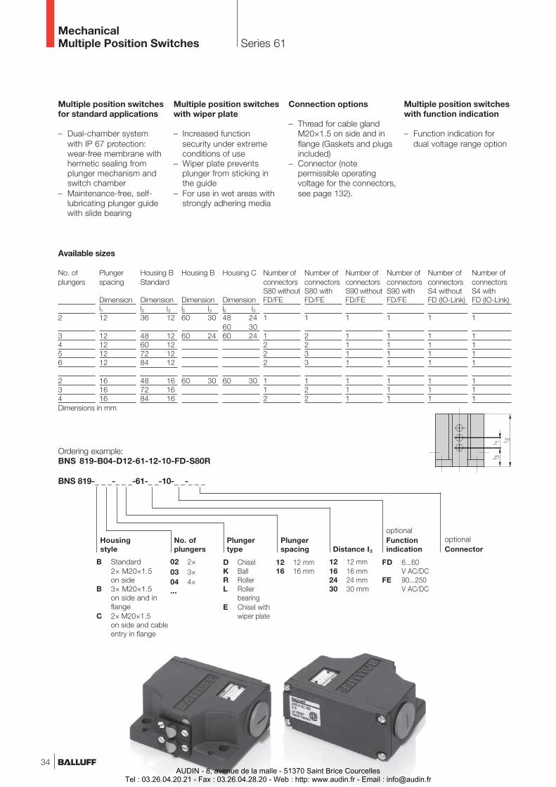
Ordering example:BNS 819-B04-D12-61-12-10-FD-S80R
BNS 819-_ _ _-_ _ _-61-_ _-10-_ _-_ _ _
12 12 mm16 16 mm24 24 mm30 30 mm
Distance I3
FD 6...60V AC/DC
FE 90...250V AC/DC
optionalFunctionindication
Housingstyle
optionalConnector
02 2×03 3×04 4×...
No. ofplungers
Number ofconnectorsS4 withFD (IO-Link)
1
1111
111
Number ofconnectorsS4 withoutFD (IO-Link)
1
1111
111
Dimensions in mm
34
12 12 mm16 16 mm
AUDIN - 8, avenue de la malle - 51370 Saint Brice CourcellesTel : 03.26.04.20.21 - Fax : 03.26.04.28.20 - Web : http: www.audin.fr - Email : [email protected]
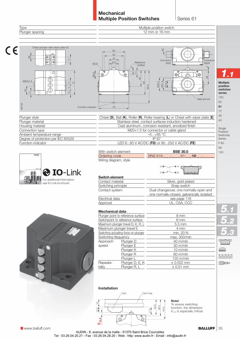
BSE 30.0BNS 819-_ _ _-_ _ _-61-_ _-10-_ _-_ _ _ _
Silver, gold platedSnap switch
Dual changeover, one normally-open andone normally-closed, galvanically isolated
see page 116UL, CSA, CCC
8 mm6 mm
5.5 mm4 mm
min. 20 Nmax. 300/min
40 m/min30 m/min10 m/min60 m/min
120 m/min± 0.002 mm± 0.01 mm
With switch elementOrdering codeWiring diagram, style
Switch elementContact materialSwitching principleContact system
Electrical dataApproval
Mechanical dataPlunger point to reference surfaceSwitchpoint to reference surfaceMaximum plunger travel D, K, R, LMaximum plunger travel ESwitching actuating force on plungerSwitching frequencyApproach Plunger Dspeed Plunger E
Plunger KPlunger RPlunger L
Repeata- Plunger D, E, Kbility Plunger R, L
Multiplepositionswitchesseries
100
62
61
72
46
40
SinglePositionSwitchesSeries
F 60
99
100
TypePlunger spacing
Plunger stylePlunger materialHousing materialConnection typeAmbient temperature rangeDegree of protection per IEC 60529Function indicator
Series 61MechanicalMultiple Position Switches
Multiple position switch12 mm or 16 mm
Chisel (D), Ball (K), Roller (R), Roller bearing (L) or Chisel with wiper plate (E)Stainless steel, contact surfaces induction hardenedCast aluminum, corrosion-resistant, anodized finish
M20×1.5 for connector or cable gland–5...+85 °C
IP 67LED 6...60 V AC/DC (FD) or 90...250 V AC/DC (FE)
Cam Cam tray
Seal groove
Chisel plunger with wiper plate (E)
www.balluff.com
1.1
ConnectorS80R
ConnectorS80L
Installation
Note!To ensure switchingfunction, the dimension5-0.5 is especially critical.
Referencesurface
5.1
5.2
5.3
Function indicator
For additional informationsee IO-Link brochure!
35AUDIN - 8, avenue de la malle - 51370 Saint Brice Courcelles
Tel : 03.26.04.20.21 - Fax : 03.26.04.28.20 - Web : http: www.audin.fr - Email : [email protected]
Series 72MechanicalMultiple Position Switches
Plungerstyle
12 12 mm16 16 mm
Plungerspacing
02 2×03 3×04 4×...
D ChiselK BallR RollerL Roller bearingE Chisel with
wiper plate
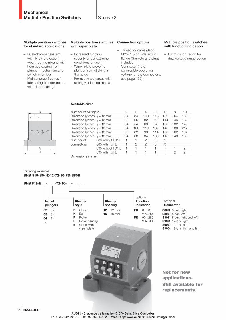
Ordering example:BNS 819-B04-D12-72-10-FD-S80R
BNS 819-B_ _-_ _ _-72-10-_ _-_ _ _ _
FD 6...60V AC/DC
FE 90...250V AC/DC
optionalFunctionindication
No. ofplungers
Multiple position switchesfor standard applications
– Dual-chamber systemwith IP 67 protection:wear-free membrane withhermetic sealing fromplunger mechanism andswitch chamber
– Maintenance-free, self-lubricating plunger guidewith slide bearing
Multiple position switcheswith wiper plate
– Increased functionsecurity under extremeconditions of use
– Wiper plate preventsplunger from sticking inthe guide
– For use in wet areas withstrongly adhering media
Connection options
– Thread for cable glandM25×1.5 on side and inflange (Gaskets and plugsincluded)
– Connector (notepermissible operatingvoltage for the connectors,see page 132).
Multiple position switcheswith function indication
– Function indication fordual voltage range option
Available sizes
Number of plungers 2 3 4 5 6 8 10Dimension l2 when l1 = 12 mm 84 84 100 116 132 164 180Dimension l3 when l1 = 12 mm 66 66 82 98 114 146 162Dimension l4 when l1 = 12 mm 54 54 68 84 100 132 148Dimension l2 when l1 = 16 mm 84 100 116 132 148 180 212Dimension l3 when l1 = 16 mm 66 82 98 114 130 162 194Dimension l4 when l1 = 16 mm 54 68 84 100 116 148 180Number of S80 without FD/FE 1 1 2 2 2connectors S80 with FD/FE 1 2 2 3 3
S90 without FD/FE 1 1 1 1 1 1 2S90 with FD/FE 1 1 1 1 1 2 2
Dimensions in mm
S80R 5-pin, rightS80L 5-pin, leftS80S 5-pin, right and leftS90R 12-pin, rightS90L 12-pin, leftS90S 12-pin, right and left
optionalConnector
36
Not for newapplications.Still available forreplacements.
AUDIN - 8, avenue de la malle - 51370 Saint Brice CourcellesTel : 03.26.04.20.21 - Fax : 03.26.04.28.20 - Web : http: www.audin.fr - Email : [email protected]
With switch elementOrdering codeWiring diagram, style
Switch elementContact materialSwitching principleContact system
Electrical dataApproval
Mechanical dataPlunger point to reference surfaceSwitchpoint to reference surfaceMaximum plunger travel D, K, R, LMaximum plunger travel ESwitching actuating force on plungerSwitching frequencyApproach Plunger Dspeed Plunger E
Plunger KPlunger RPlunger L
Repeata- Plunger D, E, Kbility Plunger R, L
Multiple position switch12 mm or 16 mm
Chisel (D), Ball (K), Roller (R), Roller bearing (L) or Chisel with wiper plate (E)Stainless steel, contact surfaces induction hardenedCast aluminum, corrosion-resistant, anodized finish
M25×1.5 for connector or cable gland–5...+85 °C
IP 67LED 6...60 V AC/DC (FD) or 90...250 V AC/DC (FE)
TypePlunger spacing
Plunger stylePlunger materialHousing materialConnection typeAmbient temperature rangeDegree of protection per IEC 60529Function indicator
Series 72MechanicalMultiple Position Switches
Multiplepositionswitchesseries
100
62
61
72
46
40
SinglePositionSwitchesSeries
F 60
99
100
Note!To ensure switchingfunction, the dimension3-0.5 is especially critical.
Functionindicator
Center M25x1.5
Cam Cam tray
Chisel plunger withwiper plate (E)
www.balluff.com
1.1
Installation
Referencesurface
5.1
5.2
5.3
ConnectorS80R
ConnectorS90R
ConnectorS80L
ConnectorS90L
BSE 30.0BNS 819-B_ _-_ _ _-72-10-_ _-_ _ _ _
Silver, gold platedSnap switch
Dual changeover, one normally-open andone normally-closed, galvanically isolated
see page 116UL, CSA, CCC
6 mm4 mm
5.5 mm4 mm
min. 20 Nmax. 300/min
40 m/min30 m/min10 m/min60 m/min
120 m/min± 0.002 mm± 0.01 mm
37AUDIN - 8, avenue de la malle - 51370 Saint Brice Courcelles
Tel : 03.26.04.20.21 - Fax : 03.26.04.28.20 - Web : http: www.audin.fr - Email : [email protected]
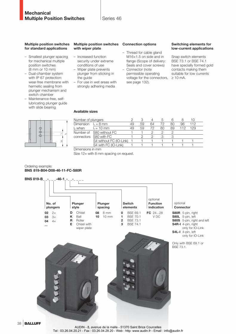
Series 46MechanicalMultiple Position Switches
Multiple position switchesfor standard applications
– Smallest plunger spacingfor mechanical multipleposition switches(8 mm or 10 mm)
– Dual-chamber systemwith IP 67 protection:wear-free membrane withhermetic sealing fromplunger mechanism andswitch chamber
– Maintenance-free, self-lubricating plunger guidewith slide bearing
Multiple position switcheswith wiper plate
– Increased functionsecurity under extremeconditions of use
– Wiper plate preventsplunger from sticking inthe guide
– For use in wet areas withstrongly adhering media
Connection options
– Thread for cable glandM16×1.5 on side and inflange (Scope of delivery:Seals and cover screws)
– Connector (notepermissible operatingvoltage for the connectors,see page 132).
Switching elements forlow-current applications
Snap switch elementsBSE 73.1 or BSE 74.1have specially formed goldcontacts making themsuitable for low currents≥ 10 mA.
Plungerstyle
08 8 mm10 10 mm
Plungerspacing
02 2×03 3×04 4×...
D ChiselK BallR RollerE Chisel with
wiper plate
Ordering example:BNS 819-B04-D08-46-11-FC-S80R
BNS 819-B_ _-_ _ _-46-1_-_ _-_ _ _ _
0 BSE 69.11 BSE 70.12 BSE 73.13 BSE 74.1
Switchelements
No. ofplungers
optionalConnector
FC 24...28V DC
optionalFunctionindication
Available sizes
Number of plungers 2 3 4 5 6 8 10Dimension l1 = 8 mm 49 59 64 72 80 96 112l2 when l1 = 10 mm 49 59 72 80 89 112 129Number of S80 without FC 1 1 2 2 2connectors S80 with FC 1 2 2 3 3
S4 without FC (IO-Link) 1 1 1 1 1 1 1S4 with FC (IO-Link) 1 1 1 1 1 1 1
Dimensions in mmSize 12× with 8 mm spacing on request.
S80R 5-pin, rightS80L 5-pin, leftS80S 5-pin, right and leftS4R-I 4-pin, right
only for IO-LinkS4L-I 4-pin, left
only for IO-Link
Only with BSE 69.1 orBSE 73.1.
38AUDIN - 8, avenue de la malle - 51370 Saint Brice Courcelles
Tel : 03.26.04.20.21 - Fax : 03.26.04.28.20 - Web : http: www.audin.fr - Email : [email protected]
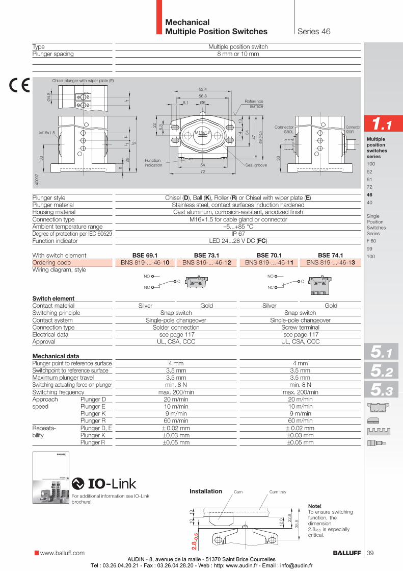
TypePlunger spacing
Plunger stylePlunger materialHousing materialConnection typeAmbient temperature rangeDegree of protection per IEC 60529Function indicator
BSE 70.1 BSE 74.1BNS 819-...-46-11 BNS 819-...-46-13
Silver GoldSnap switch
Single-pole changeoverScrew terminal see page 117UL, CSA, CCC
4 mm3.5 mm3.5 mmmin. 8 N
max. 200/min20 m/min10 m/min9 m/min
60 m/min± 0.02 mm±0.03 mm±0.05 mm
BSE 69.1 BSE 73.1BNS 819-...-46-10 BNS 819-...-46-12
Silver GoldSnap switch
Single-pole changeoverSolder connection
see page 117UL, CSA, CCC
4 mm3.5 mm3.5 mmmin. 8 N
max. 200/min20 m/min10 m/min9 m/min60 m/min
± 0.02 mm±0.03 mm±0.05 mm
Multiple position switch8 mm or 10 mm
Chisel (D), Ball (K), Roller (R) or Chisel with wiper plate (E)Stainless steel, contact surfaces induction hardenedCast aluminum, corrosion-resistant, anodized finish
M16×1.5 for cable gland or connector–5...+85 °C
IP 67LED 24...28 V DC (FC)
Series 46MechanicalMultiple Position Switches
Multiplepositionswitchesseries
100
62
61
72
46
40
SinglePositionSwitchesSeries
F 60
99
100With switch elementOrdering codeWiring diagram, style
Switch elementContact materialSwitching principleContact systemConnection typeElectrical dataApproval
Mechanical dataPlunger point to reference surfaceSwitchpoint to reference surfaceMaximum plunger travelSwitching actuating force on plungerSwitching frequencyApproach Plunger Dspeed Plunger E
Plunger KPlunger R
Repeata- Plunger D, Ebility Plunger K
Plunger R
Note!To ensure switchingfunction, thedimension2.8-0.5 is especiallycritical.
Cam Cam trayInstallation
www.balluff.com
1.1
5.1
5.2
5.3
ConnectorS80R
ConnectorS80L
Functionindication
Chisel plunger with wiper plate (E)
Referencesurface
Seal groove
For additional information see IO-Linkbrochure!
39AUDIN - 8, avenue de la malle - 51370 Saint Brice Courcelles
Tel : 03.26.04.20.21 - Fax : 03.26.04.28.20 - Web : http: www.audin.fr - Email : [email protected]
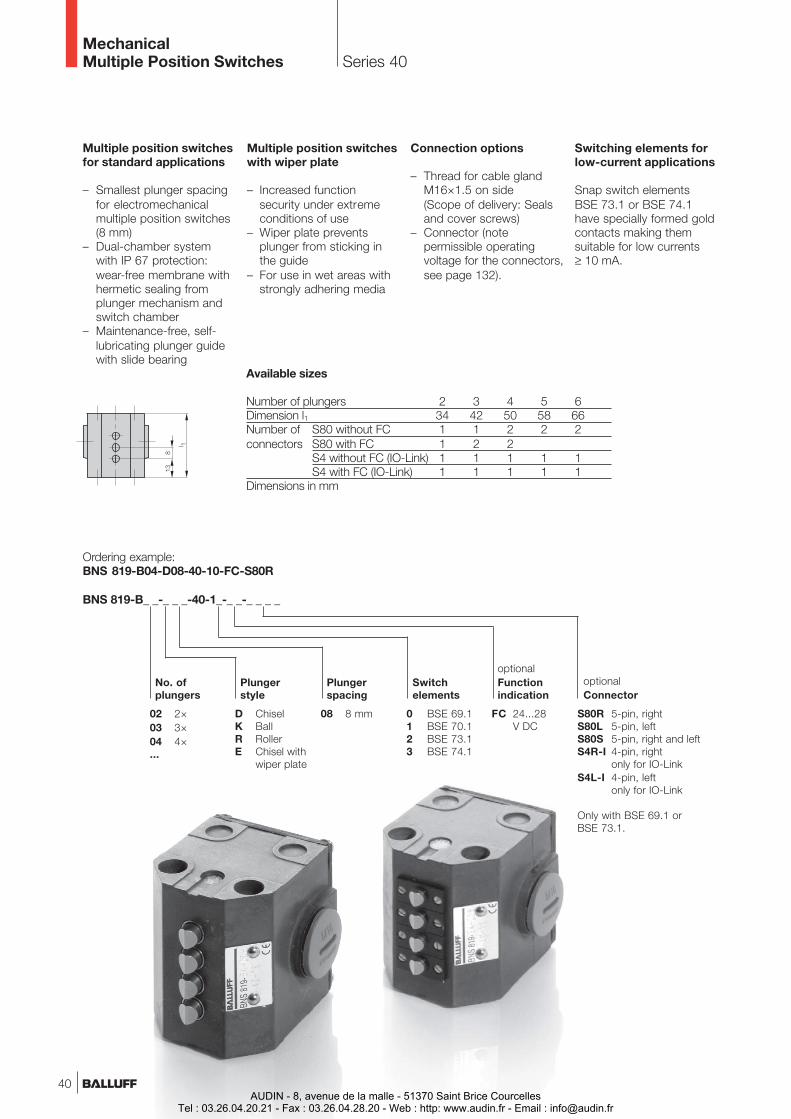
Series 40MechanicalMultiple Position Switches
Ordering example:BNS 819-B04-D08-40-10-FC-S80R
BNS 819-B_ _-_ _ _-40-1_-_ _-_ _ _ _
Multiple position switchesfor standard applications
– Smallest plunger spacingfor electromechanicalmultiple position switches(8 mm)
– Dual-chamber systemwith IP 67 protection:wear-free membrane withhermetic sealing fromplunger mechanism andswitch chamber
– Maintenance-free, self-lubricating plunger guidewith slide bearing
Multiple position switcheswith wiper plate
– Increased functionsecurity under extremeconditions of use
– Wiper plate preventsplunger from sticking inthe guide
– For use in wet areas withstrongly adhering media
Connection options
– Thread for cable glandM16×1.5 on side(Scope of delivery: Sealsand cover screws)
– Connector (notepermissible operatingvoltage for the connectors,see page 132).
Switching elements forlow-current applications
Snap switch elementsBSE 73.1 or BSE 74.1have specially formed goldcontacts making themsuitable for low currents≥ 10 mA.
Plungerstyle
08 8 mm
Plungerspacing
02 2×03 3×04 4×...
D ChiselK BallR RollerE Chisel with
wiper plate
0 BSE 69.11 BSE 70.12 BSE 73.13 BSE 74.1
Switchelements
No. ofplungers
S80R 5-pin, rightS80L 5-pin, leftS80S 5-pin, right and leftS4R-I 4-pin, right
only for IO-LinkS4L-I 4-pin, left
only for IO-Link
Only with BSE 69.1 orBSE 73.1.
optionalConnector
FC 24...28V DC
optionalFunctionindication
Available sizes
Number of plungers 2 3 4 5 6Dimension l1 34 42 50 58 66Number of S80 without FC 1 1 2 2 2connectors S80 with FC 1 2 2
S4 without FC (IO-Link) 1 1 1 1 1S4 with FC (IO-Link) 1 1 1 1 1
Dimensions in mm
40AUDIN - 8, avenue de la malle - 51370 Saint Brice Courcelles
Tel : 03.26.04.20.21 - Fax : 03.26.04.28.20 - Web : http: www.audin.fr - Email : [email protected]
TypePlunger spacing
Plunger stylePlunger materialHousing materialConnection typeAmbient temperature rangeDegree of protection per IEC 60529Function indicator
Multiple position switch8 mm
Chisel (D), Ball (K), Roller (R) or Chisel with wiper plate (E)Stainless steel, contact surfaces induction hardenedCast aluminum, corrosion-resistant, anodized finish
M16×1.5 for cable gland or connector–5...+85 °C
IP 67LED 24...28 V DC (FC)
Series 40MechanicalMultiple Position Switches
Multiplepositionswitchesseries
100
62
61
72
46
40
SinglePositionSwitchesSeries
F 60
99
100
Note!To ensure switchingfunction, thedimension 2.8-0.5 isespecially critical.
Cam Cam tray
Chisel plunger with wiper plate (E)
www.balluff.com
1.1
BSE 70.1 BSE 74.1BNS 819-...-40-11 BNS 819-...-40-13
Silver GoldSnap switch
Single-pole changeoverScrew terminal see page 117UL, CSA, CCC
4 mm3.5 mm3.5 mmmin. 8 N
max. 200/min20 m/min10 m/min9 m/min
60 m/min± 0.02 mm±0.03 mm±0.05 mm
BSE 69.1 BSE 73.1BNS 819-...-40-10 BNS 819-...-40-12
Silver GoldSnap switch
Single-pole changeoverSolder connection
see page 117UL, CSA, CCC
4 mm3.5 mm3.5 mmmin. 8 N
max. 200/min20 m/min10 m/min9 m/min60 m/min
± 0.02 mm±0.03 mm±0.05 mm
With switch elementOrdering codeWiring diagram, style
Switch elementContact materialSwitching principleContact systemConnection typeElectrical dataApproval
Mechanical dataPlunger point to reference surfaceSwitchpoint to reference surfaceMaximum plunger travelSwitching actuating force on plungerSwitching frequencyApproach Plunger Dspeed Plunger E
Plunger KPlunger R
Repeata- Plunger D, Ebility Plunger K
Plunger R
ConnectorS80R
ConnectorS80L
5.1
5.2
5.3
Referencesurface
Function indicator
For additional informationsee IO-Link brochure!
Installation
41AUDIN - 8, avenue de la malle - 51370 Saint Brice Courcelles
Tel : 03.26.04.20.21 - Fax : 03.26.04.28.20 - Web : http: www.audin.fr - Email : [email protected]
Series F 60per DIN 43693
MechanicalSingle Position Switches
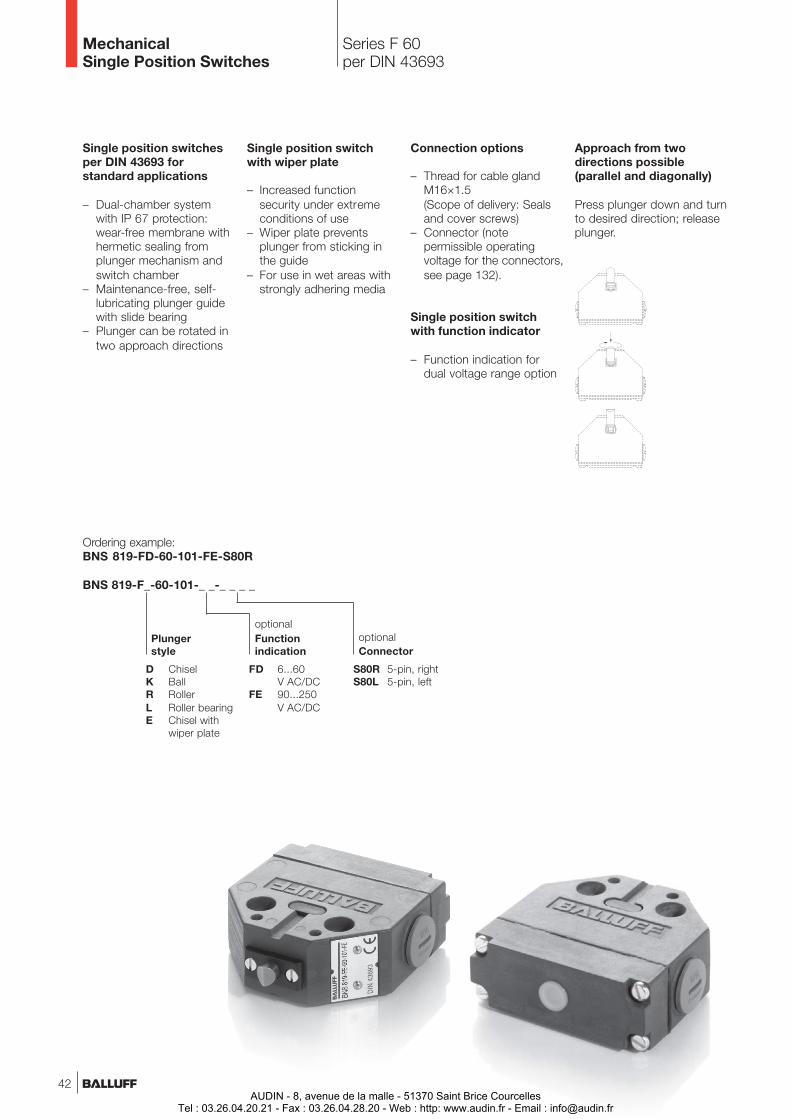
D ChiselK BallR RollerL Roller bearingE Chisel with
wiper plate
Ordering example:BNS 819-FD-60-101-FE-S80R
BNS 819-F_-60-101-_ _-_ _ _ _
FD 6...60V AC/DC
FE 90...250V AC/DC
optionalFunctionindication
Plungerstyle
S80R 5-pin, rightS80L 5-pin, left
optionalConnector
Single position switchesper DIN 43693 forstandard applications
– Dual-chamber systemwith IP 67 protection:wear-free membrane withhermetic sealing fromplunger mechanism andswitch chamber
– Maintenance-free, self-lubricating plunger guidewith slide bearing
– Plunger can be rotated intwo approach directions
Single position switchwith wiper plate
– Increased functionsecurity under extremeconditions of use
– Wiper plate preventsplunger from sticking inthe guide
– For use in wet areas withstrongly adhering media
Approach from twodirections possible(parallel and diagonally)
Press plunger down and turnto desired direction; releaseplunger.
Connection options
– Thread for cable glandM16×1.5(Scope of delivery: Sealsand cover screws)
– Connector (notepermissible operatingvoltage for the connectors,see page 132).
Single position switchwith function indicator
– Function indication fordual voltage range option
42AUDIN - 8, avenue de la malle - 51370 Saint Brice Courcelles
Tel : 03.26.04.20.21 - Fax : 03.26.04.28.20 - Web : http: www.audin.fr - Email : [email protected]
With switch elementOrdering codeWiring diagram, style
Switch elementContact materialSwitching principleContact system
Electrical dataApproval
Mechanical dataPlunger point to reference surfaceSwitchpoint to reference surfaceMaximum plunger travel D, K, R, LMaximum plunger travel ESwitching actuating force on plungerSwitching frequencyApproach Plunger Dspeed Plunger E
Plunger KPlunger RPlunger L
Repeata- Plunger D, E, Kbility Plunger R, L
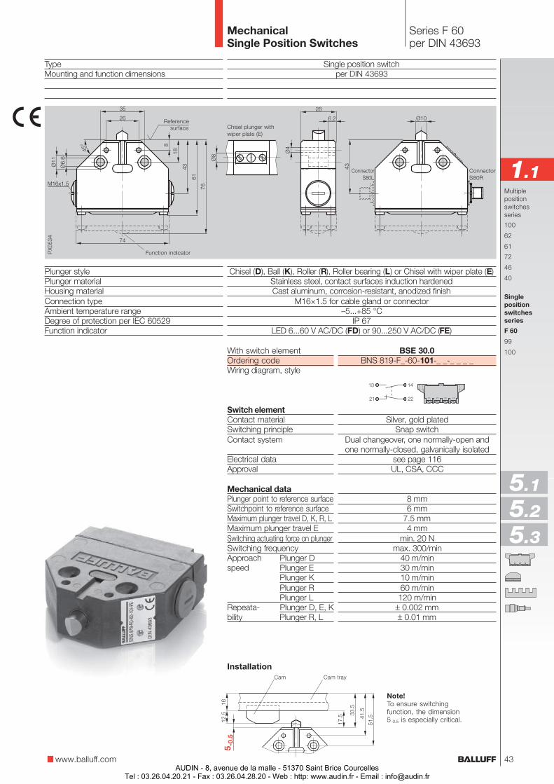
TypeMounting and function dimensions
Plunger stylePlunger materialHousing materialConnection typeAmbient temperature rangeDegree of protection per IEC 60529Function indicator
Single position switchper DIN 43693
Chisel (D), Ball (K), Roller (R), Roller bearing (L) or Chisel with wiper plate (E)Stainless steel, contact surfaces induction hardenedCast aluminum, corrosion-resistant, anodized finish
M16×1.5 for cable gland or connector–5...+85 °C
IP 67LED 6...60 V AC/DC (FD) or 90...250 V AC/DC (FE)
Series F 60per DIN 43693
MechanicalSingle Position Switches
Chisel plunger withwiper plate (E)
Function indicator
Multiplepositionswitchesseries
100
62
61
72
46
40
Singlepositionswitchesseries
F 60
99
100BSE 30.0BNS 819-F_-60-101-_ _-_ _ _ _
Silver, gold platedSnap switch
Dual changeover, one normally-open andone normally-closed, galvanically isolated
see page 116UL, CSA, CCC
8 mm6 mm
7.5 mm4 mm
min. 20 Nmax. 300/min
40 m/min30 m/min10 m/min60 m/min
120 m/min± 0.002 mm± 0.01 mm
Cam Cam tray
www.balluff.com
1.1ConnectorS80R
ConnectorS80L
Installation
Note!To ensure switchingfunction, the dimension5-0.5 is especially critical.
5.1
5.2
5.3
Referencesurface
43AUDIN - 8, avenue de la malle - 51370 Saint Brice Courcelles
Tel : 03.26.04.20.21 - Fax : 03.26.04.28.20 - Web : http: www.audin.fr - Email : [email protected]
Series 99 and 100MechanicalSingle Position Switches
Single position switchesfor standard applications
– Dual-chamber systemwith IP 67 protection:wear-free membrane withhermetic sealing fromplunger mechanism andswitch chamber
– Maintenance-free, self-lubricating plunger guidewith slide bearing
– Plunger can be rotated intwo approach directions
Single position switchwith wiper plate
– Increased functionsecurity under extremeconditions of use
– Wiper plate preventsplunger from sticking inthe guide
– For use in wet areas withstrongly adhering media
Switching elements forlow-current applications
Snap switch elementsBSE 73.1 or BSE 74.1have specially formed goldcontacts making themsuitable for low currents≥ 10 mA.
Connection variants
– Thread for cable glandM12×1.5 for series 99,Thread for cable glandM16×1.5 for series 100
– Connector (notepermissible operatingvoltage for the connectors,see page 132).
Plunger style
0 BSE 69.11 BSE 70.12 BSE 73.13 BSE 74.1
Switch elements
99 Series 99100 Series 100
D ChiselK BallR RollerE Chisel with
wiper plate
Ordering example:BNS 819-100-E-12-FC-S80
BNS 819-_ _ _-_-1_-_ _-_ _ _
Series
FC 24...28V DC
optionalFunctionindication
Only with BSE 69.1 or BSE 73.1.
S80 5-pin
optionalConnector
Approach from twodirections possible(parallel and diagonally)
Press plunger down and turnto desired direction; releaseplunger.
44AUDIN - 8, avenue de la malle - 51370 Saint Brice Courcelles
Tel : 03.26.04.20.21 - Fax : 03.26.04.28.20 - Web : http: www.audin.fr - Email : [email protected]
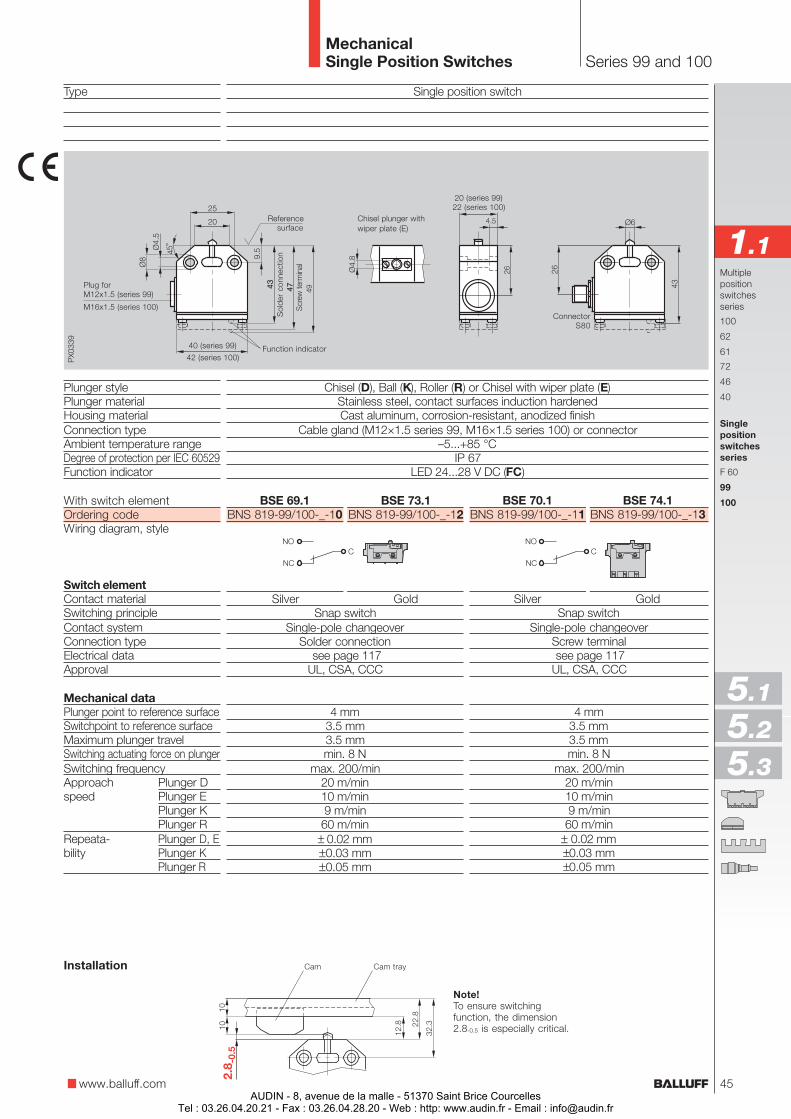
Single position switch
Chisel (D), Ball (K), Roller (R) or Chisel with wiper plate (E)Stainless steel, contact surfaces induction hardenedCast aluminum, corrosion-resistant, anodized finish
Cable gland (M12×1.5 series 99, M16×1.5 series 100) or connector–5...+85 °C
IP 67LED 24...28 V DC (FC)
Type
Plunger stylePlunger materialHousing materialConnection typeAmbient temperature rangeDegree of protection per IEC 60529Function indicator
Series 99 and 100MechanicalSingle Position Switches
Note!To ensure switchingfunction, the dimension2.8-0.5 is especially critical.
Cam Cam trayInstallation
Multiplepositionswitchesseries
100
62
61
72
46
40
Singlepositionswitchesseries
F 60
99
100
ConnectorS80
Chisel plunger withwiper plate (E)
40 (series 99)
42 (series 100)
43
Sol
der
conn
ectio
n4
7S
crew
term
inal
20 (series 99)22 (series 100)
Plug forM12x1.5 (series 99)
BSE 70.1 BSE 74.1BNS 819-99/100-_-11 BNS 819-99/100-_-13
Silver GoldSnap switch
Single-pole changeoverScrew terminal see page 117UL, CSA, CCC
4 mm3.5 mm3.5 mmmin. 8 N
max. 200/min20 m/min10 m/min9 m/min
60 m/min± 0.02 mm±0.03 mm±0.05 mm
BSE 69.1 BSE 73.1BNS 819-99/100-_-10 BNS 819-99/100-_-12
Silver GoldSnap switch
Single-pole changeoverSolder connection
see page 117UL, CSA, CCC
4 mm3.5 mm3.5 mmmin. 8 N
max. 200/min20 m/min10 m/min9 m/min60 m/min
± 0.02 mm±0.03 mm±0.05 mm
With switch elementOrdering codeWiring diagram, style
Switch elementContact materialSwitching principleContact systemConnection typeElectrical dataApproval
Mechanical dataPlunger point to reference surfaceSwitchpoint to reference surfaceMaximum plunger travelSwitching actuating force on plungerSwitching frequencyApproach Plunger Dspeed Plunger E
Plunger KPlunger R
Repeata- Plunger D, Ebility Plunger K
Plunger R
M16x1.5 (series 100)
www.balluff.com
1.1
5.1
5.2
5.3
Referencesurface
Function indicator
45AUDIN - 8, avenue de la malle - 51370 Saint Brice Courcelles
Tel : 03.26.04.20.21 - Fax : 03.26.04.28.20 - Web : http: www.audin.fr - Email : [email protected]

Objekterkennung
AUDIN - 8, avenue de la malle - 51370 Saint Brice CourcellesTel : 03.26.04.20.21 - Fax : 03.26.04.28.20 - Web : http: www.audin.fr - Email : [email protected]
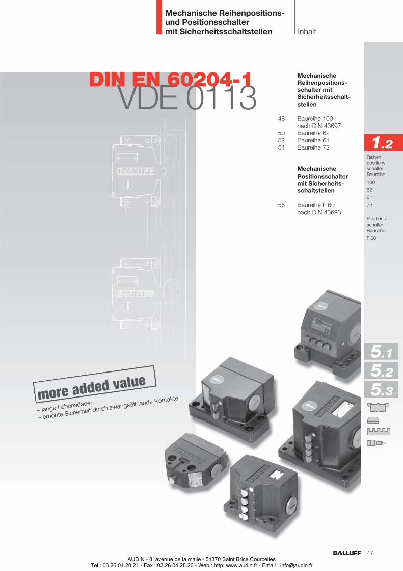
MechanischeReihenpositions-schalter mitSicherheitsschalt-stellen
48 Baureihe 100nach DIN 43697
50 Baureihe 6252 Baureihe 6154 Baureihe 72
MechanischePositionsschaltermit Sicherheits-schaltstellen
56 Baureihe F 60nach DIN 43693
Inhalt
Mechanische Reihenpositions-und Positionsschaltermit Sicherheitsschaltstellen
Reihenpositions-schalterBaureihe
100
62
61
72
Positions-schalterBaureihe
F 60
VDE 0113DIN EN 60204-1
1.2
5.1
5.2
5.3– lange Lebensdauer
– erhöhte Sicherheit durch zwangsöffnende Kontakte
47AUDIN - 8, avenue de la malle - 51370 Saint Brice Courcelles
Tel : 03.26.04.20.21 - Fax : 03.26.04.28.20 - Web : http: www.audin.fr - Email : [email protected]
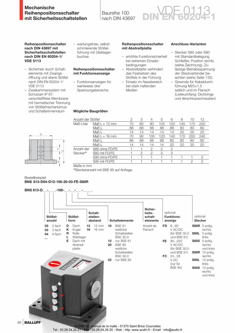
VDE 0113
Anschluss-Varianten
– Stecker S80 oder S90mit StandardbelegungSchließer, Position rechts(siehe Zeichnung). Zu-lässige Betriebsspannungder Steckverbinder be-achten (siehe Seite 132).
– Gewinde für Kabeldurch-führung M25×1,5seitlich und im Flansch(Lieferumfang: Dichtringeund Verschlussschrauben)
DIN EN 60204-1
Reihenpositionsschaltermit Abstreifplatte
– erhöhte Funktionsicherheitbei extremen Einsatz-bedingungen
– Abstreifplatte verhindertdas Festsetzen desStößels in der Führung
– Einsatz im Nassbereichbei stark haftendenMedien
Baureihe 100nach DIN 43697
MechanischeReihenpositionsschaltermit Sicherheitsschaltstellen
Reihenpositionsschalternach DIN 43697 mitSicherheitsschaltstellennach DIN EN 60204-1/VDE 0113
– Sicherheit durch Schalt-elemente mit Zwangs-öffnung und starre Stößelnach DIN EN 60204-1/VDE 0113
– Zweikammersystem mitSchutzart IP 67:verschleißfreie Membranemit hermetischer Trennungvon Stößelmechanismusund Schalterinnenraum
– wartungsfreie, selbst-schmierende Stößel-führung mit Gleitlager-buchse
Reihenpositionsschaltermit Funktionsanzeige
– Funktionsanzeigen fürwahlweise dreiSpannungsbereiche
BNS 813-D_ _-_ _ _-100-_ _-_ _-_ _ -_ _ _ _
Bestellbeispiel:BNS 813-D04-D12-100-20-03-FE-S80R
optionalStecker
Stößel-anzahl
Stößel-form
Schalt-stellen-abstand Schaltelemente
FD 6...60V AC/DC(für BSE 30.0und BSE 61)
FE 90...250V AC/DC(für BSE 30.0und BSE 61)
FC 24...28V DC(nur fürBSE 85)
optionalFunktions-anzeige
Sicher-heits-schalt-elemente
10 BSE 61restlicheSchaltstellenBSE 30.0
12 nur BSE 6120 BSE 85
restlicheSchaltstellenBSE 30.0
22 nur BSE 85
Anzahl abFlansch
12 12 mm16 16 mm
02 2-fach03 3-fach04 4-fach...
D DachK KugelR RolleL WälzlagerE Dach mit
Abstreif-platte
S80R 5-polig,rechts
S80L 5-polig,links
S80S 5-polig,rechtsund links
S90R 12-polig,rechts
S90L 12-polig,links
S90S 12-polig,rechtsund links
Mögliche Baugrößen
Anzahl der Stößel 2 3 4 5 6 8 10 12Maß l2 bei Maß l1 = 12 mm 70 80 90 105 120 140 170 200
Maß l3 88 88 88 88 88 80 80 80Maß l4 14 14 14 14 14 20 20 20Maß l1 = 16 mm 70 90 105 120 140 170 200 240Maß l3 88 88 88 88 80 80 80 80Maß l4 14 14 14 14 20 20 20 20
Anzahl der S80 ohne FD/FE 1 1 2 2 2Stecker* S80 mit FD/FE 1 2 2 3 3
S90 ohne FD/FE 1 1 1 1 1 1 1 2S90 mit FD/FE 1 1 1 1 1 1 2 2
Maße in mm
*Steckeranzahl mit BSE 85 auf Anfrage.
48AUDIN - 8, avenue de la malle - 51370 Saint Brice Courcelles
Tel : 03.26.04.20.21 - Fax : 03.26.04.28.20 - Web : http: www.audin.fr - Email : [email protected]
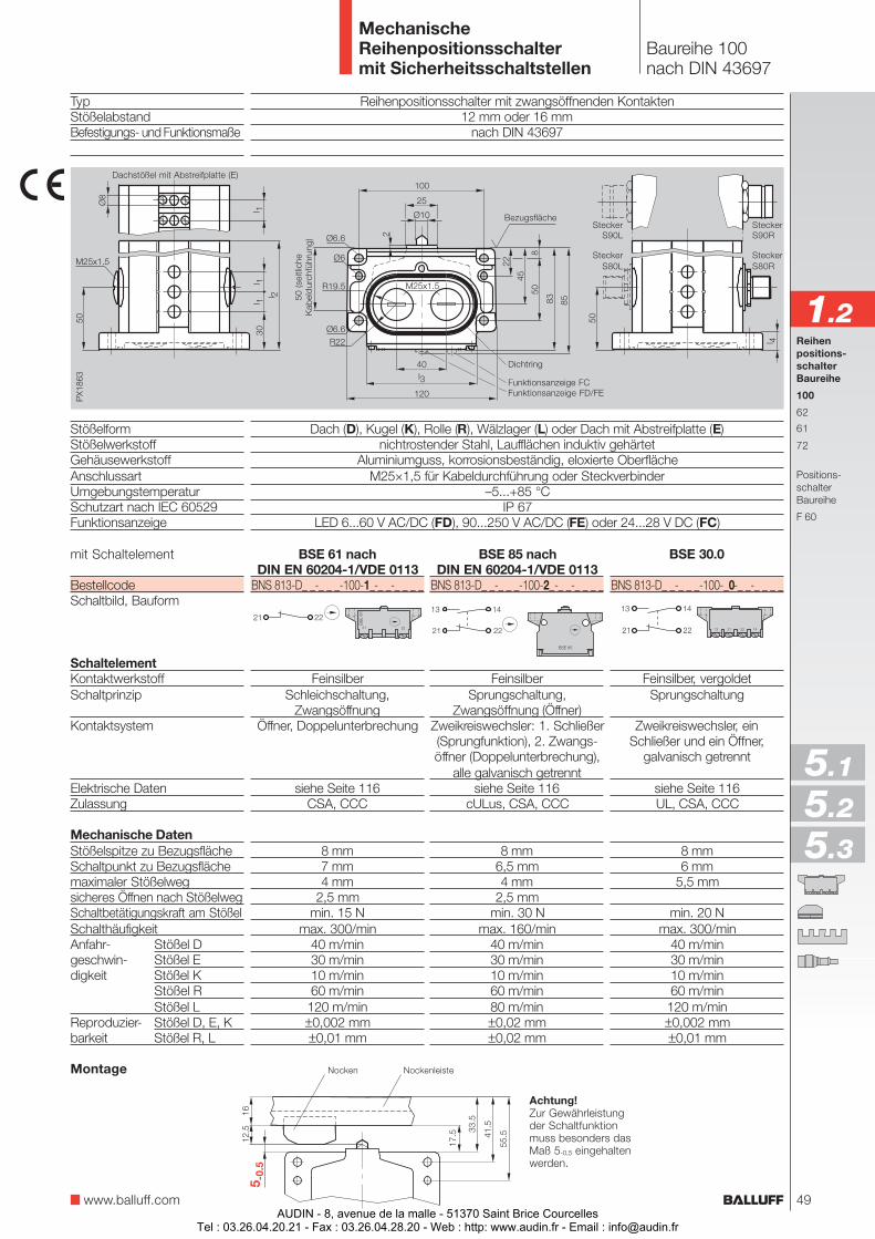
TypStößelabstandBefestigungs- und Funktionsmaße
StößelformStößelwerkstoffGehäusewerkstoffAnschlussartUmgebungstemperaturSchutzart nach IEC 60529Funktionsanzeige
mit Schaltelement
BestellcodeSchaltbild, Bauform
SchaltelementKontaktwerkstoffSchaltprinzip
Kontaktsystem
Elektrische DatenZulassung
Mechanische DatenStößelspitze zu BezugsflächeSchaltpunkt zu Bezugsflächemaximaler Stößelwegsicheres Öffnen nach StößelwegSchaltbetätigungskraft am StößelSchalthäufigkeitAnfahr- Stößel Dgeschwin- Stößel Edigkeit Stößel K
Stößel RStößel L
Reproduzier- Stößel D, E, Kbarkeit Stößel R, L
Reihenpositionsschalter mit zwangsöffnenden Kontakten12 mm oder 16 mm
nach DIN 43697
Dach (D), Kugel (K), Rolle (R), Wälzlager (L) oder Dach mit Abstreifplatte (E)nichtrostender Stahl, Laufflächen induktiv gehärtet
Aluminiumguss, korrosionsbeständig, eloxierte OberflächeM25×1,5 für Kabeldurchführung oder Steckverbinder
–5...+85 °CIP 67
LED 6...60 V AC/DC (FD), 90...250 V AC/DC (FE) oder 24...28 V DC (FC)
Baureihe 100nach DIN 43697
MechanischeReihenpositionsschaltermit Sicherheitsschaltstellen
Dichtring
Funktionsanzeige FD/FE
Dachstößel mit Abstreifplatte (E)
Funktionsanzeige FC
Achtung!Zur Gewährleistungder Schaltfunktionmuss besonders dasMaß 5-0,5 eingehaltenwerden.
Nocken NockenleisteMontage
BSE 30.0
BNS 813-D_ _-_ _ _-100-_0-_ _-_ _ _ _
Feinsilber, vergoldetSprungschaltung
Zweikreiswechsler, einSchließer und ein Öffner,
galvanisch getrennt
siehe Seite 116UL, CSA, CCC
8 mm6 mm
5,5 mm
min. 20 Nmax. 300/min
40 m/min30 m/min10 m/min60 m/min
120 m/min±0,002 mm±0,01 mm
BSE 61 nachDIN EN 60204-1/VDE 0113
BNS 813-D_ _-_ _ _-100-1_-_ _-_ _ _ _
FeinsilberSchleichschaltung,
ZwangsöffnungÖffner, Doppelunterbrechung
siehe Seite 116CSA, CCC
8 mm7 mm4 mm
2,5 mmmin. 15 N
max. 300/min40 m/min30 m/min10 m/min60 m/min120 m/min±0,002 mm±0,01 mm
BSE 85 nachDIN EN 60204-1/VDE 0113
BNS 813-D_ _-_ _ _-100-2_-_ _-_ _ _ _
FeinsilberSprungschaltung,
Zwangsöffnung (Öffner)Zweikreiswechsler: 1. Schließer(Sprungfunktion), 2. Zwangs-öffner (Doppelunterbrechung),
alle galvanisch getrenntsiehe Seite 116
cULus, CSA, CCC
8 mm6,5 mm4 mm
2,5 mmmin. 30 N
max. 160/min40 m/min30 m/min10 m/min60 m/min80 m/min±0,02 mm±0,02 mm
Reihenpositions-schalterBaureihe
100
62
61
72
Positions-schalterBaureihe
F 60
1.2
www.balluff.com
5.1
5.2
5.3
50 (s
eitli
che
Kab
eld
urch
führ
ung)
SteckerS80R
SteckerS90R
SteckerS80L
SteckerS90L
Bezugsfläche
49AUDIN - 8, avenue de la malle - 51370 Saint Brice Courcelles
Tel : 03.26.04.20.21 - Fax : 03.26.04.28.20 - Web : http: www.audin.fr - Email : [email protected]
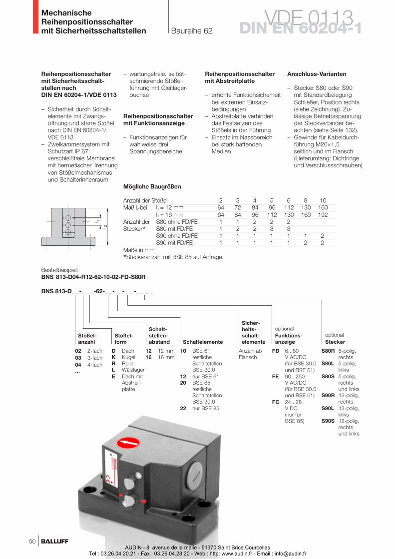
Baureihe 62
MechanischeReihenpositionsschaltermit Sicherheitsschaltstellen
Bestellbeispiel:BNS 813-D04-R12-62-10-02-FD-S80R
BNS 813-D_ _-_ _ _-62-_ _-_ _-_ _ -_ _ _ _
optionalStecker
Stößel-anzahl Schaltelemente
FD 6...60V AC/DC(für BSE 30.0und BSE 61)
FE 90...250V AC/DC(für BSE 30.0und BSE 61)
FC 24...28V DC(nur fürBSE 85)
optionalFunktions-anzeige
Sicher-heits-schalt-elemente
10 BSE 61restlicheSchaltstellenBSE 30.0
12 nur BSE 6120 BSE 85
restlicheSchaltstellenBSE 30.0
22 nur BSE 85
Anzahl abFlansch
02 2-fach03 3-fach04 4-fach...
S80R 5-polig,rechts
S80L 5-polig,links
S80S 5-polig,rechtsund links
S90R 12-polig,rechts
S90L 12-polig,links
S90S 12-polig,rechtsund links
Stößel-form
Schalt-stellen-abstand
12 12 mm16 16 mm
D DachK KugelR RolleL WälzlagerE Dach mit
Abstreif-platte
Anschluss-Varianten
– Stecker S80 oder S90mit StandardbelegungSchließer, Position rechts(siehe Zeichnung). Zu-lässige Betriebsspannungder Steckverbinder be-achten (siehe Seite 132).
– Gewinde für Kabeldurch-führung M20×1,5seitlich und im Flansch(Lieferumfang: Dichtringeund Verschlussschrauben)
Reihenpositionsschaltermit Abstreifplatte
– erhöhte Funktionsicherheitbei extremen Einsatz-bedingungen
– Abstreifplatte verhindertdas Festsetzen desStößels in der Führung
– Einsatz im Nassbereichbei stark haftendenMedien
Reihenpositionsschaltermit Sicherheitsschalt-stellen nachDIN EN 60204-1/VDE 0113
– Sicherheit durch Schalt-elemente mit Zwangs-öffnung und starre Stößelnach DIN EN 60204-1/VDE 0113
– Zweikammersystem mitSchutzart IP 67:verschleißfreie Membranemit hermetischer Trennungvon Stößelmechanismusund Schalterinnenraum
– wartungsfreie, selbst-schmierende Stößel-führung mit Gleitlager-buchse
Reihenpositionsschaltermit Funktionsanzeige
– Funktionsanzeigen fürwahlweise dreiSpannungsbereiche
VDE 0113DIN EN 60204-1
Mögliche Baugrößen
Anzahl der Stößel 2 3 4 5 6 8 10Maß l2 bei l1 = 12 mm 64 72 84 96 112 130 160
l1 = 16 mm 64 84 96 112 130 160 192Anzahl der S80 ohne FD/FE 1 1 2 2 2Stecker* S80 mit FD/FE 1 2 2 3 3
S90 ohne FD/FE 1 1 1 1 1 1 2S90 mit FD/FE 1 1 1 1 1 2 2
Maße in mm
*Steckeranzahl mit BSE 85 auf Anfrage.
50AUDIN - 8, avenue de la malle - 51370 Saint Brice Courcelles
Tel : 03.26.04.20.21 - Fax : 03.26.04.28.20 - Web : http: www.audin.fr - Email : [email protected]
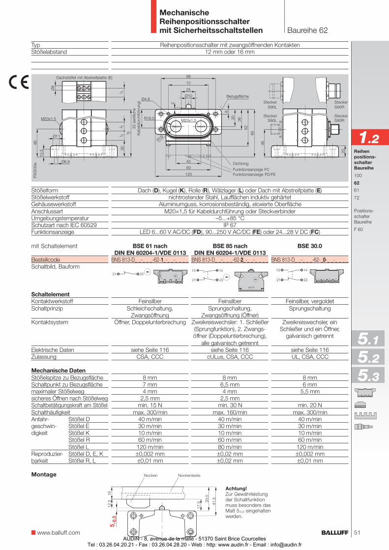
Baureihe 62
MechanischeReihenpositionsschaltermit Sicherheitsschaltstellen
Reihenpositionsschalter mit zwangsöffnenden Kontakten12 mm oder 16 mm
Dach (D), Kugel (K), Rolle (R), Wälzlager (L) oder Dach mit Abstreifplatte (E)nichtrostender Stahl, Laufflächen induktiv gehärtet
Aluminiumguss, korrosionsbeständig, eloxierte OberflächeM20×1,5 für Kabeldurchführung oder Steckverbinder
–5...+85 °CIP 67
LED 6...60 V AC/DC (FD), 90...250 V AC/DC (FE) oder 24...28 V DC (FC)
BSE 30.0
BNS 813-D_ _-_ _ _-62-_0-_ _-_ _ _ _
Feinsilber, vergoldetSprungschaltung
Zweikreiswechsler, einSchließer und ein Öffner,
galvanisch getrennt
siehe Seite 116UL, CSA, CCC
8 mm6 mm
5,5 mm
min. 20 Nmax. 300/min
40 m/min30 m/min10 m/min60 m/min
120 m/min±0,002 mm±0,01 mm
BSE 61 nachDIN EN 60204-1/VDE 0113
BNS 813-D_ _-_ _ _-62-1_-_ _-_ _ _ _
FeinsilberSchleichschaltung,
ZwangsöffnungÖffner, Doppelunterbrechung
siehe Seite 116CSA, CCC
8 mm7 mm4 mm
2,5 mmmin. 15 N
max. 300/min40 m/min30 m/min10 m/min60 m/min120 m/min±0,002 mm±0,01 mm
BSE 85 nachDIN EN 60204-1/VDE 0113
BNS 813-D_ _-_ _ _-62-2_-_ _-_ _ _ _
FeinsilberSprungschaltung,
Zwangsöffnung (Öffner)Zweikreiswechsler: 1. Schließer(Sprungfunktion), 2. Zwangs-öffner (Doppelunterbrechung),
alle galvanisch getrenntsiehe Seite 116
cULus, CSA, CCC
8 mm6,5 mm4 mm
2,5 mmmin. 30 N
max. 160/min40 m/min30 m/min10 m/min60 m/min80 m/min±0,02 mm±0,02 mm
TypStößelabstand
StößelformStößelwerkstoffGehäusewerkstoffAnschlussartUmgebungstemperaturSchutzart nach IEC 60529Funktionsanzeige
mit Schaltelement
BestellcodeSchaltbild, Bauform
SchaltelementKontaktwerkstoffSchaltprinzip
Kontaktsystem
Elektrische DatenZulassung
Mechanische DatenStößelspitze zu BezugsflächeSchaltpunkt zu Bezugsflächemaximaler Stößelwegsicheres Öffnen nach StößelwegSchaltbetätigungskraft am StößelSchalthäufigkeitAnfahr- Stößel Dgeschwin- Stößel Edigkeit Stößel K
Stößel RStößel L
Reproduzier- Stößel D, E, Kbarkeit Stößel R, L
Achtung!Zur Gewährleistungder Schaltfunktionmuss besonders dasMaß 5-0,5 eingehaltenwerden.
Nocken NockenleisteMontage
Reihenpositions-schalterBaureihe
100
62
61
72
Positions-schalterBaureihe
F 60
Dachstößel mit Abstreifplatte (E)
33 (s
eitli
che
Kab
eld
urch
führ
ung)
1.2
www.balluff.com
5.1
5.2
5.3
Dichtring
Funktionsanzeige FD/FEFunktionsanzeige FC
Bezugsfläche
SteckerS80R
SteckerS90R
SteckerS80L
SteckerS90L
51AUDIN - 8, avenue de la malle - 51370 Saint Brice Courcelles
Tel : 03.26.04.20.21 - Fax : 03.26.04.28.20 - Web : http: www.audin.fr - Email : [email protected]

Baureihe 61
MechanischeReihenpositionsschaltermit Sicherheitsschaltstellen
BNS 813-_ _ _-_ _ _-61-_-_ _-_ _-_ _ _ _
FD 6...60V AC/DC(für BSE 30.0und BSE 61)
FE 90...250V AC/DC(für BSE 30.0und BSE 61)
FC 24...28V DC(nur fürBSE 85)
S80R 5-polig,rechts
S80L 5-polig,link
S80S 5-polig,rechtsund links
S90R 12-polig,rechts
S90L 12-polig,links
S90S 12-polig,rechtsund links
Bestellbeispiel:BNS 813-B06-K12-61-A-12-02-FE-S80R
optionalFunktions-anzeige
Gehäuse-form
Stößel-anzahl
Stößel-form
Schalt-stellen-abstand
optionalSteckerAbstand I3
02 2-fach03 3-fach04 4-fach...
Anzahl abFlansch
Sicher-heits-schalt-elemente
Schalt-elemente
12 12 mm16 16 mm
D DachK KugelR RolleL WälzlagerE Dach mit
Abstreif-platte
A 12 mmB 16 mmC 24 mmD 30 mm
B Standard2× M20×1,5seitlich
B 3× M20×1,5seitlich und imFlansch
C 2× M20×1,5seitlich und Kabel-durchführung imFlansch
Anschluss-Varianten
– Stecker S80 oder S90mit StandardbelegungSchließer, Position rechts(siehe Zeichnung). Zu-lässige Betriebsspannungder Steckverbinder be-achten (siehe Seite 132).
– Gewinde für Kabeldurch-führung M20×1,5seitlich und im Flansch(Lieferumfang: Dichtringeund Verschlussschrauben)
Reihenpositionsschaltermit Abstreifplatte
– erhöhte Funktionsicherheitbei extremen Einsatz-bedingungen
– Abstreifplatte verhindertdas Festsetzen desStößels in der Führung
– Einsatz im Nassbereichbei stark haftendenMedien
Reihenpositionsschaltermit Sicherheitsschalt-stellen nachDIN EN 60204-1/VDE 0113
– Sicherheit durch Schalt-elemente mit Zwangs-öffnung und starre Stößelnach DIN EN 60204-1/VDE 0113
– Zweikammersystem mitSchutzart IP 67:verschleißfreie Membranemit hermetischer Trennungvon Stößelmechanismusund Schalterinnenraum
– wartungsfreie, selbst-schmierende Stößel-führung mit Gleitlager-buchse
Reihenpositionsschaltermit Funktionsanzeige
– Funktionsanzeigen fürwahlweise dreiSpannungsbereiche
VDE 0113DIN EN 60204-1
10 BSE 61restlicheSchaltstellenBSE 30.0
12 nur BSE 6120 BSE 85
restlicheSchaltstellenBSE 30.0
22 nur BSE 85
Gehäuse C
Maßl2 l348 2460 3060 24
60 30
Gehäuse B
Maßl2 l360 30
60 24
60 30
Gehäuse BStandard
Maßl2 l336 12
48 1260 1272 1284 12
48 1672 1684 16
Stößel-abstand
Maßl112
12121212
161616
Anzahl derStecker*S80 mitFD/FE
1
2233
122
Anzahl derStecker*S80 ohneFD/FE
1
1222
112
AnzahlderStößel
2
3456
234
Mögliche Baugrößen
Anzahl derStecker*S90 mitFD/FE
1
1111
111
Anzahl derStecker*S90 ohneFD/FE
1
1111
111
Maße in mm
*Steckeranzahl mit BSE 85 auf Anfrage.
52AUDIN - 8, avenue de la malle - 51370 Saint Brice Courcelles
Tel : 03.26.04.20.21 - Fax : 03.26.04.28.20 - Web : http: www.audin.fr - Email : [email protected]
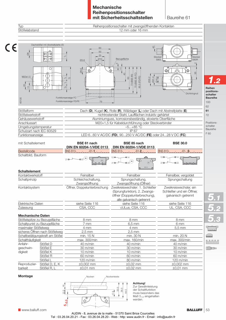
Baureihe 61
MechanischeReihenpositionsschaltermit Sicherheitsschaltstellen
Reihenpositionsschalter mit zwangsöffnenden Kontakten12 mm oder 16 mm
Dach (D), Kugel (K), Rolle (R), Wälzlager (L) oder Dach mit Abstreifplatte (E)nichtrostender Stahl, Laufflächen induktiv gehärtet
Aluminiumguss, korrosionsbeständig, eloxierte OberflächeM20×1,5 für Kabeldurchführung oder Steckverbinder
–5...+85 °CIP 67
LED 6...60 V AC/DC (FD), 90...250 V AC/DC (FE) oder 24...28 V DC (FC)
TypStößelabstand
StößelformStößelwerkstoffGehäusewerkstoffAnschlussartUmgebungstemperaturSchutzart nach IEC 60529Funktionsanzeige
mit Schaltelement
BestellcodeSchaltbild, Bauform
SchaltelementKontaktwerkstoffSchaltprinzip
Kontaktsystem
Elektrische DatenZulassung
Mechanische DatenStößelspitze zu BezugsflächeSchaltpunkt zu Bezugsflächemaximaler Stößelwegsicheres Öffnen nach StößelwegSchaltbetätigungskraft am StößelSchalthäufigkeitAnfahr- Stößel Dgeschwin- Stößel Edigkeit Stößel K
Stößel RStößel L
Reproduzier- Stößel D, E, Kbarkeit Stößel R, L
Achtung!Zur Gewährleistungder Schaltfunktionmuss besonders dasMaß 5-0,5 eingehaltenwerden.
Nocken NockenleisteMontage
BSE 30.0
BNS 813-_ _ _-_ _ _-61-_0-_ _-_ _ _ _
Feinsilber, vergoldetSprungschaltung
Zweikreiswechsler, einSchließer und ein Öffner,
galvanisch getrennt
siehe Seite 116UL, CSA, CCC
8 mm6 mm
5,5 mm
min. 20 Nmax. 300/min
40 m/min30 m/min10 m/min60 m/min
120 m/min±0,002 mm±0,01 mm
BSE 61 nachDIN EN 60204-1/VDE 0113
BNS 813-_ _ _-_ _ _-61-1_-_ _-_ _ _ _
FeinsilberSchleichschaltung,
ZwangsöffnungÖffner, Doppelunterbrechung
siehe Seite 116CSA, CCC
8 mm7 mm4 mm
2,5 mmmin. 15 N
max. 300/min40 m/min30 m/min10 m/min60 m/min120 m/min±0,002 mm±0,01 mm
BSE 85 nachDIN EN 60204-1/VDE 0113
BNS 813-_ _ _-_ _ _-61-2_-_ _-_ _ _ _
FeinsilberSprungschaltung,
Zwangsöffnung (Öffner)Zweikreiswechsler: 1. Schließer(Sprungfunktion), 2. Zwangs-öffner (Doppelunterbrechung),
alle galvanisch getrenntsiehe Seite 116
cULus, CSA, CCC
8 mm6,5 mm4 mm
2,5 mmmin. 30 N
max. 160/min40 m/min30 m/min10 m/min60 m/min80 m/min±0,02 mm±0,02 mm
Reihenpositions-schalterBaureihe
100
62
61
72
Positions-schalterBaureihe
F 60
1.2
www.balluff.com
5.1
5.2
5.3
Dichtringnut
SteckerS80R
SteckerS80LBezugsfläche
Funktionsanzeige FC
Funktionsanzeige FD/FE
Dachstößel mit Abstreifplatte (E)
53AUDIN - 8, avenue de la malle - 51370 Saint Brice Courcelles
Tel : 03.26.04.20.21 - Fax : 03.26.04.28.20 - Web : http: www.audin.fr - Email : [email protected]
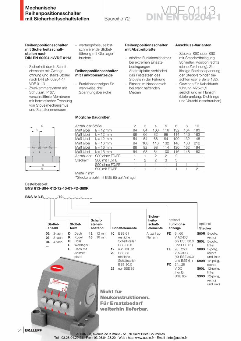
Baureihe 72
MechanischeReihenpositionsschaltermit Sicherheitsschaltstellen
BNS 813-B_ _-_ _ _-72-_ _-_ _-_ _-_ _ _ _
Bestellbeispiel:BNS 813-B04-R12-72-10-01-FD-S80R
Stößel-anzahl
Stößel-form
Schalt-stellen-abstand Schaltelemente
FD 6...60V AC/DC(für BSE 30.0und BSE 61)
FE 90...250V AC/DC(für BSE 30.0und BSE 61)
FC 24...28V DC(nur fürBSE 85)
optionalFunktions-anzeige
Sicher-heits-schalt-elemente
10 BSE 61restlicheSchaltstellenBSE 30.0
12 nur BSE 6120 BSE 85
restlicheSchaltstellenBSE 30.0
22 nur BSE 85
Anzahl abFlansch
12 12 mm16 16 mm
02 2-fach03 3-fach04 4-fach...
D DachK KugelR RolleL WälzlagerE Dach mit
Abstreif-platte
Anschluss-Varianten
– Stecker S80 oder S90mit StandardbelegungSchließer, Position rechts(siehe Zeichnung). Zu-lässige Betriebsspannungder Steckverbinder be-achten (siehe Seite 132).
– Gewinde für Kabeldurch-führung M25×1,5seitlich und im Flansch(Lieferumfang: Dichtringeund Verschlussschrauben)
Reihenpositionsschaltermit Abstreifplatte
– erhöhte Funktionsicherheitbei extremen Einsatz-bedingungen
– Abstreifplatte verhindertdas Festsetzen desStößels in der Führung
– Einsatz im Nassbereichbei stark haftendenMedien
Reihenpositionsschaltermit Sicherheitsschalt-stellen nachDIN EN 60204-1/VDE 0113
– Sicherheit durch Schalt-elemente mit Zwangs-öffnung und starre Stößelnach DIN EN 60204-1/VDE 0113
– Zweikammersystem mitSchutzart IP 67:verschleißfreie Membranemit hermetischer Trennungvon Stößelmechanismusund Schalterinnenraum
– wartungsfreie, selbst-schmierende Stößel-führung mit Gleitlager-buchse
Reihenpositionsschaltermit Funktionsanzeige
– Funktionsanzeigen fürwahlweise dreiSpannungsbereiche
VDE 0113DIN EN 60204-1
Mögliche Baugrößen
Anzahl der Stößel 2 3 4 5 6 8 10Maß l2 bei l1 = 12 mm 84 84 100 116 132 164 180Maß l3 bei l1 = 12 mm 66 66 82 98 114 146 162Maß l4 bei l1 = 12 mm 54 54 68 84 100 132 148Maß l2 bei l1 = 16 mm 84 100 116 132 148 180 212Maß l3 bei l1 = 16 mm 66 82 98 114 130 162 194Maß l4 bei l1 = 16 mm 54 68 84 100 116 148 180Anzahl der S80 ohne FD/FE 1 1 2 2 2Stecker* S80 mit FD/FE 1 2 2 3 3
S90 ohne FD/FE 1 1 1 1 1 1 1S90 mit FD/FE 1 1 1 1 1 1 2
Maße in mm
*Steckeranzahl mit BSE 85 auf Anfrage.
optionalStecker
S80R 5-polig,rechts
S80L 5-polig,links
S80S 5-polig,rechtsund links
S90R 12-polig,rechts
S90L 12-polig,links
S90S 12-polig,rechtsund links
Nicht fürNeukonstruktionen.Für Ersatzbedarfweiterhin lieferbar.
54AUDIN - 8, avenue de la malle - 51370 Saint Brice Courcelles
Tel : 03.26.04.20.21 - Fax : 03.26.04.28.20 - Web : http: www.audin.fr - Email : [email protected]
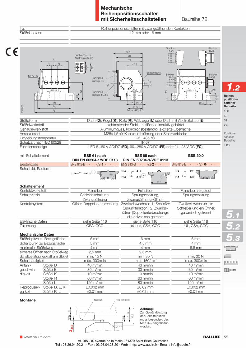
Baureihe 72
MechanischeReihenpositionsschaltermit Sicherheitsschaltstellen
Reihenpositionsschalter mit zwangsöffnenden Kontakten12 mm oder 16 mm
Dach (D), Kugel (K), Rolle (R), Wälzlager (L) oder Dach mit Abstreifplatte (E)nichtrostender Stahl, Laufflächen induktiv gehärtet
Aluminiumguss, korrosionsbeständig, eloxierte OberflächeM25×1,5 für Kabeldurchführung oder Steckverbinder
–5...+85 °CIP 67
LED 6...60 V AC/DC (FD), 90...250 V AC/DC (FE) oder 24...28 V DC (FC)
Bezugsfläche
TypStößelabstand
StößelformStößelwerkstoffGehäusewerkstoffAnschlussartUmgebungstemperaturSchutzart nach IEC 60529Funktionsanzeige
mit Schaltelement
BestellcodeSchaltbild, Bauform
SchaltelementKontaktwerkstoffSchaltprinzip
Kontaktsystem
Elektrische DatenZulassung
Mechanische DatenStößelspitze zu BezugsflächeSchaltpunkt zu Bezugsflächemaximaler Stößelwegsicheres Öffnen nach StößelwegSchaltbetätigungskraft am StößelSchalthäufigkeitAnfahr- Stößel Dgeschwin- Stößel Edigkeit Stößel K
Stößel RStößel L
Reproduzier- Stößel D, E, Kbarkeit Stößel R, L
Achtung!Zur Gewährleistungder Schaltfunktionmuss besonders dasMaß 3-0,5 eingehaltenwerden.
Nocken NockenleisteMontage
BSE 30.0
BNS 813-B_ _-_ _ _-72-_0-_ _-_ _ _ _
Feinsilber, vergoldetSprungschaltung
Zweikreiswechsler, einSchließer und ein Öffner,
galvanisch getrennt
siehe Seite 116UL, CSA, CCC
6 mm4 mm
5,5 mm
min. 20 Nmax. 300/min
40 m/min30 m/min10 m/min60 m/min
120 m/min±0,002 mm±0,01 mm
BSE 61 nachDIN EN 60204-1/VDE 0113
BNS 813-B_ _-_ _ _-72-1_-_ _-_ _ _ _
FeinsilberSchleichschaltung,
ZwangsöffnungÖffner, Doppelunterbrechung
siehe Seite 116CSA, CCC
6 mm5 mm4 mm
2,5 mmmin. 15 N
max. 300/min40 m/min30 m/min10 m/min60 m/min120 m/min±0,002 mm±0,01 mm
BSE 85 nachDIN EN 60204-1/VDE 0113
BNS 813-B_ _-_ _ _-72-2_-_ _-_ _ _ _
FeinsilberSprungschaltung,
Zwangsöffnung (Öffner)Zweikreiswechsler: 1. Schließer(Sprungfunktion), 2. Zwangs-öffner (Doppelunterbrechung),
alle galvanisch getrenntsiehe Seite 116
cULus, CSA, CCC
6 mm4,5 mm4 mm
2,5 mmmin. 30 N
max. 160/min40 m/min30 m/min10 m/min60 m/min80 m/min±0,02 mm±0,02 mm
Reihenpositions-schalterBaureihe
100
62
61
72
Positions-schalterBaureihe
F 60
1.2Funktions-anzeige FD/FE
Mitte M25x1.5
Dachstößel mitAbstreifplatte (E)
www.balluff.com
5.1
5.2
5.3
SteckerS80R
SteckerS90R
SteckerS80L
SteckerS90L
Funktions-anzeige FC
55AUDIN - 8, avenue de la malle - 51370 Saint Brice Courcelles
Tel : 03.26.04.20.21 - Fax : 03.26.04.28.20 - Web : http: www.audin.fr - Email : [email protected]
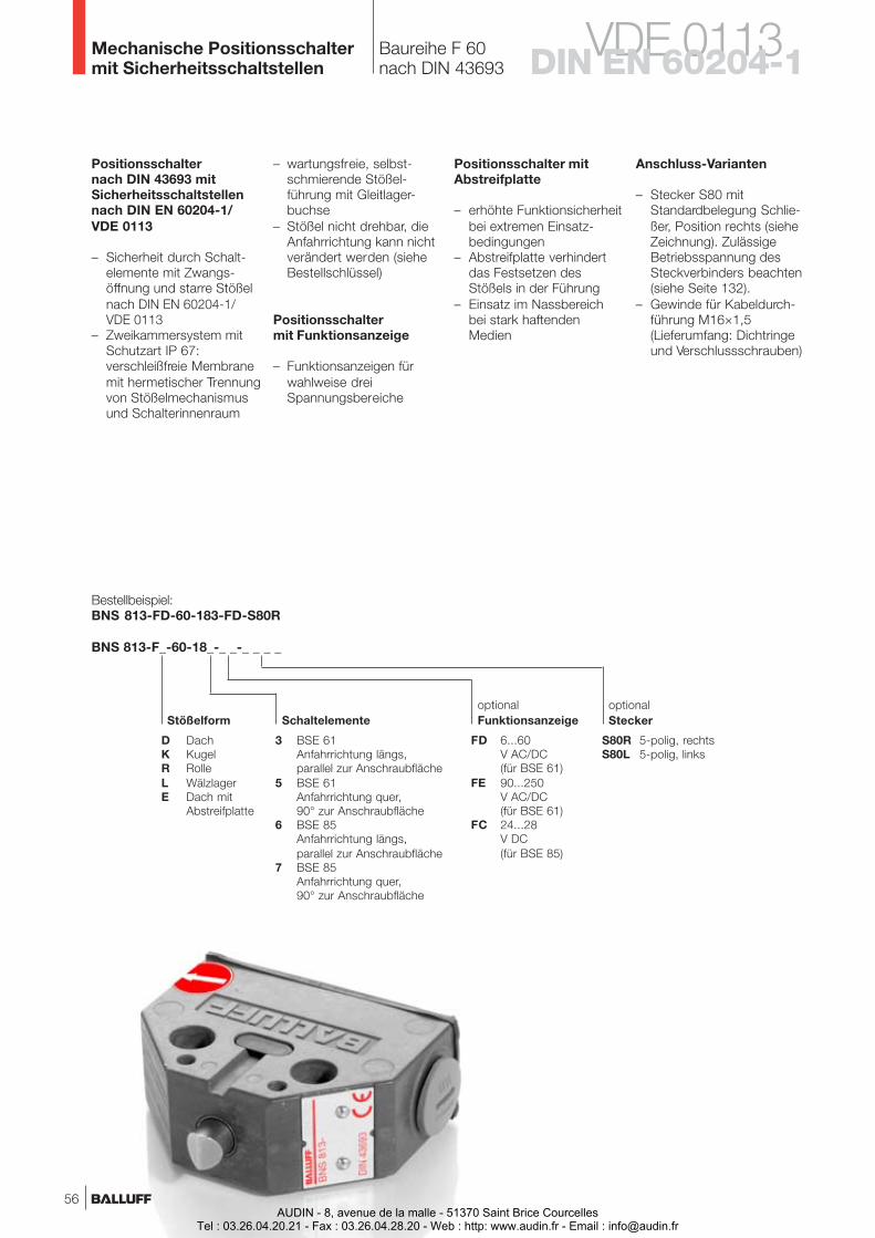
Baureihe F 60nach DIN 43693
Mechanische Positionsschaltermit Sicherheitsschaltstellen
D DachK KugelR RolleL WälzlagerE Dach mit
Abstreifplatte
Bestellbeispiel:BNS 813-FD-60-183-FD-S80R
BNS 813-F_-60-18_-_ _-_ _ _ _
3 BSE 61Anfahrrichtung längs,parallel zur Anschraubfläche
5 BSE 61Anfahrrichtung quer,90° zur Anschraubfläche
6 BSE 85Anfahrrichtung längs,parallel zur Anschraubfläche
7 BSE 85Anfahrrichtung quer,90° zur Anschraubfläche
SchaltelementeStößelform
FD 6...60V AC/DC(für BSE 61)
FE 90...250V AC/DC(für BSE 61)
FC 24...28V DC(für BSE 85)
optionalFunktionsanzeige
S80R 5-polig, rechtsS80L 5-polig, links
optionalStecker
Positionsschalternach DIN 43693 mitSicherheitsschaltstellennach DIN EN 60204-1/VDE 0113
– Sicherheit durch Schalt-elemente mit Zwangs-öffnung und starre Stößelnach DIN EN 60204-1/VDE 0113
– Zweikammersystem mitSchutzart IP 67:verschleißfreie Membranemit hermetischer Trennungvon Stößelmechanismusund Schalterinnenraum
Anschluss-Varianten
– Stecker S80 mitStandardbelegung Schlie-ßer, Position rechts (sieheZeichnung). ZulässigeBetriebsspannung desSteckverbinders beachten(siehe Seite 132).
– Gewinde für Kabeldurch-führung M16×1,5(Lieferumfang: Dichtringeund Verschlussschrauben)
VDE 0113DIN EN 60204-1
– wartungsfreie, selbst-schmierende Stößel-führung mit Gleitlager-buchse
– Stößel nicht drehbar, dieAnfahrrichtung kann nichtverändert werden (sieheBestellschlüssel)
Positionsschaltermit Funktionsanzeige
– Funktionsanzeigen fürwahlweise dreiSpannungsbereiche
Positionsschalter mitAbstreifplatte
– erhöhte Funktionsicherheitbei extremen Einsatz-bedingungen
– Abstreifplatte verhindertdas Festsetzen desStößels in der Führung
– Einsatz im Nassbereichbei stark haftendenMedien
56AUDIN - 8, avenue de la malle - 51370 Saint Brice Courcelles
Tel : 03.26.04.20.21 - Fax : 03.26.04.28.20 - Web : http: www.audin.fr - Email : [email protected]

Baureihe F 60nach DIN 43693
Mechanische Positionsschaltermit Sicherheitsschaltstellen
Positionsschalter mit zwangsöffnenden Kontaktennach DIN 43693
Dach (D), Kugel (K), Rolle (R), Wälzlager (L) oder Dach mit Abstreifplatte (E)nichtrostender Stahl, Laufflächen induktiv gehärtet
Aluminiumguss, korrosionsbeständig, eloxierte OberflächeM16×1,5 für Kabeldurchführung oder Steckverbinder
–5...+85 °CIP 67
LED 6...60 V AC/DC (FD), 90...250 V AC/DC (FE) oder 24...28 V DC (FC)
Bezugsfläche
Achtung!Zur Gewährleistungder Schaltfunktionmuss besonders dasMaß 5-0,5 eingehaltenwerden.
Nocken NockenleisteMontage
TypBefestigungs- und Funktionsmaße
StößelformStößelwerkstoffGehäusewerkstoffAnschlussartUmgebungstemperaturSchutzart nach IEC 60529Funktionsanzeige
mit Schaltelement
BestellcodeSchaltbild, Bauform
SchaltelementKontaktwerkstoffSchaltprinzip
Kontaktsystem
Elektrische DatenZulassung
Mechanische DatenStößelspitze zu BezugsflächeSchaltpunkt zu Bezugsflächemaximaler Stößelwegsicheres Öffnen nach StößelwegSchaltbetätigungskraft am StößelSchalthäufigkeitAnfahr- Stößel Dgeschwin- Stößel Edigkeit Stößel K
Stößel RStößel L
Reproduzier- Stößel D, E, Kbarkeit Stößel R, L
BSE 61 nachDIN EN 60204-1/VDE 0113
BNS 813-F_-60-183/185-_ _-_ _ _ _
FeinsilberSchleichschaltung,
ZwangsöffnungÖffner, Doppelunterbrechung
siehe Seite 116CSA, CCC
8 mm7 mm4 mm
2,5 mmmin. 15 N
max. 300/min40 m/min30 m/min10 m/min60 m/min120 m/min±0,002 mm±0,01 mm
BSE 85 nachDIN EN 60204-1/VDE 0113
BNS 813-F_-60-186/187-_ _-_ _ _ _
FeinsilberSprungschaltung,
Zwangsöffnung (Öffner)Zweikreiswechsler: 1. Schließer
(Sprungfunktion), 2. Zwangsöffner (Doppel-unterbrechung), alle galvanisch getrennt
siehe Seite 116cULus, CSA, CCC
8 mm4,5 mm6,5 mm2,5 mm
min. 30 Nmax. 160/min
40 m/min30 m/min10 m/min60 m/min80 m/min±0,02 mm±0,02 mm
Reihenpositions-schalterBaureihe
100
62
61
72
Positions-schalterBaureihe
F 60
1.2
www.balluff.com
Dachstößel mitAbstreifplatte (E)
Funktions-anzeige FD/FE
5.1
5.2
5.3
Funktions-anzeige FC
SteckerS80R
SteckerS80L
57AUDIN - 8, avenue de la malle - 51370 Saint Brice Courcelles
Tel : 03.26.04.20.21 - Fax : 03.26.04.28.20 - Web : http: www.audin.fr - Email : [email protected]

Objekterkennung
58AUDIN - 8, avenue de la malle - 51370 Saint Brice Courcelles
Tel : 03.26.04.20.21 - Fax : 03.26.04.28.20 - Web : http: www.audin.fr - Email : [email protected]
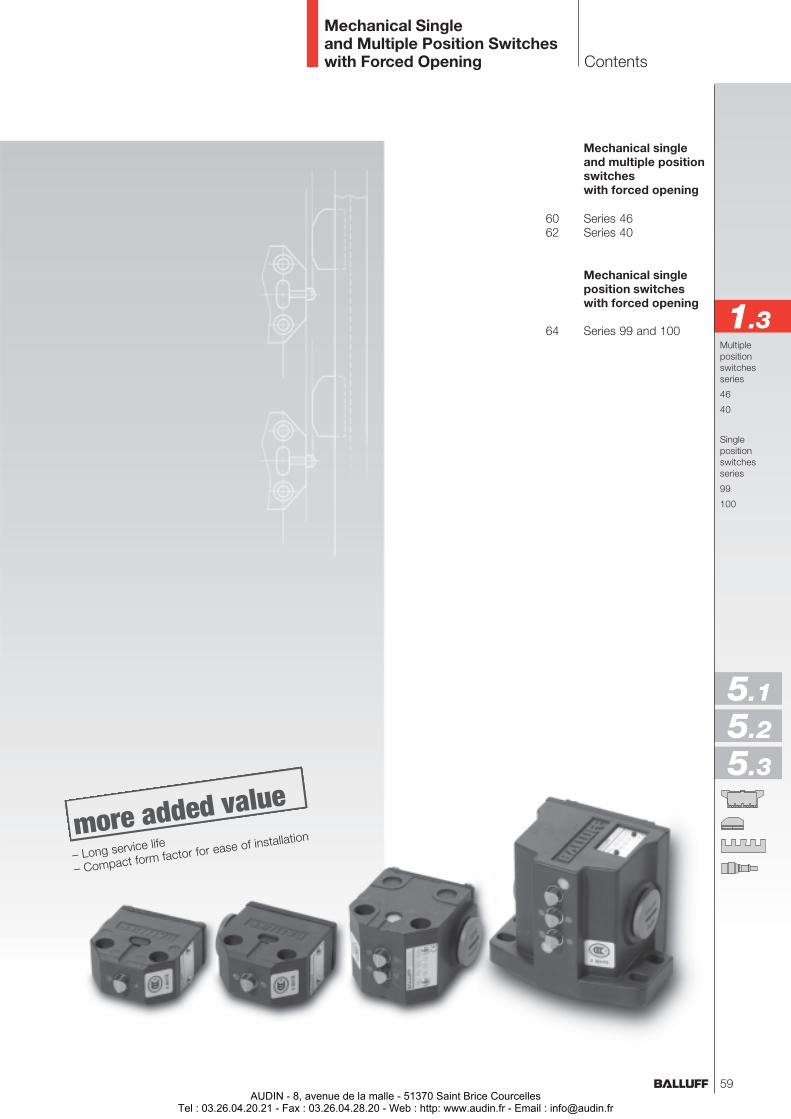
Mechanical singleand multiple positionswitcheswith forced opening
60 Series 4662 Series 40
Mechanical singleposition switcheswith forced opening
64 Series 99 and 100
Contents
Mechanical Singleand Multiple Position Switcheswith Forced Opening
Multiplepositionswitchesseries
46
40
Singlepositionswitchesseries
99
100
1.3
5.1
5.2
5.3
– Long service life
– Compact form factor for ease of installation
59AUDIN - 8, avenue de la malle - 51370 Saint Brice Courcelles
Tel : 03.26.04.20.21 - Fax : 03.26.04.28.20 - Web : http: www.audin.fr - Email : [email protected]
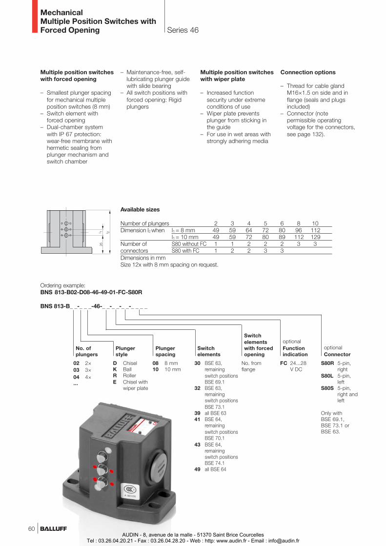
Series 46
MechanicalMultiple Position Switches withForced Opening
Multiple position switcheswith forced opening
– Smallest plunger spacingfor mechanical multipleposition switches (8 mm)
– Switch element withforced opening
– Dual-chamber systemwith IP 67 protection:wear-free membrane withhermetic sealing fromplunger mechanism andswitch chamber
Multiple position switcheswith wiper plate
– Increased functionsecurity under extremeconditions of use
– Wiper plate preventsplunger from sticking inthe guide
– For use in wet areas withstrongly adhering media
Connection options
– Thread for cable glandM16×1.5 on side and inflange (seals and plugsincluded)
– Connector (notepermissible operatingvoltage for the connectors,see page 132).
Plungerstyle
08 8 mm10 10 mm
Plungerspacing
02 2×03 3×04 4×...
D ChiselK BallR RollerE Chisel with
wiper plate
Ordering example:BNS 813-B02-D08-46-49-01-FC-S80R
BNS 813-B_ _-_ _ _-46-_ _-_ _-_ _-_ _ _ _
30 BSE 63,remainingswitch positionsBSE 69.1
32 BSE 63,remainingswitch positionsBSE 73.1
39 all BSE 6341 BSE 64,
remainingswitch positionsBSE 70.1
43 BSE 64,remainingswitch positionsBSE 74.1
49 all BSE 64
Switchelements
No. ofplungers
FC 24...28V DC
optionalFunctionindication
S80R 5-pin,right
S80L 5-pin,left
S80S 5-pin,right andleft
optionalConnector
No. fromflange
Switchelementswith forcedopening
Available sizes
Number of plungers 2 3 4 5 6 8 10Dimension l2 when l1 = 8 mm 49 59 64 72 80 96 112
l1 = 10 mm 49 59 72 80 89 112 129Number of S80 without FC 1 1 2 2 2 3 3connectors S80 with FC 1 2 2 3 3Dimensions in mmSize 12x with 8 mm spacing on request.
– Maintenance-free, self-lubricating plunger guidewith slide bearing
– All switch positions withforced opening: Rigidplungers
Only withBSE 69.1,BSE 73.1 orBSE 63.
60AUDIN - 8, avenue de la malle - 51370 Saint Brice Courcelles
Tel : 03.26.04.20.21 - Fax : 03.26.04.28.20 - Web : http: www.audin.fr - Email : [email protected]
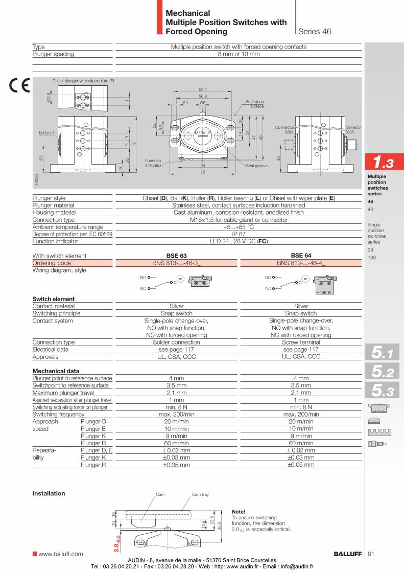
With switch elementOrdering codeWiring diagram, style
Switch elementContact materialSwitching principleContact system
Connection typeElectrical dataApprovals
Mechanical dataPlunger point to reference surfaceSwitchpoint to reference surfaceMaximum plunger travelAssured separation after plunger travelSwitching actuating force on plungerSwitching frequencyApproach Plunger Dspeed Plunger E
Plunger KPlunger R
Repeata- Plunger D, Ebility Plunger K
Plunger R
Series 46
MechanicalMultiple Position Switches withForced Opening
TypePlunger spacing
Plunger stylePlunger materialHousing materialConnection typeAmbient temperature rangeDegree of protection per IEC 60529Function indicator
Multiple position switch with forced opening contacts8 mm or 10 mm
Chisel (D), Ball (K), Roller (R), Roller bearing (L) or Chisel with wiper plate (E)Stainless steel, contact surfaces induction hardenedCast aluminum, corrosion-resistant, anodized finish
M16×1.5 for cable gland or connector–5...+85 °C
IP 67LED 24...28 V DC (FC)
www.balluff.com
Multiplepositionswitchesseries
46
40
Singlepositionswitchesseries
99
100
1.3
5.1
5.2
5.3
ConnectorS80R
ConnectorS80L
Functionindication
Chisel plunger with wiper plate (E)
Referencesurface
Note!To ensure switchingfunction, the dimension2.8-0.3 is especially critical.
Cam Cam trayInstallation
Seal groove
BSE 63BNS 813-...-46-3_
SilverSnap switch
Single-pole change-over,NO with snap function,NC with forced opening
Solder connectionsee page 117UL, CSA, CCC
4 mm3.5 mm2.1 mm1 mm
min. 8 Nmax. 200/min
20 m/min10 m/min9 m/min60 m/min
± 0.02 mm±0.03 mm±0.05 mm
BSE 64BNS 813-...-46-4_
SilverSnap switch
Single-pole change-over,NO with snap function,NC with forced opening
Screw terminalsee page 117UL, CSA, CCC
4 mm3.5 mm2.1 mm1 mm
min. 8 Nmax. 200/min
20 m/min10 m/min9 m/min
60 m/min± 0.02 mm±0.03 mm±0.05 mm
61AUDIN - 8, avenue de la malle - 51370 Saint Brice Courcelles
Tel : 03.26.04.20.21 - Fax : 03.26.04.28.20 - Web : http: www.audin.fr - Email : [email protected]
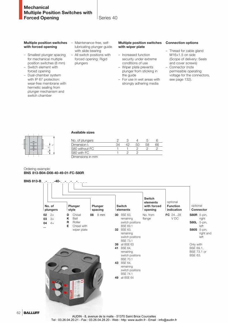
Series 40
MechanicalMultiple Position Switches withForced Opening
Multiple position switcheswith forced opening
– Smallest plunger spacingfor mechanical multipleposition switches (8 mm)
– Switch element withforced opening
– Dual-chamber systemwith IP 67 protection:wear-free membrane withhermetic sealing fromplunger mechanism andswitch chamber
Multiple position switcheswith wiper plate
– Increased functionsecurity under extremeconditions of use
– Wiper plate preventsplunger from sticking inthe guide
– For use in wet areas withstrongly adhering media
Plungerstyle
08 8 mm
Plungerspacing
02 2×03 3×04 4×...
D ChiselK BallR RollerE Chisel with
wiper plate
Ordering example:BNS 813-B04-D08-40-49-01-FC-S80R
BNS 813-B_ _-_ _ _-40-_ _-_ _-_ _-_ _ _ _
30 BSE 63,remainingswitch positionsBSE 69.1
32 BSE 63,remainingswitch positionsBSE 73.1
39 all BSE 6341 BSE 64,
remainingswitch positionsBSE 70.1
43 BSE 64,remainingswitch positionsBSE 74.1
49 all BSE 64
Switchelements
No. ofplungers
FC 24...28V DC
optionalFunctionindication
S80R 5-pin,right
S80L 5-pin,left
S80S 5-pin,right andleft
optionalConnector
No. fromflange
Switchelementswith forcedopening
Available sizes
No. of plungers 2 3 4 5 6Dimension l1 34 42 50 58 66S80 without FC 1 1 2 2 2S80 with FC 1 2 2Dimensions in mm
Connection options
– Thread for cable glandM16×1.5 on side(Scope of delivery: Sealsand cover screws)
– Connector (notepermissible operatingvoltage for the connectors,see page 132).
– Maintenance-free, self-lubricating plunger guidewith slide bearing
– All switch positions withforced opening: Rigidplungers
Only withBSE 69.1,BSE 73.1 orBSE 63.
62AUDIN - 8, avenue de la malle - 51370 Saint Brice Courcelles
Tel : 03.26.04.20.21 - Fax : 03.26.04.28.20 - Web : http: www.audin.fr - Email : [email protected]
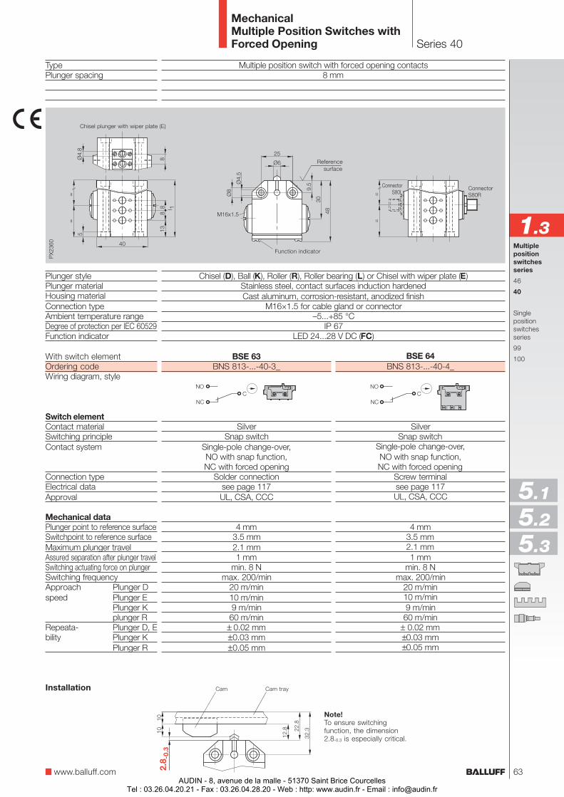
Series 40
MechanicalMultiple Position Switches withForced Opening
TypePlunger spacing
Plunger stylePlunger materialHousing materialConnection typeAmbient temperature rangeDegree of protection per IEC 60529Function indicator
Multiple position switch with forced opening contacts8 mm
Chisel (D), Ball (K), Roller (R), Roller bearing (L) or Chisel with wiper plate (E)Stainless steel, contact surfaces induction hardenedCast aluminum, corrosion-resistant, anodized finish
M16×1.5 for cable gland or connector–5...+85 °C
IP 67LED 24...28 V DC (FC)
Note!To ensure switchingfunction, the dimension2.8-0.3 is especially critical.
Cam Cam trayInstallation
www.balluff.com
Multiplepositionswitchesseries
46
40
Singlepositionswitchesseries
99
100
1.3
With switch elementOrdering codeWiring diagram, style
Switch elementContact materialSwitching principleContact system
Connection typeElectrical dataApproval
Mechanical dataPlunger point to reference surfaceSwitchpoint to reference surfaceMaximum plunger travelAssured separation after plunger travelSwitching actuating force on plungerSwitching frequencyApproach Plunger Dspeed Plunger E
Plunger Kplunger R
Repeata- Plunger D, Ebility Plunger K
Plunger R
Chisel plunger with wiper plate (E)
5.1
5.2
5.3
ConnectorS80R
ConnectorS80L
Referencesurface
Function indicator
BSE 63BNS 813-...-40-3_
SilverSnap switch
Single-pole change-over,NO with snap function,NC with forced opening
Solder connectionsee page 117UL, CSA, CCC
4 mm3.5 mm2.1 mm1 mm
min. 8 Nmax. 200/min
20 m/min10 m/min9 m/min60 m/min
± 0.02 mm±0.03 mm±0.05 mm
BSE 64BNS 813-...-40-4_
SilverSnap switch
Single-pole change-over,NO with snap function,NC with forced opening
Screw terminalsee page 117UL, CSA, CCC
4 mm3.5 mm2.1 mm1 mm
min. 8 Nmax. 200/min
20 m/min10 m/min9 m/min
60 m/min± 0.02 mm±0.03 mm±0.05 mm
63AUDIN - 8, avenue de la malle - 51370 Saint Brice Courcelles
Tel : 03.26.04.20.21 - Fax : 03.26.04.28.20 - Web : http: www.audin.fr - Email : [email protected]
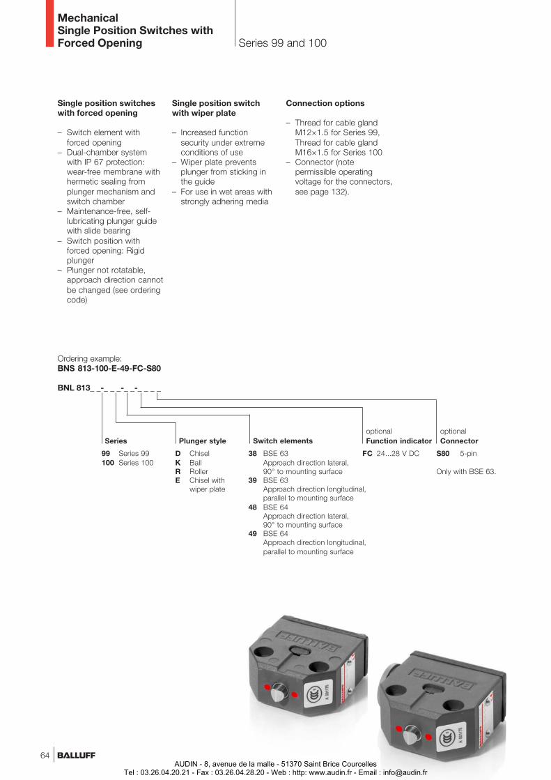
Series 99 and 100
MechanicalSingle Position Switches withForced Opening
Plunger style
38 BSE 63Approach direction lateral,90° to mounting surface
39 BSE 63Approach direction longitudinal,parallel to mounting surface
48 BSE 64Approach direction lateral,90° to mounting surface
49 BSE 64Approach direction longitudinal,parallel to mounting surface
Switch elements
99 Series 99100 Series 100
D ChiselK BallR RollerE Chisel with
wiper plate
Ordering example:BNS 813-100-E-49-FC-S80
BNL 813_ _-_ _ _-_ _-_ _ _ _
Series
FC 24...28 V DC
optionalFunction indicator
Single position switcheswith forced opening
– Switch element withforced opening
– Dual-chamber systemwith IP 67 protection:wear-free membrane withhermetic sealing fromplunger mechanism andswitch chamber
– Maintenance-free, self-lubricating plunger guidewith slide bearing
– Switch position withforced opening: Rigidplunger
– Plunger not rotatable,approach direction cannotbe changed (see orderingcode)
Single position switchwith wiper plate
– Increased functionsecurity under extremeconditions of use
– Wiper plate preventsplunger from sticking inthe guide
– For use in wet areas withstrongly adhering media
Connection options
– Thread for cable glandM12×1.5 for Series 99,Thread for cable glandM16×1.5 for Series 100
– Connector (notepermissible operatingvoltage for the connectors,see page 132).
S80 5-pin
optionalConnector
Only with BSE 63.
64AUDIN - 8, avenue de la malle - 51370 Saint Brice Courcelles
Tel : 03.26.04.20.21 - Fax : 03.26.04.28.20 - Web : http: www.audin.fr - Email : [email protected]

Series 99 and 100
MechanicalSingle Position Switches withForced Opening
www.balluff.com
Single position switch with forced opening contacts
Chisel (D), Ball (K), Roller (R), Roller bearing (L) or Chisel with wiper plate (E)Stainless steel, contact surfaces induction hardenedCast aluminum, corrosion-resistant, anodized finish
Cable gland (M12×1.5 series 99, M16×1.5 series 100) or connector–5...+85 °C
IP 67LED 24...28 V DC (FC)
Type
Plunger stylePlunger materialHousing materialConnection typeAmbient temperature rangeDegree of protection per IEC 60529Function indicator
Note!To ensure switchingfunction, the dimension2.8-0.3 is especially critical.
Cam Cam trayInstallation
Multiplepositionswitchesseries
46
40
Singlepositionswitchesseries
99
100
1.3
BSE 63BNS 813-99/100-_-3_-_ _-_ _ _
SilverSnap switch
Single-pole change-over,NO with snap function,NC with forced opening
Solder connectionsee page 117UL, CSA, CCC
4 mm3.5 mm2.1 mm1 mm
min. 8 Nmax. 200/min
20 m/min10 m/min9 m/min60 m/min
± 0.02 mm±0.03 mm±0.05 mm
With switch elementOrdering codeWiring diagram, style
Switch elementContact materialSwitching principleContact system
Connection typeElectrical dataApproval
Mechanical dataPlunger point to reference surfaceSwitchpoint to reference surfaceMaximum plunger travelAssured separation after plunger travelSwitching actuating force on plungerSwitching frequencyApproach Plunger Dspeed Plunger E
Plunger KPlunger R
Repeata- Plunger D, Ebility Plunger K
Plunger R
5.1
5.2
5.3
BSE 64BNS 813-99/100-_-4_-_ _-_ _ _
SilverSnap switch
Single-pole change-over,NO with snap function,NC with forced opening
Screw terminalsee page 117UL, CSA, CCC
4 mm3.5 mm2.1 mm1 mm
min. 8 Nmax. 200/min
20 m/min10 m/min9 m/min
60 m/min± 0.02 mm±0.03 mm±0.05 mm
ConnectorS80
Chisel plunger withwiper plate (E)
40 (series 99)
42 (series 100)
Sol
der
conn
ectio
n
Scr
ew te
rmin
al
20 (series 99)22 (series 100)
plugs forM12x1.5 (series 99)
M16x1.5 (series 100)
Referencesurface
Function indicator
65AUDIN - 8, avenue de la malle - 51370 Saint Brice Courcelles
Tel : 03.26.04.20.21 - Fax : 03.26.04.28.20 - Web : http: www.audin.fr - Email : [email protected]

Object Detection
66AUDIN - 8, avenue de la malle - 51370 Saint Brice Courcelles
Tel : 03.26.04.20.21 - Fax : 03.26.04.28.20 - Web : http: www.audin.fr - Email : [email protected]
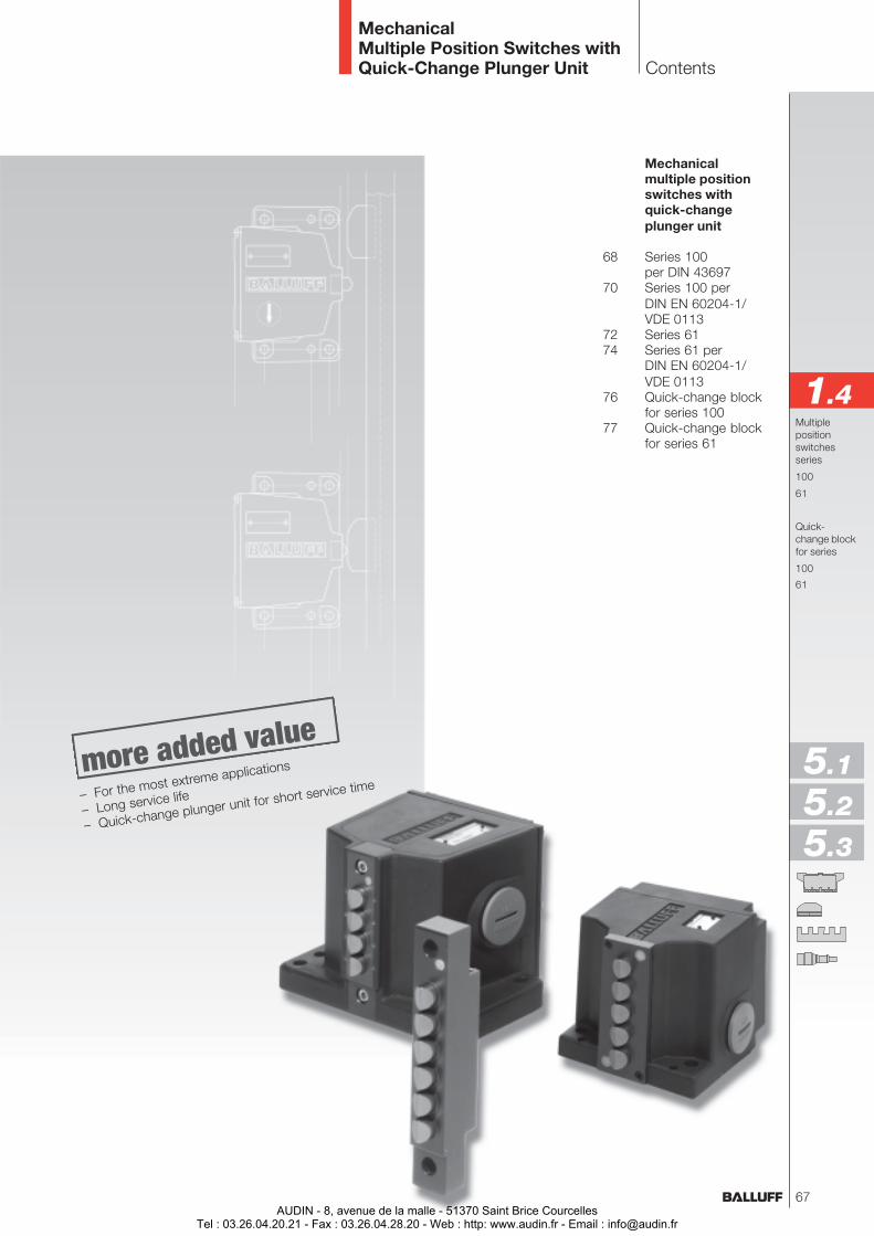
Mechanicalmultiple positionswitches withquick-changeplunger unit
68 Series 100per DIN 43697
70 Series 100 perDIN EN 60204-1/VDE 0113
72 Series 6174 Series 61 per
DIN EN 60204-1/VDE 0113
76 Quick-change blockfor series 100
77 Quick-change blockfor series 61
Contents
MechanicalMultiple Position Switches withQuick-Change Plunger Unit
Multiplepositionswitchesseries
100
61
Quick-change blockfor series
100
61
1.4
5.1
5.2
5.3
– For the most extreme applications
– Long service life
– Quick-change plunger unit for short service time
67AUDIN - 8, avenue de la malle - 51370 Saint Brice Courcelles
Tel : 03.26.04.20.21 - Fax : 03.26.04.28.20 - Web : http: www.audin.fr - Email : [email protected]
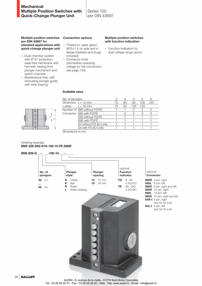
Multiple position switchesper DIN 43697 forstandard applications withquick-change plunger unit
– Dual-chamber systemwith IP 67 protection:wear-free membrane withhermetic sealing fromplunger mechanism andswitch chamber
– Maintenance-free, self-lubricating plunger guidewith slide bearing
Connection options
– Thread for cable glandM25×1.5 on side and inflange (Gaskets and plugsincluded)
– Connector (notepermissible operatingvoltage for the connectors,see page 132).
Plungerstyle
12 12 mm16 16 mm
Plungerspacing
02 2×...06 6×
D ChiselK BallR RollerL Roller bearing
Ordering example:BNS 829-D02-D16-100-10-FE-S80R
BNS 829-D_ _-_ _ _-100-10-_ _-_ _ _ _
FD 6...60V AC/DC
FE 90...250V AC/DC
optionalFunctionindicator
S80R 5-pin, rightS80L 5-pin, leftS80S 5-pin, right and leftS90R 12-pin, rightS90L 12-pin, leftS90S 12-pin, right and leftS4R-I 4-pin, right
only for IO-LinkS4L-I 4-pin, left
only for IO-Link
optionalConnector
No. ofplungers
Series 100per DIN 43697
MechanicalMultiple Position Switches withQuick-Change Plunger Unit
Available sizes
No. of plungers 2 3 4 5 6Dimension l1 = 12 mm 70 80 90 105 120l2 when l1 = 16 mm 70 90 105 120Number of S80 without FD/FE 1 1 2 2 2Connector S80 with FD/FE 1 2 2 3 3
S90 without FD/FE 1 1 1 1 1S90 with FD/FE 1 1 1 1 1S4 without FD (IO-Link) 1 1 1 1 1S4 with FD (IO-Link) 1 1 1 1 1
Dimensions in mm
Multiple position switcheswith function indication
– Function indication fordual voltage range option
68AUDIN - 8, avenue de la malle - 51370 Saint Brice Courcelles
Tel : 03.26.04.20.21 - Fax : 03.26.04.28.20 - Web : http: www.audin.fr - Email : [email protected]
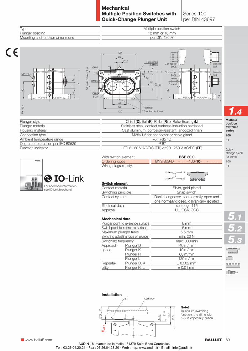
With switch elementOrdering codeWiring diagram, style
Switch elementContact materialSwitching principleContact system
Electrical dataApproval
Mechanical dataPlunger point to reference surfaceSwitchpoint to reference surfaceMaximum plunger travelSwitching actuating force on plungerSwitching frequencyApproach Plunger Dspeed Plunger K
Plunger RPlunger L
Repeata- Plunger D, Kbility Plunger R, L
TypePlunger spacingMounting and function dimensions
Plunger stylePlunger materialHousing materialConnection typeAmbient temperature rangeDegree of protection per IEC 60529Function indicator
Multiple position switch12 mm or 16 mm
per DIN 43697
Chisel (D), Ball (K), Roller (R) or Roller Bearing (L)Stainless steel, contact surfaces induction hardenedCast aluminum, corrosion-resistant, anodized finish
M25×1.5 for connector or cable gland–5...+85 °C
IP 67LED 6...60 V AC/DC (FD) or 90...250 V AC/DC (FE)
Note!To ensure switchingfunction, the dimension5-0.5 is especially critical.
Series 100per DIN 43697
MechanicalMultiple Position Switches withQuick-Change Plunger Unit
Cam Cam tray
www.balluff.com
Multiplepositionswitchesseries
100
61
Quick-change blockfor series
100
61
1.4gasket
Function indicator
50 (s
ide
cabl
e en
try)
5.1
5.2
5.3
Installation
Referencesurface
ConnectorS80R
ConnectorS90R
ConnectorS80L
ConnectorS90L
BSE 30.0BNS 829-D_ _-_ _ _-100-10-_ _-_ _ _ _
Silver, gold platedSnap switch
Dual changeover, one normally-open andone normally-closed, galvanically isolated
see page 116UL, CSA, CCC
8 mm6 mm
5.5 mmmin. 20 N
max. 300/min40 m/min10 m/min60 m/min
120 m/min± 0.002 mm± 0.01 mm
For additional informationsee IO-Link brochure!
69AUDIN - 8, avenue de la malle - 51370 Saint Brice Courcelles
Tel : 03.26.04.20.21 - Fax : 03.26.04.28.20 - Web : http: www.audin.fr - Email : [email protected]
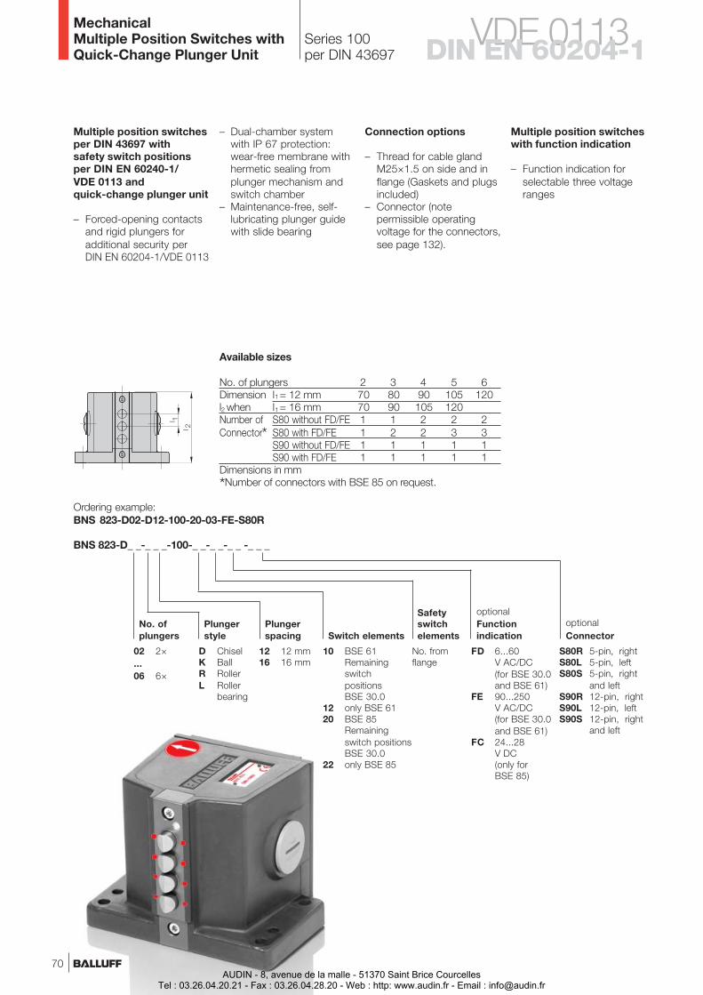
Connection options
– Thread for cable glandM25×1.5 on side and inflange (Gaskets and plugsincluded)
– Connector (notepermissible operatingvoltage for the connectors,see page 132).
Series 100per DIN 43697
Multiple position switchesper DIN 43697 withsafety switch positionsper DIN EN 60240-1/VDE 0113 andquick-change plunger unit
– Forced-opening contactsand rigid plungers foradditional security perDIN EN 60204-1/VDE 0113
– Dual-chamber systemwith IP 67 protection:wear-free membrane withhermetic sealing fromplunger mechanism andswitch chamber
– Maintenance-free, self-lubricating plunger guidewith slide bearing
BNS 823-D_ _-_ _ _-100-_ _-_ _-_ _ -_ _ _
Ordering example:BNS 823-D02-D12-100-20-03-FE-S80R
optionalConnector
No. ofplungers
Plungerstyle
Plungerspacing Switch elements
FD 6...60V AC/DC(for BSE 30.0and BSE 61)
FE 90...250V AC/DC(for BSE 30.0and BSE 61)
FC 24...28V DC(only forBSE 85)
optionalFunctionindication
Safetyswitchelements
10 BSE 61RemainingswitchpositionsBSE 30.0
12 only BSE 6120 BSE 85
Remainingswitch positionsBSE 30.0
22 only BSE 85
No. fromflange
12 12 mm16 16 mm
02 2×...06 6×
D ChiselK BallR RollerL Roller
bearing
S80R 5-pin, rightS80L 5-pin, leftS80S 5-pin, right
and leftS90R 12-pin, rightS90L 12-pin, leftS90S 12-pin, right
and left
Multiple position switcheswith function indication
– Function indication forselectable three voltageranges
Available sizes
No. of plungers 2 3 4 5 6Dimension l1 = 12 mm 70 80 90 105 120l2 when l1 = 16 mm 70 90 105 120Number of S80 without FD/FE 1 1 2 2 2Connector* S80 with FD/FE 1 2 2 3 3
S90 without FD/FE 1 1 1 1 1S90 with FD/FE 1 1 1 1 1
Dimensions in mm
*Number of connectors with BSE 85 on request.
MechanicalMultiple Position Switches withQuick-Change Plunger Unit
70
VDE 0113DIN EN 60204-1
AUDIN - 8, avenue de la malle - 51370 Saint Brice CourcellesTel : 03.26.04.20.21 - Fax : 03.26.04.28.20 - Web : http: www.audin.fr - Email : [email protected]
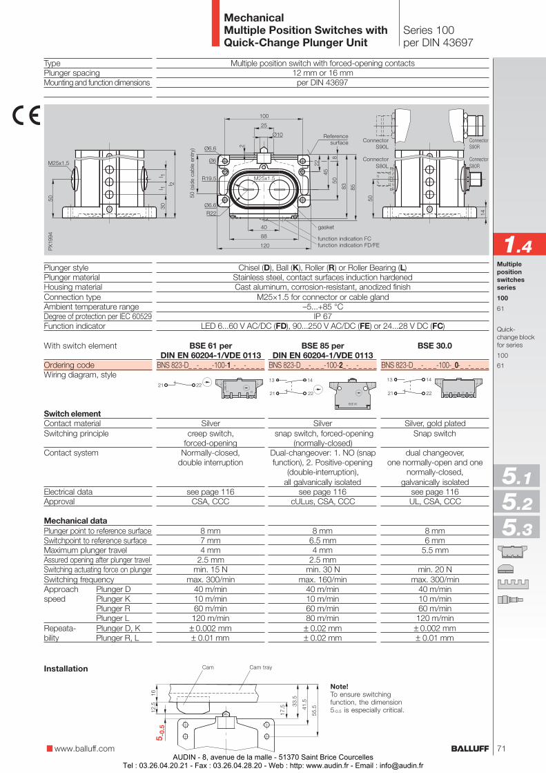
Multiple position switch with forced-opening contacts12 mm or 16 mmper DIN 43697
Chisel (D), Ball (K), Roller (R) or Roller Bearing (L)Stainless steel, contact surfaces induction hardenedCast aluminum, corrosion-resistant, anodized finish
M25×1.5 for connector or cable gland–5...+85 °C
IP 67LED 6...60 V AC/DC (FD), 90...250 V AC/DC (FE) or 24...28 V DC (FC)
Series 100per DIN 43697
TypePlunger spacingMounting and function dimensions
Plunger stylePlunger materialHousing materialConnection typeAmbient temperature rangeDegree of protection per IEC 60529Function indicator
With switch element
Ordering codeWiring diagram, style
Switch elementContact materialSwitching principle
Contact system
Electrical dataApproval
Mechanical dataPlunger point to reference surfaceSwitchpoint to reference surfaceMaximum plunger travelAssured opening after plunger travelSwitching actuating force on plungerSwitching frequencyApproach Plunger Dspeed Plunger K
Plunger RPlunger L
Repeata- Plunger D, Kbility Plunger R, L
Note!To ensure switchingfunction, the dimension5-0.5 is especially critical.
Cam Cam trayInstallation
BSE 30.0
BNS 823-D_ _-_ _ _-100-_0-_ _-_ _ _ _
Silver, gold platedSnap switch
dual changeover,one normally-open and one
normally-closed,galvanically isolated
see page 116UL, CSA, CCC
8 mm6 mm
5.5 mm
min. 20 Nmax. 300/min
40 m/min10 m/min60 m/min
120 m/min± 0.002 mm± 0.01 mm
BSE 61 perDIN EN 60204-1/VDE 0113
BNS 823-D_ _-_ _ _-100-1_-_ _-_ _ _ _
Silvercreep switch,
forced-openingNormally-closed,
double interruption
see page 116CSA, CCC
8 mm7 mm4 mm
2.5 mmmin. 15 N
max. 300/min40 m/min10 m/min60 m/min120 m/min
± 0.002 mm± 0.01 mm
BSE 85 perDIN EN 60204-1/VDE 0113
BNS 823-D_ _-_ _ _-100-2_-_ _-_ _ _ _
Silver snap switch, forced-opening
(normally-closed)Dual-changeover: 1. NO (snapfunction), 2. Positive-opening
(double-interruption),all galvanically isolated
see page 116cULus, CSA, CCC
8 mm6.5 mm4 mm
2.5 mmmin. 30 N
max. 160/min40 m/min10 m/min60 m/min80 m/min
± 0.02 mm± 0.02 mm
www.balluff.com
Multiplepositionswitchesseries
100
61
Quick-change blockfor series
100
61
1.4gasket
function indication FD/FEfunction indication FC
MechanicalMultiple Position Switches withQuick-Change Plunger Unit
5.1
5.2
5.3
ConnectorS80R
ConnectorS90R
ConnectorS80L
ConnectorS90L
Referencesurface
50 (s
ide
cabl
e en
try)
71AUDIN - 8, avenue de la malle - 51370 Saint Brice Courcelles
Tel : 03.26.04.20.21 - Fax : 03.26.04.28.20 - Web : http: www.audin.fr - Email : [email protected]
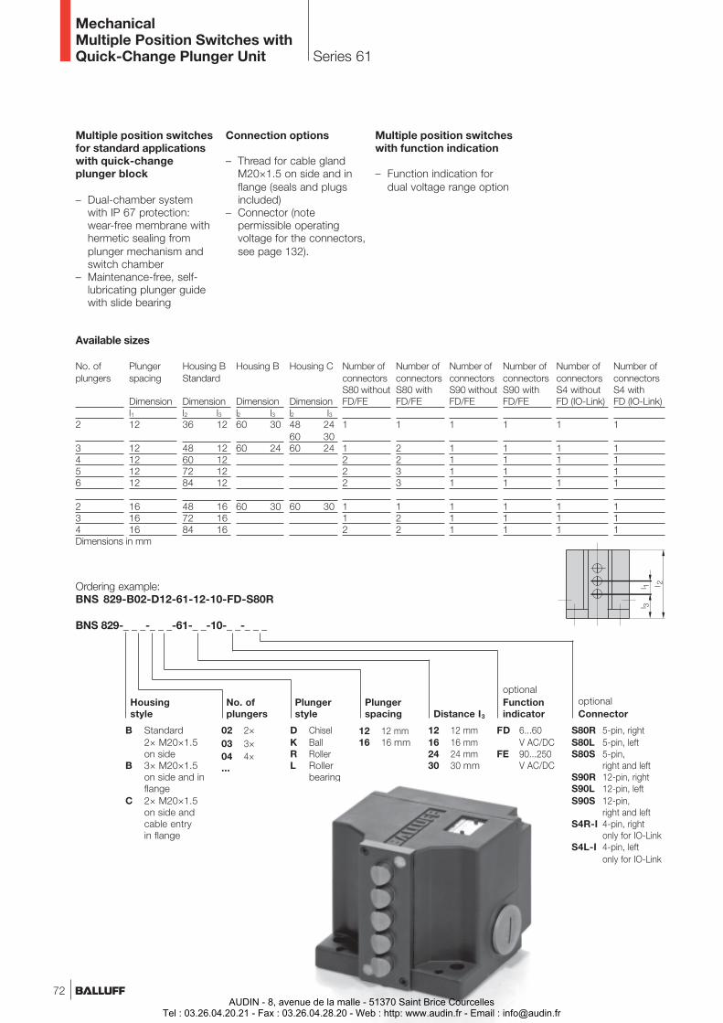
Plungerstyle
12 12 mm16 16 mm
Plungerspacing
B Standard2× M20×1.5on side
B 3× M20×1.5on side and inflange
C 2× M20×1.5on side andcable entryin flange
D ChiselK BallR RollerL Roller
bearing
Ordering example:BNS 829-B02-D12-61-12-10-FD-S80R
BNS 829-_ _ _-_ _ _-61-_ _-10-_ _-_ _ _
12 12 mm16 16 mm24 24 mm30 30 mm
Distance I3
FD 6...60V AC/DC
FE 90...250V AC/DC
optionalFunctionindicator
Housingstyle
Series 61
optionalConnector
02 2×03 3×04 4×...
No. ofplungers
Multiple position switchesfor standard applicationswith quick-changeplunger block
– Dual-chamber systemwith IP 67 protection:wear-free membrane withhermetic sealing fromplunger mechanism andswitch chamber
– Maintenance-free, self-lubricating plunger guidewith slide bearing
Connection options
– Thread for cable glandM20×1.5 on side and inflange (seals and plugsincluded)
– Connector (notepermissible operatingvoltage for the connectors,see page 132).
Multiple position switcheswith function indication
– Function indication fordual voltage range option
MechanicalMultiple Position Switches withQuick-Change Plunger Unit
S80R 5-pin, rightS80L 5-pin, leftS80S 5-pin,
right and leftS90R 12-pin, rightS90L 12-pin, leftS90S 12-pin,
right and leftS4R-I 4-pin, right
only for IO-LinkS4L-I 4-pin, left
only for IO-Link
Housing C
Dimensionl2 l348 2460 3060 24
60 30
Housing B
Dimensionl2 l360 30
60 24
60 30
Housing BStandard
Dimensionl2 l336 12
48 1260 1272 1284 12
48 1672 1684 16
Plungerspacing
Dimensionl112
12121212
161616
Number ofconnectorsS80 withFD/FE
1
2233
122
Number ofconnectorsS80 withoutFD/FE
1
1222
112
No. ofplungers
2
3456
234
Available sizes
Number ofconnectorsS90 withFD/FE
1
1111
111
Number ofconnectorsS90 withoutFD/FE
1
1111
111
Number ofconnectorsS4 withFD (IO-Link)
1
1111
111
Number ofconnectorsS4 withoutFD (IO-Link)
1
1111
111
Dimensions in mm
72AUDIN - 8, avenue de la malle - 51370 Saint Brice Courcelles
Tel : 03.26.04.20.21 - Fax : 03.26.04.28.20 - Web : http: www.audin.fr - Email : [email protected]
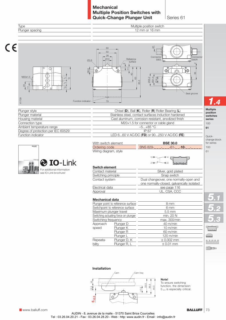
TypePlunger spacing
Plunger stylePlunger materialHousing materialConnection typeAmbient temperature rangeDegree of protection per IEC 60529Function indicator
Note!To ensure switchingfunction, the dimension5-0.5 is especially critical.
Series 61
Multiple position switch12 mm or 16 mm
Chisel (D), Ball (K), Roller (R) Roller Bearing (L)Stainless steel, contact surfaces induction hardenedCast aluminum, corrosion-resistant, anodized finish
M20×1.5 for connector or cable gland–5...+85 °C
IP 67LED 6...60 V AC/DC (FD) or 90...250 V AC/DC (FE)
BSE 30.0BNS 829-_ _ _-_ _ _-61-_ _-10-_ _-_ _ _ _
Silver, gold platedSnap switch
Dual changeover, one normally-open andone normally-closed, galvanically isolated
see page 116UL, CSA, CCC
8 mm6 mm
5.5 mmmin. 20 N
max. 300/min40 m/min10 m/min60 m/min
120 m/min± 0.002 mm± 0.01 mm
Cam Cam tray
www.balluff.com
Multiplepositionswitchesseries
100
61
Quick-change blockfor series
100
61
1.4
With switch elementOrdering codeWiring diagram, style
Switch elementContact materialSwitching principleContact system
Electrical dataApproval
Mechanical dataPlunger point to reference surfaceSwitchpoint to reference surfaceMaximum plunger travelSwitching actuating force on plungerSwitching frequencyApproach Plunger Dspeed Plunger K
Plunger RPlunger L
Repeata- Plunger D, Kbility Plunger R, L
MechanicalMultiple Position Switches withQuick-Change Plunger Unit
5.1
5.2
5.3
Seal groove
ConnectorS80R
ConnectorS80LReference
surface
Installation
For additional informationsee IO-Link brochure!
Function indicator
73AUDIN - 8, avenue de la malle - 51370 Saint Brice Courcelles
Tel : 03.26.04.20.21 - Fax : 03.26.04.28.20 - Web : http: www.audin.fr - Email : [email protected]
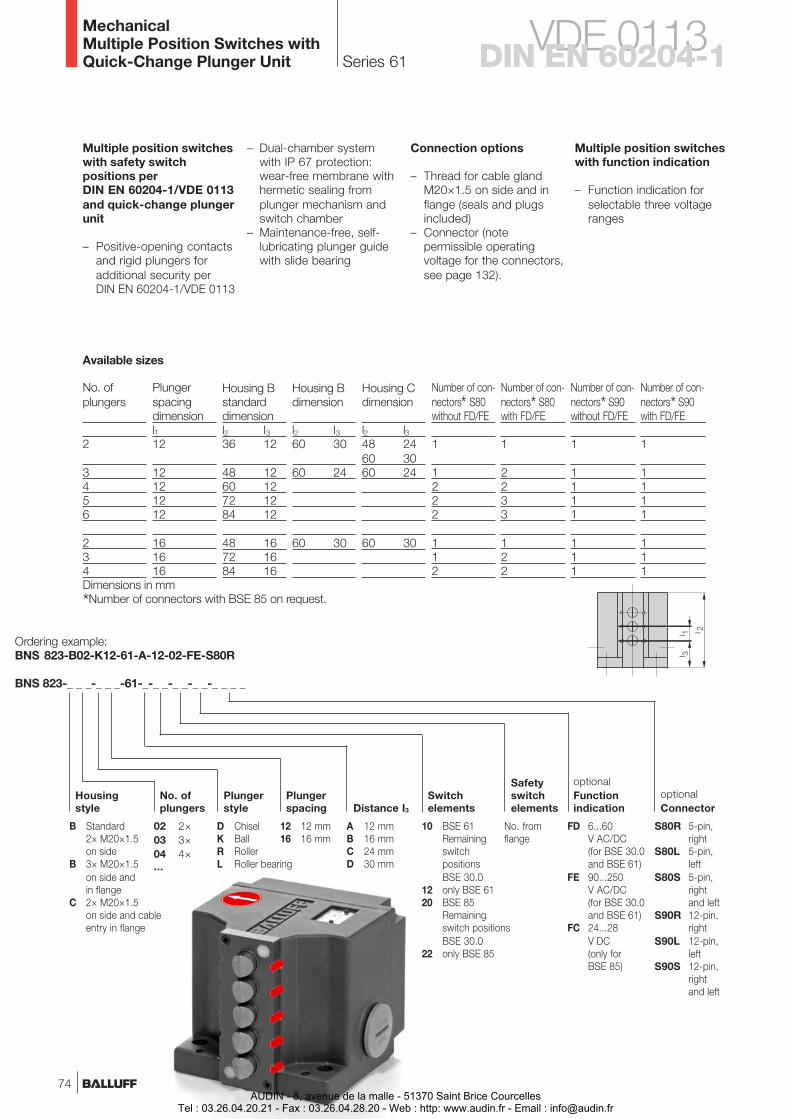
Series 61
BNS 823-_ _ _-_ _ _-61-_-_ _-_ _-_ _-_ _ _ _
FD 6...60V AC/DC(for BSE 30.0and BSE 61)
FE 90...250V AC/DC(for BSE 30.0and BSE 61)
FC 24...28V DC(only forBSE 85)
S80R 5-pin,right
S80L 5-pin,left
S80S 5-pin,rightand left
S90R 12-pin,right
S90L 12-pin,left
S90S 12-pin,rightand left
Ordering example:BNS 823-B02-K12-61-A-12-02-FE-S80R
optionalFunctionindication
Housingstyle
No. ofplungers
Plungerstyle
Plungerspacing
optionalConnectorDistance I3
02 2×03 3×04 4×...
No. fromflange
Safetyswitchelements
Switchelements
12 12 mm16 16 mm
D ChiselK BallR RollerL Roller bearing
A 12 mmB 16 mmC 24 mmD 30 mm
B Standard2× M20×1.5on side
B 3× M20×1.5on side andin flange
C 2× M20×1.5on side and cableentry in flange
Connection options
– Thread for cable glandM20×1.5 on side and inflange (seals and plugsincluded)
– Connector (notepermissible operatingvoltage for the connectors,see page 132).
Multiple position switcheswith safety switchpositions perDIN EN 60204-1/VDE 0113and quick-change plungerunit
– Positive-opening contactsand rigid plungers foradditional security perDIN EN 60204-1/VDE 0113
10 BSE 61RemainingswitchpositionsBSE 30.0
12 only BSE 6120 BSE 85
Remainingswitch positionsBSE 30.0
22 only BSE 85
Multiple position switcheswith function indication
– Function indication forselectable three voltageranges
– Dual-chamber systemwith IP 67 protection:wear-free membrane withhermetic sealing fromplunger mechanism andswitch chamber
– Maintenance-free, self-lubricating plunger guidewith slide bearing
Housing Cdimension
l2 l348 2460 3060 24
60 30
Housing Bdimension
l2 l360 30
60 24
60 30
Housing Bstandarddimensionl2 l336 12
48 1260 1272 1284 12
48 1672 1684 16
Plungerspacingdimensionl112
12121212
161616
Number of con-nectors* S80with FD/FE
1
2233
122
Number of con-nectors* S80without FD/FE
1
1222
112
No. ofplungers
2
3456
234
Available sizes
Number of con-nectors* S90with FD/FE
1
1111
111
Number of con-nectors* S90without FD/FE
1
1111
111
MechanicalMultiple Position Switches withQuick-Change Plunger Unit
Dimensions in mm
*Number of connectors with BSE 85 on request.
74
VDE 0113DIN EN 60204-1
AUDIN - 8, avenue de la malle - 51370 Saint Brice CourcellesTel : 03.26.04.20.21 - Fax : 03.26.04.28.20 - Web : http: www.audin.fr - Email : [email protected]
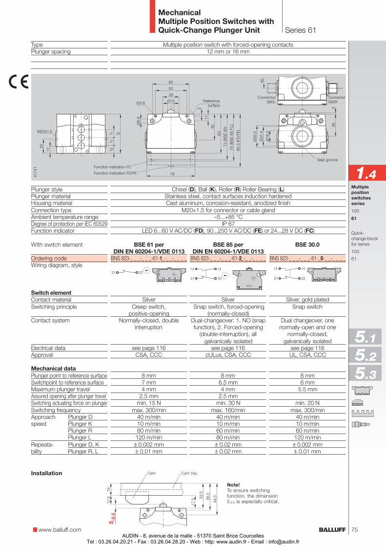
Series 61
Multiple position switch with forced-opening contacts12 mm or 16 mm
Chisel (D), Ball (K), Roller (R) Roller Bearing (L)Stainless steel, contact surfaces induction hardenedCast aluminum, corrosion-resistant, anodized finish
M20×1.5 for connector or cable gland–5...+85 °C
IP 67LED 6...60 V AC/DC (FD), 90...250 V AC/DC (FE) or 24...28 V DC (FC)
TypePlunger spacing
Plunger stylePlunger materialHousing materialConnection typeAmbient temperature rangeDegree of protection per IEC 60529Function indicator
With switch element
Ordering codeWiring diagram, style
Switch elementContact materialSwitching principle
Contact system
Electrical dataApproval
Mechanical dataPlunger point to reference surfaceSwitchpoint to reference surfaceMaximum plunger travelAssured opening after plunger travelSwitching actuating force on plungerSwitching frequencyApproach Plunger Dspeed Plunger K
Plunger RPlunger L
Repeata- Plunger D, Kbility Plunger R, L
Note!To ensure switchingfunction, the dimension5-0.5 is especially critical.
Cam Cam trayInstallation
BSE 30.0
BNS 823-_ _ _-_ _ _-61-_0-_ _-_ _ _ _
Silver, gold platedSnap switch
Dual changeover, onenormally-open and one
normally-closed,galvanically isolated
see page 116UL, CSA, CCC
8 mm6 mm
5.5 mm
min. 20 Nmax. 300/min
40 m/min10 m/min60 m/min
120 m/min± 0.002 mm± 0.01 mm
BSE 61 perDIN EN 60204-1/VDE 0113
BNS 823-_ _ _-_ _ _-61-1_-_ _-_ _ _ _
SilverCreep switch,
positive-openingNormally-closed, double
interruption
see page 116CSA, CCC
8 mm7 mm4 mm
2.5 mmmin. 15 N
max. 300/min40 m/min10 m/min60 m/min120 m/min
± 0.002 mm± 0.01 mm
BSE 85 perDIN EN 60204-1/VDE 0113
BNS 823-_ _ _-_ _ _-61-2_-_ _-_ _ _ _
Silver Snap switch, forced-opening
(normally-closed)Dual-changeover: 1. NO (snapfunction), 2. Forced-opening
(double-interruption), allgalvanically isolated
see page 116cULus, CSA, CCC
8 mm6.5 mm4 mm
2.5 mmmin. 30 N
max. 160/min40 m/min10 m/min60 m/min80 m/min
± 0.02 mm± 0.02 mm
www.balluff.com
Multiplepositionswitchesseries
100
61
Quick-change blockfor series
100
61
1.4
MechanicalMultiple Position Switches withQuick-Change Plunger Unit
5.1
5.2
5.3
Seal groove
ConnectorS80R
ConnectorS80LReference
surface
Function indication FC
Function indication FD/FE
75AUDIN - 8, avenue de la malle - 51370 Saint Brice Courcelles
Tel : 03.26.04.20.21 - Fax : 03.26.04.28.20 - Web : http: www.audin.fr - Email : [email protected]
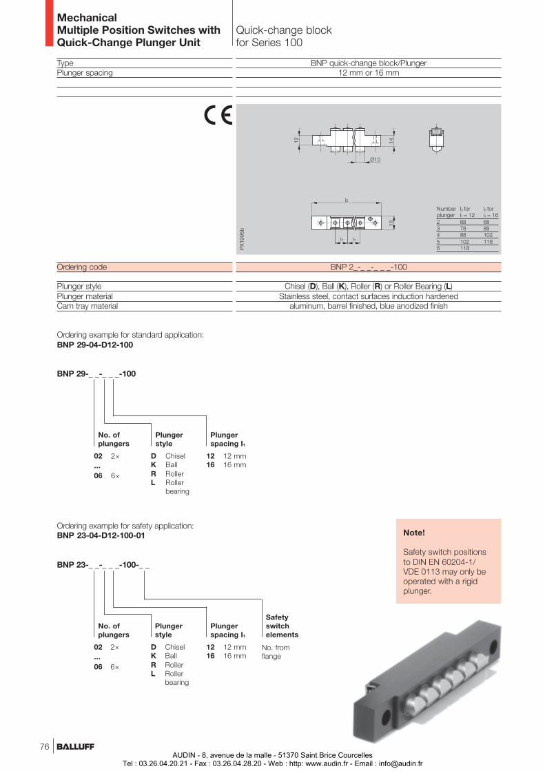
Quick-change blockfor Series 100
TypePlunger spacing
Ordering code
Plunger stylePlunger materialCam tray material
BNP quick-change block/Plunger12 mm or 16 mm
BNP 2_-_ _-_ _ _-100
Chisel (D), Ball (K), Roller (R) or Roller Bearing (L)Stainless steel, contact surfaces induction hardened
aluminum, barrel finished, blue anodized finish
Ordering example for standard application:BNP 29-04-D12-100
BNP 29-_ _-_ _ _-100
No. ofplungers
Plungerstyle
Plungerspacing I1
12 12 mm16 16 mm
02 2×...06 6×
D ChiselK BallR RollerL Roller
bearing
Note!
Safety switch positionsto DIN EN 60204-1/VDE 0113 may only beoperated with a rigidplunger.
Ordering example for safety application:BNP 23-04-D12-100-01
BNP 23-_ _-_ _ _-100-_ _
No. ofplungers
Plungerstyle
Plungerspacing I1
12 12 mm16 16 mm
02 2×...06 6×
D ChiselK BallR RollerL Roller
bearing
Safetyswitchelements
No. fromflange
MechanicalMultiple Position Switches withQuick-Change Plunger Unit
Number l2 for l2 forplunger l1 = 12 l1 = 162 68 683 78 884 88 1025 102 1186 118
76AUDIN - 8, avenue de la malle - 51370 Saint Brice Courcelles
Tel : 03.26.04.20.21 - Fax : 03.26.04.28.20 - Web : http: www.audin.fr - Email : [email protected]

Quick-change blockfor Series 61
TypePlunger spacing
Ordering code
Plunger stylePlunger materialCam tray material
BNP quick-change block/Plunger12 mm or 16 mm
BNP 2_-_ _-_ _ _-61-_ _
Chisel (D), Ball (K), Roller (R) or Roller Bearing (L)Stainless steel, contact surfaces induction hardened
Aluminum, barrel finished, blue anodized finish
BNP 29-_ _-_ _ _-61-_ _
No. ofplungers
Plungerstyle
Plungerspacing I1
12 12 mm16 16 mm
02 2×...06 6×
D ChiselK BallR RollerL Roller
bearing
Ordering example for standard application:BNP 29-04-D12-61-12
Ordering example for safety application:BNP 23-04-D12-61-A-01
12 12 mm16 16 mm24 24 mm30 30 mm
Distance I3
BNP 23-_ _-_ _ _-61-_-_ _
No. ofplungers
Plungerstyle
Plungerspacing I1
12 12 mm16 16 mm
02 2×...06 6×
D ChiselK BallR RollerL Roller
bearing
Distance I3
A 12 mmB 16 mmC 24 mmD 30 mm
Note!
Safety switch positionsto DIN EN 60204-1/VDE 0113 may only beoperated with a rigidplunger.
Safetyswitchelements
No. fromflange
www.balluff.com
Multiplepositionswitchesseries
100
61
Quick-change blockfor series
100
61
1.4
MechanicalMultiple Position Switches withQuick-Change Plunger Unit
Number Plungers Housing B Housing B Housing Cof spacing standard see p. 74plungers l1 l2 l3 l2 l3 l2 l32 12 35 12 59 30 47 243 12 47 12 59 244 12 59 125 12 71 126 12 83 12
2 16 47 16 59 303 16 71 164 16 83 16
5.1
5.2
5.3
77AUDIN - 8, avenue de la malle - 51370 Saint Brice Courcelles
Tel : 03.26.04.20.21 - Fax : 03.26.04.28.20 - Web : http: www.audin.fr - Email : [email protected]

Objekterkennung
AUDIN - 8, avenue de la malle - 51370 Saint Brice CourcellesTel : 03.26.04.20.21 - Fax : 03.26.04.28.20 - Web : http: www.audin.fr - Email : [email protected]
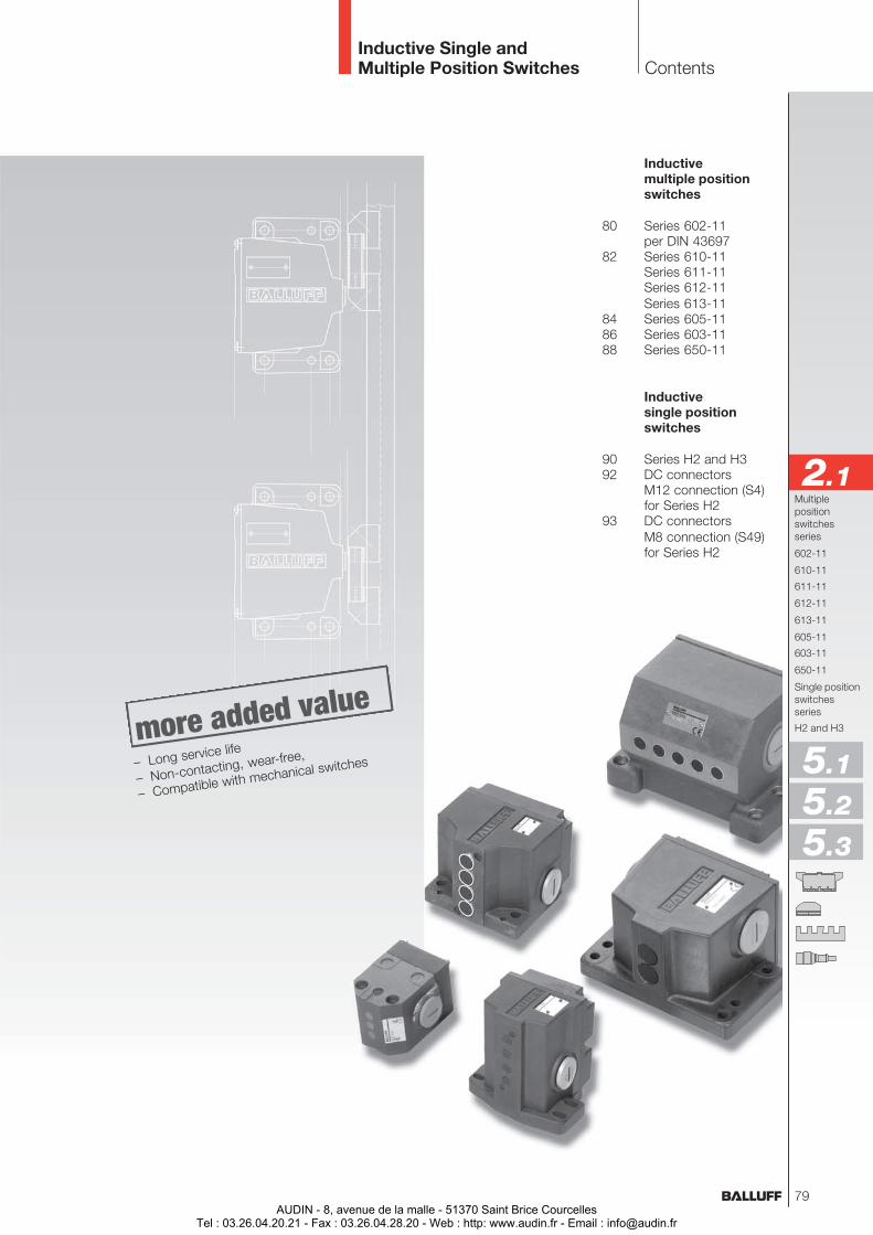
Inductivemultiple positionswitches
80 Series 602-11per DIN 43697
82 Series 610-11Series 611-11Series 612-11Series 613-11
84 Series 605-1186 Series 603-1188 Series 650-11
Inductivesingle positionswitches
90 Series H2 and H392 DC connectors
M12 connection (S4)for Series H2
93 DC connectorsM8 connection (S49)for Series H2
Multiplepositionswitchesseries
602-11
610-11
611-11
612-11
613-11
605-11
603-11
650-11
Single positionswitchesseries
H2 and H3
Contents
2.1
Inductive Single andMultiple Position Switches
5.1
5.2
5.3
– Long service life
– Non-contacting, wear-free,
– Compatible with mechanical switches
79AUDIN - 8, avenue de la malle - 51370 Saint Brice Courcelles
Tel : 03.26.04.20.21 - Fax : 03.26.04.28.20 - Web : http: www.audin.fr - Email : [email protected]
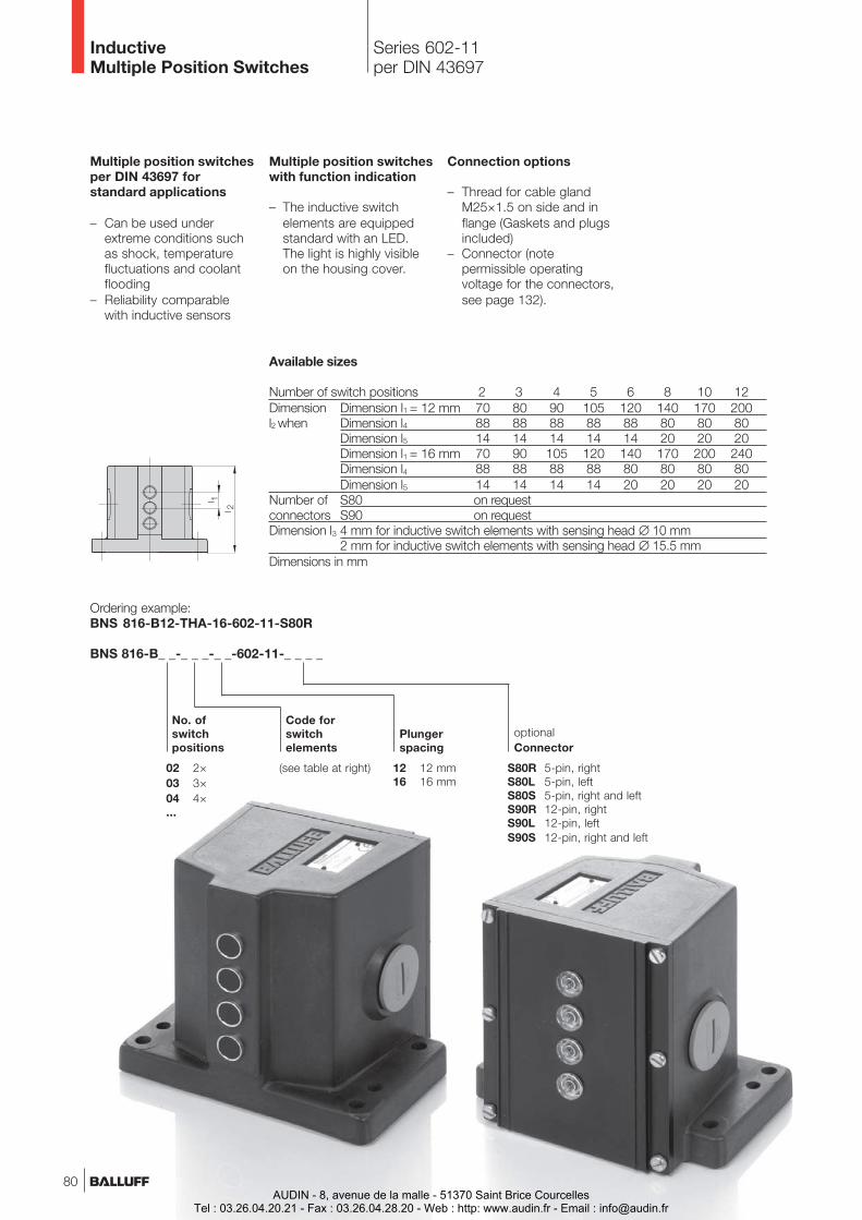
Series 602-11per DIN 43697
InductiveMultiple Position Switches
Code forswitchelements
12 12 mm16 16 mm
Plungerspacing
02 2×03 3×04 4×...
(see table at right)
Ordering example:BNS 816-B12-THA-16-602-11-S80R
BNS 816-B_ _-_ _ _-_ _-602-11-_ _ _ _
S80R 5-pin, rightS80L 5-pin, leftS80S 5-pin, right and leftS90R 12-pin, rightS90L 12-pin, leftS90S 12-pin, right and left
optionalConnector
No. ofswitchpositions
Multiple position switchesper DIN 43697 forstandard applications
– Can be used underextreme conditions suchas shock, temperaturefluctuations and coolantflooding
– Reliability comparablewith inductive sensors
Multiple position switcheswith function indication
– The inductive switchelements are equippedstandard with an LED.The light is highly visibleon the housing cover.
Connection options
– Thread for cable glandM25×1.5 on side and inflange (Gaskets and plugsincluded)
– Connector (notepermissible operatingvoltage for the connectors,see page 132).
Available sizes
Number of switch positions 2 3 4 5 6 8 10 12Dimension Dimension l1 = 12 mm 70 80 90 105 120 140 170 200l2 when Dimension l4 88 88 88 88 88 80 80 80
Dimension l5 14 14 14 14 14 20 20 20Dimension l1 = 16 mm 70 90 105 120 140 170 200 240Dimension l4 88 88 88 88 80 80 80 80Dimension l5 14 14 14 14 20 20 20 20
Number of S80 on requestconnectors S90 on requestDimension l3 4 mm for inductive switch elements with sensing head ∅ 10 mm
2 mm for inductive switch elements with sensing head ∅ 15.5 mmDimensions in mm
80AUDIN - 8, avenue de la malle - 51370 Saint Brice Courcelles
Tel : 03.26.04.20.21 - Fax : 03.26.04.28.20 - Web : http: www.audin.fr - Email : [email protected]
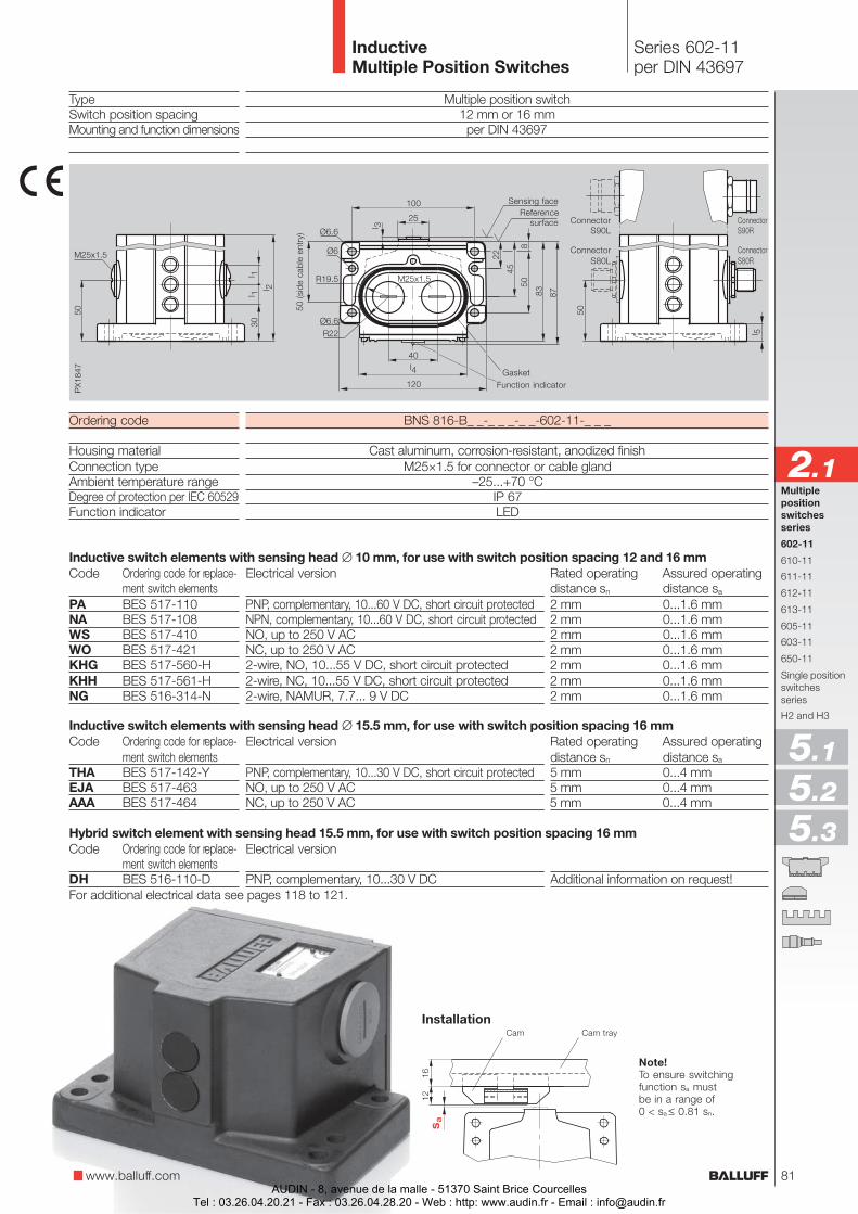
Multiple position switch12 mm or 16 mmper DIN 43697
BNS 816-B_ _-_ _ _-_ _-602-11-_ _ _
Cast aluminum, corrosion-resistant, anodized finishM25×1.5 for connector or cable gland
–25...+70 °CIP 67LED
Series 602-11per DIN 43697
InductiveMultiple Position Switches
TypeSwitch position spacingMounting and function dimensions
Ordering code
Housing materialConnection typeAmbient temperature rangeDegree of protection per IEC 60529Function indicator
Code Ordering code for replace-ment switch elements
PA BES 517-110NA BES 517-108WS BES 517-410WO BES 517-421KHG BES 517-560-HKHH BES 517-561-HNG BES 516-314-N
Code Ordering code for replace-ment switch elements
THA BES 517-142-YEJA BES 517-463AAA BES 517-464
Code Ordering code for replace-ment switch elements
DH BES 516-110-D
Note!To ensure switchingfunction sa mustbe in a range of0 < sa ≤ 0.81 sn.
Cam Cam trayInstallation
50 (s
ide
cabl
e en
try)
GasketFunction indicator
www.balluff.com
Multiplepositionswitchesseries
602-11
610-11
611-11
612-11
613-11
605-11
603-11
650-11
Single positionswitchesseries
H2 and H3
2.1
5.1
5.2
5.3
ConnectorS80R
ConnectorS90R
ConnectorS80L
ConnectorS90L
Sensing faceReference
surface
For additional electrical data see pages 118 to 121.
Electrical version Rated operating Assured operatingdistance sn distance sa
PNP, complementary, 10...60 V DC, short circuit protected 2 mm 0...1.6 mmNPN, complementary, 10...60 V DC, short circuit protected 2 mm 0...1.6 mmNO, up to 250 V AC 2 mm 0...1.6 mmNC, up to 250 V AC 2 mm 0...1.6 mm2-wire, NO, 10...55 V DC, short circuit protected 2 mm 0...1.6 mm2-wire, NC, 10...55 V DC, short circuit protected 2 mm 0...1.6 mm2-wire, NAMUR, 7.7... 9 V DC 2 mm 0...1.6 mm
Electrical version Rated operating Assured operatingdistance sn distance sa
PNP, complementary, 10...30 V DC, short circuit protected 5 mm 0...4 mmNO, up to 250 V AC 5 mm 0...4 mmNC, up to 250 V AC 5 mm 0...4 mm
Electrical version
PNP, complementary, 10...30 V DC Additional information on request!
Hybrid switch element with sensing head 15.5 mm, for use with switch position spacing 16 mm
81
Inductive switch elements with sensing head ∅ 10 mm, for use with switch position spacing 12 and 16 mm
Inductive switch elements with sensing head ∅ 15.5 mm, for use with switch position spacing 16 mm
AUDIN - 8, avenue de la malle - 51370 Saint Brice CourcellesTel : 03.26.04.20.21 - Fax : 03.26.04.28.20 - Web : http: www.audin.fr - Email : [email protected]
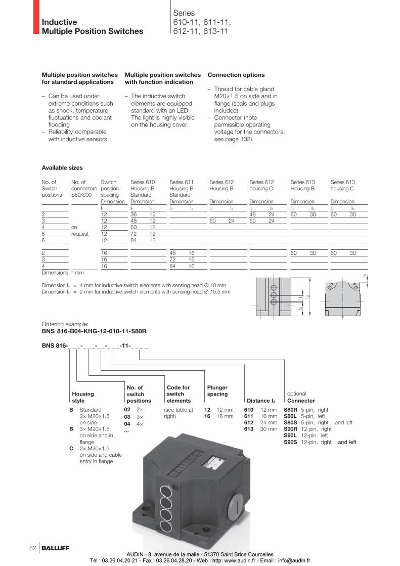
Series610-11, 611-11,612-11, 613-11
InductiveMultiple Position Switches
Multiple position switchesfor standard applications
– Can be used underextreme conditions suchas shock, temperaturefluctuations and coolantflooding
– Reliability comparablewith inductive sensors
Multiple position switcheswith function indication
– The inductive switchelements are equippedstandard with an LED.The light is highly visibleon the housing cover.
Connection options
– Thread for cable glandM20×1.5 on side and inflange (seals and plugsincluded)
– Connector (notepermissible operatingvoltage for the connectors,see page 132).
Code forswitchelements
12 12 mm16 16 mm
Plungerspacing
B Standard2× M20×1.5on side
B 3× M20×1.5on side and inflange
C 2× M20×1.5on side and cableentry in flange
Ordering example:BNS 816-B04-KHG-12-610-11-S80R
BNS 816-_ _ _-_ _ _-_ _-_ _ _-11-_ _ _ _
610 12 mm611 16 mm612 24 mm613 30 mm
Distance I3
S80R 5-pin, rightS80L 5-pin, leftS80S 5-pin, right and leftS90R 12-pin, rightS90L 12-pin, leftS90S 12-pin, right and left
optionalConnector
Housingstyle
02 2×03 3×04 4×...
No. ofswitchpositions
(see table atright)
Series 611Housing BStandardDimensionl2 l3
48 1672 1684 16
Series 610Housing BStandardDimensionl2 l336 1248 1260 1272 1284 12
SwitchpositionspacingDimensionl11212121212
161616
No. ofconnectorsS80/S90
onrequest
Series 612housing C
Dimensionl2 l348 2460 24
Series 612Housing B
Dimensionl2 l3
60 24
No. ofSwitchpositions
23456
234
Available sizes
Series 613housing C
Dimensionl2 l360 30
60 30
Series 613Housing B
Dimensionl2 l360 30
60 30
Dimensions in mm
Dimension l4 = 4 mm for inductive switch elements with sensing head ∅ 10 mmDimension l4 = 2 mm for inductive switch elements with sensing head ∅ 15.5 mm
82AUDIN - 8, avenue de la malle - 51370 Saint Brice Courcelles
Tel : 03.26.04.20.21 - Fax : 03.26.04.28.20 - Web : http: www.audin.fr - Email : [email protected]
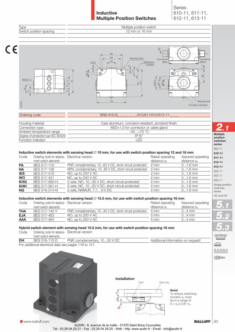
TypeSwitch position spacing
Ordering code
Housing materialConnection typeAmbient temperature rangeDegree of protection per IEC 60529Function indicator
Code Ordering code for replace-ment switch elements
PA BES 517-110NA BES 517-108WS BES 517-410WO BES 517-421KHG BES 517-560-HKHH BES 517-561-HNG BES 516-314-N
Code Ordering code for replace-ment switch elements
THA BES 517-142-YEJA BES 517-463AAA BES 517-464
Code Ordering code for replace-ment switch elements
DH BES 516-110-D
Multiple position switch12 mm or 16 mm
BNS 816-B_ _-_ _ _-_ _-610/611/612/613-11-_ _ _
Cast aluminum, corrosion-resistant, anodized finishM20×1.5 for connector or cable gland
–25...+70 °CIP 67LED
Series610-11, 611-11,612-11, 613-11
InductiveMultiple Position Switches
Electrical version Rated operating Assured operatingdistance sn distance sa
PNP, complementary, 10...60 V DC, short circuit protected 2 mm 0...1.6 mmNPN, complementary, 10...60 V DC, short circuit protected 2 mm 0...1.6 mmNO, up to 250 V AC 2 mm 0...1.6 mmNC, up to 250 V AC 2 mm 0...1.6 mm2-wire, NO, 10...55 V DC, short circuit protected 2 mm 0...1.6 mm2-wire, NC, 10...55 V DC, short circuit protected 2 mm 0...1.6 mm2-wire, NAMUR, 7.7... 9 V DC 2 mm 0...1.6 mm
Electrical version Rated operating Assured operatingdistance sn distance sa
PNP, complementary, 10...30 V DC, short circuit protected 5 mm 0...4 mmNO, up to 250 V AC 5 mm 0...4 mmNC, up to 250 V AC 5 mm 0...4 mm
Electrical version
PNP, complementary, 10...30 V DC Additional information on request!
Note!To ensure switchingfunction sa mustbe in a range of0 < sa ≤ 0.81 sn.
Cam Cam trayInstallation
Seal groove
Function indicator
www.balluff.com
ConnectorS80R
ConnectorS80L
Multiplepositionswitchesseries
602-11
610-11
611-11
612-11
613-11
605-11
603-11
650-11
Single positionswitchesseries
H2 and H3
2.1
5.1
5.2
5.3
Sensing face
Referencesurface
For additional electrical data see pages 118 to 121.
83
Inductive switch elements with sensing head ∅ 10 mm, for use with switch position spacing 12 and 16 mm
Inductive switch elements with sensing head ∅ 15.5 mm, for use with switch position spacing 16 mm
Hybrid switch element with sensing head 15.5 mm, for use with switch position spacing 16 mm
AUDIN - 8, avenue de la malle - 51370 Saint Brice CourcellesTel : 03.26.04.20.21 - Fax : 03.26.04.28.20 - Web : http: www.audin.fr - Email : [email protected]
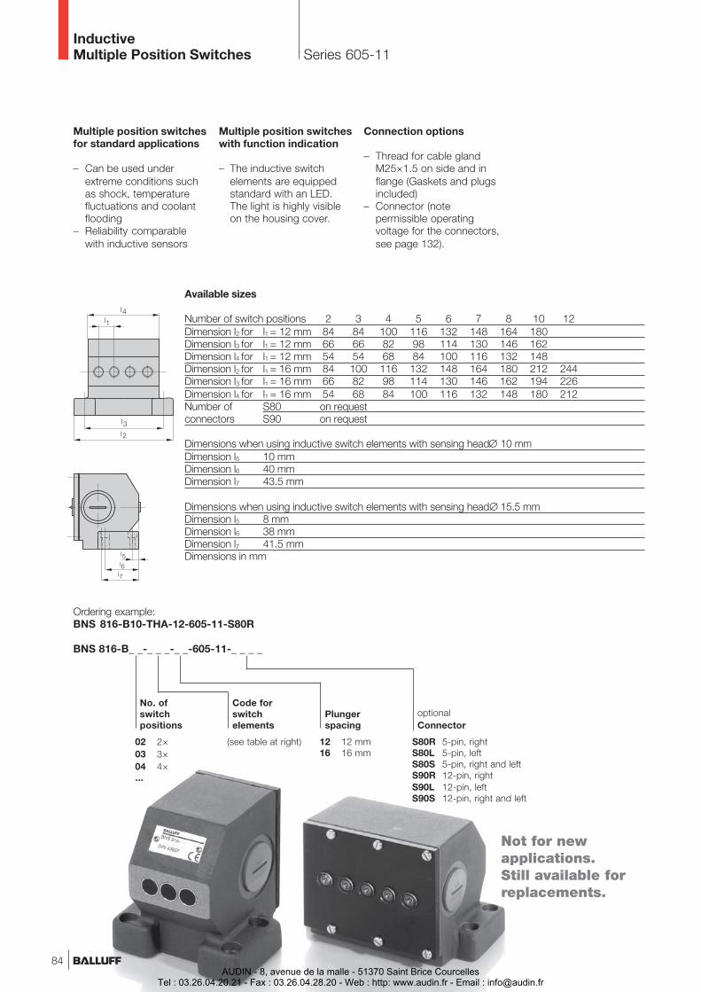
Series 605-11InductiveMultiple Position Switches
Multiple position switchesfor standard applications
– Can be used underextreme conditions suchas shock, temperaturefluctuations and coolantflooding
– Reliability comparablewith inductive sensors
Multiple position switcheswith function indication
– The inductive switchelements are equippedstandard with an LED.The light is highly visibleon the housing cover.
Connection options
– Thread for cable glandM25×1.5 on side and inflange (Gaskets and plugsincluded)
– Connector (notepermissible operatingvoltage for the connectors,see page 132).
Available sizes
Number of switch positions 2 3 4 5 6 7 8 10 12Dimension l2 for l1 = 12 mm 84 84 100 116 132 148 164 180Dimension l3 for l1 = 12 mm 66 66 82 98 114 130 146 162Dimension l4 for l1 = 12 mm 54 54 68 84 100 116 132 148Dimension l2 for l1 = 16 mm 84 100 116 132 148 164 180 212 244Dimension l3 for l1 = 16 mm 66 82 98 114 130 146 162 194 226Dimension l4 for l1 = 16 mm 54 68 84 100 116 132 148 180 212Number of S80 on requestconnectors S90 on request
Dimensions when using inductive switch elements with sensing head∅ 10 mmDimension l5 10 mmDimension l6 40 mmDimension l7 43.5 mm
Dimensions when using inductive switch elements with sensing head∅ 15.5 mmDimension l5 8 mmDimension l6 38 mmDimension l7 41.5 mmDimensions in mm
Ordering example:BNS 816-B10-THA-12-605-11-S80R
BNS 816-B_ _-_ _ _-_ _-605-11-_ _ _ _
Code forswitchelements
12 12 mm16 16 mm
Plungerspacing
02 2×03 3×04 4×...
(see table at right)
No. ofswitchpositions
S80R 5-pin, rightS80L 5-pin, leftS80S 5-pin, right and leftS90R 12-pin, rightS90L 12-pin, leftS90S 12-pin, right and left
optionalConnector
Not for newapplications.Still available forreplacements.
84AUDIN - 8, avenue de la malle - 51370 Saint Brice Courcelles
Tel : 03.26.04.20.21 - Fax : 03.26.04.28.20 - Web : http: www.audin.fr - Email : [email protected]
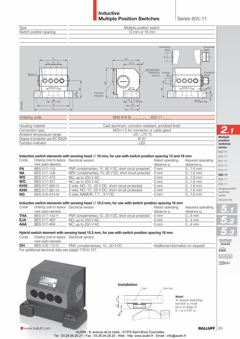
Series 605-11InductiveMultiple Position Switches
ConnectorS 80
Multiple position switch12 mm or 16 mm
BNS 816-B_ _-_ _ _-_ _-605-11-_ _ _
Cast aluminum, corrosion-resistant, anodized finishM25×1.5 for connector or cable gland
–25...+70 °CIP 67LED
Electrical version Rated operating Assured operatingdistance sn distance sa
PNP, complementary, 10...60 V DC, short circuit protected 2 mm 0...1.6 mmNPN, complementary, 10...60 V DC, short circuit protected 2 mm 0...1.6 mmNO, up to 250 V AC 2 mm 0...1.6 mmNC, up to 250 V AC 2 mm 0...1.6 mm2-wire, NO, 10...55 V DC, short circuit protected 2 mm 0...1.6 mm2-wire, NC, 10...55 V DC, short circuit protected 2 mm 0...1.6 mm2-wire, NAMUR, 7.7... 9 V DC 2 mm 0...1.6 mm
Electrical version Rated operating Assured operatingdistance sn distance sa
PNP, complementary, 10...30 V DC, short circuit protected 5 mm 0...4 mmNO, up to 250 V AC 5 mm 0...4 mmNC, up to 250 V AC 5 mm 0...4 mm
Electrical version
PNP, complementary, 10...30 V DC Additional information on request!
Functionindicator
Note!To ensure switchingfunction sa mustbe in a range of0 < sa ≤ 0.81 sn.
Cam Cam trayInstallation
www.balluff.com
Multiplepositionswitchesseries
602-11
610-11
611-11
612-11
613-11
605-11
603-11
650-11
Single positionswitchesseries
H2 and H3
2.1
5.1
5.2
5.3
TypeSwitch position spacing
Ordering code
Housing materialConnection typeAmbient temperature rangeDegree of protection per IEC 60529Function indicator
Code Ordering code for replace-ment switch elements
PA BES 517-110NA BES 517-108WS BES 517-410WO BES 517-421KHG BES 517-560-HKHH BES 517-561-HNG BES 516-314-N
Code Ordering code for replace-ment switch elements
THA BES 517-142-YEJA BES 517-463AAA BES 517-464
Code Ordering code for replace-ment switch elements
DH BES 516-110-D
Sensing faceReference
surfaceConnectorS80R
ConnectorS90R
ConnectorS80L
ConnectorS90L
85
For additional electrical data see pages 118 to 121.
Hybrid switch element with sensing head 15.5 mm, for use with switch position spacing 16 mm
Inductive switch elements with sensing head ∅ 10 mm, for use with switch position spacing 12 and 16 mm
Inductive switch elements with sensing head ∅ 15.5 mm, for use with switch position spacing 16 mm
AUDIN - 8, avenue de la malle - 51370 Saint Brice CourcellesTel : 03.26.04.20.21 - Fax : 03.26.04.28.20 - Web : http: www.audin.fr - Email : [email protected]
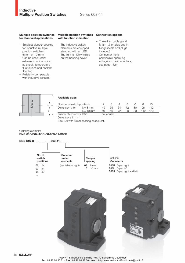
Code forswitchelements
08 8 mm10 10 mm
Plungerspacing
02 2×03 3×04 4×...
(see table at right)
Ordering example:BNS 816-B04-TOB-08-603-11-S80R
BNS 816-B_ _-_ _ _-_ _-603-11-_ _ _ _
S80R 5-pin, rightS80L 5-pin, leftS80S 5-pin, right and left
optionalConnector
No. ofswitchpositions
Series 603-11InductiveMultiple Position Switches
Multiple position switchesfor standard applications
– Smallest plunger spacingfor inductive multipleposition switches(8 mm or 10 mm)
– Can be used underextreme conditions suchas shock, temperaturefluctuations and coolantflooding
– Reliability comparablewith inductive sensors
Multiple position switcheswith function indication
– The inductive switchelements are equippedstandard with an LED.The light is highly visibleon the housing cover.
Connection options
– Thread for cable glandM16×1.5 on side and inflange (seals and plugsincluded)
– Connector (notepermissible operatingvoltage for the connectors,see page 132).
Available sizes
Number of switch positions 2 3 4 5 6 8 10Dimension l2 for l1 = 8 mm 49 59 64 72 80 96 112
l1 = 10 mm 49 59 72 80 89 112 129Number of connectors S80 on requestDimensions in mmSize 12x with 8 mm spacing on request.
86AUDIN - 8, avenue de la malle - 51370 Saint Brice Courcelles
Tel : 03.26.04.20.21 - Fax : 03.26.04.28.20 - Web : http: www.audin.fr - Email : [email protected]
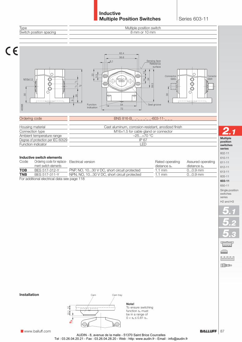
TypeSwitch position spacing
Ordering code
Housing materialConnection typeAmbient temperature rangeDegree of protection per IEC 60529Function indicator
Code Ordering code for replace-ment switch elements
TOB BES 517-312-YTNB BES 517-311-Y
Multiple position switch8 mm or 10 mm
BNS 816-B_ _-_ _ _-_ _-603-11-_ _ _
Cast aluminum, corrosion-resistant, anodized finishM16×1.5 for cable gland or connector
–25...+70 °CIP 67LED
Series 603-11InductiveMultiple Position Switches
Electrical version Rated operating Assured operatingdistance sn distance sa
PNP, NO, 10...30 V DC, short circuit protected 1.1 mm 0...0.9 mmNPN, NO, 10...30 V DC, short circuit protected 1.1 mm 0...0.9 mm
For additional electrical data see page 118
Inductive switch elements
Sensing faceReference
surface
Seal groove
www.balluff.com
Multiplepositionswitchesseries
602-11
610-11
611-11
612-11
613-11
605-11
603-11
650-11
Single positionswitchesseries
H2 and H3
2.1
5.1
5.2
5.3
ConnectorS80R
ConnectorS80L
Functionindication
Note!To ensure switchingfunction sa mustbe in a range of0 < sa ≤ 0.81 sn.
Installation Cam Cam tray
87AUDIN - 8, avenue de la malle - 51370 Saint Brice Courcelles
Tel : 03.26.04.20.21 - Fax : 03.26.04.28.20 - Web : http: www.audin.fr - Email : [email protected]
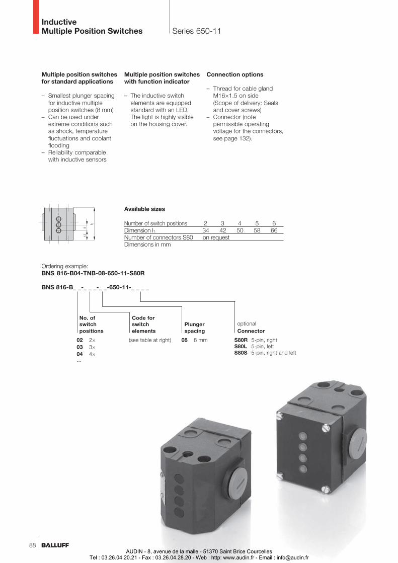
Series 650-11
Code forswitchelements
08 8 mm
Plungerspacing
02 2×03 3×04 4×...
(see table at right)
Ordering example:BNS 816-B04-TNB-08-650-11-S80R
BNS 816-B_ _-_ _ _-_ _-650-11-_ _ _ _
S80R 5-pin, rightS80L 5-pin, leftS80S 5-pin, right and left
optionalConnector
No. ofswitchpositions
InductiveMultiple Position Switches
Multiple position switchesfor standard applications
– Smallest plunger spacingfor inductive multipleposition switches (8 mm)
– Can be used underextreme conditions suchas shock, temperaturefluctuations and coolantflooding
– Reliability comparablewith inductive sensors
Multiple position switcheswith function indicator
– The inductive switchelements are equippedstandard with an LED.The light is highly visibleon the housing cover.
Connection options
– Thread for cable glandM16×1.5 on side(Scope of delivery: Sealsand cover screws)
– Connector (notepermissible operatingvoltage for the connectors,see page 132).
Available sizes
Number of switch positions 2 3 4 5 6Dimension l1 34 42 50 58 66Number of connectors S80 on requestDimensions in mm
88AUDIN - 8, avenue de la malle - 51370 Saint Brice Courcelles
Tel : 03.26.04.20.21 - Fax : 03.26.04.28.20 - Web : http: www.audin.fr - Email : [email protected]
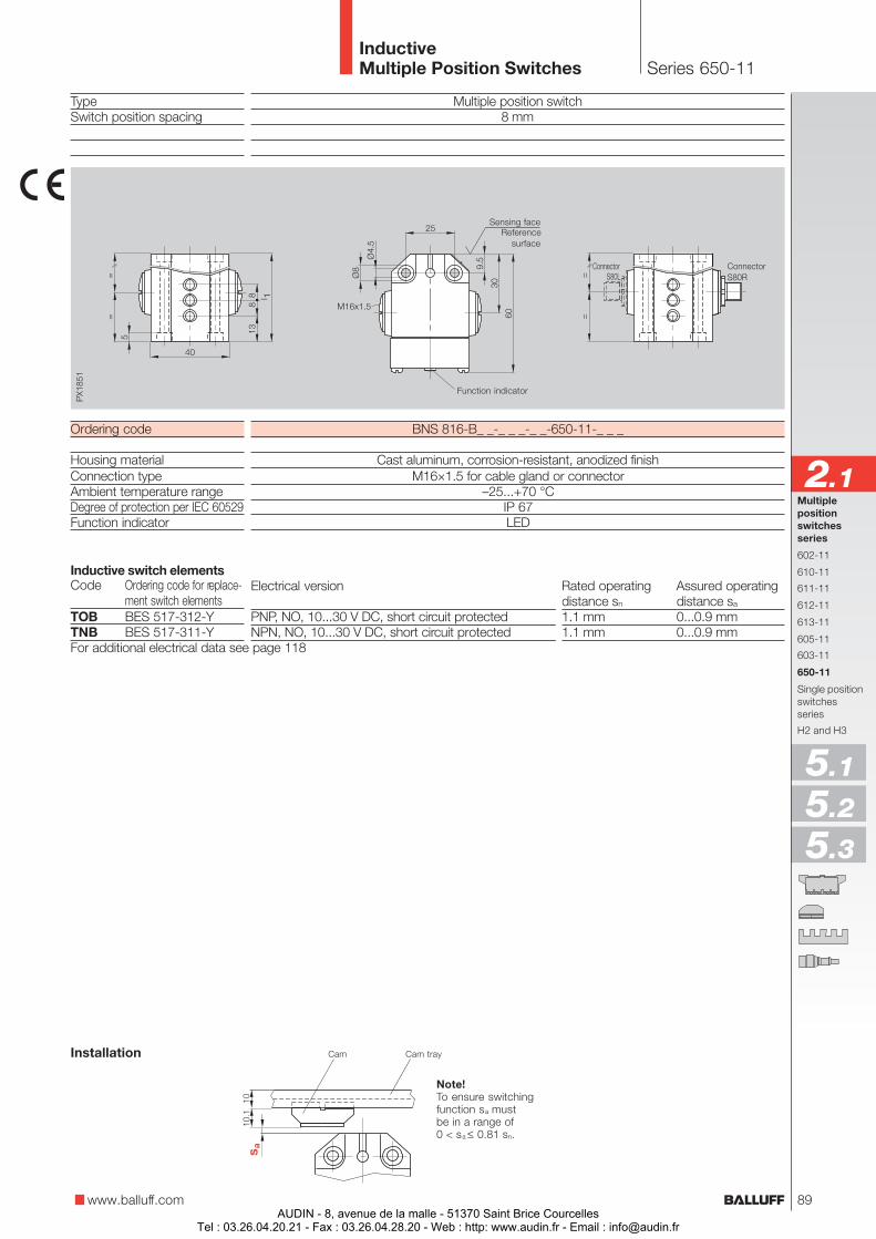
TypeSwitch position spacing
Ordering code
Housing materialConnection typeAmbient temperature rangeDegree of protection per IEC 60529Function indicator
Code Ordering code for replace-ment switch elements
TOB BES 517-312-YTNB BES 517-311-Y
Multiple position switch8 mm
BNS 816-B_ _-_ _ _-_ _-650-11-_ _ _
Cast aluminum, corrosion-resistant, anodized finishM16×1.5 for cable gland or connector
–25...+70 °CIP 67LED
Series 650-11InductiveMultiple Position Switches
Electrical version Rated operating Assured operatingdistance sn distance sa
PNP, NO, 10...30 V DC, short circuit protected 1.1 mm 0...0.9 mmNPN, NO, 10...30 V DC, short circuit protected 1.1 mm 0...0.9 mm
For additional electrical data see page 118
Inductive switch elements
Note!To ensure switchingfunction sa mustbe in a range of0 < sa ≤ 0.81 sn.
Cam Cam trayInstallation
Sensing faceReference
surface
Function indicator
www.balluff.com
Multiplepositionswitchesseries
602-11
610-11
611-11
612-11
613-11
605-11
603-11
650-11
Single positionswitchesseries
H2 and H3
2.1
5.1
5.2
5.3
ConnectorS80R
ConnectorS80L
89AUDIN - 8, avenue de la malle - 51370 Saint Brice Courcelles
Tel : 03.26.04.20.21 - Fax : 03.26.04.28.20 - Web : http: www.audin.fr - Email : [email protected]
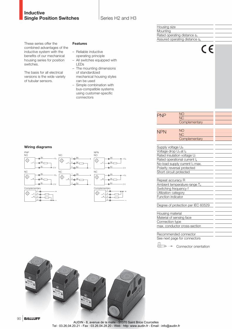
Housing sizeMountingRated operating distance sn
Assured operating distance sa
NONCComplementary
NONCComplementary
Supply voltage UB
Voltage drop Ud at IeRated insulation voltage Ui
Rated operational current IeNo-load supply current I0 max.Polarity reversal protectedShort circuit protected
Repeat accuracy RAmbient temperature range Ta
Switching frequency fUtilization categoryFunction indicator
Degree of protection per IEC 60529
Housing materialMaterial of sensing faceConnection typemax. conductor cross-section
Recommended connectorSee next page for connectors
NPN
PNP
Connector orientation
Series H2 and H3InductiveSingle Position Switches
Wiring diagramsPNP NPNNO NO NO
NC NC NC
Complementary Complementary
These series offer thecombined advantages of theinductive system with thebenefits of our mechanicalhousing series for positionswitches.
The basis for all electricalversions is the wide varietyof tubular sensors.
Features
– Reliable inductiveoperating principle
– All switches equipped withLEDs
– The mounting dimensionsof standardizedmechanical housing stylescan be used
– Simple combination withbus-compatible systemsusing customer-specificconnectors
90AUDIN - 8, avenue de la malle - 51370 Saint Brice Courcelles
Tel : 03.26.04.20.21 - Fax : 03.26.04.28.20 - Web : http: www.audin.fr - Email : [email protected]
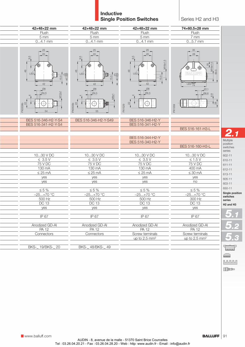
42×48×22 mmFlush5 mm
0...4.1 mm
BES 516-346-H2-YBES 516-341-H2-Y
BES 516-344-H2-YBES 516-340-H2-Y
10...30 V DC≤ 3.5 V75 V DC130 mA≤ 25 mA
yesyes
≤ 5 %–25...+70 °C
500 HzDC 13
yes
IP 67
Anodized GD-AlPA 12
Screw terminalsup to 2.5 mm²
42×48×22 mmFlush5 mm
0...4.1 mm
BES 516-346-H2-Y-S49
10...30 V DC≤ 3.5 V75 V DC130 mA≤ 25 mA
yesyes
≤ 5 %–25...+70 °C
500 HzDC 13
yes
IP 67
Anodized GD-AlPA 12
Connectors
BKS-_ 48/BKS-_ 49
42×48×22 mmFlush5 mm
0...4.1 mm
BES 516-346-H2-Y-S4BES 516-341-H2-Y-S4
10...30 V DC≤ 3.5 V75 V DC130 mA≤ 25 mA
yesyes
≤ 5 %–25...+70 °C
500 HzDC 13
yes
IP 67
Anodized GD-AlPA 12
Connectors
BKS-_ 19/BKS-_ 20
74×60.5×28 mmFlush7 mm
0...5.7 mm
BES 516-161-H3-L
BES 516-160-H3-L
10...30 V DC≤ 1.5 V75 V DC400 mA≤ 30 mA
yesno
≤ 5 %–25...+70 °C
300 HzDC 13
yes
IP 67
Anodized GD-AlPA 12
Screw terminalsup to 2.5 mm²
Series H2 and H3InductiveSingle Position Switches
www.balluff.com
Multiplepositionswitchesseries
602-11
610-11
611-11
612-11
613-11
605-11
603-11
650-11
Single positionswitchesseries
H2 and H3
2.1
5.1
5.2
5.3
91AUDIN - 8, avenue de la malle - 51370 Saint Brice Courcelles
Tel : 03.26.04.20.21 - Fax : 03.26.04.28.20 - Web : http: www.audin.fr - Email : [email protected]
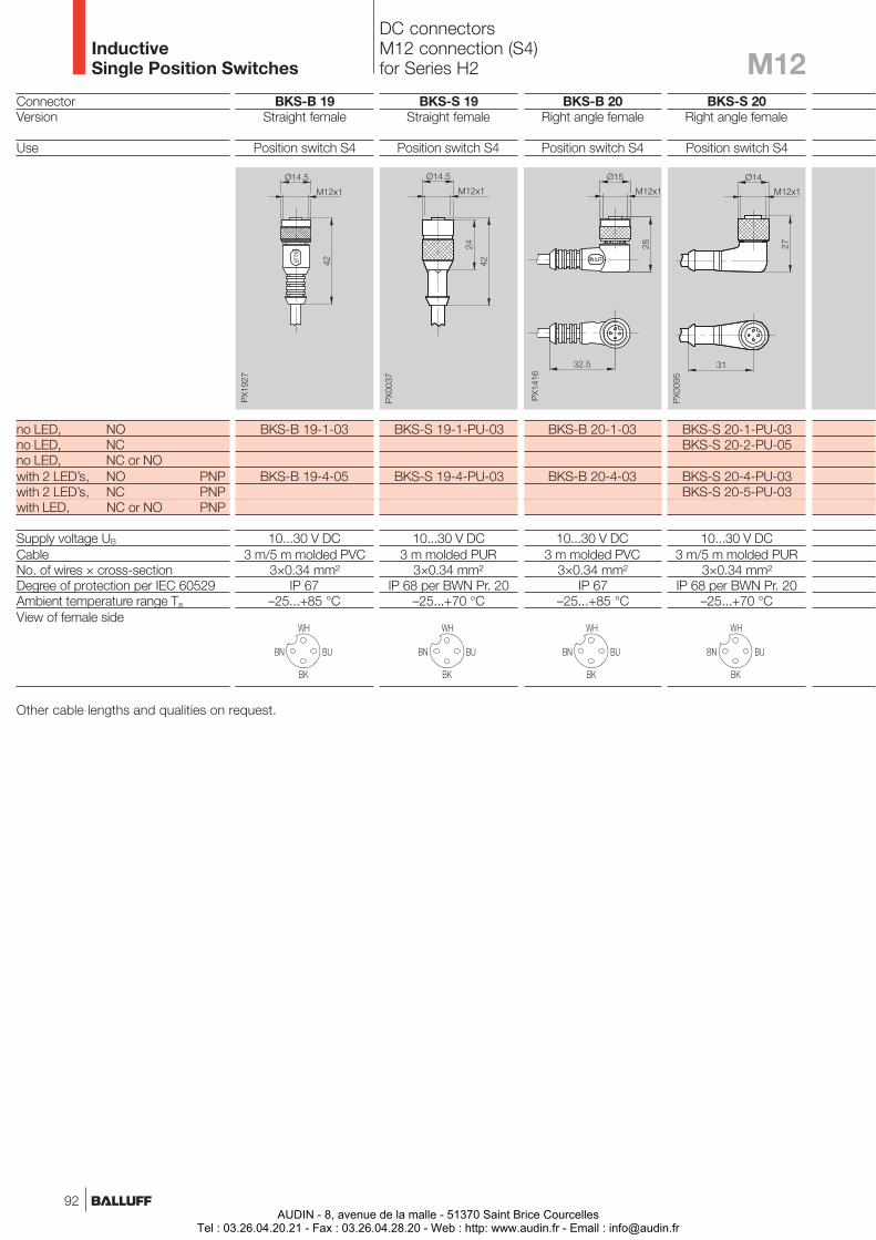
InductiveSingle Position Switches
DC connectorsM12 connection (S4)for Series H2
ConnectorVersion
Use
no LED, NOno LED, NCno LED, NC or NOwith 2 LED’s, NO PNPwith 2 LED’s, NC PNPwith LED, NC or NO PNP
Supply voltage UB
CableNo. of wires × cross-sectionDegree of protection per IEC 60529Ambient temperature range Ta
View of female side
BKS-B 19Straight female
Position switch S4
BKS-B 19-1-03
BKS-B 19-4-05
10...30 V DC3 m/5 m molded PVC
3×0.34 mm²IP 67
–25...+85 °C
BKS-S 19Straight female
Position switch S4
BKS-S 19-1-PU-03
BKS-S 19-4-PU-03
10...30 V DC3 m molded PUR
3×0.34 mm²IP 68 per BWN Pr. 20
–25...+70 °C
BKS-B 20Right angle female
Position switch S4
BKS-B 20-1-03
BKS-B 20-4-03
10...30 V DC3 m molded PVC
3×0.34 mm²IP 67
–25...+85 °C
BKS-S 20Right angle female
Position switch S4
BKS-S 20-1-PU-03BKS-S 20-2-PU-05
BKS-S 20-4-PU-03BKS-S 20-5-PU-03
10...30 V DC3 m/5 m molded PUR
3×0.34 mm²IP 68 per BWN Pr. 20
–25...+70 °C
Other cable lengths and qualities on request.
M12
92AUDIN - 8, avenue de la malle - 51370 Saint Brice Courcelles
Tel : 03.26.04.20.21 - Fax : 03.26.04.28.20 - Web : http: www.audin.fr - Email : [email protected]
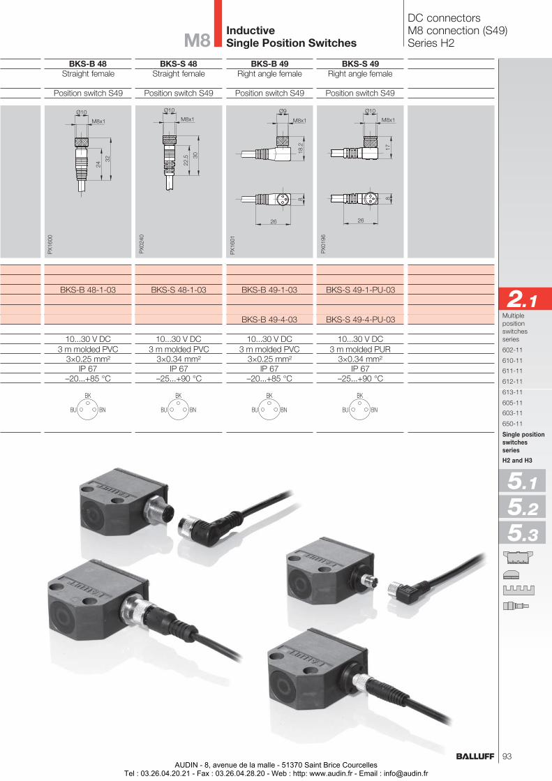
BKS-B 48Straight female
Position switch S49
BKS-B 48-1-03
10...30 V DC3 m molded PVC
3×0.25 mm²IP 67
–20...+85 °C
BKS-S 48Straight female
Position switch S49
BKS-S 48-1-03
10...30 V DC3 m molded PVC
3×0.34 mm²IP 67
–25...+90 °C
BKS-B 49Right angle female
Position switch S49
BKS-B 49-1-03
BKS-B 49-4-03
10...30 V DC3 m molded PVC
3×0.25 mm²IP 67
–20...+85 °C
BKS-S 49Right angle female
Position switch S49
BKS-S 49-1-PU-03
BKS-S 49-4-PU-03
10...30 V DC3 m molded PUR
3×0.34 mm²IP 67
–25...+90 °C
InductiveSingle Position Switches
Multiplepositionswitchesseries
602-11
610-11
611-11
612-11
613-11
605-11
603-11
650-11
Single positionswitchesseries
H2 and H3
2.1
5.1
5.2
5.3
DC connectorsM8 connection (S49)Series H2M8
93AUDIN - 8, avenue de la malle - 51370 Saint Brice Courcelles
Tel : 03.26.04.20.21 - Fax : 03.26.04.28.20 - Web : http: www.audin.fr - Email : [email protected]
Objekterkennung
AUDIN - 8, avenue de la malle - 51370 Saint Brice CourcellesTel : 03.26.04.20.21 - Fax : 03.26.04.28.20 - Web : http: www.audin.fr - Email : [email protected]
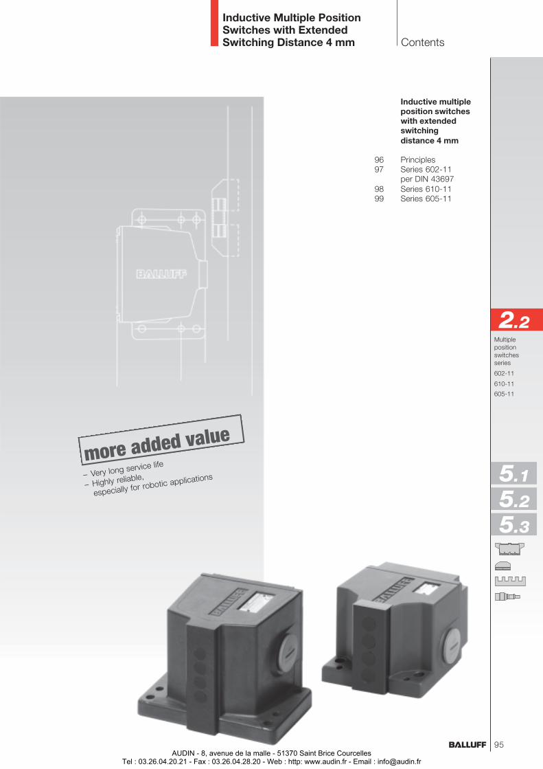
Inductive Multiple PositionSwitches with ExtendedSwitching Distance 4 mm
Inductive multipleposition switcheswith extendedswitchingdistance 4 mm
96 Principles97 Series 602-11
per DIN 4369798 Series 610-1199 Series 605-11
Multiplepositionswitchesseries
602-11
610-11
605-11
Contents
2.2
5.1
5.2
5.3
– Very long service life
– Highly reliable,
especially for robotic applications
95AUDIN - 8, avenue de la malle - 51370 Saint Brice Courcelles
Tel : 03.26.04.20.21 - Fax : 03.26.04.28.20 - Web : http: www.audin.fr - Email : [email protected]
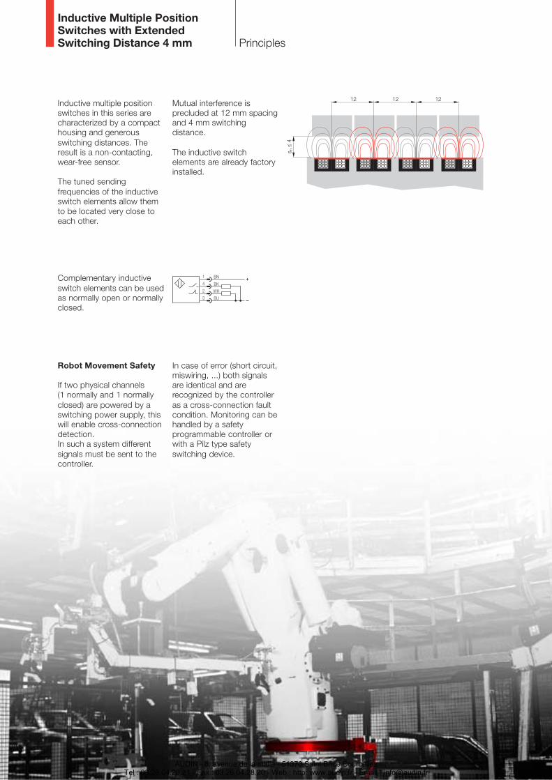
Principles
Inductive Multiple PositionSwitches with ExtendedSwitching Distance 4 mm
Inductive multiple positionswitches in this series arecharacterized by a compacthousing and generousswitching distances. Theresult is a non-contacting,wear-free sensor.
The tuned sendingfrequencies of the inductiveswitch elements allow themto be located very close toeach other.
Robot Movement Safety
If two physical channels(1 normally and 1 normallyclosed) are powered by aswitching power supply, thiswill enable cross-connectiondetection.In such a system differentsignals must be sent to thecontroller.
Complementary inductiveswitch elements can be usedas normally open or normallyclosed.
Mutual interference isprecluded at 12 mm spacingand 4 mm switchingdistance.
The inductive switchelements are already factoryinstalled.
In case of error (short circuit,miswiring, ...) both signalsare identical and arerecognized by the controlleras a cross-connection faultcondition. Monitoring can behandled by a safetyprogrammable controller orwith a Pilz type safetyswitching device.
AUDIN - 8, avenue de la malle - 51370 Saint Brice CourcellesTel : 03.26.04.20.21 - Fax : 03.26.04.28.20 - Web : http: www.audin.fr - Email : [email protected]
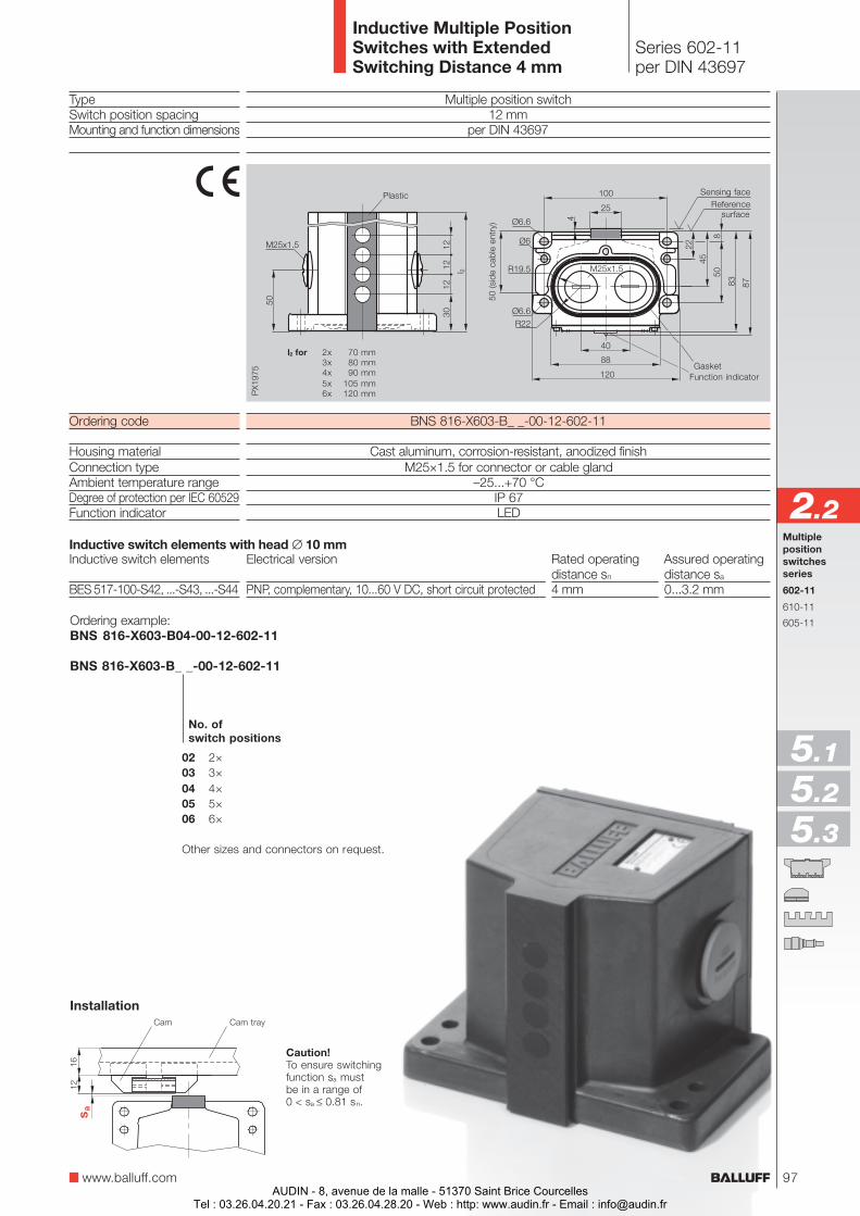
Series 602-11per DIN 43697
Inductive Multiple PositionSwitches with ExtendedSwitching Distance 4 mm
www.balluff.com
Multiple position switch12 mm
per DIN 43697
BNS 816-X603-B_ _-00-12-602-11
Cast aluminum, corrosion-resistant, anodized finishM25×1.5 for connector or cable gland
–25...+70 °CIP 67LED
TypeSwitch position spacingMounting and function dimensions
Ordering code
Housing materialConnection typeAmbient temperature rangeDegree of protection per IEC 60529Function indicator
Inductive switch elements
BES 517-100-S42, ...-S43, ...-S44
Caution!To ensure switchingfunction sa mustbe in a range of0 < sa ≤ 0.81 sn.
Cam Cam tray
Ordering example:BNS 816-X603-B04-00-12-602-11
BNS 816-X603-B_ _-00-12-602-11
Inductive switch elements with head ∅ 10 mm
02 2×03 3×04 4×05 5×06 6×
Other sizes and connectors on request.
No. ofswitch positions
Installation
l2 for
GasketFunction indicator
50 (s
ide
cabl
e en
try)
2x 70 mm3x 80 mm4x 90 mm5x 105 mm6x 120 mm
Plastic
Electrical version Rated operating Assured operatingdistance sn distance sa
PNP, complementary, 10...60 V DC, short circuit protected 4 mm 0...3.2 mm
Multiplepositionswitchesseries
602-11
610-11
605-11
2.2
5.1
5.2
5.3
Sensing faceReference
surface
97AUDIN - 8, avenue de la malle - 51370 Saint Brice Courcelles
Tel : 03.26.04.20.21 - Fax : 03.26.04.28.20 - Web : http: www.audin.fr - Email : [email protected]
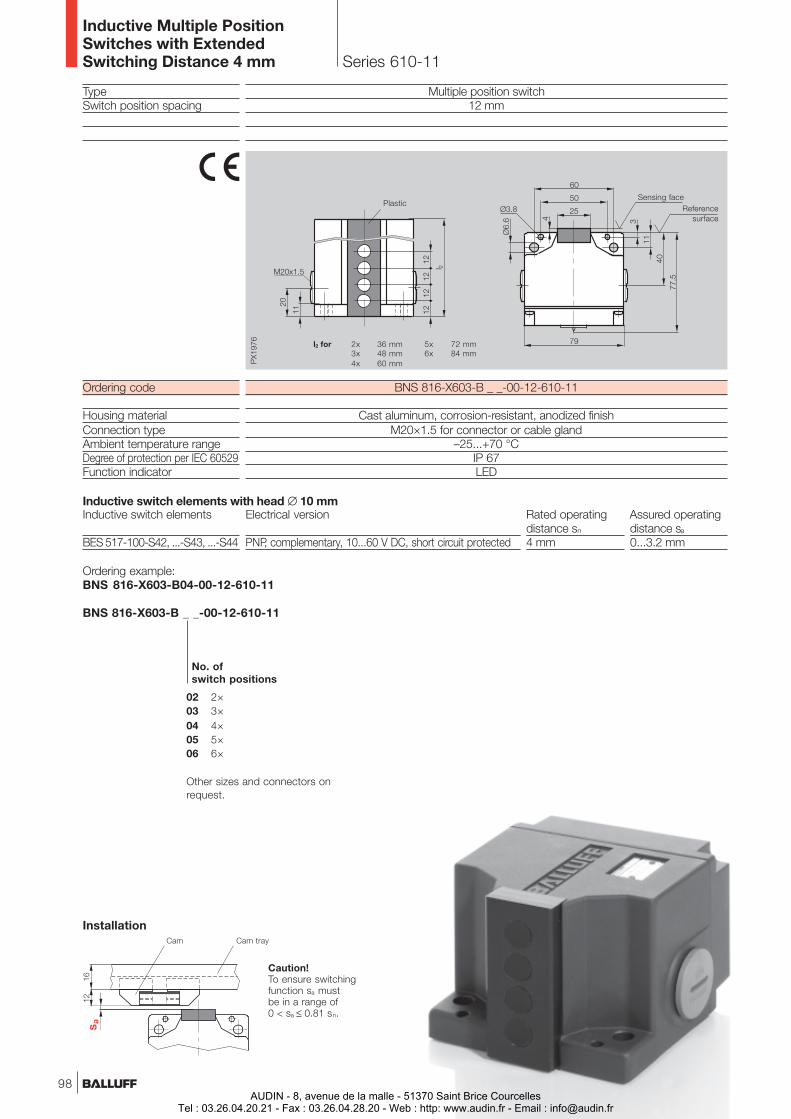
Ordering example:BNS 816-X603-B04-00-12-610-11
BNS 816-X603-B _ _-00-12-610-11
Multiple position switch12 mm
BNS 816-X603-B _ _-00-12-610-11
Cast aluminum, corrosion-resistant, anodized finishM20×1.5 for connector or cable gland
–25...+70 °CIP 67LED
TypeSwitch position spacing
Ordering code
Housing materialConnection typeAmbient temperature rangeDegree of protection per IEC 60529Function indicator
Inductive switch elements
BES 517-100-S42, ...-S43, ...-S44
Caution!To ensure switchingfunction sa mustbe in a range of0 < sa ≤ 0.81 sn.
Cam Cam tray
Installation
02 2×03 3×04 4×05 5×06 6×
Other sizes and connectors onrequest.
No. ofswitch positions
Referencesurface
Sensing face
Series 610-11
Inductive Multiple PositionSwitches with ExtendedSwitching Distance 4 mm
Plastic
Inductive switch elements with head ∅ 10 mmElectrical version Rated operating Assured operating
distance sn distance sa
PNP, complementary, 10...60 V DC, short circuit protected 4 mm 0...3.2 mm
l2 for 2x 36 mm3x 48 mm4x 60 mm
5x 72 mm6x 84 mm
98AUDIN - 8, avenue de la malle - 51370 Saint Brice Courcelles
Tel : 03.26.04.20.21 - Fax : 03.26.04.28.20 - Web : http: www.audin.fr - Email : [email protected]
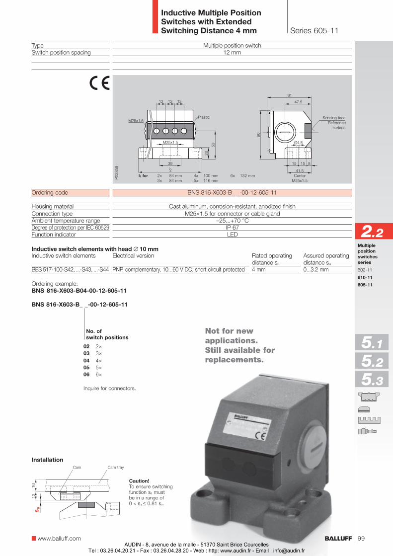
Multiple position switch12 mm
BNS 816-X603-B_ _-00-12-605-11
Cast aluminum, corrosion-resistant, anodized finishM25×1.5 for connector or cable gland
–25...+70 °CIP 67LED
TypeSwitch position spacing
Ordering code
Housing materialConnection typeAmbient temperature rangeDegree of protection per IEC 60529Function indicator
Inductive switch elements
BES 517-100-S42, ...-S43, ...-S44
Caution!To ensure switchingfunction sa mustbe in a range of0 < sa ≤ 0.81 sn.
Cam Cam tray
Installation
Ordering example:BNS 816-X603-B04-00-12-605-11
BNS 816-X603-B_ _-00-12-605-11
02 2×03 3×04 4×05 5×06 6×
Inquire for connectors.
No. ofswitch positions
Series 605-11
Inductive Multiple PositionSwitches with ExtendedSwitching Distance 4 mm
www.balluff.com
Plastic
Inductive switch elements with head ∅ 10 mmElectrical version Rated operating Assured operating
distance sn distance sa
PNP, complementary, 10...60 V DC, short circuit protected 4 mm 0...3.2 mm
l2 for 2x 84 mm3x 84 mm
4x 100 mm5x 116 mm
6x 132 mm
Multiplepositionswitchesseries
602-11
610-11
605-11
2.2
5.1
5.2
5.3
Sensing faceReference
surface
Not for newapplications.Still available forreplacements.
CenterM25x1.5
99AUDIN - 8, avenue de la malle - 51370 Saint Brice Courcelles
Tel : 03.26.04.20.21 - Fax : 03.26.04.28.20 - Web : http: www.audin.fr - Email : [email protected]

Objekterkennung
AUDIN - 8, avenue de la malle - 51370 Saint Brice CourcellesTel : 03.26.04.20.21 - Fax : 03.26.04.28.20 - Web : http: www.audin.fr - Email : [email protected]
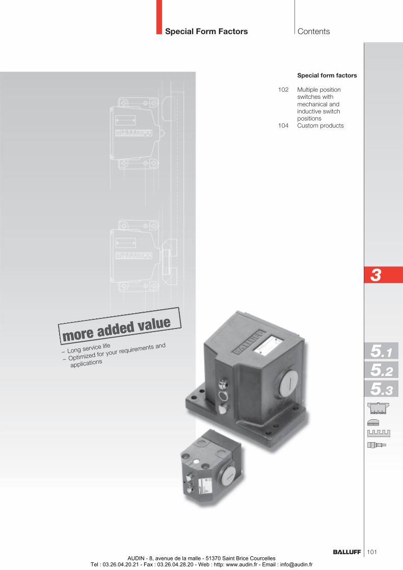
Special Form Factors Contents
Special form factors
102 Multiple positionswitches withmechanical andinductive switchpositions
104 Custom products
3
5.1
5.2
5.3
– Long service life
– Optimized for your requirements and
applications
101AUDIN - 8, avenue de la malle - 51370 Saint Brice Courcelles
Tel : 03.26.04.20.21 - Fax : 03.26.04.28.20 - Web : http: www.audin.fr - Email : [email protected]
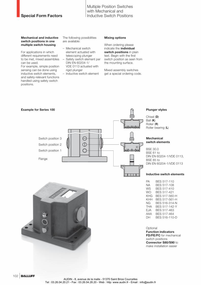
Mechanical and inductiveswitch positions in onemultiple switch housing
For applications in whichdifferent requirements needto be met, mixed assembliescan be used.For example, simple positionsensing can be done usinginductive switch elements,and safety-relevant functionshandled using safety switchpositions.
Example for Series 100 Plunger styles
Chisel (D)Ball (K)Roller (R)Roller bearing (L)
Mechanicalswitch elements
BSE 30.0BSE 61 toDIN EN 60204-1/VDE 0113,BSE 85 toDIN EN 60204-1/VDE 0113
Inductive switch elements
PA BES 517-110NA BES 517-108WS BES 517-410WO BES 517-421KHG BES 517-560-HKHH BES 517-561-HNG BES 516-314-NTHA BES 517-142-YEJA BES 517-463AAA BES 517-464DH BES 516-110-D
OptionalFunction indicatorsFD/FE/FC for mechanicalswitch positionsConnector S80/S90 tomake installation easier
Multiple Position Switcheswith Mechanical andInductive Switch PositionsSpecial Form Factors
The following possibilitiesare available:
– Mechanical switchelement actuated withtelescoping plunger
– Safety switch element perDIN EN 60204-1/VDE 0113 actuated withrigid plunger
– Inductive switch element
Switch position 3
Switch position 2
Switch position 1
Flange
Mixing options
When ordering pleaseindicate the individualswitch positions in plaintext. Begin with the firstswitch position as seen fromthe mounting surface.
Mixed assembly switchesget a special ordering code.
102AUDIN - 8, avenue de la malle - 51370 Saint Brice Courcelles
Tel : 03.26.04.20.21 - Fax : 03.26.04.28.20 - Web : http: www.audin.fr - Email : [email protected]
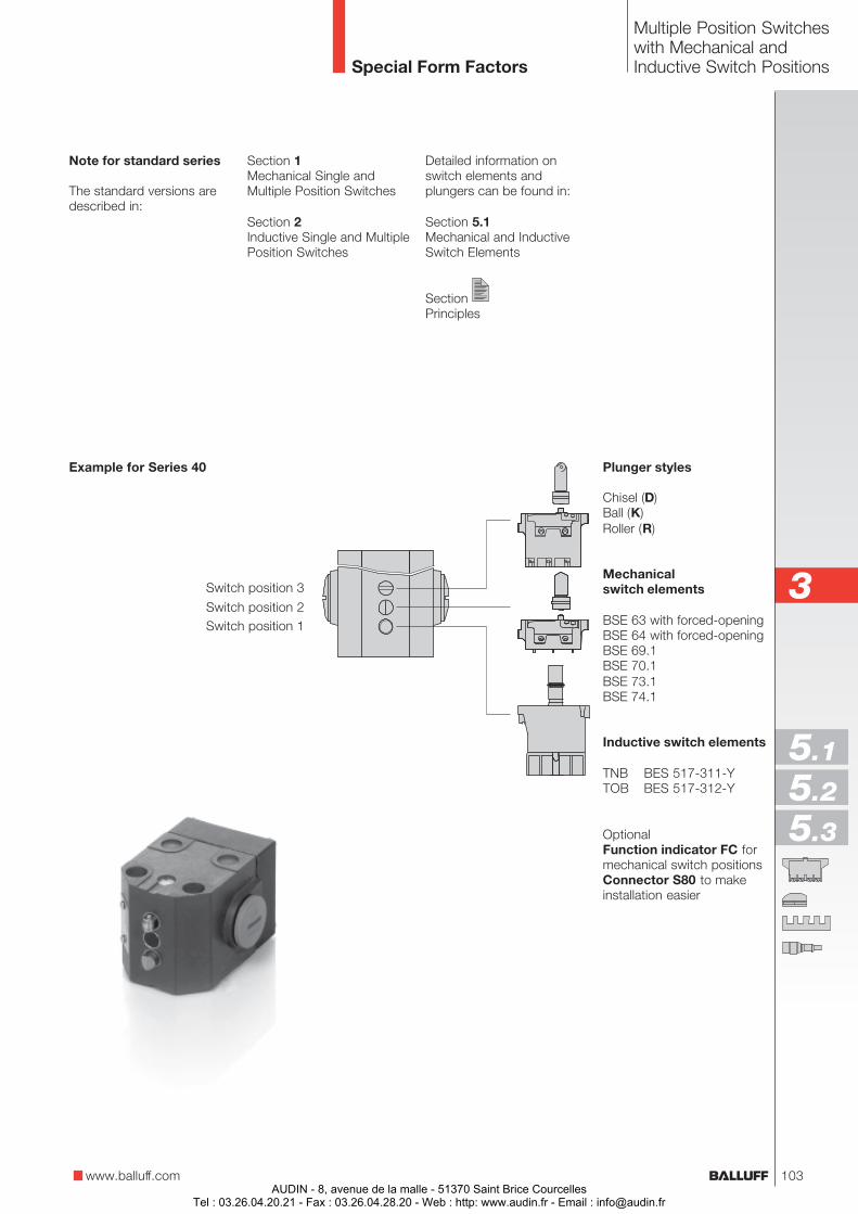
Multiple Position Switcheswith Mechanical andInductive Switch PositionsSpecial Form Factors
Example for Series 40 Plunger styles
Chisel (D)Ball (K)Roller (R)
Mechanicalswitch elements
BSE 63 with forced-openingBSE 64 with forced-openingBSE 69.1BSE 70.1BSE 73.1BSE 74.1
Inductive switch elements
TNB BES 517-311-YTOB BES 517-312-Y
OptionalFunction indicator FC formechanical switch positionsConnector S80 to makeinstallation easier
Note for standard series
The standard versions aredescribed in:
Section 1Mechanical Single andMultiple Position Switches
Section 2Inductive Single and MultiplePosition Switches
Switch position 3
Switch position 2Switch position 1
www.balluff.com
3
5.1
5.2
5.3
Detailed information onswitch elements andplungers can be found in:
Section 5.1Mechanical and InductiveSwitch Elements
SectionPrinciples
103AUDIN - 8, avenue de la malle - 51370 Saint Brice Courcelles
Tel : 03.26.04.20.21 - Fax : 03.26.04.28.20 - Web : http: www.audin.fr - Email : [email protected]
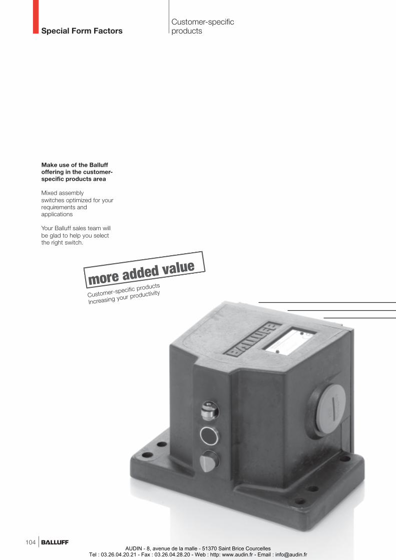
Customer-specificproductsSpecial Form Factors
Make use of the Balluffoffering in the customer-specific products area
Mixed assemblyswitches optimized for yourrequirements andapplications
Your Balluff sales team willbe glad to help you selectthe right switch.
Customer-specific products
Increasing your productivity
104AUDIN - 8, avenue de la malle - 51370 Saint Brice Courcelles
Tel : 03.26.04.20.21 - Fax : 03.26.04.28.20 - Web : http: www.audin.fr - Email : [email protected]
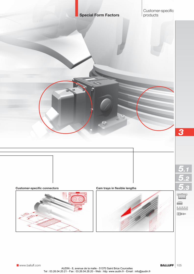
Customer-specificproductsSpecial Form Factors
www.balluff.com
Customer-specific connectors Cam trays in flexible lengths
3
5.1
5.2
5.3
105AUDIN - 8, avenue de la malle - 51370 Saint Brice Courcelles
Tel : 03.26.04.20.21 - Fax : 03.26.04.28.20 - Web : http: www.audin.fr - Email : [email protected]

Objekterkennung
AUDIN - 8, avenue de la malle - 51370 Saint Brice CourcellesTel : 03.26.04.20.21 - Fax : 03.26.04.28.20 - Web : http: www.audin.fr - Email : [email protected]
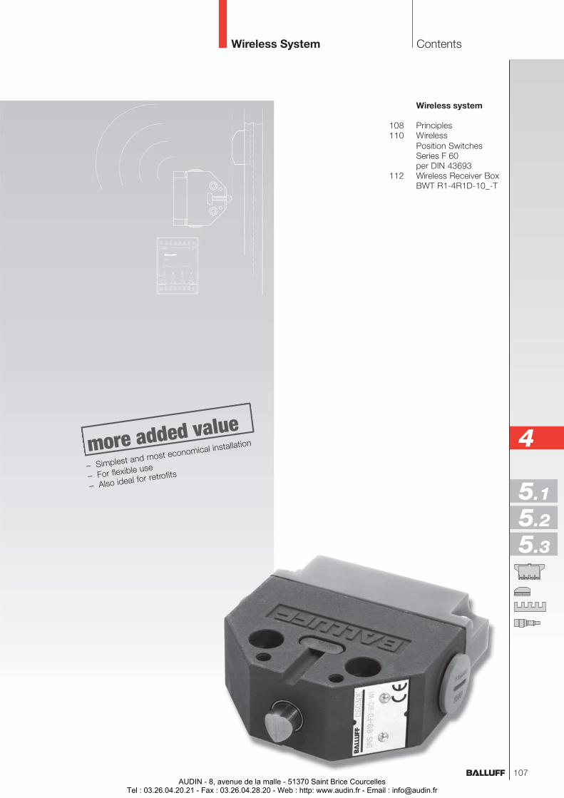
Wireless system
108 Principles110 Wireless
Position SwitchesSeries F 60per DIN 43693
112 Wireless Receiver BoxBWT R1-4R1D-10_-T
ContentsWireless System
4
5.1
5.2
5.3
– Simplest and most economical installation
– For flexible use
– Also ideal for retrofits
107AUDIN - 8, avenue de la malle - 51370 Saint Brice Courcelles
Tel : 03.26.04.20.21 - Fax : 03.26.04.28.20 - Web : http: www.audin.fr - Email : [email protected]
PrinciplesWireless System
108AUDIN - 8, avenue de la malle - 51370 Saint Brice Courcelles
Tel : 03.26.04.20.21 - Fax : 03.26.04.28.20 - Web : http: www.audin.fr - Email : [email protected]
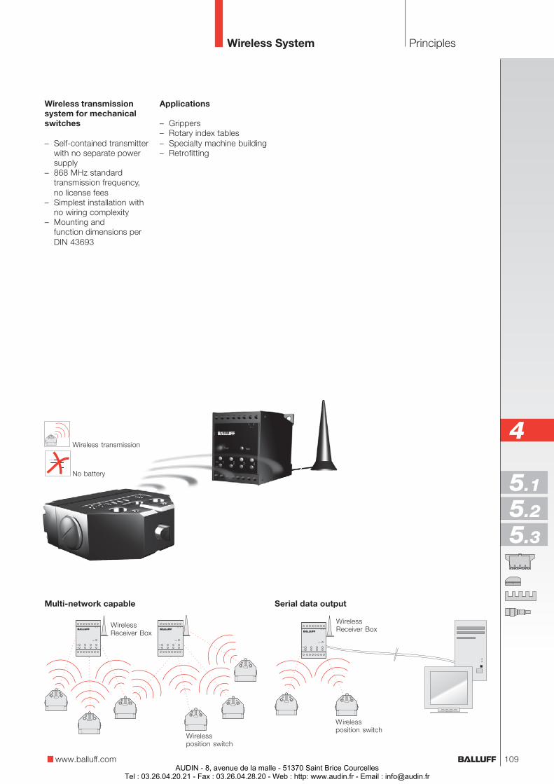
PrinciplesWireless System
www.balluff.com
Serial data output
Wirelessposition switch
WirelessReceiver Box
Wirelessposition switch
WirelessReceiver Box
Multi-network capable
Wireless transmissionsystem for mechanicalswitches
– Self-contained transmitterwith no separate powersupply
– 868 MHz standardtransmission frequency,no license fees
– Simplest installation withno wiring complexity
– Mounting andfunction dimensions perDIN 43693
Wireless transmission
No battery
4
5.1
5.2
5.3
Applications
– Grippers– Rotary index tables– Specialty machine building– Retrofitting
109AUDIN - 8, avenue de la malle - 51370 Saint Brice Courcelles
Tel : 03.26.04.20.21 - Fax : 03.26.04.28.20 - Web : http: www.audin.fr - Email : [email protected]

Wireless position switchesSeries F 60per DIN 43693
D ChiselK BallR RollerL Roller bearingE Chisel with
wiper plate
Ordering example:BNS 819-FD-60-W13
BNS 819-F_-60-W1_
3 longitudinal,parallel to mounting surface
5 lateral,90° to mounting surface
Approachdirection
Plungerstyle
Wireless position switchper DIN 43693
– Dual-chamber systemwith IP 67 protection:wear-free membrane withhermetic sealing fromplunger mechanism andswitch chamber
– Maintenance-free, self-lubricating plunger guidewith slide bearing
Advantages of thewireless position switch
– Simple installation, nowiring complexity for theswitch
– For flexible use– Also ideal for retrofitting
machines and equipment
Ranges
– approx. 30 m on plantfloors,up to 300 m outdoors
– approx. 20 m throughmax. 5 walls (plasterboard/dry wood)
– approx. 10 m throughmax. 2 walls(tile/aerated concrete)
Wireless System
Wireless position switchwith wiper plate
– Increased functionsecurity under extremeconditions of use
– Wiper plate preventsplunger from sticking inthe guide
– For use in wet areas withstrongly adhering media
110AUDIN - 8, avenue de la malle - 51370 Saint Brice Courcelles
Tel : 03.26.04.20.21 - Fax : 03.26.04.28.20 - Web : http: www.audin.fr - Email : [email protected]
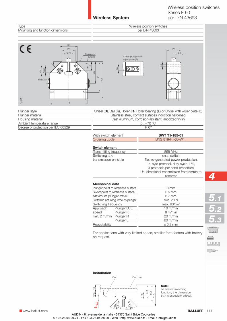
Wireless position switchesSeries F 60per DIN 43693
www.balluff.com
TypeMounting and function dimensions
Plunger stylePlunger materialHousing materialAmbient temperature rangeDegree of protection per IEC 60529
Wireless position switchesper DIN 43693
Chisel (D), Ball (K), Roller (R), Roller bearing (L) or Chisel with wiper plate (E)Stainless steel, contact surfaces induction hardenedCast aluminum, corrosion-resistant, anodized finish
0...+70 °CIP 67
Referencesurface Chisel plunger with
wiper plate (E)
Note!To ensure switchingfunction, the dimension5-0.2 is especially critical.
Cam Cam tray
4
5.1
5.2
5.3
BWT T1-185-01BNS 819-F_-60-W1_
868 MHz snap switch,
Electro-generated power production,14-byte protocol, duty cycle 1 %,3 protocols per send procedure
Uni-directional transmission from switch toreceiver
8 mm5.5 mm3.7 mm
min. 20 Nmax. 60/min
10 m/min8 m/min
20 m/min60 m/min± 0.2 mm
With switch elementOrdering code
Switch elementTransmitting frequencySwitching andtransmission principle
Mechanical dataPlunger point to reference surfaceSwitchpoint to reference surfaceMaximum plunger travelSwitching actuating force on plungerSwitching frequencyApproach Plunger D, Espeed Plunger Kmin. 2 m/min Plunger R
Plunger LRepeatability
Installation
For applications with very limited space, smaller form factors with batteryon request.
Wireless System
111AUDIN - 8, avenue de la malle - 51370 Saint Brice Courcelles
Tel : 03.26.04.20.21 - Fax : 03.26.04.28.20 - Web : http: www.audin.fr - Email : [email protected]
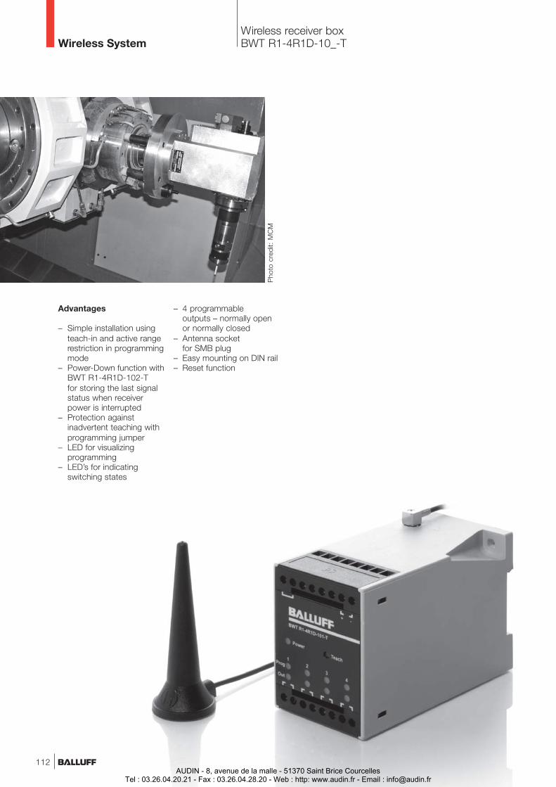
Wireless receiver boxBWT R1-4R1D-10_-T
Advantages
– Simple installation usingteach-in and active rangerestriction in programmingmode
– Power-Down function withBWT R1-4R1D-102-Tfor storing the last signalstatus when receiverpower is interrupted
– Protection againstinadvertent teaching withprogramming jumper
– LED for visualizingprogramming
– LED’s for indicatingswitching states
Pho
to c
redi
t: M
CM
Wireless System
– 4 programmableoutputs – normally openor normally closed
– Antenna socketfor SMB plug
– Easy mounting on DIN rail– Reset function
112AUDIN - 8, avenue de la malle - 51370 Saint Brice Courcelles
Tel : 03.26.04.20.21 - Fax : 03.26.04.28.20 - Web : http: www.audin.fr - Email : [email protected]
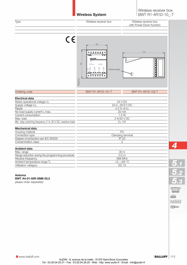
Wireless receiver boxBWT R1-4R1D-10_-T
www.balluff.com
Type
Ordering code
Electrical dataRated operational voltage Ue
Supply voltage UB
RippleNo-load supply current I0 max.Current consumptionMax. loadMin. relay switching frequency (1 A, 30 V DC, resistive load)
Mechanical dataHousing materialConnection typeDegree of protection per IEC 60529Contamination class
Ambient dataMax. rangeRange reduction during the programming procedureReceive frequencyAmbient temperature range Ta
Utilization category
AntennaBWT A4-01-50R-SMB-02,5please order separately!
Wireless receiver box Wireless receiver boxwith Power-Down function
BWT R1-4R1D-101-T BWT R1-4R1D-102-T
24 V DC20.4...28.8 V DC
≤ 5 % of Ue
20 mA1.5 W
2 A/30 V DC2× 105
PCClamping terminal
IP 202
30 m0.5 m
868 MHz+5...+65 °C
DC 13
4
5.1
5.2
5.3
Antenna base
Wireless System
113AUDIN - 8, avenue de la malle - 51370 Saint Brice Courcelles
Tel : 03.26.04.20.21 - Fax : 03.26.04.28.20 - Web : http: www.audin.fr - Email : [email protected]

Object Detection
114AUDIN - 8, avenue de la malle - 51370 Saint Brice Courcelles
Tel : 03.26.04.20.21 - Fax : 03.26.04.28.20 - Web : http: www.audin.fr - Email : [email protected]
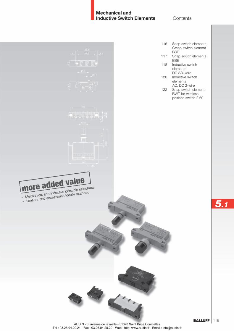
116 Snap switch elements,Creep switch elementBSE
117 Snap switch elementsBSE
118 Inductive switchelementsDC 3/4-wire
120 Inductive switchelementsAC, DC 2-wire
122 Snap switch elementBWT for wirelessposition switch F 60
Mechanical andInductive Switch Elements Contents
5.1– Mechanical and inductive principle selectable
– Sensors and accessories ideally matched
115AUDIN - 8, avenue de la malle - 51370 Saint Brice Courcelles
Tel : 03.26.04.20.21 - Fax : 03.26.04.28.20 - Web : http: www.audin.fr - Email : [email protected]
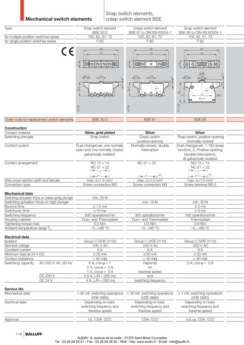
Mechanical switch elementsSnap switch elements,creep switch element BSE
Snap switch elementBSE 30.0
100, 62, 61, 72F 60
BSE 30.0
Silver, gold platedSnap switch
Dual changeover, one normallyopen and one normally closed,
galvanically isolated.
NO 13 + 14NC 21 + 22
max. 2×1.5 mm2
Screw connection M3
min. 20 N
≤ 1.5 ms≤ 10 ms
300 operations/minDuro- and Thermoplast
0.5 Nm–5...+85 °C
Group C (VDE 0110) 240 V AC
6 A≥ 20 mA< 40 mΩ
6 A, cos ϕ = 12 A, cos ϕ = 0.81 A, cos ϕ = 0.4
0.5 A, L/R = 200 ms 4 A, L/R = 200 ms
> 30 mil. switching operations(VDE 0660)
Depending on load,switching frequency and
traverse speed
UL, CSA, CCC
Snap switch elementBSE 85 to DIN EN 60204-1
100, 62, 61, 72F 60
BSE 85
Silver Snap switch, positive opening
(normally-closed)Dual-changeover: 1. NO (snapfunction), 2. Positive-opening
(double-interruption),all galvanically isolated
NO 13 + 14NC 21 + 22
max. 2×1.5 mm2
Screw terminal M3.5
min. 30 N≤ 3 ms≤ 5 ms
160 operations/minThermoplast
0.9 Nm–5...+85 °C
Group C (VDE 0110) 250 V AC
6 A≥ 20 mA< 40 mΩ
2 A, cos ϕ = 0.8
> 1 mil. switching operations(VDE 0660)
Depending on load,switching frequency and
traverse speed
cULus, CSA, CCC
Creep switch elementBSE 61 to DIN EN 60204-1
100, 62, 61, 72F 60
BSE 61
SilverCreep switch,
positive-openingNormally-closed, double
interruption
NC 21 + 22
max. 2×1.5 mm2
Screw connection M3
min. 15 N
300 operations/minDuro- and Thermoplast
0.5 Nm–5...+85 °C
Group C (VDE 0110) 250 V AC
6 A≥ 20 mA< 40 mΩDepends
ontraverse speed
andswitching frequency
> 30 mil. switching operations(VDE 0660)
Depending on load,switching frequency and
traverse speed
CSA, CCC
Type
for multiple position switches seriesfor single position switches series
Order code for replacement switch elements
ConstructionContact materialSwitching principle
Contact system
Contact arrangement
Wire cross-section (with end ferrule)Connection type
Mechanical dataSwitching actuation force on telescoping plungerSwitching actuation force on rigid plungerBounce timeSwitchover timeSwitching frequencyHousing materialTightening torque max.Ambient temperature range Ta
Electrical dataIsolationNominal voltageConstant currentMinimum load at 24 V DCContact resistanceSwitching capacity AC 250 V, 40...60 Hz
DC 220 VDC 24 V
Service lifeMechanical data
Electrical data
Approval
116AUDIN - 8, avenue de la malle - 51370 Saint Brice Courcelles
Tel : 03.26.04.20.21 - Fax : 03.26.04.28.20 - Web : http: www.audin.fr - Email : [email protected]
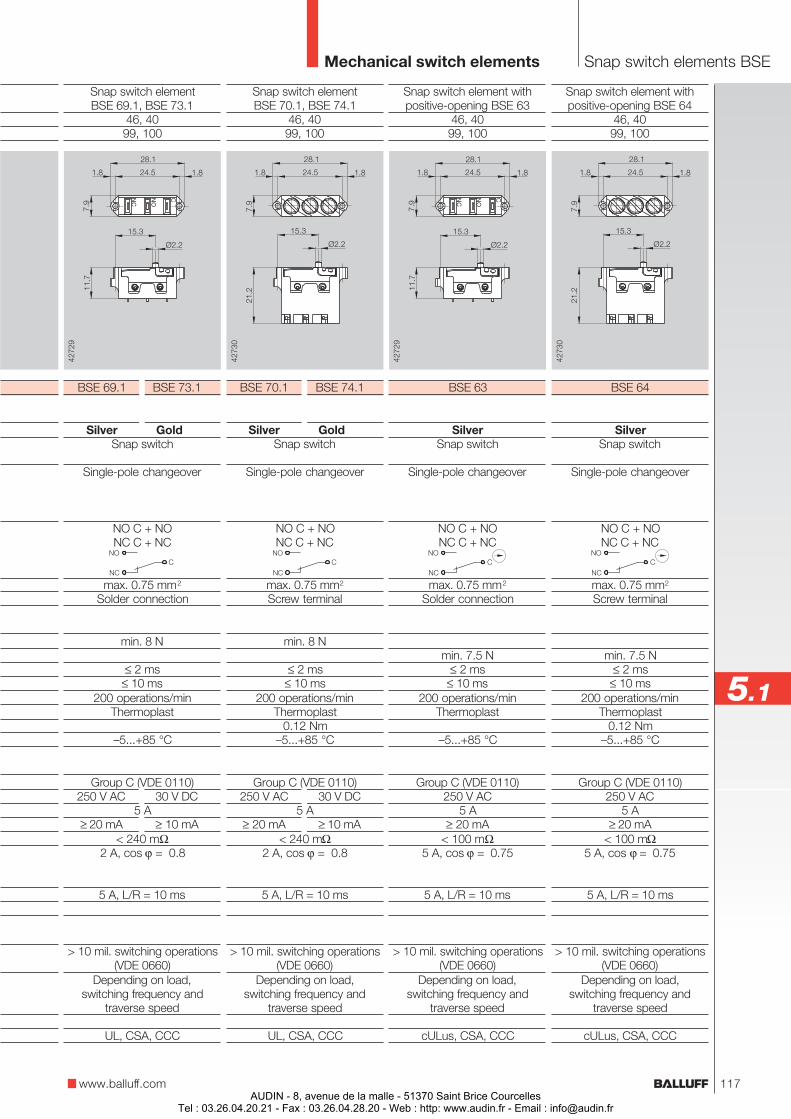
Snap switch elementBSE 70.1, BSE 74.1
46, 4099, 100
BSE 70.1 BSE 74.1
Silver GoldSnap switch
Single-pole changeover
NO C + NONC C + NC
max. 0.75 mm2
Screw terminal
min. 8 N
≤ 2 ms≤ 10 ms
200 operations/minThermoplast
0.12 Nm–5...+85 °C
Group C (VDE 0110)250 V AC 30 V DC
5 A≥ 20 mA ≥ 10 mA
< 240 mΩ2 A, cos ϕ = 0.8
5 A, L/R = 10 ms
> 10 mil. switching operations(VDE 0660)
Depending on load,switching frequency and
traverse speed
UL, CSA, CCC
Snap switch elementBSE 69.1, BSE 73.1
46, 4099, 100
BSE 69.1 BSE 73.1
Silver GoldSnap switch
Single-pole changeover
NO C + NONC C + NC
max. 0.75 mm2
Solder connection
min. 8 N
≤ 2 ms≤ 10 ms
200 operations/minThermoplast
–5...+85 °C
Group C (VDE 0110)250 V AC 30 V DC
5 A≥ 20 mA ≥ 10 mA
< 240 mΩ2 A, cos ϕ = 0.8
5 A, L/R = 10 ms
> 10 mil. switching operations(VDE 0660)
Depending on load,switching frequency and
traverse speed
UL, CSA, CCC
Mechanical switch elements Snap switch elements BSE
www.balluff.com
5.1
Snap switch element withpositive-opening BSE 63
46, 4099, 100
BSE 63
SilverSnap switch
Single-pole changeover
NO C + NONC C + NC
max. 0.75 mm2
Solder connection
min. 7.5 N≤ 2 ms
≤ 10 ms200 operations/min
Thermoplast
–5...+85 °C
Group C (VDE 0110)250 V AC
5 A≥ 20 mA
< 100 mΩ5 A, cos ϕ = 0.75
5 A, L/R = 10 ms
> 10 mil. switching operations(VDE 0660)
Depending on load,switching frequency and
traverse speed
cULus, CSA, CCC
Snap switch element withpositive-opening BSE 64
46, 4099, 100
BSE 64
SilverSnap switch
Single-pole changeover
NO C + NONC C + NC
max. 0.75 mm2
Screw terminal
min. 7.5 N≤ 2 ms
≤ 10 ms200 operations/min
Thermoplast0.12 Nm
–5...+85 °C
Group C (VDE 0110)250 V AC
5 A≥ 20 mA
< 100 mΩ5 A, cos ϕ = 0.75
5 A, L/R = 10 ms
> 10 mil. switching operations(VDE 0660)
Depending on load,switching frequency and
traverse speed
cULus, CSA, CCC
117AUDIN - 8, avenue de la malle - 51370 Saint Brice Courcelles
Tel : 03.26.04.20.21 - Fax : 03.26.04.28.20 - Web : http: www.audin.fr - Email : [email protected]
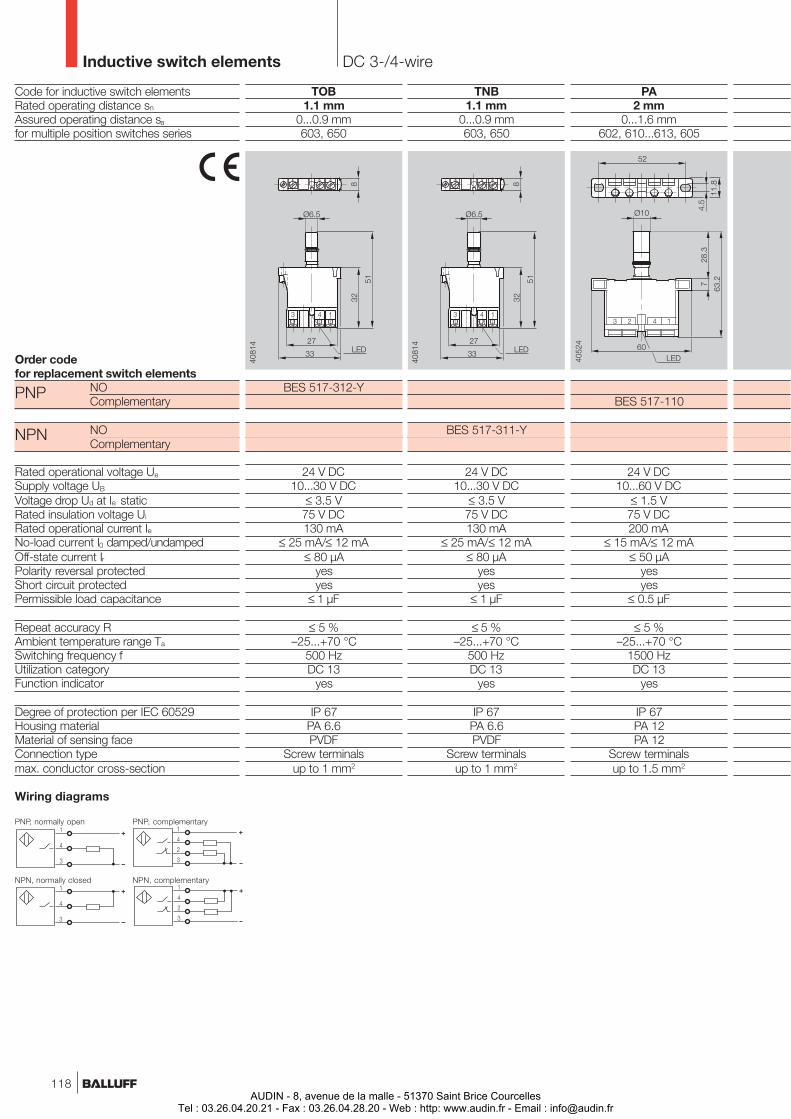
PA2 mm
0...1.6 mm602, 610...613, 605
BES 517-110
24 V DC10...60 V DC
≤ 1.5 V75 V DC200 mA
≤ 15 mA/≤ 12 mA≤ 50 µA
yesyes
≤ 0.5 µF
≤ 5 %–25...+70 °C
1500 HzDC 13
yes
IP 67PA 12PA 12
Screw terminalsup to 1.5 mm2
Code for inductive switch elementsRated operating distance sn
Assured operating distance sa
for multiple position switches series
Order codefor replacement switch elements
NOComplementary
NOComplementary
Rated operational voltage Ue
Supply voltage UB
Voltage drop Ud at Ie staticRated insulation voltage Ui
Rated operational current IeNo-load current I0 damped/undampedOff-state current IrPolarity reversal protectedShort circuit protectedPermissible load capacitance
Repeat accuracy RAmbient temperature range Ta
Switching frequency fUtilization categoryFunction indicator
Degree of protection per IEC 60529Housing materialMaterial of sensing faceConnection typemax. conductor cross-section
Wiring diagrams
Inductive switch elements DC 3-/4-wire
PNP, normally open
PNP
NPN
NPN, normally closed
PNP, complementary
NPN, complementary
TNB1.1 mm
0...0.9 mm603, 650
BES 517-311-Y
24 V DC10...30 V DC
≤ 3.5 V75 V DC130 mA
≤ 25 mA/≤ 12 mA≤ 80 µA
yesyes
≤ 1 µF
≤ 5 %–25...+70 °C
500 HzDC 13
yes
IP 67PA 6.6PVDF
Screw terminalsup to 1 mm2
TOB1.1 mm
0...0.9 mm603, 650
BES 517-312-Y
24 V DC10...30 V DC
≤ 3.5 V75 V DC130 mA
≤ 25 mA/≤ 12 mA≤ 80 µA
yesyes
≤ 1 µF
≤ 5 %–25...+70 °C
500 HzDC 13
yes
IP 67PA 6.6PVDF
Screw terminalsup to 1 mm2
118AUDIN - 8, avenue de la malle - 51370 Saint Brice Courcelles
Tel : 03.26.04.20.21 - Fax : 03.26.04.28.20 - Web : http: www.audin.fr - Email : [email protected]
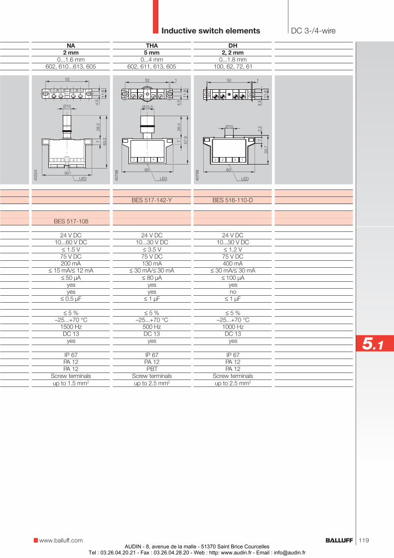
DH2, 2 mm
0...1.8 mm100, 62, 72, 61
BES 516-110-D
24 V DC10...30 V DC
≤ 1.2 V75 V DC400 mA
≤ 30 mA/≤ 30 mA≤ 100 µA
yesno
≤ 1 µF
≤ 5 %–25...+70 °C
1000 HzDC 13
yes
IP 67PA 12PA 12
Screw terminalsup to 2.5 mm2
THA5 mm
0...4 mm602, 611, 613, 605
BES 517-142-Y
24 V DC10...30 V DC
≤ 3.5 V75 V DC130 mA
≤ 30 mA/≤ 30 mA≤ 80 µA
yesyes
≤ 1 µF
≤ 5 %–25...+70 °C
500 HzDC 13
yes
IP 67PA 12PBT
Screw terminalsup to 2.5 mm2
Inductive switch elements DC 3-/4-wire
www.balluff.com
5.1
NA2 mm
0...1.6 mm602, 610...613, 605
BES 517-108
24 V DC10...60 V DC
≤ 1.5 V75 V DC200 mA
≤ 15 mA/≤ 12 mA≤ 50 µA
yesyes
≤ 0.5 µF
≤ 5 %–25...+70 °C
1500 HzDC 13
yes
IP 67PA 12PA 12
Screw terminalsup to 1.5 mm2
119AUDIN - 8, avenue de la malle - 51370 Saint Brice Courcelles
Tel : 03.26.04.20.21 - Fax : 03.26.04.28.20 - Web : http: www.audin.fr - Email : [email protected]
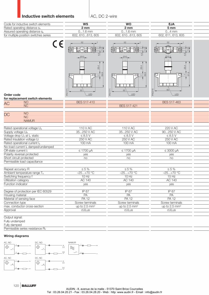
WS2 mm
0...1.6 mm602, 610...613, 605
BES 517-410
110 V AC35...250 V AC
≤ 8.5 V250 V AC100 mA
≤ 1700 µAyesno
≤ 5 %–25...+70 °C
10 HzAC 140
yes
IP 67PA
PA 12Screw terminalsup to 2.5 mm2
cULus
EJA5 mm
0...4 mm602, 611, 613, 605
BES 517-463
220 V AC90...250 V AC
≤ 8.5 V250 V AC100 mA
≤ 3000 µAyesno
≤ 5 %–25...+70 °C
15 HzAC 140
yes
IP 67PA
PA 12Screw terminalsup to 2.5 mm2
cULus
Code for inductive switch elementsRated operating distance sn
Assured operating distance sa
for multiple position switches series
Order codefor replacement switch elements
NONC
NONCNAMUR
Rated operational voltage Ue
Supply voltage UB
Voltage drop Ud at Ie staticRated insulation voltage Ui
Rated operational current IeNo-load current I0 damped/undampedOff-state current IrPolarity reversal protectedShort circuit protectedPermissible load capacitance
Repeat accuracy RAmbient temperature range Ta
Switching frequency fUtilization categoryFunction indicator
Degree of protection per IEC 60529Housing materialMaterial of sensing faceConnection typemax. conductor cross-sectionApproval
Output signal:Fully undampedFully dampedPermissible series resistance RV
Inductive switch elements AC, DC 2-wire
AC
DC
AC, NO
AC, NC
DC, NO
DC, NC
NAMUR
WO2 mm
0...1.6 mm602, 610...613, 605
BES 517-421
110 V AC35...250 V AC
≤ 8.5 V250 V AC100 mA
≤ 1700 µAyesno
≤ 5 %–25...+70 °C
10 HzAC 140
yes
IP 67PA
PA 12Screw terminalsup to 2.5 mm2
cULus
Wiring diagrams
120AUDIN - 8, avenue de la malle - 51370 Saint Brice Courcelles
Tel : 03.26.04.20.21 - Fax : 03.26.04.28.20 - Web : http: www.audin.fr - Email : [email protected]
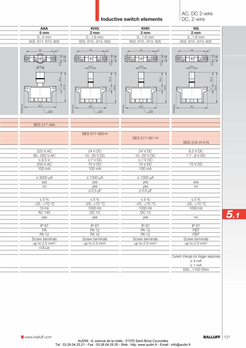
KHG2 mm
0...1.6 mm602, 610...613, 605
BES 517-560-H
24 V DC10...55 V DC
≤ 7 V DC75 V DC100 mA
≤ 1350 µAyesyes
≤ 0.5 µF
≤ 5 %–25...+70 °C
1000 HzDC 13
yes
IP 67PA 12PA 12
Screw terminalsup to 2.5 mm2
NG2 mm
0...1.6 mm602, 610...613, 605
BES 516-314-N
8.2 V DC7.7...9 V DC
75 V DC
yesno
≤ 5 %–25...+70 °C
1000 Hz
no
IP 67PBTPBT
Screw terminalsup to 2.5 mm2
Current change (no trigger response)≥ 4 mA≤ 1 mA
550...1100 Ohm
Inductive switch elementsAC, DC 2-wireDC, 2-wire
5.1
www.balluff.com
KHH2 mm
0...1.6 mm602, 610...613, 605
BES 517-561-H
24 V DC10...55 V DC
≤ 7 V DC75 V DC100 mA
≤ 1350 µAyesyes
≤ 0.5 µF
≤ 5 %–25...+70 °C
1000 HzDC 13
yes
IP 67PA 12PA 12
Screw terminalsup to 2.5 mm2
AAA5 mm
0...4 mm602, 611, 613, 605
BES 517-464
220 V AC90...250 V AC
≤ 8.5 V250 V AC100 mA
≤ 3000 µAyesno
≤ 5 %–25...+70 °C
15 HzAC 140
yes
IP 67PA
PA 12Screw terminalsup to 2.5 mm2
cULus
121AUDIN - 8, avenue de la malle - 51370 Saint Brice Courcelles
Tel : 03.26.04.20.21 - Fax : 03.26.04.28.20 - Web : http: www.audin.fr - Email : [email protected]
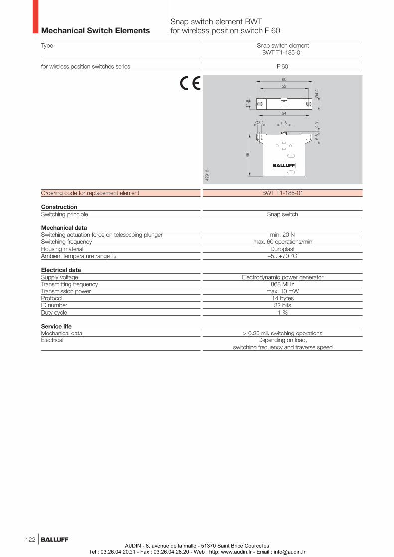
Mechanical Switch ElementsSnap switch element BWTfor wireless position switch F 60
Snap switch elementBWT T1-185-01
F 60
BWT T1-185-01
Snap switch
min. 20 Nmax. 60 operations/min
Duroplast–5...+70 °C
Electrodynamic power generator868 MHz
max. 10 mW14 bytes32 bits1 %
> 0.25 mil. switching operationsDepending on load,
switching frequency and traverse speed
Type
for wireless position switches series
Ordering code for replacement element
ConstructionSwitching principle
Mechanical dataSwitching actuation force on telescoping plungerSwitching frequencyHousing materialAmbient temperature range Ta
Electrical dataSupply voltageTransmitting frequencyTransmission powerProtocolID numberDuty cycle
Service lifeMechanical dataElectrical
122AUDIN - 8, avenue de la malle - 51370 Saint Brice Courcelles
Tel : 03.26.04.20.21 - Fax : 03.26.04.28.20 - Web : http: www.audin.fr - Email : [email protected]
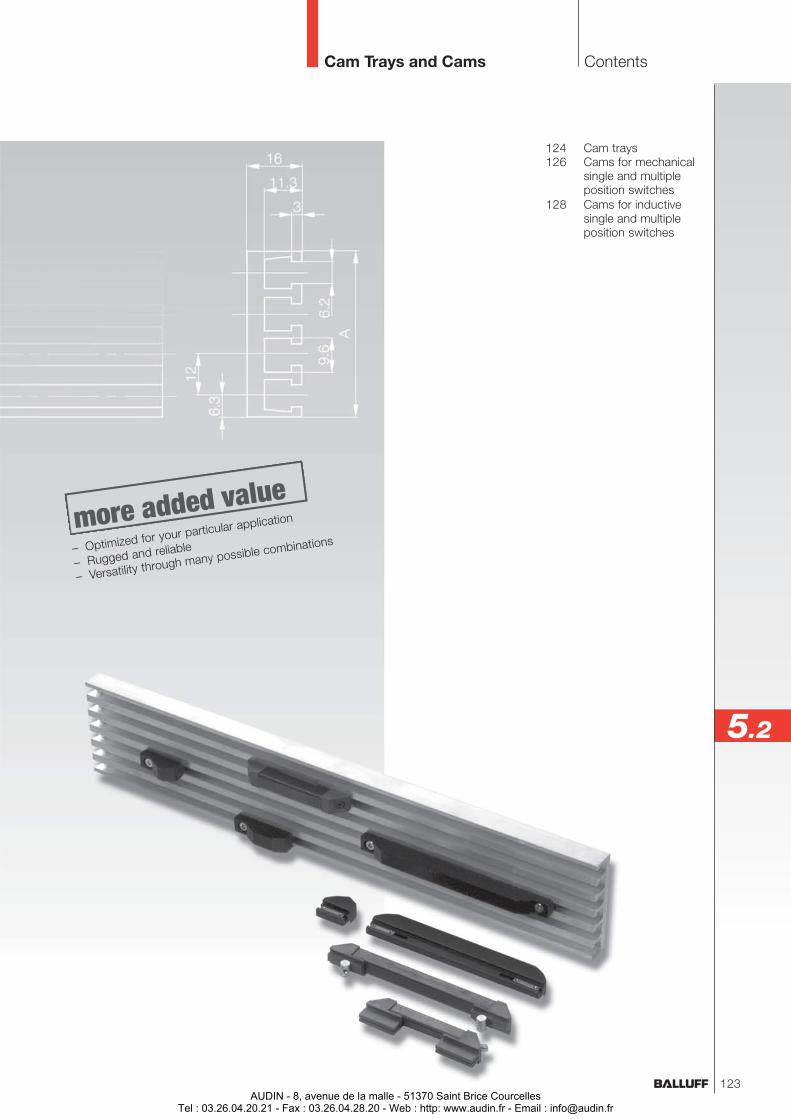
124 Cam trays126 Cams for mechanical
single and multipleposition switches
128 Cams for inductivesingle and multipleposition switches
Cam Trays and Cams Contents
5.2
– Optimized for your particular application
– Rugged and reliable
– Versatility through many possible combinations
123AUDIN - 8, avenue de la malle - 51370 Saint Brice Courcelles
Tel : 03.26.04.20.21 - Fax : 03.26.04.28.20 - Web : http: www.audin.fr - Email : [email protected]
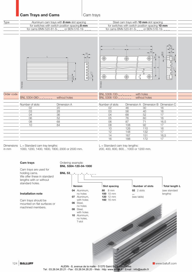
Aluminum cam trays with 8 mm slot spacingfor switches with switch position spacing 8 mm
for cams BNN 520-81-S-_ _ _ or BEN 516-19- _ _ _
BNL 5304-080-_ _-_ _ _ _ without holes
Number of slots Dimension A02 2003 2804 3606 5208 6810 84
L = Standard cam tray lengths:1000, 1200, 1400, 1600, 1800, 2000 or 2500 mm.
Type
Order code
Dimensionsin mm
Cam Trays and Cams Cam trays
Slot spacing
02 2 slots...(see table)
Number of slots
04 Aluminum,no holes
07 Aluminum,with holes
06 Steel,no holes
08 Steel,with holes
10 Aluminum,no holes,T-slot
80 8 mm100 10 mm120 12 mm160 16 mm
Version
Cam trays
Cam trays are used forholding cams.We offer these in standardlengths with or withoutstandard holes.
Installation note
Cam trays should bemounted on flat surfaces ormachined members.
Steel cam trays with 10 mm slot spacingfor switches with switch position spacing 10 mm
for cams BNN 520-81-S-_ _ _ or BEN 516-19- _ _ _
BNL 5308-100-_ _-_ _ _ _ with holesBNL 5306-100-_ _-_ _ _ _ without holes
Number of slots Dimension A Dimension B Dimension C02 46 30 1603 56 40 1604 68 52 1705 76 60 1606 87 71 16.508 108 92 1710 126 110 1612 148 132 1714 167 151 16,516 188 172 17
L = Standard cam tray lengths:200, 400, 600, 800, , 1000 or 1200 mm.
Ordering example:BNL 5304-120-04-1000
BNL 53_ _-_ _ _-_ _-_ _ _ _
(see standardlengths)
Total length L
www.balluff.com124AUDIN - 8, avenue de la malle - 51370 Saint Brice Courcelles
Tel : 03.26.04.20.21 - Fax : 03.26.04.28.20 - Web : http: www.audin.fr - Email : [email protected]
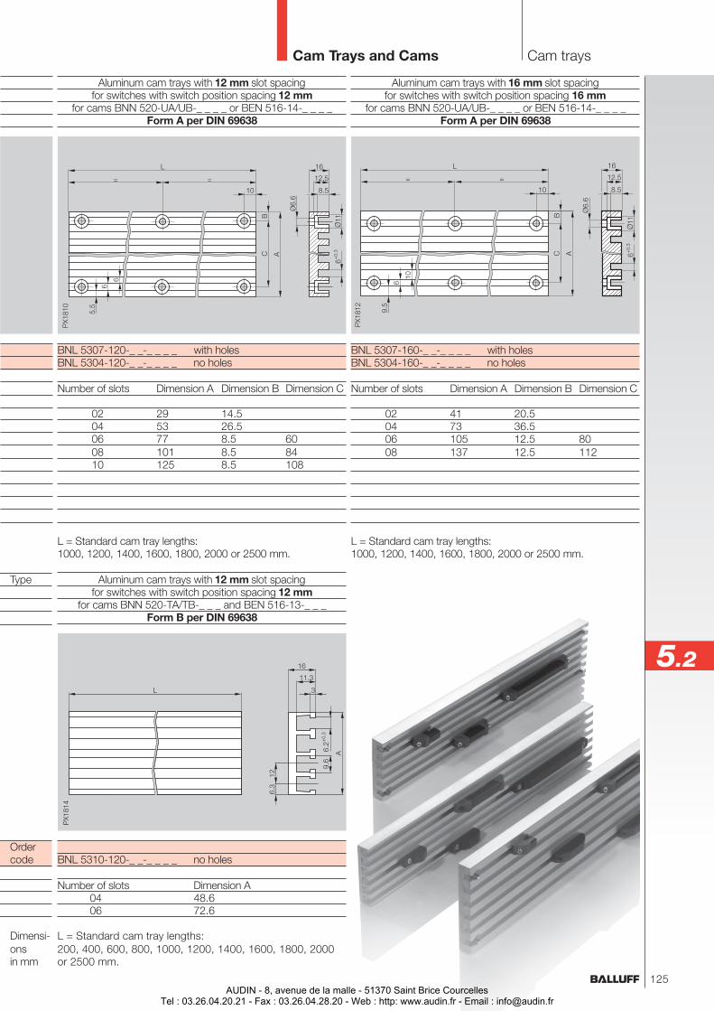
Aluminum cam trays with 12 mm slot spacingfor switches with switch position spacing 12 mm
for cams BNN 520-UA/UB-_ _ _ _ or BEN 516-14-_ _ _ _Form A per DIN 69638
BNL 5307-120-_ _-_ _ _ _ with holesBNL 5304-120-_ _-_ _ _ _ no holes
Number of slots Dimension A Dimension B Dimension C
02 29 14.504 53 26.506 77 8.5 6008 101 8.5 8410 125 8.5 108
L = Standard cam tray lengths:1000, 1200, 1400, 1600, 1800, 2000 or 2500 mm.
Aluminum cam trays with 12 mm slot spacingfor switches with switch position spacing 12 mm
for cams BNN 520-TA/TB-_ _ _ and BEN 516-13-_ _ _Form B per DIN 69638
BNL 5310-120-_ _-_ _ _ _ no holes
Number of slots Dimension A04 48.606 72.6
L = Standard cam tray lengths:200, 400, 600, 800, 1000, 1200, 1400, 1600, 1800, 2000or 2500 mm.
Aluminum cam trays with 16 mm slot spacingfor switches with switch position spacing 16 mm
for cams BNN 520-UA/UB-_ _ _ _ or BEN 516-14-_ _ _ _Form A per DIN 69638
BNL 5307-160-_ _-_ _ _ _ with holesBNL 5304-160-_ _-_ _ _ _ no holes
Number of slots Dimension A Dimension B Dimension C
02 41 20.504 73 36.506 105 12.5 8008 137 12.5 112
L = Standard cam tray lengths:1000, 1200, 1400, 1600, 1800, 2000 or 2500 mm.
Cam Trays and Cams Cam trays
5.2
125
Type
Ordercode
Dimensi-onsin mm
AUDIN - 8, avenue de la malle - 51370 Saint Brice CourcellesTel : 03.26.04.20.21 - Fax : 03.26.04.28.20 - Web : http: www.audin.fr - Email : [email protected]
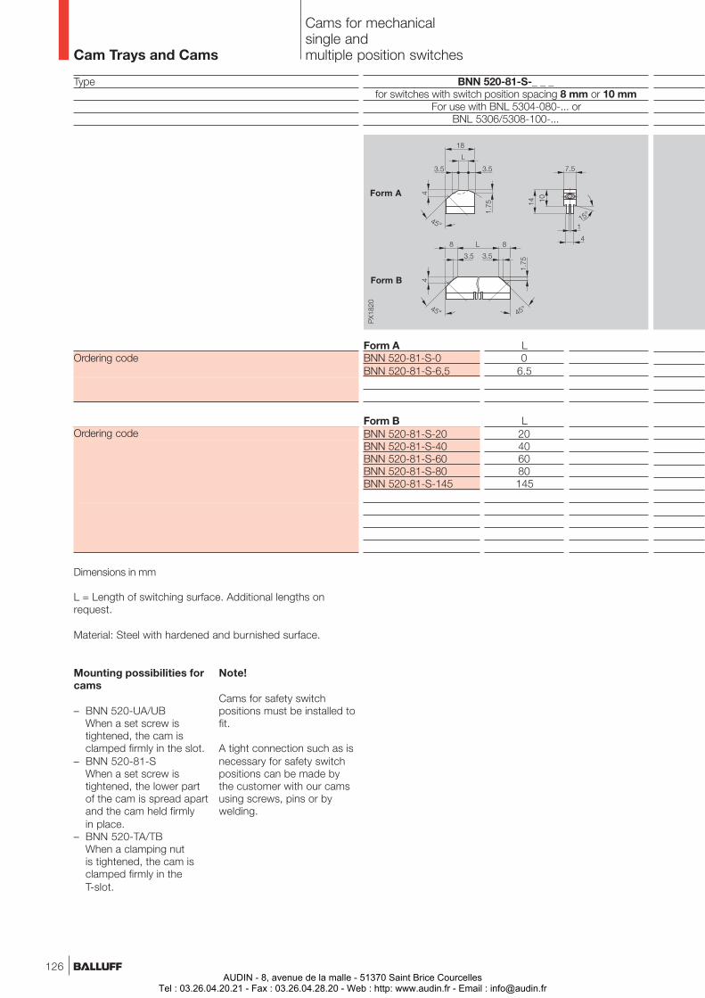
Type
Ordering code
Ordering code
Dimensions in mm
L = Length of switching surface. Additional lengths onrequest.
Material: Steel with hardened and burnished surface.
BNN 520-81-S-_ _ _for switches with switch position spacing 8 mm or 10 mm
For use with BNL 5304-080-... orBNL 5306/5308-100-...
L0
6.5
L20406080145
Form ABNN 520-81-S-0BNN 520-81-S-6,5
Form BBNN 520-81-S-20BNN 520-81-S-40BNN 520-81-S-60BNN 520-81-S-80BNN 520-81-S-145
Cams for mechanicalsingle andmultiple position switches
Mounting possibilities forcams
– BNN 520-UA/UBWhen a set screw istightened, the cam isclamped firmly in the slot.
– BNN 520-81-SWhen a set screw istightened, the lower partof the cam is spread apartand the cam held firmlyin place.
– BNN 520-TA/TBWhen a clamping nutis tightened, the cam isclamped firmly in theT-slot.
Form A
Form B
Cam Trays and Cams
Note!
Cams for safety switchpositions must be installed tofit.
A tight connection such as isnecessary for safety switchpositions can be made bythe customer with our camsusing screws, pins or bywelding.
126AUDIN - 8, avenue de la malle - 51370 Saint Brice Courcelles
Tel : 03.26.04.20.21 - Fax : 03.26.04.28.20 - Web : http: www.audin.fr - Email : [email protected]
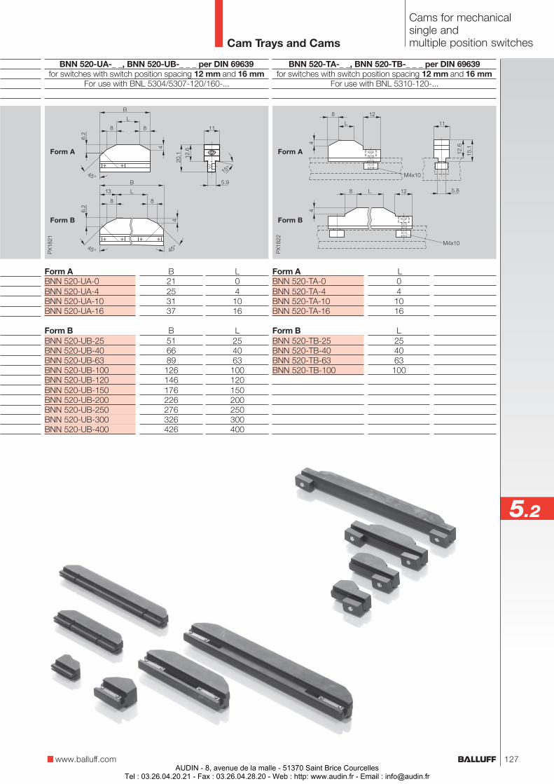
B21253137
B516689126146176226276326426
L041016
L254063100120150200250300400
Form ABNN 520-UA-0BNN 520-UA-4BNN 520-UA-10BNN 520-UA-16
Form BBNN 520-UB-25BNN 520-UB-40BNN 520-UB-63BNN 520-UB-100BNN 520-UB-120BNN 520-UB-150BNN 520-UB-200BNN 520-UB-250BNN 520-UB-300BNN 520-UB-400
BNN 520-UA-_ _, BNN 520-UB-_ _ _ per DIN 69639for switches with switch position spacing 12 mm and 16 mm
For use with BNL 5304/5307-120/160-...
Form ABNN 520-TA-0BNN 520-TA-4BNN 520-TA-10BNN 520-TA-16
Form BBNN 520-TB-25BNN 520-TB-40BNN 520-TB-63BNN 520-TB-100
BNN 520-TA-_ _, BNN 520-TB-_ _ _ per DIN 69639for switches with switch position spacing 12 mm and 16 mm
For use with BNL 5310-120-...
L04
1016
L254063
100
Cams for mechanicalsingle andmultiple position switches
Form A
Form B
Form A
Form B
www.balluff.com
5.2
Cam Trays and Cams
127AUDIN - 8, avenue de la malle - 51370 Saint Brice Courcelles
Tel : 03.26.04.20.21 - Fax : 03.26.04.28.20 - Web : http: www.audin.fr - Email : [email protected]
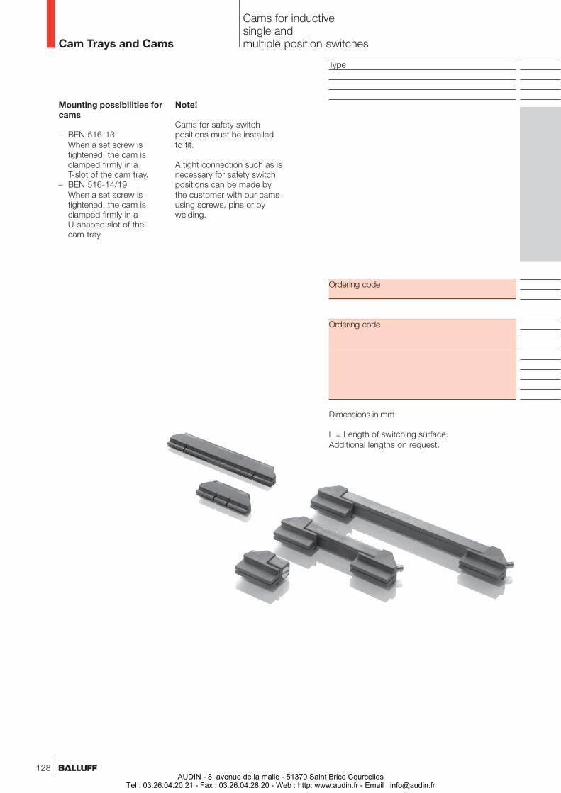
Cams for inductivesingle andmultiple position switches
Mounting possibilities forcams
– BEN 516-13When a set screw istightened, the cam isclamped firmly in aT-slot of the cam tray.
– BEN 516-14/19When a set screw istightened, the cam isclamped firmly in aU-shaped slot of thecam tray.
Cam Trays and Cams
Type
Ordering code
Ordering code
Dimensions in mm
L = Length of switching surface.Additional lengths on request.
Note!
Cams for safety switchpositions must be installedto fit.
A tight connection such as isnecessary for safety switchpositions can be made bythe customer with our camsusing screws, pins or bywelding.
128AUDIN - 8, avenue de la malle - 51370 Saint Brice Courcelles
Tel : 03.26.04.20.21 - Fax : 03.26.04.28.20 - Web : http: www.audin.fr - Email : [email protected]
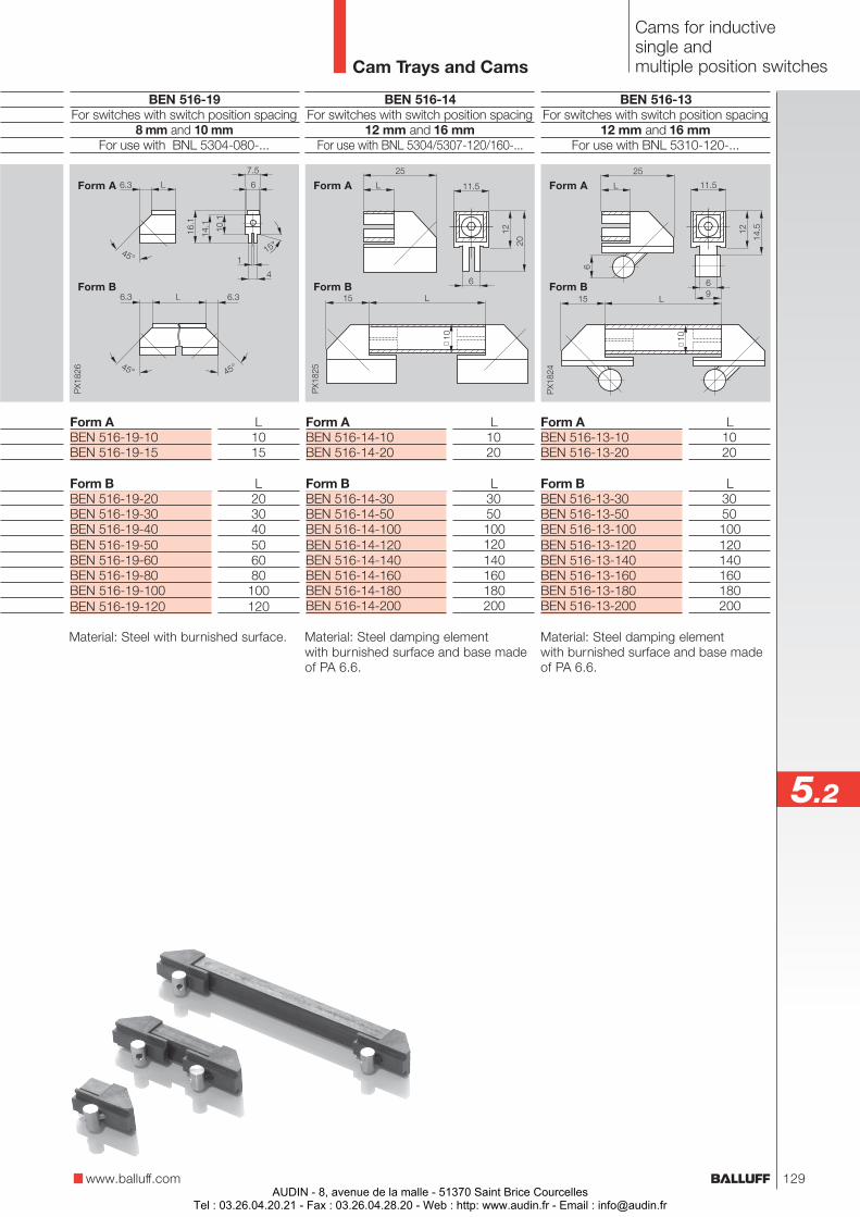
Material: Steel damping elementwith burnished surface and base madeof PA 6.6.
L1020
L3050100120140160180200
Form ABEN 516-14-10BEN 516-14-20
Form BBEN 516-14-30BEN 516-14-50BEN 516-14-100BEN 516-14-120BEN 516-14-140BEN 516-14-160BEN 516-14-180BEN 516-14-200
BEN 516-14For switches with switch position spacing
12 mm and 16 mmFor use with BNL 5304/5307-120/160-...
Cams for inductivesingle andmultiple position switches
Form ABEN 516-19-10BEN 516-19-15
Form BBEN 516-19-20BEN 516-19-30BEN 516-19-40BEN 516-19-50BEN 516-19-60BEN 516-19-80BEN 516-19-100BEN 516-19-120
BEN 516-19For switches with switch position spacing
8 mm and 10 mmFor use with BNL 5304-080-...
L1015
L203040506080100120
Material: Steel with burnished surface.
L1020
L3050100120140160180200
Form ABEN 516-13-10BEN 516-13-20
Form BBEN 516-13-30BEN 516-13-50BEN 516-13-100BEN 516-13-120BEN 516-13-140BEN 516-13-160BEN 516-13-180BEN 516-13-200
BEN 516-13For switches with switch position spacing
12 mm and 16 mmFor use with BNL 5310-120-...
Form A
Form B
Form A
Form B
Form A
Form B
www.balluff.com
5.2
Cam Trays and Cams
Material: Steel damping elementwith burnished surface and base madeof PA 6.6.
129AUDIN - 8, avenue de la malle - 51370 Saint Brice Courcelles
Tel : 03.26.04.20.21 - Fax : 03.26.04.28.20 - Web : http: www.audin.fr - Email : [email protected]

Objekterkennung
AUDIN - 8, avenue de la malle - 51370 Saint Brice CourcellesTel : 03.26.04.20.21 - Fax : 03.26.04.28.20 - Web : http: www.audin.fr - Email : [email protected]
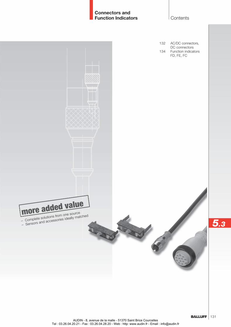
132 AC/DC connectors,DC connectors
134 Function indicatorsFD, FE, FC
Connectors andFunction Indicators Contents
5.3– Complete solutions from one source
– Sensors and accessories ideally matched
131AUDIN - 8, avenue de la malle - 51370 Saint Brice Courcelles
Tel : 03.26.04.20.21 - Fax : 03.26.04.28.20 - Web : http: www.audin.fr - Email : [email protected]
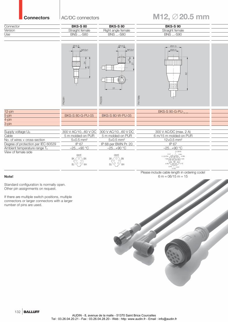
AC/DC connectors M12, ∅ 20.5 mmConnectors
ConnectorVersionUse
12-pin5-pin4-pin3-pin
Supply voltage UB
CableNo. of wires × cross-sectionDegree of protection per IEC 60529Ambient temperature range Ta
View of female side
BKS-S 80Straight femaleBNS ...-S80
BKS-S 80-G-PU-05
300 V AC/10...60 V DC5 m molded-on PUR
5×0.5 mm²IP 67
–25...+90 °C
BKS-S 80Right angle female
BNS ...-S80
BKS-S 80-W-PU-05
300 V AC/10...60 V DC5 m molded-on PUR
5×0.5 mm²IP 68 per BWN Pr. 20
–25...+90 °C
BKS-S 90Straight femaleBNS ...-S90
BKS-S 90-G-PU-_ _
300 V AC/DC (max. 2 A)6 m/15 m molded-on PUR
12×0.5 mm²IP 67
–25...+90 °C
Please include cable length in ordering code!6 m = 06/15 m = 15Note!
Standard configuration Is normally open.Other pin assignments on request.
If there are multiple switch positions, multipleconnectors or larger connectors with a largernumber of pins are used.
132AUDIN - 8, avenue de la malle - 51370 Saint Brice Courcelles
Tel : 03.26.04.20.21 - Fax : 03.26.04.28.20 - Web : http: www.audin.fr - Email : [email protected]
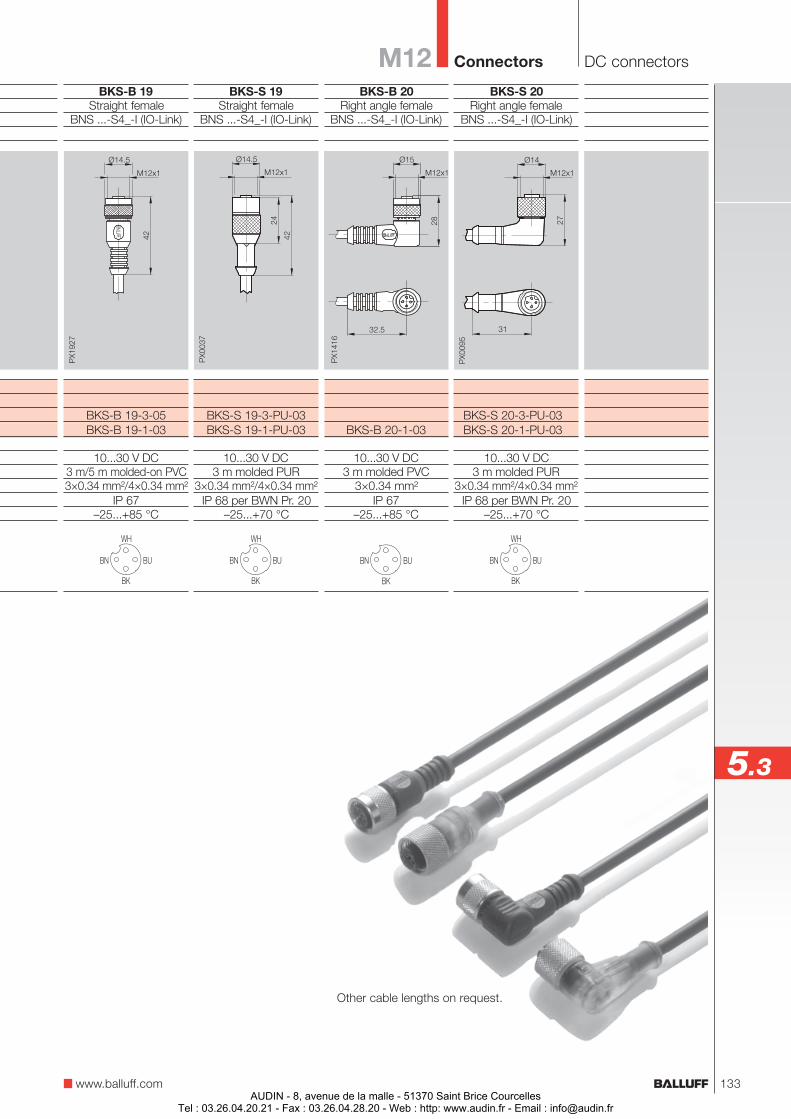
BKS-B 19Straight female
BNS ...-S4_-I (IO-Link)
BKS-B 19-3-05BKS-B 19-1-03
10...30 V DC3 m/5 m molded-on PVC3×0.34 mm²/4×0.34 mm²
IP 67–25...+85 °C
BKS-S 19Straight female
BNS ...-S4_-I (IO-Link)
BKS-S 19-3-PU-03BKS-S 19-1-PU-03
10...30 V DC3 m molded PUR
3×0.34 mm²/4×0.34 mm²IP 68 per BWN Pr. 20
–25...+70 °C
BKS-B 20Right angle female
BNS ...-S4_-I (IO-Link)
BKS-B 20-1-03
10...30 V DC3 m molded PVC
3×0.34 mm²IP 67
–25...+85 °C
BKS-S 20Right angle female
BNS ...-S4_-I (IO-Link)
BKS-S 20-3-PU-03BKS-S 20-1-PU-03
10...30 V DC3 m molded PUR
3×0.34 mm²/4×0.34 mm²IP 68 per BWN Pr. 20
–25...+70 °C
DC connectorsM12 Connectors
www.balluff.com
5.3
Other cable lengths on request.
133AUDIN - 8, avenue de la malle - 51370 Saint Brice Courcelles
Tel : 03.26.04.20.21 - Fax : 03.26.04.28.20 - Web : http: www.audin.fr - Email : [email protected]
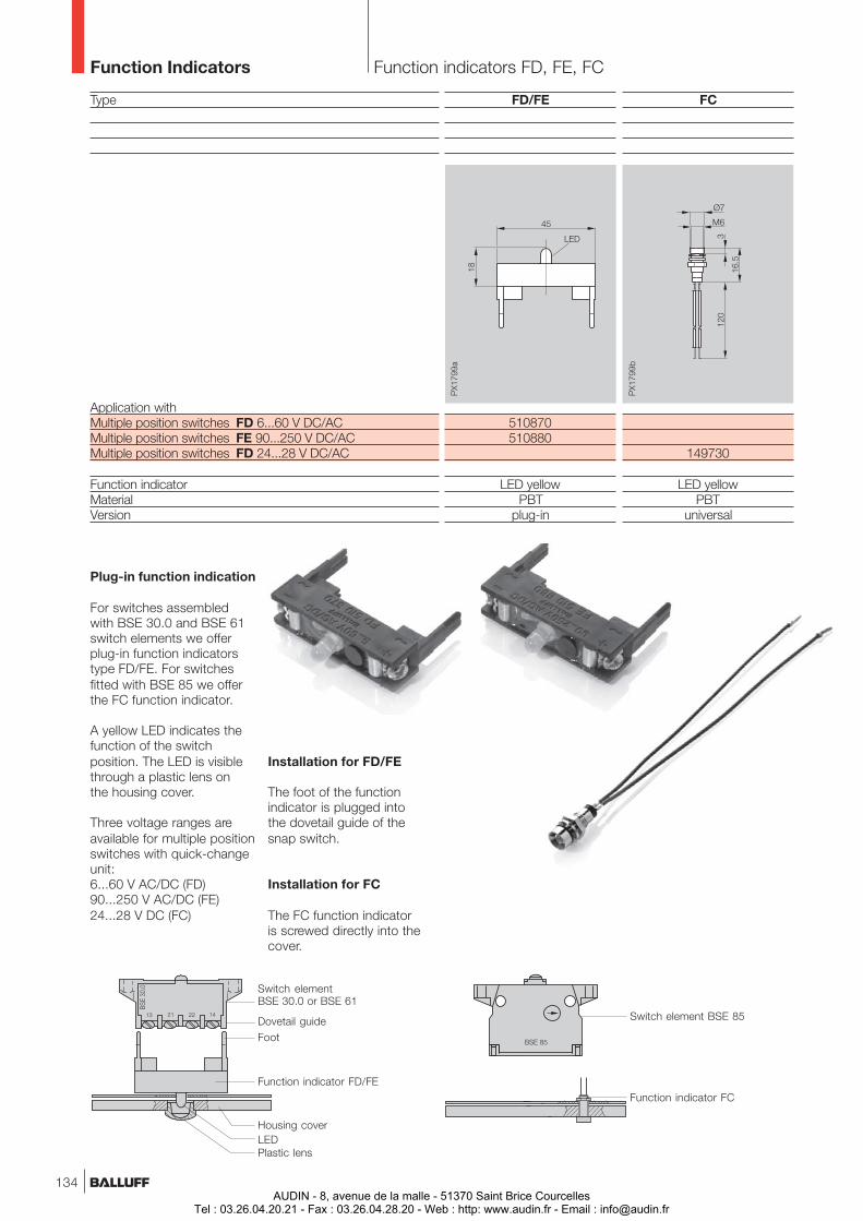
Function indicators FD, FE, FCFunction Indicators
Plug-in function indication
For switches assembledwith BSE 30.0 and BSE 61switch elements we offerplug-in function indicatorstype FD/FE. For switchesfitted with BSE 85 we offerthe FC function indicator.
A yellow LED indicates thefunction of the switchposition. The LED is visiblethrough a plastic lens onthe housing cover.
Three voltage ranges areavailable for multiple positionswitches with quick-changeunit:6...60 V AC/DC (FD)90...250 V AC/DC (FE)24...28 V DC (FC)
Switch elementBSE 30.0 or BSE 61
Dovetail guide
Function indicator FD/FE
Housing cover
Installation for FD/FE
The foot of the functionindicator is plugged intothe dovetail guide of thesnap switch.
Installation for FC
The FC function indicatoris screwed directly into thecover.
Type
Application withMultiple position switches FD 6...60 V DC/ACMultiple position switches FE 90...250 V DC/ACMultiple position switches FD 24...28 V DC/AC
Function indicatorMaterialVersion
FC
149730
LED yellowPBT
universal
Foot
LEDPlastic lens
FD/FE
510870510880
LED yellowPBT
plug-in
Switch element BSE 85
Function indicator FC
134AUDIN - 8, avenue de la malle - 51370 Saint Brice Courcelles
Tel : 03.26.04.20.21 - Fax : 03.26.04.28.20 - Web : http: www.audin.fr - Email : [email protected]

No.
832
951
E ·
Edi
tion
0807
; Sub
ject
to m
odifi
catio
n. R
epla
ces
Edi
tion
0602
.
Obje
ct
Dete
cti
on
– M
echa
nica
l and
Indu
ctiv
e S
ingl
e an
d M
ultip
le P
ositi
on S
witc
hes
Object DetectionMechanical and Inductive Single and Multiple Position Switches
Balluff GmbHSchurwaldstrasse 973765 Neuhausen a.d.F.GermanyPhone +49 7158 173-0Fax +49 7158 [email protected] www.balluff.com
Object Detection
Linear Position Sensing
Industrial Identifi cation
Industrial Networking and Connectivity
Mechanical Accessories
AUDIN - 8, avenue de la malle - 51370 Saint Brice CourcellesTel : 03.26.04.20.21 - Fax : 03.26.04.28.20 - Web : http: www.audin.fr - Email : [email protected]