Embed Size (px)
Citation preview

Page i December 18, 2017
BALANCING Market
DETAILED DESIGN

Page ii December 18, 2017
Table of Contents
Executive Summary ................................................................................................. 1
1 Introduction ....................................................................................................... 14
1.1 Importance of Balancing Electricity Markets................................................. 14
1.2 Network Code on Electricity Balancing ........................................................ 15
1.3 Architecture of the Balancing and Ancillary Services Market under the Target
Model ........................................................................................................... 15
1.3.1 Balancing and Ancillary Services Market Definition .............................. 15
1.3.2 Balancing Services Procurement ......................................................... 16
1.3.3 Central Dispatch Principle .................................................................... 20
1.3.4 Balance Responsibility and Imbalance Settlement ............................... 22
1.3.5 Summary .............................................................................................. 23
2 RES Participation in the Balancing and Ancillary Services Market .............. 25
2.1 Introduction .................................................................................................. 25
2.2 Specific Features of RES Units .................................................................... 26
2.3 RES Units Categorization in terms of Market Participation .......................... 28
3 Demand Response Participation in the Balancing and Ancillary Services
Market ................................................................................................................ 30
3.1 Introduction .................................................................................................. 30
3.2 Specific Features of DR Resources ............................................................. 30
3.3 DR Units Categorization in terms of Market Participation ............................ 32
3.4 Role of Aggregators in Enabling Market Participation of DR Resources ...... 33
3.5 Contractual Design for the Incorporation of DR Resources in the Greek
Electricity Market .......................................................................................... 34
3.5.1 Model A: Use of bilateral contracts ....................................................... 35
3.5.2 Model B: Settlement Through Regulated Prices .................................. 40

Page iii December 18, 2017
3.5.3 Model C: Assumption of Market Risk Entirely by DR Aggregator ......... 41
3.6 Baseline Methodology .................................................................................. 44
3.7 Gradual Participation of DR Resources in the Different Areas of the Greek
Wholesale Market ........................................................................................ 45
4 Optimum Integration of RES Units and DR Resources in the Balancing and
Ancillary Services Market ................................................................................ 47
5 Stakeholders in the Balancing and Ancillary Services Market ..................... 56
5.1 Entities ......................................................................................................... 56
5.2 Registries ..................................................................................................... 60
5.2.1 Generating Units Registry .................................................................... 60
5.2.2 Dispatchable Load Portfolios Registry ................................................. 61
5.2.3 Dispatchable RES Portfolios Registry .................................................. 62
5.3 Balancing Services Entities/Providers .......................................................... 63
5.4 Balance Responsible Entities/Parties ........................................................... 64
5.5 Participation Fees ........................................................................................ 65
6 Interface with the Forward, Day-Ahead and Intra-Day Markets .................... 66
7 Integrated Scheduling Process ....................................................................... 68
7.1 Timeframe of the Integrated Scheduling Process......................................... 68
7.2 Balancing Services Products ........................................................................ 71
7.3 Dispatch Period ............................................................................................ 72
7.4 Submission of Non-Availability Declarations ................................................ 72
7.5 Submission of Techno-Economic Declarations ............................................ 74
7.5.1 Contents of Techno-Economic Declarations ......................................... 74
7.5.2 Techno-Economic Declaration submission procedure .......................... 77
7.5.3 Acceptance and rejection of Techno-Economic Declarations by the
TSO ...................................................................................................... 77
7.6 Submission of Balancing Energy Offers ....................................................... 77
Page iv December 18, 2017
7.6.1 General provisions ............................................................................... 78
7.6.2 Format of the Balancing Energy Offers in the Integrated Scheduling
Process ................................................................................................ 80
7.6.3 Modification and acceptance of the Balancing Energy Offers in the
Integrated Scheduling Process ............................................................ 82
7.6.4 Consequences of non-submission of Balancing Energy Offers ............ 83
7.7 Submission of Reserve Capacity Offers ....................................................... 83
7.7.1 General provisions ............................................................................... 83
7.7.2 Format of the Reserve Capacity Offers in the Integrated Scheduling
Process ................................................................................................ 84
7.7.3 Modification and acceptance of the Reserve Capacity Offers in the
Integrated Scheduling Process ............................................................ 85
7.7.4 Consequences of non-submission of Reserve Capacity Offers ........... 85
7.8 Integrated Scheduling Process Data ............................................................ 86
7.9 Integrated Scheduling Process Solution Methodology ................................. 88
7.10 Mathematical Formulation .................................................................... 89
7.10.1 Objective Function ................................................................... 89
7.10.2 Balancing Energy Cost ............................................................. 89
7.10.3 Reserve Capacity Cost ............................................................ 90
7.10.4 Start-up Cost ............................................................................ 91
7.10.5 Penalty Cost ............................................................................. 91
7.10.6 Dispatch Scheduling and Reserve Capacity Allocation
Concept ................................................................................................ 93
7.10.7 Balancing Services Provider Operating States ........................ 96
7.10.8 Start-up Phase ......................................................................... 97
7.10.9 De-synchronization Phase ..................................................... 101
7.10.10 Logical Status of Commitment ............................................... 101
7.10.11 Minimum Up / Down Time Constraints ................................... 102

Page v December 18, 2017
7.10.12 Power Output Constraint ........................................................ 103
7.10.13 Balancing Energy Constraints ................................................ 103
7.10.14 Capacity Constraints .............................................................. 106
7.10.15 Hydro Mandatory Generation ................................................. 109
7.10.16 Maximum Daily Energy Constraint .......................................... 110
7.10.17 Ramping Constraints ............................................................... 111
7.10.18 Reserve Capacity Ramping Constraints ................................. 112
7.10.19 Reserve Capacity Contribution Constraints ............................ 113
7.10.20 Zonal Imbalance covering Constraints (Inter-zonal Transfer
Model) 118
7.10.21 Zonal Imbalance covering Constraints (Flow-Based Model) .. 124
7.10.22 Reserve Requirements Constraints ....................................... 125
7.10.23 Generic Constraints ............................................................... 128
7.10.24 Specific Operating Constraints for the Loading BSEs
(Dispatchable Load Portfolios) ........................................................... 129
7.11 Responsibilities of the Transmission System Operator .............................. 131
7.12 Integrated Scheduling Process Results ............................................. 135
7.13 Integrated Scheduling Process Results Publication ........................... 136
7.14 Integrated Scheduling Process Results Monitoring ............................ 136
8 Real-Time Balancing Energy Market ............................................................. 137
8.1 General ...................................................................................................... 137
8.2 Dispatch Period .......................................................................................... 138
8.3 Balancing Services Products – Dispatch Process ...................................... 138
8.3.1 Balancing Services Products.............................................................. 138
8.3.2 mFRR Process (two executions methods) ......................................... 139
8.4 Modification of Balancing Energy Offers by the Balancing Services
Providers .................................................................................................... 143

Page vi December 18, 2017
8.5 Obligations of BSPs in the context of the Real-Time Balancing Energy
Market ........................................................................................................ 146
8.6 Real-Time Balancing Energy Market Input Data ........................................ 147
8.7 Real-Time Balancing Energy Market Solution Methodology ...................... 148
8.8 mFRR Process Mathematical Formulation – 1st execution method (Single
Techno-economic Clearing) ........................................................................ 149
8.8.1 Objective Function ............................................................................. 149
8.8.2 Balancing Energy Cost ....................................................................... 150
8.8.3 Penalty Cost ....................................................................................... 151
8.8.4 Power Output Constraint .................................................................... 152
8.8.5 Balancing Energy Constraints ............................................................ 153
8.8.6 Capacity Constraints .......................................................................... 155
8.8.7 Ramping Constraints .......................................................................... 158
8.8.8 Maximum Daily Energy Constraint ..................................................... 159
8.8.9 Mandatory Activation Process prior to the mFRR Clearing ................ 160
8.8.10 Zonal Imbalance covering Constraints (Inter-zonal Transfer
Model) 161
8.8.11 Zonal Imbalance covering Constraints (Flow-Based Model) .. 164
8.9 Mathematical Formulation of the 2nd implementation phase of the mFRR
process (Conversion Process / Economic Clearing) .................................. 165
8.9.1 Conversion Process ........................................................................... 166
8.9.2 Objective Function ............................................................................. 166
8.9.3 Capacity Constraints .......................................................................... 167
8.9.4 Ramping Constraints .......................................................................... 169
8.9.5 Maximum Daily Energy Constraint ..................................................... 170
8.9.6 Penalty Cost ....................................................................................... 170
8.9.7 Conversion of the Balancing Energy Offers prior to mFRR Clearing and
Creation of the Final Merit Order ........................................................ 171

Page vii December 18, 2017
8.9.8 mFRR Clearing – Mathematical Formulation ..................................... 173
8.9.9 Objective Function ............................................................................. 174
8.9.10 Balancing Energy Cost ........................................................... 174
8.9.11 Penalty Cost ........................................................................... 175
8.9.12 Balancing Energy Constraints ................................................ 175
8.9.13 Zonal Imbalance covering Constraints (Inter-zonal Transfer
Model) 176
8.9.14 Zonal Imbalance covering Constraints (Flow-Based Model) .. 177
8.10 mFRR Clearing Results ..................................................................... 179
8.11 Dispatch Instructions stemming from the mFRR Problem Solution ............ 180
8.12 Direct Activation of mFRR .................................................................. 182
8.13 Activation of aFRR ............................................................................. 183
8.14 Responsibilities of the Transmission System Operator ...................... 183
9 Settlements...................................................................................................... 185
9.1 General Provisions ..................................................................................... 185
9.1.1 Balancing Market Settlements............................................................ 185
9.1.2 Responsibilities of the Transmission System Operator ...................... 185
9.1.3 Obligations of the Distribution System Operator in the context of the
Settlemnt Procedure .......................................................................... 186
9.1.4 Balancing Market Accounts ................................................................ 187
9.1.5 Settlement Scope ............................................................................... 187
9.1.6 Settlement Input Data ........................................................................ 188
9.2 Balancing Energy and Imbalance Settlement ............................................. 190
9.2.1 Balancing Energy and Imbalance Definitions ..................................... 190
9.2.2 mFRR Balancing Energy Price ........................................................... 193
9.2.3 Remuneration of Provided Balancing Energy .................................... 194
9.2.4 Remuneration of Provided mFRR Balancing Energy ......................... 194

Page viii December 18, 2017
9.2.5 Remuneration Balancing Energy Offers activated for reasons other
balancing ............................................................................................ 195
9.2.6 Remuneration of Provided aFRR Balancing Energy .......................... 195
9.2.7 Derivation of the Imbalance Settlement Price .................................... 195
9.2.8 Imbalance Settlement ........................................................................ 196
9.3 Balancing Capacity Settlement .................................................................. 197
9.3.1 Balancing Capacity Settlement Period ............................................... 197
9.3.2 Remuneration Calculation .................................................................. 197
9.4 Uplift Accounts ........................................................................................... 199
9.4.1 Uplift Accounts kept by the Transmission System Operator ............... 199
9.4.2 System Losses Uplift Account UA-1 ................................................... 199
9.4.3 Balancing Capacity Uplift Account UA-2 ............................................ 200
9.4.4 Ancillary Services Uplift Account UA-3 ............................................... 201
9.4.5 Contracted Units Uplift Account UA-4 ................................................ 201
9.4.6 Emergency Imports and Exports Uplift Account UA-5 ........................ 201
9.5 Non-compliance Charges Settlement ......................................................... 202
9.5.1 Non-Compliance with Ancillary Services Dispatch Instructions by
Balancing Service Providers .............................................................. 202
9.5.2 Consequences of non-lawful submission of Non-Availability Declarations
........................................................................................................... 203
9.5.3 Consequences of non-lawful Techno-Economic Declaration .............. 204
9.5.4 Consequences of non-submission of Balancing Energy Offers .......... 204
9.5.5 Consequences of non-submission of Reserve Capacity Offers ......... 205
9.5.6 Consequences of significant non-performance of activated upward and
downward Balancing Energy by a Balancing Service Entity .............. 206
9.5.7 Consequences of significant systematic deviations in the demand
purchased by Load Representatives .................................................. 208

Page ix December 18, 2017
9.5.8 Consequences of significant systematic deviations in the actual
generation of a Non-Dispatchable RES Portfolio ............................... 209
9.5.9 Non-Compliance Charge for import/export deviations ......................... 211
9.5.10 Consequences of non-performance by a Contracted Unit ...... 211
9.5.11 Handling of the Non-Compliance amount .............................. 212
9.6 Balancing Market Settlement Process ....................................................... 212
10 Annex A: Nomenclature ................................................................................. 215
11 Annex Β: Computation of Reserve Requirements ....................................... 244
11.1 Frequency Containment Reserve ............................................................... 244
11.2 Automatic Frequency Restoration Reserve ................................................ 245
11.3 Manual Frequency Restoration Reserve and Replacement Reserve ......... 248
12 Annex C: RES Units Categorization under Greek Law 4414/2016 .............. 250

Page x December 18, 2017
List of Tables
Table 3-1: Settlement Example of model A .............................................................. 38
Table 3-2: Settlement Example of model C .............................................................. 44
Table 4-1: Market design variables and respective decisions for the Greek Balancing
and Ancillary Services Market ........................................................................... 55
Table 7-1: Techno-Economic Declarations’ contents ............................................... 76
Table 10-1: Nomenclature ...................................................................................... 243

Page xi December 18, 2017
List of Figures
Figure 1-1: Successive “layers” of Reserve Capacity activation (Source: ENTSO-E)
........................................................................................................................... 19
Figure 1-2: Balancing in a Central Dispatch system (Source: ENTSO-E) ................ 21
Figure 1-3:Basic elements and interrelations of the Balancing and Ancillary Services
Market ................................................................................................................ 24
Figure 3-1: Relationships between market parties in model A ................................. 36
Figure 3-2: Relationships between entities in model B ............................................. 40
Figure 3-3: Relationships between market parties in model C ................................. 42
Figure 3-4: Indicative Baseline during load curtailment ............................................ 45
Figure 7-1: Timeframe of the Integrated Scheduling Process programmed executions
........................................................................................................................... 70
Figure 7-2: Upward Balancing Energy step-wise function ........................................ 81
Figure 7-3: Downward Balancing Energy step-wise function ................................... 81
Figure 7-4: Dispatch Scheduling in the ISP model ................................................... 94
Figure 7-5: Reserve Capacity allocation in the ISP model ....................................... 95
Figure 8-1: mFRR clearing process (two implementation phases) ......................... 141
Figure 8-2: Real-Time Balancing Energy Market (RTBEM) Gate Closure Times ... 144
Figure 8-3: Conversion of the Balancing Energy Offers prior to their insertion in the
mFRR clearing ................................................................................................. 173

Page 1 December, 2017
Executive Summary
ECCO International (“ECCO”) has been commissioned by the Joint Research Centre
(JRC) of the European Commission to develop a Detailed Level Design, the Market
Codes and the IT Functional Specifications for the Target Model-based energy market
in Greece. This includes the Forward, Day-Ahead, and Intraday Markets for the Market
Operator (LAGIE) and the Balancing Market for the Transmission System Operator
(ADMIE). The proposed market design contained in the report draws upon the High
Level Market Design executed by ECCO in 2014.
The work contained in this report focuses on the detailed market design of the
Balancing and Ancillary Services market (BASM) for the ADMIE. The report specifies
the participating entities and their roles and obligations, the necessary functions and
processes to be implemented by ADMIE, the optimization problems that should be
formulated and cleared in the Balancing and Ancillary Services Market, and the
Balancing Energy and imbalance settlement rules. The market design for the direct
participation of Renewable Energy Sources (RES) and Demand Response (DR)
resources in the new Balancing and Ancillary Services Market in Greece, taking into
account the provisions of the recent Greek Law 4414/2016, are also included.
The harmonization of the Greek electricity market with the provisions of ENTSO-E
Network Codes is mandatory and necessary to achieve Europe-wide coupling with the
other European wholesale electricity markets, in accordance with the so-called “Target
Model”. Based on the RAE Decision 67/2017, ADMIE is requested to implement, inter
alia, the necessary infrastructure for the management and operation of the Balancing
and Ancillary Services Market. The implementation and operation by ADMIE of an
Information System for system Balancing and for the procurement and activation of
Ancillary Services, compatible with the provisions of ENTSO-E Network Codes, which
will ensure the reliable operation of the power system, is of paramount importance and
is considered as a basic prerequisite for the timely achievement of the reorganization
of Greek wholesale electricity market in accordance with the Target Model. The main
target is to achieve a smooth transition and efficient integration of the Greek wholesale
electricity market into the single European electricity market.
The Balancing Market is a very important market function which lies at the junction of
the financial and physical activities that shall take place at the Greek electricity market
and is directly related to the procurement of market products and services that affect
the reliability of the power system. Therefore, special attention must be paid to this
market function, since at the present time there is no actual operational experience of
a separate balancing mechanism - in accordance with the ENTSO-E’s Target Model -
in the Greek electricity sector.
The BASM design constitutes a complex topic, due to the large number of design
variables and its (often) divergent policy objectives of security of supply and economic
efficiency. At a European level, as opposed to the clear target models followed for the
integration of other markets (e.g. European Regulation 2015/1222), the Balancing

Page 2 December, 2017
Market integration design has not been fully vetted yet. The Commission Regulation
that establishes the directives on electricity balancing1 (stemming from the Electricity
Balancing Network Code – EB NC) has not come into effect yet. Further, the Target
Model itself is a bit vague on important details regarding the desirable end-state of
cross-border balancing, and the clear targets for the different kinds of balancing
services. Hence, rather than detailing a specific target model design, the EB NC lays
out the general processes towards realizing the integrated Balancing Market’s
efficiency gains; namely, a better utilization of the cheapest resources by providing
access to foreign balancing services and thus mitigating concentration levels in
national Balancing Markets, as well as increased operational security2. The
implementation of Balancing Markets spanning across national frontiers constitutes an
important last step towards the full completion of the Target Model.
Dispatch Arrangements
In order to operate a secure and reliable power system in an economic and efficient
manner within the liberalized framework of competitive electricity markets, European
electricity markets have developed different dispatch arrangements, which can be
essentially divided into two high level categories: Self-Dispatch and Central Dispatch
models. These models vary by placing the balancing responsibilities on different
entities. In Self-Dispatch systems, Balance Responsible Parties (BRPs) issue
commitment decisions and determine the desired dispatch position of their resources
(self-scheduling), based on their own economic criteria and taking into account
generating unit technical constraints in conjunction with the demand elements they are
balancing with. In real-time, the BRPs acquire balancing instructions (portfolio-based
instructions) by the TSO, which they then distribute to their resources (self-dispatch)
(e.g., in Germany, Switzerland, Austria and Sweden3). Central Dispatch is based on a
dispatch architecture where the TSO considers all balancing resources and the needs
of the system overall, to determine an efficient operational schedule (central
scheduling) and issue optimal dispatch instructions in real-time (central dispatch)
directly to the available resources (e.g. in Italy, Ireland, Poland and Greece and all the
US ISOs). A hybrid model also applies; participants participate with portfolio-bidding
in the FM, DAM and IDM, determine their own schedule position (self-scheduling) and
self-nominate; then, the TSO centrally issues dispatch instructions per entity in real-
1 ENTSO-E, Draft Network Code on Electricity Balancing, Feb. 2013. Available online at:
https://www.entsoe.eu/Documents/Network%20codes%20documents/NC%20EB/Informal_Service_Level_EBGL_16-03-2017_Final.pdf
2 ENTSO-E, Supporting Document for the Network Code on Electricity Balancing, October 2013. Available online at:
:https://www.entsoe.eu/fileadmin/user_upload/_library/resources/BAL/131021_NC_EB_Supporting_Document_2013.pdf
3 ENTSO-E WGAS, Survey on Ancillary services procurement, Balancing market design 2015, May 2016. Available online at:
https://www.entsoe.eu/Documents/Publications/Market%20Committee%20publications/WGAS%20Survey_04.05.2016_final_publication_v2.pdf?Web=1

Page 3 December, 2017
time, on the basis of the submitted Nominations (e.g. in France4).
Although most of the energy markets in Europe are based on a Self-Dispatch principle,
the EB NC envisions an efficient integration of Central Dispatch and Self-Dispatch
systems within the integrated Balancing Market in Europe, without jeopardizing the
efficient functioning of Central Dispatch systems. Self-Dispatch provides firmness of
market positions, provided that the interventions of the TSO to maintain system
security are small.
A rigorous treatment of the comparison between Self-Dispatch and Central Dispatch
models is outside the scope of this work, but based on ECCO’s extensive experience
in designing and implementing both over the course of two decades worldwide we can
summarize the debate as follows: Proponents of the Self-Dispatch architecture
claim that this model is the most efficient in the long-term given the freedom it
affords to participants to determine their own dispatch positions, even though
it may result in loss of efficiency in the short-term. We believe that decentralized
designs can overcome to some extent these issues but, in general, suffer
efficiency losses due to the loss of spatial and temporal coordination among
resources. On the other hand, proponents of the Central Dispatch models claim
that this model is the most efficient exactly because of the optimal coordination
and optimization of all system resources by the TSO, the entity which has full
visibility of the system constraints and the generating resources.
The dominant player in Greece (PPC) seeks flexibility in the portfolio-bidding
approach, scheduling and dispatch, due to the short- and medium-term constraints
faced, as follows:
a) lignite units: for better handling of environmental constraints (e.g. constraints on
NOx, SOx emissions of lignite plants, and limited number of working hours from 1st
January 2016 till 31st December 2023);
b) gas units: for better handling of take-or-pay constraints on the gas supply contract;
and,
c) hydro units: for better handling of the hydro reservoir constraints, especially for
cascading units in the same river.
However, given the physical and technical characteristics of the Greek electricity
market (system size, market structure, plant portfolios, RES penetration, etc.), along
with policy objectives (transparency, competition issues, small participants’ aversion
for risk in balancing their positions), ECCO strongly recommends the adoption of the
central scheduling and dispatch market architecture as an important principle to be
4 RTE, Rules relative to Programming, the Balancing Mechanism and Recovery of Balancing Charges, April
2016. Accessed 20.12.16:
http://clients.rte-france.com/htm/an/offre/telecharge/Section_1_Ma_20160706_EN.pdf

Page 4 December, 2017
maintained in the new market design in Greece. Specifically, we recommend the
Central Dispatch architecture for the following reasons:
1) A self-scheduling scheme would result in participants making decisions on the
basis of their own criteria. This means that, all units would be scheduled to suit
their producers’ preferred profiles with no consideration of the overall system
needs or interactions with system conditions or other generators. On the contrary,
in central scheduling the TSO will have all the information for the entire system to
execute an overall optimal schedule for the generating fleet.
2) With a relatively small number of units and only one major portfolio available (the
PPC portfolio), in the Greek system, the likelihood of system balancing actions
that would require action by the TSO in real-time is greater compared to a larger
system. The degree of intervention required by the TSO is largely due to (a) the
physical attributes of the system, (b) the security constraints that need to be
observed by the TSO in terms of maintaining / engaging the adequate reserves,
c) the availability of one major portfolio, and (c) the engagement of participants. In
general, a Self-Dispatch market causes significantly more concern to the TSOs
due to lack of coordination and visibility of the individual resources by the TSO
[34].
Thus, focusing on the choice of Central Dispatch, the Supporting Document of the EB
NC [32] describes a Central Dispatch process generally consisting of two phases: (a)
the scheduling phase referred to as Integrated Scheduling Process (ISP), and (b) the
Real-Time Balancing Energy Market (RTBEM). Before proceeding with the analysis of
these two phases, the timing of the Reserve Capacity procurement along with the
relevant options for the Greek electricity market is analyzed and presented.
Timing of the Reserve Capacity procurement
There are two options for the timing of the Reserve Capacity procurement: (a) Reserve
Capacity and Balancing Energy can be procured in the same – compulsory for the
balancing resources – scheduling process in the daily timeframe (following the Italian
approach), or (b) explicit auctioning of Reserve Capacity in different timeframes from
year- to week-ahead can be considered. The first option seems to be more familiar
with the current day-ahead procedures in the Greek electricity market (co-optimization
of energy and reserves in the DAM), while the second seems to be more consistent
with the spirit of the Target Model and the EB NC, which promote independent market-
based mechanisms for different standard products (for Reserve Capacity and
Balancing Energy).
This design variable has a large impact on availability of balancing resources and
utilization efficiency, and a very large impact on price efficiency5. Generally, a short
5 R.A.C. Van Der Veen, Designing Multinational Electricity Balancing Markets, PhD thesis, September 2012.
Accessed 20.12.16:
http://repository.tudelft.nl/islandora/object/uuid:e1c5777e-be4c-4df3-a764-
f622c828c709/?collection=research

Page 5 December, 2017
contracting period for Reserve Capacity appears preferable for efficiency reasons. If it
does not jeopardize the availability of balancing resources, a daily Reserve Capacity
procurement after the DAM clearing appears the best option. Such option is also
preferable for facilitating the participation of RES and demand response resources in
the Reserve Capacity procurement process. The gate closure for Reserve Capacity
offers submission should be as close as possible to the Reserve Capacity
procurement, to enable balancing resources to bid with as much certainty on
availability and prices as possible. A possible combination of the daily market for
Reserve Capacity with a longer-term (month, annual) pre-qualification of services,
guaranteeing the TSO enough reserve potential, can also be considered, although it
may act as an entry barrier for two reasons: a) unavailability of certain resources for
long periods of time and b) potential high administrative costs. However, the main goal
here is to attain simplicity of the overall market procedure (at least in the first stage of
the reformed Greek electricity market), which will serve as a tool for the adaptation of
all involved parties to the new market regime and consequently enhance liquidity. To
this end, a daily Reserve Capacity procurement process shall be implemented,
which will be part of the Integrated Scheduling Process (ISP).
Integrated Scheduling Process (ISP)
The 1st phase of the Central Dispatch process is the Integrated Scheduling Process
(ISP). The ISP shall be performed by the TSO to:
a) allocate various types of Reserve Capacity to the eligible balancing resources,
b) procure upward and downward Balancing Energy for the relief of anticipated
system imbalances6,
c) perform congestion management, and
d) adjust appropriately the resources’ previous market positions, so as to produce a
technically feasible schedule for each resource.
The ISP essentially involves the execution of a unit commitment model and solves a
co-optimization problem of Balancing Energy and Reserve Capacity, which constitutes
a Mixed-Integer Linear Programming (MILP) model with both binary and continuous
variables. A day-ahead scheduling phase (ISP1) shall be executed, followed by two
scheduled respective executions repeated successively in the intraday stage (ISP2 –
ISP3), appropriately coordinated with the respective Intra-Day Market sessions. The
length of the scheduling time unit in the ISP should be as short as possible, in order
to more accurately accommodate (a) sub-hourly resource technical limitations, and (b)
renewable generation and load variability in the scheduling results. A half-hourly
scheduling time unit has been decided for the ISP.
6In the ISP stage, the upward and downward Balancing Energy quantities are proactively scheduled on top of the
latest market positions of the eligible resources, and are not firm and not subject to any resource -TSO
settlement; they are only indicative of the actual Balancing Energy that shall be activated in real-time.

Page 6 December, 2017
The same offers for ISP1 shall be taken into account also for the following ISPs, (no
new re-bidding process for Reserve Capacity and Balancing Energy during the ISP),
a provision which is similar with the current dispatch scheduling of the Greek TSO.
Despite the three “scheduled” ISP executions, in case a major event takes place
during day D, or even in the afternoon of day D-1, which effects in a major way the
unit scheduling and reserve allocation during day D, the TSO shall be allowed to
execute the ISP problem “on-demand”, in order to derive an updated schedule for the
available resources. The eligible resources to participate in the Greek ISP comprise
the generating units (including auto-producer conventional units), the Demand
Response (DR) resources, and the RES units and portfolios, in case the latter have
the technical capabilities to provide the required balancing services.
Most Reserve Capacity products described in the EB NC and in the draft Commission
Regulation establishing a guideline on electricity transmission system operation7
(including the Load Frequency Control and Reserves Network Code) shall be procured
in the ISP: (a) Frequency Containment Reserve (FCR), (b) Frequency Restoration
Reserve with automatic activation (aFRR) and manual activation (mFRR). Also,
according to Article 19 of the EB NC, the procurement of each type of Reserve
Capacity should be carried out separately in the upward and downward directions.
In the above context, the results of any given ISP execution contain the
following: (a) half-hourly schedules (i.e. preliminary schedules) of all balancing
resources (per entity), (b) commitment decisions and prospective payments for
the start-up costs of the resources, (c) AGC status for the resources providing
aFRR, and (d) Reserve Capacity awards and prices for the settlement of Reserve
Capacity.
Real-Time Balancing Energy Market (RTBEM)
According to the NC EB, the RTBEM shall be a separate market for procuring mFRR
and aFRR Balancing Energy in real-time, balancing supply and demand while
considering all applicable real-time system conditions. There will be two different
processes for the procurement of mFRR Balancing Energy and aFRR Balancing
Energy, namely an “mFRR process” and an “aFRR process”, respectively.
The mFRR process shall be executed every 15 minutes, for the dispatch of the
Balancing Service Providers for the following 15-minute period. The mFRR process
shall not be a unit commitment application, but rather an economic dispatch process
which respects and follows the ISP commitment decisions, unless a relevant resource
suffers a forced outage. In that respect, the mFRR process shall refine the half-hourly
ISP schedules of the dispatchable resources at a more granular level, by activating
upward and downward mFRR Balancing Energy appropriately, to address continuous
changes in the system load, renewable generation and resource availability. The half-
7 Draft Commission Regulation establishing a guideline on electricity transmission system operation. Accessed
20.07.17:
https://ec.europa.eu/energy/sites/ener/files/documents/SystemOperationGuideline%20final%28provisional%2
904052016.pdf

Page 7 December, 2017
hourly schedules of inter-tie resources (imports and exports) shall not be re-dispatched
in the mFRR process, unless due to an outage, as is the current situation.
Moreover, within the spirit of the EB NC and the Target Model itself, the clearing
engine of the mFRR process shall not procure any additional Ancillary Services.
Indeed, (a) the mFRR awards determined in the ISP shall be effectively released
by the eligible resources in the mFRR process, in order to be optimally activated
as Balancing Energy for the relief of the very short-term system forecasted
imbalances, while (b) the FCR and aFRR awards determined in the ISP shall
remain in effect; they shall then be released closer to real-time (i.e. within the
RTBEM dispatch period, e.g. through the operation of AGC for aFRR) to manage
the load and renewable production variability and any unforeseen events taking
place at a more instant timeframe. The decision to release the capacity of the
mFRR awards in the RTBEM market is driven by the objective to ensure
sufficient liquidity in that market.
A15-min time-step shall be applied in the Greek RTBEM, even though higher aFRR
requirements may be needed (as compared to the 5-min time-step). In this context,
the RTBEM shall produce 15-min dispatch instructions for the dispatchable resources.
The various balancing resources in the Greek RTBEM shall be able to update their
Balancing Energy offers (until the RTBEM gate closure) only with “better” prices (as
compared to the respective offers submitted at the ISP), namely with lower offers for
upward Balancing Energy and higher offers for downward Balancing Energy. The
rationale behind this decision is that substantial changes of offers during RTBEM might
lead to sub-optimal dispatch and could expose the TSO and energy consumers to high
costs; knowing in advance some results of the ISP (e.g. start-up decisions),
participants may use this knowledge to abuse market power in the RTBEM (e.g.
submit high bids in the RTBEM knowing that they will be probably cleared upon their
commitment in the ISP). Finally, Producers representing Generating Units that
participate in the RTBEM shall be obligated to submit offers for Balancing Energy
according to their maximum availability, regardless of whether they have been
awarded Reserve Capacity or not during the ISP, so that the TSO has more balancing
options in real-time.
It should be stressed that the above design concerns mainly the introduction of
the internal RTBEM in Greece, since discussions for a common pan-European
RTBEM optimization function have not been finalized yet in Europe. An
adaptation of the internal RTBEM shall be needed when cross-border balancing
is established, as analytically described in this report.
aFRR Balancing Energy is activated using the Automatic Generation Control (AGC)
function of the Transmission System Operator for frequency control as defined in
COMMISSION REGULATION (EU) 2017/1485 of 2 August 2017 establishing a
guideline on electricity transmission system operation. All Balancing Service Entities
with aFRR awards in the latest Integrated Scheduling Process are activated almost
simultaneously by the Transmission System Operator for the provision of aFRR

Page 8 December, 2017
Balancing Energy. The criteria for the activation of aFRR Balancing Energy include
the aFRR Balancing Energy Offer prices and the ramp-rates of the Balancing Service
Entities.
Phased approach for the Balancing Market in Greece
The new Balancing and Ancillary Services Market in Greece shall be implemented in
two phases, as follows:
1) In the 1st implementation phase, an internal RTBEM in Greece shall be
implemented without cross-border balancing activities with the neighbouring
TSOs. The mFRR process shall be executed locally by the TSO running a Mixed
Integer Linear Programming model that optimizes the balancing cost under system
constraints and technical constraints of the Balancing Service Providers. The
binary variables shall be used solely for the facilitation of minimum acceptance
ratio of mFRR Balancing Energy Offers in the mFRR process. The TSO shall then
send the Dispatch Instructions to the Balancing Service Providers.
The initiation of this phase relates with the 1st phase of the Intra-Day Market
implementation.
2) In the 2nd implementation phase, cross-border balancing activities shall
commence in the Greek RTBEM. The mFRR process shall change, and shall
comprise of two distinct steps: (a) the conversion of mFRR Balancing Energy
offers/bids in order to create a merit order list in each balancing direction (upwards,
downwards) for mFRR, and (b) the clearing of the mFRR process and possibly the
aFRR process in pan-European level, including cross-border transfer of Balancing
Energy. Such scheme shall foster cross-border competition and liquidity, and
avoid undue market fragmentation (in the European control areas).
Settlement of Reserve Capacity
The balancing resources shall be awarded the various types of Reserve Capacity
(upward / downward FCR, aFRR and mFRR) during the ISP executions, however their
remuneration shall be based on the actually provided reserves in real-time. The
remuneration shall be computed per half-hourly interval (in consistency with the ISP
time-step) and should be equal to the product of the Reserve Capacity (availability)
provided in real-time (maybe lower or higher than the reserved capacity in the ISP)
multiplied by the respective Reserve Offer Price of each BSP.
The recovery of the Reserve Capacity costs shall be performed through an uplift
account by the Load Representations pro-rata to their represented demand.
Settlement of Balancing Energy
The mFRR Balancing Energy activated during the mFRR process by a given resource
(instructed deviation) is equal to the difference between the relevant dispatch
instruction issued by the TSO directly to the resource (Central Dispatch) and the
resource’s latest market position. Since the mFRR and the respective instructions
Page 9 December, 2017
follow a 15-min time-step, the eligible resources shall be compensated for their
activated mFRR Balancing Energy based on the 15-min Balancing Energy Price
derived ex-post based on their activated Offers of the BSPs8. In case of upward mFRR
Balancing Energy, the provider shall receive the product of the activated quantity
multiplied by the upward mFRR Balancing Energy Price, whereas in case of downward
mFRR Balancing Energy, the resource shall return an amount to the TSO, equal to
the product of the activated quantity multiplied by the downward mFRR Balancing
Energy Price.
With regard to the pricing regime, all balancing resources receive one price for the
marginally accepted upward / downward mFRR Balancing Energy offer. This pricing
scheme has the obvious advantage of reflecting costs at the margin and gives better
incentives to bid at marginal costs9. Furthermore, this pricing scheme provides more
encouragement for resources to invest in appropriate generation capacity, and gives
robust price signals and incentives for the development of Demand Response.
It should be noted, though, that the activation of Balancing Energy offers for non-
balancing purposes (e.g. system constraints) shall not define the marginal price and
shall be paid-as-bid. Such provision is consistent with international practices where
zonal network representation applies (e.g. in European markets)10.
The remuneration / charge for each BSE per Imbalance Settlement Period for the
Provided Upward aFRR Balancing Energy shall be calculated as the product of:
a) the Provided Upward aFRR Balancing Energy of the BSE during the Imbalance
Settlement Period, and
b) the maximum of the mFRR Balancing Energy Price and the relevant aFRR
8 In case there is no congestion between the Bidding Zones, the Upward Balancing Energy Price (in €/MWh) for
each Imbalance Settlement Period for upward activation of Balancing Energy is the price of the most expensive
bid of mFRR which has been activated to cover the System Imbalance. In case there is congestion between the
Bidding Zones, the Upward Balancing Energy Price for each Imbalance Settlement Period for upward
activation of Balancing Energy for each Bidding Zone is the price of the most expensive bid of mFRR which
has been activated to cover the Zonal Imbalance of the specific Bidding Zone.
In case there is no congestion between the Bidding Zones, the Downward Balancing Energy Price for each
Imbalance Settlement Period for downward activation of Balancing Energy is the price of the least expensive
bid of mFRR which has been activated to cover the System Imbalance. If there is congestion between the
Bidding Zones, the Downward Balancing Energy Price for each Imbalance Settlement Period for downward
activation of Balancing Energy for each Bidding Zone is the price of the least expensive bid of mFRR, which
has been activated to cover the Zonal Imbalance of the specific bidding zone. 9 A. Weidlich, D. Veit, A critical survey of agent-based wholesale electricity market models, Energy Economics,
Volume 30, Issue 4, July 2008, 1728–1759.
P. Cramton, S. Stoft, Why We Need to Stick with Uniform-Price Auctions in Electricity Markets, The Electricity
Journal, Volume 20, Issue 1, January–February 2007, 26–37. 10 The pay-as-bid principle in this case aims to provide make-whole payments to higher-cost units that are
obligingly committed to contribute to certain system constraints (e.g. voltage control), when the zonal marginal
price (i.e. shadow price obtained by market clearing) does not fully cover their costs. Apparently, this is
irrelevant in the case of nodal markets (like the US markets), where the nodal price fully compensates the
respective costs.

Page 10 December, 2017
Balancing Energy Offer price of the BSE.
The charge / remuneration for each BSE per Imbalance Settlement Period for the
Provided Downward aFRR Balancing Energy shall be calculated as the product of:
a) the Provided Downward aFRR Balancing Energy of the BSE during the Imbalance
Settlement Period, and
b) the minimum of the mFRR Balancing Energy Price and the relevant aFRR
Balancing Energy Offer price of the BSE.
Imbalance Settlement
The Imbalance Settlement function essentially allocates the balancing costs incurred
to the TSO (when activating Balancing Energy in real-time) to the market (i.e. to the
ones that caused the imbalances). As such, and according to EB NC, the Imbalance
Settlement shall be based on cost-reflective prices (i.e. from a market design point of
view, the imbalance prices shall be “linked” with the marginal prices obtained in the
RTBEM). In brief, and following standard European practices, Balance Responsible
Entities (BREs) with an uninstructed shortage shall pay the short imbalance price to
the TSO, whereas BREs with an uninstructed surplus shall receive the long imbalance
price from the TSO.
There are various possible imbalance pricing options that are compatible with the
above spirit11. Single pricing comes out the pricing regime leading to the lowest actual
imbalance costs for the BREs (but also giving weaker incentives to balance), not
discriminating against small players, and theoretically implying a “zero-sum game” for
the TSO (cost allocation efficiency). However, high system imbalance problems (or
congestion management problems) might put forward the need for a mechanism that
provides stronger incentives for BREs to be balanced. The two-price settlement
mechanism constitutes a good choice to attain the above goals in the Greek electricity
market, and it shall be used for the Imbalance Settlement function in Greece.
With regard to the calculation of the BRE imbalance quantities (uninstructed
deviations), the perimeter for counting such quantities in each Settlement Period shall
be considered per (a) conventional generating unit (including auto-producer
conventional units and units in commissioning operation), (b) Dispatchable Load
Portfolio, (c) Non-Dispatchable Load Portfolio, (e) Dispatchable RES Portfolio, (f) Non-
Dispatchable RES Portfolio, and (g) interconnection for imbalances outside the Greek
TSO's control area (TSO-to-TSO settlement). Apparently, this design variable is
directly related to the applied Central Dispatch model.
Finally, one of the most crucial design variables in Imbalance Settlement is the length
11 R.A.C. Van Der Veen, Designing Multinational Electricity Balancing Markets, PhD thesis, September 2012.
Accessed 20.12.16:
http://repository.tudelft.nl/islandora/object/uuid:e1c5777e-be4c-4df3-a764-
f622c828c709/?collection=research

Page 11 December, 2017
of the Settlement Period. In order to comply with Article 46 of the EB NC, the
Settlement Period should be 30 minutes or shorter, which is already the case in some
NWE markets (e.g. Belgium has a 15-min Settlement Period12, alongside hourly
settlement in the DAM). The shortest the Settlement Period, the more charges shall
have to be levied on participants operating entities prone to imbalances (e.g. RES,
demand). The trend in European markets is to lower the Settlement Period to 15
minutes13. For this reason, and given that the current metering infrastructure in Greece
can accommodate 15-min measurements (but not less), a quarterly Settlement Period
shall be applied in the Greek electricity market.
The Imbalance Settlement Price (in €/MWh) per Imbalance Settlement Period shall be
calculated as follows:
a) The zonal Upward Imbalance Price upztIP is computed for an Imbalance
Settlement Period t, in which the respective Bidding Zone z was short, as the
weighted average price of all activated upward Balancing Energy quantities
(aFRR and mFRR).
b) The zonal Downward Imbalance Price dnztIP is computed for an Imbalance
Settlement Period t, in which the respective Bidding Zone z was long, as the
weighted average price of all activated downward Balancing Energy quantities
(aFRR and mFRR).
c) The Reference Price ztRP shall be used in an Imbalance Settlement Period t:
(1) for all settlements with the BRPs, if the respective Bidding Zone z is
neutral (neither short nor long), or
(2) for the settlement of any BRP Imbalance, if this Imbalance is in the
opposite direction as compared to the direction of the zonal imbalance,
namely if the BRP Imbalance passively contributed to restore the zonal
balance (“passive balancing”).
The Reference Price ztRP shall be equal to the Day-Ahead Market clearing
price for the corresponding Market Time Unit, namely the Market Time Unit
within which the given Imbalance Settlement Period lies.
The Imbalance pricing regime is presented in the following Table.
12 ENTSO-E WGAS, Survey on Ancillary services procurement, Balancing market design 2015, May 2016. Available online at:
https://www.entsoe.eu/Documents/Publications/Market%20Committee%20publications/WGAS%20Survey_04.05.2016_final_publication_v2.pdf?Web=1
13 ENTSO-E, Public consultation document for the design of the TERRE (Trans European Replacement Reserves Exchange) - Project solution, March 2016. Available online at:
https://consultations.entsoe.eu/markets/terre/

Page 12 December, 2017
Zonal imbalance
Negative (Short) Zero Positive (Long)
BR
E
Imb
ala
nc
e
Negative (Short) + upztIP + ztRP + max{ up
ztIP , ztRP }
Zero - - -
Positive (Long) -min{ upztIP , ztRP } - ztRP - dn
ztIP
Structure of the Report
Chapter 1 provides a general framework of the Balancing and Ancillary Services
Market as promoted by the Target Model and the Network Code on Electricity
Balancing, and the Balancing Services (Balancing Energy and Ancillary Services)
procurement is briefly discussed. The particular processes that should be
implemented in Central Dispatch systems are also briefly described, including the
solution of an Integrated Scheduling Process (ISP) and a Real-Time Balancing Energy
Market (RTBEM).
Chapter 2 presents in brief the specific features / characteristics of RES units (as
compared to conventional units), which place their participation in the wholesale
market in a different perspective, and presents the categorization of RES units in terms
of market participation taking into account the provisions of the recent Greek Law
4414/2016.
Chapter 3 presents in brief the specific features / characteristics of DR resources (as
compared to conventional units), which place their participation in the wholesale
market in a different perspective, and presents the categorization of DR resources in
terms of market participation.
Chapter 4 presents specific design features in order to facilitate the optimum
integration of RES units and DR resources in the Balancing Market.
Chapter 5 introduces the stakeholders associated with the operation of the Balancing
Market, either participating directly in the market (Balancing Services Providers) or
being responsible for their imbalances (Balance Responsible Parties).
Chapter 6 describes the interface between the Forward, Day-Ahead and Intra-Day
Markets with the Balancing Market.
Chapter 7 presents the Integrated Scheduling Process (ISP), concerning its timing,
the procured products, the provisions for the submission of Offers and Declarations by
the Participants for their Balancing Services Providers, the ISP data, clearing process
and results. Additionally, the analytical problem formulation of the ISP is provided in
this Chapter.
Chapter 8 presents the operation of the Real-Time Balancing Energy Market (RTBEM)
in the new market design in Greece. Additionally, the analytical problem formulation
of the RTBEM is provided in this Chapter. Such RTBEM shall be applicable until the
transition into a common real-time Balancing Market solver in the future, since some
changes / adjustments will need to be implemented thereafter (two-step process,

Page 13 December, 2017
namely conversion process and clearing), which are also described in this Chapter.
The latter design is closer to the Target Model for the Balancing Market and the
incorporation to a common Balancing Market solver with other European countries
(performing also cross-border balancing).
Chapter 9 presents the settlement of Balancing Energy and Ancillary Services for the
Balancing Services Providers, the Imbalance Settlement and the settlement of
penalties (non-compliance charges) that shall be applied in the new market design in
Greece.
Annex A tabulates the nomenclature of all symbols found in this report.
Annex B describes the dimensioning rules for the provision of Frequency Containment
Reserve, the automatic and the manual Frequency Restoration Reserve.
Finally, Annex C describes the RES Units categorization remunerated under a sliding
Feed-in Premium under the Law 4414/2016.

Page 14 December 2017
1 Introduction
1.1 Importance of Balancing Electricity Markets
Maintaining a real-time balance between electrical power generated and consumed is
essential for safeguarding a power system’s security. Due to the non-storability of
electricity in large scale at the present time, disturbances of the equilibrium between
generation and load cause the system frequency to deviate from its set value. This can
affect the behavior of electrical equipment and - in the case of large deviations - may lead
to protective disconnection of generation units and load, and eventually a system black-
out. Well-known examples of large-scale black-outs in Europe during the previous years
include the one in Italy and Switzerland (28 September 2003) and - at least an almost
black-out - in Central Europe (4 November 2006).
Imbalances between generation and load not only occur because of unforeseen events
like generation or transmission outages, but also because actual real-time deliveries may
differ from market-based committed ones due to uncertainties like weather conditions or
simply due to Participants’ trading behavior. Given their potential implications to the power
system, such deviations must be handled instantly. Imbalances are initially offset by the
kinetic energy of the rotating generating sets and motors connected to the system. The
more generators and motors are directly coupled to the transmission system, the more
kinetic energy the system has and the larger the system’s inertia is. However, regardless
of the size of the system’s inertia, the latter can only slow down and arrest frequency
deviations and is not able to restore the power balance.
The task of restoring the power balance and guaranteeing system security is
entrusted to the Transmission System Operators (TSOs). Since after the
liberalization of the electricity market they do not own any generation assets, the
TSOs are expected to guarantee system reliability by procuring Balancing Services
in the Balancing and Ancillary Services Market, from eligible Balancing Services
Providers (BSPs) that are able to meet the necessary technical requirements to
deliver such services. In order to ensure the widest possible range of BSPs, the
European Network Code on Electricity Balancing does not refer to any specific technology
type; the Balancing Services can be provided by a wide range of potential sources of
Balancing (e.g., conventional thermal and hydro generating units, energy storage,
demand side response and renewable resources), something that also fosters
competition and thus maximizes the social welfare gain.
A well-designed Balancing and Ancillary Services Market is not only important to provide
the TSO with sufficient Balancing Services at all times and at the right places in order to
safeguard secure system operation, but is also essential to ensure an efficient functioning
of the overall electricity market. In fact, the other markets are all “forward markets” that
trade derivative products maturing in real time. Put it differently, providing Participants

Page 15 December 2017
with a “last resort” for energy transactions, prices expected to be brought forth by the
Balancing Market are reflected in wholesale prices and consequently affect Participants’
decisions in the forward market timeline. This makes the economic signal conveyed by
the Balancing Market extremely important to the overall market behavior of the
Participants.
1.2 Network Code on Electricity Balancing
The adoption of the European Commission’s “Third Package for Electricity and Gas
Markets” provided the legislative instruments aimed at achieving security of supply and
economic efficiency at a European level through (a) the establishment of ACER, whose
target is to eliminate the cross-border “regulatory gaps”, and (b) the subsequent
establishment of ENTSO-E, whose target is to develop the binding European Network
Codes (following ACER’s guidance) as a harmonized framework of operation for all
European TSOs.
However, while the integration of the remaining electricity markets apart from the
Balancing Market (e.g., Day-ahead and Intraday Markets) is following rather clear target
models (European Regulation 2015/1222), the Balancing Market integration is still is a
state of flux. The Network Code on Electricity Balancing has not yet been finalized as a
European Regulation, and the Target Model itself is a bit vague on important details of
the desirable end state of cross-border Balancing.
1.3 Architecture of the Balancing and Ancillary Services Market under the Target Model
Despite the need for further improvement and clarification of the final design features
regarding the cross-border provision of Balancing Services in Europe, the fundamental
design architecture of the internal (national) European Balancing and Ancillary Services
Market has already been defined. This design architecture is expected to be adopted by
all Member States (thus also Greece), as a starting point to facilitate further integration in
the future. In this Section, we introduce the basic components of such Balancing and
Ancillary Services Market structure, taking into account the special conditions of the
Greek electricity market, and in particular, the principle of Central Dispatch, which is
recognized as an important principle to maintain in the new market design of the BASM.
1.3.1 Balancing and Ancillary Services Market Definition
In accordance to the Network Code on Electricity Balancing, we define the Balancing and
Ancillary Services Market as a market architecture model that establishes a transparent
and market-based Balance Management in a liberalized electricity market. Balance
Management covers all the actions and activities performed by a TSO to ensure the
continuous real-time Balancing of electricity demand and supply in a power system, which
is necessary to safeguard the security of electricity supply. In the Balancing and Ancillary

Page 16 December 2017
Services Market promoted by the Network Code on Electricity Balancing, many
institutional provisions are needed for the “public good” of Balance Management:
1) First, the size of the system balances (volume of MW cleared in the Real-Time
Balancing Energy Market) must be limited for reliability purposes, and the TSO
must be able to anticipate system imbalances. As a matter of fact, a high volume
of MW cleared in the Real-Time Balancing Energy Market is an indication of a
flawed market design. This requires the Balancing Market to have an
administrative system of Balance Responsibility and Imbalance Settlement,
where the Participants are responsible for delivering their wholesale energy
schedules, by being penalized for any schedule deviations.
2) Second, even if the above incentives for the Participants to limit individual
imbalances are adequate, deviations will always occur in real time, which shall
eventually be resolved by the TSO. Thus, there must be enough balancing
resources available to the TSO to restore the system balance at all times. This
requires the Balancing and Ancillary Services Market to have a market-based
system of Balancing Services Procurement, where the TSO procures the
required Balancing Services from the market (i.e., from the eligible BSPs); namely
the TSO procures the Balancing Energy needed to cope with real-time imbalances,
and the Reserve Capacity required to ensure a minimum availability of the
balancing resources at all times.
1.3.2 Balancing Services Procurement
The Balancing Services Procurement function is about the provision of Balancing
Services from eligible Balancing Services Providers (BSPs), and the procurement and
dispatch of these services by the TSO within the scope of Balance Management.
Balancing Market
Firstly, the TSO needs to ensure that it will always be able to activate a sufficient amount
of energy to balance the deviations between supply and demand in real time. This defines
the concept of “Balancing Energy”, which is dispatched by means of real-time upward or
downward adjustment of balancing resources in order to resolve the system imbalance.
In general, Balancing Energy can be provided by a wide range of technologies including
small-scale generation, energy storage, demand side response, renewable and
intermittent resources.
In the Balancing Market, the BSPs will typically offer for activation their capacity which
was secured in advance from contracted Reserve Capacity or any residual capacities that
are still available after the closure of all the other wholesale markets. In general, each
offer consists of a volume in MW and a price in €/MWh. More complex product formats
(regarding the Standard Products promoted by ENTSO-E, or the products discussed

Page 17 December 2017
within the scope of the TERRE project) may involve additional product attributes to allow
for activation through the central balancing algorithm, such as a minimum offered
quantity, a minimum duration of the delivery period of the requested power, or linked
blocks of Balancing Energy offers.
In any case, Balancing Energy offers are submitted by the BSPs in both directions,
upwards and downwards. Therefore, for each Dispatch Period, at least two bid ladders
can be formed; one for upward and one for downward activation. The TSO will have to
look at the system imbalance and activate the required amount of offers (in the direction
needed) to remove that system imbalance. The Balancing Energy offers are activated
according to economic criteria (the less expensive offers activated first), however also
depending on system conditions (e.g. congestion), and on possible limitations incurred
due to the BSPs’ operating constraints (e.g. ramping constraints) or due to the above-
mentioned product attributes (e.g., minimum delivery period). If there is a power shortage
in the system, the TSO will activate upward offers so that more power is generated in the
system (from generating Entities) and/or less power is withdrawn from the system (from
demand Entities) to resolve the shortage. In case of a power surplus in the system, the
TSO will activate downward offers so that less power is generated in the system (from
generating Entities) and/or more power is consumed in the system (from demand Entities)
to resolve the surplus.
The Balancing Market is cleared for each real-time Dispatch Period, which leads to
Balancing Energy prices (utilization payment) that are paid to successful providers (in
€/MWh/Dispatch Period). As per the adopted compensation methodology in the
Network Code, the selected BSPs shall be compensated by the market price (price
of the marginal Balancing Energy offer). Marginal pricing has the obvious
advantage of reflecting costs at the margin and gives better incentives to bid at
marginal costs. Also, the marginal pricing regime provides more encouragement
for resources to invest in appropriate generation capacity, and gives robust price
signals and incentives for the development of Demand Response (DR). Only out-
of-order Balancing Energy offers (e.g. offers activated due to congestion or BSPs’
technical / operating constraints) shall be compensated based on their offer price
(pay-as-bid principle).
Notably, if downward Balancing Energy is activated to resolve a system surplus, the TSO
shall receive - rather than pay - a revenue. That is, the generating (or demand) Entities
will pay the TSO for the profits they gain because they have to generate less (or consume
more) compared to their wholesale Market Schedules, thus avoiding variable generation
costs (or consuming energy for which they have not previously paid). In any case, the
Balancing Energy prices shall form the proper incentive for BSPs to offer their resources
in the Balancing Market.
Finally, we should mention that the Balancing Market by nature is a real-time market,
since the respective quantities shall be activated as a response to the deviations

Page 18 December 2017
occurring in real-time operation, in order to restore the system balance. Under certain
national Balancing Market regimes however, as is the case in Central Dispatch
systems, the TSO may act “proactively” and schedule an amount of Balancing
Energy in advance of real time, namely during the day-ahead or intraday
scheduling process (referred to as the Integrated Scheduling Process), in order to
update the positioning of the various resources and optimally arrange the latest
load and renewable injections forecasts. Such process (Integrated Scheduling
Process) constitutes the main design pillar of the Greek Balancing and Ancillary
Services Market, which shall also consider the Dispatchable RES Portfolios and
the Dispatchable Load Portfolios (additionally to conventional Generating Units) in
the provision of Balancing Services. The Integrated Scheduling Process will be
thoroughly analyzed - along with the functionality of the Real-Time Balancing Energy
Market - in the remaining of this report.
Ancillary Services Market
Furthermore, as the TSO is faced with the risk that it will not have enough Balancing
Energy offers from BSPs to cope with real-time deviations (occurring, for example, due
to forecast errors or unit outages), the TSO shall hedge this uncertainty by securing in
advance a sufficient amount of reserves available in its responsibility area.
An option which gives the TSO the possibility to activate a certain amount of Balancing
Energy within a certain timeframe is referred to as “Reserve Capacity”. It is typically
defined as the available generation or demand capacity which can be activated either
automatically or manually to balance the system in real time. “Balancing Capacity”, as
defined in the Network Code on Electricity Balancing, refers to the contracted part of the
Reserve Capacity. Thus, Balancing Energy in real time can be provided either by the
balancing resources which were secured in advance as Balancing Capacity, or by other
balancing resources that can offer Balancing Energy based on their Availability in real
time.
According to the Network Code on Electricity Balancing, the different types of Reserve
Capacity that shall be secured by the TSO as Balancing Capacity, namely, that shall be
procured in the Ancillary Services Market and maintained for real-time activation, are the
following:
a) Frequency Containment Reserve (FCR),
b) Frequency Restoration Reserve with automatic activation (aFRR),
c) Frequency Restoration Reserve with manual activation (mFRR), and
d) Replacement Reserve (RR).

Page 19 December 2017
The above types of Reserve Capacity essentially reflect the successive “layers” of control
that are activated to ensure system security after a disturbance of the balance between
generation and demand. As depicted in Figure 1-1 (from ENTSO-E), these layers of
control are accordingly the:
a) Frequency Containment Process,
b) Automatic Frequency Restoration Process,
c) Manual Frequency Restoration Process, and
d) Reserve Replacement Process.
Strict sequential rules are applied for the deployment and exhaustion times of the
successive layers of control, and the “replenishment” (or releasing) of there spective
reserves, once the next layer takes over. This is because those reserves with the fastest
response time are usually the more valuable and therefore should be replaced by
successively “cheaper” resources. Respective technical specifications can be found on
the draft European Regulation establishing a guideline on electricity transmission system
operation14.
Figure 1-1: Successive “layers” of Reserve Capacity activation (Source: ENTSO-E)
14https://ec.europa.eu/energy/sites/ener/files/documents/SystemOperationGuideline%20final%28provisional%29040
52016.pdf

Page 20 December 2017
In this context, the BSPs shall offer their free capacity to the TSO, by submitting offers for
the above types of Reserve Capacity, according to their technical capability to provide
each type of Reserve Capacity.
As stated by the Network Code, the offers for each type of Reserve Capacity shall be
submitted in both directions, upwards and downwards. Each offer consists of a volume in
MW and a price in €/MW. The demand in the Ancillary Services Market is the “reserve
requirement” of the system (determined by the TSO for each type of Reserve Capacity)
which represents the minimum amount of reserves that needs to be available at all times
to ensure system security. Thus, the TSO buys the required amount of Reserve Capacity
in the Ancillary ServicesMarket by selecting the cheapest offers submitted by the BSPs.
The clearing of the Ancillary Services Market results in Reserve Capacity prices
(availability payment), which are paid to successful providers (in €/MW/Dispatch Period).
The selected BSPs shall be compensated by pay-as-bid, according to the respective
practice of many European countries.
Finally, it should be noted that the Ancillary Services Market by nature is rather not a real-
time market, since the respective quantities shall be secured in advance of real time.
Indeed, the Ancillary Services Market in the new market design shall be established as
part of the scheduling process (Integrated Scheduling Process) to be performed by the
Greek TSO at the day-ahead and intraday timeframes, as further discussed in the
following Sections.
1.3.3 Central Dispatch Principle
During the elaboration of the project for the “High Level Market Design for Reorganizing
the Wholesale Market in Greece”, the principle of Central Dispatch was recognized as an
important principle to maintain in the new market design.
In general, Central Dispatch (cf. Self-Dispatch) is a dispatch arrangement where the TSO
considers all balancing resources (BSPs), and the needs of the system overall, to
determine an efficient operational schedule and issue optimal Dispatch Instructions
directly to the available resources. The Network Code on Electricity Balancing visions an
efficient integration of Central-Dispatch and Self-Dispatch systems within the integrated
Balancing Market in Europe, without jeopardizing the efficient functioning of Central
Dispatch systems. In this context, the Code describes a Central Dispatch process
consisting of two phases, as follows:
1. Integrated Scheduling Process
The first phase is the scheduling phase referred to as the Integrated Scheduling Process
(ISP). This phase essentially involves the execution of a unit commitment model at the
day-ahead timeframe (day D-1), followed by a number of respective executions repeated
successively in the intraday stage.

Page 21 December 2017
Figure 1-2: Balancing in a Central Dispatch system (Source: ENTSO-E)
More specifically, with reference to the Figure 1-2 (ENTSO-E), the Participants initially
submit for the BSPs their own/represent the Balancing Services bids (Balancing Energy
and Reserve Capacity bids) along with their Techno-Economic Declarations and Non-
Availability Declarations to the TSO, prior to an ISP Gate Closure Time (GCT) at the day-
ahead stage. In parallel, the TSO is notified by the Market Operator about the latest
wholesale Market Schedules of all Entities within its responsibility area (i.e., combined
forward, day-ahead and latest intraday Entity schedules regarding Dispatch Day D).
In the afternoon / evening of day D-1, the TSO takes into account these nominated Entity
Market Schedules (as initial Entity positions) along with all BSP technical and operational
constraints, and together with the Balancing Energy / Reserve Capacity offers and the
latest demand forecast / system conditions, simultaneously optimizes (over the
scheduling horizon of the Dispatch Day D) the following (see first purple text box in Figure
1-2):
a) Balancing Energy. As already discussed, the optimization of Balancing Energy in
the ISP does not concern a “real-time activation” of Balancing Energy. The
incremental / decremental Balancing Energy quantities are rather “scheduled”
(proactively procured) on top of the Market Schedules (initial net positions) of the
eligible BSPs. Such Balancing Energy is intended to resolve the forecasted
imbalances at the time of the ISP execution. The selected Balancing Energy at this
stage is not firm and not subject to any BSP-TSO settlement; it is only indicative of
the actual Balancing Energy that shall be activated in real time. However, it may
affect the commitment decisions of the ISP model (e.g., a proactive procurement

Page 22 December 2017
of upward Balancing Energy in the ISP, targeted to cover an increase in the
demand forecast, may result in the commitment of an additional Generating Unit).
b) Reserve Capacity. The required reserve for each type of Reserve Capacity is
procured from the eligible BSPs. The Ancillary Services Market is essentially part
of the ISP.
c) Congestion management of the Transmission System.
As shown in the Figure 1-2, the solution of the ISP model provides preliminary Dispatch
Schedules for all dispatchable Entities (namely the BSPs, e.g. Generating Units),
including synchronization instructions and reserve allocation.
Closer to real-time (namely, in subsequent intraday executions of the ISP) the TSO
makes dispatch corrections which may adjust earlier dispatch indications, to allow for
changes to forecast data and system conditions.
An analytical description and detailed design provisions regarding the ISP (timeframe,
Balancing Services products, Dispatch Period, etc.) are provided in Chapter 7 of this
report. The involved analysis also incorporates provisions regarding the RES and
Demand Response (DR) resources’ participation in the ISP.
2. Real-time phase
In the real-time phase, the TSO essentially operates the Balancing Market. The TSO
eventually activates the Balancing Energy offers needed to balance the real-time
deviations between supply and demand (in the context of cross border balancing in Figure
1-2, the TSO rather engages in economic exchange of Standard Products). This, in turn,
requires a further adjustment to the BSPs’ positions as dispatched by the TSO.
The activated Balancing Energy is now firm and subject to a BSP-TSO settlement,
according to the respective prices produced in the Real-Time Balancing Energy Market
(RTBEM).
An analytical description and detailed design specifications regarding the operation of the
RTBEM in the new market design in Greece are provided in Chapter 8 of this report. The
involved analysis pays special care to the participation of the dispatchable RES and DR
resources in the RTBEM.
1.3.4 Balance Responsibility and Imbalance Settlement
As previously discussed, the latest wholesale Market Schedule of each Entity in the
responsibility area of the TSO is notified to the TSO and considered as binding thereafter,
thereby incurring the Entity’s responsibility for delivering such schedule in real-time
operation (this defines the notion of Balance Responsibility).

Page 23 December 2017
The binding nature of the Market Schedules is established by penalizing any schedule
deviations in real time, as follows:
a) The non-dispatchable Entities (e.g., Non-Dispatchable Load Portfolios) are
penalized for their imbalances in real-time operation, which are calculated as the
difference between their real metered quantities and their Market Schedules.
b) The dispatchable Entities acting as BSPs (e.g., Generating Units, Dispatchable
Load Portfolios) receive real-time Dispatch Instructions by the TSO, which
incorporate the Balancing Energy activated over their Market Schedules
(instructed deviations); they are then penalized for their imbalances, which are
calculated as the difference between their real metered quantities and their real-
time Dispatch Instructions (uninstructed deviations).
In this context, all Entities (whether they are BSPs or not) are considered as Balance
Responsible Parties (BRPs), which shall be penalized for their imbalances through an
Imbalance Settlement process.
The Imbalance Settlement essentially allocates the balancing costs incurred to the TSO
(when activating / purchasing Balancing Energy in real time for the relief of imbalances)
to the market (i.e., to the ones that caused the imbalances). For this reason, the
Imbalance Settlement shall be based on cost-reflective prices (i.e., from a market design
point of view, the imbalance prices shall be “linked” with the marginal prices obtained in
the real-time Balancing Market). In brief, BRPs with an uninstructed shortage pay their
short imbalance price to the TSO, whereas BRPs with an uninstructed surplus receive
their long imbalance price from the TSO.
As all final mismatches between planned and actual energy shall be settled with the
imbalance prices, the BRPs will try to be balanced (namely, follow their Market Schedules
/ Dispatch Instructions in real time) to prevent imbalance costs, if they expect those to be
higher than the costs of their balancing efforts. Ideally, the imbalance prices shall provide
adequate incentive for BRPs to limit individual imbalances, allowing for a minimum TSO
intervention to balance the system in real time.
1.3.5 Summary
It becomes clear from the above description, that the main stakeholders in the Balancing
and Ancillary Services Market are the TSO, the BRPs and the BSPs, with the TSO acting
as the central counterparty, both in the Balancing Services Procurement (with the BSPs)
and the Imbalance Settlement (with the BRPs), and guaranteeing an adequate provision
of all types of Balancing Services at all times and to all locations within its area of
responsibility.
Figure 1-3 provides a graphic representation of the basic elements of the Balancing and
Ancillary Services Market described above, and emphasizes the central role of the TSO.

Page 24 December 2017
Figure 1-3:Basic elements and interrelations of the Balancing and Ancillary Services Market
TS
O
Balancing
Market (Proactively ISP &
Real time)
BRP
BRP
BSP BSP
Balance Responsibility Balancing Services Procurement Imbalance Settlement
BRP
Cost-reflective
imbalance
pricesAncillary
Services Market (ISP)
BSP BSP
BRP Metered
Data

Page 25 December 2017
2 RES Participation in the Balancing and Ancillary Services Market
2.1 Introduction
Conventional power systems have been operated satisfactorily for over a century under
the basic two-level control approach: (i) a local, decentralized droop control which keeps
the system running synchronously even under emergencies, however not optimally, and
(ii) a central control which achieves optimal system operation (and frequency restoration
after disturbances). This hierarchical control structure is designed around conventional
generating units utilizing their inertia and droop characteristics. Future low-carbon power
systems are based on low inertia or inertia-less and droop-less resources, e.g.
Renewable Energy Sources (RES), and cannot take advantage of the natural
synchronizing forces around which the present system control structure was designed.
However, utilizing emerging flexibility resources, such as Demand Response (DR),
Electrical Energy Storage (EES) and Electric Vehicles (EVs), and with the help of power
electronics technology, it is possible to plan and operate the future low-carbon power
system in a similar secure and economic way under the smart grid paradigm. The large-
scale integration of RES and the respective coordination with DR, EES and electric
mobility within a smarter grid operation constitutes a total novelty in the power systems
worldwide, so the respective market arrangements have to be decided “here and now”
for their efficient integration in the future years.
Until now, Renewable Energy Sources (RES) have been treated in Greece as a special
type of market participant due to their non-dispatchable nature and have been
compensated for their final production based on a feed-in-tariff mechanism, dependent
on the RES technology. Although such risk-free subsidization scheme has been widely
deemed as necessary for the entry level of RES technologies in the Greek power system
(but also in other national power systems across Europe), as RES penetration
progressively reaches large scale it is becoming evident that they distort market prices
(giving wrong economic signals to the various market participants) and downgrade market
efficiency. In this respect, the traditional subsidization mechanism approach has recently
drastically changed, in order to ensure a level-playing field for all large generators. Under
the EC State Aid Guidelines for Environmental Protection and Energy15, RES producers
shall be compensated through a market-based mechanism (feed-in-premium scheme)
and they shall be balance responsible (penalized in case that their forecasted power
production is different from their actual generation level). Balance responsibility is a very
strong incentive for optimal participation in the appropriate market sessions, in order to
maximize their market revenues.
15EC State Aid Guidelines for Environmental Protection and Energy. Available online at:
http://eur-lex.europa.eu/legal-content/EL/TXT/?uri=CELEX%3A52014XC0628(01)

Page 26 December 2017
The European Commission’s guidelines are mandatory and essential for all national
European markets, including the Greek market, and their inclusion in the Greek legislation
has been implemented in the recent Greek Law 4414/2016.
This Chapter takes into account market participation of RES in this context, and provides
specific provisions for RES participation in the new Balancing and Ancillary Services
Market in Greece.
2.2 Specific Features of RES Units
The RES units exhibit specific features / characteristics (as compared to conventional
units), which place their participation in the wholesale market in a different category.
These characteristics include the following:
a) Production uncertainty / variability
The major difference between variable renewable generation and conventional thermal
generation is the additional variability and uncertainty associated with the plant output.
The uncertainty (forecast errors) can be managed with better forecasting and bidding in
the market (especially as real-time approaches), but even if the forecast is perfect, there
is still additional variability that must be managed in real-time. Additional flexibility is
required from the remaining portfolio of plants to maintain schedules and keep the load
and generation balanced under the conditions of higher variability.
b) Portfolio effect
The variability in generation from a single RES unit can be high, but this variability can
smooth out considerably as the level of aggregation increases. As an example, wind
power generation from a single turbine has quite high variation and includes many hours
of zero and full outputs. However, this is not important from the perspective of a power
system, as the output from one wind turbine is miniscule in comparison with the average
power system size. Under normal operation, the output from a wind power plant with
multiple turbines is more stable than the output from a single turbine, as wind gusts are
smoothed out over many wind turbines. Furthermore, wind shade from other turbines and
non-operational turbines decrease the time with full output. It is therefore undisputable
that aggregation of RES plants in terms of participation in the market and balance
responsibility is definitely a key factor for the better integration of these resources in the
Greek power system.
Also, from the perspective of the TSO, it can become challenging and costly to negotiate
with a large number of autonomous decentralized RES units individually. The use of an
intermediate aggregator is one approach to solve effectively restrictions that are caused
by quantity and size. Commercial aggregation of individual decentralized units via ICT
forms a multi-fuel, multi-location and multi-owned power plant in this sense.

Page 27 December 2017
c) Energy resource (cf. capacity resource)
Taking into account the uncertain and variable character of the variable RES units (i.e.
wind plants, PV stations), it is obvious that these units can be mainly considered as
energy resources and not so much as capacity resources. The TSOs cannot always count
on their capacity availability and they need backup capacity in order to face the non –
availability events.
However, this does not necessarily exclude dispatchable RES units (and especially
aggregated RES units), such as biomass units, from being considered as reserve
providers in the Ancillary Services Market, in case they bear the respective technical
capability to provide / activate the respective reserve.
d) Non-dispatchable resources
Even though technology has provided solutions for variable RES units to provide
Balancing Energy and Ancillary Services to the system, the full deployment of such
services (provided by RES units) is still far from reality. Nevertheless, the adopted market
design in this document considers the technological advances to come, and includes full
capability of RES units to participate in the markets and provide Balancing Services
(voluntarily) to the power system in the future.
e) Techno-economic characteristics
The techno-economic characteristics of the RES units are quite different from the
conventional units, in terms of the following:
their capability to provide Balancing Energy and Ancillary services (upon existence
of remote control, they could provide downward Balancing Energy, and only in
case of biomass, geothermal and CSP technologies, or in case of variable RES
units with storage – hybrid station, they could be able to provide upward Balancing
Energy),
their ramp rates (e.g. in the provision of downward Balancing Energy to the
system),
their (most probably) zero start-up costs,
their (most probably) zero technical minimum, and
their very-low operation (variable) cost.
f) Subsidized resources
The objective of the European Union (EU) is to increase the share of RES in the electricity

Page 28 December 2017
systems. More precisely, the RES Directive 2009/28/EC16 determined binding targets of
20% share of RES in final energy consumption. In order to comply with the European
Directives concerning a de-carbonized energy supply and the integration of RES in the
system, the EU Member States have implemented heterogeneous types of support policy
instruments. There is already considerable experience available with the use of support
schemes, but changing market and commercial conditions requires the continuous
adaptation and reform of the currently applied support schemes. It should be noted that
as the RES penetration levels are increased, the trend of these support schemes is to
assign more and more responsibilities to RES producers by limiting the magnitude of the
subsidy or by setting constraints such as their direct participation in the energy markets.
g) Dispatch Priority (for the RES FiT Portfolio)
Priority dispatch is the obligation on TSOs to schedule and dispatch energy from
renewable producers ahead of the conventional producers due to their nearly zero
marginal cost. The purpose of priority dispatch is to further promote the objective of RES
integration into the electricity system, in order to promote sustainability and security of
supply in the European region. Also, this guaranteed grid access maximizes the use of
energy from RES units and facilitates the achievement of EU RES targets where access
to grid does not suffice for effective integration.
Given the above, RES units need certain special provisions so that their full integration in
the market is not prohibited. Such provisions are discussed in Chapter 4 of this report.
2.3 RES Units Categorization in terms of Market Participation
The categorization of RES Units having concluded a Contract for Differential State-Aid
Support with the RES and CHP Unit Registry Operator is described in Annex C.
Considering these categories of RES units (under Law 4414/2016), the broader RES
groups that can be defined in terms of market participation and which shall be used in the
rest of this report are as follows:
1st group (RES FiT Portfolio): This group includes RES units’ categories 1
(except from case (b) in this category) and 3(a) of Annex C, aggregated on a single
portfolio (RES FiT Portfolio), for which (independently of the remuneration scheme
in each separate case) the TSO (ADMIE) shall be responsible for the injection
forecasting (in all individual markets), LAGIE shall be responsible for the
16 Official Journal of the European Union, Directive 2009/28/EC of the European Parliament and of the Council, 23rd
April 2009. Available online at:
http://eur-lex.europa.eu/legal-content/EN/TXT/PDF/?uri=CELEX:32009L0028&from=en

Page 29 December 2017
submission of the respective price-taking energy offers in the markets (Day-Ahead
Market and possibly Intra-Day Market), and the TSO shall bear the balance
responsibility (through an uplift account, as already discussed). In terms of
participation in the Balancing and Ancillary Services Market, the units included in
the RES FiT Portfolio group cannot contribute to any type of Reserve Capacity
nor can they be subject to Dispatch Instructions by the TSO in real time.
2nd group (Dispatchable RES Portfolios or Non-Dispatchable RES
Portfolios): This group includes RES units’ categories 1(b), 2, 3(b) (whenever this
provision becomes active), 4, 5 and 6 of Annex C, either on a per-unit basis (RES
Portfolios with only one RES Unit) or aggregated in portfolios (RES Portfolios with
many RES Units), for which (independently of the remuneration scheme in each
separate case) the RES Operators (RES Producers, RES Aggregators or the Last
Resort Aggregator) shall be responsible for the injection forecasting and bidding
in the wholesale markets, and shall bear the foreseen balance responsibility
(either through the TMOFA or through the Imbalance Settlement provisions).
In terms of participation in the Balancing and Ancillary Services Market,
Dispatchable RES Portfolios shall voluntarily contribute to the various types of
Reserve Capacity and shall be subject to Dispatch Instructions by the TSO in real
time (on a per-unit basis for RES Portfolios with only one RES Unit or on a portfolio
basis for RES Portfolios with many RES Units) according to their respective
technical capabilities.
Therefore, in the analysis included in the following Chapters of this report, the above
broader groups of RES units (RES FiT Portfolio, Dispatchable RES Portfolios and Non-
Dispatchable RES Portfolios) shall be taken into account and handled appropriately in
terms of market design rules.

Page 30 December 2017
3 Demand Response Participation in the Balancing and Ancillary Services Market
3.1 Introduction
As referred in the previous Chapter, the introduction of DR resources in the Greek
electricity market will assist to provide the essential flexibility for the incorporation of the
RES units in the various segments of the wholesale electricity market, but at the same
time can create also new sources of risk for the existing Participants. For example, the
Load Representatives’ demand forecast (for electricity to be consumed by their
customers) in the Day-Ahead Market may fail.
Some of the customers may actually consume less because of their participation in a DR
event / DR program. In addition, customers may later increase consumption beyond the
level forecasted by their Load Representatives, in order to compensate for the earlier
reduction in consumption. These changes in the consumption pattern may create
imbalance costs for the Load Representatives if the latter are not appropriately informed
and if appropriate market arrangements are not in place. Thus, it is necessary that all
market parties that participate in the electricity market are treated equally with regard to
balancing responsibilities. This means that in order for the DR Aggregators to have
access to the services of the consumers, certain arrangements and rules should be in
place to ensure not only the security of the system, but also fair treatment of all market
parties (including the consumers) and increased competition between the service
providers (Load Representatives and DR Aggregators).
In this Chapter the market participation of DR resources is presented, along with the
specific features of DR resources, the role of DR Aggregators, the contractual
relationships between Load Representatives, DR Aggregators and consumers, along with
the adopted baseline methodology.
3.2 Specific Features of DR Resources
Accordingly, the DR resources exhibit specific features / characteristics (as compared to
conventional Generating Units), which place their participation in the wholesale market in
a different perspective. These characteristics include the following:
a) Decentralized Nature
To a great extent, DR resources involve small individual residential and commercial loads
(such as fans, electric heating and cooling, water boilers, grinders, freezers, etc.) that are
independent and disconnected to each other, concerning a wide variety of loads with
different properties.
In order for each individual resource to be able to offer its load to the system, specific pre-
requirements need to be met to ensure that performance levels fulfill market

Page 31 December 2017
requirements. Among others this means that each of these diverse customers need to
possess specific communication / technical infrastructure (hardware and software), in
order to be able to receive signals for load curtailment (from the TSO) as well as metering
capabilities/infrastructure to determine the magnitude of the curtailed load. In addition,
each individual load must ensure that it can provide a minimum size of load to participate
in the market, while it must fully assume of the risks (financial) when unable to perform.
As it may be understood, the aforementioned involves a significant amount of complexity
that small consumers most probably may not manage and thus would choose not to
participate in a DR program initiative. Such barriers to entry for small and medium
individual loads may be tackled through aggregation, the role of which in the success of
DR is deemed pivotal.
b) Consumption pattern rigidities
The essence of DR is a temporary change of consumption pattern in response to market
factors. In contrast to Generating Units whose main function is to produce energy and sell
it in the market, the providers of the DR services are consumers who buy energy in the
retail market in order to run businesses, households etc. As a result, DR resources may
be able to participate only if a small distortion of their consumption patterns is required.
By distortion of consumption pattern we mean four key elements:
Most DR resources may not be available for extended periods of time, thus being
practically excluded from the market in case of extended delivery / availability
periods required (e.g. specific reserves in Germany with availability requirements
of 12 hours, result in non-existent DR participation).
There is also the case that DR resources may not be able to initiate a DR event
unless for a minimum period of time (e.g., 1 hour). This feature resembles the
minimum period of time that some Generating Units require to stay open.
There are often limitations on the period between successive activations of DR
events. For example, a business may not be able to turn off a refrigerator twice
within an hour.
The frequency of activations is critical to the participation of DR resources. Again,
in contrast to Generating Units, DR activations are typically constrained by the
number of load curtailment events that can be called during the course of a day,
week, month or year.
c) Load curtailment uncertainty / Baseline load profiling
One of the most crucial issues regarding the DR activations concerns the accuracy of
load curtailment measurements. The magnitude of a DR event (i.e. the energy curtailed)
is determined as the difference between the electricity that would have been consumed
by the DR event resources, in the absence of the DR event (i.e., the Baseline), and the

Page 32 December 2017
actual consumption as a result of the DR event. In other words the Baseline is a measure,
which needs to be accurate, transparent and standardized using an agreed, robust
methodology.
d) Ramp rates
DR resources respond to instructed variations of their load between successive time
intervals with certain ramping capability. Full provision of response of DR resources may
take some time, which resembles the respective ramp rates of the Generating Units.
e) Techno-economic Characteristics
Finally, depending on the type of consumer providing a DR service (industrial,
commercial, residential), corresponding voltage levels are curtailed from the system
depending on the per case requirements and the capabilities of the consumer. That has
two implications for participants: (a) each participant may have a maximum technical
capability to provide a DR service and (b) the cost (and involved opportunity cost) for
providing the service is very much different depending the type of customer, provided that
all remaining factors remain equal (e.g. required time of curtailment, number of
curtailments, etc.).
As with the decentralized nature characteristic of DR resources, such techno-economic
disparities may be smoothed out through the use of aggregators, which have the
capability to pull together loads of different properties and characteristics and provide
them in the market as a single unit.
The above particularities need special attention, in the market design field, so that the DR
resources’ full integration in the market is not prohibited. Corresponding provisions are
discussed in the following Chapters of this report.
3.3 DR Units Categorization in terms of Market Participation
Given their operational and market participation characteristics, DR resources may be
categorized as follows:
1st category: Based on market areas in which DR resources participate for the
purpose of providing Balancing Services.
In this respect, DR resources can participate either in the form of Interruptible
Loads or directly in the Balancing and Ancillary Services Market. The
discriminatory point has to do with the fact that Interruptible Loads (both availability
and utilization) are procured by the TSO ahead of time (e.g. on an annual basis)
and do not participate in the Balancing and Ancillary Services Market (ISP and
RTBEM). In this context, the Interruptible Loads are activated in the event that the
remaining Balancing Services may not cover the real-time system imbalance

Page 33 December 2017
needs.
Interruptible Loads concern the simplest / most immature form of DR participation.
According to examples in the rest of Europe, as more market areas become
available for DR integration, Interruptible Loads tend to be partially or fully replaced
by the direct participation of DR resources in the Balancing and Ancillary Services
Market.
2nd category: Dispatchable vs. Non-Dispatchable Load Portfolios
Demand Response loads are considered by default as dispatchable, in the sense
that the load increase or decrease can be performed in real time following a
Dispatch Instruction issued by the TSO, subject to their pre-defined technical
constraints. For this reason, there are no provisions for the participation of Non-
Dispatchable Load Portfolios in DR events.
3rd category: Aggregated vs. Individual Dispatchable Loads
Consumers can offer their load responsiveness to the markets:
a) either individually, in which case they are designated as Dispatchable Load
Portfolios with only one load (represented by a DR Aggregator, which can be
either a third party aggregator, or the Load Representative which assumes the
DR Aggregator’s responsibilities),
b) or aggregatedly with other Dispatchable Loads included in a wider DR Portfolio
represented again by a DR Aggregator. Most consumers do not have the
means to trade directly into the energy markets, because e.g. their individual
loads are too small to qualify for such participation. For this reason, they usually
require service by a DR Aggregator, to help them participate in the electricity
market and offer them a clearly-defined offer, which is both simple to use and
contains clear benefits.
In the following of this report, the above-mentioned groups of DR resources (Dispatchable
Load Portfolios, Non-Dispatchable Load Portfolios) are taken into account and handled
appropriately in terms of market design rules.
3.4 Role of Aggregators in Enabling Market Participation of DR Resources
As already mentioned in the previous Section, consumers may offer their load to the
markets either individually or through a DR Aggregator. The role of the DR Aggregator is
viewed as critical for the participation of DR resources in the markets, since it successfully
handles multiple issues that individual loads face and consequently work as deterring
factors for their participation. More specifically, by aggregating different loads of varying
characteristics, the DR Aggregator manages to:

Page 34 December 2017
Minimize the unpredictability of individual dispatchable loads, through
diversification of the load portfolio, treated as a single source. The diversification
of the aggregated loads ensures that the committed capacity will be delivered
even if some individual loads may not be able to perform.
Make the separation of consumers’ voltage level unnecessary, since the technical
characteristics of multiple individuals are grouped together under a single
(equivalent) load and are provided to the electricity system / market as such.
Remove prequalification and testing requirements from “small” consumers that
would otherwise find it difficult to offer their load flexibility to the market; however,
a DR Aggregator’s success is entirely dependent upon the successful
participation of individual dispatchable loads in the respective DR programs.
Provide the required communication / technical infrastructure (hardware and
software), in order to be able to receive signals for load curtailment (from the
TSO) as well as metering capabilities/infrastructure to determine the magnitude
of load curtailed, that would otherwise would have to be possessed by each
individual alone.
As already mentioned, the role of the DR Aggregator can be played by the Load
Representative, however, cases from other EU markets have shown that for the DR
aggregation service to be successful and lead to market growth, the DR service
should be preferably unbundled from the sale of electricity. As such, and in order to
enable the participation of independent aggregation service providers, the relationship
between the Load Representatives, Balancing Responsible Parties (BRPs) and the
independent DR Aggregators must be clearly defined. Standardized processes for
information exchange, transfer of energy, and financial settlement between these parties
constitute a critical requirement, in order to facilitate the smooth functioning of the
electricity markets.
3.5 Contractual Design for the Incorporation of DR Resources in the Greek Electricity Market
Three main business models have been developed at European level, with regard to the
relationships between the DR Aggregators, the consumers, the Load Representatives
and the TSO. Although contractual relationships between the DR Aggregator, the Load
Representative and the consumer fall mostly under the retail electricity market
arrangements, it is necessary to describe some of the features of these relationships so
that the analysis of the optimum integration of the DR resources in the Greek wholesale
electricity market is facilitated. In the following Sections, three models (A, B and C) are
presented in detail and a recommendation is proposed for the model that is more suitable
for implementation in the Greek electricity market.

Page 35 December 2017
In all three models, a DR Aggregator enters into a flexibility contract with a consumer.
This contract specifies the relationship between the DR Aggregator and the consumer.
The consumer provides services to the DR Aggregator and is remunerated by the latter
for these services. More specifically, the consumer can be compensated for the
availability of reducing energy consumption in case he is asked to do so. The
compensation could be expressed in €/MW. The consumer can also be compensated for
participation in an actual DR event. For instance, if the DR Aggregator asks the consumer
to reduce consumption and the latter does so, then the consumer can be compensated
proportionally to the energy curtailed, in which case he would receive a payment in
€/MWh. The consumer can also be penalized in case he is asked to participate in a DR
event but fails to do so. In this case the consumer would compensate the DR Aggregator.
Depending on the model followed, the flexibility contract needs to include an agreement
on the Baseline methodology used to determine the energy curtailed (see Section 3.6
below for the adopted Baseline methodology).
The three models are differentiated as follows:
Model A requires a bilateral contract between the DR Aggregator and the Load
Representative for settling the transfer of energy. Essentially, this means that the DR
Aggregator will have access to the services of a consumer only if its Load Representative
agrees so. Models B and C do not require such contract, but are differentiated on whether
the Load Representative bears any imbalance risk due to a DR event. The design of these
three models is presented in the following sub-sections.
3.5.1 Model A: Use of bilateral contracts
In Model A, which is valid for some products in Belgium, the consumer signs a flexibility
contract with a DR Aggregator. In case of a DR event, the consumer is invoiced by his
Load Representative only for the actual energy consumed. A DR Aggregator may bid the
flexibility of the DR resources he represents in the Day-Ahead, Intra-Day or Balancing
Markets; essentially, in such case the DR Aggregator is selling the energy that shall not
be consumed to third parties (Participants) or to the TSO for balancing purposes. The
energy that was bought by the Load Representative to serve his consumers, but was
ultimately not used, is sold by the Load Representative to the DR Aggregator so that the
former avoids the unpredictable Imbalance Prices. For that reason, the Load
Representative and the DR Aggregator enter into a bilateral contract. This contract can
provide a specific methodology that determines the price at which the Load
Representative sells the non-consumed energy to the DR Aggregator.
Finally, in order for the DR Aggregator to be incentivized to participate, the price that the
DR Aggregator is paid by the TSO or the Participants for the non-consumed / curtailed
energy should be higher than the price that the DR Aggregator pays the Load
Representative, as specified in the bilateral contract. Similarly, the Load Representative
is incentivized to enter into the bilateral contract, only if the purchased energy price in the

Page 36 December 2017
wholesale market is lower than the price received by the DR Aggregator for the curtailed
energy.
The above arrangements are presented in the following Figure 3-1.
Figure 3-1: Relationships between market parties in model A
The numerical example below allows for a better understanding of the above
relationships.
Settlement Example:
This example illustrates the interaction between all market parties in model A, both in
terms of the traded product and the financial flows. The following assumptions are made:
1) There is one Load Representative, one Generating unit, one DR Aggregator and one
consumer.
2) The Load Representative buys 100 MW for the first hour of the following day in the
Day-Ahead Market. The Load Representative has perfect load forecast.
3) The Day-Ahead Market MCP for the first hour equals 10 €/MWh.
4) There is a flexibility agreement between the consumer and the DR Aggregator.
Compensation of the consumer by the DR Aggregator equals to 1 €/MWh. There is
no availability payment for the services provided by the consumer.

Page 37 December 2017
5) Generating Unit failure means that only 80 MWh are produced.
6) Upward Balancing Energy Offer by the DR Aggregator equals to 13 €/MWh and
offered quantity is 20 MWh (assuming that the Balancing Energy Offer is valid for the
whole hour).
7) Compensation of Load Representative by the DR Aggregator is specified in the
bilateral contract and is equal to 11 €/MWh.
8) The Generating Unit does not make a profit in the Day-Ahead Market and the retail
price is equal to the wholesale market price17.
All the physical and cash transactions are summarized in Table 3-1 below.
17 This assumption serves to isolate the effect of the DR event on the financial flows between the market parties.

Page 38 December 2017
Generating
unit
Load
Representative Consumer
DR
Aggregator TSO
Cleared day-ahead schedule -100 MWh 100 MWh
Day-Ahead Market MCP equals 10
€/MWh 1000 € -1000 €
Actual generation is 80 MWh. Variable
generation cost equal to 10 €/MWh -800 €
The TSO buys 20 MW in the Balancing
Market by the DR Aggregator -20 MWh 20 MWh
Upward Balancing Energy price equals
13 €/MWh 260 € -260 €
Consumer curtails consumption by 20
MW. Actual delivery of energy equals
80 MWh
-80 MWh 80 MWh
Consumer is billed by the Load
Representative for the Energy
consumed at 10 €/MWh
800 € -800 €
DR Aggregator buys 20 MWh by the
Load Representative -20 MWh 20 MWh
Price specified in the bilateral contract
between the DR Aggregator and the
Load Representative equals 11 €/ MWh
220 € -220 €
DR Aggregator compensates the
consumer for the services provided at 1
€/ MWh
20 € -20 €
Generating Unit is penalized by the
TSO at an Imbalance Price equal to 13
€/MWh
-260 € 260 €
Net financial position -60 € 20 € 20 € 20€ 0 €
Table 3-1: Settlement Example of model A
According to the assumptions, the Load Representative buys 100 MWh from the
Generating Unit and compensates the Generating Unit with 1000 €. Due to a failure of
the Generating Unit, the latter generates only 80MWh. The TSO activates the available
Page 39 December 2017
Upward Balancing Energy Offer of the DR Aggregator entirely. Therefore, the DR
Aggregator is compensated 260 € for the 20 MWh of upward Balancing Energy provided.
In order to provide the upward Balancing Energy, the DR Aggregator instructs the
consumer to reduce consumption by 20 MWh. The consumer does so successfully and
the DR Aggregator pays the consumer 20 € for this service. The consumer has consumed
only 80 MWh and pays 800 € to the Load Representative. The Load Representative sells
to the DR Aggregator the part of the energy that was bought in the Day-Ahead Market,
but that was not sold to the consumer. Depending on the terms of the bilateral contract
between the DR Aggregator and the Load Representative, the former needs to
remunerate the latter for the sold energy. Under the assumptions of this example, this
compensation amounts to 220 €. Finally, the TSO penalizes the Generating Unit through
the Imbalance Settlement process. In order for the TSO to be financially balanced, the
TSO charges the Generating Unit 260 €.
After all settlements take place, the consumer has a profit of 20 € for the curtailed energy
(20 MWh). The DR Aggregator has received 260 € from the TSO, has paid 220€ to the
Load Representative and has paid 20 € to the consumer, which leaves him with 20 €
profit. The Load Representative has made by assumption no profit from the energy sold
to the consumer. However, he paid in the Day-Ahead Market 200 € for energy not
consumed by his customer and sold this energy to the DR Aggregator for 220 €. As a
result the Load Representative has made a profit of 20 €. The Generating Unit has already
been paid 200 € in the Day-Ahead Market for the energy that failed to deliver to the Load
Representative, but has also paid 260 € to the TSO for that imbalance through the
Imbalance Settlement process. Therefore, the Generating Unit has made a loss of 60 €
which has been distributed (in this example) as a profit equally to the consumer, the DR
Aggregator and the Load Representative.
Since the DR Aggregators must enter into a bilateral contract with the Load
Representatives in order to have access to the services of the consumers, the Load
Representatives could secure very high prices, which would limit participation of
independent DR Aggregators and as a result competition. Furthermore, a Load
Representative can refuse to sign any contract with independent DR Aggregators, which
essentially means that only the Load Representative himself can take advantage of the
flexibility of the consumers. This effect can be mitigated by the fact that some consumers
may opt to switch to Load Representatives that are more willing to enter into bilateral
contracts with independent DR Aggregators.
Thus, although the presence of the bilateral contract protects the Load Representatives
from potential imbalances, as the DR Aggregator is required to buy the curtailed energy
from the Load Representative, it also hinders competition by giving the opportunity to the
Load Representatives to secure a monopoly on the potential flexibility of their customers.
This issue is mitigated in models B and C.

Page 40 December 2017
3.5.2 Model B: Settlement Through Regulated Prices
In model B, there is no need for a bilateral agreement between the DR Aggregator and
the Load Representative. The price at which the Load Representative is compensated by
the DR Aggregator is regulated by a separate entity. The TSO can assume such a role.
For example, model B is used for some products in France where, depending on the case
/ season, the regulated prices range between 28.06 €/MWh and 60.86 €/MWh. As a result,
there are fewer entry barriers for the DR Aggregators, who can enter into flexibility
contracts with the consumers without prior agreement of the Load Representatives. As in
model A, the consumer is still invoiced only for the energy consumed. The Load
Representative sells the part of the energy that was not consumed to the DR Aggregator.
The product and financial flows are not differentiated in this model compared to model A,
and therefore the numerical example of model A is also representative of model B with
the exception that the price paid by the DR Aggregator to the Load Representative is not
specified in a bilateral contract but is regulated by a separated entity.
The above arrangements are presented in the following Figure 3-2.
Figure 3-2: Relationships between entities in model B
Although this arrangement is more beneficial for the participation of the DR Resources
(as compared to model A), the Load Representatives will still be hostile to the entry of
independent DR Aggregators in the electricity market, because they still face some of the
risk of any imbalance that is created by the reduction in demand by the consumer. More

Page 41 December 2017
specifically, a Load Representative has purchased energy that was not paid by his
customers. An issue arises if the Load Representative is not sufficiently remunerated for
this amount of energy, which induces financial risk. For example, the DR Aggregator is
likely to participate in the market when wholesale prices are high. If the regulated price is
relatively low, then the DR Aggregator has a high profit. Similarly, the Load
Representative may purchase expensive energy in the wholesale market, but he may be
compensated at a lower regulated price.
This issue is solved only when the Load Representative is compensated entirely by the
consumer for the perfectly forecasted quantity that was curtailed. This leads to model C
in the following Section.
3.5.3 Model C: Assumption of Market Risk Entirely by DR Aggregator
In model C, there are no products or financial flows between the DR Aggregator and the
Load Representative. The consumer is invoiced by the Load Representative both for the
energy consumed and for the energy that was curtailed due to a DR event. In this way,
the Load Representative’s imbalance is settled directly. The TSO is notified on the part
of the energy that the Load Representative directly sold to the consumer and the part of
the energy that was curtailed by the DR Aggregator. In this way, the TSO considers the
Load Representative balanced. The Load Representative faces no imbalance or financial
risk. The consumer is compensated by the DR Aggregator for the previously invoiced but
not consumed energy, as well as for the provided service of load curtailment. Such
arrangements fall again under the flexibility contract between the DR Aggregator and the
consumer. As in models A and B, the DR Aggregator is paid for the curtailed energy in
accordance to the wholesale market clearing process.
The above arrangements are presented in the following Figure 3-3.

Page 42 December 2017
Figure 3-3: Relationships between market parties in model C
The numerical example below allows for a better understanding of the above
relationships.
Settlement example:
The example below illustrates the interaction between all the parties both in terms of
traded product and financial flows. The following assumptions are made, which are similar
to those in the settlement example of model A:
1) There is one Load Representative, one Generating unit, one DR Aggregator and one
consumer.
2) Load Representative buys 100 MW for the first hour of the following day in the Day-
Ahead Market. Load Representative has perfect load forecast.
3) Day-Ahead SMP for the first hour equals 10 €/MWh.
4) There is a flexibility agreement between the consumer and the DR Aggregator.
Compensation of the consumer by the DR Aggregator equals to an amount equal to

Page 43 December 2017
the price paid by the consumer to the Load Representative plus a mark-up to
incentivize the consumer to sell part of the energy bought to the DR Aggregator
through load curtailment. Assume that the total price is 11 €/MWh for the energy sold.
There is no availability payment for the services provided by the consumer.
5) Generating Unit failure means that only 80 MWh are produced.
6) Upward Balancing Energy Offer by the DR Aggregator equals to 13 €/MWh and
offered quantity is 20 MWh (again, assuming that the Balancing Energy Offer is valid
for the whole hour).
7) As in model A, the Generating Unit does not make profit in the Day-Ahead Market
and the retail price is equal to the wholesale market price.
All the interactions are summarized in Table 3-2 below.
Generating
Unit
Load
Representative Consumer
DR
Aggregator TSO
Cleared day-ahead schedule -100 MWh 100 MWh
Day-Ahead Market MCP equals 10
€/MWh 1000 € -1000 €
Actual generation is 80 MWh.
Variable generation cost equal to 10
€/MWh
-800 €
The TSO buys 20 MWh in the
Balancing Market by the DR
Aggregator
-20 MWh 20 MWh
Upward Balancing Energy price
equals 13 €/MWh 260 € -260 €
Consumer curtails consumption by
20 MWh. Actual delivery of energy
equals 80 MWh
-80 MWh 80 MWh
Consumer is billed by the Load
Representative for the Energy
forecasted at 10 €/MWh
1000 € -1000 €
DR Aggregator buys 20 MWh by the
consumer. Essentially, bought
Energy is transferred through the
consumer to the DR Aggregator
-20 MWh 20 MWh
-20MWh 20 MWh

Page 44 December 2017
DR Aggregator compensates the
consumer for the energy transferred
to him at 11 €/ MWh
220 € -220 €
Generating Unit is penalized by the
TSO at an Imbalance Price equal to
13 €/MWh
-260 € 260 €
Net Financial Position -60 € 0 € 20 € 40 € 0 €
Table 3-2: Settlement Example of model C
In model C, the Load Representative does not interact with the DR Aggregator. There is
only information exchange between them, as the DR Aggregator informs the Load
Representative that his customer participated in a DR event and that otherwise
consumption would have been different based on the agreed Baseline methodology.
Therefore, the Load Representative does not face any risk. This also implies that the Load
Representative will not make any profit or loss due to a DR event, as shown in the
example above. The profit will be distributed between the DR Aggregator and the
consumer depending on their negotiating power in the flexibility contracts.
As already discussed, models B, C allow greater participation of independent DR
Aggregators in the Greek Electricity Market compared to model A. Moreover, model C
removes the financial risk from the Load Representative since the latter is compensated
only by the consumer and is never imbalanced financially or otherwise. The DR
Aggregator assumes all of the risk, which is shared with the consumers based on the
flexibility contracts.
Therefore, the contractual relationships between all the market parties shall be formed
according to model C.
3.6 Baseline Methodology
As it was already mentioned above, one of the most crucial issues regarding the DR
activations concerns the accuracy of load curtailment measurements. The magnitude of
a DR event (i.e. the energy curtailed) is determined as the difference between the
electricity that would have been consumed by the DR event resources, in the absence of
the DR event (i.e., the Baseline), and the actual consumption as a result of the DR event.
In other words the Baseline is a “theoretical” measure, which needs to be accurate,
transparent and standardized using an agreed, robust methodology.
There are numerous methodologies currently used in different markets that provide robust
calculations, and as such, it is not necessary to reinvent the wheel when implementing
DR into the Greek market design. A “10-in-10” adjusted methodology shall be
adopted for the calculation of the Baseline by the TSO. According to this

Page 45 December 2017
methodology, a consumer's Baseline shall be calculated as the average of that
consumer's energy use during the 10 previous non-event days of similar load profile. The
Baseline is further adjusted to compensate for possible artificial inflation of a customer’s
usage prior to the execution of a DR event. The so-called "default morning-of adjustment”
foresees the up or down adjustment of the calculated average in accordance to the
customer's usage in the four hours immediately before the event. In any case, the
robustness of the Baseline calculation methodology should be tested against normal
meter data (i.e. meter data of loads not involved in DR events), and adjustments should
be made appropriately.
Figure 3-4: Indicative Baseline during load curtailment
3.7 Gradual Participation of DR Resources in the Different Areas of the Greek Wholesale Market
The EU Demand Response Market is still in the early development phase and variations
are observed in its implementation and progress in each Member State. At its simplest
form customer participation is being provided only in the form of Interruptible Loads,
isolated from any other Market Area, this is the case in year 2017 for Greece as well as
for Italy and Spain. In more advanced models, Demand Resources are also available in
the Balancing Market, in the form of Balancing and Ancillary Services, while finally in
mature models customer flexibility is also open in the rest of the wholesale market
segments, again with varying levels of integration.

Page 46 December 2017
As more Market Areas become available for DR products, Interruptible Loads tend to be
partially or fully replaced.
Such gradual adoption of DR resources shall take place in the Greek Market as well.
Initially, DR resources may be allowed to participate in the Balancing and Ancillary
Services Market, in parallel to Interruptibility Contracts. As DR resources are well
established in the specific market and certain levels of maturity are reached, gradually,
the remaining wholesale markets should become available for DR.

Page 47 December 2017
4 Optimum Integration of RES Units and DR Resources in the Balancing and Ancillary Services Market
In this Paragraph, some general guidelines are provided on the detailed design of the
Balancing and Ancillary Services Market under the new market structure in Greece, in
order to facilitate the optimum integration of RES units and DR resources in this market.
1st design variable: Formation of RES and DR Aggregators
RES / DR operators shall be allowed to form RES / DR Aggregators, which shall be able
to handle RES plants of different technologies / DR resources as an aggregated portfolio
in all markets, namely they shall be able to forecast, bid in all markets and be balance
responsible for the whole portfolio as one RES / DR Entity (i.e., the RES / DR Portfolio).
Additionally, the TSO shall take over the representation of the RES FiT Portfolio, namely
the TSO shall be responsible for the forecasting, bidding and balancing of its represented
portfolio per RES category and per Bidding Zone. The balancing cost may afterwards be
distributed pro-rata to all suppliers, through an uplift account.
2nd design variable: Significant technological upgrades by RES Operators
An increased market participation of RES units in all constituent markets of the wholesale
electricity market, and mainly in the Balancing and Ancillary Services Market:
may be easier for “controllable” RES units (e.g. small hydros with a reservoir,
biomass units, or small co-generation units), which -for instance- shall be able to
incorporate a controller in order to get connected with the Control Center of the TSO
for providing aFRR (namely operating under Automatic Generation Control - AGC),
or in order to contribute to upward and downward mFRR and the deployment of such
reserve(s) in real-time following a Dispatch Instruction; however,
it requires significant technological upgrades before “non-controllable” RES units
(e.g. wind plants without storage) can participate in the Balancing and Ancillary
Services Market. Such upgrades shall include the use of synthetic inertia of wind
plants for providing FCR, and/or the incorporation of controllers in RES units in order
to get connected with the Control Center of the TSO for providing aFRR.
3rd design variable: Voluntary participation in the Balancing Energy Market
The Participants representing the RES units and the DR resources shall be able to submit
Balancing Energy Offers and consequently provide Balancing Energy in real-time on a
voluntary basis, according to their respective technical capabilities.An obligatory
participation based on the maximum availability of these resources (similar to the one
applying for conventional Generating Units) would be expected to prove a major entry

Page 48 December 2017
barrier for RES units and DR resources in this market. The voluntary submission of
Balancing Energy Offers during the ISP and the RTBEM is further discussed in Section 8
of this report.
4th design variable: Voluntary participation in the Ancillary Services Market
Additionally, the Participants representing the RES units and the DR resources shall be
able to submit Reserve Capacity Offers on a voluntary basis, according to their respective
technical capabilities. An obligatory participation based on the maximum availability of
these resources (similar to the one applying for conventional Generating Units) would be
again expected to prove an entry barrier for these resources in the Ancillary Services
Market. The voluntary submission of Reserve Capacity Offers during the ISP is further
discussed in Section 7 of this report.
It is expected that the participation of RES units (depending on their technical capability)
and DR resources shall first take place in tertiary control (mFRR), then in the provision of
aFRR (operation in AGC mode, after connection to the Control Center), and shall be
afterwards enhanced by utilizing the technologies of synthetic inertia of wind plants in the
provision of FCR.
5th design variable: Daily procurement of Ancillary Services
There are two options for the timing of the Ancillary Services procurement:
a) Reserve Capacity and Balancing Energy can be procured in the same scheduling
process in the daily timeframe (following the Italian approach), or
b) explicit auctioning of the Ancillary Services in different timeframes from year- to
week-ahead can be considered (following respective approaches of markets in the
North Western European (NWE) region).
The first option seems to be more familiar with the current day-ahead procedures in the
Greek electricity market (co-optimization of energy and reserves in the Day-Ahead
Market), while the second seems to be more consistent with the spirit of Network Code
on Electricity Balancing, which promotes independent market-based mechanisms for
different standard products (for Reserve Capacity and Balancing Energy).
This design variable has a large impact on availability of BSPs and utilization efficiency,
and a very large impact on price efficiency. Generally, a short contracting period for
Reserve Capacity appears preferable for efficiency reasons. If it does not jeopardize the
availability of BSPs, a daily Reserve Capacity procurement after the Day-Ahead Market
clearing appears the best option. Such option is also preferable for facilitating the
participation of RES units and DR resources in the Ancillary Services Market. The gate
closure for Reserve Capacity Offers submission must be as close as possible to the
Ancillary Services Market clearing, to enable BSPs to bid with as much certainty on
availability and prices as possible. A possible combination of the daily market for the

Page 49 December 2017
Ancillary Services with a longer-term (month, annual) pre-qualification of services,
guaranteeing the TSO enough reserve potential, can also be considered, although it may
act as an entry barrier in case of high administrative costs. However, the main target here
is to attain simplicity of the overall market procedure, which will serve as a tool for the
adaptation of all involved parties to the new market regime and consequently enhance
liquidity. To this end, a daily Ancillary Services Market shall be applied as part of the
Integrated Scheduling Process (ISP),as analytically described in the following Chapters.
6th design variable: Duration and timing between events for DR resources
As already discussed, in contrast to Generating Units, for DR resources the duration of a
required / instructed event (e.g. provision of Balancing Energy) must usually be short.
Most DR resources may not be available for extended periods of time, thus being
practically excluded from the market in case of extended delivery / availability periods
required (e.g. specific reserves in Germany with availability requirements of 12 hours,
result in non-existent DR participation). Analysis of experiences and best practices with
the integration of DR resources in European electricity market has shown that DR
resources will be greatly engaged when the requirement (if any) does not exceed 4 hours.
In any case, no such minimum delivery / availability period requirement shall be imposed
by the Greek TSO, neither in the procurement of Balancing Energy nor in the contribution
to any type of Reserve Capacity by the BSPs (other than the time-step of the respective
clearing procedures), thereby facilitating the maximum integration of DR resources in the
market.
On the contrary, the Participants (representing the DR resources) shall have the ability to
submit a maximum delivery period for the provision of Balancing Energy (as part of their
Declared Characteristics), so as to limit the relevant event durations in the ISP and the
RTBEM according to their own “willingness”.
There is also the case that DR resources may not be able to initiate a DR event unless
for a minimum period of time (e.g., 1 hour). In this case, the Participants (representing the
DR resources) shall also have the ability to submit a minimum delivery period for the
provision of Balancing Energy (as part of their Declared Characteristics) (like the
minimum up time constraint), so as to set a lower threshold on the relevant event duration
in the ISP and the RTBEM.
Further, there are often limitations on the period between successive activations of DR
events. In this respect, the longer the period between consecutive activations, the greater
the participation of DR resources. The Participants (representing the DR resources) shall
have the ability to submit a corresponding minimum baseload period (as part of their
Declared Characteristics), namely a minimum period between two successive activations
of Balancing Energy (like the minimum down time constraint).
In correlation to events’ durations, the frequency of activations is critical to the
participation of DR resources. Again, in contrast to Generating Units, DR activations are
typically constrained by the number of load curtailment events that can be called during

Page 50 December 2017
the course of a day, week, month or year. In this respect, the fewer the requests for
activation, the greater the participation of DR resources. The Participants (representing
the DR resources) shall have the ability to submit a corresponding maximum frequency
of activations for the provision of Balancing Energy in the course of a day (as part of their
Declared Characteristics).
Further, there are often pre-defined limitations on the window of hours of the day during
which the events can be called, and sometimes even on the number of days in a row that
an event may be called. These limitations shall be taken into account by the Participants
(representing the DR resources) themselves, when bidding either in the Day-Ahead and
Intra-Day Market or participating voluntarily in the Balancing and Ancillary Services
Market.
The above characteristics should be combined with correspondingly low minimum bid
requirements, either in the Day-Ahead and Intra-Day Market or in the Balancing and
Ancillary Services Market. That is, if the minimum bid requirements are kept relatively
high, stand-alone units may not be able to meet them over the event duration period,
while DR Aggregators (as described in the 1st design variable) may require to pool a
significant number of individual dispatchable loads.
Provisions regarding the maximum delivery period, the minimum DR event duration, the
minimum period between successive DR events, and the maximum frequency of
activations constraints are taken into account in the ISP clearing algorithm in Chapter 7.
7th design variable: Low minimum capacity requirement in the Balancing and
Ancillary Services Market
The minimum capacity requirement for participation in the Balancing and Ancillary
Services Market shall be small enough (e.g. 1 MW), in order to facilitate the integration of
smaller RES units and DR resources in this market.
8th design variable: Low minimum bid sizes in the Balancing and Ancillary
Services Market
The minimum bid sizes for Balancing Energy and Ancillary Services shall be small enough
(e.g. 1 MW), so as to facilitate the lower offering capabilities of RES units and DR
resources for Balancing Services in the Balancing and Ancillary Services Market.
9th design variable: Marginal pricing in the Real-Time Balancing Energy Market
(RTBEM)
With regard to the pricing regime in the RTBEM, marginal and pay-as-bid pricing are the
two possible options. The former ensures that all BSPs receive the price for the marginally
accepted upward / downward Balancing Energy offer, whereas the latter implies that
BSPs are remunerated based on their own offer prices. Marginal pricing has the obvious
advantage of reflecting costs at the margin and gives better incentives to bid at marginal

Page 51 December 2017
costs. Furthermore, marginal pricing provides more encouragement for resources to
invest in appropriate generation capacity (including RES capacity), and gives robust price
signals and incentives for the development of DR. In view of the above mentioned
advantages and taking into account that the marginal pricing regime is clearly promoted
by the Network Code on Electricity Balancing, this pricing scheme shall beapplied in the
Greek RTBEM.
It should be noted, though, that the activation of Balancing Energy offers for non-
balancing purposes (e.g. system constraints) shall not define the marginal price and shall
be paid-as-bid. Such provision is consistent with international practices.
10th design variable: RES curtailments in real-time
RES curtailments in real-time (i.e., in the RTBEM clearing engine) shall be allowed not
only for security reasons, but also for economic reasons (upon a decision of the TSO,
who shall issue the respective Dispatch Instruction). In such case, the curtailed RES units
shall be remunerated with the downward Balancing Energy marginal price obtained in the
RTBEM (or pay-as-bid in specific cases), as further discussed in Chapter 8 of this report.
11th design variable: Decentralized dispatch for RES units and DR resources
The large-scale RES and DR penetration can be facilitated with decentralized dispatch
arrangements, namely individual RES units or DR resources to receive Dispatch
Instructions by their respective RES Aggregators or DR Aggregators, which in turn
receive portfolio-based Dispatch Instructions (i.e., for the whole portfolio) in real-time by
the TSO. This is the current dispatch scheme in some North Western European (NWE)
markets, with a significant share of RES in the overall production portfolio, and this
arrangement shall also be applied in the Greek electricity market (i.e. for the RES and DR
Portfolios).
12th design variable: 15-min Imbalance Settlement Period
A 15-min Imbalance Settlement Period shall be utilized in the Imbalance Settlement
process with the BRPs, which is the current trend in European markets, but is also
mandated by the existing metering infrastructure in HV and MV in Greece. This is also
appropriate in terms of market design and cost allocation efficiency (between the costs
incurred to the TSO when activating Balancing Energy in the RTBEM and the costs
allocated by the TSO to the BRPs for the respective imbalances in the Imbalance
Settlement process), since a 15-min time-step shall also be used when activating
Balancing Energy in the new RTBEM; in this way, no averaging of prices shall be
implemented for Imbalance Settlement purposes, as would be the case if a 5-min time-
step would be utilized in the RTBEM while a 15-min Imbalance Settlement period would
be considered instead.

Page 52 December 2017
It is also noted, that the shorter the length of the Imbalance Settlement Period, the more
imbalance charges are expected to be levied on Entities prone to imbalances, like RES
and demand. Thus, the quarterly (e.g. instead of 5-min) Imbalance Settlement Period
provisioned in this report constitutes a measure that is expected to facilitate the
integration of resources like RES and DR in the Greek electricity market.
13th design variable: Portfolio-based perimeter for the calculation of imbalances
The portfolio-based balance responsibility for aggregated RES units or aggregated DR
resources is in line with the standard practice in most European markets. Portfolio-based
balance responsibility provides the ability to the RES Aggregator or the DR Aggregator
acting as a Balance Responsible Party (BRP) to net the imbalances caused by different
RES plants / technologies or DR resources, within a single portfolio. Thus, it leads to
lower incurred imbalance costs to the RES or DR Aggregators and consequently to the
RES or DR resource owners.
The portfolio-based perimeter shall not be active for the conventional Generating Units,
but it shall be active (a) aggregately for the RES units per RES category within a portfolio
and (b) aggregately for the DR resources within a portfolio. Such portfolio-based
perimeter for the calculation of imbalances for the RES and DR Portfolios, but also for the
RES FiT Portfolio, is presented for the Greek Imbalance Settlement process in Chapter
9.
14th design variable: Tolerances in the calculation of the Imbalance Settlement
credits/debits, the imposition of penalties for significant imbalances, and the
imposition of penalties concerning non-delivery of Balancing Energy
Until the milestone of attaining a satisfactorily liquid Intra-Day Market:
In case of tolerances in the calculation of the Imbalance Settlement credits/debits,
such tolerances for the imbalances of RES units and DR resources shall be higher
than the respective tolerances of conventional units.
In case there are no tolerances in the calculation of the Imbalance Settlement
credits/debits, but there are tolerances in the imposition of penalties for significant
imbalances, then such tolerances for the imbalances of RES units and DR
resources shall be higher than the respective tolerances of conventional units.
When a satisfactorily liquid Intra-Day Market is established (based on appropriate
indicators, such as the traded consumption in the Intra-Day Market with respect to the
total traded consumption in all markets), all resources (either conventional or RES, or DR
resources) shall be subject to the same regulatory provisions concerning Imbalance
Settlement and penalties.
Finally, when RES units and DR resources acquire the technical capability to provide
Balancing Energy, and declare such capability in their Techno-economic Declarations to

Page 53 December 2017
the TSO, they shall be subject to the same penalties as conventional units concerning the
non-delivery of Balancing Energy by RES units in real-time.
15th design variable: Specific characteristics regarding the procurement and
activation of Ancillary Services
With respect to the procurement and activation of Ancillary Services, additional market
design features of the reformed Greek electricity market are provided in the following
Table 4-1.
It should be noted that currently there is no provision in Greece for the procurement (in
the ISP) and activation (in the RTBEM) of RR (having a Full Activation Time of 30 minutes
prior to the respective delivery period according to the TERRE project18).
18 ENTSO-E, Public consultation document for the design of the TERRE (Trans European Replacement Reserves
Exchange) – Project solution, March 2016. Available online at: https://consultations.entsoe.eu/markets/terre/

Page 54 December 2017
Market design
variable
Frequency
Containment Reserve
(FCR)
automatic Frequency
Restoration Reserve
(aFRR)
manual Frequency
Restoration Reserve
(mFRR)
Procured product Capacity
Capacity& energy
separately(ISP and AGC,
respectively)
Capacity& energy
separately(ISP and
RTBEM, respectively)
Possible Providers
Generating Units, RES
Units, RES Portfolios,
storage units, DR
resources
Generating Units, RES
Units, RES Portfolios,
pumping storage units,
DR resources
Generating Units, RES
Units, RES Portfolios,
pumping storage units,
DR resources
Capacity procurement
scheme
Organized market
(ISP)
Organized market
(ISP)
Organized market
(ISP)
Capacity minimum bid
size (MW) 1 MW 1 MW 1 MW
Capacity product
resolution (in time)
30 min
(ISP time-step)
30 min
(ISP time-step)
30 min
(ISP time-step)
Gate closure for
capacity bids 16:30 D-1 16:30 D-1 16:30 D-1
Product differentiation
(up/down) Asymmetrical Asymmetrical Asymmetrical
Capacity settlement
rule Pay-as-bid Pay-as-bid Pay-as-bid
Energy product
resolution (time) - 1 h in ISP
1 h in ISP
15 min in RTBEM
Energy minimum bid
size (MW) - 1 MW 1 MW
Gate closure for
energy bids - 30 min before real time
D-1 (16:30 EET),
updates until 30 min
before real time
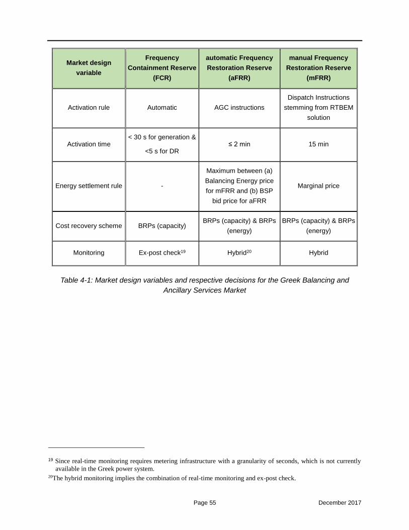
Page 55 December 2017
Market design
variable
Frequency
Containment Reserve
(FCR)
automatic Frequency
Restoration Reserve
(aFRR)
manual Frequency
Restoration Reserve
(mFRR)
Activation rule Automatic AGC instructions
Dispatch Instructions
stemming from RTBEM
solution
Activation time < 30 s for generation &
<5 s for DR ≤ 2 min 15 min
Energy settlement rule -
Maximum between (a)
Balancing Energy price
for mFRR and (b) BSP
bid price for aFRR
Marginal price
Cost recovery scheme BRPs (capacity) BRPs (capacity) & BRPs
(energy)
BRPs (capacity) & BRPs
(energy)
Monitoring Ex-post check19 Hybrid20 Hybrid
Table 4-1: Market design variables and respective decisions for the Greek Balancing and
Ancillary Services Market
19 Since real-time monitoring requires metering infrastructure with a granularity of seconds, which is not currently
available in the Greek power system. 20The hybrid monitoring implies the combination of real-time monitoring and ex-post check.

Page 56 December 2017
5 Stakeholders in the Balancing and Ancillary Services Market
In this Chapter, we record all the stakeholders associated with the operation of the
Balancing Market in Greece, either participating directly in the market (Balancing Services
Providers) or being responsible for their imbalances (Balance Responsible Parties).
5.1 Entities
The Entity is a physical unit or a portfolio of physical units which is subject to Imbalance
Settlement. Each Entity bears a Market Schedule from the Forward, Day-Ahead and Intra-
Day Markets.
The Entities are differentiated in Balancing Service Entities (BSEs) and Balancing
Responsible Entities (BREs). The Balancing Service Entities are represented by
Balancing Service Providers (BSPs), whereas the Balance Responsible Entities are
represented by Balance Responsible Parties (BRPs). A Participant can simultaneously
be Balancing Service Provider for some Entities and Balance Responsible Party for other
Entities for which it is the Registered Participant in the respective Entities’ registries.
In the current (2017) market design there are three (3) different types of Contracted Units,
namely: (1) Contracted Units for providing Ancillary Services (“Συμβάσεις Επικουρικών
Υπηρεσιών”), (2) Contracted Units for providing Supplementary System Energy
(“Συμβάσεις Συμπληρωματικής Ενέργειας Συστήματος”), and (3) Contracted Units for
providing Emergency Energy (“Συμβάσεις Εφεδρείας Εκτάκτων Αναγκών”).
For simplicity reasons, in this document there is only one type of Contracted Unit.
These units shall be used in cases of deficits in the imbalance covering constraints
and/or the reserve requirements constraints in the ISP clearing results. Such cases
are herein called “Extreme Conditions”. As further analyzed in the following, in
such cases the TSO shall execute a new (second) ISP solution, considering also
such Contracted Units, in order to resolve efficiently the resources’ shortage
situation. Even though such Contracted Units offer only Balancing Energy to the system
(in such Extreme Conditions), the commitment of a Contracted Unit shall also release
BSPs’ resources to provide reserves; therefore, their utilization attains both the coverage
of the Balancing Energy requirements and the coverage of the Reserve Capacity
requirements. That’s why a separate category of “Contracted Units for providing Ancillary
Services” is not necessary. Such simplification does not aim at “shrinking” the different
cases / options of Contracted Units that may be useful for the TSO, but rather at the
simplification of the market design rules needed for handling such Contracted Units.
The Balancing Service Entities are qualified to provide Balancing Energy and/or
Balancing Capacity and comprise of the following categories:

Page 57 December 2017
a) Generating Unit: A conventional dispatchable generating unit with an installed
capacity above 5 MW, which can provide Balancing Services to the Transmission
System Operator. This category includes also the Dispatchable CHP Units above 35
MWe, as referred to in the Independent Transmission System Operation Code. A
Generating Unit is represented by a Producer
b) Dispatchable RES Portfolio: A portfolio of individual RES Units, comprising a set of
physical RES units having concluded a Contract for Differential State-Aid Support
with the RES and CHP Unit Registry Operator, of a specific RES technology
connected at a specific Bidding Zone, which, based on its technical capability, can
provide Balancing Services on a portfolio basis to the Transmission System Operator.
A Dispatchable RES Portfolio can be represented by a RES Producer, a RES
Aggregator or by the Last Resort RES Aggregator. For simplification purposes, in this
Code where the term RES Aggregator is used in the following when referring to the
representative of a Dispatchable RES Portfolio, is shall also include the Last Resort
RES Aggregator, unless explicitly written differently. A Dispatchable RES Portfolio
can include one or more RES Units.
c) Dispatchable Load Portfolio: A portfolio of individual loads connected at a specific
Bidding Zone, which can provide Balancing Services on a portfolio basis to the
Transmission System Operator. A Dispatchable Load Portfolio is represented by a
DR Aggregator or a Self-Supplied Consumer. A Dispatchable Load Portfolio can
include one or more individual loads.
The Contracted Units are also included in the Entities, but not mentioned in the above
list, since they do not have any responsibility to establish their Balancing Schedule for the
Balancing Market processes. The Contracted Units shall be contracted with the
Transmission System Operator to provide additional services in any foreseen situation in
the Integrated Scheduling Process (ISP) which may lead to the expectation of not
covering the system load and/or the reserve requirements for any reason.
The Balance Responsible Entities are all Balancing Service Entities, plus the following:
a) Non-Dispatchable RES Portfolio: A portfolio of individual RES Units, comprising a
set of physical RES units having concluded a Contract for Differential State-Aid
Support with the RES and CHP Unit Registry Operator, of a specific RES technology
connected at a specific Bidding Zone that cannot provide Balancing Services to the
Transmission System Operator. A Non-Dispatchable RES Portfolio is represented by
a RES Producer or by a RES Aggregator.
b) Non-Dispatchable Load Portfolio: An individual load or a portfolio of individual
loads, which cannot provide Balancing Services to the Transmission System
Operator. A Non-Dispatchable Load Portfolio is represented by a Supplier or a Self-
Supplied Consumer.

Page 58 December 2017
c) RES FiT Portfolio: A portfolio (aggregation) of RES units of a specific RES
technology and connected at a specific Bidding Zone, remunerated under a Feed-in
Tariff system, which does not provide Balancing Services to the Transmission
System Operator. A RES FiT Portfolio is represented by the RES and CHP Units
Registry Operator.

Page 59 December 2017
The imports / exports scheduled by Participants (traders) among bidding areas do not
participate in the Balancing Market, but they are subject to imbalances in case the finally
nominated import/export is different from the Market Schedule (e.g. in case an import /
export quantity that has been cleared at the Greek wholesale electricity market has not
been cleared at a neighboring country’s PX).
For this reason, traders performing imports / exports among bidding areas have not been
incorporated in the above list of Entities, but in such case they are subject to Imbalance
Settlement, as described in Chapter 9.
Page 60 December 2017
5.2 Registries
For the scope of execution of the Integrated Scheduling Process (ISP) and the Real-Time
Balancing Energy Market (RTBEM), the TSO shall keep a separate Registry for all
Entities, as per the provisions of this Section. It is noted that all technical operating
characteristics of Entities in the following Registries that involve timings (e.g. time off load
before going into longer standby conditions, time to synchronize, soak time, time from
technical minimum generation to de-synchronization, etc.), should be converted to half-
hours from hours (that they currently are) to facilitate the half-hourly time resolution of the
ISP.
5.2.1 Generating Units Registry
In this registry, the following information shall be maintained and continuously updated
(when needed) for each Generating Unit directly connected to the Transmission System:
a) the Generating Unit EIC Code;
b) the Generating Unit’s geographical location;
c) the Generating Unit operators’ contact details;
d) the information described in Article 4 of the Independent Transmission System
Operation Code;
e) the Registered Operating Characteristics of the Generating Unit according to the
provisions of Article 241 of the Independent Transmission System Operation Code,
amended with the following technical characteristics:
1) maximum contribution to downward FCR;
2) maximum technical capability to provide upward and downward mFRR; and
3) the soak trajectory of each Generating Unit, namely the exact production level
of up to ten (10) half-hourly steps;
f) the identity of the Meter(s) recording the output of that Generating Unit;
g) the Node at which the Generating Unit is electrically located, or in the case of a
Generating Unit not connected at a Node, the Node which is electrically nearest to
the Generating Unit;
h) the Bidding Zone to which the Generating Unit belongs;
i) the information if the Generating Unit is a Contracted Unit, an Auto-Producer
Conventional Unit or a Dispatchable CHP Unit;
j) the Producer Account to which the Generating Unit is allocated (the “Registered
Participant”).
It is noted that Auto-Producer Conventional Units and Dispatchable CHP Units shall be
treated as simple Generating Units with regard to all procedures in this Balancing Market.
The Producers representing Generating Units with a capability to use an alternative fuel
are obliged to additionally submit the technical data of the respective Generating Units
using the alternative fuel.

Page 61 December 2017
The Producers representing multi-shaft combined-cycle Generating Units are obliged to
additionally submit the technical data of the respective Generating Units in all possible
configurations.
5.2.2 Dispatchable Load Portfolios Registry
In this registry, the following information shall be maintained and continuously updated
(when needed) for each individual Dispatchable Load Portfolio (represented by a DR
Aggregator or a Self-Supplied Consumer):
a) the Entity EIC Code;
b) the geographical location(s);
c) the Registered Operating Characteristics of the Dispatchable Load Portfolio
according to the provisions of Article 242 of the Independent Transmission System
Operation Code, amended with the following technical characteristics:
1) maximum technical capability to provide upward and downward FCR,
2) Automatic Generation Control (AGC) technical maximum power output when
providing aFRR,
3) Automatic Generation Control (AGC) technical minimum power output when
providing aFRR,
4) maximum technical capability to provide upward and downward mFRR,
5) technical minimum, corresponding to “minimum load reduction”, if non-zero,
6) minimum up time and down time, similarly to the Generating Unit respective
characteristics, if non-zero,
7) minimum and maximum delivery period for the provision of Balancing Energy,
8) minimum baseload period (i.e., minimum period between two successive
activations of Balancing Energy),
9) maximum frequency of activations for the provision of Balancing Energy during
a day,
10) ramp up rate (“load pickup rate”) and ramp down rate (“load drop rate”), and
11) the rate of demand change while operating under Automatic Generation
Control (AGC), if applicable;
d) in case of a Dispatchable Load Portfolio, the individual loads included in the
Dispatchable Load Portfolio;
e) the identity of the Meter(s) recording the consumption of the consumption of each
individual load belonging to the Dispatchable Load Portfolio;
f) the Node(s) at which each individual load belonging to a Dispatchable Load
Portfolio is electrically located in case it is connected directly to the Transmission

Page 62 December 2017
System, or in the case it is connected at the Distribution System, the Node(s) which
is(are) electrically nearest to it;
g) the Bidding Zone to which the Dispatchable Load Portfolio belongs; and
h) the DR Aggregator Account to which the Dispatchable Load Portfolio is allocated
(the “Registered Participant”).
5.2.3 Dispatchable RES Portfolios Registry
In this registry, the following information shall be maintained and continuously updated
for each individual Dispatchable RES Portfolio (represented by a RES Producer or a RES
Aggregator):
a) the Entity EIC Code;
b) the geographical location(s),
c) the information described in Article 4 of the Independent Transmission System
Operation Code,
d) the RES technology,
e) the Registered Operating Characteristics of the Dispatchable RES Portfolio
according to the provisions of Article 241 of the Independent Transmission System
Operation Code (i.e., as these characteristics are valid for the conventional
Generating Units), amended with the following technical characteristics:
1) maximum contribution to downward FCR,
2) maximum technical capability to provide upward and downward mFRR,
3) the soak trajectory, namely the exact production level of up to six (6) half-hourly
steps, if non-zero;
f) the technical characteristics included in the current Power Exchange Code and/or
its Market Manual;
g) the identity of the Meter(s) recording the output of the output of each individual
RES Unit belonging to the Dispatchable RES Portfolio,
h) the Node(s) at which each individual RES Unit belonging to a Dispatchable RES
Portfolio is electrically located in case it is connected directly to the Transmission
System, or in the case it is connected at the Distribution System, the Node(s) which
is(are) electrically nearest to it,
i) the Bidding Zone to which the Dispatchable RES Portfolio belongs, and
j) the RES Producer Account or the RES Aggregator Account to which the
Dispatchable RES Portfolio is allocated (the “Registered Participant”).

Page 63 December 2017
5.3 Balancing Services Entities/Providers
All Entities that can receive and follow Dispatch Instructions by the TSO constitute the
Balancing Services Entities (BSEs) which are represented in the Balancing and Ancillary
Services Market by their respective Balancing Services Providers (BSPs). A BSE can
essentially be one of the following:
a) a Generating Unit;
b) a Dispatchable Load Portfolio; and
c) a Dispatchable RES Portfolio
It is noted that Contracted Units may (under Extreme Conditions) also provide Balancing
Energy (in this case called Supplementary System Energy) to the TSO. However, in the
context of this document, we have not included them explicitly in the group of BSPs, in
the sense that they do not participate (with Balancing Energy Offers) in the Integrated
Scheduling Process and the Real-Time Balancing Energy Market.
The following general provisions apply regarding the participation of BSEs (through their
BSPs) in the Balancing and Ancillary Services Market:
1) Participation in the Balancing Market shall mean in particular:
a) the submission of Total or Partial Non-Availability Declarations by BSPs for their
BSEs, according to the provisions of Section 7.4,
b) the submission of Techno-Economic Declarations by BSPs for their BSEs,
according to the provisions of Section 7.5,
c) the submission of Upward / Downward Balancing Energy Offers by BSPs for their
eligible BSEs, based on their Available Capacity and their Market Schedule,
according to the provisions of Sections 7.6 and 8.4, and
d) the submission of Reserve Capacity Offerspertype ofReserve Capacity by BSPs
for their eligible BSEs, based on their Declared Characteristics, according to the
provisions of Section 7.7.
2) In brief, the participation rights / obligations of the BSEs are as follows:
a) Producers are obliged to submit for the Generating Units registered in their BSP
or BRP Account Total or Partial Non-Availability Declarations and Techno-
Economic Declarations to the TSO.
b) RES Producers are obliged to submit Total or Partial Non-Availability Declarations
for the RES Units registered in their BSP Account or BRP Account, in case the

Page 64 December 2017
RES Unit’s Registered Capacity is above a specific threshold defined by the
Regulator.
c) RES Aggregators and the Last Resort Aggregator are entitled to submit Non-
Availability Declarations for the RES Units registered in their BSP Account or BRP
Account.
d) DR Aggregators, RES Producers and RES Aggregators are obliged to submit,
accordingly, for the Dispatchable Load Portfolios and the Dispatchable RES
Portfolios registered in their BSP Account Techno-Economic Declarations to the
Transmission System Operator.
e) Producers are obliged to submit for the Generating Units registered in their BSP
Account Upward and Downward Balancing Energy Offers in the Balancing Energy
Market.
f) DR Aggregators, RES Producers and RES Aggregators are entitled to submit,
accordingly, on a voluntary basis for the Dispatchable Load Portfolios and the
Dispatchable RES Portfolios registered in their BSP Account Upward and
Downward Balancing Energy Offers in the Balancing Energy Market.
g) Producers are obliged to submit for the Generating Units registered in their BSP
Account Reserve Capacity Offers per each type of Reserve Capacity in the
Integrated Scheduling Process, provided that they have the technical capability to
contribute to a given type of Reserve Capacity based on their Declared
Characteristics.
h) DR Aggregators, RES Producers and RES Aggregators are entitled to submit,
accordingly, on a voluntary basis for the Dispatchable Load Portfolios and the
Dispatchable RES Portfolios registered in their BSP Account Reserve Capacity
Offers for each type of Reserve Capacity in the Integrated Scheduling Process,
provided that they have the technical capability to contribute to a given type of
Reserve Capacity based on their Declared Characteristics.
5.4 Balance Responsible Entities/Parties
In the context of Imbalance Settlement, each Entity referred in Section 5.1 is designated
as a Balance Responsible Entity (BRE) being responsible for settling its imbalances with
the TSO, through the respective Balance Responsible Party (BRP) representing such
Entity. A BRP can represent any of the following Entities:
a) a Generating Unit;
b) a Dispatchable Load Portfolio;

Page 65 December 2017
c) a Non-Dispatchable Load Portfolio;
d) a Dispatchable RES Portfolio;
e) a Non-Dispatchable RES Portfolio; and
f) a RES FiT Portfolio.
Thus, all BSEs offering their Balancing Services in the Balancing Market should designate
a BRP to take the responsibility for their imbalances in the Imbalance Settlement process;
the same is true for Contracted Units, when being dispatched in Extreme Conditions. The
BSEs’ imbalances (uninstructed deviations) are calculated as the difference between their
real metered quantities and their real-time Dispatch Instructions (outcome of the RTBEM),
according to the provisions of Chapter 9.
Nevertheless, also the Entities that cannot provide Balancing Services to the TSO yet
being responsible for meeting their wholesale Market Schedules in real time, should
designate a BRP to take the responsibility for their imbalances. Their imbalances are
calculated as the difference between their real metered quantities and their nominated
Market Schedules, according to the provisions of Chapter 9.
Additionally, the responsibility for the import / export schedule deviations of traders, are
also assigned to BRPs, according to the provisions of Chapter 9.
5.5 Participation Fees
The fees for the participation in the Balancing Market shall be proposed by the TSO,
decided by the NRA and charged to BRPs and possibly BSPs.

Page 66 December 2017
6 Interface with the Forward, Day-Ahead and Intra-Day Markets
The information that should be transferred from the Intra-Day Market (from the Energy
Trading System of the Market Operator) to the Balancing Market (to the Balancing Market
System of the Transmission System Operator) comprises the following:
I1: The already Scheduled Exchanges (imports/exports) on each interconnection
shall be submitted to the TSOs, in order to compute the Cross Zonal Capacity left
unused after the Intra-Day Market solution. This Cross Zonal Capacity may be used
in the Balancing Market for cross-border balancing purposes.
I2: The Market Schedule (Net Position) of each Generating Unit or Generating Unit in
Commissioning or Testing Operation, namely the energy schedule resulting from the
Intra-Day Market results. This, in conjunction with information transferred from the
Day-Ahead Market to the Intra-Day Market, shall be used as the starting point (initial
position) for each subsequent solution of the Integrated Scheduling Process problem,
as detailed in Section 7.
I3: The Market Schedule (Net Position) of each RES Unit in Commissioning or Testing
Operation, namely the energy schedule resulting from the Intra-Day Market clearing.
This, in conjunction with information transferred from the Day-Ahead Market to the
Inra-Day Market, shall be used in order to compute the RES Units’ and Net Position,
which shall be used as input data in each subsequent solution of the Integrated
Scheduling Process problem, as detailed in Section 7.
I4: The Market Schedule (Net Position) of each Non-Dispatchable RES Portfolio in
each Bidding Zone, namely the energy schedule resulting from the Intra-Day Market
clearing. This, in conjunction with information transferred from the Day-Ahead Market
to the Inra-Day Market, shall be used in order to compute the Net Position of the Non-
Dispatchable RES Portfolio which shall be used as input data in each subsequent
solution of the Integrated Scheduling Process problem, as detailed in Section 7.
I5: The Market Schedule (Net Position) of each Dispatchable RES Portfolio in each
Bidding Zone, namely the energy schedule resulting from the Intra-Day Market
clearing. This, in conjunction with information transferred from the Day-Ahead Market
to the Intra-Day Market, shall be used in order to compute the Net Position of the
Dispatchable RES Portfolio which shall be used as input data in each subsequent
solution of the Integrated Scheduling Process problem, as detailed in Section 7.
I6: The Market Schedule (Net Position) of each Non-Dispatchable Load Portfolio in
each Bidding Zone coming from the Intra-Day Market clearing, which shall be used

Page 67 December 2017
in conjunction with information transferred from the Day-Ahead Market to the Intra-
Day Market in order to compute the load imbalances that shall be inserted in each
subsequent solution of the Integrated Scheduling Process problem, as detailed in
Section 7.
I7: The Market Schedule (Net Position) of each Dispatchable Load Portfolio in each
Bidding Zone coming from the Intra-Day Market clearing, which shall be used in
conjunction with information transferred from the Day-Ahead Market to the Intra-Day
Market as input data in each subsequent solution of the Integrated Scheduling
Process problem, as detailed in Section 7.
I8: The Market Schedule (Net Position) of the RES FiT Portfolio in each Bidding Zone
coming from the Intra-Day Market clearing, which shall be used along in conjunction
with information transferred from the Day-Ahead Market to the Intra-Day Market, in
order to compute the RES FiT Portfolio injection imbalances that shall be inserted in
each subsequent solution of the Integrated Scheduling Process problem, as detailed
in Section 7.

Page 68 December 2017
7 Integrated Scheduling Process
7.1 Timeframe of the Integrated Scheduling Process
The ISP consists of three programmed on the clock consecutive scheduling phases
designated as follows:
a) one day-ahead scheduling phase (ISP1) performed at calendar day D-1
concerning all Dispatch Periods of Dispatch Day D;
b) a second one (ISP2) performed at the last hour of calendar day D-1 concerning
all Dispatch Periods of Dispatch Day D; and
c) an intra-day scheduling phase (ISP3) performed during the Dispatch Day D to
allow for changes in forecasted data and system conditions affecting the last
twenty-four (24) Dispatch Periods of the Dispatch Day D.
In case a major event takes place during day D, or even in the afternoon of day D-1, which
affects at a great extent the unit scheduling and the reserve allocation during day D (e.g.,
a unit outage or a major non-expected increase in the system load, etc.), the TSO is
allowed to execute the ISP problem on-demand (in this case called “on-demand ISP”), in
order to derive a new schedule (energy & reserves) for the available BSEs. Therefore,
the three programmed sessions of the ISP (ISP1, ISP2 and ISP3) should be considered
as the minimum number of the ISP executions that shall be implemented by the TSO
regarding the Dispatch Day D.
It should be noted that the number of ISP scheduled runs depends on the number of Intra-
Day Market auctions that will be performed, which depends on all TSOs’ proposal for the
intra-day auctions (and subsequently ID continuous sessions) and the respective decision
of the NRAs. Therefore, the number and timing of ISP scheduled runs may be revised in
the following years.
Timeframe provisions
Specific provisions regarding the timeframe of the ISP are provided in the following; it is
noted that all times and critical deadlines referred hereinafter are subject to the
Decision of the Regulator according to the TSO recommendations:
1) All procedures and actions regarding the ISP refer to one Dispatch Day (day D), and
are completed in the day pre-ceding (day D-1) or within the Dispatch Day and within
the deadlines provided for herein.
2) The Dispatch Day of the ISP coincides with the Delivery Day of the Day-Ahead Market
and Intra-Day Market. Therefore, the Dispatch Day shall mean the 24-hour period (48
half-hourly intervals) starting from 01:00 of calendar day D and ending at 01:00 of

Page 69 December 2017
calendar day D+1. This provision will assist ADMIE with the integration of the Greek
market with the balancing markets in Europe and the transition to the cross-border
balancing activities (in European level).
3) With reference to Figure 7-1, the Gate Closure Time (GCT) for the submission of all
Offers and Declarations in the ISP opens at 14:00 EET D-1 and closes at 16:00 EET
in day D-1, corresponding to the Dispatch Day D. Within this period, the BSPs can
submit their Offers and Declarations for their BSEs as many times as they wish. The
last validated Offers / Declarations shall be considered for the ISP problem solution.
4) The same Offers submitted before the execution of the ISP1 shall be taken into
account for the execution of ISP2 and ISP3, as well as any other ISP execution
triggered by the TSO on demand. Thus, there shall be no new re-bidding process
within the ISP.
5) The last validated Techno-Economic Declarations before the ISP1 GCT shall be
considered for all ISP runs.
6) The last validated Non-Availability Declarations before the ISP1 GCT shall be
considered for ISP1. However, the most recent Non-Availability Declarations shall be
considered for all subsequent ISP runs, in order to take into account any unexpected
outages or any partial unavailability of the BSEs.
7) According to Figure 7-1:
a) the ISP1 is executed at 16:00 EET D-1, the market solution is obtained at the
latest at 16:55 EET D-1 (critical deadline), and the results are published until
17:00 EET D-1,
b) the ISP2 is executed at 00:00 EET D, the market solution is obtained at the latest
at 00:40 EET D (critical deadline), and the results are published until 00:45 EET
D,
c) the ISP3 is executed at 10:30 EET D, the market solution is obtained at the latest
at 11:10 EET D (critical deadline), and the results are published until 11:15 EET
D, and finally,
d) any additional ISP is executed on demand by the TSO, the market solution is
obtained at the latest 40 minutes after the time of the initialization of the execution
(critical deadline), and the market results are published at the latest 5 minutes
after the solution has been obtained..

Page 70 December 2017
Figure 7-1: Timeframe of the Integrated Scheduling Process programmed executions

Page 71 December 2017
8) According to the Figure 7-1:
a) the scheduling horizon of the ISP1and ISP2 problem coincides with the whole
Dispatch Day D,,
b) the scheduling horizon of the ISP3 problem corresponds to the period 12:00 -
24:00 CET of Dispatch Day D (or, equivalently, 13:00 EET of calendar day D until
01:00 EET of calendar day D+1),
c) the scheduling horizon of any additional ISP executed on demand corresponds to
the period between (a) the first hour following the initialization of the execution (in
case the first hour starts after more than 40 minutes from said initialization) or the
second hour following the initialization of the execution (in case the first hour starts
after less than 40 minutes from said initialization) and (b) the end of the Dispatch
Day D (01:00 EET in calendar day D+1).
9) Each subsequent ISP execution considers as initial position (state and MW level) of
all BSEs, the respective position obtained during the last binding Dispatch Period of
the previous ISP execution. For example, in case an ISP is executed for the
scheduling horizon 13:00 EET of calendar day D – 01:00 EET of calendar day D+1
(i.e., ISP3), then as initial position of all BSEs shall be taken their position obtained
by the previous ISP execution (namely either ISP2 or an on-demand ISP executed
after ISP2 and before ISP3) for the 26th half-hour of the calendar day D.
This provision is not valid only in the following cases:
a) in case of an outage (total non-availability) of a BSE that was scheduled to
operate at the 26th half-hour in the previous ISP execution; in such case, the
declared Available Capacity is set to zero and shall be taken as the initial position
of this BSE, and
b) in case of a partial non-availability of a BSE that was scheduled to produce at a
higher level (for generating Entities, e.g. Generating Units) or to consume at a
higher level (for demand Entities, e.g. Dispatchable Load Portfolios) than his
declared Available Capacity at the 26th half-hour in the previous ISP execution; in
such case, the declared Available Capacity shall be taken as the initial position of
this BSE.
7.2 Balancing Services Products
The ISP model involves the simultaneous procurement of the following Balancing
Services products:
a) Upward and Downward mFRR Balancing Energy (BE) and aFRR Balancing

Page 72 December 2017
Energy.
b) Different types of Reserve Capacity (RC):
Upward and Downward Frequency Containment Reserve (FCR);
Upward and Downward Frequency Restoration Reserve with automatic
activation (aFRR); and
Upward and Downward Frequency Restoration Reserve with manual
activation (mFRR) .
7.3 Dispatch Period
The following provisions apply with regard to the Dispatch Period in the ISP:
1) The time-step of the ISP model is half-hourly21.
2) Accordingly, all Balancing Services Offers (Balancing Energy and Reserve
Capacity Offers) have an half-hourly validity period.
3) There are 48 Dispatch Periods in each Dispatch Day. Dispatch Periods commence
at 01:00 on the calendar day D and end at 01:00 EET of calendar day D+1.
7.4 Submission of Non-Availability Declarations
The Participants (BSPs) are responsible for submitting Non-Availability Declarations to
the TSO, in order to inform the latter in good time about possible total or partial non-
availabilities of the BSEs they operate / represent due to technical cause. The following
provisions with regard to the submission of Non-Availability Declarations apply to
Producers for the Generating Units included in their BSP Account and RES Producers for
the RES Units included in their BSP Account or BRP Account and in case the RES Unit’s
Registered Capacity is above a specific threshold defined by the Regulator. RES
Aggregators are not obligated to submit Non-Availability Declarations for the RES Units
they represent:
1) In case of an outage exclusively due to technical causes related to the operation
or safety of a Generating Unit, or a RES Unit installation, and which renders energy
generation and/or provision of Balancing Ancillary Services by the Generating
Unit, or the RES Unit impossible, the respective Participant must submit to the
TSO a Total Non-Availability Declaration for the Dispatch Day as soon as
reasonably possible after such inability appears, establishing the Dispatch Periods
21The shorter the time-step the more accurate scheduling is performed in the ISP, which is further adapted in the
RTBEM. Another reason for adopting higher (than hourly) time resolution in the ISP is to better accommodate /
facilitate possible products (and resulting Market Schedules) in future regional Intraday Markets (that Greece might
join) having shorter (than hourly) delivery periods (e.g. half-hourly products).

Page 73 December 2017
in the Dispatch Day or Dispatch Days the non-availability is anticipated to last.
2) In case of an outage exclusively due to technical causes related to the operation
or the safety of a Generating Unit, or a RES Unit installation, or in case of other
reasons, such as ageing deration, operation in different conditions than ISO
conditions, or reservoir levels for hydro units, causing a Generating Unit, or a RES
Unit inability to generate energy – and/or provide Ancillary Services corresponding
to such Entity’s Registered Capacity (as this is listed in the Generating Unit
Registry, or Dispatchable RES Portfolio Registry), the respective Participant must
submit to the TSO a Partial Non-Availability Declaration for the Generating Unit, or
the RES Unit, on which such inability exists, indicating the Available Capacity in
each Dispatch Period of the Dispatch Day on which there is reduced Available
Capacity. The Partial Non-Availability Declaration may establish a time period of
more Dispatch Days during which it is anticipated that there shall be reduced
generation capacity. In that case, a single reduced Available Capacity shall be
established for the entire period.
3) It is clarified that if there is no valid Partial Non-Availability Declaration for a
Dispatch Period, the Available Capacity of a Generating Unit, or a RES Unit is
equal to the Registered Capacity, as this is listed in the Generating Unit Registry,
or the Dispatchable RES Portfolio Registry, whereas if there is a valid Total Non-
Availability Declaration for a Dispatch Period, the Available Capacity of such Entity
is zero.
4) Total or Partial Non-Availability Declarations shall include a description of the
causes for the non-availability.
5) The most recent information submitted in the Total or Partial Non-Availability
Declarations before the ISP GCT determines the Available Capacity of Generation
Units and RES Units for this ISP. A Total or Partial Non-Availability Declaration
issued past a ISP Gate Closure Time for the Dispatch Day for which Total or Partial
Non-Availability is stated shall be considered in the next ISP solution, if any, and
in the Real-Time Balancing Energy Market.
6) The term of validity of Partial or Total Non-Availability Declarations shall be the total
number of Dispatch Periods listed in them. Such declarations shall remain in force
until the end of their term of validity, unless revoked earlier by the respective
Participants. A Non-Availability Declaration shall cease to be in force before its
term of validity has elapsed, if the TSO cancels such declaration, in accordance
with the provisions of the Hellenic Transmission System Operation Code.
7) The maximum continuous generation capability of the Generating Units for each
Dispatch Period of the Dispatch Day D that will be used in the Integrated
Scheduling Process runs and in the Real-Time Balancing Energy Market shall be
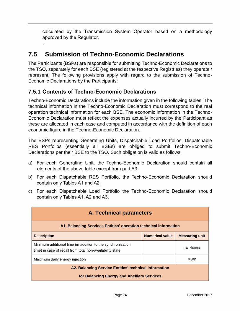
Page 74 December 2017
calculated by the Transmission System Operator based on a methodology
approved by the Regulator.
.
7.5 Submission of Techno-Economic Declarations
The Participants (BSPs) are responsible for submitting Techno-Economic Declarations to
the TSO, separately for each BSE (registered at the respective Registries) they operate /
represent. The following provisions apply with regard to the submission of Techno-
Economic Declarations by the Participants:
7.5.1 Contents of Techno-Economic Declarations
Techno-Economic Declarations include the information given in the following tables. The
technical information in the Techno-Economic Declaration must correspond to the real
operation technical information for each BSE. The economic information in the Techno-
Economic Declaration must reflect the expenses actually incurred by the Participant as
these are allocated in each case and computed in accordance with the definition of each
economic figure in the Techno-Economic Declaration.
The BSPs representing Generating Units, Dispatchable Load Portfolios, Dispatchable
RES Portfolios (essentially all BSEs) are obliged to submit Techno-Economic
Declarations per their BSE to the TSO. Such obligation is valid as follows:
a) For each Generating Unit, the Techno-Economic Declaration should contain all
elements of the above table except from part A3.
b) For each Dispatchable RES Portfolio, the Techno-Economic Declaration should
contain only Tables A1 and A2.
c) For each Dispatchable Load Portfolio the Techno-Economic Declaration should
contain only Tables A1, A2 and A3.
A. Technical parameters
A1. Balancing Services Entities’ operation technical information
Description Numerical value Measuring unit
Minimum additional time (in addition to the synchronization
time) in case of recall from total non-availability state half-hours
Maximum daily energy injection MWh
A2. Balancing Service Entities’ technical information
for Balancing Energy and Ancillary Services

Page 75 December 2017
Technical capability to provide upward FCR MW
Technical capability to provide downward FCR MW
Automatic Generation Control (AGC) technical maximum power
output (for providing aFRR)
MW
Automatic Generation Control (AGC) technical minimum power
output (for providing aFRR)
MW
Rate of generation/demand change while operating under
Automatic Generation Control (AGC)
MW/minute
A3. Technical information for Dispatchable Load Portfolios
Minimum and maximum delivery period for the provision of
Balancing Energy half-hours
Minimum baseload period half-hours
Maximum frequency of activations for the provision of Balancing
Energy in the course of a day Times/Day
B. Variable Cost Parameters for Generating Units
Fuel cost by fuel type
Fuel A
€/quantity
measuring unit Fuel B
Fuel C
Fuel Lower Heating Value (LHV)
Fuel A
GJ/quantity
measuring unit Fuel B
Fuel C
Percentage fuel composition at each
capacity interval of the Fuel Specific
Consumption Stepwise Function
Net Generation
Level (MW) Fuel A (%) Fuel B (%) Fuel C (%)

Page 76 December 2017
Special cost for raw materials besides fuel
for all capacity intervals of the Fuel Specific
Consumption Stepwise Function
Net Generation Level (MW) Cost (€/MWh)
Special cost of additional maintenance
expenses due to operation (with the
exception of fixed maintenances expenses)
for all capacity intervals in the Fuel Specific
Consumption Stepwise Function
Net Generation Level (MW) Cost (€/MWh)
Special cost for additional workforce
expenses due to operation (besides
workforce fixed expenses) for all capacity
intervals in the Fuel Specific Consumption
Stepwise Function
Net Generation Level (MW) Cost (€/MWh)
Table 7-1: Techno-Economic Declarations’ contents
The fuel cost stated in Techno-Economic Declarations corresponds to all expenses
incurred by Producers to supply fuel regardless of the type of individual cost elements.
Supply is defined as if the Producer were supplied with fuel from an independent person,
which uniformly charges a fuel price for each unit of fuel quantity it supplies. Where there
is lack of documentation through purchase invoices or other equivalent documents, fuel
cost shall be computed as the ratio of total fuel supply expenses or cost, as such
expenses or cost have been registered for a sufficient time period to the total fuel quantity
a Producer is supplied with for the Generating Unit during such time period.
In order for the TSO to establish the Generating Unit Variable Cost, it processes the
information in Techno-Economic Declarations as follows:
a) the Variable Cost curve is taken by part B of Techno-Economic Declarations; and
b) the minimum numerical value of the Variable Cost curve is established, which
corresponds to optimum Generating Unit operation. This value establishes the Unit
Minimum Variable Cost for a Generating Unit for any given Dispatch Day.
Important note: The Unit Minimum Variable Cost is solely used under the new market
design for the validation of the Balancing Energy Offers (both upward and downward)

Page 77 December 2017
submitted by BSPs operating Generating Unit(s). The Generating Unit Variable Cost is
not used in terms of a cost-recovery mechanism, since such mechanism is not present
under the new market design.
Techno-Economic Declarations submitted for an Auto-Producer Conventional Unit shall
concern only the part of the unit’s capacity corresponding to such unit’s Registered
Capacity, as defined in the Generating Unit Registry.
As Declared Characteristics shall be taken the characteristics established as a
combination of the following technical and operational characteristics of a BSE, and
represent the applicable technical capabilities of such BSE for a specific Dispatch Period
and Dispatch Day:
a) Registered Operating Characteristics,
b) Techno-Economic Declaration, and
c) Non Availability Declaration (Total or Partial), where applicable.
7.5.2 Techno-Economic Declaration submission procedure
Techno-Economic Declarations are binding and are submitted until the ISP1 GCT for the
first Dispatch Day to which they refer. The submission of Techno-Economic Declarations
after the ISP1 GCT (for the first Dispatch Day to which they refer) is not acceptable.
Techno-Economic Declarations refer to one or more Dispatch Days and apply if found
acceptable. Newer Techno-Economic Declarations if lawfully submitted shall replace all
previous ones.
7.5.3 Acceptance and rejection of Techno-Economic Declarations by the TSO
The TSO shall consider lawfully submitted all Techno-Economic Declarations submitted
in a timely manner and in accordance with Paragraphs 7.5.1 and 7.5.2 of this Section.
Where a Techno-Economic Declaration is considered unlawfully submitted, the latest
lawfully submitted Declaration shall be in force. Where there is no lawful declaration for a
BSE, the TSO shall inform the Regulator to that respect in view of the imposition of
possible sanctions and shall admit as Declared Characteristics for such BSE its
Registered Operating Characteristics.
7.6 Submission of Balancing Energy Offers
The following provisions apply with regard to the submission of Balancing Energy Offers
by the BSPs in the ISP:

Page 78 December 2017
7.6.1 General provisions
The gate for the submission of Balancing Energy Offers in the ISP opens at 14:00 EET in
calendar day D-1 and closes at 16:00 EET in calendar day D-1, corresponding to the
Dispatch Day D. Within this period, the Participants (BSPs) can submit Balancing Energy
Offers for each BSE they represent as many times as they wish. The last validated
Balancing Energy Offers shall be considered for the ISP problem solution.
The same Balancing Energy Offers submitted before the execution of the ISP1 (as per the
previous paragraph) are taken into account for the execution of ISP2 and ISP3, as well as
any other ISP execution triggered by the TSO on demand.
A Balancing Energy Offer refers to an upward or downward deviation from the latest
Market Schedule (aggregation of the traded quantities corresponding to an Entity from
the Forward, Day-Ahead and Intra-Day Markets) of a given BSE (Generating Unit,
Dispatchable Load Portfolio, Dispatchable RES Portfolio). Such Market Schedule shall
be automatically transferred (prior to each ISP execution) from the Market Operator to the
Transmission System Operator in order to be used as the initial position of the BSE in the
ISP problem, as referred in Section 6.
Especially with regard to the Dispatchable Load Portfolios, the aforementioned Market
Schedule shall be rather considered as being equal to their Baseline calculated by the
TSO for the period concerned (i.e., the electricity that would have been consumed by the
Dispatchable Load Portfolio, in the absence of an activation of a Balancing Energy Offer),
as referred in Section 3.6. The Baseline calculated by the TSO is a transparent measure,
which can be the basis for (a) the activation of Balancing Energy Offers in the ISP
execution, and (b) the ex-post verification of activation of the Balancing Energy Offers
submitted by the DR resources in the Balancing Market. The Baseline of a Dispatchable
Load Portfolio is calculated as the average of the Dispatchable Load Portfolio’s energy
use during the 10 previous non-event days of similar load profile. The Baseline shall be
further adjusted using the "default morning-of adjustment” technique (up or down
adjustment of the calculated average in accordance to the Dispatchable Load Portfolio’s
usage in the four hours immediately before the event), in order to compensate for possible
artificial inflation of a customer’s usage prior to the execution of a DR event.
A different approach would necessitate that the Load Representative supplying the given
DR resources should provide the Market Schedule of these DR resources (as obtained
by wholesale market trades concluded by the Load Representative for said DR resources)
either directly to the TSO, or to the TSO through the independent DR Aggregator (in the
latter case, a respective relationship should be established between the Load
Representative and the independent DR Aggregator, regarding the transfer of the
relevant Market Schedule). This approach, however, is not opted in theGreek market
design, since it can act as an entry barrier for DR for the following reasons: (a) the Load
Representative may not be willing to provide other parties (e.g. the independent DR
Aggregators) with sensitive commercial information regarding its represented demand

Page 79 December 2017
(i.e., he may not be willing to provide the respective Market Schedule), and (b) the
Baseline calculated with a transparent and concrete methodology by the TSO is expected
to be more accurate than any other Market Schedule calculated by the market parties,
thereby not causing any “fictitious” imbalances to the DR Aggregators, incurred due to
wrong initial estimations of the Market Schedule.
Thus, for the sake of simplicity in the hereinafter description, we shall refer to the Market
Schedule uniformly for all types of BSEs, while rather implying the Baseline calculated by
the TSO in the case of Dispatchable Load Portfolios.
Specifically, an Upward Balancing Energy Offer refers to:
a) an increase in the production level (MW) of a Generating Unit or a Dispatchable RES
Portfolio with regard to its Market Schedule,
b) a decrease in the consumption level (MW) of a Dispatchable Load Portfolio with
regard to its Market Schedule.
Inversely, a Downward Balancing Energy Offer refers to:
a) a decrease in the production level (MW) of a Generating Unit or a Dispatchable RES
Portfolio with regard to its Market Schedule,
b) an increase in the consumption level (MW) of a Dispatchable Load Portfolio with
regard to its Market Schedule.
BSPs representing Generating Units (Producers) are obliged to submit in the ISP:
a) an Upward Balancing Energy Offer per their BSE for each Dispatch Period of the
Dispatch Day, for a total upward Balancing Energy quantity equal to the Registered
Capacity of the BSE based on its Registered Operating Characteristics, and
b) a Downward Balancing Energy Offer per their BSE for each Dispatch Period of the
Dispatch Day, for a total downward Balancing Energy quantity equal to the Registered
Capacity of the BSE based on its Registered Operating Characteristics.
RES Producers and RES Aggregators are entitled to submit in the ISP:
A) an Upward Balancing Energy Offer per their BSE for each Dispatch Period of the
Dispatch Day, for a total upward Balancing Energy quantity, at maximum equal
to the Registered Capacity of the BSE based on its Registered Operating
Characteristics, and
B) a Downward Balancing Energy Offer per their BSE for each Dispatch Period of
the Dispatch Day, for a total downward Balancing Energy quantity, at maximum
equal to the Registered Capacity of the BSE based on its Registered Operating
Characteristics.
Self-Supplied Consumers and DR Aggregators representing Dispatchable Load
Portfolios are entitled to submit Upward and Downward Balancing Energy Offers, at

Page 80 December 2017
maximum for their whole technical capability to provide upward and downward Balancing
Energy.
The obligations described in the above paragraphs shall be suspended in the following
cases:
a) for the time in which the BSE is undergoing Scheduled Maintenance, in accordance
with the Independent Transmission System Operation Code, and
b) during the period of validity of the Total Non-Availability Declaration (where
applicable).
7.6.2 Format of the Balancing Energy Offers in the Integrated Scheduling Process
With regard to the format of the Balancing Energy Offers submitted in the ISP, the
following provisions apply:
1) The BSPs must submit half-hourly step-wise Balancing Energy Offers for each BSE
registered in their BSP Account in the ISP for both upward and downward direction.
Each step shall bear a non-negative upward / downward Balancing Energy quantity
in MW per half-hour, with accuracy of up to 3 decimal points, and an offer price in
€/MWh with accuracy of up to 2 decimal points.
2) According to the Figure 7-2, the upward Balancing Energy step-wise function shall
include up to ten steps, where Balancing Energy prices for successive steps must be
strictly non-decreasing. The total offered Balancing Energy quantity (sum of all steps)
shall respect the provisions of Section 7.6.1.
3) According to the Figure 7-3, the downward Balancing Energy step-wise function shall
include up to ten steps, where Balancing Energy prices for successive steps must be
strictly non-increasing. The total offered Balancing Energy quantity (sum of all steps)
shall respect the provisions of Section 7.6.1.
4) In general, the offered Balancing Energy prices for each step of the step-wise
Balancing Energy Offer must be greater than an Administratively Defined Balancing
Energy Offer Lower Limit (which can be negative) and less than or equal to an
Administratively Defined Balancing Energy Offer Cap, as such limits apply for the
Dispatch Period to which the Balancing Energy Offer corresponds.
5) The numerical values of the Administratively Defined Balancing Energy Offer Lower
Limit and the Administratively Defined Balancing Energy Offer Cap shall be
established by a decision of the Regulator. Such decision shall be taken at least two
months prior to the date of enforcement of the new values of the above limits.

Page 81 December 2017
Figure 7-2: Upward Balancing Energy step-wise function
Figure 7-3: Downward Balancing Energy step-wise function
6) Especially for the Upward Balancing Energy Offers submitted by the BSPs
(Producers) for the Generating Units they operate, these can be priced:
a) at minimum at the Unit’s Minimum Variable Cost, as computed using the data
contained in the respective Techno-Economic Declaration, and
b) at maximum at the Administratively Defined Balancing Energy Offer Cap.
7) Accordingly, the Downward Balancing Energy Offers submitted by the BSPs
(Producers) for the Generating Units they operate can be priced:
a) at minimum at the Administratively Defined Balancing Energy Offer Lower Limit,
and
b) at maximum at the Unit’s Minimum Variable Cost, as computed using the data
…
…
€ / MWh
Price10
Price1
Quantity1 Quantity10
MW
Technical capability to provide
upward Balancing Energy
…
€ / MWh
Price1
Price10
…Quantity1 Quantity10
MW
Technical capability to provide
Downward Balancing Energy

Page 82 December 2017
contained in the respective Techno-Economic Declaration.
8) There are no respective constraints on the submitted offer prices for upward and
downward Balancing Energy for Dispatchable RES Portfolios and Dispatchable Load
Portfolios. Nevertheless, it is considered rational that the respective BSPs
representing such BSEs shall submit higher prices for providing upward Balancing
Energy and lower prices for providing downward Balancing Energy, leading to the
activation of either upward or downward Balancing Energy from each BSE. However,
such rational bidding behaviour cannot be absolutely foreseen.
In case of irrational bidding behaviour by one or more BSPs (i.e., submitting a higher
price for downward Balancing Energy, as compared to the offer price for upward
Balancing Energy), the ISP problem should encompass a certain constraint for
choosing to activate only one (upward or downward) of the two services from each
BSE. Such constraint is presented in Section 7.10.13 (constraint (34)).
9) Together with their step-wise Balancing Energy Offers, the BSPs are entitled to submit
a minimum quantity of Balancing Energy in MW per each direction and each Dispatch
Period to be accepted either thoroughly or not accepted at all by the ISP (as a
minimum “acceptance ratio”), as further explained in Section 7.10.13 regarding
constraints (32) and (33).
10) Under Extreme Conditions (deficit in covering an increase in the system load, or
covering the reserve requirements), the TSO shall submit for each Dispatch Period
of each Dispatch Day a Balancing Energy Offer for each Contracted Unit. The Offer
Price (€/MWh) in such Balancing Energy Offers shall be determined in accordance
with the relevant Supplementary System Energy Contract.
7.6.3 Modification and acceptance of the Balancing Energy Offers in the Integrated Scheduling Process
As previously noted, the Balancing Energy Offers concerning a given Dispatch Day shall
be submitted before the ISP1 GCT corresponding to the specific Dispatch Day. Balancing
Energy Offers submitted after the ISP1 GCT shall not be accepted for the ISP executions.
Within the period of submission, the BSPs can submit their Balancing Energy Offers
multiple times and the final accepted Balancing Energy Offers shall be considered for the
ISP clearing.
The following provisions apply with regard to possible modifications of the submitted
Balancing Energy Offers during the period of submission in the ISP:
1) In case a Balancing Energy Offer is not valid, namely it does not fully comply with the
provisions of Sections 7.6.1 – 7.6.2, the whole Balancing Energy Offer (for all
Dispatch Periods of the Dispatch Day) shall be automatically rejected by the
Balancing Market System. In case of rejection, a justification of the reason for the

Page 83 December 2017
rejection shall immediately and automatically be sent to the BSP. In such case, the
BSP can resubmit his Balancing Energy Offer before the ISP1 GCT, until a valid
Balancing Energy Offer is finally accepted by the Balancing Market System. Only
validated Balancing Energy Offers are inserted in the ISP clearing engine.
2) After the ISP1 GCT, the Balancing Energy Offers that will be taken into account in the
ISP problem solution (in any of the subsequent ISPs regarding the Dispatch Day D)
shall not be changed.
7.6.4 Consequences of non-submission of Balancing Energy Offers
In case of non-submission of Balancing Energy Offers for a Dispatch Day by a BSP
obligated to such submission in the ISP (essentially a Producer), the TSO shall charge
such BSP for such Dispatch Day a penalty, which is described in Chapter 9.
In such case, the Balancing Market System shall automatically create Balancing Energy
Offers for each associated Generating Unit and any given Dispatch Period, by
establishing offer prices equal to the Minimum Variable Cost of the Generating Unit for
both upward and downward Balancing Energy. If the variable cost has not been declared,
then Balancing Energy Offers prices are equal to the respective prices in the last validated
Balancing Energy Offer of the BSE during the previous day(s).
7.7 Submission of Reserve Capacity Offers
The following provisions apply with regard to the submission of Reserve Capacity Offers
by the BSPs in the ISP:
7.7.1 General provisions
Producers are obligated to submit for the Generating Units registered in their BSP
Account Reserve Capacity Offers per each type of Reserve Capacity in the Integrated
Scheduling Process, provided that they have the technical capability to contribute to a
given type of Reserve Capacity based on their Declared Characteristics.
BSPs are entitled to submit on a voluntary basis for the Dispatchable Load Portfolios and
Dispatchable RES Portfolios registered in their BSP Account Reserve Capacity Offers for
each type of Reserve Capacity in the Integrated Scheduling Process, provided that they
have the technical capability to contribute to a given type of Reserve Capacity based on
their Declared Characteristics.
Participants are not entitled to submit Reserve Capacity Offers for Contracted Units.
The GCT for the submission of Reserve Capacity Offers in the ISP opens at 14:00 EET in
calendar day D-1 and closes at 16:00 EET in calendar day D-1, corresponding to the
Dispatch Day D. Within this period, the BSPs can submit Reserve Capacity Offers for each

Page 84 December 2017
BSE registered in their BSP Account as many times as they wish. The last validated
Reserve Capacity Offers shall be considered for the ISP problem solution.
The same Reserve Capacity Offers submitted before the execution of the ISP1 (as per the
previous paragraph) are taken into account for the execution of ISP2 and ISP3, as well as
any other ISP execution triggered by the TSO on demand.
The obligations of Producers under the previous paragraph shall be suspended in the
following cases:
a) for the time in which the Generating Unit is undergoing Scheduled Maintenance, in
accordance with the provisions in the Independent Transmission System Operation
Code, and
b) during the period of validity of the Total Non-Availability Declaration, where applicable.
7.7.2 Format of the Reserve Capacity Offers in the Integrated Scheduling Process
The Participants must submit half-hourly step-wise Reserve Capacity Offers in the ISP
for all types of Reserve Capacity their BSEs are technically capable to provide, according
to their Declared Characteristics.
The upward Reserve Capacity Offer step-wise function shall include up to ten steps,
where Reserve Capacity prices for successive steps must be strictly non-decreasing.
The downward Reserve Capacity Offer step-wise function shall include up to ten steps,
where Reserve Capacity prices for successive steps must be strictly non-increasing.
Together with their step-wise Reserve Capacity Offers, the Producers are entitled to
submit a minimum quantity of Reserve Capacity per each direction and each Dispatch
Period of the Dispatch Day, to be accepted under a fill-or-kill condition by the ISP.
Self-Supplied Consumers and DR Aggregators representing Dispatchable Load
Portfolios and RES Producers and RES Aggregators representing Dispatchable RES
Portfolios are entitled to submit a minimum quantity of Reserve Capacity per step, per
each direction and per Dispatch Period of the Dispatch Day, to be accepted under a fill-
or-kill condition by the ISP.
The Reserve Capacity Offers for each Dispatch Period of a Dispatch Day shall include up
to six (6) capacity prices, namely a separate price for upward and downward FCR, aFRR
and mFRR, with a numerical value higher than zero and less than or equal to the
Administratively Defined Reserve Capacity Offer Cap for each reserve type. Such
capacity prices shall be in €/MW per Dispatch Period, with an accuracy of up to two (2)
decimal points.

Page 85 December 2017
The numerical values of the Administratively Defined Reserve Capacity Offer Cap per
reserve type shall be established by a decision of the Regulator. Such decision shall be
taken at least two months prior to the date of enforcement of the new values of these
limits.
The reserve quantities shall be expressed in MW with an accuracy of up to one (1)
decimal point.
7.7.3 Modification and acceptance of the Reserve Capacity Offers in the Integrated Scheduling Process
As previously noted, the Reserve Capacity Offers concerning a given Dispatch Day shall
be submitted before the ISP1 GCT corresponding to the specific Dispatch Day. Reserve
Capacity Offers submitted after the ISP1 GCT shall not be accepted. Within the period of
submission, the BSPs can submit their Reserve Capacity Offers multiple times and the
final accepted Reserve Capacity Offers shall be considered for the ISP clearing.
The following provisions apply with regard to possible modifications of the submitted
Reserve Capacity Offers during the period of submission in the ISP:
1) In case a Reserve Capacity Offer is not valid, according to the provisions referred
above in this Section, the Reserve Capacity Offer shall be automatically rejected by
the Balancing Market System, and it shall not be taken into account in the ISP clearing.
2) In case of rejection, a justification of the reason for the rejection shall immediately
and automatically be sent to the BSP. In such case, the BSP can resubmit his Reserve
Capacity Offer before the ISP1 GCT, until a valid Reserve Capacity Offer is finally
accepted by the Balancing Market System.
3) After the ISP1 GCT, the Reserve Capacity Offers that will be taken into account in the
ISP problem solution (in any of the subsequent ISPs regarding the Dispatch Day D)
shall not be changed.
4) The Reserve Capacity Offers submitted in the ISP are economically binding, meaning
that in case a BSE is awarded FCR, aFRR and/or mFRR and provides such
availability in real time, the respective BSP shall be subject to a financial settlement
with the TSO (for the provision of such service); else, if the BSE is awarded FCR,
aFRR and/or mFRR, but does not provide such service in real time, the respective
BSP shall be subject to a Non-Compliance Charge, as described in Chapter 9.
7.7.4 Consequences of non-submission of Reserve Capacity Offers
In case of no-submission of Reserve Capacity Offers for a Dispatch Day by a BSP
obligated to such submission, the TSO shall charge such BSP a Non-Compliance
Charge, as described in Chapter 9.

Page 86 December 2017
In such case, the Balancing Market System shall automatically create a Reserve Capacity
Offer for each respective BSE and any given Dispatch Period, with reserve prices equal
to the respective prices included in the last validated Reserve Capacity Offer of the BSP
(during the previous days).
7.8 Integrated Scheduling Process Data
The TSO shall establish the results of a given ISP session based on the following
information for each Dispatch Period of the respective ISP scheduling period:
a) The Balancing Energy Offers’ price - quantity pairs corresponding to the steps of
the Balancing Energy Offers’ step-wise functions.
b) The Reserve Capacity Offers’ price-quantity pairs for upward and downward FCR,
aFRR and mFRR.
c) The Registered Operating Characteristics of the BSEs.
d) The Techno-Economic Declarations submitted by the BSPs for each BSE,
considering especially the interrelations of the multi-shaft combined cycle
Generating Units.
e) The Total Non-Availability Declarations and Partial Non-Availability Declarations
submitted by the BSPs for their BSEs.
f) The operational state of the BSEs at the start of the scheduling period, namely the
half-hours already in operation or out of operation and the scheduled injection or
consumption at the start of the ISP scheduling period.
g) The Market Schedules of all Entities, which are processed by the Transmission
System Operator.
h) Any updates in the scheduled operation of the Generating Units / RES Units in
Commissioning or Testing Operation, as submitted to the Transmission System
Operator by the respective Producers / RES Producers through the
Commissioning Schedules Declarations.
i) The mandatory generation schedules of hydro Generating Units, as submitted to
the Transmission System Operator by the respective Producers through the Hydro
Mandatory Injections Declarations.
j) The zonal Non-Dispatchable Load Imbalance, computed as the difference
between the zonal Non-Dispatchable Load Forecast and the latest Market
Schedules of all Non-Dispatchable Load Portfolios connected at the specific
Bidding Zone, as notified by the Market Operator.
k) The zonal Non-Dispatchable RES Portfolios Imbalance, computed as difference
between the zonal Non-Dispatchable RES Portfolios Forecast and the latest
Market Schedules of all Non-Dispatchable RES Portfolios connected at the specific

Page 87 December 2017
Bidding Zone, as notified by the Market Operator.
l) The zonal RES FiT Portfolio Imbalance, computed as difference between the zonal
RES FiT Portfolio Forecast and the latest Market Schedules of the RES FiT
Portfolio for a specific RES technology and Bidding Zone.
m) The available flows in the inter-zonal corridors.
n) The import / export schedule deviations at the interconnections imposed by the
Transmission System Operator;
o) The FCR, aFRR and mFRR requirements that are established by the Transmission
System Operator.
p) Events that are notified to the Transmission System Operator, in accordance with
the Independent Transmission System Operation Code.
q) Other information collected and/or notified to the Transmission System Operator
in accordance with the Independent Transmission System Operation Code, as well
as other technical and simulation data regarding the operation of the Transmission
System.
Based on the Market Schedules sent by the Market Operator, the Transmission System
Operator determines:
a) the Final Internal Schedules per Dispatch Period of the Dispatch Day, which
correspond to generation and load Entities within Greece, and are equal to the
Market Schedule sent by the Market Operator, and
b) the Final External Schedules per Dispatch Period of the Dispatch Day, which
correspond to the import / export schedules on the interconnections, and take into
account the latest Market Schedules and the import / export deviations included
the latest Physical Transmission Rights nominations of the Participants, caused:
(1) either by the difference between the imported quantity included in the Market
Schedule of a Participant and his nomination of long-term Physical
Transmission Rights for electricity imports through an interconnection at
which an obligation for physical delivery exists;
(2) or by the difference between the sold / bought energy quantities in the Greek
Day-Ahead Market corresponding to short-term Physical Transmission
Rights and the bought / sold energy quantities in neighboring countries Day-
Ahead Market(s) corresponding to the same short-term Physical
Transmission Rights.
The Final Internal Schedules and the Final External Schedules are used by the
Transmission System Operator as input for the solution of the Integrated Scheduling
Process, for the solution of the Real-Time Balancing Energy Market and for Settlement
purposes,

Page 88 December 2017
7.9 Integrated Scheduling Process Solution Methodology
The ISP problem is solved as a Mixed Integer Linear Programming model, according to
the detailed description of the following Section 7.10.
If the Balancing Energy prices of different Balancing Energy Offersfor the same Dispatch
Period arithmetically coincide and the respective Balancing Energy quantities of such
Balancing Energy Offers are not included in their entirety in the ISP results, the priority of
(partial or whole) inclusion of such Balancing Energy Offers in the ISP results shall be
established at random.
If the Reserve Capacity prices of different Reserve Capacity Offers for an Ancillary
Service and for the same Dispatch Period arithmetically coincide, and the respective
Reserve Capacity quantities of such Reserve Capacity Offers are not included in their
entirety in the ISP results, the specific Reserve Capacity Offers that are partially or wholly
included in the ISP results are selected at random.
Where the ISP performs a random selection in accordance with the provisions described
herein, the Balancing Market System shall register the exact time of such random
selection, as well as the rest of the information to which it is related.
In case the model parameters for the execution of the ISP problem are modified by the
TSO, such modification shall be notified to the Regulator and to the BSPs with a written
letter, followed by a justification for the performed modification.
In case for a Dispatch Period of the Dispatch Day it is impossible to cover the forecasted
imbalances and/or the reserve requirements, the TSO must consider the provisions
concerning Extreme Conditions, namely:
a) include Balancing Energy Offers for Contracted Units, according to the
provisions of Paragraph 7.6.2, and
b) re-run the ISP problem in order to attain feasible results.
In case after the re-run of the ISP infeasibilities still appear in the imbalance covering
constraints and/or the reserve requirements constraints, then the infeasibilities in the
respective constraints are relaxed, and the problem is solved in realtime under the
provisions of Emergency Situations, as defined in the Independent Transmission System
Operation Code.The relaxation order should be as follows:
a) First, the upward and/or downward mFRR requirements are relaxed;
b) Second, the upward and/or downward aFRR requirements are relaxed;
c) Third, the upward and/or downward FCR requirements are relaxed;

Page 89 December 2017
d) Fourth, the system imbalance constraint is relaxed.
7.10 Mathematical Formulation
7.10.1 Objective Function
The ISP model is formulated as a co-optimization problem of Balancing Energy and the
various types of Reserve Capacity, and constitutes a Mixed Integer Linear Programming
model, as follows:
(1) Min BalancingEnergyCost ReserveCapacityCost CommitmentCost PenaltyCost
The TSO total cost (1) to be minimized over the scheduling horizonis expressed in € and
consists of the:
BalancingEnergyCost :procurement (as-bid) cost of Balancing Energy,
ReserveCapacityCost : procurement (as-bid) cost of Reserve Capacity,
CommitmentCost : start-up cost,
PenaltyCost : non-physical cost due to constraint violation when no physical
solution exists.
The above costs are described in the following Paragraphs.
7.10.2 Balancing Energy Cost
The Balancing Energy cost is expressed in € and represents the procurement cost of the
priced Upward and Downward Balancing Energy Offers for the entire system and all
Dispatch Periods.
The Balancing Energy cost is expressed as follows:
(2)
BEup BEup BEdn BEdnitk itkitk itk
i t k
BalancingEnergyCost D Quant Price Quant PriceI T K
Note that the Dispatch Period duration D is set to ½ hour for the ISP, since the Dispatch
Period is half-hourly. As already discussed, the Balancing Energy Offer prices shall
be submitted by the BSPs in €/MWh, while the Balancing Energy Offer quantities
shall be submitted in MWh per hour; the respective volume in MWh to be allocated
to the BSPs, taking into account the particular duration of the Dispatch Period (half-

Page 90 December 2017
hourly), is calculated directly in the ISP problem formulation through the use of
parameter D .
Note also in (2), that in case of downward Balancing Energy procurement, the TSO
receives (rather than pays) a revenue from the BSPs, since the provision of downward
Balancing Energy implies that:
a) the Generating Units avoid variable generation costs (i.e., their production is reduced
as compared to their Market Schedule), whereas
b) the Dispatchable Load Portfolios are scheduled to consume more (i.e., withdraw more
energy than their Market Schedule, for which they have not previously paid (i.e., in
the Forward, Day-Ahead or Intraday Market).
7.10.3 Reserve Capacity Cost
The Reserve Capacity cost is expressed in € and represents the as-bid cost for the
various types of Reserve Capacity (FCR, aFRR and mFRR in both directions)22, for the
full system and all Dispatch Periods. As the Reserve Capacity is not reallocated in real
time, this cost is used only in the ISP, and it is expressed as follows:
(3)
FCRup FCRup FCRdn FCRdnit itit it
i t
aFRRup aFRRup aFRRdn aFRRdnit itit it
i t
ReserveCapacityCost=
D Quant Price Quant Price
+D Quant Price Quant Price
I T
I T
mFRRup mFRRup mFRRdn mFRRdnit itit it
i t
RRup RRupRRns RRdn RRdnit it itit it
i t
+D Quant Price Quant Price
+D Quant Quant Price Quant Price
I T
I T
Again, parameter D is equal to ½ in the ISP. The Reserve Capacity Offer prices shall be
submitted by the Participants so as to reflect their opportunity costs when contributing to
the respective Reserve Capacity quantities on a half-hourly basis, and the effect of the
particular duration of the Dispatch Period (half-hourly) is considered directly in the ISP
problem formulation through the use of parameter D .
22 RR is included in all equations in this section (even though it shall not be used in the Greek Balancing Market), just
for future reference.

Page 91 December 2017
7.10.4 Start-up Cost
No commitment costs shall be taken into account in the solution of the ISP.
(4) CommitmentCost 0
7.10.5 Penalty Cost
The penalty cost is expressed in € and represents the non-physical cost due to constraint
violation when no feasible solution exists, for the full system and all Dispatch Periods. To
handle problem infeasibility under certain circumstances, violation (surplus / deficit)
variables are considered in certain constraints, and respective terms for penalizing the
violation variables are added to the objective function.
Τhe penalty cost in the objective function of the ISP model is defined in (5). As can be
noted, a violation penalty coefficient (i.e., a price in €/MW) is associated with each of the
violation variables. With large values assigned as penalty prices, values of the respective
violation variables are zero in a feasible solution. Any non-zero violation variable at the
solution indicates that the ISP problem is infeasible. When infeasibility is detected for any
constraint, a corresponding violation notification shall be available to the TSO in the
respective results.
Different penalty prices may be applied to reflect relative priorities in the enforcement of
the various constraints, according to the TSO needs. The constraints with larger penalty
coefficients have higher priorities in being satisfied than those with lower penalty
coefficients.
The TSO shall be able to modify the penalty prices at the Balancing and Ancillary Services
Market Database on-demand, given the approval of RAE. The penalty prices can be set
initially at the respective values indicated in the Nomenclature Section.

Page 92 December 2017
ZonImb DeficitZonImbzt
z t
ZonImb SurplusZonImbzt
z t
ZonFCRup ZonFCRdnzt zt
PenaltyCost
Deficit Price
Surplus Price
Deficit Deficit P
Z T
Z T
TotDeficitFCR
z t
ZonaFRRup ZonaFRRdn TotDeficitaFRRzt zt
z t
ZonmFRRup ZonmFRRdn TotDeficitmFRRzt zt
rice
Deficit Deficit Price
Deficit Deficit Price
Z T
Z T
z t
ZonRRup ZonRRdn TotDeficitRRzt zt
z t
Deficit Deficit Price
Z T
Z T
SysFCRup SysFCRdn TotDeficitFCRt t
t
SysaFRRup SysaFRRdn TotDeficitaFRRt t
t
SysmFRRupt
Deficit Deficit Price
5 Deficit Deficit Price
Deficit
T
T
SysmFRRdn TotDeficitmFRRt
t
SysRRup SysRRdn TotDeficitRRt t
t
Deficit Price
Deficit Deficit Price
T
T
Cap DeficitCapit
i t
Cap SurplusCapit
i t
MaxEnergy SurplusMaxEnergyit
i t
Deficit Price
Surplus Price
Surplus Price
I T
I T
I T
RampUp SurplusRampUpit
i t
RampDn SurplusRampDnit
i t
RampUpRes RampDnRes SurplusRampResit it
i t
Surplus Price
Surplus Price
Surplus Surplus Price
I T
I T
T
FCRup FCRdn SurplusFCRitit
i t
Surplus Surplus Price
I
I T

Page 93 December 2017
aFRRup aFRRdn SurplusaFRRitit
i t
mFRRup mFRRdn SurplusmFRRitit
i t
RRup RRditit
Surplus Surplus Price
Surplus Surplus Price
Surplus Surplus
I T
I T
n SurplusRR
i t
ns Deficitnsit
i t
ns Surplusnsit
i t
DeficitGenConGenCon Gt t
Price
Deficit Price
Surplus Price
Deficit Price +Surplus
I T
I T
I T
SurplusGenConenCon
gc GC t
Price T
7.10.6 Dispatch Scheduling and Reserve Capacity Allocation Concept
Figure 7-4 exhibits the fundamental logic of the ISP model with regard to the dispatch
scheduling of a Generating Unit (positive y-axis) and a Dispatchable Load (negative y-
axis). As already discussed, the Market Schedule is the net energy schedule (net position)
resulting from all BSE trades in the wholesale market (i.e., trades in the Forward, Day-
Ahead or Intraday Market) concluded prior to the given ISP execution. Such Market
Schedule is depicted with the red dotted line in Figure 7-4 (either in the positive direction
regarding the Generating Unit, or in the negative direction regarding the Dispatchable
Load), and shall be automatically transferred (prior to the given ISP execution) from the
Market Operator to the TSO in order to be inserted as input data in the ISP model, namely
to be used as the initial position of the Generating Unit and the Dispatchable Load for the
solution of the ISP problem.
Since the Market Schedule is based on different (hourly) resolution from the ISP time-
step (half-hourly resolution), the Market Schedule shall be appropriately converted into
respective half-hourly MW values prior to insertion in the ISP model; for example, an
hourly Entity schedule of 150 MW shall be converted into two subsequent half-hourly
schedules of 150 MW.
During execution, the ISP model “builds” on these initial Market Schedules with upward
and/or downward Balancing Energy (see blue and orange areas, respectively, in Figure
7-4, either for the Generating Unit or for the Dispatchable Load), (i.e., the upward
Balancing Energy refers to an increase in the production level of a Generating Unit, a

Page 94 December 2017
Dispatchable RES Portfolio, and a decrease in the consumption level of a Dispatchable
Load Portfolio, with regard to their Market Schedules, while the downward Balancing
Energy refers to a decrease in the production level of a Generating Unit, a Dispatchable
RES Portfolio, and an increase in the consumption level of a Dispatchable Load Portfolio,
with regard to their Market Schedules).
Figure 7-4: Dispatch Scheduling in the ISP model
Specifically for the Dispatchable Load(or a DR Portfolio), as can be noted in Figure 7-4,
the Market Schedule itMS and the Dispatch Schedule itP are rather on the negative side
of the y-axis (they are considered as negative numbers for the solution of the ISP); max iP
indicates the full loading level (e.g., -100 MW) while min iP indicates the minimum
loading level (e.g., 0 MW / “out of operation” case), according to the respective Declared
Characteristics of the Dispatchable Load.
itz = 1
Off
t1 t2 t4 t5 t6 t8 t9
ity 1
On
itu 1itu 0
synitu = 1
Syn DispSoak Desdispitu = 1
desitu = 1
Upward
Balancing Energy
BEupitu = 1 BEdn
itu = 1
Downward
Balancing Energy
… … … … … …t3
Balancing Energy
Off
BEitu = 0
max
iP
min
iP
syn
iP
it(MS )
itP
(MW)
(h)
t7
soakitu = 1
Off
itu 0
Dispatch Schedule it(P ) Market Schedule
min
iP
Upward
Balancing Energy Downward
Balancing Energy
On
itu 1
Generating Unit
Dispatchable Load Portfolio
0
BEupitu = 1
BEdnitu = 1
ity 1 itz = 1
Balancing Energy
Off
BEupitu = 0
t

Page 95 December 2017
Τhe Balancing Energy procured in the ISP is aimed:
a) to cover mainly (1) the Non-Dispatchable Load Imbalance, namely the difference
between the Non-Dispatchable Load Forecast at the time of the ISP execution and
the Non-Dispatchable Load already cleared in the wholesale market (Forward, Day-
Ahead and Intraday Market), (2) the Non-Dispatchable RES Portfolios Imbalance,
namely the difference between the Non-Dispatchable RES Portfolios Forecast at the
time of the ISP execution and the Non-Dispatchable RES Portfolios production
already cleared in the wholesale market (Forward, Day-Ahead and Intra-Day Market),
as well as (3) the RES FiT Portfolio Imbalance, namely the difference between the
RES FiT Portfolio Forecast at the time of the ISP execution and the RES FiT Portfolio
production already cleared in the wholesale market (Forward, Day-Ahead and
Intraday Market), as further explained in Paragraph 7.10.20 (imbalance covering
constraints);
Figure 7-5: Reserve Capacity allocation in the ISP model
itz = 1
Off
t1 t2 t4 t5 t6 t8 t9
ity 1
On
synitu = 1
Syn DispSoak Desdispitu = 1
desitu = 1
… … … … ……t3
max
iP
min
iP
syn
iP
it(MS )
itP
(MW)
(h)
t7
soakitu = 1
Off
Dispatch Schedule it(P ) Market Schedule
min
iP
On
itu 1
Generating Unit
0
ity 1 itz = 1
min,AGC
iP
max,AGC
iP
FCR Up aFRR Up
FCR Down aFRR Down
Dispatchable Load Portfolio
t

Page 96 December 2017
b) to produce a technically feasible Dispatch Schedule for the BSEs based on a half-
hourly time-step and taking into account all associated BSE technical constraints;
c) to procure the required reserves for each type of Reserve Capacity (upward /
downward FCR, aFRR, mFRR, and RR), “on top” of the attained Dispatch
Schedule of each eligible BSE, taking into account the BSE’s capability to provide
any given type of Reserve Capacity. Figure 7-5 (extension of Figure 7-4) provides
a relevant example of such reserve allocation over the Dispatch Schedules (black
lines) of the afore-mentioned Generating Unit and Dispatchable Load. Specifically
for the Dispatchable Load, it is considered in Figure 7-5 that it has the capability
to contribute only to upward and downward RR.
7.10.7 Balancing Services Provider Operating States
Generating BSEs
The Dispatch Schedule ( itP ) of a generating BSE consists of various operating states,
which are presented in detail in the previous Figure 7-5 (with regard to a Generating Unit).
The Generating Unit starts-up at Dispatch Period t1 ( ity 1 ), after being reserved for a
prior period of time ( itu 0 ), and remains committed ( itu 1 ) until it shuts-down at
Dispatch Period t8( itz 1). Once committed, the Generating Unit follows four consecutive
operating phases denoted by binary variables synitu ,
soakitu ,
dispitu ,
desitu , respectively, as
follows:
1) Syn (synchronization). The synchronization phase represents the time needed
from the Generating Unit to be synchronized with the system; during this time, the
Generating Unit injection into the system is zero.
2) Soak (soak). The soak phase consists of up to six (6) (indicative number) pre-
defined half-hourly steps of MW values from the synchronization load syn
iP to the
technical minimum power output min
iP of the Generating Unit. All steps can also
be fixed to a certain value during the soak time (e.g., to the synchronization load syn
iP ) to model a constant soak trajectory.
3) Disp (normal dispatch). During normal dispatch, the Generating Unit varies its
output from its minimum power output min
iP to its nominal power output max
iP
according to its ramp-rate limits, and can contribute to the various types of spinning
Reserve Capacity.
4) Des(desynchronization). It concerns a stepwise desynchronization process with a
linear decrease rate from the Generating Unit minimum power output min
iP to zero
production.

Page 97 December 2017
The first two states (Syn and Soak) comprise the Generating Unit start-up phase. Different
start-up types are modeled, namely hot, warm and cold (as described in the following
Paragraphs) each with distinct synchronization time, soak time, and pre-defined start-up
power output trajectory, depending on the Generating Unit prior reservation time.
It should be stressed that the remaining generating BSEs, namely the Dispatchable RES
Portfolios, do not strictly have a synchronization, soak or desynchronization phase, thus
the respective times (i.e., the synchronization, soak and desynchronization times) in their
Registered Operating Characteristics shall normally be equal to zero (so as the ISP model
“bypasses” such operating phases for the given types of BSPs). Nevertheless, RES
Producers and RES Aggregators should be able to declare positive values for such
timings, in case such declaration resembles the start-up and shut-down processes of their
assets in a more accurate manner.
Loading BSEs (Dispatchable Load Portfolios)
The Dispatchable Load Portfolios have only one operating state, the normal dispatch
state denoted by the binary variable dispitu . In Figure 7-5, the Dispatchable Load starts-up
at Dispatch Period t4 ( ity 1 ), after being reserved (out of operation) for a prior period of
time ( itu 0 ), and remains committed ( disp
it itu u 1 ) until it shuts-down at Dispatch
Period t9 ( itz 1). During normal dispatch the Dispatchable Load can:
a) vary its output from its minimum loading level (min iP )to its maximum loading
level (max iP ) according to its ramp-rate limits, and
b) contribute to the various types of spinning Reserve Capacity being capable to
provide.
In this context, the following Paragraphs provide the formulation of the various operating
constraints / phases of the BSEEs, clarifying each time (a) which constraints apply only
for the generating BSEs (Generating Units, Dispatchable RES Portfolios), (b) which
constraints apply only for the Dispatchable Load Portfolios, and (c) which constraints
apply for all BSEs irrelevant of their specific category.
7.10.8 Start-up Phase
Special care has been given to the modeling of the BSE start-up sequence. Such
modeling is included only in the ISP and consists of two phases:
1) the synchronization phase (Syn) and
2) the soak phase (Soak).
As noted before, the above phases are modeled only for the BSEs i which are generating
Entities, thus all constraints presented below in this Paragraph apply only for the
Generating Units and the Dispatchable RES Portfolios, namely i G R2 .

Page 98 December 2017
The following constraints model the start-up sequence:
Start-up type constraints
Constraints (6) - (8) select the correct start-up type of BSE i (namely, hot, warm or cold),
depending on the BSE’s prior reservation time and its declared times off-load before going
into longer standby conditions ( HotToWarmiT and HotToCold
iT ). The binary variables hotity ,
warmity and
coldity indicate when a BSE begins a start-up phase in hot, warm and cold
conditions, respectively.
(6) ,HotToWarm
i
thotit i
t T 1
y z i t
G R2 T
(7) ,
HotToWarmi
HotToColdi
t Twarmit i
t T 1
y z i t
G R2 T
(8) ,
HotToColdit T
coldit i
1
y z i t
G R2 T
(9) ,hot warm coldit it it ity y y y i t G R2 T
Constraint (9) ensures that only one start-up type (hot, warm or cold) per start-up is selected. It is noted that modeling-wise the specific constraint (9) also applies for the
Dispatchable Load Portfolios having by default warm coldit ity y 0 , namely hot
it ity y
, i tL1 L3 T ; thus, it is considered that any start-up of a Dispatchable Load
Portfolio takes place in “hot conditions”.
Synchronization phase constraints
Constraints (10) - (12) ensure that a BSE i enters the synchronization phase immediately
following start-up (see also the synchronization phase of the Generating Unit between
periods t1 and t2 in Figure 7-5). The duration of the synchronization phase ,syn hotiT , ,syn warm
iT
or ,syn coldiT depends on the start-up type (hot, warm or cold). Thus, in (10) - (12) the
synchronization phase binary variable ,syn hot
itu , ,syn warm
itu or ,syn cold
itu is turned on,
whenever there is a hot, warm, or cold start-up of the BSE in the prior ,syn hotiT , ,syn warm
iT or
,syn coldiT hours, respectively. The latter constraint (13) ensures that only one
synchronization type (hot, warm or cold) per start-up is selected.

Page 99 December 2017
It is noted again that the synchronization times of the Dispatchable RES Portfolios shall
normally bear a zero value in their Registered Operating Characteristics, thus forcing the
ISP model to “bypass” the above synchronization operating phase for said BSEs (as is
currently the case with the fast hydro units in the Dispatch Scheduling of the TSO).
However, in case a Dispatchable RES Portfolio declares a (positive) synchronization time,
then the following constraints shall still be valid for such Entity.
(10) ,
,,
syn hoti
tsyn hot hot
iitt T 1
u y i t
G R2 T
(11) ,
,,
syn warmi
tsyn warm warm
iitt T 1
u y i t
G R2 T
(12) ,
,,
syn coldi
tsyn cold cold
iitt T 1
u y i t
G R2 T
(13) , , ,
,syn syn hot syn warm syn coldit it it itu u u u i t G R2 T
Soak phase constraints
Constraints (14) - (16) impose that a BSE i should enter a soak phase following its
synchronization (see also the soak phase of the Generating Unit between periods t2 and
t3 in Figure 7-5). The duration of the soak phase ,soak hotiT , ,soak warm
iT or ,soak coldiT depends
on the start-up type (hot, warm, or cold). A binary variable ,soak hot
itu , ,soak warm
itu or ,soak cold
itu is turned on during a soak phase after a hot, warm, or cold start-up,
respectively. Constraint (17) ensures that only one soak type (hot, warm, cold) per start-
up is selected.
(14)
,
, ,
, ,
syn hoti
syn hot soak hoti i
t Tsoak hot hotit i
t T T 1
u y i t
G R2 T
(15)
,
, ,
, ,
syn warmi
syn warm soak warmi i
t Tsoak warm warmit i
t T T 1
u y i t
G R2 T

Page 100 December 2017
(16)
,
, ,
, ,
syn coldi
syn cold soak coldi i
t Tsoak cold coldit i
t T T 1
u y i t
G R2 T
(17) , , , ,soak soak hot soak warm soak cold
it it it itu u u u i t G R2 T
Moreover, as shown in Figure 7-4, the power output of the Generating Unit during the
soak phase follows a pre-defined sequence of MW values ,soak hot
isP , ,soak warm
isP or ,soak cold
isP (depending on the type of start-up), for a number of half-hourly steps
,, ... , soak hotiTs 1 , ,, ... , soak warm
iTs 1 or ,, ..., soak coldiTs 1 , respectively.
Constraint (18) models such power output during the soak phase, based on the pre-
defined steps for each type of start-up.
(18)
,
,
,
,
,
,
, ( )
,
, ( )
,
, ( )
,
soak hoti
syn hoti
soak warmi
syn warmi
syn coldi
Tsoak soak hot hot
it is i t T s 1s 1
Tsoak warm warm
is i t T s 1s 1
soak cold coldis i t T s 1
s 1
P P y
P y i t
P y
G R2 T
,soak coldiT
It is noted that the pre-defined steps (soak trajectory) of each BSE for each type of start-
up (i.e., the parameters ,soak hot
isP , ,soak warm
isP and ,soak cold
isP used in (18)) shall be
recorded along with the associated soak time ( ,soak hotiT , ,soak warm
iT and ,soak coldiT ) in the
BSE’s Registered Operating Characteristics, as also stated in Section 5.3 (Generating
Unit Registries).
The registered soak trajectory shall consist of up to six pre-defined half-hourly steps of
MW values from the synchronization load syn
iP to the minimum power output min
iP of the
BSE. All steps can also be fixed to a certain value during the soak time (for example to
the synchronization load syn
iP ) to model a constant soak trajectory.
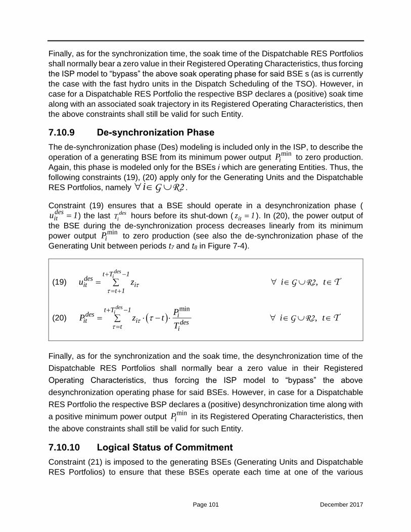
Page 101 December 2017
Finally, as for the synchronization time, the soak time of the Dispatchable RES Portfolios
shall normally bear a zero value in their Registered Operating Characteristics, thus forcing
the ISP model to “bypass” the above soak operating phase for said BSE s (as is currently
the case with the fast hydro units in the Dispatch Scheduling of the TSO). However, in
case for a Dispatchable RES Portfolio the respective BSP declares a (positive) soak time
along with an associated soak trajectory in its Registered Operating Characteristics, then
the above constraints shall still be valid for such Entity.
7.10.9 De-synchronization Phase
The de-synchronization phase (Des) modeling is included only in the ISP, to describe the
operation of a generating BSE from its minimum power output min
iP to zero production.
Again, this phase is modeled only for the BSEs i which are generating Entities. Thus, the
following constraints (19), (20) apply only for the Generating Units and the Dispatchable
RES Portfolios, namely i G R2 .
Constraint (19) ensures that a BSE should operate in a desynchronization phase (
desitu 1) the last des
iT hours before its shut-down ( itz 1 ). In (20), the power output of
the BSE during the de-synchronization process decreases linearly from its minimum
power output min
iP to zero production (see also the de-synchronization phase of the
Generating Unit between periods t7 and t8 in Figure 7-4).
(19) ,
desit T 1
desit i
t 1
u z i t
G R2 T
(20) min
,
desit T 1
des iit i des
t i
PP z t i t
T
G R2 T
Finally, as for the synchronization and the soak time, the desynchronization time of the
Dispatchable RES Portfolios shall normally bear a zero value in their Registered
Operating Characteristics, thus forcing the ISP model to “bypass” the above
desynchronization operating phase for said BSEs. However, in case for a Dispatchable
RES Portfolio the respective BSP declares a (positive) desynchronization time along with
a positive minimum power output min
iP in its Registered Operating Characteristics, then
the above constraints shall still be valid for such Entity.
7.10.10 Logical Status of Commitment
Constraint (21) is imposed to the generating BSEs (Generating Units and Dispatchable
RES Portfolios) to ensure that these BSEs operate each time at one of the various

Page 102 December 2017
operating states (Syn, Soak, Disp, Des), i.e., only one at most of the respective binary
variables can take a unitary value (1) in a given Dispatch Period t.
The Dispatchable Load Portfolios operate only in the normal dispatch state, as previously
discussed. In this case, constraint (21) is degenerated into the respective (22), which is
applied only to the Dispatchable Load Portfolios.
Constraint (23) models the logic of the start-up and shut-down status change, while
constraint (24) requires that a BSE i may not be started-up and shut-down simultaneously
in a given Dispatch Period t.
(21) ,syn dispsoak des
it it itit itu u u u u i t G R2 T
(22) ,disp
it itu u i t L1 T
(23) , it it it i t 1y z u u i tI T
(24) , it ity z 1 i t I T
The above two constraints (23) and (24) are enforced for all BSEs i irrespective of their
specific category (namely i G R1 R2 L1 L3I ).
7.10.11 Minimum Up / Down Time Constraints
Inequalities (25) and (26) enforce the minimum up and down time constraints,
respectively, uniformly for all BSEs. A BSE i must remain committed (de-committed) at
Dispatch Period t if its start-up (shut-down) started during the previous iMUT 1 ( iMDT 1)
hours.
(25) ,
i
t
i itt MUT 1
y u i tI T
(26) ,
i
t
i itt MDT 1
z 1 u i tI T
As described in Paragraph 5.3 (Dispatchable Load Registries), the Dispatchable Load
Portfolios shall also declare their minimum up and down times in their Registered

Page 103 December 2017
Operating Characteristics (as in the case of the Generating Units). Apparently, such times
can be declared with zero values, in case a Dispatchable Load Portfolio is not truly subject
to a minimum up or down time constraint.
Regarding the minimum up and down times of the Dispatchable RES Portfolios, these
are expected to be declared with zero values in the Dispatchable RES Registry
(Paragraph 5.3), thus essentially deactivating constraints (25) and (26) for such Entities.
7.10.12 Power Output Constraint
Equation (27) determines the Dispatch Schedule itP of each BSE, essentially arising
from:
a) its Market Schedule ( itMS ) obtained by the Market Operator,
b) its upward Balancing Energy ( itBEup ) scheduled in the ISP, and
c) its downward Balancing Energy ( itBEdn ) scheduled in the ISP.
Thus, (27) inherits the initial Market Schedule itMS , and computes the Dispatch Schedule
itP by adding upward Balancing Energy or subtracting downward Balancing Energy:
(27) , it it it itP MS BEup BEdn i tI T
Note that (27) is enforced for all BSEs in a uniform manner irrespectively of their specific
category.
It should be stressed again that a non-negative MW Market Schedule per Dispatch Period
t ( itMS ) shall be inserted in the ISP model for the generating BSEs (Generating Units,
Dispatchable RES Portfolios), while a non-positive MW Market Schedule per Dispatch
Period t shall be inserted for the loading BSEs (Dispatchable Load Portfolios) (opposite
of the positive MW schedule recorded for such Entities), according to the description of
the relevant Figure 7-4 (see, for example, the corresponding positive and negative red
dotted lines in this Figure, regarding the Generating Unit and the Dispatchable Load,
respectively).
7.10.13 Balancing Energy Constraints
The Balancing Energy quantities itBEup and itBEdn noted in the previous equality (27)
result from the respective step-wise Balancing Energy Offers submitted by the BSPs
according to the provisions of Section 2.6.
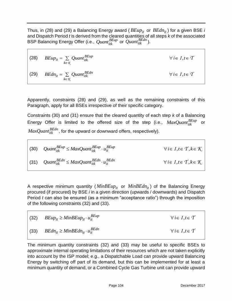
Page 104 December 2017
Thus, in (28) and (29) a Balancing Energy award ( itBEup or itBEdn ) for a given BSE i
and Dispatch Period t is derived from the cleared quantities of all steps k of the associated
BSP Balancing Energy Offer (i.e., BEupitkQuant or
BEdnitkQuant ).
(28) ,
BEup
it itkk
BEup Quant i tK
I T
(29) ,
BEdn
it itkk
BEdn Quant i tK
I T
Apparently, constraints (28) and (29), as well as the remaining constraints of this
Paragraph, apply for all BSEs irrespective of their specific category.
Constraints (30) and (31) ensure that the cleared quantity of each step k of a Balancing
Energy Offer is limited to the offered size of the step (i.e., BEupitkMaxQuant or
BEdnitkMaxQuant , for the upward or downward offers, respectively).
(30) , , BEup BEup BEup
ititk itkQuant MaxQuant u i t kI T K
(31) , , BEdn BEdn BEdnitk itk itQuant MaxQuant u i t kI T K
A respective minimum quantity ( itMinBEup or itMinBEdn ) of the Balancing Energy
procured (if procured) by BSE i in a given direction (upwards / downwards) and Dispatch
Period t can also be ensured (as a minimum “acceptance ratio”) through the imposition
of the following constraints (32) and (33).
(32) , BEup
it it itBEup MinBEup u i tI T
(33) , BEdnit it itBEdn MinBEdn u i tI T
The minimum quantity constraints (32) and (33) may be useful to specific BSEs to
approximate internal operating limitations of their resources which are not taken explicitly
into account by the ISP model; e.g., a Dispatchable Load can provide upward Balancing
Energy by switching off part of its demand, but this can be implemented for at least a
minimum quantity of demand, or a Combined Cycle Gas Turbine unit can provide upward

Page 105 December 2017
Balancing Energy by transiting to a new configuration state (i.e., committing another Gas
Turbine in addition to its Market Schedule), but such Balancing Energy shall come up to
a least minimum generation level (i.e., minimum power output of the additional Gas
Turbine).
The imposition of (32) and (33) introduces two new binary variables indicating the provision (“activation”) of Balancing Energy either in the upward or in the downward
direction (i.e., BEupitu and
BEdnitu , respectively).
In the example of Figure 7-4, the Generating Unit is committed earlier (in comparison to
its Market Schedule), by activating upward Balancing Energy ( BEupitu 1) at Dispatch
Period t2 and providing Balancing Energy quantities ( BEupitu 1) which correspond to the
pre-defined soak values until Dispatch Period t3. Upward Balancing Energy is
continuously awarded ( BEupitu 1) until the respective deactivation at Dispatch Period t5
and the restoration of the initial Market Schedule ( BEitu 0 ). A corresponding concept
applies for the activation and deactivation of downward Balancing Energy at Dispatch Periods t6 and t9, respectively, the provision of which incurs the Generating Unit’s shut-down at the intermediate interval t8 (based on the aforementioned linear de-synchronization process). An analogous logic (regarding the activation and deactivation of Balancing Energy and the Balancing Energy binary variable) applies also for the Dispatchable Load in Figure 7-4, or any other type of BSE.
It is noted again that the above minimum quantities of Balancing Energy (i.e., the
parameters itMinBEup and itMinBEdn ) shall be submitted by the BSPs as part of their
BSEs’ Balancing Energy Offers for any given Dispatch Period t, according to the provision
of Section 7.6.
(34) , BEup BEdn
ititu u 1 i tI T
Finally, as noted in Section 7.6.2, the offer prices submitted by the BSPs (Producers) for
their Generating Units should not be below the Units’ Minimum Variable Cost with regard
to Upward Balancing Energy Offers, and not above the Units’ Minimum Variable Cost with
regard to Downward Balancing Energy Offers.
However, as discussed in Section 7.6.2, there are no respective constraints on the
submitted offer prices for upward and downward Balancing Energy for the Dispatchable
RES Portfolios and the Dispatchable Load Portfolios. It is considered rational that the
respective BSPs operating / representing such BSEs shall submit higher prices for
providing upward Balancing Energy and lower prices for providing downward Balancing
Energy, in which case the activation of Balancing Energy from said BSEs will

Page 106 December 2017
deterministically take place in only one direction (upwards or downwards) in any given
Dispatch Period t. However, such rational bidding behaviour cannot be absolutely
foreseen.
In the opposite case, namely if the BSPs submit lower prices for providing upward
Balancing Energy and higher prices for providing downward Balancing Energy, their
Balancing Energy may be activated in both directions in a given Dispatch Period t (since
such counteractive provision minimizes the TSO cost in equality (2)), in which case the
BSPs experience undue losses. To prohibit such counteractive provision in case of
irrational bidding behaviour by one or more BSPs, the ISP problem may encompass
constraint (34) for choosing to activate only one (upward or downward) of the two services
from a BSE i in a given Dispatch Period t.
7.10.14 Capacity Constraints
Generating BSEs
Constraints (35) - (39) coordinate the Dispatch Schedule itP of each generating BSE
(Generating Unit, Dispatchable RES Portfolio) with the BSE contribution in any given
type of spinning Reserve Capacity (i.e., FCRupitQuant ,
FCRdnitQuant ,
aFRRupitQuant ,
aFRRdnitQuant ,
mFRRupitQuant ,
mFRRdnitQuant ,
RRupitQuant ,
RRdnitQuant ), within the
respective minimum and maximum BSE technical limits in every operating state (Syn, Soak, Disp, Des).
More specifically, the first three terms of the right-hand side of (35) - (39) constrain the
Dispatch Schedule of the BSE during the synchronization, soak and desynchronization
phases. In these phases the minimum and maximum limits essentially take the same
value forcing the Dispatch Schedule to be fixed to that value. Thus, in the synchronization
phase (i.e., when synitu 1) the Dispatch Schedule will be equal to 0, while in the soak
and de-synchronization phases, the Dispatch Schedule will be equal to soak
itP and des
itP ,
as these variables have been defined in equalities (18) and (20), respectively.
Constraints (35), (36) describe the BSE minimum limits:
(35) min
,
FCRdn aFRRdn mFRRdn RRdn Capit it it it it it
syn soak des dispit it it it it
P Quant Quant Quant Quant Deficit
0 u P P P u i t
G R2 T

Page 107 December 2017
(36) min
min, ,
Cap syn dispaFRRdn soak des AGCit it it it it itit it it
AGC AGCi it
P Quant Deficit 0 u P P P u u
P u i t
G R2 T
Constraints (37) - (39) describe the BSE maximum limits:
(37) max min max
( )desi
FCRup aFRRup mFRRup RRup Capit it it it it it
syn dispsoak desit it it it itit it i t T
P Quant Quant Quant Quant Surplus
0 u P P P u P P z
, i t G R2 T
(38) max
,
FCRup aFRRup mFRRup RRup Capit it it it it it
syn soak des dispit it it it it
P Quant Quant Quant Quant Surplus
0 u P P P u i t
G R2 T
(39)
max max, ,
aFRRup Cap syn soak desit it itit it it
disp AGC AGC AGCit it i itit
P Quant Surplus 0 u P P
P u u P u i t
G R2 T
It is noted that constraints (36) and (39) enforce the particular BSE minimum (min, AGC
iP
) and maximum (max,AGC
iP ) limits when aFRR is procured and the BSE is scheduled to
operate under AGC in the corresponding Dispatch Period t ( AGCitu 1). An illustrative
example of such aFRR procurement within the Generating Unit’s AGC limits has been provided in the previous Figure 7-5. Finally, the last term in the right-hand side of (37)
ensures that a generating BSE will operate at its minimum power output (min
itP ) at the
Dispatch Period prior to entering the desynchronization phase, as also shown in the illustrative example of Figure 7-4 (see the Dispatch Schedule of the Generating Unit in period t6). This term must be omitted for the generating BSEs not having a desynchronization phase (e.g., Dispatchable RES Portfolios or fast Generating Units). Thus, (37) is enforced only for the generating BSEs which actually have a
desynchronization phase (i.e., if des
iT 1 ), while the respective (38) (in which the afore-
mentioned last term has been omitted) is enforced for all generating BSEs (i.e., if des
iT 0
).
It should be noted that the problem formulation ignores the detailed technical constraints
of multi-shaft units, for simplicity reasons. Nevertheless, in case such formulation is
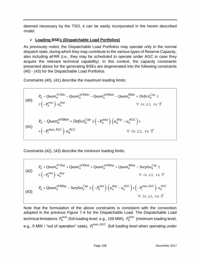
Page 108 December 2017
deemed necessary by the TSO, it can be easily incorporated in the herein described
model.
Loading BSEs (Dispatchable Load Portfolios)
As previously noted, the Dispatchable Load Portfolios may operate only in the normal
dispatch state, during which they may contribute to the various types of Reserve Capacity,
also including aFRR (i.e., they may be scheduled to operate under AGC in case they
acquire the relevant technical capability). In this context, the capacity constraints
presented above for the generating BSEs are degenerated into the following constraints
(40) - (43) for the Dispatchable Load Portfolios.
Constraints (40), (41) describe the maximum loading limits:
(40) max
,
FCRdn aFRRdn mFRRdn RRdn Capit it it it it it
dispit it
P Quant Quant Quant Quant Deficit
P u i t
L1 T
(41)
max
max, ,
Cap dispaFRRdn AGCit it it itit it
AGC AGCi it
P Quant Deficit P u u
P u i t
L1 T
Constraints (42), (43) describe the minimum loading limits:
(42) min
,
FCRup aFRRup mFRRup RRup Capit it it it it it
dispit it
P Quant Quant Quant Quant Surplus
P u i t
L1 T
(43) min min,
,
aFRRup Cap disp AGC AGC AGCit it it it it it i itP Quant Surplus P u u P u
i t
L1 T
Note that the formulation of the above constraints is consistent with the convention adopted in the previous Figure 7-4 for the Dispatchable Load. The Dispatchable Load
technical limitations max
itP (full loading level, e.g., 100 MW), min
itP (minimum loading level,
e.g., 0 MW / “out of operation” case), max,AGC
iP (full loading level when operating under

Page 109 December 2017
AGC, e.g., 80 MW) and min, AGC
iP (minimum loading level when operating under AGC,
e.g., 20 MW) are obtained as positive values from its Declared Characteristics. The
Dispatch Schedule itP is then delimited during the ISP execution (through the above
constraints) between min itP and
max itP , or min, AGC
iP and max, AGC
iP (in the case
of aFRR provision), taking also into account the contribution of the Dispatchable Load into the various types of Reserve Capacity. Under this convention, the Dispatch Schedule
itP of a Dispatchable Load or a DR Portfolio shall take only non-positive values in the ISP
results, while the upward Balancing Energy awards ( itBEup ) and the downward
Balancing Energy awards ( itBEdn ) take only non-negative values as for the generating
BSEs.
7.10.15 Hydro Mandatory Generation
Constraint (44) is imposed only to the hydro Generating Units (i.e., i H ) in order to
ensure that their Dispatch Schedules itP resulting from the ISP solution will be greater
than or equal to their mandatory injections for any given Dispatch Period t. The mandatory
generation itMand of a hydro Generating Unit shall be nominated to the TSO (through
the Hydro Mandatory Injections Declaration) on a half-hourly basis, in order to be properly
taken into account for the solution of the ISP.
(44) , it itP Mand i tH T
It should be noted that the mandatory injections of hydro units (according to the provisions
of the current Power Exchange Code) should have a special treatment in the Day-Ahead
Market Coupling process. In case they are not declared to cover forward or OTC contracts
by the respective Producers, they (upon the consent of the TSO on the declared
quantities) should be inserted in the Local Order Book of LAGIE and in the Market
Coupling input data as “price-taking” energy offers, in order to be cleared with priority in
the Market Coupling results (zonal market prices) and thus be included in the hydro units’
Market Schedules that will be initially inserted in the ISP model.
Such rule is not necessary in order to avoid gaming from the hydro Producer (e.g., a hydro
Producer deliberately provokes a zero Market Schedule for his hydro units, and the ISP
and RTBEM solutions activate upward Balancing Energy from these units to satisfy
constraint (44)), since in the Balancing Market these activated Balancing Energy Offers
shall be remunerated at the marginal Balancing Energy price and not pay-as-bid. Such
rule is rather necessary in order to avoid the distortion of the wholesale market, since in
case of zero Market Schedules from hydro units (being inserted at the ISP), the Day-
Ahead Market prices may probably be higher than the attained prices of the RTBEM (in

Page 110 December 2017
a fully competitive market structure), something which shall distort the market signals to
the BRPs (which may become unconcerned for their imbalances).
7.10.16 Maximum Daily Energy Constraint
The limit for the maximum daily energy production ( iMaxEnergy ) of the Generating Units
is imposed through (45) in the ISP. This constraint shall be enforced only for the
Generating Units, in case such Units have limits in their maximum daily generation. It is
noted however that these limits mainly concern the hydro injections.
Essentially, constraint (45) applies only when parameter iMaxEnergy is strictly positive.
Again, parameter D is equal to 1 hour.
(45)
MaxEnergyit i iit
t
P D Surplus MaxEnergy IniEnergy iT
G
Additionally, the maximum energy iMaxEnergy is decreased in each subsequent ISP
execution (i.e., ISP2, ISP3, ISP on-demand) by the amount of energy ( iIniEnergy ) already
(scheduled to be) produced during the previous Dispatch Periods (i.e., from the beginning
of the Dispatch Day until the start of the scheduling horizon in question).
Apparently, the parameter iIniEnergy takes a zero value for ISP1. For the rest ISPs, the
initial energy is computed through the expression (46):
(46)
CurrentPeriod 1 HorizonStart 1
i it itt 1 t CurrentPeriod
IniEnergy ActualMW PlannedMW i G
itActualMW is a parameter representing the actual instructed generation (in MW) for all
Dispatch Periods t until the previous of the CurrentPeriod (period of the ISP execution).
itPlannedMW is a parameter representing the generation planned for the Generating
Unit by the latest validated ISP run for all residual periods until before the start of the
scheduling horizon ( HorizonStart ).

Page 111 December 2017
Finally, it is noted that the sum of the Market Schedules itMS of a Generating Unit for all
Dispatch Periods t shall not overcome the value of the right-hand side of (45) for a given
ISP execution (BSE obligation to be imposed by regulatory means), namely the value
i iMaxEnergy IniEnergy , to avoid gaming behavior from the respective Participants.
7.10.17 Ramping Constraints
A BSE has limits on its ability to move from one level of MW to another within a specified
time period. The following constraints model such limitations separately for the generating
BSEs and the loading BSEs.
Generating BSEs (Generating Units, Dispatchable RES Portfolios)
Constraints (47) and (48) enforce the ramp rate limits on the power output between
consecutive Dispatch Periods for the generating BSEs (Generating Units, Dispatchable
RES Portfolios). Inequality (47) models the upward ramping constraint, while inequality
(48) models the downward ramping constraint.
Note that W is a large constant, so that these constraints are relaxed when a BSE is in
the synchronization, soak or desynchronization phase.
(47) RampUp disp syn soak
it i itit it iti t 1P P Surplus 60 RU u W u u
i , t
G R2 T
(48) RampDn disp des
it i it itit iti t 1P P Surplus 60 RD u W z u
i , t
G R2 T
Loading BSEs (Dispatchable Load Portfolios)
Analogous ramping constraints are enforced for the Dispatchable Load Portfolios.
Inequality (49) models the upward ramping constraint (“load pickup rate”), while inequality
(50) models the downward ramping constraint (“load drop rate”) in this case.
(49) RampUp disp
it it i iti t 1P P Surplus 60 RU u i , t L1 T
(50) RampDn disp
it it i it iti t 1P P Surplus 60 RD u W z i , t L1 T

Page 112 December 2017
Note that the above constraints have been adjusted (as compared to the previous (47)
and (48)) so as to take into account the fact that the Dispatch Schedules itP of the
Dispatchable Load Portfolios take non-positive values. In this case:
a) the parameter iRU refers to the maximum increase in the loading level of a
Dispatchable Load or a DR Portfolio in MW/min, e.g., a Dispatchable Load with
niRU 1 MW/mi can move from -50 MW to -110 MW in 60-minutes time; while
b) the parameter iRD refers to the maximum decrease in the loading level of a
Dispatchable Load or a DR Portfolio in MW/min, e.g., a Dispatchable Load with
niRD 1 MW/mi can move from -80 MW to -20 MW in 60-minutes time.
The last term in the downward ramping constraint (50) associated with parameter W is
used to relax this constraint when the Dispatchable Load or DR Portfolio is
desynchronized in the current Dispatch Period t. In this case itP 0 and i t 1P 0 , thus
the left-hand side of (50) is positive while the first term of the right-hand side is zero (
dispitu 0 ); however, the last term with itz 1 relaxes the constraint to allow for the proper
de-synchronization of the Dispatchable Load or DR Portfolio in the current period t.
7.10.18 Reserve Capacity Ramping Constraints
Constraints (51) - (54) introduce the effect of the ramp rate limits on the aggregated BSE
contribution in aFRR, mFRR and RR (per each direction, respectively).
Generating BSEs (Generating Units, Dispatchable RES Portfolios)
Specifically for the generating BSEs (Generating Units, Dispatchable RES Portfolios) the
maximum - ramp-limited - contribution in upward aFRR, mFRR and RR in each half-hourly
Dispatch Period t is given by inequality (51), while the respective maximum contribution
in downward aFRR, mFRR and RR is given by inequality (52):
(51) aFRRup mFRRup RRup RampUpResRRns
itit it it it
i
Quant Quant Quant Quant Surplus
60 RU i , t
G R2 T
(52)
RampDnResaFRRdn mFRRdn RRdnit it it it
i
Quant Quant Quant Surplus
60 RD i , t
G R2 T
Loading BSEs (Dispatchable Load Portfolios)
Accordingly, for the Dispatchable Load Portfolios, the maximum - ramp-limited -
contribution in upward aFRR, mFRR and RR in each half-hourly Dispatch Period t is given

Page 113 December 2017
by inequality (53), while the respective maximum contribution in downward aFRR, mFRR
and RR is given by inequality (54):
(53) aFRRup mFRRup RRup RampUpResRRns
itit it it it
i
Quant Quant Quant Quant Surplus
60 RD i , t
L1 T
(54) RampDnResaFRRdn mFRRdn RRdn
it it it it
i
Quant Quant Quant Surplus
60 RU i , t
L1 T
Note, again that the parameter iRD in the case of a Dispatchable Load or a DR Portfolio
refers to the maximum decrease in the loading level, thus, it is associated with the
activation of upward reserves in (53), while the parameter iRU refers to the maximum
increase in the loading level, thus, it is associated with the activation of downward
reserves in (54).
7.10.19 Reserve Capacity Contribution Constraints
As already discussed, the Ancillary Services Market is only part of the ISP; no further
market-based procurement of the various types of Reserve Capacity (upward / downward
FCR, aFRR, mFRR, RR) shall take place in the RTBEM. Thus, the following constraints
(55) - (71) which model the BSE maximum contribution to each type of Reserve Capacity
are only included in the ISP model. These constraints are applicable to all BSE s
irrespective of their specific category.
It is noted that:
a) the maximum contribution of BSE i in a given type of Reserve Capacity (i.e., RCtypeiMaxQuant in the following constraints) is computed by the Energy
Balancing System according to the provisions of Section 7.7. For the BSEs that cannot contribute to any given type of Reserve Capacity, the respective maximum
contribution RCtypeiMaxQuant shall be set to zero (as per the Declared
Characteristics);
b) the contribution in spinning reserves takes place only in the dispatchable phase
of any given BSE (i.e., when dispitu 1 ). Νo reserve contribution is modeled during
the start-up phase (synchronization and soak phases) and the shut-down phase (de-synchronization phase), as also illustrated in the previous Figure 7-5.

Page 114 December 2017
FCR contribution
The BSE maximum contribution to upward and downward FCR is modeled in (55) and
(56), respectively:
(55) , FCRup FCRup FCRup dispit it i itQuant Surplus MaxQuant u i t I T
(56) , dispFCRdn FCRdn FCRdn
it it i itQuant Surplus MaxQuant u i t I T
Since the FCR aims at the relief of instant incidents occurring within the real-time Dispatch
Period (e.g., load variations or disturbances occurring within each 15-min interval of the
RTBEM), thus the FCR procured from each BSE at the ISP shall be maintained in the
RTBEM in order to be available after each real-time solution (namely, within the real-time
Dispatch Period). This is achieved in the RTBEM by inheriting the FCR awards obtained
by the ISP execution as fixed incremental / decremental quantities over the RTBEM
Dispatch Schedules of the eligible BSEs, as further explained in Chapter 3.
aFRR contribution
Constraints (57) - (59) model the respective contribution in aFRR.
More specifically, (57) states that a BSE may provide aFRR (operate under AGC /
AGCitu 1) only at the dispatchable phase (
dispitu 1 ). For the BSEs that cannot operate
under AGC, the AGC binary variably (AGCitu ) shall be fixed to a zero value in the ISP,
through an associated flag.
The BSE maximum contribution to upward and downward aFRR is then modeled in (58)
and (59), respectively:
(57) , dispAGC
it itu u i tI T
(58) , aFRRup aFRRup aFRRup AGC
itit it iQuant Surplus MaxQuant u i tI T
(59) , aFRRdn aFRRdn aFRRdn AGCit it i itQuant Surplus MaxQuant u i t I T
Since the aFRR (AGC operation) aims at the relief of the load and RES variability
occurring within the real-time Dispatch Period, thus the aFRR procured from each BSE
at the ISP shall be maintained in the RTBEM, in order to be available after each real-time

Page 115 December 2017
solution (namely, within the real-time Dispatch Period). Again, this is achieved in the
RTBEM by inheriting the aFRR awards obtained by the ISP execution as fixed
incremental / decremental quantities over the RTBEM Dispatch Schedules of the eligible
BSEs, as further explained in Chapter 8.
An additional constraint can also be added to the clearing to ensure that the BSEs’
contribution to aFRR cannot be less than a certain percentage of their NCAP (i.e., 0.7%),
as currently considered by the TSO. The minimum percentage shall be the same for all
BSEs and its value shall be configurable according to the TSO preference (given the
approval of the Regulator). However, the minimum percentage configured can be equal
to zero, in which case the additional constraint is disabled. This additional constraint can
be written as follows:
(60) , aFRRup aFRRdn AGC
it i ititQuant Quant Percent NCAP u i tI T
Fast aFRR contribution
Moreover, as currently implemented by the TSO, a sufficient amount of fast (upward or downward) aFRR with 1-min ramping capability can be secured by the BSEs selected for
(upward or downward) aFRR, by introducing an auxiliary variable FastaFRRupitQuant or
FastaFRRdnitQuant , and enforcing constraints (61) - (64) in combination with the respective
system reserve requirement constraints (86) and (87).
(61) , FastaFRRup aFRRupit itQuant Quant i tI T
(62) min , FastaFRRup AGC
iitQuant RR 1 i t I T
(63) , FastaFRRdn aFRRdnit itQuant Quant i t I T
(64) min , FastaFRRdn AGCit iQuant RR 1 i t I T
mFRR contribution
The BSE maximum contribution to upward and downward mFRR is modeled in (65) and
(66), respectively:
(65) , mFRRup mFRRup mFRRup dispit it i itQuant Surplus MaxQuant u i tI T
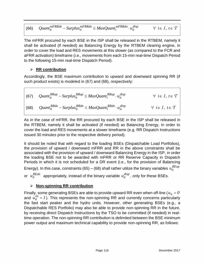
Page 116 December 2017
(66) , dispmFRRdn mFRRdn mFRRdn
it it i itQuant Surplus MaxQuant u i tI T
The mFRR procured by each BSE in the ISP shall be released in the RTBEM, namely it
shall be activated (if needed) as Balancing Energy by the RTBEM clearing engine, in
order to cover the load and RES movements at this slower (as compared to the FCR and
aFRR activation) timeframe (i.e., movements from each 15-min real-time Dispatch Period
to the following 15-min real-time Dispatch Period).
RR contribution
Accordingly, the BSE maximum contribution to upward and downward spinning RR (if
such product exists) is modeled in (67) and (68), respectively:
(67) , RRup RRup RRup dispit it i itQuant Surplus MaxQuant u i tI T
(68) , dispRRdn RRdn RRdn
it it i itQuant Surplus MaxQuant u i t I T
As in the case of mFRR, the RR procured by each BSE in the ISP shall be released in
the RTBEM, namely it shall be activated (if needed) as Balancing Energy, in order to
cover the load and RES movements at a slower timeframe (e.g. RR Dispatch Instructions
issued 30 minutes prior to the respective delivery period).
It should be noted that with regard to the loading BSEs (Dispatchable Load Portfolios), the provision of upward / downward mFRR and RR in the above constraints shall be associated with the provision of upward / downward Balancing Energy in the ISP, in order the loading BSE not to be awarded with mFRR or RR Reserve Capacity in Dispatch Periods in which it is not scheduled for a DR event (i.e., for the provision of Balancing
Energy). In this case, constraints (65) – (68) shall rather utilize the binary variables BEupitu
or BEdnitu appropriately, instead of the binary variable
dispitu , only for these BSEs.
Non-spinning RR contribution
Finally, some generating BSEs are able to provide upward RR even when off-line ( itu 0
and nsitu 1 ). This represents the non-spinning RR and currently concerns particularly
the fast start peaker and the hydro units. However, other generating BSEs (e.g., a
Dispatchable RES Portfolio) may also be able to provide non-spinning RR in the future,
by receiving direct Dispatch Instructions by the TSO to be committed (if needed) in real-
time operation. The non-spinning RR contribution is delimited between the BSE minimum
power output and maximum technical capability to provide non-spinning RR, as follows:

Page 117 December 2017
(69) , nsit itu 1 u i tI T
(70) min , RRns ns ns
it it it itQuant Deficit P u i tI T
(71) , RRns ns RRns nsit it i itQuant Surplus MaxQuant u i tI T
It is noted that the above constraints (69) - (71) are enforced for all BSEs. However, for
the BSEs that cannot provide non-spinning RR (e.g., Dispatchable Load Portfolios), the
maximum contribution to non-spinning RR RRnsiMaxQuant takes a zero value from their
Registered Operating Characteristics (Section 7.7); in this case, the non-spinning binary
variable (nsitu ) can also be fixed to a zero value prior to the ISP solution, through a
respective flag.

Page 118 December 2017
7.10.20 Zonal Imbalance covering Constraints (Inter-zonal Transfer Model)
As already discussed, the latest Market Schedules of all Entities referred in Paragraph
5.1 are sent by the Market Operator to the TSO (Balancing Market Management System)
for the purposes of the ISP execution. These Market Schedules respect in advance the
following power balance equation (on a zonal basis):
Non-dispatchable Entities: Forecast establishment by the TSO.
Dispatchable Entities (BSEs): Balancing Energy procurement to cover any
forecasted deviations of the non-dispatchable Entities from their Market Schedule.
where:
itGenUnitMS is the Market Schedule of the Generating Unit i for Dispatch Period
t,
itResPortMS is the Market Schedule of the Dispatchable RES Portfolio i for
Dispatch Period t,
ztResFiTPortMS is the sum of the Market Schedules of the RES FiT Portfolios for
all RES categories in Bidding Zone z for Dispatch Period t,
jtNonDispResUnitMS is the Market Schedule of the Non-Dispatchable RES
Portfolio j for Dispatch Period t,
,
z z
z z4
z z3
it iti i
zt jt jtj j
inter t itinter i
jtj
GenUnitMS ResPortMS
ResFiTPortMS NonDispResUnitMS + CommisMS +
ImpMS = DRPortMS
NonDispLoadMS
2G R
R C
INTER L
L , , ,
,
z z zinter t zz t z z t
inter z
t
ExpMS + Flow Flow +
ForecastedSystemLosses z t
2 INTER Z
Z T

Page 119 December 2017
jtCommisMS is the Market Schedule of the Generating Unit / RES Unit in
Commissioning or Testing Operation j for Dispatch Period t,
,inter tImpMS is the scheduled import at interconnection inter for Dispatch Period t,
itDRPortMS is the Market Schedule of the Dispatchable Load Portfolio i for
Dispatch Period t,
jtNonDispLoadMS is the Market Schedule of the Non-Dispatchable Load Portfolio
j for Dispatch Period t, and
,inter tExpMS is the scheduled export at the interconnection inter for Dispatch
Period t.
tForecastedSystemLosses is the difference between the forecasted losses in the
transmission system and the already cleared quantities in the Day-Ahead Market
and the Intra-Day Market for Dispatch Period t.
This power balance is already respected since the above-mentioned Market Schedules
have been obtained by respective balanced Participant transactions in the wholesale
market.
Now, the scope of the ISP imbalance covering equation is to cover any TSO-forecasted
deviations of the non-dispatchable Entities from their Market Schedules, by procuring
appropriately Balancing Energy from the dispatchable Entities, namely from the BSEs.
Thus, the imbalance covering constraint is described by the following linear equation (72),
taking into account a decomposition of the system into different Bidding Zones z.
In (72), the net Balancing Energy procured from all dispatchable BSEs per each zone z
(i.e., the first term on the left-hand side) covers the forecasted zonal imbalances, which
consist of the following components:
Non-Dispatchable Load Portfolios Imbalance
The zonal Non-Dispatchable Load Portfolios Imbalance is the difference between:
a) the zonal Non-Dispatchable Load Forecast ztNonDispLoadFR ; this forecast shall
be established by the TSO as provisioned in Section 7.11, and
b) the zonal Non-Dispatchable Load Portfolios already cleared in the Forward
(including OTC contracts), Day-Ahead and Intraday Market

Page 120 December 2017
z
jtj
NonDispLoadMS
2L
; this sum is essentially an aggregation of the latest
Market Schedules of all Non-Dispatchable Load Portfolios, as obtained by the
Market Operator for the current ISP.
Important note:
The Load Representatives shall nominate their Forward Market, Day-Ahead Market
and Intra-Day Market traded (bought) quantities separately for each Dispatchable
Load Portfolio i and for the Non-Dispatchable Load Portfolio j represented by them,
in order the Marker Operator to be able to determine the individual Market
Schedules of each Dispatchable Load Portfolio i and of the Non-Dispatchable Load
Portfolio j per Load Representative.

Page 121 December 2017
z
z
it iti I
zt jtj
BEup BEdn
NonDispLoadFR NonDispLoadMS
72
2L
,
,
z4
z
zt zt
zt jtj
jt jt inter tj
z t
ResFiTPortFR ResFiTPortMS
NonDispResUnitFR NonDispResUnitMS
CommisDS CommisMS ImpDev ExpDe
R
C
Z T
,
, ,
z
z
inter tinter
ZonImb ZonImbzt zt zz t z z t t
z
v
Deficit Surplus Flow Flow ForecastedSystemLosses
INTER
Z
RES FiT Portfolio Imbalance
The zonal RES FiT Portfolio Imbalance is the difference between:
a) the zonal RES FiT Portfolio Forecast ztResFiTPortFR ; this forecast shall be
established by the TSO as provisioned in Paragraph 7.11, and
Non-Dispatchable Load Portfolios Imbalance
RES FiT Portfolio Imbalance
Commissioning Imbalance
Net Balancing Energy from BSEs
Flow deviations at the interconnections
Non-Dispatchable RES Portfolios Imbalance

Page 122 December 2017
b) the zonal RES FiT Portfolio production already cleared in the wholesale market
ztResFiTPortMS ; this is essentially the latest Market Schedule of the RES FiT
Portfolio in Bidding Zone z, as obtained by the Market Operator for the current
ISP.
Non-Dispatchable RES Portfolios Imbalance
The zonal Non-Dispatchable RES Portfolios Imbalance is the difference between:
a) the zonal Non-Dispatchable RES Portfolios Forecast ztNonDispRESUnitFR ; this
forecast shall be established by the TSO as provisioned in Paragraph 7.11, and
b) the zonal Non-Dispatchable RES Portfolios production already cleared in the
wholesale market
z4
jtj
NonDispRESUnitMSR
; this is essentially an aggregation
of the latest Market Schedules of all Non-Dispatchable RES Portfolios, as
obtained by the Market Operator for the current ISP.
Commissioning Imbalance
With regard to the Generating Units / RES Units in Commissioning or Testing Operation,
the difference between a) and b) below essentially constitutes another zonal imbalance
(the zonal “Commissioning Imbalance”):
a) the Units’ MW schedules declared to the TSO prior to the given ISP execution
through the Commissioning Schedules Declarations ( jtCommisDS , j C ), and
b) the Units’ latest Market Schedules, submitted to the Market Operator at the Day-
Ahead Market and Intraday Market stage and inserted in the respective clearings
as “price-taking orders” ( jtCommisMS , j C ).
This imbalance shall also be covered by the activation of upward or downward Balancing
Energy in (72).
Flow deviations at the interconnections
These include the following categories:
a) The difference between the imported quantity in the Market Schedule (sold in the
Forward, Day-Ahead and Intraday Markets) by a trader and his nomination of
long-term Physical Transmission Rights (PTRs) for electricity imports through an

Page 123 December 2017
interconnection (e.g. Bulgaria, Italy) for which an obligation for physical delivery
exists,
b) The difference between the sold / bought energy quantity in the Greek Day-Ahead
Market corresponding to short-term (daily) PTRs and the bought / sold energy
quantities in neighboring countries Day-Ahead Market(s) corresponding to the
same daily PTRs,
c) Adjusting schedules for flow inadvertent deviations at the interconnections,
d) emergency schedules,
e) return of emergency schedules,
f) guarantees of commercial schedules that relate to the cases when an
interconnection is out of operation for more days than a maximum threshold
(included in the respective Auction Rules), and the TSO is obliged to guarantee
the commercial schedules beyond that threshold,
g) return of guarantees of commercial schedules, or
h) deviations for any other future-established purpose.
All the above constitute zonal imbalances that shall be covered appropriately by the
activation of Balancing Energy in (72).
Respective imbalances of adjacent Bidding Zones
The respective imbalances (as per the above-mentioned ones) of adjacent Bidding Zones
of each zone z can be covered with the activation of Balancing Energy from the given
zone z, through the consideration of corresponding corridor flows on the right-hand side
of (72) (i.e., Balancing Energy corridor flows).
Constraint (73) enforces the flow limit of the corridor between adjacent Bidding Zones z
and z’:
(73) , , , ' , Max zzz t zz tFlow AvailableFlow z z tZ Z T
It is noted that the corridor flows resulting from the right-hand side of (72) and constrained
by (73) above represent the additional flows produced by the ISP due to the procurement

Page 124 December 2017
of Balancing Energy and the possible sharing of such Balancing Energy between
neighboring Bidding Zones. Essentially, these “Balancing Energy” flows are only
incremental flows over those already established in the wholesale market (i.e., prior to
the given ISP execution). In this context, the maximum limit ,Maxzz tAvailableFlow imposed
in (73) constitutes the residual transfer capacity in each corridor, after subtracting the
corridor flow already scheduled in the wholesale market (Forward, Day-Ahead and
Intraday Market).
7.10.21 Zonal Imbalance covering Constraints (Flow-Based Model)
The Flow-Based (FB) model allows a better representation of the physical power flow
constraints, as compared to the simple transportation model (e.g. ATC-based model).
Under the Flow-Based model the zonal net positions are translated into physical flows in
critical branches through the usage of (linear) Power Transfer Distribution Factors
(PTDFs), thus achieving a physically feasible solution of the market clearing problem.
The following constraints (74)-(77) are enforced in order to apply the Flow-Based model
in the zonal imbalance covering equation in the ISP:

Page 125 December 2017
z
z
it iti I
zt jtj
BEup BEdn
NonDispLoadFR NonDispLoadMS
74
2L
,
,
z4
z
zt zt
zt jtj
jt jt inter tj
z t
ResFiTPortFR ResFiTPortMS
NonDispResUnitFR NonDispResUnitMS
CommisDS CommisMS ImpDev ExpDe
R
C
Z T
,
zinter t
inter
ZonImb ZonImbzt zt zt
v
Deficit Surplus NetInjection
INTER
(75) , , ,
z
zz t z z t ztz
Flow Flow =NetInjection z tZ
Z T
(76)
,, ,,
, ' ,
z ref z
zz t z tzz tz
Flow = PTDF NetInjection z z tZ Z T
(77) , , , ' ,Max zzz t zz tFlow AvailableFlow z z t Z Z T
7.10.22 Reserve Requirements Constraints
The following constraints (78) - (95) ensure that the total contribution of the BSEs in each
type of Reserve Capacity (upward / downward FCR, aFRR, mFRR, RR) meets the
associated zonal / system reserve requirements. These constraints are enforced only in
the ISP since there is no additional market-based procurement of reserves in the RTBEM.

Page 126 December 2017
FCR requirements constraints
The sum of the BSEs’ contribution in FCR must be greater than or equal to the zonal FCR
requirement in each direction (upwards / downwards), as imposed in (78) and (79),
respectively. Similar constraints (80) and (81) apply on a system basis:
(78) ,
z
FCRup ZonFCRup FCRupzt ztit
i
Quant Deficit Req z tI
Z T
(79) ,
FCRdn ZonFCRdn FCRdnit zt zt
i
Quant Deficit Req z tzI
Z T
(80)
FCRup SysFCRup FCRup
t titi
Quant Deficit Req tI
T
(81)
FCRdn SysFCRdn FCRdnit t t
i
Quant Deficit Req tI
T
aFRR requirements constraints
The sum of the BSEs’ contribution in aFRR must be greater than or equal to the zonal
aFRR requirement in each direction (upwards / downwards), as imposed in (82) and (83),
respectively. Similar constraints (84) and (85) apply on a system basis:
(82) ,
aFRRup ZonaFRRup aFRRup
zt ztiti
Quant Deficit Req z tzI
Z T
(83) ,
aFRRdn ZonaFRRdn aFRRdnit zt zt
i
Quant Deficit Req z tzI
Z T
(84)
aFRRup SysaFRRup aFRRup
t titi
Quant Deficit Req tI
T
(85)
aFRRdn SysaFRRdn aFRRdnit t t
i
Quant Deficit Req tI
T
With respect to the system requirements for fast aFRR with 1-min ramping capability,
these can be covered through constraints (86) and (87) for each direction (upwards /
downwards), respectively:
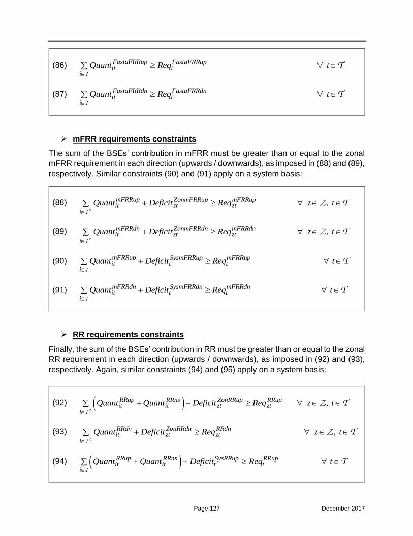
Page 127 December 2017
(86)
FastaFRRup FastaFRRup
titi
Quant Req tI
T
(87)
FastaFRRdn FastaFRRdnit t
i
Quant Req tI
T
mFRR requirements constraints
The sum of the BSEs’ contribution in mFRR must be greater than or equal to the zonal
mFRR requirement in each direction (upwards / downwards), as imposed in (88) and (89),
respectively. Similar constraints (90) and (91) apply on a system basis:
(88) ,
mFRRup ZonmFRRup mFRRup
zt ztiti
Quant Deficit Req z tzI
Z T
(89) ,
mFRRdn ZonmFRRdn mFRRdnit zt zt
i
Quant Deficit Req z tzI
Z T
(90)
mFRRup SysmFRRup mFRRup
t titi
Quant Deficit Req tI
T
(91)
mFRRdn SysmFRRdn mFRRdnit t t
i
Quant Deficit Req tI
T
RR requirements constraints
Finally, the sum of the BSEs’ contribution in RR must be greater than or equal to the zonal
RR requirement in each direction (upwards / downwards), as imposed in (92) and (93),
respectively. Again, similar constraints (94) and (95) apply on a system basis:
(92) ,
RRup RRns ZonRRup RRup
it zt ztiti
Quant Quant Deficit Req z tzI
Z T
(93) ,
RRdn ZonRRdn RRdnit zt zt
i
Quant Deficit Req z tzI
Z T
(94)
RRup RRns SysRRup RRup
it t titi
Quant Quant Deficit Req tI
T

Page 128 December 2017
(95)
RRdn SysRRdn RRdnit t t
i
Quant Deficit Req tI
T
7.10.23 Generic Constraints
The modeling of the generic constraints currently established by the TSO shall still be
valid in the ISP problem of the new market design.
Generic constraints provide a simple way for the user to program additional security type
constraints into the market clearing engine. They can be defined for the MW power output
itP (BSE generation / load) and/or the upward RR contribution RRupitQuant (allocation of
upward RR on the BSE). More specifically, the generic constraint feature shall be used
to:
a) define an additional RR requirement on a regional or blocks of units’ base,
b) model the minimum total energy injection into a Bidding Zone,
c) model manual constraints to fix the schedule of chosen BSEs for certain reasons
(i.e. voltage constraint, intra-zonal transmission constraint, etc.).
The generic constraints in the ISP are described mathematically in (96) - (98):
(96) , ,,
,
RRup RRupP GenConit it gc t gcit it gc
i i
GenCont gc
P Factor Quant Factor Surplus
Limit t gcT, GC
(97)
RRup RRupP GenConit it ,gc t ,gcit it ,gc
i i
GenCont ,gc
P Factor Quant Factor Deficit
Limit t gc T, GC
(98) , ,,
, ,
RRup RRupP GenConit it gc t gcit it gc
i i
GenCon GenCont gc t gc
P Factor Quant Factor Surplus
Deficit Limit t gc T, GC

Page 129 December 2017
It is noted that multiple generic constraints gc can be enforced for the same Dispatch
Period t.
7.10.24 Specific Operating Constraints for the Loading BSEs (Dispatchable Load Portfolios)
As already discussed, there are certain constraints regarding the provision of Balancing
Energy from loading BSEs (Dispatchable Load Portfolios), which shall be included in the
mathematical formulation, in order to help such BSEs to participate more effectively in the
market. These constraints are as follows:
Minimum delivery period constraints for the provision of Balancing Energy
Constraints (99) and (100) impose a minimum delivery period on the provision of
Balancing Energy (if activated) from a given BSE, in the upward or downward direction,
respectively. A BSE i must deliver Balancing Energy in the upward (downward) direction,
at Dispatch Period t, if the relevant activation of upward (downward) Balancing Energy
occurred during the previous BEup
iMinDP 1 ( BEdn
iMinDP 1 ) hours. The minimum delivery
periods BEupiMinDP and BEdn
iMinDP are technical characteristics which are submitted by the
respective operators in the Techno-Economic Declaration.
(99) ,BEup
i
tBEup BEupi it
t MinDP 1
y u i t
L1 T
(100) ,BEdn
i
tBEdn BEdni it
t MinDP 1
y u i t
L1 T
Maximum delivery period constraints for the provision of Balancing Energy
Constraints (101) and (102) impose a maximum delivery period on the provision of
Balancing Energy (if activated) from a given BSE, in the upward or downward direction,
respectively. A BSE i must not deliver Balancing Energy in the upward (downward)
direction, at Dispatch Period t, if a relevant de-activation of upward (downward) Balancing
Energy does not occur in the following BEupiMaxDP ( BEdn
iMaxDP ) hours. The maximum
delivery periods BEupiMaxDP and BEdn
iMaxDP are technical characteristics which are
submitted by the respective operators in the Techno-Economic Declaration.

Page 130 December 2017
(101) ,
BEupit MaxDP
BEup BEupi it
t 1
z u i t
L1 T
(102) ,
BEdnit MaxDP
BEdn BEdni it
t 1
z u i t
L1 T
Minimum baseload period constraints
Constraints (103) and (104) impose a minimum baseload period, namely a minimum
period between two successive activations of Balancing Energy from a given BSE, in the
upward or downward direction, respectively. A BSE i must not deliver Balancing Energy
in the upward (downward) direction, at Dispatch Period t, if a relevant de-activation of
upward (downward) Balancing Energy occurred during the previous iMinBP 1 hours. The
minimum baseload period iMinBP is a technical characteristic which is submitted by the
respective operators in the Techno-Economic Declaration.
(103) ,
i
tBEup BEupi it
t MinBP 1
z 1 u i t
L1 T
(104) ,
i
tBEdn BEdni it
t MinBP 1
z 1 u i t
L1 T
Maximum frequency of activations for the provision of Balancing Energy in
the course of a day
Constraints (105) and (106) impose a maximum frequency in the activations of Balancing
Energy from a given BSE in a certain Dispatch Day, in the upward or downward direction,
respectively. A BSE i shall not activate Balancing Energy in the upward (downward)
direction, in a given Dispatch Day, more than BEupiMaxFA (
BEdniMaxFA ) times. The
maximum frequency of activations BEupiMaxFA or
BEdniMaxFA is a technical
characteristic which is submitted by the respective operators in the Techno-Economic
Declaration.
It should also be noted that such characteristic shall be adjusted appropriately in
successive ISP executions in the course of a Dispatch Day (i.e. ISP2 – ISP3), in order to
take into account the already scheduled activations of Balancing Energy from a given
BSE in previous ISP executions.

Page 131 December 2017
(105) BEup BEupit i
t
y MaxFA i
T
L1
(106) BEdn BEdnit i
t
y MaxFA i
T
L1
Logical relationships of the Balancing Energy binary variables
Finally, similar logical relationships which govern the commitment binary variables, are
also applicable for the Balancing Energy binary variables, as follows:
(107)
,BEup BEup BEup BEupit it it i t 1
y z u u i t
L1 T
(108) ,BEdn BEdn BEdn BEdnit it it i t 1y z u u i t L1 T
(109) ,BEup BEupit ity z 1 ti L1 T
(110) ,BEdn BEdnit ity z 1 ti L1 T
7.11 Responsibilities of the Transmission System Operator
In the context of the Integrated Scheduling Process the TSO assumes the following
responsibilities:
1) The TSO shall establish the zonal Non-Dispatchable Load Forecast for each Dispatch
Period of the Dispatch Day used for the calculation of the zonal Non-Dispatchable
Load Imbalance in constraints (72) or (74) of the ISP model.
The Non-Dispatchable Load Forecast can be updated for each subsequent ISP
execution (i.e., ISP1, ISP2, ISP3, and any on-demand ISP) with regard to the
concerned Dispatch Periods.
For the establishment of the Non-Dispatchable Load Forecast, the TSO takes
account of the following information concerning the Dispatch Periods in question:
a) historical Non-Dispatchable Load data and statistics resulting from their
processing, such as load evolution per energy usage category,
b) weather condition forecasts, historical load data under similar weather conditions,
as well as comparable statistics, and especially load co-variation and weather
condition parameters,

Page 132 December 2017
c) events which the TSO knows in advance they will occur,
d) Transmission System / Distribution System operations that shall affect the
average half-hourly Non-Dispatchable Load at a certain Transmission Meter, of
which the TSO has been informed, and
e) other information collected and notified to the TSO.
2) The TSO shall establish the zonal RES FiT Portfolio Forecast for each Dispatch
Period of the Dispatch Day used for the calculation of the zonal RES Fit Portfolio
Imbalance in constraints (72) or (74) of the ISP model.
The RES FiT Portfolio Forecast can be updated for each subsequent ISP execution
(i.e., ISP1, ISP2, ISP3, and any on-demand ISP) with regard to the concerned
Dispatch Periods.
For the establishment of the RES FiT Portfolio Forecast, the TSO takes account of
the following information concerning the Dispatch Periods in question:
a) historical RES injection data (regarding the RES FiT Portfolios), and statistics
resulting from their processing,
b) weather condition forecasts (wind speed, solar radiation, etc.), historical RES
injection data (regarding the RES FiT Portfolio) under similar weather conditions,
as well as comparable statistics, and especially RES injection co-variation and
weather condition parameters,
c) events which the TSO knows in advance they will occur,
d) other information collected and notified to the TSO.
3) The TSO shall establish the zonal Non-Dispatchable RES Portfolios Forecast for
each Dispatch Period of the Dispatch Day used for the calculation of the zonal Non-
Dispatchable RES Portfolios Imbalance in constraints (72) or (74) of the ISP model.
The Non-Dispatchable RES Portfolios Forecast can be updated for each subsequent
ISP execution (i.e., ISP1, ISP2, ISP3, and any on-demand ISP) with regard to the
concerned Dispatch Periods.
For the establishment of the Non-Dispatchable RES Portfolios Forecast, the TSO
takes account of the following information concerning the Dispatch Periods in
question:
a) historical Non-Dispatchable RES Portfolios injection data, and statistics resulting
from their processing,
b) weather condition forecasts (wind speed, solar radiation, etc.), historical Non-
Dispatchable RES Portfolios injection data under similar weather conditions, as
Page 133 December 2017
well as comparable statistics, and especially the RES units’ injection co-variation
and weather condition parameters,
c) events which the TSO knows in advance they will occur,
d) Especially the RES Producer representing the Non-Dispatchable RES Portfolio
must send an injection forecast to the TSO for each Dispatch Period of the
Dispatch Day, not later than 13:00 EET of day D-1, which may be taken into
account by the TSO for the establishment of the Non-Dispatchable RES Portfolios
Forecast.
e) other information collected and notified to the TSO.
4) The TSO shall establish the zonal / system reserve requirements of upward and
downward FCR, aFRR and mFRR for each Dispatch Period of the Dispatch Day, used
in the reserve requirements constraints (78) - (95) of the ISP model, by utilizing
reliable and suitable scientific methodologies, as analyzed in Annex Β.
The zonal / system reserve requirements can be updated for each subsequent ISP
execution (i.e., ISP1, ISP2, ISP3, and any on-demand ISP) with regard to the
concerned Dispatch Periods.
During the zonal / system reserve requirements establishment, the TSO shall assess
the need to procure FCR, aFRR and mFRR, in order to ensure adequate system
response / regulation / replacement reserves within acceptable limits established in
the Hellenic Transmission System Operation Code, taking account of the
particularities of the System.
5) The TSO shall publish at its website seven (7) hours prior to the ISP Gate Closure
Time (namely not later than 09:00 EET in day D-1) the following information for each
Dispatch Period of the Dispatch Day:
a) the zonal Non-Dispatchable Load Forecast,
b) the RES FiT Portfolio Forecast,
c) the zonal Non-Dispatchable RES Portfolios Forecast
d) the system upward and downward FCR, aFRR and mFRR requirements.
The Non-Dispatchable Load Forecast, the RES FiT Portfolio Forecast, the zonal Non-
Dispatchable RES Portfolios Forecast, and the reserve requirements shall be
updated by the TSO and published at its website two (2) hours prior to the ISP1 GCT.
They shall also be updated for each subsequent programmed ISP execution
regarding the Dispatch Day in question, and published at the TSO website two (2)
hours prior to such execution.

Page 134 December 2017
6) The TSO receive and apply validation rules for the Balancing Energy Offers, Reserve
Capacity Offers, Non-Availability Declarations and Techno-Economic Declarations
from the BSPs.
7) The TSO shall decide on the validity of the Balancing Energy Offers and the Reserve
Capacity Offers submitted in the context of participation in the Balancing and Ancillary
Services Market.
8) The TSO shall acquire the operation schedules of the Generating Units / RES Units
in Commissioning or Testing Operation by the respective Producers, through the
Commissioning Schedules Declarations.
9) The TSO shall acquire the mandatory generation schedules of hydro Generating
Units by the respective Producers, through the Hydro Mandatory Injections
Declarations.
10) The TSO shall establish the cross-zonal transmission capacity among the internal
Bidding Zones for the solution of the ISP.
11) The TSO shall establish the import / export schedule deviations at the
interconnections for the solution of the ISP (constraint (72) or (74)).
12) The TSO shall operate the Balancing Market System, which shall exchange the
appropriate information with the Market Operator (acquire the latest Market
Schedules), in order to operate efficiently the Balancing Market, in accordance with
the provisions described in this document.
13) The TSO shall solve the ISP problem for each subsequent ISP session, according to
the timelines provided for in Section 7.1.
14) After each ISP solution, the TSO shall send to BSPs the part of the ISP results that
concern their BSEs, namely the results described in Section 7.12. The TSO shall also
prepare and publish such results in its website, in accordance with the timelines
provisioned in Section 7.1.
15) The TSO shall publish statistics and information relating to the monitoring of the
Balancing Market.
16) The TSO shallpublish in its website until 12:00 EET of each calendar day D+1 balance
information for each Real-Time Unit of the previous Dispatch Day D, regarding the
deviations of the Transmission System real operation from the Non-Dispatchable
Load Forecast, RES FiT Portfolio Forecast and Non-Dispatchable RES Portfolios
Forecast performed in day D-1 / D.
17) The TSO shall keep records with regard to the data and other parameters used for

Page 135 December 2017
the Non-Dispatchable Load Forecast, the RES FiT Portfolio Forecast, the Non-
Dispatchable RES Portfolios Forecast and the zonal / system reserve requirements,
as well as the results of these forecasts for each calendar year. The TSO shall publish
and notify to the Regulator statistics about the accuracy of the foregoing forecasts
within two (2) months from the end of each calendar year.
18) The TSO shall prepare a timetable of activities (an ISP timetable) governing the
actions required for the solution of the ISP, and this timetable shall be published on
the TSO website and shall be updated from time to time upon reasonable notice to
BSPs. The ISP Timetable shall include activities required for the Dispatch Day and
activities to be performed on the preceding day (the day ahead).
7.12 Integrated Scheduling Process Results
The ISP results of any given ISP execution contain the following:
a) a commitment schedule of the Balancing Service Entities;
b) the FCR, aFRR and mFRR awards per Balancing Service Entity and per Dispatch
Period of the Dispatch Day; and
c) an indicative production schedules of the Balancing Service Entities for each
Dispatch Period of the Dispatch Day, called ISP Schedule.
The Integrated Scheduling Process results are biding as follows:
a) the results of ISP1 are non-binding;
b) the results of ISP2 are binding only for the first twenty-four (24) Dispatch Periods
of Dispatch Day D, and
c) the results of ISP3 are binding for the last twenty-four (24) Dispatch Periods of the
Dispatch Day D.
Any preliminary acceptance (proactive procurement) of Balancing Energy Offers within
the ISP problem execution is not firm and not subject to any BSP-TSO settlement. The
ISP half-hourly production schedules do not constitute real Dispatch Instructions, but their
goal is to inform the respective Participants so that they take all necessary actions in order
to make to all extent possible the potential activation of their Balancing Energy Offers.
The provision of the Reserve Capacity awards resulted from the ISP by the Balancing
Service Entities is mandatory. In case of non-availability of such Reserve Capacity by a
BSE in real time, a non-compliance charge shall be imposed by the Transmission System
Operator to the respective Participant.

Page 136 December 2017
7.13 Integrated Scheduling Process Results Publication
One (1) hour after the ISP1 Gate Closure the Transmission System Operator shall
prepare and publish the results for the initial execution of the Integrated Scheduling
Process (ISP1).
Forty-five (45) minutes after each subsequent scheduled or unscheduled execution of the
Integrated Scheduling Process, the Transmission System Operator shall prepare and
publish the results for such execution.
Immediately after that, the Transmission System Operator shall notify all parties having
submitted accepted Balancing Energy Offers and Reserve Capacity Offers the part of the
Integrated Scheduling Process results concerning them. Such notification is not
considered a Dispatch Instruction, but its intent is to inform its recipient so that the latter
takes all necessary actions in order to proceed to the maximum extent possible with the
potential activation of the Balancing Energy Offer, and to provide the Reserve Capacity
awards during the Dispatch Day.
7.14 Integrated Scheduling Process Results Monitoring
Every calendar day D+1, not later than 11:00 EET, the TSO shall automatically transfer
all data, parameters and results of the subsequent ISPs solved for the Dispatch Day D in
editable format to the Regulator, in order the latter to monitor the normal operation of the
scheduling process and identify any potential sources of misconduct or strategic bidding
that may distort the ISP results and the scheduling of the BSEs.
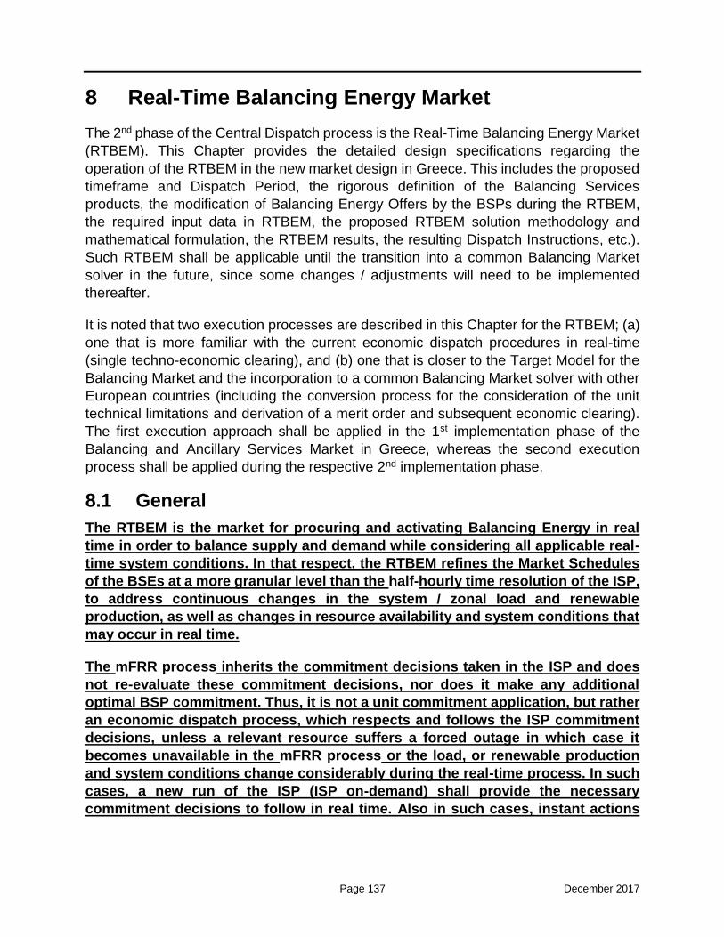
Page 137 December 2017
8 Real-Time Balancing Energy Market
The 2nd phase of the Central Dispatch process is the Real-Time Balancing Energy Market
(RTBEM). This Chapter provides the detailed design specifications regarding the
operation of the RTBEM in the new market design in Greece. This includes the proposed
timeframe and Dispatch Period, the rigorous definition of the Balancing Services
products, the modification of Balancing Energy Offers by the BSPs during the RTBEM,
the required input data in RTBEM, the proposed RTBEM solution methodology and
mathematical formulation, the RTBEM results, the resulting Dispatch Instructions, etc.).
Such RTBEM shall be applicable until the transition into a common Balancing Market
solver in the future, since some changes / adjustments will need to be implemented
thereafter.
It is noted that two execution processes are described in this Chapter for the RTBEM; (a)
one that is more familiar with the current economic dispatch procedures in real-time
(single techno-economic clearing), and (b) one that is closer to the Target Model for the
Balancing Market and the incorporation to a common Balancing Market solver with other
European countries (including the conversion process for the consideration of the unit
technical limitations and derivation of a merit order and subsequent economic clearing).
The first execution approach shall be applied in the 1st implementation phase of the
Balancing and Ancillary Services Market in Greece, whereas the second execution
process shall be applied during the respective 2nd implementation phase.
8.1 General
The RTBEM is the market for procuring and activating Balancing Energy in real
time in order to balance supply and demand while considering all applicable real-
time system conditions. In that respect, the RTBEM refines the Market Schedules
of the BSEs at a more granular level than the half-hourly time resolution of the ISP,
to address continuous changes in the system / zonal load and renewable
production, as well as changes in resource availability and system conditions that
may occur in real time.
The mFRR process inherits the commitment decisions taken in the ISP and does
not re-evaluate these commitment decisions, nor does it make any additional
optimal BSP commitment. Thus, it is not a unit commitment application, but rather
an economic dispatch process, which respects and follows the ISP commitment
decisions, unless a relevant resource suffers a forced outage in which case it
becomes unavailable in the mFRR process or the load, or renewable production
and system conditions change considerably during the real-time process. In such
cases, a new run of the ISP (ISP on-demand) shall provide the necessary
commitment decisions to follow in real time. Also in such cases, instant actions

Page 138 December 2017
can be taken by the TSO (e.g commit a unit, set a unit under AGC) that have not
been foreseen by the latest ISP, through direct (not scheduled) instructions.
Moreover, within the spirit of the Network Code on Electricity Balancing and the Target
Model in general, the mFRR process does not procure any additional Ancillary Services.
Indeed:
a) The mFRR schedules determined in the ISP are effectively released by the eligible
BSEs at each Dispatch Period of the mFRR process, in order to be optimally activated
as Balancing Energy for the relief of the very short-term forecasted imbalances.
b) The FCR and aFRR schedules determined in the ISP remain in effect at each
Dispatch Period of the mFRR process (i.e., they are being secured by the eligible
BSEs having been awarded such reserves in the ISP); they are then released closer
to real time, namely within the real-time Dispatch Period (e.g., through the operation
of AGC for aFRR) to manage the load and renewable production variability and any
unforeseen events taking place at a more instant timeframe. This applies unless the
eligible resource becomes unavailable due to an outage, in which case a new run of
the ISP shall provide the new FCR and aFRR awards to be available, as already
discussed.
8.2 Dispatch Period
The following provisions apply with regard to the Dispatch Period in the RTBEM:
1) A 15-min Dispatch Period shall be engaged in the RTBEM clearing engine.
2) Accordingly, all Balancing Energy Offers in the RTBEM have 15-min validity period or
longer.
3) There are 96 Dispatch Periods in each Dispatch Day, except from Dispatch Days
when daylight saving time changes occur where the number of Dispatch Periods
changes accordingly. Dispatch Periods commence at 00:00 on the Dispatch Day.
8.3 Balancing Services Products – Dispatch Process
8.3.1 Balancing Services Products
The following types of Balancing Energy products shall be applicable in real-time
operation23:
23 RAE Decision 67/2017, Guidelines and instructions to the competent market operators for the establishment of market codes according to par. 2 of article 6 of l. 4425/2016. Available online:

Page 139 December 2017
a) Upward and downward mFRR Balancing Energy activated through the mFRR
clearing engine in each 15-minute Real Time Unit. Essentially, the mFRR that was
secured by the BSEs as Reserve Capacity in the ISP shall be effectively released
in the mFRR process and activated (if needed) as mFRR Balancing Energy for
the relief of the very short-term forecasted imbalances. The Available Capacity of
the Balancing Service Providers that was not secured as Reserve Capacity in the
ISP is also available for activation of mFRR Balancing Energy Offers in the mFRR
process.
b) Upward and downward aFRR Balancing Energy activated through the AGC
operation. BSPs shall submit energy offers associated to the activation of aFRR
(i.e., aFRR Balancing Energy Offers), which shall be considered for the derivation
of the Economic Participation Factors. The Economic Participation Factors will be
input – along with other factors, like ramp-rates – in the AGC function to distribute
the Area Control Error (ACE) to the resources operating under AGC. An
appropriate pricing mechanism shall then provide the prices for the compensation
of the activated aFRR Balancing Energy (maximum price between the marginal
price resulting from the mFRR clearing and the aFRR energy bid of the BSP), as
detailed in Chapter 9.
The detailed methodology for the derivation of the Economic Participation Factors
and the aFRR Balancing Energy pricing mechanism shall be further analyzed
during the implementation phase of the RTBEM; in this Chapter, we focus only on
the functionality of the mFRR clearing engine (case (a) above).
8.3.2 mFRR Process (two executions methods)
1st implementation phase - Single techno-economic clearing
At the 1st implementation phase, the execution method is more familiar with the current
(2017) economic dispatch procedure of ADMIE; the main difference is that a 15-min
interval shall be applied, instead of a 5-min time-step.
As can be seen in Figure 8-1 (upper part, regarding 1st implementation phase), the TSO
executes the mFRR clearing algorithm for each subsequent 15-min interval (rolling basis).
As further discussed in Section 8.8, the single mFRR optimization problem is a techno-
economic problem, including both the main technical/operational constraints of the
resources (e.g. ramp-rates) and the economic clearance of the market for the optimal
activation of Balancing Energy.
The mFRR process is executed at -3΄ (from the start of the 15-minute period, namely for
http://www.et.gr/idocs-nph/search/pdfViewerForm.html?args=5C7QrtC22wEsrjP0JAlxBXdtvSoClrL8e5lVH_38-
2x5MXD0LzQTLf7MGgcO23N88knBzLCmTXKaO6fpVZ6Lx3UnKl3nP8NxdnJ5r9cmWyJWelDvWS_18kAEh
ATUkJb0x1LIdQ163nV9K--td6SIuV-TGxbJRNFgdUu4bLT6KrrF4evsPAEQPTGk0MlXZZKt

Page 140 December 2017
0΄ – 15΄), and results in the upward and downward mFRR Balancing Energy (in MWh)
that must be provided by each BSP. The resulted mFRR Balancing Energy is then
expressed in MW production that the BSP must reach at the end of the 15-minute period
(0΄ – 15΄), generating as follows:
a) the Balancing Service Entity must start ramping up or ramping down from the
beginning of the Real Time Unit (minute 0΄) until reaching the Dispatch Instruction
level (in MW) and then stay at this level until the end of the Real Time Unit (minute
15΄).
b) The shape of the production/withdrawal level during the Real Time Unit (0΄ – 15΄)
is such that the provided mFRR upward or downward Balancing Energy is equal
to the respective mFRR Balancing Energy resulted from the solution of the mFRR
process.
This process is executed every 15 minutes, providing new Dispatch Instructions to BSPs
for each Real Time Unit (15-minute period).
2nd implementation phase – Conversion process for merit order /
subsequent economic clearing
At the 2nd implementation phase, the mFRR process execution shall be closer to the
Target Model for the Balancing Market and the incorporation to a common Balancing
Market solver with other European countries. As in the 1st implementation phase, the TSO
shall execute the mFRR clearing algorithm for each subsequent 15-minute interval (on a
rolling basis), with each execution taking place 15 minutes (indicative time) prior to the
15-min Dispatch Period in question (see second diagram of Figure 8-1 regarding the 2nd
implementation phase).
However, each execution is now divided into two main steps:
a) a conversion process for the derivation of an appropriate merit order of the BSPs’
mFRR Balancing Energy Offers; and
b) the mFRR economic clearing execution.
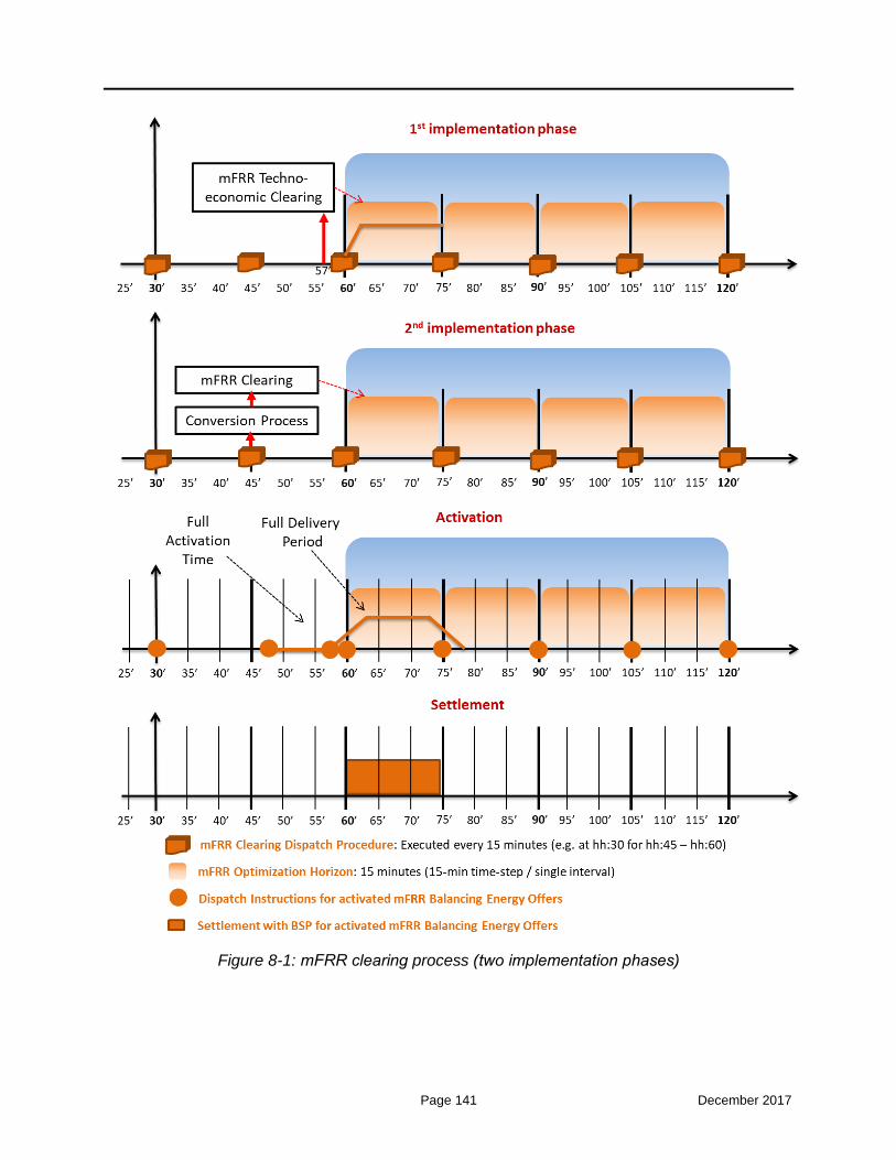
Page 141 December 2017
Figure 8-1: mFRR clearing process (two implementation phases)
Page 142 December 2017
With regard to the second step mentioned above (mFRR clearing), this step
minimizes the total activation cost of mFRR Balancing Energy in order to cover the
very short term forecasted imbalances for the Dispatch Period in question. In order
to comply with the Target Model provisions, the mFRR clearing in this case shall
constitute a pure economic activation problem for mFRR which (a) excludes the
BSE technical / operating constraints, while also (b) it does not take into account
other types of Balancing Capacity (FCR, aFRR) having been awarded to the BSEs
(in the ISP) for the Dispatch Period in question.
Thus, in order (a) to attain feasible results in the mFRR clearing, and (b) to secure
the Balancing Capacity (FCR, aFRR allocated in the ISP) for possible activation
after the mFRR clearing and closer to real time (e.g., instant events, AGC
operation), while retaining the pure economic structure of the mFRR clearing
(Target Model provisions), a set of respective constraints is taken into account in
a separate pre-process, the “conversion process” (see respective building block
in Figure 8-1). The conversion process is solved prior to each mFRR clearing
referring to the same 15-min dispatch interval, and aims:
a) to adjust (limit) the maximum quantity of mFRR Balancing Energy offered by the
BSEs, subject to the BSE technical / operating constraints, and taking into account
the already allocated Balancing Capacity (FCR, aFRR) in the ISP;
b) to provide a corresponding merit order of the converted BSEs’ Balancing Energy
Offers, which shall be available for the execution of the subsequent mFRR clearing.
It is noted that no particular action is required by the BSPs during or prior to the above-
mentioned processes, other than submitting (in the ISP) and optionally updating (until the
respective RTBEM GCT) their Balancing Energy Offers. The various processes shall be
automatically executed by the TSO according to analytical specifications provided in the
following Sections of this Chapter.
When ADMIE enters the common Balancing Market solver with other European
countries for the exchange of mFRR through the interconnections, it is expected
that some changes will have to be implemented (if any) in the mFRR solver in this
second implementation phase. Essentially, ADMIE will have to cancel the mFRR
economic clearing process (second step described above), since this will be
undertaken by the common Europe-wide solver. The conversion process shall still
be applicable prior to sending the Balancing Energy Offers to the common clearing
engine for possible activation, so as to ensure the feasibility of the results.
In the above context and with reference to the third diagram of Figure 8-1, the solution of
the mFRR clearing (e.g., at time 45’) shall activate an mFRR Balancing Energy Offer (for
the quarterly Dispatch Period 60’ - 75’), in which case the activated offer will have a 12.5-
min Full Activation Time (47.5’ - 60’) and a 15-min Full Delivery Period (60’ - 75’). For this

Page 143 December 2017
offer, the respective Dispatch Instruction is issued at time 47.5’ (see corresponding
orange circle in Figure 8-1), or the sooner possible after the results of the mFRR clearing
have been obtained. Note that there must be some time period between clearing and
sending of Dispatch Instructions. The required time for the clearing, sending of the
Dispatch Instructions, acknowledging the receipt of Dispatch Instructions, etc. shall be
considered during the implementation phase.
Note also, that the Full Activation Time (ramp) is not explicitly modeled within the clearing
engine, but is rather the “blank” time between the issuance of the Dispatch Instruction
and the respective initialization of the Full Delivery Period.
Finally, the settlement period for the BSPs (fourth diagram in Figure 8-1) coincides with
the Full Delivery Period of each mFRR Balancing Energy Offer activated by the clearing
engine.
8.4 Modification of Balancing Energy Offers by the Balancing Services Providers
In Central Dispatch systems the scheduling and dispatch process starts in day D-
1 (ISP) and continues up till real time. Substantial changes of offers during the real-
time dispatching process might lead to sub-optimal dispatch and could expose the
TSO and energy consumers as well as other Participants to very high costs. As
BSPs know in advance some results of the dispatch process (for example, the
decision about start-up and shut-down of Generating Units) they may use this
knowledge to abuse market power, for example by substantially changing the
incremental / decremental Balancing Energy Offer prices after obtaining
information that their resource will be operating in any given hours of the following
Dispatch Day D. For this reason, the opportunity for BSPs in Central-Dispatch
systems to subsequently modify their offers may be limited in the terms and
conditions (something which is also recognized in the Network Code on Electricity
Balancing of ENTSO-E). The above observations are especially valid for immature
or rapidly evolving markets.
The overall process requires therefore rules for the update / modification (during the
RTBEM) of the offers submitted in the ISP by the BSPs for their eligible BSEs. The
following provisions apply with regard to such possible modifications of the Balancing
Energy Offers after their original submission (i.e., submission prior to the ISP GCT):
1) As already stated in Section 7.6, all Balancing Energy Offers of the ISP corresponding
to the Dispatch Day D are submitted prior to the ISP1 GCT (16:00 EET in calendar
day D-1). The BSPs submit half-hourly step-wise (up to ten steps) Balancing Energy
Offers in the ISP, where Balancing Energy prices for successive steps must be strictly
non-decreasing for upward offers and non-increasing for downward offers. Each step
bears a positive upward / downward Balancing Energy quantity in MW, with accuracy
Page 144 December 2017
of up to 3 decimal points, and an offer price in €/MWh with accuracy of up to 2 decimal
points.
2) At the ISP1 GCT and in order the half-hourly ISP Balancing Energy Offers to be
properly taken into account in the 15-min process of the RTBEM, the ISP Balancing
Energy Offers shall be automatically converted (in the Balancing Market Management
System) into respective 15-min offers for the RTBEM. Essentially, each half-hourly
ISP Balancing Energy Offer shall cascade into two (2) equivalent 15-min RTBEM
Balancing Energy Offers for both mFRR and aFRR processes, with the same format
and for the same MW quantities and prices as the initial offer. The only feature that
changes is the validity period. Thus, the Balancing Energy Offers in the RTBEM are
15-min step-wise (up to ten steps) offers, where Balancing Energy prices for
successive steps must be strictly non-decreasing for upward offers and non-
increasing for downward offers. Each step bears a positive upward / downward
Balancing Energy quantity in MW, with accuracy of up to 3 decimal points, and an
offer price in €/MWh with accuracy of up to 2 decimal points.
3) The 15-min Balancing Energy Offers for mFRR and aFRR automatically obtained by
the Balancing Market System at the ISP1 GCT as per the above specification can
be voluntarily updated by the BSPs for their BSEs no later than fifteen (15) minutes
prior to each mFRR process execution, as can be seen in Figure 8-2.
Figure 8-2: Real-Time Balancing Energy Market (RTBEM) Gate Closure Times
With respect to the updated prices:

Page 145 December 2017
a) The price submitted at each step of the updated Balancing Energy Offer for
either mFRR or aFRR for a given 15-min Dispatch Period of the RTBEM shall
be “better” than the price submitted at each corresponding step of the
associated half-hourly Balancing Energy Offer in the ISP; by the term
“better” we refer to a lower price for upward offers and a higher price for
downward offers.
b) All the provisions regarding the maximum and minimum Balancing Energy
Offer Price limits (i.e., Administratively Defined Balancing Energy Offer
Lower Limit, Administratively Defined Balancing Energy Offer Cap, specific
limits for the Generating Units based on their Minimum Variable Cost, etc.)
apply also for the Balancing Energy Offers submitted in the RTBEM.
With respect to the updated quantities:
a) For the Generating Units:
1) The sum of the quantities (sum of all steps) offered for upward Balancing
Energy for a given 15-min Dispatch Period of the RTBEM shall cover the
difference between the Available Capacity (based on the Declared
Characteristics) and the latest Market Schedule of the (i.e., the most
updated Market Schedule shall be obtained by the Market Operator prior to
the respective RTBEM GCT), Generating Units.
2) The sum of the quantities over all steps offered for downward Balancing
Energy for a given 15-min Dispatch Period of the RTBEM shall cover the
latest Market Schedule of the Generating Unit.
b) For the Dispatchable RES Portfolios:
1) The sum of the quantities over all steps offered for upward Balancing
Energy for a given 15-min Real Time Unit of the RTBEM shall be at
maximum equal to the difference between the Registered Capacity (based
on the Registered Operating Characteristics) and the latest Market
Schedule of the Dispatchable RES Portfolio.
2) The sum of the quantities over all steps offered for downward Balancing
Energy for a given 15-min Real Time Unit of the RTBEM shall cover the
latest Market Schedule of the Dispatchable RES Portfolio.
c) For the Dispatchable Load Portfolios:
1) The sum of the quantities over all steps offered for upward Balancing
Energy for a given 15-min Real Time Unit of the RTBEM shall be at
maximum equal to the technical capability of the Dispatchable Load
Portfolio to provide upward Balancing Energy.
2) The sum of the quantities over all steps offered for downward Balancing
Energy for a given 15-min Real Time Unit of the RTBEM shall be at
maximum equal to the technical capability of the Dispatchable Load

Page 146 December 2017
Portfolio to provide downward Balancing Energy.
It should be noted that in case the Market Schedule of a BSE changes after the ISP
GCT for a given 15-min Dispatch Period and the respective BSP does not update the
BSE’s Balancing Energy Offer referring to said 15-min Real-Time Unit until the
relevant RTBEM GCT, then the Balancing Market System shallautomatically
implement the required quantity updates at the expiration of said RTBEM GCT.
Namely, the prices of the updated offers shall be the same with the prices of the
original offers, while the total quantity of the updated offer shall be subject to the
provisions hereinabove; thus, in case of a decreased total quantity as compared to
the original offer, the corresponding last (less competitive) steps of the offer shall be
omitted, while in case of an increased total quantity as compared to the original offer,
the last step of the original offer shall be extended so as to cover the respective
increase.
8.5 Obligations of BSPs in the context of the Real-Time Balancing Energy Market
Participation in the RTBEM shall mean in particular:
a) the submission of updated upward and downward Balancing Energy Offers by BSPs
for their BSEs regarding mFRR and aFRR processes and
b) the submission of Total or Partial Non-Availability Declarations by Producers and RES
Porducers for their Generating Units or RES Units, respectively, , in case their
Available Capacity has changed from the latest ISP GCT.
Participation in the mFRR process of Real-Time Balancing Energy Market is obligatory
for all Balancing Service Entities other than Dispatchable Load Portfolios with all their
available capacity to provide upward and downward Balancing Energy, independently of
the fact that they were or were not awarded mFRR in the relevant procurement processes.
Participation in aFRR is obligatory for all Producers with Generating Units that are
obliged, according to the Independent Power Transmission Operator Code to provide this
ancillary service (e.g. conventional units with nominal capacity higher than a certain limit
capacity).
In the context of the RTBEM, BSPs are required to:
a) submit Partial and Total Non-Availability Declarations as soon as reasonably possible
after the occurrence of an event, which results in the change of the Available Capacity
of the Generating Units or RES Units registered in their Participant Account;
b) take all necessary measures for their BSEs to be available for operation in
accordance with their Declared Characteristics; and

Page 147 December 2017
c) comply with the Commitment Instructions and Dispatch Instructions issued by the
TSO.
8.6 Real-Time Balancing Energy Market Input Data
The TSO shall establish the results of a given 15-min RTBEM execution based on the
following information:
1) The latest Market Schedules of all Balance Responsible Entities (e.g. Generating
Units, Dispatchable RES Portfolios, Non-Dispatchable RES Portfolios, Dispatchable
Load Portfolios, Non-Dispatchable Load Portfolios, etc.), as received from the
Nomination Platform of the Market Operator.
2) The operation schedules of the Generating Units / RES Units in Commissioning or
Testing Operation by the respective Producers, through the Commissioning
Schedules Declarations.
3) The mandatory generation schedules of hydro Generating Units submitted by the
respective Producers, through the Hydro Mandatory Injections Declarations.
4) The import / export schedule deviations at the interconnections used for the solution
of the ISP, along with actual tripping on interconnections (if any).
5) The already established flows in the inter-zonal corridors among Bidding Zones that
stem from the Market Schedules of all Entities, in order to establish the residual
available flows in the inter-zonal corridors for the solution of the RTBEM.
6) The information for the BSEs taken by the Energy Management System (EMS) of the
Transmission System Operator (e.g. unit in operation or not, real time measurements
of units production)
7) The AGC status for the BSΕs providing aFRR, obtained by the Balancing Market
System of the TSO.
8) The Reserve Capacity awards of the BSEs for upward / downward FCR, aFRR, and
mFRR obtained by the latest ISP execution.
9) The validated Balancing Energy Offers submitted in the ISP, and optionally updated
until the respective RTBEM GCT;
10) The Available Capacity of all BSEs, based on the latest submitted Non-Availability
Declaration.
11) The current operating plan of BSEs with an active maximum daily energy constraint.
12) The Declared Characteristics of the BSEs.

Page 148 December 2017
13) The initial production / demand level of the BSEs prior and as much as possible closer
to the start of the Dispacth Period of the given RTBEM execution.
14) The zonal Non-Dispatchable Load Imbalance, the computation of which is explained
in Paragraph 8.8.10.
15) The zonal RES FiT Portfolio Imbalance, the computation of which is explained in
Paragraph 8.8.10.
16) The zonal Non-Dispatchable RES Portfolios Imbalance, the computation of which is
explained in Paragraph 8.8.10.
8.7 Real-Time Balancing Energy Market Solution Methodology
The 15-min mFRR clearing problem is solved as a Mixed Integer Linear Programming
model, according to the detailed description of the following Section 8.8 and the two
execution methods provided.
If the Balancing Energy prices of different Balancing Energy Offers for the same
Dispatch Period arithmetically coincide and the respective Balancing Energy
quantities of such Balancing Energy Offers are not included in their entirety in the
mFRR clearing results, the priority of (partial or whole) inclusion of such Balancing
Energy Offers in the mFRR clearing results shall be given to DR providers then to
RES units and then established at random.
Where the mFRR clearing performs a random selection in accordance with the provisions
described herein, the Energy Balancing System (EBS) shall register the exact time of
such random selection, as well as the rest of the information to which it is related.
In case the model parameters for the execution of the mFRR clearing problem are
modified by the TSO, such modification shall be notified to the Regulator and to the BSPs
with a written letter, followed by a justification for the performed modification.
In case for a 15-min Dispatch Period of the Dispatch Day, it is impossible to cover
the very short-term forecasted imbalances, the TSO must consider the provisions
concerning Extreme Conditions, namely:
a) include Balancing Energy Offers for Contracted Units, and
b) re-execute the mFRR clearing problem in order to attain feasible results.
In case after the re-run of the mFRR clearing infeasibilities still appear in the
imbalance covering constraints, then the infeasibilities in the respective
constraints are relaxed, and the problem is solved in real time under the provisions
of Emergency Situations, as defined in the Independent Transmission System

Page 149 December 2017
Operation Code.
8.8 mFRR Process Mathematical Formulation – 1st execution method (Single Techno-economic Clearing)
In this Section, we provide the mathematical formulation of the 15-min mFRR clearing
problem under the 1st execution method (single techno-economic clearing), considering
the participation of all BSEs (Generating Units, Dispatchable Load Portfolios and
Dispatchable RES Portfolios). A set of BSE technical / operating constraints is taken into
account within the formulation of the single optimization problem, in order (a) to attain
feasible results for all BSEs and (b) to secure (maintain) the FCR and aFRR awards
having been allocated to the BSEs (in the ISP) for possible activation after the 15-min
mFRRclearing and closer to real time (e.g., through AGC operation within the 15-min
interval, for aFRR).
8.8.1 Objective Function
The mFRR clearingproblem is formulated as an optimization problem of Balancing
Energy, and constitutes a Mixed Integer Linear Programming model, as follows:
(1) Min BalancingEnergyCost PenaltyCost
The objective is to minimize the TSO cost of activation of mFRR Balancing Energy (
BalancingEnergyCost ) from the BSEs, as this cost is mathematically described in the
following Paragraph (equation (2)).
It is noted that the BSEs i that shall be considered in each 15-min mFRR clearing
execution are the BSEs which were scheduled to operate in the dispatchable phase (
dispitu 1 ) by the latest ISP solution (namely the BSEs which were scheduled to operate
between their minimum min
itP and maximummax
itP technical limits), or the BSEs which
were scheduled to provide non-spinning RR ( nsitu 1 ), or the loading BSEs which were
scheduled to provide Balancing Energy (/
BEup dnitu 1 ) in said 15-min Dispatch Period by
the latest ISP solution. The rest BSEs (i.e., generating BSEs scheduled to operate in the
synchronization, soak or desynchronization phase, or off-line BSEs) are considered as
“out of the market” and their offers are not included in the mFRR clearing.
The PenaltyCost included in the objective function (1) represents the non-physical cost
due to constraint violation when no physical solution exists, and is further explained in
Paragraph 8.8.3.

Page 150 December 2017
8.8.2 Balancing Energy Cost
The Balancing Energy cost is expressed in € and represents the activation cost of the
priced Upward and Downward Balancing Energy Offers for the entire system and all
Dispatch Periods.
Note that each mFRR clearing execution may “look-ahead” in more than one 15-
min Dispatch Periods in the future (e.g., four Dispatch Periods), thus resulting in a
rolling 15-min economic dispatch scheme with each single execution having a
dispatch horizon of more than one 15-min intervals in the future. In this way, the
TSO can make the most efficient dispatch in the current 15-min Dispatch Period,
taking also into account evolving (estimated) system conditions in later 15-min
intervals. Nevertheless, in each mFRR clearing execution, the Balancing Energy
activation and the respective dispatch decisions of only the current (first) 15-min
Dispatch Period shall be binding for the BSPs and the TSO, while any dispatch
decisions concerning later intervals (i.e. from the second 15-min interval until the
end of the given mFRR clearing dispatch horizon) shall be released to the Market
Participants for information purposes only. These advisory dispatch schedules will
be re-assessed by the subsequent mFRR clearing executions.

Page 151 December 2017
In this context, the Balancing Energy cost is expressed as follows:
(2)
BEup BEup BEdn BEdnitk itkitk itk
i t k
BalancingEnergyCost
+ D Quant Price Quant PriceI T K
Note that the Dispatch Period duration D is set to 1/4 for the mFRR clearing, since the
Dispatch Period has a 15-min length. Note also in (2), that in case of downward Balancing
Energy procurement, the TSO receives (rather than pays) a revenue from the BSPs, since
the provision of downward Balancing Energy implies that:
a) the Generating Units avoid variable generation costs (i.e., their production is
reduced as compared to their Market Schedule), whereas
b) the Dispatchable Load Portfolios are scheduled to consume more (i.e., withdraw
more energy than their Market Schedule, for which they have not previously paid
(i.e., in the Forward, Day-Ahead or Intra-Day Market).
8.8.3 Penalty Cost
To handle problem infeasibilities, violation (surplus / deficit) variables will be
introduced for various constraints. The penalty cost (3) is expressed in € and
represents the non-physical cost due to constraint violation when no feasible
solution exists, for the full system and all Dispatch Periods. The introduction of
penalty functions to deal with infeasibilities has been deployed as a standard
practice in recent years with substantial success. The form and strength of the
penalty functions provides a flexible methodology for including various policy
considerations in the market clearing solution approach.
When infeasibility is detected for a constraint, a corresponding violation notification with
the attained value of the surplus / deficit variable shall be available to the TSO in the
respective results. The TSO shall be able to modify the penalty prices at the Balancing
and Ancillary Services Market Database on-demand, given the approval of RAE. The
penalty prices can be set initially at the respective values indicated in the Nomenclature
Section.

Page 152 December 2017
8.8.4 Power Output Constraint
Equation (4) determines the Dispatch Schedule itP of each BSE i for each 15-min
Dispatch Period t, essentially arising from:
a) the BSE latest Market Schedule ( itMS ) obtained by the Market Operator,
b) the BSE upward Balancing Energy ( itBEup ) determined in the mFRR clearing
clearing, or
c) the BSE downward Balancing Energy ( itBEdn ) determined in the mFRR clearing.
Thus, (4) inherits the latest Market Schedule itMS prior to the current mFRR clearing
execution (for all Dispatch Periods t of the scheduling horizon), and computes the
Dispatch Schedule itP by using the upward Balancing Energy and downward Balancing
Energy, and by computing a dispatch level (in MW) that provides the Balancing Energy
(in MWh) that is optimally cleared to cover the system imbalance. The function f is derived
as follows:
a) The Transmission System Operator shall send to each Balancing Service Entity a
dispatch (production/withdrawal) level, in MW, which must be produced/ consumed
by the Balancing Service Entity at the end of the following Real Time Unit.
ZonImb DeficitZonImbzt
z t
ZonImb SurplusZonImbzt
z t
Cap DeficitCapit
i t
PenaltyCost
Deficit Price
Surplus Price
Deficit Price
Z T
Z T
T
Cap SurplusCapit
i t
RampUp SurplusRampUpit
i t
RampDn SurplusRampDnit
i t
(3) Surplus Price
Surplus Price
Surplus Price
I
I T
I T
I T
MaxEnergy SurplusMaxEnergyit
i t
Surplus Price
I T

Page 153 December 2017
b) Each Balancing Service Entity must start ramping up or ramping down from the
beginning of the Real Time Unit until reaching the Dispatch Instruction level (in
MW) and then stay at this level until the end of the Real Time Unit.
c) The shape of the production/withdrawal level during the Real Time Unit is such
that the provided mFRR upward or downward Balancing Energy is equal to the
respective mFRR Balancing Energy resulted from the solution of the mFRR
process, as detailed in the Balancing Market Manual.
(4) , , ,it it it itP f MS BEup BEdn i t I T
Note that (4) is enforced for all BSEs in a uniform manner, irrespectively of their specific
category. According to the relevant description of the ISP (Figure 7-4), it should be
stressed again that:
a) a non-negative MW Market Schedule per Dispatch Period t ( itMS ) shall be inserted
in the mFRR clearing model for the generating BSEs (Generating Units,
Dispatchable RES Portfolios), while,
b) a non-positive MW Market Schedule per Dispatch Period t shall be inserted for the
loading BSEs (Dispatchable Load Portfolios) (opposite of the positive MW schedule
recorded for such Entities).
8.8.5 Balancing Energy Constraints
The Balancing Energy quantities itBEup and itBEdn noted in the previous equality (4)
result from the most updated 15-min step-wise Balancing Energy Offers submitted by the
BSPs for their BSEs according to the provisions of Section 3.4. Thus, in (5) and (6), a
Balancing Energy award ( itBEup or itBEdn ) for a given BSE i and 15-min Dispatch Period
t is derived from the cleared quantities of all steps k of the associated BSE Balancing
Energy Offer (i.e., BEupitkQuant or
BEdnitkQuant ). Apparently, constraints (5) and (6), as well
as the remaining constraints of this Paragraph, apply for all BSEs irrespective of their
specific category.
(5) ,
BEup
it itkk
BEup Quant i tK
I T

Page 154 December 2017
(6) ,
BEdn
it itkk
BEdn Quant i tK
I T
Constraints (7) and (8) ensure that the cleared quantity of each step k of a Balancing
Energy Offer is limited to the offered size of the step (i.e., BEupitkMaxQuant or
BEdnitkMaxQuant , for the upward or downward offers, respectively).
(7) , , BEup BEup BEup
ititk itk0 Quant MaxQuant u i t kI T K
(8) , , BEdn BEdn BEdnitk itk it0 Quant MaxQuant u i t kI T K
A respective minimum quantity ( itMinBEup or itMinBEdn ) of the Balancing Energy
activated (if activated) by BSE i in a given direction (upwards / downwards) and Dispatch
Period t can also be ensured (as a minimum “acceptance ratio”) through the imposition
of constraints (9) and (10). It is noted again that the minimum quantities of Balancing
Energy (i.e., the parameters itMinBEup and itMinBEdn ) shall be submitted by the
Participants during the ISP period of submission, as part of their BSEs’ Balancing Energy
Offers for any given half-hourly Dispatch Period t. The submitted minimum quantities in
the ISP shall also be considered in the mFRR clearing (namely, in constraints (9) and
(10)), but now with a 15-min time resolution.
(9) , BEup
it it itBEup MinBEup u i tI T
(10) , BEdnit it itBEdn MinBEdn u i tI T
The imposition of constraints (9) and (10) introduces two binary variables, indicating the
activation of Balancing Energy either in the upward or in the downward direction (i.e.,BEupitu and
BEdnitu , respectively). Regarding the loading BSEs (Dispatchable Load
Portfolios), it should be noted that these binary variables BEupitu and
BEdnitu (i.e. the
activation status for upward and downward Balancing Energy) have already been
determined by the latest ISP execution (so as to take into account specific intertemporal
constraints, like the minimum baseload constraint), so they shall rather be fixed
accordingly in the mFRR clearing process.

Page 155 December 2017
Finally, constraint (11) is included in the mFRR clearing problem for the same reason
used also in the ISP model. A floor for Downward Balancing Energy Offers and a cap for
Upward Balancing Energy Offers may be decided by the NRA. However, there are no
respective constraints on the submitted offer prices for upward and downward Balancing
Energy for the Dispatchable RES Portfolios and the Dispatchable Load Portfolios. To
prohibit any counteractive provision of upward and downward Balancing Energy, the
clearing problem may encompass constraint (11) for choosing to activate only one
(upward or downward) of the two services from a BSE i in a given 15-min Dispatch Period
t.
(11) , BEup BEdn
ititu u 1 i t I T
8.8.6 Capacity Constraints
The following constraints (12) – (19) are intended to coordinate the final Dispatch
Schedule itP (of each BSE i for each 15-min Dispatch Period t), along with the respective
firm BSE Reserve Capacity awards for FCR and aFRR (obtained by the relevant ISP),
within the BSE technical minimum and maximum limits. Note again that the Reserve
Capacity awards for FCR and aFRR that have been allocated (based on half-hourly time
resolution) to the various eligible BSEs during the ISP shall remain in effect during the
corresponding 15-min Dispatch Periods in the mFRR clearing (FCR and aFRR Reserve
Capacity is not re-optimized during the mFRR clearing). Thus, the mFRR clearing
algorithm shall inherit such ISP Reserve Capacity awards as “fixed” quantities for the
eligible BSEs and for the 15-min Dispatch Periods concerned.
Constraints (12) – (15) concern the generating BSEs (Generating Units and Dispatchable
RES Portfolios), while constraints (16) – (19) concern the loading BSEs (Dispatchable
Load Portfolios).
Generating BSEs (Generating Units, Dispatchable RES Portfolios)
Constraints (12a) and (12b) describe the generating BSE minimum limits, while also
taking into account the downward FCR and aFRR reserves having been awarded by the
latest ISP execution to said BSE. Accordingly, constraint (13) describes the BSE
maximum limit, while also taking into account the upward FCR and aFRR reserves having
been awarded by the latest ISP execution to said BSE.

Page 156 December 2017
(12a) min,
FCRdn aFRRdn Capit it it itit Quant Quant Deficit P i tP G R2 T
(12b) minmax , , CapFCRdn
it it it ititP Quant Deficit P Mand i tH T
(13) max
,
FCRup aFRRup Capit itit it itP Quant Quant Surplus P
i t
G R2 T
The following explanatory comments should be noted:
a) All input parameters used in this Chapter which are assigned with the final (attained)
values of respective variables of another (preceding) process are noted with an upper
dash. Thus, constraints (12a), (12b) and (13) above consider the 15-min input
parameters FCRdnitQuant , aFRRdn
itQuant and FCRupitQuant , aFRRup
itQuant which have
been assigned with the attained values of the corresponding half-hourly variablesFCRdnitQuant ,
aFRRdnitQuant and
FCRupitQuant ,
aFRRupitQuant of the ISP, after proper
adjustment of the time resolution (e.g., a half-hourly upward aFRR award of 10 MW in
the ISP shall be converted into two respective 15-min upward aFRR awards of 10 MW
before insertion in the mFRR clearing process).
b) The quantities of FCR and aFRR allocated in the ISP are taken into account in the
mFRR clearing, so as to limit (if needed) the respective activation of upward /
downward Balancing Energy by the corresponding BSEs. This is because the already
allocated FCR and aFRR shall not be “overlapped” by the activation of Balancing
Energy in the mFRR clearing, but rather remain available for possible activation within
the 15-min Dispatch Period (e.g., at the AGC process for the allocated aFRR, or at
any occurrence of instant events for the allocated FCR).
c) In the case of hydro Generating Units (or Dispatchable CHP Units) with a nominated
mandatory generation itMand , the minimum limit considered in constraint (12b) is
rather the mandatory generation itMand , if the latter is greater than the technical
minimum min
itP of the Unit (without considering the awarded downward aFRR in this
case). As already discussed in Paragraph 7.10.15, the Market Schedule itMS in this
case already contains the mandatory generation itMand . For the rest BSEs the
parameter itMand takes a zero value in this constraint.

Page 157 December 2017
Constraints (14) and (15) enforce the respective technical minimum (min, AGC
itP ) and
maximum (max,AGC
itP ) limits when the generating BSE is operating under AGC in the
corresponding Dispatch Period t ( AGCitunder 1).
(14) min min,
,
CapaFRRdn AGC AGC AGCit it it it it ititP Quant Deficit P 1 under P under
i t
G R2 T
(15) max max,
,
aFRRup Cap AGC AGC AGCit it it it itit itP Quant Surplus P 1 under P under
i t
G R2 T
Loading BSEs (Dispatchable Load Portfolios)
The capacity constraints presented above for the generating BSEs are transformed into
the following constraints (16) - (19) for the loading BSEs.
Constraint (16) describes the BSE maximum loading limit, while constraint (17) describes
the BSE minimum loading limit:
(16) max,
FCRdn aFRRdn Capit it it itit Quant Quant Deficit P i tP L1 T
(17) min,
FCRup aFRRup Capit it it itit Quant Quant Surplus P i tP L1 T
Similarly, constraint (18) describes the BSE maximum loading limit, while constraint (19)
describes the BSE minimum loading limit, when the Dispatchable Load or the DR Portfolio
is operating under AGC:

Page 158 December 2017
(18)
max
max, ,
CapaFRRdn AGCit it it itit
AGC AGCit it
P Quant +Deficit P 1 under +
P under i t
L1 T
(19)
min
min, ,
aFRRup Cap AGCit it itit it
AGC AGCit it
P Quant -Surplus P 1 under +
+ P under i t
L1 T
8.8.7 Ramping Constraints
A BSE has limits on its ability to move from one level of MW to another within a specified
time period. For a given 15-min Dispatch Period, the initial MW level of each committed
BSE i (noted with the parameter iInitialMW ) is equal to the actual (metered) MW level of
the BSE (non-negative for the generating BSEs / non-positive for the loading BSEs)
during the associated mFRR clearingexecution (taking place, e.g. 15 minutes prior to said
Dispatch Period).
Generating BSEs (Generating Units, Dispatchable RES Portfolios)
In this context, constraints (20) and (21) enforce the ramp rate limits for the Generating
Units and Dispatchable RES Portfolios, for the binding (first) Dispatch Period of the
dispatch horizon ( t 1). Inequality (20) models the upward ramping constraint, while
inequality (21) models the downward ramping constraint. Accordingly, constraints (22)
and (23) model the upward and downward ramping limitations for the rest Dispatch
Periods of the dispatch horizon ( t 2 ), if a look-ahead functionality applies in the mFRR
clearing.
(20) itRampUp
i iitP InitialMW Surplus 15 RU i , t G R2 1
(21) itRampDn
i iitP 1InitialMW Surplus 15 RD i , t G R2
(22) ( )it i t 1RampUp
iitP P Surplus 15 RU i , t G R2 2
(23) ( )i t 1 itRampDn
iitP P 2Surplus 15 RD i , t G R2

Page 159 December 2017
Loading BSEs (Dispatchable Load Portfolios)
Analogous ramping constraints are enforced for the Dispatchable Load Portfolios.
Inequality (24) models the upward ramping constraint (“load pickup rate”), while inequality
(25) models the downward ramping constraint (“load drop rate”) for the binding (first)
Dispatch Period of the dispatch horizon ( t 1). Accordingly, constraints (26) and (27)
model the upward and downward ramping limitations for the rest Dispatch Periods of the
dispatch horizon ( t 2 ).
(24) RampUp
i it iitIn MW P Surplus 15 RU i , t 1itial L1
(25) ,RampDn
it i iitP In MW Surplus 15 RD i t 1itial L1
(26) ( )RampUp
i t 1 it iitP P Surplus 15 RU i , t 2 L1
(27) ( ) ,RampDn
it i t 1 iitP P Surplus 15 RD i t 2 L1
Note again, that the above constraints have been adjusted (as compared to the previous
(20) - (23)) so as to take into account the fact that the Dispatch Schedules itP of the
Dispatchable Load Portfolios take non-positive values. In this case:
a) the parameter iRU refers to the maximum increase in the loading level of a
Dispatchable Load or a DR Portfolio in MW/min, e.g., a Dispatchable Load with
niRU 1 MW/mi can move from -50 MW to -65 MW in 15-minutes time; while,
b) the parameter iRD refers to the maximum decrease in the loading level of a
Dispatchable Load or a DR Portfolio in MW/min, e.g., a Dispatchable Load with
niRD 1 MW/mi can move from -50 MW to -35 MW in 15-minutes time.
8.8.8 Maximum Daily Energy Constraint
In the mFRR clearing, the Dispatch Schedule itP of a Generating Unit is also limited by the
Unit current operating plan itP (ISP Dispatch Schedule), which in turn has been
constrained by a maximum daily energy limit (in the ISP). The final Dispatch Instruction
itP shall not exceed this limit:
(28) , MaxEnergy
ititit Surplus P i tP G T

Page 160 December 2017
The TSO shall also be able to de-activate this daily energy limit through an instruction
(activation of a respective flag per BSE) prior to the mFRR clearing. In such case, the
previous constraint shall not be applied.
8.8.9 Mandatory Activation Process prior to the mFRR Clearing
There exist certain conditions under which a mandatory activation of Balancing
Energy from given BSEs is required by the TSO prior to each mFRR clearing. Such
mandatory activation concerns BSEs which are considered as “out of the market”
in any of the 15-min Dispatch Periods of the dispatch horizon of a given mFRR
clearing execution (i.e., BSΕs which were either scheduled to operate in the
synchronization, soak or de-synchronization phase, or scheduled to be offline, and
thus do not participate in the mFRR clearing procedure).
The TSO is responsible to determine the MW level of such BSΕs together with the
Dispatch Instructions that will be issued for the rest BSΕs based on the results of the
mFRR clearing. The MW level will be either a zero MW level (in case the BSΕ was
scheduled to be offline), or the appropriate MW level based on the registered
synchronization, soak or de-synchronization trajectory of the BSΕ. However, the MW level
of “out of the market” resources in this case shall be computed prior to a given mFRR
clearing, so as the TSO to be able to determine the exact amount and direction of
Balancing Energy that has been manually activated (over the resource Market Schedule)
for the Dispatch Periods in question, and thus subtract this amount from the imbalances
to be covered during mFRR clearing.
If, for example, the MW level for a given BSE i in the soak phase is 25 MW at a certain Dispatch Period t, while his Market Schedule for said period is 80 MW, that means that an amount of (80 – 25) = 55 MW of downward Balancing Energy has been manually
activated by the TSO, thus BEdnitMand 55 MW . If the MW level for a BSE in the
desynchronization phase is 40 MW when the Market Schedule is zero at the same Dispatch Period t, that means that an amount of (40 – 0) = 40 MW of upward Balancing
Energy has been manually activated, thus BEupitMand 40 MW . As a last example, if the
MW level for a BSΕ is zero (off-line BSP) when the Market Schedule is 50 MW at the given Dispatch Period t, that means that an amount of (50 – 0) = 50 MW of downward Balancing Energy has been mandatorily activated over the BSΕ Market Schedule, thus
BEdnitMand 50 MW . These quantities
BEupitMand and
BEdnitMand are then considered in
the imbalance covering equation (29) in Paragraph 8.8.10 (or (31) in Paragraph 8.8.11), so as the mFRR clearing to cover only the residual imbalances of the given Dispatch Period t.
It should finally be noted that all upward or downward Balancing Energy quantities
mandatorily activated by the TSO shall define the Balancing Energy Price if greater

Page 161 December 2017
than the marginal price of mFRR clearing and shall be compensated based on this
price.
8.8.10 Zonal Imbalance covering Constraints (Inter-zonal Transfer Model)
Following the respective methodology adopted in the ISP model, the scope of the
imbalance covering equation in mFRR clearing is to cover any actual or TSO-forecasted
deviations (short-term forecasted deviations) of the non-dispatchable Entities from their
Market Schedules, by procuring appropriately Balancing Energy from the dispatchable
Entities, namely from the BSEs. Thus, the imbalance covering constraint is described by
the following linear equation (29), taking into account a decomposition of the system into
different Bidding Zones z.
In equation (29), the net Balancing Energy activated from all “in the market” BSEs per
each zone z (i.e., the first term on the left-hand side) plus the already (manually) activated
Balancing Energy by the TSO (Mandatory Activation Process) from all “out of the market”
BSEs per each zone z (i.e., the second term on the left-hand side) covers the forecasted
zonal imbalances, which consist of the following components:
( )
z z
z
z4
BEup BEdnit it itit
i I i I
zt jtj
zt zt
zt jtj
BEup BEdn Mand Mand
NonDispLoadFR NonDispLoadMS
29 ResFiTPortFR ResFiTPortMS
NonDispResUnitFR NonDispResUnitMS
2L
R
, ,
, ,
,
z z
z
jt jt inter t inter tj inter
ZonImb ZonImbzt zt zz t z z t t
z
CommisDS CommisMS ImpDev ExpDev
Deficit Surplus = Flow Flow + ForecastedSystemLosses
z t
C INTER
Z
Z T
Non-Dispatchable Load Imbalance
The zonal Non-Dispatchable Load Imbalance is the difference between:

Page 162 December 2017
a) the very short-term zonal Non-Dispatchable Load Forecast ztNonDispLoadFR ; this
forecast shall be established by the TSO prior to the given mFRR clearing, as
provisioned in Paragraph 8.13.2, and
b) the zonal Non-Dispatchable Load already cleared in the Forward (including OTC
contracts), Day-Ahead and Intra-Day Market
z
jtj
NonDispLoadMS
2L
; this sum is
essentially an aggregation of the latest Market Schedules of all Non-Dispatchable
Load Portfolios, as obtained by the Market Operator for the current mFRR clearing
execution.
RES FiT Portfolio Imbalance
The zonal RES FiT Portfolio Imbalance is the difference between:
a) the very short-term zonal RES FiT Portfolio Forecast ztResFiTPortFR ; this forecast
shall be established by the TSO prior to the given mFRR clearing execution as
provisioned in Paragraph 8.13.3 (and shall refer only to the RES FiT Portfolio per
Bidding Zone z), and
b) the zonal RES FiT Portfolio production already cleared in the wholesale market
ztResFiTPortMS ; this is essentially the latest Market Schedule of the RES FiT
Portfolio per Bidding Zone z, as obtained by the Market Operatorfor the current
mFRR clearing execution.
Non-Dispatchable RES Portfolios Imbalance
The zonal Non-Dispatchable RES Portfolios Imbalance is the difference between:
a) the zonal Non-Dispatchable RES Portfolios Forecast ztNonDispRESUnitFR ; this
forecast shall be established by the TSO as provisioned in Paragraph 8.13.4, and
b) the zonal Non-Dispatchable RES Portfolios production already cleared in the
wholesale market
z4
jtj
NonDispRESUnitMSR
; this is essentially an aggregation of
the latest Market Schedules of all Non-Dispatchable RES Portfolios, as obtained
by the Market Operatorfor the current ISP.
Commissioning Imbalance
With regard to the Generating Units / RES Units in Commissioning or Testing Operation,
the difference between a) and b) below essentially constitutes another zonal imbalance
(the zonal “Commissioning Imbalance”):
a) the Units’ MW schedules declared to the TSO through the latest Commissioning
Schedules Declarations ( jtCommisDS , j C ), and

Page 163 December 2017
b) the Units’ latest Market Schedules, submitted to the Market Operator at the Day-
Ahead and Intra-Day Market stage and inserted in the respective clearings as
“price-taking orders” ( jtCommisMS , j C ).
This imbalance shall also be covered by the activation of upward or downward Balancing
Energy in (29).
Flow deviations at the interconnections
These include the following categories:
a) the difference between the imported quantity in the Market Schedule (sold in the
Forward, Day-Ahead and Intra-Day Markets) by a trader and his nomination of
long-term Physical Transmission Rights (PTRs) for electricity imports through an
interconnection (e.g. Bulgaria, Italy) for which an obligation for physical delivery
exists,
b) the difference between the sold / bought energy quantity in the Greek Day-Ahead
Market corresponding to short-term (daily) PTRs and the bought / sold energy
quantities in neighboring countries Day-Ahead Market(s) corresponding to the
same daily PTRs,
c) adjusting schedules for flow inadvertent deviations at the interconnections,
d) emergency schedules,
e) return of emergency schedules,
f) guarantees of commercial schedules that relate to the cases when an
interconnection is out of operation for more days than a maximum threshold
(included in the respective Auction Rules), and the TSO is obliged to guarantee
the commercial schedules beyond that threshold,
g) return of guarantees of commercial schedules, or
h) deviations for any other future-established purpose.
All the above constitute zonal imbalances that shall be covered appropriately by the
activation of Balancing Energy in equation (29).
Respective imbalances of adjacent Bidding Zones
The zonal imbalances of adjacent Bidding Zones of each zone z can be covered with the
activation of Balancing Energy from the given zone z, through the consideration of
corresponding corridor flows on the right-hand side of equation (29) (i.e., Balancing
Energy corridor flows).

Page 164 December 2017
Constraint (30) enforces the flow limit of the corridor between adjacent Bidding Zones z
and z’:
(30) , , ,, ' Maxzz t zz t
zFlow AvailableFlow tz z TZ Z
It is noted that the corridor flows resulting from the right-hand side of the imbalance covering equation (29) and constrained by inequality (30) above represent the additional flows produced by the mFRR clearing due to the activation of Balancing Energy and the possible sharing of such Balancing Energy between neighboring Bidding Zones. Essentially, these “Balancing Energy” flows are only incremental flows over those already established in the wholesale market (i.e., prior to the given mFRR clearing execution). In
this context, the maximum limit ,Maxzz tAvailableFlow imposed in constraint (30) constitutes
the residual transfer capacity in each corridor, after subtracting the corridor flow already scheduled in the wholesale market (Forward, Day-Ahead and Intra-Day Market).
8.8.11 Zonal Imbalance covering Constraints (Flow-Based Model)
As already discussed, the Flow-Based (FB) model allows a better representation of the
physical power flow constraints, as compared to the simple transportation model (ATC-
based model), through the usage of (linear) Power Transfer Distribution Factors (PTDFs).
In accordance with the description provided in the previous Paragraph, the following
constraints (31) - (34) are enforced in order to apply the FB model in the zonal imbalance
covering equation of the mFRR clearing problem:
( )
z z
z
z4
BEup BEdnit it itit
i I i I
zt jtj
zt zt
zt jtj
BEup BEdn Mand Mand
NonDispLoadFR NonDispLoadMS
31 ResFiTPortFR ResFiTPortMS
NonDispResUnitFR NonDispResUnitMS
2L
R
, ,
, ,
,
z z
z
jt jt inter t inter tj inter
ZonImb ZonImbzt zt zz t z z t
z
t
CommisDS CommisMS ImpDev ExpDev
Deficit Surplus = Flow Flow +
+ ForecastedSystemLosses z t
C INTER
Z
Z T

Page 165 December 2017
(32) , , ,
z
zz t z z t ztz
Flow Flow =NetInjection z tZ
Z T
(33) ,, ,,
, ' ,
z ref z
zz t z tzz tz
Flow = PTDF NetInjection z z t Z Z T
(34)
, , , ' , Max zzz t zz tFlow AvailableFlow z z tZ Z T
8.9 Mathematical Formulation of the 2nd implementation phase of the mFRR process (Conversion Process / Economic Clearing)
As noted earlier, the execution at the 2nd implementation phase is closer to the Target
Model for the Balancing Market and the incorporation to a common Balancing Market
solver with other European countries. Again, the TSO executes the mFRR clearing
algorithm for each subsequent 15-min interval, with each execution taking place 15
minutes (indicative time) prior to the dispatch interval in question (see second diagram of
Figure 8-1). However, each execution is now divided into two main steps:
a) a conversion process for the derivation of an appropriate merit order list of the BSPs’
Balancing Energy Offers, and
b) the mFRR economic clearing execution which considers the produced merit order list.
With regard to the second step above (mFRR clearing), this minimizes the total activation
cost of mFRR Balancing Energy in order to cover the very short term forecasted
imbalances. In order to comply with the Target Model provisions, the mFRR clearing in
this case constitutes a pure economic activation problem for mFRR which (a) excludes
the BSE technical / operating constraints, while also (b) it does not take into account other
types of Balancing Capacity (FCR, aFRR) having been awarded to the BSEs (in the ISP)
for the Dispatch Period in question.

Page 166 December 2017
Thus, in order (a) to attain feasible results in the mFRR clearing, and (b) to secure the
Balancing Capacity (FCR, aFRR allocated in the ISP) for possible activation after the
mFRR clearing and closer to real time (e.g., instant events, AGC operation), while
retaining the pure economic structure of the mFRR clearing, a set of respective
constraints is taken into account in a separate pre-process, the “conversion process” (see
respective building block in Figure 8-1).
8.9.1 Conversion Process
The conversion process is solved prior to each mFRR clearing and aims:
a) to adjust (limit) the maximum quantity of mFRR Balancing Energy initially offered by
the BSEs, subject to system constraints, the BSE technical / operating constraints,
and taking into account the already allocated Balancing Capacity (FCR, aFRR) in the
ISP;
b) to provide the merit order list of the converted Balancing Energy Offers, which shall
then be available for the execution of the subsequent mFRR clearing.
The following Paragraphs provide the mathematical formulation of the mFRR conversion
process, which is again formulated as an optimization problem.
8.9.2 Objective Function
The conversion process is formulated as an optimization problem and constitutes a Linear
Programming model. The objective is to maximize the quantity of mFRR Balancing
Energy offered by the BSEs both in the upward and downward direction which shall be
considered in the subsequent mFRR clearing:
(35)
it it
i t
Max BEup BEdn PenaltyCostI T
It is noted that:
a) the conversion process (and the subsequent clearing) shall be solved once each
quarter for the following Dispatch Period t (single period optimization); in this sense,
the set t can be omitted from all symbols presented in the herein formulation, however
it has been retained for homogeneity purposes;
b) the BSEs i that shall be considered in the conversion process (and the subsequent
clearing) are again the BSEs which were scheduled to operate in the dispatchable
phase ( dispitu 1 ), or the BSEs which were scheduled to provide non-spinning RR (

Page 167 December 2017
nsitu 1 ), or the loading BSEs which were scheduled to provide Balancing Energy (
/
BEup dnitu 1 ) in said 15-min Dispatch Period by the latest ISP solution. The remaining
BSEs (i.e., generating BSEs scheduled to operate in the synchronization, soak or
desynchronization phase, or off-line BSEs) are considered as “out of the market” and
their offers are not included in the mFRR clearing.
The PenaltyCost referred in the objective function is a non-physical “cost” due constraint
violation in the conversion process, and is further explained in Paragraph 9.9.6.
8.9.3 Capacity Constraints
The following constraints are intended to limit the mFRR Balancing Energy offered by
each BSE either in the upward or in the downward direction, so as the final Dispatch
Instructions (i.e., Dispatch Instructions that shall be issued after the mFRR clearing) not
to violate the BSE technical minimum and maximum limits.
Constraints (36) – (39) concern the generating BSEs, while constraints (40) – (43)
concern the loading BSEs.
Generating BSEs
In constraint (36), the maximum downward Balancing Energy itBEdn offered by BSE i in
Dispatch Period t is delimited between the BSE Market Schedule itMS and the BSE
technical minimum min
itP , while also taking into account the downward FCR and aFRR
reserves having been awarded by the latest ISP execution to said BSE.
Accordingly, in constraint (37), the maximum upward Balancing Energy itBEup offered
by BSE i in Dispatch Period t is delimited between the BSE Market Schedule itMS and
the BSE technical maximum max
itP , while also taking into account the upward FCR and
aFRR reserves having been awarded by the latest ISP execution to said BSE.
(36a) min
,
CapFCRdn aFRRdnit it it it ititMS BEdn Quant Quant Deficit P
i t
G R2 T
(36b) minmax ,
,
CapFCRdnit it it it ititMS BEdn Quant Deficit P Mand
i tH T

Page 168 December 2017
(37) max
,
FCRup aFRRup Capit it itit it itMS BEup Quant Quant Surplus P
i t
G R2 T
Again, in the case of hydro Generating Units (or Dispatchable CHP Units) with a
nominated mandatory generation itMand , the minimum limit considered in constraint
(36b) is rather the mandatory generation itMand (without considering the awarded
downward aFRR in this case), if the latter is greater than the technical minimum min
itP of
the unit. For the rest BSEs the parameter itMand takes a zero value in this constraint.
Constraints (38) and (39) enforce the respective technical minimum (min, AGC
itP ) and
maximum (max,AGC
itP ) limits when the BSE is operating under AGC in the corresponding
Dispatch Period t ( AGCitunder 1).
(38)
min min, ,
CapaFRRdnit it it it
AGC AGC AGCit it it it
MS BEdn Quant Deficit
P 1 under P under i t
G R2 T
(39)
max max, ,
aFRRup Capit it it it
AGC AGC AGCit it it it
MS BEup Quant Surplus
P 1 under P under i t
G R2 T
Loading BSEs
Τhe capacity constraints presented above for the generating BSEs are transformed into
the following constraints (40) - (43) for the loading BSEs.
Constraint (40) describes the maximum loading limit, while constraint (41) describes the
minimum loading limit:
(40) max
,
CapFCRdn aFRRdnit it it it ititMS BEdn Quant Quant Deficit P
i t
L1 T

Page 169 December 2017
(41) min
,
FCRup aFRRup Capit it itit it itMS BEup Quant Quant Surplus P
i t
L1 T
Similarly, constraint (42) describes the maximum loading limit, while constraint (43)
describes the minimum loading limit, when the loading BSE is operating under AGC:
(42)
max max, ,
CapaFRRdnit it it it
AGC AGC AGCit it it it
MS BEdn Quant Deficit
P 1 under P under i t
L1 T
(43)
min min, ,
aFRRup Capit it it it
AGC AGC AGCit it it it
MS BEup Quant Surplus
P 1 under P under i t
L1 T
8.9.4 Ramping Constraints
A BSE has limits on its ability to move from one level of MW to another within a specified
time period. For a given 15-min Dispatch Period, the initial MW level of each committed
BSE i (noted with the parameter iInitialMW ) is equal to the actual (metered) MW level of
the BSE (non-negative for the generating BSEs / non-positive for the loading BSEs)
during the associated mFRR execution (taking place, e.g. 15 minutes prior to said
Dispatch Period).
Generating BSEs
In this context, constraint (44) maximizes the upward Balancing Energy itBEup offered
by generating BSE i in the given Dispatch Period t, so as the BSE not to ramp-up above
his iInitialMW plus his 15-min upward ramping capability. Similarly, constraint (45)
maximizes the downward Balancing Energy itBEdn offered, based on the 15-min
downward ramping capability of the BSE.
(44) RampUp
it it i iitMS BEup InitialMW Surplus 15 RU
i ,t
G R2 T

Page 170 December 2017
(45) RampDn
i it it iitInitialMW MS BEdn Surplus 15 RD
i , t
G R2 T
Loading BSEs
Analogous ramping constraints are enforced for the loading BSEs.
Inequality (46) models the upward ramping constraint (maximum increase in the loading
level), while inequality (47) models the downward ramping constraint (maximum decrease
in the loading level).
(46) RampUp
i it it iitInitialMW MS BEdn Surplus 15 RU
i ,t
L1 T
(47)
,
RampDnit it i iitMS BEup InitialMW Surplus 15 RD
i t
L1 T
8.9.5 Maximum Daily Energy Constraint
The maximum upward Balancing Energy itBEup offered by a Generating Unit is also
limited by the Unit current operating plan itP (ISP Dispatch Schedule), which in turn has
been constrained by a maximum daily energy limit (in the ISP). The final Dispatch
Instruction shall not exceed this limit:
(48) , MaxEnergy
it it ititMS BEup Surplus P i tG T
The operator shall also be able to de-activate this daily energy limit through an instruction
(activation of a respective flag per BSE) prior to the conversion process. In such case,
the previous constraint shall not be applied.
8.9.6 Penalty Cost
To handle problem infeasibilities, violation (surplus / deficit) variables have been
considered in the respective constraints, and the following penalty cost (49) has been
included in (subtracted from) the objective function.

Page 171 December 2017
Cap DeficitCapit
i t
Cap SurplusCapit
i t
Ramit
PenaltyCost
Deficit Price
Surplus Price
Surplus
I T
I T
pUp SurplusRampUp
i t
RampDn SurplusRampDnit
i t
MaxEnergy SurplusMaxEnergyit
i t
Price
(49) Surplus Price
Surplus Price
I T
I T
I T
It is noted again, that since the objective of the conversion process is to maximize the
mFRR Balancing Energy offered by the BSEs, the above penalty cost has no real cost
interpretation (the shadow costs of the respective constraints are not taken into account
at all). It is only considered in the objective in order to penalize the violation of the various
constraints with relative priorities (different penalty prices).
However, when infeasibility is detected for any constraint, a corresponding violation
notification with the attained value of the surplus / deficit variable shall be available to the
TSO in the respective results.
The TSO shall be able to modify the penalty prices at the Balancing and Ancillary Services
Market Database on-demand, given the approval of RAE. The penalty prices can be set
initially at the respective values indicated in the Nomenclature Section.
8.9.7 Conversion of the Balancing Energy Offers prior to mFRR Clearing and Creation of the Final Merit Order
The solution of the above optimization problem for a given quarterly Dispatch Period
provides the maximum quantity of upward / downward Balancing Energy that shall be
offered by each BSE i in the given Dispatch Period t during the subsequent clearing:
Maximum upward Balancing Energy: , MaxitBEup i tI T .
Maximum downward Balancing Energy: , MaxitBEdn i tI T .
The obtained maximum quantities MaxitBEup and Max
itBEdn are then used to limit
(convert) the latest (most updated) Upward / Downward Balancing Energy Offers
submitted by the BSPs, prior to their insertion in the mFRR economic clearing problem.
Figure 8-3 illustrates the above description.

Page 172 December 2017
With regard to the upper diagram of Figure 8-3, the residual Upward Balancing Energy
Offer (white area) of each BSE i for the given Dispatch Period t (i.e., remaining price -
quantity pairs BEup BEupitk itkMaxQuant Price after the conversion) is then considered as a
respective Upward Balancing Energy Offer. Accordingly, with regard to the lower diagram
of Figure 8-3, the residual Downward Balancing Energy Offer (white area) of each BSE
for the given Dispatch Period t (i.e., remaining price - quantity pairs
BEdn BEdnitk itkMaxQuant Price after the conversion) is then considered as a respective
Downward Balancing Energy Offer.
The converted Balancing Energy Offers form two merit order lists, one for the upward and
one for the downward direction, which are then inserted in the subsequent economic
clearing problem for activation purposes.
Note
The provisions of Paragraph 8.8.9 regarding the mandatory activation of Balancing
Energy from given “out of the market” BSEs apply also in this case. Any mandatory
activation of Balancing Energy shall take place prior to the subsequent economic clearing.

Page 173 December 2017
Figure 8-3: Conversion of the Balancing Energy Offers prior to their insertion in the mFRR clearing
8.9.8 mFRR Clearing – Mathematical Formulation
Every 15 minutes, and after the completion of the conversion process and the formation
of the final merit order lists, the mFRR clearing problem is solved for the following (single)
Dispatch Period t.
…
…
€ / MWh
MW
BEupit1
MaxQuant BEupit10
MaxQuant
BEupit1
Price
BEupit10
Price
Maxit
BEup
…
€ / MWh
…
MWBEdnit10
Price
BEdnit1
Price
BEdnit1
MaxQuant BEdnit10
MaxQuantMaxit
BEdn

Page 174 December 2017
The following Paragraphs describe the mathematical formulation of the mFRR clearing
problem.
8.9.9 Objective Function
The mFRR clearing problem is formulated as an optimization problem of mFRR Balancing
Energy, and constitutes a Mixed Integer Linear Programming model, as follows:
(50) Min BalancingEnergyCost PenaltyCost
The objective is to minimize the TSO cost of activation of Balancing Energy (
BalancingEnergyCost ) from the BSEs, as this cost is mathematically described in the
following Paragraph (equation (51)).
It is noted again that the BSEs that shall be considered in the mFRR clearing (as for the
conversion process) are the BSEs which were scheduled to operate in the dispatchable
phase ( dispitu 1 ), or the BSEs which were scheduled to provide non-spinning RR (
nsitu 1 ), or the loading BSEs which were scheduled to provide Balancing Energy (
/
BEup dnitu 1 ) in said 15-min Dispatch Period by the latest ISP solution. The remaining
BSEs (i.e., generating BSEs scheduled to operate in the synchronization, soak or
desynchronization phase, or off-line BSEs) are considered as “out of the market” and their
offers are not included in the mFRR clearing.
The PenaltyCost included in the objective function represents the non-physical cost due
to constraint violation when no physical solution exists, and is further explained in
Paragraph 8.10.3.
8.9.10 Balancing Energy Cost
The Balancing Energy cost is expressed in € and represents the activation cost of the
priced Upward and Downward Balancing Energy Offers for the entire system and the
given Dispatch Period t. The Balancing Energy cost is expressed as follows:
(51)
BEup BEup BEdn BEdnitk itkitk itk
i t k
BalancingEnergyCost
+ D Quant Price Quant PriceI T K

Page 175 December 2017
Note that the Dispatch Period duration D is set to ¼ for the mFRR clearing (and generally
for the RTBEM), since the Dispatch Period is quarterly.
8.9.11 Penalty Cost
The penalty cost (52) is expressed in € and represents the non-physical cost due to
constraint violation when no feasible solution exists, for the full system and the given
Dispatch Period. To handle such problem infeasibility, violation (surplus / deficit) variables
have been considered in the imbalance covering constraint (58) (or (60)).
(52)
ZonImb DeficitZonImbzt
z t
ZonImb SurplusZonImbzt
z t
PenaltyCost
Deficit Price
Surplus Price
Z T
Z T
When infeasibility is detected for this constrain (imbalance covering constraint) a
corresponding violation notification with the attained value of the surplus / deficit variable
shall be available to the TSO in the respective results.
The TSO shall be able to modify the penalty prices at the Balancing and Ancillary Services
Market Database on-demand, given the approval of RAE. The penalty prices can be set
initially at the respective values indicated in the Nomenclature Section.
8.9.12 Balancing Energy Constraints
Constraints (53) and (54) ensure that the cleared quantity of each step k of a Balancing
Energy Offer is limited to the offered size of the step (i.e., BEupitkMaxQuant or
BEdnitkMaxQuant , for the upward or downward offers, respectively). It is noted again that
the Balancing Energy Offers considered in the economic clearing are the ones included in the final upward and downward merit order lists (converted offers).
(53) , , BEup BEup BEup
ititk itk0 Quant MaxQuant u i t kI T K
(54) , , BEdn BEdn BEdnitk itk it0 Quant MaxQuant u i t kI T K
A respective minimum quantity ( itMinBEup or itMinBEdn ) of the Balancing Energy
activated (if activated) by BSE i in a given direction (upwards / downwards) can also be
ensured (as a minimum “acceptance ratio”) through the imposition of the following
constraints (55) and (56).
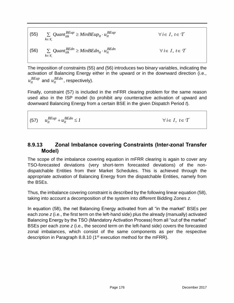
Page 176 December 2017
(55) ,
BEup BEup
it ititkk
Quant MinBEup u i tK
I T
(56) ,
BEdn BEdnitk it it
k
Quant MinBEdn u i tK
I T
The imposition of constraints (55) and (56) introduces two binary variables, indicating the activation of Balancing Energy either in the upward or in the downward direction (i.e.,
BEupitu and
BEdnitu , respectively).
Finally, constraint (57) is included in the mFRR clearing problem for the same reason
used also in the ISP model (to prohibit any counteractive activation of upward and
downward Balancing Energy from a certain BSE in the given Dispatch Period t).
(57) , BEup BEdn
ititu u 1 i t I T
8.9.13 Zonal Imbalance covering Constraints (Inter-zonal Transfer Model)
The scope of the imbalance covering equation in mFRR clearing is again to cover any
TSO-forecasted deviations (very short-term forecasted deviations) of the non-
dispatchable Entities from their Market Schedules. This is achieved through the
appropriate activation of Balancing Energy from the dispatchable Entities, namely from
the BSEs.
Thus, the imbalance covering constraint is described by the following linear equation (58),
taking into account a decomposition of the system into different Bidding Zones z.
In equation (58), the net Balancing Energy activated from all “in the market” BSEs per
each zone z (i.e., the first term on the left-hand side) plus the already (manually) activated
Balancing Energy by the TSO (Mandatory Activation Process) from all “out of the market”
BSEs per each zone z (i.e., the second term on the left-hand side) covers the forecasted
zonal imbalances, which consist of the same components as per the respective
description in Paragraph 8.8.10 (1st execution method for the mFRR).

Page 177 December 2017
(58)
z z
z
BEup BEupBEdn BEdnitk itititk
ki I i I
zt jtj
zt zt
zt
Quant Quant Mand Mand
NonDispLoadFR NonDispLoadMS
ResFiTPortFR ResFiTPortMS
NonDispResUnitFR NonDispResUnitMS
2
K
L
, ,
, ,
,
z4
z z
z
jtj
jt jt inter t inter tj inter
ZonImb ZonImbzt zt zz t z z t
z
t
CommisDS CommisMS ImpDev ExpDev
Deficit Surplus = Flow Flow +
+ ForecastedSystemLosses z t
R
C INTER
Z
Z T
Finally, constraint (59) enforces the flow limit of the corridor between adjacent Bidding
Zones z and z’:
(59) , , , ' , zMaxzz t zz t z zFlow AvailableFlow tZ Z T
It is noted again that the corridor flows resulting from the right-hand side of the imbalance covering equation (58) and constrained by inequality (59) above represent the additional flows produced by the mFRR clearing due to the activation of Balancing Energy and the possible sharing of such Balancing Energy between neighboring Bidding Zones. Essentially, these “Balancing Energy” flows are only incremental flows over those already established in the wholesale market (i.e., prior to the given mFRR clearing execution). In
this context, the maximum limit ,Maxzz tAvailableFlow imposed in constraint (59) constitutes
the residual transfer capacity in each corridor, after subtracting the corridor flow already scheduled in the wholesale market (Forward, Day-Ahead and Intra-Day Market).
8.9.14 Zonal Imbalance covering Constraints (Flow-Based Model)
As already discussed, the Flow-Based (FB) model allows a better representation of the
physical power flow constraints, as compared to the simple transportation model (ATC-
based model), through the usage of (linear) Power Transfer Distribution Factors (PTDFs).
In accordance with the description provided in the previous Paragraph, the following
constraints (60) - (63) are enforced in order to apply the FB model in the zonal imbalance
covering equation of the mFRR clearing problem:

Page 178 December 2017
(60)
z z
z
BEup BEupBEdn BEdnitk itititk
ki I i I
zt jtj
zt zt
zt
Quant Quant Mand Mand
NonDispLoadFR NonDispLoadMS
ResFiTPortFR ResFiTPortMS
NonDispResUnitFR NonDispResUnitMS
2
K
L
, ,
, ,
,
z4
z z
z
jtj
jt jt inter t inter tj inter
ZonImb ZonImbzt zt zz t z z t
z
t
CommisDS CommisMS ImpDev ExpDev
Deficit Surplus = Flow Flow +
+ ForecastedSystemLosses z t
R
C INTER
Z
Z T
(61) , , ,
z
zz t z z t ztz
Flow Flow =NetInjection z tZ
Z T
(62) ,, ,,
, ' ,
z ref z
zz t z tzz tz
Flow = PTDF NetInjection z z t Z Z T
(63)
, , , ' , Max zzz t zz tFlow AvailableFlow z z tZ Z T
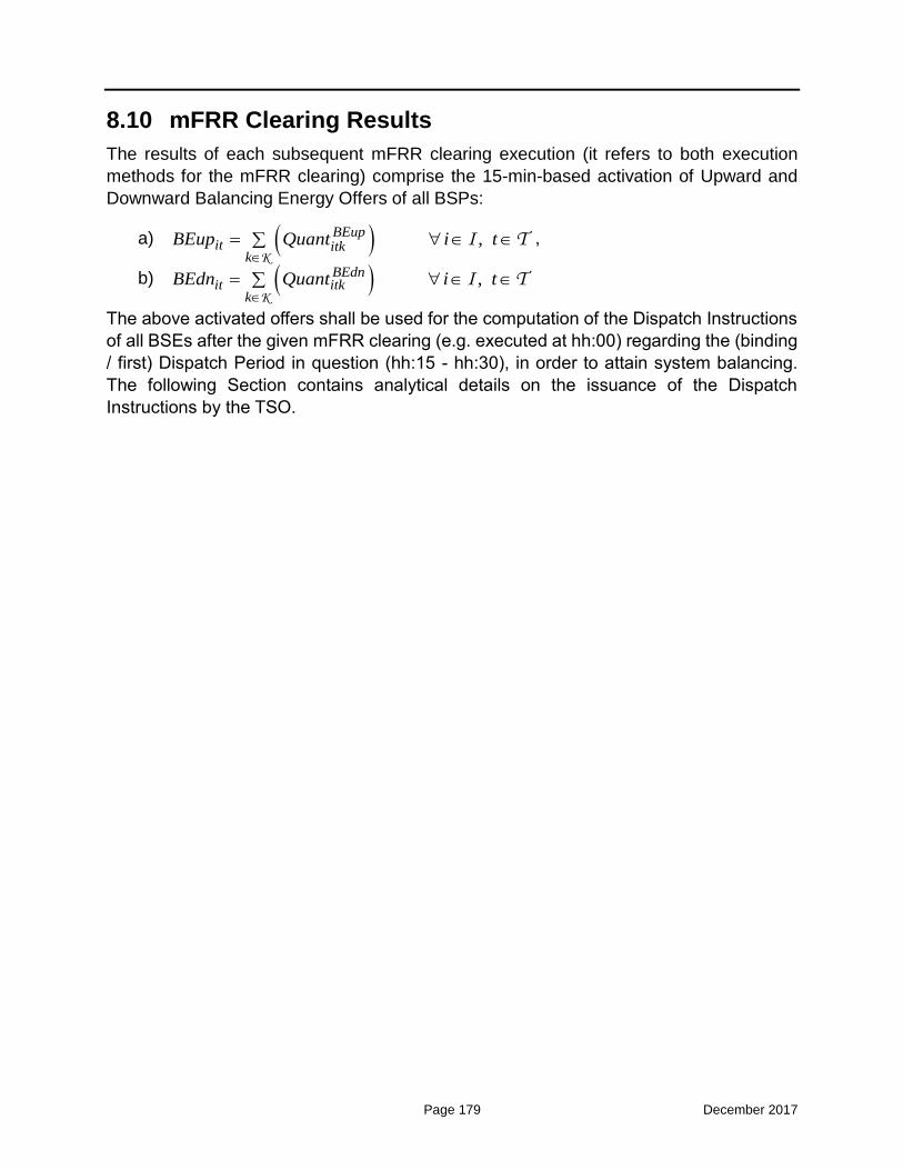
Page 179 December 2017
8.10 mFRR Clearing Results
The results of each subsequent mFRR clearing execution (it refers to both execution
methods for the mFRR clearing) comprise the 15-min-based activation of Upward and
Downward Balancing Energy Offers of all BSPs:
a) ,
BEup
it itkk
BEup Quant i t K
I T ,
b) ,
BEdn
it itkk
BEdn Quant i t K
I T
The above activated offers shall be used for the computation of the Dispatch Instructions
of all BSEs after the given mFRR clearing (e.g. executed at hh:00) regarding the (binding
/ first) Dispatch Period in question (hh:15 - hh:30), in order to attain system balancing.
The following Section contains analytical details on the issuance of the Dispatch
Instructions by the TSO.

Page 180 December 2017
8.11 Dispatch Instructions stemming from the mFRR Problem Solution
After the results of the mFRR problem solution have been obtained, the TSO shall issue
the respective Dispatch Instructions to the BSEs. The following provisions apply:
General Provisions
1) The TSO shall issue Dispatch Instructions which differ from the ISP results depending
on the degree of deviation of the operating conditions of the system, the possibly
updated Balancing Energy Offers of the BSEs, and the Available Capacity of the
BSEs during the mFRR process, from those that have been taken into account when
implementing the ISP.
2) A Dispatch Instruction (in MW) shall be issued by the TSO to each BSE the sooner
possible after the results of the given mFRR clearing have been obtained for 15-min
Dispatch Period in question. Essentially, the Dispatch Instruction that shall be issued
to each “in the market” BSE is the itP derived from the solution of the mFRR process.
(35) this equation is intentionally left blank
3) In case the TSO issues Dispatch Instructions which differ from the above stated ones
(i.e., from the Dispatch Instructions resulting from the outcome of the mFRR), then
the TSO shall submit a report to the Regulator justifying the choice of BSEs to cover
the system imbalance, in case such report is requested by the Regulator
4) The Dispatch Instructions differ from the AGC Instructions, which are provided by the
Automatic Generation Control system, and they also differ from the commitment
instructions that are issued based on the ISP results.
5) The BSEs selected for activation of Balancing Energy are obliged to follow the
Dispatch Instructions issued by the TSO for the relevant volumes and time period
they have been selected for.
Sending of Dispatch Instructions
1) Dispatch Instructions shall be sent by the TSO to the BSPs using the Dispatch
Information Administration System.
2) In case of Dispatch Information Administration System outage which renders
impossible the sending of a Dispatch Instruction, alternative means of
communications shall be used.

Page 181 December 2017
Obligation of Balancing Services Providers to comply with instructions
1) BSPs ensure the way of operation of their BSEs as this is established in the Dispatch
Instructions and change the operation of their BSE only following a Dispatch
Instruction.
2) Where compliance with a Dispatch Instruction is impossible due to constraints to the
operation of a Generating Unit, Dispatchable RES Portfolio, Dispatchable Load
Portfolio, which constraints are included in the Declared Characteristics of the BSE,
the respective Participant shall immediately inform the TSO. In that case, the TSO
may revoke the initial Dispatch Instruction and issue a new one.
3) Where compliance with a Dispatch Instruction has become impossible due to an
unforeseen impediment due exclusively to reasons regarding the safety of the
personnel or the installations of a Generating Unit, Dispatchable RES Portfolio,
Dispatchable Load Portfolio, the respective BSP is required to immediately inform the
TSO. In such case, the TSO may issue a new Dispatch Instruction in accordance with
the new Declared Characteristics of the respective BSE.
4) BSPs shall comply with the Commitment Instructions that concern the
synchronization or desynchronization of their BSE, if they execute them with a ten
(10) minute deviation from the time established in such instructions.
5) BSPs shall comply with Dispatch Instructions that refer to Active Power generation /
offtake by their BSEs, if they execute such Dispatch Instructions with a maximum
non-systematic deviation of ±5 MW (threshold defined by the TSO) from the Active
Power value and within the period established in such Dispatch Instructions.
6) In case of non-compliance on the part of a BSP with a Dispatch Instruction, the TSO
shall point out such non-compliance to such BSP indicating the relevant BSE, the
Dispatch Instruction and the time of its issue. Under no circumstances shall such
obligation of the TSO release such BSP from its obligations deriving from the
Dispatch Instruction and the consequences that may be incurred by it due to non-
compliance with such Dispatch Instruction.
Records and reporting regarding the dispatch procedure
1) The TSO is required to keep a complete data base regarding the dispatch procedure,
including:
a) a ISP Schedule record;
b) a Dispatch Instruction record;
c) a record of the proof of receipt of Dispatch Instructions.

Page 182 December 2017
2) The information contained in the above records shall be kept by the TSO for at least
five (5) years from their entry.
3) BSPs are entitled to access to the above information in any case for their BSEs, as
well as for other BSEs only in the context of settling disputes in accordance with the
procedure established in the Independent Transmission System Operation Code.
4) The TSO shall also provide all necessary information in accordance with the EU
Regulation for Energy Markets Integrity and Transparency (REMIT) and submission
and publication of data on Transparency platform of ENTSO-E.
Dispatch procedure statistics
1) The TSO is required to publish at the end of each calendar month information about
the dispatch procedure which shall include at least the following:
a) the total Energy and the maximum total system load per Dispatch Day;
b) the zonal total imbalances per Real-Time Unit;
c) the zonal marginal Balancing Energy prices per Real-Time Unit, corresponding
to the activated Balancing Energy;
d) any system events;
e) cumulative information regarding breaches of Dispatch Instructions by BSEs, as
well as information concerning the relevant actions of the TSO.
8.12 Direct Activation of mFRR
The Direct Activation (DA) of mFRR refers to the 2nd implementation phase of the
Balancing Market in Greece, where cross-border balancing shall be initiated.
Direct Activation of mFRR means an activation of mFRR Balancing Energy without
performing the described periodic mFRR process with 15 minutes cycles.
The Transmission System Operator is entitled to activate mFRR Balancing Energy
directly and send Dispatch Instructions to the Balancing Service Entities, in order to
balance the system in case of incidents, at any time between the scheduled runs of the
mFRR process, that necessitate immediate action to balance the system.
For this purpose, the Transmission System Operator creates indicatively can run the
mFRR process within the 15 minutes cycle time and/or create two merit order lists based
on the submitted Balancing Energy Offer prices, one in the upward direction and one in
the downward direction, including the Balancing Service Entities that can provide mFRR
Balancing Energy in each direction. The mFRR Balancing Energy quantity that can be
Page 183 December 2017
provided by each Balancing Service Entity is calculated based on their Balancing Energy
Offer quantity and their technical characteristics.
In such cases, the Transmission System Operator is entitled to select and activate mFRR
Balancing Energy sequentially from the merit order list in the appropriate direction.
The activation of Balancing Energy from a direct activation of mFRR starts immediately
after the receipt of the relevant dispatch instruction and ends at the end of the Real Time
Unit in which the dispatch instruction was issued.
The Balancing Energy Offers related to the direct activation of mFRR are taken into
account when calculating the Balancing Energy Price for the specific Balancing Energy
Settlement Time Unit.
8.13 Activation of aFRR
aFRR Balancing Energy is activated using the Automatic Generation Control (AGC)
function of the Transmission System Operator for frequency control as defined in
COMMISSION REGULATION (EU) 2017/1485 of 2 August 2017 establishing a guideline
on electricity transmission system operation.
All Balancing Service Entities with aFRR awards in the latest ISP are activated almost
simultaneously by the Transmission System Operator for the provision of aFRR Balancing
Energy. The criteria for the activation of aFRR Balancing Energy include the aFRR
Balancing Energy Offer prices and the ramp-rates of the Balancing Service Entities.
More details on the activation of aFRR Balancing Energy is included in the Balancing
Market Manual.
8.14 Responsibilities of the Transmission System Operator
In the context of the RTBEM the TSO shall:
1) collect the real-time telemetered power generation / offtake of the BSEs;
2) perform very short-term zonal Non-Dispatchable Load Forecasts for each 15-min
Dispatch Period of each execution of the mFRR process ;
3) perform very short-term zonal RES FiT Portfolio Forecasts for each 15-min Dispatch
Period of each execution of the mFRR process ;
4) perform very short-term zonal Non-Dispatchable RES Portfolios Forecasts for each
15-min Dispatch Period of each execution of the mFRR process ;
5) acquire and validate the updated Balancing Energy Offers and Non-Availability

Page 184 December 2017
Declarations from the BSPs;
6) operate the TSO Nomination Platform;
7) compute the respective zonal imbalances that should be covered by the activation of
Balancing Energy Offers;
8) compute the residual available flows in the inter-zonal corridors (corridors among
neighboring Bidding Zones) for the solution of the mFRR process;
9) attain the mFRR process results and the aFRR process results per BSE;
10) issue Dispatch Instructions and send them to BSEs;;
11) issue AGC Instructions and and send them to BSEs
12) monitor the compliance of BSEs to the Dispatch Instructions;
13) manage and use the Dispatch Information Administration System;
14) send the Balancing Market results to the Settlement for proper respective
calculations;
15) send the Settlement calculations to the Clearing House for invoicing, cash transfers
and Risk Management purposes;
16) publish statistics and information with regard to the results of the RTBEM and the
associated Dispatch Instructions; and
17) submit information to the ENTSO-E Transparency Platform and ACER.

Page 185 December 2017
9 Settlements
9.1 General Provisions
This Chapter presents:
a) the settlement of Balancing Energy and Balancing Capacity between the TSO and
the eligible BSΕs (through their respective BSPs), and
b) the Imbalance Settlement between the TSO and the Balance Responsible Entities
(BREs) (through their respective BRPs).
9.1.1 Balancing Market Settlements
The Settlements regarding the Balancing Market mainly consist of the following
procedures:
a) the Balancing Energy and Imbalance Settlement computations;
b) pay-as-bid reimbursement for offers activated for purposes other than balancing;
c) Contracted Units Settlement;
d) the Balancing Capacity Settlement;
e) other Ancillary Services Settlement;
f) the Uplift Account with respect to the System Losses, Balancing Capacity, Ancillary
Services, Contracted Units and Emergency Imports and Exports;
g) the Non-Compliance Charges computations; and
h) the Balancing Market Fee
i) the Transmission Use of System charges (system tariffs)
j) Calculation of the amount for financial neutrality of the TSO.
The Imbalance Settlement Period for the calculations of the Balancing Market settlements
is fifteen (15) minutes.
Financial neutrality of the TSO is achieved by a relevant amendment in the system tariffs
for next years. Specifically, net sums remaining after the Balancing Energy and Imbalance
Settlement for each Imbalance Settlement Period including interconnection deviations
and TSO interconnection schedules are credited/debited to a special reserve account of
the TSO, and are considered when calculating the system tariffs for next years. The TSO
may include a provision of the above net sum for next year Y+1 in order to be included in
the system tariffs of the year Y+1.
9.1.2 Responsibilities of the Transmission System Operator
In the context of the Settlements the Transmission System Operator is responsible to:

Page 186 December 2017
a) develop, maintain and operate the Balancing Market Settlement System;
b) calculate the debits and credits of each BSE / BRE concerning the settlement of
Balancing Energy and Reserve Capacity the Imbalance Settlement and other
Market Settlements;
c) issue the Initial Balancing Settlement Statement and the Reconciliation Balancing
Settlement Statements to the respective Participants, and
d) send to the Clearing House the final debits and credits per Participant.
The Transmission System Operator keeps a separate Balancing Market Account per type
of charge of the Balancing Market settlements, and a separate Participant Market Account
per Participant.
9.1.3 Obligations of the Distribution System Operator in the context of the Settlemnt Procedure
The Distribution System Operator shall calculate and provide to the Transmission System
Operator per Imbalance Settlement Period and Load Representative the following
regarding the Offtake of consumers connected at the Low Voltage of the Interconnected
System:
a) the ex-ante representation percentages per Load Representative and per Profile
Class, until the 20th calendar day of month M-1 for the Offtake of month M;
b) the total Offtake at the Low Voltage Profiled Offtake Meters for each Profile Class
for each Imbalance Settlement Period of month M, expressed at the Transmission-
Distribution Boundary, until the 18th calendar day of month M+1 for month M.
The Distribution System Operator shall provide to the Transmission System Operator the
aggregated metering data per Imbalance Settlement Period and Load Representative for
the Offtake of consumers connected at the Medium Voltage of the Interconnected System
expressed at the Transmission-Distribution Boundary, until the 14th calendar day of
month M+1 for month M.
The Distribution System Operator shall provide to the Transmission System Operator the
aggregated metering data per Imbalance Settlement Period for the production of RES
units connected at the Low Voltage of the Interconnected System expressed at the
Transmission-Distribution Boundary, until the 14th calendar day of month M+1 for month
M.
For every calendar month M, the Distribution System Operator will perform a
reconciliation calculation for (i) the offtake of each Profiled Meter, (ii) metering data of
consumers connected at the Medium Voltage Network and (iii) production of RES units
connected at the Low Voltage Network and send relevant data to the Transmission
System Operator the latest at the last day of month M+6, at the last day of month M+12

Page 187 December 2017
and at the last day of month M+24. No reconciliation for Profiled Meters is possible after
the above deadline.
9.1.4 Balancing Market Accounts
The Transmission System Operator shall establish and maintain the following Balancing
Market Accounts:
a) Balancing Energy Account;
b) Non-Balancing Energy Account;
c) Imbalance Energy Account;
d) Balancing Capacity Account;
e) Ancillary Services Account;
f) Contracted Units Account;
g) Uplift Account;
h) Non-Compliance Charges Account;
i) Balancing Market Fees;
j) Reserve Account for Financial Neutrality;
k) Transmission Use of System Account
The Transmission System Operator keeps a separate Participant Market Account per
Participant, in order to register the debits and credits stemming from the Balancing Market
settlements. A Participant Account shall be deactivated following removal of the relevant
Participant from the BSP Registry or the BRP Registry after all their overdue debts have
been paid, and after the finalization of all relevant settlements.
9.1.5 Settlement Scope
The Balancing Market Settlement S includes the following calculations for each Dispatch
Day:
a) mFRR Balancing Energy calculations for each BSE of a BSP and each Balancing
Energy Settlement Period in the Dispatch Day;
b) aFRR Balancing Energy calculations for each BSE of a BSP and each Balancing
Energy Settlement Period in the Dispatch Day;
c) energy provided by BSEs for purposes other than balancing for each BSE of a BSP
and each Balancing Energy Settlement Period in the Dispatch Day;
d) Imbalance quantity calculations for each BRE of a BRP and each Imbalance
Settlement Period in the Dispatch Day;

Page 188 December 2017
e) Imbalance Adjustment quantity calculations for each BSE of a BSP and each
Imbalance Settlement Period in the Dispatch Day;
f) Payment and charge calculations for the activated Balancing Energy of BSEs from
for each Imbalance Settlement Period in the Dispatch Day;
g) Payment and charge calculations for the activated Energy of BSEs for purposes other
than balancing for each Imbalance Settlement Period in the Dispatch Day;
h) Payment and charge calculations for the Imbalance of BREs for each Imbalance
Settlement Period in the Dispatch Day;
i) payment and charge calculations for Contracted Units;
j) payment and charge calculations for other Ancillary Services;
k) Cost of losses for each Imbalance Settlement Period in the Dispatch Day;
l) Calculation of non-compliance charges;
m) Calculation of the relevant Uplift Account costs;
n) Calculation of Balancing Market Fees; and
o) Calculation of amount to ensure financial neutrality of the Transmission System
Operator.
p) Calculation of Transmission Use of System charges
9.1.6 Settlement Input Data
The Settlement input data mainly consists of:
a) the Market Schedules of each BRE stemming from Day-Ahead Market and Intraday
Market accepted quantities;

Page 189 December 2017
b) the activated mFRR Balancing Energy Offers (quantity and price) per Real-Time Unit,
taken by the mFRR process;
c) the activated aFRR Balancing Energy Offers (quantity and price) per Real-Time Unit,
taken by the aFRR process;
d) The actual dispatch instructions sent to the BSPs
e) the SCADA measurements for Balancing Service Entities operating under AGC;
f) the Balancing Energy Offers of the Balancing Service Entities;
g) the Day-Ahead Market clearing prices per Delivery Period;
h) flags for activation of Balancing Energy Offers for non-balancing purposes;
i) the Certified Metered Energy quantities of all – production and demand – Entities and
interconnections;
j) the aggregated metered energy quantities for medium Voltage consumers by the
DSO;
k) the energy profiles for non-telemetered entities by the DSOs;
l) the aggregated RES units injections in the Low Voltage by the DSOs;
m) the Declared Characteristics of the Balancing Service Entities;
n) the latest valid Total or Partial Non-Availability Declarations of the Balancing Service
Entities;
o) the ISP results for awarded Reserve Capacity quantities to the BSEs, namely upward
and downward FCR, aFRR and mFRR, in MW;
p) the Reserve Capacity Offers of the Balancing Service Entities; and
q) the real-time availability of the BSEs to provide each type of Reserve Capacity, as
declared or ascertained in real time.

Page 190 December 2017
9.2 Balancing Energy and Imbalance Settlement
9.2.1 Balancing Energy and Imbalance Definitions
The Activated Balancing Energy is calculated for each Imbalance Settlement Period
separately for mFRR and aFRR. The Activated Balancing Energy is calculated based on
the results of the mFRR and aFRR processes, the actual availability of BSEs, the state
of the BSE and other special characteristics of the BSEs
a) Upward Activated Balancing Energy ( upABE ) is the additional energy
corresponding to the final Dispatch Instruction for additional balancing energy
production from generating BSEs (Generating Units, Dispatchable RES Portfolios)
with respect to their relevant Market Schedule, or equivalently less energy
consumption from Dispatchable Load Portfolios with respect to their relevant
Market Schedule; and
b) Downward Activated Balancing Energy ( dnABE ) is the reduction in energy
corresponding to the final Dispatch Instruction for less balancing energy production
from generating BSEs (Generating Units, Dispatchable RES Portfolios) with
respect to their relevant Market Schedule, or equivalently for additional energy
consumption from Dispatchable Load Portfolios with respect to their relevant
Market Schedule.
The Activated Energy for reasons other than balancing (Activated Other Energy) is
calculated for each Imbalance Settlement Period.
a) Upward Activated Other Energy (AOEup) is the additional energy corresponding
to the final Dispatch Instruction for additional energy production for reasons other
than balancing from generating BSEs (Generating Units, Dispatchable RES
Portfolios) with respect to their relevant Market Schedule, or equivalently less
energy consumption from Dispatchable Load Portfolios with respect to their
relevant Market Schedule; and
b) Downward Activated Balancing Energy (AOEdn) is the reduction in energy
corresponding to the final Dispatch Instruction for less energy production for
reasons other than balancing from generating BSEs (Generating Units,
Dispatchable RES Portfolios) with respect to their relevant Market Schedule, or
equivalently for additional energy consumption from Dispatchable Load Portfolios
with respect to their relevant Market Schedule.
The Total Activated Energy is calculated for each Imbalance Settlement Period as the
sum of all activated Balancing Energy Offers
TAEup=ABEup+AOEup

Page 191 December 2017
TAEdn=ABEdn+AOEdn.
The Instructed Energy of a Balancing Service Entity e for an Imbalance Settlement Period
t is equal to the Market Schedule plus the Upward mFRR Activated Balancing Energy
minus the Downward mFRR Activated Balancing Energy plus the Upward Activated Other
Energy minus the Downward Activated Other Energy, as follows. A tolerance per BSE
category may apply in the calculation below:
𝐼𝑁𝑆𝑇𝑒,𝑡 = 𝑀𝑆𝑒,𝑡 + 𝐴𝐵𝐸𝑒,𝑡𝑚𝐹𝑅𝑅,𝑢𝑝 − 𝐴𝐵𝐸𝑒,𝑡
𝑚𝐹𝑅𝑅,𝑑𝑛 + 𝐴𝑜𝐸𝑒,𝑡𝑢𝑝 − 𝐴𝑜𝐸𝑒,𝑡
𝑑𝑛
A tolerance per BRE category may be included in the calculation of the Instructed Energy
above.
The integral of the SCADA measurements of a Balance Responsible Entity e within an
Imbalance Settlement Period t which are higher than the Instructed Energy, ,e tINST , is
defined as the SCADA Upward Quantity, ,upe tSQ .
The integral of the SCADA measurements of a Balance Responsible Entity e within an
Imbalance Settlement Period t which are lower than the Instructed Energy, ,e tINST , is
defined as the SCADA Downward Quantity, ,dne tSQ .
The Imbalance of a Balance Responsible Entity e for an Imbalance Settlement Period t
is equal to the difference between the Entity’s Metered Quantity and the Entity’s Market
Schedule, as follows:
, , ,e t e t e tIMB MQ MS
A tolerance per BRE category may be included in the calculation above.
The Imbalance Adjustment of a Balance Responsible Entity e for an Imbalance
Settlement Period t is equal to the difference between the Entity’s Market Schedule and
the Entity’s Instructed Energy, as follows:
𝐼𝑀𝐵𝐴𝐷𝐽𝑒,𝑡 = 𝑚𝑖𝑛{[𝑀𝑆𝑒,𝑡 −𝑚𝑖𝑛(𝑀𝑄𝑒𝑡, 𝐼𝑁𝑆𝑇𝑒𝑡)], 0}, for upward balancing energy provision,
𝐼𝑀𝐵𝐴𝐷𝐽𝑒,𝑡 = 𝑚𝑎𝑥{[𝑀𝑆𝑒,𝑡 −𝑚𝑎𝑥(𝑀𝑄𝑒𝑡, 𝐼𝑁𝑆𝑇𝑒𝑡)], 0}, for downward balancing energy
provision
A tolerance per BRE category may be included in the calculation above. Moreover a
different tolerance may be applied for BRE in Commisioning Operation.
The Final Imbalance of a Balancing Service Entity e not operating under AGC for an
Imbalance Settlement Period t is equal to the Imbalance plus the Imbalance Adjustment,
as follows:
, , ,e t e t e tFIMB IMB IMBADJ

Page 192 December 2017
The Final Imbalance of a Balancing Service Entity e operating under AGC for an
Imbalance Settlement Period t is equal to zero (same with the current provisions of Annex
III of the Dispatch Manual of ADMIE).
The Final Imbalance of a Balance Responsible Entity e for an Imbalance Settlement
Period t is equal to the Imbalance as follows:
, , , ,e t e t e t e tFIMB IMB MQ MS
The Provided Upward mFRR Balancing Energy of a Balancing Service Entity e for an
Imbalance Settlement Period t is calculated as follows:
A) in case the BSE is not under AGC operation, ,upe tmFRR_PBE is computed as follows:
, , , ,max min , ,0upe t e t e t e tmFRR_PBE MQ INST MS
B) in case the BSE is under AGC operation, ,upe tmFRR_PBE is computed as follows:
, , ,max ,0upe t e t e tmFRR_PBE INST MS
The Provided Downward mFRR Balancing Energy of a Balancing Service Entity e for an
Imbalance Settlement Period t is calculated as follows:
A) in case the BSE is not under AGC operation, ,dne tmFRR_PBE is computed as follows:
, , , ,min max , ,0dne t e t e t e tmFRR_PBE MQ INST MS
B) in case the BSE is under AGC operation, ,dne tmFRR_PBE is computed as follows:
, , ,min ,0dne t e t e tmFRR_PBE INST MS
In case a Balancing Service Entity e is operating under AGC in an Imbalance Settlement
Period t , then the Provided Upward aFRR Balancing Energy is calculated as follows:
, , ,up upe t e t e taFRR_PBE SQ INST
and the Provided Downward aFRR Balancing Energy is calculated as follows:
, , ,dn dne t e t e taFRR_PBE SQ INST
According to the convention:
A) positive Final Imbalance means higher metered production from generating
BSEs (Generating Units and Dispatchable RES Portfolios) in real time as
compared to the relevant Dispatch Instruction, or equivalently less metered
consumption from Dispatchable Load Portfolios in real time as compared to the
relevant Dispatch Instruction; and

Page 193 December 2017
B) negative Final Imbalance means lower metered production from generating
BSEs (Generating Units and Dispatchable RES Portfolios) in real time as
compared to the relevant average Dispatch Instruction, or equivalently higher
metered consumption from Dispatchable Load Portfolios in real time as
compared to the relevant Dispatch Instruction.
In case the Market Schedule of a BRE e is smaller than the Technical Minimum of the
entity then:
(a) If in the ISP the energy is zero the quantity from Market Schedule to zero
is considered to be an imbalance
(b) If in the ISP the energy is larger than or equal to the Technical Minimum
the quantity from Market Schedule to the Technical Minimum is considered
to be an imbalance.
9.2.2 mFRR Balancing Energy Price
In case there is no congestion between the Bidding Zones, the mFRR Upward Balancing
Energy Price (in €/MWh) for each Imbalance Settlement Period for upward activation of
Balancing Energy is the price of the most expensive bid of mFRR which has been
activated to cover the System Imbalance. In case there is congestion between the Bidding
Zones, the Upward Balancing Energy Price for each Imbalance Settlement Period for
upward activation of Balancing Energy for each Bidding Zone is the price of the most
expensive bid of mFRR which has been activated to cover the Zonal Imbalance of the
specific Bidding Zone.
In case there is no congestion between the Bidding Zones, the mFRR Downward
Balancing Energy Price for each Imbalance Settlement Period for downward activation of
Balancing Energy is the price of the least expensive bid of mFRR which has been
activated to cover the System Imbalance. If there is congestion between the Bidding
Zones, the Downward Balancing Energy Price for each Imbalance Settlement Period for
downward activation of Balancing Energy for each Bidding Zone is the price of the least
expensive bid of mFRR, which has been activated to cover the Zonal Imbalance of the
specific bidding zone.
Upward and downward Balancing Energy Offers that are activated for reasons other than
Balancing Energy shall be tagged and excluded during the Balancing Energy Price
calculation. Other than balancing reasons will be proposed by the TSO and be approved
by the Regulator. Indicatively they can include system constraints management,
redispatching and for reconstitution of reserves.
Under Extreme Conditions when Supplementary System Energy Provision is activated
the Marginal Settlement Price (MSP) per Imbalance Settlement Period is set at the
Administratively Defined Balancing Energy Offer Cap. Contracted Units offering

Page 194 December 2017
Supplementary System Energy Provision are paid in accordance with the terms and
conditions of a Supplementary System Energy Contract.
9.2.3 Remuneration of Provided Balancing Energy
The remuneration / charge for the BSEs per Imbalance Settlement Period for the Provided
Balancing Energy shall be calculated as follows:
a) the Provided Upward Balancing Energy for each Imbalance Settlement Period
multiplied with the relevant Price; and
b) the Provided Downward mFRR Balancing Energy for each Imbalance Settlement
Period multiplied with the relevant Price.
The relevant credit/debit of the activated volume of Balancing Energy shall be defined for
each direction as defined in the next table:
positive relevant Price
negative relevant Price
Upward Balancing Energy Payment from TSO to
BSP Payment from BSP to
TSO
Downward Balancing Energy
Payment from BSP to TSO
Payment from TSO to BSP
.
9.2.4 Remuneration of Provided mFRR Balancing Energy
The remuneration / charge for the BSEs per Imbalance Settlement Period for the Provided
mFRR Balancing Energy shall be calculated as follows:
c) the Provided Upward mFRR Balancing Energy for each Imbalance Settlement
Period multiplied with the zonal mFRR upward Balancing Energy Price; and
d) the Provided Downward mFRR Balancing Energy for each Imbalance Settlement
Period multiplied with the zonal mFRR downward Balancing Energy Price.
The Balancing Energy Price, be it positive, zero or negative, of the activated volume of
Balancing Energy shall be defined for each direction as defined in the next table:
.

Page 195 December 2017
9.2.5 Remuneration Balancing Energy Offers activated for reasons other balancing
The Balancing Service Entities for which the Transmission System Operator activates
upward and downward Balancing Energy Offers for reasons other than Balancing Energy
shall be flagged. For such Entities, the respective BSP shall be credited based on the
pay-as-bid principle, namely based on the Balancing Energy Offer prices of these BSEs.
9.2.6 Remuneration of Provided aFRR Balancing Energy
The remuneration / charge for each BSE per Imbalance Settlement Period for the
Provided Upward aFRR Balancing Energy shall be calculated as the product of:
a) the Provided Upward aFRR Balancing Energy of the BSE during the Imbalance
Settlement Period, and
b) the maximum of the mFRR Balancing Energy Price and the relevant aFRR
Balancing Energy Offer price of the BSE.
The charge / remuneration for each BSE per Imbalance Settlement Period for the
Provided Downward aFRR Balancing Energy shall be calculated as the product of:
a) the Provided Downward aFRR Balancing Energy of the BSE during the Imbalance
Settlement Period, and
b) the minimum of the mFRR Balancing Energy Price and the relevant aFRR
Balancing Energy Offer price of the BSE.
9.2.7 Derivation of the Imbalance Settlement Price
The Imbalance Settlement Price (in €/MWh) per Imbalance Settlement Period shall be
calculated as follows:The zonal Upward Imbalance Price upztIP is computed for an
Imbalance Settlement Period t, in which the respective Bidding Zone z was short, as the
weighted average price of all activated upward Balancing Energy quantities (aFRR and
mFRR).The zonal Downward Imbalance Price dnztIP is computed for an Imbalance
Settlement Period t, in which the respective Bidding Zone z was long, as the weighted
average price of all activated downward Balancing Energy quantities (aFRR and mFRR).
The Reference Price ztRP shall be used in an Imbalance Settlement Period t:
for all settlements with the BRPs, if the respective Bidding Zone z is neutral (neither short
nor long), or for the settlement of any BRP Imbalance, if this Imbalance is in the opposite
direction as compared to the direction of the zonal imbalance, namely if the BRP
Imbalance passively contributed to restore the zonal balance (“passive balancing”).

Page 196 December 2017
The Reference Price ztRP shall be equal to the Day-Ahead Market clearing price for the
corresponding Market Time Unit, namely the Market Time Unit within which the given
Imbalance Settlement Period lies.
The Imbalance pricing regime is presented in the following Table.
Zonal imbalance
Negative (Short) Zero Positive (Long)
BR
E
Imb
ala
nc
e
Negative (Short) + upztIP + ztRP + max{ up
ztIP , ztRP }
Zero - - -
Positive (Long) -min{ upztIP , ztRP } - ztRP - dn
ztIP
An Administratively Defined Imbalance Energy Price Cap may be defined after a proposal
by the Transmission System Operator and a decision by the Regulator. The
Administratively Defined Imbalance Energy Price Cap will be used in case the zonal
imbalance is very low and the zonal Upward or Downward Imbalance Price computed as
the weighted average price of all activated Balancing Energy quantities is abnormally
high.
9.2.8 Imbalance Settlement
The Imbalance Settlement allocates the balancing costs incurred by the Transmission
System Operator, when activating Balancing Energy in the RTBEM to the Participants
that caused the imbalances. The Imbalance Settlement is performed initially per BRE and
afterwards aggregated per BRP, calculating the algebraic sum of Imbalance Amounts of
all BREs registered in the respective BRP Account.
The Imbalance Amount of a Balance Responsible Entity e providing mFRR and/or aFRR
Balancing Energy for an Imbalance Settlement Period t is calculated as follows:
The Imbalance Amount of a Balance Responsible Entity e for an Imbalance Settlement
Period t is calculated as the Final Imbalance ,e tFIMB multiplied by the Imbalance
Settlement Price.
In case the Imbalance Amount is positive, the BRE is debited with the calculated amount.
In case the Imbalance Amount is negative, the BRE is credited with the calculated amount
Under a recommendation of the Transmission System Operator and approval of the
Regulator, specific tolerances may be defined in the calculation of the Imbalance
Amounts of the RES Portfolios.

Page 197 December 2017
9.3 Balancing Capacity Settlement
9.3.1 Balancing Capacity Settlement Period
Balancing Capacity shall be settled with a 15-minutes time step corresponding to the
Imbalance Settlement Period. For this purpose the half-hourly Balancing Capacity results
of the ISP shall be converted into 15-minutes results. The Balancing Capacity results shall
be the same for the two 15- minutes intervals corresponding to each half-hourly interval
of the ISP.
9.3.2 Remuneration Calculation
The upward and downward FCR, aFRR and mFRR awards are taken from the solution
of the last updated Integrated Scheduling Process, for each BSE and for each AS
Imbalance Settlement Period of each Dispatch Day. The remuneration of Balancing
Service Entity e for the provision of FCR, aFRR and mFRR is calculated as described in
the following Paragraphs.
The upward and downward FCR that were available for provision in real-time by
Balancing Service Entity e for AS Imbalance Settlement Period t are calculated as follows:
,, , ,
up up FCR upe t e t e tPFCR FCR T , ,
, , ,dn dn FCR dne t e t e tPFCR FCR T
where:
,upe tFCR the provided upward FCR capacity by Balancing Service Entity e in real-time
(upward FCR Award from the Integrated Scheduling Process) for Imbalance
Settlement Period t ;
,,FCR up
e tT the percentage of time-period within a Imbalance Settlement Period t that a
Balancing Service Entity e was available for providing upward FCR in real-time;
,dne tFCR the provided downward FCR capacity by Balancing Service Entity e in real-time
(downward FCR Award from the Integrated Scheduling Process) for Imbalance
Settlement Period t ;
,,FCR dn
e tT the percentage of time-period within a Imbalance Settlement Period t that a
Balancing Service Entity e was available for providing downward FCR in real-
time;
The upward and downward aFRR that was available for provision in real-time by
Balancing Service Entity e for Imbalance Settlement Period t are calculated as follows:
,, , ,
up up aFRR upe t e t e tPaFRR aFRR T , ,
, , ,dn dn aFRR dne t e t e tPaFRR aFRR T
where:

Page 198 December 2017
,upe taFRR the provided upward aFRR capacity of Balancing Service Entity e in real-time
(part of or the whole upward aFRR Award from the Integrated Scheduling
Process) for Imbalance Settlement Period t ;
,dne taFRR the provided downward aFRR capacity of Balancing Service Entity e in real-time
(part of or the whole downward aFRR Award from the Integrated Scheduling
Process) for Imbalance Settlement Period t ;
,,aFRR up
e tT the percentage of time-period within a Imbalance Settlement Period t that a
Balancing Service Entity e was available for providing upward aFRR in real-
time;
,,aFRR dn
e tT the percentage of time-period within a Imbalance Settlement Period t that a
Balancing Service Entity e was available for providing downward aFRR in real-
time;
The upward and downward mFRR that was available for provision in real-time by
Balancing Service Entity e for Imbalance Settlement Period t is calculated as follows:
,, , ,
up up mFRR upe t e t e tPmFRR mFRR T , ,
, , ,dn dn mFRR dne t e t e tPmFRR mFRR T
where:
,upe tmFRR the provided upward mFRR of Balancing Service Entity e in real-time (part of or
the whole upward mFRR Award from the Integrated Scheduling Process) for
Imbalance Settlement Period t;
,,mFRR up
e tT the percentage of time-period within a Imbalance Settlement Period t that a
Balancing Service Entity e was available for providing upward mFRR in real-
time;
,dne tmFRR
the provided downward mFRR of Balancing Service Entity e in real-time (part of
or the whole downward mFRR Award from the Integrated Scheduling Process)
for Imbalance Settlement Period t; and
,,mFRR dn
e tT the percentage of time-period within a Imbalance Settlement Period t that a
Balancing Service Entity e was available for providing downward mFRR in real-
time.
The credits of Balancing Service Entity e for the provided upward and downward FCR,
aFRR and mFRR in Imbalance Settlement Period t, respectively, are calculated as
follows:
, ,, , , , ,
up FCR up dn FCR dne t e t e t e t e tCFCR PFCR OP PFCR OP
, ,
, , , , ,up aFRR up dn aFRR dn
e t e t e t e t e tCaFRR PaFRR OP PaFRR OP

Page 199 December 2017
, ,, , , , ,
up mFRR up dn mFRR dne t e t e t e t e tCmFRR PmFRR OP PmFRR OP
where:
,,FCR up
e tOP the Reserve Capacity Offer price of BSE e for providing upward FCR in the
Integrated Scheduling Process for Imbalance Settlement Period t;
,,FCR dn
e tOP the Reserve Capacity Offer price of BSE e for providing downward FCR in the
Integrated Scheduling Process for Imbalance Settlement Period t;
,,aFRR up
e tOP the Reserve Capacity Offer price of BSE e for providing upward aFRR in the
Integrated Scheduling Process for Imbalance Settlement Period t;
,,aFRR dn
e tOP the Reserve Capacity Offer price of BSE e for providing downward aFRR in the
Integrated Scheduling Process for Imbalance Settlement Period t;
,,mFRR up
e tOP the Reserve Capacity Offer price of BSE e for providing upward mFRR in the
Integrated Scheduling Process for Imbalance Settlement Period t; and
,,mFRR dn
e tOP the Reserve Capacity Offer price of BSE e for providing downward mFRR in the
Integrated Scheduling Process for Imbalance Settlement Period t.
9.4 Uplift Accounts
9.4.1 Uplift Accounts kept by the Transmission System Operator
The Uplift Account A-E includes the following sub-accounts:
a) UA-1: System Losses Uplift Account. This is the account for the allocation of the
cost of the system losses procured by the TSO.
b) UA-2: Balancing Capacity Uplift Account. This is the account for the allocation of
the cost Balancing Capacity.
c) UA-3: Ancillary Services Uplift Account. This is the account for the allocation for
the cost of Ancillary Services Account.
d) UA-4: Contracted Units Uplift Account. This is the account for the allocation for the
extra cost of contracted units.
e) UA-5: Emergency Imports and Exports Uplift Account. This is the account for the
allocation for the extra amounts related to Emergency Imports and Exports.
9.4.2 System Losses Uplift Account UA-1
The Transmission System Operator performs a forecast of the transmission system
losses and buys the respective energy to cover these losses by submitting Priority Price-
Taking Orders in the Day-Ahead Market and in the Intra-Day Market, as described in the
Day-Ahead Market Code and in the Intra-Day Market Code, respectively.

Page 200 December 2017
The Transmission System Operator calculates the actual transmission system losses,
and calculates the credit / debit of the Imbalance Settlement of these losses.
The System Losses Uplift Account UA-1 is used to cover the cost of transmission system
losses, which is calculated as the sum of the Day-Ahead Market and the Intra-Day Market
settlements, plus the credit / debit of the respective Imbalance Settlement.
The transmission system losses cost is allocated to BRPs in proportion to their metered
customer offtake in the Interconnected System in each Imbalance Settlement Period t ,
as follows:
,
,
,
1p t
p t t
p t
p
MQUPLIFT LOSSES
MQ
where:
tLOSSES the total cost of Transmission System Losses for Imbalance Settlement Period
t , in MWh
,p tMQ the Offtake (calculated at the Transmission-Distribution Boundary)
corresponding to consumers in the Interconnected System per BRP p for
Imbalance Settlement Period t , in MWh
9.4.3 Balancing Capacity Uplift Account UA-2
The Balancing Capacity Uplift Account UA-2 recovers the payments of Balancing
Capacity to the BSPs.
The cost for the provision of Balancing Capacity in each Imbalance Settlement Period t
,BALCAPt, is allocated to BRPs and BSPs in proportion to their total absolute Imbalance,
as follows:
,2
imbpt
p t t imbpt
p
PUPLIFT BALCAP
P
where:
tBALCAP cost for the provision of Balancing Capacity in each Imbalance Settlement
Period t , in €
imbetP the total Imbalance for the BRP or BSP for Imbalance Settlement Period t . The
total Imbalance is calculated as the algebraic sum of the imbalances of all
Entities of BRPs or BSP.
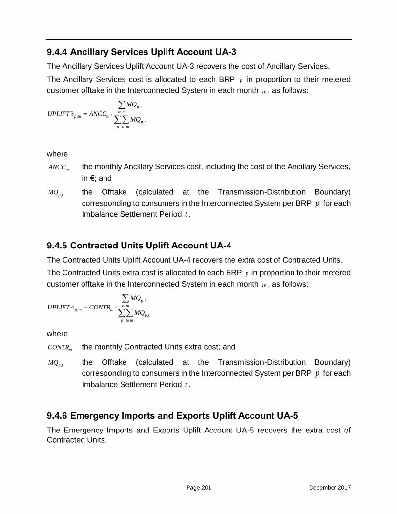
Page 201 December 2017
9.4.4 Ancillary Services Uplift Account UA-3
The Ancillary Services Uplift Account UA-3 recovers the cost of Ancillary Services.
The Ancillary Services cost is allocated to each BRP p in proportion to their metered
customer offtake in the Interconnected System in each month m , as follows:
,
,
,
3
p t
t mp m m
p t
p t m
MQ
UPLIFT ANCCMQ
where
mANCC the monthly Ancillary Services cost, including the cost of the Ancillary Services,
in €; and
,p tMQ the Offtake (calculated at the Transmission-Distribution Boundary)
corresponding to consumers in the Interconnected System per BRP p for each
Imbalance Settlement Period t .
9.4.5 Contracted Units Uplift Account UA-4
The Contracted Units Uplift Account UA-4 recovers the extra cost of Contracted Units.
The Contracted Units extra cost is allocated to each BRP p in proportion to their metered
customer offtake in the Interconnected System in each month m , as follows:
,
,
,
4
p t
t mp m m
p t
p t m
MQ
UPLIFT CONTRMQ
where
mCONTR the monthly Contracted Units extra cost; and
,p tMQ the Offtake (calculated at the Transmission-Distribution Boundary)
corresponding to consumers in the Interconnected System per BRP p for each
Imbalance Settlement Period t .
9.4.6 Emergency Imports and Exports Uplift Account UA-5
The Emergency Imports and Exports Uplift Account UA-5 recovers the extra cost of
Contracted Units.

Page 202 December 2017
The Emergency Imports and Exports extra cost is allocated to each BRP p in proportion
to their metered customer offtake in the Interconnected System in each month m , as
follows:
𝑈𝑃𝐿𝐼𝐹𝑇5𝑝,𝑡 = 𝐸𝑀𝐸𝑅𝐺𝑡𝑀𝑄𝑝,𝑡
∑ 𝑀𝑄𝑝,𝑡𝑝
where
mEMERG the Emergency Imports and Exports extra cost for each Imbalance Settlement
Period t ; and
,p tMQ the Offtake (calculated at the Transmission-Distribution Boundary)
corresponding to consumers in the Interconnected System per BRP p for each
Imbalance Settlement Period t .
9.5 Non-compliance Charges Settlement
9.5.1 Non-Compliance with Ancillary Services Dispatch Instructions by Balancing Service Providers
The Transmission System Operator shall calculate for each Imbalance Settlement Period
t of month m and for each Balancing Service Entity e the quantity of mFRR which the
Balancing Service Entity has been unable to provide despite the relevant Dispatch
Instructions and charge the respective Balancing Service Provider for such Imbalance Settlement Period the sum of ,e tNCAS , which is given by the following formula:
, , ,1x mFRR
e t AS e e t e tNCAS A NAS F CmFRR
where:
ASA a charge increase factor for non-compliance charges to Balancing Service
Entities for failing to follow Dispatch Instructions corresponding to activation of
mFRR awards;
eNAS a running counter of the Dispatch Days in the current calendar month when a
Balancing Service Entity e failed to follow Dispatch Instructions corresponding
to activation of mFRR awards at least for one Imbalance Settlement period t of
the corresponding Dispatch Day, which is bounded from above to the value
maxNAS ;
maxNAS the maximum value of the running counter eNAS
x an exponent between 0 and 1; and

Page 203 December 2017
,mFRR
e tF the part of the mFRR award that was not provided in real-time by the Balancing
Service Entity e during Imbalance Settlement Period t ; and
,e tCmFRR the remuneration of Balancing Service Entity e for the provided mFRR in
Imbalance Settlement Period t .
The numerical value of the charge increase factor ASA , NASmax and the exponent x shall
be established by proposal of the Transmission System Operator and a respective
decision of the Regulator. Such decision shall be taken at least two months prior to the
enforcement of the new values of the above parameters.
9.5.2 Consequences of non-lawful submission of Non-Availability Declarations
The Transmission System Operator shall verify whether Non-Availability Declarations
submitted are true and accurate and meet the requirements of this Code.
The Transmission System Operator may by a justified decision issued to the Participant
cancel a Total or Partial Non-Availability Declaration. In case of a decision to cancel a
Non-Availability Declaration or finding such a declaration unacceptable, the Transmission System Operator shall charge the Participant p for Dispatch Day d the sum of ,p dNCAV ,
calculated as follows:
, 1x
p d AV p u
u p
NCAV UNCAV A NAV NCAP
where:
UNCAV the unit charge for non-compliance charges to Participants for failing to submit
valid Non-Availability Declarations for their generation resources;
AVA the charge increase factor for non-compliance charges to Participants for failing
to submit valid Non-Availability Declarations for their generation resources;
pNAV the running counter of the Dispatch Days in the current calendar year when a
Participant failed to submit valid Non-Availability Declarations for its
generation resources, which starts to count after the first Dispatch Day with Non-Compliance of the year and is bounded from above to the value maxNAV .
maxNAV the maximum value of the running counter pNAV
x an exponent between 0 and 1; and
uNCAP the Registered Capacity of generation resource u , in accordance with its
Registered Operating Characteristics, for which Participant p has submitted an
unacceptable Total or Partial Non-Availability Declaration for Trading Day d .
p

Page 204 December 2017
The numerical values of UNCAV unit charge, maxNAV , the exponent x and the AVA charge
increase factor shall be established by proposal of the Transmission System Operator
and a respective decision of the Regulator. Such decision shall be taken at least two
months prior to the enforcement of the new values of the above parameters.
9.5.3 Consequences of non-lawful Techno-Economic Declaration
In case of a decision on an unacceptable Techno-Economic Declaration for a Balancing Service Entity, the Transmission System Operator shall charge the Participant p for
Trading Day d the sum of ,p dNCTD , which is given by the following formula:
, 1x
p d TD p e
e p
NCTD UNCTD A NTD NCAP
where:
UNCTD the unit charge for non-compliance charges to Participants for failing to submit
valid Techno-Economic Declarations for their Balancing Service Entities;
TDA the charge increase factor for non-compliance charges to Participants for failing
to submit valid Techno-Economic Declarations for their Balancing Service
Entities;
pNTD a running counter of the Dispatch Days in the current calendar month when a
Participant failed to submit valid Techno-Economic Declarations for its
Balancing Service Entities, which starts to count after the first Dispatch Day
with Non-Compliance of the month and is bounded from above to the value
maxNTD ;
maxNTD the maximum value of the running counter pNTD
x an exponent between 0 and 1; and
eNCAP the Registered Capacity of Balancing Service Entity e, in accordance with its
Registered Operating Characteristics, for which Participant p has submitted an
unacceptable Techno-Economic Declaration for Trading Day d .
The numerical values of UNCTD unit charge, maxNTD , the exponent x and the TDA charge
increase factor shall be established by proposal of the Transmission System Operator
and a respective decision of the Regulator. Such decision shall be taken at least two
months prior to the enforcement of the new values of the above parameters.
9.5.4 Consequences of non-submission of Balancing Energy Offers
In case of non-submission of Balancing Energy Offers for a Trading Day for a Balancing
Service Entity for which the respective Balancing Service Provider is obligated to such
p

Page 205 December 2017
submission, the Transmission System Operator shall charge such Balancing Service Provider for such Trading Day d the sum of ,e dNCBEO , calculated as follows:
, , ,1x up dn
e d EO e e t e t
t d
NCBEO UNCBEO A NBEO BEOO BEOO
where:
UNCBEO the unit charge for non-compliance charges to Balancing Service Providers for
failing to submit valid Balancing Energy Offers for their BSEs by the ISP1 Gate
Closure Time;
EOA the charge increase factor for non-compliance charges to Balancing Service
Providers for failing to submit valid Balancing Energy Offers for their BSEs by
the ISP1 Gate Closure;
eNBEO a running counter of the Dispatch Days in the current calendar month when a
Balancing Service Provider failed to submit valid Balancing Energy Offers for
its Balancing Service Entity e by the ISP1 Gate Closure, which starts to count
after the first Dispatch Day with Non-Compliance of the month and is bounded from above to the value maxNBEO ;
maxNBEO the maximum value of the running counter eNBEO
x an exponent between 0 and 1;
,upe tBEOO the part of the obligation of a Balancing Service Provider to provide an upward
Balancing Energy Offer for his Balancing Service Entity e for Trading Period t
by the ISP1 Gate Closure, for which such offer has not been submitted; and
,dne tBEOO the part of the obligation of a Balancing Service Provider to provide a downward
Balancing Energy Offer for his Balancing Service Entity e for Trading Period t
by the ISP1 Gate Closure, for which such offer has not been submitted.
The numerical values of UNCBEO unit charge, maxNBEO , the exponent x and the EOA
charge increase factor shall be established by proposal of the Transmission System
Operator and a respective decision of the Regulator. Such decision shall be taken at least
two months prior to the enforcement of the new values of the above parameters.
9.5.5 Consequences of non-submission of Reserve Capacity Offers
In case of non-submission of FCR, aFRR and mFRR Offers for a Trading Day d by a
Balancing Service Provider p obligated to such submission for its Balancing Service
Provider e, the Transmission System Operator shall charge such Balancing Service Provider for such Trading Day the sum of ,p dNCRO , calculated as follows:
, 1x
p d RO p e e e
e p
NCRO UNCRO A NRO DFCR DaFRR DmFRR

Page 206 December 2017
where:
UNCRO the unit charge for non-compliance charges to Balancing Service Providers for
failing to submit valid Reserve Capacity Offers (for FCR, aFRR and mFRR) for
their Balancing Service Entities by the ISP1 Gate Closure;
ROA the charge increase factor for non-compliance charges to Balancing Service
Providers for failing to submit valid Reserve Capacity Offers (for FCR, aFRR
and mFRR) for their Balancing Service Entities by the ISP1 Gate Closure;
pNRO a running counter of the Dispatch Days in the current calendar month when a
Balancing Service Provider failed to submit valid Reserve Capacity Offers
(for FCR, aFRR and mFRR) for its Balancing Service Entity e by the ISP1 Gate
Closure, which starts to count after the first Dispatch Day with Non-Compliance of the month and is bounded from above to the value maxNRO ;
maxNRO the maximum value of the running counter pNRO
x an exponent between 0 and 1;
eDFCR the BSE e FCR capability, in accordance with its Declared Characteristics, for
which a FCR Offer has not been submitted;
eDaFRR the BSE e aFRR capability, in accordance with its Declared Characteristics, for
which an aFRR Offer has not been submitted; and
eDmFRR the BSE e mFRR capability, in accordance with its Declared Characteristics,
for which an mFRR Offer has not been submitted.
The numerical values of UNCRO unit charge, maxNRO , the exponent x and the ROA charge
increase factor shall be established by proposal of the Transmission System Operator
and a respective decision of the Regulator. Such decision shall be taken at least two
months prior to the enforcement of the new values of the above parameters.
9.5.6 Consequences of significant non-performance of activated upward and downward Balancing Energy by a Balancing Service Entity
In case a significant non-performance of activated upward and downward Balancing
Energy by a Balancing Service Entity, namely in case the Balancing Service Entity’s metered generation/demand deviates significantly (above a specified tolerance limit beTOL
) from the Dispatch Instruction, then the Transmission System Operator shall charge the
respective Balancing Service Provider e for the Imbalance Settlement Period t the sum
p

Page 207 December 2017
,tote tNCNPBE , calculated using the following formula giving a tolerance of beSPTOL Imbalance
Settlement periods per month and per Balancing Service Provider e:
,
1 max 0, 1 ,
1 max 0, 1 ,
up upNPBE et be pt et et pt et
upe t
up upNPBE pt et be et et pt et
UNCNPBE A MQ TOL MS ABE if MQ MS ABENCNPBE
UNCNPBE A MS ABE TOL MQ if MQ MS ABE
,
1 max 0, 1 ,
1 max 0, 1 ,
dn dnNPBE et be pt et et pt et
dne t
dn dnNPBE pt et be et et pt et
UNCNPBE A MQ TOL MS ABE if MQ MS ABENCNPBE
UNCNPBE A MS ABE TOL MQ if MQ MS ABE
, , ,tot up dne t e t e tNCNPBE NCNPBE NCNPBE
where:
UNCNPBE the unit charge for non-compliance charges to Balancing Service Providers for
non-performance of their BSEs with respect to the activated upward and
downward Balancing Energy, in €/MWh;
NPBEA the charge increase factor for non-compliance charges to Balancing Service
Providers for non-performance of their BSEs with respect to the activated
upward and downward Balancing Energy;
etMQ the metered energy of Balancing Service Entity e for Imbalance Settlement
Period t properly adjusted for Transmission Losses and Distribution Losses, in
MWh;
beTOL the tolerance limit for the imposition of penalties to Balancing Service Providers
for significant non-performance of their BSEs with respect to the activated
upward and downward Balancing Energy, in %;
ptMS the Market Schedule of Balancing Service Entity e for Imbalance Settlement
Period t , in MWh;
upetABE the activated upward Balancing Energy of Balancing Service Entity e for
Imbalance Settlement Period t , in MWh; and
dnetABE the activated downward Balancing Energy of Balancing Service Entity e for
Imbalance Settlement Period t , in MWh.
The numerical values of UNCNPBE unit charge, the NPBEA charge increase factor, the
beSPTOL and the tolerance limit beTOL shall be established by proposal of the Transmission
System Operator and a respective decision of the Regulator. Such decision shall be taken
at least two months prior to the enforcement of the new values of the above parameters.

Page 208 December 2017
9.5.7 Consequences of significant systematic deviations in the demand purchased by Load Representatives
In case of systematic, within a month, significant deviations are ascertained between the energy quantity measured at all meters represented by a Load Representative p in an
Imbalance Settlement Period and the respective Market Schedule of the same Load
Representative, the Transmission System Operator shall charge such Load Representative the amount ,p mNCBAL , calculated based on the total absolute deviations
within the month m and the root-mean-square (RMS) value of the deviations within the
month m.
Significant deviation shall mean the case where the normalized absolute deviation for the month m exceeds the tolerance limit ,ld ADEVTOL or the normalized root-mean-square (RMS)
value of the deviations for the month m exceeds the tolerance limit ,ld RMSDEVTOL .
The deviation for every Imbalance Settlement Period t , ,p t
DEV , the monthly absolute
deviation for the month m, ,p mADEV , the normalized absolute deviation for the month m,
,p mNADEV , the monthly RMS deviation,
,p mRMSDEV , and the normalized RMS for the month
m, ,p mNRMSDEV , for Load Representative p are defined as follows:
,up dn
p t pt et et pte p
DEV MS ABE ABE MQ
, ,p m p tt m
ADEV DEV
,
,
, , ,
p m
p m
up dnp t e t e t
t m e p
ADEVNADEV
MS SBE SBE
2, ,p m p t
t m
RMSDEV DEV
,
,
p m
p m
up dnpt et et
t m e p
RMSDEVNRMSDEV
MS ABE ABE
where:
,p tDEV the deviation from the Market Schedule, adjusted for any activated upward
and/or downward Balancing Energy of the Dispatchable Load Portfolios represented by the Load Representative p for the Imbalance Settlement
Period t ;
ptMS the Market Schedule of Load Representative for Imbalance Settlement
Period .
p
t
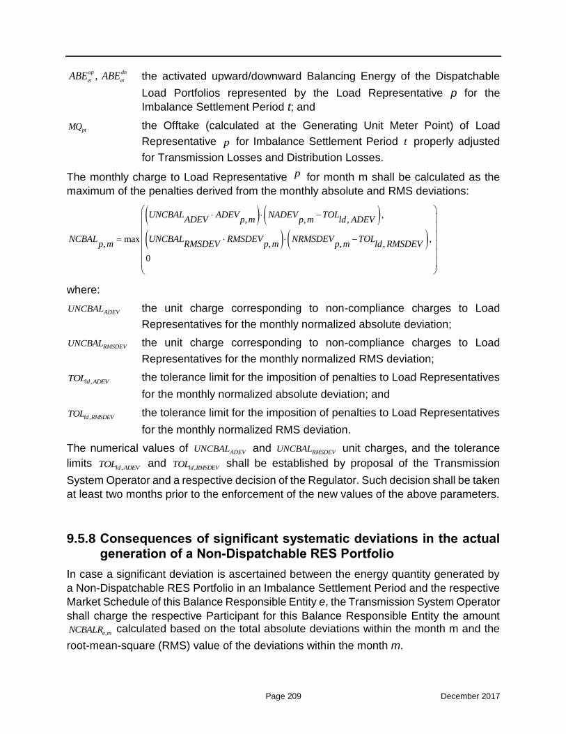
Page 209 December 2017
,up dn
et etABE ABE the activated upward/downward Balancing Energy of the Dispatchable
Load Portfolios represented by the Load Representative p for the
Imbalance Settlement Period t; and
ptMQ the Offtake (calculated at the Generating Unit Meter Point) of Load
Representative p for Imbalance Settlement Period t properly adjusted
for Transmission Losses and Distribution Losses.
The monthly charge to Load Representative p for month m shall be calculated as the
maximum of the penalties derived from the monthly absolute and RMS deviations:
,, , ,
max ,, , , ,
0
UNCBAL ADEV NADEV TOLADEV p m p m ld ADEV
NCBAL UNCBAL RMSDEV NRMSDEV TOLp m RMSDEV p m p m ld RMSDEV
where:
ADEVUNCBAL the unit charge corresponding to non-compliance charges to Load
Representatives for the monthly normalized absolute deviation;
RMSDEVUNCBAL the unit charge corresponding to non-compliance charges to Load
Representatives for the monthly normalized RMS deviation;
,ld ADEVTOL the tolerance limit for the imposition of penalties to Load Representatives
for the monthly normalized absolute deviation; and
,ld RMSDEVTOL the tolerance limit for the imposition of penalties to Load Representatives
for the monthly normalized RMS deviation.
The numerical values of ADEVUNCBAL and RMSDEVUNCBAL unit charges, and the tolerance
limits ,ld ADEVTOL and ,ld RMSDEVTOL shall be established by proposal of the Transmission
System Operator and a respective decision of the Regulator. Such decision shall be taken
at least two months prior to the enforcement of the new values of the above parameters.
9.5.8 Consequences of significant systematic deviations in the actual generation of a Non-Dispatchable RES Portfolio
In case a significant deviation is ascertained between the energy quantity generated by
a Non-Dispatchable RES Portfolio in an Imbalance Settlement Period and the respective
Market Schedule of this Balance Responsible Entity e, the Transmission System Operator
shall charge the respective Participant for this Balance Responsible Entity the amount
,e mNCBALR calculated based on the total absolute deviations within the month m and the
root-mean-square (RMS) value of the deviations within the month m.

Page 210 December 2017
Significant deviation shall mean the case where the normalized absolute deviation for the month m exceeds the tolerance limit ,r ADEVTOL or the normalized root-mean-square (RMS)
value of the deviations for the month m exceeds the tolerance limit ,r RMSDEVTOL .
The deviation for every Imbalance Settlement Period t , ,e t
DEV , the monthly absolute
deviation for the month m, ,e m
ADEV , the normalized absolute deviation for the month m,
,e mNADEV , the monthly RMS deviation,
,e mRMSDEV , and the normalized RMS for the month
m, ,e m
NRMSDEV , for Balance Responsible Entity e are defined as follows:
,e t et etDEV MS MQ
,
,
e m
e m
ett m
ADEVNADEV
MS
2, ,e m e t
t m
RMSDEV DEV
2
,
,
et
t m
e m
e mMS
RMSDEVNRMSDEV
where:
,e tDEV the deviation from the Market Schedule of Balance Responsible Entity e for the
Imbalance Settlement Period t ;
etMS the Market Schedule Balance Responsible Entity e for Imbalance Settlement
Period t ; and
etMQ the generated energy of Balance Responsible Entity e for Imbalance
Settlement Period t , properly adjusted for Transmission Losses and
Distribution Losses.
The monthly charge corresponding to the Balance Responsible Entity e for month m shall
be calculated as the maximum of the penalties derived from the monthly absolute and
RMS deviations:
,, , ,
max ,, , , ,
0
UNCBALR ADEV NADEV TOLADEV e m e m r ADEV
NCBAL UNCBALR RMSDEV NRMSDEV TOLe m RMSDEV e m e m r RMSDEV
where:
, ,e m e tt m
ADEV DEV

Page 211 December 2017
ADEVUNCBALR the unit charge corresponding to Non-Compliance Charges to RES Units
for the monthly normalized absolute deviation;
RMSDEVUNCBALR the unit charge corresponding to Non-Compliance Charges to RES Units
for the monthly normalized RMS deviation;
,r ADEVTOL the tolerance limit for the imposition of penalties to RES Units for the
monthly normalized absolute deviation; and
,r RMSDEVTOL the tolerance limit for the imposition of penalties to RES Units for the
monthly normalized RMS deviation.
The numerical values of ADEVUNCBALR and RMSDEVUNCBALR unit charges, and the
tolerance limits ,r ADEVTOL and ,r RMSDEVTOL shall be established by proposal of the
Transmission System Operator and a respective decision of the Regulator. Such decision
shall be taken at least two months prior to the enforcement of the new values of the above
parameters.
9.5.9 Non-Compliance Charge for import/export deviations
In case there is a difference between the imported/exported quantity in the Market
Schedule of a Participant and his nomination of long-term Physical Transmission Rights
for electricity imports/exports through an interconnection for which an obligation for
physical delivery exists, then the Transmission System Operator shall compute the Non-
Compliance Charge of the relevant Participant for each Imbalance Settlement Period,
which shall be equal to the above deviation multiplied by the Administrative Defined
Trading Deviation Price UNCIR for imports and UNCER for exports, providing a tolerance
of one (1) Dispatch Day, per month and per participant, with at least one Imbalance
Settlement period with the above mentioned difference.
The numerical values of the Administrative Defined Trading Deviation Price, UNCIR and
UNCER, shall be established by proposal of the Transmission System Operator and a
respective decision of the Regulator.. Such decision shall be taken at least two months
prior to the enforcement of the new values of the above parameters.
9.5.10 Consequences of non-performance by a Contracted Unit
On any occasion for which a Contracted Unit has failed to synchronize following a lawful
commitment instruction by the Transmission System Operator or the Contracted Unit has
failed to be dispatched according to a lawful Dispatch Instruction, such failure related to
the inability of the Contracted Unit to reach the instructed generation level, the
Transmission System Operator shall notify the respective Participant for such non-
compliance.
On the first occurrence on a single of such non-compliance, the Transmission System Operator shall charge the respective Contracted Unit the sum ,1u tNCCU , calculated as
follows:

Page 212 December 2017
, ,1 ( )xu t NCCU u u tNCCU A nNCCU CRPM
where:
NCCUA the charge increase factor for non-compliance charges related to the inability
of the Contracted Unit to reach the instructed generation level;
nNCCU the number of Imbalance Settlement Periods in a calendar month for which
the non-compliance has occurred, while non-compliance during part of an
Imbalance Settlement Period is considered as non-compliance for the whole period, which is bounded from above to the value maxnNCCU ;
maxnNCCU the maximum value of nNCCU
x an exponent between 0 and 1; and
,u tCRPM the capacity payment of the contracted Unit u that corresponds to one
Imbalance Settlement period t.
The numerical values of maxnNCCU , the exponent x and the NCCUA charge increase factor
shall be established by proposal of the Transmission System Operator and a respective
decision of the Regulator. Such decision shall be taken at least two months prior to the
enforcement of the new values of the above parameters.
The imposition of the non-compliance charge shall not release the Participant from the
obligations arising from the respective contract. On the occurrence of an additional
violation, the Transmission System Operator shall notify the Regulator which may impose
further sanctions.
9.5.11 Handling of the Non-Compliance amount
The total amount of the Non-Compliance Charges accumulated in the Non-Compliance
Charges Account A-D shall be credited on annual basis to TSO. The total annual amount
will be taken into consideration when calculating the system tariffs for the next years.
9.6 Balancing Market Settlement Process
The Balancing Market settlement shall be performed on a monthly basis. Settlement
months correspond to calendar months. For each Settlement Month, M, four settlement
runs are provisioned according to the timetable below:
Initial Settlement Run Last day of month M+1
1st Reconciliation Settlement Run Last day of month M+7
2nd Reconciliation Settlement Run Last day of month M+13
Final Reconciliation Settlement Run Last day of month M+25

Page 213 December 2017
Any corrections in the Settlement data and results can only occur on the specified dates
of the timetable above. After the ‘Final Reconciliation Settlement Run’ Date there can be
no corrections in the Settlement data and results. Exceptions to the above rule may apply
only after a relevant application by the affected Participant(s) and a decision by the
Regulator.
In carrying out any Reconciliation Settlement Run, the TSO shall:
A) make any adjustment or revision to any metering data;
B) make any adjustment or revision to any data following the resolution of any
Dispute;
C) use any adjusted or revised data submitted by the Market Operator or the DSOs;
D) use any revised Balancing Services data.
The Balancing Market Settlement for the Initial Settlement Run or any of the
Reconciliation Settlement Runs will be performed as follows:
A) The Transmission System Operator performs the necessary calculation of
quantities and amounts in €. The results of the Settlement calculations and any
relevant data are provided to the Participants by electronic means according to
the timetable;
B) no later than two (2) Working Days after the notification of the Settlement Results,
the Participants are entitled to lodge documented objections to the Transmission
System Operator;
C) no later than four (4) Working Days after the notification of the Settlement Results,
the Transmission System Operator shall decide on any objections, and proceed
with necessary corrections, if possible;
D) no later than five (5) Working Days after the notification of the Settlement Results,
the Transmission System Operator shall send the necessary data to the Clearing
House.
The Settlement data to be notified to the BSPs for Initial Settlement Run or any of the
Reconciliation Settlement Runs shall include at least the following information:
A) the Participant name and ID;
B) the Market Schedule of each BSE;
C) the Dispatch Instruction of the BSE per Real Time Unit;
D) the metered Energy quantities of the BSE per Imbalance Settlement Period;
E) the activated aFRR and mFRR Balancing Energy of the BSE per Imbalance
Settlement Period;
F) the Balancing Capacity provided by the BSE per Imbalance Settlement Period
per type of Reserve;

Page 214 December 2017
G) The Imbalance and Imbalance Adjustment quantities for the BSE per Imbalance
Settlement Period
H) the credit/debit for Balancing Energy and Balancing Capacity for the BSE per
Imbalance Settlement Period;
I) the credit/debit for Imbalances for the BSE per Imbalance Settlement Period;
J) the debit for the Non-Compliance Charges imposed to the Participant per penalty
type and Imbalance Settlement Period;
K) the Balancing Fee;
The Settlement data to be notified to the BSPs for Initial Settlement Run or any of the
Reconciliation Settlement Runs shall include at least the following information:
A) the BRP name and ID;
B) the Market Schedule of each Balance Responsible Entity represented by the
Participant per Imbalance Settlement Period;
C) the aggregated metered energy quantities of all the Balance Responsible Entities
represented by the BRP per Imbalance Settlement Period;
D) the Imbalance quantity of all the Balance Responsible Entities represented by
the BRP per Imbalance Settlement Period; and
E) the credit/debit to the BRP per Imbalance Settlement Period.

Page 215 December 2017
10 Annex A: Nomenclature
The following Table 10-1 provides a list of all sets (superscripts and subscripts) and
symbols used in the formulae and other algebraic expressions contained in this report. Its
purpose is to identify the variables and the parameters used in each process of the
Balancing and Ancillary Services Market. Thus:
a) the first (1st) part of this Table describes the sets and symbols used in the
Integrated Scheduling Process presented in Chapter 7 of this report,
b) the second (2nd) part of this Table describes the sets and symbols used in the Real-
Time Balancing Energy Market presented in Chapter 8 of this report; only the
additional / differentiated sets / symbols as compared to the Integrated Scheduling
Process list are presented in the Real-Time Balancing Energy Market list, while
c) the third (3rd) part of this Table describes the sets and symbols regarding the
settlement procedures described in Chapter 9 of this report.
All quantities and prices shall be used for the computations with 15 decimals (double
precision numbers). All quantities shall be reported / displayed using numbers rounded
up to three (3) decimals, whereas all prices shall be reported / displayed using numbers
rounded up to two (2) decimals.
1. Integrated Scheduling Process (Chapter 7)
Sets
Set Name and Context
t T Set of half-hourly Dispatch Periods of the scheduling horizon.
k K Set of steps of the step-wise Balancing Energy Offer.
z Z
Set of Bidding Zones.
When z is used as a superscript of another set (e.g. zI , z
3R , z2L ,
zC ), it specifies that the considered elements of the latter set
belong into the given Bidding Zone z.

Page 216 December 2017
i I
Set of the Balancing Services Entities (BSEs) participating in the
Balancing and Ancillary Services Market; I G R2 L1 where:
G I is the set of Generating Units,
H G I is the set of hydro Generating Units,
2R I is the set of Dispatchable RES Portfolios,
1L I is the set of Dispatchable Load Portfolios
j J
Set of the Balance Responsible Entities (BREs) in the context of
the Balancing and Ancillary Services Market;
IJ R3 R4 L2 C where:
I J is the set of BSPs,
3R J is the set of the RES FiT Portfolio (comprises one
element),
4R J is the set of Non-Dispatchable RES Portfolios,
2L J is the set of Non-Dispatchable Load Portfolios,
C J is the set of Generating Units / RES Units in
Commissioning or Testing Operation.
inter INTER Set of interconnections.
gc GC Set of generic constraints.
1. Integrated Scheduling Process (Chapter 7)
Symbols
Symbol Name and Context Source
BEupitkQuant
Non-negative variable representing the quantity
of upward Balancing Energy cleared for BSE i,
Dispatch Period t and step k of the respective
Balancing Energy Offer, in MW.
ISP model
BEdnitkQuant
Non-negative variable representing the quantity
of downward Balancing Energy cleared for BSE
i, Dispatch Period t and step k of the respective
Balancing Energy Offer, in MW.
ISP model
FCRupitQuant
Non-negative variable representing the
contribution of BSE i in upward FCR at Dispatch
Period t, in MW.
ISP model

Page 217 December 2017
FCRdnit Quant
Non-negative variable representing the
contribution of BSE i in downward FCR at
Dispatch Period t, in MW.
ISP model
aFRRupitQuant
Non-negative variable representing the
contribution of BSE i in upward aFRR at
Dispatch Period t, in MW.
ISP model
aFRRdnitQuant
Non-negative variable representing the
contribution of BSE i in downward aFRR at
Dispatch Period t, in MW.
ISP model
mFRRupitQuant
Non-negative variable representing the
contribution of BSE i in upward mFRR at
Dispatch Period t, in MW.
ISP model
mFRRdnitQuant
Non-negative variable representing the
contribution of BSE i in downward mFRR at
Dispatch Period t, in MW.
ISP model
RRupitQuant
Non-negative variable representing the
contribution of BSE i in upward spinning RR at
Dispatch Period t, in MW.
ISP model
RRnsitQuant
Non-negative variable representing the
contribution of BSE i in non-spinning RR at
Dispatch Period t, in MW.
ISP model
RRdnitQuant
Non-negative variable representing the
contribution of BSE i in downward RR at
Dispatch Period t, in MW.
ISP model
BEupitkPrice
Parameter representing the price of the upward
Balancing Energy Offer of BSE i, for Dispatch
Period t and step k, in €/MWh.
Upward
Balancing
Energy Offer
BEdnitkPrice
Parameter representing the price of the
downward Balancing Energy Offer of BSE i, for
Dispatch Period t and step k, in €/MWh.
Downward
Balancing
Energy Offer
FCRupitPrice
Parameter representing the price of the offer for
upward FCR of BSE i, for Dispatch Period t, in
€/MW.
FCR Offer
FCRdnitPrice
Parameter representing the price of the offer for
downward FCR of BSE i, for Dispatch Period t,
in €/MW.
FCR Offer
aFRRupitPrice Parameter representing the price of the offer for
upward aFRR of BSE i, for Dispatch Period t, in aFRR Offer

Page 218 December 2017
€/MW.
aFRRdnitPrice
Parameter representing the price of the offer for
downward aFRR of BSE i, for Dispatch Period t,
in €/MW.
aFRR Offer
mFRRupitPrice
Parameter representing the price of the offer for
upward mFRR of BSE i, for Dispatch Period t, in
€/MW.
mFRR Offer
mFRRdnitPrice
Parameter representing the price of the offer for
downward mFRR of BSE i, for Dispatch Period t,
in €/MW.
mFRR Offer
RRupitPrice
Parameter representing the price of the offer for
upward RR of BSE i, for Dispatch Period t, in
€/MW.
RR Offer
RRdnitPrice
Parameter representing the price of the offer for
downward RR of BSE i, for Dispatch Period t, in
€/MW.
RR Offer
D Parameter representing the Dispatch Period
duration, expressed in hours. For the ISP, this
parameter is set to 1.
ISP model
hotiSUC Parameter representing the start-up cost from
hot standby for BSE i, in €.
Techno-
Economic
Declaration
(Table C)
warmiSUC Parameter representing the start-up cost from
warm standby for BSE i, in €.
Techno-
Economic
Declaration
(Table C)
coldiSUC Parameter representing the start-up cost from
cold standby for BSE i, in €.
Techno-
Economic
Declaration
(Table C)
ity Binary variable indicating if BSE i is started-up
at Dispatch Period t (equal to 1 if started-up,
being 0 otherwise).
ISP model
hotity
Binary variable representing a start-up decision
from hot standby, for BSE i, at Dispatch Period t
(equal to 1 if BSE i is started-up during t after
hot standby, being 0 otherwise).
ISP model

Page 219 December 2017
warmity
Binary variable representing a start-up decision
from warm standby, for BSE i, at Dispatch
Period t (equal to 1 if BSE i is started-up during t
after warm standby, being 0 otherwise).
ISP model
coldity
Binary variable representing a start-up decision
from cold standby, for BSE i, at Dispatch Period
t (equal to 1 if BSE i is started-up during t after
cold standby, being 0 otherwise).
ISP model
HotToWarmiT
Parameter representing the time off-load before
BSE i is going into longer stand-by conditions
(i.e., from hot to warm conditions), in hours.
Registered
Operating
Characteristics
HotToColdiT
Parameter representing the time off-load before
BSE i is going into longer stand-by conditions
(i.e., from hot to cold conditions), in hours.
Registered
Operating
Characteristics
synitu Binary variable indicating if BSE i is in the
synchronization phase at Dispatch Period t. ISP model
,syn hotitu
Binary variable indicating if BSE i is in the
synchronization phase at Dispatch Period t, after
a hot start-up.
ISP model
,syn warmitu
Binary variable indicating if BSE i is in the
synchronization phase at Dispatch Period t, after
a warm start-up.
ISP model
,syn colditu
Binary variable indicating if BSE i is in the
synchronization phase at Dispatch Period t, after
a cold start-up.
ISP model
,syn hotiT Parameter representing the synchronization
time of BSE i under hot start-up, in hours.
Registered
Operating
Characteristics
,syn warmiT Parameter representing the synchronization
time of BSE i under warm start-up, in hours.
Registered
Operating
Characteristics
,syn coldiT Parameter representing the synchronization
time of BSE i under cold start-up, in hours.
Registered
Operating
Characteristics
soakitu Binary variable indicating if BSE i is in the soak
phase at Dispatch Period t. ISP model
,soak hotitu Binary variable indicating if BSE i is in the soak
phase at Dispatch Period t, after a hot start-up. ISP model
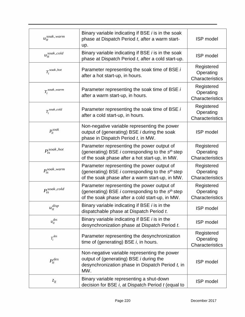
Page 220 December 2017
,soak warmitu
Binary variable indicating if BSE i is in the soak
phase at Dispatch Period t, after a warm start-
up.
ISP model
,soak colditu Binary variable indicating if BSE i is in the soak
phase at Dispatch Period t, after a cold start-up. ISP model
,soak hotiT Parameter representing the soak time of BSE i
after a hot start-up, in hours.
Registered
Operating
Characteristics
,soak warmiT Parameter representing the soak time of BSE i
after a warm start-up, in hours.
Registered
Operating
Characteristics
,soak coldiT Parameter representing the soak time of BSE i
after a cold start-up, in hours.
Registered
Operating
Characteristics
soakitP
Non-negative variable representing the power
output of (generating) BSE i during the soak
phase in Dispatch Period t, in MW.
ISP model
,soak hotisP
Parameter representing the power output of
(generating) BSE i corresponding to the sth step
of the soak phase after a hot start-up, in MW.
Registered
Operating
Characteristics
,soak warmisP
Parameter representing the power output of
(generating) BSE i corresponding to the sth step
of the soak phase after a warm start-up, in MW.
Registered
Operating
Characteristics
,soak coldisP
Parameter representing the power output of
(generating) BSE i corresponding to the sth step
of the soak phase after a cold start-up, in MW.
Registered
Operating
Characteristics
dispitu Binary variable indicating if BSE i is in the
dispatchable phase at Dispatch Period t. ISP model
desitu Binary variable indicating if BSE i is in the
desynchronization phase at Dispatch Period t. ISP model
desiT Parameter representing the desynchronization
time of (generating) BSE i, in hours.
Registered
Operating
Characteristics
desitP
Non-negative variable representing the power
output of (generating) BSE i during the
desynchronization phase in Dispatch Period t, in
MW.
ISP model
itz Binary variable representing a shut-down
decision for BSE i, at Dispatch Period t (equal to ISP model

Page 221 December 2017
1 if BSE i is shut-down during t, being 0
otherwise).
itu Binary variable indicating if BSE i is committed
(on-line) during Dispatch Period t. ISP model
iMUT Parameter representing the minimum up time of
BSE i, in hours.
Registered
Operating
Characteristics
iMDT Parameter representing the minimum down time
of BSE i, in hours.
Registered
Operating
Characteristics
minitP
Non-negative parameter representing the
technical minimum power output of BSE i in
Dispatch Period t, in MW (e.g. 150 MW of
minimum generation for a Generating Unit, or 10
MW of minimum loading for a Dispatchable
Load).
The technical minimum is included in the
Registered Operating Characteristics of the
BSEs, but when the maximum Availability of the
BSE (submitted through the Non-Availability
Declarations) equals zero, then the technical
minimum is overwritten to zero, and it is
transferred as zero in the ISP model.
Registered
Operating
Characteristics
maxitP
Non-negative parameter representing the
technical maximum power output of BSE i in
Dispatch Period t, in MW (e.g. 477 MW of
maximum generation for a Generating Unit, or
100 MW of full loading for a Dispatchable Load).
The combination of the technical maximum
included in the Registered Operating
Characteristics and in Non-Availability
Declarations (actually the minimum quantity per
Dispatch Period) is transferred as input in the
ISP model.
Registered
Operating
Characteristics
& Non-
Availability
Declarations
min, AGCiP
Non-negative parameter representing the
technical minimum power output in AGC mode
for BSE i, in MW (e.g. 182 MW of minimum
generation for a Generating Unit, or 20 MW of
minimum loading for a Dispatchable Load).
The technical minimum under AGC is included
Techno-
Economic
Declaration
(Table A2)

Page 222 December 2017
in the Techno-Economic Declarations of the
BSEs, but when the maximum Availability of the
BSE (submitted through the Non-Availability
Declarations) equals zero, then the technical
minimum under AGC is overwritten to zero, and
it is transferred as zero in the ISP model.
max,AGCiP
Parameter representing the technical maximum
power output in AGC mode for BSE i, in MW
(e.g. 417 MW of maximum generation for a
Generating Unit, or 80 MW of maximum loading
for a Dispatchable Load).
The technical maximum under AGC is included
in the Techno-Economic Declarations of the
BSEs, but when the maximum Availability of the
BSE (submitted through the Non-Availability
Declarations) equals zero, then the technical
maximum under AGC is overwritten to zero, and
it is transferred as zero in the ISP model.
Techno-
Economic
Declaration
(Table A2)
AGCitu Binary variable indicating a BSE i operating in
AGC mode. ISP model
itP
Real variable representing the power output of
BSE i during Dispatch Period t, in MW; it takes
non-negative values for Generating Units,
Dispatchable RES Portfolios, and non-positive
values for Dispatchable Load Portfolios.
ISP model
itMS
Parameter representing the Market Schedule of
BSE i during Dispatch Period t; it bears a non-
negative value for Generating Units,
Dispatchable RES Portfolios, and a non-positive
value for Dispatchable Load Portfolios.
Market
Operator
itBEup Non-negative variable representing the upward
Balancing Energy award for BSE i, at Dispatch
Period t, in MW.
ISP model
itBEdn Non-negative variable representing the
downward Balancing Energy award for BSE i, at
Dispatch Period t, in MW.
ISP model
BEupitkMaxQuant
Non-negative parameter representing the size of
step k of the Upward Balancing Energy Offer of
BSE i for Dispatch Period t, in MW.
Upward
Balancing
Energy Offer

Page 223 December 2017
BEdnitkMaxQuant
Non-negative parameter representing the size of
step k of the Downward Balancing Energy Offer
of BSE i for Dispatch Period t, in MW.
Downward
Balancing
Energy Offer
itMinBEup
Non-negative parameter representing the
minimum quantity of the upward Balancing
Energy award of BSE i for Dispatch Period t, in
MW.
Upward
Balancing
Energy Offer
itMinBEdn
Non-negative parameter representing the
minimum quantity of the downward Balancing
Energy award of BSE i for Dispatch Period t, in
MW.
Downward
Balancing
Energy Offer
BEupitu
Binary variable indicating if upward Balancing
Energy is provided by BSE i during Dispatch
Period t.
ISP model
BEdnitu
Binary variable indicating if downward Balancing
Energy is provided by BSE i during Dispatch
Period t.
ISP model
itMand Mandatory injection of hydro Generating Unit i
for Dispatch Period t, in MW.
Hydro
Mandatory
Injections
Declaration
iMaxEnergy Parameter representing the maximum daily
energy of generating BSE i, in MWh.
Techno-
Economic
Declaration
(Table A3)
iIniEnergy
Parameter representing the energy already
(scheduled to be) produced by a Generating
Unit i for all Dispatch Periods from the beginning
of the Dispatch Day until the start of the
scheduling horizon of a given ISP run, in MWh.
Metering
System / ISP
model
iRU
Non-negative parameter representing the ramp-
up rate of BSE i, in MW/min; it refers to the
maximum increase (over 1 minute) (a) in the
generating level of a generating BSE, or (b) in
the loading level of a loading BSE.
Registered
Operating
Characteristics
iRD
Non-negative parameter representing the ramp-
down rate of BSE i, in MW/min; it refers to the
maximum decrease (over 1 minute) (a) in the
generating level of a generating BSE, or (b) in
the loading level of a loading BSE.
Registered
Operating
Characteristics

Page 224 December 2017
AGCiRR Non-negative parameter representing the ramp
rate of BSE i in AGC mode, in MW/min.
Techno-
Economic
Declaration
(Table A2)
W Large constant. ISP model
FCRupiMaxQuant
Non-negative parameter representing the
maximum contribution of BSE i in upward FCR,
in MW.
Techno-
Economic
Declaration
(Table A2)
FCRdniMaxQuant
Non-negative parameter representing the
maximum contribution of BSE i in downward
FCR, in MW.
Techno-
Economic
Declaration
(Table A2)
aFRRupiMaxQuant
Non-negative parameter representing the
maximum contribution of BSE i in upward aFRR,
in MW.
Computed based
on the Techno-
Economic
Declaration
aFRRdniMaxQuant
Non-negative parameter representing the
maximum contribution of BSE i in downward
aFRR, in MW.
Computed based
on the Techno-
Economic
Declaration
Percent Percentage of NCAP for BSEs’ contribution to
aFRR.
Energy
Balancing
System
Database
iNCAP Parameter representing the BSE i net capacity,
in MW.
Registered
Operating
Characteristics
FastaFRRupitQuant
Non-negative variable representing the
contribution in fast upward aFRR (1-min
ramping capability) for BSE i in Dispatch Period
t, in MW.
ISP model
FastaFRRdnitQuant
Non-negative variable representing the
contribution in fast downward aFRR (1-min
ramping capability) for BSE i in Dispatch Period
t, in MW.
ISP model
mFRRupiRegMaxQuant Non-negative parameter representing the
maximum technical capability of BSE i to
Registered
Operating

Page 225 December 2017
provide upward mFRR, in MW. Characteristics
mFRRdniRegMaxQuant
Non-negative parameter representing the
maximum technical capability of BSE i to
provide downward mFRR, in MW.
Registered
Operating
Characteristics
RRupiRegMaxQuant
Non-negative parameter representing the
maximum technical capability of BSE i to
provide upward RR, in MW.
Registered
Operating
Characteristics
RRdniRegMaxQuant
Non-negative parameter representing the
maximum technical capability of BSE i to
provide downward RR, in MW.
Registered
Operating
Characteristics
RRnsiRegMaxQuant
Non-negative parameter representing the
maximum technical capability of BSE i to
provide non-spinning RR, in MW.
Registered
Operating
Characteristics
mFRRupiMaxQuant
Non-negative parameter representing the
maximum contribution of BSE i in upward
mFRR, in MW. It is computed as described in
Paragraph 7.7.
Computed based
on the
Registered
Operating
Characteristics
mFRRdniMaxQuant
Non-negative parameter representing the
maximum contribution of BSE i in downward
mFRR, in MW.
Computed based
on the
Registered
Operating
Characteristics
RRupiMaxQuant
Non-negative parameter representing the
maximum contribution of BSE i in upward RR, in
MW.
Computed based
on the
Registered
Operating
Characteristics
RRdniMaxQuant
Non-negative parameter representing the
maximum contribution of BSE i in downward
RR, in MW.
Computed based
on the
Registered
Operating
Characteristics
RRnsiMaxQuant
Non-negative parameter representing the
maximum contribution of BSE i in non-spinning
RR, in MW.
Computed based
on the
Registered
Operating
Characteristics
nsitu Binary variable indicating if BSE i is contributing
to non-spinning RR during Dispatch Period t. ISP model

Page 226 December 2017
ztNonDispLoadFR
Non-negative parameter representing the Non-
Dispatchable Load Forecast of the TSO for zone
z and Dispatch Period t, in MW. Load Forecast
jtNonDispLoadMS Non-negative parameter representing the
Market Schedule of Non-Dispatchable Load j (
2j L ) for Dispatch Period t, in MW.
Market
Operator
ztResFiTPortFR Non-negative parameter representing the RES
FiT Portfolio Forecast of the TSO for zone z and
Dispatch Period t, in MW.
RES Injections
Forecast
ztResFiTPortMS Non-negative parameter representing the
Market Schedule of the RES FiT Portfolio for
zone z and Dispatch Period t, in MW.
Market
Operator
ztNonDispResUnitFR Non-negative parameter representing the Non-
Dispatchable RES Portfolios Forecast of the
TSO for zone z and Dispatch Period t, in MW.
RES Injections
Forecast
jtNonDispResUnitMS Non-negative parameter representing the
Market Schedule of Non-Dispatchable RES
Portfolio j ( 4j R ) for Dispatch Period t, in MW.
Market
Operator
jtCommisDS
Non-negative parameter representing the
schedule of the Generating Unit / RES Unit in
Commissioning or Testing Operation j ( j C ),
declared to the TSO prior to the ISP execution,
for Dispatch Period t, in MW.
Commissioning
Schedules
Declaration
jtCommisMS
Non-negative parameter representing the
Market Schedule of the Generating Unit / RES
Unit in Commissioning or Testing Operation j (
j C ), submitted to the Market Operator at the
Day-Ahead Market and Intraday Market stage
(and inserted in the respective clearings as
“price-taking orders”), for Dispatch Period t, in
MW.
Market
Operator
,inter tImpDev
Non-negative parameter representing the import
deviation at the interconnection inter at Dispatch
Period t, due to one or more causes described
in Paragraph 7.10.20, in MW.
LT PTR
Nominations &
Day-Ahead
Market results,
ADMIE
Scheduling
System

Page 227 December 2017
,inter tExpDev
Non-negative parameter representing the export
deviation at the interconnection inter at Dispatch
Period t, due to one or more causes described
in Paragraph 7.10.20, in MW.
LT PTR
Nominations &
Day-Ahead
Market results,
ADMIE
Scheduling
System
,zz tFlow Non-negative variable representing the flow
from Bidding Zone z to Bidding Zone z’, at
Dispatch Period t, in MW.
ISP model
,Maxzz tAvailableFlow
Non-negative parameter representing the
maximum residual flow from Bidding Zone z to
Bidding Zone z’ that is available at the Balancing
Market stage (considering the already
established flows at the wholesale market) at
Dispatch Period t, in MW.
Corridor limits
computation
process
ztNetInjection
Real variable representing the net position
(activated upward Balancing Energy minus
activated downward Balancing Energy) of
Bidding Zone z at Dispatch Period t, in MW.
ISP model
,,
z refzz t
PTDF
Parameter representing the Power Transfer
Distribution Factor at the corridor from Bidding
Zone z to Bidding Zone z’ at Dispatch Period t,
when an injection at zone z’’and a withdrawal at
the reference zone takes place.
Zonal data
computation
process
FCRupztReq
Parameter representing the upward FCR
requirement for Bidding Zone z during Dispatch
Period t, in MW.
Reserve
Requirements
Forecast
FCRuptReq
Parameter representing the upward FCR
requirement for the entire system during
Dispatch Period t, in MW.
Reserve
Requirements
Forecast
FCRdnztReq
Parameter representing the downward FCR
requirement for Bidding Zone z during Dispatch
Period t, in MW.
Reserve
Requirements
Forecast
FCRdntReq
Parameter representing the downward FCR
requirement for the entire system during
Dispatch Period t, in MW.
Reserve
Requirements
Forecast
aFRRupztReq
Parameter representing the upward aFRR
requirement for Bidding Zone z during Dispatch
Period t, in MW.
Reserve
Requirements
Forecast
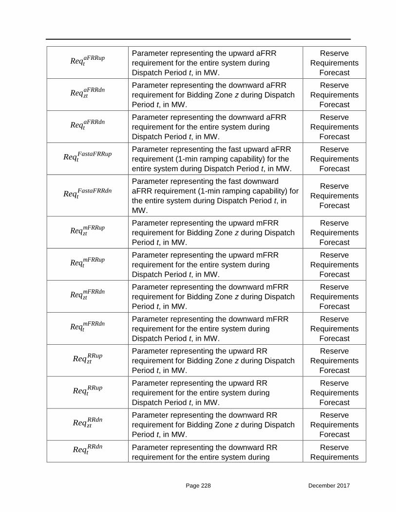
Page 228 December 2017
aFRRuptReq
Parameter representing the upward aFRR
requirement for the entire system during
Dispatch Period t, in MW.
Reserve
Requirements
Forecast
aFRRdnztReq
Parameter representing the downward aFRR
requirement for Bidding Zone z during Dispatch
Period t, in MW.
Reserve
Requirements
Forecast
aFRRdntReq
Parameter representing the downward aFRR
requirement for the entire system during
Dispatch Period t, in MW.
Reserve
Requirements
Forecast
FastaFRRuptReq
Parameter representing the fast upward aFRR
requirement (1-min ramping capability) for the
entire system during Dispatch Period t, in MW.
Reserve
Requirements
Forecast
FastaFRRdntReq
Parameter representing the fast downward
aFRR requirement (1-min ramping capability) for
the entire system during Dispatch Period t, in
MW.
Reserve
Requirements
Forecast
mFRRupztReq
Parameter representing the upward mFRR
requirement for Bidding Zone z during Dispatch
Period t, in MW.
Reserve
Requirements
Forecast
mFRRuptReq
Parameter representing the upward mFRR
requirement for the entire system during
Dispatch Period t, in MW.
Reserve
Requirements
Forecast
mFRRdnztReq
Parameter representing the downward mFRR
requirement for Bidding Zone z during Dispatch
Period t, in MW.
Reserve
Requirements
Forecast
mFRRdntReq
Parameter representing the downward mFRR
requirement for the entire system during
Dispatch Period t, in MW.
Reserve
Requirements
Forecast
RRupztReq
Parameter representing the upward RR
requirement for Bidding Zone z during Dispatch
Period t, in MW.
Reserve
Requirements
Forecast
RRuptReq
Parameter representing the upward RR
requirement for the entire system during
Dispatch Period t, in MW.
Reserve
Requirements
Forecast
RRdnztReq
Parameter representing the downward RR
requirement for Bidding Zone z during Dispatch
Period t, in MW.
Reserve
Requirements
Forecast
RRdntReq Parameter representing the downward RR
requirement for the entire system during
Reserve
Requirements

Page 229 December 2017
Dispatch Period t, in MW. Forecast
,GenCont gcLimit Parameter representing the generic constraint
gc right-hand side limit for Dispatch Period t.
Generic
Constraints
Declaration
,P
it gcFactor Parameter representing the factor of the generic
constraint gc, associated with the power output
of BSE i for Dispatch Period t; , ,Pit gcFactor 0 1
Generic
Constraints
Declaration
,RRup
it gcFactor
Parameter representing the factor of the generic
constraint gc, associated with the upward RR
contribution of BSE i for Dispatch Period t;
, ,RRup
it gcFactor 0 1
Generic
Constraints
Declaration
BEupity
Binary variable indicating if upward Balancing
Energy is activated by BSE i during Dispatch
Period t.
ISP model
BEdnity
Binary variable indicating if downward Balancing
Energy is activated by BSE i during Dispatch
Period t.
ISP model
BEupitz
Binary variable indicating if upward Balancing
Energy is de-activated by BSE i during Dispatch
Period t.
ISP model
BEdnitz
Binary variable indicating if downward Balancing
Energy is de-activated by BSE i during Dispatch
Period t.
ISP model
BEupiMinDP
Parameter representing the minimum delivery
period (duration) of Balancing Energy provision
in the upward direction, submitted by loading
BSE i, in hours.
Declared
Characteristics
BEdniMinDP
Parameter representing the minimum delivery
period (duration) of Balancing Energy provision
in the downward direction, submitted by loading
BSE i, in hours.
Declared
Characteristics
BEupiMaxDP
Parameter representing the maximum delivery
period (duration) of Balancing Energy provision
in the upward direction, submitted by loading
BSE i, in hours.
Declared
Characteristics
BEdniMaxDP Parameter representing the maximum delivery
period (duration) of Balancing Energy provision Declared

Page 230 December 2017
in the downward direction, submitted by loading
BSE i, in hours.
Characteristics
iMinBP
Parameter representing the minimum baseload
period (i.e., minimum period between two
successive activations of Balancing Energy),
submitted by loading BSE i, in hours.
Declared
Characteristics
BEupiMaxFA
Parameter representing the maximum frequency
of activations of Balancing Energy in the upward
direction, from loading BSE i in the course of a
Dispatch Day.
Declared
Characteristics
BEdniMaxFA
Parameter representing the maximum frequency
of activations of Balancing Energy in the
downward direction, from loading BSE i in the
course of a Dispatch Day.
Declared
Characteristics
DeficitZonImbPrice Deficit price for the violation of the zonal
imbalance covering constraint. Default value:
25.000 €/MW.
Energy
Balancing
System
Database
SurplusZonImbPrice Surplus price for the violation of the zonal
imbalance covering constraint. Default value:
25.000 €/MW.
Energy
Balancing
System
Database
TotDeficitFCRPrice Deficit price for the violation of the zonal /
system upward and downward FCR requirement
constraints. Default value: 20.000 €/MW.
Energy
Balancing
System
Database
TotDeficitaFRRPrice
Deficit price for the violation of the zonal /
system upward and downward aFRR
requirement constraints. Default value: 15.000
€/MW.
Energy
Balancing
System
Database
TotDeficitmFRRPrice
Deficit price for the violation of the zonal /
system upward and downward mFRR
requirement constraints. Default value: 12.000
€/MW.
Energy
Balancing
System
Database

Page 231 December 2017
TotDeficitRRPrice Deficit price for the violation of the zonal /
system upward and downward RR requirement
constraints. Default value: 10.000 €/MW.
Energy
Balancing
System
Database
DeficitCapPrice Deficit price for the violation of the BSE
minimum capacity constraints. Default value:
45.000 €/MW.
Energy
Balancing
System
Database
SurplusCapPrice Surplus price for the violation of the BSE
maximum capacity constraints. Default value:
45.000 €/MW.
Energy
Balancing
System
Database
SurplusMaxEnergyitPrice
Surplus price for the violation of the BSE
maximum daily energy constraint. Default value:
8.000 €/MWh.
Energy
Balancing
System
Database
SurplusRampUpPrice Surplus price for the violation of the BSE upward
ramping constraint. Default value: 40.000 €/MW.
Energy
Balancing
System
Database
SurplusRampDnPrice Surplus price for the violation of the BSE
downward ramping constraint. Default value:
40.000 €/MW.
Energy
Balancing
System
Database
SurplusRampResPrice Surplus price for the violation of the BSE upward
and downward Reserve Capacity ramping
constraints. Default value: 38.000 €/MW.
Energy
Balancing
System
Database
SurplusFCRPrice Surplus price for the violation of the BSE upward
and downward FCR contribution constraints.
Default value: 20.000 €/MW.
Energy
Balancing
System
Database
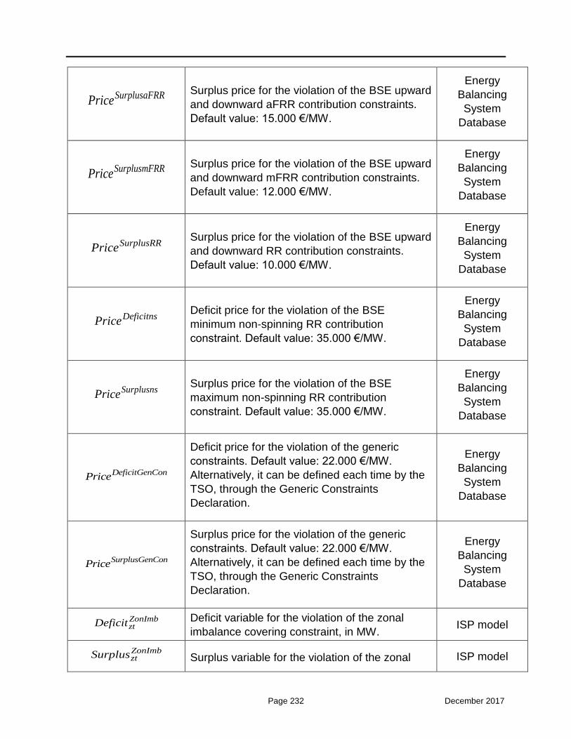
Page 232 December 2017
SurplusaFRRPrice Surplus price for the violation of the BSE upward
and downward aFRR contribution constraints.
Default value: 15.000 €/MW.
Energy
Balancing
System
Database
SurplusmFRRPrice Surplus price for the violation of the BSE upward
and downward mFRR contribution constraints.
Default value: 12.000 €/MW.
Energy
Balancing
System
Database
SurplusRRPrice Surplus price for the violation of the BSE upward
and downward RR contribution constraints.
Default value: 10.000 €/MW.
Energy
Balancing
System
Database
DeficitnsPrice Deficit price for the violation of the BSE
minimum non-spinning RR contribution
constraint. Default value: 35.000 €/MW.
Energy
Balancing
System
Database
SurplusnsPrice Surplus price for the violation of the BSE
maximum non-spinning RR contribution
constraint. Default value: 35.000 €/MW.
Energy
Balancing
System
Database
DeficitGenConPrice
Deficit price for the violation of the generic
constraints. Default value: 22.000 €/MW.
Alternatively, it can be defined each time by the
TSO, through the Generic Constraints
Declaration.
Energy
Balancing
System
Database
SurplusGenConPrice
Surplus price for the violation of the generic
constraints. Default value: 22.000 €/MW.
Alternatively, it can be defined each time by the
TSO, through the Generic Constraints
Declaration.
Energy
Balancing
System
Database
ZonImbztDeficit Deficit variable for the violation of the zonal
imbalance covering constraint, in MW. ISP model
ZonImbztSurplus Surplus variable for the violation of the zonal ISP model

Page 233 December 2017
imbalance covering constraint, in MW.
ZonFCRupztDeficitZonFCRdnztDeficit
Deficit variables for the violation of the zonal
upward and downward FCR requirement
constraints, in MW.
ISP model
ZonaFRRupztDeficitZonaFRRdnztDeficit
Deficit variables for the violation of the zonal
upward and downward aFRR requirement
constraints, in MW.
ISP model
ZonmFRRupztDeficit
ZonmFRRdnztDeficit
Deficit variables for the violation of the zonal
upward and downward mFRR requirement
constraints, in MW.
ISP model
ZonRRupztDeficitZonRRdnztDeficit
Deficit variables for the violation of the zonal
upward and downward RR requirement
constraints, in MW. ISP model
CapitDeficit Deficit variable for the violation of the BSE
minimum capacity constraint, in MW. ISP model
CapitSurplus Surplus variable for the violation of the BSE
maximum capacity constraint, in MW. ISP model
MaxEnergyitSurplus Surplus variable for the violation of the BSE
maximum daily energy constraint, in MWh. ISP model
RampUpitSurplus Surplus variable for the violation of the BSE
upward ramping constraint, in MW. ISP model
RampDnitSurplus Surplus variable for the violation of the BSE
downward ramping constraint, in MW. ISP model
RampUpResitSurplus
RampDnResitSurplus
Surplus variables for the violation of the BSE
upward and downward Reserve Capacity
ramping constraints, in MW.
ISP model
FCRupitSurplusFCRdnitSurplus
Surplus variables for the violation of the BSE
upward and downward FCR contribution
constraints, in MW.
ISP model
aFRRupitSurplusaFRRdnitSurplus
Surplus variables for the violation of the BSE
upward and downward aFRR contribution
constraints, in MW.
ISP model
mFRRupitSurplus
Surplus variables for the violation of the BSE
upward and downward mFRR contribution ISP model

Page 234 December 2017
mFRRdnitSurplus constraints, in MW.
RRupitSurplusRRdnitSurplus
Surplus variables for the violation of the BSE
upward and downward RR contribution
constraints, in MW.
ISP model
nsitDeficit
Deficit variable for the violation of the BSE
minimum non-spinning RR contribution
constraint, in MW.
ISP model
nsitSurplus
Surplus variable for the violation of the BSE
maximum non-spinning RR contribution
constraint, in MW.
ISP model
,GenCont gcDeficit Deficit variable for the violation of the generic
constraint gc, in MW. ISP model
,GenCont gcSurplus Surplus variable for the violation of the generic
constraint gc, in MW. ISP model
2. Real-Time Balancing Energy Market (Chapter 8)
Sets
Set Name and Context
t T Set of 15-min Dispatch Periods of the scheduling horizon.
2. Real-Time Balancing Energy Market (Chapter 8)
Symbols
Symbol Name and Context Source
itP
Real variable representing the power output of
BSE i during Dispatch Period t, in MW; it takes
non-negative values for Generating Units,
Dispatchable RES Portfolios, and non-positive
values for Dispatchable Load Portfolios.
RTBEMRTBEM
model
itMS
Parameter representing the latest Market
Schedule of BSE i during Dispatch Period t; it
bears a non-negative value for Generating
Units, Dispatchable RES Portfolios, and a non-
Market
Operator

Page 235 December 2017
positive value for Dispatchable Load Portfolios.
itBEup Non-negative variable representing the upward
Balancing Energy award for BSE i, at Dispatch
Period t, in MW.
RTBEMRTBEM
model
itBEdn Non-negative variable representing the
downward Balancing Energy award for BSE i, at
Dispatch Period t, in MW.
RTBEMRTBEM
model
FCRupitQuant
Non-negative parameter representing the
upward FCR award of BSE i in the ISP, at
Dispatch Period t, in MW.
ISP Results
FCRdnitQuant
Non-negative parameter representing the
downward FCR award of BSE i in the ISP, at
Dispatch Period t, in MW.
ISP Results
aFRRupitQuant
Non-negative parameter representing the
upward aFRR award of BSE i in the ISP, at
Dispatch Period t, in MW.
ISP Results
aFRRdnitQuant
Non-negative parameter representing the
downward aFRR award of BSE i in the ISP, at
Dispatch Period t, in MW.
ISP Results
AGCitunder Status parameter indicating a BSE i operating in
AGC mode at Dispatch Period t.
Energy
Balancing
System
iInitialMW
Parameter representing the initial power output
of BSE i for a given RTBEMRTBEM execution,
in MW; it bears a non-negative value for
Generating Units, Dispatchable RES Portfolios,
and a non-positive value for Dispatchable Load
Portfolios.
SCADA
itP Parameter representing the ISP schedule from
the latest ISP execution for the Generating Unit i
and Dispatch Period t.
ISP Results
BEupitMand
Parameter representing the quantity of upward
Balancing Energy activated manually
(mandatorily) by the TSO, for BSE i and
Dispatch Period t, in MW.
Mandatory
Activation
Process
BEdnitMand
Parameter representing the quantity of
downward Balancing Energy activated manually
(mandatorily) by the TSO, for BSE i and
Mandatory
Activation

Page 236 December 2017
Dispatch Period t, in MW. Process
D Parameter representing the Dispatch Period
duration, expressed in hours. For the
RTBEMRTBEM, this parameter is set to 1/4.
RTBEMRTBEM
model
BEupitkQuant
Non-negative variable representing the quantity
of upward Balancing Energy cleared for BSE i,
Dispatch Period t and step k of the respective
Balancing Energy Offer, in MW.
RTBEM model
BEupitkPrice
Parameter representing the price of the upward
Balancing Energy Offer of BSE i, for Dispatch
Period t and step k, in €/MWh.
Upward
Balancing
Energy Offer
BEdnitkQuant
Non-negative variable representing the quantity
of downward Balancing Energy cleared for BSE
i, Dispatch Period t and step k of the respective
Balancing Energy Offer, in MW.
RTBEM model
BEdnitkPrice
Parameter representing the price of the
downward Balancing Energy Offer of BSP i, for
Dispatch Period t and step k, in €/MWh.
Downward
Balancing
Energy Offer
BEupitkMaxQuant
Non-negative parameter representing the size of
step k of the Upward Balancing Energy Offer of
BSP i for Dispatch Period t, in MW.
Upward
Balancing
Energy Offer
BEdnitkMaxQuant
Non-negative parameter representing the size of
step k of the Downward Balancing Energy Offer
of BSP i for Dispatch Period t, in MW.
Downward
Balancing
Energy Offer
BEupitu
Binary variable indicating if upward Balancing
Energy is activated by BSE i during Dispatch
Period t.
RTBEM model
BEdnitu
Binary variable indicating if downward Balancing
Energy is activated by BSE i during Dispatch
Period t.
RTBEM model
DeficitCapPrice Deficit price for the violation of the BSE
minimum capacity constraints. Default value:
45.000 €/MW.
Energy
Balancing
System
Database

Page 237 December 2017
SurplusCapPrice Surplus price for the violation of the BSE
maximum capacity constraints. Default value:
45.000 €/MW.
Energy
Balancing
System
Database
SurplusRampUpPrice Surplus price for the violation of the BSE upward
ramping constraint. Default value: 40.000 €/MW.
Energy
Balancing
System
Database
SurplusRampDnPrice Surplus price for the violation of the BSE
downward ramping constraint. Default value:
40.000 €/MW.
Energy
Balancing
System
Database
SurplusMaxEnergyPrice Surplus price for the violation of the BSE
maximum daily energy constraint. Default value:
8.000 €/MW.
Energy
Balancing
System
Database
DeficitZonImbPrice Deficit price for the violation of the zonal
imbalance covering constraint. Default value:
25.000 €/MW.
Energy
Balancing
System
Database
SurplusZonImbPrice Surplus price for the violation of the zonal
imbalance covering constraint. Default value:
25.000 €/MW.
Energy
Balancing
System
Database
CapitDeficit Deficit variable for the violation of the BSE
minimum capacity constraints, in MW. RTBEM model
CapitSurplus Surplus variable for the violation of the BSE
maximum capacity constraint, in MW. RTBEM model
RampUpitSurplus Surplus variable for the violation of the BSE
upward ramping constraint, in MW. RTBEM model
RampDnitSurplus Surplus variable for the violation of the BSE
downward ramping constraint, in MW. RTBEM model
MaxEnergyitSurplus Surplus variable for the violation of the BSE
maximum daily energy constraint, in MW. RTBEM model

Page 238 December 2017
ZonImbztDeficit Deficit variable for the violation of the zonal
imbalance covering constraint, in MW. RTBEM model
ZonImbztSurplus Surplus variable for the violation of the zonal
imbalance covering constraint, in MW. RTBEM model
3. Settlements (Chapter 9)
Sets
Set Name and Context
t T Set of Settlement Periods (length: 15-min for the Balancing Energy
Settlement / 15-min for the Imbalance Settlement).
p P Set of BSPs or Balance Responsible Parties (BRPs).
3. Balancing Energy and Imbalance Settlement (Chapter 9)
Symbols
Symbol Name and Context Source
jtMS
Parameter representing the Market Schedule of
BRE j during Settlement Period t, in MW.
Market
Operator
itBEup
Parameter representing the procured upward
Balancing Energy of BSE i for Settlement
Period t, in MW.
RTBEM
itBEdn
Parameter representing the procured
downward Balancing Energy of BSE i for
Settlement Period t, in MW.
RTBEM
BEupztMP
Parameter representing the Marginal Upward
Balancing Energy Price of Bidding Zone z for
Settlement Period t, derived by the shadow
price (Lagrange multiplier) of the zonal
imbalance covering constraint of the RTBEM
clearing, in case the Bidding Zone is short in
the given Settlement Period, in €/MWh.
RTBEM
BEdnztMP
Parameter representing the Marginal
Downward Balancing Energy Price of Bidding
Zone z for Settlement Period t, derived by the
shadow price (Lagrange multiplier) of the zonal
imbalance covering constraint of the RTBEM
RTBEM

Page 239 December 2017
clearing, in case the Bidding Zone is long in the
given Settlement Period, in €/MWh.
BEupztLP
Parameter representing the (maximum) price of
the last activated Upward Balancing Energy
Offer of Bidding Zone z for Settlement Period t,
in case the Bidding Zone is long in the given
Settlement Period, in €/MWh.
RTBEM
BEdnztLP
Parameter representing the (minimum) price of
the last activated Downward Balancing Energy
Offer of Bidding Zone z for Settlement Period t,
in case the Bidding Zone is short in the given
Settlement Period, in €/MWh.
RTBEM
BEupitOP
Parameter representing the offer price of
upward Balancing Energy of BSE i for
Settlement Period t, in €/MWh.
Balancing
Market
Manageme
nt System
BEdnitOP
Parameter representing the offer price of
downward Balancing Energy of BSE i for
Settlement Period t, in €/MWh.
Balancing
Market
Manageme
nt System
D
Parameter representing the Settlement Period
duration, expressed in hours. For the Balancing
Energy settlement this parameter is set equal to
1/4; for the Imbalance Settlement this
parameter is set equal to 1/4.
Balancing
Market
Settlement
System
BEitSettlement
Parameter representing the resulting cash
amount to be settled between BSE i (through
the respective Participant) and the TSO
(payment to the BSE when positive, collection
from the BSE when negative), for the BSE
Balancing Energy procured in the upward or
downward direction during Settlement Period t,
in €.
Balancing
Market
Settlement
System
BEitAddRemun
Parameter representing the additional
remuneration for BSE i and Settlement Period t,
through the bid-recovery mechanism, for its
mandatorily activated Balancing Energy
quantities (Mandatory Activation Process), in €.
Balancing
Market
Settlement
System
AvitP
Parameter representing the Dispatch Instruction
for a given 15-min Imbalance Settlement
Period, for BSE i and Imbalance Settlement
Balancing
Market
Settlement
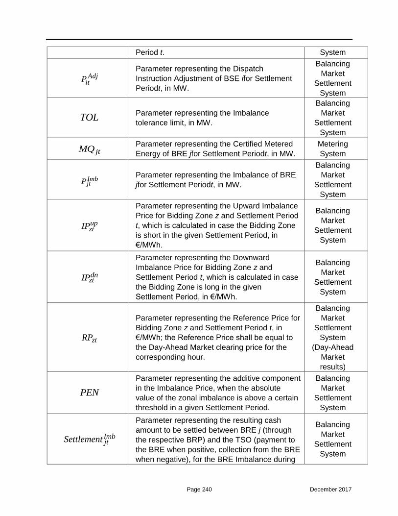
Page 240 December 2017
Period t. System
AdjitP
Parameter representing the Dispatch
Instruction Adjustment of BSE ifor Settlement
Periodt, in MW.
Balancing
Market
Settlement
System
TOL Parameter representing the Imbalance
tolerance limit, in MW.
Balancing
Market
Settlement
System
jtMQ Parameter representing the Certified Metered
Energy of BRE jfor Settlement Periodt, in MW.
Metering
System
ImbjtP
Parameter representing the Imbalance of BRE
jfor Settlement Periodt, in MW.
Balancing
Market
Settlement
System
upztIP
Parameter representing the Upward Imbalance
Price for Bidding Zone z and Settlement Period
t, which is calculated in case the Bidding Zone
is short in the given Settlement Period, in
€/MWh.
Balancing
Market
Settlement
System
dnztIP
Parameter representing the Downward
Imbalance Price for Bidding Zone z and
Settlement Period t, which is calculated in case
the Bidding Zone is long in the given
Settlement Period, in €/MWh.
Balancing
Market
Settlement
System
ztRP
Parameter representing the Reference Price for
Bidding Zone z and Settlement Period t, in
€/MWh; the Reference Price shall be equal to
the Day-Ahead Market clearing price for the
corresponding hour.
Balancing
Market
Settlement
System
(Day-Ahead
Market
results)
PEN
Parameter representing the additive component
in the Imbalance Price, when the absolute
value of the zonal imbalance is above a certain
threshold in a given Settlement Period.
Balancing
Market
Settlement
System
ImbjtSettlement
Parameter representing the resulting cash
amount to be settled between BRE j (through
the respective BRP) and the TSO (payment to
the BRE when positive, collection from the BRE
when negative), for the BRE Imbalance during
Balancing
Market
Settlement
System

Page 241 December 2017
Settlement Period t, in €.
3. Ancillary Services Settlement (Chapter 9)
Symbols
Symbol Name and Context Source
RCtypeitProvQuant
Parameter representing the reserve quantity of
type “RCtype” (i.e., FCRup , FCRdn , aFRRup ,
aFRRdn , mFRRup , mFRRdn , RRup , RRdn ) of
BSE i for Settlement Period t, that was available
for provision in real time, in MW.
Balancing
Market
Settlement
System
RCtypeitT
Parameter representing the percentage of time-
period within a Settlement Period t that a BSE i
provided Reserve Capacity of type “RCtype”
(i.e., FCRup , FCRdn , aFRRup , aFRRdn ,
mFRRup , mFRRdn , RRup , RRdn ) in real time,
in %.
Balancing
Market
Settlement
System
iNR
Parameter representing the nominal ramp-rate
of BSE i' of the same BSE category when
operating under Automatic Generation Control,
in MW/min.
Decision of
Regulator
RCtypeztMRCP
Parameter representing the Marginal Reserve
Capacity Price in Bidding Zone z for Settlement
Period t,obtained by the ISP for each type of
Reserve Capacity “RCtype” (i.e., FCRup ,
FCRdn , aFRRup , aFRRdn , mFRRup , mFRRdn ,
RRup , RRdn ), in €/MW.
ISP results
RCtypeitSettlement
Parameter representing the remuneration
amount of BSE i for the provided reserve
quantity of type “RCtype” (i.e., FCRup , FCRdn ,
aFRRup , aFRRdn , mFRRup , mFRRdn , RRup ,
RRdn ) in Settlement Period t, in €.
Balancing
Market
Settlement
System
3. Penalties Settlement (Chapter 9)
Symbols
Symbol Name and Context Source
NonCompBEDailyChargei
Parameter representing the non-compliance Balancing

Page 242 December 2017
charge imposed to a BSE i for failing to submit
valid Balancing Energy Offers by the ISP Gate
Closure Time, in €.
Market
Settlement
System
UNCBEO
Parameter representing the unit charge for non-
compliance charges imposed to BSEs, for
failing to submit valid Balancing Energy Offers
by the ISP Gate Closure Time, in €/MWh.
Balancing
Market
Settlement
System
BEOA
Parameter representing the charge increase
factor for non-compliance charges imposed to
BSEs, for failing to submit valid Balancing
Energy Offers by the ISP Gate Closure Time.
Balancing
Market
Settlement
System
iNBEO
Parameter representing the running counter of
the Dispatch Days in the current calendar year
when a BSE i failed to submit valid Balancing
Energy Offers by the ISP Gate Closure Time.
Balancing
Market
Manageme
nt System
upitBEOO
Parameter representing the obligation of BSE i
to provide an upward Balancing Energy Offer
for Dispatch Period t by the ISP Gate Closure
Time, in MWh.
Balancing
Market
Manageme
nt System
dnitBEOO
Parameter representing the obligation of BSE i
to provide a downward Balancing Energy Offer
for Dispatch Period t by the ISP Gate Closure
Time, in MWh.
Balancing
Market
Manageme
nt System
NonCompRCiDailyCharge
Parameter representing the non-compliance
charge imposed to a BSE i for failing to submit
valid Reserve Capacity Offers by the ISP Gate
Closure Time, in €.
Balancing
Market
Settlement
System
UNCRO
Parameter representing the unit charge for non-
compliance charges imposed to BSEs for
failing to submit valid Reserve Capacity Offers
by the ISP Gate Closure Time, in €/MW.
Balancing
Market
Settlement
System
ROA
Parameter representing the charge increase
factor for non-compliance charges imposed to
BSEs for failing to submit valid Reserve
Capacity Offers by the ISP Gate Closure Time.
Balancing
Market
Settlement
System
iNRO
Parameter representing the running counter of
the Dispatch Days in the current calendar year
when a BSE i failed to submit valid Reserve
Capacity Offers by the ISP Gate Closure Time.
Balancing
Market
Manageme
nt System

Page 243 December 2017
Table 10-1: Nomenclature

Page 244 December 2017
11 Annex Β: Computation of Reserve Requirements
This Annex presents the methodology to be performed by the TSO in order to compute
the reserve requirements per reserve type, which will be procured through the ISP
process.
11.1 Frequency Containment Reserve
According to Article 142 of the draft Regulation establishing a guideline on electricity
transmission system operation:
“The control target of Frequency Containment Process shall be the stabilization of
the system frequency by activation of FCR. The overall characteristic for FCR
activation in a synchronous area shall reflect a monotonic decrease of the FCR
activation as a function of the frequency deviation.”
According to Article 153 of the above-mentioned draft Regulation,
“All TSOs of each synchronous area shall specify dimensioning rules in the
synchronous area operational agreement in accordance with the following criteria:
(a) the reserve capacity for FCR required for the synchronous area shall cover at
least the reference incident and, for the CE24 and Nordic synchronous areas, the
results of the probabilistic dimensioning approach for FCR carried out pursuant to
point (c);
(b) the size of the reference incident shall be determined in accordance with the
following conditions:
(i) for the CE synchronous area, the reference incident shall be 3000 MW in
positive direction and 3000 MW in negative direction;
……
(c) for the CE and Nordic synchronous areas, all TSOs of the synchronous area shall
have the right to define a probabilistic dimensioning approach for FCR taking into
account the pattern of load, generation and inertia, including synthetic inertia as
well as the available means to deploy minimum inertia in real-time in accordance with
the methodology referred to in Article 39, with the aim of reducing the probability of
insufficient FCR to below or equal to once in 20 years; and
(d) the shares of the reserve capacity on FCR required for each TSO as initial FCR
obligation shall be based on the sum of the net generation and consumption of
24Continental Europe

Page 245 December 2017
its control area divided by the sum of net generation and consumption of the
synchronous area over a period of one year.”
The above process results in a half-hourly FCR requirement equal to 43MW for the
Greek interconnected control area. This constitutes the minimum FCR requirement
that should be procured on half-hourly basis by the Greek TSO; this means that the
TSO may decide to procure a higher FCR requirement, in case it is deemed
necessary to ensure the system operational security. This requirement is not
modified during a year (it is the same for all scheduling intervals), since it does not
depend on interval duration, lead time and corresponding day time.
11.2 Automatic Frequency Restoration Reserve
According to Article 143 of the draft Regulation establishing a guideline on electricity
transmission system operation:
“The control target of the Frequency Restoration Process shall be to:
(a) regulate the FRCE towards zero within the time to restore frequency;
(b) for the CE and Nordic synchronous areas, to progressively replace the activated
FCR by activation of FRR in accordance with Article 145.”
According to Article 157 of the above-mentioned draft Regulation,
“The FRR dimensioning rules shall include at least the following:
(a) all TSOs of a LFC block in the CE and Nordic synchronous areas shall determine
the required reserve capacity of FRR of the LFC block based on consecutive
historical records comprising at least the historical LFC block imbalance
values. The sampling of those historical records shall cover at least the time to
restore frequency. The time period considered for those records shall be
representative and include at least one full year period ending not earlier than 6
months before the calculation date;
(b) all TSOs of a LFC block in the CE and Nordic synchronous areas shall determine
the reserve capacity on FRR of the LFC block sufficient to respect the current FRCE
target parameters in Article 128 for the time period referred to in point (a) based at
least on a probabilistic methodology. In using that probabilistic methodology, the
TSOs shall take into account the restrictions defined in the agreements for the sharing
or exchange of reserves due to possible violations of operational security and the
FRR availability requirements. All TSOs of a LFC block shall take into account any
expected significant changes to the distribution of LFC block imbalances or take into
account other relevant influencing factors relative to the time period considered;
(c) all TSOs of a LFC block shall determine the ratio of automatic FRR, manual
FRR, the automatic FRR full activation time and manual FRR full activation time

Page 246 December 2017
in order to comply with the requirement of paragraph (b). For that purpose, the
automatic FRR full activation time of a LFC block and the manual FRR full activation
time of the LFC block shall not be more than the time to restore frequency;
(d) the TSOs of a LFC block shall determine the size of the dimensioning incident
which shall be the largest imbalance that may result from an instantaneous
change of active power of a single power generating module, single demand facility,
or single HVDC interconnector or from a tripping of an AC line within the LFC block;
(e) all TSOs of a LFC block shall determine the positive reserve capacity on FRR,
which shall not be less than the positive dimensioning incident of the LFC
block;
(f) all TSOs of a LFC block shall determine the negative reserve capacity on FRR,
which shall not be less than the negative dimensioning incident of the LFC
block;
(g) all TSOs of a LFC block shall determine the reserve capacity on FRR of a LFC
block, any possible geographical limitations for its distribution within the LFC block
and any possible geographical limitations for any exchange of reserves or sharing of
reserves with other LFC blocks to comply with the operational security limits;
(h) all TSOs of a LFC block shall ensure that the positive reserve capacity on FRR
or a combination of reserve capacity on FRR and RR is sufficient to cover the
positive LFC block imbalances for at least 99 % of the time, based on the
historical records referred to in point (a);
(i) all TSOs of a LFC block shall ensure that the negative reserve capacity on FRR
or a combination of reserve capacity on FRR and RR is sufficient to cover the
negative LFC block imbalances for at least 99 % of the time, based on the
historical record referred to in point (a);
(j) all TSOs of a LFC block may reduce the positive reserve capacity on FRR of
the LFC block resulting from the FRR dimensioning process by developing a
FRR sharing agreement with other LFC blocks in accordance with provisions in
Title 8. The following requirements shall apply to that sharing agreement:
(i) for the CE and Nordic synchronous areas, the reduction of the positive reserve
capacity on FRR of a LFC block shall be limited to the difference, if positive, between
the size of the positive dimensioning incident and the reserve capacity on FRR
required to cover the positive LFC block imbalances during 99 % of the time, based
on the historical records referred to in point (a). The reduction of the positive
reserve capacity shall not exceed 30 % of the size of the positive dimensioning
incident;
………………..
(k) all TSOs of a LFC block may reduce the negative reserve capacity on FRR of
the LFC block, resulting from the FRR dimensioning process by developing a

Page 247 December 2017
FRR sharing agreement with other LFC blocks in accordance with the provisions
of Title 8. The following requirements shall apply to that sharing agreement:
(i) for the CE and Nordic synchronous areas, the reduction of the negative reserve
capacity on FRR of a LFC block shall be limited to the difference, if positive, between
the size of the negative dimensioning incident and the reserve capacity on FRR
required to cover the negative LFC block imbalances during 99 % of the time, based
on the historical records referred to in point (a);”
Based on the above, we can summarize that FRR has a double aim: the first is to restore
the frequency to its nominal value after a major disturbance and the second is to match
for the minute to minute net load variability. Consequently its quantification depends on
the first two factors (contingency events and net load variability).
A Control Area is responsible to nullify the Area Control Error (ACE) in case a
sudden generation loss takes place in its area. As a result the contingency part of
the FRR is calculated equal to largest generator/interconnector outage.
The variability part of the FRR is affected by the net load variability inside the
RTBEM interval, which is 15 minutes. For the calculation, the TSO shall use the
standard deviation of the historical differences between the net load minute values
from the net load 15-min average values, over a period of one year25. In this
analysis, the positive and negative differences are treated separately.
The net load minute to fifteen minute variability is not constant inside the day for
all 96 fifteen minute time intervals of the day; it is higher in the morning and
afternoon hours due to the morning and afternoon load ramps. The variability part
of the FRR is calculated for each 15-min interval as three standard deviations26.
The total value of upward/downward FRR is finally calculated as the algebraic sum of the
worst contingency event and the variability part of the FRR, as shown in the equations
below, where ,c upR , ,c dnR are the worst upward/downward contingency events,
respectively, var,net,
1 15
, var,net,
1 15
are the mean values of the positive/negative differences,
respectively, and var,net,
1 15
, var,net,
1 15
are the standard deviations of the minute net load value
to fifteen minute net load average positive/negative differences, respectively.
, var,net, var,net,
1 15 1 153
up c upFRR R , var,net,
1 15 0
, var,net
1 15 0 (for positive differences)
, var,net, var,net,
1 15 1 153
dn c dnFRR R , var,net,
1 15 0
, var,net
1 15 0 (for negative differences)
25This is the “probabilistic methodology” defined in Article 157(b) of the draft Regulation establishing a guideline on electricity transmission system operation.
26Actually, in order to cover 99% of the positive/negative LFC block imbalances, according to Article 157 of the draft Regulation, a FRR requirement equal to only 2.58 times the standard deviation is needed. However, in order to enhance system operational security, the TSO may decide on a higher FRR requirement.

Page 248 December 2017
11.3 Manual Frequency Restoration Reserve and Replacement Reserve
Tertiary control is a broader definition incorporating manual Frequency
Restoration Reserve and Replacement Reserve.
Separate provisions for the manual Frequency Restoration Reserve are not included in
the draft Regulation establishing a guideline on electricity transmission system operation.
For the Greek power system, the calculation above in Section 11.2 is regarded to concern
exclusively the automatic FRR. In the Greek power system the manual FRR is supposed
to handle the forecast errors of Non-Dispatchable Load Portfolios, Non-Dispatchable RES
Portfolios, etc., namely the difference between the forecasted production/demand of
these entities and the actual metered production/demand in each RTBEM time-step (15-
minute interval), plus what is specifically defined in the draft Regulation for the RR.
Concerning the Replacement Reserve, according to Article 144 of the draft Regulation
establishing a guideline on electricity transmission system operation:
“The control target of the RRP shall be to fulfil at least one of the following goals by
activation of RR:
(a) progressively restore the activated FRR;
(b) support FRR activation;”
According to Article 160 of the above-mentioned draft Regulation,
“The RR dimensioning rules shall comprise at least the following requirements:
(a) for the Nordic and CE synchronous areas there shall be sufficient positive
reserve capacity on RR to restore the required amount of positive FRR. For the
GB and IE/NI synchronous areas there shall be sufficient positive reserve capacity
on RR to restore the required amount of positive FCR and positive FRR;
(b) for the Nordic and CE synchronous areas, there shall be sufficient negative
reserve capacity on RR to restore the required amount of negative FRR. For the
GB and IE/NI synchronous areas, there shall be sufficient negative reserve capacity
on RR to restore the required amount of negative FCR and negative FRR;
(c) there shall be sufficient reserve capacity on RR, where this is taken into account
to dimension the reserve capacity on FRR in order to respect the FRCE quality target
for the period of time concerned; and
(d) compliance with the operational security within a LFC block to determine the
reserve capacity on RR.
4. All TSOs of an LFC block may reduce the positive reserve capacity on RR of
the LFC block, resulting from the RR dimensioning process, by developing a

Page 249 December 2017
RR sharing agreement for that positive reserve capacity on RR with other LFC
blocks in accordance with the provisions of Title 8 of Part IV. The control capability
receiving TSO shall limit the reduction of its positive reserve capacity on RR in order
to:
(a) guarantee that it can still meet its FRCE target parameters set out in Article 128;
(b) ensure that operational security is not endangered; and
(c) ensure that the reduction of the positive reserve capacity on RR does not exceed
the remaining positive reserve capacity on RR of the LFC block.
5. All TSOs of a LFC block may reduce the negative reserve capacity on RR of
the LFC block, resulting from the RR dimensioning process, by developing a
RR sharing agreement for that negative reserve capacity on RR with other LFC
blocks in accordance with the provisions of Chapter 9 of Part IV. The control
capability receiving TSO shall limit the reduction of its negative reserve capacity on
RR in order to:
(a) guarantee that it can still meet its FRCE target parameters set out in Article 128;
(b) ensure that operational security is not endangered; and
(c) ensure that the reduction of the negative reserve capacity on RR does not exceed
the remaining negative reserve capacity on RR of the LFC block.”
Again, based on the probabilistic methodology, an analysis can be performed based on
the above-mentioned differences between the forecasted production/demand of these
entities and the actual metered production/demand in each RTBEM time-step (15-minute
interval) over a period of one year. In this analysis, the positive and negative differences
shall be treated separately.
The total value of upward/downward manual FRR shall be finally calculated as the
algebraic sum of the worst contingency event and the uncertainty part of the FRR, as
shown in the equations below, where ,c upR , ,c dnR are the worst upward/downward
contingency events, respectively, ,net,
1 15
unc , ,net,
1 15
unc are the mean values of the
positive/negative differences, respectively, and ,net,
1 15
unc , ,net,
1 15
unc are the standard
deviations of the positive/negative differences, respectively.
, ,net, ,net,
1 15 1 153
up c up unc uncmFRR R , var,net,
1 15 0
, var,net
1 15 0 (for positive differences)
, ,net, ,net,
1 15 1 153
dn c dn unc uncmFRR R , var,net,
1 15 0
, var,net
1 15 0 (for negative differences)

Page 250 December 2017
12 Annex C: RES Units Categorization under Greek Law 4414/2016
In most European countries there is a differentiation in the market participation rules of
old and new RES units, and there is also a differentiation between small and larger new
RES units. Similar differentiations exist also in the recent Greek Law 4414/201627,
concerning the new remuneration scheme of RES units in Greece. Specifically, the
following categorization of RES units has been adopted:
1st category: Old RES units with a Power Purchase Agreement (PPA) with LAGIE
until 31/12/2015, for which the purchase contract (e.g. lasting 20 or 25 years,
depending on technology) has not been terminated yet, independently of their
installed capacity.
According to the Law 4414/2016, the RES units with an installed capacity below 5
MWp shall continue to be remunerated with their Feed-in-Tariff (FiT), until the
termination of their contract with LAGIE, as stated in Article 3, par. 11 of Law
4414/2016.
On the contrary, the RES units with an installed capacity above 5 MWp (threshold
defined by a Ministerial Decision) have two options:
a) either to continue to be remunerated with their FiT, until the termination of their
contract with LAGIE, as stated in Article 3, par. 11 of Law 4414/2016,
b) or to sign a Contract for Difference (CfD) with LAGIE, in which case they shall
be remunerated with:
• the wholesale market prices, depending on the market they sell their
production, and
• an additional fee derived by the sliding Feed-in-Premium (FiP) mechanism,
and considering their existing FiT price, as stated in Article 3, par. 13 of Law
4414/2016.
In case of RES units with an installed capacity below 5 MWp, and in case (a) above,
the TSO (ADMIE) shall be responsible for the injection forecasting (in all individual
markets) for such RES units, LAGIE shall be responsible for the submission of the
respective price-taking energy offers in the markets (Day-Ahead Market and
possibly Intra-Day Market), and the TSO shall bear their balance responsibility,
namely the relevant imbalance cost shall be transferred to an uplift account (as it is

Page 251 December 2017
currently the case in Greece), which shall be fully covered by the Load
Representatives (pro-rata to their represented load).
In case (b) above, the respective RES operator (RES Producer, RES Aggregator,
or Last Resort Aggregator) shall be responsible for the RES units’ forecasting and
bidding in the markets, and shall bear their balance responsibility (according to the
Imbalance Settlement mechanism applying in categories 4 and 5 below, regarding
larger new RES units).
2nd category: Old RES units with a Power Purchase Agreement (PPA) with LAGIE
until 31/12/2015, for which the purchase contract (e.g. lasting 20 or 25 years,
depending on technology) has terminated, independently of their installed capacity.
The market participation of such units has not been decided yet by the Ministry of
Energy; such decision is expected to be taken in the following months.
One option for these RES units is to be remunerated with the wholesale market
prices, depending on where they sell their production (namely, to be remunerated
with the Day-Ahead Market price for the sold energy in the Day-Ahead Market, and
with the Intra-Day Market price for the sold energy in the Intra-Day Market). These
RES units shall not have any rights for remuneration through a sliding FiP.
If such option is implemented, such RES units shall fully enter in the wholesale
market, namely the respective RES operators (RES Producers, RES Aggregators,
or the Last Resort Aggregator) shall be responsible for their injection forecasting
and bidding in the markets, and shall bear their full balance responsibility.
3rdcategory: New RES units, that have the right to enter to a contract agreement
with LAGIE (refers to projects that conclude this process after the 1st January 2016),
with the aid granted either through an auctioning process or not, but with an
installed capacity up to 3 MWp for wind plants and up to 500 kWp for all other RES
categories (hereinafter called “small new RES units”)
These RES units have currently only the following option:
a) to sign a Fixed Price Power Purchase Agreement with LAGIE (in accordance
with the provisions of Article 3 par. 5 of Law 4414/2016), thus hereinafter called
“small new RES units under FiT”, in which case they will be remunerated with:
• either the Reference Price of Article 4 of Law 4414/2016,
• or the auction offer price in case the aid is granted through an auctioning
process, according to Article 7 par. 4 of Law 4414/2016.
At a later stage and upon the operation of the new electricity market model these
RES units could also have the following option:
b) to sign a CfD with LAGIE (most probably through a RES Aggregator), thus
hereinafter called “small new RES units under FiP”, in which case they shall be
remunerated with:

Page 252 December 2017
• the wholesale market prices, depending on the market they sell their
production, and
• an additional fee derived by the sliding FiP mechanism, while considering the
Reference Price stated in Article 4 of Law 4414/2016.
For RES units of case (a) (“small new RES units under FiT”), the TSO (ADMIE)
shall be responsible for their injection forecasting (in all individual markets), LAGIE
shall be responsible for the submission of the respective price-taking energy offers
in the markets (Day-Ahead Market and possibly Intra-Day Market), and the TSO
shall bear their balance responsibility (through an uplift account, as discussed
above).
For RES units of case (b) (“small new RES units under FiP”), whenever this
becomes active, the RES Operator (RES Producer, RES Aggregator, or Last
Resort Aggregator) shall be responsible for their forecasting and bidding in the
markets, and shall bear their balance responsibility (according to the Imbalance
Settlement mechanism applying in categories 4 and 5 below, regarding larger new
RES units).
4th category: New RES units, with a Contract for Difference (CfD) with LAGIE within
year 2016 (or, in any case, before the commencement of the auctioning processes
for the granting of new aid, as discussed in the 5th category), but with an installed
capacity above 3 MWp for wind plants and above 500 kWp for all other RES
categories (hereinafter called “larger new RES units”).
These RES units, having signed a CfD with LAGIE, shall be remunerated:
a) with the wholesale market prices, depending on the market they sell their
production, and
b) with an additional fee derived by the sliding FiP mechanism, while considering
the Reference Price stated in Article 4 of Law 4414/2016.
The Participants responsible for these RES units (RES operators) are either the
RES Producers, or the RES Aggregators (contracted appropriately with the RES
Producers), or the Last Resort Aggregator (according to the Law 4414/2016).
Concerning the balance responsibility for these RES units (“larger new RES units”),
a Transitory Mechanism for the Optimal Forecasting Accuracy (hereinafter
“TMOFA”) shall be activated. According to TMOFA, the respective RES operators
shall be penalized (at the monthly Imbalance Settlement process) in case of high
deviations of the forecasted injections (offered energy quantity at the Day-Ahead
Market) and the actual injections. The accuracy of the forecasted injections also
affects (increases) the “management fee” to be given to these RES operators during
the validity period of the TMOFA.
The TMOFA shall be active until the implementation of a liquid Intra-Day Market in
Greece, under the provisions of the Target Model. Then, the TMOFA shall be
Page 253 December 2017
terminated (along with the “management fee” given to the RES operators) and the
RES operators shall have full balance responsibilities (same as the balancing rules
for the conventional units) for the RES units they represent, according to the
provisions of the Imbalance Settlement process.
5th category: New RES units, which have been granted aid through an auction,
having signed a Sliding FiP Contract for Differences (CfD) with LAGIE, and with an
installed capacity above 3 MWp for wind plants and above 500 kWp for all other
RES categories (included in the group called “larger new RES units”).
These RES units, having signed a Sliding FiP Contract for Differences (CfD) with
LAGIE, shall be remunerated:
a) with the wholesale market prices, depending on the market they sell their
production, and
b) with an additional fee derived by the sliding FiP mechanism, while considering
their offered price in the auctioning process (according to Article 7 par. 4 of Law
4414/2016).
The Participants responsible for these RES units (RES operators) are either the
RES Producers, or the RES Aggregators (contracted appropriately with the RES
Producers), or the Last Resort Aggregator (according to the Law 4414/2016).
Concerning their balance responsibility, the same rules with the 4th category of RES
units applies. However, no “management fee” is provided to such RES operators.
It should be noted that the above categories refer exclusively to RES units connected at
the Greek interconnected power system. The respective status and categories for non-
interconnected islands are different, since special rules are valid for such RES units under
the Greek Law 4414/2016.
In this context, a 6th category can also be included in the above analysis,
concerning new RES units that shall be connected at a non-interconnected island,
which shall be afterwards connected with the Greek interconnected power system.
Upon such interconnection, the same remuneration scheme and market rules (as they
are valid in the interconnected system) shall apply for these RES units.


![Petunjuk Teknis BSPS 2015 [29072015]](https://img.dokumen.tips/doc/110x75/577c80221a28abe054a77683/petunjuk-teknis-bsps-2015-29072015.jpg)