Embed Size (px)
Citation preview

Background Issues: Real Time Radiation Measurement
S.M.YangEPC.IHEP
Mini-Workshop on BEPCII Background Study10-12 March 2008
Institute of High Energy Physics ,CAS

2
Outline
Detectors introduction Experiments introduction Some preliminary results Next to do
3
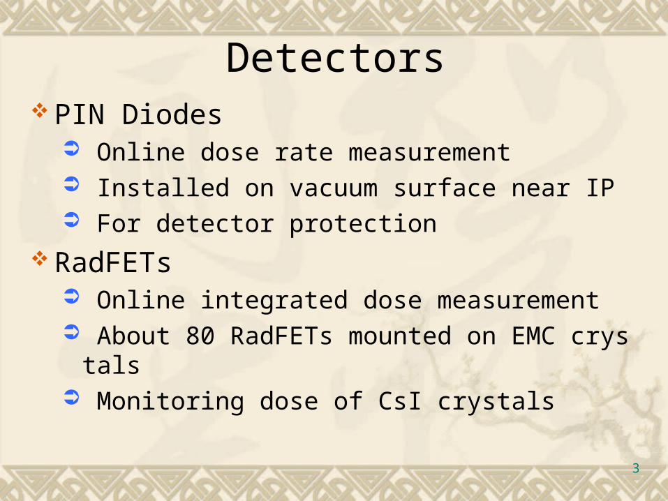
Detectors PIN Diodes
Online dose rate measurement Installed on vacuum surface near IP For detector protection
RadFETs Online integrated dose measurement About 80 RadFETs mounted on EMC crystals Monitoring dose of CsI crystals
4
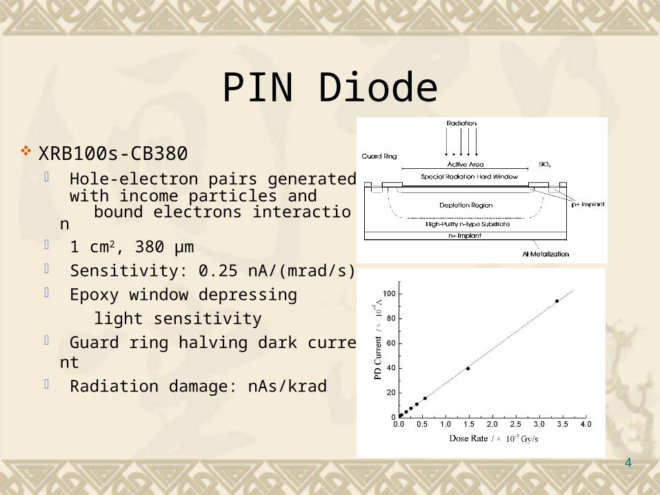
PIN Diode
XRB100s-CB380 Hole-electron pairs generated
with income particles and bound electrons interaction 1 cm2, 380 μm Sensitivity: 0.25 nA/(mrad/s) Epoxy window depressing
light sensitivity Guard ring halving dark current Radiation damage: nAs/krad
5
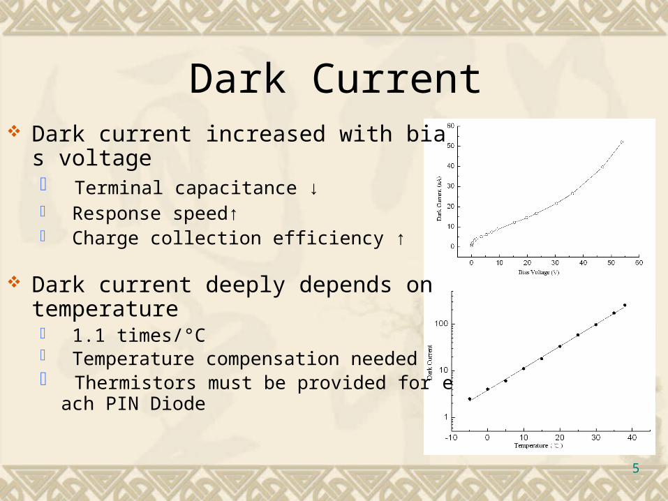
Dark Current Dark current increased with bias voltage
Terminal capacitance ↓ Response speed↑ Charge collection efficiency ↑
Dark current deeply depends on temperature 1.1 times/°C Temperature compensation needed Thermistors must be provided for each PIN Diode
6
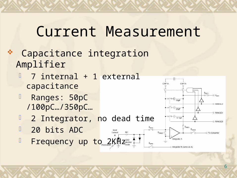
Current Measurement Capacitance integration Amplifier
7 internal + 1 external capacitance Ranges: 50pC /100pC…/350pC… 2 Integrator, no dead time 20 bits ADC Frequency up to 2KHz

7
RadFET
RadFETs p-type MOSFETs Threshold voltage will increase after exposure

8
RadFETs Readout & Calibration
Operation Modes: Exposure Mode Readout Mode Analog switch used 10min cycle Accuracy: 1mv
Calibration 60Co γ Source 8358000280 .D.ΔV

9
First period of run Before Aug. 2007 SCQ was not installed Collimator was unavailable 6 PIN Diodes & 8 RadFETs was used
Background Measurement
10
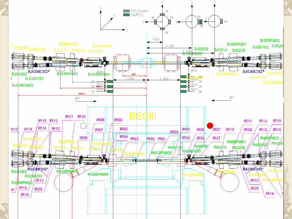
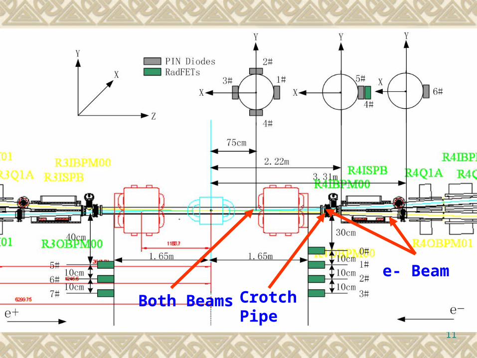
75cm
1#
2#
3#
4#
5#
2. 22m
6#
3. 31m
1. 65m1. 65m
PI N Di odesRadFETs
30cm
10cm10cm10cm
0#1#2#
3#
4#
10cm10cm
40cm
e+ e-
5#6#7#
Z
X
Y
X
Y
X
Y Y
X
11
Crotch PipeBoth Beams
e- Beam
12
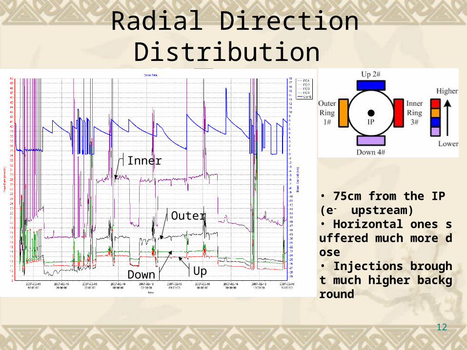
Radial Direction Distribution
• 75cm from the IP (e- upstream)• Horizontal ones suffered much more dose• Injections brought much higher background
Inner
Outer
Down Up
13
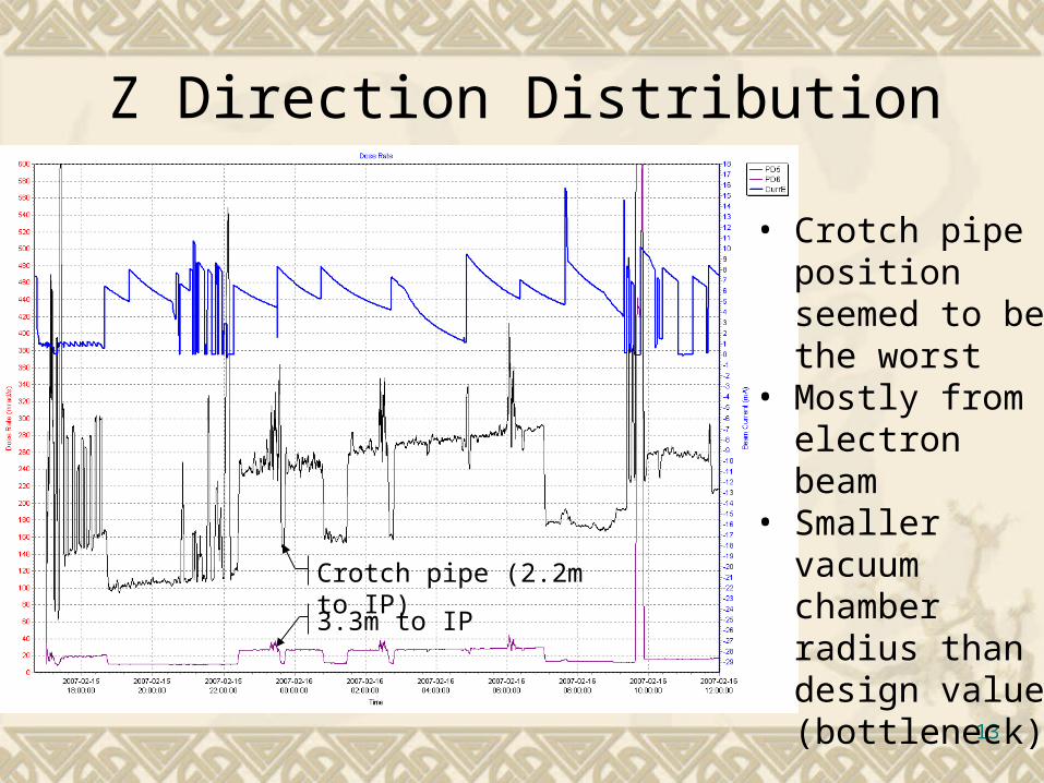
Z Direction Distribution
• Crotch pipe position seemed to be the worst
• Mostly from electron beam
• Smaller vacuum chamber radius than design value (bottleneck)Crotch pipe (2.2m to IP)
3.3m to IP
14
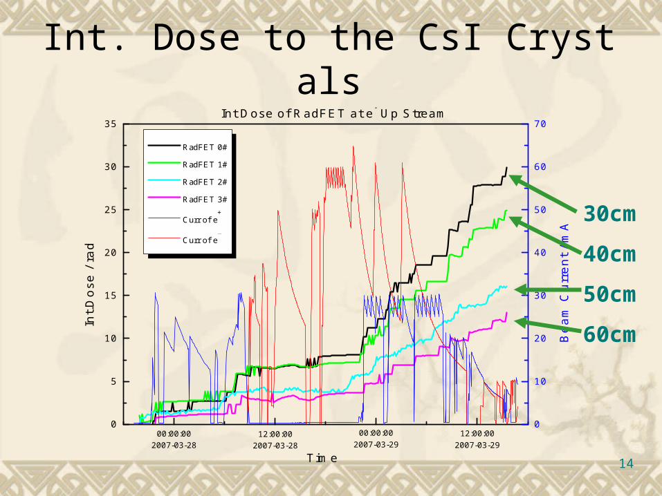
Int. Dose to the CsI Crystals
0
5
10
15
20
25
30
35
Int.D
ose
/ ra
d
RadFET 0#
RadFET 1#
RadFET 2#
RadFET 3#
Curr of e+
Curr of e-
Int Dose of RadFET at e- Up Stream
Time
00:00:002007-03-28
12:00:002007-03-28
00:00:002007-03-29
12:00:002007-03-29
0
10
20
30
40
50
60
70
Be
am
Cu
rre
nt /
mA
30cm
40cm
50cm
60cm
15
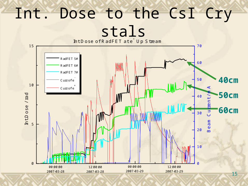
Int. Dose to the CsI Crystals
40cm
50cm
60cm
0
5
10
15
RadFET 5#
RadFET 6#
RadFET 7#
Curr of e-
Curr of e+
Int Dose of RadFET at e+ Up Stream
0
10
20
30
40
50
60
70
Int.D
ose
/ ra
d
Be
am
Cu
rre
nt /
mA
00:00:002007-03-28
12:00:002007-03-28
00:00:002007-03-29
12:00:002007-03-29
16
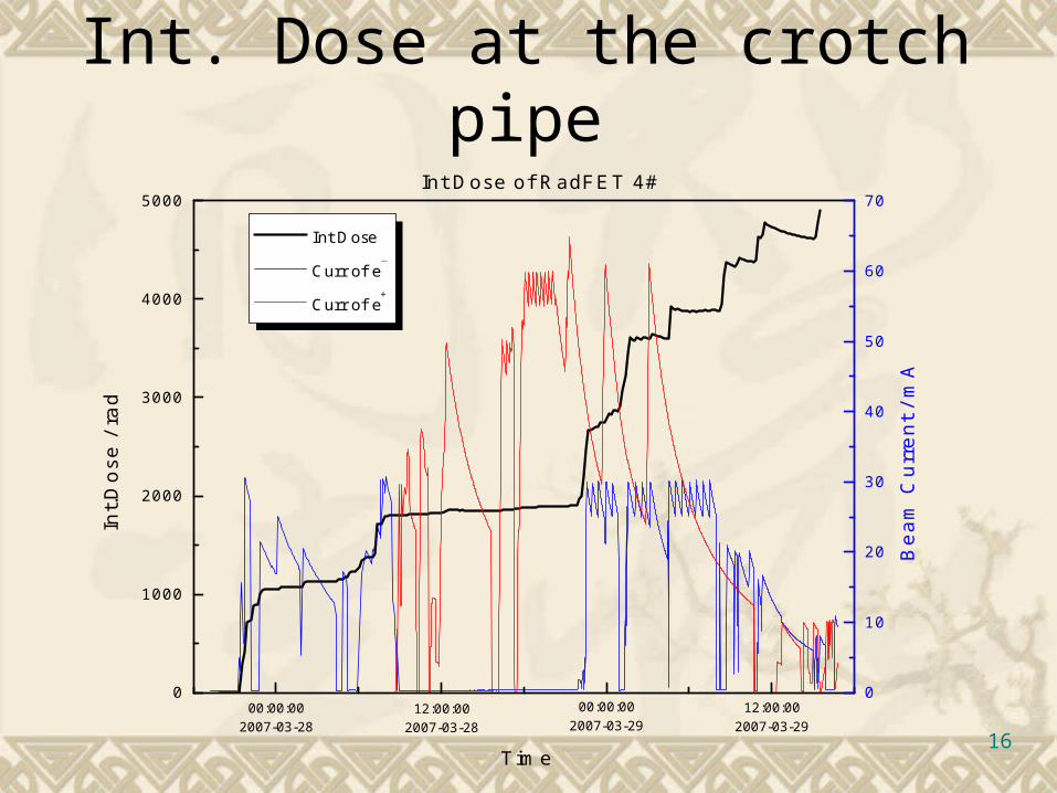
Int. Dose at the crotch pipe
0
1000
2000
3000
4000
5000
Int Dose
Curr of e-
Curr of e+
Time
Int.D
ose
/ ra
d
00:00:002007-03-28
12:00:002007-03-28
00:00:002007-03-29
12:00:002007-03-29
Int Dose of RadFET 4#
0
10
20
30
40
50
60
70
Be
am
Cu
rre
nt /
mA
17
Preliminary Results
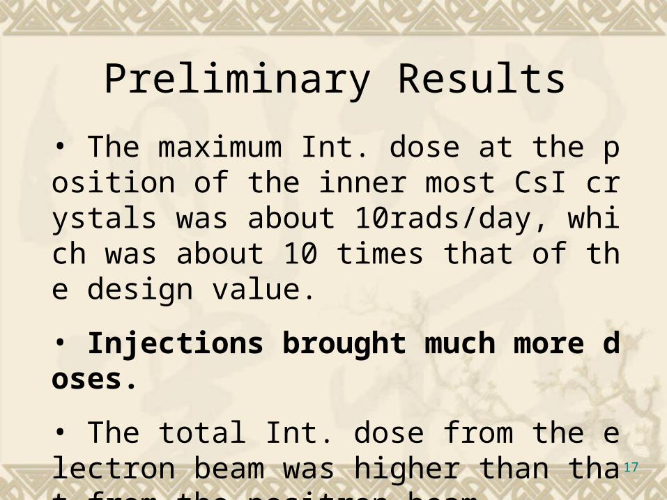
• The maximum Int. dose at the position of the inner most CsI crystals was about 10rads/day, which was about 10 times that of the design value.
• Injections brought much more doses.
• The total Int. dose from the electron beam was higher than that from the positron beam.
18
Second period of run Oct, 2007 ~ Jan,2008 SCQ was installed Collimators were installed Detectors were rearranged
Background Measurement
19
Detectors Arrangement (Oct.07)
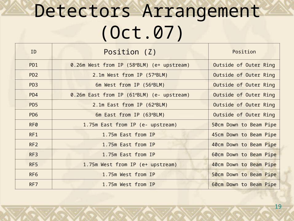
ID Position (Z) Position
PD1 0.26m West from IP (58#BLM) (e+ upstream) Outside of Outer Ring
PD2 2.1m West from IP (57#BLM) Outside of Outer Ring
PD3 6m West from IP (56#BLM) Outside of Outer Ring
PD4 0.26m East from IP (61#BLM) (e- upstream) Outside of Outer Ring
PD5 2.1m East from IP (62#BLM) Outside of Outer Ring
PD6 6m East from IP (63#BLM) Outside of Outer Ring
RF0 1.75m East from IP (e- upstream) 50cm Down to Beam Pipe
RF1 1.75m East from IP 45cm Down to Beam Pipe
RF2 1.75m East from IP 40cm Down to Beam Pipe
RF3 1.75m East from IP 60cm Down to Beam Pipe
RF5 1.75m West from IP (e+ upstream) 40cm Down to Beam Pipe
RF6 1.75m West from IP 50cm Down to Beam Pipe
RF7 1.75m West from IP 60cm Down to Beam Pipe
20
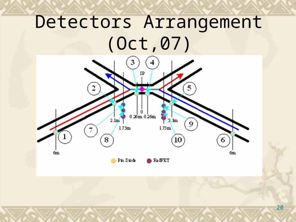
Detectors Arrangement (Oct,07)

21
Status of Detectors (2007/12/28) Dark Currents of PIN Diodes
GT 470nA @ ±6m For a temperature precision of 0.02°C, the poor dose rate accuracy wo
uld be only 4mrad/s!!! GT 150nA @ ±0.26m Newly Installed:
5# @ 2.1m (e- upstream) about 100nA
2# @ -2.1m (e+ upstream) about 10nA
RadFETs Suffered Int. Dose from 1500 to 2700 Rad Accuracy was getting worse (±5rad)

22
Early in the second period The position of inner most CsI Crystals upstream e- beamMore than 100rads for 10 days
The position of inner most CsI Crystals upstream e+ beamMore than 100rads for 10 days
Accelerator people were doing experiments
23
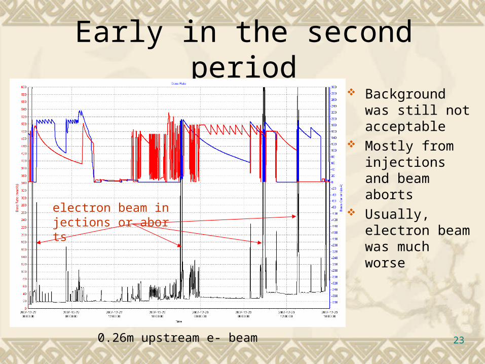
Early in the second period
0.26m upstream e- beam
Background was still not acceptable
Mostly from injections and beam aborts
Usually, electron beam was much worseelectron beam injections
or aborts
24
Experiments of Collimators
Storage ring collimators and transport line collimators.
Influences of collimators for stable beam run and injections were studied.
251
10
100
1000
10000
100000
0
1
2
3
4
5
6
7
I nsi deOutsi deLi f et i me
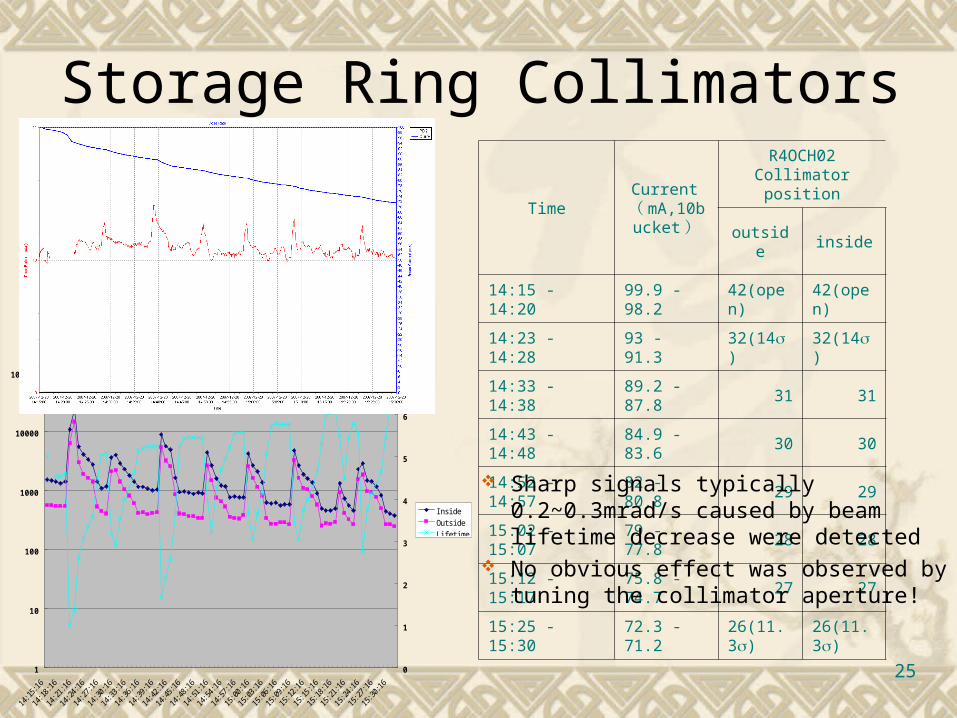
Storage Ring Collimators
TimeCurrent
( mA,10bucket )
R4OCH02 Collimator position
outside inside
14:15 - 14:20 99.9 - 98.2 42(open) 42(open)
14:23 - 14:28 93 - 91.3 32(14) 32(14)
14:33 - 14:38 89.2 - 87.8 31 31
14:43 - 14:48 84.9 - 83.6 30 30
14:52 - 14:57 82 - 80.8 29 29
15:02 - 15:07 79 - 77.8 28 28
15:12 - 15:17 75.8 - 74.7 27 27
15:25 - 15:30 72.3 - 71.226(11.3)
26(11.3) Sharp signals typically 0.2~0.3mrad/s
caused by beam lifetime decrease were detected
No obvious effect was observed by tuning the collimator aperture!
26
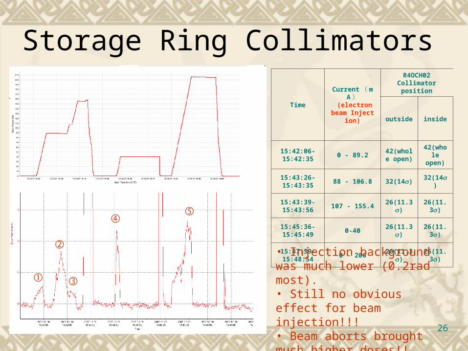
Time
Current(mA)
(electron beam Injection)
R4OCH02 Collimator position
outside inside
15:42:06- 15:42:35
0 - 89.242(whole
open)42(whole open)
15:43:26-15:43:35
88 - 106.8 32(14) 32(14)
15:43:39-15:43:56
107 - 155.426(11.3
)26(11.3
)
15:45:36-15:45:49
0-4026(11.3
)26(11.3
)
15:47:59-15:48:54
0 - 20626(11.3
)26(11.3
)
Storage Ring Collimators
• Injection background was much lower (0.2rad most).• Still no obvious effect for beam injection!!!• Beam aborts brought much higher doses!!
①
②
③
④ ⑤
27
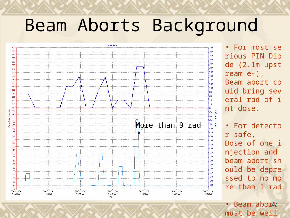
Beam Aborts Background
More than 9 rad
• For most serious PIN Diode (2.1m upstream e-),Beam abort could bring several rad of int dose.
• For detector safe, Dose of one injection and beam abort should be depressed to no more than 1 rad.
• Beam abort must be well treated.
28
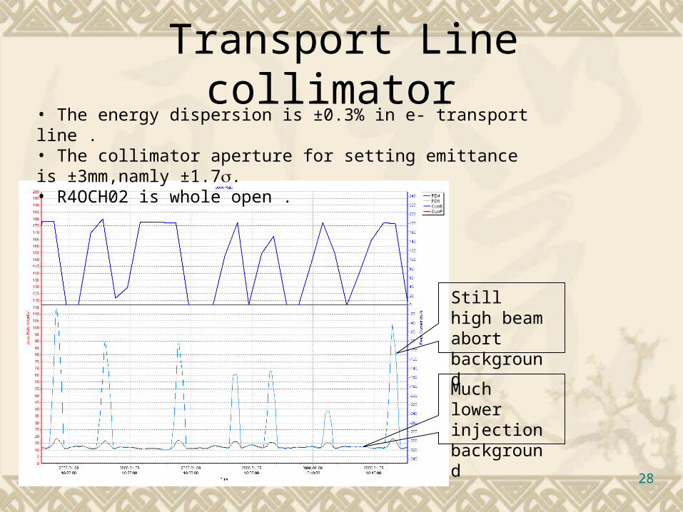
Transport Line collimator
Still high beam abort background
Much lower injection background
• The energy dispersion is ±0.3% in e- transport line . • The collimator aperture for setting emittance is ±3mm,namly ±1.7. • R4OCH02 is whole open .
29
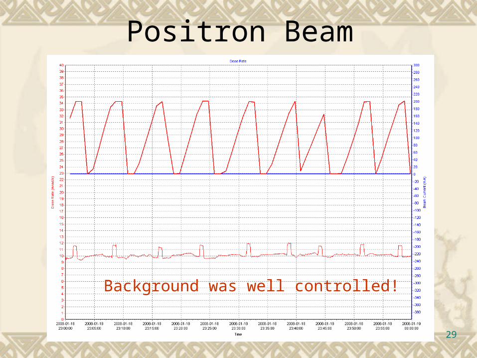
Positron Beam
Background was well controlled!

30
Beam Abort Improved
Temporary beam abort system were used to let the beam lose in injection region by using injection kickers and a local bump in that region
Beam abort and injection were all well controlled!

31
Electron-Positron Collision
0.26m upstream e-
2.1m upstream e-
Single beam background was good enough!But there was some trouble with e+e- collision.
e- always be worse!
32
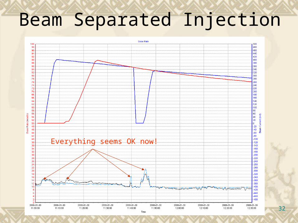
Beam Separated Injection
Everything seems OK now!
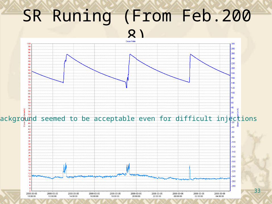
33
SR Runing (From Feb.2008)
Background seemed to be acceptable even for difficult injections

34
The inner most RadFET
SR Runing (From Feb.2008)
The value was getting smaller with time,It seemed to be annealing

35
Conclusions Background was being effectively decreased. For single beam, background from injections an
d beam aborts is safe for CsI crystals. Synchrotron radiation is also safe enough. Injection with collision is not ideal, Beam must
be separated by tuning RF phase for injection.
36
Next to do
Study of background source and proportion for radiation protection.
Improve the performance of radiation detectors for steady run measurement.
More experimental study of collimators. Background study after BESIII finally installed. Suggestions from you…

37
Thank you!