Embed Size (px)
Citation preview
B-500-EXT-230-RS
OWNER’S MANUAL HDBaseT EXTENDER

pg.2
B-500-EXT-230-RS Installation and Users Manual
IMPORTANT SAFETY INSTRUCTIONS
WARNING: To reduce the risk of fire or electric shock, do not expose this apparatus to rain or moisture.1. Read and follow all instructions and warnings in this manual. Keep for future reference.
2. Do not use this apparatus near water.
3. Clean only with a dry cloth.
4. Do not block any ventilation openings. Install according to manufacturer’s instructions.
5. Do not install near any heat sources such as radiators, heat registers, stoves or other apparatus
(including amplifiers) that produce heat.
6. Do not override the safety purpose of the polarized or grounding-type plug. A polarized plug has
two blades - one wider than the other. A grounding type plug has two blades and a third grounding
prong. The wide blade or the third prong is provided for your safety. If the provided plug does not fit
into your outlet, consult an electrician for replacement of the obsolete outlet.
7. Protect the power cord from being walked on or pinched particularly at plug, convenience
receptacles, and the point where it exits from the apparatus.
8. Only use attachments/accessories specified by the manufacturer.
9. Refer all servicing to qualified service personnel. Servicing is required when the apparatus has
been damaged in any way, such as when the power-supply cord or plug is damaged, liquid has
been spilled or objects have fallen into the apparatus, the apparatus has been exposed to rain or
moisture, does not operate normally, or has been dropped.
10. DO NOT EXPOSE THIS EQUIPMENT TO DRIPPING OR SPLASHING AND ENSURE THAT NO OBJECTS
FILLED WITH LIQUIDS, SUCH AS VASES, ARE PLACED ON THE EQUIPMENT.
11. TO COMPLETELY DISCONNECT THIS EQUIPMENT FROM THE AC MAINS, DISCONNECT THE POWER
SUPPLY CORD PLUG FROM THE AC RECEPTACLE.
12. THE MAINS PLUG OF THE POWER SUPPLY CORD SHALL REMAIN READILY OPERABLE.
CAUTION: TO REDUCE THE RISK OF ELECTRICAL SHOCK, DO NOT REMOVE COVER. NO USER SERVICEABLE PARTS INSIDE. REFER SERVICING TO QUALIFIED SERVICE PERSONNEL.
The lightning flash with arrowhead symbol, within an equilateral triangle, is intended to alert the user to the presence of un-insulated dangerous voltage within the product’s enclosure that may be of sufficient magnitude to constitute a risk of electric shock to persons.
The exclamation point within an equilateral triangle is intended to alert the user to the presence of important operating and maintenance (servicing) instructions in the literature accompanying the appliance.
© 2012 Binary
B-500-EXT-230-RS Installation and Users Manual
pg.3
TABLE OF CONTENTS
1. Overview ......................................................................................................................... 4
2. Package Contents .......................................................................................................... 4
3. Features .......................................................................................................................... 5
4. Connections and Controls ............................................................................................. 6
4.1. B-500-EXT-230-RS Transmitter..........................................................................................................6
4.2. B-500-EXT-230-RS Receiver ...............................................................................................................7
5. Basic Connections .......................................................................................................... 8
5.1. HDBaseT Link (RJ45) Connection ....................................................................................................8
5.2. IR Control Connections .......................................................................................................................9
5.2.1. IR Control In (3.5mm {1/8”} Mono) - Transmitter .............................................................10
5.2.2. IR Receiver In (3.5mm {1/8”} Stereo) - Receiver ................................................................10
5.2.3. IR Flasher Out (3.5mm {1/8”} Mono) – Transmitter and Receiver ..............................11
5.3. RS232 Control Connections .............................................................................................................11
5.3.1. RS232 Control (DB9) Connection ..........................................................................................11
5.4. HDMI Out to Display (HDMI) ............................................................................................................12
5.5. Latch Locking Power Supply ............................................................................................................12
6. Installation .................................................................................................................... 13
6.1. B-500-EXT-230-RS Transmitter Installation .................................................................................13
6.2. B-500-EXT-230-RS Receiver Installation .......................................................................................13
7. Specifications ................................................................................................................ 14
8. WARRANTY .................................................................................................................... 15
9. Contacting Technical Support ...................................................................................... 15
pg.4
B-500-EXT-230-RS Installation and Users Manual
1. OVERVIEW The B-500-EXT-230-RS extends HDMI over single Cat5e/6 using HDBaseT technology allowing video and audio transmission to remote displays. In addition, the B-500-EXT-230-RS is equipped with bi-directional IR pass-through and bi-directional RS-232 pass-through all over a single Cat5e/6 cable.
Supports all HDMI defined Audio and Video formats, including 3D Video.
The Power Over Cable feature requires only one end of the link to be powered.
2. PACKAGE CONTENTS(1) B-500-EXT-230-RS Transmitter
(1) B-500-EXT-230-RS Receiver
(1) 24V DC 1A Power Supply
(4) Mounting Screws
(8) Rubber Feet
(1) User Manual
(1) IR Adapter Cable
© 2012 Binary
B-500-EXT-230-RS Installation and Users Manual
pg.5
3. FEATURES
Form and Function• Wall-Mountable Housing Design for Easy Installation• Extends all HDMI formats up to 4Kx2K via a Single cable
• Transmits HDMI Signal via HDBaseT up to 10.2Gbps• HDCP 1.2 Compliant• Power Over Cable (POC) Allows for Single Power Supply• Latch Locking Power Supply
Video• 2D Resolutions up to 1080p@60Hz – 48 Bit; including Deep Color• 4Kx2K• 3D Resolutions up to 1080p@24Hz – 48 Bit; including Deep Color• EDIDs Read from Connected Display to Source
Audio•Supports all HDMI supported Audio Formats, including DTS-HD Master and Dolby TrueHD
Control Functionality• Bi-Directional IR Pass-Through
- Supports IR Signal from 20kHz To 60kHz - Adaptive IR Input Levels (3.5V DC To 12V DC)
• Bi-Directional RS232 Up to 115.2 Kb/s
Cat5e Up to 200ft
Cat6/Cat6a Up to 230ft
pg.6
B-500-EXT-230-RS Installation and Users Manual
4. CONNECTIONS AND CONTROLS
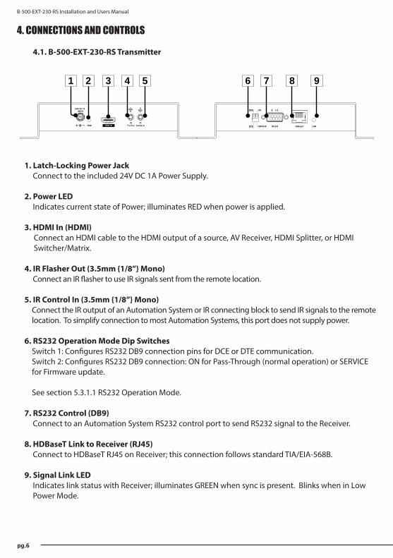
4.1. B-500-EXT-230-RS Transmitter
1. Latch-Locking Power JackConnect to the included 24V DC 1A Power Supply.
2. Power LEDIndicates current state of Power; illuminates RED when power is applied.
3. HDMI In (HDMI)Connect an HDMI cable to the HDMI output of a source, AV Receiver, HDMI Splitter, or HDMI Switcher/Matrix.
4. IR Flasher Out (3.5mm {1/8”} Mono)Connect an IR flasher to use IR signals sent from the remote location.
5. IR Control In (3.5mm {1/8”} Mono) Connect the IR output of an Automation System or IR connecting block to send IR signals to the remote location. To simplify connection to most Automation Systems, this port does not supply power.
6. RS232 Operation Mode Dip SwitchesSwitch 1: Configures RS232 DB9 connection pins for DCE or DTE communication.Switch 2: Configures RS232 DB9 connection: ON for Pass-Through (normal operation) or SERVICE for Firmware update.
See section 5.3.1.1 RS232 Operation Mode.
7. RS232 Control (DB9)Connect to an Automation System RS232 control port to send RS232 signal to the Receiver.
8. HDBaseT Link to Receiver (RJ45)Connect to HDBaseT RJ45 on Receiver; this connection follows standard TIA/EIA-568B.
9. Signal Link LEDIndicates link status with Receiver; illuminates GREEN when sync is present. Blinks when in Low Power Mode.
+24V DC 1AINPUT
PWR Control InHDMI IN RS-232 LINK
DTE
DCE
ON
SERVICE
5 3 2
HDBaseT
1 2
ON
RS-232 LINK
ON
SERVICE
5 3 2
HDBaseTDTE
DCE
1 2
ON
21 3 4 5 6 7 8 9
© 2012 Binary
B-500-EXT-230-RS Installation and Users Manual
pg.7
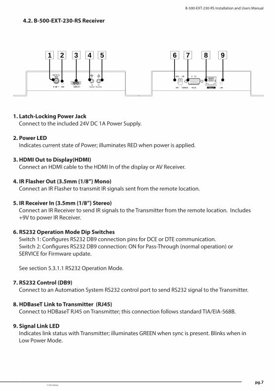
1. Latch-Locking Power JackConnect to the included 24V DC 1A Power Supply.
2. Power LEDIndicates current state of Power; illuminates RED when power is applied.
3. HDMI Out to Display(HDMI)Connect an HDMI cable to the HDMI In of the display or AV Receiver.
4. IR Flasher Out (3.5mm {1/8”} Mono)Connect an IR Flasher to transmit IR signals sent from the remote location.
5. IR Receiver In (3.5mm {1/8”} Stereo) Connect an IR Receiver to send IR signals to the Transmitter from the remote location. Includes +9V to power IR Receiver.
6. RS232 Operation Mode Dip SwitchesSwitch 1: Configures RS232 DB9 connection pins for DCE or DTE communication.Switch 2: Configures RS232 DB9 connection: ON for Pass-Through (normal operation) or SERVICE for Firmware update.
See section 5.3.1.1 RS232 Operation Mode.
7. RS232 Control (DB9)Connect to an Automation System RS232 control port to send RS232 signal to the Transmitter.
8. HDBaseT Link to Transmitter (RJ45)Connect to HDBaseT RJ45 on Transmitter; this connection follows standard TIA/EIA-568B.
9. Signal Link LEDIndicates link status with Transmitter; illuminates GREEN when sync is present. Blinks when in Low Power Mode.
4.2. B-500-EXT-230-RS Receiver
+24V DC 1AINPUT
PWR HDMI OUT RS-232 LINK
DTE
DCE
ON
SERVICE
5 3 2
HDBaseT
1 2
ON
21 3 4 5
RS-232 LINKDTE
DCE ON
SERVICE
5 3 2
HDBaseT
1 2
ON
6 7 8 9
pg.8
B-500-EXT-230-RS Installation and Users Manual
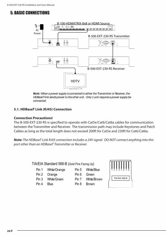
5. BASIC CONNECTIONS
5.1. HDBaseT Link (RJ45) Connection
Connection Precautions!The B-500-EXT-230-RS is specified to operate with Cat5e/Cat6/Cat6a cables for communication between the Transmitter and Receiver. The transmission path may include Keystones and Patch Cables as long as the total length does not exceed 200ft for Cat5e and 230ft for Cat6/Cat6a.
Note: The HDBaseT Link RJ45 connection includes a 24V signal. DO NOT connect anything into this port other than an HDBaseT Transmitter or Receiver.
+24V DC 1AINPUT
PWR Control InHDMI IN
+24V DC 1AINPUT
PWR HDMI OUT
RS-232 LINK
DTE
DCE
ON
SERVICE
5 3 2
HDBaseT
1 2
ON
RS-232 LINK
ON
SERVICE
5 3 2
HDBaseTDTE
DCE
1 2
ON
HDTV
ETHERNET
IR Receiver Engineered in the USAManufactured in Taiwan
12V DC 5AINPUT
OUTPUT 1 OUTPUT 2 OUTPUT 3 OUTPUT 4 OUTPUT 5 OUTPUT 6 OUTPUT 7 OUTPUT 8INPUT 1 INPUT 2 INPUT 3 INPUT 4 INPUT 5 INPUT 6 INPUT 7 INPUT 8
PIN2 Transmit Data3 Receive Data5 Signal Ground
SIGNALRS-232 Pin Out
RS-232
B-100-HDMATRIX-8x8 or HDMI Source
AC Power
RS-232 LINK
DTE
DCE
ON
SERVICE
5 3 2
HDBaseT
1 2
ON
RS-232 LINKDTE
DCE ON
SERVICE
5 3 2
HDBaseT
1 2
ON
Note: When a power supply is connected to either the Transmitter or Receiver, theHDBaseT link sends power to the other unit. Only 1 unit requires a power supply beconnected.
B-500-EXT-230-RS Transmitter
B-500-EXT-230-RS Receiver
Pin 1 White/Orange Pin 5 White/BluePin 2 Orange Pin 6 GreenPin 3 White/Green Pin 7 White/BrownPin 4 Blue Pin 8 Brown
TIA/EIA Standard 568-B (Gold Pins Facing Up)
© 2012 Binary
B-500-EXT-230-RS Installation and Users Manual
pg.9
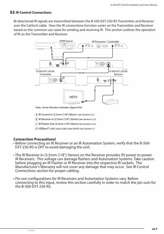
5.2. IR Control Connections
Bi-directional IR signals are transmitted between the B-500-EXT-230-RS Transmitter and Receiver over the Cat5e/6 cable. How the IR connections function varies on the Transmitter and Receiver based on the common use cases for sending and receiving IR. This section outlines the operation of IR on the Transmitter and Receiver.
Connection Precautions!• Before connecting an IR Receiver or an IR Automation System, verify that the B-500-
EXT-230-RS is OFF to avoid damaging the unit.
• The IR Receiver In (3.5mm {1/8”} Stereo) on the Receiver provides 9V power to power IR Receivers. This voltage can damage flashers and Automation Systems. Take caution before plugging an IR Flasher or IR Receiver into the respective IR sockets. The Manufacturer’s Warranty will not cover any damage that may occur. See IR Control Connections section for proper cabling.
• Pin out configurations for IR Receivers and Automation Systems vary. Before connecting to this input, review this section carefully in order to match the pin outs for the B-500-EXT-230-RS.
IR OutputsIR Inputs
IR Processor / ControllerPLAY
HDMI Source
+24V DC 1AINPUT
PWR HDMI OUT
+24V DC 1AINPUT
PWR Control InHDMI IN
RS-232 LINK
DTE
DCE
ON
SERVICE
5 3 2
HDBaseT
1 2
ON
B-500-EXT-230-RS Transmitter
RS-232 LINK
ON
SERVICE
5 3 2
HDBaseTDTE
DCE
1 2
ON
HDTV
RS-232 LINK
DTE
DCE
ON
SERVICE
5 3 2
HDBaseT
1 2
ON
B-500-EXT-230-RS Receiver
RS-232 LINKDTE
DCE ON
SERVICE
5 3 2
HDBaseT
1 2
ON
DB
A IR Control In (3.5mm {1/8”} Mono) -See Section 5.2.1
B IR Receiver In (3.5mm {1/8”} Stereo)-See Section 5.2.2
C IR Flasher Out (3.5mm {1/8”} Mono)-See Section 5.2.3
C A
C
D HDBaseT Link Cat5e/Cat6/Cat6a (RJ45)-See Section 5.1
or
Note: Arrow Direction Indicates Signal Flow
pg.10
B-500-EXT-230-RS Installation and Users Manual
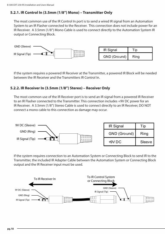
5.2.1. IR Control In (3.5mm {1/8”} Mono) – Transmitter Only
The most common use of the IR Control In port is to send a wired IR signal from an Automation System to an IR Flasher connected to the Receiver. This connection does not include power for an IR Receiver. A 3.5mm {1/8”} Mono Cable is used to connect directly to the Automation System IR output or Connecting Block.
5.2.2. IR Receiver In (3.5mm {1/8”} Stereo) – Receiver Only
The most common use of the IR Receiver port is to send an IR signal from a powered IR Receiver to an IR Flasher connected to the Transmitter. This connection includes +9V DC power for an IR Receiver. A 3.5mm {1/8”} Stereo Cable is used to connect directly to an IR Receiver, DO NOT connect a mono cable to this connection as damage may occur.
If the system requires a powered IR Receiver at the Transmitter, a powered IR Block will be needed between the IR Receiver and the Transmitters IR Control In.
If the system requires connection to an Automation System or Connecting Block to send IR to the Transmitter, the included IR Adapter Cable between the Automation System or Connecting Block output and the IR Receiver input must be used.
IR Signal (Tip)
GND (Sleeve)IR Signal Tip
GND (Ground) Ring
IR Signal (Tip)
GND (Ring)
9V DC (Sleeve) IR Signal Tip
GND (Ground) Ring
+9V DC Sleeve
IR Signal (Tip)
GND (Ring)
9V DC (Sleeve)IR Signal (Tip)
GND (Sleeve)
To IR Receiver In To IR Control Systemor Connecting Block
© 2012 Binary
B-500-EXT-230-RS Installation and Users Manual
pg.11
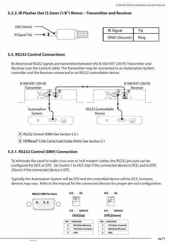
5.2.3. IR Flasher Out (3.5mm {1/8”} Mono) – Transmitter and Receiver
5.3. RS232 Control Connections
Bi-directional RS232 signals are transmitted between the B-500-EXT-230-RS Transmitter and Receiver over the Cat5e/6 cable. The Transmitter may be connected to an Automation System controller and the Receiver connected to an RS232 controllable device.
5.3.1. RS232 Control (DB9) Connection
To eliminate the need to make cross over or ‘null modem’ cables, the RS232 pin outs can be configured for DCE or DTE. Set Switch 1 to DCE (Up) if the connected device is DCE, and to DTE (Down) if the connected device is DTE.
Typically the Automation System will be DTE and the controlled device will be DCE, however, devices may vary. Refer to the manual for the connected devices for proper pin-out configuration.
IR Signal (Tip)
GND (Sleeve)IR Signal Tip
GND (Ground) Ring
RS-232 LINK
DTE
DCE
ON
SERVICE
5 3 2
HDBaseT
1 2
ON
B-500-EXT-230-RS Transmitter
RS-232 LINK
DTE
DCE
ON
SERVICE
5 3 2
HDBaseT
1 2
ON
B-500-EXT-230-RS Receiver
Automation System
RS232 Controllable Device
RS-232 LINK
ON
SERVICE
5 3 2
HDBaseTDTE
DCE
1 2
ON
RS-232 LINKDTE
DCE ON
SERVICE
5 3 2
HDBaseT
1 2
ON
A
A RS232 Control (DB9)-See Section 5.3.1
B HDBaseT Link Cat5e/Cat6/Cat6a (RJ45)-See Section 5.1
A BB
PIN FUNCTION
2 RxD (Data Receive)
3 TxD (Data Transmit)
5 GND
PIN FUNCTION
2 TxD (Data Transmit)
3 RxD (Data Receive)
5 GND
235
RS232 DB9 Pin Outs
DTE
DCE ON
SERVICE
1 2ON
DCE (Up)
ON
SERVICE
1 2ON
DTE
DCE
DTE (Down)
pg.12
B-500-EXT-230-RS Installation and Users Manual
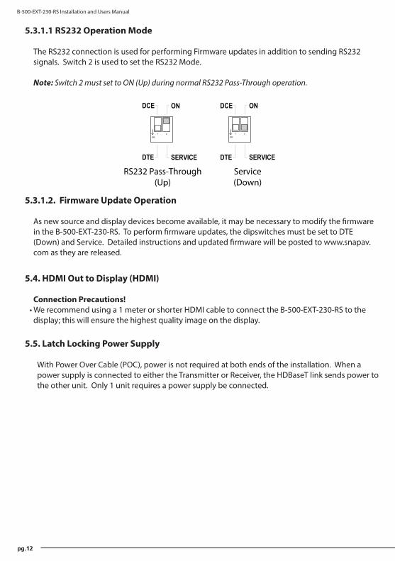
5.3.1.1 RS232 Operation Mode
The RS232 connection is used for performing Firmware updates in addition to sending RS232 signals. Switch 2 is used to set the RS232 Mode.
Note: Switch 2 must set to ON (Up) during normal RS232 Pass-Through operation.
5.3.1.2. Firmware Update Operation
As new source and display devices become available, it may be necessary to modify the firmware in the B-500-EXT-230-RS. To perform firmware updates, the dipswitches must be set to DTE (Down) and Service. Detailed instructions and updated firmware will be posted to www.snapav.com as they are released.
5.4. HDMI Out to Display (HDMI)
Connection Precautions!• We recommend using a 1 meter or shorter HDMI cable to connect the B-500-EXT-230-RS to the
display; this will ensure the highest quality image on the display.
5.5. Latch Locking Power Supply
With Power Over Cable (POC), power is not required at both ends of the installation. When a power supply is connected to either the Transmitter or Receiver, the HDBaseT link sends power to the other unit. Only 1 unit requires a power supply be connected.
ON
SERVICE
1 2ON
DTE
DCE
RS232 Pass-Through(Up)
ON
SERVICE
1 2ON
DTE
DCE
Service(Down)
© 2012 Binary
B-500-EXT-230-RS Installation and Users Manual
pg.13
6. INSTALLATION
Note: DO NOT connect power to the B-500-EXT-230-RS until all other connections are made and the unit is installed.
6.1. B-500-EXT-230-RS Transmitter Installation
1. Run the Cat5e/Cat6/Cat6a cable from the location of the Transmitter to the remote location of the Receiver.
2. Mount the B-500-EXT-230-RS Transmitter in the desired location.3. Connect the HDMI Out of a source component using an HDMI cable.4. Connect the RS232 DB9 from an Automation System if being used.5. Connect an IR Control System to the IR Control In and/or IR Flasher if being used.6. Connect the Cat5e/6 cable to the B-500-EXT-230-RS Transmitter.7. Connect the 24V DC 1A Power Supply to the Latch-Locking Power Jack, unless POC is being
used to send power from the Receiver. DO NOT plug the power supply into an AC outlet until Step 9 under Receiver Installation.
6.2. B-500-EXT-230-RS Receiver Installation
1. Run the Cat5e/Cat6/Cat6a cable from the location of the Transmitter to the remote location of the Receiver.
2. Install the B-500-EXT-230-RS Transmitter following the steps outlined in section 6.1. B-500-EXT-230-RS Transmitter Installation.
3. Mount the B-500-EXT-230-RS Receiver in the desired location.4. Connect the Cat5e/6 cable to the B-500-EXT-230-RS Receiver.5. Connect an IR Flasher and/or IR Receiver if being used.6. Connect an HDMI cable from the B-500-EXT-230-RS to the display.7. Connect the RS232 DB9 to an RS232 controllable source if being used.8. Connect the 24V DC 1A Power Supply to the Latch-Locking Power Jack, unless POC is being
used to send power from the Transmitter.9. Plug the power supply for either the Transmitter or the Receiver (depending on which unit is
supplying power) into an AC outlet.
pg.14
B-500-EXT-230-RS Installation and Users Manual
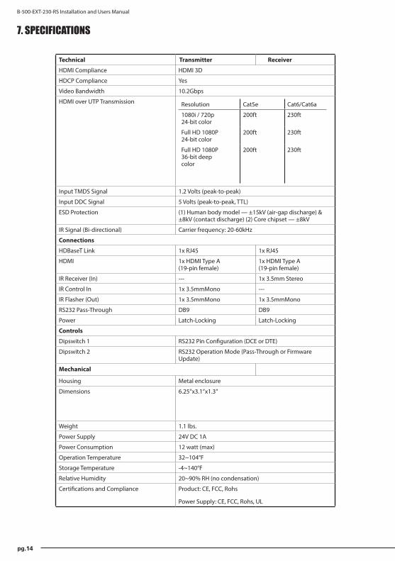
Technical Transmitter Receiver
HDMI Compliance HDMI 3D
HDCP Compliance Yes
Video Bandwidth 10.2Gbps
HDMI over UTP Transmission Resolution Cat5e Cat6/Cat6a
1080i / 720p 24-bit color
200ft 230ft
Full HD 1080P 24-bit color
200ft 230ft
Full HD 1080P 36-bit deep color
200ft 230ft
Input TMDS Signal 1.2 Volts (peak-to-peak)
Input DDC Signal 5 Volts (peak-to-peak, TTL)
ESD Protection (1) Human body model — ±15kV (air-gap discharge) & ±8kV (contact discharge) (2) Core chipset — ±8kV
IR Signal (Bi-directional) Carrier frequency: 20-60kHz
Connections
HDBaseT Link 1x RJ45 1x RJ45
HDMI 1x HDMI Type A (19-pin female)
1x HDMI Type A (19-pin female)
IR Receiver (In) --- 1x 3.5mm Stereo
IR Control In 1x 3.5mmMono ---
IR Flasher (Out) 1x 3.5mmMono 1x 3.5mmMono
RS232 Pass-Through DB9 DB9
Power Latch-Locking Latch-Locking
Controls
Dipswitch 1 RS232 Pin Configuration (DCE or DTE)
Dipswitch 2 RS232 Operation Mode (Pass-Through or Firmware Update)
Mechanical
Housing Metal enclosure
Dimensions 6.25”x3.1”x1.3”
Weight 1.1 lbs.
Power Supply 24V DC 1A
Power Consumption 12 watt (max)
Operation Temperature 32~104°F
Storage Temperature -4~140°F
Relative Humidity 20~90% RH (no condensation)
Certifications and Compliance Product: CE, FCC, Rohs
Power Supply: CE, FCC, Rohs, UL
7. SPECIFICATIONS
© 2012 Binary
B-500-EXT-230-RS Installation and Users Manual
pg.15
8. WARRANTY
2-Year Limited WarrantyThis Binary™ Product has a Two-Year Limited Warranty. This warranty includes parts and labor repairs on all components found to be defective in material or workmanship under normal conditions of use. This warranty shall not apply to products which have been abused, modified or disassembled. Products to be repaired under this warranty must be returned to SnapAV or a designated service center with prior notification and an assigned return authorization number (RA).
9. CONTACTING TECHNICAL SUPPORT
Phone: (866) 838-5052Email: [email protected]

© 2012 Binary™121130-1620


![[5159]Ext. -501 M.Com. (Part - I) MANAGEMENT ACCOUNTINGcollegecirculars.unipune.ac.in/sites/examdocs/April 2017/M.COM... · Year Machine A Machine B Rs. Rs. 1 60,000 20,000 2 80,000](https://img.dokumen.tips/doc/110x75/606a2cb83647f77843608a32/5159ext-501-mcom-part-i-management-accoun-2017mcom-year-machine.jpg)