Embed Size (px)
Citation preview

Progress In Electromagnetics Research, Vol. 122, 467–496, 2012
AXIAL-FLUX PERMANENT-MAGNET MOTOR DESIGNFOR ELECTRIC VEHICLE DIRECT DRIVE USINGSIZING EQUATION AND FINITE ELEMENT ANALYSIS
A. Mahmoudi*, N. A. Rahim, and H. W. Ping
UMPEDAC, Engineering Tower, University of Malaya, Kuala Lumpur,Malaysia
Abstract—The design process of a double-sided slotted TORUS axial-flux permanent-magnet (AFPM) motor suitable for direct drive ofelectric vehicle (EV) is presented. It used sizing equation and FiniteElement Analysis (FEA). AFPM motor is a high-torque-density motoreasily mounted compactly onto a vehicle wheel, fitting the wheelrim perfectly. A preliminary design is a double-sided slotted AFPMmotor with 6 rotor poles for high torque-density and stable rotation.In determining the design requirements, a simple vehicle-dynamicsmodel that evaluates vehicle performance through the typical cruisingtrip of an automobile was considered. To obtain, with the highestpossible torque, the initial design parameters of the motor, AFPM’sfundamental theory and sizing equation were applied. Vector FieldOpera-3D 14.0 commercial software ran the FEA of the motor design,evaluating and enhancing accuracy of the design parameters. Resultsof the FEA simulation were compared with those obtained from thesizing equation; at no-load condition, the flux density at every part ofthe motor agreed. The motor’s design meets all the requirements andlimits of EV, and fits the shape and size of a classical-vehicle wheel rim.The design process is comprehensive and can be used for an arbitraryEV with an arbitrary cruising scenario.
1. INTRODUCTION
Protection of natural environments sparked interest in electric vehicle(EV), a non-polluting personal transport. EV first appeared in 1870but was for many years not further developed.The past 10 years,however, have seen developmental progress of EV [1]. Battery, electric
Received 4 September 2011, Accepted 22 November 2011, Scheduled 8 December 2011* Corresponding author: Amin Mahmoudi ([email protected]).
468 Mahmoudi, Rahim, and Ping
motor, motor drive circuit, and transmission gears make up EV’spower system. Researchers and designers look into increasing theefficiency and reliability of EV power systems. Improvement of eachsubsystem increases the overall efficiency, and consequently, the drivingrange. One reason for EV’s little commercial success over the pastcentury is that its efficiency had yet to reach the public’s expectationsfor it [2]. Low price and simple but strong physical structure arethe reasons for induction motor’s wide application in EV [3]. Also,it can withstand high overloading and have low torque ripple. Itsdisadvantages, however, are low power-density, huge size and averageefficiency. Permanent-magnet motor competing with induction motorin EV application has recently been developed; it fulfills the requiredhigh efficiency, small size, and high power density [4–7]. A motordesigned for EV can be classified as direct drive or indirect drive [8, 9].Direct drive excludes transmission gears and mechanical differentialincluding the associated energy losses.The motor is mounted insidevehicle wheel rim and turns the wheel directly, so it must be compactand have high torque [10].
Permanent-magnet machines generally can be axial-flux or radial-flux [11]. Advantages of axial-flux permanent-magnet (AFPM) motorsover conventional radial-flux permanent-magnet (RFPM) motorsinclude high torque-to-weight ratio, good efficiency, adjustable air-gap,balanced rotor-stator attractive forces, and better heat-removal [12–14]. They can be easily and compactly mounted onto vehicle wheel,fitting the wheel rim perfectly, suitable for direct drive applications.AFPM machines can be single-sided or double-sided, with or withoutarmature slots, with or without armature core, with internal orexternal permanent-magnet rotors, with surface-mounted or interiorpermanent-magnet, and single-stage or multistage machines [15].Double-sided configurations have either external stator or externalrotor. An external stator means fewer permanent magnets but pooruse of winding, whereas an external rotor is considered particularlyadvantageous to machine topology. Topologies for double-sided AFPMmachines are one-stator-two-rotor (TORUS) and two-stator-one-rotor(AFIR) [16]. Among various configurations, slotted TORUS AFPMis the most applicable [17]; double-sided slotted TORUS AFPMconfiguration thus is the subject of this paper, as is its design for EVapplication.
Huang et al. derived the general-sizing and power-densityequations for RFP machines, also a systematic method for comparingthe capabilities of machines of various topologies [18]. In 1999,they developed the sizing equation for AFPM machines [19]. Aydinet al. presented optimum-sized AFPM machines for TORUS and

Progress In Electromagnetics Research, Vol. 122, 2012 469
AFIR topologies [20, 21]. Since then, there have been only a fewpapers reporting application of sizing equation to AFPM machinedesign, no doubt because of its limits (e.g., magnet skewing andwinding configurations cannot be considered) [22]. Unlike traditionalRFPM machines, AFPM machines have a unique construction,including a complex magnetic circuit that usually needs 3D FiniteElement Analysis (FEA) for design of the machines. FEA, thoughaccurate, has a long computation time that still can increase with theremodeling (including re-meshing) required when machine geometrychanges. A solution to this problem is the application of 3D FEAcomplementarily to sizing equation. The electromagnetic torqueagainst diameter ratio is extracted from AFPM machine’s fundamentalequation, to obtain maximum torque. A sizing equation capableof calculating,with acceptable accuracy and speed, flux distributionand torque characteristics, is then applied to obtain the initialAFPM motor dimensions, before FEA is applied, for permanent-magnet skewing, accuracy enhancing, and the desired electric motorparameters.
This research aims for an electric motor that is suitable for electricvehicle application. The limits of the sizing equation used in the designwas overcome by FEA, which increased accuracy, so the resulting motorhas high power density, a most-sinusoidal back-EMF waveform, andreduced torque.
The paper is organized as follows: Section 2 presents the basicequations for vehicle dynamics; Section 3 extracts the sizing equationsthat give the TORUS AFPM machine its power-producing potential;Section 4 presents the electromagnetic field analysis via FEA on theproposed motor topology, from the sizing equation, for the desiredparameters, results of the FEA simulation results and of the sizingequation compared; Section 5 concludes with discussing the results.
2. VEHICLE DYNAMIC, DESIGN RESTRICTIONS ANDREQUIREMENTS
A simple model of vehicle dynamics that evaluates vehicle performanceis herewith presented. A simplified vehicle driving resistance forceor road load (Frm) consists of rolling resistance force (fro), climbingresistance force (fst), and aerodynamic drag force (fl):
Frm = fro + fst + fl (1)
Rolling resistance force (fro) is caused by on-road tire deformation:
fro = fr ·M · ag (2)

470 Mahmoudi, Rahim, and Ping
where fr, M , and ag are rolling resistance coefficient, vehicle mass,and gravity acceleration, respectively. Climbing resistance (fst withpositive operational sign) and downward force (fst with negativeoperational sign) are given by:
fst = M · ag · sinα (3)
where α is angle of vehicle movement relative to horizon. Aerodynamicdrag force (fl) is air viscous resistance on vehicle:
fl =12ρa · Cd · S · (v + v0)2 (4)
where ρa is air density, Cd is air-resistance coefficient, S is frontalprojected area, v is vehicle speed, and v0 is headwind speed. Actingas propulsion, driving force is applied to wheels to overcome drivingresistance. Driving force lower than driving resistance does not makevehicle roll. In angular movement, minimum required torque for vehiclepropulsion is:
τmin = r × Frm (5)
where r is position vector. Minimum power required is thus:
Pmin = τmin · ωm (6)
where ωm is angular speed.The energy required for acceleration (a),too, must factor in calculations of the vehicle movement. The powerrequired to accelerate the EV is:
Paccel = M · v · a (7)
The power required in total is:
Pout = Paccel + Pmin (8)
In designing the motor propulsion, the vehicle dynamics should firstbe determined. Fig. 1 is an EV cruising scenario that includes theEV’s typical-trip elements such as increased speed, constant speed,and braking action. Power needed by the vehicle is calculated fromthe proposed driving cycle in Fig. 1, together with Equations (1) to(8). Note that in this study, 4 motors were needed, mounted ontothe vehicle wheels to provide the required power. Table 1 lists theparameters of the study.
The design of an AFPM motor appropriate for an electric vehicleshould consider both requirements and limits. Some of the motor’sparameters and characteristics cannot vary much,the inability eitherinherent or owing to material and/or application limits. Table 2 liststhe limits of the design procedure.

Progress In Electromagnetics Research, Vol. 122, 2012 471
3. THE AXIAL-FLUX PERMANENT-MAGNET MOTORDESIGN PARAMETERS
3.1. The Fundamental Design Equations
The air-gap flux density (Bg) is calculated by using remanence fluxdensity (Br) and the relative permeability (µra) of the permanentmagnet, also the geometrical dimensions of the air-gap, and thepermanent magnet geometry as in [15]:
Bg = kσpmBr
1 + µrakCgLpm
Spm
Sg
(9)
where, g and Lpm are respectively the air-gap thickness and permanentmagnet thickness; Sg and Spm are respectively the air-gap area and
0
20
40
60
80
100
120
0 15 30 45 60 75 90 105 120 135 150
Sp
eed
(K
m/h
)
Time (s)
Figure 1. Proposed driving cycles for electric-vehicle design.
Table 1. Parameters used in this study.
Vehicle SpecificationWeight of Vehicle 80 kg
Weight of Passengers 4× 70 kgWheel Diameter 0.35m
Tire Set 4 unitsRim Diameter 14 inchDrive System direct-drive
Frontal Area (S) 2.5m2
Air Resistance Coefficient (Cd) 0.35Tire Resistance Coefficient (fr) 2.5× 10⁻³
Air Density (ρa) 1.22 kg/m3
Maximum Speed (vmax) 120 km/h

472 Mahmoudi, Rahim, and Ping
Table 2. Design restrictions and requirements.
Dimensional Constrains
Stator Outer Diameter ≤ 350mm
Total Axial-Length ≤ 100mm
Material Limitations
Permanent Remanence 1.3 T
Stator and Rotor Core Flux Density Bcs, Bcr ≤ Bmax = 1.5 T
Limitations on Power System
Rated line-to-line Voltage ≤ 150V
Requirements
Minimum Torque 33Nm
Output Power 10 kW
Motor Efficiency ≥ 90%
permanent magnet area. kσPM is a factor that takes into account theleakage flux and kC>1 is the Carter coefficient. The air-gap magneticflux density in fact reduces under each slot opening, owing to decreasedmagnetic permeance. The Carter coefficient considers this change inmagnetic flux density (caused by slot opening) by defining a fictitiousair-gap greater than the physical one, and is computed from [15]:
kC =t
t− γg(10)
where t is the average slot pitch, and the fictitious air-gap coefficientγ is defined by:
γ =4π
Ws
2gtan−1
(Ws
2g
)− ln
√1 +
(Ws
2g
)2 (11)
where Ws is the width of the slot opening. Fig. 2 is construction ofthe double-sided slotted AFPM machine including its configurationsfor rotor, stator, and slot. Assuming a sinusoidal waveform for the air-gap flux density, the average electromagnetic torque τ of a double-sidedAFPM motor is calculated from:
τ =π
4BgAlin D3
o λ(1− λ2) (12)
where Alin is the linear current density of the machine’s inner radiusand λ is AFPM diameter ratio Di /Do; Do is diameter of the machine’souter surface; Di is diameter of the machine’s inner surface. Fora given outer diameter and magnetic and electrical loading, AFPM

Progress In Electromagnetics Research, Vol. 122, 2012 473
(a) (b)
Wsb
Ws
Ds
D
d
d
1
2
l
d
Figure 2. Double-sided axial-flux permanent-magnet construction.(a) Stator and rotor of the AFPM machine configuration. (b) Internalstator slot configuration.
0
0.2
0.4
0.6
0.8
1
0 0.1 0.2 0.3 0.4 0.5 0.6 0.7 0.8 0.9 1
Ele
cto
mag
ne
tic T
orq
ue
p
u
Diameter Ratio
τ
λ
pu max
~~ 0.58
λ
τ
Figure 3. Per-unit electromagnetic torque τpu against diameter ratioλ.
machine’s diameter ration λ is very important as it determines themotor’s maximum torque. Fig. 3 shows the per-unit electromagnetictorque against the diameter ratio. The maximum torque is achievablewhen λ ≈ 0.58.
3.2. The Sizing Equation
The main dimensions of each electrical machine are determined viaelectrical-machine-output power equation. Assuming negligible leakageinductance and resistance, the rated power is expressed as [19]:
Pout = ηm
T
∫ T
0e (t) · i (t) dt = m kp ηEpkIpk (13)
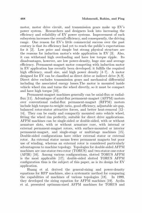
474 Mahmoudi, Rahim, and Ping
e(t) is phase air-gap EMF, i(t) is phase current, η is machine efficiency,m is the number of machine phases, and T is the period of one EMFcycle; Epk and Ipk respectively are peaks of phase air-gap EMF and ofcurrent; kp is electrical power waveform factor, defined as:
Kp =1T
∫ T
0
e(t) · i(t)Epk · Ipk
dt =1T
∫ T
0fe(t) · fi(t)dt (14)
where fe(t) = e(t)/Epk and fi(t) = i(t)/Ipk are expressions fornormalized EMF and current waveforms. For effect of current, thecurrent waveform factor (ki) is defined as:
ki =Ipk
Irms=
1√1T
∫ T0
(i(t)Ipk
)2dt
(15)
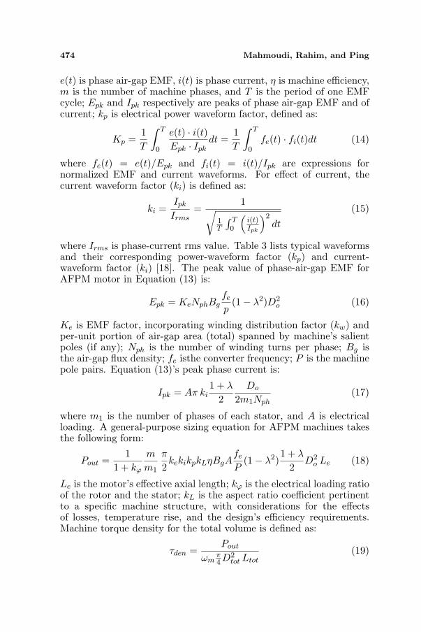
where Irms is phase-current rms value. Table 3 lists typical waveformsand their corresponding power-waveform factor (kp) and current-waveform factor (ki) [18]. The peak value of phase-air-gap EMF forAFPM motor in Equation (13) is:
Epk = KeNphBgfe
p(1− λ2)D2
o (16)
Ke is EMF factor, incorporating winding distribution factor (kw) andper-unit portion of air-gap area (total) spanned by machine’s salientpoles (if any); Nph is the number of winding turns per phase; Bg isthe air-gap flux density; fe isthe converter frequency; P is the machinepole pairs. Equation (13)’s peak phase current is:
Ipk = Aπ ki1 + λ
2Do
2m1Nph(17)
where m1 is the number of phases of each stator, and A is electricalloading. A general-purpose sizing equation for AFPM machines takesthe following form:
Pout =1
1 + kϕ
m
m1
π
2kekikpkLηBgA
fe
P(1− λ2)
1 + λ
2D2
o Le (18)
Le is the motor’s effective axial length; kϕ is the electrical loading ratioof the rotor and the stator; kL is the aspect ratio coefficient pertinentto a specific machine structure, with considerations for the effectsof losses, temperature rise, and the design’s efficiency requirements.Machine torque density for the total volume is defined as:
τden =Pout
ωmπ4 D2
tot Ltot(19)
Progress In Electromagnetics Research, Vol. 122, 2012 475
Table 3. Typical prototype waveforms.
Model t) i (t) ki kp
Sinusoidal 2 0.5Cos
Sinusoidal
2 0.5
Rectangular 1 1
Trapezoidal
1.134 0.777
Triangular
3 0.333
e (
ϕ
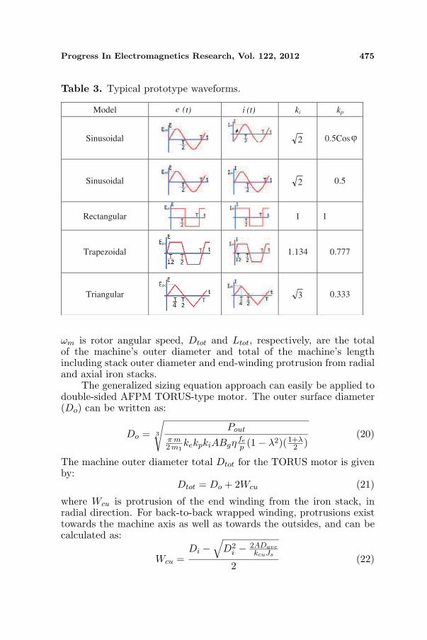
ωm is rotor angular speed, Dtot and Ltot, respectively, are the totalof the machine’s outer diameter and total of the machine’s lengthincluding stack outer diameter and end-winding protrusion from radialand axial iron stacks.
The generalized sizing equation approach can easily be applied todouble-sided AFPM TORUS-type motor. The outer surface diameter(Do) can be written as:
Do = 3
√Pout
π m2 m1
kekpkiABgηfe
p (1− λ2)(1+λ2 )
(20)
The machine outer diameter total Dtot for the TORUS motor is givenby:
Dtot = Do + 2Wcu (21)
where Wcu is protrusion of the end winding from the iron stack, inradial direction. For back-to-back wrapped winding, protrusions existtowards the machine axis as well as towards the outsides, and can becalculated as:
Wcu =Di −
√D2
i − 2ADavekcuJs
2(22)

476 Mahmoudi, Rahim, and Ping
where Dave is the average diameter of the machine, Js is the slot currentdensity, and kcu is the copper fill factor. Axial length Le of the machineis given by:
Le = Ls + 2Lr + 2g (23)
Lr is the rotor’s axial length, and g is the air-gap length. Axial lengthof the stator Ls can be written as:
Ls = Lcs + 2Lss (24)
Note that for slotted machines, depth of the stator slot is Lss = Wcu.Axial length of stator core Lcs can be written as:
Lcs =BgπαpDo(1 + λ)
4pBcs(25)
where Bcs is the flux density in the stator core, and αp is the ratio ofthe average air-gap flux density to the peak air-gap flux density. Axiallength of the rotor, Lr, becomes:
Lr = Lcr + Lpm (26)
Lpm is the permanent-magnet length; axial length of the rotor core,Lcr, is:
Lcr =BuπDo(1 + λ)
8pBcr(27)
where Bcr is flux density in the rotor disc core, and Bu is the fluxdensity attainable on the permanent-magnet surface. Permanent-magnet length Lpm can be calculated as:
Lpm =µrBg
Br −(
kf
kdBg
)kCg (28)
where µr is the magnet’s recoil relative permeability, Br is thepermanent-magnetmaterial-residual-flux density, kd is the leakage fluxfactor, kC is Carter factor, kf = Bgpk/Bg is the peak value correctedfactor of the air-gap flux density in radial direction of the AFPM motor.These factors can be obtained from FEM analysis [20].
4. SIMULATION RESULTS AND DISCUSSION
3D-FEA analyzed the magnetic circuit and power density of thedouble-sided slotted TORUS AFPM motor, for an overall picture ofthe saturation levels in various parts of the motor, and to extractthe motor’s characteristics. An advantage of 3D-FEA is that variouscomponents of flux density can be calculated highly accurately [23, 24].Note that FEM (Finite Element Method) facilitates field analysis of

Progress In Electromagnetics Research, Vol. 122, 2012 477
electromagnetic problems with complex geometries [25–28]. The designwas simulated on commercial Vector Field Opera 14.0 3D software [29].Corresponding materials and circuit currents were assigned to eachblock of the model.The simulation model reached the output (10 kW)targeted for EV. The motor’s 3D model is symmetric, so 6 magneticpoles were sliced to reduce simulation/calculation time, and the modelbecame one magnetic pole piece.For simulation, input parameters tobe considered were permanent-magnet thickness, air-gap width, andmagnetic properties of all the active materials. Table 4 lists the motor’sdesign dimensions and specifications.
Table 4. The motor’s final design dimensions and specifications.
Rated Voltage (Line-Line RMS ) Vnom 130VRated Power Pnom 10 kW
Number of pole pairs P 3Number of phases m 3Drive Frequency f 50
Efficiency η 91.5%Outer Diameter Do 240mmInner Diameter Di 139mm
Inner to Outer Diameter’s Ratio λ 0.58Magnet’s axial length Lpm 12mm
Pole Pitch γp 117
Permanent magnet Skew θi 7
Stator-yoke thickness 2× Lcs 41mmRotor-yoke thickness Lcr 9 mmSlot Bottom Width Wsb 6
Slot Top Width Ws 3Slot Depth Ds 11mm
Slot Top Depth 1 d1 3Slot Top Depth 2 d2 3Number of slots Ns 18
Number of winding turns per phase Nph (18× 10)/3Air-Gap Flux Density Bg 0.71T
Air-gap length g 2 mm

478 Mahmoudi, Rahim, and Ping
(a) (b)
Figure 4. Field analysis of an AFPM machine, in vector field opera14.0 software. (a) 3D auto-mesh generation. (b) Flux-density plot.
Figure 4 shows only one twelfth of the motor modeling thestructure of the FEA-designed AFPM: 60 degrees of the entire motorstructure and 1 pole, fulfilling symmetry conditions. The wholemachine comprises 18 slots and 3 pole-pairs. Fig. 4(a) (generatedon Vector Field Opera 14.0 software) is a 3D auto-mesh: tetrahedralelements with 6 nodes fitting circular shape of the layers startingfrom inner to outer diameter of the AFPM machine [29]. Fig. 4(b)is the distribution of the magnetic flux density in various sectors ofthe AFPM machine. Appendix A presents the optimized windingconfiguration for various numbers of slots of the brushless DC AFPMmotor.The best winding configuration (for 18 slots) was used here,giving as sinusoidal waveform as possible (see Fig. A1(d)). Magneticflux density evaluation in the various sectors of an AFPM machine isimportant because if the flux density of the core or the teeth goes tosaturation, machine efficiency reduces, affecting operation. Fig. 5 isthe air-gap flux density distribution, in average radius. The maximumflux density is obviously 0.95 Tesla, averaging 0.71 Tesla.
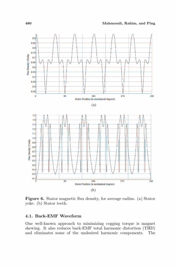
Figure 6 shows the magnetic flux density in stator yoke andteeth at average radius. The maximum magnetic flux was 0.95 Tesla,averaging 0.67 Tesla. The flux density in the stator teeth reaches 1.5Tesla, which, based on material limits, is the maximum allowable value.Fig. 7 is the magnetic flux density distribution in average radius forrotor yoke and magnet surface. Figs. 5, 6, and 7 give the flux densitydistribution, all in average radius, in Tesla. The presentation enablescomparison of the simulation results from FEA with those obtainedfrom the sizing equation. Table 5 lists the average magnetic flux densitycompared between FEA simulation results and sizing equation analysis,

Progress In Electromagnetics Research, Vol. 122, 2012 479
Figure 5. Magnetic flux density distribution of air-gap, for averageradius.
Table 5. Magnetic flux density compared among various parts of themotor, at no-load condition.
Air-gap Stator yoke Rotor yoke Magnet surface
Bg Bcs Bcr Bm
Ave. Max. Ave. Max. Ave. Max. Ave. Max.
FEA 0.71 0.95 0.67 0.95 0.82 1.15 0.97 1.10
Sizing Eq. 0.70 0.95 0.64 0.95 0.80 1.10 0.96 1.10
at no-load condition, for various parts of the motor design. Theflux density obtained from FEA was a little less than that calculatedtheoretically via the sizing equation, owing to core magnetic reluctancehaving been neglected. In real conditions, however, flux density of thedifferent core parts decreases via MMF drop.
The slotted-TORUS configuration used in this paper is north-north magnet arrangement. The phase winding is wound around thestator core, giving a short end-winding. It reduces copper losses, butthe main flux has to flow circumferentially along the stator core. Figs. 8and 9 respectively show the magnetic flux path in the stator teeth andthe magnetic potential vectors for the rotor magnets, modeled in VectorField Opera-3D 14.
480 Mahmoudi, Rahim, and Ping
(a)
(b)
Figure 6. Stator magnetic flux density, for average radius. (a) Statoryoke. (b) Stator teeth.
4.1. Back-EMF Waveform
One well-known approach to minimizing cogging torque is magnetskewing. It also reduces back-EMF total harmonic distortion (THD)and eliminates some of the undesired harmonic components. The

Progress In Electromagnetics Research, Vol. 122, 2012 481
(a)
(b)
Figure 7. Magnetic flux density distribution for average radius, on(a) rotor yoke; (b) magnet surface.
maximum magnet skewing angle relative to the stator teeth shouldbe equal to the slot pitch, not exceed it. Fig. 10(a) shows magnet’sgeometric skewing relative to stator teeth. Fig. 10(b) shows the back-EMF THD variation versus magnet skewing angle θi. The aim isto design an AFPM machine that hasa sinusoidal waveform(the back

482 Mahmoudi, Rahim, and Ping
Figure 8. Flux path in stator yoke and teeth of slotted-TORUSAFPM motor.
Figure 9. Magnetic potential vectors for rotor and permanentmagnets.
EMF should be as sinusoidal as possible). The minimum THD occurswhen the magnet skewing angle is 7 degrees. Fig. 11 shows the backEMF at 1000 rpm rated speed, also the FEA-calculated THD andback-EMF RMS.The Fourier transform of the back-EMF waveformis obtained as indicated in Fig. 12. THD significantly decreased from26.7% to 3.1% after a 7-degree optimized magnet-skewing.
4.2. Torque
In torque performance assessment, both torque density and torqueripple must be considered. Asdo RFPM machines, AFPM machines,

Progress In Electromagnetics Research, Vol. 122, 2012 483
2
3
4
5
6
7
8
9
10
0 5 10 15 20 25 30Bac
k-E
MF
To
tal
Har
mo
nic
Dis
tort
ion
(T
HD
in
per
cen
t)
Magnet Skew Angle i (in degrees)
(b)
θ
(a)
Figure 10. Permanent magnet skewing. (a) A diagram of magnet’sgeometric skewing relative to stator teeth. (b) THD variation versuspermanent magnet skewing angle θi.
too, produce undesirable performance-affecting torque ripples. Mainsources of torque ripple are: cogging torque, non-ideal back EMFwaveforms, and saturation of machine’s magnetic circuit. In designinga motor, undesired harmonics that make back EMF non-ideal arereduced by creating a back-EMF waveform that is as sinusoidal aspossible. Saturation of the proposed machine’s magnetic circuitin various motor parts was controlled by FEA simulation of itselectromagnetic field. Cogging torque is also an issue in machinedesign. It results from permanent magnet‘s tendency to align itselfat the position of minimum magnetic reluctance path between rotorand stator. Permeance variation in the slot opening leading tangentialforces in the rotor, owing to flux entering the teeth, creates an

484 Mahmoudi, Rahim, and Ping
0
0
-80
-60
-40
-20
0
20
40
60
80
100
120
0 30 60 90 120 150 180 210 240 270 300 330 360
Bac
k E
MF
(V
olt
)
Electrical Angle (in degrees)
THD = 3.1%
RMS Back EMF = 74V
Phase A
Phase B
Phase C
-10
Figure 11. Back EMF at speed 1000 rpm.
0%
10%
20%
30%
40%
50%
60%
70%
80%
90%
100%
1 3 5 7 9 11 13 15 17 19 21 23 25
Bac
k-E
MF
Harmonic Order
Initial Design befor Skew THD=26.7%
Opimized Designafte r 7 degrees Skew THD=3.1%
-
-
Figure 12. Comparison of harmonic components for initial andoptimized design.
oscillatory output called cogging torque,which introduces noise andvibration, both of which degrade the response of high-performancemotion control particularly at low speed and light loads.
An effective, most simple and common technique to reduce coggingtorque is skewing. It is done by either stator slots or rotor permanentmagnet skewing. Since stator slot skewing is relatively difficult to

Progress In Electromagnetics Research, Vol. 122, 2012 485
-4
-3
-2
-1
0
1
2
3
4
0 10 20 30 40 5
Co
gg
ing
To
rqu
e (N
.m)
Rotor Position (in mechanical degrees)
without skew
7 degrees skew
60 0
Figure 13. Cogging torque versus mechanical angle.
achieve in AFPM machines, the magnets instead are skewed. Fig. 13shows the cogging torque of the AFPM machine, with, and without,permanent magnet skewing. Pre-skewing peak cogging torque was3.3Nm. Skewed magnets reduce cogging torque; at 7-degree skewing,peak cogging torque reduced to 2.1 Nm (a 36% reduction).
4.3. Efficiency
For accurate assessment of machine efficiency and thermal behav-ior,calculation of the losses is crucial. Machine efficiency is:
η =Pout
Pout + Pcu + Pcor + Prot(29)
where Pcu, Pcor, Prot are respectively copper losses, core losses, androtational losses. Copper loss (Rs × I2) makes up most of theloss total. Stator resistance (Rs) depends on load and on windingtemperature [30].
Rs =2Nph-s (l + le)σT Nph-p scu
(30)
Nph-s is the number of winding turns in series per phase, Nph-p isthe number of winding turns in parallel per phase, σT is electricconductivity of wire at temperature T , and scu is cross-sectional areaof wire. Thin parallel wires minimized skin effect, eliminating itsconsideration in Equation (30). l and le respectively are coil lengthand end-winding length.

486 Mahmoudi, Rahim, and Ping
(a) (b)
Figure 14. Spiral and axial lamination of an axial-flux motor’s stator.(a) Spiral lamination. (b) Axial lamination.
Hysteresis loss (Ph) and eddy current loss (Pe) make up the motorcore loss and can be calculated from:
Ph =kh ·Bn
m · f2
ρ(31)
Pe =ke ·B2
m · f2
ρ(32)
kh, ke, Bmax, and ρ respectively are hysteresis constant, eddy currentconstant, maximum flux density, and core material density. FE-ACanalysis was repeated for every space harmonic component (up to the49th order) and for every current waveform’s simulated time harmoniccomponent, to get the eddy current losses in the stator steel. The statorof an axial-flux motor is laminated either spirally or axially (see Fig. 14for their configurations). Each made from silicon steel, the thicknessof the laminating silicon steel paper is 0.1 mm. In this work, spirallamination was used in the simulations. The core loss for the statorlaminated 0.1 mm thick, calculated via FE-AC analysis, was 63 W.
Figure 15 shows the motor’s efficiency in various speeds.Rotational loss (which includes windage and friction losses) wasestimated from the following Equation [31]:
Prot =12cfρr
(π n3
) (D5
o −D5i
)(33)
where cf is friction coefficient, ρr is density of the rotating part, and nis rotation speed (in ‘rotation per second’). Efficiency of the laminated-stator motor, obtained with full loading at full load, was 91.5 %.

Progress In Electromagnetics Research, Vol. 122, 2012 487
0%
10%
20%
30%
40%
50%
60%
70%
80%
90%
100%
0 100 200 300 400 500 600 700 800 900 1000
Eff
icie
ncy
Speed (rpm)
Figure 15. Efficiency versus speed.
5. CONCLUSION
The design and simulation of a slotted TORUS AFPM motor forEV application has been presented. The motor produced 10 kWpower and the maximum amplitude of the sinusoidal back EMFwas 105 V at 1000 rpm rated speed. Its design met specificationsand requirements of EV direct drive. The requirements had beendetermined through a simple model of vehicle dynamics that considereda cruising scenario. Limits to material and application were consideredas well. The motor’s performance was increased by optimizingthe design parameters (air-gap length, permanent-magnet size andmaterial, magnet orientation, and winding configuration) via sizingequation and Finite Element Analysis. The simulated and desiredvalues agreed. Comparison of FEA and sizing equation shows thedesign’s flux density at no-load condition and in various parts of themotor agreeing. The design process is comprehensive and can be usedfor an arbitrary EV considering an arbitrary cruising scenario.
APPENDIX A. WINDING CONFIGURATIONS
A method described in [32] was used to place the coils. There areinfinite possibilities for pole and slot-count combinations as there arefor winding layouts; assumptions are necessary, either for focus or forscope limitation, so desirable windings can be found. The assumptionswere:
a) Three-phase motor.

488 Mahmoudi, Rahim, and Ping
b) All slots filled; the number of slots is thus a multiple of the numberof phases (i.e., Ns = k×Nph); for three-phase motors, the numberof slots is thus always a multiple of three.
c) Two coil-sides in each slot, the winding can be classified as double-layer winding.
d) Balanced-windings only, i.e., only pole and slot-count combina-tions that result in back EMF of phases B and C being 120Eoffset from back EMF of phase A.
e) Coils have equal number of turns, all spanning equal number ofslots, implying same-sized coils and therefore same resistance andsame inductance.
The assumptions routinely lead to motors capable of high performance,and to motors that are readily wound. Motors can be wound violatingone or more of the assumptions, but they may be more difficult towind; such winding could also lower performance. Fig. A1 shows thecoil arrangements (9, 12, 15, 18, 21, and 24 slots) that gave the bestsinusoidal waveforms. A, B, and C represent the phases, and + and −represent direction of the windings.
The number of winding configuration options can also be increasedby short-pitching the fractional-slot structures. The 15-slot stator was
Table A1. Possible winding configurations and number of slots ineach pole, per phase.
Configuration
Number
Number
of Slots
Coil Pitch/Pole
Pitch
Number of slots
in each pole per phase
(Nspp)
1 9 2/2.25 0.75
2 12 2/3 1
3 12 full-pitch 1
4 15 2/3.75 1.25
5 15 3/3.75 1.25
6 18 3/4.5 1.5
7 18 4/4.5 1.5
8 21 3/5.25 1.75
9 21 4/5.25 1.75
10 21 5/5.25 1.75
11 24 4/6 2
12 24 5/6 2
13 24 full-pitch 2

Progress In Electromagnetics Research, Vol. 122, 2012 489
1 2 3 4 5 6 7 8 9
+A -B -A +B -C -B +C -A -C
+A +C -A +B +A -B +C +B -C
Slot
No.
up
down
1 2 3 4 5 6 7 8 9 10 11 12
+A -B +C -A +B -C +A -B +C -A +B -C
+A -B +C -A +B -C +A -B +C -A +B -C
Slot
No.
up
down
1 2 3 4 5 6 7 8 9 10 11 12Slot
No. 13 14 15
+A -B +C -A +B +B -C +A +A -B +C -Aup +B -C -C
-B -B +C +C -A -C -C +A -B +C -A -Adown +B +B +A
1 2 3 4 5 6 7 8 9
+A -B -B +C -A +B +B -C +A
+A -B +C +C -A -A +B -C -C
10 11 12 13 14 15 16 17 18
+A -B +C +C -A -A +B -C -C
+A -B +C +C -A +B +B -C +A
Slot
No.
up
down
1 2 3 4 5 6 7 8 9
+A -B -B +C -A +B +B -C +A
+A -B +C +C -A -A +B -C -C
10 11 12 13 14 15 16 17 18
+A -B +C +C -A -A +B -C -C
+A -B +C +C -A +B +B -C +A
Slot
No.
up
down
1 2 3 4 5 6 7 8 9
+A -B -B +C +C -A -A +B -C
+A -B -B +C +C -A +B +B -C
10 11 12 13 14 15 16 17 18
-C +A +A -B -B +C -A -A +B
-C +A +A -B +C +C -A -A +B
Slot
No.
up
down
19 20 21
+B -C -C
+B -C +A
1 2 3 4 5 6 7 8 9
+A +A -B -B +C +C -A -A +B
+A +A -B -B +C +C -A -A +B
10 11 12 13 14 15 16 17 18
+B -C -C +A +A -B -B +C +C
+B -C -C +A +A -B -B +C +C
Slot
No.
up
down
19 20 21 22 23 24
-A -A +B +B -C -C
-A -A +B +B -C -C
(a)
(b)
(c)
(d)
(e)
(f)
Figure A1. Stator winding constructions for 9, 12, 15, 18, 21, and 24slots. (a) 9-slot double-layer stator winding (coil span = 2). (b) 12-slotdouble-layer stator winding (full-pitch). (c) 15-slot double-layer statorwinding (coil span = 2). (d) 18-slot double-layer stator winding (coilspan = 4). (e) 21-slot double-layer stator winding (coil span = 5).(f) 24-slot double-layer stator winding (full-pitch).
designed with a 3-slot coil span, but a 2-slot coil span is possible,reconfiguration for it easy. For an 18-slot structure, 3-slot coil span,and for 21-slot structure, both 3-slot and 4-slot coil spans can beconsidered. For the 13 stator configurations in Table A1 and theirpossible magnet spans, their losses, back-EMF harmonic content, andpulsating torque components were investigated.Efficiencies were foundto not differ much except at lower speeds, where the differences weremore pronounced (owing to copper losses). The worst structure interms of copper losses was found to be 24-slot, full-pitched.

490 Mahmoudi, Rahim, and Ping
APPENDIX B. NOMENCLATURE
A electrical loading total [A]Alin linear current density of the machine’s inner radius [A/m]B magnetic flux density [T]Bcr rotor-disc flux density [T]Bcs stator-core flux density [T]Bg air-gap flux density [Wb/m2]Bgpk peak value of air-gap flux density [Wb/m2]Bm permanent magnet flux density [T]Bmax maximum flux density [T]Br permanent-magnet residual-flux density [T]Bu flux density on permanent-magnet surface [T]Cd air-resistance coefficientDave machine stator average diameter [m]Di machine stator inner diameter [m]Do machine stator outer diameter [m]Ds slot depth [m]Dtot machine outer diameter total [m]Epk peak value of phase-air-gap EMF [V]Frm vehicle driving resistance force[N]Irms phase current rms value [A]Ipk phase current peak value [A]J external current density [A/m2]Js slot current density [A/m2]H magnetic field intensity [A/m]Ke EMF factorKn×n stiffness matrixLcr rotor-core axial length [m]Lcs stator-core axial length [m]Le effective axial length of motor [m]Lpm permanent-magnet length [m]Lr rotor axial length [m]

Progress In Electromagnetics Research, Vol. 122, 2012 491
Ls stator axial length [m]Lss stator slot depth [m]Ltot machine axial length total [m]M vehicle mass [kg]Nph number of winding turns per phase
Nph−snumber of winding turns
in series per phase
Nph−pnumber of winding turns
in parallel per phaseNs number of slots [m]P number of motor pole pairsPaccel power required to accelerate [W]Pcor core losses [W]Pcu Copper losses [W]Prot rotational losses [W]Pnom nominal power [kW]Pmin minimum required power [W]Pout rated power [W]Rs stator resistance [Ω]S frontal projected area [m2]Sg air-gap area [m2]Spm permanent magnet area [m2]T period of one EMF cycle [Sec]Vnom nominal voltage (line to line RMS) [V]Wcu end-winding protrusion from iron stack [m]Ws Slot opening widthWsb Slot bottom width [m]a vehicle acceleration [m/s2]ag gravity acceleration [m/s2]cf friction coefficientd1 slot top depth 1 [m]d2 slot top depth 2 [m]e(t) phase-air-gap EMF [V]i(t) phase current [A]

492 Mahmoudi, Rahim, and Ping
fe electrical frequency [Hz]fe(t) normalized EMF waveformsfi(t) normalized current waveformsfl aerodynamic-resistance force [N]fr rolling-resistance coefficientfro rolling-resistance force [N]fst climbing-resistance force [N]g air-gap length [m]gn×1 excitation vectorkC Carter coefficientkL aspect ratio coefficientkcu copper fill factorkd leakage-flux factorke eddy current constantkh hysteresis constantki current waveform factorkp electrical power waveform factorkf peak value corrected factor of air-gap flux densitykw winding distribution factorkσPM a factor that takes into account the leakage fluxkϕ electrical loading ratiol coil length [m]le end winding length [m]m number of phasesm1 number of phases of each statorn rotation speed [rs−1]r position vector [m]scu cross-section area of wiret average slot pitch [m]v vehicle speed [m/s]v0 headwind speed [m/s]Φ winding flux linkage [Wb]Ψ magnetic vector potential [V · s ·m−1]α vehicle movement angle [Rad]

Progress In Electromagnetics Research, Vol. 122, 2012 493
αp average air-gap flux density to its peak value ratioγ air-gap fictions coefficientγp pole pitch [in degrees]η motor efficiencyθi Permanent magnet skew [in degrees]λ diameter ratioµ permeability [A ·m2]µ0 Permeability of free space [A ·m2]µr Relative permeabilityµra relative permeability of the permanent magnetρ core material density [kg/m3]ρa air density [kg/m3]ρr density of the rotating part of the motor [kg/m3]σ electrical conductivity [Ω ·m]σT electric conductivity of wire [Sm−1]τden torque density [N · m/cm3]τmin minimum required torque [N · m]ωm angular speed [Rad/s]
ACKNOWLEDGMENT
The authors acknowledge University of Malaya’s provision of the HighImpact Research Grant No. D000022-16001 funding the Hybrid SolarEnergy Research Suitable for Rural Electrification.
REFERENCES
1. Rahim, N. A., W. P. Hew, and A. Mahmoudi, “Axial-fluxpermanent-magnet brushless dc traction motor for direct drive ofelectric vehicle,” International Review of Electrical Engineering,Vol. 6, No. 2, 760–769, April 2011.
2. Johansen, P. R., D. Patterson, C. O’Keefe, and J. Swenson, “Theuse of an axial flux permanent magnet in-wheel direct drive inan electric vehicle,” Renewable Energy, Vol. 22, No. 1–3, 151–157,January–March 2001.
3. Kim, M. J., B. K. Kim, J. W. Moon, Y. H. Cho, D. H. Hwang,and D. S. Kang, “A method for diagnosis of induction machinefed by PWM vector control,” International Journal of Applied

494 Mahmoudi, Rahim, and Ping
Electromagnetics and Mechanics, Vol. 28, No. 1, 2, 275–281,September 2008.
4. Nguyen, P. H., E. Hoang, and M. Gabsi, “Performance synthesisof permanent-magnet synchronous machines during the drivingcycle of a hybrid electric vehicle,” IEEE Transaction on VehicularTechnology, Vol. 60, No. 5, 1991–1998, June 2011.
5. Dai, Y., L. Song, and S. Cui, “Development of PMSM drives ofhybrid electric car applications,” IEEE Transaction on Magnetics,Vol. 43, No. 1, 434–437, January 2007.
6. Baoquan, K., L. Chunyan, and C. Shukang, “Flux-weakening-characteristic analysis of a new permanent-magnet synchronousmotor used for electric vehicles,” IEEE Transaction on PlasmaScience, Vol. 39, No. 1, 511–515, January 2011.
7. Choi, J. H., Y. D. Chun, P. W. Han, M. J. Kim, D. H. Koo, J. Lee,and J. S. Chun, “Design of high power permanent magnet motorwith segment rectangular copper wire and closed slot opening onelectric vehicles,” IEEE Transaction on Magnetics, Vol. 46, No. 6,2070–2073, June 2010.
8. Yang, Y. P., Y. P. Lah, and C. H. Cheung, “Design and controlof axial-flux brushless DC wheel motors for electric vehicles-partI: Multiobjective optimal design and analysis,” IEEE Transactionon Magnetics, Vol. 40, No. 4, 1873–1882, July 2004.
9. Yang, Y. P., Y. P. Lah, and C. H. Cheung, “Design and controlof axial-flux brushless DC wheel motors for electric vehicles-part II: Optimal current waveforms and performance test,” IEEETransaction on Magnetics, Vol. 40, No. 4, 1883–1891, July 2004.
10. Rahman, K. M., N. R. Patel, T. G. Ward, J. M. Nagashima,F. Caricchi, and F. Crescimbini, “Application of direct-drive wheelmotor for fuel cell electric and hybrid electric vehicle propulsionsystem,” IEEE Transaction on Industry Applications, Vol. 42,No. 5, 1185–1192, September–October 2006.
11. Cavagnino, A., M. Lazzari, F. Profumo, and A. Tenconi,“A comparison between the axial flux and the radial fluxstructures for PM synchronous motors,” IEEE Transaction onIndustrial Applications, Vol. 38, No. 6, 1517–1524, November–December 2002.
12. Mahmoudi, A., N. A. Rahim, and W. P. Hew, “Axial-fluxpermanent-magnet machine modeling, design, simulation, andanalysis,” Scientific Research and Essay, Vol. 6, No. 12, 2525–2549, June 2011.
13. Mahmoudi, A., N. A. Rahim, and W. P. Hew, “Analyticalmethod for determining axial-flux permanent-magnet machine

Progress In Electromagnetics Research, Vol. 122, 2012 495
sensitivity to design variables,” International Review of ElectricalEngineering, Vol. 5, No. 5, 2039–2048, September–October 2010.
14. Mahmoudi, A., N. A. Rahim, and W. P. Hew, “An analyticalcomplementary FEA tool for optimizing of axial-flux permanent-magnet machines,” International Journal of Applied Electromag-netics Machines, Vol. 37, No. 1, 19–34, September 2011.
15. Gieras, J. F., R. J. Wang, and M. J. Kamper, Axial FluxPermanent Magnet Brushless Machines, Springer Verla, 2008.
16. Mahmoudi, A., N. A. Rahim, and W. P. Hew, “TORUS andAFIR axial-flux permanent-magnet machines: A comparison viafinite element analysis,” International Review on Modelling andSimulations, Vol. 4, No. 2, 624–631, April 2011.
17. Gholamian, S. A., “Optimum design and manufacturing of axialflux permanent magnet motor for electric vehicle application,”Ph.D. Dissertation, K. N. Toosi Univ. Technology, Tehran, Iran,January 2008.
18. Huang, S., J. Luo, F. Leonardi, and T. A. Lipo, “A generalapproach to sizing and power density equations for comparison ofelectrical machines,” IEEE Transaction on Industry Applications,Vol. 34, No. 1, 92–97, January–February 1998.
19. Huang, S., J. Luo, F. Leonardi, and T. A. Lipo, “A comparison ofpower density for axial flux machines based on the general purposesizing equation,” IEEE Transaction on Energy Conversion,Vol. 14, No. 2, 185–192, January 1999.
20. Aydin, M., S. Huang, and T. A. Lipo, “Design and 3Delectromagnetic field analysis of non-slotted and slotted TORUStype axial flux surface mounted permanent magnet discmachines,” IEEE International Electric Machines and DrivesConference, January 17th–20th, 2001.
21. Aydin, M., S. Huang, and T. A. Lipo, “Optimum design and 3Dfinite element analysis of nonslotted and slotted internal rotor typeaxial flux pm disc machines,” IEEE Power Engineering SocietySummer Meeting, July 15th–19th, 2001.
22. Mahmoudi, A., N. A. Rahim, and H. W. Ping, “Genetic algorithmand finite element analysis for optimum design of slotted Torusaxial-flux permanent-magnet brushless DC motor,” Progress InElectromagnetics Research B, Vol. 33, 383–407, 2011.
23. Liu, C. T. and S. C. Lee, “Magnetic field modeling andoptimal operational control of a single-side axial-flux permanentmagnet motor with center poles,” Journal of Magnetism andMagnetic Materials, Vol. 304, No. 1, 454–456, September 2006.

496 Mahmoudi, Rahim, and Ping
24. Liu, C. T., S. C. Lin, and T. S. Chiang, “On the analytical fluxdistribution modeling of an axial-flux surface-mounted permanentmagnet motor for control applications,” Journal of Magnetism andMagnetic Materials, Vol. 282, 346–350, November 2004.
25. Vaseghi, B., N. Takorabet, and F. Meibody-Tabar, “Transientfinite element analysis of induction machines with stator windingturn fault,” Progress In Electromagnetics Research, Vol. 95, 1–18,2009.
26. Torkaman, H. and E. Afjei, “FEM analysis of angularmisalignment fault in SRM magnetostatic characteristics,”Progress In Electromagnetics Research, Vol. 104, 31–48, 2010.
27. Torkaman, H. and E. Afjei, “Comparison of two types of duallayer generator in field assisted mode utilizing 3D-FEM andexperimental verification,” Progress In Electromagnetics ResearchB, Vol. 23, 293–309, 2010.
28. Torkaman, H. and E. Afjei, “Magnetio static field analysisregarding the effects of dynamic eccentricity in switched reluctancemotor,” Progress In Electromagnetics Research M, Vol. 8, 163–180,2009.
29. Opera Version 14.0 User Guide, Vector Fields, 2011, http://www.cobham.com.
30. Wang, R. J., M. J. Kamper, and K. V. D. Westhuizen,“Optimal design of a coreless stator axial flux permanent magnetgenerator,” IEEE Transaction on Magnetics, Vol. 41, No. 1, 55–64, January 2005.
31. Saari, J., “Thermal analysis of high-speed induction machines,”Ph.D. Dissertation, Helsinki Univ. Technology, Helsinki, Finland,January 1998.
32. Hanselman, D. C., Brushless Permanent Magnet Motor Design,McGraw-Hill, New York, 1994.