Embed Size (px)
Citation preview

Avaya - Proprietary. Use pursuant to the terms of your signed agreement or Avaya policy.
AvayaTM Communication Manager MessagingInstallation and Initial Configuration
August 2008
Avaya - Proprietary. Use pursuant to the terms of your signed agreement or Avaya policy.
© 2008 Avaya Inc. All Rights Reserved.
NoticeWhile reasonable efforts were made to ensure that the information in this document was complete and accurate at the time of printing, Avaya Inc. can assume no liability for any errors. Changes and corrections to the information in this document might be incorporated in future releases.
Documentation disclaimerAvaya Inc. is not responsible for any modifications, additions, or deletions to the original published version of this documentation unless such modifications, additions, or deletions were performed by Avaya. Customer and/or End User agree to indemnify and hold harmless Avaya, Avaya's agents, servants and employees against all claims, lawsuits, demands and judgments arising out of, or in connection with, subsequent modifications, additions or deletions to this documentation to the extent made by the Customer or End User.
Link disclaimerAvaya Inc. is not responsible for the contents or reliability of any linked Web sites referenced elsewhere within this documentation, and Avaya does not necessarily endorse the products, services, or information described or offered within them. We cannot guarantee that these links will work all the time and we have no control over the availability of the linked pages.
WarrantyAvaya Inc. provides a limited warranty on this product. Refer to your sales agreement to establish the terms of the limited warranty. In addition, Avaya’s standard warranty language, as well as information regarding support for this product, while under warranty, is available through the Avaya Support Web site:http://www.avaya.com/support
LicenseUSE OR INSTALLATION OF THE PRODUCT INDICATES THE END USER'S ACCEPTANCE OF THE TERMS SET FORTH HEREIN AND THE GENERAL LICENSE TERMS AVAILABLE ON THE AVAYA WEB SITE http://support.avaya.com/LicenseInfo/ ("GENERAL LICENSE TERMS"). IF YOU DO NOT WISH TO BE BOUND BY THESE TERMS, YOU MUST RETURN THE PRODUCT(S) TO THE POINT OF PURCHASE WITHIN TEN (10) DAYS OF DELIVERY FOR A REFUND OR CREDIT.Avaya grants End User a license within the scope of the license types described below. The applicable number of licenses and units of capacity for which the license is granted will be one (1), unless a different number of licenses or units of capacity is specified in the Documentation or other materials available to End User. "Designated Processor" means a single stand-alone computing device. "Server" means a Designated Processor that hosts a software application to be accessed by multiple users. "Software" means the computer programs in object code, originally licensed by Avaya and ultimately utilized by End User, whether as stand-alone Products or pre-installed on Hardware. "Hardware" means the standard hardware Products, originally sold by Avaya and ultimately utilized by End User.
License type(s)Designated System(s) License (DS). End User may install and use each copy of the Software on only one Designated Processor, unless a different number of Designated Processors is indicated in the Documentation or other materials available to End User. Avaya may require the Designated Processor(s) to be identified by type, serial number, feature key, location or other specific designation, or to be provided by End User to Avaya through electronic means established by Avaya specifically for this purpose.Concurrent User License (CU). End User may install and use the Software on multiple Designated Processors or one or more Servers, so long as only the licensed number of Units are accessing and using the Software at any given time. A "Unit" means the unit on which Avaya, at its sole discretion, bases the pricing of its licenses and can be, without limitation, an agent, port or user, an e-mail or voice mail account in the name of a person or corporate function (e.g., webmaster or helpdesk), or a directory entry in the administrative database utilized by the Product that permits one user to interface with the Software. Units may be linked to a specific, identified Server.Named User License (NU). Customer may: (i) install and use the Software on a single Designated Processor or Server per authorized Named User (defined below); or (ii) install and use the Software on a Server so long as only authorized Named Users access and use the Software. "Named User," means a user or device that has been expressly authorized by Avaya to access and use the Software. At Avaya's sole discretion, a "Named User" may be, without limitation, designated by name, corporate function (e.g., webmaster or helpdesk), an e-mail or voice mail account in the name of a person or corporate function, or a directory entry in the administrative database utilized by the Product that permits one user to interface with the Product. Shrinkwrap License (SR). With respect to Software that contains elements provided by third party suppliers, End User may install and use the Software in accordance with the terms and conditions of the applicable license agreements, such as "shrinkwrap" or "clickwrap" license accompanying or applicable to the Software ("Shrinkwrap License"). The text of the Shrinkwrap
License will be available from Avaya upon End User’s request (see “Third-party Components" for more information).
Copyright Except where expressly stated otherwise, the Product is protected by copyright and other laws respecting proprietary rights. Unauthorized reproduction, transfer, and or use can be a criminal, as well as a civil, offense under the applicable law.
Third-party componentsCertain software programs or portions thereof included in the Product may contain software distributed under third party agreements ("Third Party Components"), which may contain terms that expand or limit rights to use certain portions of the Product ("Third Party Terms"). Information identifying Third Party Components and the Third Party Terms that apply to them is available on the Avaya Support Web site:http://support.avaya.com/ThirdPartyLicense/
Preventing toll fraud"Toll fraud" is the unauthorized use of your telecommunications system by an unauthorized party (for example, a person who is not a corporate employee, agent, subcontractor, or is not working on your company's behalf). Be aware that there can be a risk of toll fraud associated with your system and that, if toll fraud occurs, it can result in substantial additional charges for your telecommunications services.
Avaya fraud interventionIf you suspect that you are being victimized by toll fraud and you need technical assistance or support, call Technical Service Center Toll Fraud Intervention Hotline at +1-800-643-2353 for the United States and Canada. For additional support telephone numbers, see the Avaya Support Web site:http://www.avaya.com/support
TrademarksAvaya and the Avaya logo are either registered trademarks or trademarks of Avaya Inc. in the United States of America and/or other jurisdictions.All other trademarks are the property of their respective owners.
Downloading documentsFor the most current versions of documentation, see the Avaya Support Web site:http://www.avaya.com/support
Avaya supportAvaya provides a telephone number for you to use to report problems or to ask questions about your product. The support telephone number is 1-800-242-2121 in the United States. For additional support telephone numbers, see the Avaya Support Web site:http://www.avaya.com/support

CMM Installation and Initial Configuration August 2008 3
Avaya - Proprietary. Use pursuant to the terms of your signed agreement or Avaya policy.
Introduction to Avaya Communication Manager Messaging (stand alone) . . . . . . . . . 7Communication Manager Messaging (stand alone) overview . . . . . . . . . . . . . . 7CMM Topology Example. . . . . . . . . . . . . . . . . . . . . . . . . . . . . . . . . . . 8Required hardware . . . . . . . . . . . . . . . . . . . . . . . . . . . . . . . . . . . . . 8Required software . . . . . . . . . . . . . . . . . . . . . . . . . . . . . . . . . . . . . . 9Required installation documentation. . . . . . . . . . . . . . . . . . . . . . . . . . . . 9
Administering the Communication Manager server . . . . . . . . . . . . . . . . . . . . . 11Installing the Communication Manager server . . . . . . . . . . . . . . . . . . . . . . 11Connecting to the Communication Manager server SAT interface. . . . . . . . . . . . 12Checking H.323 customer options for the Communication Manager server . . . . . . 12Setting feature access codes for messaging . . . . . . . . . . . . . . . . . . . . . . . 17Setting feature parameters for messaging. . . . . . . . . . . . . . . . . . . . . . . . . 19Administering IP Interfaces . . . . . . . . . . . . . . . . . . . . . . . . . . . . . . . . . 25System parameters coverage . . . . . . . . . . . . . . . . . . . . . . . . . . . . . . . . 30Creating a signaling group for messaging. . . . . . . . . . . . . . . . . . . . . . . . . 31Creating a trunk group for messaging . . . . . . . . . . . . . . . . . . . . . . . . . . . 37Configuring the new signaling group for messaging . . . . . . . . . . . . . . . . . . . 41AAR and ARS digit conversion . . . . . . . . . . . . . . . . . . . . . . . . . . . . . . . 43
Path replacement settings . . . . . . . . . . . . . . . . . . . . . . . . . . . . . . . 43Converting ARS digits. . . . . . . . . . . . . . . . . . . . . . . . . . . . . . . . . . 44Converting AAR digits. . . . . . . . . . . . . . . . . . . . . . . . . . . . . . . . . . 45
Creating a route pattern for the new trunk group . . . . . . . . . . . . . . . . . . . . . 46Creating a hunt group for messaging . . . . . . . . . . . . . . . . . . . . . . . . . . . 50Adding a coverage path for messaging . . . . . . . . . . . . . . . . . . . . . . . . . . 52Creating stations and assigning coverage paths . . . . . . . . . . . . . . . . . . . . . 53Saving translations . . . . . . . . . . . . . . . . . . . . . . . . . . . . . . . . . . . . . 54Verifying product IDs . . . . . . . . . . . . . . . . . . . . . . . . . . . . . . . . . . . . 55Restarting the system . . . . . . . . . . . . . . . . . . . . . . . . . . . . . . . . . . . . 55
Installing and configuring the Communication Manager Messaging (stand alone) server . 57Important rules about installing the CMM server . . . . . . . . . . . . . . . . . . . . . 57Obtaining the appropriate documentation . . . . . . . . . . . . . . . . . . . . . . . . . 57Verifying site readiness . . . . . . . . . . . . . . . . . . . . . . . . . . . . . . . . . . . 58Checking for and FTP/SCP/SFTP server or compact flash for backing up data. . . . . 58Obtaining required service pack files . . . . . . . . . . . . . . . . . . . . . . . . . . . 59Obtaining remote field updates and language files for CMM . . . . . . . . . . . . . . . 60
Contents

Contents
4 CMM Installation and Initial Configuration August 2008
Avaya - Proprietary. Use pursuant to the terms of your signed agreement or Avaya policy.
Obtaining Optional language files . . . . . . . . . . . . . . . . . . . . . . . . . . . 61Obtaining Ethernet interface IP address and subnet mask . . . . . . . . . . . . . . 61Laptop preparation, software, and system information. . . . . . . . . . . . . . . . 61Obtaining the authentication file . . . . . . . . . . . . . . . . . . . . . . . . . . . . 62Obtaining login IDs and passwords . . . . . . . . . . . . . . . . . . . . . . . . . . 62Running the Automatic Registration Tool (ART) for the INADS IP address, if necessary . . . . . . . . . . . . . . . . . . . . . . . . 62
S8510 . . . . . . . . . . . . . . . . . . . . . . . . . . . . . . . . . . . . . . . . . . . . . 63Equipment specifications . . . . . . . . . . . . . . . . . . . . . . . . . . . . . . . . . . 65 . . . . . . . . . . . . . . . . . . . . . . . . . . . . . . . . . . . . . . . . . . . . . . . . S8500 hardware . . . . . . . . . . . . . . . . . . . . . . . . . . . . . . . . . . . . . . . . . . 67
Equipment specifications . . . . . . . . . . . . . . . . . . . . . . . . . . . . . . . . . . 69About the Server Availability Management Processor . . . . . . . . . . . . . . . . . . 72
About SAMP connections . . . . . . . . . . . . . . . . . . . . . . . . . . . . . . . . 72About SAMP software . . . . . . . . . . . . . . . . . . . . . . . . . . . . . . . . . . 73
S8500 server port connections . . . . . . . . . . . . . . . . . . . . . . . . . . . . . . . 74About modem connections . . . . . . . . . . . . . . . . . . . . . . . . . . . . . . . . 75Configuring SNMP module in the UPS . . . . . . . . . . . . . . . . . . . . . . . . . . . 76Clearing the ARP cache on the laptop . . . . . . . . . . . . . . . . . . . . . . . . . . . 76Applying power to the media server . . . . . . . . . . . . . . . . . . . . . . . . . . . . 76Accessing the media server . . . . . . . . . . . . . . . . . . . . . . . . . . . . . . . . 77Configuring Telnet (for initial software installation only) . . . . . . . . . . . . . . . . . 77Installing CMM software . . . . . . . . . . . . . . . . . . . . . . . . . . . . . . . . . . . 77Opening the Maintenance Web Interface. . . . . . . . . . . . . . . . . . . . . . . . . . 79Copying files to the media server . . . . . . . . . . . . . . . . . . . . . . . . . . . . . 80Installing security files and Communication Manager service packs, if any . . . . . . 80Installing the CMM Remote Field Update. . . . . . . . . . . . . . . . . . . . . . . . . . 82Downloading optional language files, if needed. . . . . . . . . . . . . . . . . . . . . . 86Verifying the Time, Date, and Time Zone. . . . . . . . . . . . . . . . . . . . . . . . . . 86Configuring the S8500/S8510 . . . . . . . . . . . . . . . . . . . . . . . . . . . . . . . . 87Creating a super-user login, if necessary, for R4.0 or higher . . . . . . . . . . . . . . 102Installing the authentication file . . . . . . . . . . . . . . . . . . . . . . . . . . . . . . 105Stop Messaging . . . . . . . . . . . . . . . . . . . . . . . . . . . . . . . . . . . . . . . 106Administering the Switch Link . . . . . . . . . . . . . . . . . . . . . . . . . . . . . . . 107Starting Messaging . . . . . . . . . . . . . . . . . . . . . . . . . . . . . . . . . . . . . 109Setting CMM server parameters . . . . . . . . . . . . . . . . . . . . . . . . . . . . . . 110Setting system-wide messaging parameters . . . . . . . . . . . . . . . . . . . . . . . 112

Contents
CMM Installation and Initial Configuration August 2008 5
Avaya - Proprietary. Use pursuant to the terms of your signed agreement or Avaya policy.
Adding test subscribers for messaging . . . . . . . . . . . . . . . . . . . . . . . . . . 114Verifying the messaging application . . . . . . . . . . . . . . . . . . . . . . . . . . . . 115
Calling the hunt group to access messaging . . . . . . . . . . . . . . . . . . . . . 116Calling an extension to verify messaging coverage . . . . . . . . . . . . . . . . . 116
Index . . . . . . . . . . . . . . . . . . . . . . . . . . . . . . . . . . . . . . . . . . . 117

Contents
6 CMM Installation and Initial Configuration August 2008
Avaya - Proprietary. Use pursuant to the terms of your signed agreement or Avaya policy.

CMM Installation and Initial Configuration August 2008 7
Avaya - Proprietary. Use pursuant to the terms of your signed agreement or Avaya policy.
Introduction to Avaya Communication Manager Messaging (stand alone)
This document describes how to install and administer Avaya Communication Manager Messaging (stand alone) (CMM).
Note:Note: This guide is applicable for Communication Manager Messaging for Federal
Market Customers as well as General Customers.
Communication Manager Messaging (stand alone) overview
Communication Manager Messaging (stand alone) is a voice messaging system that is based on the Intuity AUDIX family of messaging applications. Communication Manager Messaging (stand alone) is a cost-effective solution that offers up to 80 messaging voice ports and supports up to 5,000 mailboxes.
Note:Note: An additional number of ports, up to 40, equaling 50% of the administered
messaging ports need to be allocated for call transfer and other system signaling.These ports cannot be used for messaging access.
Communication Manager Messaging (stand alone), or CMM, runs on an S8500C/S8510 Server. CMM is an external adjunct messaging application that provides voice mailboxes to one or more Communication Manager systems running on separate S8400, S8500, or S87xx Servers. The CMM server integrates with the Communication Manager server using H.323 IP trunks for voice connections and an H.248 trunk for data connections.
Communication Manager software is automatically installed with CMM software so that CMM can use many of Communication Manager’s platform administration and maintenance capabilities. However, the call processing capabilities of Communication Manager, as well as the connections for physical telephones and trunks, are available only on the separately installed Communication Manager server.

Introduction to Avaya Communication Manager Messaging (stand alone)
8 CMM Installation and Initial Configuration August 2008
Avaya - Proprietary. Use pursuant to the terms of your signed agreement or Avaya policy.
CMM Topology Example
Note:Note: Communication Manager Messaging (CMM) server is a stand alone external
server. First, install and programme the Communication Manager to integrate with CMM. Then, load and provision the CMM server.
Required hardwareCMM requires all of the hardware for a normal S8500C/S8510 installation.
1. See Quick Start for Hardware Installation: Avaya S8500 Media Server, 555-245-701.
2. See Installing the Avaya S8510 Server Family and Its Components, 03-602918

Required software
CMM Installation and Initial Configuration August 2008 9
Avaya - Proprietary. Use pursuant to the terms of your signed agreement or Avaya policy.
Required softwareFor Federal Market customers, CMM requires CM Release 4.0.2 software.
For General Customers, CMM requires CM Release 4.0.3 or 5.1 or higher software.
The CD-ROM that contains the CM Release 4.0.2 or 4.0.3 or 5.1 or higher software can be used for both CMM and Communication Manager server installations.
Required installation documentationCMM requires the following documentation in addition to this document:
● Installing and Configuring the Avaya s8700-Series Media Server Release 4.0, 03-300145
● Installing and Configuring the Avaya S8500 Media Server Release 4.0, 03-300143
● Installing the Avaya S8510 Server Family and Its Components, 03-602918

Introduction to Avaya Communication Manager Messaging (stand alone)
10 CMM Installation and Initial Configuration August 2008
Avaya - Proprietary. Use pursuant to the terms of your signed agreement or Avaya policy.

CMM Installation and Initial Configuration August 2008 11
Avaya - Proprietary. Use pursuant to the terms of your signed agreement or Avaya policy.
Administering the Communication Manager server
You should install and configure the Avaya Communication Manager server before you set up the Communication Manager Messaging (stand alone) server.
Installing the Communication Manager serverYou must install the Communication Manager server hardware and software before administering the Communication Manager server to support Communication Manager Messaging (stand alone), or CMM. See the appropriate documents from the following list:
! Important:Important: When loading the software on the Communication Manager server, if you receive
either of the following prompts, you must answer No:
● Run AUDIX Installation?
● Run SAM Installation?
In addition, if the Communication Manager server is an S8400 Server, do not enter an IP address for Integrated Messaging when running the Configure Server screens.
S8400 Server● Installing and Configuring the Avaya S8400 Media Server, 03-300678
● Quick Start for Hardware Installation: Avaya S8400 Media Server in an Avaya G650 Media Gateway, 03-300705
● Quick Start for Hardware Installation: Avaya S8400 Media Server in an Avaya CMC or G600 Media Gateway, 03-300706
S8500 Server● Installing and Configuring the Avaya S8500 Media Server, 03-300143
● Quick Start for Hardware Installation: Avaya S8500 Media Server, 555-245-701
S8510 Server● Installing the Avaya S8510 Server Family and Its Components, 03-602918
Administering the Communication Manager server
12 CMM Installation and Initial Configuration August 2008
Avaya - Proprietary. Use pursuant to the terms of your signed agreement or Avaya policy.
S8700-series Server● Installing and Configuring the Avaya S8700 Series Media Server, 03-300145
● Quick Start for Hardware Installation: Avaya S8700 Media Server, 555-245-703
Other necessary installation information● Installing and Connecting the MDF and Telephones, 03-300686
● Adding New Hardware for Avaya Media Servers and Gateways, 03-300684
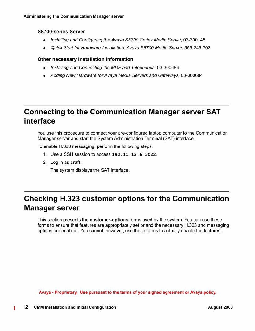
Connecting to the Communication Manager server SAT interface
You use this procedure to connect your pre-configured laptop computer to the Communication Manager server and start the System Administration Terminal (SAT) interface.
To enable H.323 messaging, perform the following steps:
1. Use a SSH session to access 192.11.13.6 5022.
2. Log in as craft.The system displays the SAT interface.
Checking H.323 customer options for the Communication Manager server
This section presents the customer-options forms used by the system. You can use these forms to ensure that features are appropriately set or and the necessary H.323 and messaging options are enabled. You cannot, however, use these forms to actually enable the features.

Checking H.323 customer options for the Communication Manager server
CMM Installation and Initial Configuration August 2008 13
Avaya - Proprietary. Use pursuant to the terms of your signed agreement or Avaya policy.
To view the customer-options form on the Communication Manager server, perform the following steps:
! Important:Important: If these options are not set as indicated, you must contact your project manager
to have a new license file, with the proper features, regenerated for this installation. You will not be able to successfully perform the installation without the proper customer options. If you do not have the correct options, contact your project manager or Avaya support representative.
1. At the SAT interface prompt, and enter:
display system-parameters customer-options
The system displays page 1 of the OPTIONAL FEATURES form.
display system-parameters customer-options Page 2 of 10 OPTIONAL FEATURES
IP PORT CAPACITIES USED Maximum Administered H.323 Trunks: 500 324 Maximum Concurrently Registered IP Stations: 12000 1 Maximum Administered Remote Office Trunks: 0 0 Maximum Concurrently Registered Remote Office Stations: 0 0 Maximum Concurrently Registered IP eCons: 0 0 Max Concur Registered Unauthenticated H.323 Stations: 0 0 Maximum Video Capable H.323 Stations: 0 0 Maximum Video Capable IP Softphones: 0 0 Maximum Administered SIP Trunks: 100 0
Maximum Number of DS1 Boards with Echo Cancellation: 0 0 Maximum TN2501 VAL Boards: 10 0 Maximum Media Gateway VAL Sources: 0 0 Maximum TN2602 Boards with 80 VoIP Channels: 128 0 Maximum TN2602 Boards with 320 VoIP Channels: 128 0 Maximum Number of Expanded Meet-me Conference Ports: 0 0
(NOTE: You must logoff & login to effect the permission changes.)
2. Go to page 2, and locate the Maximum Administered H.323 Trunks field.
3. Check the quantity in the first column of the Maximum Administered H.323 Trunks field is set to a number that can accommodate the following:
● The busy hour number of H.323 connections required by the Communication Manager port networks, including port network-to-port network voice connections, port network to media gateway voice connections, and CM Server-to-CM Server voice connections.
● The number of voice ports and transfer ports (normally 50% of voice ports) for Communication Manager Messaging (stand alone).

display system-parameters customer-options Page 3 of 10 OPTIONAL FEATURES
Abbreviated Dialing Enhanced List? n Audible Message Waiting? n Access Security Gateway (ASG)? n Authorization Codes? n Analog Trunk Incoming Call ID? n CAS Branch? n A/D Grp/Sys List Dialing Start at 01? n CAS Main? nAnswer Supervision by Call Classifier? n Change COR by FAC? n ARS? y Computer Telephony Adjunct Links? n ARS/AAR Partitioning? y Cvg Of Calls Redirected Off-net? n ARS/AAR Dialing without FAC? n DCS (Basic)? n ASAI Link Core Capabilities? n DCS Call Coverage? n ASAI Link Plus Capabilities? n DCS with Rerouting? n Async. Transfer Mode (ATM) PNC? n Async. Transfer Mode (ATM) Trunking? n Digital Loss Plan Modification? n ATM WAN Spare Processor? n DS1 MSP? n ATMS? n DS1 Echo Cancellation? n Attendant Vectoring? n
(NOTE: You must logoff & login to effect the permission changes.)
Field Setting
ARS? y
ARS/AAR Partitioning? y
Administering the Communication Manager server
14 CMM Installation and Initial Configuration August 2008
Avaya - Proprietary. Use pursuant to the terms of your signed agreement or Avaya policy.
4. Go to page 3.
5. Verify that the following fields are set as shown:

display system-parameters customer-options Page 4 of 10 OPTIONAL FEATURES
Emergency Access to Attendant? y IP Stations? y Enable 'dadmin' Login? y Enhanced Conferencing? y ISDN Feature Plus? y Enhanced EC500? n ISDN Network Call Redirection? y Enterprise Survivable Server? n ISDN-BRI Trunks? y Enterprise Wide Licensing? n ISDN-PRI? y ESS Administration? n Local Survivable Processor? n Extended Cvg/Fwd Admin? n Malicious Call Trace? n External Device Alarm Admin? n Media Encryption Over IP? n Five Port Networks Max Per MCC? n Mode Code for Centralized Voice Mail? n Flexible Billing? n Forced Entry of Account Codes? n Multifrequency Signaling? y Global Call Classification? n Multimedia Call Handling (Basic)? y Hospitality (Basic)? y Multimedia Call Handling (Enhanced)? y Hospitality (G3V3 Enhancements)? n IP Trunks? y
IP Attendant Consoles? n (NOTE: You must logoff & login to effect the permission changes.)
Field Setting
IP Trunks? y
ISDN-PRI? y
Checking H.323 customer options for the Communication Manager server
CMM Installation and Initial Configuration August 2008 15
Avaya - Proprietary. Use pursuant to the terms of your signed agreement or Avaya policy.
6. Go to page 4.
7. Verify that the following fields are set as shown:

display system-parameters customer-options Page 5 of 10 OPTIONAL FEATURES
Multinational Locations? n Station and Trunk MSP? n Multiple Level Precedence & Preemption? n Station as Virtual Extension? n Multiple Locations? n System Management Data Transfer? n Personal Station Access (PSA)? n Tenant Partitioning? n Posted Messages? n Terminal Trans. Init. (TTI)? n PNC Duplication? n Time of Day Routing? n Port Network Support? y Uniform Dialing Plan? y Usage Allocation Enhancements? y Processor and System MSP? n TN2501 VAL Maximum Capacity? y Private Networking? y Processor Ethernet? y Wideband Switching? n Wireless? n Remote Office? n Restrict Call Forward Off Net? y Secondary Data Module? y
(NOTE: You must logoff & login to effect the permission changes.)
Field Setting
Private Networking? y
Processor Ethernet? y
Uniform Dialing Plan? y
Administering the Communication Manager server
16 CMM Installation and Initial Configuration August 2008
Avaya - Proprietary. Use pursuant to the terms of your signed agreement or Avaya policy.
8. Go to page 5.
9. Verify that the following fields are set as shown:
Note:Note: Processor Ethernet is not available if the Communication Manager server is an
S87xx Server.

display system-parameters customer-options Page 8 of 10 QSIG OPTIONAL FEATURES
Basic Call Setup? y Basic Supplementary Services? y Centralized Attendant? y Interworking with DCS? n Supplementary Services with Rerouting? y Transfer into QSIG Voice Mail? y Value-Added (VALU)? y
(NOTE: You must logoff & login to effect the permission changes.)
Field Setting
Basic Call Setup? y
Basic Supplementary Services? y
Supplementary Services with Rerouting? y
Transfer into QSIG Voice Mail? y
Value-Added (VALU)? y
Setting feature access codes for messaging
CMM Installation and Initial Configuration August 2008 17
Avaya - Proprietary. Use pursuant to the terms of your signed agreement or Avaya policy.
10. Go to page 8.
11. Verify that the following fields are set as shown:
12. Exit this form by clicking Cancel.
Setting feature access codes for messagingFor messaging to function, you must create two feature access codes (FACs) and set two features to use these FACs on the System Parameters Features form. You must also create one dial access code (DAC) for later use by the trunk group. The DAC is used to create the Trunk Access Code (TAC) in Creating a trunk group for messaging on page 37.

Administering the Communication Manager server
18 CMM Installation and Initial Configuration August 2008
Avaya - Proprietary. Use pursuant to the terms of your signed agreement or Avaya policy.
To create the two FACs for messaging, perform the following steps:
1. Go to the SAT interface prompt, and enter:
change dialplan analysis
The system displays the DIAL PLAN ANALYSIS TABLE form.
change dialplan analysis Page 1 of 12 DIAL PLAN ANALYSIS TABLE Percent Full: 1
Dialed Total Call Dialed Total Call Dialed Total Call String Length Type String Length Type String Length Type 1 3 dac 2 5 ext 3 5 ext 4 5 ext 5 5 ext 8 1 fac 9 1 fac * 3 fac # 3 fac
2. Create two FACs. The FACs that you use for messaging can be one or more digits.
For example, in the following screen, Dialed Strings 8 and 9 are specified as FACs, and Dialed String 1 is specified as a DAC.
Note:Note: The first FAC Dialed String value will be used for the Auto Alternate Routing
(AAR) setting. The second FAC Dialed String value will be used for the Auto Route Selection (ARS) setting.
3. Exit this form and save these values by clicking Submit.

Setting feature parameters for messaging
CMM Installation and Initial Configuration August 2008 19
Avaya - Proprietary. Use pursuant to the terms of your signed agreement or Avaya policy.
4. Go to the SAT interface prompt, and enter:
change feature-access-codes
The system displays the FEATURE ACCESS CODE (FAC) form.
change feature-access-codes Page 1 of 6 FEATURE ACCESS CODE (FAC) Abbreviated Dialing List1 Access Code: Abbreviated Dialing List2 Access Code: Abbreviated Dialing List3 Access Code: Abbreviated Dial - Prgm Group List Access Code: Announcement Access Code: Answer Back Access Code: Attendant Access Code: Auto Alternate Routing (AAR) Access Code: 8 Auto Route Selection (ARS) - Access Code 1: 9 Access Code 2: Automatic Callback Activation: Deactivation: Call Forwarding Activation Busy/DA: All: Deactivation: Call Forwarding Enhanced Status: Act: Deactivation: Call Park Access Code: Call Pickup Access Code: CAS Remote Hold/Answer Hold-Unhold Access Code: CDR Account Code Access Code: Change COR Access Code: Change Coverage Access Code: Contact Closure Open Code: Close Code:
5. Verify that the Auto Alternate Routing (AAR) Access Code field is set to the first FAC Dialed String value you entered for step 2.
If you use the example in step 2, the Feature Access Code (FAC) for Auto Alternate routing (AAR) Access Code would be set to 3.
6. Verify that the Auto Route Selection (ARS) - Access Code 1 field is set to the second FAC Dialed String value you entered for step 2.
If you use the example in step 2, the Feature Access Code (FAC) for Auto Route Selection (ARS) - Access Code 1 would be set to 9.
7. Exit this form and save these values by clicking Submit.
Setting feature parameters for messagingThis procedure provides the steps for setting the feature-related parameters needed for messaging.

Administering the Communication Manager server
20 CMM Installation and Initial Configuration August 2008
Avaya - Proprietary. Use pursuant to the terms of your signed agreement or Avaya policy.
To set the internal parameters for messaging, perform the following steps:
1. Go to the SAT interface prompt, and enter:
change system-parameters features
The system displays the FEATURE-RELATED SYSTEM PARAMETERS form.
change system-parameters features Page 1 of 17 FEATURE-RELATED SYSTEM PARAMETERS Self Station Display Enabled? n Trunk-to-Trunk Transfer: all Automatic Callback - No Answer Timeout Interval (rings): 3 Call Park Timeout Interval (minutes): 10 Off-Premises Tone Detect Timeout Interval (seconds): 20 AAR/ARS Dial Tone Required? y Music/Tone on Hold: none Music (or Silence) on Transferred Trunk Calls? no DID/Tie/ISDN/SIP Intercept Treatment: attd Internal Auto-Answer of Attd-Extended/Transferred Calls: transferred Automatic Circuit Assurance (ACA) Enabled? n
Abbreviated Dial Programming by Assigned Lists? n Auto Abbreviated/Delayed Transition Interval (rings): 2 Protocol for Caller ID Analog Terminals: Bellcore Display Calling Number for Room to Room Caller ID Calls? n
Field Setting
Trunk-to-Trunk Transfer all
2. Verify that the following fields are set as shown on page 1:
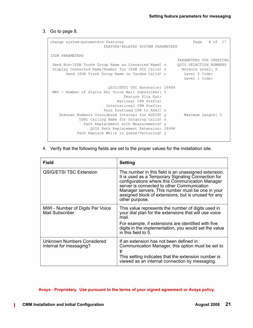
change system-parameters features Page 8 of 17 FEATURE-RELATED SYSTEM PARAMETERS
ISDN PARAMETERS PARAMETERS FOR CREATING Send Non-ISDN Trunk Group Name as Connected Name? n QSIG SELECTION NUMBERS Display Connected Name/Number for ISDN DCS Calls? n Network Level: 0 Send ISDN Trunk Group Name on Tandem Calls? n Level 2 Code: Level 1 Code:
QSIG/ETSI TSC Extension: 29999 MWI - Number of Digits Per Voice Mail Subscriber: 5 Feature Plus Ext: National CPN Prefix: International CPN Prefix: Pass Prefixed CPN to ASAI? n Unknown Numbers Considered Internal for AUDIX? y Maximum Length: 5 USNI Calling Name for Outgoing Calls? n Path Replacement with Measurements? y QSIG Path Replacement Extension: 29998 Path Replace While in Queue/Vectoring? y
Setting feature parameters for messaging
CMM Installation and Initial Configuration August 2008 21
Avaya - Proprietary. Use pursuant to the terms of your signed agreement or Avaya policy.
3. Go to page 8.
4. Verify that the following fields are set to the proper values for the installation site.
Field Setting
QSIG/ETSI TSC Extension The number in this field is an unassigned extension. It is used as a Temporary Signaling Connection for configurations where this Communication Manager server is connected to other Communication Manager servers. This number must be one in your assigned block of extensions, but is unused for any other purpose.
MWI - Number of Digits Per Voice Mail Subscriber
This value represents the number of digits used in your dial plan for the extensions that will use voice mail. For example, if extensions are identified with five digits in the implementation, you would set the value in this field to 5.
Unknown Numbers Considered Internal for messaging?
If an extension has not been defined in Communication Manager, this option must be set to y. This setting indicates that the extension number is viewed as an internal connection by messaging.

Administering the Communication Manager server
22 CMM Installation and Initial Configuration August 2008
Avaya - Proprietary. Use pursuant to the terms of your signed agreement or Avaya policy.
5. Exit this form and save these values by clicking Submit.
Maximum Length When the Unknown Numbers Considered Internal for messaging? field is set to y, the Maximum Length field is displayed to the right. This value represents the number of digits that define a number external to the contact center. Any dialed number exceeding this value is considered an external telephone number. For example, if you are using four digit extensions in your dial plan, enter 4 in this field. This field cannot be left blank.
QSIG Path Replacement Extension This number must be within your assigned block of extensions, and not used for any other purpose. This number is usually the extension before or after the QSIG/ETSI TSC extension.
Path Replace While in Queue/Vectoring?
If you use an attendant console that has queueing or vectoring, this option must be set to y.If this option is not set to y, the operator will not see where the incoming call came from, or not hear the caller for approximately 10 seconds. With vector processing the call might go to dead air.
Field Setting

Setting feature parameters for messaging
CMM Installation and Initial Configuration August 2008 23
Avaya - Proprietary. Use pursuant to the terms of your signed agreement or Avaya policy.
6. Go to the SAT interface prompt, and enter:
change dialplan parameters
The system displays the Dialplan Parameters form.
change dialplan parameters Page 1 of 1 DIAL PLAN PARAMETERS
Local Node Number: 1 ETA Node Number: ETA Routing Pattern: UDP Extension Search Order: udp-table-first
EXTENSION DISPLAY FORMATS Inter-Location/SAT Intra-Location 6-Digit Extension: xx.xx.xx xx.xx.xx 7-Digit Extension: xxx-xxxx xxx-xxxx 8-Digit Extension: xx.xx.xx.xx xx.xx.xx.xx 9-Digit Extension: xxx-xxx-xxx xxx-xxx-xxx 10-Digit Extension: xxx-xxx-xxxx xxx-xxx-xxxx 11-Digit Extension: xxxx-xxx-xxxx xxxx-xxx-xxxx 12-Digit Extension: xxxxxx-xxxxxx xxxxxx-xxxxxx 13-Digit Extension: xxxxxxxxxxxxx xxxxxxxxxxxxx
Field Setting
Local Node Number The number for this communication server.Usually this number is 1, but it can be a number from 1 to 99, depending on your contact center configuration.
7. Verify that the following fields are set to the proper values for the installation site
8. Exit this form and save this value by clicking Submit.

Administering the Communication Manager server
24 CMM Installation and Initial Configuration August 2008
Avaya - Proprietary. Use pursuant to the terms of your signed agreement or Avaya policy.
9. Go to the SAT interface prompt, and enter:
change node-names ip
The system displays the IP NODE NAMES form.
change node-names ip Page 1 of 2 IP NODE NAMES Name IP Addresscl1-vision 135.9.84.248 default 0.0.0.0 mp1-vision 135.9.84.249 procr 135.9.84.239 msgserver 135.9.50.142
( 8 of 8 administered node-names were displayed )Use 'list node-names' command to see all the administered node-namesUse 'change node-names ip xxx' to change a node-name 'xxx' or add a node-name
10. Enter the name of the CMM server in the next available Name field.
11. Enter the IP Address for Integrated Messaging on the CMM server. This address is the same IP address you enter in the Integrated Messaging field when configuring the CMM server. See Configure Interfaces Screen on page 91.
! Important:Important: The IP address in the previous step is not the IP address of the CMM server itself.
Note:Note: The CMM name must be consistent between the IP node names and the
signaling group assigned for messaging.
12. Check the list of interfaces for existing procr or clan interfaces. If no procr or clan interfaces exist, continue with the following procedure, Administering IP Interfaces.
Note:Note: When both the Processor Ethernet and CLAN interfaces are available on a
system, you may base the decision on which interface to use for messaging communications on factors such as:
● Whether or not an Enterprise Survivable Server (ESS) is being used for reliabilitiy. An ESS can support messaging in the event of a Communication Manager server failure only if messaging uses the CLAN interface.
Administering IP Interfaces
CMM Installation and Initial Configuration August 2008 25
Avaya - Proprietary. Use pursuant to the terms of your signed agreement or Avaya policy.
● Load balancing. If media gateways, IP telephones, or other devices have the CLAN as the primary interface to Communication Manager, then the Processor Ethernet interface may be preferable to the CLAN interface.
13. Exit the form and save these values by clicking Submit.
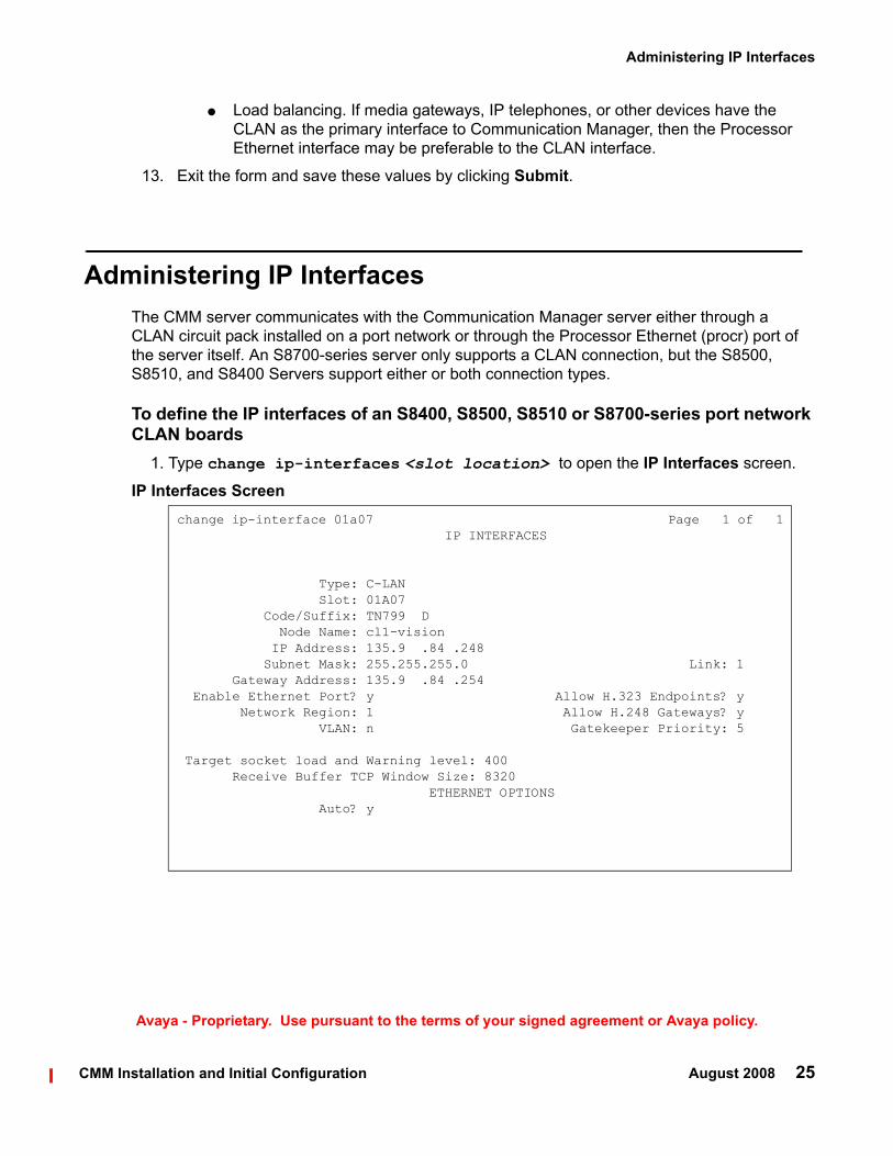
Administering IP InterfacesThe CMM server communicates with the Communication Manager server either through a CLAN circuit pack installed on a port network or through the Processor Ethernet (procr) port of the server itself. An S8700-series server only supports a CLAN connection, but the S8500, S8510, and S8400 Servers support either or both connection types.
To define the IP interfaces of an S8400, S8500, S8510 or S8700-series port network CLAN boards
1. Type change ip-interfaces <slot location> to open the IP Interfaces screen.
IP Interfaces Screenchange ip-interface 01a07 Page 1 of 1 IP INTERFACES
Type: C-LAN Slot: 01A07 Code/Suffix: TN799 D Node Name: cl1-vision IP Address: 135.9 .84 .248 Subnet Mask: 255.255.255.0 Link: 1 Gateway Address: 135.9 .84 .254 Enable Ethernet Port? y Allow H.323 Endpoints? y Network Region: 1 Allow H.248 Gateways? y VLAN: n Gatekeeper Priority: 5
Target socket load and Warning level: 400 Receive Buffer TCP Window Size: 8320 ETHERNET OPTIONS Auto? y

Administering the Communication Manager server
26 CMM Installation and Initial Configuration August 2008
Avaya - Proprietary. Use pursuant to the terms of your signed agreement or Avaya policy.
2. Complete the fields as described the in Table 1.
Table 1: IP interfaces field descriptions
Field Conditions/CommentsType Either C-LAN.
Slot The slot location for the circuit pack.
Code/Suffix Display only. This field is automatically populated with TN799 for C-LAN.
Node name The unique node name for the IP interface. The node name here must already be administered on the Node Names screen.
IP Address The IP address (on the customer LAN) of the C-LAN.
Subnet Mask The subnet mask associated with the IP address for this IP interface. For more information on IP addresses and subnetting, see “Administration for Network Connectivity for Avaya Communication Manager, 555-233-504”.
Gateway Address
The address of a network node that serves as the default gateway for the IP interface.
Enable Ethernet Port?
The Ethernet port must be enabled (y) before it can be used. The port must be disabled (n) before changes can be made to its attributes on this screen.
Network Region The region number for this IP interface.
VLAN The VLAN number assigned to the C-LAN, if any.
Target socket load
The threshold for the number of sockets used by this C-LAN within the same Gatekeeper Priority as that of other IP interfaces. If the targeted number is exceeded on a CLAN, a warning alarm is generated. If the targeted percentage is exceeded on an PE interface, a procr error is generated.
Receive Buffer TCP Window Size
The threshold for the number of sockets used by this C-LAN that triggers a warning message to be sent to the error log.
Link This display only field shows the unique number for the Ethernet link. The Ethernet link was assigned on the data module form.
Allow H.323 Endpoints
Enter a ’y’ to allow H.323 endpoint connectivity on this CLAN. Enter ’n’ if you do not want H.323 endpoints to connect to this CLAN.
1 of 2

Administering IP Interfaces
CMM Installation and Initial Configuration August 2008 27
Avaya - Proprietary. Use pursuant to the terms of your signed agreement or Avaya policy.
3. Close the screen.
To define the IP interface of the S8400, S8500, S8510 processor Ethernet port
Note:Note: This should have already been established as a part of normal S8400, S8500,
and S8510 Media Server installation.
1. Type change ip-interfaces procr to open the IP Interfaces screen.
Allow H.248 Gateways?
Enter ’y’ to allow H.248 gateway connectivity to this CLAN. Enter ’n’ if you do not want H.248 gateways to connect to this CLAN.
Gatekeeper Priority
This value is used on the alternate gatekeeper list. The lower the number the higher the priority. Valid values for this field are one through nine with five being the default. This field displays only if the allow H.323 endpoints field is set to a yes on this form.
Auto? Enter ’y’ or ’n’ to set auto-negotiation.
Speed Enter 10 or 100 Mbps if Auto was set to no.
Duplex Enter half or full if Auto was set to no.
Table 1: IP interfaces field descriptions (continued)
Field Conditions/Comments
2 of 2

Administering the Communication Manager server
28 CMM Installation and Initial Configuration August 2008
Avaya - Proprietary. Use pursuant to the terms of your signed agreement or Avaya policy.
IP Interfaces Screenchange ip-interface procr Page 1 of 1 IP INTERFACES
Type: PROCR
Node Name: procr IP Address: 135.9 .81 .6 Subnet Mask: 255.255.255.0
Enable Ethernet Port? y Allow H.323 Endpoints? y Network Region: 1 Allow H.248 Gateways? y Gatekeeper Priority: 5
Target socket load: 1700
2. Complete the fields as described the in Table 2.
Table 2: IP interfaces field descriptions
Field Conditions/CommentsType Display only. PROCR
Node name The unique node name for the IP interface. procr is the default node name. The node name here must already be administered on the Node Names screen.
IP Address The IP address (on the customer LAN) of the Processor Ethernet.
Subnet Mask The subnet mask associated with the IP address for this IP interface. For more information on IP addresses and subnetting, see “Administration for Network Connectivity for Avaya Communication Manager, 555-233-504”.
Enable Ethernet Port?
The Ethernet port must be enabled (y) before it can be used. The port must be disabled (n) before changes can be made to its attributes on this screen.
Network Region The region number for this IP interface.
1 of 2

Administering IP Interfaces
CMM Installation and Initial Configuration August 2008 29
Avaya - Proprietary. Use pursuant to the terms of your signed agreement or Avaya policy.
Target socket load
The threshold for the number of sockets used by this C-LAN within the same Gatekeeper Priority as that of other IP interfaces. If the targeted number is exceeded on a CLAN, a warning alarm is generated. If the targeted percentage is exceeded on an PE interface, a procr error is generated.
Allow H.323 Endpoints
Enter a ’y’ to allow H.323 endpoint connectivity on this CLAN. Enter ’n’ if you do not want H.323 endpoints to connect to this CLAN.
Allow H.248 Gateways?
Enter ’y’ to allow H.248 gateway connectivity to this CLAN. Enter ’n’ if you do not want H.248 gateways to connect to this CLAN.
Gatekeeper Priority
This value is used on the alternate gatekeeper list. The lower the number the higher the priority. Valid values for this field are one through nine with five being the default. This field displays only if the allow H.323 endpoints field is set to a yes on this form.
Table 2: IP interfaces field descriptions (continued)
Field Conditions/Comments
2 of 2
Administering the Communication Manager server
30 CMM Installation and Initial Configuration August 2008
Avaya - Proprietary. Use pursuant to the terms of your signed agreement or Avaya policy.
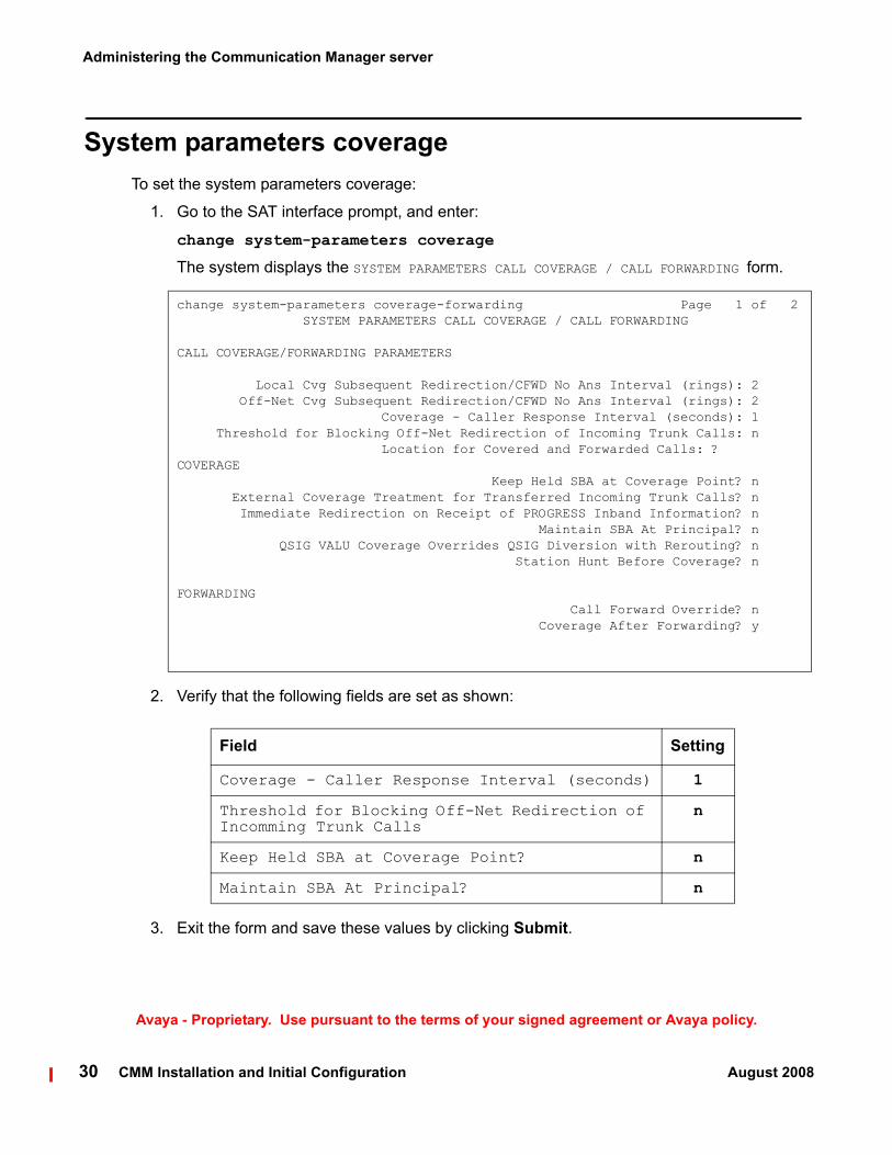
System parameters coverageTo set the system parameters coverage:
1. Go to the SAT interface prompt, and enter:
change system-parameters coverage
The system displays the SYSTEM PARAMETERS CALL COVERAGE / CALL FORWARDING form.
change system-parameters coverage-forwarding Page 1 of 2 SYSTEM PARAMETERS CALL COVERAGE / CALL FORWARDING
CALL COVERAGE/FORWARDING PARAMETERS
Local Cvg Subsequent Redirection/CFWD No Ans Interval (rings): 2 Off-Net Cvg Subsequent Redirection/CFWD No Ans Interval (rings): 2 Coverage - Caller Response Interval (seconds): 1 Threshold for Blocking Off-Net Redirection of Incoming Trunk Calls: n Location for Covered and Forwarded Calls: ? COVERAGE Keep Held SBA at Coverage Point? n External Coverage Treatment for Transferred Incoming Trunk Calls? n Immediate Redirection on Receipt of PROGRESS Inband Information? n Maintain SBA At Principal? n QSIG VALU Coverage Overrides QSIG Diversion with Rerouting? n Station Hunt Before Coverage? n
FORWARDING Call Forward Override? n Coverage After Forwarding? y
Field Setting
Coverage - Caller Response Interval (seconds) 1
Threshold for Blocking Off-Net Redirection of Incomming Trunk Calls
n
Keep Held SBA at Coverage Point? n
Maintain SBA At Principal? n
2. Verify that the following fields are set as shown:
3. Exit the form and save these values by clicking Submit.

Creating a signaling group for messaging
CMM Installation and Initial Configuration August 2008 31
Avaya - Proprietary. Use pursuant to the terms of your signed agreement or Avaya policy.
Creating a signaling group for messagingTo create a signaling group for messaging, perform the following steps:
1. Go to the SAT interface prompt, and enter:
add signaling-group <nnn>
where <nnn> represents the number of this new signaling group
Note:Note: The number of this signaling group must not be in use and should also be
available for the creation of a trunk group. For example, if you create this signaling group as 99, the corresponding trunk group should be created as 99. For this group, choose a number that is easily differentiated from other signaling and trunk groups.
The system displays the SIGNALING GROUP form.
add signaling-group 3 Page 1 of 1 SIGNALING GROUP
Group Number: 3 Group Type: h.323 Remote Office? n Max number of NCA TSC: 10 SBS? n Max number of CA TSC: 10 IP Video? n Trunk Group for NCA TSC: Trunk Group for Channel Selection: TSC Supplementary Service Protocol: b Network Call Transfer? y T303 Timer(sec): 10
Near-end Node Name: cl1-vision Far-end Node Name: msgserver Near-end Listen Port: 1720 Far-end Listen Port: 1720 Far-end Network Region: 1 LRQ Required? n Calls Share IP Signaling Connection? y RRQ Required? n Bypass If IP Threshold Exceeded? n H.235 Annex H Required? n DTMF over IP: out-of-band Direct IP-IP Audio Connections? y Link Loss Delay Timer(sec): 90 IP Audio Hairpinning? n Enable Layer 3 Test? n Interworking Message: PROGress DCP/Analog Bearer Capability: 3.1kHz
2. Verify that the following fields are set as shown:
Field Setting
Group Type h.323
Remote Office? n
Max number of NCA TSC 10

Administering the Communication Manager server
32 CMM Installation and Initial Configuration August 2008
Avaya - Proprietary. Use pursuant to the terms of your signed agreement or Avaya policy.
Max number of CA TSC 10
Trunk Group for NCA TSC1 (Leave blank)
Trunk Group for Channel Selection (Leave blank)
TSC Supplementary Service Protocol b
Near-end Node Name procr or name of the
C-LAN, depending on
which interface connects to
CMM
Far-end Node Name Name of the messaging
server that is resident on the CMM server. This name is
the same name that
appears on the Node Names screen and
has the Integrated
Messaging IP address.
Near-end Listen Port 1720
Far-end Listen Port 1720
Far-end Network Region2 1
Calls Share IP Signaling Connection?3 y
DTMF over IP out-of-band
Enable Layer 3 Test? n
Direct IP-IP Audio Connections? y
IP Audio Hairpinning? n
Interworking Message PROGress
1. The fields that must be left blank must not have any values entered at this time. The values will be populated later in the administration process.
2. The field, Far-end Network Region, defaults to 1 if a value is not specified.
Field Setting

Creating a signaling group for messaging
CMM Installation and Initial Configuration August 2008 33
Avaya - Proprietary. Use pursuant to the terms of your signed agreement or Avaya policy.
Note:Note: If the configuration of the Far-end Network Region field changes, the signaling
group may not function correctly for messaging.
3. Go to the SAT interface prompt, and enter the following command to ensure that the Network Region will function properly for messaging:
change ip-network-region <n>
where <n> represents the value in the Far-end Network Region field.
4. Press Enter.The system displays the IP NETWORK REGION form.
change ip-network-region 1 Page 1 of 19 IP NETWORK REGION Region: 1 Location: Authoritative Domain: Name: MEDIA PARAMETERS Intra-region IP-IP Direct Audio: yes Codec Set: 1 Inter-region IP-IP Direct Audio: yes UDP Port Min: 2048 IP Audio Hairpinning? n UDP Port Max: 3329 DIFFSERV/TOS PARAMETERS RTCP Reporting Enabled? y Call Control PHB Value: 46 RTCP MONITOR SERVER PARAMETERS Audio PHB Value: 46 Use Default Server Parameters? y Video PHB Value: 26802.1P/Q PARAMETERS Call Control 802.1p Priority: 6 Audio 802.1p Priority: 6 Video 802.1p Priority: 5 AUDIO RESOURCE RESERVATION PARAMETERSH.323 IP ENDPOINTS RSVP Enabled? n H.323 Link Bounce Recovery? y Idle Traffic Interval (sec): 20 Keep-Alive Interval (sec): 5 Keep-Alive Count: 5
Field Setting
Intra-region IP-IP Direct Audio yes
Inter-region IP-IP Direct Audio yes
IP Audio Hairpinning? n
5. Verify that the following fields are set as shown on page 1:
3. The Calls Share IP Signaling Connection field is set to y so that messaging does not attempt to create a new TCP/IP connection for each call.

change ip-network-region 1 Page 3 of 19
Inter Network Region Connection Management
src dst codec direct WAN-BW-limits Video Dyn rgn rgn set WAN Units Total Norm Prio Shr Intervening-regions CAC IGAR 1 1 1 1 2 1 3 1 4 1 5 1 6 1 7 1 8 1 9 1 10 1 11 1 12 1 13 1 14 1 15
Field Setting
src rgn The value in this column must match the Far-end Network Region set in step 2.
codec set The codec set you recorded in step 6 must be assigned to the first row in this table.
Administering the Communication Manager server
34 CMM Installation and Initial Configuration August 2008
Avaya - Proprietary. Use pursuant to the terms of your signed agreement or Avaya policy.
6. Record the value in the Codec Set field for use later in this procedure.
7. Go to page 3.
8. Verify that the following fields are set as shown to ensure that the source region and far-end regions are configured properly.
9. Exit this form and save these values by selecting the Submit function.

Creating a signaling group for messaging
CMM Installation and Initial Configuration August 2008 35
Avaya - Proprietary. Use pursuant to the terms of your signed agreement or Avaya policy.
10. Go to the SAT interface prompt, and enter:
change ip-codec-set <n>
where <n> represents the value you recorded for the Codec Set.The system displays the IP Codec Set form.
change ip-codec-set 1 Page 1 of 2
IP Codec Set
Codec Set: 1
Audio Silence Frames Packet Codec Suppression Per Pkt Size(ms) 1: G.711MU n 2 20 2: 3: 4: 5: 6: 7:
Field Setting
Audio Codec G.711MU
Silence Suppression n
11. Verify that the following fields are set as shown:
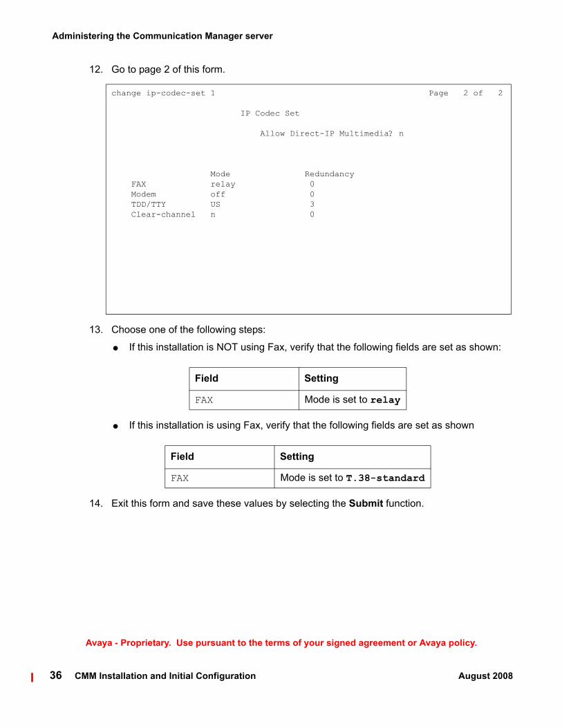
change ip-codec-set 1 Page 2 of 2
IP Codec Set
Allow Direct-IP Multimedia? n
Mode Redundancy FAX relay 0 Modem off 0 TDD/TTY US 3 Clear-channel n 0
Administering the Communication Manager server
36 CMM Installation and Initial Configuration August 2008
Avaya - Proprietary. Use pursuant to the terms of your signed agreement or Avaya policy.
12. Go to page 2 of this form.
13. Choose one of the following steps:
● If this installation is NOT using Fax, verify that the following fields are set as shown:
Field Setting
FAX Mode is set to relay
● If this installation is using Fax, verify that the following fields are set as shown
Field Setting
FAX Mode is set to T.38-standard
14. Exit this form and save these values by selecting the Submit function.

Creating a trunk group for messaging
CMM Installation and Initial Configuration August 2008 37
Avaya - Proprietary. Use pursuant to the terms of your signed agreement or Avaya policy.
Creating a trunk group for messagingTo create a trunk group for messaging, perform the following steps:
1. Go to the SAT interface prompt, and enter:
add trunk-group <nnn>
where <nnn> represents the number of this new trunk group.
Note:Note: This number must not be in use. For ease of identification, set this number equal
to that of the signaling group that you created. For example, if you created a signaling group as 99, create the corresponding trunk group 99.
The system displays page 1 of the TRUNK GROUP form.
add trunk-group 3 Page 1 of 21 TRUNK GROUP
Group Number: 3 Group Type: isdn CDR Reports: y Group Name: msgserver COR: 1 TN: 1 TAC: 103 Direction: two-way Outgoing Display? n Carrier Medium: H.323 Dial Access? y Busy Threshold: 255 Night Service: Queue Length: 0 Service Type: tie Auth Code? n Member Assignment Method: auto Signaling Group: 3 Number of Members: 120
2. Verify that the following fields are set as shown:

Administering the Communication Manager server
38 CMM Installation and Initial Configuration August 2008
Avaya - Proprietary. Use pursuant to the terms of your signed agreement or Avaya policy.
! Important:Important: Some of the fields below Group Type are not displayed unless this field is set to
isdn.
Field Setting
Group Type isdn
Group Name msgserver
Carrier Medium H.323
COR 1
Dial Access? y
Service Type: tie
Outgoing Display? n
Member Assignment Method auto
Signaling Group The number of the signaling group you created in step 1 of this procedure.
3. Enter a value in the TAC field. The TAC must start with the Dialed String value for the DAC you set up in Setting feature access codes for messaging on page 17, and include the number of the trunk group.
If you use the example in Setting feature access codes for messaging on page 17, the TAC would be 199.
4. Enter the number of trunks (ports) in the Number of Members field is appropriate for the number of messaging mailboxes for your platform. Use the table in Number of Ports to Mailboxes Mapping on page 108 to determine the appropriate value.
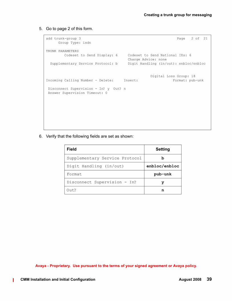
add trunk-group 3 Page 2 of 21 Group Type: isdn
TRUNK PARAMETERS Codeset to Send Display: 6 Codeset to Send National IEs: 6 Charge Advice: none Supplementary Service Protocol: b Digit Handling (in/out): enbloc/enbloc
Digital Loss Group: 18Incoming Calling Number - Delete: Insert: Format: pub-unk
Disconnect Supervision - In? y Out? n Answer Supervision Timeout: 0
Field Setting
Supplementary Service Protocol b
Digit Handling (in/out) enbloc/enbloc
Format pub-unk
Disconnect Supervision - In? y
Out? n
Creating a trunk group for messaging
CMM Installation and Initial Configuration August 2008 39
Avaya - Proprietary. Use pursuant to the terms of your signed agreement or Avaya policy.
5. Go to page 2 of this form.
6. Verify that the following fields are set as shown:

add trunk-group 3 Page 3 of 21 TRUNK FEATURES ACA Assignment? n Measured: none Internal Alert? n Maintenance Tests? y Data Restriction? n NCA-TSC Trunk Member: 1 Send Name: n Send Calling Number: y Used for DCS? n Hop Dgt? n Send EMU Visitor CPN? n Suppress # Outpulsing? n Format: public UUI IE Treatment: service-provider
Replace Restricted Numbers? n Replace Unavailable Numbers? n Send Called/Busy/Connected Number: y Hold/Unhold Notifications? y Send UUI IE? y Modify Tandem Calling Number? n Send UCID? n Send Codeset 6/7 LAI IE? y
Field Setting
Send Name n
NCA-TSC Trunk Member 1
Send Calling Number y
Format1
1. The private setting is recommended. If the private setting will not work for your site, use public, unknown, or unk-pvt. You must use AAR or ARS digit conversion for path replacement to work. For more information, see AAR and ARS digit conversion on page 43.
private
Administering the Communication Manager server
40 CMM Installation and Initial Configuration August 2008
Avaya - Proprietary. Use pursuant to the terms of your signed agreement or Avaya policy.
7. Go to page 3 of this form.
8. Verify that the following fields are set as shown:

add trunk-group 3 Page 4 of 21 QSIG TRUNK GROUP OPTIONS
TSC Method for Auto Callback: drop-if-possible Diversion by Reroute? y Path Replacement? yPath Replacement with Retention? n Path Replacement Method: better-route SBS? n Display Forwarding Party Name? y Character Set for QSIG Name: eurofont QSIG Value-Added? y Encoding Method: proprietary
Field Setting
Path Replacement with Retention? n
Path Replacement Method better-route
QSIG Value-Added? y
Configuring the new signaling group for messaging
CMM Installation and Initial Configuration August 2008 41
Avaya - Proprietary. Use pursuant to the terms of your signed agreement or Avaya policy.
9. Go to page 4 of this form.
10. Verify that the following fields are set as shown:
Note:Note: After you submit this form, trunk groups are dynamically assigned for all trunks.
11. Exit this form and save these values by clicking Submit.
Configuring the new signaling group for messagingAfter you have created the new signaling group and trunk group for messaging, you must modify the signaling group to associate it with the new trunk group.

Administering the Communication Manager server
42 CMM Installation and Initial Configuration August 2008
Avaya - Proprietary. Use pursuant to the terms of your signed agreement or Avaya policy.
To associate the new signaling group with the new trunk group, perform the following steps:
1. Go to the SAT interface prompt, and enter:
change signaling-group <nnn>
where <nnn> represents the number of the signaling group you created in Creating a signaling group for messaging on page 31.
The system displays the signaling-group form.
change signaling-group 3 Page 1 of 1 SIGNALING GROUP
Group Number: 3 Group Type: h.323 Remote Office? n Max number of NCA TSC: 10 SBS? n Max number of CA TSC: 10 IP Video? n Trunk Group for NCA TSC: 3 Trunk Group for Channel Selection: 3 TSC Supplementary Service Protocol: b Network Call Transfer? y T303 Timer(sec): 10
Near-end Node Name: cl1-vision Far-end Node Name: msgserver Near-end Listen Port: 1720 Far-end Listen Port: 1720 Far-end Network Region: 1 LRQ Required? n Calls Share IP Signaling Connection? y RRQ Required? n Bypass If IP Threshold Exceeded? n H.235 Annex H Required? n DTMF over IP: out-of-band Direct IP-IP Audio Connections? y Link Loss Delay Timer(sec): 90 IP Audio Hairpinning? n Enable Layer 3 Test? n Interworking Message: PROGress DCP/Analog Bearer Capability: 3.1kHz
2. Set the Trunk Group for NCA TSC field to the number of the new trunk group that you created in Creating a trunk group for messaging on page 37.
For example, if you created the new signaling group and the new trunk group as 99, enter 99 in this field.
3. Set the Trunk Group for Channel Selection field to the number of the new trunk group that you created in Creating a trunk group for messaging on page 37.
For example, if you created the new signaling group and the new trunk group as 99, enter 99 in this field.
4. Exit this form and save this value by clicking Submit.

AAR and ARS digit conversion
CMM Installation and Initial Configuration August 2008 43
Avaya - Proprietary. Use pursuant to the terms of your signed agreement or Avaya policy.
AAR and ARS digit conversionDepending on the Format field setting on Page 3 of the Trunk Group form, you must translate the ARS and AAR digit conversion tables.
Path replacement settings
Trunk format setting Digit conversion
Private AAR digit conversion
Public ARS digit conversion
Unknown AAR digit conversion, or ARS digit conversion
Unk-pvt AAR digit conversion, or ARS digit conversion
The following table lists the AAR and ARS digit conversion translation requirements based on the trunk format.

Administering the Communication Manager server
44 CMM Installation and Initial Configuration August 2008
Avaya - Proprietary. Use pursuant to the terms of your signed agreement or Avaya policy.
Converting ARS digitsTo convert the ARS digits:
1. Go to the SAT interface prompt, and enter:
change ars digit-conversion 1
change ars digit-conversion 1 Page 1 of 2 ARS DIGIT CONVERSION TABLE Location: all Percent Full: 0
Matching Pattern Min Max Del Replacement String Net Conv ANI Req
3 5 5 0 ext y n n n n n n n n n n n n n n n n
2. Verify that the Net, Conv, and Req fields are set as shown in the following example.
! Important:Important: You must use values for Matching Pattern, Min, Max, and Del that are
appropriate for your configuration.
The preceding screen example is based on a system that uses 5 digit extensions that begin with 3.
3. Exit this form and save these values by clicking Submit.

AAR and ARS digit conversion
CMM Installation and Initial Configuration August 2008 45
Avaya - Proprietary. Use pursuant to the terms of your signed agreement or Avaya policy.
Converting AAR digitsTo convert the AAR digits:
1. Go to the SAT interface prompt, and enter:
change aar digit-conversion 1
The system displays the AAR DIGIT CONVERSION TABLE form.
change aar digit-conversion 1 Page 1 of 2 AAR DIGIT CONVERSION TABLE Percent Full: 0
Matching Pattern Min Max Del Replacement String Net Conv ANI Req
2 5 5 0 ext y n 3 5 5 0 ext y n 4 5 5 0 ext y n 5 5 5 0 ext y n x11 3 3 0 ars y n n n n n n n n n n n n
2. Verify that the Net, Conv, and Req fields are set as shown in the following example.
! Important:Important: You must use values for Matching Pattern, Min, Max, and Del that are
appropriate for your configuration.
The preceding screen example is based on a system that uses 5 digit extensions that begin with 3.
3. Exit this form and save these values by clicking Submit.

Administering the Communication Manager server
46 CMM Installation and Initial Configuration August 2008
Avaya - Proprietary. Use pursuant to the terms of your signed agreement or Avaya policy.
Creating a route pattern for the new trunk groupYou must create a route pattern for the new trunk group so that messaging can correctly receive and retrieve voice mail.
To create a route pattern for the new trunk group, perform the following steps:
1. Go to the SAT interface prompt, and enter:
change route-pattern <nnn>
where <nnn> represents the number of the new trunk group that you created in Creating a trunk group for messaging on page 37. You must enter this number for messaging to function properly.
The system displays the route-pattern form.
change route-pattern 3 Page 1 of 3 Pattern Number: 3 Pattern Name: msgserver Secure SIP? n Grp FRL NPA Pfx Hop Toll No. Inserted DCS/ IXC No Mrk Lmt List Del Digits QSIG Dgts Intw 1: 3 0 n user 2: n user 3: n user 4: n user 5: n user 6: n user
BCC VALUE TSC CA-TSC ITC BCIE Service/Feature PARM No. Numbering LAR 0 1 2 M 4 W Request Dgts Format Subaddress 1: y y y y y n y none rest rehu 2: y y y y y n n rest none 3: y y y y y n n rest none 4: y y y y y n n rest none 5: y y y y y n n rest none 6: y y y y y n n rest none
2. Verify that the following fields are set as shown:
Field Setting
Pattern Name The route pattern name for the messaging trunk group. For example, msgserver.
GrpNo.
The column contains the number of the trunk group you created in Creating a trunk group for messaging on page 37.

Creating a route pattern for the new trunk group
CMM Installation and Initial Configuration August 2008 47
Avaya - Proprietary. Use pursuant to the terms of your signed agreement or Avaya policy.
3. Exit this form and save these values by selecting the Submit function.
FRL 0
DCS/QSIG Intw
n
IXC user
BCC VALUE0 1 2 3 4 W
y y y y y n
TSC y
CA-TSCRequest1
none
ITC rest
LAR rehu
1. The CA-TSC Request field cannot contain a value until the TSC field is set to y.
Field Setting

Administering the Communication Manager server
48 CMM Installation and Initial Configuration August 2008
Avaya - Proprietary. Use pursuant to the terms of your signed agreement or Avaya policy.
4. Go to the SAT interface prompt, and enter:
change aar analysis <n>
where <n> represents the first digit of the welcome to messaging extension.
The system displays the AAR DIGIT ANALYSIS TABLE form.
change aar analysis 3 Page 1 of 2 AAR DIGIT ANALYSIS TABLE Percent Full: 1
Dialed Total Route Call Node ANI String Min Max Pattern Type Num Reqd 30000 5 5 3 aar n 4 7 7 999 aar n 5 7 7 999 aar n 6 7 7 999 aar n 7 7 7 999 aar n 8 7 7 999 aar n 9 7 7 999 aar n n n n n n n n n
5. On page 1 of this form, verify that the following fields are set as shown:
! Important:Important: You must use values that are appropriate for your configuration.
The preceding screen example is based on a system that uses 5 digit extensions. The default messaging voice mail extension number is 30000. This number will vary per site.
The columns for Total Min and Total Max refer to the number of digits in the voice mail extension. If you are using a dial plan with more than five digits, you must adjust this number accordingly.
6. Exit this form and save these values by clicking Submit.

Creating a route pattern for the new trunk group
CMM Installation and Initial Configuration August 2008 49
Avaya - Proprietary. Use pursuant to the terms of your signed agreement or Avaya policy.
7. Go to the SAT interface prompt, and enter:
change public-unknown-numbering <n>
Where <n> is the number of digits for extensions
The system displays the NUMBERING - PUBLIC/UNKNOWN FORMAT form.
change public-unknown-numbering 3 Page 1 of 2 NUMBERING - PUBLIC/UNKNOWN FORMAT TotalExt Ext Trk CPN CPNLen Code Grp(s) Prefix Len Total Administered: 2 5 3 3 5 Maximum Entries: 9999
8. On page 1 of this form, verify that the following fields are set as shown:
! Important:Important: You must define all of the numbers that appear as the first digits in the available
extension numbers that use voice mail, and the path replacement numbers on page 8 of the change system-parameters features form.
Field Setting
Ext Len The number of digits for extensions. For example, if the dial plan is configured for five-digit extensions, enter 5 in this column.
Ext Code The first digit or digits in the range of extensions for this site plus the path replacement numbers.
Trk Grp(s) The number of the new trunk group that you created in Creating a trunk group for messaging on page 37.
CPN Len The number of digits for extensions. For example, if the dial plan is configured for five-digit extensions, enter 5 in this column.
9. Exit this form and save these values by selecting the Submit function.
Administering the Communication Manager server
50 CMM Installation and Initial Configuration August 2008
Avaya - Proprietary. Use pursuant to the terms of your signed agreement or Avaya policy.
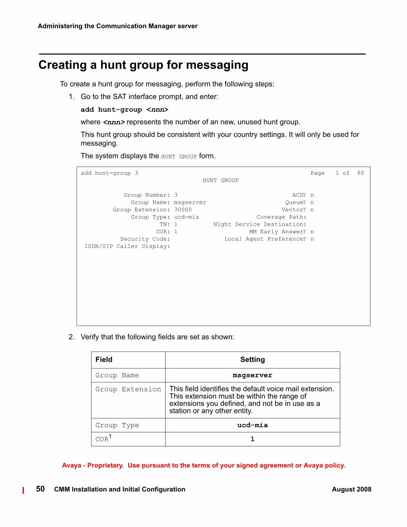
Creating a hunt group for messagingTo create a hunt group for messaging, perform the following steps:
1. Go to the SAT interface prompt, and enter:
add hunt-group <nnn>
where <nnn> represents the number of an new, unused hunt group.
This hunt group should be consistent with your country settings. It will only be used for messaging.
The system displays the HUNT GROUP form.
add hunt-group 3 Page 1 of 60 HUNT GROUP
Group Number: 3 ACD? n Group Name: msgserver Queue? n Group Extension: 30000 Vector? n Group Type: ucd-mia Coverage Path: TN: 1 Night Service Destination: COR: 1 MM Early Answer? n Security Code: Local Agent Preference? n ISDN/SIP Caller Display:
Field Setting
Group Name msgserver
Group Extension This field identifies the default voice mail extension. This extension must be within the range of extensions you defined, and not be in use as a station or any other entity.
Group Type ucd-mia
COR1 1
2. Verify that the following fields are set as shown:

add hunt-group 3 Page 2 of 60 HUNT GROUP
LWC Reception: none AUDIX Name:
Message Center: qsig-mwi Send Reroute Request: y Voice Mail Number: 30000 Routing Digits (e.g. AAR/ARS Access Code): 8 Provide Ringback? n TSC per MWI Interrogation? n
Creating a hunt group for messaging
CMM Installation and Initial Configuration August 2008 51
Avaya - Proprietary. Use pursuant to the terms of your signed agreement or Avaya policy.
3. Go to page 2 of this form.
4. Verify that the following fields are set as shown:
! Important:Important: The three fields below Message Center are not displayed unless this field is set
to qsig-mwi.
Field Setting
Message Center qsig-mwi
Send Reroute Request y
Voice Mail Number This field identifies the default voice mail extension.
Routing Digits (e.g. AAR/ARS Access Code)
The value in the Routing Digits field must match the Feature Access Code that you specified for the Auto Alternate Routing (AAR) Access Code in Setting feature access codes for messaging on page 17.
5. Exit this form and save these values by clicking Submit.
1. The COR for the hunt group must not be outward restricted.

Administering the Communication Manager server
52 CMM Installation and Initial Configuration August 2008
Avaya - Proprietary. Use pursuant to the terms of your signed agreement or Avaya policy.
Adding a coverage path for messagingAfter the hunt groups are created, you must add a coverage path in Communication Manager.
To create this coverage path, perform the following steps:
1. Go to the SAT interface prompt, and enter:
add coverage path <nnn>
where <nnn> represents the number of a new, unused coverage path. You can substitute <nnn> with next to use the first unused number. For example, if coverage paths 1 through 5 are in use, the next parameter creates coverage path 6.
The system displays the COVERAGE PATH form.
add coverage path 3 Page 1 of 1 COVERAGE PATH
Coverage Path Number: 3 Hunt after Coverage? n Next Path Number: Linkage
COVERAGE CRITERIA
Station/Group Status Inside Call Outside Call Active? n n Busy? y y Don't Answer? y y Number of Rings: 2 All? n n DND/SAC/Goto Cover? y y Holiday Coverage? n n
COVERAGE POINTS Terminate to Coverage Pts. with Bridged Appearances? n Point1: h3 Rng: Point2: Point3: Point4: Point5: Point6:
2. Enter in the Point1 field hxx.
where xx is the hunt group you created for messaging.
For example, h3 represents hunt group 3.
3. Exit this form and save this value by clicking Submit.

Creating stations and assigning coverage paths
CMM Installation and Initial Configuration August 2008 53
Avaya - Proprietary. Use pursuant to the terms of your signed agreement or Avaya policy.
Creating stations and assigning coverage pathsStations must be created before calls can be redirected to messaging through the correct coverage path. You must create two stations to perform the initial testing of your messaging deployment.
To create a station, perform the following steps:
1. At the SAT interface prompt, and enter:
add station <nnn>
where <nnn> represents the number of the extension that you want to create. This number must be within the range of extensions defined for this call center.
The system displays the add station form.
add station 30101 Page 1 of 5 STATION
Extension: 30101 Lock Messages? n BCC: 0 Type: 8410D Security Code: * TN: 1 Port: 01A0802 Coverage Path 1: 3 COR: 1 Name: Ext 30101 Coverage Path 2: COS: 1 Hunt-to Station: STATION OPTIONS Time of Day Lock Table: Loss Group: 2 Personalized Ringing Pattern: 1 Data Module? n Message Lamp Ext: 30101 Speakerphone: 2-way Mute Button Enabled? y Display Language: english
Survivable COR: internal Media Complex Ext: Survivable Trunk Dest? y IP SoftPhone? n
2. Enter the appropriate information in the Type and Port fields.
Note:Note: If you are unsure about what information to put in these fields, see "Completing
the station screens" in Administrator Guide for Avaya Communication Manager.
3. Ensure that the Coverage Path 1 field is set to the number of the coverage path that you created in Adding a coverage path for messaging on page 52.

add station 30101 Page 2 of 5 STATIONFEATURE OPTIONS LWC Reception: spe Auto Select Any Idle Appearance? n LWC Activation? y Coverage Msg Retrieval? y LWC Log External Calls? n Auto Answer: none CDR Privacy? n Data Restriction? n Redirect Notification? y Idle Appearance Preference? n Per Button Ring Control? n Bridged Idle Line Preference? n Bridged Call Alerting? n Restrict Last Appearance? y Active Station Ringing: single
H.320 Conversion? n Per Station CPN - Send Calling Number? Service Link Mode: as-needed Multimedia Mode: basic MWI Served User Type: qsig-mwi Display Client Redirection? n Select Last Used Appearance? n Coverage After Forwarding? s Multimedia Early Answer? n Direct IP-IP Audio Connections? y Emergency Location Ext: 30101 IP Audio Hairpinning? n
Field Setting
LWC Reception spe
LWC Activation? y
MWI Served User Type qsig-mwi
Administering the Communication Manager server
54 CMM Installation and Initial Configuration August 2008
Avaya - Proprietary. Use pursuant to the terms of your signed agreement or Avaya policy.
4. Go to page 2 of this form.
5. Verify that the following fields are set as shown:
6. Save these changes and exit this form by clicking Submit.
Saving translationsTranslations refers to the process of configuring the communication server settings through the preceding procedures. When you complete the translations, you must save them.
To save translations, perform the following steps:
1. At the SAT interface prompt, and enter:
save translation
The system saves the translations.

Verifying product IDs
CMM Installation and Initial Configuration August 2008 55
Avaya - Proprietary. Use pursuant to the terms of your signed agreement or Avaya policy.
Verifying product IDsConfirm that the server is properly installed and registered.
To view the list of installed products, perform the following steps:
1. At the SAT command line prompt, type logoff to logout of the SAT command line interface.
2. At the Linux prompt, type productid and press Enter.The system displays a list of installed products.
3. Verify that the server product ID, messaging product ID, and the RMB product IDs are displayed.
! Important:Important: If the IDs are not displayed, you must reinstall the system.
Restarting the systemWhen you complete the previous procedures, you must restart the Avaya Communication Manager system.
To restart the system, perform the following steps:
1. Open your browser and log in as craft to the Communication Manager server services port using http://192.11.13.6.
2. Access the Maintenance Web page.
3. From the Server category in the menu on the left side of the Web page, click Shutdown Server.The Shutdown This Server Web page is displayed.
4. Select the Immediate Shutdown option.
5. Select the Restart server after shutdown check box.
6. Click Shutdown.
The Communication Manager server restarts. The server takes approximately 10 to 15 minutes to restart.

Administering the Communication Manager server
56 CMM Installation and Initial Configuration August 2008
Avaya - Proprietary. Use pursuant to the terms of your signed agreement or Avaya policy.

CMM Installation and Initial Configuration August 2008 57
Avaya - Proprietary. Use pursuant to the terms of your signed agreement or Avaya policy.
Installing and configuring the Communication Manager Messaging (stand alone) server
You must install and configure the Avaya Communication Manager Messaging (stand alone) server to communicate with the Communication Manager server.
Important rules about installing the CMM serverThough the Communication Manager Messaging (stand alone),or CMM, application runs on the S8500C/S8510 Server and uses the platform maintenance and administration capabilities of Communication Manager software, CMM is not a Communication Manager server. As a result, the following key rules about a CMM installation apply:
● The CMM server does not use RAM Disk. As a result, the server does not create a RAM Disk partition and does not boot from RAM Disk.
● The Dual NIC card, while present in the S8500C Server, is not connected to the customer’s network.
● No license is installed on the CMM server. The number of CMM administrable port and trunk capacities are limited by the H.323 trunks licensed on the Communication Manager server.
● You cannot use the Avaya Installation Wizard to install software on the CMM server.
● The Communication Manager server must run release 4.0.2.
● The CMM software CD-ROM is the same CD-ROM used for installing software on a Communication Manager server. When you initially choose to run the CMM installation, the CMM application and the platform capabilities of Communication Manager are installed, but the call processing capabilities of Communication Manager are turned off.
Obtaining the appropriate documentationAvaya recommends that you have a copy of Avaya Communication Manager Messaging (stand alone) Documentation CD (03-xxxxxx), which includes all documentation for CMM.

Installing and configuring the Communication Manager Messaging (stand alone) server
58 CMM Installation and Initial Configuration August 2008
Avaya - Proprietary. Use pursuant to the terms of your signed agreement or Avaya policy.
Avaya also recommends that you have copies of the following documents available when you do the installation. The Documentation for Avaya Communication Manager, Media Gateways and Servers CD (03-300151) includes these documents.
● Quick Start for Hardware Installation: Avaya S8500 Media Server (555-245-701) — a quick reference guide providing physical installation and connection information.
● Installing the Avaya S8510 Server Family and Its Components (03-602918)
● Avaya Server Availability Management Processor User Guide (03-300322) — documentation providing information on administering the SAMP.
● Job Aid: Approved Grounds (555-245-772) — provides a description of all approved grounds.
Verifying site readinessBefore you go to the site, ensure the customer has:
● Adequate power
● The correct number of 19-inch (48-cm) 4-post data racks that are securely installed to EIA-310D or equivalent standards and grounded
● A local area network (LAN) that is set up and running
● A network administrator who is available on the day of the installation
If you stage the installation at a location other than the customer’s site, compare the list of items that were ordered to the contents of the boxes to verify that you have all the equipment. Your project manager can give you an inventory list. Do not rely on the packing slips inside the boxes for the correct information.
Checking for and FTP/SCP/SFTP server or compact flash for backing up data
During the installation procedures, you must back up the system data to an FTP, SFTP, or SCP server, or to the USB Compact Flash drive. You use a server on the customer’s LAN for backups.
● Check with your project manager or the customer for the following information about the FTP, SFTP, or SCP server.
- Login ID and password
- IP address

Obtaining required service pack files
CMM Installation and Initial Configuration August 2008 59
Avaya - Proprietary. Use pursuant to the terms of your signed agreement or Avaya policy.
- Directory path on the FTP/SFTP/SCP server
! Important:Important: Before going to the customer site, make sure that you can use either a customer
server for backups or a compact flash card.
Obtaining required service pack files
For Release 4.0.2, one or more service packs are required for this installation procedure. Download the service pack files from the Avaya Support web site to your laptop.
To download a service pack1. On your laptop, create a directory to store the file (for example, c:\S85XXdownload).
2. Connect to the LAN using a browser on your laptop or the customer’s PC and access http://www.avaya.com/support on the Internet to copy the required Communication Manager service pack file to the laptop.
3. At the Avaya support site, select the following links:
a. Downloadsb. Find documentation and downloads by product namec. S8500/S8510 Media Serverd. Software downloads
4. In the Software Downloads list, click on the link for the appropriate Communication Manager release (for example, Avaya Communication Manager Service Packs for 4.0.2).
5. Scroll down the page to find a link called Latest Avaya Communication Manager x.x.x Software Update (where x.x.x is the release number).
After this link, there should be a link starting with “PCN: “Click on this link to read about the release and software load to which this service pack applies.
6. Click on Latest Avaya Communication Manager x.x.x Software Update (where x.x.x is the release that is currently running on the S8500/S8510).
The File Download window displays.

Installing and configuring the Communication Manager Messaging (stand alone) server
60 CMM Installation and Initial Configuration August 2008
Avaya - Proprietary. Use pursuant to the terms of your signed agreement or Avaya policy.
File download window
7. Click the Save button and browse to the directory on your laptop in which you want the file saved.
Obtaining remote field updates and language files for CMMFor Release 4.0.2, one or more remote field updates (RFUs) are needed. You need to also determine whether optional languages are used. If so, obtain the data files.
To obtain an CMM RFU file1. On the Avaya Support Web site, click on Find Documentation and Downloads by
Product Name.
2. Under the letter "S", select CMM Messaging Application.
3. Click on Downloads.
To download the CMM patch software:
4. Click on CMM Embedded Messaging Application Patches.
5. Click on the service pack file name for this release.
For example, C6072rf+b.rpm.6. Click on Save and browse to the location on your laptop where you want to save the file.

Obtaining remote field updates and language files for CMM
CMM Installation and Initial Configuration August 2008 61
Avaya - Proprietary. Use pursuant to the terms of your signed agreement or Avaya policy.
Obtaining Optional language filesOptional languages are any language other than English (us-eng or us-tdd). If optional languages will be used with this CMM, you can also download the appropriate language files from the Download Web site.
1. Follow the steps as in Obtaining remote field updates and language files for CMM on page 60.
2. At step 4, select CMM Messaging Application Languages.
Obtaining Ethernet interface IP address and subnet maskYou must obtain an IP address and subnet mask to be used for the Ethernet interface for the H.323 integration. The subnet mask must be the same as that used for the media server (control network).
Laptop preparation, software, and system informationVerify that your computer has the correct hardware and software.
Copy to your computer:
- IP addresses- Product IDs for the media server, remote maintenance board, and Communication
Manager Messaging (stand alone)- Avaya services telephone number for remote access over modem- Avaya services IP address for reporting alarms through the network
● The current Communications Manager software update, if required. To get the service pack, go to the Avaya Support Web site (http://support.avaya.com) and click Downloads. From the list, identify and copy the required service pack.
● The current Communication Manager Messaging (stand alone) software remote field update (RFU).
● The required Avaya authentication file.
Note:Note: No license is required for the Communication Manager Messaging (stand alone)
application.

Installing and configuring the Communication Manager Messaging (stand alone) server
62 CMM Installation and Initial Configuration August 2008
Avaya - Proprietary. Use pursuant to the terms of your signed agreement or Avaya policy.
Obtaining the authentication fileYou must install an authentication file on the CMM server to set secure services passwords. Obtain the authentication file from the Automatic Registration Tool (ART).
Obtaining login IDs and passwordsEnsure that you have all the login IDs and passwords that you need to access the media server, the maintenance adapter, and the components of the server complex. These passwords include the unique Services password for the customer equipment.
To get the unique Services password for a specific media server, call ASG Conversant (1-800-248-1234 or 1-720-444-5557). You must have the IL, FL, or product ID to get the password.
Running the Automatic Registration Tool (ART) for the INADS IP address, if necessary
Note:Note: Business Partners call 800-295-0099. ART is available only to Avaya
associates.
The ART tool is a software tool that generates an IP address for a customer’s INADS alarming modem. This IP address is required for configuring the S8500’s/S8510’s modem for alarming.
Note:Note: You must generate an authentication file before you use the ART tool. Also, the
ART process is available only to Avaya personnel. You need an ART login ID and password, which you can set up at the ART web site. Non-Avaya personnel must contact their service support or customer care center for INADS addresses, if required.
To run the ART1. Access the ART web site on your laptop at http://art.dr.avaya.com.
2. Select Administer S8x00 Server products for installation script. a. Log in.
b. Enter the customer information.
c. Select Installation Script.

S8510
CMM Installation and Initial Configuration August 2008 63
Avaya - Proprietary. Use pursuant to the terms of your signed agreement or Avaya policy.
d. Click Start Installation script & IP Addr Admin.
A script file is created and downloaded or emailed to you.
3. You can use the installation script to set up an IP address and other alarming parameters automatically.
Obtaining the static craft password (Avaya technicians only)After installing new software and new Authentication file, you will need to use a static craft password to access the customer’s system. This static password will enable you to log in to the S8500/S8510 with a direct connection to the Services port without the ASG challenge/response. To obtain the static password, call the ASG Conversant number, 800-248-1234 or 720-444-5557 and follow the prompts to get the password. In addition to your credentials, you will need to enter the customer’s Product ID or the FL or IL number.Business Partners must use the dadmin password after the installation. Call 877-295-0099 for more information.
S8510The following two diagrams show the hardware components on the front and back panels of the S8510.
Figure 1: S8510 Front Panel
Figure notes:1. Power-on LED2. NMI button (unused)3. System ID button4. LCD Display
5. USB ports6. Video Connector7. Hard disk drives8. Optical DVD/CD drives
Figure 2: S8510 Back Panel

Installing and configuring the Communication Manager Messaging (stand alone) server
64 CMM Installation and Initial Configuration August 2008
Avaya - Proprietary. Use pursuant to the terms of your signed agreement or Avaya policy.
Figure notes:
1. Remote access controller (unused)2. Serial connector3. Video connector (for optional use of
monitor)4. USB ports (for optional use of modem,
mouse and keyboard)5. GB-16. GB-27. System status indicator connector
8. System ID button9. System status LED
10. Bay for optional redundant power supply11. Power supply12. Dual NIC13. Remote maintenance board
(SAMP-optional)

Equipment specifications
CMM Installation and Initial Configuration August 2008 65
Avaya - Proprietary. Use pursuant to the terms of your signed agreement or Avaya policy.
Equipment specificationsTable 3 outlines the features and specifications of S8510 server
Table 3: S8510 Media Server Specification
Feature S8510
Micro- processors
CPU: One or two Quad Core Intel® Xeon® Processor 5000 Sequence
Memory Architecture: PC2–4100 667–MHz fully bufferedDIMMS with ECC protectionModule sockets: 8 240–pinModule capacities: 1 GB, 2 GB, 4 GBMin/Max RAM: 1 GB/32 GBThe system board has 8 memory module sockets and can have a maximum of 32 GB
Drives Two 3.5-inch, internal hot-pluggable SATA (7200 rpm) hard drivesA slimline DVD-ROM/CD-RW drive
Dual NIC One dual network interface card (NIC) with gigabit Ethernet NICs capable ofsupporting 10-Mbps, 100-Mbps, and 1000-Mbps data rates (optional)
Fan Four fan modules, each comprises two dual-rotor fans, for a total of eight cooling fans
SAMP Card One PCI-e Server Availability Management Processor (optional)
VGA An integrated VGA-compatible video subsystem with an ATI ES1000, 33-MHz PCI video controller

Installing and configuring the Communication Manager Messaging (stand alone) server
66 CMM Installation and Initial Configuration August 2008
Avaya - Proprietary. Use pursuant to the terms of your signed agreement or Avaya policy.
Table 4 outlines the environmental specifications of S8510 server
Power supply
Wattage: 670 WVoltage:90–264 VAC, autoranging, 47–63 Hz, 10–.0 A (at 90 VAC)Heat dissipation: 2697 BTU/h (maximum)Maximum inrush current: Under typical line conditions and over the entire system ambient operating range, the inrush current may reach 55 A per power supply for 10 ms or less.There is an option of installing a second power supply in a 1 + 1 redundant configuration
Connectors (front)
USB: 2 4–pin, USB 2.0–compliantVideo: 15–pin VGA
Connectors (back)
NIC: 2 RJ-45Serial: 9–pin, DTE, 16550–compatibleUSB: 2 4–pin, USB 2.0–compliantVideo: 15–pin VGA
System battery
CR 2032 3.0–V lithium ion coin cell
Dimensions (HxWxD/Us)
1.7 x 10 x 30 in. (4.3 x 48.3 x 7./26 cm)/1 U
Weight 39 lb (18 kg)
Table 4: Environmental specifications
Paramter S8510 Specification
Operatingtemperature
10° to 35° C (50° to 95° F)
Storage temperature
–40° to 65° C (–40° to 149° F)
Operating relativehumidity
8% to 85% (noncondensing) with a maximum humidity gradationof 10% per hour
Table 3: S8510 Media Server Specification
Feature S8510

S8500 hardware
CMM Installation and Initial Configuration August 2008 67
Avaya - Proprietary. Use pursuant to the terms of your signed agreement or Avaya policy.
S8500 hardwareThe following two diagrams show the hardware components on the front and back panels of the S8500C with the default port assignments.
Storage relativehumidity
5% to 95% (noncondensing)
Operating maximumvibration
0.25 G at 3–200 Hz for 15 min
Storage maximumvibration
0.5 G at 3–200 Hz for 15 min
Operating maximumshock
One shock pulse in the positive z axis (one pulse on each side of the system) of 41 G for up to 2 ms
Storage maximumshock
Six consecutively executed shock pulses in the positive and negative x, y, and z axes (one pulse on each side of the system) of 71 G for up to 2 ms
Operating altitude
–16 to 3048 m (–50 to 10,000 ft)
Storage altitude
–16 to 10,600 m (–50 to 35,000 ft)
Table 4: Environmental specifications

Installing and configuring the Communication Manager Messaging (stand alone) server
68 CMM Installation and Initial Configuration August 2008
Avaya - Proprietary. Use pursuant to the terms of your signed agreement or Avaya policy.
Figure 3: S8500C front panel
Figure notes:
1. Power-on LED2. Power button3. Reset button4. Hard disk drive activity LED5. Locator LED6. System error LED
7. USB port8. USB port9. Hard disk drive
10. CD eject button11. CD-ROM drive activity LED
Figure 4: S8500C back panel
Figure notes:
1. Power cord connector2. SAMP power3. USB connection to USB modem4. Ethernet port (SAMP Eth 1)5. SAMP Services port (SAMP Eth 2)6. SAMP card7. Dual NIC (not used)8. Ethernet 4 (not used)9. Ethernet 3 (not used)
10. Mouse connector11. USB port12. USB port13. Ethernet 014. Ethernet 115. Video connector 16. Serial connector17. Keyboard connector

Equipment specifications
CMM Installation and Initial Configuration August 2008 69
Avaya - Proprietary. Use pursuant to the terms of your signed agreement or Avaya policy.
Equipment specifications
Table 5: S8500 control network components specifications
Component Dimensions English (height x width x depth in inches)
Dimensions Metric (height x width x depth in centimeters)
Height (u)
Weight (lb/kg)
S8500C 1.75 x 17 x 22 4 x 43 x 56 1 28/13
Ethernet Switch: C363T C364T
1.75 x 17 x 14.4 1.75 x 17 x 14.4
4 x 43 x 37 4 x 43 x 37
1 1
11/5 11/5
UPS: 700 VA 1500 VA
3.5 x 17 x 19 3.5 x 17 x 24
9 x 43 x 48 9 x 43 x 61
2 2
34/15 50/23
The S8500 Media Server control network components consist of the media server, one UPS, and an Avaya-provided Ethernet switch (optional). The physical specifications for the control network components are shown in Table 5.

Table 6: S8500 Media Server specifications
Feature S8500C
Micro- processors
CPU: 3.2 GHz Pentium (P4)FSB: 800 MHz front-side bus
Memory Two 512 MB PC2-4200 CL4 ECC DDR2 SDRAM DIMM
Drives One 80 GB SATA hard disk driveCD-ROM/DVD-ROM: IDE
Dual NIC One dual NIC card (not used)
Slots Two PCI-X slots - 64 bit/66 MHzAccommodates the SAMP and dual NIC
Power supply
350 W (110 VAC or 220 VAC autosensing)
Installing and configuring the Communication Manager Messaging (stand alone) server
70 CMM Installation and Initial Configuration August 2008
Avaya - Proprietary. Use pursuant to the terms of your signed agreement or Avaya policy.
Table 6 outlines the features and specifications of the Avaya S8500C Server.
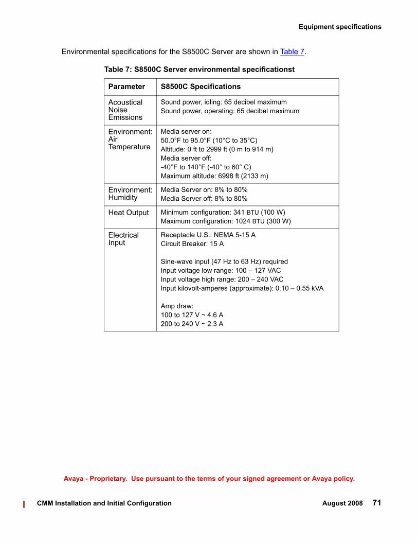
Table 7: S8500C Server environmental specificationst
Parameter S8500C Specifications
Acoustical Noise Emissions
Sound power, idling: 65 decibel maximumSound power, operating: 65 decibel maximum
Environment: Air Temperature
Media server on: 50.0°F to 95.0°F (10°C to 35°C)Altitude: 0 ft to 2999 ft (0 m to 914 m)Media server off: -40°F to 140°F (-40° to 60° C)Maximum altitude: 6998 ft (2133 m)
Environment: Humidity
Media Server on: 8% to 80%Media Server off: 8% to 80%
Heat Output Minimum configuration: 341 BTU (100 W)Maximum configuration: 1024 BTU (300 W)
Electrical Input
Receptacle U.S.: NEMA 5-15 ACircuit Breaker: 15 A
Sine-wave input (47 Hz to 63 Hz) requiredInput voltage low range: 100 – 127 VACInput voltage high range: 200 – 240 VACInput kilovolt-amperes (approximate): 0.10 – 0.55 kVA
Amp draw: 100 to 127 V ~ 4.6 A200 to 240 V ~ 2.3 A
Equipment specifications
CMM Installation and Initial Configuration August 2008 71
Avaya - Proprietary. Use pursuant to the terms of your signed agreement or Avaya policy.
Environmental specifications for the S8500C Server are shown in Table 7.

Installing and configuring the Communication Manager Messaging (stand alone) server
72 CMM Installation and Initial Configuration August 2008
Avaya - Proprietary. Use pursuant to the terms of your signed agreement or Avaya policy.
About the Server Availability Management ProcessorFor information on the Server Availability Management Processor (SAMP) functionality, see Installing and Configuring the S8500 Media Server, 03-300143.
About SAMP connectionsIn the Avaya S8500C Media Server, the SAMP card is installed in PCI-X slot 1. Slot 1 is a full-height, three-quarters length slot.
In the Avaya S8510 Media Server, the SAMP card is optional, if avaiable it is in the PCI-e slot.
The SAMP comes in a half-card PCI form factor and is powered externally. The SAMP supports one USB interface and two 10/100 Ethernet ports that are located on the rear of the media server.
● SAMP Ethernet 1 is not used.
● SAMP Ethernet 2 is for local access. This port is for on-site services personnel to access the SAMP with the craft login.
● The USB interface is used to connect a USB modem for remote dial-in and dial-out access. The media server and the SAMP share this modem connection for remote maintenance, administration, and alarming. For remote dial-in, the user first establishes a Point-to-Point Protocol (PPP) session that terminates at the SAMP. The user can then use the craft login to establish an SSH (Secure Shell) or an HTTPS (Secure Web) session to the SAMP or the host.
The SAMP also communicates with the host in-band by way of an on-board industry-standard Ethernet controller on the PCI bus of the host with an internal link to the SAMP.
Figure 5: SAMP connections for S8500C on page 73 shows the locations of the connections on the SAMP for the S8500C.

About the Server Availability Management Processor
CMM Installation and Initial Configuration August 2008 73
Avaya - Proprietary. Use pursuant to the terms of your signed agreement or Avaya policy.
Figure 5: SAMP connections for S8500C
Figure notes:
1. SAMP Eth2—to the services laptop computer (cross-connect CAT5 cable)
2. SAMP Eth1 (not used)
3. USB connection for the modem4. External power to the SAMP
About SAMP softwareThe SAMP is shipped from the factory with the software installed and with some default settings. However, you might need to install an updated version of the software, and you must configure the SAMP before you can use it.
If a SAMP software update file is available on the Avaya Support Web site, one of the preinstallation tasks required that you load the file on your laptop: see Using the Avaya Server Availability Management Processor (SAMP) (03-300322) for how to install software on the SAMP and change the default settings.

Installing and configuring the Communication Manager Messaging (stand alone) server
74 CMM Installation and Initial Configuration August 2008
Avaya - Proprietary. Use pursuant to the terms of your signed agreement or Avaya policy.
S8500 server port connections The following section explains how to connect the Ethernet ports on the back of the media server.
Use standard CAT5 cables with RJ45 connectors on each end to connect to the various ports. Figure 6: S8500C Media Server connectivity guide on page 74 shows typical connectivity for the S8500C Media Server.
Figure 6: S8500C Media Server connectivity guide
Figure notes:
1. Eth0—To the customer network (straight-through CAT5 cable)
2. Eth1—To the Services laptop computer (cross-over CAT5 cable)
3. Eth3—Not used 4. Eth4—Not used

About modem connections
CMM Installation and Initial Configuration August 2008 75
Avaya - Proprietary. Use pursuant to the terms of your signed agreement or Avaya policy.
About modem connections Note:
Note: You cannot connect USB modems to rotary lines. A touch tone line is required.
On an Avaya S8500/S8510 Server, connect the modem to the USB port on the SAMP.
Avaya defaults on the SAMP set the required options on the SAMP modem. For modem connectivity, see Figure 7: Modem connectivity on the S8500 Media Server.
Figure 7: Modem connectivity on the S8500 Media Server
Figure notes:
1. Modem2. USB cable that connects the USB modem
to the USB port on the media server
3. Telephone line that connects the modem to the outside line
You set the modem options when you configure the media server. You do not set options on the modems themselves.

Installing and configuring the Communication Manager Messaging (stand alone) server
76 CMM Installation and Initial Configuration August 2008
Avaya - Proprietary. Use pursuant to the terms of your signed agreement or Avaya policy.
Configuring SNMP module in the UPSYou must configure the SNMP modules in each Avaya-supplied UPS to send alarms or traps to the S8500C/S8510 Server. This process requires that you also configure the SNMP subagent in the Avaya-supplied Ethernet switch.
For these procedures, see Chapter 2 in Installing and Configuring the S8500 Media Server, 03-300143.
! Important:Important: Use the procedures in this section to configure Avaya-supplied equipment only.
Clearing the ARP cache on the laptop Depending on the operating system of your Services laptop computer, you might need to clear the Address Resolution Protocol (ARP) cache before you enter a new IP address. If you enter an IP address and your computer cannot connect, perform the following procedure to clear the cache.
1. On your computer, click Start > Run to open the Run dialog box.
2. Type command and press Enter to open an MS-DOS command line window.
3. Type arp -d 192.11.13.6 and press Enter to clear the ARP cache in the laptop.
If the ARP cache does not contain the specified IP address, the message The specified entry was not found appears. You can ignore this message.
4. Type exit and press Enter to close the command line window.
Applying power to the media server Note:
Note: In this procedure, the software CD-ROM must be placed into the CD-ROM drive on the media server immediately after you turn on the power to the media server.
1. Connect the AC power cord to the media server and to the UPS or a nonswitched electrical outlet.
2. If the Server does not turn on, press the white power control button on the front of the media server.

Accessing the media server
CMM Installation and Initial Configuration August 2008 77
Avaya - Proprietary. Use pursuant to the terms of your signed agreement or Avaya policy.
3. Immediately place the software CD-ROM into the CD-ROM drive on the media server.
Accessing the media server 1. Use a cross-over cable to connect your laptop computer to the Services port on the back
of the media server. The Services port is labeled "2" and is configured as Eth1.
2. Wait at least 3 minutes after you turn on the media server before you start a Telnet session to access the information on the CD-ROM.
Configuring Telnet (for initial software installation only)The Telnet application is used only at initial installation of the software and only for initial access to the Services port. Telnet might be set to send a carriage return (CR) and a line feed (LF) whenever you press Enter. The Communication Manager installation program sees this as two key presses. If you are running Windows 2000 or Windows XP, you must correct this setting before you copy the software to the hard disk drive.
1. Click Start > Run to open the Run dialog box.
2. Type telnet and press Enter to open a Microsoft Telnet session.
3. Type unset crlf and press Enter.4. Type display and press Enter to verify that you see the message Line feed mode -
Causes return key to send CR.
5. Type q and press Enter to exit the Telnet session.
Installing CMM software
Use a Telnet session to access the information on the CD-ROM.
1. On your Services laptop computer, click Start > Run to open the Run dialog box.
2. Type cmd in the text box, and click OK.

Installing and configuring the Communication Manager Messaging (stand alone) server
78 CMM Installation and Initial Configuration August 2008
Avaya - Proprietary. Use pursuant to the terms of your signed agreement or Avaya policy.
3. Type telnet 192.11.13.6 and press Enter to view the first screen.
Note:Note: To navigate on these screens, use the arrow keys to move to an option, and then
press the spacebar to select the option. Press Enter to submit the information on the screen.
4. Select Install, ensure that <OK> is highlighted, and press Enter.The Select Release Version screen appears.
5. On the Select Release Version screen, ensure that the Build line for release 4.0-00.2.xxx.x and <OK> are highlighted. Press Enter.The Run CMM Installation screen appears.
6. On the Run CMM Installation screen, select Yes, and press Enter to partition the hard disk drive and reformat the partitions.
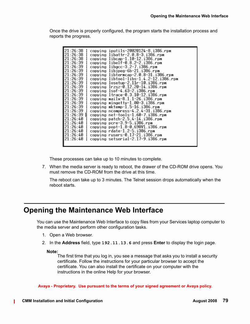
Opening the Maintenance Web Interface
CMM Installation and Initial Configuration August 2008 79
Avaya - Proprietary. Use pursuant to the terms of your signed agreement or Avaya policy.
Once the drive is properly configured, the program starts the installation process and reports the progress.
These processes can take up to 10 minutes to complete.
7. When the media server is ready to reboot, the drawer of the CD-ROM drive opens. You must remove the CD-ROM from the drive at this time.
The reboot can take up to 3 minutes. The Telnet session drops automatically when the reboot starts.
Opening the Maintenance Web InterfaceYou can use the Maintenance Web Interface to copy files from your Services laptop computer to the media server and perform other configuration tasks.
1. Open a Web browser.
2. In the Address field, type 192.11.13.6 and press Enter to display the login page.
Note:Note: The first time that you log in, you see a message that asks you to install a security
certificate. Follow the instructions for your particular browser to accept the certificate. You can also install the certificate on your computer with the instructions in the online Help for your browser.

Installing and configuring the Communication Manager Messaging (stand alone) server
80 CMM Installation and Initial Configuration August 2008
Avaya - Proprietary. Use pursuant to the terms of your signed agreement or Avaya policy.
3. Log in as craft and use the initial craft password.
4. When you see a message that asks Suppress alarm origination?, select Yes.
A "Welcome to your new account" screen appears.
5. Click Continue.
The Main Menu screen appears.
6. Click Launch Maintenance Web Interface.
Copying files to the media serverYou can use the Maintenance Web Interface to copy the authentication file, the CMM RFU, Communication Manager service packs, and SAMP update files from the Services laptop to the media server.
1. On the Maintenance Web Interface, under Miscellaneous, click Download Files.
2. Select File(s) to download from the machine I’m using to connect to the server.3. Click Browse next to the top field to open the Choose File window on your computer. Find
the files that you need to copy to the media server.
4. Click Download to copy the files to the media server.
The files are automatically copied to the default file location.
Installing security files and Communication Manager service packs, if any
To install security files and/or service packs1. Under Server Upgrades, select Manage Updates.
The Manage Updates screen appears.

Installing security files and Communication Manager service packs, if any
CMM Installation and Initial Configuration August 2008 81
Avaya - Proprietary. Use pursuant to the terms of your signed agreement or Avaya policy.
Manage Updates Screen
2. Do one or both of the following:
a. If a file you want to activate shows packed in the Status column, select that file and click Unpack.
The screen shows the status of the unpacking.
b. Click Continue at this point.
3. Check the Type column for the file you want to activate. Tell the customer that the system will reboot if the file type is cold. The customer may want to wait to install this security update.
4. Select the file you want to activate and click Activate.
The screen shows the status of activating the update.
5. Click Continue.
If a reboot is required, the system automatically reboots.

Installing and configuring the Communication Manager Messaging (stand alone) server
82 CMM Installation and Initial Configuration August 2008
Avaya - Proprietary. Use pursuant to the terms of your signed agreement or Avaya policy.
Installing the CMM Remote Field Update
To install the CMM Remote Field Update (RFU)1. On the Maintenance Web Pages under Miscellaneous, select Messaging Administration.
The Messaging Administration Main Menu appears.
Messaging Administration Screen

Installing the CMM Remote Field Update
CMM Installation and Initial Configuration August 2008 83
Avaya - Proprietary. Use pursuant to the terms of your signed agreement or Avaya policy.
2. On the left navigation pane under Software Management, select Software Installation.
A backup reminder screen appears.
3. Click Continue without current system backup.
The Packages will be installed from ... screen appears. The CMM RFUs are listed and are preselected for installation.

Installing and configuring the Communication Manager Messaging (stand alone) server
84 CMM Installation and Initial Configuration August 2008
Avaya - Proprietary. Use pursuant to the terms of your signed agreement or Avaya policy.
Packages will be installed from Screen
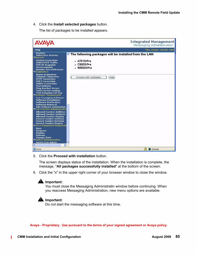
Installing the CMM Remote Field Update
CMM Installation and Initial Configuration August 2008 85
Avaya - Proprietary. Use pursuant to the terms of your signed agreement or Avaya policy.
4. Click the Install selected packages button.
The list of packages to be installed appears.
5. Click the Proceed with installation button.
The screen displays status of the installation. When the installation is complete, the message, "All packages successfully installed" at the bottom of the screen.
6. Click the "x" in the upper right corner of your browser window to close the window.
! Important:Important: You must close the Messaging Administratin window before continuing. When
you reaccess Messaging Administration, new menu options are available.
! Important:Important: Do not start the messaging software at this time.

Installing and configuring the Communication Manager Messaging (stand alone) server
86 CMM Installation and Initial Configuration August 2008
Avaya - Proprietary. Use pursuant to the terms of your signed agreement or Avaya policy.
Downloading optional language files, if neededIf the optional language files are needed, copy the files from the language CD to /var/home/ftp/pub.
To download optional language files1. Insert the optional language CD in your laptop’s CD-ROM drive.
2. On the Maintenance Web Interface, under Miscellaneous, select Download Files.
3. Select the Files to download from the machine I’m using to connect to the server download method.
4. Browse to the laptop CD and select each language file that you wish to copy.
5. Click the Download button.
When the transfer is complete, the message
Files have been successfully downloaded to the server is displayed.
6. If more than four optional language files need to be downloaded, repeat this procedure.
Copies of the optional language files are now in the /var/home/ftp/pub directory and will be automatically installed during the installation process.
Verifying the Time, Date, and Time Zone
To verify the Time, Date, and Time Zone:1. Under Server click Server Date/Time.

Configuring the S8500/S8510
CMM Installation and Initial Configuration August 2008 87
Avaya - Proprietary. Use pursuant to the terms of your signed agreement or Avaya policy.
Server Date/Time Window
2. Verify or set the media server's time close enough to the NTP's time, date, and time zone that synchronization can occur (within about 5 minutes).
3. If you change any values, click the Submit button to save your changes.
Configuring the S8500/S8510
To configure the S8500/S8510 server using the Maintenance Web Interface
CAUTION:!
CAUTION: For a new installation, be sure you have set the time and timezone before proceeding. Failure to do so may cause network problems later.
1. On the S8500/S8510 Web page main menu, click on Configure Server under Server Configuration. The system displays the Configure Server screen.

Installing and configuring the Communication Manager Messaging (stand alone) server
88 CMM Installation and Initial Configuration August 2008
Avaya - Proprietary. Use pursuant to the terms of your signed agreement or Avaya policy.
Configure Server Screen
2. Click Continue.
The system displays the Back Up Data Notice screen. For a new installation, a backup at this point is unnecessary. Perform a backup after the installation.
3. Click Continue.
The Select Method screen appears.

Configuring the S8500/S8510
CMM Installation and Initial Configuration August 2008 89
Avaya - Proprietary. Use pursuant to the terms of your signed agreement or Avaya policy.
Select Method Screen
4. Click Configure all services using the wizard.
With this option, the wizard guides you through the screens to configure all of the IP services.
Note:Note: This option is for the built-in Web Interface configuration wizard, not the Avaya
Installation Wizard (IW). You cannot use the IW to install CMM.
If you are upgrading an existing system, you may also click Configure individual services. This method is useful after an initial configuration has been completed and one or more services need to be changed.
5. Click Continue.
The Set Identities screen appears.

Installing and configuring the Communication Manager Messaging (stand alone) server
90 CMM Installation and Initial Configuration August 2008
Avaya - Proprietary. Use pursuant to the terms of your signed agreement or Avaya policy.
Set Identities Screen
6. Enter the host name for this server in the Host Name field.
The host name uniquely identifies this server.
7. Select UNUSED for this server in the Control Network A field.
The CMM S8500/S8510 Server does not control any port networks.
8. Select Ethernet1 for this server in the Services Port field.
9. Select UNUSED in the Control Network B field.
10. Select Ethernet0 in the Corporate LAN field.
11. Select Corporate LAN in the Assign the Processor Ethernet to an interface field.
12. Click Continue.
The Configure Interfaces screen appears.

Configuring the S8500/S8510
CMM Installation and Initial Configuration August 2008 91
Avaya - Proprietary. Use pursuant to the terms of your signed agreement or Avaya policy.
Configure Interfaces Screen
13. Use your planning forms to complete the fields for the:
● Ethernet 0: Corporate LAN Interface- IP Address server1 (hostname) assigned to the S8500/S8510 Media Server.
- Gateway with the IP address of the default gateway of the subnet.
- Subnet mask with the value of the subnet mask of the hosting subnet.
- Speed which should be set to Auto Sense.
● Integrated Messaging- IP Address (unused) assigned to CMM. This address must be different from the IP
address for the Corporate LAN interface.
! Important:Important: The Integrated Messaging IP address must also match the IP address for the
messaging server entered in the IP Node Names screen on the Communication Manager server. See change node-names ip on page 24.
Note:Note: The Ethernet 1 interface is automatically set for laptop access.

Installing and configuring the Communication Manager Messaging (stand alone) server
92 CMM Installation and Initial Configuration August 2008
Avaya - Proprietary. Use pursuant to the terms of your signed agreement or Avaya policy.
CAUTION:!
CAUTION: Do not guess on the addresses on this screen. If you enter the wrong addresses, CMM will not function properly. Service will be disrupted across the customer’s network and may be difficult to correct.
14. Click Continue.
The Configure ESS/LSP screen appears.
Configure ESS/LSP Screen
15. Select This is neither an enterprise survivable server nor a local spare processor.16. Click Continue.
The Configure Switches screen appears.

Configuring the S8500/S8510
CMM Installation and Initial Configuration August 2008 93
Avaya - Proprietary. Use pursuant to the terms of your signed agreement or Avaya policy.
Configure Switches Screen
17. In the Number of UPS Units field, select the number of Uninterruptible Power Supplies (UPS) units connected to the S8500/S8510 Media Server.
This number is usually 0 or 1.
18. If you enter 1 in the Number of UPS Units field, enter its IP address in the UPS 1 IP Address field.
The system will use this address to trap power loss signals from the UPS.
19. (Optional) If you enter 1 in the Number of UPS Units field, enter the SNMP community strings for the UPS in the SNMP GET and SET fields.
20. Click Continue.
The Set DNS/DHCP screen appears.
Most corporate networks have one or more domain name service (DNS) servers that associate an IP address with a device's name. When the DNS is administered with the S8500/S8510 Media Server name, you will be able to access the S8500/S8510 server by name as well as IP address over the corporate network.
CAUTION:!
CAUTION: If you configure an external DNS server, the DNS will be an extra device that, if not working properly, can cause delays in S8500/S8510 access.

Installing and configuring the Communication Manager Messaging (stand alone) server
94 CMM Installation and Initial Configuration August 2008
Avaya - Proprietary. Use pursuant to the terms of your signed agreement or Avaya policy.
Set DNS/DHCP Screen
21. Enter the appropriate IP addresses from your planning documentation.
Complete the following fields:
- In the Name Servers fields, enter the IP addresses for up to 3 DNS servers on the corporate network.
The S8500/S8510 Media Server checks the DNS servers in the order in which their addresses are entered for name-to-IP address resolution.
- In the DNS Domain field, enter the name for the part of the network on which the DNS server(s) reside (for example, mycompany.com).
Internet domains are sets of addresses generally organized by location or purpose.
- In the Search Domain fields, 1 to 5, enter the names of the domains that will be searched, in order, if a user enters an unqualified or incomplete name (such as a host name only without its domain).
Note:Note: For Search Domain 1, enter the same domain name you entered in the DNS
Domain field above.

Configuring the S8500/S8510
CMM Installation and Initial Configuration August 2008 95
Avaya - Proprietary. Use pursuant to the terms of your signed agreement or Avaya policy.
- Do not check the Enable DHCP service on this server for IPSIs fields. This server does not support port networks.
22. Click Continue.
The Set Static Routes screen appears.
Static Network Routes are used only if the customer has defined additional routes for IP packets other than through the default gateway. Leave these entries blank, unless the planning documentation supplies routing information.
Set Static Routes Screen
23. Click Continue.
The system displays the Configure Time Server screen.
The Network Time Server screen allows you to set up the Network Time Protocol (NTP) Service.

Installing and configuring the Communication Manager Messaging (stand alone) server
96 CMM Installation and Initial Configuration August 2008
Avaya - Proprietary. Use pursuant to the terms of your signed agreement or Avaya policy.
Configure Time Server Screen
Make the following choices, according to the planning documentation:
- Choose Use Local Clock if the user does not want the Network Time Protocol to run on the S8500/S8510 Media Server.
Select this option to disable Network Time Protocol (NTP) and use the media server's own clock as a time source. You typically choose this option if this is the only media server in the configuration and it will not be synchronized with an external time source.
- Choose Use these Network Time Servers to enter up to three time servers.
Select this option to enable NTP and be synchronized with an external time source on the corporate network.
Configuring the S8500/S8510
CMM Installation and Initial Configuration August 2008 97
Avaya - Proprietary. Use pursuant to the terms of your signed agreement or Avaya policy.
24. If you did not select Use these Network Time Servers in the previous step, click Continue and go to the next step.
If you selected Use these Network Time Servers in the previous step, complete the following fields:
Specify up to three network time servers by IP address or DNS name in the order in which you want the S8500/S8510 Media Server to check them. You should always specify at least two.
- Primary — Enter an IP address or DNS name.
If a trusted key is required, enter a valid key number in the Trusted Key field.
- Secondary — Enter an IP address or DNS name.
If a trusted key is required, enter a valid key number in the Trusted Key field.
- Tertiary — Enter an IP address or DNS name.
If a trusted key is required, enter a valid key number in the Trusted Key field.
- Multicast Client Support — Select Yes if the NTS routinely broadcasts its timing messages to multiple clients.
Select No if the S8500/S8510 Media Server is to poll (directly request the time from) the NTS.
- Additional trusted keys (optional) — If you want to encrypt the messages between an NTS and the S8500/S8510 Media Server, list the valid key numbers, up to 3, provided by your LAN administrator on the pre-installation worksheet.
Trusted keys function like a checksum to make sure the time packets are valid. Use a blank space as a delimiter if there is more than one key (for example, 2 3 6 to specify valid keys 2, 3, and 6). These numbers are associated with encryption codes in a "keys" file.
- Request key — Enter a key to send a remote query request.
Only 1 key is allowed in this field.
- Control key — Enter a key to query and request changes to an NTS.
Only 1 key is allowed in this field.
25. If you have a file named keys.install to allow the media server to communicate with the NTS, select Install keys from var/home/ftp/pub/keys.install.
If you do not have a keys.install file, select Do not install a new keys file.

Installing and configuring the Communication Manager Messaging (stand alone) server
98 CMM Installation and Initial Configuration August 2008
Avaya - Proprietary. Use pursuant to the terms of your signed agreement or Avaya policy.
Note:Note: If you have a keys.install file, upload or create it now, if possible. See Providing
the keys.install File (If Necessary) on page 98. If you upload the keys file later, you have to run the Web Interface Configure Server wizard again to have the system recognize it.
Providing the keys.install File (If Necessary)Use this procedure only if you selected one of the customer-provided keys options in the Configure Time Server Screen on page 96.
If encryption between the NTS and S8500/S8510 Media Server is to be used for additional security, you must provide a keys.install file that specifies for each key:
● The key number
● The encryption type
● The key code
If the keys file is short, the network administrator can create one now during configuration if needed:
To create the key file
a. On a directly connected laptop or other computer, create a flat-text file named keys.install, with the correct keys information using any ASCII application (for example, Notepad).
b. Upload the keys.install file using the Upload Files to Server screen as described earlier.
c. When finished, click on the Configure Server wizard window to resume server configuration.
The keys file can be loaded in one of the following two ways. If a keys.install file was previously created on or downloaded to the services laptop or another computer on the network, it can be installed now, as follows:
To upload the keys file
d. In the main menu under Miscellaneous, click the Upload Files to Server link.
e. Locate the keys.install file on your computer or network, then click Load File.
The file is uploaded to the media server's FTP directory.
f. When finished, click on the Configure Server wizard window to resume server configuration.
Longer files may be transferred from the network time server to the S8500/S8510 Media Server as follows:
To download or copy the keys file
g. Using either the Download Files to Server screen to access the keys file.
h. In both cases, the file is transferred to the media server's FTP directory.

Configuring the S8500/S8510
CMM Installation and Initial Configuration August 2008 99
Avaya - Proprietary. Use pursuant to the terms of your signed agreement or Avaya policy.
i. When finished, click on the Configure Server wizard window to resume server configuration.
j. After the keys.install file is uploaded, select the location where it resides, usually in the /var/home/ftp/pub subdirectory. (Services personnel may direct you to use the /tmp directory.)
k. If a keys file is not used, or if the correct keys.install file is already installed, select the option not to install a new keys file.
26. Click Continue.
27. At the next screen, Set Modem Interface, you can set up the Modem Interface IP Address for Avaya-provided service.
Set Modem Interface Screen
Note:Note: The Modem IP Address for the Avaya INADS alarming is assigned by the ART
tool. You should have obtained this address when you performed Running the Automatic Registration Tool (ART) for the INADS IP address, if necessary on page 62.
Click Continue.
The next Configure RMB screen displays the connection information for the services port on the SAMP. The LAN IP address should be 192.11.13.6, the Gateway IP Address should be 0.0.0.0, and the subnet mask should be 255.255.255.252.

Installing and configuring the Communication Manager Messaging (stand alone) server
100 CMM Installation and Initial Configuration August 2008
Avaya - Proprietary. Use pursuant to the terms of your signed agreement or Avaya policy.
Configure RMB Screen
Click Continue.
The next Update System screen indicates that the data entry process has concluded and that the system is ready to be configured.
Update System Screen
Note:Note: This is the final step in configuring the system. When you click Continue, all the
configuration information will be written to disk and implemented. This step normally completes in about 30 seconds. This is your last chance to cancel or correct the configuration.
28. To check, or possibly change, something you entered on a previous screen, use your browser's Back button to page back through the Configure Server screens.
29. Check or change the items in question.

Configuring the S8500/S8510
CMM Installation and Initial Configuration August 2008 101
Avaya - Proprietary. Use pursuant to the terms of your signed agreement or Avaya policy.
Note:Note: For any configuration, it is always safe to Cancel the configuration, and run the
Configure Server screens of the Web Interface again later from the beginning. You might use this option if you are checking or modifying settings on a server that has already been configured, and there is not a large amount of new information to enter.
30. Click the Continue button to update the configuration.
You can watch the progress of the configuration at the Updating System Files screen. If the configuration status displays stops updating at some point and the screen appears to freeze, you may have lost contact with the server. In this case, the configuration process will continue and you can log back on and pick up where left off.
Updating System Files Screen
When the process is complete, the screen displays the message that the server is running S014.x00.2.xxx.x. Note that the "S" reflects that the software has been configured as a Communication Manager Messaging (stand alone) system.
31. Click Close Window.
32. Click Exit to close the Maintenance Menu.
33. Click Logoff to log out of the Web screens.

Installing and configuring the Communication Manager Messaging (stand alone) server
102 CMM Installation and Initial Configuration August 2008
Avaya - Proprietary. Use pursuant to the terms of your signed agreement or Avaya policy.
Creating a super-user login, if necessary, for R4.0 or higher
If a super-user login does not exist, you must add at least one before you complete the authentication file installation. The easiest way to add a login is with the Maintenance Web pages.
Note:Note: A craft level login can create a super-user login in Release 4.0 or later.
To create a login:1. Ask a customer representative for a login name and password that the customer would like
for the superuser login. If you are a business partner, you can also repeat this procedure to add the dadmin login.
Note:Note: Make sure the customer can change this login, its password, or its permissions
later.
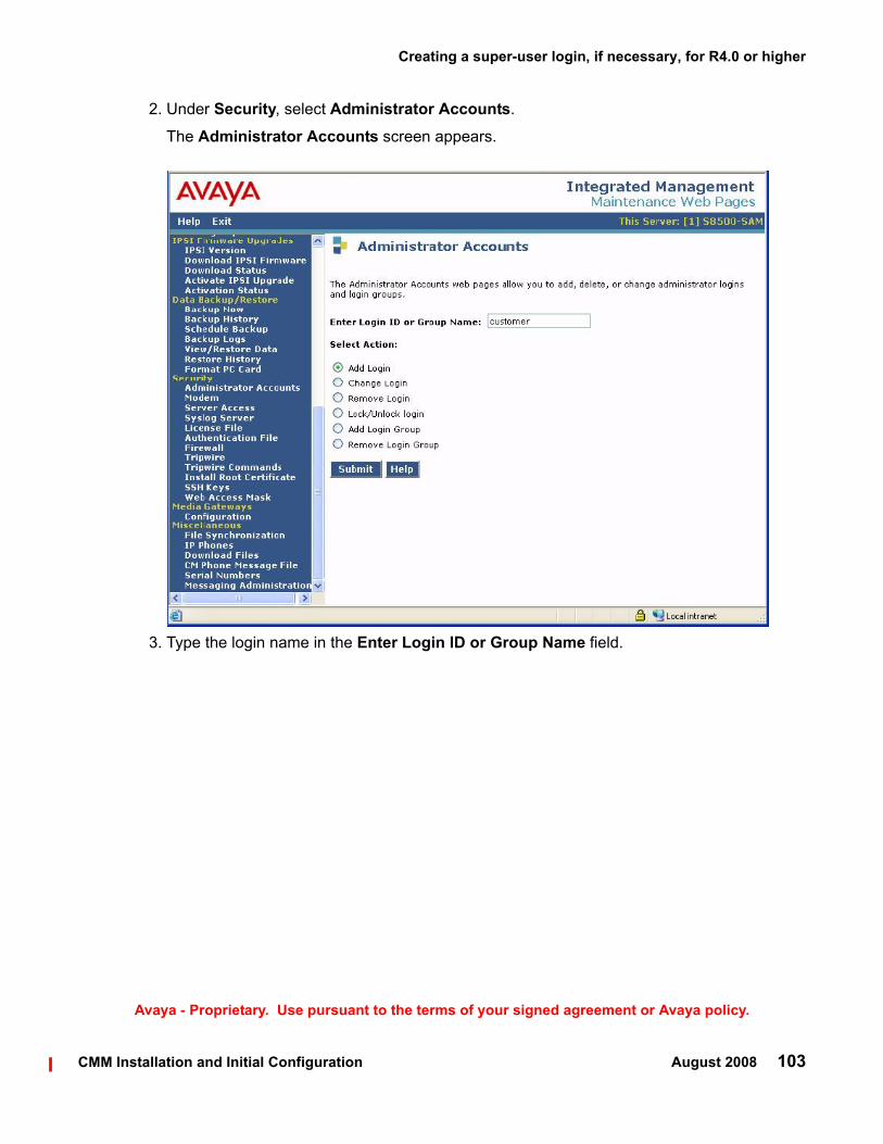
Creating a super-user login, if necessary, for R4.0 or higher
CMM Installation and Initial Configuration August 2008 103
Avaya - Proprietary. Use pursuant to the terms of your signed agreement or Avaya policy.
2. Under Security, select Administrator Accounts.
The Administrator Accounts screen appears.
3. Type the login name in the Enter Login ID or Group Name field.

Installing and configuring the Communication Manager Messaging (stand alone) server
104 CMM Installation and Initial Configuration August 2008
Avaya - Proprietary. Use pursuant to the terms of your signed agreement or Avaya policy.
4. Select Add Login, and click Submit.The Administrator Logins -- Add Login screen appears.
5. Type susers in the login group field.
6. Type prof18, voice in the additional groups field. prof18 is the code for the customer superuser, and voice indicates the superuser has messaging administration permissions.
7. Put a check in the standard shell access field.
8. Skip the lock this account and date on which account is disabled fields.
9. For the select type of authentication option, select password.
10. Complete the following fields:
● enter a challenge key or password
● re-enter challenge key or password
● force password/key change on first login
Note:Note: Do not lock the account or set the password to be disabled.

Installing the authentication file
CMM Installation and Initial Configuration August 2008 105
Avaya - Proprietary. Use pursuant to the terms of your signed agreement or Avaya policy.
11. Leave the defaults in the remaining fields.
12. Click Add.
The system tells the login is added successfully.
Installing the authentication file
To install the authentication file1. Under Security, select Authentication File.
The Authentication File screen appears.
Authentication File Screen
2. Select "Install the Authentication file I previously downloaded" and click Install.

Installing and configuring the Communication Manager Messaging (stand alone) server
106 CMM Installation and Initial Configuration August 2008
Avaya - Proprietary. Use pursuant to the terms of your signed agreement or Avaya policy.
Note:Note: You downloaded the authentication file previously as in Copying files to the media
server on page 80.
The system tells you the authentication is installed successfully
If the authentication file does not install, you may need to add a super-user login first. See Creating a super-user login, if necessary, for R4.0 or higher on page 102.
Stop Messaging
To stop messaging1. On the Maintenance Web Pages under Miscellaneous, select Messaging Administration.
The Messaging Administration Main Menu appears.
Messaging Administration Screen

Administering the Switch Link
CMM Installation and Initial Configuration August 2008 107
Avaya - Proprietary. Use pursuant to the terms of your signed agreement or Avaya policy.
2. Under Utilities in the left navigation pane, select Stop Messaging.
The Stop Messaging Software screen appears.
Stop Messaging Software Screen
3. Click the Stop button.
The Stop Messaging Software screen displays status as messaging begins stopping. When Messaging has stopped, the screen displays the message, "Stop of voice system completed" at the top of the screen.
Administering the Switch Link
To administer the switch link:1. On the left navigation pane under Utilities, select Switch Link Admin.
The Switch Link Administration screen appears.

Installing and configuring the Communication Manager Messaging (stand alone) server
108 CMM Installation and Initial Configuration August 2008
Avaya - Proprietary. Use pursuant to the terms of your signed agreement or Avaya policy.
Switch Link Administration Screen
2. Enter 1 in the Switch Number field.
3. Select an extension length in the Extension Length field.
4. Enter the IP address of the Communication Manager server (or the IP address of a C-LAN controlled by an S87xx Server) in the Switch IP Address field. See Administering IP Interfaces on page 25
5. Enter the number of voice ports and trunks CMM will use for mailbox connections to the Communication Manager server. You can use the following table to determine the number of ports required for the anticipated number of mailboxes to administer on CMM.
Number of Ports to Mailboxes Mapping
Users Maximum Users
Call Answer Ports
Transfer Ports
Total Ports
1 to 5 users 5 2 1 3
6 to 10 users 10 2 1 3

Starting Messaging
CMM Installation and Initial Configuration August 2008 109
Avaya - Proprietary. Use pursuant to the terms of your signed agreement or Avaya policy.
6. Click the Save button.
The system calculates the number transfer ports and displays them in the Transfer Ports field.
Note:Note: The number of H.323 trunks set on the Communication Manager server must
accommodate the sum of voice ports and transfer ports you administer on the Switch Link screen. This number of H.323 trunks for messaging is in addition to H.323 trunks the Communication Manager server requires for other functions such as IP telephone connections, faxes, and other data connections throughout the network. The number of H.323 trunks on the Communication Manager server are listed in the Maximum Number of H.323 Trunks field, which is available on the System Parameters Customer Options SAT screen.
Starting Messaging
To start messaging:1. On the Maintenance Web Pages, select Messaging Administration.
The Messaging Administration Main Menu appears.
11 to 25 users 25 3 2 5
26 to 50 users 50 4 2 6
51 to 100 users 100 5 3 8
101 to 250 users
250 8 4 12
25 to 500 users 500 13 7 20
501 to 1000 users
1000 22 11 33
1001 to 2000 users
2000 34 17 51
2001 to 3000 users
3000 48 24 72
3001 to 4000 users
4000 62 31 93
4001 to 5000 users
5000 80 40 120
Number of Ports to Mailboxes Mapping

Installing and configuring the Communication Manager Messaging (stand alone) server
110 CMM Installation and Initial Configuration August 2008
Avaya - Proprietary. Use pursuant to the terms of your signed agreement or Avaya policy.
2. On the left navigation pane, select Start Messaging.
The Start Messaging Software screen appears, with the phrase "Start Voice System Info: Starting" at the top. The screen refreshes periodically while messaging is starting. When Messaging has completed its startup, the phrase "Start Voice System Info: Started" appears at the top of the screen ,and the message "Voice Messaging is now completely up" appears at the bottom.
Setting CMM server parameters
To set parameters for the CMM server:1. On the left navigation pane under Server Administration, select Messaging Server
Admin.
The Edit Messaging Server screen appears.

Setting CMM server parameters
CMM Installation and Initial Configuration August 2008 111
Avaya - Proprietary. Use pursuant to the terms of your signed agreement or Avaya policy.
Edit Messaging Server Screen
2. Enter the name of the voice mail system in the Server Name field. This name must match the name in the Host Name field you entered in the Set Identities Screen on page 90.
3. Enter a password for other messaging servers to use to access this messaging server in the Password field.This password is provided by the customer.
4. Enter the starting and ending extensions that are assigned to this call center in the Start Ext. and End Ext. fields of the ADDRESS RANGES table.
5. Verify that the following fields are set as shown:
Field Setting
IP address The IP address of the CMM server
Server Type tcpip
Voiced Name? n

Installing and configuring the Communication Manager Messaging (stand alone) server
112 CMM Installation and Initial Configuration August 2008
Avaya - Proprietary. Use pursuant to the terms of your signed agreement or Avaya policy.
6. Leave the defaults in all other fields.
7. Click the Save button.
The system displays the message, "Server information modified successfully."
Setting system-wide messaging parameters
To set system-wide parameters for messaging:1. On the left-side navigation pane under Messaging Administration, select System
Administration.
The Administer System Attributes and Features screen appears.
Extension Length The number of digits that are used in the dial plan for this site.
Voice ID 0
Default Community 1
Field Setting

Setting system-wide messaging parameters
CMM Installation and Initial Configuration August 2008 113
Avaya - Proprietary. Use pursuant to the terms of your signed agreement or Avaya policy.
Administer System Attributes and Features Screen
2. In the Lock Duration field, enter the length of time a mailbox remains locked after the administered number of failed login attempts.
3. In the Consecutive Invalid Attempts field, enter the number of login attempts allowed before a mailbox is locked.
4. In the Minimum Password length field, enter the minimum number of digits that subscriber passwords must contain.
5. In the Passwords History field, enter the number of old passwords that the system saves to check against old password reuse by a subscriber.
6. In the Passwords Expiration Interval field, enter the number of days a subscriber password is valid, after which the system requires the subscriber to change the password.
7. Leave defaults in the remaining fields.
8. Click the Save button.

Installing and configuring the Communication Manager Messaging (stand alone) server
114 CMM Installation and Initial Configuration August 2008
Avaya - Proprietary. Use pursuant to the terms of your signed agreement or Avaya policy.
Adding test subscribers for messagingNote:
Note: For each test subscriber, you must administer telephones on the Communication Manager server (see Creating stations and assigning coverage paths on page 53). The following procedure then creates a mailbox associated with each subscriber’s telephone.
Create two subscribers to perform the initial testing of your messaging software.
To create a subscriber of the messaging server, perform the following steps:
1. On the left navigation pane under Messaging Administration, select Subscriber Management.The Manage Subscribers screen appears.
Manage Subscribers Screen
2. In the Local Subscriber Mailbox Number field, enter the extension number of the first test subscriber.

Verifying the messaging application
CMM Installation and Initial Configuration August 2008 115
Avaya - Proprietary. Use pursuant to the terms of your signed agreement or Avaya policy.
3. Click the Add or Edit button.
The Add Local Subscriber screen appears.
Add Local Subscriber Screen
4. In the Name field, enter the name of the first test subscriber.
5. In the Password field, enter the password for the subscriber’s mailbox.
6. Ensure that the Switch Number field displays the number you administered in the Switch Number field on the Switch Link Administration screen.
7. Click the Save button.
8. Repeat steps 2 through 7 for the second test subscriber mailbox.
Verifying the messaging applicationYou must verify that the messaging application is functioning properly after CMM is configured.

Installing and configuring the Communication Manager Messaging (stand alone) server
116 CMM Installation and Initial Configuration August 2008
Avaya - Proprietary. Use pursuant to the terms of your signed agreement or Avaya policy.
This section includes the following topics:
● Calling the hunt group to access messaging on page 116
● Calling an extension to verify messaging coverage on page 116
Calling the hunt group to access messagingFrom one of the stations that you created in Creating stations and assigning coverage paths on page 53, place a call to the messaging hunt group number that you specified in Creating a hunt group for messaging on page 50. You should hear the greeting, "Welcome to Audix." If you do not hear this greeting, ensure that the settings for the hunt group, coverage path, station, and subscriber are set properly by reviewing the previous procedures in this document.
Calling an extension to verify messaging coverageCall one of the two stations that you set as a subscriber to the messaging server and do not let the call be answered. You should be routed to the messaging system. You will hear the greeting, "Your call is being answered by AUDIX." If you do not hear this greeting, ensure that the settings for the hunt group, coverage path, station, and subscriber are set properly by reviewing the configuration procedures in this document.
Leave a message and verify that the Message Waiting Indicator (MWI) lamp on the receiving extension is lit. From the receiving extension, retrieve the message and verify that the MWI lamp is no longer lit.

CMM Installation and Initial Configuration August 2008 117
Avaya - Proprietary. Use pursuant to the terms of your signed agreement or Avaya policy.
Index
Index
Aaccessing the media server. . . . . . . . . . . . . 77ARP cache, clearing . . . . . . . . . . . . . . . . 76ART, Automatic Registration Tool . . . . . . . . . . 62
Cclearing ARP cache . . . . . . . . . . . . . . . . 76connect to customer network . . . . . . . . . . . . 74customer network, connecting to . . . . . . . . . . 74
Eenvironmental specifications
S8500 . . . . . . . . . . . . . . . . . . . . . 71S8510 . . . . . . . . . . . . . . . . . . . . . 66
equipment specificationsS8510 . . . . . . . . . . . . . . . . . . . . . 65
Hhunt groups
Message Center screen . . . . . . . . . . . . . 51
Iinstalling
Communication Manager software . . . . . . . . 77IP interface
processor ethernet . . . . . . . . . . . . . . . 27
Kkeys.install file . . . . . . . . . . . . . . . . . . . 98
Llanguages, for IA770 announcements . . . . . . .60, 86login, super-user . . . . . . . . . . . . . . . . . . 102
Mmedia server
accessing . . . . . . . . . . . . . . . . . . . 77powering up . . . . . . . . . . . . . . . . . . 76
modemconnect to media server . . . . . . . . . . . . . 75
Ppowering up media server . . . . . . . . . . . . . . 76processor ethernet
defining . . . . . . . . . . . . . . . . . . . . . 27
SS8500
control network components specifications . . . . 69environmental specifications . . . . . . . . . . . 71front and back panel . . . . . . . . . . . . . . . 67
S8500C . . . . . . . . . . . . . . . . . . . . . . 71S8510
front and back panel . . . . . . . . . . . . . . . 63software, installing Communication Manager . . . . . 77specifications
S8500 control network components. . . . . . . . 69super-user login . . . . . . . . . . . . . . . . . 102
TTelnet
configuring for Win2000/XP . . . . . . . . . . . 77

118 CMM Installation and Initial Configuration August 2008
Avaya - Proprietary. Use pursuant to the terms of your signed agreement or Avaya policy.
Index