Embed Size (px)
Citation preview
OWNER’S MANUALMODE D’EMPLOI
BEDIENUNGSANLEITUNGBRUKSANVISNING
MANUALE DI ISTRUZIONIMANUAL DE INSTRUCCIONES
GEBRUIKSAANWIJZING
DSP-AZ2
GB
AV AmplifierAmplificateur Audio-Video
YAMAHA ELECTRONICS CORPORATION, USA 6660 ORANGETHORPE AVE., BUENA PARK, CALIF. 90620, U.S.A.YAMAHA CANADA MUSIC LTD. 135 MILNER AVE., SCARBOROUGH, ONTARIO M1S 3R1, CANADAYAMAHA ELECTRONIK EUROPA G.m.b.H. SIEMENSSTR. 22-34, 25462 RELLINGEN BEI HAMBURG, F.R. OF GERMANYYAMAHA ELECTRONIQUE FRANCE S.A. RUE AMBROISE CROIZAT BP70 CROISSY-BEAUBOURG 77312 MARNE-LA-VALLEE CEDEX02, FRANCEYAMAHA ELECTRONICS (UK) LTD. YAMAHA HOUSE, 200 RICKMANSWORTH ROAD WATFORD, HERTS WD1 7JS, ENGLANDYAMAHA SCANDINAVIA A.B. J A WETTERGRENS GATA 1, BOX 30053, 400 43 VÄSTRA FRÖLUNDA, SWEDENYAMAHA MUSIC AUSTRALIA PTY, LTD. 17-33 MARKET ST., SOUTH MELBOURNE, 3205 VIC., AUSTRALIA Printed in Malaysia V977840
DS
P-A
Z2
0100DSPAZ2(GB)-cv1/4 02.8.22, 1:26 PM1

1 To assure the finest performance, please read this manualcarefully. Keep it in a safe place for future reference.
2 Install this sound system in a well ventilated, cool, dry, cleanplace — away from direct sunlight, heat sources, vibration,dust, moisture, and/or cold. Allow ventilation space of atleast 30 cm on the top, 20 cm on the left and right, and20 cm on the back of this unit.
3 Locate this unit away from other electrical appliances,motors, or transformers to avoid humming sounds.
4 Do not expose this unit to sudden temperature changes fromcold to hot, and do not locate this unit in a environment withhigh humidity (i.e. a room with a humidifier) to preventcondensation inside this unit, which may cause an electricalshock, fire, damage to this unit, and/or personal injury.
5 Avoid installing this unit where foreign object may fall ontothis unit and/or this unit may be exposed to liquid drippingor splashing. On the top of this unit, do not place:– Other components, as they may cause damage and/or
discoloration on the surface of this unit.– Burning objects (i.e. candles), as they may cause fire,
damage to this unit, and/or personal injury.– Containers with liquid in them, as they may fall and liquid
may cause electrical shock to the user and/or damage tothis unit.
6 Do not cover this unit with a newspaper, tablecloth, curtain,etc. in order not to obstruct heat radiation. If the temperatureinside this unit rises, it may cause fire, damage to this unit,and/or personal injury.
7 Do not plug in this unit to a wall outlet until all connectionsare complete.
8 Do not operate this unit upside-down. It may overheat,possibly causing damage.
9 Do not use force on switches, knobs and/or cords.10 When disconnecting the power cord from the wall outlet,
grasp the plug; do not pull the cord.11 Do not clean this unit with chemical solvents; this might
damage the finish. Use a clean, dry cloth.12 Only voltage specified on this unit must be used. Using this
unit with a higher voltage than specified is dangerous andmay cause fire, damage to this unit, and/or personal injury.YAMAHA will not be held responsible for any damageresulting from use of this unit with a voltage other thanspecified.
13 To prevent damage by lightning, disconnect the power cordfrom the wall outlet during an electrical storm.
14 Do not attempt to modify or fix this unit. Contact qualifiedYAMAHA service personnel when any service is needed.The cabinet should never be opened for any reasons.
15 When not planning to use this unit for long periods of time(i.e. vacation), disconnect the AC power plug from the walloutlet.
16 Be sure to read the “TROUBLESHOOTING” section oncommon operating errors before concluding that this unit isfaulty.
17 Before moving this unit, press STANDBY/ON to set thisunit in the standby mode, and disconnect the AC power plugfrom the wall outlet.
18 VOLTAGE SELECTOR (For China and General modelsonly)The VOLTAGE SELECTOR on the rear panel of this unitmust be set for your local main voltage BEFORE plugginginto the AC main supply.Voltages are 110/120/220/240 V AC, 50/60 Hz.
CAUTION: READ THIS BEFORE OPERATING YOUR UNIT.
WARNINGTO REDUCE THE RISK OF FIRE OR ELECTRIC SHOCK,DO NOT EXPOSE THIS UNIT TO RAIN OR MOISTURE.
This unit is not disconnected from the AC power source aslong as it is connected to the wall outlet, even if this unititself is turned off. This state is called the standby mode. Inthis state, this unit is designed to consume a very smallquantity of power.
For U.K. customersIf the socket outlets in the home are not suitable for theplug supplied with this appliance, it should be cut off andan appropriate 3 pin plug fitted. For details, refer to theinstructions described below.
Note• The plug severed from the mains lead must be destroyed, as a
plug with bared flexible cord is hazardous if engaged in a livesocket outlet.
Special Instructions for U.K.Model
IMPORTANTTHE WIRES IN MAINS LEAD ARE COLOUREDIN ACCORDANCE WITH THE FOLLOWINGCODE:
Blue: NEUTRALBrown: LIVE
As the colours of the wires in the mains lead of thisapparatus may not correspond with the colouredmarkings identifying the terminals in your plug,proceed as follows:The wire which is coloured BLUE must be connectedto the terminal which is marked with the letter N orcoloured BLACK. The wire which is colouredBROWN must be connected to the terminal which ismarked with the letter L or coloured RED.Making sure that neither core is connected to the earthterminal of the three pin plug.
CAUTION
0101DSPAZ2_Cau_EN(GB) 02.8.22, 0:15 PM2

En
glish
INT
RO
DU
CT
ION
PR
EPA
RA
TIO
NB
AS
ICO
PE
RA
TIO
NA
DD
ITIO
NA
LIN
FO
RM
AT
ION
AD
VAN
CE
DO
PE
RA
TIO
N
1
CONTENTS
ADVANCED OPERATION
REMOTE CONTROL FEATURES ................... 41Control Area ............................................................ 41Setting the Manufacturer Code ............................... 42Learn Feature .......................................................... 43Changing the Source Name in the Display
Window ............................................................... 44Using the Macro Feature ......................................... 45Clearing Learned Functions, Macros, Renamed
Source Names, and Setup ManufacturerCodes ................................................................... 47
Clearing a Learned Function ................................... 48Clearing a Macro Function ...................................... 48Each Component Control Area ............................... 50
SET MENU ........................................................... 55Adjusting the Items on the SET MENU ................. 551 SPEAKER SET (speaker mode settings) ............ 562 LOW FRQ TEST ................................................ 603 L/R BALANCE (balance of the left and right
main speakers) ..................................................... 604 HP TONE CTRL (headphone tone control) ........ 615 CENTER GEQ (center graphic equalizer) .......... 616 INPUT RENAME ............................................... 617 I/O ASSIGNMENT ............................................. 628 INPUT MODE (initial input mode) .................... 639 PARAM. INI (parameter initialization) .............. 6310LFE LEVEL ........................................................ 6311D-RANGE (dynamic range) ............................... 6412SP DELAY .......................................................... 6413DISPLAY SET .................................................... 6514MEMORY GUARD ............................................ 66156CH INPUT SET ................................................ 66
ADJUSTING THE LEVEL OF THE EFFECTSPEAKERS ....................................................... 67
SLEEP TIMER ..................................................... 68Setting the Sleep Timer ........................................... 68Canceling the Sleep Timer ...................................... 68
ADDITIONAL INFORMATION
SOUND FIELD PROGRAM PARAMETEREDITING .......................................................... 69What Is a Sound Field? ........................................... 69Sound Field Program Parameters ............................ 69Changing Parameter Settings .................................. 70Resetting a Parameter to the Factory-set Value ....... 70
DIGITAL SOUND FIELD PARAMETERDESCRIPTIONS .............................................. 71
TROUBLESHOOTING ....................................... 75GLOSSARY .......................................................... 79SPECIFICATIONS .............................................. 81
INTRODUCTION
CONTENTS ............................................................ 1FEATURES ............................................................. 2GETTING STARTED ............................................ 3
Checking the Package Contents ................................ 3Installing Batteries in the Remote Control ................ 3
CONTROLS AND FUNCTIONS ......................... 4Front Panel ................................................................ 4Remote Control ......................................................... 6Using the Remote Control ......................................... 7Front Panel Display ................................................... 8Rear Panel ................................................................. 9
PREPARATION
SPEAKER SETUP ............................................... 10Speakers to Be Used ................................................ 10Speaker Placement .................................................. 11Connecting the Speakers ......................................... 12
CONNECTIONS .................................................. 15Before Connecting Components ............................. 15Connecting Video Components ............................... 15Connecting Audio Components .............................. 18Connecting to an External Amplifier ...................... 20Connecting to the 6CH INPUT Jacks ..................... 20Connecting the Power Supply Cords ...................... 21Turning on the Power .............................................. 22
ON-SCREEN DISPLAY (OSD) .......................... 23OSD Modes ............................................................. 23Selecting the OSD Mode ......................................... 23
SPEAKER MODE SETTINGS .......................... 24Summary of SPEAKER SET Items 1A
through 1H .......................................................... 24ADJUSTING THE SPEAKER OUTPUT
LEVELS ............................................................ 25Before You Begin .................................................... 25TEST DOLBY SUR. ............................................... 25TEST DSP ............................................................... 27
BASIC OPERATION
BASIC PLAYBACK ............................................. 28Input Modes and Indications ................................... 30Selecting a Sound Field Program ............................ 31Selecting PRO LOGIC, PRO LOGIC
or Neo: 6 ............................................................. 32DIGITAL SOUND FIELD PROCESSING
(DSP) ................................................................. 34Understanding Sound Fields ................................... 34Hi-Fi DSP Programs ............................................... 34CINEMA-DSP ........................................................ 34Straight Decode ....................................................... 35Sound Field Effect ................................................... 35Features of DSP Programs ...................................... 36Table of Program Names for Each Input Format .... 39
BASIC RECORDING .......................................... 40
0102DSPAZ2_1-9_EN(GB) 02.8.22, 0:15 PM1
2
Manufactured under license from Dolby Laboratories.
“Dolby”, “Pro Logic”, and the double-D symbol are trademarksof Dolby Laboratories.
“DTS”, “DTS-ES Extended Surround” and “Neo: 6” aretrademarks of Digital Theater System, Inc.
FEATURES
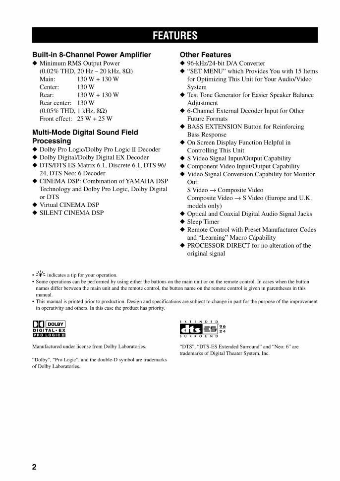
Built-in 8-Channel Power Amplifier Minimum RMS Output Power
(0.02% THD, 20 Hz – 20 kHz, 8Ω)Main: 130 W + 130 WCenter: 130 WRear: 130 W + 130 WRear center: 130 W(0.05% THD, 1 kHz, 8Ω)Front effect: 25 W + 25 W
Multi-Mode Digital Sound FieldProcessing Dolby Pro Logic/Dolby Pro Logic Decoder Dolby Digital/Dolby Digital EX Decoder DTS/DTS ES Matrix 6.1, Discrete 6.1, DTS 96/
24, DTS Neo: 6 Decoder CINEMA DSP: Combination of YAMAHA DSP
Technology and Dolby Pro Logic, Dolby Digitalor DTS
Virtual CINEMA DSP SILENT CINEMA DSP
Other Features 96-kHz/24-bit D/A Converter “SET MENU” which Provides You with 15 Items
for Optimizing This Unit for Your Audio/VideoSystem
Test Tone Generator for Easier Speaker BalanceAdjustment
6-Channel External Decoder Input for OtherFuture Formats
BASS EXTENSION Button for ReinforcingBass Response
On Screen Display Function Helpful inControlling This Unit
S Video Signal Input/Output Capability Component Video Input/Output Capability Video Signal Conversion Capability for Monitor
Out:S Video → Composite VideoComposite Video → S Video (Europe and U.K.models only)
Optical and Coaxial Digital Audio Signal Jacks Sleep Timer Remote Control with Preset Manufacturer Codes
and “Learning” Macro Capability PROCESSOR DIRECT for no alteration of the
original signal
•y indicates a tip for your operation.• Some operations can be performed by using either the buttons on the main unit or on the remote control. In cases when the button
names differ between the main unit and the remote control, the button name on the remote control is given in parentheses in thismanual.
• This manual is printed prior to production. Design and specifications are subject to change in part for the purpose of the improvementin operativity and others. In this case the product has priority.
0102DSPAZ2_1-9_EN(GB) 02.8.22, 0:15 PM2
En
glish
INT
RO
DU
CT
ION
PR
EPA
RA
TIO
NB
AS
ICO
PE
RA
ION
TA
DVA
NC
ED
OP
ER
AT
ION
AD
DIT
ION
AL
INF
OR
MA
TIO
NA
PP
EN
DIX
3
TRANSMIT RE-NAME
STANDBY
6CH INPUT
SOUND
SYSTEM
CLEAR LEARN MACRO OFF ONMACRO
PHONOA B
CD
DVDVCR2/DVRVCR 1
TITLE
MENU
CHAPTER
PAUSESTOPPOWER REC
HALL 1
EX/ES
DSP10KEY
ROCKCONCERT
MOVIETHEATER 1
MOVIETHEATER 2
MUTE
VOLUME
STEREO
TV INPUT
TV VOL CH
PRESET
DISC
PARAMETER
SET MENU
EFFECT
LEVELON SCREEN
TESTSLEEP
TV MUTE
MUSICVIDEO
TVTHEATER
ENTER-TAINMENT
HALL 2 CHURCH JAZZ CLUB
SELECT/DTS
SUR.
CHP/INDEX
A/B/C/D/E
SELECT
DISPLAY
SEARCH
SOURCE
PLAY
– +
ENTER
D-TV/LD CBL/SAT
CD-RMD/TAPETUNERV-AUX
POWER
1
5
9
6
100 10 100
11 12
7 8
2 3 4
++
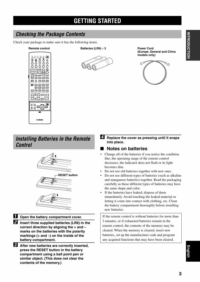
Installing Batteries in the RemoteControl
1 Open the battery compartment cover.
2 Insert three supplied batteries (LR6) in thecorrect direction by aligning the + and –marks on the batteries with the polaritymarkings (+ and –) on the inside of thebattery compartment.
3 After new batteries are correctly inserted,press the RESET button in the batterycompartment using a ball point pen orsimilar object. (This does not clear thecontents of the memory.)
4 Replace the cover as pressing until it snapsinto place.
Notes on batteries• Change all of the batteries if you notice the condition
like; the operating range of the remote controldecreases, the indicator does not flash or its lightbecomes dim.
• Do not use old batteries together with new ones.• Do not use different types of batteries (such as alkaline
and manganese batteries) together. Read the packagingcarefully as these different types of batteries may havethe same shape and color.
• If the batteries have leaked, dispose of themimmediately. Avoid touching the leaked material orletting it come into contact with clothing, etc. Cleanthe battery compartment thoroughly before installingnew batteries.
If the remote control is without batteries for more than3 minutes, or if exhausted batteries remain in theremote control, the contents of the memory may becleared. When the memory is cleared, insert newbatteries, set up the manufacturer code and programany acquired functions that may have been cleared.
Batteries (LR6) × 3Remote control
GETTING STARTED
Checking the Package ContentsCheck your package to make sure it has the following items.
Power Cord(Europe, General and Chinamodels only)
RESET button
0102DSPAZ2_1-9_EN(GB) 02.8.22, 0:15 PM3

4
BASS
VOLUME
VIDEO AUX
SILENT
PROGRAMSTEREO
REC OUT
SPEAKERS
INPUT MODE
BASSEXTENSION
PROCESSORDIRECT
SET MENU
PHONES
EFFECT
SOURCEMD/TAPECD–R
TUNER
CD
PHONO
DVDD–TV/LD
CBL/SAT
VCR 1
V–AUX
VCR2/DVR
NEXT +–
S VIDEO VIDEO AUDIO OPTICALL R
STANDBY/ON
NATURAL SOUND AV AMPLIFIER DSP-AZ2
TREBLE
– + – +
6CHINPUT
A B
D I G I T A L
1 2 3 4 5 6
7 q w e r t y u8 9 0 i o
CONTROLS AND FUNCTIONS
Front Panel
1 STANDBY/ONTurns on and sets this unit in the standby mode. Whenyou turn on this unit, you will hear a click and there willbe a 4 to 5-second delay before this unit can reproducesound.
Standby modeIn this mode, this unit consumes a small amount ofpower to receive infrared-signals from the remotecontrol.
2 INPUT selectorSelects the input source you want to listen to or watch.
3 (INPUT) MODESets the priority for the types of input signals (AUTO,DTS, ANALOG) to receive when one component isconnected to two or more input jacks of this unit (seepage 30). Priority cannot be set when 6CH INPUT isselected as the input source.
4 Remote control sensorReceives signals from the remote control.
5 Front panel displayShows information about the operational status of thisunit.
6 VOLUMEControls the output level of all audio channels.This does not affect the REC OUT level.
7 PHONES jackOutputs audio signals for private listening withheadphones. When you connect headphones, no signalsare output to the PRE OUT/MAIN IN jacks or to thespeakers.(There is an exception depending on the “1H SP B SET”setting on the SET MENU.)
8 BASS EXTENSIONTurns on or off the BASS EXTENSION function at eachtime the button is pressed, this feature boosts the bassfrequency of the left and right main channels by +6 dB(60 Hz) while maintaining overall tonal balance. Thisboost is useful if you do not use a subwoofer.
9 PROCESSOR DIRECTTurns on or off the PROCESSOR DIRECT function ateach time the button is pressed. When this is on, BASS,TREBLE, and BASS EXTENSION are bypassed,eliminating any alteration of the original signal.
0102DSPAZ2_1-9_EN(GB) 02.8.22, 0:15 PM4

5
En
glish
INT
RO
DU
CT
ION
PR
EPA
RA
TIO
NB
AS
ICO
PE
RA
ION
TA
DVA
NC
ED
OP
ER
AT
ION
AD
DIT
ION
AL
INF
OR
MA
TIO
NA
PP
EN
DIX
CONTROLS AND FUNCTIONS
D I G I T A L
NATURAL SOUND AV AMPLIFIER DSP-AZ2
To open, press gently on the lower part of the panel.
0 SPEAKERS A/BTurn on or off the set of main speakers connected to the Aand/or B terminals on the rear panel at each time itscorresponding button is pressed.(Depending on the “1H SP B SET” setting on the SETMENU, the output from each speaker varies whenSPEAKER B is set to on.)
q BASSAdjusts the low-frequency response for the left and rightmain channels.Turn the control to the right to increase or to the left todecrease the low-frequency response.
w TREBLEAdjusts the high-frequency response for the left and rightmain channels.Turn the control to the right to increase or to the left todecrease the high-frequency response.
Note• If you increase or decrease the high-frequency or the low-
frequency sound to an extreme level, the tonal quality from thecenter and rear speakers may not match that of the left andright main speakers.
e REC OUTSelects the source you want to direct to the audio/videorecorder independent of the source you are listening to orwatching in the main room. When set to the SOURCEposition, the input source is directed to all outputs.
r STEREO/EFFECTSwitches the normal stereo or DSP effect reproduction.When STEREO is selected, 2-channel input signals aredirected to the main left and right speakers without effectsounds. All Dolby Digital and DTS audio signals exceptfor the LFE channel are mixed down to the main left andright speakers.
t NEXTDisplays SET MENU items. This button works like n onthe remote control when using the SET MENU.
y PROGRAM l / hSelects the DSP program.
u 6CH INPUTSelects the source connected to the 6CH INPUT jacks.The source selected by pressing 6CH INPUT takespriority over the source selected with INPUT (or the inputselector buttons on the remote control).
i SET MENU +/–Adjusts the settings and parameter values of SET MENUitems.
o VIDEO AUX jacksInputs audio and video signals from a portable externalsource such as a game console. To reproduce sourcesignals from these jacks, select V-AUX as the inputsource.
Opening and closing the frontpanel door
When you want to use the controls behind the front paneldoor, open the door gently pressing on the lower part ofthe panel. When you are not using them, close the door.
0102DSPAZ2_1-9_EN(GB) 02.8.22, 0:15 PM5

6
CONTROLS AND FUNCTIONS
TRANSMIT RE-NAME
STANDBY
6CH INPUT
SOUND
SYSTEM
CLEAR LEARN MACRO OFF ONMACRO
PHONOA B
CD
DVDVCR2/DVRVCR 1
TITLE
MENU
CHAPTER
PAUSESTOPPOWER REC
HALL 1
EX/ES
DSP10KEY
ROCKCONCERT
MOVIETHEATER 1
MOVIETHEATER 2
MUTE
VOLUME
STEREO
TV INPUT
TV VOL CH
PRESET
DISC
PARAMETER
SET MENU
EFFECT
LEVELON SCREEN
TESTSLEEP
TV MUTE
MUSICVIDEO
TVTHEATER
ENTER-TAINMENT
HALL 2 CHURCH JAZZ CLUB
SELECT/DTS
SUR.
CHP/INDEX
A/B/C/D/E
SELECT
DISPLAY
SEARCH
SOURCE
PLAY
– +
ENTER
D-TV/LD CBL/SAT
CD-RMD/TAPETUNERV-AUX
POWER
1
5
9
6
100 10 100
11 12
7 8
2 3 4
++
1
2
3
4
5
6
7
0
w
e
r
t
9
8
q
y
u
io
p
d
g
f
s
j
k
h
a
l
Remote ControlThis section describes the controls and their functions ofthe remote control. See “REMOTE CONTROLFEATURES” on pages 41 to 54 for operating othercomponents with this remote control.
1 Infrared windowOutputs infrared control signals. Aim this window at thecomponent you want to operate.
2 RE-NAMEUsed for changing the input source name in the displaywindow (see page 44).
3 TRANSMIT indicatorFlashes while the remote control is sending signals.
4 STANDBYSets this unit in the standby mode.
5 SYSTEM POWERTurns on the power of this unit.
6 Display windowShows the selected source component that you arecontrolling.
7 SOURCE SELECT k/nSelects the another component to control independentlyfrom the input that has been selected by pressing an inputselector button.
8 LIGHTTurn the light on or off. When you press this button once,the light turns on for about ten seconds. Press again toturn off the light.
9 10KEY/DSPSelects the numeric button (10KEY) mode or DSP mode.
0 Operation buttonsProvides functions such as play, stop, skip, etc. foroperating your other components selected by the inputselector buttons.
q EX/ESTurns on or off the Dolby Digital EX or DTS ES decoderwith 10 KEY/DSP set to the DSP position.
w LEVELSelects the effect speaker channel to be adjusted and setsthe level.
e ON SCREENSelects the on-screen display (OSD) mode for your videomonitor.
r SLEEPSets the sleep timer.
t TESTOutputs the test tone to adjust the speaker levels.
y CLEARUsed for clearing functions acquired when using the learnand rename features, and set manufacturer codes (seepages 47 and 48).
u LEARNUsed for setting up the manufacturer code or forprogramming the functions of other remote controls (seepages 42 to 44).
0102DSPAZ2_1-9_EN(GB) 02.8.22, 0:15 PM6

7
En
glish
INT
RO
DU
CT
ION
PR
EPA
RA
TIO
NB
AS
ICO
PE
RA
ION
TA
DVA
NC
ED
OP
ER
AT
ION
AD
DIT
ION
AL
INF
OR
MA
TIO
NA
PP
EN
DIX
CONTROLS AND FUNCTIONS
BASS
VOLUME
VIDEO AUX
SILENT
PROGRAMSTEREO
REC OUT
SPEAKERS
INPUT MODE
BASSEXTENSION
PROCESSORDIRECT
SET MENU
PHONES
EFFECT
SOURCEMD/TAPECD–R
TUNER
CD
PHONO
DVDD–TV/LD
CBL/SAT
VCR 1
V–AUX
VCR2/DVR
NEXT +–
S VIDEO VIDEO AUDIO OPTICALL R
STANDBY/ON
NATURAL SOUND AV AMPLIFIER DSP-AZ2
TREBLE
– + – +
6CHINPUT
A B
D I G I T A L
30°30° Approximately 6 m (20 feet)
i MACROUsed to program a series of operations for control by asingle button (see pages 46 and 47).
o MACRO ON/OFFTurns the macro function on and off.
p Å and ıSwitch the control area for the extra components that arenot connected to this unit without changing the input.
a Input selector buttonsSelect the input source and change the control area.
s 6CH INPUTSelects the source connected to the 6CH INPUT jacks.
d DSP program/Numeric buttonsSelect DSP programs or numbers according to theposition of 10KEY/DSP.
f MUTEMutes the sound. The MUTE indicator turns on when theMUTE function is on. Press again to restore the audiooutput to the previous volume level.
g VOLUME +/–Increases or decreases the volume level.
h STEREO/EFFECTSwitches the normal stereo or DSP effect reproduction.When STEREO is selected, 2-channel input signals aredirected to the main left and right speakers without effectsounds. All Dolby Digital and DTS audio signals exceptfor the LFE channel are also directed to the main left andright speakers.
j PARAMETER/SET MENUSelects the PARAMETER mode or SET MENU mode.
k Cursor buttons k/n/–/+Select and adjust DSP program parameters and SETMENU items according to the position of PARAMETER/SET MENU.
l CoverSlides down to use the various setup buttons. Slides upwhen these buttons are not being used.
Using the Remote Control
The remote control transmits a directional infrared beam.Be sure to aim the remote control directly at the remotecontrol sensor on the main unit during operation.
Handling the remote control• Do not spill water or other liquids on the remote
control.• Do not drop the remote control.• Do not leave or store the remote control in the
following types of conditions:– high humidity or temperature such as near a heater,
stove or bath;– dusty places; or– in places subject to extremely low temperatures.
0102DSPAZ2_1-9_EN(GB) 02.8.22, 0:15 PM7

8
CONTROLS AND FUNCTIONS
RL
L C R
RC RR
LFEVIRTUAL
DTS NeoMOVIE TV THEATER ENTERTAINMENT12
:6 DOLBY DIGITAL PRO LOGIC
VCR DVD TUNER CD PHONOCD RV AUX
DSP
EX
MATRIXDISCRETEES
PCM
1
SILENT96/24
SP
DIGITAL
VCR2/DVR CBL/SAT MD/TAPETV/LD
P. DIRECTBASS
MUTE VOLUMESLEEP
D
96KHz /24bit
PRO LOGIC /
A B dB
ftmS
0 q r t y iu
21 4 5 76 8 9
we
3
1 DSP indicatorLights up when you select a digital sound field program.
2 Decoder indicatorsWhen any of the decoders equipped on this unitfunctions, the indicator lights up.
3 VIRTUAL indicatorLights up when using Virtual CINEMA DSP (see page33).
4 Input source indicatorShows the current input source with a cursor.
5 BASS indicatorLights up while BASS EXTENSION is on.
6 SLEEP indicatorLights up while the sleep timer is on.
7 MUTE indicatorLights up while the MUTE function is on.
8 96/24 indicatorLights up when the DTS 96/24 signal is input to this unit.
9 VOLUME level indicatorIndicates the volume level.
0 PCM indicatorLights up when this unit is reproducing PCM (pulse codemodulation) digital audio signals.
q SILENT indicatorLights up when headphones are connected with the soundeffect (see “SILENT CINEMA DSP” on page 33).
w SP A B indicatorLights up according to which set of main speakers isselected. Both indicators light up when both sets ofspeakers are selected.
e Headphones indicatorLights up when headphones are connected.
Front Panel Display
r DSP program indicatorsThe name of the selected DSP program lights up whenthe ENTERTAINMENT, MOVIE THEATER 1, MOVIETHEATER 2, TV THEATER or V/DTS SURROUNDDSP program is selected.
t Multi-information displayShows the current DSP program name and otherinformation when adjusting or changing settings.
y P. DIRECTLights up while PROCESSOR DIRECT is on.
u Input channel indicatorIndicates the channel components of input signals beingreceived.
i LFE indicatorLights up when the input signal contains the LFE signal.
0102DSPAZ2_1-9_EN(GB) 02.8.22, 0:15 PM8
9
En
glish
INT
RO
DU
CT
ION
PR
EPA
RA
TIO
NB
AS
ICO
PE
RA
ION
TA
DVA
NC
ED
OP
ER
AT
ION
AD
DIT
ION
AL
INF
OR
MA
TIO
NA
PP
EN
DIX
CONTROLS AND FUNCTIONS
AC OUTLETSSWITCHED
50W MAX. TOTAL
AC IN
CENTER
SUBWOOFER S VIDEO
MONITOR OUT
VIDEO
DIGITAL OUTPUT
DIGITALINPUT 6CH INPUTGND
AUDIO AUDIO VIDEO
CONTROL OUT
SPEAKERS
REMOTE
IN
OUT
1
2
RC-232C
+12V15mA MAX.
COMPONENT VIDEOS VIDEO
DVD
D-TV/LD
CBL/SAT
VIDEO
PR
DVD
MONITOROUT
CBL/SAT
MAIN
IN
OUT
MAIN
REAR CENTER
(SURROUND)
FRONTEFFECT
REAR
CENTER
REARCENTER
PRE OUT/MAIN IN
IMPEDANCE SELECTOR SET BEFORE POWER ON
SUBWOOFER
CENTER
REAR
FRONT EFFECT
REAR CENTER
PB Y
R
R
L
L
R L
R L
R L
R L
R L
R L
OPTICAL
OPTICAL
MD/TAPE
IN(PLAY)
IN(PLAY)
OUT(REC)
OUT(REC)
CD-R
CD-R
MD/TAPE
CD-R
DVD
CBL/SAT
CD
CD
PHONO IN
OUT
OUT
TUNER
VCR 2 /DVR
VCR 1
IN
MAIN
SURROUND
CD
D-TV/LD
(SURROUND)
COAXIAL
+ –
–+
+ – – +
+ – – +
+ – – +
+ – – +
REAR CENTER
A+B
REAR
8ΩMIN./SPEAKER8ΩMIN./SPEAKER8ΩMIN./SPEAKER8ΩMIN./SPEAKER8ΩMIN./SPEAKER
16ΩMIN./SPEAKER
CENTERFRONT
MAIN A OR B::::
::
MAIN A OR B
FRONT
6ΩMIN./SPEAKER4ΩMIN./SPEAKER6ΩMIN./SPEAKER6ΩMIN./SPEAKER4ΩMIN./SPEAKER
REAR CENTERCENTER
REAR:::
::
A + B 8ΩMIN./SPEAKER:
A
B
VOLTAGESELECTOR
1
9 0 2 e
2 3 5 874 6
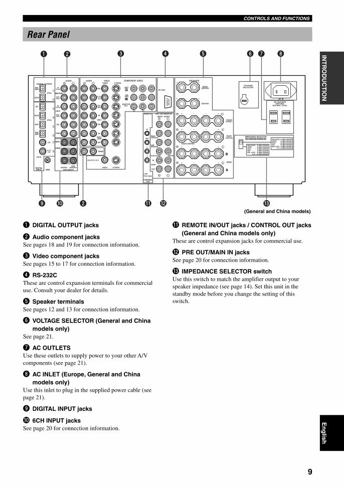
q w(General and China models)
1 DIGITAL OUTPUT jacks
2 Audio component jacksSee pages 18 and 19 for connection information.
3 Video component jacksSee pages 15 to 17 for connection information.
4 RS-232CThese are control expansion terminals for commercialuse. Consult your dealer for details.
5 Speaker terminalsSee pages 12 and 13 for connection information.
6 VOLTAGE SELECTOR (General and Chinamodels only)
See page 21.
7 AC OUTLETSUse these outlets to supply power to your other A/Vcomponents (see page 21).
8 AC INLET (Europe, General and Chinamodels only)
Use this inlet to plug in the supplied power cable (seepage 21).
9 DIGITAL INPUT jacks
0 6CH INPUT jacksSee page 20 for connection information.
q REMOTE IN/OUT jacks / CONTROL OUT jacks(General and China models only)
These are control expansion jacks for commercial use.
w PRE OUT/MAIN IN jacksSee page 20 for connection information.
e IMPEDANCE SELECTOR switchUse this switch to match the amplifier output to yourspeaker impedance (see page 14). Set this unit in thestandby mode before you change the setting of thisswitch.
Rear Panel
0102DSPAZ2_1-9_EN(GB) 02.8.22, 0:15 PM9

10
SPEAKER SETUP
This unit has been designed to provide the best sound-field quality with an 8-speaker system, using left and rightmain speakers, left and right rear speakers, left and rightfront effect speakers and a center and rear centerspeakers. If you use different brands of speakers (withdifferent tonal qualities) in your system, the tone of amoving human voice and other types of sound may notshift smoothly. We recommend that you use speakersfrom the same manufacturer or speakers with the sametonal quality.
The main speakers are used for the main source soundplus the effect sounds. They will probably be the speakersfrom your present stereo system. The rear speakers areused for the effect and surround sounds, and the centerspeaker is for the center sounds (dialog, vocals, etc.). Thefront effect speakers are used for the effect sound. If forsome reason it is not practical to use one of speakers (forexample, a center speaker), you can do without it. Bestresults, however, are obtained with the full system.
The main speakers should be high-performance modelsand have enough power-handling capacity to accept themaximum output of your audio system. The otherspeakers do not have to be equal to the main speakers. Forprecise sound localization, however, it is ideal to use themodels of equivalent performance with the mainspeakers.
PREPARATION
Use of a subwoofer expands yoursound field
It is also possible to further expand your system with theaddition of a subwoofer. The use of a subwoofer iseffective not only for reinforcing bass frequencies fromany or all channels, but also for reproducing the LFE(low-frequency effect) channel with high fidelity whenthe Dolby Digital signal or the DTS signal is played back.The YAMAHA Active Servo Processing SubwooferSystem is ideal for natural and lively bass reproduction.
CAUTION
Use magnetically shielded speakers. If this type ofspeakers still creates the interference with a monitor,place the speakers away from the monitor.
Speakers to Be Used
0103DSPAZ2_10-22_EN(GB) 02.8.22, 0:15 PM10

11
En
glish
INT
RO
DU
CT
ION
PR
EPA
RA
TIO
NB
AS
IC O
PE
RA
-T
ION
AD
VAN
CE
DO
PE
RA
TIO
NA
DD
ITIO
NA
LIN
FO
RM
AT
ION
AP
PE
ND
IXSPEAKER SETUP
Rear center speakerPlace the rear center speaker in the center between the leftand right rear speakers at the same height from the flooras the rear speakers.
Front effect speakersPlace the front effect speakers about 0.5 - 1 m (1 - 3 feet)outside the main speakers and in front of the room, facingslightly inwards, nearly 1.8 m (6 feet) above the floor.
SubwooferThe position of the subwoofer is not so critical, becauselow bass sounds are not highly directional. But it is betterto place the subwoofer near the main speakers. Turn itslightly toward the center of the room to reduce the wallreflections.
Main speakersPlace the left and right main speakers an equal distancefrom the ideal listening position. The distance of eachspeaker from each side of the video monitor should be thesame.
Center speakerAlign the front face of the center speaker with the frontface of your video monitor. Place the speaker as close tothe monitor as possible, such as directly over or under themonitor and centrally between the main speakers.
Rear speakersPlace these speakers behind your listening position,facing slightly inwards, nearly 1.8 m (6 feet) above thefloor.
Speaker PlacementRefer to the following diagram when you place the speakers.
Main speaker (L)
1.8 m (6 feet)
Rear speaker (L)
Rear center speaker
Rear speaker (R)
Subwoofer
Main speaker (R)
Center speaker
Front effect speaker (R)
Front effect speaker (L)
Note• If you do not use any effect speakers (rear, front effect, center and/or rear center), change the settings of SPEAKER SET items in the
SET MENU to designate the signals to other terminals you connect speakers to.
0103DSPAZ2_10-22_EN(GB) 02.8.22, 0:15 PM11
12
SPEAKER SETUP
1 2
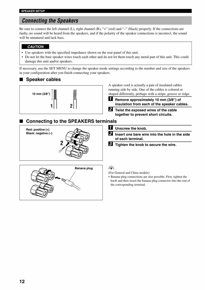
Connecting the SpeakersBe sure to connect the left channel (L), right channel (R), “+” (red) and “–” (black) properly. If the connections arefaulty, no sound will be heard from the speakers, and if the polarity of the speaker connections is incorrect, the soundwill be unnatural and lack bass.
CAUTION
• Use speakers with the specified impedance shown on the rear panel of this unit.• Do not let the bare speaker wires touch each other and do not let them touch any metal part of this unit. This could
damage this unit and/or speakers.
If necessary, use the SET MENU to change the speaker mode settings according to the number and size of the speakersin your configuration after you finish connecting your speakers.
Speaker cablesA speaker cord is actually a pair of insulated cablesrunning side by side. One of the cables is colored orshaped differently, perhaps with a stripe, groove or ridge.
1 Remove approximately 10 mm (3/8”) ofinsulation from each of the speaker cables.
2 Twist the exposed wires of the cabletogether to prevent short circuits.
Connecting to the SPEAKERS terminals1 Unscrew the knob.
2 Insert one bare wire into the hole in the sideof each terminal.
3 Tighten the knob to secure the wire.
y(For General and China models)• Banana plug connections are also possible. First, tighten the
knob and then insert the banana plug connector into the end ofthe corresponding terminal.
10 mm (3/8”)
Red: positive (+)Black: negative (–)
Banana plug
3
12
0103DSPAZ2_10-22_EN(GB) 02.8.22, 0:15 PM12

13
En
glish
INT
RO
DU
CT
ION
PR
EPA
RA
TIO
NB
AS
IC O
PE
RA
-T
ION
AD
VAN
CE
DO
PE
RA
TIO
NA
DD
ITIO
NA
LIN
FO
RM
AT
ION
AP
PE
ND
IXSPEAKER SETUP
AC OUTLETS
VOLTAGESELECTOR
SWITCHED50W MAX. TOTAL
AC IN
CENTER
SUBWOOFER S VIDEO
MONITOR OUT
VIDEO
DIGITAL OUTPUT
DIGITALINPUT 6CH INPUTGND
AUDIO AUDIO VIDEO
CONTROL OUT
SPEAKERS
REMOTE
IN
OUT
1
2
RS-232C
+12V15mA MAX.
COMPONENT VIDEOS VIDEO
DVD
D-TV/LD
CBL/SAT
VIDEO
PR
DVD
MONITOROUT
CBL/SAT
MAIN
IN
OUT
MAIN
REAR CENTER
(SURROUND)
FRONTEFFECT
REAR
CENTER
REARCENTER
PRE OUT/MAIN IN
IMPEDANCE SELECTOR SET BEFORE POWER ON
SUBWOOFER
CENTER
REAR
FRONT EFFECT
REAR CENTER
PB Y
R
R
L
L
R L
R L
R L
R L
R L
R L
OPTICAL
OPTICAL
MD/TAPE
IN(PLAY)
IN(PLAY)
OUT(REC)
OUT(REC)
CD-R
CD-R
MD/TAPE
CD-R
DVD
CBL/SAT
CD
CD
PHONO IN
OUT
OUT
TUNER
VCR 2 /DVR
VCR 1
IN
MAIN
SURROUND
CD
D-TV/LD
(SURROUND)
COAXIAL
+ –
–+
+ – – +
+ – – +
+ – – +
+ – – +
REAR CENTER
A+B
REAR
8ΩMIN./SPEAKER8ΩMIN./SPEAKER8ΩMIN./SPEAKER8ΩMIN./SPEAKER8ΩMIN./SPEAKER
16ΩMIN./SPEAKER
CENTERFRONT
MAIN A OR B::::
::
MAIN A OR B
FRONT
6ΩMIN./SPEAKER4ΩMIN./SPEAKER6ΩMIN./SPEAKER6ΩMIN./SPEAKER4ΩMIN./SPEAKER
REAR CENTERCENTER
REAR:::
::
A + B 8ΩMIN./SPEAKER:
A
B
Subwoofersystem
Rear Centerspeaker
Rear speaker
Centerspeaker
(General and China models)
Right Right Left
Front Effect speaker
Right Left
Left
Main B speaker
MAIN SPEAKERS terminalsOne or two speaker systems can be connected to these terminals. If you use only one speaker system, connect it to eitherof the MAIN A or B terminals.
REAR SPEAKERS terminalsA rear speaker system can be connected to these terminals.
CENTER SPEAKER terminalsA center speaker can be connected to these terminals.
REAR CENTER SPEAKER terminalsA rear center speaker can be connected to these terminals.
FRONT EFFECT SPEAKERS terminalsA front effect speaker system can be connected to these terminals.
SUBWOOFER jackWhen using a subwoofer with built-in amplifier, including the YAMAHA Active Servo Processing Subwoofer System,connect the input jack of the subwoofer system to this jack. Low bass signals distributed from the main, center and/orrear channels are directed to this jack if they are assigned to this jack. (The cut-off frequency of this jack is 90 Hz.) TheLFE (low-frequency effect) signals generated when Dolby Digital or DTS is decoded are also directed if they areassigned to this jack.
Note• Depending on the settings of “1 SPEAKER SET” and “10 LFE LEVEL” on the SET MENU, some signals may not be output from
the SUBWOOFER jack.
Right Left
Main A speaker
0103DSPAZ2_10-22_EN(GB) 02.8.22, 0:15 PM13

14
SPEAKER SETUP
AC OUTLETS
VOLTAGESELECTOR
SWITCHED50W MAX. TOTAL
AC IN
MAIN
(SURROUND)
FRONTEFFECT
REAR IMPEDANCE SELECTOR SET BEFORE POWER ON
L
L
L
L
+
+
+
+
REAR CENTER
A+B
REAR
8ΩMIN./SPEAKER8ΩMIN./SPEAKER8ΩMIN./SPEAKER8ΩMIN./SPEAKER8ΩMIN./SPEAKER
16ΩMIN./SPEAKER
CENTERFRONT
MAIN A OR B::::
::
MAIN A OR B
FRONT
6ΩMIN./SPEAKER4ΩMIN./SPEAKER6ΩMIN./SPEAKER6ΩMIN./SPEAKER4ΩMIN./SPEAKER
REAR CENTERCENTER
REAR:::
::
A + B 8ΩMIN./SPEAKER:
A
B
IMPEDANCE SELECTOR SET BEFORE POWER ON
REAR CENTER
A+B
REAR
8ΩMIN./SPEAKER8ΩMIN./SPEAKER8ΩMIN./SPEAKER8ΩMIN./SPEAKER8ΩMIN./SPEAKER
16ΩMIN./SPEAKER
CENTERFRONT
MAIN A OR B::::
::
MAIN A OR B
FRONT
6ΩMIN./SPEAKER4ΩMIN./SPEAKER6ΩMIN./SPEAKER6ΩMIN./SPEAKER4ΩMIN./SPEAKER
REAR CENTERCENTER
REAR:::
::
A + B 8ΩMIN./SPEAKER:
Switchposition
Upper
Lower
Speaker
RearCenter
Center
FrontEffect
Rear
Main
RearCenter
Center
FrontEffect
Rear
Main
Impedance level
The impedance must be 6 Ω or higher.
The impedance must be 4 Ω or higher.
The impedance of each speaker must be 6 Ω or higher.
The impedance of each speaker must be 6 Ω or higher.
If you use one set of main speakers, the impedance ofeach speaker must be 4 Ω or higher.If you use two sets of main speakers, the impedance ofeach speaker must be 8 Ω or higher.
The impedance must be 8 Ω or higher.
The impedance must be 8 Ω or higher.
The impedance of each speaker must be 8 Ω or higher.
The impedance of each speaker must be 8 Ω or higher.
If you use one set of main speakers, the impedance ofeach speaker must be 8 Ω or higher.If you use two sets of main speakers, the impedance ofeach speaker must be 16 Ω or higher.
IMPEDANCE SELECTOR switch
IMPEDANCE SELECTOR switch
WARNINGDo not change the IMPEDANCE SELECTOR switch setting while the power of this unit is on, otherwise this unitmay be damaged.If this unit fails to turn on when STANDBY/ON (or SYSTEM POWER) is pressed, the IMPEDANCE SELECTORswitch may not be fully slid to either position. If so, slide the switch to either position fully when this unit is in thestandby mode.
Select the upper or lower position according to the impedance of the speakers in your system. Be sure to move thisswitch only when this unit is in the standby mode.
(General and China models)
0103DSPAZ2_10-22_EN(GB) 02.8.22, 0:15 PM14
15
En
glish
INT
RO
DU
CT
ION
PR
EPA
RA
TIO
NB
AS
IC O
PE
RA
-T
ION
AD
VAN
CE
DO
PE
RA
TIO
NA
DD
ITIO
NA
LIN
FO
RM
AT
ION
AP
PE
ND
IX
y• The signals input through the S VIDEO jacks can be converted
to composite signals inside of this unit and output through theVIDEO MONITOR OUT jacks on this unit as well.
• (Europe and U.K. models only) The signals input through theVIDEO jack on this unit can be output through the S VIDEOMONITOR OUT jack by setting “V CONV.” in “13 DISPLAYSET” on the SET MENU to ON (see page 65).
• When signals input through both S VIDEO and VIDEO jacks,signals input through the S VIDEO jack has priority.
• You can designate the input for the COMPONENT VIDEO Aand B jacks according to your component by using “7 I/OASSIGNMENT” on the SET MENU (see page 62 for details).
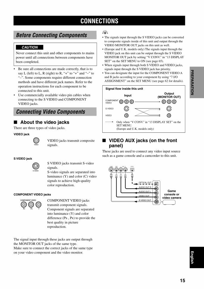
VIDEO AUX jacks (on the frontpanel)
These jacks are used to connect any video input sourcesuch as a game console and a camcorder to this unit.
Before Connecting Components
CAUTION
Never connect this unit and other components to mainspower until all connections between components havebeen completed.
• Be sure all connections are made correctly, that is tosay L (left) to L, R (right) to R, “+” to “+” and “–” to“–”. Some components require different connectionmethods and have different jack names. Refer to theoperation instructions for each component to beconnected to this unit.
• Use commercially available video pin cables whenconnecting to the S VIDEO and COMPONENTVIDEO jacks.
Connecting Video Components
About the video jacksThere are three types of video jacks.
VIDEO jacks transmit compositesignals.
S VIDEO jacks transmit S-videosignals.S-video signals are separated intoluminance (Y) and color (C) videosignals to achieve high-qualitycolor reproduction.
COMPONENT VIDEO jackstransmit component signals.Component signals are separatedinto luminance (Y) and colordifference (PB , PR) to provide thebest quality in picturereproduction.
The signal input through these jacks are output throughthe MONITOR OUT jacks of the same type.Make sure to connect the correct jacks of the same typeon your video component and the video monitor.
CONNECTIONS
VIDEO jack
S VIDEO jack
COMPONENT VIDEO jacks
VIDEO AUX
S VIDEO VIDEO AUDIO OPTICALL R
AUDIO OUT R
AUDIO OUT L
VIDEO OUT
OPTICAL OUT
S VIDEO OUT
OV L RS
COMPONENT VIDEO
PR PB Y
VIDEO
S VIDEO
Gameconsole or
video camera
S VIDEO
VIDEO
COMPONENTVIDEO
Signal flow inside this unit
Only when “V CONV.” in “13 DISPLAY SET” on theSET MENU.(Europe and U.K. models only)
InputOutput
(MONITOR OUT)
0103DSPAZ2_10-22_EN(GB) 02.8.22, 0:15 PM15

16
CONNECTIONS
CENTER
SUBWOOFER S VIDEO
MONITOR OUT
VIDEO
DIGITAL OUTPUT
DIGITALINPUT 6CH INPUTGND
AUDIO AUDIO VIDEO
CONTROL OUT
REMOTE
IN
OUT
1
2
RS-232C
+12V15mA MAX.
COMPONENT VIDEOS VIDEO
DVD
D-TV/LD
CBL/SAT
VIDEO
PR
DVD
MONITOROUT
CBL/SAT
MAIN
IN
OUT
PRE OUT/MAI
SUBWOOFER
REAR
FRONT EFFEC
REAR CENTER
PB Y
R
R
L
L
R L
R L
OPTICAL
OPTICAL
MD/TAPE
IN(PLAY)
IN(PLAY)
OUT(REC)
OUT(REC)
CD-R
CD-R
MD/TAPE
CD-R
DVD
CBL/SAT
CD
CD
PHONO IN
OUT
OUT
TUNER
VCR 2 /DVR
VCR 1
IN
MAIN
SURROUND
CD
D-TV/LD
(SURROUND)
COAXIAL
V SL R
VVC S SL R
O
L
S
R
V
C
O
COMPONENTINPUT
S VIDEOINPUT
VIDEOINPUT
S VIDEOOUTPUT
VIDEOOUTPUT
AUDIO OUTPUT
COAXIAL OUTPUT
OPTICAL OUTPUT
AUDIO OUTPUT COMPONENT OUTPUT
VIDEOOUTPUT
S VIDEOOUTPUT V V V
V V V
V
V
V
(General and Chinamodels)
indicates S-video cables
indicates video cables
indicates coaxial cables
indicates optical cables
indicates right analog cables
indicates left analog cables
indicates signal direction
TV/digital TV orLD player
DVD player
Videomonitor
indicates component video cables
0103DSPAZ2_10-22_EN(GB) 02.8.22, 0:15 PM16

17
En
glish
INT
RO
DU
CT
ION
PR
EPA
RA
TIO
NB
AS
IC O
PE
RA
-T
ION
AD
VAN
CE
DO
PE
RA
TIO
NA
DD
ITIO
NA
LIN
FO
RM
AT
ION
AP
PE
ND
IXCONNECTIONS
CENTER
SUBWOOFER S VIDEO
MONITOR OUT
VIDEO
DIGITAL OUTPUT
DIGITALINPUT 6CH INPUTGND
AUDIO AUDIO VIDEO
CONTROL OUT
REMOTE
IN
OUT
1
2
RS-232C
+12V15mA MAX.
COMPONENT VIDEOS VIDEO
DVD
D-TV/LD
CBL/SAT
VIDEO
PR
DVD
MONITOROUT
CBL/SAT
MAIN
IN
OUT
PRE OUT/MAI
SUBWOOFER
REAR
FRONT EFFEC
REAR CENTER
PB Y
R
R
L
L
R L
R L
OPTICAL
OPTICAL
MD/TAPE
IN(PLAY)
IN(PLAY)
OUT(REC)
OUT(REC)
CD-R
CD-R
MD/TAPE
CD-R
DVD
CBL/SAT
CD
CD
PHONO IN
OUT
OUT
TUNER
VCR 2 /DVR
VCR 1
IN
MAIN
SURROUND
CD
D-TV/LD
(SURROUND)
COAXIAL
V SL R
VV S S SL R L R
O
S VIDEO OUTPUTVIDEO OUTPUT
AUDIO OUTPUT
OPTICAL OUTPUT
S VIDEOINPUT
S VIDEOOUTPUT
S VIDEO INPUT
VIDEOOUTPUT
V
VIDEOINPUT
AUDIO INPUT
AUDIO OUTPUTVIDEOINPUT
COMPONENT OUTPUT
V V V
V V V
L
S
R
V
O
COMPONENTINPUT
V
V
V
indicates S-video cables
indicates video pin cables
indicates optical cables
indicates right audio pin cables
indicates left audio pin cables
indicates signal direction
Videomonitor
VCR 1 or VCR 2/DVR (digital
video recorder)
Cable TV orSatellite tuner
(General and Chinamodels)
indicates component video cables
0103DSPAZ2_10-22_EN(GB) 02.8.22, 0:15 PM17

18
CONNECTIONS
Connecting Audio Components
Connecting a CD playery• The COAXIAL CD and OPTICAL CD jacks are available for a
CD player which has coaxial or optical digital output jacks.• When you connect a CD player to both the COAXIAL CD and
OPTICAL CD jacks, priority is given to the input signals fromthe COAXIAL CD jack.
Connecting an MD recorder, tapedeck or CD recorder
y• DIGITAL OUTPUT jacks and analog OUT (REC) are
independent. Only digital signals are output from DIGITALOUTPUT jacks and analog signals from OUT (REC) jacks.
• When you connect your recording component to both theanalog and digital input jacks, the priority is given to the digitalsignal.
Note• When you connect a recording component to this unit, keep its
power on while using this unit. If the power is off, this unit maydistort the sound from other components.
Connecting to digital jacksThis unit has digital jacks for direct transmission ofdigital signals through either coaxial or fiber optic cables.You can use the digital jacks to input PCM, Dolby Digitaland DTS bitstreams. When you connect components toboth the COAXIAL and OPTICAL jacks, priority is givento the input signals from the COAXIAL jack. All digitalinput jacks are acceptable for 96-kHz sampling digitalsignals.
y• You can designate the input for each digital jacks according to
your component by using “7 I/O ASSIGNMENT” on the SETMENU (see page 62 for details).
About the dust protection capPull out the cap from the optical jack before you connectthe fiber optic cable. Do not discard the cap. When youare not using the optical jack, be sure to put the cap backin place. This cap protects the jack from dust.
Notes• DIGITAL OUTPUT jacks and analog OUT (REC) jacks are
independent. Only digital signals are output from DIGITALOUTPUT jacks and analog signals from OUT (REC) jacks.
• The OPTICAL jacks on this unit conform to the EIA standard.If you use a fiber optic cable that does not conform to thisstandard, this unit may not function properly.
Connecting a turntablePHONO jacks are for connecting a turntable with an MMor high-output MC cartridge. If you have a turntable witha low-output MC cartridge, use an in-line boostingtransformer or MC-head amplifier when connecting tothese jacks.
y• Connect your turntable to the GND terminal to reduce noise in
the signal. However you may hear less noise without theconnection to the GND terminal for some record players.
0103DSPAZ2_10-22_EN(GB) 02.8.22, 0:15 PM18

19
En
glish
INT
RO
DU
CT
ION
PR
EPA
RA
TIO
NB
AS
IC O
PE
RA
-T
ION
AD
VAN
CE
DO
PE
RA
TIO
NA
DD
ITIO
NA
LIN
FO
RM
AT
ION
AP
PE
ND
IXCONNECTIONS
CENTER
SUBWOOFER S VIDEO
MONITOR OUT
VIDEO
DIGITAL OUTPUT
DIGITALINPUT 6CH INPUTGND
AUDIO AUDIO VIDEOS VIDEO
DVD
D-TV/LD
CBL/SAT
VIDEO
R LR L
OPTICAL
OPTICAL
MD/TAPE
IN(PLAY)
IN(PLAY)
OUT(REC)
OUT(REC)
CD-R
CD-R
MD/TAPE
CD-R
DVD
CBL/SAT
CD
CD
PHONO IN
OUT
OUT
TUNER
VCR 2 /DVR
VCR 1
IN
MAIN
SURROUND
CD
D-TV/LD
COAXIAL
L R L R L R
C
L R L R L RL R
O
OPTICALINPUT
OPTICALOUTPUT
INPUT
INPUT
L R
OUTPUT
OPTICALINPUT
OUTPUT
OUTPUT
OUTPUT
GND MAINOUTPUT OUTPUT
SURROUNDOUTPUT
SUBWOOFEROUTPUT
CENTER OUTPUT
OO
O
R
L
OPTICALOUTPUT
COAXIAL OUTPUT
L
R
C
O
indicates coaxial cables
indicates optical cables
indicates right analog cables
indicates left analog cables
indicates signal direction
CD player
CD recorderMD recorder ortape deck
External decoderSee page 20
Turntable
(General andChina models)
Tuner
0103DSPAZ2_10-22_EN(GB) 02.8.22, 0:15 PM19

20
CONNECTIONS
Connecting to an ExternalAmplifier
If you want to increase the power output to the speakers,or want to use another amplifier, connect an externalamplifier to the PRE OUT/MAIN IN jacks as follows.
Notes• When RCA pin plugs are connected to the PRE OUT/MAIN
IN jacks for output to an external amplifier, it is not necessaryto use the corresponding SPEAKERS terminals. Set the volumeof the amplifier connected to this unit to the maximum.
• No signals will be output from any other PRE OUT jacks thanthe MAIN jacks when SPEAKER A is turned off with ZONE Bselected for “1H SP B SET” on the SET MENU.
1 FRONT EFFECT jacksFront effect channel line output jacks.
2 REAR (SURROUND) jacksRear channel line output jacks.
3 SUBWOOFER jacksWhen using a subwoofer with built-in amplifier, includingthe YAMAHA Active Servo Processing SubwooferSystem, connect the input jack of the subwoofer systemto this jack. Low bass signals distributed from the main,center and/or rear channels are directed to this jack if theyare assigned to this jack. (The cut-off frequency of thisjack is 90 Hz.) The LFE (low-frequency effect) signalsgenerated when Dolby Digital or DTS is decoded are alsodirected if they are assigned to this jack.
Notes• Adjust the volume level of the subwoofer with the control on
the subwoofer. It is also possible to adjust the volume level byusing the remote control of this unit (see “ADJUSTING THELEVEL OF THE EFFECT SPEAKERS” on page 67).
• Depending on the settings of “1 SPEAKER SET” and “10 LFELEVEL” on the SET MENU, some signals may not be outputfrom the SUBWOOFER jack.
Connecting to the 6CH INPUTJacks
This unit is equipped with 6 additional input jacks (leftand right MAIN, CENTER, left and right SURROUNDand SUBWOOFER) for discrete multi-channel input froman external decoder, sound processor or pre-amplifier.
Connect the output jacks on your external decoder to the6CH INPUT jacks. Be sure to match the left and rightoutputs to the left and right input jacks for the main andsurround channels.
Notes• When 6CH INPUT is selected, the signals input to the 6CH
INPUT jacks have priority over any other input source.• When you select 6CH INPUT as the input source, this unit
automatically turns off the digital sound field processor, andyou cannot listen to DSP programs.
• When you select 6CH INPUT as the input source, settings of“1 SPEAKER SET (1A to 1E)” on the SET MENU do notapply.
• When headphones are used, only main L/R channels areoutput. The setting for “6CH INPUT SET” on the SET MENUwill not be applied.
• Setting for “15 6CH INPUT SET” on the SET MENU will beapplied when 6CH INPUT is selected.
MAIN
IN
OUT
PRE OUT/MAIN IN
SUBWOOFER
CENTER
REAR
FRONT EFFECT
REAR CENTER
R L
R L
(SURROUND)
6
1
2
3
4
5
4 REAR CENTER jackRear center channel line output jack.
5 MAIN jacksIN: Line input to this unit’s main channel amplifiers.When connecting to these jacks, signals input to thepreamplifier of this unit will not be output from the mainamplifier of this unit.
OUT: Main channel line output jacks.
Note• The signals output through these jacks are affected by the
BASS, TREBLE and BASS EXTENSION settings.
6 CENTER jackCenter channel line output jack.
0103DSPAZ2_10-22_EN(GB) 02.8.22, 0:15 PM20

21
En
glish
INT
RO
DU
CT
ION
PR
EPA
RA
TIO
NB
AS
IC O
PE
RA
-T
ION
AD
VAN
CE
DO
PE
RA
TIO
NA
DD
ITIO
NA
LIN
FO
RM
AT
ION
AP
PE
ND
IXCONNECTIONS
Connecting the Power Supply Cords
Connecting the AC power cord[Europe, General and China models]Plug the power cord into the AC inlet when allconnections are complete, and then plug in this unit to thewall outlet.
Caution
• Do not use other AC power cords than the one provided.Otherwise it may result in causing fire or an electricalshock.
[U.K. model]Plug this unit into the wall outlet.
Plug in the other components connected to this unit to thewall outlet.
AC OUTLET(S) (SWITCHED)Europe, General and China models ............. 2 OUTLETSU.K. model ..................................................... 1 OUTLETUse these outlets to connect the power cords from yourcomponents to this unit. The power to the ACOUTLET(S) is controlled by this unit’s STANDBY/ON(or SYSTEM POWER and STANDBY). These outletswill supply power to any connected component wheneverthis unit is turned on. The maximum power (total powerconsumption of components) that can be connected to theAC OUTLET(S) is:Europe and U.K. models ........................................ 100 WGeneral and China models ....................................... 50 W
VOLTAGE SELECTOR(General and China models only)
The VOLTAGE SELECTOR on the rear panel of this unitmust be set for your local main voltage BEFOREplugging into the AC main supply. Voltages are 110/120/220/240 V AC, 50/60 Hz.
(General and China models)
AC OUTLETSSWITCHED
50W MAX. TOTAL
AC IN
ECTORWER ON
MIN./SPEAKERMIN./SPEAKERMIN./SPEAKERMIN./SPEAKERMIN./SPEAKERMIN./SPEAKER
MAIN A OR B
FRONT
6ΩMIN./SPEAKER4ΩMIN./SPEAKER6ΩMIN./SPEAKER6ΩMIN./SPEAKER4ΩMIN./SPEAKER
REAR CENTERCENTER
REAR:::
::
A + B 8ΩMIN./SPEAKER:
To AC outlet
AC OUTLETS
VOLTAGESELECTOR
SWITCHED50W MAX. TOTAL
AC IN
IMPEDANCE SELECTOR SET BEFORE POWER ON
REAR CENTER
A+B
REAR
8ΩMIN./SPEAKER8ΩMIN./SPEAKER8ΩMIN./SPEAKER8ΩMIN./SPEAKER8ΩMIN./SPEAKER
16ΩMIN./SPEAKER
CENTERFRONT
MAIN A OR B::::
::
MAIN A OR B
FRONT
6ΩMIN./SPEAKER4ΩMIN./SPEAKER6ΩMIN./SPEAKER6ΩMIN./SPEAKER4ΩMIN./SPEAKER
REAR CENTERCENTER
REAR:::
::
A + B 8ΩMIN./SPEAKER:
VOLTAGE SELECTOR
(General and China models)
0103DSPAZ2_10-22_EN(GB) 02.8.22, 0:15 PM21

22
CONNECTIONS
Turning on the PowerWhen all connections are completed, turn on the power ofthis unit.
1 Press STANDBY/ON (SYSTEM POWER onthe remote control) to turn on the power ofthis unit.
2 Turn on the video monitor connected to thisunit.
BASS
VOLUME
VIDEO AUX
SILENT
PROGRAMSTEREO
REC OUT
SPEAKERS
INPUT MODE
BASSEXTENSION
PROCESSORDIRECT
PHONES
EFFECT
SOURCEMD/TAPECD–R
TUNER
CD
PHONO
DVDD–TV/LD
CBL/SAT
VCR 1
V–AUX
VCR2/DVR
S VIDEO VIDEO AUDIO OPTICALL R
STANDBY/ON
NATURAL SOUND AV AMPLIFIER DSP-AZ2
TREBLE
– + – +
6CHINPUT
A B
D I G I T A L
SET MENUNEXT +–
1
TRANSMIT RE-NAME
STANDBY
6CH INPUT
SOUND
SYSTEM
CLEAR LEARN MACRO OFF ONMACRO
PHONOA B
CD
DVDVCR2/DVRVCR 1
TITLE
MENU
CHAPTER
PAUSESTOPPOWER REC
SELECT
DISPLAY
SEARCH
SOURCE
PLAY
– +
ENTER
D-TV/LD CBL/SAT
CD-RMD/TAPETUNERV-AUX
POWER1
STANDBY/ON
SYSTEMPOWER
or
Remote controlFront panel
0103DSPAZ2_10-22_EN(GB) 02.8.22, 0:15 PM22

23
En
glish
INT
RO
DU
CT
ION
PR
EPA
RA
TIO
NB
AS
ICO
PE
RA
ION
TA
DVA
NC
ED
OP
ER
AT
ION
AD
DIT
ION
AL
INF
OR
MA
TIO
NA
PP
EN
DIX
Selecting the OSD Mode
1 Turn on the video monitor connected to thisunit.
2 Press ON SCREEN on the remote controlrepeatedly to change the display mode.The OSD mode changes in the following order: fulldisplay, short display, and display off.
If the video monitor is connected to theCOMPONENT VIDEO MONITOR OUT jacks of thisunit, the OSD can be shown only when operating theSET MENU. However, the OSD cannot besuperimposed over the image.
Notes• Playing back video software that has an anti-copy signal or
video signals with a lot of noise may produce unstable images.• The OSD signal output to the COMPONENT VIDEO
MONITOR OUT jacks is created from the composite or S-video signal. Therefore, the quality of the OSD signal may varydepending on the signal input through the VIDEO or S VIDEOjacks.
P01 CONCERT HALL 1≥ DSP LEVEL…………0dB
INIT.DLY…………30msROOM SIZE…………1.OLIVENESS…………………5
Europe Hall A
P01 CONCERT HALL 1Europe Hall A
PARAMETER
SET MENU
LEVELON SCREEN
TESTSLEEP
ON-SCREEN DISPLAY (OSD)
You can display the operation information for this unit ona video monitor. If you display the SET MENU and DSPprogram parameter settings on a monitor, it is much easierto see the available options and parameters than it is byreading this information on the front panel display.
y• If a video source is being reproduced, the OSD is
superimposed over the image.• The OSD signal is not output to the REC OUT jack, and will
not be recorded with any video signal.• You can set the OSD to turn on (gray background) or off when
a video source is not being reproduced (or the sourcecomponent is turned off) by using “13 DISPLAY SET” on theSET MENU (see page 65).
OSD ModesYou can change the amount of information the OSDshows.
Full displayThis mode always shows the DSP program parametersettings on the video monitor.
Short displayThis mode briefly shows the same contents as the frontpanel display at the bottom of the screen and thendisappears.
Display offThis mode briefly shows the “DISPLAY OFF” message atthe bottom of the screen and then disappears. Afterwards,no changes to operations appear on the monitor exceptthose of the ON SCREEN button.
Full display Short display
y• When you choose the full display mode, INPUT, VOLUME
and some other types of operation information are displayed atthe bottom of the screen in the same format as that for the frontpanel display.
• The SET MENU and test tone display appear regardless of theOSD mode.
0104DSPAZ2_23-27_EN(GB) 02.8.22, 0:15 PM23

24
Item
1A CENTER SP
1B MAIN SP
1C REAR L/R SP
1D REAR CT SP
1E LFE/BASS OUT
1F FRONT EFCT SP
1G MAIN LEVEL
1H SP B SET
Description
Selects the output mode according to whether or not a center speaker isbeing used and its performance.
Selects the output mode according to the performance of the mainspeakers.
Selects the output mode according to whether or not rear L/R speakersare being used and their performance.
Selects the output mode according to whether or not a rear centerspeaker is being used and its performance.
Selects the speaker according to use for LFE signal output and low basssignal.
Selects the output mode according to whether or not front effectspeakers are being used.
Selects the main speaker level.
Select the location of the main speakers to be connected to theSPEAKERS B terminals.
Control value (defaultsetting indicated in bold)
LRG/SML/NONE
LARGE/SMALL
LRG/SML/NONE
LRG/SML/NONE
SWFR/MAIN/BOTH
YES/NONE
Normal/–10 dB
MAIN / ZONE B
SPEAKER MODE SETTINGS
This unit has 8 SPEAKER SET items on the SET MENU that you must set according to the number of speakers in yourconfiguration and their size. The following table summarizes these SPEAKER SET items, and shows the initial settingsas well as other possible settings.If the initial settings shown in the following table are not appropriate for your speaker configuration, change settingsfollowing the steps described in “1 SPEAKER SET” from pages 56 to 59.
Summary of SPEAKER SET Items 1A through 1H
0104DSPAZ2_23-27_EN(GB) 02.8.22, 0:15 PM24
25
En
glish
INT
RO
DU
CT
ION
PR
EPA
RA
TIO
NB
AS
ICO
PE
RA
ION
TA
DVA
NC
ED
OP
ER
AT
ION
AD
DIT
ION
AL
INF
OR
MA
TIO
NA
PP
EN
DIX
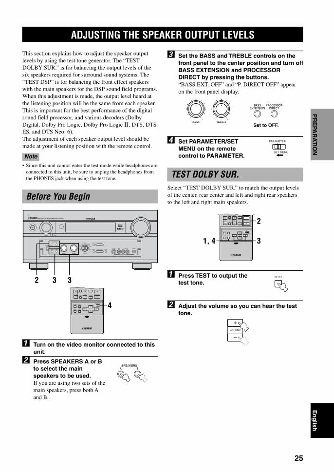
3 Set the BASS and TREBLE controls on thefront panel to the center position and turn offBASS EXTENSION and PROCESSORDIRECT by pressing the buttons.“BASS EXT. OFF” and “P. DIRECT OFF” appearon the front panel display.
4 Set PARAMETER/SETMENU on the remotecontrol to PARAMETER.
TEST DOLBY SUR.Select “TEST DOLBY SUR.” to match the output levelsof the center, rear center and left and right rear speakersto the left and right main speakers.
1 Press TEST to output thetest tone.
2 Adjust the volume so you can hear the testtone.
This section explains how to adjust the speaker outputlevels by using the test tone generator. The “TESTDOLBY SUR.” is for balancing the output levels of thesix speakers required for surround sound systems. The“TEST DSP” is for balancing the front effect speakerswith the main speakers for the DSP sound field programs.When this adjustment is made, the output level heard atthe listening position will be the same from each speaker.This is important for the best performance of the digitalsound field processor, and various decoders (DolbyDigital, Dolby Pro Logic, Dolby Pro Logic , DTS, DTSES, and DTS Neo: 6).The adjustment of each speaker output level should bemade at your listening position with the remote control.
Note• Since this unit cannot enter the test mode while headphones are
connected to this unit, be sure to unplug the headphones fromthe PHONES jack when using the test tone.
Before You Begin
1 Turn on the video monitor connected to thisunit.
2 Press SPEAKERS A or Bto select the mainspeakers to be used.If you are using two sets of themain speakers, press both Aand B.
TEST
BASS TREBLE
– + – +
MUTE
VOLUME
STEREO
TV INPUT
TV VOL CH
PRESET
DISC
PARAMETER
SET MENU
EFFECT
LEVELON SCREEN
TESTSLEEP
TV MUTE
A/B/C/D/E
2
31, 4
BASSEXTENSION
PROCESSORDIRECT
SPEAKERSA B
ADJUSTING THE SPEAKER OUTPUT LEVELS
Set to OFF.
BASS
VOLUME
VIDEO AUX
SILENT
PROGRAMSTEREO
REC OUT
SPEAKERS
INPUT MODE
BASSEXTENSION
PROCESSORDIRECT
PHONES
EFFECT
SOURCEMD/TAPECD–R
TUNER
CD
PHONO
DVDD–TV/LD
CBL/SAT
VCR 1
V–AUX
VCR2/DVR
S VIDEO VIDEO AUDIO OPTICALL R
STANDBY/ON
NATURAL SOUND AV AMPLIFIER DSP-AZ2
TREBLE
– + – +
6CHINPUT
A B
D I G I T A L
SET MENUNEXT +–
2 33MUTE
VOLUME
STEREO
TV INPUT
TV VOL CH
PRESET
DISC
PARAMETER
SET MENU
EFFECT
LEVELON SCREEN
TESTSLEEP
TV MUTE
A/B/C/D/E
4
PARAMETER
SET MENU
VOLUME
0104DSPAZ2_23-27_EN(GB) 02.8.22, 0:16 PM25

26
ADJUSTING THE SPEAKER OUTPUT LEVELS
Notes• If “1A CENTER SP” on the SET MENU is set to NONE, the
center channel sound is automatically output from the left andright main speakers.
• If “1C REAR L/R SP” on the SET MENU is set to NONE, theoutput level of the rear right, left and center speakers cannot beadjusted in step 3. The test tone will be circulated in the orderof LEFTCENTERRIGHTSUBWOOFERLEFT...,skipping the rear right and left speakers and the rear centerspeaker.
• If “1D REAR CT SP” on the SET MENU is set to NONE, theoutput level of the rear center speaker cannot be adjusted instep 3. The test tone will be circulated in the order ofLEFTCENTERRIGHTRIGHT SURROUNDLEFTSURROUNDSUBWOOFERLEFT ..., skipping the rearcenter speaker.
• If “1E LFE/BASS OUT” on the SET MENU is set to MAIN,the output level of the subwoofer cannot be adjusted. The testtone will be circulated in the order of LEFTCENTER
RIGHTRIGHT SURROUNDREAR CENTERLEFTSURROUNDLEFT…, skipping the subwoofer.
y• It is not necessary to readjust the speaker level once it is set as
long as you do not change the speakers. You can enjoy listeningto or watching the input source with the desired volume byadjusting the volume key.
• You can increase the output levels of the effect speakers(center, left rear and right rear and rear center) to +10 dB. If theoutput level of these speakers is lower than that of the mainspeakers even after you have increased the output level of thesespeakers up to +10 dB, set “1G MAIN LEVEL” on the SETMENU to –10 dB (see page 59). This setting decreases themain speaker output level to about one-third of the normallevel. After you have set “1G MAIN LEVEL” on the SETMENU to –10 dB, adjust the levels for the center and rearspeakers again.
The test tone is heard from the left main speaker,center speaker, right main speaker, right rear speaker,rear center speaker, left rear speaker and subwooferin order. The tone is produced for 2.5 seconds eachtime.The state of the test tone output is also shown on themonitor by an image of the audio listening room.This is convenient for adjusting each speaker level.
Front panel display also indicates from whichspeaker the test tone is output in the order ofTEST LEFTTEST CENTERTEST RIGHT
TEST R SUR.TEST REAR CNTRTEST L SUR.TEST SUBWOOFER
Note• If the test tone cannot be heard, turn down the volume, set this
unit in the standby mode and check the speaker connections.
3 Press –/+ repeatedly toadjust the output level ofthe effect speakers so thatthe output level comingfrom each speaker is thesame.While adjusting, the test tone is heard from theselected speaker.
Note• Main L/R speaker level cannot be adjusted by itself. Use
VOLUME to adjust the main volume.
4 When the adjustment iscomplete, press TEST.To enter the “TEST DSP”mode, press TEST once.To stop the test tone, pressTEST twice.
LEFT
TEST DOLBY SUR.
LEFT SURROUND RIGHT SURROUND
CENTER
REAR CENTER
RIGHT LEFT
SUBWOOFER
TEST
0104DSPAZ2_23-27_EN(GB) 02.8.22, 0:16 PM26

27
En
glish
INT
RO
DU
CT
ION
PR
EPA
RA
TIO
NB
AS
ICO
PE
RA
ION
TA
DVA
NC
ED
OP
ER
AT
ION
AD
DIT
ION
AL
INF
OR
MA
TIO
NA
PP
EN
DIX
CONNECTIONSADJUSTING THE SPEAKER OUTPUT LEVELS
TEST DSPSelect “TEST DSP” to match the output levels of thefront effect speakers to the main speakers.
Note• You cannot enter the “TEST DSP” mode if “1F FRONT EFCT
SP” is set to NONE.
1 Press TEST repeatedly tooutput the test tone.
2 Adjust the volume so youcan hear the test tone.
The test tone is heard alternately from the front effectspeakers and main speakers. The tone is produced for2.5 seconds each time. Press k to hear the test tonefrom the front effect L speaker, and n to hear the testtone from the front effect R speaker.
TEST
MUTE
VOLUME
STEREO
TV INPUT
TV VOL CH
PRESET
DISC
PARAMETER
SET MENU
EFFECT
LEVELON SCREEN
TESTSLEEP
TV MUTE
A/B/C/D/E
2
31, 4
VOLUME
RIGHT
FRONTLEFT
FRONT
The state of the test tone output is also shown on themonitor by an image of the audio listening room.This is convenient for adjusting each speaker level.
Front panel display also indicates from whichspeaker the test tone is output as follows:TEST MAIN TEST FRONT TEST MAIN …
Note• If the test tone cannot be heard, turn down the volume, set this
unit in the standby mode and check the speaker connections.
3 Press –/+ repeatedly toadjust the output level ofthe front effect speakersso that the output levelcoming from eachspeaker is the same.While adjusting, the test tone is heard from the fronteffect speaker.
Note• Main L/R speaker level cannot be adjusted by itself. Use
VOLUME to adjust the main volume.
4 When the adjustment iscomplete, press TEST tostop the test tone.
y• It is not necessary to readjust the speaker level once it is set as
long as you do not change the speakers. You can enjoy listeningto or watching the input source with the desired volume byadjusting the volume key.
• You can increase the output levels of the front effect speakersto +10 dB. If the output level of these speakers is lower thanthat of the main speakers even after you have increased theoutput level of these speakers up to +10 dB, set “1G MAINLEVEL” on the SET MENU to –10 dB (see page 59). Thissetting decreases the main speaker output level to about one-third of the normal level. After you have set “1G MAINLEVEL” on the SET MENU to –10 dB, adjust the levels forthe center and rear speakers again.
MAIN
TEST DSP
TEST
0104DSPAZ2_23-27_EN(GB) 02.8.22, 0:16 PM27

28
BASIC PLAYBACK
1 Press STANDBY/ON (SYSTEM POWER onthe remote control) to turn on the power.
2 Turn on the video monitor connected to thisunit.
3 Press SPEAKERS A or Bto select the mainspeakers to be used.If you are using two sets ofmain speakers, press both Aand B. The speaker indicator(s)for the selected set(s) lights upon the front panel display.
4 Rotate INPUT (or press one of the inputselector buttons on the remote control) toselect the input source.The current input source name and input modeappear on the front panel display and on the videomonitor for a few seconds.
Note• The input source names correspond to the jack names on the
rear panel of this unit, not the names of the componentconnected to this unit.
To select a source connected to the 6CH INPUTjacksPress 6CH INPUT until “6CH INPUT” appears on thefront panel display and on the video monitor.
Notes• If “6CH INPUT” is shown on the front panel display and on
the video monitor, no other source can be played. To selectanother input source with INPUT (one of the input selectorbuttons), press 6CH INPUT to turn off “6CH INPUT” from thefront panel display and the video monitor.
• If you want to enjoy an audio source connected to the 6CHINPUT jacks together with a video source, first select the videosource and then press 6CH INPUT.
INPUT
TRANSMIT RE-NAME
STANDBY
6CH INPUT
SOUND
SYSTEM
CLEAR LEARN MACRO OFF ONMACRO
PHONOA B
CD
DVDVCR2/DVRVCR 1
TITLE
MENU
CHAPTER
PAUSESTOPPOWER REC
HALL 1DSP10KEY HALL 2 CHURCH JAZZ CLUB
SELECT
DISPLAY
SEARCH
SOURCE
PLAY
– +
ENTER
D-TV/LD CBL/SAT
CD-RMD/TAPETUNERV-AUX
POWER
HALL 1
EX/ES
DSP10KEY
ROCKCONCERT
MOVIETHEATER 1
MOVIETHEATER 2
MUTE
VOLUME
STEREO
TV INPUT
TV VOL CH
PRESET
DISC EFFECT
TV MUTE
MUSICVIDEO
TVTHEATER
ENTER-TAINMENT
HALL 2 CHURCH JAZZ CLUB
SELECT/DTS
SUR.
CHP/INDEX
A/B/C/D/E
1
5
9
6
100 10 100
11 12
7 8
2 3 4
++17
46
PHONO
CD
DVDVCR2/DVRVCR 1D-TV/LD CBL/SAT
CD-RMD/TAPETUNERV-AUX
L R
VCR DVD TUNER CD PHONOCD RV AUX 1
SP
VCR2/DVR CBL/SAT MD/TAPETV/LD VOLUMED
A DVD AUTO
BASS
VOLUME
VIDEO AUX
SILENT
PROGRAMSTEREO
REC OUT
SPEAKERS
INPUT MODE
BASSEXTENSION
PROCESSORDIRECT
PHONES
EFFECT
SOURCEMD/TAPECD–R
TUNER
CD
PHONO
DVDD–TV/LD
CBL/SAT
VCR 1
V–AUX
VCR2/DVR
S VIDEO VIDEO AUDIO OPTICALL R
STANDBY/ON
NATURAL SOUND AV AMPLIFIER DSP-AZ2
TREBLE
– + – +
6CHINPUT
A B
D I G I T A L
SET MENUNEXT +–
1
6
64
3 6 7 4
STANDBY/ON
SYSTEMPOWER
SPEAKERSA B
or
or
Remote control
Remote control
Front panel
Front panel
Selected input source
6CHINPUT
6CH INPUT
Remote controlFront panel
or
0105DSPAZ2_28-33_EN(GB) 02.8.22, 0:16 PM28

29
En
glish
INT
RO
DU
CT
ION
PR
EPA
RA
TIO
NB
AS
ICO
PE
RA
TIO
NA
DVA
NC
ED
OP
ER
AT
ION
AD
DIT
ION
AL
INF
OR
MA
TIO
NA
PP
EN
DIX
BASIC PLAYBACK
BGV (background video) functionThe BGV function allows you to combine a video imagefrom a video source with a sound from an audio source.For example, you can enjoy listening to classical musicwhile having beautiful scenery from the video source onthe video monitor.
Select a source from the video group and then select asource from the audio group with the input selectorbuttons on the remote control. This selection for BGVcannot be made with INPUT on the front panel.
To mute the soundPress MUTE on theremote control.To resume the audio output,press MUTE again.
y• You can also cancel mute to press any operation buttons such as
VOLUME +/–.• During muting, the “MUTE” indicator flashes on the front
panel display.• When this unit enters the standby mode, the mute function will
be cancelled.
When you have finished usingthis unitPress STANDBY/ON (STANDBY on theremote control) to set this unit in thestandby mode.
5 Start playback or select a broadcast stationon the source component.Refer to the operation instructions for thecomponent.
Note• If you playback a video source that uses scrambled or encoded
signals to prevent it from being dubbed, the picture itself maybe disturbed due to those signals.
6 Adjust the volume to the desired outputlevel.
If desired, use BASS, TREBLE and BASSEXTENSION. These controls are only effective forsound from the main speakers.
Notes• If the component connected to the VCR 1 OUT, VCR 2/DVR
OUT, CD-R OUT and MD/TAPE OUT jacks is turned off, thereproduced sound may be distorted or the volume may belowered for the characteristics of AV receivers. In this case,turn on the component.
• BASS EXTENSION may not be effective if “1B MAIN SP” onthe SET MENU is set to SMALL and “1E LFE/BASS OUT” isset to SWFR.
7 Select a DSP program if desired.Use PROGRAM l / h (DSP program buttons onthe remote control) to select a DSP program. Seepages 34 to 38 for details about the DSP program.
PHONO
CD
DVDVCR2/DVRVCR 1D-TV/LD CBL/SAT
CD-RMD/TAPETUNERV-AUX
VOLUME
VOLUME
BASS TREBLE
– + – +
BASSEXTENSION
Front panel
or
Remote control
STANDBY/ON or
STANDBY
Front panel Remote control
MUTE
PROGRAM
or
HALL 1
EX/ES
DSP10KEY
ROCKCONCERT
MOVIETHEATER 1
MOVIETHEATER 2
MUSICVIDEO
TVTHEATER
ENTER-TAINMENT
HALL 2 CHURCH JAZZ CLUB
SELECT/DTS
SUR.
CHP/INDEX
1
5
9
6
100 10 100
11 12
7 8
2 3 4
++
Front panel Remote control
0105DSPAZ2_28-33_EN(GB) 02.8.22, 0:16 PM29

30
BASIC PLAYBACK
Input Modes and IndicationsThis unit comes with various input jacks. You can set thepriority of the input signal among different types of inputsignals.
Press (INPUT) MODE (the input selectorbutton that you have pressed to select theinput source on the remote control)repeatedly until the desired input mode isshown on the front panel display and on thevideo monitor.
AUTO: In this mode, the input signal isautomatically selected in the followingorder:1) Digital signal2) Analog signal
DTS: In this mode, only the digital input signalencoded with DTS is selected even ifanother signal is input at the same time.
ANALOG: In this mode, only the analog input signal isselected even if a digital signal is input atthe same time.
Notes• If digital signals are input from both the COAXIAL and
OPTICAL jacks, the digital signal from the COAXIAL jackhas precedence over the OPTICAL jack.
• In playing the disc encoded with Dolby Digital or DTS onsome LD or DVD players, the sound output delays for amoment when playback resumes after a search because thedigital signal is selected again.
• When playing the LD source that has not been digitallyrecorded, the sound may not be output for some LD players. Inthis case, set the input mode to ANALOG.
y• When AUTO is selected, this unit automatically determines the
type of signal. If this unit detects a Dolby Digital or DTSsignal, the decoder automatically switches to the appropriatesetting.
• When you turn on the power of this unit, the input mode is setaccording to “8 INPUT MODE” on the SET MENU (see page63 for details).
MODE
L R
VCR DVD TUNER CD PHONOCD RV AUX 1
SP
VCR2/DVR CBL/SAT MD/TAPETV/LD VOLUMED
A DVD AUTO
PHONO
CD
DVDVCR2/DVRVCR 1D-TV/LD CBL/SAT
CD-RMD/TAPETUNERV-AUX
Remote controlFront panel
or
Input mode
Notes on the digital signalThe digital input jacks of this unit can handle up to a96 kHz sampling digital signal. However when inputtinga higher digital signal than 48 kHz, be aware of thefollowing points.• Sound effect will be added to the signals after converting the
sampling frequency to 48 kHz or below.• When the sound effect is turned off by pressing STEREO/
EFFECT, this unit reproduces sound in 2-channel stereo at thesampling frequency of the input signal.
Notes on playing DTS-CD/LDs• If the digital output data of the player has been
processed in any way, you may not be able to performDTS decoding even if you make a digital connectionbetween this unit and the player.
• If you play a source encoded with a DTS signal andset the input mode to ANALOG, this unit reproducesthe noise of an unprocessed DTS signal. When youwant to play a DTS source, be sure to connect thesource to a digital input jack and set the input mode toAUTO or DTS.
• If you switch the input mode to ANALOG whileplaying a source encoded with a DTS signal, this unitreproduces no sound.
• If you play a source encoded with a DTS signal withthe input mode set to AUTO;– This unit automatically switches to the DTS-
decoding mode (The “t” indicator lights up.)after having detected the DTS signal. When playbackof the DTS source is completed, the “t” indicatormay flash. While this indicator is flashing, only DTSsource can be played. If you want to play a normalPCM source soon, set the input mode back to AUTO.
– The “t” indicator may flash when a search orskip operation is performed while the DTS source isplaying back with the input mode set to AUTO. Ifthis status continues for longer than 30 seconds, thisunit will automatically switch from “DTS-decoding”mode to PCM digital signal input mode. The “t”indicator will turn off.
0105DSPAZ2_28-33_EN(GB) 02.8.22, 0:16 PM30

31
En
glish
INT
RO
DU
CT
ION
PR
EPA
RA
TIO
NB
AS
ICO
PE
RA
TIO
NA
DVA
NC
ED
OP
ER
AT
ION
AD
DIT
ION
AL
INF
OR
MA
TIO
NA
PP
EN
DIX
BASIC PLAYBACK
Selecting a Sound Field ProgramYou can enhance your listening experience by selecting aDSP program. There are 11 programs with sub-programsavailable with this unit. However the selection depends onthe input signal format and not all the sub-programs arepossible for all input signal formats. For details abouteach program, see pages 34 to 38.
1 Set 10KEY/DSP to DSP onthe remote control.
2 Press PROGRAM l / h (one of the DSPprogram buttons on the remote control) toselect the desired program.The name of the selected program appears on thefront panel display and on the video monitor.
BASS
VOLUME
VIDEO AUX
SILENT
PROGRAMSTEREO
REC OUT
SPEAKERS
INPUT MODE
BASSEXTENSION
PROCESSORDIRECT
PHONES
EFFECT
SOURCEMD/TAPECD–R
TUNER
CD
PHONO
DVDD–TV/LD
CBL/SAT
VCR 1
V–AUX
VCR2/DVR
S VIDEO VIDEO AUDIO OPTICALL R
STANDBY/ON
NATURAL SOUND AV AMPLIFIER DSP-AZ2
TREBLE
– + – +
6CHINPUT
A B
D I G I T A L
SET MENUNEXT +–
2
DSP10KEY
MUTE
VOLUME
STEREO
TV INPUT
TV VOL CH
PRESET
DISC EFFECT
TV MUTE
CHP/INDEX
A/B/C/D/E
1
5
9
6
100 10 100
11 12
7 8
2 3 4
++
HALL 1
EX/ES
ROCKCONCERT
MOVIETHEATER 1
MOVIETHEATER 2
MUSICVIDEO
TVTHEATER
ENTER-TAINMENT
HALL 2 CHURCH JAZZ CLUB
SELECT/DTS
SUR.
2,31
3 After selecting the desired program, pressthe same button repeatedly to select thedesired sub-program if available.For example, to select the sub-program “70 mmSci-Fi”, press MOVIE THEATER 1 repeatedly.
Notes• When you select an input source, this unit automatically selects
the last DSP program used with that source.• When you set this unit in the standby mode, the current source
and DSP program are memorized and are automaticallyselected when you turn on the power again.
• If a Dolby Digital or DTS signal is input when the input modeis set to AUTO, the DSP program (No. 9–11) automaticallyswitches to the appropriate decoding program.
• When a monaural source is being played with PRO LOGIC/Normal or PRO LOGIC/Enhanced, PRO LOGIC Movie, orNeo: 6 Cinema, no sound will be heard from the main speakersand the rear speakers. Sound can only be heard from the centerspeaker. However, if “1A CENTER SP” on the SET MENU isset to NONE, the center channel sound is output from the mainspeakers.
• When a source connected to the 6CH INPUT jacks of this unitis selected, the digital sound field processor cannot be used.
y• Choose a DSP program based on your listening preference, and
not on the name of the program. The acoustics of your listeningroom affect the DSP program. Minimize the sound reflectionsin your room to maximize the effect created by the program.
DTS 96/24• Select DTS DIGITAL SUR/Normal among CINEMA
DSP programs or press STEREO/EFFECT to turn offthe sound effect in order to decode the DTS 96/24signal. DTS 96/24 decoder does not function in othercases.
• When the sound effect is turned off by pressingSTEREO/EFFECT, this unit plays the DTS 96/24signal in 2-channel stereo at the sampling frequency96 kHz.
• Press EX/ES for 6.1-channel playback. However, theDTS 96/24 decoder does not function during 6.1-channel playback.
• 96KHz /24bit indicator lights up while the DTS 96/24decoder functions.
L R
MOVIE THEATER1
VCR DVD TUNER CD PHONOCD RV AUX
DSP
1
SP
VCR2/DVR CBL/SAT MD/TAPETV/LD VOLUMED
PRO LOGIC /
A 70mm Sci-Fi
PROGRAM
Sub-program name
Program name
Front panel
or
Remote control
L R
MOVIE THEATER1
VCR DVD TUNER CD PHONOCD RV AUX
DSP
1
SP
VCR2/DVR CBL/SAT MD/TAPETV/LD VOLUMED
96KHz /24Bit
PRO LOGIC /
A 70mm Spectacle
HALL 1
EX/ES
DSP10KEY
ROCKCONCERT
MOVIETHEATER 1
MOVIETHEATER 2
MUSICVIDEO
TVTHEATER
ENTER-TAINMENT
HALL 2 CHURCH JAZZ CLUB
SELECT/DTS
SUR.
CHP/INDEX
1
5
9
6
100 10 100
11 12
7 8
2 3 4
++
HALL 1
EX/ES
DSP10KEY
ROCKCONCERT
MOVIETHEATER 1
MOVIETHEATER 2
MUSICVIDEO
TVTHEATER
ENTER-TAINMENT
HALL 2 CHURCH JAZZ CLUB
SELECT/DTS
SUR.
CHP/INDEX
1
5
9
6
100 10 100
11 12
7 8
2 3 4
++
Program name
Sub-program name
DSP10KEY
0105DSPAZ2_28-33_EN(GB) 02.8.22, 0:16 PM31

32
BASIC PLAYBACK
4 Select a subprogram suitable for the source.The selection switches as follows each time V/DTSSUR. is pressed.• When PRO LOGIC is selected
Normal ↔ Enhanced
• When PRO LOGIC is selectedMovie↔ Music
• When Neo: 6 is selectedCinema ↔ Music
Playing the Dolby Digital EX orDTS ES software
Press EX/ES to turn on the Dolby Digital EX or DTS ESdecoder to listen to the Dolby Digital EX and DTS ESsoftware with a rear center speaker.
Press EX/ES to select the mode. (The modes that can beselected vary depending on the format of the software toplay.)AUTO: This mode automatically switches Dolby
Digital EX/DTS ES Matrix 6.1/DTS ESDiscrete 6.1 depending on the signal (flag)in the input source that this unit can detect.If the input source has no signal that thisunit can detect (“AUTO:OFF” is displayed.),press EX/ES to select “Matrix 6.1”.
Discrete 6.1: This mode can be selected only when thesource with DTS ES Discrete format hasbeen detected. (The DISCRETE indicatorlights up.) If the source switches to othersources with rear left and right channelsduring playback, this unit reproduces thosesources through the Matrix decoder. (Either
EX or MATRIX indicator lights up.)Matrix 6.1: This mode makes 6-channel playback of the
input source with Matrix or Matrixcompatible format through the Matrix 6.1decoder. (Either EX or MATRIXindicator lights up.)
OFF: The Dolby Digital EX or DTS ES decoderdoes not work in this mode.
Selecting PRO LOGIC,PRO LOGIC or Neo: 6
You can enjoy the 2-channel sources decoded into five orsix discrete channels by selecting PRO LOGIC, PROLOGIC or Neo: 6 in the program No. 11.
1 Select a 2-channel source and start playbackon the source component.
2 (Operating using the front panel)Select a decoder and subprogram.Press PROGRAM l / h on the front panelrepeatedly to select PRO LOGIC, PRO LOGIC
, or Neo: 6.
(Operating using the remote control)Press V/DTS SUR. on the remote control.The previously selected sub program appears on thefront panel display.
3 Select a decoder.Press SELECT to select PRO LOGIC, PRO LOGIC
or Neo: 6.
L R
DOLBY PRO LOGIC
VCR DVD TUNER CD PHONOCD RV AUX 1
SP
VCR2/DVR CBL/SAT MD/TAPETV/LD VOLUMED
PRO LOGIC /
A PRO LOGIC II
HALL 1
EX/ES
DSP10KEY
ROCKCONCERT
MOVIETHEATER 1
MOVIETHEATER 2
MUSICVIDEO
TVTHEATER
ENTER-TAINMENT
HALL 2 CHURCH JAZZ CLUB
SELECT/DTS
SUR.
CHP/INDEX
1
5
9
6
100 10 100
11 12
7 8
2 3 4
++
Remote control
HALL 1
EX/ES
DSP10KEY
ROCKCONCERT
MOVIETHEATER 1
MOVIETHEATER 2
MUSICVIDEO
TVTHEATER
ENTER-TAINMENT
HALL 2 CHURCH JAZZ CLUB
SELECT/DTS
SUR.
CHP/INDEX
1
5
9
6
100 10 100
11 12
7 8
2 3 4
++
BASS
VOLUME
VIDEO AUX
SILENT
PROGRAMSTEREO
REC OUT
SPEAKERS
INPUT MODE
BASSEXTENSION
PROCESSORDIRECT
PHONES
EFFECT
SOURCEMD/TAPECD–R
TUNER
CD
PHONO
DVDD–TV/LD
CBL/SAT
VCR 1
V–AUX
VCR2/DVR
S VIDEO VIDEO AUDIO OPTICALL R
STANDBY/ON
NATURAL SOUND AV AMPLIFIER DSP-AZ2
TREBLE
– + – +
6CHINPUT
A B
D I G I T A L
SET MENUNEXT +–
2HALL 1
EX/ES
DSP10KEY
ROCKCONCERT
MOVIETHEATER 1
MOVIETHEATER 2
MUTE
VOLUME
STEREO
TV INPUT
TV VOL CH
PRESET
DISC EFFECT
TV MUTE
MUSICVIDEO
TVTHEATER
ENTER-TAINMENT
HALL 2 CHURCH JAZZ CLUB
SELECT/DTS
SUR.
CHP/INDEX
A/B/C/D/E
1
5
9
6
100 10 100
11 12
7 8
2 3 4
++ 32,4
PROGRAM
Front panel
EX/ES
CHP/INDEX
RL
L C R
RC RR
LFE
VCR DVD TUNER CD PHONOCD RV AUX
DSP
1
SP
DIGITAL
VCR2/DVR CBL/SAT MD/TAPETV/LD VOLUMED
A Matrix 6.1EX
HALL 1
EX/ES
DSP10KEY
ROCKCONCERT
MOVIETHEATER 1
MOVIETHEATER 2
MUSICVIDEO
TVTHEATER
ENTER-TAINMENT
HALL 2 CHURCH JAZZ CLUB
SELECT/DTS
SUR.
CHP/INDEX
1
5
9
6
100 10 100
11 12
7 8
2 3 4
++
(Example: when playing the Dolby Digital EX software)
0105DSPAZ2_28-33_EN(GB) 02.8.22, 0:16 PM32

33
En
glish
INT
RO
DU
CT
ION
PR
EPA
RA
TIO
NB
AS
ICO
PE
RA
TIO
NA
DVA
NC
ED
OP
ER
AT
ION
AD
DIT
ION
AL
INF
OR
MA
TIO
NA
PP
EN
DIX
BASIC PLAYBACK
Normal Stereo ReproductionPress STEREO/EFFECT to turn off the soundeffect for normal stereo reproduction.Press STEREO/EFFECT again to turn the soundeffect back on.
Notes• If “1B MAIN SP” on the SET MENU is set to “SMALL” and
“1E LFE/BASS OUT” is set to “SWFR”, or “1E LFE/BASSOUT” is set to “BOTH”, the LFE signals will be output fromthe subwoofer.
• If you turn off the sound effect while a Dolby Digital or DTSsignal is being output, the dynamic range of the signal isautomatically compressed and the sounds of the center and rearspeaker channels are mixed and output from the main speakers.
• The volume may be greatly reduced when you turn off thesound effect or if you set “11 D-RANGE” on the SET MENUto MIN. In this case turn on the sound effect.
Displaying the information aboutthe input source
During the stereo reproduction, you can display theinformation such as the type, format and samplingfrequency of the signal input from the componentconnected to this unit.
(During playback)
1 Set PARAMETER/SETMENU to PARAMETER.
2 Press k/n to display the information aboutthe input signal.
Notes• The DTS 96/24 decoder and the DTS ES decoder cannot be
activated at the same time while playing the DTS 96/24 signal.When “AUTO” is selected, the DTS 96/24 decoder hasprecedence over the DTS ES decoder.
• 6.1-channel playback is not possible even if EX/ES is pressedin the following cases:– When “1C REAR L/R SP”is set to “NONE”.– When the sound effect is turned off.– When the source connected to the 6CH INPUT jack is
being played.– When the source being played does not contain rear L/R
channel signals.– When Dolby Digital KARAOKE source is being played.– When headphones are connected.– When “8ch Stereo” is selected.
• When the power of this unit is turned off, the input modewill be reset to AUTO.
Virtual CINEMA DSPWith the Virtual CINEMA DSP, you can enjoy all theDSP programs without rear speakers. It creates the virtualspeakers to reproduce the natural sound field.The sound field processing is changed to the VirtualCINEMA DSP mode according to the selected DSPprogram by setting “1C REAR L/R SP” on the SETMENU to NONE.
Notes• This unit is not set in the virtual CINEMA DSP mode even if
“1C REAR L/R SP” is set to NONE in the following cases:– when the 8ch Stereo, DOLBY DIGITAL Normal, Pro Logic
Normal, Pro Logic , DTS Normal or Neo: 6 program isselected;
– when the sound effect is turned off;– when 6CH INPUT is selected as the input source;– when using the test tone; or– when connecting the headphones.
• When over 48 kHz sampling digital signal is being input, thisunit reproduces sound in the virtual CINEMA DSP mode afterconverting the sampling frequency to 48 kHz or below.
SILENT CINEMA DSPYou can enjoy the powerful sound field as if there wereactual speakers with the SILENT CINEMA DSP. You canlisten to SILENT CINEMA DSP by connecting yourheadphones to the PHONES jack while the digital soundfield processor is on. Enjoy all the DSP program using theheadphones. The “SILENT” indicator lights up on thefront panel display. (If the sound effect is off, you listen tothe source with normal stereo reproduction.)
Notes• When 6CH INPUT is selected as the input source, this unit is
not set in the SILENT CINEMA DSP mode even if the soundeffect is on.
• When over 48 kHz sampling digital signal is being input, thisunit reproduces sound in the CINEMA DSP mode afterconverting the sampling frequency to 48 kHz or below.
STEREO
EFFECT
STEREO
EFFECT
Front panel
or
Remote control
PARAMETER
SET MENU
PARAMETER
SET MENU
LEVELON SCREEN
TESTSLEEP
0105DSPAZ2_28-33_EN(GB) 02.8.22, 0:16 PM33

34
DIGITAL SOUND FIELD PROCESSING (DSP)
Understanding Sound FieldsA sound field is defined as the “characteristic sound reflections of aparticular space.” In concert halls and other music venues, we hearearly reflections and reverberations as well as the direct soundproduced by the artist(s). The variations in the early reflections andother reverberations among the different music venues is what giveseach venue its special and recognizable sound quality.YAMAHA sent teams of sound engineers all around the world tomeasure the sound reflections of famous concert halls and musicvenues, and collect detailed sound field information such as thedirection, strength, range, and delay time of those reflections. Thenwe stored this enormous amount of data in the ROM chips of thisunit.
Hi-Fi DSP ProgramsRecreating the sound field of a concert hall or an opera house requires localizing the virtual sound sources in yourlistening room. The traditional stereo system that uses only two speakers is not capable of recreating a realistic soundfield. YAMAHA’s DSP requires four effect speakers to recreate sound fields based on the measured sound field data.The processor controls the strength and delay time of the signals output from the four effect speakers to localize thevirtual sound sources in a full circle around the listener.
CINEMA-DSPFilmmakers intend the dialog to be located right on the screen, the effect sound a little farther back, the music spreadeven farther back, and the surround sound around the listener. Of course, all of these sounds must be synchronized withthe images on the screen.CINEMA-DSP is an upgraded version of YAMAHA DSP specially designed for movie soundtracks. CINEMA-DSPintegrates the DTS, Dolby Digital, and Dolby Pro Logic surround sound technologies with YAMAHA DSP sound fieldprograms to provide the surround sound field. It recreates the most complete movie sound design in your audio room. InCINEMA-DSP sound field programs, YAMAHA’s exclusive DSP processing is added to the right and left Main andCenter channels, so the listener can enjoy realistic dialogue, depth of sound, smooth transition between sound sources,and a surround sound field that goes beyond the screen.When a DTS or Dolby Digital signal is detected, the CINEMA-DSP sound field processor automatically chooses themost suitable sound field program for that signal.
L SURROUND SOUND FIELD
R SURROUND SOUND FIELD
PRESENCE SOUND FIELD
DIALOG EFFECT MUSIC
0106DSPAZ2_34-39_EN(GB) 02.8.22, 0:16 PM34

35
En
glish
INT
RO
DU
CT
ION
PR
EPA
RA
TIO
NB
AS
ICO
PE
RA
TIO
NA
DVA
NC
ED
OP
ER
AT
ION
AD
DIT
ION
AL
INF
OR
MA
TIO
NA
PP
EN
DIX
DIGITAL SOUND FIELD PROCESSING (DSP)
Sound Field EffectThe 6-channel soundtracks found on 70-mm film produce precise sound field localization and rich, deep sound withoutusing matrix processing. This unit’s MOVIE THEATER programs provide the same quality of sound and soundlocalization that 6-channel soundtracks do. The built-in Dolby Digital or DTS decoder brings the professional-qualitysound designed for movie theaters into your home. With this unit’s MOVIE THEATER programs, you can recreate adynamic sound that gives you the feeling of being at a public theater in your listening room by using Dolby Digital orDTS technology.
Dolby Digital/DTS + DSP sound field effectThese programs use YAMAHA’s tri-field DSP processingon each of the Dolby Digital or DTS signals for the front,left surround and right surround channels. This processingenables this unit to reproduce the immense sound fieldand surround expression of a Dolby Digital- or DTS-equipped movie theater without sacrificing the clearseparation of all channels.
Dolby Digital EX/DTS ES + DSP sound field effectThese programs provide you with the maximum experience of the spacious surround effects since an extra rear centerDSP sound field created from the rear center channel is added.
Dolby Pro Logic + DSP sound field effectMost movie software has 4-channel (left, center, right andsurround) sound information encoded by Dolby Surroundmatrix processing and stored on the left and right tracks.These signals are processed by the Dolby Pro Logicdecoder. The MOVIE THEATER programs for 2-channelsources are designed to recreate the spaciousness anddelicate nuances of sound that tend to be lost in theencoding and decoding processes.
Dolby Pro Logic /DTS Neo: 6Dolby Pro Logic and DTS Neo: 6 equipped on this unit decode the 2-channel Dolby Surround software into five orsix full range channels. They also provide two modes; MOVIE/CINEMA for movies and MUSIC for 2-channel sources.
Surround DSPsound field
Right surround DSPsound field
Presence DSPsound field
Left surround DSPsound field
Presence DSPsound field
Straight DecodeThis unit is equipped with various precise decoders;
• Dolby Digital/DTS decoder for multi-channel reproduction of the original sound• Dolby Digital EX/DTS ES decoder for an additional rear center channel• DTS 96/24 decoder for the high quality playback of the DTS 96/24 signal at the sampling frequency 96 kHz.• Dolby Pro Logic/Pro Logic /DTS Neo:6 decoder for multi-channel reproduction of 2-channel sources
Select any of the STRAIGHT DECODE modes in Program 11 (except for the sub-program “Enhanced.”) to use any ofthese decoders for reproducing the original sound without any sound effects added. In this case, no DSP effect is appliedand the DSP indicator turns off.
0106DSPAZ2_34-39_EN(GB) 02.8.22, 0:16 PM35

36
DIGITAL SOUND FIELD PROCESSING (DSP)
Features of DSP ProgramsThe following list gives you a brief description of the sound fields produced by each of the DSP programs. Keep inmind that most of these are precise digital recreations of actual acoustic environments.
No.
1
2
3
4
5
Program
CONCERT HALL 1
CONCERT HALL 2
CHURCH
JAZZ CLUB
ROCK CONCERT
Features
This is a large fan-shaped concert hall in Munichwhich has approximately 2500 seats. Almost thewhole interior is made of wood. There is relativelylittle reflection from the walls, and sound spreadsfinely and beautifully.
This is a large shoe-box type concert hall with lessthan 2400 seats located in Frankfurt. This hall has avery solid, powerful sound. The listener’s virtualseat is in the center-right section on the first floor.
This is a large 2600 seat concert hall in the UnitedStates which features a fairly traditional Europeandesign. The interior is relatively simple, in theAmerican style. The middle and high frequencies arerichly and beautifully reinforced.
A large round concert hall with a rich surroundeffect. Prounced reflections from all directionsemphasize the extension of sounds. The sound fieldhas a great deal of presence, and your virtual seat isnear the center, close to the stage.
This program recreates the acoustic environment ofa big church with a high dome and columns alongeach side. The reverberation delay is very long whilethe early reflections are smaller than with othersound field programs.
This program features the sound field created by therefectory (dining hall) of a beautiful medievalGothic monastery located in Royaumont on theoutskirts of Paris.
This is the sound field at a jazz club in New York. Itis in a basement and has a relatively spacious floorarea. The listener’s virtual seat is at the center left ofthe hall.
This is the sound field at stage front in “The BottomLine”, a famous New York jazz club. The floor canseat 300 people to the left and right in a sound fieldoffering a real and vibrant sound.
The ideal program for lively, dynamic rock music.The data for this program was recorded at LA’s“hottest” rock club. The listener’s virtual seat is atthe center-left of the hall.
A classic shoe-box type concert hall. This programgives you long delays between direct sounds andeffect sounds, with the extraordinarily spacious feelof a large arena.
Type ofsources
For musicsources
Sub program
Europe Hall A
Europe Hall B
U.S.A. Hall C
Live Concert
Freiburg
Royaumont
Village Gate
The BottomLine
The RoxyTheatre
Arena
Mod
eH
i-F
i DS
P
0106DSPAZ2_34-39_EN(GB) 02.8.22, 0:16 PM36
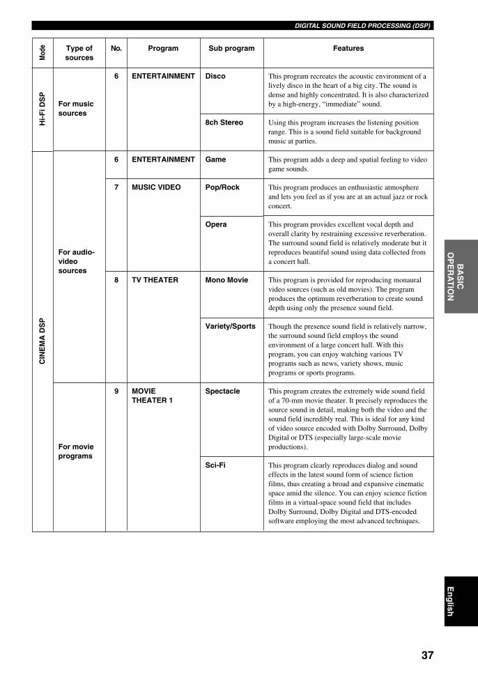
37
En
glish
INT
RO
DU
CT
ION
PR
EPA
RA
TIO
NB
AS
ICO
PE
RA
TIO
NA
DVA
NC
ED
OP
ER
AT
ION
AD
DIT
ION
AL
INF
OR
MA
TIO
NA
PP
EN
DIX
DIGITAL SOUND FIELD PROCESSING (DSP)
No.
6
6
7
8
9
Program
ENTERTAINMENT
ENTERTAINMENT
MUSIC VIDEO
TV THEATER
MOVIETHEATER 1
Features
This program recreates the acoustic environment of alively disco in the heart of a big city. The sound isdense and highly concentrated. It is also characterizedby a high-energy, “immediate” sound.
Using this program increases the listening positionrange. This is a sound field suitable for backgroundmusic at parties.
This program adds a deep and spatial feeling to videogame sounds.
This program produces an enthusiastic atmosphereand lets you feel as if you are at an actual jazz or rockconcert.
This program provides excellent vocal depth andoverall clarity by restraining excessive reverberation.The surround sound field is relatively moderate but itreproduces beautiful sound using data collected froma concert hall.
This program is provided for reproducing monauralvideo sources (such as old movies). The programproduces the optimum reverberation to create sounddepth using only the presence sound field.
Though the presence sound field is relatively narrow,the surround sound field employs the soundenvironment of a large concert hall. With thisprogram, you can enjoy watching various TVprograms such as news, variety shows, musicprograms or sports programs.
This program creates the extremely wide sound fieldof a 70-mm movie theater. It precisely reproduces thesource sound in detail, making both the video and thesound field incredibly real. This is ideal for any kindof video source encoded with Dolby Surround, DolbyDigital or DTS (especially large-scale movieproductions).
This program clearly reproduces dialog and soundeffects in the latest sound form of science fictionfilms, thus creating a broad and expansive cinematicspace amid the silence. You can enjoy science fictionfilms in a virtual-space sound field that includesDolby Surround, Dolby Digital and DTS-encodedsoftware employing the most advanced techniques.
Type ofsources
For musicsources
For audio-videosources
For movieprograms
Sub program
Disco
8ch Stereo
Game
Pop/Rock
Opera
Mono Movie
Variety/Sports
Spectacle
Sci-Fi
Mod
eH
i-F
i DS
PC
INE
MA
DS
P
0106DSPAZ2_34-39_EN(GB) 02.8.22, 0:16 PM37

38
DIGITAL SOUND FIELD PROCESSING (DSP)
No.
10
11
11
Program
MOVIETHEATER 2
DOLBY DIGITAL
DTS DIGITALSUR
PRO LOGIC
DOLBY DIGITAL
DTS DIGITALSUR
PRO LOGIC
PRO LOGIC
DTS Neo:6
Features
This program is ideal for precisely reproducing thesound design of the newest 70-mm and multichannelsoundtrack films. The sound field is made to besimilar to that of the newest movie theaters, so thereverberations of the sound field itself are restrainedas much as possible.
This program is for reproducing sounds from 70-mmand multichannel soundtrack films, and ischaracterized by a soft and extensive sound field. Thepresence sound field is relatively narrow. It spatiallyspreads all around and toward the screen, restrainingthe echo effect of conversations without losingclarity.
This program ideally simulates the multi-surroundspeaker systems of the 35-mm film theaters. DolbyPro Logic decoding, Dolby Digital decoding or DTSdecoding and digital sound field processing createprecise effects without altering the original soundorientation.The surround effects produced by this sound fieldwrap around the viewer naturally from the back to theleft and right, and toward the screen.
The built-in decoder precisely reproduces sounds andsound effects from sources. The highly efficientdecoding process improves crosstalk and channelseparation and makes sound positioning smootherand more precise.In this program, no DSP effect is applied.
To reproduce 2 channel sources decoding intomultichannels in each decoding mode.
Type ofsources
For movieprograms
Sub program
Adventure
General
Enhanced
Enhanced
Enhanced
Normal
Normal
Normal
Movie
Music
Cinema
Music
Mod
eC
INE
MA
DS
PS
TR
AIG
HT
DE
CO
DE
0106DSPAZ2_34-39_EN(GB) 02.8.22, 0:16 PM38
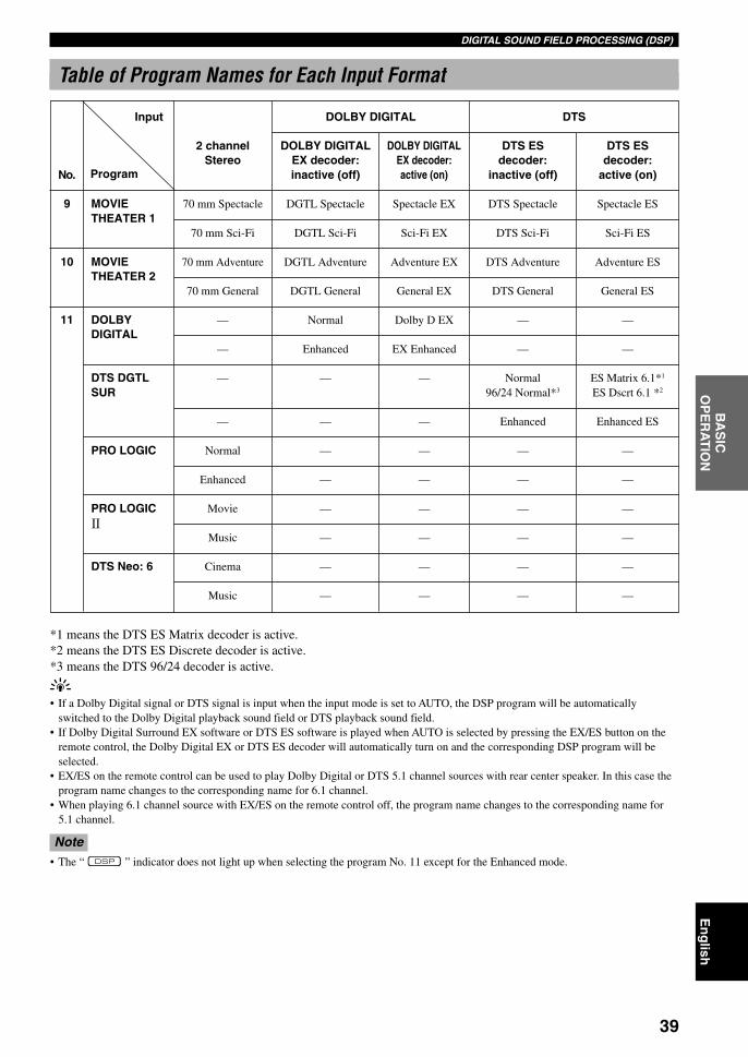
39
En
glish
INT
RO
DU
CT
ION
PR
EPA
RA
TIO
NB
AS
ICO
PE
RA
TIO
NA
DVA
NC
ED
OP
ER
AT
ION
AD
DIT
ION
AL
INF
OR
MA
TIO
NA
PP
EN
DIX
DIGITAL SOUND FIELD PROCESSING (DSP)
Table of Program Names for Each Input Format
MOVIETHEATER 1
MOVIETHEATER 2
DOLBYDIGITAL
DTS DGTLSUR
PRO LOGIC
PRO LOGIC
DTS Neo: 6
2 channelStereo
70 mm Spectacle
70 mm Sci-Fi
70 mm Adventure
70 mm General
—
—
—
—
Normal
Enhanced
Movie
Music
Cinema
Music
DOLBY DIGITALEX decoder:inactive (off)
DGTL Spectacle
DGTL Sci-Fi
DGTL Adventure
DGTL General
Normal
Enhanced
—
—
—
—
—
—
—
—
DOLBY DIGITALEX decoder:active (on)
Spectacle EX
Sci-Fi EX
Adventure EX
General EX
Dolby D EX
EX Enhanced
—
—
—
—
—
—
—
—
DTS ESdecoder:
active (on)
Spectacle ES
Sci-Fi ES
Adventure ES
General ES
—
—
ES Matrix 6.1*1
ES Dscrt 6.1 *2
Enhanced ES
—
—
—
—
—
—
DTS ESdecoder:
inactive (off)
DTS Spectacle
DTS Sci-Fi
DTS Adventure
DTS General
—
—
Normal96/24 Normal*3
Enhanced
—
—
—
—
—
—
*1 means the DTS ES Matrix decoder is active.*2 means the DTS ES Discrete decoder is active.*3 means the DTS 96/24 decoder is active.
y• If a Dolby Digital signal or DTS signal is input when the input mode is set to AUTO, the DSP program will be automatically
switched to the Dolby Digital playback sound field or DTS playback sound field.• If Dolby Digital Surround EX software or DTS ES software is played when AUTO is selected by pressing the EX/ES button on the
remote control, the Dolby Digital EX or DTS ES decoder will automatically turn on and the corresponding DSP program will beselected.
• EX/ES on the remote control can be used to play Dolby Digital or DTS 5.1 channel sources with rear center speaker. In this case theprogram name changes to the corresponding name for 6.1 channel.
• When playing 6.1 channel source with EX/ES on the remote control off, the program name changes to the corresponding name for5.1 channel.
Note• The “ ” indicator does not light up when selecting the program No. 11 except for the Enhanced mode.
DOLBY DIGITAL DTSInput
ProgramNo.
9
10
11
0106DSPAZ2_34-39_EN(GB) 02.8.22, 0:16 PM39

40
BASIC RECORDING
REC OUT allows you to record one source whilewatching and/or listening to another source.
Recording adjustments and other operations areperformed from the recording components. Refer to theoperation instructions for these components.
1 Turn on the power to this unit and allconnected components.
2 Select the source component you want torecord from by using REC OUT.• To record the current input source that you are
watching or listening to, set REC OUT toSOURCE.
• To record a source other than the one that you arewatching or listening to, set REC OUT to thesource you want to record.
Note• At this setting, you can change the source to listen to or watch
during recording by rotating INPUT (one of the input selectorbuttons on the remote control).
3 Start playback (or select a broadcast station)on the source component.
4 Start recording on the recording component.
y• Setting REC OUT to SOURCE and using the BGV function
(see page 29) allows the recording of audio and video from adifferent source.
Notes• Do a test recording before you start an actual recording.• When this unit is set in the standby mode, you cannot record
between other components connected to this unit.• The setting of BASS, TREBLE, BASS EXTENSION,
VOLUME, “3 L/R BALANCE” on the SET MENU and DSPprograms does not affect the recorded material.
• A source connected to the 6CH INPUT jacks of this unitcannot be recorded.
• S-video and composite video signals pass independentlythrough this unit’s video circuits. Therefore, when recording ordubbing video signals, if your video source component isconnected to provide only an S-video (or only a compositevideo) signal, you can record only an S-video (or only acomposite video) signal by your VCR.
• A given input source is not output on the same REC OUTchannel. (For example, the signal input from VCR 1 IN is notoutput on VCR 1 OUT.)
• Check the copyright laws in your country to record fromrecords, CDs, radio, etc. Recording of copyrighted materialmay infringe copyright laws.
If you playback a video source that uses scrambled orencoded signals to prevent it from being dubbed, thepicture itself may be disturbed due to those signals.
Special considerations whenrecording DTS software
The DTS signal is a digital bitstream. Attempting todigitally record the DTS bitstream will result in noisebeing recorded. Therefore, if you want to use this unit torecord sources that have DTS signals recorded on them,the following considerations and adjustments need to bemade.
For LDs, DVDs and CDs encoded with DTS, when yourplayer is compatible with the DTS format, follow itsoperation instruction to make a setting so that the analogsignal will be output from the player.
Timer playback/recordingThis unit can perform playback or recording with anexternal timer (not supplied). Refer to the operationinstruction for the component and the timer to be used.
Notes• The stored data such as input source will be reflected in the
playback or recording with the timer.• If you do not want any sound output during the recording with
a timer, turn the volume down.
Memory back-upThe memory back-up circuit prevents the stored data(input source, volume level, set menu settings and soon) from being lost even if this unit is in the standbymode (disconnected from the AC outlet). However ifthe timer is turned off for more than one week, thestored data will be lost.
BASS
VOLUME
VIDEO AUX
SILENT
PROGRAMSTEREO
REC OUT
SPEAKERS
INPUT MODE
BASSEXTENSION
PROCESSORDIRECT
PHONES
EFFECT
SOURCEMD/TAPECD–R
TUNER
CD
PHONO
DVDD–TV/LD
CBL/SAT
VCR 1
V–AUX
VCR2/DVR
S VIDEO VIDEO AUDIO OPTICALL R
STANDBY/ON
NATURAL SOUND AV AMPLIFIER DSP-AZ2
TREBLE
– + – +
6CHINPUT
A B
D I G I T A L
SET MENUNEXT +–
1 2
REC OUT
SOURCEMD/TAPECD–R
TUNER
CD
PHONO
DVDD–TV/LD
CBL/SAT
VCR 1
V–AUX
VCR2/DVR
REC OUT
SOURCEMD/TAPECD–R
TUNER
CD
PHONO
DVDD–TV/LD
CBL/SAT
VCR 1
V–AUX
VCR2/DVR
0107DSPAZ2_40-40_EN(GB) 02.8.22, 0:16 PM40
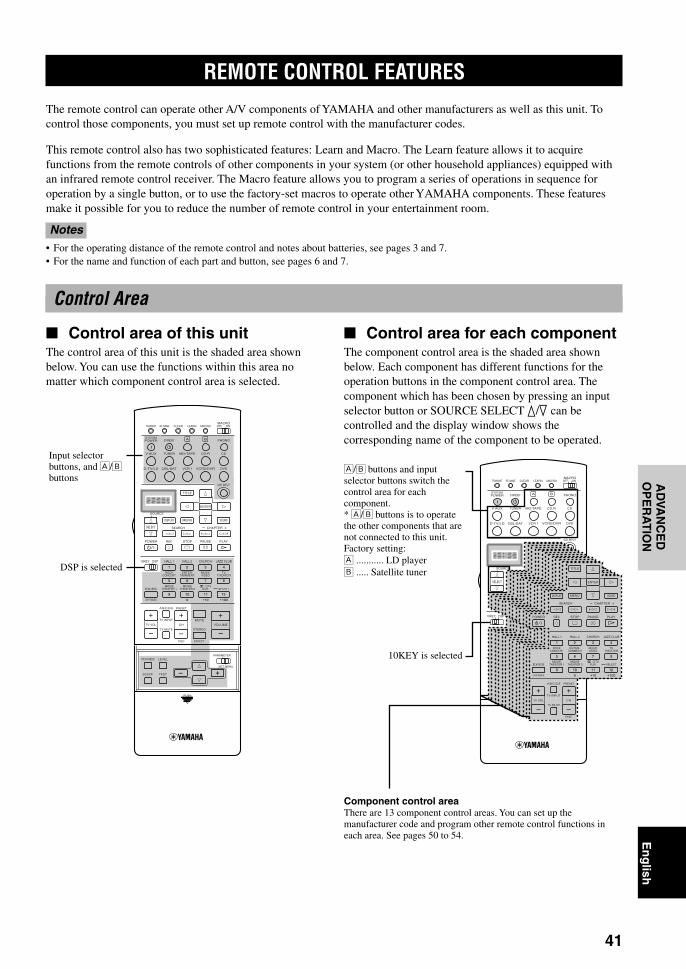
41
En
glish
INT
RO
DU
CT
ION
PR
EPA
RA
TIO
NB
AS
IC O
PE
RA
-T
ION
AD
VAN
CE
DO
PE
RA
TIO
NA
DD
ITIO
NA
LIN
FO
RM
AT
ION
AP
PE
ND
IX
REMOTE CONTROL FEATURES
The remote control can operate other A/V components of YAMAHA and other manufacturers as well as this unit. Tocontrol those components, you must set up remote control with the manufacturer codes.
This remote control also has two sophisticated features: Learn and Macro. The Learn feature allows it to acquirefunctions from the remote controls of other components in your system (or other household appliances) equipped withan infrared remote control receiver. The Macro feature allows you to program a series of operations in sequence foroperation by a single button, or to use the factory-set macros to operate other YAMAHA components. These featuresmake it possible for you to reduce the number of remote control in your entertainment room.
Notes• For the operating distance of the remote control and notes about batteries, see pages 3 and 7.• For the name and function of each part and button, see pages 6 and 7.
Control Area
Control area of this unitThe control area of this unit is the shaded area shownbelow. You can use the functions within this area nomatter which component control area is selected.
Control area for each componentThe component control area is the shaded area shownbelow. Each component has different functions for theoperation buttons in the component control area. Thecomponent which has been chosen by pressing an inputselector button or SOURCE SELECT k/n can becontrolled and the display window shows thecorresponding name of the component to be operated.
Å/ı buttons and inputselector buttons switch thecontrol area for eachcomponent.* Å/ı buttons is to operatethe other components that arenot connected to this unit.Factory setting:Å ........... LD playerı ..... Satellite tuner
Component control areaThere are 13 component control areas. You can set up themanufacturer code and program other remote control functions ineach area. See pages 50 to 54.
Input selectorbuttons, and Å/ıbuttons
TRANSMIT RE-NAME
STANDBY
6CH INPUT
SOUND
SYSTEM
CLEAR LEARN MACRO OFF ONMACRO
PHONOA B
CD
DVDVCR2/DVRVCR 1
TITLE
MENU
CHAPTER
PAUSESTOPPOWER REC
HALL 1
EX/ES
DSP10KEY
ROCKCONCERT
MOVIETHEATER 1
MOVIETHEATER 2
MUTE
VOLUME
STEREO
TV INPUT
TV VOL CH
PRESET
DISC
PARAMETER
SET MENU
EFFECT
LEVELON SCREEN
TESTSLEEP
TV MUTE
MUSICVIDEO
TVTHEATER
ENTER-TAINMENT
HALL 2 CHURCH JAZZ CLUB
SELECT/DTS
SUR.
CHP/INDEX
A/B/C/D/E
SELECT
DISPLAY
SEARCH
SOURCE
PLAY
– +
ENTER
D-TV/LD CBL/SAT
CD-RMD/TAPETUNERV-AUX
POWER
1
5
9
6
100 10 100
11 12
7 8
2 3 4
++
TRANSMIT RE-NAME
STANDBY
6CH INPUT
SOUND
SYSTEM
CLEAR LEARN MACRO OFF ONMACRO
PHONOA B
CD
DVDVCR2/DVRVCR 1
TITLE
MENU
CHAPTER
PAUSESTOPPOWER REC
HALL 1
6.1/ES
DSP10KEY
ROCKCONCERT
MOVIETHEATER 1
MOVIETHEATER 2
MUTE
VOLUME
STEREO
TV INPUT
TV VOL CH
PRESET
DISC EFFECT
TV MUTE
TVSPORTS
MONOMOVIE
ENTER-TAINMENT
HALL 2 CHURCH JAZZ CLUB
SELECT/DTS
SUR.
CHP/INDEX
A/B/C/D/E
SELECT
DISPLAY
SEARCH
SOURCE
PLAY
– +
ENTER
D-TV/LD CBL/SAT
CD-RMD/TAPETUNERV-AUX
POWER
1
5
9
6
100 10 100
11 12
7 8
2 3 4
++
SOUND
TITLE
MENU
CHAPTER
PAUSESTOPPOWER REC
HALL 1
EX/ES
ROCKCONCERT
MOVIETHEATER 1
MOVIETHEATER 2
TV INPUT
TV VOL CH
PRESET
DISC
TV MUTE
MUSICVIDEO
TVTHEATER
ENTER-TAINMENT
HALL 2 CHURCH JAZZ CLUB
SELECT/DTS
SUR.
CHP/INDEX
A/B/C/D/E
DISPLAY
SEARCH
PLAY
– +
ENTER
1
5
9
6
100 10 100
11 12
7 8
2 3 4
++
DSP is selected
10KEY is selected
0108DSPAZ2_41-54_EN(GB) 02.8.22, 0:16 PM41

42
REMOTE CONTROL FEATURES
Note• You may not be able to operate your Yamaha component even
if Yamaha manufacture code is initially set as listed above. Inthis case, try to set other Yamaha manufacture code(s).
1 Press an input selector button, Å or ı toselect the source component you want to setup.
2 Press and hold LEARN for about 3 secondsby using a ballpoint pen or similar object.“SETUP” and the selected component name appearalternately in the display window.
Notes• Press LEARN for at least 3 seconds, otherwise the learning
process is started.• Complete each of the following steps in 30 seconds. Otherwise,
the learning mode will be automatically canceled. In this case,press LEARN again.
3 Press k / n to select the name of yourcomponent’s manufacturer.You will find the names of most worldwide audio-video manufacturers in alphabetical order in thedisplay window.
If you want to change a library (componentcategory), press l / h. You can set adifferent component from the input selectorname.Library choices: L:DVD, L:LD, L:CD, L:CDR,L:MD, L:TAP, L:TUN, L:AMP*, L:TV, L:CAB,L:DBS, L:SAT, L:VCR
Amplifier Library (L:AMP)The code to operate this unit has been preset in thesupplied remote control. However you can change thecode in Amplifier Library if necessary.
Amplifier Library has the following four codes:YPC: Code to operate this unit.Zone 2: Code to use the Zone 2 function. This code is
not used with this unit.DSP:Code to operate other Yamaha DSP amplifiers that
cannot be operated with the YPC code.NO: Code to operate other manufacturers’ amplifiers
using this unit’s remote control.
4 Press one of the buttons shaded below tocheck if it works for the component beingset. If it does, the manufacturer code settinghas been correctly made.
Note• If the manufacturer of your component has more than one
codes, try each of them until you find the correct one.
y• If you continuously want to set up another code for another
component, press ENTER and repeat steps 1, 3 and 4.
Setting the Manufacturer CodeYou can control other components by setting amanufacturer code. A code can be set up in each inputarea.
The following table shows factory-set component(Library: component category) and the manufacturer codefor each area. If you are to make a setting for differentcomponent from the factory setting, change the library asdescribed in step 3 on right.
LEARN
Input area
A
B
PHONO
V-AUX
TUNER
Component category(Library)
LD
SAT
TV
VCR
TUNER
Manufacturer
Yamaha
–
–
–
Yamaha-1
ENTER
6CH INPUT
SOUND
TITLE
MENU
CHAPTER
PAUSESTOPPOWER REC
SELECT
DISPLAY
SEARCH
SOURCE
PLAY
– +
ENTER
PHONOA B
CD
DVDVCR2/DVRVCR 1D-TV/LD CBL/SAT
CD-RMD/TAPETUNERV-AUX
Yamaha-1
Yamaha
–
–
–
Yamaha-1
MD/TAPE
CD-R
D-TV/LD
VCR 1
VCR 2/DVR
DVD
MD
CD-R
TV
VCR
VCR
DVD
CD
CBL/SAT
CD
CABLE
Yamaha-1
–
0108DSPAZ2_41-54_EN(GB) 02.8.22, 0:16 PM42

43
En
glish
INT
RO
DU
CT
ION
PR
EPA
RA
TIO
NB
AS
IC O
PE
RA
-T
ION
AD
VAN
CE
DO
PE
RA
TIO
NA
DD
ITIO
NA
LIN
FO
RM
AT
ION
AP
PE
ND
IXREMOTE CONTROL FEATURES
3 Place this remote control and the otherremote control about 5 to 10 cm apart on aflat surface so that their infrared transmittersare aimed at each other.
4 Press LEARN by using a ballpoint pen orsimilar object.
Notes• Complete each of the following steps in 30 seconds. Otherwise,
the learning mode will be automatically canceled. In this case,press LEARN again.
• Do not press and hold LEARN longer than 3 seconds.Otherwise this unit enters the manufacturer code setting mode.
5 Press the button for which you want toprogram the new function.“LEARN” is displayed.
LEARN
5 Press LEARN again to exit from the setupmode.
Notes• Supplied remote control does not store all the manufacturer
codes for commercially available AV components (includingYamaha AV components). Therefore it may not work to operateyour AV component. If operation is not possible with any of themanufacturer codes, program the new remote control functionwith the Learn feature or use the remote control for thecomponent.
• If you have already programmed a remote control function for abutton, the function by learning programming takes priorityover the setup manufacturer code’s function.
• “ERROR” appears in the display window when pressingbuttons other than indicated in each step, or more than onebutton at once.
Learn FeatureIf you want to program functions not included in the basicoperations covered by the manufacturer code, or amanufacturer code is not available, the followingprocedure needs to be performed. The possibleprogramming area is the same as a component controlarea, so the buttons are programmable independently foreach source component area.
Note• This remote control transmits infrared rays. If the other remote
control also uses infrared rays, this remote control can learnmost of the other remote control’s functions. However, youmay not be able to program some special signals or extremelylong transmissions. (Refer to the operation instructions for theother remote control.)
Programming a new remotecontrol function
1 Set 10KEY/DSP to 10KEY.
Note• It is also possible to program in the control area of this unit
with 10KEY/DSP set to DSP. However, if you programfunctions in this area, you cannot control this unit and select aDSP program.
2 Press an input selector button, Å or ı toselect a source component.
5 to 10 cm (2 to 4 inch)TRANSM
ITRE-NAM
E
STANDBY
6CH INPUT
SY
ST
EM
CLE
AR
LEA
RN
MA
CR
OO
FF
ON
MA
CR
O
PH
ON
OA
B
CD
DV
DV
CR
2/D
VR
VC
R 1
TIT
LE
SO
UR
CE
EN
TE
R
D-T
V/L
DC
BL
/SA
T
CD
-RM
D/T
AP
ET
UN
ER
V-A
UX
PO
WE
R
LEARN
DSP10KEY
Flashes alternately
PHONOA B
CD
DVDVCR2/DVRVCR 1D-TV/LD CBL/SAT
CD-RMD/TAPETUNERV-AUX
TRANSMIT
RE-NAME
STANDBY
6CH INPUT
SY
ST
EM
CLE
AR
LEA
RN
MA
CR
OO
FF
ON
MA
CR
O
PH
ON
OA
B
CD
DV
DV
CR
2/D
VR
VC
R 1
TIT
LE
SO
UR
CE
EN
TE
R
D-T
V/L
DC
BL/S
AT
CD
-RM
D/T
AP
ET
UN
ER
V-A
UX
PO
WE
R
0108DSPAZ2_41-54_EN(GB) 02.8.22, 0:16 PM43

44
REMOTE CONTROL FEATURES
LEARN
Changing the Source Name in theDisplay Window
You can change the name that appears in the displaywindow on the remote control if you want to use thedifferent name from the original input selector buttonnames. This is useful when different component is set inthe input selector button.
1 Press an input selector button, Å or ı toselect the source component you want torename.The selected component name appears in the displaywindow.
2 Press RE-NAME by usinga ballpoint pen or similarobject.
3 Press k / n to select a character.Choices are A to Z, a to z, 0 to 9, space, -(hyphen),and /(slash).
4 Press l / h to move the cursor to the nextposition.
y• If you continuously want to rename another source component,
press ENTER and repeat steps 1, 3 and 4.
5 Press RE-NAME again to exit from therenaming mode.
Note• “ERROR” appears in the display window when pressing
buttons other than indicated in each step, or more than onebutton at once.
RE-NAME
ENTER
ENTER
PHONOA B
CD
DVDVCR2/DVRVCR 1D-TV/LD CBL/SAT
CD-RMD/TAPETUNERV-AUX
RE-NAME
TRANSMIT
RE-NAME
STANDBY
6CH INPUT
SY
ST
EM
CLE
AR
LEA
RN
MA
CR
OO
FF
ON
MA
CR
O
PH
ON
OA
B
CD
DV
DV
CR
2/D
VR
VC
R 1
TIT
LE
SO
UR
CE
EN
TE
R
D-T
V/L
DC
BL
/SA
T
CD
-RM
D/T
AP
ET
UN
ER
V-A
UX
PO
WE
R
6 Press and hold the button on the otherremote control that has the function youwant to program into this remote controluntil “OK” appears in the display window.
Notes• “NG” appears in the display window when programming has
not been done correctly. In this case, start over from step 5.• This remote control can learn approximately 120 functions.
However depending on the signals learned, “FULL” mayappear in the display window much earlier than this number. Inthis case, clear unnecessary programmed functions to makefurther learning on the remote control.
7 Repeat steps 5 and 6 to program additionalfunctions.
y• To learn functions in other source component control area,
press SOURCE SELECT k / n in step 4 to select other sourcecomponent.
8 Press LEARN again to exit from the learningmode.
Notes• Learning may not be possible in the following cases:
– when the batteries in the remote control for this unit or othercomponents are weak
– when the distance between the two remote controls is toomuch or too little
– when the remote control infrared windows are not facing atthe appropriate angle
– when the remote control is exposed to the direct sunlight– when the function to be programmed is continuous or
uncommon• “ERROR” appears in the display window when pressing
buttons other than indicated in each step, or more than onebutton at once.
0108DSPAZ2_41-54_EN(GB) 02.8.22, 0:16 PM44

45
En
glish
INT
RO
DU
CT
ION
PR
EPA
RA
TIO
NB
AS
IC O
PE
RA
-T
ION
AD
VAN
CE
DO
PE
RA
TIO
NA
DD
ITIO
NA
LIN
FO
RM
AT
ION
AP
PE
ND
IXREMOTE CONTROL FEATURES
Using the Macro FeatureThe Macro feature makes it possible to perform a series of operations by pressing just one button. For example, whenyou want to play a CD, normally you would turn on the components, select the CD input, and press the play button tostart playback. The Macro feature lets you perform all those operations by simply pressing the CD macro button. Themacro buttons (the input selector buttons, Å and ı buttons, SYSTEM POWER and STANDBY) are factory set withmacro programs. You can also program your own macros (see page 46).
*1 In order to turn on some components (including YAMAHA components) connected to this unit, connect thosecomponents to the AC OUTLET(S) on the rear panel. (Power control may not be synchronized with this unitdepending on the component. For details, please refer to the operation instruction for the connected component.)
*2 If the macro you select includes power control functions, the component may be turned off if it is already on whenyou press the macro button. For example, if your TV is on and you press the SYSTEM POWER macro button, theTV is turned off.
*3 By factory setting, playback can be started with any YAMAHA remote control-compatible MD recorders, CDplayers, CD recorders, DVD players, and LD players. When using macros to operate other components, it is eithernecessary to program the PLAY button on the control area of that component (see pages 43 and 44) or to set up amanufacturer code (see page 42).
*4 When TUNER is selected as the input source, YAMAHA tuners receive the last station when this unit is set in thestandby mode.
(DVD area) (*3)
Press one of the macro buttons Automatically transmits signals of each button sequentiallyCD
SYSTEMPOWER
CD PLAY
(CD area)
Macro buttons
PHONO
V-AUX
TUNER
MD/TAPE
CD-R
CD
D-TV/LD
CBL/SAT
VCR 1
VCR2/DVR
DVD
A
B
STANDBY
SYSTEMPOWER
First Second
–
–
–
Third
–
–
–
–
–
–
–
–
–
PHONO
V-AUX
TUNER
MD/TAPE
CD-R
CD
D-TV/LD
CBL/SAT
VCR 1
VCR2/DVR
DVD
POWER
PLAY
(*1)
(D-TV/LD area) (*2)
PLAY
PLAY
PLAY
PLAY
PLAY
(MD/TAPE area) (*3)
(CD-R area) (*3)
(CD area) (*3)
(VCR 1 area) (*3)
(VCR 2/DVR area) (*3)
(*4)
STANDBY
SYSTEMPOWER
0108DSPAZ2_41-54_EN(GB) 02.8.22, 0:17 PM45

46
REMOTE CONTROL FEATURES
2 Press a macro button for which you want toprogram the macro operation.The button you chose for programming the macrooperation and the selected component name appearalternately in the display window.
Note• “AGAIN” appears in the display window when a button other
than the macro buttons is pressed.
3 Press the buttons of the functions that youwant to include in the macro operationsequence in order.
y• You can set up to 10 steps (10 functions). After you have set 10
steps, “FULL” appears and the remote control automaticallyexits from the macro mode.
Notes• “NG” appears in the display window when programming has
not been done correctly. In this case, start over from step 2.• If you want to change the source component, use SOURCE
SELECT k / n. When you use the input selector buttons,selecting the input is programmed as a macro step, whereasSOURCE SELECT k / n only changes the component.
Operating the macro
1 Set MACRO ON/OFF to ON.
2 Press a macro button.
Notes• When you have finished using the Macro feature, set MACRO
ON/OFF to OFF.• While this unit is carrying out a macro program, this unit does
not receive any other button’s function until the macrooperation has been completed (the TRANSMIT indicator stopsflashing).
• Continue to aim the remote control at the component the macrois operating until the macro operation has been completed.
Programming a macroYou can program your own macros and use the Macrofeature to transmit many remote control commands bypressing a single button.
Notes• The factory-set macro is not cleared when a new macro is
programmed for a button. The factory-set macro can be usedagain when the programmed macro is cleared.
• It is not possible to add a new signal (macro step) to thefactory-set macro. Programming a macro changes all macrocontents.
• A macro programming is used to transmit learning or setup (orYAMAHA preset) button signals of this remote control to amacro button. If necessary, set up the manufacturer code orprogram a function with the remote control for yourcomponent.
• This remote control handles button signals that operatecontinuously, such as volume control, as short time intervalcodes. Macro programming that include these types of macrosteps are therefore not recommended.
1 Press MACRO by using a ballpoint pen orsimilar object.“MCR ?” appears in the display window.
Note• Complete each of the following steps in 30 seconds. Otherwise,
the learning mode will be automatically canceled. In this case,press MACRO again.
TRANSMIT RE-NAME
STANDBYSYSTEM
CLEAR LEARN MACRO OFF ONMACRO
PHONOA B
CD
DVDVCR2/DVRVCR 1D-TV/LD CBL/SAT
CD-RMD/TAPETUNERV-AUX
POWER
Macro buttons
MACROMACRO ON/OFF
MACRO
indicate the numberof macro steps youentered
STANDBY
6CH INPUT
SOUND
SYSTEMPHONOA B
CD
DVDVCR2/DVRVCR 1
TITLE
MENU
CHAPTER
PAUSESTOPPOWER REC
SELECT
DISPLAY
SEARCH
SOURCE
PLAY
– +
ENTER
D-TV/LD CBL/SAT
CD-RMD/TAPETUNERV-AUX
POWER
1
2
MCR 2 : DVD p
MCR 1 : DVD a
appear alternately so that you canset up the next step
STANDBYSYSTEM
PHONOA B
CD
DVDVCR2/DVRVCR 1D-TV/LD CBL/SAT
CD-RMD/TAPETUNERV-AUX
POWER
0108DSPAZ2_41-54_EN(GB) 02.8.22, 0:17 PM46

47
En
glish
INT
RO
DU
CT
ION
PR
EPA
RA
TIO
NB
AS
IC O
PE
RA
-T
ION
AD
VAN
CE
DO
PE
RA
TIO
NA
DD
ITIO
NA
LIN
FO
RM
AT
ION
AP
PE
ND
IXREMOTE CONTROL FEATURES
4 Press MACRO again whenthe operation sequenceyou want to program iscomplete.
Note• “ERROR” appears in the display when pressing buttons other
than indicated in each step, or more than one button at once.
Memory back-upIf the remote control is without batteries for more than3 minutes, or if exhausted batteries remain in theremote control, the contents of the memory may becleared. When the memory is cleared, insert newbatteries, set up the manufacturer code and programany acquired functions that may have been cleared.
MACRO
Clearing Learned Functions,Macros, Renamed Source Names,and Setup Manufacturer Codes
1 Press CLEAR by using a ballpoint pen orsimilar object.
Note• Complete each of the following steps in 30 seconds. Otherwise,
the learning mode will be automatically canceled. In this case,press CLEAR again.
CLEAR
CLEAR
CLEAR
Clears all programmed functionsincluding setup manufacturercodes. This returns to thefactory settings.
(L: name of a component) Clearsall learned functions for thecomponent area. Press the inputselector button, Å or ı to selectthe component.
Clears all learned functions forthis unit control area.
Clears all learned functions.
Clears all programmed macros.
Clears all renamed sourcenames in the display window.
2 Press k / n to select the clear mode.The mode is shown in the display window in thefollowing order:
3 Press and hold CLEAR again for about 3seconds.“C:OK” appears in the display window.
Note• “C:NG” appears in the display window if the operation is
unsuccessful. In this case, start over from step 2.
4 Press CLEAR to exit from the clearing mode.Once you have cleared a learned function or macrofor a button, the button reverts to the factory setting.
Note• “ERROR” appears in the display window under the following
circumstances:– when pressing a button other than the cursor and ENTER;– when pressing more than one button at once; or– when MACRO ON/OFF, 10KEY/DSP or PARAMETER/SET
MENU is switched to another position.
0108DSPAZ2_41-54_EN(GB) 02.8.22, 0:17 PM47

48
REMOTE CONTROL FEATURES
MACRO
MACRO
LEARN
TRANSMIT RE-NAME
STANDBYSYSTEM
CLEAR LEARN MACRO OFF ONMACRO
PHONOA B
CD
DVDVCR2/DVRVCR 1D-TV/LD CBL/SAT
CD-RMD/TAPETUNERV-AUX
POWER
LEARN
PHONOA B
CD
DVDVCR2/DVRVCR 1D-TV/LD CBL/SAT
CD-RMD/TAPETUNERV-AUX
Clearing a Macro Function
1 Press MACRO to clear a programmed macroby using a ballpoint pen or similar object.
Note• Complete each of the following steps in 30 seconds. Otherwise
the learning mode will be automatically canceled. In this case,press MACRO again.
2 Press and hold CLEAR by using a ballpointpen or similar object, then press the buttonfor which you want to clear the macro forabout 3 seconds.“C:OK” appears in the display window.
y• You can clear other macros at this time by holding down
CLEAR again and pressing the other buttons for which thosemacros have been programmed.
Note• “C:NG” appears in the display window if the operation is
unsuccessful. In this case, try step 2 again.
3 Press MACRO again to exit from the clearingmode.Once you have cleared macro for a button, the buttonreverts to the factory setting.
TRANSMIT RE-NAME
STANDBYSYSTEM
CLEAR LEARN MACRO OFF ONMACRO
PHONOA B
CD
DVDVCR2/DVRVCR 1D-TV/LD CBL/SAT
CD-RMD/TAPETUNERV-AUX
POWER
Clearing a Learned FunctionYou can clear the function learned in a certainprogrammable button in each area.
1 Press an input selector button, Å or ı toselect the source component you want toclear the function.The selected component name appears in the displaywindow.
2 Press LEARN by using a ballpoint pen orsimilar object.“LEARN” and the selected component name appearalternately in the display window.
Note• Complete each of the following steps in 30 seconds. Otherwise
the learning mode will be automatically canceled. In this case,press LEARN again.
3 Press and hold CLEAR by using a ballpointpen or similar object, then press the buttonfor which you want to clear the function forabout 3 seconds.“C:OK” appears in the display window.
y• You can clear other learned functions at this time by holding
down CLEAR again and pressing the other buttons for whichthose learned functions have been programmed.
Note• “C:NG” appears in the display window if the operation is
unsuccessful. In this case, try step 3 again.
4 Press LEARN again toexit.Once you have cleared a learned function for abutton, the button reverts to the factory setting.
0108DSPAZ2_41-54_EN(GB) 02.8.22, 0:17 PM48

49
En
glish
INT
RO
DU
CT
ION
PR
EPA
RA
TIO
NB
AS
IC O
PE
RA
-T
ION
AD
VAN
CE
DO
PE
RA
TIO
NA
DD
ITIO
NA
LIN
FO
RM
AT
ION
AP
PE
ND
IXREMOTE CONTROL FEATURES
SOURCE SELECT k / nYou can control another component independently fromthe input you have selected by pressing an input selectorbutton.
Press SOURCE SELECT k / n to choose thecomponent and set the remote control to beused for it.The display window will show one of the following:(when pressing n) OPTN (option), Å, ı, PHONO,V-AUX, TUNER, MD, CD-R, CD, TV/LD (TV ordigital TV/LD), CBSAT (cable TV/satellite tuner),VCR 1, VCR 2, DVD.
y• Pressing k shows the same in the reverse order, but you cannot
select OPTN.
OPTN (option) areaOPTN is an extra component control area that can beprogrammed with other remote control functions.
y• For the signals that will be used only in macro, it is
recommended to learn signals in the OPTN area.
Note• You cannot set up the manufacturer code in this area.
Pressing n always selects OPTN first
SELECT
SOURCE
6CH INPUT
SOUND
TITLE
MENU
CHAPTER
PAUSESTOPPOWER REC
SELECT
DISPLAY
SEARCH
SOURCE
PLAY
– +
ENTER
TRANSMIT RE-NAME
STANDBY
6CH INPUT
SOUND
SYSTEM
CLEAR LEARN MACRO OFF ONMACRO
PHONOA B
CD
DVDVCR2/DVRVCR 1
TITLE
MENU
CHAPTER
PAUSESTOPPOWER REC
HALL 1DSP10KEY
ROCKCONCERT
MUSICVIDEO
TVTHEATER
ENTER-TAINMENT
HALL 2 CHURCH JAZZ CLUB
SELECT
DISPLAY
SEARCH
SOURCE
PLAY
– +
ENTER
D-TV/LD CBL/SAT
CD-RMD/TAPETUNERV-AUX
POWER
1 2 3 4
Area that lights up (Only buttonsthat send the signal light up inorange.)
Light up functionThe buttons which are active and the display windowlight up for 10 seconds after pressing LIGHT.
0108DSPAZ2_41-54_EN(GB) 02.8.22, 0:17 PM49
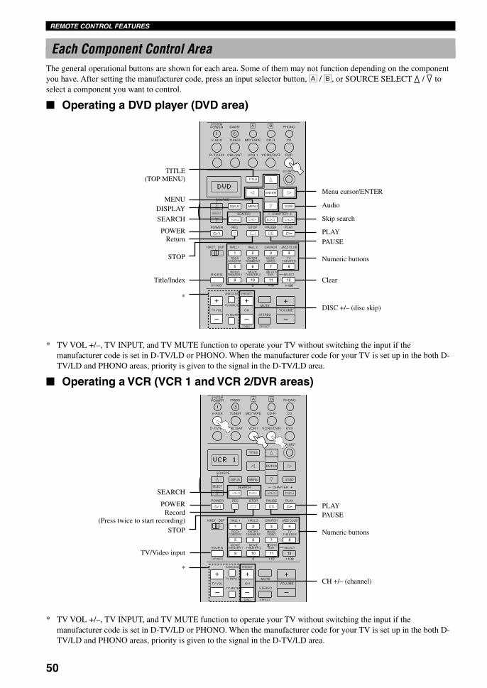
50
REMOTE CONTROL FEATURES
Each Component Control AreaThe general operational buttons are shown for each area. Some of them may not function depending on the componentyou have. After setting the manufacturer code, press an input selector button, Å / ı, or SOURCE SELECT k / n toselect a component you want to control.
Operating a DVD player (DVD area)
STANDBY
6CH INPUT
SOUND
SYSTEMPHONOA B
CD
DVDVCR2/DVRVCR 1
TITLE
MENU
CHAPTER
PAUSESTOPPOWER REC
HALL 1
EX/ES
DSP10KEY
ROCKCONCERT
MOVIETHEATER 1
MOVIETHEATER 2
MUTE
VOLUME
STEREO
TV INPUT
TV VOL CH
PRESET
DISC EFFECT
TV MUTE
MUSICVIDEO
TVTHEATER
ENTER-TAINMENT
HALL 2 CHURCH JAZZ CLUB
SELECT/DTS
SUR.
CHP/INDEX
A/B/C/D/E
SELECT
DISPLAY
SEARCH
SOURCE
PLAY
– +
ENTER
D-TV/LD CBL/SAT
CD-RMD/TAPETUNERV-AUX
POWER
1
5
9
6
100 10 100
11 12
7 8
2 3 4
++
* TV VOL +/–, TV INPUT, and TV MUTE function to operate your TV without switching the input if themanufacturer code is set in D-TV/LD or PHONO. When the manufacturer code for your TV is set up in the both D-TV/LD and PHONO areas, priority is given to the signal in the D-TV/LD area.
Operating a VCR (VCR 1 and VCR 2/DVR areas)
* TV VOL +/–, TV INPUT, and TV MUTE function to operate your TV without switching the input if themanufacturer code is set in D-TV/LD or PHONO. When the manufacturer code for your TV is set up in the both D-TV/LD and PHONO areas, priority is given to the signal in the D-TV/LD area.
DISPLAY
DISC +/– (disc skip)
STOP
*
Title/Index
TITLE(TOP MENU)
MENU
ReturnPOWER
SEARCH
Menu cursor/ENTER
Audio
Skip search
PLAYPAUSE
Numeric buttons
Clear
CH +/– (channel)
SEARCH
POWERRecord
(Press twice to start recording)
TV/Video input
*
STOP
PLAYPAUSE
Numeric buttons
0108DSPAZ2_41-54_EN(GB) 02.8.22, 0:17 PM50

51
En
glish
INT
RO
DU
CT
ION
PR
EPA
RA
TIO
NB
AS
IC O
PE
RA
-T
ION
AD
VAN
CE
DO
PE
RA
TIO
NA
DD
ITIO
NA
LIN
FO
RM
AT
ION
AP
PE
ND
IXREMOTE CONTROL FEATURES
STANDBY
6CH INPUT
SOUND
SYSTEMPHONOA B
CD
DVDVCR2/DVRVCR 1
TITLE
MENU
CHAPTER
PAUSESTOPPOWER REC
HALL 1
EX/ES
DSP10KEY
ROCKCONCERT
MOVIETHEATER 1
MOVIETHEATER 2
MUTE
VOLUME
STEREO
TV INPUT
TV VOL CH
PRESET
DISC EFFECT
TV MUTE
MUSICVIDEO
TVTHEATER
ENTER-TAINMENT
HALL 2 CHURCH JAZZ CLUB
SELECT/DTS
SUR.
CHP/INDEX
A/B/C/D/E
SELECT
DISPLAY
SEARCH
SOURCE
PLAY
– +
ENTER
D-TV/LD CBL/SAT
CD-RMD/TAPETUNERV-AUX
POWER
1
5
9
6
100 10 100
11 12
7 8
2 3 4
++
Operating a TV/digital TV (D-TV/LD area) or a cable TV/satellite TV (CBL/SAT area)
Set the manufacture code for your LD player following the setting procedure described on page 42 because TV isfactory-set for this input selector button.
* TV VOL +/–, TV INPUT, and TV MUTE function to operate your TV without switching the input if themanufacturer code is set in PHONO.
* SEARCH, REC, STOP, PAUSE and PLAY function to operate your VCR without switching the input to VCR 1 if themanufacturer code is set in VCR 1.
Operating an LD player (D-TV/LD area)
CH +/– (channel)
DISPLAY
POWER
EnterTV INPUT
TV VOL +/–
TV MUTE
*
Numeric buttons
Clear
DISPLAY
SEARCH
POWER
STOP
Chapter/Time
*
SOUND
CHAPTER –/+ (chapter search)
PLAYPAUSE
Numeric buttons
0108DSPAZ2_41-54_EN(GB) 02.8.22, 0:17 PM51

52
REMOTE CONTROL FEATURES
STANDBY
6CH INPUT
SOUND
SYSTEMPHONOA B
CD
DVDVCR2/DVRVCR 1
TITLE
MENU
CHAPTER
PAUSESTOPPOWER REC
HALL 1
EX/ES
DSP10KEY
ROCKCONCERT
MOVIETHEATER 1
MOVIETHEATER 2
MUTE
VOLUME
STEREO
TV INPUT
TV VOL CH
PRESET
DISC EFFECT
TV MUTE
MUSICVIDEO
TVTHEATER
ENTER-TAINMENT
HALL 2 CHURCH JAZZ CLUB
SELECT/DTS
SUR.
CHP/INDEX
A/B/C/D/E
SELECT
DISPLAY
SEARCH
SOURCE
PLAY
– +
ENTER
D-TV/LD CBL/SAT
CD-RMD/TAPETUNERV-AUX
POWER
1
5
9
6
100 10 100
11 12
7 8
2 3 4
++
Operating a CD player (CD area)
STANDBY
6CH INPUT
SOUND
SYSTEMPHONOA B
CD
DVDVCR2/DVRVCR 1
TITLE
MENU
CHAPTER
PAUSESTOPPOWER REC
HALL 1
EX/ES
DSP10KEY
ROCKCONCERT
MOVIETHEATER 1
MOVIETHEATER 2
MUTE
VOLUME
STEREO
TV INPUT
TV VOL CH
PRESET
DISC EFFECT
TV MUTE
MUSICVIDEO
TVTHEATER
ENTER-TAINMENT
HALL 2 CHURCH JAZZ CLUB
SELECT/DTS
SUR.
CHP/INDEX
A/B/C/D/E
SELECT
DISPLAY
SEARCH
SOURCE
PLAY
– +
ENTER
D-TV/LD CBL/SAT
CD-RMD/TAPETUNERV-AUX
POWER
1
5
9
6
100 10 100
11 12
7 8
2 3 4
++
* TV VOL +/–, TV INPUT, and TV MUTE function to operate your TV without switching the input if themanufacturer code is set in D-TV/LD or PHONO. When the manufacturer code for your TV is set up in the both D-TV/LD and PHONO areas, priority is given to the signal in the D-TV/LD area.
Operating a CD recorder (CD-R area) or an MD recorder (MD/TAPE area)
* TV VOL +/–, TV INPUT, and TV MUTE function to operate your TV without switching the input if themanufacturer code is set in D-TV/LD or PHONO. When the manufacturer code for your TV is set up in the both D-TV/LD and PHONO areas, priority is given to the signal in the D-TV/LD area.
DISC +/– (disc skip)
DISPLAY
SEARCH
POWER
STOP
INDEX
*
Skip search
PLAYPAUSE
Numeric buttons
Clear
DISPLAY
SEARCH
POWER
STOP
INDEX(CD-R only)
*
Skip search
PLAYPAUSE
Numeric buttons
Clear(CD-R only)
Record(MD only)
0108DSPAZ2_41-54_EN(GB) 02.8.22, 0:17 PM52
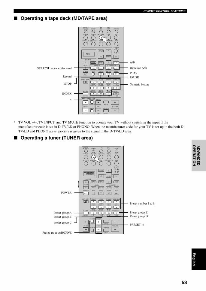
53
En
glish
INT
RO
DU
CT
ION
PR
EPA
RA
TIO
NB
AS
IC O
PE
RA
-T
ION
AD
VAN
CE
DO
PE
RA
TIO
NA
DD
ITIO
NA
LIN
FO
RM
AT
ION
AP
PE
ND
IXREMOTE CONTROL FEATURES
STANDBY
6CH INPUT
SOUND
SYSTEMPHONOA B
CD
DVDVCR2/DVRVCR 1
TITLE
MENU
CHAPTER
PAUSESTOPPOWER REC
HALL 1
EX/ES
DSP10KEY
ROCKCONCERT
MOVIETHEATER 1
MOVIETHEATER 2
MUTE
VOLUME
STEREO
TV INPUT
TV VOL CH
PRESET
DISC EFFECT
TV MUTE
MUSICVIDEO
TVTHEATER
ENTER-TAINMENT
HALL 2 CHURCH JAZZ CLUB
SELECT/DTS
SUR.
CHP/INDEX
A/B/C/D/E
SELECT
DISPLAY
SEARCH
SOURCE
PLAY
– +
ENTER
D-TV/LD CBL/SAT
CD-RMD/TAPETUNERV-AUX
POWER
1
5
9
6
100 10 100
11 12
7 8
2 3 4
++
Operating a tape deck (MD/TAPE area)
STANDBY
6CH INPUT
SOUND
SYSTEMPHONOA B
CD
DVDVCR2/DVRVCR 1
TITLE
MENU
CHAPTER
PAUSESTOPPOWER REC
HALL 1
EX/ES
DSP10KEY
ROCKCONCERT
MOVIETHEATER 1
MOVIETHEATER 2
MUTE
VOLUME
STEREO
TV INPUT
TV VOL CH
PRESET
DISC EFFECT
TV MUTE
MUSICVIDEO
TVTHEATER
ENTER-TAINMENT
HALL 2 CHURCH JAZZ CLUB
SELECT/DTS
SUR.
CHP/INDEX
A/B/C/D/E
SELECT
DISPLAY
SEARCH
SOURCE
PLAY
– +
ENTER
D-TV/LD CBL/SAT
CD-RMD/TAPETUNERV-AUX
POWER
1
5
9
6
100 10 100
11 12
7 8
2 3 4
++
* TV VOL +/–, TV INPUT, and TV MUTE function to operate your TV without switching the input if themanufacturer code is set in D-TV/LD or PHONO. When the manufacturer code for your TV is set up in the both D-TV/LD and PHONO areas, priority is given to the signal in the D-TV/LD area.
Operating a tuner (TUNER area)
SEARCH backward/forward
Record
STOP
INDEX
A/B
Direction A/B
PLAY
PAUSE
Numeric button
PRESET +/–
POWER
Preset group APreset group B
Preset group C
Preset group A/B/C/D/E
Preset number 1 to 8
Preset group EPreset group D
*
0108DSPAZ2_41-54_EN(GB) 02.8.22, 0:17 PM53

54
REMOTE CONTROL FEATURES
Operating the component set in Å or ıThese buttons are not input selector buttons but simply provide the space for an extra component to control with thisunit’s remote control without making connection to this unit. The white area shown below can be used for thecomponent set in Å and ı, and the function for each button differs depending on the component.
YAMAHA LD player is factory-set in Å and satellite tuner in ı. However if you want to set other component, set themanufacturer code for the component you want to set in the Å / ı button following the manufacturer code settingprocedure described on page 42.
* TV VOL +/–, TV INPUT, and TV MUTE function to operate your TV without switching the input if themanufacturer code is set in D-TV/LD or PHONO. When the manufacturer code for your TV is set up in the both D-TV/LD and PHONO areas, priority is given to the signal in the D-TV/LD area.
The functions of these buttons in thecomponent control area differ for thecomponent you set in Å or ı.
STANDBY
6CH INPUT
SOUND
SYSTEMPHONOA B
CD
DVDVCR2/DVRVCR 1
TITLE
MENU
CHAPTER
PAUSESTOPPOWER REC
HALL 1
EX/ES
DSP10KEY
ROCKCONCERT
MOVIETHEATER 1
MOVIETHEATER 2
MUTE
VOLUME
STEREO
TV INPUT
TV VOL CH
PRESET
DISC EFFECT
TV MUTE
MUSICVIDEO
TVTHEATER
ENTER-TAINMENT
HALL 2 CHURCH JAZZ CLUB
SELECT/DTS
SUR.
CHP/INDEX
A/B/C/D/E
SELECT
DISPLAY
SEARCH
SOURCE
PLAY
– +
ENTER
D-TV/LD CBL/SAT
CD-RMD/TAPETUNERV-AUX
POWER
1
5
9
6
100 10 100
11 12
7 8
2 3 4
++
*
0108DSPAZ2_41-54_EN(GB) 02.8.22, 0:17 PM54

55
En
glish
INT
RO
DU
CT
ION
PR
EPA
RA
TIO
NB
AS
IC O
PE
RA
-T
ION
AD
VAN
CE
DO
PE
RA
TIO
NA
DD
ITIO
NA
LIN
FO
RM
AT
ION
AP
PE
ND
IX
Adjusting the Items on the SETMENU
Adjustment should be made with the remote control.Adjustment procedures are explained using SET MENU 2LOW FRQ TEST as an example.
y• Adjustment can be made using NEXT and SET MENU +/– on
the front panel. Press NEXT repeatedly to select the item youwant to adjust, then press SET MENU +/– repeatedly to changethe setting of the item.
1 Set PARAMETER/SETMENU to SET MENU.
2 Press k / n repeatedly to select the item (1 to15) you want to adjust.
Note• If k is pressed when SET MENU 1 is selected, and if n is
pressed when SET MENU 15 is selected, SET MENU will beclosed. Press k / n to open SET MENU again.
PARAMETER
SET MENU
SET MENU
ADVANCED OPERATION
HALL 1
EX/ES
DSP10KEY
ROCKCONCERT
MOVIETHEATER 1
MOVIETHEATER 2
MUTE
VOLUME
STEREO
TV INPUT
TV VOL CH
PRESET
DISC
PARAMETER
SET MENU
EFFECT
LEVELON SCREEN
TESTSLEEP
TV MUTE
MUSICVIDEO
TVTHEATER
ENTER-TAINMENT
HALL 2 CHURCH JAZZ CLUB
SELECT/DTS
SUR.
CHP/INDEX
A/B/C/D/E
1
5
9
6
100 10 100
11 12
7 8
2 3 4
++
12, 3, 53, 4
5
The SET MENU consists of 15 items including thespeaker mode setting, center graphic equalizer andparameter initialization features. Choose the appropriateitem and adjust or select the values as necessary.
y• You can adjust the items on the SET MENU while playing a
source.• We recommend that you adjust the items on the SET MENU
while using a video monitor. It is easier to see the videomonitor than it is to see the front panel display on this unitwhile adjusting the items.
Note• The indication on the front panel display is the abbreviation of
the OSD.
1 SPEAKER SET
1A CENTER SP
1B MAIN SP
1C REAR L/R SP
1D REAR CT SP
1E LFE/BASS OUT
1F FRONT EFCT SP
1G MAIN LEVEL
1H SP B SET
2 LOW FRQ TEST
3 L/R BALANCE
4 HP TONE CTRL
5 CENTER GEQ
6 INPUT RENAME
7 I/O ASSIGNMENT
7A CMPNT-V INPUT
7B OPTICAL OUT
7C OPTICAL IN
7D COAXIAL IN
8 INPUT MODE
9 PARAM. INI
10 LFE LEVEL
11 D. RANGE
12 SP DELAY
13 DISPLAY SET
14 MEMORY GUARD
15 6CH INPUT SET
SET MENU 1/4≥ 2 LOW FRQ TEST
3 L/R BALANCE4 HP TONE CTRL
/ : Up/Down-/+ : Enter
1 SPEAKER SET
0109DSPAZ2_55-68_EN(GB) 02.8.22, 0:17 PM55

56
SET MENU
1 SPEAKER SET (speaker modesettings)
Use this feature to select suitable output modes for yourspeaker configuration.
y• Select SML/SMALL if the woofer diameter of you speaker is
smaller than 16 cm. If it is larger than 16 cm, select LRG/LARGE.
Note• When 6CH INPUT is selected as the input source, level
adjustments in items 1A through 1E are not affected.
1A CENTER SP (center speakermode)
By adding a center speaker to your speaker configuration,this unit can provide good dialog localization for manylisteners and superior synchronization of sound andimages. The OSD shows a large, small or no centerspeaker depending on how you set this item.
Choices: LRG (large), SML (small), NONEInitial setting: LRG
LRGSelect this if you have a large center speaker. The entirerange of the center channel signal is directed to the centerspeaker.
SMLSelect this if you have a small center speaker. The low-frequency signals (90 Hz and below) of the centerchannel are directed to the speakers selected with “1ELFE/BASS OUT”.
NONESelect this if you do not have a center speaker. All of thecenter channel signal are directed to the left and rightmain speakers.
LRG SML NONE
1A CENTER SP
3 Press –/+ once to enter the setup mode ofthe selected item.The last setting you adjusted appears on the videomonitor or on the front panel display.
Depending on the item, press n to select a sub item.
4 Press –/+ repeatedly to change the setting ofthe item.
5 Press k / n repeatedly until the current DSPprogram appears or simply press one of theDSP program group buttons to exit from theSET MENU.
Memory back-upThe memory back-up circuit prevents the stored datafrom being lost even if this unit is in the standbymode. However if the power cord is disconnected fromthe AC outlet, or the power supply is cut for more thanone week, the stored data will be lost. If so, adjust theitems again.
2 LOW FRQ TESTOUTPUT…MAIN L/RFRQ……………………88Hz
≥ TEST TONE…………ON
LRG SML NONE
1A CENTER SP
LRG SML NONE
1A CENTER SP
HALL 1DSP10KEY HALL 2 CHURCH JAZZ CLUB
SELECT
1
5
9
6
100 10 100
11 12
7 8
2 3 4
++
ROCKCONCERT
MOVIETHEATER 1
MOVIETHEATER 2
MUSICVIDEO
TVTHEATER
ENTER-TAINMENT
/DTSSUR.
or
2 LOW FRQ TEST≥ OUTPUT…MAIN L/R
FRQ……………………88Hz
TEST TONE………OFF
2 LOW FRQ TESTOUTPUT…MAIN L/RFRQ……………………88Hz
≥ TEST TONE………OFF
0109DSPAZ2_55-68_EN(GB) 02.8.22, 0:17 PM56

57
En
glish
INT
RO
DU
CT
ION
PR
EPA
RA
TIO
NB
AS
IC O
PE
RA
-T
ION
AD
VAN
CE
DO
PE
RA
TIO
NA
DD
ITIO
NA
LIN
FO
RM
AT
ION
AP
PE
ND
IXSET MENU
1C REAR L/R SP (rear speakermode)
The OSD shows large, small or no rear speakersdepending on how you set this item.
Choices: LRG (large), SML (small), NONEInitial setting: LRG
LRGSelect this if you have large left and right rear speakers orif a rear subwoofer is connected to the rear speakers. Theentire range of the rear channel signal is directed to theleft and right rear speakers.
SMLSelect this if you have small left and right rear speakers.The low-frequency signals (90 Hz and below) of the rearchannel are directed to the speakers selected with “1ELFE/BASS OUT”.
NONESelect this if you do not have rear speakers.
Note• If “1C REAR L/R SP” is set to NONE, “1D REAR CT SP”
will be skipped.
y• This unit is set in the virtual CINEMA DSP mode by selecting
NONE for “1C REAR L/R SP” (see page 33).
LARGE SMALL
1B MAIN SP
LRG SML NONE
1C REAR L/R SP
LRG SML NONE
1C REAR L/R SP
LRG SML NONE
1C REAR L/R SP
LARGE SMALL
1B MAIN SP
1B MAIN SP (main speaker mode)The OSD shows large or small main speakers dependingon how you set this item.
Choices: LARGE, SMALLInitial setting: LARGE
LARGESelect this if you have large main speakers. The entirerange of the left and right main channel signal is directedto the left and right main speakers.
SMALLSelect this if you have small main speakers. The low-frequency signals (90 Hz and below) of the main channelare directed to the speakers selected with “1E LFE/BASSOUT”.
Note• When you select MAIN for “1E LFE/BASS OUT”, the low-
frequency signals (90 Hz and below) of the main channel aredirected to the main speakers even if you select SMALL for themain speaker mode.
0109DSPAZ2_55-68_EN(GB) 02.8.22, 0:17 PM57
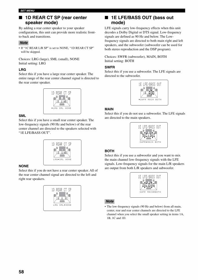
58
SET MENU
1E LFE/BASS OUT (bass outmode)
LFE signals carry low-frequency effects when this unitdecodes a Dolby Digital or DTS signal. Low-frequencysignals are defined as 90 Hz and below. The Low-frequency signals are directed to both main right and leftspeakers, and the subwoofer (subwoofer can be used forboth stereo reproduction and the DSP program).
Choices: SWFR (subwoofer), MAIN, BOTHInitial setting: BOTH
SWFRSelect this if you use a subwoofer. The LFE signals aredirected to the subwoofer.
MAINSelect this if you do not use a subwoofer. The LFE signalsare directed to the main speakers.
BOTHSelect this if you use a subwoofer and you want to mixthe main channel low-frequency signals with the LFEsignals. Low-frequency signals for the main L/R speakersare output from both L/R speakers and subwoofer.
Note• The low-frequency signals (90 Hz and below) from all main,
center, rear and rear center channels are directed to the LFEchannel when you select the small speaker setting in items 1A,1B, 1C and 1D.
1D REAR CT SP (rear centerspeaker mode)
By adding a rear center speaker to your speakerconfiguration, this unit can provide more realistic front-to-back and transitions.
Note• If “1C REAR L/R SP” is set to NONE, “1D REAR CT SP”
will be skipped.
Choices: LRG (large), SML (small), NONEInitial setting: LRG
LRGSelect this if you have a large rear center speaker. Theentire range of the rear center channel signal is directed tothe rear center speaker.
SMLSelect this if you have a small rear center speaker. Thelow-frequency signals (90 Hz and below) of the rearcenter channel are directed to the speakers selected with“1E LFE/BASS OUT”.
NONESelect this if you do not have a rear center speaker. All ofthe rear center channel signal are directed to the left andright rear speakers.
SWFR MAIN BOTH
1E LFE/BASS OUT
SWFR MAIN BOTH
1E LFE/BASS OUT
SWFR MAIN BOTH
1E LFE/BASS OUT
LRG SML NONE
1D REAR CT SP
LRG SML NONE
1D REAR CT SP
LRG SML NONE
1D REAR CT SP
0109DSPAZ2_55-68_EN(GB) 02.8.22, 0:17 PM58

59
En
glish
INT
RO
DU
CT
ION
PR
EPA
RA
TIO
NB
AS
IC O
PE
RA
-T
ION
AD
VAN
CE
DO
PE
RA
TIO
NA
DD
ITIO
NA
LIN
FO
RM
AT
ION
AP
PE
ND
IXSET MENU
1F FRONT EFCT SP (front effectspeaker mode)
This unit uses front effect speakers to localize the virtualsound sources of the sound field programs. If you do notuse front effect speakers, you can direct the front effectsignals to the main speakers.The OSD shows small or no front effect speakersdepending on how you set this item.
Choices: YES, NONEInitial setting: YES
YESSelect this setting if you use front effect speakers.
NONESelect this setting if you do not use front effect speakers.The front effect signals are mixed with the main channels.
1F FRONT EFCT SP
YES NONE
1F FRONT EFCT SP
YES NONE
1H SP B SET (speaker B set)Use this feature to select the location of the main speakersto be connected to the SPEAKERS B terminals.
Choices: MAIN, ZONE BInitial setting: MAIN
MAINSelect this to turn on/off SPEAKERS A and B when thespeakers connected to the SPEAKERS B terminals are setin the main room.
ZONE BSelect this if the speakers connected to the SPEAKERS Bterminals are set in the second room. If SPEAKERS A isturned OFF and SPEAKERS B is turned ON, all theeffect speakers in the main room are muted and the soundis output only from SPEAKERS B.
y• When a DSP program is selected, this unit automatically enters
the Virtual CINEMA DSP mode. If the headphones areconnected to PHONES jack on this unit in the VirtualCINEMA DSP mode, this unit enters the SILENT CINEMADSP mode and the sound is output from both headphones andSPEAKERS B.
1H SP B SET
-/+ : Select/ : Exit
MAIN “ZONE B
1G MAIN LEVEL (main levelmode)
Change this setting if you cannot match the output levelof the center, rear (L/R) and rear center speakers with themain speakers because of the unusually high-efficiencyperformance of the main speakers.
Choices: Normal, –10 dBInitial setting: Normal
NormalSelect this if you can match the output level of your effectspeakers with that of your main speakers when using thetest tone.
Normal -10dB
1G MAIN LEVEL
Normal -10dB
1G MAIN LEVEL
1H SP B SET
-/+ : Select/ : Exit
“MAIN ZONE B
–10 dBSelect this if you cannot match the output level of youreffect speakers with that of your main speakers whenusing the test tone.
0109DSPAZ2_55-68_EN(GB) 02.8.22, 0:17 PM59

60
SET MENU
2 LOW FRQ TESTUse this feature to adjust the output level of thesubwoofer so it matches that of the other speakers in yourconfiguration. Change the setting with the remote controlwhile sitting in the listening position.
1 Press –/+ to set “TEST TONE” to ON, andadjust the volume with VOLUME +/– so youcan hear the tone.
Notes• ON cannot be selected when the headphones are being used.• Setting turns to OFF if the headphones are connected during
testing.• Do not turn up the volume too high.• If no test tone is heard, turn down the volume, set this unit in
the standby mode and make sure all the necessary connectionsare correct.
2 Press n to go to “OUTPUT” and press –/+ toselect the speaker you want to compare withthe subwoofer.If SWFR is selected, the test tone above 90 Hz willnot be output from the subwoofer. The test tone willnot necessarily be output from the selected speakers.The output mode of the test tone depends on thesettings of “1 SPEAKER SET” on the SET MENU.
3 Press n to go to “FRQ” and press –/+ toselect the frequency you want to use.
3 L/R BALANCE0
-/+ : Adjust/ : Exit
L…………………… ……………………R
4 Adjust the volume of the subwoofer with thecontrols on the subwoofer so it matches thatof the speaker you are comparing it to.
About the test toneThe test tone is produced by the tone generator.The tone generator produces a narrow-band noisecentered on a specified frequency by the band pass filterbeside a wide-band noise.You can change this center frequency from 35 Hz through250 Hz in one-sixth octave steps.You can use the test tone not only for adjusting thesubwoofer level, but also for checking the low-frequencycharacteristics of your listening room. Low-frequencysounds are especially affected by the listener’s position,speaker placement, subwoofer polarity and otherconditions.
Digital generator(wide band noise produced)
Band pass filter
35 Hz – 250 HzCenter freq.
Freq.
Noise
3 L/R BALANCE (balance of theleft and right main speakers)
Use this feature to adjust the balance of the output levelfrom the left and right main speakers.
Control range: 10 steps for L/RInitial setting: 0 dB for L/R
Press + to decrease the output level for theleft main speaker. Press – for the right mainspeaker.2 LOW FRQ TEST
OUTPUT…MAIN L/R≥ FRQ……………………88Hz
TEST TONE………OFF
2 LOW FRQ TESTOUTPUT…MAIN L/RFRQ……………………88Hz
≥ TEST TONE…………ON
2 LOW FRQ TEST≥ OUTPUT…MAIN L/R
FRQ……………………88Hz
TEST TONE………OFF
0109DSPAZ2_55-68_EN(GB) 02.8.22, 0:17 PM60

61
En
glish
INT
RO
DU
CT
ION
PR
EPA
RA
TIO
NB
AS
IC O
PE
RA
-T
ION
AD
VAN
CE
DO
PE
RA
TIO
NA
DD
ITIO
NA
LIN
FO
RM
AT
ION
AP
PE
ND
IXSET MENU
6 INPUT RENAMEUse this feature to change the name of the input whichappears on the OSD or the front panel display.
1 Press an input selector button to select theinput you want to change the name of.
2 Press –/+ to place the _ (under-bar) underthe space or the character you want to edit.
3 Press k / n to select the character you wantto use and –/+ to move to the next one.• Press n to change the character in the following
order, or press k to go in the reverse order.A to Z, a space, 0 to 9, a space, a to z, a space, #,*, +, and so on.
• Follow the foregoing procedure to rename otherinputs.
Note• You can use up to 8 characters to rename the inputs.
4 Press + repeatedly to exit from INPUTRENAME.
6 INPUT RENAME
-/+ : Position/ : Character
DVD ≥ DVD
6 INPUT RENAME
-/+ : Position/ : Character
DVD ≥ DVD1
6 INPUT RENAME
-/+ : Position/ : Character
DVD ≥ DVD
5 CENTER GEQ≥ 300Hz
1kHz3kHz
10kHz- +
+3dB
100Hz
4 HP TONE CTRL (headphone tonecontrol)
Use this feature to adjust the level of the bass and treblewhen you use your headphones.
Control range (dB): –6 to +3 for both BASS and TRBL(treble)
Initial setting: 0 dB for both BASS and TRBL (treble)
5 CENTER GEQ (center graphicequalizer)
Use this feature to adjust the built-in 5-band graphicequalizer so that the center speaker tonal quality matchesthat of the left and right main speakers. You can select the100 Hz, 300 Hz, 1 kHz, 3 kHz, or 10 kHz frequencies.
Control range (dB): –6 to +6Initial setting: 0 dB for 5-band
1 Press n to select a higher frequency and kto select a lower frequency.
2 Press –/+ to adjust the level of thatfrequency.
y• You can monitor the center speaker sound while adjusting this
item by using the test tone. Press TEST before starting theforegoing procedure. “TEST DOLBY SUR.” or “TEST DSP”appears on the video monitor, and the test tone startsalternating among the speakers. Once you begin this procedure,the test tone remains at the center speaker and you can hearhow the sound changes as you adjust the various frequencylevels. To stop the test tone, press TEST (see pages 25 to 27).
4 HP TONE CTRLTRBL
- +0dB
≥ BASS
5 CENTER GEQ300Hz1kHz3kHz
10kHz- +
0dB
≥ 100Hz
0109DSPAZ2_55-68_EN(GB) 02.8.22, 0:17 PM61

62
SET MENU
7C OPTICAL IN for OPTICALINPUT jacks (3) to (6)
Choices: (3) CD, PHONO, VCR 2/DVR, VCR 1,CBL/SAT, D-TV/LD, DVD, MD/TAPE, CD-R, TUNER
(4) CD-R, TUNER, CD, PHONO, VCR 2/DVR, VCR 1, CBL/SAT, D-TV/LD,DVD, MD/TAPE
(5) DVD, MD/TAPE, CD-R, TUNER,CD, PHONO, VCR 2/DVR, VCR 1,CBL/SAT, D-TV/LD
(6) CBL/SAT, D-TV/LD, DVD, MD/TAPE, CD-R, TUNER, CD, PHONO,VCR 2/DVR, VCR 1
Initial settings: (3) CD(4) CD-R(5) DVD(6) CBL/SAT
7D COAXIAL IN for COAXIALINPUT jacks (7) and (8)
Choices: (7) CD, PHONO, V-AUX, VCR 2/DVR,VCR 1, CBL/SAT, D-TV/LD, DVD,MD/TAPE, CD-R, TUNER
(8) D-TV/LD, DVD, MD/TAPE, CD-R,TUNER, CD, PHONO, V-AUX,VCR 2/DVR, VCR 1, CBL/SAT
Initial settings: (7) CD(8) D-TV/LD
Note• You cannot select an item more than once for the same type of
jack.
7D COAXIAL IN≥ (8)……………D-TV/LD
(7)…………… CD
7C OPTICAL IN(4)…………… CD-R
≥ (5)…………… DVD(6)……………CBL/SAT
(3)…………… CD
7A CMPNT-V INPUT[B]……………CBL/SAT
≥ [A]…………… DVD
7B OPTICAL OUT(2)…………… CD-R
≥ (1)……………MD/TAPE
7 I/O ASSIGNMENTIt is possible to assign jacks according to the componentto be used if this unit’s COMPONENT VIDEO input jackor DIGITAL INPUT/OUTPUT jack settings (componentnames for jacks) differ from that component. This makesit possible to change the jack assignment and effectivelyconnect more component.Once you assign, you can select that component withINPUT (the input selector buttons on the remote control).
7A CMPNT-V INPUT forCOMPONENT VIDEO INPUT jacks[A] and [B]
Choices: [A] DVD, V-AUX, VCR 2/DVR, VCR 1,CBL/SAT, D-TV/LD
[B] CBL/SAT, D-TV/LD, DVD, V-AUX,VCR 2/DVR, VCR 1
Initial settings: [A] DVD[B] CBL/SAT
7B OPTICAL OUT for OPTICALOUTPUT jacks (1) and (2)
Choices: (1) MD/TAPE, CD-R, TUNER, CD,PHONO, V-AUX, VCR 2/DVR,VCR 1, CBL/SAT, D-TV/LD, DVD
(2) CD-R, TUNER, CD, PHONO,V-AUX, VCR 2/DVR, VCR 1, CBL/SAT, D-TV/LD, DVD, MD/TAPE
Initial settings: (1) MD/TAPE(2) CD-R
0109DSPAZ2_55-68_EN(GB) 02.8.22, 0:17 PM62
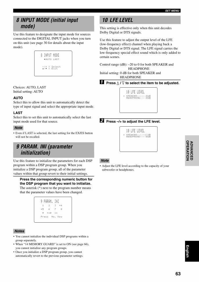
63
En
glish
INT
RO
DU
CT
ION
PR
EPA
RA
TIO
NB
AS
IC O
PE
RA
-T
ION
AD
VAN
CE
DO
PE
RA
TIO
NA
DD
ITIO
NA
LIN
FO
RM
AT
ION
AP
PE
ND
IXSET MENU
9 PARAM. INI (parameterinitialization)
Use this feature to initialize the parameters for each DSPprogram within a DSP program group. When youinitialize a DSP program group, all of the parametervalues within that group revert to their initial settings.
Press the corresponding numeric button forthe DSP program that you want to initialize.The asterisk (*) next to the program number meansthat the parameter values have been changed.
Notes• You cannot initialize the individual DSP programs within a
group separately.• When “14 MEMORY GUARD” is set to ON (see page 66),
you cannot initialize any program groups.• Once you initialize a DSP program group, you cannot
automatically revert to the previous parameter settings.
9 PARAM. INI
*5 6 7 8
9 *10 11
Press No. Key
1 2 3 *4
10 LFE LEVELHEADPHONE…………0dB
≥ SPEAKER………………0dB
10 LFE LEVELHEADPHONE…………0dB
≥ SPEAKER…………-11dB
10 LFE LEVELThis setting is effective only when this unit decodesDolby Digital or DTS signals.
Use this feature to adjust the output level of the LFE(low-frequency effect) channel when playing back aDolby Digital or DTS signal. The LFE signal carries thelow-frequency special effect sound which is only added tocertain scenes.
Control range (dB): –20 to 0 for both SPEAKER andHEADPHONE
Initial setting: 0 dB for both SPEAKER andHEADPHONE
1 Press k / n to select the item to be adjusted.
2 Press –/+ to adjust the LFE level.
Note• Adjust the LFE level according to the capacity of your
subwoofer or headphones.
8 INPUT MODE (initial inputmode)
Use this feature to designate the input mode for sourcesconnected to the DIGITAL INPUT jacks when you turnon this unit (see page 30 for details about the inputmode).
Choices: AUTO, LASTInitial setting: AUTO
AUTOSelect this to allow this unit to automatically detect thetype of input signal and select the appropriate input mode.
LASTSelect this to set this unit to automatically select the lastinput mode used for that source.
Note• Even if LAST is selected, the last setting for the EX/ES button
will not be recalled.
8 INPUT MODE
-/+ : Select/ : Exit
AUTO LAST
0109DSPAZ2_55-68_EN(GB) 02.8.22, 0:17 PM63

64
SET MENU
11 D-RANGE (dynamic range)Use this feature to adjust the dynamic range. This settingis effective only when this unit decodes Dolby Digitalsignals.
Choices: MAX, STD, MINInitial setting: MAX (for both speakers and headphones)
MAXSelect the “MAX” setting for feature films.
STDSelect the “STD” (Standard) setting for general use.
MINSelect the “MIN” setting for listening to sources atextremely low volume levels.
11 D-RANGEHP: MAX STD MIN
≥ SP: MAX STD MIN
12 SP DELAYUse this feature to adjust the delay of the Center and theRear Center channel sounds. This feature works whenthere is sound output from the center speakers with asource like Dolby Digital or DTS, etc. Ideally, the Centerspeaker and the Rear Center speaker should be the samedistance from the main listening position as the left andright Main speakers. However, in most home situations,the Center speaker or the Rear Center speaker is placed inline with the Main speakers or the Rear speakers. Bydelaying the sound from the Center speaker and the RearCenter speaker, the apparent distance from the Centerspeaker and the Rear Center speaker to the main listeningposition can be adjusted to make it seem the same as thedistance between the left and right Main speaker, and theleft and right Rear speakers to the listening position.Adjusting the delay time for the Center speaker isespecially important for giving depth to the dialogue.
1 Press k / n to select “UNIT”.
2 Press –/+ to select the unit to be used forsetting.Select one from “msec”, “meters”, and “feet”.
Notes• Setting items change depending on the unit chosen.• When “meters” or “feet” is selected, enter the distance from
your listening position to each speaker.
3 Press k / n to select the speaker for whichthe delay is adjusted.
4 Press –/+ to set the delay.Press + for higher value and – for lower value.
L C
C
RC
R
RL RRRC
Center speaker image
12 SP DELAYCENTER……………0.0msREAR CT…………3.0ms
≥ UNIT……………………msec
0109DSPAZ2_55-68_EN(GB) 02.8.22, 0:17 PM64

65
En
glish
INT
RO
DU
CT
ION
PR
EPA
RA
TIO
NB
AS
IC O
PE
RA
-T
ION
AD
VAN
CE
DO
PE
RA
TIO
NA
DD
ITIO
NA
LIN
FO
RM
AT
ION
AP
PE
ND
IXSET MENU
13 DISPLAY SET
DIMMERYou can adjust the brightness of the front panel display.
Control range: –4 to 0Initial setting: 0
OSD SHIFT (OSD off-set position)This setting is used to adjust the vertical position of theOSD.
Control range: +5 (downward) to –5 (upward)Initial setting: 0
Press + to lower the position of the OSD.Press – to raise the position of the OSD.
GRAY BACKSelecting AUTO for the on-screen display setting displaysa gray background when there’s no video signal input.Nothing is displayed on the screen including the on-screen display if OFF is selected.
Choices: AUTO, OFFInitial setting: AUTO
Note• If “GRAY BACK” is set to OFF, no information will be
displayed on the screen when video signals are not being input.
V CONV. (Video conversion)(Europe and U.K. models only)
Use this feature to turn on/off the function to convertcomposite signals to S-video signals to output through theS-video jack when no S-video signals are input.
Choices: ON, OFFInitial setting: OFF
OFFSelect this not to convert composite signals to S-videosignals.
ONSelect this to convert composite signals to S-videosignals.
13 DISPLAY SETOSD SHIFT………………0
≥ DIMMER………………………0
GRAY BACK………AUTOV CONV.………………OFF
12 SP DELAYMAIN L/R……10.0ftCENTER…………10.0ftREAR L/R……10.0ft
≥ UNIT……………………feet
REAR CT…………7.0ft
Setting by “msec”Control range: 0 to 5.0 ms (for center), 0 to 30.0 ms
(for rear center)Initial settings: 0 ms (for center), 3.0 ms (for rear
center)
Setting by “meters”Control range: 0.15 to 30.00 m (for main L/R,
center, rear L/R, rear center)Initial settings: 3.00 m (for main L/R, center, rear L/
R), 2.10 m (for rear center)
Setting by “feet”Control range: 0.5 to 100 ft (for main L/R, center,
rear L/R, rear center)Initial settings: 10.0 ft (for main L/R, center, rear L/
R), 7.0 ft (for rear center)
Note• No delay will be set if the same distance is set for the main L/R
and center, or the rear L/R and rear center with “meters” or“feet” selected.
12 SP DELAYCENTER……………0.0msREAR CT…………3.0ms
≥ UNIT……………………msec
12 SP DELAYMAIN L/R………3.00mCENTER……………3.00mREAR L/R………3.00m
≥ UNIT………………meters
REAR CT…………2.10m
0109DSPAZ2_55-68_EN(GB) 02.8.22, 0:17 PM65

66
SET MENU
14 MEMORY GUARD
-/+ : Select/ : Exit
OFF ON
14 MEMORY GUARDUse this feature to prevent accidental changes to DSPprogram parameter values and other settings on this unit.
Choices: ON, OFFInitial setting: OFF
Select ON to protect the following features:• DSP program parameters• All SET MENU items• Center, rear speakers, rear center, front effect, and
subwoofer levels• The on-screen display (OSD) mode
Notes• When “14 MEMORY GUARD” is set to ON, you cannot use
the test tone.• When “14 MEMORY GUARD” is set to ON, you cannot select
any other SET MENU items.
15 6CH INPUT SETUse this feature to set the direction of the signals inputinto the center and subwoofer channels when the sourcecomponent is connected to the 6CH INPUT jacks.
15A CENTER to (direction of thecenter channel signals)
This item sets the direction of the signals input into theCENTER jack.
Choices: CENTER, MAINInitial setting: CENTER
CENTERThe input signals are output from the center speaker.
MAINThe input signals are directed to the main L/R speakerswith same level.
15B SWFR to (direction of thesignals input into the subwoofer)
This item sets the direction of the signals input into theSUBWOOFER jack.
Choices: SWFR, MAINInitial setting: SWFR
SWFRThe input signals are output from the subwoofer.
MAINThe input signals are directed to the main L/R speakerswith same level.
CENTER MAIN
15A CENTER to
SWFR MAIN
15B SWFR to
0109DSPAZ2_55-68_EN(GB) 02.8.22, 0:17 PM66
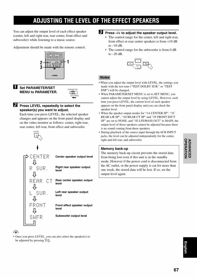
67
En
glish
INT
RO
DU
CT
ION
PR
EPA
RA
TIO
NB
AS
IC O
PE
RA
-T
ION
AD
VAN
CE
DO
PE
RA
TIO
NA
DD
ITIO
NA
LIN
FO
RM
AT
ION
AP
PE
ND
IX
3 Press –/+ to adjust the speaker output level.• The control range for the center, left and right rear,
front effect or rear center speakers is from +10 dBto –10 dB.
• The control range for the subwoofer is from 0 dBto –20 dB.
Notes• When you adjust the output level with LEVEL, the settings you
made with the test tone (“TEST DOLBY SUR.” or “TESTDSP”) will be changed.
• When PARAMETER/SET MENU is set to SET MENU, youcannot adjust the output level by using LEVEL. However, eachtime you press LEVEL, the current level of each speakerappears on the front panel display and you can check thespeaker level.
• When the speaker output modes for “1A CENTER SP”, “1CREAR L/R SP”, “1D REAR CT SP” and “1F FRONT EFCTSP” are set to NONE, and “1E LFE/BASS OUT” to MAIN, theoutput level of those speakers cannot be adjusted because thereis no sound coming from these speakers.
• During playback of the source input through the 6CH INPUTjacks, the level can be adjusted independently for the center,right and left rear, and subwoofer.
Memory back-upThe memory back-up circuit prevents the stored datafrom being lost even if this unit is in the standbymode. However if the power cord is disconnected fromthe AC outlet, or the power supply is cut for more thanone week, the stored data will be lost. If so, set theoutput level again.
You can adjust the output level of each effect speaker(center, left and right rear, rear center, front effect andsubwoofer) while listening to a music source.
Adjustment should be made with the remote control.
1 Set PARAMETER/SETMENU to PARAMETER.
2 Press LEVEL repeatedly to select thespeaker(s) you want to adjust.Each time you press LEVEL, the selected speakerchanges and appears on the front panel display andon the video monitor as follows: center, right rear,rear center, left rear, front effect and subwoofer.
LEVEL
PARAMETER
SET MENU
MUTE
VOLUME
STEREO
TV INPUT
TV VOL CH
PRESET
DISC
PARAMETER
SET MENU
EFFECT
LEVELON SCREEN
TESTSLEEP
TV MUTE
A/B/C/D/E
123
ADJUSTING THE LEVEL OF THE EFFECT SPEAKERS
y• Once you press LEVEL, you can also select the speaker(s) to
be adjusted by pressing n/k.
Center speaker output level
Front effect speaker outputlevel
Left rear speaker outputlevel
Rear center speaker outputlevel
Right rear speaker outputlevel
Subwoofer output level
0109DSPAZ2_55-68_EN(GB) 02.8.22, 0:17 PM67
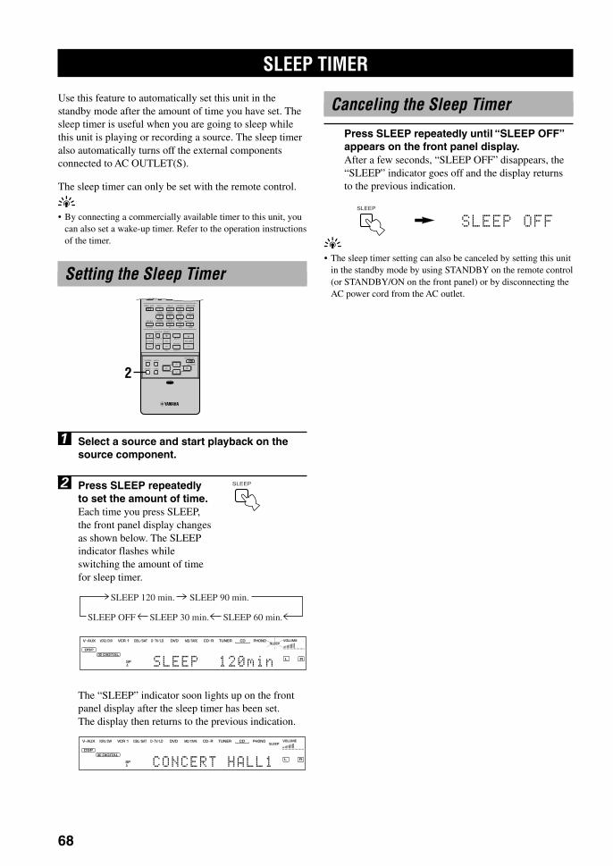
68
Use this feature to automatically set this unit in thestandby mode after the amount of time you have set. Thesleep timer is useful when you are going to sleep whilethis unit is playing or recording a source. The sleep timeralso automatically turns off the external componentsconnected to AC OUTLET(S).
The sleep timer can only be set with the remote control.
y• By connecting a commercially available timer to this unit, you
can also set a wake-up timer. Refer to the operation instructionsof the timer.
Setting the Sleep Timer
1 Select a source and start playback on thesource component.
2 Press SLEEP repeatedlyto set the amount of time.Each time you press SLEEP,the front panel display changesas shown below. The SLEEPindicator flashes whileswitching the amount of timefor sleep timer.
The “SLEEP” indicator soon lights up on the frontpanel display after the sleep timer has been set.The display then returns to the previous indication.
SLEEP TIMER
Canceling the Sleep Timer
Press SLEEP repeatedly until “SLEEP OFF”appears on the front panel display.After a few seconds, “SLEEP OFF” disappears, the“SLEEP” indicator goes off and the display returnsto the previous indication.
y• The sleep timer setting can also be canceled by setting this unit
in the standby mode by using STANDBY on the remote control(or STANDBY/ON on the front panel) or by disconnecting theAC power cord from the AC outlet.
SLEEP
SLEEP
L R
VCR DVD TUNER CD PHONOCD RV AUX
DSP
1
SP
DIGITAL
VCR2/DVR CBL/SAT MD/TAPETV/LD VOLUMESLEEP
D
A SLEEP 120min
SLEEP 120 min. SLEEP 90 min.
SLEEP 60 min.SLEEP 30 min.SLEEP OFF
L R
VCR DVD TUNER CD PHONOCD RV AUX
DSP
1
SP
DIGITAL
VCR2/DVR CBL/SAT MD/TAPETV/LD VOLUMESLEEP
D
A CONCERT HALL1
HALL 1
EX/ES
DSP10KEY
ROCKCONCERT
MOVIETHEATER 1
MOVIETHEATER 2
MUTE
VOLUME
STEREO
TV INPUT
TV VOL CH
PRESET
DISC
PARAMETER
SET MENU
EFFECT
LEVELON SCREEN
TESTSLEEP
TV MUTE
MUSICVIDEO
TVTHEATER
ENTER-TAINMENT
HALL 2 CHURCH JAZZ CLUB
SELECT/DTS
SUR.
CHP/INDEX
A/B/C/D/E
1
5
9
6
100 10 100
11 12
7 8
2 3 4
++
2
0109DSPAZ2_55-68_EN(GB) 02.8.22, 0:17 PM68

69
En
glish
INT
RO
DU
CT
ION
PR
EPA
RA
TIO
NB
AS
IC O
PE
RA
-T
ION
AD
VAN
CE
DO
PE
RA
TIO
NA
DD
ITIO
NA
LIN
FO
RM
AT
ION
AP
PE
ND
IX
SOUND FIELD PROGRAM PARAMETER EDITING
What Is a Sound Field?What really creates the rich, full tones of a live instrumentare the multiple reflections from the walls of the room. Inaddition to making the sound “live”, these reflectionsenable us to tell where the player is situated, and the sizeand shape of the room in which we are sitting.
Elements of a sound fieldIn any environment, in addition to the direct soundcoming straight to our ears from the player’s instrument,there are two distinct types of sound reflections thatcombine to make up the sound field:
Early reflectionsReflected sounds reach our ears extremely rapidly(50 ms – 100 ms after the direct sound), after reflectingfrom one surface only — for example, from the ceiling ora wall. Early reflections actually add clarity to the directsound.
ReverberationsThese are caused by reflections from more than onesurface — walls, ceiling, the back of the room — sonumerous that they merge together to form a continuoussonic “afterglow”. They are non-directional, and lessenthe clarity of the direct sound.
Direct sound, early reflections and subsequentreverberation taken together help us to determine thesubjective size and shape of the room, and it is thisinformation that the digital sound field processorreproduces in order to create sound fields.
If you could create the appropriate early reflections andsubsequent reverberations in your listening room, youwould be able to create your own listening environment.The acoustics in your room could be changed to those ofa concert hall, a dance floor, or virtually any size room atall. This ability to create sound fields at will is exactlywhat YAMAHA has done with the digital sound fieldprocessor.
Sound Field Program ParametersDSP programs consist of some parameters to determinethe apparent room size, reverberation time, distance fromyou to the performer, etc. In each program, theseparameters are set with values precisely calculated byYAMAHA to create a sound field unique to the program.It is recommended to use DSP programs withoutchanging the values of parameters; however, this unit alsoallows you to create your own sound fields. Starting withone of the built-in programs, you can adjust thoseparameters.
Each DSP program has a set of parameters that allow youto change the characteristics of the acoustic environmentto precisely create the effect you want. These parameterscorrespond to the many natural acoustic factors that createthe sound field you experience in an actual concert hall orother listening environment. The size of the room, forexample, affects the length of time between the earlyreflections. The “ROOM SIZE” parameter provided inmany of the DSP programs alters the timing betweenthese reflections, thus changing the shape of the “room”you are listening. In addition to room size, the shape ofthe room and the characteristics of its surfaces have asignificant effect on the final sound. Surfaces that absorbsound, for example, cause the reflections andreverberations to die out more quickly, while highlyreflective surfaces allow the reflections to carry on for alonger period of time. The digital sound field parametersallow you to control these and many other factors thatcontribute to your personal sound field, allowing you toessentially “redesign” the concert halls, theaters, etc.provided to create custom-tailored listening environmentsthat ideally match your mood and music.
See “DIGITAL SOUND FIELD PARAMETERDESCRIPTIONS” on pages 71 to 74.
0110DSPAZ2_69-74_EN(GB) 02.8.22, 0:17 PM69

70
SOUND FIELD PROGRAM PARAMETER EDITING
4 Press k / n to select theparameter.
5 Press –/+ to change theparameter value.When you set the parameter toa value other than the factory-set value, an asterisk mark (*)appears by the parameter nameon the video monitor.
6 Repeat steps 3 to 5 above as necessary tochange other program parameters.
Notes• The available parameters may be displayed on more than one
OSD page for some of the programs. To scroll through pages,press k / n.
• You cannot change parameter values when “14 MEMORYGUARD” on the SET MENU is set to ON. If you want tochange the parameter values, set “14 MEMORY GUARD” toOFF (see page 66).
Memory back-upThe memory back-up circuit prevents the stored datafrom being lost even if this unit is set in the standbymode, the power cord is disconnected from the ACoutlet, or the power supply is temporarily cut due topower failure. However, if the power is cut for morethan one week, the parameter value you edited willreturn to the factory setting. If so, edit the parametervalue again.
Resetting a Parameter to theFactory-set Value
To reset some of the parametersto the factory-set values
Select the parameter you want to reset. Then press andhold –/+ until the value temporarily stops at the factory-set value. The asterisk mark (*) by the parameter namedisappears on the video monitor.
To reset all of the parameters tothe factory-set values
Use “9 PARAM. INI” on the SET MENU to reset all ofthe parameter values of all DSP programs within theselected group to the factory-set values (see page 63).This operation resets all of the parameter values of allDSP programs within that group to the factory-set values.
Changing Parameter SettingsYou can enjoy good quality sound with the factory-setparameters. Although you do not have to change theinitial settings, you can change some of the parameters tobetter suit the input source or your listening room.
1 Set PARAMETER/SETMENU to PARAMETER.
2 Turn on the video monitorand press ON SCREENrepeatedly to select thefull display mode.
3 Select a DSP program you want to adjust.
PARAMETER
SET MENU
P05 ROCK CONCERT
≥ INIT.DLY…………15msROOM SIZE…………1.0LIVENESS…………………5REV.TIME…………1.6s
The Roxy TheatreDSP LEVEL…………0dB
HALL 1DSP10KEY
ROCKCONCERT
MOVIETHEATER 1
MOVIETHEATER 2
MUSICVIDEO
TVTHEATER
ENTER-TAINMENT
HALL 2 CHURCH JAZZ CLUB
SELECT/DTS
SUR.
1
5
9
6
100 10 100
11 12
7 8
2 3 4
++
ON SCREEN
Program No.
Example of the parameter setting display
Parameters
Cursor
Program name
HALL 1
EX/ES
DSP10KEY
ROCKCONCERT
MOVIETHEATER 1
MOVIETHEATER 2
MUTE
VOLUME
STEREO
TV INPUT
TV VOL CH
PRESET
DISC
PARAMETER
SET MENU
EFFECT
LEVELON SCREEN
TESTSLEEP
TV MUTE
MUSICVIDEO
TVTHEATER
ENTER-TAINMENT
HALL 2 CHURCH JAZZ CLUB
SELECT/DTS
SUR.
CHP/INDEX
A/B/C/D/E
1
5
9
6
100 10 100
11 12
7 8
2 3 4
++
1
3
425
Parameter valves
0110DSPAZ2_69-74_EN(GB) 02.8.22, 0:17 PM70
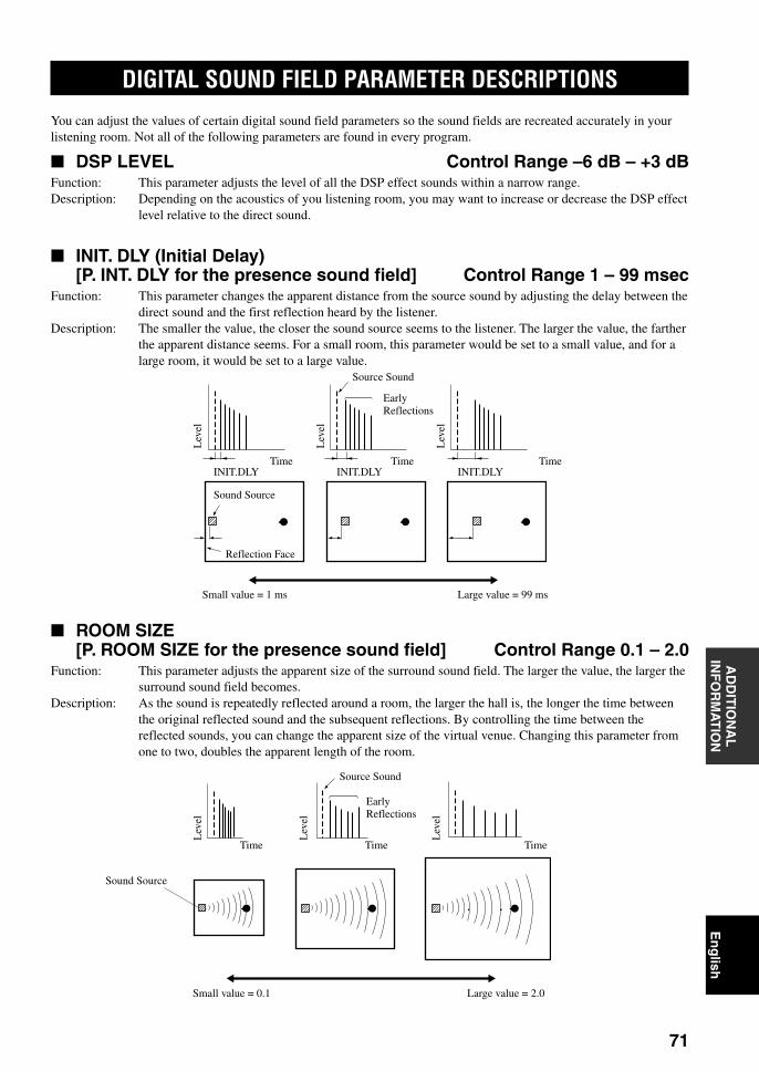
71
En
glish
INT
RO
DU
CT
ION
PR
EPA
RA
TIO
NB
AS
IC O
PE
RA
-T
ION
AD
VAN
CE
DO
PE
RA
TIO
NA
DD
ITIO
NA
LIN
FO
RM
AT
ION
AP
PE
ND
IX
Large value = 2.0Small value = 0.1
Sound Source
TimeTimeTime
EarlyReflections
Source Sound
Lev
el
Lev
el
Lev
el
ROOM SIZE[P. ROOM SIZE for the presence sound field] Control Range 0.1 – 2.0
Function: This parameter adjusts the apparent size of the surround sound field. The larger the value, the larger thesurround sound field becomes.
Description: As the sound is repeatedly reflected around a room, the larger the hall is, the longer the time betweenthe original reflected sound and the subsequent reflections. By controlling the time between thereflected sounds, you can change the apparent size of the virtual venue. Changing this parameter fromone to two, doubles the apparent length of the room.
Large value = 99 msSmall value = 1 ms
Reflection Face
Sound Source
TimeTime TimeINIT.DLYINIT.DLYINIT.DLY
EarlyReflections
Source Sound
Lev
el
Lev
el
Lev
el
DIGITAL SOUND FIELD PARAMETER DESCRIPTIONS
You can adjust the values of certain digital sound field parameters so the sound fields are recreated accurately in yourlistening room. Not all of the following parameters are found in every program.
DSP LEVEL Control Range –6 dB – +3 dBFunction: This parameter adjusts the level of all the DSP effect sounds within a narrow range.Description: Depending on the acoustics of you listening room, you may want to increase or decrease the DSP effect
level relative to the direct sound.
INIT. DLY (Initial Delay)[P. INT. DLY for the presence sound field] Control Range 1 – 99 msec
Function: This parameter changes the apparent distance from the source sound by adjusting the delay between thedirect sound and the first reflection heard by the listener.
Description: The smaller the value, the closer the sound source seems to the listener. The larger the value, the fartherthe apparent distance seems. For a small room, this parameter would be set to a small value, and for alarge room, it would be set to a large value.
0110DSPAZ2_69-74_EN(GB) 02.8.22, 0:17 PM71
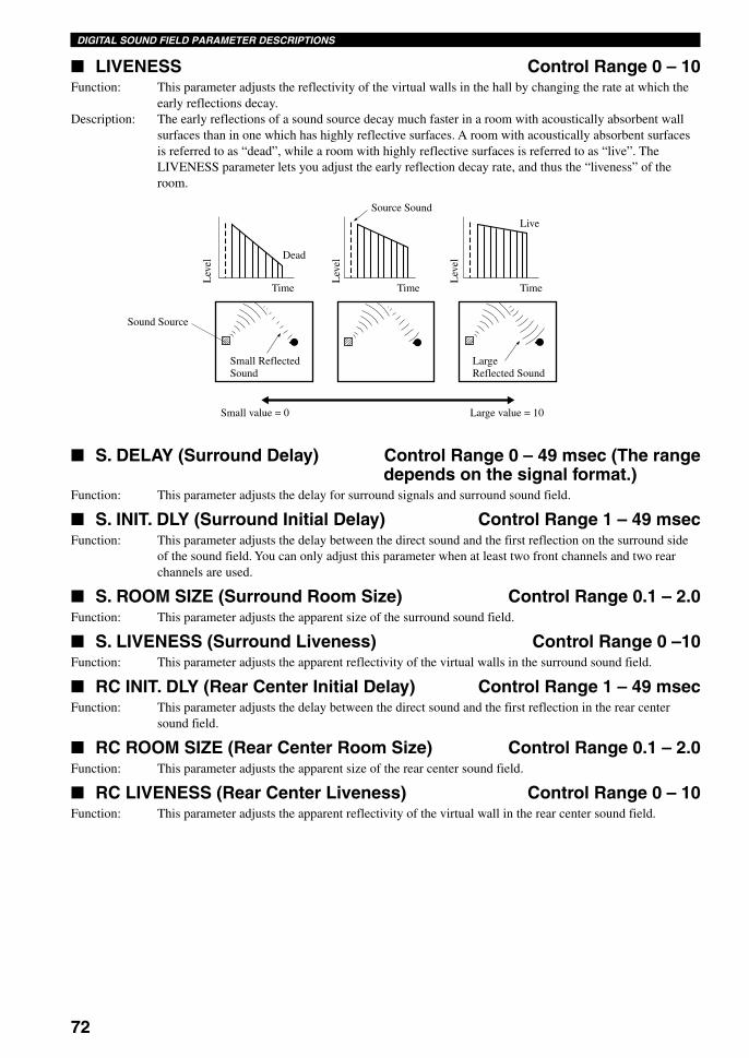
72
DIGITAL SOUND FIELD PARAMETER DESCRIPTIONS
S. DELAY (Surround Delay) Control Range 0 – 49 msec (The rangedepends on the signal format.)
Function: This parameter adjusts the delay for surround signals and surround sound field.
S. INIT. DLY (Surround Initial Delay) Control Range 1 – 49 msecFunction: This parameter adjusts the delay between the direct sound and the first reflection on the surround side
of the sound field. You can only adjust this parameter when at least two front channels and two rearchannels are used.
S. ROOM SIZE (Surround Room Size) Control Range 0.1 – 2.0Function: This parameter adjusts the apparent size of the surround sound field.
S. LIVENESS (Surround Liveness) Control Range 0 –10Function: This parameter adjusts the apparent reflectivity of the virtual walls in the surround sound field.
RC INIT. DLY (Rear Center Initial Delay) Control Range 1 – 49 msecFunction: This parameter adjusts the delay between the direct sound and the first reflection in the rear center
sound field.
RC ROOM SIZE (Rear Center Room Size) Control Range 0.1 – 2.0Function: This parameter adjusts the apparent size of the rear center sound field.
RC LIVENESS (Rear Center Liveness) Control Range 0 – 10Function: This parameter adjusts the apparent reflectivity of the virtual wall in the rear center sound field.
Large value = 10Small value = 0
LargeReflected Sound
Small ReflectedSound
Sound Source
Live
TimeTimeTime
Dead
Source SoundL
evel
Lev
el
Lev
el
LIVENESS Control Range 0 – 10Function: This parameter adjusts the reflectivity of the virtual walls in the hall by changing the rate at which the
early reflections decay.Description: The early reflections of a sound source decay much faster in a room with acoustically absorbent wall
surfaces than in one which has highly reflective surfaces. A room with acoustically absorbent surfacesis referred to as “dead”, while a room with highly reflective surfaces is referred to as “live”. TheLIVENESS parameter lets you adjust the early reflection decay rate, and thus the “liveness” of theroom.
0110DSPAZ2_69-74_EN(GB) 02.8.22, 0:17 PM72

73
En
glish
INT
RO
DU
CT
ION
PR
EPA
RA
TIO
NB
AS
IC O
PE
RA
-T
ION
AD
VAN
CE
DO
PE
RA
TIO
NA
DD
ITIO
NA
LIN
FO
RM
AT
ION
AP
PE
ND
IXSOUND FIELD PROGRAM PARAMETER EDITINGDIGITAL SOUND FIELD PARAMETER DESCRIPTIONS
60 dB 60 dB 60 dB
(dB)
60 dB
Lev
el
Time
REV. LEVEL
Source Sound
REV. LEVEL (Reverberation Level) Control Range 0 – 100 %Function: This parameter adjusts the volume of the reverberation sound.Description: The larger the value, the stronger the reverberation becomes.
Time
REV. TIMEREV.DELAY
Reverberation
Source Sound
Lev
el
REV. DELAY (Reverberation Delay) Control Range 0 – 250 msecFunction: This parameter adjusts the time difference between the beginning of the direct sound and the beginning
of the reverberation sound.Description: The larger the value, the later the reverberation sound begins. A later reverberation sound makes you
feel like you are in a larger acoustic environment.
Large value = 5.0 sSmall value = 1.0 s
LongReverberation
ShortReverberation
Sound Source
REV. TIMEREV. TIMEREV. TIME
Early Reflections
ReverberationSource SoundReverberation
REV. TIME (Reverberation Time) Control Range 1.0 – 5.0 secFunction: This parameter adjusts the amount of time it takes for the dense, subsequent reverberation sound to
decay by 60 dB (at 1 kHz). This changes the apparent size of the acoustic environment over anextremely wide range.
Description: Set a longer reverberation time for “dead” sources and listening room environments, and a shorter timefor “live” sources and listening room environments.
0110DSPAZ2_69-74_EN(GB) 02.8.22, 0:17 PM73

74
DIGITAL SOUND FIELD PARAMETER DESCRIPTIONS
For 8ch Stereo
CT LEVEL (Center Level) Control Range 0 – 100 %Function: This parameter adjusts the volume level for the center channel in 8-channel stereo mode.
RL LEVEL (Rear Left Level) Control Range 0 – 100 %Function: This parameter adjusts the volume level for the rear left channel in 8-channel stereo mode.
RR LEVEL (Rear Right Level) Control Range 0 – 100 %Function: This parameter adjusts the volume level for the rear right channel in 8-channel stereo mode.
RC LEVEL (Rear Center Level) Control Range 0 – 100 %Function: This parameter adjusts the volume level for the rear center channel in 8-channel stereo mode.
FL LEVEL (Front Left Level) Control Range 0 – 100 %Function: This parameter adjusts the volume level for the front effect left channel in 8-channel stereo mode.
FR LEVEL (Front Right Level) Control Range 0 – 100 %Function: This parameter adjusts the volume level for the front effect right channel in 8-channel stereo mode.
For PRO LOGIC Music
PANORAMA Control Range OFF/ONFunction: Extends the front stereo image to include the surround speakers for wraparound effect.
DIMENSION Control Range –3 – STD – +3Function: Gradually adjusts the soundfield either towards the front or towards the rear.
CT WIDTH (Center Width) Control Range 0 – 7Function: Adjusts the center image from all three front speakers to varying degrees.
For DTS Neo: 6 Music
C. IMAGE (Center Image) Control Range 0 – 0.5Function: This parameter adjusts the center image from all three front speakers.
0110DSPAZ2_69-74_EN(GB) 02.8.22, 0:17 PM74
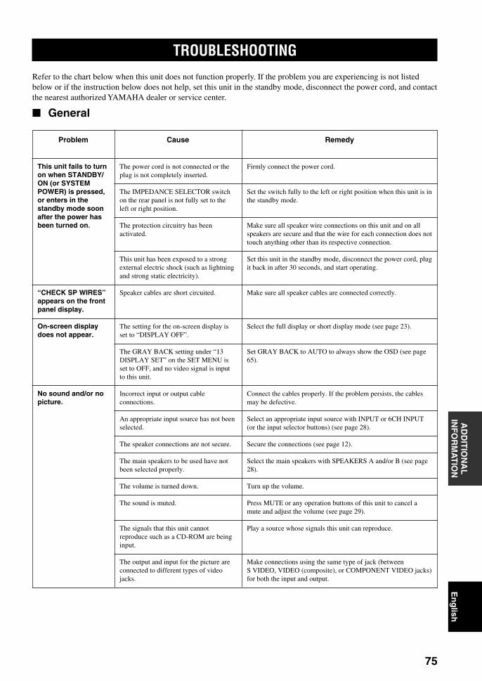
75
En
glish
INT
RO
DU
CT
ION
PR
EPA
RA
TIO
NB
AS
ICO
PE
RA
ION
TA
DVA
NC
ED
OP
ER
AT
ION
AD
DIT
ION
AL
INF
OR
MA
TIO
NA
PP
EN
DIX
TROUBLESHOOTING
Refer to the chart below when this unit does not function properly. If the problem you are experiencing is not listedbelow or if the instruction below does not help, set this unit in the standby mode, disconnect the power cord, and contactthe nearest authorized YAMAHA dealer or service center.
General
Problem
This unit fails to turnon when STANDBY/ON (or SYSTEMPOWER) is pressed,or enters in thestandby mode soonafter the power hasbeen turned on.
“CHECK SP WIRES”appears on the frontpanel display.
On-screen displaydoes not appear.
No sound and/or nopicture.
Cause
The power cord is not connected or theplug is not completely inserted.
The IMPEDANCE SELECTOR switchon the rear panel is not fully set to theleft or right position.
The protection circuitry has beenactivated.
This unit has been exposed to a strongexternal electric shock (such as lightningand strong static electricity).
Speaker cables are short circuited.
The setting for the on-screen display isset to “DISPLAY OFF”.
The GRAY BACK setting under “13DISPLAY SET” on the SET MENU isset to OFF, and no video signal is inputto this unit.
Incorrect input or output cableconnections.
An appropriate input source has not beenselected.
The speaker connections are not secure.
The main speakers to be used have notbeen selected properly.
The volume is turned down.
The sound is muted.
The signals that this unit cannotreproduce such as a CD-ROM are beinginput.
The output and input for the picture areconnected to different types of videojacks.
Remedy
Firmly connect the power cord.
Set the switch fully to the left or right position when this unit is inthe standby mode.
Make sure all speaker wire connections on this unit and on allspeakers are secure and that the wire for each connection does nottouch anything other than its respective connection.
Set this unit in the standby mode, disconnect the power cord, plugit back in after 30 seconds, and start operating.
Make sure all speaker cables are connected correctly.
Select the full display or short display mode (see page 23).
Set GRAY BACK to AUTO to always show the OSD (see page65).
Connect the cables properly. If the problem persists, the cablesmay be defective.
Select an appropriate input source with INPUT or 6CH INPUT(or the input selector buttons) (see page 28).
Secure the connections (see page 12).
Select the main speakers with SPEAKERS A and/or B (see page28).
Turn up the volume.
Press MUTE or any operation buttons of this unit to cancel amute and adjust the volume (see page 29).
Play a source whose signals this unit can reproduce.
Make connections using the same type of jack (betweenS VIDEO, VIDEO (composite), or COMPONENT VIDEO jacks)for both the input and output.
0111DSPAZ2_75-78_EN(GB) 02.8.22, 0:17 PM75

76
TROUBLESHOOTING
Problem
The sound suddenlygoes off.
Only the speaker onone side can beheard.
No sound from theeffect speakers.
No sound from thecenter speaker.
No sound from therear speakers.
No sound from therear center speaker.
No sound from thesubwoofer.
Cause
The protection circuit has been activatedbecause of a short circuit, etc.
The sleep timer has functioned.
The sound is muted.
Incorrect cable connections.
Incorrect setting of “3 L/R BALANCE”on the SET MENU.
The sound effect is off.
The source encoded with a Dolby Digitalor DTS signal does not have a center,rear L/R or rear center channel signals.
The output level of the center speaker isset to minimum.
“1A CENTER SP” on the SET MENU isset to NONE.
One of the Hi-Fi DSP programs (1 to 6except for Game and 8ch Stereo) hasbeen selected.
The output level of the rear speakers isset to minimum.
“1C REAR L/R SP” on the SET MENUis set to NONE.
A monaural source is being played withthe program 11.
“1C REAR L/R SP” on the SET MENUis set to NONE.
“1D REAR CT SP” on the SET MENUis set to NONE.
“1E LFE/BASS OUT” on the SETMENU is set to MAIN when a DolbyDigital or DTS signal is being played.
“1E LFE/BASS OUT” on the SETMENU is set to SWFR or MAIN when a2-channel source is being played.
The source does not contain low basssignals (90 Hz and below).
Remedy
Check the IMPEDANCE SELECTOR switch is set to theappropriate position and then turn this unit back on.
Check the speaker wires are not touching each other and then turnthis unit back on.
Turn on the power, and play the source again.
Press MUTE or any operation buttons of this unit to cancel amute and adjust the volume (see page 29).
Connect the cables properly. If the problem persists, the cablesmay be defective.
Adjust it to the appropriate position.
Press STEREO/EFFECT to turn it on (see page 33).
Raise the level of the center speaker (see pages 25 and 26).
Select the appropriate mode for your center speaker (see page56).
Select another DSP program.
Raise the output level of the rear speakers (see pages 25 and 26).
Select the appropriate speaker mode for the rear L/R speakers(see page 57).
Select another DSP program.
If the speaker mode for the rear L/R speakers is set to NONE, thespeaker mode for the rear center speaker is automatically set toNONE. Select the appropriate speaker mode for the rear L/Rspeaker mode (see page 57).
Select LRG or SML (see page 58).
Select SWFR or BOTH (see page 58).
Select BOTH (see page 58).
0111DSPAZ2_75-78_EN(GB) 02.8.22, 0:17 PM76

77
En
glish
INT
RO
DU
CT
ION
PR
EPA
RA
TIO
NB
AS
ICO
PE
RA
ION
TA
DVA
NC
ED
OP
ER
AT
ION
AD
DIT
ION
AL
INF
OR
MA
TIO
NA
PP
EN
DIX
TROUBLESHOOTING
Problem
Dolby Digital or DTSsources cannot beplayed. (Dolby Digital orDTS indicator on thefront panel displaydoes not light up.)
Poor bassreproduction.
A “humming” soundcan be heard.
The volume level is lowwhile playing a record.
The volume levelcannot be increased, orthe sound is distorted.
The sound effectcannot be recorded.
A source cannot berecorded.
The sound fieldparameters and someother settings on thisunit cannot bechanged.
This unit does notoperate properly.
Cause
“Digital output” and “Dolby Digital” or“DTS” are not selected on the connectedcomponents.
“1E LFE/BASS OUT” on the SETMENU is set to SWFR or BOTH andyour system does not include asubwoofer.
The output mode for each speaker (main,center, rear, or rear center) on the SETMENU does not match your speakerconfiguration.
Incorrect cable connections.
No connection from the turntable to theGND terminal.
The record is being played on a turntablewith an MC cartridge.
The component connected to theOUT(REC) jacks of this unit is turnedoff.
It is not possible to record the soundeffect by a recording component.
A source component is connected to theanalog input jacks of this unit for digitalrecording.
Digital connections are not made betweenthis unit and other components forplayback or recording.
A source component is connected to thedigital input jacks of this unit for analogrecording.
Analog connections are not madebetween this unit and other componentsfor playback or recording.
Some recording components cannotrecord the Dolby Digital or DTS sources.
“14 MEMORY GUARD” on the SETMENU is set to ON.
The internal microcomputer has beenfrozen by an external electric shock (suchas lightning or excessive static electricity)or by a power supply with low voltage.
Remedy
Make an appropriate setting following the operationinstructions for your component.
Select MAIN (see page 58).
Select the appropriate output mode for each speaker based onthe size of the speakers in your configuration (see pages 56–59).
Firmly connect the audio plugs. If the problem persists, thecables may be defective.
Connect the grounding cord of your turntable to the GNDterminal of this unit (see page 19).
The turntable should be connected to this unit through anMC-head amplifier (see page 18).
Turn on the power to the component.
Connect the source component to the DIGITAL INPUT jacks.
Make digital connections.
Connect a source component to the analog input jacks.
Make analog connections.
Select OFF (see page 66).
Disconnect the AC power cord from the outlet and then plugit in again after about 30 seconds.
0111DSPAZ2_75-78_EN(GB) 02.8.22, 0:17 PM77

78
TROUBLESHOOTING
Remote control
Problem
The remote controldoes not work norfunction properly.
The remote controldoes not “learn” newfunctions.
Cause
Wrong distance or angle.
Direct sunlight or lighting (from aninverter type of fluorescent lamp, etc.) isstriking the remote control sensor of thisunit.
The batteries are weak.
The manufacturer code has not beencorrectly set.
Even if the maufacturer code is correctlyset, there are some models that do notrespond to the remote control.
The batteries of this remote control and/or the other remote control are too weak.
The distance between the two remotecontrols is too much or too little.
The signal coding or modulation of theother remote control is not compatiblewith this remote control.
Memory capacity is full.
Remedy
The remote control will function within a maximum range of 6m (20 feet) and no more than 30 degrees off-axis from thefront panel (see page 7).
Reposition this unit.
Replace the batteries.
Set the manufacturer code correctly (see page 42).
Try to set the other codes of the same maufacturer (see page42).
Program the necessary functions independently into theprogrammable buttons on this unit’s remote control using theLearn feature.
Replace the batteries (see page 3).
Place the remote controls at the proper distance (see page 43).
Learning is not possible.
Further learning is not possible without deleting unnecessaryfunctions (see page 48).
Problem
The sound is degradedwhen listening withheadphones connectedto a tape deck or CDplayer that is connectedto this unit.
There is noiseinterference from digitalor high-frequencyequipment, or this unit.
This unit suddenlyturns into the standbymode.
Cause
This unit is in the standby mode.
This unit is too close to the digital or high-frequency equipment.
The internal temperature becomes too highand the overheat protection circuitry hasbeen activated.
Remedy
Turn on the power of this unit.
Move this unit further away from such equipment.
Wait until this unit cools down and then turn it back on.
0111DSPAZ2_75-78_EN(GB) 02.8.22, 0:17 PM78

79
En
glish
INT
RO
DU
CT
ION
PR
EPA
RA
TIO
NB
AS
ICO
PE
RA
ION
TA
DVA
NC
ED
OP
ER
AT
ION
AD
DIT
ION
AL
INF
OR
MA
TIO
NA
PP
EN
DIX
GLOSSARY
Dolby SurroundDolby Surround uses a four analog channel recordingsystem to reproduce realistic and dynamic sound effects:two left and right main channels (stereo), a center channelfor dialog (monaural), and a rear channel for specialsound effects (monaural). The rear channel reproducessound within a narrow frequency range.Dolby Surround is widely used with nearly all video tapesand laser discs, and in many TV and cable broadcasts aswell. The Dolby Pro Logic decoder built into this unitemploys a digital signal processing system thatautomatically stabilizes the volume on each channel toenhance moving sound effects and directionality.
Dolby DigitalDolby Digital is a digital surround sound system thatgives you completely independent multi-channel audio.With three front channels (left, center and right), and tworear stereo channels, Dolby Digital provides five full-range audio channels. With an additional channelespecially for bass effects, called LFE (low frequencyeffect), the system has a total of 5.1 channels (LFE iscounted as 0.1 channel).Using two-channel stereo for the rear speakers, moreaccurate moving sound effects and surround soundenvironment are possible than with Dolby Surround. Thewide dynamic range (from maximum to minimumvolume) reproduced by the five full-range channels andthe precise sound orientation generated using digitalsound processing provide listeners with previouslyunheard of excitement and realism.With this unit, any sound environment from monaural upto a 5.1-channel configuration can be freely selected foryour enjoyment.
Dolby Digital Surround EXThis unit is equipped with the Dolby Digital decoder thatcan reproduce 5.1-channel sources adding a rear centerchannel. (The sound to be output from a rear centerspeaker is created by mixing the content of rear L/Rchannels.) This decoder is the most suitable to reproducethe soundtrack for the movies recorded by Dolby DigitalSurround EX. You can enjoy dynamic and realistic soundsby adding another channel.
Dolby Pro Logic Dolby Pro Logic is the improved technique to decodevast numbers of existing Dolby Surround programs. Thisnew technology enables a discrete 5-channel playbackwith two left and right main channels, a center channel,and two left and right rear channels compared with onelimited rear channel for the conventional Pro Logictechnology. Also the music mode is available for 2-channel sources in addition to the movie mode.
DTS (Digital Theater Systems)Digital Surround
DTS digital surround was developed to replace the analogsoundtracks of movies with a six-channel digital soundtrack, and is now rapidly gaining popularity in movietheaters around the world. Digital Theater Systems Inc.has developed a home theater system so that you canenjoy the depth of sound and natural spatialrepresentation of DTS digital surround in your home.This system is practically distortion-free, clear 6-channelsound (technically, a left, right and center channels, tworear channels, plus an LFE 0.1 channel as a subwoofer,for a total of 5.1 channels).
DTS ES (Extended Surround)This unit is equipped with the DTS ES decoder that canreproduce 5.1-channel sources adding a rear centerchannel. The DTS ES decoder on this unit is compatiblewith the two types of format: Discrete 6.1 and Matrix 6.1.The DTS ES Discrete decoder enables the 6.1-channelplayback by adding a rear center channel recordedindependently from the 5.1 channels. The DTS ES Matrixdecoder enables the 6.1-channel playback by adding arear center created from the rear L/R channels. Thisdecoder is the most suitable to reproduce the music or thesoundtrack of the movies recorded by DTS ES.
Neo: 6Neo: 6 decodes the conventional 2-channel sources for 6channel playback by the specific decoder. It enablesplayback with the full-range channels with higherseparation just like digital discrete signal playback. Twomodes are available; “Music mode” for playing musicsources and “Cinema mode” for movies.
DTS 96/24DTS 96/24 achieves the high quality playback with all 5.1channels at the sampling frequency 96 kHz / 24 bit byusing the data for extension of a DTS signal, that isrecorded on the DTS 96/24 software.
0112DSPAZ2_79-81_EN(GB) 02.8.22, 0:17 PM79

80
GLOSSARY
LFE 0.1 channelThis channel is for the reproduction of low bass signals.The frequency range for this channel is 20 Hz to 120 Hz.This channel is counted as 0.1 because it only enforces alow frequency range compared to the full-rangereproduced by the other 5 channels in a Dolby Digital orDTS 5.1 channel systems.
CINEMA DSP D I G I T A L
Since the Dolby Surround and DTS systems wereoriginally designed for use in movie theaters, their effectis best felt in a theater having many speakers anddesigned for acoustic effects. Since home conditions,such as room size, wall material, number of speakers, andso on, can differ so widely, it’s inevitable that there aredifferences in the sound heard as well. Based on a wealthof actually measured data, YAMAHA CINEMA DSP usesYAMAHA original sound field technology to combineDolby Pro Logic, Dolby Digital and DTS systems toprovide the visual and audio experience of movie theaterin the listening room of your own home.
SILENT CINEMAYAMAHA has developed a natural, realistic sound effectDSP algorithm for headphones.Parameters for headphones have been set for each soundfield so that accurate representations of all the sound fieldprograms can be enjoyed on headphones.
Virtual CINEMA DSPYAMAHA has developed a virtual CINEMA DSPalgorithm that allows you to enjoy DSP sound fieldsurround effects even without any rear speakers by usingvirtual rear speakers.It is even possible to enjoy virtual CINEMA DSP in aminimum two-speaker system that does not include acenter speaker.
S VIDEO signalWith S VIDEO signal system, the video signal normallytransmitted using a pin cable is separated and transmittedas the Y signal for the luminance and the C signal for thechrominance through the S VIDEO cable. Using the SVIDEO jack eliminates video signal transmission loss andallows recording and playback of even more beautifulimages.
Component video signalWith the component video signal system, the video signalis separated into the Y signal for the luminance and thePB/CB and PR/CR signals for the chrominance. Color canbe reproduced more faithfully with this system becauseeach of these signals is independent. The componentsignal is also called the “color difference signal” becausethe luminance signal is subtracted from the color signal.A monitor with component input jacks is required inorder to use the component signal for output.
PCM (Linear PCM)Linear PCM is a signal format under which an analogaudio signal is digitized, recorded and transmitted withoutusing any compression. This is used as a method ofrecording CDs and DVD audio. The PCM system uses atechnique for sampling the size of the analog signal pervery small unit of time. Standing for “pulse codemodulation”, the analog signal is encoded as pulses andthen modulated for recording.
Sampling frequency and numberof quantized bits
When digitizing an analog audio signal, the number oftimes the signal is sampled per second is called thesampling frequency, while the degree of fineness whenconverting the sound level into a numeric value is calledthe number of quantized bits.The range of rates that can be played back is determinedbased on the sampling rate, while the dynamic rangerepresenting the sound level difference is determined bythe number of quantized bits. In principle, the higher thesampling frequency, the wider the range of frequenciesthat can be played back, and the higher the number ofquantized bits, the more finely the sound level can bereproduced.
I/O assignment (SET MENU)Although component is normally connected according tojack names shown on the rear panel, this unit includes afunction that assigns jacks according to the componentbeing connected. If the component being used differsfrom the component name shown for this unit’scomponent video input jacks or digital input/output jacks,it is possible to assign jacks according to the componentbeing connected. This makes it possible to change thejack assignment and effectively connect more component.
0112DSPAZ2_79-81_EN(GB) 02.8.22, 0:17 PM80

81
En
glish
INT
RO
DU
CT
ION
PR
EPA
RA
TIO
NB
AS
ICO
PE
RA
ION
TA
DVA
NC
ED
OP
ER
AT
ION
AD
DIT
ION
AL
INF
OR
MA
TIO
NA
PP
EN
DIX
SPECIFICATIONSAUDIO SECTION• Minimum RMS Output Power
Main, Center, Rear, R. Center(20 Hz to 20 kHz, 0.02% THD, 8 Ω) ............................... 130 W
Front effect(1 kHz, 0.05% THD, 8 Ω) .................................................. 25 W
• Maximum Power (EIAJ) [General and China models]Main, Center, Rear, R. Center
(1 kHz, 10% THD, 8 Ω) ................................................... 175 WFront effect
(1 kHz, 10% THD, 8 Ω) ..................................................... 35 W
• Dynamic Power (IHF)8/6/4/2 Ω ........................................................ 155/195/250/340 W
• DIN Standard Output Power [Europe and U.K. models]Main, Center, Rear, R. Center
(1 kHz, 0.7% THD, 4 Ω) .................................................. 190 WFront effect
(1 kHz, 0.7% THD, 4 Ω) .................................................... 45 W
• Damping Factor (IHF)20 Hz to 20 kHz, 8 Ω ................................................. 200 or more
• Frequency ResponseCD to Main L/R ...................................... 10 Hz to 100 kHz, –3 dB
• Total Harmonic Distortion20 Hz to 20 kHz, 65 W, 8 Ω, MAIN IN to Main L/R ......... 0.008%
• Signal to Noise Ratio (IHF-A Network)Phono MM (5 mV) to Main L/R .......................................... 86 dBCD (250 mV, shorted) to Main L/R, Effect Off .................. 100 dB
• Residual Noise (IHF-A Network)Main L/R ................................................................ 150 µV or less
• Channel Separation (1kHz/10 kHz)CD (5.1 kΩ terminated) to Main L/R ........................ 60 dB/45 dB
• Tone Control (Main L/R)BASS Boost/Cut ...................................................... ±10 dB/50 HzTREBLE Boost/Cut ............................................... ±10 dB/20 kHzBASS EXTENSION .................................................. +6 dB/60 Hz
• Phones Output ........................................................... 150 mV/100 Ω
• Input SensitivityPHONO ................................................................... 2.5 mV/47 kΩCD, etc .................................................................... 150 mV/47 kΩMAIN IN ....................................................................... 1 V/47 kΩ
• Output LevelREC OUT .............................................................. 150 mV/1.2 kΩPRE OUT .................................................................. 1.0 V/1.2 kΩSUBWOOFER .......................................................... 4.0 V/1.2 kΩ
VIDEO SECTION• Video Signal Type .......................................................... NTSC/PAL
• Signal to Noise Ratio ............................................................... 50 dB
• Frequency Response (MONITOR OUT)Composite, S-Video ................................. 5 Hz to 10 MHz, –3 dBComponent ................................................. DC to 60 MHz, –3 dB
GENERAL• Power Supply
[Europe and U.K. models] ................................... AC 230 V/50 Hz[China model] ...................................................... AC 220 V/50 Hz[General model] ........................ AC 110/120/220/240 V, 50/60 Hz
• Power Consumption ............................................................... 500 WStandby mode ............................................................ 1.2 W or less
• AC Outlets[Europe model] .................................... 2 (Total 100 W Maximum)[General and China models] .................. 2 (Total 50 W Maximum)[U.K. model] ....................................... 1 (Total 100 W Maximum)
• Dimension (W x H x D) ................................... 435 x 191 x 453 mm(17-1/8" x 7-1/2" x 17-13/16")
• Weight ................................................................. 22 kg (48 lbs 8 oz)
0112DSPAZ2_79-81_EN(GB) 02.8.22, 0:17 PM81

OWNER’S MANUALMODE D’EMPLOI
BEDIENUNGSANLEITUNGBRUKSANVISNING
MANUALE DI ISTRUZIONIMANUAL DE INSTRUCCIONES
GEBRUIKSAANWIJZING
DSP-AZ2
GB
AV AmplifierAmplificateur Audio-Video
YAMAHA ELECTRONICS CORPORATION, USA 6660 ORANGETHORPE AVE., BUENA PARK, CALIF. 90620, U.S.A.YAMAHA CANADA MUSIC LTD. 135 MILNER AVE., SCARBOROUGH, ONTARIO M1S 3R1, CANADAYAMAHA ELECTRONIK EUROPA G.m.b.H. SIEMENSSTR. 22-34, 25462 RELLINGEN BEI HAMBURG, F.R. OF GERMANYYAMAHA ELECTRONIQUE FRANCE S.A. RUE AMBROISE CROIZAT BP70 CROISSY-BEAUBOURG 77312 MARNE-LA-VALLEE CEDEX02, FRANCEYAMAHA ELECTRONICS (UK) LTD. YAMAHA HOUSE, 200 RICKMANSWORTH ROAD WATFORD, HERTS WD1 7JS, ENGLANDYAMAHA SCANDINAVIA A.B. J A WETTERGRENS GATA 1, BOX 30053, 400 43 VÄSTRA FRÖLUNDA, SWEDENYAMAHA MUSIC AUSTRALIA PTY, LTD. 17-33 MARKET ST., SOUTH MELBOURNE, 3205 VIC., AUSTRALIA Printed in Malaysia V977840
DS
P-A
Z2
0100DSPAZ2(GB)-cv1/4 02.8.22, 1:26 PM1