Embed Size (px)
Citation preview

Supplementary Catalog to Full Line Catalogs, Volumes 3/4 Edition 2014/2
AUTOMATION INTERFACE ELECTRONIC

3/4
The new items in this catalog supplement products found in the following main catalogs
Volume 3AUTOMATION
Volume 4INTERFACE ELECTRONIC
Contents AUTOMATION Volume 3 04 – 131
INTERFACE ELECTRONIC Volume 4 132 – 251
Marking and Tools 252 – 257
Item Number Index 258

Modular I/O-SYSTEM IP20, 750 XTR Series for eXTReme environmental conditions Programmable Fieldbus Controllers, Fieldbus Coupler, Digital Inputs and Outputs, Analog Inputs and Outputs, Communication, Supply and Segment Modules 68 – 101
AUTOMATIONContents
Wireless Technology, 758 Series Bluetooth® Module, RS-232, IP67 120 WLAN ETHERNET Gateway 121
Modular I/O-SYSTEM IP67, 767 Series sercos Fieldbus Coupler 102 – 103 Digital Input Module, 24 VDC, High Speed, 8 Inputs 104 – 105 Digital Output Module, 24 VDC, 0.1 A, High Speed, 8 Outputs 106 – 107 Digital Input/Output Module, 24 VDC / 0.2 A, High Speed, 4 Inputs/Outputs 108 – 109 TTL Incremental/SSI Encoder Interface 110 – 111 HTL Incremental Encoder/Counter Interface 112 – 113 MOVILINK® Interface (RS-232, RS-485) 114 – 115 Accessories: sercos Cables, M12 Panel Feed-Through Connectors, Torque Wrench M8 and M12 M12 Sensor/Actuator Cables, with One End of Cable Fitted, 8-Pole, Shielded 116 – 119
Telecontrol, 761 Series TO-PASS® Compact, 2 AI, Web, MODBUS, RS-485 122 TO-PASS® Compact, 8 AI, Web, MODBUS, RS-485 123 WAGO Telecontrol Gateway 124
AccessoriesWAGO Ribbon Cables 10/20-Pole Female Connector/753 Series Pluggable Connector 128Marker Carriers for 750/753 Series 129
Industrial Switches, 852 Series 5-Port 1000BASE-T Industrial Eco Switch 126
Modular I/O-SYSTEM IP20, 750, 753 Series e!COCKPIT 4 – 5 IEC 60870 Configurator, IEC 61850 Configurator 6 – 7 WAGO WebVisu App 8 PLC – PFC200 CS 2ETH RS Controller 10 – 11 PLC – PFC200 2ETH CAN Controller 12 – 13 PLC – PFC200 CS 2ETH RS CAN Controller 14 – 15 PLC – PFC200 CS 2ETH RS CAN DPS Controller 16 – 17 PLC – ETHERNET Programmable Media Redundancy Fieldbus Controller 18 – 19 PLC – ETHERNET Programmable Fieldbus Controller ECO 20 – 21 PLC – MODBUS Programmable Fieldbus Controller 22 – 25 BACnet/IP and BACnet MS/TP Programmable Fieldbus Controller 26 – 29 KNX IP Programmable Fieldbus Controller 30 – 31 PROFINET IO advanced Fielbus Coupler 32 – 33 PROFINET IO advanced ECO Fielbus Coupler 34 – 35 EtherCAT® Fieldbus Coupler, ID Switch 36 – 37 MODBUS Fieldbus Coupler 38 – 41 8-Channel PTC Module 42 – 43 4-Channel / 8-Channel Analog Input Module for RTDs 44 – 45 3-Phase Power Measurement Module (480 V and 690 V) 46 – 47 CAN Gateway 48 Proportional Valve Modulew 49 LON® FTT Module; LON® Configurator 50 – 51 DALI Multi-Master Module; DALI Configurator; DALI Multi-Master DC/DC Converter; Power Supply for DALI Multi-Master 52 – 55 DALI Multi-Sensors, WAGO DALI Multi-Sensor Kit 56 – 58 Intrinsically Safe, 4-Channel Digital Input Module with Inputs for Functional Safety, PROFIsafe V2 iPar 60 – 61 8-Channel Digital Input Module NAMUR, Ex i 62 – 63 2-Channel Relay Output Module 125 V AC, 30 V DC, Ex i 64 – 65 2-Channel Analog Output Module 4-20 mA, Ex i 66 – 67
WAGO flexROOM® Distribution Box, 2854 Series 130 – 131

Products highlighted in RED are new items for Autumn 2014
INTERFACE ELECTRONICContentsRelays and Optocouplers, 859 Series Rail-Mounted Terminal Blocks with Miniature Switching Relay 132 – 133 Rail-Mounted Terminal Blocks with Optocoupler 134 – 143
Overvoltage Protection, 280 Series Rail-Mounted Terminal Blocks with Overvoltage Protection 233
Current Measurement, 855 Series Rogowski Coils RT 500 240 Rogowski Coils RT 2000 241 Plug-In Current Transformers 242 – 245 Split-Core Current Transformers 246 – 247 Current Transducer for RT 2000 Rogowski Coils 248 – 249 Accessories for 789 Series Current Sensor Modules 250
Interface Modules and Cables, 288, 289, 704, 706 Series Interface Modules 168 – 169 DIN-Rail Mount Potential Multiplication Modules 170 – 171 DIN-Rail Mount Resistor Modules 172 WAGO System Wiring 174 – 175 Interface Modules for System Wiring 176 – 179 WAGO Interface Cables 180 – 185
Transducers, 2857 Series JUMPFLEX® Universal Isolation Amplifier 186 – 187 JUMPFLEX® RTD Threshold Value Switch 188 – 189 JUMPFLEX® TC Threshold Value Switch 190 – 191 JUMPFLEX® Current Transducer AC/DC 100 A 192 – 193 Configuration Display 194 Interface Configuration Software and Interface Configuration App 196 – 197
Modular Empty Housing, 2857 Series Overview and Configuration 234 – 235 Housing width: 12.5 mm 236 Housing width: 22.5 mm 237 Stripboards 238 – 239
Relays and Time Relays, 857 Series Sockets with Miniature Switching Relay 144 Multifunction Time Relay with Plugged Miniature Switching Relay 145 Multifunction Time Relays with SSR 146 – 147 Multifunction Time Relays 148 – 149
Relays and Switches, 286, 788, 789, 858 Series Sockets with Miniature Switching Relay 151 – 155 Accessories, 788 and 858 Series 156 Sockets with Industrial Relay 157 – 159 Pluggable Modules – Latching Relays 160 Relay Modules in DIN-Rail Mounted Enclosure 161 – 164 Switching Modules 165 – 167
Power Supplies, 787 Series EPSITRON® COMPACT Power 198 – 201 EPSITRON® ECO Power 202 – 206 EPSITRON® CLASSIC Power 207 – 220 EPSITRON® – Electronic Circuit Breakers 221 – 229 EPSITRON® – Diode Redundancy Modules 230 – 231 EPSITRON® Power for JUMPLEX® 232
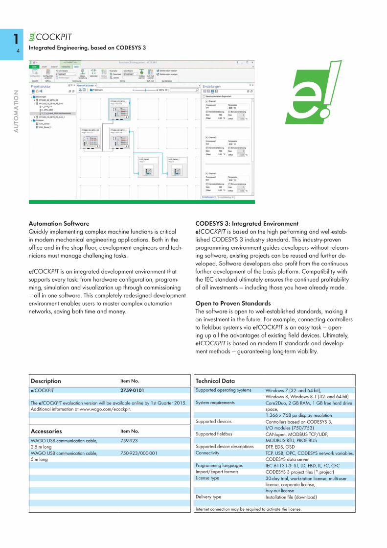
Automation SoftwareQuickly implementing complex machine functions is critical in modern mechanical engineering applications. Both in the office and in the shop floor, development engineers and tech-nicians must manage challenging tasks.
e!COCKPIT is an integrated development environment that supports every task: from hardware configuration, program-ming, simulation and visualization up through commissioning — all in one software. This completely redesigned development environment enables users to master complex automation networks, saving both time and money.
CODESYS 3: Integrated Environmente!COCKPIT is based on the high performing and well-estab-lished CODESYS 3 industry standard. This industry-proven programming environment guides developers without relearn-ing software, existing projects can be reused and further de-veloped. Software developers also profit from the continuous further development of the basis platform. Compatibility with the IEC standard ultimately ensures the continued profitability of all investments — including those you have already made.
Open to Proven StandardsThe software is open to well-established standards, making it an investment in the future. For example, connecting controllers to fieldbus systems via e!COCKPIT is an easy task — open-ing up all the advantages of existing field devices. Ultimately, e!COCKPIT is based on modern IT standards and develop-ment methods — guaranteeing long-term viability.
Integrated Engineering, based on CODESYS 3
Technical DataSupported operating systems Windows 7 (32- and 64-bit),
Windows 8, Windows 8.1 (32- and 64-bit)System requirements Core2Duo, 2 GB RAM, 1 GB free hard drive
space, 1.366 x 768 px display resolution
Supported devices Controllers based on CODESYS 3, I/O modules (750/753)
Supported fieldbus CANopen, MODBUS TCP/UDP, MODBUS RTU, PROFIBUS
Supported device descriptions DTP, EDS, GSDConnectivity TCP, USB, OPC, CODESYS network variables,
CODESYS data serverProgramming languages IEC 61131-3: ST, LD, FBD, IL, FC, CFCImport/Export formats CODESYS 3 project files (*.project)License type 30-day trial, workstation license, multi-user
license, corporate license, buy-out license
Delivery type Installation file (download)
Internet connection may be required to activate the license.
Description Item No.
e!COCKPIT 2759-0101
The e!COCKPIT evaluation version will be available online by 1st Quarter 2015. Additional information at www.wago.com/ecockpit.
Accessories Item No.
WAGO USB communication cable, 2.5 m long
759-923
WAGO USB communication cable, 5 m long
750-923/000-001
14
AU
TOM
ATI
ON

Configuration and ParameterizationThe integrated e!COCKPIT configurators provide modern operating tools and workspaces, such as: • Graphical network topology: Complex dependencies between
network participants and their current states can be accessed easily and intuitively.
• Drag & Drop: Simplifies interaction with devices.• Copy & Paste: Individual devices or whole network branches
can be duplicated quickly.• Batch processing: Parameter values are set simultaneously for
several devices.
Feature Overview
Programminge!COCKPIT offers multiple software development options:• IEC 61131-3 PLC programming languages: Structured Text
(ST), Ladder Diagram (LD), Function Block Diagram (FBD), Instruction List (IL), Sequential Function Chart (SFC), Continuous Function Chart (CFC).
• All programming languages are combinable.• Created programs can be easily debugged on the engineering
PC via simulation.• New paradigms such as object-oriented programming are
included.
VisualizationModern user interfaces for operating and monitoring ma-chines are standard. Today, HMI-based design is also essen-tial to those purchasing an entire automation line. e!COCKPIT simplifies the design of modern interfaces via Drag & Drop. The integrated visualization editor provides:• Access to IEC program variables• Closed simulation of HMI and PLC program on the engineering
PC • Guaranteed language independence via Unicode character
set• Current standards such as HTM L 5 or CSS
DiagnosticsKnowing the detailed current states of the automation network is absolutely necessary for fast error detection and correction — whether it is during development in the office or directly on the machine during commissioning.e!COCKPIT provides comprehensive diagnostic capabilities: • Individual views always show the controllers’ status information,
for example — both graphically and in tabular form.• Error messages are transmitted directly and clearly.• The structured wiring test systematically identifies wiring errors.
15
AU
TOM
ATI
ON

IEC 60870 ConfiguratorConfiguration dialog integrated in WAGO-I/O-PRO v2.3 for IEC 60870-5-101/-103/-104 communication parameterization
The IEC 60870 Configurator is part of the WAGO-I/O-PRO v2.3 software. The configurator fully supports the IEC 60870-5-101/ -103/-104 specific functions of all WAGO telecontrollers.The configurator sets up IEC 60870 objects, while configuring data exchange to the PLC application or I/O modules. Import and export functions in CSV format allow configured data to be transmitted to other engineering tools.The IEC 60870-5-101 and -104 protocols are supported on both client and server side, while the IEC 60870-5-103 protocol is exclusively supported on the client side. This permits the creation of gateways used to convert one protocol into another, e.g., allowing protection devices to be read out via IEC 60870-5-103 and data to be transmitted to the network control system via IEC 60870-5-104. Various options are available for the time synchronization of tele-control substations (server). Time synchronization can be performed either via the IEC 60870 protocol with object 103 or via (S)NTP. Using the WAGO 750-640 Module, clock time can also be synchronized via DCF77 or GPS.
IEC-60870-5-101/-104 information objects can be used in monitoring direction for single, double and step messages. Bit patterns, counter values, as well as normalized, scaled and floating-point measurement values can also be used. All information objects can be transmitted with or without time stamp. This also applies to information objects in control direction.An IEC 60870-5-104 server can simultaneously maintain up to 4 connections to the control system (client).
Supported controllers:
Programmable Fieldbus Controllers 0750-0872, 0750-0872/0020-0000 0750-0880/0025-0001, 0750-0880/0025-0002
PFC200 0750-8202/0025-0001
I/O-IPC 0758-0874/0000-0130, 0758-0874/0000-0131 0758-0875/0000-0130, 0758-0875/0000-0131
IEC 60870 Configurator
Description
System requirements:
WAGO-I/O-PRO Version 2.3.9.40 or higher
Function:
IEC-60870-5-101 Server and client IEC 60870-5-103 Client IEC 60870-5-104 Server and client
IEC 60870 Configuration Dialog
16
AU
TOM
ATI
ON
IEC 61850 ConfiguratorConfiguration dialog integrated in WAGO-I/O-PRO v2.3 for IEC 61850 communication parameterization
The IEC 61850 Configurator is part of the WAGO-I/O-PRO v2.3 software. The configurator fully supports the IEC 61850 specific functions of the WAGO telecontrollers.The configurator sets up IEC 61850 objects, while configuring data exchange to the PLC application or I/O modules. Import and export functions in IEC 61850 SCL exchange format allow configured data to be transmitted to other engineering tools.On the server side, the IEC 61850 protocol is supported for MMS* communication to the control system. Some types of controllers can also be operated as GOOSE publisher or subscriber. This permits the creation of gateways used to convert one protocol into another, e.g., allowing data from protection devices to be received via GOOSE, while being transmitted to the network control system via IEC 60870-5-104 protocol. Time synchronization is performed via SNTP, NTP, DCF77 and GPS (750-640 Module is also required for GPS).Various options are available for the time synchronization of telecontrol substations (server). Synchronization can be performed via (S)NTP or clock time can be synchronized via DCF77 or GPS using the WAGO 750-640 Module.The IEC 61850 MMS server can simultaneously maintain up to 5 connections to the control system (client).
*MMS = Manufacturing Messaging Specification
Supported controllers:
with MMS communication 0750-0872 0750-0880/0025-0001, 0750-0880/0025-0002
with MMS and GOOSE communication 0750-8202/0025-0001 0758-0874/0000-0130, 0758-0874/0000-0131 0758-0875/0000-0130, 0758-0875/0000-0131
IEC 61850 Configurator
Description
System requirements:
WAGO-I/O-PRO Version 2.3.9.40 or higher
Function: IEC 61850 serverObject types: IEC 61850-7-4 and IEC 61400-25Data sets: static and dynamicReporting: buffered and unbuffered
IEC 61850 Configuration Dialog
17
AU
TOM
ATI
ON

Using WAGO WebVisu App, you can call up CODESYS 2 WebVisu websites on mobile end devices. The system or ma-chine to be monitored can then be operated and monitored at any time. You can define up to 100 controllers for direct and quick access via the URL.
WAGO WebVisu App is available for free as an iOS version for iPhones and iPads in the Apple store and as an Android version for smartphones and tablets in the Google store.
Note: An overview of the supported WAGO controllers, operating manuals and application notes can be found on our website or directly via www.wago.com/webvisu
WAGO WebVisu Appfor system operation/monitoring
WAGO WebVisu App
Description
System requirements:
Operating system: iOS 4.3 or new version Android 2.2 or new version
Compatibility: iPhone, iPad and iPod touch Android smartphones and tablets
QR Code for WebVisu App
Simply scan the QR code with your mobile end device and you will automatically be directed to the WAGO App in “App Store“ or “Play Store.“
Trademark Notice
Apple, the Apple logo, iPhone, iPad, and iPod touch are trademarks of Apple Inc., registered in the U.S. and other countries. App Store is a service mark of Apple Inc.
Google PlayTM is a trademark of Google Inc.
18
AU
TOM
ATI
ON

19
AU
TOM
ATI
ON

750-8202
110
AU
TOM
ATI
ON
PLC – PFC200 ControllerPFC200 CS 2ETH RS
U6U5U4U3
RUNSTOPRESET
U2U1
SYS RSTRUNI/OMSNSU7
750-
8202
SD
24V 0V
+ +
— —
01 02
0 V
A
B
ACT
ACT
LNK
ETHLN
KX3
RS23
2/48
5X1
X2
Fieldbus connectionRJ-45
Serial interface
Fieldbus connectionRJ-45
Power jumper contacts
Configuration and programming interface
Data contacts
Marking area
Supply viapower jumper contacts24 V
Supply24 V0 V
Status voltage supply-System-Power jumper contacts
The PFC200 Controller is a compact PLC for the modular WAGO-I/O-SYSTEM. Besides network and fieldbus interfaces, the controller supports all digital, analog and specialty modules found within the 750/753 Series. Two ETHERNET interfaces and integrated switch enable line topology wiring. An integrated Web server provides the user with configuration options and status information from the PFC200.Besides the processing industry and building automation, typical markets for the PFC200 include the standard machine and plant industries (e.g., packaging, bottling, textiles, production and metal & wood processing).
Programmable to IEC 61131-3• Programmable via WAGO-I/O-PRO V2.3 • Direct connection of WAGO I/O modules• 2 x ETHERNET (switched), RS-232/-485 • Linux 3.6 operating system with RT-Preemption patch• Configuration via CODESYS or Web-based management interface• Maintenance-free
Description Item No. Pack. Unit
PFC200 CS 2ETH RS 750-8202 1PFC200 CS 2ETH RS/T 750-8202/025-000 1Extended temperature range: -20 °C ... +60 °CPFC200 CS 2ETH RS Telecontrol/T 750-8202/025-001 1Extended temperature range: -20 °C ... +60 °CPFC200 CS 2ETH RS Telecontrol ECO/T 750-8202/025-002 1Extended temperature range: -20 °C ... +60 °C
Accessories Item No. Pack. Unit
WAGO-I/O-PRO V2.3, RS-232 kit 759-333 1SD memory card, 1 GB 758-879/000-001 1Miniature WSB Quick marking system
plain 248-501 5with marking see Full Line Catalog AUTOMATION
2012/2013
ApprovalsConformity marking 1
Shipbuilding GLr UL 508
System DataCPU Cortex A8, 600 MHzOperating system Real-time Linux 3.6 (with RT-Preemption
patch)Main memory (RAM) 256 MbytesInternal memory (flash) 256 MbytesRetain memory 128 KbytesETHERNET 2 x RJ-45 (switched)Transmission medium Twisted Pair S-UTP
100 Ω, Cat 5; Max. line length: 100 m
Baud rate 10/100 Mbit/s; 10Base-T/100Base-TXInterface (serial) RS-232/-485 (switchable)Protocols
750-8202/025-001 and -002
DHCP, DNS, NTP, FTP, FTPS, SNMP, HTTP, HTTPS, SSH, MODBUS (TCP, UDP, RTU)IEC 60870-5-101/-103/-104, IEC 61850-7-4, IEC 61400-25
Programming WAGO-I/O-PRO V2.3IEC 61131-3 IL, LD, FBD, ST, FCSD card slot Push-push mechanism, sealable cover lidType of memory card SD and SDHC up to 32 GB (All
guaranteed properties are only valid in connection with the WAGO 758-879/000-001 memory card.)

111
AU
TOM
ATI
ON
1
1
5
2/6
3/7
4/8
2
3
4
5
6
7
8
DCDC
24 V
10 nF
10 nF
10 nF
24 V
10 nF
47 nF
47 nF
0 V
0 V
750-8202
ELECTRONICS
Bob Smith Termination
Bob Smith Termination
I/O
mod
ules
ETH
ERN
ET
Inte
rfac
e RS
-232
/-48
5
ELEC
TRO
NIC
S Interface RS-232/-485
Technical DataNumber of I/O modules (per node) 64
with bus extension 250750-8202/025-002 4
Input and output process image (max.)Internal data bus 1000 wordsMODBUS 1000 words
I/O interfaces (serial) 1 x serial interface per TIA/EIA 232 and TIA/EIA 485 (switchable), 9-pole D-sub female connector
Diagnostic LEDs Power supply; SYS; RUN; FIELDBUS (MS, NS); USER (U1 ... U7); Internal data bus
User LEDs via CODESYS libraryProgram memory 16 MBData memory 64 MBNon-volatile memory (retain) 128 KbytesPower supply 24 V DC (-25 % ... +30 %)Max. input current (24 V) 550 mATotal current for I/O modules (5 V) 1700 mAIsolation 500 V system/supply
General SpecificationsDimensions (mm) W x H x L 79 x 65 x 100
Height from upper-edge of DIN 35 railWeight 210 gEMC: 1 - immunity to interference acc. to EN 61000-6-2 (2005)EMC: 1 - emission of interference acc. to EN 61000-6-2 (2005)EMC: marine applications - immunity to interference pendingEMC: marine applications - emission of interference pendingDegree of protection IP20 acc. to DIN 60529Type of mounting DIN 35 railHousing material PCAmbient conditions
Operating temperature 0 °C ... +55 °CStorage temperature -25 °C ... +85 °CRelative air humidity (no condensation) 95 %
Wire connection CAGE CLAMP®
Cross sections 0.08 mm² ... 2.5 mm² / AWG 28 ... 14Strip lengths 8 ... 9 mm / 0.33 in

750-8203
112
AU
TOM
ATI
ON
PLC – PFC200 ControllerPFC200 CS 2ETH CAN
U6U5U4U3
RUNSTOPRESET
U2U1
SYS RSTRUNI/OMSNSCAN
750-
8203
SD
24V 0V
+ +
— —
01 02
0 V
A
B
ACT
ACT
LNK
ETHLN
KX4
CAN
X1X2
Fieldbus connectionRJ-45
Fieldbus connectionRJ-45
Power jumper contacts
Configuration and programming interface
Data contacts
Marking area
Supply viapower jumper contacts24 V
Supply24 V0 V
Status voltage supply-System-Power jumper contacts
Fieldbus connectionCAN, CANopen
The PFC200 Controller is a compact PLC for the modular WAGO-I/O-SYSTEM. Besides network and fieldbus interfaces, the controller supports all digital, analog and specialty modules found within the 750/753 Series. Two ETHERNET interfaces and integrated switch enable line topology wiring. An integrated Web server provides the user with configuration options and status information from the PFC200.Besides the processing industry and building automation, typical markets for the PFC200 include the standard machine and plant industries (e.g., packaging, bottling, textiles, production and metal & wood processing).
Programmable to IEC 61131-3• Programmable via WAGO-I/O-PRO V2.3 • Direct connection of WAGO I/O modules• 2 x ETHERNET (switched), CAN, CANopen• Linux 3.6 operating system with RT-Preemption patch• Configuration via CODESYS or Web-based management interface• Maintenance-free
Description Item No. Pack. Unit
PFC200 CS 2ETH CAN 750-8203 1PFC200 CS 2ETH CAN/T 750-8203/025-000 1Extended temperature range: -20 °C ... +60 °C
Accessories Item No. Pack. Unit
WAGO-I/O-PRO V2.3, RS-232 kit 759-333 1SD memory card, 1 GB 758-879/000-001 1Miniature WSB Quick marking system
plain 248-501 5with marking see Full Line Catalog AUTOMATION
2012/2013
ApprovalsConformity marking 1
Shipbuilding GLr UL 508
System DataCPU Cortex A8, 600 MHzOperating system Real-time Linux 3.6 (with RT-Preemption
patch)Main memory (RAM) 256 MbytesInternal memory (flash) 256 MbytesRetain memory 128 KbytesETHERNET 2 x RJ-45 (switched)Transmission medium Twisted Pair S-UTP
100 Ω, Cat 5; Max. line length: 100 m
Baud rate 10/100 Mbit/s; 10Base-T/100Base-TXFieldbus CAN, CANopenProtocols DHCP, DNS, NTP, FTP, FTPS, SNMP, HTTP,
HTTPS, SSH, MODBUS (TCP, UDP)Programming WAGO-I/O-PRO V2.3IEC 61131-3 IL, LD, FBD, ST, FCSD card slot Push-push mechanism, sealable cover lidType of memory card SD and SDHC up to 32 GB (All
guaranteed properties are only valid in connection with the WAGO 758-879/000-001 memory card.)

113
AU
TOM
ATI
ON
1
1
5
2/6
3/7
4/8
2
3
4
5
6
7
8
DCDC
24 V
10 nF
10 nF
10 nF
24 V
10 nF
47 nF
47 nF
0 V
0 V
750-8203
ELECTRONICS
Bob Smith Termination
Bob Smith Termination
Interface CAN
I/O
mod
ules
ETH
ERN
ET
Inte
rfac
e CA
N
ELEC
TRO
NIC
S
Technical DataNumber of I/O modules (per node) 64
with bus extension 250Input and output process image (max.)
Internal data bus 1000 wordsMODBUS 1000 wordsCAN 2000 words
Diagnostic LEDs Power supply; SYS; RUN; FIELDBUS (CAN, MS, NS); USER (U1 ... U6); Internal data bus
User LEDs via CODESYS libraryProgram memory 16 MBData memory 64 MBNon-volatile memory (retain) 128 KbytesPower supply 24 V DC (-25 % ... +30 %)Max. input current (24 V) 550 mATotal current for I/O modules (5 V) 1700 mAIsolation 500 V system/supply
General SpecificationsDimensions (mm) W x H x L 79 x 65 x 100
Height from upper-edge of DIN 35 railWeight 210 gEMC: 1 - immunity to interference acc. to EN 61000-6-2 (2005)EMC: 1 - emission of interference acc. to EN 61000-6-2 (2005)EMC: marine applications - immunity to interference pendingEMC: marine applications - emission of interference pendingDegree of protection IP20 acc. to DIN 60529Type of mounting DIN 35 railHousing material PCAmbient conditions
Operating temperature 0 °C ... +55 °CStorage temperature -25 °C ... +85 °CRelative air humidity (no condensation) 95 %
Wire connection CAGE CLAMP®
Cross sections 0.08 mm² ... 2.5 mm² / AWG 28 ... 14Strip lengths 8 ... 9 mm / 0.33 in

750-8204
114
AU
TOM
ATI
ON
PLC – PFC200 ControllerPFC200 CS 2ETH RS CAN
U6U5U4U3
RUNSTOPRESET
U2U1
SYS RSTRUNI/OMSNSCAN
750-
8204
SD
24V 0V
+ +
— —
01 02
0 V
A
B
ACT
ACT
LNK
ETHLN
KX3
RS23
2/48
5
X4 CA
N
X1X2
Power jumper contacts
Data contacts
Marking area
Supply viapower jumper contacts24 V
Supply24 V0 V
Status voltage supply-System-Power jumper contacts
Fieldbus connectionRJ-45
Serial interface
Fieldbus connectionCAN, CANopen
Fieldbus connectionRJ-45
Configuration and programming interface
The PFC200 Controller is a compact PLC for the modular WAGO-I/O-SYSTEM. Besides network and fieldbus interfaces, the controller supports all digital, analog and specialty modules found within the 750/753 Series. Two ETHERNET interfaces and integrated switch enable line topology wiring. An integrated Web server provides the user with configuration options and status information from the PFC200.Besides the processing industry and building automation, typical markets for the PFC200 include the standard machine and plant industries (e.g., packaging, bottling, textiles, production and metal & wood processing).
Programmable to IEC 61131-3• Programmable via WAGO-I/O-PRO V2.3 • Direct connection of WAGO I/O modules• 2 x ETHERNET (switched), RS-232/-485, CAN, CANopen• Linux 3.6 operating system with RT-Preemption patch• Configuration via CODESYS or Web-based management interface• Maintenance-free
Description Item No. Pack. Unit
PFC200 CS 2ETH RS CAN 750-8204 1PFC200 CS 2ETH RS CAN/T 750-8204/025-000 1Extended temperature range: -20 °C ... +60 °C
Accessories Item No. Pack. Unit
WAGO-I/O-PRO V2.3, RS-232 kit 759-333 1SD memory card, 1 GB 758-879/000-001 1Miniature WSB Quick marking system
plain 248-501 5with marking see Full Line Catalog AUTOMATION
2012/2013
ApprovalsConformity marking 1
Shipbuilding GLr UL 508
System DataCPU Cortex A8, 600 MHzOperating system Real-time Linux 3.6 (with RT-Preemption
patch)Main memory (RAM) 256 MbytesInternal memory (flash) 256 MbytesRetain memory 128 KbytesETHERNET 2 x RJ-45 (switched)Transmission medium Twisted Pair S-UTP
100 Ω, Cat 5; Max. line length: 100 m
Baud rate 10/100 Mbit/s; 10Base-T/100Base-TXInterface (serial) RS-232/-485 (switchable)Fieldbus CAN, CANopenProtocols DHCP, DNS, NTP, FTP, FTPS, SNMP, HTTP,
HTTPS, SSH, MODBUS (TCP, UDP, RTU)Programming WAGO-I/O-PRO V2.3IEC 61131-3 IL, LD, FBD, ST, FCSD card slot Push-push mechanism, sealable cover lidType of memory card SD and SDHC up to 32 GB (All
guaranteed properties are only valid in connection with the WAGO 758-879/000-001 memory card.)
115
AU
TOM
ATI
ON
1
1
5
2/6
3/7
4/8
2
3
4
5
6
7
8
DCDC
24 V
10 nF
10 nF
10 nF
24 V
10 nF
47 nF
47 nF
0 V
0 V
750-8204
ELECTRONICS
Bob Smith Termination
Bob Smith Termination
Interface CAN
Interface RS-232/-485
I/O
mod
ules
ETH
ERN
ET
Inte
rfac
e CA
N
Inte
rfac
e RS
-232
/-48
5
ELEC
TRO
NIC
S
Technical DataNumber of I/O modules (per node) 64
with bus extension 250Input and output process image (max.)
Internal data bus 1000 wordsMODBUS 1000 wordsCAN 2000 words
I/O interfaces (serial) 1 x serial interface per TIA/EIA 232 and TIA/EIA 485 (switchable), 9-pole D-sub female connector
Diagnostic LEDs Power supply; SYS; RUN; FIELDBUS (MS, NS, CAN); USER (U1 ... U6); Internal data bus
User LEDs via CODESYS libraryProgram memory 16 MBData memory 64 MBNon-volatile memory (retain) 128 KbytesPower supply 24 V DC (-25 % ... +30 %)Max. input current (24 V) 550 mATotal current for I/O modules (5 V) 1700 mAIsolation 500 V system/supply
General SpecificationsDimensions (mm) W x H x L 112 x 65 x 100
Height from upper-edge of DIN 35 railWeight 250 gEMC: 1 - immunity to interference acc. to EN 61000-6-2 (2005)EMC: 1 - emission of interference acc. to EN 61000-6-2 (2005)EMC: marine applications - immunity to interference pendingEMC: marine applications - emission of interference pendingDegree of protection IP20 acc. to DIN 60529Type of mounting DIN 35 railHousing material PCAmbient conditions
Operating temperature 0 °C ... +55 °CStorage temperature -25 °C ... +85 °CRelative air humidity (no condensation) 95 %
Wire connection CAGE CLAMP®
Cross sections 0.08 mm² ... 2.5 mm² / AWG 28 ... 14Strip lengths 8 ... 9 mm / 0.33 in

750-8206
116
AU
TOM
ATI
ON
PLC – PFC200 ControllerPFC200 CS 2ETH RS CAN DPS
BFDIAU4U3
RUNSTOPRESET
U2U1
SYS RSTRUNI/OMSNSCAN
750-
8206
SD
24V 0V
+ +
— —
01 02
0 V
A
B
ACT
ACT
LNK
ETH
LNK
X3 RS
232/
485
X4 CA
N
X5 PR
OFIBU
S
X1X2
Power jumper contacts
Data contacts
Marking area
Supply viapower jumper contacts24 V
Supply24 V0 V
Status voltage supply-System-Power jumper contacts
Fieldbus connectionRJ-45
Serial interface
Fieldbus connectionCAN, CANopen
Fieldbus connectionRJ-45
Configuration and programming interface
Fieldbus connectionPROFIBUS
The PFC200 Controller is a compact PLC for the modular WAGO-I/O-SYSTEM. Besides network and fieldbus interfaces, the controller supports all digital, analog and specialty modules found within the 750/753 Series. Two ETHERNET interfaces and integrated switch enable line topology wiring. An integrated Web server provides the user with configuration options and status information from the PFC200.Besides the processing industry and building automation, typical markets for the PFC200 include the standard machine and plant industries (e.g., packaging, bottling, textiles, production and metal & wood processing).
Programmable to IEC 61131-3• Programmable via WAGO-I/O-PRO V2.3 • Direct connection of WAGO I/O modules• 2 x ETHERNET (switched), RS-232/-485, CAN, CANopen,
PROFIBUS DP Slave• Linux 3.6 operating system with RT-Preemption patch• Configuration via CODESYS or Web-based management interface• Maintenance-free
Description Item No. Pack. Unit
PFC200 CS 2ETH RS CAN DPS 750-8206 1PFC200 CS 2ETH RS CAN DPS/T 750-8206/025-000 1Extended temperature range: -20 °C ... +60 °CPFC200 CS 2ETH RS CAN DPS TELE/T 750-8206/025-001 1Extended temperature range: -20 °C ... +60 °C
Accessories Item No. Pack. Unit
WAGO-I/O-PRO V2.3, RS-232 kit 759-333 1SD memory card, 1 GB 758-879/000-001 1Miniature WSB Quick marking system
plain 248-501 5with marking see Full Line Catalog AUTOMATION
2012/2013
ApprovalsConformity marking 1
Shipbuilding GLr UL 508
System DataCPU Cortex A8, 600 MHzOperating system Real-time Linux 3.6
(with RT-Preemption patch)Main memory (RAM) 256 MbytesInternal memory (flash) 256 MbytesRetain memory 128 KbytesETHERNET 2 x RJ-45 (switched)Transmission medium Twisted Pair S-UTP
100 Ω, Cat 5; Max. line length: 100 m
Baud rate 10/100 Mbit/s; 10Base-T/100Base-TXInterface (serial) RS-232/-485 (switchable)Fieldbus PROFIBUS DP Slave, CAN, CANopenProtocols
750-8206/025-001:
DHCP, DNS, NTP, FTP, FTPS, SNMP, HTTP, HTTPS, SSH, MODBUS (TCP, UDP, RTU), IEC 60870-5-101/-103/-104, IEC 61850-7-4, IEC 61400-25
Programming WAGO-I/O-PRO V2.3IEC 61131-3 IL, LD, FBD, ST, FCSD card slot Push-push mechanism, sealable cover lidType of memory card SD and SDHC up to 32 GB
(All guaranteed properties are only valid in connection with the WAGO 758-879/000-001 memory card.)

117
AU
TOM
ATI
ON
1
1
5
2/6
3/7
4/8
2
3
4
5
6
7
8
DCDC
24 V
10 nF
10 nF
10 nF
24 V
10 nF
47 nF
47 nF
0 V
0 V
750-8206
ELECTRONICS
Bob Smith Termination
Bob Smith Termination
Interface PROFIBUS
Interface CAN
Interface RS-232/-485
I/O
mod
ules
ETH
ERN
ET
Inte
rfac
e CA
N
Inte
rfac
e RS
-232
/-48
5
Inte
rfac
e PR
OFI
BUS
ELEC
TRO
NIC
S
Technical DataNumber of I/O modules (per node) 64
with bus extension 250Input and output process image (max.)
Internal data bus 1000 wordsMODBUS 1000 wordsCAN 2000 words
I/O interfaces (serial) 1 x serial interface per TIA/EIA 232 and TIA/EIA 485 (switchable), 9-pole D-sub female connector
Diagnostic LEDs Power supply; SYS; RUN; FIELDBUS (MS, NS, CAN, DIA, BF); USER (U1 ... U4); Internal data bus
User LEDs via CODESYS libraryProgram memory 16 MBData memory 64 MBNon-volatile memory (retain) 128 KbytesPower supply 24 V DC (-25 % ... +30 %)Max. input current (24 V) 550 mATotal current for I/O modules (5 V) 1700 mAIsolation 500 V system/supply
General SpecificationsDimensions (mm) W x H x L 112 x 65 x 100
Height from upper-edge of DIN 35 railWeight 250 gEMC: 1 - immunity to interference acc. to EN 61000-6-2 (2005)EMC: 1 - emission of interference acc. to EN 61000-6-2 (2005)EMC: marine applications - immunity to interference pendingEMC: marine applications - emission of interference pendingDegree of protection IP20 acc. to DIN 60529Type of mounting DIN 35 railHousing material PCAmbient conditions
Operating temperature 0 °C ... +55 °CStorage temperature -25 °C ... +85 °CRelative air humidity (no condensation) 95 %
Wire connection CAGE CLAMP®
Cross sections 0.08 mm² ... 2.5 mm² / AWG 28 ... 14Strip lengths 8 ... 9 mm / 0.33 in

750-885
118
AU
TOM
ATI
ON
PLC - ETHERNET Programmable Media Redundancy Fieldbus Controller32-bit CPU, multitasking, with memory card slot
X1
1
8
ON
0: WBM255: DHCP
X2
I/O
NS
MS
LINKACT 1LINKACT 2
ETHERNET
W75
0-88
5
USRSD
12
34
56
78
ON 24V 0V
+ +
— —
01 02
C
DB
A
0 V
Fieldbus connectionRJ-45
Address
Fieldbus connectionRJ-45
Power jumper contactsConfiguration andprogramming interface(with cover open)
Data contacts
Marking area
Supply viapower jumper contacts24 V
Supply24 V0 V
Status voltage supply-System-Power jumper contacts
In conjunction with the WAGO-I/O-SYSTEM, the 750-885 ETHERNET PLC serves ETHERNET networks requiring fast and safe media redundancy. The PLC supports all digital, analog and specialty modules found within the 750/753 Series, and is suitable for data rates of 10/100 Mbit/s.Media redundancy is achieved by operating the controller in two separate networks — which is accessible via two different IP addresses (including two MAC IDs). Cross communication between separate channels is not possible. The two separate ETHERNET interfaces allow redundant connection of two transmission paths (no hub or switch required). Both interfaces support Auto-Negotiation and Auto-MDI(X). The DIP switch configures the last byte of both default IP addresses and may be used for IP address assignment (DHCP, BootP).
The media redundancy PLC is designed for fieldbus communication via MODBUS/TCP in ETHERNET networks. It also supports a wide variety of standard ETHERNET protocols (e.g., HTTP, BootP, DHCP, DNS, FTP).An integrated Web server provides configuration options to the user, while displaying PLC status information.The IEC 61131-3 programmable controller is multitasking-capable and features a battery-backed RTC. A data memory of 1 Mbyte is available.For memory expansion, the 750-885 PLC is equipped with a removable memory card slot.
Description Item No. Pack. Unit
ETHERNET MR/SD Fieldbus Controller 750-885 1ETHERNET MR/SD Fieldbus Controller/T 750-885/025-000 1Extended temperature range: -20 °C ... +60 °C
Accessories Item No. Pack. Unit
SD memory card, 1 GB 758-879/000-001 1WAGO-I/O-PRO V2.3, RS-232 kit 759-333 1Miniature WSB Quick marking system
plain 248-501 5with marking see Full Line Catalog AUTOMATION
2012/2013
ApprovalsConformity marking 1
Shipbuilding GL, pendingr UL 508 pending
System DataNo. of controllers connected to Master limited by ETHERNET specificationTransmission medium Twisted Pair S-UTP
100 Ω, Cat 5; Max. line length: 100 m
Baud rate 10/100 Mbit/sTransmission performance Class D acc. to EN 50173Buscoupler connection 2 x RJ-45Protocols MODBUS/TCP (UDP), HTTP, BootP, DHCP,
DNS, FTPProgramming WAGO-I/O-PRO V2.3IEC 61131-3 IL, LD, FBD, ST, FCRedundancy function via two logically separated ETHERNET
interfacesSD card slot Push-push mechanism, sealable cover lidType of memory card SD and SDHC up to 32 Gbytes (All
guaranteed properties are only valid in combination with the WAGO 758-879/000-001 memory card.)

119
AU
TOM
ATI
ON
1
2
3
4
5
6
7
8
DCDC
24 V
10 nF
24 V
10 nF
0 V
24 V /0 V
24 V
0 V
0 V
750-885
ELECTRONICS
I/Omodules
FIEL
DBU
S IN
TERF
ACE
ELEC
TRO
NIC
S
FIE
LDBU
SIN
TERF
ACE
Technical DataNumber of I/O modules 64
with bus extension 250Fieldbus
Max. input process image 1020 wordsMax. output process image 1020 words
Configuration via PCProgram memory 1024 KbytesData memory 1024 KbytesNon-volatile memory (retain) 32 KbytesPower supply 24 V DC (-25 % ... +30 %)Input current typ. at rated load (24 V) 500 mAEfficiency of the power supply (typ.) at nominal load (24 V) 90 %Internal current consumption (5 V) 450 mATotal current for I/O modules (5 V) 1700 mAIsolation 500 V system/supply
General SpecificationsOperating temperature 0 °C ... +55 °CWire connection CAGE CLAMP®
Cross sections 0.08 mm² ... 2.5 mm² / AWG 28 ... 14Strip lengths 8 ... 9 mm / 0.33 inDimensions (mm) W x H x L 62 x 65 x 100
Height from upper-edge of DIN 35 railWeight 164 gStorage temperature -25 °C ... +85 °CRelative air humidity (no condensation) 95 %Vibration resistance acc. to IEC 60068-2-6Shock resistance acc. to IEC 60068-2-27Degree of protection IP20EMC: 1 - immunity to interference acc. to EN 61000-6-2 (2005)EMC: 1 - emission of interference acc. to EN 61000-6-3 (2007)EMC: marine applications - immunity to interference acc. to Germanischer Lloyd (2003)EMC: marine applications - emission of interference acc. to Germanischer Lloyd (2003)

750-852
120
AU
TOM
ATI
ON
PLC - ETHERNET Programmable Fieldbus Controller ECO32-bit CPU
24VX3
X1
1
8
ON
0: WBM255: DHCP
X2
0V
I/O
NS
MS
LINKACT 1LINKACT 2
ETHERNET
W75
0-85
2
USR
12
34
56
78
ON
Fieldbus connectionRJ-45
Address
Supply24 V0 V
Fieldbus connectionRJ-45 Configuration and
programming interface (with cover open)
Data contacts
Marking area
Status indication-Fieldbus-Fieldbus node
The 750-852 ETHERNET PLC connects ETHERNET to the modular WAGO-I/O-SYSTEM.
The PLC automatically configures, creating a local process image which may include analog, digital or specialty modules. Analog and specialty module data is sent via words and/or bytes; digital data is sent bit by bit.
Two ETHERNET interfaces and an integrated switch allow the fieldbus to be wired in a line topology. This eliminates additional network devices, such as switches or hubs. Both interfaces support Auto-Negotiation and Auto-MDI(X).
The DIP switch configures the last byte of the IP address and may be used for IP address assignment.
The PLC is designed for fieldbus communication in both EtherNet/IP and MODBUS networks. It also supports a wide variety of standard ETHERNET protocols (e.g., HTTP, BootP, DHCP, DNS, SNTP, FTP). An integrated Web server provides the user with configuration options and status information from the controller. The IEC 61131-3 programmable controller is multitasking-capable.
Description Item No. Pack. Unit
ETHERNET ECO Controller 750-852 1
Accessories Item No. Pack. Unit
WAGO-I/O-PRO V2.3, RS-232 kit 759-333 1Miniature WSB Quick marking system
plain 248-501 5with marking see Full Line Catalog AUTOMATION
2012/2013
ApprovalsConformity marking 1
Shipbuilding GL applied forr UL 508
System DataNo. of controllers connected to Master limited by ETHERNET specificationTransmission medium Twisted Pair S-UTP
100 Ω, Cat 5; Max. line length: 100 m
Baud rate 10/100 Mbit/sTransmission performance Class D acc. to EN 50173Buscoupler connection 2 x RJ-45Protocols EtherNet/IP, MODBUS/TCP (UDP), HTTP,
BootP, DHCP, DNS, SNTP, FTPProgramming WAGO-I/O-PRO V2.3IEC 61131-3 IL, LD, FBD, ST, FC

121
AU
TOM
ATI
ON
DCDC
24 V
10 nF
10 nF
24 V
0 V
0 V
750-852
ELECTRONICS
I/Omodules
FIEL
DBU
S IN
TERF
ACE
ELEC
TRO
NIC
S
FIE
LDBU
SIN
TERF
ACE
Technical DataNumber of I/O modules 64
with bus extension 250Fieldbus
Max. input process image 1020 wordsMax. output process image 1020 words
Configuration via PCProgram memory 512 KbytesData memory 256 KbytesNon-volatile memory (retain) 8 KbytesPower supply 24 V DC (-25 % ... +30 %)Input current typ. at rated load (24 V) 300 mAEfficiency of the power supply (typ.) at nominal load (24 V) 90 %Internal current consumption (5 V) 400 mATotal current for I/O modules (5 V) 700 mAIsolation 500 V system/supply
General SpecificationsOperating temperature 0 °C ... +55 °CWire connection CAGE CLAMP®
Cross sections 0.08 mm² ... 1.5 mm² / AWG 28 ... 14Strip lengths 5 ... 6 mm / 0.22 inDimensions (mm) W x H x L 50 x 65 x 97
Height from upper-edge of DIN 35 railWeight 110.5 gStorage temperature -25 °C ... +85 °CRelative air humidity (no condensation) 95 %Vibration resistance acc. to IEC 60068-2-6Shock resistance acc. to IEC 60068-2-27Degree of protection IP20EMC: 1 - immunity to interference acc. to EN 61000-6-2 (2005)EMC: 1 - emission of interference acc. to EN 61000-6-3 (2007)EMC: marine applications - immunity to interference acc. to Germanischer Lloyd (2003)EMC: marine applications - emission of interference acc. to Germanischer Lloyd (2003)

750-815/300-000, 750-815/325-000
122
AU
TOM
ATI
ON
PLC - MODBUS Programmable Fieldbus Controller16-bit CPU
ON
TxD
RxD
Modbus
x10FEDC B A98765
43
21
0FEDC B A9876543
21x10
ADDRESS
CD
B
A
CRC
750-
815/
300-
000
W
24V 0V
+ +
— —
01 02
I/O
Data contacts
FieldbusconnectionD-Sub
Power jumper contacts
0 V
Supply viapower jumper contacts24 V
Supply24 V0 V
Status voltage supply-System-Power jumper contacts
Configurationand programminginterface
Address
Address
The MODBUS PLC is an extension of the WAGO-I/O-SYSTEM.
This controller combines a WAGO MODBUS fieldbus coupler with PLC functionality. Application PLC programming is IEC 61131-3 compliant. The programmer can access all fieldbus and I/O data.
Features and applications:• Decentralized control to optimize support for a PLC or PC• Devide complex applications into individually testable units• Programmable fault response in the event of a fieldbus failure• Signal pre-processing to reduce fieldbus transmissions• Directly control peripheral equipment for faster system response times• Stand-alone, compact controller
Description Item No. Pack. Unit
Contr. MODBUS / RS-485 / 150 Bd ... 115.2 kBd 750-815/300-000 1Contr. MODBUS / RS-485 / 150 Bd ... 115.2 kBd/T 750-815/325-000 1Extended temperature range: -20 °C ... +60 °C
Accessories Item No. Pack. Unit
Miniature WSB Quick marking systemplain 248-501 5with marking see Full Line Catalog AUTOMATION
2012/2013
ApprovalsConformity marking 1
Shipbuilding (versions upon request) ABS, BV, DNV, GL, KR, LR, NKK, PRS, RINAr UL 508 r ANSI/ISA 12.12.01 Class I, Div. 2, Grp. ABCD, T44 TÜV 07 ATEX 554086 X I M2 Ex d I Mb,
II 3 G Ex nA IIC T4 Gc, II 3 D Ex tc IIIC T135°C Dc, TUEV 12.1297 X Ex nA IIC T4 Gc
* Permissible ambient temperature 0 °C ... +60 °CIECEx TUN 09.0001X Ex d I Mb,
Ex nA IIC T4 Gc, Ex tc IIIC T135°C Dc
* Permissible ambient temperature 0 °C ... +60 °C
System DataNo. of controllers connected to Master 247 with repeaterMax. no. of I/O points approx. 6000 (depends on master)Transmission medium Shielded Cu cable 2 (4) x 0.25 mm²Max. length of fieldbus segment 1200 m (depends on baud rate/cable)Baud rate 150 baud ... 115.2 KbaudBuscoupler connection 1 x D-Sub 9; socketProgramming WAGO-I/O-PRO V2.3IEC 61131-3 IL, LD, FBD (CFC), ST, FC

123
AU
TOM
ATI
ON
1
2
3
4
5
6
7
8
750-815/300-000
24 V
10 nF
24 V
10 nF
0 V
24 V /0 V
24 V
0 V
0 V5 V
5 V24 V
ELECTRONICS
I/Omodules
ELEC
TRO
NIC
S
FIEL
DBU
S IN
TERF
ACE
FIELDBUSINTERFACE
Technical DataNumber of I/O modules 64Fieldbus
Max. input process image 1024 bytesMax. output process image 1024 bytesMax. input variables 512bytesMax. output variables 512bytes
Configuration Via PC, function block or rotary encoder switch
Program memory 32KbytesData memory 32KbytesNon-volatile memory (retain) 8 KbytesCycle time < 3 ms for 1,000 statements /
256 dig. I/OsPower supply 24 V DC (-25 % ... +30 %)Max. input current (24 V) 500mAPower supply efficiency 87%Internal current consumption (5 V) 350mATotal current for I/O modules (5 V) 1650mAIsolation 500 V system/supplyVoltage via power jumper contacts 24 V DC (-25 % ... +30 %)Current via power jumper contacts (max.) 10 A DCVoltage via power jumper contacts 24 V DC (-25 % ... +30 %)
General SpecificationsOperating temperature 0 °C ... +55 °CWire connection CAGE CLAMP®
Cross sections 0.08 mm² ... 2.5 mm² / AWG 28 ... 14Strip lengths 8 ... 9 mm / 0.33 inDimensions (mm) W x H x L 51 x 65 x 100
Height from upper-edge of DIN 35 railWeight 183.2gStorage temperature -25 °C ... +85 °CRelative air humidity (no condensation) 95%Vibration resistance acc. to IEC 60068-2-6Shock resistance acc. to IEC 60068-2-27Degree of protection IP20EMC: 1 - immunity to interference acc. to EN 61000-6-2 (2005)EMC: 1 - emission of interference acc. to EN 61000-6-4 (2007)EMC: marine applications - immunity to interference acc. to Germanischer Lloyd (2003)EMC: marine applications - emission of interference acc. to Germanischer Lloyd (2003)

750-816/300-000
124
AU
TOM
ATI
ON
PLC - MODBUS Programmable Fieldbus Controller16-bit CPU
ON
TxD
RxD
Modbus
x10FEDC B A98765
43
21
0FEDC B A9876543
21x10
ADDRESS
CD
B
A
CRC
750-
816/
300-
000
W
24V 0V
+ +
— —
01 02
I/O
Data contacts
FieldbusconnectionD-Sub
Power jumper contacts
0 V
Supply viapower jumper contacts24 V
Supply24 V0 V
Status voltage supply-System-Power jumper contacts
Configurationand programminginterface
Address
Address
The MODBUS PLC is an extension of the WAGO-I/O-SYSTEM.
This controller combines a WAGO MODBUS fieldbus coupler with PLC functionality. Application PLC programming is IEC 61131-3 compliant. The programmer can access all fieldbus and I/O data.
Features and applications:• Decentralized control to optimize support for a PLC or PC• Devide complex applications into individually testable units• Programmable fault response in the event of a fieldbus failure• Signal pre-processing to reduce fieldbus transmissions• Directly control peripheral equipment for faster system response times• Stand-alone, compact controller
Description Item No. Pack. Unit
Contr. MODBUS / RS-232 / 150 Bd ... 115.2 kBd 750-816/300-000 1
Accessories Item No. Pack. Unit
Miniature WSB Quick marking systemplain 248-501 5with marking see Full Line Catalog AUTOMATION
2012/2013
ApprovalsConformity marking 1
Shipbuilding (versions upon request) ABS, BV, DNV, GL, KR, LR, NKK, PRS, RINAr UL 508 r ANSI/ISA 12.12.01 Class I, Div. 2, Grp. ABCD, T44 TÜV 07 ATEX 554086 X I M2 Ex d I Mb,
II 3 G Ex nA IIC T4 Gc, II 3 D Ex tc IIIC T135°C Dc, TUEV 12.1297 X Ex nA IIC T4 Gc
* Permissible ambient temperature 0 °C ... +60 °CIECEx TUN 09.0001X Ex d I Mb,
Ex nA IIC T4 Gc, Ex tc IIIC T135°C Dc
* Permissible ambient temperature 0 °C ... +60 °C
System DataNo. of controllers connected to Master 247 with repeaterMax. no. of I/O points approx. 6000 (depends on master)Transmission medium Shielded Cu cable 2 (4) x 0.25 mm²Max. length of fieldbus segment 1200 m (depends on baud rate/cable)Baud rate 150 baud ... 115.2 KbaudBuscoupler connection 1 x D-Sub 9; socketProgramming WAGO-I/O-PRO V2.3IEC 61131-3 IL, LD, FBD (CFC), ST, FC

125
AU
TOM
ATI
ON
1
2
3
4
5
6
7
8
750-816/300-000
24 V
10 nF
24 V
10 nF
0 V
24 V /0 V
24 V
0 V
0 V5 V
5 V24 V
ELECTRONICS
I/Omodules
ELEC
TRO
NIC
S
FIEL
DBU
S IN
TERF
ACE
FIELDBUSINTERFACE
Technical DataNumber of I/O modules 64Fieldbus
Max. input process image 1024 bytesMax. output process image 1024 bytesMax. input variables 512bytesMax. output variables 512bytes
Configuration Via PC, function block or rotary encoder switch
Program memory 32KbytesData memory 32KbytesNon-volatile memory (retain) 8 KbytesCycle time < 3 ms for 1,000 statements /
256 dig. I/OsPower supply 24 V DC (-25 % ... +30 %)Max. input current (24 V) 500mAPower supply efficiency 87%Internal current consumption (5 V) 350mATotal current for I/O modules (5 V) 1650mAIsolation 500 V system/supplyVoltage via power jumper contacts 24 V DC (-25 % ... +30 %)Current via power jumper contacts (max.) 10 A DCVoltage via power jumper contacts 24 V DC (-25 % ... +30 %)
General SpecificationsOperating temperature 0 °C ... +55 °CWire connection CAGE CLAMP®
Cross sections 0.08 mm² ... 2.5 mm² / AWG 28 ... 14Strip lengths 8 ... 9 mm / 0.33 inDimensions (mm) W x H x L 51 x 65 x 100
Height from upper-edge of DIN 35 railWeight 184.9gStorage temperature -25 °C ... +85 °CRelative air humidity (no condensation) 95%Vibration resistance acc. to IEC 60068-2-6Shock resistance acc. to IEC 60068-2-27Degree of protection IP20EMC: 1 - immunity to interference acc. to EN 61000-6-2 (2005)EMC: 1 - emission of interference acc. to EN 61000-6-4 (2007)EMC: marine applications - immunity to interference acc. to Germanischer Lloyd (2003)EMC: marine applications - emission of interference acc. to Germanischer Lloyd (2003)
750-831
126
AU
TOM
ATI
ON
BACnet/IP Programmable Fieldbus Controller32-bit CPU, multitasking
X1
1
8
ON
0: WBM255: DHCP
X2
I/O
NS
MS/BT
LNKACT 1LNKACT 2
W75
0-83
1
USRSD
12
34
56
78
ON 24V 0V
+ +
— —
01 02
C
DB
A
0 V
BACnet/IP
Fieldbus connectionRJ-45
Address
Fieldbus connectionRJ-45
Power jumper contactsConfiguration andprogramming interface(with cover open)
Data contacts
Marking area
Supply viapower jumper contacts24 V
Supply24 V0 V
Status voltage supply-System-Power jumper contacts
The 750-831 BACnet/IP Controller connects the WAGO-I/O-SYSTEM to the BACnet protocol. The 750-831 Controller supports the B-BC BACnet device profile according to DIN EN ISO 16484-5. It communicates with other BACnet devices via BACnet/IP.The controller provides the three following functionalities:• 1. Native server: For each channel, appropriate BACnet objects are generated
automatically for the digital/analog input and output modules that are connected to the controller.
• 2. Application server: Other supported BACnet objects can be created via IEC -61131-3 programming environment and made available to a BACnet network.
• 3. Application client: Using the client functionality, objects and their properties can be accessed by other BACnet devices.
Two ETHERNET interfaces and an integrated switch allow the fieldbus to be wired in a line topology. This eliminates additional network devices, such as switches or hubs. Both interfaces support Auto-Negotiation and Auto-MDI(X).The DIP switch configures the last byte of the IP address and may be used for IP address assignment.An integrated Web server provides configuration options to the user, while displaying controller's status information.The IEC 61131-3 programmable controller is multitasking-capable and features a battery-backed RTC. A data memory of 1 MB is available.The 750-831 Controller has a slot for a removable memory card, allowing device parameters or files (e.g., boot files) to be transferred from one controller to another. The memory card can be accessed via FTP and be used as an additional drive.Start-up and configuration of the BACnet networks is performed using the Windows-compliant WAGO BACnet Configurator.
Description Item No. Pack. Unit
BACnet/IP Controller 750-831 1
Accessories Item No. Pack. Unit
WAGO BACnet configurator see Full Line Catalog AUTOMATION 2012/2013Download: www.wago.com
WAGO-I/O-PRO V2.3, RS-232 kit 759-333 1Miniature WSB Quick marking system
plain 248-501 5with marking see Full Line Catalog AUTOMATION
2012/2013SD memory card, 1 GB 758-879/000-001 1
ApprovalsBACnet approvals
WSPCert certification ISO 16484-5:2012BTL listing BTL (BACnet® Testing Labs Product Listing)AMEV attestation AMEV profile AS-A
Conformity marking 1
r UL 508
System DataNo. of controllers connected to Master limited by ETHERNET specificationTransmission medium Twisted Pair S-UTP
100 Ω, Cat 5; Max. line length: 100 m
Baud rate 10/100 Mbit/sTransmission performance Class D acc. to EN 50173Buscoupler connection 2 x RJ-45Protocols BACnet/IP, MODBUS/TCP (UDP), HTTP,
BootP, DHCP, DNS, SNTP, FTP, SNMPProgramming WAGO-I/O-PRO V2.3IEC 61131-3 IL, LD, FBD, ST, FCSD card slot Push-push mechanism, sealable cover lidType of memory card SD and SDHC up to 32 GB (All
guaranteed properties are only valid in connection with the WAGO 758-879/000-001 memory card.)
BACnet device profile B-BC (BACnet Building Controller)BACnet version 1.7

127
AU
TOM
ATI
ON
1
2
3
4
5
6
7
8
DCDC
24 V
10 nF
24 V
10 nF
0 V
24 V /0 V
24 V
0 V
0 V
750-831
ELECTRONICS
I/Omodules
FIEL
DBU
S IN
TERF
ACE
ELEC
TRO
NIC
S
FIE
LDBU
SIN
TERF
ACE
Technical DataNumber of I/O modules 64
with bus extension 99Fieldbus
Max. input process image 1020 wordsMax. output process image 1020 words
Configuration via PCProgram memory 1024 KbytesData memory 1024 KbytesNon-volatile memory (retain) 28 KbytesFlash 4.5 MbytesPower supply 24 V DC (-25 % ... +30 %)Input current typ. at rated load (24 V) 500 mAEfficiency of the power supply (typ.) at nominal load (24 V) 90 %Internal current consumption (5 V) 450 mATotal current for I/O modules (5 V) 1700 mAIsolation 500 V system/supply
General SpecificationsOperating temperature 0 °C ... +55 °CWire connection CAGE CLAMP®
Cross sections 0.08 mm² ... 2.5 mm² / AWG 28 ... 14Strip lengths 8 ... 9 mm / 0.33 inDimensions (mm) W x H x L 62 x 65 x 100
Height from upper-edge of DIN 35 railWeight 164 gStorage temperature -25 °C ... +85 °CRelative air humidity (no condensation) 95 %Vibration resistance acc. to IEC 60068-2-6Shock resistance acc. to IEC 60068-2-27Degree of protection IP20EMC: 1 - immunity to interference acc. to EN 61000-6-2 (2005)EMC: 1 - emission of interference acc. to EN 61000-6-3 (2007)
750-829
128
AU
TOM
ATI
ON
PLC — BACnet MS/TP Programmable Fieldbus Controller32-bit CPU, multitasking
X1
Termination + BIASOFF ON
DFLT IP
X2
I/O
NS
MS/BT
LNKACT 1LNKACT 2
BACnetMS/TP
W75
0-82
9
USR
24V 0V
+ +
— —
01 02
C
DB
A
0 V
Fieldbus connectionRJ-45
Fieldbus connectionRJ-45
Power jumper contactsConfiguration andprogramminginterface(flap open)
Data contacts
Marking area
Supply via power jumper contacts24 V
Supply24 V0 V
Status voltage supply-System-Power jumper contacts
Fieldbusconnection231 Series (MCS)
Slide switch for BIAS/terminating resistor activation
Addressing button for setting IP address
The BACnet MS/TP Controller (750-829) connects the WAGO-I/O-SYSTEM with the BACnet protocol. The 750-829 Controller supports the B-BC BACnet device profile according to DIN EN ISO 16484-5. It communicates with other BACnet devices via BACnet MS/TP.The controller provides the three following functionalities:• 1. Native server: For each channel, appropriate BACnet objects are generated
automatically for the digital and analog I/O modules that are connected to the controller.
• 2. Application server: Other supported BACnet objects can be created via the IEC 61131-3 programming environment and made available to a BACnet network.
• 3. Application client: Using the client functionality, objects and their properties can be accessed by other BACnet devices.
The IEC 61131-3 programmable controller is multitasking-capable and features a battery-backed RTC.
The ETHERNET service interfaces can be used for IEC downloads, for example. Furthermore, two ETHERNET interfaces and an integrated switch allow the ETHERNET fieldbus to be wired in a line topology. This eliminates the need for additional network devices, such as switches or hubs. Both interfaces support Auto-Negotiation and Auto-MDI(X). An integrated Web server provides configuration options to the user, while displaying controller's status information. The Web server cannot be used via BACnet MS/TP.For initial start-up, access to the Web-based Management (WBM) via standard Web browser is required to set the baud rate and activate the MS/TP fieldbus. Further configuration and commissioning is performed via a Windows-compliant WAGO BACnet Configurator (V1.8 or higher) and requires an additional BACnet router within the network.The Protocol Implementation Statement (PICS) contains all supported objects, services and properties. The controller supports a maximum of 250 BACnet objects.A slide switch enables the switching on of a terminating resistor together with the BIAS network on the RS-485 interface.
Description Item No. Pack. Unit
BACnet MS/TP Controller 750-829 1
Accessories Item No. Pack. Unit
PC Software WAGO BACnet configurator 759-321Download: www.wago.com
WAGO-I/O-PRO V2.3 759-333 1Miniature WSB Quick marking system
plain 248-501 5with marking see Full Line Catalog AUTOMATION
2012/2013female connector; 4-pole 231-2304
ApprovalsBACnet approvals
WSPCert certification pendingBTL listing pending
Conformity marking 1
System DataProgramming WAGO-I/O-PRO V2.3IEC 61131-3 IL, LD, FBD (CFC), ST, FCSystem data BACnet MS/TP
Baud rate 9600, 19200, 38400*, 57600, 76800, 115200 Baud (per BACnet standard); *Factory default setting
Max. length of fieldbus segment Depends on baud rate/cable (per BACnet standard) 1200 m at ≤ 76800 baud; 1000 m at > 76800 baud
Buscoupler connection 1 x 4-pole male connector; 231 Series MCS (MULTI CONNECTION SYSTEM), female connector 231-2304 (included)
Protocols BACnet MS/TPBACnet device profile B-BC (BACnet Building Controller)BACnet version 1.7
System data ETHERNETNo. of controllers limited by network topologyTransmission medium Twisted Pair S-UTP, STP 100 Ω Cat 5eMax. length of fieldbus segment 100 m limited by IEEE 802.3Max. length of network acc. to IEEE 802.3 standardBaud rate 10/100 Mbit/sBuscoupler connection 2 x RJ-45 (2-port switch)Protocols MODBUS/TCP (UDP), HTTP, BootP, DHCP,
DNS, SNTP, FTP, SNMP, SMTP

129
AU
TOM
ATI
ON
1
2
3
4
5
6
7
8
DCDC
750-829
24 V
10 nF
24 V
10 nF
0 V
24 V /0 V
24 V
0 V
0 V
ELECTRONICS
I/O modules
ELEC
TRO
NIC
S
FIEL
DBU
S IN
TERF
ACE
FIEL
DBUS
INTE
RFA
CE
Technical DataNumber of I/O modules 64
with bus extension 99Configuration via PCProgram memory 1024 KbytesData memory 1024 KbytesNon-volatile memory (retain) 32 Kbytes (16 Kbytes retain, 8 Kbytes flag)Powerfail RTC buffer Min. six daysPower supply 24 V DC (-25 % ... +30 %)Input current typ. at rated load (24 V) 500 mAEfficiency of the power supply (typ.) at nominal load (24 V) 90 %Internal current consumption (5 V) 450 mATotal current for I/O modules (5 V) 1700 mAIsolation 500 V system/supply
BACnet MS/TP: 1500 V (per BACnet standard)
Voltage via power jumper contacts 24 V DC (-25 % ... +30 %)Current via power jumper contacts (max.) DC10 A DC AFieldbus (Modbus/TCP):
Max. input process image 2 KbytesMax. output process image 2 KbytesMax. input variables 512 bytesMax. output variables 512 bytes
General SpecificationsOperating temperature 0 °C ... +55 °CWire connection CAGE CLAMP®
Cross sections 0.08 mm² ... 2.5 mm² / AWG 28 ... 14Strip length 8 ... 9 mm / 0.33 inWire connection MCS (MULTI CONNECTION SYSTEM)Cross sections 0.2 mm² ... 2.5 mm² / AWG 24 ... 12Strip length 9 ... 10 mm / 0.35 ... 0.39 inDimensions (mm) W x H x L 62 x 65 x 100
Height from upper-edge of DIN 35 railWeight 188 gStorage temperature -25 °C ... +85 °CRelative air humidity (no condensation) 95 %Vibration resistance acc. to IEC 60068-2-6Shock resistance acc. to IEC 60068-2-27Degree of protection IP20EMC: 1 - immunity to interference acc. to EN 61000-6-2 (2005)EMC: 1 - emission of interference acc. to EN 61000-6-3 (2007)

750-889
130
AU
TOM
ATI
ON
KNX IP Programmable Fieldbus Controller32-bit CPU, multitasking
X1
X2
I/O
NS/PRG RT
MS/PRG IP
LINKACT 1LINKACT 2
KNX IP
W75
0-88
9
USRSD
24V 0V
+ +
— —
01 02
C
DB
A
PRG IP
PRG RT
DFLT IP
0 V
Fieldbus connectionRJ-45
Fieldbus connectionRJ-45
Configuration and programming interface (flap open)
Programming button for router and device modes
Power jumper contacts
Data contacts
Marking area
Supply viapower jumper contacts24 V
Supply24 V0 V
Status voltage supply-System-Power jumper contacts
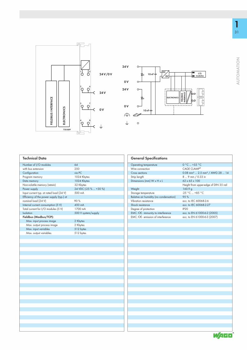
This controller can accommodate up to two KNX logic devices at the same time.• 1. In conjunction with the WAGO-I/O-SYSTEM, the KNX IP Controller is used as
a user-programmable application controller within KNX IP networks. The controller supports all digital, analog and specialty modules found within the 750/753 Series. The IEC 61131-3 programmable controller is capable of 10/100 Mbit/s data rates. KNX objects of any type (EIS/DPT) can be created using the programming tool. Libraries including pre-made function blocks are rea-dily available on the WAGO Web site for programming. The controller supports a maximum of 253 communication objects, as well as 254 group addresses and associations.
• 2. Combined with the KNX/EIB/TP1 Module, the 750-889 KNX IP Controller can operate as a router on an IP backbone (ETHERNET). No IEC application is required for router functionality.
Both devices are commissioned and configured within the ETS software using the WAGO product database. The software includes a plug-in that automatically installs and opens for configuration. The KNX IP controller features an integrated 2-port 10/100 Mbit/s switch and allows easy line structure creation without additional network components. The maximum number of controllers that can be wired in series is 20.An internal server is available for Web-based applications.The controller provides 1024 KB program memory, 1024 KB data memory and 32 KB retain memory. It is capable of multitasking, has a battery-backed, real-time clock and is based on a 32-bit CPU. The controller offers many different application protocols for control tasks (MODBUS, KNXnet/IP) or for system management and diagnostics (HTTP, BootP, DHCP, DNS, AutoIP, SNTP, FTP, SNMP and SMTP).The number of KNX/EIB/TP1 Modules (750-646) supported by the KNX IP Controller does not depend on the application.
Description Item No. Pack. Unit
KNX IP Controller 750-889 1
Accessories Item No. Pack. Unit
WAGO ETS3 plug-in Download: www.wago.comWAGO-I/O-PRO V2.3, RS-232 kit 759-333 1SD memory card, 2 GB 758-879/000-001 1Miniature WSB Quick marking system
plain 248-501 5with marking see Full Line Catalog AUTOMATION
2012/2013
ApprovalsKNX certified IP controller: 61/8316/08;
IP router: 61/8317/08Conformity marking 1
System DataNo. of controllers limited by network topologyTransmission medium S-UTP 100 Ω Cat. 5Max. length of fieldbus segment 100 m limited by IEEE 802.3Max. length of network ≤ 2000 m; max. 20 controllers in seriesBaud rate 10/100 Mbit/sBuscoupler connection 2 x RJ-45 (linked via 2-port switch)Protocols KNXnet/IP, MODBUS/TCP (UDP), HTTP,
BootP, DHCP, DNS, AutoIP, SNTP, FTP, SNMP V3, SMTP
Programming WAGO-I/O-PRO V2.3IEC 61131-3 IL, LD, FBD (CFC), ST, FCSD card slot Push-push mechanism, sealing lidType of memory card SD and SDHC up to 32 GB (All
guaranteed properties are only valid in connection with the WAGO 758-879/000-001 memory card.)
KNX-specificKNX/TP1 bus specification 1.0Commissioning (KNX side) with ETS3/4 plug-in,
2 programming buttonsDevice mode:
Number of communication objects 253Number of group addresses 254
Max. number of KNX logic devices, simultaneous
2; 1. device, 2. router (with 1. KNX/EIB/TP1 module)
131
AU
TOM
ATI
ON
1
2
3
4
5
6
7
8
DCDC
24 V
10 nF
24 V
10 nF
0 V
24 V /0 V
24 V
0 V
0 V
750-889
ELECTRONICS
I/O modules
ELEC
TRO
NIC
S
FIEL
DBU
S IN
TERF
ACE
FIEL
DBUS
INTE
RFA
CE
Technical DataNumber of I/O modules 64with bus extension 250Configuration via PCProgram memory 1024 KbytesData memory 1024 KbytesNon-volatile memory (retain) 32 KbytesPower supply 24 VDC (-25 % ... +30 %)Input current typ. at rated load (24 V) 500 mAEfficiency of the power supply (typ.) at nominal load (24 V) 90 %Internal current consumption (5 V) 450 mATotal current for I/O modules (5 V) 1700 mAIsolation 500 V system/supplyFieldbus (Modbus/TCP):
Max. input process image 2 KbytesMax. output process image 2 KbytesMax. input variables 512 bytesMax. output variables 512 bytes
General SpecificationsOperating temperature 0 °C ... +55 °CWire connection CAGE CLAMP®
Cross sections 0.08 mm² ... 2.5 mm² / AWG 28 ... 14Strip length 8 ... 9 mm / 0.33 inDimensions (mm) W x H x L 62 x 65 x 100
Height from upper-edge of DIN 35 railWeight 160.9 gStorage temperature -25 °C ... +85 °CRelative air humidity (no condensation) 95 %Vibration resistance acc. to IEC 60068-2-6Shock resistance acc. to IEC 60068-2-27Degree of protection IP20EMC: 1 - immunity to interference acc. to EN 61000-6-2 (2005)EMC: 1 - emission of interference acc. to EN 61000-6-3 (2007)

750-375
132
AU
TOM
ATI
ON
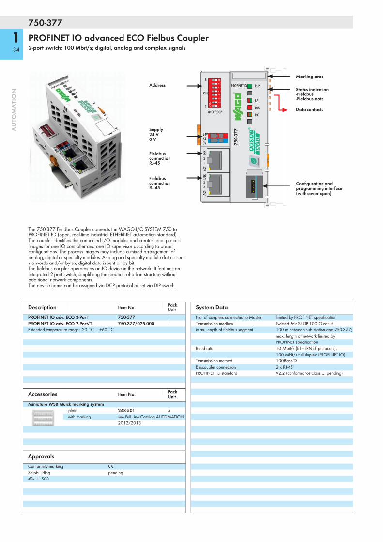
PROFINET IO advanced Fielbus Coupler2-port switch; 100 Mbit/s; digital, analog and complex signals
X1
ACT
ACT
LNK
LNK
1
8
ON
8=OFF:DCP
X2
I/O
DIA
BF
RUNPROFINET IO
W75
0-37
5
12
34
56
78
ON 24V 0V
+ +
— —
01 02
C
DB
A
0 V
P NET
ROFI®
Fieldbus connectionRJ-45
Address
Fieldbus connectionRJ-45
Configuration and programming interface (with cover open)
Power jumper contacts
Data contacts
Marking area
Supply viapower jumper contacts24 V
Supply24 V0 V
Status voltage supply-System-Power jumer contacts
The 750-375 Fieldbus Coupler connects the WAGO-I/O-SYSTEM 750 to PROFINET IO (open, real-time industrial ETHERNET automation standard). The coupler identifies the connected I/O modules and creates local process images for maximum two IO controllers and one IO supervisor according to preset configurations. The process images may include a mixed arrangement of analog, digital or specialty modules. Analog and specialty module data is sent via words and/or bytes; digital data is sent bit by bit. The fieldbus coupler operates as an IO device in the network. It features an integrated 2-port switch, simplifying the creation of a line structure without additional network components.The device name can be assigned via DCP protocol or set via DIP switch.
Description Item No. Pack. Unit
PROFINET IO adv. 2-Port 750-375 1PROFINET IO adv. 2-Port/T 750-375/025-000 1Extended temperature range: -20 °C ... +60 °C
Accessories Item No. Pack. Unit
Miniature WSB Quick marking systemplain 248-501 5with marking see Full Line Catalog AUTOMATION
2012/2013
ApprovalsConformity marking 1
Shipbuilding pendingr UL 508
System DataNo. of couplers connected to Master limited by PROFINET specification Transmission medium Twisted Pair S-UTP 100 Ω cat. 5Max. length of fieldbus segment 100 m between hub station and 750-375;
max. length of network limited by PROFINET specification
Baud rate 10 Mbit/s (ETHERNET protocols), 100 Mbit/s full duplex (PROFINET IO)
Transmission method 100Base-TXBuscoupler connection 2 x RJ-45PROFINET IO standard V2.2 (conformance class C, pending)

133
AU
TOM
ATI
ON
1
2
3
4
5
6
7
8
DCDC
24 V
10 nF
24 V
10 nF
0 V
24 V /0 V
24 V
0 V
0 V
750-375
ELECTRONICS
I/Omodules
FIEL
DBU
S IN
TERF
ACE
ELEC
TRO
NIC
S
FIE
LDBU
SIN
TERF
ACE
Technical DataNumber of I/O modules 64
with bus extension 250Fieldbus
Max. input process image 512 bytesMax. output process image 512 bytes
Configuration via PCPROFINET IO features Integrated 2-port switch;
Auto-negotiation, Auto-MDIX; Isochronous real-time communication (pending); Transmission clock: 1 ms (RT), 1, 2, 4 ms (IRT); Device replacement without programming tool; Shared device
Protocols Topology detection / LLDP, Network diagnostics / SNMP / MIB-2, media redundancy / MRP (pending), Web server / HTTP
Profiles supported PROFIsafe V2, PROFIenergy V1.0ID code Vendor ID: 0x011D;
Device ID: 0x02EE; Coupler ID: 0x01000177
Power supply 24 V DC (-25 % ... +30 %)Input current typ. at rated load (24 V) 500 mAEfficiency of the power supply (typ.) at nominal load (24 V) 90 %Internal current consumption (5 V) 450 mATotal current for I/O modules (5 V) 1700 mAIsolation 500 V system/supply
General SpecificationsOperating temperature 0 °C ... +55 °CWire connection CAGE CLAMP®
Cross sections 0.08 mm² ... 2.5 mm² / AWG 28 ... 14Strip lengths 8 ... 9 mm / 0.33 inDimensions (mm) W x H x L 62 x 65 x 100
Height from upper-edge of DIN 35 railWeight 160 gStorage temperature -25 °C ... +85 °CRelative air humidity (no condensation) 95 %Vibration resistance acc. to IEC 60068-2-6Shock resistance acc. to IEC 60068-2-27Degree of protection IP20EMC: 1 - immunity to interference acc. to EN 61000-6-2 (2005)EMC: 1 - emission of interference acc. to EN 61000-6-3 (2007)EMC: marine applications - immunity to interference pendingEMC: marine applications - emission of interference pending
750-377
134
AU
TOM
ATI
ON
PROFINET IO advanced ECO Fielbus Coupler2-port switch; 100 Mbit/s; digital, analog and complex signals
24VX3
1
8
ON
0V
W75
0-37
7
12
34
56
78
ON
I/O
DIA
BF
RUNPROFINET IO
X1
ACT
ACT
LNK
LNK
8=OFF:DCP
X2
P NET
ROFI®
Address
Supply24 V0 V
Configuration and programming interface (with cover open)
Data contacts
Marking area
Status indication-Fieldbus-Fieldbus note
Fieldbus connectionRJ-45
Fieldbus connectionRJ-45
The 750-377 Fieldbus Coupler connects the WAGO-I/O-SYSTEM 750 to PROFINET IO (open, real-time industrial ETHERNET automation standard). The coupler identifies the connected I/O modules and creates local process images for one IO controller and one IO supervisor according to preset configurations. The process images may include a mixed arrangement of analog, digital or specialty modules. Analog and specialty module data is sent via words and/or bytes; digital data is sent bit by bit. The fieldbus coupler operates as an IO device in the network. It features an integrated 2-port switch, simplifying the creation of a line structure without additional network components.The device name can be assigned via DCP protocol or set via DIP switch.
Description Item No. Pack. Unit
PROFINET IO adv. ECO 2-Port 750-377 1PROFINET IO adv. ECO 2-Port/T 750-377/025-000 1Extended temperature range: -20 °C ... +60 °C
Accessories Item No. Pack. Unit
Miniature WSB Quick marking systemplain 248-501 5with marking see Full Line Catalog AUTOMATION
2012/2013
ApprovalsConformity marking 1
Shipbuilding pendingr UL 508
System DataNo. of couplers connected to Master limited by PROFINET specification Transmission medium Twisted Pair S-UTP 100 Ω cat. 5Max. length of fieldbus segment 100 m between hub station and 750-377;
max. length of network limited by PROFINET specification
Baud rate 10 Mbit/s (ETHERNET protocols), 100 Mbit/s full duplex (PROFINET IO)
Transmission method 100Base-TXBuscoupler connection 2 x RJ-45PROFINET IO standard V2.2 (conformance class C, pending)
135
AU
TOM
ATI
ON
DCDC
24 V
10 nF
10 nF
24 V
0 V
0 V
750-377
ELECTRONICS
I/Omodules
FIEL
DBU
S IN
TERF
ACE
ELEC
TRO
NIC
S
FIE
LDBU
SIN
TERF
ACE
Technical DataNumber of I/O modules 64Fieldbus
Max. input process image 256 bytesMax. output process image 256 bytes
Configuration via PCPROFINET IO features Integrated 2-port switch;
Auto-negotiation, Auto-MDIX; Isochronous real-time communication (pending); Transmission clock: 1 ms (RT), 1, 2, 4 ms (IRT); Device replacement without programming tool
Protocols Topology detection / LLDP, Network diagnostics / SNMP / MIB-2, media redundancy / MRP (pending), Web server / HTTP
Profiles supported PROFIsafe V2, PROFIenergy V1.0ID code Vendor ID: 0x011D;
Device ID: 0x02EE; Coupler ID: 0x01000179
Power supply 24 V DC (-25 % ... +30 %)Input current typ. at rated load (24 V) 280 mAEfficiency of the power supply (typ.) at nominal load (24 V) 90 %Internal current consumption (5 V) 450 mATotal current for I/O modules (5 V) 700 mAIsolation 500 V system/supply
General SpecificationsOperating temperature 0 °C ... +55 °CWire connection CAGE CLAMP®
Cross sections 0.08 mm² ... 1.5 mm² / AWG 28 ... 14Strip lengths 5 ... 6 mm / 0.22 inDimensions (mm) W x H x L 50 x 65 x 97
Height from upper-edge of DIN 35 railWeight 110 gStorage temperature -25 °C ... +85 °CRelative air humidity (no condensation) 95 %Vibration resistance acc. to IEC 60068-2-6Shock resistance acc. to IEC 60068-2-27Degree of protection IP20EMC: 1 - immunity to interference acc. to EN 61000-6-2 (2005)EMC: 1 - emission of interference acc. to EN 61000-6-3 (2007)EMC: marine applications - immunity to interference pendingEMC: marine applications - emission of interference pending

750-354/000-001
136
AU
TOM
ATI
ON
EtherCAT® Fieldbus Coupler, ID Switch100 Mbit/s; digital and analog signals
24VX3
X1
INX2
OUT
0V
I/O
ERR
RUN
L/A OUT
L/A INEtherCAT ®
W75
0-35
4/00
0-00
1
1
8
ON
ID 1-2550: off
12
34
56
78
ON
Fieldbus connectionRJ-45
Supply24 V0 V
Fieldbus connectionRJ-45 Configuration and
programming interface (with cover open)
Data contacts
Marking area
Status indication-Fieldbus-Fieldbus node
Address
The 750-354 EtherCAT® Fieldbus Coupler connects EtherCAT® to the modular WAGO-I/O-SYSTEM. The fieldbus coupler automatically configures, creating a local process image which may include analog, digital or specialty modules. Analog and specialty module data is sent via words and/or bytes; digital data is sent bit by bit.
The upper EtherCAT® interface connects the coupler to the network. The lower RJ-45 socket connects additional EtherCAT® devices to the same line.
EtherCAT® (Ethernet Control Automation Technology) is a real-time ETHERNET solution designed for industrial automation applications and characterized by high performance, flexible topology and simple configuration. With EtherCAT®, the costly ETHERNET star topology can be replaced with a simple line or tree structure.The address selection switch is used to set an Explicit Device ID (EDI), which allows a fixed address to be assigned to an EtherCAT® slave.
Description Item No. Pack. Unit
EtherCAT® Fieldbus Coupler, ID Switch 750-354/000-001 1
Accessories Item No. Pack. Unit
Miniature WSB Quick marking systemplain 248-501 5with marking see Full Line Catalog AUTOMATION
2012/2013
ApprovalsConformity marking 1
r UL 508
System DataNo. of couplers connected to Master limited by EtherCAT specificationTransmission medium Shielded twisted pair
S/FTP, F/FTP or SF/FTP; 100 Ω, Cat 6
Baud rate 100 Mbit/sTransmission performance Class D acc. to EN 50173-1Buscoupler connection 2 x RJ-45Protocols EtherCAT (direct mode)
*EtherCAT® is regristered trademark and patented technology, licensed by Beckhoff Automation GmbH, Germany.

137
AU
TOM
ATI
ON
DCDC
24 V
10 nF
10 nF
24 V
0 V
0 V
750-354/000-001
ELECTRONICS
I/Omodules
FIEL
DBU
S IN
TERF
ACE
ELEC
TRO
NIC
S
FIE
LDBU
SIN
TERF
ACE
Technical DataNumber of I/O modules 64Fieldbus
Max. input process image 1024 bytesMax. output process image 1024 bytes
Configuration via PCPower supply 24 V DC (-25 % ... +30 %)Input current typ. at rated load (24 V) 250 mAEfficiency of the power supply (typ.) at nominal load (24 V) 85 %Internal current consumption (5 V) 300 mATotal current for I/O modules (5 V) 700 mAIsolation 500 V system/supply
General SpecificationsOperating temperature 0 °C ... +55 °CWire connection CAGE CLAMP®
Cross sections 0.08 mm² ... 1.5 mm² / AWG 28 ... 14Strip lengths 5 ... 6 mm / 0.22 inDimensions (mm) W x H x L 65 x 50 x 97
Height from upper-edge of DIN 35 railWeight 152 gStorage temperature -25 °C ... +85 °CRelative air humidity (no condensation) 95 %Vibration resistance acc. to IEC 60068-2-6Shock resistance acc. to IEC 60068-2-27Degree of protection IP20EMC: 1 - immunity to interference acc. to EN 61000-6-2 (2005)EMC: 1 - emission of interference acc. to EN 61000-6-3 (2007)

750-315/300-000
138
AU
TOM
ATI
ON
MODBUS Fieldbus CouplerRS-485; 150 baud ... 115.2 Kbaud; digital and analog signals
ON
TxD
RxD
Modbus
x1
x10
ADDRESS
C
DB
A
CRC
W
24V 0V
+ +
— —
01 02
0FEDC B A9876543
21
0FEDC B A9876543
21
750-
315/
300-
000
I/O
Data contacts
FieldbusconnectionD-Sub
Power jumper contacts
0 V
Supply viapower jumper contacts24 V
Supply24 V0 V
Status voltage supply-System-Power jumper contacts
Address
Configurationinterface
Address
This buscoupler connects the WAGO-I/O-SYSTEM as a slave to the MODBUS fieldbus.
The buscoupler automatically configures, creating a local process image which may include analog, digital or specialty modules. Analog and specialty module data is sent via words and/or bytes, digital data is sent bit by bit.
The data of the analog modules is stored in the process image, which is created automatically according to the order in which the modules are connected to the buscoupler. The bits of the digital modules are sent byte by byte and added to the analog data. If the amount of digital information exceeds 8 bits, the buscoupler automatically starts with a new byte.
Description Item No. Pack. Unit
MODBUS / RS-485 / 150 Bd ... 115.2 kBd 750-315/300-000 1
Accessories Item No. Pack. Unit
Miniature WSB Quick marking systemplain 248-501 5with marking see Full Line Catalog AUTOMATION
2012/2013
ApprovalsConformity marking 1
Shipbuilding ABS, BV, DNV, GL, KR, LR, NKK, PRS, RINAr UL 508 r ANSI/ISA 12.12.01 Class I, Div. 2, Grp. ABCD, T44 TÜV 07 ATEX 554086 X I M2 Ex d I Mb,
II 3 G Ex nA IIC T4 Gc, II 3 D Ex tc IIIC T135°C Dc, TUEV 12.1297 X Ex nA IIC T4 Gc
* Permissible ambient temperature 0 °C ... +60 °CIECEx TUN 09.0001X Ex d I Mb,
Ex nA IIC T4 Gc, Ex tc IIIC T135°C Dc
* Permissible ambient temperature 0 °C ... +60 °C
System DataNo. of couplers connected to Master 247 with repeaterMax. no. of I/O points approx. 6000 (depends on master)Transmission medium Shielded Cu cable 2 (4) x 0.25 mm²Max. length of fieldbus segment 1200 m (depends on baud rate/cable)Baud rate 150 baud ... 115.2 KbaudBuscoupler connection 1 x D-Sub 9; socket

139
AU
TOM
ATI
ON
1
2
3
4
5
6
7
8
24 V
10 nF
24 V
10 nF
0 V
24 V /0 V
24 V
0 V
0 V5 V
5 V24 V
750-315/300-000
ELECTRONICS
I/Omodules
FIELDBUSINTERFACE
FIEL
DBU
SIN
TERF
ACE
ELEC
TRO
NIC
S
Technical DataNumber of I/O modules 64Fieldbus
Max. input process image 512 bytesMax. output process image 512 bytes
Configuration Via PC or rotary encoder switchPower supply 24 V DC (-25 % ... +30 %)Max. input current (24 V) 500mAPower supply efficiency 87%Internal current consumption (5 V) 350mATotal current for I/O modules (5 V) 1650mAIsolation 500 V system/supplyVoltage via power jumper contacts 24 V DC (-25 % ... +30 %)Current via power jumper contacts (max.) 10 A DCVoltage via power jumper contacts 24 V DC (-25 % ... +30 %)
General SpecificationsOperating temperature 0 °C ... +55 °CWire connection CAGE CLAMP®
Cross sections 0.08 mm² ... 2.5 mm² / AWG 28 ... 14Strip lengths 8 ... 9 mm / 0.33 inDimensions (mm) W x H x L 51 x 65 x 100
Height from upper-edge of DIN 35 railWeight 183.2gStorage temperature -25 °C ... +85 °CRelative air humidity (no condensation) 95%Vibration resistance acc. to IEC 60068-2-6Shock resistance acc. to IEC 60068-2-27Degree of protection IP20EMC: 1 - immunity to interference acc. to EN 61000-6-2 (2005)EMC: 1 - emission of interference acc. to EN 61000-6-4 (2007)EMC: marine applications - immunity to interference acc. to Germanischer Lloyd (2003)EMC: marine applications - emission of interference acc. to Germanischer Lloyd (2003)
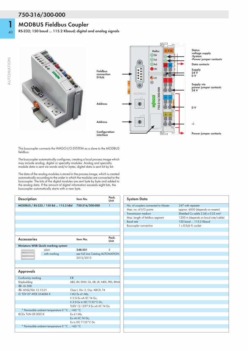
750-316/300-000
140
AU
TOM
ATI
ON
MODBUS Fieldbus CouplerRS-232; 150 baud ... 115.2 Kbaud; digital and analog signals
ON
TxD
RxD
Modbus
x1
x10
ADDRESS
C
DB
A
CRC
W
24V 0V
+ +
— —
01 02
0FEDC B A9876543
21
0FEDC B A9876543
21
750-
316/
300-
000
I/O
Data contacts
FieldbusconnectionD-Sub
Power jumper contacts
0 V
Supply viapower jumper contacts24 V
Supply24 V0 V
Status voltage supply-System-Power jumper contacts
Address
Configurationinterface
Address
This buscoupler connects the WAGO-I/O-SYSTEM as a slave to the MODBUS fieldbus.
The buscoupler automatically configures, creating a local process image which may include analog, digital or specialty modules. Analog and specialty module data is sent via words and/or bytes, digital data is sent bit by bit.
The data of the analog modules is stored in the process image, which is created automatically according to the order in which the modules are connected to the buscoupler. The bits of the digital modules are sent byte by byte and added to the analog data. If the amount of digital information exceeds eight bits, the buscoupler automatically starts with a new byte.
Description Item No. Pack. Unit
MODBUS / RS-232 / 150 Bd ... 115.2 kBd 750-316/300-000 1
Accessories Item No. Pack. Unit
Miniature WSB Quick marking systemplain 248-501 5with marking see Full Line Catalog AUTOMATION
2012/2013
ApprovalsConformity marking 1
Shipbuilding ABS, BV, DNV, GL, KR, LR, NKK, PRS, RINAr UL 508 r ANSI/ISA 12.12.01 Class I, Div. 2, Grp. ABCD, T44 TÜV 07 ATEX 554086 X I M2 Ex d I Mb,
II 3 G Ex nA IIC T4 Gc, II 3 D Ex tc IIIC T135°C Dc, TUEV 12.1297 X Ex nA IIC T4 Gc
* Permissible ambient temperature 0 °C ... +60 °CIECEx TUN 09.0001X Ex d I Mb,
Ex nA IIC T4 Gc, Ex tc IIIC T135°C Dc
* Permissible ambient temperature 0 °C ... +60 °C
System DataNo. of couplers connected to Master 247 with repeaterMax. no. of I/O points approx. 6000 (depends on master)Transmission medium Shielded Cu cable 2 (4) x 0.25 mm²Max. length of fieldbus segment 1200 m (depends on baud rate/cable)Baud rate 150 baud ... 115.2 KbaudBuscoupler connection 1 x D-Sub 9; socket
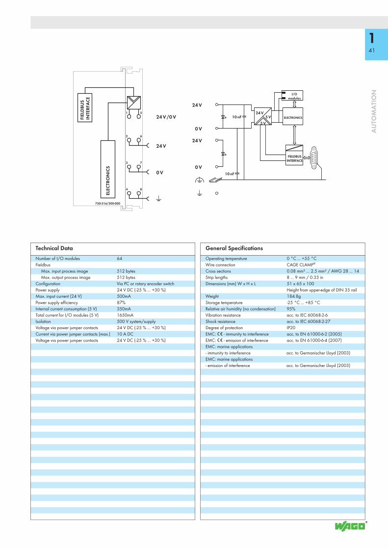
141
AU
TOM
ATI
ON
1
2
3
4
5
6
7
8
24 V
10 nF
24 V
10 nF
0 V
24 V /0 V
24 V
0 V
0 V5 V
5 V24 V
750-316/300-000
ELECTRONICS
I/Omodules
FIELDBUSINTERFACE
FIEL
DBU
SIN
TERF
ACE
ELEC
TRO
NIC
S
Technical DataNumber of I/O modules 64Fieldbus
Max. input process image 512 bytesMax. output process image 512 bytes
Configuration Via PC or rotary encoder switchPower supply 24 V DC (-25 % ... +30 %)Max. input current (24 V) 500mAPower supply efficiency 87%Internal current consumption (5 V) 350mATotal current for I/O modules (5 V) 1650mAIsolation 500 V system/supplyVoltage via power jumper contacts 24 V DC (-25 % ... +30 %)Current via power jumper contacts (max.) 10 A DCVoltage via power jumper contacts 24 V DC (-25 % ... +30 %)
General SpecificationsOperating temperature 0 °C ... +55 °CWire connection CAGE CLAMP®
Cross sections 0.08 mm² ... 2.5 mm² / AWG 28 ... 14Strip lengths 8 ... 9 mm / 0.33 inDimensions (mm) W x H x L 51 x 65 x 100
Height from upper-edge of DIN 35 railWeight 184.8gStorage temperature -25 °C ... +85 °CRelative air humidity (no condensation) 95%Vibration resistance acc. to IEC 60068-2-6Shock resistance acc. to IEC 60068-2-27Degree of protection IP20EMC: 1 - immunity to interference acc. to EN 61000-6-2 (2005)EMC: 1 - emission of interference acc. to EN 61000-6-4 (2007)EMC: marine applications - immunity to interference acc. to Germanischer Lloyd (2003)EMC: marine applications - emission of interference acc. to Germanischer Lloyd (2003)

750-1425
142
AU
TOM
ATI
ON
8-Channel PTC ModuleConnects to PTC thermistors according to DIN 44081/44082
12345678
750-1425
13 14
ϑ↑↓ϑ↑↓
Data contacts
CAGE CLAMP®Sconnection 1T2 … 8T2
Error1T ... 8T
Status1T ... 8T
CAGE CLAMP®Sconnection 1T1 … 8T1
Power jumper contacts
1
2
3
4
5
6
7
8
13
12
11
10
9
14
15
16
750-1425
+24 V
0 V
10 nF
270 pF
10 nF
10 nF
T1T2
1T1
2T1
3T1
4T1
5T1
6T1
7T1
8T1
0 V
+ 24 V
1T2
2T2
3T2
4T2
5T2
6T2
7T2
8T2
FunctionError
Logic
Just 12 mm wide, the PTC module features eight channels to connect PTC thermistors according to DIN 44081 and DIN 44082 for thermal monitoring (overload protection) of motors, machinery, bearings, etc.Up to 6 PTC thermistors can be connected in series per channel. If the nominal response temperature (ϑnat) is exceeded, a bit is set in the module's input process image. In addition, wire breaks and short circuits are monitored for each channel. If an error occurs, a bit is also set in the input process image. One green and one red status LED per channel indicate overtemperature or wiring errors. Field and system levels are electrically isolated.
Description Item No. Pack. Unit
8DI PTC 750-1425 1
Accessories Item No. Pack. Unit
Miniature WSB Quick marking systemplain 248-501 5with marking see Full Line Catalog AUTOMATION
2012/2013Operating tool, with partially insulated shaftType 1, blade (2.5 x 0.4) mm 210-719 50
ApprovalsConformity marking 1
Shipbuilding GL pending
Technical DataNumber of inputs 8Power supply via system voltage DC/DCCurrent consumption typ. (internal) 52 mAPower consumption P max. 260 mWSensor connection 2-wire;
Sensor voltage: ≤ 2.5 V / ≤ 7.5 V (based on resistance value); Sensor current: ≤ 1 mA; Number of PTCs per channel: max. 6 PTCs in series; Operating value (status bit “1” to “0”): R ≥ 3 kΩ; Return value (status bit “0” to “1”): ≤ 1.5 kΩ; Hysteresis: R = 1.5 kΩ; Wire break value: R ≥ 8 kΩ; Short circuit value: R ≤ 20 Ω
Input filter 100 msIsolation 500 V system/fieldBit width 16-bit (status)Wire connection CAGE CLAMP® SCross sections solid:
0.08 mm² ... 1.5 mm² / AWG 28 ... 16fine-stranded: 0.25 mm² ... 1.5 mm² / AWG 22 ... 16
Strip lengths 8 ... 9 mm / 0.33 inWidth 12mmWeight 46.7 gEMC: 1 - immunity to interference acc. to EN 61000-6-2 (2005)EMC: 1 - emission of interference acc. to EN 61000-6-4 (2007)

143
AU
TOM
ATI
ON
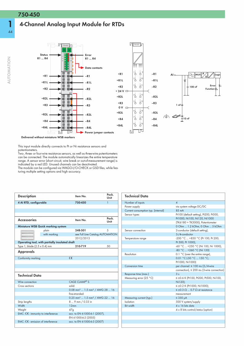
750-450
144
AU
TOM
ATI
ON
4-Channel Analog Input Module for RTDs
Delivered without miniature WSB markers
1234
750-450
13 145678
Data contacts
ErrorR1 ... R4
Power jumper contacts
‒R1
‒R1L
‒R2
‒R2L
‒R3
‒R3L
‒R4
‒R4L
StatusR1 ... R4
+R1
+R1L
+R2
+R2L
+R3
+R3L
+R4
+R4L
1
2
3
4
5
6
7
8
13
12
11
10
9
14
15
16
750-450
1 nF
100 nF
10 nF
AI
FunctionError
LogicMUX+R1
+R1L
+R2
+R2L
+R3
+R3L
+R4
+R4L
0 V
+ 24 V
–R1
–R1L
–R2
–R2L
–R3
–R3L
–R4
–R4L
This input module directly connects to Pt or Ni resistance sensors and potentiometers.Two-, three- or four-wire resistance sensors, as well as three-wire potentiometers can be connected. The module automatically linearizes the entire temperature range. A sensor error (short circuit, wire break or out-of-measurement range) is indicated by a red LED. Unused channels can be deactivated.The module can be configured via WAGO-I/O-CHECK or GSD files, while fea-turing multiple setting options and high accuracy.
Description Item No. Pack. Unit
4 AI RTD, configurable 750-450 1
Accessories Item No. Pack. Unit
Miniature WSB Quick marking systemplain 248-501 5with marking see Full Line Catalog AUTOMATION
2012/2013Operating tool, with partially insulated shaftType 1, blade (2.5 x 0.4) mm 210-719 50
ApprovalsConformity marking 1
Technical DataWire connection CAGE CLAMP® SCross sections solid:
0.08 mm² ... 1.5 mm² / AWG 28 ... 16fine-stranded: 0.25 mm² ... 1.5 mm² / AWG 22 ... 16
Strip lengths 8 ... 9 mm / 0.33 inWidth 12mmWeight 47gEMC: 1 - immunity to interference acc. to EN 61000-6-1 (2007),
EN 61000-6-2 (2005)EMC: 1 - emission of interference acc. to EN 61000-6-3 (2007)
Technical DataNumber of inputs 4Power supply via system voltage DC/DCCurrent consumption typ. (internal) 85 mASensor types Pt100 (default setting), Pt200, Pt500,
Pt1000, Ni100, Ni120, Ni1000 (TK6180 + TK5000), Potentiometer 0 Ohm ... 1.2 kOhm, 0 Ohm ... 5 kOhm
Sensor connection 2-conductor (default setting), 3-/4-conductor
Temperature range -200 °C ... +850 °C (Pt 100, Pt 200, Pt 500, Pt 1000), -60 °C ... +250 °C (Ni 100, Ni 1000), -80 °C ... +260 °C (Ni 120)
Resolution 0.1 °C (over the entire range), 0.01 °C (-50 °C ... 150 °C; Pt1000, Ni1000)
Conversion time per channel: ≤ 100 ms (2-/4-wire connection), ≤ 200 ms (3-wire connection)
Response time (max.) 3 sMeasuring error (25 °C) ≤ ±0.6 K (Pt100, Pt200, Pt500, Ni100,
Ni120); ≤ ±0.2 K (Pt1000, Ni1000); ≤ ±0.3 Ω ... 0.7 Ω at resistance measurement
Measuring current (typ.) ≤ 350 μAIsolation 500 V system/supplyBit width 4 x 16 bits data
4 x 8 bits control/status (option)

750-451
145
AU
TOM
ATI
ON
8-Channel Analog Input Module for RTDs
Delivered without miniature WSB markers
12345678
750-451
13 149
10111213141516
StatusR1 ... R8
Data contacts
ErrorR1 ... R8
Power jumper contacts
‒R1
‒R2
‒R3
‒R4
‒R5
‒R6
‒R7
‒R8
+R1
+R2
+R3
+R4
+R5
+R6
+R7
+R8
1
2
3
4
5
6
7
8
13
12
11
10
9
14
15
16
750-451
1 nF
100 nF
10 nF
AI
FunctionError
LogicMUX+R1
+R2
+R3
+R4
+R5
+R6
+R7
+R8
0 V
+ 24 V
–R1
–R2
–R3
–R4
–R5
–R6
–R7
–R8
The input module directly connects to Pt and Ni resistance sensors.Two-wire sensors can be connected.The module automatically linearizes the entire temperature range. A sensor error (short circuit, wire break or out-of-measurement range) is indicated by a red LED. Unused channels can be deactivated. The module can be configured via WAGO-I/O-CHECK or GSD files, while fea-turing multiple setting options and high accuracy.
Description Item No. Pack. Unit
8 AI RTD, configurable 750-451 1
Accessories Item No. Pack. Unit
Miniature WSB Quick marking systemplain 248-501 5with marking see Full Line Catalog AUTOMATION
2012/2013Operating tool, with partially insulated shaftType 1, blade (2.5 x 0.4) mm 210-719 50
ApprovalsConformity marking 1
Technical DataWire connection CAGE CLAMP® SCross sections solid:
0.08 mm² ... 1.5 mm² / AWG 28 ... 16fine-stranded: 0.25 mm² ... 1.5 mm² / AWG 22 ... 16
Strip length 8 ... 9 mm / 0.33 inWidth 12mmWeight 47gEMC: 1 - immunity to interference acc. to EN 61000-6-1 (2007),
EN 61000-6-2 (2005)EMC: 1 - emission of interference acc. to EN 61000-6-3 (2007)
Technical DataNumber of inputs 8Power supply via system voltage DC/DCCurrent consumption typ. (internal) 110 mASensor types Pt100 (default setting), Pt200, Pt500,
Pt1000, Ni100, Ni120, Ni1000 (TK6180 + TK5000), Potentiometer 0 Ohm ... 1.2 kOhm, 0 Ohm ... 5 kOhm
Sensor connection 2-conductorTemperature range -200 °C ... +850 °C (Pt100, Pt200,
Pt500, Pt1000), -60 °C ... +250 °C (Ni100, Ni1000), -80 °C ... +260 °C (Ni120)
Resolution 0.1 °C (over the entire range), 0.01 °C (-50 °C ... 150 °C; Pt1000, Ni1000)
Conversion time per channel: ≤ 100 msResponse time (max.) 3 sMeasuring error (25 °C) ≤ ±0.6 K (Pt100, Pt200, Pt500, Ni100,
Ni120); ≤ ±0.2 K (Pt1000, Ni1000); ≤ ±0.3 Ω at resistance measurement
Measuring current (typ.) ≤ 350 μAIsolation 500 V system/supplyBit width 8 x 16 bits data
8 x 8 bits control/status (option)

750-494
146
AU
TOM
ATI
ON
3-Phase Power Measurement Module
Delivered without miniature WSB markers
L1 IL1
13 14
750-494
L2 IL2
L3 IL3
N IN
ABCD
EFGH
IL1
IL2L2
IN
L1
N
IL3L3
Interchange in phase sequence L1-L2-L3
Communication
Error L1Display: Override in
current measurement pathDisplay: Undervoltage in
voltage measurement path
Error L2Error L3Display: Override in voltage measurement path
750-494
L1
L2
L3
N
IL1
IL2
IL3
IN
The 750-494 3-Phase Power Measurement Module measures electrical data in a three-phase supply network. The voltage is measured via network connection to L1, L2, L3 and N. The current of the three phases is fed to IL1, IL2, IL3 and IN via current transformers. The 750-494 Module transmits metrics (e.g., reactive/apparent/effective power, energy consumption, power factor, phase angle, frequency, over-/undervoltage) directly into the process image, without requiring high computing power from the controller. Both comprehensive metrics and harmonic analysis up to the 41st harmonic permit an extensive network analysis via the fieldbus.
Metrics allow the operator to optimize the supply to a drive or machine, protecting the system from damage and failure. The 4-quadrant display indicates the type of load (inductive, capacitive) and whether it is an energy consumer or producer.
Description Item No. Pack. Unit
3-Phase Power Measurement Module (480V/1A) 750-494 13-Phase Power Measurement Module (480V/5A) 750-494/000-001 13-Phase Power Measurement Module (480V/1A)/T 750-494/025-000 1Extended temperature range: -20 °C ... +60 °C3-Phase Power Measurement Module (480V/5A)/T 750-494/025-001 1Extended temperature range: -20 °C ... +60 °C
Accessories Item No. Pack. Unit
Miniature WSB Quick marking systemplain 248-501 5with marking see Full Line Catalog AUTOMATION
2012/2013
ApprovalsConformity marking 1
r UL 508 r ANSI/ISA 12.12.01 applied for4 TÜV 07 ATEX 554086 X I M2 Ex d I Mb,
II 3 G Ex nA IIC T4 Gc, II 3 D Ex tc IIIC T135°C Dc
Permissible ambient temperature 0 °C ... +60 °C4 TUN 09.0001 X Ex d I Mb,
Ex nA IIC T4 Gc, Ex tc IIIC T135°C Dc
Permissible ambient temperature 0 °C ... +60 °C
Technical DataWire connection CAGE CLAMP®
Cross sections 0.08 mm² ... 2.5 mm² / AWG 28 ... 14Strip lengths 8 ... 9 mm / 0.33 inWidth 12mmWeight 48.5 gEMC: 1 - immunity to interference acc. to EN 61000-6-2 (2005)EMC: 1 - emission of interference acc. to EN 61000-6-3 (2007)
Technical DataNumber of measurement inputs 6 (3 voltage measurement inputs,
3 current measurement inputs)Rated voltage VLN = 277 V AC/DC; VLL = 480 V ACInput resistance voltage path (typ.) 1072 kΩMeasuring current (max.) 1 A (750-494, 750-494/025-000)
5 A (750-494/000-001, 750-494/025-001)Input resistance current path (typ.) 22 mΩ (750-494, 750-494/025-000)
5 mΩ (750-494/000-001, 750-494/025-001)Resolution 24 bitsFrequency range - frequency of supply network 45 Hz ... 65 HzFrequency range - analysis of harmonics 0 Hz ... 3300 HzMax. operating frequency 15.9 kHzSignal form any periodic signals (taking the maximum
frequency into account)Measuring error for current and voltage AC: Max. 0.5 %;
DC: 1.0 % (of the upper range value); DC measurement (2 channels only)
Measuring procedure True RMS measurementMeasuring cycle time Adjustable for arithmetic mean value,
Min_Max_ValuesMeasured values Line-to-line voltage, power output, energy,
power factors, mains frequency, harmonic analysis (up to the 41st harmonic), THD
Power supply via system voltage internal bus (5 V)Current consumption (internal) 100 mARated surge voltage 4 kVOvervoltage category IIIDegree of pollution 2Bit width 2 x 128 bits data
2 x 64 bits control/status

750-495
147
AU
TOM
ATI
ON
3-Phase Power Measurement Module
Delivered without miniature WSB markers
L1
13 14
750-495
L2
L3
N
ABCD
EFGH
I1+ I1-
15 16
I2+ I2-
I3+ I3-
IN+ IN-
ABCD
EFGH
I1-I1+
Data contacts
I2-L2
IN-
L1
N
I3-
I2+
IN+
I3+L3
Interchange in phase sequence L1-L2-L3
Communication
Error L1Display: Override in
current measurement pathDisplay: Undervoltage in
voltage measurement path
Error L2Error L3Display: Override in voltage measurement path
750-495
I1-I1+
N IN-IN+
L1
L2
L3
I2-I2+
I3-I3+
The 750-495 3-Phase Power Measurement Module measures electrical data in a three-phase supply network. The voltage is measured via network connection to L1, L2, L3 and N. The current of the three phases is fed to IL1, IL2, IL3 and IN (two clamping points each +,-) via current transformers or via Rogowski coils for the 750-495/000-002 module. The 750-495 Module transmits metrics (e.g., reactive/apparent/effective power, energy consumption, power factor, phase angle, frequency, over-/undervoltage) directly into the process image, without requiring high computing power from the controller. Both comprehensi-ve metrics and harmonic analysis up to the 41st harmonic permit extensive net-work analysis via the fieldbus.
Metrics allow the operator to optimize the supply to a drive or machine, protecting the system from damage and failure. Insulation failures can be detected and prevented via current measurement performed in the neutral conductor. The 4-quadrant display indicates the type of load (inductive, capacitive) and whether it is an energy consumer or producer.
Description Item No. Pack. Unit
3-Phase Power Measurement Module (690V/1A) 750-495 13-Phase Power Measurement Module (690V/5A) 750-495/000-001 13-Phase Power Measurement Module (690V/RC) Rogowski Coils 750-495/000-002 1
Accessories Item No. Pack. Unit
Miniature WSB Quick marking systemplain 248-501 5with marking see Full Line Catalog AUTOMATION
2012/2013
ApprovalsConformity marking 1
Technical DataWire connection CAGE CLAMP®
Cross sections 0.08 mm² ... 2.5 mm² / AWG 28 ... 14Strip lengths 8 ... 9 mm / 0.33 inWidth 24mmWeight 48.5 gEMC: 1 - immunity to interference acc. to EN 61000-6-2 (2005)EMC: 1 - emission of interference acc. to EN 61000-6-3 (2007)
Technical DataNumber of measurement inputs 7 (3 voltage measurement inputs,
4 differential current measurement inputs)Rated voltage VLN = 400 V AC; VLL = 690 V ACInput resistance voltage path (typ.) 1429 kΩMeasuring current (max.) 1 A (750-495)
5 A (750-495/000-001)Rogowski Coils RT500/RT2000 (750-495/000-002)
Input resistance current path (typ.) 22 mΩ (750-495)5 mΩ (750-495/000-001)44 kΩ (750-495/000-002)
Resolution 24 bitsFrequency range - frequency of supply network 45 Hz ... 65 HzFrequency range - analysis of harmonics 0 Hz … 3300 HzMax. operating frequency 15.9 kHzSignal form any periodic signals (taking the maximum
frequency into account)Measuring error for current and voltage Max. 0.5 % (of the upper range value)Measuring procedure True RMS measurementMeasuring cycle time Adjustable for arithmetic mean value,
Min_Max_ValuesMeasured values Line-to-line voltage, power output, energy,
power factors, mains frequency, harmonic analysis (up to the 41st harmonic), THD
Power supply via system voltage internal bus (5 V)Current consumption (internal) 100 mARated surge voltage 6 kVOvervoltage category IIIDegree of pollution 2Bit width 2 x 128 bits data
2 x 64 bits control/status

750-658
148
AU
TOM
ATI
ON
CAN Gateway
CH CL
13 14
750-658
CG +
--
S S
CAN-L
Internal data bus RUNCAN-TxInt. error
Data contacts
CAN-StatusCAN-Rx
CAN-H
CAN-GND
Power jumper contacts
+24 V
0 V
Shield (screen)
Shield (screen)
10 nF
1 MΩ
+24 V24 V
0 V
750-658
Shield (screen)
Logic
CAN-Rx CAN-Tx
CAN-StatusInternal data bus RUNInt. error
Shield (screen)
CAN-GND
0 V24 V
CAN-LCAN-HCAN-L
CAN-GND
CAN-H
The CAN Gateway supports CAN Layer 2, while meeting CAN specifications 2.0A (11-bit identifier) and 2.0B (29-bit identifier). Function blocks allow the gateway to read and write higher-protocol telegrams (e.g., CANopen).
The gateway adjusts itself to baud rates between 10 kbit/s to 1 Mbit/s via automatic bit-rate detection (Auto Baud Rate). It is also possible to set a fixed transmission rate. Six configurable filters for input telegrams allow CAN messages to be filtered via the CAN identifiers.
Three operation modes are available: Sniffer mode provides a detailed CAN bus analysis without interactions. In transparent mode, the gateway works as an active CAN device that can send and receive any type of CAN telegrams. Mapped mode enables CAN telegrams to be generated directly from the process image. It also allows select process values to be copied from received telegrams into the input process image.A CAN telegram may be sent cyclically, manually or event-triggered (change of process value).
Description Item No. Pack. Unit
CAN Gateway 750-658 1
Accessories Item No. Pack. Unit
Miniature WSB Quick marking systemplain 248-501 5with marking see Full Line Catalog AUTOMATION
2012/2013
ApprovalsConformity marking 1
Shipbuilding GLr UL 508
Technical DataNumber of CAN interfaces 1Supported baud rates 10 kbit/s, 20 kbit/s, 50 kbit/s, 125 kbit/s,
250 kbit/s, 500 kbit/s, 800 kbit/s, 1 Mbit/s, Auto Baud Rate
CAN data formats acc. to 2.0A (Standard: 11-bit ID), acc. to 2.0B (Extended: 29-bit ID)
Operation modes Sniffer mode, transparent mode, mapped mode
Internal bit width 8, 12, 16, 20, 24, 32, 40, 48 bytes configurable; incl. control/status byte
Isolation (peak value) VM = 500 V system/supplyCurrent consumption typ. (24 V) 12 mACurrent consumption typ. (KBUS) 50 mAWire connection CAGE CLAMP®
Cross sections 0.08 mm² ... 2.5 mm² / AWG 28 ... 14Strip lengths 8 ... 9 mm / 0.33 inWidth 12mmWeight 55 gEMC: 1 - immunity to interference acc. to EN 61000-6-2 (2005),
EN 61131-2 (2007)EMC: 1 - emission of interference acc. to EN 61000-6-3 (2007),
EN 61131-2 (2007)EMC: marine applications - immunity to interference pendingEMC: marine applications - emission of interference pending
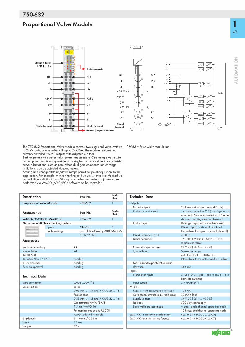
750-632
149
AU
TOM
ATI
ON
Proportional Valve Module
1 92 103 114 125 13 6 14 7 15 8 16
750-632
13 14
Data contacts
Status + ErrorLED 1 ... 16
Power jumper contacts
L1+
+24 V
0 V
DI 1
L1-
A+
B+
Shield (screen)
L2+
+24 V
L2-
A–
B–
Shield (screen)
0 V
DI 2
I_lim
16x
I_lim
3.3 V24 V
SetCurrent A
Temp AOCP A
Current A
SetCurrent B
Temp BOCP B
Current B
+24 V
0 V
B+
B−
A+
A−
1 9
2 10
3 11
4 12
5 13
6 14
7 15
8 16
750-632
0 V
+ 24 V
+24 V
0 V
B+ B−
A+ A−
Logic
Logic
DI 1
DI 2
L1+L1−L2+L2−
DI 1
L1+
L1−
Shield (screen)
DI 2
L2+
L2−
The 750-632 Proportional Valve Module controls two single-coil valves with up to 24V/1.6A, or one valve with up to 24V/2A. The module features two current-controlled PWM* outputs with adjustable dither. Both unipolar and bipolar valve control are possible. Operating a valve with two unipolar coils is also possible via a single-channel module. Characteristic curve adaptations, such as zero offset, dual gain compensation or range limitations, can be adjusted via parameters. Scaling and configurable up/down ramps permit set point adjustment to the application. For example, monitoring threshold value switches is performed via two additional digital inputs. Start-up and valve parameters adjustment are performed via WAGO-I/O-CHECK software or the controller.
*PWM = Pulse width modulation
Description Item No. Pack. Unit
Proportional Valve Module 750-632 1
Accessories Item No. Pack. Unit
WAGO-I/O-CHECK, RS-232 kit 759-302 1Miniature WSB Quick marking system
plain 248-501 5with marking see Full Line Catalog AUTOMATION
2012/2013
ApprovalsConformity marking 1
Shipbuilding GLr UL 508r ANSI/ISA 12.12.01 pendingIECEx approval pending4 ATEX approval pending
Technical DataWire connection CAGE CLAMP® SCross sections solid:
0.08 mm² ... 1.5 mm² / AWG 28 ... 16fine-stranded:0.25 mm² ... 1.5 mm² / AWG 22 ... 16Coil terminals A+/A-/B+/B-: 1.5 mm²/AWG 16 For applications acc. to UL 508: AWG 16 for all terminals
Strip lengths 8 ... 9 mm / 0.33 inWidth 12 mmWeight 50 g
Technical DataOutputs
No. of outputs 2 bipolar outputs (A+, A- and B+, B-)Output current (max.) 1-channel operation: 2 A (Derating must be
observed); 2-channel operation: 1.6 A per channel (Derating must be observed)
Output type H-bridge output with current-regulated PWM output (short-circuit proof and thermal overload-proof for each channel)
PWM frequency (typ.) 50 kHzDither frequency 250 Hz; 125 Hz; 62.5 Hz; ... 1 Hz
(parameterizable)Nominal output voltage 24 V DC (-25 % ... +30 %)Type of load Operating range:
inductive (1 mH ... 600 mH); Internal resistance of the load (> 8 Ohm)
Max. errors (setpoint/actual value deviation) ±4.5 mA
InputsNumber of inputs 2 (DI 1, DI 2), Type 1 acc. to IEC 61131;
high-side switchingInput current 2.7 mA at 24 V
ModuleMax. current consumption (internal) 125 mACurrent consumption max. (field side) 20 mA + loadSupply voltage 24 V DC (-25 % ... +30 %)Isolation 500 V system/supplyData width process image 6 bytes: single-channel operating mode;
12 bytes: dual-channel operating modeEMC: 1 - immunity to interference acc. to EN 61000-6-2 (2005)EMC: 1 - emission of interference acc. to EN 61000-6-4 (2007)

753-648
150
AU
TOM
ATI
ON
LON FTT Module
753-648
13 14
BUS BUS
ABCD
EFGH
Data contacts
A: User ConfigurationB: TxDC: MailboxD: Service
E: LonWorks StatusF: RxDG: Communication/Initialization PhaseH: Service
Service Switch
LON Bus A LON Bus B
Service Switch
LON BLON A
FT50
0
A
RxD
TxD
BCD
EFGH
753-648
Logic
LON Bus
Service Switch
Connection
not assigned
not assigned
0 V
24 V
The 753-648 LON FTT Module complies with the ISO/IEC 14908 standard. The 1⁄2 inch (12 mm) wide I/O module connects LON to 750 Series Controller and Modules (e.g., BACnet, KNX, EnOcean, DALI, MODBUS). It is a full-fledged and flexible LON device within LonWorks FT or LP networks. The module's network variable interface defines 249 network variables of any type and supports both LonMark objects and configuration properties. LON network interface is defined via LON Configurator, a comprehensive and easy-to-use WAGO-I/O-PRO software tool. Interface representations are programmed via IEC-61131-3 and can be easily used for further applications.Fieldbus nodes are programmed via WAGO-I/O-PRO software. WAGO provides a comprehensive IEC-61131-3 library of function blocks, simplifying the creation of complex control applications.
A maximum of two modules may be connected to one controller. However, the number of modules depends on the memory required by the IEC application and the type of controller. The module is supplied via 24V power jumper contacts.
Description Item No. Pack. Unit
LON FTT Module 753-648
Accessories Item No. Pack. Unit
LON-LIB Download: www.wago.comLON Configurator see page 51WAGO-I/O-PRO V2.3, RS-232 kit 759-333 1
Miniature WSB Quick marking systemplain 248-501 5with marking see Full Line Catalog AUTOMATION
2012/2013753 Series Connectors 753-110 25Coding fingers 753-150 100753 Series pluggable connectors and coding fingers are included.
ApprovalsConformity marking 1
r UL 508
Technical DataTransmission medium Twisted Pair - FTTMax. length of fieldbus segment 500 m (free topology);
2700 m (bus topology)Topology acc. to LON specificationBaud rate 78 kbpsCommissioning via WAGO-I/O-CHECKProgramming via WAGO-I/O-PROInterface to LON network programmable via WAGO-I/O-PRONumber of network variables max. 254 (249 for application)Number of aliases max. 127ISI (Interoparable Self-Installation) noDMF (Direct Memory Files) noProcessor FT5000Transceiver FTX2Transmission channel 1Current consumption (internal) 30 mAPower supply via system powerIsolation 500 V system/supplyInternal bit width 24-byte dataWire connection CAGE CLAMP®
Cross sections 0.08 mm² ... 2.5 mm² / AWG 28 ... 14Stripped lengths 9 ... 10 mm / 0.37 inWidth 12 mmWeight 55 gEMC: 1 - immunity to interference acc. to EN 61000-6-2 (2005)EMC: 1 - emission of interference acc. to EN 61000-6-3 (2007)EMC: marine applications - immunity to interference acc. to Germanischer Lloyd (2003)EMC: marine applications - emission of interference acc. to Germanischer Lloyd (2003)
LON®, LonWorks® and LonMark® are registered trademarks of Echelon Corporation.
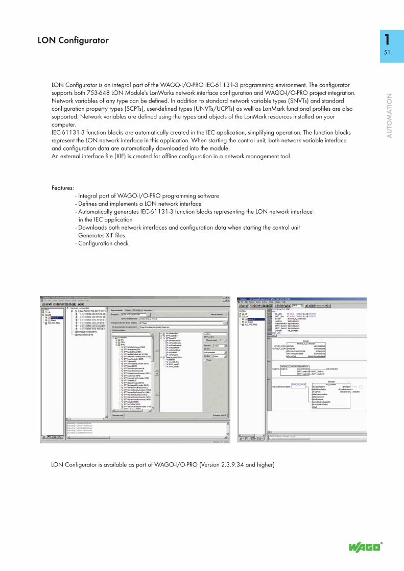
151
AU
TOM
ATI
ON
LON Configurator
LON Configurator is an integral part of the WAGO-I/O-PRO IEC-61131-3 programming environment. The configurator supports both 753-648 LON Module's LonWorks network interface configuration and WAGO-I/O-PRO project integration.Network variables of any type can be defined. In addition to standard network variable types (SNVTs) and standard configuration property types (SCPTs), user-defined types (UNVTs/UCPTs) as well as LonMark functional profiles are also supported. Network variables are defined using the types and objects of the LonMark resources installed on your computer.IEC-61131-3 function blocks are automatically created in the IEC application, simplifying operation. The function blocks represent the LON network interface in this application. When starting the control unit, both network variable interface and configuration data are automatically downloaded into the module.An external interface file (XIF) is created for offline configuration in a network management tool.
Features: - Integral part of WAGO-I/O-PRO programming software - Defines and implements a LON network interface - Automatically generates IEC-61131-3 function blocks representing the LON network interface in the IEC application - Downloads both network interfaces and configuration data when starting the control unit - Generates XIF files - Configuration check
LON Configurator is available as part of WAGO-I/O-PRO (Version 2.3.9.34 and higher)

753-647
152
AU
TOM
ATI
ON
DALI Multi-Master Module
753-647
13 14ABCD
EFGH
Data contacts
A: Easy ModeB: TxDC: AvailabilityD: 1- or 2-Button Operation
E: Full ModeF: RxDG: Power OnH: Latching Function
-DALI Bus
+DALI Bus
+V
-V
+V
-V
-DALI Bus
+DALI Bus+DALI
+DALI
-DALI
2 x 4.7nF
-DALIRxD
TxD
2 x 4.7nF
ABCD
EFGH
753-647
-V
-V
Logic
+V
+V
The 753-647 DALI Multi-Master Module complies with DALI standard according to IEC 62386. This manufacturer-independent protocol ensures interoperability of DALI devices in lighting applications.The 1⁄2 inch (12 mm) wide module is a DALI interface used in combination with WAGO 750 Series Controllers and Modules (e.g., BACnet, KNX, EnOcean, LON, MODBUS).Each DALI Multi-Master Module supports 64 addresses for electronic control gears (ECGs) and 64 addresses for DALI sensors. Each DALI ECG can be assigned to 16 groups and 16 scenes. The 753-647 Module also offers 16 additional virtual groups on the DALI bus.Using the WAGO-I/O-SYSTEM, DALI control devices are seamlessly integrated with all supported BA and fieldbus protocols. Several DALI masters can be connected to a single fieldbus node. The maximum number of modules that can be connected to a controller depends on the memory required by the application. Fieldbus nodes are programmed via WAGO-I/O-PRO software. WAGO provides a comprehensive IEC-61131-3 library of function blocks, simplifying the creation of complex lighting applications.
Alternatively an “Easy Mode” allows lighting functions to be easily controlled without any complicated PLC programming. The 753-647 Module is future-proof and upgradable to the latest DALI release. A comprehensive and easy-to-use commissioning and mainte-nance tool is available as stand-alone application or as integrated WAGO-I/O-CHECK software component.The two following power supply options are available for the 753-647 Series:1. The 753-620 DALI Multi-Master DC/DC Converter is used to supply one single module.2. The 787-1007 Power Supply is used to supply several modules.
Description Item No. Pack. Unit
DALI Multi-Master Module 753-647
Accessories Item No. Pack. Unit
DALI Configurator see page 53 or download: www.wago.com
WAGO-I/O-CHECK, RS-232 kit 759-302 1Miniature WSB Quick marking systemplain 248-501 5with marking see Full Line Catalog AUTOMATION
2012/2013753 Series Connectors 753-110 25Coding fingers 753-150 100753 Series pluggable connectors and coding fingers are included.
ApprovalsConformity marking 1
r UL 5084 EN 60079-0, -15 EN 61241-0, -1
pending
Technical DataDALI specification DIN IEC 62386 only in conjunction with
753-620 or 787-1007 Power SuppliesNumber of slaves (DALI) addressable:
64 control devices + 64 control gearsModule power supply at +V and -V 18 V via 753-620 / 787-1007 Power
SuppliesTransmission channel 1Technical information acc. to DALI specification
Maximum supply current 250 mAGuaranteed supply current 200 mA
Current consumption (internal) 30 mAPower supply via system voltage (DC/DC)Isolation 1500 V DC DALI bus/Internal data busInternal bit width 24-byte dataCommissioning via WAGO-I/O-CHECKConfiguration with WAGO DALI ConfiguratorProgramming via WAGO-I/O-PROWire connection CAGE CLAMP®
Cross sections 0.08 mm² ... 2.5 mm² / AWG 28 ... 14Stripped lengths 9 ... 10 mm / 0.37 inWidth 12 mmWeight 55 gEMC: 1 - immunity to interference acc. to EN 61000-6-2 (2005) *EMC: 1 - emission of interference acc. to EN 61000-6-3 (2007) *
* Only in conjunction with 753-620 / 787-1007 DC/DC Converter
EMC: marine applications - immunity to interference acc. to Germanischer Lloyd (2003)EMC: marine applications - emission of interference acc. to Germanischer Lloyd (2003)

153
AU
TOM
ATI
ON
DALI Configurator
The DALI Configurator allows easy commissioning of a DALI network via 753-647 DALI Multi-Master Module. The configurator is available as stand-alone Windows application or for use with WAGO-I/O-CHECK software.It provides the following functions: easy commissioning, configuration, service, support and maintenance of a DALI network. Comprehensive backup & restore features, as well as online and offline configuration option for the entire DALI network (including ECGs and sensors) are available.
Features: - Stand-alone software or for use with WAGO-I/O-CHECK - Commissioning functions: - Addressing - Formation of scenes and groups - Control gear configuration - Offline configuration option - Import and export functions - Project documentation - Service, support and maintenance functions: - Backup & restore - Status messages from defective ECGs/lamps - Identification of double addresses - Operating hours display - Diagnostic report - Windows-conform user interface: - Multiple selection for time-optimized configuration - Displays network in a clear tree structure - Supports different commissioning workflows
DALI Configurator is available as part of WAGO-I/O-CHECK (Version 3.5.1 and higher) or as a stand-alone application (www.wago.com).

753-620
541
AU
TOM
ATI
ON
DALI Multi-Master DC/DC Converter
753-620
SY
C
DB
A
13 14
Data contacts
24 V
0 V
-V+V
Power jumper contacts
0 V
753-620
0 V0 V
24 V
-V+V
Part of the WAGO-I/O-SYSTEM, the 753-620 DALI Multi-Master DC/DC Converter is just ½ inch (12mm) wide. It supplies power to the 753-647 DALI Multi-Master Module and delivers maximum 200mA current to operate a single DALI line. The maximum number of slaves depends on the total power consumption of the single DALI devices. The 753-620 DC/DC Converter is supplied via 24V power jumper contacts. Cable bridges connect the DC/DC Converter to the DALI Multi-Master Module.
Description Item No. Pack. Unit
DALI Multi-Master DC/DC Converter 753-620 1
Accessories Item No. Pack. Unit
Miniature WSB Quick marking systemplain 248-501 5with marking see Full Line Catalog AUTOMATION
2012/2013753 Series Connectors 753-110 25Coding fingers 753-150 100753 Series pluggable connectors and coding fingers are included.
Technical DataVoltage via power jumper contacts (max.) 24 VDCInput voltage range 18 ... 31.2 VDCCurrent via power jumper contacts (max.) 10 ADCOutput voltage 18 VDC (at +V and -V)Nominal output current 200 mAShort circuit protection permanentTest voltage input / output 1.5 kV eff.Wire connection CAGE CLAMP®
Cross sections 0.08 mm² ... 2.5 mm² / AWG 28 ... 14Stripped lengths 9 ... 10 mm / 0.37 inWidth 12 mmWeight 55 g

787-1007
155
AU
TOM
ATI
ON
Power Supplyfor 753-647 DALI Multi-Master Module
L
N
DC+DC+DC -DC -
The 787-1007 Primary Switch Mode Power Supply is specially designed to supply the 753-647 DALI Multi-Master Module. The 787-1007 features a 54mm-wide DIN-rail mount enclosure with input voltage range of 85 to 264VAC (120 – 373VAC). The power supply provides an output voltage of 18VDC and a maximum output current of 1100mA — enough to supply up to five parallel modules. The maximum current per DALI line is limited to 200mA in each DALI Multi-Master Module.• Supplies up to five 753-647 DALI Multi-Master Modules*• Prepared for class II equipment• Natural convection cooling when horizontally mounted• Stage profile, ideal for distribution boards or distribution boxes
Description Item No. Pack. Unit
Primary Switch Mode Power Supply, 18 VDC / 1.1A
787-1007 1
Technical DataInput:
Nominal input voltage Vi nom 100 ... 240 VACInput voltage range 85 ... 264 VAC; 120 ... 373 VDCFrequency 44 ... 66 Hz; 0 HzInput current Ii 0.6 A at 110 VAC / 0.4 A at 230 VACInrush current < 30 A, NTCMains failure hold-up time > 10 ms at 110 VAC /
> 80 ms at 230 VACOutput:
Nominal output voltage Vo nom 18 VDCOutput current Io 1.1 A at 18 VDC
max. 0.8 A (18 VDC) in any mounting position
Factory preset 18 VDCAdjustment accuracy 2 %Residual ripple < 150 mV (peak-peak)Current limitation 1.1 x Io typ.Overload behavior Constant currentOperational indication LED green (Va)
Efficiency / power losses:Efficiency 80 % typ.Power loss PV 3 W (no load) /
6 W (rated load)Fuse protection:
Internal fuse 2 ATExternal fuse Wire breaking 10 A, 16 A,
Characteristic B, CAn external DC fuse is required for the DC input voltage
* Note: The 787-1007 Power Supply must be operated in a DALI network with interconnected 753-647 DALI Multi-Master Module. Otherwise the connected DALI devices will be destroyed.
Technical DataEnvironmental requirements:
Ambient operating temperature -25 °C ... +55 °CStorage temperature -25 °C ... +80 °CRel. humidity 30 % ... 85 % (no condensation)Degree of pollution 2 (acc. to EN 50178)Climatic category 3K3 (acc. to EN 60721)
Safety and protection:Enclosure Plastic, light gray,
Flammability class V0 acc. to UL94Test voltage pri. - sec. 4.2 kV DCProtection class Prepared for class II equipmentDegree of protection IP20 (acc. to EN 60529)No-load proof yesFeedback voltage max. 20 VDCShort circuit protection yesMTBF 500000 h
Connection and type of mounting:Wire connection Input/Output: WAGO Series 740Cross sections Input/Output:
0.08 mm² ... 2.5 mm² / AWG 28 ... 12Stripped lengths Input/Output: 6 ... 7 mm / 0.24 ... 0.28 inType of mounting DIN-rail mount (EN 60715)
Dimensions and weight:Dimensions (mm) W x H x L 54 x 89 x 59
Length: 55 mm, from upper-edge of DIN 35 rail
Weight 170 gStandards and approvals:
Standards/Specifications EN 60950 (SELV), EN 61204-3, GL (Environmental Category A, EMC 2), UL 60950**, UL 508** (** pending)

Ø70
Ø86
465 Ø86
554,2
6,9
405520
79
Ø101
Ø103
Ø52 60
Ø4,5
DALI Multi-Sensors
Installation notes:- The DALI MSensor 02 is supplied directly via DALI line.
- DALI is not SELV (Safety Extra Low Voltage). The installation instructions for mains voltage therefore apply.
- The detection range of the sensor must be within the lighting area of the controlled luminaires.
- The detection ranges of the sensors must not overlap as this may influence the lighting control.
- When installed at a height other than the recommended installation height (2.5 m), the presence and light sensor might show different characteristics. When mounted at a higher level, its sensitivity is reduced. If mounted at a lower level, its range is diminished.
- Heaters, fans, printers and copiers located in the detection range may cause incorrect presence detection.
The WAGO DALI MSensor 02 is used with WAGO DALI Modules (753-647 DALI Multi-Master Module or 750-641DALI/DSI Module). It has been designed for the following principal applications:- Individual offices- Open-plan offices- Training/presentation rooms- Corridors, passageways and garages
The Multi-Sensor features both motion and light detection. As an option, the sensor can be operated via remote control (from Tridonic). The sensor enables both motion detection and daylight-dependent lighting control; both of which can also be deactivated.Addressing is performed via rotary switch or WAGO DALI Configurator. Parameters can be adjusted individually via WAGO DALI Configurator. Power supply is provided via DALI line.The number of sensors, which can be operated on a DALI line, depends on the total power consumption of the specific devices and address range for the actuators and sensors. Due to the capacity of the DALI bus, a maximum of 16 DALI sensor couplers must be operated on the DALI Multi-Master Module (753-647).
Ceiling Installation Box Installation Surface Mounting
Description DALI MSensor 02 5DPI 41rc (Ceiling Installation)
DALI MSensor 02 5DPI 41w (Box Installation)
DALI MSensor 02 5DPI 41rs (Surface Mounting)
Item Number 2851-8301 2851-8302 2851-8303
Technical DataØ of detection range, mounted at a height of 2.5 m 5 mExtension of the detection range 2 m (if mounted at a height of 2.5 m
and swivelled through 15°)2 m (if mounted at a height of 2.5 m and swivelled through 15°)
-
Swivel design yes yes noSwivel range ± 15° ± 15° 0°Detection angle 360°Light measurement at the sensor head 10 ... 650 lx (The measured value at the sensor head corresponds to approx. 15 to 2,000 lux on the surface measured.)Remote control range 5 m
156
AU
TOM
ATI
ON

h
d2
90°70°
d1
h
h * d1 d2
1,7 m 2,4 m 3,4 m
2,0 m 2,8 m 4,0 m
2,3 m 3,2 m 4,6 m
2,5 m 3,5 m 5,0 m
2,7 m 3,8 m 5,4 m
3,0 m 4,2 m 6,0 m
3,5 m 4,9 m 7,0 m
4,0 m 5,6 m 8,0 m
Technical DataPower supply via DALI lineCurrent consumption 6 mA from DALI lineOperating temperature 0 °C ... +50 °CStorage temperature -25 °C ... +55 °CDegree of protection IP20Wire type and cross-section Solid or fine-stranded wires ranging from
0.5 mm² to 1.5 mm² (AWG 20–16)
Technical DataGeneral settings:Motion detection enabled, on/offLighting control enabledSetpoint, lighting control 150 IxPower-on setting no actionBright-out timeout 10 min.Bright-out threshold 150 %Control speed 4Switch-on value auto (calculated)Rotary switch 0, broadcast
Motion detector settings:Fade-in time < 0.7 sPresence value regulatedRun-on time 20 min.Fade time 5.6 sAbsence value 3 %Switch-off delay 10 min.Fade-off time 5.6 sManual-off 10 min.
Light detection Motion detection
* The recommended maximum room height for office applications is 3 m and for corridor applications 4 m, for example.
Calculation of the diameter:d = 2 x tan (0.5 x ) x h
157
AU
TOM
ATI
ON
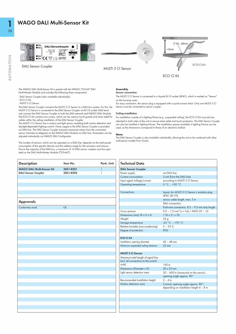
WAGO DALI Multi-Sensor Kit
AssemblySensor connectionThe MULTI 3 CI Sensor is connected to a 4-pole RJ-10 socket (4P4C), which is marked as “Sensor” on the housing cover. For easy connection, the sensor plug is equipped with a quick-connect latch. Only one MULTI 3 CI Sensor must be connected to sensor coupler.
Ceiling installationFor installation outside of a lighting fixture (e.g., suspended ceiling), the ECO CI Kit must also be attached to both sides of the unit to ensure strain relief and touch protection. The DALI Sensor Coupler can also be installed in lighting fixtures. The installation spaces available in lighting fixtures can be used, as the dimensions correspond to those of an electronic ballast.
Note:The DALI Sensor Coupler is also available individually, allowing the unit to be combined with other multi-sensor models from Osram.
Description Item No. Pack. Unit
WAGO DALI Multi-Sensor Kit 2851-8201 1DALI Sensor Coupler 2851-8202 1
ApprovalsConformity mark 1
The WAGO DALI Multi-Sensor Kit is paired with the WAGO 753-647 DALI Multi-Master Module and includes the following three components:- DALI Sensor Coupler (also available individually)- ECO CI Kit- MULTI 3 CI SensorThe DALI Sensor Coupler connects the MULTI 3 CI Sensor to a DALI bus system. For this, the MULTI 3 CI Sensor is connected to the DALI Sensor Coupler via RJ-10 socket. DALI termi-nals connect the DALI Sensor Coupler to both the DALI network and WAGO DALI Module. The ECO CI Kit contains two covers, which can be used as touch guards and strain relief for cables within the ceiling installation of the DALI Sensor Coupler. The MULTI 3 CI Sensor has a motion and light sensor, enabling both motion detection and daylight-dependent lighting control. Power supply to the DALI Sensor Coupler is provided via DALI line. The DALI Sensor Coupler transmits measured values from the connected sensor channels as telegrams to the WAGO DALI Module via DALI line. Parameters can be adjusted individually via WAGO DALI Configurator.
The number of sensors, which can be operated on a DALI line, depends on the total power consumption of the specific devices and the address range for the actuators and sensors. Due to the capacity of the DALI bus, a maximum of 16 DALI sensor couplers must be oper-ated on the DALI Multi-Master Module (753-647).
MULTI 3 CI Sensor
ECO CI Kit
DALI Sensor Coupler
Technical DataDALI Sensor CouplerPower supply via DALI lineCurrent consumption 5 mA (from the DALI line)Input signal voltage/current: according to MULTI 3 CI SensorOperating temperature 0 °C ... +50 °C
Connections Inputs: for MULTI 3 CI Sensor’s modular plug 4P4C (RJ-10), sensor cable length, max. 5 mDALI connection: Push-wire connectors, 8.5 – 9.5 mm strip length
Cross sections 0.5 – 1.5 mm² (s + f-st) / AWG 20 – 16Dimensions (mm) W x H x D 118 x 21 x 30Weight 35 gStorage temperature -25 °C ... +70 °CRelative humidity (non-condensing) 5 – 93 %Degree of protection IP20
ECO CI KitInstallation opening diameter 42 – 48 mmMinimum suspended ceiling distance 25 mm
MULTI 3 CI SensorMaximum total length of signal line (incl. all connections to the control units) 100 mDimensions (Diameter x H) 50 x 25 mmLight sensor detection area 20 – 600 lx (measured on the sensor),
opening angle approx. 90°Recommended installation height 2 – 4 mMotion detection area Conical, opening angle approx. 80°,
depending on installation height 4 – 8 m
158
AU
TOM
ATI
ON

159
AU
TOM
ATI
ON

750-663/000-003
160
AU
TOM
ATI
ON
Intrinsically Safe, 4-Channel Digital Input Module with Inputs for Functional Safety, PROFIsafe V2 iPar
13 14
750-663/
15 16
000-003
ABCD
EFGH
IKLM
NOPQ
I1
I2
I3
I4
T1
T2
T1
T2
Data contacts
Diagnostic LEDs
Status LEDsInputs
Pulse output 1Input 1
Pulse output 2Input 2
Pulse output 1Input 3
Pulse output 2Input 4
Power jumpercontacts
The intrinsically safe 750-663/000-003 PROFIsafe Input Module for functional safety provides risk reductions up to SIL 3, Cat. 4, PL e, and connects to potential-free, contact-based emergency stop switches, safety door switches, mode selectors, as well as safety sensors, that are located hazardous environments 0, 1 and 2. The fail-safe input module must be located in Zone 2.The input module has 4 clock sensitive inputs (I1 ... I4) that are fed by 2 differently clocked, short-circuit proof outputs (T1 ... T2). Inputs are continually monitored for cross circuits and voltage supply from separate sources.Additional safety-relevant functions (e.g., operating modes, switching off test pulses, discrepancy or filter times) can be configured via WAGO-I/O-CHECK. This configuration tool supports both CC2 and CC3 tool calling interfaces (TCI). When exchanging the module, parameters are automatically downloaded by the controller via PROFIsafe-compatible iPar server – depending on settings. The module supports both PROFIsafe V1 and V2 (PROFIBUS, PROFINET) protocols.
Individual I/O modules can be arranged in any combination within the fieldbus node's Ex segment.Note 1: The PROFIsafe input module shall only be operated using an Ex i 24VDC power supply (e.g., 750-606, 750-625/000-001)! General information (e.g., installation regulations) on explosion protection is available in the WAGO-I/O-SYSTEM 750 manuals!Note 2: To protect the module against surge voltages (surge protection acc. to IEC 61000-4-5), a filter module (750-626 or 750-624) or an external surge filter must be used before the Ex i 24VDC power supply.Reference the product manual for further information!
Description Item No. Pack. Unit
4F Ex i DI 24V PROFIsafe V2 iPar 750-663/000-003 1
Accessories Item No. Pack. Unit
Miniature WSB Quick marking systemplain 248-501 5with marking see Full Line Catalog AUTOMATION
2012/2013
Technical DataInputs:
Sensor inputs I1 ... I4; clock sensitive to T1 ... T2 Type 1 acc. to IEC 61131
Input current (typ.) 3 mAInput frequency (max.) 50 HzInput filter 0 ms ... 200 ms, configurable in stepsClock outputs T1 ... T2Output current (max.) ≤ 5 mAShort-circuit current ≤ 25 mA
General specifications:Voltage supply 5 V system voltage via internal busVoltage via power jumper contacts 24 VDC (provided via Ex i power supply
VO = max. 27.3 V)Isolation (peak value) VM = 375 V system/supplyLine length (max.) 100 m

161
AU
TOM
ATI
ON
T1, I1
0 V
+24 VT2, I2 T1
T1, I3
T2, I4
I1
T2
I4
750-663/000-003
9 13
10 14
11 15
12 16
Technical DataWire connection CAGE CLAMP®
Cross sections 0.08 mm² ... 2.5 mm² / AWG 28 ... 14Strip lengths 8 ... 9 mm / 0.33 inWidth 24mmWeight 100 gEMC: 1 - immunity to interference acc. to EN 61000-6-2:2005EMC: 1 - emission of interference acc. to EN 61000-6-3:2007+A1:2011EMC: marine applications - immunity to interference acc. to Germanischer Lloyd (2012)EMC: marine applications - emission of interference acc. to Germanischer Lloyd (2012)
Explosion ProtectionElectric circuit, safety-relevant data V0 = 27.3 V; I0 = 23 mA; P0 = 157 mW;
Characteristic: LinearReactances Ex ia IIC L0 = 61 mH; C0 = 64 nFReactances Ex ia IIB L0 = 100 mH; C0 = 552 nFReactances Ex ia I L0 = 100 mH; C0 = 2.95 μF
(The above-listed ratings do not account for the coincidental occurrence of capacitances and inductances. For ratings taking the coincidental occurrence of capacitances and inductances into account, see manual)
Functional SafetyAchievable risk reduction SIL 3 acc. to IEC 61508:2010;
SIL 3 acc. to IEC 61511:2005; SIL 3 acc. to IEC 62061:2005; Cat. 4, PL e acc. to EN ISO 13849:2008
Standards, Guidelines and ApprovalsEC EMC guideline 2004/108/ECATEX directive 94 / 9 / EG EN 60079-0:2012, EN 60079-11:2012,
EN 60079-15:2010, EN 60079-26:2007, EN 60079-31:2009
Conformity marking 1
Safety standards IEC 61508:2010; IEC 62061:2005; EN ISO 13849:2008; IEC 61511:2005
Shipbuilding GLr UL 508r ANSI/ISA 12.12.01 pending4 TÜV 12 ATEX 106032 X I M2 (M1) Ex d [ia Ma] I Mb
II 3 (1) G Ex nA [ia Ga] IIC T4 Gc II 3 (1) D Ex tc [ia Da] IIIC T135°C Dc
Permissible ambient temperature: 0 °C ≤ TA ≤ +60 °CIECEx TUN 12.0039 X Ex d [ia Ma] I Mb
Ex nA [ia Ga] IIC T4 Gc Ex tc [ia Da] IIIC T135°C Dc
Permissible ambient temperature: 0 °C ≤ TA ≤ +60 °C
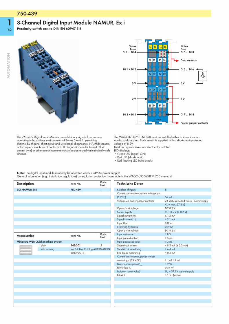
750-439
162
AU
TOM
ATI
ON
8-Channel Digital Input Module NAMUR, Ex iProximity switch acc. to DIN EN 60947-5-6
13 14
0 V
0 V
E3 E4
750-439
15 16
E1 E2 E6
E7 E8
--
A
0 V
0 V
E5
0V 0V 0V0V
0V 0V 0V0V
StatusError
DI 1 ... DI 4
DI 1 + DI 2
DI 3 + DI 4
DI 5 ... DI 6
Data contacts
DI 7 ... DI 8
StatusErrorDI 5 ... DI 8
Power jumper contacts
The 750-439 Digital Input Module records binary signals from sensors operating in hazardous environments of Zones 0 and 1, permitting channel-by-channel short-circuit and wire-break diagnostics. NAMUR sensors, optocouplers, mechanical contacts (LED diagnostics can be turned off via control byte) or other actuating elements can be connected via intrinsically safe devices.
The WAGO-I/O-SYSTEM 750 must be installed either in Zone 2 or in a non-hazardous area. Each sensor is supplied with a short-circuit-protected voltage of 8.2V.Field and system levels are electrically isolated.LED displays:• Green LED (signal ON)• Red LED (short-circuit)• Red flashing LED (wire-break)
Note: The digital input module must only be operated via Ex i 24VDC power supply!General information (e.g., installation regulations) on explosion protection is available in the WAGO-I/O-SYSTEM 750 manuals!
Description Item No. Pack. Unit
8DI NAMUR Ex i 750-439 1
Accessories Item No. Pack. Unit
Miniature WSB Quick marking systemplain 248-501 5with marking see Full Line Catalog AUTOMATION
2012/2013
Technische DatenNumber of inputs 8Current consumption, system voltage typ. (5 VDC) 56 mAVoltage via power jumper contacts 24 VDC (provided via Ex i power supply
VO = max. 27.3 V)Open-circuit voltage DC 8.2 VSensor supply VV = 8.2 V (± 0.2 V)Signal current (0) ≤ 1.2 mASignal current (1) ≥ 2.1 mAInput filter 3.0 msSwitching hysteresis 0.2 mAOpen-circuit voltage DC 8.2 VInput resistance 1 kΩInput pulse duration ≥ 5 msInput pulse separation ≥ 3 msShort-circuit current ≤ 8.2 mA (± 0.2 mA)Short-circuit monitoring > 6.4 mALine break monitoring < 0.3 mACurrent consumption, power jumper contact typ. (24 VDC) 11 mA + loadPower consumption Pmax. 1.2 WPower loss PV 0.54 WIsolation (peak value) UM = 375 V system/supplyBit width 16 bits (status)

163
AU
TOM
ATI
ON
750-439
9
10
11
12
13
14
15
16
1
2
3
4
5
6
7
8
24 V
0 V
24 V
0 V
10 nF 10 nF 330 pF
1k24V
8.2V
DI 1, DI 2
DI 3, DI 4
0 V
DI 7, DI 8
0 V
0 V 0 V
DI 5, DI 6
Logic
DI
Status
Error
Technical DataWire connection CAGE CLAMP®
Cross sections 0.08 mm² ... 2.5 mm² / AWG 28 ... 14Strip lengths 8 ... 9 mm / 0.33 inWidth 24mmWeight 97.8 gEMC: 1 - immunity to interference acc. to EN 61000-6-2.2005EMC: 1 - emission of interference acc. to EN 61000-6-3:2007+A1:2011EMC: marine applications - immunity to interference acc. to Germanischer Lloyd (2012)EMC: marine applications - emission of interference acc. to Germanischer Lloyd (2012)
Explosion ProtectionATEX directive 94 / 9 / EG EN 60079-0:2012, EN 60079-11:2012,
EN 60079-15:2010, EN 60079-26:2007, EN 60079-31:2009
Electric circuit, safety-relevant data V0 = 11.76 V; I0 = 12.4 mA; P0 = 36.67 mW; Characteristic: Linear
Reactances Ex ia IIC L0 = 100 mH; C0 = 1 μFReactances Ex ia IIB L0 = 100 mH; C0 = 9.9 μFReactances Ex ia I L0 = 100 mH; C0 = 30 μFReactances (The above-listed ratings do not account for
the coincidental occurrence of capacitances and inductances. For ratings taking the coincidental occurrence of capacitances and inductances into account, see manual)
Standards, Guidelines and ApprovalsEC EMC guideline 2004/108/ECConformity marking 1
Shipbuilding GLr UL 508r ANSI/ISA 12.12.01 pending4 TÜV 12 ATEX 106032 X I M2 (M1) Ex d [ia Ma] I Mb,
II 3 (1) G Ex nA [ia Ga] IIC T4 Gc, II 3 (1) D Ex tc [ia Da] IIIC T135°C Dc
Permissible ambient temperature: 0 °C ≤ TA ≤ +60 °CIECEx TUN 12.0039 X Ex d [ia Ma] I Mb,
Ex nA [ia Ga] IIC T4 Gc, Ex tc [ia Da] IIIC T135°C Dc
Permissible ambient temperature: 0 °C ≤ TA ≤ +60 °C

750-538
164
AU
TOM
ATI
ON
2-Channel Relay Output Module 100 V AC, 30 V DC, Ex iIsolated outputs; 2 changeover contacts
14 24
11 21
12 22
13 14
750-538
DO 2
L 2
Data contacts
DO 2_____
Status relay 1
DO 1
L 1
DO 1_____
Status relay 2
Power jumper contact
The digital output module switches intrinsically safe circuits of Zone 0+1 (e.g., magnetic valves, contactors, optical/acoustic encoders).The internal system voltage triggers the relay.Both maximum switching current and voltage must comply with EN 60079-11.The switched status of the relays is shown by an LED.The NO contacts are electrically isolated.The WAGO-I/O-SYSTEM 750 must be installed either in Zone 2 or in a non-hazardous area.
Note: The digital output module must only be operated via Ex i 24VDC power supply!General information (e.g., installation regulations) on explosion protection is available in the WAGO-I/O-SYSTEM 750 manuals!
Description Item No. Pack. Unit
2DO RELAY Ex i 750-538 1
Accessories Item No. Pack. Unit
Miniature WSB Quick marking systemplain 248-501 5with marking see Full Line Catalog AUTOMATION
2012/2013
Technische DatenNo. of outputs 2 changeover contactsCurrent consumption, system voltage typ. (5 VDC) 26 mAVoltage via power jumper contacts 24 VDC (provided via Ex i power supply
VO = max. 27.3 V)Type of load resistive, inductive, lampsMax. switching frequency 20/minMax. switching voltage 100 V AC / 30 V DCMax. switching current 0.5 A AC / 1 A DCMin. switching current 0.01 mA / 10 mV DCSwitching power 50 VA / 30 WPull-in time (max.) 4 msDrop-out time (max.) 4 msContact material Silver alloy, gold-platedMechanical life (min.) 1 x 10⁸ switching operationsElectrical life (min.) 1 x 10⁵ (0.5 A / 100 V AC)
2 x 10⁵ (1 A / 30 V DC)Isolation VM = 375 V system/supplyPower consumption Pmax. 0.8 WPower loss PV 0.8 WBit width 2 bits (status)

165
AU
TOM
ATI
ON
———
14
12
11
24
21
220 V
24 V
750-538
10 nF
10 nF
24 V
0 V
L
Status
DO
DO
Technical DataWire connection CAGE CLAMP®
Cross sections 0.08 mm² ... 2.5 mm² / AWG 28 ... 14Strip lengths 8 ... 9 mm / 0.33 inWidth 12mmWeight 51 gEMC: 1 - immunity to interference acc. to EN 61000-6-2.2005EMC: 1 - emission of interference acc. to EN 61000-6-3:2007+A1:2011EMC: marine applications - immunity to interference acc. to Germanischer Lloyd (2012)EMC: marine applications - emission of interference acc. to Germanischer Lloyd (2012)
Explosion ProtectionATEX directive 94 / 9 / EG EN 60079-0:2012, EN 60079-11:2012,
EN 60079-15:2010, EN 60079-26:2007, EN 60079-31:2009
Electric circuit, safety-relevant data Relay output: Vi = 30 V DC; Ii = 1 A; Pi = 30 W; Vi = 100 V AC; Ii = 0.5 A; Pi = 50 VA; Li = negligible; Ci = negligible
Both maximum switching current and voltage must comply with EN 60079-11
Standards, Guidelines and ApprovalsEC EMC guideline 2004/108/ECConformity marking 1
Shipbuilding GLr UL 508r ANSI/ISA 12.12.01 pending4 TÜV 12 ATEX 106032 X I M2 (M1) Ex d [ia Ma] I Mb,
II 3 (1) G Ex nA [ia Ga] IIC T4 Gc, II 3 (1) D Ex tc [ia Da] IIIC T135°C Dc
Permissible ambient temperature: 0 °C ≤ TA ≤ +60 °CIECEx TUN 12.0039 X Ex d [ia Ma] I Mb,
Ex nA [ia Ga] IIC T4 Gc, Ex tc [ia Da] IIIC T135°C Dc
Permissible ambient temperature: 0 °C ≤ TA ≤ +60 °C

750-586
166
AU
TOM
ATI
ON
2-Channel Analog Output Module 4-20 mA, Ex i
AO 2
Data contacts
0 V
Shield (screen)
Function AO 1
AO 1
Shield (screen)
Function AO 2
Power jumper contacts
13 14
— —
A1 A2
S S
750-586
15 16
The analog output module transmits intrinsically safe 4-20mA signals in the hazardous Zone 0+1.The WAGO-I/O-SYSTEM 750 must be installed either in Zone 2 or in a non-hazardous area.Power is derived from the power jumper contacts.The outputs are short-circuit proof.
LED indicators:• Green LED (output status)
An optocoupler provides electrical isolation between the bus and the field side.
Note:
Only use the analog output module in connection with the 24VDC Ex i Supply Module (note the power supply instructions)!
General information (e.g., installation regulations) on explosion protection is available in the WAGO-I/O-SYSTEM 750 manuals!
Description Item No. Pack. Unit
2AO 4-20 mA Ex i 750-586 1
Accessories Item No. Pack. Unit
Miniature WSB Quick marking systemplain 248-501 5with marking see Full Line Catalog AUTOMATION
2012/2013
Technische DatenNo. of outputs 2Current consumption, system voltage typ. (5 VDC) 21 mAVoltage via power jumper contacts 24 VDC (provided via Ex i power supply
VO = max. 27.3 V)Signal current 4 mA ... 20 mALoad impedance < 500 ΩLinearity ± 2 LSBResolution 12 bitsConversion time < 2 msOutput error 25 °C < ± 0.2 % of the full scale valueTemperature coefficient < ± 0.01 % / K of the full scale valueCurrent consumption, power jumper contact typ. (24 VDC) 19 mA + load (2 x 20 mA)Power consumption Pmax. 1.5 WPower loss PV 0.9 WIsolation 375 V system/supplyBit width 2 x 16 bits data
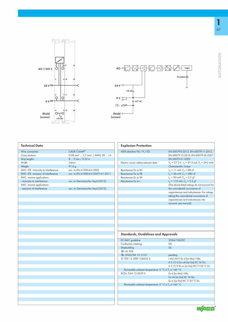
167
AU
TOM
ATI
ON
750-586
1
2
3
4
5
6
7
8
U
10 nF
ID
A9
10
11
12
13
14
15
16
AO 1/AO 2 AO
4.7 nF
24 V
Function
0 V0 V
24 V
Logic
Shield(screen)
Shield(screen)
Technical DataWire connection CAGE CLAMP®
Cross sections 0.08 mm² ... 2.5 mm² / AWG 28 ... 14Strip lengths 8 ... 9 mm / 0.33 inWidth 24mmWeight 91.6 gEMC: 1 - immunity to interference acc. to EN 61000-6-2.2005EMC: 1 - emission of interference acc. to EN 61000-6-3:2007+A1:2011EMC: marine applications - immunity to interference acc. to Germanischer Lloyd (2012)EMC: marine applications - emission of interference acc. to Germanischer Lloyd (2012)
Explosion ProtectionATEX directive 94 / 9 / EG EN 60079-0:2012, EN 60079-11:2012,
EN 60079-15:2010, EN 60079-26:2007, EN 60079-31:2009
Electric circuit, safety-relevant data V0 = 27.3 V ; I0 = 57.5 mA; P0 = 392 mW; Characteristic: Linear
Reactances Ex ia IIC L0 = 11 mH; C0 = 88 nFReactances Ex ia IIB L0 = 56 mH; C0 = 680 nFReactances Ex ia IIA L0 = 90 mH; C0 = 2.2 μFReactances Ex ia I L0 = 110 mH; C0 = 3.5 μF
(The above-listed ratings do not account for the coincidental occurrence of capacitances and inductances. For ratings taking the coincidental occurrence of capacitances and inductances into account, see manual)
Standards, Guidelines and ApprovalsEC EMC guideline 2004/108/ECConformity marking 1
Shipbuilding GLr UL 508 r ANSI/ISA 12.12.01 pending4 TÜV 12 ATEX 106032 X I M2 (M1) Ex d [ia Ma] I Mb,
II 3 (1) G Ex nA [ia Ga] IIC T4 Gc, II 3 (1) D Ex tc [ia Da] IIIC T135°C Dc
Permissible ambient temperature: 0 °C ≤ TA ≤ +60 °CIECEx TUN 12.0039 X Ex d [ia Ma] I Mb,
Ex nA [ia Ga] IIC T4 Gc, Ex tc [ia Da] IIIC T135°C Dc
Permissible ambient temperature: 0 °C ≤ TA ≤ +60 °C

The WAGO-I/O-SYSTEM 750 XTR is easily recognizable by its dark-gray modules. Benefit from the unique added value (e.g., no extra air-conditioning components) provided by this system in extreme environment applications:
• Lower space requirements• Lower purchase costs• Lower energy costs• Lower maintenance costs• Safe investment• Maximum system availability• Greater productivity
The WAGO-I/O-SYSTEM 750 XTR features outstanding characteristics: It is extremely weather-resistant, immune to interferences, vibration-proof and has a high impulse-voltage withstand. This is what makes 750 XTR the first choice for demanding applications:
• Shipbuilding and onshore/offshore industry
• Renewable energy systems (wind po-wer, photovoltaic and biogas plants)
• Secondary substations and power distribution systems
• Petrochemical industry• Water and wastewater industry• Custom machine engineering
THE STANDARD FOR 750 XTR
TAKING IT TO THE EXTREME –
168
AU
TOM
ATI
ON

DIN EN 60870-2-1 DIN EN 60068-2-6
eXTReme vibration up to 5g acceleration
eXTReme insulationup to 5 kV impulse voltage
eXTReme temperature from -40 °C to +70 °C
Great reliability in extreme climates The XTR variant of the WAGO-I/O-SYSTEM 750 remains unaffected by both freezing cold down to -40 °C and scorching heat up to +70 °C. And this applies equally for both start-up and ongoing operation.
The maximum approved operating altitude of 5,000 m is another highlight. Even in the rarefied air of a top station, the system impressively demonstrates its high performance and availability.
Additional protection against interference pulses The WAGO-I/O-SYSTEM 750 XTR provides higher impulse-voltage withstand up to 5 kV, lower EMC emission of interference and higher insensitivity against EMC interference. This guarantees a trouble-free operati-on.
High mechanical performanceThe WAGO-I/O-SYSTEM 750 XTR is also setting new standards here: With 5g vibration resistance per DIN EN 60068-2-6 (acceleration: 50 m/s2), 15g (150 m/s2) shock resistance or 25g (250 m/s2) continuous shock resistance per IEC 60068-2-27, the system can really take a lot.
169
AU
TOM
ATI
ON

750-880/040-000, 750-880/040-001
170
AU
TOM
ATI
ON
PLC - ETHERNET Programmable Fieldbus Controllerfor eXTReme environmental conditions; 32-bit CPU, multitasking
X1
1
8
ON
0: WBM255: DHCP
X2
I/O
NS
MS
LINKACT 1LINKACT 2
ETHERNET
W75
0-88
0/04
0-00
0
USRSD
12
34
56
78
ON 24V 0V
+ +
— —
ABCD
01 02
Fieldbus connectionRJ-45
Address
Fieldbus connectionRJ-45
Power jumper contactsConfiguration andprogramming interface
Data contacts
Marking area
Supply viapower jumper contacts24 V
Supply24 V0 V
Status voltage supply-System-Power jumper contacts
0 V
In conjunction with the WAGO-I/O-SYSTEM, the ETHERNET PLC is used as a programmable controller within ETHERNET networks. The PLC supports all digital, analog, and specialty modules found within the 750/753 Series, and is suitable for data rates of 10/100 Mbit/s.Two ETHERNET interfaces and an integrated switch enable fieldbus wiring in a line topology. This eliminates additional network devices, such as switches or hubs. Both interfaces support Auto-Negotiation and Auto-MDI(X). The DIP switch configures the last byte of the IP address and may be used for IP address assignment.The PLC supports both MODBUS/TCP and ETHERNET/IP for use in industrial environments. It also supports a wide variety of standard ETHERNET protocols for easy integration into IT environments (e.g., HTTP, BootP, DHCP, DNS, SNTP, SNMP, FTP). For telecontrol applications, the 750-880/040-001 Controller supports the IEC 60870-5-101/-103-104, IEC 61850-7 and IEC 61400-25 communication protocols.
An integrated Web server provides the user with configuration options and status information from the controller.The IEC 61131-3 programmable controller is multitasking-capable and features a battery-backed RTC. A data memory of 1 MB is available.The 750-880 PLC has a slot for a removable memory card, allowing device parameters or files (e.g., boot files) to be transferred from one controller to another. The memory card can be accessed via FTP and be used as an additional drive.
The module is ideally suited for operation in harsh environmental conditions:- strongly extended temperature range - higher dielectric strength and EMC resistance- higher vibration resistance
Description Item No. Pack. Unit
ETHERNET Controller /XTR 750-880/040-000 1ETHERNET Telecontroller /XTR 750-880/040-001 1
Accessories Item No. Pack. Unit
SD memory card, 2 GB 758-879/000-001 1WAGO-I/O-PRO V2.3, RS-232 kit 759-333 1WAGO-I/O-PRO V2.3, USB kit 759-333/000-923 1Miniature WSB Quick marking system
plain 248-501 5with marking see Full Line Catalog AUTOMATION
2012/2013
ApprovalsConformity marking 1
Shipbuilding GLr UL 508 r ANSI/ISA 12.12.01 Class I, Div. 2, Grp. ABCD, T4
Korea Certification
System DataNo. of controllers connected to Master limited by ETHERNET specificationTransmission medium Twisted Pair S-UTP
100 Ω, Cat 5; Max. line length: 100 m
Baud rate 10/100 Mbit/sTransmission performance Class D acc. to EN 50173Buscoupler connection 2 x RJ-45Protocols EtherNet/IP, MODBUS/TCP (UDP), HTTP,
BootP, DHCP, DNS, SNTP, FTP, SNMP750-880/040-001 IEC 60870-5-101/-103/-104, IEC 61850,
IEC 61400-25Programming WAGO-I/O-PROIEC 61131-3 IL, LD, FBD (CFC), ST, FCSD card slot Push-push mechanism, sealable cover lidType of memory card SD and SDHC up to 32 GB (All
guaranteed properties are only valid in connection with the WAGO 758-879/000-001 memory card.)

171
AU
TOM
ATI
ON
1
2
3
4
5
6
7
8
DCDC
24 V
47 nF
24 V
47 nF
0 V
24 V /0 V
24 V
0 V
0 V
750-880/040-000
ELECTRONICS
I/Omodules
FIEL
DBU
S IN
TERF
ACE
ELEC
TRO
NIC
S
FIE
LDBU
SIN
TERF
ACE
Technical DataNumber of I/O modules 64Fieldbus
Max. input process image 1020 wordsMax. output process image 1020 words
Configuration via PCProgram memory 1024 KbytesData memory 1024 KbytesNon-volatile memory (retain) 32 KbytesPower supply via CAGE CLAMP® connections, 24 VDCInput current typ. at rated load (24 V) 500 mAEfficiency of the power supply (typ.) at nominal load (24 V) 90 %Internal current consumption (5 V) 450 mATotal current for I/O modules (5 V) 1700 mA
up to 60°C operating temperature; 1500 mA > 60°C operating temperature
Voltage via power jumper contacts 24 V DCunder laboratory conditions +15°C ... +35°C 18 V ... 31.2 V (17.4 V ... 31.2 V)1)
for -40°C ... +55°C 18 V ... 28.8 V (17.4 V ... 28.8 V)1)
for +55°C ... +70°C 18 V ... 26.4 V (17.4 V ... 26.4 V)1)
1) including residual ripple of 15 %Isolation (peak value) 510 VAC or 775 VDC
power supply/DIN railRated impulse voltage 1 kVOvervoltage category III
General SpecificationsOperating temperature -40 °C ... +70 °CWire connection CAGE CLAMP®
Cross sections 0.25 mm² ... 2.5 mm² / AWG 24 ... 14Strip lengths 8 ... 9 mm / 0.33 inDimensions (mm) W x H x L 62 x 65 x 100
Height from upper-edge of DIN 35 railWeight 164 gStorage temperature -40 °C ... +85 °CRelative humidity 95 %, short-term condensation acc. to class
3K7 / IEC EN 60721-3-3 (except wind-driven precipitation, water and ice formation)
Vibration resistance acc. to IEC 60068-2-6 (acceleration: 5g), EN 60870-2-2, IEC 60721-3-1, -3, EN 61131-2
Shock resistance acc. to IEC 60068-2-27Degree of protection IP20EMC: 1 - immunity to interference acc. to EN 61000-6-1, -2, EN 61131-2,
marine applications, EN 50121-3-2, -4, -5, EN 60255-26, EN 60870-2-1, EN 61850-3, IEC 61000-6-5, IEEE 1613, VDEW: 1994
EMC: 1 - emission of interference acc. to EN 61000-6-3, -4, EN 61131-2, EN 60255-26, marine applications, EN 60870-2-1, EN 61850-3, EN 50121-3-2, -4, -5
Operating altitude without temperature derating: 0 m ... 2000 m; with temperature derating: 2000 m ... 5000 m (0.5 K/100 m); max.: 5000 m
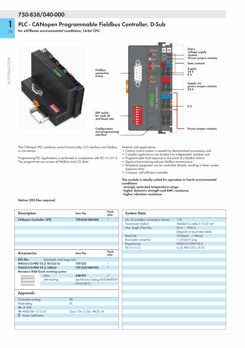
750-838/040-000
172
AU
TOM
ATI
ON
PLC - CANopen Programmable Fieldbus Controller, D-Subfor eXTReme environmental conditions; 16-bit CPU
I/O
750-
838
/040
-000
W
24V 0V
+ +
— —
STOP
RUN
TX
CANopen
RXOVERFLOW
12
34
56
78
ON
USR
ABCD
01 02
Data contacts
FieldbusconnectionD-Sub
Power jumper contacts
0 V
Supply viapower jumper contacts24 V
Supply24 V0 V
Status voltage supply-System-Power jumper contacts
Configurationand programminginterface
DIP switchfor node IDand baud rate
The CANopen PLC combines control functionality, I/O interface and fieldbus in one device.
Programming PLC applications is performed in compliance with IEC 61131-3. The programmer can access all fieldbus and I/O data.
Features and applications:• Central control system is assisted by decentralized processing units• Complex applications are divided into independent, testable units• Programmable fault response in the event of a fieldbus failure• Signal pre-processing reduces fieldbus transmissions• Peripheral equipment can be controlled directly, resulting in faster system
response times• Compact, self-sufficient controller
The module is ideally suited for operation in harsh environmental conditions:- strongly extended temperature range - higher dielectric strength and EMC resistance- higher vibration resistance
Notice: EDS files required
Description Item No. Pack. Unit
CANopen Controller /XTR 750-838/040-000 1
Accessories Item No. Pack. Unit
EDS files Download: www.wago.comWAGO-I/O-PRO V2.3, RS-232 kit 759-333 1WAGO-I/O-PRO V2.3, USB kit 759-333/000-923 1Miniature WSB Quick marking system
plain 248-501 5with marking see Full Line Catalog AUTOMATION
2012/2013
ApprovalsConformity marking 1
Shipbuilding GLr UL 508r ANSI/ISA 12.12.01 Class I, Div. 2, Grp. ABCD, T4
Korea Certification
System DataNo. of controllers connected to Master 110Transmission medium Shielded Cu cable 3 x 0.25 mm²Max. length of bus line 30 m ... 1000 m
(depends on baud rate/cable)Baud rate 10 Kbaud ... 1 MbaudBuscoupler connection 1 x D-Sub 9; plugProgramming WAGO-I/O-PRO V2.3IEC 61131-3 IL, LD, FBD (CFC), ST, FC

173
AU
TOM
ATI
ON
1
2
3
4
5
6
7
8
1) 2)
24 V
24 V
0 V
24 V /0 V
24 V
0 V
0 V
47 nF
47 nF5 V
24 V5 V
2) 10 nF /1 kV1) 2 MΩ
750-838/040-000
ELECTRONICS
I/Omodules
ELEC
TRO
NIC
S
FIEL
DBU
S IN
TERF
ACE
FIELDBUSINTERFACE
Technical DataNumber of I/O modules 64Fieldbus
Max. input process image 512 bytesMax. output process image 512 bytesMax. input variables 512 bytesMax. output variables 512 bytes
Configuration via PC or PLCProgram memory 640 KbytesData memory 832 KbytesNon-volatile memory (retain) 8 KbytesCycle time < 3 ms for 1,000 statements /
256 dig. I/OsNo. of PDOs 32 Tx / 32 RxNo. of SDOs 2 server SDOs / 16 client SDOsCommunication profile DS-301 V4.01Device profile DS-401 V 2.0
Marginal checkEdge-triggered PDOsProgrammable error responseDSP 405using function blocks NMT master can be programmed
COB ID distribution SDO, standardNode ID distribution DIP switchesOther CANopen features NMT slave
Minimum boot-upVariable PDO mappingEmergency messageLife guarding / heartbeatConfiguration of virtual modules
Power supply via CAGE CLAMP® connections, 24 VDCMax. input current (24 V) 500 mAEfficiency of the power supply 90 %Internal current consumption (5 V) 350 mATotal current for I/O modules (5 V) 1650 mA
up to 60°C operating temperature; 1250 mA > 60°C operating temperature
Voltage via power jumper contacts 24 V DCunder laboratory conditions +15°C ... +35°C 18 V ... 31.2 V (17.4 V ... 31.2 V)1)
for -40°C ... +55°C 18 V ... 28.8 V (17.4 V ... 28.8 V)1)
for +55°C ... +70°C 18 V ... 26.4 V (17.4 V ... 26.4 V)1)
1) including residual ripple of 15 %
General SpecificationsCurrent via power jumper contacts (max.) DC10 AIsolation (peak value) 510 VAC or 775 VDC
power supply/DIN railRated impulse voltage 1 kVOvervoltage category IIIOperating temperature -40 °C ... +70 °CWire connection CAGE CLAMP®
Cross sections 0.25 mm² ... 2.5 mm² / AWG 24 ... 14Strip lengths 8 ... 9 mm / 0.33 inDimensions (mm) W x H x L 51 x 65 x 100
Height from upper-edge of DIN 35 railWeight 200 gStorage temperature -40 °C ... +85 °CRelative humidity 95 %, short-term condensation acc. to class
3K7 / IEC EN 60721-3-3 (except wind-driven precipitation, water and ice formation)
Vibration resistance acc. to IEC 60068-2-6 (acceleration: 5g), EN 60870-2-2, IEC 60721-3-1, -3, EN 61131-2
Shock resistance acc. to IEC 60068-2-27Degree of protection IP20EMC: 1 - immunity to interference acc. to EN 61000-6-1, -2, EN 61131-2,
marine applications, EN 50121-3-2, -4, -5, EN 60255-26
EMC: 1 - emission of interference acc. to EN 61000-6-3, -4, EN 61131-2, EN 60255-26, marine applications, EN 60870-2-1, EN 61850-3, EN 50121-3-2, -4, -5
Operating altitude without temperature derating: 0 m ... 2000 m; with temperature derating: 2000 m ... 5000 m (0.5 K/100 m); max.: 5000 m
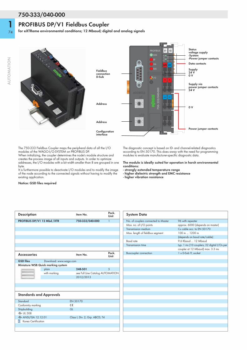
750-333/040-000
174
AU
TOM
ATI
ON
PROFIBUS DP/V1 Fieldbus Couplerfor eXTReme environmental conditions; 12 Mbaud; digital and analog signals
RUN
BF
DIA
I/O
PROFIBUS
x1012345678
9
x10012345678
9
ADDRESS
BUS
750-
333
/040
-000
W
24V 0V
+ +
— —
01 02ABCD
Data contacts
FieldbusconnectionD-Sub
Address
Power jumper contacts
0 V
Supply viapower jumper contacts24 V
Supply24 V0 V
Status voltage supply-System-Power jumper contacts
Address
Configurationinterface
The 750-333 Fieldbus Coupler maps the peripheral data of all the I/O modules of the WAGO-I/O-SYSTEM on PROFIBUS DP.When initializing, the coupler determines the node's module structure and creates the process image of all inputs and outputs. In order to optimize addresses, the I/O modules with a bit width smaller than 8 are grouped in one byte.It is furthermore possible to deactivate I/O modules and to modify the image of the node according to the connected signals without having to modify the existing application.
The diagnostic concept is based on ID- and channel-related diagnostics according to EN 50170. This does away with the need for programming modules to evaluate manufacturer-specific diagnostic data.
The module is ideally suited for operation in harsh environmental conditions:- strongly extended temperature range - higher dielectric strength and EMC resistance- higher vibration resistance
Notice: GSD files required
Description Item No. Pack. Unit
PROFIBUS DP/V1 12 Mbd /XTR 750-333/040-000 1
Accessories Item No. Pack. Unit
GSD files Download: www.wago.comMiniature WSB Quick marking system
plain 248-501 5with marking see Full Line Catalog AUTOMATION
2012/2013
Standards and ApprovalsStandard EN 50170Conformity marking 1
Shipbuilding GLr UL 508 r ANSI/ISA 12.12.01 Class I, Div. 2, Grp. ABCD, T4
Korea Certification
System DataNo. of couplers connected to Master 96 with repeaterMax. no. of I/O points approx. 6000 (depends on master)Transmission medium Cu cable acc. to EN 50170Max. length of fieldbus segment 100 m ... 1200 m
(depends on baud rate/cable)Baud rate 9.6 Kbaud ... 12 MbaudTransmission time typ. 1 ms (10 couplers; 32 digital I/Os per
coupler at 12 Mbaud) max. 3.3 msBuscoupler connection 1 x D-Sub 9; socket

175
AU
TOM
ATI
ON
1
2
3
4
5
6
7
8
750-333/040-000
24 V
47 nF
24 V
47 nF
0 V
24 V /0 V
24 V
0 V
0 V5 V
5 V24 V
ELECTRONICS
I/Omodules
FIELDBUSINTERFACE
ELEC
TRO
NIC
S
FIEL
DBU
SIN
TERF
ACE
Technical DataNumber of I/O modules 63Fieldbus
Max. input process image 244 bytesMax. output process image 244 bytes
Configuration via PC or PLCPower supply via CAGE CLAMP® connections, 24 VDCMax. input current (24 V) 500 mAEfficiency of the power supply 90 %Internal current consumption (5 V) 200 mATotal current for I/O modules (5 V) 1800 mAVoltage via power jumper contacts 24 V DC
under laboratory conditions +15°C ... +35°C 18 V ... 31.2 V (17.4 V ... 31.2 V)1)
for -40°C ... +55°C 18 V ... 28.8 V (17.4 V ... 28.8 V)1)
for +55°C ... +70°C 18 V ... 26.4 V (17.4 V ... 26.4 V)1)
1) including residual ripple of 15 %Current via power jumper contacts (max.) DC10 AIsolation (peak value) 510 VAC or 775 VDC
power supply/DIN railRated impulse voltage 1 kVOvervoltage category III
General SpecificationsOperating temperature -40 °C ... +70 °CWire connection CAGE CLAMP®
Cross sections 0.25 mm² ... 2.5 mm² / AWG 24 ... 14Strip lengths 8 ... 9 mm / 0.33 inDimensions (mm) W x H x L 51 x 65 x 100
Height from upper-edge of DIN 35 railWeight 182 gStorage temperature -40 °C ... +85 °CRelative humidity 95 %, short-term condensation acc. to class
3K7 / IEC EN 60721-3-3 (except wind-driven precipitation, water and ice formation)
Vibration resistance acc. to IEC 60068-2-6 (acceleration: 5g), EN 60870-2-2, IEC 60721-3-1, -3, EN 61131-2
Shock resistance acc. to IEC 60068-2-27Degree of protection IP20EMC: 1 - immunity to interference acc. to EN 61000-6-2, EN 61131-2,
marine applications, EN 50121-3-2, -4, -5, EN 60255-26, EN 60870-2-1, EN 61850-3, IEC 61000-6-5, IEEE 1613, VDEW: 1994
EMC: 1 - emission of interference acc. to EN 61000-6-4, EN 61131-2, EN 60255-26, marine applications, EN 60870-2-1, EN 61850-3, EN 50121-3-2, -4, -5
Operating altitude without temperature derating: 0 m ... 2000 m; with temperature derating: 2000 m ... 5000 m (0.5 K/100 m); max.: 5000 m

750-352/040-000
176
AU
TOM
ATI
ON
ETHERNET Fieldbus Couplerfor eXTReme environmental conditions; 10/100 Mbit/s; digital and analog signals
24VX3
X1
1
8
ON
0: WBM255: DHCP
X2
0V
I/O
NS
MS
LINKACT 1LINKACT 2
ETHERNET
W75
0-35
2/04
0-00
0
12
34
56
78
ON
Fieldbus connectionRJ-45
Address
Supply24 V0 V
Fieldbus connectionRJ-45 Configuration and
programming interface
Data contacts
Marking area
Status indication-Fieldbus-Fieldbus node
The 750-352 ETHERNET Fieldbus Coupler connects ETHERNET to the modular WAGO-I/O-SYSTEM.The fieldbus coupler automatically configures, creating a local process image which may include analog, digital or specialty modules. Analog and specialty module data is sent via words and/or bytes; digital data is sent bit by bit.Two ETHERNET interfaces and an integrated switch allow the fieldbus to be wired in a line topology. This eliminates the need for additional network devices, such as switches or hubs. Both interfaces support Auto-Negotiation and Auto-MDI(X).The DIP switch configures the last byte of the IP address and may be used for IP address assignment (DHCP, BootP, static).The coupler is designed for fieldbus communication in both EtherNet/IP and MODBUS networks. It also supports a wide variety of standard ETHERNET protocols (e.g., HTTP, BootP, DHCP, DNS, SNMP, FTP). An integrated Web server provides configuration options and status information from the coupler.The coupler has an integrated supply terminal for the system voltage. The field power jumper contacts are supplied via a separate supply module.
The module is ideally suited for operation in harsh environmental conditions:- strongly extended temperature range - higher dielectric strength and EMC resistance- higher vibration resistance
Description Item No. Pack. Unit
ETHERNET Fieldbus Coupler /XTR 750-352/040-000 1
Accessories Item No. Pack. Unit
Miniature WSB Quick marking systemplain 248-501 5with marking see Full Line Catalog AUTOMATION
2012/2013
ApprovalsConformity marking 1
Shipbuilding GLr UL 508 r ANSI/ISA 12.12.01 Class I, Div. 2, Grp. ABCD, T4
Korea Certification
System DataNo. of couplers connected to Master limited by ETHERNET specificationTransmission medium Twisted Pair S-UTP
100 Ω, Cat 5; Max. line length: 100 m
Baud rate 10/100 Mbit/sTransmission performance Class D acc. to EN 50173Buscoupler connection 2 x RJ-45Protocols EtherNet/IP, MODBUS/TCP (UDP), HTTP,
BootP, DHCP, DNS, FTP, SNMP

177
AU
TOM
ATI
ON
DCDC
24 V
47 nF
47 nF
24 V
0 V
0 V
750-352/040-000
ELECTRONICS
I/Omodules
FIEL
DBU
S IN
TERF
ACE
ELEC
TRO
NIC
S
FIE
LDBU
SIN
TERF
ACE
Technical DataNumber of I/O modules 64
with bus extension 250Fieldbus
Max. input process image 1020 wordsMax. output process image 1020 words
Configuration via PCPower supply via CAGE CLAMP® connections, 24 VDCInput current typ. at rated load (24 V) 280 mAEfficiency of the power supply (typ.) at nominal load (24 V) 90 %Internal current consumption (5 V) 450 mATotal current for I/O modules (5 V) 700 mAVoltage via power jumper contacts 24 V DC
under laboratory conditions +15°C ... +35°C 18 V ... 31.2 V (17.4 V ... 31.2 V)1)
for -40°C ... +55°C 18 V ... 28.8 V (17.4 V ... 28.8 V)1)
for +55°C ... +70°C 18 V ... 26.4 V (17.4 V ... 26.4 V)1)
1) including residual ripple of 15 %Isolation (peak value) 510 VAC or 775 VDC
power supply/DIN railRated impulse voltage 1 kVOvervoltage category III
General SpecificationsOperating temperature -40 °C ... +70 °CWire connection CAGE CLAMP®
Cross sections 0.25 mm² ... 1.5 mm² / AWG 24 ... 14Strip lengths 5 ... 6 mm / 0.22 inDimensions (mm) W x H x L 50 x 65 x 97
Height from upper-edge of DIN 35 railWeight 80.6 gStorage temperature -40 °C ... +85 °CRelative humidity 95 %, short-term condensation acc. to class
3K7 / IEC EN 60721-3-3 (except wind-driven precipitation, water and ice formation)
Vibration resistance acc. to IEC 60068-2-6 (acceleration: 5g), EN 60870-2-2, IEC 60721-3-1, -3, EN 61131-2
Shock resistance acc. to IEC 60068-2-27Degree of protection IP20EMC: 1 - immunity to interference acc. to EN 61000-6-1, -2, EN 61131-2,
marine applications, EN 50121-3-2, -4, -5, EN 60255-26, EN 60870-2-1, EN 61850-3, IEC 61000-6-5, IEEE 1613, VDEW: 1994
EMC: 1 - emission of interference acc. to EN 61000-6-3, -4, EN 61131-2, EN 60255-26, marine applications, EN 60870-2-1, EN 61850-3, EN 50121-3-2, -4, -5
Operating altitude without temperature derating: 0 m ... 2000 m; with temperature derating: 2000 m ... 5000 m (0.5 K/100 m); max.: 5000 m

750-338/040-000
178
AU
TOM
ATI
ON
CANopen Fieldbus Coupler D-Subfor eXTReme environmental conditions; 10 kbaud ... 1 Mbaud; digital and analog signals
I/O
750-
338
/040
-000
W
24V 0V
+ +
— —
STOP
RUN
TX
CANopen
RXOVERFLOW
12
34
56
78
ON
ABCD
01 02
Data contacts
FieldbusconnectionD-Sub
Power jumper contacts
0 V
Supply viapower jumper contacts24 V
Supply24 V0 V
Status voltage supply-System-Power jumper contacts
DIP switchfor node IDand baud rate
Configurationinterface
The 750-338/040-000 Fieldbus Coupler connects the WAGO-I/O-SYSTEM as a slave to the CANopen fieldbus. Data is transmitted via PDOs and SDOs.The fieldbus coupler automatically configures, creating a local process image which may include analog, digital or specialty modules. Analog and specialty module data is sent via words and/or bytes, digital data is sent bit by bit.The local process image is divided into two data zones containing the data received and the data to be sent. The process data can be sent via the CANopen bus to a control system for further processing. The process output data can be sent via the CANopen bus.The data of the analog modules is stored in the PDOs according to the order in which the modules are connected to the coupler. The bits of the digital modules are sent byte by byte and also mapped in the PDOs. If the amount of digital information exceeds 8 bits, the buscoupler automatically starts with a new byte.All entries of the object directory can be mapped as required in the 32 Rx PDOs and 32 Tx PDOs. The complete input and output process image can be transmitted via SDOs.Spacer modules can be set via software.
The module is ideally suited for operation in harsh environmental conditions:- strongly extended temperature range - higher dielectric strength and EMC resistance- higher vibration resistance
Description Item No. Pack. Unit
CANopen D-Sub /XTR 750-338/040-000 1
Accessories Item No. Pack. Unit
EDS files Download: www.wago.comMiniature WSB Quick marking system
plain 248-501 5with marking see Full Line Catalog AUTOMATION
2012/2013
ApprovalsConformity marking 1
Shipbuilding GLr UL 508 r ANSI/ISA 12.12.01 Class I, Div. 2, Grp. ABCD, T4
Korea Certification
System DataNo. of couplers connected to Master 110Transmission medium Shielded Cu cable 3 x 0.25 mm²Max. length of bus line 30 m ... 1000 m
(depends on baud rate/cable)Baud rate 10 Kbaud ... 1 MbaudBuscoupler connection 1 x D-Sub 9; plug

179
AU
TOM
ATI
ON
1
2
3
4
5
6
7
8
1) 2)
24 V
24 V
0 V
24 V /0 V
24 V
0 V
0 V
47 nF
47 nF5 V
5 V24 V
2) 10 nF /1 kV1) 2 MΩ
750-338/040-000
ELECTRONICS
I/Omodules
FIELDBUSINTERFACE
ELEC
TRO
NIC
S
FIEL
DBU
SIN
TERF
ACE
Technical DataNumber of I/O modules 64Fieldbus
Max. input process image 512 bytesMax. output process image 512 bytes
Configuration via PC or PLCNo. of PDOs 32 Tx / 32 RxNo. of SDOs 2 server SDOsCommunication profile DS-301 V4.1Device profile DS 401 V2.0
Marginal check Edge-triggered PDOsProgrammable error response
COB ID distribution SDO, standardNode ID distribution DIP switchesOther CANopen features NMT slave
Minimum boot-upVariable PDO mappingEmergency messageLife guardingConfiguration of virtual modules
Power supply via CAGE CLAMP® connections, 24 VDCMax. input current (24 V) 500 mAEfficiency of the power supply 90 %Internal current consumption (5 V) 350 mATotal current for I/O modules (5 V) 1650 mAVoltage via power jumper contacts 24 V DC
under laboratory conditions +15°C ... +35°C 18 V ... 31.2 V (17.4 V ... 31.2 V)1)
for -40°C ... +55°C 18 V ... 28.8 V (17.4 V ... 28.8 V)1)
for +55°C ... +70°C 18 V ... 26.4 V (17.4 V ... 26.4 V)1)
1) including residual ripple of 15 %Current via power jumper contacts (max.) 10 ADCIsolation (peak value) 510 VAC or 775 VDC
power supply/DIN railRated impulse voltage 1 kVOvervoltage category III
General SpecificationsOperating temperature -40 °C ... +70 °CWire connection CAGE CLAMP®
Cross sections 0.25 mm² ... 2.5 mm² / AWG 24 ... 14Strip lengths 8 ... 9 mm / 0.33 inDimensions (mm) W x H x L 51 x 65 x 100
Height from upper-edge of DIN 35 railWeight 200 gStorage temperature -40 °C ... +85 °CRelative humidity 95 %, short-term condensation acc. to class
3K7 / IEC EN 60721-3-3 (except wind-driven precipitation, water and ice formation)
Vibration resistance acc. to IEC 60068-2-6 (acceleration: 5g), EN 60870-2-2, IEC 60721-3-1, -3, EN 61131-2
Shock resistance acc. to IEC 60068-2-27Degree of protection IP20EMC: 1 - immunity to interference acc. to EN 61000-6-1, -2, EN 61131-2,
marine applications, EN 50121-3-2, -4, -5, EN 60255-26
EMC: 1 - emission of interference acc. to EN 61000-6-3, -4, EN 61131-2, EN 60255-26, marine applications, EN 60870-2-1, EN 61850-3, EN 50121-3-2, -4, -5
Operating altitude without temperature derating: 0 m ... 2000 m; with temperature derating: 2000 m ... 5000 m (0.5 K/100 m); max.: 5000 m

750-1415/040-000
180
AU
TOM
ATI
ON
8-Channel Digital Input Module 24 VDCfor eXTReme environmental conditions; high-side switching, 2-wire connection
1
1 9
2 10
3 11
4 12
5 13
6 14
7 15
8 16
2345678
750-1415/040-000
13 14
24 VCAGE CLAMP®Sconnection
DI 1 … DI 8
Data contacts
Power jumper contacts
StatusDI 1 ... DI 8
1
2
3
4
5
6
7
8
13
12
11
10
9
14
15
16
750-1415/040-000
10nF
10nF 10nF
DI 1
DI 2
DI 3
DI 4
DI 5
DI 6
DI 7
DI 8
0 V
+ 24 V
24 V
24 V
24 V
24 V
24 V
24 V
24 V
24 V
DI
0 V
+ 24 V
DI
This 2-wire digital input module provides 8 channels at a width of just 12 mm.It receives binary control signals from digital field devices (e.g., sensors, encoders, switches or proximity switches).The module features CAGE CLAMP® S connections providing push-in termination of solid conductors.Each input channel has a noise-rejection RC filter with 3.0 ms time constant.A green LED indicates the switched status of each channel.Field and system levels are electrically isolated.
An operating tool with a 2.5 mm blade (210-719) is required to open the CAGE CLAMP® S connections.
The module is ideally suited for operation in harsh environmental conditions:- extended temperature range- higher dielectric strength and EMC resistance- higher vibration resistance
Description Item No. Pack. Unit
8DI 24VDC 3.0ms, 2-wire connection /XTR 750-1415/040-000 1
Accessories Item No. Pack. Unit
Miniature WSB Quick marking systemplain 248-501 5with marking see Full Line Catalog AUTOMATION
2012/2013Operating tool, with partially insulated shaft, type 1, blade (2.5 x 0.4) mm
210-719 1
ApprovalsConformity marking 1
Shipbuilding GLr UL 508 r ANSI/ISA 12.12.01 Class I, Div. 2, Grp. ABCD, T4
Korea Certification
Technical DataWire connection CAGE CLAMP® SCross sections 0.25 mm² ... 1.5 mm² / AWG 24 ... 16Strip lengths 8 ... 9 mm / 0.33 inDimensions (mm) W x H x L 12 x 62 x 100
Height from upper-edge of DIN 35 railWeight 45 gOperating temperature -40 °C ... +70 °CStorage temperature -40 °C ... +85 °CRelative humidity 95 %, short-term condensation acc. to class
3K7 / IEC EN 60721-3-3 (except wind-driven precipitation, water and ice formation)
Operating altitude without temperature derating: 0 m ... 2000 m; with temperature derating: 2000 m ... 5000 m (0.5 K/100 m); max.: 5000 m
Technical DataNumber of inputs 8Input type High-side switchingSignal voltage (0) -3 V ... +5 VDC (Type 1/3)Signal voltage (1) +11 V ... +30 VDC (Type 3)Input current (typ.) +1.6 mA (at 5 VDC)
+4.3 mA ... +4.6 mA (at 24 VDC)Input filter 3.0 msCurrent consumption (internal) 6 mACurrent consumption typ. (field side) 2 mAVoltage via power jumper contacts 24 VDC
under laboratory conditions +15°C ... +35°C 18 V ... 31.2 V (17.4 V ... 31.2 V)1)
for -40°C ... +55°C 18 V ... 28.8 V (17.4 V ... 28.8 V)1)
for +55°C ... +70°C 18 V ... 26.4 V (17.4 V ... 26.4 V)1)
1) including residual ripple of 15 %Current via power jumper contacts (max.) 10 AIsolation (peak value) 510 VAC or 775 VDC
power supply/DIN railRated impulse voltage 1 kVOvervoltage category IIIBit width 8 bitsVibration resistance acc. to IEC 60068-2-6 (acceleration: 5g),
EN 60870-2-2, IEC 60721-3-1, -3, EN 61131-2
Shock resistance acc. to IEC 60068-2-27EMC: 1 - immunity to interference acc. to EN 61000-6-1, -2, EN 61131-2,
marine applications, EN 50121-3-2, -4, -5, EN 60255-26, EN 60870-2-1, EN 61850-3, IEC 61000-6-5, IEEE 1613, VDEW: 1994
EMC: 1 - emission of interference acc. to EN 61000-6-3, -4, EN 61131-2, EN 60255-26, marine applications, EN 60870-2-1, EN 61850-3, EN 50121-3-2, -4, -5
750-1415/040-000

750-1405/040-000
181
AU
TOM
ATI
ON
16-Channel Digital Input Module 24 VDCfor eXTReme environmental conditions; high-side switching
1
1 2
3 4
5 6
7 8
9 10
11 12
13 14
15 16
23 45 67 89 1011 1213 1415 16
750-1405/040-000
13 14
StatusDI 1 ... DI 16 Data contacts
CAGE CLAMP®SconnectionDI 1 … DI 16
Power jumper contacts
1
750-1405/040-000
10nF
10nF 10nF
3
5
7
9
11
13
15
10
8
6
4
2
12
14
16
DI 1
DI 3
DI 5
DI 7
DI 9
DI 11
DI 13
DI 15
0 V
+ 24 V
DI 2
DI 4
DI 6
DI 8
DI 10
DI 12
DI 14
DI 16
DI
0 V
+ 24 V
DI
This digital input module provides 16 channels at a width of just 12 mm.It receives binary control signals from digital field devices (e.g., sensors, enco-ders, switches or proximity switches).The module features CAGE CLAMP® S connections providing push-in terminati-on of solid conductors. Each input channel has a noise-rejection RC filter with 3.0 ms time constant.A green LED indicates the switched status of each channel.Field and system levels are electrically isolated.
The module is ideally suited for operation in harsh environmental conditions:- extended temperature range- higher dielectric strength and EMC resistance- higher vibration resistance
Description Item No. Pack. Unit
16DI 24VDC 3.0ms /XTR 750-1405/040-000 1
Accessories Item No. Pack. Unit
Miniature WSB Quick marking systemplain 248-501 5with marking see Full Line Catalog AUTOMATION
2012/2013Operating tool, with partially insulated shaft, type 1, blade (2.5 x 0.4) mm
210-719 1
ApprovalsConformity marking 1
Shipbuilding GLr UL 508 r ANSI/ISA 12.12.01 Class I, Div. 2, Grp. ABCD, T4
Korea Certification
Technical DataWire connection CAGE CLAMP® SCross sections 0.25 mm² ... 1.5 mm² / AWG 24 ... 16Strip lengths 8 ... 9 mm / 0.33 inDimensions (mm) W x H x L 12 x 62 x 100
Height from upper-edge of DIN 35 railWeight 60 gOperating temperature -40 °C ... +70 °CStorage temperature -40 °C ... +85 °CRelative humidity 95 %, short-term condensation acc. to class
3K7 / IEC EN 60721-3-3 (except wind-driven precipitation, water and ice formation)
Operating altitude without temperature derating: 0 m ... 2000 m; with temperature derating: 2000 m ... 5000 m (0.5 K/100 m); max.: 5000 m
Technical DataNumber of inputs 16Input type Type 1 (IEC 61131-2), high-side switchingSignal voltage (0) -3 V ... +5 VDCSignal voltage (1) 15 V ... 30 VDCInput current (typ.) +0.6 mA (at 5 VDC)
+2.1 mA ... +2.4 mA (at 24 VDC)Input filter 3.0 msDelay time "0" > "1" 3 msDelay time "1" > "0" 4 msCurrent consumption (internal) 25 mAVoltage via power jumper contacts 24 VDC
under laboratory conditions +15°C ... +35°C 18 V ... 31.2 V (17.4 V ... 31.2 V)1)
for -40°C ... +55°C 18 V ... 28.8 V (17.4 V ... 28.8 V)1)
for +55°C ... +70°C 18 V ... 26.4 V (17.4 V ... 26.4 V)1)
1) including residual ripple of 15 %Current via power jumper contacts (max.) 10 AIsolation (peak value) 510 VAC or 775 VDC
power supply/DIN railRated impulse voltage 1 kVOvervoltage category IIIBit width 16 bitsVibration resistance acc. to IEC 60068-2-6 (acceleration: 5g),
EN 60870-2-2, IEC 60721-3-1, -3, EN 61131-2
Shock resistance acc. to IEC 60068-2-27EMC: 1 - immunity to interference acc. to EN 61000-6-1, -2, EN 61131-2,
marine applications, EN 50121-3-2, -4, -5, EN 60255-26, EN 60870-2-1, EN 61850-3, IEC 61000-6-5, IEEE 1613, VDEW: 1994
EMC: 1 - emission of interference acc. to EN 61000-6-3, -4, EN 61131-2, EN 60255-26, marine applications, EN 60870-2-1, EN 61850-3, EN 50121-3-2, -4, -5
750-1405/040-000

750-407/040-000
182
AU
TOM
ATI
ON
2-Channel Digital Input Module 220 VDCfor eXTReme environmental conditions; 2- to 4-wire connection; high-side switching
750-407/040-000
+ — + —
13 14
+ +
— —
ABCD
EFGH
13 14
Data contacts
Power jumper contacts
DI 2DI 1
220 V
0 V
Status DI 2Status DI 1
0 V
220 V220 V
0 V
750-407/040-000
DI 2DI 1 DI
DI 2.2nF 1.1nF
1.1nF
The digital input module receives control signals from digital field devices (e.g., sensors).The module is a 4-conductor device allowing direct connection of sensors with ground contact.Each input module has a 3.0 ms noise-rejection filter.Field and system levels are electrically isolated.When using the ground CAGE CLAMP® connection, the field power must be reapplied after every seven 750-407/040-000 I/O modules!
The module is ideally suited for operation in harsh environmental conditions:- extended temperature range- higher dielectric strength and EMC resistance- higher vibration resistance
Description Item No. Pack. Unit
2DI 220VDC 3.0ms /XTR 750-407/040-000 1
Accessories Item No. Pack. Unit
Miniature WSB Quick marking systemplain 248-501 5with marking see Full Line Catalog AUTOMATION
2012/2013
ApprovalsConformity marking 1
Shipbuilding GLr UL 508 r ANSI/ISA 12.12.01 Class I, Div. 2, Grp. ABCD, T4
Korea Certification
Technical DataWire connection CAGE CLAMP®
Cross sections 0.25 mm² ... 2.5 mm² / AWG 24 ... 14Strip lengths 8 ... 9 mm / 0.33 inDimensions (mm) W x H x L 12 x 62 x 100
Height from upper-edge of DIN 35 railWeight 48 gOperating temperature -40 °C ... +70 °CStorage temperature -40 °C ... +85 °CRelative humidity 95 %, short-term condensation acc. to class
3K7 / IEC EN 60721-3-3 (except wind-driven precipitation, water and ice formation)
Operating altitude without temperature derating: 0 m ... 2000 m; with temperature derating: 2000 m ... 5000 m (0.5 K/100 m); max.: 5000 m
Technical DataNumber of inputs 2Signal voltage (0) -3 V ... +100 VDCSignal voltage (1) 160 V ... 286 VDCVoltage via power jumper contacts 220 VDC (-20 % ... +25 %)Input current (typ.) 1.2 mA at 220 VDCInput filter 3.0 msCurrent consumption (internal) 5 mACurrent via power jumper contacts (max.) 10 A (operating temperature < 60 °C);
8 A (60°C ... 70°C operating temperature)
Isolation (supply/DIN rail) Rated Insulation Voltage : 2.5 kV AC or 3.5 kV DCRated impulse voltage: 5 kVOvervoltage category: III
Bit width 2 bitsVibration resistance acc. to IEC 60068-2-6 (acceleration: 5g),
EN 60870-2-2, IEC 60721-3-1, -3, EN 61131-2
Shock resistance acc. to IEC 60068-2-27EMC: 1 - immunity to interference acc. to EN 61000-6-1, -2, EN 61131-2,
marine applications, EN 50121-3-2, -4, -5, EN 60255-26, EN 60870-2-1, EN 61850-3, IEC 61000-6-5, IEEE 1613, VDEW: 1994
EMC: 1 - emission of interference acc. to EN 61000-6-3, -4, EN 61131-2, EN 60255-26, marine applications, EN 60870-2-1, EN 61850-3, EN 50121-3-2, -4, -5
750-407/040-000

750-508/040-000
183
AU
TOM
ATI
ON
2-Channel Digital Output Module 24 VDCfor eXTReme environmental conditions; short-circuit protected, high-side switching, with diagnostics
750-508/040-000
13 14
+ +
— —
ABCD
EFGH
13 14
Data contacts
Power jumper contacts
DO 2DO 1
24 V
0 V
Status DO 2Status DO 1Error DO 2Error DO 1
270pF
100nF
10nF
10nF
10nF
μC
0 V
24 V 24 V
0 V
750-508/040-000
StatusDiag.
Status
Diagnostics
DO 1 DO 2 DO
This digital output module transmits control signals from the automation device to the connected actuators.All outputs are short-circuit proof.This output module detects the following errors: overload, short-circuit and wire break. The status is transmitted to the fieldbus coupler and indicated by LEDs.The module is a 3-conductor device.Field and system levels are electrically isolated.
The module is ideally suited for operation in harsh environmental conditions:- strongly extended temperature range - higher dielectric strength and EMC resistance- higher vibration resistance
Description Item No. Pack. Unit
2DO 24VDC 2.0A/Diagnostics /XTR 750-508/040-000 1
Interference-free for use in safety functions (see manual)
Accessories Item No. Pack. Unit
Miniature WSB Quick marking systemplain 248-501 5with marking see Full Line Catalog AUTOMATION
2012/2013
ApprovalsConformity marking 1
Shipbuilding GLr UL 508 r ANSI/ISA 12.12.01 Class I, Div. 2, Grp. ABCD, T4
Korea Certification
Technical DataWire connection CAGE CLAMP®
Cross sections 0.25 mm² ... 2.5 mm² / AWG 24 ... 14Strip lengths 8 ... 9 mm / 0.33 inDimensions (mm) W x H x L 12 x 62 x 100
Height from upper-edge of DIN 35 railWeight 48.6 gOperating temperature -40 °C ... +70 °CStorage temperature -40 °C ... +85 °CRelative humidity 95 %, short-term condensation acc. to class
3K7 / IEC EN 60721-3-3 (except wind-driven precipitation, water and ice formation)
Operating altitude without temperature derating: 0 m ... 2000 m; with temperature derating: 2000 m ... 5000 m (0.5 K/100 m); max.: 5000 m
Technical DataNo. of outputs 2Output type High-side switchingType of load Inductive, resistive loads and lampsMax. switching frequency 1 kHzOutput current (max.) 2 ACurrent consumption (internal) 14 mACurrent consumption typ. (field side) 7 mA + chargeVoltage via power jumper contacts 24 VDC
under laboratory conditions +15°C ... +35°C 18 V ... 31.2 V (17.4 V ... 31.2 V)1)
for -40°C ... +55°C 18 V ... 28.8 V (17.4 V ... 28.8 V)1)
for +55°C ... +70°C 18 V ... 26.4 V (17.4 V ... 26.4 V)1)
1) including residual ripple of 15 %Current via power jumper contacts (max.) 10 AIsolation (peak value) 510 VAC or 775 VDC
power supply/DIN railRated impulse voltage 1 kVOvervoltage category IIIBit width 2 bitsVibration resistance acc. to IEC 60068-2-6 (acceleration: 5g),
EN 60870-2-2, IEC 60721-3-1, -3, EN 61131-2
Shock resistance acc. to IEC 60068-2-27EMC: 1 - immunity to interference acc. to EN 61000-6-1, -2, EN 61131-2,
marine applications, EN 50121-3-2, -4, -5, EN 60255-26, EN 60870-2-1, EN 61850-3, IEC 61000-6-5, IEEE 1613, VDEW: 1994
EMC: 1 - emission of interference acc. to EN 61000-6-3, -4, EN 61131-2, EN 60255-26, marine applications, EN 60870-2-1, EN 61850-3, EN 50121-3-2, -4, -5
750-508/040-000

750-1515/040-000
184
AU
TOM
ATI
ON
8-Channel Digital Output Module 24 VDCfor eXTReme environmental conditions; high-side switching, 2-wire connection
1
1 9
2 10
3 11
4 12
5 13
6 14
7 15
8 16
2345678
750-1515/040-000
13 14
0 V
0 V
0 V
0 V
0 V
0 V
0 V
0 V
CAGE CLAMP®Sconnection
Data contacts
Power jumper contacts
StatusDO 1 ... DO 8
DO 1
DO 2
DO 3
DO 4
DO 5
DO 6
DO 7
DO 8
1
2
3
4
5
6
7
8
13
12
11
10
9
14
15
16
750-1515/040-000
DO 1
DO 2
DO 3
DO 4
DO 5
DO 6
DO 7
DO 8
0 V
+ 24 V
0 V
0 V
0 V
0 V
0 V
0 V
0 V
0 V
24 V
0 V
270 pF
10 nF
10 nF
10 nF
DO
DO
This 2-wire digital output module provides 8 channels at a width of just 12 mm.It transmits binary control signals from the automation device to the connected actuators (e.g., magnetic valves, contactors, transmitters, relays or other electrical loads).The module features CAGE CLAMP® S connections providing push-in termination of solid conductors.A green LED indicates the switched status of each channel.Field and system levels are electrically isolated.
An operating tool with a 2.5 mm blade (210-719) is required to open the CAGE CLAMP® S connections.
The module is ideally suited for operation in harsh environmental conditions:- strongly extended temperature range - higher dielectric strength and EMC resistance- higher vibration resistance
Description Item No. Pack. Unit
8DO 24VDC 0.5A, 2-wire connection /XTR 750-1515/040-000 1
Interference-free for use in safety functions (see manual)
Accessories Item No. Pack. Unit
Miniature WSB Quick marking systemplain 248-501 5with marking see Full Line Catalog AUTOMATION
2012/2013Operating tool, with partially insulated shaft, type 1, blade (2.5 x 0.4) mm
210-719 1
ApprovalsConformity marking 1
Shipbuilding GLr UL 508 r ANSI/ISA 12.12.01 Class I, Div. 2, Grp. ABCD, T4
Korea Certification
Technical DataWire connection CAGE CLAMP® SCross sections 0.25 mm² ... 1.5 mm² / AWG 24 ... 16Strip lengths 8 ... 9 mm / 0.33 inDimensions (mm) W x H x L 12 x 62 x 100
Height from upper-edge of DIN 35 railWeight 48 gOperating temperature -40 °C ... +70 °CStorage temperature -40 °C ... +85 °CRelative humidity 95 %, short-term condensation acc. to class
3K7 / IEC EN 60721-3-3 (except wind-driven precipitation, water and ice formation)
Operating altitude without temperature derating: 0 m ... 2000 m; with temperature derating: 2000 m ... 5000 m (0.5 K/100 m); max.: 5000 m
Technical DataNo. of outputs 8Output type High-side switchingType of load Inductive, resistive loads and lampsMax. switching frequency 1 kHzOutput current (max.) 0.5 A, short-circuit protectedMax. current consumption (internal) 20 mACurrent consumption typ. (field side) 15 mAVoltage via power jumper contacts 24 VDC
under laboratory conditions +15°C ... +35°C 18 V ... 31.2 V (17.4 V ... 31.2 V)1)
for -40°C ... +55°C 18 V ... 28.8 V (17.4 V ... 28.8 V)1)
for +55°C ... +70°C 18 V ... 26.4 V (17.4 V ... 26.4 V)1)
1) including residual ripple of 15 %Current via power jumper contacts (max.) 10 AIsolation (peak value) 510 VAC or 775 VDC
power supply/DIN railRated impulse voltage 1 kVOvervoltage category IIIBit width 8 bitsVibration resistance acc. to IEC 60068-2-6 (acceleration: 5g),
EN 60870-2-2, IEC 60721-3-1, -3, EN 61131-2
Shock resistance acc. to IEC 60068-2-27EMC: 1 - immunity to interference acc. to EN 61000-6-1, -2, EN 61131-2,
marine applications, EN 50121-3-2, -4, -5, EN 60255-26, EN 60870-2-1, EN 61850-3, IEC 61000-6-5, IEEE 1613, VDEW: 1994
EMC: 1 - emission of interference acc. to EN 61000-6-3, -4, EN 61131-2, EN 60255-26, marine applications, EN 60870-2-1, EN 61850-3, EN 50121-3-2, -4, -5
750-1515/040-000

750-517/040-000
185
AU
TOM
ATI
ON
2-Channel Relay Output Module 230 VAC, 1.0 Afor eXTReme environmental conditions, potential-free, 2 changeover contacts
750-517/040-000
14 24
11 21
12 22
———— ————
ABCD
EFGH
K1 K2
Data contacts
Statusrelay 2
Status relay 1
DO 2DO 1
L 2L 1
DO 1 DO 2 ———
14
12
11
24
21
22
750-517/040-000
L
DO
DO
Status
This digital output module transmits control signals from the automation device to the connected actuators.The internal system voltage triggers the relay.The NO contacts are electrically isolated.The switched status of the relay is shown by a LED.
The module is ideally suited for operation in harsh environmental conditions:- strongly extended temperature range - higher dielectric strength and EMC resistance- higher vibration resistance
Description Item No. Pack. Unit
2DO 230VAC 1.0A/ Relay 2CO/ potential-free /XTR
750-517/040-000 1
Accessories Item No. Pack. Unit
Miniature WSB Quick marking systemplain 248-501 5with marking see Full Line Catalog AUTOMATION
2012/2013
ApprovalsConformity marking 1
Shipbuilding GLr UL 508 r ANSI/ISA 12.12.01 Class I, Div. 2, Grp. ABCD, T4
Korea Certification
Technical DataWire connection CAGE CLAMP®
Cross sections 0.25 mm² ... 2.5 mm² / AWG 24 ... 14Strip lengths 8 ... 9 mm / 0.33 inDimensions (mm) W x H x L 12 x 62 x 100
Height from upper-edge of DIN 35 railWeight 52.5 gOperating temperature -40 °C ... +70 °CStorage temperature -40 °C ... +85 °CRelative humidity 95 %, short-term condensation acc. to class
3K7 / IEC EN 60721-3-3 (except wind-driven precipitation, water and ice formation)
Operating altitude without temperature derating: 0 m ... 2000 m; with temperature derating: 2000 m ... 5000 m (0.5 K/100 m); max.: 5000 m
Technical DataNo. of outputs 2 changeover contactsMax. switching frequency 6/min (at nominal load)Pull-in time (max.) 8 msDrop-out time (max.) 4 msContact material Silver alloyMechanical life (min.) 5 x 10⁶ (180 switching cycles/min.)Electrical life (min.) 1 x 10⁶ (1 A AC/250 V) (resistive load)Max. switching voltage 250 VAC / 300 VDCMin. switching current 100 mA / 12 VDCMax. switching current 1A AC; 1 A at 40 VDC;
0.15 A at 300 VDCMax. current consumption (internal) 90 mAIsolation (supply/DIN rail) Rated Insulation Voltage :
2.5 kV AC or 3.5 kV DCRated impulse voltage: 5 kVOvervoltage category: III
Internal bit width 2-bit outputVibration resistance acc. to IEC 60068-2-6 (acceleration: 5g),
EN 60870-2-2, IEC 60721-3-1, -3, EN 61131-2
Shock resistance acc. to IEC 60068-2-27EMC: 1 - immunity to interference acc. to EN 61000-6-1, -2, EN 61131-2,
marine applications, EN 50121-3-2, -4, -5, EN 60255-26, EN 60870-2-1, EN 61850-3, IEC 61000-6-5, IEEE 1613, VDEW: 1994
EMC: 1 - emission of interference acc. to EN 61000-6-3, -4, EN 61131-2, EN 60255-26, marine applications, EN 60870-2-1, EN 61850-3, EN 50121-3-2, -4, -5
750-517/040-000

750-453/040-000, 750-455/040-000
186
AU
TOM
ATI
ON
4-Channel Analog Input Module 0/4-20 mAfor eXTReme environmental conditions; single-ended
750-453/040-000
E1 E2
M M
E3 E4
M M
ABCD
EFGH
13 14
AI 2AI 1
AI 4AI 3
Error AI 2Error AI 1Error AI 4Error AI 3
Data contacts
Common(ground)
Common(ground)
Power jumper contacts
24 V
AD
270 pF
10 nF
0 V
I
750-453/040-000
AI 2
AI 4
AI 1
Common(ground)
AI
Common(ground)
Logic
Error
AI 3
Common(ground)
The analog input module processes standard 4–20 mA signals.The input signal is electrically isolated and transmitted with a resolution of 12 bits.The internal system supply powers the module.The input channels of the module have a common ground potential.
The module is ideally suited for operation in harsh environmental conditions:- strongly extended temperature range - higher dielectric strength and EMC resistance- higher vibration resistance
Description Item No. Pack. Unit
4AI 0-20mA S.E. /XTR 750-453/040-000 14AI 4-20mA S.E. /XTR 750-455/040-000 1
Accessories Item No. Pack. Unit
Miniature WSB Quick marking systemplain 248-501 5with marking see Full Line Catalog AUTOMATION
2012/2013
ApprovalsConformity marking 1
Shipbuilding GLr UL 508 r ANSI/ISA 12.12.01 Class I, Div. 2, Grp. ABCD, T4
Korea Certification
Technical DataWire connection CAGE CLAMP®
Cross sections 0.25 mm² ... 2.5 mm² / AWG 24 ... 14Strip lengths 8 ... 9 mm / 0.33 inDimensions (mm) W x H x L 12 x 62 x 100
Height from upper-edge of DIN 35 railWeight 51 gOperating temperature -40 °C ... +70 °CStorage temperature -40 °C ... +85 °CRelative humidity 95 %, short-term condensation acc. to class
3K7 / IEC EN 60721-3-3 (except wind-driven precipitation, water and ice formation)
Operating altitude without temperature derating: 0 m ... 2000 m; with temperature derating: 2000 m ... 5000 m (0.5 K/100 m); max.: 5000 m
Technical DataNumber of inputs 4Signal characteristic Single-endedSignal current 0 mA ... 20 mA (750-453/040-000)
4 mA ... 20 mA (750-455/040-000)Input voltage (max.) 32 VInput resistance < 100 Ω/ 20 mAConversion time (typ.) 10 msResolution 12 bitsMeasuring error (25°C) < ± 0.1 % of the full scale valueTemperature coefficient < ± 0.01 % / K of the full scale valueCurrent consumption (internal) 65 mAVoltage via power jumper contacts 24 VDC
under laboratory conditions +15°C ... +35°C 18 V ... 31.2 V (17.4 V ... 31.2 V)1)
for -40°C ... +55°C 18 V ... 28.8 V (17.4 V ... 28.8 V)1)
for +55°C ... +70°C 18 V ... 26.4 V (17.4 V ... 26.4 V)1)
1) including residual ripple of 15 %Current via power jumper contacts (max.) 10 AIsolation (peak value) 510 VAC or 775 VDC
power supply/DIN railRated impulse voltage 1 kVOvervoltage category IIIBit width 4 x 16 bits data
4 x 8 bits control/status (optional)EMC: 1 - immunity to interference acc. to EN 61000-6-1, -2, EN 61131-2,
marine applications, EN 50121-3-2, -4, -5, EN 60255-26, EN 60870-2-1, EN 61850-3, IEC 61000-6-5, IEEE 1613, VDEW: 1994
EMC: 1 - emission of interference acc. to EN 61000-6-3, -4, EN 61131-2, EN 60255-26, marine applications, EN 60870-2-1, EN 61850-3, EN 50121-3-2, -4, -5
Vibration resistance acc. to IEC 60068-2-6 (acceleration: 5g), EN 60870-2-2, IEC 60721-3-1, -3, EN 61131-2
Shock resistance acc. to IEC 60068-2-27
750-453/040-000, 750-455/040-000

750-468/040-000
187
AU
TOM
ATI
ON
4-Channel Analog Input Module 0-10 Vfor eXTReme environmental conditions; single-ended
750-468/040-000
E1 E2
E3 E4
M M
S S
ABCD
EFGH
13 14
Data contacts
Shield(screen)
Common(ground)
AI 2AI 1
AI 4AI 3
Function AI 2Function AI 1Function AI 4Function AI 3
270 pF
10 nF
750-468/040-000
AI 2AI 1
Shield(screen)
AI
Shield(screen)
Logic
Function
Common(ground)
Common(ground)
AI 3 AI 4
The analog input module processes standard 0–10 V signals.The input signal is electrically isolated and transmitted with a resolution of 12 bits.The internal system supply powers the module.The input channels of the module have a common ground potential.The shield (screen) is directly connected to the DIN rail.
The module is ideally suited for operation in harsh environmental conditions:- strongly extended temperature range - higher dielectric strength and EMC resistance- higher vibration resistance
Description Item No. Pack. Unit
4AI 0-10V DC S.E. /XTR 750-468/040-000 1
Accessories Item No. Pack. Unit
Miniature WSB Quick marking systemplain 248-501 5with marking see Full Line Catalog AUTOMATION
2012/2013
ApprovalsConformity marking 1
Shipbuilding GLr UL 508 r ANSI/ISA 12.12.01 Class I, Div. 2, Grp. ABCD, T4
Korea Certification
Technical DataWire connection CAGE CLAMP®
Cross sections 0.25 mm² ... 2.5 mm² / AWG 24 ... 14Strip lengths 8 ... 9 mm / 0.33 inDimensions (mm) W x H x L 12 x 62 x 100
Height from upper-edge of DIN 35 railWeight 52.5 gOperating temperature -40 °C ... +70 °CStorage temperature -40 °C ... +85 °CRelative humidity 95 %, short-term condensation acc. to class
3K7 / IEC EN 60721-3-3 (except wind-driven precipitation, water and ice formation)
Operating altitude without temperature derating: 0 m ... 2000 m; with temperature derating: 2000 m ... 5000 m (0.5 K/100 m); max.: 5000 m
Technical DataNumber of inputs 4Signal characteristic Single-endedSignal voltage 0 V ... 10 VInput voltage (max.) 35 VInternal resistance 133 kΩConversion time (typ.) 4 msResolution 12 bitsMeasuring error (25°C) < ± 0.2 % of the full scale valueTemperature coefficient < ± 0.01 % / K of the full scale valueCurrent consumption typ. (internal) 60 mAVoltage via power jumper contacts 24 VDC
under laboratory conditions +15°C ... +35°C 18 V ... 31.2 V (17.4 V ... 31.2 V)1)
for -40°C ... +55°C 18 V ... 28.8 V (17.4 V ... 28.8 V)1)
for +55°C ... +70°C 18 V ... 26.4 V (17.4 V ... 26.4 V)1)
1) including residual ripple of 15 %Isolation (peak value) 510 VAC or 775 VDC
power supply/DIN railRated impulse voltage 1 kVOvervoltage category IIIBit width 4 x 16 bits data
4 x 8 bits control/status (optional)EMC: 1 - immunity to interference acc. to EN 61000-6-1, -2, EN 61131-2,
marine applications, EN 50121-3-2, -4, -5, EN 60255-26, EN 60870-2-1, EN 61850-3, IEC 61000-6-5, IEEE 1613, VDEW: 1994
EMC: 1 - emission of interference acc. to EN 61000-6-3, -4, EN 61131-2, EN 60255-26, marine applications, EN 60870-2-1, EN 61850-3, EN 50121-3-2, -4, -5
Vibration resistance acc. to IEC 60068-2-6 (acceleration: 5g), EN 60870-2-2, IEC 60721-3-1, -3, EN 61131-2
Shock resistance acc. to IEC 60068-2-27
750-468/040-000

750-457/040-000
188
AU
TOM
ATI
ON
4-Channel Analog Input Module ±10 Vfor eXTReme environmental conditions; single-ended
750-457/040-000
E1 E2
M M
E3 E4
M M
ABCD
EFGH
13 14
Error AI 2Error AI 1Error AI 4Error AI 3
Data contacts
Common(ground)
Common(ground)
Power jumper contacts
AI 2AI 1
AI 4AI 3
24 V
AD
270pF
10nF
0 V
750-457/040-000
AI 2
AI 4
AI 1
Common(ground)
AI
Common(ground)
Logic
Error
AI 3
Common(ground)
This analog input module processes standard ±10 V signals.The input signal is electrically isolated and transmitted with a resolution of 12 bits.The internal system supply powers the module.The input channels of the module have a common ground potential.
The module is ideally suited for operation in harsh environmental conditions:- strongly extended temperature range - higher dielectric strength and EMC resistance- higher vibration resistance
Description Item No. Pack. Unit
4AI ±10VDC S.E. /XTR 750-457/040-000 1
Accessories Item No. Pack. Unit
Miniature WSB Quick marking systemplain 248-501 5with marking see Full Line Catalog AUTOMATION
2012/2013
ApprovalsConformity marking 1
Shipbuilding GLr UL 508 r ANSI/ISA 12.12.01 Class I, Div. 2, Grp. ABCD, T4
Korea Certification
Technical DataWire connection CAGE CLAMP®
Cross sections 0.25 mm² ... 2.5 mm² / AWG 24 ... 14Strip lengths 8 ... 9 mm / 0.33 inDimensions (mm) W x H x L 12 x 62 x 100
Height from upper-edge of DIN 35 railWeight 50.5 gOperating temperature -40 °C ... +70 °CStorage temperature -40 °C ... +85 °CRelative humidity 95 %, short-term condensation acc. to class
3K7 / IEC EN 60721-3-3 (except wind-driven precipitation, water and ice formation)
Operating altitude without temperature derating: 0 m ... 2000 m; with temperature derating: 2000 m ... 5000 m (0.5 K/100 m); max.: 5000 m
Technical DataNumber of inputs 4Signal characteristic Single-endedSignal voltage ± 10 VInput voltage (max.) ± 40 VInput resistance > 100 kΩConversion time (typ.) 10 msResolution 12 bitsMeasuring error (25°C) < ± 0.1 % of the full scale valueTemperature coefficient < ± 0.01 % / K of the full scale valueCurrent consumption (internal) 65 mAVoltage via power jumper contacts 24 VDC
under laboratory conditions +15°C ... +35°C 18 V ... 31.2 V (17.4 V ... 31.2 V)1)
for -40°C ... +55°C 18 V ... 28.8 V (17.4 V ... 28.8 V)1)
for +55°C ... +70°C 18 V ... 26.4 V (17.4 V ... 26.4 V)1)
1) including residual ripple of 15 %Current via power jumper contacts (max.) 10 AIsolation (peak value) 510 VAC or 775 VDC
power supply/DIN railRated impulse voltage 1 kVOvervoltage category IIIBit width 4 x 16 bits data
4 x 8 bits control/status (optional)EMC: 1 - immunity to interference acc. to EN 61000-6-1, -2, EN 61131-2,
marine applications, EN 50121-3-2, -4, -5, EN 60255-26, EN 60870-2-1, EN 61850-3, IEC 61000-6-5, IEEE 1613, VDEW: 1994
EMC: 1 - emission of interference acc. to EN 61000-6-3, -4, EN 61131-2, EN 60255-26, marine applications, EN 60870-2-1, EN 61850-3, EN 50121-3-2, -4, -5
Vibration resistance acc. to IEC 60068-2-6 (acceleration: 5g), EN 60870-2-2, IEC 60721-3-1, -3, EN 61131-2
Shock resistance acc. to IEC 60068-2-27
750-457/040-000

750-464/040-000
189
AU
TOM
ATI
ON
2-/4-Channel Analog Input Module for RTDsfor eXTReme environmental conditions
750-464/040-000
AB
DC
EF
HG
A1+ A2+
A1- A2-
A3+ A4+
A3- A4-
13 14
+AI 2+AI 1
−AI 2−AI 1
−AI 4−AI 3
+AI 4+AI 3
ErrorAI 2/AI 4
Function
Data contacts
ErrorAI 1/AI 3
Function
Power jumper contacts
2-channel/3-wire
2-channel/2-wire
4-channel/2-wire
24 V
AD
10 nF
0 V
MUXNTC
750-464/040-000
24 V
0 V
10nF
10nF
AI
Common(ground)
Logic
FunctionError
+AI 2+AI 1
-AI 3
+AI 3
-AI 1 -AI 2
-AI 4
+AI 4
The input module directly connects to Pt or Ni resistance sensors and potentiometers.It can be operated as a 2-channel (2- and 3-wire technology) or 4-channel (2-wire technology) module.The bus module linearizes the entire temperature range. A sensor error (short circuit, line break or measuring range overflow) is indicated by a red LED.The module can be configured via WAGO-I/O-CHECK or GSD files.The module features multiple setting options and high accuracy.
The module is ideally suited for operation in harsh environmental conditions:- strongly extended temperature range - higher dielectric strength and EMC resistance- higher vibration resistance
Description Item No. Pack. Unit
2/4 AI RTD configurable /XTR 750-464/040-000 1
Accessories Item No. Pack. Unit
Miniature WSB Quick marking systemplain 248-501 5with marking see Full Line Catalog AUTOMATION 2012/2013
ApprovalsConformity marking 1
Shipbuilding GLr UL 508 r ANSI/ISA 12.12.01 Class I, Div. 2, Grp. ABCD, T4
Korea Certification
Technical DataWire connection CAGE CLAMP®
Cross sections 0.25 mm² ... 2.5 mm² / AWG 24 ... 14Strip lengths 8 ... 9 mm / 0.33 inDimensions (mm) W x H x L 12 x 62 x 100; Height from upper-edge of DIN 35 railWeight 47.3 gOperating temperature -40 °C ... +70 °CStorage temperature -40 °C ... +85 °CRelative humidity 95 %, short-term condensation acc. to class
3K7 / IEC EN 60721-3-3 (except wind-driven precipitation, water and ice formation)
Operating altitude without temperature derating: 0 m ... 2000 m; with temperature derating: 2000 m ... 5000 m (0.5 K/100 m); max.: 5000 m
EMC: 1 - immunity to interference acc. to EN 61000-6-1, -2, EN 61131-2, marine applications, EN 50121-3-2, -4, -5, EN 60255-26, EN 60870-2-1, EN 61850-3, IEC 61000-6-5, IEEE 1613, VDEW: 1994
EMC: 1 - emission of interference acc. to EN 61000-6-3, -4, EN 61131-2, EN 60255-26, marine applications, EN 60870-2-1, EN 61850-3, EN 50121-3-2, -4, -5
Technical DataNumber of inputs 2 / 4 (default setting)Sensor types Pt100 (default), Pt200, Pt500, Pt1000
(IEC 751), Ni100, Ni1000 (DIN 43760), Ni120 (Minco), Ni1000 (TK 5000), 2-channel operation: potentiometer, resistance measurement 10 Ω ... 5000 Ω, 10 Ω ... 1200 Ω
Sensor connection 2-conductor (default setting), 3-conductor (2-channel operation)
Measuring current (typ.) ≤ 350 μA per measurement circuitMeasurement repetition rate (standard) 1.1 sMeasurement repetition rate (2-channel/2-conductor) 0.63 sResponse time (max.) 4 sResolution 16 bits (0.1 °C)Conversion time ≤ 320 msMeasuring error (25°C) ≤ 1 K in the entire temp. range,
≤ 0.5 K in the restricted temp. range (-30 °C ... +120 °C)
Accuracy (+25 °C) ≤ ± 0.2% of full scale value; typ.: ≤ ± 0.1% of full scale value
Temperature coefficient ≤ 20 ppm/K; typ. ≤ 15 ppm/KCurrent consumption typ. (internal) 50 mAVoltage via power jumper contacts 24 VDC
under laboratory conditions +15°C ... +35°C 18 V ... 31.2 V (17.4 V ... 31.2 V)1)
for -40°C ... +55°C 18 V ... 28.8 V (17.4 V ... 28.8 V)1)
for +55°C ... +70°C 18 V ... 26.4 V (17.4 V ... 26.4 V)1)
1) including residual ripple of 15 %Current via power jumper contacts (max.) 10 AIsolation (peak value) 510 VAC or 775 VDC power supply/DIN railRated impulse voltage 1 kVOvervoltage category IIIBit width 4 (2) x 16 bits data
4 (2) x 8 bits control/status (option)Vibration resistance acc. to IEC 60068-2-6 (acceleration: 5g),
EN 60870-2-2, IEC 60721-3-1, -3, EN 61131-2Shock resistance acc. to IEC 60068-2-27
750-464/040-000

750-469/040-000
190
AU
TOM
ATI
ON
2-Channel Analog Input Module for Thermocouplesfor eXTReme environmental conditions
750-469/040-000
+TC +TC
—TC —TC
M M
S S
ABCD
EFGH
13 14
Data contacts
Error AI 2
Shield(screen)
Common(ground)
Function AI 2Function AI 1Error AI 1
+TC 1
-TC 1
+TC 2
-TC 2 270 pF
20 nF
270 pF
JVGL
750-469/040-000
+TC 2+TC 1
Shield(screen)
+TC
Shield(screen)
Logic
FunctionCommon(ground)
-TC 1 -TC 2 -TC
Common(ground)
Error
This input module directly connects to two thermocouples. Internal electrical isolation allows operation of grounded sensors.The bus module linearizes the entire temperature range.Cold junction compensation mitigates the clamping unit offset voltage over the 0–55°C operating range. A line break is indicated by a red LED. A green LED indicates readiness for operation and error-free communication with the bus coupler.The shield (screen) is directly connected to the DIN rail.
The module is ideally suited for operation in harsh environmental conditions:- strongly extended temperature range - higher dielectric strength and EMC resistance- higher vibration resistance
Description Item No. Pack. Unit
2AI Thermocouple/configurable /XTR 750-469/040-000 1
Accessories Item No. Pack. Unit
Miniature WSB Quick marking systemplain 248-501 5with marking see Full Line Catalog AUTOMATION 2012/2013
ApprovalsConformity marking 1
Shipbuilding GLr UL 508 r ANSI/ISA 12.12.01 Class I, Div. 2, Grp. ABCD, T4
Korea Certification
Technical DataWire connection CAGE CLAMP®
Cross sections 0.25 mm² ... 2.5 mm² / AWG 24 ... 14Strip lengths 8 ... 9 mm / 0.33 inDimensions (mm) W x H x L 12 x 62 x 100; Height from upper-edge of DIN 35 railWeight 38.2 gOperating temperature -40 °C ... +70 °CStorage temperature -40 °C ... +85 °CRelative humidity 95 %, short-term condensation acc. to class
3K7 / IEC EN 60721-3-3 (except wind-driven precipitation, water and ice formation)
Operating altitude without temperature derating: 0 m ... 2000 m; with temperature derating: 2000 m ... 5000 m (0.5 K/100 m); max.: 5000 m
EMC: 1 - immunity to interference acc. to EN 61000-6-1, -2, EN 61131-2, marine applications, EN 50121-3-2, -4, -5, EN 60255-26, EN 60870-2-1, EN 61850-3, IEC 61000-6-5, IEEE 1613, VDEW: 1994
EMC: 1 - emission of interference acc. to EN 61000-6-3, -4, EN 61131-2, EN 60255-26, marine applications, EN 60870-2-1, EN 61850-3, EN 50121-3-2, -4, -5
Technical DataNumber of inputs 2Sensor types Type L: -100°C ... +900°C;
Type K: -100°C ... +1370°C; Type J: -100°C ... +1200°C; Type E: -100°C ... +1000°C; Type T: -100°C ... +400°C; Type N: -100°C ... +1300°C; Type U: -25°C ... +600°C; Type B: +600°C ... +1800°C; Type R: 0°C ... +1700°C; Type S: -50°C ... +1700°C; -30 mV ... +30 mV; -60 mV ... +60 mV; -120 mV ... +120 mV
Internal resistance 1 MΩCold junction compensation at each pair of terminal blocksResolution (over entire range) 0.1 °CConversion time 320 ms (each channel)Measuring error (25°C) < ± 6 K (volt. input < ± 2 K, cold junct. < ± 4 K)Temperature coefficient < ± 0.2 K/KMax. admissible current between the ground contacts 3 and 7: 100 mAMax. current consumption (internal) 65 mAVoltage via power jumper contacts 24 VDC
under laboratory conditions +15°C ... +35°C 18 V ... 31.2 V (17.4 V ... 31.2 V)1)
for -40°C ... +55°C 18 V ... 28.8 V (17.4 V ... 28.8 V)1)
for +55°C ... +70°C 18 V ... 26.4 V (17.4 V ... 26.4 V)1)
1) including residual ripple of 15 %Isolation (peak value) 510 VAC or 775 VDC power supply/DIN railRated impulse voltage 1 kVOvervoltage category IIIBit width 2 x 16 bits data
2 x 8 bits control/status (optional)Vibration resistance acc. to IEC 60068-2-6 (acceleration: 5g),
EN 60870-2-2, IEC 60721-3-1, -3, EN 61131-2
Shock resistance acc. to IEC 60068-2-27
750-469/040-000

750-563/040-000
191
AU
TOM
ATI
ON
2-Channel Analog Output Module, 0/4 ... 20 mA / 6 ... 18 VDCfor eXTReme environmental conditions; 16-bit, configurable
750-563/040-000
A1+ A2–
M M
S1+ S2+
S1– S2–
ABCD
EFGH
13 14
Data contacts
Common(ground)Power jumper contacts
+AO 2+AO 1
− Sense AO 2− Sense AO 1
Function AO 1Error AO 1
+ Sense AO 2+ Sense AO 1
Function AO 2Error AO 2
1
2
3
4
5
6
7
8
+ 24 V
0 V
+24 V
0 V
100 nF
10 nF 10 nF
AD
IU
0...20mA
6...18V
750-563/040-000
+ AO 1
Common(ground)
Common(ground)
+ Sense AO 1
- Sense AO 1
+ Sense AO 2
- Sense AO 2
+ AO 2 AO
Function Error
Common(ground)
Logic
This analog output module generates 0/4–20 mA output currents or 6–18 V output voltages for the field.Output ranges can be configured via WAGO-I/O-CHECK or GSD files.The module has two short-circuit-proof output channels and enables direct connection of two 2-wire actuators to AO 1 and ground or AO2 and ground. Signals are output via AO 1 or AO 2. In addition, the sense lines from 4-wire actu-ators can be connected to -Sense AO1 and +Sense AO1 or -Sense AO2 and +Sense AO2.Both output channels have a common ground potential.
The output signal is electrically isolated and transmitted with a resolution of 16 bits.Both internal system and field side supply power the module.
The module is ideally suited for operation in harsh environmental conditions:- strongly extended temperature range - higher dielectric strength and EMC resistance- higher vibration resistance
Description Item No. Pack. Unit
2 AO 0/4-20mA / 6-18VDC configurable /XTR
750-563/040-000 1
Accessories Item No. Pack. Unit
Miniature WSB Quick marking systemplain 248-501 5with marking see Full Line Catalog AUTOMATION
2012/2013
ApprovalsConformity marking 1
Shipbuilding GLr UL 508 r ANSI/ISA 12.12.01 Class I, Div. 2, Grp. ABCD, T4
Korea Certification
Technical DataWire connection CAGE CLAMP®
Cross sections 0.25 mm² ... 2.5 mm² / AWG 24 ... 14Strip lengths 8 ... 9 mm / 0.33 inDimensions (mm) W x H x L 12 x 62 x 100
Height from upper-edge of DIN 35 railWeight 53.5 gOperating temperature -40 °C ... +70 °CStorage temperature -40 °C ... +85 °CRelative humidity 95 %, short-term condensation acc. to class
3K7 / IEC EN 60721-3-3 (except wind-driven precipitation, water and ice formation)
Operating altitude without temperature derating: 0 m ... 2000 m; with temperature derating: 2000 m ... 5000 m (0.5 K/100 m); max.: 5000 m
Vibration resistance acc. to IEC 60068-2-6 (acceleration: 5g), EN 60870-2-2, IEC 60721-3-1, -3, EN 61131-2
Shock resistance acc. to IEC 60068-2-27
Technical DataNo. of outputs 2Operation modes configurable:
0 mA ... 20 mA; 4 mA ... 20 mA; 6 V ... 18 V
Load impedance > 1.8 kΩ (voltage output) < 500 Ω (current output)
Resolution 16 bitsConversion time (typ.) 5 msRecovery time (typ.) < 300 μsMeasuring error (25°C) < ± 0.05 % of the scale end valueTemperature coefficient < ± 100 ppmCurrent consumption (internal) 80 mA ... 110 mAVoltage via power jumper contacts 24 VDC
under laboratory conditions +15°C ... +35°C min. ... 31.2 V1)
for -40°C ... +55°C min. ... 28.8 V1)
for +55°C ... +70°C min. ... 26.4 V1)
min. voltage range: 21.6 V (24 V - 10 %); min. current range: 20.4 V (24 V - 15 %); 1) including residual ripple of 15 %
Current via power jumper contacts (max.) 10 AIsolation (peak value) 510 VAC or 775 VDC
power supply/DIN railRated impulse voltage 1 kVOvervoltage category IIIBit width 2 x 16 bits data
2 x 8 bits control/status (optional)EMC: 1 - immunity to interference acc. to EN 61000-6-1, -2, EN 61131-2,
marine applications, EN 50121-3-2, -4, -5, EN 60255-26, EN 60870-2-1, EN 61850-3, IEC 61000-6-5, IEEE 1613, VDEW: 1994
EMC: 1 - emission of interference acc. to EN 61000-6-3, -4, EN 61131-2, EN 60255-26, marine applications, EN 60870-2-1, EN 61850-3, EN 50121-3-2, -4, -5
750-563/040-000

750-557/040-000, 750-559/040-000
192
AU
TOM
ATI
ON
4-Channel Analog Output Module ±10 V/0-10 Vfor eXTReme environmental conditions
750-557/040-000
A1 A2
M M
A3 A4
M M
ABCD
EFGH
13 14
Data contacts
Common(ground)
Common(ground)
Function
Power jumper contacts
Error
AO 2AO 1
AO 4AO 3
24 V 220 nF
10nF
0 V
750-557/040-000
AO 2AO 1
Common(ground)
AO
Common(ground)
Function
AO 4
Logic
Common(ground)
AO 3
This analog output module generates standard ±10 V or 0–10 V signals.The output signal is electrically isolated and transmitted with a resolution of 12 bits.The internal system supply powers the module.The output channels of the module have a common ground potential.
The module is ideally suited for operation in harsh environmental conditions:- strongly extended temperature range - higher dielectric strength and EMC resistance- higher vibration resistance
Description Item No. Pack. Unit
4AO ± 10VDC /XTR 750-557/040-000 14AO 0-10VDC /XTR 750-559/040-000 1
Accessories Item No. Pack. Unit
Miniature WSB Quick marking systemplain 248-501 5with marking see Full Line Catalog AUTOMATION
2012/2013
ApprovalsConformity marking 1
Shipbuilding GLr UL 508 r ANSI/ISA 12.12.01 Class I, Div. 2, Grp. ABCD, T4
Korea Certification
Technical DataWire connection CAGE CLAMP®
Cross sections 0.25 mm² ... 2.5 mm² / AWG 24 ... 14Strip lengths 8 ... 9 mm / 0.33 inDimensions (mm) W x H x L 12 x 62 x 100
Height from upper-edge of DIN 35 railWeight 53.5 gOperating temperature -40 °C ... +70 °CStorage temperature -40 °C ... +85 °CRelative humidity 95 %, short-term condensation acc. to class
3K7 / IEC EN 60721-3-3 (except wind-driven precipitation, water and ice formation)
Operating altitude without temperature derating: 0 m ... 2000 m; with temperature derating: 2000 m ... 5000 m (0.5 K/100 m); max.: 5000 m
Technical DataNo. of outputs 4Signal voltage ±10 V (750-557/040-000)
0 V ... 10 V (750-559/040-000)Load impedance > 5 kΩResolution 12 bitsConversion time (typ.) 10 msRecovery time (typ.) 100 msMeasuring error (25°C) < ± 0.1 % of the full scale valueTemperature coefficient < ± 0.01 % / K of the full scale valueMax. current consumption (internal) 125 mAVoltage via power jumper contacts 24 V DC
under laboratory conditions +15°C ... +35°C 18 V ... 31.2 V (17.4 V ... 31.2 V)1)
for -40°C ... +55°C 18 V ... 28.8 V (17.4 V ... 28.8 V)1)
for +55°C ... +70°C 18 V ... 26.4 V (17.4 V ... 26.4 V)1)
1) including residual ripple of 15 %Current via power jumper contacts (max.) 10 AIsolation (peak value) 510 VAC or 775 VDC
power supply/DIN railRated impulse voltage 1 kVOvervoltage category IIIBit width 4 x 16 bits data
4 x 8 bits control/status (optional)Vibration resistance acc. to IEC 60068-2-6 (acceleration: 5g),
EN 60870-2-2, IEC 60721-3-1, -3, EN 61131-2
Shock resistance acc. to IEC 60068-2-27EMC: 1 - immunity to interference acc. to EN 61000-6-1, -2, EN 61131-2,
marine applications, EN 50121-3-2, -4, -5, EN 60255-26, EN 60870-2-1, EN 61850-3, IEC 61000-6-5, IEEE 1613, VDEW: 1994
EMC: 1 - emission of interference acc. to EN 61000-6-3, -4, EN 61131-2, EN 60255-26, marine applications, EN 60870-2-1, EN 61850-3, EN 50121-3-2, -4, -5
750-557/040-000, 750-559/040-000

750-652/040-000
193
AU
TOM
ATI
ON
Serial Interface RS-232 / RS-485for eXTReme environmental conditions; freely configurable
750-652/040-000
13 14AB
DC
EF
HG
D0 D1
D2 D3
M M
S S
TxD (RS-232)Y (RS-485/422)
RS ... enabledFlow control enabledUser LED 1User LED 0Data contacts
FunctionTransmission status
Reception statusError (buffer full)
RTS (RS-232)Z (RS-485/422)
CTS (RS-232)B (RS-485/422)
Power jumper contacts
Common(ground)
RxD (RS-232)A (RS-485/422)
Shield(screen)
4 x 270pF
10 nF
1 MΩ
24 V
0 V
750-652/040-000
Shield(screen)
Shield(screen)
Logic
Reception Transmission
Operating mode(RS-232/-485)Flow controlFunction
Common(ground) Common
(ground)
TxD/YRTS/Z
RxD/A
CTS/B RTS/Z
TxD/Y
RxD/A
CTS/B
This serial interface module connects RS-485, RS-422 or RS-232 interface devices to the WAGO-I/O-SYSTEM 750. It also provides gateways between the serial interface and the fieldbus systems supported by the WAGO-I/O-SYSTEM 750. No higher protocol level is required by the module. Communication is completely transparent to the fieldbus master, which provides a wide range of applications for the serial interface module. If required, communication protocols can be configured via fieldbus master.The 2560-byte input buffer provides for high data baud rates. At lower baud rates, the data received in lower priority tasks is evaluated without data loss.
The 512-byte output buffer provides fast transmission of larger data strings.The module can be configured via WAGO-I/O-CHECK or GSD files. Flexible baud rate and data width selection provides perfect adaptation to the respective applicationThe module is ideally suited for operation in harsh environmental conditions:- strongly extended temperature range - higher dielectric strength and EMC resistance- higher vibration resistance
Description Item No. Pack. Unit
RS-232/RS-485 freely configurable /XTR 750-652/040-000 1
Accessories Item No. Pack. Unit
Miniature WSB Quick marking systemplain 248-501 5with marking see Full Line Catalog AUTOMATION
2012/2013
ApprovalsConformity marking 1
Shipbuilding GLr UL 508 r ANSI/ISA 12.12.01 Class I, Div. 2, Grp. ABCD, T4
Korea Certification
Technical DataWire connection CAGE CLAMP®
Cross sections 0.25 mm² ... 2.5 mm² / AWG 24 ... 14Strip lengths 8 ... 9 mm / 0.33 inDimensions (mm) W x H x L 12 x 62 x 100
Height from upper-edge of DIN 35 railWeight 51 gOperating temperature -40 °C ... +70 °CStorage temperature -40 °C ... +85 °CRelative humidity 95 %, short-term condensation acc. to class
3K7 / IEC EN 60721-3-3 (except wind-driven precipitation, water and ice formation)
Operating altitude without temperature derating: 0 m ... 2000 m; with temperature derating: 2000 m ... 5000 m (0.5 K/100 m); max.: 5000 m
Technical DataTransmission channels 1 TxD / 1 RxD, full duplex, half duplex 7 or
8 bit data, 1 or 2 stop bitBaud rate 9,600 baud (default setting)
300 baud ... 115,200 baudBit transfer RS-485/-422: ISO 8482 /
DIN 66259 - 4; RS-232: EIA/TIA-232-FLine length RS-485/-422: max. approx. 1000 m,
RS-232: max. 40 m, data exchange mode/DMX: max. 100 m twisted-pair cable
Buffer 2560 bytes for reception / 512 bytes for transmission
Internal bit width 8, 24 or 48 bytes (parametrizable)Current consumption (internal) 85 mAVoltage via power jumper contacts 24 VDC
under laboratory conditions +15°C ... +35°C 18 V ... 31.2 V (17.4 V ... 31.2 V)1)
for -40°C ... +55°C 18 V ... 28.8 V (17.4 V ... 28.8 V)1)
for +55°C ... +70°C 18 V ... 26.4 V (17.4 V ... 26.4 V)1)
1) including residual ripple of 15 %Current via power jumper contacts (max.) 10 AIsolation (peak value) 510 VAC or 775 VDC
power supply/DIN railRated impulse voltage 1 kVOvervoltage category IIIEMC: 1 - immunity to interference acc. to EN 61000-6-1, -2, EN 61131-2, marine
applications, EN 50121-3-2, -4, -5, EN 60255-26, EN 60870-2-1, EN 61850-3, IEC 61000-6-5, IEEE 1613, VDEW: 1994
EMC: 1 - emission of interference acc. to EN 61000-6-3, -4, EN 61131-2, EN 60255-26, marine applications, EN 60870-2-1, EN 61850-3, EN 50121-3-2, -4, -5
Vibration resistance acc. to IEC 60068-2-6 (acceleration: 5g), EN 60870-2-2, IEC 60721-3-1, -3, EN 61131-2
Shock resistance acc. to IEC 60068-2-27
750-652/040-000
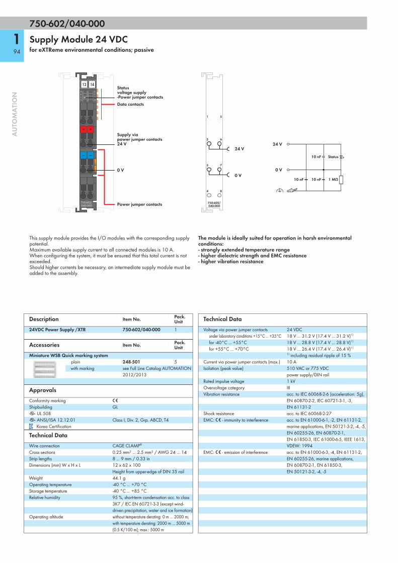
750-602/040-000
194
AU
TOM
ATI
ON
Supply Module 24 VDCfor eXTReme environmental conditions; passive
750-602/040-000
+ +
— —
ABCD
EFGH
13 14
Data contacts
Power jumper contacts
0 V
Supply viapower jumper contacts24 V
Status voltage supply-Power jumper contacts
0 V
24 V24 V
0 V
750-602/040-000
1 MΩ 10 nF
10 nF
10 nF
Status
This supply module provides the I/O modules with the corresponding supply potential.Maximum available supply current to all connected modules is 10 A. When configuring the system, it must be ensured that this total current is not exceeded.Should higher currents be necessary, an intermediate supply module must be added to the assembly.
The module is ideally suited for operation in harsh environmental conditions:- strongly extended temperature range - higher dielectric strength and EMC resistance- higher vibration resistance
Description Item No. Pack. Unit
24VDC Power Supply /XTR 750-602/040-000 1
Accessories Item No. Pack. Unit
Miniature WSB Quick marking systemplain 248-501 5with marking see Full Line Catalog AUTOMATION
2012/2013
ApprovalsConformity marking 1
Shipbuilding GLr UL 508 r ANSI/ISA 12.12.01 Class I, Div. 2, Grp. ABCD, T4
Korea Certification
Technical DataWire connection CAGE CLAMP®
Cross sections 0.25 mm² ... 2.5 mm² / AWG 24 ... 14Strip lengths 8 ... 9 mm / 0.33 inDimensions (mm) W x H x L 12 x 62 x 100
Height from upper-edge of DIN 35 railWeight 44.1 gOperating temperature -40 °C ... +70 °CStorage temperature -40 °C ... +85 °CRelative humidity 95 %, short-term condensation acc. to class
3K7 / IEC EN 60721-3-3 (except wind-driven precipitation, water and ice formation)
Operating altitude without temperature derating: 0 m ... 2000 m; with temperature derating: 2000 m ... 5000 m (0.5 K/100 m); max.: 5000 m
Technical DataVoltage via power jumper contacts 24 VDC
under laboratory conditions +15°C ... +35°C 18 V ... 31.2 V (17.4 V ... 31.2 V)1)
for -40°C ... +55°C 18 V ... 28.8 V (17.4 V ... 28.8 V)1)
for +55°C ... +70°C 18 V ... 26.4 V (17.4 V ... 26.4 V)1)
1) including residual ripple of 15 %Current via power jumper contacts (max.) 10 AIsolation (peak value) 510 VAC or 775 VDC
power supply/DIN railRated impulse voltage 1 kVOvervoltage category IIIVibration resistance acc. to IEC 60068-2-6 (acceleration: 5g),
EN 60870-2-2, IEC 60721-3-1, -3, EN 61131-2
Shock resistance acc. to IEC 60068-2-27EMC: 1 - immunity to interference acc. to EN 61000-6-1, -2, EN 61131-2,
marine applications, EN 50121-3-2, -4, -5, EN 60255-26, EN 60870-2-1, EN 61850-3, IEC 61000-6-5, IEEE 1613, VDEW: 1994
EMC: 1 - emission of interference acc. to EN 61000-6-3, -4, EN 61131-2, EN 60255-26, marine applications, EN 60870-2-1, EN 61850-3, EN 50121-3-2, -4, -5

750-612/040-000
195
AU
TOM
ATI
ON
Supply Module 230 V AC/DCfor eXTReme environmental conditions; passive
750-612/040-000
+ +
— —
ABCD
EFGH
13 14
Data contacts
Power jumper contacts
0 V
Supply viapower jumper contacts0 ... 230 V 0 ... 230 V
0 V 0 V
0 ... 230 V
750-612/040-000
470 pF
470 pF
470 pF
This supply module provides the I/O modules with the corresponding supply potential.Maximum available supply current to all connected modules is 10 A. When configuring the system, it must be ensured that this total current is not exceeded.Should higher currents be necessary, an intermediate supply module must be added to the assembly.
The module is ideally suited for operation in harsh environmental conditions:- strongly extended temperature range - higher dielectric strength and EMC resistance- higher vibration resistance
Description Item No. Pack. Unit
0-230V AC/DC Power Supply /XTR 750-612/040-000 1
Accessories Item No. Pack. Unit
Miniature WSB Quick marking systemplain 248-501 5with marking see Full Line Catalog AUTOMATION
2012/2013
ApprovalsConformity marking 1
Shipbuilding GLr UL 508 r ANSI/ISA 12.12.01 Class I, Div. 2, Grp. ABCD, T4
Korea Certification
Technical DataWire connection CAGE CLAMP®
Cross sections 0.25 mm² ... 2.5 mm² / AWG 24 ... 14Strip lengths 8 ... 9 mm / 0.33 inDimensions (mm) W x H x L 12 x 62 x 100
Height from upper-edge of DIN 35 railWeight 51.5 gOperating temperature -40 °C ... +70 °CStorage temperature -40 °C ... +85 °CRelative humidity 95 %, short-term condensation acc. to class
3K7 / IEC EN 60721-3-3 (except wind-driven precipitation, water and ice formation)
Operating altitude without temperature derating: 0 m ... 2000 m; with temperature derating: 2000 m ... 5000 m (0.5 K/100 m); max.: 5000 m
Technical DataVoltage via power jumper contacts 0 V ... 230 V AC/DC (-20 % ... +25 %)Current via power jumper contacts (max.) 10 ADCIsolation (supply/DIN rail) Rated Insulation Voltage :
2.5 kV AC or 3.5 kV DCRated impulse voltage: 5 kVOvervoltage category: III
Vibration resistance acc. to IEC 60068-2-6 (acceleration: 5g), EN 60870-2-2, IEC 60721-3-1, -3, EN 61131-2
Shock resistance acc. to IEC 60068-2-27EMC: 1 - immunity to interference acc. to EN 61000-6-1, -2, EN 61131-2,
marine applications, EN 50121-3-2, -4, -5, EN 60255-26, EN 60870-2-1, EN 61850-3, IEC 61000-6-5, IEEE 1613, VDEW: 1994
EMC: 1 - emission of interference acc. to EN 61000-6-3, -4, EN 61131-2, EN 60255-26, marine applications, EN 60870-2-1, EN 61850-3, EN 50121-3-2, -4, -5

750-613/040-000
196
AU
TOM
ATI
ON
Internal System Supply Module 24 VDCfor eXTReme environmental conditions
750-613/040-000
+ +
— —
24V 0V
ABCD
EFGH
13 14
Data contacts
Power jumper contacts
0 V
Supply viapower jumper contacts24 V
Supply24 V0 V
Status voltage supply-System-Power jumper contacts
0 V
24 V24 V
0 V
750-613/040-000
10 nF
10 nF
10 nF
47 nF 47 nF
0 V24 V
24 V
0 V
2/6
3/7
I/O modulesStatus
Status
This internal system supply module increases the current supply for the internal system by 2 A.If the internal current consumption of all modules is higher than 2 A, an additional supply module must be added.The module also supplies field side power to the adjoining modules via the power jumper contacts.
The module is ideally suited for operation in harsh environmental conditions:- strongly extended temperature range - higher dielectric strength and EMC resistance- higher vibration resistance
Description Item No. Pack. Unit
24VDC Bus Power Supply /XTR 750-613/040-000 1
Accessories Item No. Pack. Unit
Miniature WSB Quick marking systemplain 248-501 5with marking see Full Line Catalog AUTOMATION
2012/2013
ApprovalsConformity marking 1
Shipbuilding GLr UL 508 r ANSI/ISA 12.12.01 Class I, Div. 2, Grp. ABCD, T4
Korea Certification
Technical DataWire connection CAGE CLAMP®
Cross sections 0.25 mm² ... 2.5 mm² / AWG 24 ... 14Strip lengths 8 ... 9 mm / 0.33 inDimensions (mm) W x H x L 12 x 62 x 100
Height from upper-edge of DIN 35 railWeight 58.5 gOperating temperature -40 °C ... +70 °CStorage temperature -40 °C ... +85 °CRelative humidity 95 %, short-term condensation acc. to class
3K7 / IEC EN 60721-3-3 (except wind-driven precipitation, water and ice formation)
Operating altitude without temperature derating: 0 m ... 2000 m; with temperature derating: 2000 m ... 5000 m (0.5 K/100 m); max.: 5000 m
Technical DataInput current max. 500 mATotal current for I/O modules 2000 mAVoltage via power jumper contacts 24 VDC
under laboratory conditions +15°C ... +35°C 18 V ... 31.2 V (17.4 V ... 31.2 V)1)
for -40°C ... +55°C 18 V ... 28.8 V (17.4 V ... 28.8 V)1)
for +55°C ... +70°C 18 V ... 26.4 V (17.4 V ... 26.4 V)1)
1) including residual ripple of 15 %Current via power jumper contacts (max.) 10 AIsolation (peak value) 510 VAC or 775 VDC
power supply/DIN railRated impulse voltage 1 kVOvervoltage category IIIVibration resistance acc. to IEC 60068-2-6 (acceleration: 5g),
EN 60870-2-2, IEC 60721-3-1, -3, EN 61131-2
Shock resistance acc. to IEC 60068-2-27EMC: 1 - immunity to interference acc. to EN 61000-6-1, -2, EN 61131-2,
marine applications, EN 50121-3-2, -4, -5, EN 60255-26, EN 60870-2-1, EN 61850-3, IEC 61000-6-5, IEEE 1613, VDEW: 1994
EMC: 1 - emission of interference acc. to EN 61000-6-3, -4, EN 61131-2, EN 60255-26, marine applications, EN 60870-2-1, EN 61850-3, EN 50121-3-2, -4, -5

750-624/040-001
197
AU
TOM
ATI
ON
Field-Side Power Supply Filterfor eXTReme environmental conditions; for field-side power supply
750-624/040-001
+ +
— —
ABCD
EFGH
13 14
Data contacts
Power jumper contacts
0 V
Supply viapower jumper contacts24 V
Status voltage supply-Power jumper contacts
24 V
0 V
24 V
0 V
750-624/040-001
10 nF
10 nF 1 MΩ
2/6
3/7
The WAGO-I/O-SYSTEM 750 XTR can also be used in shipbuilding applications and onshore/offshore installations (e.g., platforms, loading facilities). This is possible via certification under the standards of leading agencies such as Germanischer Lloyd and Lloyds Register. Proper system operation is ensured (certified) by using this overvoltage protection module. This also applies to XTR I/O modules used in substations and/or telecontrol systems. The following modules are required for power supply: 750-626/040-000 Power Supply Filter (system and field supply) or 750-624/040-001 Field-Side Power Supply Filter (only field supply).
WAGO's 750-624/040-001 Field-Side Power Supply Filter is equipped with surge suppression and can also be used as a power supply module.
The module is ideally suited for operation in harsh environmental conditions:- strongly extended temperature range - higher dielectric strength and EMC resistance- higher vibration resistance
Description Item No. Pack. Unit
24VDC Field-Side Power Supply Filter with Overvoltage (Surge) Protection /XTR
750-624/040-001 1
Accessories Item No. Pack. Unit
Miniature WSB Quick marking systemplain 248-501 5with marking see Full Line Catalog AUTOMATION
2012/2013
ApprovalsConformity marking 1
Shipbuilding GLr UL 508 r ANSI/ISA 12.12.01 Class I, Div. 2, Grp. ABCD, T4
Korea Certification
Technical DataWire connection CAGE CLAMP®
Cross sections 0.25 mm² ... 2.5 mm² / AWG 24 ... 14Strip lengths 8 ... 9 mm / 0.33 inDimensions (mm) W x H x L 12 x 62 x 100
Height from upper-edge of DIN 35 railWeight 51 gOperating temperature -40 °C ... +70 °CStorage temperature -40 °C ... +85 °CRelative humidity 95 %, short-term condensation acc. to class
3K7 / IEC EN 60721-3-3 (except wind-driven precipitation, water and ice formation)
Operating altitude without temperature derating: 0 m ... 2000 m; with temperature derating: 2000 m ... 5000 m (0.5 K/100 m); max.: 5000 m
Technical DataVoltage via power jumper contacts 24 VDC
under laboratory conditions +15°C ... +35°C 18 V ... 31.2 V (17.4 V ... 31.2 V)1)
for -40°C ... +55°C 18 V ... 28.8 V (17.4 V ... 28.8 V)1)
for +55°C ... +70°C 18 V ... 26.4 V (17.4 V ... 26.4 V)1)
1) including residual ripple of 15 %Current via power jumper contacts (max.) 10 AIsolation (peak value) 510 VAC or 775 VDC
power supply/DIN railRated impulse voltage 1 kVOvervoltage category IIIVibration resistance acc. to IEC 60068-2-6 (acceleration: 5g),
EN 60870-2-2, IEC 60721-3-1, -3, EN 61131-2
Shock resistance acc. to IEC 60068-2-27EMC: 1 - immunity to interference acc. to EN 61000-6-1, -2, EN 61131-2,
marine applications, EN 50121-3-2, -4, -5, EN 60255-26, EN 60870-2-1, EN 61850-3, IEC 61000-6-5, IEEE 1613, VDEW: 1994
EMC: 1 - emission of interference acc. to EN 61000-6-3, -4, EN 61131-2, EN 60255-26, marine applications, EN 60870-2-1, EN 61850-3, EN 50121-3-2, -4, -5

750-626/040-000
198
AU
TOM
ATI
ON
Power Supply Filterfor eXTReme environmental conditions; for system and field-side power supply
750-626/040-000
+ +
— —
—+
+ —
ABCD
EFGH
13 14
Data contacts
System power supply (Out)24 V0 V
Supply viapower jumper contacts24 V
Status voltage supply-System-Power jumper contacts
Power jumper contacts
0 V
System power supply (In)24 V0 V
0 V/OUT24 V/OUT
24 V/IN
24 V/OUT
24 V/IN
0 V/IN
0 V
24 V
24 V
0 V/OUT
0 V
0 V/IN750-626/040-000
10 nF 10 nF
10 nF
10 nF
1 MΩ
1 MΩ
2/6
3/7
51
4
8
The WAGO-I/O-SYSTEM 750 XTR can also be used in shipbuilding applications and onshore/offshore installations (e.g., platforms, loading facilities). This is possible via certification under the standards of leading agencies such as Germanischer Lloyd and Lloyds Register. Proper system operation is ensured (certified) by using this overvoltage protection module. This also applies to XTR I/O modules used in substations and/or telecontrol systems. The following modules are required for power supply: 750-626/040-000 Power Supply Filter (system and field supply) or 750-624/040-001 Field-Side Power Supply Filter (only field supply).
WAGO's 750-626/040-000 Power Supply Filter filters the 24 V system power supply and is equipped with surge suppression. The power supply filter can also be used as a power supply module
The module is ideally suited for operation in harsh environmental conditions:- strongly extended temperature range - higher dielectric strength and EMC resistance- higher vibration resistance
Description Item No. Pack. Unit
24VDC Power Supply Filter with Overvoltage (Surge) Protection /XTR
750-626/040-000 1
Accessories Item No. Pack. Unit
Miniature WSB Quick marking systemplain 248-501 5with marking see Full Line Catalog AUTOMATION
2012/2013
ApprovalsConformity marking 1
Shipbuilding GLr UL 508 r ANSI/ISA 12.12.01 Class I, Div. 2, Grp. ABCD, T4
Korea Certification
Technical DataWire connection CAGE CLAMP®
Cross sections 0.25 mm² ... 2.5 mm² / AWG 24 ... 14Strip lengths 8 ... 9 mm / 0.33 inDimensions (mm) W x H x L 12 x 62 x 100
Height from upper-edge of DIN 35 railWeight 51 gOperating temperature -40 °C ... +70 °CStorage temperature -40 °C ... +85 °CRelative humidity 95 %, short-term condensation acc. to class
3K7 / IEC EN 60721-3-3 (except wind-driven precipitation, water and ice formation)
Operating altitude without temperature derating: 0 m ... 2000 m; with temperature derating: 2000 m ... 5000 m (0.5 K/100 m); max.: 5000 m
Technical DataVoltage via power jumper contacts 24 VDC
under laboratory conditions +15°C ... +35°C 18 V ... 31.2 V (17.4 V ... 31.2 V)1)
for -40°C ... +55°C 18 V ... 28.8 V (17.4 V ... 28.8 V)1)
for +55°C ... +70°C 18 V ... 26.4 V (17.4 V ... 26.4 V)1)
1) including residual ripple of 15 %Current via system voltage (max.) 1.5 ACurrent via power jumper contacts (max.) 10 AIsolation (peak value) 510 VAC or 775 VDC
power supply/DIN railRated impulse voltage 1 kVOvervoltage category IIIVibration resistance acc. to IEC 60068-2-6 (acceleration: 5g),
EN 60870-2-2, IEC 60721-3-1, -3, EN 61131-2
Shock resistance acc. to IEC 60068-2-27EMC: 1 - immunity to interference acc. to EN 61000-6-1, -2, EN 61131-2,
marine applications, EN 50121-3-2, -4, -5, EN 60255-26, EN 60870-2-1, EN 61850-3, IEC 61000-6-5, IEEE 1613, VDEW: 1994
EMC: 1 - emission of interference acc. to EN 61000-6-3, -4, EN 61131-2, EN 60255-26, marine applications, EN 60870-2-1, EN 61850-3, EN 50121-3-2, -4, -5

750-1605/040-000
199
AU
TOM
ATI
ON
Field-Side Connection Module 16+for eXTReme environmental conditions; 24 VDC
1 9
2 10
3 11
4 12
5 13
6 14
7 15
8 16
750-1605/040-000
13 14
24 V
24 V
24 V
24 V
24 V
24 V
24 V
24 V
24 V
24 V
24 V
24 V
24 V
24 V
24 V
24 V
CAGE CLAMP®Sconnection
Data contacts
Power jumper contacts
1
2
3
4
5
6
7
8
13
12
11
10
9
14
15
16
+
+
+
+
+
+
+
+
0 V
+ 24 V
+
+
+
+
+
+
+
+
750-1605/040-000
This field-side connection module provides the 24 V potential to the inputs via 16-channel 750-1405/040-000 input module, eliminating the need for additional terminal blocks.The 24 V supply and 0 V potential are derived from the internal power jumper contacts of an adjacent upstream I/O module. A connection of the potentials to the downstream I/O modules is made automatically via the power jumper contacts when snapping the I/O modules together. The 24 V power is provided to all 16 field-side CAGE CLAMP® connections and the 0 V potential passed through without being used by the module.An operating tool with a 2.5 mm blade (210-719) is required to open the CAGE CLAMP® S connections.
The module is ideally suited for operation in harsh environmental conditions:- strongly extended temperature range - higher dielectric strength and EMC resistance- higher vibration resistance
Description Item No. Pack. Unit
Field-Side Connection Module 16+ /XTR 750-1605/040-000 1
Accessories Item No. Pack. Unit
Miniature WSB Quick marking systemplain 248-501 5with marking see Full Line Catalog AUTOMATION
2012/2013Operating tool, with partially insulated shaft, type 1, blade (2.5 x 0.4) mm
210-719 1
ApprovalsConformity marking 1
Shipbuilding GLr UL 508 r ANSI/ISA 12.12.01 Class I, Div. 2, Grp. ABCD, T4
Technical DataWire connection CAGE CLAMP® SCross sections 0.25 mm² ... 1.5 mm² / AWG 24 ... 16Strip lengths 8 ... 9 mm / 0.33 inDimensions (mm) W x H x L 12 x 62 x 100
Height from upper-edge of DIN 35 railWeight 40.2 gOperating temperature -40 °C ... +70 °CStorage temperature -40 °C ... +85 °CRelative humidity 95 %, short-term condensation acc. to class
3K7 / IEC EN 60721-3-3 (except wind-driven precipitation, water and ice formation)
Operating altitude without temperature derating: 0 m ... 2000 m; with temperature derating: 2000 m ... 5000 m (0.5 K/100 m); max.: 5000 m
Technical DataVoltage via power jumper contacts 24 VDC
under laboratory conditions +15°C ... +35°C 18 V ... 31.2 V (17.4 V ... 31.2 V)1)
for -40°C ... +55°C 18 V ... 28.8 V (17.4 V ... 28.8 V)1)
for +55°C ... +70°C 18 V ... 26.4 V (17.4 V ... 26.4 V)1)
1) including residual ripple of 15 %Current via power jumper contacts (max.) 10 AIsolation (peak value) 510 VAC or 775 VDC
power supply/DIN railRated impulse voltage 1 kVOvervoltage category IIIVibration resistance acc. to IEC 60068-2-6 (acceleration: 5g),
EN 60870-2-2, IEC 60721-3-1, -3, EN 61131-2
Shock resistance acc. to IEC 60068-2-27EMC: 1 - immunity to interference acc. to EN 61000-6-1, -2, EN 61131-2,
marine applications, EN 50121-3-2, -4, -5, EN 60255-26, EN 60870-2-1, EN 61850-3, IEC 61000-6-5, IEEE 1613, VDEW: 1994
EMC: 1 - emission of interference acc. to EN 61000-6-3, -4, EN 61131-2, EN 60255-26, marine applications, EN 60870-2-1, EN 61850-3, EN 50121-3-2, -4, -5
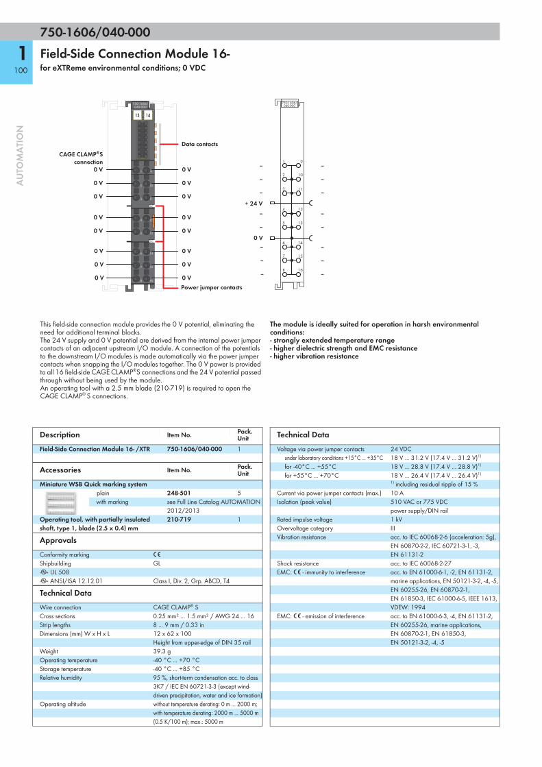
750-1606/040-000
1100
AU
TOM
ATI
ON
Field-Side Connection Module 16-for eXTReme environmental conditions; 0 VDC
1 9
2 10
3 11
4 12
5 13
6 14
7 15
8 16
750-1606/040-000
13 14
0 V
0 V
0 V
0 V
0 V
0 V
0 V
0 V
0 V
0 V
0 V
0 V
0 V
0 V
0 V
0 V
CAGE CLAMP®Sconnection
Data contacts
Power jumper contacts
1
2
3
4
5
6
7
8
13
12
11
10
9
14
15
16
‒
‒
‒
‒
‒
‒
‒
‒
0 V
+ 24 V
‒
‒
‒
‒
‒
‒
‒
‒
750-1606/040-000
This field-side connection module provides the 0 V potential, eliminating the need for additional terminal blocks.The 24 V supply and 0 V potential are derived from the internal power jumper contacts of an adjacent upstream I/O module. A connection of the potentials to the downstream I/O modules is made automatically via the power jumper contacts when snapping the I/O modules together. The 0 V power is provided to all 16 field-side CAGE CLAMP®S connections and the 24 V potential passed through without being used by the module.An operating tool with a 2.5 mm blade (210-719) is required to open the CAGE CLAMP® S connections.
The module is ideally suited for operation in harsh environmental conditions:- strongly extended temperature range - higher dielectric strength and EMC resistance- higher vibration resistance
Description Item No. Pack. Unit
Field-Side Connection Module 16- /XTR 750-1606/040-000 1
Accessories Item No. Pack. Unit
Miniature WSB Quick marking systemplain 248-501 5with marking see Full Line Catalog AUTOMATION
2012/2013Operating tool, with partially insulated shaft, type 1, blade (2.5 x 0.4) mm
210-719 1
ApprovalsConformity marking 1
Shipbuilding GLr UL 508 r ANSI/ISA 12.12.01 Class I, Div. 2, Grp. ABCD, T4
Technical DataWire connection CAGE CLAMP® SCross sections 0.25 mm² ... 1.5 mm² / AWG 24 ... 16Strip lengths 8 ... 9 mm / 0.33 inDimensions (mm) W x H x L 12 x 62 x 100
Height from upper-edge of DIN 35 railWeight 39.3 gOperating temperature -40 °C ... +70 °CStorage temperature -40 °C ... +85 °CRelative humidity 95 %, short-term condensation acc. to class
3K7 / IEC EN 60721-3-3 (except wind-driven precipitation, water and ice formation)
Operating altitude without temperature derating: 0 m ... 2000 m; with temperature derating: 2000 m ... 5000 m (0.5 K/100 m); max.: 5000 m
Technical DataVoltage via power jumper contacts 24 VDC
under laboratory conditions +15°C ... +35°C 18 V ... 31.2 V (17.4 V ... 31.2 V)1)
for -40°C ... +55°C 18 V ... 28.8 V (17.4 V ... 28.8 V)1)
for +55°C ... +70°C 18 V ... 26.4 V (17.4 V ... 26.4 V)1)
1) including residual ripple of 15 %Current via power jumper contacts (max.) 10 AIsolation (peak value) 510 VAC or 775 VDC
power supply/DIN railRated impulse voltage 1 kVOvervoltage category IIIVibration resistance acc. to IEC 60068-2-6 (acceleration: 5g),
EN 60870-2-2, IEC 60721-3-1, -3, EN 61131-2
Shock resistance acc. to IEC 60068-2-27EMC: 1 - immunity to interference acc. to EN 61000-6-1, -2, EN 61131-2,
marine applications, EN 50121-3-2, -4, -5, EN 60255-26, EN 60870-2-1, EN 61850-3, IEC 61000-6-5, IEEE 1613, VDEW: 1994
EMC: 1 - emission of interference acc. to EN 61000-6-3, -4, EN 61131-2, EN 60255-26, marine applications, EN 60870-2-1, EN 61850-3, EN 50121-3-2, -4, -5

750-600/040-000
1101
AU
TOM
ATI
ON
End Modulefor eXTReme environmental conditions
750-600/040-000
ABCD
EFGH
An end module must be snapped onto the assembly at the end of a fieldbus node.
The end module completes the internal data bus, while providing correct data transmission.
The module is ideally suited for operation in harsh environmental conditions:- strongly extended temperature range - higher dielectric strength and EMC resistance- higher vibration resistance
Description Item No. Pack. Unit
End Module /XTR 750-600/040-000 1
Accessories Item No. Pack. Unit
Miniature WSB Quick marking systemplain 248-501 5with marking see Full Line Catalog AUTOMATION
2012/2013
ApprovalsConformity marking 1
Shipbuilding GLr UL 508 r ANSI/ISA 12.12.01 Class I, Div. 2, Grp. ABCD, T4
Korea Certification
Technical DataDimensions (mm) W x H x L 12 x 62 x 100
Height from upper-edge of DIN 35 railWeight 32.5 gOperating temperature -40 °C ... +70 °CStorage temperature -40 °C ... +85 °CRelative humidity 95 %, short-term condensation acc. to class
3K7 / IEC EN 60721-3-3 (except wind-driven precipitation, water and ice formation)
Operating altitude without temperature derating: 0 m ... 2000 m; with temperature derating: 2000 m ... 5000 m (0.5 K/100 m); max.: 5000 m
Vibration resistance acc. to IEC 60068-2-6 (acceleration: 5g), EN 60870-2-2, IEC 60721-3-1, -3, EN 61131-2
Shock resistance acc. to IEC 60068-2-27EMC: 1 - immunity to interference acc. to EN 61000-6-1, -2, EN 61131-2,
marine applications, EN 50121-3-2, -4, -5, EN 60255-26, EN 60870-2-1, EN 61850-3, IEC 61000-6-5, IEEE 1613, VDEW: 1994
EMC: 1 - emission of interference acc. to EN 61000-6-3, -4, EN 61131-2, EN 60255-26, marine applications, EN 60870-2-1, EN 61850-3, EN 50121-3-2, -4, -5

767-1311
2102
AU
TOM
ATI
ON
sercos Fieldbus Couplerincl. 8 digital high-speed inputs (8 x M8)
X8
X6
X4
X2
X1
X3
X5
X7
0
2
4
6
7
5
3
1
767-1311
24 VULS UA
COM
MS 1 CS
S3ACT/LNK
2
sercos
1 FB 2
1211
7654321
IIIIIII
II
RESB/E
2⁶8I 2⁷9I 2⁸
2⁵2⁴2³2²2¹2⁰
SBM
10I DS
FC 8DI HS
System bus connection (3)
Supply output (1)
Supply input (1)
Digital inputs (2)
USB connection (5)
sercosInput 1 (4)
Operationpanel
sercosInput 2 (4) Module
marking
Channel marking
LED indicators
Short description:This fieldbus coupler links the WAGO SPEEDWAY 767 system to the sercos network. It determines station structureand generates the required process images of the configured inputs and outputs. Setting up the station can involve a mixed arrangement of analog, di-gital or specialty I/O modules. The fieldbus coupler application allows access to the de-vice as a sercos I/O device on the network. The sercos service channel (SVC), real-time channel (RTC) and IP channel (NRT) are supported for standard TCP/IP communication. Two integrated ETHERNET ports allow easy creation of a line and ring structure without requiring additional components. Each port supports Auto MDI/MDI-X and automatically detects the direction of transmission, allowing both patch and crossover cables to be used. Assigning the sercos address can be performed via switch 10, either using the operation panel (switches) or software (retentive memory). In addition, the fieldbus coupler has 8 digital inputs to capture binary signals from switches and sensors.
Characteristics:• 8 digital high-speed inputs, type 1 (IEC 61131)• Hardware delay: 10 μs• Modular and extendable by up to 64 I/O modules (via system port)• USB interface for service purposes• Configuration and parameter setting via SDDML device description file• Parameter setting via FDT/DTM (incl. diagnostics and simulation)• Sealable operation panel (operating mode and address switches)
Included:• 1 x WMB marker, yellow• 1 x channel marking strip• 2 x M8 protective cap
Description Item No. Pack. Unit
FC sercos 8DI 24V DC HS 767-1311 1
Accessories Item No.
ETHERNET cable + accessoriesSystem bus/power supply cable + accessoriesGeneral accessories see Full Line Catalog AUTOMATION
2012/2013DTM (Device Type Manager) Download: www.wago.comSDDML files Download: www.wago.com
Technical DataFieldbus:
Device type sercos I/O deviceConnection type (4) M12 connectors, D coded, 4 polesBaud rate 100 Mbit/s, full duplexTransmission medium Copper cable (Cat. 5e, Class D)Station address 0 – 511 (adjustable via operation panel or
software)Protocols sercos v1.1.2, TCP/IP, FTP, HTTPsercos services SVC, RTC, CC, IPsercos profiles GDP_Basic, SCP_VarCfg, SCP_Sync,
SCP_Diag, SCP_WD, SCP_NRT, FSP_IOModule supply:
Connection type (1) M12 connectors, A coded, 4 polesCurrent carrying capacity of supply connections Max. 8 A (ULS: 4 A, UA: 4 A)Supply voltage
Logic and sensor voltage ULS 24 VDC (-25 % ... +30 %)Actuator voltage UA 24 V DC (-25 % ... +30 %);
Also required for power supply transmission
Supply currentLogic and sensor current ILS typ. 140 mA + sensors (max. 400 mA)Actuator current IA 5mA
Protection Reverse voltage protection for ULS + UA; short circuit protection for sensor supply

2103
AU
TOM
ATI
ON
M8
M8
M12
M8
M12 A coded
1: 24 V ULS2: 24 V UA3: 0 V ULS4: 0 V UA
M12 B coded
System busconnection 1: TD+
2: TD--3: RD--4: RD+5: GNDHousing: Shield
1: +5 V2: –Data3: +Data4: GNDHousing: Shield
USBCOM
Supply Input Output
Digital InputsX1 ... X8 1: 24 V
3: 0 V ULS
4: Input
1: TX+2: RX+3: TX–4: RX–Housing: Shield
M12 D coded
sercosInput 1 Input 2
Address
20
21
22
23
24
25
26
27
28
Boot / ExecuteDisable Switch
Reset
Ope
ratio
n pa
nel
Logic
Block diagram of an input
Error F
Input 0 ... 7
SupplyDigital Input X1 ... X8
Modulemount
Technical DataDigital inputs:
Number of inputs 8Connection type (2) M8 connectors, 3 polesWire connection 2- or 3-wireInput filter Hardware: ≤ 10 μs, software
parametrizable depending on operating mode
Hardware delay up to fieldbus 10 μs (direct mode)Input characteristic Type 1, acc. to IEC 61131-2Signal voltage (0) -3 V ... +5 V DCSignal voltage (1) +15 V ... +30 V DCInput wiring high-side switchingInput voltage 24 VDC (-30 VDC < UIN < +30 VDC)Input current (typ.) 2.8 mACable length, unshielded ≤ 30 mWrong connection of inputs No effect
System bus:Cycle time min. 250 μsNumber of expendable modules 64Connection type (3) M12 connectors, B coded, 5 poles,
shieldedDistance between two modules 20 mTotal extension per station 200 m
Isolation:Channel - Channel NoULS, UA, system bus, fieldbus 500 VDC each
Service:Type USB standard 1.1Connection type (5) M8 connectors, 4 poles
Standards and approvals:r UL 508Conformity marking 1
Configurable functions:Fieldbus coupler see manualDigital Inputs depending on operating mode
0.1/ 0.5/ 3 /15 /20 ms/ filter offInput filter (per channel)Inversion (per channel) On/offOnline simulation (per channel) Lock/unlock, simulation value: 0/1
I/O diagnostics:I/O diagnostics (per module) Short circuit of sensor supply
Undervoltage (ULS + UA)
Technical DataProcess image:
Input process image 2048 bytesOutput process image 2048 bytes
LED indicators:MS: Module status LED (green/red)S3: sercos status LED (green/red)ACT/LNK 1 : ETHERNET data exchange/network connection LED (green)ACT/LNK 2 : ETHERNET data exchange/network connection LED (green)CS : Fieldbus coupler status LED (green/red)SBM : System bus master status LED (green/red)F: Error status LED (red)0 ... 7: Input signal status LED (yellow)ULS + UA: Supply status LED (green)Indicators Non-latching
Advanced features:Operating hours counter Values in [h]High-speed inputs parametrizable, depending on operating
mode (see manual)
General SpecificationsDimensions (mm) W x H x L 75 x 35.7 x 117Weight 400 g
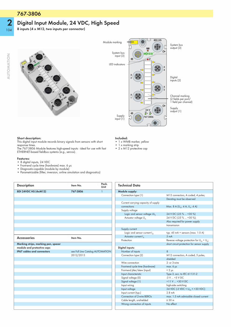
767-3806
2104
AU
TOM
ATI
ON
Digital Input Module, 24 VDC, High Speed 8 inputs (4 x M12, two inputs per connector)
767-3806
24 VULS UA
X1
X3
X4
X2
1
0
5
4
6
7
2
3
8DI HS
System busoutput (3)
System businput (3)
Supplyoutput (1)
Supplyinput (1)
Digital inputs (2)
Channel marking(2 fields per port/1 field per channel)
Module marking
LED indicators
Short description:This digital input module records binary signals from sensors with short response times.The 767-3806 Module features high-speed inputs - ideal for use with fast ETHERNET-based fieldbus systems (e.g., sercos).
Features:• 8 digital inputs, 24 VDC• Front-end cycle time (hardware) max. 6 μs• Diagnostic-capable (module by module)• Parametrizable (filter, inversion, online simulation and diagnostics)
Included:• 1 x WMB marker, yellow• 1 x marking strip• 2 x M12 protective cap
Description Item No. Pack. Unit
8DI 24VDC HS (4xM12) 767-3806 1
Accessories Item No.
Marking strips, marking pen, spacer module and protective capsIP67 cables and connectors see Full Line Catalog AUTOMATION
2012/2013
Technical DataModule supply:
Connection type (1) M12 connectors, A coded, 4 poles; Derating must be observed
Current carrying capacity of supply connections Max. 8 A (ULS: 4 A, UA: 4 A)Supply voltage
Logic and sensor voltage ULS 24 V DC (-25 % ... +30 %)Actuator voltage UA 24 V DC (-25 % ... +30 %);
Also required for power supply transmission
Supply currentLogic and sensor current ILS typ. 45 mA + sensors (max. 1.0 A)Actuator current IA 5 mA
Protection Reverse voltage protection for ULS + UA; short circuit protection for sensor supply
Digital inputs:Number of inputs 8Connection type (2) M12 connectors, A coded, 5 poles,
shieldedWire connection 2- or 3-wireFront-end cycle time (hardware) max. 6 μsFront-end jitter/skew (input) < 2 μsInput characteristic Type 3, acc. to IEC 61131-2Signal voltage (0) -3 V ... +5 V DCSignal voltage (1) +11 V ... +30 V DCInput wiring high-side switchingInput voltage 24 VDC (-3 VDC < UIN < +30 VDC)Input current (typ.) 2.8 mAConnection of 2-wire BEROs max. 1.5 mA admissible closed currentCable length, unshielded ≤ 30 mWrong connection of inputs No effect
767-3806
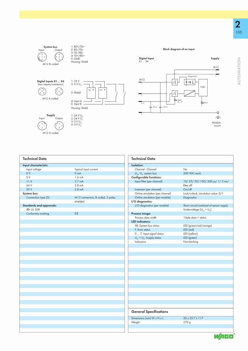
2105
AU
TOM
ATI
ON
270 pF270 pF
5
M12
M12
5 5
1: 24 V ULS2: 24 V UA3: 0 V ULS4: 0 V UA
1: RD+/TD+2: RD--/TD--3: TD--/RD--4: TD+/RD+5: GNDHousing: Shield
1: 24 V3: 0 V ULS
5: Shield
4: Input A2: Input BHousing: Shield
M12 A coded
SupplyInput Output
M12 B coded
System busInput Output
M12 A coded
Digital Inputs X1 ... X4(two intputs/connector)
Block diagram of an input
SupplyDigital InputX1 ... X4
Modulemount
Logic
Input 0 ... 7 Error
Diagnostics
Technical DataInput characteristic:
Input voltage Typical input current0 V 0 mA5 V 1.6 mA11 V 2.7 mA24 V 2.8 mA30 V 2.8 mA
System bus:Connection type (3) M12 connectors, B coded, 5 poles,
shieldedStandards and approvals:
r UL 508Conformity marking 1
Technical DataIsolation:
Channel - Channel NoULS, UA, system bus 500 VDC each
Configurable functions:Input filter (per channel) 10/ 25/ 50/ 100/ 200 μs/ 1/ 3 ms/
filter offInversion (per channel) On/offOnline simulation (per channel) Lock/unlock, simulation value: 0/1Online simulation (per module) Diagnostics
I/O diagnostics:I/O diagnostics (per module) Short circuit/overload of sensor supply
Undervoltage (ULS + UA)Process image:
Process data width 1-byte data + statusLED indicators:
SB: System bus status LED (green/red/orange)F: Error status LED (red)0 ... 7: Input signal status LED (yellow)ULS + UA: Supply status LED (green)Indicators Non-latching
General SpecificationsDimensions (mm) W x H x L 50 x 35.7 x 117Weight 270 g

767-4808
2106
AU
TOM
ATI
ON
Digital Output Module, 24 VDC, 0.1 A, High Speed8 outputs (4 x M12, two outputs per connector)
767-4808
24 VULS UA
X1
X3
X4
X2
1
0
5
4
6
7
2
3
8DO HS
System busoutput (3)
System businput (3)
Supplyoutput (1)
Supplyinput (1)
Digital outputs (2)
Channel marking(2 fields per port/1 field per channel)
Module marking
LED indicators
Short description:This digital output module outputs signals from actuators with short response times. The 767-4808 Module features high-speed outputs - ideal for use with fast ETHERNET-based fieldbus systems (e.g., sercos).
Features:• 8 digital outputs, 24 VDC / 0.1 A• Front-end cycle time (hardware) max. 0,5 μs• Diagnostic-capable (channel by channel/module by module)• Parametrizable (inversion, substitute value strategy, substitute value, manual
mode, online simulation and diagnostics)
Included:• 1 x WMB marker, red• 1 x marking strip• 2 x M12 protective cap
Description Item No. Pack. Unit
8DO 24VDC 0,1A HS (4xM12) 767-4808 1
Accessories Item No.
Marking strips, marking pen, spacer module and protective capsIP67 cables and connectors see Full Line Catalog AUTOMATION
2012/2013
Technical DataModule supply:
Connection type (1) M12 connectors, A coded, 4 poles; Derating must be observed
Current carrying capacity of supply connections Max. 8 A (ULS: 4 A, UA: 4 A)Supply voltage
Logic and sensor voltage ULS 24 V DC (-25 % ... +30 %)Actuator voltage UA 24 V DC (-25 % ... +30 %)
Supply currentLogic and sensor current ILS typ. 40 mA (logic component only)Actuator current IA typ. 35 mA + actuator supply (≤ 1 A) +
loadProtection Reverse voltage protection for ULS + UA,
short-circuit protection for actuator supplyDigital outputs:
No. of outputs 8Connection type (2) M12 connectors, A coded, 5 poles,
shieldedWire connection 2- or 3-wireOutput voltage ≤ UA
Output current (per channel) 0.1 A, short-circuit/overload proof (thermal disconnection)
Voltage drop against UA at nominal load Max. 1.7 V DCOutput current (module) max. 0.8ALeakage current in OFF state typ. 50 μAOutput circuit Push/Pull
767-4808

2107
AU
TOM
ATI
ON
10 nF 10 nF
270 pF
M12M12
5 5
5
1: 24 V ULS2: 24 V UA3: 0 V ULS4: 0 V UA
1: RD+/TD+2: RD--/TD--3: TD--/RD--4: TD+/RD+5: GNDHousing: Shield
1: 24 V3: 0 V UA
5: Shield
4: Output A2: Output BHousing: Shield
M12 A coded
M12 B coded
M12 A coded
Digital Outputs X1 ... X4(two outputs/connector)
Supply Input Output
System busInput Output Block diagram of an output
SupplyDigital OutputX1 ... X4
Modulemount
Logic
Output 0 ... 7
Output0 ... 7
Diagnostics 0 ... 7
ErrorF
Technical DataInformation on actuator selection:
Front-end cycle time 90% (hardware) max. 0,5 μsEdge steepness TON/OFF: typ. < 0,2 μsFront-end jitter/skew (output) < 0,2 μsCable length ≤ 30 mType of load Inductive, resistive loads and lampsSwitching frequency Inductive load upon request
Resistive load upon request Lamp load upon request
Type of protective circuit External protection (e.g., recovery diodes)Operating state influence on output:
PLC CPU stop Acc. to substitute value strategyFieldbus disruption Acc. to substitute value strategyS-bus (system bus) disruption 0 V statusSupply voltage under rated voltage tolerance 0 V statusInterruption of supply voltage 0 V statusOutput operation Non-latchingOverload behavior Automatic restart
System bus:Connection type (3) M12 connectors, B coded, 5 poles,
shieldedStandards and approvals:
r UL 508Conformity marking 1
Technical DataIsolation:
Channel - Channel NoULS, UA, system bus 500 VDC each
Configurable functions:Inversion (per channel) On/offSubstitute value strategy (per channel) Switch substitute value/hold last valueSubstitute value (per channel) 0/1Manual mode (per channel) On/offManual mode value (per channel) 0/1Online simulation (per channel) Lock/Unlock; simulation value: 0/1;
diagnosticsI/O diagnostics:
I/O diagnostics (per channel) Overtemperature, actuatorsI/O diagnostics (per module) Undervoltage (ULS + UA)
Process image:Process data width 1-byte data + status
LED indicators:SB: System bus status LED (green/red/orange)F: Error status LED (red)0 ... 7: Output signal status LED (yellow/red)ULS + UA: Supply status LED (green)Indicators Non-latching
General SpecificationsDimensions (mm) W x H x L 50 x 35.7 x 117Weight 260 g

767-5401
2108
AU
TOM
ATI
ON
Digital Input/Output Module, 24 VDC / 0.2 A, High Speed4 inputs/outputs (4 x M12)
767-5401
24 VULS UA
X1
X3
X4
X20
2
3
1
4DIO HS
System busoutput (3)
System businput (3)
Supplyoutput (1)
Supplyinput (1)
Digital inputs /outputs (2)
Channel marking(2 fields per port/channel)
Module marking
LED indicators
Short description:This digital input/output module records/outputs binary signals from sensors/actuators with short response times. The 767-5401 Module features high-speed inputs/outputs - ideal for use with fast ETHERNET-based fieldbus systems (e.g., sercos).
Features:• 4 digital inputs/outputs, 24 VDC / 0.2 A, incl. counter function• Front-end cycle time (hardware) max. 3 μs• Diagnostic-capable (channel by channel/module by module)• Parametrizable (operating mode, filter, inversion, substitute value strategy,
substitute value, manual mode, online simulation and diagnostics)
Included:• 1 x WMB marker, orange• 1 x marking strip• 2 x M12 protective cap
Description Item No. Pack. Unit
4DIO 24VDC 0.2A HS (4xM12) 767-5401 1
Accessories Item No.
Marking strips, marking pen, spacer module and protective capsIP67 cables and connectors see Full Line Catalog AUTOMATION
2012/2013
Technical DataModule supply:
Connection type (1) M12 connectors, A coded, 4 poles; Derating must be observed
Current carrying capacity of supply connections Max. 8 A (ULS: 4 A, UA: 4 A)Supply voltage
Logic and sensor voltage ULS 24 V DC (-25 % ... +30 %)Actuator voltage UA 24 V DC (-25 % ... +30 %)
Supply currentLogic and sensor current ILS typ. 40 mA (logic component only)Actuator current IA typ. 30 mA + sensors/actuators
(max. 1000 mA) + loadProtection Reverse voltage protection for ULS + UA
Short-circuit protection for sensor/actuator supply
Technical DataDigital inputs:
Number of inputs 4Connection type (2) M12 connectors, A coded, 5 poles,
shieldedWire connection 2- or 3-wireFront-end cycle time (hardware) max. 3 μsFront-end jitter/skew (input) < 2 μsInput characteristic Type 1, acc. to IEC 61131-2Signal voltage (0) -3 V ... +5 V DCSignal voltage (1) +15 V ... +30 V DCInput wiring high-side switchingInput voltage 24 VDC (-3 VDC < UIN < +30 VDC);
Power from UA strongly recommendedInput current (typ.) 2.9 mAConnection of 2-wire BEROs max. 1.5 mA admissible closed currentCable length, shielded ≤ 30 m
Input characteristic:Input voltage Typical input current0 V 0 mA5 V 2.0 mA15 V 2.5 mA24 V 2.9 mA30 V 3.2 mA
Counters:No. of counters 1Counter type Event, gateway time, pulse durationCounting/switching frequency 0 Hz ... 1 kHz
767-5401

2109
AU
TOM
ATI
ON
10 nF 10 nF
270 pF270 pF
M12M122
4
5 5
1: 24 V ULS2: 24 V UA3: 0 V ULS4: 0 V UA
1: RD+/TD+2: RD--/TD--3: TD--/RD--4: TD+/RD+5: GNDHousing: Shield
1: 24 V3: 0 V UA
5: Shield
4: In-/OutputHousing: Shield
3
1
4
5
M12, A coded
M12, B coded
System bus Input Output
M12, A coded
Digital Inputs/OutputsX1 ... X4
Block diagram of an input/output
SupplyDigital Input/OutputX1 ... X4
Modulemount
Diagnostics sensor/actuator supply
Supply Input Output
Logic
Input/Output0 ... 3
ErrorF
Input 0 ... 3
Output 0 ... 3
Technical DataDigital outputs:
No. of outputs 4Connection type (2) M12 connectors, A coded, 5 poles,
shieldedWire connection 2- or 3-wireOutput voltage ≤ UA
Output current (per channel) 0.2 A, short-circuit/overload proof (thermal disconnection)
Voltage drop against UA at 200 mA Max. 2.0 V DCOutput current (module) max. 0.8ALeakage current in OFF state typ. 100 μAOutput circuit Push/Pull
Information on actuator selection:Front-end cycle time 90% (hardware) max. 0,5 μsEdge steepness TON/OFF: typ. < 0,2 μsFront-end jitter/skew (output) < 0,2 μsType of load Inductive, resistive loads and lampsSwitching frequency Inductive load upon request
Resistive load upon request Lamp load upon request
Type of protective circuit External protection (e.g., recovery diodes)Operating state influence on output:
PLC CPU stop Acc. to substitute value strategyFieldbus disruption Acc. to substitute value strategyS-bus (system bus) disruption 0 V statusSupply voltage under rated voltage tolerance 0 V statusInterruption of supply voltage 0 V statusOutput operation Non-latchingOverload behavior Automatic restart
Technical DataSystem bus:
Connection type (3) M12 connectors, B coded, 5 poles, shielded
Standards and approvals:r UL 508Conformity marking 1
Isolation:Channel - Channel NoULS, UA, system bus 500 VDC each
Configurable functions:Operating mode (per module) DO module/DI module/DIO module/
DIO + 1 counterInput filter (per channel) 10/ 25/ 50/ 100/ 200 μs/ 1/ 3 ms/
filter offInversion (per channel) On/offSubstitute value strategy (per channel) Switch substitute value/hold last valueSubstitute value (per channel) 0/1Manual mode (per channel) On/offManual mode value (per channel) 0/1Online simulation (per channel) Lock/unlock, simulation value: 0/1Online simulation (per channel/ Diagnostics
I/O diagnostics:I/O diagnostics (per channel) OvertemperatureI/O diagnostics (per module) Short-circuit of sensor/actuator supply
Undervoltage (ULS + UA)Process image:
Process data width depends on operating modeLED indicators:
SB: System bus status LED (green/red/orange)F: Error status LED (red)0 – 3: Signal status, inputs/outputs LED (yellow/red)0 – 3: Diagnostics, outputs LED (red)ULS + UA: Supply status LED (green)
General SpecificationsDimensions (mm) W x H x L 50 x 35.7 x 117Weight 255 g

767-5201
2110
AU
TOM
ATI
ON
TTL Incremental/SSI Encoder InterfaceTwo encoder interfaces (2 x M12) + 4 digital inputs/outputs (2 x M12, two inputs/outputs per connector)
767-5201
24 VULS UA
X1
X3
X4
X2
1
0
Ch1.2
Ch1.1
Ch2.1
Ch2.2
2
3
TTL CNT
System bus output (4)
System businput (4)
Supply output (1)
Supplyinput (1)
Digital inputs/outputs,channel 3 + 4(3)
Incremental/SSI encoder 2(2)
Digital inputs/outputs,
channel 1 + 2(3)
Incremental/SSI encoder 1
(2)
Module marking
LED indicators
Channel marking(2 fields for each port1 field for each channel)
Short description:The 767-5201 Module evaluates both incremental and absolute encoders with RS-422 signal levels. Integrated DIOs allow outputs to be directly set depending on counter states. Two of the four DIO channels can also be used as PWM outputs*.
Characteristics:• Two incremental/SSI encoder interfaces• Four digital inputs/outputs 24 VDC/0.1 A (incl. 2 PWM* outputs)• Configurable (incremental/SSI encoder, DIOs)• Diagnostic-capable (channel by channel/module by module)
Included:• 1 x WMB marker, orange• 1 x marking strip• 2 x M12 protective cap
*Pulse-Width Modulated outputs
Description Item No. Pack. Unit
TTL Incremental/SSI Encoder 767-5201 1
AccessoriesMarking strips, marking pen, spacer module and protective caps see Full Line Catalog AUTOMATION
2012/2013IP67 cables and connectors
Technical DataModule supply:
Connection type (1) M12 connectors, A coded, 4 polesCurrent carrying capacity of supply connections max. 8 A (ULS: 4 A, UA: 4 A)Supply voltage
Logic and sensor voltage ULS 24 V DC (-25 % ... +30 %)Actuator voltage UA 24 V DC (-25 % ...+30 %)
Supply currentLogic and sensor current ILS typ. 50 mAActuator current IA typ. 25 mA + actuators (max. 800 mA)
Protection Reverse voltage protection for ULS + UA Short-circuit protection for sensor/actuator supply
Incremental encoder:Number of inputs (incremental)
2Connection type (2) M12 connectors, A coded, 8 poles,
shieldedSensor supply 5 V/24 V, max. 300 mAEncoder connection (incremental) A, A\, B, B\, C, C\
Technical DataSignal input (incremental) RS-422 differential signalCounter 32 bitsMax. operating frequency 1 MHzZero impulse latch 32 bitsType of cable, cable length shielded, ≤ 30 m
SSI encoder:Number of inputs (SSI encoder) 2Connection type (2) M12 connectors, A coded, 8 poles,
shieldedSensor supply 5 V/24 V, max. 300 mAEncoder connection (SSI) D+, D-, CL+, CL-Signal input (SSI encoder) +D, -D: RS-422 differential signalSignal output (SSI encoder) CL+, CL-: RS-422 differential signalBit width 32 bitsBaud rate 62.5 kHz ... 2 MHzMethod of conversion Binary/GrayType of cable, cable length shielded, ≤ 30 m
Digital inputs:Number of inputs 4Connection type (3) M12 connectors, A coded, 5 poles,
shieldedWire connection 2- or 3-wireFront-end cycle time (hardware) max. 3 μsInput characteristic Type 3, acc. to IEC 61131-2Signal voltage (0) -3 V ... +5 V DCSignal voltage (1) +15 V ... +30 V DCInput wiring High-side switchingInput voltage 24 VDC (-3 VDC < UIN < +30 VDC)Connection of 2-wire BEROs max. 1.5 mA admissible closed currentType of cable, cable length (digital inputs) shielded, ≤ 30 m

2111
AU
TOM
ATI
ON
7 81 2
3456
38
2 45
671
X3 ... X4
1: 24 V ULS2: 24 V UA3: 0 V ULS4: 0 V UA
1: RD+/TD+2: RD--/TD--3: TD--/RD--4: TD+/RD+5: GNDHousing: Shield
1: 24 V3: 0 V UA
5: Shield
4: In-/Output A2: In-/Output BHousing: Shield
5 5
M12 A coded
Supply Input Output
M12 A coded
Incremental/SSI encoder
Incremental1: GND2: +5 V/24 V3: A 4: A\ 5: B 6: B\ 7: C 8: C\ Housing: Shield
SSI encoder1: GND2: +5 V/24 V3: +CL4: -CL5: +D6: -D7: n.c.8: n.c.
M12 B coded
System bus Input Output
M12 A coded
Digital Inputs/Outputs X1 ... X2
(two inputs/outputs / connector)
3
1
2
1
3
4
5
6
7
8
4/2
10 nF
1 nF
270 pF270 pF
10 nF
10 nF 10 nF
2
4
270 pF
Digital Input/OutputM12
Supply input M12
Incremental/SSI encoderM12
Functional ground (FE)
Digital Input/Output0 - 3
Logic
Incremental/SSI encoder0 - 1
ErrorF-LED
Technical DataInput characteristic:
Input voltage Typical input current0 V 0 mA5 V 2.0 mA15 V 2.5 mA24 V 2.9 mA30 V 3.2 mA
Digital outputs (see manual for actuator selection information)No. of outputs 4Connection type (3) M12 connectors, A coded, 5 poles,
shieldedWire connection 2- or 3-wireOutput voltage ≤ UA
Output current (channel/module) 0.1 A/0.4 AOutput current, short time, 1s (channel) 0.2 AOutput protection Short-circuit/overload protection, thermal
shutdownResponse time approx. 10 μs (output, 90 %)Pulse width modulation (PWM)
Pulse frequency 100 Hz ... 10 kHzPulse duty factor 0 ... 100 %Resolution 16 bits (≤ 1 kHz), 12 bits (> 1 kHz)
Voltage drop against UA max. 1.7 V at 100 mALeakage current in OFF state typ. 150 μAOutput circuit push-pull
System bus:Connection type (4) M12 connectors, B coded, 5 poles,
shieldedStandards and approvals:
r UL 508Conformity marking 1
Isolation:Channel - Channel noULS, UA, system bus 500 V DC each
Technical DataConfigurable functions: (see manual for configuration details)
Incremental encoder (channel by channel)
Evaluation, filter
SSI encoder (channel by channel) Data width/length, transmission rate, etc.Cam (channel-by-channel) Upper/lower value, output, etc.Pulse-width modulation (channel-by-channel)
Pulse duty factor, frequency, etc..
DIOs (channel by channel/module by module)
Operating mode, filter, substitute value strategy, etc.
Configurable functions (channel by channel/module by module)
Online simulation and diagnostics
I/O diagnostics:I/O diagnostics (per channel) Encoder: Over-/underflow, wire break,
limit value violation (min./max.); DIO: Overtemperature (actuators)
I/O diagnostics (per module) Supply: Short-circuit/Overload of sensor/actuator supply, undervoltage (ULS + UA)
Process image:Process data width 2 x 4-byte encoder value,
2 x 2-byte control data, 1-byte status DI/control DO
Synchronous diagnostics (optional) 2 bytesLED indicators:
SB: System bus status LED (green/red/orange)F: Error status LED (red)0 – 3: Signal status, inputs/outputs LED (yellow/red)Ch1 + Ch2: Encoder status LED (green/yellow/red)ULS + UA: Supply status LED (green)Indicators Non-latching
General SpecificationsDimensions (mm) W x H x L 50 x 35.7 x 117Weight 270 g

767-5202
2112
AU
TOM
ATI
ON
HTL Incremental Encoder/Counter InterfaceTwo encoder/counter interfaces (2 x M12) + 4 digital inputs/outputs (2 x M12, two inputs/outputs per connector)
767-5202
24 VULS UA
X1
X3
X4
X2
1
0
Ch1.2
Ch1.1
Ch2.1
Ch2.2
2
3
HTL CNT
System bus output (4)
System businput (4)
Supply output (1)
Supplyinput (1)
Digital inputs/outputs,channel 3 + 4(3)
IncrementalEncoder/Counter 2(2)
Digital inputs/outputs,
channel 1 + 2(3)
Incremental Encoder/Counter 1
(2)
Channel marking(2 fields for each port1 field for each channel)
Module marking
LED indicators
Short description:The 767-5202 Module evaluates incremental encoders and counts binary sig-nals with 24V signal levels. Integrated DIOs allow outputs to be directly set depending on counter states. Two of the four DIO channels can also be used as PWM outputs*.
Characteristics:• Two incremental encoder/counter interfaces• Four digital inputs/outputs 24 VDC/0.1 A (incl. 2 PWM outputs)• Configurable (incremental encoder, counter, DIOs)• Diagnostic-capable (channel by channel/module by module)
Included:• 1 x WMB marker, orange• 1 x marking strip• 2 x M12 protective cap
*Pulse-Width Modulated outputs
Description Item No. Pack. Unit
HTL Incremental Encoder/Counter 767-5202 1
AccessoriesMarking strips, marking pen, spacer module and protective caps see Full Line Catalog AUTOMATION
2012/2013IP67 cables and connectors
Technical DataModule supply:
Connection type (1) M12 connectors, A coded, 4 polesCurrent carrying capacity of supply connections max. 8 A (ULS: 4 A, UA: 4 A)Supply voltage
Logic and sensor voltage ULS 24 V DC (-25 % ... +30 %)Actuator voltage UA 24 V DC (-25 % ...+30 %)
Supply currentLogic and sensor current ILS typ. 50 mAActuator current IA typ. 25 mA + actuators (max. 800 mA)
Protection Reverse voltage protection for ULS + UA Short-circuit protection for sensor/actuator supply
Incremental encoder:Number of inputs (incremental)
2Connection type (2) M12 connectors, A coded, 8 poles,
shieldedSensor supply 5 V/24 V, max. 300 mAEncoder connection (incremental) A, A\, B, B\, C, C\
Technical DataSignal input (incremental) HTL, differential/single-endedCounter 32 bitsMax. operating frequency 250 kHzZero impulse latch 32 bitsType of cable, cable length shielded, ≤ 30 m
Counters:Number of inputs (counter) 2Connection type (2) M12 connectors, A coded, 8 poles,
shieldedCounter type Up/Down counter,
gate-time/frequency countergate-time/cycle-time counter,pulse-duration counter,pulse-width counter
Counter input DC 24 VPower supply max. 300 mABit width 32 bitsCounter frequency 250 kHz
Digital inputs:Number of inputs 4Connection type (3) M12 connectors, A coded, 5 poles,
shieldedWire connection 2- or 3-wireFront-end cycle time (hardware) max. 3 μsInput characteristic Type 3, acc. to IEC 61131-2Signal voltage (0) -3 V ... +5 V DCSignal voltage (1) +15 V ... +30 V DCInput wiring High-side switchingInput voltage 24 VDC (-3 VDC < UIN < +30 VDC)Connection of 2-wire BEROs max. 1.5 mA admissible closed currentType of cable, cable length (digital inputs) shielded, ≤ 30 m

2113
AU
TOM
ATI
ON
7 81 2
3456
38
2 45
671
5 5
1: 24 V ULS2: 24 V UA3: 0 V ULS4: 0 V UA
1: RD+/TD+2: RD--/TD--3: TD--/RD--4: TD+/RD+5: GNDHousing: Shield
1: 24 V3: 0 V UA
5: Shield
4: In-/Output A2: In-/Output BHousing: Shield
X3 ... X43
1
2
1
3
4
5
6
7
8
4/2
10 nF
1 nF
10 nF
270 pF270 pF270 pF
10 nF 10 nF
2
4
M12 A coded
Supply Input Output
M12 A coded
M12 B coded
System bus Input Output
M12 A coded
Digital Inputs/Outputs X1 ... X2
(two inputs/outputs / connector)
HTL Incr. Enc./Counter
HTL Incr. Enc.1: GND2: +24 V3: A 4: A\ 5: B 6: B\ 7: C 8: C\ Housing: Shield
Counter1: GND2: +24 V3: Input A 4: Input A\ 5: Counter direction6: Counter direction\ 7: n.c.8: n.c.
Digital Input/OutputM12
Supply input M12
Incremental encoder/Counter M12
Functional ground (FE)
Digital Input/Output0 - 3
Logic
Incremental encoder/Counter0 - 1
ErrorF-LED
Technical DataInput characteristic:
Input voltage Typical input current0 V 0 mA5 V 2.0 mA15 V 2.5 mA24 V 2.9 mA30 V 3.2 mA
Digital outputs (see manual for actuator selection information)No. of outputs 4Connection type (3) M12 connectors, A coded, 5 poles,
shieldedWire connection 2- or 3-wireOutput voltage ≤ UA
Output current (channel/module) 0.1 A/0.4 AOutput current, short time, 1s (channel) 0.2 AOutput protection Short-circuit/overload protection, thermal
shutdownResponse time approx. 10 μs (output, 90 %)Pulse width modulation (PWM)
Pulse frequency 100 Hz ... 10 kHzPulse duty factor 0 ... 100 %Resolution 16 bits (≤ 1 kHz), 12 bits (> 1 kHz)
Voltage drop against UA max. 1.7 V at 100 mALeakage current in OFF state typ. 150 μAOutput circuit push-pull
System bus:Connection type (4) M12 connectors, B coded, 5 poles,
shieldedStandards and approvals:
r UL 508Conformity marking 1
Isolation:Channel - Channel noULS, UA, system bus 500 V DC each
Technical DataConfigurable functions: (see manual for configuration details)
Incremental encoder (channel by channel) Evaluation, filterCounter (channel by channel) Gate, direction, gate time, preset, etc.Cam (channel-by-channel) Upper/lower value, output, etc.Pulse-width modulation (channel-by-channel)
Pulse duty factor, frequency, etc.
DIOs (channel by channel/module by module)
Operating mode, filter, substitute value strategy, etc.
Configurable functions (channel by channel/module by module)
Online simulation and diagnostics
I/O diagnostics:I/O diagnostics (per channel) Encoder: Over-/underflow, wire break,
limit value violation (min./max.); DIO: Overtemperature (actuators)
I/O diagnostics (per module) Supply: Short-circuit/Overload of sensor/actuator supply, undervoltage (ULS + UA)
Process image:Process data width 2 x 4-byte encoder value,
2 x 2-byte control data, 1-byte status DI/control DO
Synchronous diagnostics (optional) 2 bytesLED indicators:
SB: System bus status LED (green/red/orange)F: Error status LED (red)0 – 3: Signal status, inputs/outputs LED (yellow/red)Ch1 + Ch2: Encoder status LED (green/yellow/red)ULS + UA: Supply status LED (green)Indicators Non-latching
General SpecificationsDimensions (mm) W x H x L 50 x 35.7 x 117Weight 270 g

767-5204
2114
AU
TOM
ATI
ON
MOVILINK® Interface (RS-232, RS-485)2 interfaces (2 x M12) + 4 digital inputs/outputs (2 x M12, two inputs/outputs per connector)
767-5204
24 VULS UA
X1
X3
X4
X2
1
0
Ch1.2
Ch1.1
Ch2.1
Ch2.2
2
3
MOVILINK® System bus output (3)
System businput (3)
Supply output (1)
Supplyinput (1)
Digital inputs/outputs,channel 3 + 4(2)Digital inputs/
outputs,channel 1 + 2
(2)
Module marking
LED indicators
Channel marking(2 fields for each port1 field for each channel)
MOVILINK® Interface 2RS-232/RS-485 (2)
MOVILINK® Interface 1RS-232/RS-485 (2)
Channel marking(2 fields for each port/channel)
Short description:Interface module for drive control via MOVILINK® protocol (see note). The maximum number of drives per interface depends on the type of application and is described in more detail in the manual.
Features:• 2 MOVILINK® interfaces (RS-232, RS-485)• 4 digital inputs/outputs, 24 VDC / 0.5 A• Diagnostic-capable (per channel/per module)• Parametrizable (operating mode, baud rate, filter, inversion, substitute value
strategy, manual mode, online simulation and diagnostics)
Included:• 1 x WMB marker, orange• 1 x marking strip• 2 x M12 protective cap
Note:MOVILINK® is a registered trademark of SEW-EURODRIVE GmbH & Co. KG
Description Item No. Pack. Unit
MOVILINK® Interface (RS-232, RS-485) 767-5204 1
Technical DataModule supply:
Connection type (1) M12 connectors, A coded, 4 poles; Derating must be observed
Current carrying capacity of supply connections max. 8 A (ULS: 4 A, UA: 4 A)Supply voltage
Logic and sensor voltage ULS 24 V DC (-25 % ... +30 %)Actuator voltage UA 24 V DC (-25 % ...+30 %)
Supply currentLogic and sensor current ILS typ. 75 mAActuator current IA typ. 25 mA + sensors (max. 400 mA)
+ actuators 2.4 A (4 x 600 mA)Protection Reverse voltage protection for ULS + UA
Short-circuit protection for sensor/actuator supply
MOVILINK® InterfaceInterfaces 2Connection type (2) M12 connectors, A coded, 5 poles,
shieldedTransmission channels 1 RxD / 1 TxD (half duplex)Cable length max. 15 m (RS-232); max. 200 m (RS-485)Baud rate 9,600 Baud; 57,600 BaudProtocols MOVILINK® PDU types,
0x05 (cyclic) and 0x85 (acyclic)Data bits 8Parity EvenStop bits 1
AccessoriesMarking strips, marking pen, spacer module and protective caps
see Full Line Catalog AUTOMATION 2012/2013
IP67 cables and connectors
Technical DataDigital inputs:
Number of inputs 4Connection type (2) M12 connectors, A coded, 5 poles,
shieldedWire connection 2- or 3-wireInput filter Hardware: ≤ 110 μs
Software: parametrizableInput characteristic Type 2, acc. to IEC 61131-2Signal voltage (0) -3 ... +5 VDCSignal voltage (1) + 11 VDC ... UA
Input wiring High-side switchingInput voltage 24 VDC (-3 VDC < UIN < +30 VDC);
Power from UA is strongly recommended, recovery for voltages > UA
Input current (typ.) 7.3 mAConnection of 2-wire BEROs max. 1.5 mA admissible closed currentCable length, unshielded ≤ 30 mWrong connection of inputs No effect
Input characteristic:Input voltage Typical input current-3 V < UA < 0 V 0 mA5 V 2.3 mA ... 2.5 mA11 V 6.4 mA ... 6.7 mA24 V < UA < 31.2 V 7.3 mA ... 7.5 mA

2115
AU
TOM
ATI
ON
10 nF 10 nF
270 pF270 pF
270 pF 270 pF
270 pF 270 pF
M12M12
M12
2
4
X3 X4
3
1
5
21
43
4/2
1: 24 V ULS2: 24 V UA3: 0 V ULS4: 0 V UA
1: RD+/TD+2: RD--/TD--3: TD--/RD--4: TD+/RD+5: GNDHousing: Shield
RS-232 RS-4851: n.c. Tx+/Y2: TxD Tx-/Z3: n.c. Rx+/A4: RxD Rx-/B5: GND GNDHousing: Shield
1: 24 V3: 0 V UA
5: n.c.
4: In-/Output A2: In-/Output BHousing: Shield
M12 A coded
Supply Input Output
Block diagram
M12 A coded
M12 B coded
System bus Input Output
M12 A coded
Digital inputs/outputs X1 ... X2
(two inputs/outputs / connector)
Logic
Digital Input/OutputX1 ... X2
MOVILINK® interface
MOVILINK® InterfaceX3 ... X4 Module mount
Input/Output0 ... 3
MOVILINK®
Interface1 + 2
ErrorF
Input 0 ... 3
Output 0 ...3
Diagnostics sensor/actuator supply
Supply
Technical DataDigital outputs:
No. of outputs 4Connection type (2) M12 connectors, A coded, 5 poles,
shieldedWire connection 2- or 3-wireOutput voltage ≤ UA
Output current (per channel) 0.5 A (max. 0.6 A), short-circuit/overload proof (thermal disconnection)
Voltage drop against UA at 500 mA max. 0.2 V DCOutput current (module) max. 2ALeakage current in OFF state typ. 5 μAOutput circuit High-side switching
Information on actuator selection:Delay time HW from "0" to "1" (0-90%) typ. 90 μs (resistive load)Delay time HW from "1" to "0" (0-90%) typ. 310 μs (resistive load)Rise time from "0" to "1" typ. 60 μs (resistive load)Fall time from "1" to "0" typ. 45 μs (resistive load)Cable length ≤ 30 mReverse current (in case of recovery for voltages > UA) ≤ 1 A (error: 1 channel)Type of load Inductive, resistive loads and lampsSwitching frequency Inductive load approx. 20 Hz
Resistive load approx. 500 Hz Lamp load approx. 500 Hz
Parallel connection of 2 outputs for power boostfor redundant actuation of a load
Type of protective circuit External protection (e.g., recovery diodes)Output resistance < 0,4 Ω
Operating state influence on output:PLC CPU stop Acc. to substitute value strategyFieldbus disruption Acc. to substitute value strategyS-bus (system bus) disruption 0 V statusSupply voltage under rated voltage tolerance 0 V statusInterruption of supply voltage 0 V statusOutput operation Non-latchingOverload behavior Automatic restart
Technical DataSystem bus:
Connection type (3) M12 connectors, B coded, 5 poles, shielded
Standards and approvals:r UL 508Conformity marking 1
Isolation:Channel – Channel noULS, UA, system bus 500 V DC each
Parameterizable functions, MOVILINK® interfaceOperating mode (per module) Easy mode; Mailbox modeType (per channel) RS-232; RS-485Baud rate (per channel) 9,600; 57,600 baud
Parameterizable functions, digital inputs/outputsOperating mode, input filter, inversion, substitute value strategy, manual mode, online simulation and diagnostics
For details, see manual.
I/O diagnostics:I/O diagnostics (per channel) Overtemperature (DO)I/O diagnostics (per module) Short-circuit/overload of sensor/actuator
supply Undervoltage (ULS + UA)
Process image:Process data width Interface: 10-bytes data in/out;
DIO: 1-byte data in/out + 1-byte statusLED indicators:
SB: System bus status LED (green/red/orange)F: Error status LED (red)0 – 3: Signal status, inputs/outputs LED (yellow/red)Ch1.1 + Ch2.1: Transmission status LED (yellow)Ch1.2 + Ch2.2: Reception status LED (yellow/red)ULS + UA: Supply status LED (green)Indicators Non-latching
General SpecificationsDimensions (mm) W x H x L 50 x 35.7 x 117Weight 260 g

2116
AU
TOM
ATI
ON
WAGO SPEEDWAY 767sercos cabel, fitted at one or at both ends
M12 plug, straight, D coded Item No. Pack. Unit
M12 plug, straight, one free cable end, 2.0 m 756-1601/060-020 1M12 plug, straight, one free cable end, 5.0 m 756-1601/060-050 1M12 plug, straight, one free cable end, 10.0 m 756-1601/060-100 1M12 plug, straight, one free cable end, 20.0 m 756-1601/060-200 1
M12 plug, right angle, D coded Item No. Pack. Unit
M12 plug, right angle, one free cable end, 2.0 m 756-1602/060-020 1M12 plug, right angle, one free cable end, 5.0 m 756-1602/060-050 1M12 plug, right angle, one free cable end, 10.0 m 756-1602/060-100 1M12 plug, right angle, one free cable end, 20.0 m 756-1602/060-200 1
M12 plug, straight / M12 plug, straight, D coded Item No. Pack. Unit
M12 plug, straight, M12 plug, straight, 2.0 m 756-1603/060-020 1M12 plug, straight, M12 plug, straight, 5.0 m 756-1603/060-050 1M12 plug, straight, M12 plug, straight, 10.0 m 756-1603/060-100 1M12 plug, straight, M12 plug, straight, 20.0 m 756-1603/060-200 1
M12 plug, right angle / M12 plug, right angle, D coded Item No. Pack. Unit
M12 plug, right angle, M12 plug, right angle, 2.0 m 756-1604/060-020 1M12 plug, right angle, M12 plug, right angle, 5.0 m 756-1604/060-050 1M12 plug, right angle, M12 plug, right angle, 10.0 m 756-1604/060-100 1M12 plug, right angle, M12 plug, right angle, 20.0 m 756-1604/060-200 1* Cable length
L*)52,3 35±2
(mm)ø1
5M
12x1
4
1
3
2
Pin 1 - 4: 0.34 mm²1 yellow2 white3 orange4 blue
35,3
L*)37,5 35±2
(mm)
ø15M12x1
4
1
3
2
Pin 1 - 4: 0.34 mm²1 yellow2 white3 orange4 blue
L*)52,3
(mm)
ø15
M12
x1
52,3
ø15
M12
x1
4
1
3
2
4
1
3
2
Pin 1 - 4: 0.34 mm²1 yellow2 white3 orange4 blue
L*)
35,3
37,5
(mm)35,3
37,5
ø15M12x1
ø15M12x1
4
1
3
2
4
1
3
2
Pin 1 - 4: 0.34 mm²1 yellow2 white3 orange4 blue
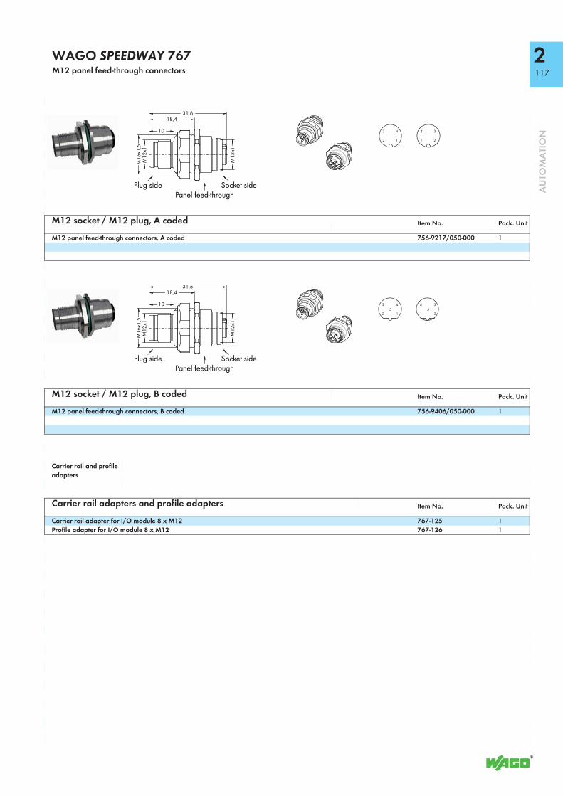
117
AU
TOM
ATI
ON
WAGO SPEEDWAY 767M12 panel feed-through connectors
M12 socket / M12 plug, A coded Item No. Pack. Unit
M12 panel feed-through connectors, A coded 756-9217/050-000 1
M12 socket / M12 plug, B coded Item No. Pack. Unit
M12 panel feed-through connectors, B coded 756-9406/050-000 1
Carrier rail and profile adapters
Carrier rail adapters and profile adapters Item No. Pack. Unit
Carrier rail adapter for I/O module 8 x M12 767-125 1Profile adapter for I/O module 8 x M12 767-126 1
31,618,4
10M
16x1
,5M
12x1
M12
x1
Socket sidePanel feed-through
Plug side
3
2
4
1
4
1
3
2
31,618,4
10
M16
x1,5
M12
x1
M12
x1
Socket sidePanel feed-through
Plug side
3
2
45
1
4
1
35
2
2

206-701
1182
AU
TOM
ATI
ON
Torque Wrench M8 and M12Assembly kit
Adjustment tool Torquescrewdriver
Allen key
Tool kit
Assembly kit for 756 Series pre-assembled IP67 cables and connectors, consists of:• Tool kit• Torque screwdriver with adjustable torque (window scale)• Adjustment tool for changing the torque• One Allen key (interchangeable 4 mm blade) for each of the M8 and M12
connectorsA torque specification of 0.6 Nm for M8 connectors and 1.0 Nm for M12 connectors is required for 756 Series cables and connectors.
Description Item No. Pack. Unit
Torque Wrench M8 and M12 206-701 1
Technical DataTorque range 0.4 ... 1 Nm ±6 % (adjustable)Material Handle:
PP (Polypropylene) for hard portion, Thermoplastic elastomers (TPE) for soft zone Allen key: Polyamide (PA), glass-fiber-reinforced; chrome-vanadium-molybdenum steel (CrMoV) (1.2381) Adjustment tool: Cellulose acetate; chrome-vanadium-molybdenum steel (CrMoV) (1.2381)
Color blackStandards/specifications EN ISO 6789;
BS EN 26789; ASME B107.14.M

119
AU
TOM
ATI
ON
WAGO-I/O-SYSTEM 756
Sensor/actuator cables, with one end of cable fitted
M12 Sensor/actuator cables, with one end of cable fitted Item No. Pack. Unit
8-pole, shielded M12 plug, straight, one free cable end, 1.5 m 756-5311/090-015 10M12 plug, straight, one free cable end, 5 m 756-5311/090-050 10M12 plug, straight, one free cable end, 10 m 756-5311/090-100 10
M12 Sensor/actuator cables, with one end of cable fitted Item No. Pack. Unit
8-pole, shielded M12 plug, right angle, one free cable end, 1.5 m 756-5312/090-015 10M12 plug, right angle, one free cable end, 5 m 756-5312/090-050 10M12 plug, right angle, one free cable end, 10 m 756-5312/090-100 10
Configurable connectors
M12 Plug, for self assembly Item No. Pack. Unit
8-pole, shielded M12 socket, straight, screw clamp connection 756-9211/090-000 1M12 socket, right angle, screw clamp connection 756-9214/090-000 1
* Cable length
L*)52,3 35±2
(mm)
ø15
M12
x1 1 2
4567 38
M12 plug
12345678
whitebrowngreenyellowgraypinkbluered
Shield (screen)
Pin 1 ... 8: 0.25 mm²
35,3
L*)37,5 35±2
(mm)
ø15M12x1
1 2
4567 38
M12 plug
12345678
whitebrowngreenyellowgraypinkbluered
Shield (screen)
Pin 1 ... 8: 0.25 mm²
M12
x 1
Ø 2
0mm
∼57mm
PG 7
... P
G 9
∼20m
m
45°∼3
8mm
∼56mm
M12 x 1
Ø 1
8mm
2 1
6543 78
M12 socket
Conductor size Ø 6 ... 8 mm/0.14 ... 0.50 mm²
5

7120
AU
TOM
ATI
ON
Bluetooth® Module, RS-232, IP67
WAGO's 757-801 Bluetooth® Module wirelessly connects a serial interface to external Bluetooth® devices (e.g., PCs/notebooks with Bluetooth®). Data is exchanged via Bluetooth® SPP (Serial Port Profile).
Substitute cabling between two serial devices by automatically restoring the outgoing wireless connection (e.g., to a second Bluetooth® module). High protection class provides enhanced, wireless Bluetooth® module's installation outside of control cabinets.
Coexistence properties:• AFH (Adaptive Frequency Hopping)• Adaptive transmission power with configurable upper limits for data ex-
change and device discovery• Configurable channel blacklist for FHSS (Frequency Hopping Spread
Spectrum)• Coexistence optimized device discovery supported (media allocation < 5 %,
allocation duration < 100 ms)
Description Item No. Pack. Unit
Bluetooth® Module 757-801 1
AccessoriesMarking strips, felt-tip pen see Full Line Catalog AUTOMATION
2012/2013
ApprovalsConformity marking 1
Bluetooth® approval
Technical DataVersion 2.1Radio class Class 1/max. 100 mAntenna integratedRF output power max. +10 dBmRF input sensitivity typ. -82 dBmFrequency range 2.402 ... 2.483 GHz (ISM band)Type of communication Point-to-point connectionProfiles supported Serial Port Profile (SPP)Security encryption Bluetooth® security mode 4
“Secure Simple Pairing” 128-bit encryption
Dimensions (mm) W x H x L 30 x 20 x 117 (without cable)Weight 418 gFixing Screw mountingPorts RS-232 interface (RX/TX) with hardware
flow control (CTS/RTS) Bluetooth® radio interface
Technical DataBaud rate 9600 ... 115200 bpsIndicators five LEDsVoltage supply +24 VDCVoltage range +10 V ... +32 VDCCurrent input (at 24 VDC) < 50 mAEMC: 1 - immunity to interference acc. to EN 61000-6-2 (2005)EMC: 1 - emission of interference acc. to EN 61000-6-3 (2007)Permissible temperature range -20 °C ... +60 °C (static);
-5 °C ... +60 °C (moving)Storage temperature -30 °C ... +80 °CDegree of protection IP67Connecting cable
Cable length approx 5 mCable design Outer sheath PUR halogen-free
BlackCable Ø 6.6 mm (± 0.2 mm)Screening Copper braiding, tin-plated,
0.10 mm single-wire diameterConductor design 4 x 0.34 mm2 + 2 x 0.75 mm2
conductor 0.34 mm2, extra-fine stranded, 43 x 0.10 mmconductor 0.75 mm2, extra-fine stranded, 21 x 0.205 mm
bending radius 10 x cable diameter for flexible applicationBending cycles 1 million cycles

758-916, 758-917
7121
AU
TOM
ATI
ON
WLAN ETHERNET GatewayWireless transmission link for ETHERNET protocols
1: Vin + (DC 9 ... 30 V)2: External Trigger Ground3: Vin GND (0 V)4: External Trigger + (DC 9 ... 30 V)5: n.c.
1: Transmit +2: Receive +3: Transmit -4: Receive -
ETHERNET connector:M12 socket, D-coded
Power connector:M12 plug, A-coded
WAGO WLAN ETHERNET Gateways simplify creation of a wireless transmission link for ETHERNET protocols (e.g., PROFINET, MODBUS/TCP, Ethernet/IP).
The gateway is used as a cable substitute to create a robust, industry-proven WLAN link between two automation devices.
The IP65 housing and circularly polarized antenna allow the gateway to be used even in harsh industrial environments. Simple, push-button operation provides very fast connection between two WLAN ETHERNET Gateways.
Note:Two WLAN ETHERNET Gateways of the same type are required to establish a point-to-point connection.
Description Item No. Pack. Unit
WLAN ETHERNET Gateway, 2.4 GHz 758-916 1WLAN ETHERNET Gateway, 5 GHz 758-917 1
Accessories Item No. Pack. Unit
IP67 cables and connectors see Full Line Catalog 2012/2013, Volume 3, Sections 2 and 5
ApprovalsR&TTE (Europe)FCC/CFR 47 part 15 IC (Industry Canada)
Conformity marking 1
Technical DataWireless technology IEEE 802.11 bgn (758-916)
IEEE 802.11 an (758-917)Topology Point-to-point connectionSecurity authentification Open, Shared, WPA/WPA2 PSK, LEAP,
PEAPSecurity encryption None, WEP64, WEP128, TKIP,
AES/CCMPFrequency band License-free ISM band, 2.4 GHz (758-916)
License-free ISM band, 5 GHz (758-917)Transmission range up to 400 m (758-916)
up to 200 m (758-917)Antenna Internal, circularly polarized, directional
antennaVoltage supply 24 V DCVoltage range 9 V ... 30 V DCPorts ETHERNET connector:
M12 socket, D-codedPower connector:M12 plug, A-coded
Configuration Simple, push-button operation and Web-based management
Number of inputs 1 (trigger input 9 V ... 30 VDC)Dimensions (mm) W x H x L 66 x 36.2 x 91Weight 120 gOperating temperature -30 °C ... +65 °CStorage temperature -40 °C ... +85 °CDegree of protection IP65EMC: 1 - immunity to interference acc. to EN 61000-6-2 (2005)

761-114
8122
AU
TOM
ATI
ON
TO-PASS® Compact, 2 AI, Web, MODBUS, RS-485Telecontrol module for fault detection/indication, monitoring and remote control
Com
Busy
Run
StatusSIM PC
TO-PASS®
<________________________________________ 109 mm/4.29 in ________________________________________>
<_____________________________________
105
mm
/4.1
2 in _____________________________________>
Compact telecontrol module provides fault detection/indication and Internet connectivity for machines and installations over a GSM network. The module can be used in many countries via an integrated quad-band GSM modem. Messages are sent via SMS, e-mail, fax or phone call. In addition, the process image can be transmitted in an adjustable cycle to a user-selected Internet address. A MODBUS slave (e.g., 750-815) can be connected via RS-485 interface to link additional process values. Switching of outputs is performed via SMS or TO-PASS® Web Portal.The module is equipped with 4 digital inputs, 4 analog outputs and 2 digital inputs, including an integrated GSM modem. Ideal for applications in distributed stations for temperatures ranging from -20°C to +70°C. Ability to mount on DIN-rail and intuitive user software make unit easy to use. Operating voltage ranges from +10 to +30 VDC.
Specialty functions:• Acknowledgement: Any fault message• Stand-by: Automatic remote switching of stand-by service• Remote parameterization: Programming and process visualization
conveniently performed from the office• GPRS-dedicated line: Permanent online connection to the process on a Web
server or PC with fixed IP address (e.g., DSL connection)• Counter function: Maximum four of the digital inputs can be used as up or
down counter. The maximum operating frequency is 1250 Hz.
Description Item No. Pack. Unit
TO-PASS® Compact, 2 AI, Web, MODBUS, RS-485
761-114 1
AccessoriesAntennas, USB adapter, GSM modem and power supply units
see Full Line Catalog AUTOMATION 2012/2013
ApprovalsApprovals for all EU countries
Approvals for other countries on requestr UL 508 pending
Technical DataOperating temperature -20 °C ... +70 °CType of mounting DIN 35 railAntenna connection SMAWire connection Terminal strips (WAGO 250 Series)
with PUSH WIRE® connectionCross sections 0.5 mm² ... 1.5 mm² / AWG 22 ... 14Strip lengths 9 mm /0.35 inDimensions (mm) W x H x L 109 x 78 x 105Weight 412 gStorage temperature -40 °C ... +85 °CDegree of protection IP20EMC: 1 - immunity to interference acc. to EN 61000-6-2 (2005)EMC: 1 - emission of interference acc. to EN 61000-6-3 (2007)
Technical DataMODBUS
Transmission modes RS-485 (2-conductor), RTU MasterBaud rate 9.6 and 19.2 kbaud (8N1, 8E1, 8O1,
8N1)Read-out register max. 64 registers (input or holding)
Digital inputs:Number of inputs 4 (Type 3)Input current max. 2.9 mA at 30 V DCSignal voltage (0) 0 V ... 5 V DCSignal voltage (1) 7 V ... 30 V DC
Analog inputs:Number of inputs 2 (0/4 mA ... 20 mA)Internal resistance approx. 200 Ω / 20 mAMeasuring error (25°C) < ± 1 % of the full scale valueTemperature coefficient < ± 0.1 % / K of the full scale value
Digital outputs:No. of outputs 4 contactsOutput current (max.) 0.5 A/ 30 V DC, short-circuit protected
Analog outputs:Measuring error (25°C) < ± 1 % of the full scale valueTemperature coefficient < ± 0.1 % / K of the full scale value
Communication GSM quad-bandCommunication types SMS (bidirectional),
telecommunication dial-up connection (CSD) GPRS connection to Internet
Signaling 3 LEDs for operating status indicationOperating voltage +10 V ... +30 V DCClosed current approx. 20 mA at +24V operating voltageCurrent during transmission < 500 mA at +24V operating voltage

761-217
8123
AU
TOM
ATI
ON
TO-PASS® Compact, 8 AI, Web, MODBUS, RS-485Telecontrol module for fault detection/indication, monitoring and remote control
Com
Busy
Run
StatusSIM PC
TO-PASS®
<________________________________________ 109 mm/4.29 in ________________________________________>
<_____________________________________
105
mm
/4.1
2 in _____________________________________>
Universal telecontrol module provides fault detection/indication and Internet connectivity for machines and installations over a GSM network. The module can be used in many countries via an integrated quad-band GSM modem. Messages are sent via SMS, e-mail, fax or phone call. The data memory stores up to 4096 process images in an adjustable cycle time. In addition, the process image can be transmitted in an adjustable cycle to a user-selected Internet address. A MODBUS slave (e.g., 750-815) can be connected via RS-485 interface to link additional process values. Switching of outputs is performed via SMS or TO-PASS® Web Portal.The module is equipped with 8 digital inputs, 8 analog inputs, 4 digital outputs and 2 analog outputs, including an integrated GSM modem. Ideal for applications in distributed stations for temperatures ranging from -20°C to +70°C. Ability to mount on DIN-rail and intuitive user software make unit easy to use. Operating voltage ranges from +10 to +30 VDC.
Specialty functions:• Acknowledgement: Any fault message• Stand-by: Automatic remote switching of stand-by service• Remote parameterization: Programming and process visualization
conveniently performed from the office• GPRS-dedicated line: Permanent online connection to the process on a Web
server or PC with fixed IP address (e.g., DSL connection)• Event logger: Saves all occurring status changes• Data logger: Saves all process values with adjustable cycle• Counter function: Maximum four of the digital inputs can be used as up or
down counter. The maximum operating frequency is 1250 Hz.
Description Item No. Pack. Unit
TO-PASS® Compact, 8 AI, Web, MODBUS, RS-485
761-217 1
AccessoriesAntennas, USB adapter, GSM modem and power supply units
see Full Line Catalog AUTOMATION 2012/2013
ApprovalsApprovals for all EU countries
Approvals for other countries on requestr UL 508 pending
Technical DataOperating temperature -20 °C ... +70 °CType of mounting DIN 35 railAntenna connection SMAWire connection Terminal strips (WAGO 250 Series)
with PUSH WIRE® connectionCross sections 0.5 mm² ... 1.5 mm² / AWG 22 ... 14Strip lengths 9 mm /0.35 inDimensions (mm) W x H x L 109 x 78 x 105Weight 412 gStorage temperature -40 °C ... +85 °CDegree of protection IP20EMC: 1 - immunity to interference acc. to EN 61000-6-2 (2005)EMC: 1 - emission of interference acc. to EN 61000-6-3 (2007)
Technical DataMODBUS
Transmission modes RS-485 (2-conductor), RTU MasterBaud rate 9.6 and 19.2 kbaud (8N1, 8E1, 8O1,
8N1)Read-out register max. 64 registers (input or holding)
Digital inputs:Number of inputs 8 (Type 3)Input current max. 2.9 mA at 30 V DCSignal voltage (0) 0 V ... 5 V DCSignal voltage (1) 7 V ... 30 V DC
Analog inputs:Number of inputs 8 (0/4 mA ... 20 mA)Internal resistance approx. 200 Ω / 20 mAMeasuring error (25°C) < ± 1 % of the full scale valueTemperature coefficient < ± 0.1 % / K of the full scale value
Digital outputs:No. of outputs 4 contactsOutput current (max.) 0.5 A/ 30 V DC, short-circuit protected
Analog outputs:No. of outputs 2 (0/4 mA ... 20 mA)Load impedance ≤ 600 ΩMeasuring error (25°C) < ± 1 % of the full scale valueTemperature coefficient < ± 0.1 % / K of the full scale value
Communication GSM quad-bandCommunication types SMS (bidirectional),
telecommunication dial-up connection (CSD) GPRS connection to Internet
Signaling 3 LEDs for operating status indicationOperating voltage +10 V ... +30 V DCClosed current approx. 20 mA at +24V operating voltageCurrent during transmission < 500 mA at +24V operating voltage

759-200
8124
AU
TOM
ATI
ON
WAGO Telecontrol Gateway
Parameter setting and diagnostics via Web server
Connection to control system acc. to IEC 60870-5-101/-104
Max. 12 RS-232/-485 I/O modules and ISDN/analog modem (19‘‘ plug-in card)
Max. 64 substations can be connected via fieldbus controller acc. to IEC 60870-5:- 101 via analog, GSM or ISDN dial-up connections- 103 via RS-485 I/O module- 104 via ETHERNET or GPRS
WAGO Telecontrol Gateway (WTG), in connection with the controllers mentioned below, is a gateway software for communication between max. 64 telecontrol substations (IEC 60870-5-101/-103/-104) and a control system equipped with interface (IEC 60870-5-101/-104). This gateway is ideal for connecting telecontrol substations and for control system applications being restricted by the transmission protocol or the number of connections.In addition to data transfer bundling, the WTG also supports coordination of incoming and outgoing analog, GSM or ISDN dial-up connections to substations.
Description Item No. Pack. Unit
WAGO Telecontrol Gateway Softwarefor 758-875/000-130 759-200 1for 750-880/025-002 759-200/000-002 1
Technical DataNumber of I/O modules
for 758-875/000-130 max. 12 I/O module 750-652for 750-880/025-002 max. 4 I/O mudule 750-652
Number of connectable telecontrol substationsfor 758-875/000-130 max. 64for 750-880/025-002 max. 16
AccessoriesAccessories for WAGO Telecontrol Gateway:
Telecontrol I/O-IPC-C10: 758-875/000-130 or Controller 750-880/025-002RS-232/-485 module, WAGO-I/O-SYSTEM: 750-652End module, WAGO-I/O-SYSTEM: 750-60019‘‘ rack, INSYS: 11-02-05-01-01.00619‘‘ plug-in card (ISDN modem), INSYS: 11-02-05-03-01.003Alternative: 19‘‘ plug-in card (analog modem), INSYS: 11-02-05-02-03.003
Telecontrol substation with ISDN dial-up modem:WAGO Telecontroller: 750-872Additional 750/753 Series I/O modules, if necessaryEnd module, WAGO-I/O-SYSTEM: 750-600RS-232 null modem cable: 761-9011ISDN modem (for DIN rail mounting), INSYS ISDN-TA 4.0: 11-02-01-02-00.018
Telecontrol substation with analog dial-up modem:WAGO Telecontroller: 750-872Additional 750/753 Series I/O modules, if necessaryEnd module, WAGO-I/O-SYSTEM: 750-600RS-232 null modem cable: 761-9011Analog modem (for DIN rail mounting), INSYS Modem 56k 4.2: 11-02-01-01-40.039
Telecontrol substation with GSM connection:WAGO Telecontroller: 750-872Additional 750/753 Series I/O modules, if necessaryEnd module, WAGO-I/O-SYSTEM: 750-600RS-232 null modem cable: 761-9011GSM modem (for DIN rail mounting), INSYS GSM 4.3: 11-02-01-03-01.042Magnetic foot antenna for INSYS GSM 4.3: 31-01-01.007
Telecontrol substation with DSL/ETHERNET connection:WAGO Telecontroller: 750-872Alternative: WAGO Telecontroller: 750-880/025-001Additional 750/753 Series I/O modules, if necessaryEnd module, WAGO-I/O-SYSTEM: 750-600

8125
AU
TOM
ATI
ON
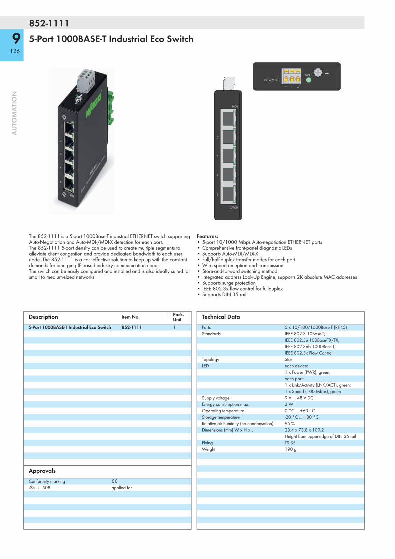
852-1111
9126
AU
TOM
ATI
ON
5-Port 1000BASE-T Industrial Eco Switch
5
4
3
2
1
1000
10/100
+9~48V DC
+ -
PWR
The 852-1111 is a 5-port 1000Base-T industrial ETHERNET switch supporting Auto-Negotiation and Auto-MDI-/MDI-X detection for each port. The 852-1111 5-port density can be used to create multiple segments to alleviate client congestion and provide dedicated bandwidth to each user node. The 852-1111 is a cost-effective solution to keep up with the constant demands for emerging IP-based industry communication needs. The switch can be easily configured and installed and is also ideally suited for small to medium-sized networks.
Features:• 5-port 10/1000 Mbps Auto-negotiation ETHERNET ports• Comprehensive front-panel diagnostic LEDs• Supports Auto-MDI/MDI-X• Full/half-duplex transfer modes for each port• Wire speed reception and transmission• Store-and-forward switching method• Integrated address Look-Up Engine, supports 2K absolute MAC addresses• Supports surge protection• IEEE 802.3x flow control for fullduplex• Supports DIN 35 rail
Description Item No. Pack. Unit
5-Port 1000BASE-T Industrial Eco Switch 852-1111 1
ApprovalsConformity marking 1
r UL 508 applied for
Technical DataPorts 5 x 10/100/1000Base-T (RJ-45)Standards IEEE 802.3 10Base-T;
IEEE 802.3u 100Base-TX/FX; IEEE 802.3ab 1000Base-T; IEEE 802.3x Flow Control
Topology StarLED each device:
1 x Power (PWR), green; each port: 1 x Link/Activity (LNK/ACT), green; 1 x Speed (100 Mbps), green
Supply voltage 9 V ... 48 V DCEnergy consumption max. 3 WOperating temperature 0 °C ... +60 °CStorage temperature -20 °C ... +80 °CRelative air humidity (no condensation) 95 %Dimensions (mm) W x H x L 23.4 x 73.8 x 109.2
Height from upper-edge of DIN 35 railFixing TS 35Weight 190 g

9127
AU
TOM
ATI
ON

10128
AU
TOM
ATI
ON
WAGO Ribbon Cables
WAGO ribbon cables provide fast and easy connection of WAGO I/O modules equipped with pluggable connectors (e.g., 753-430, -431, -530) to appropriate interface or relay modules featuring a 10-pole female connector.
WAGO ribbon cables provide fast and easy connection of WAGO I/O modules equipped with pluggable connectors (e.g., 753-430, -431, -530) to appropriate interface or relay modules featuring a 20-pole female connector.
For example, this cable connects two WAGO I/O modules to one relay output module (16-channel).
Description Item No. Pack. Unit Description Item No. Pack.
UnitWAGO ribbon cable, 1 x 753 Series pluggable connector/10-pole female connector, 1 m long
706-7753/300-100 1 WAGO ribbon cable, 2 x 753 Series pluggable connector/20-pole female connector, 2 m long
706-7753/301-200 1
For other cable lengths, please contact factory. For other cable lengths, please contact factory.
Technical Data Technical Data
Wire cross-section 0.14 mm2 LiYY Wire cross-section 0.14 mm2 LiYYColor coding acc. to DIN VDE 47100 Color coding acc. to DIN VDE 47100Current per channel max. 1 A Current per channel max. 1 AOperating temperature * -25 °C ... +70 °C Operating temperature -25 °C ... +70 °CDegree of protection IP20 Degree of protection IP20Length 1 m Length 2 m
* Observe maximum operating temperature of the WAGO I/O modules used.
10-pole female connector
753 Series connector
20-pole female connector
753 Series connector

10129
AU
TOM
ATI
ON
Marker Carriers for 750/753 Series
WAGO's 750-106 and 750-107 Marker Carriers allow I/O functions to be identified throughout the node via continuous marking strips. Both carrier mo-dels permit continuous marking regardless of the I/O module housing used. • 750-106, for I/O module housing with up to 4 LEDs,
as well as for 48 mm I/O module housing • 750-107, for I/O module housing with 8 or 16 LEDsThe marker carrier can be accommodated in the upper miniature WSB marker slot. It is not necessary to use a carrier on each I/O module to mount the marking strip.
Description Item No. Pack. Unit
Marker Carrier for 750/753 Series, 4 LEDs 750-106 50Marker Carrier for 750/753 Series, 8/16 LEDs 750-107 50
Accessories Item No. Pack. Unit
Marking strip, plain, 11 mm wide, 50 m roll 2009-110 1WMB Inline, pitch 5 mm, stretchable, 5 mm ... 5.2 mm, on reel 2009-115 1
Technical DataMaterial PolycarbonateWeight 0.4 g

WAGO flexROOM® Distribution Box, 2854 Series
Several flexROOM® distribution boxes can be combined into a network via ETHERNET. A standard Web browser also establishes communication between the distribution boxes.A flexROOM® distribution box for weather stations can transmit weather data (e.g., outside temperature or wind alarms) to other flexROOM® distribution boxes for further processing.
For the connection of higher-level management stations, each flexROOM® distribution box provides data in MODBUS tables, that can be read and partly be written by the stations.Configuration data of the flexROOM® distribution box can cyclically be saved eit-her directly on the included controller or on a separate computer.
The flexROOM® distribution box is equipped with WAGO WINSTA® connectors. The flexROOM® distribution boxes differ from each other in the number of room axes, the support of specialty application areas, various functions depending on the inputs and outputs used.
WAGO flexROOM® office distribution boxes support the automation of commercial and functional buildings (offices) with floor plans based on a room axis concept. The boxes automate both lighting and sun protection, while performing single-room control (heating/cooling) for up to 24 room axes. In addition to the room axes, special areas (e.g., stairways, corridors, sanitary facilities) may be automated via specialty flexROOM® distribution boxes.
Control is performed via WAGO 750-884 Application Controller, which is inclu-ded in the flexROOM® distribution box and preloaded with a flexROOM® office application. Initial commissioning (IP address assignment via BootP server) can be performed via WAGOupload PC software.
A standard Web browser performs both initial room axis configuration and later reconfiguration directly on the distribution box’s controler.
Technical DataPower supply
Supply voltage 230 VAC, 50 ... 60 Hz Voltage range +/- 10 %Fuse protection In accordance with applicable regulations
and electrotechnical provisions outside the enclosure; SCPD 16 A (B)
Connectors 3-pole plug-in connectors, WAGO 770-713
ConfigurationConfiguration via Web server
Bus connection (ETHERNET)Transmission medium Twisted Pair S-UTP, 100 Ohm, Cat. 5;
100 m maximum cable lengthBaud rate 10/100 Mbit/sTransmission performance Class D acc. to EN 50173Bus connection 2 x RJ-45
Room axesInputs
Dew point detectorSignaling 24 VDCMulti-sensorsSignaling, presence 24 VDCSignaling, brightness 0 ... 10 VAC
OutputsSunblind driveSwitching voltage 230 VAC, 50 ... 60 HzVoltage range +/- 10 %Switching current 1.5 A at 230 VACSwitching power (relay) 300 W (AC3)Output short-circuit protection Not short-circuit protectedLighting (DALI)Switching voltage 230 VAC; +/-10%Voltage range +/- 10 %Switching current max. 16 A in totalSwitching power 3.600 VA in total Heating/Cooling valvesSwitching voltage 24 VDC; +/-10%Switching current 250 mASwitching power 6 W (temporary), 3 W (average)
Description Item No. Pack. Unit
Type 1 – 8 axes 2854-0300/1008-0032 1Type 1 – 16 axes 2854-0300/1016-0032 1Type 1 – 24 axes 2854-0300/1024-0032 1Type 1 – 8 axes with specialty areas 2854-0300/1008-8032 1Type 1 – 16 axes with specialty areas 2854-0300/1016-8032 1Type 3 – 8 axes 2854-0300/1008-0002 1Type 3 – 16 axes 2854-0300/1016-0002 1Type 3 – 24 axes 2854-0300/1024-0002 1Type 3 – 8 axes with specialty areas 2854-0300/1008-8002 1Type 3 – 16 axes with specialty areas 2854-0300/1016-8002 1
Connector set for flexROOM® Office Distribution Box (upon request) 1For detailed information on WINSTA® connection technology, see “Distribution Box” documentation.
WINSTA® accessoriesWINSTA® Distribution Box 770-631/100-000 1Three-phase to single-phase distribution connectorwith phase selection 770-640 1h-distribution connector for 2 sockets 770-993 1Distribution connector, 3-way, 770-609 1Fixing pin 890-601 1Interconnecting cable, plug/socket, 3 x 2.5 mm², 40 cm 771-9993/007-041 1
130
AU
TOM
ATI
ON

75 mm 75 mm
l
17 m
mb
17 m
mh
3-pole
2-pole
3-pole4-pole4-pole
2-/5-pole
4-pole
8-pole
3-pole
flexROOM®
Office Distribution Box
* Support is distribution box specific
Dew point detector
Heating/cooling valves24 VDC PWM
Special areas*Presence detectors, light buttons24 VDC
Lighting230 V
Multi-sensors24 V
DALI sensors andDALI lights1 ... 64 devices
Sunblind drives230 V
EnOcean gatewayRS-485
Network connections2 x RJ-45
Power supply230 V (3 to 5 per distribution box)
Subsystems Office areas Special areas General AbbreviationInputs Outputs Inputs Outputs Dimensions Weight
DALI
EnO
cean
Dew
poi
nt d
etec
tor
Mul
ti-sen
sors
(con
vent
iona
l)*
DALI
sens
ors*
Hea
ting/
Cool
ing
Light
ing
(DAL
I)
Sunb
linds
(rel
ays)
Sunb
lind
butto
n
Light
but
ton
Pres
ence
det
ecto
r
Hea
ting/
Cool
ing
Light
ing
(rela
y)
Sunb
linds
(rel
ays)
L in
[mm
]
W in
[mm
]
H in
[mm
] in
cl. a
cces
sorie
s
Wt i
n [k
g]
2854-0300/1008-0032 x x 2 4 x 8 16 8 - - - - - - 550 350 120 8.8 T1 A82854-0300/1016-0032 x x 2 8 x 16 32 16 - - - - - - 550 500 150 12.7 T1 A162854-0300/1024-0032 x x 2 12 x 24 48 24 - - - - - - 750 500 140 17 T1 A24
2854-0300/1008-8032 x x 2 4 x 8 16 8 4 4 4 2 4 4 650 500 150 14.3 T1 A8S
2854-0300/1016-8032 x x 2 8 x 16 32 16 4 4 4 2 4 4 650 500 150 16 T1 A16S
2854-0300/1008-0002 x x 2 - x 8 16 8 - - - - - - 550 350 120 8.5 T3 A82854-0300/1016-0002 x x 2 - x 16 32 16 - - - - - - 550 500 150 12.3 T3 A162854-0300/1024-0002 x x 2 - x 24 48 24 - - - - - - 750 500 140 16.5 T3 A24
2854-0300/1008-8002 x x 2 - x 8 16 8 4 4 4 2 4 4 650 500 150 13.8 T3 A8S
2854-0300/1016-8002 x x 2 - x 16 32 16 4 4 4 2 4 4 650 500 150 15.5 T3 A16S
*Either Multi-sensors or DALI sensors can be used.
Technical DataSpecial areas Standards and approvals
Inputs CE conformity DIN EN 61439-1/2:2009Sunblind, light buttons, presence detectorSignalizing
General specifications24 VDC Operating temperature -5 °C … +45 °C, non-condensing
Outputs Storage temperature -20 °C ... +70 °CSunblind drives see room axes Type of mounting Wall, screw fixingLighting (relay) Assembly Interior area, e.g., intermediate floors,
suspended ceilingSwitching voltage 230 VAC; +/-10%Voltage range +/- 10 % Mounting position anySwitching currentmax 16 A in total with DALI lighting fixtures Degree of protection IP20Switching powermax 3600 VA in total with DALI lighting
fixturesPollution degree 2Housing material Galvanized steel plate, material DC01
hot-dip galvanized, raw
131
AU
TOM
ATI
ON

1132
INTE
RFA
CE E
LECT
RON
IC
Rail-Mounted Terminal Blocks with Miniature Switching Relay
Relay with 1 changeover contact (1 u) Gold-plated contacts, 5 μmfor normal switching power Nominal input voltage VN 5 VDC
Coil voltage supplements 859-314
Relay with 1 changeover contact (1 u) for normal switching power Nominal input voltage VN. 60 V AC/DC
Coil voltage supplements 859-353 ... -358 models
DC load limit curve
** To prevent damage to the gold layer, do not exceed 30 VDC switching voltages and 50 mA currents. Higher switching power can vaporize the gold layer. The resulting precipitate in the enclosure may cause arcing [spark-overs] between the coil and the contact.
Description VN IN Item No. Pack. Unit VN IN Item No. Pack.
UnitRail-mounted terminal blocks with miniature switching relay, for DIN 35 rail
5 VDC 31 mA 859-312 1 60 V AC/DC 4.1 mA 859-356 1
Technical Data For accessories, see Full Line Catalog INTERFACE ELECTRONIC 2012/2013
For accessories, see Full Line Catalog INTERFACE ELECTRONIC 2012/2013
coil:Input voltage range VN -15 % ... +20 % VN -15 % ... +20 %
Contacts:Contact material AgNi + 5 μm Au AgNiMax. continuous current 5 A ** 5 AMax. make current (resistive) at 10 % OT * - -Max. switching voltage 250 VAC ** 250 VACMax. switching power (resistive) 1250 VA AC; DC see load curve ** 1250 VA AC; DC see load curveRecommended minimum load 1 VDC / 1 mA / 1 mW 10 VDC / 10 mA, 24 VDC / 1 mAPull-in/drop-out/bounce time typ. 5 ms / 6 ms / 5 ms 5 ms / 6 ms / 5 msMechanical life 5 x 10⁶ switching operations 5 x 10⁶ switching operations
General specifications:Nominal voltage to EN 60664-1 250 V / 4 kV / 2 250 V / 4 kV / 2Dielectric strength, contact-coil (AC, 1 min) 4 kVrms 4 kVrmsDielectric strength open contact (AC, 1 min) 1 kVrms 1 kVrmsDielectric strength contact-contact (AC, 1 min) - -Ambient operating temperature at VN -25 °C … +70 °C -25 °C ... +50 °CStorage temperature -40 °C … +70 °C -40 °C ... +70 °CDimensions (mm) W x H x L 6 x 56 x 91 6 x 56 x 91
Height from upper-edge of DIN 35 rail Height from upper-edge of DIN 35 railWire connection CAGE CLAMP® CAGE CLAMP®
Cross sections 0.08 mm² ... 2.5 mm² / AWG 28 ... 14 0.08 mm² ... 2.5 mm² / AWG 28 ... 14Strip lengths 5 ... 6 mm / 0.22 in 5 ... 6 mm / 0.22 inStandards/Specifications EN 60664-1; EN 61810-5;
UL 508; EEx nC II T4; gEN 60664-1; EN 61810-5;
UL 508; EEx nC II T4; g
* (OT = On-time)
A1 +
14
12
11
A2 –
14
12
11
A1
A2
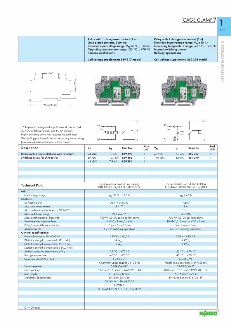
1133
8
INTE
RFA
CE E
LECT
RON
IC
Relay with 1 changeover contact (1 u) Gold-plated contacts, 5 μm AuExtended input voltage range: VN -30 % ... +25 %;Operating temperature range: -25 °C ... +70 °C Railway applications
Coil voltage supplements 859-317 model
Relay with 1 changeover contact (1 u) Extended input voltage range: VN ±40 %;Operating temperature range: -25 °C ... +70 °C Normal switching power Railway applications
Coil voltage supplements 859-398 model
** To prevent damage to the gold layer, do not exceed 30 VDC switching voltages and 50 mA currents. Higher switching power can vaporize the gold layer. The resulting precipitate in the enclosure may cause arcing [spark-overs] between the coil and the contact.
Description VN IN Item No. Pack. Unit VN IN Item No. Pack.
UnitRail-mounted terminal blocks with miniature switching relay, for DIN 35 rail
24 VDC 10 mA 859-392 1 48 VDC 7.9 mA 859-397 136 VDC 10.1 mA 859-386 1 110 VDC 3.1 mA 859-399 148 VDC 7.9 mA 859-384 1
Technical Data For accessories, see Full Line Catalog INTERFACE ELECTRONIC 2012/2013
For accessories, see Full Line Catalog INTERFACE ELECTRONIC 2012/2013
coil:Input voltage range VN -30 % ... +25 % VN ± 40 %
Contacts:Contact material AgNi + 5 μm Au AgNiMax. continuous current 3 A ** 3 AMax. make current (resistive) at 10 % OT * -Max. switching voltage 250 VAC ** 250 VACMax. switching power (resistive) 750 VA AC; DC see load limit curve 750 VA AC; DC see load curveRecommended minimum load 1 VDC / 1 mA / 1 mW 10 VDC / 10 mA, 24 VDC / 1 mAPull-in/drop-out/bounce time typ. 5 ms / 6 ms / 5 ms 5 ms / 6 ms / 5 msMechanical life 5 x 10⁶ switching operations 5 x 10⁶ switching operations
General specifications:Nominal voltage to EN 60664-1 250 V / 4 kV / 2 250 V / 4 kV / 2Dielectric strength, contact-coil (AC, 1 min) 4 kVrms 4 kVrmsDielectric strength open contact (AC, 1 min) 1 kVrms 1 kVrmsDielectric strength contact-contact (AC, 1 min) - -Ambient operating temperature at VN -25 °C ... +70 °C -25 °C ... +70 °CStorage temperature -40 °C ... +70 °C -40 °C ... +70 °CDimensions (mm) W x H x L 6 x 56 x 91 6 x 56 x 91
Height from upper-edge of DIN 35 rail Height from upper-edge of DIN 35 railWire connection CAGE CLAMP® CAGE CLAMP®
Cross sections 0.08 mm² ... 2.5 mm² / AWG 28 ... 14 0.08 mm² ... 2.5 mm² / AWG 28 ... 14Strip lengths 5 ... 6 mm / 0.22 in 5 ... 6 mm / 0.22 inStandards/Specifications 859-384, 859-386:
EN 60664-1; EN 61810-5859-392:
EN 60664-1; EN 61810-5; UL 508; g
EN 60664-1; EN 61810-5; g
* (OT = On-time)
91 mm/3.58 in
56
mm
/2.2
in
A1 +
14
12
11
A2 –

1134
INTE
RFA
CE E
LECT
RON
IC
Rail-Mounted Terminal Blocks with Optocoupler
Power optocoupler Input: 12 ... 48 VDC Output: 3 ... 53 VDC / 4 A
Power optocoupler Input: 24 VDC Output: 3 ... 30 VDC / 5 A
Derating for 859-744
Derating for 859-737
Description VN IN Item No. Pack. Unit VN IN Item No. Pack.
UnitRail-mounted terminal blocks with optocoupler, for DIN 35 rail
48 VDC 5 mA 859-744 1 24 VDC 3.5 mA 859-737 1
Technical Data For accessories, see Full Line Catalog INTERFACE ELECTRONIC 2012/2013
For accessories, see Full Line Catalog INTERFACE ELECTRONIC 2012/2013
Control circuit:Input voltage range (low level) 0 ... 4 VDC 0 ... 5 VDCInput voltage range (high level) 10 ... 53 VDC 15 ... 30 VDC
Load circuit:Output voltage range 3 ... 53 VDC 3 ... 30 VDCMax. continuous current 4 A 5 APeak output current 30 A 25 ATurn-on time 200 μs 200 μsTurn-off time 450 μs 450 μsMax. switching frequency 100 Hz 100 HzMax. voltage drop at output 0.2 V 0.2 VReverse voltage transistor/triac 80 V 55 V
General specifications:Dielectric strength, control/load circuit 2.5 kVrms 2.5 kVrmsDielectric strength, channel/channel - -Ambient operating temperature -25 °C ... +70 °C (Derating must be observed) -25 °C ... +70 °C (Derating must be observed)Storage temperature -40 °C ... +70 °C -40 °C ... +70 °CDimensions (mm) W x H x L 6 x 56 x 91 6 x 56 x 91
Height from upper-edge of DIN 35 rail Height from upper-edge of DIN 35 railWire connection CAGE CLAMP® CAGE CLAMP®
Cross sections 0.08 mm² ... 2.5 mm² / AWG 28 ... 14 0.08 mm² ... 2.5 mm² / AWG 28 ... 14Strip lengths 5 ... 6 mm / 0.22 in 5 ... 6 mm / 0.22 inStandards/Specifications EN 60664 EN 60664
4
3
2
1
200 40 60 ϑ (°C)
"
!
I (A)! Terminal strip" Individual terminal blocks
Ambient operating temperature
Continuous current
4
5
3
2
1
200 40 60 ϑ (°C)
"
!
I (A)! Terminal strip" Individual terminal blocks
Ambient operating temperature
Continuous current
A2 –
A1 +
RL
-2
A
A2 –
A1 +
RL
RL
-2
A
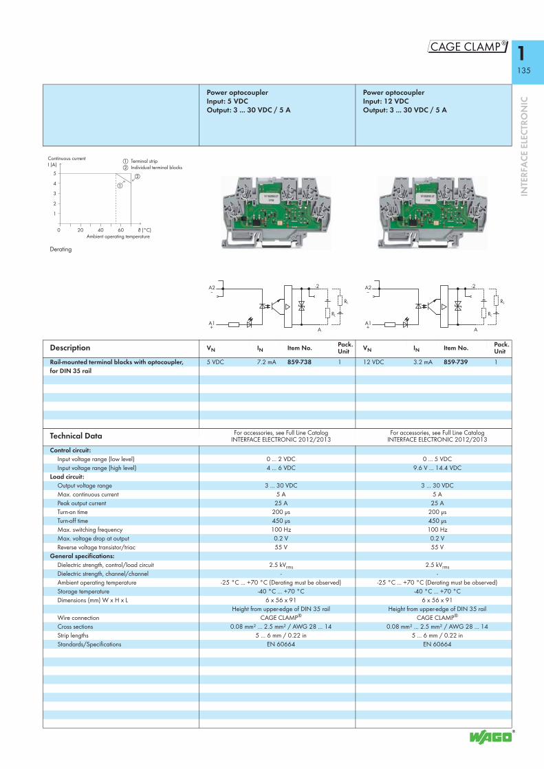
1135
8
INTE
RFA
CE E
LECT
RON
IC
Power optocoupler Input: 5 VDC Output: 3 ... 30 VDC / 5 A
Power optocoupler Input: 12 VDC Output: 3 ... 30 VDC / 5 A
Derating
Description VN IN Item No. Pack. Unit VN IN Item No. Pack.
UnitRail-mounted terminal blocks with optocoupler, for DIN 35 rail
5 VDC 7.2 mA 859-738 1 12 VDC 3.2 mA 859-739 1
Technical Data For accessories, see Full Line Catalog INTERFACE ELECTRONIC 2012/2013
For accessories, see Full Line Catalog INTERFACE ELECTRONIC 2012/2013
Control circuit:Input voltage range (low level) 0 ... 2 VDC 0 ... 5 VDCInput voltage range (high level) 4 ... 6 VDC 9.6 V ... 14.4 VDC
Load circuit:Output voltage range 3 ... 30 VDC 3 ... 30 VDCMax. continuous current 5 A 5 APeak output current 25 A 25 ATurn-on time 200 μs 200 μsTurn-off time 450 μs 450 μsMax. switching frequency 100 Hz 100 HzMax. voltage drop at output 0.2 V 0.2 VReverse voltage transistor/triac 55 V 55 V
General specifications:Dielectric strength, control/load circuit 2.5 kVrms 2.5 kVrmsDielectric strength, channel/channel - -Ambient operating temperature -25 °C ... +70 °C (Derating must be observed) -25 °C ... +70 °C (Derating must be observed)Storage temperature -40 °C ... +70 °C -40 °C ... +70 °CDimensions (mm) W x H x L 6 x 56 x 91 6 x 56 x 91
Height from upper-edge of DIN 35 rail Height from upper-edge of DIN 35 railWire connection CAGE CLAMP® CAGE CLAMP®
Cross sections 0.08 mm² ... 2.5 mm² / AWG 28 ... 14 0.08 mm² ... 2.5 mm² / AWG 28 ... 14Strip lengths 5 ... 6 mm / 0.22 in 5 ... 6 mm / 0.22 inStandards/Specifications EN 60664 EN 60664
4
5
3
2
1
200 40 60 ϑ (°C)
"
!
I (A)! Terminal strip" Individual terminal blocks
Ambient operating temperature
Continuous current
A2 –
A1 +
RL
RL
-2
A
A2 –
A1 +
RL
RL
-2
A

1136
INTE
RFA
CE E
LECT
RON
IC
Rail-Mounted Terminal Blocks with Optocoupler
Optocoupler Input: 230 VAC Output: 5 VDC / 500 mA Negative switching
Optocoupler Input: 230 VAC Output: 12 VDC / 500 mA Negative switching
Description VN IN Item No. Pack. Unit VN IN Item No. Pack.
UnitRail-mounted terminal blocks with optocoupler, for DIN 35 rail
230 VAC 0.6 mA 859-710 1 230 VAC 0.6 mA 859-711 1
Technical Data For accessories, see Full Line Catalog INTERFACE ELECTRONIC 2012/2013
For accessories, see Full Line Catalog INTERFACE ELECTRONIC 2012/2013
Control circuit:Input voltage range (low level) 0 ... 90 VAC 0 ... 90 VACInput voltage range (high level) 175 ... 250 VAC 175 ... 250 VAC
Load circuit:Output voltage range 4 ... 6.25 VDC 8 ... 18 VDCMax. continuous current 500 mA 500 mAPeak output current 4 A 4 ATurn-on time < 30 ms < 30 msTurn-off time < 30 ms < 30 msMax. switching frequency - -Max. voltage drop at output 1.2 V 1.2 VReverse voltage transistor/triac 80 V 80 V
General specifications:Dielectric strength, control/load circuit 2.5 kVrms 2.5 kVrmsDielectric strength, channel/channel - -Ambient operating temperature -25 °C ... +55 °C -25 °C ... +55 °CStorage temperature -40 °C ... +70 °C -40 °C ... +70 °CDimensions (mm) W x H x L 6 x 56 x 91 6 x 56 x 91
Height from upper-edge of DIN 35 rail Height from upper-edge of DIN 35 railWire connection CAGE CLAMP® CAGE CLAMP®
Cross sections 0.08 mm² ... 2.5 mm² / AWG 28 ... 14 0.08 mm² ... 2.5 mm² / AWG 28 ... 14Strip lengths 5 ... 6 mm / 0.22 in 5 ... 6 mm / 0.22 inStandards/Specifications EN 60664 EN 60664
91 mm/3.58 in
56
mm
/2.2
in
A2 ~
A1 ~
0 V
+5 V
ARL
A2 ~
A1 ~
0 V
+12 V
ARL

1137
8
INTE
RFA
CE E
LECT
RON
IC
Optocoupler Input: 24 VDC Output: 12 VDC / 500 mA Negative switching
Description VN IN Item No. Pack. Unit
Rail-mounted terminal blocks with optocoupler, for DIN 35 rail
24 VDC 7 mA 859-707 1
Technical Data For accessories, see Full Line Catalog INTERFACE ELECTRONIC 2012/2013
Control circuit:Input voltage range (low level) 0 V ... 5 VDCInput voltage range (high level) 19 V ... 30 VDC
Load circuit:Output voltage range 4 ... 6.25 VDCMax. continuous current 500 mATurn-on time < 10 μsTurn-off time < 10 μsMax. switching frequency 25 kHzSwitching frequency type 10 kHzMax. voltage drop at output 1.2 VReverse voltage transistor/triac 80 V
General specifications:Dielectric strength, control/load circuit 2.5 kVrmsDielectric strength, channel/channel -Ambient operating temperature -25 °C ... +55 °CStorage temperature -40 °C ... +70 °CDimensions (mm) W x H x L 6 x 56 x 91
Height from upper-edge of DIN 35 railWire connection CAGE CLAMP®
Cross sections 0.08 mm² ... 2.5 mm² / AWG 28 ... 14Strip lengths 5 ... 6 mm / 0.22 inStandards/Specifications EN 60664
91 mm/3.58 in
56
mm
/2.2
in
0 V
+12 V
ARL
A2 —
A1 +

1138
INTE
RFA
CE E
LECT
RON
IC
Rail-Mounted Terminal Blocks with Optocoupler
Optocoupler Input: 5 VDC Output: 24 VDC / 100 mA Positive switching
Optocoupler Input: 24 VDC Output: 5 VDC / 100 mA Positive switching
Description VN IN Item No. Pack. Unit VN IN Item No. Pack.
UnitRail-mounted terminal blocks with optocoupler, for DIN 35 rail
5 VDC 16.5 mA 859-753 1 24 VDC 9 mA 859-755 1
Technical Data For accessories, see Full Line Catalog INTERFACE ELECTRONIC 2012/2013
For accessories, see Full Line Catalog INTERFACE ELECTRONIC 2012/2013
Control circuit:Input voltage range (low level) 0 ... 1 VDC 0 ... 5 VDCInput voltage range (high level) 4 ... 6.25 VDC 20 ... 30 VDC
Load circuit:Output voltage range 20 ... 28.8 VDC 4 ... 6 VDCMax. continuous current 100 mA 100 mAPeak output current 0.8 A 0.8 ATurn-on time < 0.5 μs < 0.5 μsTurn-off time < 5 μs < 2 μsMax. switching frequency 100 kHz 100 kHzMax. voltage drop at output 0.6 V 0.6 VReverse voltage transistor/triac 40 V 40 V
General specifications:Dielectric strength, control/load circuit 2.5 kVrms 2.5 kVrmsDielectric strength, channel/channel - -Ambient operating temperature -25 °C ... +55 °C -25 °C ... +55 °CStorage temperature -40 °C ... +70 °C -40 °C ... +70 °CDimensions (mm) W x H x L 6 x 56 x 91 6 x 56 x 91
Height from upper-edge of DIN 35 rail Height from upper-edge of DIN 35 railWire connection CAGE CLAMP® CAGE CLAMP®
Cross sections 0.08 mm² ... 2.5 mm² / AWG 28 ... 14 0.08 mm² ... 2.5 mm² / AWG 28 ... 14Strip lengths 5 ... 6 mm / 0.22 in 5 ... 6 mm / 0.22 inStandards/Specifications EN 60664; UL 508 EN 60664
91 mm/3.58 in
56
mm
/2.2
in
A2 —
A1 +
0 V
+24 V
A
RL
A2 —
A1 +
0 V
+5 V
A
RL

1139
8
INTE
RFA
CE E
LECT
RON
IC
Optocoupler Input: 24 VDC Output: 24 VDC / 100 mA Positive switching
Description VN IN Item No. Pack. Unit
Rail-mounted terminal blocks with optocoupler, for DIN 35 rail
24 VDC 9 mA 859-759 1
Technical Data For accessories, see Full Line Catalog INTERFACE ELECTRONIC 2012/2013
Control circuit:Input voltage range (low level) 0 ... 5 VDCInput voltage range (high level) 20 ... 30 VDC
Load circuit:Output voltage range 20 ... 28.8 VDCMax. continuous current 100 mAPeak output current 0.8 ATurn-on time < 0.5 μsTurn-off time < 2 μsMax. switching frequency 100 kHzMax. voltage drop at output 1.2 VReverse voltage transistor/triac 40 V
General specifications:Dielectric strength, control/load circuit 2.5 kVrmsDielectric strength, channel/channel -Ambient operating temperature -25 °C ... +55 °CStorage temperature -40 °C ... +70 °CDimensions (mm) W x H x L 6 x 56 x 91
Height from upper-edge of DIN 35 railWire connection CAGE CLAMP®
Cross sections 0.08 mm² ... 2.5 mm² / AWG 28 ... 14Strip lengths 5 ... 6 mm / 0.22 inStandards/Specifications EN 60664
91 mm/3.58 in
56
mm
/2.2
in
A2 —
A1 +
0 V
+24 V
A
RL

1140
INTE
RFA
CE E
LECT
RON
IC
Rail-Mounted Terminal Blocks with Optocoupler
Optocoupler Input: 5 VDC Output: 5 VDC / 500 mA Positive switching
Optocoupler Input: 5 VDC Output: 12 VDC / 500 mA Positive switching
Description VN IN Item No. Pack. Unit VN IN Item No. Pack.
UnitRail-mounted terminal blocks with optocoupler, for DIN 35 rail
5 VDC 8 mA 859-750 1 5 VDC 8 mA 859-751 1
Technical Data For accessories, see Full Line Catalog INTERFACE ELECTRONIC 2012/2013
For accessories, see Full Line Catalog INTERFACE ELECTRONIC 2012/2013
Control circuit:Input voltage range (low level) 0 ... 1 VDC 0 ... 1 VDCInput voltage range (high level) 4 ... 6.25 VDC 4 ... 6 VDC
Load circuit:Output voltage range 4 ... 6.25 VDC 8 ... 18 VDCMax. continuous current 500 mA 500 mAPeak output current 4 A 4 ATurn-on time < 15 μs < 15 μsTurn-off time < 30 μs < 30 μsMax. switching frequency 10 kHz 10 kHzMax. voltage drop at output 1.2 V 1.2 VReverse voltage transistor/triac 80 V 80 V
General specifications:Dielectric strength, control/load circuit 2.5 kVrms 2.5 kVrmsDielectric strength, channel/channel - -Ambient operating temperature -25 °C ... +40 °C -25 °C ... +40 °CStorage temperature -40 °C ... +70 °C -40 °C ... +70 °CDimensions (mm) W x H x L 6 x 56 x 91 6 x 56 x 91
Height from upper-edge of DIN 35 rail Height from upper-edge of DIN 35 railWire connection CAGE CLAMP® CAGE CLAMP®
Cross sections 0.08 mm² ... 2.5 mm² / AWG 28 ... 14 0.08 mm² ... 2.5 mm² / AWG 28 ... 14Strip lengths 5 ... 6 mm / 0.22 in 5 ... 6 mm / 0.22 inStandards/Specifications EN 60664; UL 508;
EEx nA II T4 / DEMKO 02 ATEX 132280UEN 60664; UL 508;
EEx nA II T4 / DEMKO 02 ATEX 132280U
91 mm/3.58 in
56
mm
/2.2
in
A2 —
A1 +
0 V
+5 V
A
RL
A2 —
A1 +
0 V
+12 V
A
RL

1141
8
INTE
RFA
CE E
LECT
RON
IC
Optocoupler Input: 24 VDC Output: 24 ... 260 VAC / 500 mA Zero-voltage switching
Optocoupler Input: 24 VAC Output: 24 ... 260 VAC / 500 mA Zero-voltage switching
Description VN IN Item No. Pack. Unit VN IN Item No. Pack.
UnitRail-mounted terminal blocks with optocoupler, for DIN 35 rail
24 VDC 6 mA 859-734 1 24 VAC 7.5 mA 859-760 1
Technical Data For accessories, see Full Line Catalog INTERFACE ELECTRONIC 2012/2013
For accessories, see Full Line Catalog INTERFACE ELECTRONIC 2012/2013
Control circuit:Input voltage range (low level) 0 ... 5 VDC 0 ... 5 VACInput voltage range (high level) 19 ... 28.8 VDC 16.8 ... 28.8 VAC
Load circuit:Output voltage range 24 ... 260 VAC (50 Hz ... 60 Hz) 24 ... 260 VAC (50 Hz ... 60 Hz)Max. continuous current 500 mA 500 mAPeak output current 30 A 30 ATurn-on time 10 ms 10 msTurn-off time 10 ms 10 msMax. switching frequency - -Max. voltage drop at output 1 V 1 VReverse voltage transistor/triac 600 V 600 V
General specifications:Dielectric strength, control/load circuit 2.5 kVrms 2.5 kVrmsDielectric strength, channel/channel - -Ambient operating temperature -25 °C ... +55 °C -25 °C ... +55 °CStorage temperature -40 °C ... +70 °C -40 °C ... +70 °CDimensions (mm) W x H x L 6 x 56 x 91 6 x 56 x 91
Height from upper-edge of DIN 35 rail Height from upper-edge of DIN 35 railWire connection CAGE CLAMP® CAGE CLAMP®
Cross sections 0.08 mm² ... 2.5 mm² / AWG 28 ... 14 0.08 mm² ... 2.5 mm² / AWG 28 ... 14Strip lengths 5 ... 6 mm / 0.22 in 5 ... 6 mm / 0.22 inStandards/Specifications EN 60664; UL 508 EN 60664
91 mm/3.58 in
56
mm
/2.2
in
A2 —
Zero
Vol
tSw
itch
A1 +
A2
Zero
Vol
tSw
itch
A1

1142
INTE
RFA
CE E
LECT
RON
IC
Rail-Mounted Terminal Blocks with Optocoupler
Optocoupler Input: 24 VDC Output: 3 ... 30 VDC / 500 mA Changeover contact output
OptocouplerInput: 12 VDC Output: 24 VDC/100 mA
Derating
Description VN IN Item No. Pack. Unit VN IN Item No. Pack.
UnitRail-mounted terminal blocks with optocoupler, for DIN 35 rail
24 VDC 5.3 mA 859-732 1 12 VDC 4 mA 859-798 1
Technical Data For accessories, see Full Line Catalog INTERFACE ELECTRONIC 2012/2013
For accessories, see Full Line Catalog INTERFACE ELECTRONIC 2012/2013
Control circuit:Input voltage range (low level) 0 ... 5 VDC 0.4 … 4.8 VDCInput voltage range (high level) 15 V ... 42 VDC 8.4 … 15 VDC
Load circuit:Output voltage range 3 ... 30 VDC 9 … 60 VDCMax. continuous current 500 mA 100 mAPeak output current 4 ATurn-on time < 25 μs 20 μsTurn-off time 150 μs 120 μsMax. switching frequency 1.5 kHz at IN 1.5 kHzMax. voltage drop at output 1.5 V 2 VReverse voltage transistor/triac 80 V 300 V
General specifications:Dielectric strength, control/load circuit 3.75 kVrms 2.5 kVrmsDielectric strength, channel/channel - -Ambient operating temperature -25 °C ... +55 °C (Derating must be observed) -25 °C … +40 °C
(-25 °C … +70 °C at 50 mA)Storage temperature -25 °C ... +70 °C -40 °C … +70 °CDimensions (mm) W x H x L 6 x 56 x 91 6 x 56 x 91
Height from upper-edge of DIN 35 rail Height from upper-edge of DIN 35 railWire connection CAGE CLAMP® CAGE CLAMP®
Cross sections 0.08 mm² ... 2.5 mm² / AWG 28 ... 14 0.08 mm² ... 2.5 mm² / AWG 28 ... 14Strip lengths 5 ... 6 mm / 0.22 in 5 ... 6 mm / 0.22 inStandards/Specifications EN 60664; UL 508 EN 60664-1
70503010
100
300
500
0 ϑ (°C)
I (mA)
Ambient operating temperature
Continuous current
A2
A1
12
14
11
RL
RL1
A1 +
A2 –
1+
2–
RL

1143
8
INTE
RFA
CE E
LECT
RON
IC
Power optocoupler Input: 24 VDC Output: 3 ... 30 VDC/3 A
Power optocoupler Input: 24 VDC Output: 3 ... 30 VDC/3 A
Description VN IN Item No. Pack. Unit VN IN Item No. Pack.
UnitRail-mounted terminal blocks with optocoupler, for DIN 35 rail
24 VDC 14 mA 859-761 1 24 VDC 7 mA 859-762 1
Technical Data For accessories, see Full Line Catalog INTERFACE ELECTRONIC 2012/2013
For accessories, see Full Line Catalog INTERFACE ELECTRONIC 2012/2013
Control circuit:Input voltage range (low level) 0 ... 5 VDC 0 ... 9 VDCInput voltage range (high level) 15 … 27 VDC 19 … 27 VDC
Load circuit:Output voltage range 3 … 30 VDC 3 … 30 VDCMax. continuous current 3 A 3 APeak output current 25 A 25 ATurn-on timeTurn-off timeMax. switching frequency 350 Hz 350 HzMax. voltage drop at output 0.2 V 0.2 VReverse voltage transistor/triac 55 V 55 V
General specifications:Dielectric strength, control/load circuit 2.5 kVrms 2.5 kVrmsAmbient operating temperature -25 °C … +40 °C -25 °C … +40 °CStorage temperature -40 °C … +70 °C -40 °C … +70 °CDimensions (mm) W x H x L 6 x 56 x 91 6 x 56 x 91
Height from upper-edge of DIN 35 rail Height from upper-edge of DIN 35 railWire connection CAGE CLAMP® CAGE CLAMP®
Cross sections 0.08 mm² ... 2.5 mm² / AWG 28 ... 14 0.08 mm² ... 2.5 mm² / AWG 28 ... 14Strip lengths 5 ... 6 mm / 0.22 in 5 ... 6 mm / 0.22 inStandards/Specifications EN 60664-1 EN 60664-1
91 mm/3.58 in
56
mm
/2.2
in
A1 +
RL
13
14
A2 –
A1 +
RL
13
14
A2 –

1144
INTE
RFA
CE E
LECT
RON
IC
Relay Socket with Miniature Switching Relay
Relay with 1 changeover contact (1 u), with integrated base load module, nominal input voltage VN 230 VAC
Relay with 1 changeover contact (1 u), with integrated base load module and gold contacts, nominal input voltage VN 230 VAC
DC load limit curve
** In order to prevent the gold layer from being damaged, 30 VDC switching voltages and 50 mA currents shall not be exceeded. Higher switching power leads to evaporation of the gold layer. The resulting deposits in the enclosure may cause sparkovers between the coil and the contact.Note: Inductive loads have to be attenuated by an appropriate protective circuit in order to protect relay coils and contacts.
Description VN IN Item No. Pack. Unit VN IN Item No. Pack.
UnitRelay socket with miniature switching relay, for DIN 35 rail
230 VAC 16 mA 857-358/006-000 25 230 VAC 16 mA 857-368/006-000 25
Technical Data
Coil:Input voltage range VN -15 % ... +10 % VN -15 % ... +10 %
Contacts:Contact material AgNi AgNi + AuMax. continuous current 6 A 6 A *Max. switching voltage 250 VAC 250 VAC *Max. switching power (resistive) 1500 VA AC; DC see load limit curve 1500 VA AC; DC see load limit curve *Recommended minimum load 10 VDC / 10 mA, 24 VDC / 1 mA 1 V / 1 mA / 1 mWPull-in/drop-out/bounce time typ. 8 ms / 4 ms / - 8 ms / 4 ms / -Mechanical life 5 x 10⁶ switching operations 5 x 10⁶ switching operations
General specifications:Nominal voltage to EN 60664-1 250V / 4kV / 3 250V / 4kV / 3Dielectric strength, contact-coil (AC, 1 min) 4 kVrms 4 kVrmsDielectric strength open contact (AC, 1 min) 1 kVrms 1 kVrmsDielectric strength contact-contact (AC, 1 min) - --Max. switching load with load/without load 6 min-1 / 20 s-1 6 min-1 / 20 s-1
Ambient operating temperature at VN -40 °C … +50 °C -40 °C … +50 °CProcessing temperature -25 °C … +50 °C -25 °C … +50 °CStorage temperature -40 °C … +70 °C -40 °C … +70 °CDimensions (mm) W x H x L 6 x 81 x 94 6 x 81 x 94
Height from upper-edge of DIN 35 rail Height from upper-edge of DIN 35 railWire connection CAGE CLAMP® S CAGE CLAMP® SCross sections 0.34 … 2.5 mm² / AWG 22 … 12 0.34 … 2.5 mm² / AWG 22 … 12 Strip length 5 … 6 mm / 0.2 … 0.24 in 5 … 6 mm / 0.2 … 0.24 inStandards/specifications EN 60664-1; EN 61810-1 EN 60664-1; EN 61810-1Max. line capacitance 170 nF 170 nFMax. line length > 350 m for a line capacitance of 330 nF/km > 350 m for a line capacitance of 330 nF/km
1
10
1 10 100 400
resistive load
Switching voltage (V)
Switc
hing
cur
rent
(A)
0.1
A2
A1
A2
A1
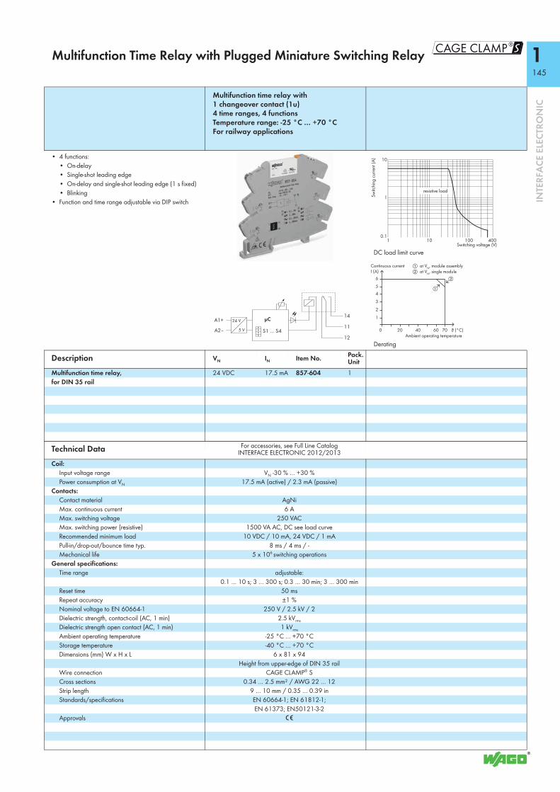
1145
8
INTE
RFA
CE E
LECT
RON
IC
Multifunction Time Relay with Plugged Miniature Switching Relay
Multifunction time relay with 1 changeover contact (1u) 4 time ranges, 4 functions Temperature range: -25 °C … +70 °C For railway applications
• 4 functions:• On-delay• Single-shot leading edge• On-delay and single-shot leading edge (1 s fixed)• Blinking
• Function and time range adjustable via DIP switch
DC load limit curve
Derating
Description VN IN Item No. Pack. Unit
Multifunction time relay, for DIN 35 rail
24 VDC 17.5 mA 857-604 1
Technical Data For accessories, see Full Line Catalog INTERFACE ELECTRONIC 2012/2013
Coil:Input voltage range VN -30 % … +30 %Power consumption at VN 17.5 mA (active) / 2.3 mA (passive)
Contacts:Contact material AgNiMax. continuous current 6 AMax. switching voltage 250 VACMax. switching power (resistive) 1500 VA AC, DC see load curveRecommended minimum load 10 VDC / 10 mA, 24 VDC / 1 mAPull-in/drop-out/bounce time typ. 8 ms / 4 ms / -Mechanical life 5 x 10⁶ switching operations
General specifications:Time range adjustable:
0.1 … 10 s; 3 … 300 s; 0.3 … 30 min; 3 … 300 minReset time 50 msRepeat accuracy ±1 %Nominal voltage to EN 60664-1 250 V / 2.5 kV / 2Dielectric strength, contact-coil (AC, 1 min) 2.5 kVrms
Dielectric strength open contact (AC, 1 min) 1 kVrms
Ambient operating temperature -25 °C … +70 °CStorage temperature -40 °C … +70 °CDimensions (mm) W x H x L 6 x 81 x 94
Height from upper-edge of DIN 35 railWire connection CAGE CLAMP® SCross sections 0.34 … 2.5 mm² / AWG 22 … 12 Strip length 9 … 10 mm / 0.35 … 0.39 inStandards/specifications EN 60664-1; EN 61812-1;
EN 61373; EN50121-3-2Approvals 1
1
10
1 10 100 400
resistive load
Switching voltage (V)
Switc
hing
cur
rent
(A)
0.1
6
4
2
200 40 60 ϑ (°C)
"
!
I (A)
70
5
3
1
Ambient operating temperature
Continuous current ! at VN, module assembly" at VN, single module
A1+
A2– S1 … S4
14
11
12
24 V
5 V
μC
S

1146
INTE
RFA
CE E
LECT
RON
IC
Multifunction Time Relay with SSR
Multifunction time relay with SSR 1 make contact (1a) 4 time ranges, 4 functions Switching voltage: 0 … 24 VDC
• 4 functions:• On-delay• Single-shot leading edge• On-delay and single-shot leading edge (1 s fixed)• Blinking
• Function and time range adjustable via DIP switch
Description VN IN Item No. Pack. Unit
Multifunction time relay with SSR, for DIN 35 rail
24 VDC 9.15 mA 857-624 1
Technical Data For accessories, see Full Line Catalog INTERFACE ELECTRONIC 2012/2013
Control circuit:Input voltage range VN -15 % … +30 %Power consumption at VN 9.15 mA (active) / 2.5 mA (passive)
Load circuit:Switching voltage 0 V … 24 V DCPeak reverse voltage 33 VMax. switching current 2 ATurn-on time 100 μsTurn-off time 2 msForward voltage at max. switching current < 120 mV DC
General specifications:Time range adjustable:
0.1 … 10 s; 3 … 300 s; 0.3 … 30 min; 3 … 300 minReset time 50 msRepeat accuracy ±1 %Dielectric strength, control/load circuit 2.5 kVrms
Ambient operating temperature -20 °C … +60 °CStorage temperature -40 °C … +70 °CDimensions (mm) W x H x L 6 x 81 x 94
Height from upper-edge of DIN 35 railWire connection CAGE CLAMP® SCross sections 0.34 mm² … 2.5 mm² / AWG 22 … 12Strip length 9 … 10 mm / 0.35 … 0.39 inStandards/specifications EN 60664-1; EN 61812-1;
EN 61373; EN50121-3-2Approvals 1
A1+
A2– S1 … S4
14RL13+N.C.
24 V
5 V
μC
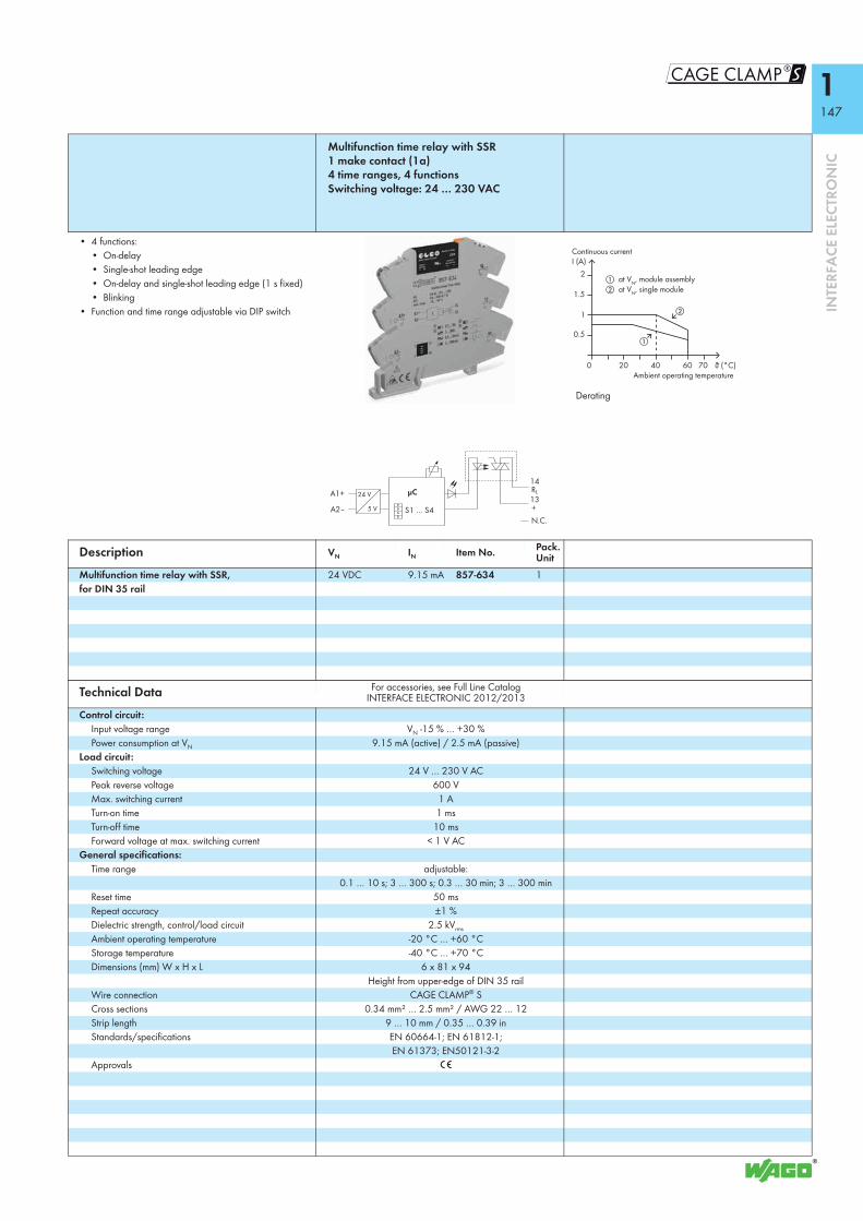
1147
8
INTE
RFA
CE E
LECT
RON
IC
Multifunction time relay with SSR 1 make contact (1a) 4 time ranges, 4 functions Switching voltage: 24 … 230 VAC
• 4 functions:• On-delay• Single-shot leading edge• On-delay and single-shot leading edge (1 s fixed)• Blinking
• Function and time range adjustable via DIP switch
Derating
Description VN IN Item No. Pack. Unit
Multifunction time relay with SSR, for DIN 35 rail
24 VDC 9.15 mA 857-634 1
Technical Data For accessories, see Full Line Catalog INTERFACE ELECTRONIC 2012/2013
Control circuit:Input voltage range VN -15 % … +30 %Power consumption at VN 9.15 mA (active) / 2.5 mA (passive)
Load circuit:Switching voltage 24 V … 230 V ACPeak reverse voltage 600 VMax. switching current 1 ATurn-on time 1 msTurn-off time 10 msForward voltage at max. switching current < 1 V AC
General specifications:Time range adjustable:
0.1 … 10 s; 3 … 300 s; 0.3 … 30 min; 3 … 300 minReset time 50 msRepeat accuracy ±1 %Dielectric strength, control/load circuit 2.5 kVrms
Ambient operating temperature -20 °C … +60 °CStorage temperature -40 °C … +70 °CDimensions (mm) W x H x L 6 x 81 x 94
Height from upper-edge of DIN 35 railWire connection CAGE CLAMP® SCross sections 0.34 mm² … 2.5 mm² / AWG 22 … 12Strip length 9 … 10 mm / 0.35 … 0.39 inStandards/specifications EN 60664-1; EN 61812-1;
EN 61373; EN50121-3-2Approvals 1
2
200 40 60 ϑ (°C)
"
!
I (A)
70
1
Ambient operating temperature
Continuous current
0.5
1.5
! at VN, module assembly" at VN, single module
A1+
A2– S1 … S4
14RL13+N.C.
24 V
5 V
μC
S

1148
INTE
RFA
CE E
LECT
RON
IC
Multifunction Time Relay
Multifunction time relay with 1 changeover contact (1u) 8 time ranges, 14 functions Temperature range: -25 °C … +70 °C For railway applications
• 14 functions:• On-delay• On-delay with control input• Off-delay with control input• On- and off-delay with control input• Single-shot leading edge• Single-shot leading edge with control input• Single-shot trailing edge with control input• Single-shot leading and trailing edge with control
input• On-delay and single-shot leading edge• On-delay and single-shot leading edge with control
input• Step switching• Blinking, pulse start• Blinking, interval start• Relay switching
• Function and time range adjustable via DIP switch• Digital output (DO): max. 31.2 VDC, 100 mA• Control input: max. 31.2 VDC, pulse length 10 ms
DC load limit curve
Description VN IN Item No. Pack. Unit
Multifunction time relay, for DIN 35 rail
24 VDC 18 mA 857-640 1
Technical Data For accessories, see Full Line Catalog INTERFACE ELECTRONIC 2012/2013
Coil:Input voltage range VN -30 % … +30 %Power consumption at VN 18 mA (active) / 4.5 mA (passive)
Contacts:Contact material AgNiMax. continuous current 6 A (up to 60 °C)
2 A (60 °C … 70 °C)Max. switching voltage 250 VACMax. switching power (resistive) 1500 VA AC, DC see load curveRecommended minimum load 10 VDC / 10 mA, 24 VDC / 1 mAPull-in/drop-out/bounce time typ. 8 ms / 4 ms / -Mechanical life 5 x 10⁶ switching operations
General specifications:Time range adjustable:
0.01 … 0.1 s; 0.1 … 1 s; 1 … 10 s; 10 … 100 s; 1 … 10 min; 10 … 100 min; 1 … 10 h; 10 … 100 h
Reset time 50 msNominal voltage to EN 60664-1 250 V / 2.5 kV / 2Dielectric strength, contact-coil (AC, 1 min) 2.5 kVrms
Dielectric strength open contact (AC, 1 min) 1 kVrms
Ambient operating temperature -25 °C … +70 °CStorage temperature -40 °C … +70 °CDimensions (mm) W x H x L 6 x 96 x 94
Height from upper-edge of DIN 35 railWire connection CAGE CLAMP® SCross sections 0.34 … 2.5 mm² / AWG 22 … 12 Strip length 9 … 10 mm / 0.35 … 0.39 inStandards/specifications EN 60664-1; EN 61812-1;
EN 61373; EN50121-3-2Approvals 1
1
10
1 10 100 400
resistive load
Switching voltage (V)
Switc
hing
cur
rent
(A)
0.1
US
GND DOS1 … S10
St
14
11
1224 V
5 V
μC
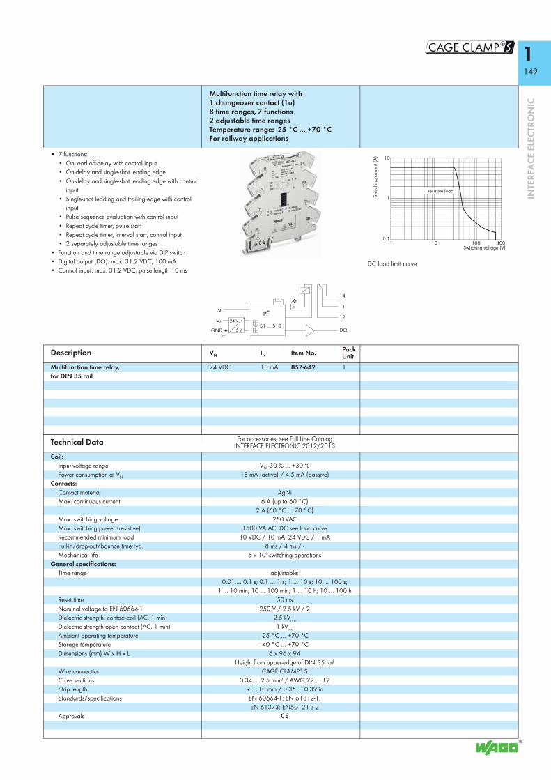
1149
8
INTE
RFA
CE E
LECT
RON
IC
Multifunction time relay with 1 changeover contact (1u) 8 time ranges, 7 functions 2 adjustable time ranges Temperature range: -25 °C … +70 °C For railway applications
• 7 functions:• On- and off-delay with control input• On-delay and single-shot leading edge• On-delay and single-shot leading edge with control
input• Single-shot leading and trailing edge with control
input• Pulse sequence evaluation with control input• Repeat cycle timer, pulse start• Repeat cycle timer, interval start, control input• 2 separately adjustable time ranges
• Function and time range adjustable via DIP switch• Digital output (DO): max. 31.2 VDC, 100 mA• Control input: max. 31.2 VDC, pulse length 10 ms
DC load limit curve
Description VN IN Item No. Pack. Unit
Multifunction time relay, for DIN 35 rail
24 VDC 18 mA 857-642 1
Technical Data For accessories, see Full Line Catalog INTERFACE ELECTRONIC 2012/2013
Coil:Input voltage range VN -30 % … +30 %Power consumption at VN 18 mA (active) / 4.5 mA (passive)
Contacts:Contact material AgNiMax. continuous current 6 A (up to 60 °C)
2 A (60 °C … 70 °C)Max. switching voltage 250 VACMax. switching power (resistive) 1500 VA AC, DC see load curveRecommended minimum load 10 VDC / 10 mA, 24 VDC / 1 mAPull-in/drop-out/bounce time typ. 8 ms / 4 ms / -Mechanical life 5 x 10⁶ switching operations
General specifications:Time range adjustable:
0.01 … 0.1 s; 0.1 … 1 s; 1 … 10 s; 10 … 100 s; 1 … 10 min; 10 … 100 min; 1 … 10 h; 10 … 100 h
Reset time 50 msNominal voltage to EN 60664-1 250 V / 2.5 kV / 2Dielectric strength, contact-coil (AC, 1 min) 2.5 kVrms
Dielectric strength open contact (AC, 1 min) 1 kVrms
Ambient operating temperature -25 °C … +70 °CStorage temperature -40 °C … +70 °CDimensions (mm) W x H x L 6 x 96 x 94
Height from upper-edge of DIN 35 railWire connection CAGE CLAMP® SCross sections 0.34 … 2.5 mm² / AWG 22 … 12 Strip length 9 … 10 mm / 0.35 … 0.39 inStandards/specifications EN 60664-1; EN 61812-1;
EN 61373; EN50121-3-2Approvals 1
1
10
1 10 100 400
resistive load
Switching voltage (V)
Switc
hing
cur
rent
(A)
0.1
US
GND DOS1 … S10
St
14
11
1224 V
5 V
μC
S

1150
INTE
RFA
CE E
LECT
RON
IC
Sockets with Miniature Switching Relay
Relay with 1 changeover contactand status indication (25 mm high) Nominal input voltage VN: 12 VDC
Coil voltage supplements 788-324 model
Relay with 2 changeover contactsand status indication (25 mm high) Nominal input voltage VN: 12 VDC, 110 VDC
Coil voltage supplements 788-334 model
DC load limit curve 788-323
DC load limit curve 788-333 and 788-337
Description VN IN Item No. Pack. Unit VN IN Item No. Pack.
UnitSocket with miniature switching relay,for DIN 35 rail
12 VDC 45 mA 788-323 1 12 VDC 45 mA 788-333 1110 VDC 6.8 mA 788-337 1
Technical Data For accessories, see Full Line Catalog INTERFACE ELECTRONIC 2012/2013
For accessories, see Full Line Catalog INTERFACE ELECTRONIC 2012/2013
Coil:Input voltage range VN ± 10 % VN ± 10 %
Contacts:Contact material AgCdO AgCdOMax. continuous current 16 A 2 x 8 AMax. make current (resistive) at 10 % OT * 25 A / 4 s (AC) 14 A / 4 s (AC)Max. switching voltage 250 VAC 250 VACMax. switching power (resistive) 4 kVA AC, DC see load curve 2 x 2 kVA AC, DC see load curveRecommended minimum load - -Pull-in/drop-out/bounce time typ. 8 ms / 2 ms / 4 ms 9 ms / 3 ms / 3 msMechanical life 30 x 106 switching operations 20 x 106 switching operations
General specifications:Nominal voltage to EN 60664-1 250 V / 4 kV / 3 250 V / 4 kV / 3Dielectric strength, contact-coil (AC, 1 min) 4 kVrms 4 kVrmsDielectric strength open contact (AC, 1 min) 1 kVrms 1 kVrmsDielectric strength contact-contact (AC, 1 min) - 2.5 kVeffAmbient operating temperature at VN -25 °C ... +50 °C -25 °C ... +50 °CStorage temperature -40 °C ... +70 °C -40 °C ... +70 °CDimensions (mm) W x H x L 15 x 63 x 86 15 x 64 x 86
Height from upper-edge of DIN 35 rail Height from upper-edge of DIN 35 railWire connection CAGE CLAMP® S CAGE CLAMP® SCross sections 0.34 mm² ... 2.5 mm² / AWG 22 ... 12 0.34 mm² ... 2.5 mm² / AWG 22 ... 12Strip lengths 9 ... 10 mm / 0.37 in 9 ... 10 mm / 0.37 inStandards/Specifications EN 61810-1, EN 60664-1, EN 61140,
UL 508 (max. 40 °C/10 A)EN 61810-1, EN 60664-1, EN 61140,
UL 508 (max. 40 °C/10 A)
* (OT = On-time)
0.1 0.2 0.5 1 2 5 10 20
resistive load
Switching current
Switc
hing
vol
tage
(V)
0.1 0.2 0.5 1 2 5 10 20
resistive load
2 contacts in serie
1 contact
Switching current (A)
Switc
hing
vol
tage
(V)
300
200
100
504030
20
10

1151
8
INTE
RFA
CE E
LECT
RON
IC
Safety relay (2 changeover contacts) with force-guided gold contacts (Type A) and status indication Nominal input voltage VN 24 VDC
Similiar to picture
Description VN IN Item No. Pack. Unit
Socket with miniature switching relay,for DIN 35 rail
24 VDC 30 mA 788-906 1
Technical Data For accessories, see Full Line Catalog INTERFACE ELECTRONIC 2012/2013
Coil:Input voltage range VN -15 % ... +10 %
Contacts:Contact material AgNi10 + 5 μm AuMax. continuous current 0.3 AMax. switching voltage 60 VRecommended minimum load 0.1 V / 1 mA / 1 mWPull-in/drop-out/bounce time typ. 15 ms / 12 ms / -Mechanical life 50 x 106 switching operations
General specifications:Nominal voltage to EN 60664-1 250 V / 4 kV / 2Dielectric strength, contact-coil (AC, 1 min) 4 kVrmsDielectric strength contact-contact (AC, 1 min) 2.5 kVeffAmbient operating temperature at VN -25 °C … +55 °CStorage temperature -40 °C … +70 °CDimensions (mm) W x H x L 15 x 54 x 86
Height from upper-edge of DIN 35 railWire connection CAGE CLAMP® SCross sections 0.34 mm² ... 2.5 mm² / AWG 22 ... 12Strip lengths 9 ... 10 mm / 0.37 inStandards/Specifications EN 61140, EN 60664-1, EN 61810-5, EN 50205
S

1152
INTE
RFA
CE E
LECT
RON
IC
Sockets with Miniature Switching Relay
Relay with 1 changeover contactand status indication(15 mm high) Nominal input voltage VN 12 VDC
Load limit curve
Description VN IN Item No. Pack. Unit
Socket with miniature switching relay,for DIN 35 rail
12 VDC 35 mA 788-353 1
Technical Data For accessories, see Full Line Catalog INTERFACE ELECTRONIC 2012/2013
Coil:Input voltage range VN -15 % ... +20 %
Contacts:Contact material Ag alloyMax. continuous current 16 AMax. make current (resistive) at 10 % OT * 120 A / 50 ms (at 230 VAC)Max. switching voltage 250 VACMax. switching power (resistive) 4 kVA AC, DC see load curveRecommended minimum load > 100 mA / 12 V AC/DCPull-in/drop-out/bounce time typ. 15 ms / 5 ms / -Mechanical life 10 x 106 switching operations
General specifications:Nominal voltage to EN 60664-1 250 V / 4 kV / 3Dielectric strength, contact-coil (AC, 1 min) 5 kVrmsDielectric strength open contact (AC, 1 min) 1 kVrmsAmbient operating temperature at VN -25 °C … +50 °CStorage temperature -40 °C … +70 °CDimensions (mm) W x H x L 15 x 54 x 86
Height from upper-edge of DIN 35 railWire connection CAGE CLAMP® SCross sections 0.34 mm² ... 2.5 mm² / AWG 22 ... 12Strip lengths 9 ... 10 mm / 0.37 inStandards/Specifications EN 61140; EN 60664-1; EN 50178;
UL 508 (max. 10 A)
* (OT = On-time)
10 100 1000
100
10
1DC resistive load
AC resistive load
Switching voltage (V)
Switc
hing
cur
rent
(A) Contact life,
type of load Capability Electrical lifeIncandescent lamp 2200 W 20,000Halogen lamp 230 VAC 1400 W 50,000Halogen trafo 120 VA 20,000Fluorescent lamp not comp., CCG !, cos ϕ 0.406 20 x 58 W 25,000Fluorescent lamp comp., CCG !, C parallel 9 x 58 W 25,000Fluorescent lamp comp., CCG !, Duo-circuit 600 W 20,000Fluorescent lamp with ECG " 12 x 58 W 25,000Energy saving lamp 15 W 25 pcs 20,000Energy saving lamp 13 W 30 pcs 20,000Energy saving lamp 9 W 38 pcs 20,000Gas discharge lamp 1000 W 20,000Dulux-Lamp not compensated 800 W 20,000Dulux-Lamp compensated 500 W 20,000Max. capacitance at 230 VAC 60 μF > 5,000! CCG = Conventional Control Gear" ECG = Electronic Control Gear

1153
8
INTE
RFA
CE E
LECT
RON
IC
Relay with 1 make contact and status indication(15 mm high) Nominal input voltage VN: 24 VDC for lamp loads
DC load limit curve Similiar to picture
Description VN IN Item No. Pack. Unit
Socket with miniature switching relay,for DIN 35 rail
24 VDC 19 mA 788-356 1
Technical Data For accessories, see Full Line Catalog INTERFACE ELECTRONIC 2012/2013
Coil:Input voltage range VN -15 % ... +20 %
Contacts:Contact material AgSnO2Max. continuous current 16 AMax. make current (resistive) at 10 % OT * 30 A / 4 s (AC); 80 A / 20 ms (AC)Max. switching voltage 250 VACMax. switching power (resistive) 4 kVA AC, DC see load curveRecommended minimum load ≥ 100 mA / 12 V AC/DCPull-in/drop-out/bounce time typ. 8 ms / 3 ms / -Mechanical life 30 x 106 switching operations
General specifications:Nominal voltage to EN 60664-1 250 V / 4 kV / 3Dielectric strength, contact-coil (AC, 1 min) 5 kVrmsDielectric strength open contact (AC, 1 min) 1 kVrmsDielectric strength contact-contact (AC, 1 min) -Ambient operating temperature at VN -25 °C ... +50 °CStorage temperature -40 °C ... +70 °CDimensions (mm) W x H x L 15 x 53 x 96
Height from upper-edge of DIN 35 railWire connection CAGE CLAMP® SCross sections 0.34 mm² ... 2.5 mm² / AWG 22 ... 12Strip lengths 9 ... 10 mm / 0.37 inStandards/Specifications EN 61810-1, EN 60664-1, EN 61140,
UL 508 (max. 50 °C/10 A)
* (OT = On-time)
resistive load
Switching current (A)
Switc
hing
vol
tage
(V)
. . .
Contact life,type of load Electrical life1000 W, incandescent lamp 80,00016 A, 240 VAC, UL 508 50,00021/3.5 A, 230 VAC, Compressor, cos ϕ = 0.5 230,000
11
14
S

1154
INTE
RFA
CE E
LECT
RON
IC
Sockets with Miniature Switching Relay
Relay with 1 make contact and status indication(15 mm high) Nominal input voltage VN: 24 VDC for lamp loads
DC load limit curve
Description VN IN Item No. Pack. Unit
Socket with miniature switching relay,for DIN 35 rail
24 VDC 17 mA 788-357 1
Technical Data For accessories, see Full Line Catalog INTERFACE ELECTRONIC 2012/2013
Coil:Input voltage range VN -10 % ... +20 %
Contacts:Contact material AgSnO2, W pre-make contactMax. continuous current 16 AMax. make current (resistive) at 10 % OT * 165 A / 20 ms (AC)Max. switching voltage 250 VACMax. switching power (resistive) 4 kVA AC, DC see load curveRecommended minimum load -Pull-in/drop-out/bounce time typ. 10 ms / 5 ms / 4 msMechanical life 5 x 10⁶ switching operations
General specifications:Nominal voltage to EN 60664-1 250 V / 4 kV / 3Dielectric strength, contact-coil (AC, 1 min) 4 kVrmsDielectric strength open contact (AC, 1 min) 1.25 kVrmsDielectric strength contact-contact (AC, 1 min) -Ambient operating temperature at VN -25 °C ... +50 °CStorage temperature -40 °C ... +70 °CDimensions (mm) W x H x L 15 x 53 x 86
Height from upper-edge of DIN 35 railWire connection CAGE CLAMP® SCross sections 0.34 mm² ... 2.5 mm² / AWG 22 ... 12Strip lengths 9 ... 10 mm / 0.37 inStandards/Specifications EN 61810-1, EN 60664-1, EN 61140
* (OT = On-time)
resistive load
Switching current (A)
Switc
hing
vol
tage
(V)
. . .
Contact life, type of load Electrical life3000 W, incandescent lamp, 230 VAC, OT 8.3 % !, 5 min-1 12,000620 W, gas discharge lamp, CCG ",120/277 VAC, UL 508, 50 °C 6,0001200 W, tungsten lamp, 120/277 VAC, UL 508, 50 °C 6,00016 A, 250 VAC, cos ϕ = 1, 85 °C, IEC 61810 5,000! OT= On-Time" CCG = Conventional Control Gear
13
14

1155
8
INTE
RFA
CE E
LECT
RON
IC
Relay with 1 changeover contactElectrical and mechanical status indication(25 mm high) Nominal input voltage VN: 24 VDC Railway applications
Relay with 2 changeover contactElectrical and mechanical status indication(25 mm high) Nominal input voltage VN: 24 VDC Railway applications
Description VN IN Item No. Pack. Unit VN IN Item No. Pack.
UnitSocket with miniature switching relay,for DIN 35 rail
24 VDC 19.1 mA 788-391 1 24 VDC 19.1 mA 788-390 1
Technical Data For accessories, see Full Line Catalog INTERFACE ELECTRONIC 2012/2013
For accessories, see Full Line Catalog INTERFACE ELECTRONIC 2012/2013
Coil:Input voltage range VN -30 % ... +25 % VN -30 % ... +25 %
Contacts:Contact material AgNi AgNiMax. continuous current 3 A (single socket) 2 x 3 A (single socket)Max. make current (resistive) at 10 % OT * 16 A 2 x 8 AMax. switching voltage 250 VAC 250 VACMax. switching power (resistive) 750 VA AC 2 x 750 VA ACRecommended minimum load ≥ 10 mA / 12 V AC/DC ≥ 10 mA / 12 V AC/DCPull-in/drop-out/bounce time typ. 15 ms / 8 ms / - 15 ms / 8 ms / -Mechanical life 5 x 10⁶ switching operations 5 x 10⁶ switching operations
General specifications:Nominal voltage to EN 60664-1 250 V / 4 kV / 3 250 V / 4 kV / 3Dielectric strength, contact-coil (AC, 1 min) 5 kVrms 5 kVrmsDielectric strength open contact (AC, 1 min) 1 kVrms 1 kVrmsDielectric strength contact-contact (AC, 1 min) - 2.5 kVeffAmbient operating temperature at VN -25 °C ... +70 °C -25 °C ... +70 °CStorage temperature -40 °C ... +70 °C -40 °C ... +70 °CDimensions (mm) W x H x L 15 x 73 x 86 15 x 73 x 86
Height from upper-edge of DIN 35 rail Height from upper-edge of DIN 35 railWire connection CAGE CLAMP® S CAGE CLAMP® SCross sections 0.34 mm² ... 2.5 mm² / AWG 22 ... 12 0.34 mm² ... 2.5 mm² / AWG 22 ... 12Strip lengths 9 ... 10 mm / 0.37 in 9 ... 10 mm / 0.37 inStandards/Specifications EN 61810-1, EN 60664-1, EN 61140 EN 61810-1, EN 60664-1, EN 61140
* (OT = On-time)
A1+
A2-
14
11
12
14
11
12
24
21
22
A1+
A2-
S

1156
INTE
RFA
CE E
LECT
RON
IC
Accessories, 788 and 858 Series
Suppressor module,pluggable, for 788 and 858 Series Relay Sockets
Note: To guarantee safe operation, residual voltages (due to the cable capacitance of long connection lines or leakage currents of semi-conductor switches and their protective circuits) must be lower than the release voltage of the relays. For DC relays, the release voltage is specified with ≤ 5 % of the nominal voltage; for AC relays, it is 15 % of the nominal voltage (acc. to VDE 0435).The relay may not reset if a high residual voltage exists. Depending on the reason for the residual voltage, changing the cable routing or a parallel connection of an RC element could remedy this situation.
Description Item No. Pack. Unit
Suppressor module for miniature switching relay 788-148 50
Technical DataOperating data:
Operating voltage max. 230 VAC, 50 ... 60 HzOperating current 3.6 mA at 115 VAC, 50 Hz
7.2 mA at 230 VAC, 50 HzModule's characteristics:
Resistor 470 ΩCapacity 100 nF
General specifications:Ambient operating temperature -25 °C ... +70 °CStorage temperature -40 °C ... +70 °CDimensions (mm) W x H x L 15 x 15 x 10Standards/Specifications EN 60664

1157
8
INTE
RFA
CE E
LECT
RON
IC
Relay Sockets with Industrial Relay
Relay sockets with industrial relay Coil voltage: 48 V, 110 V, 220 V DC 4 changeover contacts
Coil voltage supplements 858-304 model
Relay sockets with industrial relay Coil voltage: 24 V, 115 V AC 4 changeover contacts
Coil voltage supplements 858-508 model
Description VN IN Item No. Pack. Unit VN IN Item No. Pack.
UnitRelay socket with industrial relay, for DIN 35 rail
48 VDC 18.5 mA 858-305 1 24 VAC 50 mA 858-504 1110 VDC 10 mA 858-307 1 115 VAC 10 mA 858-507 1220 VDC 4.1 mA 858-308 1
Technical Data For accessories, see Full Line Catalog INTERFACE ELECTRONIC 2012/2013
For accessories, see Full Line Catalog INTERFACE ELECTRONIC 2012/2013
Coil:Input voltage range VN -20 % ... +10 % VN -20 % ... +10 %
Contacts:Contact material AgCe AgCeMax. continuous current 5 A 5 AMax. make current (resistive) at 10 % OT * 15 A / 4 s 15 A / 4 sMax. switching voltage 250 VAC 250 VACMax. switching power (resistive) 1250 VA AC 1250 VA ACRecommended minimum load ≥ 100 mA / 12 V AC/DC ≥ 100 mA / 12 V AC/DCPull-in/drop-out/bounce time typ. 25 ms / 25 ms / 4 ms 25 ms / 25 ms / 4 msMechanical life 20 x 106 switching operations 20 x 106 switching operations
General specifications:Nominal voltage to EN 60664-1 250 V / 2.5 kV / 2 250 V / 2.5 kV / 2Dielectric strength, contact-coil (AC, 1 min) 1.5 kVrms 1.5 kVrmsDielectric strength open contact (AC, 1 min) 1 kVrms 1 kVrmsDielectric strength contact-contact (AC, 1 min) 1.5 kVeff 1.5 kVeffAmbient operating temperature at VN -25 °C ... +70 °C -25 °C ... +70 °CStorage temperature -40 °C ... +80 °C -40 °C ... +80 °CDimensions (mm) W x H x L 31 x 73 x 97 31 x 73 x 97
Height from upper-edge of DIN 35 rail Height from upper-edge of DIN 35 railWire connection CAGE CLAMP® S CAGE CLAMP® SCross sections 2 x 0.34 mm² ... 2 x 1.5 mm² /
1 x 2.5 mm²/ AWG 22 ... 16
2 x 0.34 mm² ... 2 x 1.5 mm² / 1 x 2.5 mm²/
AWG 22 ... 16Strip lengths 9 ... 10 mm / 0.37 in 9 ... 10 mm / 0.37 inStandards/Specifications EN 61810-1, EN 60664-1 EN 61810-1, EN 60664-1
* (OT = On-time)
14
34
24
44
12
32
22
42
11
31
21
41
A1
A2-
+
14
34
24
44
12
32
22
42
11
31
21
41
A1~
A2~
S
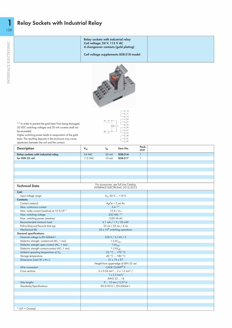
1158
INTE
RFA
CE E
LECT
RON
IC
Relay Sockets with Industrial Relay
Relay sockets with industrial relay Coil voltage: 24 V, 115 V AC 4 changeover contacts (gold plating)
Coil voltage supplements 858-518 model
** In order to prevent the gold layer from being damaged, 30 VDC switching voltages and 50 mA currents shall not be exceeded. Higher switching power leads to evaporation of the gold layer. The resulting deposits in the enclosure may cause sparkovers between the coil and the contact.
Description VN IN Item No. Pack. Unit
Relay sockets with industrial relay, for DIN 35 rail
24 VAC 50 mA 858-514 1115 VAC 10 mA 858-517 1
Technical Data For accessories, see Full Line Catalog INTERFACE ELECTRONIC 2012/2013
Coil:Input voltage range VN -20 % ... +10 %
Contacts:Contact material AgCe + 5 μm AuMax. continuous current 5 A **Max. make current (resistive) at 10 % OT * 15 A / 4 sMax. switching voltage 250 VAC **Max. switching power (resistive) 1250 VA ACRecommended minimum load ≥ 1 mA / 1 V / 50 mWPull-in/drop-out/bounce time typ. 25 ms / 25 ms / 4 msMechanical life 20 x 106 switching operations
General specifications:Nominal voltage to EN 60664-1 250 V / 2.5 kV / 2Dielectric strength, contact-coil (AC, 1 min) 1.5 kVrmsDielectric strength open contact (AC, 1 min) 1 kVrmsDielectric strength contact-contact (AC, 1 min) 1.5 kVeffAmbient operating temperature at VN -25 °C ... +70 °CStorage temperature -40 °C ... +80 °CDimensions (mm) W x H x L 31 x 73 x 97
Height from upper-edge of DIN 35 railWire connection CAGE CLAMP® SCross sections 2 x 0.34 mm² ... 2 x 1.5 mm² /
1 x 2.5 mm²/ AWG 22 ... 16
Strip lengths 9 ... 10 mm / 0.37 inStandards/Specifications EN 61810-1, EN 60664-1
* (OT = On-time)
14
34
24
44
12
32
22
42
11
31
21
41
A1~
A2~

1159
8
INTE
RFA
CE E
LECT
RON
IC
Relay socket with industrial relay Coil voltage: 24 VDC 4 changeover contacts Railway applications
Relay socket with industrial relay Coil voltage: 24 VDC 4 changeover contacts (gold plating) Railway applications
Load limit curve
** In order to prevent the gold layer from being damaged, 30 VDC switching voltages and 50 mA currents shall not be exceeded. Higher switching power leads to evaporation of the gold layer. The resulting deposits in the enclosure may cause sparkovers between the coil and the contact.
Description VN IN Item No. Pack. Unit VN IN Item No. Pack.
UnitRelay socket with industrial relay, for DIN 35 rail
24 VDC 42 mA 858-354 1 24 VDC 42 mA 858-355 1
Technical Data For accessories, see Full Line Catalog INTERFACE ELECTRONIC 2012/2013
For accessories, see Full Line Catalog INTERFACE ELECTRONIC 2012/2013
Coil:Input voltage range VN -30 % ... +25 % VN -30 % ... +25 %
Contacts:Contact material AgCe AgCe + 5 μm AuMax. continuous current 5 A 5 A **Max. make current (resistive) at 10 % OT * 15 A / 4 sMax. switching voltage 250 VAC 250 VAC **Max. switching power (resistive) 1 kVA AC, DC see load curveRecommended minimum load ≥ 100 mA / 12 V AC/DC 1 V / 1 mA / 1 mWPull-in/drop-out/bounce time typ. 25 ms / 25 ms / 4 ms 25 ms / 25 ms / 4 msMechanical life 20 x 106 switching operations 20 x 106 switching operations
General specifications:Nominal voltage to EN 60664-1 250 V / 2.5 kV / 2 250 V / 2.5 kV / 2Dielectric strength, contact-coil (AC, 1 min) 1.5 kVrms 1.5 kVrmsDielectric strength open contact (AC, 1 min) 1 kVrms 1 kVrmsDielectric strength contact-contact (AC, 1 min) 1.5 kVeff 1.5 kVeffAmbient operating temperature at VN -25 °C ... +70 °C -25 °C … +70 °CStorage temperature -40 °C ... +80 °C -40 °C ... +80 °CDimensions (mm) W x H x L 31 x 72 x 96 31 x 72 x 96
Height from upper-edge of DIN 35 rail Height from upper-edge of DIN 35 railWire connection CAGE CLAMP® S CAGE CLAMP® SCross sections 2 x 0.34 mm² ... 2 x 1.5 mm² /
1 x 2.5 mm²/ AWG 22 ... 16
2 x 0.34 mm² … 2 x 1.5 mm² / 1 x 2.5 mm²/
AWG 22…. 16Strip lengths 9 ... 10 mm / 0.37 in 9 ... 10 mm / 0.37 inStandards/Specifications EN 61810-1, EN 60664-1 EN 61810-1, EN 60664-1
* (OT = On-time)
10 100 1000
10
5
1
AC resistive load
DC resistive load
AC inductive load
DC inductive load
Switching voltage (V)
0.1
Switc
hing
cur
rent
(A)
14
34
24
44
12
32
22
42
11
31
21
41
A1+
A2-
14
34
24
44
12
32
22
42
11
31
21
41
A1+
A2-
S

1160
INTE
RFA
CE E
LECT
RON
IC
Pluggable Modules – Latching Relays
Latching relays with 1 changeover contact (1 u)
Latching relay with 1 changeover contact (1 u) Extended input voltage and temperature range Railway applications
WSB marker cards• Marking K; Item No.: 209-782• Marking 1 ... 10; Item No.: 209-702• Marking A1, A1, A2, A2, 11, 12, 13, 14, 23, 24;
Item No.: 209-693• Marking A1, A3, A2, 11, 12, 14;
Item No.: 249-6075 cards, each containing 10 strips with 10 markers
Description VN IN Item No. Pack. Unit VN IN Item No. Pack.
UnitLatching relay 24 VDC 40 mA 286-573 1 24 VDC 70 mA 286-575 1
230 VAC 10 mA 286-574 1
Technical Data For accessories, see Full Line Catalog INTERFACE ELECTRONIC 2012/2013
For accessories, see Full Line Catalog INTERFACE ELECTRONIC 2012/2013
Coil:Input voltage range VN -15 % ... +10 % VN -30 % ... +25 %
Contacts:Contact material AgSnO2 AgSnO2Max. continuous current 6 A 3 A (6 A at 50 °C)Max. make current (resistive) at 10 % OT * 50 A (20 ms) 50 A (20 ms)Max. switching voltage 250 V 250 VMax. switching power (resistive) 1500 VA 1500 VARecommended minimum load ≥ 10 mA / 10 V ≥ 10 mA / 10 VMechanical life 10 x 106 switching operations at DC
1 x 10⁵ switching operations at AC10 x 106 switching operations
General specifications:Nominal voltage to EN 60664-1 250 V / 4 kV / 2 250 V / 4 kV / 2Dielectric strength, contact-coil (AC, 1 min) 4 kVrms 4 kVrmsDielectric strength open contact (AC, 1 min) 1.5 kVrms 1.5 kVrmsDielectric strength contact-contact (AC, 1 min) - -Ambient operating temperature at VN -25 °C ... +50 °C -25 °C ... +70 °C (Ia < 3 A)Storage temperature -40 °C ... +70 °C -40 °C ... +70 °CDimensions (mm) W x H x L 17 x 82.5 x 73 22 x 82.5 x 73
Height from upper-edge of DIN 35 rail Height from upper-edge of DIN 35 railStandards/Specifications EN 60664 EN 60664
* (OT = On-time)
Accessories Item No. Pack. Unit Item No. Pack.
UnitTerminal block for pluggable modules, with 2-conductor terminal blocks, orange separator ➊ 17 mm / 0.669 in 280-619 1 22 mm / 0.866 in 280-638 1with 4-conductor terminal blocks, orange separator ➋ 17 mm / 0.669 in 280-609 1 22 mm / 0.866 in 280-628 1with 4-conductor terminal blocks, marker plate ➋ 20 mm / 0.787 in 280-763 1 25 mm / 0.984 in 280-764 1
A1
A2
A2
~
~
~
14
1211
A1+
A2-
A2-
141211
A1
A1
+
A2-A2-
1114
11
12
+

1161
8
INTE
RFA
CE E
LECT
RON
IC
Relay Modules in DIN-Rail Mount Enclosure
Relay with 1 make contact (1 a)Nominal input voltage VN: 24 VDC for lamp loads
Load limit curve Similiar to picture
Note: Inductive loads have to be attenuated by an appropriate protective circuit in order to protect relay coils and contacts.
Description VN IN Item No. Pack. Unit
Relay module in DIN-rail mount enclosure,for DIN 35 rail
24 VDC 19 mA 789-320 1
Technical Data For accessories, see Full Line Catalog INTERFACE ELECTRONIC 2012/2013
Coil:Input voltage range VN -15 % ... +20 %
Contacts:Contact material Ag alloyMax. continuous current 16 AMax. make current (resistive) at 10 % OT * 120 A / 50 ms (AC)Max. switching voltage 250 VACMax. switching power (resistive) 4 kVA AC, DC see load curveRecommended minimum load ≥ 100 mA / 12 V AC/DCPull-in/drop-out/bounce time typ. 15 ms / 5 ms / -Mechanical life 10 x 106 switching operations
General specifications:Nominal voltage to EN 60664-1 250 V / 4 kV / 3Dielectric strength, contact-coil (AC, 1 min) 4 kVrmsDielectric strength open contact (AC, 1 min) 1 kVrmsDielectric strength contact-contact (AC, 1 min) -Ambient operating temperature at VN -25 °C ... +40 °CStorage temperature -40 °C ... +70 °CDimensions (mm) W x H x L 17.5 x 55 x 90
Height from upper-edge of DIN 35 railWire connection CAGE CLAMP®
Cross sections 0.08 mm² ... 2.5 mm² / AWG 28 ... 14Strip lengths 5 ... 6 mm / 0.22 inStandards/Specifications EN 61810-1, EN 60664-1,
EN 61140, EN 50178
* (OT = On-time)
10 100 1000
100
10
1DC resistive load
AC resistive load
Switching voltage (V)
Switc
hing
cur
rent
(A) Contact life,
type of load Capability Electrical Incandescent lamp 2200 W 20,000Halogen lamp 230 VAC 1400 W 50,000Halogen trafo 120 VA 20,000Fluorescent lamp not comp., CCG !, cos ϕ 0.406 20 x 58 W 25,000Fluorescent lamp comp., CCG !, C parallel 9 x 58 W 25,000Fluorescent lamp comp., CCG !, Duo-circuit 600 W 20,000Fluorescent lamp with ECG " 12 x 58 W 25,000Energy saving lamp 15 W 25 pcs 20,000Energy saving lamp 13 W 30 pcs 20,000Energy saving lamp 9 W 38 pcs 20,000Gas discharge lamp 1000 W 20,000Dulux-Lamp not compensated 800 W 20,000Dulux-Lamp compensated 500 W 20,000Max. capacitance at 230 VAC 60 μF > 5,000! CCG = Conventional Control Gear" ECG = Electronic Control Gear
14
13 13A2-
A2-
A1+

1162
INTE
RFA
CE E
LECT
RON
IC
Relay Modules in DIN-Rail Mount Enclosure
Relay with 1 make contact (1 a)Nominal input voltage VN: 24 V, 230 V AC for lamp loads
Load limit curve Similiar to picture
Note: Inductive loads have to be attenuated by an appropriate protective circuit in order to protect relay coils and contacts.
Description VN IN Item No. Pack. Unit
Relay module in DIN-rail mount enclosure,for DIN 35 rail
24 VAC 32 mA 789-520 1230 VAC 15 mA 789-321 1
Technical Data For accessories, see Full Line Catalog INTERFACE ELECTRONIC 2012/2013
Coil:Input voltage range VN -15 % ... +20 %
Contacts:Contact material Ag alloyMax. continuous current 16 AMax. make current (resistive) at 10 % OT * 120 A / 50 ms (AC)Max. switching voltage 250 VACMax. switching power (resistive) 4 kVA AC, DC see load curveRecommended minimum load ≥ 100 mA / 12 V AC/DCPull-in/drop-out/bounce time typ. 15 ms / 5 ms / -Mechanical life 10 x 106 switching operations
General specifications:Nominal voltage to EN 60664-1 250 V / 4 kV / 3Dielectric strength, contact-coil (AC, 1 min) 4 kVrmsDielectric strength open contact (AC, 1 min) 1 kVrmsDielectric strength contact-contact (AC, 1 min) -Ambient operating temperature at VN -25 °C ... +40 °CStorage temperature -40 °C ... +70 °CDimensions (mm) W x H x L 17.5 x 55 x 90
Height from upper-edge of DIN 35 railWire connection CAGE CLAMP®
Cross sections 0.08 mm² ... 2.5 mm² / AWG 28 ... 14Strip lengths 5 ... 6 mm / 0.22 inStandards/Specifications EN 61810-1, EN 60664-1,
EN 61140, EN 50178
* (OT = On-time)
10 100 1000
100
10
1DC resistive load
AC resistive load
Switching voltage (V)
Switc
hing
cur
rent
(A) Contact life,
type of load Capability Electrical lifeIncandescent lamp 2200 W 20,000Halogen lamp 230 VAC 1400 W 50,000Halogen trafo 120 VA 20,000Fluorescent lamp not comp., CCG !, cos ϕ 0.406 20 x 58 W 25,000Fluorescent lamp comp., CCG !, C parallel 9 x 58 W 25,000Fluorescent lamp comp., CCG !, Duo-circuit 600 W 20,000Fluorescent lamp with ECG " 12 x 58 W 25,000Energy saving lamp 15 W 25 pcs 20,000Energy saving lamp 13 W 30 pcs 20,000Energy saving lamp 9 W 38 pcs 20,000Gas discharge lamp 1000 W 20,000Dulux-Lamp not compensated 800 W 20,000Dulux-Lamp compensated 500 W 20,000Max. capacitance at 230 VAC 60 μF > 5,000! CCG = Conventional Control Gear" ECG = Electronic Control Gear
14
13 13A2
A2
A1~
~
~

1163
8
INTE
RFA
CE E
LECT
RON
IC
Relay with 1 make contact (1 a), manual-0-automatic switch with monitoring contact
DC load limit curve
Note: Inductive loads have to be attenuated by an appropriate protective circuit in order to protect relay coils and contacts.
Description VN IN Item No. Pack. Unit
Relay module in DIN-rail mount enclosure,for DIN 35 rail
24 VDC 17 mA 789-324 1
Technical Data For accessories, see Full Line Catalog INTERFACE ELECTRONIC 2012/2013
Coil:Input voltage range VN -15 % ... +20 %
Contacts:Contact material AgSnO2, W pre-make contactMax. continuous current 16 AMax. make current (resistive) at 10 % OT * 165 A / 20 ms (AC)Max. switching voltage 250 VACMax. switching power (resistive) 4 kVA AC, DC see load curveRecommended minimum load -Pull-in/drop-out/bounce time typ. 10 ms / 5 ms / 4 msMechanical life 5 x 10⁶ switching operations
General specifications:Nominal voltage to EN 60664-1 250 V / 4 kV / 3Dielectric strength, contact-coil (AC, 1 min) 4 kVrmsDielectric strength open contact (AC, 1 min) 1.25 kVrmsDielectric strength contact-contact (AC, 1 min) -Ambient operating temperature at VN -25 °C ... +40 °CStorage temperature -40 °C ... +70 °CDimensions (mm) W x H x L 17.5 x 55 x 90
Height from upper-edge of DIN 35 railWire connection CAGE CLAMP®
Cross sections 0.08 mm² ... 2.5 mm² / AWG 28 ... 14Strip lengths 5 ... 6 mm / 0.22 inStandards/Specifications EN 61810-1, EN 60664-1, EN 61140
* (OT = On-time)
resistive load
Switching current (A)
Switc
hing
vol
tage
(V)
. . .
Contact life, type of load Electrical life3000 W, incandescent lamp, 230 VAC, OT 8.3 % !, 5 min-1 12,000620 W, gas discharge lamp, CCG ",120/277 VAC, UL 508, 50 °C 6,0001200 W, tungsten lamp, 120/277 VAC, UL 508, 50 °C 6,00016 A, 250 VAC, cos ϕ = 1, 85 °C, IEC 61810 5,000! OT= On-Time" CCG = Conventional Control Gear
01
A3+
n.c.B2
(+24V)
14
13 13
A2-
A2-
A1+
B1
A A = Automatic (AUTO)0 = OFF1 = Manual ON (MAN)

1164
INTE
RFA
CE E
LECT
RON
IC
Relay Modules in DIN-Rail Mounted Enclosure
Relay with 1 changeover contact (1 u), Manual/0FF/Auto switch for lamp loads
Load limit curve
Note: Inductive loads have to be attenuated by an appropriate protective circuit in order to protect relay coils and contacts.
Description VN IN Item No. Pack. Unit
Relay module in DIN-rail mount enclosure,for DIN 35 rail
24 VDC 19 mA 789-326 1
Technical Data For accessories, see Full Line Catalog INTERFACE ELECTRONIC 2012/2013
Coil:Input voltage range VN -15 % ... +20 %
Contacts:Contact material Ag alloyMax. continuous current 12 AMax. make current (resistive) at 10 % OT * 120 A / 50 ms (AC)Max. switching voltage 250 VACMax. switching power (resistive) 4 kVA AC, DC DC see load curveRecommended minimum load ≥ 100 mA / 12 V AC/DCPull-in/drop-out/bounce time typ. 15 ms / 5 ms / -Mechanical life 10 x 106 switching operations
General specifications:Nominal voltage to EN 60664-1 250 V / 4 kV / 3Dielectric strength, contact-coil (AC, 1 min) 4 kVrmsDielectric strength open contact (AC, 1 min) 1 kVrmsDielectric strength contact-contact (AC, 1 min) -Ambient operating temperature at VN -20 °C ... +40 °CStorage temperature -40 °C ... +70 °CDimensions (mm) W x H x L 17.5 x 55 x 90
Height from upper-edge of DIN 35 railWire connection CAGE CLAMP®
Cross sections 0.08 mm² ... 2.5 mm² / AWG 28 ... 14Strip lengths 5 ... 6 mm / 0.22 inStandards/Specifications EN 61810-1, EN 60664-1,
EN 61140, EN 50178
* (OT = On-time)
10 100 1000
100
10
1DC resistive load
AC resistive load
Switching voltage (V)
Switc
hing
cur
rent
(A) Contact life,
type of load Capability Electrical Incandescent lamp 2200 W 20,000Halogen lamp 230 VAC 1400 W 50,000Halogen trafo 120 VA 20,000Fluorescent lamp not comp., CCG !, cos ϕ 0.406 20 x 58 W 25,000Fluorescent lamp comp., CCG !, C parallel 9 x 58 W 25,000Fluorescent lamp comp., CCG !, Duo-circuit 600 W 20,000Fluorescent lamp with ECG " 12 x 58 W 25,000Energy saving lamp 15 W 25 pcs 20,000Energy saving lamp 13 W 30 pcs 20,000Energy saving lamp 9 W 38 pcs 20,000Gas discharge lamp 1000 W 20,000Dulux-Lamp not compensated 800 W 20,000Dulux-Lamp compensated 500 W 20,000Max. capacitance at 230 VAC 60 μF > 5,000! CCG = Conventional Control Gear" ECG = Electronic Control Gear
A2-
A2-
A1+
A01
A3+(+24V)
14
11
12
A =0 =1 =
Automatic (AUTO)OFFManual ON (HAND)

1165
8
INTE
RFA
CE E
LECT
RON
IC
Switching Modules
Switching module, changeover,1-pole
Switching module, breaker, 1-pole
Similiar to picture
Description Item No. Pack. Unit Item No. Pack.
UnitSwitching module in DIN-rail mount enclosure,for DIN 35 rail
789-800 1 789-801 1
Technical Data For accessories, see Full Line Catalog INTERFACE ELECTRONIC 2012/2013
For accessories, see Full Line Catalog INTERFACE ELECTRONIC 2012/2013
Contacts:Contact material Ag alloy Ag alloyOperating voltage 250 VAC 250 VACMax. switching power (resistive) 10 A 16 AMax. switching power (motor load) 4 A 4 APeak inrush current 100 A, capacitive 100 A, capacitiveContact resistance < 100 mΩ (12 V / 1A DC, new condition) < 100 mΩ (12 V / 1A DC, new condition)Insulation resistance > 100 MΩ (500 VDC, new condition) > 100 MΩ (500 VDC, new condition)Contact gap ≥ 3 mm ≥ 3 mmMechanical life 1 x 10⁵ switching operations 5 x 10⁴ switching operationsElectrical life 1 x 10⁴ switching operations 1 x 10⁴ switching operations
General specifications:Dielectric strength open contact 1.25 kV 1.25 kVNominal voltage to EN 60664-1 250 V / 4 kV / 3 250 V / 4 kV / 3Ambient operating temperature at VN -20 °C ... +55 °C -20 °C ... +55 °CStorage temperature -40 °C ... +80 °C -40 °C ... +80 °CDimensions (mm) W x H x L 17.5 x 55 x 90 17.5 x 55 x 90
Height from upper-edge of DIN 35 rail Height from upper-edge of DIN 35 railWire connection CAGE CLAMP® CAGE CLAMP®
Cross sections 0.08 mm² ... 2.5 mm² / AWG 28 ... 14 0.08 mm² ... 2.5 mm² / AWG 28 ... 14Strip lengths 5 ... 6 mm / 0.22 in 5 ... 6 mm / 0.22 inStandards/Specifications EN 50178; EN 60664-1, EN 61058-1 EN 50178; EN 60664-1, EN 61058-1
EE
A
D
A
D
BCC
B
22 1
1

1166
INTE
RFA
CE E
LECT
RON
IC
Switching Modules
Switching module, breaker, 2-pole
Switching module, switch, 1-pole
Description Item No. Pack. Unit Item No. Pack.
UnitSwitching module in DIN-rail mount enclosure,for DIN 35 rail
789-802 1 789-803 1
Technical Data For accessories, see Full Line Catalog INTERFACE ELECTRONIC 2012/2013
For accessories, see Full Line Catalog INTERFACE ELECTRONIC 2012/2013
Contacts:Contact material Ag alloy Ag alloyOperating voltage 250 VAC 250 VACMax. switching power (resistive) 16 A 16 AMax. switching power (motor load) 4 A 4 APeak inrush current 100 A, capacitive 100 A, capacitiveContact resistance < 100 mΩ (12 V / 1A DC, new condition) < 100 mΩ (12 V / 1A DC, new condition)Insulation resistance > 100 MΩ (500 VDC, new condition) > 100 MΩ (500 VDC, new condition)Contact gap ≥ 3 mm ≥ 3 mmMechanical life 5 x 10⁴ switching operations 5 x 10⁴ switching operationsElectrical life 1 x 10⁴ switching operations 1 x 10⁴ switching operations
General specifications:Dielectric strength open contact 1.25 kV 1.25 kVNominal voltage to EN 60664-1 250 V / 4 kV / 3 250 V / 4 kV / 3Ambient operating temperature at VN -20 °C ... +55 °C -20 °C ... +55 °CStorage temperature -40 °C ... +80 °C -40 °C ... +80 °CDimensions (mm) W x H x L 17.5 x 55 x 90 17.5 x 55 x 90
Height from upper-edge of DIN 35 rail Height from upper-edge of DIN 35 railWire connection CAGE CLAMP® CAGE CLAMP®
Cross sections 0.08 mm² ... 2.5 mm² / AWG 28 ... 14 0.08 mm² ... 2.5 mm² / AWG 28 ... 14Strip lengths 5 ... 6 mm / 0.22 in 5 ... 6 mm / 0.22 inStandards/Specifications EN 50178; EN 60664-1, EN 61058-1 EN 50178; EN 60664-1, EN 61058-1
13
24
22 1
1

1167
8
INTE
RFA
CE E
LECT
RON
IC
Switching module, push-button switch, 1-pole
Description Item No. Pack. Unit
Switching module in DIN-rail mount enclosure,for DIN 35 rail
789-804 1
Technical Data For accessories, see Full Line Catalog INTERFACE ELECTRONIC 2012/2013
Contacts:Contact material Ag alloyOperating voltage 250 VACMax. switching power (resistive) 16 AMax. switching power (motor load) 4 APeak inrush current 100 A, capacitiveContact resistance < 100 mΩ (12 V / 1A DC, new condition)Insulation resistance > 20 MΩContact gap ≥ 3 mmMechanical life 5 x 10⁴ switching operationsElectrical life 1 x 10⁴ switching operations
General specifications:Dielectric strength open contact 1.25 kVNominal voltage to EN 60664-1 250 V / 4 kV / 3Ambient operating temperature at VN -20 °C ... +55 °CStorage temperature -40 °C ... +80 °CDimensions (mm) W x H x L 17.5 x 55 x 90
Height from upper-edge of DIN 35 railWire connection CAGE CLAMP®
Cross sections 0.08 mm² ... 2.5 mm² / AWG 28 ... 14Strip lengths 5 ... 6 mm / 0.22 inStandards/Specifications EN 50178; EN 60664-1, EN 61058-1
22 1
1

2168
INTE
RFA
CE E
LECT
RON
IC
Interface Modules
Interface module with HD D-sub female connector, mounting carrier for DIN 35 rail
Interface module with HD D-sub male connector, mounting carrier for DIN 35 rail
Picture: 289-708Drawing: 289-708
Similiar to pictureDrawing: 289-710
Description No. of Poles Width Item No. Pack.
UnitNo. of Poles Width Item No. Pack.
UnitInterface module 15 35 289-713 1 15 35 289-714 1
44 79 289-707 162 108 289-708 1 62 62 289-710 1
Technical DataOperating voltage 125 V AC/DC 125 V AC/DCNominal current 1 A 1 AConnector contact Copper alloy, gold-plated, 0.1 μm Copper alloy, gold-plated, 0.1 μmContact resistance ≤ 10 mΩ ≤ 10 mΩPerformance level 3 3Nominal voltage to EN 60664-1 125 V / 0.8 kV / 2 125 V / 0.8 kV / 2Mounting direction vertical verticalPull relief stud bolt UNC 4-40 UNC 4-40Ambient operating temperature -20 °C ... +55 °C -20 °C ... +55 °CStorage temperature -40 °C ... +70 °C -40 °C ... +70 °CDimensions (mm) W x H x L incl. mounting feet or mounting carrier W x 62 x 85 W x 62 x 85
Height from upper-edge of DIN 35 rail Height from upper-edge of DIN 35 railWire connection CAGE CLAMP® (WAGO 737 Series) CAGE CLAMP® (WAGO 737 Series)Cross sections 0.08 mm² ... 2.5 mm² / AWG 28 ... 12 (THHN, THWN) 0.08 mm² ... 2.5 mm² / AWG 28 ... 12 (THHN, THWN)Strip lengths 5 ... 6 mm / 0.22 in 5 ... 6 mm / 0.22 inStandards/Specifications VDE 0660, EN 60947 VDE 0660, EN 60947
Accessories:WMB Multi marking system for mounting carrier See Full Line Catalog INTERFACE ELECTRONIC 2012/2013 See Full Line Catalog INTERFACE ELECTRONIC 2012/2013Marker strips for mounting carrier White 709-198 / Transparent 709-197 White 709-198 / Transparent 709-197
51122 3643 57
23 3744 58
24 3825 3926 4027 4128 4245 5946 6047 6148 6249
612 713 814 915 026 127
S
51122 3643 57
23 3744 58
24 3825 3926 4027 4128 4245 5946 6047 6148 6249
612 713 814 915 026 127
S

2169
8
INTE
RFA
CE E
LECT
RON
IC
RJ-45 interface module with shield carrier for WAGO shield clamping saddleMounting carrier for DIN 35 rail
Description Item No. Pack. Unit
Interface module 289-179 1
Technical DataConnecting cable min. CAT5Max. transmission length 100 mConnector RJ-45, shieldedMin. mating cycles 1000Current load ≤ 2.1AVoltage load 35 VAC / 50 VDCInsulation resistance > 500 MΩDielectric strength contact-contact 1 kVrmsContact resistance typ. < 40 mΩWAGO shield (screen) clamping saddle 790-108 (11 mm wide; up to 8 mm cable diameter)Ambient operating temperature -20 °C ... +85 °CDimensions (mm) W x H x L incl. mounting feet or mounting carrier 30 x 67 x 85
Height from upper-edge of DIN 35 railWire connection CAGE CLAMP® (WAGO 739 Series)Cross sections 0.08 mm² ... 1.5 mm² / AWG 28 ... 14Strip lengths 5 ... 6 mm / 0.22 inStandards/Specifications ISO/IEC 11801: 2002-09; EN 55022
Accessories:WMB Multi marking system for mounting carrier See Full Line Catalog INTERFACE ELECTRONIC 2012/2013

2170
INTE
RFA
CE E
LECT
RON
IC
DIN-Rail Mount Potential Multiplication Modules
DIN-rail mount potential multiplication module4 potentials with each 18 connection points
DIN-rail mount potential multiplication module4 potentials with each one power supply and 18 connection points, jumpable
Description Item No. Pack. Unit Item No. Pack.
UnitPotential multiplication module 288-825 1 288-837 1
Technical DataMax. operating voltage per potential 250 V AC/DC 250 V AC/DCMax. total current per potential 12 A 32 AMax. current per connection 12 A 12 ANominal voltage to EN 60664-1 250 V / 4 kV / 3 250 V / 4 kV / 3Ambient operating temperature -20 °C ... +50 °C -20 °C ... +50 °CStorage temperature -40 °C ... +80 °C -40 °C ... +80 °CDimensions (mm) W x H x L incl. mounting feet or mounting carrier 85 x 45 x 115 85 x 45 x 115
Height from upper-edge of DIN 35 rail Height from upper-edge of DIN 35 railWire connection CAGE CLAMP® (WAGO 739 Series) Power supply: CAGE CLAMP® (WAGO 745 Series)
Connection points: CAGE CLAMP® (WAGO 739 Series)Cross sections 0.08 mm² ... 2.5 mm² / AWG 28 ... 12 (THHN, THWN) Power supply:
0.2 mm² ... 6 mm² / AWG 24 ... 10 Connection points:
0.08 mm² ... 2.5 mm² / AWG 28 ... 12 (THHN, THWN)Strip lengths 8 ... 9 mm / 0.33 in Power supply: 11 ... 12 mm / 0.45 in
Connection points: 8 ... 9 mm / 0.33 in
Accessories:Comb-style jumper bar, 2-pole 745-382
9
10 10
9
18
1 1
18
8
11 11
8
17
2 2
17
7
12 12
7
16
3 3
16
6
13 13
6
15
4 4
15
5
14 14
5
14
5 5
14
4
15 15
4
13
6 6
13
3
16 16
3
12
7 7
12
2
17 17
2
11
8 8
11
1
18 18
1X2
X1
X4
X3
10
9 9
10
9
10 10
9
18
1 1
18
8
11 11
8
17
2 2
17
7
12 12
7
16
3 3
16
6
13 13
6
15
4 4
15
5
14 14
5
14
5 5
14
4
15 15
4
13
6 6
13
3
16 16
3
12
7 7
12
2
17 17
2
11
8 8
11
1
18 18
1
X2
X1
X4
X3
10
9 9
10

2171
8
INTE
RFA
CE E
LECT
RON
IC
DIN-rail mount potential multiplication module 4 potential groups with 6 connection points each for plus and minus, jumper for common minus potential
• May be used with electronic circuit breakers for 24 and 0 VDC power distribution, as a substitute for DIN-rail-mount terminal blocks
• 4 potential groups for 4 output circuits• 6 connection points per potential group for plus and
minus• Features on-unit commoned minus potential with
commoning option to adjancent modules via 745-682 comb-style jumper bar
• On-unit marker carrier
Description Item No. Pack. Unit
Potential Multiplication Module 288-867 1
Technical DataOperating voltage 24 VDCNumber of potentials 4Max. total current per potential 10 AMax. current per connection 10 AMax. total current 0 V 40 ANominal voltage to EN 60664-1 50 V / 0.8 kV / 2Ambient operating temperature -20 °C … +50 °CStorage temperature -40 °C … +70 °CDimensions (mm) L x W x H incl. mounting carrier and universal mounting feet 70x50x105
Height from upper-edge of DIN 35 railType of mounting DIN-rail mount (EN 60715)Wire connection Connection points: CAGE CLAMP® (WAGO 736 Series)
Minus potential: CAGE CLAMP® (WAGO 745 Series)Cross sections Connection points:
0.08 mm² … 2.5 mm² / AWG 28 … 12 Minus potential:
0.2 mm² … 16 mm² / AWG 24 … 6 (AWG 12 THHN, THWN)
Strip length Connection points: 5 … 6 mm / 0.2 … 0.24 in Minus potential: 12 … 13 mm / 0.47 … 0.51 in
AccessoriesComb-style jumper bar, 2-pole 745-682
X5
X3
X1
X6
X4
X2

2172
INTE
RFA
CE E
LECT
RON
IC
DIN-Rail Mount Resistor Modules
Module with freely wirable resistor
Derating
Depending on operating conditions, the components' temperature may exceed the limit temperature for accessible parts.
For other resistors, please contact factory.
Picture: 289-128/003-000
Description Resistor Item No. Pack. Unit
Resistor module 100R 289-128/005-000 1 270R 289-128/006-000 12K4 289-128/001-000 14K7 289-128/002-000 16K8 289-128/003-000 19K1 289-128 1
Technical DataTemperature coefficient 50 ppmTolerance ± 10 %Power dissipation 5 WAmbient operating temperature -20 °C ... +50 °C (Derating must be observed)Storage temperature -40 °C ... +70 °CDimensions (mm) W x H x L incl. mounting feet or mounting carrier 13 x 34 x 85
Height from upper-edge of DIN 35 railWire connection CAGE CLAMP® (WAGO 236 Series)Cross sections 0.08 mm² ... 2.5 mm² / AWG 28 ... 12 (THHN, THWN)Strip lengths 5 ... 6 mm / 0.22 in
10 20 30 40 50
1
2
3
4
5
ϑ (°C)Ambient operating temperature
Continous power dissipationP [W]
1
2
3
4

2173
Inte
rface
-Bau
stei
ne

WAGO System WiringOverview and Application Examples
WAGO-I/O-SYSTEM 753 WAGO Interface Cables WAGO Interface ModulesI/O Modules Item No. pcs Type pcs
DI
753-430 (x1) 8 DI 706-7753/300-XXX 1 T8ES 1753-430 (x2) 16 DI 706-7753/301-XXX 1 T16ES 1753-431 (x1) 8 DI 706-7753/300-XXX 1 T8ES 1753-431 (x2) 16 DI 706-7753/301-XXX 1 T16ES 1
DO 753-530 (x1) 8 DO 706-7753/300-XXX 1 T8ES/T8S 1
753-530 (x2) 16 DO 706-7753/301-XXX 1 T16ES/T16S 1
WAGO-I/O-SYSTEM 750 WAGO Interface Cables WAGO Interface ModulesI/O Modules Item No. pcs Type pcs
DI 750-1400 16 DI 706-3057/300-XXX 1 T16ES 1
DO 750-1500 16 DO 706-3057/300-XXX 1 T16ES 1
DI/
DO 750-1502 8 DI/8 DO 706-7753/302-XXX 1 T8ES/T8S 1/1
750-1502 8 DI/8 DO 706-3057/300-XXX 1 T16ES 1
SIEMENS S7-300 WAGO Interface Cables WAGO Interface ModulesItem No. pcs Type pcs
CPU
6ES7 313-5BE01-0AB0 16 DI/16 DO 706-2300/301-XXX 1 T16ES/T16S 1/16ES7 313-5BF03-0AB0 16 DI/16 DO 706-2300/301-XXX 1 T16ES/T16S 1/16ES7 313-6BE01-0AB0 16 DI/16 DO 706-2300/301-XXX 1 T16ES/T16S 1/16ES7 313-6BF03-0AB0 16 DI/16 DO 706-2300/301-XXX 1 T16ES/T16S 1/16ES7 313-6CE01-0AB0 16 DI/16 DO 706-2300/301-XXX 1 T16ES/T16S 1/16ES7 313-6CF03-0AB0 16 DI/16 DO 706-2300/301-XXX 1 T16ES/T16S 1/16ES7 314-6BF01-0AB0 16 DI/16 DO 706-2300/301-XXX 1 T16ES/T16S 1/16ES7 314-6BG03-0AB0 16 DI/16 DO 706-2300/301-XXX 1 T16ES/T16S 1/16ES7 314-6CF01-0AB0 16 DI/16 DO 706-2300/301-XXX 1 T16ES/T16S 1/16ES7 314-6CG03-0AB0 16 DI/16 DO 706-2300/301-XXX 1 T16ES/T16S 1/1
DI
6ES7 321-1BH02-0AA0 16 DI 706-2300/300-XXX 1 T16ES 16ES7 321-1BH10-0AA0 16 DI 706-2300/300-XXX 1 T16ES 16ES7 321-1BH80-0AA0 16 DI 706-2300/300-XXX 1 T16ES 16ES7 321-1BL00-0AA0 32 DI 706-2300/301-XXX 1 T16ES 26ES7 321-1BL80-0AA0 32 DI 706-2300/301-XXX 1 T16ES 26ES7 321-1BP00-0AA0 64 DI 706-2300/100-XXX 2 T16ES 46ES7 321-7BH01-0AA0 16 DI 706-2300/101-XXX 1 T16ES 16ES7 321-7BH80-0AA0 16 DI 706-2300/101-XXX 1 T16ES 1
DO
6ES7 322-1BH01-0AA0 16 DO 706-2300/300-XXX 1 T16ES /T16S 16ES7 322-1BH10-0AA0 16 DO 706-2300/300-XXX 1 T16ES /T16S 16ES7 322-1BH80-0AA0 16 DO 706-2300/300-XXX 1 T16ES /T16S 16ES7 322-1BL00-0AA0 32 DO 706-2300/301-XXX 1 T16ES /T16S 26ES7 322-1BP00-0AA0 64 DO 706-2300/200-XXX 2 T16ES /T16S 46ES7 322-1EH01-0AA0 16 D0 706-2300/300-XXX 1 T16ES /T16S 16ES7 322-8BF00-0AB0 8 DO 706-2300/201-XXX 1 T8ES /T8S 1
AI
6ES7 331-7HF01-0AB0 8 AI 706-2300/400-XXX 1 A8ES 16ES7 331-7KF02-0AB0 8 AI 706-2300/400-XXX 1 A8ES 16ES7 331-7NF00-0AB0 8 AI 706-2300/404-XXX 1 A8ES 16ES7 331-7NF10-0AB0 8 AI 706-2300/406-XXX 1 A8ES 16ES7 331-7SF00-0AB0 8 AI 706-2300/400-XXX 1 A8ES 16ES7 331-7TF00-0AB0 8 AI 706-2300/400-XXX 1 A8ES 1
AO
6ES7 332-5HB01-0AB0 2 AO 706-2300/400-XXX 1 A4ES 16ES7 332-5HB81-0AB0 2 AO 706-2300/400-XXX 1 A4ES 16ES7 332-5HD01-0AB0 4 AO 706-2300/404-XXX 1 A4ES 16ES7 332-5HF00-0AB0 8 AO 706-2300/406-XXX 1 A8ES 16ES7 332-7ND02-0AB0 4 AO 706-2300/400-XXX 1 A4ES 16ES7 332-8TF00-0AB0 8 AO 706-2300/400-XXX 1 A8ES 1
2174
INTE
RFA
CE
ELEC
TRO
NIC

Application Examples
WAGO-I/O-SYSTEM 753 WAGO Interface Cables WAGO Interface Modules
753-430 (x2), 16 DI WAGO-753 T8ES, 2 m long 706-7753/301-200
T16ES 704-2004
WAGO Interface ModulesType Item No.
DI/
DO
T8ES289-611 see Full Line Catalog INTERFACE
ELECTRONIC 2012/2013
704-2003 see page 17
T8S704-5003 see Full Line Catalog INTERFACE
ELECTRONIC 2012/2013704-5013
T16ES
289-614 see Full Line Catalog INTERFACE ELECTRONIC 2012/2013
704-2004 see page 177704-2024 see page 177704-2044 see page 178704-2054 see page 178
T16S
704-5004
see Full Line Catalog INTERFACE ELECTRONIC 2012/2013
704-5014704-5024704-5034704-5044704-5054704-5064704-5074
AI/
AO
A4ES 704-8012 see page 179
A8ES 704-8013 see page 179
WAGO Interface CablesType Item No.
DI/
DO
WAGO-753 T8ES 706-7753/300-XXXsee Full Line Catalog
INTERFACE ELECTRONIC 2012/2013
WAGO-753 T16ES 706-7753/301-XXXWAGO-750 HE T8E8S 706-7753/302-XXXTSX T16ES 706-3057/300-XXXS7-300 T16E 706-2300/101-XXX see page 180S7-300 2 x T16E 706-2300/100-XXX see page 180S7-300 T8S 706-2300/201-XXX see page 181S7-300 2 x T16S 706-2300/200-XXX see page 181S7-300 T16ES 706-2300/300-XXX see page 182S7-300 2 x T16ES 706-2300/301-XXX see page 182
AI/
AO
S7-300 A8E 706-2300/400-XXX see page 183S7-300 A8EI1 706-2300/404-XXX see page 184S7-300 A8EI2 706-2300/406-XXX see page 184S7-300 A4SI 706-2300/500-XXX see page 185S7-300 A8SI 706-2300/502-XXX see page 185
Cable Length OverviewItem No. -XXX Length Example
706-2300/201-XXX-100 1 m 706-2300/201-100-200 2 m 706-2300/201-200-300 3 m 706-2300/201-300
2175
INTE
RFA
CE
ELEC
TRO
NIC

2176
INTE
RFA
CE E
LECT
RON
IC
Interface Modules for System Wiring
Interface module for direct wiring (3 conductors)8 channels with integrated status indication, 10-pole male header acc. to DIN 41651
Description Item No. Pack. Unit
Interface module, for DIN 35 rail 704-2003 1
Technical DataOperating voltage 24 V DC (± 10 %)Max. continuous current 1 A per channelMax. total current 2 AFuse 2 AStatus indication LED green : Channel
LED yellow : Power supplyPower consumption LED 5 mANominal voltage to EN 60664-1 50 V / 0.8 kV / 2Ambient operating temperature -20 °C … +50 °CStorage temperature -40 °C … +70 °CDimensions incl. mounting carrier (mm) W x H x L 56 x 85 x 63
Height from upper-edge of DIN 35 railWire connection CAGE CLAMP®
Cross sections 0.08 mm² … 2.5 mm² / AWG 28 ... 12Strip lengths 5 … 6 mm / 0.22 in

2177
8
INTE
RFA
CE E
LECT
RON
IC
Interface module for direct wiring (1 conductor)16 channels with integrated status indication, 20-pole male header acc. to DIN 41651
Interface module for direct wiring (2 conductors)16 channels with integrated status indication, 20-pole male header acc. to DIN 41651
Description Item No. Pack. Unit Item No. Pack.
UnitInterface module, for DIN 35 rail 704-2004 1 704-2024 1
Technical DataOperating voltage 24 V DC (± 10 %) 24 V DC (± 10 %)Max. continuous current 1 A per channel 1 A per channelMax. total current 2 A 2 AFuse 2 A 2 AStatus indication LED green : Channel
LED yellow : Power supplyLED green : Channel
LED yellow : Power supplyPower consumption LED 5 mA 5 mANominal voltage to EN 60664-1 50 V / 0.8 kV / 2 50 V / 0.8 kV / 2Ambient operating temperature -20 °C … +50 °C -20 °C … +50 °CStorage temperature -40 °C … +70 °C -40 °C … +70 °CDimensions incl. mounting carrier (mm) W x H x L 55 x 85 x 50 85 x 85 x 50
Height from upper-edge of DIN 35 rail Height from upper-edge of DIN 35 railWire connection CAGE CLAMP® CAGE CLAMP®
Cross sections 0.08 mm² … 2.5 mm² / AWG 28 ... 12 0.08 mm² … 2.5 mm² / AWG 28 ... 12Strip lengths 5 … 6 mm / 0.22 in 5 … 6 mm / 0.22 in

2178
INTE
RFA
CE E
LECT
RON
IC
Interface Modules for System Wiring
Interface module for direct wiring (2 conductors)16 channels with integrated status indication and disconnection, 20-pole male header acc. to DIN 41651
Interface module for direct wiring (3 conductors)16 channels with integrated status indication, 20-pole male header acc. to DIN 41651
Description Item No. Pack. Unit Item No. Pack.
UnitInterface module, for DIN 35 rail 704-2044 1 704-2054 1
Technical DataOperating voltage 24 V DC (± 10 %) 24 V DC (± 10 %)Max. continuous current 1 A per channel 1 A per channelMax. total current 2 A 2 AFuse 2 A 2 AStatus indication LED green : Channel
LED yellow : Power supplyLED green : Channel
LED yellow : Power supplyPower consumption LED 5 mA 5 mANominal voltage to EN 60664-1 50 V / 0.8 kV / 2 50 V / 0.8 kV / 2Ambient operating temperature -20 °C … +50 °C -20 °C … +50 °CStorage temperature -40 °C … +70 °C -40 °C … +70 °CDimensions incl. mounting carrier (mm) W x H x L 99 x 85 x 50 85 x 85 x 63
Height from upper-edge of DIN 35 rail Height from upper-edge of DIN 35 railWire connection CAGE CLAMP® CAGE CLAMP®
Cross sections 0.08 mm² … 2.5 mm² / AWG 28 ... 12 0.08 mm² … 2.5 mm² / AWG 28 ... 12Strip lengths 5 … 6 mm / 0.22 in 5 … 6 mm / 0.22 in

2179
8
INTE
RFA
CE E
LECT
RON
IC
Interface module for analog sensors (2 and 4 conductors)4 channels with integrated disconnection, 15-pole D-subminiature female header acc. to DIN 41651
Interface module for analog sensors (2 and 4 conductors)8 channels with integrated disconnection, 15-pole D-subminiature female header acc. to DIN 41651
Description Item No. Pack. Unit Item No. Pack.
UnitInterface module, for DIN 35 rail 704-8012 1 704-8013 1
Technical DataOperating voltage max. 48 V DC max. 48 V DCOutput current (per channel) max. 1 A max. 1 AFuse 2 A (Supply) 2 A (Supply)Nominal voltage to EN 60664-1 50 V / 0.8 kV / 2 50 V / 0.8 kV / 2Ambient operating temperature -20 °C … +50 °C -20 °C … +50 °CStorage temperature -40 °C … +70 °C -40 °C … +70 °CDimensions incl. mounting carrier (mm) W x H x L 66 x 105 x 50 92 x 105 x 50
Height from upper-edge of DIN 35 rail Height from upper-edge of DIN 35 railWire connection CAGE CLAMP® CAGE CLAMP®
Cross sections 0.08 mm² … 2.5 mm² / AWG 28 ... 12 0.08 mm² … 2.5 mm² / AWG 28 ... 12Strip lengths 5 … 6 mm / 0.22 in 5 … 6 mm / 0.22 in

2180
INTE
RFA
CE E
LECT
RON
IC
WAGO Interface Cablesin connection with Siemens S7-300
Description Item No. Pack. Unit Description Item No. Pack.
UnitWAGO Interface Cable 2 x T16E, 1 m long 706-2300/100-100 1 WAGO Interface Cable T16E, 1 m long 706-2300/101-100 1WAGO Interface Cable 2 x T16E, 2 m long 706-2300/100-200 1 WAGO Interface Cable T16E, 2 m long 706-2300/101-200 1WAGO Interface Cable 2 x T16E, 3 m long 706-2300/100-300 1 WAGO Interface Cable T16E, 3 m long 706-2300/101-300 1
Technical Data Technical Data
Ports 1 x Fujitsu FCN-367-J402 x 20-pole female connector acc. to DIN 41651
Ports 1 x Siemens 6ES7-392-1BJ00-0AA01 x 20-pole female connector acc. to DIN 41651
Wire cross-section 0.14 mm2 LiYY Wire cross-section 0.14 mm2 LiYYColor coding acc. to DIN VDE 47100 Color coding acc. to DIN VDE 47100Operating voltage 60 V Operating voltage 60 VCurrent per channel max. 1 A Current per channel max. 1 AOperating temperature -20 °C … +50 °C Operating temperature -20 °C … +50 °CDegree of protection IP20 Degree of protection IP20Length 1 m (706-2300/100-100)
2 m (706-2300/100-200)3 m (706-2300/100-300)
Length 1 m (706-2300/101-100)2 m (706-2300/101-200)3 m (706-2300/101-300)

2181
INTE
RFA
CE E
LECT
RON
IC
Similiar to picture
Description Item No. Pack. Unit Description Item No. Pack.
UnitWAGO Interface Cable 2 x T16S, 1 m long 706-2300/200-100 1 WAGO Interface Cable T8S, 1 m long 706-2300/201-100 1WAGO Interface Cable 2 x T16S, 2 m long 706-2300/200-200 1 WAGO Interface Cable T8S, 2 m long 706-2300/201-200 1WAGO Interface Cable 2 x T16S, 3 m long 706-2300/200-300 1 WAGO Interface Cable T8S, 3 m long 706-2300/201-300 1
Technical Data Technical Data
Ports 1 x Fujitsu FCN-367-J402 x 20-pole female connector acc. to DIN 41651
Ports 1 x Siemens 6ES7-392-1BJ00-0AA01 x 10-pole female connector acc. to DIN 41651
Wire cross-section 0.14 mm2 LiYY Wire cross-section 0.14 mm2 LiYYColor coding acc. to DIN VDE 47100 Color coding acc. to DIN VDE 47100Operating voltage 60 V Operating voltage 60 VCurrent per channel max. 1 A Current per channel max. 1 AOperating temperature -20 °C … +50 °C Operating temperature -20 °C … +50 °CDegree of protection IP20 Degree of protection IP20Length 1 m (706-2300/200-100)
2 m (706-2300/200-200)3 m (706-2300/200-300)
Length 1 m (706-2300/201-100)2 m (706-2300/201-200)3 m (706-2300/201-300)
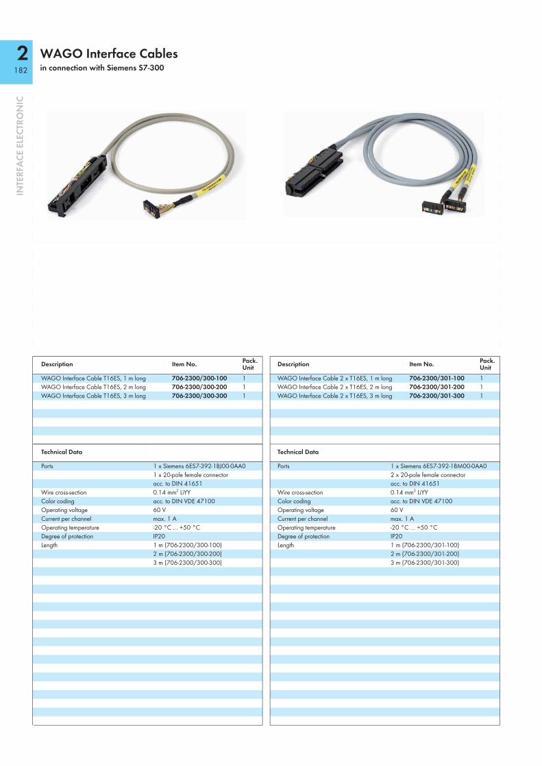
2182
INTE
RFA
CE E
LECT
RON
IC
WAGO Interface Cablesin connection with Siemens S7-300
Description Item No. Pack. Unit Description Item No. Pack.
UnitWAGO Interface Cable T16ES, 1 m long 706-2300/300-100 1 WAGO Interface Cable 2 x T16ES, 1 m long 706-2300/301-100 1WAGO Interface Cable T16ES, 2 m long 706-2300/300-200 1 WAGO Interface Cable 2 x T16ES, 2 m long 706-2300/301-200 1WAGO Interface Cable T16ES, 3 m long 706-2300/300-300 1 WAGO Interface Cable 2 x T16ES, 3 m long 706-2300/301-300 1
Technical Data Technical Data
Ports 1 x Siemens 6ES7-392-1BJ00-0AA01 x 20-pole female connector acc. to DIN 41651
Ports 1 x Siemens 6ES7-392-1BM00-0AA02 x 20-pole female connector acc. to DIN 41651
Wire cross-section 0.14 mm2 LiYY Wire cross-section 0.14 mm2 LiYYColor coding acc. to DIN VDE 47100 Color coding acc. to DIN VDE 47100Operating voltage 60 V Operating voltage 60 VCurrent per channel max. 1 A Current per channel max. 1 AOperating temperature -20 °C … +50 °C Operating temperature -20 °C … +50 °CDegree of protection IP20 Degree of protection IP20Length 1 m (706-2300/300-100)
2 m (706-2300/300-200)3 m (706-2300/300-300)
Length 1 m (706-2300/301-100)2 m (706-2300/301-200)3 m (706-2300/301-300)

2183
INTE
RFA
CE E
LECT
RON
IC
Description Item No. Pack. Unit
WAGO Interface Cable A8E, 1 m long 706-2300/400-100 1WAGO Interface Cable A8E, 2 m long 706-2300/400-200 1WAGO Interface Cable A8E, 3 m long 706-2300/400-300 1
Technical Data
Ports 1 x Siemens 6ES7-392-1BJ00-0AA01 x 25-pole D-sub female connector
Wire cross-section 0.25 mm2 Li YCYColor coding acc. to DIN VDE 47100Operating voltage 125 VCurrent per channel max. 2 AOperating temperature -20 °C … +50 °CDegree of protection IP20Length 1 m (706-2300/400-100)
2 m (706-2300/400-200)3 m (706-2300/400-300)

2184
INTE
RFA
CE E
LECT
RON
IC
WAGO Interface Cablesin connection with Siemens S7-300
Description Item No. Pack. Unit Description Item No. Pack.
UnitWAGO Interface Cable A8EI1, 1 m long 706-2300/404-100 1 WAGO Interface Cable A8EI2, 1 m long 706-2300/406-100 1WAGO Interface Cable A8EI1, 2 m long 706-2300/404-200 1 WAGO Interface Cable A8EI2, 2 m long 706-2300/406-200 1WAGO Interface Cable A8EI1, 3 m long 706-2300/404-300 1 WAGO Interface Cable A8EI2, 3 m long 706-2300/406-300 1
Technical Data Technical Data
Ports 1 x Siemens 6ES7-392-1BM00-0AA01 x 25-pole D-sub female connector acc. to DIN 41651
Ports 1 x Siemens 6ES7-392-1BM00-0AA01 x 25-pole D-sub female connector
Wire cross-section 0.25 mm2 Li YCY Wire cross-section 0.25 mm2 Li YCYColor coding acc. to DIN VDE 47100 Color coding acc. to DIN VDE 47100Operating voltage 125 V Operating voltage 125 VCurrent per channel max. 2 A Current per channel max. 2 AOperating temperature -20 °C … +50 °C Operating temperature -20 °C … +50 °CDegree of protection IP20 Degree of protection IP20Length 1 m (706-2300/404-100)
2 m (706-2300/404-200)3 m (706-2300/404-300)
Length 1 m (706-2300/406-100)2 m (706-2300/406-200)3 m (706-2300/406-300)

2185
INTE
RFA
CE E
LECT
RON
IC
Description Item No. Pack. Unit Description Item No. Pack.
UnitWAGO Interface Cable A4SI, 1 m long 706-2300/500-100 1 WAGO Interface Cable A8SI, 1 m long 706-2300/502-100 1WAGO Interface Cable A4SI, 2 m long 706-2300/500-200 1 WAGO Interface Cable A8SI, 2 m long 706-2300/502-200 1WAGO Interface Cable A4SI, 3 m long 706-2300/500-300 1 WAGO Interface Cable A8SI, 3 m long 706-2300/502-300 1
Technical Data Technical Data
Ports 1 x Siemens 6ES7-392-1BJ00-0AA01 x 15-pole D-sub female connector
Ports 1 x Siemens 6ES7-392-1BM00-0AA01 x 15-pole D-sub female connector
Wire cross-section 0.25 mm2 Li YCY Wire cross-section 0.25 mm2 Li YCYColor coding acc. to DIN VDE 47100 Color coding acc. to DIN VDE 47100Operating voltage 125 V Operating voltage 125 VCurrent per channel max. 2 A Current per channel max. 2 AOperating temperature -20 °C … +50 °C Operating temperature -20 °C … +50 °CDegree of protection IP20 Degree of protection IP20Length 1 m (706-2300/500-100)
2 m (706-2300/500-200)3 m (706-2300/500-300)
Length 1 m (706-2300/502-100)2 m (706-2300/502-200)3 m (706-2300/502-300)

2857-401
3186
INTE
RFA
CE E
LECT
RON
IC
JUMPFLEX® TransducersUniversal Isolation Amplifier
12,5 mm/0.49 in
107
mm
/4.2
1 in
110 mm/4.33 in
Configuration via:
Interface configuration software
Interface configuration app
Configuration display
DIP switch
Short description:The Universal Isolation Amplifier converts, amplifies, filters and electrically isolates analog signals.Features:• Analog unipolar/bipolar signals at input/output• A digital signal output reacts to configured measuring range limits (switching ON/OFF
delay and threshold value switch function configurable with up to two threshold values).
• A digital HOLD input freezes the output signal.• Clipping capability provides analog signal limitation to output end values.• Adjustable software/hardware filter• Input/Output response simulation via configuration display• Safe 3-way isolation with 4 kV test voltage acc. to EN 61140
Description Item No. Pack. Unit
JUMPFLEX® Transducer, for DIN 35 rail 2857-401 1Universal Isolation Amplifier
Technical DataConfiguration:
Configuration DIP switch, interface configuration software, interface configuration app, configuration display
Input:Input signal Current:
± 1 mA; 0 … 1 mA; ± 10 mA; 0 … 10 mA; 2 … 10 mA; ± 20 mA; 0 … 20 mA; 4 … 20 mA; ± 100 mA; 0 … 100 mA Voltage: ± 1 V; 0 … 1 V; ± 10 V; 0 … 10 V; 2 … 10 V; ± 30 V; 0 … 30 V; ± 100 V; 0 … 100 V; ± 200 V; 0 … 220 V
Input resistance ≥ 1 MΩ (U input); ≤ 50 Ω (I input)Max. operating frequency 10 kHz / 5 kHz / 100 Hz / 30 Hz
(configurable via DIP switch)Input – Digital:
HOLD signal 11.8 V … US
Output:Output signal Current:
± 10 mA; 0 … 10 mA; 2 … 10 mA; ± 20 mA; 0 … 20 mA; 4 … 20 mA Voltage: ± 5 V; 0 … 5 V; 1 … 5 V; ± 10 V; 0 … 10 V; 2 … 10 V
Load impedance Current: ≤ 600 Ω; Voltage: ≥ 1 kΩ
Overload capacity -250 V; +250 V / -120 mA; +120 mAOutput – Digital:
Max. switching voltage Supply voltage applied -0.3 VMax. continuous current IDO 100 mA (no internal restriction)
Technical DataGeneral specifications:
Supply voltage US 24 VDCSupply voltage range 16.8 V … 31.2 V (-30 % … +30 %)Current consumption at 24 VDC ≤ 70 mA (+ IDO)Response time (T10-90) < 1 msTransmission error ≤ 0.1 % of the full scale valueTemperature coefficient ≤ 0.01 %/K
Environmental requirements:Ambient operating temperature -40 °C … +70 °CStorage temperature -40 °C … +85 °C
Safety and protection:Test voltage (input/output/supply) 4 kV AC, 50 Hz, 1 min.
Connection and type of mounting:Wire connection CAGE CLAMP® S (picoMAX® 5.0)Cross sections solid/fine-stranded:
0.2 … 2.5 mm² / AWG 24 … 12 Strip length 9 … 10 mm / 0.35 … 0.39 in
Dimensions and weight:Dimensions (mm) W x H x L 12.5 x 107 x 110
Height from upper-edge of DIN 35 railWeight 86 g
Standards and approvals:Conformity marking 1
Standards/Specifications DIN EN 61010-1:2010;DIN EN 60664-1:2008;Safe isolation acc. to DIN EN 61140:2002; IEC 61000-6-2; IEC 61000-6-4
Accessories: For accessories, see Full Line Catalog INTERFACE ELECTRONIC 2012/2013

3187
INTE
RFA
CE E
LECT
RON
IC = ON 2857-401DIP Switch Adjustability
DIP Switch S1
Input
1 Signal 2 Polarity 3 4 5 Range / mA Range / V 6 Inverted Characteristic 7 8 Limit Frequency Current Unipolar 0 … 20 0 … 10 Not inverted 10 kHz
Voltage Bipolar * 0 … 1 0 … 1 Inverted 5 kHz
0 … 5 0 … 5 100 Hz
0 … 10 1 … 5 30 Hz
2 … 10 2 … 10
4 … 20 0 … 30
0 … 50 0 … 100
0 … 100 0 … 220
DIP Switch S1 DIP Switch S2
Output Output
9 Signal 10 Polarity 1 2 Range / mA Range / V
Current Unipolar 0 … 20 0 … 10
Voltage Bipolar * 4 … 20 2 … 10
0 … 10 0 … 5
2 … 10 1 … 5
DIP Switch S1
Output Digital Output (DO)
3 4 Measuring Range Underfl ow Measuring Range Overfl ow 5 6 Lower limit of output range -5% ** Upper limit of output range +2.5% ** Off
Lower limit of output range Upper limit of output range +2.5% DO US+ switching
Lower limit of output range Upper limit of output range DO GND switching
Lower limit of output range -5% Upper limit of output range +5% Off
* Bipolar only applies to ranges starting with 0.
** acc. to NAMUR NE 43

2857-533
3188
INTE
RFA
CE E
LECT
RON
IC
JUMPFLEX® TransducersRTD Threshold Value Switch
12,5 mm/0.49 in
107
mm
/4.2
1 in
110 mm/4.33 in
Configuration via:
Interface configuration software
Interface configuration app
Configuration display
DIP switch
Short description:WAGO's RTD Threshold Value Switch for RTD sensors, potentiometers and resistors monitors and reports signals of up to two switching thresholds.Features:• Both digital signal output and relay with make contact react to configured
measuring range limits (switching ON/OFF delay and threshold value switch function configurable with up to two threshold values).
• Configurable RTD factor• Adjustable software filter• Input/Output response simulation via configuration display• Safe 3-way isolation with 4 kV test voltage acc. to EN 61140
Description Item No. Pack. Unit
JUMPFLEX® Transducer, for DIN 35 rail 2857-533 1RTD Threshold Value Switch
Technical DataConfiguration:
Configuration DIP switch, interface configuration software, interface configuration app, configuration display
Input:Input signal RTD sensors, potentiometers and resistorsSensor types Pt100, Pt200, Pt500, Pt1000,
Pt5000, Pt10000, Pt10 … Pt20000 (expanded)
Sensor connection 2-, 3-, and 4-wire, DifferenceSensor supply current < 0.5 mATemperature range -200 °C … +850 °CResistor input 0 … 100 kΩ
Output:Output – Digital:
Max. switching voltage Supply voltage applied -0.3 VMax. continuous current IDO 100 mA (no internal restriction)Number of switching tresholds 1 or 2Configurable rise and fall delay time
0 … 10 s (via DIP switch); 0 … 60 s (expanded)
Output – Relay:Contact type 1 make contact (1 a)Contact material AgNi (gold-plated)Max. switching voltage 250 VACMax. continuous current (terminal blocks in a row)
6 A (up to 60 °C), 3 A (60 °C … 70 °C)
Dielectric strength open contact (AC, 1 min) 1 kVrms
Pull-in/drop-out/bounce time typ. 8 ms / 4 ms / 8 msNumber of switching tresholds 1 or 2Configurable rise and fall delay time
0 … 10 s (via DIP switch); 0 … 60 s (expanded)
Technical DataGeneral specifications:
Supply voltage US 24 VDCSupply voltage range 16.8 V … 31.2 V (-30 % … +30 %)Current consumption at 24 VDC ≤ 40 mA + IDO
Measurement error ± 1 KTemperature coefficient ≤ 0.01 %/K
Environmental requirements:Ambient operating temperature -40 °C … +70 °CStorage temperature -40 °C … +85 °C
Safety and protection:Test voltage (input/output/supply) 4 kV AC, 50 Hz, 1 min.
Connection and type of mounting:Wire connection CAGE CLAMP® S (picoMAX® 5.0)Cross sections solid/fine-stranded:
0.2 … 2.5 mm² / AWG 24 … 12 Strip length 9 … 10 mm / 0.35 … 0.39 in
Dimensions and weight:Dimensions (mm) W x H x L 12.5 x 107 x 110
Height from upper-edge of DIN 35 railWeight 86 g
Standards and approvals:Conformity marking 1
Standards/Specifications DIN EN 50178:1997 (Basic isolation); DIN EN 61010-1:2010;DIN EN 60664-1:2008; EN 61000-6-2; EN 61000-6-4
Accessories: For accessories, see Full Line Catalog INTERFACE ELECTRONIC 2012/2013

3189
INTE
RFA
CE E
LECT
RON
IC = ON 2857-533DIP Switch Adjustability
DIP Switch S1
Sensor Type Connection Technology Hysteresis Rise/Fall Delay Time Relay/Digital Output (DO)
1 2 3 4 5 6 T / K 7 8 9 t / s 10 Not assigned
Pt100 2-wire 3 0 Pt200 3-wire 5 1
Pt500 4-wire 2 Pt1000 Diff erence 3
Pt5000 4 Pt10000 5
Resistor 8 Potentiometer 10
Default Settings Sensor Type Pt100
Connection Technology 2-wire
Starting Value 0 °C
End Value 100 °C
Hysteresis 3 K
Rise/Fall Delay Time Relay/Digital Output (DO) 0 s
DIP Switch S2 Starting Value End Value
1 2 3 4 5 Temperature / °C Resistance / Ω Potentiometer Position 6 7 8 9 10 Temperature / °C Resistance / Ω Potentiometer Position
0 OFF OFF 100 OFF OFF OFF 10 0 % OFF 10 0 %
-200 15 5 % -200 15 5 % -150 22 10 % -150 22 10 %
-100 33 15 % -100 33 15 % -50 47 20 % -50 47 20 %
-10 68 25 % -10 68 25 % 10 100 30 % 10 100 30 %
20 120 35 % 20 120 35 % 30 150 40 % 30 150 40 %
40 220 45 % 40 220 45 % 50 330 50 % 50 330 50 %
60 470 55 % 60 470 55 % 70 560 60 % 70 560 60 %
80 680 65 % 80 680 65 % 90 1000 70 % 90 1000 70 %
100 1200 75 % 100 1200 75 % 150 1500 80 % 150 1500 80 %
200 2200 85 % 200 2200 85 % 250 3300 90 % 250 3300 90 %
300 4700 95 % 300 4700 95 % 350 5600 100 % 350 5600 100 %
400 6800 OFF 400 6800 OFF 450 10000 OFF 450 10000 OFF
500 12000 OFF 500 12000 OFF 550 15000 OFF 550 15000 OFF
600 22000 OFF 600 22000 OFF 650 33000 OFF 650 33000 OFF
700 47000 OFF 700 47000 OFF 750 56000 OFF 750 56000 OFF
800 68000 OFF 800 68000 OFF 850 100000 OFF 850 100000 OFF

2857-534
3190
INTE
RFA
CE E
LECT
RON
IC
JUMPFLEX® TransducersTC Threshold Value Switch
12,5 mm/0.49 in
107
mm
/4.2
1 in
110 mm/4.33 in
Configuration via:
Interface configuration software
Interface configuration app
Configuration display
DIP switch
Short description:WAGO's Thermocouple Threshold Value Switch for TC sensors monitors and reports signals of up to two switching thresholds. Features:• Both digital signal output and relay with changeover contact react to
configured measuring range limits (switching ON/OFF delay and threshold value switch function configurable with up to two threshold values).
• Adjustable software filter• Input/Output response simulation via configuration display• Safe 3-way isolation with 4 kV test voltage acc. to EN 61140
Description Item No. Pack. Unit
JUMPFLEX® Transducer, for DIN 35 rail 2857-534 1TC Threshold Value Switch
Technical DataConfiguration:
Configuration DIP switch, interface configuration software, interface configuration app, configuration display
Input:Input signal ThermocouplesSensor types Thermocouple's type J, K, E, R, N, S, T, B, STemperature range Type J: -210 °C … +1200 °C
Type K: -200 °C … +1372 °CCold junction compensation On/Off (Default: On)Cold junction error 3 K (type 2 K)
Output:Output – Digital:
Max. switching voltage Supply voltage applied -0.3 VMax. continuous current IDO 100 mA (no internal restriction)Number of switching tresholds 1 or 2Configurable rise and fall delay time
0 … 10 s (via DIP switch); 0 … 60 s (expanded)
Output – Relay:Contact type 1 changeover contact (1 u)Contact material AgNi (gold-plated)Max. switching voltage 250 VACMax. continuous current (terminal blocks in a row)
6 A (up to 60 °C), 3 A (60 °C … 70 °C)
Dielectric strength open contact (AC, 1 min) 1 kVrms
Pull-in/drop-out/bounce time typ. 8 ms / 4 ms / 8 msNumber of switching tresholds 1 or 2Configurable rise and fall delay time
0 … 10 s (via DIP switch); 0 … 60 s (expanded)
Technical DataGeneral specifications:
Supply voltage US 24 VDCSupply voltage range 16.8 V … 31.2 V (-30 % … +30 %)Current consumption at 24 VDC ≤ 40 mA + IDO
Measurement error ± 1 KTemperature coefficient ≤ 0.01 %/K
Environmental requirements:Ambient operating temperature -40 °C … +70 °CStorage temperature -40 °C … +85 °C
Safety and protection:Test voltage (input/output/supply) 4 kV AC, 50 Hz, 1 min.
Connection and type of mounting:Wire connection CAGE CLAMP® S (picoMAX® 5.0)Cross sections solid/fine-stranded:
0.2 … 2.5 mm² / AWG 24 … 12 Strip length 9 … 10 mm / 0.35 … 0.39 in
Dimensions and weight:Dimensions (mm) W x H x L 12.5 x 107 x 110
Height from upper-edge of DIN 35 railWeight 87 g
Standards and approvals:Conformity marking 1
Standards/Specifications DIN EN 50178:1997 (Basic isolation); DIN EN 61010-1:2010;DIN EN 60664-1:2008; EN 61000-6-2; EN 61000-6-4
Accessories: For accessories, see Full Line Catalog INTERFACE ELECTRONIC 2012/2013

3191
INTE
RFA
CE E
LECT
RON
IC = ON 2857-534DIP Switch Adjustability
Default Settings Cold Junction Compensation ON
Sensor Type Thermocouple of type J
Lower Value 0 °C
Upper Value 100 °C
Hysteresis 3 K
Rise/Fall Delay Time Relay/Digital Output (DO) 0 s
DIP Switch S1
Sensor TypeThermocouple Cold Junction Compensation Hysteresis Rise/Fall Delay Time Relay/
Digital Output (DO)
1 2 3 4 Type 5 6 T / K 7 8 9 t / s 10 Not assigned
J ON 3 0 K OFF 5 1
E 2 R 3
N 4 S 5
T 8 B 10
C
DIP Switch S2 Lower Value Upper Value
1 2 3 4 5 Temperature / °C 6 7 8 9 10 Temperature / °C
0 100 OFF OFF
-200 -200 -150 -150
-100 -100 -50 -50
50 50 100 100
150 150 200 200
250 250 300 300
350 350 400 400
450 450 500 500
550 550 600 600
650 650 700 700
750 750 800 800
850 850 900 900
950 950 1000 1000
1050 1050 1100 1100
1150 1150 1200 1200
1300 1300 1400 1400

2857-550
3192
INTE
RFA
CE E
LECT
RON
IC
JUMPFLEX® TransducersCurrent Transducer AC/DC 100 A
22,5 mm/0.89 in
107
mm
/4.2
1 in
105 mm/4.13 in
Ø 9
,5 m
m/0
.37
in
Configuration via:
Interface configuration software
Interface configuration app
Configuration display
DIP switch
Short description:The 2857-550 Current Transducer measures AC/DC currents up to 100 A, while converting the measured current into an analog standard signal at the output.Features:• Both digital signal output and relay with changeover contact react to configured
measuring range limits (switching ON/OFF delay and threshold value switch function configurable with up to two threshold values).
• Clipping capability provides analog signal limitation to output end values.• Adjustable software filter• Input/Output response simulation via configuration display• Safe 3-way isolation with 4 kV test voltage acc. to EN 61140
Description Item No. Pack. Unit
JUMPFLEX® Transducer, for DIN 35 rail 2857-550 1Current Transducer AC/DC 100 A
Technical DataConfiguration:
Configuration DIP switch, interface configuration software, interface configuration app, configuration display
Input:Input signal AC/DC 100 AResponse threshold 250 mA (DC) / 250 mA (AC)Resolution 10 mA Frequency range 15 Hz … 1000 Hz
Output:Output signal Current: ± 10 mA; 0 … 10 mA; 2 … 10 mA;
± 20 mA; 0 … 20 mA; 4 … 20 mA Voltage: ± 5 V; 0 … 5 V; 1 … 5 V; ± 10 V; 0 … 10 V; 2 … 10 V
Overcurrent 0% or +5% (e.g., 10.5 V / 24 mA)Measuring range overflow/underflow 0% or +2.5%Load impedance Current: ≤ 600 Ω; Voltage: ≥ 1 kΩMeasuring procedure True RMS measurement (TRMS) or
Arithmetic mean valueOutput – Digital:
Max. switching voltage Supply voltage applied -0.3 VMax. continuous current IDO 100 mA (no internal restriction)
Output – Relay:Contact type 1 changeover contact (1 u)Contact material AgNi (gold-plated)Max. switching voltage 250 VACMax. continuous current (terminal blocks in a row) 6 A (up to 60 °C), 3 A (60 °C … 70 °C) Dielectric strength open contact (AC, 1 min) 1 kVrms
Pull-in/drop-out/bounce time typ. 8 ms / 4 ms / 8 msGeneral specifications:
Supply voltage US 24 VDCSupply voltage range 16.8 V … 31.2 V (-30 % … +30 %)Current consumption at 24 VDC ≤ 50 mA (+ IDO)
Technical DataGeneral specifications:
Max. operating frequency 3.3 kHzResponse time Signal cycle duration + 1 msResponse time (T10-90) max. 60 msFilter (T10-90) Software filter: 600 msLinearity error ≤ 1 %Measurement error ≤ 0,2 % (of the full scale value)Temperature coefficient ≤ 0.01 %/K
Environmental requirements:Ambient operating temperature -40 °C … +70 °CStorage temperature -40 °C … +85 °C
Safety and protection:Test voltage (input/output/supply) 2.5 kV AC, 50 Hz, 1 min.Test voltage (measuring circuit – output) 4 kV AC, 50 Hz, 1 min.
Connection and type of mounting:Wire connection CAGE CLAMP® S (picoMAX® 5.0)Cross sections solid/fine-stranded:
0.2 … 2.5 mm² / AWG 24 … 12 Strip length 9 … 10 mm / 0.35 … 0.39 inPower cable feed-through Ø 9.5 mmRecommended measurement conductor cross-section 16 mm²; max. 25 mm²
Dimensions and weight:Dimensions (mm) W x H x L 22.5 x 107 x 105
Height from upper-edge of DIN 35 railWeight 106 g
Standards and approvals:Conformity marking 1
Standards/Specifications DIN EN 61010-1:2010;DIN EN 60664-1:2008; Safe isolation acc. to DIN EN 61140:2002; IEC 61000-6-2; IEC 61000-6-4
Accessories: For accessories, see Full Line Catalog INTERFACE ELECTRONIC 2012/2013

3193
INTE
RFA
CE E
LECT
RON
IC = ON 2857-550DIP Switch Adjustability
DIP Switch S1 Measuring Range
Underfl ow Measuring Range
Overfl ow Overcurrent
(Input Signal - End Value +20%) Digital Output (DO)/
Relay 7 8 9 10
Lower measuring range -5% * Upper measuring range +2.5% * Upper measuring range +5% Off Lower measuring range Upper measuring range +2.5% Upper measuring range +5% DO US+ switching – relay pulls in
Lower measuring range Upper measuring range Lower measuring range DO GND switching – relay drops out Lower measuring range -5 % Upper measuring range +5% Upper measuring range Off
DIP Switch S1
Measuring Method Filter Analog OutputInverted
Output Signal(Bipolar for Arithmetic Mean Value)
1 2 3 4 5 6 Analog Output
True RMS inactive not inverted (± ) 0 … 20 mA
Arithmetic mean value(bipolar output) active inverted 4 … 20 mA
(± ) 0 … 10 V
2 … 10 V
(± ) 0 … 10 mA
2 … 10 mA
(± ) 0 … 5 V
1 … 5 V
DIP Switch S2 Lower Value Upper value
1 2 3 4 A / % (RMS) A / % (arithmetic mean value) 5 6 7 A / % Software confi guration (0) Software confi guration (-100) Software confi guration (100)
0 -100 100
5 -75 90
8 -50 70
10 -25 50
12 -10 30
14 0 20
16 5 10
18 10
20 15
25 20
30 25
35 30
40 35
45 40
50 50
*acc. to NAMUR NE 43

2857-900
3194
INTE
RFA
CE E
LECT
RON
IC
Configuration Display
Features:• Easy mounting on 2857 Series devices• Automatic module detection• Capacitive user interface with slider function• Intuitive menu navigation• Color backlight for status indication• Device configuration and process value visualization• Easy copying of device configuration
Description Item No. Pack. Unit
Configuration Display 2857-900 1
Technical DataEnvironmental requirements:
Ambient operating temperature -20 °C … +70 °CStorage temperature -30 °C … +80 °C
Dimensions and weight:Dimensions (mm) W x H x L 22 x 13 x 59
Standards and approvals:Conformity marking 1

3195
INTE
RFA
CE E
LECT
RON
IC
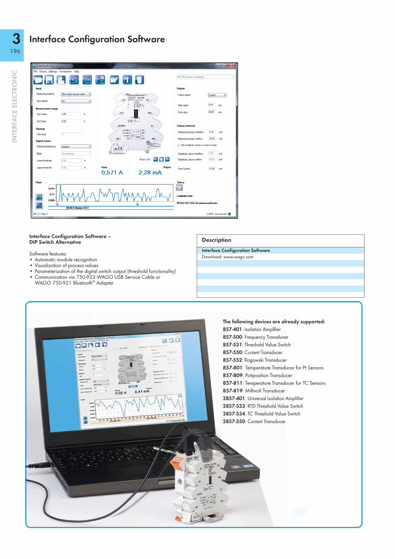
3196
INTE
RFA
CE E
LECT
RON
IC
Interface Configuration Software
Interface Configuration Software – DIP Switch Alternative
Software features:• Automatic module recognition• Visualization of process values• Parameterization of the digital switch output (threshold functionality)• Communication via 750-923 WAGO USB Service Cable or
WAGO 750-921 Bluetooth® Adapter
DescriptionInterface Configuration SoftwareDownload: www.wago.com
The following devices are already supported: 857-401: Isolation Amplifi er 857-500: Frequency Transducer 857-531: Threshold Value Switch 857-550: Current Transducer 857-552: Rogowski Transducer 857-801: Temperature Transducer for Pt Sensors 857-809: Potiposition Transducer 857-811: Temperature Transducer for TC Sensors 857-819: Millivolt Transducer 2857-401: Universal Isolation Amplifi er 2857-533: RTD Threshold Value Switch 2857-534: TC Threshold Value Switch 2857-550: Current Transducer

3197
INTE
RFA
CE E
LECT
RON
IC
Interface Configuration App
Interface Configuration App DIP Switch Alternative
WAGO's Interface Configuration App brings the power of a PC-based configuration software to mobile end-user devices. WAGO's 857 Series transducer's input and output parameters can be configured via finger swipe on an Android-based smartphone or tablet. Furthermore, both configuration data and actual measured values can be easily displayed.WAGO's 750-921 Bluetooth® Adapter communicates between a smartphone and transducer.
DescriptionWAGO Interface Configuration App (Android)Download from Google Play
2857-401: Universal Isolation Amplifi er 2857-533: RTD Threshold Value Switch 2857-534: TC Threshold Value Switch 2857-550: Current Transducer
The following devices are already supported: 857-401: Isolation Amplifi er 857-500: Frequency Transducer 857-531: Threshold Value Switch 857-550: Current Transducer 857-552: Rogowski Transducer 857-801: Temperature Transducer for Pt Sensors 857-809: Potiposition Transducer 857-811: Temperature Transducer for TC Sensors 857-819: Millivolt Transducer
Device Information Output ParameterInput Parameter Digital Output Actual Value
JUMPFLEX®-ToGo Download from Google Play
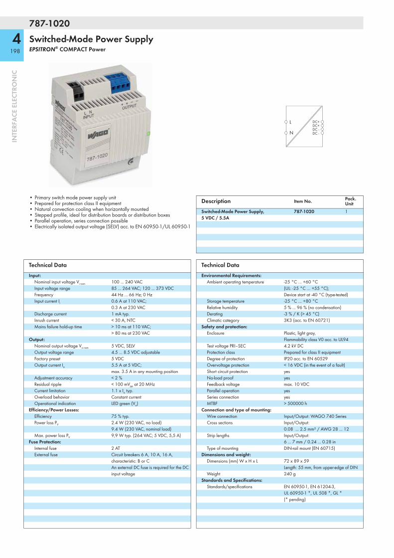
787-1020
4198
INTE
RFA
CE E
LECT
RON
IC
Switched-Mode Power SupplyEPSITRON® COMPACT Power
L
N
DC+DC+DC -DC -
• Primary switch mode power supply unit• Prepared for protection class II equipment• Natural convection cooling when horizontally mounted• Stepped profile, ideal for distribution boards or distribution boxes• Parallel operation, series connection possible• Electrically isolated output voltage (SELV) acc. to EN 60950-1/UL 60950-1
Description Item No. Pack. Unit
Switched-Mode Power Supply, 5 VDC / 5.5A
787-1020 1
Technical DataInput:
Nominal input voltage Vi nom 100 ... 240 VACInput voltage range 85 ... 264 VAC; 120 ... 373 VDCFrequency 44 Hz ... 66 Hz; 0 HzInput current Ii 0.6 A at 110 VAC;
0.3 A at 230 VACDischarge current 1 mA typ.Inrush current < 30 A, NTCMains failure hold-up time > 10 ms at 110 VAC;
> 80 ms at 230 VACOutput:
Nominal output voltage Vo nom 5 VDC, SELVOutput voltage range 4.5 ... 8.5 VDC adjustableFactory preset 5 VDCOutput current Io 5.5 A at 5 VDC;
max. 3.5 A in any mounting positionAdjustment accuracy < 2 %Residual ripple < 100 mVpp at 20 MHzCurrent limitation 1.1 x Io typ.Overload behavior Constant currentOperational indication LED green (Vo)
Efficiency/Power Losses:Efficiency 75 % typ.Power loss PV 2.4 W (230 VAC, no load)
9.4 W (230 VAC, nominal load)Max. power loss PV 9,9 W typ. (264 VAC; 5 VDC, 5,5 A)
Fuse Protection:Internal fuse 2 ATExternal fuse Circuit breakers 6 A, 10 A, 16 A,
characteristic: B or C An external DC fuse is required for the DC input voltage
Technical DataEnvironmental Requirements:
Ambient operating temperature -25 °C … +60 °C (UL: -25 °C … +55 °C); Device start at -40 °C (type-tested)
Storage temperature -25 °C … +80 °CRelative humidity 5 % ... 96 % (no condensation)Derating -3 % / K (> 45 °C)Climatic category 3K3 (acc. to EN 60721)
Safety and protection:Enclosure Plastic, light gray,
Flammability class V0 acc. to UL94Test voltage PRI–SEC 4.2 kV DCProtection class Prepared for class II equipmentDegree of protection IP20 acc. to EN 60529Overvoltage protection < 16 VDC (in the event of a fault)Short circuit protection yesNo-load proof yesFeedback voltage max. 10 VDCParallel operation yesSeries connection yesMTBF > 500000 h
Connection and type of mounting:Wire connection Input/Output: WAGO 740 SeriesCross sections Input/Output:
0.08 ... 2.5 mm² / AWG 28 ... 12Strip lengths Input/Output:
6 ... 7 mm / 0.24 ... 0.28 inType of mounting DIN-rail mount (EN 60715)
Dimensions and weight:Dimensions (mm) W x H x L 72 x 89 x 59
Length: 55 mm, from upper-edge of DIN Weight 240 g
Standards and Specifications:Standards/specifications EN 60950-1, EN 61204-3,
UL 60950-1 *, UL 508 *, GL * (* pending)

787-1017
4199
INTE
RFA
CE E
LECT
RON
IC
Switched-Mode Power SupplyEPSITRON® COMPACT Power
L
N
DC+DC+DC -DC -
• Primary switch mode power supply unit• Prepared for class II equipment• Natural convection cooling when horizontally mounted• Stage profile, ideal for distribution boards or distribution boxes• At reduced output current, any type of mounting positions are possible
(e.g., horizontal, overhead mounting).• Electrically isolated output voltage (SELV) acc. to EN / UL 60950-1
Description Item No. Pack. Unit
Switched-mode power supply, 15 ... 28 VDC / 2 A
787-1017 1
Technical DataInput:
Nominal input voltage Vi nom 100 ... 240 VACInput voltage range 85 ... 264 VAC; 120 ... 373 VDCInput voltage derating max. 2 A (< 100 VAC)Frequency 44 Hz ... 66 Hz; 0 HzInput current Ii 0.9 A at 110 VAC /
0.5 A at 230 VACDischarge current 1 mA typ.Inrush current < 30 A, NTCMains failure hold-up time > 10 ms at 110 VAC /
> 130 ms at 230 VACOutput:
Nominal output voltage Vo nom 18 VDCOutput voltage range 15 ... 28 VDC adjustableOutput current Io 2.4 A at 18 VDC
2.0 A at 24 VDC in horizontal mounting position
Factory preset 18 VDCAdjustment accuracy 2 %Residual ripple < 100 mVpp at 20 MHzCurrent limitation 1.1 x Io typ.Overload behavior Constant currentOperational indication LED green (Va)
Efficiency/Power losses:Efficiency 84 % typ.Power loss PV 2.6 W (230 VAC / no load)
8.1 W (230 VAC / nominal load)Max. power loss PV 8.2 W (100 VAC / 18 VDC, 2.4 A)
Fuse protection:Internal fuse 2 ATExternal fuse Circuit breakers 10 A, 16 A,
characteristic: B or C An external DC fuse is required for the DC input voltage
Technical DataEnvironmental requirements:
Ambient operating temperature -25 °C … +60 °C (UL: -25 °C … +55 °C, pending)); Device start at -40 °C (type-tested)
Storage temperature -25 °C ... +80 °CRel. humidity 5 % ... 96 % (no condensation)Derating -3 % / K (> 45 °C)Degree of pollution 2 (acc. to EN 50178)Climatic category 3K3 (acc. to EN 60721)
Safety and protection:Enclosure Plastic, light gray,
Flammability class V0 acc. to UL94Test voltage pri. - sec. 4.2 kV DCProtection class Prepared for class II equipmentDegree of protection IP20 (acc. to EN 60529)Overvoltage protection < 40 VDC (in the event of a fault)Short circuit protection yesNo-load proof yesFeedback voltage max. 25 VDCParallel operation yesSeries connection yesMTBF 500000 h
Connection and type of mounting:Wire connection Input/Output: WAGO 740 SeriesCross sections Input/Output:
0.08 ... 2.5 mm² / AWG 28 ... 12Strip lengths Input/Output:
6 ... 7 mm / 0.24 ... 0.28 inType of mounting DIN-rail mount (EN 60715)
Dimensions and weight:Dimensions (mm) W x H x L 72 x 89 x 59
Length from upper-edge of DIN 35 railWeight 264 g
Standards and approvals:Standards/Specifications EN 60950 (SELV), EN 61204-3, GL*, UL*
(* pending)
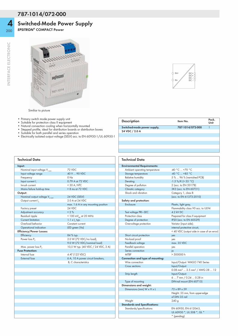
787-1014/072-000
4200
INTE
RFA
CE E
LECT
RON
IC
Switched-Mode Power SupplyEPSITRON® COMPACT Power
Similiar to picture
IN+ DC+DC+DC -DC -IN-
• Primary switch mode power supply unit• Suitable for protection class II equipment• Natural convection cooling when horizontally mounted• Stepped profile, ideal for distribution boards or distribution boxes• Suitable for both parallel and series operation• Electrically isolated output voltage (SELV) acc. to EN 60950-1/UL 60950-1
Description Item No. Pack. Unit
Switched-mode power supply, 24 VDC / 2.0 A
787-1014/072-000 1
Technical DataInput:
Nominal input voltage Vi nom 72 VDCInput voltage range 40 V … 90 VDCFrequency 0 HzInput current Ii 0.79 A at 72 VDCInrush current < 30 A, NTCMains failure hold-up time > 8 ms at 72 VDC
Output:Nominal output voltage Vo nom 24 VDC (SELV)Output current Io 2.0 A at 24 VDC
max. 1.6 A in any mounting positionFactory preset 24 VDCAdjustment accuracy < 2 %Residual ripple < 100 mVpp at 20 MHzCurrent limitation 1.1 x Io typ.Overload behavior Constant currentOperational indication LED green (Va)
Efficiency/Power Losses:Efficiency 84 % typ.Power loss PV 2.0 W (72 VDC/no load),
9.0 W (72 VDC/nominal load)Max. power loss PV 10,5 W typ. (40 VDC / 24 VDC, 2 A)
Fuse Protection:Internal fuse 4 AT (125 VDC)External fuse 6 A, 10 A power circuit breakers,
B, C characteristics
Technical DataEnvironmental Requirements:
Ambient operating temperature -40 °C … +70 °CStorage temperature -40 °C … +85 °CRelative humidity 5 % … 96 % (varnished PCB)Derating -1.5 %/K (> 55 °C)Degree of pollution 2 (acc. to EN 50178)Climatic category 3K3 (acc. to EN 60721)Shock and vibration Category 1, class B
(acc. to EN 61373:2010)Safety and protection:
Enclosure Plastic, light gray, Flammability class V0 acc. to UL94
Test voltage PRI–SEC 4.2 kV DCProtection class Prepared for class II equipmentDegree of protection IP20 (acc. to EN 60529)Overvoltage protection Varistor (input side);
internal protective circuit, < 40 VDC (output side in case of an error)
Short circuit protection yesNo-load proof yesFeedback voltage max. 35 VDCParallel operation yesSeries connection jaMTBF > 500000 h
Connection and type of mounting:Wire connection Input/Output: WAGO 740 SeriesCross sections Input/Output:
0.08 mm² … 2.5 mm² / AWG 28 … 12Strip length Input/Output:
6 … 7 mm / 0.24 … 0.28 inType of mounting DIN-rail mount (EN 60715)
Dimensions and weight:Dimensions (mm) W x H x L 72 x 89 x 59
Height: 55 mm, from upper-edge of DIN 35 rail
Weight 240 gStandards and Specifications:
Standards/specifications EN 60950, EN 61204-3, UL 60950 *, UL 508 *, GL * * (pending)
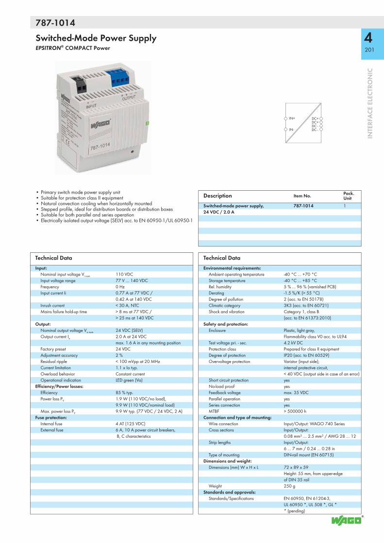
787-1014
4201
INTE
RFA
CE E
LECT
RON
IC
Switched-Mode Power SupplyEPSITRON® COMPACT Power
IN+ DC+DC+DC -DC -IN-
• Primary switch mode power supply unit• Suitable for protection class II equipment• Natural convection cooling when horizontally mounted• Stepped profile, ideal for distribution boards or distribution boxes• Suitable for both parallel and series operation• Electrically isolated output voltage (SELV) acc. to EN 60950-1/UL 60950-1
Description Item No. Pack. Unit
Switched-mode power supply, 24 VDC / 2.0 A
787-1014 1
Technical DataInput:
Nominal input voltage Vi nom 110 VDCInput voltage range 77 V … 140 VDCFrequency 0 HzInput current Ii 0.77 A at 77 VDC /
0.42 A at 140 VDCInrush current < 30 A, NTCMains failure hold-up time > 8 ms at 77 VDC /
> 25 ms at 140 VDCOutput:
Nominal output voltage Vo nom 24 VDC (SELV)Output current Io 2.0 A at 24 VDC
max. 1.6 A in any mounting positionFactory preset 24 VDCAdjustment accuracy 2 %Residual ripple < 100 mVpp at 20 MHzCurrent limitation 1.1 x Io typ.Overload behavior Constant currentOperational indication LED green (Va)
Efficiency/Power losses:Efficiency 85 % typ.Power loss PV 1.9 W (110 VDC/no load),
9.9 W (110 VDC/nominal load)Max. power loss PV 9.9 W typ. (77 VDC / 24 VDC, 2 A)
Fuse protection:Internal fuse 4 AT (125 VDC)External fuse 6 A, 10 A power circuit breakers,
B, C characteristics
Technical DataEnvironmental requirements:
Ambient operating temperature -40 °C … +70 °CStorage temperature -40 °C … +85 °CRel. humidity 5 % … 96 % (varnished PCB)Derating -1.5 %/K (> 55 °C)Degree of pollution 2 (acc. to EN 50178)Climatic category 3K3 (acc. to EN 60721)Shock and vibration Category 1, class B
(acc. to EN 61373:2010)Safety and protection:
Enclosure Plastic, light gray, Flammability class V0 acc. to UL94
Test voltage pri. - sec. 4.2 kV DCProtection class Prepared for class II equipmentDegree of protection IP20 (acc. to EN 60529)Overvoltage protection Varistor (input side);
internal protective circuit, < 40 VDC (output side in case of an error)
Short circuit protection yesNo-load proof yesFeedback voltage max. 35 VDCParallel operation yesSeries connection yesMTBF > 500000 h
Connection and type of mounting:Wire connection Input/Output: WAGO 740 SeriesCross sections Input/Output:
0.08 mm² … 2.5 mm² / AWG 28 … 12Strip lengths Input/Output:
6 … 7 mm / 0.24 … 0.28 inType of mounting DIN-rail mount (EN 60715)
Dimensions and weight:Dimensions (mm) W x H x L 72 x 89 x 59
Height: 55 mm, from upper-edge of DIN 35 rail
Weight 250 gStandards and approvals:
Standards/Specifications EN 60950, EN 61204-3, UL 60950 *, UL 508 *, GL * * (pending)

787-734
4202
INTE
RFA
CE E
LECT
RON
IC
Switched-Mode Power SupplyEPSITRON® ECO Power
DC+DC+DC -DC -DC -
DC O.K.
LN
• Prepared for class I equipment• Natural convection cooling when horizontally mounted• Enclosed for use in switchgear cabinets• Fast and tool-free termination via lever-actuated terminal blocks• Bounce-free switching contact (DC OK)• Parallel operation• Electrically isolated output voltage (SELV) acc. to EN / UL 60950-1
Description Item No. Pack. Unit
Switched-mode power supply, 24 VDC / 20 A
787-734 1
Technical DataInput:
Nominal input voltage Vi nom 100 ... 240 VACInput voltage range 85 ... 264 VAC; 130 ... 373 VDC
(use of DC requires external protection)Frequency 47 Hz ... 63 HzInput current Ii 3 A typ. at 230 VAC;
6.0 A at 115 VACDischarge current 1.7 mAInrush current < 30 AMains failure hold-up time > 20 ms at 230 VAC
Output:Nominal output voltage Vo nom 24 VDC (SELV)Output voltage range 22 ... 28 VDC adjustableOutput current Io 20 A at 24 VDCFactory preset 24 VDCAdjustment accuracy 1 %Residual ripple < 100 mV (peak-peak)Overload behavior Constant power
(in overload range: 1.15 ... 1.4 x Io); shutdown and automatic restart in the event of a short circuit
Operational indication LED green (24 V DC o.k.), LED red (overload)
Efficiency/Power losses:Efficiency 90 % typ.Power loss PV 65 W (230 VAC / nominal load)Max. power loss PV 107 W typ. (110 VAC / 24 VDC, 23 A)
Fuse protection:Internal fuse 16 AT / 250 VExternal fuse Circuit breakers 10 A, 16 A,
characteristic: B or C An external DC fuse is required for the DC input voltage
Technical DataEnvironmental requirements:
Ambient operating temperature -25 °C ... +70 °CStorage temperature -25 °C ... +85 °CRel. humidity 95 % (no condensation)Derating see instruction manualDegree of pollution 2 (acc. to EN 50178)Climatic category 3K3 (acc. to EN 60721)
Safety and protection:Test voltage PRI-SEC/PRI-GND/SEC-GND 3 kV AC / 1.5 kV AC / 0.5 kV ACProtection class Prepared for class I equipmentDegree of protection IP20 (acc. to EN 60529)Overvoltage protection via varistor at primary circuitShort circuit protection yesNo-load proof yesFeedback voltage 29 VDCParallel operation yesSeries connection yesMTBF > 250000 h
Connection and type of mounting:Wire connection Input/Signalising: WAGO 2706 Series
Output: WAGO 2716 SeriesCross sections Input/Signalising:
0.5 mm² ... 6 mm² / AWG 20 ... 10 Output: 1.5 mm² ... 16 mm² / AWG 16 ... 6
Strip lengths Input/Signalising: 11 ... 12 mm / 0.45 in Output: 12 ... 13 mm / 0.47 in
Type of mounting DIN-rail mount (EN 60715)Dimensions and weight:
Dimensions (mm) W x H x L 115 x 136 x 144Length from upper-edge of DIN 35 rail
Weight 2120 gStandards and approvals:
Standards/Specifications EN 60950 (SELV), EN 61000-6-2, EN 61000-6-3 UL 60950, UL 508* (* pending)
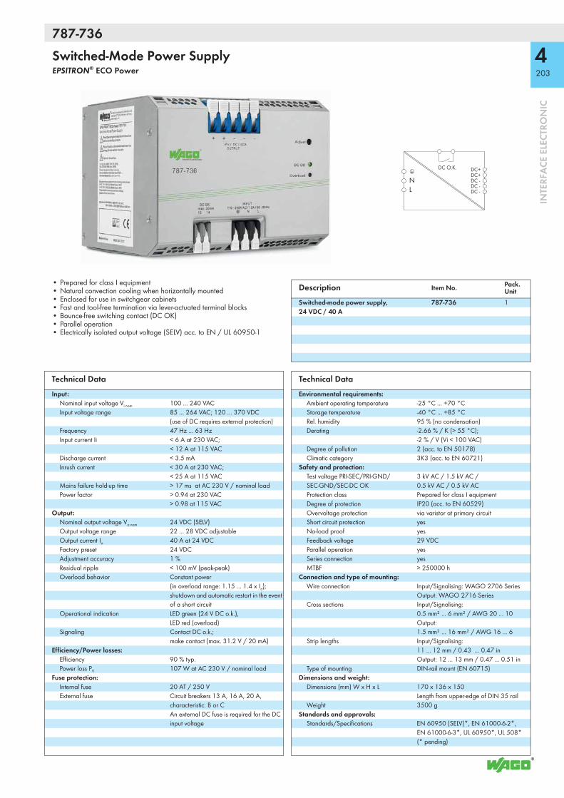
787-736
4203
INTE
RFA
CE E
LECT
RON
IC
Switched-Mode Power SupplyEPSITRON® ECO Power
DC+DC+DC -DC -DC -
DC O.K.
LN
• Prepared for class I equipment• Natural convection cooling when horizontally mounted• Enclosed for use in switchgear cabinets• Fast and tool-free termination via lever-actuated terminal blocks• Bounce-free switching contact (DC OK)• Parallel operation• Electrically isolated output voltage (SELV) acc. to EN / UL 60950-1
Description Item No. Pack. Unit
Switched-mode power supply, 24 VDC / 40 A
787-736 1
Technical DataInput:
Nominal input voltage Vi nom 100 ... 240 VACInput voltage range 85 ... 264 VAC; 120 ... 370 VDC
(use of DC requires external protection)Frequency 47 Hz ... 63 HzInput current Ii < 6 A at 230 VAC;
< 12 A at 115 VACDischarge current < 3.5 mAInrush current < 30 A at 230 VAC;
< 25 A at 115 VACMains failure hold-up time > 17 ms at AC 230 V / nominal loadPower factor > 0.94 at 230 VAC
> 0.98 at 115 VACOutput:
Nominal output voltage Vo nom 24 VDC (SELV)Output voltage range 22 ... 28 VDC adjustableOutput current Io 40 A at 24 VDCFactory preset 24 VDCAdjustment accuracy 1 %Residual ripple < 100 mV (peak-peak)Overload behavior Constant power
(in overload range: 1.15 ... 1.4 x Io); shutdown and automatic restart in the event of a short circuit
Operational indication LED green (24 V DC o.k.), LED red (overload)
Signaling Contact DC o.k.; make contact (max. 31.2 V / 20 mA)
Efficiency/Power losses:Efficiency 90 % typ.Power loss PV 107 W at AC 230 V / nominal load
Fuse protection:Internal fuse 20 AT / 250 VExternal fuse Circuit breakers 13 A, 16 A, 20 A,
characteristic: B or C An external DC fuse is required for the DC input voltage
Technical DataEnvironmental requirements:
Ambient operating temperature -25 °C ... +70 °CStorage temperature -40 °C ... +85 °CRel. humidity 95 % (no condensation)Derating -2.66 % / K (> 55 °C);
-2 % / V (Vi < 100 VAC)Degree of pollution 2 (acc. to EN 50178)Climatic category 3K3 (acc. to EN 60721)
Safety and protection:Test voltage PRI-SEC/PRI-GND/SEC-GND/SEC-DC OK
3 kV AC / 1.5 kV AC / 0.5 kV AC / 0.5 kV AC
Protection class Prepared for class I equipmentDegree of protection IP20 (acc. to EN 60529)Overvoltage protection via varistor at primary circuitShort circuit protection yesNo-load proof yesFeedback voltage 29 VDCParallel operation yesSeries connection yesMTBF > 250000 h
Connection and type of mounting:Wire connection Input/Signalising: WAGO 2706 Series
Output: WAGO 2716 SeriesCross sections Input/Signalising:
0.5 mm² ... 6 mm² / AWG 20 ... 10 Output: 1.5 mm² ... 16 mm² / AWG 16 ... 6
Strip lengths Input/Signalising: 11 ... 12 mm / 0.43 ... 0.47 in Output: 12 ... 13 mm / 0.47 ... 0.51 in
Type of mounting DIN-rail mount (EN 60715)Dimensions and weight:
Dimensions (mm) W x H x L 170 x 136 x 150Length from upper-edge of DIN 35 rail
Weight 3500 gStandards and approvals:
Standards/Specifications EN 60950 (SELV)*, EN 61000-6-2*, EN 61000-6-3*, UL 60950*, UL 508* (* pending)

787-738
4204
INTE
RFA
CE E
LECT
RON
IC
Switched-Mode Power SupplyEPSITRON® ECO Power
L1
L2
L3
DC+DC+DC -DC -DC -
DC O.K.
• Suitable for protection class I equipment• Natural convection cooling when horizontally mounted• Enclosed for use in switchgear cabinets• Fast and tool-free termination via lever-actuated terminal blocks• DC O.K. contact• Parallel operation• Electrically isolated output voltage (SELV) acc. to
EN 60950-1/UL 60950-1
Description Item No. Pack. Unit
Switched-mode power supply,24 VDC / 6.25 A
787-738 1
Technical DataInput:
Nominal input voltage Vi nom 3 x (2 x) 400 V … 500 VACInput voltage range 325 V … 575 VAC; 460 V … 800 VDCFrequency 47 Hz … 63 HzInput current Ii 3 x 0.4 A at 400 VAC and 6.25 ADCPower factor ≥ 0.6Discharge current < 3.5 mAInrush current < 25 AMains failure hold-up time > 17 ms at 3x 400 VAC
Output:Nominal output voltage Vo nom 24 VDC (SELV)Output voltage range 22 ... 28 VDC adjustableOutput current Io 6.25 A at 24 VDCFactory preset 24 VDCAdjustment accuracy 1 %Residual ripple < 80 mVpp
Overload behavior Constant power (in overload range: 1.15 ... 1.4 x Io); shutdown and automatic restart in the event of a short circuit
Operational indication Green LED (Vo) Red LED (overload)
Signaling DC O.K. contact; Make contact (max. 31.2 V / 20 mA)
Efficiency/Power losses:Efficiency 87 % typ.Power loss PV 18.5 WMax. power loss PV 20 W
Fuse protection:Internal fuse 3 x T2AExternal fuse 3 x circuit breakers 10 A, 16 A,
B or C characteristic, or motor circuit breakers External DC fuse required for DC input voltage
Environmental requirements:Ambient operating temperature -25 °C … +70 °CStorage temperature -40 °C … +85 °CRel. humidity 95% (no condensation permissible)
Technical DataEnvironmental requirements:
Derating -2.5 % / K (> +50 °C; 400 VAC)Degree of pollution 2 (acc. to EN 50178)Climatic category 3K3 (acc. to EN 60721)
Safety and protection:Test voltage PRI-SEC/PRI-GND/SEC-GND/SEC-DC OK
3 kV AC / 1.5 kV AC / 0.5 kV AC / 0.5 kV AC
Protection class Prepared for class I equipmentDegree of protection IP20 (acc. to EN 60529)Overvoltage protection yesShort circuit protection yesNo-load proof yesFeedback voltage 30 VParallel operation yesSeries connection yesMTBF > 250000 h
Connection and type of mounting:Wire connection Input/Output: WAGO 2706 Series
Signaling: WAGO 2091 SeriesCross sections Input/Output:
0.5 mm² … 6 mm² / AWG 20 … 10 Signaling: 0.2 mm² … 1.5 mm² / AWG 24 … 14
Strip lengths Input/Output: 11 … 12 mm / 0.43 … 0.47 in Signaling: 8 … 9 mm / 0.31 … 0.35 in
Type of mounting DIN-rail mount (EN 60715)Dimensions and weight:
Dimensions (mm) W x H x L 50 x 130 x 92Length from upper-edge of DIN 35 rail
Weight 3500 gStandards and approvals:
Standards/Specifications EN 60950, EN 61204-3, UL 60950*, UL 508* (* pending)

787-740
4205
INTE
RFA
CE E
LECT
RON
IC
Switched-Mode Power SupplyEPSITRON® ECO Power
L1
L2
L3
DC+DC+DC -DC -DC -
DC O.K.
• Suitable for protection class I equipment• Natural convection cooling when horizontally mounted• Enclosed for use in switchgear cabinets• Fast and tool-free termination via lever-actuated terminal blocks• DC O.K. contact• Parallel operation• Electrically isolated output voltage (SELV) acc. to
EN 60950-1/UL 60950-1
Description Item No. Pack. Unit
Switched-mode power supply, 24 VDC / 10 A
787-740 1
Technical DataInput:
Nominal input voltage Vi nom 3 x (2 x) 400 V … 500 VACInput voltage range 325 V … 575 VAC; 460 V … 800 VDCFrequency 47 Hz … 63 HzInput current Ii 3 x 0.6 A at 400 VAC and 10 ADCPower factor ≥ 0.6Discharge current < 3.5 mAInrush current < 25 AMains failure hold-up time > 17 ms at 3x 400 VAC
Output:Nominal output voltage Vo nom 24 VDC (SELV)Output voltage range 22 ... 28 VDC adjustableOutput current Io 10 A at 24 VDCFactory preset 24 VDCAdjustment accuracy 1 %Residual ripple < 80 mVpp
Overload behavior Constant power (in overload range: 1.15 ... 1.4 x Io); shutdown and automatic restart in the event of a short circuit
Operational indication Green LED (Vo) Red LED (overload)
Signaling DC O.K. contact; Make contact (max. 31.2 V / 20 mA)
Efficiency/Power losses:Efficiency 89 % typ.Power loss PV 32.5 WMax. power loss PV 36 W
Fuse protection:Internal fuse 3 x T2AExternal fuse 3 x circuit breakers 10 A, 16 A,
B or C characteristic, or motor circuit breakers External DC fuse required for DC input voltage
Environmental requirements:Ambient operating temperature -25 °C … +70 °CStorage temperature -40 °C … +85 °CRel. humidity 95% (no condensation permissible)
Technical DataEnvironmental requirements:
Derating -1.25 % / K (> +50 °C; 400 VAC)Degree of pollution 2 (acc. to EN 50178)Climatic category 3K3 (acc. to EN 60721)
Safety and protection:Test voltage PRI-SEC/PRI-GND/SEC-GND/SEC-DC OK
3 kV AC / 1.5 kV AC / 0.5 kV AC / 0.5 kV AC
Protection class Prepared for class I equipmentDegree of protection IP20 (acc. to EN 60529)Overvoltage protection yesShort circuit protection yesNo-load proof yesFeedback voltage 30 VParallel operation yesSeries connection yesMTBF > 250000 h
Connection and type of mounting:Wire connection Input/Output: WAGO 2706 Series
Signaling: WAGO 2091 SeriesCross sections Input/Output:
0.5 mm² … 6 mm² / AWG 20 … 10 Signaling: 0.2 mm² … 1.5 mm² / AWG 24 … 14
Strip lengths Input/Output: 11 … 12 mm / 0.43 … 0.47 in Signaling: 8 … 9 mm / 0.31 … 0.35 in
Type of mounting DIN-rail mount (EN 60715)Dimensions and weight:
Dimensions (mm) W x H x L 65 x 130 x 130Length from upper-edge of DIN 35 rail
Weight 2120 gStandards and approvals:
Standards/Specifications EN 60950, EN 61204-3, UL 60950*, UL 508* (* pending)

787-742
4206
INTE
RFA
CE E
LECT
RON
IC
Switched-Mode Power SupplyEPSITRON® ECO Power
L1
L2
L3
DC+DC+DC -DC -DC -
DC O.K.
• Suitable for protection class I equipment• Natural convection cooling when horizontally mounted• Enclosed for use in switchgear cabinets• Fast and tool-free termination via lever-actuated terminal blocks• DC O.K. contact• Parallel operation• Electrically isolated output voltage (SELV) acc. to
EN 60950-1/UL 60950-1
Description Item No. Pack. Unit
Switched-mode power supply,24 VDC / 20 A
787-742 1
System DataInput:
Nominal input voltage Vi nom 3 x (2 x) 400 V … 500 VACInput voltage range 325 V … 575 VAC; 460 V … 800 VDCFrequency 47 Hz … 63 HzInput current Ii 3 x 2.05 A at 400 VAC and 20 ADCPower factor ≥ 0.6Discharge current < 3.5 mAInrush current < 30 AMains failure hold-up time > 17 ms at 3x 400 VAC
Output:Nominal output voltage Vo nom 24 VDC (SELV)Output voltage range 22 ... 28 VDC adjustableOutput current Io 20 A at 24 VDCFactory preset 24 VDCAdjustment accuracy 1 %Residual ripple < 80 mVpp
Overload behavior Constant power (in overload range: 1.15 ... 1.4 x Io); shutdown and automatic restart in the event of a short circuit
Operational indication Green LED (Vo), Red LED (overload)Signaling DC O.K. contact; Make contact
(max. 31.2 V / 20 mA)Efficiency/Power losses:
Efficiency 90 % typ.Power loss PV 50 WMax. power loss PV 55 W
Fuse protection:Internal fuse 3 x T5AExternal fuse 3 x circuit breakers 10 A, 16 A,
B or C characteristic, or motor circuit breakers External DC fuse required for DC input voltage
Environmental Requirements:Ambient operating temperature -25 °C … +70 °CStorage temperature -40 °C … +85 °CRel. humidity 95% (no condensation permissible)
Technical DataEnvironmental Requirements:
Derating -2 % / K (> +50 °C; 400 VAC)Degree of pollution 2 (acc. to EN 50178)Climatic category 3K3 (acc. to EN 60721)
Safety and protection:Test voltage PRI-SEC/PRI-GND/SEC-GND/SEC-DC OK
3 kV AC / 1.5 kV AC / 0.5 kV AC / 0.5 kV AC
Protection class Prepared for class I equipmentDegree of protection IP20 (acc. to EN 60529)Overvoltage protection yesShort circuit protection yesNo-load proof yesFeedback voltage 30 VParallel operation yesSeries connection yesMTBF > 250000 h
Connection and type of mounting:Wire connection Input/Output: WAGO 2706 Series
Signaling: WAGO 2091 SeriesCross sections Input/Output:
0.5 mm² … 6 mm² / AWG 20 … 10 Signaling: 0.2 mm² … 1.5 mm² / AWG 24 … 14
Strip lengths Input/Output: 11 … 12 mm / 0.43 … 0.47 in Signaling: 8 … 9 mm / 0.31 … 0.35 in
Type of mounting DIN-rail mount (EN 60715)Dimensions and weight:
Dimensions (mm) W x H x L 110 x 130 x 151Length from upper-edge of DIN 35 rail
Weight 1930 gStandards and approvals:
Standards/Specifications EN 60950, EN 61204-3, UL 60950*, UL 508* (* pending)

787-1601
4207
INTE
RFA
CE E
LECT
RON
IC
Switched-Mode Power SupplyEPSITRON® CLASSIC Power
Similiar to picture
LDC+DC+DC -DC -
DC O.K.N
• Primary switch mode power supply unit• Protection class II• Natural convection cooling when horizontally mounted• Enclosed for use in switchgear cabinets• Bounce-free switching signal (DC OK)• Suitable for both parallel and series operation• Electrically isolated output voltage (SELV) acc. to EN 60950-1/UL 60950-1
Description Item No. Pack. Unit
Switched-mode power supply, 12 VDC / 2 A
787-1601 1
Technical DataInput:
Nominal input voltage Vi nom 100 … 240 VACInput voltage range 85 … 264 VAC; 120 V … 372 VDCInput voltage derating -2.5 % (< 95 VAC)Frequency 47 Hz … 63 Hz; 0 HzInput current Ii 0.22 A (240 VAC);
0.45 A (100 VAC)Inrush current < 30 AMains failure hold-up time 120 ms (230 VAC);
15 ms (100 VAC)Output:
Nominal output voltage Vo nom 12 VDC (SELV)Output voltage range 11.5 … 14.5 VDC adjustableOutput current Io 2 A at 12 VDC (2.1 A up to 40 °C)Factory preset 12 VDCAdjustment accuracy < 1 %Residual ripple 25 mVpp typ.Current limitation 1.1 x Io typ.Overload behavior Constant currentOperational indication Green LED (Vo)Signaling 1 x active signal output 12 VDC, 40 mA
Efficiency/Power losses:Efficiency 82 % typ.Power loss PV < 0.7 W (230 VAC, no load);
5.3 W (230 VAC, nominal load)Max. power loss PV 5.7 W typ. (100 VAC / 12 VDC, 2 A)
Fuse protection:Internal fuse 2 ATExternal fuse Circuit breakers 6 A, 10 A, 16 A,
B or C characteristic
Technical DataEnvironmental Requirements:
Ambient operating temperature -25 °C … +70 °C; Device start at -40 °C (type-tested)
Storage temperature -25 °C … +85 °CRelative humidity 30 % … 85 % (no condensation permissible)Derating -3 %/K (> 50 °C)Degree of pollution 2 (acc. to EN 50178)Climatic category 3K3 (acc. to EN 60721)
Safety and protection:Test voltage pri. - sec. 4.2 kV DCProtection class IIDegree of protection IP20 (acc. to EN 60529)Overvoltage protection Varistor (input side);
internal protective circuit, < 35 VDC (output side in case of an error)
Short circuit protection yesNo-load proof yesFeedback voltage max. 25 VDCParallel operation yesSeries connection yesMTBF > 500,000 h (acc. to IEC 61709)
Connection and type of mounting:Wire connection Input/Output/Signaling:
WAGO 721 SeriesCross sections Input/Output/Signaling:
0.08 mm² … 2.5 mm² / AWG 28 … 12Strip lengths Input/Output/Signaling:
8 … 9 mm / 0.31 … 0.35 inType of mounting DIN-rail mount (EN 60715)
Dimensions and weight:Dimensions (mm) W x H x L 22.5 x 90 x 107.5
Length from upper-edge of DIN 35 railWeight 128 g
Standards and approvals:Standards/Specifications EN 60950-1, EN 61204-3, EN 60335-1,
UL 60950-1, UL 508, GL * (* pending)
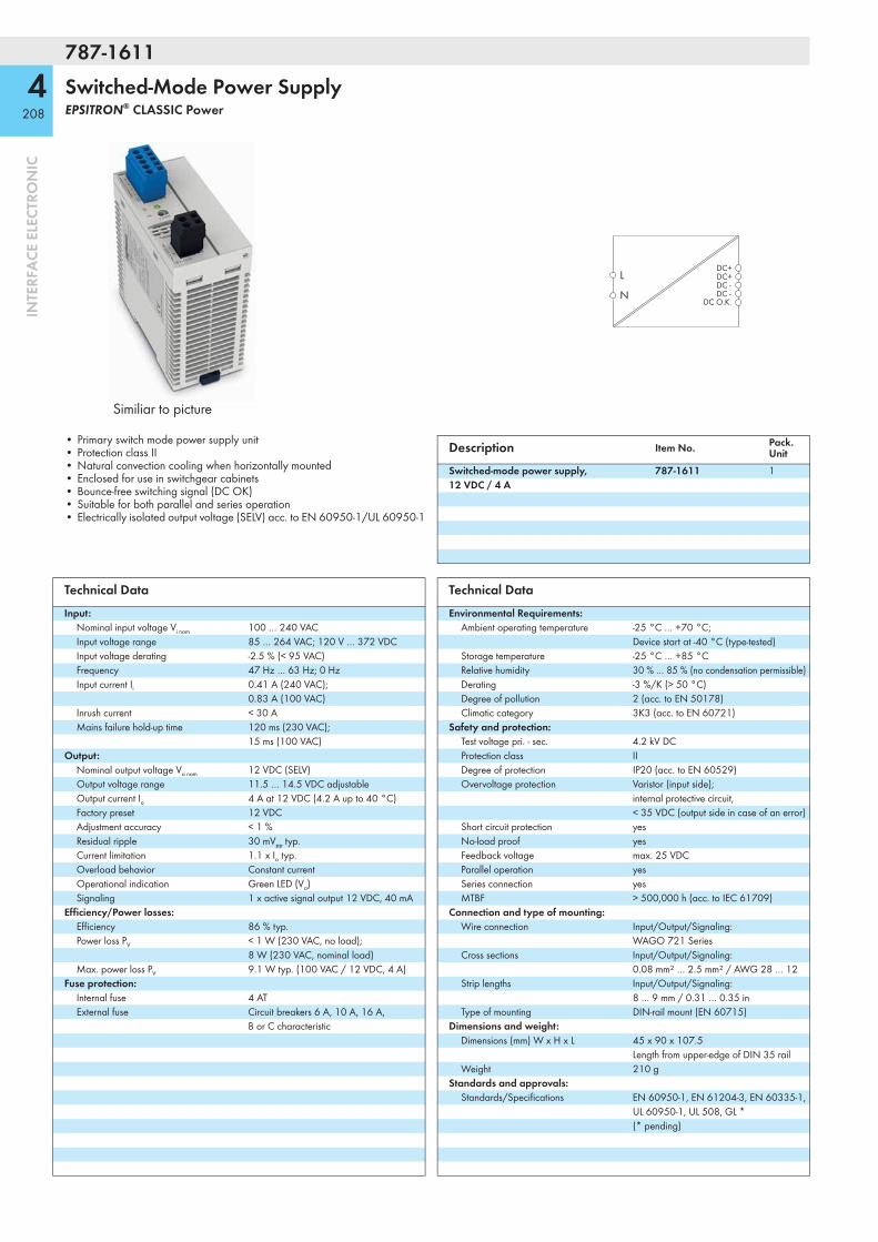
787-1611
4208
INTE
RFA
CE E
LECT
RON
IC
Switched-Mode Power SupplyEPSITRON® CLASSIC Power
Similiar to picture
LDC+DC+DC -DC -
DC O.K.N
• Primary switch mode power supply unit• Protection class II• Natural convection cooling when horizontally mounted• Enclosed for use in switchgear cabinets• Bounce-free switching signal (DC OK)• Suitable for both parallel and series operation• Electrically isolated output voltage (SELV) acc. to EN 60950-1/UL 60950-1
Description Item No. Pack. Unit
Switched-mode power supply, 12 VDC / 4 A
787-1611 1
Technical DataInput:
Nominal input voltage Vi nom 100 … 240 VACInput voltage range 85 … 264 VAC; 120 V … 372 VDCInput voltage derating -2.5 % (< 95 VAC)Frequency 47 Hz … 63 Hz; 0 HzInput current Ii 0.41 A (240 VAC);
0.83 A (100 VAC)Inrush current < 30 AMains failure hold-up time 120 ms (230 VAC);
15 ms (100 VAC)Output:
Nominal output voltage Vo nom 12 VDC (SELV)Output voltage range 11.5 … 14.5 VDC adjustableOutput current Io 4 A at 12 VDC (4.2 A up to 40 °C)Factory preset 12 VDCAdjustment accuracy < 1 %Residual ripple 30 mVpp typ.Current limitation 1.1 x Io typ.Overload behavior Constant currentOperational indication Green LED (Vo)Signaling 1 x active signal output 12 VDC, 40 mA
Efficiency/Power losses:Efficiency 86 % typ.Power loss PV < 1 W (230 VAC, no load);
8 W (230 VAC, nominal load)Max. power loss PV 9.1 W typ. (100 VAC / 12 VDC, 4 A)
Fuse protection:Internal fuse 4 ATExternal fuse Circuit breakers 6 A, 10 A, 16 A,
B or C characteristic
Technical DataEnvironmental Requirements:
Ambient operating temperature -25 °C … +70 °C; Device start at -40 °C (type-tested)
Storage temperature -25 °C … +85 °CRelative humidity 30 % … 85 % (no condensation permissible)Derating -3 %/K (> 50 °C)Degree of pollution 2 (acc. to EN 50178)Climatic category 3K3 (acc. to EN 60721)
Safety and protection:Test voltage pri. - sec. 4.2 kV DCProtection class IIDegree of protection IP20 (acc. to EN 60529)Overvoltage protection Varistor (input side);
internal protective circuit, < 35 VDC (output side in case of an error)
Short circuit protection yesNo-load proof yesFeedback voltage max. 25 VDCParallel operation yesSeries connection yesMTBF > 500,000 h (acc. to IEC 61709)
Connection and type of mounting:Wire connection Input/Output/Signaling:
WAGO 721 SeriesCross sections Input/Output/Signaling:
0.08 mm² … 2.5 mm² / AWG 28 … 12Strip lengths Input/Output/Signaling:
8 … 9 mm / 0.31 … 0.35 inType of mounting DIN-rail mount (EN 60715)
Dimensions and weight:Dimensions (mm) W x H x L 45 x 90 x 107.5
Length from upper-edge of DIN 35 railWeight 210 g
Standards and approvals:Standards/Specifications EN 60950-1, EN 61204-3, EN 60335-1,
UL 60950-1, UL 508, GL * (* pending)

787-1621
4209
INTE
RFA
CE E
LECT
RON
IC
Switched-Mode Power SupplyEPSITRON® CLASSIC Power
Similiar to picture
LDC+DC+DC -DC -
DC O.K.N
• Primary switch mode power supply unit• Protection class II• Natural convection cooling when horizontally mounted• Enclosed for use in switchgear cabinets• Bounce-free switching signal (DC OK)• Suitable for both parallel and series operation• Electrically isolated output voltage (SELV) acc. to EN 60950-1/UL 60950-1
Description Item No. Pack. Unit
Switched-mode power supply, 12 VDC / 7 A
787-1621 1
Technical DataInput:
Nominal input voltage Vi nom 100 … 240 VACInput voltage range 85 … 264 VAC; 120 V … 372 VDCInput voltage derating -2.5 % (< 95 VAC)Frequency 47 Hz … 63 Hz; 0 HzInput current Ii 0.7 A (240 VAC);
1.5 A (100 VAC)Inrush current < 30 AMains failure hold-up time 100 ms (230 VAC);
15 ms (100 VAC)Output:
Nominal output voltage Vo nom 12 VDC (SELV)Output voltage range 11.5 … 14.5 VDC adjustableOutput current Io 7 A at 12 VDC (7.5 A up to 40 °C)Factory preset 12 VDCAdjustment accuracy < 1 %Residual ripple 50 mVpp typ.Current limitation 1.1 x Io typ.Overload behavior Constant currentOperational indication Green LED (Vo)Signaling 1 x active signal output 12 VDC, 40 mA
Efficiency/Power losses:Efficiency 85 % typ.Power loss PV < 0.6 W (230 VAC, no load);
15.2 W (230 VAC, nominal load)Max. power loss PV 16.4 W typ. (100 VAC / 12 VDC, 7 A)
Fuse protection:Internal fuse 4 ATExternal fuse Circuit breakers 6 A, 10 A, 16 A,
B or C characteristic
Technical DataEnvironmental Requirements:
Ambient operating temperature -25 °C … +70 °C; Device start at -40 °C (type-tested)
Storage temperature -25 °C … +85 °CRelative humidity 30 % … 85 % (no condensation permissible)Derating -3 %/K (> 50 °C)Degree of pollution 2 (acc. to EN 50178)Climatic category 3K3 (acc. to EN 60721)
Safety and protection:Test voltage pri. - sec. 4.2 kV DCProtection class IIDegree of protection IP20 (acc. to EN 60529)Overvoltage protection Varistor (input side);
internal protective circuit, < 32 VDC (output side in case of an error)
Short circuit protection yesNo-load proof yesFeedback voltage max. 25 VDCParallel operation yesSeries connection yesMTBF > 500,000 h (acc. to IEC 61709)
Connection and type of mounting:Wire connection Input/Output/Signaling:
WAGO 721 SeriesCross sections Input/Output/Signaling:
0.08 mm² … 2.5 mm² / AWG 28 … 12Strip lengths Input/Output/Signaling:
8 … 9 mm / 0.31 … 0.35 inType of mounting DIN-rail mount (EN 60715)
Dimensions and weight:Dimensions (mm) W x H x L 52 x 90 x 119
Length from upper-edge of DIN 35 railWeight 384 g
Standards and approvals:Standards/Specifications EN 60950-1, EN 61204-3, EN 60335-1,
UL 60950-1, UL 508, GL * (* pending)
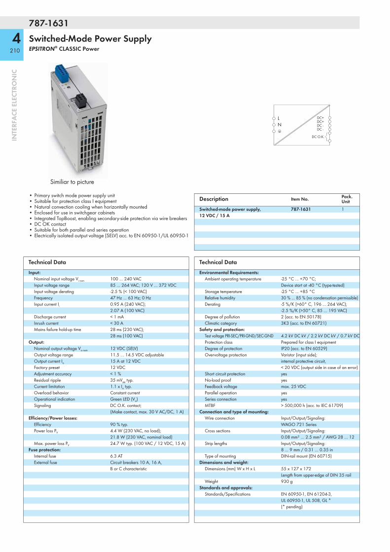
787-1631
4210
INTE
RFA
CE E
LECT
RON
IC
Switched-Mode Power SupplyEPSITRON® CLASSIC Power
Similiar to picture
LN
DC+DC+DC -DC -
DC O.K.
• Primary switch mode power supply unit• Suitable for protection class I equipment• Natural convection cooling when horizontally mounted• Enclosed for use in switchgear cabinets• Integrated TopBoost, enabling secondary-side protection via wire breakers• DC OK contact• Suitable for both parallel and series operation• Electrically isolated output voltage (SELV) acc. to EN 60950-1/UL 60950-1
Description Item No. Pack. Unit
Switched-mode power supply, 12 VDC / 15 A
787-1631 1
Technical DataInput:
Nominal input voltage Vi nom 100 … 240 VACInput voltage range 85 … 264 VAC; 120 V … 372 VDCInput voltage derating -2.5 % (< 100 VAC)Frequency 47 Hz … 63 Hz; 0 HzInput current Ii 0.95 A (240 VAC);
2.07 A (100 VAC)Discharge current < 1 mAInrush current < 30 AMains failure hold-up time 28 ms (230 VAC);
28 ms (100 VAC)Output:
Nominal output voltage Vo nom 12 VDC (SELV)Output voltage range 11.5 … 14.5 VDC adjustableOutput current Io 15 A at 12 VDCFactory preset 12 VDCAdjustment accuracy < 1 %Residual ripple 35 mVpp typ.Current limitation 1.1 x Io typ.Overload behavior Constant currentOperational indication Green LED (Vo)Signaling DC O.K. contact;
(Make contact, max. 30 V AC/DC, 1 A)Efficiency/Power losses:
Efficiency 90 % typ.Power loss PV 4.4 W (230 VAC, no load);
21.8 W (230 VAC, nominal load)Max. power loss PV 24.7 W typ. (100 VAC / 12 VDC, 15 A)
Fuse protection:Internal fuse 6.3 ATExternal fuse Circuit breakers 10 A, 16 A,
B or C characteristic
Technical DataEnvironmental Requirements:
Ambient operating temperature -25 °C … +70 °C; Device start at -40 °C (type-tested)
Storage temperature -25 °C … +85 °CRelative humidity 30 % … 85 % (no condensation permissible)Derating -5 %/K (>60° C, 196 … 264 VAC);
-2.5 %/K (>50° C, 85 … 195 VAC)Degree of pollution 2 (acc. to EN 50178)Climatic category 3K3 (acc. to EN 60721)
Safety and protection:Test voltage PRI-SEC/PRI-GND/SEC-GND 4.2 kV DC kV / 2.2 kV DC kV / 0.7 kV DC Protection class Prepared for class I equipmentDegree of protection IP20 (acc. to EN 60529)Overvoltage protection Varistor (input side);
internal protective circuit, < 20 VDC (output side in case of an error)
Short circuit protection yesNo-load proof yesFeedback voltage max. 25 VDCParallel operation yesSeries connection yesMTBF > 500,000 h (acc. to IEC 61709)
Connection and type of mounting:Wire connection Input/Output/Signaling:
WAGO 721 SeriesCross sections Input/Output/Signaling:
0.08 mm² … 2.5 mm² / AWG 28 … 12Strip lengths Input/Output/Signaling:
8 … 9 mm / 0.31 … 0.35 inType of mounting DIN-rail mount (EN 60715)
Dimensions and weight:Dimensions (mm) W x H x L 55 x 127 x 172
Length from upper-edge of DIN 35 railWeight 930 g
Standards and approvals:Standards/Specifications EN 60950-1, EN 61204-3,
UL 60950-1, UL 508, GL * (* pending)
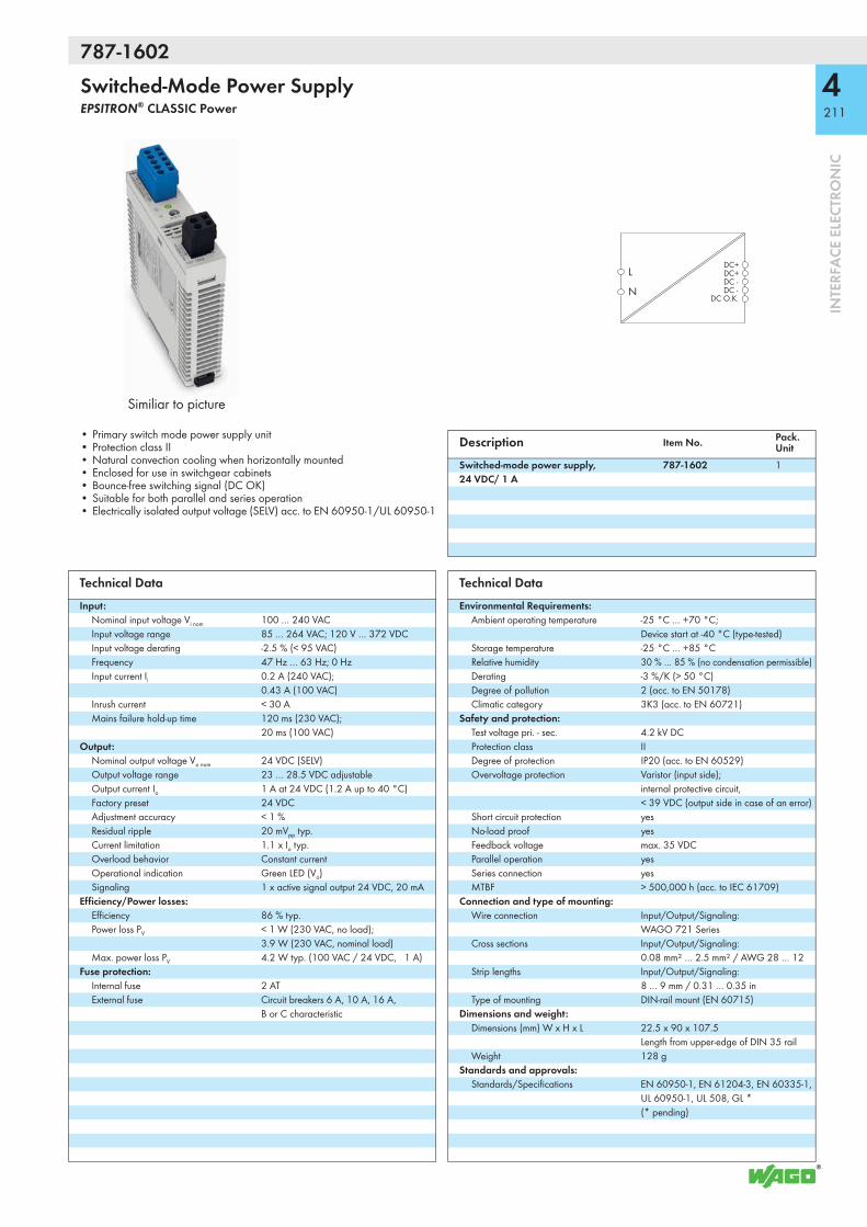
787-1602
4211
INTE
RFA
CE E
LECT
RON
IC
Switched-Mode Power SupplyEPSITRON® CLASSIC Power
Similiar to picture
LDC+DC+DC -DC -
DC O.K.N
• Primary switch mode power supply unit• Protection class II• Natural convection cooling when horizontally mounted• Enclosed for use in switchgear cabinets• Bounce-free switching signal (DC OK)• Suitable for both parallel and series operation• Electrically isolated output voltage (SELV) acc. to EN 60950-1/UL 60950-1
Description Item No. Pack. Unit
Switched-mode power supply, 24 VDC/ 1 A
787-1602 1
Technical DataInput:
Nominal input voltage Vi nom 100 … 240 VACInput voltage range 85 … 264 VAC; 120 V … 372 VDCInput voltage derating -2.5 % (< 95 VAC)Frequency 47 Hz … 63 Hz; 0 HzInput current Ii 0.2 A (240 VAC);
0.43 A (100 VAC)Inrush current < 30 AMains failure hold-up time 120 ms (230 VAC);
20 ms (100 VAC)Output:
Nominal output voltage Vo nom 24 VDC (SELV)Output voltage range 23 … 28.5 VDC adjustableOutput current Io 1 A at 24 VDC (1.2 A up to 40 °C)Factory preset 24 VDCAdjustment accuracy < 1 %Residual ripple 20 mVpp typ.Current limitation 1.1 x Io typ.Overload behavior Constant currentOperational indication Green LED (Vo)Signaling 1 x active signal output 24 VDC, 20 mA
Efficiency/Power losses:Efficiency 86 % typ.Power loss PV < 1 W (230 VAC, no load);
3.9 W (230 VAC, nominal load)Max. power loss PV 4.2 W typ. (100 VAC / 24 VDC, 1 A)
Fuse protection:Internal fuse 2 ATExternal fuse Circuit breakers 6 A, 10 A, 16 A,
B or C characteristic
Technical DataEnvironmental Requirements:
Ambient operating temperature -25 °C … +70 °C; Device start at -40 °C (type-tested)
Storage temperature -25 °C … +85 °CRelative humidity 30 % … 85 % (no condensation permissible)Derating -3 %/K (> 50 °C)Degree of pollution 2 (acc. to EN 50178)Climatic category 3K3 (acc. to EN 60721)
Safety and protection:Test voltage pri. - sec. 4.2 kV DCProtection class IIDegree of protection IP20 (acc. to EN 60529)Overvoltage protection Varistor (input side);
internal protective circuit, < 39 VDC (output side in case of an error)
Short circuit protection yesNo-load proof yesFeedback voltage max. 35 VDCParallel operation yesSeries connection yesMTBF > 500,000 h (acc. to IEC 61709)
Connection and type of mounting:Wire connection Input/Output/Signaling:
WAGO 721 SeriesCross sections Input/Output/Signaling:
0.08 mm² … 2.5 mm² / AWG 28 … 12Strip lengths Input/Output/Signaling:
8 … 9 mm / 0.31 … 0.35 inType of mounting DIN-rail mount (EN 60715)
Dimensions and weight:Dimensions (mm) W x H x L 22.5 x 90 x 107.5
Length from upper-edge of DIN 35 railWeight 128 g
Standards and approvals:Standards/Specifications EN 60950-1, EN 61204-3, EN 60335-1,
UL 60950-1, UL 508, GL * (* pending)

787-1606
4212
INTE
RFA
CE E
LECT
RON
IC
Switched-Mode Power SupplyEPSITRON® CLASSIC Power
Similiar to picture
LDC+DC+DC -DC -
DC O.K.N
• Primary switch mode power supply unit• Protection class II• Natural convection cooling when horizontally mounted• Enclosed for use in switchgear cabinets• Bounce-free switching signal (DC OK)• Suitable for both parallel and series operation• Electrically isolated output voltage (SELV) acc. to EN 60950-1/UL 60950-1
Description Item No. Pack. Unit
Switched-mode power supply, 24 VDC / 2 A
787-1606 1
Technical DataInput:
Nominal input voltage Vi nom 100 … 240 VACInput voltage range 85 … 264 VAC; 120 V … 372 VDCInput voltage derating -2.5 % (< 95 VAC)Frequency 47 Hz … 63 Hz; 0 HzInput current Ii 0.37 A (240 VAC);
0.73 A (100 VAC)Inrush current < 30 AMains failure hold-up time 120 ms (230 VAC);
20 ms (100 VAC)Output:
Nominal output voltage Vo nom 24 VDC (SELV)Output voltage range 23 … 28.5 VDC adjustableOutput current Io 2 A at 24 VDC (2.2 A up to 40 °C)Factory preset 24 VDCAdjustment accuracy < 1 %Residual ripple 20 mVpp typ.Current limitation 1.1 x Io typ.Overload behavior Constant currentOperational indication Green LED (Vo)Signaling 1 x active signal output 24 VDC, 20 mA
Efficiency/Power losses:Efficiency 89 % typ.Power loss PV < 1 W (230 VAC, no load);
6 W (230 VAC, nominal load)Max. power loss PV 6.6 W typ. (100 VAC / 24 VDC, 2 A)
Fuse protection:Internal fuse 4 ATExternal fuse Circuit breakers 6 A, 10 A, 16 A,
B or C characteristic
Technical DataEnvironmental Requirements:
Ambient operating temperature -25 °C … +70 °C; Device start at -40 °C (type-tested)
Storage temperature -25 °C … +85 °CRelative humidity 30 % … 85 % (no condensation permissible)Derating -3 %/K (> 50 °C)Degree of pollution 2 (acc. to EN 50178)Climatic category 3K3 (acc. to EN 60721)
Safety and protection:Test voltage pri. - sec. 4.2 kV DCProtection class IIDegree of protection IP20 (acc. to EN 60529)Overvoltage protection Varistor (input side);
internal protective circuit, < 37 VDC (output side in case of an error)
Short circuit protection yesNo-load proof yesFeedback voltage max. 35 VDCParallel operation yesSeries connection yesMTBF > 500,000 h (acc. to IEC 61709)
Connection and type of mounting:Wire connection Input/Output/Signaling:
WAGO 721 SeriesCross sections Input/Output/Signaling:
0.08 mm² … 2.5 mm² / AWG 28 … 12Strip lengths Input/Output/Signaling:
8 … 9 mm / 0.31 … 0.35 inType of mounting DIN-rail mount (EN 60715)
Dimensions and weight:Dimensions (mm) W x H x L 45 x 90 x 107.5
Length from upper-edge of DIN 35 railWeight 210 g
Standards and approvals:Standards/Specifications EN 60950-1, EN 61204-3, EN 60335-1,
UL 60950-1, UL 508, GL * (* pending)
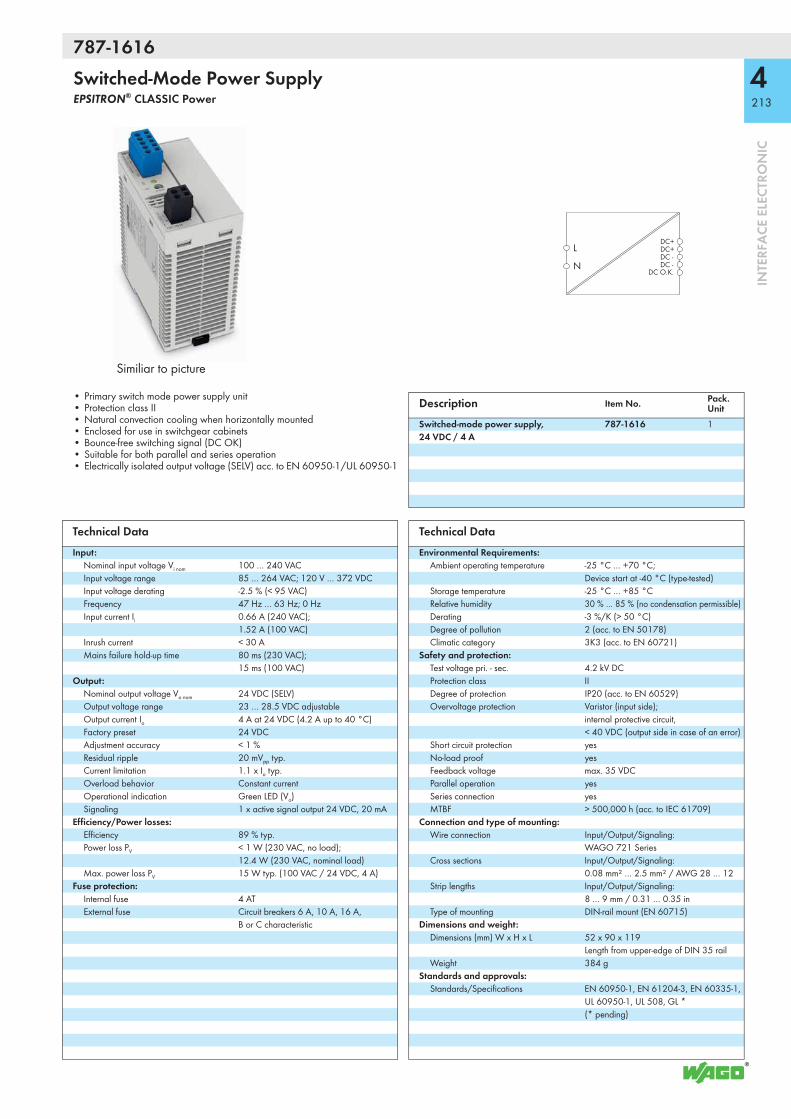
787-1616
4213
INTE
RFA
CE E
LECT
RON
IC
Switched-Mode Power SupplyEPSITRON® CLASSIC Power
Similiar to picture
LDC+DC+DC -DC -
DC O.K.N
• Primary switch mode power supply unit• Protection class II• Natural convection cooling when horizontally mounted• Enclosed for use in switchgear cabinets• Bounce-free switching signal (DC OK)• Suitable for both parallel and series operation• Electrically isolated output voltage (SELV) acc. to EN 60950-1/UL 60950-1
Description Item No. Pack. Unit
Switched-mode power supply, 24 VDC / 4 A
787-1616 1
Technical DataInput:
Nominal input voltage Vi nom 100 … 240 VACInput voltage range 85 … 264 VAC; 120 V … 372 VDCInput voltage derating -2.5 % (< 95 VAC)Frequency 47 Hz … 63 Hz; 0 HzInput current Ii 0.66 A (240 VAC);
1.52 A (100 VAC)Inrush current < 30 AMains failure hold-up time 80 ms (230 VAC);
15 ms (100 VAC)Output:
Nominal output voltage Vo nom 24 VDC (SELV)Output voltage range 23 … 28.5 VDC adjustableOutput current Io 4 A at 24 VDC (4.2 A up to 40 °C)Factory preset 24 VDCAdjustment accuracy < 1 %Residual ripple 20 mVpp typ.Current limitation 1.1 x Io typ.Overload behavior Constant currentOperational indication Green LED (Vo)Signaling 1 x active signal output 24 VDC, 20 mA
Efficiency/Power losses:Efficiency 89 % typ.Power loss PV < 1 W (230 VAC, no load);
12.4 W (230 VAC, nominal load)Max. power loss PV 15 W typ. (100 VAC / 24 VDC, 4 A)
Fuse protection:Internal fuse 4 ATExternal fuse Circuit breakers 6 A, 10 A, 16 A,
B or C characteristic
Technical DataEnvironmental Requirements:
Ambient operating temperature -25 °C … +70 °C; Device start at -40 °C (type-tested)
Storage temperature -25 °C … +85 °CRelative humidity 30 % … 85 % (no condensation permissible)Derating -3 %/K (> 50 °C)Degree of pollution 2 (acc. to EN 50178)Climatic category 3K3 (acc. to EN 60721)
Safety and protection:Test voltage pri. - sec. 4.2 kV DCProtection class IIDegree of protection IP20 (acc. to EN 60529)Overvoltage protection Varistor (input side);
internal protective circuit, < 40 VDC (output side in case of an error)
Short circuit protection yesNo-load proof yesFeedback voltage max. 35 VDCParallel operation yesSeries connection yesMTBF > 500,000 h (acc. to IEC 61709)
Connection and type of mounting:Wire connection Input/Output/Signaling:
WAGO 721 SeriesCross sections Input/Output/Signaling:
0.08 mm² … 2.5 mm² / AWG 28 … 12Strip lengths Input/Output/Signaling:
8 … 9 mm / 0.31 … 0.35 inType of mounting DIN-rail mount (EN 60715)
Dimensions and weight:Dimensions (mm) W x H x L 52 x 90 x 119
Length from upper-edge of DIN 35 railWeight 384 g
Standards and approvals:Standards/Specifications EN 60950-1, EN 61204-3, EN 60335-1,
UL 60950-1, UL 508, GL * (* pending)

787-1616/000-1000
4214
INTE
RFA
CE E
LECT
RON
IC
Switched-Mode Power SupplyEPSITRON® CLASSIC Power
Similiar to picture
LDC+DC+DC -DC -
DC O.K.N
• Primary switch mode power supply unit• Protection class II• Natural convection cooling when horizontally mounted• Enclosed for use in switchgear cabinets• Limited Power Source (LPS) acc. to NEC Class 2• Bounce-free switching signal (DC OK)• Suitable for both parallel and series operation• Electrically isolated output voltage (SELV) acc. to EN 60950-1/UL 60950-1
Description Item No. Pack. Unit
Switched-mode power supply, 24 VDC / 3.8 A LPS
787-1616/000-1000 1
Technical DataInput:
Nominal input voltage Vi nom 100 … 240 VACInput voltage range 85 … 264 VAC; 120 V … 372 VDCInput voltage derating -2.5 % (< 95 VAC)Frequency 47 Hz … 63 Hz; 0 HzInput current Ii 0.7 A (240 VAC);
1.8 A (100 VAC)Inrush current < 30 AMains failure hold-up time 80 ms (230 VAC);
15 ms (100 VAC)Output:
Nominal output voltage Vo nom 24 VDC (SELV)Output voltage range 23 … 28.5 VDC adjustableOutput current Io 3.8 A at 24 VDCFactory preset 24 VDCAdjustment accuracy < 1 %Residual ripple 20 mVpp typ.Current limitation 3.8 A (3.2 A at Vo > 25 VDC),
LPS acc. to NEC Class 2Overload behavior Constant currentOperational indication Green LED (Vo)Signaling 1 x active signal output 24 VDC, 20 mA
Efficiency/Power losses:Efficiency 87 % typ.Power loss PV 2.8 W (230 VAC, no load);
14 W (230 VAC, nominal load)Max. power loss PV < 20 W (100 VAC / 91 W)
Fuse protection:Internal fuse 4 ATExternal fuse Circuit breakers 6 A, 10 A, 16 A,
B or C characteristic
Technical DataEnvironmental Requirements:
Ambient operating temperature -25 °C … +70 °C; Device start at -40 °C (type-tested)
Storage temperature -25 °C … +85 °CRelative humidity 30 % … 85 % (no condensation permissible)Derating -3 %/K (> 50 °C)Degree of pollution 2 (acc. to EN 50178)Climatic category 3K3 (acc. to EN 60721)
Safety and protection:Test voltage pri. - sec. 4.2 kV DCProtection class IIDegree of protection IP20 (acc. to EN 60529)Overvoltage protection Varistor (input side);
internal protective circuit, < 40 VDC (output side in case of an error)
Short circuit protection yesNo-load proof yesFeedback voltage max. 35 VDCParallel operation yesSeries connection yesMTBF > 500,000 h (acc. to IEC 61709)
Connection and type of mounting:Wire connection Input/Output/Signaling:
WAGO 721 SeriesCross sections Input/Output/Signaling:
0.08 mm² … 2.5 mm² / AWG 28 … 12Strip lengths Input/Output/Signaling:
8 … 9 mm / 0.31 … 0.35 inType of mounting DIN-rail mount (EN 60715)
Dimensions and weight:Dimensions (mm) W x H x L 52 x 90 x 119
Length from upper-edge of DIN 35 railWeight 384 g
Standards and approvals:Standards/Specifications EN 60950-1, EN 61204-3, EN 60335-1,
UL 60950-1, UL 508, GL * (* pending)

787-1622
4215
INTE
RFA
CE E
LECT
RON
IC
Switched-Mode Power SupplyEPSITRON® CLASSIC Power
Similiar to picture
LN
DC+DC+DC -DC -
DC O.K.
• Primary switch mode power supply unit• Suitable for protection class I equipment• Natural convection cooling when horizontally mounted• Enclosed for use in switchgear cabinets• Integrated TopBoost, enabling secondary-side protection via wire breakers• DC OK contact• Suitable for both parallel and series operation• Electrically isolated output voltage (SELV) acc. to EN 60950-1/UL 60950-1
Description Item No. Pack. Unit
Switched-mode power supply, 24 VDC / 5 A
787-1622 1
Technical DataInput:
Nominal input voltage Vi nom 100 … 240 VACInput voltage range 85 … 264 VAC; 120 V … 372 VDCInput voltage derating -2.5 % (< 97 VAC)Frequency 47 Hz … 63 Hz; 0 HzInput current Ii 1.2 A (240 VAC);
2.25 A (100 VAC)Discharge current < 1 mAInrush current < 30 AMains failure hold-up time 80 ms (230 VAC);
10 ms (100 VAC)Output:
Nominal output voltage Vo nom 24 VDC (SELV)Output voltage range 23 … 28.5 VDC adjustableOutput current Io 5 A at 24 VDCFactory preset 24 VDCAdjustment accuracy < 1 %Residual ripple 30 mVpp typ.Current limitation 1.1 x Io typ.Overload behavior Constant currentOperational indication Green LED (Vo)Signaling DC O.K. contact;
(Make contact, max. 30 V AC/DC, 1 A)Efficiency/Power losses:
Efficiency 89 % typ.Power loss PV 1.2 W (230 VAC, no load);
14.6 W (230 VAC, nominal load)Max. power loss PV 19.4 W typ. (100 VAC / 24 VDC, 5 A)
Fuse protection:Internal fuse 4 ATExternal fuse Circuit breakers 6 A, 10 A, 16 A,
B or C characteristic
Technical DataEnvironmental Requirements:
Ambient operating temperature -25 °C … +70 °C; Device start at -40 °C (type-tested)
Storage temperature -25 °C … +85 °CRelative humidity 30 % … 85 % (no condensation permissible)Derating -5 %/K (>60° C, 196 … 264 VAC);
-2.5 %/K (>50° C, 85 … 195 VAC)Degree of pollution 2 (acc. to EN 50178)Climatic category 3K3 (acc. to EN 60721)
Safety and protection:Test voltage PRI-SEC/PRI-GND/SEC-GND 4.2 kV DC kV / 2.2 kV DC kV / 0.7 kV DC Protection class Prepared for class I equipmentDegree of protection IP20 (acc. to EN 60529)Overvoltage protection Varistor (input side);
internal protective circuit, < 41 VDC (output side in case of an error)
Short circuit protection yesNo-load proof yesFeedback voltage max. 35 VDCParallel operation yesSeries connection yesMTBF > 500,000 h (acc. to IEC 61709)
Connection and type of mounting:Wire connection Input/Output/Signaling:
WAGO 721 SeriesCross sections Input/Output/Signaling:
0.08 mm² … 2.5 mm² / AWG 28 … 12Strip lengths Input/Output/Signaling:
8 … 9 mm / 0.31 … 0.35 inType of mounting DIN-rail mount (EN 60715)
Dimensions and weight:Dimensions (mm) W x H x L 42 x 127 x 137.5
Length from upper-edge of DIN 35 railWeight 590 g
Standards and approvals:Standards/Specifications EN 60950-1, EN 61204-3, EN 60335-1,
UL 60950-1, UL 508, GL * (* pending)

787-1632
4216
INTE
RFA
CE E
LECT
RON
IC
Switched-Mode Power SupplyEPSITRON® CLASSIC Power
Similiar to picture
LN
DC+DC+DC -DC -
DC O.K.
• Primary switch mode power supply unit• Suitable for protection class I equipment• Natural convection cooling when horizontally mounted• Enclosed for use in switchgear cabinets• Integrated TopBoost, enabling secondary-side protection via wire breakers• DC OK contact• Suitable for both parallel and series operation• Electrically isolated output voltage (SELV) acc. to EN 60950-1/UL 60950-1
Description Item No. Pack. Unit
Switched-mode power supply, 24 VDC / 10 A
787-1632 1
Technical DataInput:
Nominal input voltage Vi nom 100 … 240 VACInput voltage range 85 … 264 VAC; 120 V … 372 VDCInput voltage derating -2.5 % (< 100 VAC)Frequency 47 Hz … 63 Hz; 0 HzInput current Ii 1.25 A (240 VAC);
2.74 A (100 VAC)Discharge current < 1 mAInrush current < 30 AMains failure hold-up time 17 ms (230 VAC);
15 ms (100 VAC)Output:
Nominal output voltage Vo nom 24 VDC (SELV)Output voltage range 23 … 28.5 VDC adjustableOutput current Io 10 A at 24 VDCFactory preset 24 VDCAdjustment accuracy < 1 %Residual ripple 50 mVpp typ.Current limitation 1.1 x Io typ.Overload behavior Constant currentOperational indication Green LED (Vo)Signaling DC O.K. contact;
(Make contact, max. 30 V AC/DC, 1 A)Efficiency/Power losses:
Efficiency 91 % typ.Power loss PV 6.6 W (230 VAC, no load);
24.4 W (230 VAC, nominal load)Max. power loss PV 31.3 W typ. (100 VAC / 24 VDC, 10 A)
Fuse protection:Internal fuse 6.3 ATExternal fuse Circuit breakers 10 A, 16 A,
B or C characteristic
Technical DataEnvironmental Requirements:
Ambient operating temperature -25 °C … +70 °C; Device start at -40 °C (type-tested)
Storage temperature -25 °C … +85 °CRelative humidity 30 % … 85 % (no condensation permissible)Derating -5 %/K (>60° C, 196 … 264 VAC);
-2.5 %/K (>50° C, 85 … 195 VAC)Degree of pollution 2 (acc. to EN 50178)Climatic category 3K3 (acc. to EN 60721)
Safety and protection:Test voltage PRI-SEC/PRI-GND/SEC-GND 4.2 kV DC kV / 2.2 kV DC kV / 0.7 kV DC Protection class Prepared for class I equipmentDegree of protection IP20 (acc. to EN 60529)Overvoltage protection Varistor (input side);
internal protective circuit, < 40 VDC (output side in case of an error)
Short circuit protection yesNo-load proof yesFeedback voltage max. 35 VDCParallel operation yesSeries connection yesMTBF > 500,000 h (acc. to IEC 61709)
Connection and type of mounting:Wire connection Input/Output/Signaling:
WAGO 721 SeriesCross sections Input/Output/Signaling:
0.08 mm² … 2.5 mm² / AWG 28 … 12Strip lengths Input/Output/Signaling:
8 … 9 mm / 0.31 … 0.35 inType of mounting DIN-rail mount (EN 60715)
Dimensions and weight:Dimensions (mm) W x H x L 55 x 127 x 172
Length from upper-edge of DIN 35 railWeight 930 g
Standards and approvals:Standards/Specifications EN 60950-1, EN 61204-3,
UL 60950-1, UL 508, GL * (* pending)

787-1634
4217
INTE
RFA
CE E
LECT
RON
IC
Switched-Mode Power SupplyEPSITRON® CLASSIC Power
Similiar to picture
LN
DC+DC+DC -DC -
DC O.K.
• Primary switch mode power supply unit• Suitable for protection class I equipment• Natural convection cooling when horizontally mounted• Enclosed for use in switchgear cabinets• Integrated TopBoost, enabling secondary-side protection via wire breakers• DC OK contact• Suitable for both parallel and series operation• Electrically isolated output voltage (SELV) acc. to EN 60950-1/UL 60950-1
Description Item No. Pack. Unit
Switched-mode power supply, 24 VDC / 20 A
787-1634 1
Technical DataInput:
Nominal input voltage Vi nom 100 … 240 VACInput voltage range 85 … 264 VAC; 120 V … 372 VDCInput voltage derating -1.8 % (< 105 VAC)Frequency 47 Hz … 63 Hz; 0 HzInput current Ii 2.23 A (240 VAC);
5.56 A (100 VAC)Discharge current < 1 mAInrush current < 30 AMains failure hold-up time 20 ms (230 VAC);
20 ms (100 VAC)Output:
Nominal output voltage Vo nom 24 VDC (SELV)Output voltage range 23 … 28.5 VDC adjustableOutput current Io 20 A at 24 VDCFactory preset 24 VDCAdjustment accuracy < 1 %Residual ripple 70 mVpp typ.Current limitation 1.1 x Io typ.Overload behavior Constant currentOperational indication Green LED (Vo)Signaling DC O.K. contact;
(Make contact, max. 30 V AC/DC, 1 A)Efficiency/Power losses:
Efficiency 92 % typ.Power loss PV 7.0 W (230 VAC, no load);
40.8 W (230 VAC, nominal load)Max. power loss PV 68.3 W typ. (100 VAC / 24 VDC, 20 A)
Fuse protection:Internal fuse 10 ATExternal fuse Circuit breakers 10 A, 16 A,
B or C characteristic
Technical DataEnvironmental Requirements:
Ambient operating temperature -25 °C … +70 °C; Device start at -40 °C (type-tested)
Storage temperature -25 °C … +85 °CRelative humidity 30 % … 85 % (no condensation permissible)Derating -5 %/K (>60° C, 196 … 264 VAC);
-2.5 %/K (>50° C, 85 … 195 VAC)Degree of pollution 2 (acc. to EN 50178)Climatic category 3K3 (acc. to EN 60721)
Safety and protection:Test voltage PRI-SEC/PRI-GND/SEC-GND 4.2 kV DC kV / 2.2 kV DC kV / 0.7 kV DC Protection class Prepared for class I equipmentDegree of protection IP20 (acc. to EN 60529)Overvoltage protection Varistor (input side);
internal protective circuit, < 40 VDC (output side in case of an error)
Short circuit protection yesNo-load proof yesFeedback voltage max. 35 VDCParallel operation yesSeries connection yesMTBF > 500,000 h (acc. to IEC 61709)
Connection and type of mounting:Wire connection Input/Signaling: WAGO 721 Series
Output: WAGO 831 SeriesCross sections Input/Signaling:
0.08 mm² … 2.5 mm² / AWG 28 … 12 Output: 0.5 mm² … 10 mm² / AWG 20 … 8
Strip lengths Input/Signaling: 8 … 9 mm / 0.31 … 0.35 in Output: 13 … 15 mm / 0.51 … 0.59 in
Type of mounting DIN-rail mount (EN 60715)Dimensions and weight:
Dimensions (mm) W x H x L 95 x 127 x 170Length from upper-edge of DIN 35 rail
Weight 1600 gStandards and approvals:
Standards/Specifications EN 60950-1, EN 61204-3, UL 60950-1, UL 508, GL * (* pending)

787-1623
4218
INTE
RFA
CE E
LECT
RON
IC
Switched-Mode Power SupplyEPSITRON® CLASSIC Power
Similiar to picture
LDC+DC+DC -DC -
DC O.K.N
• Primary switch mode power supply unit• Protection class II• Natural convection cooling when horizontally mounted• Enclosed for use in switchgear cabinets• Bounce-free switching signal (DC OK)• Suitable for both parallel and series operation• Electrically isolated output voltage (SELV) acc. to EN 60950-1/UL 60950-1
Description Item No. Pack. Unit
Switched-mode power supply, 48 VDC / 2 A
787-1623 1
Technical DataInput:
Nominal input voltage Vi nom 100 … 240 VACInput voltage range 85 … 264 VAC; 120 V … 372 VDCInput voltage derating -2.5 % (< 95 VAC)Frequency 47 Hz … 63 Hz; 0 HzInput current Ii 0.9 A (240 VAC);
1.78 A (100 VAC)Inrush current < 30 AMains failure hold-up time 80 ms (230 VAC);
15 ms (100 VAC)Output:
Nominal output voltage Vo nom 48 VDC (SELV)Output voltage range 40 … 56 VDC adjustableOutput current Io 2 A at 48 VDC (2.1 A up to 40 °C)Factory preset 48 VDCAdjustment accuracy < 1 %Residual ripple 20 mVpp typ.Current limitation 1.1 x Io typ.Overload behavior Constant currentOperational indication Green LED (Vo)Signaling 1 x active signal output 48 VDC, 10 mA
Efficiency/Power losses:Efficiency 86 % typ.Power loss PV < 1 W (230 VAC, no load);
16.2 W (230 VAC, nominal load)Max. power loss PV 19.8 W typ. (100 VAC / 48 VDC, 2 A)
Fuse protection:Internal fuse 4 ATExternal fuse Circuit breakers 6 A, 10 A, 16 A,
B or C characteristic
Technical DataEnvironmental Requirements:
Ambient operating temperature -25 °C … +70 °C; Device start at -40 °C (type-tested)
Storage temperature -25 °C … +85 °CRelative humidity 30 % … 85 % (no condensation permissible)Derating -3 %/K (> 50 °C)Degree of pollution 2 (acc. to EN 50178)Climatic category 3K3 (acc. to EN 60721)
Safety and protection:Test voltage pri. - sec. 4.2 kV DCProtection class IIDegree of protection IP20 (acc. to EN 60529)Overvoltage protection Varistor (input side);
internal protective circuit, < 60 VDC (output side in case of an error)
Short circuit protection yesNo-load proof yesFeedback voltage max. 63 VDCParallel operation yesSeries connection yesMTBF > 500,000 h (acc. to IEC 61709)
Connection and type of mounting:Wire connection Input/Output/Signaling:
WAGO 721 SeriesCross sections Input/Output/Signaling:
0.08 mm² … 2.5 mm² / AWG 28 … 12Strip lengths Input/Output/Signaling:
8 … 9 mm / 0.31 … 0.35 inType of mounting DIN-rail mount (EN 60715)
Dimensions and weight:Dimensions (mm) W x H x L 52 x 90 x 119
Length from upper-edge of DIN 35 railWeight 385 g
Standards and approvals:Standards/Specifications EN 60950-1, EN 61204-3, EN 60335-1,
UL 60950-1, UL 508, GL * (* pending)
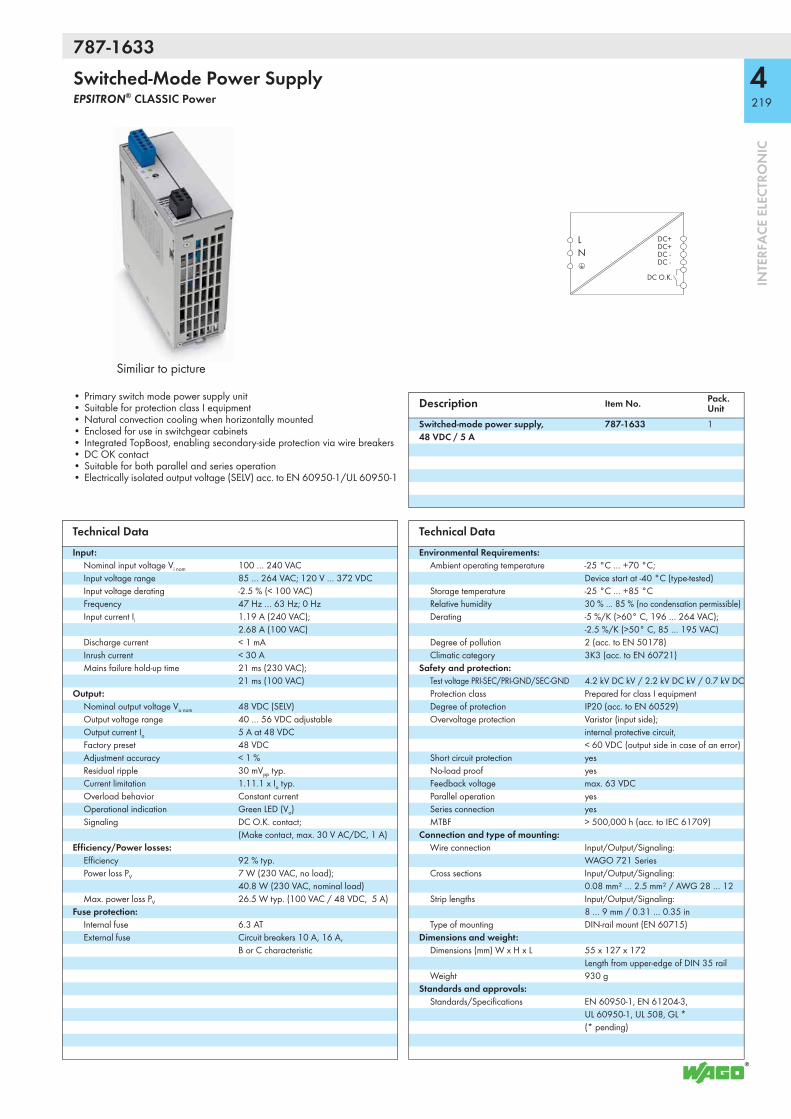
787-1633
4219
INTE
RFA
CE E
LECT
RON
IC
Switched-Mode Power SupplyEPSITRON® CLASSIC Power
Similiar to picture
LN
DC+DC+DC -DC -
DC O.K.
• Primary switch mode power supply unit• Suitable for protection class I equipment• Natural convection cooling when horizontally mounted• Enclosed for use in switchgear cabinets• Integrated TopBoost, enabling secondary-side protection via wire breakers• DC OK contact• Suitable for both parallel and series operation• Electrically isolated output voltage (SELV) acc. to EN 60950-1/UL 60950-1
Description Item No. Pack. Unit
Switched-mode power supply, 48 VDC / 5 A
787-1633 1
Technical DataInput:
Nominal input voltage Vi nom 100 … 240 VACInput voltage range 85 … 264 VAC; 120 V … 372 VDCInput voltage derating -2.5 % (< 100 VAC)Frequency 47 Hz … 63 Hz; 0 HzInput current Ii 1.19 A (240 VAC);
2.68 A (100 VAC)Discharge current < 1 mAInrush current < 30 AMains failure hold-up time 21 ms (230 VAC);
21 ms (100 VAC)Output:
Nominal output voltage Vo nom 48 VDC (SELV)Output voltage range 40 … 56 VDC adjustableOutput current Io 5 A at 48 VDCFactory preset 48 VDCAdjustment accuracy < 1 %Residual ripple 30 mVpp typ.Current limitation 1.11.1 x Io typ.Overload behavior Constant currentOperational indication Green LED (Vo)Signaling DC O.K. contact;
(Make contact, max. 30 V AC/DC, 1 A)Efficiency/Power losses:
Efficiency 92 % typ.Power loss PV 7 W (230 VAC, no load);
40.8 W (230 VAC, nominal load)Max. power loss PV 26.5 W typ. (100 VAC / 48 VDC, 5 A)
Fuse protection:Internal fuse 6.3 ATExternal fuse Circuit breakers 10 A, 16 A,
B or C characteristic
Technical DataEnvironmental Requirements:
Ambient operating temperature -25 °C … +70 °C; Device start at -40 °C (type-tested)
Storage temperature -25 °C … +85 °CRelative humidity 30 % … 85 % (no condensation permissible)Derating -5 %/K (>60° C, 196 … 264 VAC);
-2.5 %/K (>50° C, 85 … 195 VAC)Degree of pollution 2 (acc. to EN 50178)Climatic category 3K3 (acc. to EN 60721)
Safety and protection:Test voltage PRI-SEC/PRI-GND/SEC-GND 4.2 kV DC kV / 2.2 kV DC kV / 0.7 kV DC Protection class Prepared for class I equipmentDegree of protection IP20 (acc. to EN 60529)Overvoltage protection Varistor (input side);
internal protective circuit, < 60 VDC (output side in case of an error)
Short circuit protection yesNo-load proof yesFeedback voltage max. 63 VDCParallel operation yesSeries connection yesMTBF > 500,000 h (acc. to IEC 61709)
Connection and type of mounting:Wire connection Input/Output/Signaling:
WAGO 721 SeriesCross sections Input/Output/Signaling:
0.08 mm² … 2.5 mm² / AWG 28 … 12Strip lengths Input/Output/Signaling:
8 … 9 mm / 0.31 … 0.35 inType of mounting DIN-rail mount (EN 60715)
Dimensions and weight:Dimensions (mm) W x H x L 55 x 127 x 172
Length from upper-edge of DIN 35 railWeight 930 g
Standards and approvals:Standards/Specifications EN 60950-1, EN 61204-3,
UL 60950-1, UL 508, GL * (* pending)

787-1635
4220
INTE
RFA
CE E
LECT
RON
IC
Switched-Mode Power SupplyEPSITRON® CLASSIC Power
Similiar to picture
LN
DC+DC+DC -DC -
DC O.K.
• Primary switch mode power supply unit• Suitable for protection class I equipment• Natural convection cooling when horizontally mounted• Enclosed for use in switchgear cabinets• Integrated TopBoost, enabling secondary-side protection via wire breakers• DC OK contact• Suitable for both parallel and series operation• Electrically isolated output voltage (SELV) acc. to EN 60950-1/UL 60950-1
Description Item No. Pack. Unit
Switched-mode power supply, 48 VDC / 10 A
787-1635 1
Technical DataInput:
Nominal input voltage Vi nom 100 … 240 VACInput voltage range 85 … 264 VAC; 120 V … 372 VDCInput voltage derating -2.5 % (< 100 VAC)Frequency 47 Hz … 63 Hz; 0 HzInput current Ii 2.22 A (240 VAC);
5.15 A (100 VAC)Discharge current < 1 mAInrush current < 30 AMains failure hold-up time 20 ms (230 VAC);
20 ms (100 VAC)Output:
Nominal output voltage Vo nom 48 VDC (SELV)Output voltage range 40 … 56 VDC adjustableOutput current Io 10 A at 48 VDCFactory preset 48 VDCAdjustment accuracy < 1 %Residual ripple 80 mVpp typ.Current limitation 1.1 x Io typ.Overload behavior Constant currentOperational indication Green LED (Vo)Signaling DC O.K. contact;
(Make contact, max. 30 V AC/DC, 1 A)Efficiency/Power losses:
Efficiency 93 % typ.Power loss PV 11.7 W (230 VAC, no load);
36.3 W (230 VAC, nominal load)Max. power loss PV 64.9 W typ. (100 VAC / 48 VDC, 10 A)
Fuse protection:Internal fuse 10 ATExternal fuse Circuit breakers 10 A, 16 A,
B or C characteristic
Technical DataEnvironmental Requirements:
Ambient operating temperature -25 °C … +70 °C; Device start at -40 °C (type-tested)
Storage temperature -25 °C … +85 °CRelative humidity 30 % … 85 % (no condensation permissible)Derating -5 %/K (>60° C, 196 … 264 VAC);
-2.5 %/K (>50° C, 85 … 195 VAC)Degree of pollution 2 (acc. to EN 50178)Climatic category 3K3 (acc. to EN 60721)
Safety and protection:Test voltage PRI-SEC/PRI-GND/SEC-GND 4.2 kV DC kV / 2.2 kV DC kV / 0.7 kV DC Protection class Prepared for class I equipmentDegree of protection IP20 (acc. to EN 60529)Overvoltage protection Varistor (input side);
internal protective circuit, < 60 VDC (output side in case of an error)
Short circuit protection yesNo-load proof yesFeedback voltage max. 63 VDCParallel operation yesSeries connection yesMTBF > 500,000 h (acc. to IEC 61709)
Connection and type of mounting:Wire connection Input/Signaling: WAGO 721 Series
Output: WAGO 831 SeriesCross sections Input/Signaling:
0.08 mm² … 2.5 mm² / AWG 28 … 12 Output: 0.5 mm² … 10 mm² / AWG 20 … 8
Strip lengths Input/Signaling: 8 … 9 mm / 0.31 … 0.35 in Output: 13 … 15 mm / 0.51 … 0.59 in
Type of mounting DIN-rail mount (EN 60715)Dimensions and weight:
Dimensions (mm) W x H x L 95 x 127 x 170Length from upper-edge of DIN 35 rail
Weight 1600 gStandards and approvals:
Standards/Specifications EN 60950-1, EN 61204-3, UL 60950-1, UL 508, GL * (* pending)
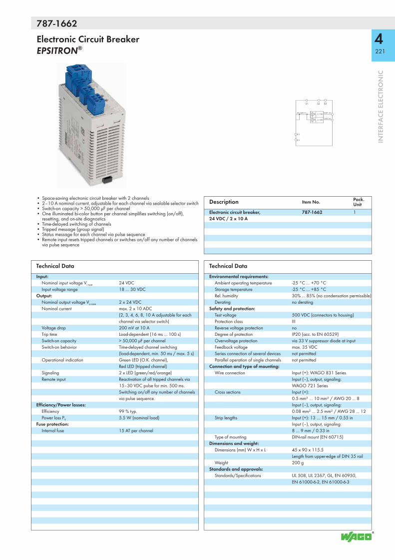
787-1662
4221
INTE
RFA
CE E
LECT
RON
IC
Electronic Circuit Breaker EPSITRON®
S2 S3S1
OUT1 (+)DC 24V (+)
0 V
OUT2 (+)
0 V
2..10A
2..10A
• Space-saving electronic circuit breaker with 2 channels• 2–10 A nominal current, adjustable for each channel via sealable selector switch• Switch-on capacity > 50,000 μF per channel• One illuminated bi-color button per channel simplifies switching (on/off),
resetting, and on-site diagnostics• Time-delayed switching of channels• Tripped message (group signal)• Status message for each channel via pulse sequence• Remote input resets tripped channels or switches on/off any number of channels
via pulse sequence
Description Item No. Pack. Unit
Electronic circuit breaker, 24 VDC / 2 x 10 A
787-1662 1
Technical DataInput:
Nominal input voltage Vi nom 24 VDCInput voltage range 18 … 30 VDC
Output:Nominal output voltage Vo nom 2 x 24 VDCNominal current max. 2 x 10 ADC
(2, 3, 4, 6, 8, 10 A adjustable for each channel via selector switch)
Voltage drop 200 mV at 10 ATrip time Load-dependent (16 ms ... 100 s)Switch-on capacity > 50,000 μF per channelSwitch-on behavior Time-delayed channel switching
(load-dependent, min. 50 ms / max. 5 s)Operational indication Green LED (O.K. channel),
Red LED (tripped channel)Signaling 2 x LED (green/red/orange)Remote input Reactivation of all tripped channels via
15–30 VDC pulse for min. 500 ms. Switching on/off any number of channels via pulse sequence.
Efficiency/Power losses:Efficiency 99 % typ.Power loss PV 5.5 W (nominal load)
Fuse protection:Internal fuse 15 AT per channel
Technical DataEnvironmental requirements:
Ambient operating temperature -25 °C … +70 °CStorage temperature -25 °C … +85 °CRel. humidity 30% ... 85% (no condensation permissible)Derating no derating
Safety and protection:Test voltage 500 VDC (connectors to housing)Protection class IIIReverse voltage protection noDegree of protection IP20 (acc. to EN 60529)Overvoltage protection via 33 V suppressor diode at inputFeedback voltage max. 35 VDCSeries connection of several devices not permittedParallel operation of single channels not permitted
Connection and type of mounting:Wire connection Input (+): WAGO 831 Series
Input (–), output, signaling: WAGO 721 Series
Cross sections Input (+): 0.5 mm² … 10 mm² / AWG 20 ... 8 Input (–), output, signaling: 0.08 mm² … 2.5 mm² / AWG 28 ... 12
Strip lengths Input (+): 13 … 15 mm / 0.55 in Input (–), output, signaling: 8 … 9 mm / 0.33 in
Type of mounting DIN-rail mount (EN 60715)Dimensions and weight:
Dimensions (mm) W x H x L 45 x 90 x 115.5Length from upper-edge of DIN 35 rail
Weight 200 gStandards and approvals:
Standards/Specifications UL 508, UL 2367, GL, EN 60950, EN 61000-6-2, EN 61000-6-3

787-1662/106-000
4222
INTE
RFA
CE E
LECT
RON
IC
Electronic Circuit Breaker EPSITRON®
S2 S3S1
OUT1 (+)DC 24V (+)
0 V
OUT2 (+)
0 V
1..6A
1..6A
• Space-saving electronic circuit breaker with 4 channels• 1–6 A nominal current, adjustable for each channel via sealable selector switch• Switch-on capacity > 50,000 μF per channel• One illuminated bi-color button per channel simplifies switching (on/off),
resetting, and on-site diagnostics• Time-delayed switching of channels• Tripped message (group signal)• Status message for each channel via pulse sequence• Remote input resets tripped channels or switches on/off any number of channels
via pulse sequence
Description Item No. Pack. Unit
Electronic circuit breaker, 24 VDC / 2 x 6 A
787-1662/106-000 1
Technical DataInput:
Nominal input voltage Vi nom 24 VDCInput voltage range 18 … 30 VDC
Output:Nominal output voltage Vo nom 2 x 24 VDCNominal current max. 2 x 6 ADC
(1, 2, 3, 4, 5, 6 A adjustable for each channel via selector switch)
Voltage drop 120 mV at 6 ATrip time Load-dependent (16 ms ... 100 s)Switch-on capacity > 50,000 μF per channelSwitch-on behavior Time-delayed channel switching
(load-dependent, min. 50 ms / max. 5 s)Operational indication Green LED (O.K. channel),
Red LED (tripped channel)Signaling 2 x LED (green/red/orange)Remote input Reactivation of all tripped channels via
15–30 VDC pulse for min. 500 ms. Switching on/off any number of channels via pulse sequence.
Efficiency/Power losses:Efficiency 99 % typ.Power loss PV 2.5 W (nominal load)
Fuse protection:Internal fuse 15 AT per channel
Technical DataEnvironmental requirements:
Ambient operating temperature -25 °C … +70 °CStorage temperature -25 °C … +85 °CRel. humidity 30% ... 85% (no condensation permissible)Derating no derating
Safety and protection:Test voltage 500 VDC (connectors to housing)Protection class IIIReverse voltage protection noDegree of protection IP20 (acc. to EN 60529)Overvoltage protection via 33 V suppressor diode at inputFeedback voltage max. 35 VDCSeries connection of several devices not permittedParallel operation of single channels not permitted
Connection and type of mounting:Wire connection Input (+): WAGO 831 Series
Input (–), output, signaling: WAGO 721 Series
Cross sections Input (+): 0.5 mm² ... 10 mm² / AWG 20 ... 8 Input (–), output, signaling: 0.08 mm² ... 2.5 mm² / AWG 28 ... 12
Strip lengths Input (+): 13 … 15 mm / 0.55 in Input (–), output, signaling: 8 … 9 mm / 0.33 in
Type of mounting DIN-rail mount (EN 60715)Dimensions and weight:
Dimensions (mm) W x H x L 45 x 90 x 115.5Length from upper-edge of DIN 35 rail
Weight 170 gStandards and approvals:
Standards/Specifications UL 508, UL 2367, GL, EN 60950, EN 61000-6-2, EN 61000-6-3
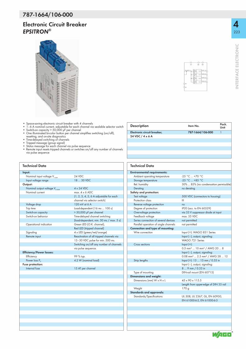
787-1664/106-000
4223
INTE
RFA
CE E
LECT
RON
IC
Electronic Circuit Breaker EPSITRON®
S2 S3S1
OUT1 (+)DC 24V (+)
0 V
OUT2 (+)
OUT3 (+)
OUT4 (+)
0 V
1..6A
1..6A
1..6A
1..6A
• Space-saving electronic circuit breaker with 4 channels• 1–6 A nominal current, adjustable for each channel via sealable selector switch• Switch-on capacity > 50,000 μF per channel• One illuminated bi-color button per channel simplifies switching (on/off),
resetting, and on-site diagnostics• Time-delayed switching of channels• Tripped message (group signal)• Status message for each channel via pulse sequence• Remote input resets tripped channels or switches on/off any number of channels
via pulse sequence
Description Item No. Pack. Unit
Electronic circuit breaker, 24 VDC / 4 x 6 A
787-1664/106-000 1
Technical DataInput:
Nominal input voltage Vi nom 24 VDCInput voltage range 18 … 30 VDC
Output:Nominal output voltage Vo nom 4 x 24 VDCNominal current max. 4 x 6 ADC
(1, 2, 3, 4, 5, 6 A adjustable for each channel via selector switch)
Voltage drop 120 mV at 6 ATrip time Load-dependent (16 ms ... 100 s)Switch-on capacity > 50,000 μF per channelSwitch-on behavior Time-delayed channel switching
(load-dependent, min. 50 ms / max. 5 s)Operational indication Green LED (O.K. channel),
Red LED (tripped channel)Signaling 4 x LED (green/red/orange)Remote input Reactivation of all tripped channels via
15–30 VDC pulse for min. 500 ms. Switching on/off any number of channels via pulse sequence.
Efficiency/Power losses:Efficiency 99 % typ.Power loss PV 4.2 W (nominal load)
Fuse protection:Internal fuse 15 AT per channel
Technical DataEnvironmental requirements:
Ambient operating temperature -25 °C … +70 °CStorage temperature -25 °C … +85 °CRel. humidity 30% ... 85% (no condensation permissible)Derating no derating
Safety and protection:Test voltage 500 VDC (connectors to housing)Protection class IIIReverse voltage protection noDegree of protection IP20 (acc. to EN 60529)Overvoltage protection via 33 V suppressor diode at inputFeedback voltage max. 35 VDCSeries connection of several devices not permittedParallel operation of single channels not permitted
Connection and type of mounting:Wire connection Input (+): WAGO 831 Series
Input (–), output, signaling: WAGO 721 Series
Cross sections Input (+): 0.5 mm² ... 10 mm² / AWG 20 ... 8 Input (–), output, signaling: 0.08 mm² ... 2.5 mm² / AWG 28 ... 12
Strip lengths Input (+): 13 … 15 mm / 0.55 in Input (–), output, signaling: 8 … 9 mm / 0.33 in
Type of mounting DIN-rail mount (EN 60715)Dimensions and weight:
Dimensions (mm) W x H x L 45 x 90 x 115.5Length from upper-edge of DIN 35 rail
Weight 170 gStandards and approvals:
Standards/Specifications UL 508, UL 2367, GL, EN 60950, EN 61000-6-2, EN 61000-6-3

787-1664/000-004
4224
INTE
RFA
CE E
LECT
RON
IC
Electronic Circuit Breaker EPSITRON®
Similiar to picture
S2 S3S1
OUT1 (+)DC 24V (+)
0 V
OUT2 (+)
OUT3 (+)
OUT4 (+)
0 V
2..10A
2..10A
2..10A
2..10A
• Space-saving electronic circuit breaker with 4 channels• 2–10 A nominal current, adjustable for each channel via sealable selector switch;
factory preset: 2 A, switched off• Switch-on capacity > 50000 μF per channel• One illuminated three-colored button per channel simplifies switching (on/off),
resetting, and on-site diagnosis• Time-delayed switching of channels• Tripped and switched off message (common group signal S3)• Status message for each channel via pulse sequence• Remote input resets tripped channels or switches on/off any number of channels via
pulse sequence
Description Item No. Pack. Unit
Electronic Circuit Breaker, 24 VDC / 4 x 10 A
787-1664/000-004 1
Technical DataInput:
Nominal input voltage Vi nom 24 VDCInput voltage range 18 … 30 VDC
Output:Nominal output voltage Vo nom 4 x 24 VDCNominal current max. 4 x 10 ADC
(2, 3, 4, 6, 8, 10 A adjustable for each channel via selector switch)
Factory preset 2 ADC, switched offVoltage drop 200 mV at 10 ATrip time Load-dependent (20 ms – 100 s)Switch-on capacity > 50000 μF per channelSwitch-on behavior Time-delayed channel switching
(50 – 100 ms each)Operational indication Green LED (channel OK),
Red LED (channel triggered)Signaling 4 x LED (green/red/orange)Remote input Reactivation of all tripped channels via
15–30 VDC pulse for min. 500 ms. Switching on/off any number of channels via pulse sequence.
Efficiency/Power Losses:Efficiency 99 % typ.Power loss PV 1.3 W (stand-by) / 20 W (nominal load)
Fuse Protection:Internal fuse 15 AT per channel
Technical DataEnvironmental Requirements:
Ambient operating temperature -25 °C … +70 °CStorage temperature -25 °C … +85 °CRelative humidity 30% ... 85% (no condensation permissible)Derating ≥ +50 °C: see instruction manual
Safety and protection:Test voltage 500 VDC (connectors to housing)Protection class IIIReverse voltage protection noDegree of protection IP20 (acc. to EN 60529)Overvoltage protection via 33 V suppressor diode at inputFeedback voltage max. 35 VDCSeries connection of several devices not permittedParallel operation of single channels not permitted
Connection and type of mounting:Wire connection Input (+): WAGO 831 Series
Input (–), output, signaling: WAGO 721 Series
Cross sections Input (+): 0.5 mm² … 10 mm² / AWG 20 ... 8 Input (–), output, signaling: 0.08 mm² … 2.5 mm² / AWG 28 ... 12
Strip lengths Input (+): 13 … 15 mm / 0.55 in Input (–), output, signaling: 8 … 9 mm / 0.33 in
Type of mounting DIN-rail mount (EN 60715)Dimensions and weight:
Dimensions (mm) W x H x L 45 x 90 x 115.5Length from upper-edge of DIN 35 rail
Weight 161 gStandards and Specifications:
Standards/specifications UL 508, UL 2367, GL, EN 60950, EN 61000-6-2, EN 61000-6-3
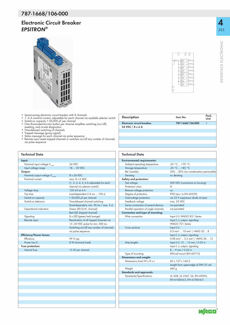
787-1668/106-000
4225
INTE
RFA
CE E
LECT
RON
IC
Electronic Circuit Breaker EPSITRON®
S1
OUT1 (+)DC 24V (+)
0 V
OUT2 (+)
OUT3 (+)
OUT4 (+)
0 V
1..6A
1..6A
1..6A
1..6A
OUT5 (+)
OUT6 (+)
OUT7 (+)
OUT8 (+)
1..6A
1..6A
1..6A
1..6A
S2 S3
• Space-saving electronic circuit breaker with 8 channels• 1–6 A nominal current, adjustable for each channel via sealable selector switch• Switch-on capacity > 50,000 μF per channel• One illuminated bi-color button per channel simplifies switching (on/off),
resetting, and on-site diagnostics• Time-delayed switching of channels• Tripped message (group signal)• Status message for each channel via pulse sequence• Remote input resets tripped channels or switches on/off any number of channels
via pulse sequence
Description Item No. Pack. Unit
Electronic circuit breaker, 24 VDC / 8 x 6 A
787-1668/106-000 1
Technical DataInput:
Nominal input voltage Vi nom 24 VDCInput voltage range 18 … 30 VDC
Output:Nominal output voltage Vo nom 8 x 24 VDCNominal current max. 8 x 6 ADC
(1, 2, 3, 4, 5, 6 A adjustable for each channel via selector switch)
Voltage drop 120 mV at 6 ATrip time Load-dependent (16 ms ... 100 s)Switch-on capacity > 50,000 μF per channelSwitch-on behavior Time-delayed channel switching
(load-dependent, min. 50 ms / max. 5 s)Operational indication Green LED (O.K. channel),
Red LED (tripped channel)Signaling 8 x LED (green/red/orange)Remote input Reactivation of all tripped channels via
15–30 VDC pulse for min. 500 ms. Switching on/off any number of channels via pulse sequence.
Efficiency/Power losses:Efficiency 99 % typ.Power loss PV 8 W (nominal load)
Fuse protection:Internal fuse 15 AT per channel
Technical DataEnvironmental requirements:
Ambient operating temperature -25 °C … +70 °CStorage temperature -25 °C … +85 °CRel. humidity 30% ... 85% (no condensation permissible)Derating no derating
Safety and protection:Test voltage 500 VDC (connectors to housing)Protection class IIIReverse voltage protection noDegree of protection IP20 (acc. to EN 60529)Overvoltage protection via 33 V suppressor diode at inputFeedback voltage max. 35 VDCSeries connection of several devices not permittedParallel operation of single channels not permitted
Connection and type of mounting:Wire connection Input (+): WAGO 831 Series
Input (–), output, signaling: WAGO 721 Series
Cross sections Input (+): 0.5 mm² ... 10 mm² / AWG 20 ... 8 Input (–), output, signaling: 0.08 mm² ... 2.5 mm² / AWG 28 ... 12
Strip lengths Input (+): 13 … 15 mm / 0.55 in Input (–), output, signaling: 8 … 9 mm / 0.33 in
Type of mounting DIN-rail mount (EN 60715)Dimensions and weight:
Dimensions (mm) W x H x L 42 x 127 x 142.5Length from upper-edge of DIN 35 rail
Weight 440 gStandards and approvals:
Standards/Specifications UL 508, UL 2367, GL, EN 60950, EN 61000-6-2, EN 61000-6-3

787-1668/000-004
4226
INTE
RFA
CE E
LECT
RON
IC
Electronic Circuit Breaker EPSITRON®
Similiar to picture
S1
OUT1 (+)DC 24V (+)
0 V
OUT2 (+)
OUT3 (+)
OUT4 (+)
0 V
2..10A
2..10A
2..10A
2..10A
OUT5 (+)
OUT6 (+)
OUT7 (+)
OUT8 (+)
2..10A
2..10A
2..10A
2..10A
S2 S3
• Space-saving electronic circuit breaker with 8 channels• 2–10 A nominal current, adjustable for each channel via sealable selector switch;
factory preset: 2 A, switched off• Switch-on capacity > 50000 μF per channel• One illuminated three-colored button per channel simplifies switching (on/off),
resetting, and on-site diagnosis• Time-delayed switching of channels• Tripped and switched off message (common group signal S3)• Status message for each channel via pulse sequence• Remote input resets tripped channels or switches on/off any number of channels via
pulse sequence
Description Item No. Pack. Unit
Electronic Circuit Breaker, 24 VDC / 8 x 10 A
787-1668/000-004 1
System DataInput:
Nominal input voltage Vi nom 24 VDCInput voltage range 18 … 30 VDC
Output:Nominal output voltage Vo nom 8 x 24 VDCNominal current max. 8 x 10 ADC
(2, 3, 4, 6, 8, 10 A adjustable for each channel via selector switch)
Factory preset 2 ADC, switched offVoltage drop 200 mV at 10 ATrip time Load-dependent (20 ms – 100 s)Switch-on capacity > 50000 μF per channelSwitch-on behavior Time-delayed channel switching
(50 – 100 ms each)Operational indication Green LED (channel OK),
Red LED (channel triggered)Signaling 8 x LED (green/red/orange)Remote input Reactivation of all tripped channels via
15–30 VDC pulse for min. 500 ms. Switching on/off any number of channels via pulse sequence.
Efficiency/Power Losses:Efficiency 99 % typ.Power loss PV 1.3 W (stand-by) / 20 W (nominal load)
Fuse Protection:Internal fuse 15 AT per channel
Technical DataEnvironmental Requirements:
Ambient operating temperature -25 °C … +70 °CStorage temperature -25 °C … +85 °CRelative humidity 30% ... 85% (no condensation permissible)Derating ≥ +50 °C: see instruction manual
Safety and protection:Test voltage 500 VDC (connectors to housing)Protection class IIIReverse voltage protection noDegree of protection IP20 (acc. to EN 60529)Overvoltage protection via 33 V suppressor diode at inputFeedback voltage max. 35 VDCSeries connection of several devices not permittedParallel operation of single channels not permitted
Connection and type of mounting:Wire connection Input (+): WAGO 831 Series
Input (–), output, signaling: WAGO 721 Series
Cross sections Input (+): 0.5 mm² … 10 mm² / AWG 20 ... 8 Input (–), output, signaling: 0.08 mm² … 2.5 mm² / AWG 28 ... 12
Strip lengths Input (+): 13 … 15 mm / 0.55 in Input (–), output, signaling: 8 … 9 mm / 0.33 in
Type of mounting DIN-rail mount (EN 60715)Dimensions and weight:
Dimensions (mm) W x H x L 42 x 127 x 142.5Length from upper-edge of DIN 35 rail
Weight 420 gStandards and Specifications:
Standards/specifications UL 508, UL 2367, GL, EN 60950, EN 61000-6-2, EN 61000-6-3

787-1662/006-1000
4227
INTE
RFA
CE E
LECT
RON
IC
Electronic Circuit Breaker EPSITRON®
S2 S3S1
OUT1 (+)DC 24V (+)
0 V
OUT2 (+)
0 V
0,5..6A
0,5..6A
• Space-saving electronic circuit breaker with 2 channels• 0.5–6 A nominal current, adjustable for each channel via sealable selector switch• Active current limitation• Switch-on capacity > 65000 μF per channel• One illuminated bi-color button per channel simplifies switching (on/off), resetting,
and on-site diagnostics• Time-delayed switching of channels• Tripped message (group signal)• Status message for each channel via pulse sequence• Remote input resets tripped channels or switches on/off any number of channels via
pulse sequence
Description Item No. Pack. Unit
Electronic circuit breaker, 24 VDC / 2 x 6 A
787-1662/006-1000 1
Technical DataInput:
Nominal input voltage Vi nom 24 VDCInput voltage range 18 … 30 VDC
Output:Nominal output voltage Vo nom 2 x 24 VDCNominal current max. 2 x 6 ADC
(0.5, 1, 2, 3, 4, 6 A adjustable for each channel via selector switch)
Voltage drop 145 mV at 6 ATrip time Load-dependent (16 ms ... 100 s)Switch-on capacity > 65,000 μF per channelSwitch-on behavior Time-delayed channel switching
(load-dependent, min. 50 ms / max. 5 s)Operational indication Green LED (O.K. channel),
Red LED (tripped channel)Signaling 2 x LED (green/red/orange)Remote input Reactivation of all tripped channels via
15–30 VDC pulse for min. 500 ms. Switching on/off any number of channels via pulse sequence.
Efficiency/Power losses:Efficiency 99 % typ.Power loss PV 2.5 W (nominal load)
Fuse protection:Internal fuse 15 AT per channel
Technical DataEnvironmental requirements:
Ambient operating temperature -25 °C … +70 °CStorage temperature -25 °C … +85 °CRel. humidity 30% ... 85% (no condensation permissible)Derating no derating
Safety and protection:Test voltage 500 VDC (connectors to housing)Protection class IIIReverse voltage protection noDegree of protection IP20 (acc. to EN 60529)Overvoltage protection via 33 V suppressor diode at inputFeedback voltage max. 35 VDCSeries connection of several devices not permittedParallel operation of single channels not permitted
Connection and type of mounting:Wire connection Input (+): WAGO 831 Series
Input (–), output, signaling: WAGO 721 Series
Cross sections Input (+): 0.5 mm² ... 10 mm² / AWG 20 ... 8 Input (–), output, signaling: 0.08 mm² ... 2.5 mm² / AWG 28 ... 12
Strip lengths Input (+): 13 … 15 mm / 0.55 in Input (–), output, signaling: 8 … 9 mm / 0.33 in
Type of mounting DIN-rail mount (EN 60715)Dimensions and weight:
Dimensions (mm) W x H x L 45 x 90 x 115.5Length from upper-edge of DIN 35 rail
Weight 170 gStandards and approvals:
Standards/Specifications UL 508*, UL 2367*, GL, EN 60950, EN 61000-6-2, EN 61000-6-3 (* pending)

787-1664/006-1000
4228
INTE
RFA
CE E
LECT
RON
IC
Electronic Circuit Breaker EPSITRON®
S2 S3S1
OUT1 (+)DC 24V (+)
0 V
OUT2 (+)
OUT3 (+)
OUT4 (+)
0 V
0,5..6A
0,5..6A
0,5..6A
0,5..6A
• Space-saving electronic circuit breaker with 4 channels• 0.5–6 A nominal current, adjustable for each channel via sealable selector switch• Active current limitation• Switch-on capacity > 65000 μF per channel• One illuminated bi-color button per channel simplifies switching (on/off), resetting,
and on-site diagnostics• Time-delayed switching of channels• Tripped message (group signal)• Status message for each channel via pulse sequence• Remote input resets tripped channels or switches on/off any number of channels via
pulse sequence
Description Item No. Pack. Unit
Electronic circuit breaker, 24 VDC / 4 x 6 A
787-1664/006-1000 1
Technical DataInput:
Nominal input voltage Vi nom 24 VDCInput voltage range 18 … 30 VDC
Output:Nominal output voltage Vo nom 4 x 24 VDCNominal current max. 4 x 6 ADC
(0.5, 1, 2, 3, 4, 6 A adjustable for each channel via selector switch)
Voltage drop 145 mV at 6 ATrip time Load-dependent (16 ms ... 100 s)Switch-on capacity > 65,000 μF per channelSwitch-on behavior Time-delayed channel switching
(load-dependent, min. 50 ms / max. 5 s)Operational indication Green LED (O.K. channel),
Red LED (tripped channel)Signaling 4 x LED (green/red/orange)Remote input Reactivation of all tripped channels via
15–30 VDC pulse for min. 500 ms. Switching on/off any number of channels via pulse sequence.
Efficiency/Power losses:Efficiency 99 % typ.Power loss PV 4.3 W (nominal load)
Fuse protection:Internal fuse 15 AT per channel
Technical DataEnvironmental requirements:
Ambient operating temperature -25 °C … +70 °CStorage temperature -25 °C … +85 °CRel. humidity 30% ... 85% (no condensation permissible)Derating no derating
Safety and protection:Test voltage 500 VDC (connectors to housing)Protection class IIIReverse voltage protection noDegree of protection IP20 (acc. to EN 60529)Overvoltage protection via 33 V suppressor diode at inputFeedback voltage max. 35 VDCSeries connection of several devices not permittedParallel operation of single channels not permitted
Connection and type of mounting:Wire connection Input (+): WAGO 831 Series
Input (–), output, signaling: WAGO 721 Series
Cross sections Input (+): 0.5 mm² ... 10 mm² / AWG 20 ... 8 Input (–), output, signaling: 0.08 mm² ... 2.5 mm² / AWG 28 ... 12
Strip lengths Input (+): 13 … 15 mm / 0.55 in Input (–), output, signaling: 8 … 9 mm / 0.33 in
Type of mounting DIN-rail mount (EN 60715)Dimensions and weight:
Dimensions (mm) W x H x L 45 x 90 x 115.5Length from upper-edge of DIN 35 rail
Weight 170 gStandards and approvals:
Standards/Specifications UL 508*, UL 2367*, GL, EN 60950, EN 61000-6-2, EN 61000-6-3 (* pending)

787-1668/006-1000
4229
INTE
RFA
CE E
LECT
RON
IC
Electronic Circuit Breaker EPSITRON®
S1
OUT1 (+)DC 24V (+)
0 V
OUT2 (+)
OUT3 (+)
OUT4 (+)
0 V
OUT5 (+)
OUT6 (+)
OUT7 (+)
OUT8 (+)
S2 S3
0,5..6A
0,5..6A
0,5..6A
0,5..6A
0,5..6A
0,5..6A
0,5..6A
0,5..6A
• Space-saving electronic circuit breaker with 8 channels• 0.5–6 A nominal current, adjustable for each channel via sealable selector switch• Active current limitation• Switch-on capacity > 65000 μF per channel• One illuminated bi-color button per channel simplifies switching (on/off), resetting,
and on-site diagnostics• Time-delayed switching of channels• Tripped message (group signal)• Status message for each channel via pulse sequence• Remote input resets tripped channels or switches on/off any number of channels via
pulse sequence
Description Item No. Pack. Unit
Electronic circuit breaker, 24 VDC / 8 x 6 A
787-1668/006-1000 1
Technical DataInput:
Nominal input voltage Vi nom 24 VDCInput voltage range 18 … 30 VDC
Output:Nominal output voltage Vo nom 8 x 24 VDCNominal current max. 8 x 6 ADC
(0.5, 1, 2, 3, 4, 6 A adjustable for each channel via selector switch)
Voltage drop 155 mV at 6 ATrip time Load-dependent (16 ms ... 100 s)Switch-on capacity > 65,000 μF per channelSwitch-on behavior Time-delayed channel switching
(load-dependent, min. 50 ms / max. 5 s)Operational indication Green LED (O.K. channel),
Red LED (tripped channel)Signaling 8 x LED (green/red/orange)Remote input Reactivation of all tripped channels via
15–30 VDC pulse for min. 500 ms. Switching on/off any number of channels via pulse sequence.
Efficiency/Power losses:Efficiency 99 % typ.Power loss PV 8.6 W (nominal load)
Fuse protection:Internal fuse 15 AT per channel
Technical DataEnvironmental requirements:
Ambient operating temperature -25 °C … +70 °CStorage temperature -25 °C … +85 °CRel. humidity 30% ... 85% (no condensation permissible)Derating no derating
Safety and protection:Test voltage 500 VDC (connectors to housing)Protection class IIIReverse voltage protection noDegree of protection IP20 (acc. to EN 60529)Overvoltage protection via 33 V suppressor diode at inputFeedback voltage max. 35 VDCSeries connection of several devices not permittedParallel operation of single channels not permitted
Connection and type of mounting:Wire connection Input (+): WAGO 831 Series
Input (–), output, signaling: WAGO 721 Series
Cross sections Input (+): 0.5 mm² ... 10 mm² / AWG 20 ... 8 Input (–), output, signaling: 0.08 mm² ... 2.5 mm² / AWG 28 ... 12
Strip lengths Input (+): 13 … 15 mm / 0.55 in Input (–), output, signaling: 8 … 9 mm / 0.33 in
Type of mounting DIN-rail mount (EN 60715)Dimensions and weight:
Dimensions (mm) W x H x L 42 x 127 x 142.5Length from upper-edge of DIN 35 rail
Weight 440 gStandards and approvals:
Standards/Specifications UL 508*, UL 2367*, GL, EN 60950, EN 61000-6-2, EN 61000-6-3 (* pending)
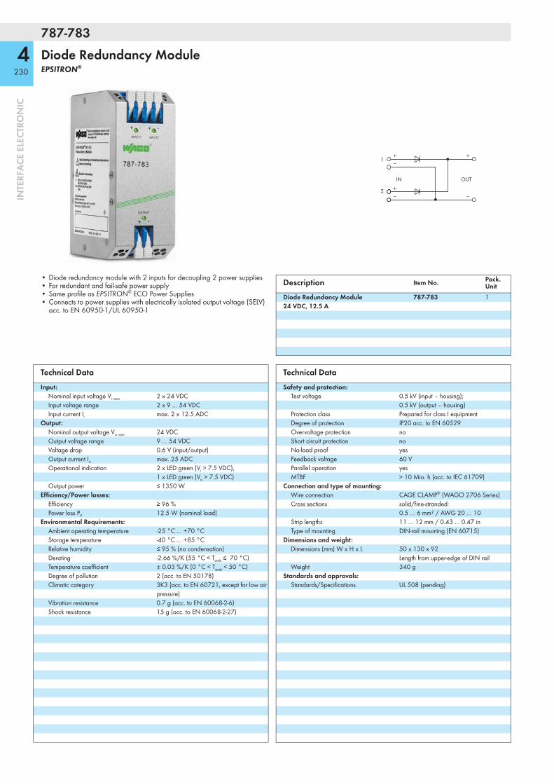
787-783
4230
INTE
RFA
CE E
LECT
RON
IC
Diode Redundancy ModuleEPSITRON®
IN
1+−
+−
+
−2
OUT
• Diode redundancy module with 2 inputs for decoupling 2 power supplies• For redundant and fail-safe power supply• Same profile as EPSITRON® ECO Power Supplies• Connects to power supplies with electrically isolated output voltage (SELV)
acc. to EN 60950-1/UL 60950-1
Description Item No. Pack. Unit
Diode Redundancy Module 24 VDC, 12.5 A
787-783 1
Technical DataInput:
Nominal input voltage Vi nom 2 x 24 VDCInput voltage range 2 x 9 … 54 VDCInput current Ii max. 2 x 12.5 ADC
Output:Nominal output voltage Vo nom 24 VDCOutput voltage range 9 … 54 VDCVoltage drop 0.6 V (input/output)Output current Io max. 25 ADCOperational indication 2 x LED green (Vi > 7.5 VDC),
1 x LED green (Vo > 7.5 VDC)Output power ≤ 1350 W
Efficiency/Power losses:Efficiency ≥ 96 %Power loss PV 12.5 W (nominal load)
Environmental Requirements:Ambient operating temperature -25 °C … +70 °CStorage temperature -40 °C … +85 °CRelative humidity ≤ 95 % (no condensation)Derating -2.66 %/K (55 °C < Tamb ≤ 70 °C)Temperature coefficient ± 0.03 %/K (0 °C < Tamb < 50 °C)Degree of pollution 2 (acc. to EN 50178)Climatic category 3K3 (acc. to EN 60721, except for low air
pressure)Vibration resistance 0.7 g (acc. to EN 60068-2-6)Shock resistance 15 g (acc. to EN 60068-2-27)
Technical DataSafety and protection:
Test voltage 0.5 kV (input – housing); 0.5 kV (output – housing)
Protection class Prepared for class I equipmentDegree of protection IP20 acc. to EN 60529Overvoltage protection noShort circuit protection noNo-load proof yesFeedback voltage 60 VParallel operation yesMTBF > 10 Mio. h (acc. to IEC 61709)
Connection and type of mounting:Wire connection CAGE CLAMP® (WAGO 2706 Series)Cross sections solid/fine-stranded:
0.5 … 6 mm² / AWG 20 … 10 Strip lengths 11 … 12 mm / 0.43 … 0.47 in Type of mounting DIN-rail mounting (EN 60715)
Dimensions and weight:Dimensions (mm) W x H x L 50 x 130 x 92
Length from upper-edge of DIN railWeight 340 g
Standards and approvals:Standards/Specifications UL 508 (pending)

787-785
4231
INTE
RFA
CE E
LECT
RON
IC
Diode Redundancy ModuleEPSITRON®
IN
1+−
+−
+
−2
OUT
• Diode redundancy module with 2 inputs for decoupling 2 power supplies• For redundant and fail-safe power supply• Same profile as EPSITRON® ECO Power Supplies• Connects to power supplies with electrically isolated output voltage (SELV)
acc. to EN 60950-1/UL 60950-1
Description Item No. Pack. Unit
Diode Redundancy Module 24 VDC, 40 A
787-785 1
Technical DataInput:
Nominal input voltage Vi nom 2 x 24 VDCInput voltage range 2 x 9 … 54 VDCInput current Ii max. 2 x 40 ADC
(in total max. 76 ADC)Output:
Nominal output voltage Vo nom 24 VDCOutput voltage range 9 … 54 VDCVoltage drop 0.6 V (input/output)Output current Io max. 76 ADCOperational indication 2 x LED green (Vi > 7.5 VDC),
1 x LED green (Vo > 7.5 VDC)Output power ≤ 4104 W
Efficiency/Power losses:Efficiency ≥ 97 %Power loss PV 29.7 W (nominal load)
Environmental Requirements:Ambient operating temperature -25 °C … +70 °CStorage temperature -40 °C … +85 °CRelative humidity ≤ 95 % (no condensation)Derating -2.66 %/K (55 °C < Tamb ≤ 70 °C)Temperature coefficient ± 0.03 %/K (0 °C < Tamb < 50 °C)Degree of pollution 2 (acc. to EN 50178)Climatic category 3K3 (acc. to EN 60721, except for low air
pressure)Vibration resistance 0.7 g (acc. to EN 60068-2-6)Shock resistance 15 g (acc. to EN 60068-2-27)
Technical DataSafety and protection:
Test voltage 0.5 kV (input – housing); 0.5 kV (output – housing)
Protection class Prepared for class I equipmentDegree of protection IP20 acc. to EN 60529Overvoltage protection noShort circuit protection noNo-load proof yesFeedback voltage 60 VParallel operation yesMTBF > 10 Mio. h (acc. to IEC 61709)
Connection and type of mounting:Wire connection CAGE CLAMP® (WAGO 2716 Series)Cross sections solid/fine-stranded:
1.5 … 16 mm² / AWG 16 … 6 Strip lengths 12 … 13 mm / 0.47 … 0.51 in Type of mounting DIN-rail mounting (EN 60715)
Dimensions and weight:Dimensions (mm) W x H x L 83 x 130 x 153
Length from upper-edge of DIN railWeight 960 g
Standards and approvals:Standards/Specifications UL 508 (pending)

787-2852
4232
INTE
RFA
CE E
LECT
RON
IC
Switched-Mode Power Supply in 2857 Series HousingEPSITRON® Power for JUMPFLEX®
Similiar to picture
DC O.K.DC-DC-
DC+
LLNN
DC+DC–
• Primary switch mode power supply in 22.5 mm wide 2857 Series Housing, same profile as 2857 and 857 Series JUMPFLEX® Transducers
• Both 24 VDC and 0 V output voltage can be easily supplied to adjacent JUMPFLEX® modules via 859-4xx Jumpers
• Pluggable picoMAX® connection technology• Natural convection cooling• DC OK message as active signal output (24 VDC, 20 mA)• Integrated redundancy diode enables easy fail-safe power supply via parallel
connection of two power supplies• Approvals for worldwide applications with JUMPFLEX® Modules (pending)
Description Item No. Pack. Unit
Switched-mode power supply in 2857 Series housing, 24 VDC / 1 A
787-2852 1
Technical DataInput:
Nominal input voltage Vi nom 100 … 240 VACInput voltage range 85 … 264 VAC; 90 … 370 VDCFrequency 47 Hz … 63 Hz; 0 HzInput current Ii < 0.2 A (230 VAC, nominal load);
< 0.9 A (90 VAC, nominal load)Power factor > 0.6 (230 VAC, nominal load,
acc. to EN 61000-3-2)Discharge current < 1 mA (230 VAC)Inrush current < 30 A (230 VAC), limitedMains failure hold-up time 120 ms (230 VAC)
Output:Nominal output voltage Vo nom 24 VDC (SELV)Factory preset 24 VDCNominal load Po nom 24 WOutput current Io 1 ADCDeviation, dynamic load change 10 … 90 % < ± 1 %Adjustment accuracy < 2 %Residual ripple < 100 mVpp at 20 MHzCurrent limitation 1.1 x Io typ.Overload behavior Constant currentOperational indication Green LED (Vo > 21.5 V)
Efficiency/Power losses:Efficiency 86 % typ. (230 VAC, nominal load);
84 % typ. (110 VAC, nominal load)Power loss PV < 1 W (230 VAC, no load);
4.3 W (230 VAC, nominal load)Max. power loss PV 4.6 W typ. (100 VAV / 24 VDC, 1 A)
Fuse protection:Internal fuse 2 ATExternal fuse Circuit breakers 6 A,
B or C characteristicEnvironmental Requirements:
Ambient operating temperature -25 °C … +70 °CStorage temperature -40 °C … +85 °CRelative humidity 30 % … 85 % (no condensation Derating -2 %/K (> +60 °C)Degree of pollution 2 (acc. to EN 50178)Climatic category 3K3 (acc. to EN 60721)
Technical DataSafety and protection:
Test voltage 4.2 kV DC (input – output)Protection class IIDegree of protection IP20 (acc. to EN 60529)Overvoltage protection Varistor (input side);
internal protective circuit, < 29 … 31 VDC (output side in case of an error)
Short circuit protection yesNo-load proof yesFeedback voltage max. 60 VDCParallel operation yes, for 2 devices of the same typeSeries connection yes, for 2 devices of the same typeMTBF > 500,000 h (at 25 °C)
Calculation acc. to IEC 61709Connection and type of mounting:
Wire connection Input/Output/Signaling: CAGE CLAMP® S (picoMAX® 5.0)
Cross sections Input/Output/Signaling: solid/fine-stranded: 0.2 … 2.5 mm² / AWG 24 … 10
Strip lengths Input/Output/Signaling: 9 … 10 mm / 0.35 … 0.39 in
Type of mounting DIN-rail mount (EN 60715)Dimensions and weight:
Dimensions (mm) W x H x L 22.5 x 110 x 118Length from upper-edge of DIN 35 rail
Weight 195 gStandards and approvals:
Standards/Specifications EN 61000-6-2, EN 61000-6-3, EN 60950-1, UL 60950 *, cULus 508 *, ANSI-ISA 12.12.01 (Class I Div 2) *, ATEX/IEC Ex *, GL * (* pending)

5233
8
INTE
RFA
CE E
LECT
RON
IC
Rail-Mounted Terminal Blocks with Overvoltage Protection
Varistor VBN 24 V AC/DC ... 230 VAC; IN 300 A ... 1 kA
Terminal block width: 10 mm/0.394 in.
Suppressor diode VBN 24 V AC/DC ... 230 VAC; IN 14 ... 169 A
Terminal block width: 10 mm/0.394 in.
Description VBN Item No. Pack. Unit VBN Item No. Pack.
UnitDouble-deck terminal block with surge suppression device
24 VDC 280-504/281-582 25 24 VDC 280-944/281-589 25 48 VDC 280-504/281-583 25 48 VDC 280-944/281-590 25 60 VDC 280-504/281-584 25 60 VDC 280-944/281-591 25 110 VDC 280-504/281-585 25 110 VDC 280-944/281-592 25 24 VAC 280-504/281-586 25 24 VAC 280-944/281-593 25 115 VAC 280-504/281-587 25 115 VAC 280-944/281-594 25 230 VAC 280-504/281-588 25 230 VAC 280-944/281-595 25
Technical Data Nominal operating voltage VBN
Max. cont. operating voltage VC
Nominal discharge current (8/20 μs) per line IN
Max. surge current (8/20 μs) IS max.
Capacity Protection level (8/20 μs) VP
Terminal blocks with varistor and end plate
24 VDC 31 VDC 300 A 1 kA ≤ 4.6 nF 77 VDC 48 VDC 56 VDC 300 A 1 kA ≤ 2.8 nF 135 VDC 60 VDC 85 VDC 1 kA 4.5 kA ≤ 1.7 nF 165 VDC 110 VDC 150 VDC 1 kA 4.5 kA ≤ 0.8 nF 300 VDC 24 VAC 30 VAC 300 A 1 kA ≤ 3.5 nF 93 VAC 115 VAC 150 VAC 1 kA 4.5 kA ≤ 0.57 nF 395 VAC 230 VAC 275 VAC 1 kA 4.5 kA ≤ 0.32 nF 710 VAC
Terminal blocks with suppressor diode and end plate
24 VDC 28 VDC 169 A ≤ 2.7 nF 59 VDC 48 VDC 53 VDC 90 A ≤ 1.7 nF 111 VDC 60 VDC 70 VDC 69 A ≤ 1.35 nF 146 VDC 110 VDC 128 VDC 38 A ≤ 0.85 nF 265 VDC 24 VAC 26 VAC 143 A ≤ 2.4 nF 70 VAC 115 VAC 133 VAC 26 A ≤ 0.63 nF 388 VAC 230 VAC 253 VAC 14 A ≤ 0.4 nF 706 VAC
Technical DataWire connection CAGE CLAMP® CAGE CLAMP®
Cross sections 0.08 mm² ... 2.5 mm² / AWG 28 ... 14 0.08 mm² ... 2.5 mm² / AWG 28 ... 14Strip length 8 ... 9 mm / 0.33 in 8 ... 9 mm / 0.33 in

Modular Empty Housing, 2857 SeriesOverview and Configuration
Pluggable connection with picoMAX®
Fixed connection with picoMAX®
Empty slot without connection technology
... freely selectable at each connection point
Supplied as a pre-assembled unit
1. Pre-assembled unit 2. Inserting and soldering the PCB.
3. Snapping on side wall.
7234
INTE
RFA
CE
ELEC
TRO
NIC

1 2
1
2
1
2
3
Housing configuration
Housing width: 12.5 mm
2857-101 2857-102 2857-103
–
Housing width: 22.5 mm
2857-121 2857-122 2857-123 2857-124
Connection levels 2-2 3-2 3-3 1-1
Jumper slots 2-2 0-2 0-0 2-2
Mixed configuration (fixed/removable/empty slot) upon request.
Connection level
Example of connection level and jumper slot assignment:
Connection levels 3-2
Jumper slots 0-2
Connection level
Jumper slot
7235
INTE
RFA
CE
ELEC
TRO
NIC

2857 Series
7236
INTE
RFA
CE E
LECT
RON
IC
Modular Empty HousingHousing width: 12.5 mm
12,5 mm/0.49 in
107
mm
/4.2
1 in
T
Features:• picoMAX® female connectors, with coding keys, 2-pole• Pre-assembled unit• Flexible conductor termination• Customization of connection levels• Various marking options available• Sealable, transparent cover• Commoning option via 859-402 jumpers
Description Item No. Pack. Unit
Modular empty housing, for DIN 35 rail Housing width: 12.5 mm2-2 connection levels, 2-2 jumper slots 2857-101 103-2 connection levels, 0-2 jumper slots 2857-102 103-3 connection levels, 0-0 jumper slots 2857-103 10
Technical Data: Empty HousingMaterial Data:
Housing material PCFlammability rating V0
Environmental Requirements:Ambient operating temperature -40 °C … +70 °CStorage temperature -40 °C … +85 °C
Dimensions:Dimensions (mm) W x H x L 12.5 x 107 x 108 (2857-101)
12.5 x 107 x 110 (2857-102)12.5 x 107 x 112 (2857-103)Height from upper-edge of DIN 35 rail
Technical Data:Power loss 2 WAccessories Coding key carrier: 2092-1610
Jumpers: 859-402 Marker strips, WMB and WMB Inline: see Full Line Catalog INTERFACE ELECTRONIC 2012/2013, pages 402 and 408
Technical Data: Female Connector with picoMAX® 5.0 Conductor TerminationTechnical Data:
Pin spacing 5 mm / 0.197 inRatings per IEC/EN 60664-1Overvoltage category EN III III IIPollution degree 3 2 2
250 V 320 V 630 V4 kV 4 kV 4 kV16 A 16 A 16 AUL/CSAB C D300 V - 300 V
Rated voltage ENRated surge voltageNominal currentApprovals perUse roup UL 1059Rated voltageNominal current UL 15 A - 10 A
Conductor Data:Wire connection CAGE CLAMP® SSolid sizes 0.2 … 2.5 mm² / AWG 24 … 12Fine-stranded wires 0.2 … 2.5 mm² / AWG 24 … 12Fine-stranded wires with insulated ferrule 0.2 … 1.5 mm² / AWG 24 … 16Fine-stranded wires with uninsulated ferrule 0.2 … 2.5 mm² / AWG 24 … 14Strip length 9 … 10 mm / 0.35 … 0.39 in
Material Data:Clamping spring material Chrome nickel spring steel (CrNi)Contact material Electrolytic copper (Ecu)Contact plating Tin-platedInsulating material Polyphtalamide glass fiber (PPA-GF)Flammability rating V0
For additional technical data, see WAGO's picoMAX® catalog.

2857 Series
7237
INTE
RFA
CE E
LECT
RON
IC
Modular Empty HousingHousing width: 22.5 mm
22,5 mm/0.89 in
107
mm
/4.2
1 in
T
Features:• picoMAX® female connectors, with coding keys, 4-pole• Pre-assembled unit• Flexible conductor termination• Customization of connection levels• Various marking options available• Sealable, transparent cover• Commoning option via 859-402 jumpers
Description Item No. Pack. Unit
Modular empty housing, for DIN 35 rail Housing width: 22.5 mm2-2 connection levels, 2-2 jumper slots 2857-121 53-2 connection levels, 0-2 jumper slots 2857-122 53-3 connection levels, 0-0 jumper slots 2857-123 51-1 connection levels, 2-2 jumper slots 2857-124 5
Technical Data: Empty HousingMaterial Data:
Housing material PCFlammability rating V0
Environmental Requirements:Ambient operating temperature -40 °C … +70 °CStorage temperature -40 °C … +85 °C
Dimensions:Dimensions (mm) W x H x L 22.5 x 107 x 108 (2857-121)
22.5 x 107 x 110 (2857-122)22.5 x 107 x 112 (2857-123)22.5 x 107 x 105 (2857-124)Height from upper-edge of DIN 35 rail
Technical Data:Power loss 3 WAccessories Coding key carrier: 2092-1610
Jumpers: 859-402 Marker strips, WMB and WMB Inline: see Full Line Catalog INTERFACE ELECTRONIC 2012/2013, pages 402 and 408
Technical Data: Female Connector with picoMAX® 5.0 Conductor TerminationTechnical Data:
Pin spacing 5 mm / 0.197 inRatings per IEC/EN 60664-1Overvoltage category EN III III IIPollution degree 3 2 2Rated voltage EN 250 V 320 630 V
4 kV 4 kV 4 kV16 A 16 A 16 AUL/CSAB C D300 V - 300 V
Rated surge voltageNominal currentApprovals perUse roup UL 1059Rated voltageNominal current UL 15 A - 10 A
Conductor Data:Wire connection CAGE CLAMP® SSolid sizes 0.2 … 2.5 mm² / AWG 24 … 12Fine-stranded wires 0.2 … 2.5 mm² / AWG 24 … 12Fine-stranded wires with insulated ferrule 0.2 … 1.5 mm² / AWG 24 … 16Fine-stranded wires with uninsulated ferrule 0.2 … 2.5 mm² / AWG 24 … 14Strip length 9 … 10 mm / 0.35 … 0.39 in
Material Data:Clamping spring material Chrome nickel spring steel (CrNi)Contact material Electrolytic copper (Ecu)Contact plating Tin-platedInsulating material Polyphtalamide glass fiber (PPA-GF)Flammability rating V0
For additional technical data, see WAGO's picoMAX® catalog.

<__________ 47,5 __________>
<________________________
92,5 _______________________>
<____________________
80,5 ___________________><
_____
Ø 1,8
<_____
Ø 2,3
<__________ 47,5 __________>
<________________________
92,5 _______________________>
<____________________
80,5 ___________________><
_____
Ø 1,8
<_____
Ø 2,3
<__________ 47,5 __________>
<________________________
92,5 _______________________>
<____________________
80,5 ___________________><
_____
Ø 1,8
<_____
Ø 2,3
Stripboards, 2857 Seriesfor Empty Housings
Stripboard 2–2 connection levels
2–2 jumper slots
Stripboard 3–2 connection levels
0–2 jumper slots
Stripboard 3–3 connection levels
0–0 jumper slots
Item No. Pack. Unit Item No. Pack. Unit Item No. Pack. Unit
Stripboard, for installation in 12.5mm and 22.5mm empty housings
Stripboard, for installation in 12.5mm and 22.5mm empty housings
Stripboard, for installation in 12.5mm and 22.5mm empty housings
2857-191/3140-000 5 (5 x 1) 2857-192/3140-000 5 (5 x 1) 2857-193/3140-000 5 (5 x 1)
7238
INTE
RFA
CE
ELEC
TRO
NIC
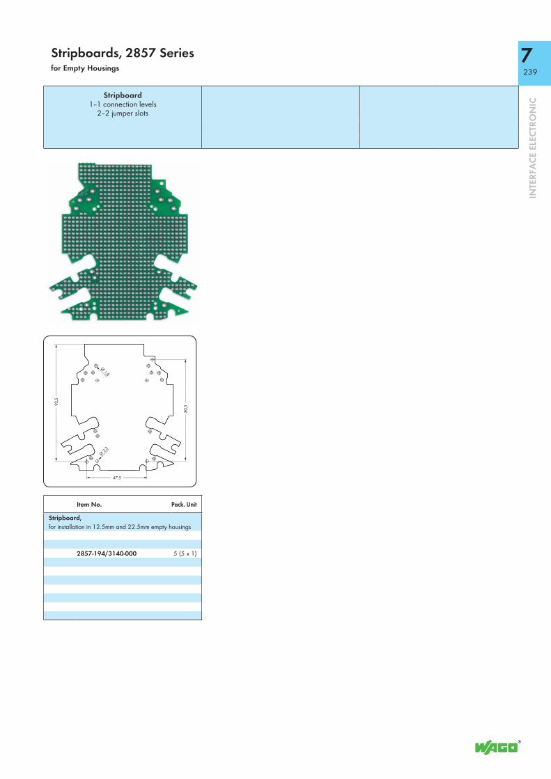
<__________ 47,5 __________>
<________________________
92,5 _______________________>
<____________________
80,5 ___________________><
_____
Ø 1,8
<_____
Ø 2,3
Stripboard 1–1 connection levels
2–2 jumper slots
Item No. Pack. Unit
Stripboard, for installation in 12.5mm and 22.5mm empty housings
2857-194/3140-000 5 (5 x 1)
Stripboards, 2857 Seriesfor Empty Housings
7239
INTE
RFA
CE
ELEC
TRO
NIC

855 Series
240
INTE
RFA
CE E
LECT
RON
IC
Rogowski Coils RT 500
Ip
Ø 5
Ø 5
1500 / 300015.7
27.4
white+Vs
black-Vs
Output voltage (open output, no load)
- dynamic Vout = M x dIp/dt
- sinusoidal signal Vout = 2 x π x M x f x Ip ACExample: Vout = 2 x π x 0.064 μH x 50 Hz x 500 A = 10.05 mV
34.4
Øm
ax 5
5
Short description:The Rogowski coil is a closed-air coil with non-magnetic split core, placed around a conductor or a current bar.The magnetic field produced by the AC current flowing through the conductor induces an output voltage in the coil.This measurement procedure provides galvanic isolation between the primary circuit (power) and secondary circuit (measurement).Easy placement of the Rogowski coils allows existing systems to be retrofitted without time-consuming installation or process interruption.The Rogowski coil can be used together with the 789-652 Signal Conditioner or the 857-552 Rogowski Transducer.
Features:• Split-core style coil for easy installation• Ø 55 mm coil aperture for non-contact measurement• 1.5 m or 3 m output cable• Insulated plastic case to UL 94-V0
Description Item No. Pack. Unit
Rogowski coil RT 500, 1.5 m output cable 855-9100/500-000 3Rogowski coil RT 500, 3 m output cable 855-9300/500-000 3
ApprovalsConformity marking 1
Standards/Specifications IEC 61010-1:2001 (2nd edition), IEC 61010-2-032:2002, IEC 61010-031:2002 + A1:2008
Technical DataElectrical data
Primary rated current IpN 500 ArmsCoil inductance (± 5 %) 125 μHCoil resistance 40 Ω
(at 20 °C ambient operating temperature, typ.)
Transfer ratio M 0.064 μH(WAGO provides uncalibrated coils with 5 % tolerance)
Output signal Example shown above 10.05 mV at IpN = 500 A, sinusoidal, 50 Hz (open output, no load)
Max. operating frequency 700 kHz (open output, no load)
Accuracy and dynamic performance:Linearity error noneTemperature coefficient 30 ppm/K, related to transfer ratio MPositioning error 855-9100/500-000: max. 0.65 %
855-9300/500-000: max. 0,80 %(considering a primary conductor of at least Ø 15 mm perpendicular to the coil)
Safety and protection:Nominal isolation voltage 300 Vrms
(between primary conductor and ground)Voltage for isolation test 3.5 kVrms AC / 50 Hz / 1 minImpulse withstand voltage (1.2/50 μs) 6.5 kVAdjacent contacts 6 mm / 6 mmComparative Tracking Index (CTI, group I) 600 V (plastic parts)Degree of protection IP2X
General specifications:Cable length 855-9100/500-000: 1.5 m
855-9300/500-000: 3 mAmbient operating temperature -10 °C ... +65 °CStorage temperature -25 °C ... +70 °CWeight 85 g
Technical Data

241
INTE
RFA
CE E
LECT
RON
IC
855 SeriesRogowski Coils RT 2000
Ip
Ø 5
Ø 5
1500 / 300015.7
27.4
white+Vs
black-Vs
Output voltage (open output, no load)
- dynamic Vout = M x dIp/dt
- sinusoidal signal Vout = 2 x π x M x f x Ip ACExample: Vout = 2 x π x 0.064 μH x 50 Hz x 2000 A = 40.2 mV
34.4
Øm
ax 1
25
Short description:The Rogowski coil is a closed-air coil with non-magnetic split core, placed around a conductor or a current bar.The magnetic field produced by the AC current flowing through the conductor induces an output voltage in the coil.This measurement procedure provides galvanic isolation between the primary circuit (power) and secondary circuit (measurement).Easy placement of the Rogowski coils allows existing systems to be retrofitted without time-consuming installation or process interruption.The Rogowski coil can be used together with the 857-552 Rogowski Transducer.
Features:• Split-core style coil for easy installation• Ø 125 mm coil aperture for non-contact measurement• 1.5 m or 3 m output cable• Insulated plastic case to UL 94-V0
Description Item No. Pack. Unit
Rogowski coil RT 2000, 1.5 m output cable 855-9100/2000-000 3Rogowski coil RT 2000, 3 m output cable 855-9300/2000-000 3
ApprovalsConformity marking 1
Standards/Specifications IEC 61010-1:2001 (2nd edition), IEC 61010-2-032:2002, IEC 61010-031:2002 + A1:2008
Technical DataElectrical data
Primary rated current IpN 2000 ArmsCoil inductance (± 5 %) 190 μHCoil resistance 60 Ω
(at 20 °C ambient operating temperature, typ.)
Transfer ratio M 0.064 μH(WAGO provides uncalibrated coils with 5 % tolerance)
Output signal Example shown above 40.2 mV at IpN = 2000 A, sinusoidal, 50 Hz (open output, no load)
Max. operating frequency 500 kHz (open output, no load)
Accuracy and dynamic performance:Linearity error noneTemperature coefficient 30 ppm/K, related to transfer ratio MPositioning error 855-9100/2000-000: max. 0.65 %
855-9300/2000-000: max. 0,80 %(considering a primary conductor of at least Ø 15 mm perpendicular to the coil)
Safety and protection:Nominal isolation voltage 300 Vrms
(between primary conductor and ground)Voltage for isolation test 3.5 kVrms AC / 50 Hz / 1 minImpulse withstand voltage (1.2/50 μs) 6.5 kVAdjacent contacts 6 mm / 6 mmComparative Tracking Index (CTI, group I) 600 V (plastic parts)Degree of protection IP2X
General specifications:Cable length 855-9100/2000-000: 1.5 m
855-9300/2000-000: 3 mAmbient operating temperature -10 °C ... +65 °CStorage temperature -25 °C ... +70 °CWeight 90 g
Technical Data

242
INTE
RFA
CE E
LECT
RON
IC
Plug-In Current Transformers
Plug-In Current Transformers Secondary rated current: 1 A
Plug-In Current Transformers Secondary rated current: 5 A
Short description:The 855 Series Plug-In Current Transformers are inductive, single-conductor current transformers. Based on the principle of measurement, current transformers of this type are used exclusively in AC networks.
Features:• Screwless CAGE CLAMP® connection technology• Several mounting options available• Vibration- and shock-resistant• High mechanical retention forces• High current-carrying capacity• Continuous overload of 120 % the nominal primary
current• Low-voltage current transformer for max. operating
voltages up to 1.2 kV• Can be used in 690 V power networks• UL Recognized Components
Description IpN IsN SN G Item No. Pack. Unit IpN IsN SN G Item No. Pack.
UnitPlug-in current transformer 50 A 1 A 1.25 3 855-301/050-103 1 50 A 5 A 1.25 3 855-305/050-103 1
60 A 1 A 1.25 1 855-301/060-101 1 60 A 5 A 1.25 1 855-305/060-101 175 A 1 A 2.5VA 1 855-301/075-201 1 75 A 5 A 2.5VA 1 855-305/075-201 1100 A 1 A 2.5VA 1 855-301/100-201 1 100 A 5 A 2.5VA 1 855-305/100-201 1150 A 1 A 5VA 1 855-301/150-501 1 150 A 5 A 5VA 1 855-305/150-501 1200 A 1 A 5VA 1 855-301/200-501 1 200 A 5 A 5VA 1 855-305/200-501 1250 A 1 A 5VA 1 855-301/250-501 1 250 A 5 A 5VA 1 855-305/250-501 1
IpN = Primary rated current IsN = Secondary rated current SN = Rated power G = Accuracy class
400 A 1 A 10VA 1 855-301/400-1001 1 400 A 5 A 10VA 1 855-305/400-1001 1600 A 1 A 10VA 1 855-301/600-1001 1 600 A 5 A 10VA 1 855-305/600-1001 1400 A 1 A 5VA 1 855-401/400-501 1 400 A 5 A 5VA 1 855-405/400-501 11000 A 1 A 10VA 1 855-501/1000-1001 1 1000 A 5 A 10VA 1 855-505/1000-1001 1
Technical DataInput:
Rated continuous thermal current Icth 1.2 x IN 1.2 x INRated short-time thermal current Ith 60 x IN (max.100 kA), 1 s 60 x IN (max.100 kA), 1 sMax. operating voltage Vm 1.2 kV 1.2 kVRated frequency 50 Hz ... 60 Hz 50 Hz ... 60 HzOvercurrent limiting factor FS5 or FS10 (type-dependent, see type plate inscription) FS5 or FS10 (type-dependent, see type plate inscription)
Environmental requirements:Ambient operating temperature -5 °C ... +50 °C -5 °C ... +50 °CStorage temperature -25 °C ... +70 °C -25 °C ... +70 °CMax. operating altitude 1000 m 1000 m
Safety and protection:Test voltage 6 kVrms AC / 50 Hz / 1 min 6 kVrms AC / 50 Hz / 1 minInsulation class E E
Connection and type of mounting:Connection technology (1) CAGE CLAMP® CAGE CLAMP®
Cross sections 0.08 mm² ... 4 mm² / AWG 28 ... 12 0.08 mm² ... 4 mm² / AWG 28 ... 12Strip lengths 9 ... 10 mm / 0.37 in 9 ... 10 mm / 0.37 in
Standards and approvals:Conformity marking 1 1
Standards/Specifications DIN EN 60044-1 (12/2003) VDE 0414-1 (12/2003) DIN EN 60044-1 (12/2003) VDE 0414-1 (12/2003)Y (Recognized Components) E356480 E356480
Accessories Item No. Pack. Unit
Carrier rail adapter for plug-in current transformers(for 855-3xx/xxxx-xxxx and 855-4xx/xxxx-xxxx) 855-9900 1Quick-mount kit 855-9910 1Operating tool, with partially insulated shaft, type 2, blade (3.5 x 0.5) mm 210-720 1Connector assembly for current transformer 2007-8873 1

243
INTE
RFA
CE E
LECT
RON
ICL1
Currenttransformer250 A/1 A
DO/LED indication24 V/500 mA
PLC/LED indication
e.g. 787-100216.8 ... 31.2 V
230 VAC
13 14
CD
B
A
750-493
L1 IL1
L2 IL2
L3 IL3
N N
CD
B
A
750-600
AI1 AI2
13 14
C
DB
A
UV1 UV2
0V 0V
S S
750-470
X1
1
8
ON
0: WBM255: DHCP
X2
I/O
NS
MS
LINKACT 1LINKACT 2
ETHERNET
750-
880
USRSD
12
34
56
78
ON 24V 0V
+ +
— —
01 02
C
DB
A
k-S1
L1 L2 L3
I-S2
k-S1 I-S2
k-S1 I-S2
L1L2
L3N
PE
2007-8873 Terminal block assembly for current transformers
Connection / Connection AssignmentImplementation of the primary winding is designated with “K-P1” and “L-P2.” Connections for the secondary winding are designated with the corresponding lower case letters “ k-S1” and “I-S2.”
Dimensions: Item No. 855-3xx/xxxx-xxxx
Current bar 1: 30 x 10 mm Current bar 2: 25 x 12 mm Current bar 3: 20 x 20 mm Round cable: 26 mm
Width: 60 mm Overall height: 80.5 mm Overall depth: 52 mm
Current bar 1: 40 x 10 mm Current bar 2: 30 x 15 mm Round cable: 32 mm
Width: 70 mm Overall height: 91 mm Overall depth: 52 mm
Current bar 1: 50 x 12 mm Current bar 2: 40 x 30 mm
Round cable: 44 mm
Width: 85 mm Overall height: 105.25 mm Overall depth: 52 mm
Item No. 855-4xx/xxxx-xxxx
Item No. 855-5xx/xxxx-xxxx
855 Series
Mounting on round cable
750 Series (3-Phase Power Measurement Module) 857 Series (JUMPFLEX® Current Transducer)
Mounting on copper current bar
Mounting on mounting plate Quick-mount installa-tion for conductors
Mounting on carrier rail with carrier rail adapter
Note: * The carrier rail adapter is only suitable for 855-3xx/xxxx-xxxx and 855-4xx/xxxx-xxxx transformers.
Application examples:
Mounting Options

244
INTE
RFA
CE E
LECT
RON
IC
Plug-In Current Transformers, 855 Serieswith picoMAX® pluggable connector
Primary rated current: 35 A Secondary rated current: 1 A
Primary rated current: 64 A Secondary rated current: 1 A
Short description:The 855 Series Plug-In Current Transformers are inductive, single-conductor current transformers. Due to the measurement principle used, these current transformers are exclusively designed for AC network applications.
Features:• First current transformer featuring picoMAX® connection
technology• Also suitable for space-restricted applications• Simple assembly permits 17.5 mm phase spacing,
allowing perfect adjustment to any circuit breaker.• Easy mounting on DIN rails or panels via carrier rail
adapter• Converts currents from 64 A or 35 A to 1 A• Accuracy class 1
Description IpN IsN SN G Item No. Pack. Unit IpN IsN SN G Item No. Pack.
UnitPlug-in current transformer 35 A 1 A 0.2VA 1 855-2701/035-001 15 64 A 1 A 0.2VA 1 855-2701/064-001 15
IpN = Primary rated current IsN = Secondary rated current SN = Rated power G = Accuracy class
Technical DataInput:
Rated continuous thermal current Icth 100 % 100 %Rated short-time thermal current Ith 60 x Ipr / 1 s 60 x Ipr / 1 sRated surge current Idyn 2.5 x Ith 2.5 x IthMax. operating voltage Vm 0.72/3/- kV 0.72/3/- kVRated frequency fR 50 Hz … 60 Hz 50 Hz … 60 HzOvercurrent limiting factor FS5 FS5
Environmental requirements:Ambient operating temperature -10 °C … +55 °C -10 °C … +55 °CStorage temperature -20 °C … +70 °C -20 °C … +70 °CRel. humidity 5 % … 85 % (non-condensing) 5 % … 85 % (non-condensing)Max. operating altitude 2000 m 2000 m
Safety and protection:Degree of protection IP20 IP20Insulation class E (120 °C) E (120 °C)Housing material PA 6.6 PA 6.6 Flammability rating V2 (UL94) V2 (UL94)
Connection and type of mounting:Power cable feed-through Ø 7.5 mm Ø 7.5 mmWire connection CAGE CLAMP® S (picoMAX® 3.5, 2091-1122) CAGE CLAMP® S (picoMAX® 3.5, 2091-1122)Cross sections 0.2 mm² … 1.5 mm² / 24 … 14 0.2 mm² … 1.5 mm² / 24 … 14Strip lengths 8 … 9 mm / 0.31 … 0.35 in 8 … 9 mm / 0.31 … 0.35 in
Standards and approvals:Conformity marking 1 1
Standards/Specifications EN 61869-2:2012 EN 61869-2:2012
Accessories Item No. Pack. Unit
Carrier rail adapter for plug-in current transformer 855-9927 1Connector assembly for current transformer 2007-8873 1Operating tool, with partially insulated shaft, type 2, blade (3.5 x 0.5) mm 210-720 1

245
INTE
RFA
CE E
LECT
RON
IC
Ø 7,519
3046,3
17,5
23,1 27
Ø 7,5
27
54
17,517,5
3819
Termination
Mounting
DimensionsApplication
855 Series
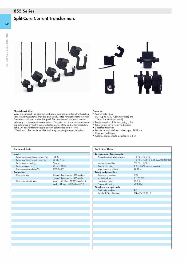
855 Series
246
INTE
RFA
CE E
LECT
RON
IC
Split-Core Current Transformers
Short description:WAGO's compact split-core current transformers are ideal for retrofit applica-tions in existing systems. They are particularly suited for applications in which the current path may not be disrupted. The transformer's accuracy permits extremely precise current measurements. The split-core current transformers are capable of supplying the specified rated power at the end of the secondary cable. All transformers are supplied with color-coded cables. Two UV-resistant cable ties for reliable and easy mounting are also included.
Features:• Current ratios from
60 A up to 1000 A (primary side) and 1 A or 5 A (secondary side)
• No interruption of the measuring cable• Ideal for use in very confined spaces• Superfast mounting• For use around insulated cables up to Ø 42 mm• Compact and hinged• Color-coded connecting cables up to 5 m
Technical DataInput:
Rated continuous thermal current Icth 100 %Rated short-time thermal current Ith 60 x Ipr / 1 sRated surge current Idyn 2.5 x IthRated frequency fR 50 Hz … 60 HzMax. operating voltage Vm 0.72/3/- kV
Connection:Conductor size 0.5 mm², fine-stranded (855-xxx1/…)
1.5 mm², fine-stranded (855-xxx5/…)Conductor identification brown = S1, blue = S2 (855-xxx1/…)
black = S1, red = S2 (855-xxx5/…)
Technical DataEnvironmental Requirements:
Ambient operating temperature -10 °C … +55 °C -10 °C … +40 °C (855-5xxx/1000-000)
Storage temperature -20 °C … +70 °CRelative humidity 5 % … 85 % (non-condensing)Max. operating altitude 2000 m
Safety and protection:Degree of protection IP20Insulation class E (120 °C)Housing material PA 6.6Flammability rating V2 (UL94)
Standards and approvals:Conformity marking 1Standards/Specifications EN 61869-2:2012

247
INTE
RFA
CE E
LECT
RON
IC
Power Cable Feed-Through
Primary Rated Current
Secondary Rated Current Rated Power Accuracy Class Cable Length Item No. Pack.
UnitØ 18 mm 60 A 1 A 0.2VA 3 3 m 855-3001/060-003 1
100 A 1 A 0.2VA 3 3 m 855-3001/100-003 1200 A 1 A 0.2VA 1 3 m 855-3001/200-001 1250 A 1 A 0.2VA 1 3 m 855-3001/250-001 1
Power Cable Feed-Through
Primary Rated Current
Secondary Rated Current Rated Power Accuracy Class Cable Length Item No. Pack.
UnitØ 18 mm 100 A 1 A 0.2VA 1 3 m 855-4001/100-001 1
150 A 1 A 0.2VA 1 3 m 855-4001/150-001 1150 A 5 A 1VA 1 0.5 m 855-4005/150-101 1200 A 1 A 0.2VA 0.5 3 m 855-4001/200-001 1
Power Cable Feed-Through
Primary Rated Current
Secondary Rated Current Rated Power Accuracy Class Cable Length Item No. Pack.
UnitØ 28 mm 200 A 1 A 0.2VA 1 3 m 855-4101/200-001 1
250 A 1 A 0.2VA 1 3 m 855-4101/250-001 1250 A 5 A 1VA 1 0.5 m 855-4105/250-101 1400 A 1 A 0.2VA 1 3 m 855-4101/400-001 1400 A 5 A 1VA 1 0.5 m 855-4105/400-101 1
Power Cable Feed-Through
Primary Rated Current
Secondary Rated Current Rated Power Accuracy Class Cable Length Item No. Pack.
UnitØ 42 mm 250 A 1 A 0.5VA 1 5 m 855-5001/250-001 1
400 A 1 A 0.5VA 0.5 5 m 855-5001/400-000 1400 A 5 A 0.5VA 1 3 m 855-5005/400-001 1600 A 1 A 0.5VA 0.5 5 m 855-5001/600-000 1600 A 5 A 0.5VA 0.5 3 m 855-5005/600-000 11000 A 1 A 0.5VA 0.5 5 m 855-5001/1000-000 11000 A 5 A 0.5VA 0.5 3 m 855-5005/1000-000 1
Power Cable Feed-Through
Primary Rated Current
Secondary Rated Current Rated Power Accuracy Class Cable Length Item No. Pack.
UnitØ Ø 42 mm x 48 1000 A 1 A 0.5VA 0.5 5 m 855-5101/1000-000 1
1000 A 5 A 0.5VA 0.5 3 m 855-5105/1000-000 1

789-654
248
INTE
RFA
CE E
LECT
RON
IC
Current Transducer for RT 2000 Rogowski Coils
U2
GND
U1
GND
U3
GND
IN (U)
OUT (I)
POWER
IL1
IN24 V
0 V
IL2
IL3
Short description:The Rogowski Current Transducer acquires 5–2000A alternating currents in a three-phase system. The magnetic field produced around each conductor is sensed via three non-contact Rogowski coils and provided as a proportional voltage signal to the signal conditioner. The current transducer adjusts the phase of each of the three voltage signals, converting them into 100mA alternating current signals. These are then transmitted to the 750-494 3-Phase Power Measurement Module.
The 750-494 3-Phase Power Measurement Module within the WAGO-I/O-SYSTEM measures electrical data (e.g., voltages, currents, effective power and energy consumption) in a three-phase supply network. Thus, the user is always able to determine the load condition (imbalance, capacitive components), to optimize consumption and protect machines or systems from damage and breakdowns. Easy installation of Rogowski coils also allows existing systems to be retrofitted without process interruption.
Description Item No. Pack. Unit
Current Transducer for RT 2000 Rogowski Coils
789-654 1
Accessories Item No. Pack. Unit
Rogowski Coil RT 2000, 1.5 m output cable 855-9100/2000-000
3
Rogowski Coil RT 2000, 3 m output cable 855-9300/2000-000
3
Technical DataInput:
Input signal 3 x RT 2000 (2000 A)Sensitivity 42.2 mV
50 Hz sinusOutputs
Output signal 3 x 100 mA ACRated output current 100 mA AC (for direct connection to
750-494 Phase Power Measurement Module)
Overcurrent 3000 A (max. 150 mA per output)
General specifications:Supply voltage range 16.8 ... 32 VMax. power consumption 4000 mWOperational indication LED, greenDegree of protection IP20Phase error < 1° Max. operating frequency 300 Hz (phase accuracy at 50 Hz only)Linearity ≤ 0.1 %Temperature coefficient ≤ 0.1 %/KTransmission error < 1.1 %Response threshold 2 A
Environmental requirements:Ambient operating temperature -25 °C ... +70 °CStorage temperature -40 °C ... +85 °C
Safety and protection:Test voltage (input/output/supply)
2.5 kV AC, 50 Hz, 1 min.Connection and type of mounting:
Wire connection CAGE CLAMP®
Cross sections 0.08 mm² ... 2.5 mm² / AWG 28 ... 12Strip lengths 5 ... 6 mm / 0.22 in
Dimensions and weight:Dimensions (mm) W x H x L 70 x 55 x 90Weight 128.3 g
Standards and approvals:Conformity marking 1
r UL 508 (pending)
Technical Data

249
INTE
RFA
CE E
LECT
RON
IC789-654
IL1
U1 U2 U3
IL2 IL3 IN
OUT
US
GND GND GND
IN
24 V
POWER
OV
13 14
750-494
L1 IL1
L2 IL2
L3 IL3
N N
789-654Rogowski - Current Transducer
CD
B
A
750-600
AI1 AI2
13 14
C
DB
A
UV1 UV2
0V 0V
S S
750-470
L1 L2 L3
X1
1
8
ON
0: WBM255: DHCP
X2
I/O
NS
MS
LINKACT 1LINKACT 2
ETHERNET
750-
880
USRSD
12
34
56
78
ON 24V 0V
+ +
— —
01 02
C
DB
A ABCD
EFGH
-US+US +US +US
-US -US
(Conductor length < 30 m)
Application example:
Recommended conductor sizes and lengths:
1 2 3 5 10 15 20 25
0.14 0.26 0.51 0.77 1.28 2.55 3.83 5.10 6.38
0.5 0.07 0.14 0.21 0.36 0.71 1.07 1.43 1.79
0.75 0.05 0.10 0.14 0.24 0.48 0.71 0.95 1.19
1 0.04 0.07 0.11 0.18 0.36 0.54 0.71 0.89
1.25 0.03 0.06 0.09 0.14 0.29 0.43 0.57 0.71
1.5 0.02 0.05 0.07 0.12 0.24 0.36 0.48 0.60
2.5 0.01 0.03 0.04 0.07 0.14 0.21 0.29 0.36
Conductor length in m Conductor sizein mm2
Conductor resistance in Ω (total value for both outgoing and return conductors)Recommendation: Select the conductor size so that the conductor resistance is ≤ 0.3 Ω.
0.34 0.11 0.21 0.32 0.53 1.05 1.58 2.10 2.63
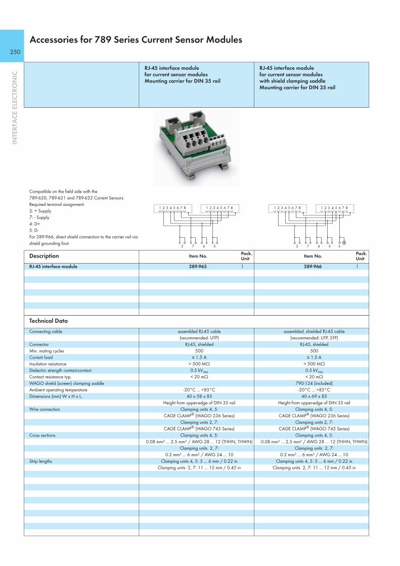
250
INTE
RFA
CE E
LECT
RON
IC
Accessories for 789 Series Current Sensor Modules
RJ-45 interface module for current sensor modules Mounting carrier for DIN 35 rail
RJ-45 interface module for current sensor modules with shield clamping saddle Mounting carrier for DIN 35 rail
Compatible on the field side with the 789-620, 789-621 and 789-622 Current Sensors. Required terminal assignment:2: + Supply 7: - Supply4: D+ 5: D- For 289-966, direct shield connection to the carrier rail via shield grounding foot.
Description Item No. Pack. Unit Item No. Pack.
UnitRJ-45 interface module 289-965 1 289-966 1
Technical DataConnecting cable assembled RJ-45 cable
(recommended: UTP)assembled, shielded RJ-45 cable
(recommended: UTP, STP)Connector RJ-45, shielded RJ-45, shieldedMin. mating cycles 500 500Current load ≤ 1.5 A ≤ 1.5 AInsulation resistance > 500 MΩ > 500 MΩDielectric strength contact-contact 0.5 kVrms 0.5 kVrmsContact resistance typ. < 20 mΩ < 20 mΩWAGO shield (screen) clamping saddle 790-124 (included)Ambient operating temperature -20°C ... +85°C -20°C ... +85°CDimensions (mm) W x H x L, 40 x 58 x 85 40 x 69 x 85
Height from upper-edge of DIN 35 rail Height from upper-edge of DIN 35 railWire connection Clamping units 4, 5:
CAGE CLAMP® (WAGO 236 Series)Clamping units 2, 7:
CAGE CLAMP® (WAGO 745 Series)
Clamping units 4, 5: CAGE CLAMP® (WAGO 236 Series)
Clamping units 2, 7: CAGE CLAMP® (WAGO 745 Series)
Cross sections Clamping units 4, 5: 0.08 mm² ... 2.5 mm² / AWG 28 ... 12 (THHN, THWN)
Clamping units 2, 7: 0.2 mm² ... 6 mm² / AWG 24 ... 10
Clamping units 4, 5: 0.08 mm² ... 2.5 mm² / AWG 28 ... 12 (THHN, THWN)
Clamping units 2, 7: 0.2 mm² ... 6 mm² / AWG 24 ... 10
Strip lengths Clamping units 4, 5: 5 ... 6 mm / 0.22 in Clamping units 2, 7: 11 ... 12 mm / 0.45 in
Clamping units 4, 5: 5 ... 6 mm / 0.22 in Clamping units 2, 7: 11 ... 12 mm / 0.45 in
1 2 3 4 5 6 7 8
2 7 4 5
1 2 3 4 5 6 7 8
1 2 3 4 5 6 7 8
S2 7 4 5
1 2 3 4 5 6 7 8

251
INTE
RFA
CE E
LECT
RON
IC

252
Thermal Transfer Printer smartPRINTER
Description Item No. Pack. Unit
smartPRINTERincludes: - Power supply unit and cable - USB cable - 1 x marking strip roll and WMB Inline markers- 2 x rollers - 1 x roll holder - 1 x ink ribbon - smartSCRIPT marking software and driver
258-5000 1
Accessories
Ink ribbon for smartPRINTER
258-5005 1
Roller for markingSTRIP
258-5006 1
Roller for WMB Inline
258-5007 1
Roller for Miniature WSB Inline
258-5008 1
Carrying case for smartPRINTERlight gray, with foam padding for printer Dimensions (W x H x D): 50 x 26 x 33 cm
258-5015 1
Technical DataPrinting method Thermal transfer Print head Glass layer, spring-mounted Print speed max. 127 mm/s
(WAGO recommends 50.8 mm/s) Print width (max.) 47 mm Print length (max.) 762 mm Print resolution 300 dpi (12 pixels/mm) Transmissive/Reflective sensor yes, centrally fixed Operating display Color TFT LCD with navigation button Memory 8 MB Flash, 16 MB SDRAM Interfaces USB, RS-232, ETHERNET 10/100 Mbps Operating voltage 100 ... 240 VAC, 50 ... 60 Hz
(automatic adjustment)Dimensions (W x H x D) 135 x 175 x 245 mm Weight 2,000 g (without printing material) Operating temperature 5 °C ... 40 °C (41 °F ... 104 °F) Storage temperature -20 °C ... 50 °C (-4 °F ... 122 °F) Safety approvals CE (EMC) Ink ribbon External roll diameter: 40 mm;
Internal core diameter: 0.5“ (12.7 mm); Max. length: 110 m; Max. width: 58 mm
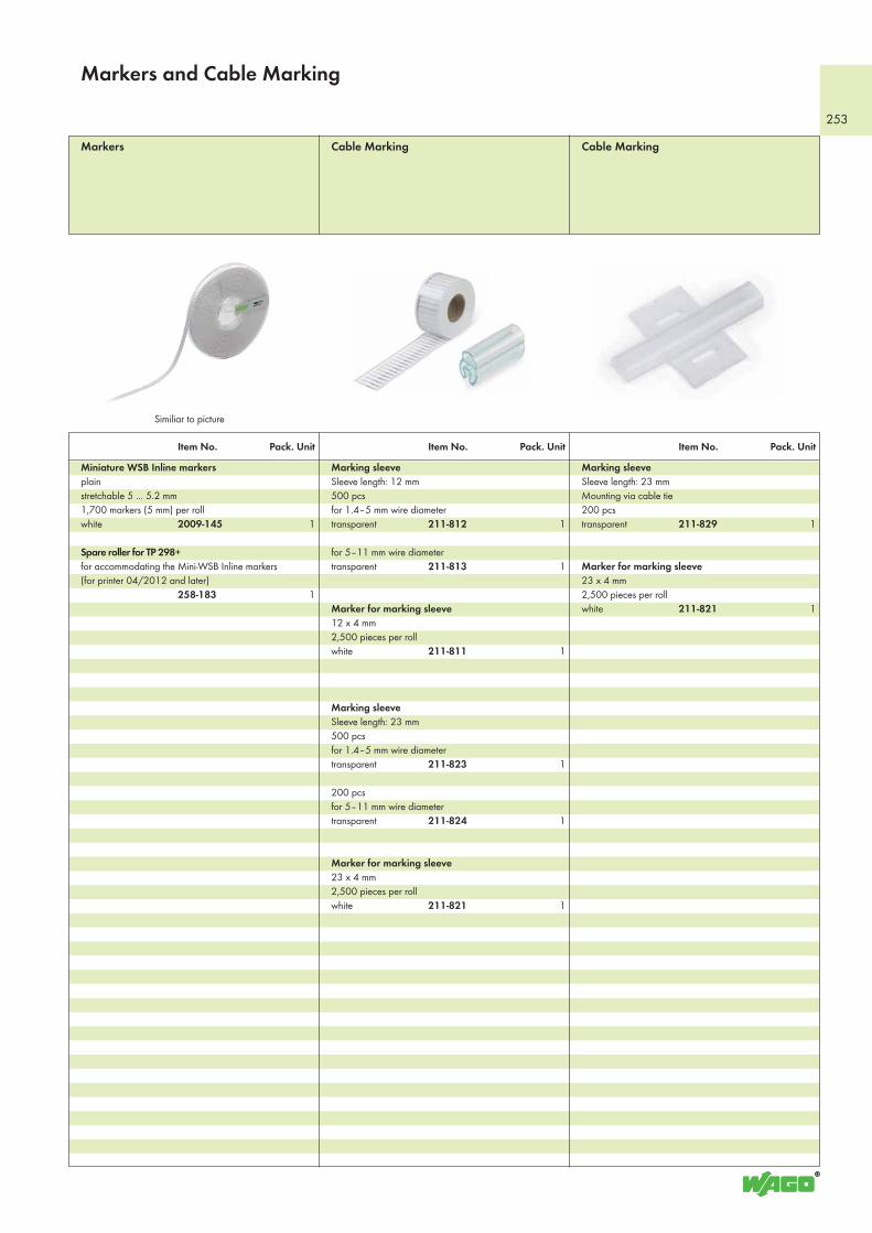
253
Item No. Pack. Unit Item No. Pack. Unit Item No. Pack. Unit
Marking sleeve Sleeve length: 12 mm500 pcsfor 1.4–5 mm wire diametertransparent 211-812 1
for 5–11 mm wire diametertransparent 211-813 1
Marker for marking sleeve12 x 4 mm2,500 pieces per rollwhite 211-811 1
Marking sleeve Sleeve length: 23 mm500 pcsfor 1.4–5 mm wire diametertransparent 211-823 1
200 pcsfor 5–11 mm wire diametertransparent 211-824 1
Marker for marking sleeve23 x 4 mm2,500 pieces per rollwhite 211-821 1
Cable MarkingCable MarkingMarkers
Marking sleeveSleeve length: 23 mmMounting via cable tie200 pcstransparent 211-829 1
Marker for marking sleeve23 x 4 mm2,500 pieces per rollwhite 211-821 1
Miniature WSB Inline markersplain stretchable 5 ... 5.2 mm1,700 markers (5 mm) per rollwhite 2009-145 1
Spare roller for TP 298+for accommodating the Mini-WSB Inline markers(for printer 04/2012 and later) 258-183 1
Markers and Cable Marking
Similiar to picture

254
Item No. Pack. Unit Item No. Pack. Unit Item No. Pack. Unit
Label rollPolyester, self-adhesive 3,000 labels per roll6 x 15 mmwhite 210-805 1yellow 210-805/000-002 1
9 x 15 mmwhite 210-806 1yellow 210-806/000-002 1
8 x 20 mmwhite 210-807 1yellow 210-807/000-002 1
9.5 x 25 mmwhite 210-808 1
5 x 35 mmwhite 210-810 1
Type platesPolyester 500 markers per roll70 x 33 mm white 210-801 1silver 210-802 1
99 x 44 mm white 210-803 1silver 210-804 1
Label rollFabric, self-adhesive 3,000 labels per roll7 x 20 mmwhite 210-811 1yellow 210-811/000-002 1
Label Rolls and Type PlatesCable Marking Cable Marking
Cable tie marker500 pieces per roll25 x 20 mm25 x 10 mm write-on surfacewhite 211-835 1
800 pieces per roll Inner wrap (write-on surface on the inner side)117.5 x 15 mm100 x 15 mm write-on surfacewhite 211-836 1
Self-laminating labels (no illustration)1,000 pieces per roll9 x 18 mm write-on surfacewhite 211-855 1
Self-laminating labels (no illustration)1,000 pieces per roll15 x 22 mm write-on surfacewhite 211-856 1
500 pieces per roll18 x 44 mm write-on surfacewhite 211-857 1
Wire marker for thread-on mounting1,000 pieces per roll0.75 … 1.5 mm²white 211-861 1
2.5 … 6 mm²white 211-862 1
6 … 16 mm²white 211-863 1
Similiar to picture Similiar to picture
Cable Marking and Labels

255
Item No. Pack. Unit Item No. Pack. Unit Item No. Pack. Unit
Push-button markerssemi-permanent adhesive1000 markers per roll26.5 x 18 mm silver 210-850 1
Plastic cover100 covers26.5 x 18 mm transparent 210-851 1
Push-button markerssemi-permanent adhesive1000 markers per roll27.5 x 17.5 mm silver 210-856 1
Plastic cover100 covers27.5 x 17.5 mm transparent 210-857 1
Push-button markerspermanent adhesive1000 markers per roll22 x 22 mm silver 210-858 1
Plastic cover100 covers22 x 22 mm transparent 210-859 1
Push-button markerspermanent adhesive1000 markers per roll27 x 27 mm silver 210-860 1
Plastic cover100 covers27 x 27 mm transparent 210-861 1
Push-Button Markers
Push-button markerspermanent adhesive1000 markers per roll27 x 12.5 mm silver 210-862 1
Plastic cover100 covers27 x 12.5 mm transparent 210-863 1
Push-button markerspermanent adhesive350 markers per roll27 x 19 mm silver 210-852 1
Push-button markerspermanent adhesive350 markers per roll27 x 18 mm silver 210-855 1
Universal push-button framefor push-button markers 210-852 and 210-855100 pcs per bag27 x 19 mm black 210-853 1
Label roll DD (device designation)Polyester 500 labels per roll28 x 28 mm175 μm thicksilver 210-854 1
Push-Button MarkersContinuous Labels
Continuous labelsPolyester, self-adhesive 9 lengths at 25 mWidth: 2.3 mmwhite 210-831 1
Width: 3 mmwhite 210-832 1
5 lengths at 25 mWidth: 5 mmwhite 210-834 1
Width: 6 mmwhite 210-833 1
Lables and Push-Button Markers

Test and Measurement Tools
Application Notes
Item No. Pack. Unit
Clamp MeterClamp-Multi-Tester
Clamp-Multi-Tester, digital clamp meter- DC and AC current up to 600 A- True RMS and min./max. value measurement- DC and AC voltage up to 600 V- Manual or automatic selection of measurement range- Resistance up to 60 MΩ- Capacitance measurement- Acoustical continuity test- Diode test- Data hold function- Large LCD with backlight- LED measuring point lighting- CAT III 600 V overvoltage protection- IEC/EN 61010-1 (DIN VDE 0411)- Including batteries, measurement leads and carrying bag
206-816 1
Current measurement in switchgear cabinet
Voltage testing in switchgear cabinet
256

257

Item No. Page Item No. Page Item No. Page Item No. Page
Item Number Index16 Bit)
Products highlighted in RED are new items for Autumn 2014
206 Series
206-701 118
206-816 236
210 Series
210-719 80210-801 254210-802 254210-803 254210-804 254210-805 254210-805/000-002 254210-806 254210-806/000-002 254210-807 254210-807/000-002 254210-808 254
210-810 254210-811 254210-811/000-002 254
210-831 255210-832 255210-833 255210-834 255
210-850 255210-851 255210-852 255210-853 255210-854 255210-855 255210-856 255210-857 255210-858 255210-859 255210-860 255210-861 255210-862 255210-863 255
211 Series
211-811 253211-812 253211-813 253
211-821 253211-823 253211-824 253211-829 253
211-835 254211-836 254211-855 254211-856 254211-857 254
211-861 254211-862 254211-863 254
248 Series
248-501 10
258 Series
258-183 253
258-5000 252
258-5005 252258-5006 252258-5007 252258-5008 252258-5015 252
280 Series
280-504/281-582 233280-504/281-583 233280-504/281-584 233280-504/281-585 233280-504/281-586 233280-504/281-587 233280-504/281-588 233
280-944/281-589 233280-944/281-590 233280-944/281-591 233280-944/281-592 233280-944/281-593 233280-944/281-594 233280-944/281-595 233
286 Series
286-573 160286-574 160286-575 160
288 Series
288-825 170288-837 170288-867 171
289 Series
289-128 172289-128/001-000 172289-128/002-000 172289-128/003-000 172289-128/005-000 172289-128/006-000 172289-179 169
289-707 168289-708 168289-710 168289-713 168289-714 168
289-965 250289-966 250
704 Series
704-2003 176704-2004 177704-2024 177704-2044 178704-2054 178704-8012 179704-8013 179
706 Series
706-2300/100-100 180706-2300/100-200 180706-2300/100-300 180706-2300/101-100 180
706-2300/101-200 180706-2300/101-300 180
706-2300/200-100 181706-2300/200-200 181706-2300/200-300 181706-2300/201-100 181706-2300/201-200 181706-2300/201-300 181
706-2300/300-100 182706-2300/300-200 182706-2300/300-300 182706-2300/301-100 182706-2300/301-200 182706-2300/301-300 182
706-2300/400-100 183706-2300/400-200 183706-2300/400-300 183706-2300/404-100 184706-2300/404-200 184706-2300/404-300 184706-2300/406-100 184706-2300/406-200 184706-2300/406-300 184
706-2300/500-100 185706-2300/500-200 185706-2300/500-300 185706-2300/502-100 185706-2300/502-200 185706-2300/502-300 185
706-7753/300-100 128706-7753/301-200 128
750 Series
750-106 129750-107 129
750-315/300-000 38750-316/300-000 40750-333/040-000 74750-338/040-000 78750-352/040-000 76 750-354/000-001 36750-375 32750-375/025-000 32750-377 34 750-377/025-000 34
750-407/040-000 82750-439 62750-450 44750-451 45750-453/040-000 86750-455/040-000 86750-457/040-000 88750-464/040-000 89750-468/040-000 87750-469/040-000 90750-494 46750-494/000-001 46750-494/025-000 46750-494/025-001 46750-495 47750-495/000-001 47750-495/000-002 47
750-508/040-000 83750-517/040-000 85750-538 64750-557/040-000 92750-559/040-000 92750-563/040-000 91750-586 66
750-600/040-000 101750-602/040-000 94
750-612/040-000 95750-613/040-000 96750-624/040-001 97750-626/040-000 98750-632 49750-652/040-000 93750-658 48750-663/000-003 60
750-815/300-000 22750-815/325-000 22750-816/300-000 24
750-829 28750-831 26750-838/040-000 72750-852 20750-880/040-000 70750-880/040-001 70 750-885 18750-885/025-000 18750-889 30
750-1405/040-000 81750-1415/040-000 80750-1425 42
750-1515/040-000 84
750-1605/040-000 99750-1606/040-000 100
750-8202 10750-8202/025-000 10750-8202/025-001 10750-8202/025-002 10750-8203 12750-8203/025-000 12750-8204 14750-8204/025-000 14750-8206 16750-8206/025-000 16750-8206/025-001 16
753 Series
753-110 50753-150 50
753-620 54753-647 52753-648 50
756 Series
756-1601/060-020 116756-1601/060-050 116756-1601/060-100 116756-1601/060-200 116756-1602/060-020 116756-1602/060-050 116756-1602/060-100 116756-1602/060-200 116756-1603/060-020 116756-1603/060-050 116756-1603/060-100 116756-1603/060-200 116756-1604/060-020 116756-1604/060-050 116756-1604/060-100 116756-1604/060-200 116
756-5311/090-015 119756-5311/090-050 119756-5311/090-100 119756-5312/090-015 119756-5312/090-050 119
258

Item No. Page Item No. Page Item No. Page Item No. Page
756-5312/090-100 119
756-9211/090-000 119756-9214/090-000 119756-9217/050-000 117756-9406/050-000 117
757 Series
757-801 120
758 Series
758-879/000-001 10
758-916 121758-917 121
759 Series
759-200 124759-200/000-002 124
759-302 49759-333 10759-333/000-923 70
761 Series
761-114 122
761-217 123
767 Series
767-125 117767-126 117767-1311 102
767-3806 104
767-4808 106
767-5201 110767-5202 112767-5204 114767-5401 108
787 Series
787-1007 55787-1014 201787-1014/072-000 200787-1017 199787-1020 198
787-1601 207787-1602 211787-1606 212787-1611 208787-1616 213787-1616/000-1000 214787-1621 209787-1622 215787-1623 218787-1631 210787-1632 216787-1633 219787-1634 217787-1635 220
787-1662 221787-1662/006-1000 227787-1662/106-000 222787-1664/000-004 224787-1664/006-1000 228787-1664/106-000 223787-1668/000-004 226787-1668/006-1000 229787-1668/106-000 225
787-2852 232
787-734 202787-736 203787-738 204787-740 205787-742 206787-783 230787-785 231
788 Series
788-148 156
788-323 150788-333 150788-337 150788-353 152788-356 153788-357 154788-390 155788-391 155
788-906 151
789 Series
789-320 161789-321 162789-324 163789-326 164789-520 162
789-654 248
789-800 165789-801 165789-802 166789-803 166789-804 167
852 Series
852-1111 126
855 Series
855-2701/035-001 244855-2701/064-001 244
855-3001/060-003 247855-3001/100-003 247855-3001/200-001 247855-3001/250-001 247
855-301/050-103 242855-301/060-101 242855-301/075-201 242855-301/100-201 242855-301/150-501 242855-301/200-501 242855-301/250-501 242855-301/400-1001 242855-301/600-1001 242
855-305/050-103 242855-305/060-101 242855-305/075-201 242855-305/100-201 242855-305/150-501 242855-305/200-501 242855-305/250-501 242855-305/400-1001 242855-305/600-1001 242
855-4001/100-001 247855-4001/150-001 247855-4001/200-001 247855-4005/150-001 247855-401/400-501 242855-405/400-501 242
855-4101/200-001 247855-4101/250-001 247855-4101/400-001 247855-4105/250-001 247855-4105/400-001 247
855-5001/1000-000 247855-5001/250-001 247855-5001/400-000 247855-5001/600-000 247855-5005/1000-000 247855-5005/400-000 247855-5005/600-000 247
855-501/1000-1001 242855-505/1000-1001 242
855-5101/1000-000 247855-5105/1000-000 247
855-9100/500-000 240855-9100/2000-000 241855-9300/500-000 240855-9300/2000-000 241
855-9900 242855-9910 242855-9927 244
857 Series
857-358/006-000 144857-368/006-000 144857-604 145857-624 146857-634 147857-640 148857-642 149
858 Series
858-305 157858-307 157858-308 157858-354 159858-355 159
858-504 157858-507 157858-514 158858-517 158
859 Series
859-312 132859-356 132859-384 133859-386 133859-392 133859-397 133
859-399 133859-707 137859-710 136859-711 136859-732 142859-734 141859-737 134859-738 135859-739 135859-744 134859-750 140859-751 140859-753 138859-755 138859-759 139859-760 141859-761 143859-762 143859-798 142
2009 Series
2009-110 1292009-115 129
2009-145 253
2759 Series
2759-0101 4
2851 Series
2851-8201 582851-8202 582851-8301 562851-8302 562851-8303 56
2854 Series
2854-0300/1008-0002 1302854-0300/1008-0032 1302854-0300/1008-8002 1302854-0300/1008-8032 1302854-0300/1016-0002 1302854-0300/1016-0032 1302854-0300/1016-8002 1302854-0300/1016-8032 1302854-0300/1024-0002 1302854-0300/1024-0032 130
2857 Series
2857-101 2362857-102 2362857-103 2362857-121 2372857-122 2372857-123 2372857-124 237
2857-191/3140-000 2382857-192/3140-000 2382857-193/3140-000 2382857-194/3140-000 239
2857-401 186
2857-533 1882857-534 1722857-550 192
2857-900 194
259

Algeriaplease contact WAGO France
ArgentinaBruno Schillig S.A.Arenales 4030, B1604CFDFlorida, PBAPhone +54 11 4730 1100Fax +54 11 4761 [email protected]
AustraliaKontact GroupBuilding Automation & WINSTA SystemsOffice: 730 Springvale RdMulgrave Victoria 3170P.O. Box 3003, Wheelers Hill VIC 3150Tel. +61 03 95602757Fax +61 03 [email protected]
NHP ELECTRICAL ENGINEERINGPRODUCTS PTY LTD43-67 River StreetRichmond, Victoria, 3121, P.O. Box 199Phone +61 3 9429 2999Fax +61 3 9429 [email protected]
AustriaWAGO Kontakttechnik Ges.m.b.H.Laxenburger Straße 2441230 WienPhone +43 1 6150780Fax +43 1 [email protected]
AzerbaijanAZ Technics LTDZulfi V. AlizadeY.Safarov str.33 , AZ1025,BakuRepublic of AzerbaijanTel. +994 12 4968335Fax +994 12 [email protected]
BelarusOOO FEKpr-t Pushkina 29-B220015 MinskPhone +375 17 2102189Fax +375 17 [email protected]
UE ATAVAul. Denisovskaya, 47, office 1220006 MinskPhone +375 17 2054015Fax +375 17 2851759
BelgiumWAGO KontakttechnikExcelsiorlaan 111930 ZaventemPhone +32 2 7179090Fax +32 2 [email protected]
BoliviaKoln s.r.l.Barrio ConvifagC/Toborrochi #6, Zona NorteSanta CruzTel. +591 3 3120272Fax +591 3 3120272
Bosnia and Herzegovinaplease contact WAGO Bulgaria
BrazilWAGO Eletroeletrônicos LtdaRua Américo Simões 1470São Roque da ChaveItupeva SP Brasil 13295-000Phone +55 11 4591 0199Fax +55 11 4591 [email protected]
BulgariaWAGO Kontakttechnik GmbH & Co. KG/Representative Office SofiaBusiness Center Serdika2E Akad. Ivan Geshov Blvd. Building 1, Floor 4, Office 4171330 SofiaTel. +359 2 489 46 09Fax +359 2 928 28 [email protected]
Canadaplease contact WAGO USA
ChileDesimat ChileAv Puerto Vespucio 9670Pudahuel SantiagoPhone +56 2 7470152Fax +56 2 [email protected]
ChinaWAGO ELECTRONIC (TIANJIN) Co. LTDNo.5, Quan Hui Road, Wuqing Development AreaTianjin 301700Phone +86 22 59617688Fax +86 22 [email protected]
ColumbiaT.H.L. Ltda.Cra. 49 B # 91-33BogotáPhone +57 1 621 85 50Fax +57 1 621 60 [email protected]
CroatiaM.B.A. d.o.o. za trgovinu i zastupanjeFrana Supila 551211 Matulji HRPhone +385 51 275-736Fax +385 51 [email protected]
GENERA CTR d.o.o.- just for automation technology - Siget 18 b10020 ZagrebPhone +385 13647849Fax +385 [email protected]
Czech RepublicWAGO Elektro spol. sr. o.Rozvodova 1116/36143 00 Praha 4 - ModřanyPhone +420 261 090 143Fax +420 261 090 [email protected]
DenmarkWAGO DanmarkFilial of WAGO Kontakttechnik GmbH & Co. KGLejrvej 173500 VærløsePhone +45 44 357777Fax +45 44 [email protected]
EcuadorECUAINSETEC CIA LTDAEl Zurriago E9-32 y el VengadorQuitoTel. +593 2 2 26 91 48Fax +593 2 2 46 18 [email protected]
EgyptIBN Engineering Instrumentation & Control71 a El Shaheed Ahmed Hamdi St.King Faisal, GizaPhone +20 2 7214350Fax +20 2 [email protected]
EstoniaEltarko OÜLaki 14 - 50210621 TallinnPhone +372 651 7731Fax +372 651 [email protected]
FinlandWAGO Kontakttechnik GmbH & Co. KGFilial i FinlandVellamonkatu 30 B00550 HelsinkiPhone +358 9 7744 060Fax +358 9 7744 [email protected]
FranceWAGO CONTACT SASParis Nord 283 Rue des ChardonneretsB.P. 55065 - Tremblay en France95947 - ROISSY CDG CEDEXPhone +33 1 48172590Fax +33 1 [email protected]
GermanyWAGO Kontakttechnik GmbH & Co. KGPostfach 28 80, 32385 MindenHansastraße 2732423 MindenPhone +49 571 887-0Fax +49 571 [email protected]
WAGO Kontakttechnik GmbH & Co. KGWaldstraße 199706 SondershausenPhone +49 3632 659-0Fax +49 3632 [email protected]
Great BritianWAGO LimitedTriton Park, Swift Valley Industrial EstateRUGBYWarwickshire, CV21 1SGPhone +44 1788 568008Fax +44 1788 [email protected]
GreecePANAGIOTIS SP. DIMOULAS - BIOMATDIMOULAS AUTOMATIONSKritis Str. 2610439 AthenTel. +30 210 883 3337Fax +30 210 883 [email protected]
HondurasCILASAS S.A. de C.V.Barrio Los Andes7 Calle entre 14 y 15 Ave. N.O.P.O. Box. 1061San Pedro SulaTel. +504 25571146/7Fax +504 25571149
Hong KongNational Concord Eng., Ltd.Unit A-B, 5/F.Southeast Industrial Building611-619 Castle Peak RoadTsuen Wan, N.T.Phone +852 24292611Fax +852 [email protected]
HungaryWAGO Hungá¡ria KFTIpari Park, Gyár u. 22040 BudapestPhone +36 23 502-170Fax +36 23 [email protected]
IcelandS. Gudjonsson ehf.Audbrekku 9-11202 KopavogurPhone +354 520-4500Fax +354 [email protected]
IndiaWAGO LTD.C-27, Sector-58, Phase-IIINoida-201 301Gautam Budh Nagar (U.P)Tel. +91 120 2 580409 10Fax +91 120 2 [email protected]
Indonesiaplease contact WAGO Singapore
Iraqplease contact WAGO Middle East
IrelandDrives & ControlsUnit F4, Riverview Business ParkNangor RoadDublin 12Phone +353 1 4604474Fax +353 1 [email protected]
IsraelComtel Israel Electronic Solutions Ltd.Bet Hapaamon20 Hataas StreetP.O. Box 6644425 Kefar-SabaPhone +972 9 76 77 240Fax +972 9 76 77 [email protected]
ItalyWAGO ELETTRONICA SRL a Socio UnicoVia Parini 140033 Casalecchio di Reno (BO)Tel. +39 051 6132112Fax +39 051 [email protected]
JapanWAGO Co. of JAPAN Ltd.Nittetsu ND-Tower Building 4F5-7, Kameido 1-chomeKoto-KuTokyo 136-0071Tel. +81 3 5627 2050Fax +81 3 5627 [email protected]
Jordanplease contact WAGO Middle East
KazakhstanTOO INTANTul. Muratbaeva, d. 61050026 AlmatyTel. +7 727 2371492Fax +7 727 [email protected]
TOO Technik-Tradeul. i. A. Protosanova, 81070004 Ust-KamenogorskTel. +7 7232 254064Fax +7 7232 [email protected]
ITC Electronics: AlmatyProspekt Raiymbeka 221 ?/4050016 AlmatyKazakhstanTel. +7 727 2797117Fax +7 727 2339344
KoreaWAGO Korea Co., Ltd.#205 Anyang Mega ValleyDongan-gu, Anyang-siKyunggi-do, South KoreaPhone +82 3142 [email protected]
Kosovoplease contact WAGO Bulgaria
LatviaINSTABALT LATVIA SIAVestienas iela 6Rīga, LV-1035Phone +371 790 1188Fax +371 790 [email protected]
LebanonGemayel Trading & ContractingAntonins ProjectP.O. BOX 70-1096 Antelias, LebanonPhone +961 4 521 029Fax +961 4 521 [email protected]
LithuaniaINSTABALT LIT UABSavanorių 187Vilnius, 2053Phone +370 52 322 295Fax +370 52 322 [email protected]
WAGO Worldwide – Companies and Representatives –
260

Luxembourgplease contact WAGO Belgium
Macedoniaplease contact WAGO Bulgaria
Kompjunet InzeneringVladimir Komarov 1A-3/91000 SkopjeRepublic of MacedoniaTel. +389 2 521 12 00Tel. +389 2 246 11 08
MalaysiaWAGO Representative Office MalaysiaNo 806, Block A4, Leisure Commerce Square,No 9, Jalan PJS 8/9, 46150 Petaling Jaya,Selangor Darul Ehsan, MalaysiaTel. +60 3 7877 1776Fax +60 3 7877 [email protected]
HPH Materials (M) Sdn BhdNo. 4, Jalan Nilam 1/6Suban Hi-Tech Industrial Park40000 Shah AlamSelangor, D.E. MalaysiaTel. +60 3 5638 2213Fax +60 3 5638 [email protected]
Setia Raya Teknik Sdn. Bhd.40 & 42 Jalan SS15/4Subang Jaya, 47500 P.J.Selangor D.E. MalaysiaTel. +60 3 5633 5511Tel. +60 3 5633 [email protected]
MexicoWAGO SA de CVAv. Del Marques 38 Bodega 3P. I. Bernardo Quintana76240 El Marques, QuerétaroPhone +52 442 221 5946Fax +52 442 221 5063Toll-Free: [email protected]
MoldovaElectroservice Slavinschi T.T.str. Bolgarskaia 9, office 62001 KishinevPhone +373 22 274427Fax +373 22 [email protected]
Moroccoplease contact WAGO France
NetherlandsWAGO NederlandLaan van de Ram 197234 BW APELDOORNTel. +31 55 36 83 500Fax +31 55 36 83 [email protected]
New ZealandNHP NZ7 Lockhart PlaceMt WellingtonNew ZealandPhone +64 9 2761967Fax +64 9 [email protected]
NigeriaGIL Automations Ltd.Daily Times Complex2 Lateef Jakande Rd., Agidingbi100271 Ikeja, Lagos StateTel. +234 [email protected]
NorwayWAGO Norge NUFJerikoveien 201067 OsloPhone +47 22 30 94 50Fax +47 22 30 94 [email protected]
Omanplease contact WAGO Middle East
PakistanFuziLogiX Automation & ControlSuit No. 14, 5th Floor, Shan ArcadeNew Garden Town, LahorePakistanPhone +92 42 594 1503 - 4Fax +92 42 585 [email protected]
PeruManufacturas Eléctricas S.A.Av O.R. Benavides 121515000 LimaTel. +511 6196200Fax +511 6196247
Philippinesplease contact WAGO Singapore
PolandWAGO ELWAG sp. z o. o.ul. Piękna 58 a50-506 WrocławPhone +48 71 3602970Fax +48 71 [email protected]
PortugalMORGADO & CA. LDA - SEDEEstrada Exterior daCircunvalação 3558/3560Apartado 10574435 Rio TintoPhone +351 22 9770600Fax +351 22 [email protected]
Quatarplease contact WAGO Middle East
RomaniaWAGO Kontakttechnik GmbH & Co. KG/Representative Office BukarestStr. Nicolae G. Caramfil Nr. 26Bl. 1D, Et. 3, Ap. 7, Sect. 1, OP 52014144-BucurestiTel. +40-(0)31 421 85 [email protected]
VDR & Servicii srlStr. Valeriu Branişte, nr. 60, ap.1, sector 3RomaniaTel. +40 21 3225074/76Fax +40 21 [email protected]
RussiaООО WAGO Kontakt RusDmitrovskoe shosse, 157, bldg. 12/5 127411 MoscowRussiaPhone +7 495 663-3305Fax +7 495 [email protected]
WAGO Branch officeEkaterinburgTel. +7 343 216 3426
WAGO Branch officeNovosibirskTel. +7 383 217 9244
WAGO Branch officeSt. PetersburgTel. +7 812 312 1918
Saudi ArabiaSaudi Electronic Trading Company (SETRA)P.O. Box 6071211555-RiyadhTel. +966 1 2062277Fax +966 1 [email protected]
Serbiaüber WAGO Bulgarien
Avalon Partners dooPatrijarha Dimitrija 2411000 BeogradTel. +381 11 2685311Fax +381 11 [email protected]
Sigma dooBalzakova 321000 Novi SadTel. +381 21 468431Fax +381 21 [email protected]
SingaporeWAGO Electronic Pte Ltd10 Upper Aljunied Link#04-04 Johnson Controls BuildingSingapore 367904Phone +65 62866776Fax +65 [email protected]
SlovakiaWAGO Elektrik spol. s r. oOdborárska 5283102 BratislavaTel. +421 2 [email protected]
Proelektro spol. s r.o.Na barine 22841 03 Bratislava - LamačTel. +421 2 4569 2503 [email protected]
SloveniaGENERA d.o.o.Prevale 101236 TrzinPhone +386 14393050Fax +386 [email protected]
IC elektronika d.o.o.Vodovodna cesta 1001000 LjubljanaPhone +386 15680110Fax +386 [email protected]
South AfricaShorrock Automation (Pty) LtdPostnet Suite # 219Private Bag X 8,Elardus Park0047 PRETORIATel. +27 12 4500300Fax +27 12 [email protected]
SpainDICOMAT S.L.Avda. de la Industria, 36Apartado Correos, 1.17828108 - Alcobendas (Madrid)Phone +34 91 6621362Fax +34 91 [email protected]
SwedenWAGO SverigeWAGO Kontakttechnik GmbHTyskland FilialBox 11127, 161 11 BROMMABesöksadress: Adolfsbergsv. 31Tel. +46 858410680Fax +46 [email protected]
SwitzerlandWAGO CONTACT SARte. de l’Industrie 19Case Postale 1681564 DomdidierPhone +41/26 676 75 86Fax +41/26 676 75 [email protected]
SyriaZahabi Co.8/5 Shouhadaa St., P.O. Box 8262AleppoPhone +963 21 21 22 235 / 6Fax +963 21 21 24 [email protected]
Taiwan R.O.C.WAGO Contact, Ltd.5F., No.168, Jiankang RdZhonghe CityTaipei County 23585, TaiwanPhone +886 2 22250123Fax +886 2 [email protected]
ThailandWAGO Representative Office Thailand4th Floor, KS Building213/6-8 Rachada-Phisek RoadDingdaeng, Bangkok 10320Tel. +66 2 6935611Fax +66 2 [email protected]
US Power Distribution Co., Ltd.4th Floor K.S. Building213/6-8 Rachada Phisek RoadDing Daeng, Bangkok 10400Tel. +66 2 2763040Fax +66 2 [email protected]
Tunisiaplease contact WAGO France
TurkeyWAGO Elektronik Sanayi ve Ticaret Ltd. Şti.Yukan Dudullu Mahallesi Bayraktar BulvanCad. Hattat Sok. No. 1034775 Ümraniye - IstanbulTurkeyTel. +90 216 472 1133Fax +90 216 472 [email protected]
UkraineNPP LogiconPredslavinskaya street, 39, office 30303150 KievTel. +380 44 5228019Fax +380 44 [email protected]
OOO Mikropriborul. Kotelnikova, 403115 KievTel. +380 44 5369386Fax +380 44 [email protected]
ITC Electronics: Kievpr. Vossoyedineniya 7aoffice 10702160 KievTel. +38 44 5596890Fax +38 44 [email protected]
United Arab Emirates (UAE)WAGO Middle East (FZC)SAIF Zone, Q4-282P.O. Box: 120665Sharjah, UAEPhone +971 6 5579920Fax +971 6 [email protected]
USAWAGO CorporationN120 W19129 Freistadt RoadGermantown, WI 53022Phone +1 262 255 6222Fax +1 262 255 3232Toll-Free: 1-800 DIN Rail (346-7245)[email protected]
VenezuelaPETROBORNAS, C.A.C.C. PLAZA AEROPUERTO - PISO 1 - LOCAL P1 - B - 03(8015) UNARE - PUERTO ORDAZ - ESTADO BOLÍVARREPÚBLICA BOLIVARIANA DE VENEZUELATel. +58 286 951 3382Fax +58 286 951 [email protected]
Vietnamplease contact WAGO Germany (Minden)
Version: 10/2014Current addresses at www.wago.com
261


0888
-100
2/02
14-6
901
· Sup
pl. C
at. A
utom
atio
n · U
S · 2
014/
2 - P
rinte
d in
Ger
man
y - S
ubje
ct to
des
ign
chan
ges
WAGO Kontakttechnik GmbH & Co. KGPostfach 2880 · D - 32385 MindenHansastraße 27 · D - 32423 MindenGermanyPhone: +49 571 887 - 0Fax: +49 571 887 - 169E-Mail: [email protected]: www.wago.com