Embed Size (px)
Citation preview
6
32
116
428
522
538
556
578
44
392
600
692
710
716
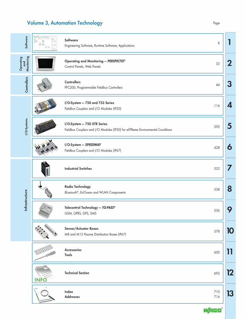
Page
I/O-System — SPEEDWAY
Fieldbus Couplers and I/O Modules (IP67)
Software
Engineering Software, Runtime Software, Applications
Sensor/Actuator Boxes
M8 and M12 Passive Distribution Boxes (IP67)
Operating and Monitoring — PERSPECTO®
Control Panels, Web Panels
Radio Technology
Bluetooth®, EnOcean and WLAN Components
Telecontrol Technology — TO-PASS®
GSM, GPRS, GPS, SMS
Industrial Switches
Controllers
PFC200, Programmable Fieldbus Controllers
I/O-System — 750 XTR Series
Fieldbus Couplers and I/O Modules (IP20) for eXTReme Environmental Conditions
I/O-System — 750 and 753 Series
Fieldbus Couplers and I/O Modules (IP20)
Volume 3, Automation Technology
Accessories
Tools
Technical Section
Index
Addresses
So
ftw
are
Op
era
tin
g
an
d
Mo
nit
ori
ng
Co
ntro
llers
I/O
-Sy
ste
ms
Infr
ast
ruct
ure
1
2
3
5
6
7
8
9
10
11
12
13
4
S
2
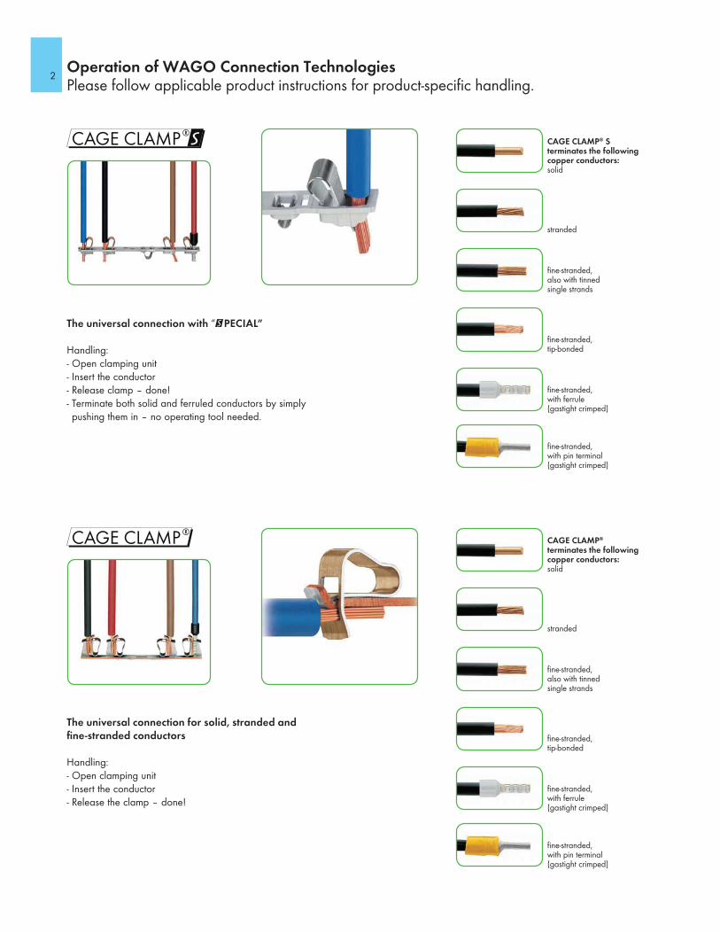
The universal connection for solid, stranded and fine-stranded conductors
Handling:- Open clamping unit- Insert the conductor- Release the clamp – done!
Operation of WAGO Connection TechnologiesPlease follow applicable product instructions for product-specific handling.
CAGE CLAMP® S terminates the following copper conductors:solid
stranded
fine-stranded, also with tinned single strands
fine-stranded, tip-bonded
fine-stranded, with ferrule (gastight crimped)
fine-stranded, with pin terminal (gastight crimped)
CAGE CLAMP® terminates the following copper conductors:solid
stranded
fine-stranded, also with tinned single strands
fine-stranded, tip-bonded
fine-stranded, with ferrule (gastight crimped)
fine-stranded, with pin terminal (gastight crimped)
The universal connection with “@PECIAL”
Handling:- Open clamping unit- Insert the conductor- Release clamp – done!- Terminate both solid and ferruled conductors by simply pushing them in – no operating tool needed.
3
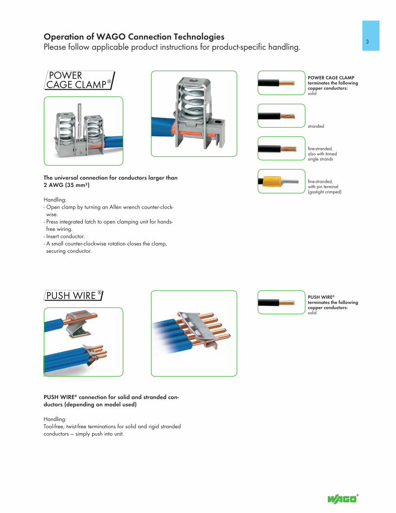
PUSH WIRE® connection for solid and stranded con-ductors (depending on model used)
Handling:Tool-free, twist-free terminations for solid and rigid stranded conductors — simply push into unit.
Operation of WAGO Connection TechnologiesPlease follow applicable product instructions for product-specific handling.
POWER CAGE CLAMP terminates the following copper conductors:solid
stranded
fine-stranded, also with tinned single strands
fine-stranded, with pin terminal (gastight crimped)
PUSH WIRE® terminates the following copper conductors:solid
The universal connection for conductors larger than 2 AWG (35 mm²)
Handling:- Open clamp by turning an Allen wrench counter-clock-wise.
- Press integrated latch to open clamping unit for hands-free wiring.
- Insert conductor.- A small counter-clockwise rotation closes the clamp, securing conductor.
S
oft
wa
reO
pe
rati
ng
& M
on
ito
rin
g C
on
tro
llers
I/
O-S
yst
em
sIn
fra
stru
ctu
re
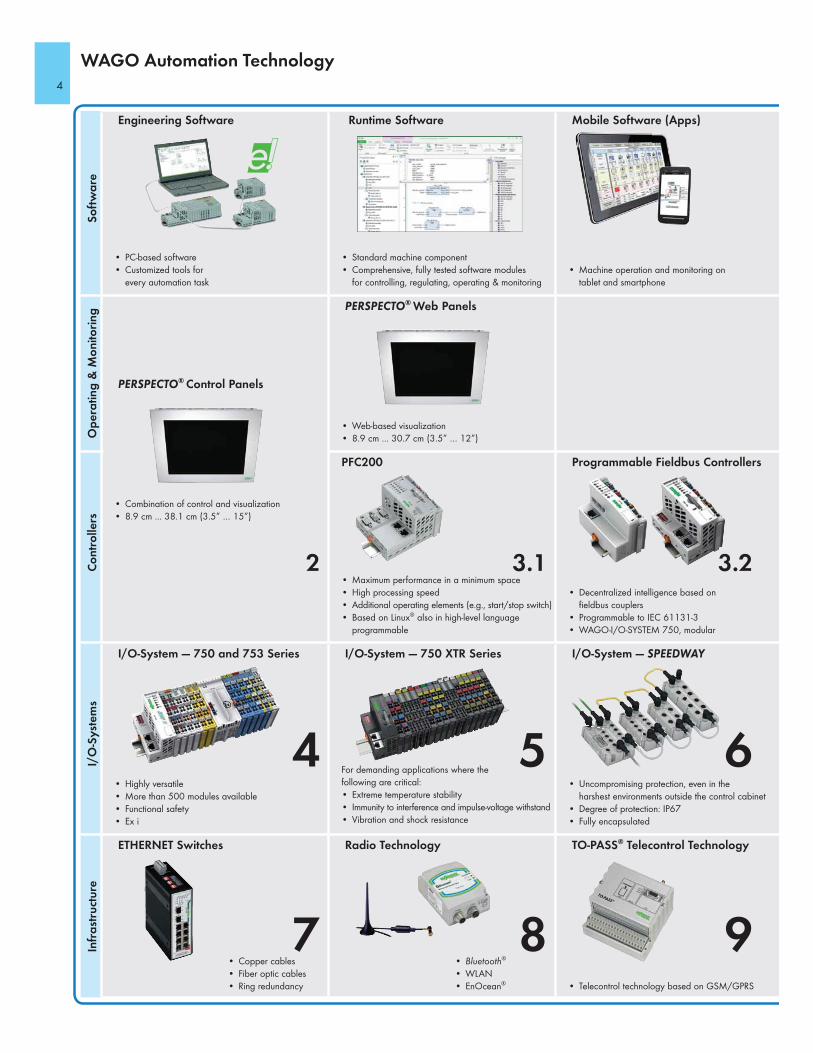
Engineering Software Runtime Software Mobile Software (Apps)
PERSPECTO® Web Panels
WAGO Automation Technology
PERSPECTO® Control Panels
Programmable Fieldbus ControllersPFC200
I/O-System — 750 and 753 Series I/O-System — 750 XTR Series I/O-System — SPEEDWAY
ETHERNET Switches Radio Technology TO-PASS® Telecontrol Technology
• Copper cables
• Fiber optic cables
• Ring redundancy
• Bluetooth®
• WLAN
• EnOcean®
• Telecontrol technology based on GSM/GPRS
• Uncompromising protection, even in the
harshest environments outside the control cabinet
• Degree of protection: IP67
• Fully encapsulated
For demanding applications where the
following are critical:
• Extreme temperature stability
• Immunity to interference and impulse-voltage withstand
• Vibration and shock resistance
• Highly versatile
• More than 500 modules available
• Functional safety
• Ex i
• Maximum performance in a minimum space
• High processing speed
• Additional operating elements (e.g., start/stop switch)
• Based on Linux® also in high-level language
programmable
• Combination of control and visualization
• 8.9 cm ... 38.1 cm (3.5” … 15”)
• Decentralized intelligence based on
fieldbus couplers
• Programmable to IEC 61131-3
• WAGO-I/O-SYSTEM 750, modular
• Web-based visualization
• 8.9 cm ... 30.7 cm (3.5” … 12”)
• PC-based software
• Customized tools for
every automation task
• Standard machine component
• Comprehensive, fully tested software modules
for controlling, regulating, operating & monitoring
• Machine operation and monitoring on
tablet and smartphone
3.23.12
654
987
4
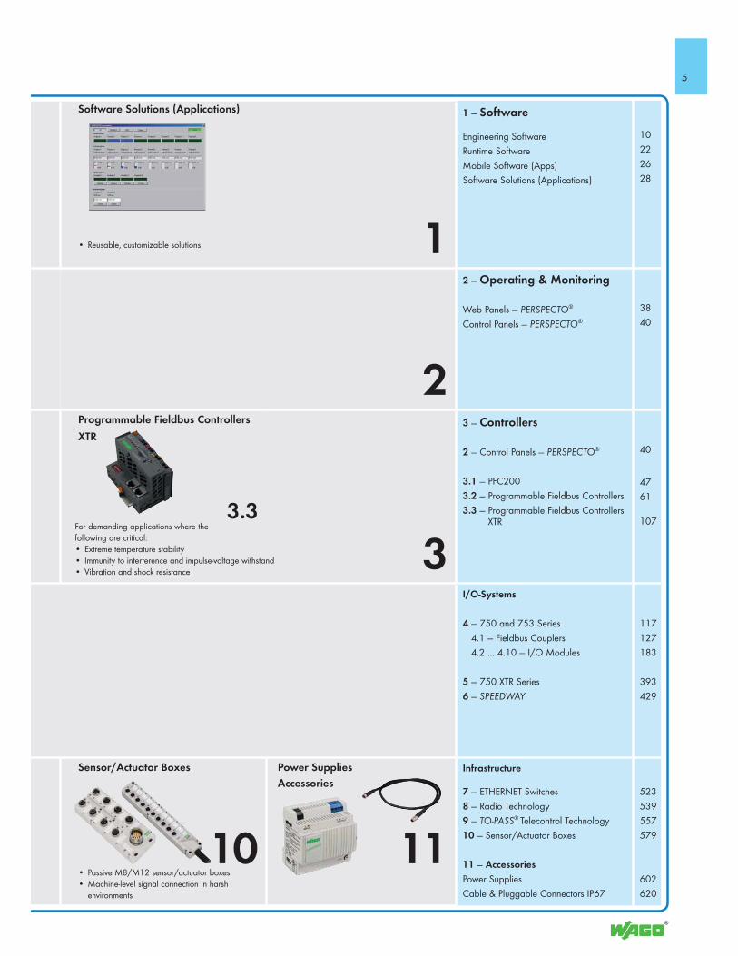
1 — Software
Engineering Software
Runtime Software
Mobile Software (Apps)
Software Solutions (Applications)
10
22
26
28
2 — Operating & Monitoring
Web Panels — PERSPECTO®
Control Panels — PERSPECTO®
38
40
3 — Controllers
2 — Control Panels — PERSPECTO®
3.1 — PFC200
3.2 — Programmable Fieldbus Controllers
3.3 — Programmable Fieldbus Controllers XTR
40
47
61
107
I/O-Systems
4 — 750 and 753 Series
4.1 — Fieldbus Couplers
4.2 ... 4.10 — I/O Modules
5 — 750 XTR Series
6 — SPEEDWAY
117
127
183
393
429
Infrastructure
7 — ETHERNET Switches
8 — Radio Technology
9 — TO-PASS® Telecontrol Technology
10 — Sensor/Actuator Boxes
11 — Accessories
Power Supplies
Cable & Pluggable Connectors IP67
523
539
557
579
602
620
• Reusable, customizable solutions
Software Solutions (Applications)
Programmable Fieldbus Controllers
XTR
Sensor/Actuator Boxes Power Supplies
Accessories
• Passive M8/M12 sensor/actuator boxes
• Machine-level signal connection in harsh
environments
For demanding applications where the
following are critical:
• Extreme temperature stability
• Immunity to interference and impulse-voltage withstand
• Vibration and shock resistance
3.3
10 11
2
1
3
5
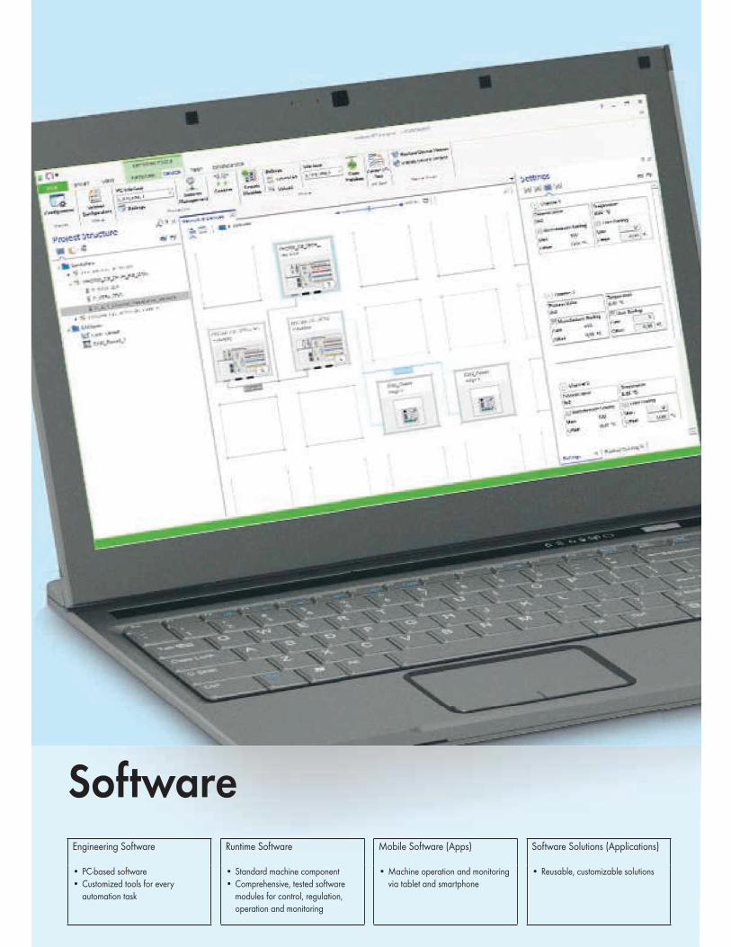
SoftwareEngineering Software
• PC-based software
• Customized tools for every
automation task
Runtime Software
• Standard machine component
• Comprehensive, tested software
modules for control, regulation,
operation and monitoring
Mobile Software (Apps)
• Machine operation and monitoring
via tablet and smartphone
Software Solutions (Applications)
• Reusable, customizable solutions
7
1
1
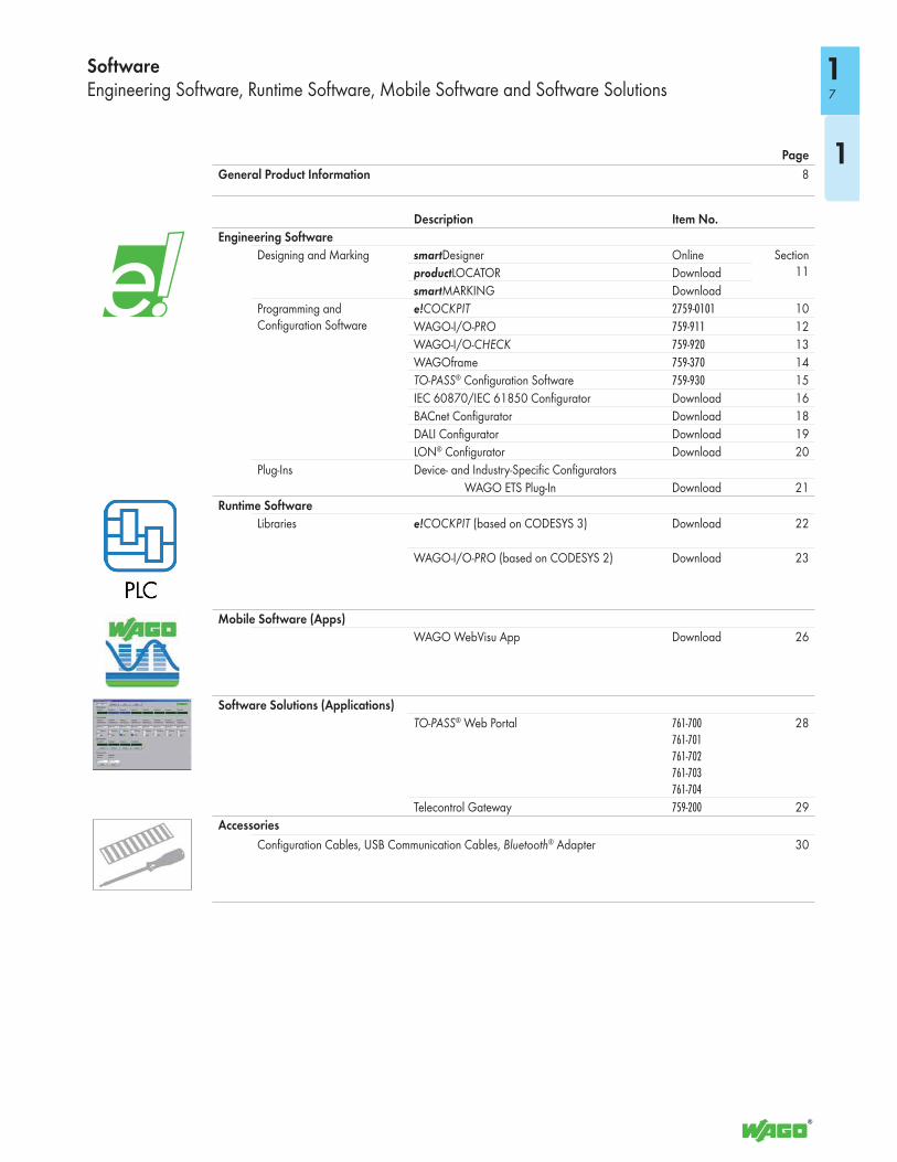
SoftwareEngineering Software, Runtime Software, Mobile Software and Software Solutions
Page
General Product Information 8
Description Item No.
Engineering Software
Designing and Marking smartDesigner Online Section 11productLOCATOR Download
smartMARKING Download
Programming and Configuration Software
e!COCKPIT 2759-0101 10
WAGO-I/O-PRO 759-911 12
WAGO-I/O-CHECK 759-920 13
WAGOframe 759-370 14
TO-PASS® Configuration Software 759-930 15
IEC 60870/IEC 61850 Configurator Download 16
BACnet Configurator Download 18
DALI Configurator Download 19
LON® Configurator Download 20
Plug-Ins Device- and Industry-Specific Configurators
WAGO ETS Plug-In Download 21
Runtime Software
Libraries e!COCKPIT (based on CODESYS 3) Download 22
WAGO-I/O-PRO (based on CODESYS 2) Download 23
Mobile Software (Apps)
WAGO WebVisu App Download 26
Software Solutions (Applications)
TO-PASS® Web Portal 761-700
761-701
761-702
761-703
761-704
28
Telecontrol Gateway 759-200 29
Accessories
Configuration Cables, USB Communication Cables, Bluetooth® Adapter 30
18
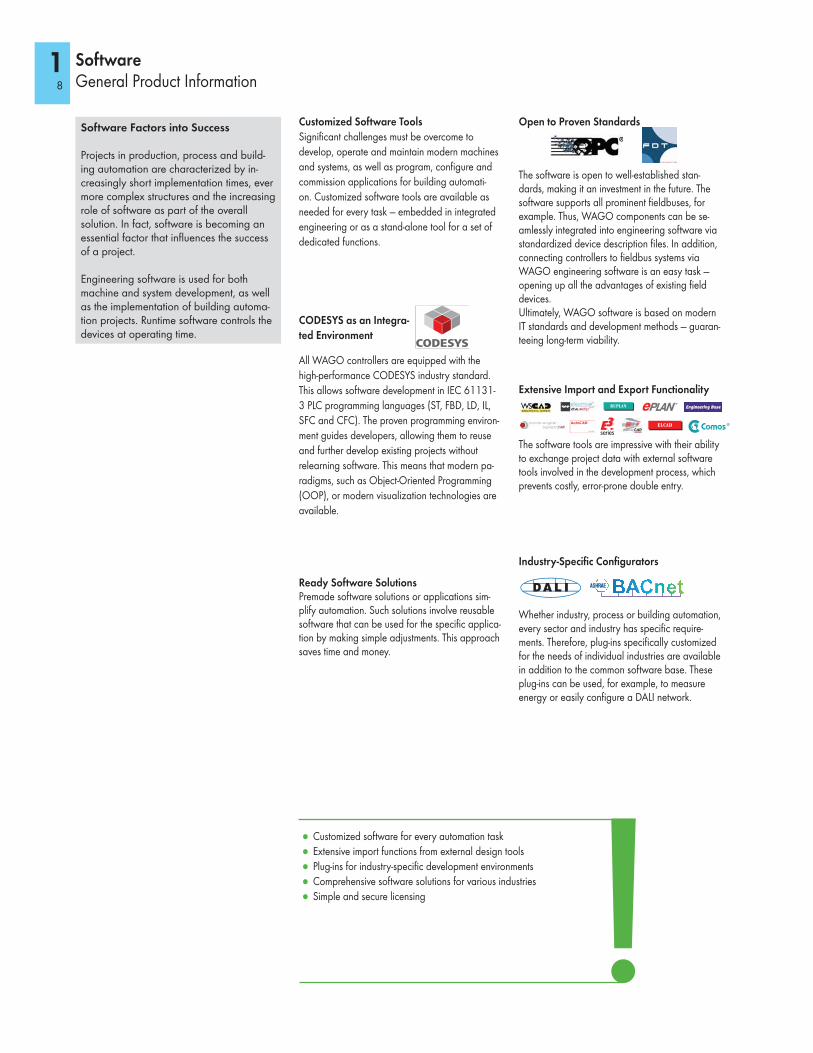
Software Factors into Success
Projects in production, process and build-ing automation are characterized by in-creasingly short implementation times, ever more complex structures and the increasing role of software as part of the overall solution. In fact, software is becoming an essential factor that influences the success of a project.
Engineering software is used for both machine and system development, as well as the implementation of building automa-tion projects. Runtime software controls the devices at operating time.
Open to Proven Standards
CODESYS as an Integra-
ted Environment
SoftwareGeneral Product Information
Customized Software Tools
Significant challenges must be overcome to
develop, operate and maintain modern machines
and systems, as well as program, configure and
commission applications for building automati-
on. Customized software tools are available as
needed for every task — embedded in integrated
engineering or as a stand-alone tool for a set of
dedicated functions.
All WAGO controllers are equipped with the
high-performance CODESYS industry standard.
This allows software development in IEC 61131-
3 PLC programming languages (ST, FBD, LD, IL,
SFC and CFC). The proven programming environ-
ment guides developers, allowing them to reuse
and further develop existing projects without
relearning software. This means that modern pa-
radigms, such as Object-Oriented Programming
(OOP), or modern visualization technologies are
available.
Extensive Import and Export Functionality
Industry-Specific Configurators
Ready Software SolutionsPremade software solutions or applications sim-plify automation. Such solutions involve reusable software that can be used for the specific applica-tion by making simple adjustments. This approach saves time and money.
The software is open to well-established stan-dards, making it an investment in the future. The software supports all prominent fieldbuses, for example. Thus, WAGO components can be se-amlessly integrated into engineering software via standardized device description files. In addition, connecting controllers to fieldbus systems via WAGO engineering software is an easy task — opening up all the advantages of existing field devices.Ultimately, WAGO software is based on modern IT standards and development methods — guaran-teeing long-term viability.
The software tools are impressive with their ability to exchange project data with external software tools involved in the development process, which prevents costly, error-prone double entry.
Whether industry, process or building automation, every sector and industry has specific require-ments. Therefore, plug-ins specifically customized for the needs of individual industries are available in addition to the common software base. These plug-ins can be used, for example, to measure energy or easily configure a DALI network.
● Customized software for every automation task
● Extensive import functions from external design tools
● Plug-ins for industry-specific development environments
● Comprehensive software solutions for various industries
● Simple and secure licensing
9
1
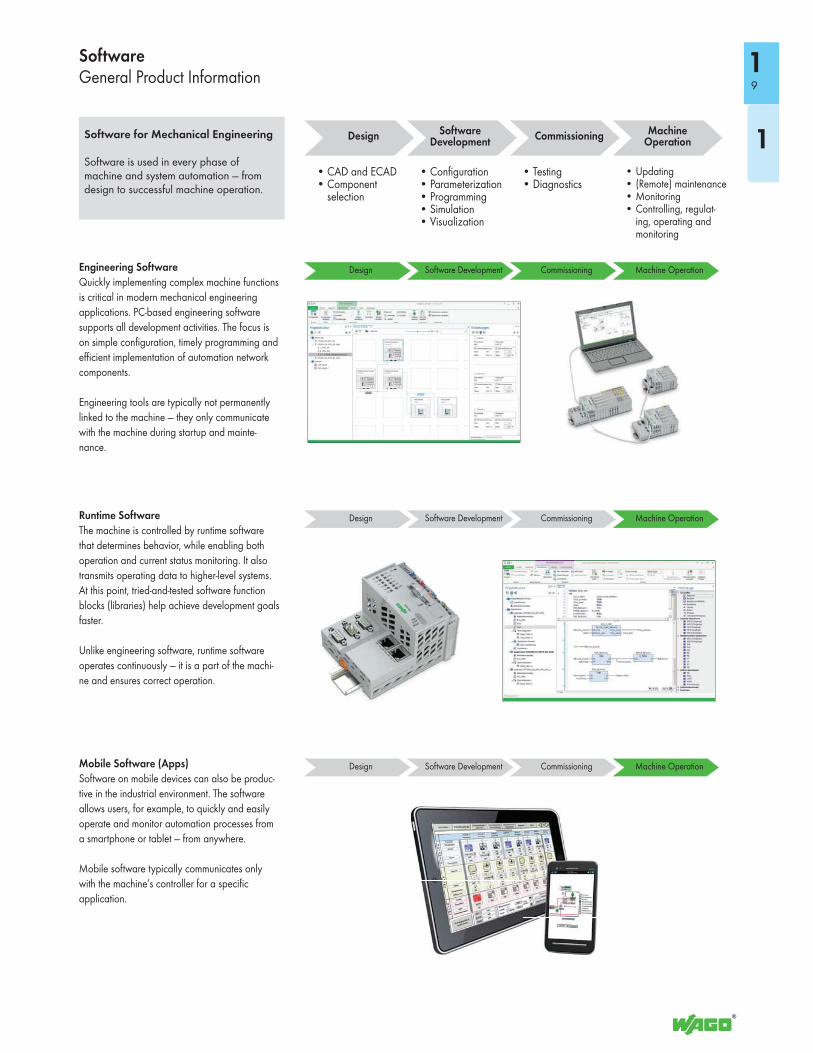
1Software for Mechanical Engineering
Software is used in every phase of machine and system automation — from design to successful machine operation.
Engineering Software
Quickly implementing complex machine functions
is critical in modern mechanical engineering
applications. PC-based engineering software
supports all development activities. The focus is
on simple configuration, timely programming and
efficient implementation of automation network
components.
Engineering tools are typically not permanently
linked to the machine — they only communicate
with the machine during startup and mainte-
nance.
SoftwareGeneral Product Information
Commissioning Machine Operation
Software Development
Design
Commissioning Machine OperationSoftware DevelopmentDesign
Runtime Software
The machine is controlled by runtime software
that determines behavior, while enabling both
operation and current status monitoring. It also
transmits operating data to higher-level systems.
At this point, tried-and-tested software function
blocks (libraries) help achieve development goals
faster.
Unlike engineering software, runtime software
operates continuously — it is a part of the machi-
ne and ensures correct operation.
Mobile Software (Apps)
Software on mobile devices can also be produc-
tive in the industrial environment. The software
allows users, for example, to quickly and easily
operate and monitor automation processes from
a smartphone or tablet — from anywhere.
Mobile software typically communicates only
with the machine’s controller for a specific
application.
• CAD and ECAD• Component
selection
• Configuration• Parameterization• Programming• Simulation• Visualization
• Testing• Diagnostics
• Updating• (Remote) maintenance• Monitoring• Controlling, regulat-
ing, operating and monitoring
Commissioning Machine OperationSoftware DevelopmentDesign
Commissioning Machine OperationSoftware DevelopmentDesign
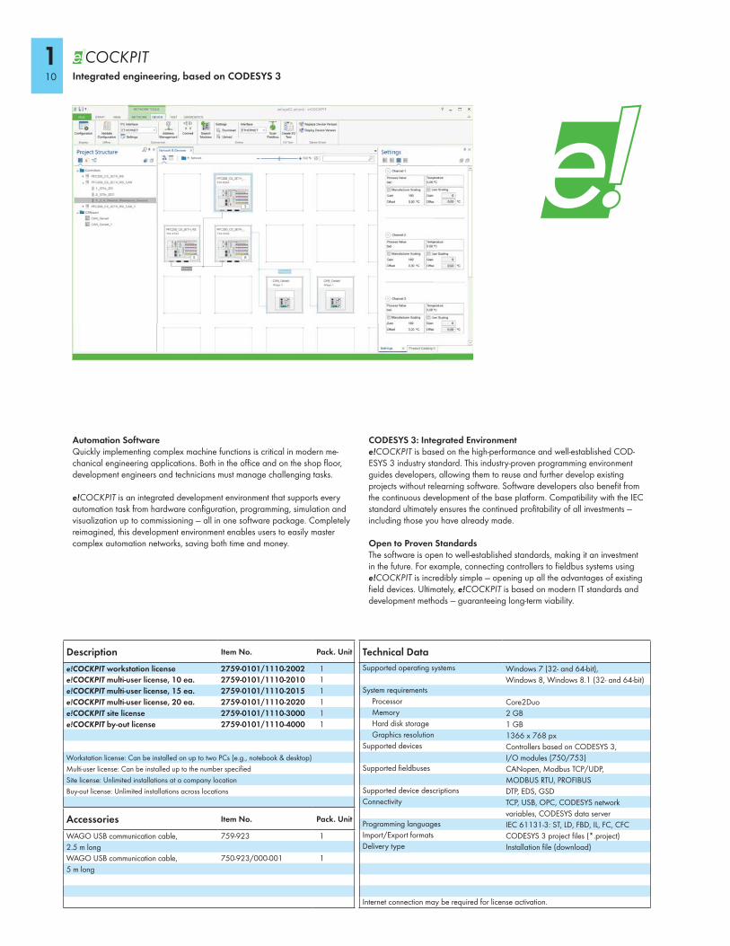
Automation SoftwareQuickly implementing complex machine functions is critical in modern me-chanical engineering applications. Both in the office and on the shop floor, development engineers and technicians must manage challenging tasks.
e!COCKPIT is an integrated development environment that supports every automation task from hardware configuration, programming, simulation and visualization up to commissioning — all in one software package. Completely reimagined, this development environment enables users to easily master complex automation networks, saving both time and money.
CODESYS 3: Integrated Environmente!COCKPIT is based on the high-performance and well-established COD-ESYS 3 industry standard. This industry-proven programming environment guides developers, allowing them to reuse and further develop existing projects without relearning software. Software developers also benefit from the continuous development of the base platform. Compatibility with the IEC standard ultimately ensures the continued profitability of all investments — including those you have already made.
Open to Proven StandardsThe software is open to well-established standards, making it an investment in the future. For example, connecting controllers to fieldbus systems using e!COCKPIT is incredibly simple — opening up all the advantages of existing field devices. Ultimately, e!COCKPIT is based on modern IT standards and development methods — guaranteeing long-term viability.
Technical Data
Supported operating systems Windows 7 (32- and 64-bit),
Windows 8, Windows 8.1 (32- and 64-bit)System requirements
Processor Core2DuoMemory 2 GBHard disk storage 1 GBGraphics resolution 1366 x 768 px
Supported devices Controllers based on CODESYS 3,
I/O modules (750/753)Supported fieldbuses CANopen, Modbus TCP/UDP,
MODBUS RTU, PROFIBUSSupported device descriptions DTP, EDS, GSDConnectivity TCP, USB, OPC, CODESYS network
variables, CODESYS data serverProgramming languages IEC 61131-3: ST, LD, FBD, IL, FC, CFCImport/Export formats CODESYS 3 project files (*.project)Delivery type Installation file (download)
Internet connection may be required for license activation.
Description Item No. Pack. Unit
e!COCKPIT workstation license 2759-0101/1110-2002 1
e!COCKPIT multi-user license, 10 ea. 2759-0101/1110-2010 1
e!COCKPIT multi-user license, 15 ea. 2759-0101/1110-2015 1
e!COCKPIT multi-user license, 20 ea. 2759-0101/1110-2020 1
e!COCKPIT site license 2759-0101/1110-3000 1
e!COCKPIT by-out license 2759-0101/1110-4000 1
Workstation license: Can be installed on up to two PCs (e.g., notebook & desktop)
Multi-user license: Can be installed up to the number specified
Site license: Unlimited installations at a company location
Buy-out license: Unlimited installations across locations
Accessories Item No. Pack. Unit
WAGO USB communication cable,
2.5 m long
759-923 1
WAGO USB communication cable,
5 m long
750-923/000-001 1
Integrated engineering, based on CODESYS 3
110
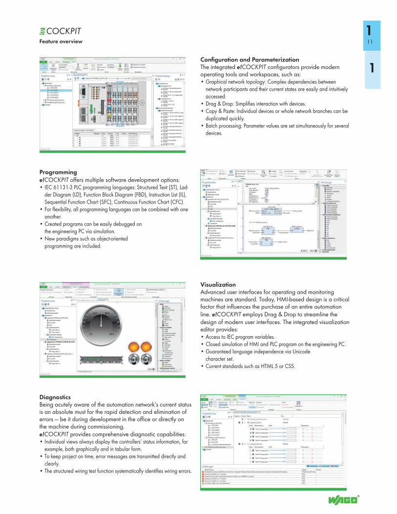
Configuration and ParameterizationThe integrated e!COCKPIT configurators provide modern operating tools and workspaces, such as: • Graphical network topology: Complex dependencies between
network participants and their current states are easily and intuitively accessed.
• Drag & Drop: Simplifies interaction with devices.• Copy & Paste: Individual devices or whole network branches can be
duplicated quickly.• Batch processing: Parameter values are set simultaneously for several
devices.
Programminge!COCKPIT offers multiple software development options:• IEC 61131-3 PLC programming languages: Structured Text (ST), Lad-
der Diagram (LD), Function Block Diagram (FBD), Instruction List (IL), Sequential Function Chart (SFC), Continuous Function Chart (CFC).
• For flexibility, all programming languages can be combined with one another.
• Created programs can be easily debugged on the engineering PC via simulation.
• New paradigms such as object-oriented programming are included.
VisualizationAdvanced user interfaces for operating and monitoring machines are standard. Today, HMI-based design is a critical factor that influences the purchase of an entire automation line. e!COCKPIT employs Drag & Drop to streamline the design of modern user interfaces. The integrated visualization editor provides:• Access to IEC program variables.• Closed simulation of HMI and PLC program on the engineering PC. • Guaranteed language independence via Unicode
character set.• Current standards such as HTML 5 or CSS.
DiagnosticsBeing acutely aware of the automation network’s current status is an absolute must for the rapid detection and elimination of errors — be it during development in the office or directly on the machine during commissioning.e!COCKPIT provides comprehensive diagnostic capabilities: • Individual views always display the controllers’ status information, for
example, both graphically and in tabular form.• To keep project on time, error messages are transmitted directly and
clearly.• The structured wiring test function systematically identifies wiring errors.
Feature overview 11
1
1
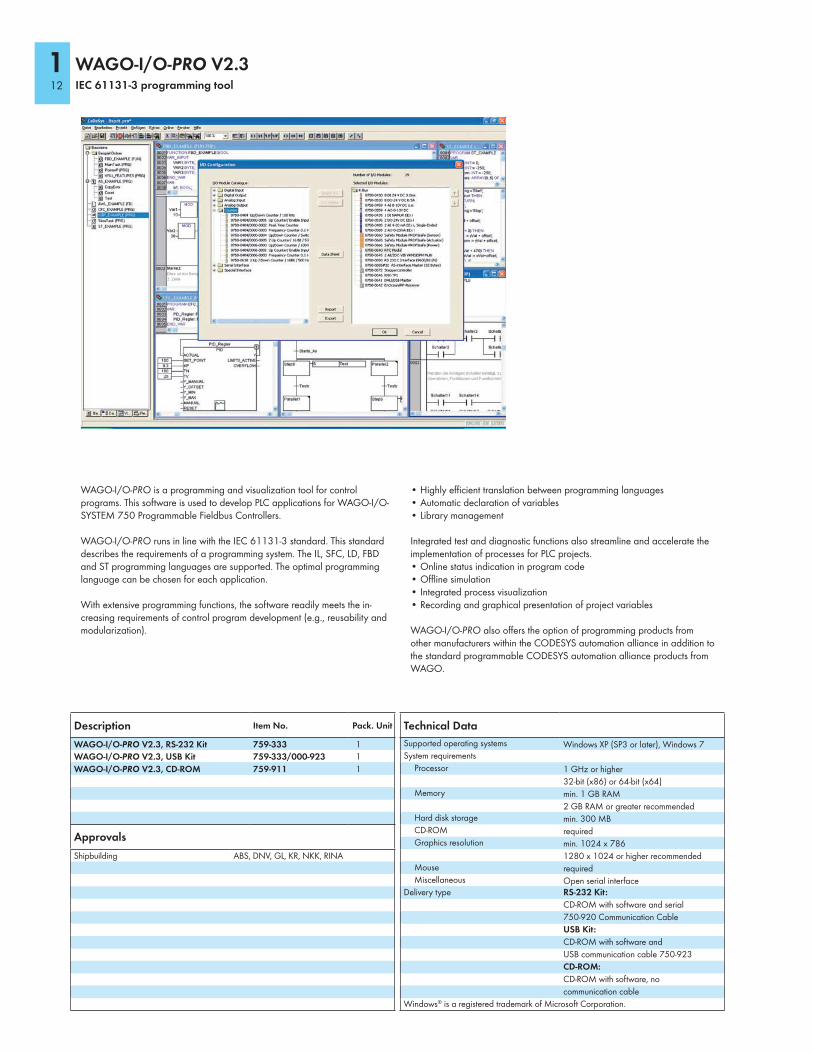
WAGO-I/O-PRO is a programming and visualization tool for control programs. This software is used to develop PLC applications for WAGO-I/O-SYSTEM 750 Programmable Fieldbus Controllers.
WAGO-I/O-PRO runs in line with the IEC 61131-3 standard. This standard describes the requirements of a programming system. The IL, SFC, LD, FBD and ST programming languages are supported. The optimal programming language can be chosen for each application.
With extensive programming functions, the software readily meets the in-creasing requirements of control program development (e.g., reusability and modularization).
• Highly efficient translation between programming languages• Automatic declaration of variables• Library management
Integrated test and diagnostic functions also streamline and accelerate the implementation of processes for PLC projects.• Online status indication in program code• Offline simulation• Integrated process visualization• Recording and graphical presentation of project variables
WAGO-I/O-PRO also offers the option of programming products from other manufacturers within the CODESYS automation alliance in addition to the standard programmable CODESYS automation alliance products from WAGO.
WAGO-I/O-PRO V2.3IEC 61131-3 programming tool
Technical Data
Supported operating systems Windows XP (SP3 or later), Windows 7System requirements
Processor 1 GHz or higher
32-bit (x86) or 64-bit (x64)Memory min. 1 GB RAM
2 GB RAM or greater recommendedHard disk storage min. 300 MBCD-ROM requiredGraphics resolution min. 1024 x 786
1280 x 1024 or higher recommendedMouse requiredMiscellaneous Open serial interface
Delivery type RS-232 Kit:
CD-ROM with software and serial
750-920 Communication Cable
USB Kit:
CD-ROM with software and
USB communication cable 750-923
CD-ROM:
CD-ROM with software, no
communication cable
Windows® is a registered trademark of Microsoft Corporation.
Approvals
Shipbuilding ABS, DNV, GL, KR, NKK, RINA
Description Item No. Pack. Unit
WAGO-I/O-PRO V2.3, RS-232 Kit 759-333 1
WAGO-I/O-PRO V2.3, USB Kit 759-333/000-923 1
WAGO-I/O-PRO V2.3, CD-ROM 759-911 1
112
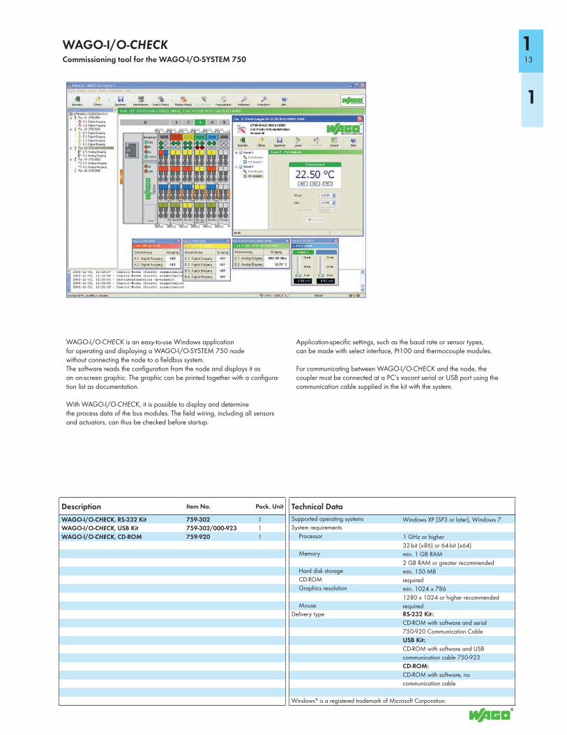
WAGO-I/O-CHECK is an easy-to-use Windows applicationfor operating and displaying a WAGO-I/O-SYSTEM 750 nodewithout connecting the node to a fieldbus system.The software reads the configuration from the node and displays it asan on-screen graphic. The graphic can be printed together with a configura-tion list as documentation.
With WAGO-I/O-CHECK, it is possible to display and determinethe process data of the bus modules. The field wiring, including all sensors and actuators, can thus be checked before startup.
Application-specific settings, such as the baud rate or sensor types,can be made with select interface, Pt100 and thermocouple modules.
For communicating between WAGO-I/O-CHECK and the node, the coupler must be connected at a PC’s vacant serial or USB port using the communication cable supplied in the kit with the system.
WAGO-I/O-CHECKCommissioning tool for the WAGO-I/O-SYSTEM 750
Technical Data
Supported operating systems Windows XP (SP3 or later), Windows 7System requirements
Processor 1 GHz or higher
32-bit (x86) or 64-bit (x64)Memory min. 1 GB RAM
2 GB RAM or greater recommendedHard disk storage min. 150 MBCD-ROM requiredGraphics resolution min. 1024 x 786
1280 x 1024 or higher recommendedMouse required
Delivery type RS-232 Kit:
CD-ROM with software and serial
750-920 Communication Cable
USB Kit:
CD-ROM with software and USB
communication cable 750-923
CD-ROM:
CD-ROM with software, no
communication cable
Windows® is a registered trademark of Microsoft Corporation.
Description Item No. Pack. Unit
WAGO-I/O-CHECK, RS-232 Kit 759-302 1
WAGO-I/O-CHECK, USB Kit 759-302/000-923 1
WAGO-I/O-CHECK, CD-ROM 759-920 1
13
1
1
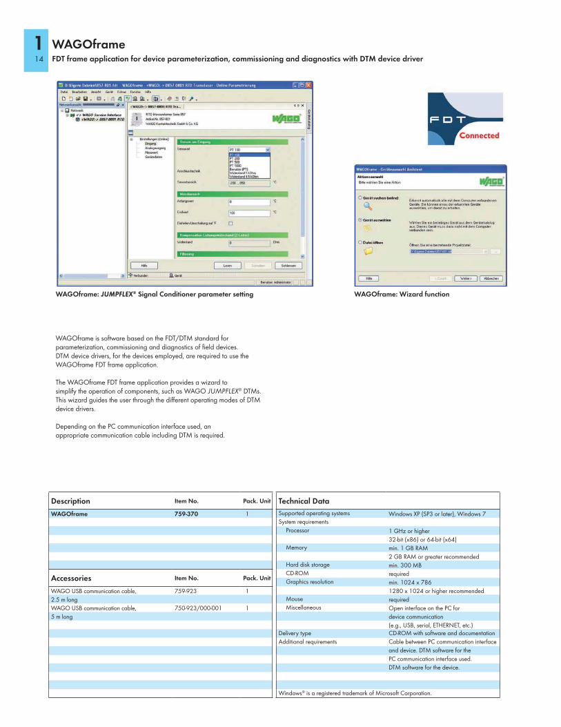
WAGOframe is software based on the FDT/DTM standard forparameterization, commissioning and diagnostics of field devices.DTM device drivers, for the devices employed, are required to use the WAGOframe FDT frame application.
The WAGOframe FDT frame application provides a wizard tosimplify the operation of components, such as WAGO JUMPFLEX® DTMs.This wizard guides the user through the different operating modes of DTM device drivers.
Depending on the PC communication interface used, anappropriate communication cable including DTM is required.
WAGOframeFDT frame application for device parameterization, commissioning and diagnostics with DTM device driver
Technical Data
Supported operating systems Windows XP (SP3 or later), Windows 7System requirements
Processor 1 GHz or higher
32-bit (x86) or 64-bit (x64)Memory min. 1 GB RAM
2 GB RAM or greater recommendedHard disk storage min. 300 MBCD-ROM requiredGraphics resolution min. 1024 x 786
1280 x 1024 or higher recommendedMouse requiredMiscellaneous Open interface on the PC for
device communication
(e.g., USB, serial, ETHERNET, etc.)Delivery type CD-ROM with software and documentation
Additional requirements Cable between PC communication interface
and device. DTM software for the
PC communication interface used.
DTM software for the device.
Windows® is a registered trademark of Microsoft Corporation.
Description Item No. Pack. Unit
WAGOframe 759-370 1
Accessories Item No. Pack. Unit
WAGO USB communication cable,
2.5 m long
759-923 1
WAGO USB communication cable,
5 m long
750-923/000-001 1
WAGOframe: JUMPFLEX® Signal Conditioner parameter setting WAGOframe: Wizard function
114
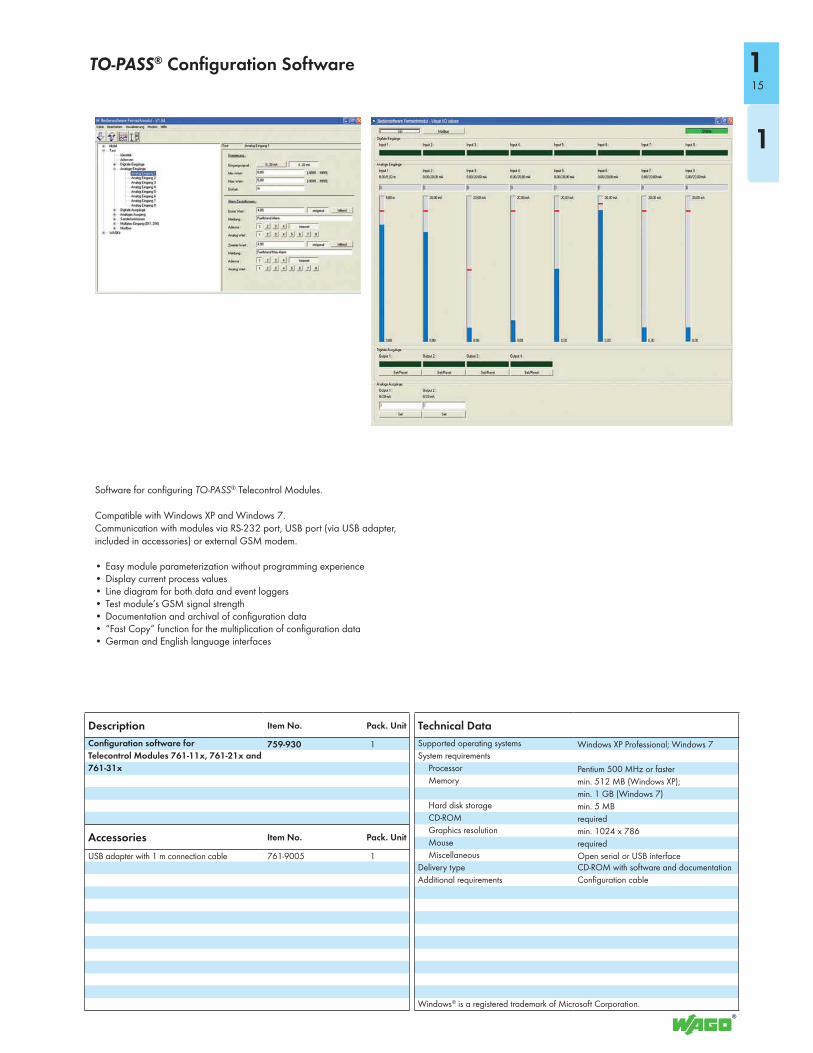
Software for configuring TO-PASS® Telecontrol Modules.
Compatible with Windows XP and Windows 7. Communication with modules via RS-232 port, USB port (via USB adapter, included in accessories) or external GSM modem.
• Easy module parameterization without programming experience• Display current process values• Line diagram for both data and event loggers• Test module’s GSM signal strength• Documentation and archival of configuration data• “Fast Copy” function for the multiplication of configuration data• German and English language interfaces
TO-PASS® Configuration Software
Technical Data
Supported operating systems Windows XP Professional; Windows 7System requirements
Processor Pentium 500 MHz or fasterMemory min. 512 MB (Windows XP);
min. 1 GB (Windows 7)Hard disk storage min. 5 MBCD-ROM requiredGraphics resolution min. 1024 x 786Mouse requiredMiscellaneous Open serial or USB interface
Delivery type CD-ROM with software and documentation
Additional requirements Configuration cable
Windows® is a registered trademark of Microsoft Corporation.
Description Item No. Pack. Unit
Configuration software for
Telecontrol Modules 761-11x, 761-21x and
761-31x
759-930 1
Accessories Item No. Pack. Unit
USB adapter with 1 m connection cable 761-9005 1
15
1
1
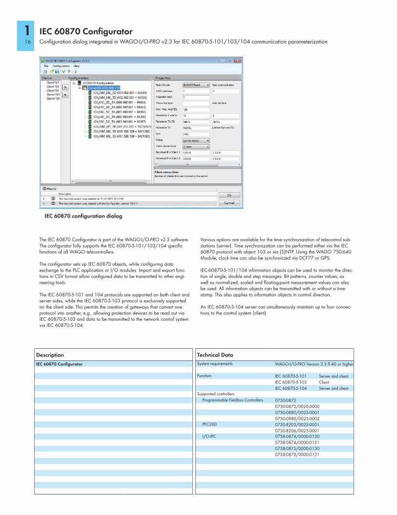
The IEC 60870 Configurator is part of the WAGO-I/O-PRO v2.3 software. The configurator fully supports the IEC 60870-5-101/103/104 specific functions of all WAGO telecontrollers.
The configurator sets up IEC 60870 objects, while configuring data exchange to the PLC application or I/O modules. Import and export func-tions in CSV format allow configured data to be transmitted to other engi-neering tools.
The IEC 60870-5-101 and 104 protocols are supported on both client and server sides, while the IEC 60870-5-103 protocol is exclusively supported on the client side. This permits the creation of gateways that convert one protocol into another, e.g., allowing protection devices to be read out via IEC 60870-5-103 and data to be transmitted to the network control system via IEC 60870-5-104.
Various options are available for the time synchronization of telecontrol sub-stations (server). Time synchronization can be performed either via the IEC 60870 protocol with object 103 or via (S)NTP. Using the WAGO 750-640 Module, clock time can also be synchronized via DCF77 or GPS.
IEC-60870-5-101/104 information objects can be used to monitor the direc-tion of single, double and step messages. Bit patterns, counter values, as well as normalized, scaled and floating-point measurement values can also be used. All information objects can be transmitted with or without a time stamp. This also applies to information objects in control direction.
An IEC 60870-5-104 server can simultaneously maintain up to four connec-tions to the control system (client).
IEC 60870 Configurator
Configuration dialog integrated in WAGO-I/O-PRO v2.3 for IEC 60870-5-101/103/104 communication parameterization
IEC 60870 configuration dialog
Technical Data
System requirements WAGO-I/O-PRO Version 2.3.9.40 or higher
Function IEC 60870-5-101 Server and client
IEC 60870-5-103 Client
IEC 60870-5-104 Server and clientSupported controllers
Programmable Fieldbus Controllers 0750-0872
0750-0872/0020-0000
0750-0880/0025-0001
0750-0880/0025-0002PFC200 0750-8202/0025-0001
0750-8206/0025-0001I/O-IPC 0758-0874/0000-0130
0758-0874/0000-0131
0758-0875/0000-0130
0758-0875/0000-0131
Description
IEC 60870 Configurator
116
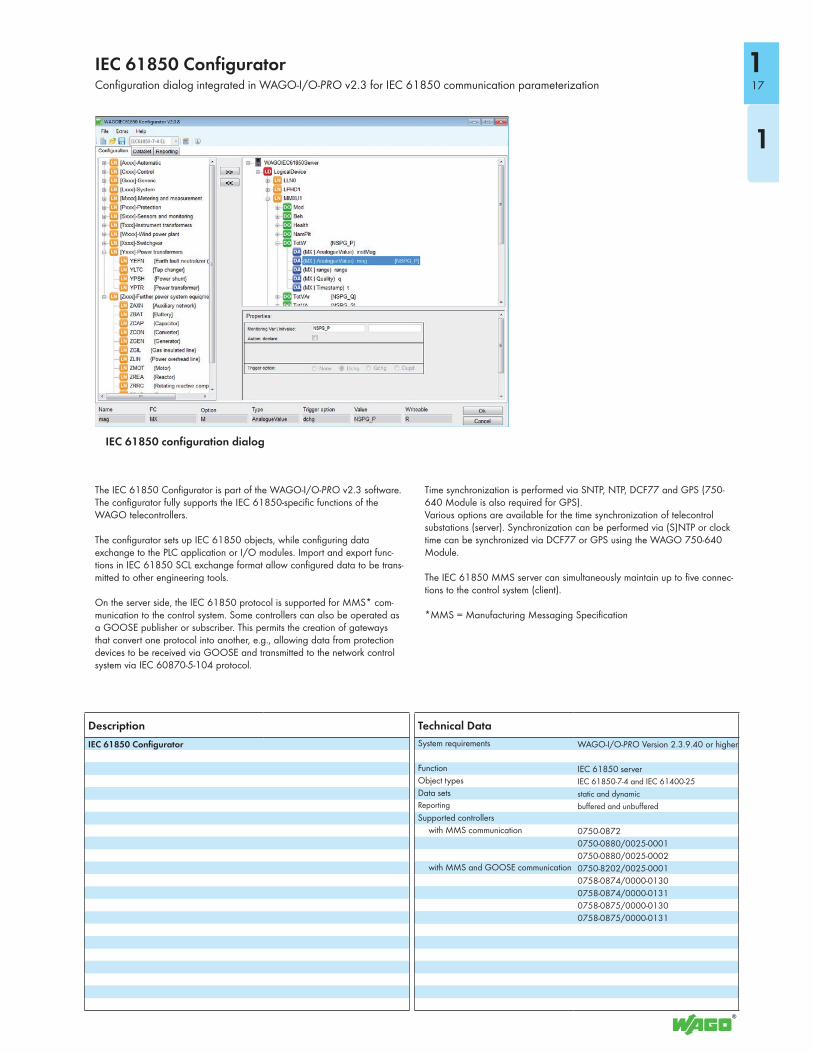
The IEC 61850 Configurator is part of the WAGO-I/O-PRO v2.3 software. The configurator fully supports the IEC 61850-specific functions of the WAGO telecontrollers.
The configurator sets up IEC 61850 objects, while configuring data exchange to the PLC application or I/O modules. Import and export func-tions in IEC 61850 SCL exchange format allow configured data to be trans-mitted to other engineering tools.
On the server side, the IEC 61850 protocol is supported for MMS* com-munication to the control system. Some controllers can also be operated as a GOOSE publisher or subscriber. This permits the creation of gateways that convert one protocol into another, e.g., allowing data from protection devices to be received via GOOSE and transmitted to the network control system via IEC 60870-5-104 protocol.
Time synchronization is performed via SNTP, NTP, DCF77 and GPS (750-640 Module is also required for GPS).Various options are available for the time synchronization of telecontrol substations (server). Synchronization can be performed via (S)NTP or clock time can be synchronized via DCF77 or GPS using the WAGO 750-640 Module.
The IEC 61850 MMS server can simultaneously maintain up to five connec-tions to the control system (client).
*MMS = Manufacturing Messaging Specification
IEC 61850 Configurator
Configuration dialog integrated in WAGO-I/O-PRO v2.3 for IEC 61850 communication parameterization
IEC 61850 configuration dialog
Technical Data
System requirements WAGO-I/O-PRO Version 2.3.9.40 or higher
Function IEC 61850 serverObject types IEC 61850-7-4 and IEC 61400-25
Data sets static and dynamic
Reporting buffered and unbuffered
Supported controllers
with MMS communication 0750-0872
0750-0880/0025-0001
0750-0880/0025-0002with MMS and GOOSE communication 0750-8202/0025-0001
0758-0874/0000-0130
0758-0874/0000-0131
0758-0875/0000-0130
0758-0875/0000-0131
Description
IEC 61850 Configurator
17
1
1
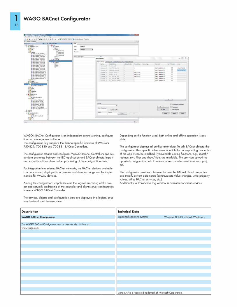
WAGO’s BACnet Configurator is an independent commissioning, configura-tion and management software. The configurator fully supports the BACnet-specific functions of WAGO’s 750-829, 750-830 and 750-831 BACnet Controllers.
The configurator creates and configures WAGO BACnet Controllers and sets up data exchange between the IEC application and BACnet objects. Import and export functions allow further processing of the configuration data. For integration into existing BACnet networks, the BACnet devices available can be scanned, displayed in a browser and data exchange can be imple-mented for WAGO devices.
Among the configurator’s capabilities are the logical structuring of the proj-ect and network, addressing of the controller and client/server configuration in every WAGO BACnet Controller.
The devices, objects and configuration data are displayed in a logical, struc-tured network and browser view.
Depending on the function used, both online and offline operation is pos-sible.
The configurator displays all configuration data. To edit BACnet objects, the configurator offers specific table views in which the corresponding properties of the object can be modified. Typical table editing functions, e.g., search/replace, sort, filter and show/hide, are available. The user can upload the updated configuration data to one or more controllers and save as a proj-ect.
The configurator provides a browser to view the BACnet object properties and modify current parameters (communicate value changes, write property values, utilize BACnet services, etc.). Additionally, a Transaction Log window is available for client services.
WAGO BACnet Configurator
Technical Data
Supported operating systems Windows XP (SP3 or later), Windows 7
Windows® is a registered trademark of Microsoft Corporation.
Description
WAGO BACnet Configurator
The WAGO BACnet Configurator can be downloaded for free at:
www.wago.com
118
DALI Configurator
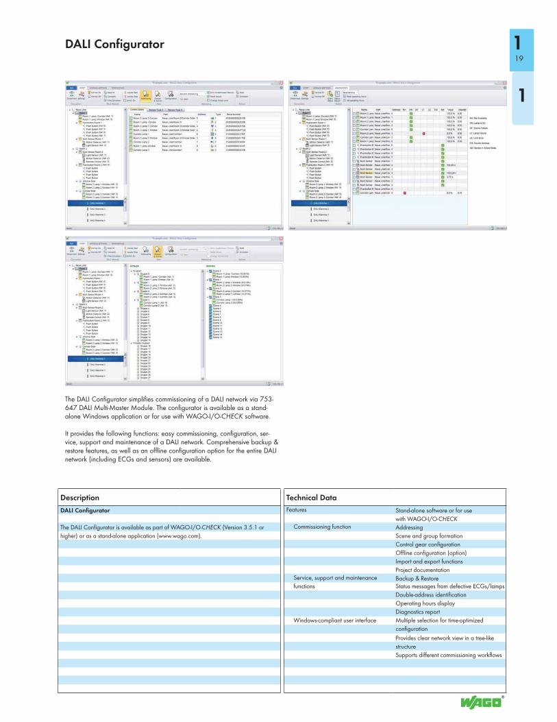
The DALI Configurator simplifies commissioning of a DALI network via 753-647 DALI Multi-Master Module. The configurator is available as a stand-alone Windows application or for use with WAGO-I/O-CHECK software.
It provides the following functions: easy commissioning, configuration, ser-vice, support and maintenance of a DALI network. Comprehensive backup & restore features, as well as an offline configuration option for the entire DALI network (including ECGs and sensors) are available.
Technical Data
Features Stand-alone software or for use
with WAGO-I/O-CHECKCommissioning function Addressing
Scene and group formation
Control gear configuration
Offline configuration (option)
Import and export functions
Project documentationService, support and maintenance
functionsBackup & RestoreStatus messages from defective ECGs/lamps
Double-address identification
Operating hours display
Diagnostics report
Windows-compliant user interface Multiple selection for time-optimized
configuration
Provides clear network view in a tree-like
structure
Supports different commissioning workflows
Description
DALI Configurator
The DALI Configurator is available as part of WAGO-I/O-CHECK (Version 3.5.1 or
higher) or as a stand-alone application (www.wago.com).
19
1
1
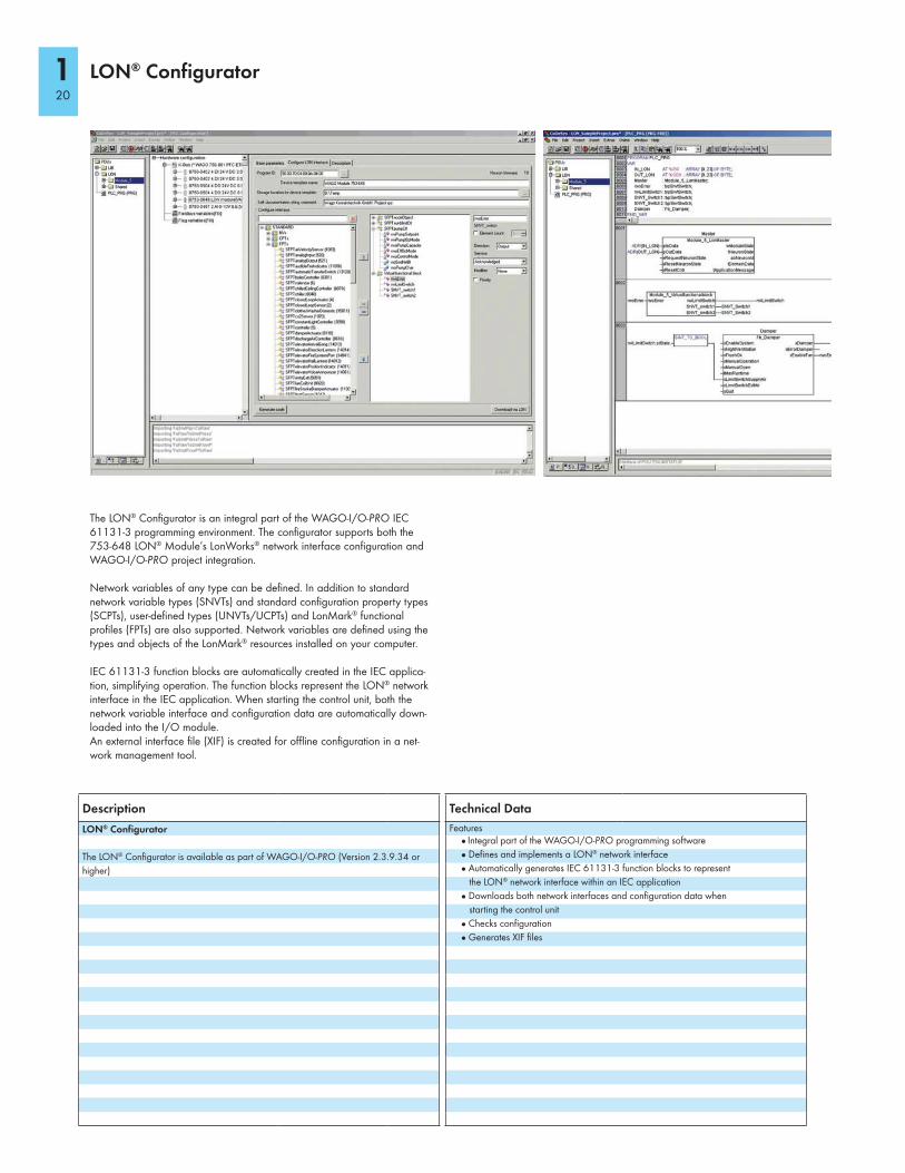
The LON® Configurator is an integral part of the WAGO-I/O-PRO IEC 61131-3 programming environment. The configurator supports both the 753-648 LON® Module’s LonWorks® network interface configuration and WAGO-I/O-PRO project integration.
Network variables of any type can be defined. In addition to standard network variable types (SNVTs) and standard configuration property types (SCPTs), user-defined types (UNVTs/UCPTs) and LonMark® functional profiles (FPTs) are also supported. Network variables are defined using the types and objects of the LonMark® resources installed on your computer.
IEC 61131-3 function blocks are automatically created in the IEC applica-tion, simplifying operation. The function blocks represent the LON® network interface in the IEC application. When starting the control unit, both the network variable interface and configuration data are automatically down-loaded into the I/O module.An external interface file (XIF) is created for offline configuration in a net-work management tool.
LON® Configurator
Technical Data
Features● Integral part of the WAGO-I/O-PRO programming software
● Defines and implements a LON® network interface
● Automatically generates IEC 61131-3 function blocks to represent
the LON® network interface within an IEC application
● Downloads both network interfaces and configuration data when
starting the control unit
● Checks configuration
● Generates XIF files
Description
LON® Configurator
The LON® Configurator is available as part of WAGO-I/O-PRO (Version 2.3.9.34 or
higher)
120
WAGO ETS Plug-In
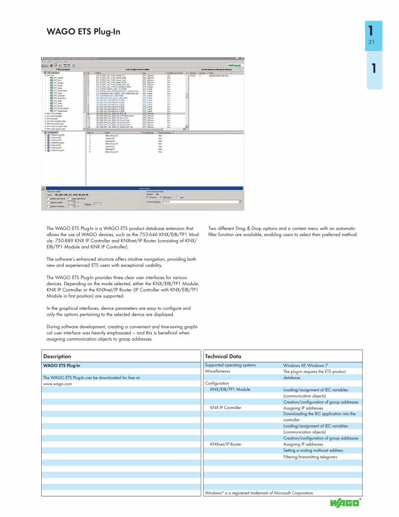
The WAGO ETS Plug-In is a WAGO ETS product database extension that allows the use of WAGO devices, such as the 753-646 KNX/EIB/TP1 Mod-ule, 750-889 KNX IP Controller and KNXnet/IP Router (consisting of KNX/EIB/TP1 Module and KNX IP Controller).
The software’s enhanced structure offers intuitive navigation, providing both new and experienced ETS users with exceptional usability.
The WAGO ETS Plug-In provides three clear user interfaces for various devices. Depending on the mode selected, either the KNX/EIB/TP1 Module, KNX IP Controller or the KNXnet/IP Router (IP Controller with KNX/EIB/TP1 Module in first position) are supported.
In the graphical interfaces, device parameters are easy to configure and only the options pertaining to the selected device are displayed.
During software development, creating a convenient and time-saving graphi-cal user interface was heavily emphasized — and this is beneficial when assigning communication objects to group addresses.
Two different Drag & Drop options and a context menu with an automatic filter function are available, enabling users to select their preferred method.
Technical Data
Supported operating systems Windows XP, Windows 7Miscellaneous The plug-in requires the ETS product
database.Configuration
KNX/EIB/TP1 Module Loading/assignment of IEC variables
(communication objects)
Creation/configuration of group addressesKNX IP Controller Assigning IP addresses
Downloading the IEC application into the
controller
Loading/assignment of IEC variables
(communication objects)
Creation/configuration of group addresses
KNXnet/IP Router Assigning IP addresses
Setting a routing multicast address
Filtering/transmitting telegrams
Windows® is a registered trademark of Microsoft Corporation.
Description
WAGO ETS Plug-In
The WAGO ETS Plug-In can be downloaded for free at:
www.wago.com
21
1
1
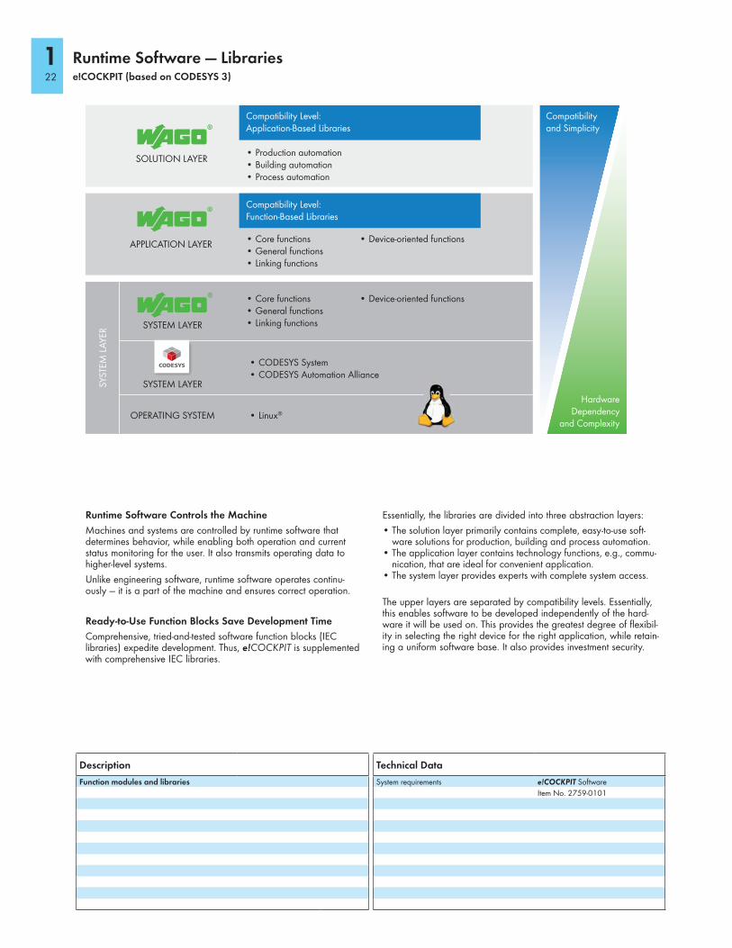
Runtime Software — Libraries e!COCKPIT (based on CODESYS 3)
Runtime Software Controls the Machine
Machines and systems are controlled by runtime software that determines behavior, while enabling both operation and current status monitoring for the user. It also transmits operating data to higher-level systems.
Unlike engineering software, runtime software operates continu-ously — it is a part of the machine and ensures correct operation.
Ready-to-Use Function Blocks Save Development Time
Comprehensive, tried-and-tested software function blocks (IEC libraries) expedite development. Thus, e!COCKPIT is supplemented with comprehensive IEC libraries.
Essentially, the libraries are divided into three abstraction layers:
• The solution layer primarily contains complete, easy-to-use soft-ware solutions for production, building and process automation.
• The application layer contains technology functions, e.g., commu-nication, that are ideal for convenient application.
• The system layer provides experts with complete system access.
The upper layers are separated by compatibility levels. Essentially, this enables software to be developed independently of the hard-ware it will be used on. This provides the greatest degree of flexibil-ity in selecting the right device for the right application, while retain-ing a uniform software base. It also provides investment security.
Compatibility Level: Application-Based Libraries
Compatibility Level: Function-Based Libraries
• Core functions• General functions• Linking functions
• Core functions• General functions• Linking functions
• Production automation• Building automation• Process automation
• Device-oriented functions
• Device-oriented functions
SOLUTION LAYER
APPLICATION LAYER
SYSTEM LAYER
SYSTEM LAYER
OPERATING SYSTEM
SYS
TEM
LA
YER
• CODESYS System• CODESYS Automation Alliance
• Linux®
Compatibility and Simplicity
Hardware Dependency
and Complexity
Description
Function modules and libraries
Technical Data
System requirements e!COCKPIT Software
Item No. 2759-0101
122
Konfiguration eines DALI-Beleuchtungssystems über die Visualisierung der WAGO-I/O-PRO
Anwendungshinweis
Version: 14.07.2006
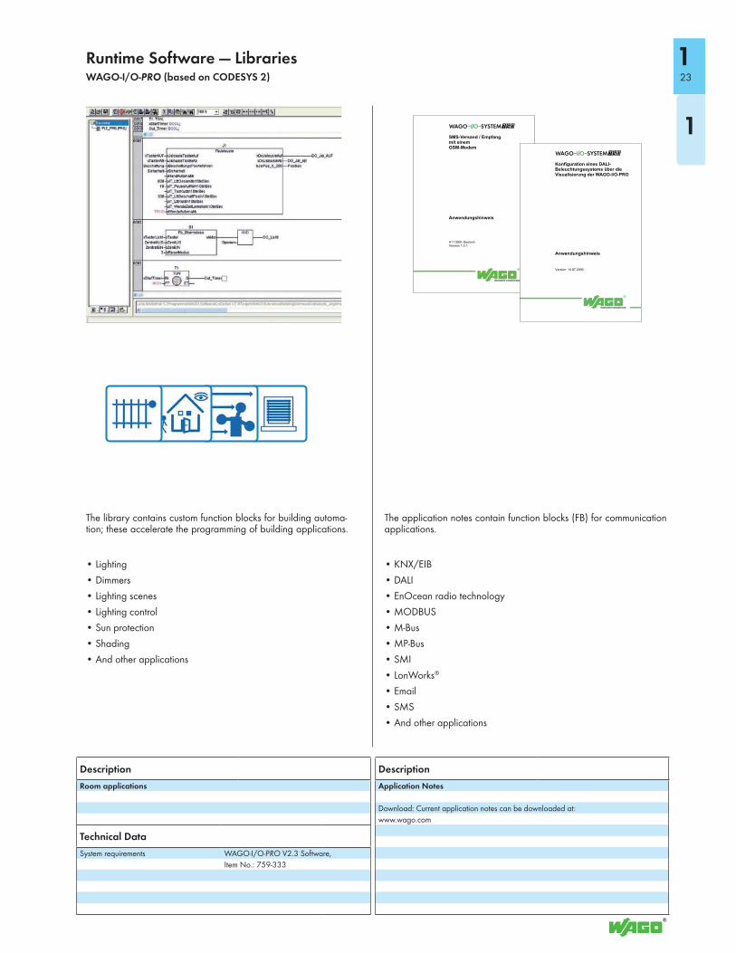
The library contains custom function blocks for building automa-tion; these accelerate the programming of building applications.
• Lighting
• Dimmers
• Lighting scenes
• Lighting control
• Sun protection
• Shading
• And other applications
The application notes contain function blocks (FB) for communication applications.
• KNX/EIB
• DALI
• EnOcean radio technology
• MODBUS
• M-Bus
• MP-Bus
• SMI
• LonWorks®
• SMS
• And other applications
Description
Room applications
Technical Data
System requirements WAGO-I/O-PRO V2.3 Software,
Item No.: 759-333
Description
Application Notes
Download: Current application notes can be downloaded at:
www.wago.com
Runtime Software — Libraries WAGO-I/O-PRO (based on CODESYS 2) 23
1
1
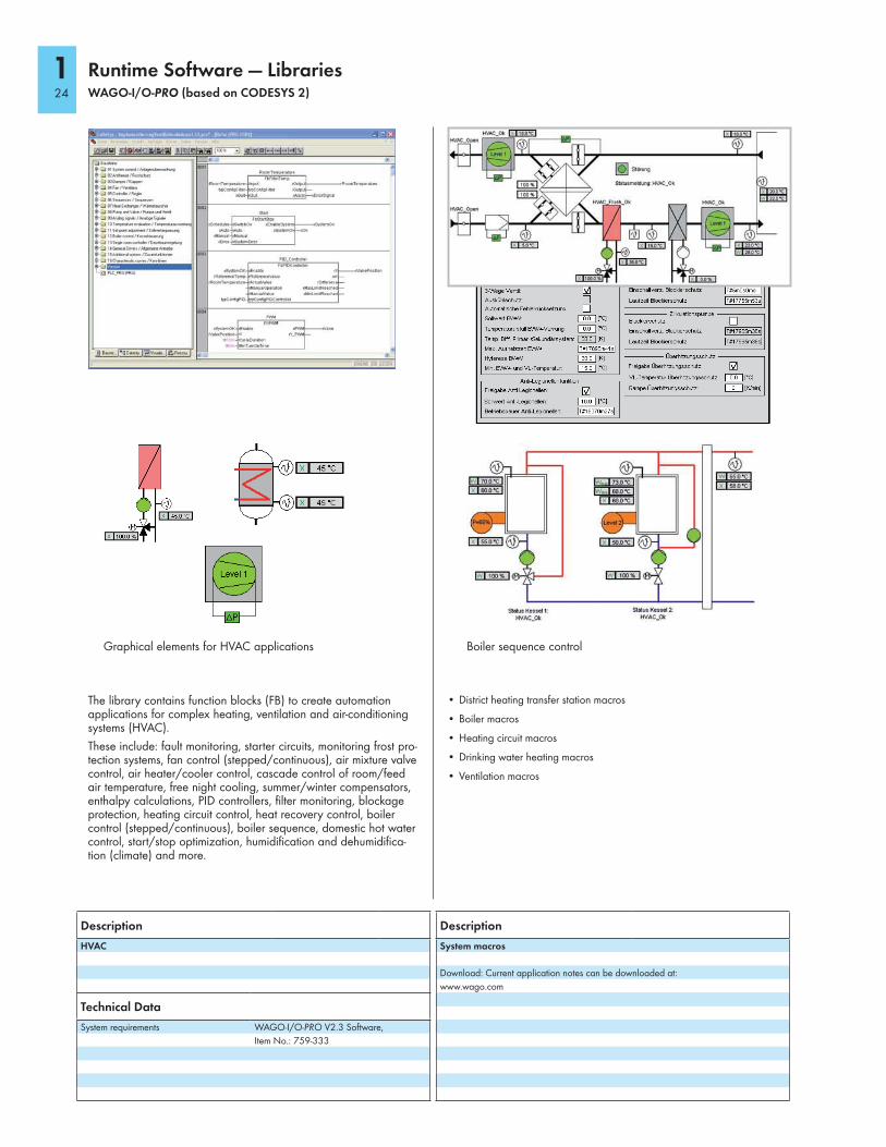
The library contains function blocks (FB) to create automation applications for complex heating, ventilation and air-conditioning systems (HVAC).
These include: fault monitoring, starter circuits, monitoring frost pro-tection systems, fan control (stepped/continuous), air mixture valve control, air heater/cooler control, cascade control of room/feed air temperature, free night cooling, summer/winter compensators, enthalpy calculations, PID controllers, filter monitoring, blockage protection, heating circuit control, heat recovery control, boiler control (stepped/continuous), boiler sequence, domestic hot water control, start/stop optimization, humidification and dehumidifica-tion (climate) and more.
Graphical elements for HVAC applications Boiler sequence control
• District heating transfer station macros
• Boiler macros
• Heating circuit macros
• Drinking water heating macros
• Ventilation macros
Runtime Software — Libraries WAGO-I/O-PRO (based on CODESYS 2)
Description
HVAC
Technical Data
System requirements WAGO-I/O-PRO V2.3 Software,
Item No.: 759-333
Description
System macros
Download: Current application notes can be downloaded at:
www.wago.com
124

25
1
1
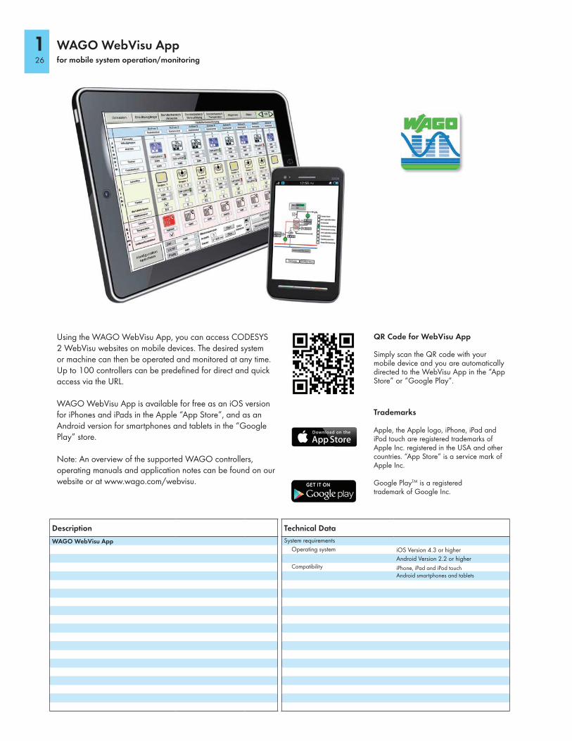
Using the WAGO WebVisu App, you can access CODESYS 2 WebVisu websites on mobile devices. The desired system or machine can then be operated and monitored at any time. Up to 100 controllers can be predefined for direct and quick access via the URL.
WAGO WebVisu App is available for free as an iOS version for iPhones and iPads in the Apple “App Store”, and as an Android version for smartphones and tablets in the “Google Play” store.
Note: An overview of the supported WAGO controllers, operating manuals and application notes can be found on our website or at www.wago.com/webvisu.
QR Code for WebVisu App
Simply scan the QR code with your mobile device and you are automatically directed to the WebVisu App in the “App Store” or “Google Play”.
Trademarks
Apple, the Apple logo, iPhone, iPad and iPod touch are registered trademarks of Apple Inc. registered in the USA and other countries. “App Store” is a service mark of Apple Inc.
Google PlayTM is a registered trademark of Google Inc.
WAGO WebVisu Appfor mobile system operation/monitoring
Technical Data
System requirements
Operating system iOS Version 4.3 or higher
Android Version 2.2 or higherCompatibility iPhone, iPad and iPod touch
Android smartphones and tablets
Description
WAGO WebVisu App
126

27
1
1
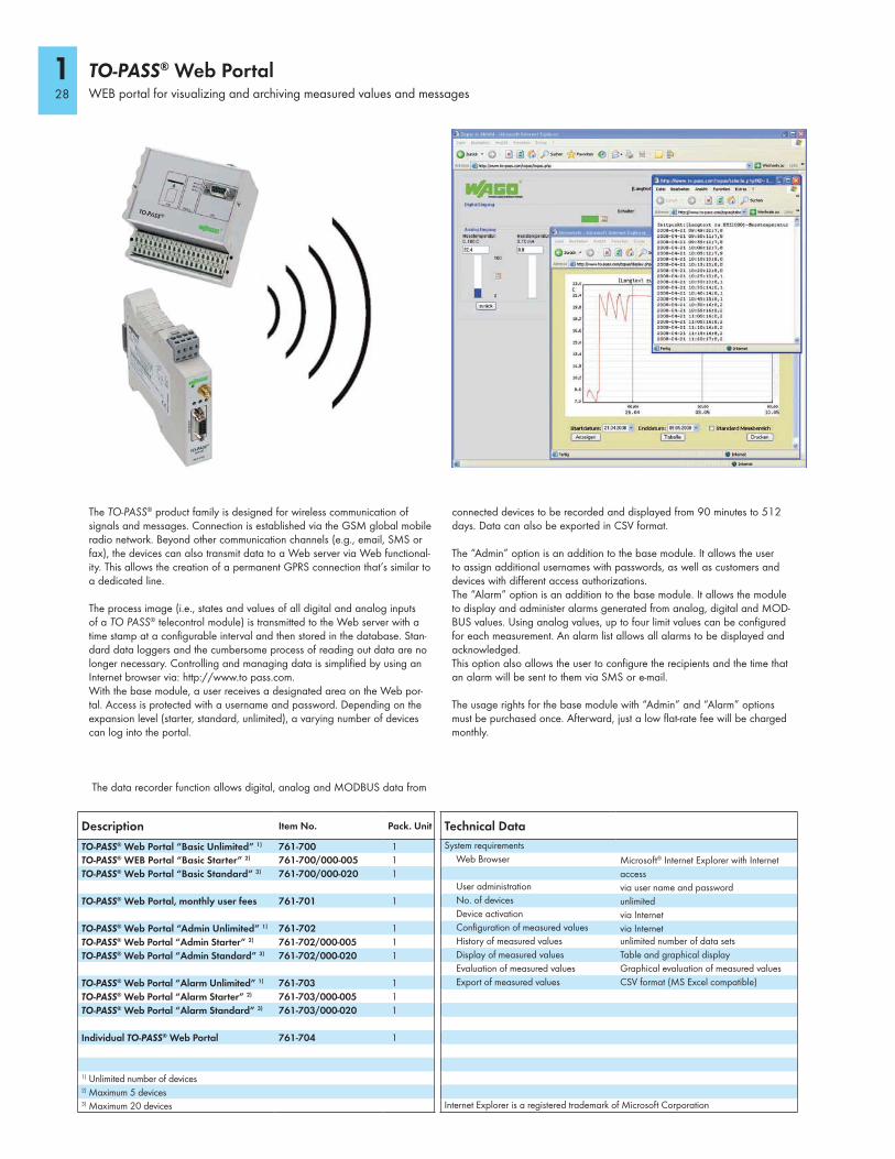
The TO-PASS® product family is designed for wireless communication of signals and messages. Connection is established via the GSM global mobile radio network. Beyond other communication channels (e.g., email, SMS or fax), the devices can also transmit data to a Web server via Web functional-ity. This allows the creation of a permanent GPRS connection that’s similar to a dedicated line.
The process image (i.e., states and values of all digital and analog inputs of a TO PASS® telecontrol module) is transmitted to the Web server with a time stamp at a configurable interval and then stored in the database. Stan-dard data loggers and the cumbersome process of reading out data are no longer necessary. Controlling and managing data is simplified by using an Internet browser via: http://www.to pass.com. With the base module, a user receives a designated area on the Web por-tal. Access is protected with a username and password. Depending on the expansion level (starter, standard, unlimited), a varying number of devices can log into the portal.
The data recorder function allows digital, analog and MODBUS data from
connected devices to be recorded and displayed from 90 minutes to 512 days. Data can also be exported in CSV format.
The “Admin” option is an addition to the base module. It allows the user to assign additional usernames with passwords, as well as customers and devices with different access authorizations.The “Alarm” option is an addition to the base module. It allows the module to display and administer alarms generated from analog, digital and MOD-BUS values. Using analog values, up to four limit values can be configured for each measurement. An alarm list allows all alarms to be displayed and acknowledged.This option also allows the user to configure the recipients and the time that an alarm will be sent to them via SMS or e-mail.
The usage rights for the base module with “Admin” and “Alarm” options must be purchased once. Afterward, just a low flat-rate fee will be charged monthly.
TO-PASS® Web PortalWEB portal for visualizing and archiving measured values and messages
Technical Data
System requirements
Web Browser Microsoft® Internet Explorer with Internet
accessUser administration via user name and passwordNo. of devices unlimitedDevice activation via InternetConfiguration of measured values via InternetHistory of measured values unlimited number of data sets
Display of measured values Table and graphical display
Evaluation of measured values Graphical evaluation of measured values
Export of measured values CSV format (MS Excel compatible)
Internet Explorer is a registered trademark of Microsoft Corporation
Description Item No. Pack. Unit
TO-PASS® Web Portal “Basic Unlimited” 1) 761-700 1
TO-PASS® WEB Portal “Basic Starter” 2) 761-700/000-005 1
TO-PASS® Web Portal “Basic Standard” 3) 761-700/000-020 1
TO-PASS® Web Portal, monthly user fees 761-701 1
TO-PASS® Web Portal “Admin Unlimited” 1) 761-702 1
TO-PASS® Web Portal “Admin Starter” 2) 761-702/000-005 1
TO-PASS® Web Portal “Admin Standard” 3) 761-702/000-020 1
TO-PASS® Web Portal “Alarm Unlimited” 1) 761-703 1
TO-PASS® Web Portal “Alarm Starter” 2) 761-703/000-005 1
TO-PASS® Web Portal “Alarm Standard” 3) 761-703/000-020 1
Individual TO-PASS® Web Portal 761-704 1
1) Unlimited number of devices2) Maximum 5 devices3) Maximum 20 devices
128
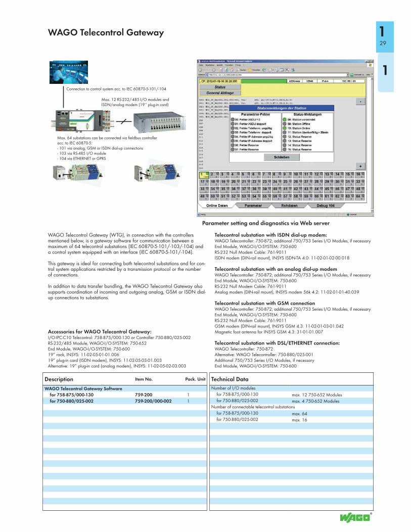
WAGO Telecontrol Gateway (WTG), in connection with the controllers mentioned below, is a gateway software for communication between a maximum of 64 telecontrol substations (IEC 60870-5-101/-103/-104) and a control system equipped with an interface (IEC 60870-5-101/-104).
This gateway is ideal for connecting both telecontrol substations and for con-trol system applications restricted by a transmission protocol or the number of connections.
In addition to data transfer bundling, the WAGO Telecontrol Gateway also supports coordination of incoming and outgoing analog, GSM or ISDN dial-up connections to substations.
Accessories for WAGO Telecontrol Gateway:I/O-IPC-C10 Telecontrol: 758-875/000-130 or Controller 750-880/025-002RS-232/485 Module, WAGO-I/O-SYSTEM: 750-652End Module, WAGO-I/O-SYSTEM: 750-60019” rack, INSYS: 11-02-05-01-01.00619” plug-in card (ISDN modem), INSYS: 11-02-05-03-01.003Alternative: 19” plug-in card (analog modem), INSYS: 11-02-05-02-03.003
Telecontrol substation with ISDN dial-up modem:WAGO Telecontroller: 750-872; additional 750/753 Series I/O Modules, if necessaryEnd Module, WAGO-I/O-SYSTEM: 750-600RS-232 Null Modem Cable: 761-9011ISDN modem (DIN-rail mount), INSYS ISDN-TA 4.0: 11-02-01-02-00.018
Telecontrol substation with an analog dial-up modemWAGO Telecontroller: 750-872; additional 750/753 Series I/O Modules, if necessaryEnd Module, WAGO-I/O-SYSTEM: 750-600RS-232 Null Modem Cable: 761-9011Analog modem (DIN-rail mount), INSYS modem 56k 4.2: 11-02-01-01-40.039
Telecontrol substation with GSM connectionWAGO Telecontroller: 750-872; additional 750/753 Series I/O Modules, if necessaryEnd Module, WAGO-I/O-SYSTEM: 750-600RS-232 Null Modem Cable: 761-9011GSM modem (DIN-rail mount), INSYS GSM 4.3: 11-02-01-03-01.042Magnetic foot antenna for INSYS GSM 4.3: 31-01-01.007
Telecontrol substation with DSL/ETHERNET connection:WAGO Telecontroller: 750-872Alternative: WAGO Telecontroller: 750-880/025-001Additional 750/753 Series I/O Modules, if necessaryEnd Module, WAGO-I/O-SYSTEM: 750-600
WAGO Telecontrol Gateway
Parameter setting and diagnostics via Web server
Technical Data
Number of I/O modules
for 758-875/000-130 max. 12 750-652 Modulesfor 750-880/025-002 max. 4 750-652 Modules
Number of connectable telecontrol substations
for 758-875/000-130 max. 64for 750-880/025-002 max. 16
Description Item No. Pack. Unit
WAGO Telecontrol Gateway Software
for 758-875/000-130 759-200 1
for 750-880/025-002 759-200/000-002 1
Connection to control system acc. to IEC 60870-5-101/-104
Max. 12 RS-232/-485 I/O modules and ISDN/analog modem (19‘‘ plug-in card)
Max. 64 substations can be connected via fieldbus controller acc. to IEC 60870-5:- 101 via analog, GSM or ISDN dial-up connections- 103 via RS-485 I/O module- 104 via ETHERNET or GPRS
29
1
1
Accessories
Description Item No. Pack. Unit
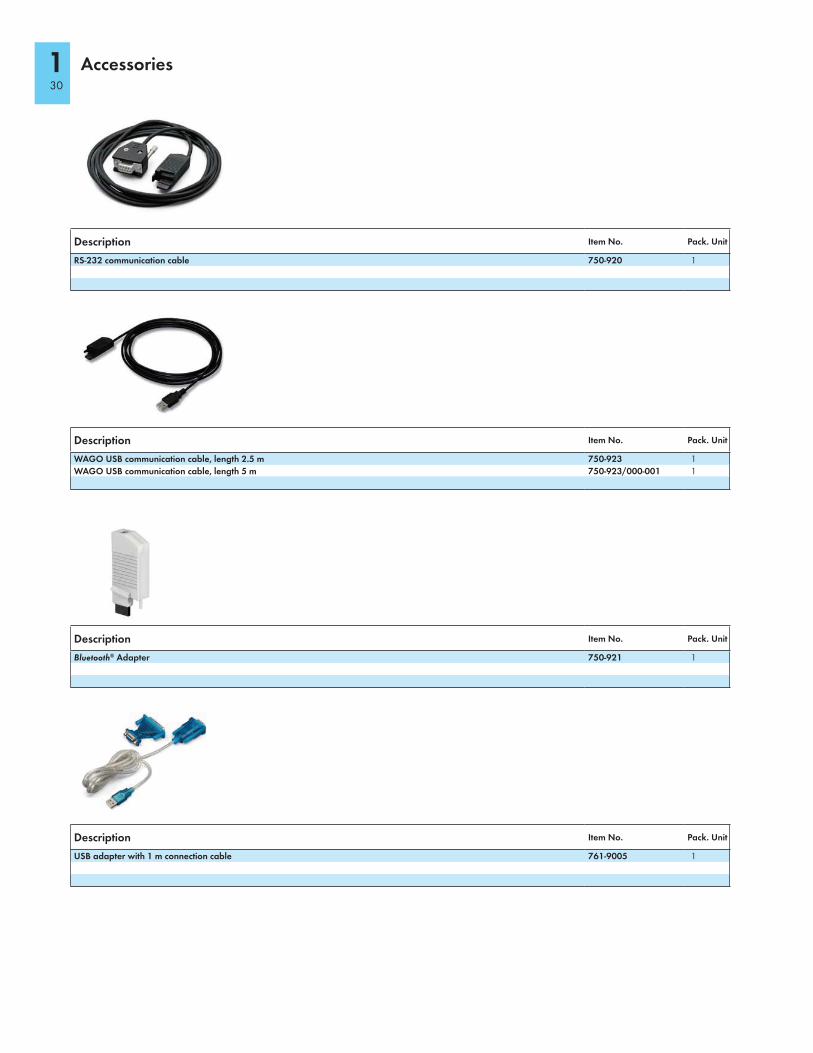
RS-232 communication cable 750-920 1
Description Item No. Pack. Unit
WAGO USB communication cable, length 2.5 m 750-923 1
WAGO USB communication cable, length 5 m 750-923/000-001 1
Description Item No. Pack. Unit
Bluetooth® Adapter 750-921 1
Description Item No. Pack. Unit
USB adapter with 1 m connection cable 761-9005 1
130