Embed Size (px)
Citation preview

Attachment A: High Efficiency Exterior Lights
Definition:�
High efficiency exterior lighting means a lighting technology that, when installed on the vehicle, is expected to
reduce the total electrical demand of the exterior lighting system when compared to conventional lighting
systems.
Credits:
Credits are determined by comparing wattage of new high efficiency exterior lights to the wattage of the
baseline lights that are replaced.
Description of Ford System:
Ford uses bidirectional Xenon high intensity discharge (HID) lamps, Xenon HID for short. These lamps are
approximately 30 percent more efficient than standard halogen bulbs.
Ford also uses light-emitting diode (LED) lamps, which is one of the most energy-efficient lighting sources. LEDs
are increasingly being purchased to replace other types of lamps. LEDs are relatively more expensive than
other types of bulbs, but are very cost-effective because they use only a fraction of the electricity of traditional
lighting methods and can last far longer.
Ford Methodology:
Ford currently uses high efficiency exterior lights on the following lighting components:
• Low beam
• High beam
• Parking/position
• Turn signal, front
• Side marker, front
• Tail
• Turn signal, rear
• Side marker, rear
• License plate
The credits Ford is requesting are calculated by using EPA’s formula from the Joint TSD based on our measured
baseline and new light wattage.
The fleet credit will be calculated based on credit for each type of vehicle, vehicle lifetime miles and U.S. sales
volume for applicable 2012 and beyond model year products.

Attachment B: Thermal Control Technology - Glass / Glazing
Definition: Glass Glazing Technologies which can reduce the amount of solar heat gain in the cabin by
reflecting or absorbing some of the infrared solar energy. One measure of solar load-reducing
potential for glazing is Total Solar Transmittance or Tts which expresses the percentage of solar energy
which passes through the glazing. (p. 5-101 of EPA’s Joint Technical Support Document: Final
Rulemaking for 2017-2025 Light-Duty Vehicle Greenhouse Gas Emission Standards and Corporate
Average Fuel Economy Standards.)
Credits
The maximum passenger automobile credit is 2.9 grams/mile. The maximum light truck credit is 3.9
grams/mile. (40 CFR 86.1869-12(b)(viii)(A))
Description of Ford System: Ford glass applications are designed in accordance with FMVSS 205/ ANSI
Z26.1 glazing standards for Passenger cars, SUV and Trucks.
Ford Methodology: Tts values are provided by our glass suppliers. Values represent modelled nominal
values for each glass construction based on methodology outlined in ISO 13837. Note, page 5-102 of
EPA’s Joint Technical Support Document: Final Rulemaking for 2017-2025 Light-Duty Vehicle
Greenhouse Gas Emission Standards and Corporate Average Fuel Economy Standards states that EPA
considers the April 15, 2008 version of ISO 13837 standard to be the appropriate method for measuring
the solar transmittance of glazing used in automotive applications.
Credits due to glazed glass for each application are calculated based on glass locations, glass Ttsbase and
Ttsnew and total glass area G for each location. Glass area, G, for each location represents the day-
light opening area (DLO) vs total glass area. Estimates of fleet credit are based on vehicle type
(car/truck) and US sales volume.
86.1869-12 CO2 credits for off-cycle CO2-reducing technologies
(viii) Thermal control technologies. The maximum credit allowed for thermal control technologies is
limited to 3.0 g/mi for passenger automobiles and to 4.3 g/mi for light trucks.
(A) Glass or glazing. Glass or glazing credits are calculated using the following equation, and rounded to
the nearest 0.1 grams/mile:
i × i�redit = [Z × ]
Where:Credit = the total glass or glazing credits in grams per mile rounded to the nearest 0.1 grams/mile. Thecredit may not exceed 2.9 g/mi for passenger automobiles or 3.9 g/mi for light trucks:
Z = 0.3 for passenger automobiles and 0.4 for light trucks
Attachment B: Thermal Control Technology - Glass / Glazing
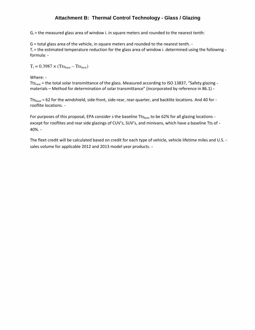
Gi = the measured glass area of window i. in square meters and rounded to the nearest tenth:
G = total glass area of the vehicle, in square meters and rounded to the nearest tenth.Ti = the estimated temperature reduction for the glass area of window i. determined using the followingformula:
Ti = 0.3987 × (Ttsbase – Ttsnew)
Where:Ttsnew = the total solar transmittance of the glass. Measured according to ISO 13837, “Safety glazingmaterials – Method for determination of solar transmittance” (incorporated by reference in 86.1)
Ttsbase = 62 for the windshield, side-front, side-rear, rear-quarter, and backlite locations. And 40 forrooflite locations.
For purposes of this proposal, EPA consider s the baseline Ttsbase to be 62% for all glazing locations
except for rooflites and rear side glazings of CUV’s, SUV’s, and minivans, which have a baseline Tts of
40%.
The fleet credit will be calculated based on credit for each type of vehicle, vehicle lifetime miles and U.S.
sales volume for applicable 2012 and 2013 model year products.

Attachment C: Thermal Control Technology - Active Seat Ventilation
Definition: Active Seat Ventilation, a device which draws air, forces air or transfers heat from the seating
surface which is in contact with the occupant and exhausts it to a location away from the seat. At a minimum,
the front driver and passenger seat must utilize this technology for a vehicle to be eligible for credit. If the
vehicle only has two seats, then these seats must have active seat ventilation for a vehicle to be eligible for
credit.
Credit: (40 CFR §86.1869-12 (b) (viii) (B))
Active Ventilation –
(A) The passenger automobile credit is 1.0 grams/mile
(B) The light truck credit is 1.3 grams/mile
Description of Ford System:
Active occupant cooling is achieved by incorporating two thermoelectric modules, one in the cushion and the
other in the lumbar region of the seat. Each module is comprised of a thermal electric chiller and the air
distribution system matched to the seat foam & trim. The blower draws cabin air and forces the air across the
thermal electric chiller exchanger. The air travels through the distribution layer across the lower side of the
seat and then uses passages in the foam to bring the cooled air to the surface of the seat. The seat trim is also
perforated to allow the air to reach the seat occupant, providing supplemental thermal comfort, thus reducing
HVAC load.
Ford Methodology: Per the methodology described in the Joint TSD regarding credit determination, we intend
to apply the pre-defined credit listed above for each active ventilation application per vehicle type (car/truck).
The fleet credit will be calculated based on credit for each type of vehicle, vehicle lifetime miles and U.S. sales
volume for applicable 2012 and 2013 model year products.

Attachment D: Thermal Control Technology - Solar Reflective Surface Coating
Definition:
Solar reflective surface coating means a vehicle paint or other surface coating which reflects at least 65
percent of the impinging infrared solar energy, as determined using ASTM standards E903, E1918-06, or
C1549-09 (incorporated by reference in § 86.1). The coating must be applied at a minimum to all of the
approximately horizontal surfaces of the vehicle that border the passenger and luggage compartments
of the vehicle, (e.g., the rear deck lid and the cabin roof).
Credits:
• The passenger automobile credit is 0.4 grams/mile.
• The light truck credit is 0.5 grams/mile.
Description of Ford System:
Ford currently utilizes one vehicle paint that reflects at least 65 percent of the impinging infrared solar
energy. The paint was tested per the ASTM standard E903, E1918-06.
Ford Methodology:
• Determine the % impinging infrared solar energy for each paint using ASTM standards E903,
E1918-06
• Apply the EPA estimate of credits due to solar reflective paint results in a credit of 0.4 g/mi for
cars and 0.5 g/mi for trucks.
• The fleet credit will be calculated based on credit for each type of vehicle, vehicle lifetime miles
and U.S. sales volume for applicable 2012 and 2013 model year products.
Attachment E: Active Aerodynamic Improvements (Active Grill Shutters)
Definition:
Active aerodynamic improvements means technologies that are automatically activated under certain conditions
to improve aerodynamic efficiency (e.g., lowering of the coefficient of drag, or Cd), while preserving other
vehicle attributes or functions.
Credits:
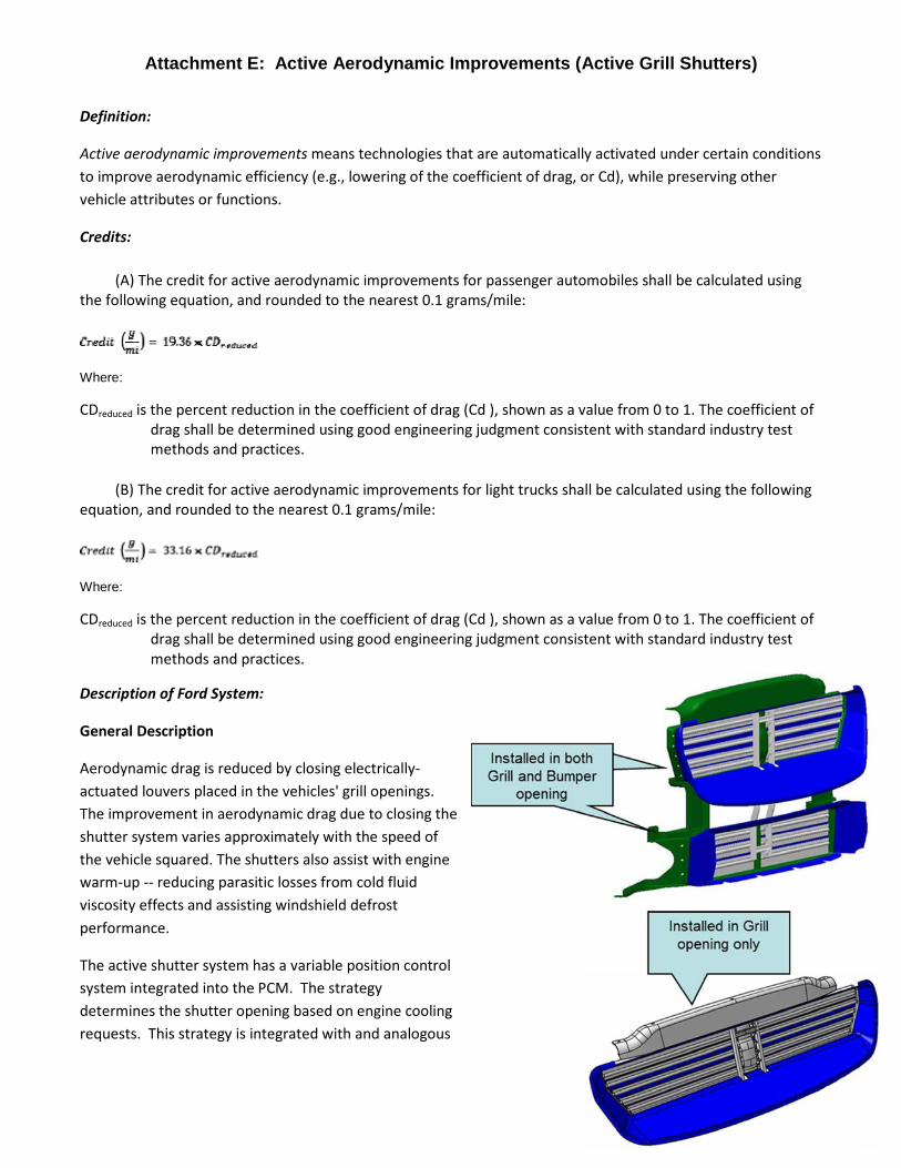
(A) The credit for active aerodynamic improvements for passenger automobiles shall be calculated using
the following equation, and rounded to the nearest 0.1 grams/mile:
Where:
CDreduced is the percent reduction in the coefficient of drag (Cd ), shown as a value from 0 to 1. The coefficient of
drag shall be determined using good engineering judgment consistent with standard industry test
methods and practices.
(B) The credit for active aerodynamic improvements for light trucks shall be calculated using the following
equation, and rounded to the nearest 0.1 grams/mile:
Where:
CDreduced is the percent reduction in the coefficient of drag (Cd ), shown as a value from 0 to 1. The coefficient of
drag shall be determined using good engineering judgment consistent with standard industry test
methods and practices.
Description of Ford System:
General Description
Aerodynamic drag is reduced by closing electrically-
actuated louvers placed in the vehicles' grill openings.
The improvement in aerodynamic drag due to closing the
shutter system varies approximately with the speed of
the vehicle squared. The shutters also assist with engine
warm-up -- reducing parasitic losses from cold fluid
viscosity effects and assisting windshield defrost
performance.
The active shutter system has a variable position control
system integrated into the PCM. The strategy
determines the shutter opening based on engine cooling
requests. This strategy is integrated with and analogous

Attachment E: Active Aerodynamic Improvements (Active Grill Shutters)
to Ford's fan control system, determining the powertrain cooling needs based on key inputs such as engine
coolant temperature, intake air temperature, ambient temperature, vehicle speed, throttle position, and A/C
head pressure. For example, during closed pedal conditions the cooling request is reduced to help close the
shutters, anticipating the reduction in heat load for the low load condition. The shutters are also likely opened
under braking events to take advantage of these "no cost" powertrain cooling opportunities. Under potential
snow and ice conditions the shutters are kept partially open (~30%) to avoid freezing the shutters closed.
Ford has developed a process for ensuring that the AGS system remains sufficiently closed to provide at least
75% effectiveness over an FTP, Highway, and US06 test run using a Road Speed Modulated Fan (RSF), where fan
speed is proportional to the vehicle speed. The 75% effectiveness determination utilizes the position of the AGS
over this drive cycle, weighted by the aerodynamic effectiveness and vehicle speed and excluding any braking
events.
When grill shutters are installed on an application, different configurations are available and can include
shutters in all or only part of the front openings (grill and / or bumper). Some turbo charged vehicle applications
utilize a secondary set of independently controlled grill shutters, which modulate the air flow to the charge air
cooler heat exchanger. The primary function of these shutters is to maintain an optimum temperature of the
boosted intake air to maximize performance and to mitigate condensate formation.
Ford Methodology/Data:
• Wind tunnel data collected on prototype vehicle with shutters disabled, then repeated with shutters
enabled.
• Determined the aero benefits (counts of aero).
• Utilized the TSD performance metric to determine the corresponding benefit in CO2 reductionassociated with the % improvement for both cars and trucks.
• Actual calculations based on testing prototypes that provide data representative of production values.
• Development data consists of estimates based on clay model testing.
The fleet credit will be calculated based on credit for each type of vehicle, vehicle lifetime miles and U.S. sales
volume for applicable 2012 and 2013 model year products.

Attachment F: Active Transmission Warm-Up
Definition:�
Active transmission warmup means a system that uses waste heat from the vehicle to quickly warm
the transmission fluid to an operating temperature range using a heat exchanger, increasing the overall
transmission efficiency by reducing parasitic losses associated with the transmission fluid, such as losses
related to friction and fluid viscosity.
Credits:
(A) The passenger automobile credit is 1.5 grams/mile.
(B) The light truck credit is 3.2 grams/mile.
Description of Ford System:
o To assist automatic transmission fluid warm-up (as well as cooling), a heat exchanger is incorporated
into the engine coolant loop. With this the transmission warm-up will provide improved fuel economy
performance through faster transmission fluid warm-up rates by minimizing viscous/parasitic losses
during initial warm-up where heater performance is not affected. During colder ambient operation the
transmission warm-up loop is bypassed until the engine coolant temperature starts to stabilize, i.e.,
entering thermostat control.
ATWU Schematic:
Engine
Radiator + in tank
cooler
Heater Core
ATWU Heat
Exchanger Automatic
Transmission
T'stat In-Tank TOC or aux
OTA
ATF
Bypass
Valve
The diagram shown above is for the 5.0L F-150. The schematic for other programs have minor differences
in valve locations for packaging and other constraints, but the active heating of the transmission fluid
among the different vehicle lines is functionally the same

Attachment F: Active Transmission Warm-Up
Ford Methodology: Per the methodology described in the Joint TSD regarding credit determination, we
intend to apply the pre-defined credit listed above for each active transmission warm-up application per
vehicle type (car/truck). The fleet credit will be calculated based on credit for each type of vehicle, vehicle
lifetime miles and U.S. sales volume for applicable 2012 and 2013 model year products.

Attachment G: Active Engine Warm-Up - Cooled Exhaust Manifold
Definition: Active engine warm-up means a system using waste heat from the vehicle to warm up
targeted parts of the engine. This reduces engine friction losses and enables the closed-loop fuel control
more quickly allowing for a faster transition from cold operation to warm operation, thereby decreasing
CO2 emissions, and increasing fuel economy
Credits: (40 CFR §86.1869-12 (b) (vii).)
Active Engine Warm Up
(A) The passenger automobile credit is 1.5 grams/mile.
(B) The light truck credit is 3.2 grams/mile.
Description of Ford CEM:
A Cooled Exhaust Manifold(CEM) is a secondary component that is downstream of the conventional
exhaust manifold that features a heat exchanger that utilizes engine coolant to extract waste heat from
the exhaust gas. The heat from the exhaust is transferred to the engine coolant and pumped back to
the engine. This serves to accelerate warm-up time when the engine is not up to nominal operating
temperature such as during cold start conditions. The benefits are:
1) By warming the engine up more quickly, total friction losses are reduced.
2) Time spent operating in less efficient rich air/fuel ratio modes associated with cold engine
operation is reduced due to faster warm-up and less time spent in these cold operation modes.
3) Engine time off during stop/start mode will be optimized due to faster engine/cabin warm-up.
Ford’s 2013MY and beyond Hybrid and Plug-in Hybrid Electric Vehicles utilize the cooled exhaust
manifold shown below in Figure 1:
Upper Coolant (exit) Plenum Figure 1
Lower Coolant (entrance) Plenum�
The coolant flows into the lower plenum where it is distributed to the jackets covering the four exhaust
runners. The coolant flows through the jackets over the upper portions of the four runners and then
rejoins in the upper plenum before it flows back into the system.

Attachment G: Active Engine Warm-Up - Cooled Exhaust Manifold
Figure 2
CEM In Coolant Flow System Schematic:
Figure 2, shown above, shows the coolant flow circuit for a typical P/HEV. The CEM is located to the
right of the red engine and the lines in the diagram represent the coolant flows in the engine cooling
system.
Ford Methodology: Per the methodology described in the Joint TSD regarding credit determination, we
intend to apply the pre-defined credit listed above for each active engine warm-up application per
vehicle type (car/truck). The fleet credit will be calculated based on credit for each type of vehicle,
vehicle lifetime miles and U.S. sales volume for applicable 2012 and 2013 model year products.

Attachment H: Active Engine Warm-Up - Integrated Exhaust Manifold
Definition:
Active engine warm-up means a system using waste heat from the vehicle, to warm up targeted parts of
the engine. This reduces engine friction losses and enables the closed-loop fuel control more quickly
allowing for a faster transition from cold operation to warm operation, thereby decreasing CO2
emissions, and increasing fuel economy
Credits: (40 CFR §86.1869-12 (b) (vii.)
Active Engine Warm Up -
(A) The passenger automobile credit is 1.5 grams/mile.
(B) The light truck credit is 3.2 grams/mile.
Description of Ford IEM:
A Integrated Exhaust Manifold is a technology which incorporates a conventional exhaust manifold and
cylinder head into a single component. The integrated exhaust manifold features internal cooling jackets
which surround the exhaust port runners. Waste exhaust heat is captured and transferred to the
coolant and circulated back through the cooling circuit to accelerate engine warm-up time.
Attachment H: Active Engine Warm-Up - Integrated Exhaust Manifold
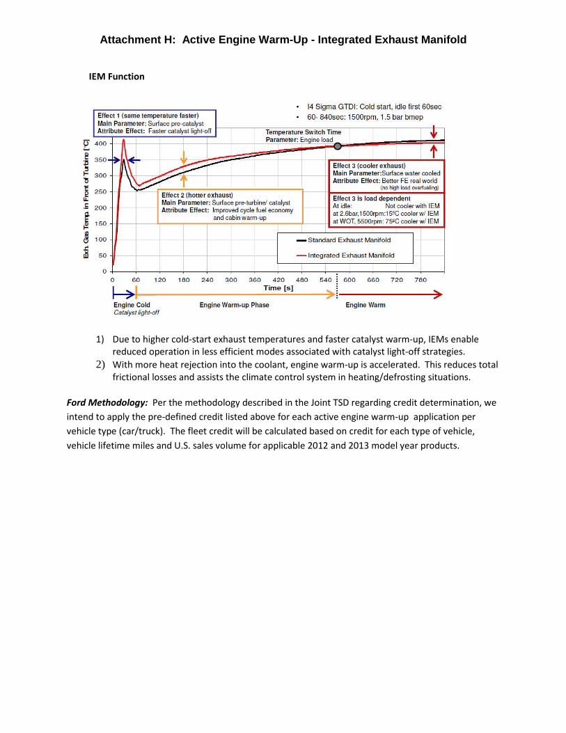
IEM Function
1) Due to higher cold-start exhaust temperatures and faster catalyst warm-up, IEMs enable
reduced operation in less efficient modes associated with catalyst light-off strategies.
2) With more heat rejection into the coolant, engine warm-up is accelerated. This reduces total
frictional losses and assists the climate control system in heating/defrosting situations.
Ford Methodology: Per the methodology described in the Joint TSD regarding credit determination, we
intend to apply the pre-defined credit listed above for each active engine warm-up application per
vehicle type (car/truck). The fleet credit will be calculated based on credit for each type of vehicle,
vehicle lifetime miles and U.S. sales volume for applicable 2012 and 2013 model year products.

Attachment I: Engine Idle Start-Stop
Definitions:�
Engine idle start-stop means a technology which enables a vehicle to automatically turn off the engine
when the vehicle comes to a rest and restarts the engine when the driver applies pressure to the
accelerator or releases the brake. Off-cycle engine start-stop credits will only be allowed for a vehicle if
the Administrator has made a determination under the testing and calculation provisions in 40 CFR Part
600 that engine start-stop is the predominant operating mode for that vehicle.
Electric heater circulation system means a system installed in a vehicle equipped with an engine idle
start-stop system that continues to circulate heated air to the cabin when the engine is stopped during a
stop-start event. This system must be calibrated to keep the engine off for a minimum of one minute
when the external ambient temperature is 30 °F and when cabin heating is enabled.
Credits:
The passenger automobile credit for engine idle start-stop systems is 2.5 grams/mile, provided that the
vehicle is equipped with an electric heater circulation system (or a technology that provides a similar
function). For vehicles not equipped with such systems the credit is 1.5 grams/mile.
The light truck credit for engine idle start-stop systems is 4.4 grams/mile, provided that the vehicle is
equipped with an electric heater circulation system (or a technology that provides a similar function).
For vehicles not equipped with such systems the credit is 2.9 grams/mile.
Description of Ford’s Stop Start System:
Ford’s engine Stop Start is an energy conserving technology that shuts off the engine when the vehicle is
stopped and idling with the foot on the brake (i.e. traffic light) and automatically re-starts it when the
driver releases the brake. Vehicles with Start/Stop technology would not fall under the definition and
requirements associated with Hybrid Electric Vehicles.
• These systems do not have an electric drive system that provides power/torque for propulsion,
i.e., no electric drive assist
• Ford technology is Starter-Assisted Direct Start
o Utilizes starter motor and combustion to enable rapid restarts
o As opposed to Direct Start (combustion-only – not starter assist) and Belt-driven
Integrated Starter Generator (B-ISG) systems, a.k.a. Belt Alternator/Starter (BAS)
• Synergistic/enabling technology already planned:
o Direction Injection Engines, Electrical Power Steering, Battery Management Systems
(battery current sensor)
o Ford’s strategy includes a smart opportunistic charging feature to temporarily increase
the alternator output voltage under certain conditions such as higher speeds and
decelerations to help maintain 12V battery charge for engine-off operation.

Attachment I: Engine Idle Start-Stop
• Key new or upgraded components include:
o Hall effect crank sensor, Electric aux transmission fluid pump, Enhanced starter motor
and battery, Brake pedal travel and vacuum sensor, Cabin Comfort Sensors, PCM
strategy, Instrument Cluster and Stop/Start Menu, may include aux water pump
• Stop Start temporary deactivation capabilities.
o A temporary deactivation option is provided via a dedicated button
o Defaults to Stop Start operation after the next key-start
• Predominant Operating Mode is established according to EPA guidance CISD-09-19:
o For vehicles which default to the “best fuel economy” mode on key-off,
manufacturers may perform EPA fuel economy testing in the “best fuel economy”
mode because this mode would “reasonably be expected to be followed by the
ultimate purchaser under in-use conditions;” ref. 40 CFR 86.128-00.
Ford’s HEV and PHEV models also employ equivalent or better start-stop functionality, with a broader
range of engine-off capability. Therefore, we believe these models are also eligible for engine idle start-
stop credits. According to the Joint Technical Support Document: “HEV and PHEVs can also idle-off
and are thus eligible for this credit.”
Description of Ford’s Occupant Thermal Comfort Systems (e.g. Auxiliary Water Pump)
Our electric heater circulation system for conventional start-stop vehicles is an auxiliary water pump
which continues to circulate hot coolant through the heater core during engine off. This continued
supply of hot coolant allows air taken into the HVAC system to be warmed and then circulated through
the cabin. The auxiliary water pump only comes on when the engine is off, and start/stop function is
only allowed when the engine coolant is above a temperature threshold.
Similar technology is employed on our HEV and PHEV vehicles and should therefore be eligible for this
incremental credit. The two systems are different in that the PHEV has an isolation valve that allows the
auxiliary water pump to circulate coolant through a smaller circuit to the heater core and an electrically
powered coolant heater, providing more effective heating. For the HEV the main engine coolant pump
is electric so it can be run independently of the engine, allowing it to maintain coolant circulation while
the engine is stopped.
Ford Methodology: Per the methodology described in the Joint TSD regarding credit determination, we
intend to apply the pre-defined credit listed above for each engine idle start-stop application per vehicle
type (car/truck). The fleet credit will be calculated based on credit for each type of vehicle, vehicle
lifetime miles and U.S. sales volume for applicable 2012 and 2013 model year products.