Embed Size (px)
Citation preview

ATTACHMENT 1
LAND DEVELOPMENT SERVICES
May 21, 2019
STAFF REPORT PREPARED BY PERMITTING AND CODE ADMINISTRATION
PROPOSED COUNTY CODE AMENDMENT
PROPOSED PFM AMENDMENT
PROPOSED ZONING AMENDMENT
APPEAL OF DECISION
WAIVER REQUEST
Proposed Amendments to the Public Facilities Manual (PFM) Regarding Phase 2
of the “PFM Flex Project,” a Fairfax First Initiative to Improve the Speed,
Consistency and Predictability of the County’s Land Development Review
Process.
PUBLIC HEARING DATES
Authorization to Advertise: May 21, 2019
Planning Commission Hearing: June 12, 2019 at 7:30 p.m.
Board of Supervisors Hearing: July 16, 2019 at 4:00 p.m.
Prepared By: Danielle Badra, Management Analyst I
(703) 324-7180
Don Lacquement, Engineer IV
(703) 324-1670
Site Code Research & Development Branch,
Land Development Services (LDS)
STAFF REPORT
STAFF RECOMMENDATION
Staff recommends that the Board of Supervisors adopt the proposed PFM amendments. Edits
within each amendment are shown by underlining (added text), strikethrough (deleted text),
double underlining (relocated text), and double-strikethrough (text being relocated).
DISCUSSION
On December 4, 2018, the Board adopted amendments to the PFM as a result of Phase 1 of the
“PFM Flex Project,” a Fairfax First Initiative to improve speed, consistency, and predictability of
the County’s land development review process. The County has fully implemented the PFM Flex
Project Phase 1 amendments. The amendment process for Phase 2 is underway.
This proposed amendment to modernize street light fixtures to light emitting diodes (LED) and
allow an additional pipe material for storm sewers is part of Phase 2 of the PFM Flex Project,
which focuses on technical issues that require additional research and vetting with stakeholders.
These amendments are on a fast-track for implementation. Additional PFM Flex Project
amendments will be presented at public hearings starting in Spring 2020.
LED Street Lights:
In order to further the objectives of the Environmental Vision approved by the Board on June 20,
2017, the Board developed an Operational Energy Strategy (OES) which was adopted on
July 10, 2018. It provides goals, targets, and actions in ten focus areas including “energy use and
efficiency” and “innovative energy solutions.” Using more energy efficient LED street light
fixtures is one way the County can work toward those OES goals. Currently, the PFM requires
High Pressure Sodium streetlights in new developments. This proposed amendment will require
all new development to use LED street light fixtures, which will reduce energy usage and
equivalent carbon dioxide emissions. LED lights also have a longer lifecycle, which will reduce
the County’s lifecycle operating costs. The new fixtures will also be smart-city-capable, with the
ability to add dimming, automatic outage reporting, or other smart-city techniques, as they
become available.
Polypropylene Storm Sewer Pipe:
Virginia Department of Transportation (VDOT) added the use of polypropylene pipe into its
standards and specifications in 2016 for storm sewer applications. This proposed amendment
closely aligns with VDOT standards and specifications for this product, while also incorporating
recommendations from the manufacturer, the American Association of State Highway and
Transportation Officials, and the American Society for Testing and Materials.

PROPOSED AMENDMENTS
1. Chapter 2: General Subdivision and Site Plan Information
The proposed amendment to Chapter 2 (General Subdivision and Site Plan Information)
updates the current inspection requirements for high density polyethylene storm sewer pipe
in §2-0402.2E to require the same inspection standards for polypropylene storm sewer pipe.
2. Chapter 6: Storm Drainage
The proposed amendment to Chapter 6 (Storm Drainage) will add polypropylene pipe to the
list of acceptable pipe and culvert materials for storm drain construction and will provide
technical specifications for the material itself and the methods used to design and install it.
3. Chapter 7: Streets, Street Lights, Parking and Driveways
The proposed amendment to Chapter 7 (Streets, Street Lights, Parking and Driveways) will
update §7-0800 to require LED street light fixtures be used for proposed light fixtures and for
the replacement of existing High Pressure Sodium, Metal Halide and Mercury Vapor light
fixtures where existing streetlights are being used to meet lighting requirements for a
proposed development. The PFM plates 23-7 through 30-7 are being updated to match
amendment text.
ATTACHED DOCUMENTS
Attachment A – Proposed LED Street Lights and Polypropylene Pipe Amendments

Attachment A
1
Proposed Amendments
to
the Fairfax County Public Facilities Manual
Light Emitting Diode (LED) Street Lights 1 2
Amend Chapter 7 (Streets, Street Lights, Parking and Driveways), §7-0802 (General 3
Requirements), by revising §7-0802.1A, to read as follows: 4 5
7-0802.1A Subdivisions with an Average Lot Size Under Less Than 18,000 square feet. 6
7
8
Amend Chapter 7 (Streets, Street Lights, Parking and Driveways), §7-0803 (Authorization 9
and Procedures), by revising §7-0803.1, to read as follows: 10 11
7-0803.1 Fairfax County is served by two electric utility companies: Dominion Energy 12
Virginia Power (Dominion) and the Northern Virginia Electric Cooperative 13
(NOVEC). Depending on which electric service area the project is located in, the 14
following authorization and procedures apply. 15
16
17
Amend Chapter 7 (Streets, Street Lights, Parking and Driveways), by revising §7-0804 18
(Standards and Criteria), to read as follows: 19 20
7-0804 Standards and Criteria 21 22
7-0804.1 Luminaire Style 23
24
A. There are three standard lighting fixture styles and poles available for use. The 25
selection of the style of fixture and pole combination for a particular 26
development is to be made in relation to the area classification (see Table 7.5) 27
and roadway classification (see Table 7.6). These lighting fixtures are to be set 28
in accordance with the current VDOT Road Design Manual, Section A-2, 29
Clear Zone Guidelines for fixed objects and must meet the VDOT clear zone 30
requirements or pass current crash test requirements for obstacles within street 31
clear zones. The available lighting fixtures are as follows: 32
33
1. Dominion Shoebox Cobrahead or NOVEC Cobrahead (RF-1 and RF-2): 34
This is a cut-off fixture which is bracket mounted to a concrete (RF-2) or 35
wood pole (RF-1) (see Plates 28-7 and 29-7). These two fixtures can be 36
used on all roadways and area classifications, where the clear zone is less 37
than 20 feet. When street light poles are set in-line with an existing power 38
pole line, the light pole is to be wood (RF-1). When the light pole is to be 39
set in an area where the electrical distribution is underground, the poles are 40

Attachment A
2
to be concrete (RF-2). When the street light poles are set in front of an 41
existing pole line, either RF-1 and RF-2 (preferred) can be utilized used. 42
43
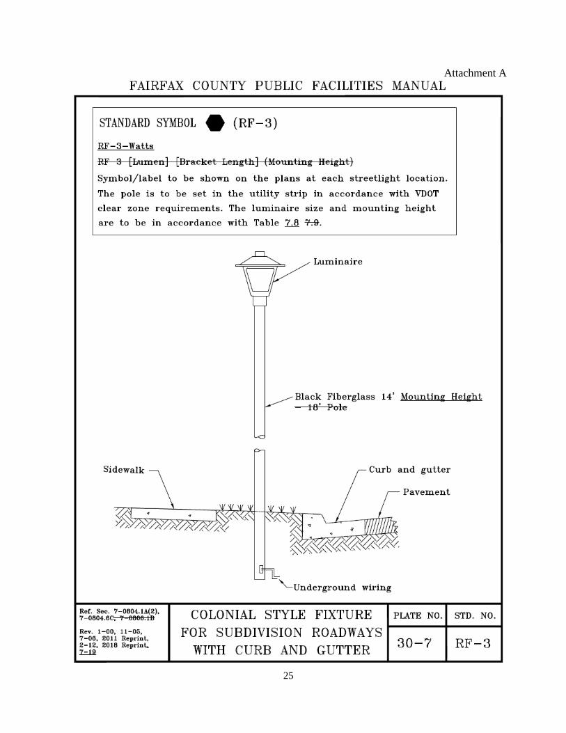
2. Colonial Cut-off (RF-3): This is a top pole mounted coach fixture on a 44
black fiberglass pole that is set in the utility strip (see Plate 30-7). 45
46
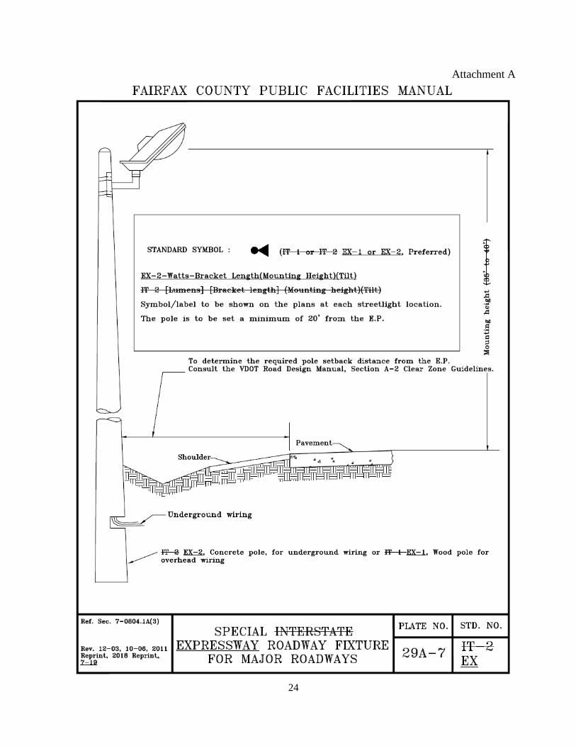
3. Interstate Expressway (IT EX): This special fixture is only used on primary 47
roadways where the VDOT’s clear zone is greater than 20 feet. This fixture 48
can be installed on wood poles (IT-1)(EX-1) or concrete (IT-2)(EX-2) (see 49
Plate 29A-7). 50
51
B. Local Roadways (ADT 0-2000) in Residential, Single Family Detached 52
Dwelling, classification areas: The preferred luminaire is the Colonial Cut-off 53
(RF-3). This fixture is limited to curb-and-gutter roadways with less than 3,000 54
VPD and for underground electrical wiring. As an alternative, the RF-1 and 55
RF-2 can also be utilized used. For local roadway with commercial or 56
industrial classifications, use RF-1 or RF-2 luminaires. 57
58
C. Collector and Arterial roadways in Commercial/Industrial and Residential 59
classification areas: Luminaires to be used are the RF-1 or RF-2. Where the 60
clear zone for fixed objects is greater than 20 feet, the luminaires to be used are 61
the EX-1 and EX-2. 62
63
1. Local Roadways (ADT 2001-5500) in Residential classification areas: The 64
luminaires to be used are the RF-1 and RF-2. 65
66
2. Collector and Arterial roadways in Commercial and Residential 67
classification areas: Luminaires to be used are the RF-1 or RF-2. 68
69
3. Collector and Arterial roadways in Commercial and Residential 70
classification areas: Where the clear zone for fixed object is greater than 20 71
feet, the luminaires to be used are the IT-1 and IT-2. 72
73
7-0804.2 Street Light Source 74
75
A. The standard light source for all street lights is the Light Emitting Diode (LED) 76
with Smart City capability High Pressure Sodium (HPS) lamps. The use of 77
LED HPS street lights must conform to the standards as set forth in Tables 7.7, 78
7.8 and 7.8 9, unless otherwise approved by the Director. 79
80
B. Any use of existing Mercury Vapor (MV), High Pressure Sodium (HPS), or 81
Metal Halide (MH) street lights along existing state road frontage must be 82
converted upgraded to LED. These new fixtures must meet the requirements of 83
the American Nation Standards Institute/Illuminating Engineering Society’s of 84
North America (ANSI/IESNA), American National Standard Recommended 85

Attachment A
3
Practice for Design and Maintenance of Roadway and Parking Facility 86
Lighting (ANSI/IESNA RP-8-18 14, or latest). 87
88
7-0804.3 Light Level Requirements. Illumination levels are determined based on area and road 89
classification as described in Tables 7.7, 7.8, 7.8 9 and 7.9 10. See Tables 7.5 and 7.6 90
for definitions of area and road classifications. Due to the variations in the geometrics 91
and traffic counts for existing State roadways, the design of street lights at these 92
locations is very site specific. The initial design of these street lights must conform to 93
the generalized standards as set forth in Table 7.7. Special coordination with DPWES 94
during the preparation of this street light design may be required to address specific 95
site conditions. The design of these street lights must be shown on the first submission 96
construction plans. This street light design may be subject to revision after review by 97
DPWES. DPWES may also adjust approved street lighting layouts along existing 98
State roadways. DPWES will explain to the developer the reasons why the approved 99
lighting layout is adjusted. These modifications will be made only to coordinate with 100
the location of existing or proposed street lights adjacent to the site or to meet current 101
ANSI/IESNA RP-8-18 Standard Practice for Roadway Lighting. 102
103
A. Residential Areas 104
105
1. Street lights must be provided along roadways within new residential 106
subdivisions in accordance with § 7-0802.1. Luminaire size and maximum 107
allowable spacing and mounting height must conform to the standards set 108
forth in Tables 7.7, 7.8 and 7.8 9. 109
110
2. A minimum of three street lights must be provided at all subdivision 111
entrances as set forth in Tables 7.7 and 7.8. 112
113
B. Commercial/Industrial Areas 114
115
1. Street lights must be provided along all proposed and existing roadways 116
that are or will be included in the State Roadway System within new 117
commercial and industrial subdivisions. Luminaire size and maximum 118
allowable spacing must conform to the standards set forth in Tables 7.7 and 119
7.8. 120
121
2. A minimum of three street lights must be provided at all subdivision 122
entrances as set forth in Tables 7.7 and 7.8. 123
124
7-0804.4 Pole Placement and Bracket Length 125
126
A. All standard roadway fixtures must be installed in such a manner as to 127
maintain a minimum roadway overhang of 2 feet. All pole locations must 128
conform to the current edition of the VDOT Road Design Manual, Section A-2 129
Clear Zone Guidelines and must meet the VDOT clear zone requirements or 130
pass current crash test requirements for obstacles within street clear zones. 131

Attachment A
4
132
1. Residential Areas. Poles located at intersections must be installed as close as 133
possible to, but outside, the radius of the intersection. Poles located along 134
roadways between intersections must be installed with a 1-foot offset to side 135
lot property boundaries. All pole placements and bracket lengths must 136
conform to the standards set forth in Tables 7.7 and 7.8. 137
138
2. Commercial/Industrial Areas. Poles located at intersections must be 139
installed as close as possible to, but outside, the radius of the intersection. 140
Poles located along roadways between intersections must be installed, if 141
possible, with a 1-foot offset to side lot property boundaries. All pole 142
placements and bracket lengths must conform to the standards set forth in 143
Tables 7.7 and 7.8. 144
145
B. Standard colonial style roadway lighting fixtures must utilize black fiberglass 146
poles. These poles must should be installed 2 feet behind the face of curb as set 147
forth in Table 7.9. 148
149
C. If a development has frontage on an existing or proposed public service road, 150
street lights must be located to light the main roadway in accordance with adopted 151
illumination standards. 152
153
7-0804.5 Luminaire Mounting Height – All RF-1 and RF-2 luminaires must be installed 154
with mounting heights as specified in Tables 7.7 and 7.8. All RF-3 luminaires 155
must be installed at a height of 14 feet. 156
157
7-0804.6 Street light information to be shown on development plans: 158
159
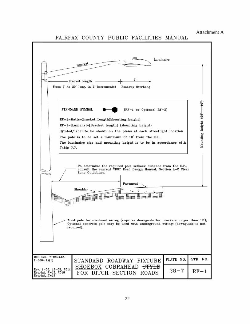
A. The standard roadway fixture for use on ditch section roadways is the RF-1 160
(Plate 28-7). However, the RF-1 could can be substituted with the RF-2 161
(concrete pole with underground wiring) if desired. The RF-1 locations must 162
be designated on the plan in accordance with the symbol shown in Plate 28-7 163
or 29-7. Each RF-1 location must be dimensioned from edge-of-pavement to 164
face-of-pole. Each RF-1 location must be labeled as to luminaire size, bracket 165
length and mounting height as follows: RF-1-luminaire size-bracket 166
length(mounting height), RF-1-(luminaire size)-(bracket length)(mounting 167
height), e.g., RF-1-145-12(35) RF-1-23-12(35) refers to a 23,000 145 watt 168
lumen luminaire with a 12-foot feet bracket length at a mounting height of 35 169
feet. 170
171
B. Standard roadway fixture for use on curb-and-gutter roadways (Plate 29-7). The 172
RF-2 locations must be designated on the plan with the symbol shown in 173
Plate 29-7. Each RF-2 location must be labeled as to luminaire size, bracket length 174
and mounting height as follows: RF-2-luminaire size-bracket length(mounting 175
height) RF-2-(luminaire size)-(bracket length)(mounting height), e.g., RF-2-71-176

Attachment A
5
10(35) RF-2-14-10(30) refers to a 14,000 71 watt lumen luminaire with a 10-foot 177
feet bracket length at a mounting height of 30 35 feet. 178
179
C. Standard colonial style roadway lighting fixture (Plate 30-7). The RF-3 180
locations must be designated on the plan in accordance with the symbol shown 181
in Plate 30-7. Each RF-3 location must be labeled as to luminaire size as 182
follows: RF-3-luminaire size RF-3-(luminaire size), e.g., RF-3-72 RF-3-5 183
refers to a 5,000 72 watt-lumen luminaire. 184
185
D. Special Expressway lighting fixture (Plate 29A-7). The EX-1 and EX-2 186
locations must be designated on the plan in accordance with the symbol shown 187
in Plate 29A-7. Each EX-1 and EX-2 location must be labeled as to luminaire 188
size, bracket length, mounting height and tilt as follows: EX-1-luminaire size-189
bracket length(mounting height)(tilt), e.g., EX-1-145-1(35)(0) refers to a 145 190
watt luminaire with a 1-foot bracket length at a mounting height of 35 feet with 191
a tilt of zero. 192
193
E. All RF-1, RF-2, and RF-3, EX-1, and EX-2 street lights must be plotted 194
accurately to scale on the plans with respect to pole location and, where 195
applicable, bracket length. 196
197
7-0804.7 For design examples, see Plates 23-7 through 27-7. 198
Table 7.5 Area Classification
Residential – All land uses as described in Article 3 of the Zoning Ordinance.
Commercial/Industrial – All land uses as described in Articles 4 and 5 of the Zoning Ordinance.
Planned Development – All land uses as described in Article 6 of the Zoning Ordinance.
Table 7.6 Road Classification
Local – Roadways used primarily for direct access to residential, commercial, or industrial or other abutting
property. These roadways do not carry through traffic.
Collector – Roadways used for serving through traffic between arterial and local roadways. These roadways are
used mainly for traffic movement within residential, commercial and industrial areas.
Arterial – Roadways used as a principal network for through traffic flow. These roadways connect areas of
principal traffic generation and important rural highways entering population centers such as cities.
Attachment A
6
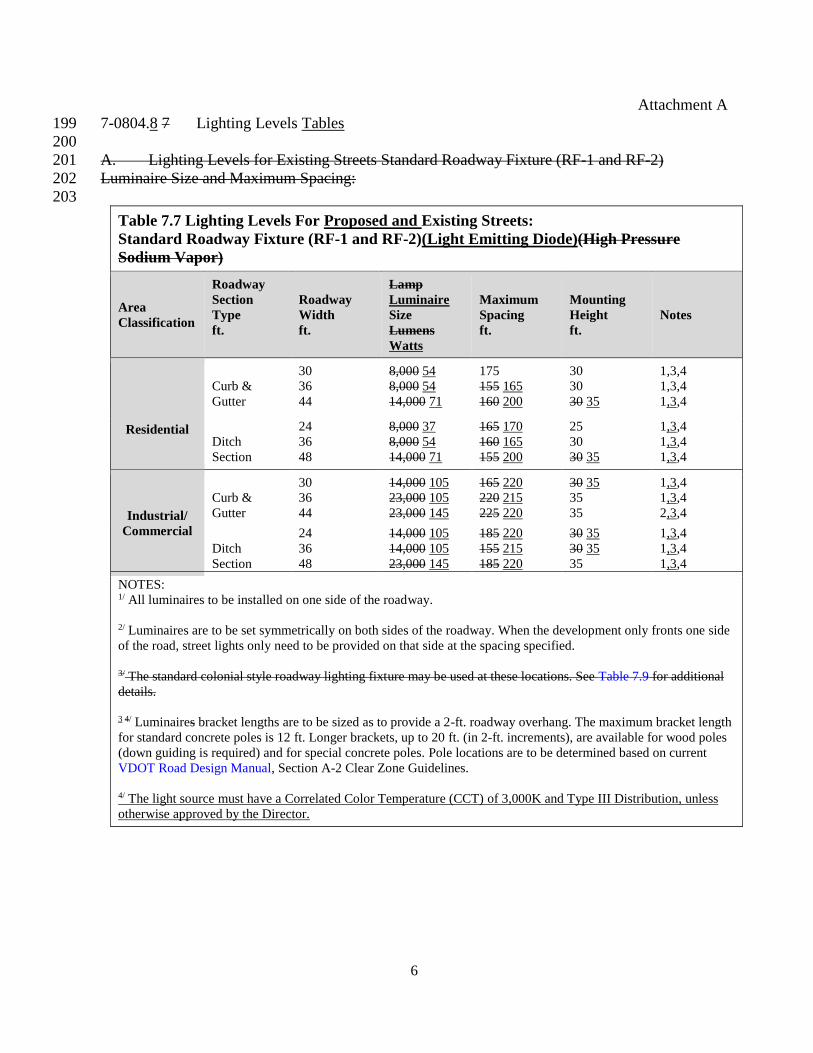
7-0804.8 7 Lighting Levels Tables 199
200
A. Lighting Levels for Existing Streets Standard Roadway Fixture (RF-1 and RF-2) 201
Luminaire Size and Maximum Spacing: 202
203
Table 7.7 Lighting Levels For Proposed and Existing Streets:
Standard Roadway Fixture (RF-1 and RF-2)(Light Emitting Diode)(High Pressure
Sodium Vapor)
Area
Classification
Roadway
Section
Type
ft.
Roadway
Width
ft.
Lamp
Luminaire
Size
Lumens
Watts
Maximum
Spacing
ft.
Mounting
Height
ft.
Notes
Residential
Curb &
Gutter
30
36
44
8,000 54
8,000 54
14,000 71
175
155 165
160 200
30
30
30 35
1,3,4
1,3,4
1,3,4
Ditch
Section
24
36
48
8,000 37
8,000 54
14,000 71
165 170
160 165
155 200
25
30
30 35
1,3,4
1,3,4
1,3,4
Industrial/
Commercial
Curb &
Gutter
30
36
44
14,000 105
23,000 105
23,000 145
165 220
220 215
225 220
30 35
35
35
1,3,4
1,3,4
2,3,4
Ditch
Section
24
36
48
14,000 105
14,000 105
23,000 145
185 220
155 215
185 220
30 35
30 35
35
1,3,4
1,3,4
1,3,4
NOTES: 1/ All luminaires to be installed on one side of the roadway.
2/ Luminaires are to be set symmetrically on both sides of the roadway. When the development only fronts one side
of the road, street lights only need to be provided on that side at the spacing specified.
3/ The standard colonial style roadway lighting fixture may be used at these locations. See Table 7.9 for additional
details.
3 4/ Luminaires bracket lengths are to be sized as to provide a 2-ft. roadway overhang. The maximum bracket length
for standard concrete poles is 12 ft. Longer brackets, up to 20 ft. (in 2-ft. increments), are available for wood poles
(down guiding is required) and for special concrete poles. Pole locations are to be determined based on current
VDOT Road Design Manual, Section A-2 Clear Zone Guidelines.
4/ The light source must have a Correlated Color Temperature (CCT) of 3,000K and Type III Distribution, unless
otherwise approved by the Director.

Attachment A
7
B. Lighting Levels for Proposed Curb and Gutter Streets Standard Roadway Fixture 204
(Plate 29-7) Luminaire Size and Maximum Spacing: 205
206
Table 7.8 Lighting Levels For Proposed Curb & Gutter Streets:
Standard Roadway Fixture (RF-2)(High Pressure Sodium Vapor)
Area
Classification
Roadway
Classification ADT
Lamp Size
Lumens
Maximum
Spacing
ft.
Mounting
Height
ft.
Notes
Residential Local
0-250 8,000 180 30 1,3,4
251-400 8,000 180 30 1,3,4
401-1000 8,000 160 30 1,3,4
1001-2000 8,000 160 25 1,3,4
2001-4000 8,000 160 30 1,4
4001-5500 8,000 155 30 1,4
Collector 4001-5500 14,000 160 30 2,4
Industrial/
Commercial
Local
0-250 14,000 170 30 1,4
251-400 14,000 175 30 1,4
401-1000 14,000 160 30 1,4
1001-2000 23,000 210 35 1,4
2001-4000 23,000 215 35 1,4
4001-5500 23,000 210 35 1,4
Collector 4001-5500 23,000 220 35 2,4
NOTES: 1/ Luminaires are to be set on one side of the roadway.
2/ Luminaires are to be set symmetrically on both side of the roadway.
3/ The standard colonial style roadway lighting fixture may be used at these locations. See Table 7.9 for additional
details.
4/ Luminaires bracket lengths are to be sized as to provide a 2-ft. roadway overhang. The maximum bracket length
for standard concrete poles is 12 ft. Longer brackets, up to 20 ft. (in 2-ft. increments), are available for wood poles
(down guiding is required) and for special concrete poles. Pole locations are to be determined based on current
VDOT Road Design Manual, Section A-2-Clear Zone Guidelines
Attachment A
8
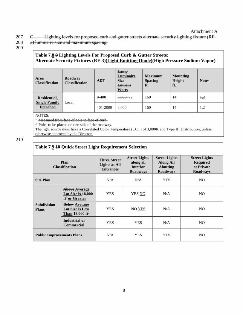
C. Lighting levels for proposed curb and gutter streets alternate security lighting fixture (RF-207
3) luminaire size and maximum spacing. 208
209
Table 7.8 9 Lighting Levels For Proposed Curb & Gutter Streets:
Alternate Security Fixtures (RF-3)(Light Emitting Diode)(High Pressure Sodium Vapor)
Area
Classification
Roadway
Classification ADT
Lamp
Luminaire
Size
Lumens
Watts
Maximum
Spacing
ft.
Mounting
Height
ft.
Notes
Residential,
Single Family
Detached
Local
0-400 5,000 72 160 14 1,2
401-2000 8,000 160 14 1,2
NOTES: 1/ Measured from face of pole to face of curb. 2/ Poles to be placed on one side of the roadway.
The light source must have a Correlated Color Temperature (CCT) of 3,000K and Type III Distribution, unless
otherwise approved by the Director.
210
Table 7.9 10 Quick Street Light Requirement Selection
Plan
Classification
Three Street
Lights at All
Entrances
Street Lights
along all
Interior
Roadways
Street Lights
Along All
Abutting
Roadways
Street Lights
Required
at Private
Roadways
Site Plan N/A N/A YES NO
Subdivision
Plans
Above Average
Lot Size is 18,000
ft2 or Greater
YES YES NO N/A NO
Below Average
Lot Size is Less
Than 18,000 ft2
YES NO YES N/A NO
Industrial or
Commercial YES YES N/A NO
Public Improvements Plans N/A YES YES NO

Attachment A
9
Amend Chapter 7 (Streets, Street Lights, Parking, and Driveways), §7-0805 (Nonstandard 211
Street Lighting), by revising §7-0805.5B, to read as follows: 212 213
7-0805.5B Lighting computations for the proposed nonstandard lighting system must be 214
provided by the developer to DPWES. These computations must show that the 215
proposed nonstandard lighting system meets the current IESNA Standard Practice 216
for Roadway Lighting (ANSI/IESNA RP-8-18 00 or latest version), and that it 217
conforms to the guidelines of the International Dark-Sky Association (IDA) 218
concerning glare and light trespass. These computations must be sealed by a 219
Lighting Certified professional by the National Council on Qualifications for the 220
Lighting Professional (NCQLP), or by a State licensed professional engineer. 221
222
223
Amend Chapter 7 (Streets, Street Lights, Parking, and Driveways), by striking §7-0806 224
(Design Examples), updating and relocating the design examples to Plates 23-7 to 27-7. 225 226
7-0806 Design Examples 227 228
7-0806.1 Typical Lighting Layout Plate 23-7. This is a proposed hypothetical residential 229
subdivision containing lots averaging less than 18,000 square feet in area. 230
231
A. According to § 7-0802.1A, street lighting is required at all entrances to the 232
subdivision along all roads to be included in the State roadway system. A 233
minimum of three lights are required at the entrances to the subdivision. This 234
existing State roadway is a curb-and-gutter roadway with a 44-foot pavement 235
width. Therefore, the standard RF-2 must be utilized in accordance with 236
§ 7-0804.1. According to Table 7.7, 14,000 lumen street lights at a maximum 237
spacing of 160 feet are required with a mounting height of 30 feet. 238
239
B. Since roads with ADTs between 0 and 250 meet all requirements for use of 240
the standard colonial style roadway lighting fixture, (§ 7-0804.1) the 241
developer may use the standard RF-3. According to Table 7.9, for a local 242
residential road with ADTs between 0 and 250, a luminaire size of 5,000 243
lumens is required at a spacing of 160 feet. The poles must be placed 2 feet 244
behind the curb as specified on Plate 30-7 and along the property line 245
between the lots. 246
247
C. Roads with ADTs between 1001 and 2000 also meet all requirements for use 248
of the RF-3 fixture. According to Table 7.9, a luminaire size of 8,000 lumens is 249
required at a maximum spacing of 160 feet. As stated above, pole placement 250
must be 2 feet behind the face-of-curb and along the property line between the 251
lots. 252
253
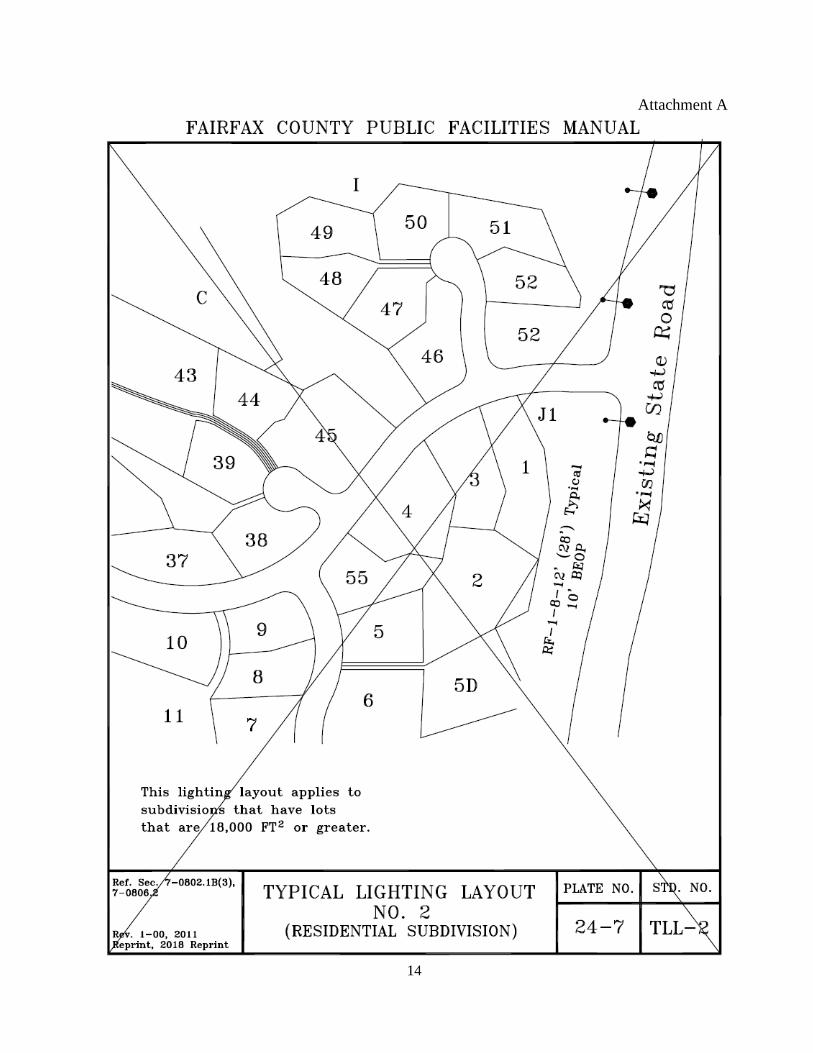
7-0806.2 Typical Lighting Layout Plate 24-7. This is a proposed hypothetical residential 254
subdivision containing lots averaging 18,000 square feet and greater. According to 255
§ 7-0802.1B(2), a minimum of three street lights are required at the proposed 256
Attachment A
10
subdivision entrance along the existing State road. This existing State road is a 24-257
foot wide ditch section road. According to Table 7.7, an 8,000 lumen RF-1 light 258
must be utilized at a spacing of 165 feet with a mounting height of 25 feet. 259
260
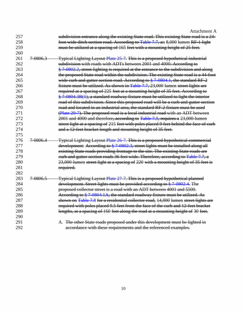
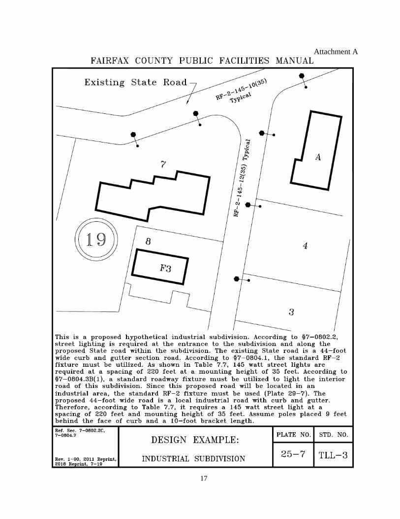
7-0806.3 Typical Lighting Layout Plate 25-7. This is a proposed hypothetical industrial 261
subdivision with roads with ADTs between 2001 and 4000. According to 262
§ 7-0802.2, street lighting is required at the entrance to the subdivision and along 263
the proposed State road within the subdivision. The existing State road is a 44-foot 264
wide curb and gutter section road. According to § 7-0804.1, the standard RF-2 265
fixture must be utilized. As shown in Table 7.7, 23,000 lumen street lights are 266
required at a spacing of 225 feet at a mounting height of 35 feet. According to 267
§ 7-0804.3B(1), a standard roadway fixture must be utilized to light the interior 268
road of this subdivision. Since this proposed road will be a curb and gutter section 269
road and located in an industrial area, the standard RF-2 fixture must be used 270
(Plate 29-7). The proposed road is a local industrial road with an ADT between 271
2001 and 4000 and therefore, according to Table 7.8, requires a 23,000-lumen 272
street light at a spacing of 215 feet with poles placed 9 feet behind the face of curb 273
and a 12-feet bracket length and mounting height of 35 feet. 274
275
7-0806.4 Typical Lighting Layout Plate 26-7. This is a proposed hypothetical commercial 276
development: According to § 7-0802.3, street lights must be installed along all 277
existing State roads providing frontage to the site. The existing State roads are 278
curb and gutter section roads 36 feet wide. Therefore, according to Table 7.7, a 279
23,000-lumen street light at a spacing of 220 with a mounting height of 35 feet is 280
required. 281
282
7-0806.5 Typical Lighting Layout Plate 27-7. This is a proposed hypothetical planned 283
development. Street lights must be provided according to § 7-0802.4. The 284
proposed collector street is a road with an ADT between 4001 and 5500. 285
According to § 7-0804.1A, the standard roadway fixture must be utilized. As 286
shown on Table 7.8 for a residential collector road, 14,000 lumen street lights are 287
required with poles placed 9.5 feet from the face of the curb and 12-feet bracket 288
lengths, at a spacing of 160 feet along the road at a mounting height of 30 feet. 289
290
A. The other State roads proposed under this development must be lighted in 291
accordance with these requirements and the referenced examples. 292
Attachment A
11
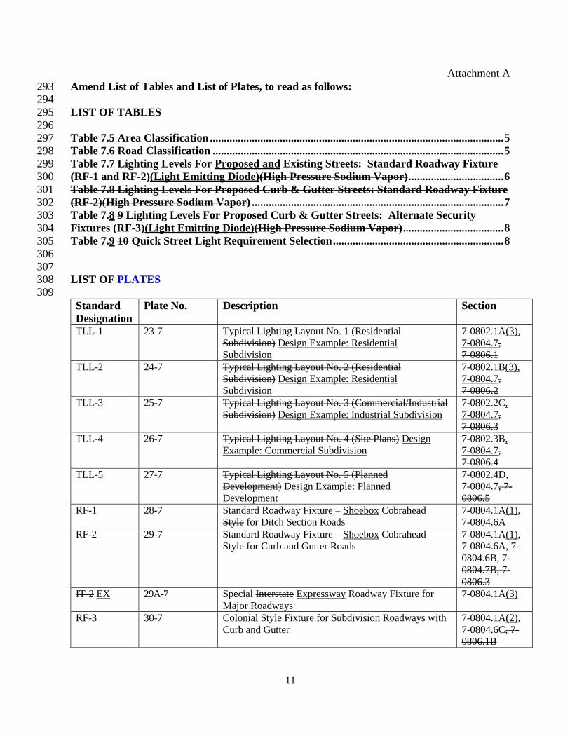
Amend List of Tables and List of Plates, to read as follows: 293 294
LIST OF TABLES 295
296
Table 7.5 Area Classification ......................................................................................................... 5 297
Table 7.6 Road Classification ........................................................................................................ 5 298
Table 7.7 Lighting Levels For Proposed and Existing Streets: Standard Roadway Fixture 299
(RF-1 and RF-2)(Light Emitting Diode)(High Pressure Sodium Vapor) .................................. 6 300
Table 7.8 Lighting Levels For Proposed Curb & Gutter Streets: Standard Roadway Fixture 301
(RF-2)(High Pressure Sodium Vapor) .......................................................................................... 7 302
Table 7.8 9 Lighting Levels For Proposed Curb & Gutter Streets: Alternate Security 303
Fixtures (RF-3)(Light Emitting Diode)(High Pressure Sodium Vapor) .................................... 8 304
Table 7.9 10 Quick Street Light Requirement Selection ............................................................. 8 305
306
307
LIST OF PLATES 308 309
Standard
Designation
Plate No. Description Section
TLL-1 23-7 Typical Lighting Layout No. 1 (Residential
Subdivision) Design Example: Residential
Subdivision
7-0802.1A(3),
7-0804.7,
7-0806.1
TLL-2 24-7 Typical Lighting Layout No. 2 (Residential
Subdivision) Design Example: Residential
Subdivision
7-0802.1B(3),
7-0804.7,
7-0806.2
TLL-3 25-7 Typical Lighting Layout No. 3 (Commercial/Industrial
Subdivision) Design Example: Industrial Subdivision
7-0802.2C,
7-0804.7,
7-0806.3
TLL-4 26-7 Typical Lighting Layout No. 4 (Site Plans) Design
Example: Commercial Subdivision
7-0802.3B,
7-0804.7,
7-0806.4
TLL-5 27-7 Typical Lighting Layout No. 5 (Planned
Development) Design Example: Planned
Development
7-0802.4D,
7-0804.7, 7-
0806.5
RF-1 28-7 Standard Roadway Fixture – Shoebox Cobrahead
Style for Ditch Section Roads
7-0804.1A(1),
7-0804.6A
RF-2 29-7 Standard Roadway Fixture – Shoebox Cobrahead
Style for Curb and Gutter Roads
7-0804.1A(1),
7-0804.6A, 7-
0804.6B, 7-
0804.7B, 7-
0806.3
IT-2 EX 29A-7 Special Interstate Expressway Roadway Fixture for
Major Roadways
7-0804.1A(3)
RF-3 30-7 Colonial Style Fixture for Subdivision Roadways with
Curb and Gutter
7-0804.1A(2),
7-0804.6C, 7-
0806.1B

Attachment A
12
Amend Plates 23-7 to 27-7 to relocate the Design Examples from §7-0806 into the 310
appropriate Plates, and Plates 28-7 to 30-7 to match amendment text, as shown below. 311

Attachment A
13
Attachment A
14

Attachment A
15

Attachment A
16
Attachment A
17

Attachment A
18

Attachment A
19

Attachment A
20

Attachment A
21
Attachment A
22

Attachment A
23
Attachment A
24
Attachment A
25

Attachment A
26
Polypropylene Pipe 312 313
Amend Chapter 6 (Storm Drainage), §6-0902 (Storm Sewer Pipe), by adding §6-0902.2O 314
(Polypropylene Pipe), to read as follows: 315 316
6-0902.2O Polypropylene Pipe 317
318 1. Polypropylene pipe must conform to the requirements of AASHTO M 330 and 319
must be double-wall pipe (Type S) for nominal diameters of 12 inches through 30 320
inches, and must be triple-wall pipe (Type D) for nominal diameters of 36 inches 321
through 60 inches. The use of polypropylene pipe less than 12” or greater than 322
60” is not permitted. Suppliers of polypropylene pipe for stormwater applications 323
must be on VDOT Materials Division Approved List meeting the requirements of 324
VDOT’s PP Corrugated Pipe Products Quality Assurance Program. 325
326
2. Joints between pipe segments and connections to manholes and other pipe 327
structures must meet VDOT requirements and, in accordance with VDOT Road 328
and Bridge Specifications, Section 232.02(m) and IIM-LD-254.2, joints must meet 329
the requirements of AASHTO PP-63-09-14. Joint systems must be on the VDOT 330
Materials Division Approved List for pipe joints. Rubber gaskets must conform to 331
ASTM F 477. 332
333
3. Installations must be in accordance with ASTM D 2321 “Standard Practice for 334
Underground Installation of Thermoplastic Pipe for Sewers and Other Gravity-335
Flow Applications,” the manufacturer’s recommendations, and VDOT 336
requirements, whichever are more stringent. Pipe bedding, embedment, and 337
backfill must conform to the standards set forth in VDOT Road and Bridge 338
Specifications, Section 302.03(a)(2), and PFM Plate 61-6. 339
340
4. A minimum cover of 2’ or ½ pipe diameter, whichever is greater, must be 341
provided in accordance with VDOT requirements. The engineer must determine 342
whether construction and maintenance traffic will traverse the pipe trench once 343
backfilled and must provide minimum cover in accordance with VDOT Standards, 344
AASHTO’s Load and Resistance Factor Design Bridge Construction 345
Specifications, Section 30 (Thermoplastic Culverts), or the manufacturer’s 346
recommendations, whichever is greater. 347
348
5. Filter fabric must surround the aggregate fill material when there is a high-349
water table or where the movement of groundwater can cause the migration of 350
fines from the soil envelope (into the class I embedment material). The filter fabric 351
must overlap by a minimum of 2 feet. Use non-woven geotextile fabric with AOS 352
of 70-100 US Sieve or 0.22 mm-0.15 mm as determined by ASTM D 4751 and a 353
trapezoidal tear strength of 45 LB as determined by ASTM D 4533. Geotextile 354
fabric may not be exposed to direct sunlight for more than 24 hours before 355
installation. 356
357

Attachment A
27
6. Adequate cover must be provided to prevent flotation in accordance with the 358
manufacturer’s recommendations. 359
360
361
Amend Chapter 6 (Storm Drainage), §6-0903 (Pipe and Culvert Materials), by revising 362
Table 6.8, to read as follows: 363 364
Table 6.8 Pipe And Culvert Materials – Roughness Coefficients
Material Manning “n”
Plain Concrete Culvert Pipe (PCCP)2 .013
Non-Reinforced Concrete Sewer Pipe (NRCSP)2 .013
Reinforced Concrete Pipe (RCP) .013
Vitrified Clay Pipe, Extra Strength (VCPX) .013
Cast Iron Pipe (CIP) .013
Corrugated Plain Metal Pipe (CMP)1 .024
25% Paved .021
50% Paved .018
100% Paved .013
High-Density Polyethylene Pipe (HDPE) .012
Polypropylene Pipe (PP) .013
1Corrugated metal pipe is approved for use at residential driveway entrances, temporary installations, and
privately maintained detention systems. Except for the above uses, this type of pipe may be used only when
approved by the Director. In approving the use of CMP, the Director may apply certain conditions to provide for
inspection and testing in accordance with AASHTO’s standards, including deflection testing.
2Plain Concrete Culvert Pipe (PCCP) and Non-Reinforced Concrete Sewer Pipe (NRCSP) must conform to the
VDOT Road and Bridge Specifications. Pipe sizes 12 in. through 24 in. are permitted, in accordance with
§ 6-0902.2.

Attachment A
28
Amend Chapter 6 (Storm Drainage), by revising Plate 61-6, to read as follows: 365 366

Attachment A
29
Amend Chapter 2 (General Subdivision and Site Plan Information), §2-0402 (Inspections), 367
by revising §2-0402.2E(1) through 2-0402.2E(4), to read as follows: 368 369
2-0402.2E Storm sewer pipes must undergo visual and video inspections, installation 370
deflection testing and pipe evaluations by the developer to ensure proper 371
performance in accordance with the following: 372
373
1. Visual Inspection for High Density Polyethylene (HDPE) and 374
Polypropylene (PP) Pipe: During the installation process, the developer 375
must provide for full-time visual inspection of high density polyethylene 376
HDPE and PP storm sewer pipe. Installation and inspection of bedding and 377
backfill materials, as well as and their placement and compaction, must 378
meet the PFM requirements and Section 30.7.1 (Visual Inspection) of the 379
American Association of State and Highway Transportation Official’s 380
(AASHTO’s) Load and Resistance Factor Design, Bridge Construction 381
Specifications, respectively. Visual inspection must be performed by an 382
independent inspection and testing agency or design professional licensed 383
in the Commonwealth of Virginia. (In accordance with standard practice, 384
the actual testing and inspections may be performed by an individual under 385
responsible charge of the licensed professional.) 386
387
2. Video Inspection for all pipes: No sooner than 30 days after completion of 388
installation and final fill and pavement or alternative section, a video 389
record must be performed by the developer on all storm sewer pipes unless 390
deemed unnecessary by the Site Development and Inspections Division 391
(County inspector), LDS. 392
393
3. HDPE and PP Installation Deflection Testing: No sooner than 30 days after 394
completion of installation and final fill and pavement or alternative 395
pavement section, HDPE and PP pipe must be evaluated for deflection 396
using a mandrel or other device that can physically verify the dimension of 397
the pipe as approved by the Director. The pipe must be evaluated by the 398
developer to determine whether the internal diameter of the barrel has been 399
reduced more than 5 percent. A minimum of 10 percent of the total number 400
of pipe runs representing at least 10 percent of the total length of installed 401
pipe must be tested for deflection, in addition to all areas that were 402
identified in the visual inspection as having deflection. Deflection testing 403
must be conducted by the Developer in the presence of a County inspector, 404
or by an independent inspection and testing agency or design professional 405
licensed in the Commonwealth of Virginia. Testing must be conducted in 406
the locations specified by the County inspector. 407
408
4. Pipe Evaluations for concrete, and HDPE, and PP: Pipe inspection must be 409
in accordance with Sections 27.6 (Field Inspection) and 30.5.6.2 30.7.2 410
(Installation Deflection) of AASHTO’s Load and Resistance Factor 411
Design, Bridge Construction Specifications as determined by the Director. 412

Attachment A
30
For instances where cracks are wider than 0.01 inches for concrete pipe, 413
and where pipe deflection exceeds 5 percent of the inside diameter of 414
HDPE or PP pipe, an evaluation must be conducted by the developer’s 415
design professional licensed in the Commonwealth of Virginia and 416
submitted to the County for review and approval considering the severity 417
of the deflection (HDPE or PP), structural integrity, environmental 418
conditions, and the design life of the pipe. Repairs, replacement and 419
remediation must be noted on the inspection report and made in a manner 420
acceptable to the Director. Copies of inspection and mandrel test results, 421
and video record that depict construction and installation of pipes in 422
compliance with PFM standards must be provided to the County inspector 423
for review and record within two weeks of the time the video was taken. 424
The video recording must be provided in a format acceptable to the 425
Director. The independent inspection and testing agency or design 426
professional licensed in the Commonwealth of Virginia must certify that 427
the required testing and inspections have been completed and construction 428
complies with the approved plans, VDOT specifications and standards of 429
the PFM. 430
431