Embed Size (px)
Citation preview
Zammit-Mangion, A., Cressie, N., Ganesan, A. L., O'Doherty, S., &Manning, A. J. (2015). Spatio-temporal bivariate statistical models foratmospheric trace-gas inversion. Chemometrics and Intelligent LaboratorySystems, 149, 227-241. https://doi.org/10.1016/j.chemolab.2015.09.006
Early version, also known as pre-print
Link to published version (if available):10.1016/j.chemolab.2015.09.006
Link to publication record in Explore Bristol ResearchPDF-document
University of Bristol - Explore Bristol ResearchGeneral rights
This document is made available in accordance with publisher policies. Please cite only the publishedversion using the reference above. Full terms of use are available: http://www.bristol.ac.uk/pure/user-guides/explore-bristol-research/ebr-terms/

Spatio-temporal bivariate statistical models for atmospheric trace-gasinversion
Andrew Zammit-Mangiona,∗, Noel Cressiea, Anita L. Ganesanb, Simon O’ Dohertyc, AlistairJ. Manningd
aNational Institute for Applied Statistics Research Australia (NIASRA), School of Mathematics and AppliedStatistics (SMAS), University of Wollongong, Northfields Avenue, Wollongong, NSW 2522, Australia
bSchool of Geographical Sciences, University of Bristol, University Road, Bristol, BS8 1SS, UKcSchool of Chemistry, University of Bristol, Cantock’s Close, Bristol, BS8 1TS, UK
dHadley Centre, Met Office, Fitzroy Road, Exeter, Devon EX1 3PB, UK
Abstract
Atmospheric trace-gas inversion refers to any technique used to predict spatial and temporal
fluxes using mole-fraction measurements and atmospheric simulations obtained from determin-
istic computer models. Studies to date are most often of a data-assimilation flavour, which
implicitly consider univariate statistical models with the flux as the variate of interest. This
univariate approach typically assumes that the flux field is either a spatially correlated Gaussian
process or a spatially uncorrelated non-Gaussian process with prior expectation fixed using flux
inventories (e.g., NAEI or EDGAR in Europe). Here, we extend this approach in three ways.
First, we develop a bivariate model for the mole-fraction field and the flux field. The bivariate
approach allows optimal prediction of both the flux field and the mole-fraction field, and it
leads to significant computational savings over the univariate approach. Second, we employ a
lognormal spatial process for the flux field that captures both the lognormal characteristics of
the flux field (when appropriate) and its spatial dependence. Third, we propose a new, geo-
statistical approach to incorporate the flux inventories in our updates, such that the posterior
spatial distribution of the flux field is predominantly data-driven. The approach is illustrated
on a case study of methane (CH4) emissions in the United Kingdom and Ireland.
Keywords: Conditional multivariate models, Methane emissions, Multivariate geostatistics,
Hamiltonian Monte Carlo, Spatial statistics
∗Corresponding authorEmail address: [email protected] (Andrew Zammit-Mangion)
arX
iv:1
509.
0091
5v1
[st
at.A
P] 3
Sep
201
5

1. Introduction
Atmospheric trace-gas inversion refers to any technique used to predict spatial and tem-
poral fluxes of a gas from observations of mole fractions. Since mole-fraction measurements
are affected by weather patterns that are time varying, there is no straightforward relationship
between the observations and the fluxes. The relationship, termed a ‘source-receptor relation-
ship’ (SRR), is typically obtained by simulating from a deterministic computer model, such as a
Lagrangian Particle Dispersion Model (LPDM), which maps the fluxes to the mole fractions [1].
The SRR can be characterised through a bivariate function bt(s,u) where the spatial locations
s,u ∈ R2 are in a given domain of interest, D ⊂ R2, and t ∈ {1, 2, . . . } is a discrete-time index.
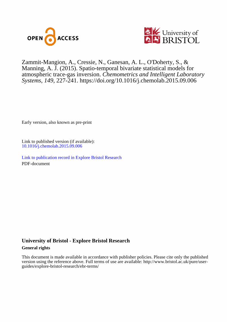
Figure 1, top-left panel, shows the UK and Ireland methane (CH4) total fluxes by grid cell,
in units g s−1, obtained from a combination of flux inventories. Here, the component inventories
are principally the National Atmospheric Emissions Inventory (NAEI) [2] and the Emissions
Database for Global Atmospheric Research version 4.2 (EDGAR) [3]; see [4] for details. Figure 1,
top-right panel, shows an evaluation of bt(s,u), in units s ng−1, of methane fluxes, for s located at
a mole-fraction monitoring station at Angus, Scotland (TTA), where u takes values on a discrete
lattice, and where t = 1 (01 January 2014 at midnight). Figure 1, bottom panel, shows the two-
hourly averaged observations in parts per billion (ppb) at TTA, following background-removal
(see Section 4.2 for details), for all of January 2014. In atmospheric trace-gas inversion, the aim
is to recover a flux map, such as that in Figure 1, top-left panel, from time-series observations
taken at various monitoring stations and from the collection of atmospheric simulations (one
such is shown in Figure 1, top-right panel) that establish the SRR.
Atmospheric trace-gas inversion is an ill-posed problem. Consequently, “small uncertainties
in the observational data correspond to much higher uncertainty in the emission[s]” [5]. However,
in addition to observation and flux-field uncertainties, there is a third source of uncertainty
arising from the use of an atmospheric model that does not perfectly match the true SRR due
to physical parameterisations, solver discretisations, etc. Sometimes this third term is called
the discrepancy term, and failure to acknowledge it can lead to over-confident predictions [6, 7].
Until very recently, this discrepancy was not considered separately from the observation error;
see [4]. However, it is crucial to distinguish between the errors due to observations and those
due to model misspecification, as these are likely to have different statistical properties.
A critical contribution of our work is to formalise the insight in [4] and treat the mole-fraction
field as a second variable of interest. The consideration of modelling a mole-fraction field in
2
Figure 1: Top-left panel: Total flux by grid cell in g s−1 obtained by combining methane inventories (see[4] for details) for January 2014. Top-right panel: The source-receptor relationship on 01 January 2014 at00:00, b1(sTTA, ·), obtained from the UK Met Office’s Lagrangian Particle Dispersion Model (LPDM), NumericalAtmospheric-dispersion Modelling Environment (NAME), where sTTA is the coordinate vector of the Angusmeasurement station (TTA), in Scotland. Also shown are the three other stations used in this study, Mace Head(MHD), Ridge Hill (RGL), and Tacolneston (TAC). Bottom panel: Measurements of methane mole fraction inparts per billion (ppb) at TAC for January 2014, following background-removal (black dots), together with astraightforward prediction (red line) using NAME and the methane flux inventory. Each time step correspondsto an interval of 2 h.
addition to the flux field through a discrepancy term results in a bivariate model (see [8] for a
recent review on such models). The bivariate model brings two advantages to this problem of
trace-gas inversion: The locations at which the mole-fraction field is modelled need not coincide
with the data points. This in turn allows the predictive distribution of mole fraction at any
unobserved locations to be found, and then averaged over any subset of the spatio-temporal
domain, with relative ease (provided the SRR is available for these locations/domain). The
other advantage is that the decoupling leads to computationally efficient methods in spatial
statistics that can be used to scale up the inversion to large, remote-sensing datasets.
3
Another contribution of our work is to introduce the lognormal spatial process as a prior
distribution for the flux field. This model acts as a bridge between the two sides of the di-
chotomous literature that either assumes spatial (possibly truncated) Gaussian-process priors
(e.g., [9]) or spatially uncorrelated lognormal priors (e.g., [10]). A lognormal spatial process is
attractive, as it is able to capture both (i) the nonnegativity and heavy tails in the distribution
of the flux (valid for some trace gases such as methane) and (ii) the spatial correlation of the flux
field. We show that expectations and covariances for both the flux field and the mole-fraction
field can be obtained analytically if the flux field is defined as a lognormal process, by directly
applying results from the univariate case [11, 12, p. 135].
The third contribution of our work is to propose a new way to carry out assimilation in
atmospheric trace-gas inversion. Frequently, the prior expectation of the flux process is set
from one or more inventories that are many times unreliable and that may have unquantifiable
effects on a posterior assessment. Here, we only use characteristics of the inventories, namely
the spatial length scales and the marginal variance, while setting the prior expectation to be
spatially constant. In this way, the inventory fluxes are not used directly in the assimilation, and
the spatial distribution of fluxes obtained from the posterior expectation will be predominantly
data-driven. Our contribution addresses a concern in [13, Section 5.2] that suggests that such
an approach is difficult when prior distributions are non Gaussian.
The article is structured as follows. In Section 2, we discuss the three contributions outlined
above. In Section 3, we detail our approach to inferring the fields of interest using a combination
of approximate inferential methods. The proposed framework is then assessed in Section 4, first
in a study in one-dimensional space with simulated datasets, and then for emissions prediction
in the UK and Ireland using the four measurement stations illustrated in Figure 1, top-right
panel. Section 5 contains conclusions and an outline of future research directions.
2. Theory
The notation we use corresponds to that commonly found in the spatial-statistics literature
(e.g., [14]). Here, stochastic processes are denoted using regular typeface, while bold typeface is
used to denote vectors. The symbol Z denotes observations while Y denotes processes (fields).
The notation Y (·) is shorthand for ‘the process Y over the given spatial domain’ while Y (s)
is the process Y evaluated at a specific location s. The subscripts m and f are used for fields
or domains associated with the mole-fraction field and the flux field, respectively, while the
4

subscript t denotes a discrete-time index. Therefore Yf (·) denotes the flux field, while Ym,t(·)
denotes the spatio-temporal mole-fraction field at time-index t. Spatial domains are notated
using the letter D; the superscript O is used to denote observation domains and the superscript
L is used to denote process (discretised onto a lattice) domains. The cardinality of a set is
denoted using | · |, while [A|B] denotes the conditional probability distribution of A given B.
For simplicity, as in [4, 10], we will assume throughout that the flux is a spatial process
over a short time period; the development of models for spatio-temporal flux processes will be
considered elsewhere. Recall that we use the subscript f to denote ‘flux,’ however because in
this paper we constrain the fluxes to be positive a priori, we use the words ‘flux’ and ‘emissions’
interchangeably.
2.1. Bivariate modelling: Treating mole fraction as a second variate
In this section we discuss the univariate- and bivariate-modelling approaches to atmospheric
trace-gas inversion, highlighting the key differences between the two. This discussion is used to
motivate the advantages of the bivariate model, namely (i) interpretability, (ii) the possibility
to compute the predictive distribution of mole fraction anywhere in, or averaged over any subset
of, the domain of interest, and (iii) computational benefits arising from the decoupling.
Denote the mole-fraction observation at location s and time t as Zm,t(s), and define DOm,t
as the set of measurement locations at time t. Further, denote the collection of all observation
locations as DOm ≡
⋃t∈T D
Om,t, where T ≡ {1, . . . , T} is the temporal domain and T > 1 is
the number of time steps. There are typically very few or no flux observations; flux prediction
usually proceeds by using the following univariate model (or its discretised equivalent) for
inversion [9, 15, 10, 16, 17]:
Zm,t(s) =
∫Dbt(s,u)Yf (u)du + em,t(s); s ∈ DO
m,t ⊂ D; t ∈ T , (1)
where D is the spatial domain, em,t(s) is (Gaussian) observation error, bt(s,u) is the interaction
function, or SRR, that returns quantities with dimensions [time][mass]−1, and Yf (·) is the
flux field that returns quantities with dimensions [mass][time]−1[area]−1. The field Yf (·) is a
stochastic process that, as we discuss below in Section 2.2, has statistical properties that reflect
those of the underlying process (e.g., positivity). Note that {Yf (u) : u ∈ D} is the flux density,
and it is different from the flux by grid cell {A(u)Yf (u) : u ∈ DL} (where A(u) is the grid
cell area at u and DL is some discrete subset of D) that returns quantities with dimensions
5

[mass][time]−1. Note also that there is no mention of the complete mole-fraction field in (1),
only observations of the mole-fraction field at specific locations.
In our bivariate model, the object of interest shifts from the observations of mole fraction
to the mole-fraction field itself, which we model as
Ym,t(s) =
∫Dbt(s,u)Yf (u)du + ζt(s); s ∈ DL
m; t ∈ T , (2)
where Ym,t(·) is the mole-fraction field and DLm is a user-defined set of discrete locations in
D at which Ym,t is evaluated. The additive component, ζt(s), captures the spatio-temporal
discrepancy (due to mole-fraction background) and variation in the true mole-fraction field
that cannot be explained by the flux field through the SRR. Note that it is different from
em,t(s) in (1), which represents all the unexplained signal, since it explicitly accounts for model
misspecification. Finally, the observations available for the inversion are not the field itself, but
a noisy, incomplete version of it:
Zm,t(s) = Ym,t(s) + εm,t(s); s ∈ DOm,t, (3)
where εm,t(·) is a measurement-error process.
There are three important differences between (1) and (2). First, (2) is defined on DLm, while
(1) is only defined for DOm,t ⊂ D; that is, the locations at which mole fraction is inferred need not
(but could) coincide with the observation locations. Second, due to the decoupling, the locations
s ∈ DLm at which the SRR is evaluated are not dependent on the observation locations; the case of
|DLm| � |DO
m| occurs for regional studies that use computationally-intensive LPDMs to simulate
the SRR. Third, the mole-fraction observations do not appear in (2). This is computationally
beneficial as it is usually reasonable to assume that observations are conditionally independent
given the mole-fraction field, but not necessarily given only the flux field. This conditional
independence implies that the conditional covariance matrix of {Zm,t(s)} given the mole-fraction
field is diagonal, resulting in simplified matrix computations.
Consider a discretisation of D for the flux field, denoted DLf (that need not be identical to
DLm). Define
6

Zm,t ≡ (Zm,t(s) : s ∈ DOm,t)
′,
Zm ≡ (Z′m,t : t ∈ T )′,
Ym,t ≡ (Ym,t(s) : s ∈ DLm)′,
Ym ≡ (Y′m,t : t ∈ T )′,
Yf ≡ (Yf (s) : s ∈ DLf )′,
em,t ≡ (em,t(s) : s ∈ DOm,t)
′,
em ≡ (e′m,t : t ∈ T )′,
εm,t ≡ (εm,t(s) : s ∈ DOm,t)
′,
εm ≡ (ε′m,t : t ∈ T )′,
ζt ≡ (ζt(s) : s ∈ DLm)′,
ζ ≡ (ζ′t : t ∈ T )′,
where the ‘prime’ symbol is used to denote the transpose operation. Then, in the univariate
model (1), the relationship between the mole-fraction observations and the flux field is approx-
imated by
Zm,t ' BU,tYf + em,t; t ∈ T , (4)
where BU,t ≡ (A(u)bt(s,u) : s ∈ DOm,t; u ∈ DL
f ) is a |DOm,t| × |DL
f | matrix that approximates
the integral in (1), and {A(u) : u ∈ DLf } are integration weights with dimension, [area]. In
the bivariate model, the relationship between the mole-fraction field and the flux field, (2), is
approximated by
Ym,t ' BB,tYf + ζt; t ∈ T , (5)
where
BB,t ≡ (A(u)bt(s,u) : s ∈ DLm; u ∈ DL
f ) (6)
is a |DLm| × |DL
f | matrix that approximates the integral in (2). The relationship between the
mole-fraction observations and the mole-fraction field is
Zm,t = CtYm,t + εm,t; t ∈ T , (7)
where Ct is a |DOm,t| × |DL
m| incidence matrix that indicates where the observation locations
DOm,t are in DL
m.
The first advantage of the bivariate approach is the ability to compute the predictive distri-
bution of the mole-fraction field at locations, or over space-time domains, where the field is not
directly observed (note that the SRR still needs to be available for these locations or domains).
In the univariate approach, (4), we are able to compute (through a standard application of
7

Bayes’ rule), the probability distribution of the flux field given the mole-fraction observations,
that is, [Yf | Zm]. Following this, we could try to obtain the predictive distribution of the mole
fractions at time t through [BU,tYf | Zm], but this does not take into account the discrepancy
ζt(s). In the bivariate case, with (5) and (7) we can compute the joint posterior distribution
[Yf ,Ym | Zm] at locations DLm×DL
f , from which we can in principle obtain both the posterior
distribution of the flux field [Yf | Zm] and that of the mole-fraction field [Ym | Zm]. We may
also easily find the posterior distribution of any affine transformation of the random vector Ym,
and hence it is straightforward to carry out inferences over a spatial or temporal aggregation of
the mole-fraction field if desired.
The second advantage of the bivariate approach is computational. In many applications it is
reasonable to assume that the observation error εm is uncorrelated. However, this assumption
does not hold for em (in the univariate case), since em,t(s) should incorporate spatio-temporal
correlations arising indirectly from the discrepancy term [10]. Since the observations Zm are
(in practice) spatio-temporally irregular, there is no straightforward way, without modifying
the underlying model (e.g., through covariance tapering [18]), to define cov(em,t) such that it is
sparse or such that it can be decomposed into simpler components. On the other hand, Ym,t(·)
(equivalently ζt(·)) can be discretised in such a way that covariance matrices associated with
ζt(s) can be easily stored and inverted. For example, in Section 3.2, we use a regular space-time
grid for the discretisation, and we exploit the properties of the Kronecker product to simplify
the computation as in [4].
2.2. The lognormal bivariate model and its properties
To date, most studies have assumed either that Yf (·) is a Gaussian process or that Yf (·)
is spatially uncorrelated and non-Gaussian. Non-Gaussianity is generally important to model
since the spatial distribution of fluxes tends to exhibit a heavy right tail and, for some trace
gases such as methane, it is reasonable to further assume that it has only positive support.
However, it is easy to see from flux inventories that often the spatially-uncorrelated assumption
is unrealistic. In this section we present a new model, namely a lognormal spatial process, that
can cater for both non-Gaussianity and for spatial correlations that appear in the flux field.
We then embed this in the bivariate model and discuss the model’s resulting first-order and
second-order properties.
Assume that Yf (·) is a spatial process such that Yf (·) ≡ lnYf (·) is a Gaussian process [19].
8

Then Yf (·) is termed a lognormal spatial process; clearly, P (Yf (s) ≤ 0) = 0, for s ∈ D, so that
Yf (·) is almost surely positive everywhere. Assume further that E(Yf (s) | ϑ) ≡ µf (s | ϑ) and
cov(Yf (s), Yf (u) | ϑ) ≡ Cff(s,u | ϑ), where ϑ is a vector of unknown parameters. Then from
[20],
µf (s | ϑ) ≡ E(Yf (s) | ϑ) ≡ exp(µf (s | ϑ) + (1/2)Cff(s, s | ϑ)); s ∈ D, (8)
Cff(s,u | ϑ) ≡ cov(Yf (s), Yf (u) | ϑ) ≡ µf (s | ϑ)µf (u | ϑ)[exp(Cff(s,u | ϑ))− 1]; s,u ∈ D. (9)
That is, the mean and covariances of the lognormal spatial process are adjusted versions of
the exponentiated mean and covariances of the Gaussian spatial process, and thus they can be
easily computed.
We only need to specify two components in (8) and (9): the prior mean and the prior
covariance functions in the ‘log space,’ that is, µf (s | ϑ) and Cff(s,u | ϑ); s,u ∈ D. The way
in which we do so does not differ substantially from when Gaussian spatial processes are used
to model the prior and, in this regard, research to date falls into two broad categories. First, in
works that employ a data-assimilation framework, µf (s | ϑ) is typically set from values in a flux
inventory, whilst Cff(s,u | ϑ); s,u ∈ D, is chosen through expert judgment (e.g., [21]). Second,
in works that employ a geostatistical framework, µf (s | ϑ) is defined as a linear combination
of regressors, whilst Cff(s,u | ϑ); s,u ∈ D, is a standard univariate covariance function (e.g.,
the stationary and isotropic exponential covariance function [9, 22]). In Section 2.3, we offer an
enhanced approach to eliciting the first-order and second-order moments of Yf (·).
Given (2), we are able to obtain closed-form expressions for the expectation and covariance
function of the mole-fraction field at time t. These are,
µm,t(s | ϑ) ≡ E(Ym,t(s) | ϑ) =
∫Dbt(s,v)µf (v | ϑ)dv + E(ζt(s)); s ∈ D, (10)
where we deliberately allow the possibility that E(ζt(s)) 6= 0; and
Cmm,t(s,u | θ,ϑ) ≡ cov(Ym,t(s), Ym,t(u) | θ,ϑ)
= Cζζ,t(s,u | θ) +
∫D
∫Dbt(s,v)Cff(v,w | ϑ)bt(u,w)dvdw; s,u ∈ D, (11)
where Cζζ,t(s,u | θ) ≡ cov(ζt(s), ζt(u) | θ), and θ is a vector of unknown parameters appear-
ing in the covariance function of the discrepancy term. Again, from (2), the cross-covariance
9

functions between the mole-fraction field at time t and the flux field are,
Cfm,t(s,u | ϑ) ≡ cov(Yf (s), Ym,t(u) | ϑ) =
∫DCff(s,w | ϑ)bt(u,w)dw; s,u ∈ D, (12)
Cmf,t(s,u | ϑ) ≡ cov(Ym,t(s), Yf (u) | ϑ) =
∫DCff(w,u | ϑ)bt(s,w)dw; s,u ∈ D. (13)
Equations (10)–(13) are identical to those given in [23] with µf and Cff given by (8) and
(9), respectively. Now we can write down the expectation and covariance of the joint model at
time t as
Yt(·) ∼ Dist
µf (·)
µm,t(·)
, Cff(·, ·) Cfm,t(·, ·)
Cmf,t(·, ·) Cmm,t(·, ·)
, (14)
where Yt(·) ≡ (Yf (·), Ym,t(·))′, Dist(·, ·) is a distribution that here is not Gaussian but which
features the first two moments, and the terms in (14) are given by (10)–(13). We stress that,
unlike in a bivariate Gaussian process, here the joint model [Yt(·)] given by (14) is not fully spec-
ified by the mean and covariance functions. However, closed-form equations (8) and (9), for the
mean and covariance functions, are useful for developing computationally efficient approximate
inference methods, such as those described in Section 3.
We have derived above the expectation and covariance of Yt(·), that is, of the bivariate
process at a single time point t. In practice, we need to find the expectation and covariance of
Y(·) ≡ (Yf (·), (Ym,t(·) : t ∈ T ))′. (15)
These can be obtained using the same ideas used to construct (10)–(13) and the mole-fraction
covariances cov(Ym,t(·), Ym,t′(·)); t, t′ ∈ T .
2.3. Inventories for estimating the spatial lognormal characteristics of the flux field
One would ideally estimate from the data all unknown parameters appearing in the model.
However, this can be difficult for parameters affecting fields that are not directly observed (in
our case Yf (·)) and in ill-posed problems such as that considered here. In other fields of study,
this problem has been rectified by estimating the parameters from deterministic models. In [24],
for example, parameters appearing in a dynamic stochastic model of aerosol optical depth were
estimated from a chemical-tracer numerical model. In [25], the varying spatial-length scales of
precipitation patterns were estimated from a regional climate model. In the present study, we
10

Figure 2: Left panel: Histogram of total methane flux by grid cell in the UK and Ireland (see Figure 1, top-leftpanel). Right panel: The empirical (open circles) and fitted (solid line) isotropic semivariogram of the methaneflux as a function of lag distance in degrees (latitude and longitude).
propose estimating the spatial-length scale and the marginal variance of the process Yf (·) from
flux inventories. Importantly, unlike several works in atmospheric trace-gas inversion, we do
not fix the prior expectation of the flux process to be equal to values given in an inventory,
since it is often found that inventories can be biased due to errors in activity data or emissions
factors. Instead, we set µf (·) = c, where c ∈ R is a spatially-invariant constant evaluated below.
We now show the procedure for obtaining c and the parameters in Cff(·, ·) from the inventory
shown in Figure 1, top-left panel.
The flux field is generally spatio-temporal and not isotropic, but here we only seek to capture
the dominant spatial dependence using a simple spatial isotropic model; the spatio-temporal dis-
crepancy term ζt(s) accounts for any remaining variability. First, we divide the total flux by grid
cell in our inventory (shown in Figure 1, top-left panel) by the grid cell area in order to obtain flux
densities, which we collect into a vector Zinv. Then, we let Yinv ≡ ln Zinv, elementwise. Note
that Yinv can be considered dimensionless since, for any constant k, ln(kZiinv) = ln k + lnZiinv,
where Ziinv is the ith element of Zinv. A histogram of the elements in Zinv is given in Figure
2, left panel, while the empirical isotropic semivariogram based on Yinv is shown in Figure 2,
right panel.
To obtain Cff(s,u | ϑ), we first fit a spherical semivariogram, γo(h | ϑ), to the empirical
semivariogram shown in Figure 2, where h = ‖u − s‖, and ϑ is the vector of parameters
11

appearing in the specification of the semivariogram. Parameter estimates ϑ were obtained
using weighted least squares with fit.variogram in the package gstat with R Software [26,
27]. We fitted three semivariogram models: the spherical, the exponential, and the Gaussian
semivariogram. From these three, the spherical model was the one that gave the best fit in
terms of smallest sum-of-squared errors and thus is the one we proceeded with in our analysis.
For the spherical semivariogram, ϑ ≡ (σ21, σ22, R)′, σ21 is the dimensionless variance of a fine-
scale variation component (nugget), σ22 is the dimensionless variance of a spatially correlated
component (partial sill), R is a range parameter in degrees (latitude and longitude), and
γo(h | ϑ) ≡
0, h = 0;
σ21 + σ22((3h)/(2R)− (1/2)(h/R)3), 0 < h < R;
σ21 + σ22, h ≥ R.
(16)
The spherical semivariogram has a finite sill, σ21 +σ22, and hence there is a stationary covariance
function [12, Section 2.3.2],
Cff(s,u | ϑ) ≡ σ21 + σ22 − γo(‖u− s‖ | ϑ). (17)
The parameters corresponding to the fitted semivariogram, shown in Figure 2, right panel,
are ϑ = (0.0053, 0.80, 3.3◦)′. The fitted values were used in (17) to obtain the covariance
function, Cff(s,u | ϑ), which is used to describe the spatial dependence in the log-flux field.
We complete the prior specification of the flux field by recalling that µf (·) = c, and setting
c =∑
s∈DLfYinv(s)/|DL
f | = 7.35, which is a spatially invariant, dimensionless constant. We
verified the adequacy of the fitted lognormal process through a leave-one-out cross-validation
study and analysis of the prediction residuals in the log space.
3. Methods
Atmospheric trace-gas-inversion problems are computationally demanding and the bivariate
model does not fully alleviate this. First, there are four domains to consider, T , DOm, D
Lm, and
DLf , the sizes of which can affect the computational efficiency and hence the strategy we employ.
Second, even after estimating ϑ using the inventories, there are still unknown parameters in the
discrepancy that need to be estimated; we denote those parameters as θ. For small problems, a
full Markov chain Monte Carlo (MCMC) procedure to sample from the posterior distribution,
12

[Yf ,Ym,θ | Zm, ϑ], may be employed [4] and, when |T | grows, exact or approximate algorithms
that process the data one-temporal-interval-at-a-time may be used [28, 29].
Hierarchical models where prior distributions are placed on the unknown parameters θ, are
known as Bayesian hierarchical models (BHMs). As both |DLm| and |DL
f | increase, MCMC
schemes may become prohibitive due to the time taken to obtain a single sample from the
posterior distribution and due to poor mixing resulting from increased correlations between θ
and (Y′f ,Y′m)′. To deal with this, one can implement empirical hierarchical models (EHMs, see
[14, pp. 20–21]) in which the parameters θ are treated as fixed unknowns that are estimated using
standard maximum-likelihood techniques. MCMC is then used to sample from the empirical
predictive distribution, [Yf ,Ym | Zm, θ, ϑ], where the estimate θ of θ is substituted into
the posterior distribution in place of θ. EHMs do not account for ‘parameter uncertainty’
in the Bayesian sense, and prediction intervals obtained for [Yf ,Ym | Zm, θ, ϑ] tend to be
narrower than those obtained using BHMs [10, 30]. Nonetheless, EHMs have been shown to
give reasonable results at a fraction of the computational cost of BHMs [31]. We discuss how
adjusted intervals may be obtained for EHMs in Section 5.
3.1. Estimating the remaining parameters
Since the flux and mole-fraction fields are not directly observed, the likelihood of θ is not
available in closed form. Maximum-likelihood estimation in this context can be treated as a
‘missing-data’ problem. Missing-data problems appear in all statistical contexts, and they are
often solved using iterative methods. One of these methods is the expectation-maximisation
(EM) algorithm, given in the celebrated article of [32]. Since its appearance, the EM algorithm
has been widely employed for parameter estimation in empirical hierarchical spatio-temporal
models (e.g., [33]), where the latent process is treated as missing data.
The EM algorithm for estimating θ is relatively straightforward to implement. Define the
complete-data likelihood, Lc(θ) ≡ [Yf ,Ym,Zm | θ, ϑ]. Thus, Lc(θ) inherits its randomness
from Yf ,Ym, and Zm. The EM algorithm is defined iteratively through: (i) the E-step, in
which the function
Q(θ | θ(i)) ≡ E(lnLc(θ) | Zm,θ(i), ϑ),
is found for some ‘current’ estimate θ(i), and (ii) the M-step, which computes
θ(i+1) = arg maxθ
Q(θ | θ(i)). (18)
13

The algorithm is iterated until convergence (convergence is assessed by monitoring the change
in the elements of θ(i) for successive values of i). For a comprehensive treatment of the EM
algorithm, see [34].
A slight modification to the standard EM algorithm is necessary in this setting: Because Yf
is lognormal, the E-step cannot be carried out analytically. However, since ζt(s) is a Gaussian
process, it turns out that we only need to compute the conditional expectation and the condi-
tional covariance of (Yf ,Ym) | Zm,θ(i), ϑ (see (A.5) in Appendix A.1). We obtain these by
finding the mode and the curvature of the log-density (thus invoking a Laplace approximation;
see [35, p. 213]). Formulas required for the E-step are given in Appendix A.1. The resulting
(approximate) algorithm is referred to as a Laplace-EM algorithm in [31].
For the models we consider, the optimisation (18) can be carried out using gradient descent.
Since computing the derivatives of Q(θ | θ(i)) can be quite costly, we suggest halting the
gradient descent prematurely for the first few M-steps in order to decrease computational cost.
The resulting ‘generalised EM algorithm’ [34, p. 84] converges to a stationary point θ (when
the E-step is exact), although it requires more iterations until convergence.
3.2. Computationally efficient models for the discrepancy term
As discussed in Section 2.1, one reason to employ a bivariate model is the flexibility it gives
in choosing a model for the discrepancy term. Clearly, one should choose a model for the
discrepancy that allows it to scale well with both |T | and |DLm|. In this article we employ a
separable space-time structure (e.g., [4, 36]) that is computationally efficient and is a reasonable
choice in the face of lack of structural information on the discrepancy term ζt(s); see Section 5
for further discussion of this choice.
A separable covariance function is one that can be characterised through
cov(ζt(s), ζt′(u) | θ) ≡ σ2ζρs(s,u | θ)ρt(t, t′ | θ),
where ρs(·, · | θ) is a spatial correlation function and ρt(·, · | θ) is a temporal correlation function.
In this work, we restrict our attention to the following correlation functions:
ρs(s,u | d) ≡ exp(−‖u− s‖/d); d > 0,
ρt(t, t′ | a) ≡ a|t′−t|; |a| < 1,
14
where d and a are range-like parameters that determine the correlation length of the spatial
and temporal components, respectively (we refer to d as a correlation e-folding length). The
derivatives of these correlation functions with respect to d and a can be easily computed for
the M-step. Recall that, in our model, the unknown parameters θ are all associated with the
discrepancy term’s covariance function; therefore, θ ≡ (σ2ζ , a, d)′.
Separability implies that
Σζ(θ) ≡ (cov(ζt(s), ζt′(u) | θ) : s,u ∈ DLm; t, t′ ∈ T )
= σ2ζRζ,t(a)⊗Rζ,s(d),
where ⊗ is the Kronecker product, Rζ,t(a) is a correlation matrix of size |T | × |T | and Rζ,s(d)
is a correlation matrix of size |DLm| × |DL
m|. One can take advantage of the Kronecker product
to greatly reduce the memory and computational requirements of the E-steps and M-steps.
Formulas required for the M-step for this model are given in Appendix A.2.
3.3. Taking advantage of the closed-form gradient: Hamiltonian Monte Carlo
Recall that with an EHM, we first estimate the parameters using, for example, the EM
algorithm. Then, after fixing them at the EM-estimate, we carry out inference on the bivariate
fields using MCMC. This section describes the second, MCMC, stage for sampling from the
empirical predictive distribution, [Yf ,Ym | Zm, θ, ϑ].
The most popular MCMC algorithm in use is a random-walk Metropolis algorithm, where
one uses a symmetric density to propose new states in the Markov chain. Metropolis algorithms
do not take into account the ‘shape’ of the density and, as a result, the optimal acceptance rate
typically results in chains that are highly correlated. We can improve on the Metropolis sampler
by using the gradient of the posterior density, which in our case can be computed analytically.
The gradient is used to reduce the probability of proposing samples in the direction where
the probability density drops off steeply, and to increase the probability in regions where the
probability density is relatively smooth. Hamiltonian (or hybrid) Monte Carlo (HMC) is an
MCMC method that takes into account gradient information and can thus be used to propose
states that might be distant, in probability space, from the current sample and yet have a small
chance of rejection. In practice, a trajectory for the samples is simulated using Hamiltonian
dynamics [37].
A Hamiltonian system is described by a position vector and a momentum vector. In HMC,
15

the position vector corresponds to the current sample, while the momentum vector is randomly
sampled from a pre-specified distribution. Hamilton’s equations are then used to simulate
the trajectory of the current sample, under the random momentum vector, for a certain time
interval. The potential-energy surface used is the negative log-density, and thus the trajectory
of the sample can be thought of as a particle rolling inside a surface characterised by the
probability density of interest. In practice, Hamilton’s equations are discretised in time using
a suitable scheme like the leapfrog method [38], with a given discretisation interval ∆. Then
the number of time steps is L = (time interval)/∆. Choice of ∆ and L are critical for good
performance of the MCMC scheme.
In general, ∆ needs to be set such that the narrow, possibly curving valleys in the negative
log-density can be explored, while L needs to be set such that the time interval, L∆, is large
enough for the proposal to be treated as independent from the current sample. This is no simple
task, however by transforming the variables to have roughly unit scale, we can explore values
of L and ∆ for a suitable acceptance rate (≈ 60%) such that L∆ ' 1 [38]. The quantity ∆ can
also be randomised in order to minimise the chance of obtaining periodicity in the trajectories;
see [38] for further implementation details.
Since Ym is conditionally Gaussian, conditional on Yf , θ, and ϑ, we can marginalise out
Ym from [Yf ,Ym | Zm, θ, ϑ] and use HMC to sample {Y(i)f } directly from [Yf | Zm, θ, ϑ]. For
each Y(i)f , we then sample Y
(i)m from [Ym | Y(i)
f ,Zm, θ, ϑ], which is Gaussian. This sampling
scheme is known as a collapsed Gibbs sampler [39]. The log-density and the gradient for the
collapsed distribution (i.e., [Yf | Zm, θ, ϑ]) can be derived in a very similar way to the Laplace-
approximated E-step (Appendix A.1), and thus they are not detailed here.
4. Results
In this section, we implement the model of Section 2 and the inference techniques discussed
in Section 3 in two settings. First, in Section 4.1 we use simulated datasets on a one-dimensional
‘toy’ problem. Second, in Section 4.2 we apply the method to inferring methane emissions from
mole-fraction observations in the UK and Ireland, as described in Section 1.
4.1. Study with simulated data
In the simulation study we simulate the flux from some known prior distribution, and the
interaction function, which describes the SRR, is synthesised from a spatio-temporal model.
16

For consistency with the analysis of methane emissions given in Section 4.2, we assume that
the mole fractions obtained using the simulated flux field and the SRR are in ppb, that the
spatial-length scales are in degrees, and that each time step corresponds to a temporal interval
of 2 h. In order to facilitate the analysis and visualisation of the results, we carry out these
simulations in one-dimensional space. Specifically, the domain of interest is D ≡ [−10◦, 10◦],
and DLf ≡ {−9.9◦,−9.7◦, . . . , 9.9◦}, so that |DL
f | = 100. The lognormal spatial process that
defines the flux field has µf (s) ≡ 5 and Cff(s, u | ϑ) given by a spherical, isotropic covariance
function, with parameters ϑ set equal to those estimated in Section 2.3.
We synthesised an SRR that reflects something that would be obtained from a numerical
model such as NAME. That is, we use an SRR characterised by a plume originating at u = s
with a particular orientation that decays slowly with |u− s| (see Figure 1, top-right panel) and
varies smoothly in time. We achieved this by simulating a flow process through a truncated nor-
malised Gaussian density with spatio-temporally varying scale. Specifically, we first simulated
a parameter υt(s) from a Gaussian process with separable spatio-temporal covariance structure,
and then we defined
bt(s, u | υt(s)) ≡ exp
(−(u− s)2
2υt(s)2
)I(|u− s| < |υt(s)|
)J(s, u), (19)
where
J(s, u) ≡
I[(u− s) ≥ 0]; υt(s) ≥ 0,
I[(u− s) ≤ 0]; υt(s) < 0,
and I(·) is the indicator function. In (19), the exponential function describes a bell-shaped
curve centred at u = s, where the indicator function truncates this curve at u = s± υt(s). The
third term, J(s, u), then truncates the bottom half of the function if υt(s) ≥ 0 and the upper
half otherwise. A plot showing {bt(s, u) : u ∈ DLf ; t ∈ T } at five locations s (that coincide with
the observation locations, DOm, to be described later), where T ≡ {1, 2, . . . , T}, T = 100 steps,
is shown in Figure 3, top panel.
The SRR was subsequently used to construct the matrix BB,t defined by (6), with A(u) =
0.2◦. For the purposes of simulation, we set the true-discrepancy parameters to σζ = 50 ppb,
a = 0.8, and d = 1◦, so that θ = (2500 ppb2, 0.8, 1◦)′. We also set E(ζt(s)) = 0, thereby
assuming that any background mole fraction has been correctly removed a priori. Using these
parameters and assumptions, we then simulated the flux field from (8) and (9) and the mole-
17

Figure 3: Top panel: The source-receptor relationship bt(s, u) synthesised at five observation locations s ∈ DOm =
{−5.3◦,−4.5◦,−3.9◦,−3.7◦,−0.1◦}. Note that bt(s, u) = 0 for u > 4.3. Bottom panel: A sample realisation ofthe flux field (solid line), the resulting time-averaged mole-fraction field (dashed line), and the five observationlocations (arrows).
fraction field from (2). This simulation was done only once, to give us a simulated dataset where
the true fields are known. In Figure 3, bottom panel, we show the true lognormal flux field and
the true time-averaged mole-fraction field with DLm ≡ DL
f .
We first considered the typical scenario of when we have only a few measurement stations
where mole-fraction data are collected. For example, in Section 4.2, we have only four stations
in the UK and Ireland. In this simulation study in one-dimensional space we considered five
stations, shown by the arrows in the bottom panel of Figure 3, whose locations DOm were
obtained by sampling randomly from DLf . Data were generated at these locations using (3),
18

and we assumed that data for all time steps were available (i.e., DOm,t = DO
m; t ∈ T ). Recall that
T = 100 time steps, which corresponds to about 8 days of 2-hourly observations. We assume
that we are interested in predicting the mole-fraction field at the observation locations and, for
illustration, at another location s = 0.3◦, and hence we set DLm = DO
m ∪ {0.3◦}.
The function bt(s, u) is a measure of how sensitive Ym,t(s) is to flux at u. It can be prob-
lematic, in ill-posed problems such as this one, to obtain inferences for locations u when the
sensitivity at all measurement sites DOm,t is zero (or approximately zero) for t ∈ T , since the
influence of the flux field at these locations on the observed mole fractions is zero (or negligi-
ble). Without assuming a spatial process for the flux field, these regions would not even be
identifiable, and hence they can be justifiably removed from the model. We therefore re-defined
the flux domain DLf to exclude these regions. Formally, we can define Dt(s) ≡ {u : bt(s, u) > 0}
and re-define DLf ≡ {−9.9◦,−9.7◦, . . . , 9.9◦} ∩
(∪s∈DO
m,t∈TDt(s)).
In order to run the Laplace-EM algorithm, we chose the starting value, θ(0) ≡ (1000
ppb2, 0.2, 0.2◦)′, and commenced the gradient descent at Yf = exp(µf + 0.5σ2f )1 (where µf = 5
and σ2f ≡ Cff(s, s | ϑ)) and Ym = Zm. Using 50 gradient descents at each M-step, the Laplace-
EM algorithm converged in 40 iterations to θ = (2000 ppb2, 0.71, 0.77◦)′ (convergence was as-
sessed visually). Recall that the true value of the parameters were θ = (2500 ppb2, 0.8, 1◦)′. We
can expect the accuracy of these estimates to increase with the length of the observation record,
T . Hence, when using this method in temporal blocks (e.g., [4, 10]), it is recommended to use
large temporal intervals; for example in the case study in Section 4.2 we employ a three-month
block with T ≈ 1000 time steps.
We substituted the EM-estimated θ for θ into [Yf ,Ym | Zm,θ, ϑ] and sampled 10,000 times
from the (empirical) posterior distribution of the flux field using the HMC sampler of Section
3.3 with L = 10 steps and ∆ ∈ [0.066, 0.068]; this resulted in an acceptance rate of 57%. Box
plots showing inferences for the flux field from the HMC sampler (after discarding the first 1,000
samples for burn-in), together with the true flux field (crosses) and the observation locations
(arrows on the horizontal axis) are shown in Figure 4. Notice how the uncertainty increases as
distance away from the nearest observation location increases, as expected, but also notice how
the true fluxes conform with our posterior inferences.
The Laplace approximation is used for parameter estimation and not for prediction of the
fields, although predictions could be provided as by-products of the E-step at convergence of
the EM algortihm. The reason we do not use the predictions from the Laplace approximation
19

Figure 4: Samples from the posterior distribution of the lognormal flux field obtained using Hamiltonian MonteCarlo (HMC). The boxes denote the interquartile range, the whiskers extend to the last values that are within1.5 times the interquartile range from the quartiles, and the dots show the samples that lie beyond the end ofthe whiskers. The crosses denote the true (simulated) fluxes, and the arrows along the horizontal axis denote thelocations of the measurements. The vertical dashed lines show the spatial locations analysed in Figure 5. Sincethe observed mole fractions are insensitive to flux at {s : s > 4.3}, these locations were excluded from the model.
is that, while correctly locating the mode in the posterior distribution, these predictions do
not account for skewness, something that is expected from a lognormal process. The difference
between the prediction from the Laplace approximation and that from the HMC sampler at
s = 3.9◦ (far from an observation location) is shown in Figure 5, left panel. We find that this
difference is less marked close to an observation location, since the posterior distribution is less
sensitive to the prior distribution in these regions (e.g., at s = −5.3◦); see Figure 5, right panel.
One of the contributions of this article is to introduce a lognormal-spatial model for the flux
field, for trace gases where fluxes are positive. We show the importance of capturing the spatial
characteristics of the flux field by comparing our results obtained with spatial range R = 3.3◦,
to results we obtained with a misspecified, non-spatial model where R = 0.0◦ in (16). To assess
20

Figure 5: Laplace approximation (dashed line) and a histogram of the empirical posterior distribution from theMCMC samples for the flux at s = 3.9◦ (left panel) and s = −5.3◦ (right panel).
Table 1: Statistics S1,f , S2,f , and S0.31,m for the simulated case studies using a lognormal uncorrelated spatial
process (R = 0.0◦) and a lognormal correlated spatial process (R = 3.3◦)
R (degrees)
0.03.3
S1,f (g s−1 degree−1) S2,f S0.31,m (ppb)
97 0.74 3262 0.83 32
the ‘goodness-of-prediction’ for both models we use the root-average-squared prediction error:
S1,f =
1
|DLf |
|DLf |∑
i=1
(Yf,i − Yf,i
)21/2
, (20)
where Yf,i is the ith element of the vector Yf and Yf,i is the posterior expectation of Yf,i
assuming a spatial range that may be different from the true range. The lower the value for
S1,f , the better the predictive performance in terms of pointwise prediction. To assess the
distributional accuracy of the forecast, we use
S2,f =
1|DL
f |∑|DL
f |i=1
(Yf,i − Yf,i
)21|DL
f |∑|DL
f |i=1 σ2Yf,i
1/2
, (21)
where σ2Yf,i is the posterior variance of Yf,i. Clearly, S2,f should be close to 1 if uncertainty is
correctly captured.
21

In Table 1, we show the statistics (20) and (21) obtained under uncorrelated (i.e., misspec-
ified) and correlated (i.e., correctly specified) flux-field assumptions. The statistic S1,f for the
model with the spatially correlated flux was 62 g s−1 degree−1, while for the uncorrelated model
(with R = 0.0◦), S1,f was 97 g s−1 degree−1. Assuming an uncorrelated flux field results in
a considerable reduction in performance, caused mainly by poor observability of the flux field
at s > 0.0◦ (plot not shown). Because of such regions, it is important to capture the spatial
correlations of the unobserved fields. Also, the statistic S2,f is closer to 1 when R = 3.3◦ than
when R = 0.0◦. A value lower than 1 is indicative of under-confidence (an overall posterior
variance which is too large); in our case, R = 0.0◦ represents a model misspecification, and we
see the consequence in the low value of S2,f (namely, 0.74).
Another advantage of the proposed approach is the ease with which we can infer the mole-
fraction field anywhere in the domain. In Figure 6, we show the distributions of the mole
fractions at every time point at s = 0.3◦, which are consistent with the true mole fraction
values. A statistic similar to (20) for evaluating the mole-fraction ‘goodness-of-prediction’ at
s = 0.3◦ is
S0.31,m =
1
|T |
|T |∑t=1
(Y 0.3m,t − Y 0.3
m,t
)21/2
, (22)
where Y 0.3m,t is the element of the vector Ym,t corresponding to the location s = 0.3◦, and Y 0.3
m,t
is the posterior expectation of Y 0.3m,t assuming different values of R. Interestingly, unlike with
S1,f , the statistic (22) was found to be insensitive to R; see Table 1. This reflects a well-known
consequence of the ill-posed nature of the problem: There are several ‘plausible’ flux fields that
can reproduce the observed mole fractions.
Next, we show that the bivariate approach scales well with dataset size by considering the
case where |DOm| = 1000. The locations of the 1000 observations were obtained by uniform
sampling within the domain, and the observations were generated using (3). Since the number
of time steps is T = 100, we have 100,000 observations in all, far more than can be handled
efficiently with the standard univariate approach based on (1). This problem becomes tractable
by choosing DLm such that |DL
m| � |DOm|, which is possible only when using a bivariate model.
Here we set DLm = DL
f and, since |DLf | = 100, we have 10,000 space-time locations at which to
infer the mole-fraction field, which is an order of magnitude less than |DOm|. The Laplace-EM al-
gorithm converged in 5 iterations to θ = (2300 ppb2, 0.81, 0.89◦)′. As expected, these estimates
22

Figure 6: Distributions of mole fraction at s = 0.3◦ and t ∈ T , following Gibbs sampling. The dark and lightshadings denote the interquartile and the 5th–95th percentile ranges, respectively. The crosses denote the true(simulated) mole fractions.
are more accurate due to the increased number of observations (recall that the true parameters
were θ = (2500 ppb2, 0.80, 1.00◦)′). Increased accuracy was also noted in the posterior mode of
the flux field, which was virtually identical to the true flux field at all locations in DLf .
Although it seems relatively straightforward to adopt this separable geostatistical model
with large datasets, since both Rζ,t and Rζ,s are dense, one cannot use it when either |T | or
|DLm| become larger than, say, 2000. One way to remedy this limitation is to employ sparse
inverse covariance matrices or reduced-rank covariance matrices instead; we provide further
discussion on one such approach in Section 5.
Reproducible code for this simulation study is available from https://github.com/andrewzm/
atminv.
4.2. Inference on methane emissions in the UK and Ireland
In this section we present a case study that analyses real data on mole fraction in the UK and
Ireland from the four stations shown in Figure 1, top-right panel, and we infer the discretised
flux and mole-fraction fields.
4.2.1. Data, preprocessing, and the source-receptor relationships
Methane observations, available in ppb, were made at four sites: Mace Head, Ireland (MHD),
Ridge Hill, England (RGL), Tacolneston, England (TAC) and Angus, Scotland (TTA). These
sites are from the UK Department of Energy and Climate Change (DECC) observation network
[40]. In this analysis, the period January–March 2014 was used. The SRR was evaluated at the
observation locations using the UK Met Office’s Numerical Atmospheric-dispersion Modelling
Environment (NAME) [1], which is a Lagrangian Particle Dispersion Model (LPDM) that was
23

run backwards for 30 days. The spatial domain extended from −14◦ to 31◦ E and 36◦ to 66◦
N at a grid resolution of 0.352◦ lon by 0.234◦ lat, thus covering the UK and a large part of
continental Europe with a 128 × 128 grid. For a complete description of the measurement
procedure, ancillary information about the measurement sites, and a description of NAME and
its application to prediction of UK and Ireland emissions, see [4].
Since the LPDM only simulates the effect of emissions from the previous 30 days before
measurement, a substantial ‘background’ level of methane exists in the observed mole fractions
that would not be accounted for by the LPDM. This background depends on the direction of the
origin of the air mass due to, for example, the N-S latitudinal gradient or the vertical gradient.
We used the following simple procedure to cater for the background. First, using NAME, we
identified which observations were influenced by southerly transport or were influenced by the
upper atmosphere due to vertical transport by tracking the directions that particles exited
the NAME domain. Due to the complexities involved in estimating these backgrounds, these
observations were removed from the dataset. Second, winds that were westerly in origin and
passed over the Atlantic ocean were considered to be relatively free of regional emissions. Hence,
this background, due to air masses originating in the west, can be clearly observed at Mace
Head in Ireland. We used the 5th percentile of the extant mole fraction observations at Mace
Head as a crude estimate of the background for all observations. Third, we subtracted this
background estimate from the extant observations at all sites. In addition to removing data
for background purposes, observations that could have significant influence from sub-grid scale
processes (defined as ‘local’ processes), also identified using NAME, were removed. These data
corresponded to times when there was a significant sensitivity to the nine grid cells surrounding
the measurement point (i.e., when air was more likely to be stagnant).
To restrict our attention to land areas in the UK and Ireland, we used the methane flux
inventory, together with NAME, to subtract contributions from the rest of Europe, including
the sea territories of the UK and Ireland. Thus, we have final, extant observations of methane
mole fraction, corrected for background and due to methane emissions only in the UK and
Ireland land areas. The flux inventory and the NAME outputs were aggregated to a coarser
resolution by grouping 2 × 2 grid cells. This is a downsampling factor of four so that finally
|DLf | = 122 coarse-resolution grid cells over the UK and Ireland; see Figure 1, top panels. Since
we were only provided with the interaction function bt(s, ·) evaluated with s corresponding to
the four measurement station locations, we set DLm = DO
m.
24

4.2.2. Inference
The final, extant dataset had 3,409 observations for the period January–March 2014. Out
of these, we held 20% for validation purposes and used the other 80% for model-training pur-
poses. The validation set was chosen by randomly sampling without replacement from all the
observations.
In this application we are interested in computing the total flux by grid cell, in units g
s−1. This can be carried out directly by adding a grid-area-dependent offset to µf (s | ϑ) and
constructing BB,t without the grid-area weights (see Appendix B). The Laplace-EM algorithm
was configured to carry out 10 gradient descents at each M-step, and it converged in 20 iterations
to the parameter estimates, θ ≡ (σ2ζ , a, d)′ =(690 ppb2, 0.972, 2.27◦)′. The standard deviation
of the discrepancy, σζ ' 26 ppb, is considerably larger than that associated with fine-scale
temporal variability during each 2 h window and instrumentation error (' 8.6 ppb at TAC, for
example), and thus it is not negligible. Moreover, the magnitudes of d = 2.27◦ and a = 0.972
are indicative of considerable spatial and temporal dependence. The parameter a = 0.972
corresponds to a temporal-correlation e-folding length of −2/ ln(a) = 70 h (where the factor 2
adjusts for the temporal interval used, 2 h).
The case study presented here is illustrative, as it only considers a crude treatment of the
background and makes the strong assumption that the fluxes outside the UK and Ireland land
areas are known. Yet, it is indicative to compare our results to those in [4], where a similar
model to ours was used, but without the lognormal spatial assumption. The spatial-correlation
e-folding length obtained here (d = 2.27◦) matches within error that obtained in [4] (posterior
median equal to 133 km), but the temporal-correlation e-folding length we obtain is 2–3 times
larger than the one in [4]. Such a difference is possibly because they considered sea areas within
the UK and Ireland territory (these were omitted from the model by us), because the result
in [4] is averaged from several monthly studies over a 2-year period, and because we use a
lognormal process for the flux field.
As in the simulation study (Section 4.1), we iterated the HMC sampler 10,000 times in order
to obtain samples from the empirical predictive distribution, [Yf | Zm, θ, ϑ], with L = 20 steps
and ∆ ∈ [0.070, 0.071] in the HMC. These settings resulted in an acceptance rate of 54%. The
pointwise posterior median and 95th percentile are shown in the left and right panel, respectively,
of Figure 7, and they should be compared with the inventory emissions map shown in Figure
1, top-left panel. We obtain total estimates for the UK and Ireland (including inventory values
25

Figure 7: Median (left panel) and 95th percentile (right panel) total methane emissions (fluxes) in the UK andIreland by grid cell, obtained using our Laplace-EM/HMC approach. White grid cells denote regions were totalfluxes were assumed known and used to correct the observation as described in Section 4.2.1.
for the sea territories) of 2.23 ± 0.08 Tg yr−1 and 0.37 ± 0.05 Tg yr−1, respectively. Both these
estimates are lower than those obtained from the inventory shown in Figure 1, top-left panel
(2.65 Tg yr−1 and 0.64 Tg yr−1, respectively), and they support the conclusion in [4] that these
inventory emissions might be too large.
Interestingly, despite the omission of a spatially varying prior distribution, the posterior
spatial distribution of emissions (Figure 7) is compatible somewhat with that in the inventory
(Figure 1, top-left panel). However, there are some key differences. Many large cities, such
as Edinburgh, Glasgow, and Dublin, were estimated with lower methane emissions. On the
other hand, we obtained larger emissions for the south of the UK, most notably a median total
emission of 0.128 Tg yr−1 in the grid cell containing London, which compares to 0.062 Tg yr−1
in the inventory. We note that there is no consensus on methane emissions in London, but
our result supports the observation in [41] that there is a two- to three-fold difference between
inventory and measured fluxes in central London.
In Figure 8, we show the distributions of mole fraction at each station location during the
month of January, together with both those observations used to train the model (black crosses)
and those observations left out for validation (red crosses). The first thing to note is that the
distributions of mole fractions are available at times when observations are missing. Mole-
fraction uncertainty increases at these times, but clear patterns are also discernible (e.g., at
26

RGL, the peak at t =130 is noticeable). It would be straightforward to show the distribution of
mole fractions at other isolated locations, however this requires the interaction function to be
evaluated at these locations too. Second, sometimes the posterior density of the mole fraction
at a space-time coordinate (s, t) might have probability mass on the negative real axis. This
does not imply a negative (unphysical) mole fraction, rather an imperfect correction of the
background, which in this example is on the order of 1900 ppb. Third, the observations used
for validation lie within the 90% prediction intervals, with the exception of a few outliers. The
ability to obtain what seem to be realistic predictions for out-of-sample mole fractions increases
our confidence in inferences for Yf . However, without the availability of validation methane-flux
data, critical predictive performance measures in trace-gas inversion cannot be obtained.
5. Discussion
In this article, we present a bivariate spatio-temporal model for flux and mole-fraction fields
that allows atmospheric trace-gas inversion. We make use of efficient computational methods,
and we include spatial correlations in the flux-field description while maintaining lognormal
properties typical of some trace gases. We give a way to estimate these spatial correlations using
flux inventories, and we show how to include them within our model. Importantly, uncertainties
are captured at each layer in the model (flux level, mole-fraction level, observation level), and
predictive distributions of mole fractions include uncertainty on the SRR discrepancy.
However, as yet we do not capture the uncertainty in estimation of the parameters in the flux
and discrepancy models. Consequently, adjustments might need to be made to the prediction
intervals obtained from [Yf ,Ym | Zm, θ, ϑ] to cater for the uncertainty in {θ, ϑ}. Of the several
approaches that may be used for adjustment, the parametric bootstrap approach of Laird and
Louis [42, 43, Chapter 3] appears to be readily applicable here. In the context of this work,
one would forward-simulate an ensemble of mole-fraction observations using the parameter
estimates {θ, ϑ} and from each of these simulated observations, one would re-estimate the
parameters using the Laplace-EM algorithm. Then the collection of parameter estimates can
be used to obtain a collection of predictive densities (using HMC) that can be averaged to give
an adjusted predictive distribution for {Yf ,Ym}. Here we expect ϑ to be unidentifiable, so
we suggest bootstrapping only to adjust for uncertainty in θ. Alternatively, one might obtain
bootstrap estimates of ϑ using only the inventory data Zinv (Section 2.3).
The lognormal distribution was chosen in order to satisfy the positivity constraint typically
27

Figure 8: Distributions of mole fraction (with the background mole fraction subtracted) due to UK and Irelandland-based emissions at the four measurement stations, where t = 1 corresponds to 01 January 2014 at 00:00,t = 2 corresponds to 01 January 2014 at 02:00, and so on until 31 January 2014 at 22:00. The dark and lightshadings denote the interquartile and the 5th–95th percentile ranges, respectively. The red crosses denote theobservations used for validation, whilst the black crosses denote those used for training.
imposed on methane flux. As has been noted elsewhere [13], it has the undesirable property
that negative fluxes occur with zero probability; negative methane fluxes are unlikely but can
occur. This can be remedied by introducing a third, shifting parameter into the lognormal
distribution such that P (Yf ≤ 0) > 0. The resulting distribution, known as the three-parameter
lognormal distribution in the univariate case [44, p. 113], can also be calibrated using existing
28

inventories, in a manner similar to Section 2.3. This increases the model’s generality and, of
course, distributions other than the lognormal may also be considered.
For computational reasons, we assumed that the discrepancy term has a covariance function
that is separable in space and time. However, computational limits will also be reached with
this approach, for increasing |T | or |DLm|. The cost of storing an n× n dense matrix is O(n2),
and the computational cost of inverting it is O(n3). One approach to remedy this is to define
sparse inverse covariance matrices for two Gaussian Markov random fields (GMRFs), one for
space and one for time, over the space-time locations of the mole-fraction field; see [45] for
a comprehensive treatment of GMRFs. This sparsity reduces considerably the memory and
computational requirements in inference. Space-time separable GMRFs have been used in the
context of air-quality monitoring in [46]. Another approach is through reduced-rank spatio-
temporal models [47, 48, 49], and there spatio-temporal basis functions (but not separability)
is required. Other possibilities are through predictive processes [50] and approximations to
stochastic partial differential equations [51].
Acknowledgements
Noel Cressie’s research was partially supported by the 2015–2017 Australian Research Coun-
cil Discovery Project DP150104576 and partially supported by the National Aeronautics and
Space Administration (NASA) grant NNH14ZDA001N-OCO2. Anita Ganesan was funded by
the Natural Environment Research Council (NERC) Independent Research Fellowship NE/L010992/1.
Measurements at Mace Head, Ridge Hill, Tacolneston, and Angus were funded by the UK De-
partment of Energy and Climate Change (DECC) grant GA0201 to the University of Bristol.
Measurements at Mace Head were also partially funded from NASA grant NNX11AF17G to the
Massachusetts Institute of Technology, which supports the Advanced Global Atmospheric Gases
Experiment (AGAGE) and at Tacolneston through the NERC National Centre for Atmospheric
Research. The UK National Atmospheric Emissions Inventory (NAEI) was funded by DECC,
the Department for Environment, Food and Rural Affairs (DEFRA), the Scottish Government,
the Welsh Government, and the Northern Ireland Department of Environment. We would like
to thank Matthew Rigby, Jonathan Rougier, and Dani Gammerman for discussions relevant to
this article.
29
References
[1] A. Jones, D. J. Thomson, M. Hort, B. Devenish, The UK Met Office’s next-generation at-
mospheric dispersion model, NAME III, in: C. Borrego, A.-L. Norman (Eds.), Air Pollution
Modeling and its Application XVII, Springer, New York, NY, 2007, pp. 580–589.
[2] Department for Environment Food and Rural Affairs (DEFRA), National Atmospheric
Emissions Inventory, http://naei.defra.gov.uk, 2014 [Online; accessed 01 March 2015].
[3] Joint Research Centre of the European Commission (JRC) and the Netherlands Environ-
mental Assessment Agency (PBL), Emission Database for Global Atmospheric Research
(EDGAR), release version 4.2, http://edgar.jrc.ec.europa.eu, 2011 [Online; accessed
12 May 2014].
[4] A. L. Ganesan, A. J. Manning, A. Grant, D. Young, D. E. Oram, W. T. Sturges, J. B.
Moncrieff, S. O’Doherty, Quantifying methane and nitrous oxide emissions from the UK
and Ireland using a national-scale monitoring network, Atmospheric Chemistry and Physics
15 (11) (2015) 6393–6406.
[5] A. M. Michalak, L. Bruhwiler, P. P. Tans, A geostatistical approach to surface flux esti-
mation of atmospheric trace gases, Journal of Geophysical Research 109 (2004) D14109.
[6] J. Brynjarsdottir, A. O’Hagan, Learning about physical parameters: the importance of
model discrepancy, Inverse Problems 30 (2014) 114007.
[7] M. C. Kennedy, A. O’Hagan, Bayesian calibration of computer models, Journal of the
Royal Statistical Society: Series B 63 (2001) 425–464.
[8] M. G. Genton, W. Kleiber, Cross-covariance functions for multivariate geostatistics, Sta-
tistical Science 30 (2015) 147–163.
[9] S. M. Miller, S. C. Wofsy, A. M. Michalak, E. A. Kort, A. E. Andrews, S. C. Biraud, E. J.
Dlugokencky, J. Eluszkiewicz, M. L. Fischer, G. Janssens-Maenhout, B. R. Miller, J. B.
Miller, S. A. Montzka, T. Nehrkorn, C. Sweeney, Anthropogenic emissions of methane in the
United States, Proceedings of the National Academy of Sciences 110 (2013) 20018–20022.
[10] A. L. Ganesan, M. Rigby, A. Zammit-Mangion, A. J. Manning, R. G. Prinn, P. J. Fraser,
C. M. Harth, K.-R. Kim, P. B. Krummel, S. Li, J. Muhle, S. J. O’Doherty, S. Park, P. K.
30

Salameh, L. P. Steele, R. F. Weiss, Characterization of uncertainties in atmospheric trace
gas inversions using hierarchical Bayesian methods, Atmospheric Chemistry and Physics
14 (2014) 3855–3864.
[11] N. Cressie, Block kriging for lognormal spatial processes, Mathematical Geology 38 (2006)
413–443.
[12] N. Cressie, Statistics for Spatial Data, rev. edn, John Wiley & Sons, New York, NY, 1993.
[13] S. M. Miller, A. M. Michalak, P. J. Levi, Atmospheric inverse modeling with known physical
bounds: an example from trace gas emissions, Geoscientific Model Development 7 (2014)
303–315.
[14] N. Cressie, C. K. Wikle, Statistics for Spatio-Temporal Data, John Wiley and Sons, Hobo-
ken, NJ, 2011.
[15] M. Rigby, A. J. Manning, R. G. Prinn, Inversion of long-lived trace gas emissions using
combined Eulerian and Lagrangian chemical transport models, Atmospheric Chemistry
and Physics 11 (2011) 9887–9898.
[16] A. Stohl, P. Seibert, J. Arduini, S. Eckhardt, P. Fraser, B. R. Greally, C. Lunder,
M. Maione, J. Muhle, S. O’Doherty, R. G. Prinn, S. Reimann, T. Saito, N. Schmidbauer,
P. G. Simmonds, M. K. Vollmer, R. F. Weiss, Y. Yokouchi, An analytical inversion method
for determining regional and global emissions of greenhouse gases: Sensitivity studies and
application to halocarbons, Atmospheric Chemistry and Physics 9 (2009) 1597–1620.
[17] R. L. Thompson, A. Stohl, FLEXINVERT: an atmospheric Bayesian inversion framework
for determining surface fluxes of trace species using an optimized grid, Geoscientific Model
Development 7 (2014) 2223–2242.
[18] C. G. Kaufman, M. J. Schervish, D. W. Nychka, Covariance tapering for likelihood-based
estimation in large spatial data sets, Journal of the American Statistical Association 103
(2008) 1545–1555.
[19] C. E. Rasmussen, C. K. I. Williams, Gaussian Processes for Machine Learning, The MIT
Press, Cambridge, MA, 2006.
[20] J. Aitchison, J. A. C. Brown, The Lognormal Distribution with Special Reference to its
Uses in Economics, Cambridge University Press, Cambridge, UK, 1957.
31

[21] K. R. Gurney, R. M. Law, A. S. Denning, P. J. Rayner, D. Baker, P. Bousquet, L. Bruhwiler,
Y.-H. Chen, P. Ciais, S. Fan, I. Y. Fung, M. Gloor, M. Heimann, K. Higuchi, J. John,
T. Maki, S. Maksyutov, K. Masarie, P. Peylin, M. Prather, B. C. Pak, J. Randerson,
J. Sarmiento, S. Taguchi, T. Takahashi, C.-W. Yuen, Towards robust regional estimates of
CO2 sources and sinks using atmospheric transport models, Nature 415 (2002) 626–630.
[22] S. M. Gourdji, K. L. Mueller, K. Schaefer, A. M. Michalak, Global monthly averaged CO2
fluxes recovered using a geostatistical inverse modeling approach: 2. Results including
auxiliary environmental data, Journal of Geophysical Research 113 (2008) D21115.
[23] N. Cressie, A. Zammit-Mangion, Bivariate spatial covariance models: A conditional ap-
proach, submitted, http://arxiv.org/abs/1504.01865, 2015 [Online; accessed 09 April
2015].
[24] C. A. Calder, C. Berrett, T. Shi, N. Xiao, D. K. Munroe, Modeling space–time dynam-
ics of aerosols using satellite data and atmospheric transport model output, Journal of
Agricultural, Biological, and Environmental Statistics 16 (2011) 495–512.
[25] A. Zammit-Mangion, J. Rougier, J. Bamber, N. Schon, Resolving the Antarctic contri-
bution to sea-level rise: a hierarchical modelling framework, Environmetrics 25 (2014)
245–264.
[26] R Core Team, R: A Language and Environment for Statistical Computing, R Foundation
for Statistical Computing, Vienna, Austria (2014).
[27] E. J. Pebesma, Multivariable geostatistics in S: the gstat package, Computers & Geosciences
30 (2004) 683–691.
[28] C. K. Carter, R. Kohn, On Gibbs sampling for state space models, Biometrika 81 (1994)
541–553.
[29] A. Zammit-Mangion, G. Sanguinetti, V. Kadirkamanathan, Variational estimation in spa-
tiotemporal systems from continuous and point-process observations, IEEE Transactions
on Signal Processing 60 (2012) 3449–3459.
[30] E. L. Kang, D. Liu, N. Cressie, Statistical analysis of small-area data based on indepen-
dence, spatial, non-hierarchical, and hierarchical models, Computational Statistics & Data
Analysis 53 (2009) 3016–3032.
32

[31] A. Sengupta, N. Cressie, Hierarchical statistical modeling of big spatial datasets using the
exponential family of distributions, Spatial Statistics 4 (2013) 14–44.
[32] A. P. Dempster, N. M. Laird, D. B. Rubin, Maximum likelihood from incomplete data via
the EM algorithm, Journal of the Royal Statistical Society: Series B 39 (1977) 1–38.
[33] M. Dewar, K. Scerri, V. Kadirkamanathan, Data-driven spatio-temporal modeling using
the integro-difference equation, IEEE Transactions on Signal Processing 57 (2009) 83–91.
[34] G. McLachlan, T. Krishnan, The EM Algorithm and Extensions, John Wiley & Sons, New
York, NY, 1997.
[35] C. M. Bishop, Pattern Recognition and Machine Learning, Springer, New York, NY, 2006.
[36] T. Gneiting, M. G. Genton, P. Guttorp, Geostatistical space-time models, stationarity,
separability, and full symmetry, in: B. Finkenstadt, L. Held, V. Isham (Eds.), Statistical
Methods for Spatio-Temporal Systems, Chapman & Hall/CRC Press, Boca Raton, FL,
2006, pp. 151–172.
[37] S. Duane, A. D. Kennedy, B. J. Pendleton, D. Roweth, Hybrid Monte Carlo, Physics Letters
B 195 (1987) 216–222.
[38] R. Neal, MCMC using Hamiltonian dynamics, in: S. Brooks, A. Gelman, G. L. Jones, X.-
L. Meng (Eds.), Handbook of Markov Chain Monte Carlo, Chapman & Hall/CRC Press,
Boca Raton, FL, 2011, pp. 113–162.
[39] D. A. Van Dyk, T. Park, Partially collapsed Gibbs samplers: theory and methods, Journal
of the American Statistical Association 103 (2008) 790–796.
[40] A. J. Manning, S. O’Doherty, Atmospheric trends, http://www.metoffice.gov.uk/
atmospheric-trends, 2012 [Online; accessed 01 April 2015].
[41] C. Helfter, E. Nemitz, J. F. Barlow, C. R. Wood, Carbon dioxide & methane emis-
sion dynamics in central London (UK), Poster presented at the EGU General Assembly,
Vienna Austria. http://www.picarro.com/sites/default/files/Helfter_EGU_2013_
ERE51_urban_v3_0.pdf, 2013 [Online; accessed 01 March 2015].
[42] N. M. Laird, T. A. Louis, Empirical Bayes confidence intervals based on bootstrap samples,
Journal of the American Statistical Association 82 (1987) 739–750.
33
[43] B. P. Carlin, T. A. Louis, Bayes and empirical Bayes methods for data analysis, 2nd
Edition, Chapman & Hall/CRC Press, Boca Raton, FL, 2000.
[44] N. L. Johnson, S. Kotz, Distributions in Statistics: Continuous Univariate Distributions–1,
Houghton Mifflin, Boston, MA, 1970.
[45] H. Rue, L. Held, Gaussian Markov Random Fields: Theory and Applications, Chapman
and Hall/CRC Press, Boca Raton, FL, 2005.
[46] M. Cameletti, F. Lindgren, D. Simpson, H. Rue, Spatio-temporal modeling of particulate
matter concentration through the SPDE approach, Advances in Statistical Analysis 97
(2013) 109–131.
[47] C. K. Wikle, R. F. Milliff, D. Nychka, L. M. Berliner, Spatiotemporal hierarchical Bayesian
modeling: tropical ocean surface winds, Journal of the American Statistical Association 96
(2001) 382–397.
[48] N. Cressie, T. Shi, E. L. Kang, Fixed Rank Filtering for spatio-temporal data, Journal of
Computational and Graphical Statistics 19 (2010) 724–745.
[49] M. Katzfuss, N. Cressie, Spatio-temporal smoothing and EM estimation for massive remote-
sensing data sets, Journal of Time Series Analysis 32 (2011) 430–446.
[50] S. Banerjee, A. E. Gelfand, A. O. Finley, H. Sang, Gaussian predictive process models for
large spatial data sets, Journal of the Royal Statistical Society: Series B 70 (2008) 825–848.
[51] F. Lindgren, H. Rue, J. Lindstrom, An explicit link between Gaussian fields and Gaussian
Markov random fields: the stochastic partial differential equation approach, Journal of the
Royal Statistical Society B 73 (2011) 423–498.
Appendix A. The Laplace-EM algorithm for estimating discrepancy parameters
We first describe some of the notation used throughout this appendix. The symbol � will be
used to denote element-wise division whilst the symbol � denotes element-wise multiplication.
These operators can only be used for vectors or matrices of the same size and result in a vector,
or matrix, of that size. Throughout, we will use numerator layout notation: The derivative of
a scalar by a (column) vector returns a transposed vector, whilst the derivative of a scalar by
34

a matrix X returns a matrix whose (i, j)th element corresponds to the derivative of the scalar
with respect to the (j, i)th element of X.
We shall also be repeatedly using the following identities for two vectors X,Y in the E-step:
diag(Y)X ≡ diag(X)Y,
∂ ln X
X≡ diag(1�X),
where diag(X) returns a diagonal matrix with X on the diagonal.
In the M-step of the EM algorithm we shall use the following identities for two matrices
A,B of size p× p and q × q respectively, and scalar x:
|An| ≡ |A|n,
(A⊗B)−1 ≡ A−1 ⊗B−1,
|A⊗B| ≡ |A|q|B|p,
∂ ln |A|∂x
≡ tr
(A−1
∂A
∂x
), (A.1)
∂(A⊗B)
∂x≡ A⊗ ∂B
∂x+∂A
∂x⊗B, (A.2)
where in this context | · | is the determinant and ⊗ is the Kronecker product.
Appendix A.1. E-Step
In the E-step, we compute
Q(θ | θ(i)) ≡ E(lnLc(θ) | Zm,θ(i), ϑ), (A.3)
that is, the expectation of the complete-data log-likelihood with respect to the conditional
distribution of {Yf ,Ym} given the data Zm, ϑ, and the current parameter estimate θ(i), i =
0, 1, . . . . Hence, in order to be able to evaluate Q(θ | θ(i)), we first need to determine the
conditional distribution under which to take expectations.
Define QO ≡ σ−2ε I, Qζ(θ(i)) ≡ Σ−1ζ (θ(i)), and Qf (ϑ) = Σ−1f (ϑ), where
Σζ(θ(i)) ≡ (cov(ζt(s), ζt′(u) | θ(i)) : s,u ∈ DL
m; t, t′ ∈ T ),
Σf (ϑ) ≡ (Cff(s,u | ϑ) : s,u ∈ DLf ).
35

For notational convenience, from now on we shall omit the dependence of Σf and Qf on ϑ, and
the dependence of Σζ and Qζ on θ(i).
The observation model for the discretised system is,
Zm = CYm + εm,
where C ≡ (C′t : t ∈ T )′ is the incidence matrix mapping the discretised mole-fraction field to
the observations. Define BB ≡ (B′B,t : t ∈ T )′ and µf ≡ (µf (s | ϑ) : s ∈ DLf )′. Then
ln[Yf ,Ym | Zm,θ(i), ϑ] = c1−0.5(Zm −CYm)′QO(Zm −CYm)
− 0.5(Ym −BBYf )′Qζ(Ym −BBYf ) (A.4)
− 0.5(ln Yf − µf )′Qf (ln Yf − µf )− (ln Yf )′1.
Due to the presence of ln Yf in (A.4), this conditional distribution is not Gaussian. We sum-
marise it using the first two moments, approximated using first-order and second-order deriva-
tives.
Define Df ≡ diag(1�Yf ) and Dff ≡ diag(1� (Yf �Yf )). Then the derivatives J of (A.4)
with respect to Y ≡ (Y′f ,Y′m)′, are given by
J(Y | θ(i), ϑ) ≡
∂ ln[Yf ,Ym | Zm,θ(i), ϑ]
∂Y′f
∂ ln[Yf ,Ym | Zm,θ(i), ϑ]
∂Y′m
=
B′BQζYm −B′BQζBYf −DfQf (ln Yf − µf )− (1�Yf )
−C′QOCYm + C′QOZm −Qζ(Ym −BBYf )
.The Hessian H is
36
H(Y | θ(i), ϑ) ≡
∂ ln[Yf ,Ym | Zm,θ(i), ϑ]
∂YfY′f
∂ ln[Yf ,Ym | Zm,θ(i), ϑ]
∂YmY′f
∂ ln[Yf ,Ym | Zm,θ(i), ϑ]
∂YfY′m
∂ ln[Yf ,Ym | Zm,θ(i), ϑ]
∂YmY′m
=
−B′BQζBB −DfQfDf + diag(Qf (ln Yf − µf ))Dff + Dff B′BQζ
QζBB −C′QOC−Qζ
.We now use a gradient-descent algorithm with the derivatives J(Y | θ(i), ϑ) to find the mode
Y∗ of the distribution and use this as an approximation to the mean. We evaluate H at this
mode; the approximate covariance is then given by −H(Y∗ | θ(i), ϑ)−1. For gradient descent,
we used the R function optim with the method BFGS.
From (A.3), the function Q(θ | θ(i)) is
Q(θ | θ(i)) = −0.5 ln |Σζ(θ)| − 0.5tr(Qζ(θ)Ψ),
where
Ψ ≡E(YmY′m | Zm,θ(i), ϑ)
+ BBE(YfY′f | Zm,θ(i), ϑ)B′B (A.5)
− 2BBE(YfY′m | Zm,θ(i), ϑ).
Note that only the first two moments of (Y′f ,Y′m)′ are required to compute (A.5).
Appendix A.2. M-step
In the M-step we set
θ(i+1) = arg maxθ
Q(θ | θ(i)). (A.6)
The discrepancy term ζt(s) has a separable spatio-temporal covariance function. Hence, we can
write the full space-time covariance matrix as
Σζ(θ) = σ2ζRζ(a, d)
= σ2ζRζ,t(a)⊗Rζ,s(d), (A.7)
37
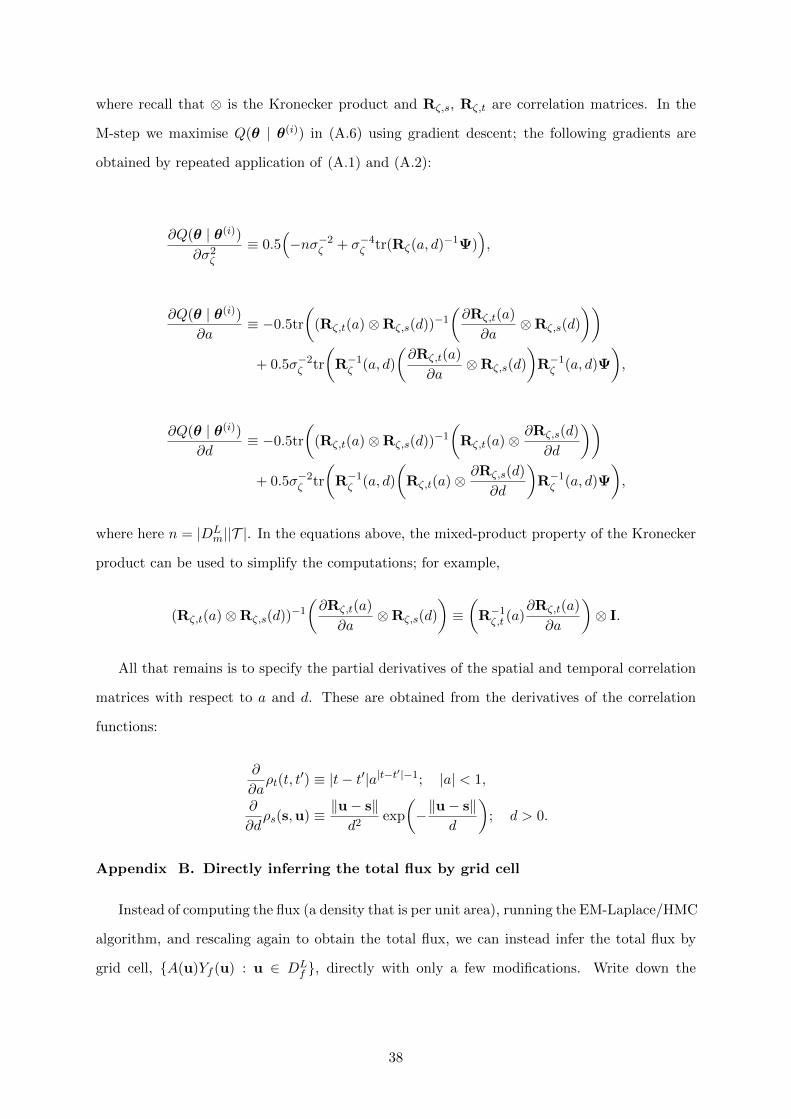
where recall that ⊗ is the Kronecker product and Rζ,s, Rζ,t are correlation matrices. In the
M-step we maximise Q(θ | θ(i)) in (A.6) using gradient descent; the following gradients are
obtained by repeated application of (A.1) and (A.2):
∂Q(θ | θ(i))∂σ2ζ
≡ 0.5(−nσ−2ζ + σ−4ζ tr(Rζ(a, d)−1Ψ)
),
∂Q(θ | θ(i))∂a
≡ −0.5tr
((Rζ,t(a)⊗Rζ,s(d))−1
(∂Rζ,t(a)
∂a⊗Rζ,s(d)
))+ 0.5σ−2ζ tr
(R−1ζ (a, d)
(∂Rζ,t(a)
∂a⊗Rζ,s(d)
)R−1ζ (a, d)Ψ
),
∂Q(θ | θ(i))∂d
≡ −0.5tr
((Rζ,t(a)⊗Rζ,s(d))−1
(Rζ,t(a)⊗
∂Rζ,s(d)
∂d
))+ 0.5σ−2ζ tr
(R−1ζ (a, d)
(Rζ,t(a)⊗
∂Rζ,s(d)
∂d
)R−1ζ (a, d)Ψ
),
where here n = |DLm||T |. In the equations above, the mixed-product property of the Kronecker
product can be used to simplify the computations; for example,
(Rζ,t(a)⊗Rζ,s(d))−1(∂Rζ,t(a)
∂a⊗Rζ,s(d)
)≡(
R−1ζ,t (a)∂Rζ,t(a)
∂a
)⊗ I.
All that remains is to specify the partial derivatives of the spatial and temporal correlation
matrices with respect to a and d. These are obtained from the derivatives of the correlation
functions:
∂
∂aρt(t, t
′) ≡ |t− t′|a|t−t′|−1; |a| < 1,
∂
∂dρs(s,u) ≡ ‖u− s‖
d2exp
(−‖u− s‖
d
); d > 0.
Appendix B. Directly inferring the total flux by grid cell
Instead of computing the flux (a density that is per unit area), running the EM-Laplace/HMC
algorithm, and rescaling again to obtain the total flux, we can instead infer the total flux by
grid cell, {A(u)Yf (u) : u ∈ DLf }, directly with only a few modifications. Write down the
38

approximation to the integral in (2) as
∫Dbt(s,u)Yf (u)du '
∑u∈DL
f
bt(s,u)(A(u)Yf (u))
=∑
u∈DLf
bt(s,u)Y totf (u),
where Y totf (u) ≡ A(u)Yf (u). Now we seek a model for Y tot
f (u) ; however, this poses no additional
work since
Y totf (s) ≡ lnY tot
f (s) = lnA(s) + lnYf (s). (B.1)
It thus follows that Y totf is also a lognormal spatial process, shifted by a known quantity. From
(B.1),
E(Y totf (s) | ϑ) = lnA(s) + µf (s | ϑ),
cov(Y totf (s), Y tot
f (u) | ϑ) = Cff(s,u | ϑ).
Note that the covariance function remains unchanged, and in order to solve directly for Y totf (·)
one uses µtotf (s) ≡ lnA(s) + µf (s | ϑ), instead of µf (s | ϑ) in (8) and (9). Then BB,t is
constructed without the area-weight terms since they have already been accounted for. That is,
in this case the matrix BB,t is given by,
BB,t ≡ (bt(s,u) : s ∈ DLm; u ∈ DL
f ).
39