Embed Size (px)
Citation preview

282
Asymmetrical Vortex over Slender Body: A Computational Approach
P.K. Karn*, P. Kumar, and S. DasDepartment of Space Engineering and Rocketry, Birla Institute of Technology Mesra, Ranchi - 835 215, India
*E-mail: [email protected]
ABSTRACT
Computational investigations were carried out on an ogive-cylinder configuration having a slenderness ratio of 7.5. The geometry of the nose tip was generated based on the physical geometry of the nose tip observed under a scanning electron microscope. Time-dependent simulations were performed on the slender body at a diameter Reynolds number of 3.0×10⁴. Results indicated that the onset of vortex asymmetry was mainly due to the micro-tip imperfection existing at the tip. It was also observed that the variation in the roll angle of the model affected the flow physics largely which has been experimentally observed by several researchers in the past. The computed results were in better agreement with the referenced experimental data.
Keywords: Asymmetrical vortex; Lateral force; Slender body; Unsteady; Perturbation
Defence Science Journal, Vol. 71, No. 2, March 2021, pp. 282-288, DOI : 10.14429/dsj.71.15959 © 2021, DESIDOC
NOMENCLATUREα Angle of attacka Speed of sound in air at sea levelRe Reynolds numberReD Reynolds number based on base DiameterU∞ Free stream velocityD Base DiameterX Length along the bodyφ Circumferential angleCY Lateral Force coefficientCN Normal Force coefficientCp Pressure coefficientΦ Roll angleSA Spalart-Allamaras turbulence modelkω-SST k-ω turbulence model with shear stress transport
equations
1. INTRODUCTIONPointed-nosed slender bodies such as missiles, spikes,
and the frontal portion of combat aircraft flying at high angles of attack often experience lateral loads which lead to loss of controllability and stability sometimes even the control surfaces being submerged in the wake become ineffective at high angles of attack. These lateral forces exist mainly due to the development of the vortex asymmetry on the leeward side of the body. Due to the presence of such leeward vortices, pressure differences appear along the vertical midplane. Such pressure differences create a lateral load and a large yawing moment on the body at high angles of attack. At lower angles of attack, the vortices remain almost symmetric along the vertical midplane whereas, the vortices become asymmetric at higher angles of attack (refer Fig. 1(a)). In the angle of attack
range of 0° to 10°, the flow remains almost attached to the surface and no separation of vortices throughout the body length takes place. An increase in angles of attack further causes the approaching flow to separate in the leeward side of the body leading to a pair of counter-rotating vortex. At α ranging from 10° to 30°, the vortices appear symmetric in the cross-plane and hence there is negligible lateral force. However, moving onto a higher range of angle of attack, i.e. α ranging from 40° to 70°, the vortices become asymmetric which is mainly because of the early separation of one of the vortices along the body length while the other vortex remains attached. This causes the vortices to appear asymmetric in different cross-plane longitudinally. These asymmetric vortices create an asymmetric surface pressure that leads to lateral loads on the body. Such forces are generally experienced till an angle of attack of 70o. At α>70°, the global instabilities start to dominate and phenomenon like vortex shedding starts dominating the flow. The major factors influencing the flow and hence the lateral forces are a) micro imperfections near the nose apex: – It has been observed that the presence of micro imperfection of size within the body boundary layer near the nose apex leads to pressure imbalance in the upcoming flow which develops sufficient energy to propagates downstream at high angles of attack and develops asymmetry in the flow2; b) surface roughness: - high surface roughness leads to the early development of turbulence in the flow which further leads to oscillation of vortices and development of lateral forces over the body2; c) Reynolds number: - at below and above critical Reynolds No. the effect is minimal but in the critical range the overall lateral force reduces1; d) initial turbulence in incoming flow: - it has been observed that initial turbulence in the flow leads to absolute instability in the flow over the leeward side of the body which induces a fluctuating lateral force over Received : 29 May 2020, Revised : 17 November 2020
Accepted : 11 February 2021, Online published : 10 March 2021

KARN, et al.: ASyMMETRICAL VORTEx OVER SLENDER BODy: A COMPUTATIONAL APPROACH
283
the body10. Computation on slender bodies at high angles of attack is a strenuous task as the vortex asymmetry needs to be generated forcibly either by providing a side slip angle or the introduction of a tip perturbation2,3,8. The mentioned techniques to generate the lateral forces have been highly effective as shown in Fig. 1(b) which shows the effect of tip perturbation on overall lateral force over the body by switching it on and off numerically. The lateral force has been observed for the non-dimensional time ((t x a)/D) in computation. It can be observed that with the use of perturbation initially, an overall lateral force is observed over the body, but when it’s removed, the flow switches to symmetric mode generating no lateral force.
Generally, the shape, size & location of the perturbation is fixed in such a way so that it matches with experimental results. References2-8 highlight the computational work performed over the slender body at higher angles of attack. Ref.2,3 shows the vortex asymmetry over the slender body similar to the experimental results can be obtained numerically by introducing a small disturbance of size within the body viscous boundary layer near about the nose apex. Ref.4 concluded that the asymmetry is obtained after a critical angle of attack irrespective of the source of the disturbance. Asymmetry was obtained numerically by providing a side slip and validated. Ref.5 shows the roll angle effect on the overall lateral force over the slender body at different angles of attack. Experimentally it was shown that the overall lateral force at high angles of attack had a square wave pattern for the roll angle and a bi-stable state of lateral force was observed. Ref.6 shows the introduction of a helical groove and a circular trip used to reduce the lateral force over the slender body at high angles of attack. Circular trips at the 3.5D axial position were found to be more effective than the helical strip in reducing lateral force. Ref.7,8 shows the effect in the variation of circular trip height on the lateral force reduction and a height of 3% of the local diameter at 3.5D axial location was found greatly effective in reducing the lateral force.
Since it is an established fact that the lateral force is vastly dependent on the nose tip perturbation, it becomes imperative to investigate the tip geometry which leads to such phenomena. Secondly, the lateral force is largely reliant upon the roll alignment of the nose tip as shown in Fig. 1(c). It can be observed from the figure that there is a sudden reversal in direction of overall lateral force coefficients and the pattern seems to be similar to the square wave pattern, but for a few roll angles the magnitude and directions of the overall lateral force coefficient as well as the local lateral force coefficients are similar as at 96.6° and 136.8° roll angles. It is expected that the nose tip micro perturbation will have a major effect on the flow physics of a slender body at higher angles of attack.
In the present work, the scanning electron microscope (SEM) analysis of the tip of the fabricated model has been performed to create a computational model similar to the physical model. Time-dependent computations were made to understand the mechanism behind the generation of the asymmetric vortices at an angle of attack of 50° in presence of tip perturbation. Computations were also performed to observe the effect of roll orientation on the flow physics.
2. RESEARCH METHODOLOGY2.1 SEM Analysis
The SEM having a resolution of around 30 nm was used to investigate the fabricated tip of a typical test model. Fig. 2 shows the SEM analysis performed on the model tip. The figure clearly indicates that a tip perturbation of around 100 μm was observed which is mainly due to the machining.
2.2 Computational Techniques
Fluid Simulation software ANSyS-FLUENT available commercially, which uses the Finite Volume approach, was utilised to compute the flow over a slender body at 50° angle of attack. Air was utilised as the working fluid and three-
Figure 1. (a) Different phases of flow over the slender body4, (b) Effect of tip perturbation on lateral force coefficient3, and (c) Effect of Roll5.
(a)
(b)
(c)
DEF. SCI. J., VOL. 71, NO. 2, MARCH 2021
284
dimensional, transient equations were incorporated as the flow over the body having three-dimensional and time-dependent characteristics. Incompressible flow condition was utilised in the present computation as the freestream velocity was lower (M < 0.3). An implicit method was utilised due to the existence of large numbers of unknown variables and a second-order discretisation scheme was applied for turbulent, spatial, and temporal equations to obtain a more precise solution. The spherical domain of 30D was preferred over cylindrical or cuboid domains for all the computations as the spherical domain yielded better residuals. Figure 3 shows the computational domain. The computational model tip was made similar to the SEM Analysis of the model tip (Fig. 2), as shown in Fig. 4(a) and the designed mesh is shown in Fig. 4(b).
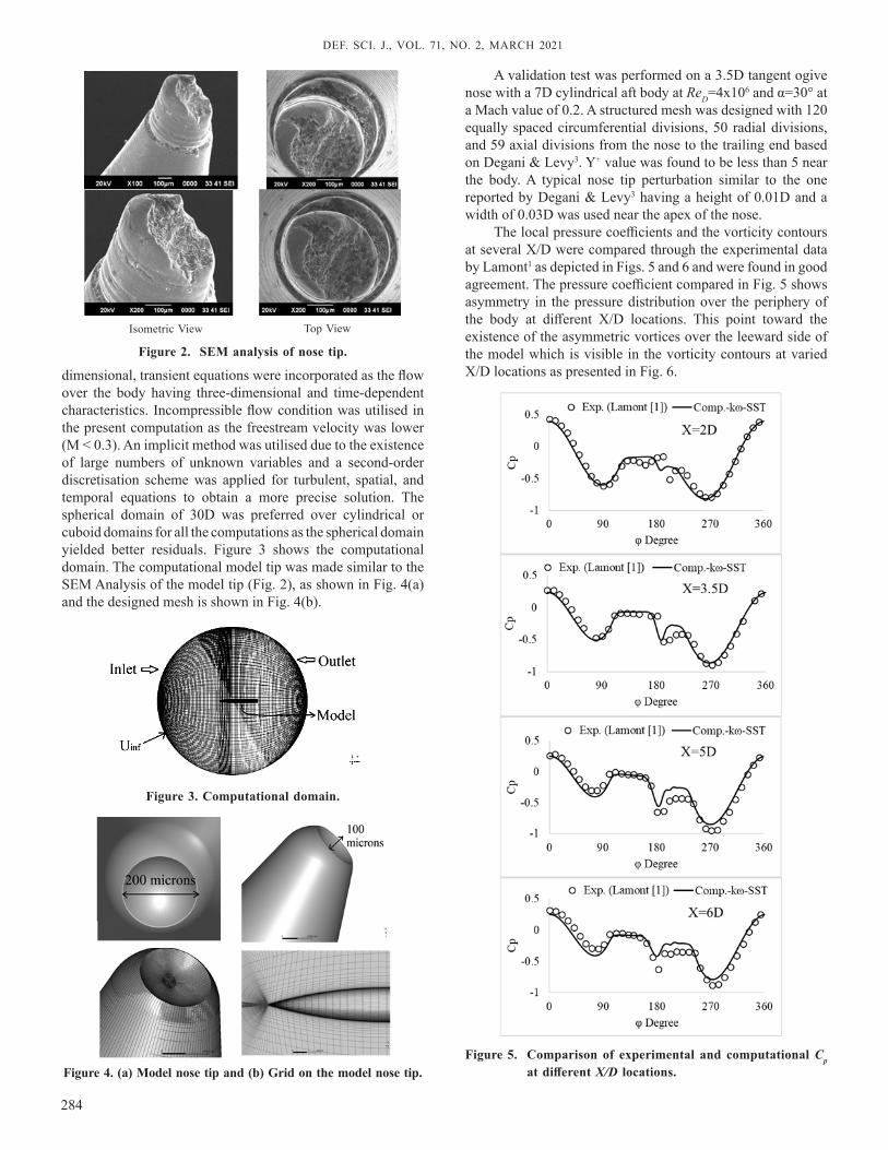
A validation test was performed on a 3.5D tangent ogive nose with a 7D cylindrical aft body at ReD=4x10⁶ and α=30° at a Mach value of 0.2. A structured mesh was designed with 120 equally spaced circumferential divisions, 50 radial divisions, and 59 axial divisions from the nose to the trailing end based on Degani & Levy3. y+ value was found to be less than 5 near the body. A typical nose tip perturbation similar to the one reported by Degani & Levy3 having a height of 0.01D and a width of 0.03D was used near the apex of the nose.
The local pressure coefficients and the vorticity contours at several x/D were compared through the experimental data by Lamont1 as depicted in Figs. 5 and 6 and were found in good agreement. The pressure coefficient compared in Fig. 5 shows asymmetry in the pressure distribution over the periphery of the body at different x/D locations. This point toward the existence of the asymmetric vortices over the leeward side of the model which is visible in the vorticity contours at varied x/D locations as presented in Fig. 6.
Figure 3. Computational domain.
Figure 2. SEM analysis of nose tip.
Figure 4. (a) Model nose tip and (b) Grid on the model nose tip.
Isometric View Top View
Figure 5. Comparison of experimental and computational Cp at different X/D locations.

KARN, et al.: ASyMMETRICAL VORTEx OVER SLENDER BODy: A COMPUTATIONAL APPROACH
285
A suitable grid independence test was performed for the present computations and it was found that the grid with 1 million cells was suitable for the present computations as the value of lateral force coefficient obtained was in good agreement with the experiment value and also it required less computational time compared to higher grid size mesh. Figure 7(a) shows the lateral and normal force coefficients obtained with different grid sizes and turbulence models compared with Ref. Kumar & Prasad7,8. The Lateral force coefficient time history comparison with the Ref. Degani & Levy3 as shown in Fig. 7(b) was also found in good agreement with it. The Non-Dimensional Time ((t x a)/D) was used to compare the time history of the lateral force coefficient as the computation was performed at different time step values compared to the reference. The kω-SST model was found suitable for further computations. The kω-SST model is a two-equation eddy viscosity model with a shear stress transport formulation. This model has a good formulation through the viscous sub-layers of the boundary layer hence is also suitable for Low Reynolds number flows. It also gives good results in case of adverse pressure gradient and separating flows11. Figure 8 shows the Cp plot and local lateral force comparison with reference data of the grid independence test. The results are in good match with the reference data.
3. RESULTS AND DISCUSSIONComputation was performed over 3.5D tangent ogive
nose, having the tip imperfection as that of the SEM analysis report, with 4.5D cylindrical aft body at 50° angle of attack and ReD=3x10⁴. The roll orientation of the tip imperfection was kept at 90° as shown in Fig. 9.
Due to the tip imperfection being asymmetrical along the midplane, a pressure imbalance was created on one side of the nose which resulted in a pair of asymmetrical vortices and the asymmetry further propagates downstream. One of the primary vortex separates near the tip and the next vortex develops beneath the primary vortex further downstream. The process continues for subsequent vortices. This can be observed from the vorticity contours at different x/D locations in Fig. 10. The Pathlines over the body shown in Fig. 11 clearly shows the phenomenon at 90° roll configuration.
Further computations were performed over for different roll angles with a gap of 45° to study the roll effect of tip defect. Figure 9 shows all the roll orientations. Figure 10 shows the vorticity contour at different x/D locations for different roll configurations. It can be clearly observed from the figure that with the change in model roll orientation, the flow physics in the leeward side of the body was found to change. This is the cause for the variation in the lateral force with different roll angles. An increase in the number of perturbations may change the flow physics. As can be observed from the figure that at 0° and 180° roll configurations there is not much asymmetry being observed mainly because the perturbation being symmetrical about the midplane. For roll angle 45° to 135° the first vortex separation appears from the starboard side and for the roll
Figure 7. (a) CY and CN for different grid sizes and (b) CY time history vs. non-dimensional time compared with ref.3.
Figure 6. (a) Vorticity Contour at different X/D locations3 and (b) Vorticity contour at different X/D locations [Present computation].
(a)
(b)
(a)
(b)

DEF. SCI. J., VOL. 71, NO. 2, MARCH 2021
286
Figure 10. Vorticity Contour at different X/D location for different roll configurations at α = 50°.
Figure 8. (a) Pressure coefficient plot comparison of present computation with Ref. Exp.6 at X/D=4 and 6, and (b) Lateral Force Coefficient variation with X compared with Ref. Exp.8.
Figure 9. Roll orientation of the model nose tip.
(a)
(b)

KARN, et al.: ASyMMETRICAL VORTEx OVER SLENDER BODy: A COMPUTATIONAL APPROACH
287
angles 225° to 315° the first vortex separation appears from the port side due to asymmetry in the vortices. Along the model length, there is a change in the direction of the vortex being observed. This is not observed in the case of roll angles 0° and 180° as there is very little asymmetry in the flow. Secondary vortices formation can also be observed which over the length give rise to another vortex.
The Pathlines and Vorticity Contours, shown in Figs. 11 and 12, indicate the presence of multiple vortices existing on the body which has been reported by several researchers in the past. At roll configuration 90° and 270° the vortices pattern and separation points seem to be each other’s mirror image and at roll configuration 0° and 180° the flow pattern seem to be similar. Tip perturbation provided creates a pressure imbalance which is not equivalent on both the side of the model. This results in the asymmetry of the vortices which further propagates downstream and sheds the model surface due to adverse pressure gradient. The place is occupied by another vortex formed beneath the primary vortex.
Figure 13 shows the variation of lateral force coefficient with different roll angle configurations. The shift in direction of lateral force is observed near the 180° roll angle. The overall shift in direction of lateral force over roll configurations 0° to 360° is observed only once in comparison to the previous research. One of the reasons for this can be related to the imperfection designed in the present computation which is a dip over the tip of the nose. This is different in comparison to the tip perturbation previously used to produce asymmetry in the flow which is a point to be further investigated in detail.
4. CONCLUSIONSComputations were performed over the designed nose
tip deformation at a diameter Reynolds number of ReD=3x10⁴ and 50° angle of attack based on the SEM (Scanning Electron Microscope) analysis of the experimental model nose tip to obtain the vortex asymmetry. Such perturbations were found to initiate the vortex asymmetry leading to the lateral force. Initially grid validation was performed and compared with the reference computational and experimental values and was found in good agreement with the data. Computations were carried out with different grid sizes and turbulence models on the designed nose tip with deformity to perform the grid Figure 11. Pathline at α = 50°.
Figure 13. Lateral force coefficient variation with different Roll angle configurations.
Figure 12. Vorticity contour at α = 50°.

DEF. SCI. J., VOL. 71, NO. 2, MARCH 2021
288
independence test. kω-SST turbulence model, with 1 million cells and y+ value less than 5, was found to have good agreement with the reference data.
Effect of the roll orientation was observed on the lateral force due to the tip imperfection. The obtained results indicated that the tip imperfection is the decisive factor for the direction and magnitude of the lateral force. The reason for such behaviour might be the introduction of deformity in the nose tip based on the SEM analysis of the experimental model nose tip. A further detailed investigation is necessary to study this behaviour. Finally, the modification of computation nose tip based on SEM analysis of the experimental model was found a good substitute for the perturbation used to simulate asymmetry at high angles of attack over the slender body in the subsonic range.
REFERENCES1. Lamont, P. The complex asymmetric flow over a 3.5D
ogive nose and cylindrical afterbody at high angles of attack. In Proceedings of the 20th Aerospace Sciences Meeting 1982, 75–76, American Institute of Aeronautics and Astronautics, 1982.
doi:10.2514/6.1982-53.2. Degani, D. & Schiff, L. Numerical simulation of the
effect of spatial disturbances on vortex asymmetry. In Proceedings of the 27th Aerospace Sciences Meeting 1989, vol. 29 344–352 American Institute of Aeronautics and Astronautics, 1989.
doi:10.2514/6.1989-3403. Degani, D. & Levy, y. Asymmetric turbulent vortical
flows over slender bodies. In 9th Appl. Aerodyn. Conf., 1991, 30, 2267–2273.
doi:10.2514/6.1991-32964. Liu, C. H.; Wong, T.-C. & Kandil, O. A. Prediction of
asymmetric vortical flows around slender bodies using Navier-Stokes equations. Fluid Dyn. Res., 1992, 10, 409–450.
doi:10.1016/0169-5983(92)90032-R5. Luo, S. C.; Lim, T. T.; Lua, K. B.; Chia, H. T.; R. Goh,
E. K. & Ho, Q. W. Flowfield around ogive/elliptic-tip cylinder at high angle of attack. AIAA J., 1998, 36, 1778–1787.
doi: 10.2514/2.2866. Lua, K. B.; Lim, T. T.; Luo, S. C. & R. Goh, E. K. Helical-
groove and circular-trip effects on side force. J. Aircr., 2000, 37, 906–915.
doi: 10.2514/2.26897. Kumar, P. & Prasad, J. K. Effect of ring size on the
side force over ogive-cylinder body at subsonic speed. Aeronaut. J., 2016, 120, 1487–1506.
doi: 10.1017/aer.2016.63
8. Kumar, P. & Prasad, J. K. mechanism of side force generation and its alleviation over a slender body. J. Spacecr. Rockets, 2016, 53, 195–208.
doi: 10.2514/1.A332909. Degani, D.; Ishay, M. & Gottlieb, O. Fluid-structure
interaction of a rolling restrained body of revolution at high angles of attack. Phys. Fluids, 2017, 29, 037106.
doi: 10.1063/1.497841610. Obeid, O.; AlQadi, I. & AlMutairi, J. Investigation of
asymmetric flow past a slender body at high angles of attack. Theor. Comput. Fluid Dyn., 2019, 33, 481–508.
doi: 10.1007/s00162-019-00503-011. Menter, F. R.; Kuntz, M. & Langtry, R. Ten years of
Industrial Experience with the SST Turbulence Model. In Proceedings of 4th Internal Symposium 2003: Turbulence, heat and mass transfer, Begell House, New york, Wallingford, 625-632. ISBN: 1567001963
ACKNOWLEDGEMENTThis research is supported by the Aeronautical Research
and Development Board (AR&DB), DRDO.
CONTRIBUTORS
Mr Pawan Kumar Karn is currently pursuing a PhD and also working as JRF (AR&DB-DRDO Funded Project) in the field of Aerodynamics from the Department of Space Engineering and Rocketry, Birla Institute of Technology, Mesra, Ranchi since January 2017. He has working experience in Computational Fluid Dynamics as well as Experimental Aerodynamics.His current role was to perform computations and experiments for the Project.
Dr Priyank Kumar is currently working as an Assistant Professor in the Department of Space Engineering & Rocketry, Birla Institute of Technology, Mesra, Ranchi. He has several years of Research and Teaching experience with many published papers and several conferences attended. His research areas are Fluid dynamics, Aerodynamics and Low-speed flow.His current role was to guide and help in performing computations and experiments.
Dr Sudip Das is currently working as a Professor in the Department of Space Engineering & Rocketry, Birla Institute of Technology, Mesra, Ranchi. His Research area is Experimental Aerodynamics. He has completed several funded projects and is currently working on a project.His current role was to guide and help in performing computations and experiments.