Embed Size (px)
Citation preview

With the support of KFPE Commission for Research Partnerships with Developing Countries
ASSESSMENT OF GOLD RECOVERY PROCESSES
IN BANGALORE, INDIA AND EVALUATION OF AN ALTERNATIVE RECYCLING PATH
FOR PRINTED WIRING BOARDS
A CASE STUDY
Diploma thesis at the Institute for Spatial and Landscape Planning, Regional Resource
Management at the ETH Zurich
October 2006
Diploma Student: Miriam Keller
Supervisors: Prof. Dr. Susanne Kytzia (ETH) and Rolf Widmer (EMPA)


Abstract
i
Abstract Recycling of e-waste respectively of PWB is an ambiguous issue. On the one hand,
precious metals can be recovered; on the other hand, environmental damages are caused
during the recycling processes. The encountered recycling management system in
Bangalore bears several problematic processes. One of the identified problematic
processes by Rochat (2006) is the precious metal recovery. For example to recover gold
from e-waste wet chemical leaching processes, which use several hazardous substances
and materials (e.g. cyanide and nitric acid) are conducted. Scientific base data about these
processes are barely available. Therefore, the focus of this thesis is to provide scientific
background knowledge about gold recovery processes. In addition, an alternative pathway
for the recycling of e-waste-, respectively of printed wiring boards (PWB) is evaluated.
Using the methodology of material flow analysis (MFA) the used substances and materials
of three different gold recovery techniques could be identified and partly quantified. Based
on these results environmental impacts of the processes are qualitatively evaluated. The
environmental contamination caused by the conducted processes in Bangalore is severe.
The released toxic substances and heavy metals are high concentrated and most of them
have the potential to accumulate in organisms and environment. In the effluent of a
conducted gold recovery technique in an informal facility in Bangalore, metal concentrations,
which are 5 to 370 times higher than the maximum permissible value in Switzerland, were
detected. The solid waste from the processes, end up in the solid waste stream of
Bangalore. This means that the metals eventually leach out to the environment.
Further, the efficiency of the PWB recycling processes in Bangalore could be determined
making a substance flow analysis (SFA) of gold. This assessment revealed that the gold
yields of the recycling systems are quite poor. The yields of the gold recovery techniques
are approximately 50 %.
The assessed alternative is a relocation of the PWB treatment to an industrial smelter in
Belgium (Umicore Precious Metals Refining) which is equipped with best available
technology. It could be shown that the economic profit is much higher if the material is sold
to the industrial smelter. In addition, the emissions to the environment would decrease
drastically if these fractions of e-waste were treated with the metallurgic technique,
conducted in Belgium.
Acknowledgement
ii
Acknowledgement I would like to express my gratitude to all those who gave me the possibility to complete this
thesis. Special thanks belong to…
… David Rochat, who accompanied my fieldwork in India being a mentor and a friend.
… the whole staff of the GTZ-office in Bangalore where I had a working place and met
wonderful people.
… Mr. Parthasarathy and his employees, especially Mr. Prakashchandra, whose help were
essential to realise this work.
… Rizwan Khan and his workers for their cooperation.
… Umicore Precious Metals Refining who offered to make the analysis and in particular
Steven Art and Jan Kegels for providing all the essential information and
Dr. Eddie Adriaenssens, Dr. Christian Hagelüken and Thierry van Kerckhoven for the
several advices.
… Rolf Widmer, the e-waste expert of EMPA and Professor Susanne Kytzia for supervising
and guiding me during this thesis.
… Martin Streicher-Porte for providing a lot of information and giving critical and constructive
comments to my work.
… Dr. Hartmut Schönberg, Dr. Richard Klinger, Dr. Johannes Gauglhofer, Mischa Classen
and Dr. Christina Seyler-Jahn for the fruitful discussions and information.
… Dominik Zumbühl and Ronny Haase for their company and the highly appreciated
sharing of IT knowledge.
… Lucia Oetjen, Reto Keller and Dr. Oskar Keller for reviewing my thesis.
… my parents for giving me constant support and encouragement throughout all the years
of my studies.
Table of contents
iii
Table of contents
Abstract .................................................................................................................................. i Acknowledgement ................................................................................................................ii 1 Introduction................................................................................................................1 1.1 What is e-waste? .........................................................................................................1 1.2 Global e-waste situation...............................................................................................2
1.2.1 Global e-waste development............................................................................2 1.2.2 E-waste management and regulation...............................................................4
1.3 E-waste Situation in India ............................................................................................6 1.4 E-waste Situation in Bangalore....................................................................................7 1.5 Scope and aims of the thesis.......................................................................................9
1.5.1 Scope ...............................................................................................................9 1.5.2 Aims and scientific questions ...........................................................................9
1.6 Proceeding and structure of thesis ............................................................................10 2 Gold recovery techniques and hazards.................................................................11 2.1 Methodology ..............................................................................................................11 2.2 System Description....................................................................................................12
2.2.1 System definition ............................................................................................12 2.2.2 Data collection................................................................................................13 2.2.3 Investigated facilities ......................................................................................13 2.2.4 Cyanide leaching at Eco BIRD.......................................................................15 2.2.5 Mercury amalgamation at Eco BIRD..............................................................20 2.2.6 Gold stripping at Surface Chem Finishers......................................................22
2.3 Quantification.............................................................................................................24 2.3.1 Data collection................................................................................................24 2.3.2 Cyanide leaching at Eco BIRD.......................................................................25 2.3.3 Mercury amalgamation at Eco BIRD..............................................................28 2.3.4 Gold stripping at Surface Chem Finishers......................................................29
2.4 Interpretation..............................................................................................................30 2.4.1 Cyanide leaching at Eco BIRD.......................................................................30 2.4.2 Mercury amalgamation at Eco BIRD..............................................................32 2.4.3 Gold stripping at Surface Chem Finishers......................................................33
2.5 Discussion..................................................................................................................34 2.5.1 Suitability of the method .................................................................................34 2.5.2 Evaluation of the systems ..............................................................................34
3 Evaluation of recovery rates...................................................................................39 3.1 Methodology ..............................................................................................................39

Table of contents
iv
3.2 System description .................................................................................................... 39 3.2.1 System definition ........................................................................................... 39 3.2.2 Investigated systems ..................................................................................... 40
3.3 Quantification ............................................................................................................ 40 3.3.1 Preparation .................................................................................................... 40 3.3.2 Subsystem 1 .................................................................................................. 41 3.3.3 Subsystem 2 .................................................................................................. 44
3.4 Interpretation ............................................................................................................. 48 3.4.1 Informal sector ............................................................................................... 49 3.4.2 Formal sector................................................................................................. 49
3.5 Discussion ................................................................................................................. 49 3.5.1 Informal sector ............................................................................................... 50 3.5.2 Formal sector................................................................................................. 50
4 Comparison of two PWB recycling scenarios...................................................... 52 4.1 Scenario description.................................................................................................. 52
4.1.1 Scenario A ..................................................................................................... 52 4.1.2 Scenario B ..................................................................................................... 52
4.2 Methodology.............................................................................................................. 52 4.3 Environmental assessment ....................................................................................... 53
4.3.1 Goal and scope definition .............................................................................. 53 4.3.2 Inventory analysis .......................................................................................... 54 4.3.3 Interpretation.................................................................................................. 57
4.4 Economic assessment .............................................................................................. 59 4.4.1 Goal and scope definition .............................................................................. 59 4.4.2 Inventory analysis .......................................................................................... 59 4.4.3 Impact assessment........................................................................................ 61 4.4.4 Interpretation.................................................................................................. 62
5 Conclusion............................................................................................................... 64 5.1 Main findings ............................................................................................................. 64
5.1.1 Gold recovery techniques and hazards ......................................................... 64 5.1.2 Evaluation of recovery rates .......................................................................... 64 5.1.3 Comparison of two PWB recycling scenarios ................................................ 65
5.2 Outlook ...................................................................................................................... 66 References .......................................................................................................................... 68
Table of contents
v
Appendices..........................................................................................................................72 Appendix I: Glossary...........................................................................................72
Appendix II: Seco’s global e-waste programme...................................................74
Appendix III: E-waste definitions...........................................................................75
Appendix IV: Environmental legislations in India...................................................76
Appendix V: The E-waste Agency (EWA) ............................................................77
Appendix VI: Development of gold price between 1993 and 2006........................78
Appendix VII: Material and sample preparation .....................................................79
Appendix VIII: Flowchart material preparation ........................................................88
Appendix IX: Detailed flowchart „mercury amalgamation“ ....................................89
Appendix X: Pictures documenting the “mercury amalgamation” ........................90
Appendix XI: Silver recovery .................................................................................92
Appendix XII: Detailed flowchart „Gold stripping“...................................................93
Appendix XIII: Indicative assay results on e-scrap samples - 21/8/06 ....................94
Appendix XIV: Assay results from liquid samples....................................................95
Appendix XV: Summary of hazardous substances and metals ..............................97
Appendix XVI: Anhang 3.2, Gewässerschutzverordnung (GSchV) 814.201 .........101
Appendix XVII: Indicative Purchase Prices from UPMR.........................................102
Appendix XVIII: Used ecoinvent data ......................................................................103
Appendix XIX: Umicore Precious Metals Refining (UPMR)...................................104
Appendix XX: Approximate theoretical value of the basic raw material (BRM) ....105
List of Figures
vi
List of Figures
Figure 1.1: Top scoring countries in PC growth rates (left) and penetration rates (right) (Schwarzer et al., 2005)......................................................................................3
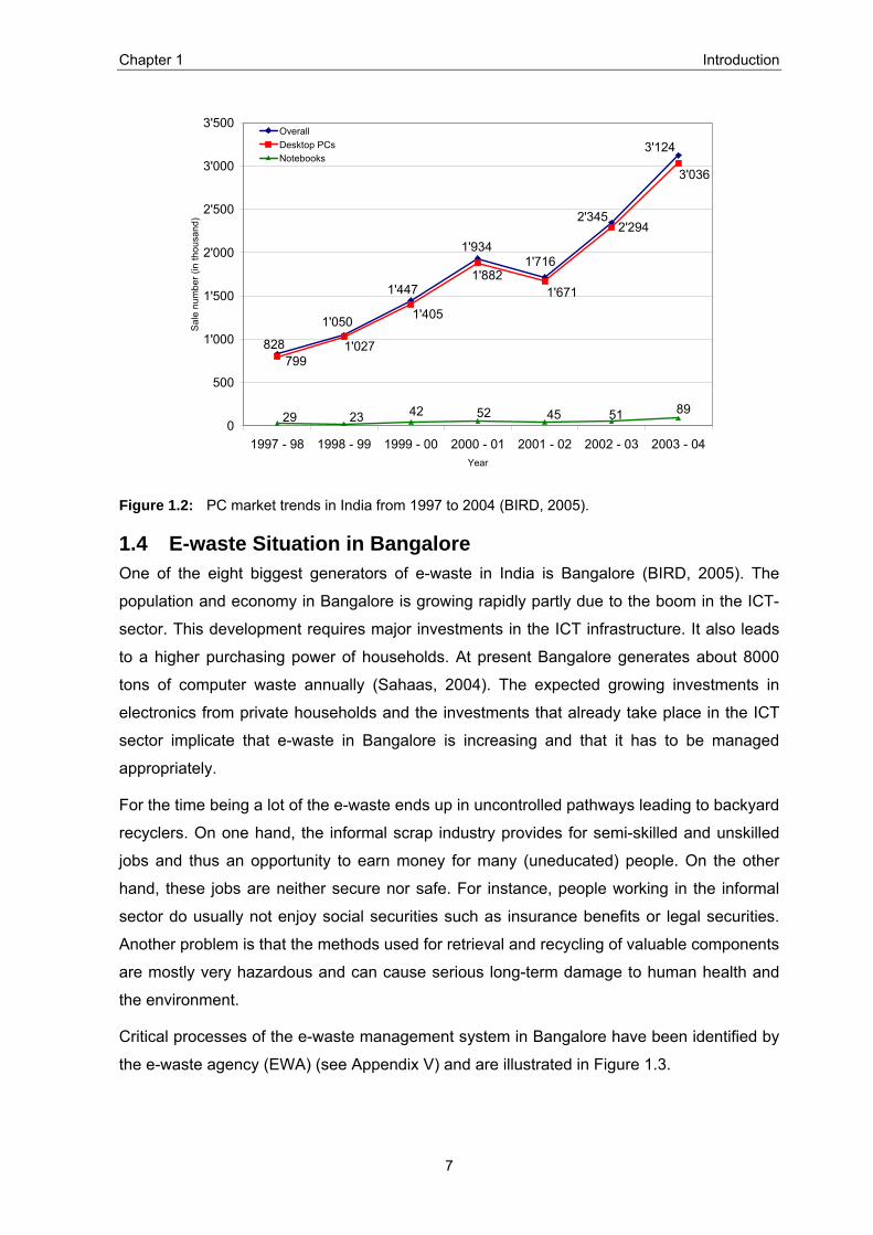
Figure 1.2: PC market trends in India from 1997 to 2004 (BIRD, 2005)...............................7
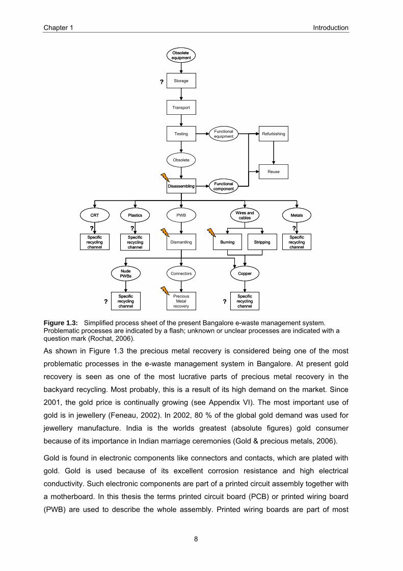
Figure 1.3: Simplified process sheet of the present Bangalore e-waste management system. Problematic processes are indicated by a flash; unknown or unclear processes are indicated with a question mark (Rochat, 2006)...........................8
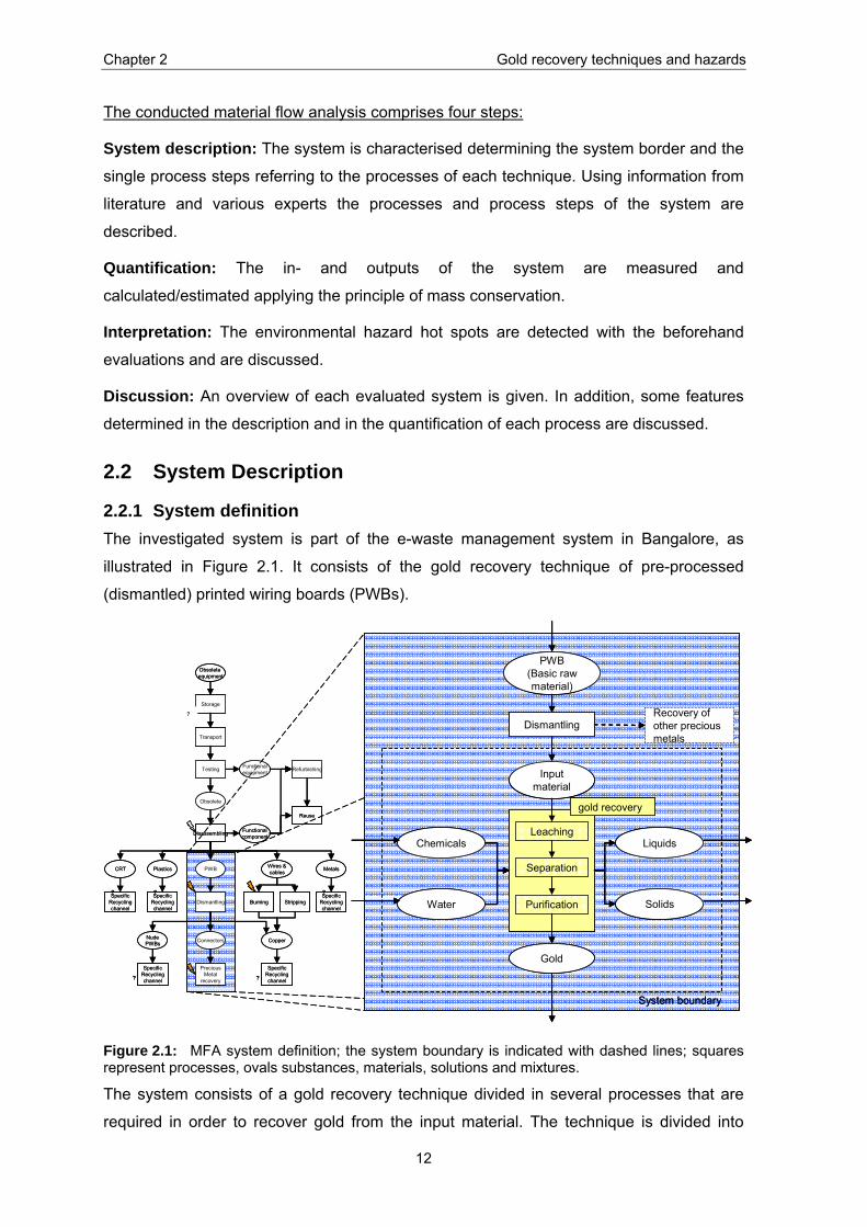
Figure 2.1: MFA system definition; the system boundary is indicated with dashed lines; squares represent processes, ovals substances, materials, solutions and mixtures.............................................................................................................12
Figure 2.2: Simplified flowchart of the „cyanide leaching“...................................................19
Figure 2.3: Simplified flowchart “ of the mercury amalgamation”........................................22
Figure 2.4: Simplified flowchart of the “gold stripping”. .......................................................24
Figure 2.5: Quantified flowchart of the cyanide leaching (main process); unit of numbers is gram. .................................................................................................................26
Figure 2.6: Preparation of silver-salt used in the main process of the cyanide leaching; unit of numbers is gram. ..........................................................................................27
Figure 2.7: Simplified and quantified flowchart of the “gold stripping”; unit of numbers is gram. .................................................................................................................29
Figure 2.8: Major flows of the “cyanide leaching”. ..............................................................35
Figure 2.9: Major flows of the “mercury amalgamation”......................................................37
Figure 2.10: Major flows of the “gold stripping”.....................................................................37
Figure 3.1: SFA system definition; the system boundaries are indicated with dashed lines; squares represent processes, ovals materials, solutions and mixtures where the gold is contained. ........................................................................................40
Figure 3.2: Mass flow of the material during preparation; BRM= Basic raw material, IM= Input material. ...................................................................................................41
Figure 3.3: Scheme for the calculation of the input material (Subsystem 1). .....................42
Figure 3.4: Conducted dismantling for the informal sector; BRM =Basic raw material, IM = Input material, C and B = material, the denominations accord with Appendix VIII. ....................................................................................................................42
Figure 3.5: Approximate gold flow in the Subsystem 1 (informal sector)............................43
Figure 3.6: Conducted dismantling for the formal sector; BRM =Basic raw material, IM = Input material, A = material, the denominations accord with Appendix VIII. ....43
Figure 3.7: Approximate gold flow in the Subsystem 1 (formal sector). .............................44
Figure 3.8: Scheme for the calculation of the input material (Subsystem 2). .....................45
Figure 3.9: Conducted gold recovery in the informal sector; IM = Input material, BC = Body components, WS = Waste solution, SS = Silver solution, Au = Gold. ..............45
Figure 3.10: Approximate gold flow in the Subsystem 2 (informal sector)............................46
Figure 3.11: Conducted gold recovery in the formal sector; IM = Input material, BC = Body components, L = Liquid after Leaching.............................................................47
Figure 3.12: Approximate gold flow in the Subsystem 2 (formal sector). .............................47
Figure 3.13: Illustration of the gold yields..............................................................................48
Figure 4.1: Scheme of life cycle assessment (LCA) comprising four steps (Guinée et al., 2001). ................................................................................................................53
List of Figures
vii
Figure 4.2: System definition of the environmental assessment; the system boundaries are indicated with dashed lines; the squares represent processes, ovals materials; PWB= Printed wiring boards, IM= Input material, UPMR= Umicore Precious Metals Refining. ................................................................................................54
Figure 4.3: Emissions of the scenarios per ton board.........................................................56
Figure 4.4: Raw material depletion of the scenarios per ton board. ...................................57
Figure 4.5: PWB recycling system and system boundary of the environmental assessment; squares represent processes and actors, ovals materials; the system boundary of the analysed system is indicated with dashed lines; PWB= Printed wiring boards, IM= Input material. ...............................................................................59
Figure 4.6: Money flux (in EUR) in Scenario A. ..................................................................61
Figure 4.7: Money flux (in EUR) in Scenario B. ..................................................................61
Figure 5.1: Major flows of the cyanide leaching..................................................................64
Figure 5.2: Gold yields in the informal and formal sector of PWB recycling in Bangalore; BRM= Basic raw material (printed wiring boards), IM= Input material (apparent gold parts). ........................................................................................................65
List of Tables
viii
List of Tables
Table 2.1: Input materials of the cyanide leaching per gram recovered gold.......................27
Table 2.2: Output materials of the cyanide leaching per gram recovered gold....................27
Table 2.3: Input materials of the mercury amalgamation per gram recovered gold.............28
Table 2.4: Output materials of the mercury amalgamation per gram recovered gold..........28
Table 2.5: Input materials of the “gold stripping” per gram recovered gold..........................30
Table 2.6: Output materials of the “gold stripping” per gram recovered gold.......................30
Table 2.7: Metal concentrations in the waste solution of the “cyanide leaching” .................31
Table 2.8: Metal concentration in the body components of the “cyanide leaching” .............31
Table 2.9: Comparing the thresholds of the Swiss legislation (see Appendix XVI) of industrial waste water with the found concentration in the waste solution of the “cyanide leaching” ...............................................................................................32
Table 2.10: Metal concentration in the body components of the “gold stripping”...................34
Table 3.1: Overview of the calculation of the gold in the input material 1 (Subsystem 1)....43
Table 3.2: Overview of the calculation for the input material 2 (Subsystem 1) ....................44
Table 3.3: Overview for the calculation of the gold in the input material 1 (Subsystem 2) ..46
Table 3.4: Overview of the calculation for the input material 2 (Subsystem 2) ....................47
Table 3.5: Gold yields of Eco BIRD (cyanide leaching)........................................................49
Table 3.6: Gold yields of Surface Chem Finishers (gold stripping) ......................................49
Table 4.1: Inventory of environmental indicators; functional unit: one ton PWB..................56
Table 4.2: Emissions to air during shipping (Scenario B).....................................................56
Table 4.3: Approximate theoretical value of input material 1 (IM 1).....................................60
Table 4.4: Approximate evaluation of total expenses (Scenario A) .....................................61
Table 4.5: Economical benefit of the scenarios in € / t IM 1.................................................61
Chapter 1 Introduction
1
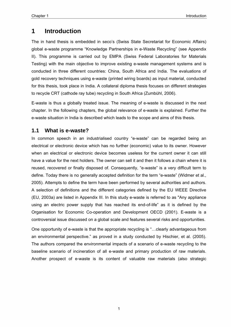
1 Introduction The in hand thesis is embedded in seco’s (Swiss State Secretariat for Economic Affairs)
global e-waste programme “Knowledge Partnerships in e-Waste Recycling” (see Appendix
II). This programme is carried out by EMPA (Swiss Federal Laboratories for Materials
Testing) with the main objective to improve existing e-waste management systems and is
conducted in three different countries: China, South Africa and India. The evaluations of
gold recovery techniques using e-waste (printed wiring boards) as input material, conducted
for this thesis, took place in India. A collateral diploma thesis focuses on different strategies
to recycle CRT (cathode ray tube) recycling in South Africa (Zumbühl, 2006).
E-waste is thus a globally treated issue. The meaning of e-waste is discussed in the next
chapter. In the following chapters, the global relevance of e-waste is explained. Further the
e-waste situation in India is described which leads to the scope and aims of this thesis.
1.1 What is e-waste? In common speech in an industrialised country “e-waste” can be regarded being an
electrical or electronic device which has no further (economic) value to its owner. However
when an electrical or electronic device becomes useless for the current owner it can still
have a value for the next holders. The owner can sell it and then it follows a chain where it is
reused, recovered or finally disposed of. Consequently, “e-waste” is a very difficult term to
define. Today there is no generally accepted definition for the term “e-waste” (Widmer et al.,
2005). Attempts to define the term have been performed by several authorities and authors.
A selection of definitions and the different categories defined by the EU WEEE Directive
(EU, 2003a) are listed in Appendix III. In this study e-waste is referred to as "Any appliance
using an electric power supply that has reached its end-of-life” as it is defined by the
Organisation for Economic Co-operation and Development OECD (2001). E-waste is a
controversial issue discussed on a global scale and features several risks and opportunities.
One opportunity of e-waste is that the appropriate recycling is “…clearly advantageous from
an environmental perspective.” as proved in a study conducted by Hischier, et al. (2005).
The authors compared the environmental impacts of a scenario of e-waste recycling to the
baseline scenario of incineration of all e-waste and primary production of raw materials.
Another prospect of e-waste is its content of valuable raw materials (also strategic

Chapter 1 Introduction
2
materials1) including many rare metals. They can be recovered with different existing
techniques. Thus, e-waste recycling has become a lucrative business.
The risky part of e-waste is that it contains over 1’000 different substances and metals.
Many of these substances and metals are toxic. According to Widmer et al. (2005) hazards
such as lead, mercury, arsenic, cadmium, selenium, hexavalent chromium and flame
retardants in casings and circuit boards are present. The printed circuit boards (i.e. printed
wiring boards) contain polychlorinated and polybrominated biphenyls that create dioxin-like
emissions when burned. All these hazardous substances can threaten human health and
the environment unless they are disposed of properly (Li et al., 2006). Corresponding to
Silicon Valley Toxics Coalition (Puckett et al., 2002) “About 70 % of heavy metals (including
mercury and cadmium) found in landfills come from electronic discards”. According to a
report of the European commission 40 % of the lead found in landfills derives from
consumer electronics (Commission of the European Communities, 2000).
Thus, e-waste is a double-edged sword. On the one hand, valuable materials can be
recovered economically whilst natural resources can be saved. On the other hand, the risks
of hazardous substances when not recycled properly and released to the environment can
cause serious damage to human health and the environment.
1.2 Global e-waste situation
1.2.1 Global e-waste development Because of the rapid technological progress and the decreasing lifespan of the single
electronic devices, e-waste is growing rapidly. In 2004, more than 180 million personal
computers (PCs) were sold worldwide. In the same year, an estimated 100 million obsolete
PCs entered waste streams (Widmer et al., 2005). Worldwide e-waste growth can only be
estimated and is in the range of 20 to 50 million tons per year. The main volume is produced
in North America followed from Europe and Asia (Siemers and Vest, 1999). According to
“The Economist” (2005) e-waste is one of the fastest growing waste fractions. It accounts for
around 8 % of all municipal waste in industrialised countries.
At present e-waste is mainly generated by industrialised countries, which already have a
high amount of electrical and electronic equipment. It is assumed that some of the e-waste
generated in these countries ends up in developing countries such as India or Africa. The
British Protection Agency released a report in May 2005 admitting that a large amount of e-
1 Material for which the quantity required for essential civilian and military uses exceeds the reasonably secure domestic and foreign supplies and for which acceptable substitutes are not available within a reasonable period of time (American Metal Market, 1985)

Chapter 1 Introduction
3
waste had been exported illegally from the UK (Agarwal, 2005). In Lagos (Nigeria) 400’000
used computers arrive at the port each month. 25 % – 75 % of them are out of order and
have to be disposed of (Puckett et al., 2002). According to Iles (2004) the US exported up to
10.2 millions obsolete computers to Asia in 2002, which makes around 50 % – 80 % of all
PCs sent for recycling in the US. The reason for these exports might be the less strict
environmental standards in developing countries and the lower costs for disposal. For
example disposing a computer in the US can cost up to USD 20. The same device sold to
an Indian e-waste trader would yield USD 10 and USD 15 (Agarwal, 2005).
In the future however, the developing countries themselves will produce a large quantity of
e-waste. Figure 1.1 shows the growth of personal computers in the different countries. It
reveals the enormous PC growth per capita in developing countries.
Due to the above developments, countries like India, China and Africa will face an
increasing amount of e-waste in the coming years, originating through illegal exports and
from inland. To deal with the fast-growing, valuable and hazardous waste load, this waste
stream has to be managed properly and has to be controlled by putting up guidelines and
regulations.
Figure 1.1: Top scoring countries in PC growth rates (left) and penetration rates (right) (Schwarzer et al., 2005).
Chapter 1 Introduction
4
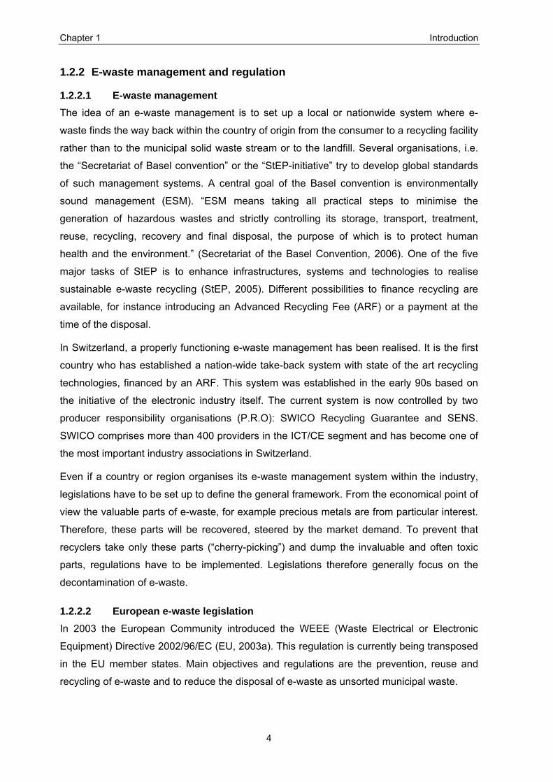
1.2.2 E-waste management and regulation
1.2.2.1 E-waste management The idea of an e-waste management is to set up a local or nationwide system where e-
waste finds the way back within the country of origin from the consumer to a recycling facility
rather than to the municipal solid waste stream or to the landfill. Several organisations, i.e.
the “Secretariat of Basel convention” or the “StEP-initiative” try to develop global standards
of such management systems. A central goal of the Basel convention is environmentally
sound management (ESM). “ESM means taking all practical steps to minimise the
generation of hazardous wastes and strictly controlling its storage, transport, treatment,
reuse, recycling, recovery and final disposal, the purpose of which is to protect human
health and the environment.” (Secretariat of the Basel Convention, 2006). One of the five
major tasks of StEP is to enhance infrastructures, systems and technologies to realise
sustainable e-waste recycling (StEP, 2005). Different possibilities to finance recycling are
available, for instance introducing an Advanced Recycling Fee (ARF) or a payment at the
time of the disposal.
In Switzerland, a properly functioning e-waste management has been realised. It is the first
country who has established a nation-wide take-back system with state of the art recycling
technologies, financed by an ARF. This system was established in the early 90s based on
the initiative of the electronic industry itself. The current system is now controlled by two
producer responsibility organisations (P.R.O): SWICO Recycling Guarantee and SENS.
SWICO comprises more than 400 providers in the ICT/CE segment and has become one of
the most important industry associations in Switzerland.
Even if a country or region organises its e-waste management system within the industry,
legislations have to be set up to define the general framework. From the economical point of
view the valuable parts of e-waste, for example precious metals are from particular interest.
Therefore, these parts will be recovered, steered by the market demand. To prevent that
recyclers take only these parts (“cherry-picking”) and dump the invaluable and often toxic
parts, regulations have to be implemented. Legislations therefore generally focus on the
decontamination of e-waste.
1.2.2.2 European e-waste legislation In 2003 the European Community introduced the WEEE (Waste Electrical or Electronic
Equipment) Directive 2002/96/EC (EU, 2003a). This regulation is currently being transposed
in the EU member states. Main objectives and regulations are the prevention, reuse and
recycling of e-waste and to reduce the disposal of e-waste as unsorted municipal waste.

Chapter 1 Introduction
5
Most of the costs for the current disposal and the environmental sound recycling of e-waste
are generated due to its hazardous substances. To reduce the hazardous content of future
e-waste the RoHS (Restrictions of Hazardous Substances) directive (EU, 2003b) bans
several hazardous substances in the manufacturing of EEE. Materials like lead, mercury or
polybrominated biphenyls (PBB) have to be substituted by safer materials if technically and
economically feasible. The appendix of the RoHS directive specifies some exceptions for
the use of mercury mainly in fluorescent lamps, lead in CRTs or solder, cadmium and
hexavalent chromium and lead containing devices are defined. The regulation has become
effective by July 2006.
1.2.2.3 Intercontinental legislation Despite of the implementation of the above-mentioned legislations there are still concerns
about the treatment of e-waste in non EC- or OECD countries. As mentioned before the
driving forces for the recyclers to send e-waste to developing regions are low labour costs
and partly the absence of environmental regulations. This makes it economically interesting
to send e-waste to non OECD-countries such as China and India.
To prevent the developed world to use the developing world as a dumping ground a
multilateral environmental agreement known as the Basel Convention (BC) was
implemented and entered into force in 1992. BC is an UN convention and its principle idea
was to set up a framework for controlling the “transboundary” movements of hazardous
wastes. In 1995, the “Ban Amendment” which is incorporated in the BC had been
introduced. “The Amendment calls for prohibiting exports of hazardous wastes (for any
purpose) from countries listed in a proposed new annex to the Convention (Annex VII -
Parties that are members of the EU, OECD, Liechtenstein) to all other Parties to the
Convention.” The Amendment has not yet entered into force (Secretariat of the Basel
Convention, 2006).
The implementation of the BC and related agreements are coordinated by the “Secretariat of
the Basel Convention”, located in Geneva, Switzerland and administered by UNEP. It also
provides assistance and guidelines on legal and technical issues, gathers statistical data
and conducts training on the proper management of hazardous waste (Secretariat of the
Basel Convention, 2006).

Chapter 1 Introduction
6
1.3 E-waste Situation in India At present, the e-waste management system in India is characterised by a market driven
collection and recycling implying no direct cost to consumers, producers or taxpayers. The
system is dominated by the informal sector in backyard workshops (Sinha-Khetriwal et al.,
2005). Backyard workshops are considered being a part of the informal economy. Informal
and underground economy is defined by Frey and Schneider (2000): “It comprises all
presently not recorded productive (i.e. value-adding) activities which should be in the
national product (GNP).” In this thesis the informal scrap industry is seen as recycling
facilities that do not comply with state regulations regarding taxation, environmental
protection or safety standards (Streicher-Porte, 2006).
Up to now no regulations or controls on material or financial flows, standards of emissions or
occupational hazards have been implemented (Sinha, 2004). Though India signed the Basel
Convention, there is no specific legislation regulating the export or the collection and
treatment of e-waste. There are however several existing environmental legislations which
are of importance and useful in the context of e-waste (see Appendix IV).
India is one of the countries that have to deal with the arising load of e-waste. Figure 1.1
indicates that the PC growth per capita in India had been over 1’000 % between 1993 and
2000. From 2002 to 2004 the sales of computers in India almost doubled as a market study
shows, which had been performed in 22 Indian cities (see Figure 1.2). Since the growth of
PC sales correlates with the generation of e-waste (Jain and Sareen, 2006) these sales
implicate a massive increase of e-waste.
As an outcome of Phase I of seco’s global e-waste programme the Indo-German-Swiss
Initiative for e-waste management had been set up. It brings together the experience and
expertise of all the partners (MoEF, GTZ, seco) involved. The partners work in close
collaboration with manufacturers, users, recyclers, and NGOs to develop a sustainable e-
waste management system in India (eWaste Guide India, 2006).
Chapter 1 Introduction
7
2'294
828
1'050
1'447
1'934
2'345
3'124
1'716
799
1'405
3'036
1'027
1'6711'882
2329 42 52 45 51 890
500
1'000
1'500
2'000
2'500
3'000
3'500
1997 - 98 1998 - 99 1999 - 00 2000 - 01 2001 - 02 2002 - 03 2003 - 04Year
Sal
e nu
mbe
r (in
thou
sand
)
OverallDesktop PCsNotebooks
Figure 1.2: PC market trends in India from 1997 to 2004 (BIRD, 2005).
1.4 E-waste Situation in Bangalore One of the eight biggest generators of e-waste in India is Bangalore (BIRD, 2005). The
population and economy in Bangalore is growing rapidly partly due to the boom in the ICT-
sector. This development requires major investments in the ICT infrastructure. It also leads
to a higher purchasing power of households. At present Bangalore generates about 8000
tons of computer waste annually (Sahaas, 2004). The expected growing investments in
electronics from private households and the investments that already take place in the ICT
sector implicate that e-waste in Bangalore is increasing and that it has to be managed
appropriately.
For the time being a lot of the e-waste ends up in uncontrolled pathways leading to backyard
recyclers. On one hand, the informal scrap industry provides for semi-skilled and unskilled
jobs and thus an opportunity to earn money for many (uneducated) people. On the other
hand, these jobs are neither secure nor safe. For instance, people working in the informal
sector do usually not enjoy social securities such as insurance benefits or legal securities.
Another problem is that the methods used for retrieval and recycling of valuable components
are mostly very hazardous and can cause serious long-term damage to human health and
the environment.
Critical processes of the e-waste management system in Bangalore have been identified by
the e-waste agency (EWA) (see Appendix V) and are illustrated in Figure 1.3.
Chapter 1 Introduction
8
Obsolete equipment
Obsolete
Functionalequipment
Functionalcomponent
MetalsCRT Plastics PWB Wires andcables
Storage
Transport
Testing
Disassembling
Specificrecyclingchannel
Specificrecyclingchannel
Dismantling StrippingSpecificrecyclingchannel
CopperConnectorsNudePWBs
Specificrecyclingchannel
PreciousMetal
recovery
Specificrecyclingchannel
Refurbishing
Reuse
Burning
? ?
? ? ?
?
Figure 1.3: Simplified process sheet of the present Bangalore e-waste management system. Problematic processes are indicated by a flash; unknown or unclear processes are indicated with a question mark (Rochat, 2006).
As shown in Figure 1.3 the precious metal recovery is considered being one of the most
problematic processes in the e-waste management system in Bangalore. At present gold
recovery is seen as one of the most lucrative parts of precious metal recovery in the
backyard recycling. Most probably, this is a result of its high demand on the market. Since
2001, the gold price is continually growing (see Appendix VI). The most important use of
gold is in jewellery (Feneau, 2002). In 2002, 80 % of the global gold demand was used for
jewellery manufacture. India is the worlds greatest (absolute figures) gold consumer
because of its importance in Indian marriage ceremonies (Gold & precious metals, 2006).
Gold is found in electronic components like connectors and contacts, which are plated with
gold. Gold is used because of its excellent corrosion resistance and high electrical
conductivity. Such electronic components are part of a printed circuit assembly together with
a motherboard. In this thesis the terms printed circuit board (PCB) or printed wiring board
(PWB) are used to describe the whole assembly. Printed wiring boards are part of most

Chapter 1 Introduction
9
electronic devices. According to Hagelüken (2006) the most valuable metals compared to all
the e-waste are contained in PWBs. Approximately two third of the gold contained in a PC
are within the PWBs2.
Consequently, gold recovery is the most important division of the precious metal recovery in
Bangalore and printed wiring boards are considered as one of the most important fraction in
e-waste for the gold recovery.
1.5 Scope and aims of the thesis
1.5.1 Scope The conducted case study of this thesis is integrated in the Indian project of seco’s global e-
waste programme. It provides background information for the planned activities of EWA to
upgrade the informal recyclers. It serves also to make a case for shifting the treatment of
hazardous fractions and critical recovery processes to the formal industry. To improve the
current system the existing practices as well as an alternative practice have to be analysed
properly. Today no detailed descriptions for the existing practices are available. The
accessibility to quantitative and qualitative data is poor and assessing an informal facility in
Bangalore in detail is doing pioneer work.
1.5.2 Aims and scientific questions In this thesis, the gold recovery from PWBs is analysed as an example for the precious
metals recovery from e-waste. In addition, an alternative scenario to the current pathway for
PWB recycling is evaluated. This leads to the two following aims (A) and scientific questions
(Q):
A 1: Providing scientific information of the quality of both the formal and informal gold
recovery processes conducted in Bangalore.
• Q 1: What are the main substances and goods and their quantities used to recover
gold from PWBs conducting a gold recovery process in Bangalore?
• Q 2: What are the main health and environmental hazards occurring during or as a
consequence of the gold recovery processes in Bangalore?
• Q 3: What is the efficiency of PWB-recycling conducted in Bangalore?
A 2: Assessing an alternative to recycle PWB to the current recycling pathway and
comparing the two possibilities.
2 Average gold content in a PC=: 0,3 g (Streicher-Porte, 2006); Average weight of boards in computers: 812 g ± 212g (Li et al., 2006), average gold concentration in PWB: 250 ppm (Hagelüken, 2006); => 0,2 g ± 0,05g gold from PWB in PC
Chapter 1 Introduction
10
• Q 4: Is a shifting of the gold recovery process to an industrial smelter in Belgium
reasonable considering economical and environmental aspects?
1.6 Proceeding and structure of thesis The aims and scientific questions are tackled making three different assessments, which
build up on each other.
To answer Q 1 and Q 2 a mass flow analysis is conducted and described in Chapter 2. In
this chapter, the investigated systems in Bangalore are described, quantified and interpreted
in order to determine the used substances and materials and to evaluate the main health
and environmental hazards.
In chapter 3, the recovery rates are determined, answering Q 3. Gold contents in the
different materials are quantified using a substance flow analysis.
In chapter 4, an alternative scenario to the investigated current recycling path of PWB with
the focus on gold recovery is evaluated as asked for in Q 4.
Chapter 5 presents the main findings and outlook, which are made during the different
assessments.
To assess an unorganised system like that of the backyard recyclers (informal sector) no
general practice exists. Therefore, the methodology for each assessment had to be
consistently adjusted to the existing situations. This iterative approach led to the
proceedings, which can only be described in retrospect and are depicted in detail in each
chapter.

Chapter 2 Gold recovery techniques and hazards
11
2 Gold recovery techniques and hazards In this chapter, three processes to recover gold from e-waste are described. The main
materials used are determined and partly quantified. From this information, the major
hazard-“hot spots” to health and environment are identified.
2.1 Methodology The system is described using the material flow analysis (MFA). “Material flow analysis
(MFA) is a systematic assessment of the flows and stocks of materials within a system
defined in space and time.” (Brunner and Rechenberger, 2004). The goal of an MFA is to
determine the in- and outputs of a process and to understand the flows within a system.
The analysis of material fluxes is an essential approach to gain a system comprehension
and an understanding of the processes occurring within the anthroposphere (Binder et al.,
2001). “Because of the law of the conservation of matter, the results of an MFA can be
controlled by a simple material balance comparing all inputs, stocks, and outputs of a
process. It is this distinct characteristic of MFA that makes the method attractive as a
decision-support tool in resource management, waste management, and environmental
management” (Brunner and Rechberger, 2004). In this analysis the used terminology has
been developed according to the terminology defined in the Practical Handbook of
Material and Flow Analysis (Brunner and Rechenberger, 2004).
Subsequent the mainly used terms in this thesis are defined:
A substance is any (chemical) element or compound composed of uniform units. All
substances are characterised by a unique and identical constitution and are thus
homogenous.
The term material is used for a solid matter composed of heterogeneous units.
A solution is the product of mixed substances and materials and is a heterogeneous
liquid.
A mixture is the product of mixed substances and is a homogeneous liquid.
Process is a term used for the transformation and transport of materials and substances.
A technique is defined to be a sequence of processes.
A process step is an activity within a process (sub-process).
The system is defined by a group of processes, the interaction between these processes
and the system boundaries.
Chapter 2 Gold recovery techniques and hazards
12
The conducted material flow analysis comprises four steps:
System description: The system is characterised determining the system border and the
single process steps referring to the processes of each technique. Using information from
literature and various experts the processes and process steps of the system are
described.
Quantification: The in- and outputs of the system are measured and
calculated/estimated applying the principle of mass conservation.
Interpretation: The environmental hazard hot spots are detected with the beforehand
evaluations and are discussed.
Discussion: An overview of each evaluated system is given. In addition, some features
determined in the description and in the quantification of each process are discussed.
2.2 System Description
2.2.1 System definition The investigated system is part of the e-waste management system in Bangalore, as
illustrated in Figure 2.1. It consists of the gold recovery technique of pre-processed
(dismantled) printed wiring boards (PWBs).
Obsolete equipment
Obsolete
Functionalequipment
Functionalcomponent
MetalsCRT Plastics PWB Wires &cables
Storage
Transport
Testing
Disassembling
SpecificRecyclingchannel
SpecificRecyclingchannel
Dismantling StrippingSpecific
Recyclingchannel
CopperConnectorsNudePWBs
SpecificRecyclingchannel
PreciousMetal
recovery
SpecificRecyclingchannel
Refurbishing
Reuse
Burning
? ?
? ? ?
?
Input material
Gold
Liquids
Solids
Chemicals
Water
Dismantling
gold recovery
PWB(Basic rawmaterial)
Recovery of other preciousmetals
Leaching
Purification
Separation
System boundary
Obsolete equipment
Obsolete
Functionalequipment
Functionalcomponent
MetalsCRT Plastics PWB Wires &cables
Storage
Transport
Testing
Disassembling
SpecificRecyclingchannel
SpecificRecyclingchannel
Dismantling StrippingSpecific
Recyclingchannel
CopperConnectorsNudePWBs
SpecificRecyclingchannel
PreciousMetal
recovery
SpecificRecyclingchannel
Refurbishing
Reuse
Burning
? ?
? ? ?
?
Input material
Gold
Liquids
Solids
Chemicals
Water
Dismantling
gold recovery
PWB(Basic rawmaterial)
Recovery of other preciousmetals
Leaching
Purification
Separation
Input material
Gold
Liquids
Solids
Chemicals
Water
Dismantling
gold recovery
PWB(Basic rawmaterial)
Recovery of other preciousmetals
Leaching
Purification
Separation
System boundary
Figure 2.1: MFA system definition; the system boundary is indicated with dashed lines; squares represent processes, ovals substances, materials, solutions and mixtures.
The system consists of a gold recovery technique divided in several processes that are
required in order to recover gold from the input material. The technique is divided into
Chapter 2 Gold recovery techniques and hazards
13
three processes: Leaching, Separation and Purification. In the context of gold extraction,
leaching is the dissolution of a metal or mineral in a liquid (Marsden and House, 1992).
During the separation, the gold is extracted out of a solution or separated from a material.
Purification is the procedure of rendering something pure, i.e. cleaning it from impurities.
2.2.2 Data collection The description of the techniques is based on different data sources: Observations,
photographs, documentation, literature research and interviews. The observations were
made and photographs were taken during several visits of facilities conducting gold
recovery processes. Rough documentations of the conducted processes in the informal
facility already existed and were taken as a basis. These flowcharts were drawn by
Sahaas, an NGO active in waste management in Bangalore (Rodriguez, 2005). The main
literature resources were articles and books concerning gold mining. In gold mines, similar
techniques are used to recover gold from the ore as they are used to recover gold from
pre-processed PWBs. The corresponding literature was then adapted to the specific
cases with the support of Dr. Richard Klinger (Central Environmental Laboratory of the
Karnataka State Pollution Control Board, Bangalore), Dr. Eddie Adriaenssens (Manager
Analytical Laboratory, UMICORE Precious Metals Refining, Hoboken, Belgium) and
Dr. Hartmut Schönberg (Department of Chemistry and Applied Biosciences, ETH Zurich).
2.2.3 Investigated facilities Three different gold recovery techniques conducted in Bangalore were investigated.
According to consultants working for GTZ (German technical organisation) these three are
the mainly conducted gold recovery techniques in Bangalore. Two of the techniques are
executed in several informal facilities; the other one in a formal facility.
2.2.3.1 Informal sector Currently about 20 informal facilities in and around Bangalore are involved in the recovery
of precious metals from e-waste (Rodriguez, 2005). All of them presumably use the same
technique to recover gold. Consultants of GTZ and EMPA are closely working together
with an informal association of recyclers called Eco BIRD. With the help of GTZ and
EMPA, it was possible to use these contacts and to work together with a gold recovery
unit of Eco BIRD. The following paragraph gives a short description of Eco BIRD and the
investigated unit.
Chapter 2 Gold recovery techniques and hazards
14
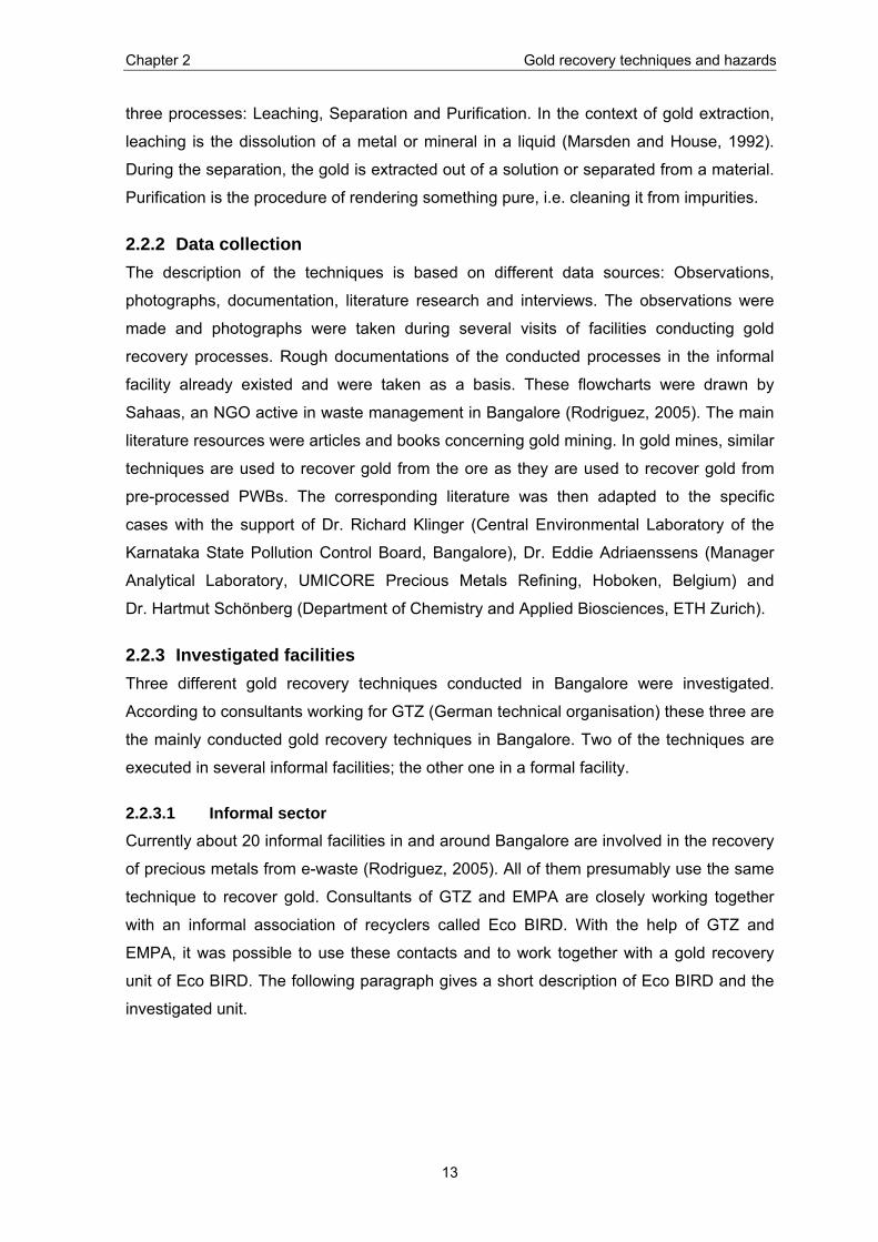
Eco BIRD
Picture 2.1: Eco BIRD (Rizwan’s) facility
In the informal sector in Bangalore, a recently founded association consisting of 11
recycling units called Eco BIRD exists. The word “Eco” stands for “Eco-friendly” and BIRD
is an acronym for Bifurcation, Identification, Recycling and Disposal. The 11 recycling
units either deal with scrap, dismantle the equipment or recover precious metals.
The examined facility belongs to Rizwan Khan (president of Eco Bird) and is situated on a
roof (approx. 46m2) in Gowripalya, Padarayanapura, a suburb of Bangalore. There is a
room (approx. 16 m2) on top of the roof, where the furnace is situated and the materials
and substances are stored in. The containers with acidic liquids are placed outside.
Rizwan employs three workers between the age 10 and 20. Several other people are also
using his facility. The material that is treated by Rizwan per year is estimated to be 1800
kg with a gold production of 7200g (Bineesha, 2006).
To recover gold from e-waste two different techniques are conducted according to the
quality of the input material. If the gold concentration in the input material is low (low-
grade material), “cyanide leaching” is used. If the input material is high-grade material,
they conduct “mercury amalgamation”. Both of the processes are described in the
following chapters.
2.2.3.2 Formal sector In the formal sector, only one company, Surface Chem Finishers, is known conducting a
gold recovery process. It was possible to collaborate with this company and investigate
the exercised process. In the following paragraph a short description and scope of the
company is given.
Chapter 2 Gold recovery techniques and hazards
15
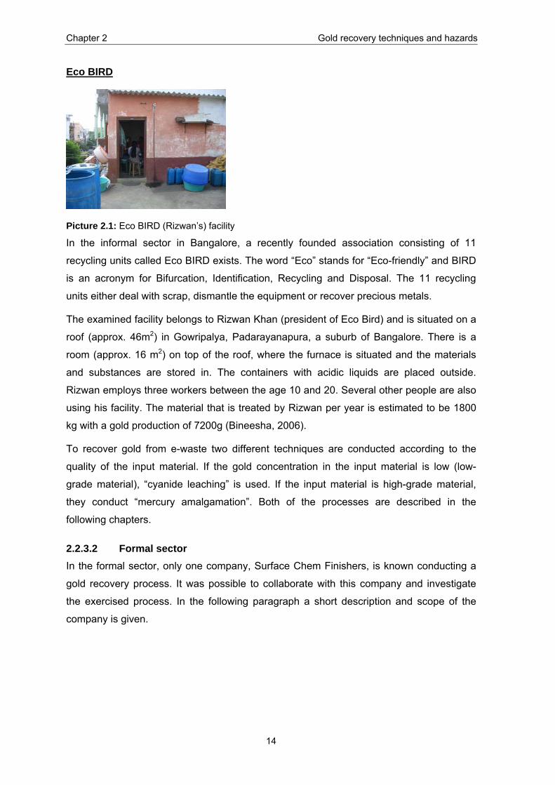
Surface Chem Finishers
Picture 2.2: E-Parisaraa Pvt. Ltd.
“Surface Chem Finishers” is an ISO 9001 – 2000 certified gold plating unit in Peenya
Industrial Estate, Bangalore. It is a sister company of “E-Parisaraa Pvt. Ltd.” which
recycles and dismantles e-waste. The vision of the director of the two companies is to be
eco-friendly and low cost. “E-Parisaraa” is located on the outskirt of Bangalore. About 5 %
of the gold used for the gold plating in “Surface Chem Finishers” is recovered from e-
waste pre-processed at “E-Parisaraa”. Thus, gold recovery is only a side task of Surface
Chem Finishers.
Today there are 45 people working in the two companies. Three persons are involved in
the gold recovery process. At present, E Parisaraa is handling about one ton of e-waste
per day. According to Prakashchandra (Engineer of Surface Chem Finishers, E-Parisaraa
Pvt. Ltd.), approximately 920 kg of material is processed per year to recover gold. Thereof
440 g of gold is recovered per year.
2.2.4 Cyanide leaching at Eco BIRD Cyanide has been used in the mining industry for more than 100 years to recover gold. It
is universally used because of its relatively low cost and great effectiveness of gold
dissolution. The reaction takes place in an alkaline environment, which is important for
economic and safety reasons. It has been shown that the maximum dissolution of gold,
silver, platinum and palladium in cyanide solution is at pH 10-10,5 (Dorin and Woods,
1991). The observed cyanide leaching technique was conducted at around pH 12 (see
Table 2.9). This is almost ideal for the leaching process as the loss of cyanide is very low
at pH 11,5 because the loss due to hydrogen cyanide (HCN) formation is very low
(Kulundaisamy et al., 2003). The main chemical reaction consists of four starting materials
and substances: water, oxygen, gold and cyanide. Cyanide is acting as the complexing
agent in the process and oxygen as an oxidiser (Marsden and House, 1992). However,
other elements contained in the electronic devices disturb this chemical reaction. For
example, the present copper will form cyanide complexes and cause an increased use of
cyanide. These copper-cyanide complexes will tend to inhibit the dissolution of gold.
Chapter 2 Gold recovery techniques and hazards
16
Detailed description of the technique
During a participating observation, this process had been investigated. The input material
is provided to the informal facility (see Appendix VII for details to the material preparation).
With this material, the process is conducted as it would be conducted with purchased
material and it is therefore an acceptable representative for the “usual” process. In the
following description the denominations (L1… P6) refer to the detailed and quantified
flowchart in chapter 2.3.2 (Figure 2.5 and Figure 2.6).
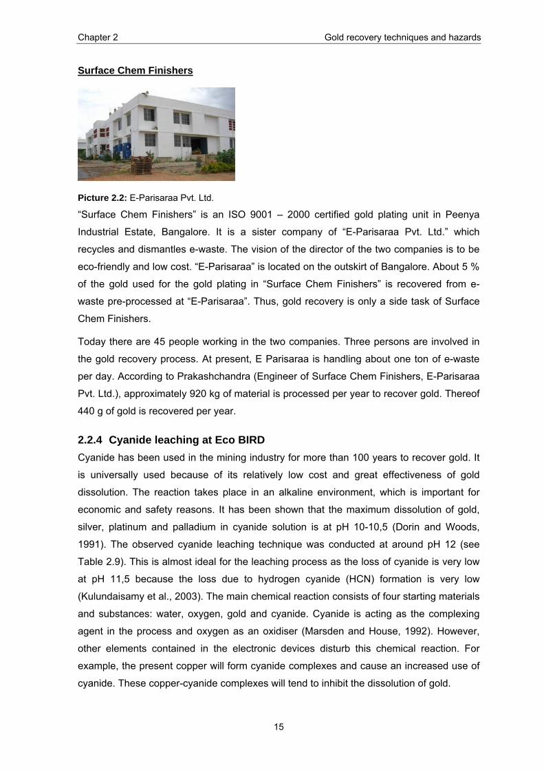
Leaching L 1: Lixiviation
The connectors are put into a plastic container and are doused with hot water. The gold leaching is initiated by adding substance 1 (most probably potassium or sodium cyanide). Under mildly oxidising conditions, the gold is dissolved. Adding cyanide results in a strong complex between cyanide and gold. The reaction known as Elsner's Equation is: 4 Au(s) + 8 CN-(aq) + O2(g) + 2 H2O(l) 4 Au(CN)2
-(aq) + 4 OH-(aq)
Because cyanide is one of the strongest ligands several other complexes are formed (ex.: [Ag(CN)2]-, [Cu(CN)2] -, [Ni(CN)4]-2).
Picture 2.3: Lixiviation with cyanide
L 2: Sieving / Washing
The components are removed from the pregnant (gold-bearing) solution and are washed with water. This is important in order to deplete the waste components as good as possible of their gold. These components are sometimes kept to recover copper in a separate process.
Picture 2.4: Sieving of components
The pregnant solution has a brownish colour.
Picture 2.5: Pregnant solution
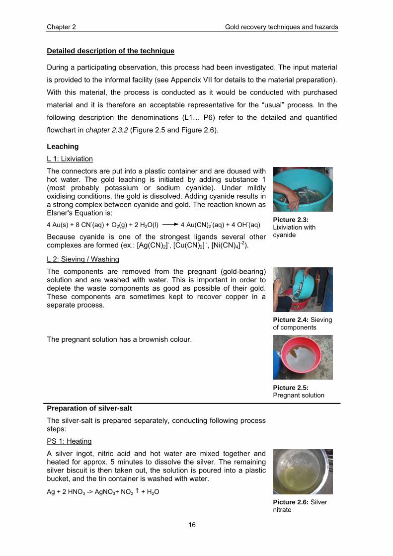
Preparation of silver-salt The silver-salt is prepared separately, conducting following process steps:
PS 1: Heating
A silver ingot, nitric acid and hot water are mixed together and heated for approx. 5 minutes to dissolve the silver. The remaining silver biscuit is then taken out, the solution is poured into a plastic bucket, and the tin container is washed with water.
Ag + 2 HNO3 -> AgNO3+ NO2 + H2O
Picture 2.6: Silver nitrate
Chapter 2 Gold recovery techniques and hazards
17
PS 2: Precipitation
Sodium chloride and water are added to the silver solution. The silver-salt precipitates as silver chloride, which is a white precipitation. Sodium nitrate has a high solubility in water and is dissolved in the solution.
AgNO3 + NaCl -> AgCl + NaNO3
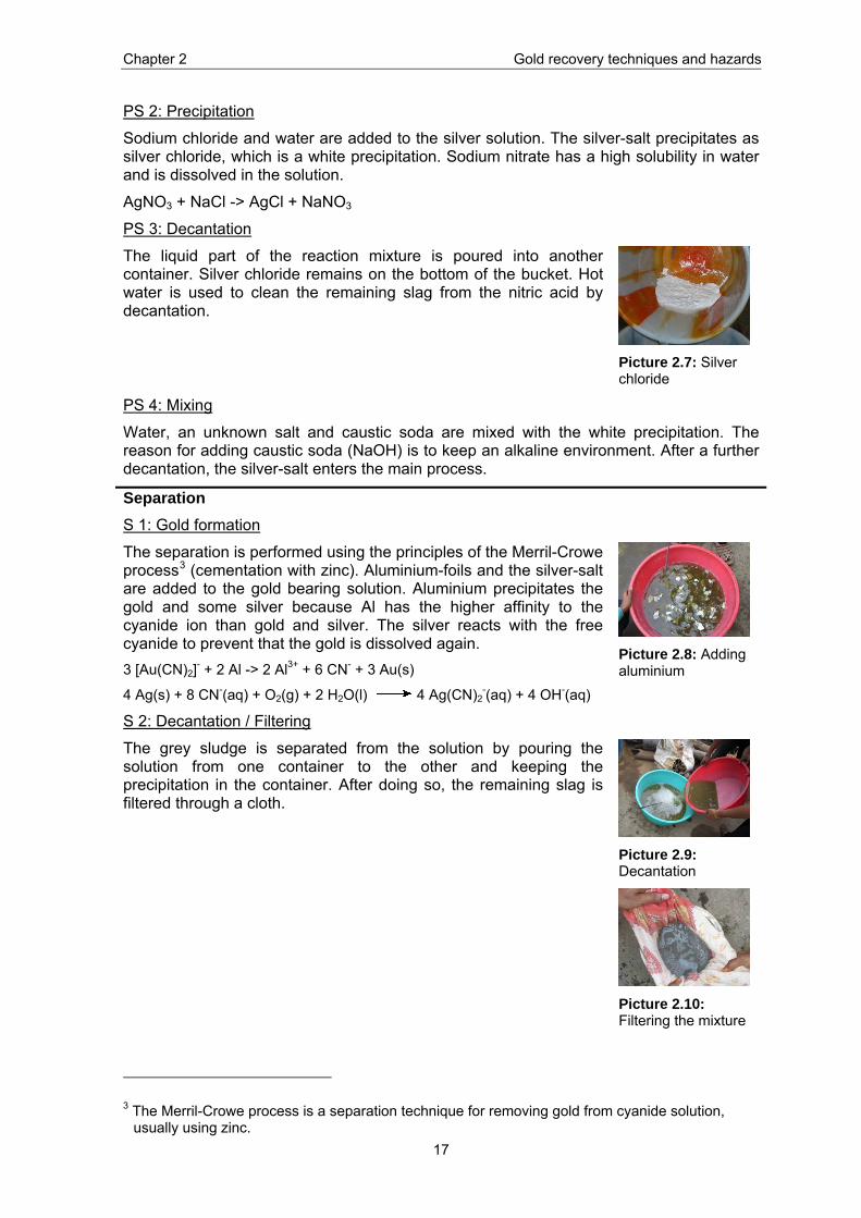
PS 3: Decantation
The liquid part of the reaction mixture is poured into another container. Silver chloride remains on the bottom of the bucket. Hot water is used to clean the remaining slag from the nitric acid by decantation.
Picture 2.7: Silver chloride
PS 4: Mixing
Water, an unknown salt and caustic soda are mixed with the white precipitation. The reason for adding caustic soda (NaOH) is to keep an alkaline environment. After a further decantation, the silver-salt enters the main process.
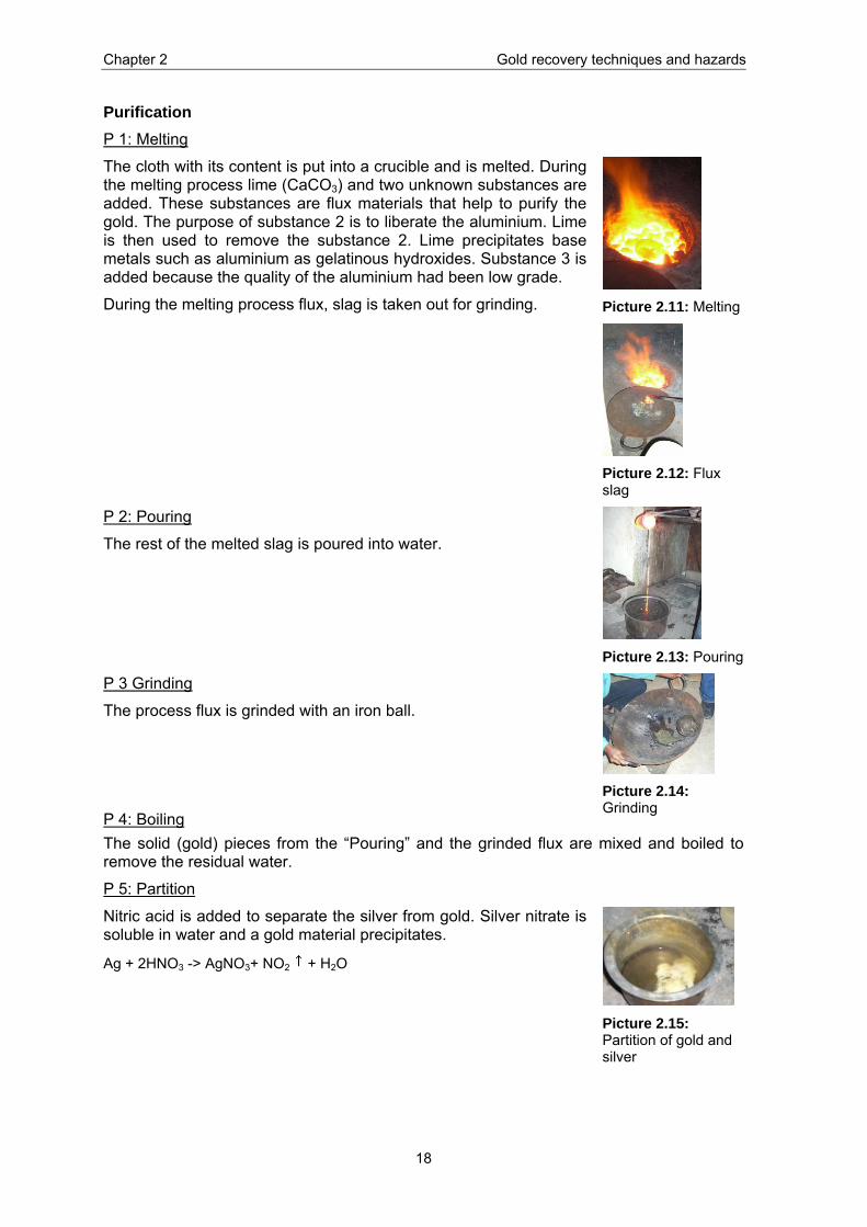
Separation S 1: Gold formation
The separation is performed using the principles of the Merril-Crowe process3 (cementation with zinc). Aluminium-foils and the silver-salt are added to the gold bearing solution. Aluminium precipitates the gold and some silver because Al has the higher affinity to the cyanide ion than gold and silver. The silver reacts with the free cyanide to prevent that the gold is dissolved again. 3 [Au(CN)2]- + 2 Al -> 2 Al3+ + 6 CN- + 3 Au(s)
4 Ag(s) + 8 CN-(aq) + O2(g) + 2 H2O(l) 4 Ag(CN)2-(aq) + 4 OH-(aq)
Picture 2.8: Adding aluminium
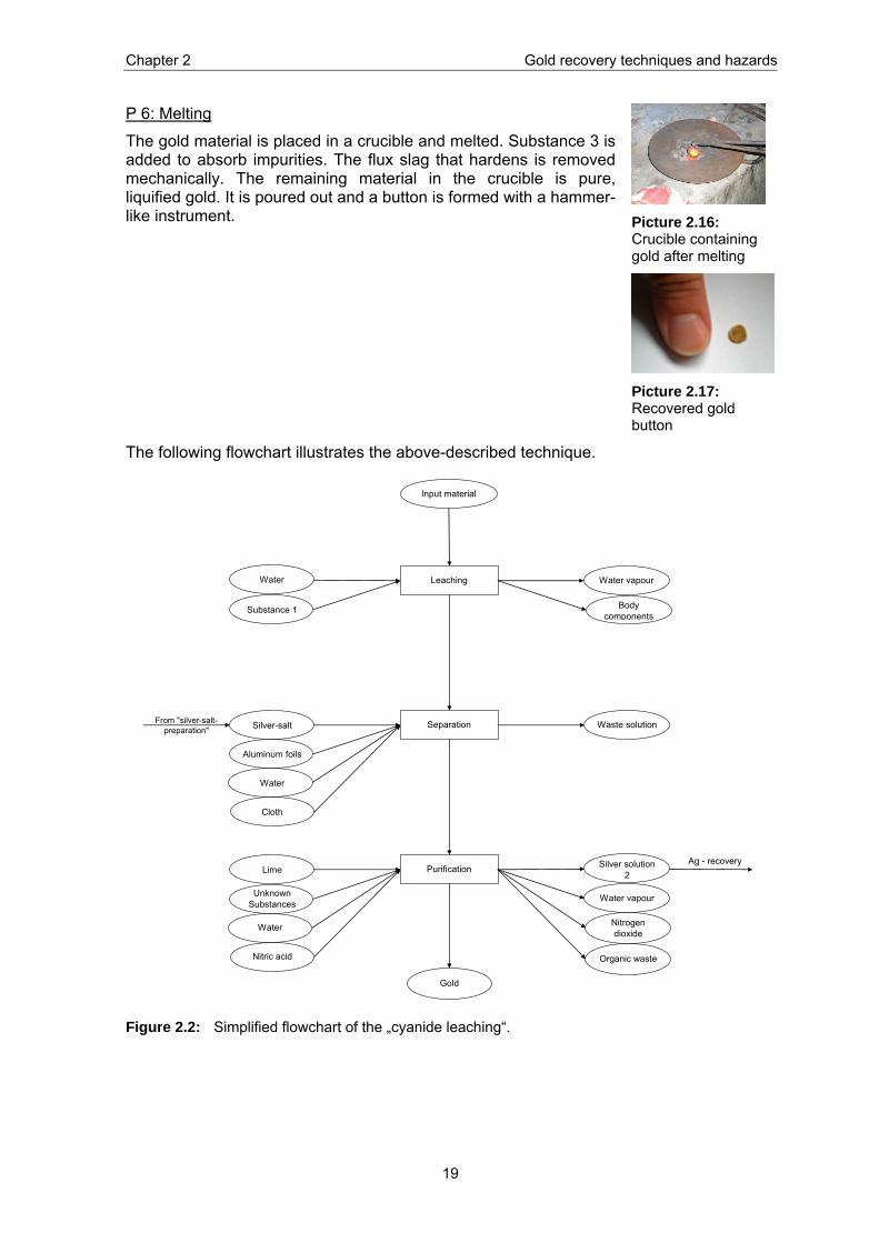
S 2: Decantation / Filtering
The grey sludge is separated from the solution by pouring the solution from one container to the other and keeping the precipitation in the container. After doing so, the remaining slag is filtered through a cloth.
Picture 2.9: Decantation
Picture 2.10: Filtering the mixture
3 The Merril-Crowe process is a separation technique for removing gold from cyanide solution, usually using zinc.
Chapter 2 Gold recovery techniques and hazards
18
Purification P 1: Melting
The cloth with its content is put into a crucible and is melted. During the melting process lime (CaCO3) and two unknown substances are added. These substances are flux materials that help to purify the gold. The purpose of substance 2 is to liberate the aluminium. Lime is then used to remove the substance 2. Lime precipitates base metals such as aluminium as gelatinous hydroxides. Substance 3 is added because the quality of the aluminium had been low grade.
During the melting process flux, slag is taken out for grinding.
Picture 2.11: Melting
Picture 2.12: Flux slag
P 2: Pouring
The rest of the melted slag is poured into water.
Picture 2.13: Pouring
P 3 Grinding
The process flux is grinded with an iron ball.
P 4: Boiling
Picture 2.14: Grinding
The solid (gold) pieces from the “Pouring” and the grinded flux are mixed and boiled to remove the residual water.
P 5: Partition
Nitric acid is added to separate the silver from gold. Silver nitrate is soluble in water and a gold material precipitates.
Ag + 2HNO3 -> AgNO3+ NO2 + H2O
Picture 2.15: Partition of gold and silver
Chapter 2 Gold recovery techniques and hazards
19
P 6: Melting
The gold material is placed in a crucible and melted. Substance 3 is added to absorb impurities. The flux slag that hardens is removed mechanically. The remaining material in the crucible is pure, liquified gold. It is poured out and a button is formed with a hammer-like instrument.
Picture 2.16: Crucible containing gold after melting
Picture 2.17: Recovered gold button
The following flowchart illustrates the above-described technique.
Substance 1
From "silver-salt-preparation" Silver-salt
Aluminum foils
Water
Cloth
LimeAg - recovery
Unknown Substances
Separation
Leaching
Input material
Purification
Water
Waste solution
Water vapour
Water vapour
Body components
Water
Nitric acid
Silver solution 2
Nitrogen dioxide
Gold
Organic waste
Figure 2.2: Simplified flowchart of the „cyanide leaching“.
Chapter 2 Gold recovery techniques and hazards
20
2.2.5 Mercury amalgamation at Eco BIRD The gold recovery with mercury goes back to the 11th century. In the Middle Ages
alchemists tried to produce gold with base metals (which did not work).
The mercury amalgamation is based on the fact that mercury forms an amalgam4 with
gold. With this procedure, the gold can be separated from the other metals present and
from impurities. The attraction of mercury is based on the fact that it is readily available,
cheap and efficient in recovering fine-grained gold (Commission of the European
Communities, 2000). It is a quite simple process using only three substances (mercury,
nitric acid and sodium bicarbonate) to recover the gold. However, it is an old technique
and no longer used in modern gold plants because of the known health and environmental
problems arising.
Detailed description of the technique
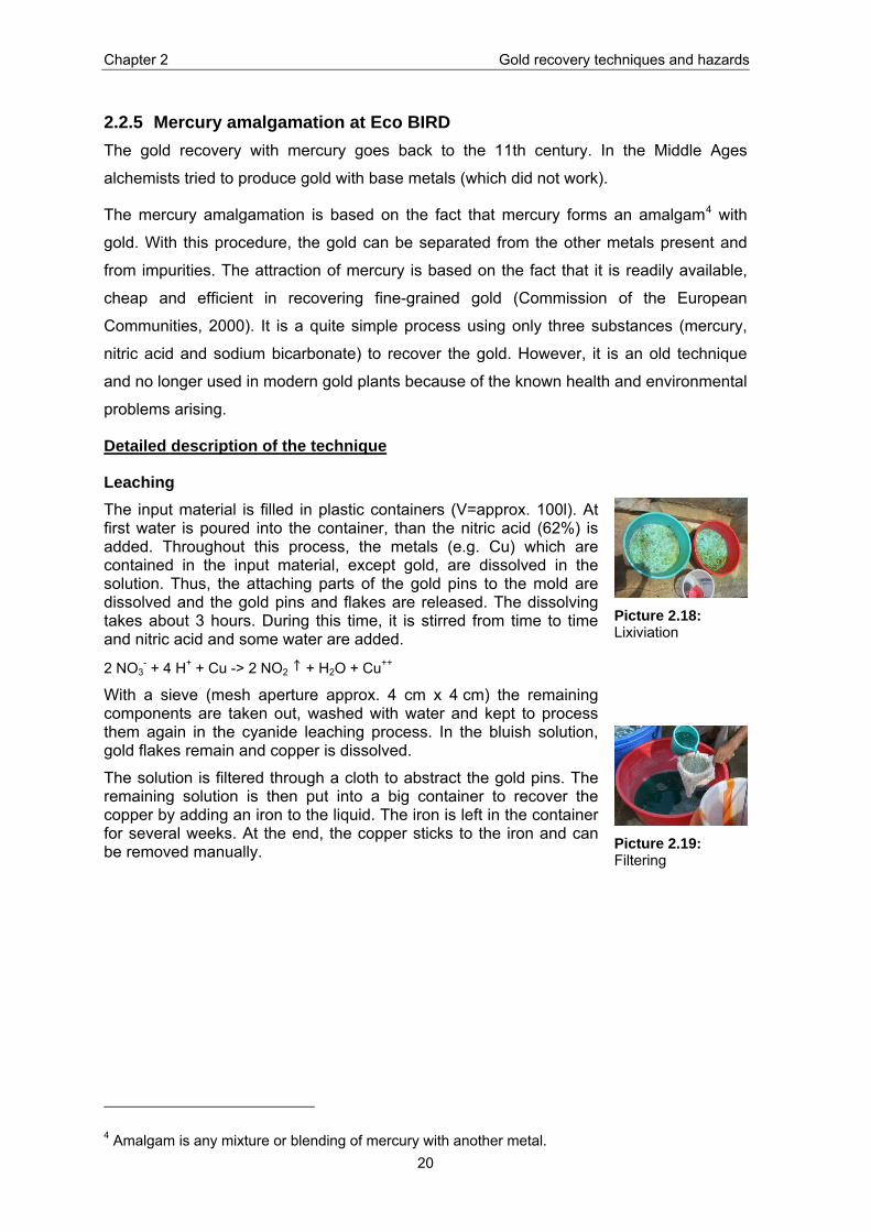
Leaching The input material is filled in plastic containers (V=approx. 100l). At first water is poured into the container, than the nitric acid (62%) is added. Throughout this process, the metals (e.g. Cu) which are contained in the input material, except gold, are dissolved in the solution. Thus, the attaching parts of the gold pins to the mold are dissolved and the gold pins and flakes are released. The dissolving takes about 3 hours. During this time, it is stirred from time to time and nitric acid and some water are added.
2 NO3- + 4 H+ + Cu -> 2 NO2 + H2O + Cu++
With a sieve (mesh aperture approx. 4 cm x 4 cm) the remaining components are taken out, washed with water and kept to process them again in the cyanide leaching process. In the bluish solution, gold flakes remain and copper is dissolved.
The solution is filtered through a cloth to abstract the gold pins. The remaining solution is then put into a big container to recover the copper by adding an iron to the liquid. The iron is left in the container for several weeks. At the end, the copper sticks to the iron and can be removed manually.
Picture 2.18: Lixiviation
Picture 2.19: Filtering
4 Amalgam is any mixture or blending of mercury with another metal.
Chapter 2 Gold recovery techniques and hazards
21
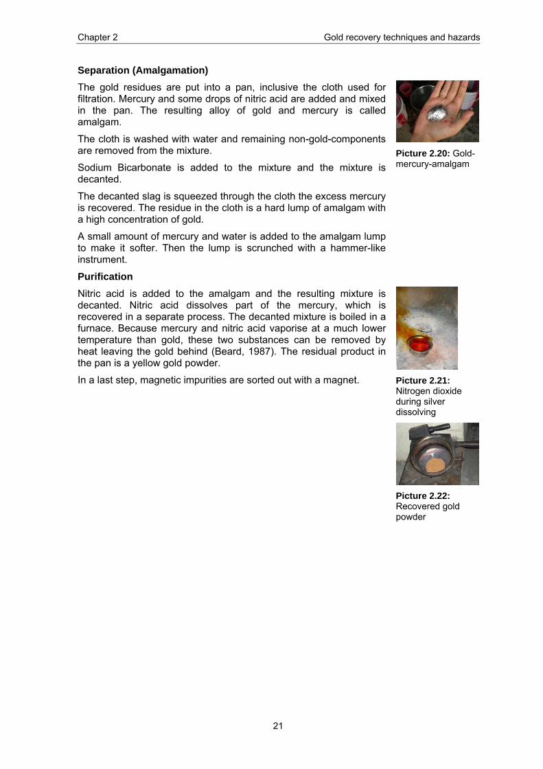
Separation (Amalgamation) The gold residues are put into a pan, inclusive the cloth used for filtration. Mercury and some drops of nitric acid are added and mixed in the pan. The resulting alloy of gold and mercury is called amalgam.
The cloth is washed with water and remaining non-gold-components are removed from the mixture.
Sodium Bicarbonate is added to the mixture and the mixture is decanted.
The decanted slag is squeezed through the cloth the excess mercury is recovered. The residue in the cloth is a hard lump of amalgam with a high concentration of gold.
A small amount of mercury and water is added to the amalgam lump to make it softer. Then the lump is scrunched with a hammer-like instrument.
Picture 2.20: Gold-mercury-amalgam
Purification Nitric acid is added to the amalgam and the resulting mixture is decanted. Nitric acid dissolves part of the mercury, which is recovered in a separate process. The decanted mixture is boiled in a furnace. Because mercury and nitric acid vaporise at a much lower temperature than gold, these two substances can be removed by heat leaving the gold behind (Beard, 1987). The residual product in the pan is a yellow gold powder.
In a last step, magnetic impurities are sorted out with a magnet.
Picture 2.21: Nitrogen dioxide during silver dissolving
Picture 2.22: Recovered gold powder
Chapter 2 Gold recovery techniques and hazards
22
The following flowchart illustrates the above-described technique.
Copper recovery
Mercury recovery
Separation
Leaching
Connectors
Purification
Nitric acid
Mercury
Nitric acid
Gas / Fumes
Body components
Waste components
Waste solution
Copper solution
Water
Sodium bicarbonate
Water
Mercury
Nitric acid
Water Mercury solution
Gas / Fumes
Gold
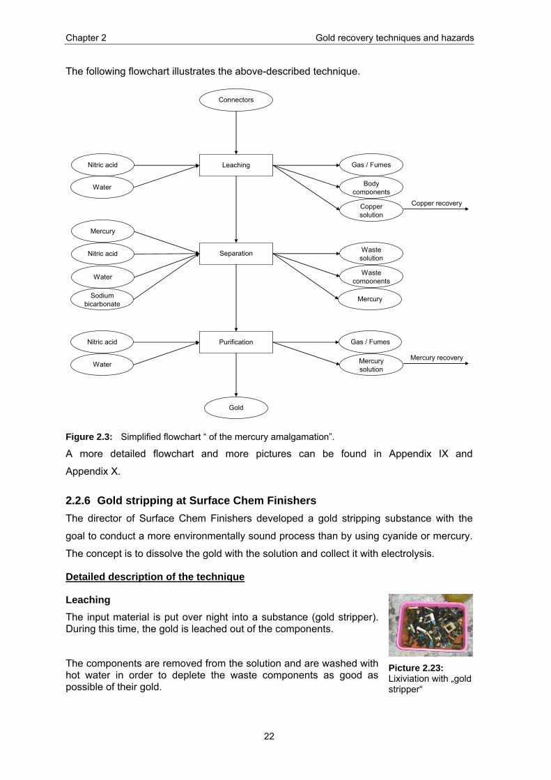
Figure 2.3: Simplified flowchart “ of the mercury amalgamation”.
A more detailed flowchart and more pictures can be found in Appendix IX and
Appendix X.
2.2.6 Gold stripping at Surface Chem Finishers The director of Surface Chem Finishers developed a gold stripping substance with the
goal to conduct a more environmentally sound process than by using cyanide or mercury.
The concept is to dissolve the gold with the solution and collect it with electrolysis.
Detailed description of the technique
Leaching The input material is put over night into a substance (gold stripper). During this time, the gold is leached out of the components.
The components are removed from the solution and are washed with hot water in order to deplete the waste components as good as possible of their gold.
Picture 2.23: Lixiviation with „gold stripper“
Chapter 2 Gold recovery techniques and hazards
23
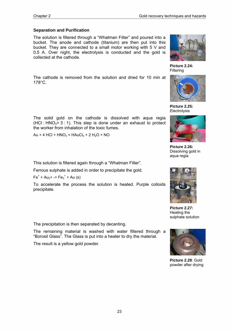
Separation and Purification The solution is filtered through a “Whatman Filter” and poured into a bucket. The anode and cathode (titanium) are then put into this bucket. They are connected to a small motor working with 5 V and 0,5 A. Over night, the electrolysis is conducted and the gold is collected at the cathode.
Picture 2.24: Filtering
The cathode is removed from the solution and dried for 10 min at 178°C.
Picture 2.25: Electrolysis
The solid gold on the cathode is dissolved with aqua regia (HCl : HNO3= 3 : 1). This step is done under an exhaust to protect the worker from inhalation of the toxic fumes. Au + 4 HCl + HNO3 = HAuCl3 + 2 H2O + NO
Picture 2.26: Dissolving gold in aqua regia
This solution is filtered again through a “Whatman Filter”.
Ferrous sulphate is added in order to precipitate the gold. Fe+ + Au2+ -> Fe3
+ + Au (s)
To accelerate the process the solution is heated. Purple colloids precipitate.
Picture 2.27: Heating the sulphate solution
The precipitation is then separated by decanting.
The remaining material is washed with water filtered through a “Borosil Glass”. The Glass is put into a heater to dry the material.
The result is a yellow gold powder.
Picture 2.28: Gold powder after drying

Chapter 2 Gold recovery techniques and hazards
24
The following flowchart illustrates the above-described technique.
PurificationFerrous sulphate
Water
Leaching
Connectors
Gold Stripper
Body components (BC
Waste solution 1Separation
Water
Aqua regia
Water
Vapour
Waste solution 2
Gold
Figure 2.4: Simplified flowchart of the “gold stripping”.
2.3 Quantification
2.3.1 Data collection During the observations made for the description of the three gold recovery techniques
measurements were conducted to quantify the in- and outputs of the processes.
The in- and outputs were weighed with an electronic scale, measured with a measuring
cup or calculated by multiplying the volume with the density (assumed to be 1000 g / l). To
find out the volume, the diameter of the cylindrical containers and the height of the
contained liquid were measured. According to the received figures the mass flow could be
completed applying the law of conservation of mass (Input = Output), making feasible
assumptions and considering the chemical equations. In a further step the amounts of in-
and outputs were converted according to the functional unit “one gram recovered gold”.
The cyanide leaching and the gold stripping are quantified using provided material (the
material preparation is described in Appendix VII). The mercury amalgamation is only
partly quantified during an investigation of the informal facility doing usual business.

Chapter 2 Gold recovery techniques and hazards
25
2.3.2 Cyanide leaching at Eco BIRD The measurements for the different used and produced materials, substances, solutions,
mixtures and vapours are made according to following descriptions:
• All the inputs of this process were measured except the cloth.
• All the liquid outputs and the silver salt (which was also a mixture) were calculated
(volume * density).
• The wet output components were weighed. The estimation was made that the weight
of the dry output components correspond approximately with the weight of the input
components (the amount of leached metals was neglected).
• The amount of “water vapour 1” results from subtracting the weight of the input
components from the wet weight of the output components.
• The estimations for the produced nitrogen dioxide were made according to the
chemical equation of the silver dissolution with nitric acid.
• The deficiency of the mass in the flowchart was identified that it is most probably the
water, which had vaporised (especially during heating). This is proved plausible
considering that the evaporation enthalpy of water is 2257 kJ / kg, charcoal produces
25 MJ / kg and assuming a 30 % efficiency factor. Following for 4,91 kg (4880 g + 30
g) water vapour approximately 1,3 kg charcoal is used.
The quantified mass flows are shown in the subsequent flowcharts (Figure 2.5 and
Figure 2.6).

Chapter 2 Gold recovery techniques and hazards
26
Input material 1
12400
Energy (Coal)~ 2000
Hot water11800
L 1: Lixiviation4880
Substance 1111
Water5850
L 2: Sieving/ Washing12400
Body components
136
From "silver-salt-preparation" Silver-salt
4570S 1: Gold formation
Aluminum foils28
Water2250
Cloth?
S 2: Decantation / Filtering 18100
Waste solution
Energy (Coal)~ 500 g
Lime28
P 1: Melting
Substance 21
Substance 310
P 2: Pouring
Water2050
P 3: Grinding3500
Silver solution 2Ag - recovery
P 4: Boiling 30
52 g
Water125
P 5: Partition435
Silver solution 2Ag - recovery
Nitric acid278 20
Substance 31
P 6: Melting?
Organic waste
0,6
Gold
Water vapour
Nitrogen dioxide
Water vapour
Water vapour
Process flux
Solid (gold) pieces
Estimations / Calculations
Assumption: Density of liquids = 1000g/l
Figure 2.5: Quantified flowchart of the cyanide leaching (main process); unit of numbers is gram.
Chapter 2 Gold recovery techniques and hazards
27
Energy (Coal)~ 500g
Silver70
PS 1: Heating28
Nitrogen dioxide
Nitric acid128 4
Silver
Water1000
Sodium chloride236
PS 2: Precipitation
Water5600
Hot water2000
PS 3: Decantation
Water1500
PS 4: Mixing4570
Silver-salt
Unknown salt81 6160
Silver solution 1Ag - recovery
Caustic soda147
Estimations / Calculations
Assumption: Density of liquids = 1000g/l
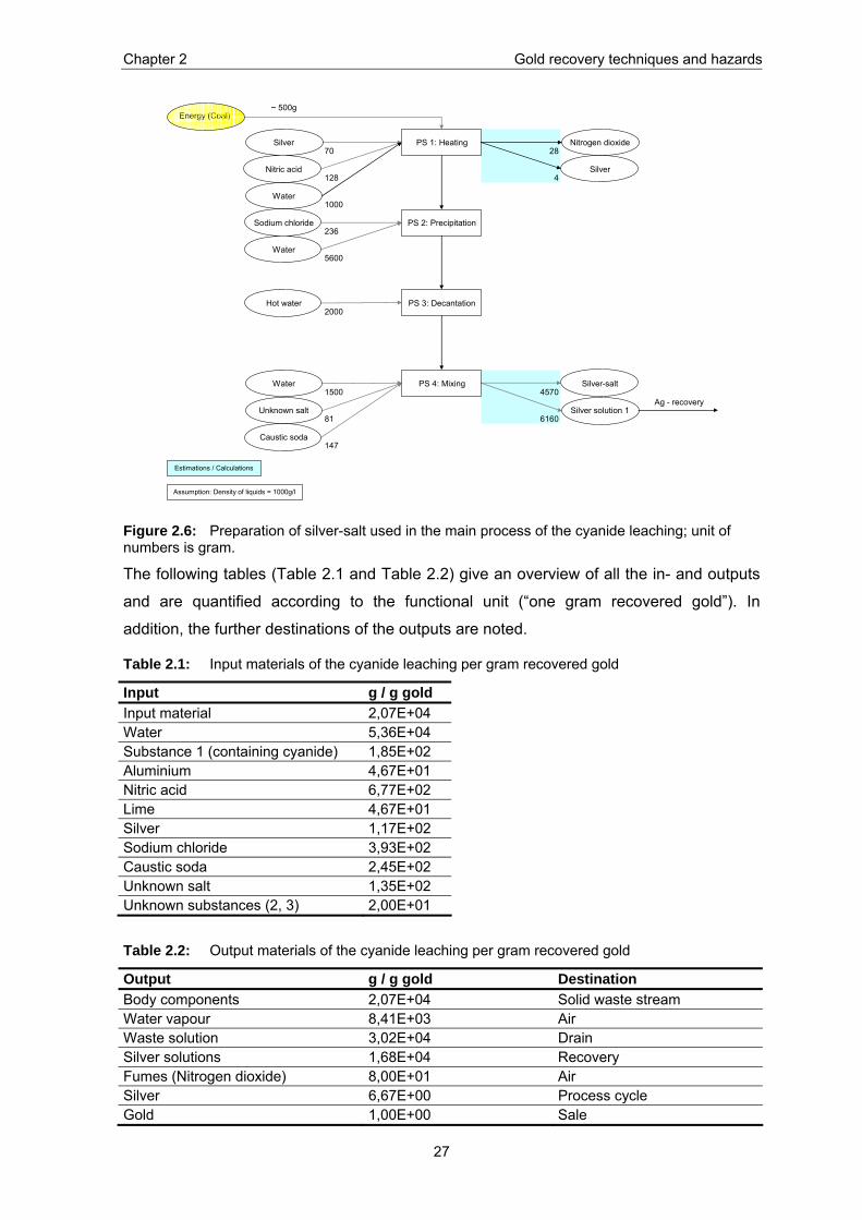
Figure 2.6: Preparation of silver-salt used in the main process of the cyanide leaching; unit of numbers is gram.
The following tables (Table 2.1 and Table 2.2) give an overview of all the in- and outputs
and are quantified according to the functional unit (“one gram recovered gold”). In
addition, the further destinations of the outputs are noted.
Table 2.1: Input materials of the cyanide leaching per gram recovered gold
Input g / g gold Input material 2,07E+04 Water 5,36E+04 Substance 1 (containing cyanide) 1,85E+02 Aluminium 4,67E+01 Nitric acid 6,77E+02 Lime 4,67E+01 Silver 1,17E+02 Sodium chloride 3,93E+02 Caustic soda 2,45E+02 Unknown salt 1,35E+02 Unknown substances (2, 3) 2,00E+01
Table 2.2: Output materials of the cyanide leaching per gram recovered gold
Output g / g gold Destination Body components 2,07E+04 Solid waste stream Water vapour 8,41E+03 Air Waste solution 3,02E+04 Drain Silver solutions 1,68E+04 Recovery Fumes (Nitrogen dioxide) 8,00E+01 Air Silver 6,67E+00 Process cycle Gold 1,00E+00 Sale
Chapter 2 Gold recovery techniques and hazards
28
The silver solutions are further treated with a silver recovery technique. This technique is
not included in the system boundary. However, a short description of the process is given
in the subsequent paragraph.
Silver Recovery
The silver from the silver solutions (output) is recovered using sodium chloride, which
reacts with silver producing silver chloride. In a further step iron is added which
precipitates the silver, acting as a reducing agent (flowchart see Appendix XI). The
precipitation is then melted and solid silver is recovered. Using this procedure in the
above process 50 grams of silver, were recovered. Thus per gram of produced gold 83
grams of silver are recovered. This means that during the cyanide leaching 27 grams of
silver are lost per gram recovered gold.
2.3.3 Mercury amalgamation at Eco BIRD This technique was investigated during a visit of the informal facility doing usual business.
The in- and outputs were only partly measured.
The input material of the observed process was connectors assumingly from PWBs of
telephones. From 14,3 kilograms of connectors 54 grams of gold was recovered. During
this technique, more than 130 g of mercury was used. The other used materials have not
been measured. The in- and outputs and their further destinations are listed below.
Table 2.3: Input materials of the mercury amalgamation per gram recovered gold
Input g / g gold Input material (connectors) 2,64E+02 Mercury 3,59E+00 Sodium bicarbonate Water
Table 2.4: Output materials of the mercury amalgamation per gram recovered gold
Output g / g gold Destination Body components Solid waste stream Gas / Fumes (i.e. water vapour, nitrogen dioxide) Air Copper solution Recovery Waste solution Drain Mercury solution Recovery Mercury 0,07E+00 Process cycle Gold 1,00E+00 Sale
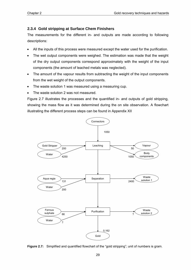
Chapter 2 Gold recovery techniques and hazards
29
2.3.4 Gold stripping at Surface Chem Finishers The measurements for the different in- and outputs are made according to following
descriptions:
• All the inputs of this process were measured except the water used for the purification.
• The wet output components were weighed. The estimation was made that the weight
of the dry output components correspond approximately with the weight of the input
components (the amount of leached metals was neglected).
• The amount of the vapour results from subtracting the weight of the input components
from the wet weight of the output components.
• The waste solution 1 was measured using a measuring cup.
• The waste solution 2 was not measured.
Figure 2.7 illustrates the processes and the quantified in- and outputs of gold stripping,
showing the mass flow as it was determined during the on site observation. A flowchart
illustrating the different process steps can be found in Appendix XII
1050
200 50
4250 1050
131 2400
200
66 ?
?
0,162
PurificationFerrous sulphate
Water
Leaching
Connectors
Gold Stripper
Body components
Waste solution 1Separation
Water
Aqua regia
Water
Vapour
Waste solution 2
Gold
Figure 2.7: Simplified and quantified flowchart of the “gold stripping”; unit of numbers is gram.
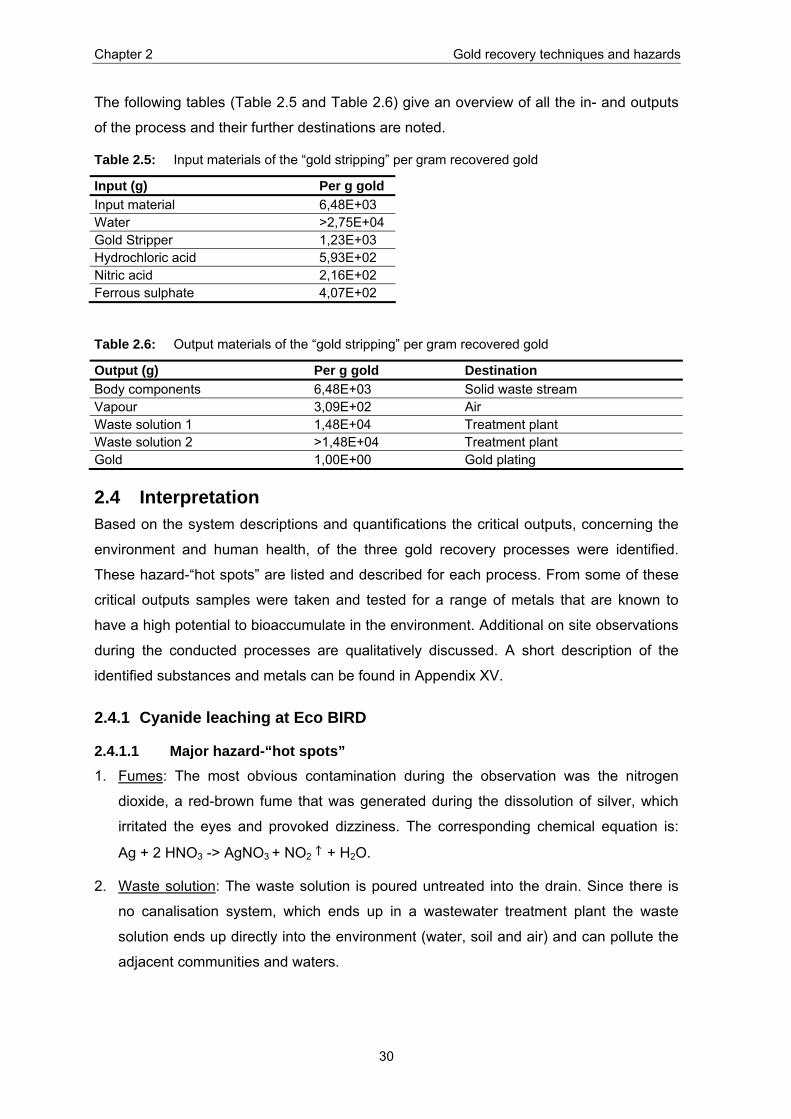
Chapter 2 Gold recovery techniques and hazards
30
The following tables (Table 2.5 and Table 2.6) give an overview of all the in- and outputs
of the process and their further destinations are noted.
Table 2.5: Input materials of the “gold stripping” per gram recovered gold
Input (g) Per g gold Input material 6,48E+03 Water >2,75E+04 Gold Stripper 1,23E+03 Hydrochloric acid 5,93E+02 Nitric acid 2,16E+02 Ferrous sulphate 4,07E+02
Table 2.6: Output materials of the “gold stripping” per gram recovered gold
Output (g) Per g gold Destination Body components 6,48E+03 Solid waste stream Vapour 3,09E+02 Air Waste solution 1 1,48E+04 Treatment plant Waste solution 2 >1,48E+04 Treatment plant Gold 1,00E+00 Gold plating
2.4 Interpretation Based on the system descriptions and quantifications the critical outputs, concerning the
environment and human health, of the three gold recovery processes were identified.
These hazard-“hot spots” are listed and described for each process. From some of these
critical outputs samples were taken and tested for a range of metals that are known to
have a high potential to bioaccumulate in the environment. Additional on site observations
during the conducted processes are qualitatively discussed. A short description of the
identified substances and metals can be found in Appendix XV.
2.4.1 Cyanide leaching at Eco BIRD
2.4.1.1 Major hazard-“hot spots” 1. Fumes: The most obvious contamination during the observation was the nitrogen
dioxide, a red-brown fume that was generated during the dissolution of silver, which
irritated the eyes and provoked dizziness. The corresponding chemical equation is:
Ag + 2 HNO3 -> AgNO3 + NO2 + H2O.
2. Waste solution: The waste solution is poured untreated into the drain. Since there is
no canalisation system, which ends up in a wastewater treatment plant the waste
solution ends up directly into the environment (water, soil and air) and can pollute the
adjacent communities and waters.

Chapter 2 Gold recovery techniques and hazards
31
3. Body components: The body components probably end up in the solid waste stream.
This means that they are piled up on the streets for some time and in the best-case
end up in the landfill. In both cases over a certain amount of time, the contents in the
body components will be released to the environment. A study from Jang and
Townsend (2003) showed that lead will leach out from PWB when landfilled.
Samples of the waste solution and the body components were collected and tested for the
concentration of a range of metals (see Appendix XIV and Appendix XIII). The most
relevant metals to the environment according to Smidt (2006) and their concentration in
the body components, respectively in the waste solution are presented in
Table 2.8 and Table 2.7. In addition, aluminium is also listed in Table 2.7 because of its
elevated concentration in the wastewater.
Table 2.7: Metal concentrations in the waste solution of the “cyanide leaching”
Table 2.8: Metal concentration in the body components of the “cyanide leaching”
Element Concentration (ppm) Stdev (ppm)Copper (Cu) 229250 2333Nickel (Ni) 3200 141Lead (Pb) 22650 1626Tin (Sb) 5100 283Zinc (Zn) 23950 4596
2.4.1.2 Additional on site observations The handling of the materials, which contain cyanide salts and nitric acid, is very frivolous
and no personal protection like gloves, goggles or masks are used. All of the workers
have small burns in the skin of the palms and a yellowish discoloration of skin and nails
which are most probably symptoms of the contact with nitric acid. Beverages and food are
consumed while handling the different and often hazardous substances. Thus, the
substances can enter the body through absorption or ingestion.
Element Concentration (ppm) Stdev [ppm]Aluminium (Al) 1315 55Arsenic (As) <0.5 Cadmium (Cd) <1 Copper (Cu) 185 6Mercury (Hg) <0.5 Nickel (Ni) 9 Lead (Pb) 4 Zinc (Zn) 17 1
Chapter 2 Gold recovery techniques and hazards
32
2.4.1.3 Comparison to the Swiss legislation To give a quantitative statement to the possible hazards the results of the sampling are
put into relation with the allowed concentrations to discharge industry effluents into water
in Switzerland, according to Annex 3, GschV (Schweizerische Eidgenossenschaft, 1998).
The Swiss “regulation of water pollution control” limits the effluent concentration from
industry, amongst others, of the pH, eight metals and the free cyanide ion. These metals
(plus mercury, molybdenum and thallium) are the most relevant heavy metals to the
environment (Smidt, 2006). In the following table, the requirements of the Swiss regulation
are compared with the concentration of the wastewater of the “cyanide leaching” at Eco
BIRD. The ratio indicates the deviation of the values of the waste effluent from the cyanide
leaching conducted at Eco BIRD, in Bangalore, to the Swiss thresholds.
Table 2.9: Comparing the thresholds of the Swiss legislation (see Appendix XVI) of industrial waste water with the found concentration in the waste solution of the “cyanide leaching”
Parameter Request GschV Ratio Waste water Eco BIRD pH-value 6,5 to 9,0 12 Arsenic (As) 0,1 mg / l < 5 <0,5 mg / l Lead (Pb) 0,5 mg / l 8 4 mg / l Cadmium (Cd) 0,1 mg / l < 10 <1 mg / l Chromium (Cr) 2 mg / l n.a. Cobalt (Co) 0,5 mg / l n.a. Copper (Cu) 0,5 mg / l 370 185 mg / l Nickel (Ni) 2 mg / l 4,5 9 mg / l Zinc (Zn) 2 mg / l 8,5 17 mg / l
The concentration of copper in Eco BIRD’s effluent exceeds Swiss industrial wastewater
thresholds 370 times. In addition, the concentrations of all the other heavy metals are
above the Swiss thresholds. These high concentrations of metals in the effluent are
because the cyanide salt, which is used to dissolve the gold, also dissolves all other
metals. Another concern is the high pH of the tested effluent, which makes the water
environmentally hazardous.
2.4.2 Mercury amalgamation at Eco BIRD
2.4.2.1 Major hazard-“hot spots” 1. Fumes: The most obvious exposure to a hazard has been observed during the first
step in the mercury amalgamation process when almost the whole workplace had
been covered with a redish fume (see Picture X.2 in Appendix X). Nitrogen dioxide is
produced, corresponding to the chemical equation:
2 NO3- + 4 H+ + Cu -> 2 NO2 + H2O + Cu++.
It was observed that the mercury is heated and vaporises during the purification. Thus,
it ends up in the air. The production of gold using mercury amalgamation is stated to
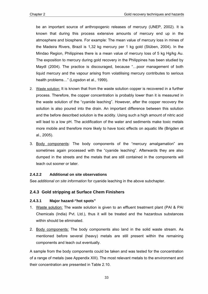
Chapter 2 Gold recovery techniques and hazards
33
be an important source of anthropogenic releases of mercury (UNEP, 2002). It is
known that during this process extensive amounts of mercury end up in the
atmosphere and biosphere. For example: The mean value of mercury loss in mines of
the Madeira Rivers, Brazil is 1,32 kg mercury per 1 kg gold (Stüben, 2004). In the
Mindao Region, Philippines there is a mean value of mercury loss of 5 kg Hg/kg Au.
The exposition to mercury during gold recovery in the Philippines has been studied by
Maydl (2004). The practice is discouraged, because “…poor management of both
liquid mercury and the vapour arising from volatilising mercury contributes to serious
health problems…” (Logsdon et al., 1999).
2. Waste solution: It is known that from the waste solution copper is recovered in a further
process. Therefore, the copper concentration is probably lower than it is measured in
the waste solution of the “cyanide leaching”. However, after the copper recovery the
solution is also poured into the drain. An important difference between this solution
and the before described solution is the acidity. Using such a high amount of nitric acid
will lead to a low pH. The acidification of the water and sediments make toxic metals
more mobile and therefore more likely to have toxic effects on aquatic life (Brigden et
al., 2005).
3. Body components: The body components of the “mercury amalgamation” are
sometimes again processed with the “cyanide leaching”. Afterwards they are also
dumped in the streets and the metals that are still contained in the components will
leach out sooner or later.
2.4.2.2 Additional on site observations See additional on site information for cyanide leaching in the above subchapter.
2.4.3 Gold stripping at Surface Chem Finishers
2.4.3.1 Major hazard-“hot spots” 1. Waste solution: The waste solution is given to an effluent treatment plant (PAI & PAI
Chemicals (India) Pvt. Ltd.), thus it will be treated and the hazardous substances
within should be eliminated.
2. Body components: The body components also land in the solid waste stream. As
mentioned before several (heavy) metals are still present within the remaining
components and leach out eventually.
A sample from the body components could be taken and was tested for the concentration
of a range of metals (see Appendix XIII). The most relevant metals to the environment and
their concentration are presented in Table 2.10.
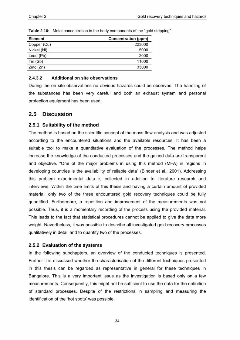
Chapter 2 Gold recovery techniques and hazards
34
Table 2.10: Metal concentration in the body components of the “gold stripping”
Element Concentration (ppm) Copper (Cu) 223000 Nickel (Ni) 5000 Lead (Pb) 2000 Tin (Sb) 11000 Zinc (Zn) 33000
2.4.3.2 Additional on site observations During the on site observations no obvious hazards could be observed. The handling of
the substances has been very careful and both an exhaust system and personal
protection equipment has been used.
2.5 Discussion
2.5.1 Suitability of the method The method is based on the scientific concept of the mass flow analysis and was adjusted
according to the encountered situations and the available resources. It has been a
suitable tool to make a quantitative evaluation of the processes. The method helps
increase the knowledge of the conducted processes and the gained data are transparent
and objective. “One of the major problems in using this method (MFA) in regions in
developing countries is the availability of reliable data” (Binder et al., 2001). Addressing
this problem experimental data is collected in addition to literature research and
interviews. Within the time limits of this thesis and having a certain amount of provided
material, only two of the three encountered gold recovery techniques could be fully
quantified. Furthermore, a repetition and improvement of the measurements was not
possible. Thus, it is a momentary recording of the process using the provided material.
This leads to the fact that statistical procedures cannot be applied to give the data more
weight. Nevertheless, it was possible to describe all investigated gold recovery processes
qualitatively in detail and to quantify two of the processes.
2.5.2 Evaluation of the systems In the following subchapters, an overview of the conducted techniques is presented.
Further it is discussed whether the characterisation of the different techniques presented
in this thesis can be regarded as representative in general for these techniques in
Bangalore. This is a very important issue as the investigation is based only on a few
measurements. Consequently, this might not be sufficient to use the data for the definition
of standard processes. Despite of the restrictions in sampling and measuring the
identification of the ‘hot spots’ was possible.
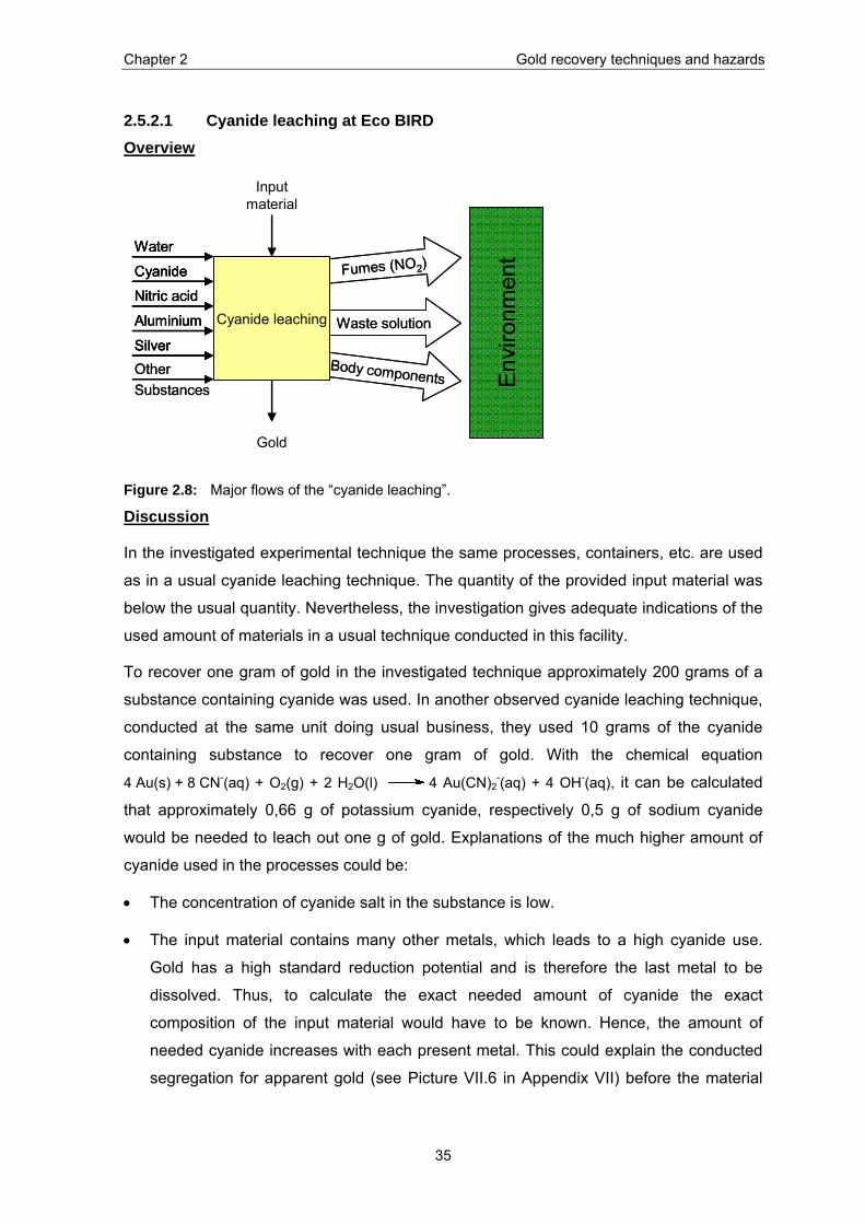
Chapter 2 Gold recovery techniques and hazards
35
2.5.2.1 Cyanide leaching at Eco BIRD Overview
Waste solution
Body components
Fumes (NO2)
Input material
Gold
Cyanide leaching
Water
Cyanide
Nitric acid
Aluminium
SilverOther Substances E
nviro
nmen
t
Waste solution
Body components
Fumes (NO2)
Input material
Gold
Cyanide leaching
WaterWater
CyanideCyanide
Nitric acidNitric acid
AluminiumAluminium
SilverSilverOther Substances E
nviro
nmen
t
Figure 2.8: Major flows of the “cyanide leaching”.
Discussion
In the investigated experimental technique the same processes, containers, etc. are used
as in a usual cyanide leaching technique. The quantity of the provided input material was
below the usual quantity. Nevertheless, the investigation gives adequate indications of the
used amount of materials in a usual technique conducted in this facility.
To recover one gram of gold in the investigated technique approximately 200 grams of a
substance containing cyanide was used. In another observed cyanide leaching technique,
conducted at the same unit doing usual business, they used 10 grams of the cyanide
containing substance to recover one gram of gold. With the chemical equation
4 Au(s) + 8 CN-(aq) + O2(g) + 2 H2O(l) 4 Au(CN)2-(aq) + 4 OH-(aq), it can be calculated
that approximately 0,66 g of potassium cyanide, respectively 0,5 g of sodium cyanide
would be needed to leach out one g of gold. Explanations of the much higher amount of
cyanide used in the processes could be:
• The concentration of cyanide salt in the substance is low.
• The input material contains many other metals, which leads to a high cyanide use.
Gold has a high standard reduction potential and is therefore the last metal to be
dissolved. Thus, to calculate the exact needed amount of cyanide the exact
composition of the input material would have to be known. Hence, the amount of
needed cyanide increases with each present metal. This could explain the conducted
segregation for apparent gold (see Picture VII.6 in Appendix VII) before the material

Chapter 2 Gold recovery techniques and hazards
36
enters the gold leaching process. It also leads to the assumption that rather more
cyanide is used as required to make sure all the gold is dissolved.
In the investigated process, 21 kg of input material to recover one gram of recovered gold
is needed. In another observed process, 3 kg of input material per one gram of recovered
gold is used and from the estimated figures (see chapter 2.2.3.1), the average recovery
rate would be one g gold per 250 g of input material. This wide-ranging amount of input
material used to recover one gram of gold might be because of the different gold content
in the input material and because of different people conducting the process.
A piece in the process, which is surprising, is the preparation of silver-salt (see PS 1 –
PS 3 in Figure 2.6). Theoretically, silver-salt is not needed to precipitate/form the gold
(see S 1 in Figure 2.5). According to Dr. Schönberg (ETH) and literature resources, gold
can be precipitated using only zinc or aluminium. Due to the addition of silver-salt 27
grams of silver are lost per gram recovered gold, which is a lot considering that it is a
precious metal and thus valuable.
Possible explanations could be:
• In the first process, excess cyanide is added to be sure all possible gold is dissolved.
The silver salt is used to bind the excess cyanide in the “Gold formation” process step
(S 1). Maybe it is cheaper to add the silver that can be recovered and used again than
to add more aluminium or zinc to precipitate the gold (Schönberg, 2006)
• The used silver is not pure enough to be sold and is therefore a waste product that
has no better use than to decrease the amount of aluminium needed in the separation
process.
• “The purpose of adding silver is to obtain a more impure gold alloy. If there is more
silver than gold present in the alloy, it is easier to separate them” (Parthasarathy,
2006).
Regarding the purification process (see P 1 to P 6 in Figure 2.5), the question is raised
why it is composed of so many steps. The essential steps are the melting (P 6) and the
partition (P 5), where the gold is separated from silver and other impurities. Theoretically,
the process could be simplified concentrating on the essential steps. However, the
experience of the workers goes back several generations and the made assumptions
would have to be discussed with them and evaluated.
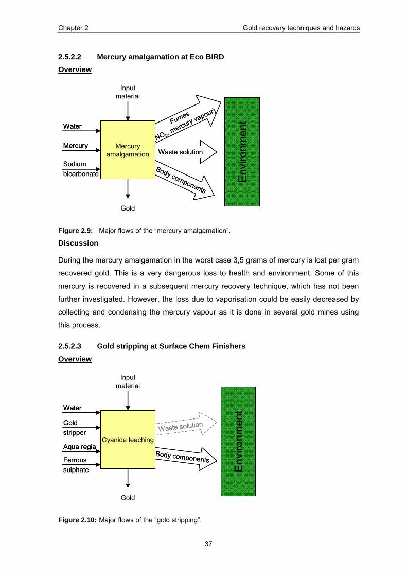
Chapter 2 Gold recovery techniques and hazards
37
2.5.2.2 Mercury amalgamation at Eco BIRD Overview
Waste solution
Body components
Fumes
(NO 2, mercury vapour)
Input material
Gold
Mercury amalgamation
Water
Mercury
Env
ironm
ent
Sodium bicarbonate
Waste solution
Body components
Fumes
(NO 2, mercury vapour)
Input material
Gold
Mercury amalgamation
WaterWater
MercuryMercury
Env
ironm
ent
Sodium bicarbonate
Figure 2.9: Major flows of the “mercury amalgamation”.
Discussion
During the mercury amalgamation in the worst case 3,5 grams of mercury is lost per gram
recovered gold. This is a very dangerous loss to health and environment. Some of this
mercury is recovered in a subsequent mercury recovery technique, which has not been
further investigated. However, the loss due to vaporisation could be easily decreased by
collecting and condensing the mercury vapour as it is done in several gold mines using
this process.
2.5.2.3 Gold stripping at Surface Chem Finishers Overview
Waste solution
Body components
Input material
Gold
Cyanide leaching
Water
Aqua regia
Env
ironm
ent
Gold stripper
Ferrous sulphate
Waste solution
Body components
Input material
Gold
Cyanide leaching
WaterWater
Aqua regiaAqua regia
Env
ironm
ent
Gold stripper
Ferrous sulphate
Figure 2.10: Major flows of the “gold stripping”.
Chapter 2 Gold recovery techniques and hazards
38
Discussion
The conducted experimental technique was a miniaturised example of the usual
technique. Usually around 100 kg of input material is treated together. Because of the
small amount of material, some adaptations had to be made: no additional oxygen was
pumped into the solution, which is left over night; the cathode was titanium instead of
stainless steel; the cathode was put directly into aqua regia (usually the gold is scraped off
before). According to the director of the facility, the experiment is nevertheless
comparable with his usual technique.
Taking the figures given from the Engineer of E-Parisaraa (see chapter 2.2.3.2) 2 kg input
material are needed to recover one g gold. In the experiment 6,5 kg of input material
would be needed to recover one gram gold. This is an indication that the input material of
the experiment is a little less concentrated on gold or the gold is easier to leach out when
the quantity of used material and substance is higher. In order to take the right amount
and not waste anything the different auxiliary substances are always measured carefully.
Thus, it seems that this process is standardised and it is known that qualitative checks are
regularly executed by the director of the facility.
Chapter 3 Evaluation of recovery rates
39
3 Evaluation of recovery rates In this chapter, the gold recovery rates from PWB recycling in the informal and the formal
sector in Bangalore are determined. It was possible to extend the system boundaries
compared to the previous chapter.
3.1 Methodology The system is described using the substance flow analysis (SFA). SFA has the same
characteristics as the material flow analysis (MFA) and is based on the simple principle of
material balance (Input = Output). The goal is to follow a specific substance in the system.
The same terminology is used as in the MFA conducted in the previous chapter (see
chapter 2.1).
The conducted gold flow analysis comprises three steps:
System description: The system and their boundaries are defined and the investigated
systems are shortly depicted.
Quantification: The gold flows of the overall system and subsystems are measured and
calculated using two different approaches and applying the principle of mass conservation.
Interpretation: The recovery rates (gold yields) of the systems are determined.
3.2 System description
3.2.1 System definition The investigated systems are part of the e-waste management system in Bangalore, as
illustrated in Figure 3.1. The Overall system is divided into two subsystems. Subsystem 1
consists of the dismantling process, Subsystem 2 of the gold recovery process, which is
described in detail in chapter 2.
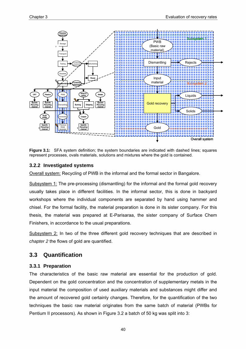
Chapter 3 Evaluation of recovery rates
40
Obsolete equipment
Obsolete
Functionalequipment
Functionalcomponent
MetalsCRT Plastics PWB Wires &cables
Storage
Transport
Testing
Disassembling
SpecificRecyclingchannel
SpecificRecyclingchannel
Dismantling StrippingSpecific
Recyclingchannel
CopperConnectorsNudePWBs
SpecificRecyclingchannel
PreciousMetal
recovery
SpecificRecyclingchannel
Refurbishing
Reuse
Burning
? ?
? ? ?
?
Liquids
Solids
Dismantling
Gold recovery
PWB(Basic rawmaterial)
Overall system
Subsystem 2
Rejects
Input material
Subsystem 1
Gold
Figure 3.1: SFA system definition; the system boundaries are indicated with dashed lines; squares represent processes, ovals materials, solutions and mixtures where the gold is contained.
3.2.2 Investigated systems Overall system: Recycling of PWB in the informal and the formal sector in Bangalore.
Subsystem 1: The pre-processing (dismantling) for the informal and the formal gold recovery
usually takes place in different facilities. In the informal sector, this is done in backyard
workshops where the individual components are separated by hand using hammer and
chisel. For the formal facility, the material preparation is done in its sister company. For this
thesis, the material was prepared at E-Parisaraa, the sister company of Surface Chem
Finishers, in accordance to the usual preparations.
Subsystem 2: In two of the three different gold recovery techniques that are described in
chapter 2 the flows of gold are quantified.
3.3 Quantification
3.3.1 Preparation The characteristics of the basic raw material are essential for the production of gold.
Dependent on the gold concentration and the concentration of supplementary metals in the
input material the composition of used auxiliary materials and substances might differ and
the amount of recovered gold certainly changes. Therefore, for the quantification of the two
techniques the basic raw material originates from the same batch of material (PWBs for
Pentium II processors). As shown in Figure 3.2 a batch of 50 kg was split into 3:
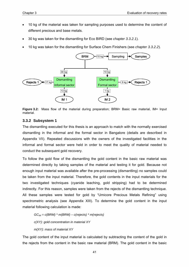
Chapter 3 Evaluation of recovery rates
41
• 10 kg of the material was taken for sampling purposes used to determine the content of
different precious and base metals.
• 30 kg was taken for the dismantling for Eco BIRD (see chapter 3.3.2.1).
• 10 kg was taken for the dismantling for Surface Chem Finishers (see chapter 3.3.2.2).
Dismantling
Informal sector
10 kg
Sampling10 kg
30 kg
BRM
Dismantling
Formal sector
IM 1
13 kg
Rejects 1 17 kg Rejects 19 kg
1 kg
IM 2
Samples
Dismantling
Informal sector
10 kg
Sampling10 kg
30 kg
BRM
Dismantling
Formal sector
IM 1
13 kg
Rejects 1 17 kg Rejects 19 kg
1 kg
IM 2
Samples
Figure 3.2: Mass flow of the material during preparation; BRM= Basic raw material, IM= Input material.
3.3.2 Subsystem 1 The dismantling executed for this thesis is an approach to match with the normally exercised
dismantling in the informal and the formal sector in Bangalore (details are described in
Appendix VII). Repeated discussions with the owners of the investigated facilities in the
informal and formal sector were held in order to meet the quality of material needed to
conduct the subsequent gold recovery.
To follow the gold flow of the dismantling the gold content in the basic raw material was
determined directly by taking samples of the material and testing it for gold. Because not
enough input material was available after the pre-processing (dismantling) no samples could
be taken from the input material. Therefore, the gold contents in the input materials for the
two investigated techniques (cyanide leaching, gold stripping) had to be determined
indirectly. For this reason, samples were taken from the rejects of the dismantling technique.
All these samples were tested for gold by “Umicore Precious Metals Refining” using
spectrometric analysis (see Appendix XIII). To determine the gold content in the input
material following calculation is made:
GCIM = c(BRM) * m(BRM) – c(rejects) * m(rejects)
c(XY): gold concentration in material XY
m(XY): mass of material XY
The gold content of the input material is calculated by subtracting the content of the gold in
the rejects from the content in the basic raw material (BRM). The gold content in the basic
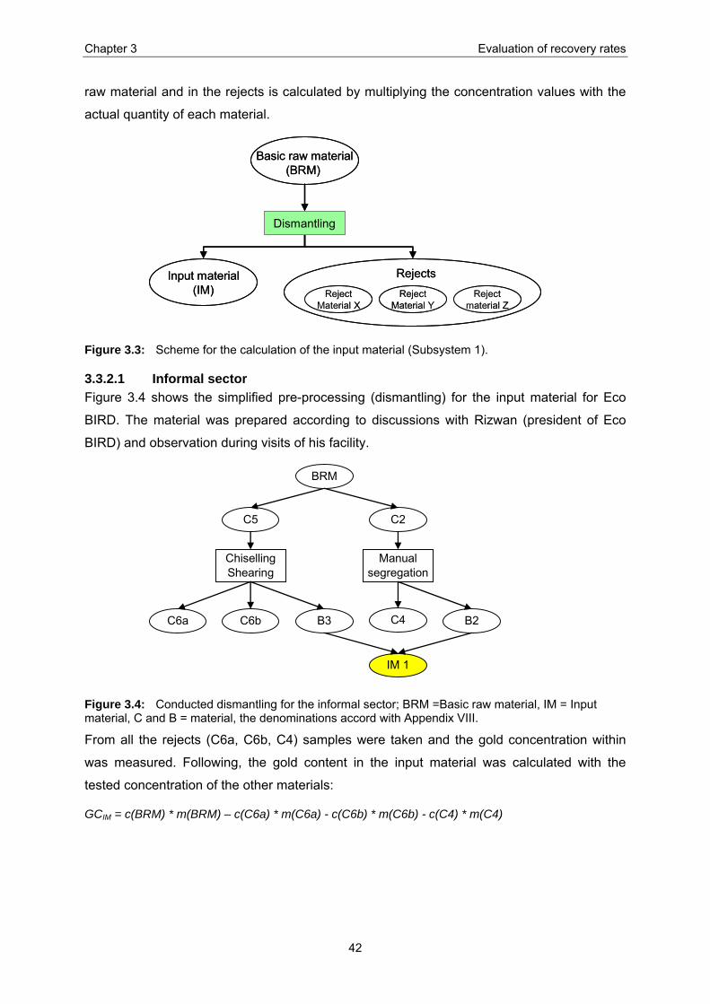
Chapter 3 Evaluation of recovery rates
42
raw material and in the rejects is calculated by multiplying the concentration values with the
actual quantity of each material.
Basic raw material(BRM)
Input material(IM) Reject
Material XReject
Material YReject
material Z
Dismantling
Rejects
Basic raw material(BRM)
Input material(IM) Reject
Material XReject
Material YReject
material Z
Dismantling
Rejects
Figure 3.3: Scheme for the calculation of the input material (Subsystem 1).
3.3.2.1 Informal sector Figure 3.4 shows the simplified pre-processing (dismantling) for the input material for Eco
BIRD. The material was prepared according to discussions with Rizwan (president of Eco
BIRD) and observation during visits of his facility.
C2
Manual segregation
B2C4
C5
ChisellingShearing
B3 C6a C6b
BRM
IM 1
Figure 3.4: Conducted dismantling for the informal sector; BRM =Basic raw material, IM = Input material, C and B = material, the denominations accord with Appendix VIII.
From all the rejects (C6a, C6b, C4) samples were taken and the gold concentration within
was measured. Following, the gold content in the input material was calculated with the
tested concentration of the other materials:
GCIM = c(BRM) * m(BRM) – c(C6a) * m(C6a) - c(C6b) * m(C6b) - c(C4) * m(C4)

Chapter 3 Evaluation of recovery rates
43
Table 3.1: Overview of the calculation of the gold in the input material 1 (Subsystem 1).
Abbreviation
Description
Weight kg
Au tested ppm
Au testedppm
Average ppm
Stdev ppm
BRM Basic raw material 30,224 112 200 156 62C6a Nude PWB 0,334 15 15 C6b Plastic + copper parts 4,682 264 293 279 21C4 "non gold"-parts 12,836 266 274 270 6
Weight kg
Au calculated g
Au calculated ppm
Stdev ppm
IM 1 = B3 + B2 Input material 1 12,400 < 1,5 0 133
The above calculations led to the quantified gold flows that are illustrated in the figure below.
Dismantling Rejects
Input material
PWB(Basic rawmaterial)
3,4 6,1
0 1,5
4,6
4,9
Min
Max
Dismantling Rejects
Input material
PWB(Basic rawmaterial)
3,4 6,1
0 1,5
4,6
4,9
Min
Max
Figure 3.5: Approximate gold flow in the Subsystem 1 (informal sector).
3.3.2.2 Formal sector Figure 3.6 shows the simplified pre-processing (dismantling) for the input material for Surface
Chem Finishers. The material was prepared according to discussions with Parthasarathy
(director of Surface Chem Finishers).
BRM
A3
Chiselling
A3a
Chiselling
A4a A5A5a
A4
A6
segregation
IM 2 A7
Figure 3.6: Conducted dismantling for the formal sector; BRM =Basic raw material, IM = Input material, A = material, the denominations accord with Appendix VIII.
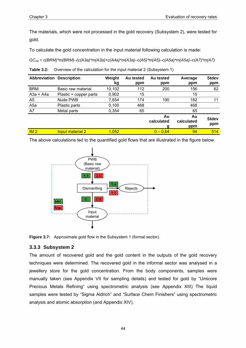
Chapter 3 Evaluation of recovery rates
44
The materials, which were not processed in the gold recovery (Subsystem 2), were tested for
gold.
To calculate the gold concentration in the input material following calculation is made:
GCIM = c(BRM)*m(BRM)–(c(A3a)*m(A3a)+c(A4a)*m(A3a)–c(A5)*m(A5)–c(A5a)*m(A5a)–c(A7)*m(A7)
Table 3.2: Overview of the calculation for the input material 2 (Subsystem 1)
Abbreviation
Description
Weight kg
Au tested ppm
Au testedppm
Average ppm
Stdev ppm
BRM Basic raw material 10,102 112 200 156 62A3a + A4a Plastic + copper parts 0,902 15 15 A5 Nude PWB 7,654 174 190 182 11A5a Plastic parts 0,100 468 468 A7 Metal parts 0,354 65 65
Au
calculated g
Au calculated
ppm Stdev
ppm
IM 2 Input material 2 1,052 0 – 0,64 94 514
The above calculations led to the quantified gold flows that are illustrated in the figure below.
Dismantling Rejects
Input material
PWB(Basic rawmaterial)
1,1 2,0
0 0,6
1,4
1,5
Min
Max
Dismantling Rejects
Input material
PWB(Basic rawmaterial)
1,1 2,0
0 0,6
1,4
1,5
Min
Max
Figure 3.7: Approximate gold flow in the Subsystem 1 (formal sector).
3.3.3 Subsystem 2 The amount of recovered gold and the gold content in the outputs of the gold recovery
techniques were determined. The recovered gold in the informal sector was analysed in a
jewellery store for the gold concentration. From the body components, samples were
manually taken (see Appendix VII for sampling details) and tested for gold by “Umicore
Precious Metals Refining” using spectrometric analysis (see Appendix XIII) The liquid
samples were tested by “Sigma Aldrich” and “Surface Chem Finishers” using spectrometric
analysis and atomic absorption (and Appendix XIV).

Chapter 3 Evaluation of recovery rates
45
To calculate the gold content in the input material following calculation is made:
GCIM = c(Au) * m(Au) + c(BC)* m(BC)+ c(S)* m(S)
c(XY): gold concentration in material XY
m(XY): mass of material XY
The gold content in the input material is determined by adding up the recovered gold with the
losses of the gold during the processes (illustrated in Figure 3.8). The possibilities of gold
loss during the gold recovery are evaluated regarding the description of gold recovery
techniques (see chapter 2). The amount of lost gold is then calculated by multiplying the gold
concentration of these outputs with the weight of the outputs.
Gold (Au)
Solutions (S)
Body components
(BC)
Gold recoveryprocess
Input material(IM)
Gold (Au)
Solutions (S)
Body components
(BC)
Gold recoveryprocess
Input material(IM)
Figure 3.8: Scheme for the calculation of the input material (Subsystem 2).
3.3.3.1 Cyanide leaching at Eco BIRD (informal sector) The possible gold losses were identified according to the flowchart (see Figure 2.5 and
Figure 2.6). In the separate process (preparation of silver salt) the silver solution 1 (SS 1)
could contain gold. In the main process gold can be found in the body components (BC 1),
the waste solution (WS 1) and the silver solution 2 (SS 2).
Au 1
WS 1
BC 1Cyanideleaching
IM 1
SS 1
SS 2
Au 1
WS 1
BC 1Cyanideleaching
IM 1
SS 1
SS 2
Figure 3.9: Conducted gold recovery in the informal sector; IM = Input material, BC = Body components, WS = Waste solution, SS = Silver solution, Au = Gold.
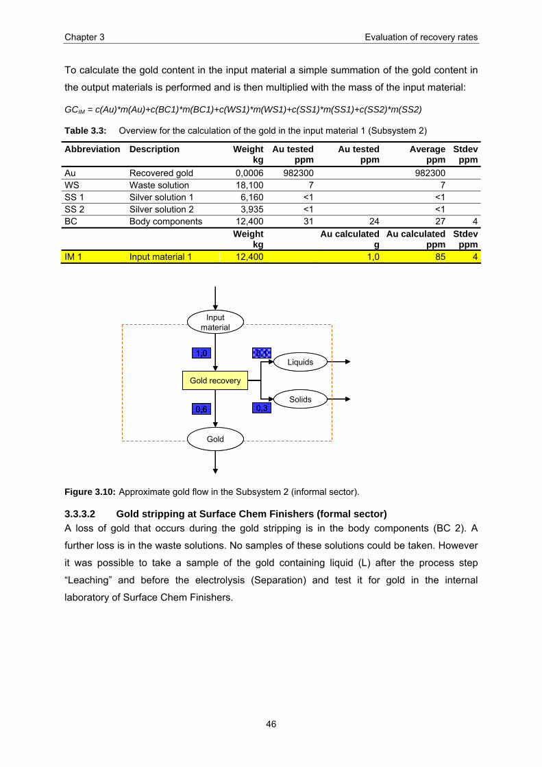
Chapter 3 Evaluation of recovery rates
46
To calculate the gold content in the input material a simple summation of the gold content in
the output materials is performed and is then multiplied with the mass of the input material:
GCIM = c(Au)*m(Au)+c(BC1)*m(BC1)+c(WS1)*m(WS1)+c(SS1)*m(SS1)+c(SS2)*m(SS2)
Table 3.3: Overview for the calculation of the gold in the input material 1 (Subsystem 2)
Abbreviation
Description
Weight kg
Au tested ppm
Au testedppm
Average ppm
Stdev ppm
Au Recovered gold 0,0006 982300 982300 WS Waste solution 18,100 7 7 SS 1 Silver solution 1 6,160 <1 <1 SS 2 Silver solution 2 3,935 <1 <1 BC Body components 12,400 31 24 27 4
Weight kg
Au calculated g
Au calculated ppm
Stdev ppm
IM 1 Input material 1 12,400 1,0 85 4
Liquids
Solids
Gold recovery
Input material
Gold
0,11,0
0,6 0,3
Liquids
Solids
Gold recovery
Input material
Gold
0,11,0
0,6 0,3
Figure 3.10: Approximate gold flow in the Subsystem 2 (informal sector).
3.3.3.2 Gold stripping at Surface Chem Finishers (formal sector) A loss of gold that occurs during the gold stripping is in the body components (BC 2). A
further loss is in the waste solutions. No samples of these solutions could be taken. However
it was possible to take a sample of the gold containing liquid (L) after the process step
“Leaching” and before the electrolysis (Separation) and test it for gold in the internal
laboratory of Surface Chem Finishers.

Chapter 3 Evaluation of recovery rates
47
IM 2
L
BC 2Leaching
SeperationPurification
Figure 3.11: Conducted gold recovery in the formal sector; IM = Input material, BC = Body components, L = Liquid after Leaching.
To calculate the gold content in the input material 2 a summation of the gold content in the
gold bearing solution and the gold content in the body components is conducted:
GCIM = c(L)*m(L)+c(BC2 *m(BC2)
In order to receive the gold concentration in the input material, the gold content is multiplied
with the weight of the material.
Table 3.4: Overview of the calculation for the input material 2 (Subsystem 2)
Abbreviation
Description
Weight kg
Au tested
ppmAu tested
ppmAverage
ppm Stdev
ppm
L Pregnant solution 2,400 89 89 BC 2 Body components 2 1,050 130 130
Au calculated mg
Au calculated ppm
Stdev ppm
IM 2 Input material 2 1,050 0,35 333
SolidsLeaching
Input material
Gold
0,10,4
0,16
0,3
Separation Liquids0,14
SolidsLeaching
Input material
Gold
0,10,4
0,16
0,3
Separation Liquids0,14
Figure 3.12: Approximate gold flow in the Subsystem 2 (formal sector).
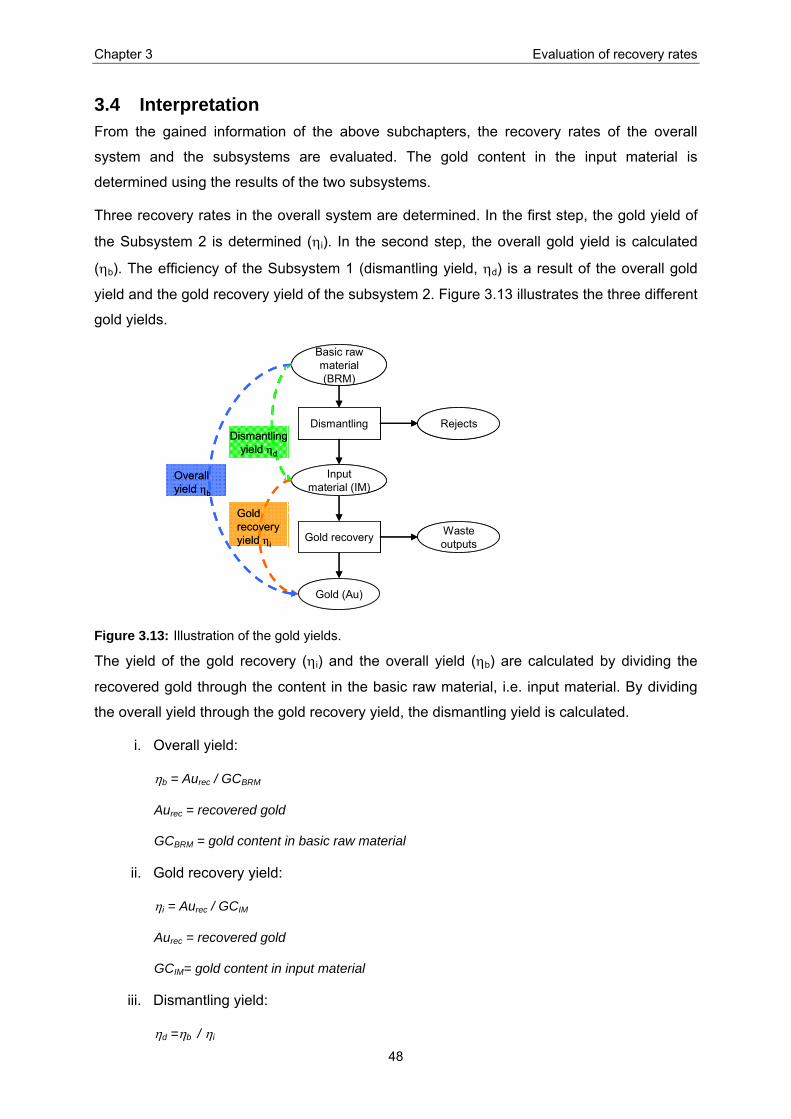
Chapter 3 Evaluation of recovery rates
48
3.4 Interpretation From the gained information of the above subchapters, the recovery rates of the overall
system and the subsystems are evaluated. The gold content in the input material is
determined using the results of the two subsystems.
Three recovery rates in the overall system are determined. In the first step, the gold yield of
the Subsystem 2 is determined (ηi). In the second step, the overall gold yield is calculated
(ηb). The efficiency of the Subsystem 1 (dismantling yield, ηd) is a result of the overall gold
yield and the gold recovery yield of the subsystem 2. Figure 3.13 illustrates the three different
gold yields.
Input material (IM)
Gold (Au)
Dismantling
Gold recovery
Basic rawmaterial (BRM)
Gold recoveryyield ηi
Overall yield ηb
Rejects
Wasteoutputs
Dismantlingyield ηd
Input material (IM)
Gold (Au)
Dismantling
Gold recovery
Basic rawmaterial (BRM)
Gold recoveryyield ηi
Overall yield ηb
Rejects
Wasteoutputs
Dismantlingyield ηd
Figure 3.13: Illustration of the gold yields.
The yield of the gold recovery (ηi) and the overall yield (ηb) are calculated by dividing the
recovered gold through the content in the basic raw material, i.e. input material. By dividing
the overall yield through the gold recovery yield, the dismantling yield is calculated.
i. Overall yield:
ηb = Aurec / GCBRM
Aurec = recovered gold
GCBRM = gold content in basic raw material
ii. Gold recovery yield:
ηi = Aurec / GCIM
Aurec = recovered gold
GCIM= gold content in input material
iii. Dismantling yield:
ηd =ηb / ηi
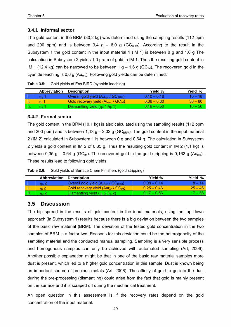
Chapter 3 Evaluation of recovery rates
49
3.4.1 Informal sector The gold content in the BRM (30,2 kg) was determined using the sampling results (112 ppm
and 200 ppm) and is between 3,4 g – 6,0 g (GCBRM). According to the result in the
Subsystem 1 the gold content in the input material 1 (IM 1) is between 0 g and 1,6 g The
calculation in Subsystem 2 yields 1,0 gram of gold in IM 1. Thus the resulting gold content in
IM 1 (12,4 kg) can be narrowed to be between 1 g – 1.6 g (GCIM). The recovered gold in the
cyanide leaching is 0,6 g (Aurec). Following gold yields can be determined:
Table 3.5: Gold yields of Eco BIRD (cyanide leaching)
Abbreviation Description Yield % Yield % i. ηb 1 Overall gold yield (Aurec / GCBRM) 0,10 – 0,18 10 – 18 ii. ηi 1 Gold recovery yield (Aurec / GCIM) 0,36 – 0,60 36 – 60 iii. ηd 1 Dismantling yield (ηb 1 /ηi 1) 0,16 – 0,50 16 – 50
3.4.2 Formal sector The gold content in the BRM (10,1 kg) is also calculated using the sampling results (112 ppm
and 200 ppm) and is between 1,13 g – 2,02 g (GCBRM). The gold content in the input material
2 (IM 2) calculated in Subsystem 1 is between 0 g and 0,64 g. The calculation in Subsystem
2 yields a gold content in IM 2 of 0,35 g. Thus the resulting gold content in IM 2 (1,1 kg) is
between 0,35 g – 0.64 g (GCIM). The recovered gold in the gold stripping is 0,162 g (Aurec).
These results lead to following gold yields:
Table 3.6: Gold yields of Surface Chem Finishers (gold stripping)
Abbreviation Description Yield % Yield %i. ηb 2 Overall gold yield (Aurec / GCBRM) 0,08 – 0,14 8 – 14ii. ηi 2 Gold recovery yield (Aurec / GCIM) 0,25 – 0,46 25 – 46iii. ηd 2 Dismantling yield (ηb 2 /ηi 2) 0,17 – 0,56 17 – 56
3.5 Discussion The big spread in the results of gold content in the input materials, using the top down
approach (in Subsystem 1) results because there is a big deviation between the two samples
of the basic raw material (BRM). The deviation of the tested gold concentration in the two
samples of BRM is a factor two. Reasons for this deviation could be the heterogeneity of the
sampling material and the conducted manual sampling. Sampling is a very sensible process
and homogenous samples can only be achieved with automated sampling (Art, 2006).
Another possible explanation might be that in one of the basic raw material samples more
dust is present, which led to a higher gold concentration in this sample. Dust is known being
an important source of precious metals (Art, 2006). The affinity of gold to go into the dust
during the pre-processing (dismantling) could arise from the fact that gold is mainly present
on the surface and it is scraped off during the mechanical treatment.
An open question in this assessment is if the recovery rates depend on the gold
concentration of the input material.

Chapter 3 Evaluation of recovery rates
50
3.5.1 Informal sector The process gold yield (ηi 1) of the cyanide leaching process is between 36 % and 60 %. The
major gold loss is contained in the body components, which still contain approx. 370 mg of
gold. They are removed during the process step “L 2: Sieving and washing”. The second
major loss occurs during “S 2: Decantation and Filtering” (see Figure 2.5). In the waste liquid,
which is not treated, any further approximately 130 mg of gold is still present. Possible
explanations of these losses are:
• The decantation (S 2) is not done properly enough and grey sludge, which contains gold
remains in the waste solution.
• The used quantities of the auxiliary substances are not properly adjusted to the quality of
the input material and not all the gold can be leached out.
• The gold is not at the surface of the material and cannot be reached with the cyanide
solution.
• It might be in the nature of the chemical process that with this process not more gold can
be leached out.
Even more significant is the loss of gold during the pre-processing (dismantling), which is
50 % and 84 % of the gold contained in the basic raw material. One of the main reasons for
this loss might be the visual checking for apparent gold. It seems that this is very bad
practice and obviously decreases the concentration of gold in the material. Another reason is
that during shredding, shearing, chiselling, etc. dust containing gold is produced which
cannot be collected.
3.5.2 Formal sector The process gold yield (ηi 2) of the gold stripping process is in the same range as for the
above-discussed cyanide leaching with 25 % to 46 %. It is important to mention that the
output liquids go through a supplementary process to recover gold. According to
Parthasarathy (director of Surface Chem Finishers) the output liquid of that process is
disposed when the gold concentration is below 0,2 ppm. Thus, the remaining gold content in
the liquid is not considered being a major loss. The major gold loss is in the body
components. The body components still contain 136 mg of gold, which is almost the amount
of the recovered gold (162 mg).
As seen in the Eco BIRD example here also a major gold loss (44 % to 83 %) occurs during
the pre-processing (dismantling). The director of E-Parisaraa is aware of this loss and is
planning to sell the nude PWBs to Umicore Precious Metal Refinings (UPMR) in Belgium.
Today he chisels the PWBs and stores the nude PWB to be sold to UPMR. The chiselled
components (copper coils, connectors, condensers, etc.) are segregated and either further

Chapter 3 Evaluation of recovery rates
51
processed or sold. This only partly makes sense since the efficiency of the downstream gold
recovery process is only around 50 % (as stated before). Thus it might be more reasonable
to sell the PWBs including the connectors and only chisel the pieces which cannot be
recovered (or are not paid for) at UPMR, such as condensers or Al-containing pieces.

Chapter 4 Comparison of two PWB recycling scenarios
52
4 Comparison of two PWB recycling scenarios According to the second aim of this thesis, an alternative scenario to the current ways to
recover gold is proposed. The chosen baseline scenario comprises the cyanide leaching
conducted in the informal sector as described in the previous chapters. For the formal sector,
not enough data could be collected to make a reasonable comparison because some figures
were confidential. However, in the previous chapter some possible environmental hazards
and the efficiency of the gold stripping could be determined. The challenge of the new
scenario is to decrease the environmental impacts encountered in the baseline scenario and
to be economically profitable. Thus, the scenarios are compared making an environmental
and an economic assessment. In the following chapter, the two scenarios are described.
Subsequent the two assessments are conducted.
4.1 Scenario description
4.1.1 Scenario A Scenario A is the baseline scenario and represents the current state of the gold recovery
from printed wiring boards (PWBs) in the informal sector in Bangalore. The PWBs are
dismantled and than treated using the cyanide leaching process. The cyanide leaching is
described and quantified in chapter 2.2.4 and chapter 2.3.2. The gold is then sold in the
informal market where no taxes are charged.
4.1.2 Scenario B Scenario B is the alternative scenario. The PWBs or the pre-processed (dismantled) PWBs
are shipped to Belgium for recycling. The metallurgic technique conducted at Umicore
Precious Metals Refining (UPMR) in Belgium is considered being the best available
technology (BAT) for e-waste recycling. The value for the shipped material is disbursed in
Euro. A short description about UPMR is given in Appendix XIX.
4.2 Methodology The method used for the environmental and economic assessments is based on the four-
step concept of life cycle assessment (LCA) as shown in Figure 4.1. According to the ISO
LCA standards (14040 series of the International Organization for Standardization) an LCA
consists of the goal and scope definition, the life cycle inventory analysis, the life cycle
impact assessment and the life cycle interpretation (Guinée et al., 2001). In this thesis, the
goal and scope definition includes a) the intention of the assessment, b) the identification of a
system and the setting of system boundaries as well as c) the definition of a functional unit.
In the second step, the inventory is set up. This means that a) the setting up of suitable
indicators to describe the system is explained, b) the data collection is described and c) the
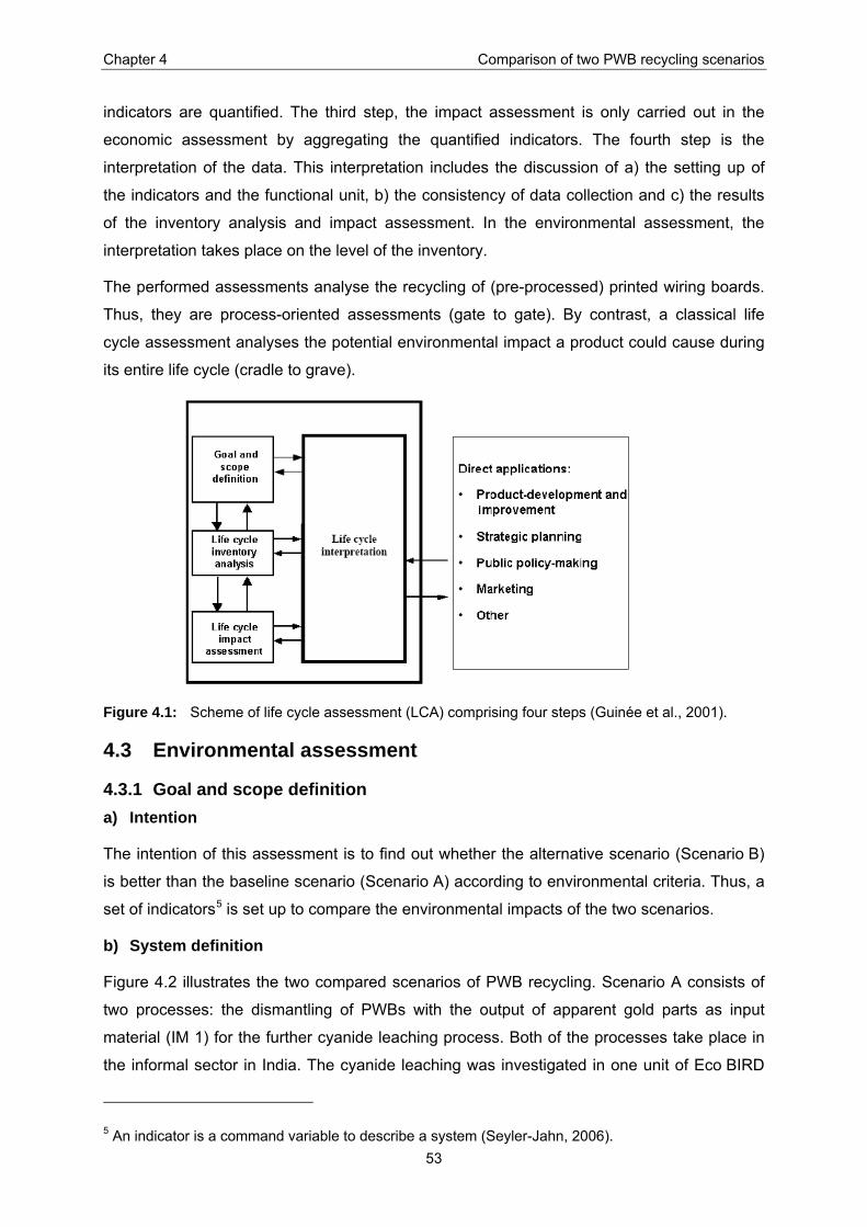
Chapter 4 Comparison of two PWB recycling scenarios
53
indicators are quantified. The third step, the impact assessment is only carried out in the
economic assessment by aggregating the quantified indicators. The fourth step is the
interpretation of the data. This interpretation includes the discussion of a) the setting up of
the indicators and the functional unit, b) the consistency of data collection and c) the results
of the inventory analysis and impact assessment. In the environmental assessment, the
interpretation takes place on the level of the inventory.
The performed assessments analyse the recycling of (pre-processed) printed wiring boards.
Thus, they are process-oriented assessments (gate to gate). By contrast, a classical life
cycle assessment analyses the potential environmental impact a product could cause during
its entire life cycle (cradle to grave).
Figure 4.1: Scheme of life cycle assessment (LCA) comprising four steps (Guinée et al., 2001).
4.3 Environmental assessment
4.3.1 Goal and scope definition a) Intention
The intention of this assessment is to find out whether the alternative scenario (Scenario B)
is better than the baseline scenario (Scenario A) according to environmental criteria. Thus, a
set of indicators5 is set up to compare the environmental impacts of the two scenarios.
b) System definition
Figure 4.2 illustrates the two compared scenarios of PWB recycling. Scenario A consists of
two processes: the dismantling of PWBs with the output of apparent gold parts as input
material (IM 1) for the further cyanide leaching process. Both of the processes take place in
the informal sector in India. The cyanide leaching was investigated in one unit of Eco BIRD
5 An indicator is a command variable to describe a system (Seyler-Jahn, 2006).

Chapter 4 Comparison of two PWB recycling scenarios
54
(an informal association of recyclers in Bangalore). Scenario B consists of two processes:
the transport of PWBs to Belgium (shipping) and their treatment at “Umicore Precious Metals
Refining” (UPMR) using a metallurgic process.
c) Functional unit
Because the driving force of this assessment is to find an environmentally sound disposal
process for PWBs, the functional unit “one ton printed wiring boards” is chosen.
System boundary
Dismantling
Cyanideleaching
PWB
Scenario A
Energy
Water
IM 1
Gold
Rejects
Emissions to air
Emissions to water
Solid waste
UPMR
PWB
Shipping
Scenario B
Energy
Preciousand base
metals
Emissions to air
Emissions to water
Solid waste
System boundary
Water
System boundary
Dismantling
Cyanideleaching
PWB
Scenario A
Energy
Water
IM 1
Gold
Rejects
Emissions to air
Emissions to waterEmissions to water
Solid waste
UPMR
PWB
Shipping
Scenario B
Energy
Preciousand base
metals
Emissions to air
Emissions to waterEmissions to water
Solid waste
System boundary
Water
Figure 4.2: System definition of the environmental assessment; the system boundaries are indicated with dashed lines; the squares represent processes, ovals materials; PWB= Printed wiring boards, IM= Input material, UPMR= Umicore Precious Metals Refining.
4.3.2 Inventory analysis The environmental inventory describes the material used and the emissions that will occur
during the processes. Data is collected to quantify the inputs from and the outputs to the
environment.
a) Definition of Indicators
The mass streams for the cyanide leaching in Scenario A have been quantified in
chapter 2.4.1. The environmental impacts during dismantling are considered not to be
relevant because mechanical work is conducted and only small electrical devices such as a
chisel or a screwdriver are used. Using this information, consulting the environmental report
of Umicore (Umicore, 2004) and holding discussions with LCA experts from EMPA and ETH
a set of indicators had been defined to compare the two scenarios. The evaluation in
chapter 2.4.1 showed that the fumes, the waste solution and the solid waste (body
components) bear the main hazards to the environment. In Umicore’s environmental report it
could be seen that also other indicators such as “CO2, NOx, SO2 emissions” or “water

Chapter 4 Comparison of two PWB recycling scenarios
55
consumption” are important. Thus, a set of nine indicators has been set up comparing the
raw material depletion and emissions occurring during the PWB recycling in the two
scenarios.
b) Data collection
The information to Scenario B is based on Umicore’s yearly conducted environmental
assessment. The data had been adapted by Jan Kegels (environmental coordinator,
Umicore) for board like material, which is the best available estimation for the functional unit
“one ton PWB”. The emissions during transport were calculated with data from ecoinvent
Centre (2005) and Dataloy (2006).
The calculations to determine the indicators for Scenario A are based on measurements
made in chapter 2.3.2, data from ecoinvent Centre (2005) and from the Swiss Federal Office
for Statistics (BFE, 2005).
In both the scenarios the inland transport are neglected since they are presumed to be about
the same in both scenarios.
c) Quantification
In the experiment executed for this thesis, 30 kg of PWB were used as basic raw material.
From this material 12 kg of dismantled PWB (IM 1) enter the cyanide leaching. Four of the
environmental indicators can be directly extrapolated to the functional unit, using the data
from chapter 2.3.2. The following additional analysis were made to determine the three
remaining indicators:
• Metals emitted to water: A sample of the effluent of the cyanide leaching has been
taken and tested for a range of metals by Sigma Aldrich using spectrometric analysis
(see Sb 8 in Appendix XIV).
• NaBr, NaCl, NaF, CO2, SOx, NOx emissions to air: These substances are produced
during the combustion of charcoal. It is assumed that 2,5 kg of charcoal are used
during the conducted cyanide leaching. With average values for the emission during
combustion according to ecoinvent Centre (2005) the emissions were calculated (see
Appendix XVIII).
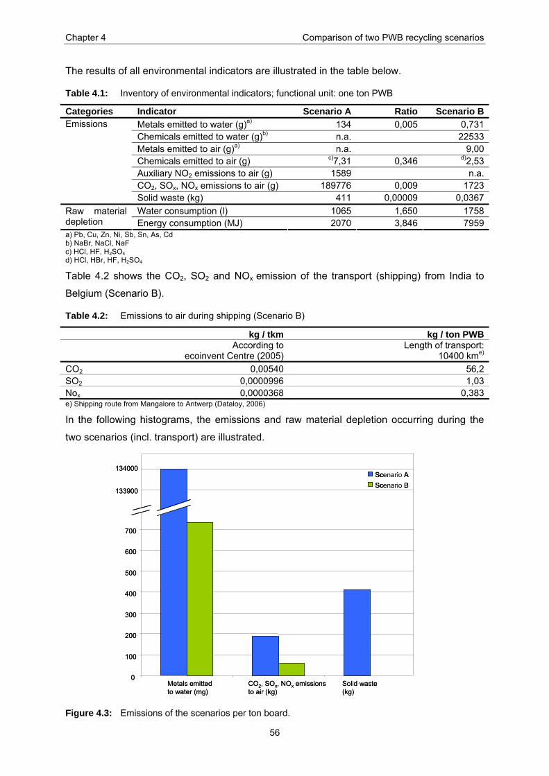
Chapter 4 Comparison of two PWB recycling scenarios
56
The results of all environmental indicators are illustrated in the table below.
Table 4.1: Inventory of environmental indicators; functional unit: one ton PWB
Categories Indicator Scenario A Ratio Scenario B Metals emitted to water (g)a) 134 0,005 0,731Chemicals emitted to water (g)b) n.a. 22533Metals emitted to air (g)a) n.a. 9,00Chemicals emitted to air (g) c)7,31 0,346 d)2,53Auxiliary NO2 emissions to air (g) 1589 n.a.CO2, SOx, NOx emissions to air (g) 189776 0,009 1723
Emissions
Solid waste (kg) 411 0,00009 0,0367Water consumption (l) 1065 1,650 1758Raw material
depletion Energy consumption (MJ) 2070 3,846 7959a) Pb, Cu, Zn, Ni, Sb, Sn, As, Cd b) NaBr, NaCl, NaF c) HCl, HF, H2SO4 d) HCl, HBr, HF, H2SO4
Table 4.2 shows the CO2, SO2 and NOx emission of the transport (shipping) from India to
Belgium (Scenario B).
Table 4.2: Emissions to air during shipping (Scenario B)
kg / tkm kg / ton PWB
According to
ecoinvent Centre (2005) Length of transport:
10400 kme) CO2 0,00540 56,2 SO2 0,0000996 1,03 Nox 0,0000368 0,383 e) Shipping route from Mangalore to Antwerp (Dataloy, 2006)
In the following histograms, the emissions and raw material depletion occurring during the
two scenarios (incl. transport) are illustrated.
0
100
200
300
400
500
600
700
Metals emittedto water (mg)
CO2, SOx, NOx emissionsto air (kg)
Solid waste(kg)
Scenario AScenario B
134000
133900
0
100
200
300
400
500
600
700
Metals emittedto water (mg)
CO2, SOx, NOx emissionsto air (kg)
Solid waste(kg)
Scenario AScenario BScenario AScenario B
134000
133900
Figure 4.3: Emissions of the scenarios per ton board.
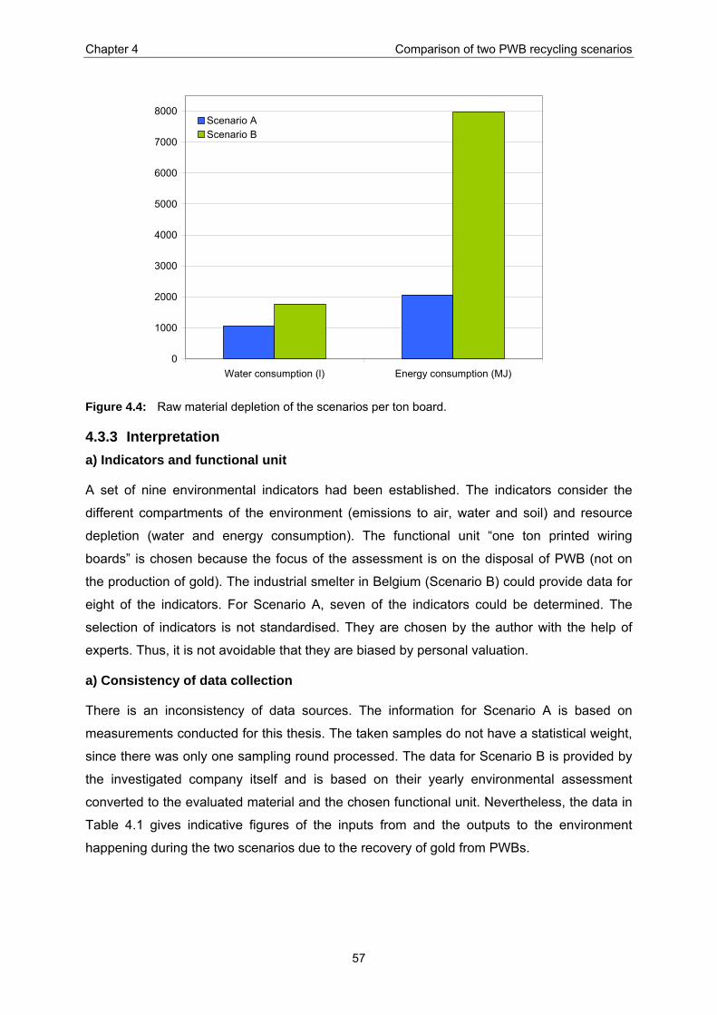
Chapter 4 Comparison of two PWB recycling scenarios
57
0
1000
2000
3000
4000
5000
6000
7000
8000
Water consumption (l) Energy consumption (MJ)
Scenario AScenario B
Figure 4.4: Raw material depletion of the scenarios per ton board.
4.3.3 Interpretation a) Indicators and functional unit
A set of nine environmental indicators had been established. The indicators consider the
different compartments of the environment (emissions to air, water and soil) and resource
depletion (water and energy consumption). The functional unit “one ton printed wiring
boards” is chosen because the focus of the assessment is on the disposal of PWB (not on
the production of gold). The industrial smelter in Belgium (Scenario B) could provide data for
eight of the indicators. For Scenario A, seven of the indicators could be determined. The
selection of indicators is not standardised. They are chosen by the author with the help of
experts. Thus, it is not avoidable that they are biased by personal valuation.
a) Consistency of data collection
There is an inconsistency of data sources. The information for Scenario A is based on
measurements conducted for this thesis. The taken samples do not have a statistical weight,
since there was only one sampling round processed. The data for Scenario B is provided by
the investigated company itself and is based on their yearly environmental assessment
converted to the evaluated material and the chosen functional unit. Nevertheless, the data in
Table 4.1 gives indicative figures of the inputs from and the outputs to the environment
happening during the two scenarios due to the recovery of gold from PWBs.

Chapter 4 Comparison of two PWB recycling scenarios
58
c) Results
The emissions occurring during the PWB recycling conducted in the informal sector in India
(Scenario A) are higher than shipping the material to Belgium and treating them with the best
available technique (Scenario B).
The highest discrepancy (factor 11200) of the two scenarios is the amount of solid waste.
UPMR (Scenario B) has a highly developed waste management. For instance, the slag that
is produced during the metallurgic technique is used in concrete as filler instead being land
filled. According to the owner and workers of the informal facility (Scenario A), the solid
waste is dumped in the streets and enters the solid waste stream of Bangalore. Most
probably, they end up in a landfill. The waste consists mainly of PWB components containing
heavy metals, which leach out eventually. However, it is also possible that these components
are picked up from the streets from other recyclers and are further treated. Within the limits
of this thesis, this has not been further investigated.
As shown in chapter 2.4.1 the effluent in Scenario A has a high concentration of heavy
metals. The indicator “metals emitted to water” in Scenario A is more than 180 times higher
than in Scenario B. This is because the different metals from the input material are dissolved
in the waste solution during the cyanide leaching. The solution is poured untreated into the
drain and the metals end up in the environment.
CO2, SOx, and NOx emissions to air in Scenario A occur during the combustion of charcoal.
These emissions are approximately 3 times higher than the emissions in Scenario B
(including transport). The data for the emissions during transport is rather overrated since it
is based on data that has analysed the process from cradle to grave. This means that for
instance the production of the ship itself is also included. Hence, the CO2, SOx, and NOx
emissions for transport within the system boundary of the PWB recycling might be less than
presented in Table 4.2.
The raw material depletion (water and energy consumption) in Scenario A is between 1,5 to
4 times lower than in Scenario B. However all the water used in Scenario A is polluted with
chemicals and metals after the cyanide leaching while in Scenario B the the waste waters
are treated in the waste water treatment plant of UPMR and enter the environment again as
„clean“ water. Thus, the increased energy use in Scenario B compared to scenario A is the
main negative environmental burden in the alternative scenario.
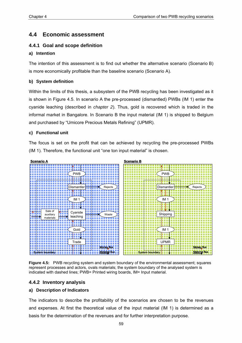
Chapter 4 Comparison of two PWB recycling scenarios
59
4.4 Economic assessment
4.4.1 Goal and scope definition a) Intention
The intention of this assessment is to find out whether the alternative scenario (Scenario B)
is more economically profitable than the baseline scenario (Scenario A).
b) System definition
Within the limits of this thesis, a subsystem of the PWB recycling has been investigated as it
is shown in Figure 4.5. In scenario A the pre-processed (dismantled) PWBs (IM 1) enter the
cyanide leaching (described in chapter 2). Thus, gold is recovered which is traded in the
informal market in Bangalore. In Scenario B the input material (IM 1) is shipped to Belgium
and purchased by “Umicore Precious Metals Refining” (UPMR).
c) Functional unit
The focus is set on the profit that can be achieved by recycling the pre-processed PWBs
(IM 1). Therefore, the functional unit “one ton input material” is chosen.
Cyanideleaching
Scenario A
System boundary
Trade
Gold
Dismantler
IM 1
Sale of auxiliarymaterials
Waste
PWB
Rejects
Scenario B
System boundary
UPMR
Dismantler
Shipping
IM 1
IM 1
PWB
Rejects
Money flux
Material flux
Money flux
Material flux
Cyanideleaching
Scenario A
System boundary
Trade
Gold
Dismantler
IM 1
Sale of auxiliarymaterials
Waste
PWB
Rejects
Scenario B
System boundary
UPMR
Dismantler
Shipping
IM 1
IM 1
PWB
Rejects
Money flux
Material flux
Money flux
Material flux
Money flux
Material flux
Money flux
Material flux
Figure 4.5: PWB recycling system and system boundary of the environmental assessment; squares represent processes and actors, ovals materials; the system boundary of the analysed system is indicated with dashed lines; PWB= Printed wiring boards, IM= Input material.
4.4.2 Inventory analysis a) Description of Indicators
The indicators to describe the profitability of the scenarios are chosen to be the revenues
and expenses. At first the theoretical value of the input material (IM 1) is determined as a
basis for the determination of the revenues and for further interpretation purpose.
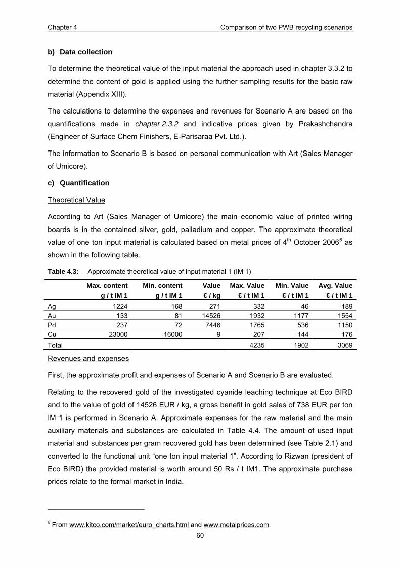
Chapter 4 Comparison of two PWB recycling scenarios
60
b) Data collection
To determine the theoretical value of the input material the approach used in chapter 3.3.2 to
determine the content of gold is applied using the further sampling results for the basic raw
material (Appendix XIII).
The calculations to determine the expenses and revenues for Scenario A are based on the
quantifications made in chapter 2.3.2 and indicative prices given by Prakashchandra
(Engineer of Surface Chem Finishers, E-Parisaraa Pvt. Ltd.).
The information to Scenario B is based on personal communication with Art (Sales Manager
of Umicore).
c) Quantification
Theoretical Value
According to Art (Sales Manager of Umicore) the main economic value of printed wiring
boards is in the contained silver, gold, palladium and copper. The approximate theoretical
value of one ton input material is calculated based on metal prices of 4th October 20066 as
shown in the following table.
Table 4.3: Approximate theoretical value of input material 1 (IM 1)
Max. content Min. content Value Max. Value Min. Value Avg. Value g / t IM 1 g / t IM 1 € / kg € / t IM 1 € / t IM 1 € / t IM 1Ag 1224 168 271 332 46 189 Au 133 81 14526 1932 1177 1554 Pd 237 72 7446 1765 536 1150 Cu 23000 16000 9 207 144 176 Total 4235 1902 3069
Revenues and expenses
First, the approximate profit and expenses of Scenario A and Scenario B are evaluated.
Relating to the recovered gold of the investigated cyanide leaching technique at Eco BIRD
and to the value of gold of 14526 EUR / kg, a gross benefit in gold sales of 738 EUR per ton
IM 1 is performed in Scenario A. Approximate expenses for the raw material and the main
auxiliary materials and substances are calculated in Table 4.4. The amount of used input
material and substances per gram recovered gold has been determined (see Table 2.1) and
converted to the functional unit “one ton input material 1”. According to Rizwan (president of
Eco BIRD) the provided material is worth around 50 Rs / t IM1. The approximate purchase
prices relate to the formal market in India.
6 From www.kitco.com/market/euro_charts.html and www.metalprices.com

Chapter 4 Comparison of two PWB recycling scenarios
61
Table 4.4: Approximate evaluation of total expenses (Scenario A)
kg / t IM1 Rs / kg Rs / t IM1 € / Rs € / t IM 1 Input material 1000 50 50000 0,017 850 Substance containing cyanide (~20 %) 179 250 44686 0,017 760 Nitric acid 33 27 883 0,017 15 Sodium chloride 19 127 2405 0,017 41 Caustic soda 12 32 379 0,017 6 Charcoal 105 350 36694 0,017 624 Total expenses 2296
Using indicative prices of Umicore Precious Metals Refining (UPMR) the purchase price of a
material with the quality of IM 1 would be between 900 to 3’000 EUR / ton (see Appendix
XVII). According to Art (2006) the net value7 for the average contents as shown in Table 4.3
would be 2’680 EUR/ton (metal price fixation of 19th September 2006). The only matter of
expense in this scenario is the transport from India to Belgium. The shipping of 20 containers
(content ~ 8t/container) from Chennai to Antwerp costs about 900 EUR/container (Art, 2006).
4.4.3 Impact assessment A cash-basis accounting is conducted to determine the net benefit of the compared
scenarios. A balance of revenues and expenses is made, shown in the following table.
Table 4.5: Economical benefit of the scenarios in € / t IM 1
Scenario A Scenario BRevenue Max. 738 900 – 3000Expenses 2296 113Total Benefit < 0 787 - 2287
Cyanideleaching
Trade
Gold
Dismantler
IM 1
Sale of auxiliarymaterials
PWB
2296
< 0
738
Money flux
Cyanideleaching
Trade
Gold
Dismantler
IM 1
Sale of auxiliarymaterials
PWB
2296
< 0
738
Money fluxMoney flux
Figure 4.6: Money flux (in EUR) in Scenario A.
UPMR
Dismantler
Shipping
IM 1
IM 1
900 - 3000 113
PWB
Money fluxUPMR
Dismantler
Shipping
IM 1
IM 1
900 - 3000 113
PWB
Money fluxMoney flux
Figure 4.7: Money flux (in EUR) in Scenario B.
7 Net value is the value that UPMR would pay in an assay based toll refining contract after deduction of all treatment charges and repurchase conditions and with a lot size of >10 tons.
Chapter 4 Comparison of two PWB recycling scenarios
62
4.4.4 Interpretation a) Indicators and functional unit
The choice to determine the revenues and expenses is essential to find the net benefit of the
scenarios. It was possible to make reasonable assumptions for these indicators. The choice
of functional unit has been based on the investigated system in this thesis. Another
possibility would have been to choose the same functional unit as for the environmental
assessment (per ton PWB). However, this would have led to an incomplete assessment
because the expenses and profits during the dismantling are not known.
b) Consistency of data collection
The data for Scenario A is mainly based on measurements and calculation while the data for
Scenario B is based on information given by UPMR. Thus, the same inconsistency of data
sources as in the environmental assessment consists.
c) Results
Regarding the calculated theoretical value of IM 1, which refers to the one batch of
dismantled material pre-processed for experimental purpose, the maximum value of the
examined metals is in gold (~ 40 %) and in palladium (~ 40%). Thus, Eco BIRD’s focus on
gold seems to make economical sense. As seen during on site observations and stated by
Widmer (2006) Eco BIRD can also recover silver and palladium. However, from the provided
material the investigated facility only recovered gold. At UPMR (Scenario B) 17 metals are
recovered (Kerckhoven, 2006). This could be a possible reason for the high total profit in
Scenario B. On a broader perspective, it serves also to decrease the production of primary
metals.
The net benefit of Scenario A is calculated to be negative due to the high expenses for raw
and auxiliary materials. Further expenses like loss of silver, rent and labour expenses have
been neglected. This result seems to be unrealistic since the people conducting this process
somehow have to earn money. An explanation could be that the prices for auxiliary
substances and materials are more favourable in the informal market than in the formal
market (formal market prices are used for the evaluation of the expenses).
In Scenario B the approximate net benefit is 800 – 2’900 EUR per ton IM 1 (shipment cost
included). The average net benefit (incl. shipment) would be 2’567 EUR/ton, which is more
than 80 % of the calculated approximate theoretical value of the shipped material (IM 1) and
which would remain in India.
Consequently, the dismantler could make more profit if they would sell their material to
UPMR instead of processing it. Even more profitable might be to send the basic raw material
(avoiding the dismantling) instead of the input material. During the dismantling of the one
Chapter 4 Comparison of two PWB recycling scenarios
63
batch of PWB treated as described in chapter 3.3.2 and in Appendix VII, 60 % of the basic
raw material is “lost” as rejects. The further pathway of the rejects is not known. If these
rejects are actually lost (not sold), the precious and base metals within are also lost. The
theoretical value of one ton of untreated PWB is approximately the same as of IM 1 (see
Appendix XX). Thus, the profit made by selling the unprocessed (not dismantled) PWB would
be 60 % more than by selling IM 1.

Chapter 5 Conclusion
64
5 Conclusion
5.1 Main findings The executed assessments in this thesis are all based on a few measurements made in the
informal and formal sector in Bangalore, India and are thus momentary recordings. The
investigated processes and techniques are only partly standardised. Hence, the absolute
collected figures may not be representative for the average processes. However, all of the
findings were clear enough that if conducting a more comprehensive study no other results
are expected.
5.1.1 Gold recovery techniques and hazards Using the material flow analysis (MFA) the main substances and quantities used to recover
one gram of gold from an input material deriving from PWBs were determined. The MFA has
been a useful tool to describe the informal as well as the formal system of gold recovery. In
addition, with this method the main hazards to the environment could be identified. In the
formal sector, it is mainly the solid waste. In the informal sector, the identified hazards to the
environment are the produced fumes, the untreated effluent and the dumped solid waste.
The produced nitrogen dioxide and mercury fumes might also be dangerous to the workers
since it can damage the lungs. The different metals dissolved in the waste solution and
contained in the output components have the potential to bioaccumulate in the environment
and are thus problematic.
To exemplify some of the findings of the material flow analysis following figure shows the
overview of the investigated cyanide leaching in the informal sector.
Waste solution
Body components
Fumes (NO2)
Input material
Gold
Cyanide leaching
Water
Cyanide
Nitric acid
Aluminium
SilverOther Substances E
nviro
nmen
t
Waste solution
Body components
Fumes (NO2)
Input material
Gold
Cyanide leaching
WaterWater
CyanideCyanide
Nitric acidNitric acid
AluminiumAluminium
SilverSilverOther Substances E
nviro
nmen
t
Figure 5.1: Major flows of the cyanide leaching.
5.1.2 Evaluation of recovery rates The beforehand conducted material flow analysis served as a fundament to determine the
efficiencies of the PWB recycling system. The evaluation of the recovery rates for the
informal sector (conducting cyanide leaching) and the formal sector (conducting gold
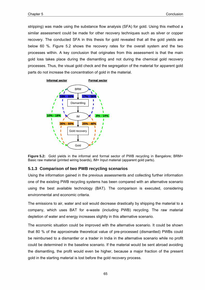
Chapter 5 Conclusion
65
stripping) was made using the substance flow analysis (SFA) for gold. Using this method a
similar assessment could be made for other recovery techniques such as silver or copper
recovery. The conducted SFA in this thesis for gold revealed that all the gold yields are
below 60 %. Figure 5.2 shows the recovery rates for the overall system and the two
processes within. A key conclusion that originates from this assessment is that the main
gold loss takes place during the dismantling and not during the chemical gold recovery
processes. Thus, the visual gold check and the segregation of the material for apparent gold
parts do not increase the concentration of gold in the material.
IM
Gold
Dismantling
Gold recovery
BRM
10% - 18%
16% - 60%
36% - 60%
Informal sector Formal sector
17% - 56%
25% - 46%
8% - 14%IM
Gold
Dismantling
Gold recovery
BRM
10% - 18%
16% - 60%
36% - 60%
Informal sector Formal sector
17% - 56%
25% - 46%
8% - 14%
Figure 5.2: Gold yields in the informal and formal sector of PWB recycling in Bangalore; BRM= Basic raw material (printed wiring boards), IM= Input material (apparent gold parts).
5.1.3 Comparison of two PWB recycling scenarios Using the information gained in the previous assessments and collecting further information
one of the existing PWB recycling systems has been compared with an alternative scenario
using the best available technology (BAT). The comparison is executed, considering
environmental and economic criteria.
The emissions to air, water and soil would decrease drastically by shipping the material to a
company, which uses BAT for e-waste (including PWB) recycling. The raw material
depletion of water and energy increases slightly in this alternative scenario.
The economic situation could be improved with the alternative scenario. It could be shown
that 80 % of the approximate theoretical value of pre-processed (dismantled) PWBs could
be reimbursed to a dismantler or a trader in India in the alternative scenario while no profit
could be determined in the baseline scenario. If the material would be sent abroad avoiding
the dismantling, the profit would even be higher, because a major fraction of the present
gold in the starting material is lost before the gold recovery process.

Chapter 5 Conclusion
66
With these results, a shifting of the treatment from the informal sector in Bangalore to the
formal company in Belgium is reasonable. Both an increase of economical profitability and a
decrease in environmental impacts due to emissions can be achieved. Still, the social
aspects have to be evaluated before implementing such a major change in the e-waste
management system in Bangalore. For example, it would be important to investigate where
the additional money would go to.
5.2 Outlook Further studies would be needed to validate the found results and to close further
knowledge gaps occurring in the e-waste recycling system in Bangalore.
Following issues should be considered and treated in additional studies:
• The material preparation has to be discussed in every detail with the owners of the
facilities and a pre-test of material should be prepared in order to fulfil all the
requirements in the posterior experiment.
• Bigger batches of basic raw material would be needed to repeat the processes and find
average values. With further measurements, the question if the recovery rates depend
on the concentration of the input material could be answered. In addition, samples of the
input material could be taken instead of the rejects.
• Both processes conducted in the informal sector should be studied and if possible in
several informal facilities.
• The possibility if the environmental situation in the informal sector could be improved by
collecting and properly disposing the liquid and solid waste, should be investigated.
• The auxiliary processes, such as the silver-, mercury- and copper-recovery should be
analysed in more detail.
• The single processes of the dismantling should be determined and evaluated in order to
answer following questions: Where do the rejects end up? Which profit can be made
with the rejects? Will they be an environmental hazard?
Further, an improved risk assessment would be required in order to determine the precise
level of health and environmental impact occurring due to the treatment of PWBs. For a
better knowledge of the impact to the environment, the pathway of the effluent would have
to be evaluated. Identification of the extent of impact of the effluent to the surrounding would
be essential. Hence, the background concentration of metals in surrounding soil and water
would have to be determined in order to judge the impact level that is coming from the gold
recovery processes. It is already known that the concentration of heavy metals in soils and
Chapter 5 Conclusion
67
sediments found around places, where gold leaching takes place is a lot higher than the
background levels (Brigden et al., 2005).
The acceptance and practicability of the alternative scenario has to be evaluated
considering social and political aspects. In addition other alternatives might be interesting to
evaluate in detail, e.g. alternative collaboration scenarios where the formal or informal sector
(which is planned by Surface Chem Finishers) provide UPMR with appropriate dismantled
PWBs or the possibility to build a facility using best available technique in India.
References
68
References AGARWAL R. (2005). Computer Myths: The Story of Scrap. Southern Initiatives, Journal for
Sustainable Development. 1 (3).
AMERICAN METAL MARKET (1985). Recycling can cut US reliance on strategic metal imports - scrap metal industry. Information retrieved from: http://findarticles.com/p/articles/mi_m3MKT/is_v93/ai_3860738. [Date of Access: September 2006].
ART S. (2006). Sales Manager. Umicore. Personal communication.
ATSDR (1999-2005). Toxicological Profile Information Sheet. Agency for Toxic Substances and Disease Registry. Information retrieved from: www.atsdr.cdc.gov/toxprofiles. [Date of Access: September 2006].
ATSDR (2006). 2005 CERCLA Priority List of Hazardous Substances. Agency for Toxic Substances & Disease Registry. Information retrieved from: www.atsdr.cdc.gov/cercla/05list.html. [Date of Access: August 2006].
BACCINI P. and BADER H.-P. (1996). Regionaler Stoffhaushalt. Erfassung, Bewertung und Steuerung. Spektrum Akademischer Verlag GmbH.
BEARD R. R. (1987). Treating gold ores by amalgamation. Arizona miner's seminar. Ehrenberg. Arizona Department of Mines and Mineral Resources.
BFE (2005). Schweizerische Gesamtenergiestatistik. Bundesamt für Energie.
BINDER C., et al. (2001). Dynamic models for managing durables using a stratified approach: the case of Tunja, colombia. Ecological Economics. 38 (2), 191 - 207.
BINEESHA (2006). Chief Environmental Advisor. KSPCB. Bangalore. Personal communication.
BIRD (2005). Indian IT Hardware Market Study (ITOPS). Business & Industrial Research Division.
BRIGDEN K., et al. (2005). Recycling of electronic wastes in China & India: Workplace & environmental contamination. Greenpeace International. Information retrieved from: www.greenpeace.org/raw/content/international/press/reports/recyclingelectronicwasteindiachinafull.pdf. [Date of Access: September 2006].
BRUNNER P. and RECHENBERGER H. (2004). Practical Handbook of Material Flow Analysis. CRC Press LLC.
BRUNNER P. H. and RECHBERGER H. (2004). Practical handbook of material flow analysis. CRC Press LLC.
CIS (2003). International Chemical Safety card. International Occupational Safety and Health Information Centre. Information retrieved from: http://www.ilo.org/public/english/protection/safework/cis/products/icsc/dtasht/index.htm. [Date of Access: September 2006].
COMMISSION OF THE EUROPEAN COMMUNITIES (2000). Proposal for a Directive of the European Parliament and of the Council on waste electrical and electronic equipment. Information retrieved from: http://europa.eu.int/eur-lex/en/com/pdf/2000/en_500PC0347_02.pdf. [Date of Access: September 2006].
CYANIDE MANAGEMENT CODE (2006). Environmental and Health Effects of Cyanide. Information retrieved from: http://www.cyanidecode.org/cyanide_environmental.php. [Date of Access: September 2006].
DATALOY (2006). Dataloy Distance Table - DDT. Information retrieved from: www.dataloy.com/. [Date of Access: September 2006].
DORIN R. and WOODS R. (1991). Determination of leaching rates of precious metals by electrohemical techniques. Journal of applied electrochemistry. 21, 419 - 424.
ECOINVENT CENTRE (2005). ecoinvent data v1.2. Final reports ecoinvent 2000 No. 1-15. Dübendorf, CH, Swiss Centre for Life Cycle Inventories. Final reports ecoinvent 2000 No. 1-15.
ECONINVENT CENTRE (2005). ecoinvent data v1.2. Final reports ecoinvent 2000 No. 1-15. Dübendorf, CH, Swiss Centre for Life Cycle Inventories. Final reports ecoinvent 2000 No. 1-15.

References
69
ELECTRONIC WASTE GUIDE (2006). A knowledge base for the sustainable recycling of eWaste. Information retrieved from: www.ewaste.ch. [Date of Access: August 2006].
EPA (2006). What are the contaminants of concern in old electronics and what are their pathways? Environmental Protection Agency. Information retrieved from: www.epa.gov/epaoswer/hazwaste/recycle/ecycling/faq.htm. [Date of Access: August 2006].
EU (2002). Directive 2002/96/EC of the European Parliament and of the Council of 27 January 2003 on waste electrical and electronic equipment (WEEE). Information retrieved from. [Date of Access.
EU (2003a). Directive 2002/96/EC of the European Parliament and of the Council of 27 January 2003 on waste electrical and electronic equipment (WEEE).
EU (2003b). Directive 2002/95/EC of the European Parliament and of the Council of 27 January 2003 on the restriction of the use of certain hazardous substances in electrical and electronic equipment
EWA (2006). Byelaws for the e-Waste Agency for e-Waste managment in Bangalore. Information retrieved from: www.ewa.co.in/ewa.html. [Date of Access: August 2006].
EWASTE GUIDE INDIA (2006). Information retrieved from: www.e-waste.in. [Date of Access: October 2006].
FENEAU C. (2002). Non-ferrous metals. Umicore.
FREY B. and SCHNEIDER F. (2000). Informal and Underground Economy. Elsevier Science Publishing Company.
GOLD & PRECIOUS METALS (2006). Gold: a scarce resource. Information retrieved from: http://www.goldpreciousmetals.com/goldrare.asp. [Date of Access: October 2006].
GUINÉE J., et al. (2001). Life cycle assessment; An operational guide to the ISO standards.
HAGELÜKEN D. C. (2006). Recycling of e-scrap in a global environment - chances and challenges. Meeting with Umicore, ETH, EMPA. Hoboken.
HISCHIER R., et al. (2005). Does WEEE recycling make sense from an environmental perspective? The environmental impacts of the Swiss take-back and recycling systems for waste electrical and electronic equipment (WEEE). Environmental Impact Assessment Review. 25, 525 – 539.
ILES A. (2004). Mapping Environmental Justice in Technology Flows: Computer Waste Impacts in Asia. Global Environmental Politics. 4 (4).
JAIN A. and SAREEN R. (2006). E-waste assessment methodology and validation in India. J Mater Cycles Waste Manag. 8, 40-45.
JANG Y.-C. and TOWNSEND T. (2003). Leaching of Lead from Computer Printed Wire Boards and Cathode Ray Tubes by Municipal Solid Waste Landfill Leachates. Environmental Science & Technology. 37 (20).
KERCKHOVEN T. V. (2006). Manager Raw Materials Supply. Umicore. Personal communication.
KULUNDAISAMY S., et al. (2003). The aqueous recovery of gold from electronic scrap. JOM.
LENNTECH (2006). Periodic Table. Water treatment & Air Purification. Information retrieved from: www.lenntech.com/Periodic-chart-elements. [Date of Access: September 2006].
LI Y., et al. (2006). TCLP Heavy Metal Leaching of Personal Computer Components. Journal of Environmental Engineering
LOGSDON M., et al. (1999). The management of cyanide in gold extraction. INTERNATIONAL COUNCIL ON METALS AND THE ENVIRONMENT.
MARSDEN J. and HOUSE I. (1992). The chemistry of gold extraction. Ellis Horwood Limited.
MAYDL S. (2004). Goldgewinnung als Ursache von chronischer Quecksilbervergiftungen in Mount Diwata, Mindanao, Philippinen. (Doctoral thesis). Institut für Rechtsmedizin Ludwig - Maximilians – Universität zu München.
OECD (2001). Extended Producer Responsibility: A Guidance Manual for Governments.

References
70
PARTHASARATHY (2006). Director. E Parisaraa Pvt Ltd. Personal communication.
PUCKETT J., et al. (2002). Exporting Harm: The High-Tech Trashing of Asia. The Basel Action Network (BAN), Silicon Valley Toxics Coalition (SVTC). Information retrieved from: www.ban.org. [Date of Access: August 2006].
RAIS D. (2005). Soil solution chemistry in a heavy metal contaminated forest model ecosystem. (Doctoral thesis). ETH, Zürich.
REICHL F.-X. (2002). Taschenatlas der Toxikologie. Subsanzen, Wirkungen, Umwelt. Georg Thieme Verlag. 2.
ROCHAT D. (2006). Implementing clean e-waste channels in Banalore: progress on the training of the informal sector. Information retrieved from: www.ewa.co.in. [Date of Access: August 2006].
RODRIGUEZ W. (2005). Technical requirements for upgrading the informal gold leachers of Gowri Pallya to best practice. Unpublished work.
SAHAAS (2004). E-waste Bangalore wakes up to a new threat. Karnataka State Pollution Control Board. Bangalore.
SCHÖNBERG H. (2006). Laboratory for Anorganic Chemistry. ETH Zürich. Personal communication.
SCHWARZER S., et al. (2005). E-waste the hidden side of IT equipment's manufacturing and use. Information retrieved from: www.grid.unep.ch/product/publication/download/ew_ewaste.en.pdf. [Date of Access: August 2006].
SCHWEIZERISCHE EIDGENOSSENSCHAFT (1998). Gewässerschutzverordnung vom 28. Oktober 1998 (GSchV).
SECRETARIAT OF THE BASEL CONVENTION (2006). Information retrieved from: www.basel.int. [Date of Access: October 2006].
SEYLER-JAHN C. (2006). Institute for Spatial and Landscape Planning. ETH Zurich. Personal communication.
SIEMERS W. and VEST H. (1999). Environmental Handbook. Environmentally Sound Electroscrap Disposal and Recycling. German Federal Ministry for Economic Cooperation and Development (BMZ).
SIMEONEOVA F. and FISHBEIN L. (2004). Hydrogen cyanide and cyanides: Human health aspects. World Health Organization. Geneva.
SINHA-KHETRIWAL D., et al. (2005). A comparison of electronic waste recycling in Switzerland and in India. Environmental Impact Assessment Review. 25, 492 - 504.
SINHA-KHETRIWAL D., et al. (2006). Legislating e-waste management: progress from various countries. elni Review. (1+2).
SINHA D. (2004). The Management of Electronic Waste. (Master thesis). University of St. Gallen.
SMIDT (2006). Grundlagen II. Anorganische Chemie. Toxizität der Metallverbindungen. (Lecture). Universität für Bodenkultur, Wien.
STEP (2005). Solving the e-waste problem: a synthetic approach (StEP). Information retrieved from: http://work.step-initiative.org. [Date of Access: August 2006].
STREICHER-PORTE M. (2006). Material Flow Accounting and economic evaluation as tools for system design in recycling of waste from electrical and electronic equipment. Special focus on the recycling of personal computers. (Doctoral Thesis). Institute for Spatial and Landscape Planning, Regional Resource. ETH Zurich. Unpublished work.
STÜBEN P. D. D. (2004). Gold und Silber - Von der Lagerstätte bis zur Verwendung. (Lecture). Umweltgeochemisches SeminarUniversität Karlsruhe.
THE ECONOMIST (2005). February 29.
UMICORE (2004). Environment, Health and Safety Report 2004.
UMICORE (2006). Excellence in recycling... Presentation July 2006.

References
71
UNEP (2002). Global Mercury Assessment. United Nations Environment Programme. Information retrieved from: www.chem.unep.ch/mercury. [Date of Access: September 2006].
UNEP (2006). Compendium on National WEEE Legislation. Zero Emissions Forum, European Focal Point, United Nations University, Bonn.
WHO (1995). Environmental Health Criteria 165. Inorganic Lead. World Health Organization. Information retrieved from: www.inchem.org/documents/ehc/ehc/ehc165.htm#SectionNumber:1.7. [Date of Access: September 2006].
WIDMER R., et al. (2005). Global perspectives on e-waste. Environmental Impact Assessment Review. 25, 436-458.
WIDMER R. (2006). Project Manager. EMPA: Swiss Federal Laboratories for Materials Testing and Research. Personal communication.
WIKIPEDIA (2006). Information retrieved from: www.wikipedia.org. [Date of Access: August 2006].
ZARDA C., et al. (2005). Umweltatlas Hessen. Hessisches Landesamt für Umwelt und Geologie.
ZUMBÜHL D. (2006). Mass Flow Assessment (MFA) and assessment of recycling strategies for Cathode Ray Tubes (CRTs) for the Cape Metropolitan Area (CMA), South Africa. (Diploma thesis). Institute for Spatial and Landscape Planning, Regional Resource. ETH Zurich. Unpublished work.
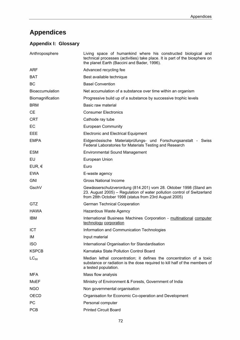
Appendices
72
Appendices Appendix I: Glossary
Anthroposphere Living space of humankind where his constructed biological and technical processes (activities) take place. It is part of the biosphere on the planet Earth (Baccini and Bader, 1996).
ARF Advanced recycling fee
BAT Best available technique
BC Basel Convention
Bioaccumulation Net accumulation of a substance over time within an organism
Biomagnification Progressive build up of a substance by successive trophic levels
BRM Basic raw material
CE Consumer Electronics
CRT Cathode ray tube
EC European Community
EEE Electronic and Electrical Equipment
EMPA Eidgenössische Materialprüfungs- und Forschungsanstalt - Swiss Federal Laboratories for Materials Testing and Research
ESM Environmental Sound Management
EU European Union
EUR, € Euro
EWA E-waste agency
GNI Gross National Income
GschV Gewässerschutzverordung (814.201) vom 28. Oktober 1998 (Stand am 23. August 2005) – Regulation of water pollution control of Switzerland from 28th October 1998 (status from 23rd August 2005)
GTZ German Technical Cooperation
HAWA Hazardous Waste Agency
IBM International Business Machines Corporation - multinational computer technology corporation
ICT Information and Communication Technologies
IM Input material
ISO International Organisation for Standardisation
KSPCB Karnataka State Pollution Control Board
LC50 Median lethal concentration; it defines the concentration of a toxic substance or radiation is the dose required to kill half of the members of a tested population.
MFA Mass flow analysis
MoEF Ministry of Environment & Forests, Government of India
NGO Non governmental organisation
OECD Organisation for Economic Co-operation and Development
PC Personal computer
PCB Printed Circuit Board
Appendices
73
PWB Printed Wiring Board
Recycling Extraction of materials from a product in order to reuse them (UNEP, 2006).
RoHS Restrictions of Hazardous Substances
Seco Swiss State Secretariat for Economic Affairs
SENS Stiftung Entsorgung Schweiz – Foundation for disposal Switzerland
StEP Solving the e-Waste Problem
SWICO Swiss Association for Information, Communication and Organisation Technology
TLV Threshold limit value; it defines the concentration level of a substance to which a worker can be exposed without adverse health effects
UNEP United Nations Environment Programme
UPMR Umicore Precious Metals Refining
USG Schweizerisches Umweltschutzgesetz – Swiss environmental protection law
WEEE Waste Electronic and Electrical Equipment
Wipro Infotech IT Services, Solutions & Products division of “Western India Products” Limited
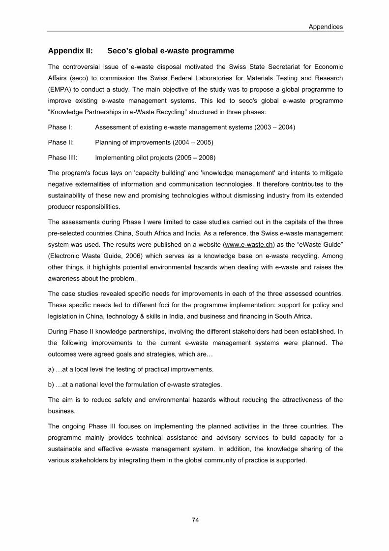
Appendices
74
Appendix II: Seco’s global e-waste programme
The controversial issue of e-waste disposal motivated the Swiss State Secretariat for Economic
Affairs (seco) to commission the Swiss Federal Laboratories for Materials Testing and Research
(EMPA) to conduct a study. The main objective of the study was to propose a global programme to
improve existing e-waste management systems. This led to seco's global e-waste programme
"Knowledge Partnerships in e-Waste Recycling" structured in three phases:
Phase I: Assessment of existing e-waste management systems (2003 – 2004)
Phase II: Planning of improvements (2004 – 2005)
Phase IIII: Implementing pilot projects (2005 – 2008)
The program's focus lays on 'capacity building' and 'knowledge management' and intents to mitigate
negative externalities of information and communication technologies. It therefore contributes to the
sustainability of these new and promising technologies without dismissing industry from its extended
producer responsibilities.
The assessments during Phase I were limited to case studies carried out in the capitals of the three
pre-selected countries China, South Africa and India. As a reference, the Swiss e-waste management
system was used. The results were published on a website (www.e-waste.ch) as the “eWaste Guide”
(Electronic Waste Guide, 2006) which serves as a knowledge base on e-waste recycling. Among
other things, it highlights potential environmental hazards when dealing with e-waste and raises the
awareness about the problem.
The case studies revealed specific needs for improvements in each of the three assessed countries.
These specific needs led to different foci for the programme implementation: support for policy and
legislation in China, technology & skills in India, and business and financing in South Africa.
During Phase II knowledge partnerships, involving the different stakeholders had been established. In
the following improvements to the current e-waste management systems were planned. The
outcomes were agreed goals and strategies, which are…
a) …at a local level the testing of practical improvements.
b) …at a national level the formulation of e-waste strategies.
The aim is to reduce safety and environmental hazards without reducing the attractiveness of the
business.
The ongoing Phase III focuses on implementing the planned activities in the three countries. The
programme mainly provides technical assistance and advisory services to build capacity for a
sustainable and effective e-waste management system. In addition, the knowledge sharing of the
various stakeholders by integrating them in the global community of practice is supported.

Appendices
75
Appendix III: E-waste definitions
Selected definitions of e-waste (Widmer et al., 2005):
Reference Definition
EU WEEE Directive (EU, 2003a)
“Electrical or electronic equipment (EEE)8 which is waste9… including all components, sub-assemblies and consumables, which are part of the product at the time of discarding”. In Annex IA of the Directive ten categories of EEE are defined.
Basel Action Network (Puckett et al., 2002)
"E-waste encompasses a broad and growing range of electronic devices ranging from large household devices such as refrigerators, air conditioners, cell phones, personal stereos, and consumer electronics to computers which have been discarded by their users."
OECD (2001) "Any appliance using an electric power supply that has reached its end-of-life."
SINHA (2004) "An electrically powered appliance that no longer satisfies the current owner for its original purpose."
StEP (2005) E-Waste refers to "…the reverse supply chain which collects products no longer desired by a given consumer and refurbishes for other consumers, recycles, or otherwise processes wastes."
Categories of e-waste defined by the EU WEEE Directive (EU, 2002): 1. Large household appliances 2. Small household appliances 3. IT and telecommunications equipment 4. Consumer equipment 5. Lighting equipment 6. Electrical and electronic tools (with the exception of large-scale stationary industrial tools) 7. Toys, leisure and sports equipment 8. Medical devices (with the exception of all implanted and infected products) 9. Monitoring and control instruments 10. Automatic dispensers
8 “electrical and electronic equipment” is defined as equipment which is dependent on electric currents or electromagnetic fields in order to work properly and equipment for the generation, transfer and measurement of such currents.
9 “waste” is defined as any substance or object which the holder disposes of or is required to dispose
of pursuant to the provisions of national law in force.
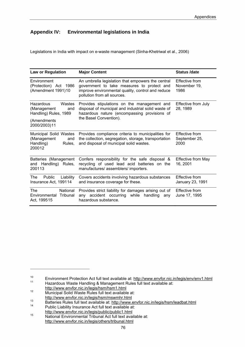
Appendices
76
Appendix IV: Environmental legislations in India
Legislations in India with impact on e-waste management (Sinha-Khetriwal et al., 2006)
Law or Regulation Major Content Status /date
Environment (Protection) Act 1986 (Amendment 1991)10
An umbrella legislation that empowers the central government to take measures to protect and improve environmental quality, control and reduce pollution from all sources.
Effective from November 19, 1986
Hazardous Wastes (Management and Handling) Rules, 1989
(Amendments 2000/2003)11
Provides stipulations on the management and disposal of municipal and industrial solid waste of hazardous nature (encompassing provisions of the Basel Convention).
Effective from July 28, 1989
Municipal Solid Wastes (Management and Handling) Rules, 200012
Provides compliance criteria to municipalities for the collection, segregation, storage, transportation and disposal of municipal solid wastes.
Effective from September 25, 2000
Batteries (Management and Handling) Rules, 200113
Confers responsibility for the safe disposal & recycling of used lead acid batteries on the manufactures/ assemblers/ importers.
Effective from May 16, 2001
The Public Liability Insurance Act, 199114
Covers accidents involving hazardous substances and insurance coverage for these.
Effective from January 23, 1991
The National Environmental Tribunal Act, 199515
Provides strict liability for damages arising out of any accident occurring while handling any hazardous substance.
Effective from June 17, 1995
10 Environment Protection Act full text available at: http://www.envfor.nic.in/legis/env/env1.html 11 Hazardous Waste Handling & Management Rules full text available at:
http://www.envfor.nic.in/legis/hsm/hsm1.html 12 Municipal Solid Waste Rules full text available at:
http://www.envfor.nic.in/legis/hsm/mswmhr.html 13 Batteries Rules full text available at: http://www.envfor.nic.in/legis/hsm/leadbat.html 14 Public Liability Insurance Act full text available at:
http://www.envfor.nic.in/legis/public/public1.html 15 National Environmental Tribunal Act full text available at:
http://www.envfor.nic.in/legis/others/tribunal.html
Appendices
77
Appendix V: The E-waste Agency (EWA)
To solve the above-mentioned problems in Bangalore and as a part of Phase III of seco’s global e-
waste programme the E-Waste Agency (EWA) has been founded in 2005 by various stakeholders
such as IT companies, the Karnataka State Pollution Control Board (KSPCB) and the partners in the
Indo-German-Swiss e-waste initiative. EWA foresees and supports activities for a sustainable e-waste
management system for Bangalore where…
a) …large e-waste generators have access to a fully controlled disposal path.
b) …small e-waste generators can still rely on the convenience of an informal collection system.
The main objectives are (EWA, 2006):
To facilitate eco-friendly, financially viable and socially acceptable e-waste management in Bangalore.
To promote and safeguard the interests, rights and privileges of the concerned industries, and
Government bodies.
To develop a voluntary but binding charter to define and regulate an e-waste management system for
Bangalore.
To promote and encourage fellowship and document "lessons learnt" so that it could be replicated in
other cities.
One of the first activities was to promote eco friendly recyclers in the e-waste recycling market. This
has been accomplished recently and the Karnataka State Pollution Control Board has licensed two
recycling companies to handle e-waste in Bangalore: Ash Recyclers and E-Parisaraa Pvt. Ltd. E-
Parisaraa had been audited and certified for ISO 14001 standards and independently audited by
several multinational companies.
Still, there is no fully organised and controlled recycling path in Bangalore that can guarantee the
consumer that their e-waste is disposed of properly. Therefore, another work being undertaken is
assisting the informal e-waste recyclers in reaching a formal status and in improving their process in
terms of workers health and safety and emission control to the environment.
In a further step business models will be developed to evacuate critical recovery processes (e.g. as
conducted for Au-, Ag-, Cu- or Pd-recovery) and critical fractions (e.g. Pb-glass, Br-plastics, batteries)
from the (informal) e-waste stream to large formal smelters or refiners.
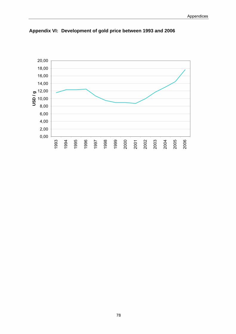
Appendices
78
Appendix VI: Development of gold price between 1993 and 2006
0,00
2,00
4,00
6,00
8,00
10,00
12,00
14,00
16,00
18,00
20,0019
93
1994
1995
1996
1997
1998
1999
2000
2001
2002
2003
2004
2005
2006
USD
/ g
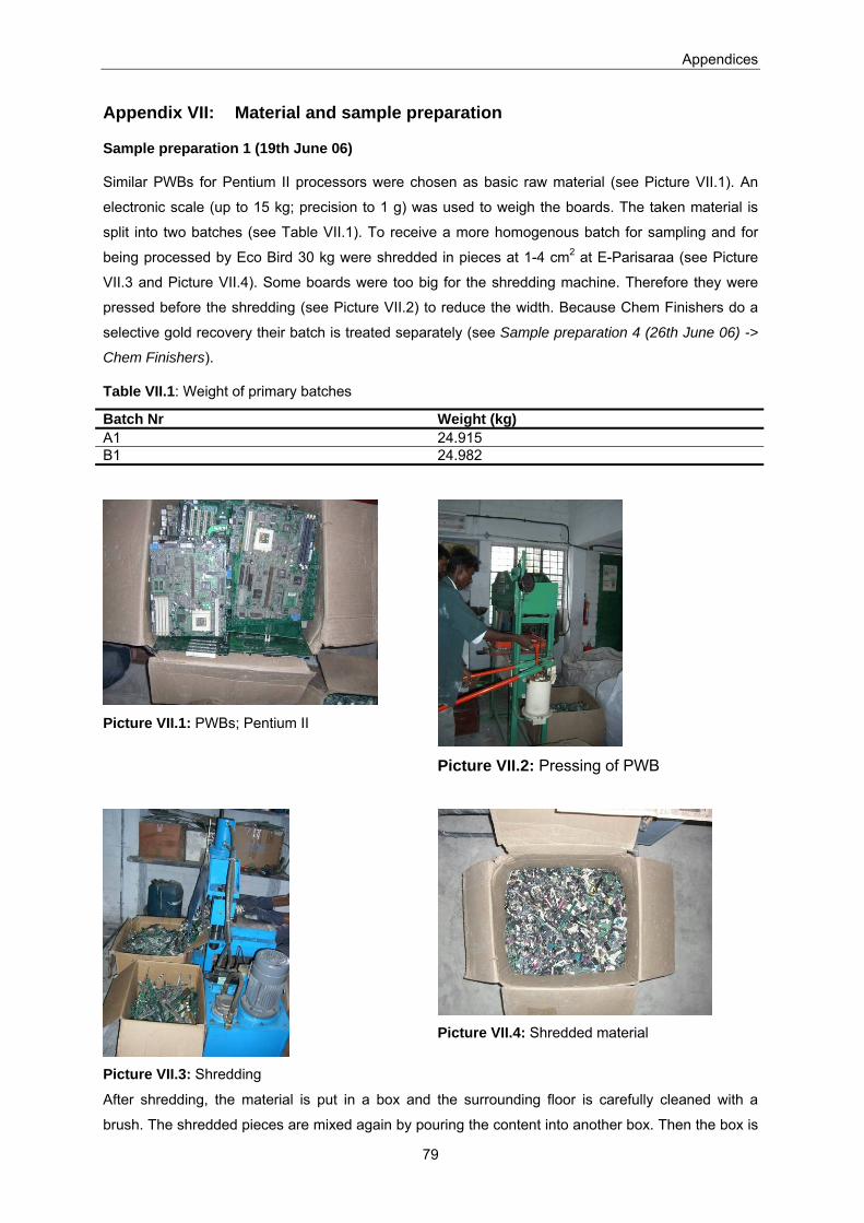
Appendices
79
Appendix VII: Material and sample preparation
Sample preparation 1 (19th June 06)
Similar PWBs for Pentium II processors were chosen as basic raw material (see Picture VII.1). An
electronic scale (up to 15 kg; precision to 1 g) was used to weigh the boards. The taken material is
split into two batches (see Table VII.1). To receive a more homogenous batch for sampling and for
being processed by Eco Bird 30 kg were shredded in pieces at 1-4 cm2 at E-Parisaraa (see Picture
VII.3 and Picture VII.4). Some boards were too big for the shredding machine. Therefore they were
pressed before the shredding (see Picture VII.2) to reduce the width. Because Chem Finishers do a
selective gold recovery their batch is treated separately (see Sample preparation 4 (26th June 06) ->
Chem Finishers).
Table VII.1: Weight of primary batches
Batch Nr Weight (kg) A1 24.915 B1 24.982
Picture VII.1: PWBs; Pentium II
Picture VII.2: Pressing of PWB
Picture VII.3: Shredding
Picture VII.4: Shredded material
After shredding, the material is put in a box and the surrounding floor is carefully cleaned with a
brush. The shredded pieces are mixed again by pouring the content into another box. Then the box is
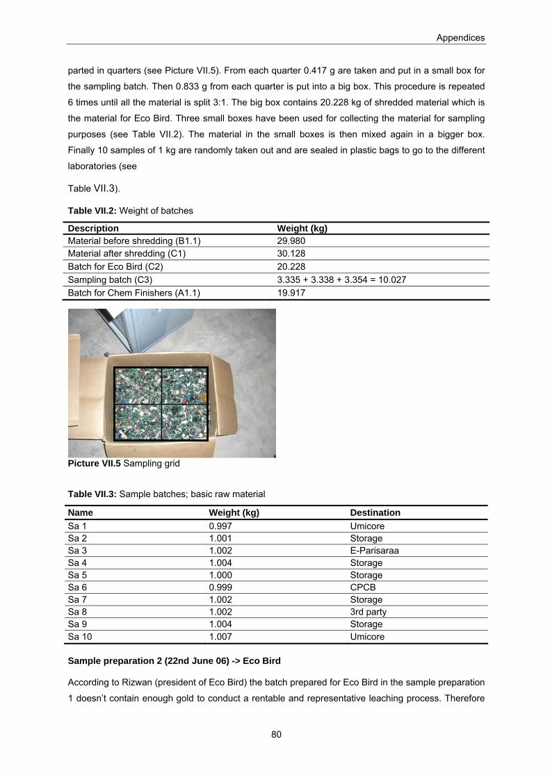
Appendices
80
parted in quarters (see Picture VII.5). From each quarter 0.417 g are taken and put in a small box for
the sampling batch. Then 0.833 g from each quarter is put into a big box. This procedure is repeated
6 times until all the material is split 3:1. The big box contains 20.228 kg of shredded material which is
the material for Eco Bird. Three small boxes have been used for collecting the material for sampling
purposes (see Table VII.2). The material in the small boxes is then mixed again in a bigger box.
Finally 10 samples of 1 kg are randomly taken out and are sealed in plastic bags to go to the different
laboratories (see
Table VII.3).
Table VII.2: Weight of batches
Description Weight (kg) Material before shredding (B1.1) 29.980 Material after shredding (C1) 30.128 Batch for Eco Bird (C2) 20.228 Sampling batch (C3) 3.335 + 3.338 + 3.354 = 10.027 Batch for Chem Finishers (A1.1) 19.917
Table VII.3: Sample batches; basic raw material
Name Weight (kg) Destination Sa 1 0.997 Umicore Sa 2 1.001 Storage Sa 3 1.002 E-Parisaraa Sa 4 1.004 Storage Sa 5 1.000 Storage Sa 6 0.999 CPCB Sa 7 1.002 Storage Sa 8 1.002 3rd party Sa 9 1.004 Storage Sa 10 1.007 Umicore
Sample preparation 2 (22nd June 06) -> Eco Bird
According to Rizwan (president of Eco Bird) the batch prepared for Eco Bird in the sample preparation
1 doesn’t contain enough gold to conduct a rentable and representative leaching process. Therefore
Picture VII.5 Sampling grid

Appendices
81
the parts with apparent gold are segregated manually by the author (see Picture VII.6). The rest of the
material (C4 + C4a) is also sent to Umicore for sampling (see Sample preparation 7 (5th July 06)).
Table VII.4: Weight of batches
Description Weight (kg) Material before segregation (C2) 20.228 Segregated gold parts (B2) 7.386 Rest material (C4 + C4a) 12.836
Picture VII.6: Segregation of gold / non gold - parts
Sample preparation 3 (23rd June 06) -> Eco Bird
The batch for Chem Finishers (A1.1) is split in two parts, because Eco Bird has to process at least
10kg so that the process can be done properly.
The part for Eco Bird undergoes the following preparation process:
The first 3 motherboards are treated with an electrical chiselling hammer (Boschhammer, Bosch GSH
3 E Professional). With the chiselling hammer the apparent gold parts are taken off (see Picture
VII.7). The nude boards are put into a box. By doing this procedure we realised that it would be more
efficient to cut the gold parts off the boards. Therefore the rest of the sample was cut with a shearing
machine (see Picture VII.8). The machine is carefully cleaned with a brush to keep the loss of value
as less as possible (see Picture VII.9). From the remaining boards (Picture VII.10) samples are
taken and sent to Umicore (see Sample preparation 5 (3rd July 06)). The gold parts (see Picture
VII.11) are then mixed with the segregated gold parts (B2) from sample preparation 2.
Table V.5: Weight of batches
Description Weight (kg) Material before treatment (C5) 9.996 Gold parts (B3) 5.016 Nude PWBs (C6) 4.974
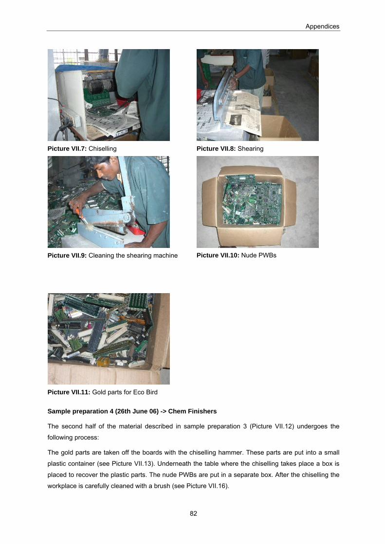
Appendices
82
Picture VII.7: Chiselling
Picture VII.8: Shearing
Picture VII.9: Cleaning the shearing machine
Picture VII.10: Nude PWBs
Picture VII.11: Gold parts for Eco Bird
Sample preparation 4 (26th June 06) -> Chem Finishers
The second half of the material described in sample preparation 3 (Picture VII.12) undergoes the
following process:
The gold parts are taken off the boards with the chiselling hammer. These parts are put into a small
plastic container (see Picture VII.13). Underneath the table where the chiselling takes place a box is
placed to recover the plastic parts. The nude PWBs are put in a separate box. After the chiselling the
workplace is carefully cleaned with a brush (see Picture VII.16).
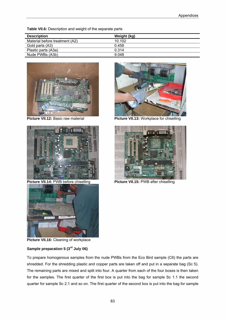
Appendices
83
Table VII.6: Description and weight of the separate parts
Description Weight (kg) Material before treatment (A2) 10.102 Gold parts (A3) 0.458 Plastic parts (A3a) 0.314 Nude PWBs (A3b) 9.048
Picture VII.12: Basic raw material
Picture VII.13: Workplace for chiselling
Picture VII.14: PWB before chiselling
Picture VII.15: PWB after chiselling
Picture VII.16: Cleaning of workplace
Sample preparation 5 (3rd July 06)
To prepare homogenous samples from the nude PWBs from the Eco Bird sample (C6) the parts are
shredded. For the shredding plastic and copper parts are taken off and put in a separate bag (Sc 5).
The remaining parts are mixed and split into four. A quarter from each of the four boxes is then taken
for the samples. The first quarter of the first box is put into the bag for sample Sc 1.1 the second
quarter for sample Sc 2.1 and so on. The first quarter of the second box is put into the bag for sample
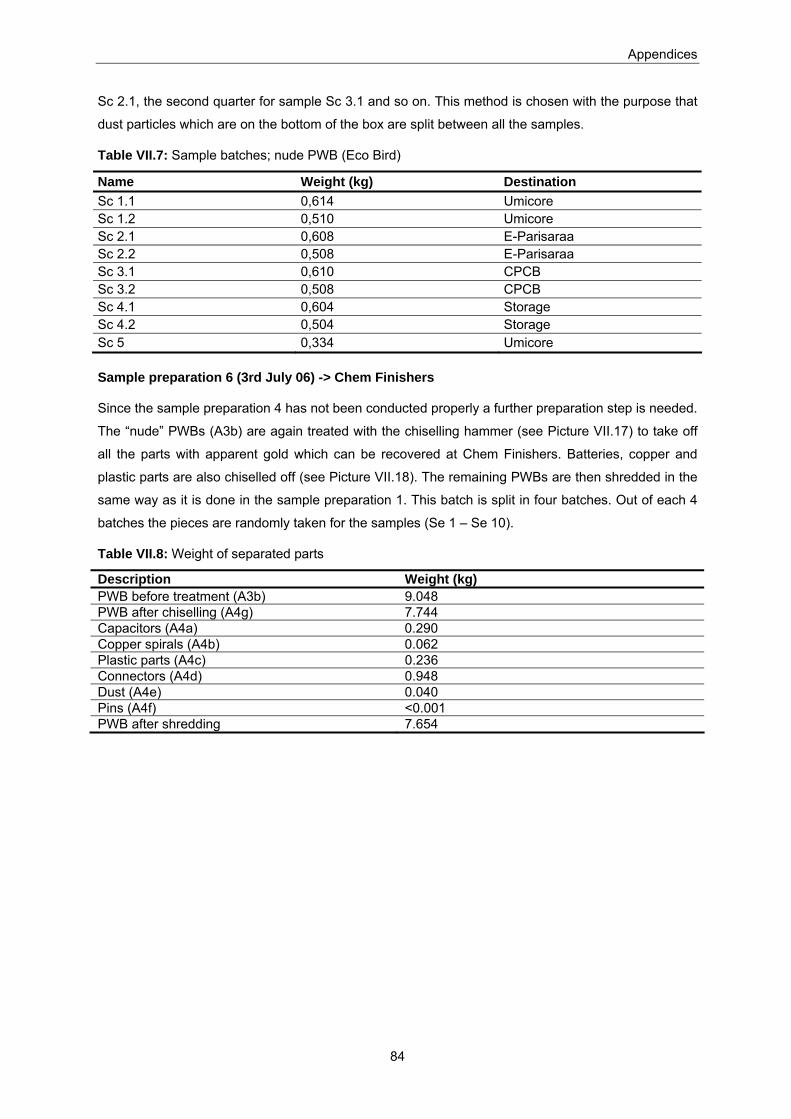
Appendices
84
Sc 2.1, the second quarter for sample Sc 3.1 and so on. This method is chosen with the purpose that
dust particles which are on the bottom of the box are split between all the samples.
Table VII.7: Sample batches; nude PWB (Eco Bird)
Name Weight (kg) Destination Sc 1.1 0,614 Umicore Sc 1.2 0,510 Umicore Sc 2.1 0,608 E-Parisaraa Sc 2.2 0,508 E-Parisaraa Sc 3.1 0,610 CPCB Sc 3.2 0,508 CPCB Sc 4.1 0,604 Storage Sc 4.2 0,504 Storage Sc 5 0,334 Umicore
Sample preparation 6 (3rd July 06) -> Chem Finishers
Since the sample preparation 4 has not been conducted properly a further preparation step is needed.
The “nude” PWBs (A3b) are again treated with the chiselling hammer (see Picture VII.17) to take off
all the parts with apparent gold which can be recovered at Chem Finishers. Batteries, copper and
plastic parts are also chiselled off (see Picture VII.18). The remaining PWBs are then shredded in the
same way as it is done in the sample preparation 1. This batch is split in four batches. Out of each 4
batches the pieces are randomly taken for the samples (Se 1 – Se 10).
Table VII.8: Weight of separated parts
Description Weight (kg) PWB before treatment (A3b) 9.048 PWB after chiselling (A4g) 7.744 Capacitors (A4a) 0.290 Copper spirals (A4b) 0.062 Plastic parts (A4c) 0.236 Connectors (A4d) 0.948 Dust (A4e) 0.040 Pins (A4f) <0.001 PWB after shredding 7.654
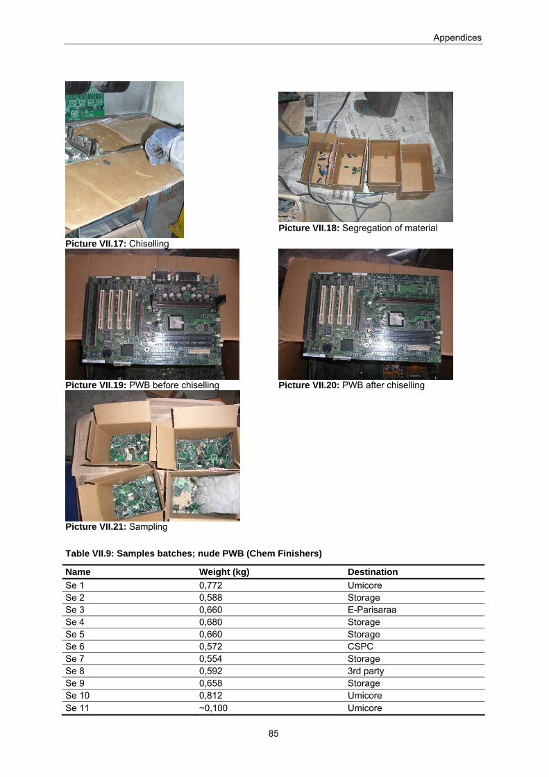
Appendices
85
Picture VII.17: Chiselling
Picture VII.18: Segregation of material
Picture VII.19: PWB before chiselling
Picture VII.20: PWB after chiselling
Picture VII.21: Sampling
Table VII.9: Samples batches; nude PWB (Chem Finishers)
Name Weight (kg) Destination Se 1 0,772 Umicore Se 2 0,588 Storage Se 3 0,660 E-Parisaraa Se 4 0,680 Storage Se 5 0,660 Storage Se 6 0,572 CSPC Se 7 0,554 Storage Se 8 0,592 3rd party Se 9 0,658 Storage Se 10 0,812 Umicore Se 11 ~0,100 Umicore

Appendices
86
Sample preparation 7 (5th July 06)
The remaining parts of the manual segregation (see Sample preparation 2 (22nd June 06) -> Eco
Bird) consist of pieces of PWB and dust which has been on the bottom of the box. The pieces are
mixed by hand and the box is split in 4 quarters (cp. Picture VII.5). In order to get a representative
sample the pieces are picked randomly from each quarter. The “non gold parts” consist of 12 % dust.
For each sample of pieces of PWB the amount of dust is calculated added to the sample. Before
weighing the dust part, the bag containing all the dust is properly mixed by shaking the bag. 10
samples are prepared like that (see Table VII.10).
Table VII.10: Sample batches; „non gold“ parts (Eco Bird)
Name Weight (kg) Destination Sf 1 1,191 Umicore Sf 2 1,060 Storage Sf 3 1,116 E-Parisaraa Sf 4 1,203 Storage Sf 5 1,077 Storage Sf 6 1,148 CSPC Sf 7 0,697 Storage Sf 8 0,721 3rd party Sf 9 0,786 Storage Sf 10 0,769 Umicore
Sample preparation 8
After conducting the processes there are output components which are a waste product of the
processes. These components where washed properly and then prepared as samples for Umicore.
In the case of the Eco Bird a few parts are rejected by Rizwan (Sg1, see Table VII.11), these were
sent only to CPCB. The output components of the process are mixed in a box and the randomly taken
out to prepare 10 bags for sampling (see Table VII.12).
In the case of the Chem Finishers there were again metal parts taken off before conducting the
process (Sh1). The output components (Sh2) make up only 1kg, which is sent to Umicore for
sampling (see Table VII.13).
Table VII.11: Sample batch; rejected parts (Eco Bird)
Name Weight (kg) destination Sg 1 0,108 CPCB

Appendices
87
Table VII.12: Sample batches; output components (Eco Bird)
Name Weight (kg) Destination Sd 1 0,504 Umicore Sd 2 0,502 storage Sd 3 0,500 E-Parisaraa Sd 4 0,508 storage Sd 5 0,502 storage Sd 6 0,502 CPCB Sd 7 0,500 storage Sd 8 0,510 3rd party Sd 9 0,502 storage Sd 10 0,506 Umicore
Table VII.13: Sample batches: metal parts, output components (Chem Finishers)
Name Weight (kg) Destination Sh 1 0,354 Umicore Sh 2 1,088 Umicore
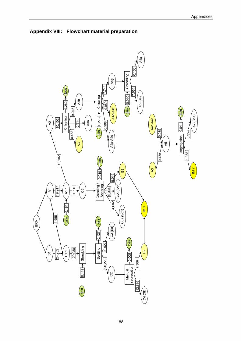
Appendices
88
Appendix VIII: Flowchart material preparation
A1
B1.1
A1.1
B1
Shre
ddin
g
Split
ting
C2
C3
(Sa)
loss
Man
ual
segr
egat
ion
B2C
4 (S
f)
4,99
819
,917
24,9
82
29,9
80
gain
0,14
8
0,12
7
10,0
2720
,228
7,38
612
,836
C5
9,99
6
loss
0,00
5
Chi
selin
g /
Shea
ring
B3
C6a
(Sc1
)
5,01
64,
682
loss
0,01
0
10,1
02
gain
0,18
1
C6b
(Sc5
)
0,33
4
A2
A3
Chi
selin
g
A3a
A3b
10,1
02
0,45
8
0,31
49,
048 C
hise
ling
A4a-
A4c
A4g
Shre
ddin
g
A5
(Se)
A5a
7,74
4
7,65
40,
100
A4d-
A4f0,98
90,
588
gain
0,27
3
0,28
2lo
ss
gain
0,01
0
A3A4
d-A4
f
A6
0,98
90,
458 se
greg
atio
n
IM 2
A7 (S
h1)
0,35
41,
052
loss
0,04
1
BRM
IM 1

Appendices
89
Appendix IX: Detailed flowchart „mercury amalgamation“
The following flowchart shows the separate steps of the observed “mercury amalgamation”. The
numbers refer to a one day observation. The pictures in Appendix X were also generated during the
same day.
Connectors
14.3 kg
Nitric acid L 1: Lixiviation Gas / fumes
Water
Water L 2: Washing Body-componentsCyanide leaching
Water L 3: Filtering Copper bearing solution
Cu recovery
Mercury194 g
S 1: Mixing + Washing Waste components
Nitric acid Waste solution
Water
Water S 2: Mixing + Dispersing
Sodium bicarbonate
Water S 3: Filtering + Washing
60 gMercury-compound
Hg recovery
Waste solution
Mercury S 4: Crushing
Water
Energy
Nitric acid P 8: Boiling + Washing Mercury-solutionHg recovery
Water Gas / fumes
P 9: Sorting with magnet solid waste (iron)
53.8 g
Au
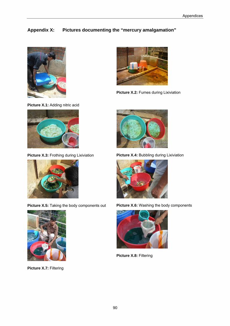
Appendices
90
Appendix X: Pictures documenting the “mercury amalgamation”
Picture X.1: Adding nitric acid
Picture X.2: Fumes during Lixiviation
Picture X.3: Frothing during Lixiviation
Picture X.4: Bubbling during Lixiviation
Picture X.5: Taking the body components out
Picture X.6: Washing the body components
Picture X.7: Filtering
Picture X.8: Filtering

Appendices
91
Picture X.9: Amalgamation
Picture X.10: Amalgam lump
Picture X.11: Recovering excess mercury
Picture X.12: Scrunching
Picture X.13: Fumes during boiling
Picture X.14: Vaporisation of nitric acid and mercury
Picture X.15: Gold powder
Picture X.16: Weighing the recovered gold
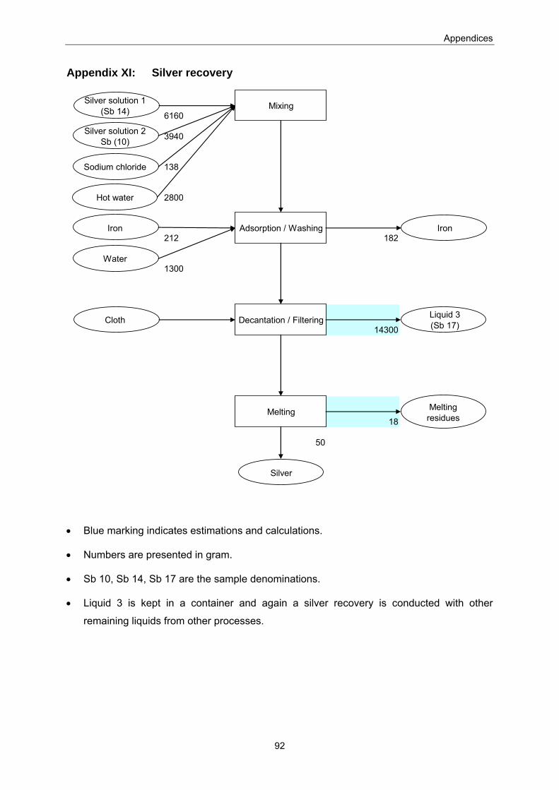
Appendices
92
Appendix XI: Silver recovery
Silver solution 1(Sb 14) 6160
Mixing
Silver solution 2Sb (10) 3940
Sodium chloride 138
Hot water 2800
Iron212
Adsorption / Washing182
Iron
Water1300
Cloth Decantation / Filtering14300
Liquid 3(Sb 17)
Melting18
50
Silver
Melting residues
• Blue marking indicates estimations and calculations.
• Numbers are presented in gram.
• Sb 10, Sb 14, Sb 17 are the sample denominations.
• Liquid 3 is kept in a container and again a silver recovery is conducted with other
remaining liquids from other processes.
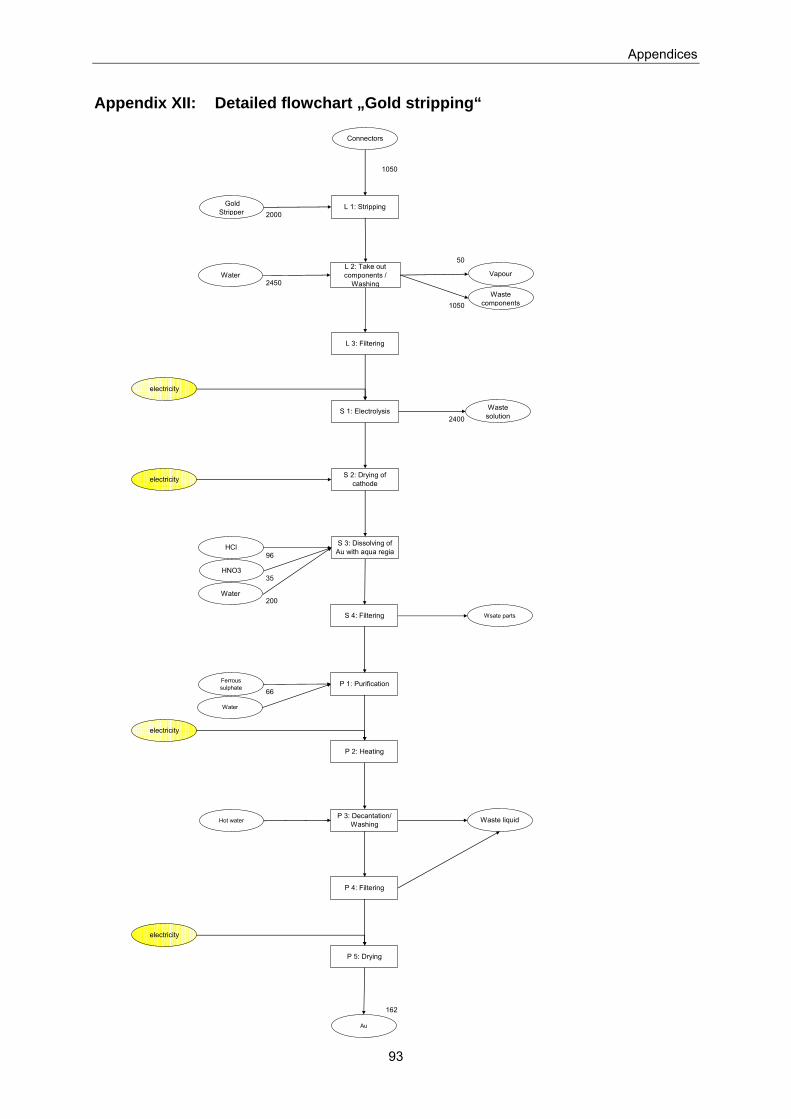
Appendices
93
Appendix XII: Detailed flowchart „Gold stripping“
1050
2000
50
2450
1050
2400
96
35
200
66
162
P 1: PurificationFerrous sulphate
Water
L 1: Stripping
Connectors
Gold Stripper
Waste components
S 1: Electrolysis
L 3: Filtering
Waste solution
L 2: Take out components /
Washing
S 3: Dissolving of Au with aqua regia
Water
HNO3
HCl
Water
P 2: Heating
P 3: Decantation/ WashingHot water Waste liquid
P 4: Filtering
P 5: Drying
Au
S 2: Drying of cathode electricity
S 4: Filtering
electricity
electricity
electricity
Wsate parts
Vapour

Appendices
94
Appendix XIII: Indicative assay results on e-scrap samples - 21/8/06 U
nkno
wn %
14,0
17,0
11,0
12,0
1,0
18,0
11,0
16,0
16,0
13,0
12,0
15,0
3,0
11,0
Org
anic
s** %
33,7
29,9
27,9
30,3
37,9
25,2
36,4
31,1
31,0
31,3
27,3
29,0
19,3
38,1
SiO
2 %
15,8
17,6
19,9
22,0
2,9
16,4
13,1
22,5
20,7
19,6
19,4
18,5
4,2
10,5
Al2
O3 %
7,0
9,2
15,9
12,0
22,6
5,8
4,4
6,3
5,7
12,9
12,6
10,1
3,2
3,1
Fe
%
2,4
2,7
2,4
1,1
15,6
1,5
1,5
0,9
0,9
9,7
4,3
4,1
10,5
8,6
Zn
%
1,1
1,3
0,3
0,4
1,8
2,1
2,7
0,2
0,3
2,5
1,6
1,0
13,4
3,3
Sn
%
3,8
2,9
2,3
2,4
0,5
4,9
4,6
3,3
3,9
0,1
2,4
2,2
2,3
1,4
Sb
%
0,4
0,5
0,2
0,1
0,2
0,5
0,5
0,3
0,2
2,0
0,3
0,4
0,6
1,1
Ni %
0,3
0,5
0,3
0,3
1,4
0,3
0,3
0,3
0,3
0,9
0,4
0,4
0,4
0,5
Cu %
20,1
17,3
18,5
18,3
15,5
22,8
23,1
18,1
19,1
7,3
18,2
18,2
42,5
22,3
Pb
%
1,7
1,3
1,2
1,2
0,3
2,4
2,2
1,5
1,8
0,3
1,2
1,1
0,1
0,2
Pd
ppm
64,9
132,
7
50,1
53,4
7,9
82,2
102,
8
9,1
81,1
3,5
52,7
76,3
8,6
156,
9
Au
ppm
111,
9
199,
7
293,
0
264,
0
14,5
30,5
24,3
174,
0
189,
9
468
*
274,
0
266,
0
64,9
129,
9
Ag
ppm
558,
0
991,
0
874,
0
823,
0
42,2
306,
0
394,
0
538,
0
776,
0
54,8
906,
0
775,
0
39,0
728,
0
Wei
ght
kg
0,99
7
1,00
7
0,61
4
0,51
0
0,33
4
0,50
4
0,50
6
0,77
2
0,81
2
+/-0
0,1
1,19
1
0,76
9
0,35
4
1,08
8
Des
crip
tion
Bas
ic ra
w m
ater
ial
Bas
ic ra
w m
ater
ial
Nud
e P
WB
(Eco
Bird
)
Nud
e P
WB
(Eco
Bird
)
Pla
stic
+ c
oppe
r par
ts
Out
put c
ompo
nent
s (E
co B
ird)
Out
put c
ompo
nent
s (E
co B
ird)
Nud
e P
WB
(Che
m F
inis
hers
)
Nud
e P
WB
(Che
m F
inis
hers
)
Pla
stic
par
ts
Non
gol
d pa
rts (E
co B
ird)
Non
gol
d pa
rts (E
co B
ird)
Met
al p
arts
(C
hem
Fin
ishe
rs)
Out
put c
ompo
nent
s (C
hem
Fin
ishe
rs)
Sam
ple
nam
e
Sa
1
Sa1
0
Sc1
.1
Sc1
.2
Sc5
Sd1
Sd1
0
Se1
Se1
0
Se1
1
Sf1
Sf1
0
Sh1
Sh2
*: S
e11:
the
plas
tic p
arts
are
ver
y pr
obab
ly th
e pl
astic
con
nect
or b
ars;
thes
e ba
rs ty
pica
lly h
ave
gold
pin
s in
side
**
all c
arbo
n co
mpo
unds
(in
this
cas
e m
ainl
y pl
astic
s, b
ut w
ood,
pap
er is
als
o in
clud
ed)
Ana
lysi
s co
nduc
ted
by:
Um
icor
e P
reci
ous
Met
al R
efin
ings
, Bel
gium
M
etho
ds u
sed:
P
reci
ous
Met
als:
Spe
ctro
phot
omet
er
Oth
er m
etal
s: P
d, C
u …
. Cd
are
dete
rmin
ed b
y X
RF
(X-R
ay F
luor
esce
nce
Spe
ctro
met
ry)
Org
anic
s: C
ombu
stio
n (lo
st o
f ign
ition
: ini
tial w
eigh
t min
us th
e w
eigh
t afte
r com
bust
ion
give
s th
e w
eigh
t of o
rgan
ics)
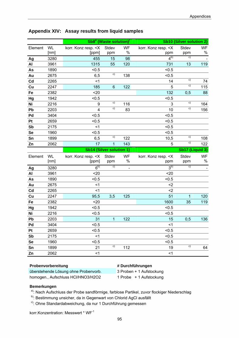
Appendices
95
Appendix XIV: Assay results from liquid samples
Sb8a (Waste solution)) Sb10 (Silver solution 2)Element
WL [nm]
korr. Konz resp. <X [ppm]
Stdev ppm
WF %
korr. Konz resp. <X ppm
Stdev ppm
WF %
Ag 3280 455 15 98 4b) c) -Al 3961 1315 55 120 731 13 119As 1890 <0.5 <0.5 Au 2675 6,5 c) 138 <0.5 Cd 2265 <1 14 c) 74Cu 2247 185 6 122 5 c) 115Fe 2382 <20 132 0,5 88Hg 1942 <0.5 <0.5 Ni 2216 9 c) 116 3 c) 164Pb 2203 4 c) 83 10 c) 156Pd 3404 <0.5 <0.5 Pt 2659 <0.5 <0.5 Sb 2175 <1 <0.5 Se 1960 <0.5 <0.5 Sn 1899 6,5 c) 122 10,5 c) 108Zn 2062 17 1 143 5 c) 122 Sb14 (Silver solution 1) Sb17 (Liquid 3)Element
WL [nm]
korr. Konz resp. <X [ppm]
Stdevppm
WF%
korr. Konz resp. <X ppm
Stdev ppm
WF %
Ag 3280 6b) c) - 3b) c) -Al 3961 <20 <20 As 1890 <0.5 <0.5 Au 2675 <1 <2 Cd 2265 <1 <2 Cu 2247 95,5 3,5 125 51 1 120Fe 2382 <20 1600 35 119Hg 1942 <0.5 <0.5 Ni 2216 <0.5 <0.5 Pb 2203 31 1 122 15 0,5 136Pd 3404 <0.5 <1 Pt 2659 <0.5 <0.5 Sb 2175 <1 <0.5 Se 1960 <0.5 <0.5 Sn 1899 21 c) 112 19 c) 64Zn 2062 <1 <1
Probenvorbereitung # Durchführungen überstehende Lösung ohne Probenvorb. 3 Proben + 1 Aufstockung homogen., Aufschluss HCl/HNO3/H2O2 1 Probe + 1 Aufstockung Bemerkungen a): Nach Aufschluss der Probe sandförmige, farblose Partikel, zuvor flockiger Niederschlag b): Bestimmung unsicher, da in Gegenwart von Chlorid AgCl ausfällt c): Ohne Standardabweichung, da nur 1 Durchführung gemessen
korr.Konzentration: Messwert * WF-1

Appendices
96
Stdev: Standardabweichung WF: Wiederfindungsrate
Sample pH-value °C Sb8 12.1 20.9 Sb10 12.0 20.9 Sb14 0.2 20.9 Sb17 0.3 20.9
Analysis conducted by:
Sigma Aldrich, Switzerland
Methods used:
Metal traces: ICP-OES16
16 Inductively Coupled Plasma Optical Emission Spectrometry

Appendices
97
Appendix XV: Summary of hazardous substances and metals
Substances
Cyanide
A cyanide is any chemical compound that contains the cyano group CN- (Wikipedia, 2006). Cyanide is
produced in the human body and exhaled in extremely low concentrations with each breath. It is also
produced by over 1’000 plant species including sorghum, bamboo and cassava.
Hydrogen cyanide is produced when cyanide is present in water. At pH 9.2 half of the present cyanide
is in the form of molecular HCN. With increasing pH the concentration of HCN decreases.
Liquid or gaseous hydrogen cyanide and alkali salts of cyanide can enter the body through inhalation,
ingestion or absorption through the eyes and skin. Once in the bloodstream, cyanide prevents oxygen
being transported in the blood. This can result in respiratory arrest and death. Hydrogen cyanide
(HCN) is extremely toxic with an LC50 of 100 – 300 ppm.
The body has several mechanisms to detoxify cyanide and it does not accumulate or bio magnify.
Therefore, chronic exposure to sub lethal concentrations of cyanide does not appear to result in
severe toxicity. However chronic cyanide exposure is linked to lesions of the optic nerve, depressed
thyroid function and can affect the nervous system (Cyanide Management Code, 2006). More
complete information to impacts to humans from cyanide are compiled in the WHO-study: Human
health aspects of hydrogen cyanide and cyanides: human health aspects (Simeoneova and Fishbein,
2004).
Fish and aquatic invertebrates are particularly sensitive to cyanide exposure. Concentrations of free
cyanide in the aquatic environment ranging from 5.0 to 7.2 micrograms per litre reduce swimming
performance and inhibit reproduction in many species of fish (Logsdon et al., 1999).
Nitric acid and nitrogen dioxide
Nitric acid is a colourless and corrosive liquid. It can cause serious skin burns and a yellow
discoloration of the skin. Ingestion leads to abdominal pain and can end in shock. It is a strong oxidant
and reacts violently with combustible and reducing materials, e.g., turpentine, charcoal or alcohol (CIS,
2003).
Nitrogen dioxide is produced from nitric acid. It is a brownish coloured, irritant gas with a sweet smell
(TLV: 5 ml / m3). Inhalation results in: Burning sensation, sore throat, cough, dizziness, headache, etc.
(CIS, 2003). A chronic or acute exposure to nitrogen dioxide is associated to a bacterial or viral
colonisation of the pulmonary and can lead to several lung diseases such as pulmonary oedema or
pulmonary fibrosis (Reichl, 2002).
Nitrogen dioxide can have negative effects on plants, e.g. it can harm the upper layer from leaves.
Nitric acid contributes to the soil acidification. It is presumed that damages to forests are partly due to
the air pollution with nitrogen dioxide. Contamination of soil and groundwater, may affect aquatic
systems (Zarda et al., 2005)
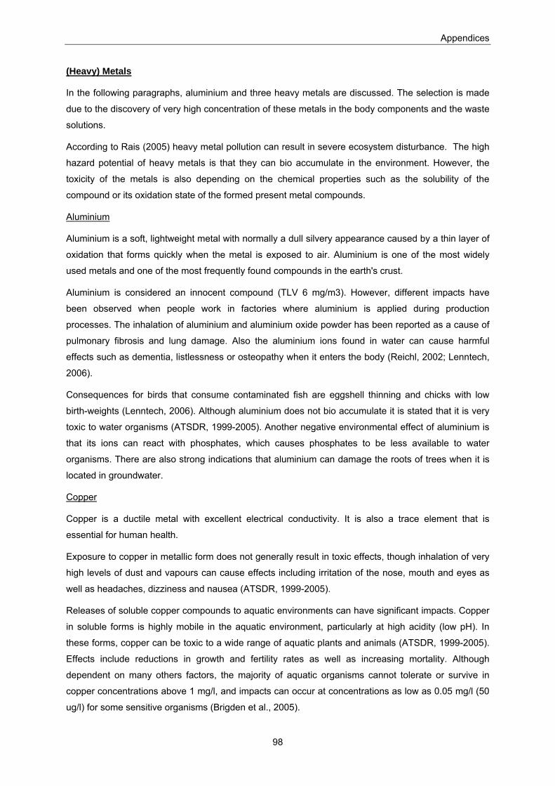
Appendices
98
(Heavy) Metals
In the following paragraphs, aluminium and three heavy metals are discussed. The selection is made
due to the discovery of very high concentration of these metals in the body components and the waste
solutions.
According to Rais (2005) heavy metal pollution can result in severe ecosystem disturbance. The high
hazard potential of heavy metals is that they can bio accumulate in the environment. However, the
toxicity of the metals is also depending on the chemical properties such as the solubility of the
compound or its oxidation state of the formed present metal compounds.
Aluminium
Aluminium is a soft, lightweight metal with normally a dull silvery appearance caused by a thin layer of
oxidation that forms quickly when the metal is exposed to air. Aluminium is one of the most widely
used metals and one of the most frequently found compounds in the earth's crust.
Aluminium is considered an innocent compound (TLV 6 mg/m3). However, different impacts have
been observed when people work in factories where aluminium is applied during production
processes. The inhalation of aluminium and aluminium oxide powder has been reported as a cause of
pulmonary fibrosis and lung damage. Also the aluminium ions found in water can cause harmful
effects such as dementia, listlessness or osteopathy when it enters the body (Reichl, 2002; Lenntech,
2006).
Consequences for birds that consume contaminated fish are eggshell thinning and chicks with low
birth-weights (Lenntech, 2006). Although aluminium does not bio accumulate it is stated that it is very
toxic to water organisms (ATSDR, 1999-2005). Another negative environmental effect of aluminium is
that its ions can react with phosphates, which causes phosphates to be less available to water
organisms. There are also strong indications that aluminium can damage the roots of trees when it is
located in groundwater.
Copper
Copper is a ductile metal with excellent electrical conductivity. It is also a trace element that is
essential for human health.
Exposure to copper in metallic form does not generally result in toxic effects, though inhalation of very
high levels of dust and vapours can cause effects including irritation of the nose, mouth and eyes as
well as headaches, dizziness and nausea (ATSDR, 1999-2005).
Releases of soluble copper compounds to aquatic environments can have significant impacts. Copper
in soluble forms is highly mobile in the aquatic environment, particularly at high acidity (low pH). In
these forms, copper can be toxic to a wide range of aquatic plants and animals (ATSDR, 1999-2005).
Effects include reductions in growth and fertility rates as well as increasing mortality. Although
dependent on many others factors, the majority of aquatic organisms cannot tolerate or survive in
copper concentrations above 1 mg/l, and impacts can occur at concentrations as low as 0.05 mg/l (50
ug/l) for some sensitive organisms (Brigden et al., 2005).
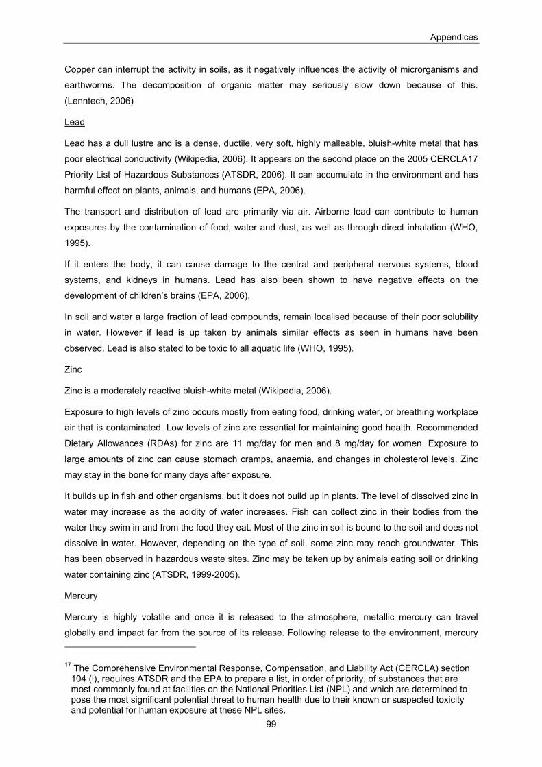
Appendices
99
Copper can interrupt the activity in soils, as it negatively influences the activity of microrganisms and
earthworms. The decomposition of organic matter may seriously slow down because of this.
(Lenntech, 2006)
Lead
Lead has a dull lustre and is a dense, ductile, very soft, highly malleable, bluish-white metal that has
poor electrical conductivity (Wikipedia, 2006). It appears on the second place on the 2005 CERCLA17
Priority List of Hazardous Substances (ATSDR, 2006). It can accumulate in the environment and has
harmful effect on plants, animals, and humans (EPA, 2006).
The transport and distribution of lead are primarily via air. Airborne lead can contribute to human
exposures by the contamination of food, water and dust, as well as through direct inhalation (WHO,
1995).
If it enters the body, it can cause damage to the central and peripheral nervous systems, blood
systems, and kidneys in humans. Lead has also been shown to have negative effects on the
development of children’s brains (EPA, 2006).
In soil and water a large fraction of lead compounds, remain localised because of their poor solubility
in water. However if lead is up taken by animals similar effects as seen in humans have been
observed. Lead is also stated to be toxic to all aquatic life (WHO, 1995).
Zinc
Zinc is a moderately reactive bluish-white metal (Wikipedia, 2006).
Exposure to high levels of zinc occurs mostly from eating food, drinking water, or breathing workplace
air that is contaminated. Low levels of zinc are essential for maintaining good health. Recommended
Dietary Allowances (RDAs) for zinc are 11 mg/day for men and 8 mg/day for women. Exposure to
large amounts of zinc can cause stomach cramps, anaemia, and changes in cholesterol levels. Zinc
may stay in the bone for many days after exposure.
It builds up in fish and other organisms, but it does not build up in plants. The level of dissolved zinc in
water may increase as the acidity of water increases. Fish can collect zinc in their bodies from the
water they swim in and from the food they eat. Most of the zinc in soil is bound to the soil and does not
dissolve in water. However, depending on the type of soil, some zinc may reach groundwater. This
has been observed in hazardous waste sites. Zinc may be taken up by animals eating soil or drinking
water containing zinc (ATSDR, 1999-2005).
Mercury
Mercury is highly volatile and once it is released to the atmosphere, metallic mercury can travel
globally and impact far from the source of its release. Following release to the environment, mercury
17 The Comprehensive Environmental Response, Compensation, and Liability Act (CERCLA) section 104 (i), requires ATSDR and the EPA to prepare a list, in order of priority, of substances that are most commonly found at facilities on the National Priorities List (NPL) and which are determined to pose the most significant potential threat to human health due to their known or suspected toxicity and potential for human exposure at these NPL sites.

Appendices
100
can enter water bodies (either directly or following deposition) where it can become transformed into
methyl mercury, a highly toxic form that can bio accumulate and bio magnify in food chains,
particularly in fish. This is the major route of exposure for the public. Workers may also be exposed to
mercury through inhalation of mercury vapour or dust (UNEP, 2002).
Inhalation of high levels of mercury vapour may cause a range of effects including impact to the
central nervous system. Long-term exposure to lower levels of mercury vapour (0,1 - 0,2 mg/m3) can
also cause amongst other symptoms tremor, agitation or periodontosis (Reichl, 2002).
The same effects have also been reported in animals (ATSDR, 1999-2005).
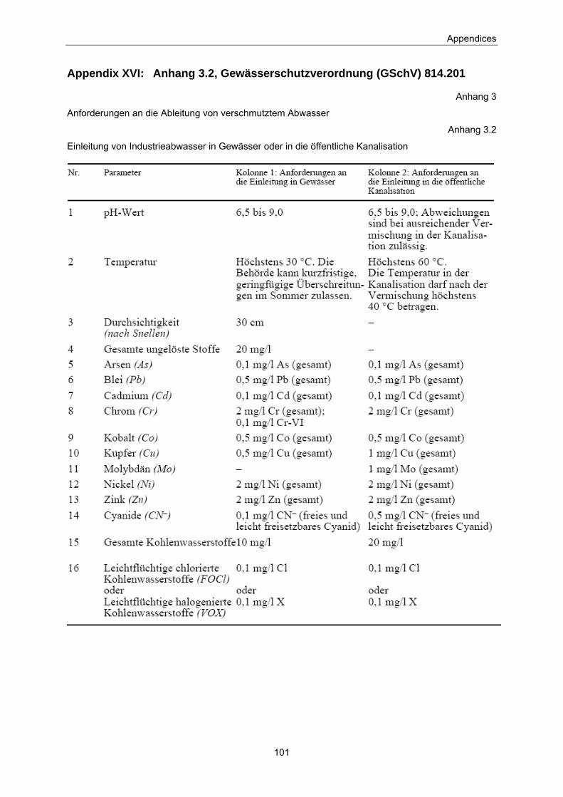
Appendices
101
Appendix XVI: Anhang 3.2, Gewässerschutzverordnung (GSchV) 814.201
Anhang 3
Anforderungen an die Ableitung von verschmutztem Abwasser
Anhang 3.2
Einleitung von Industrieabwasser in Gewässer oder in die öffentliche Kanalisation
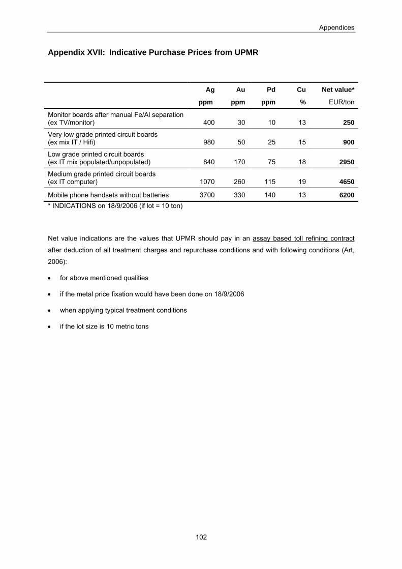
Appendices
102
Appendix XVII: Indicative Purchase Prices from UPMR
Ag Au Pd Cu Net value*
ppm ppm ppm % EUR/ton
Monitor boards after manual Fe/Al separation (ex TV/monitor) 400 30 10 13 250
Very low grade printed circuit boards (ex mix IT / Hifi) 980 50 25 15 900
Low grade printed circuit boards (ex IT mix populated/unpopulated) 840 170 75 18 2950
Medium grade printed circuit boards (ex IT computer) 1070 260 115 19 4650
Mobile phone handsets without batteries 3700 330 140 13 6200 * INDICATIONS on 18/9/2006 (if lot = 10 ton)
Net value indications are the values that UPMR should pay in an assay based toll refining contract
after deduction of all treatment charges and repurchase conditions and with following conditions (Art,
2006):
• for above mentioned qualities
• if the metal price fixation would have been done on 18/9/2006
• when applying typical treatment conditions
• if the lot size is 10 metric tons

Appendices
103
Appendix XVIII: Used ecoinvent data
Chemicals emitted to air from combustion of charcoal:
Substance kg/MJ CO2 9,15E-02 HCl 3,31E-06 HF 1,24E-07 H2SO4 1,00E-07 NOx 1,00E-04 SO2 1,00E-04
Chemicals emitted to air from shipping material:
Substance kg/tkm CO2 5,40E-03 SO2 9,96E-05 Nox 3,68E-05

Appendices
104
Appendix XIX: Umicore Precious Metals Refining (UPMR)
“Umicore Precious Metals Refining” (UPMR), a business unit of “Umicore”, is one of the world’s largest
precious metals recycling facilities. They offer eco-efficient (ISO 9001 and ISO 14001 certified)
recycling and refining services for precious metals and other non-ferrous metals out of secondary raw
materials and recyclables such as e-waste. Precious metals are recovered using a metallurgical
process. The costumer can choose if the recovered metals shall be returned physically or if they want
to sell it to “Umicore”.
The main activities of UPMR take place in the site of Hoboken. Around 1,150 people are active in
sampling and assaying activities, in smelting and refining operations and in commercial and supporting
services. Each year Umicore Precious Metals Refining receives around 300’000 tonnes of about 200
different raw materials containing lead, copper, nickel and precious metals. From these material 17
different metals are recovered. Amongst others, 25 tons of gold and 1200 tons silver per year are
recovered. E-waste constitutes 10 % of the input material, i.e. 30’000 tons per year (Umicore, 2006)
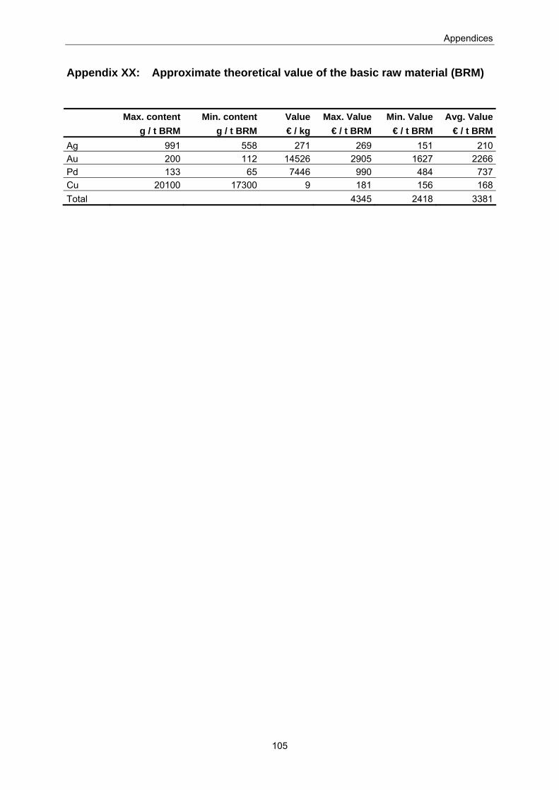
Appendices
105
Appendix XX: Approximate theoretical value of the basic raw material (BRM)
Max. content Min. content Value Max. Value Min. Value Avg. Value g / t BRM g / t BRM € / kg € / t BRM € / t BRM € / t BRMAg 991 558 271 269 151 210Au 200 112 14526 2905 1627 2266Pd 133 65 7446 990 484 737Cu 20100 17300 9 181 156 168Total 4345 2418 3381