Embed Size (px)
Citation preview

WHC-SD-WM-ETP-118, Rev. 0
ENGINEERING TASK PLAN FOR
TANKS 241-AN-103, 104, 105
COLOR VIDEO CAMERA SYSTEMS
Impact level SQ
Ed Kohlman October 1994
DISCLAIMER
File: TP-AHFARH.CAH
This report was prepared as an account of work sponsored by an agency of the United States Government. Neither the United States Government nor any agency thereof, nor any of their employees, makes any warranty, express or implied, or assumes any legal liability or responsibility for the accuracy, completeness, or usefulness of any information, apparatus, product, or process disclosed, or represents that its use would not infringe privately owned rights. Reference herein to any specific commercial product, process, or service by trade name, trademark, manufacturer, or otherwise does not necessarily constitute or imply its endorsement, recommendation, or favoring by the United States Government or any agency thereof. The views and opinions of authors expressed herein do not necessarily state or reflect those of the United States Government or any agency thereof. ETN-94-0171
asmmmou OF TH.S DOCUMENT i s M r e o

DISCLAIMER
Portions of this document may be illegible in electronic image products. Images are produced from the best available original document.

WHC-SD-WM-ETP-118 REV 0
TABLE OF CONTENTS
Page 1.0 INTRODUCTION 1 2.0 SCOPE 1
2.1 Objective 1 2.2 Deliverables 1
3.0 DESCRIPTION 2 3.1 Physical Description 2 3.2 Procurement 2 3.3 Fabrication 2 3.4 Testing 2 3.5 Special Reviews 3 3.6 Installation 3 3.7 Maintenance/Operation 3
4.0 SYSTEM FUNCTIONAL PERFORMANCE DESCRIPTION 3 4.1 Camera Systems 3 4.2 Design Verification 7
5.0 ORGANIZATIONAL RESPONSIBILITIES 7 5.1 Customer 8 5.2 Responsible Manager and Engineer 8 5.3 Camera System Design Manager and Engineer 9 5.4 Nitrogen Purge System Engineer 10 5.5 Electrical Support Engineer 11 5.6 Multiport Flanged Riser Support Engineer 11 5.7 Camera System and Ancillary Equipment Installation Engineer . 12 5.8 Assessments 12 5.9 Structural/Seismic Support Engineer 13 5.10 TWRS Operations Support 13 5.11 Cognizant Engineer 13 5.12 ABU Requirements 14
6.0 SCHEDULE 14 7.0 COST ESTIMATE 14 8.0 QUALITY ASSURANCE 16 9.0 APPROVAL DESIGNATOR 16 10.0 SAFETY CLASS 16
File: TP-ANFARH.CAM i ETN-94-0171

WHC-SD-WM-ETP-118 REV 0
ENGINEERING TASK PLAN FOR TANKS 241-AN-103, 104, 105 COLOR VIDEO CAMERA SYSTEMS
.. 1.0 INTRODUCTION This Engineering Task Plan (ETP) describes the design, fabrication,
assembly, and installation of the video camera systems into the vapor space within tanks 241-AN-103, 104, and 105 (AN-103, AN-104, and AN-105). The one camera remotely operated color video systems will be used to observe and record the activities within the vapor space. Activities may include but are not limited to core sampling, auger activities, crust layer examination, monitoring of equipment installation/removal, and any other activities.
2.0 SCOPE 2.1 Objective
The objective of this task is to provide a single camera system in each of the tanks for the Flammable Gas Tank Safety Program. The camera systems will provide observation, video recording, and monitoring of the activities that occur in the vapor space of tanks AN-103, AN-104, and AN-105. 2.2 Deliverables
A remotely operable camera system which is qualified for use in an atmosphere containing combustible hydrogen will be provided to Tank Farms Operations. The deliverables consist of the following. 2.2.1 Project supporting documentation including an ETP, procurement
specifications, drawings, test plan, safety assessment, structural analysis, plant forces work review, As Low As Reasonably Achievable Management Work Sheet, dose rate calculations, and unreviewed safety question (USQ) screening (where required).
2.2.2 Hardware to support the camera system installation in each of the tanks. A multi-port flange assembly with a 50.8 cm (20") port, one for each of the camera installations.
2.2.3 New nitrogen bottle (or.compressed dry air) supply system and new purge panels, similar in design to the 241-AW-101 system.
2.2.4 Zoom video camera, a remotely controlled pan and tilt unit, video recorder, monitor, video printer, camera control equipment, and all controls necessary to operate the system. Also to be included is a local control console with video jacks for auxiliary monitors.
2.2.5 Electrical lighting fixtures which conform to the National Electrical Code (NEC) Article 501 for use in a Class I, Division 1, Group B atmosphere and are listed Underwriters
File: TP-ANFARM.CAH 1 ETN-94-0171

WHC-SD-WM-ETP-118 REV 0
Laboratory (UL) 1572, UL 844, and suitable for use in wet locations.
2.2.6 Installation work plan and operating and maintenance procedures as required.
2.2.7 Racks will be furnished to house remote monitoring, remote control, and video recording equipment in the local instrument building.
3.0 DESCRIPTION 3.1 Physical Description
These single camera, remotely operated systems include all components required to observe and record activities within the vapor space of tanks AN-103, AN-104, and AN-105.
The camera systems will consist of one radiation resistant camera assembly. The camera system will be mounted to a pan and tilt unit (modified to a roll system), capable of a pan of greater than 350° (360° field of view) and tilt of 120° minimum. The systems will also provide their own Class I, Division 1, Group B atmosphere lighting and will be deployed through a 50.8 cm (20") riser in the 106.7 cm (42") multi-flange assembly for each tank. 3.2 Procurement
All material procurement will be identified and accomplished in accordance with WHC-CM-2-1, Procurement Manual and Procedures. Lighting fixtures will include documentation which confirms compliance to the requirements stated in Section 2.2.5. Emergency procurements will be used only if time constraints on the item will exceed scheduled commitments. 3.3 Fabrication
Ancillary camera system components required for this installation will be designed and fabricated by Westinghouse Hanford Company (WHC) engineers and craftsmen. The equipment associated with this task may be developed in accordance with WHC-CM-6-1, Standard Engineering Practices. EP-2.4, "Development Control." See Section 8.0 for detailed information on requirements. 3.4 Testing
Testing of the video system will include a complete functional test of the camera system, pan and tilt unit, lighting, and purge system prior to and just after installation in the tank. Testing will be accomplished in accordance with an Impact Level SQ approved test procedure. Radiation durability of the system shall be supported by customer use documentation and will be provided by the camera system vendor.
File: TP-ANFARH.CAH 2 ETN-94-0171

WHC-SD-WM-ETP-118 REV 0
3.5 Special Reviews Special reviews required include a review by Materials and Process
Engineering for material compatibility, review of the system design for purging to qualify it for use, review by Instrumentation Systems Engineering for risk of spark generation from electrical components, review by Safety Analysis, and a final Operational Readiness Review (Type 6 per WHC-CM-1-5, Standard Operating Practices. Section 1.2) prior to installation and operation of. the system. A design review of the camera system may be performed prior to camera fabrication. In addition, a USQ determination will be performed on any documentation that will affect installation into the tank farm, in accordance with WHC-CM-1-3, Management Requirements and Procedures. MRP 5.12. 3.6 Installation
Installation will be completed by appropriate Operations personnel with technical support from Surveillance Systems Engineering (SSE) personnel. Installation will not commence until all installation work package documentation is approved in accordance with WHC-CM-8-8, Job Control System. 3.7 Maintenance/Operation
Operation and maintenance of the system will be performed through approved Tank Farm preventive maintenance and operation/maintenance documents. 3.8 Metric Units
All drawings, documents, and procedures will utilize metric units in their development. Soft conversions from English units to metric units (also known as SI units) shall be implemented on this program. For example, pipes, tubing, fittings, plate sizes, wiring, panels, etc., will be true English dimensioned components, but will be called out with its equivalent metric dimension. English unit callouts, in parentheses, will only follow those SI units which are at critical locations, interfaces with English components, or where confusion may occur with them. Bills of material will utilize both units.
Mechanical and digital pressure gauges as well as flow measuring and sensing devices will have combination measurement units called out, with the primary numbers in SI units. The pressure units will be in centimeters of water (inches of water) and/or kilopascals (psi) as required. The flow measuring devices will read in liters per minute (cfm) or similar units.
4.0 SYSTEM FUNCTIONAL PERFORMANCE DESCRIPTION 4.1 Camera Systems 4.1.1 The camera systems will consist of a vendor procured color zoom
lensed camera and shielded housing, mast assembly, shield plug/ purge manifold, and lighting system. The camera shall be designed to fit in a 50.8 cm (20") pipe riser and be mounted to the multi-flange assembly designed for this project. The multi-flange riser
File: TP-ANFARM.CAM 3 ETN-94-0171

WHC-SD-WM-ETP-118 REV 0
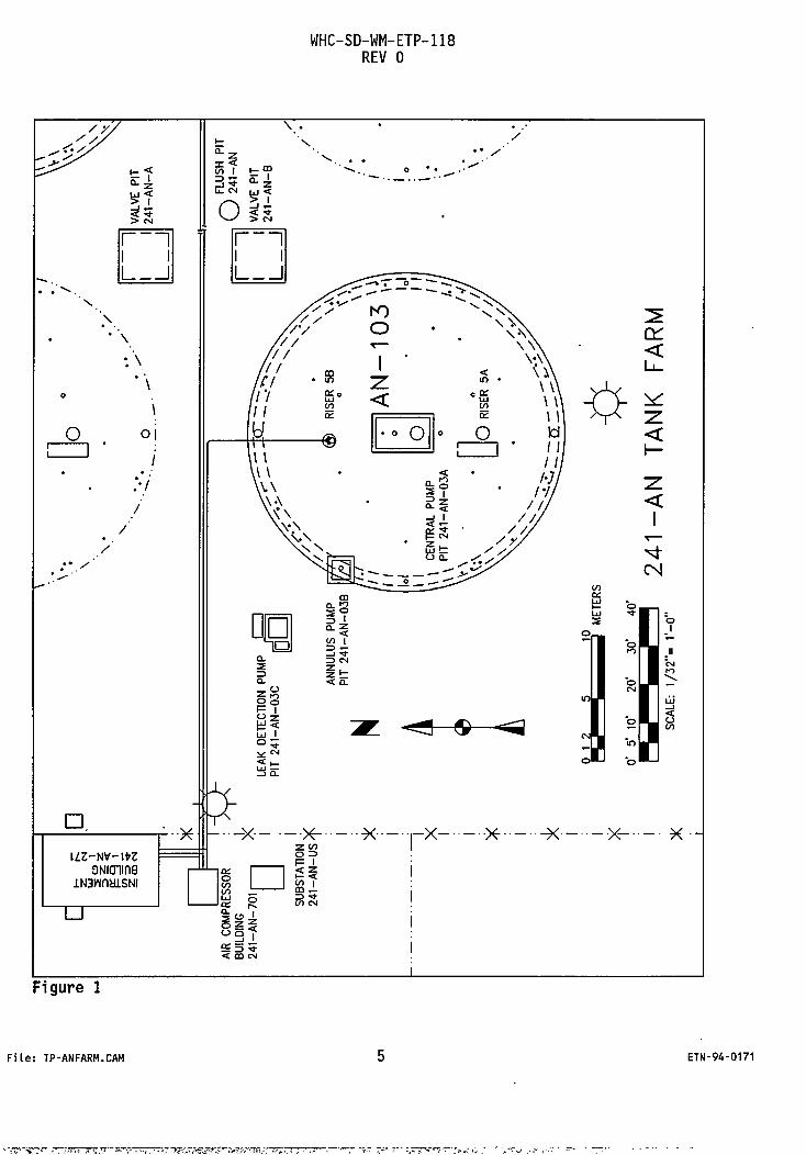
shall consist of a 50.8 cm (20"), 30.5 cm (12"), and two 20.3 cm (8") 150# class flanges on standard weight pipe risers, or of a similar configuration. The primary purpose of this camera is to monitor core sampling and auger activities within the tank. The camera shall provide full tank monitoring through the use of pan and tilt and zoom capabilities. The cameras will be installed in the following 106.7 cm (42") risers in the AN tanks.
Tank Riser AN-103 5B AN-104 5B AN-105 5B
See Figures 1 and 2 for riser locations and cable/purge line routing
4.1.2 The visual components shall be contained in a shielded nitrogen (or compressed dry air) purged housing to withstand the radiation field anticipated for this tank. The camera assembly shall have a two-year minimum useful life expectancy. The pan and tilt (if not hydraulically operated) assembly will also be purged with the gas supply. The camera assemblies shall be designed for a radiation field of 200 R/hr, hard gamma with an average expected energy level of 0.667 MeV (Cs 132).
4.1.3 Purge supply lines shall be fabricated of stainless steel tubing and fittings, with the exception of the flexible lines to the camera housing and pan/tilt unit. The purge system for the new camera assembly shall include a nitrogen bottle supply system (or compressed dry air) located in the AN Tank Farm and will include a purge panel based on the design of the existing 241-AW-101 camera system. The compressed gas will purge all electrical components not listed for a Class I, Division 1, Group B hazardous location. Purging will be in accordance with the National Fire Protection Association (NFPA) Article 496.
4.1.4 The pan actuator shall have a full turning range of appx. 350° (360° field of view), and the tilt actuator (or roll mechanism) shall have a range of 120° minimum (- 90° from horizontal, + 30° minimum from horizontal) for full coverage of the tank interior. Flexible hoses will dictate flexibility of the tilt system. The pan/tilt unit shall be designed for and rated leak tight at a system pressure of 38 cm (15") water column or less.
4.1.5 A control system for the pan and tilt shall be provided. The controller and monitoring systems shall be located in an existing instrumentation building located near the AN Tank Farm. A local control console with video jacks for local monitor(s) at the riser shall also be provided.
File: TPrANFARM.CAM ETN-94-0171
-JX'S-T^rA-
WHC-SD-WM-ETP-118 REV 0
s // Y . . . •
,'&r °-3 '"v . . /
X < ^ • CO 1 t - °? - ~ . . o • : ^ : ^ '
3 5 ^ z G. CM QJ < oh
' > CM •
1 1 i i
1 1 i 1
•
i i 1 1
1 1
1 1
/ v v O / / / T —
A 7 I • • \
< \ A < L i
' \ /// •« z: m * \ v _ l y
o
\ / / / S p l - -J ̂ l "- 111 ^ l o oi H ti 5 • c o O Id
! 1 * / J < I— i I I <3 5 • c o O Id
! 1 * / J < I— i 1 i \\ \ III < I—
/
\ \ \
\ \ \ 1° ' /'V 2 5 / / / <
1 / 1
/ X ^ So. s.//
0 „̂— -** ^***^
^ ^ "-* "—
So. s.//
0 „̂— -** ^***^ CO DC
<N __ "~~ CO
DC
<N m
CO DC
<N
2 '-' • . i
A o
II u 1
IE n
J 35 O
2 A o
II ^ 3 CM
1 it •o J§ _, O CM • § 3 •°rf1 1 LU
5z ui I ^ —
* > — - i 4 A -J < o
5z ui I ^ — ^9 * ^ « 4 \ 1 v^CM it He < h-_ l D-
1 ,
O " - 1 o ™ - 1
. iif D. ^ • x X - - X -X--• r x x x x x ••-• x X - - X -X--• r x x x x x ••-
z<5 1 uz-w-m ONicnina
O 3 uz-w-m ONicnina «- 1 ^ 1?
iN3Wf1ciLSNI o CO to
1 -M. CO 1 CD J-
iN3Wf1ciLSNI o CO to
1 -M. CO 1 CD J-
£ °. J3S U O S 5
O O i - j • £ 5 5 < C CD CM
_ l Figure 1
File: TP-ANFARH.CAH ETN-94-0171

to c -i a>
VENTILATION INSTRUMENT PIT 3
MOTOR CONTROL CENTER MCC-241-AN
VALVE PIT 241 - A N -
1 ANNULUS PUMP PIT 241-AN-04B
DETECTION PUMF PIT 241-AN-04C
METERS
O FLUSH PIT 241-AN
VALVE PIT • 241-AN-B
PIT 2
241-AN TANK FARM 0' 5" 10' 20' 30' 40'
SCALE: 1/32"= 1'-0"
/ \ / N

WHC-SD-WM-ETP-118 REV 0
4.1.6 The upper mast plate will manifold all electrical and compressed gas purge lines.
4.1.7 The zoom camera shall have roughly a 4:1 zoom capability (22:90 mm lens) for tank component viewing. The camera shall be capable of across-the-tank viewing 18.3 m (60') minimum, with adequate support lighting in all camera viewing situations.
4.1.8 Lighting fixtures shall be listed UL 1572, UL 844 for use in Class I, Division 1, Group B atmospheres. Lights shall also be suitable for use in wet locations.
4.1.9 All materials used in the camera design which are located in the vapor space shall be compatible with the radiological and chemical constituents. Testing shall be performed on all components that are not generally used in this environment to ensure design adequacy.
4.2 Design Verification Verification of the design of the video systems will be documented
accordingly per WHC-CM-6-1, Section 4.1. Verification approval will be for Impact Level SQ documentation. Reviews will take place in parallel with the fabrication and assembly. Installation and use of the system will not be allowed until final design verification has been completed and all required approvals have been obtained.
All electrical components located within the vapor space of the tank shall conform to the NEC Article 501 for use in a Class I, Division 1, Group B atmosphere.
Components not identified for use in combustible atmospheres, as purchased, will be qualified by purging as described in the NFPA Article 496. Approval for installation and operation in the vapor space will be upon design verification in accordance with WHC-CM-6-1, Section 4.1.
5.0 ORGANIZATIONAL RESPONSIBILITIES Following are tasks assigned to each organization involved in the
project. The items listed are the major activities for each group and may not include all areas of responsibilities that may be implied by the specific task. All appropriate training by engineering staff shall be obtained and/or maintained to satisfactorily perform onsite tasks in the tank farm.
File: TP-ANFARH.CAH 7 ETN-94-0171

WHC-SD-WM-ETP-118 REV 0
5.1 Customer
Customer: fiD Johnson (Flammable Gas Tank Safety Program)
The Customer for this project is Jerry Johnson in the Flammable Gas Tank Safety Program. The Customer will have overall input on the requirements and direction for the camera system. The Customer will provide funding and scheduling requirements for the activities.
5.2 Responsible Manager and Engineer
Responsible Manager: TL Moore (Mechanical Equipment) Responsible Engineer: EH Kohlman (Mechanical Equipment)
The Responsible Manager has overall responsibility in implementing the design and installation of the camera systems. All other organizations will be responsible to the Responsible Manager and Engineer. The following are the major tasks of the Responsible Manager and Engineer.
5.2.1 Provide project management, coordination, and direction on the camera systems and related components.
5.2.2 Overall project scheduling and budget development.
5.2.3 Overall design review of the camera systems, nitrogen purge systems, and site work.
5.2.4 Prepare ETP.
5.2.5 Support and provide input to the environmental and safety assessment individuals with their tasks.
5.2.6 Provide lead on formal design review of camera system, if required.
5.2.7 Assist in system acceptance test plans (ATPs), operational test plans (OTPs), and system turnover acceptance for beneficial use (ABU).
5.2.8 Provide input on site work design, as required.
5.2.9 Provide coordination with other tank activities tied to the camera system tasks.
5.2.10 Provide mechanical support on the program.
le: TP-ANFARM.CAM 8 ETN-94-0171

WHC-SD-WM-ETP-118 REV 0
5.3 Camera System Design Manager and Engineer
Camera System Design Kanageri DB Smet (Surveillance Systems Engineering) AN-103, 104, 105 Camera Engineers: LT Pedersen, <3L Castleberry, RA Harding
{Surveillance Systems Engineering)
The Camera System Manager and Engineer will be accountable to the Responsible Manager and Engineer and will primarily interface with the Responsible Engineer. As the title implies, the Camera System Design Manager and Engineer will be responsible for all activities associated with the camera system. Interfacing with related systems is also the responsibility of this organization. The following are the major responsibilities of this task group and may not be all inclusive. 5.3.1 Design of the camera system, fabrication support, of the multi-
flange riser assembly, design and development of the camera stand, and locating/coordinating with the instrument facility to house the camera control systems in component racks.
5.3.2 Provide input and interface with related systems or activities such as nitrogen purge system, electrical, environmental/safety assessments, structural/seismic analysis, etc.
5.3.3 Provide input to the ETP. 5.3.4 Provide input to environmental and safety assessment
organizations, nitrogen purge activities, electrical, Quality Assurance (QA) organization, tank farm installation activities, seismic/structural reviews, and others as necessary.
5.3.5 Provide comment resolution, input, and support during design reviews on the camera systems.
5.3.6 Provide procurement documentation, including any sole source justifications required for expedited procurement. All review and comment resolutions will be performed.
5.3.7 Vendor interface for the camera unit. Witness functional testing at the vendor facility.
5.3.8 Provide guidance and direction on site work design and during camera installations. Provide work package direction and assistance as required to ensure installation success.
5.3.9 Provide lead coordination and direction during testing and final turnover of camera systems and ancillary equipment. Provide and lead ATP/OTP documentation.
5.3.10 Provide functional design criteria on the camera system to both the ETP and to the procurement specification.
i l e : TP-ANFARM.CAM 9 ETN-94-0171
7rxr*vZEg®~-
WHC-SD-WM-ETP-118 REV 0
5.3.11 Provide required documentation as identified in the ABU checklist. 5.3.12 Will act as the.cognizant engineer, as the design authority and
customer for Plant Engineering for all structures, systems, and equipment provided by this project.
5.3.13 Will assist in the determination what is required for "Acceptance for Beneficial Use" (ABU).
5.3.14 Will accept primary engineering responsibility for the camera system provided by this project after approval of ABU. Will assume ownership of the camera system.
5.4 Nitrogen Purge System Engineer
Nitrogen Purge System Engineer: R Leyva (IEMC/Refueling Mechanical Engr) -Panel Support
Support Role: 6L Ralston (Mechanical Equipment) -_ ^ Site H2 Design ,' - "
The Nitrogen Purge System Engineers will be accountable to the Responsible Engineer for all activities and tasks performed. The following are the major responsibilities of these engineers and may not be all inclusive. 5.4.1 Provide complete nitrogen purge system for the camera(s). This
will encompass a new purge panel for the new camera systems and nitrogen bottle facility (and/or compressed air tie-in) located at the AN Tank Farm for each of the tanks.
5.4.2 Responsible for interfacing with associated activities and organizations.
5.4.3 Provide comment resolution, input, and support during design reviews on the nitrogen system.
5.4.4 Provide guidance and direction on site work design and installations as required. Develop Engineering Change Notices (ECNs) as needed.
5.4.5 Provide support for shop testing of the purge panels with complete camera system in operation. Also provide support during testing of purge system and camera after installation.
5.4.6 Coordinate testing and final turnover of nitrogen system.
File: TP-ANFARM.CAH 10 ETN-94-0171
^z^Tr-r^-'^r'r-^r-.-.!!FXJ/?r<m'rTrr-!<
WHC-SD-WM-ETP-118 REV 0
5.5 Electrical Support Engineer
Electrical Support Engineer: 3ElBunks {Eljctncaf:Power Systems)
The Electrical Support Engineer will provide electrical support on the camera system and will be accountable to the Responsible Engineer. The Electrical Support Engineer will provide all electrical support on the task including requirements for the nitrogen purge system. 5.5.1 Responsible for electrical designs on the program. This includes
power systems to the camera lights, pan/tilt, camera control panels, and the nitrogen purge systems.
5.5.2 Responsible for interfacing with associated activities and organizations.
5.5.3 Provide comment resolution, input, and support during design reviews on the electrical systems.
5.5.4 Provide guidance and direction on site work design and installations as required. Develop ECNs as needed.
5.5.5 Coordinate testing and final turnover of electrical systems. 5.6 Multiport Flanged Riser Support Engineer
fluitipor#F1 ariged Ri^eri-Support; Engi neef:7 8K Schroeder : ;i? ;;i 17 I; •% 1 -K ---'•:• i 7 J vCSpent Fuel Engineering Support)
The Multiport Flanged Riser Support Engineer will provide mechanical support on the multiport flanged risers for the tanks and will be accountable to the Responsible Engineer. The engineer will provide all required support on the task. 5.6.1 Provide mechanical design and fabrication support on the multiport
units. This includes the multiport design, modifications, and system interfacing as required. The design will utilize, to the extent possible, the existing design of the multiport flanged riser unit.
5.6.2 Responsible for interfacing with associated activities and organizations.
5.6.3 Provide comment resolution, input, and support during design reviews on the multiport units, if required.
5.6.4 Provide guidance and direction on fabrication work and installations as required. Develop ECNs as needed.
5.6.5 Coordinate testing and final turnover of multiport units.
File: TP-ANFARM.CAH 11 ETN-94-0171

WHC-SD-WM-ETP-118 REV 0
5.7 Camera System and Ancillary Equipment Installation Engineer
Camera System and Ancillary Equipment Installation Engineer: OH Strasser (Installation and Acceptance Engineering)
The Camera System and Ancillary Equipment Installation Engineer will be responsible for the field work plans for installation of the camera system and ancillary equipment in the tank farm. The following are the major responsibilities of this engineer and may not be all inclusive. 5.7.1 Assist with procedures for maintenance, craft personnel, and
operators for the installation of the camera and ancillary equipment in the tank farm.
5.7.2 Support the preparation, planning, scheduling, and performance of the Job Control System work packages in the tank farms.
5.7.3 Review and approve testing procedures per Conduct of Testing. 5.8 Assessments
Environmental Documentation Review; WR Brxwh (Regulatpipy Support) : Environmental Assessment: SR Tifft (HEPA<:DSci&e^ttpi^ft4aiJ1zat1oiO Safety Assessment? RJ Van Vleet (Douple^Sfteli-Jank Safety Assessment)
The support organizations will provide assessments, environmental and safety, on this program. The assessments may be part of the ongoing overall assessments or be individual assessments covering these specific areas. 5.8.1 Provide appropriate environmental documentation. This includes
preparing a documented plan and conducting an independent assessment of operational readiness, with respect to environmental protection, and verifying that all required environmental documentation is in place relative to this task in accordance with WHC-CM-1-5, Section 1.2, "Operational Readiness Reviews." Currently this task is covered under an ongoing generic environmental assessment for these double-shell tanks.
5.8.2 Ensure appropriate National Environmental Protection Act (NEPA) reviews and documentation are prepared as required.
5.8.3 Provide safety assessment documentation. This includes preparing a documented plan and providing input for a safety review (USQ screening) on operational readiness in accordance with WHC-CM-1-5, Section 1.2, "Operational Readiness Reviews."
F i l e : TP-ANFARM.CAM 12 ETN-94-0171
•£p.T:£'P«-sps?^ .* .Ef^T^;-. ~<e&
WHC-SD-WM-ETP-118 REV 0
5.9 Structural/Seismic Support Engineer
Sj^uc1bura1^eismfclSupp1>rt Engineered? StrlBfiilow (TWRS Engineering Support)
The Structural/Seismic Support Engineer will provide analysis support on the camera system and will be accountable to the Responsible Engineer. The Structural/Seismic Support Engineer will provide all analysis support on the task including interfacing with offsite analysis contractors. 5.9.1 Provide structural and seismic analysis support on the program.
This includes analysis of the camera assembly, multiport units, camera stand, and other requested analysis needs.
5.9.2 Responsible for interfacing with associated activities and organizations.
5.9.3 Provide comment resolution, input, and support during design reviews on structures.
5.9.4 Provide complete analysis reports and preliminary reports to engineering when required.
5.10 TWRS Operations Support
TWRS Operations Support:r HP Harding/33 Badden {TWRS Operations)
TWRS Operations will provide Operations support on the camera system during installation and will be the end user of the system. 5.10.1 Provide input and reviews on the camera system designs to
determine site adequacy and interface problems in the tank farms. 5.10.2 Responsible for installation of the camera systems into the
designated tanks. This may include installation of all ancillary components as well as wiring and piping needs.
5.10.3 Provide resources to complete the work packages and field installations, as required. Operations will also develop and obtain approval on the readiness review.
5.11 Cognizant Engineer
I ?Cognf zanii Erigiheer;f" Kft Whif& (jEalt ̂ nk-IFarjBsP1ari£ Engineering)
The Cognizant Engineer will verify the planned activities and equipment to meet all associated Operational Safety Requirements, Operating Specification Document, Interim Safety Basis, and other miscellaneous requirements. The Cognizant Engineer will also provide review and approval
File: TP-ANFARM.CAM 13 ETN-94-0171

WHC-SD-WM-ETP-118 REV 0
for activities. Specific technical information is to be obtained from the Camera System and Ancillary Equipment Installation Engineer. 5.12 ABU Requirements
This section will describe the turnover requirements on this program prior to final acceptance of the camera system. The following table "Documents Required for Acceptance for Beneficial Use" (from the ABU document) is included to identify tasks to be completed and the responsible individuals for these tasks.
6.0 SCHEDULE All hardware for AN-104 will be ready for installation by May 10, 1995;
AN-105 by July 7, 1995; and AN-103 by September 1, 1995. The ATP/OTP will be completed after installation dates for system turnover. See separate schedule for details.
7.0 COST ESTIMATE
Task Respbnsiljle Organisation : ...: funding Req'rats (K) 1. Materials Camera System Design Organization $708.6 2. Project Lead Responsible Manager and Engineer $161.1 3. Camera System Design Camera System Design Organization $184.7 4. Design/Drafting Design Services $76.6 5. Nitrogen Purge System Nitrogen Purge System Engineer $50.9 6. Electrical Design Support Electrical Support Engineer $40.6 7. Safety/Environmental Assessments Safety and Environmental
Organizations $52.5
8. Industrial Safety Support Industrial Safety $4.4 9. Quality Assurance Quality Assurance $8.8 10. OPS, HPT, Maintenance, Crane and
Rigging Support OPS, HPT, Maintenance, Crane and . Rigging Organizations
$190.0
11. Analysis Structural and Materials Organizations $133.9
12. Stand/Multiports/Purge Panels Fabrication
Fabrication Shops $209.4
13. Site Support ICF KH Shops/Crafts $74.3
TOTAL $1,895.8
ICF KH = ICF Kaiser Hanford Company HPT = Health Physics Technician OPS = Operations
File: TP-ANFARM.CAM 14 ETN-94-0171

WHC-SD-WM-ETP-118 REV 0
DOCUMENTATION REQUIRED for ACCEPTANCE FOR BENEFICIAL USE '•'
DESCRIPTION RESPONSIBILITY DESCRIPTION RESPONSIBILITY
ENGINEERING INDIVIDUAL ENGINEERING cont'd INDIVIDUAL • Engineering Task Plan (ETP) DC] Kohlman • Incorporate outstanding pro j ect
• A c t i v i t y Schedule C 1 generated ECNs C ]
• F inal Safety Analysis Report (FSAR) C ]
• Software Configurat ion Management Plan C ]
• In te r im Safety Basis - update C 1 • System Requirements Specs. C ]
• Safety Assessment (SA) rxi Van Vleet • Software Design Descr ipt ion C ]
• Safety Equipment L i s t (SEL) DC] Fein • V a l i d a t i o n & V e r i f i c a t i o n Records C ]
• Operational Safety Requirements (OSR) - or update ex is t ing c ] • System Q u a l i f i c a t i o n
• Operational Safety Document(s) Plan DC] Smet (OSD) - or update ex is t ing C ]
• Personnel Q u a l i f i c a t i o n • Functional Design C r i t e r i a Record CX] Smet
CFDC) DC] Kohlman • Conceptual Design Report
(CDR) C ] TRAINING • Supplemental Design Requirements • Training Plan C ]
Document (SDRD) t ] • Training Manuals C ]
• System Design Descr ipt ion (SDD) CX] Smet/Kohlman • Tra in ing t o Operating
Crews C ] • Test P lan /Spec i f ica t ions I ]
• Tra in ing to Maintenance • Acceptance Test Procedures (ATPs) Crews C ]
and Final Test Report DC] Smet • Tra in ing Mock-Up C ] • Operational Test Procedures (OTPs)
and Final Test Report DC] Smet OPERATIONS/ • Environmental Impact Statement C ] MAINTENANCE • Environmental Report [ ] • Environmental Permit [ ] • Operating and Maintenance
• Hazardous Waste Disposal Manuals C ] Plan/Procedures C ] • Operating Procedures C ]
• So l id Waste Disposal • Survei l lance Procedures I ] Plan/Procedures t ] • C a l ib ra t io n Procedures DC] Smet • Stress/Seismic Analysis CX] Strehlow • Preventat ive Maintenance
• Stress/Design Report DC] Strehlow Procedures DC] Smet
• Design Speci f icat ions/Report C ] • Repair/Maintenance
• Equipment Speci f icat ions C ] Procedures DC] Smet
• Procurement Speci f icat ions DC] Smet • Functional Check Procedures C ]
• Construction Spec i f ica t ions C ] • CBRS (PM/S) Data Sheets C ]
• Essent ia l Ma te r ia l Speci f icat ions C ] QUALITY ASSURANCE
• F ina l Design Drawing(s) DC] Smet • Inspection Plan C ] • I n s t a l l a t i o n Drauing(s) C ] • QAPP C ] • I n s t a l l a t i o n Work Plan C ] • QAPjP I ] • A s - b u i l t Drawing(s) DC] Smet
• I n te r face Control Drawing(s) C ] PROCUREMENT ACTIVITIES • IEFD Drawing(s) C 1 • Vendor Information F i l es DC] Smet • Systems Drawing(s) C ] • Comprehensive Equip. L i s t C ] • Drawing Tree DC] Kohlman • Spare Parts L i s t
• Spare Parts in Stock
DC]
C ]
Smet
File: TP-ANFARM.CAM 15 ETN-94-0171

WHC-SD-WM-ETP-118 REV 0
8.0 QUALITY ASSURANCE QA requirements for activities defined within the scope of work shall be
in accordance with the U.S. Department of Energy, Richland Operations Office Order 5700.1A, and WHC-CM-4-2, Quality Assurance Manual. These documents establish American Society of Mechanical Engineers, Quality Assurance Program Requirements for Nuclear Facilities as the quality standard for this work. The intent is to provide assurance that the facility and equipment are adequate to meet task requirements; the prepared plans and specifications adequately state QA requirements; fabrication and construction are performed in accordance with the design; and tests confirm the adequacy of design and the quality of construction and manufactured components, where appropriate. Acceptance testing of the camera assemblies shall be performed at the vendor's facility prior to shipment, and shall be witnessed by the camera engineer and an individual from QA. ATP/OTP testing of the camera assemblies including all purge control systems shall be performed on site after installation has been completed. Components of the purge panels shall be calibrated and tested prior to being shipped to the field. The equipment associated with this project may be developed in accordance with WHC-CM-6-1, EP-2.4, "Development Control." The fabrication will be completed using "Development Control" design sketches followed by releasing approved as-built H-2- drawings. Changes to the "Development Control" design sketches will be controlled by either marking the changes in "red" or preparing additional sketches and identifying traceability with the affected sketch. All changes will be approved by the Responsible Engineer by signing and dating the changes. A log book should be kept to trace the drawing changes and to log the justification for each change. The drawings will also be verified through field inspection to ensure that they accurately reflect the fabricated items. The drawings will be released prior to using the equipment at the 241-AN Tank Farm. All inspection and testing requirements will be identified on the drawings and/or documentation used on this program. All inspections and tests will be documented and recorded per approved procedures.
9.0 APPROVAL DESIGNATOR An approval designator of SQ applies to the overall work scope of the
camera system installation into the AN tanks. Drawings related to the purge system and grounding requirements will be SQ. All other drawings may be Q or NA.
10.0 SAFETY CLASS The overall safety class of this program is Safety Class 3. The
following are the sub-assemblies with their respective safety classification for this task.
File: TP-ANFARH.CAH 16 ETN-94-0171

WHC-SD-WM-ETP-118 REV 0
10.1 The lighting and electrical conduit and connectors which are located in the tank vapor space (tank atmosphere) will be Safety Class 3.
10.2 The balance of the camera, pan and tilt, support structure, and housings will be Safety Class 3.
10.3 Fittings, hoses, wiring, raw materials, camera stand, etc., will be Safety Class 4. Fasteners shall be Safety Class 3.
10.4 The control system for the purge system will be Safety Class 3. 10.5 Purge system components which do not control purge operation will be
Safety Class 3. Note: The purge system controls function as a passive protection system on the
loss of alternating current power and loss of/or over pressurization.
F i l e : TP-ANFARH.CAH 17 ETN-94-0171
'.? ^^'/^^VyTT!'^^Ti"v^ff^T^^^}fi^!Z^^i^^/S-^b?--
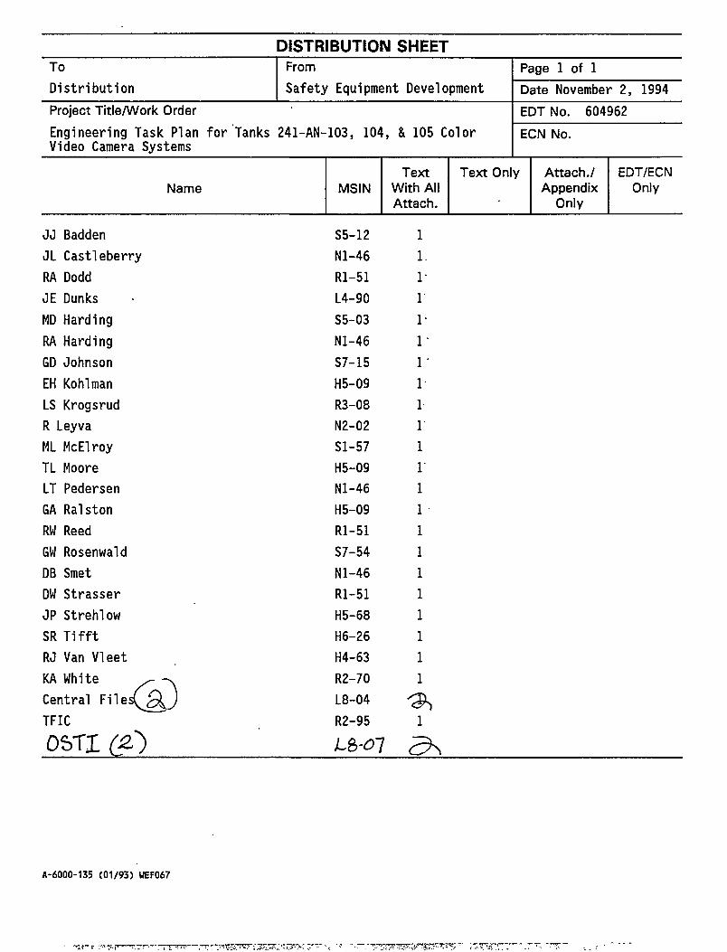
DISTRIBUTION SHEET To From Page 1 of 1 D is t r ibu t ion Safety Equipment Development Date November 2, 1994 Project Title/Work Order
241-AN-103, 104, & 105 Color EDT No. 604962
Engineering Task Plan fo r Tanks Video Camera Systems
241-AN-103, 104, & 105 Color ECN No.
Name MSIN Text
With All Attach.
Text Only Attach./ Appendix
Only
EDT/ECN Only
JJ Badden JL Castleberry RA Dodd JE Dunks MD Harding RA Harding GD Johnson EH Kohl man LS Krogsrud R Leyva ML McElroy TL Moore LT Pedersen GA Ralston RW Reed GW Rosenwald DB Smet DW Strasser JP Strehlow SR Tifft RJ Van Vleet KA White Central File TFIC OST1 (£)
S5-12 Nl-46 Rl-51 L4-90 S5-03 Nl-46 S7-15 H5-09 R3-08 N2-02 Sl-57 H5-09 Nl-46 H5-09 Rl-51 S7-54 Nl-46 Rl-51 H5-68 H6-26 H4-63 R2-70 L8-04 R2-95 1
5H
A-6000-135 (01/93) UEF067

NOV 17 i 334 ( j ^ •J&.-?/
NGINEERING DATA TRANSMITTAL Pago 1 of \_
I.EDT 604962
2. To: (Receiving Organization)
Distribution 3. From: (Originating Organization) Safety Equipment Development 7EA30 / (N2089)
4 . Related EDT No. :
NA
5. Proj./Prog./Dept./Div.:
241-AN-103, 104, 105 Video Camera Systems
6. Cog. Engr.:
EH Kohlman 7. Purchase Order No.
NA
8. Originator Remarks:
ETN-94-0171 The following ETP is being distributed for approval and issuance.
9. Equip./Component No.:
NA 10. System/Bldg./Facility:
241-AN-103, 104, 105 11. Receiver Remarks: 12. Major Assm. Dwg. No.
NA 13. Permit/Permit Application No.
14. Required Response Date: NA
15. DATA TRANSMITTED (F) (G) (H) (I) (A)
Item No.
(B) Document/Drawing No. (C)
Sheet No.
(D) Rev. No.
(E) Title or Description of Data Transmitted
Impact Level
Reason for
Transmittal
Originator Disposition
Receiver
Disposition
WHC-SD-WM-ETP-118 All Engineering Task Plan for Tanks 241-AN-103, 104, 105 Color Video Camera Systems
SQ
16. KEY Impact Level (F) Reason for Transmittal (G) Disposition (H) & (I)
1, 2, 3, or 4 (see MRP 5.43)
1. Approval 4. Review 2. Release 5. Post-Review 3. Information 6. Dist. (Receipt Acknow. Required)
1. Approved 2. Approved w/comment 3. Disapproved w/comment
4. Reviewed no/comment 5. Reviewed w/comment 6. Receipt acknowledged
(Q) (H) 17. SIGNATURE/DISTRIBUTION (See Impact Level for required signatures)
(G) (H)
Reason
Disp. (J) Name (K) Signature (L) Date (M) MSIN
Cog.Eng. EH Kohlman '^tk. H5-09 Cog. Mgr. TL Moore jf^ml^_l^A^l_ QA ML HcElroy-^^^^^/j^yj^V^SI-Sy
(J) Name (K) Signature (L) Date (M) MSIN Reason
Disp.
JE Dunks/ si
^ R3-08
/ L4-90
iH K .1 . ^4 .
Safety MN Islam LT Pe N1-46
H6-2fe DW Strasser jQ^/^ > f e S ^ - /l/lMj R1-51
N1-4fc> RJ Van Vleet H4-63
>M&»f*-*> MD Harding
"ijifli Rgyo-
S5-03
GD Johnson ^a itlZlfH S7-15
N2-02 JP Strehlow H5-68
Signature of Originator
Authorized Representative Date for Receiving Organization
tfy6-20
TLMi
Cognizant/Project Engineer's Manager
'&U H Date
21. DOE APPROVAL ( i f required) Ltr. No.
[] Approved [] Approved w/comments W Disapproved w/comments
BD-7400-172-2 (07/91) GEF097
BD-7400-172-1 (07/91)

RELEASE AUTHORIZATION
Document Number: WHC-SD-WM-ETP-118, REV.O
Document Title: ENGINEERING TASK PLAN FOR TANKS 241-AN-103, 104, 105 COLOR VIDEO CAMERA SYSTEMS
Release Date: 11/17/94
This document was reviewed following the procedures described in WHC-CM-3-4 and is:
APPROVED FOR PUBLIC RELEASE
WHC Information Release Administration Specialist:
ZU>A's/f. ($<$//& 11/17/94 Sol is
TRADEMARK DISCLAIMER. Reference herein to any specific commercial product, process, or service by trade name, trademark, manufacturer, or otherwise, does not necessarily constitute or imply its endorsement, recommendation, or favoring by the United States Government or any agency thereof or its contractors or subcontractors.
This report has been reproduced from the best available copy. Available in paper copy and microfiche. Printed in the United States of America. Available to the U.S. Department of Energy and its contractors from:
U.S. Department of Energy Office of Scientific and Technical Information (OSTI) P.O. Box 62 Oak Ridge, TN 37831 Telephone: (615) 576-8401
Available to the public from: U.S. Department of Commerce National Technical Information Service (NTIS) 5285 Port Royal Road Springfield, VA 22161 Telephone: (703) 487-4650
A-6001-400.2 (09/94) UEF256

SUPPORTING DOCUMENT 1. Total Pages 20
Title
Engineering Task Plan for Tanks 241-AN-103, 105 Color Video Camera Systems
104, 3. Number
WHC-SD-WM-ETP-118
4. Rev No.
0
5. Key Words
AN Tanks TWRS Tank Farm Camera Systems Nitrogen Purge Video
6. Author
-" A. £>* i
Name: EH Kohlman I) -£
////7/f/^Mii>-
Signature
Organization/Charge Code 7 E A 3 0 / N 2 4 4 4
7. Abstract
This Engineering Task Plan describes the deliverables and responsibilities on the installation of color zoom camera systems into the vapor space of tanks 241-AN-103, 104, and 105. The systems will utilize all new components which include such items as the vendor furnished mast, light assembly, manifold and shield, pan & tilt unit, and camera. The nitrogen supply and purge panel will be fabricated onsite for these systems. a. PURPOSE AND USE OF DOCUMENT - Thi^doeument was prepared for use wilton the U.S. Department of Enepy and its contractors.^^ is to
be eked only to perform, cWect, or ̂ integrate w#k under U.S. D\partment of Energy contorts. This d\ument is jyt approved for pul\ic release until revised. PATENT S1\TUS - This doc( advance o-fXaatent clearanj for use IV performai U.S. DepartmeVj of Enerj
ent copy, since i<% is transmitted in is made available iVc#ifidence solely of work under contracts with the This document is not jAbe published nor
its contents oVierwisafftiisseminated or used forAirjpses other than specified above^befojp patent approval for sudF release or use has been secured, upoVnfc|uest, from the Patent Co^sel, % S . Department of Energy Field Ofjfce, Richland, UA. DISCLAIMER - TUTs Import Has prepared M% an acccLnt of work sponsored by anJagency^tf the United StatewGovernment.Neither the United States^fovernmenVnor any agency Jnereof, nor any of their employees, r\w any of trVir contractor* subcontractors or their employees, apices any warranty, express Mr implied, or assumes any legal liability or responsibility for thelaccuracy, completeness, or any third^rty's use or the results of such use of any information, apparatus^ product, or process qLscIosed, or represents that its use would ndf infringe privately ownw rights. Reference herein to any specify commercial product, process, or service by trade name, tradenTrk, manufacturer, or otherwise, does not necessarily consWtute or imply its endorsement, recommendation, or favoring by the ^United States Government or any agency thereof or its contractors or subcontractors. The views and opinions of authors expressed herein do not necessarily state or reflect those of the United States Government or any agency thereof.
9. Impact Level SQ
10. RELEASE STAMP
| - - - N O V 17 1994 c<