Embed Size (px)
Citation preview
TRAINING SERIES ARTICULATIED BOOM TRUCK TRAINING SERIES ARTICULATIED BOOM TRUCK
ARTICULATED BOOM TRUCK
OPERATOR SAFETY
TRAINING
ARTICULATED ARTICULATED BOOM TRUCKBOOM TRUCK
OPERATOR OPERATOR SAFETYSAFETY
TRAININGTRAINING

TRAINING SERIES ARTICULATIED BOOM TRUCK TRAINING SERIES ARTICULATIED BOOM TRUCK
TYPES OF MOBILE CRANETYPES OF MOBILE CRANE
TRAINING SERIES ARTICULATIED BOOM TRUCK TRAINING SERIES ARTICULATIED BOOM TRUCK
INSPECTION AREA INSPECTION RESULTSSat. Unsat. N/A Comments
CarrierEngine OilRadiatorSuspensionTiresWheelsRotation SystemOutriggersMounting Bolts & WeldsHydraulic Fluid LevelsCarrier Structure
Oper. Station & TurretGuagesControls & LabelsHydraulic CylindersHydraulic HosesWarning AlarmsService BrakesSwing BrakesElectrical SystemSafety Equipment
BoomSheavesWire RopeHook & SwivelBoom Angle IndicatorLoad IndicatorsAnti-Two-Block SystemWinchSlide PadsDeformations, CracksBoom ExtentionLoad Block
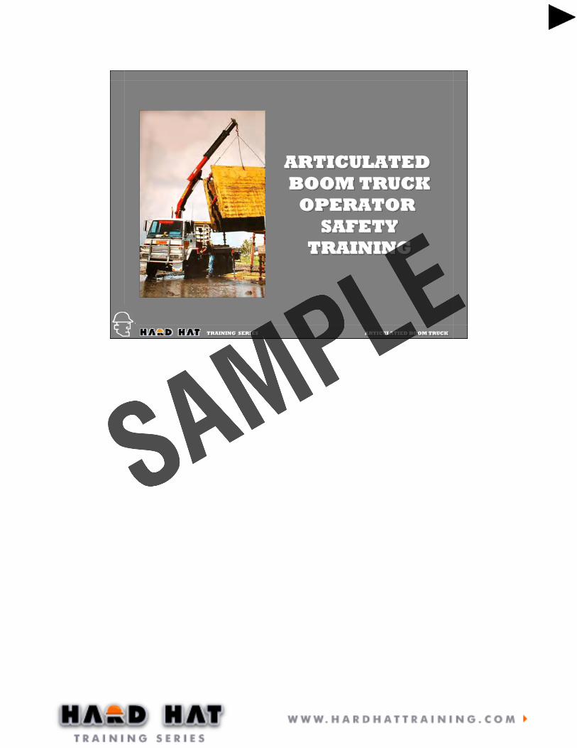
BOOM TRUCK INSPECTION CHECKLIST
BOOM TRUCK INSPECTION CHECKLIST
OBJECTIVE: To present the inspection checklist to the students.
1. The inspection checklist is introduced now so that the students can refer to it during the discussions regarding the mechanical structure of the crane.2. Review briefly the items on the checklist but do not go into any detail at this time.

TRAINING SERIES ARTICULATIED BOOM TRUCK TRAINING SERIES ARTICULATIED BOOM TRUCK
CRANE COMPONENTSCRANE COMPONENTS
KnuckleHinges
BoomExtensions
Pedestal Boom Cylinders
Stabilizer Hook
Main BoomHinge
TRAINING SERIES ARTICULATIED BOOM TRUCK TRAINING SERIES ARTICULATIED BOOM TRUCK
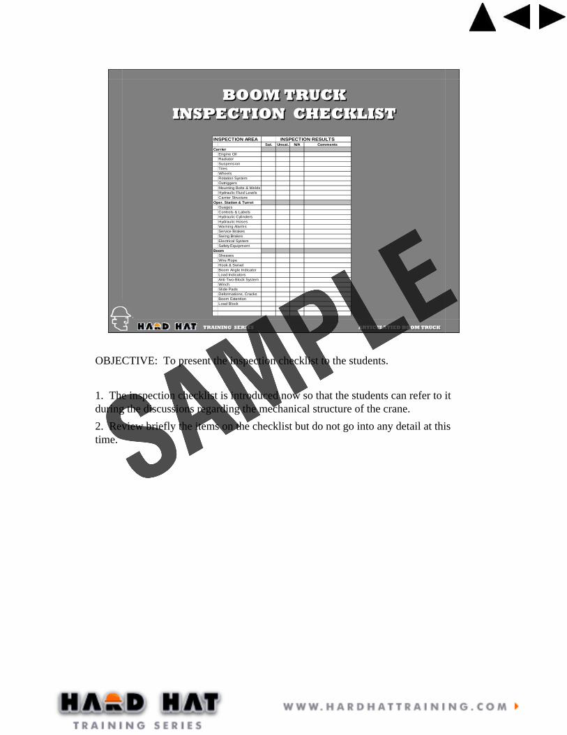
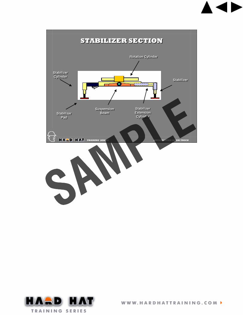
STABILIZER SECTIONSTABILIZER SECTION
TRAINING SERIES ARTICULATIED BOOM TRUCK TRAINING SERIES ARTICULATIED BOOM TRUCK
STABILIZER SECTIONSTABILIZER SECTION
StabilizerPad
StabilizerPad
StabilizerStabilizer
StabilizerExtensionCylinder
StabilizerExtensionCylinder
SuspensionBeam
SuspensionBeam
Rotation CylinderRotation Cylinder
StabilizerCylinder
StabilizerCylinder
TRAINING SERIES ARTICULATIED BOOM TRUCK TRAINING SERIES ARTICULATIED BOOM TRUCK
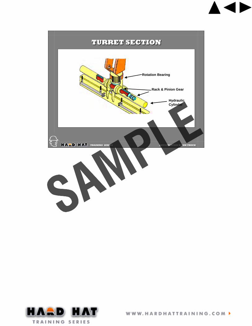
TURRET SECTIONTURRET SECTION
Rotation Bearing
Rack & Pinion Gear
HydraulicCylinder

TRAINING SERIES ARTICULATIED BOOM TRUCK TRAINING SERIES ARTICULATIED BOOM TRUCK
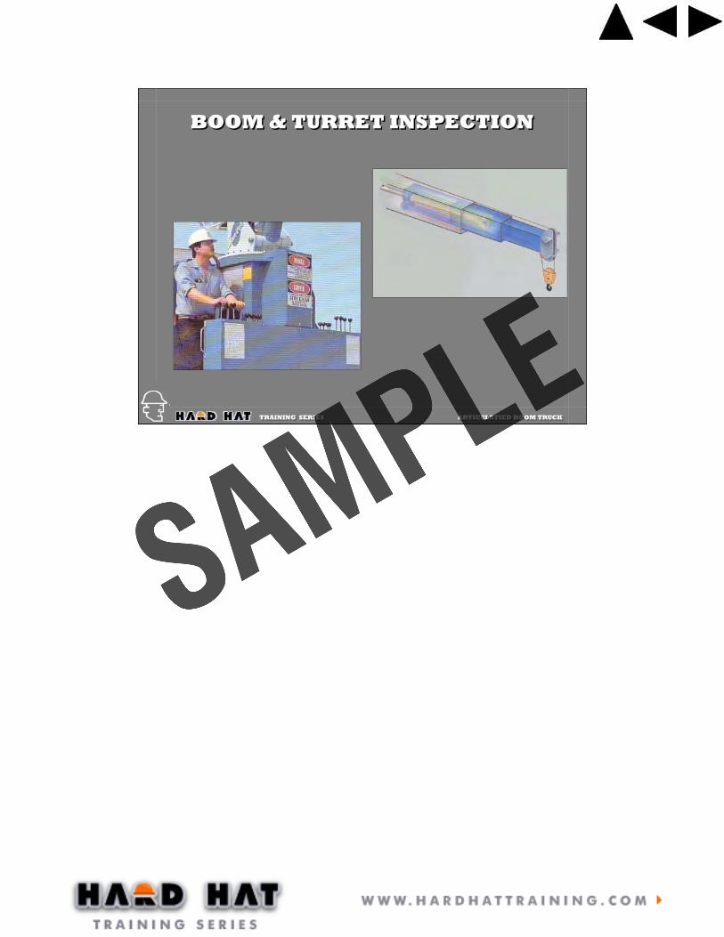
BOOM & TURRET INSPECTIONBOOM & TURRET INSPECTION
Worn pinsWorn pins
Damaged cylinder
rods
Damaged cylinder
rods
Cracked WeldsCracked WeldsDamaged Hydraulic
Hoses
Damaged Hydraulic
Hoses

TRAINING SERIES ARTICULATIED BOOM TRUCK TRAINING SERIES ARTICULATIED BOOM TRUCK
Note The AccumulationOf Dirt And/or PaintNote The AccumulationOf Dirt And/or Paint
CHECKING FOR TIGHTNESSCHECKING FOR TIGHTNESS
Cracks In Paint Or Dirt Build-upOften Is Caused By Loose Bolts.Cracks In Paint Or Dirt Build-upOften Is Caused By Loose Bolts.

TRAINING SERIES ARTICULATIED BOOM TRUCK TRAINING SERIES ARTICULATIED BOOM TRUCK
Inspect Welds For Cracks
Inspect Welds For Cracks
CRACKED WELDSCRACKED WELDS

TRAINING SERIES ARTICULATIED BOOM TRUCK TRAINING SERIES ARTICULATIED BOOM TRUCK
BOOM & TURRET INSPECTIONBOOM & TURRET INSPECTION
Damaged or bentextension cylindersDamaged or bentextension cylinders
Damaged or bentboom sectionsDamaged or bentboom sections
OBJECTIVE: To do an overview of the whole crane components.
1. Use this slide to discuss the parts of the crane that have not been covered yet.2. All welds need to be checked for cracks.3. The boom needs to be extended and check for smoothness of operation. Any binding or difficulty in extending could be the result of damaged boom sections.4. Any hydraulic leaks need to be investigated and repaired. Check the hoses for chaffing and damage.5. The slide pads can be checked for proper alignment by extending the boom completely and lowering the tip toward the ground. Move the boom tip back and forth by pushing on it and observing how much the boom sections move inside each other. Excessive movement will require the slide pads to be adjusted or replaced.6. The boom tip needs to be checked to deformation and twisting.7. The next few slides provide more details.
TRAINING SERIES ARTICULATIED BOOM TRUCK TRAINING SERIES ARTICULATIED BOOM TRUCK
BOOM & TURRET INSPECTIONBOOM & TURRET INSPECTION

TRAINING SERIES ARTICULATIED BOOM TRUCK TRAINING SERIES ARTICULATIED BOOM TRUCK
WINCHWINCH
CAREFULLYMONITORREEVING
CAREFULLYMONITORREEVING
OBJECTIVE: The spooling of the wire rope on the winch needs be monitored regularly to prevent damage.
1. One of the most common causes of damaged wire rope on boom trucks is from crushing due to spooling problems.2. The operator needs to monitor the winch to prevent the wraps from loosing and allowing the wire rope to cross over itself.3. Loosely wrapped wire rope needs to be un-spooled and then re-spooled on the winch properly to prevent damage.

TRAINING SERIES ARTICULATIED BOOM TRUCK TRAINING SERIES ARTICULATIED BOOM TRUCK
WIRESTRAND
WIRE ROPE
WIRE ROPE CONSTRUCTIONWIRE ROPE CONSTRUCTION
INDEPENDENTWIRE ROPE
CORE
FIBER CORE
19 WIRESPER STRAND
6 X 19 IWRC 8 X 19 FC
PROPER WAY TO MEASUREWIRE ROPE DIAMETER
OBJECTIVE: To discuss the construction of wire rope.
1. Wire rope comes in various sizes and construction. The most common is the right regular lay wire rope of the 6X19 class.2. The strands of a wire rope are made up of several wires twisted together.3. Several strands are twisted together to form the wire rope.4. Common wire rope will have either a fiber core or an independent wire rope core or IWRC. For lifting purposes, IWRC is recommended because it resist crushing.5. The designation, 6X19, refers to the basic construction. The ‘6’ stands for the number of strands, not counting the core, that are used in the rope. The ‘19’ refers to the number of wire in each strand.6. When measuring the diameter of wire rope, make sure to measure across the stands and not the flat area between the strands.

TRAINING SERIES ARTICULATIED BOOM TRUCK TRAINING SERIES ARTICULATIED BOOM TRUCK
ROTATION RESISTANT WIRE ROPEROTATION RESISTANT WIRE ROPE
The non-rotating characteristic is secured by building into the rope two layers of strands, one having Right Lay and the other Left Lay.
The non-rotating characteristic is secured by building into the rope two layers of strands, one having Right Lay and the other Left Lay.
The tendency of one layer of strands to rotate in one direction is counteracted by the tendency of the other layer of strands to rotate in the opposite direction.The tendency of one layer of strands to rotate in one direction is counteracted by the tendency of the other layer of strands to rotate in the opposite direction.
OBJECTIVE: To discuss rotation resistant rope and how it is constructed differently than other types of wire rope.
1. Point out how non-rotating rope is constructed. It has two layers of strands, oneRight Lay and the other Left Lay.
2. These two layers rotate against one another, counteracting to keep the rope from rotating.

TRAINING SERIES ARTICULATIED BOOM TRUCK TRAINING SERIES ARTICULATIED BOOM TRUCK
Rotation Resistant wire rope require very careful handling prior to, during and after installation. When a non-rotating rope is cut, bent around a thimble or wedge socket, or is attached to any fitting, care must be taken to prevent core slippage.
Core slippage can happen quite easily. When the rope is twisted in one direction, one layer of strands will tighten up and shorten, while the other layer of strands loosens, or becomes longer. As a result the shorter layers of strands carry the majority of the load.
To ensure that core slippage does not take place, always apply wire seizings to bind the inner and outer cores together before the rope is cut or attached to any fitting.
ROTATION RESISTANT WIRE ROPEROTATION RESISTANT WIRE ROPE
OBJECTIVE: To emphasize why Rotation Resistant wire rope must be handled differently than other types of wire rope.
1. Since Rotation Resistant rope is so different from other types of wire rope, the industry lists separate standards for its use.
2. Most Rotation Resistant rope’s safety factor is at least 5:1. It is 10:1 when hoisting personnel.
3. ANSI has very strict procedures that must be followed when operating wire rope under a 5:1 safety factor
4. Rotation Resistant rope does not react well to bending around sheaves, thimbles or wedge sockets. Many manufacturers discourage the use of wedge sockets with non-rotating rope.
5. Great care must be taken when cutting non-rotating rope or attaching it to any fitting. To ensure that core slippage does not take place, the ends must have wire seizings applied prior to cutting or attaching it to any fitting.
6. Rotation Resistant wire rope should be inspected often.

TRAINING SERIES ARTICULATIED BOOM TRUCK TRAINING SERIES ARTICULATIED BOOM TRUCK
Crossed lines on drum
Heavy loads over small sheaves
Accentuated with heavy loads
Improper socketing, kinks
Sudden tension release
Repeated bending, normal loads
KINKED WIRE ROPE
STRAND KNICKING
FATIGUE FAILURE
HIGH STRAND
BIRDCAGE
FATIGUE BREAKS
WIRE ROPE INSPECTIONWIRE ROPE INSPECTION
OBJECTIVES: How to identify different types of wire rope problems.
1. Note the different types of damage and their causes.2. Kinked rope is common on small cranes because of over running the wire rope when winching down.AFTER THIS DISCUSSION HOLD A BRIEF REVIEW OF THE CRANE INSPECTION AND THEN ADJOURN TO THE CRANE FOR HANDS A HANDS ON EXERCISE. HAVE EACH PARTICIPANT CONDUCT AN INSPECTION.
TRAINING SERIES ARTICULATIED BOOM TRUCK TRAINING SERIES ARTICULATIED BOOM TRUCK
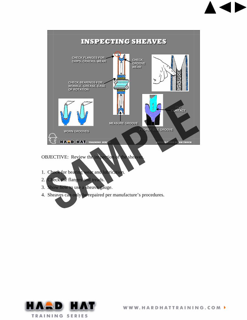
WORN GROOVESWORN GROOVES PROPER SIZE GROOVEPROPER SIZE GROOVE
CHECK FLANGES FORCHIPS, CRACKS, WEARCHECK FLANGES FORCHIPS, CRACKS, WEAR
CHECK BEARINGS FORWOBBLE, GREASE, EASEOF ROTATION
CHECK BEARINGS FORWOBBLE, GREASE, EASEOF ROTATION
MEASURE GROOVEMEASURE GROOVE
INSPECTING SHEAVESINSPECTING SHEAVES
CHECK GROOVE WEAR
CHECK GROOVE WEAR
150ºCONTACT
150ºCONTACT
OBJECTIVE: Review the inspection of the sheaves.
1. Check for bearing wear and lubrication.2. Check the flanges and treads.3. Show how to use a sheave gauge.4. Sheaves can only be repaired per manufacture’s procedures.

TRAINING SERIES ARTICULATIED BOOM TRUCK TRAINING SERIES ARTICULATIED BOOM TRUCK
CRANE CONTROLSCRANE CONTROLS
Controls need to beproperly labeled andfunction smoothly
Controls need to beproperly labeled andfunction smoothly

TRAINING SERIES ARTICULATIED BOOM TRUCK TRAINING SERIES ARTICULATIED BOOM TRUCK
HOOK INSPECTIONHOOK INSPECTION
Wear & DeformationWear & Deformation
“Opening Up”
“Opening Up”
Wear & CracksWear & Cracks
Cracks & TwistingCracks & Twisting
[ Wear[ Deformation[ Cracks & Sharp Nicks[ Modifications[ Safety Latches[ Swivel Wear & Lubrication[ Hook Shackle Housing
[ Wear[ Deformation[ Cracks & Sharp Nicks[ Modifications[ Safety Latches[ Swivel Wear & Lubrication[ Hook Shackle Housing
CHECK FOR:CHECK FOR:
Check SafetyLatch & SpringCheck SafetyLatch & Spring
OBJECTIVE: Point out inspection areas for different types of hooks and blocks.
1. Hooks with threads and nuts need to have threads inspected periodically.2. Hooks can only be repaired per manufacturer’s procedures.3. Wear in excess of 5% in the neck of the hook and 10% in other areas including the bow of the hook is cause for removal.4. An increase in the hook throat opening of more than 15% is cause for removal.5. Any twist in the hook of more than 10% is cause for removal.6. The hook safety latch should be present and function properly.

TRAINING SERIES ARTICULATIED BOOM TRUCK TRAINING SERIES ARTICULATIED BOOM TRUCK
CRANE BLOCKCRANE BLOCK
SIDE PLATEBOLTS TIGHTSIDE PLATE
BOLTS TIGHT
SHEAVE PIN& BEARING
TIGHT
SHEAVE PIN& BEARING
TIGHTSAFETYLATCH
FUNCTIONING
SAFETYLATCH
FUNCTIONING
CHECK FOR DISTORTIONSOR WEAR
CHECK FOR DISTORTIONSOR WEAR
SHEAVE GROOVENOT WORN, SHEAVES
TURN FREELY
SHEAVE GROOVENOT WORN, SHEAVES
TURN FREELY
HOOK NUT TIGHT& THEADS INSPECTED
PERIODICALLY
HOOK NUT TIGHT& THEADS INSPECTED
PERIODICALLY
HOOK ROTATION &SWIVEL SMOOTH &
TIGHT
HOOK ROTATION &SWIVEL SMOOTH &
TIGHT
SIDE PLATESSTRAIGHT
SIDE PLATESSTRAIGHT
SHEAVE PINKEEPER IN PLACE
AND TIGHT
SHEAVE PINKEEPER IN PLACE
AND TIGHT
OBJECTIVE: To review the inspection criteria for hook blocks.
1. The sheaves and bearings need to be inspected as discussed earlier.2. The side plates and any additional weights attached to the their sides need to be inspected for loose or missing bolts or other fasteners.3. The hook should rotate freely on the swivel bearing. Check for excessive movement.4. The hook shank and nut should be separated periodically and the threads inspected for corrosion and other damage. The lose of more than 20% of the treaded area due to corrosion is cause for removal.5. The safety latch must be in place and functioning properly.

TRAINING SERIES ARTICULATIED BOOM TRUCK TRAINING SERIES ARTICULATIED BOOM TRUCK
BOOM TRUCKSETUP
BOOM TRUCKSETUP

TRAINING SERIES ARTICULATIED BOOM TRUCK TRAINING SERIES ARTICULATIED BOOM TRUCK
SETTING UPSETTING UP
STABILIZERS FULLY
EXTENDED
WEIGHT OFF WHEELSPADS ON FIRM
GROUND
KNOWNRADIUS
CRANE IS LEVEL
OBJECTIVE: This slide introduces the topic of boom truck set up.
1. Point out each of the areas that need to be taken into consideration when setting up the boom truck.2. When the stabilizers are fully extended the tires may not be off the ground but the weight of the truck will primarily be on the stabilizers.

TRAINING SERIES ARTICULATIED BOOM TRUCK TRAINING SERIES ARTICULATIED BOOM TRUCK
SETTING UPSETTING UP
Selecting a Suitable SiteSelecting a Suitable Site
Avoid recentfill areasAvoid recentfill areas
Do not set upover buried objects that could collapse
Do not set upover buried objects that could collapse
Avoid slopesAvoid slopes
NEVER block under the outriggerbeam
NEVER block under the outriggerbeam
RIGHTRIGHT
WRONGWRONG
WRONGWRONG
OBJECTIVE: To discuss the consideration that need to be understood to safely set the boom truck up.
1. The first consideration is the quality of the surface the boom truck will be set up on. 2. Soils along the foundation of buildings are often poorly compacted and may contain drain pipe and other voids. Setting up in these areas should be avoid when possible and additional floats used when not.3. Floats of at least 24” X 24” should be used under each stabilizer pad regardless of the type of surface being set up on. The use of these floats will reduce the pounds per square inch loading on the surface which will help prevent the stabilizer from sinking.4. Blocking under the A-frame type of stabilizer which prevents the stabilizer from fully deploying should be avoid. Doing so will shorten the distance from the stabilizer pad to the center of rotation which results in a lose of leverage for the boom truck and makes it more likely to tipping over.5. Always extend both outriggers. Not doing so can result in the boom truck tipping over.

TRAINING SERIES ARTICULATIED BOOM TRUCK TRAINING SERIES ARTICULATIED BOOM TRUCK
LEVELING THE CRANELEVELING THE CRANE
SWING BOOM OVER REAR & LEVEL CRANE UNTIL HOISTWIRE IS PLUMB WITH BOOM
SWING BOOM OVER REAR & LEVEL CRANE UNTIL HOISTWIRE IS PLUMB WITH BOOM
SWING BOOM OVER SIDE & LEVEL CRANEUNTIL HOIST WIRE IS PLUMB WITH BOOM
SWING BOOM OVER SIDE & LEVEL CRANEUNTIL HOIST WIRE IS PLUMB WITH BOOM
OBJECTIVE: To show how a crane can be leveled using the hoist line and the boom.
1. Leveling may take a few minutes but it is very important.2. Boom trucks typically have a bubble level mounted at the control station which is used for leveling the crane.3. In the absence of a bubble level, a carpenter’s level can be placed on the turret for leveling purposes. The level will need to be positions fore and aft and cross-wise to assure leveling in both directions.4. A third way to level the boom is by using the hoist line as a plumb-bob. This is a very accurate leveling procedure. The above diagram illustrates the basic procedure.

TRAINING SERIES ARTICULATIED BOOM TRUCK TRAINING SERIES ARTICULATIED BOOM TRUCK
SETTING UPSETTING UP
Small stabilizer padShould have additionalFloats placed under them
Small stabilizer padShould have additionalFloats placed under them
TRAINING SERIES ARTICULATIED BOOM TRUCK TRAINING SERIES ARTICULATIED BOOM TRUCK
Load’s LeverageLoad’s
LeverageCrane’s
LeverageCrane’s
Leverage
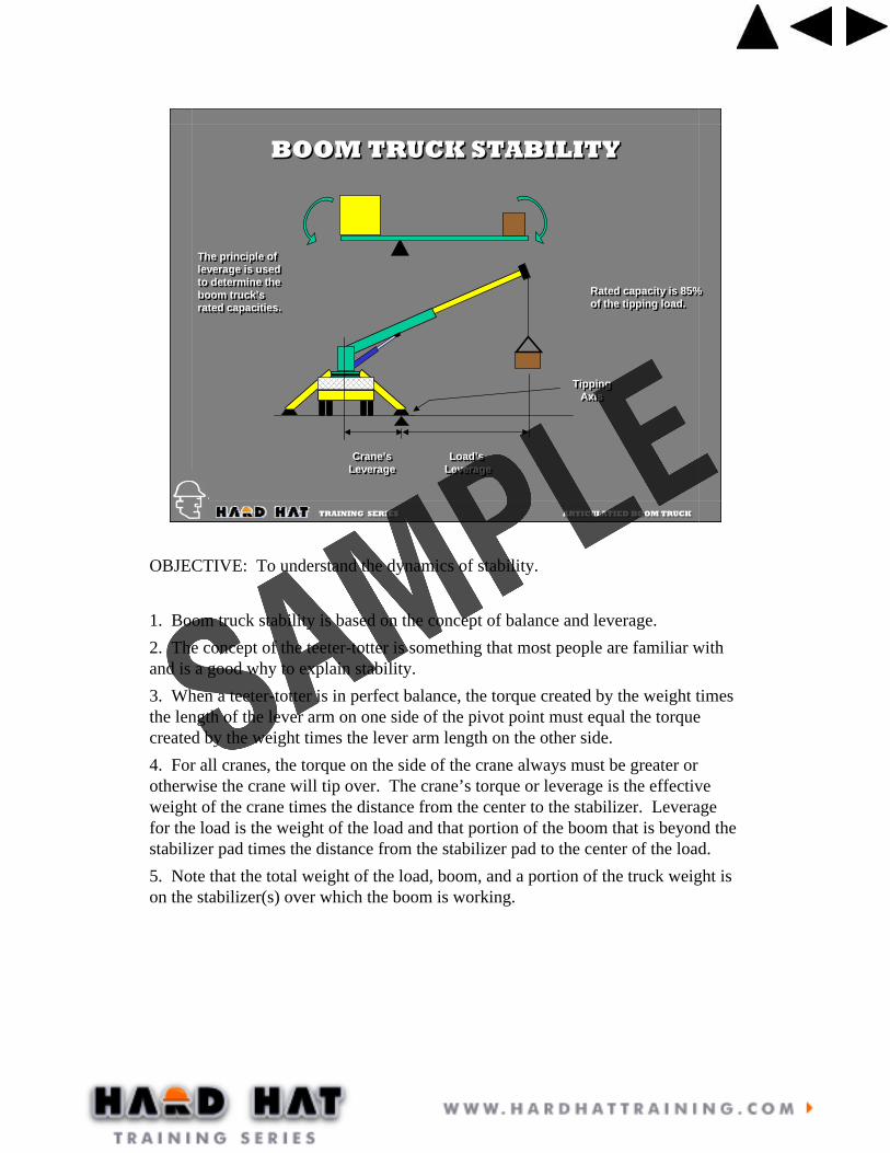
BOOM TRUCK STABILITYBOOM TRUCK STABILITY
TippingAxis
TippingAxis
The principle of leverage is usedto determine theboom truck’srated capacities.
The principle of leverage is usedto determine theboom truck’srated capacities.
Rated capacity is 85%of the tipping load.Rated capacity is 85%of the tipping load.
OBJECTIVE: To understand the dynamics of stability.
1. Boom truck stability is based on the concept of balance and leverage.2. The concept of the teeter-totter is something that most people are familiar with and is a good why to explain stability.3. When a teeter-totter is in perfect balance, the torque created by the weight times the length of the lever arm on one side of the pivot point must equal the torque created by the weight times the lever arm length on the other side.4. For all cranes, the torque on the side of the crane always must be greater or otherwise the crane will tip over. The crane’s torque or leverage is the effective weight of the crane times the distance from the center to the stabilizer. Leverage for the load is the weight of the load and that portion of the boom that is beyond the stabilizer pad times the distance from the stabilizer pad to the center of the load.5. Note that the total weight of the load, boom, and a portion of the truck weight is on the stabilizer(s) over which the boom is working.

TRAINING SERIES ARTICULATIED BOOM TRUCK TRAINING SERIES ARTICULATIED BOOM TRUCK
High BearingPressureHigh BearingPressure
STABILITYSTABILITY
STABILITY AT A MINIMUMTIPPING POINT IS CLOSESTTO CENTER OF ROTATION
STABILITY AT A MINIMUMTIPPING POINT IS CLOSESTTO CENTER OF ROTATION
OBJECTIVE: To understand how the stability of the crane changes as the boom is rotated.
1. When the boom is located directly over the stabilizer, the pressure applied to the ground is the greatest because this one stabilizer is supporting most of the load.2. Most boom truck pads are 12”X16” which equals 192 sq. in. of surface pressing on the ground. The load placed on this pad can be in the neighborhood of 20,000 lbs. This would result in a ground bearing pressure of 100 lbs per sq. in.3. For this pressure the ground would need to be hard pan or compacted gravel soils. For many sites the soil conditions are poor and may be only able to support 40 lbs per sq. in.4. A 24” X 24” float placed under the stabilizer pad will increase the surface area to 576 sq. in. This will yield a ground bearing pressure for the above situation of 34 lbs per sq. in. This is a much improved situation.5. The students should be highly encouraged to have a set of floats for their boom truck and to use them for every set-up regardless of the soil conditions.

TRAINING SERIES ARTICULATIED BOOM TRUCK TRAINING SERIES ARTICULATIED BOOM TRUCK
STABILITYSTABILITY
STABILITY INCREASEDTIPPING POINT IS FARTHERFROM CENTER OF ROTATION
STABILITY INCREASEDTIPPING POINT IS FARTHERFROM CENTER OF ROTATION
OBJECTIVE: To show how the load on the stabilizers change as the boom is rotated.
1. As the boom moves from over the forward stabilizer toward the back of the truck the pressure on the ground is shared by the two stabilizers. 2. The distance from the crane’s center to the tipping moment line has increased so the leverage for the truck has increased making the boom truck more stable.3. The students need to be cautioned about picking a load over the rear of the truck and swinging over the side. When initially picked, the boom truck may be very stable but as the load is swung over the side the boom trucks leverage decreases and making the truck less stable. Many operators are deceived by this condition and have resulted in a tip over.

TRAINING SERIES ARTICULATIED BOOM TRUCK TRAINING SERIES ARTICULATIED BOOM TRUCK
STABILITYSTABILITY
REMEMBERREMEMBERREMEMBER
THE STABILITY OF THE CRANEIS EXTREMELY COMPROMISEDWHEN THE STABILIZERS ARENOT FULLY EXTENDED!
THE STABILITY OF THE CRANEIS EXTREMELY COMPROMISEDWHEN THE STABILIZERS ARENOT FULLY EXTENDED!

TRAINING SERIES ARTICULATIED BOOM TRUCK TRAINING SERIES ARTICULATIED BOOM TRUCK
LIFT REQUIREMENTS LIFT REQUIREMENTS
•The Big Picture
•Assessing the Load
•Rigging Requirements
•Assessing the Pick Area
•Assessing the Placement Area
•The Big Picture
•Assessing the Load
•Rigging Requirements
•Assessing the Pick Area
•Assessing the Placement Area
OBJECTIVE: To review the things the operator needs to consider before making a lift.
1. The Big Picture. The operator should take a moment to study the area in which he will be working. Look for power lines, obstructions, vehicle and pedestrian traffic, ground conditions and other potential areas to avoid in set-up.2. When assessing the load the operator must know the weight. Along with this the load’s center of gravity must be known in order to rig properly. Also the load’s structural strength must be assessed to ensure that it will not be damaged during the lift.3. What type of rigging will be required needs to be determined. The operator needs to ensure that the rigging is equal to the job.4. Where the load will be picked from and where it needs to be placed must be determined. This is necessary so the boom truck can be placed so that both picking and placing of the load will remain within the load chart.
TRAINING SERIES ARTICULATIED BOOM TRUCK TRAINING SERIES ARTICULATIED BOOM TRUCK
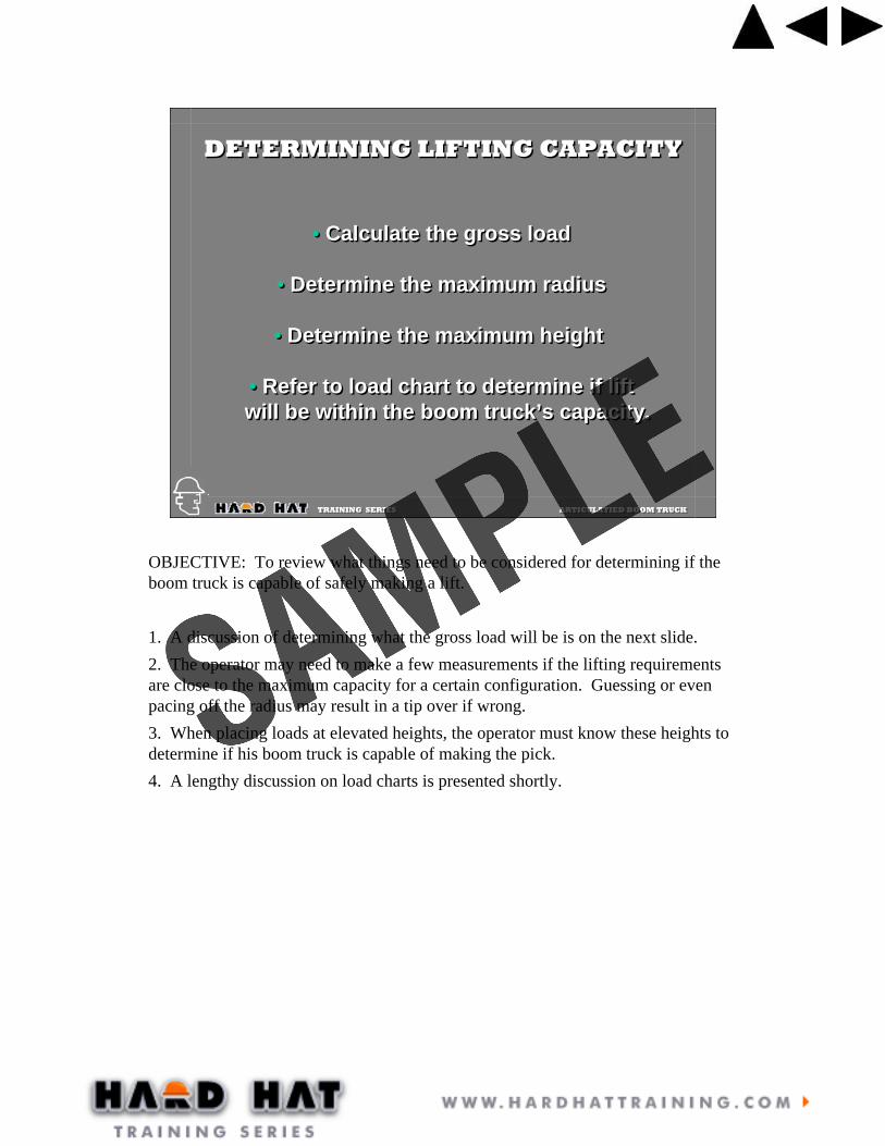
DETERMINING LIFTING CAPACITYDETERMINING LIFTING CAPACITY
• Calculate the gross load
• Determine the maximum radius
• Determine the maximum height
• Refer to load chart to determine if liftwill be within the boom truck’s capacity.
• Calculate the gross load
• Determine the maximum radius
• Determine the maximum height
• Refer to load chart to determine if liftwill be within the boom truck’s capacity.
OBJECTIVE: To review what things need to be considered for determining if the boom truck is capable of safely making a lift.
1. A discussion of determining what the gross load will be is on the next slide.2. The operator may need to make a few measurements if the lifting requirements are close to the maximum capacity for a certain configuration. Guessing or even pacing off the radius may result in a tip over if wrong.3. When placing loads at elevated heights, the operator must know these heights to determine if his boom truck is capable of making the pick.4. A lengthy discussion on load charts is presented shortly.

TRAINING SERIES ARTICULATIED BOOM TRUCK TRAINING SERIES ARTICULATIED BOOM TRUCK
Net Load
Gross Load = Net Load + Rigging + Wire Rope + Block +Boom Attachments
Gross Load = Net Load + Rigging + Wire Rope + Block +Boom Attachments
GROSS LOADGROSS LOAD
OBJECTIVE: To determine what constitutes the gross load.
1. All crane load charts are based on the load being anything that is hanging below the tip of the boom.2. All of the above items listed on the slide technically need to be considered but for boom trucks, the weight of the hoist line can be neglected.
TRAINING SERIES ARTICULATIED BOOM TRUCK TRAINING SERIES ARTICULATIED BOOM TRUCK
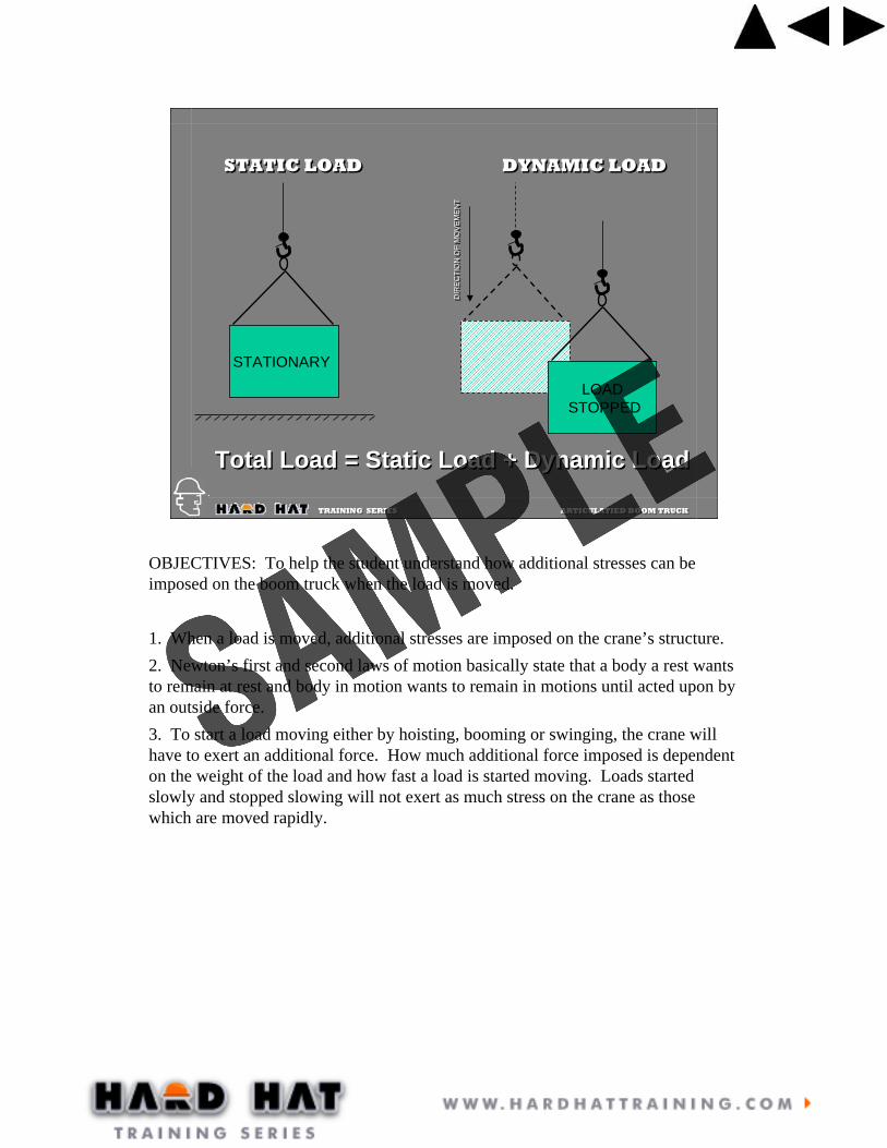
STATIONARY
LOAD STOPPED
STATIC LOADSTATIC LOAD DYNAMIC LOADDYNAMIC LOAD
DIR
EC
TIO
N O
F M
OV
EM
EN
TD
IRE
CTI
ON
OF
MO
VE
ME
NT
Total Load = Static Load + Dynamic LoadTotal Load = Static Load + Dynamic Load
OBJECTIVES: To help the student understand how additional stresses can be imposed on the boom truck when the load is moved.
1. When a load is moved, additional stresses are imposed on the crane’s structure. 2. Newton’s first and second laws of motion basically state that a body a rest wants to remain at rest and body in motion wants to remain in motions until acted upon by an outside force.3. To start a load moving either by hoisting, booming or swinging, the crane will have to exert an additional force. How much additional force imposed is dependent on the weight of the load and how fast a load is started moving. Loads started slowly and stopped slowing will not exert as much stress on the crane as those which are moved rapidly.

TRAINING SERIES ARTICULATIED BOOM TRUCK TRAINING SERIES ARTICULATIED BOOM TRUCK
AVOID SIDE LOADING
FROM TILTING
AVOID SIDE LOADING
FROM TILTING
Tilting up objectscan place significantside loads on the boom.
Tilting up objectscan place significantside loads on the boom.
OBJECTIVE: To emphasize the negative impact that side loading can have on the boom.
1. The boom is very susceptible to side loading damage and needs to be above the load at all times.2. Tilting up panels are a common cause of side loading. When tilting up a panel, the load line must remain vertical at all times.

TRAINING SERIES ARTICULATIED BOOM TRUCK TRAINING SERIES ARTICULATIED BOOM TRUCK
AVOID SIDE LOADING
FROM SWINGAND/OR
WIND
AVOID SIDE LOADING
FROM SWINGAND/OR
WIND
OBJECTIVE: To show how wind can have a negative affect on the crane.
1. Although it is not very apparent, wind can cause excessive stresses on the crane.2. Wind on the boom itself, especially when extended fully, can contribute to a tip over. The operator must stop operations when the wind becomes a significant factor. When to stop is left to the judgement of the operator.3. The wind pressure on the load can also add side loading to the boom as well as loosing control of the load. Tag lines may be necessary to help control the load but should never be used to pull the load around.

TRAINING SERIES ARTICULATIED BOOM TRUCK TRAINING SERIES ARTICULATIED BOOM TRUCK
A B
A B
A B
RATE OF TIPPINGRATE OF TIPPING
As the boom truck begins to tip, the load’s leverage increasesand the boom truck’s leverage decrease. The rate of tipping increases to a point where recovery is not possible.
As the boom truck begins to tip, the load’s leverage increasesand the boom truck’s leverage decrease. The rate of tipping increases to a point where recovery is not possible.
OBJECTIVE: To show how the rate or speed at which a boom truck tips increases the further it tips.
1. When in a stable situation, the boom truck leverage is greater than the load leverage.2. As the boom truck begins to tip, the distance A becomes shorter and the distance B increases. This results in a decrease in leverage for the truck and an increase in leverage for the load.3. As the boom truck continues to tip, distance A continues to decrease and distance B continues to increase. Tipping continues to increase at a faster rate.4. Unless the operator is able to land the load immediately when the rate of tipping is slow, in a matter of seconds, it may be impossible to stop the tipping.

TRAINING SERIES ARTICULATIED BOOM TRUCK TRAINING SERIES ARTICULATIED BOOM TRUCK
LOCATING THE CRANELOCATING THE CRANE
• Ground Stability• Obstructions• Power Lines• Load Travel Path
• Ground Stability• Obstructions• Power Lines• Load Travel Path
OBJECTIVE: This slide is to review the requirements for safely placing the boom truck.
1. Note all of the items listed above in determining the exact placement.2. When the load exceeds 75% of the rated load capacity, the lift is considered a critical lift. Before the lift is attempted, a dry run should be performed to verify the boom truck is adequately located and the lift will remain within the parameters of the load chart.

TRAINING SERIES ARTICULATIED BOOM TRUCK TRAINING SERIES ARTICULATIED BOOM TRUCK
CRANE SAFETYCRANE SAFETY
Avoid two-blocking the crane, use an anti-two blocking device
Do not leave the crane with a suspended load
Rig the crane with sufficient parts of line for the load
Always have a minimum of three wraps of cable on the drum
Monitor the winch to make sure that it is spooling correcting
Do not lift loads over personnel
Lift one load at a time
Maintain correct electrical clearance
Never use the hoist line as a sling
OBJECTIVE: To review the points for a safe lift.

TRAINING SERIES ARTICULATIED BOOM TRUCK TRAINING SERIES ARTICULATIED BOOM TRUCK
MAKING THE LIFTMAKING THE LIFT
Review the lift scenario with the operator, riggers and signal person
Attach taglines when necessary
Position signal person within visibility of the load and operator
Begin by lifting the load slowly
Keep load as low as possible when moving it
Swing slowly to avoid swing out.
Avoid erratic booming
Follow signal and stop operation when uncertain
Lower load slowly
OBJECTIVE: To review the conditions for making a safe lift.

TRAINING SERIES ARTICULATIED BOOM TRUCK TRAINING SERIES ARTICULATIED BOOM TRUCK
RAISE THE LOADLOWER THE BOOM
LOWER THE LOADRAISE THE BOOM
DOG EVERYTHING EMERGENCY STOPEXTEND BOOM
RETRACT BOOM
HAND SIGNALSHAND SIGNALS
OBJECTIVE: To review the standard hand signals used in crane operations.
1. Emphasize the importance of using the standard hand signals to avoid misunderstandings which could lead to an accident.2. When working at night, an orange glove is useful for good visible hand signals.

TRAINING SERIES ARTICULATIED BOOM TRUCK TRAINING SERIES ARTICULATIED BOOM TRUCK
RAISE THE LOAD
LOWER THE LOAD
RAISE THE BOOM
LOWER THE BOOM
SWING
STOP
HAND SIGNALSHAND SIGNALS
Continuation of previous slide.

TRAINING SERIES ARTICULATIED BOOM TRUCK TRAINING SERIES ARTICULATIED BOOM TRUCK
POWERLINE CONTACTPOWERLINE CONTACT
Required ClearancesRequired Clearances
50kV 10 ft50 to 200kV 15 ft200 to 350kV 20 ft
50kV 10 ft50 to 200kV 15 ft200 to 350kV 20 ft
OBJECTIVE: To review the requirements for operating around power lines.
1. The minimum clearance requirements need to be observed.2. It may be necessary to a have an assigned spotter to watch the crane boom to ensure that it does not enter the danger zone.3. Electrocution is the number one cause of death involving cranes.
TRAINING SERIES ARTICULATIED BOOM TRUCK TRAINING SERIES ARTICULATIED BOOM TRUCK
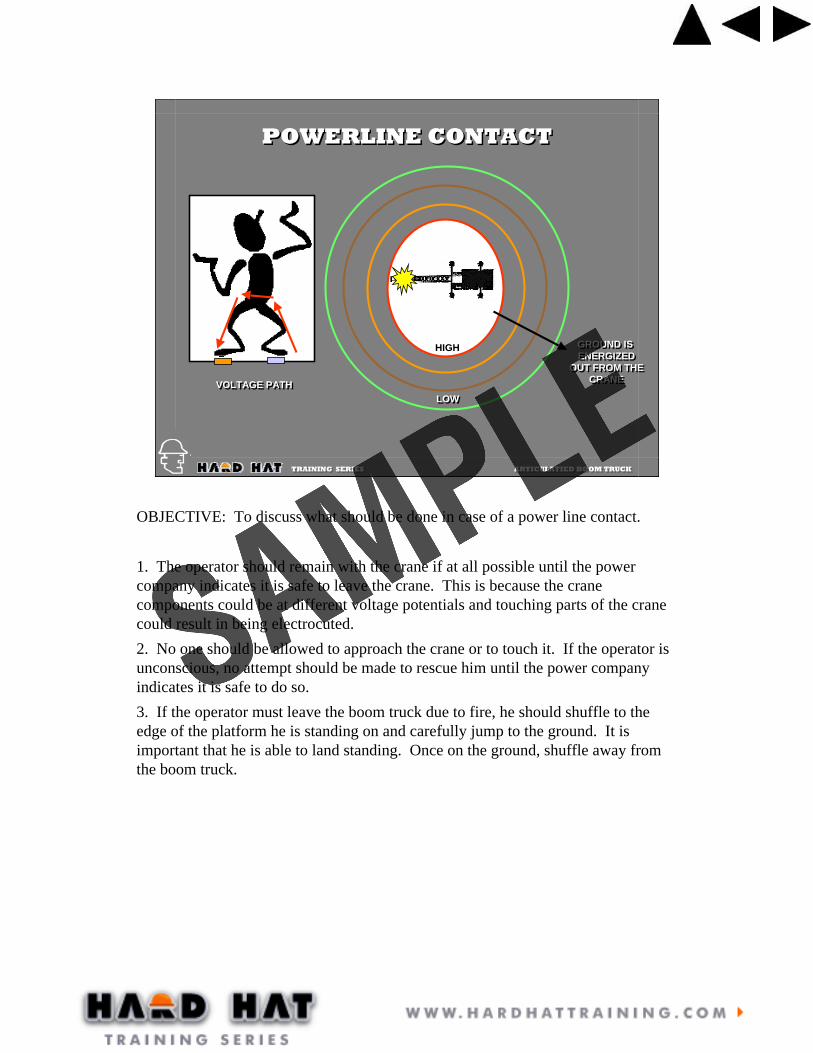
GROUND IS ENERGIZED
OUT FROM THECRANE
GROUND IS ENERGIZED
OUT FROM THECRANE
HIGH
LOWLOWVOLTAGE PATHVOLTAGE PATH
POWERLINE CONTACTPOWERLINE CONTACT
OBJECTIVE: To discuss what should be done in case of a power line contact.
1. The operator should remain with the crane if at all possible until the power company indicates it is safe to leave the crane. This is because the crane components could be at different voltage potentials and touching parts of the crane could result in being electrocuted.2. No one should be allowed to approach the crane or to touch it. If the operator is unconscious, no attempt should be made to rescue him until the power company indicates it is safe to do so. 3. If the operator must leave the boom truck due to fire, he should shuffle to the edge of the platform he is standing on and carefully jump to the ground. It is important that he is able to land standing. Once on the ground, shuffle away from the boom truck.

TRAINING SERIES ARTICULATIED BOOM TRUCK TRAINING SERIES ARTICULATIED BOOM TRUCK
WIRE ROPE SLING INSPECTIONWIRE ROPE SLING INSPECTION
OBJECTIVE: To review the requirements for inspecting wire rope slings.
1. Wire rope slings are to be inspected on a regular basis and a record kept of these inspections. Refer to the inspection card for inspection criteria.2. As of July 2000 wire rope slings are to have a tag which indicates the lifting capacities of the sling for vertical, choker, and basket hitches.
TRAINING SERIES ARTICULATIED BOOM TRUCK TRAINING SERIES ARTICULATIED BOOM TRUCK
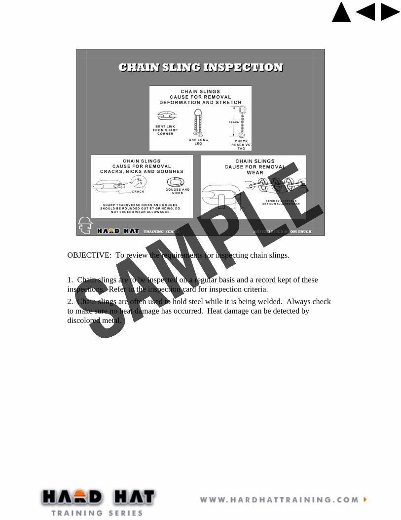
CHAIN SLING INSPECTIONCHAIN SLING INSPECTION
OBJECTIVE: To review the requirements for inspecting chain slings.
1. Chain slings are to be inspected on a regular basis and a record kept of these inspections. Refer to the inspection card for inspection criteria.2. Chain slings are often used to hold steel while it is being welded. Always check to make sure no heat damage has occurred. Heat damage can be detected by discolored metal.

TRAINING SERIES ARTICULATIED BOOM TRUCK TRAINING SERIES ARTICULATIED BOOM TRUCK
DEFORMATIONDEFORMATION BOLT SUBSTITUTIONBOLT SUBSTITUTION WEARWEAR
SHACKLESSHACKLES
TWO TYPES OFSHACKLES USED
FOR LIFTING.
TWO TYPES OFSHACKLES USED
FOR LIFTING.
OBJECTIVE: To discuss the inspection and use of shackles.
1. Only two type of shackles are to be used in rigging for lifts. The screw pin type and the bolt type shackle.2. Shackles that are damaged or deformed must be removed from service.
TRAINING SERIES ARTICULATIED BOOM TRUCK TRAINING SERIES ARTICULATIED BOOM TRUCK
SHACKLESSHACKLES
IN-LINEIN-LINE45 DEGREES45 DEGREES
90 DEGREES90 DEGREES
LOAD
Side Loading Reduction ChartFor Screw Pin & Bolt Type Shackles Only†
0° In-Line45° from In-Line90° from In-Line
100% of Rated Working Load Limit70% of Rated Working Load Limit50% of Rated Working Load Limit
Angle of Side Load Adjusted Working Load Limit
† DO NOT SIDE LOAD ROUND PIN SHACKLES
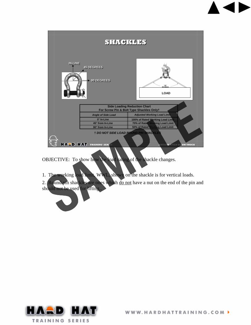
OBJECTIVE: To show how the load rating of the shackle changes.
1. The working load limit, WWL, shown on the shackle is for vertical loads.2. Round pin shackles are ones which do not have a nut on the end of the pin and should not be used for lifting..
TRAINING SERIES ARTICULATIED BOOM TRUCK TRAINING SERIES ARTICULATIED BOOM TRUCK
EYE BOLTSEYE BOLTS
DO NOT REEVE SLINGS ONE EYE BOLT TO ANOTHER. LOAD ON BOLT IS ALTERED.
DO NOT REEVE SLINGS ONE EYE BOLT TO ANOTHER. LOAD ON BOLT IS ALTERED.
WRONG!WRONG!
CAUTION!CAUTION!
STRUCTURE MAY BUCKLE FROMCOMPRESSION FORCES.
STRUCTURE MAY BUCKLE FROMCOMPRESSION FORCES.
DIRECTION OF PULL ADJUSTED WORKING LOAD
In-Line
45 Degrees
60 Degrees
Full Rated Working Load
30% of Rated Working Load
60% of Rated Working Load
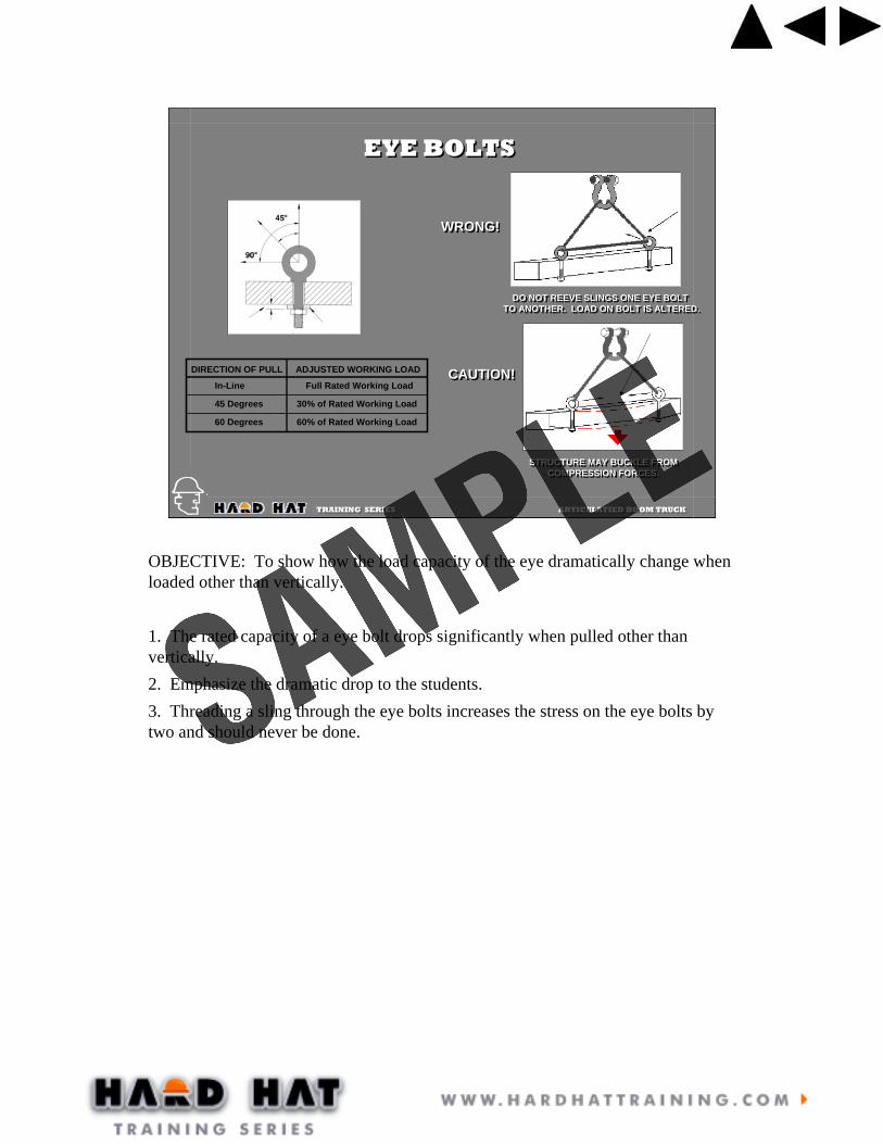
OBJECTIVE: To show how the load capacity of the eye dramatically change when loaded other than vertically.
1. The rated capacity of a eye bolt drops significantly when pulled other than vertically.2. Emphasize the dramatic drop to the students.3. Threading a sling through the eye bolts increases the stress on the eye bolts by two and should never be done.

TRAINING SERIES ARTICULATIED BOOM TRUCK TRAINING SERIES ARTICULATIED BOOM TRUCK
SYNTHETIC SLING INSPECTIONSYNTHETIC SLING INSPECTION
LOOSE STITCHINGLOOSE STITCHING HEAT DAMAGEHEAT DAMAGE WELD SPLATTERWELD SPLATTER
KNOTSKNOTS PUNCTURESPUNCTURES CUTSCUTS
OBJECTIVE: To review the requirements for inspecting synthetic slings.
1. This slide and the next two show the different types of sling damage that can occur. Refer to the inspection record of additional inspection criteria.2. Synthetic slings are required to be inspected on a regular basis and a record kept of such inspections.

TRAINING SERIES ARTICULATIED BOOM TRUCK TRAINING SERIES ARTICULATIED BOOM TRUCK
SYNTHETIC SLING INSPECTIONSYNTHETIC SLING INSPECTION
SCUFFINGSCUFFING RED THREADSRED THREADS NICKSNICKS
MANUFACTURER TAGMANUFACTURER TAG
Continuation of previous slide.
TRAINING SERIES ARTICULATIED BOOM TRUCK TRAINING SERIES ARTICULATIED BOOM TRUCK
SLING ANGLESSLING ANGLES
Tension in slingsTension in slings
Compression in loadCompression in load
Sling Angle
Stresses in the slings and the load increase as the sling angle decreasesStresses in the slings and the load increase as the sling angle decreases
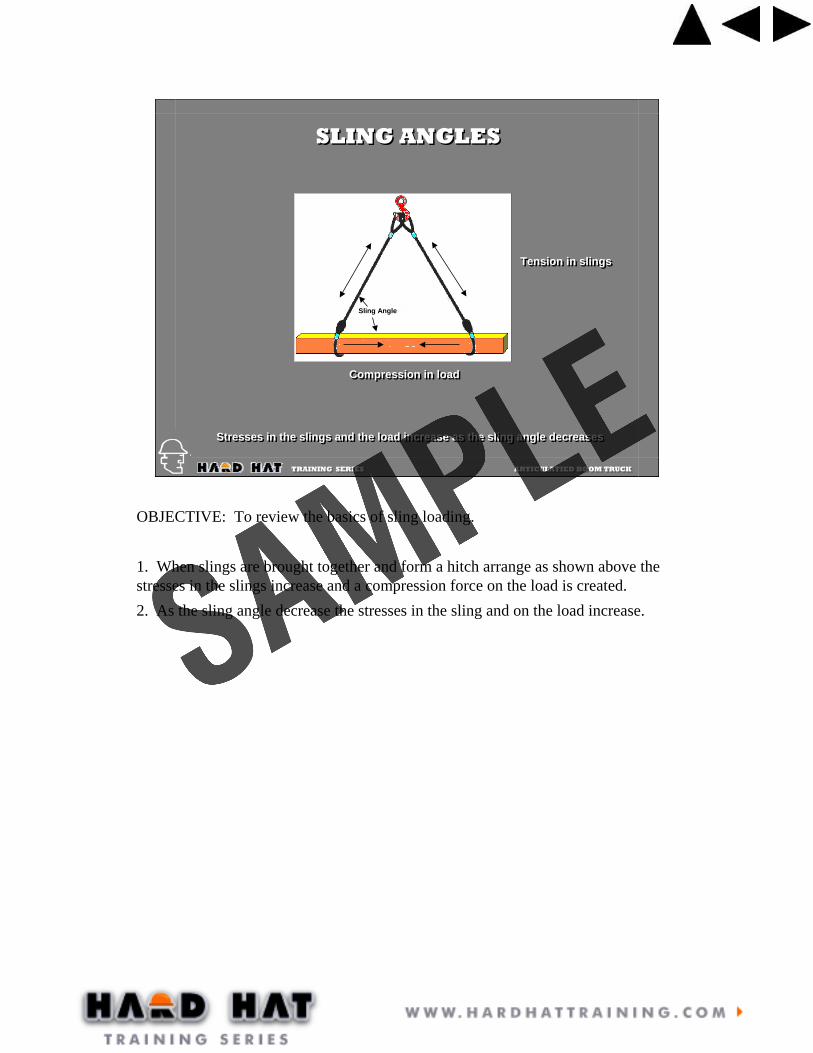
OBJECTIVE: To review the basics of sling loading.
1. When slings are brought together and form a hitch arrange as shown above the stresses in the slings increase and a compression force on the load is created.2. As the sling angle decrease the stresses in the sling and on the load increase.

TRAINING SERIES ARTICULATIED BOOM TRUCK TRAINING SERIES ARTICULATIED BOOM TRUCK
1000 lbs1000 lbs10
00 lb
s10
00 lb
s1000 lbs1000 lbs
500
lbs
500
lbs
500
lbs
500
lbs
1000 lbs1000 lbs
575
lbs
575
lbs 575 lbs
575 lbs
1000 lbs1000 lbs
705 l
bs
705 l
bs
705 lbs
705 lbs
1000 lbs1000 lbs
1000 lbs1000 lbs 1000 lbs
1000 lbs
1000 lbs1000 lbs
5735 lbs5735 lbs5735 lbs5735 lbs
SLING ANGLESSLING ANGLES
5°5°
60°60°
45°45° 30°30°
OBJECTIVE: To show how the stress in the slings increase as the sling angle decreases.
1. Review each of the different sling angle configurations and point out the increase in the stresses.2. Sling angles of 60 degrees are the best to use because of the minimal increase of stress in the slings. When required to use smaller sling angles, slings need to be selected based on the increased stress and not on the weight of the load.3. When the sling angle is 30 degrees for a 1000 lbs load, the compression loads which are crushing the load will be 866 lbs. Depending on the structural strength of the load, it may be damaged.

TRAINING SERIES ARTICULATIED BOOM TRUCK TRAINING SERIES ARTICULATIED BOOM TRUCK
1000 lbs1000 lbs 1000 lbs1000 lbs 1000 lbs1000 lbs
500
lbs
500
lbs
500
lbs
500
lbs
A
Factor ofAngle “A”Factor ofAngle “A”
Load in each slingleg = 500 x Load Angle Factor
Load in each slingleg = 500 x Load Angle Factor
H
L
A
Sling Angle Degree (A) Load Angle Factor = L/H9060504530
1.0001.1551.3051.4142.000
Load On Each Leg Of Sling = (Load / 2) X Load Angle Factor
SLING ANGLESSLING ANGLES
OBJECTIVE: To show how the stresses in the slings can be determined.
1. All that is need to calculate these stress is the weight of the object and a measuring tape.2. As shown in the slide above, the length of the sling is divided by the height of the sling connection to the top of the load.3. The answer is then multiplied by the portion of the load it is to support and this will be the stress in the sling.Example: If my sling was 8 feet long and the height ‘H’ was 4 feet, 8 divided by 4 equals 2. The portion of the weight the sling is to support is half of 1000 lbs or 500 lbs. 2 X 500 = 1000 lbs which is the stress in the sling.

TRAINING SERIES ARTICULATIED BOOM TRUCK TRAINING SERIES ARTICULATIED BOOM TRUCK
Acceptable methods of determining weight
You may find the weight from:
Data on manufacturing label plates.
Manufacturer documentation.
Blueprints or drawings.
Shipping receipts.
Weigh the item.
Bill of lading (be careful)
Stamped or written on the load
Approved calculations
Never use word of mouth to establish the weight of and item!
ESTIMATING WEIGHTSESTIMATING WEIGHTS
OBJECTIVE: To show the different means of determining the weight of a load.

TRAINING SERIES ARTICULATIED BOOM TRUCK TRAINING SERIES ARTICULATIED BOOM TRUCK
Calculating the weight
To find the weight of any item you need to know its volume and unit weight.
• Volume x Unit weight = Load weight
• Unit weight is the density of the material
• Unit weight is normally measured by pounds per cubic foot.
Calculating the weight
To find the weight of any item you need to know its volume and unit weight.
• Volume x Unit weight = Load weight
• Unit weight is the density of the material
• Unit weight is normally measured by pounds per cubic foot.
ESTIMATING WEIGHTSESTIMATING WEIGHTS
OBJECTIVE: To emphasize the importance of knowing how to calculate weights.

TRAINING SERIES ARTICULATIED BOOM TRUCK TRAINING SERIES ARTICULATIED BOOM TRUCK
343634503053623030282550
524564
10075120105
TIMBERCedarCherryFir, seasonedFir, wetHemlockMapleOakPinePoplarSpruceWhite pineRailroad tiesLIQUIDSDieselGasolineWaterEARTHEarth, wetEarth, drySand and gravel, wetSand and gravel, dry
165535500560480710490460
16011014060155110130144150
80160
METALSAluminumBrassBronzeCopperIronLeadSteelTinMASONARYAshlar masonryBrick, softBrick, pressedClay tileRubble masonryConcrete, cinder, hayditeConcrete, slagConcrete, stoneConcrete, reinforcedMISC.AsphaltGlass
Here are some examples of common materials and their unit weight:
(POUNDS PER CUBIC FOOT)
Here are some examples of common materials and their unit weight:
(POUNDS PER CUBIC FOOT)
ESTIMATING WEIGHTSESTIMATING WEIGHTS
OBJECTIVE: To show the unit weights for some common materials.
1. It’s wise to have similar “cheat sheets” for materials that you handle frequently.

TRAINING SERIES ARTICULATIED BOOM TRUCK TRAINING SERIES ARTICULATIED BOOM TRUCK
If the material was cedar, then all we would have to do to determine it’s weight would be to multiply the unit weight of cedar x 64.
Unit weight x Volume = Weight
34 lbs. X 64 cubic ft. = 2,176 lbs.
If the material was cedar, then all we would have to do to determine it’s weight would be to multiply the unit weight of cedar x 64.
Unit weight x Volume = Weight
34 lbs. X 64 cubic ft. = 2,176 lbs.
CALCULATING VOLUMECALCULATING VOLUME
Volume of a cube
Length x Width x Height = Volume
Volume of a cube
Length x Width x Height = Volume
8 ft x 4 ft x 2 ft = 64 cubic feet8 ft x 4 ft x 2 ft = 64 cubic feet
8 ft long
4 ft wide
2 ft high
OBJECTIVE: To demonstrate how to calculate the volume of a cube.
1. Cubes are easy to calculate.2. Finding the weight is as simple as multiplying the volume of the cube by the
unit weight of what it is made of.

TRAINING SERIES ARTICULATIED BOOM TRUCK TRAINING SERIES ARTICULATIED BOOM TRUCK
CALCULATING VOLUMECALCULATING VOLUME
Volume of a cylinder
Pi x Radius Squared x Length = Volume
π x Radius² x Length = Volume
Volume of a cylinder
Pi x Radius Squared x Length = Volume
π x Radius² x Length = Volume
3.14 x 1² ft x 10 ft = 31.4 cubic ft3.14 x 1² ft x 10 ft = 31.4 cubic ft
If the material was reinforced concrete, then all we would have to do to determine it’s weight would be to multiply the unit weight of reinforced concrete x 31.4.
150 lbs. X 31.4 cubic ft. = 4,710 lbs.
If the material was reinforced concrete, then all we would have to do to determine it’s weight would be to multiply the unit weight of reinforced concrete x 31.4.
150 lbs. X 31.4 cubic ft. = 4,710 lbs.
2 ft wide
10 ft long
OBJECTIVE: To demonstrate how to find the volume of a cylinder.
1. The volume of a cylinder is a little more difficult, but not rocket science. Having a scientific calculator and knowing how to use it is a good idea.
2. Again, just multiply the volume in cubic feet by the unit weight to find the weight of the load.

TRAINING SERIES ARTICULATIED BOOM TRUCK TRAINING SERIES ARTICULATIED BOOM TRUCK
Volume of pipe
Calculating the volume of pipe is a bit trickier but it is just simply subtracting the volume of the hole from the volume of the pipe.
Volume of pipe
Calculating the volume of pipe is a bit trickier but it is just simply subtracting the volume of the hole from the volume of the pipe.
CALCULATING VOLUMECALCULATING VOLUME
If the pipe were one inch thick, three feet wide and 8 feet long,then we would figure the volume of the entire pipe and subtract the volume of the hole to get the the volume of the material.
If the pipe were one inch thick, three feet wide and 8 feet long,then we would figure the volume of the entire pipe and subtract the volume of the hole to get the the volume of the material.
3.14 x (1 ½ ft.)² x 8 feet = total volume of pipe (56.52 ft³)
3.14 x (1ft 5 in.)² x 8 feet = volume of hole (50.41 ft³)
56.52 ft³ – 50.41 ft³ = 6.11 ft³
Volume of material x unit weight = total weight
If this pipe were steel then the unit weight would be 490 lbs.
6.11 x 490 lbs = 2,9994 lbs.
8 ft long
1 in. thick
3 ft wide
OBJECTIVE: To demonstrate how to find the volume of a pipe.
1. Finding the volume of a pipe is not too much different than finding the volume of a cylinder. You just have to do it twice and then subtract the volume of the hole from the total volume of the pipe.
2. It is helpful to know how to change fractions into decimals. Calculators are a must for this. To change 1 foot 5 inches (or 17/12ths) into a decimal, simple divide 12 into 17 which would be 1.4266.

TRAINING SERIES ARTICULATIED BOOM TRUCK TRAINING SERIES ARTICULATIED BOOM TRUCK
For thin pipe a quick way to *ESTIMATE the volume is to split the pipe open and calculate the volume like a cube. The formula would be:
π x diameter = width, so:
π x diameter x length x thickness x unit weight = weight of object
3.14 x 3 ft x 8 ft x 1/12 ft (or .08 ft) x 490 lbs = *3,077.2 lbs
8 ft long
3.14 (π) x 3 ft diameter = 9.42 (width)
1/12 ft = 1 in. thick
CALCULATING VOLUMECALCULATING VOLUME
OBJECTIVE: To demonstrate how to estimate the volume of thin pipe.
1. This is only an estimate and should not be used with thick pipe.2. Simply spit the pipe down the middle and open it up into a thin plate.3. Then calculate the the volume of the cube that is created.4. To find the width, multiply pi times the diameter.

TRAINING SERIES ARTICULATIED BOOM TRUCK TRAINING SERIES ARTICULATIED BOOM TRUCK
WEIGHT TABLES
Weight tables are an excellent way to calculate load weight.If you are handling certain materials often, then having a chartthat gives you the weight per cubic foot, cubic yard, square foot,linear foot or per gallon. Here are a few examples:
METAL PLATES
STEEL PLATES weigh approximately 40 lbs per sq. ft. at 1 inch thick.1/2 inch thick would then be about 20 lbs. per sq. ft.
A steel plate measuring 8 ft. x 10 ft. x 1/2 inch would then weigh about 3,200 lbs. (8 x 10 x 40 lbs = 3,200 lbs.)
BEAMS
Beams come in all kinds of materials and shapes and lengths. STEELI-BEAMS weigh approximately 40 lbs a linear ft. at 1/2 inch thick and8 inches x 8 inches. If it were 1 inch thick then it would be 80 lbs a linear ft. If it were 20 feet long at 1 inch thick then it would weigh about1,600 lbs. (20 ft. x 80 lbs. = 1,600lbs.)
WEIGHT TABLESWEIGHT TABLES
OBJECTIVE: To encourage the use of weight tables for determining the weights of loads.


![6044-Boom Truck Plan of Training2[1]](https://img.dokumen.tips/doc/110x75/625d5da368f8e904734957eb/6044-boom-truck-plan-of-training21.jpg)