Embed Size (px)
Citation preview

1
INTRODUCTION
1. Training can reduce the risk of accidents to you and those you work with.
2. Training can also reduce the operating costs of your company by avoiding damage to the truck, property and product.
Boom trucks are versatile machines, which can be used for many job applications from loading and unloading materials to placing those materials or personnel up to heights of 170 feet. Mounted on a truck bed these cranes can move between job sites at highway speeds carrying payloads in excess of 15,000 lbs. As with all cranes, significant training is needed to ensure safe operation and productivity.
Training makes sense.
The ultimate responsibility for each lift lies with the boom truck operator. To operate the boom truck safely and effectively, the operator must understand all the aspects of the machine, including: control locations and functions; crane movements; capacities, load charts and related data; operation speeds; signals, both visual and audible. He is also responsible for the inspection of all components and hardware on the truck and crane and have a practical knowledge of rigging and rigging hardware and be able to assess loads and situations that might present a hazard.

2
BOOM TRUCK INSPECTION
INSPECTION AREA INSPECTION RESULTSSat. Unsat. N/A Comments
CarrierEngine OilRadiatorSuspensionTiresWheelsRotation SystemOutriggersMounting Bolts & WeldsHydraulic Fluid LevelsCarrier Structure
Oper. Station & TurretGuagesControls & LabelsHydraulic CylindersHydraulic HosesWarning AlarmsService BrakesSwing BrakesElectrical SystemSafety Equipment
BoomSheavesWire RopeHook & SwivelBoom Angle IndicatorLoad IndicatorsAnti-Two-Block SystemWinchSlide PadsDeformations, CracksBoom ExtentionLoad Block
BOOM TRUCK INSPECTION CHECK LIST

3
BOOM TRUCK INSPECTION
Stabilizers should deploy smoothly.
Check for deformities or dents in the box tubes.
The pads should not be bent up at the corners and should move smoothly. Check to see that the pin keepers are present and that there is no excessive play in that area.
Check the upper hinge pin and bushing by lowering the stabilizer within a few inches of the ground and movingit back and forth. Some movement is normal, but excessive play will allow the crane to move back and forth causing further damage.
All welds need to be checked for cracks.
Check attachment of crane to truck chassis. If bolted, check around the bolt heads and washer area to see if there is cracked paint or dirt which could indicate movement.
StabilizerPad
Stabilizer
StabilizerExtensionCylinder
SuspensionBeam
Rotation CylinderStabilizerCylinder

4
• The rack and pinion should be greased on a regular basis perthe manufacturer maintenance manual.
• The rotation bearing is attached to the pedestal by bolts. These need to be checked for tightness. The turret is also attached to the bearing with bolts and they also need to be checked.
• The rotation drive motor is typically mounted up in the pedestal and the mounting bolts need to be checked.
• Check the rack and pinion gears for grease.
BOOM TRUCK INSPECTION
Rotation Bearing
Rack & Pinion Gear
HydraulicCylinder

5
The four areas in the slide can be checked by performing the following test:
• Set up the crane on level ground with the stabilizers fully extended.
• Retract the boom fully and raise it to its most vertical position and extend the hoist wire about 10 feet.
• Abruptly lower the boom momentarily which will result in the turret and boom component rocking. Observe the movements in the rotation bearing, boom hinge pin and bushing, and the lift cylinder pins and bushings. CAUTION: WHEN SHAKING THE CRANE, OBSERVE THE HOOK AND STOP ANY BOOM MOVEMENT IF IT CAN SWING INTO THE BOOM.
• Any excessive movement must be noted and evaluated per the manufacturer’s specifications.
• Check the turret area for cracked welds and any deformed components.
Worn pins
Damaged cylinder
rods
Cracked WeldsDamaged Hydraulic
Hoses
BOOM TRUCK INSPECTION

6
BOOM & TURRET INSPECTION
• The boom needs to be extended and checked for smoothness of operation. Any binding or difficulty in extending could be the result of damaged boom sections.
• All welds need to be checked for cracks.
• Any hydraulic leaks need to be investigated and repaired. Check the hoses for chaffing and wear.
• The slide pads can be checked for proper alignment by extending the boom completely and lowering the tip toward the ground. Move the boom tip back and forth by pushing on it and observe how much the boom sections move inside each other. Excessive movement will require the slide pads to be adjusted or replaced.
• The boom tip needs to be checked for deformation and twisting.
• The winch should be checked for proper reeving. The most commoncause of damage to wire rope is crushing due to crossed wrapson the winch drum.
BOOM TRUCK INSPECTION
7
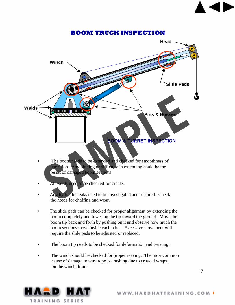
Pins & Bosses
BOOM & TURRET INSPECTION
Slide Pads
Head
Winch
Welds
• The boom needs to be extended and checked for smoothness of operation. Any binding or difficulty in extending could be the result of damaged boom sections.
• All welds need to be checked for cracks.
• Any hydraulic leaks need to be investigated and repaired. Check the hoses for chaffing and wear.
• The slide pads can be checked for proper alignment by extending the boom completely and lowering the tip toward the ground. Move the boom tip back and forth by pushing on it and observe how much the boom sections move inside each other. Excessive movement will require the slide pads to be adjusted or replaced.
• The boom tip needs to be checked for deformation and twisting.
• The winch should be checked for proper reeving. The most commoncause of damage to wire rope is crushing due to crossed wrapson the winch drum.
BOOM TRUCK INSPECTION

8
WORN GROOVES PROPER SIZE GROOVE
CHECK FLANGES FORCHIPS, CRACKS, WEAR
CHECK BEARINGS FORWOBBLE, GREASE, EASEOF ROTATION
MEASURE GROOVE
INSPECTING SHEAVES
CHECK GROOVE WEAR
150ºCONTACT
HOOK INSPECTION
Wear & Deformation
“Opening Up”
Wear & Cracks
Cracks & Twisting
[ Wear[ Deformation[ Cracks & Sharp Nicks[ Modifications[ Safety Latches[ Swivel Wear & Lubrication[ Hook Shackle Housing
CHECK FOR:
CRANE BLOCK
SIDE PLATEBOLTS TIGHT
SHEAVE PIN& BEARING
TIGHT
SAFETYLATCH
FUNCTIONING
CHECK FOR DISTORTIONSOR WEAR
SHEAVE GROOVENOT WORN, SHEAVES
TURN FREELY
HOOK NUT TIGHT& THEADS INSPECTED
PERIODICALLY
HOOK ROTATION &SWIVEL SMOOTH &
TIGHT
SIDE PLATESSTRAIGHT
SHEAVE PINKEEPER IN PLACE
AND TIGHT
• Check sheaves for bearing wear and lubrication.• Check the flanges and treads. Use a sheave gauge. • Sheaves can only be repaired per manufacturer’s procedures.
• The sheaves and bearings need to be checked on crane blocks.• Check the side plates and any additional weights attached to the sides need to bechecked for loose or missing bolts or fasteners.• The hook and shank nut should be separated periodically and the threads inspected for corrosion and other damage.• The safety latch must be in place and functioning properly.• The hook should rotate freely on theswivel bearing. Check for excessive movement.
• Wear in excess of 5% in the neck of the hook and 10% in other areas is cause for removal.• An increase in the hook throat opening ofmore than 15% is cause for removal• Any twist in the hook of more than 10% is cause for removal.• Hooks can only be repaired per manufacturer’s procedures.
BOOM TRUCK INSPECTION

9
WIRE
STRAND
WIRE ROPE
WIRE ROPE CONSTRUCTION
INDEPENDENTWIRE ROPE
COREFIBER CORE
19 WIRESPER STRAND
6 X 19 IWRC 8 X 19 FC
PROPER WAY TO MEASUREWIRE ROPE DIAMETER
Wire rope is made of steel wires laid together to form a strand. These strands are laid together to form a rope, usually around a central core of either fiber or wire, as indicated above. IWRC is the abbreviation for independent wire rope core. This wire core, which is actually another strand, has several advantages over fiber core. It adds about 7 ½% in strength and helps to resist rope crushing. Fiber core is impregnated with lubricant which is released during use. Fiber core also helps to cushion the strands during use. Fiber core wire rope should not be used for hoisting or rigging.Most wire rope is made from preformed strands. The preforming gives the the stands a better load distribution, and it prevents unraveling when the rope is cut.The number of strands, number of wires per strand, type of material and nature of the core will depend on the intended purpose of the wire rope.Wire Rope Lays:The lay refers to the direction of the winding of the wires in the strands and to the strands in the rope. This term refers to two basic lays. Regular Lay and Lang Lay.Regular Lay: The wires in the strands are laid in one direction while the strands in the rope are laid in the opposite direction. The wires are able to withstand considerable crushing and distortion due to the short length of the exposed wires. Lang Lay: The wires in the strands and the strands in the rope are laid in the same direction. Lang Lay rope should not be used for single part hoisting due to its tendency to untwist. Its biggest advantage is its resistance to abrasion.
WIRE ROPE

10
ROTATION RESISTANT WIRE ROPE
The non-rotating characteristic is secured by building into the rope two layers of strands, one having Right Lay and the other Left Lay.
The tendency of one layer of strands to rotate in one direction is counteracted by thetendency of the other layer of strands to rotate in the opposite direction.
Rotation Resistant wire rope requires very careful handling prior to, during and afterinstallation. When a non-rotating rope is cut, bent around a thimble or wedge socket, or is attached to any fitting, care must be taken to prevent core slippage.Core slippage can happen quite easily. When the rope is twisted in one direction, one layer of strands will tighten up and shorten, while the other layer of strands loosens, or becomes longer. As a result the shorter layers of strands carry the majority of the load. To ensure that core slippage does not take place, always apply wire seizings to bind the inner and outer cores together before the rope is cut or attached to any fitting.
The use of a swivel at the load hook or in the termination for a rotation resistantrope can result in unpredictable service. This practice, or any other which allows the rope to rotate while in service, can lead to unbalanced loading between inner and outer layers of strands, which may result in core failure. If any significant change in diameter is found in a short length of an operating rope, or if there is an unevenness of outer strands, the rope should be replaced.
Since rotation rope is special, applicable industry standards list separate design,maintenance, inspection and removal criteria for them. The minimum safety factor for rotation resistant rope is usually 5:1, and there are some who list it as8:1. When hoisting personnel, it is 10:1.

11
KINKED WIRE ROPE
STRAND NICKING
FATIGUE FAILURE
HIGH STRAND
BIRDCAGE
FATIGUE BREAKS
WIRE ROPE INSPECTION
Kinks are a permanent distortion. After a wire rope is kinked it is impossible to straighten the rope enough to return it to its original strength. The rope must be replaced. Causes: crossed lines on drum, improper handling and installation, and uncoiling.
Strand Nicking is due to continued operation under a high load which results in core failure.
Metal Fatigue is usually caused by bending stress from repeated passes over sheaves, or from vibration such as crane pendants.
Fatigue Breaks can be either external or internal. They also can be caused by wobbly sheaves, tight grooves, poor end terminations. In the absence of all these causes, remember that all wire rope will eventually fail from fatigue.
Bird Caging is a result of mistreatment such as sudden stops, wound on too tight of drum, or pulling through tight sheaves. The strands will not return to their original position
High Stranding is a condition caused when overloading and crushing take place and the other strands become overloaded.

12
CRANE IS LEVEL
STABILIZERS FULLYEXTENDED
WEIGHT OFF WHEELSPADS ON FIRM
GROUND
KNOWNRADIUS
KNOWNLOAD WEIGHT
HOIST LINEVERTICAL TO THE CG OF THE LOAD
BOOM TRUCK SETUP
Picking a suitable location is the foundation to a safe lift. The quality of the surface is your first consideration. Is it level? Can all stabilizers be extended fully? Will the soil or surface hold up under the weight of the lift?
*On some boom trucks, the stabilizers will not take all the weight off the tires.
You should know the following:
• Load weight• Radius of the pick• Can crane be leveled• How high load must be lifted
• Are there power lines nearby• Any other structures• Pedestrians or traffic• Plan for making the lift

13
STABILIZER SET UP
WRONGWRONG RIGHT
Avoid recentfill areas
Do not set upover buried objects that could collapse
NEVER block under stabilizer
ShortenedRadius
Avoid slopes
• Always extend all stabilizers.
• Avoid setting up on a slope.
• Soils along foundations may be poorly compacted or conceal objects that couldcollapse.
• Floats of at least 24” x 24” should be used under each stabilizer. These floats will reduce the lbs. per sq. inch on the surfaceand help the stabilizer from sinking.
• Blocking under the A-frame type stabilizerwill prevent it from fully deploying. Thiswill shorten the distance of the pad to the center of rotation which reduces the leverageof the boom truck and increases the chancesof a tip over.
FLOATS UNDER PADS

14
LEVELING THE CRANE USING HOIST LINE AND BOOM
Radius
KnownWeight
Boom Angle
SWING BOOMOVER REAR& LEVEL CRANEUNTIL HOISTWIRE IS PLUMBWITH BOOM
SWING BOOMOVER SIDE& LEVEL CRANEUNTIL HOISTWIRE IS PLUMBWITH BOOM
The radius for the load is measured from the centerof the rotation of the crane to directly under thevertically hanging hook. The boom angle is measuredfrom a horizontal line to the center of the boom.
The weight of the load and the riggingmust be known to determine the safeworking load for a particular set-up.
LEVELING THE CRANE
LOAD RADIUS AND BOOM ANGLE

15
LEVELING THE CRANE
ESTIMATED OUT OF LEVEL
CAPACITY REDUCTIONS
BOOM LENGTHAND RADIUS
CAPACITY REDUCTIONWHEN OUT OF LEVEL(Deg)
1 2 3
Short Boom, Minimum Radius
Short Boom, Maximum Radius
Long Boom, Minimum Radius
Long Boom, Maximum Radius
10% 20% 30%
8% 15% 20%
30% 41% 50%
5% 10% 15%
Note that the percentage of reduction is less when the boom is at maximumradius than when the boom is at minimum radius. Even though the changein the angle for both A and B is the same, the resulting change is much greater when the boom is raised high than when it is low.
A
B
Difference in radius
MAXIMUM RADIUS CHANGES LESS PER DEGREE THAN MINUMUM RADIUS

16
Rated capacity is 85%of the tipping load.
TippingAxis
Crane’sLeverage
Load’s Leverage
The principle of leverage is usedto determine theboom truck’srated capacities.
BOOM TRUCK STABILITY
Boom truck stability is based on the concept of balance and leverage
The concept of the teeter-totter is something that most people are familiar withand is a good way to explain stability. When a teeter-totter is in perfect balance,the torque created by the weight times length of the lever arm on one side of thepivot point must equal the torque created by the weight times the lever arm lengthon the other side.
For all cranes, the torque on the side of the crane always must be greater or otherwisethe crane will tip over. The crane’s torque or leverage is the effective weight of thecrane times the distance from the cranes center of gravity to the stabilizer. Leveragefor the load is the weight of the load and that portion of the boom that is beyond the stabilizer pad times the distance from the stabilizer pad to the center of the load.
Note that the total weight of the load, boom, and a portion of the truck weight ison the stabilizer(s) over which the boom is working.

17
High BearingPressure
TippingMomentLine
BOOM TRUCK STABILITY
When the boom is located directly overthe stabilizer, the pressure applied to theground is the greatest because the stabilizeris supporting most of the load.
Most boom pads are 12” x 16” which equals192 sq. in. of surface pressing on the ground.The load placed on this pad can be upwardsof 20,000 lbs. This would result in a groundbearing pressure of 100 lbs. per sq. inch.
For this pressure, the ground would need to be hard pan or compacted gravel soil. For many sites, the soil conditions are poor and may be only able to support 40 lbs. per sq. inch. A 24” x 24” float placed under the stabilizer will increase the surface area to 576 lbs. per sq inch. This will yield a ground bearing pressure for the above situation of 34 lbs. per sq. inch. This is a much improved situation.
As the boom moves from the forwardstabilizer toward the back of the truck,the pressure on the ground is shared bythe two stabilizers.The distance from the cranes center to the tipping moment line has increased so theleverage for the truck has increased makingthe boom truck more stable.The danger here is doing the opposite. When a load is picked up from the rear of the truck and brought over the side, the boom truck may initially be very stable, but as the load is swung over the side, the boom truck’s leverage decreases, making it less stable. Many operators are deceived by this condition and it results in a tip over.That’s why it is important for the operator to take the time to plan every lift.

18
•The Big Picture
•Assessing the Load
•Rigging Requirements
•Assessing the Pick Area
•Assessing the Placement Area
LIFT REQUIREMENTS
• Calculate the gross load• Determine the maximum radius• Determine the maximum height
• Refer to load chart to determine if liftwill be within the boom truck’s capacity.
The operator should take a moment to study the area in which he will be working. Look for power lines, obstructions, vehicle and pedestrian traffic, ground conditions and other potential areas to avoid in the set-up. When assessing the load, the operator must know the weight, the load’s center of gravity and its structural strength in order to rig properly. Using the same rigging technique for every lift often is not wise. In order to properly situate the truck you must know where the load will be picked from and where it needs to be placed.
POWER LINES:
Electrocution is the number one cause of death involving cranes. Always observe the minimum clearance distances. If for some reason you must get closer, you should use a spotter to watch the crane boom to ensure that it does not enter into the danger zone. Tag lines should not be used close to electrical lines.
50kV 10 ft50 to 200kV 15 ft200 to 350kV 20 ft
Required Clearances

19
LIFT REQUIREMENTS
GROSS LOAD
Net Load
When assessing the load the operator must know the weight. The gross load would include everything below the boom tip.
Gross Load = � Net Load + � Rigging + � Wire Rope + � Block +� Boom Attachments
Radius
KnownWeight
Boom Angle
The load radius is the horizontal distance measured from the center of rotation of the crane to the load hook while the boom is under load. The operator may need to make a few measurements if the lifting requirements are close to the maximum capacity for a certain configuration. When placing loads at elevated heights, the operator must know these heights to determine if his boom truck is capable of making the pick. Guessing at the height or the radius may result in a tip over if wrong. Once those distances are known, then the operator can refer to the load chart.
KnownHeight
Known radius to placement

200 30 60 90 120 150 180 210 240 270 300
40
35
30
25
20
15
10
5
0
1 ft
2 ft
4 ft
6 ft
8 ft10 ft
Load Velocity F.P.M.
Incr
ease
in L
oad
%
The below chart shows how the dynamic load increases as the rate of starting and stopping the load increases.
STATIONARYLOAD
STOPPED
DIR
EC
TIO
N O
F M
OV
EM
EN
TSTATIC LOAD DYNAMIC LOAD
TOTAL LOAD = STATIC LOAD + DYANAMIC LOAD
When a load is moved, additionalstresses are imposed on the crane’s structure. To start a load moving either by hoisting, booming or swinging, the crane will have to exert an additional force. How much additional force is dependent on the weight of the load and how fast it has started moving. Loads started slowly and stopped slowly will not exert as much stress on the crane as those which are move rapidly.
IMPACT OF DYNAMIC LOADING
Distances in whichload is stopped.
DYNAMIC LOADING

21A A AB B B
AVOID SIDE LOADING
FROM SWINGAND/OR
WIND
AVOID SIDE LOADING
FROM TILTINGTilting up objectscan place significant
side loads on the boom.
BOOM TRUCK STABILITY
The boom is very susceptible to side loading damage and needs to be above the load at all times. Tilting up panels are a common cause of side loading. When tilting up a panel, the hoist line must remain vertical at all times. Although it is not very apparent, wind can cause excessive stresses on the crane. Wind on the boom itself, especially when fully extended, can contribute to a tip over. The operator must stop operations when the wind becomes a significant factor. When to stop is left up to the judgment of the operator. According to OSHA, lifting of personnel shall not be done in winds in excess of 15 mph. The wind pressure on the load can also add side loading to the boom as well as losing control of the load. Tag lines may be necessary to help control the load, but should never be used to pull the load around.
Rate of tipping: In a stable situation, the boom truck leverage is greater thanthe load leverage. As the boom truck begins to tip, distance A becomes shorter anddistance B increases. This results in a decrease in leverage for the truck and increasein leverage for the load. If the truck continues to tip, the rate increases and unless theoperator is able to land the load immediately, it may be impossible to stop.

22
• Do not leave the crane with a suspended load• Rig the crane with sufficient parts of line for the load• Avoid two-blocking the crane• Always have a minimum of three wraps of cable on the drum• Monitor the winch to make sure that it is spooling correcting• Do not lift loads over personnel• Lift one load at a time• Maintain correct electrical clearance
Review the lift scenario with the operator, riggers and signal person
Attach taglines when necessary
Position signal person within visibility of the load and operator
Begin by lifting the load slowly
Re-check the boom angle indicator to assess radius increase
Keep load as low as possible when moving it
Swing slowly to avoid swing out.
Avoid erratic booming
Follow signal and stop operation when uncertain
Lower load slowly
CRANE SAFETY
MAKING THE LIFT
SIGNALS
• Only one person should be designated as the signal person.• The emergency stop signal can be given by anyone on the site.• The signals must be clear and precise.• The crane operator should never respond to a signal that is not
clearly understood.

23
DOG EVERYTHING EXTEND BOOM EMERGENCY STOP
SIGNALS
RAISE THE LOAD RAISE THE BOOM SWING
LOWER THE LOAD
LOWER THE BOOMSTOP
LOWER THE LOADRAISE THE BOOM RETRACT BOOM
RAISE THE LOADLOWER THE BOOM

24
50kV 10 ft50 to 200kV 15 ft200 to 350kV 20 ft
Required Clearances
POWERLINE CONTACT
GROUND IS ENERGIZED
OUT FROM THECRANE
HIGH
LOW
VOLTAGE PATH
ELECTROCUTION IS THE #1 CAUSE OF DEATHINVOLVING CRANES. If contact is made….
1. The operator should remain with the crane if possible until the utility company indicates it is safe.
2. No one should be allowed to approach the machine or touch it. If the operator is unconscious, no attempt should be made to rescue him until it is safe.
3. If the operator must leave the machine due to fire, he should stand up carefully without touching anything and carefully jump to the ground landing on both feet.Once on the ground, he should shuffle away from themachine.

25
SHACKLE INSPECTION
Only two types of shackles are to be used in rigging for lifts. The screw pintype and the bolt type shackle.
Shackles that are deformed or damaged must be removed from service.
IN-LINE45 DEGREES
90 DEGREES
The working load limit (WLL) mustbe printed on the shackle or it must betaken out of service. This WLL is for vertical lifts only.
Side Loading Reduction ChartFor Screw Pin & Bolt Type Shackles Only†
0° In-Line45° from In-Line90° from In-Line
100% of Rated Working Load Limit70% of Rated Working Load Limit50% of Rated Working Load Limit
Angle of Side Load Adjusted Working Load Limit
† DO NOT SIDE LOAD ROUND PIN SHACKLES

26
DIRECTION OF PULL ADJUSTED WORKING LOAD
In-Line
45 Degrees
60 Degrees
Full Rated Working Load
30% of Rated Working Load
60% of Rated Working Load
EYE BOLTS
Shoulder Nut Eye Bolt
Eye bolts should always be inspected before use. Look for signs of wear and damage. Look to see if shank is bent or elongated. Make sure the threads on the shank and the receiving hole are clean.
• Always use Shouldered Eye Boltsfor angular lifts.
• For angular lifts, reduce working loadaccording to chart.
• Never exceed load limits.• Always screw eye bolt down completely
for proper seating.• Always tighten nuts securely against the
load.• Always stand clear of load when lifting.• Always lift load with steady, even pull-
do not jerk.• Do not reeve slings from one eye bolt to
another.• Never machine, grind or cut the eye bolt.
WRONG!
STRUCTURE MAY BUCKLE FROMCOMPRESSION FORCES
CAUTION

27
WIRE ROPE SLING INSPECTION
Wire rope slings need to be inspected in the same way wire rope is anda record kept of those inspections. All slings must have a tag on them indicating the capacity or they must be taken out of service.
Chain slings are to be inspectedregularly and a record kept of these inspections also. Again, if there is no capacity tag, it must be taken out of service.Chain slings are often used to holdsteel while it is being welded. Alwayscheck to make sure heat damagehas not occurred. Heat damage can bedetected by discolored metal.

28
SYNTHETIC SLING INSPECTION
Far too many web slings have to be discardedprematurely simply because abusive or carelesswork habits caused irreparable damage.
To the right are some examples of damagedslings.
Regardless of whether a sling shows damagefrom abuse or regular wear, the overriding rulein all cases is that the sling eyes should be cut, and the sling discarded immediately wheneverdamage is detected.
When using synthetic slings, remember:
• Slings without a capacity tag should bediscarded. That tag should have the following information:
-Name and trademark of manufacturer.-Manufacturer’s code or stock number.-Rated loads (rated capacities) for the
type of hitches used.-Type of synthetic material.
• Use wear pads on corners to protect thesling from cuts, or abrasions.
• Do not pull the sling out from under the load if caught under it.
• Take into consideration the sling angleswhen calculating the capacity of the sling to handle the load.
29
1000 lbs
1000
lbs
1000 lbs
500
lbs
500
lbs
1000 lbs57
5 lb
s 575 lbs
1000 lbs
705 l
bs 705 lbs
1000 lbs
1000 lbs 1000 lbs
1000 lbs
5735 lbs5735 lbs
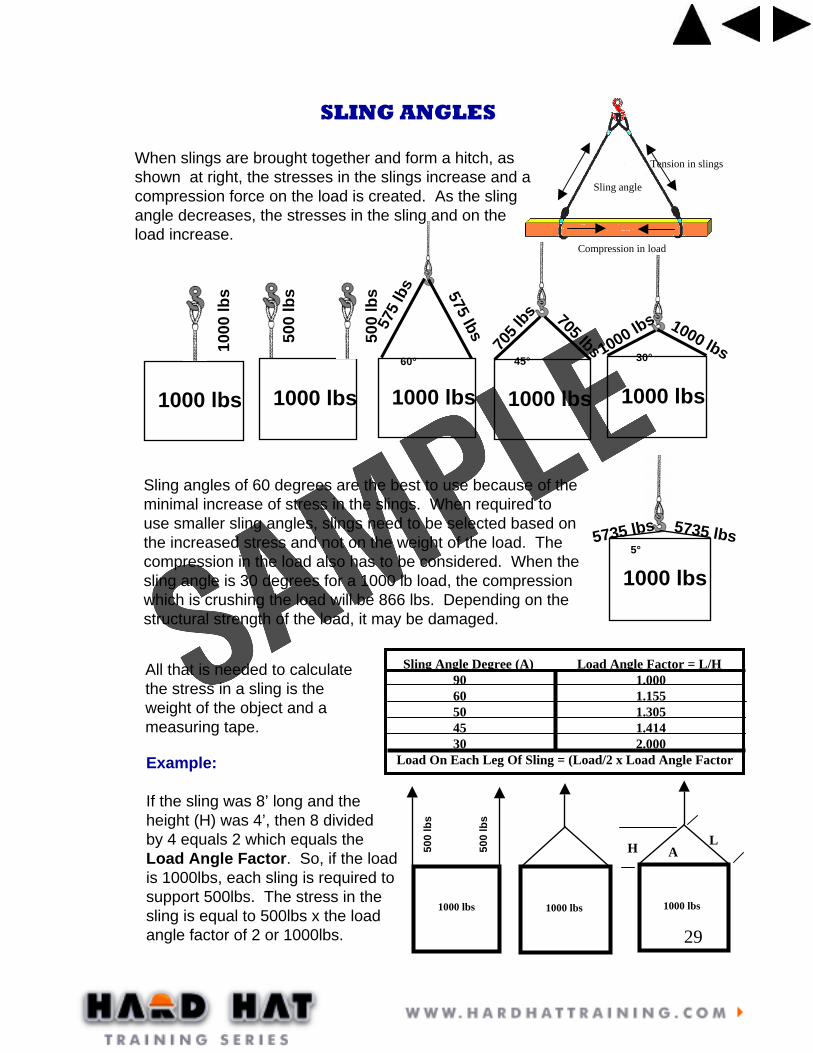
SLING ANGLES
Sling angle
Tension in slingsWhen slings are brought together and form a hitch, as shown at right, the stresses in the slings increase and a compression force on the load is created. As the sling angle decreases, the stresses in the sling and on the load increase.
Sling angles of 60 degrees are the best to use because of the minimal increase of stress in the slings. When required to use smaller sling angles, slings need to be selected based on the increased stress and not on the weight of the load. The compression in the load also has to be considered. When the sling angle is 30 degrees for a 1000 lb load, the compression which is crushing the load will be 866 lbs. Depending on the structural strength of the load, it may be damaged.
30°45°60°
5°
Compression in load
500
lbs
500
lbs
Sling Angle Degree (A) Load Angle Factor = L/H90 1.00060 1.15550 1.30545 1.41430 2.000
Load On Each Leg Of Sling = (Load/2 x Load Angle Factor
All that is needed to calculate the stress in a sling is the weight of the object and a measuring tape.
Example:
If the sling was 8’ long and the height (H) was 4’, then 8 dividedby 4 equals 2 which equals the Load Angle Factor. So, if the loadis 1000lbs, each sling is required tosupport 500lbs. The stress in the sling is equal to 500lbs x the loadangle factor of 2 or 1000lbs.
1000 lbs 1000 lbs 1000 lbs
H LA
30
CALCULATING LOAD WEIGHT
Importance of load weights
The weight of the load to be lifted must be known to prevent overloading of theboom truck. Without the weight the load chart cannot be referred to and guessing the weight can be dangerous.
You must know the weight of the load to prevent tipovers!
If you must estimate, never boom out to a point where the estimated weight would exceed 50% of the capacity of that load zone. In other words, make the best estimate you can and then multiply it by 2 to determine the safest load zone you can operate in.
Acceptable methods of determining weight
You may find the weight from:
Data on manufacturing label plates.
Manufacturer documentation.
Blueprints or drawings.
Shipping receipts.
Weigh the item.
Bill of lading (be careful)
Stamped or written on the load
Approved calculations
Never use word of mouth to establish the weight of an item!

31
To find the weight of any item you need to know its volume and unit weight.
• Volume x Unit weight = Load weight
• Unit weight is the density of the material
Here are some examples of common materials and their unit weight:
WEIGHTS OF MATERIALS BASED ON VOLUME (lbs. Per cubic ft.)
343634503053623030282550
524564
10075120105
TIMBERCedarCherryFir, seasonedFir, wetHemlockMapleOakPinePoplarSpruceWhite pineRailroad tiesLIQUIDSDieselGasolineWaterEARTHEarth, wetEarth, drySand and gravel, wetSand and gravel, dry
165535500560480710490460
16011014060155110130144150
80160
METALSAluminumBrassBronzeCopperIronLeadSteelTinMASONARYAshlar masonryBrick, softBrick, pressedClay tileRubble masonryConcrete, cinder Concrete, slagConcrete, stoneConcrete, reinforcedMISC.AsphaltGlass
MATERIALUNITWEIGHT MATERIAL
UNITWEIGHT
CALCULATING LOAD WEIGHT

32
CALCULATING VOLUME
Volume of a cube
Length x Width x Height = Volume
4 ft wide
8 ft long
2 ft high
8 ft x 4 ft x 2 ft = 64 cubic feet
If the material was cedar, then all we need to do to determine it’s weight would be to multiply the unit weight of cedar x 64.
Unit weight x Volume = Weight
34 lbs per cubic foot X 64 cubic ft. = 2,176 lbs.
Volume of a cylinder
Pi (π) x Radius Squared x Length = Volume
π = 3.14
10 ft long
2 ft diameter
3.14 x 1² ft x 10 ft = 31.4 cubic ft
If the material was reinforced concrete, then all we need to do to determine it’s weight would be to multiply the unit weight of reinforced concrete x 31.4.
150 lbs per cubic foot x 31.4 cubic ft. = 4,710 lbs.
CALCULATING LOAD WEIGHT

33
Volume of pipe
Calculating the volume of pipe is a bit trickier but it is just simply subtracting the volume of the hole from the volume of the pipe.
1 in. thick
3 ft diameter
8 ft longIf the pipe were one inch thick, three feet in diameter and 8 feet long, then we would figure the volume of the entire pipe and subtract the volume of the hole to get the the volume of the material.
3.14 x (1 ½ ft.)² x 8 feet = total volume of pipe (56.52 ft³)
3.14 x (1ft 5 in.)² x 8 feet = volume of hole (50.41 ft³)
56.52 ft³ – 50.41 ft³ = 6.11 ft³
Volume of material x unit weight = total weight
If this pipe were steel then the unit weight would be 490 lbs.
6.11 x 490 lbs = 2,994 lbs.
For thin pipe a quick way to *ESTIMATE the volume is to split the pipe open and calculate the volume like a cube. The formula would be:
π x diameter = width, so:
π x diameter x length x thickness x unit weight = weight of object
3.14 x 3 ft x 8 ft x 1/12 ft (or .008 ft) x 490 lbs = *3,077.2 lbs
CALCULATING LOAD WEIGHT

34
WEIGHT TABLES
Weight tables are an excellent way to calculate load weight.If you are handling certain materials often, then having a chartthat gives you the weight per cubic foot, cubic yard, square foot,linear foot or per gallon is handy. Here are a few examples:
METAL PLATES
1 INCH STEEL PLATE weighs approximately 40 lbs per sq. ft. 1/2 inch steel plate would then be about 20 lbs. per sq. ft.
A steel plate measuring 8 ft. x 10 ft. x 1inch would then weigh about 3,200 lbs. (8 x 10 x 40 lbs = 3,200 lbs.)
BEAMS
Beams come in all kinds of materials and shapes and lengths. STEELI-BEAMS weigh approximately 40 lbs a linear ft. at 1/2 inch thick and8 inches x 8 inches. If it were 1 inch thick then it would be 80 lbs a linear ft. If it were 20 feet long at 1 inch thick then it would weigh about1,600 lbs. (20 ft. x 80 lbs. = 1,600lbs.)
There are weight tables for everything from creosoted pine polesto Steel coils. Take advantage of these. But, if you don’t know for sure the weight of a load and there are no other resources available to help you, don’t hesitate to do the calculations yourself.
CALCULATING LOAD WEIGHT

Student Student ManualManual
ArticulatingArticulating
Boom TruckBoom Truck
OperatorOperator
Safety TrainingSafety Training