Embed Size (px)
Citation preview

© 2003 Directed Electronics, Inc. Vista, CA N909595 3-03
installation guide
tab
le o
f co
nte
nts
wh
at
is i
ncl
ud
ed
. .
. .
. .
. .
. .
. .
. .
. .
. .
. .
. .
. .
. .
. .
. .
. .
. .
. .
. .
. .
. .
. .
. .
.2
tra
nsm
itte
r co
nfi
gu
rati
on
s .
. .
. .
. .
. .
. .
. .
. .
. .
. .
. .
. .
. .
. .
. .
. .
. .
. .
. .
. .
2
tra
nsm
itte
r fu
nct
ion
s .
. .
. .
. .
. .
. .
. .
. .
. .
. .
. .
. .
. .
. .
. .
. .
. .
. .
. .
. .
. .
. .
3
stan
dard
co
nfig
ura
tio
n .
. .
. .
. .
. .
. .
. .
. .
. .
. .
. .
. .
. .
. .
. .
. .
. .
. .
. .
. .
.3
pri
ma
ry h
arn
ess
wir
e c
on
ne
ctio
n g
uid
e .
. .
. .
. .
. .
. .
. .
. .
. .
. .
. .
. .
. .
. .
.4
prim
ary
harn
ess
wirin
g d
iag
ram
. .
. .
. .
. .
. .
. .
. .
. .
. .
. .
. .
. .
. .
. .
. .
. .
.4
prim
ary
harn
ess
wirin
g g
uid
e .
. .
. .
. .
. .
. .
. .
. .
. .
. .
. .
. .
. .
. .
. .
. .
. .
. .
5
imm
ob
iliz
er
ha
rne
ss w
ire
co
nn
ect
ion
gu
ide
. .
. .
. .
. .
. .
. .
. .
. .
. .
. .
. .
. .
.9
imm
ob
ilize
r h
arn
ess
wirin
g d
iag
ram
. .
. .
. .
. .
. .
. .
. .
. .
. .
. .
. .
. .
. .
. .
. .
9
imm
ob
ilize
r h
arn
ess
wirin
g g
uid
e .
. .
. .
. .
. .
. .
. .
. .
. .
. .
. .
. .
. .
. .
. .
. .
.9
do
or
lock
ha
rne
ss w
ire
co
nn
ect
ion
gu
ide
. .
. .
. .
. .
. .
. .
. .
. .
. .
. .
. .
. .
. .
.1
0
typ
e A
: p
osi
tive
(+
) 1
2-v
olt p
uls
e .
. .
. .
. .
. .
. .
. .
. .
. .
. .
. .
. .
. .
. .
. .
. .
. .
10
typ
e B
: n
eg
ative
(-)
pu
lse
. .
. .
. .
. .
. .
. .
. .
. .
. .
. .
. .
. .
. .
. .
. .
. .
. .
. .
. .
.1
1
typ
e C
: re
vers
ing
po
larity
. .
. .
. .
. .
. .
. .
. .
. .
. .
. .
. .
. .
. .
. .
. .
. .
. .
. .
. .
.1
1
typ
e D
: aft
er-
mark
et
act
uato
rs .
. .
. .
. .
. .
. .
. .
. .
. .
. .
. .
. .
. .
. .
. .
. .
. .
. .
12
typ
e E
: m
erc
ed
es-
ben
z an
d a
ud
i (1
98
5 &
new
er)
. .
. .
. .
. .
. .
. .
. .
. .
. .
. .
13
typ
e F
: o
ne-w
ire s
yste
m .
. .
. .
. .
. .
. .
. .
. .
. .
. .
. .
. .
. .
. .
. .
. .
. .
. .
. .
. .
.1
4
typ
e G
: p
osi
tive
(+
) m
ultip
lex .
. .
. .
. .
. .
. .
. .
. .
. .
. .
. .
. .
. .
. .
. .
. .
. .
. .
.1
4
typ
e H
: n
eg
ative
(-)
mu
ltip
lex
. .
. .
. .
. .
. .
. .
. .
. .
. .
. .
. .
. .
. .
. .
. .
. .
. .
. .1
5
pe
rip
he
ral
plu
g-i
n h
arn
ess
es
. .
. .
. .
. .
. .
. .
. .
. .
. .
. .
. .
. .
. .
. .
. .
. .
. .
. .
.1
6
sup
er
brig
ht
blu
e led
, 2
-pin
wh
ite p
lug
. .
. .
. .
. .
. .
. .
. .
. .
. .
. .
. .
. .
. .
. .
16
pla
in-v
iew
vale
t .
. .
. .
. .
. .
. .
. .
. .
. .
. .
. .
. .
. .
. .
. .
. .
. .
. .
. .
. .
. .
. .
. .
.1
6
sen
sor
harn
ess
, 4
-pin
co
nn
ect
or
. .
. .
. .
. .
. .
. .
. .
. .
. .
. .
. .
. .
. .
. .
. .
. .
.1
6
mo
un
tin
g t
he r
ece
iver/
an
ten
na
. .
. .
. .
. .
. .
. .
. .
. .
. .
. .
. .
. .
. .
. .
. .
. .
. .
17
arm
ing
/dis
arm
ing
dia
gn
ost
ics
. .
. .
. .
. .
. .
. .
. .
. .
. .
. .
. .
. .
. .
. .
. .
. .
. .
. .
18
arm
ing
. .
. .
. .
. .
. .
. .
. .
. .
. .
. .
. .
. .
. .
. .
. .
. .
. .
. .
. .
. .
. .
. .
. .
. .
. .
. .
18
dis
arm
ing
. .
. .
. .
. .
. .
. .
. .
. .
. .
. .
. .
. .
. .
. .
. .
. .
. .
. .
. .
. .
. .
. .
. .
. .
. .
18
syst
em
sta
tus
chir
ps
. .
. .
. .
. .
. .
. .
. .
. .
. .
. .
. .
. .
. .
. .
. .
. .
. .
. .
. .
. .
. .
. .
.18
mu
ltip
le e
ve
nt
tota
l re
call
. .
. .
. .
. .
. .
. .
. .
. .
. .
. .
. .
. .
. .
. .
. .
. .
. .
. .
. .
.1
8
tab
le o
f zo
ne
s .
. .
. .
. .
. .
. .
. .
. .
. .
. .
. .
. .
. .
. .
. .
. .
. .
. .
. .
. .
. .
. .
. .
. .
. .
19
syst
em
fe
atu
res
pro
gra
mm
ing
. .
. .
. .
. .
. .
. .
. .
. .
. .
. .
. .
. .
. .
. .
. .
. .
. .
. .
19
cliffn
et
wiz
ard
pro
in
stalla
tio
n s
oft
ware
pro
gra
mm
ing
. .
. .
. .
. .
. .
. .
. .
. .
.1
9
man
ual p
rog
ram
min
g in
stru
ctio
ns .
. .
. .
. .
. .
. .
. .
. .
. .
. .
. .
. .
. .
. .
. .
. .
.2
0
use
r se
lect
ab
le f
eatu
res
. .
. .
. .
. .
. .
. .
. .
. .
. .
. .
. .
. .
. .
. .
. .
. .
. .
. .
. .
. .
21
use
r se
lect
ab
le f
eatu
res
desc
rip
tio
ns
- co
lum
n o
ne
. .
. .
. .
. .
. .
. .
. .
. .
. .
.2
1
use
r se
lect
ab
le f
eatu
res
desc
rip
tio
ns
- co
lum
n t
wo
. .
. .
. .
. .
. .
. .
. .
. .
. .
.2
3
use
r se
lect
ab
le f
eatu
res
desc
rip
tio
ns
- co
lum
n t
hre
e .
. .
. .
. .
. .
. .
. .
. .
. .
.2
4
inst
alle
r se
lect
ab
le f
eatu
res
. .
. .
. .
. .
. .
. .
. .
. .
. .
. .
. .
. .
. .
. .
. .
. .
. .
. .
.2
5
inst
alle
r se
lect
ab
le f
eatu
res
desc
rip
tio
ns
. .
. .
. .
. .
. .
. .
. .
. .
. .
. .
. .
. .
. .
. .2
6
pro
gra
mm
ing
no
tes
. .
. .
. .
. .
. .
. .
. .
. .
. .
. .
. .
. .
. .
. .
. .
. .
. .
. .
. .
. .
. .
.28
fact
II
- fa
lse
ala
rm c
on
tro
l te
chn
olo
gy
. .
. .
. .
. .
. .
. .
. .
. .
. .
. .
. .
. .
. .
. .
.3
0
sma
rt p
ow
er
up
II
. .
. .
. .
. .
. .
. .
. .
. .
. .
. .
. .
. .
. .
. .
. .
. .
. .
. .
. .
. .
. .
. .
. .
30
rem
ote
co
ntr
ol
sen
sor
dis
ab
le .
. .
. .
. .
. .
. .
. .
. .
. .
. .
. .
. .
. .
. .
. .
. .
. .
. .
.3
0
tro
ub
lesh
oo
tin
g .
. .
. .
. .
. .
. .
. .
. .
. .
. .
. .
. .
. .
. .
. .
. .
. .
. .
. .
. .
. .
. .
. .
. .
31
wir
ing
qu
ick
re
fere
nce
gu
ide
. .
. .
. .
. .
. .
. .
. .
. .
. .
. .
. .
. .
. .
. .
. .
. .
. .
. .
.3
2
Bitwriter™, Code Hopping™, DEI®, Directed®, Doubleguard®, ESP™, FailSafe®, Ghost Switch™, Learn
Routine™, Nite-Lite®, Nuisance Prevention Circuitry®, NPC®, Revenger®, Silent Mode™, Soft Chirp®, Stinger®,
Valet®, Vehicle Recovery System®, VRS®, and Warn Away® are all Trademarks or Registered Trademarks of
Directed Electronics, Inc., Vista, California.
IMPO
RTA
NT!
Plea
se n
ote
that
this m
anua
l was
inte
nded
for U
S co
nsum
ers
and
ther
efor
e in
clud
es A
mer
ican
phr
ases
or w
ords
.
© 2003 directed electronics, inc.
3www.directed.com
2
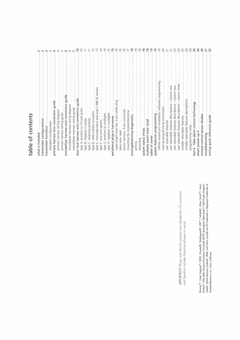
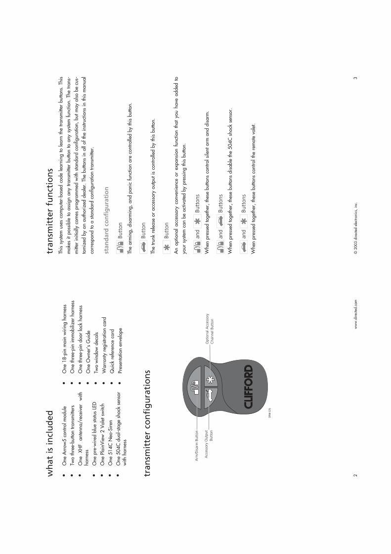
One Arrow5 control module
Two three-button transmitters
One XHF antenna/receiver with
harness
One pre-wired blue status LED
One PlainView 2 Valet switch
One 514C Neo-Siren
One 504C dual-stage shock sensor
with harness
One 18-pin main wiring harness
One three-pin immobilizer harness
One three-pin door lock harness
One Owner’s Guide
Two window decals
Warranty registration card
Quick reference card
Presentation envelope
wh
at
is i
ncl
ud
ed
tran
smit
ter
con
fig
ura
tio
ns
DRW
-376
Arm
/Dis
arm
Butt
on
Acc
ess
ory
Outp
ut
Butt
on
Optional A
ccess
ory
Channel Butt
on
tran
smit
ter
fun
ctio
ns
This system uses computer-based code learning to learn the transmitter buttons. This
makes it possible to assign any transmitter button to any system function. The trans-
mitter initially comes programmed with standard configuration, but may also be cus-
tomized by an authorized dealer. The buttons in all of the instructions in this manual
correspond to a standard configuration transmitter.
sta
nd
ard
co
nfi
gu
rati
on
Butt
on
The arming, disarming, and panic function are controlled by this button.
Butt
on
The trunk release or accessory output is controlled by this button.
Butt
on
An optional accessory convenience or expansion function that you have added to
your system can be activated by pressing this button.
and
Butt
ons
When pressed together, these buttons control silent arm and disarm.
and
Butt
ons
When pressed together, these buttons disable the 504C shock sensor.
and
Butt
ons
When pressed together, these buttons control the remote valet.
© 2003 directed electronics, inc.
5
pri
ma
ry h
arn
ess
wir
ing
gu
ide
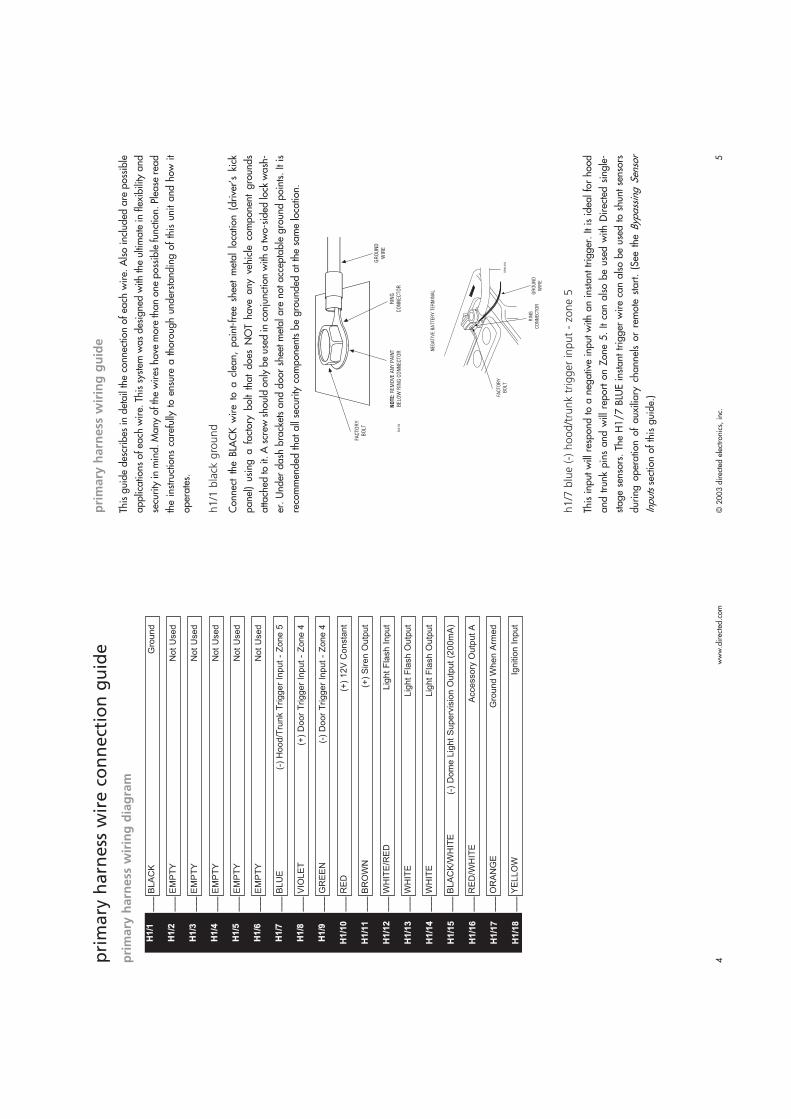
This guide describes in detail the connection of each wire. Also included are possible
applications of each wire. This system was designed with the ultimate in flexibility and
security in mind. Many of the wires have more than one possible function. Please read
the instructions carefully to ensure a thorough understanding of this unit and how it
operates.
h1/1
bla
ck g
round
Connect the BLACK wire to a clean, paint-free sheet metal location (driver’s kick
panel) using a factory bolt that does NOT have any vehicle component grounds
attached to it. A screw should only be used in conjunction with a two-sided lock wash-
er. Under dash brackets and door sheet metal are not acceptable ground points. It is
recommended that all security components be grounded at the same location.
h1/7
blu
e (
-) h
ood/t
runk
trig
ger
input
- zo
ne 5
This input will respond to a negative input with an instant trigger. It is ideal for hood
and trunk pins and will report on Zone 5. It can also be used with Directed single-
stage sensors. The H1/7 BLUEinstant trigger wire can also be used to shunt sensors
during operation of auxiliary channels or remote start. (See the Bypassing Sensor
Inputssection of this guide.)
www.directed.com
4pri
mary
harn
ess
wir
e c
on
nect
ion
gu
ide
pri
ma
ry h
arn
ess
wir
ing
dia
gra
m
___
___
___
___
___
___
___
___
___
___
___
___
___
___
___
___
___
___
YE
LL
OW
Ign
itio
n I
np
ut
OR
AN
GE
Gro
un
d W
he
n A
rme
d
RE
D/W
HIT
EA
cce
sso
ry O
utp
ut
A
BLA
CK
/WH
ITE
(-)
Do
me
Lig
ht
Su
pe
rvis
ion
Ou
tpu
t (2
00
mA
)
WH
ITE
Lig
ht
Fla
sh
Ou
tpu
t
WH
ITE
Lig
ht
Fla
sh
Ou
tpu
t
WH
ITE
/RE
DL
igh
t F
lash
In
pu
t
BR
OW
N(+
) S
ire
n O
utp
ut
RE
D(+
) 1
2V
Co
nsta
nt
GR
EE
N(-
) D
oo
r T
rig
ge
r In
pu
t -
Zo
ne
4
VIO
LE
T(+
) D
oo
r T
rig
ge
r In
pu
t -
Zo
ne
4
BL
UE
(-)
Ho
od
/Tru
nk
Trig
ge
r In
pu
t -
Zo
ne
5
EM
PT
YN
ot
Use
d
EM
PT
YN
ot
Use
d
EM
PT
YN
ot
Use
d
EM
PT
YN
ot
Use
d
EM
PT
YN
ot
Use
d
BLA
CK
Gro
un
dH1/1
H1/2
H1/3
H1/4
H1/5
H1/6
H1/7
H1/8
H1/9
H1/10
H1/11
H1/12
H1/13
H1/14
H1/15
H1/16
H1/17
H1/18

© 2003 directed electronics, inc.
7www.directed.com
6
h1/1
2 w
hite/r
ed lig
ht
flash
input
This wire is the input for the on-board dual light flash relay. If the vehicle has positive
parking light activation wires, connect this wire to a constant (+) 12V source that is
fused at 15A or higher (be sure to use the supplied fuse holder and a 15 amp fuse).
If the vehicle parking light activation wire is negative, connect this wire to a chassis
ground location.
h1/1
3 a
nd h
1/1
4 w
hite p
ark
ing lig
ht
outp
ut
These wires are the output of an on-board dual make relay and should be connected
to wires in the vehicle that control the parking light wire polarity. The dual outputs are
designed for European vehicles with isolated parking light systems. If the vehicle’s
parking lights are controlled by a single wire, connect both WHITE wires to it.
IMPO
RTA
NT!
The
pol
arity
of t
his
wire
is d
eter
min
ed b
y th
e co
nnec
tion
of th
e H
1/
12
light
flas
h in
put w
ire.
Alw
ays
conf
irm li
ght f
lash
pol
arity
bef
ore
conn
ectin
g H
1/
12 o
rda
mag
e to
the
vehi
cle
light
ing
syste
m c
ould
occ
ur.
h1/1
5 b
lack
/white (
-) d
om
e lig
ht
superv
isio
n o
utp
ut
(200m
A)
Connect the H1/15 BLACK/WHITE wire to the optional domelight supervision relay
as shown in the following diagram.
IMPO
RTA
NT!
This o
utpu
t is o
nly
inte
nded
to
driv
e a
rela
y. I
t ca
nnot
be
conn
ecte
ddi
rect
ly to
the
dom
elig
ht c
ircui
t, as
the
outp
ut c
anno
t sup
port
the
curre
nt d
raw
of o
neor
mor
e bu
lbs.
h1/8
vio
let
(+)
door
trig
ger
input
- zo
ne 4
Connect the violet wire to a wire that shows (+)12V when any door is opened. This
wire will report Zone 4.
h1/9
gre
en (
-) d
oor
trig
ger
input
- zo
ne 4
Most vehicles use negative door trigger circuits. Connect the GREEN
wire to a wire
showing ground when any door is opened. When connecting to newer model vehicles
there is generally a need to use individual door triggers. This wire will report Zone 4.
NO
TE:
If us
ing
a do
or tr
igge
r w
ire th
at h
as a
del
ay,
the
insta
ller-s
elec
tabl
e pr
ogra
m-
min
g gr
id o
r th
e C
liffn
et W
izar
d ca
n be
use
d to
turn
the
door
aja
r w
arni
ng o
ff.
h1/1
0 r
ed (
+)
12v
const
ant
Before connecting the RED wire, remove the supplied fuse. Connect to the battery pos-
itive terminal (be sure to use the supplied fuse holder and a 5 amp fuse) or the con-
stant (+) 12V supply to the vehicle fusebox.
h1/1
1 b
row
n (
+)
sire
n o
utp
ut
Connect the BROWN (+) siren output wire to the RED wire of the 514C. Connect the
BLACK wire of the siren to (-) chassis ground at the same point you connect the control
module’s BLACK ground wire.
© 2003 directed electronics, inc.
9www.directed.com
8
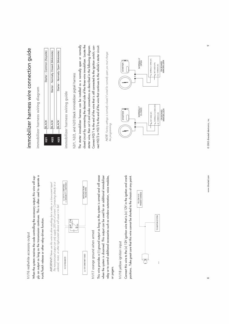
imm
ob
iliz
er
harn
ess
wir
e c
on
nect
ion
gu
ide
imm
ob
iliz
er
ha
rne
ss w
irin
g d
iag
ram
___
___
___
imm
ob
iliz
er
ha
rne
ss w
irin
g g
uid
e
h2/1
, h2/2
, and h
2/3
bla
ck im
mobili
zer
pig
tail
harn
ess
The starter immobilizer harness can be installed as a normally open or normally
closed circuit by connecting the desired side of the three-wire immobilizer. Locate the
starter wire, then cut it and make connections as described in the following diagram.
Connect H2/1 to the end of the wire that is still connected to the ignition switch; con-
nect H2/2 or H2/3 to the end of the wire that continues to the vehicle’s starter circuit.
NO
TE: F
acto
ry s
ettin
gs is
nor
mal
ly c
lose
d if
wire
d fo
r nor
mal
ly o
pen
you
mus
t cha
nge
the
prog
ram
min
g.
ON
BO
AR
DIM
MO
BIL
IZE
R
NO
RM
AL
LY
OP
EN
(8
7)
NO
T U
SE
D (
87
A)
CO
MM
ON
(3
0)
NO
RM
ALLY
OP
EN
NO
RM
ALLY
CLO
SE
D
ON
BO
AR
DIM
MO
BIL
IZE
R
NO
T U
SE
D (
87
)
NO
RM
AL
LY
CL
OS
ED
(8
7A
)
CO
MM
ON
(3
0)
BLA
CK
Sta
rte
r -
No
rma
lly O
pe
n (
Mo
tors
ide
)
BLA
CK
Sta
rte
r -
No
rma
lly C
lose
d (
Mo
tors
ide
)
BLA
CK
Sta
rte
r -
Co
mm
on
(K
eysid
e)
H2/1
H2/2
H2/3
h1/1
6 r
ed/w
hite a
ccess
ory
outp
ut
When the system receives the code controlling the accessory output, this wire will sup-
ply an output as long as the transmission continues. This is often used to operate a
trunk/hatch release or other relay-driven function.
IMPO
RTA
NT!
Nev
er u
se th
is w
ire to
driv
e an
ythi
ng b
ut a
rel
ay o
r a
low
-cur
rent
inpu
t!Th
e tra
nsisto
rized
out
put c
an o
nly
supp
ly 2
00 m
A o
f cur
rent
. C
onne
ctin
g di
rect
ly to
aso
leno
id,
mot
or,
or o
ther
hig
h-cu
rrent
dev
ice
will
cau
se it
to fa
il.
h1/1
7 o
range g
round w
hen a
rmed
This wire provides a (-) ground output as long as the system is armed and will cease
when the system is disarmed. This output can be used for an additional immobilizer
relay or to control additional accessories such as window automation, voice modules,
or pagers.
h1/1
8 y
ello
w ignitio
n input
Connect this wire to the (+) 12V ignition wire that is (+) 12V in the igntion and crank
positions.. Take great care that this wire cannot be shorted to the chassis at any point.
© 2003 directed electronics, inc.
11
www.directed.com
10
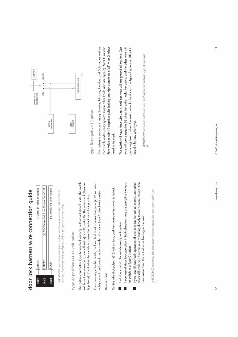
typ
e B
: n
eg
ati
ve
(-)
pu
lse
This system is common in many Toyotas, Nissans, Hondas, and Saturns, as well as
Fords with keyless entry systems (some other Fords also use Type B). Most European
Ford vehicles with (-) negative pulse locking are high current so a 451M or 2 relays
need to be used.
The switch will have three wires on it, and one wire will test ground all the time. One
wire will pulse negative (-) when the switch locks the doors, and the other wire will
pulse negative (-) when the switch unlocks the doors. This type of system is difficult to
mistake for any other type.
IMPO
RTA
NT!
Rem
embe
r th
at th
ese
wire
s' fu
nctio
ns r
ever
se b
etw
een
Type
A a
nd T
ype
B.
do
or
lock
harn
ess
wir
e c
on
nect
ion
gu
ide
___
___
___
IMPO
RTA
NT!
The
doo
r loc
k ou
tput
s ar
e lo
w c
urre
nt a
nd s
houl
d no
t be
atta
ched
dire
ct-
ly to
any
hig
h-cu
rrent
dev
ice;
they
are
onl
y to
be
used
to a
ctiv
ate
rela
ys
typ
e A
: p
osi
tiv
e (
+)
12
-vo
lt p
uls
e
The system can control Type A door locks directly, with no additional parts. The switch
will have three wires on it; one will test (+)12 volt constantly. The others will alternate-
ly pulse (+)12 volt when the switch is pressed to the lock or unlock position.
If you cannot get to the switch, and you find a set of wires that pulse (+)12 volt alter-
nately on lock and unlock, make sure that it is not a Type C direct-wire system.
Here is a test:
Cut the wire that pulses (+)12 volt on lock, and then operate the switch to unlock.
■If all doors unlock, the vehicle uses type A system.
■If you lose all door lock operation in both directions, you are operating the mas-
ter switch in a Type C system.
■If you lose all door lock operation of one or more, but not all motors, and other
doors still work, you have cut a wire leading directly to one or more motors. You
must instead find the actual wires leading to the switch.
IMPO
RTA
NT!
Rem
embe
r th
at th
ese
wire
s' fu
nctio
ns r
ever
se b
etw
een
Type
A a
nd T
ype
B.
BL
UE
(-)
Un
lock,
(-)
Lo
ck O
utp
ut
EM
PT
Y(+
) 1
2V
Pro
tecte
d,
Lo
w C
urr
en
t fo
r 4
51
M
GR
EE
N(-
) L
ock,
(+)
Un
lock O
utp
ut
H3/1
H3/2
H3/3
© 2003 directed electronics, inc.
13
www.directed.com
12
IMPO
RTA
NT!
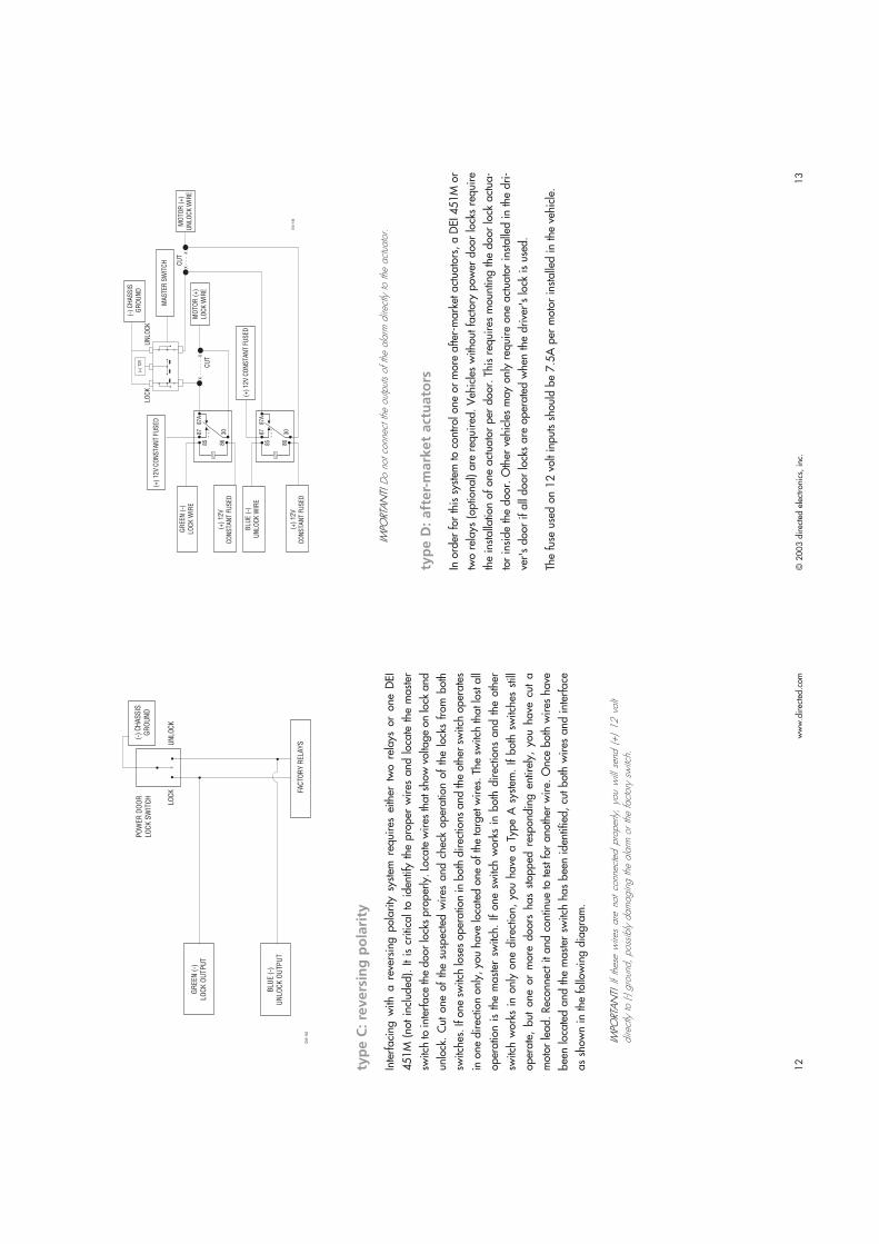
Do
not c
onne
ct th
e ou
tput
s of
the
alar
m d
irect
ly to
the
actu
ator
.
typ
e D
: a
fte
r-m
ark
et
act
ua
tors
In order for this system to control one or more after-market actuators, a DEI 451M or
two relays (optional) are required. Vehicles without factory power door locks require
the installation of one actuator per door. This requires mounting the door lock actua-
tor inside the door. Other vehicles may only require one actuator installed in the dri-
ver's door if all door locks are operated when the driver's lock is used.
The fuse used on 12 volt inputs should be 7.5A per motor installed in the vehicle.
typ
e C
: re
ve
rsin
g p
ola
rity
Interfacing with a reversing polarity system requires either two relays or one DEI
451M (not included). It is critical to identify the proper wires and locate the master
switch to interface the door locks properly. Locate wires that show voltage on lock and
unlock. Cut one of the suspected wires and check operation of the locks from both
switches. If one switch loses operation in both directions and the other switch operates
in one direction only, you have located one of the target wires. The switch that lost all
operation is the master switch. If one switch works in both directions and the other
switch works in only one direction, you have a Type A system. If both switches still
operate, but one or more doors has stopped responding entirely, you have cut a
motor lead. Reconnect it and continue to test for another wire. Once both wires have
been located and the master switch has been identified, cut both wires and interface
as shown in the following diagram.
IMPO
RTA
NT!
If
thes
e w
ires
are
not
conn
ecte
d pr
oper
ly,
you
will
sen
d (+
) 12 v
olt
dire
ctly
to (-
) gro
und,
pos
sibl
y da
mag
ing
the
alar
m o
r th
e fa
ctor
y sw
itch.
© 2003 directed electronics, inc.
15
www.directed.com
14
typ
e F
: o
ne
-wir
e s
yst
em
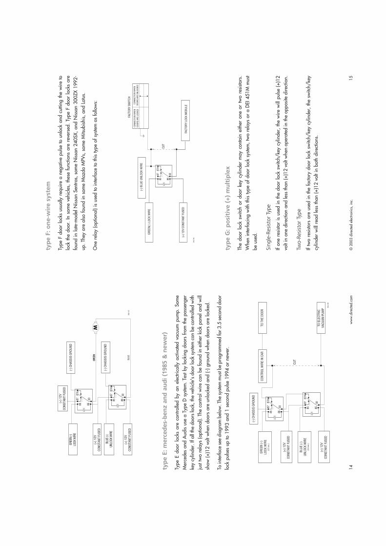
Type F door locks usually require a negative pulse to unlock and cutting the wire to
lock the door. In some vehicles, these functions are reversed. Type F door locks are
found in late-model Nissan Sentras, some Nissan 240SX, and Nissan 300ZX 1992-
up. They are also found in some Mazda MPVs, some Mitsubishis, and Lotus.
One relay (optional) is used to interface to this type of system as follows:
typ
e G
: p
osi
tiv
e (
+)
mu
ltip
lex
The door lock switch or door key cylinder may contain either one or two resistors.
When interfacing with this type of door lock system, two relays or a DEI 451M must
be used.
Sin
gle
-Resi
stor
Type
If one resistor is used in the door lock switch/key cylinder, the wire will pulse (+)12
volt in one direction and less than (+)12 volt when operated in the opposite direction.
Two-R
esi
stor
Type
If two resistors are used in the factory door lock switch/key cylinder, the switch/key
cylinder will read less than (+)12 volt in both directions.
typ
e E
: m
erc
ed
es-
be
nz a
nd
au
di
(19
85
& n
ew
er)
Type E door locks are controlled by an electrically activated vacuum pump. Some
Mercedes and Audis use a Type D system. Test by locking doors from the passenger
key cylinder. If all the doors lock, the vehicle's door lock system can be controlled with
just two relays (optional). The control wire can be found in either kick panel and will
show (+)12 volt when doors are unlocked and (-) ground when doors are locked.
To interface see diagram below. The system must be programmed for 3.5 second door
lock pulses up to 1993 and 1 second pulse 1994 or newer.
© 2003 directed electronics, inc.
17
www.directed.com
16
peri
ph
era
l p
lug
-in
harn
ess
es
sup
er
bri
gh
t b
lue
le
d,
2-p
in w
hit
e p
lug
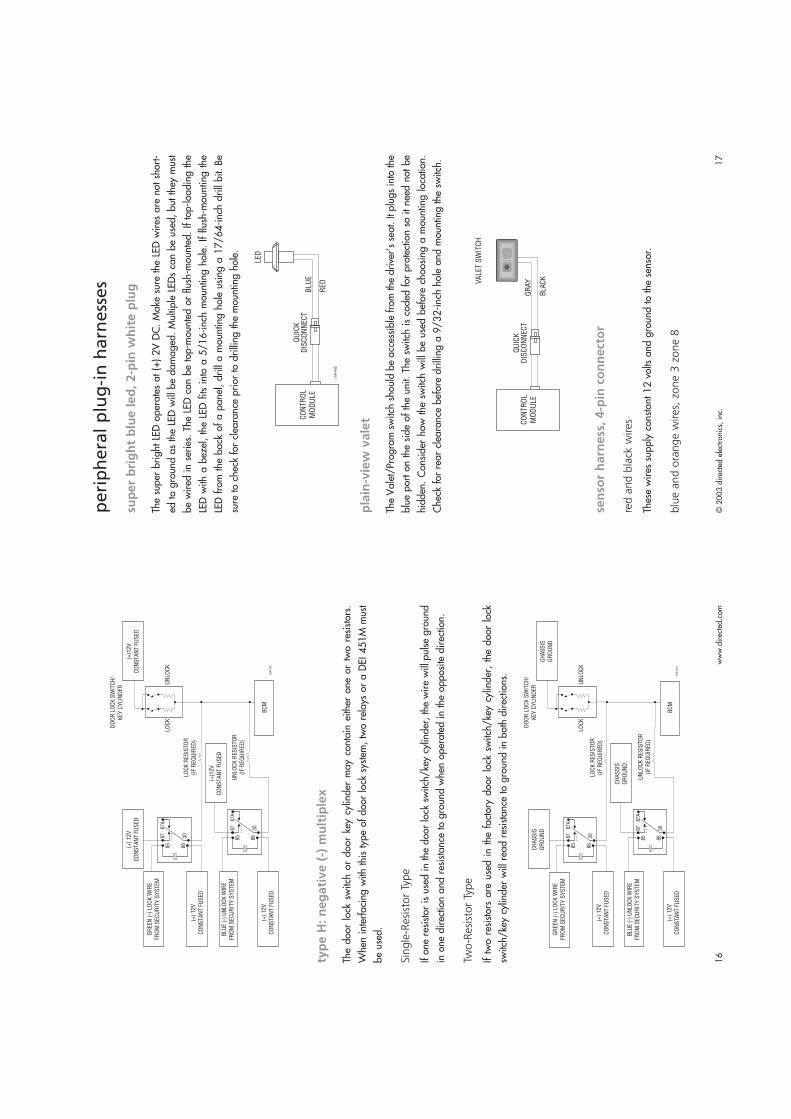
The super bright LED operates at (+) 2V DC. Make sure the LED wires are not short-
ed to ground as the LED will be damaged. Multiple LEDs can be used, but they must
be wired in series. The LED can be top-mounted or flush-mounted. If top-loading the
LED with a bezel, the LED fits into a 5/16-inch mounting hole. If flush-mounting the
LED from the back of a panel, drill a mounting hole using a 17/64-inch drill bit.Be
sure to check for clearance prior to drilling the mounting hole.
pla
in-v
iew
va
let
The Valet/Program switch should be accessible from the driver’s seat. It plugs into the
blue port on the side of the unit. The switch is coded for protection so it need not be
hidden. Consider how the switch will be used before choosing a mounting location.
Check for rear clearance before drilling a 9/32-inch hole and mounting the switch.
sen
sor
ha
rne
ss,
4-p
in c
on
ne
cto
r
red a
nd b
lack
wires
These wires supply constant 12 volts and ground to the sensor.
blu
e a
nd o
range w
ires,
zone 3
zone 8
typ
e H
: n
eg
ati
ve
(-)
mu
ltip
lex
The door lock switch or door key cylinder may contain either one or two resistors.
When interfacing with this type of door lock system, two relays or a DEI 451M must
be used.
Sin
gle
-Resi
stor
Type
If one resistor is used in the door lock switch/key cylinder, the wire will pulse ground
in one direction and resistance to ground when operated in the opposite direction.
Two-R
esi
stor
Type
If two resistors are used in the factory door lock switch/key cylinder, the door lock
switch/key cylinder will read resistance to ground in both directions.

© 2003 directed electronics, inc.
19
www.directed.com
18
arm
ing
/dis
arm
ing
dia
gn
ost
ics
The systems microprocessor monitors and reports all active and violated zones when
arming and disarming the system.
arm
ing
Zones that are triggered at the time the system is armed are reported by an addition-
al set of status chirps called Malfunction AutoBypass. The specific zone bypassed is
then reported by the LED. For more zone information, refer to Table of Zonessection
of this guide.
dis
arm
ing
If a zone is triggered, three disarm chirps will sound. The specific zone that was trig-
gered is then reported by the LED when the ignition is turned on. For more zone infor-
mation, refer to the Table of Zonessection of this guide.
syst
em
sta
tus
chir
ps
mu
ltip
le e
ven
t to
tal
reca
llThis will report the last eight system triggers.
1.
Press and hold
of the PlainView 2 Valet switch.
2.
While still holding
, arm and disarm the system, then release the button.
3.
The LED will start to blink to indicate the most recent trigger and proceed down
to the eighth trigger. If fewer than eight triggers are stored in memory, the LED
will blink continuously until the system is armed/disarmed using the transmitter
Action
No.ofChirps
Description
Arm
2S
yste
m a
rme
d.
Arm
4S
yste
m a
rme
d w
ith
ho
od
an
d
tru
nk b
yp
ass z
on
es 5
an
d 6
.
Arm
2 (
5-s
eco
nd
pa
use
) 4
Syste
m a
rmed w
ith d
oor
bypass z
on
es
Arm
2 (
10-s
econd p
ause)
4S
yste
m a
rmed w
ith s
ensor
activ
e
and b
ypassed z
on
es 3
an
d 8
.
Dis
arm
1S
yste
m d
isarm
ed.
Dis
arm
3S
yste
m d
isa
rme
d w
ith
zo
ne
vio
latio
n
Dis
arm
5S
yste
m d
isarm
ed t
ransm
itte
r lo
w b
attery
These wires are multiplex inputs. If a (-) input of less than 0.8 seconds is supplied to
either wire, the Warning Zone response will occur. A (-) input of longer than 0.8 sec-
onds to either wire will initiate the triggered sequence and report Zone 3 or Zone 8.
mo
un
tin
g t
he
re
ceiv
er/
an
ten
na
NO
TE:
Be s
ure
not t
o bu
ndle
exc
ess
cabl
e as
this w
ill red
uce
the
rang
e.
The receiver/antenna position should be discussed with the vehicle owner prior to
installation since the antenna may be visible to the vehicle’s operator.
The best position to locate the receiver/antenna is centered high on either the front or
rear windshield. For optimal range, the antenna should be mounted vertically. It can
be mounted horizontally in relation to the windshield or under the dashboard away
from metal, but range will be reduced. Metallic window tint can also affect range, so
this should be a consideration when determining the mounting location.
After determining the best mounting location, follow these steps:
1.
Clean the mounting area with a quality glass cleaner or alcohol to remove any
dirt or residue.
2.
Plug the receiver/antenna cable into the receiver/antenna.
3.
Mount the receiver/antenna with double-sided tape.
4.
Route the receiver/antenna cable down the window pillar to the control module
and plug the cable into the control module.
© 2003 directed electronics, inc.
21
www.directed.com
20
Cliffnet Wizard help menu.
ma
nu
al
pro
gra
mm
ing
in
stru
ctio
ns
Be sure to document changes by taking note of all feature changes made in program-
ming mode.
To enter the User Selectable Features programming:
1.
Ignition on - Turn the ignition to the run position or start the engine.
2.
Enter PIN - Enter the factory preset PIN code of 2 by pressing
on the
PlainView 2 Valet switch twice, then
once.
NO
TE:
If th
e fa
ctor
y pr
eset
PIN
has
bee
n ch
ange
d, th
e ne
w P
IN m
ust b
e en
tere
d.
3.
Hold/Chirp/Release - After entering the PIN code, press and hold
until a
chirp is heard and the LED turns on, then release the button. You have now
entered the feature selection position of the User Selectable Features grid.
4.
Column select - Press
the same number of times as the desired column. After
a pause the siren will chirp the same number of times as the selected column for
confirmation.
5.
Feature select - Press
the same number of times as the desired feature. The
siren will chirp with each press. The feature can now be changed using the
remote control.
6.
Feature change - Press the arm/disarm button on the transmitter. If the system
chirps once, the feature has just turned off; if the system chips twice, the feature
has just turned on. If the feature has more than two settings, continue pressing
the arm/disarm button on the transmitter to toggle through the settings.
To advance to the next feature in the same column, press
the same number
of times as the desired feature within 60 seconds; to change a feature in a
different column begin at step 4 by entering the column number first and then
the row number.
NO
TE:
Refe
r to
the
Featu
re D
escr
iptio
nsse
ctio
ns o
f thi
s gu
ide
for im
porta
nt n
otes
and
desc
riptio
ns o
f the
sys
tem
feat
ures
and
pro
gram
min
g.
7.
Exit programming - To exit programming mode turn the ignition off or wait 60
seconds without pressing the PlainView 2 Valet switch. The siren will chirp three
times to indicate programming mode has been exited.
after recalling the final trigger. For more information, please refer to the Table
of Zones section of this guide.
tab
le o
f zo
nes
When using the diagnostic functions, use the Table of Zones to see which input has
triggered the system. It is also helpful in deciding which input to use when connecting
optional sensors and switches.
NO
TE:
The
War
ning
Zon
e re
spon
se d
oes
not r
epor
t on
the
LED
.
syst
em
featu
res
pro
gra
mm
ing
This system has many features that can be programmed to accommodate the user's
personal preferences and make system installation easier. They are listed in two pro-
gramming grids on the following pages. Many features have default setting that have
been programmed at the factory and are indicated in bold type.
The User Selectable Features grid allows the user and installer to change operational
features through the PlainView 2 Valet. The Installer Selectable Features grid allows
the installer to change input/output functions of the system to integrate with the vehi-
cle’s specific characteristics.
clif
fne
t w
iza
rd p
ro i
nst
all
ati
on
so
ftw
are
pro
gra
mm
ing
Cliffnet Wizard Pro provides access to all available system features and some that are
not available when manually programming with the Valet switch. Cliffnet Wizard Pro
is compatible with Microsoft Windows 95/98/2000/ME/XP/NT so most program-
ming operations can be accomplished by pointing and clicking with a mouse. This
eliminates the need for programming grids and lengthy programming sequences. For
a complete guide to system programming using the Cliffnet Wizard Pro refer to the
LEDFlashes
Triggertype
Inputdescription
3M
ux
Se
nso
r in
pu
t
4In
sta
nt
Door
Pin
5In
sta
nt
Ho
od
/Tru
nk P
in
6In
sta
nt
Ho
od
(o
nly
with
IS
4)
7In
sta
nt
Ign
itio
n
8M
ux
Se
nso
r 2
In
pu
t
10
N/A
Ala
rm p
ow
er
rese
t

www.directed.com
22
Quiet: Chirps will sound when arming/disarming the system but at a lower
volume than normal. This feature is only available with the 515C siren.
auto
lock
- i
gn
itio
n/o
ff/r
pm
Ignition: The doors will automatically lock three seconds after the ignition is
turned on unless a door is open at that time.
Off: The doors will not lock automatically.
Rpm: The doors will lock when the system sees the engine reach a prepro-
grammed RPM. This feature is only available with IntelliStart.
auto
unlo
ck -
ignitio
n/o
ff
Ignition: The doors will automatically unlock as soon as the ignition is turned off.
Off: The doors will not automatically unlock when the ignition is turned off
pass
ive lock
- o
n/o
ff
On: The doors will lock when the system passively arms. This feature only applies
when passive arming is programmed on.
Off: The doors will not lock when the system passively arms.
sire
n d
ura
tion -
30/6
0/9
0
The system will sound the alarm for the programmed duration (30/60/90
seconds) during an alarm trigger or when the system is put into panic mode.
auto
sta
rt s
ett
ing -
off
/batt
ery
only
/tem
p o
nly
/batt
ery
and t
em
p
This feature is only available with the IntelliStart option.
Off: The vehicle will not autostart.
Battery: The vehicle will only autostart when the car battery gets low.
Temperature: The vehicle will only autostart at a preset low temperature.
Battery and temperature: The vehicle will autostart with a low car battery or low
temperature.
NO
TE:
Tem
pera
ture
and
bat
tery
cal
ibra
tion
and
setti
ngs
can
be m
ade
only
with
the
Clif
fnet
Wiz
ard
Pro.
www.directed.com
23
use
r se
lect
ab
le f
ea
ture
s
*This feature is only available with optional 515C siren.
**This feature is only available with optional IntelliStart connected.
***This feature is only available with optional SmartWindows connected.
use
r se
lect
ab
le f
ea
ture
s d
esc
rip
tio
ns
- co
lum
n o
ne
add n
ew
rem
ote
(auto
learn
)
Auto-learn new three-button cello remote controls to the system in the standard
button configuration. For more information, see programming note #1.
auto
arm
- o
n/o
ff
On: When the system sees the ignition turn off and the last protected entry (door,
hood, or trunk) close, it will begin a 30-second countdown before arming itself.
After the first five seconds, you will hear two chirps and the lights will flash. The
system will arm 25 seconds later.
Off: The transmitter must be used to arm the system.
chirps
- o
n/o
ff/q
uie
t
On: Chirps will sound when arming/disarming the system.
Off: Chirps will not sound when arming/disarming the system.
Fir
st
Pre
ss
Th
en
Pre
ss
Ad
d n
ew
re
mo
te(a
uto
lea
rn)
Se
t P
IN c
od
eN
ew
re
mo
te le
arn
arm
/dis
arm
on
ly
Au
to a
rmo
n/o
ffS
ele
ct
sire
nso
un
ds*
New
re
mo
te le
arn
acce
so
ry o
utp
ut
Ch
irp
so
n/o
ff/q
uie
t*FA
CT
II
on
/off
New
re
mo
te le
arn
sile
nt
mo
de
Au
to lo
ck
ign
itio
n/o
ff/r
pm
**R
em
ote
va
let
on
/off
New
re
mo
te le
arn
rem
ote
va
let
Au
to u
nlo
ck
ign
itio
n/o
ffE
ntr
y d
ela
y o
n/o
ffN
ew
re
mo
te le
arn
rem
ote
sta
rt**
Pa
ssiv
e lo
ck
on
/off
Re
se
t to
de
fau
lt(e
xce
pt
tra
nsm
itte
ra
nd
va
let
co
de
)
New
re
mo
te le
arn
win
dow
dow
n/v
en
t***
Sire
n d
ura
tio
n3
0/6
0/9
0P
an
ic o
n/o
ffC
lea
r a
ll re
mo
tes
Au
tosta
rt/o
ff**
(ba
tte
ry o
nly
,te
mp
on
ly,
an
db
att
ery
an
d t
em
p)
No
t u
se
dN
ot
use
d
© 2003 directed electronics, inc.
25
www.directed.com
24
use
r se
lect
ab
le f
ea
ture
s d
esc
rip
tio
ns
- co
lum
n t
hre
e
The features in this column pertain to programming individual transmitter channels in
custom configurations. Following is an explanation of the features. Program the indi-
vidual transmitter channels following the instructions in programming note #2.
arm
/dis
arm
only
The remote control channel programmed into this feature will arm/disarm the
system only.
NO
TE:
Whe
n pr
ogra
mm
ing
a ne
w rem
ote
cont
rol t
o cu
stom
con
figur
atio
n a
chan
nel
mus
t firs
t be
prog
ram
med
to th
is fe
atur
e be
fore
pro
gram
min
g th
e re
mai
ning
cha
nnel
s.
acc
ess
ory
outp
ut
The transmitter channel programmed into this feature will activate the accessory
output.
sile
nt
mode
The transmitter channel programmed into this feature will arm/disarm the
system, but the siren will not chirp.
rem
ote
vale
t
The transmitter channel programmed into this feature will make the system
enter/exit valet mode.
rem
ote
sta
rt
This feature is only available with IntelliStart connected
The transmitter channel programmed into this feature will activate or shut down
the Intellistart remote start system.
win
dow
contr
ol
This feature is only available with SmartWindows connected
The transmitter channel programmed into this feature will activate the vent or roll
down feature of the SmartWindows system.
clear
all
rem
ote
s
This feature will erase all remote codes from the system memory. This feature is
convenient for erasing any transmitters that have been lost, stolen, or incorrect-
ly programmed into the system.
After entering this feature press any button on the transmitter; the siren will chirp
to indicate that all transmitters have been erased from memory.
use
r se
lect
ab
le f
ea
ture
s d
esc
rip
tio
ns
- co
lum
n t
wo
set
pin
code
This feature allows the setting of the user's personal PIN code. For more infor-
mation, see programming note #5.
sele
ct s
iren s
ounds
The individual sounds the 515C siren produces during an full trigger alarm can
be customized for owner recognition of an alarm trigger. For more information,
see programming note #3.
fact
2 o
n/o
ff
On: The alarm will bypass for 60 minutes if zones 3, 5, and 8 are triggered
three times within a one hour period.
Off: The alarm will respond to zones 3, 5, and 8 inputs indefinitely without
bypassing.
rem
ote
vale
t on/o
ff
On: The alarm can be put into valet mode with the remote control.
Off: The alarm can not be put into valet mode with the remote control.
entr
y dela
y on/o
ff
On: If the system has passively armed, it will not trigger for 15 seconds after a
door is opened allowing the user to enter the vehicle and disarm the system via
the PlainView 2 Valet switch.
Off: There is no entry delay when armed. The system will trigger instantly when
a door is opened.
rese
t to
defa
ult s
ett
ings
All system settings (except PIN and remote programming) in the User
Programming grid will be reset to their default factory setting as indicated in
bold lettering.
Press the arm/disarm button of the TX; the siren will chirp twice as confimation.
panic
on/o
ff
On: The panic feature is available.
Off: The panic feature is not available.
© 2003 directed electronics, inc.
27
www.directed.com
26
inst
all
er
sele
cta
ble
fe
atu
res
de
scri
pti
on
s
lock
puls
e s
ingle
/double
Single: One door lock pulse will be output when the system arms.
Double: Two door lock pulses will be output when the system arms.
unlo
ck p
uls
e s
ingle
/double
Single: One door unlock pulse will be output when the system arms.
Double: Two door unlock pulses will be output when the system arms.
lock
puls
e d
ura
tion 0
.8/3
.5 s
ec
0.8 seconds: The door lock pulses will be 800 milliseconds in length.
3.5 seconds: The door lock pulses will be 3.5 seconds in length.
dom
elig
ht
dela
y
On: No malfunction autobypass chirps will be generated if any door triggers or
the delay domelight are active when the system is armed.
Off: Malfunction autobypass chirps will be generated if any door triggers or the
delay domelight are active when the system is armed.
acc
ess
ory
outp
ut
pro
gra
mm
ing
The auxiliary accessory output wire (RED/WHITE) can be programmed for several dif-
ferent types of outputs.
P1 0.8 seconds: The pulsed output is disabled with the ignition on or the alarm
armed.
P2 0.8 seconds: The pulsed output will operate any time.
Timed: The length of output duration set.
Latched: The output on/off controlled by button(s) controlling accessory.
Latched (ignition reset): The output on/off controlled by button(s) controlling
accessory if on, will turn off when the ignition is turned on.
acc
ess
ory
outp
ut
auto
act
ivation t
ype
NO
TE:
The
acce
ssor
y ou
tput
will
not
aut
o-ac
tivat
e if
the
acce
ssor
y ou
tput
is
pro-
gram
med
to e
ither
latc
hed
setti
ng.
Off.
Arm: The accessory output will auto-activate when the system is armed.
inst
all
er
sele
cta
ble
fe
atu
res
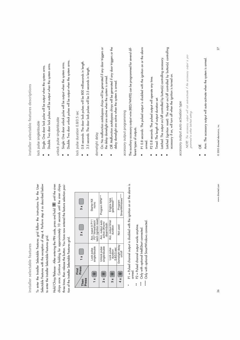
To enter the Installer Selectable Features grid follow the instructions for the User
Selectable Features with the exception of step 4. Perform step 4 as described below
to enter the Installer Selectable Features grid.
Hold/Chirp/Release - After entering the PIN code, press and hold
until the siren
chirps once. Continue holding for approximately 10 seconds until the siren chirps
three times, then release the button. You have now entered the feature selection posi-
tion of the Installer Selectable Features grid.
*P1 = Pulsed channel output is disabled with the ignition on or the alarm is
armed.
**P2 = Pulsed channel output works anytime.
***Only with optional IntelliStart connected.
****Only with optional SmartWindows connected.
Fir
st
Pre
ss
Th
en
Pre
ss
Lo
ck p
uls
esin
gle
/do
uble
Acc.
ou
pu
t A
P1
*/P
2**
/tim
ed
/la
tch
/la
tch
(ig
nitio
n r
ese
t)
Sta
rte
r K
illn
o/n
c
Un
lock p
uls
esin
gle
/do
uble
Acc.
ou
tpu
t a
uto
active
off
/arm
/d
isa
rm/b
oth
Pro
gra
m R
PM
***
Lo
ck p
uls
ed
ura
tio
n0
.8/3
.5 s
ec
Acc.
ou
tpu
t tim
er
du
ratio
nE
ng
ine
typ
eg
as/d
iese
l***
Do
me
ligh
t d
ela
yo
n/o
ffN
ot
use
dP
rogra
mS
ma
rtW
ind
ow
s**
**
© 2003 directed electronics, inc.
29
www.directed.com
28
pro
gra
mm
ing
no
tes
Note #1: Adding a new transmitter in auto-learn configuration
Press the arm/disarm button of the three-button cello remote control; the siren
will chirp once.
Immediately press arm/disarm again; the siren will chirp twice to confirm the
new transmitter has been programmed.
Note #2: Adding a new transmitter in custom-configuration
For the arm/disarm channel, transmit the channel of the new three, four, or five but-
ton transmitter that you want to control that feature; the siren will then chirp once.
Immediately transmit the same channel again, the siren will chirp twice to con-
firm the transmitter channel has been programmed.
For the rest of the channels, the siren will chirp the same number of times as the
feature row.
NO
TE:
Whe
n pr
ogra
mm
ing
a ne
w tra
nsm
itter
to
custo
m c
onfig
urat
ion,
an
arm
/di
s-ar
m c
hann
el m
ust f
irst b
e pr
ogra
mm
ed b
efor
e pr
ogra
mm
ing
the
rem
aini
ng c
hann
els.
Note #3: Selecting siren sounds
After entering this feature, press the arm/disarm button. The siren will generate a five-
second sample of each available siren sound. Perform the following steps to add or
delete that specific sound.
Personalized siren sounds require the use of a 515C in place of the standard
siren.
Add sound: Press
on the PlainView 2 Valet switch while playing the desired
sound to add that sound.
Delete sound: Press
on the PlainView 2 Valet switch while playing the
desired sound to delete that sound.
Note #4: RPM programming
Drive the vehicle to an open area and allow the engine to warm up until the
engine RPM drops to normal idle speed.
Place the engine in park or neutral and set the parking brake.
Enter the feature and press the arm/disarm button.
The lights will flash twice to confirm the engine RPM has been learned.
Disarm: The accessory output will auto-activate when the system is disarmed.
Both: The accessory output will auto-activate when the system is armed and
disarmed.
acc
ess
ory
outp
ut
tim
er
dura
tion
Start Timer: Press the arm/disarm button; the siren will chirp to signal the start
of the timer duration setting.
Stop Timer: Press the arm/disarm button; the siren will chirp to signal the end of the
timer duration setting, or for maximum time, do not press the arm/disarm button.
inte
rrupt
no/n
c
NO: If the starter immobilizer circuit is normally open and power is lost to the
system, the circuit will remain open and the starter will not operate.
NC: If the starter immobilizer circuit is normally closed and power is lost to the
system, the circuit will close and the starter will operate normally.
rpm
pro
gra
mm
ing
This feature applies only if IntelliStart 4 is installed.
Programs the tachometer input for the IntelliStart 4. For more information, see
programming note #4.
engin
e t
ype g
as/
die
sel
This feature applies only if IntelliStart 4 is installed.
Petrol: The IntelliStart will crank the engine three seconds after the ignition is
turned on or after input on the wait-to-start wires ceases.
Diesel: The IntelliStart will crank the engine 20 seconds after it turns the ignition
on and will ignore the wait-to-start input wires.
NO
TE:
RPM
mus
t be
repr
ogra
mm
ed a
fter ch
angi
ng th
is fe
atur
e.
smart
win
dow
s pro
gra
m
This feature applies only if SmartWindows is installed.
Enter this feature and then follow the programming instructions included with
SmartWindows.

© 2003 directed electronics, inc.
31
www.directed.com
30
FACT II will bypass an input zone for 60 minutes if the system sees the same zone trig-
gered three times within one hour, the system will bypass that input for 60 minutes. If
that zone does not attempt to trigger the system during the 60 minute bypass period,
the system will begin to monitor the zone again at the end of the hour. If it does
attempt to trigger while bypassed the 60 minute time period starts over. FACT II will
also bypass warn away triggers for the 60 minute duration.
FACT II requires that you change the way you test the system once you have it
installed. Resetting FACT II requires the 60 minute time period expiring without
attempted triggers or the ignition to be turned on and off. This allows the system to be
repeatedly triggered, disarmed and rearmed, and still allow FACT II to bypass a faulty
zone. N
OTE
:Re
mem
ber to
res
et w
ith th
e ig
nitio
n w
hen
testi
ng s
enso
rs.
smart
po
wer
up
II
The Smart Power Up II feature ensures that when the security system is powered back
up after being disconnected, the system will resume the same state it was in before
power was lost. For example, if power is disconnected during a full trigger sequence,
the system will still be in the full trigger sequence when power is reconnected to the
unit. If power is disconnected while the unit is disarmed, it will still be disarmed when
power is restored.
rem
ote
co
ntr
ol
sen
sor
dis
ab
le1.
Arm the system.
2.
Use the transmitter to bypass the sensor.
3.
The lights will flash four times. All warn away zones are now bypassed.
4.
Transmit the sensor bypass channel again.
5.
The lights will flash four times again. The sensor warn away and full trigger
zones are now bypassed.
6.
The sensor zones will reset when disarmed.
NO
TE:If
only
one
flas
h is s
een,
the
engi
ne R
PM w
as n
ot s
ucce
ssfu
lly le
arne
d. T
est t
heta
ch w
ire c
onne
ctio
n an
d re
try.
Turn the ignition off and activate remote start to test.
Note #5: PINProgramming
A PINcode can have one to four digits; each digit can be from 0-9.
NO
TE:
A P
IN c
ode
cann
ot b
egin
with
a z
ero.
Programming Procedure
1.
Enter the feature location in the user-selectable programming grid.
2.
Immediately press and release
of the PlainView 2 Valet switch.
3.
Select each digit by pressing
1-9 times, and then press
to enter
the number into the system. To enter a zero, press
only.
To program a PIN code of 1032:
1.
Press and release
once and
once. You will hear one chirp.
3.
Press and release
once. You will not hear a chirp after programming
a zero.
5.
Press and release
three times, and then press
once. You will hear
three chirps.
6.
Press and release
two times, and then press
once. You will hear
two chirps.
4.
Wait for two siren chirps after a five second pause or five seconds after the
last digit has been entered if using less than four digit code number.
5.
Turn off the ignition; the siren will chirp three times.
6.
The programming mode is now exited.
PIN Code Confirmation Procedure
Begin this procedure within 15 seconds of finishing the programming sequence
or the new code will not be set.
1.
Turn on the ignition.
2.
Enter the new PIN code.
3.
Press and hold
for three seconds.
LED turns on: New PIN code is learned and programming is complete.
LEDstays off: New PIN code is not learned and the system reverts to
the old PIN code. Repeat the programming sequence.
fact
II
- fa
lse a
larm
co
ntr
ol
tech
no
log
y

© 2003 directed electronics, inc.
33
www.directed.com
32
trou
ble
sho
otin
g
BLACK - Ground
Empty
Empty
Empty
GREEN - Door Trigger (-)
VIOLET - Door Trigger (+)
BLUE - Instant Trigger (-)
Empty
Empty
WHITE - Light Flash Output
WHITE - Light Flash Output
WHITE/RED - Light Flash Input
RED - 12V Input
BLACK/WHITE - Domelight Supervision Output (-) 200Ma
RED/WHITE - Accessory Output (-) 200Ma
ORANGE - Ground When Armed Output (-) 500Ma
YELLOW - Ignition Input (+)
BROWN - Siren Output (+)
18-Pin Main Harness
18-Pin Main Harness
504CShock Sensor
Antenna/Receiver
CliffNet WizardData Port
PlainView 2 Valet
(87) Starter Wire Normally Open
(87A) Starter Wire Normally Closed
(30) Starter Wire Common
BLUE LED
BLUE - (-) Unlock, (+) Lock Output
Empty (Unless Using a 451M)
GREEN - (+) Unlock, (-) Lock Output
3-Pin 2-Wire DoorLock Harness
www.directed.com34
Starter kill does not work.
Is the correct starter wire being interrupted? If the car starts when the starter killrelay is completely disconnected, the wrong starter wire has been cut and inter-rupted.
Is the YELLOW wire seeing true ignition? Is it connected to an accessory circuit?
Has the no/nc feature been changed?
Shock sensor does not trigger the alarm.
Has the FACT II system been triggered? To check this, turn the ignition key onand off to clear the FACT II from memory, and then retest the shock sensor. Fora detailed description of FACT II, see the FACT II: False Alarm ControlTechnology section of this guide.
Closing the door triggers the system, but opening the door does not.
Have you correctly identified the type of door switch system? This happens oftenwhen the wrong door input has been used.
The system will not passively arm until it is remotely armed and then disarmed.
Are the door inputs connected? Is a BLUE wire connected to the door trigger wirein the vehicle? Either the GREEN H1/9 or the VIOLET H1/8 should be usedinstead.
The PlainView 2 Valet switch does not work.
Is the quick disconnect plugged in correctly?
Is it plugged into the correct socket?
Check the System Features Learn Routine for the default PIN code.
Has the PIN code been changed?
The status LED does not work.
Make sure that it is plugged in. (See the Plug-In Harnesses section of this guide.)Is the LED plugged into the correct socket?
Is the quick disconnect plugged in correctly?


![Anhang B Übersicht DVB-T Funktionen - pdf.ampire.depdf.ampire.de/caraudiosystems/DVB1-dvbLOGiC/Anhang.pdf · 2. Mit [OK] den rechts dargestellten Bildschirm ... Die DVB-T-Funkionen](https://img.dokumen.tips/doc/110x75/5b9f877a09d3f267388b69fd/anhang-b-uebersicht-dvb-t-funktionen-pdf-2-mit-ok-den-rechts-dargestellten.jpg)


